Embed Size (px)
Citation preview
Beam Experiments to Investigate Loading Protocol and Stop Criteria for Load Testing
Eva O.L. Lantsoght1,2, Yuguang Yang2, Dick Hordijk2
1 Politécnico, Universidad San Francisco de Quito, Quito, Ecuador2 Concrete Structures, Faculty of Civil Engineering and Geosciences, Delft University of Technology, The Netherlands
Proof load testing research: field testing
Laboratory testing: beams
Results
Proof load testing in the NetherlandsTo explore the possibility of using proof load testing for the assessment of existing bridges, a number of pilot proof load tests on shear- and flexure-critical bridges, with and without material degradation, were carried out [2].
Open questions after pilot testsWhich stop criteria should we use? Stop criteria [3, 4] are criteria based on the structural response measurements. If a criterion is exceeded, the test needs to be terminated. Further load could cause irreversible damage or collapse.Which loading protocol should we use? How many load cycles per load level? At which loading speed?
References[1] Lantsoght EOL, van der Veen C, de Boer A, Walraven JC (2013) Recommendations for the Shear Assessment of Reinforced Concrete Slab Bridges from Experiments. Structural Engineering International, Vol. 23, Nr. 4, pp. 418-426[2] Lantsoght EOL, Van der Veen C, De Boer A, Hordijk DA (in press) Proof load testing of reinforced concrete slab bridges in the Netherlands. Structural Concrete.[3] Deutscher Ausschuss für Stahlbeton (2000) DAfStb-Guideline: Load tests on concrete structures. Deutscher Ausschuss für Stahlbeton.[4] ACI Committee 437 (2013) Code Requirements for Load Testing of Existing Concrete Structures (ACI 437.2M-13) and Commentary Farmington Hills, MA.
What is proof load testing?In a proof load test, a load representative of the factored live load is applied to the bridge. If the structure can withstand the applied load without signs of distress, it is experimentally shown that the bridge fulfills the loading requirements.
Why proof load testing?Existing bridges often do not rate sufficient for the current live load models [1]. When uncertainties with regard to material degradation or the structural system are large, proof load testing can be used.
Fig. 4: Vertical deformation of a beam test
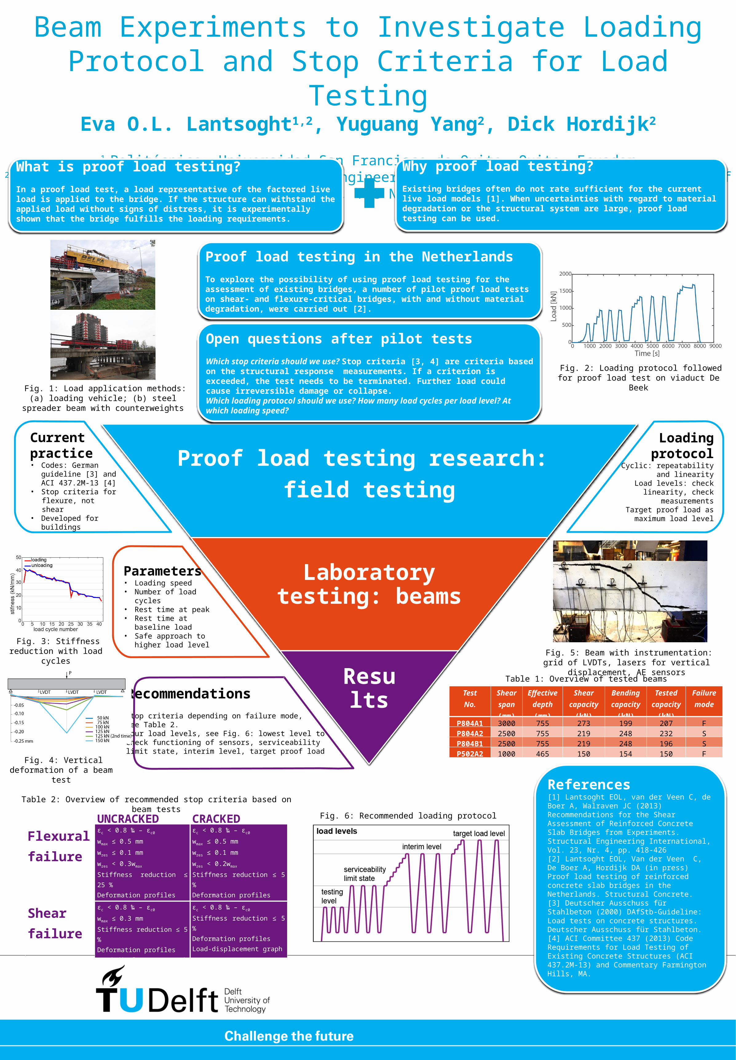
Fig. 2: Loading protocol followed for proof load test on viaduct De Beek
Fig. 1: Load application methods: (a) loading vehicle; (b) steel spreader beam with
counterweights
Fig. 5: Beam with instrumentation: grid of LVDTs, lasers for vertical displacement, AE sensors
UNCRACKED CRACKEDFlexural failure
εc < 0.8 ‰ – εc0
wmax ≤ 0.5 mmwres ≤ 0.1 mmwres < 0.3wmax
Stiffness reduction ≤ 25 %Deformation profilesLoad-displacement graph
εc < 0.8 ‰ – εc0
wmax ≤ 0.5 mmwres ≤ 0.1 mmwres < 0.2wmax
Stiffness reduction ≤ 5 %Deformation profilesLoad-displacement graph
Shear failure
εc < 0.8 ‰ – εc0
wmax ≤ 0.3 mmStiffness reduction ≤ 5 %Deformation profilesLoad-displacement graph
εc < 0.8 ‰ – εc0
Stiffness reduction ≤ 5 %Deformation profilesLoad-displacement graph
Table 2: Overview of recommended stop criteria based on beam tests
Current practice• Codes: German
guideline [3] and ACI 437.2M-13 [4]
• Stop criteria for flexure, not shear
• Developed for buildings
Loadingprotocol
Cyclic: repeatability and linearity
Load levels: check linearity, check measurements
Target proof load as maximum load level
Parameters• Loading speed• Number of load cycles• Rest time at peak• Rest time at baseline
load• Safe approach to higher
load level
TestNo.
Shear span(mm)
Effective depth(mm)
Shear capacity
(kN)
Bending capacity
(kN)
Tested capacit
y(kN)
Failure mode
P804A1 3000 755 273 199 207 FP804A2 2500 755 219 248 232 SP804B1 2500 755 219 248 196 SP502A2 1000 465 150 154 150 F
Table 1: Overview of tested beams
Fig. 6: Recommended loading protocol
RecommendationsStop criteria depending on failure mode,See Table 2.Four load levels, see Fig. 6: lowest level tocheck functioning of sensors, serviceabilitylimit state, interim level, target proof load
Fig. 3: Stiffness reduction with load cycles
(a)


![Blast Loading of Epoxy Panels Using a Shock Tubeing an alternative way to investigate material behavior subjected to blast loading [1]. The shock tube is a well understood instrument,](https://img.pdfslide.net/doc/110x75/5ed47b375b5aa30cb3151bb9/blast-loading-of-epoxy-panels-using-a-shock-tube-ing-an-alternative-way-to-investigate.jpg)