Embed Size (px)
Citation preview
CCNA – Semester1
Chapter 6 -
Addressing the Network – IPv4
CCNA Exploration version 4.0
Objectives
• Explain the structure IP addressing and demonstrate the
ability to convert between 8-bit binary and decimal
numbers.
• Given an IPv4 address, classify by type and describe how
it is used in the network
• Explain how addresses are assigned to networks by ISPs
and within networks by administrators
• Determine the network portion of the host address and
explain the role of the subnet mask in dividing networks.
• Given IPv4 addressing information and design criteria,
calculate the appropriate addressing components.
• Use common testing utilities to verify and test network
connectivity and operational status of the IP protocol stack
on a host.
Introduction
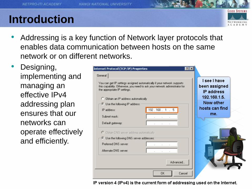
• Addressing is a key function of Network layer protocols that
enables data communication between hosts on the same
network or on different networks.
• Designing,
implementing and
managing an
effective IPv4
addressing plan
ensures that our
networks can
operate effectively
and efficiently.
IPv4 Addresses
IP Addressing Structure
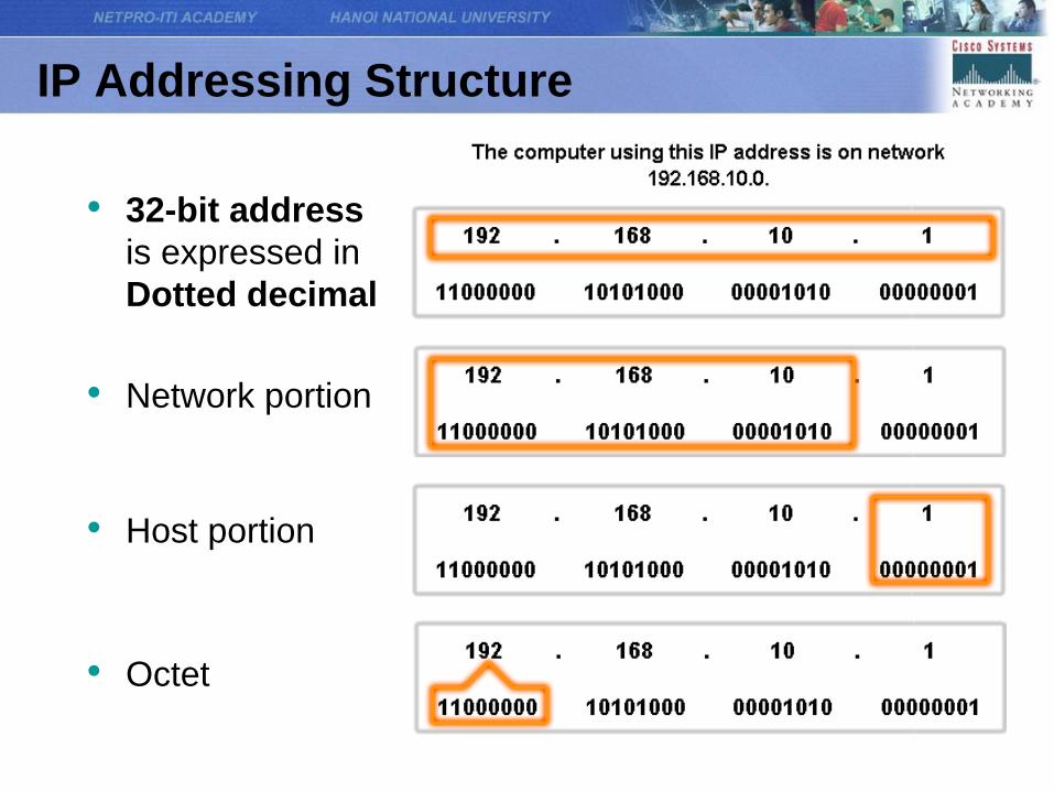
• 32-bit address
is expressed in
Dotted decimal
• Network portion
• Host portion
• Octet
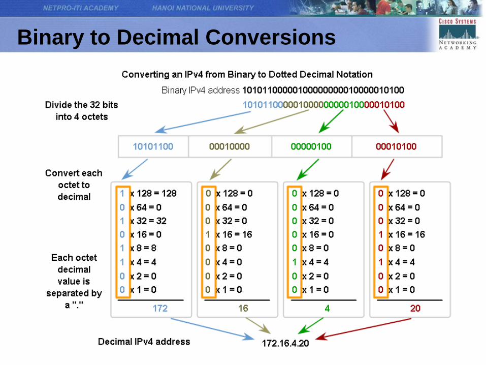
Binary to Decimal Conversions
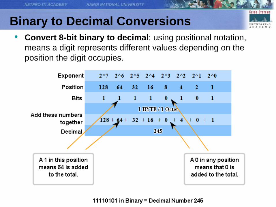
• Convert 8-bit binary to decimal: using positional notation,
means a digit represents different values depending on the
position the digit occupies.
Binary to Decimal Conversions
Binary to Decimal Conversions
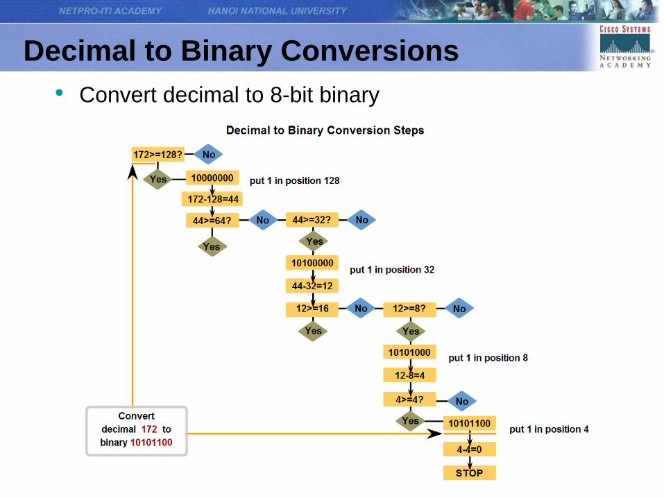
Decimal to Binary Conversions
• Convert decimal to 8-bit binary
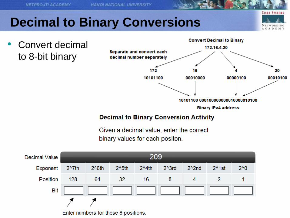
Decimal to Binary Conversions
• Convert decimal
to 8-bit binary
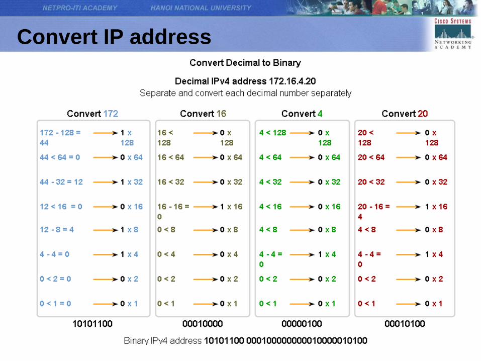
Convert IP address
Subnet Mask
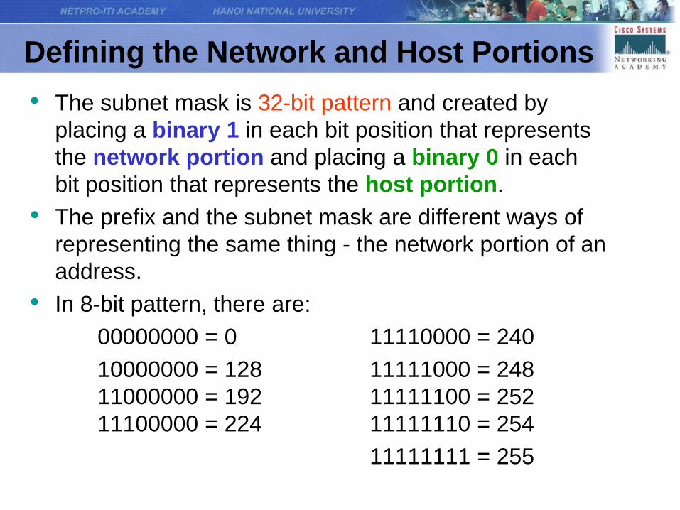
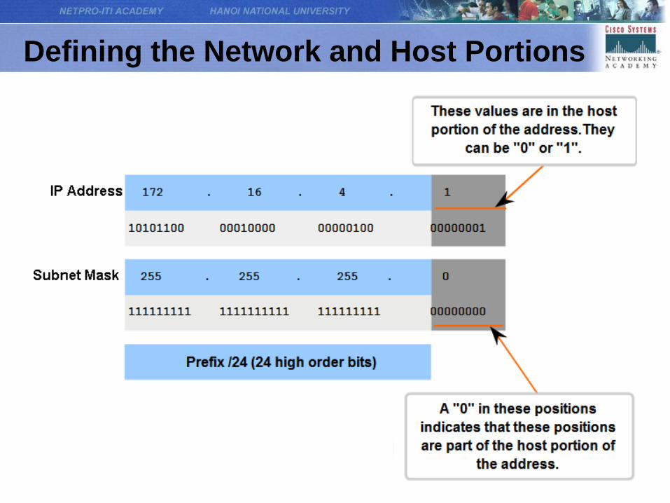
Defining the Network and Host Portions
• The subnet mask is 32-bit pattern and created by
placing a binary 1 in each bit position that represents
the network portion and placing a binary 0 in each
bit position that represents the host portion.
• The prefix and the subnet mask are different ways of
representing the same thing - the network portion of an
address.
• In 8-bit pattern, there are:
00000000 = 0 11110000 = 240
10000000 = 128 11111000 = 248
11000000 = 192 11111100 = 252
11100000 = 224 11111110 = 254
11111111 = 255
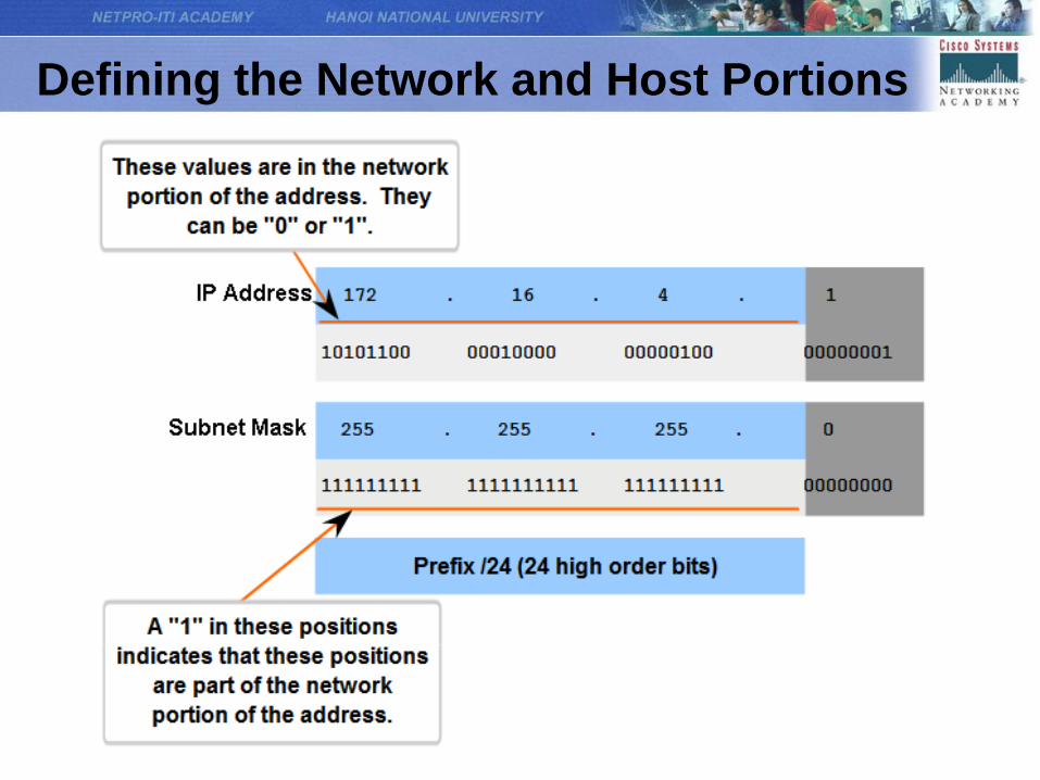
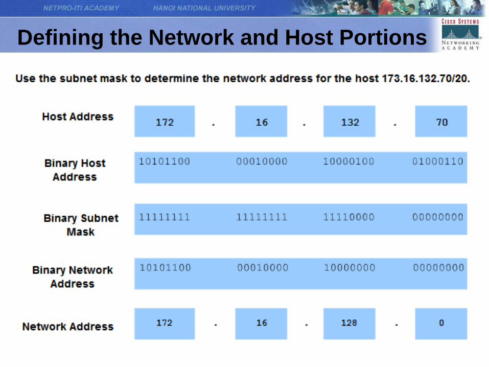
Defining the Network and Host Portions
Defining the Network and Host Portions
Defining the Network and Host Portions
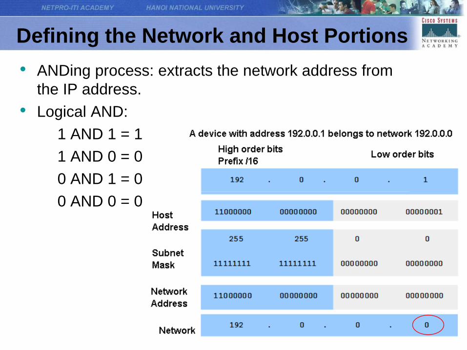
• ANDing process: extracts the network address from
the IP address.
• Logical AND:
1 AND 1 = 1
1 AND 0 = 0
0 AND 1 = 0
0 AND 0 = 0
Defining the Network and Host Portions

Addresses for Different Purposes
Type of Address in an IPv4 Network
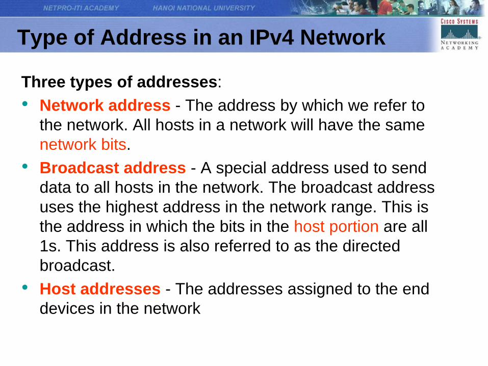
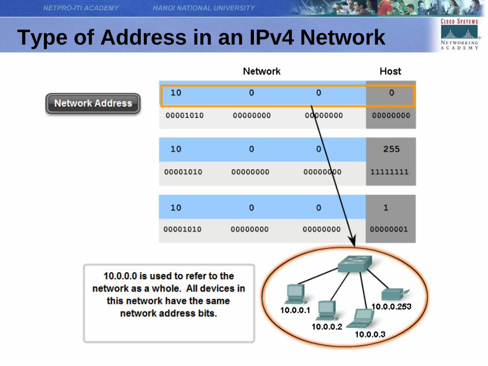
Three types of addresses:
• Network address - The address by which we refer to
the network. All hosts in a network will have the same
network bits.
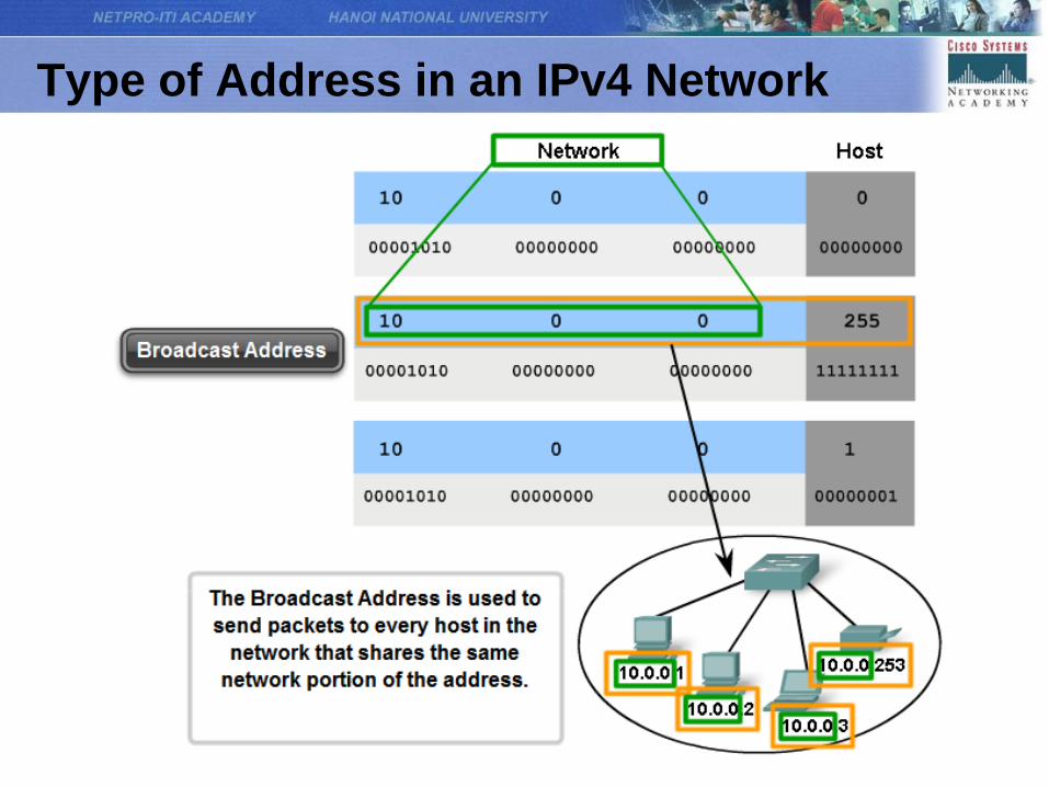
• Broadcast address - A special address used to send
data to all hosts in the network. The broadcast address
uses the highest address in the network range. This is
the address in which the bits in the host portion are all
1s. This address is also referred to as the directed
broadcast.
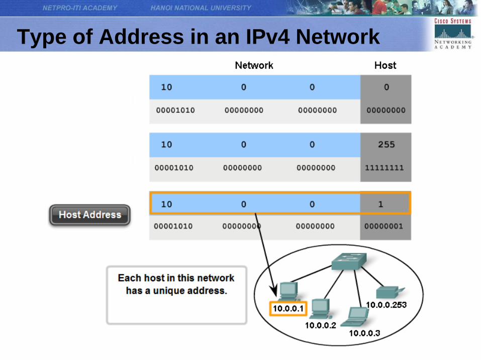
• Host addresses - The addresses assigned to the end
devices in the network
Type of Address in an IPv4 Network
Type of Address in an IPv4 Network
Type of Address in an IPv4 Network
Type of Address in an IPv4 Network
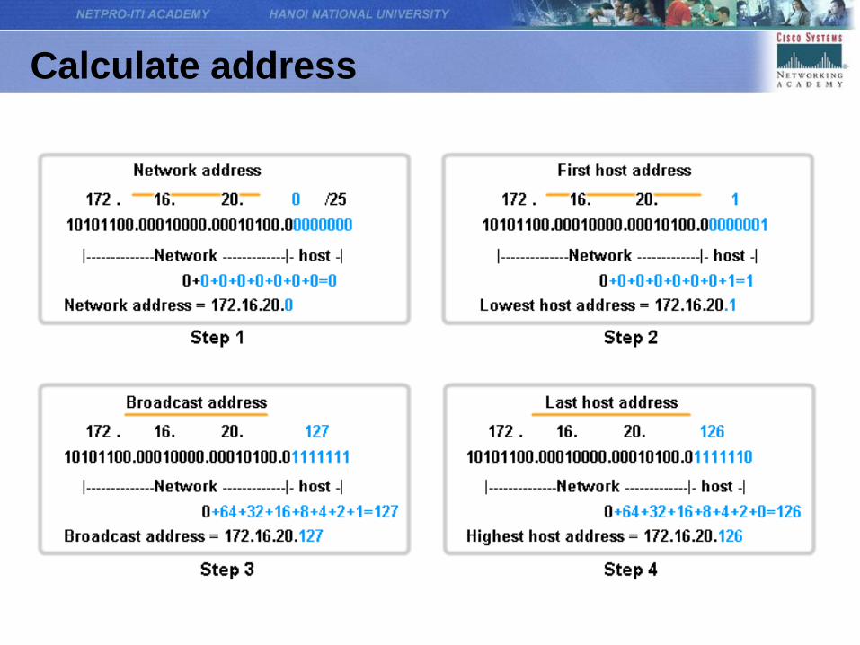
Calculate address
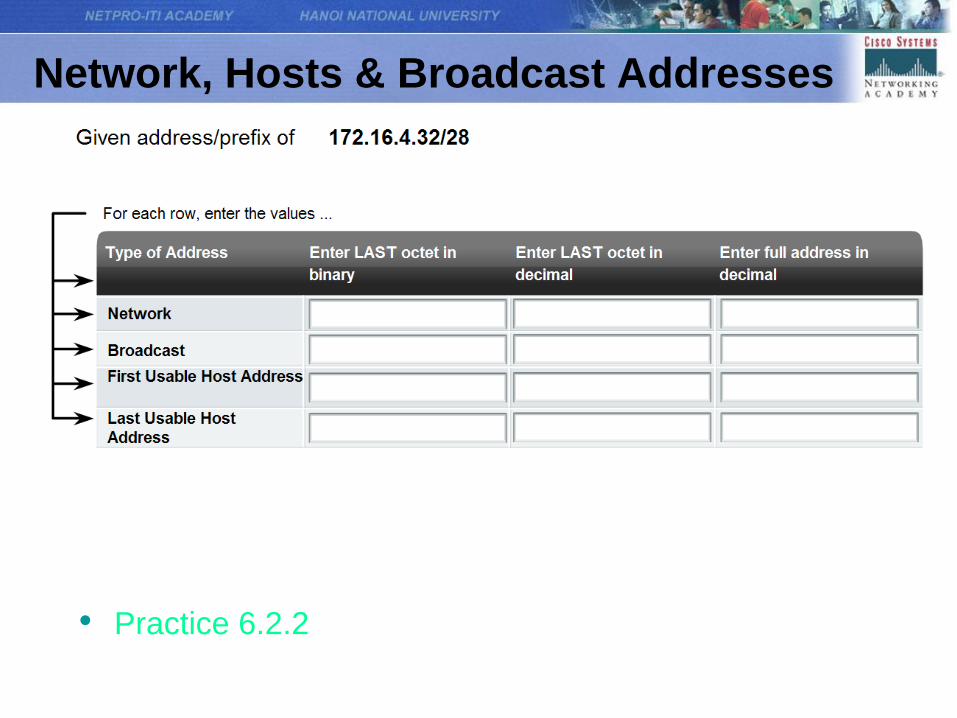
Network, Hosts & Broadcast Addresses
• Practice 6.2.2
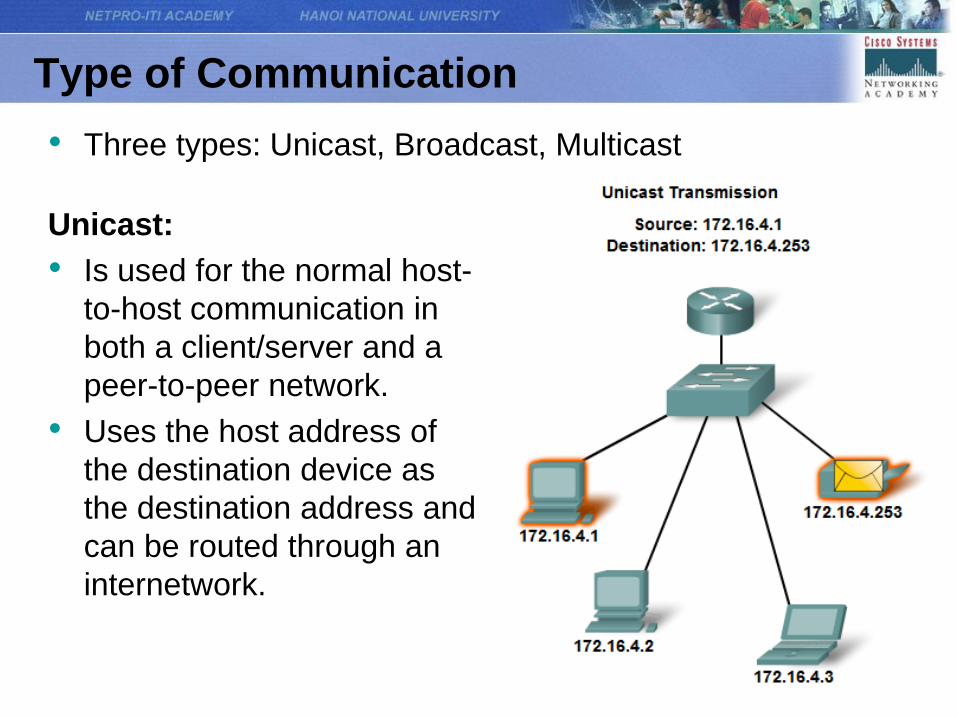
Type of Communication
Unicast:
• Is used for the normal host-
to-host communication in
both a client/server and a
peer-to-peer network.
• Uses the host address of
the destination device as
the destination address and
can be routed through an
internetwork.
• Three types: Unicast, Broadcast, Multicast
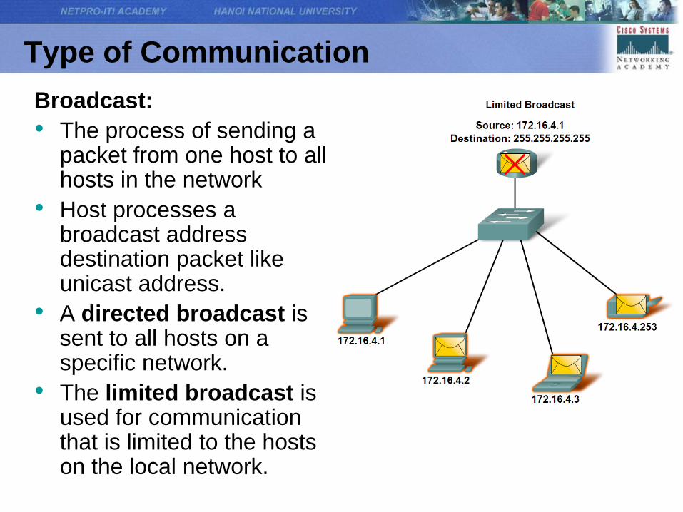
Type of Communication
Broadcast:
• The process of sending a packet from one host to all hosts in the network
• Host processes a broadcast address destination packet like unicast address.
• A directed broadcast is sent to all hosts on a specific network.
• The limited broadcast is used for communication that is limited to the hosts on the local network.
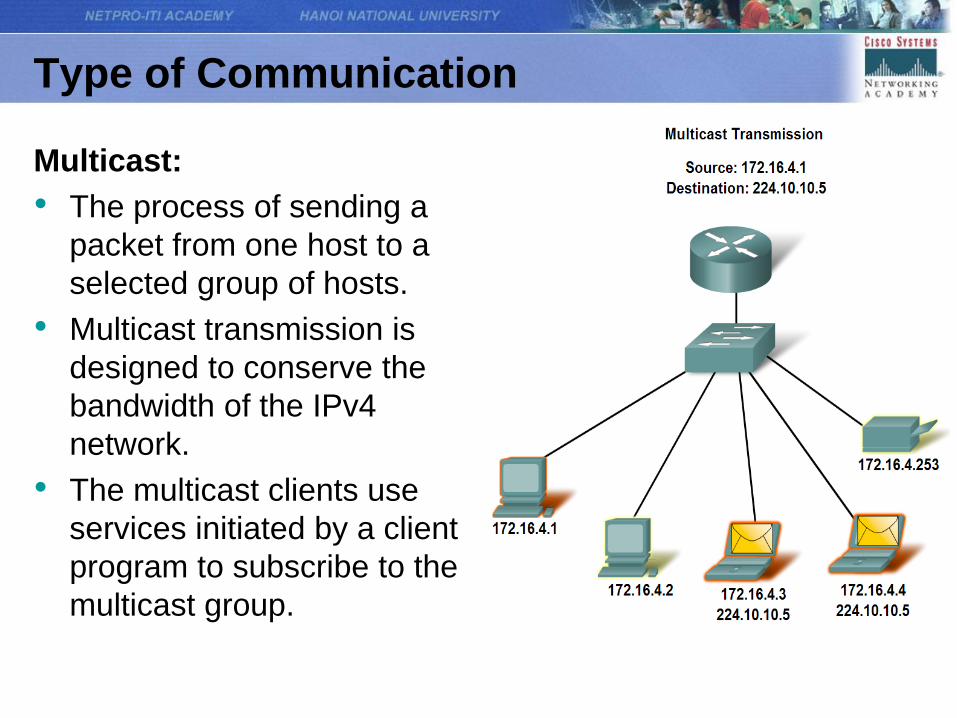
Type of Communication
Multicast:
• The process of sending a
packet from one host to a
selected group of hosts.
• Multicast transmission is
designed to conserve the
bandwidth of the IPv4
network.
• The multicast clients use
services initiated by a client
program to subscribe to the
multicast group.
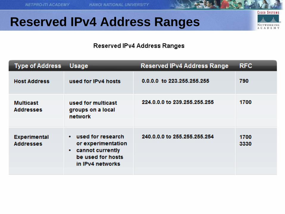
Reserved IPv4 Address Ranges
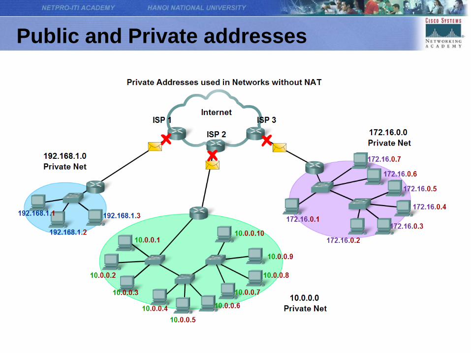
Public and Private addresses
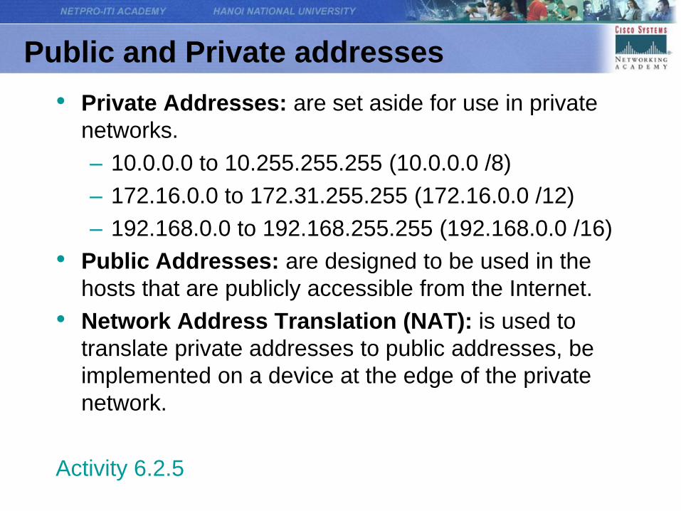
Public and Private addresses
• Private Addresses: are set aside for use in private
networks.
– 10.0.0.0 to 10.255.255.255 (10.0.0.0 /8)
– 172.16.0.0 to 172.31.255.255 (172.16.0.0 /12)
– 192.168.0.0 to 192.168.255.255 (192.168.0.0 /16)
• Public Addresses: are designed to be used in the
hosts that are publicly accessible from the Internet.
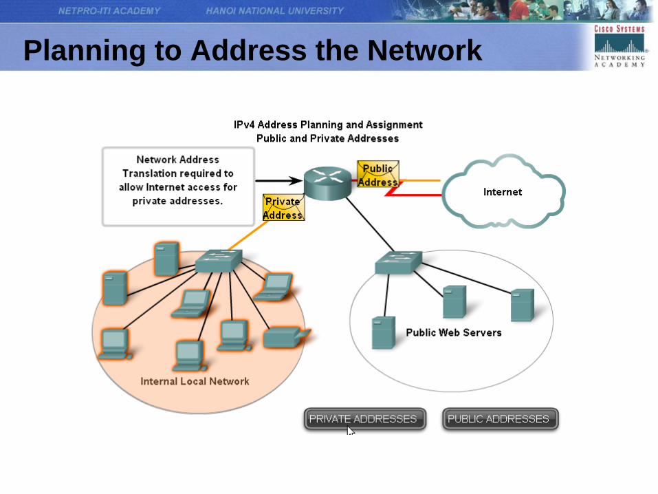
• Network Address Translation (NAT): is used to
translate private addresses to public addresses, be
implemented on a device at the edge of the private
network.
Activity 6.2.5
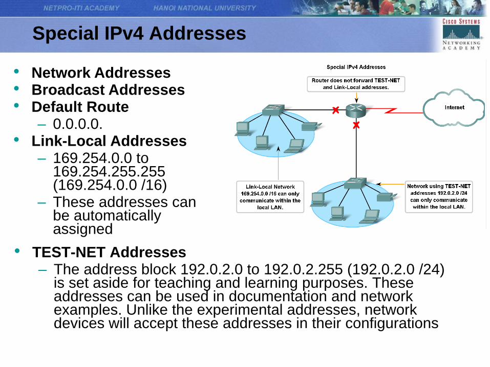
Special IPv4 Addresses
• TEST-NET Addresses– The address block 192.0.2.0 to 192.0.2.255 (192.0.2.0 /24)
is set aside for teaching and learning purposes. These addresses can be used in documentation and network examples. Unlike the experimental addresses, network devices will accept these addresses in their configurations
• Network Addresses• Broadcast Addresses• Default Route
– 0.0.0.0.• Link-Local Addresses
– 169.254.0.0 to 169.254.255.255 (169.254.0.0 /16)
– These addresses can be automatically assigned
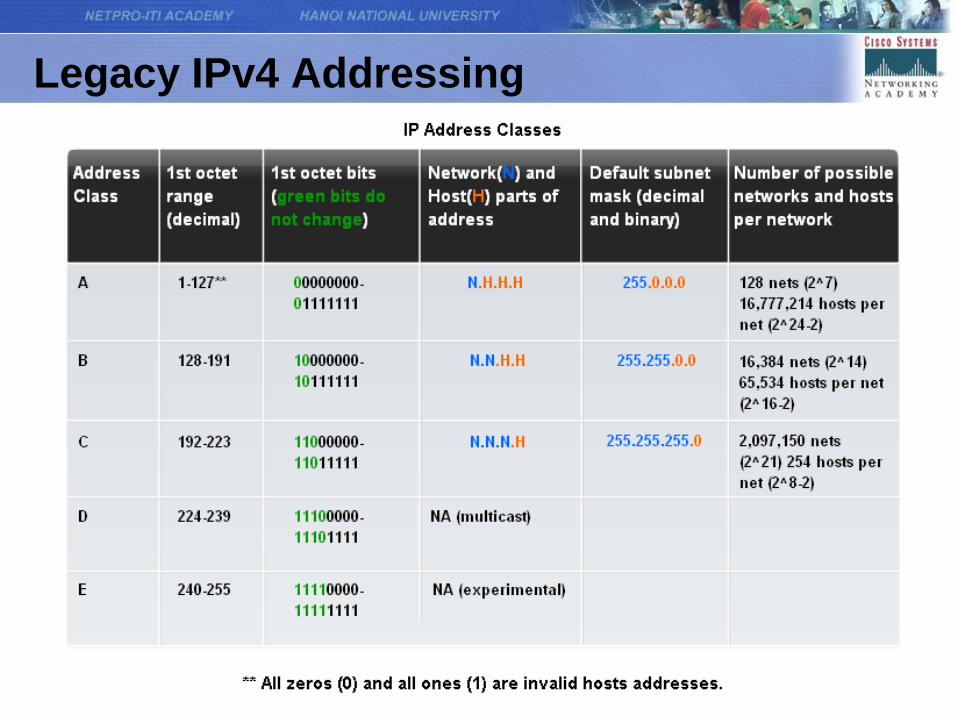
Legacy IPv4 Addressing
Legacy IPv4 Addressing
• Classful addressing: A company or organization was
assigned an entire class A, class B, or class C address
block.
• Limits to the Class-based System
– Classful allocation of address space often wasted
many addresses, which exhausted the availability of
IPv4 addresses.
• Classless Addressing
– Address blocks appropriate to the number of hosts
are assigned to companies or organizations without
regard to the unicast class.
Assigning Addresses
Planning to Address the Network
• The allocation of these addresses inside the networks
should be planned and documented for the purpose of:
• Preventing duplication of addresses: each host in an
internetwork must have a unique address.
• Providing and controlling access: Some hosts provide
resources to the internal network as well as to the external
network. If the addresses for these resources are not
planned and documented, the security and accessibility of
the devices are not easily controlled.
• Monitoring security and performance: As part of the
monitoring process, we examine network traffic looking for
addresses that are generating or receiving excessive
packets.
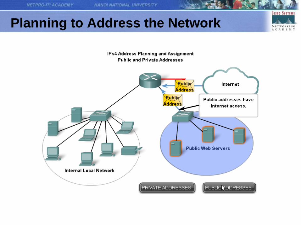
Planning to Address the Network
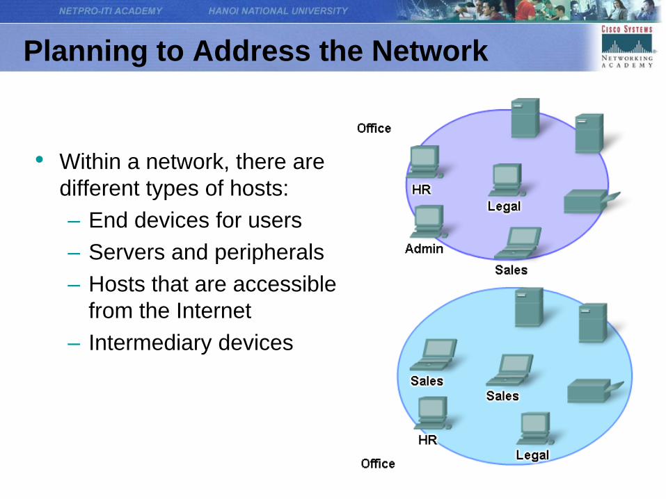
• Within a network, there are
different types of hosts:
– End devices for users
– Servers and peripherals
– Hosts that are accessible
from the Internet
– Intermediary devices
Planning to Address the Network
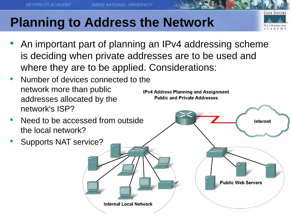
• An important part of planning an IPv4 addressing scheme
is deciding when private addresses are to be used and
where they are to be applied. Considerations:
• Number of devices connected to the
network more than public
addresses allocated by the
network's ISP?
• Need to be accessed from outside
the local network?
• Supports NAT service?
Planning to Address the Network
Planning to Address the Network
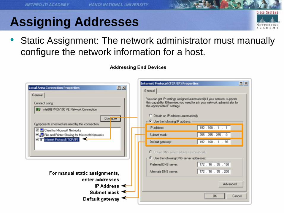
Assigning Addresses
• Static Assignment: The network administrator must manually
configure the network information for a host.
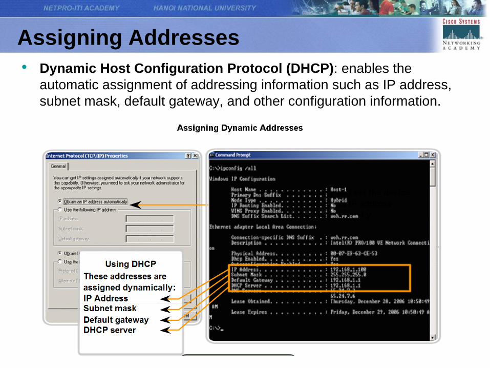
Assigning Addresses
• Dynamic Host Configuration Protocol (DHCP): enables the
automatic assignment of addressing information such as IP address,
subnet mask, default gateway, and other configuration information.
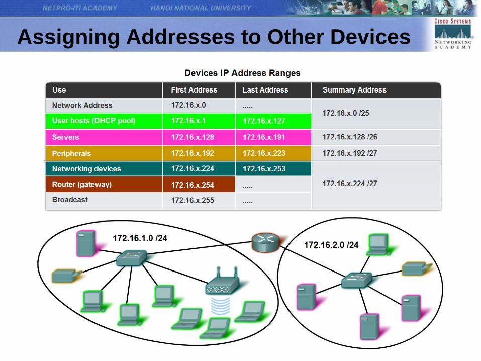
Assigning Addresses to Other Devices
Assigning Addresses
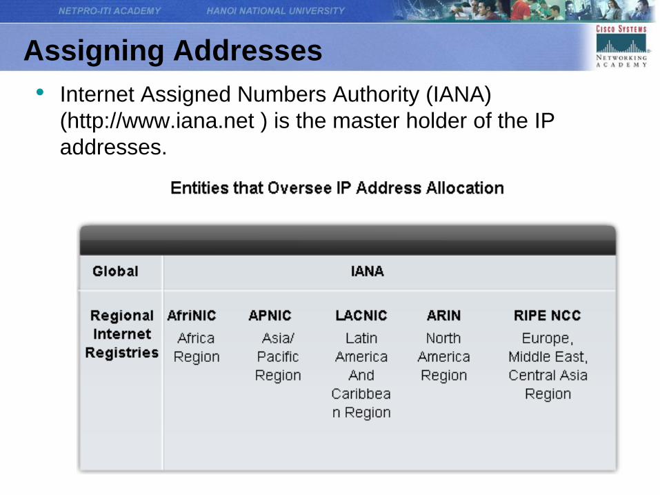
• Internet Assigned Numbers Authority (IANA)
(http://www.iana.net ) is the master holder of the IP
addresses.
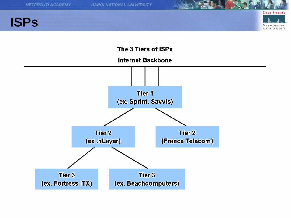
ISPs
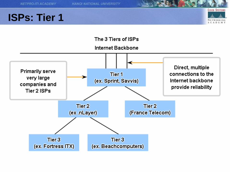
ISPs: Tier 1
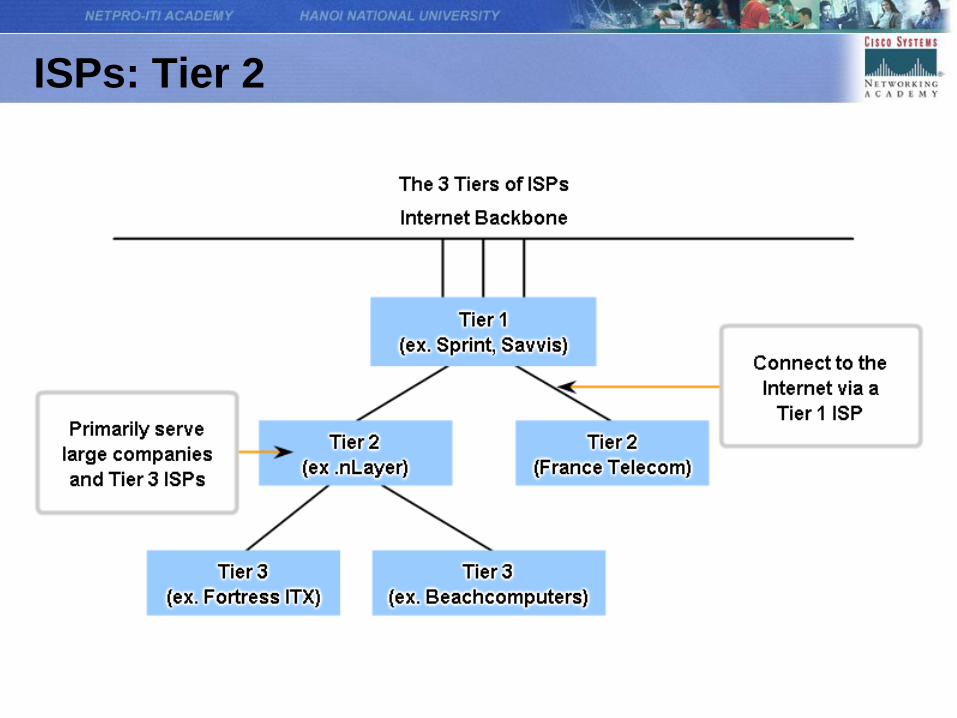
ISPs: Tier 2
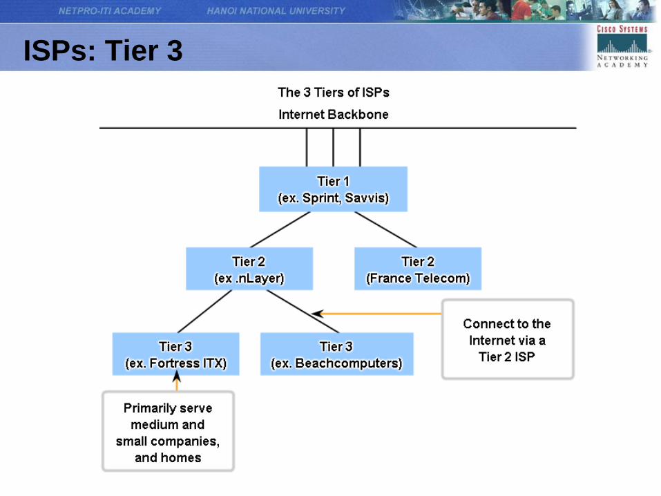
ISPs: Tier 3
Overview of IPv6
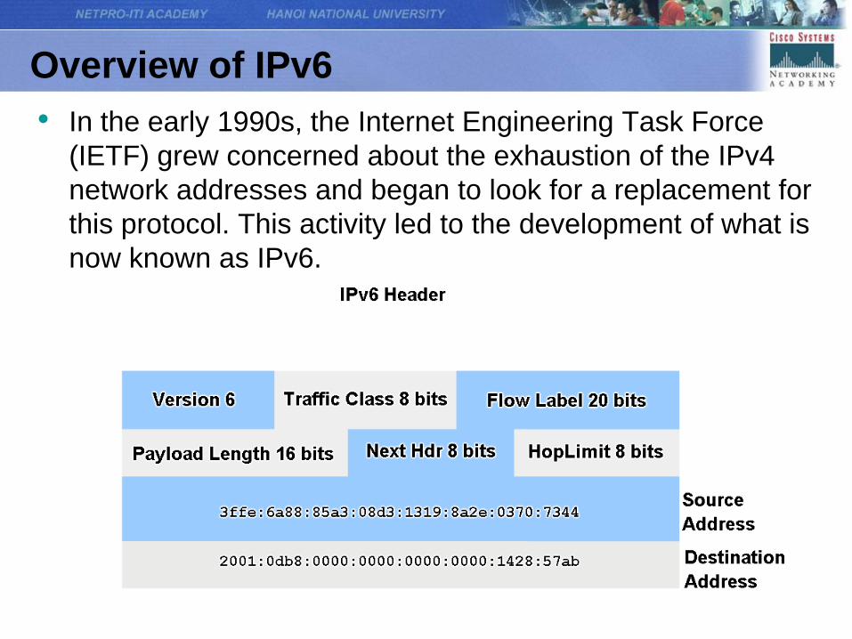
• In the early 1990s, the Internet Engineering Task Force
(IETF) grew concerned about the exhaustion of the IPv4
network addresses and began to look for a replacement for
this protocol. This activity led to the development of what is
now known as IPv6.
Overview of IPv6
• Creating expanded addressing capabilities was the initial motivation for
developing this new protocol. Other issues were also considered
during the development of IPv6, such as:
– Improved packet handling
– Increased scalability and longevity
– QoS mechanisms
– Integrated security
• To provide these features, IPv6 offers:
– 128-bit hierarchical addressing - to expand addressing capabilities
– Header format simplification - to improve packet handling
– Improved support for extensions and options - for increased
scalability/longevity and improved packet handling
– Flow labeling capability - as QoS mechanisms
– Authentication and privacy capabilities - to integrate security
Calculating Addresses
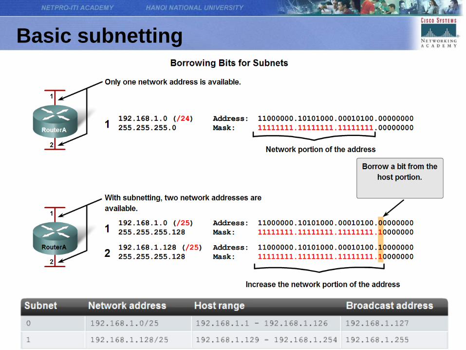
Basic subnetting
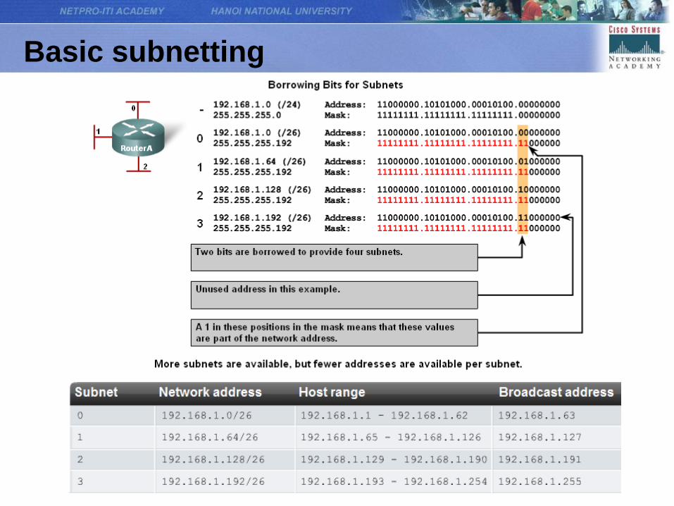
Basic subnetting
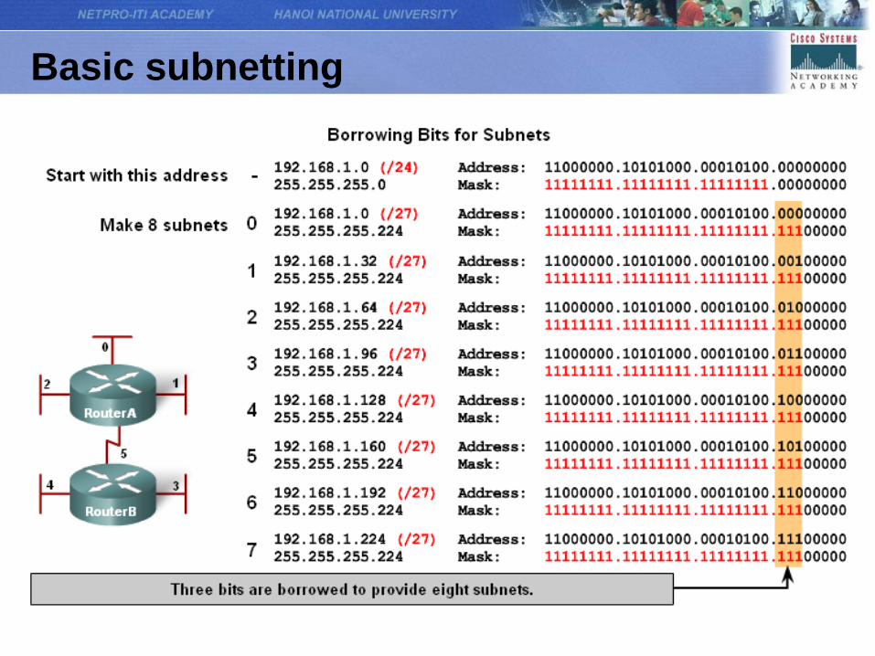
Basic subnetting
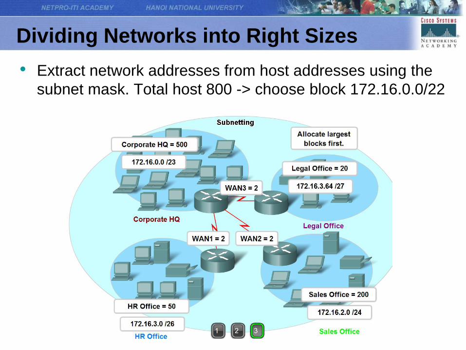
Dividing Networks into Right Sizes
• Extract network addresses from host addresses using the
subnet mask. Total host 800 -> choose block 172.16.0.0/22
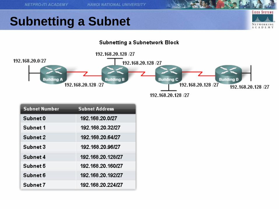
Subnetting a Subnet
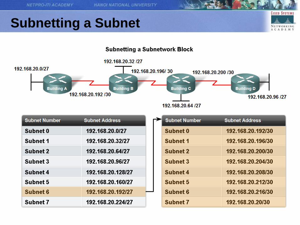
Subnetting a Subnet
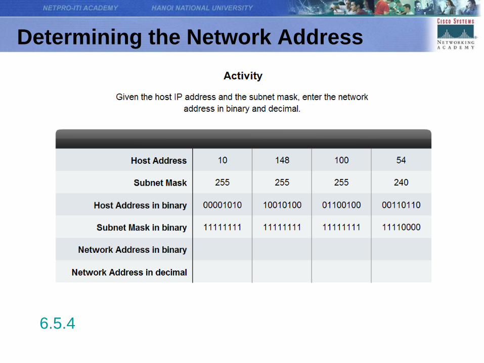
Determining the Network Address
6.5.4
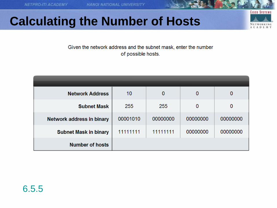
Calculating the Number of Hosts
6.5.5
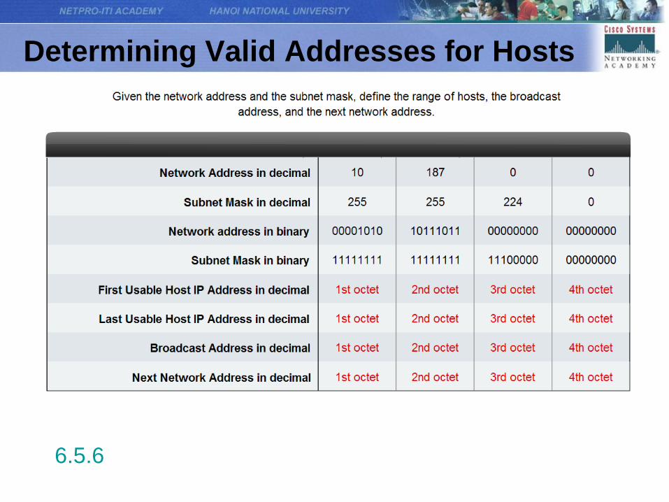
Determining Valid Addresses for Hosts
6.5.6
Testing the Network Layer
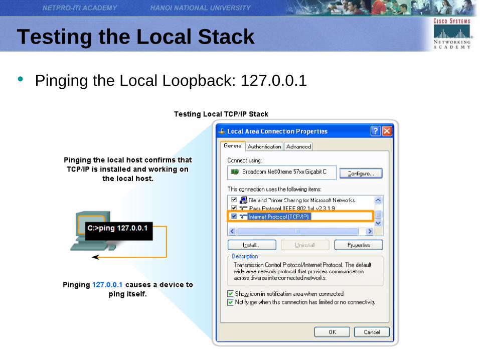
Testing the Local Stack
• Pinging the Local Loopback: 127.0.0.1
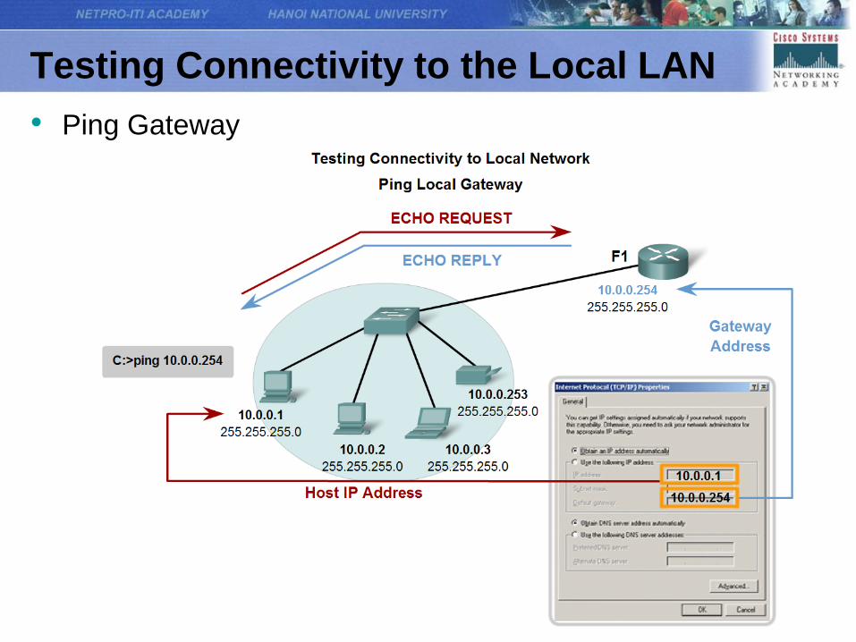
Testing Connectivity to the Local LAN
• Ping Gateway
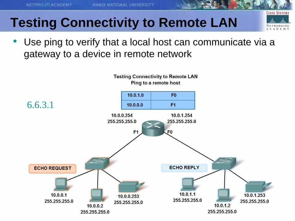
Testing Connectivity to Remote LAN
• Use ping to verify that a local host can communicate via a
gateway to a device in remote network
6.6.3.1
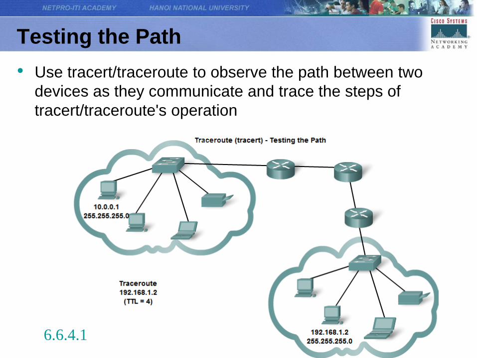
Testing the Path
• Use tracert/traceroute to observe the path between two
devices as they communicate and trace the steps of
tracert/traceroute's operation
6.6.4.1
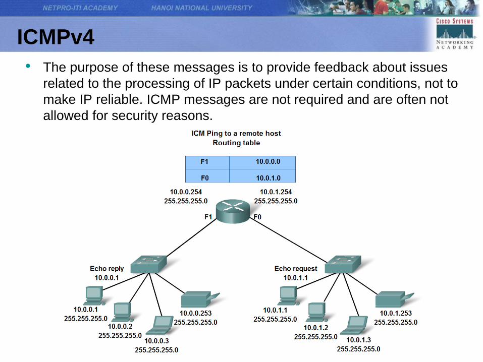
ICMPv4
• The purpose of these messages is to provide feedback about issues
related to the processing of IP packets under certain conditions, not to
make IP reliable. ICMP messages are not required and are often not
allowed for security reasons.
ICMP
• ICMP is the messaging protocol for the TCP/IP suite. ICMP provides control and error messages and is used by the ping and traceroute utilities. Although ICMP uses the basic support of IP as if it were a higher-level protocol ICMP, it is actually a separate Layer 3 of the TCP/IP suite.
• The types of ICMP messages - and the reasons why they are sent - are extensive. We will discuss some of the more common messages. ICMP messages that may be sent include:
– Host confirmation
– Unreachable Destination or Service
– Time exceeded
– Route redirection
– Source quench
Summary