Embed Size (px)
Citation preview
© 2006 Fluxtrol, Inc. www.fluxtrol.com
Chapter IV. Chapter IV.
Computer Simulation for Computer Simulation for Induction Processes and Induction Processes and
Coil DesignCoil Design

© 2006 Fluxtrol, Inc. www.fluxtrol.com
Opening RemarksOpening Remarks
• First works on computer simulation of induction coils were made in 1960’s. Due to a limited access to computers, their low memory, speed and poor programming methods the computer simulation did not receive significant industrial application until the 1980’s
• Now computer simulation has become a practical tool for everyday use in the induction industry. It allows the user to design optimal systems, improve equipment performance, dramatically reduce development time and costs, better understand the process dynamics, etc.
• Though there are still difficulties in accurate simulation of non-linear and different mutually-coupled tasks, computer simulation is effectively used for design of induction heating coils and problem solution
• Material of this chapter is based mainly on experience of the author, his colleagues and his collaborators in development and use of computer simulation programs in different areas of induction heating

© 2006 Fluxtrol, Inc. www.fluxtrol.com
Special Features of Induction Heating Special Features of Induction Heating Computer SimulationComputer Simulation
• The induction heating market is small compared to other industrial sectors and there are only a few specialized simulation packages on the market that can be used for induction process and coil design
• Induction heating simulation involves a set of mutually coupled non-linear phenomena
• Many induction applications are unique and may require different program modules
• In addition to computer simulation software an extensive database is necessary for accurate results

© 2006 Fluxtrol, Inc. www.fluxtrol.com
Process Design & Coil DesignProcess Design & Coil Design
Process Design
• Optimal Frequency, Power and Time
• Heating style (Static, Scanning, Single-Shot)
Coil Design
• Coil style selection• Copper cross-section• Magnetic flux controller
• Coil matching In many cases we have limited control due to existing machines, dictating frequency and power range and heating style.
This is something we can change to improve the process.
© 2006 Fluxtrol, Inc. www.fluxtrol.com
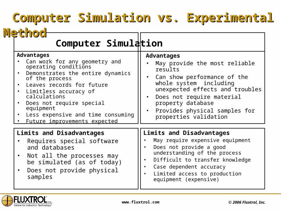
Computer Simulation Experimental MethodAdvantages• Can work for any geometry and
operating conditions• Demonstrates the entire dynamics of
the process• Leaves records for future• Limitless accuracy of calculations• Does not require special equipment• Less expensive and time consuming• Future improvements expected
Advantages• May provide the most reliable results • Can show performance of the whole
system including unexpected effects and troubles
• Does not require material property database
• Provides physical samples for properties validation
Limits and Disadvantages• May require expensive equipment • Does not provide a good understanding
of the process• Difficult to transfer knowledge• Case dependent accuracy• Limited access to production equipment
(expensive)
Limits and Disadvantages• Requires special software and
databases• Not all the processes may be
simulated (as of today)• Does not provide physical samples
Computer Simulation vs. Experimental MethodComputer Simulation vs. Experimental Method

© 2006 Fluxtrol, Inc. www.fluxtrol.com
Induction Process and Coil Development via Induction Process and Coil Development via Computer SimulationComputer Simulation
• Induction process design (Power, Frequency, Time) • Induction coil design• Coil engineering and manufacturing• Process set-up and performance validation• Final modification of induction coil and process if required
Example: Development of aluminum heat exchanger brazing and experimental validation
Typical stages of computer-assisted induction coil development:
© 2006 Fluxtrol, Inc. www.fluxtrol.com
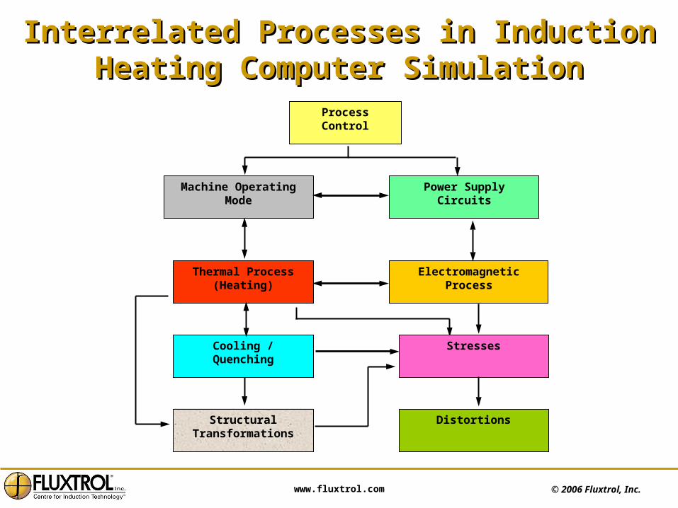
Interrelated Processes in Induction Heating Interrelated Processes in Induction Heating Computer SimulationComputer Simulation
Process Control
Machine Operating Mode Power Supply Circuits
Thermal Process (Heating)
Electromagnetic Process
Cooling / Quenching Stresses
Structural Transformations
Distortions
© 2006 Fluxtrol, Inc. www.fluxtrol.com
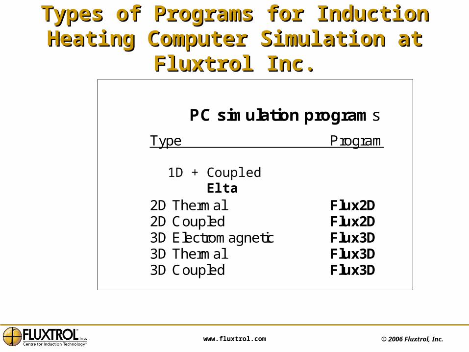
Types of Programs for Induction Heating Types of Programs for Induction Heating Computer Simulation at Fluxtrol Inc.Computer Simulation at Fluxtrol Inc.
PC simulation programs
Type Program 1D Coupled Elta 2D Electromagnetic Flux2D 2D Thermal Flux2D 2D Coupled Flux2D 3D Electromagnetic Flux3D 3D Thermal Flux3D 3D Coupled Flux3D
1D + Coupled Elta
© 2006 Fluxtrol, Inc. www.fluxtrol.com
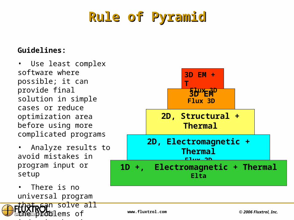
Rule of PyramidRule of Pyramid
3D EMFlux 3D
2D, Electromagnetic + ThermalFlux 2D
1D +, Electromagnetic + ThermalElta
2D, Structural + Thermal
3D EM + TFlux 3D
Guidelines:
• Use least complex software where possible; it can provide final solution in simple cases or reduce optimization area before using more complicated programs
• Analyze results to avoid mistakes in program input or setup
• There is no universal program that can solve all the problems of induction heating

© 2006 Fluxtrol, Inc. www.fluxtrol.com
ELTA Software FeaturesELTA Software Features
• User friendly interface with very fast solver
• Electromagnetic + Thermal
• Combines numerical 1D calculations with analytical account of the system length
• Axisymmetrical (OD & ID) & plane parallel geometries
• Module for simulating internal coils
• Possibility to simulate power supplying circuit (busswork, capacitors, transformer)
• Database with non-linear properties of materials
• Option of automatic frequency variation
• Automatic report generation according to selected or created template
Scanning process simulation

© 2006 Fluxtrol, Inc. www.fluxtrol.com
When to Use ELTAWhen to Use ELTA
• Valuable for almost all cases to determine optimal process parameters (P, f, t, Quenching) and coil style
• May be used for coil design
– Determine number of turns for proper matching
– Large (relative to part size), uniform heating areas
– Scanning applications
• Very valuable for in-field support, new project evaluation and presentations• Multi- stage and multi - inductor process simulation possible• Valuable for learning and training
© 2006 Fluxtrol, Inc. www.fluxtrol.com
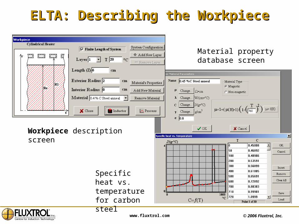
ELTA: Describing the WorkpieceELTA: Describing the Workpiece
Material property database screen
Specific heat vs. temperature for carbon steel
Workpiece description screen
© 2006 Fluxtrol, Inc. www.fluxtrol.com
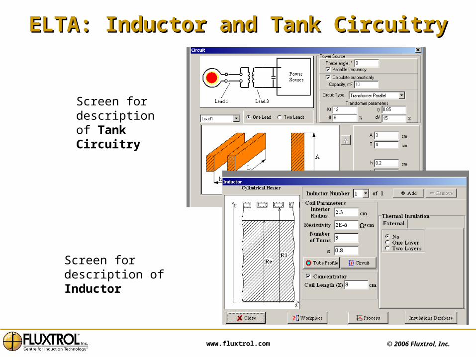
ELTA: Inductor and Tank CircuitryELTA: Inductor and Tank Circuitry
Screen for description of Tank Circuitry
Screen for description of Inductor

© 2006 Fluxtrol, Inc. www.fluxtrol.com
Example: Design of In-Line Example: Design of In-Line Heat Treating ProcessHeat Treating Process
• In-Line processes are more and more popular in industry
• Durations of all stages of in-line process (Austenization, Quenching, Tempering and Final Cooling) must be coordinated
ELTA simulation program
Task: Hardening and tempering of the shaft end
• Diameter – 40 mm
• Length – 60 mm
• Case depth – 4 mm
• Steel 1040

© 2006 Fluxtrol, Inc. www.fluxtrol.com
Design of In-Line Design of In-Line Heat Treating Process (cont.)Heat Treating Process (cont.)
Load/Unload
Austenitizing
Quenching
Tempering
Cooling
AUSTENITIZING
QUENCHCOOLING
TEMPERING
t
Simulation showed that minimum time for austenization heating is slightly under 4 sec. at optimal frequency 3kHz
This time was selected as a base for other stages:
• Austenization 4sec
• Quenching 8 sec
• Tempering 4 + 4 sec
• Final cooling 8 sec
Rotary table machine with 8 positions was selected for heat treating. Two positions were used for tempering

© 2006 Fluxtrol, Inc. www.fluxtrol.com
Design of In-Line Design of In-Line Heat Treating Process (cont.)Heat Treating Process (cont.)
Color Map of temperature distribution shows that at the end of the first stage a depth of austenitized layer (T> 800 C) is 4 mm as required.
After 8-second quenching, temperature at the depth of 4 mm dropped below 120 C, which is sufficient for complete martensite transformation, while temperature at the center remained around 300 C.
This residual temperature and two-stage heating for tempering provided very uniform temperature in hardened layer during tempering process.
Temperature evolution in optimized process:Green – part surfaceRed – centerBlack – temperature
differential
ELTA Software

© 2006 Fluxtrol, Inc. www.fluxtrol.com
Design of In-Line Design of In-Line Heat Treating Process (cont.)Heat Treating Process (cont.)
Radius, cm
Time, sec
3D presentation of temperature evolution
Cooling curves for different radii
ELTA Software

© 2006 Fluxtrol, Inc. www.fluxtrol.com
Report Generated by ELTAReport Generated by ELTA
Heat source (power density) distribution in the workpiece
PowerP, W
t, s
Generator
Inductor
Coil losses
Workpiece
Leads
0
50000
1E005
0 5 10 15 20 25 30
Heat Sources DensityP, W/cm3
r, cm
t=0.8
t=1.5439
t=2.386
t=3.1579
t=4
0
2000
4000
6000
0 0.5 1 1.5 2
Version: 3.3
Date: 2/25/2006 3:26:06 PM Page 5 of 5
Project: Induction hardening

© 2006 Fluxtrol, Inc. www.fluxtrol.com
Scanning Simulation Using ELTAScanning Simulation Using ELTA
Color map and isolines of temperature generated by the program
Scanning heating of water-cooled plate demonstrating effect of Fluxtrol Concentrator
water
water
no concentrator
with concentrator
See Robotic System video
© 2006 Fluxtrol, Inc. www.fluxtrol.com
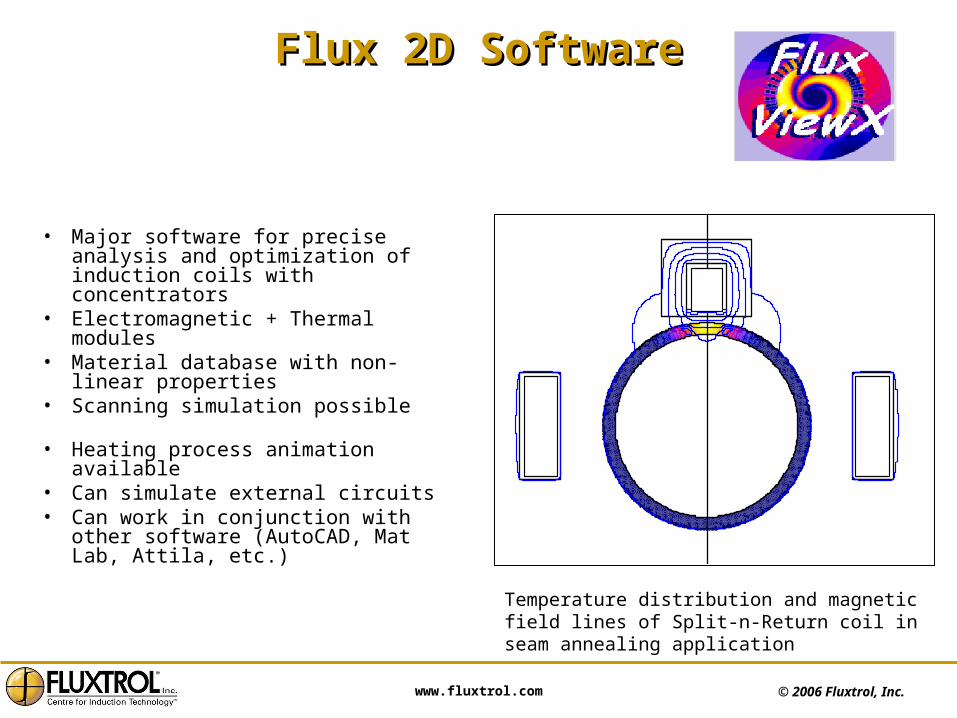
Flux 2D SoftwareFlux 2D Software
• Major software for precise analysis and optimization of induction coils with concentrators
• Electromagnetic + Thermal modules• Material database with non-linear
properties• Scanning simulation possible• Heating process animation available• Can simulate external circuits• Can work in conjunction with other
software (AutoCAD, Mat Lab, Attila, etc.)
Temperature distribution and magnetic field lines of Split-n-Return coil in seam annealing application

© 2006 Fluxtrol, Inc. www.fluxtrol.com
When to Use Flux 2-D SimulationWhen to Use Flux 2-D Simulation
• Process and coil design– Part dimensions/heat pattern
changes – Heat pattern is not uniform in length
and the need exists to optimize distribution of temperature
– Part & coil have rotational or planar symmetry (or partial symmetry)
© 2006 Fluxtrol, Inc. www.fluxtrol.com
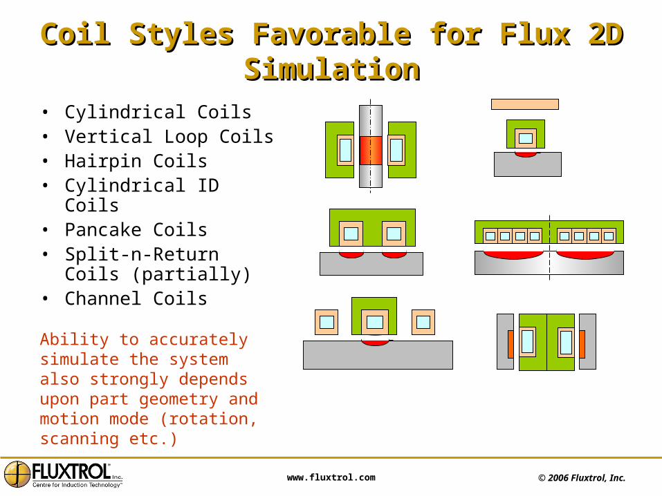
Coil Styles Favorable for Flux 2D SimulationCoil Styles Favorable for Flux 2D Simulation
• Cylindrical Coils• Vertical Loop Coils• Hairpin Coils• Cylindrical ID Coils• Pancake Coils • Split-n-Return Coils
(partially)• Channel Coils
Ability to accurately simulate the system also strongly depends upon part geometry and motion mode (rotation, scanning etc.)
© 2006 Fluxtrol, Inc. www.fluxtrol.com
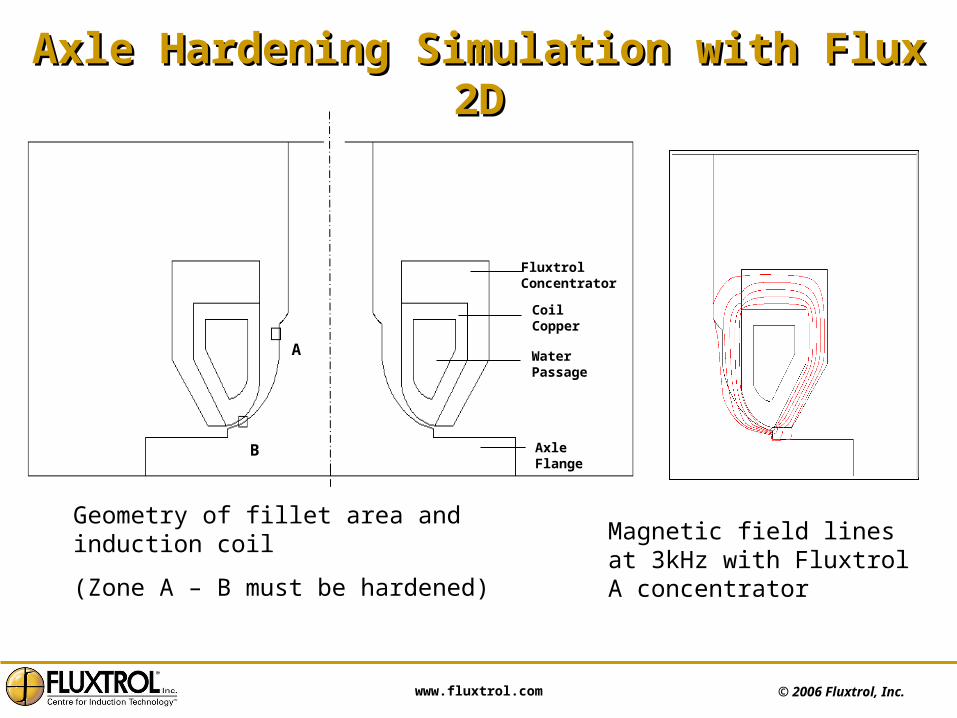
Axle Hardening Simulation with Flux 2DAxle Hardening Simulation with Flux 2D
A
B
Fluxtrol Concentrator
Coil Copper
Water Passage
Axle Flange
Geometry of fillet area and induction coil
(Zone A – B must be hardened) Magnetic field lines at 3kHz with Fluxtrol A concentrator
© 2006 Fluxtrol, Inc. www.fluxtrol.com
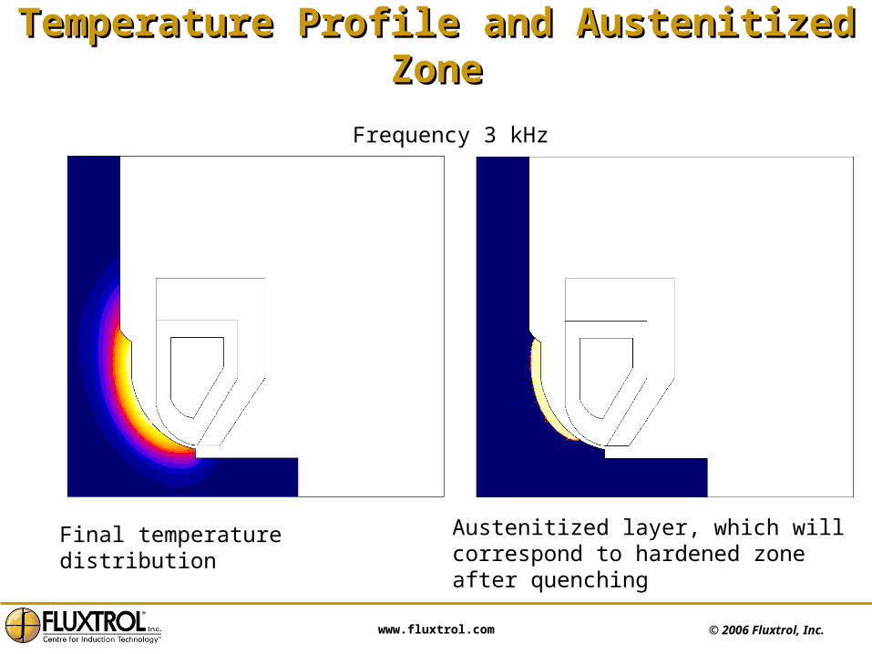
Temperature Profile and Austenitized ZoneTemperature Profile and Austenitized Zone
Frequency 3 kHz
Final temperature distribution Austenitized layer, which will correspond to hardened zone after quenching

© 2006 Fluxtrol, Inc. www.fluxtrol.com
Example of Melting Furnace Designed with Example of Melting Furnace Designed with FLUX 2D Computer SimulationFLUX 2D Computer Simulation
Dry (air-cooled) induction furnace for special material melting.
Coil is made of Litz cable and potted. Fluxtrol Concentrator plates are used to decrease current demand and improve efficiency.
They are used also as radiators for heat transfer from the coil to inert gas in the chamber.

© 2006 Fluxtrol, Inc. www.fluxtrol.com
When to Use Flux 3-D SimulationWhen to Use Flux 3-D Simulation
• When good information and results cannot be achieved using 2-D with reasonable approximations
• Evaluate 3-D effects for some systems where 2D is used with some assumptions (lead area in cylindrical coils, cross-over parts of single-short coils etc.)
• Understand some uncertain effects from experiments
• Simulation of strongly 3D systems/processes such as gear hardening, welding, some brazing systems etc.
3D system composed from 2D coil and 2D parts
© 2006 Fluxtrol, Inc. www.fluxtrol.com
Flux 3D Software FeaturesFlux 3D Software Features
• May be Electromagnetic, Thermal or Coupled
• Material database with non-linear properties is available
• Usage Considerations
– More complicated and less user friendly than Flux 2D
– Requires powerful computers for reasonable calculation times
– Time and knowledge consuming for problem formulation, geometry description and calculation process setup (mesh building etc.)

© 2006 Fluxtrol, Inc. www.fluxtrol.com
Gear Heating Simulation Using Flux 3DGear Heating Simulation Using Flux 3D
Frequency 50 kHz, concentrator - Ferrotron 559H; gear modulus is 5 mm.
Maximum current density is in root area near the tooth end.
Eddy current density distribution in a quarter of a gear tooth
© 2006 Fluxtrol, Inc. www.fluxtrol.com
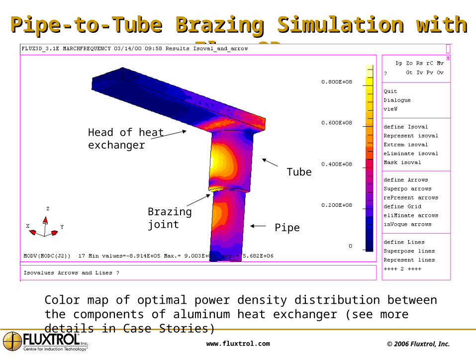
Pipe-to-Tube Brazing Simulation with Flux 3DPipe-to-Tube Brazing Simulation with Flux 3D
Color map of optimal power density distribution between the components of aluminum heat exchanger (see more details in Case Stories)
Brazing joint
Head of heat exchanger
Pipe
Tube

© 2006 Fluxtrol, Inc. www.fluxtrol.com
Accuracy of 2D and 3D Computer SimulationAccuracy of 2D and 3D Computer Simulation
Simulation accuracy depends upon:
1. Accuracy of system geometry description
2. Accuracy of description of material properties and processing parameters such as quenching intensity
3. Problem formulation; there are several options how to describe the electromagnetic field in 3D systems
4. Number, distribution and type of elements of simulation mesh
5. Algorithms used in the program and software quality
Position 1 is the most important for 2D simulation, when the user needs to neglect 3D effects of real induction systems (such as lead area in a cylindrical coil, “spirality” of multi-turn coils etc.).
Calculation errors may be reduced to negligible values by means of proper selection of mesh and calculation process parameters.
Accuracy of simulation also depends on experience and knowledge of the user especially in 3D simulation cases.

© 2006 Fluxtrol, Inc. www.fluxtrol.com
ConclusionsConclusions• At present time personal computers are powerful enough for
simulation of most induction heating problems
• 1D and 2D simulation are well established in induction industry
• 3D simulation is an emerging technology
• Computer simulation is a powerful tool for:
– Induction process and equipment design
– Optimal design of induction coils
– Research and development
– Development of databases of processes, projects and coil designs
– Troubleshooting
– Advertisements and business presentations
– Training, education and self-education
New advances in computers, software and data bases of material properties will lead to wider and more effective use of computer simulation
in induction heating !