Embed Size (px)
Citation preview
Installation manual for measuring tables
DIATEST-System COME
Installation manual for measuring tables DIATEST-System COME
This manual is valid for all versions C2, C2-AL and C2-JS as well as C3, C3-AL and C3 JS. Installation is shown based on
measuring table DIA-COME C2, but this manual can be used the same way for other measuring tables!
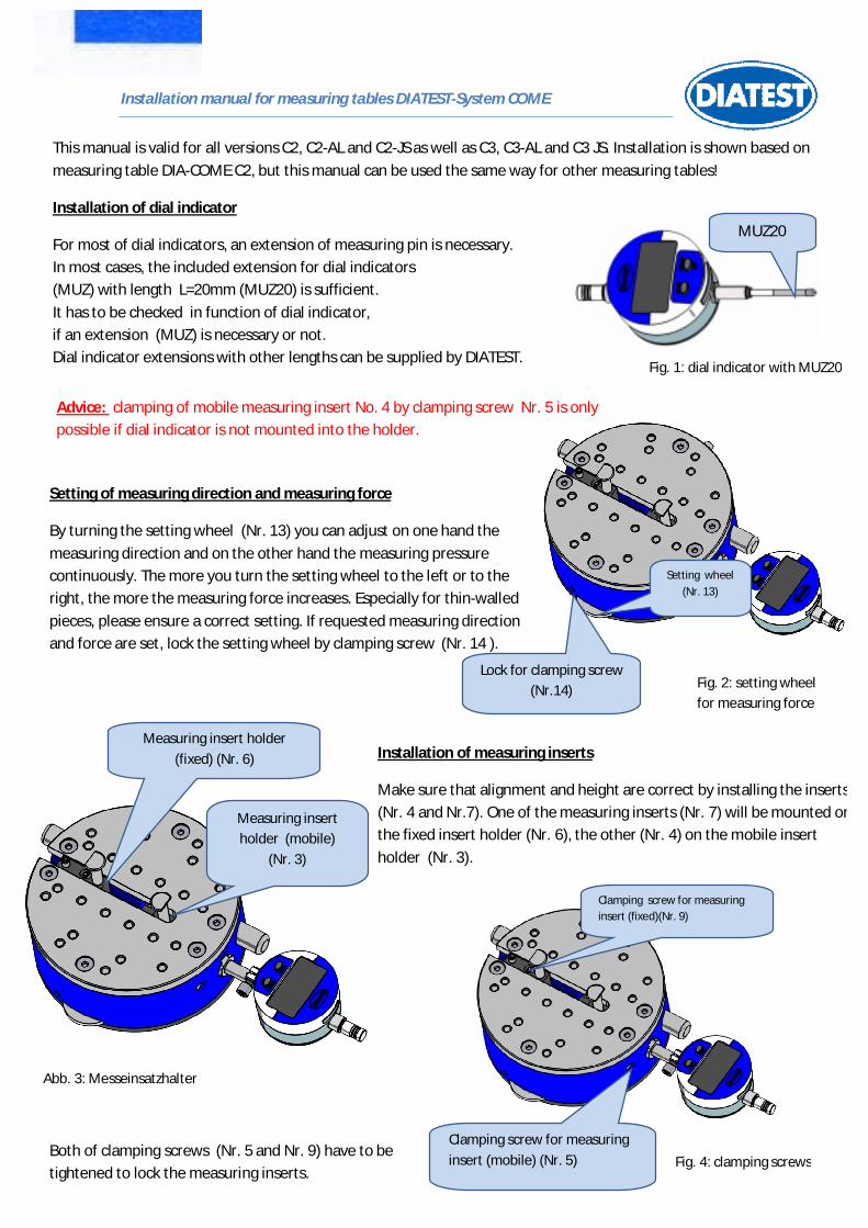
Installation of dial indicator
For most of dial indicators, an extension of measuring pin is necessary.
In most cases, the included extension for dial indicators
(MUZ) with length L=20mm (MUZ20) is sufficient.
It has to be checked in function of dial indicator,
if an extension (MUZ) is necessary or not.
Dial indicator extensions with other lengths can be supplied by DIATEST.
MUZ20
Fig. 2: setting wheel
for measuring force
Setting of measuring direction and measuring force
By turning the setting wheel (Nr. 13) you can adjust on one hand the
measuring direction and on the other hand the measuring pressure
continuously. The more you turn the setting wheel to the left or to the
right, the more the measuring force increases. Especially for thin-walled
pieces, please ensure a correct setting. If requested measuring direction
and force are set, lock the setting wheel by clamping screw (Nr. 14 ).
Installation of measuring inserts
Make sure that alignment and height are correct by installing the inserts
(Nr. 4 and Nr.7). One of the measuring inserts (Nr. 7) will be mounted on
the fixed insert holder (Nr. 6), the other (Nr. 4) on the mobile insert
holder (Nr. 3).
Abb. 3: Messeinsatzhalter
Both of clamping screws (Nr. 5 and Nr. 9) have to be
tightened to lock the measuring inserts. Fig. 4: clamping screws
Fig. 1: dial indicator with MUZ20
Advice: clamping of mobile measuring insert No. 4 by clamping screw Nr. 5 is only
possible if dial indicator is not mounted into the holder.
Setting wheel
(Nr. 13)
Lock for clamping screw
(Nr.14)
Measuring insert
holder (mobile)
(Nr. 3)
Measuring insert holder
(fixed) (Nr. 6)
(Nr. 6)
Clamping screw for measuring
insert (mobile) (Nr. 5)
Clamping screw for measuring
insert (fixed)(Nr. 9)
Installation manual for measuring tables DIATEST-System COME
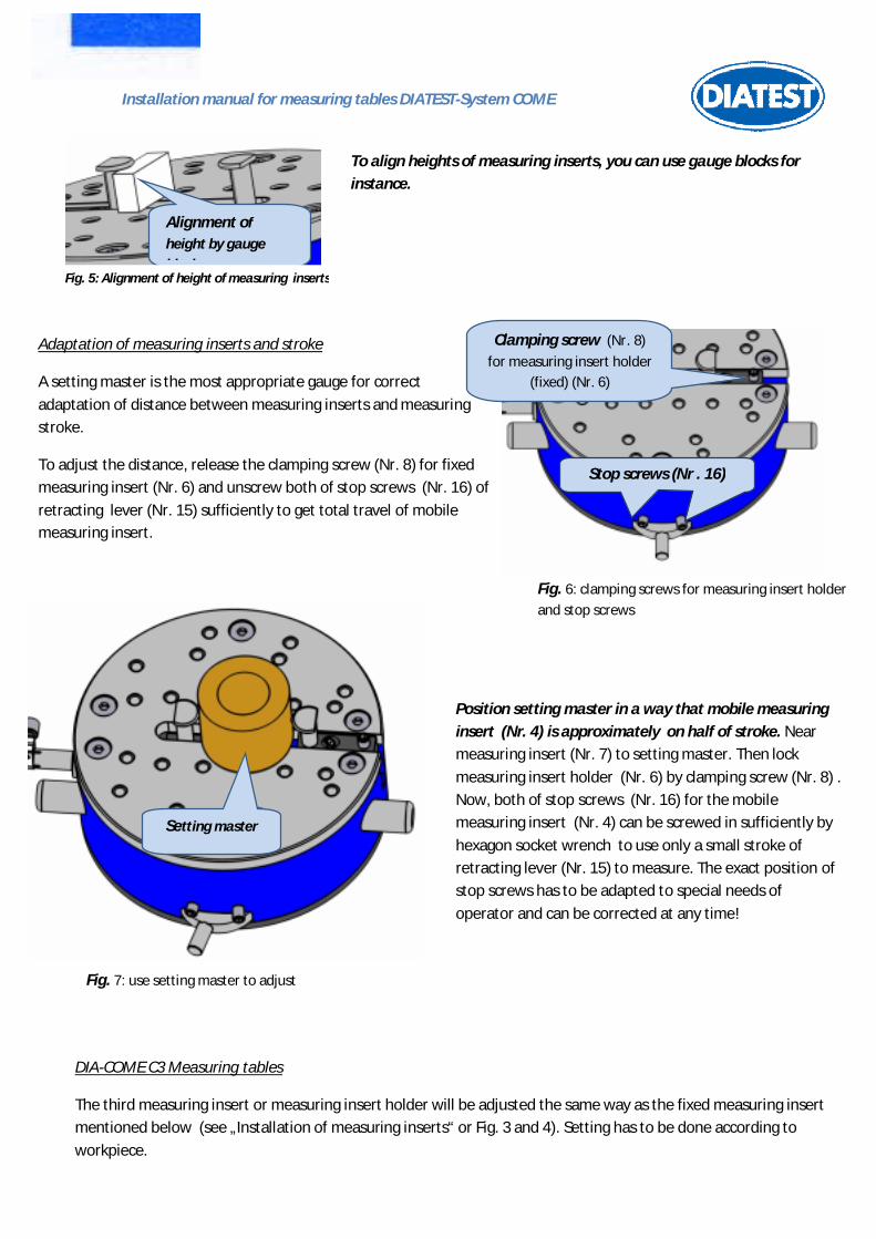
To align heights of measuring inserts, you can use gauge blocks for
instance.
Alignment of
height by gauge
blocks Fig. 5: Alignment of height of measuring inserts
Adaptation of measuring inserts and stroke
A setting master is the most appropriate gauge for correct
adaptation of distance between measuring inserts and measuring
stroke.
To adjust the distance, release the clamping screw (Nr. 8) for fixed
measuring insert (Nr. 6) and unscrew both of stop screws (Nr. 16) of
retracting lever (Nr. 15) sufficiently to get total travel of mobile
measuring insert.
Fig. 6: clamping screws for measuring insert holder
and stop screws
Position setting master in a way that mobile measuring
insert (Nr. 4) is approximately on half of stroke. Near
measuring insert (Nr. 7) to setting master. Then lock
measuring insert holder (Nr. 6) by clamping screw (Nr. 8) .
Now, both of stop screws (Nr. 16) for the mobile
measuring insert (Nr. 4) can be screwed in sufficiently by
hexagon socket wrench to use only a small stroke of
retracting lever (Nr. 15) to measure. The exact position of
stop screws has to be adapted to special needs of
operator and can be corrected at any time!
Setting master
Fig. 7: use setting master to adjust
DIA-COME C3 Measuring tables
The third measuring insert or measuring insert holder will be adjusted the same way as the fixed measuring insert
mentioned below (see „Installation of measuring inserts“ or Fig. 3 and 4). Setting has to be done according to
workpiece.
Clamping screw (Nr. 8)
for measuring insert holder
(fixed) (Nr. 6)
Stop screws (Nr . 16)
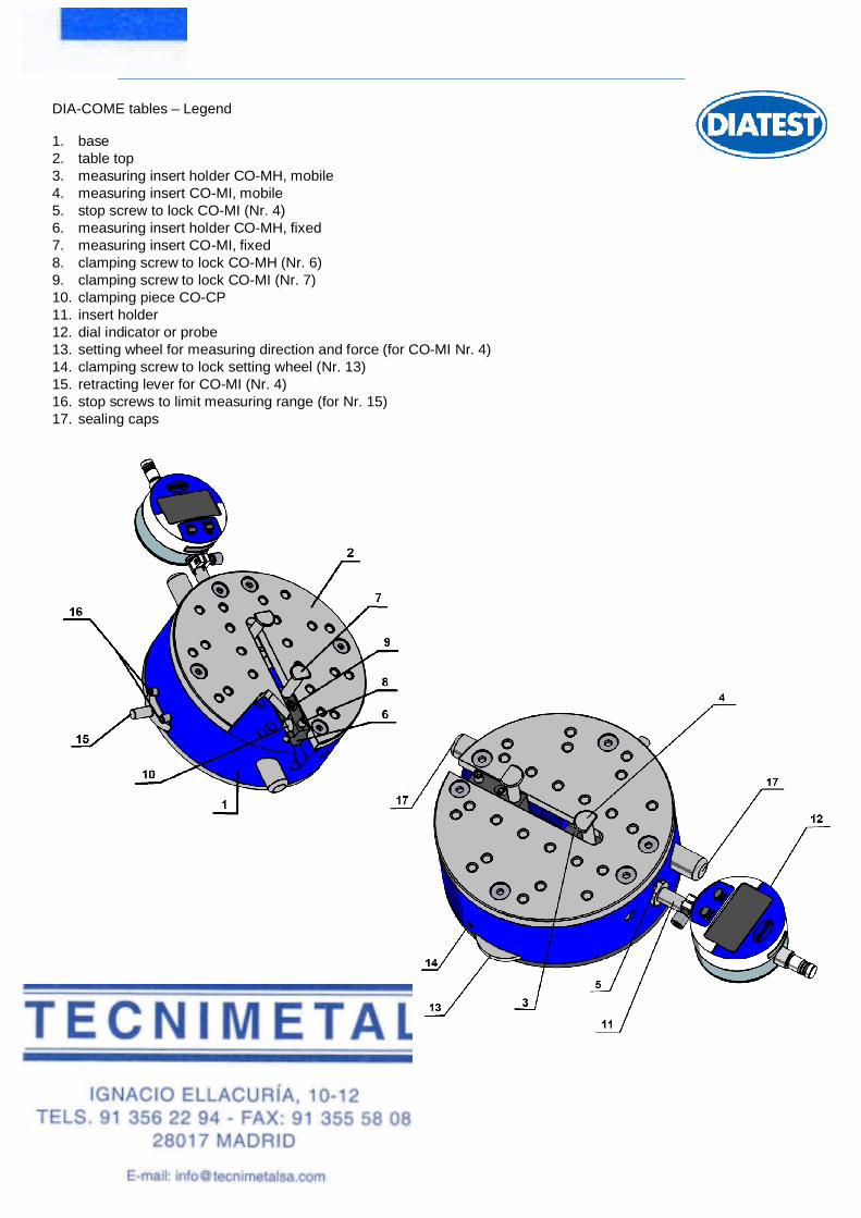
DIA-COME tables – Legend
1. base 2. table top 3. measuring insert holder CO-MH, mobile 4. measuring insert CO-MI, mobile 5. stop screw to lock CO-MI (Nr. 4) 6. measuring insert holder CO-MH, fixed 7. measuring insert CO-MI, fixed 8. clamping screw to lock CO-MH (Nr. 6) 9. clamping screw to lock CO-MI (Nr. 7) 10. clamping piece CO-CP 11. insert holder 12. dial indicator or probe 13. setting wheel for measuring direction and force (for CO-MI Nr. 4) 14. clamping screw to lock setting wheel (Nr. 13) 15. retracting lever for CO-MI (Nr. 4) 16. stop screws to limit measuring range (for Nr. 15) 17. sealing caps


![Linee Guida Italia Startup Hub [Eng]italiastartupvisa.mise.gov.it/media/documents/Linee... · Title: Microsoft Word - Linee Guida Italia Startup Hub [Eng].docx Author: alberto Created](https://img.pdfslide.net/doc/110x75/5fbe29852ab92a5bb3119e96/linee-guida-italia-startup-hub-eng-title-microsoft-word-linee-guida-italia.jpg)