Embed Size (px)
Citation preview
The International Journal of Multimedia & Its Applications (IJMA) Vol.6, No.6, December 2014
DOI : 10.5121/ijma.2014.6601 1
DISPARITY MAP GENERATION BASED ON
TRAPEZOIDAL CAMERA ARCHITECTURE FOR
MULTI-VIEW VIDEO
Abdulkadir Iyyaka Audu and Abdul Hamid Sadka
Department of Electronic and Computer Engineering,
Brunel University, London, United Kingdom
ABSTRACT
Visual content acquisition is a strategic functional block of any visual system. Despite its wide possibilities,
the arrangement of cameras for the acquisition of good quality visual content for use in multi-view video
remains a huge challenge. This paper presents the mathematical description of trapezoidal camera
architecture and relationships which facilitate the determination of camera position for visual content
acquisition in multi-view video, and depth map generation. The strong point of Trapezoidal Camera
Architecture is that it allows for adaptive camera topology by which points within the scene, especially the
occluded ones can be optically and geometrically viewed from several different viewpoints either on the
edge of the trapezoid or inside it. The concept of maximum independent set, trapezoid characteristics, and
the fact that the positions of cameras (with the exception of few) differ in their vertical coordinate
description could very well be used to address the issue of occlusion which continues to be a major
problem in computer vision with regards to the generation of depth map.
KEYWORDS
Multi-view Video, Occlusion, Stereoscopic distance, Trapezoidal Camera Architecture, Visual Content
Acquisition
1. INTRODUCTION
Human vision system (HVS) has stimulated an interest in acquisition of visual content and
provided an acceptable guide to its understanding. The subject of visual content acquisition
developed very early in history because its principles can be formulated from HVS of which
visual attention forms an important characteristic. Right from the very beginning it promises a
photorealistic replica of scenes for enormous emerging domains with many applications in many
different areas. In this regard, mathematical descriptions of propagation pattern of light,
parameterization of the behavioral response of optical devices are required.
A substantial body of evidence according to [1] demonstrates that exposure experience allows the
individual to learn a great deal about the stimulus object, so that the ability to recognize,
discriminate, and categorize the object generally improves. The first order step in the
achievement of these improvements is the registration of both optical and geometric properties of
The International Journal of Multimedia & Its Applications (IJMA) Vol.6, No.6, December 2014
2
the scene. The identification of this knowledge has triggered the visual content acquisition of
scenes from a single viewpoint using optical cameras.
On the one hand, the simplest image acquisition is a two-dimensional (2D) array of light intensity
functions representing points in the three-dimensional (3D) world. The intensity function at each
spatial coordinate is determined by the degree of illumination at that coordinate. The uniqueness
and potential of information embedded in 2D image has brought about the convergence of fields
such as image processing, computer graphics, pattern recognition, artificial intelligence,
psychophysics, and machine vision [1]. On the other hand, a complete description of an object in
terms of its physical shape and size is only possible when 3D coordinates are available. 3D
acquisition requires a geometrically and photometrically calibrated camera.
Building on the premise of distributed vision-based sensing and processing, multi-camera
networks have emerged as one of the preferred approaches for generating 3D content. 3D content
is known to provide depth perception of the observed scene [2]. Such content can be obtained by
having a high-resolution, wide-angle camera focused during a moderate object motion [3].
However, in computer vision, a synchronized set of multi-cameras with known accurate positions
and orientations, brightness and chromatic characteristics are used to observe object surface
areas. Single camera techniques, Holoscopic capture devices, pattern projection technique, and
time-of-flight techniques have been actively used in 3D content acquisition in other applications.
One important application of multi-camera system is in multi-view video. This is popularly used
in free viewpoint television (FVT), [4], [5], which enables a 3D scene to be viewed by freely
changing our viewpoint, and 3D television (3DTV) in which the illusion of depth is created.
Multi-view imaging has also attracted increasing attention in another wide variety of interesting
new research topics and applications. These range from virtual view synthesis, high performance
imaging, image and video segmentation, object tracking and recognition, environmental
surveillance, remote education, to industrial inspection [6]. Its application in video content
service such as video summarization [7], a condensed form of video content is generated for the
purpose of browsing, retrieval and storage enhancement. 3D seismology now has a considerable
driving force as opposed to its two-dimensional counterpart. It can help to solve the increased
dimensionality of the problems associated with imaging, processing, and visualization of
resultant images.
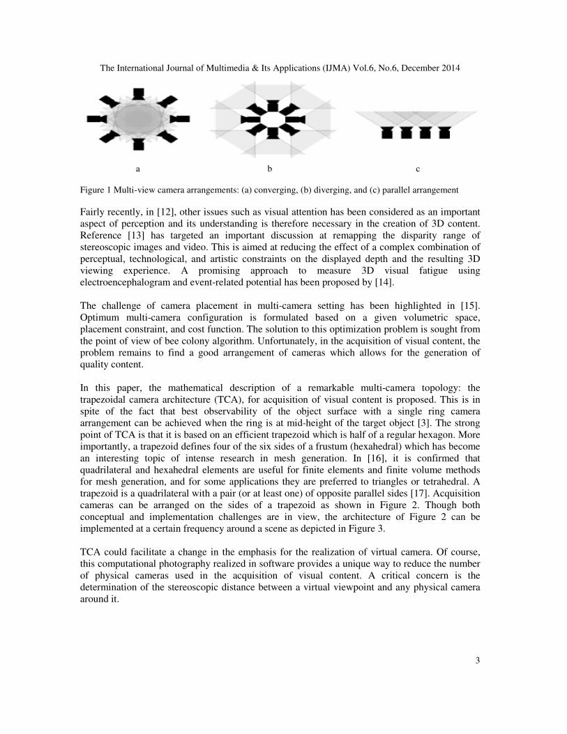
Until recently, however, the focus has been on understanding the brilliant successes of three lines
of development in camera configurations such as parallel array, convergence array, and
divergence array, Figure 1. Parallel array is the simplest form in which identical cameras are all
in a linear orientation. It is mentioned in [8] that more complicated settings can have different
camera lens properties and zoom facing the same 3D scene from different directions. The
geometry of these camera topologies can very easily be analysed. The need to improve the
camera architecture used in visual acquisition has been made evident from a variety of angles.
This includes the issue of camera density, the reduction in the number of physical cameras, image
quality, synchronization [9], depth estimation and occlusion [10], [11].
The International Journal of Multimedia & Its Applications (IJMA) Vol.6, No.6, December 2014
3
a b c
Figure 1 Multi-view camera arrangements: (a) converging, (b) diverging, and (c) parallel arrangement
Fairly recently, in [12], other issues such as visual attention has been considered as an important
aspect of perception and its understanding is therefore necessary in the creation of 3D content.
Reference [13] has targeted an important discussion at remapping the disparity range of
stereoscopic images and video. This is aimed at reducing the effect of a complex combination of
perceptual, technological, and artistic constraints on the displayed depth and the resulting 3D
viewing experience. A promising approach to measure 3D visual fatigue using
electroencephalogram and event-related potential has been proposed by [14].
The challenge of camera placement in multi-camera setting has been highlighted in [15].
Optimum multi-camera configuration is formulated based on a given volumetric space,
placement constraint, and cost function. The solution to this optimization problem is sought from
the point of view of bee colony algorithm. Unfortunately, in the acquisition of visual content, the
problem remains to find a good arrangement of cameras which allows for the generation of
quality content.
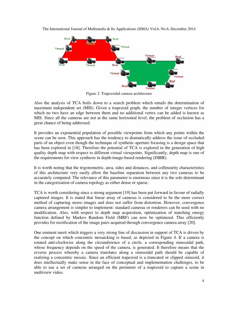
In this paper, the mathematical description of a remarkable multi-camera topology: the
trapezoidal camera architecture (TCA), for acquisition of visual content is proposed. This is in
spite of the fact that best observability of the object surface with a single ring camera
arrangement can be achieved when the ring is at mid-height of the target object [3]. The strong
point of TCA is that it is based on an efficient trapezoid which is half of a regular hexagon. More
importantly, a trapezoid defines four of the six sides of a frustum (hexahedral) which has become
an interesting topic of intense research in mesh generation. In [16], it is confirmed that
quadrilateral and hexahedral elements are useful for finite elements and finite volume methods
for mesh generation, and for some applications they are preferred to triangles or tetrahedral. A
trapezoid is a quadrilateral with a pair (or at least one) of opposite parallel sides [17]. Acquisition
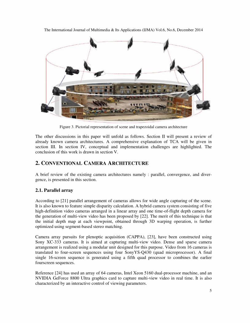
cameras can be arranged on the sides of a trapezoid as shown in Figure 2. Though both
conceptual and implementation challenges are in view, the architecture of Figure 2 can be
implemented at a certain frequency around a scene as depicted in Figure 3.
TCA could facilitate a change in the emphasis for the realization of virtual camera. Of course,
this computational photography realized in software provides a unique way to reduce the number
of physical cameras used in the acquisition of visual content. A critical concern is the
determination of the stereoscopic distance between a virtual viewpoint and any physical camera
around it.
The International Journal of Multimedia & Its Applications (IJMA) Vol.6, No.6, December 2014
4
Figure 2. Trapezoidal camera architecture
Also the analysis of TCA boils down to a search problem which entails the determination of
maximum independent set (MIS). Given a trapezoid graph, the number of integer vertices for
which no two have an edge between them and no additional vertex can be added is known as
MIS. Since all the cameras are not at the same horizontal level, the problem of occlusion has a
great chance of being addressed.
It provides an exponential population of possible viewpoints from which any points within the
scene can be seen. This approach has the tendency to dramatically address the issue of occluded
parts of an object even though the technique of synthetic aperture focusing is a design space that
has been explored in [18]. Therefore the potential of TCA is explored in the generation of high
quality depth map with respect to different virtual viewpoints. Significantly, depth map is one of
the requirements for view synthesis in depth-image-based rendering (DIBR).
It is worth noting that the trigonometric, area, sides and distances, and collinearity characteristics
of this architecture very easily allow the baseline separation between any two cameras to be
accurately computed. The relevance of this parameter is enormous since it is the sole determinant
in the categorization of camera topology as either dense or sparse.
TCA is worth considering since a strong argument [19] has been put forward in favour of radially
captured images. It is stated that linear array of cameras is considered to be the more correct
method of capturing stereo images and does not suffer from distortion. However, convergence
camera arrangement is simpler to implement: standard cameras or renderers can be used with no
modification. Also, with respect to depth map acquisition, optimization of matching energy
function defined by Markov Random Field (MRF) can now be optimized. This efficiently
provides for rectification of the image pairs acquired through convergence camera array [20].
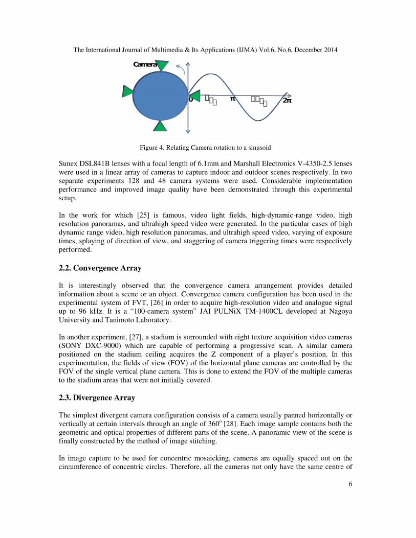
One eminent merit which triggers a very strong line of discussion in support of TCA is driven by
the concept on which concentric mosaicking is based, as depicted in Figure 4. If a camera is
rotated anti-clockwise along the circumference of a circle, a corresponding sinusoidal path,
whose frequency depends on the speed of the camera, is generated. It therefore means that the
reverse process whereby a camera translates along a sinusoidal path should be capable of
realizing a concentric mosaic. Since an efficient trapezoid is a truncated or clipped sinusoid, it
does intellectually make sense in the face of conceptual and implementation challenges, to be
able to use a set of cameras arranged on the perimeter of a trapezoid to capture a scene in
multiview video.
The International Journal of Multimedia & Its Applications (IJMA) Vol.6, No.6, December 2014
5
Figure 3. Pictorial representation of scene and trapezoidal camera architecture
The other discussions in this paper will unfold as follows. Section II will present a review of
already known camera architectures. A comprehensive explanation of TCA will be given in
section III. In section IV, conceptual and implementation challenges are highlighted. The
conclusion of this work is drawn in section V.
2. CONVENTIONAL CAMERA ARCHITECTURE
A brief review of the existing camera architectures namely : parallel, convergence, and diver-
gence, is presented in this section.
2.1. Parallel array
According to [21] parallel arrangement of cameras allows for wide angle capturing of the scene.
It is also known to feature simple disparity calculation. A hybrid camera system consisting of five
high-definition video cameras arranged in a linear array and one time-of-flight depth camera for
the generation of multi-view video has been proposed by [22]. The merit of this technique is that
the initial depth map at each viewpoint, obtained through 3D warping operation, is further
optimized using segment-based stereo matching.
Camera array pursuits for plenoptic acquisition (CAPPA), [23], have been constructed using
Sony XC-333 cameras. It is aimed at capturing multi-view video. Dense and sparse camera
arrangement is realized using a modular unit designed for this purpose. Video from 16 cameras is
translated to four-screen sequences using four SonyYS-Q430 (quad microprocessor). A final
single 16-screen sequence is generated using a fifth quad processor to combines the earlier
fourscreen sequences.
Reference [24] has used an array of 64 cameras, Intel Xeon 5160 dual-processor machine, and an
NVIDIA GeForce 8800 Ultra graphics card to capture multi-view video in real time. It is also
characterized by an interactive control of viewing parameters.
The International Journal of Multimedia & Its Applications (IJMA) Vol.6, No.6, December 2014
6
Figure 4. Relating Camera rotation to a sinusoid
Sunex DSL841B lenses with a focal length of 6.1mm and Marshall Electronics V-4350-2.5 lenses
were used in a linear array of cameras to capture indoor and outdoor scenes respectively. In two
separate experiments 128 and 48 camera systems were used. Considerable implementation
performance and improved image quality have been demonstrated through this experimental
setup.
In the work for which [25] is famous, video light fields, high-dynamic-range video, high
resolution panoramas, and ultrahigh speed video were generated. In the particular cases of high
dynamic range video, high resolution panoramas, and ultrahigh speed video, varying of exposure
times, splaying of direction of view, and staggering of camera triggering times were respectively
performed.
2.2. Convergence Array
It is interestingly observed that the convergence camera arrangement provides detailed
information about a scene or an object. Convergence camera configuration has been used in the
experimental system of FVT, [26] in order to acquire high-resolution video and analogue signal
up to 96 kHz. It is a “100-camera system” JAI PULNiX TM-1400CL developed at Nagoya
University and Tanimoto Laboratory.
In another experiment, [27], a stadium is surrounded with eight texture acquisition video cameras
(SONY DXC-9000) which are capable of performing a progressive scan. A similar camera
positioned on the stadium ceiling acquires the Z component of a player’s position. In this
experimentation, the fields of view (FOV) of the horizontal plane cameras are controlled by the
FOV of the single vertical plane camera. This is done to extend the FOV of the multiple cameras
to the stadium areas that were not initially covered.
2.3. Divergence Array
The simplest divergent camera configuration consists of a camera usually panned horizontally or
vertically at certain intervals through an angle of 360o [28]. Each image sample contains both the
geometric and optical properties of different parts of the scene. A panoramic view of the scene is
finally constructed by the method of image stitching.
In image capture to be used for concentric mosaicking, cameras are equally spaced out on the
circumference of concentric circles. Therefore, all the cameras not only have the same centre of
The International Journal of Multimedia & Its Applications (IJMA) Vol.6, No.6, December 2014
7
projection, [29], but all input image rays are naturally indexed in radius, rotation angle, and
vertical elevation.
3. THE PROPOSED METHOD
Linear, divergence, and convergence camera arrangements have been used for acquiring visual
content in multi-view video. One feature which is common to these camera configurations is that
they are planar. All the cameras are constrained to the same, usually horizontal plane. We now
explore the design space of trapezoid graph to seek the possibility of having some of the cameras
positioned at a different vertical coordinate level.
The strong point of TCA is that it allows for adaptive camera topology by which points within the
scene, especially the occluded ones can be optically and geometrically viewed from several
different viewpoints either on the edge of the trapezoid or inside it.
3.1. Trapezoid graph and Maximal Independent Sets
In a greater generality, in [8] [9], [10], [11], a trapezoid can be obtained from a trapezoid graph,
which is an undirected graph G(V,E) consisting of a set of vertices V = { V1, V2,V3,…Vn } and a
set of edges E = { e1, e2, e3, ….., en } if and only if (Vi, Vj) ϵ E. The concept of MIS allows for the
determination of a corner camera viewpoint with maximum cardinality and to be used in
conjunction with the initially chosen corner viewpoint on the perimeter of the trapezoid. Using
this concept it is possible to determine any two cameras located on the corner points of the
trapezoid that can be considered for stereoscopic analysis.
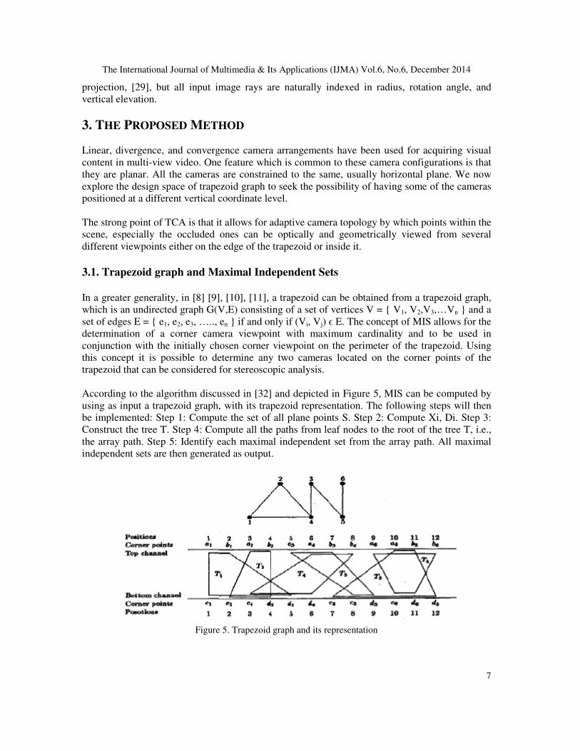
According to the algorithm discussed in [32] and depicted in Figure 5, MIS can be computed by
using as input a trapezoid graph, with its trapezoid representation. The following steps will then
be implemented: Step 1: Compute the set of all plane points S. Step 2: Compute Xi, Di. Step 3:
Construct the tree T. Step 4: Compute all the paths from leaf nodes to the root of the tree T, i.e.,
the array path. Step 5: Identify each maximal independent set from the array path. All maximal
independent sets are then generated as output.
Figure 5. Trapezoid graph and its representation
The International Journal of Multimedia & Its Applications (IJMA) Vol.6, No.6, December 2014
8
3.2. Formal Mathematical Statement of TCA
A trapezoid is considered based on the inclusive definition of having high significance in
mathematical analysis. It is well known that any proven property of a trapezoid automatically
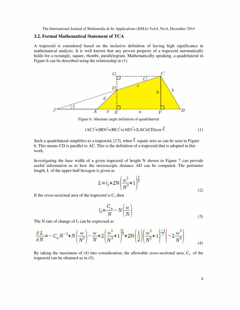
holds for a rectangle, square, rhombi, parallelogram. Mathematically speaking, a quadrilateral in
Figure 6 can be described using the relationship in (1).
Figure 6. Alternate angle definition of quadrilateral
(AC)2+(BD)
2=(BC)
2+(AD)
2+2(AC)(CD)cos (1)
Such a quadrilateral simplifies to a trapezoid, [17], when equals zero as can be seen in Figure
6. This means CD is parallel to AC. This is the definition of a trapezoid that is adopted in this
work.
Investigating the base width of a given trapezoid of height N shown in Figure 7 can provide
useful information as to how the stereoscopic distance AD can be computed. The perimeter
length, L of the upper-half hexagon is given as
(2)
If the cross-sectional area of the trapezoid is Ca then
(3)
The N rate of change of L can be expressed as
(4)
By taking the maximum of (4) into consideration, the allowable cross-sectional area, Ca of the
trapezoid can be obtained as in (5).
The International Journal of Multimedia & Its Applications (IJMA) Vol.6, No.6, December 2014
9
(5)
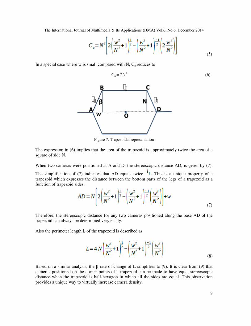
In a special case where w is small compared with N, Ca reduces to
Ca = 2N2
(6)
Figure 7. Trapezoidal representation
The expression in (6) implies that the area of the trapezoid is approximately twice the area of a
square of side N.
When two cameras were positioned at A and D, the stereoscopic distance AD, is given by (7).
The simplification of (7) indicates that AD equals twice . This is a unique property of a
trapezoid which expresses the distance between the bottom parts of the legs of a trapezoid as a
function of trapezoid sides.
(7)
Therefore, the stereoscopic distance for any two cameras positioned along the base AD of the
trapezoid can always be determined very easily.
Also the perimeter length L of the trapezoid is described as
(8)
Based on a similar analysis, the β rate of change of L simplifies to (9). It is clear from (9) that
cameras positioned on the corner points of a trapezoid can be made to have equal stereoscopic
distance when the trapezoid is half-hexagon in which all the sides are equal. This observation
provides a unique way to virtually increase camera density.
The International Journal of Multimedia & Its Applications (IJMA) Vol.6, No.6, December 2014
10
(9)
3.3. Characterization of Trapezoid
A trapezoid has five important characteristics which can be explored in the computation of
camera positions in TCA. These are sides and distances, collinearity, trigonometry, area [16] and
v-parallelogram characteristics.
3.3.1. Sides and Distances
In the trapezoid of Figure 7, triangles ACB and DBC have equal areas since they both have an
altitude of N . Therefore, it can be written that
(10)
The distance w can be obtained by equating the sum of the left and right hand-terms of (10) with
(8). In this way, the coordinate description of the position of any camera located along AB can be
easily obtained. Also, in the event of any cameras located at the point of intersection of diagonals
AC and BD, the position coordinates of any such cameras can be determined based on the
generalized Euler parallelogram law expressed in (11). X is the horizontal difference between the
center point of AC and D. In certain specialized applications, cameras positioned at
the midpoints of the trapezoid diagonals can also be explored to attempt to solve the problem of
occlusion.
(AB)2+(BC)
2+(CD)
2+(AD)
2=(AC)
2+(BD)
2+4(X)
2 (11)
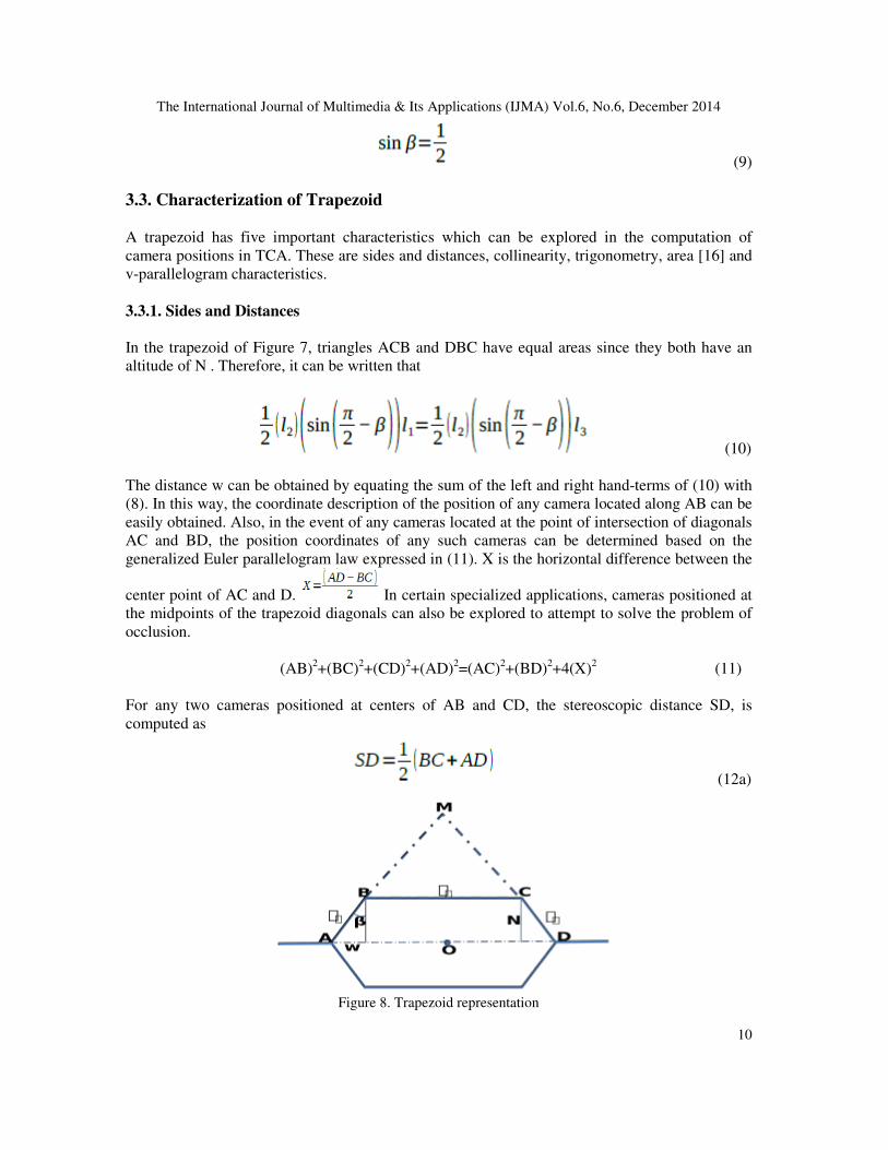
For any two cameras positioned at centers of AB and CD, the stereoscopic distance SD, is
computed as
(12a)
Figure 8. Trapezoid representation
The International Journal of Multimedia & Its Applications (IJMA) Vol.6, No.6, December 2014
11
Assuming two cameras are positioned at and on the non-parallel sides AB and CD of the
trapezoid of Fig. 7. Let k be the same ratio by which and divide the non-parallel sides. The
mathematical analysis provided by [12] shows that the stereoscopic distance can be obtained
as
(12b)
The dependency of the diagonals on the sides and β can be formulated for an efficient trapezoid
(all sides are equal) as
(13)
(14)
(15)
(16)
The relationship in (16) states that for an efficient trapezoid, the sum of the squares of the
diagonal is directly proportional to the square of the side length . The constant of
proportionality equals 6. Again, when β is equal to zero degrees, (16) simplifies to the expression
expected for the sum of squares of the diagonal of a square. This is a further confirmation of the
validity of (16).
In an attempt to solve the conceptual and implementation challenges, the trapezoid of Figure 8
will be used to define a scene. This is will be further explained in section 4.
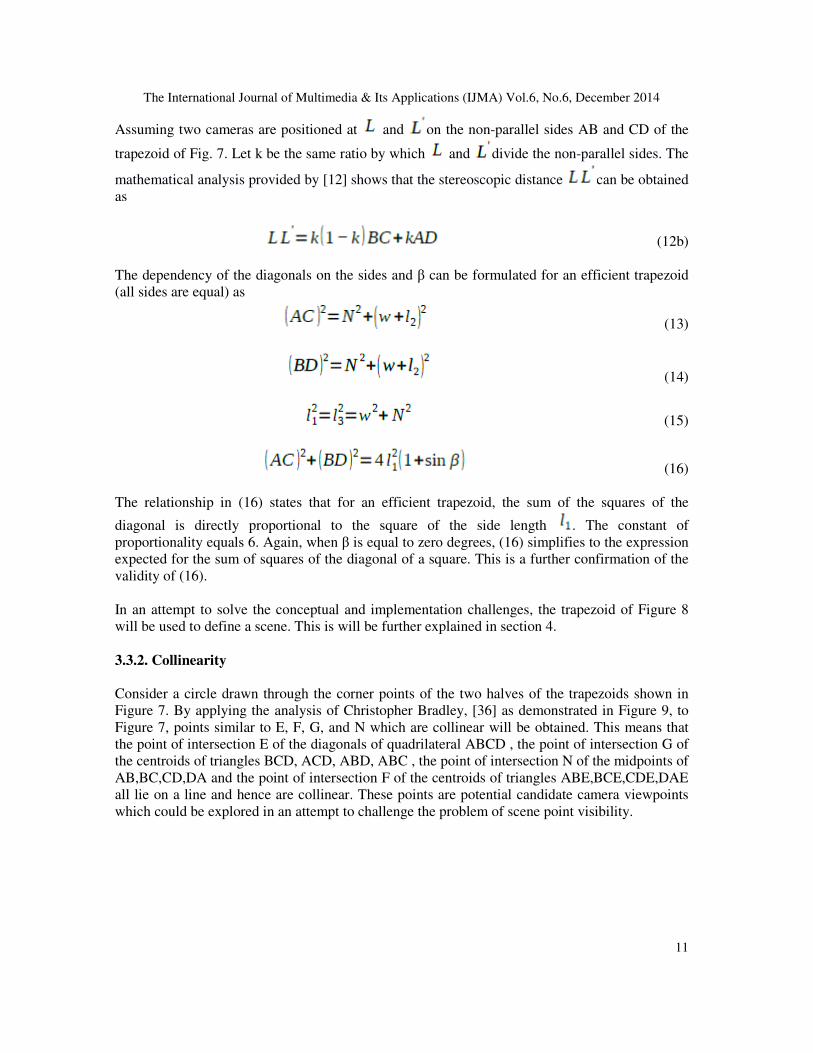
3.3.2. Collinearity
Consider a circle drawn through the corner points of the two halves of the trapezoids shown in
Figure 7. By applying the analysis of Christopher Bradley, [36] as demonstrated in Figure 9, to
Figure 7, points similar to E, F, G, and N which are collinear will be obtained. This means that
the point of intersection E of the diagonals of quadrilateral ABCD , the point of intersection G of
the centroids of triangles BCD, ACD, ABD, ABC , the point of intersection N of the midpoints of
AB,BC,CD,DA and the point of intersection F of the centroids of triangles ABE,BCE,CDE,DAE
all lie on a line and hence are collinear. These points are potential candidate camera viewpoints
which could be explored in an attempt to challenge the problem of scene point visibility.
The International Journal of Multimedia & Its Applications (IJMA) Vol.6, No.6, December 2014
12
Figure 9. Cyclic quadrilateral
3.3.3. Area
The area characteristic of a trapezoid is important in the computation of scene volume. An
extension of the work in [13] provides a clue to the area of trapezoid as in (17)
(17)
3.3.4. Similarity
Assuming in Fig. 7 that the diagonals AC and BD intersect at a point P. Let the perpendicular
lines from P to AD and BC have lengths h1 and h2 respectively. Also let θ1 and θ2 respectively
be the angles subtended by AC and BD with AD. The following two equations can be written
(18)
(19)
(20)
Expression (20) is a trapezoidal similarity characteristic which can facilitate the computation of
the coordinates of any cameras positioned at P.
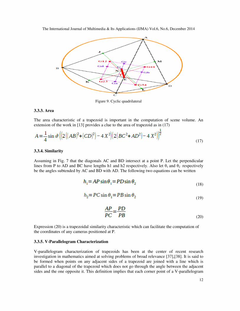
3.3.5. V-Parallelogram Characterization
V-parallelogram characterization of trapezoids has been at the center of recent research
investigation in mathematics aimed at solving problems of broad relevance [37],[38]. It is said to
be formed when points on any adjacent sides of a trapezoid are joined with a line which is
parallel to a diagonal of the trapezoid which does not go through the angle between the adjacent
sides and the one opposite it. This definition implies that each corner point of a V-parallelogram
The International Journal of Multimedia & Its Applications (IJMA) Vol.6, No.6, December 2014
13
lie on one and only one side of the trapezoid. Therefore, it means that cameras positioned on
adjacent sides of a trapezoid can stereoscopically be used to observe a scene.
Figure 10. V-parallelogram M of a trapezoid
In multi-view visual content acquisition, cameras can also be positioned at viewpoints M1, M2,
M3, M4 which, according to a statement in Euclidean geometry define a v-parallelogram
M1M2M3M4 shown in Figure 10. The homothetic transformation of triangles ABC and M1BM2
around the corner point B of the trapezoid in Figure 10 provides for (21) from which the baseline
distance can be determined.
(21)
4. IMPLEMENTATION CONSIDERATIONS
Of course, TCA is potentially inclined to addressing some of the critical challenges in multiview
video acquisition; however its implementation could also be a challenge. Two issues easily come
to mind namely the possible curvature of the scene and the frequency of the trapezoid.
For a scene of large volume, the curvature of the opposite and parallel sides of the trapezoid
becomes significant and adds up to the complexity of the implementation strategy. Practically,
this situation implies that the stereoscopic distance can no longer be measured on a straight line
between two camera positions.
Again, for a large scene where a small stereoscopic distance is required between cameras, several
cycles of TCA will have to be implemented. This will significantly make the cost ofimplementing
this strategy very high. A right balance will have to be struck between small and large scenes on
one hand and curvature and frequency of TCA on the other.
The International Journal of Multimedia & Its Applications (IJMA) Vol.6, No.6, December 2014
14
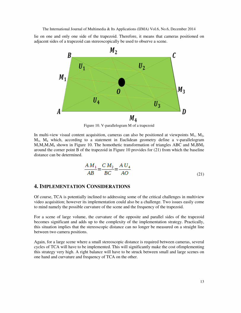
To adequately address these issues, an implementation strategy is proposed based on the
assumption that the scene is contained in a pyramidal frustum defined by four trapezoids as
shown in Figure. 10.
In this method, only four half-cycles of TCA are required for the entire scene. The acquisition
cameras are then placed on the edges of the trapezoid such that the ones along the legs of the
trapezoid exhibit convergence topology. The idea of scene volume in this work does not require a
strong argument for it to be embraced since it has been mentioned in [16] in a different way
though implying the same sense.
The formulation of scene volume is actually a fortification of the basic volume (22) of a frustum.
The modification of (22) will take into account the near and far depth parameters of the scene.
(22)
Figure 11. Implementation strategy of TCA
5. CAMERA AND DEPTH MAP CONSTRUCTION
Stereoscopic camera system with parallel axes is believed to be necessary to avoid the vertical
image disparity generated by systems that verge the camera axes [38]. However, “Two forward
facing camera” technique [39] used to deliver a two-dimensional (2D) projection of a scene
remains a fundamental challenge in stereo vision. Correspondences between multiple images
need to be accurately established. These are understood to be attributable, in the view of [40], to
scene properties such as textureless areas, non-Lambertian surfaces, reflections and translucency,
and occlusions. Camera issues include image noise, calibration and synchronization, differences
in exposure, white balancing, and other radiometric properties.
A camera is formulated based on pin-hole camera model expressed in (23)
(23)
The International Journal of Multimedia & Its Applications (IJMA) Vol.6, No.6, December 2014
15
K is a 3x3 matrix consisting of camera intrinsic parameters namely: focal length, aspect ratio,
skew and principal point. R denotes an orthogonal matrix and t a vector, encoding camera
rotation and translation, depth, λ, is equal to Z. Both are determined by the orientation and
displacement of the camera at the virtual viewpoint on the edge of the trapezoid. x and X0 are the
extended image and scene point coordinates. The projection matrix P is used to render the
quantization level v, for each vertex and face of the graphic. The substitution of v into (24) yields
the expected depth for all the vertices and faces.
Using uniform quantization of depth value between Znear and Zfar to minimize disocclusion, and
taken into consideration the fact that in humans, the perceived depth distance of close objects is
much less than the depth distance of further objects [41], [42] depth is formulated as
(24)
where v is the number of quantization levels from zero through to 232
– 1. The high number of
quantization levels is aimed at improving the resolution of the depth map.
6. EXPERIMENTAL RESULTS
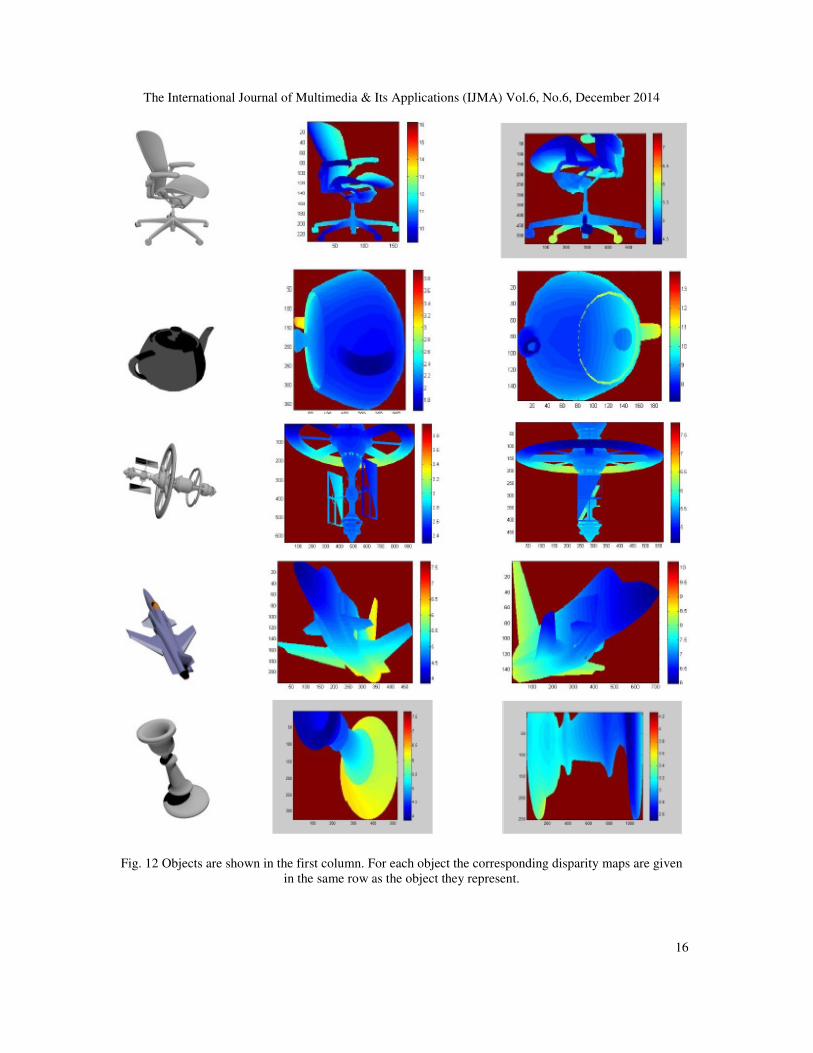
Some of the simulation results to validate the concept of TCA are shown in Figure 12. Each
disparity map of an object is generated using a different virtual viewpoint. These are high quality
disparity map. In the analysis leading to the determination of disparity map, correspondence
problem still remain a major source of error. This is because correlation based techniques is
widely used. It is formulated based on resemblance constraint which requires intensity similarity
between any corresponding points [40]. Also, it cannot cope with textureless regions where pixels
are insufficiently distinct. Occlusions and discontinuities of some parts of scene are important
features which correlation method cannot adequately handle. The choice of window size is
critical the regards to accurate disparity map. To reduce the error contribution due to the
aforementioned, comparison of quantitative results with Normalized Cross Correlation (NCC)
method, Daisy descriptor, Error Quadratic Means (EQM), and Local evidence have been
employed in most research work related to depth map.
Since only a single image of the different objects is used in this work, i.e not stereo images, the
earlier mentioned objective quality metrics cannot be applied. However, subjective quality
assessment (SQA) of the generated disparity maps has been conducted at Centre for Media
Communication Research (CMCR), Brunel University, London. Research students who already
have a good understanding of disparity map were invited to take a look at the disparity maps for
different objects. The SQA was based on double stimulus impairment scale (DSIS) in which the
following scales were used. “Very clean and sharp = 5”, “Clear but not sharp = 4”, “Clear but
blur = 3”, “blur = 2”, and “Not clear = 1”. The calculated Mean opinion scores (MOSs) for each
disparity map were then analysed. More than 90 percent of the observers scored each disparity
map with DSIS of 5.
The International Journal of Multimedia & Its Applications (IJMA) Vol.6, No.6, December 2014
16
Fig. 12 Objects are shown in the first column. For each object the corresponding disparity maps are given
in the same row as the object they represent.
The International Journal of Multimedia & Its Applications (IJMA) Vol.6, No.6, December 2014
17
7. CONCLUSIONS
In this paper, the mathematical description of TCA has been presented based on an efficient
trapezoid. In principle, the definition of a trapezoid is simple. However, it is the diverse different
methods of determining the coordinates of its corner points, points on the edges, and in some
critical applications, points in the space defined by the edges that make TCA so appealing in
camera positioning for multi-view video. The similarity, sides and distances, areas, and
trigonometric characteristics of a trapezoid provide for computation of baseline and coordinate
description of camera positions.
Also the understanding provided by TCA has been used for depth map generation with respect to
virtual viewpoints on the edge of the trapezoid. Virtual viewpoints which trace a trapezoid
guarantee high quality disparity map as indicated by DSIS, with almost complete absence of
holes. Therefore, the minimization of deviation from actual disparity which is widely considered
as the default measure of success is not required to validate the generated disparity map.
REFERENCES [1] V. R Ion and C. Stromeyer, “Affective discrimination of stimuli that cannot be recognised,”
Science, vol. 207, pp. 1, Feb. 1980.
[2] R. Jain, R. Kasturi and B. G. Schunck, Machine Vision. McGraw-Hill New York, 1995.
[3] P. Merkle, K. Muller and T. Wiegand, "3D video: acquisition, coding, and display," Consumer
Electronics, IEEE Transactions on, vol. 56, no. 2, pp. 946-950, May. 2010.
[4] T. Matsuyama, S. Nobuhara, T. Takai and T. Tung, 3D video and its applications. Springer
Publishing Company, Incorporated, 2012.
[5] S. Jarusirisawad and H. Saito, "3DTV view generation using uncalibrated pure rotating and
zooming cameras," Signal Process Image Commun, vol. 24, pp. 17-30, no. 1, Jan. 2009.
[6] M. Tanimoto, "FTV: Free-viewpoint Television," Signal Process Image Commun, vol. 27, pp.
555-570, Jul. 2012.
[7] A. Kubota, A. Smolic, M. Magnor, M. Tanimoto, C. Zhang, "Multiview imaging and 3DTV,"
IEEE Signal Process. Mag., vol. 1053, no. 5888/07, pp. 10-21, 2007.
[8] Y. Fu, Y. Guo, Y. Zhu, F. Liu, C. Song and Z. Zhou, "Multi-view video summarization,"
Multimedia, IEEE Transactions on, vol. 12, no. 7, pp. 717-729, 2010.
[9] L. Onural, 3D Video Technologies : An Overview of Research Trends. Bellingham, Wash:
SPIE, 2010, pp. 27-32.
[10] H. K. Aghajan, A. Cavallaro and ScienceDirect (Online service), Multi-Camera Networks
Electronic Resource : Principles and Applications. Amsterdam ; Boston: Elsevier, AP, 2009, pp.
29-75.
[11] A. Saxena, J. Schulte and A. Y. Ng, "Depth estimation using monocular and stereo cues." in
IJCAI, 2007, pp. 2197-2203.
[12] A. V. Bhavsar and A. N. Rajagopalan, "Towards unrestrained depth inference with coherent
occlusion filling," Int J Comput Vision, vol. 97, no. 2, pp. 167-190, 2012.
[13] Q. Huynh-Thu and L. Schiatti, "Examination of 3D visual attention in stereoscopic video
content," in IS&T/SPIE Electronic Imaging, 2011, pp. 78650J-78650J.
[14] M. Lang, A. Hornung, O. Wang, S. Poulakos, A. Smolic and M. Gross, "Nonlinear disparity
mapping for stereoscopic 3D," ACM Transactions on Graphics (TOG), vol. 29, no. 4, pp. 75:1-
10, 2010.
[15] H. Li, J. Seo, K. Kham and S. Lee, "Measurement of 3D visual fatigue using event-related
potential (ERP): 3D oddball paradigm," in 3DTV Conference: The True Vision-Capture,
Transmission and Display of 3D Video, 2008, 2008, pp. 213-216.
The International Journal of Multimedia & Its Applications (IJMA) Vol.6, No.6, December 2014
18
[16] D. Chrysostomou and A. Gasteratos, "Optimum multi-camera arrangement using a bee colony
algorithm," in Imaging Systems and Techniques (IST), 2012 IEEE International Conference on,
2012, pp. 387-392.
[17] R. Schneiders, "Algorithms for quadrilateral and hexahedral mesh generation," Proceedings of
the VKI Lecture Series on Computational Fluid Cynamics, 2000.
[18] M. Josefsson, "Characterizations of trapezoids," in Forum Geometricorum, 2013, pp. 23-35.
[19] V. Vaish, M. Levoy, R. Szeliski, C. L. Zitnick and S. B. Kang, "Reconstructing occluded
surfaces using synthetic apertures: Stereo, focus and robust measures," in Computer Vision and
Pattern Recognition, 2006 IEEE Computer Society Conference on, 2006, pp. 2331-2338.
[20] N. A. Dodgson, "Resampling radially captured images for perspectively correct stereoscopic
display," in Photonics West'98 Electronic Imaging, 1998, pp. 100-110.
[21] W. Jang and Y. Ho, "Direct Depth Value Extraction Method for Various Stereo Camera
Arrangements," in The 2013 International Conference on Embedded System and Intelligent
Technology (ICESIT 2013), 2013, pp. 128-131.
[22] Y. Ho, "Challenging Technical Issues of 3D Video Processing," Journal of Convergence, vol. 4,
no. 1, pp. 1-6, Mar. 2013.
[23] E. K. Lee and Y. S. Ho, "Generation of high-quality depth maps using hybrid camera system for
3-D video," Journal of Visual Communication and Image Representation, vol. 22, no. 1, pp. 73-
84, Jan. 2011.
[24] T. Naemura, J. Tago and H. Harashima, "Real-time video-based modeling and rendering of 3D
scenes," Computer Graphics and Applications, IEEE, vol. 22, no. 2, pp. 66-73, Mar. 2002.
[25] Y. Taguchi, T. Koike, K. Takahashi and T. Naemura, "TransCAIP: A live 3D TV system using
a camera array and an integral photography display with interactive control of viewing
parameters," Visualization and Computer Graphics, IEEE Transactions on, vol. 15, no. 5, pp.
841-852, Sep. 2009.
[26] M. Levoy, "Light fields and computational imaging," Computer, vol. 39, no. 8, pp. 46-55, Aug.
2006.
[27] M. Tanimoto, "Overview of free viewpoint television," Signal Process Image Commun, vol. 21,
no. 6, pp. 454-461, 07, Jul. 2006.
[28] T. Koyama, I. Kitahara and Y. Ohta, "Live mixed-reality 3d video in soccer stadium," in Mixed
and Augmented Reality, 2003. Proceedings. The Second IEEE and ACM International
Symposium on, 2003, pp. 178-186.
[29] M. Brown and D. G. Lowe, "Automatic panoramic image stitching using invariant features,"
International Journal of Computer Vision, vol. 74, no. 1, pp. 59-73, 2007.
[30] M. Gong and Yee-Hong Yang, "Rayset: a Taxonomy for Image-Based Rendering," International
Journal of Image & Graphics, vol. 6, no. 3, pp. 313-339, Jul. 2006.
[31] I. Dagan, M. C. Golumbic and R. Y. Pinter, "Trapezoid graphs and their coloring," Discrete
Applied Mathematics, vol. 21, no. 1, pp. 35-46, Sep. 1988.
[32] M. Hota, M. Pal and T. K. Pal, "An efficient algorithm to generate all maximal independent sets
on trapezoid graphs," International Journal of Computer Mathematics, vol. 70, no. 4, pp. 587-
599, 1999.
[33] C. Flotow, "On powers of m-trapezoid graphs," Discrete Applied Mathematics, vol. 63, no. 2,
pp. 187-192, Nov. 1995.
[34] G. B. Mertzios and D. G. Corneil, "Vertex splitting and the recognition of trapezoid graphs,"
Discrete Applied Mathematics, vol. 159, no. 11, pp. 1131-1147, Jul. 2011.
[35] L. Droussent, "On a theorem of J. Griffiths," The American Mathematical Monthly, vol. 54,
no.9, pp. 538-540, Nov. 1947.
[36] C. Bradley, Three centroids created by a cyclic quadrilateral, in: Article: CJB/2011/141, 2011,
pp. 1–3.
[37] M. Josefsson, "Five proofs of an area characterization of rectangles," in Forum Geometricorum,
2013, pp. 17-21.
[38] M. F. Mammana, B. Micale and M. Pennisi, "Properties of valtitudes and vaxes of a convex
quadrilateral," in Forum Geometricorum, 2012, pp. 47-61.
The International Journal of Multimedia & Its Applications (IJMA) Vol.6, No.6, December 2014
19
[39] G. R. Jones, D. Lee, N. S. Holliman and D. Ezra, "Controlling perceived depth in stereoscopic
images," in Photonics West 2001-Electronic Imaging, 2001, pp. 42-53.
[40] H. Fradi and J. Dugelay, "Improved depth map estimation in stereo vision," in IS&T/SPIE
Electronic Imaging, 2011, pp. 78631U-78631U-7.
[41] C. L. Zitnick and S. B. Kang, "Stereo for image-based rendering using image over
segmentation," International Journal of Computer Vision, vol. 75, pp. 49-65, 2007.
[42] Yu-Cheng Fan and Tsung-Chen Chi, "The novel non-hole-filling approach of depth image
based rendering," in 2008, pp. 325-328.