Embed Size (px)
Citation preview
Game ProgrammingShaders
Nick Prühs
Objectives
• To get an overview of the graphics pipeline ofmodern GPUs
• To understand the basics of shader development
• To learn how to write your own advanced Cg shaders
2 / 77

Shaders
• Control the shape, appearance, and motion of objects drawn using programmable graphics hardware
• Very specialized
• Incredibly fast
3 / 77
CPU vs. GPU
• CPUs are, by design, general purpose
• GPUs are, due to their specialized design, much faster at graphics tasks such as vector math• add, multiply, multiply-add• minimum and maximum• component-wise swizzling (pos.xz)• negation, subtraction• dot and cross products• vector-by-scalar division and vector normalization• exponential, logarithmic, and trigonometric
approximations
4 / 77
Performance Requirements
• Desired frame rate of 60 or more frames per second
• A million or more pixels that require redrawing
• GPU typically processes every pixel on the screen many times• to account for how objects occlude each other
• to improve the appearance of each pixel
• Thus, real-time 3D applications can require hundreds of millions of pixel updates per second
5 / 77
Shader Languages
• Based on a data-flow computational model
• Operate on vertices and fragments (think "pixels" for now as we do not know yet what a fragment is) that are processed when rendering an image
• Execute in relative isolation• Well suited for hardware execution by highly pipelined
and parallel hardware
6 / 77
Cg
• "C for graphics”
• Developed by Nvidia in close collaboration with the Microsoft Corporation
• Compatible with both the OpenGL API and Microsoft's High-Level Shading Language (HLSL) for DirectX 9.0
7 / 77
Cg Language Features
• Arrays
• Structures
• Vectors
• Matrices
• Loops
• Conditionals
• Function Calls
8 / 77
Cg Limitations
• No classes
• No pointers
• No memory allocation
• No file I/O
9 / 77
Limited Execution
• GPUs are specialized
• Our program not only must be correct, but it also must limit itself to the restrictions imposed by the particular profile used to compile our Cg program• GPU architecture
• graphics API
10 / 77

Graphics Pipeline
11 / 77
Vertex Data
• Position
• Color
• Specular color
• Texture coordinate sets
• Normal vector
12 / 77
Vertex Transformation
13 / 77
• Performs a sequence of math operations on each vertex• transforming the vertex position into a screen position
for use by the rasterizer
• generating texture coordinates for texturing
• lighting the vertex to determine its color

Graphics Pipeline
14 / 77
Primitive Assembly
• Assembling vertices into geometric primitives based on the geometric primitive batching information that accompanies the sequence of vertices• sequence of triangles, lines, or points
• Clipping to the view frustum
• Discarding polygons based on whether they face forward or backward (culling)
15 / 77

Graphics Pipeline
16 / 77
Rasterization
• Determining the set of pixels covered by a geometric primitive
17 / 77
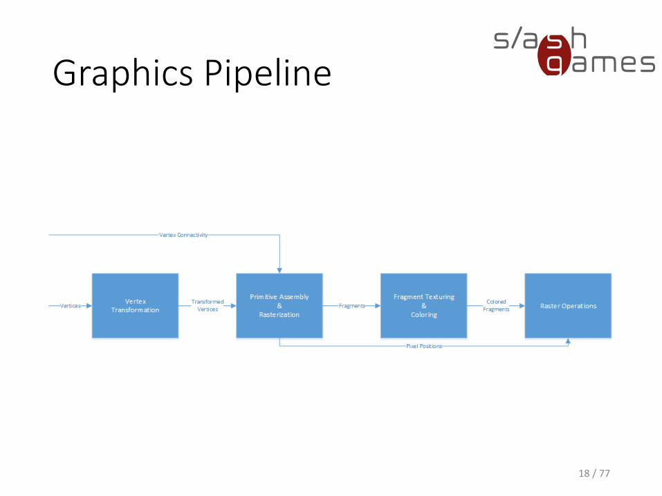
Graphics Pipeline
18 / 77
Pixel vs. Fragment
• Pixels represent the contents of the frame buffer at specific locations• Color
• Depth
• Fragments are the states required potentially to update particular pixels (“potential pixel”)
19 / 77
Fragment Data
• Pixel location
• Depth value
• Set of interpolated parameters derived from the transformed vertices that make up the particular geometric primitive used to generate the fragments• Color
• Specular color
• One or more texture coordinate sets
20 / 77
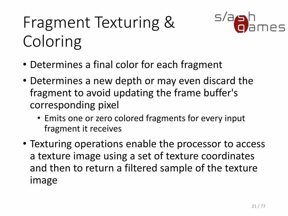
Fragment Texturing &Coloring• Determines a final color for each fragment
• Determines a new depth or may even discard the fragment to avoid updating the frame buffer's corresponding pixel• Emits one or zero colored fragments for every input
fragment it receives
• Texturing operations enable the processor to access a texture image using a set of texture coordinates and then to return a filtered sample of the texture image
21 / 77

Graphics Pipeline
22 / 77
Raster Operations
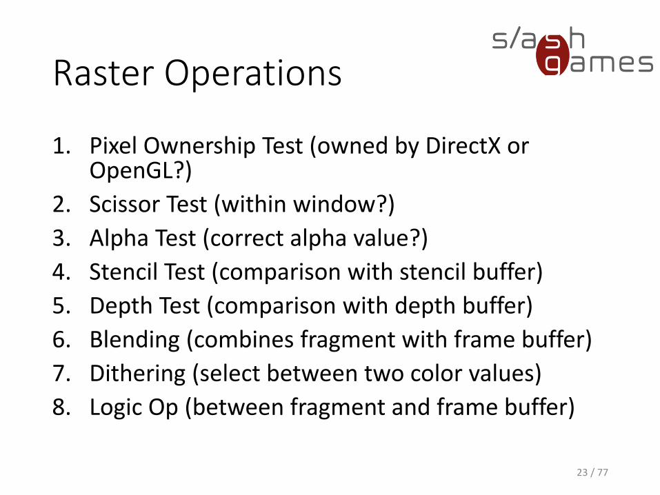
1. Pixel Ownership Test (owned by DirectX or OpenGL?)
2. Scissor Test (within window?)
3. Alpha Test (correct alpha value?)
4. Stencil Test (comparison with stencil buffer)
5. Depth Test (comparison with depth buffer)
6. Blending (combines fragment with frame buffer)
7. Dithering (select between two color values)
8. Logic Op (between fragment and frame buffer)
23 / 77
Hello World
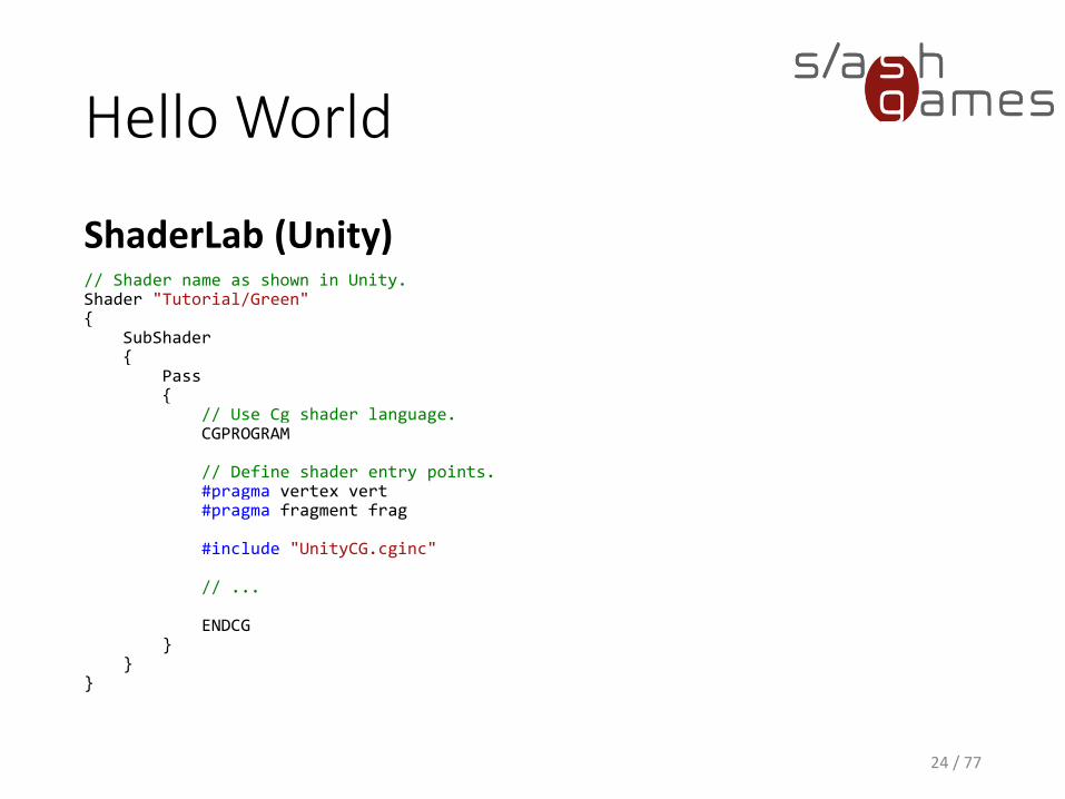
ShaderLab (Unity)
24 / 77
// Shader name as shown in Unity.Shader "Tutorial/Green"{
SubShader{
Pass{
// Use Cg shader language.CGPROGRAM
// Define shader entry points.#pragma vertex vert#pragma fragment frag
#include "UnityCG.cginc"
// ...
ENDCG}
}}
Hello World
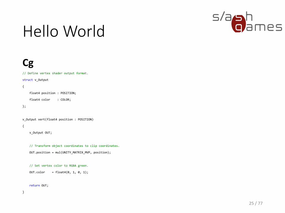
Cg
25 / 77
// Define vertex shader output format.
struct v_Output
{
float4 position : POSITION;
float4 color : COLOR;
};
v_Output vert(float4 position : POSITION)
{
v_Output OUT;
// Transform object coordinates to clip coordinates.
OUT.position = mul(UNITY_MATRIX_MVP, position);
// Set vertex color to RGBA green.
OUT.color = float4(0, 1, 0, 1);
return OUT;
}
Shader Semantics
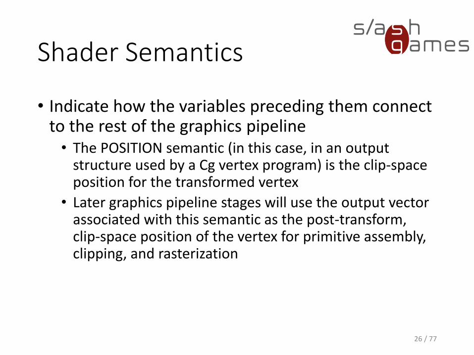
• Indicate how the variables preceding them connect to the rest of the graphics pipeline• The POSITION semantic (in this case, in an output
structure used by a Cg vertex program) is the clip-space position for the transformed vertex
• Later graphics pipeline stages will use the output vector associated with this semantic as the post-transform, clip-space position of the vertex for primitive assembly, clipping, and rasterization
26 / 77
Shader Semantics
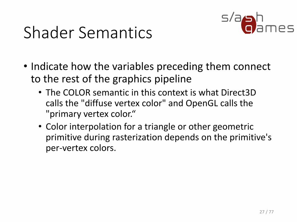
• Indicate how the variables preceding them connect to the rest of the graphics pipeline• The COLOR semantic in this context is what Direct3D
calls the "diffuse vertex color" and OpenGL calls the "primary vertex color.“
• Color interpolation for a triangle or other geometric primitive during rasterization depends on the primitive's per-vertex colors.
27 / 77
Hello World
Cg
28 / 77
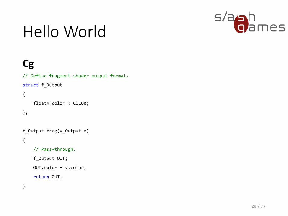
// Define fragment shader output format.
struct f_Output
{
float4 color : COLOR;
};
f_Output frag(v_Output v)
{
// Pass-through.
f_Output OUT;
OUT.color = v.color;
return OUT;
}
Hello World
29 / 77
Shader Parameters
ShaderLab (Unity)
30 / 77
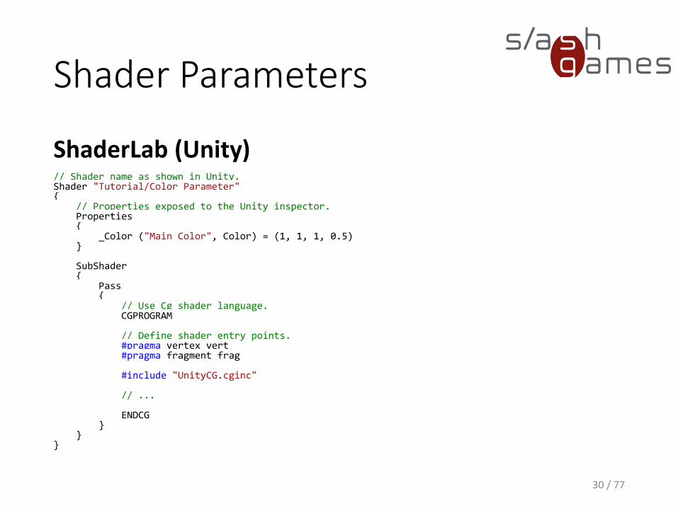
// Shader name as shown in Unity.Shader "Tutorial/Color Parameter"{
// Properties exposed to the Unity inspector.Properties{
_Color ("Main Color", Color) = (1, 1, 1, 0.5)}
SubShader{
Pass{
// Use Cg shader language.CGPROGRAM
// Define shader entry points.#pragma vertex vert#pragma fragment frag
#include "UnityCG.cginc"
// ...
ENDCG}
}}
Gotcha!
Usually, when a Cg program declares a variable as uniform, it conveys that the
variable's initial value comes from an environment that is external to the specified
Cg program.
In Unity (and RenderMan), the uniform storage modifier indicates variables whose values are constant over a shaded surface.
31 / 77
Shader Parameters
Cg
32 / 77
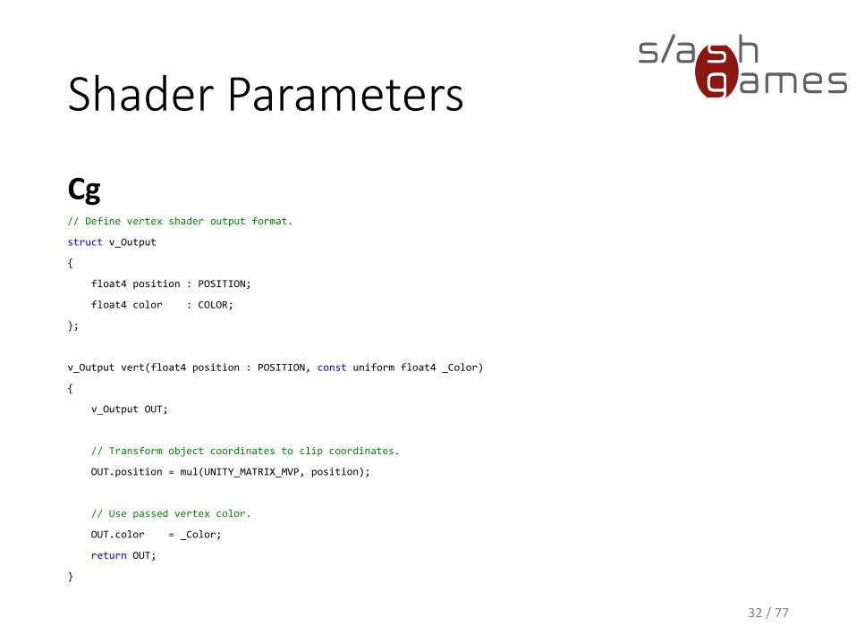
// Define vertex shader output format.
struct v_Output
{
float4 position : POSITION;
float4 color : COLOR;
};
v_Output vert(float4 position : POSITION, const uniform float4 _Color)
{
v_Output OUT;
// Transform object coordinates to clip coordinates.
OUT.position = mul(UNITY_MATRIX_MVP, position);
// Use passed vertex color.
OUT.color = _Color;
return OUT;
}
Shader Parameters
33 / 77
Texture Sampling
ShaderLab (Unity)
34 / 77
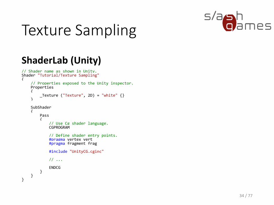
// Shader name as shown in Unity.Shader "Tutorial/Texture Sampling"{
// Properties exposed to the Unity inspector.Properties{
_Texture ("Texture", 2D) = "white" {} }
SubShader{
Pass{
// Use Cg shader language.CGPROGRAM
// Define shader entry points.#pragma vertex vert#pragma fragment frag
#include "UnityCG.cginc"
// ...
ENDCG}
}}
Texture Sampling
Cg
35 / 77
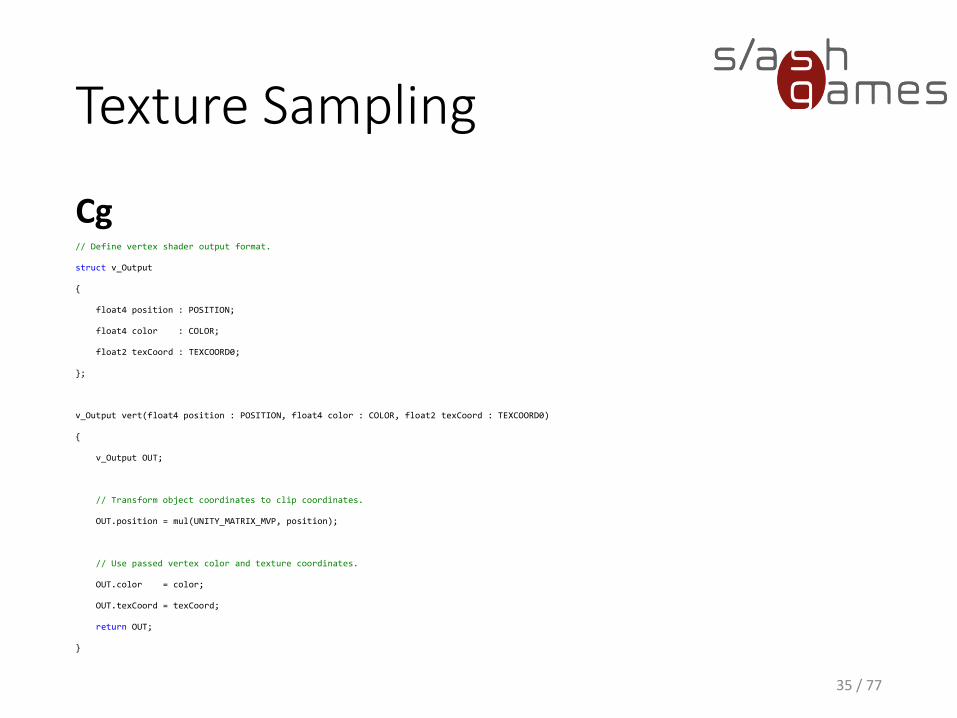
// Define vertex shader output format.
struct v_Output
{
float4 position : POSITION;
float4 color : COLOR;
float2 texCoord : TEXCOORD0;
};
v_Output vert(float4 position : POSITION, float4 color : COLOR, float2 texCoord : TEXCOORD0)
{
v_Output OUT;
// Transform object coordinates to clip coordinates.
OUT.position = mul(UNITY_MATRIX_MVP, position);
// Use passed vertex color and texture coordinates.
OUT.color = color;
OUT.texCoord = texCoord;
return OUT;
}
Texture Sampling
Cg
36 / 77
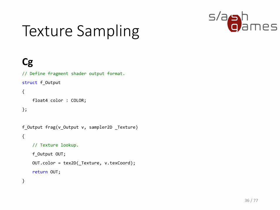
// Define fragment shader output format.
struct f_Output
{
float4 color : COLOR;
};
f_Output frag(v_Output v, sampler2D _Texture)
{
// Texture lookup.
f_Output OUT;
OUT.color = tex2D(_Texture, v.texCoord);
return OUT;
}
Texture Sampling
37 / 77
Texture Sampling
ShaderLab (Unity)
38 / 77
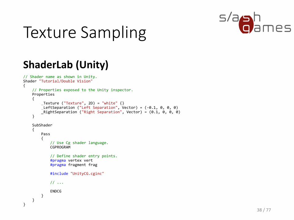
// Shader name as shown in Unity.Shader "Tutorial/Double Vision"{
// Properties exposed to the Unity inspector.Properties{
_Texture ("Texture", 2D) = "white" {} _LeftSeparation ("Left Separation", Vector) = (-0.1, 0, 0, 0) _RightSeparation ("Right Separation", Vector) = (0.1, 0, 0, 0)
}
SubShader{
Pass{
// Use Cg shader language.CGPROGRAM
// Define shader entry points.#pragma vertex vert#pragma fragment frag
#include "UnityCG.cginc"
// ...
ENDCG}
}}
Texture Sampling
Cg
39 / 77
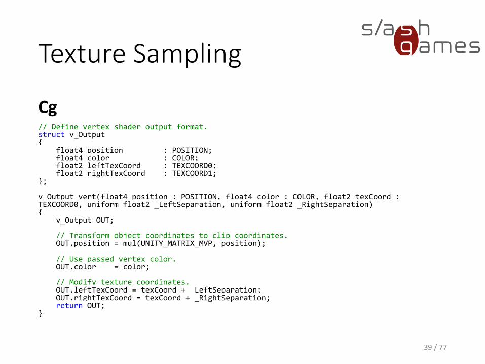
// Define vertex shader output format.struct v_Output{
float4 position : POSITION;float4 color : COLOR;float2 leftTexCoord : TEXCOORD0;float2 rightTexCoord : TEXCOORD1;
};
v_Output vert(float4 position : POSITION, float4 color : COLOR, float2 texCoord : TEXCOORD0, uniform float2 _LeftSeparation, uniform float2 _RightSeparation){
v_Output OUT;
// Transform object coordinates to clip coordinates.OUT.position = mul(UNITY_MATRIX_MVP, position);
// Use passed vertex color.OUT.color = color;
// Modify texture coordinates.OUT.leftTexCoord = texCoord + _LeftSeparation;OUT.rightTexCoord = texCoord + _RightSeparation;return OUT;
}
Texture Sampling
Cg
40 / 77
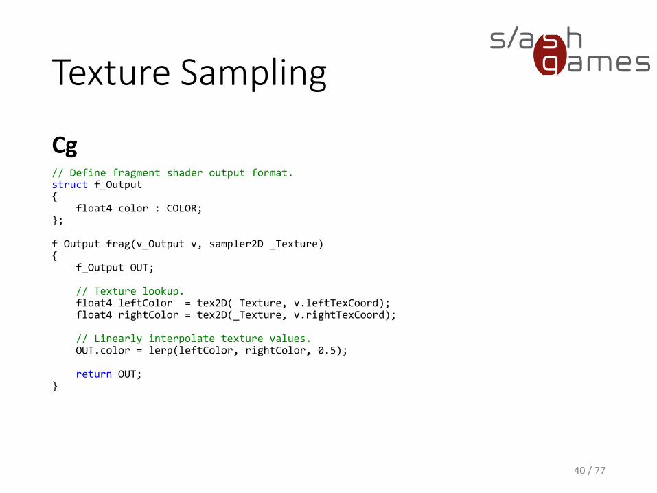
// Define fragment shader output format.struct f_Output{
float4 color : COLOR;};
f_Output frag(v_Output v, sampler2D _Texture){
f_Output OUT;
// Texture lookup.float4 leftColor = tex2D(_Texture, v.leftTexCoord);float4 rightColor = tex2D(_Texture, v.rightTexCoord);
// Linearly interpolate texture values.OUT.color = lerp(leftColor, rightColor, 0.5);
return OUT;}
Texture Sampling
41 / 77
42 / 77
OUT.position = mul(UNITY_MATRIX_MVP, position);
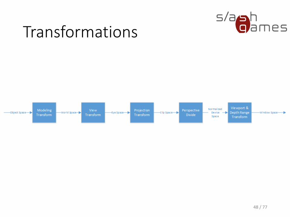
Transformations
• Graphics pipeline takes geometric data representing an object or scene in three dimensions and creates a two-dimensional image from it.
• Our application supplies the geometric data as a collection of vertices that form polygons, lines, and points.
• The resulting image typically represents what an observer or camera would see from a particular point of view.
43 / 77

Transformations
44 / 77
Object Space
• Applications specify vertex positions in a coordinate system known as object space (also called model space).
• When an artist creates a 3D model of an object, the artist selects a convenient orientation, scale, and position with which to place the model's constituent vertices.
45 / 77

Transformations
46 / 77
World Space
• Provides some absolute reference for all the objects in our scene
• How a world-space coordinate system is established is arbitrary• For example, we may decide that the origin of world
space is the center of our room.
• Objects in the room are then positioned relative to the center of the room and some notion of scale and orientation
47 / 77
Transformations
48 / 77
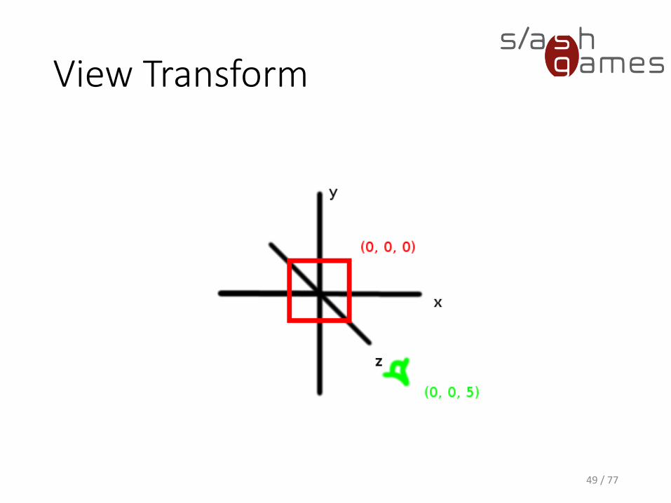
View Transform
49 / 77
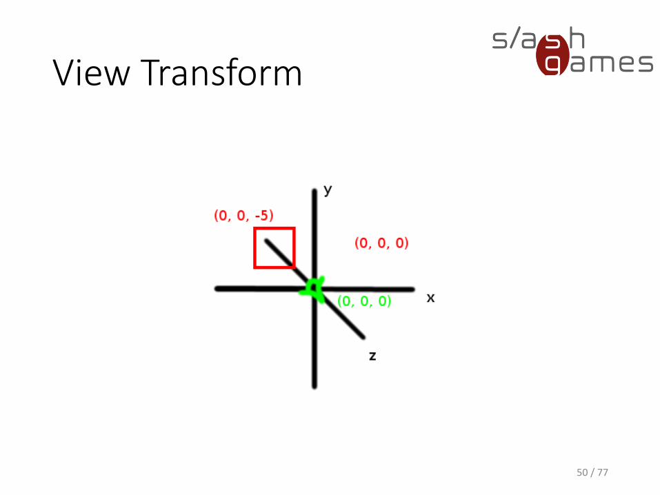
View Transform
50 / 77
Eye Space
• We want to look at our scene from a particular viewpoint (the "eye")
• In the coordinate system known as eye space (or view space), the eye is located at the origin of the coordinate system.
51 / 77

Transformations
52 / 77
Clip Space
• Axis-aligned cube containing the region of eye space where objects are viewable
• Also known as the view frustum
54 / 77

Transformations
55 / 77
Normalized Device Space
• All the visible geometric data lies in a cube with positions• between <-1, -1, -1> and <1, 1, 1> in OpenGL
• between <-1, -1, 0> and <1, 1, 1> in Direct3D
56 / 77

Transformations
57 / 77
Window Space
• Final coordinate system that is measured in pixels for x and y
• Determines the final image
• Scales the z value of the vertices into the range of the depth buffer for use in depth buffering
58 / 77
Basic Per-Vertex Lighting(Phong)• Color is computed as the sum of four lighting
contributions:• Emissive light represents light emitted or given off by a
surface.
• Ambient light accounts for light that has bounced around so much in the scene that it seems to come from everywhere.
• Diffuse light accounts for directed light reflected off a surface equally in all directions.
• Specular light represents light scattered from a surface predominantly around the mirror direction.
59 / 77
Emissive Light
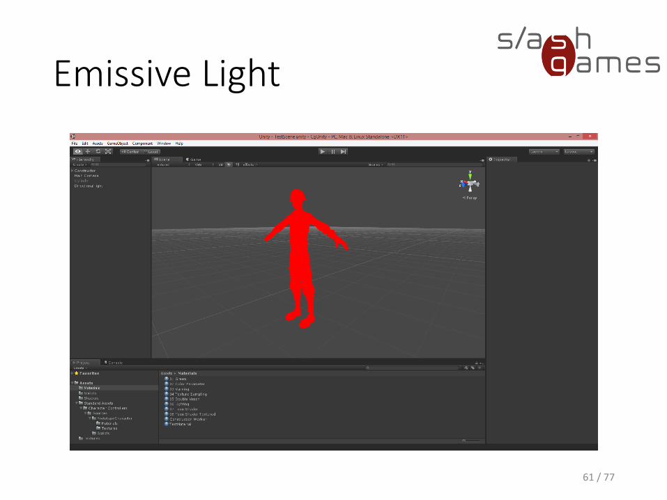
• RGB value that indicates the color of the emitted light
• Contribution is independent of all light sources• If we were to view an emissive material in a completely
dark room, it would appear to be this color
• Same all over the object
𝑒𝑚𝑖𝑠𝑠𝑖𝑣𝑒 = 𝐾𝑒
60 / 77
Emissive Light
61 / 77
Ambient Light
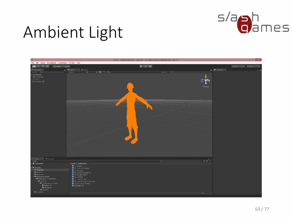
• Does not appear to come from any particular direction
• Does not depend on the light source position
• Affected by the global ambient lighting
𝑎𝑚𝑏𝑖𝑒𝑛𝑡 = 𝐾𝑎 × 𝑔𝑙𝑜𝑏𝑎𝑙𝐴𝑚𝑏𝑖𝑒𝑛𝑡
62 / 77
Ambient Light
63 / 77
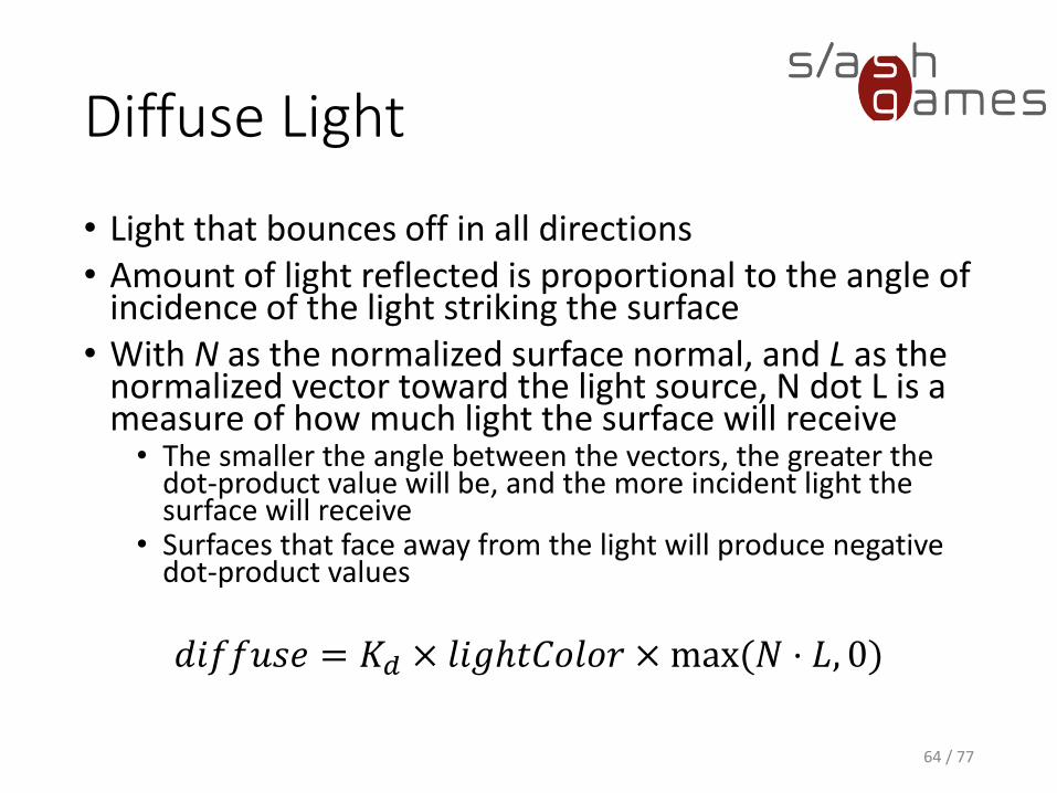
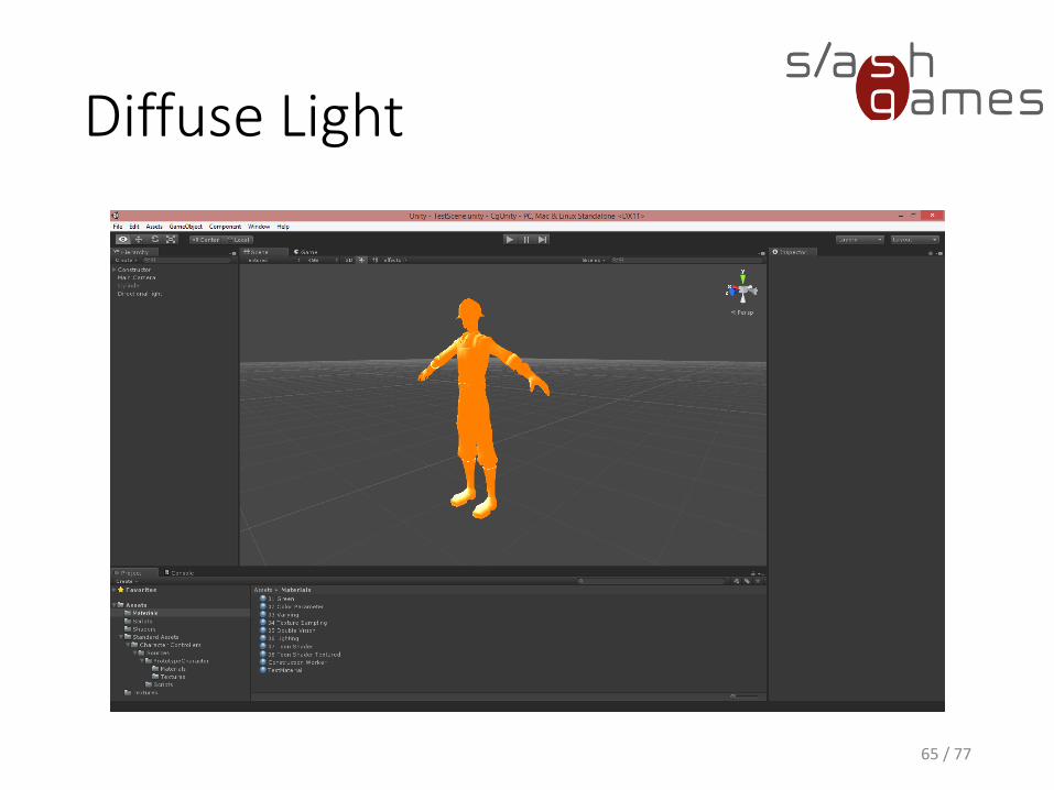
Diffuse Light
• Light that bounces off in all directions• Amount of light reflected is proportional to the angle of
incidence of the light striking the surface• With N as the normalized surface normal, and L as the
normalized vector toward the light source, N dot L is a measure of how much light the surface will receive• The smaller the angle between the vectors, the greater the
dot-product value will be, and the more incident light the surface will receive
• Surfaces that face away from the light will produce negative dot-product values
𝑑𝑖𝑓𝑓𝑢𝑠𝑒 = 𝐾𝑑 × 𝑙𝑖𝑔ℎ𝑡𝐶𝑜𝑙𝑜𝑟 × max(𝑁 ⋅ 𝐿, 0)
64 / 77
Diffuse Light
65 / 77
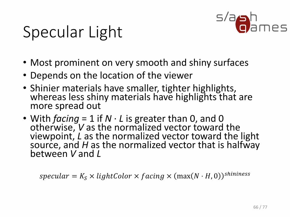
Specular Light
• Most prominent on very smooth and shiny surfaces• Depends on the location of the viewer• Shinier materials have smaller, tighter highlights,
whereas less shiny materials have highlights that are more spread out
• With facing = 1 if N · L is greater than 0, and 0 otherwise, V as the normalized vector toward the viewpoint, L as the normalized vector toward the light source, and H as the normalized vector that is halfway between V and L
𝑠𝑝𝑒𝑐𝑢𝑙𝑎𝑟 = 𝐾𝑆 × 𝑙𝑖𝑔ℎ𝑡𝐶𝑜𝑙𝑜𝑟 × 𝑓𝑎𝑐𝑖𝑛𝑔 × max 𝑁 ⋅ 𝐻, 0 𝑠ℎ𝑖𝑛𝑖𝑛𝑒𝑠𝑠
66 / 77
Specular Light
68 / 77
DEMO
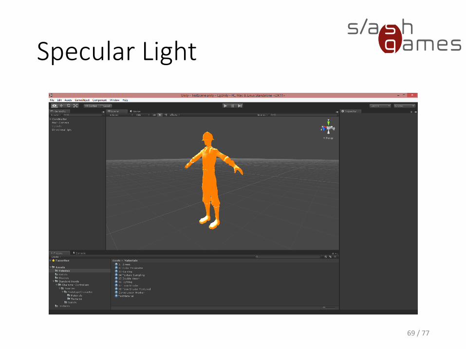
Specular Light
69 / 77
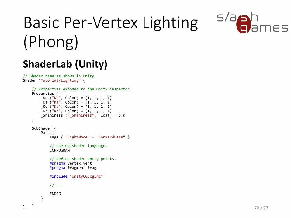
Basic Per-Vertex Lighting(Phong)ShaderLab (Unity)
70 / 77
// Shader name as shown in Unity.Shader "Tutorial/Lighting“ {
// Properties exposed to the Unity inspector.Properties {
_Ke ("Ke", Color) = (1, 1, 1, 1)_Ka ("Ka", Color) = (1, 1, 1, 1)_Kd ("Kd", Color) = (1, 1, 1, 1)_Ks ("Ks", Color) = (1, 1, 1, 1)_Shininess ("_Shininess", Float) = 5.0
}
SubShader {Pass {
Tags { "LightMode" = "ForwardBase“ }
// Use Cg shader language.CGPROGRAM
// Define shader entry points.#pragma vertex vert#pragma fragment frag
#include "UnityCG.cginc"
// ...
ENDCG}
}}
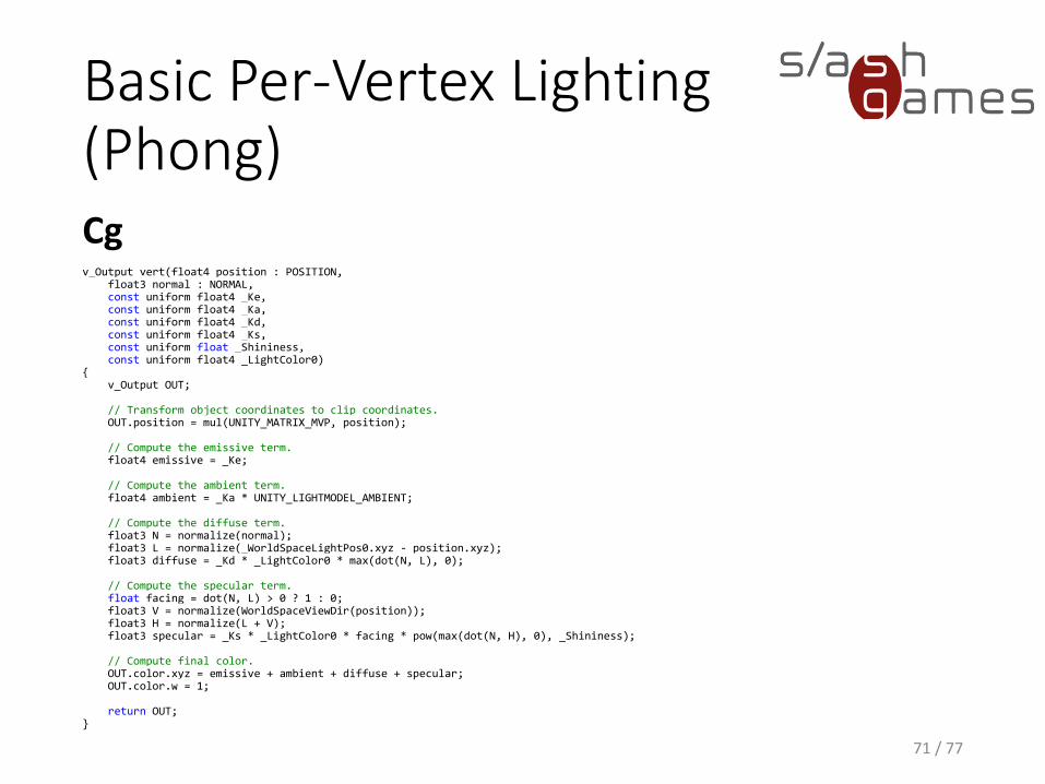
Basic Per-Vertex Lighting(Phong)Cg
71 / 77
v_Output vert(float4 position : POSITION,float3 normal : NORMAL,const uniform float4 _Ke,const uniform float4 _Ka,const uniform float4 _Kd,const uniform float4 _Ks,const uniform float _Shininess,const uniform float4 _LightColor0)
{v_Output OUT;
// Transform object coordinates to clip coordinates.OUT.position = mul(UNITY_MATRIX_MVP, position);
// Compute the emissive term.float4 emissive = _Ke;
// Compute the ambient term.float4 ambient = _Ka * UNITY_LIGHTMODEL_AMBIENT;
// Compute the diffuse term.float3 N = normalize(normal);float3 L = normalize(_WorldSpaceLightPos0.xyz - position.xyz);float3 diffuse = _Kd * _LightColor0 * max(dot(N, L), 0);
// Compute the specular term.float facing = dot(N, L) > 0 ? 1 : 0;float3 V = normalize(WorldSpaceViewDir(position));float3 H = normalize(L + V);float3 specular = _Ks * _LightColor0 * facing * pow(max(dot(N, H), 0), _Shininess);
// Compute final color.OUT.color.xyz = emissive + ambient + diffuse + specular;OUT.color.w = 1;
return OUT;}
Toon Shading
• Common and useful non-photorealistic rendering technique
• Shades objects with constant, sharply delineated colors
• Renderings look like cartoons without having to change how we represent our characters and objects (e.g. draw everything as 2D images)
72 / 77
Toon Shading
1. The diffuse shading needs to be represented by just two values: one for bright regions, and another for dark regions.
2. Specular highlights need to be identified and represented as a single color where their intensity is sufficiently high.
3. Objects need to be outlined to complete the cartoon look.
73 / 77
Toon Shading
Cg
74 / 77
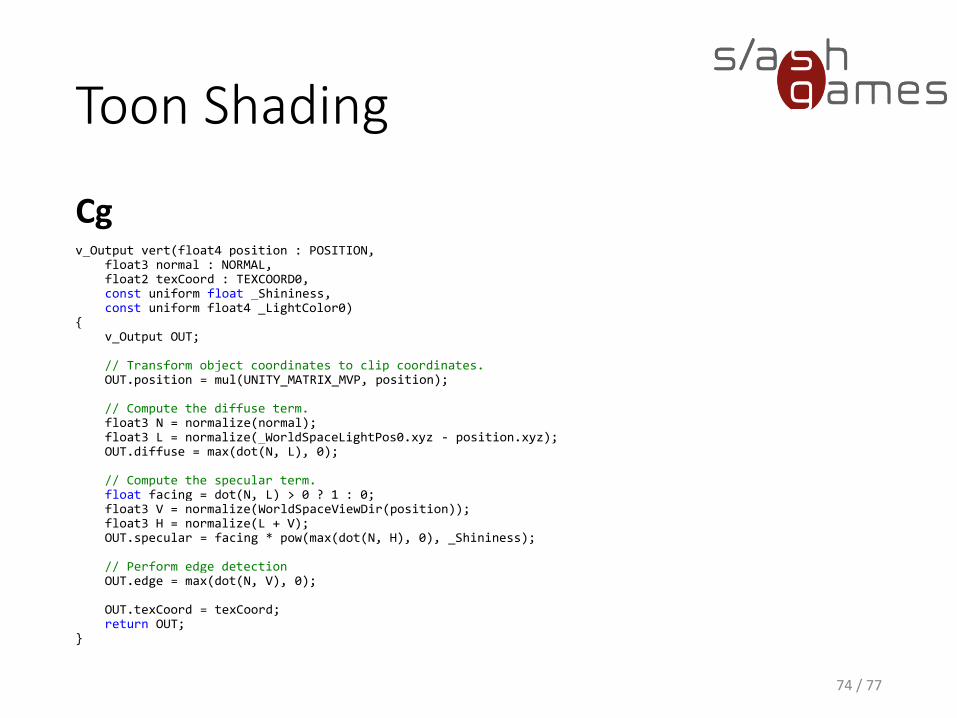
v_Output vert(float4 position : POSITION,float3 normal : NORMAL,float2 texCoord : TEXCOORD0,const uniform float _Shininess,const uniform float4 _LightColor0)
{v_Output OUT;
// Transform object coordinates to clip coordinates.OUT.position = mul(UNITY_MATRIX_MVP, position);
// Compute the diffuse term.float3 N = normalize(normal);float3 L = normalize(_WorldSpaceLightPos0.xyz - position.xyz);OUT.diffuse = max(dot(N, L), 0);
// Compute the specular term.float facing = dot(N, L) > 0 ? 1 : 0;float3 V = normalize(WorldSpaceViewDir(position));float3 H = normalize(L + V);OUT.specular = facing * pow(max(dot(N, H), 0), _Shininess);
// Perform edge detectionOUT.edge = max(dot(N, V), 0);
OUT.texCoord = texCoord;return OUT;
}
Toon Shading
Cg
75 / 77
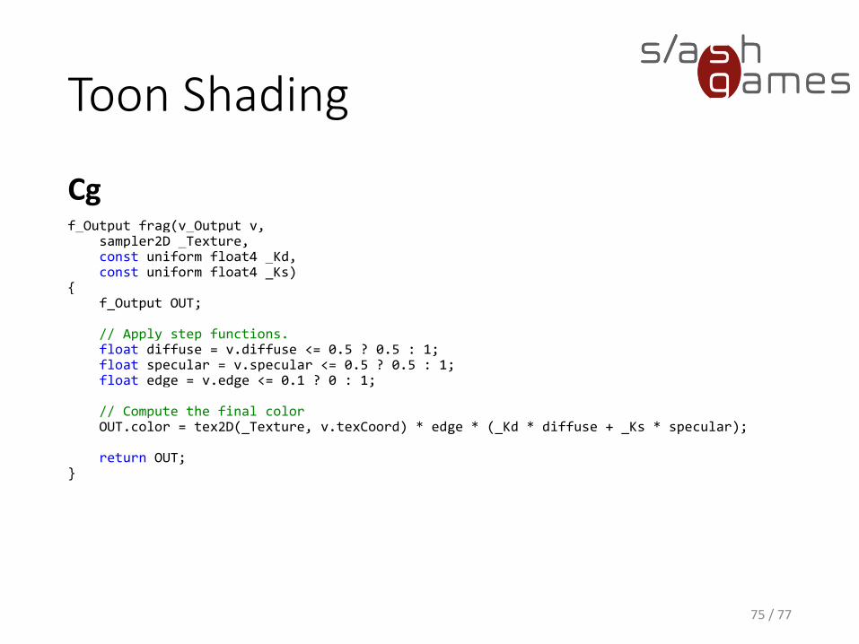
f_Output frag(v_Output v,sampler2D _Texture,const uniform float4 _Kd,const uniform float4 _Ks)
{f_Output OUT;
// Apply step functions.float diffuse = v.diffuse <= 0.5 ? 0.5 : 1;float specular = v.specular <= 0.5 ? 0.5 : 1;float edge = v.edge <= 0.1 ? 0 : 1;
// Compute the final colorOUT.color = tex2D(_Texture, v.texCoord) * edge * (_Kd * diffuse + _Ks * specular);
return OUT;}
Toon Shading
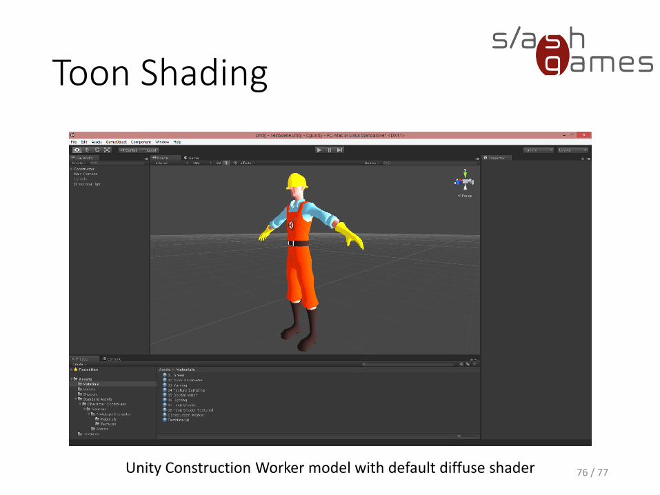
76 / 77Unity Construction Worker model with default diffuse shader
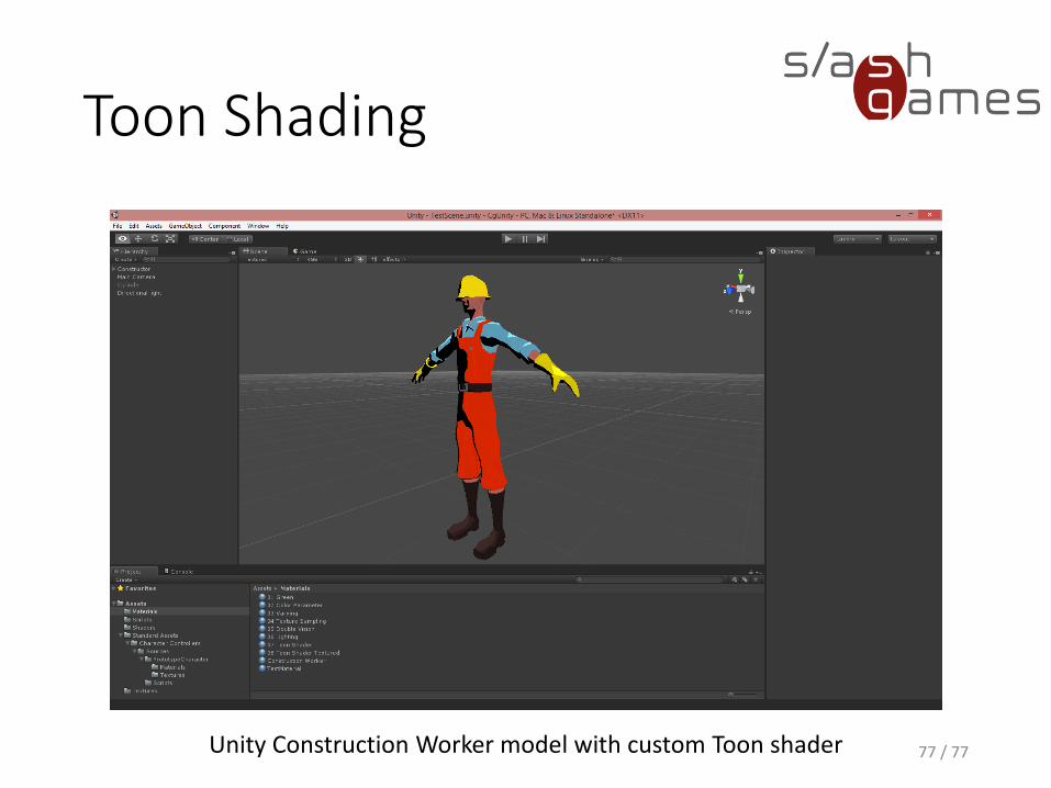
Toon Shading
77 / 77Unity Construction Worker model with custom Toon shader
Team Colors
78 / 77
DEMO
References
• Fernando, Kilgard. The Cg Tutorial. Addison-Wesley, March 8, 2003.
• Blythe. Per-Fragment Operations. https://www.opengl.org/documentation/specs/version1.1/glspec1.1/node93.html, 1997.
• Unity Technologies. Vertex and Fragment Shader Examples.http://docs.unity3d.com/Manual/SL-VertexFragmentShaderExamples.html, 2016.
• Unity Technologies. Accessing shader properties in Cg.http://docs.unity3d.com/Manual/SL-PropertiesInPrograms.html, 2016.
• Unity Technologies. Built-in shader include files.http://docs.unity3d.com/Manual/SL-BuiltinIncludes.html, 2016.
79 / 77
5 Minute Review Session
• What are the major stages of the graphics pipeline? In what order are the stages arranged?
• Where do vertex and fragment programs fit into the pipeline?
• What is a vertex? What is a fragment? Distinguish a fragment from a pixel.
• What are shader semantics?
• What are shader parameters?
• Which transformations happen in the graphics pipeline from geometric data in three dimensions and the final two-dimensional image?
• The Phong shading model computes final color as the sum of four lighting contributions – which ones?