Embed Size (px)
Citation preview
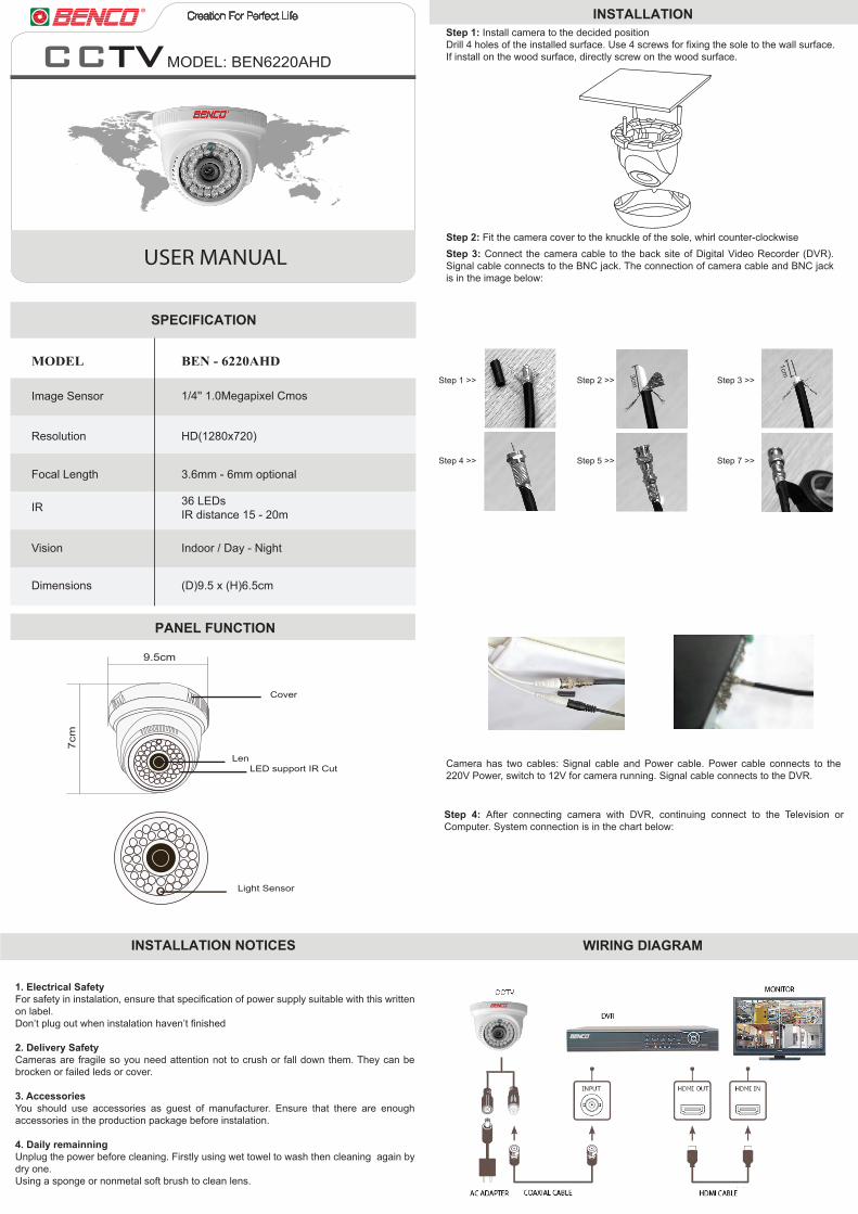
USER MANUAL
MODEL: BEN6220AHD
MODEL BEN - 6220AHD
SPECIFICATION
PANEL FUNCTION
Resolution HD(1280x720)
Focal Length
IR
Vision
Dimensions (D)9.5 x (H)6.5cm
Indoor / Day - Night
36 LEDsIR distance 15 - 20m
Image Sensor
3.6mm - 6mm optional
1/4'' 1.0Megapixel Cmos
Cover
LED support IR Cut
Light Sensor
Len
INSTALLATION NOTICES WIRING DIAGRAM
1. Electrical SafetyFor safety in instalation, ensure that specification of power supply suitable with this written on label.Don’t plug out when instalation haven’t finished
2. Delivery SafetyCameras are fragile so you need attention not to crush or fall down them. They can be brocken or failed leds or cover.
3. AccessoriesYou should use accessories as guest of manufacturer. Ensure that there are enough accessories in the production package before instalation.
4. Daily remainningUnplug the power before cleaning. Firstly using wet towel to wash then cleaning again by dry one.Using a sponge or nonmetal soft brush to clean lens.
Step 2: Fit the camera cover to the knuckle of the sole, whirl counter-clockwiseStep 3: Connect the camera cable to the back site of Digital Video Recorder (DVR). Signal cable connects to the BNC jack. The connection of camera cable and BNC jack is in the image below:
INSTALLATIONStep 1: Install camera to the decided position Drill 4 holes of the installed surface. Use 4 screws for fixing the sole to the wall surface.If install on the wood surface, directly screw on the wood surface.
Camera has two cables: Signal cable and Power cable. Power cable connects to the 220V Power, switch to 12V for camera running. Signal cable connects to the DVR.
Step 4: After connecting camera with DVR, continuing connect to the Television or Computer. System connection is in the chart below:
Step 1 >>
Step 4 >> Step 5 >> Step 7 >>
Step 2 >> Step 3 >>
9.5cm
7cm
3cm
1cm