Embed Size (px)
Citation preview

PRESENTED BY:Debasish Das DG/ME/B/35/14Ujjal Das DG/ME/B/36/14Kishan Choudhry DG/ME/B/38/14Beacon Debbarma DG/ME/B/40/14Mritunjoy Rudra Paul DG/ME/B/43/14Prasun Debnath DG/ME/B/44/14Susandeep Saha DG/ME/B/45/14 Swagata Sarkar DG/ME/B/46/14Sourav Chowhan DG/ME/B/47/14

Engine Design

Parts Of An Engine.PISTON
SPARK PLUG CAM SHAFT
VALVE
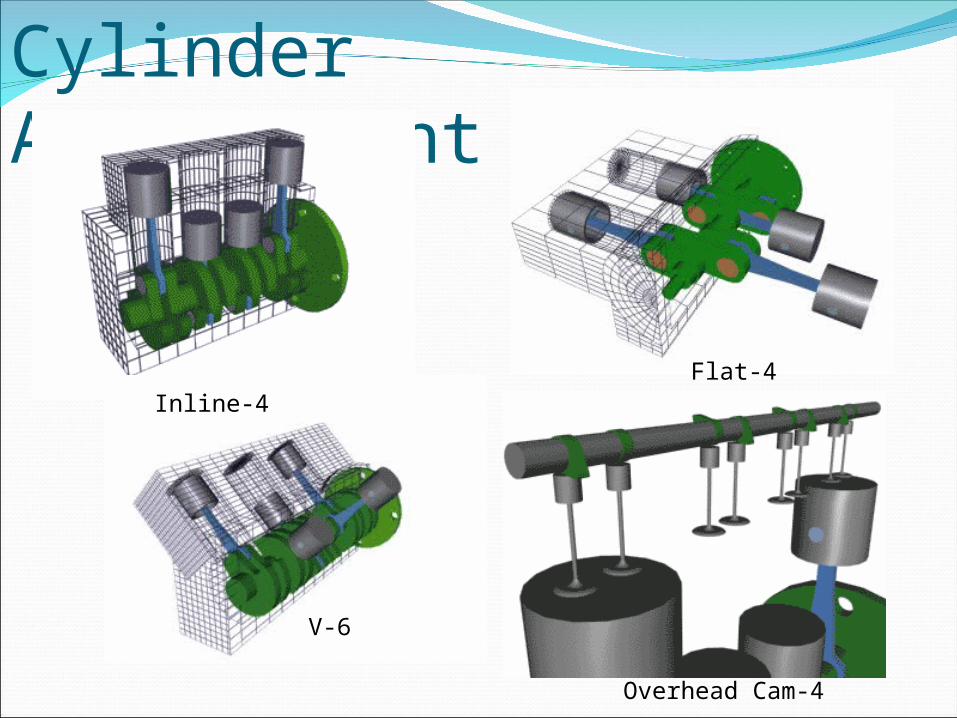
Cylinder Arrangement
Inline-4
V-6
Flat-4
Overhead Cam-4
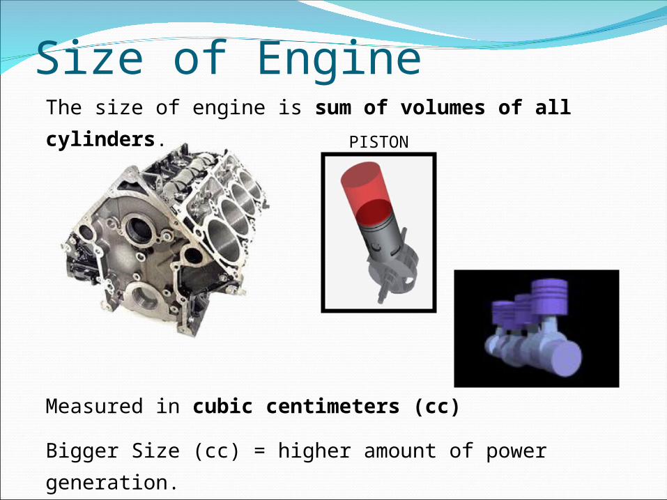
The size of engine is sum of volumes of all cylinders.
Measured in cubic centimeters (cc)
Bigger Size (cc) = higher amount of power generation.
Size of Engine
PISTON
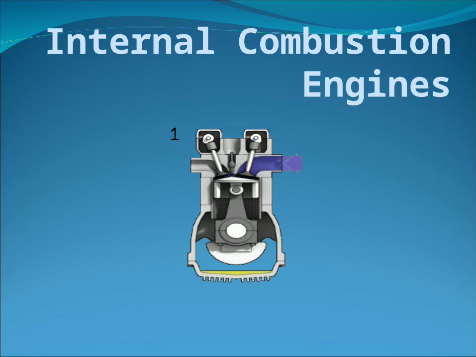
Internal Combustion Engines
Topics covered I.C. Engines Introduction of I.C. Engines Classification of I.C. EnginesConstructional details of I.C. Engine Comparison of Two-stroke and Four-stroke Cycle EngineWorking of two stroke and four stroke diesel and petrol enginesComparison of Petrol and Diesel Engine
Introduction of I.C. Engine Heat Engines - A machine or device which derives heat from the
combustion of fuel and converts part of this energy into mechanical work is called a heat engine. Heat engines may be classified into two main classes as follows:
1. External combustion engines 2. Internal combustion engines.

Introduction of I.C. Engine Internal Combustion Engines – In this case, combustion of fuel with oxygen of the air occurs
within the cylinder of the engine. The internal combustion engines group includes engines employing mixtures of combustible gases and air, known as gas engines, those using lighter liquid fuel or spirit known as petrol engines and those using heavier liquid fuels, known as oil, compression ignition or diesel engines.
The important applications of I.C. engines are: (i) Road vehicles, locomotives, ships and aircraft, (ii) Portable standby units for power generation in case of scarcity of electric power, (iii) Extensively used in farm tractors, lawn movers, concrete mixing devices and motor boats.

Classification of I.C. Engines The internal combustion engines may be classified in the
following ways: 1. According to the type of fuel used a) Petrol engines, b) Diesel engines, and c) Gas engines. 2. According to the method of igniting the fuel a) Spark ignition engines, and b) Compression ignition engines. 3. According to the number of strokes per cycle a) Four stroke cycle engines, and b) Two stroke cycle engines. 4. According to the cycle of operation a) Otto cycle engines, b) Diesel cycle engines, and c) Dual cycle engines.

Classification of I.C. Engines 5. According to the speed of the engine
a) Slow speed engines, b) Medium speed engines, and
c) High speed engines.
6. According to the cooling system
a) Air-cooled engines, and b) Water-cooled engines.
7. According to the method of fuel injection
a) Carburettor engines, and b) Air injection engines.
8. According to the number of cylinders
a) Single cylinder engines, and b) Multi-cylinder engines.

Classification of I.C. Engines 9. According to the arrangement of cylinders a) Vertical engines, b) Horizontal engines, c) Radial engines,
d) In-line multi-cylinder engines, e) V-type multi-cylinder engines, f) Opposite-cylinder engines, and g) Opposite-piston engines. 10. According to the valve mechanism a) Overhead valve engines, and b) Side valve engines. 11. According to the method of governing a) Hit and miss governed engines, b) Quantitatively governed engines, and Qualitatively governed engines.
Basic Idea of I.C. Engines The basic idea of internal combustion engine is shown in Fig.
(Basic idea of I.C. engine). The cylinder which is closed at one end is filled with a mixture of fuel and air. As the crankshaft turns it pushes cylinder. The piston is forced up and compresses the mixture in the top of the cylinder. The mixture is set alight and, as it burns, it creates a gas pressure on the piston, forcing it down the cylinder.
This motion is shown by arrow ‘1’. The piston pushes on the rod which pushes on the crank. The crank is given rotary (turning) motion as shown by the arrow ‘2’. The flywheel fitted on the end of the crankshaft stroes energy and keeps the crank turning steadily.

Fig. Basic idea of I.C. engine
Constructional details of I.C. Engines A cross-section of an air-cooled I.C. engine with principal parts
is shown in Fig. (Air-cooled I.C. engine). A. Parts common to both Petrol and Diesel engine: 1. Cylinder, 2. Cylinder head, 3. Piston, 4. Piston rings, 5. Gudgeon pin, 6. Connecting rod, 7. Crankshaft, 8. Crank, 9. Engine bearing, 10. Crank case. 11. Flywheel, 12. Governor, 13. Valves and valve operating mechanism. B. Parts for Petrol engines only: 1. Spark plug, 2. Carburettor, 3. Fuel pump. C. Parts for Diesel engine only : 1. Fuel pump, 2. Injector.
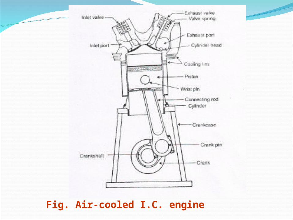
Fig. Air-cooled I.C. engine

Constructional details of I.C. Engines
The details of the I.C. Engine parts are: 1. Cylinder - It is one of the most important part of the engine, in which the piston moves to and fro in order to develop power. The engine cylinder has to withstand a high pressure (more than 50 bar) and temperature (more than 2000 deg C). Thus the material for the engine cylinder should be such that it can retain sufficient strength at such a high pressure and temperature. For ordinary engines, the cylinder is made of ordinary cast iron. But for heavy duty engines, it is made of steel alloys or aluminum alloys.
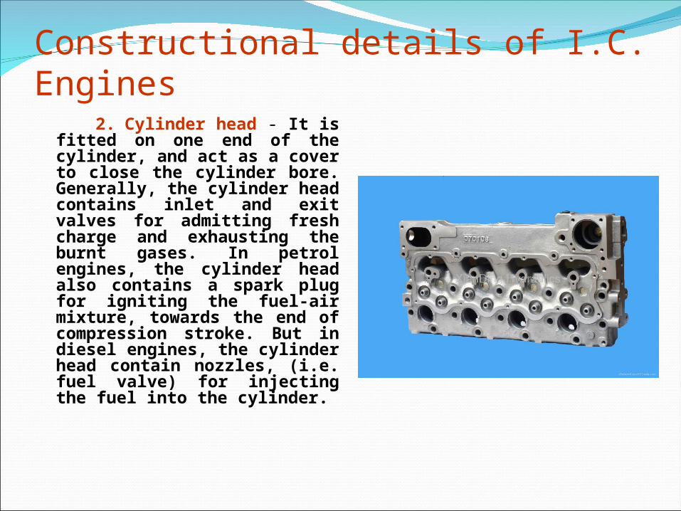
Constructional details of I.C. Engines 2. Cylinder head - It is fitted on
one end of the cylinder, and act as a cover to close the cylinder bore. Generally, the cylinder head contains inlet and exit valves for admitting fresh charge and exhausting the burnt gases. In petrol engines, the cylinder head also contains a spark plug for igniting the fuel-air mixture, towards the end of compression stroke. But in diesel engines, the cylinder head contain nozzles, (i.e. fuel valve) for injecting the fuel into the cylinder.
Constructional details of I.C. Engines (contd..)
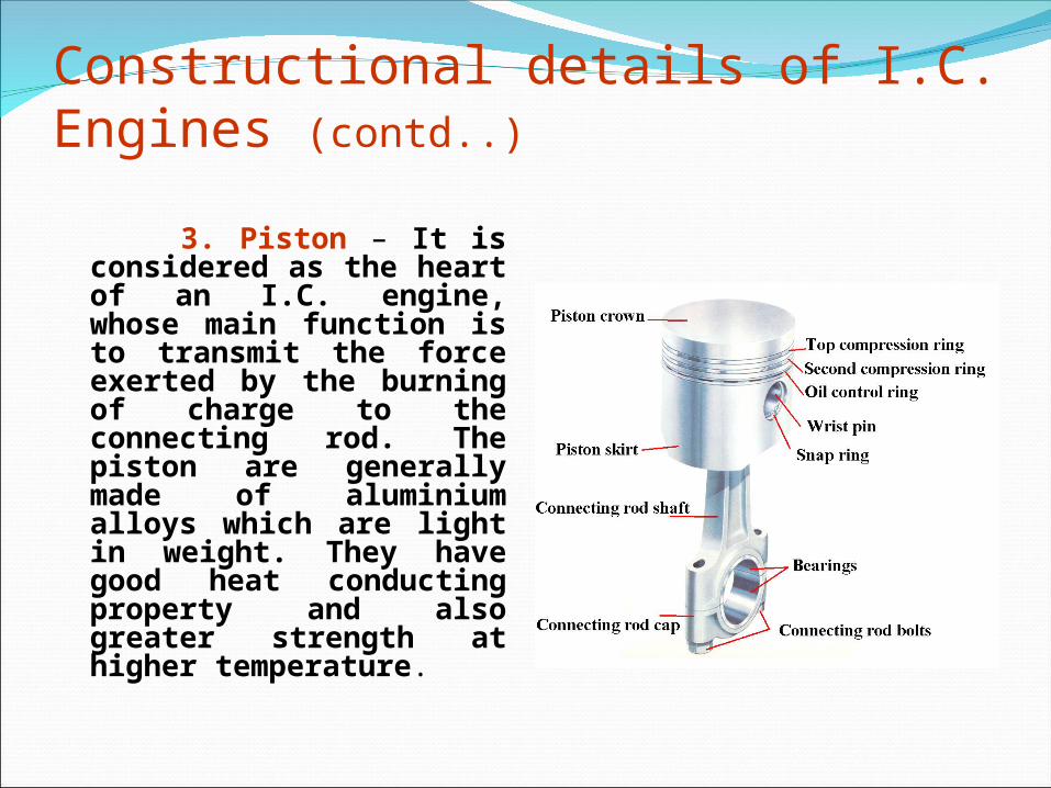
3. Piston – It is considered as the heart of an I.C. engine, whose main function is to transmit the force exerted by the burning of charge to the connecting rod. The piston are generally made of aluminium alloys which are light in weight. They have good heat conducting property and also greater strength at higher temperature.

Constructional details of I.C. Engines
4. Piston rings – These are circular rings and made of special steel alloys which retain elastic properties even at high temperatures. Generally, there are two sets of rings mounted for the piston. The function of the upper rings is to provide air tight seal to prevent leakage of the burnt gases into the lower portion. Similarly, the function of the lower rings is to provide effective seal to prevent leakage of the oil into the engine cylinder.

Constructional details of I.C. Engines 5. Connecting rod – It is a
link between the piston and crankshaft, whose main function is to transmit force from the piston to the crankshaft. The upper (i.e. smaller) end of the connecting rod is fitted to the piston and the lower (i.e. bigger) end of the crank.
The special steel alloys or aluminium alloys are used for connecting rods

Constructional details of I.C. Engines 6. Crankshaft – It is considered
as the backbone of an I.C. engine whose function is to covert the reciprocating motion of the piston into the rotary motion with the help of connecting rod. This shaft contains one or more eccentric portions called cranks.
Special steel alloys are used for
the manufacture of crankshaft.

Constructional details of I.C. Engines
7. Crank case – It is a cast iron case, which holds the cylinder and crankshaft of an I.C. engine. It also serves as a sump for the lubricating oil. The lower portion of the crank case is known as bed plate, which is fixed with the help of bolts.

Constructional details of I.C. Engines
8. Flywheel – It is a big wheel, mounted on the crankshaft, whose function is to maintain its speed constant. It is done by storing excess energy during power stroke, which, is returned during other stroke.

Four-stroke Cycle In a four-stroke engine, the
working cycle is completed in four strokes of the piston or two revolutions of the crankshaft. This is achieved by carrying out suction, compression, expansion and exhaust processes in each stroke.
Sequence of Operation The sequence of operation in a cycle are as follows: 1. Suction stroke – In this stroke, the fuel vapour in correct
proportion, is applied to the engine cylinder. 2. Compression stroke –. In this stroke, the fuel vapour is
compressed in the engine cylinder. 3. Expansion stroke – In this stroke, the fuel vapour is fired just
before the compression is complete. It results in the sudden rise of pressure, due to expansion of the combustion products in the engine cylinder. This sudden rise of pressure pushes the piston with a great force, and rotates the crankshaft. The crankshaft, in turn, drives the machine connected to it.
4. Exhaust stroke – In this stroke, the burnt gases (or combustion products) are exhausted from the engine cylinder, so as to make space available for the fresh fuel vapour.
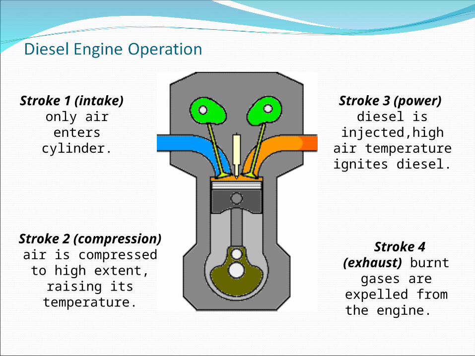
Stroke 1 (intake) only
air enters cylinder.
Stroke 2 (compression) air is compressed to high extent, raising its
temperature.
Stroke 3 (power) diesel is injected,high air
temperature ignites diesel.
Stroke 4 (exhaust) burnt
gases are expelled from the
engine.

Diesel Engine OperationA Diesel engines operation sequence
is as follows:
Stroke 1 (intake) – only air enters
cylinder.
Stroke 2 (compression) – air is
compressed to high extent, raising
temperature.
Stroke 3 (power) – diesel is
injected, high air temperature
ignites diesel.
Stroke 4 (exhaust) – burnt gases
are expelled from the engine.
Comparison of Two-stroke and Four-stroke Cycle
Engine Following are the advantages and disadvantages of two-stroke
cycle engines over four-stroke cycle engines: Advantages 1. A two stroke cycle engine gives twice the number of power
strokes than the four stroke cycle engine at the same engine speed.
2. For the same power developed, a two-stroke cycle engine is lighter, less bulky and occupies less floor area.
3. As the number of working strokes in a two-stroke cycle engine are twice than the four-stroke cycle engine, so the turning moment of a two-stroke cycle engine is more uniform. Thus it makes a two-stroke cycle engine to have a lighter flywheel and foundations. This also leads to a higher mechanical efficiency of a two-stroke cycle engine.

Comparison of Two-stroke and Four-stroke Cycle Engine (contd..) 4. The initial cost of a two-stroke cycle engine is considerably
less than a four-stroke cycle engine.
5. The mechanism of a two-stroke cycle engine is much simpler than a four-stroke cycle engine.
6. The two-stroke cycle engines are much easier to start.
Disadvantages
1. Thermal efficiency of a two-stroke cycle engine is less than that a four-stroke cycle engine.

Comparison of Two-stroke and Four-stroke Cycle Engine (contd..) 2. Overall efficiency of a two-stroke cycle engine is also less
than that of a four-stroke cycle engine because in a two-stroke cycle, inlet and exhaust ports remain open simultaneously for sometime. A small quantity of charge is lost from the engine cylinder.
3. In case of a two-stroke cycle engine, the number of power strokes are twice as those of a four-stroke cycle engine. Thus the capacity of the cooling system must be higher. There is a greater wear and tear in a two-stroke cycle engine.
4. The consumption of lubricating oil is large in a two-stroke cycle engine because of high operating temperature.
5. The exhaust gases in a two-stroke cycle engine creates noise, because of short time available for their exhaust.

Comparison of Petrol and Diesel EnginesPetrol Engines
1. A petrol engine draws a mixture of petrol and air during suction stroke.
2. The carburettor is employed to mix air and petrol in the required proportion and to supply it to the engine during suction stroke.
3. Pressure at the end of compression is about 10 bar.
4. The charge (i.e. petrol and air mixture) is ignited with the help of spark plug.
Diesel Engines A diesel engine draws only air
during suction stroke.
The injector or atomiser is employed to inject the fuel at the end of combustion stroke.
Pressure at the end of compression is about 35 bar.
The fuel is injected in the form of fine spray. The temperature of the compressed air is sufficiently high to ignite the fuel.
Comparison of Petrol and Diesel Engines5. The combustion of the fuel takes
place at constant volume. It works on Otto cycle.
6. A petrol engine has compression ratio from 6 to 10.
7. The starting is easy due to low compression ratio.
8. As the compression ratio is low, the petrol engines are lighter and cheaper.
9. The running cost of a petrol engine is high because of the higher cost of petrol.
The combustion of the fuel takes place at constant pressure. It works on Diesel cycle.
A diesel engine has compression ratio from 15 to 25.
The starting is difficult due to high compression ratio.
As the compression ratio is high, the diesel engines are heavier and costlier.
The running cost of diesel engine is low because of the lower cost of diesel.
Comparison of Petrol and Diesel Engines10. The maintenance cost is less.11. The thermal efficiency is about
26%.12. Overheating trouble is more due
to low thermal efficiency.13. These are high speed engines.
14. The petrol engines are generally employed in light duty vehicle such as scooters, motorcycles and cars. These are also used in aeroplanes.
The maintenance cost is more. The thermal efficiency is about
40%. Overheating trouble is less due to
high thermal efficiency. These are relatively low speed
engines. The diesel engines are generally
employed in heavy duty vehicles like buses, trucks, and earth moving machines.