Embed Size (px)
Citation preview

Satellite Communication ConceptsSatellite Communication Concepts

2
Copyright NoticeCopyright Notice
iDirect Technologies Technical Training ManualCopyright © 2002; 2004, iDirect, Inc. All rights reserved. This training material may not be reproduced, in part or in whole, without the permission of iDirect, Inc. All other brands or product names are trademarks or registered trademarks of their respective holders.Printed in the USA.No part of this work covered by copyright may be reproduced in any form. Reproduction, adaptation, or translation without prior written permission is prohibited, except as allowed under the copyright laws.This publication is provided by iDirect Technologies as-is without warranty of any kind, either express or implied, including, but not limited to, the implied warranties or conditions of merchantability or fitness for a particular purpose. iDirect Technologies shall not be liable for any errors or omissions which may occur in this publication, nor for incidental or consequential damages of any kind resulting from the furnishing, performance, or use of this publication.Information published here is current or planned as of the date of publication of this document. Because we are improving and adding features to our products continuously, the information in this document is subject to change without notice.

3
Satellite Communications Concepts Satellite Communications Concepts --ObjectivesObjectives
Discuss the advantages of Satellite Communications
Explain the principals behind the use of Geo-synchronous (GEO) satellites
Examine a typical satellite link
Describe the different frequency bands used within a satellite network
Describe the various components of the satellite network hardware
Discuss various Satellite Communications terminology

4
Deciding On Satellite Communications ?Deciding On Satellite Communications ?
Geographical Coverage Unsurpassed
Minimal ‘line-of-site’ difficulties
Extremely reliable (99.9% Up time)
Extremely Reliable Data Broadcast or Multicast
Single Vendor Typically
Easy Remote Site Deployment
Supports multiple applications:
Streaming Video & Audio applications
Data applications
Voice applications; Voice Over IP

5
Why Satellite Communications ?Why Satellite Communications ?Added AdvantagesAdded Advantages
Ideally suited for point-to-multipoint and large distributed networks
Capable of asymmetrical bandwidth
A single point of management allows for easier traffic analysis/management
Operational Low Bit Error Rate (BER); typically >10-8 (iDirect >10-9)
Capable of simultaneous delivery of data to an unlimited number of remotes
Independence from typical telephone infrastructure
Private Network capabilities
6
Satellite OrbitsSatellite Orbits
Geographically-synchronous Earth Orbit (GEO)
Orbital period = Earth's rotation (23h 56m 4sec)
Orbit directly over equator – 0o Latitude
Orbital position measured by degrees of Longitude
Satellite orbit would weave figure-eights around a point on the ecliptic when viewed from the ground
Alternatives are:
Medium Earth Orbit (MEO)
Low Earth Orbit (LEO)
Polar Orbit, using the North/South Pole as reference

7
Geosynchronous Earth Orbit (GEO)Geosynchronous Earth Orbit (GEO)
Never Placed innon-Equatorial Orbit
EQUATOR
22,240 Miles35,790 Km
2o spacing916 miles1,475 km
Degrees of Longitude
Orbital Plane(known as “Clark Belt”)
164,870 miles265,490 km
6,870 mph11,060 kph
Orbital Circumference:
Orbital Velocity:
ALL Geosynchronous Satellites are Geostationary, meaningthey orbit in fixed positions over the EQUATOR (0o Latitude).Therefore, position is determined & reported in L/ONGITUDE.

8
Propagation DelayPropagation Delay
GeoSynchronous OrbitPropagation Delay
Speed of Light186,282 mps299,762 kms
Therefore: 22240/186282 = .119sec 35,790/299762= .119sec, or
120ms Uplink delay+ 120ms Downlink delay
240ms Total delay, one way
Delay for both Outboundand Inbound (IP ‘Ping’)Total Round-trip Delay of 480ms
Satellite Altitude22,240 miles35,790 Km
Repeater

9
Frame Start Delay (FSD)Frame Start Delay (FSD)
GeoSynchronous OrbitFrame Start Delay (FSD)
Repeater
Each earth station location has a unique distance from a geostationary satellite based on its Geographic (GEO) Location
Each sites GEO Location is a uniquely physical position on the earth, given in geographic coordinates as degrees, minutes and seconds of Latitude & Longitude in a given hemisphere
Location ‘A’ is found to be at a different distance from a geostationary satellite (closer in this case) than site ‘B’ or ‘C’, therefore, for synchronized timing, it must be delayed ‘longer’.
A unique Frame Start Delay (FSD) is required for each earth station location
The FSD is calculated based on three factors: the GEO Location of the teleport, the satellite & the remote site
The FSD is that transmission delay associated with an earth station geo-location such that the signal arrives at the satellite timed to eliminate interference with other earth stations
Bd AB
Ad
Equator
C
Cd>Bd>Ad
10
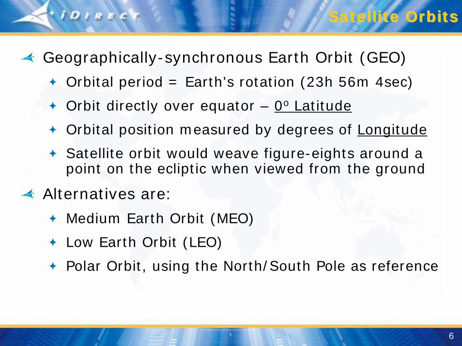
Terms to RememberTerms to Remember
UplinkTransmission path from teleport/earth station to satellite
DownlinkTransmission path from satellite to teleport/earth station
Outbound Channel, aka Outroute or DownstreamSignal from the Hub to the Remote
• Outbound Uplink (Hub to Satellite)
• Outbound Downlink (Satellite to Remote)
Inbound Channel, aka Inroute or UpStreamSignal from the Remote to the Hub
• Inbound Uplink (Remote to Satellite)
• Inbound Downlink (Satellite to Hub)
(Outbound and Inbound signals typically use the same satellite & transponder)

11
Typical Communications LinkTypical Communications Link
= Uplink (to satellite from earth station)= Downlink (from satellite to earth station)
Remote Site
Satellite Reference
Teleport/Hub

12
Communications Link PerspectiveCommunications Link Perspective
Remote Site
Hub Reference
Teleport/Hub
= Outbound/Outroute/Downstream (from the hub)= Inbound/Inroute/Upstream (to the hub)

13
The Satellite The Satellite -- ComponentsComponents
Power System
Solar Panels
Propulsion Jets
Guidance System
Antennas
RF Transmission Equipment
Transponders/Converters
Switching & Redundancy Components
Operational, Guidance & Control Components
Communications Components

14
The Satellite The Satellite –– Major ComponentsMajor Components
Antenna - ReceiveAntenna, divider and Bandpass Filter
Bandpass Filter allows only desired signals to pass through
Amplifier - ReceiveThe Low Noise Amplifier (LNA) increases the power level of the signal
TransponderA transponder receives the transmission from earth (uplink), amplifies the signal, changes frequency and retransmits the signal to a receiving earth station(s) (downlink)
Includes the receiving antenna, a broadband receiver and a frequency converter (also called the Local Oscillator)
Mixer Frequency Converter (per transponder)The Mixer is the intermediate step between the receive components and the transmit components
Mixing utilizes a known stabilized frequency source called the Local Oscillator (L/O) to translate the received Uplink frequencies to the transmitted Downlink frequencies
Amplifier - TransmitThe High Power Amplifier (HPA) increases the power level of the signal to a level that the Earth Station can receive it
Antenna - TransmitAntenna, combiner/isolation and frequency Bandpass Filter

15
The Satellite The Satellite –– Block DiagramBlock Diagram
Receives on Uplink Translates/Converts Retransmits on Downlink
Satellite Capacity is typically 500 MHz divided over many ‘Transponders’
Transponders of 36, 54 or 72 MHz have been typical
Transponder
Transponder
Transponder
Freq. Converter Power Amplifier
Freq. Converter Power Amplifier
Freq. Converter Power Amplifier
Rx-antenna Tx-antenna
1
15
16
Low Noise AmpReceiver
Low Noise AmpReceiver
Low Noise AmpReceiver

16
Transponder Block DiagramTransponder Block Diagram
TX Antenna11.7- 12.2 GHz (F1-F2)
RX Antenna14.0-14.5 GHz (F1)
Transponder
Tx Band PassFilter (OMUX)
Low NoiseAmplifier Local Oscillator
2300 MHz(F2)
Mixer
High PowerAmplifier
Output SwitchingIsolation
Rx Band PassFilter (IDEMUX)
Output after mixerInput (Band Pass) Filter (IDEMUX)
Low Noise Amplifier (LNA) acts as a low power pre-amplifier
Mixer, or Frequency Down Converter
Output filter (OMUX)
High Power Traveling Wave Tube Amplifier (TWTA)
Output isolation & switching
F1-F2 F1 +F2F1-2F2 F1+2F2F1-3F2 F1+3F2F1-4F2 F1+4F4
. .
. .
. .
F1-F2 F1 +F2F1-2F2 F1+2F2F1-3F2 F1+3F2F1-4F2 F1+4F4
. .
. .
. .

17
Typical Satellite Foot PrintTypical Satellite Foot Print
EIRP Effective Isotropic Radiated Power

18
TerminologyTerminology
Signal PolarizationIn electrodynamics polarization is a property of waves, such as light and other electromagnetic radiation. Unlike more familiar wave phenomena such as waves on water or waves propagating on a string, electromagnetic waves are three-dimensional, and it is this higher-dimensional nature that gives rise to the phenomenon of polarization. Take the case of a simple plane wave, which is a good approximation to most light waves. The plane of the wave is perpendicular to the direction the wave is propagating in. Simply because the plane is two-dimensional the electric vector in the plane at a point in space can be decomposed into two orthogonal components. Call these the xand y components (following the conventions of analytic geometry). For a simple harmonic wave where the amplitude of the electric vector varies in a sinusoidal manner, the two components have exactly the same frequency. However, these components have two other defining characteristics that can differ. First, the two components may not have the same amplitude. Second, the two components may not have the same phase, that is they may not reach their maxima and minima at the same time in the fixed plane we are talking about. Consider first the special case where the two orthogonal components are in phase. In this case the direction of the electric vector in the plane, the vector sum of these two components, will always fall on a single line in the plane. We call this special case linear polarization. The direction of this line will depend on the relative amplitude of the two components. This direction can be in any angle in the plane, but the direction never varies. Now consider another special case, where the two orthogonal components have exactly the same amplitude and are exactly ninety degrees out of phase. In this case one component is zero when the other component is at maximum or minimum amplitude. Notice that there are two possible phase relationships that satisfy this requirement. The x component can be ninety degrees ahead of the y component or it can be ninety degrees behind the y component. In this special case the electric vector in the plane formed by summing the two components will rotate in a circle. We call this special case circular polarization. The direction of rotation will depend on which of the two phase relationships exists. We call these cases right-hand circular polarization and left-hand circular polarization, depending on which way the electric vector rotates.

19
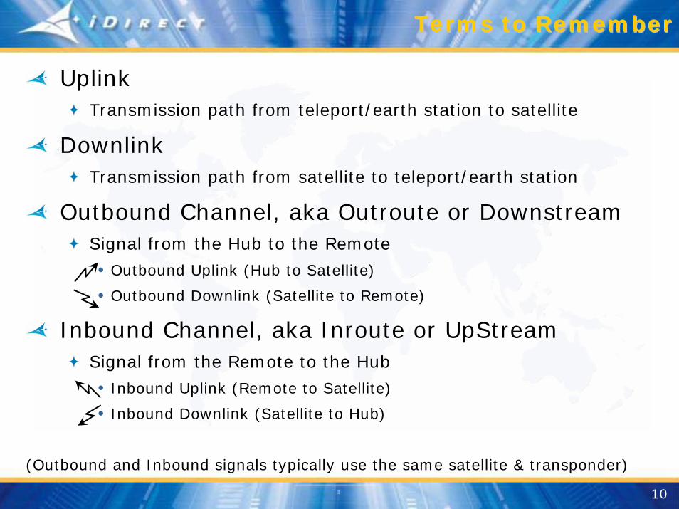
TerminologyTerminology
Linear PolarizationIn this case the direction of the electric vector in the plane, the vector sum of these two components, will always fall on a single line in the plane. We call this special case linear polarization. The direction of this line will depend on the relative amplitude of the two components. This direction can be in any angle in the plane, but the direction never varies.

20
Cross Polarization (Cross Polarization (XPolXPol))
Satellite
Cross PolarizationUplink and Downlink Use different polarization
Horizo
ntal
Vertic
al HorizontalVertical

21
Coincident Polarization (Coincident Polarization (CoPolCoPol))
Satellite
Co PolarizationUplink and Downlink Use same polarization
HorizontalVer
tical
HorizontalVertic
al

22
VSAT Feed AssemblyVSAT Feed Assembly
BUC
BUCLNBOMT
Orthogonal
Block Up ConverterLow Noise Block (Down Converter)Orthogonal Mode TransducerRelating to or composed of right angles. Having a set of mutually perpendicular axes
23
Linear PolarizationLinear Polarization

24
TerminologyTerminology
In electrodynamics circular polarization of electromagnetic radiation is polarization such that the tip of the electric field vector at a fixed point in space describes a circle. The magnitude of the electric field vector is constant.
A circularly polarized wave may be resolved into two linearly polarized waves, of equal amplitude, in phase quadrature and with their planes of polarization at right angles to each other.
Circular polarization may be referred to as "right-hand" or "left-hand," depending on the direction in which the electric field vector rotates.
Circular Polarization

25
Circular PolarizationCircular Polarization
Circular PolarizationSatellite Capabilities are 500 MHz for each Polarization (Right hand and Left hand)
Right HandCircular
Polarization
Left HandCircular
Polarization

26
Satellites Frequencies used within Satellites Frequencies used within the Frequency Spectrumthe Frequency Spectrum
EHFExtraHighFreq.
SHFSuperHighFreq.
UHFUltraHighFreq.
ULFUltraLow Freq.
VHFVeryHighFreq.
HFHighFreq.
MFMedFreq.
LFLowFreq.
VLFVeryLowFreq.
AudioFrequencies
VideoBaseband
AmateurRadio
Government Communications and Radar
Microwave
Infra-Red
SatelliteSatellite
30Hz 300Hz 3kHz 30kHz 300kHz 3MHz 30MHz 300MHz 3GHz 30GHz 300GHz

27
Satellite Link FrequenciesSatellite Link Frequencies
L BAND FREQUENCYDomestic USFrequency (MHz)
9501450
InternationalFrequency (MHz)
9501700
Ku BAND FREQUENCY
Up LinkFrequency (MHz)
1400014500
Down LinkFrequency (MHz)
1170012200
TranslationFrequency (MHz)
Varies
C BAND FREQUENCY
Up LinkFrequency (MHz)
59256425
Down LinkFrequency (MHz)
37004200
TranslationFrequency (MHz)
(Varies)
Ka BAND FREQUENCY
Up LinkFrequency (MHz)
2750030500
Down LinkFrequency (MHz)
1770020700
TranslationFrequency (MHz)
Varies

28
Overview Overview ––Satellite/Transponder BandwidthSatellite/Transponder Bandwidth
Satellite Capacities are500 MHz Vertical Polarization500 MHz Horizontal PolarizationDivided into bands using Transponders
Ku-Band14000 MHz to 14500 MHz (Uplink)11700 MHz to 12200 MHz (Downlink)
Transponder Bandwidth is generally one of following:27 MHz, 36 MHz, 54 MHz, 72 MHz
Transponders for Vertical and Horizontal Polarization
GuardBand2 MHz
GuardBand4 MHz
TransponderBandwidth
36 MHz
36 MHz 36 MHz36 MHz36 MHz36 MHz36 MHz
GuardBand2 MHz
14000 14500MHz
Trans-ponder
1 3 5 7 9 11 …
Vertical
Horizontal
36 MHz 36 MHz36 MHz36 MHz36 MHz36 MHz2 4 6 8 10 12 …
Vertical Transponder is centeredon Guard Band of Horizontal

29
iDirect Typical Hub ConfigurationiDirect Typical Hub Configuration
Upstream Router
ProtocolProcessors
NMS Server &
Spare
Regional UpLink
iDirect Hub EquipmentiDirect Hub Equipment
NMS GUI(Configuration & Monitoring)
Internet/Backbone
Hub Chassis
RFT
iDirect Hub Chassis used by Network Operators to Share NetModem Services and Connect NetModems to the Internet
Upstream LAN
Tunnel LAN
Hub CFE Hub CFE

30
Typical Remote Site ConfigurationTypical Remote Site Configuration
10/100 MbpsEthernet Switch
Video
VoIPPhones
10/100Ethernet
VSAT Antenna
L-BandIFL
NetModem II Plus
iDirect Components
NetworkOperatorPartner
Simple Deployment…
• Integrated, single box connection to the LAN
• No power needed at VSAT Antenna
• Centrally Managed
• Enable Broadband Connectivity!
Simple DeploymentSimple Deployment……
• Integrated, single box connection to the LAN
• No power needed at VSAT Antenna
• Centrally Managed
• Enable Broadband Connectivity!
PCs
IP RouterQoSTPC AcceleratorSatellite Modem3DES Security

31
Overview Overview -- Hub Line CardHub Line Card
FECEncoderFEC
Encoder SCPC/TDMQPSK Modulator
SCPC/TDMQPSK Modulator
TxRF
TxRF
FECDecoderFEC
DecoderTDMA QPSKDeModulator
TDMA QPSKDeModulator
RxRF
RxRF
L- Band
Pack
et F
orw
ardi
ng
10 / 100Ethernet
Proc
essi
ng d
one
onPr
otoc
ol P
roce
ssor
iDirectNMS
Server
iDirectProtocol
Processor(s)
Router
L- Band
FECSCPCTDMA
Forward Error CorrectionSingle Channel Per CarrierTime Division Multiple Access

32
Overview Overview -- Hub Teleport ComponentsHub Teleport Components
Hub Chassisw/Hub Line
Cards
Modulator
Demodulator
UpConverter
HPATx
DownConverter
LNA
RxLocal
Oscillator
LocalOscillator
L - BandC, Ku, Ka
Band
High PowerAmplifier
Low NoiseAmplifier

33
Overview Overview -- Satellite ComponentsSatellite Components
Ku-Band(Domestic)
UpLink
2300 MHzTranslation(Typical forKu-Band)
HPA
High PowerAmplifier
Mixer
LNADownLink
Low NoiseAmplifier
Ku-Band Domestic US Frequency
Up LinkFrequency (MHz)
1400014500
Down LinkFrequency (MHz)
1170012250
TranslationFrequency (MHz)
2300

34
Overview Overview -- Remote VSAT ComponentsRemote VSAT Components
NetModem II+
Modulator
Demodulator
UpConverter
HPA Tx
DownConverter
LNA
Rx
L/OW NOISE BL/OCK D/C (LNB)
BL/OCK UP CONVERTER (BUC)
L/O Local Oscillator
LocalOscillator
LocalOscillator
L - BandC, Ku, Ka
Band
High PowerAmplifier
Low NoiseAmplifier

35
Overview Overview -- Remote ModemRemote Modem
FECEncoderTPC .66
FECEncoderTPC .66
TDMAModulatorTDMA
ModulatorTxRF
TxRF
FECDecoderTPC .793
FECDecoderTPC .793
SCPCDeModulator
QPSK
SCPCDeModulator
QPSKRxRF
RxRF
L- Band
L- Band
Packet Processing and Modem
Control
TCP A
ccelerationQ
ueuing, QoS
10 / 100Ethernet
Customer
LAN
NetModem II+
FECSCPC
Forward Error CorrectionSingle Channel Per Carrier

36
Link BudgetLink Budget
The process of correctly sizing uplink and downlink paths
Takes into account:
Established Satellite performance
Path Loss (22,300 miles traversing space)
Atmospheric effects (weather, ion storms, sunspots, etc.)
Frequency bands used (Ku, C, Ka)
Hub uplink antenna and amplifier performance
Downlink antenna size and receiver noise figure
Assigns Transponder Uplink & Downlink Frequencies

37
Link Budget Link Budget –– Rain MarginRain Margin
Design for the specified availability
99.5% availability will give you about two days of outage per year
99.9% will give just 8 hours of outage per year
Note that for the Hub Outbound Carrier, only the Teleport external Uplink Power Control (UPC) can compensate for rain
iDirects Hub controls remote site Inbound Carrier power using our Uplink Control Process, or UCP

38
TerminologyTerminology
SCPC is used for economical distribution of broadcast data, digital audio and video materials, as well as for full-duplex or two-way data, audio or video communications. In an SCPC system, user data is transmitted to the satellite continuously on a single satellite carrier. The satellite signal is received at a single location, in the case of a point-to-point system, or at many locations in a broadcast application, providing connectivity among multiple sites.
SCPC got its name from the older analog transmission technology,when a single satellite channel could carry only one data carrier
A mechanism for sharing a channel, whereby a number of users have access to the whole channel bandwidth for asmall period of time (a time slot)
The difference between time-division multiplexing (TDM)and time-division multiple access is that time-division multiplexing requires users to be collocated to be multiplexed into the channel
In that regard, time-division multiple access can be considered as a remote multiplexing technology
Single Channel per Carrier - SCPC
Time Division Multiple Access - TDMA

39
Satellite Frequency BreakdownSatellite Frequency Breakdown
14000 14500MHz
GuardBand2 MHz
GuardBand4 MHz
TransponderBandwidth
36 MHz
36 MHz 36 MHz36 MHz36 MHz36 MHz36 MHz
GuardBand2 MHz
14038 MHz14000 + 2 MHz Guard + 36 MHz Transponder BW
14180 MHz14000 + 2 MHz Guard + 36 + 4 + 36 + 4 + 36 + 4 + 36 + 4 + 18
14000 14500MHz
GuardBand2 MHz
GuardBand4 MHz
TransponderBandwidth
36 MHz
36 MHz 36 MHz36 MHz36 MHz36 MHz36 MHz
GuardBand2 MHz
2 36 4 36 4 18
14100 MHz14000 + 2 MHz Guard + 36 + 4 + 36 + 4 +18User bandwidth of 4 MHz
Network Operator assigns a transmit frequency of 14.1 GHz to Customer A
40
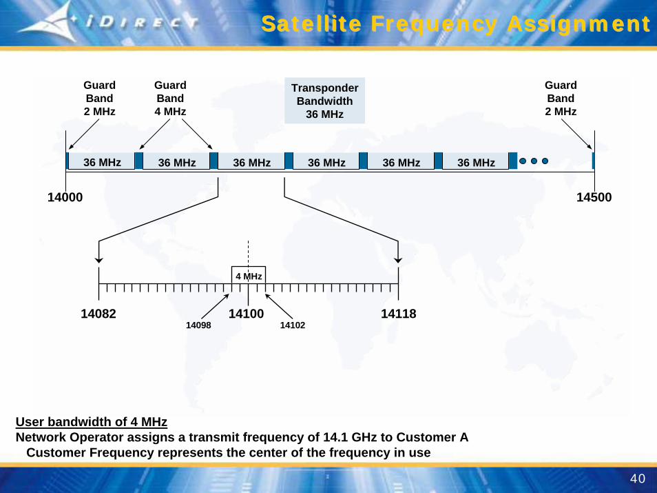
Satellite Frequency AssignmentSatellite Frequency Assignment
14000 14500
GuardBand2 MHz
GuardBand4 MHz
TransponderBandwidth
36 MHz
36 MHz 36 MHz36 MHz36 MHz36 MHz36 MHz
GuardBand2 MHz
14082 14118
4 MHz
1410014098 14102
User bandwidth of 4 MHzNetwork Operator assigns a transmit frequency of 14.1 GHz to Customer A
Customer Frequency represents the center of the frequency in use

41
Satellite Up/Downlink FrequenciesSatellite Up/Downlink Frequencies
L-Band950-1450 MHz
HUB
Modulator
Demodulator
UpConverter
HPATx
DownConverter
LNA
Rx13050 MHz
L/O
10750 MHzL/O Ku-Band
11.7 – 12.2 GHz(11700 - 12200 MHz)
Ku-Band14.0 – 14.5 GHz(14000 - 14500 MHz)
Power LeveldBm
(milliwatt)
Power LeveldBW(Watt)
Power LeveldBm
(milliwatt)
Power Level
(milliw
att)
Power Level
(milliw
att)
Power Level(milliwatt)
Frequency Calculated by NMS -Ku-Band minus Converter L/O
TransmitKu-Band low end 14000 MHzLocal Oscillator - 13050 MHzL-Band low end 950 MHz
ReceiveKu-Band high end 12200 MHzLocal Oscillator - 10750 MHzL-Band high end 1450 MHz

42
Hub Chassis
HubLine
Cards
UpConverter
HPA
L-Band950-1450 MHz
(950-1450 MHz Europe)
Tx
DownConverter
LNA
Rx13050 MHz
L/O
10750 MHzL/O Ku-Band
11.7 – 12.2 GHz(11700 - 12200 MHz)
Ku-Band14.0 – 14.5 GHz(14000 - 14500 MHz)
14100 MHz
14100 MHz1050 MHz 14100 MHz
14100 Ku-Band Uplink RF- 13050 Up Conv L/O
1050 Ku-Band Out (TX)
L Ku
Hub Transmit OperationHub Transmit Operation

43
SCPC SCPC -- Time Division MultiplexingTime Division Multiplexing
User A User CUser B
Broadcast to AllNetwork Remotes
Hub Location
User E
User D

44
Satellite Conversion, Amplification & Satellite Conversion, Amplification & RetransmissionRetransmission
14000 14500
36 MHz 36 MHz36 MHz36 MHz36 MHz36 MHz
14082 14118
14100 MHz 11800 MHz
4 M
14100
2300
14100 Ku-Band Uplink RF- 2300 Sat Xponder L/O (typical)11800 Ku-Band Downlink RF
HUBUp
ConverterL/O HPATx
DownConverter
L/O
LNA
Rx
14100 MHz14100 MHz1050 MHz
13050
10750
NETMODEMUp
ConverterL/OHPA
Tx
DownConverter
L/O
LNA
Rx
11800 MHz
11800 MHz 1050 MHz10750
13050
HubLocation
RemoteLocation
BUC
LNB

45
Remote Receive OperationRemote Receive Operation
NETMODEMUp
Converter
HPA
L-Band950-1450 MHz
Tx
DownConverter
LNA
Rx13050 MHz
L/O
10750 MHzL/OKu-Band
11.7 – 12.2 GHz(11700 - 12200 MHz)
Ku-Band14.0 – 14.5 GHz(14000 - 14500 MHz)
11800 MHz
11800 MHz1050 MHz
11800 MHz
11800 Ku-Band Downlink RF- 10750 LNB L/O
1050 L-Band In (RX)
Ku L
Power Level(milliwatt)
Power Level(milliwatt)

46
NETMODEMUp
Converter
HPA
L-Band950-1450 MHz
Tx
DownConverter
LNA
Rx13050 MHz
L/O
10750 MHzL/OKu-Band
11.7 – 12.2 GHz(11700 - 12200 MHz)
Ku-Band14.0 – 14.5 GHz(14000 - 14500 MHz)
14150 MHz
14150 MHz 1100 MHz14150 MHz
14150 Ku-Band Uplink RF- 13050 BUC L/O
1100 L-Band Out (TX)
Ku L
Power Level(dBmilliwatt)
Power Level(dBWatt)
Power Level(dBmilliwatt)
Remote Transmit OperationRemote Transmit Operation

47
Time Division Multiple AccessTime Division Multiple Access
User A User CUser B
1
2
3
Hub Location
User E
User D

48
Remote to HubRemote to Hub
14000 14500
36 MHz 36 MHz36 MHz36 MHz36 MHz36 MHz
14122
11850 MHz
14158
256KHz
14150
2300
14150 Ku-Band Uplink RF- 2300 Sat Xponder L/O11850 Ku-Band Downlink RF
14150 MHz
HUBUp
ConverterL/O HPATx
DownConverter
L/O
LNA
Rx
14150 MHz14150 MHz
1100 MHz
13050
10750
11850 MHz
NETMODEMUp
ConverterL/OHPA
Tx
DownConverter
L/O
LNA
Rx
11850 MHz
1100 MHz
10750
13050
HubLocation
RemoteLocation
BUC
LNB

49
Hub Receive OperationHub Receive Operation
HUBUp
Converter
HPA
L-Band950-1450 MHz
Tx
DownConverter
LNA
Rx13050 MHz
L/O
10750 MHzL/O Ku-Band
11.7 – 12.2 GHz(11700 - 12200 MHz)
Ku-Band14.0 – 14.5 GHz(14000 - 14500 MHz)
11850 MHz
11850 MHz1100 MHz
11850 MHz
11850 Ku-Band Downlink RF- 10750 Down Conv L/O
1100 L-Band In (RX)
L Ku

50
iDirect DiDirect D--TDMA Network ArchitectureTDMA Network Architecture
Hub
Upstream64K – 4 M
Downstream128K – 9 M
Remotes
1 2 5 n
NM-1NM-2
NM-50
3.95 Mbps
Burstable Bandwidth
4 Mbps
1 kbps
• Each Remote get a certain dedicated Bandwidth• Bandwidth Allocated to Each Remote Dynamically
• Multiple times a second• Bandwidth allocated based on
• Queue Depth at each remote• CIR Configuration• QoS/Prioritization Configuration• Rate Limiting at each remote

51
TerminologyTerminology
D-TDMA
Deterministic - Time Division Multiple Access (TDMA)
• Technique used to prevention of collisions of remotes transmitting simultaneously
• Network timing provided by synchronized burst time plan
Time slot assignments provide guaranteed delivery
• Improves throughput by reducing/eliminating retransmissions
D-FTDMA
Deterministic - Frequency & TDMA
• Allows remotes to better utilize shared bandwidth
• Hub can control data traffic flow to ‘load balance’ during normal network operations

52
Scheduled Dedicated TimeslotScheduled Dedicated Timeslot
Inroute TDMA Frame
Burstable Bandwidth
2 3 4 5 6 7 8 9 10 11 7512 13 14
R1 R2 R3 R5
1
With the default configuration every remote is given a dedicated timeslot, in every frame. For ex., 5 Remotes using 5 Timeslots, with each remote getting a timeslot every frame.
• If a remote is configured to have its dedicated time slot once every 2 frames, then 10 remotes will need only 5 timeslots (minimum is one time slot every two seconds)
• This allows one to oversubscribe an inroute at a much higher ratio• Some example applications would be business continuity and low bandwidth networks
that need a guaranteed amount of bandwidth
1 2 3 4 5 6 7
R1 R2 R3 R5
Frame 1Frame 1
1 2 3 4 5 6 7
R1 R2 R3 R5
Frame 3Frame 3
2 3 4 5 6 7
R6 R7 R8 R10
Frame 2Frame 2
1
Burstable Bandwidth
2 3 4 5 6 7 8 9 10 11 7512 13 14
R1 R2 R3 R10
1

53
Multiple Inbounds per OutboundMultiple Inbounds per Outbound
Hub
Upstream64K – 4 M
Downstream128K – 9 M
Remotes Remotes Remotes Remotes

54
Frequency HoppingFrequency Hopping
Hub
Upstream64K – 4 M
Downstream128K – 9 M
Inroutes with No Terminals Assigned
Remotes Remotes RemotesRemotes

55
Forward Error CorrectionForward Error Correction
Forward Error Correction (FEC)
A technique for allowing a receiver to correct errors itself, without reference to the transmitter
It does this by using additional information transmittedalong with the data and employing one of the errordetection techniques
The receiver can correct a small number of the errors that have been detected
If the receiver cannot correct all detected errors, the data must be re-transmitted
Turbo Product (Block) Code (TPC)
Small block (128 Byte – 1kb)
Large block (512 Byte – 4kb)
Large block (2k Byte – 16kb)• Next Generation Hub Line Cards, Downstream ONLY

56
Forward Error Correction Forward Error Correction -- ExistingExisting
FEC .793 (Represented fractionally as: 3249 / 4096)
A forward correction utilizing .207 overhead bits for each .793 bits of User data
Large Block (4kb) TPC
Downstream & Upstream (hub to remote; remote to hub)
FEC .495 (Represented fractionally as: 2028 / 4096)
A forward correction utilizing .505 overhead bits for each .495 bits of User data
Large Block (4kb) TPC
Downstream carrier only (hub to remote)
FEC .660 (Represented fractionally as: 676 / 1024)
A forward correction utilizing .340 overhead bits for each .660 bits of User data
Small Block (1kb) TPC
Upstream carrier only (remote to hub)

57
Forward Error Correction Forward Error Correction –– Next GenNext Gen
FEC .431 (Represented fractionally as: 441 / 1024)
A forward correction utilizing .569 overhead bits for each .431 bits of User data
Small Block (1kb) TPC
Downstream carrier only (hub to remote)
FEC .533 (Represented fractionally as: 546 / 1024)
A forward correction utilizing .467 overhead bits for each .533 bits of User data
Small Block (1kb) TPC
Downstream carrier only (hub to remote)
FEC .879 (Represented fractionally as: 14400 / 16384)
A forward correction utilizing .121 overhead bits for each .879 bits of User data
Large Block (16kb) TPC
Downstream carrier only (hub to remote)

58
Forward Error CorrectionForward Error Correction
Greater number of FEC bits utilized (.505 v .207) requires
Greater allowance for overhead
Provides better data integrity
Smaller the VSAT dish required at the remote
Greater overhead for FEC bits reduces the user traffic payload in the data stream
Info Rate of 6.344Mbps utilizing a FEC of .793 would require a Transmission Rate of 6.344/.793 = 8 Mbps

59
Hub Rate ConversionsHub Rate Conversions
FECEncoderFEC
EncoderSCPC/TDM
QPSKModulator
SCPC/TDMQPSK
ModulatorTxRF
TxRF
FECDecoderFEC
DecoderTDMAQPSK
DeModulator
TDMAQPSK
DeModulatorRxRF
RxRF
Hub Line Card
10 / 100Ethernet
Pack
et F
orw
ardi
ngPr
oces
sing
don
e on
Prot
ocol
Pro
cess
or
iDirectNMS
Server
iDirectProtocol
Processor(s)
Router
InfoRate
TxRate
SymRate
IP/UserData
InfoRate
RxRate
SymRate
L- Band
L- Band
IP/UserData
FECSCPC
TDMTDMA
SymTxRx
Forward Error CorrectionSingle Channel Per CarrierTime Division MultiplexTime Division Multiple AccessSymbol RateTransmission RateReceive Rate

60
Remote Rate ConversionsRemote Rate Conversions
FECEncoderTPC .66
FECEncoderTPC .66
TDMAQPSK
Modulator
TDMAQPSK
ModulatorTxRF
TxRF
FECDecoderTPC .793
FECDecoderTPC .793
SCPC/TDMQPSK
DeModulator
SCPC/TDMQPSK
DeModulatorRxRF
RxRF
NetModem II+
Packet Processing and Modem
Control
TCP A
ccelerationQ
ueuing, QoS
10 / 100Ethernet
Customer
LAN
InfoRate
RxRate
SymRate
IP/UserData
InfoRate
TxRate
SymRate
IP/UserData
L- Band
L- Band
FECSCPC
TDMTDMA
SymTxRx
Forward Error CorrectionSingle Channel Per CarrierTime Division MultiplexTime Division Multiple AccessSymbol RateTransmission RateReceive Rate

61
Hub Transmit OperationHub Transmit Operation
FECMbpsMspsSCPC
TPC
Forward Error CorrectionMega (Millions of) bits per secondMega (Millions of) symbols per secondSingle Channel per CarrierTurbo Product Code
FECEncoderTPC .793
SCPC/TDMQPSK
ModulatorTxRF
TxRF
FECDecoderTPC .66
FECDecoderTPC .66
TDMAQPSK
DeModulator
TDMAQPSK
DeModulatorRxRF
RxRF
L- Band
L- Band
10 / 100Ethernet
Pack
et F
orw
ardi
ngPr
oces
sing
don
e on
Prot
ocol
Pro
cess
or
iDirectNMS
Server
iDirectProtocol
Processor(s)
Router
InfoRate
TxRate
SymRate
IP/UserData
InfoRate
RxRate
SymRate
Digital AnalogDigital Analog
Digital AnalogDigital Analog
6.344 Mbps 8 Mbps 4 Msps 4 MHz BWFEC
950-1450MHz
(6.344 Mbps/ .793)
1050MHz
4 MHz
2MHz
1048MHz
1052MHz
2MHz
6.185 Mbps
IP/UserData
Hub Line Card
950-1450MHz

62
Remote Receive OperationRemote Receive Operation
FECEncoderTPC .66
FECEncoderTPC .66
TDMAQPSK
Modulator
TDMAQPSK
ModulatorTxRF
TxRF
FECDecoderTPC .793
FECDecoderTPC .793
SCPCQPSK
DeModulator
SCPCQPSK
DeModulatorRxRF
RxRF
L- Band
L- Band
Packet Processing and Modem
Control
TCP A
ccelerationQ
ueuing, QoS
10 / 100Ethernet
Customer
LAN
6.344 Mbps8 Mbps4 Msps4 MHz BW FEC
DigitalAnalog DigitalAnalog
DigitalAnalog Digital
(8 Mbps * .793)
NetModem II+
6.185 Mbps
InfoRate
RxRate
SymRate
InfoRate
TxRate
SymRate
IP/UserData
Analog
IP/UserData
FECMbpsMspsSCPC
TPC
Forward Error CorrectionMega (Millions of) bits per secondMega (Millions of) symbols per secondSingle Channel per CarrierTurbo Product Code

63
Remote Transmit OperationRemote Transmit Operation
FECEncoderTPC .66
FECEncoderTPC .66
TDMAQPSK
Modulator
TDMAQPSK
ModulatorTxRF
TxRF
FECDecoderTPC .793
FECDecoderTPC .793
SCPCQPSK
DeModulator
SCPCQPSK
DeModulatorRxRF
RxRF
L- Band
960MHz
256 kHz
128kHz
959.872MHz
960.128MHz
128kHz
L- Band
Packet Processing and Modem
Control
TCP A
ccelerationQ
ueuing, QoS, U
PC, D
A
10 / 100Ethernet
Customer
LAN
338 kbps512 kbps256 ksps256 kHz BW FEC
DigitalAnalog Digital
DigitalAnalog DigitalAnalog
950-1450MHz
338 kbps/ .66
NetModem II+
InfoRate
TxRate
SymRate
254 kbps
User IPRate
Analog
FECkbpsksps
SCPCTPC
Forward Error Correctionkilo (thousands of) bits per secondkilo (thousands of) symbols per secondSingle Channel per CarrierTurbo Product Code

64
HUB Receive OperationHUB Receive Operation
FECEncoderTPC .793
TDMAQPSK
ModulatorTxRF
TxRF
FECDecoderTPC .66
SCPCQPSK
DeModulatorRxRF
RxRF
Hub Line Card
L- Band
L- Band
10 / 100Ethernet
Pack
et F
orw
ardi
ngPr
oces
sing
don
e on
Prot
ocol
Pro
cess
or
iDirectNMS
Server
iDirectProtocol
Processor(s)
Router
InfoRate
TxRate
SymRate
UserData
InfoRate
RxRate
SymRate
Digital AnalogDigital Analog
Digital AnalogDigital Analog
338 kbps 512 kbps 256 ksps 256 kHz BWFEC
.66 * 512 kbps
FECkbpsksps
SCPCTPC
Forward Error Correctionkilo (thousands of) bits per secondkilo (thousands of) symbols per secondSingle Channel per CarrierTurbo Product Code
UserData
254 kbps

65
Anatomy of A Satellite Space SegmentAnatomy of A Satellite Space Segment
Insert formula
* - Example Case Study using 1.2 Channel Spacing
Channel Rate/Transmission Rate – QPSK(8.0 Mbps*)
Information Rate(6.344 Mbps*)
Coding Bits
IP Data Rate(6.185 Mbps*)
L2 Overhead
Guard BandGuard Band
Carrier Size(4.8 Mhz*)
0.793

66
Satellite FrequenciesSatellite Frequencies
14000 14500
GuardBand2 MHz
GuardBand4 MHz
TransponderBandwidth
36 MHz
36 MHz 36 MHz36 MHz36 MHz36 MHz36 MHz
GuardBand2 MHz
14082 14118
4 MHz
14100
Guard Band.8 MHz
14.102 to 14.1028
Guard Band.8 MHz
14.0972 to 14.098
Leased Bandwidth
UserTraffic
14.098 to 14.102
User bandwidth required 4 MHzNetwork Operator assigns a transmit frequency of 14.1 GHz
Assigned frequency is the center of the user bandwidth required
Network Operator provides a Guard Band around user bandwidthGuard band typically is 40% of allocated bandwidth (called 1.4 Channel spacing)4 MHz x .4 = 1.6 MHz > .8 MHz on low end and .8 MHz on high end
Network Operator will not assign these guard band frequencies to other users

67
Satellite FrequenciesSatellite Frequencies
14000 14500
GuardBand2 MHz
GuardBand4 MHz
TransponderBandwidth
36 MHz
36 MHz 36 MHz36 MHz36 MHz36 MHz36 MHz
GuardBand2 MHz
14082 14118
4 MHz
14100
User bandwidth required 4 MHz
User A (4MHz)Traffic
14.098 to 14.102
Guard Band.8 MHz
14.102 to 14.1028
Guard Band.8 MHz
14.0972 to 14.098
4 MHz
User B (4MHz)Traffic
14105.6 MHzcenter
GHzGHz
Network Operator assigns User A bandwidth of 4 MHzUser A uses a transmit frequency of 14.1 GHz center (14097.2 MHz to 14102.8 MHz)
Network Operator assigns User B bandwidth of 4 MHzUser B uses a transmit frequency of 14105.6 MHz center (user 14103.6 to 14107.6)Guard Band includes frequencies 14102.8 to 14108.4

68
1.2 v 1.4 Spacing1.2 v 1.4 Spacing
14000 14500
GuardBand2 MHz
GuardBand4 MHz
TransponderBandwidth
36 MHz
36 MHz 36 MHz36 MHz36 MHz36 MHz36 MHz
GuardBand2 MHz
14082 14118
4 MHz
14100
Guard Band.4 MHz
14.102 to 14.1024
Guard Band.4 MHz
14.0976 to 14.098
User bandwidth required 4 MHzNetwork Operator assigns a transmit frequency of 14.1 GHz
Assigned frequency is the center of the user bandwidth required
Network Operator still provides a Guard Band around user bandwidth, howeverGuard band using 20% of allocated bandwidth is called 1.2 Channel spacing4 MHz x .2 = .8 MHz or .4 MHz on low end and .4 MHz on high end
Network Operator will not assign these guard band frequencies to other users
iDirect1.2 Spacing
Benefit of lowerBandwidth Requirements
On Satellite(14.3% savings v 1.4 spacing)
UserTraffic
14.098 to 14.102

69
1.2 v 1.4 Spacing1.2 v 1.4 Spacing
14082 14118
4 MHz
14100
UserTraffic
14.098 to 14.102
Guard Band.4 MHz
14.102 to 14.1024
Guard Band.4 MHz
14.0976 to 14.098
iDirect1.2 Spacing
Benefit is lowerBandwidth Requirements
On Satellite(14.3% savings v 1.4 spacing)
4 MHz User Bandwidth
14100Leased Bandwidth
GuardBand
GuardBand
BandwidthSavings
BandwidthSavings

70
1.2 Carrier Spacing1.2 Carrier Spacing
DownstreamUser Data (Info) Rate
= 5MbpsUpstream #1
1Mbps
4.4136 MHz
Upstream #21Mbps
Upstream #31Mbps
882.7 kHz
7.0618 MHz Total
iDirect Network Prior to Carrier Bandwidth Optimization(40% Guardband)
DownstreamUser Data (Info) Rate
= 5MbpsUpstream #1
1Mbps
3.7831 MHz
Upstream #21Mbps
Upstream #31Mbps
756.620 kHz
6.80958 MHz Total
iDirect Network After Carrier Bandwidth Optimization (20% Guardband)Allows a fourth upstream to be added with room to spare!
Upstream #41Mbps
882.7 kHz 882.7 kHz
756.620 kHz 756.620 kHz 756.620 kHz
In this case study, an additional 1Mbps upstream channel is added to an existing network by exploiting the reduced guardbandbetween channels!

71
TerminologyTerminology
Energy per Bit to Noise Ratio – E b/No
Signal to noise ratio
The ratio given by E b/N 0, where E b is the signal energy per bit and Nois the noise energy per hertz of noise bandwidth

Satellite Communication ConceptsSatellite Communication Concepts*** Thank You ****** Thank You ***