Embed Size (px)
Citation preview
Concept development of compact DEMO reactor
Kenji Tobitafor DEMO Plant Design Team
Japan Atomic Energy Research Institute
Special thanks: F. Najmabadi (UCSD), C.P.C. Wong (GA), K. Okano(CRIEPI)
IEA/LT Workshop (W59) combined with DOE/JAERI Technical Planning of Tokamak Experiments (FP1-2) 'Shape and Aspect Ratio Optimization for High Beta Steady-State Tokamak'
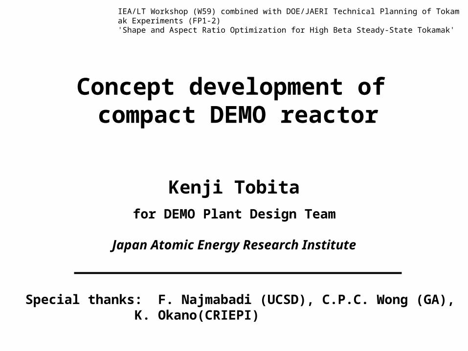
OUTLINE
1. ABC of Fusion Reactor Study
2. Compact reactor study at JAERI
3. DEMO design study at JAERIStarted in 2003
Focus on the possibility of an economically attractive reactor in low-A (= 2-2.9), left behind in fusion reactor study previously
- 2 -
1. ABC of Fusion Reactor Study
• Direction of fusion reactor studies
• Necessity to pursue economic fusion energy
- 3 -
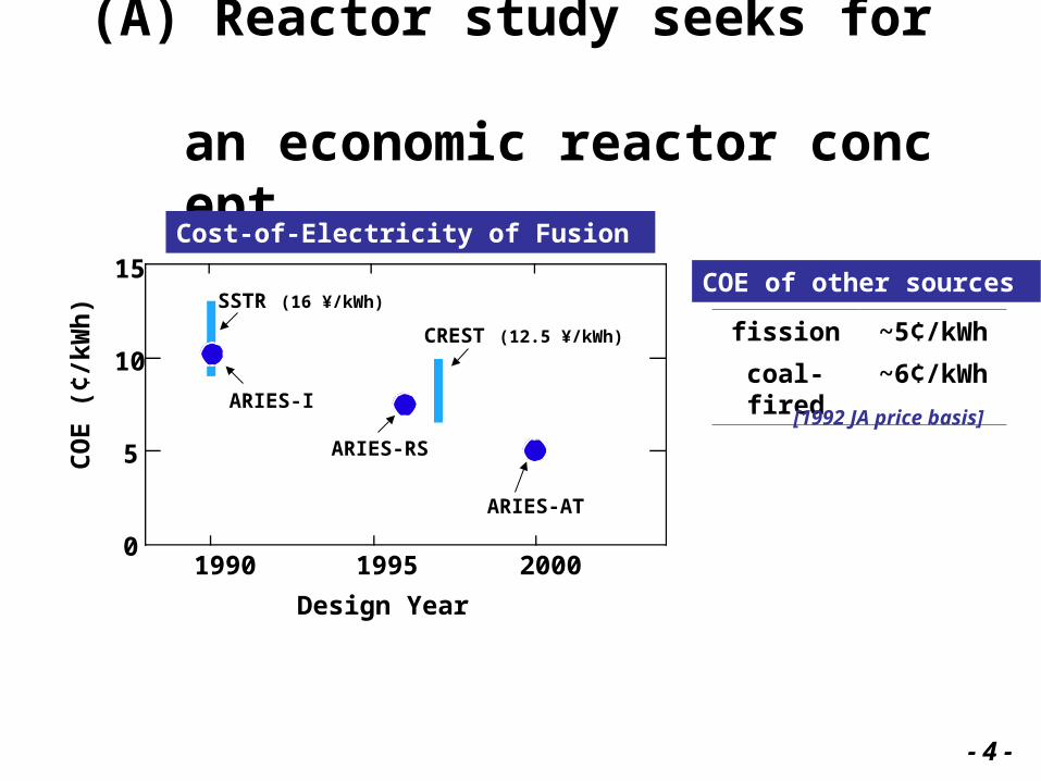
(A) Reactor study seeks for an economic reactor concept
Design Year
1995 200019900
5
10
15
CO
E (
¢/kW
h) SSTR (16 ¥/kWh)
ARIES-I
ARIES-RS
ARIES-AT
CREST (12.5 ¥/kWh)
Cost-of-Electricity of Fusion
COE of other sources
fission ~5¢/kWh
coal-fired ~6¢/kWh
[1992 JA price basis]
- 4 -
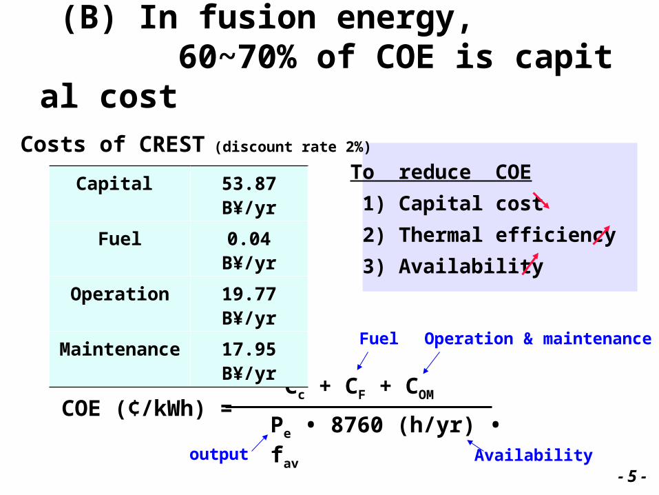
(B) In fusion energy, 60~70% of COE is capital cost
COE (¢/kWh) = Cc + CF + COM
Pe • 8760 (h/yr) • fav
Capital Fuel Operation & maintenance
Capital 53.87 B¥/yr
Fuel 0.04 B¥/yr
Operation 19.77 B¥/yr
Maintenance 17.95 B¥/yr
Costs of CREST (discount rate 2%)
Availabilityoutput
To reduce COE
1) Capital cost
2) Thermal efficiency
3) Availability
- 5 -
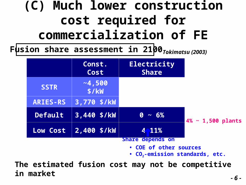
(C) Much lower construction cost required for commercialization of FE
Const. Cost Electricity Share
SSTR ~4,500 $/kW
ARIES-RS 3,770 $/kW
Default 3,440 $/kW 0 ~ 6%
Low Cost 2,400 $/kW 4~11%
- 6 -
Fusion share assessment in 2100
4% ~ 1,500 plants
Share depends on
• COE of other sources• CO2-emission standards, etc.
The estimated fusion cost may not be competitive in market
Tokimatsu (2003)
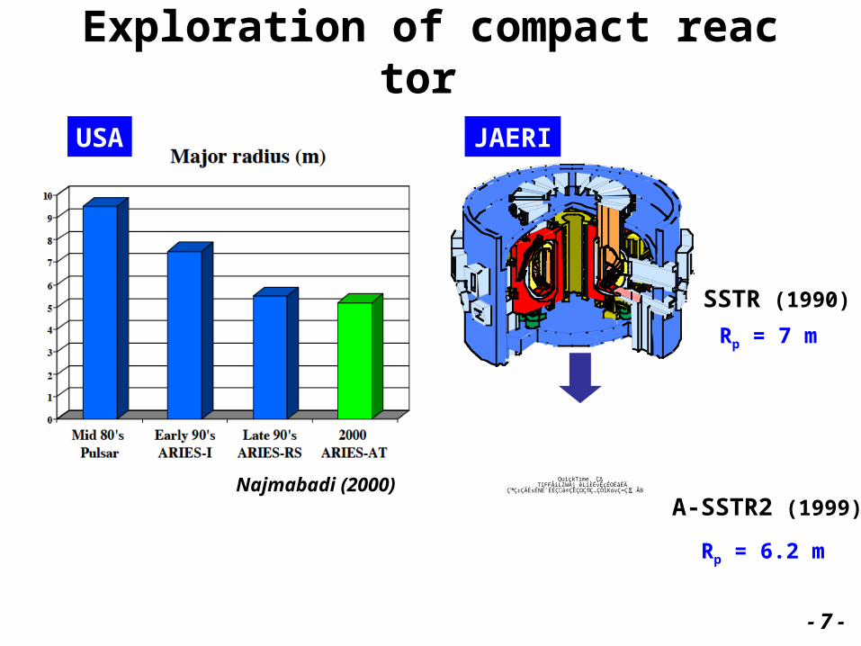
Exploration of compact reactor
USA
Najmabadi (2000) QuickTime˛ Ç∆TIFFÅiLZWÅj êLí£ÉvÉçÉOÉâÉÄ
ǙDZÇÃÉsÉNÉ`ÉÉÇ å©ÇÈÇΩÇflÇ…ÇÕïKóvÇ≈Ç∑ÅB
JAERI
SSTR (1990)
A-SSTR2 (1999)
Rp = 7 m
Rp = 6.2 m
- 7 -
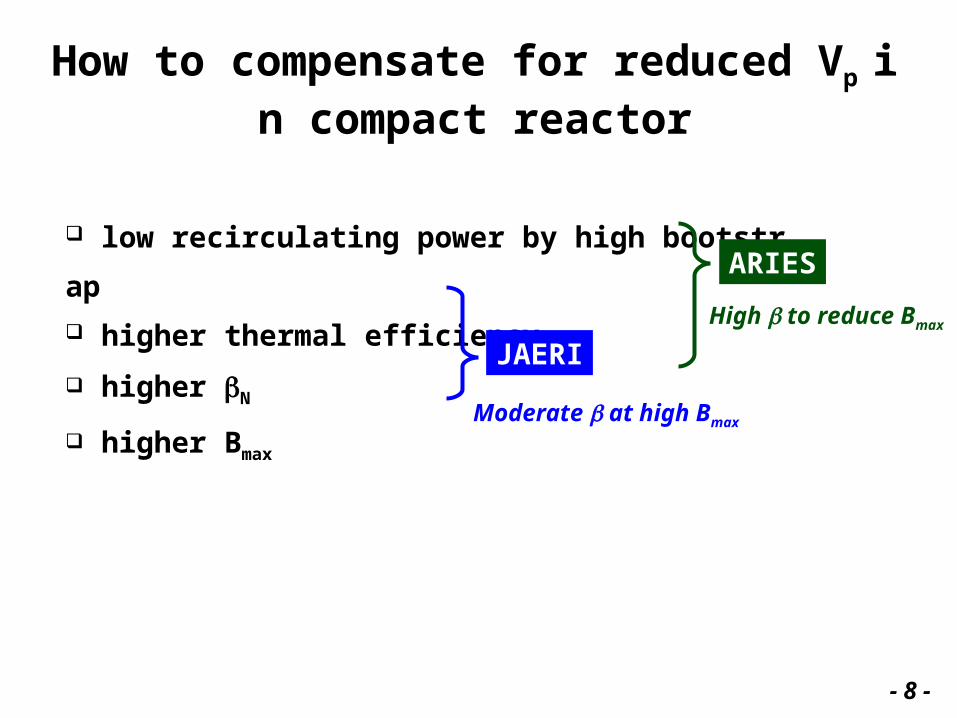
How to compensate for reduced Vp in compact reactor
low recirculating power by high bootstrap
higher thermal efficiency
higher N
higher Bmax
ARIES
JAERIHigh to reduce Bmax
Moderate at high Bmax
- 8 -
2. Compact reactor study at JAERI
What led us to low-A compact reactor concept?
- 9 -
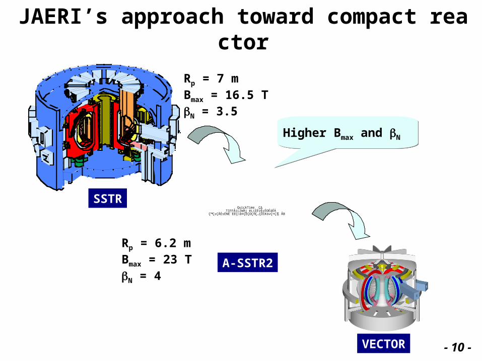
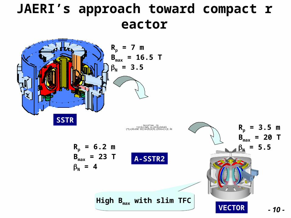
JAERI’s approach toward compact reactor
QuickTime˛ Ç∆TIFFÅiLZWÅj êLí£ÉvÉçÉOÉâÉÄ
ǙDZÇÃÉsÉNÉ`ÉÉÇ å©ÇÈÇΩÇflÇ…ÇÕïKóvÇ≈Ç∑ÅB
Rp = 7 mBmax = 16.5 TN = 3.5
Rp = 6.2 mBmax = 23 TN = 4
A-SSTR2
VECTOR
SSTR
Higher Bmax and N
- 10 -
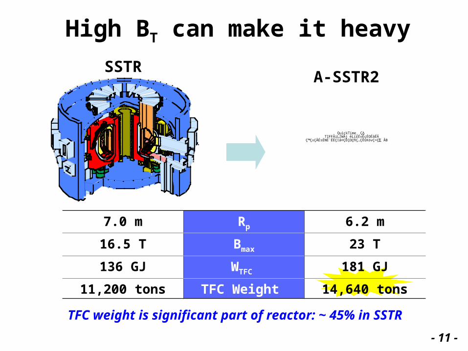
High BT can make it heavy
SSTRA-SSTR2
7.0 m Rp 6.2 m
16.5 T Bmax 23 T
136 GJ WTFC 181 GJ
11,200 tons TFC Weight 14,640 tons
TFC weight is significant part of reactor: ~ 45% in SSTR
QuickTime˛ Ç∆TIFFÅiLZWÅj êLí£ÉvÉçÉOÉâÉÄ
ǙDZÇÃÉsÉNÉ`ÉÉÇ å©ÇÈÇΩÇflÇ…ÇÕïKóvÇ≈Ç∑ÅB
- 11 -
JAERI’s approach toward compact reactor
QuickTime˛ Ç∆TIFFÅiLZWÅj êLí£ÉvÉçÉOÉâÉÄ
ǙDZÇÃÉsÉNÉ`ÉÉÇ å©ÇÈÇΩÇflÇ…ÇÕïKóvÇ≈Ç∑ÅB
Rp = 7 mBmax = 16.5 TN = 3.5
Rp = 6.2 mBmax = 23 TN = 4
Rp = 3.5 mBmax = 20 TN = 5.5
A-SSTR2
VECTOR
SSTR
High Bmax with slim TFC - 10 -
0 5 10R (m)
0 5 10R (m)
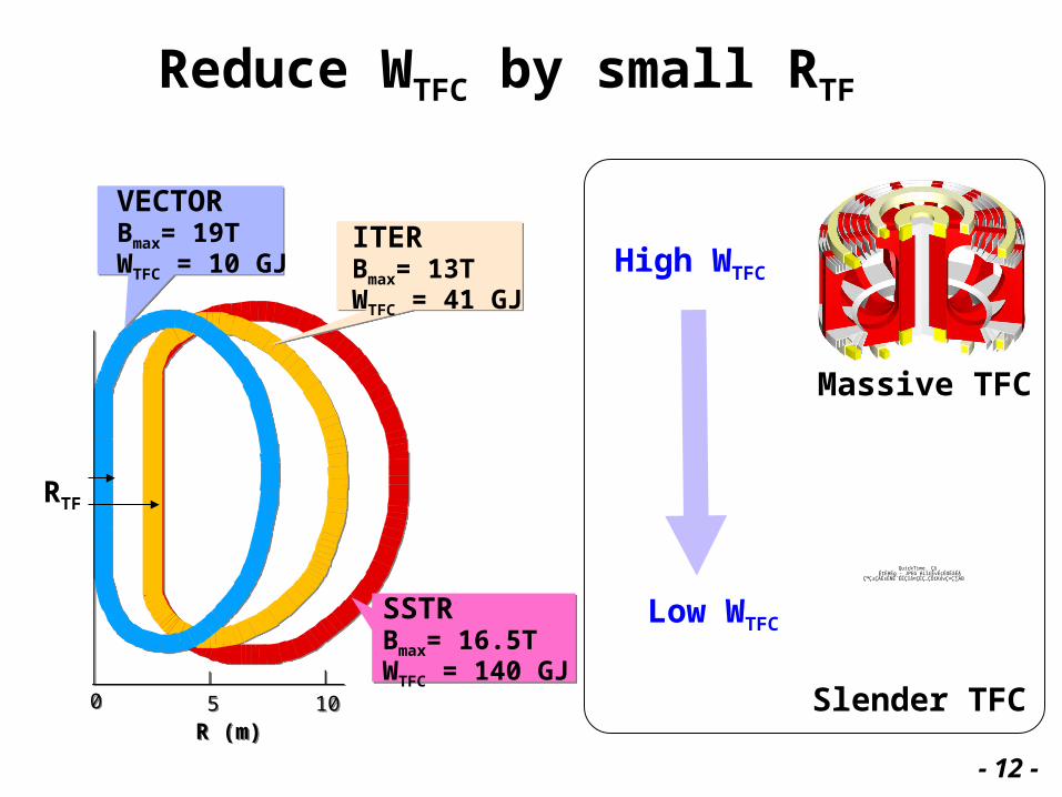
Reduce WTFC by small RTF
ITERBmax= 13TWTFC = 41 GJ
SSTRBmax= 16.5TWTFC = 140 GJ
VECTORBmax= 19TWTFC = 10 GJ
QuickTime˛ Ç∆ÉtÉHÉg - JPEG êLí£ÉvÉçÉOÉâÉÄ
ǙDZÇÃÉsÉNÉ`ÉÉÇ å©ÇÈÇ…ÇÕïKóvÇ≈Ç∑ÅB
High WTFC
Low WTFC
Massive TFC
Slender TFC
RTF
- 12 -
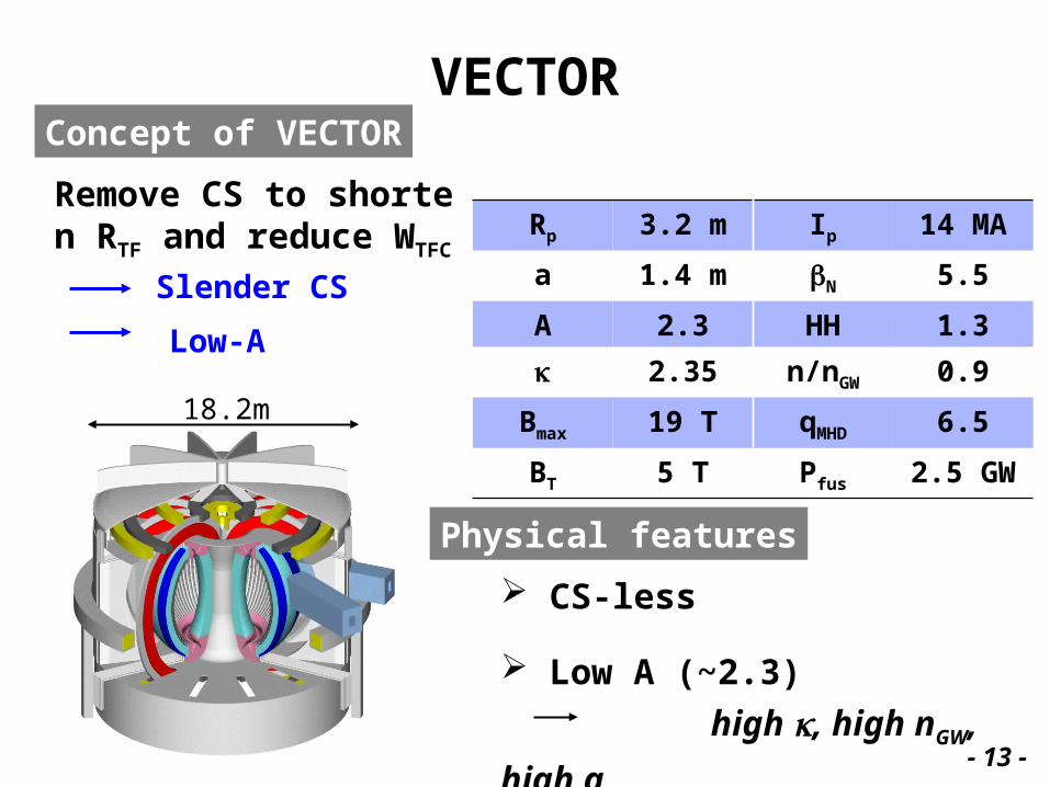
VECTOR
18.2m
Rp 3.2 m Ip 14 MA
a 1.4 m N 5.5
A 2.3 HH 1.3
2.35 n/nGW 0.9
Bmax 19 T qMHD 6.5
BT 5 T Pfus 2.5 GW
Physical features
CS-less
Low A (~2.3)
high , high nGW, high q- 13 -
Remove CS to shorten R
TF and reduce WTFC
Concept of VECTOR
Slender CS
Low-A
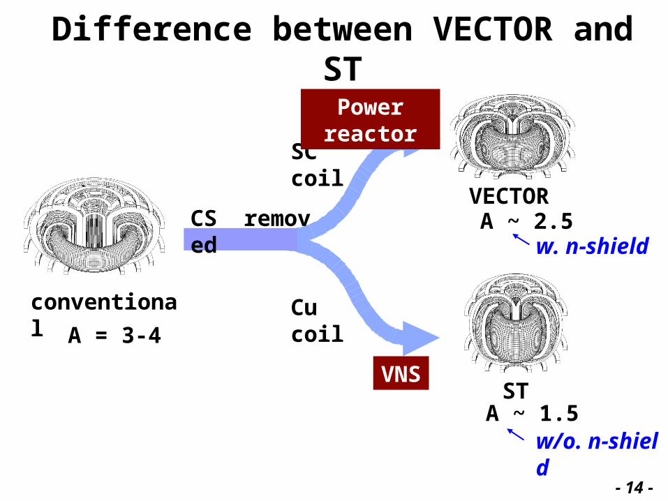
Difference between VECTOR and ST
conventional
VECTOR
ST
CS removed
Cu coil
SC coil
A ~ 2.5
A ~ 1.5
Power reactor
VNS
w. n-shield
w/o. n-shield
A = 3-4
- 14 -
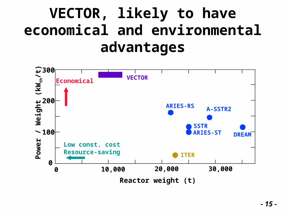
VECTOR, likely to have economical and environmental advantages
Reactor weight (t)
Po
wer
/ W
eig
ht
(kW
th/t
)
Low const. costResource-saving
Economical
0
100
200
300
0 10,000 20,000 30,000
ITER
ARIES-RS
ARIES-STSSTR
A-SSTR2
DREAM
VECTOR
- 15 -
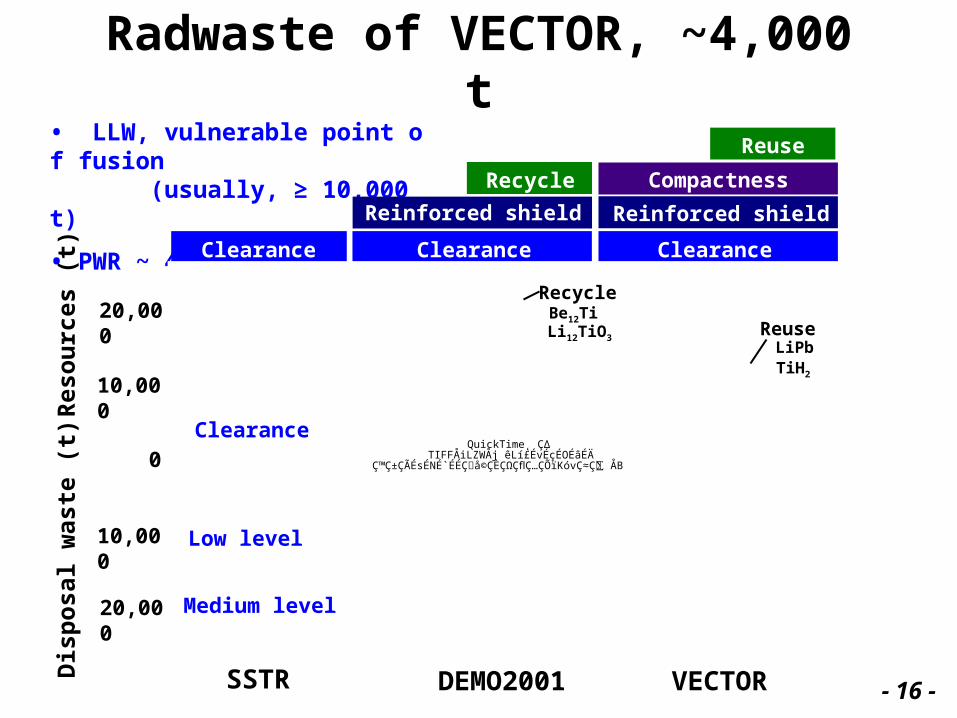
Radwaste of VECTOR, ~4,000 t• LLW, vulnerable point of fusion (usually, ≥ 10,000 t)
• PWR ~ 4,000 tClearance Clearance Clearance
Reinforced shield Reinforced shield
Recycle
Reuse
Compactness
Res
ou
rces
(t)
QuickTime˛ Ç∆TIFFÅiLZWÅj êLí£ÉvÉçÉOÉâÉÄ
ǙDZÇÃÉsÉNÉ`ÉÉÇ å©ÇÈÇΩÇflÇ…ÇÕïKóvÇ≈Ç∑ÅB
Dis
po
sal
was
te (
t) 0
10,000
10,000
20,000
20,000
Clearance
Low level
Medium level
SSTR DEMO2001 VECTOR
ReuseLiPbTiH2
RecycleBe12TiLi12TiO3
- 16 -
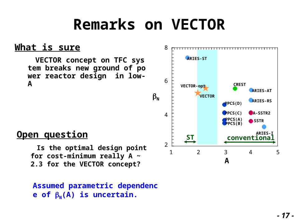
Remarks on VECTOR
VECTOR concept on TFC system breaks new ground of power reactor design in low-A
ST
1 2 3 4 52
4
6
8
ARIES-ST
ARIES-AT
ARIES-RS
ARIES-I
A-SSTR2
SSTRPPCS(B)PPCS(A)
PPCS(C)
PPCS(D)
CREST
VECTOR
VECTOR-opt
conventional
A
N
What is sure
Open question
Is the optimal design point for cost-minimum really A ~ 2.3 for the VECTOR concept?
Assumed parametric dependence of N(A) is uncertain.
- 17 -
3. DEMO design study at JAERI
How to fit VECTOR concept to DEMO
Three DEMO options
- 18 -
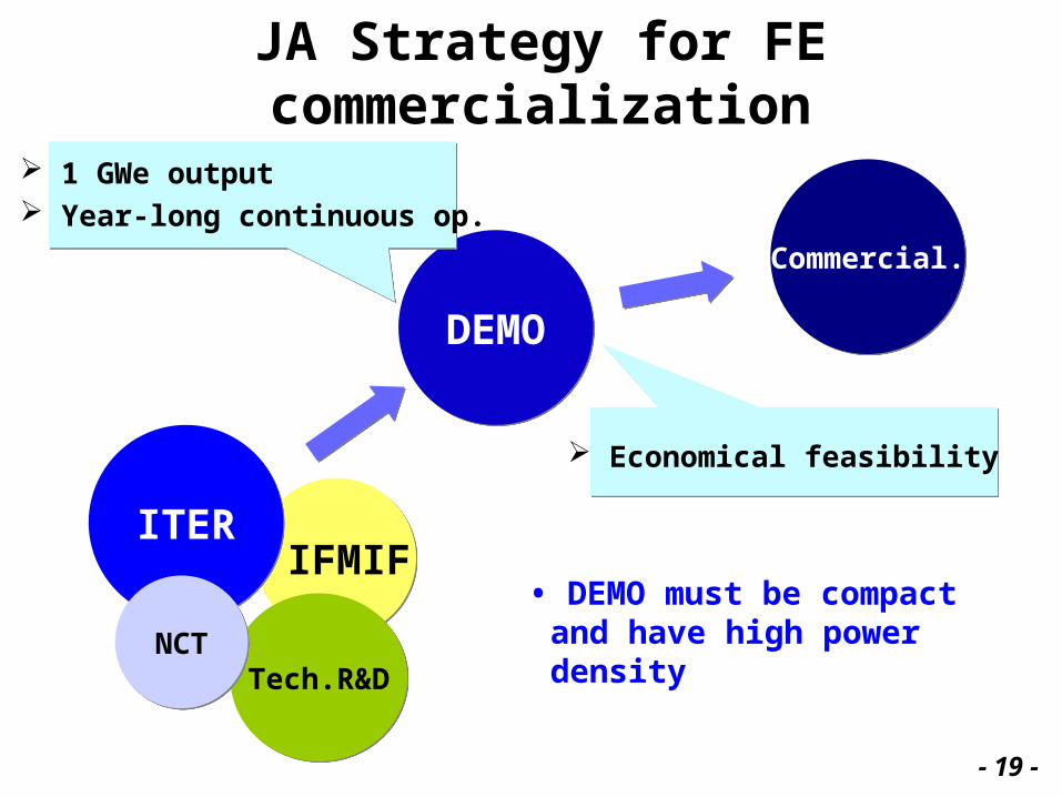
JA Strategy for FE commercialization
IFMIF IFMIF
Commercial.Commercial.
DEMODEMO
ITERITER
Tech.R&DTech.R&DNCTNCT
1 GWe output Year-long continuous op.
Economical feasibility
• DEMO must be compact and have high power density
- 19 -
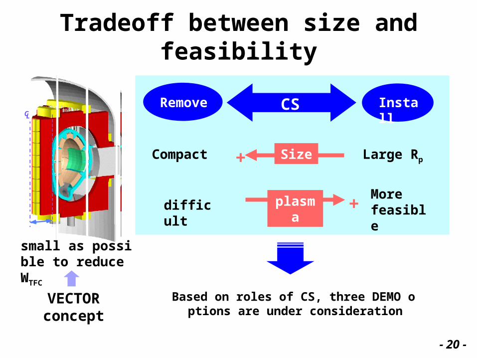
Tradeoff between size and feasibility
CL
small as possible to reduce WTFC
CSRemove Install
Compact Large Rp
More feasible
+
difficult +
Size
plasma
Based on roles of CS, three DEMO options are under consideration
VECTOR concept
- 20 -
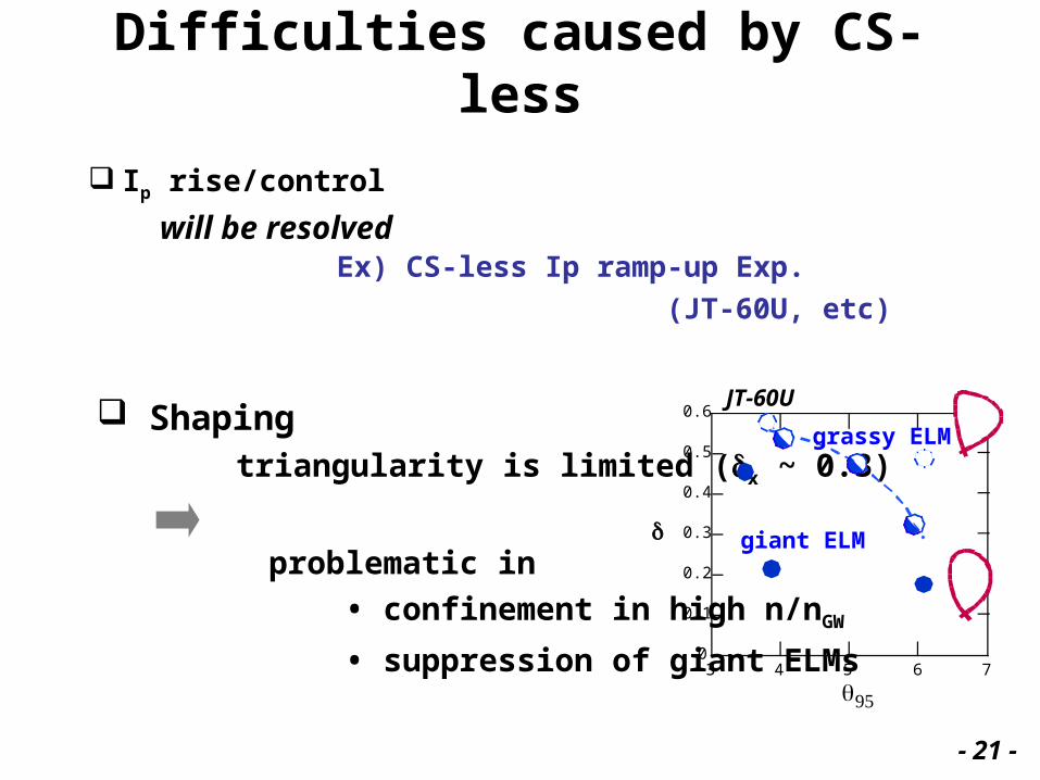
Difficulties caused by CS-less
Ip rise/control
Ex) CS-less Ip ramp-up Exp.
(JT-60U, etc)
will be resolved
Shaping triangularity is limited (x ~ 0.3)
problematic in
• confinement in high n/nGW
• suppression of giant ELMs
0.6
0.5
0.4
0.3
0.2
0.1
03 4 5 6 7
q95
giant ELM
grassy ELM
JT-60U
- 21 -
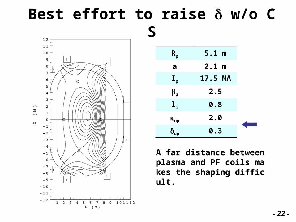
Best effort to raise w/o CS
Rp 5.1 m
a 2.1 m
Ip 17.5 MA
p 2.5
li 0.8
up 2.0
up 0.3
A far distance between plasma and PF coils makes the shaping difficult.
- 22 -
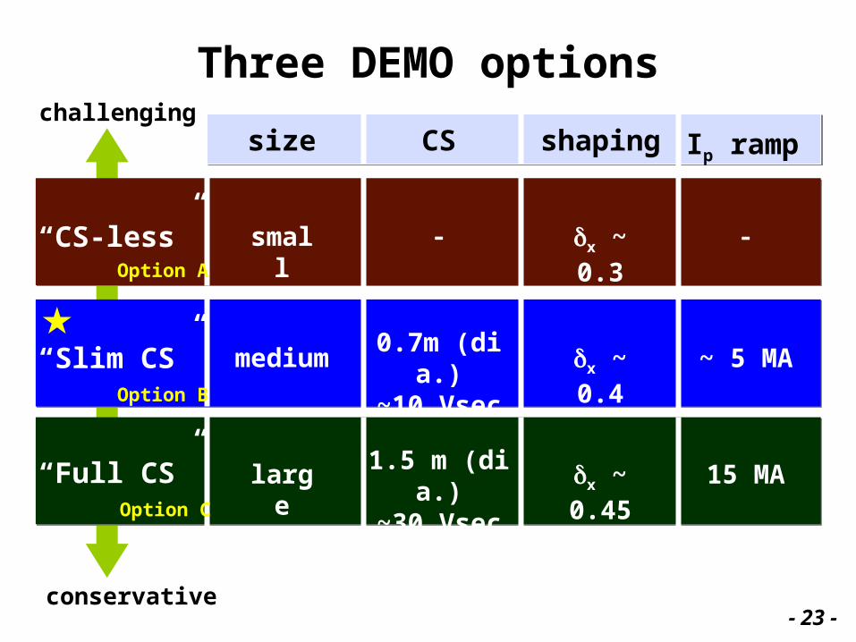
Three DEMO options
shaping Ip rampCSsize
“Full CS” 1.5 m (dia.)~30 Vsec
x ~ 0.45 15 MAlargeOption C
“CS-less” small x ~ 0.3 Option A
0.7m (dia.)~10 Vsec
“Slim CS” x ~ 0.4 ~ 5 MAmediumOption B
challenging
conservative- 23 -
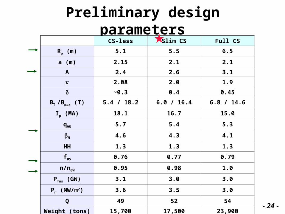
Preliminary design parametersCS-less Slim CS Full CS
Rp (m) 5.1 5.5 6.5
a (m) 2.15 2.1 2.1
A 2.4 2.6 3.1
2.08 2.0 1.9
~0.3 0.4 0.45
BT /Bmax (T) 5.4 / 18.2 6.0 / 16.4 6.8 / 14.6
Ip (MA) 18.1 16.7 15.0
q95 5.7 5.4 5.3
N 4.6 4.3 4.1
HH 1.3 1.3 1.3
fBS 0.76 0.77 0.79
n/nGW 0.95 0.98 1.0
Pfus (GW) 3.1 3.0 3.0
Pn (MW/m2) 3.6 3.5 3.0
Q 49 52 54
Weight (tons) 15,700 17,500 23,900- 24 -
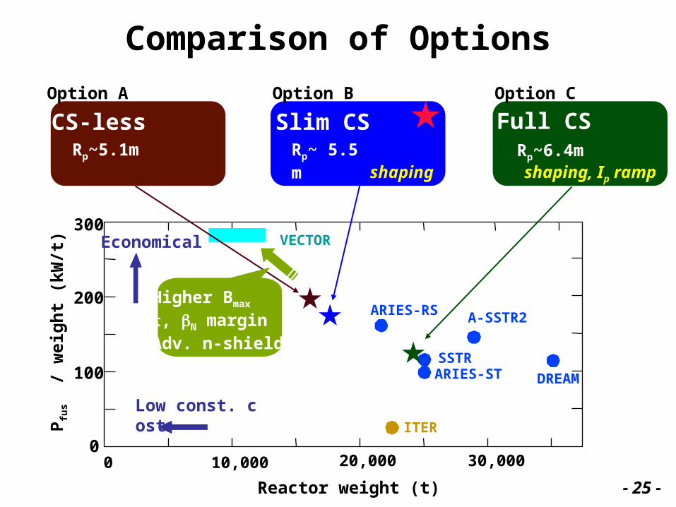
Comparison of Options
0
100
200
300
0 10,000 20,000 30,000
ITER
ARIES-RS
ARIES-STSSTR
A-SSTR2
DREAM
VECTOREconomical
Low const. costPfu
s /
wei
gh
t (k
W/t
)
Reactor weight (t)
Option A
CS-lessRp~5.1m
Full CSRp~6.4m
Option C
shaping, Ip ramp
Slim CSRp~ 5.5m
Option B
shaping
Higher Bmax
, N margin Adv. n-shield
- 25 -
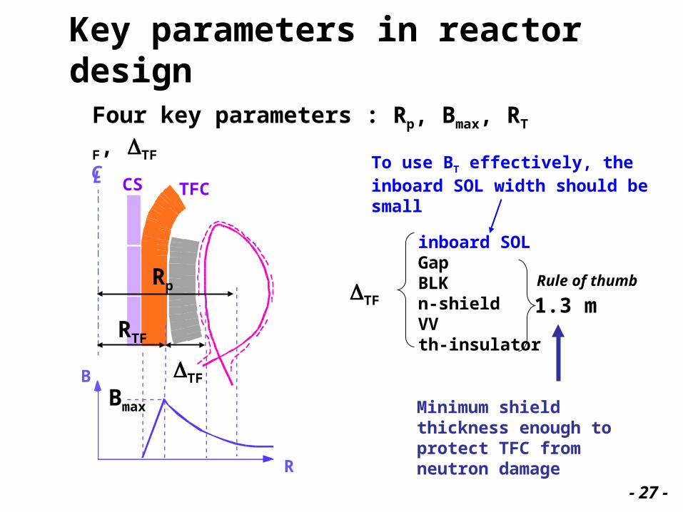
Key parameters in reactor design
inboard SOLGapBLKn-shieldVVth-insulator
B
R
CL
Rp
RTF
Bmax
TF
TF 1.3 m Rule of thumb
TFCCS
Minimum shield thickness enough to protect TFC from neutron damage
Four key parameters : Rp, Bmax, RTF, TF
To use BT effectively, the inboard SOL width should be small
- 27 -
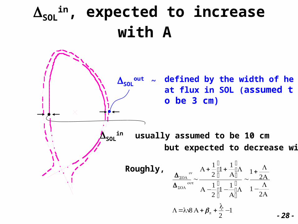
SOLin, expected to increase with A
SOLin usually assumed to be 10 cm
but expected to decrease with A.
SOLout ~
€
SOL in
SOL out
~A + 1
21+ 1
A
⎛
⎝ ⎜
⎞
⎠ ⎟L
A −12
1−1A
⎛
⎝ ⎜
⎞
⎠ ⎟L~1+
L2A
1− L2A
L =ln8A +p +li2−1
Roughly,
defined by the width of heat flux in SOL (assumed to be 3 cm)
- 28 -
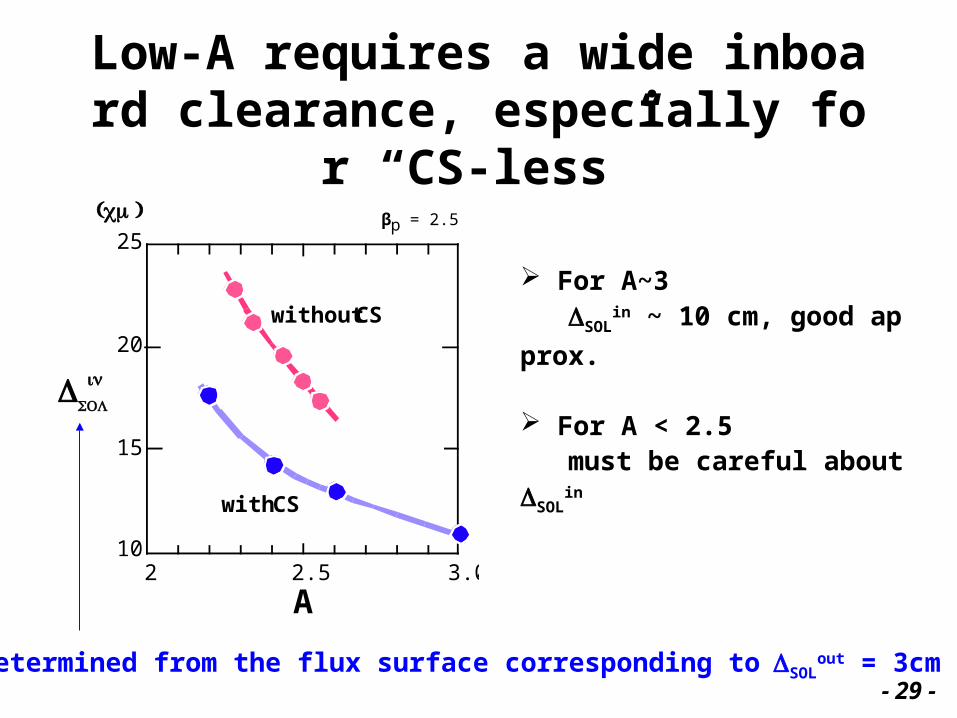
Low-A requires a wide inboard clearance, especially for “CS-less”
For A~3 SOL
in ~ 10 cm, good approx.
For A < 2.5 must be careful about SOL
in
without CS
25
20
15
102 2.5 3.0
A
SOL
(cm)
inp = 2.5
βpp = 2.5 = 2.5
with CS
Determined from the flux surface corresponding to SOLout = 3cm
- 29 -
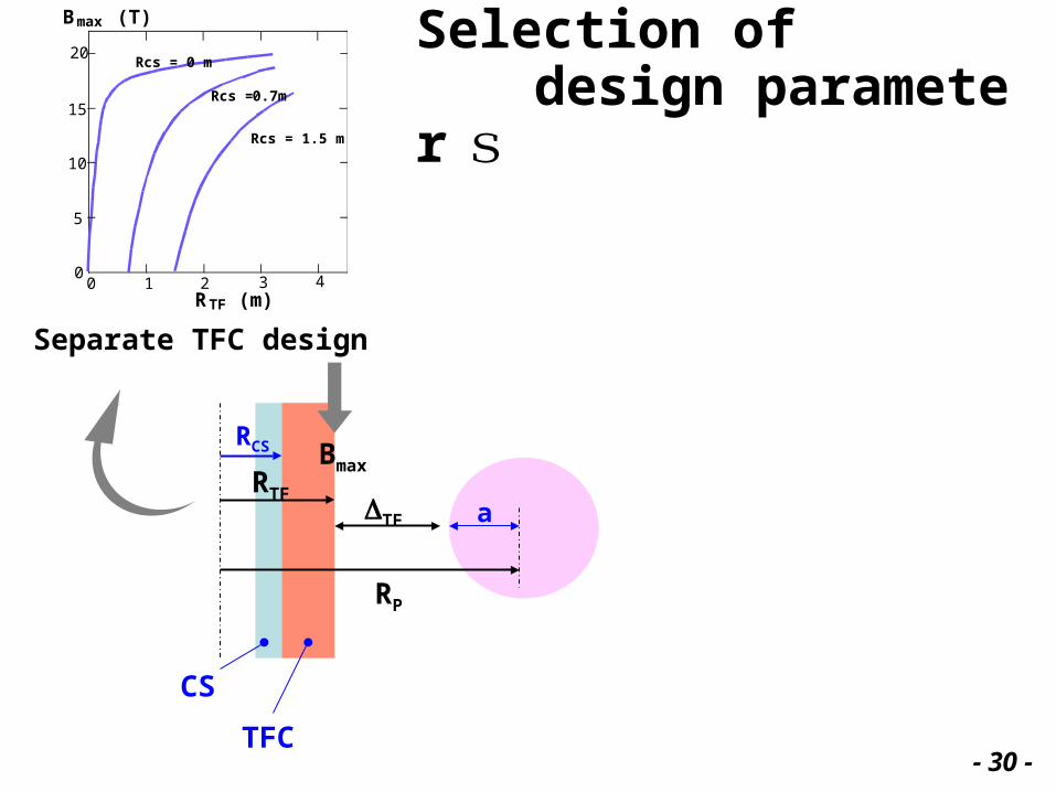
RCS
RTFTF a
RP
0
5
10
15
20
0 1 2 3 4RTF (m)
Bmax (T)
Rcs = 0.7m
Rcs = 0 m
Rcs = 1.5 m
Separate TFC design
Bmax
CS
TFC
Selection of design parameters
- 30 -
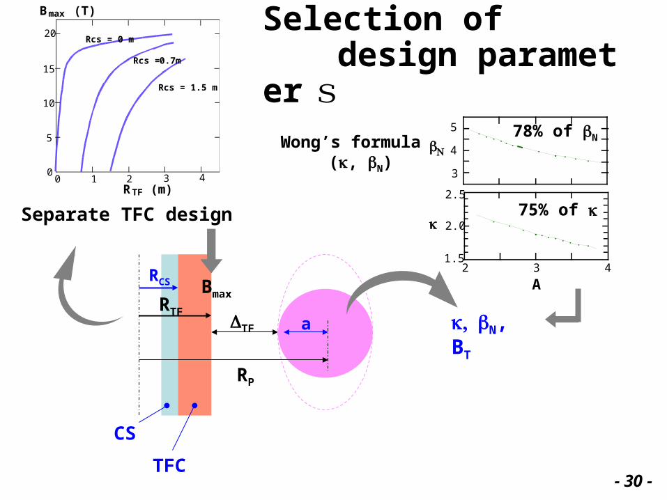
N, BT
Selection of design parameters
RCS
RTFTF a
RP
0
5
10
15
20
0 1 2 3 4RTF (m)
Bmax (T)
Rcs = 0.7m
Rcs = 0 m
Rcs = 1.5 m
Separate TFC design
Bmax
CS
TFC
75% of
78% of N
2 3 41.5
2.0
2.5
3
4
5
A
NWong’s formula
(, N)
- 30 -
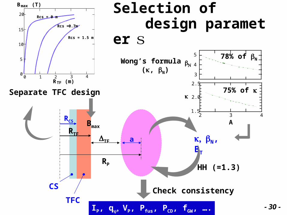
Selection of design parameters
N, BT
RCS
RTFTF a
RP
0
5
10
15
20
0 1 2 3 4RTF (m)
Bmax (T)
Rcs = 0.7m
Rcs = 0 m
Rcs = 1.5 m
Separate TFC design
Bmax
CS
TFC
2 3 41.5
2.0
2.5
3
4
5
A
N
75% of
78% of NWong’s formula (, N)
HH (=1.3)
IP, q VP, Pfus, PCD, fGW, ….
Check consistency
- 30 -
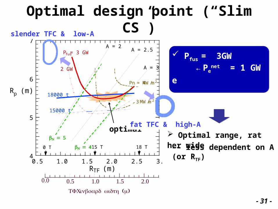
0.5 1.0 1.5 2.0 2.5 3.04
5
6
7
18000 t
15000 t
Pfus= 3 GW
2 GW
RTF (m)
Rp (m)
A = 2A = 2.5
A = 3
18 T0 T 15 T
Pn = 4 MW/m2
3 MW/m2
N = 5
TFC ( )inboard width m
0.5 1.0 1.5 2.00.0
N = 4
Optimal design point (“Slim CS”)
Pfus = 3GW ← Pe
net = 1 GWe
Weight minimum
Optimal range, rather wideoptimal
–– less dependent on A (or RTF)
fat TFC & high-A
slender TFC & low-A
- 31 -
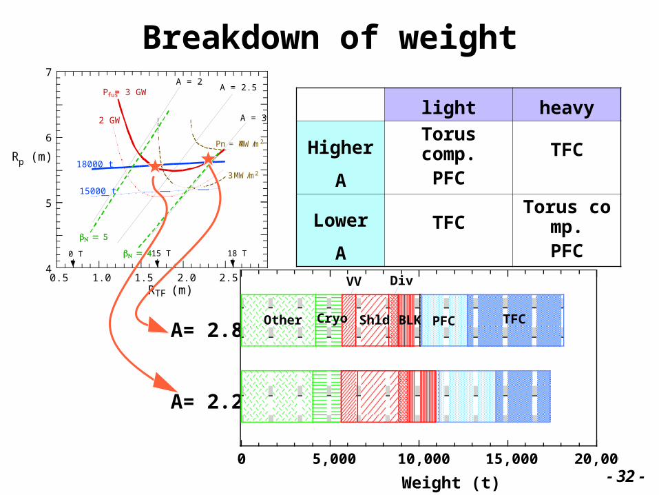
Breakdown of weight
A= 2.2
A= 2.8
0.5 1.0 1.5 2.0 2.5 3.04
5
6
7
18000 t
15000 t
Pfus= 3 GW
2 GW
RTF (m)
Rp (m)
A = 2A = 2.5
A = 3
18 T0 T 15 T
Pn = 4 MW/m2
3 MW/m2
N = 5
N = 4
Weight (t)
light heavy
Higher ATorus comp.
PFC TFC
Lower A TFCTorus comp.
PFC
5,000 10,000 15,000 20,0000
TFCPFCBLK
Div
Shld
VV
CryoOther
- 32 -
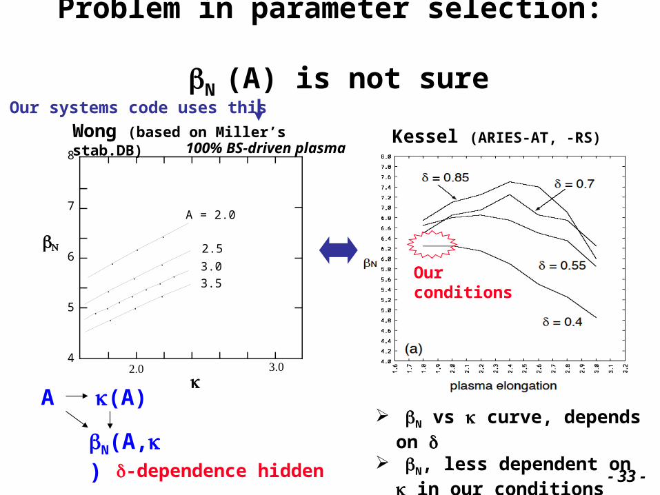
Problem in parameter selection: N (A) is not sure
Kessel (ARIES-AT, -RS)Wong (based on Miller’s stab.DB)
A (A)
N(A,)-dependence hidden
N vs curve, depends on
N, less dependent on in our conditions
Our conditions
A = 2.0
2.5
3.0 3.5
8
7
6
5
4
N
2.0 3.0
100% BS-driven plasma
Our systems code uses this
- 33 -
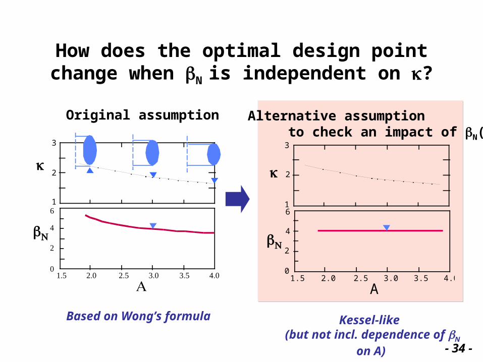
How does the optimal design point change when N is independent on ?
Original assumption
2
3
1
1.5 2.0 2.5 3.0 3.5 4.00
2
4
6
N
A1.5 2.0 2.5 3.0 3.5 4.0
2
3
1
0
2
4
6
A
N
Alternative assumption to check an impact of N()
Based on Wong’s formula Kessel-like (but not incl. dependence of N on A)
- 34 -
RTF (m)
0.5 1.0 1.5 2.00.0
1.5 2.0 2.5 3.0 3.5 4.0
2
3
1
0
2
4
6
A
N
TF ( )inboard width m
0.5 1.0 1.5 2.0 2.5 3.04
5
6
7
18000 t
15000 t
A = 2 A = 2.5 A = 3
18 T0 T 15 T
4 MW/m2
Pn = 3 MW/m2
Pfus = 3 GW
2 GW
0.5 1.0 1.5 2.0 2.5 3.04
5
6
7
18000 t
15000 t
Pfus = 3 GW
2 GW
RTF (m)
Rp (m)
A = 2A = 2.5
A = 3
18 T0 T 15 T
Pn = 4 MW/m2
3 MW/m2
N = 4
TFC ( )inboard width m0.5 1.0 1.5 2.00.0
1.5 2.0 2.5 3.0 3.5 4.0
2
3
1
0
2
4
6
N
A
N = 5
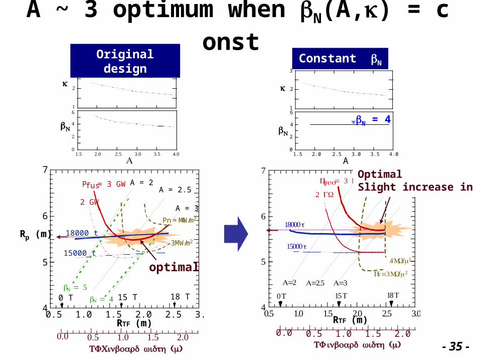
A ~ 3 optimum when N(A,) = const Original design Constant N
N = 4
optimal
OptimalSlight increase in Rp
- 35 -
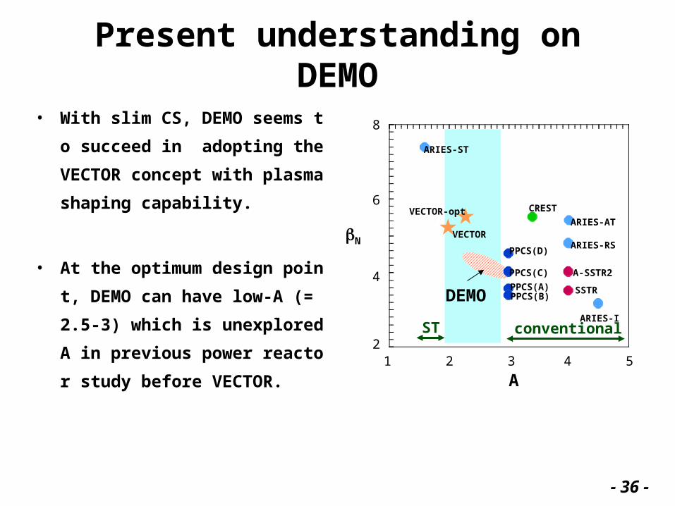
Present understanding on DEMO
• With slim CS, DEMO seems to su
cceed in adopting the VECTOR c
oncept with plasma shaping capa
bility.
• At the optimum design point, DE
MO can have low-A (= 2.5-3) whic
h is unexplored A in previous po
wer reactor study before VECTO
R.
ST
1 2 3 4 52
4
6
8
ARIES-ST
ARIES-AT
ARIES-RS
ARIES-I
A-SSTR2
SSTRPPCS(B)PPCS(A)
PPCS(C)
PPCS(D)
CREST
VECTOR
VECTOR-opt
conventional
A
N
DEMO
- 36 -
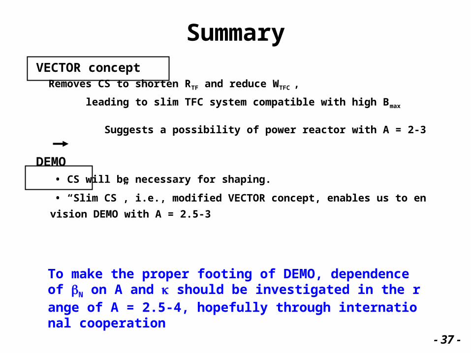
SummaryVECTOR concept Removes CS to shorten RTF and reduce WTFC ,
leading to slim TFC system compatible with high Bmax
Suggests a possibility of power reactor with A = 2-3
DEMO • CS will be necessary for shaping.
• “Slim CS”, i.e., modified VECTOR concept, enables us to envision DEM
O with A = 2.5-3
To make the proper footing of DEMO, dependence of N on A and should be investigated in the range of A = 2.5-4, hopefully through international cooperation
- 37 -


![Layered 3D: tomographic image synthesis for …web.media.mit.edu/~dlanman/research/compressivedisplays/...et al. [2010] introduce content-adaptive parallax barriers, optimiz-ing dual-layer](https://img.pdfslide.net/doc/110x75/5fb7b7e2a1584a2dfd5e0d66/layered-3d-tomographic-image-synthesis-for-webmediamitedudlanmanresearchcompressivedisplays.jpg)