Embed Size (px)
Citation preview

PLATES AND SCREWS:
An OverviewPresented by :
Dr. REM KUMAR RAI

SCREW : BRIEF OVERVIEW
SCREW: INTRODUCTION
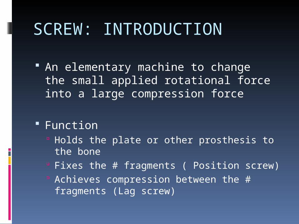
An elementary machine to change the small applied rotational force into a large compression force
Function Holds the plate or other prosthesis to the
bone Fixes the # fragments ( Position screw) Achieves compression between the #
fragments (Lag screw)
Screw: Parts
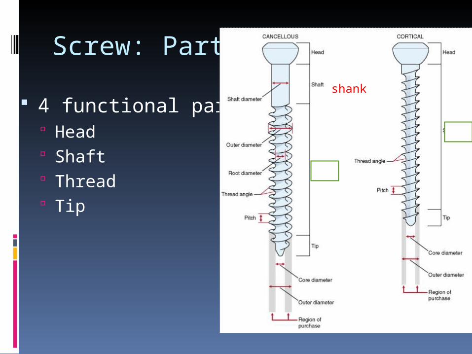
4 functional parts Head Shaft Thread Tip
shank
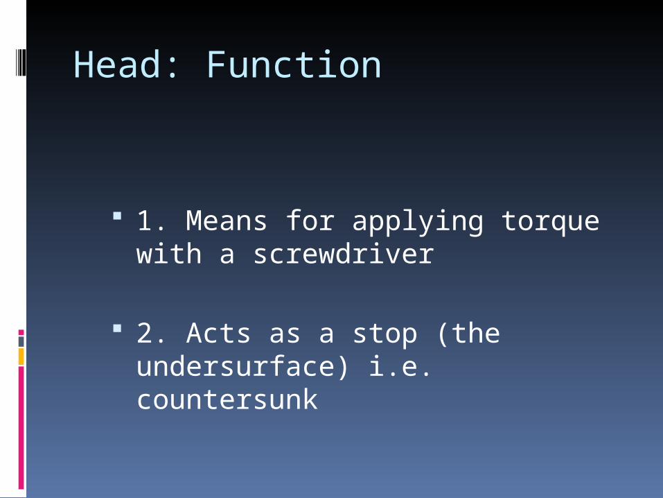
Head: Function
1. Means for applying torque with a screwdriver
2. Acts as a stop (the undersurface) i.e. countersunk
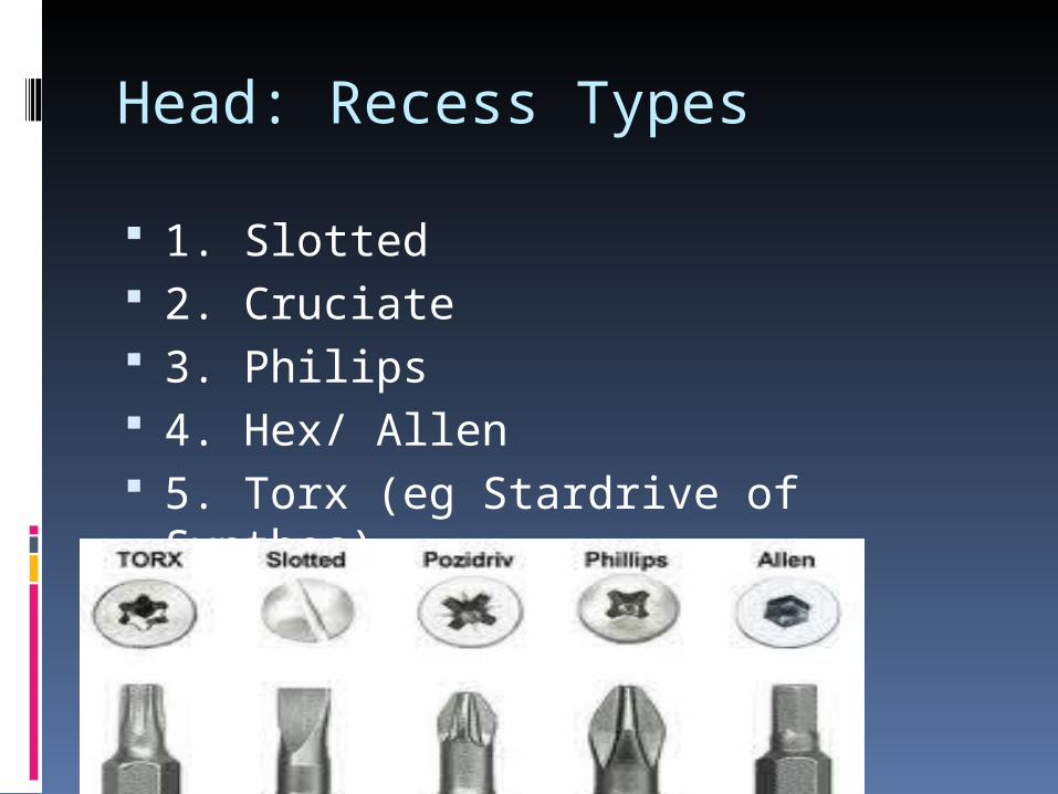
Head: Recess Types
1. Slotted 2. Cruciate 3. Philips 4. Hex/ Allen 5. Torx (eg Stardrive of Synthes)
Head: Countersink
Undersurface of head Conical Hemispherical Morse-cone (steep): locking plates
Screw: Shaft/ Shank
Smooth link Almost not present in standard
cortex screw Present in cortical SHAFT SCREW or
cancellous screw
Screw: Run out
Transition between shaft and thread Site of most stress riser Screw break
Incorrectly centered hole Hole not perpendicular to the plate

Screw: Thread
Inclined plane encircling the root Single thread May have two or more sets of
threads
V-thread profile: more stress at sharp corner
Buttress thread profile: less stress at the rounded corner
Screw: Core Diameter
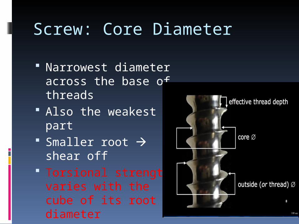
Narrowest diameter across the base of threads
Also the weakest part
Smaller root shear off
Torsional strength varies with the cube of its root diameter
Screw: Pitch and Lead
Distance between the adjacent threads Cortex screw : small pitch 1.75mm Cancellous screw: large pitch
Pitch also determines the lead Lead :distance advanced in a complete
turn Equals pitch in single threaded screw Greater M.A. if smaller lead
Screw: Thread Diameter
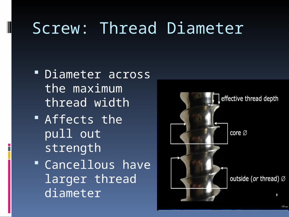
Diameter across the maximum thread width
Affects the pull out strength
Cancellous have larger thread diameter
Screw: Tip Designs
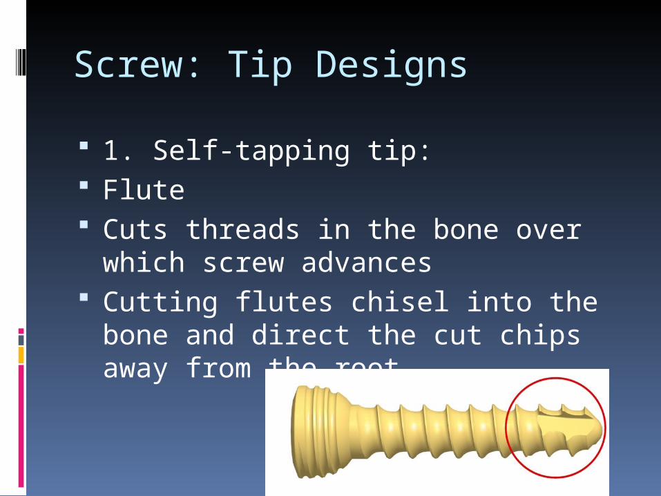
1. Self-tapping tip: Flute Cuts threads in the bone over which
screw advances Cutting flutes chisel into the bone
and direct the cut chips away from the root
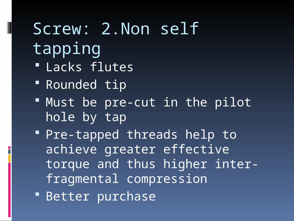
Screw: 2.Non self tapping Lacks flutes Rounded tip Must be pre-cut in the pilot hole by
tap Pre-tapped threads help to achieve
greater effective torque and thus higher inter-fragmental compression
Better purchase
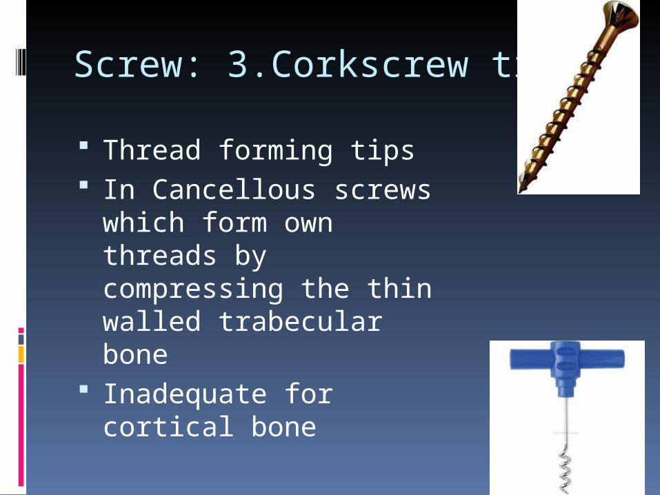
Screw: 3.Corkscrew tip
Thread forming tips In Cancellous screws
which form own threads by compressing the thin walled trabecular bone
Inadequate for cortical bone
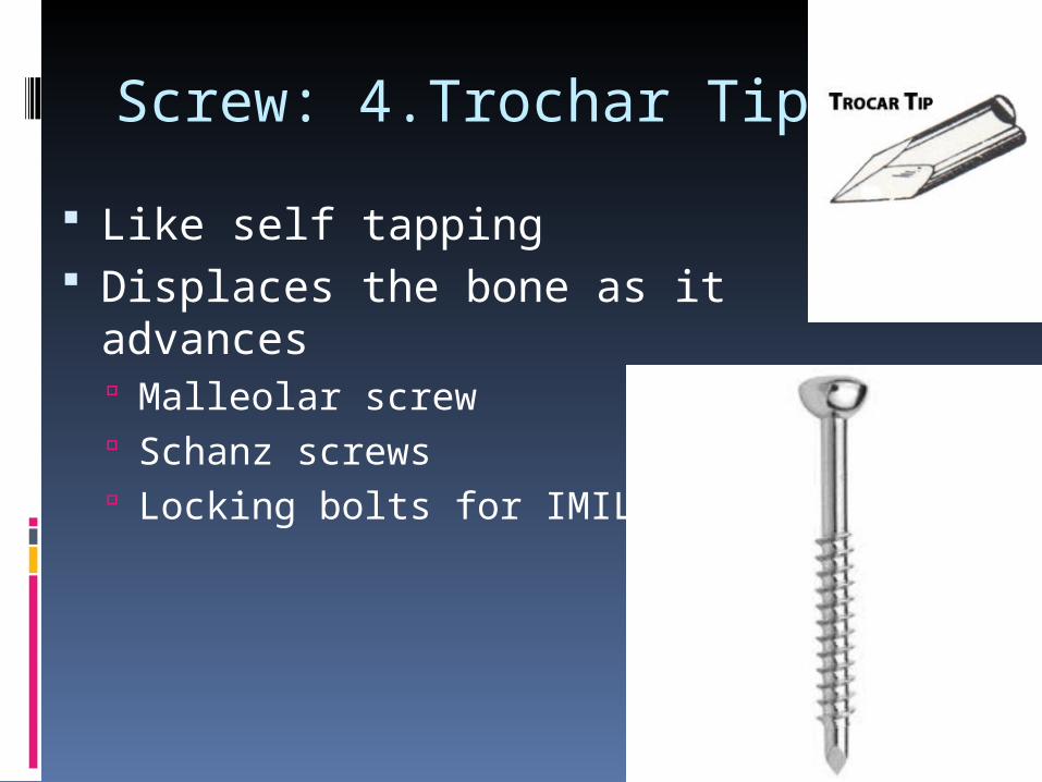
Screw: 4.Trochar Tip
Like self tapping Displaces the bone as it
advances Malleolar screw Schanz screws Locking bolts for IMIL
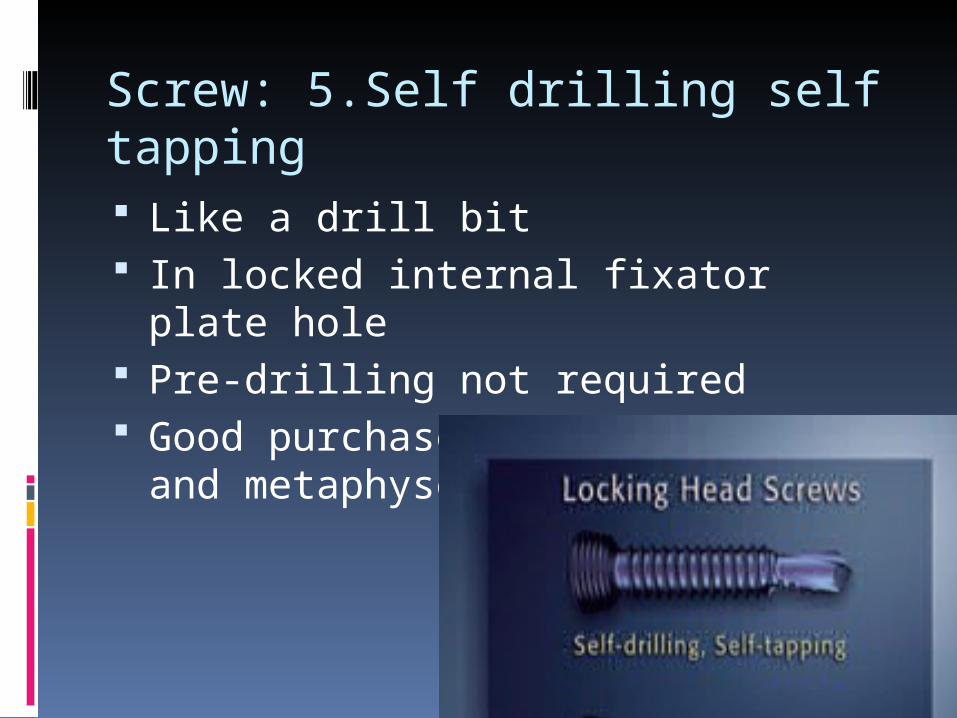
Screw: 5.Self drilling self tapping Like a drill bit In locked internal fixator plate hole Pre-drilling not required Good purchase in osteoporotic and
metaphyseal area
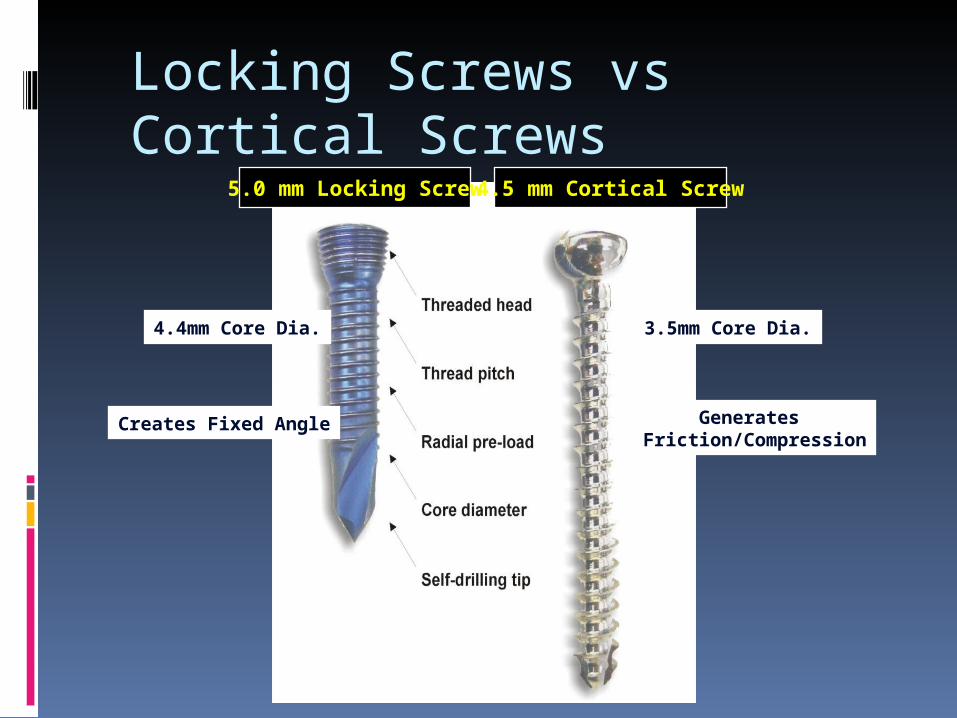
Locking Screws vs Cortical Screws
Creates Fixed Angle Generates Friction/Compression
4.4mm Core Dia. 3.5mm Core Dia.
5.0 mm Locking Screw4.5 mm Cortical Screw
Bending stiffness proportional to the core diameter
Pull out strength is proportional to the size of the thread
Cannulated screws have less bending stiffness
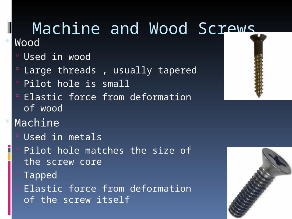
Machine and Wood Screws Wood
Used in wood Large threads , usually tapered Pilot hole is small Elastic force from deformation of
wood Machine
Used in metals Pilot hole matches the size of the
screw core Tapped Elastic force from deformation of
the screw itself
Tensile strength is directly proportional to the squared core diameter d2
Pull out strength is depends on the outer diameter
Shear strength is directly proportional to the cubed core diameter d3.
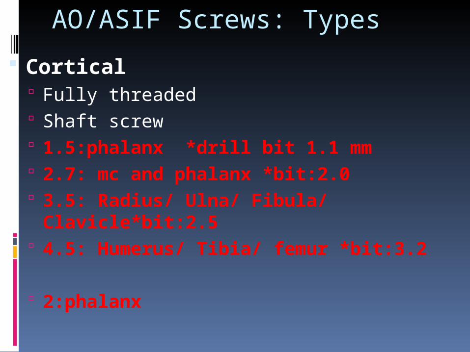
AO/ASIF Screws: Types
Cortical Fully threaded Shaft screw 1.5:phalanx *drill bit 1.1 mm 2.7: mc and phalanx *bit:2.0 3.5: Radius/ Ulna/ Fibula/
Clavicle*bit:2.5 4.5: Humerus/ Tibia/ femur *bit:3.2
2:phalanx
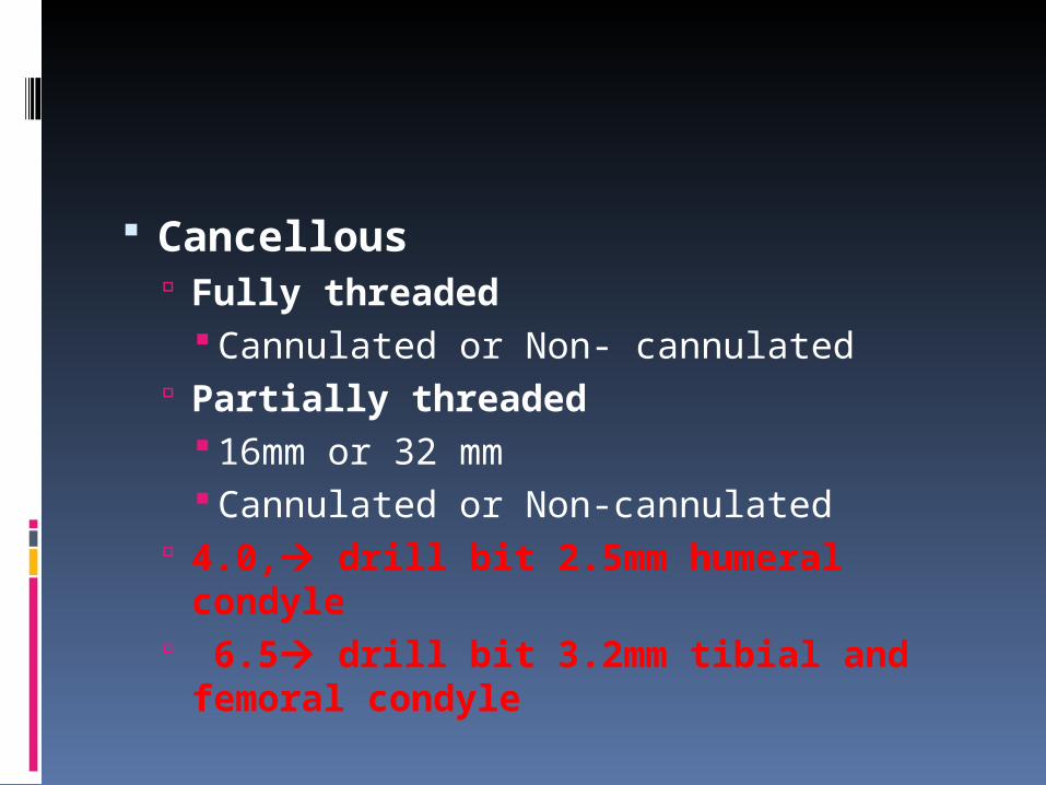
Cancellous Fully threaded
Cannulated or Non- cannulated Partially threaded
16mm or 32 mm Cannulated or Non-cannulated
4.0, drill bit 2.5mm humeral condyle
6.5 drill bit 3.2mm tibial and femoral condyle
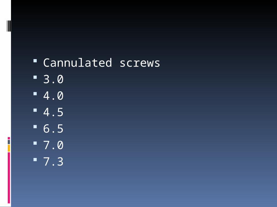
Cannulated screws 3.0 4.0 4.5 6.5 7.0 7.3
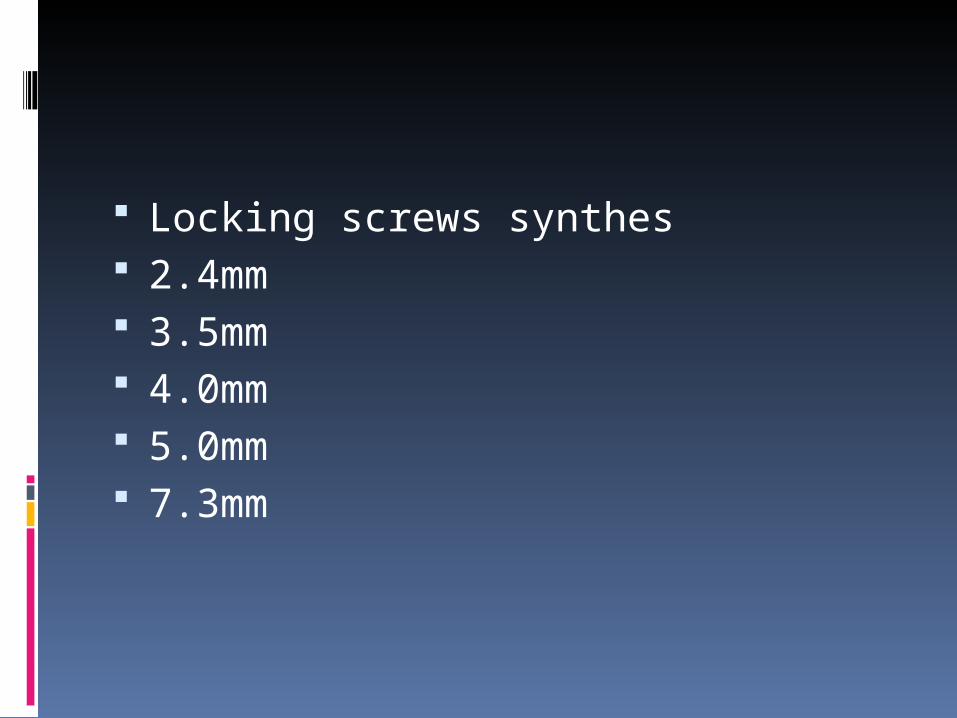
Locking screws synthes 2.4mm 3.5mm 4.0mm 5.0mm 7.3mm
AO/ASIF Screws
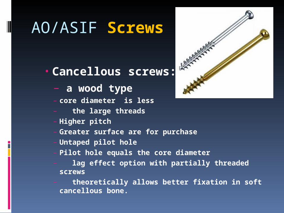
• Cancellous screws:– a wood type– core diameter is less– the large threads– Higher pitch– Greater surface are for purchase– Untaped pilot hole– Pilot hole equals the core diameter– lag effect option with partially threaded
screws – theoretically allows better fixation in soft
cancellous bone.
AO/ASIF Screws
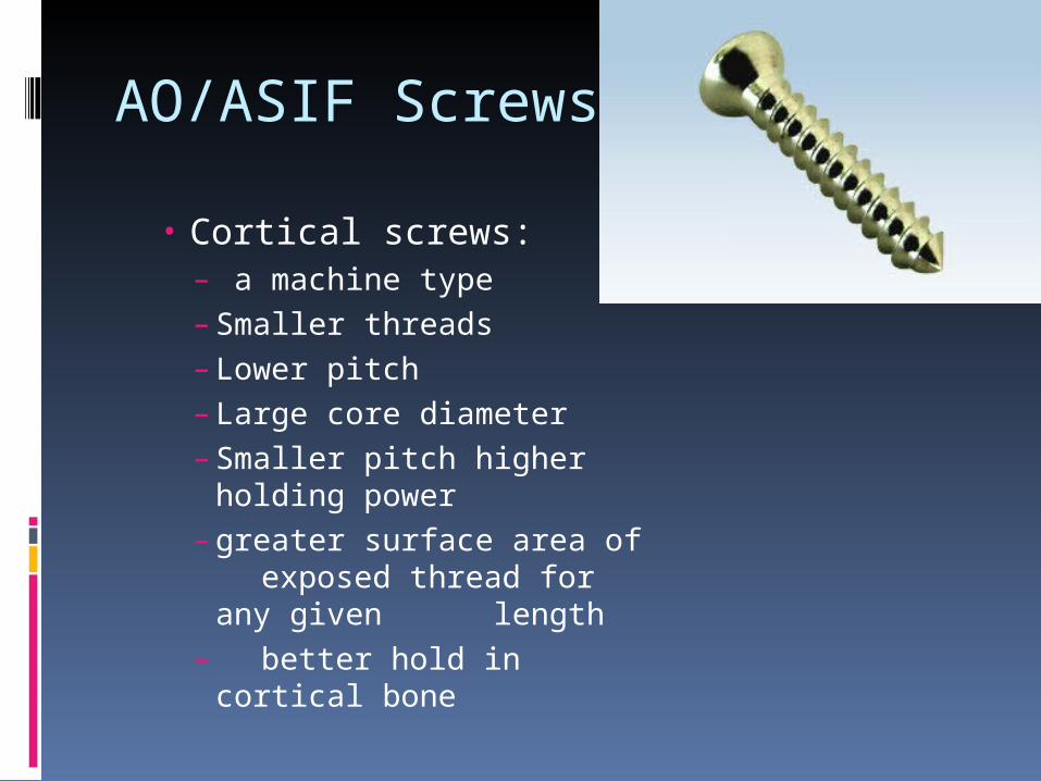
• Cortical screws:– a machine type– Smaller threads– Lower pitch– Large core diameter– Smaller pitch higher
holding power– greater surface area of
exposed thread for any given length
– better hold in cortical bone
Special Screws
Herbert Screw Dynamic Hip Screw Malleolar Screw Locking bolt Interference screw Suture anchor Acutrak screw Pedicle screw
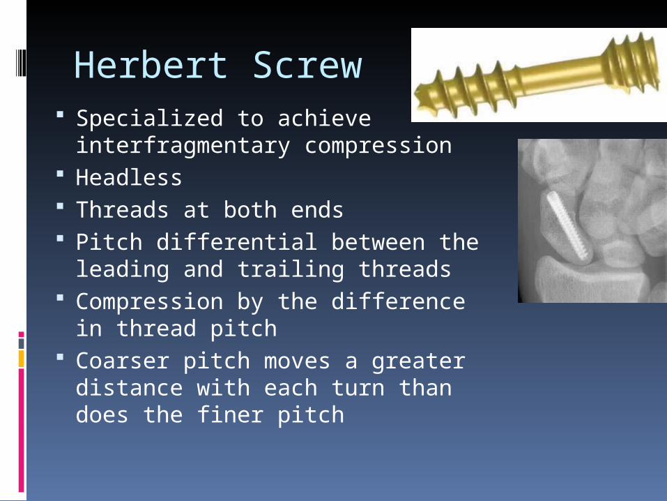
Herbert Screw Specialized to achieve
interfragmentary compression Headless Threads at both ends Pitch differential between the
leading and trailing threads Compression by the difference
in thread pitch Coarser pitch moves a greater
distance with each turn than does the finer pitch
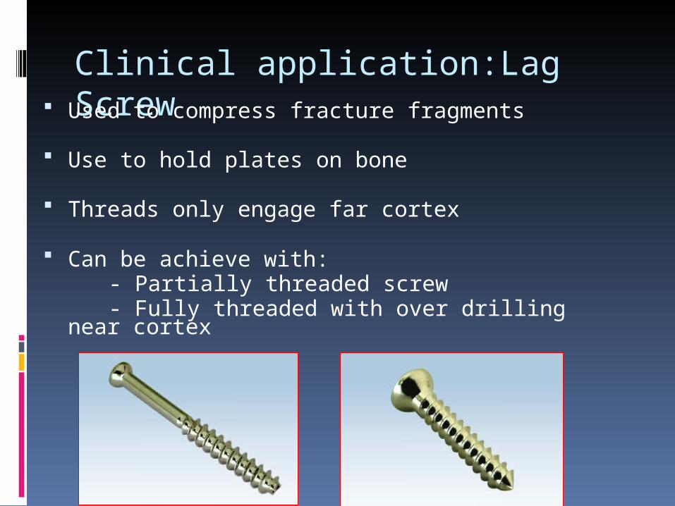
Clinical application:Lag Screw Used to compress fracture fragments
Use to hold plates on bone
Threads only engage far cortex
Can be achieve with: - Partially threaded screw - Fully threaded with over drilling near cortex

Clinical Application: Positional Screw
Lag Screw
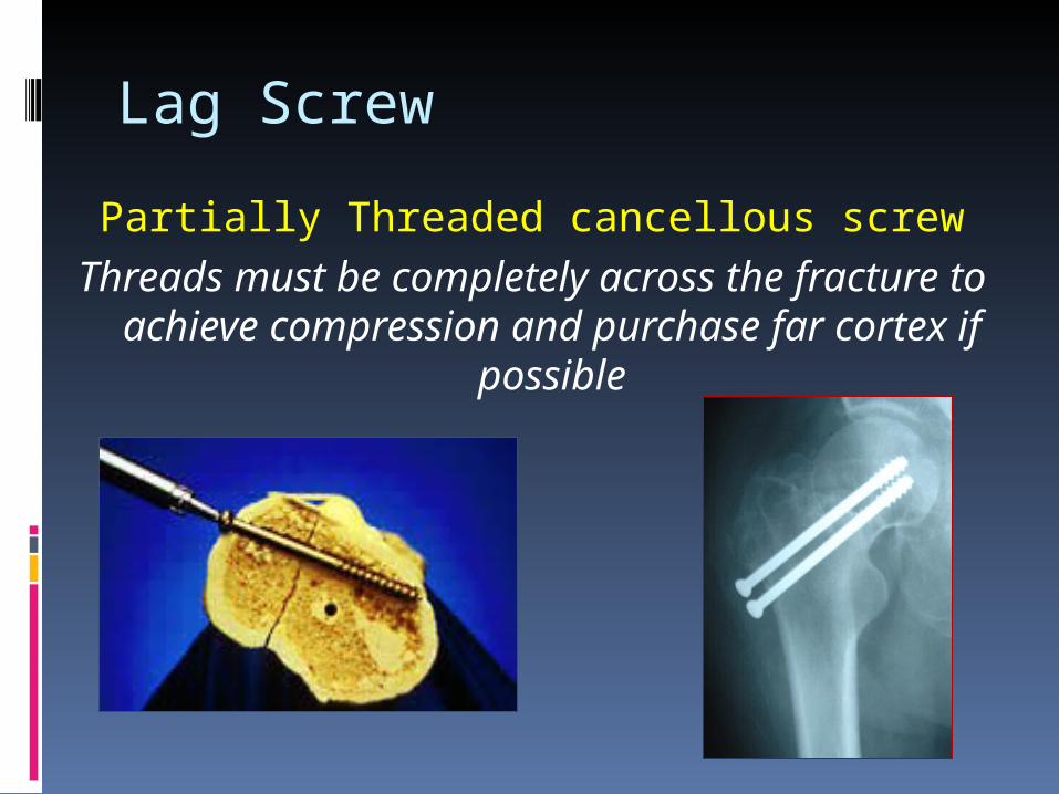
Partially Threaded cancellous screwThreads must be completely across the
fracture to achieve compression and purchase far cortex if possible

PLATES
Introduction : Bone plates are like internal
splints holding together the fractured ends of a bone.
Mechanical functions of plate1. Transmit forces from one end to
another, bypassing and thus protecting the area of fractures.
2. Holds the fracture ends together in alignment throughout the healing process.

Names of plates.
1. Shape (Semitubular, 1/3rd tubular)2. Width of plate (Small, Narrow,
Broad)3. Shape of screw holes. (Round, Oval)4. Surface contact characteristics. (LC,
PC)5. Intended site of application
(Condylar Plate)6. According to the function
Type of plate – Functional Regardless of their length, thickness,
geometry, configuration and types of hole, all plates may be classified in to 4 groups according to their function.
1. Neutralization plate.2. Compression plates.3. Buttress plate.4. Tension band plates.
Standard Plates
Narrow DCP-4.5 mm Broad DCP – 4.5 mm,3.5 mm DCP LC-DCP 3.5 & 4.5mm Reconstruction plate 3.5 & 4.5mm 1/3 tubular plate 2.7, 3.5 & 4.5 mm
Special Plates
T Plates T&L Buttress plates Lateral Tibial head buttress plates Condylar buttress plate Narrow lenthening plates Broad Lengthening plate Spoon plate Clover leaf plate
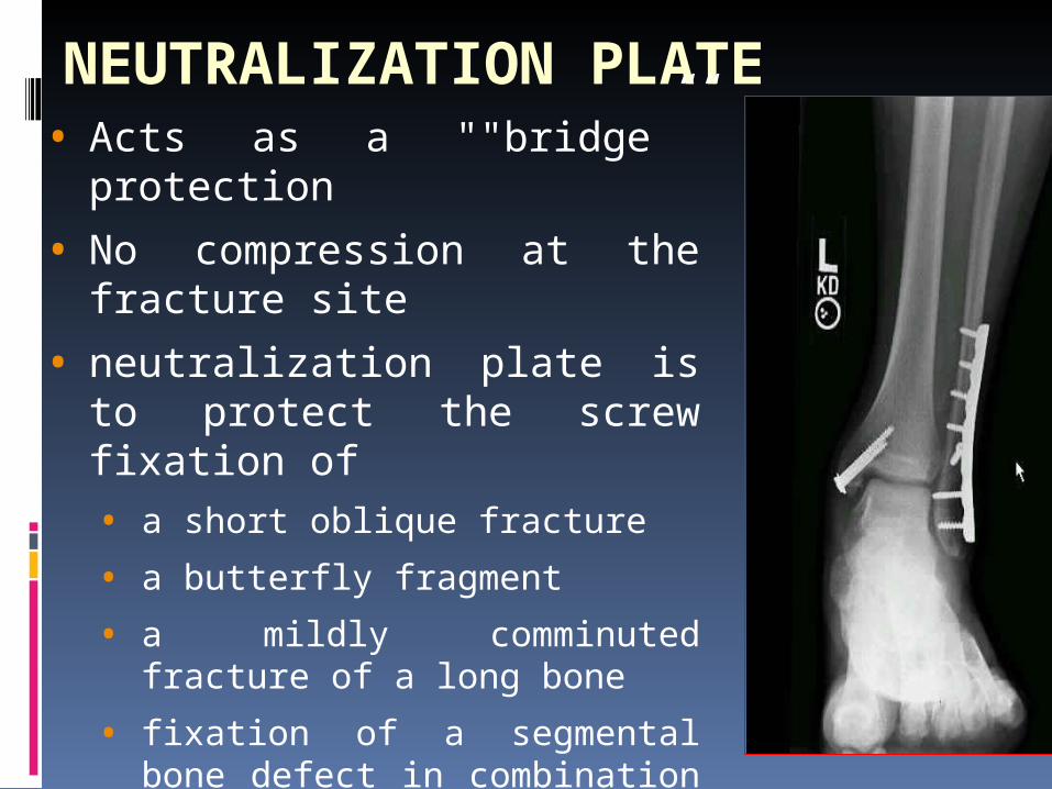
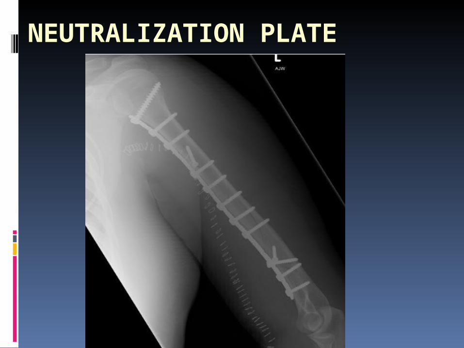
NEUTRALIZATION PLATE• Acts as a ""bridge””
protection
• No compression at the fracture site
• neutralization plate is to protect the screw fixation of • a short oblique fracture
• a butterfly fragment
• a mildly comminuted fracture of a long bone
• fixation of a segmental bone defect in combination with bone grafting.
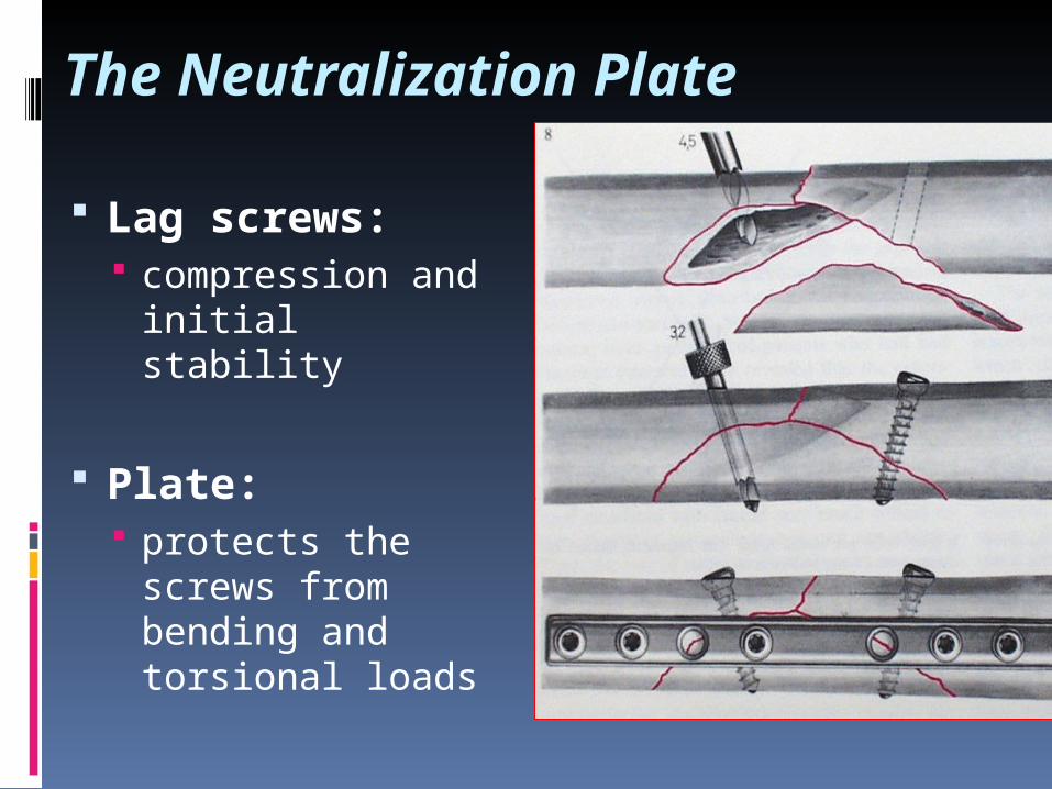
The Neutralization Plate
Lag screws: compression and
initial stability
Plate: protects the
screws from bending and torsional loads
NEUTRALIZATION PLATE
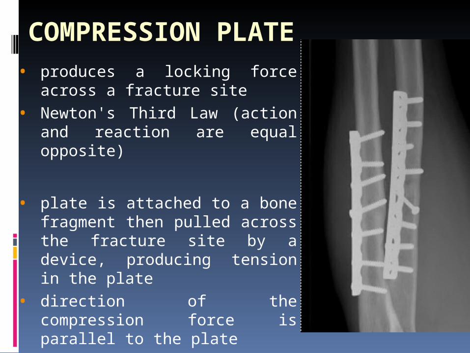
COMPRESSION PLATE• produces a locking force across
a fracture site
• Newton's Third Law (action and reaction are equal opposite)
• plate is attached to a bone fragment then pulled across the fracture site by a device, producing tension in the plate
• direction of the compression force is parallel to the plate
COMPRESSION
Static: does not change with time
Dynamic: periodic partial loading & unloading due to functional activity
1. Tension Band wiring2. Tension Band Plating
BONE UNDER COMPRESSION
• Superior stability – Utilization of physiological forces
• Improved milieu for bone healing
• Early mobilization
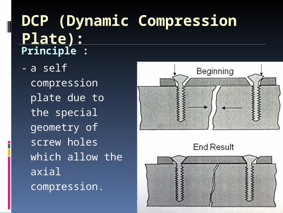
DCP (Dynamic Compression Plate):Principle :
- a self compression plate due to the special geometry of screw holes which allow the axial compression.
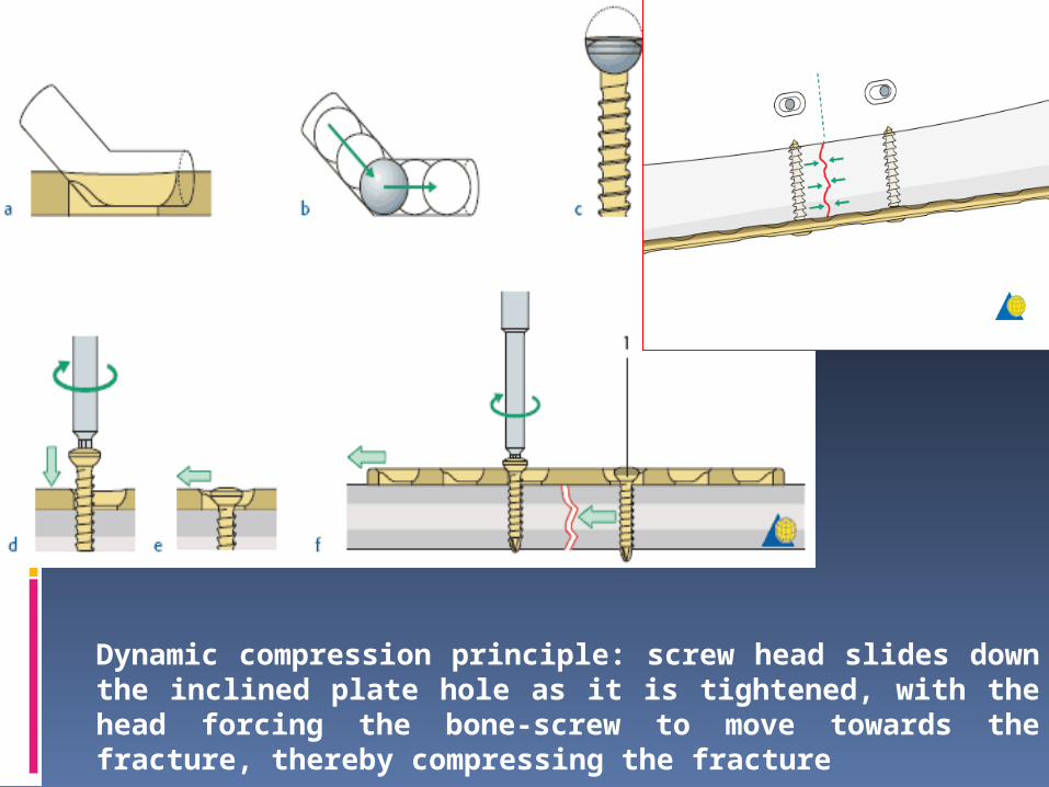
Dynamic compression principle: screw head slides down the inclined plate hole as it is tightened, with the head forcing the bone-screw to move towards the fracture, thereby compressing the fracture
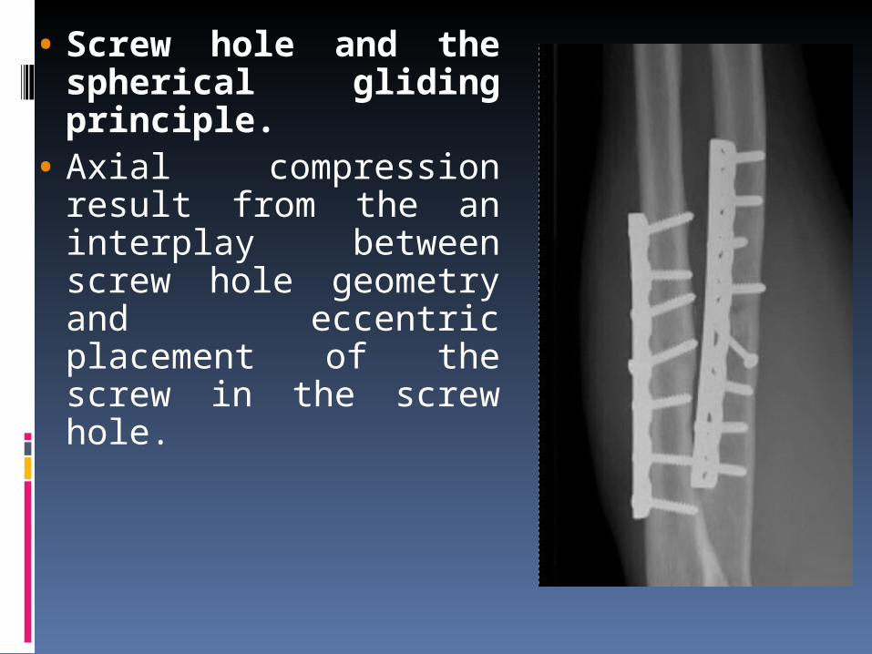
• Screw hole and the spherical gliding principle.
• Axial compression result from the an interplay between screw hole geometry and eccentric placement of the screw in the screw hole.
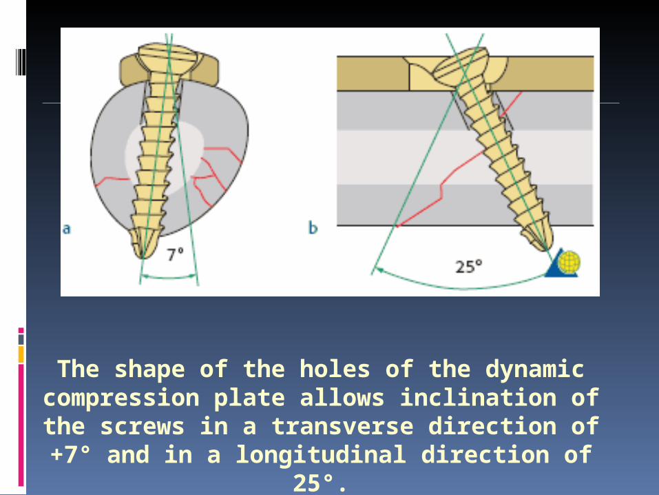
The shape of the holes of the dynamic compression plate allows inclination of the screws in a transverse
direction of +7° and in a longitudinal direction of 25°.
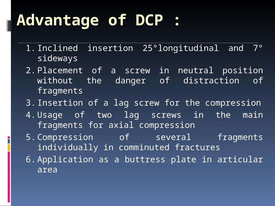
Advantage of DCP :
1. Inclined insertion 25°longitudinal and 7° sideways
2. Placement of a screw in neutral position without the danger of distraction of fragments
3. Insertion of a lag screw for the compression4. Usage of two lag screws in the main
fragments for axial compression5. Compression of several fragments individually
in comminuted fractures6. Application as a buttress plate in articular area
Shortcomings of DCP :
1. Flat under surface.2. Inclination upto 25°3. Plate hole distribution (extended
middle segment)
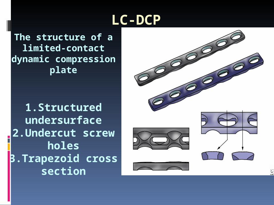
The structure of a limited-contact dynamic
compression plate
1.Structured undersurface
2.Undercut screw holes3.Trapezoid cross
section
LC-DCP
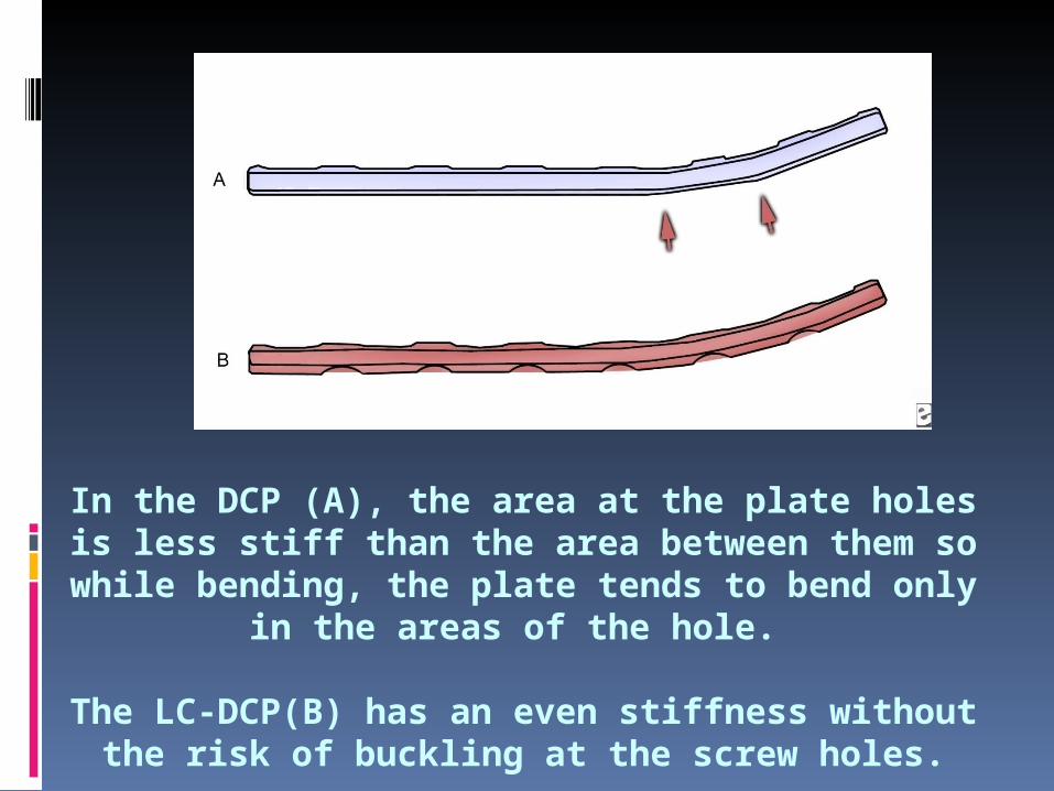
In the DCP (A), the area at the plate holes is less stiff than the area between them so while bending, the plate
tends to bend only in the areas of the hole.
The LC-DCP(B) has an even stiffness without the risk of buckling at the screw holes.
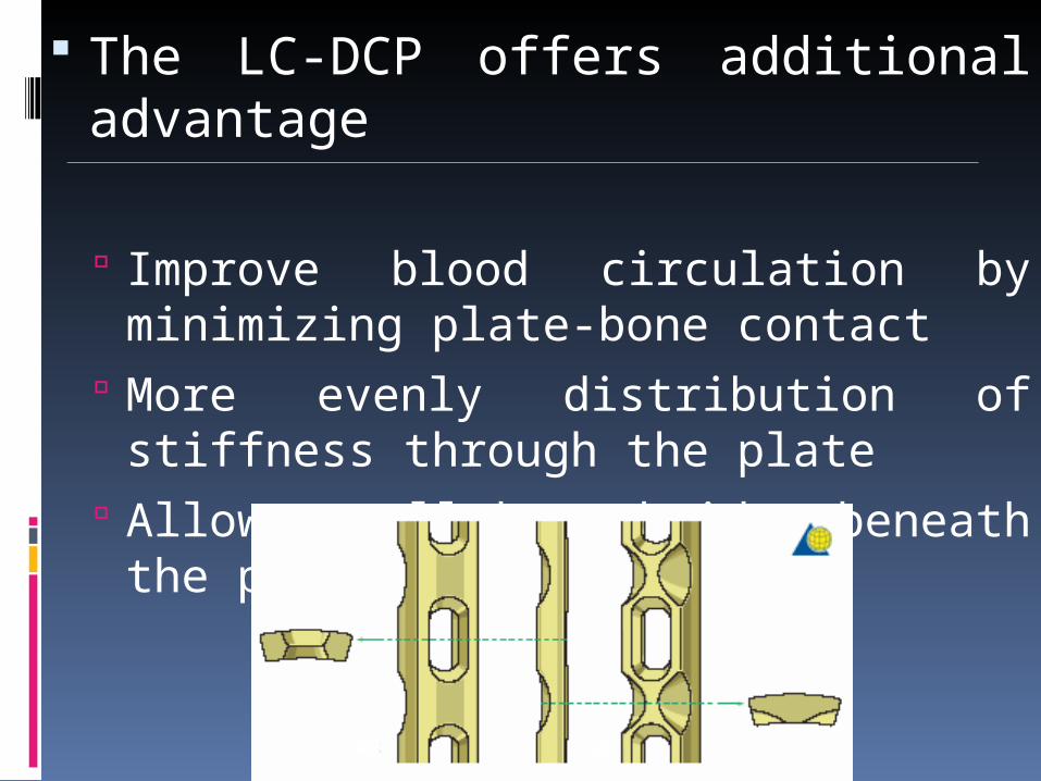
The LC-DCP offers additional advantage
Improve blood circulation by minimizing plate-bone contact
More evenly distribution of stiffness through the plate
Allows small bone bridge beneath the plate
The trapezoid cross section of the plate results in a smaller contact area between plate and bone.
The plate holes are uniformaly spaced, which permits easy positioning of the plate.
Undercuts plate holes; undercut at each end of the plate hole allows 40 tilting of screws both ways along the long axis of the plate. Lag screw fixation of short oblique fractures is thereby possible.
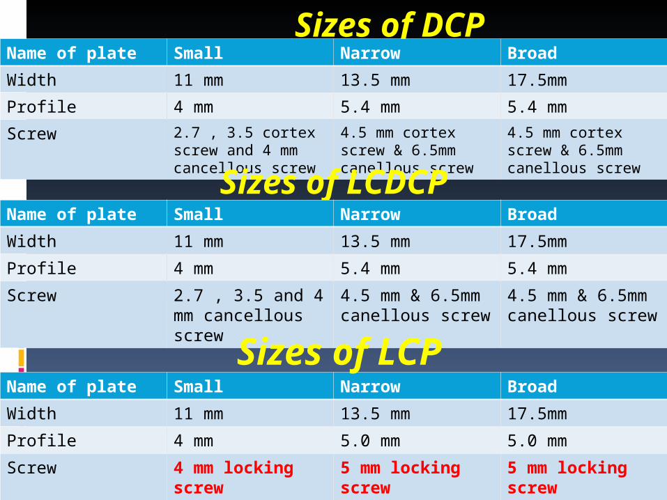
Sizes of DCPName of plate Small Narrow Broad
Width 11 mm 13.5 mm 17.5mm
Profile 4 mm 5.4 mm 5.4 mm
Screw 2.7 , 3.5 cortex screw and 4 mm cancellous screw
4.5 mm cortex screw & 6.5mm canellous screw
4.5 mm cortex screw & 6.5mm canellous screw
Sizes of LCDCPName of plate Small Narrow Broad
Width 11 mm 13.5 mm 17.5mm
Profile 4 mm 5.4 mm 5.4 mm
Screw 2.7 , 3.5 and 4 mm cancellous screw
4.5 mm & 6.5mm canellous screw
4.5 mm & 6.5mm canellous screw
Name of plate Small Narrow Broad
Width 11 mm 13.5 mm 17.5mm
Profile 4 mm 5.0 mm 5.0 mm
Screw 4 mm locking screw 5 mm locking screw 5 mm locking screw
Sizes of LCP
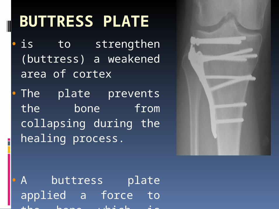
BUTTRESS PLATE• is to strengthen
(buttress) a weakened area of cortex
• The plate prevents the bone from collapsing during the healing process.
• A buttress plate applied a force to the bone which is perpendicular (normal) to the flat surface of the plate.
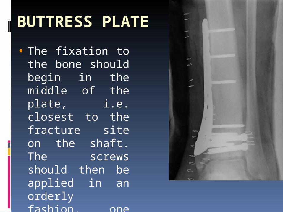
• The fixation to the bone should begin in the middle of the plate, i.e. closest to the fracture site on the shaft. The screws should then be applied in an orderly fashion, one after the other, towards both ends of the plate.
• A representative clinical example of a buttress plate is the T-plate used for the fixation of fractures of the distal radius and the tibial plateau.
BUTTRESS PLATE
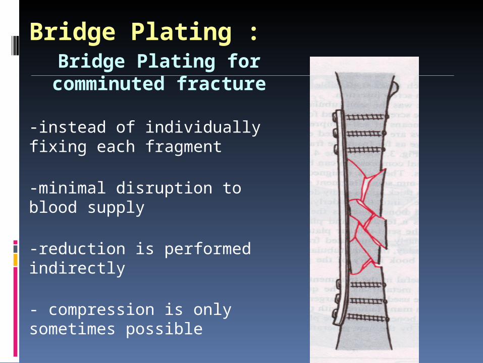
Bridge Plating :Bridge Plating for
comminuted fracture
-instead of individually fixing each fragment
-minimal disruption to blood supply
-reduction is performed indirectly
- compression is only sometimes possible
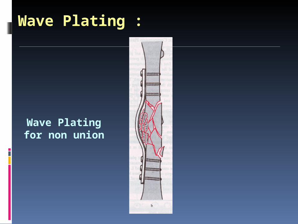
Wave Plating :
Wave Plating for non union
ADDITIONAL PRINCIPLES OF PLATE FIXATION
The engineering principle of the tension band is widely used in fracture fixation. It applies to the conversion of tensile forces to compression forces on the convex side of an eccentrically loaded bone.
Reconstruction Plates :
Can be bent and twisted in two dimensions.
Decrease stiffness than DCP.
Should not be bent more than 15°.
Used were the exact and complex contouring is required. eg. Pelvis, Distal Humerus, Clavicle.
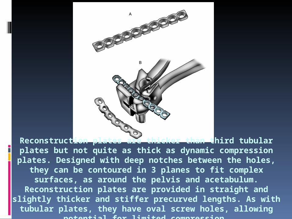
Reconstruction plates are thicker than third tubular plates but not quite as thick as dynamic compression plates. Designed with deep notches between the holes, they can be contoured in 3 planes to fit
complex surfaces, as around the pelvis and acetabulum. Reconstruction plates are provided in straight and slightly thicker and stiffer precurved lengths. As with tubular plates, they have oval screw
holes, allowing potential for limited compression.
One Third Tubular Plates : Plates have the form of one third of the
circumference of a cylinder. Low rigidity (1mm thick). Oval holes – Axial compression can be
achieved. Uses – Lateral malleolus, distal ulna,
metatarsals.
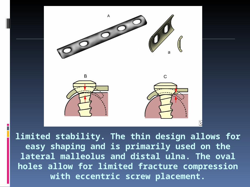
limited stability. The thin design allows for easy shaping and is primarily used on the lateral malleolus and distal
ulna. The oval holes allow for limited fracture compression with eccentric screw placement.
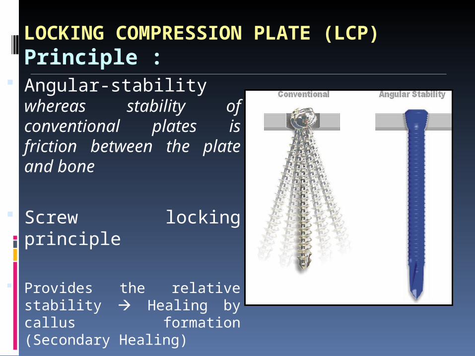
LOCKING COMPRESSION PLATE (LCP)Principle :
Angular-stability whereas stability of conventional plates is friction between the plate and bone
Screw locking principle
Provides the relative stability Healing by callus formation (Secondary Healing)
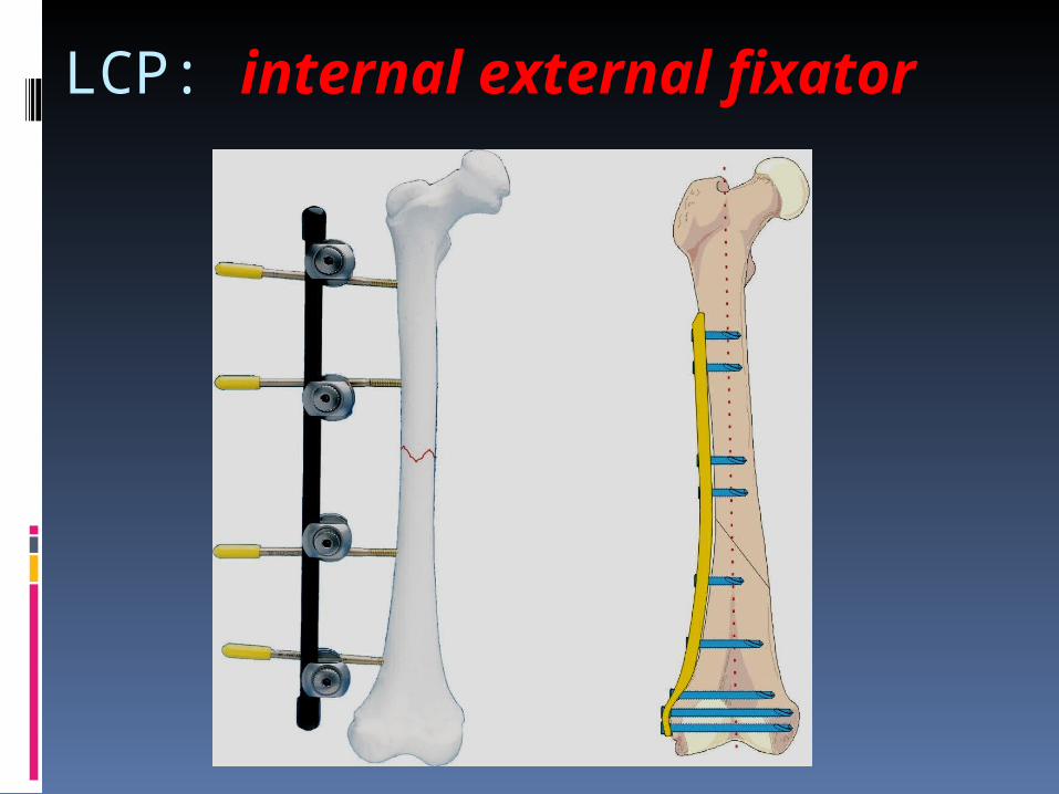
LCP: internal external fixator
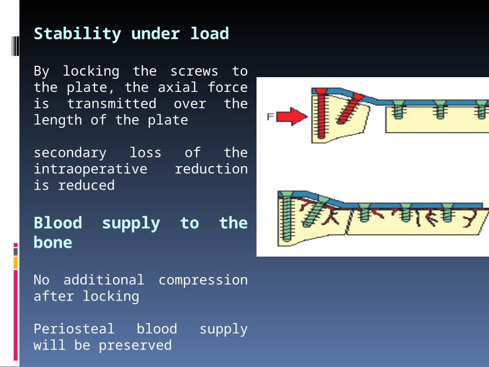
Stability under load
By locking the screws to the plate, the axial force is transmitted over the length of the plate secondary loss of the intraoperative reduction is reduced
Blood supply to the bone
No additional compression after locking
Periosteal blood supply will be preserved
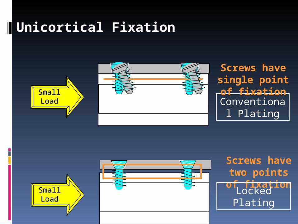
Unicortical Fixation
Conventional Plating
Small Small LoadLoad
Small Small LoadLoad
Screws have single point of
fixation
Screws have two points of fixationLocked Plating
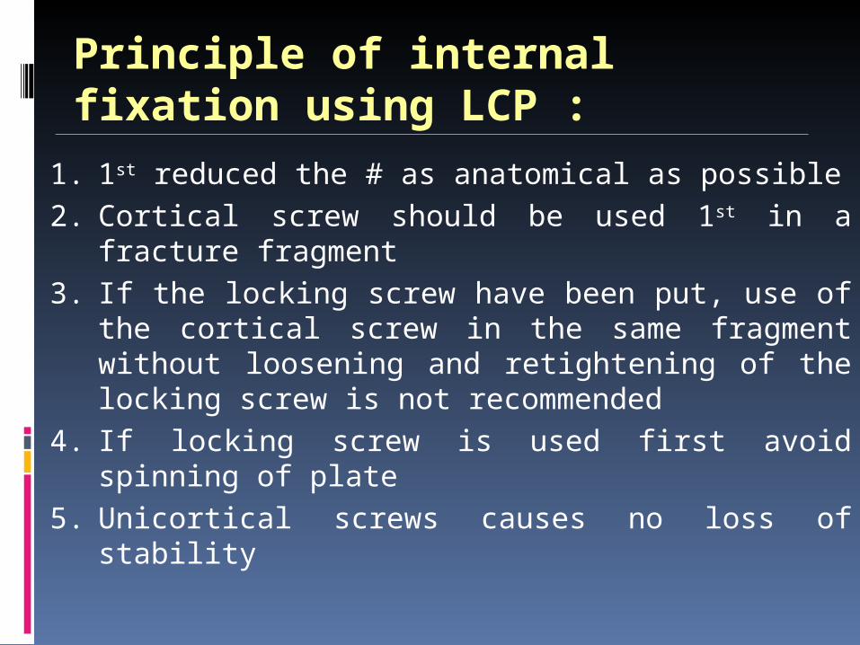
Principle of internal fixation using LCP :
1. 1st reduced the # as anatomical as possible2. Cortical screw should be used 1st in a fracture
fragment3. If the locking screw have been put, use of the
cortical screw in the same fragment without loosening and retightening of the locking screw is not recommended
4. If locking screw is used first avoid spinning of plate
5. Unicortical screws causes no loss of stability

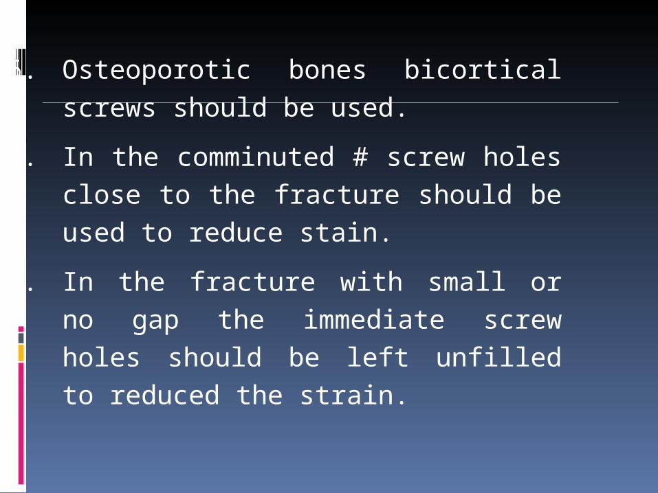
6. Osteoporotic bones bicortical screws should be used.
7. In the comminuted # screw holes close to the fracture should be used to reduce stain.
8. In the fracture with small or no gap the immediate screw holes should be left unfilled to reduced the strain.
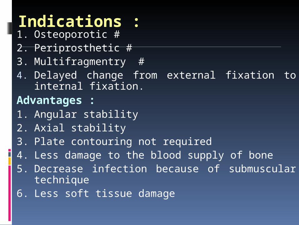
Indications :1. Osteoporotic #2. Periprosthetic #3. Multifragmentry #4. Delayed change from external fixation to internal
fixation.Advantages :1. Angular stability 2. Axial stability3. Plate contouring not required4. Less damage to the blood supply of bone5. Decrease infection because of submuscular
technique6. Less soft tissue damage
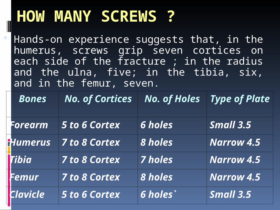
HOW MANY SCREWS ? Hands-on experience suggests that, in the
humerus, screws grip seven cortices on each side of the fracture ; in the radius and the ulna, five; in the tibia, six, and in the femur, seven.Bones No. of
CorticesNo. of Holes
Type of Plate
Forearm 5 to 6 Cortex 6 holes Small 3.5
Humerus
7 to 8 Cortex 8 holes Narrow 4.5
Tibia 7 to 8 Cortex 7 holes Narrow 4.5
Femur 7 to 8 Cortex 8 holes Narrow 4.5
Clavicle 5 to 6 Cortex 6 holes` Small 3.5
HOW CLOSE TO THE FRACTURE SITE?
A screw, as a result, should not be placed closer than one centimeter from the fracture line.
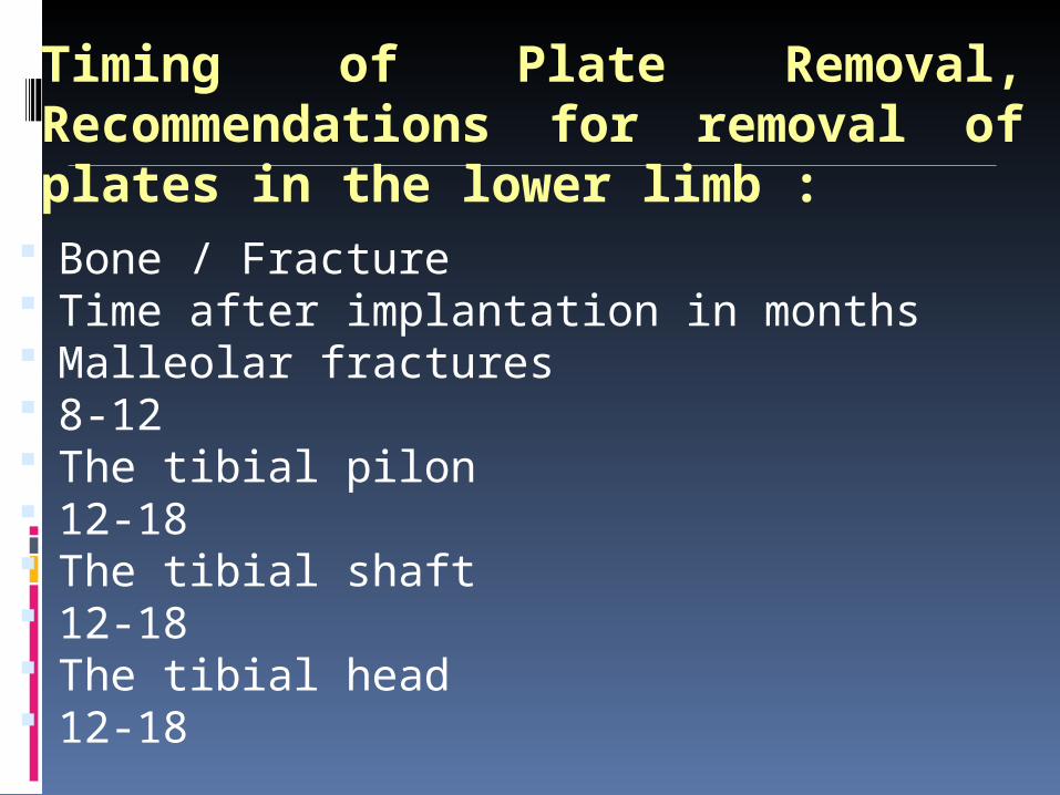
Timing of Plate Removal, Recommendations for removal of plates in the lower limb :
Bone / Fracture Time after implantation in months Malleolar fractures 8-12 The tibial pilon 12-18 The tibial shaft 12-18 The tibial head 12-18
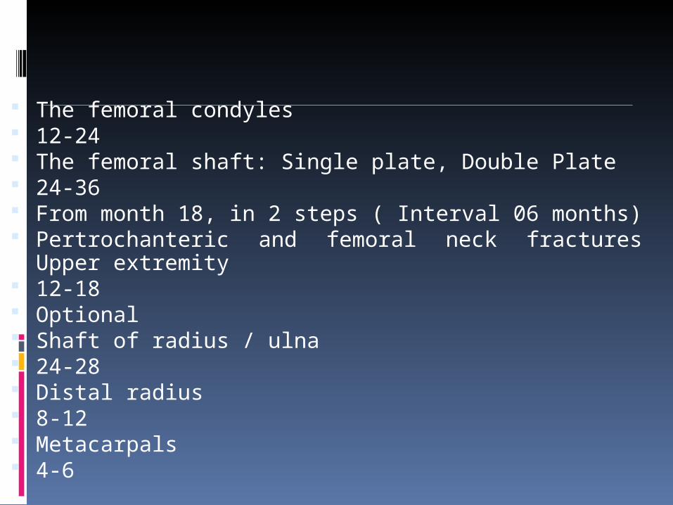
The femoral condyles 12-24 The femoral shaft: Single plate, Double Plate 24-36 From month 18, in 2 steps ( Interval 06 months) Pertrochanteric and femoral neck fractures Upper
extremity 12-18 Optional Shaft of radius / ulna 24-28 Distal radius 8-12 Metacarpals 4-6

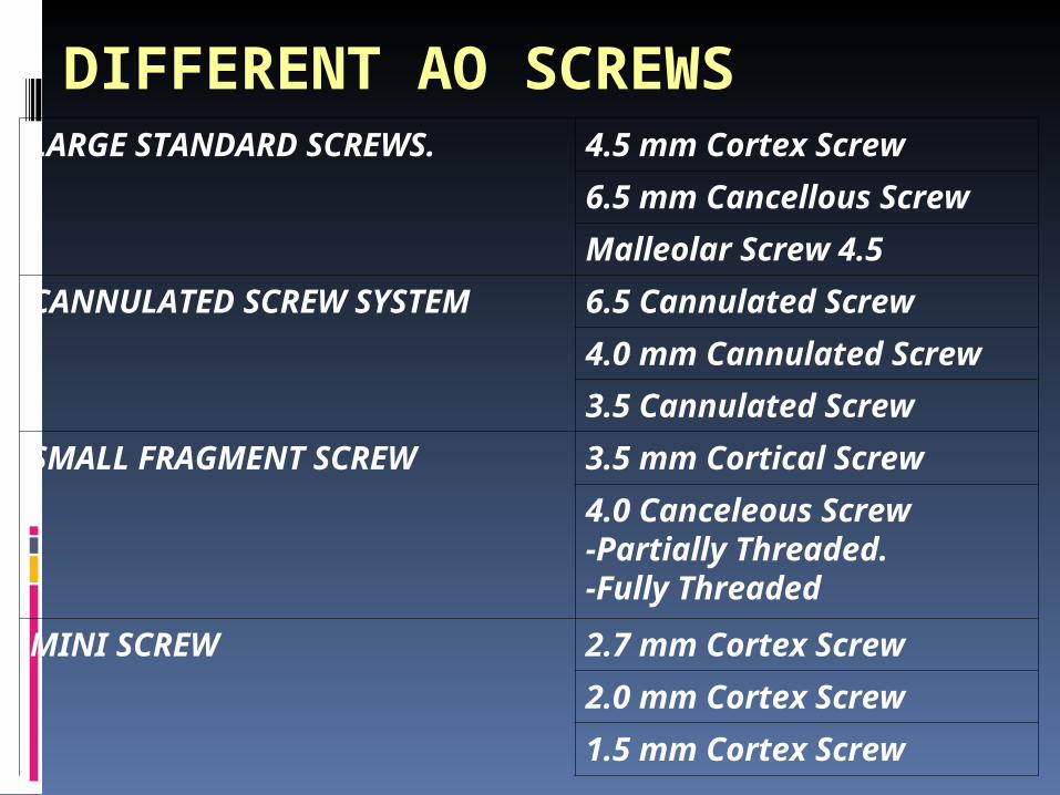
DIFFERENT AO SCREWS LARGE STANDARD SCREWS. 4.5 mm Cortex Screw
6.5 mm Cancellous Screw
Malleolar Screw 4.5
CANNULATED SCREW SYSTEM
6.5 Cannulated Screw
4.0 mm Cannulated Screw
3.5 Cannulated Screw
SMALL FRAGMENT SCREW 3.5 mm Cortical Screw
4.0 Canceleous Screw-Partially Threaded.-Fully Threaded
MINI SCREW 2.7 mm Cortex Screw
2.0 mm Cortex Screw
1.5 mm Cortex Screw
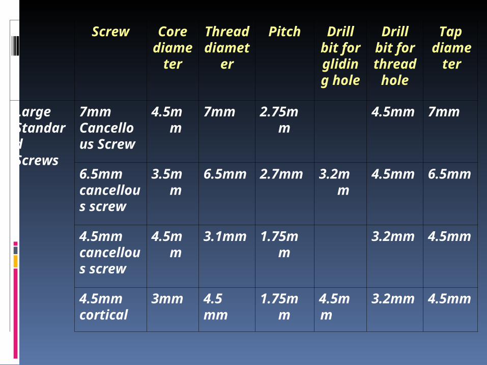
Screw Core diameter
Thread
diameter
Pitch Drill bit for
gliding
hole
Drill bit for
thread
hole
Tap diameter
Large Standard Screws
7mm Cancellous Screw
4.5mm
7mm 2.75mm
4.5mm
7mm
6.5mm cancellous screw
3.5mm
6.5mm
2.7mm
3.2mm
4.5mm
6.5mm
4.5mm cancellous screw
4.5mm
3.1mm
1.75mm
3.2mm
4.5mm
4.5mm cortical
3mm 4.5 mm
1.75mm
4.5mm
3.2mm
4.5mm
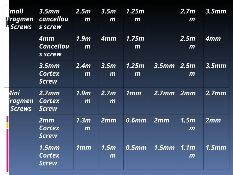
Small Fragment Screws
3.5mm cancellous screw
2.5mm
3.5mm
1.25mm
2.7mm
3.5mm
4mm Cancellous screw
1.9mm
4mm 1.75mm
2.5mm
4mm
3.5mm Cortex Screw
2.4mm
3.5mm
1.25mm
3.5mm
2.5mm
3.5mm
Mini Fragment Screws
2.7mm Cortex Screw
1.9mm
2.7mm
1mm 2.7mm
2mm 2.7mm
2mm Cortex Screw
1.3mm
2mm 0.6mm
2mm 1.5mm
2mm
1.5mm Cortex Screw
1mm 1.5mm
0.5mm
1.5mm
1.1mm
1.5mm


![The Orthodontic...orthodontic mini-implant (also known as mini-screw, mini-screw implant, micro-implant or temporary anchorage device [TAD]). For the firsttime, orthodontists are able](https://img.pdfslide.net/doc/110x75/5ec604d55638540e6d6ee534/the-orthodontic-orthodontic-mini-implant-also-known-as-mini-screw-mini-screw.jpg)