Embed Size (px)
Citation preview
431-BTS0-00-10 Scout Bi-Oc Ops Manual.book Page i Thursday, March 29, 2012 1:27 PM
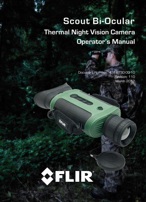
Scout Bi-OcularThermal Night Vision Camera
Operator’s Manual
Document Number: 431-BTS0-00-10Revision: 110March 2012

431-BTS0-00-10 Scout Bi-Oc Ops Manual.book Page ii Thursday, March 29, 2012 1:27 PM
© 2012 FLIR Commercial Systems, Inc. All rights reserved worldwide. No parts of this manual, in whole or in part, may be copied, photocopied, translated, or transmitted to any electronic medium or machine readable form without the prior written permission of FLIR Commercial Systems, Inc.
Names and marks appearing on the products herein are either registered trademarks or trademarks of FLIR Commercial Systems, Inc. and/or its subsidiaries. All other trademarks, trade names, or company names referenced herein are used for identification only and are the property of their respective owners.
This product is protected by patents, design patents, patents pending, or design patents pending.
If you have questions that are not covered in this manual, or need service, contact FLIR Commercial Vision Systems, Inc. customer support at 805.964.9797 for additional information prior to returning a camera.
The contents of this document are subject to change. For additional information visit www.flir.com or write to FLIR Commercial Systems, Inc., 70 Castilian Drive, Goleta CA 93117.
Proper Disposal of Electrical and Electronic Equipment (EEE)
The European Union (EU) has enacted Waste Electrical and Electronic Equipment Directive 2002/96/EC (WEEE), which aims to prevent EEE waste from arising; to encourage reuse, recycling, and recovery of EEE waste; and to promote environmental responsibility.
In accordance with these regulations, all EEE products labeled with the “crossed out wheeled bin” either on the product itself or in the product literature must not be disposed of in regular rubbish bins,
mixed with regular household or other commercial waste, or by other regular municipal waste collection means. Instead, and in order to prevent possible harm to the environment or human health, all EEE products (including any cables that came with the product) should be responsibly discarded or recycled.
To identify a responsible disposal method where you live, please contact your local waste collection or recycling service, your original place of purchase or product supplier, or the responsible government authority in your area. Business users should contact their supplier or refer to their purchase contract.
This document is controlled to FLIR Technology Level EAR 1. The information contained in this document is proprietary and/or restricted and pertains to a dual use product controlled for export by the Export Administration Regulations (EAR). This document and data disclosed herein or herewith is not to be reproduced, used, or disclosed in whole or in part to anyone without the written permission of FLIR Systems, Inc. Diversion contrary to US law is prohibited. US Department of Commerce authorization is not required prior to export or transfer to foreign persons, parties, or uses otherwise prohibited.

Scout Bi-Ocular Operator’s Manual
431-BTS0-00-10 Scout Bi-Oc Ops Manual.book Page iii Thursday, March 29, 2012 1:27 PM
Important Instructions and Notices to the User:
Modification of this device without the express authorization of FLIR Commercial Systems, Inc. may void the user’s authority under FCC rules to operate this device.
Note 1: This equipment has been tested and found to comply with the limits for a Class B digital device, pursuant to Part 15 of the FCC rules. These limits are designed to provide reasonable protection against harmful interference in a residential installation. This equipment generates, uses, and can radiate radio frequency energy and, if not installed and used in accordance with the instructions, may cause harmful interference to radio communications. However, there is no guarantee that the interference will not occur in a particular installation. If this equipment does cause harmful interference to radio or television reception, which can be determined by turning the equipment off and on, the user is encouraged to try to correct the interference by one or more of the following measures:
• Reorient or relocate the receiving antenna;
• Increase the separation between the equipment and receiver;
• Connect the equipment into an outlet on a circuit different from that of the receiver; and/or
• Consult the dealer or an experienced radio/television technician for help.
Note 2: This equipment was tested for compliance with the FCC limits for a Class B digital device using a shielded cable for connecting the equipment to an analog video output to a monitor and using a shielded USB cable for connecting the equipment to a personal computer. When making such connections, shielded cables must be used with this equipment.
Industry Canada Notice: This Class B digital apparatus complies with Canadian ICES-003.
Avis d’Industrie Canada:Cet appareil numérique de la classe B est conforme à la norme NMB-003 du Canada.
FLIR Commercial Systems, Inc.70 Castilian DriveGoleta, CA 93117
Phone: 888.747.FLIR (888.747.3547)International: +1.805.964.9797
www.flir.com
431-BTS0-00-10, Revision 110 iii

Scout Bi-Ocular Operator’s Manual
431-BTS0-00-10 Scout Bi-Oc Ops Manual.book Page iv Thursday, March 29, 2012 1:27 PM
iv March 2012
431-BTS0-00-10 Scout Bi-Oc Ops Manual.book Page v Thursday, March 29, 2012 1:27 PM
Table of ContentsIntroduction. . . . . . . . . . . . . . . . . . . . . . . . . . . . . . . . . . . . . . . . . . . . . . . . . . .1
Scout Bi-Ocular Camera Features . . . . . . . . . . . . . . . . . . . . . . . . . . . 2Cautions . . . . . . . . . . . . . . . . . . . . . . . . . . . . . . . . . . . . . . . . . . . . . . . . . . 3
Getting Started . . . . . . . . . . . . . . . . . . . . . . . . . . . . . . . . . . . . . . . . . . . . . . . 5Scout Bi-Ocular Camera Accessories . . . . . . . . . . . . . . . . . . . . . . . . 6Lens Options . . . . . . . . . . . . . . . . . . . . . . . . . . . . . . . . . . . . . . . . . . . . . . 7
Operating Your Camera. . . . . . . . . . . . . . . . . . . . . . . . . . . . . . . . . . . . . . . .9Camera Features and Controls . . . . . . . . . . . . . . . . . . . . . . . . . . . . .9Installing the SD Card . . . . . . . . . . . . . . . . . . . . . . . . . . . . . . . . . . . . 10Installing the Batteries . . . . . . . . . . . . . . . . . . . . . . . . . . . . . . . . . . . 11Charging the Camera . . . . . . . . . . . . . . . . . . . . . . . . . . . . . . . . . . . . 12Scout Bi-Ocular Power Management . . . . . . . . . . . . . . . . . . . . . . 13Buttons and Controls . . . . . . . . . . . . . . . . . . . . . . . . . . . . . . . . . . . . 15Batteries. . . . . . . . . . . . . . . . . . . . . . . . . . . . . . . . . . . . . . . . . . . . . . . . 20SD Card Door . . . . . . . . . . . . . . . . . . . . . . . . . . . . . . . . . . . . . . . . . . . 21Auto-Standby Operation . . . . . . . . . . . . . . . . . . . . . . . . . . . . . . . . . . 23The Hot Shoe. . . . . . . . . . . . . . . . . . . . . . . . . . . . . . . . . . . . . . . . . . . . 24Bayonet Lens Mounting System . . . . . . . . . . . . . . . . . . . . . . . . . . . 25Installing Software Upgrades. . . . . . . . . . . . . . . . . . . . . . . . . . . . . . 26
Technical Data . . . . . . . . . . . . . . . . . . . . . . . . . . . . . . . . . . . . . . . . . . . . . . 29Scout Bi-Ocular Camera Model Features . . . . . . . . . . . . . . . . . . . 29Power . . . . . . . . . . . . . . . . . . . . . . . . . . . . . . . . . . . . . . . . . . . . . . . . . . 29Environmental . . . . . . . . . . . . . . . . . . . . . . . . . . . . . . . . . . . . . . . . . . . 29Physical . . . . . . . . . . . . . . . . . . . . . . . . . . . . . . . . . . . . . . . . . . . . . . . . . 30Additional Features . . . . . . . . . . . . . . . . . . . . . . . . . . . . . . . . . . . . . . 30Field of View . . . . . . . . . . . . . . . . . . . . . . . . . . . . . . . . . . . . . . . . . . . . . 30Range Detection . . . . . . . . . . . . . . . . . . . . . . . . . . . . . . . . . . . . . . . . . 31
431-BTS0-00-10, Revision 110 v

Scout Bi-Ocular Operator’s Manual
431-BTS0-00-10 Scout Bi-Oc Ops Manual.book Page vi Thursday, March 29, 2012 1:27 PM
vi March 2012
431-BTS0-00-10 Scout Bi-Oc Ops Manual.book Page 1 Thursday, March 29, 2012 1:27 PM
1 Introduction
FLIR’s Scout Bi-Ocular handheld thermal imaging cameras give hikers, hunters, and outdoorsmen the ability to see clearly in total darkness, providing a wealth of valuable information during any nighttime excursion.
The Scout Bi-Ocular camera enables the outdoorsman to:
• See animals and difficult terrain in reduced visibility and total darkness
• See through smoke, dust, and light fog
• See camouflage and foliage in any lighting conditions
• See more—and see farther—than with low-light night vision goggles
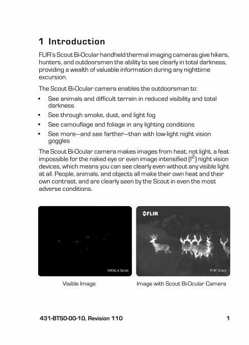
The Scout Bi-Ocular camera makes images from heat, not light, a feat impossible for the naked eye or even image intensified (I2) night vision devices, which means you can see clearly even without any visible light at all. People, animals, and objects all make their own heat and their own contrast, and are clearly seen by the Scout in even the most adverse conditions.
Image with Scout Bi-Ocular CameraVisible Image
431-BTS0-00-10, Revision 110 1
1—Introduction Scout Bi-Ocular Operator’s Manual
431-BTS0-00-10 Scout Bi-Oc Ops Manual.book Page 2 Thursday, March 29, 2012 1:27 PM
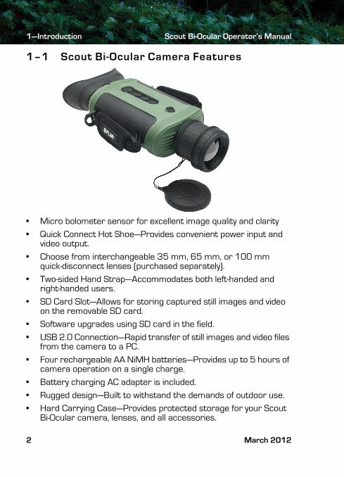
1–1 Scout Bi-Ocular Camera Features
• Micro bolometer sensor for excellent image quality and clarity
• Quick Connect Hot Shoe—Provides convenient power input and video output.
• Choose from interchangeable 35 mm, 65 mm, or 100 mm quick-disconnect lenses (purchased separately).
• Two-sided Hand Strap—Accommodates both left-handed and right-handed users.
• SD Card Slot—Allows for storing captured still images and video on the removable SD card.
• Software upgrades using SD card in the field.
• USB 2.0 Connection—Rapid transfer of still images and video files from the camera to a PC.
• Four rechargeable AA NiMH batteries—Provides up to 5 hours of camera operation on a single charge.
• Battery charging AC adapter is included.
• Rugged design—Built to withstand the demands of outdoor use.
• Hard Carrying Case—Provides protected storage for your Scout Bi-Ocular camera, lenses, and all accessories.
2 March 2012
Scout Bi-Ocular Operator’s Manual 1—Introduction
431-BTS0-00-10 Scout Bi-Oc Ops Manual.book Page 3 Thursday, March 29, 2012 1:27 PM
1–2 Cautions
Do not disassemble the camera enclosure. Disassembly can cause permanent damage and will void the warranty.Keep the compartment covers closed to avoid exposing the cameras electronics to water or debris.
Do not point the camera directly at extremely high-intensity radiation sources, such as the sun, lasers, arc welders, etc.
Use only the supplied adapters to power or recharge the camera.
Be careful not to leave fingerprints on the camera’s optics.
Always keep the camera window covered. A lens or the lens cover should always be installed on the camera to protect the window.
Caution!Always keep the camera window covered. A lens or the lens cover should always be installed on the camera to protect the window.
431-BTS0-00-10, Revision 110 3

1—Introduction Scout Bi-Ocular Operator’s Manual
431-BTS0-00-10 Scout Bi-Oc Ops Manual.book Page 4 Thursday, March 29, 2012 1:27 PM
4 March 2012
431-BTS0-00-10 Scout Bi-Oc Ops Manual.book Page 5 Thursday, March 29, 2012 1:27 PM
2 Getting Started
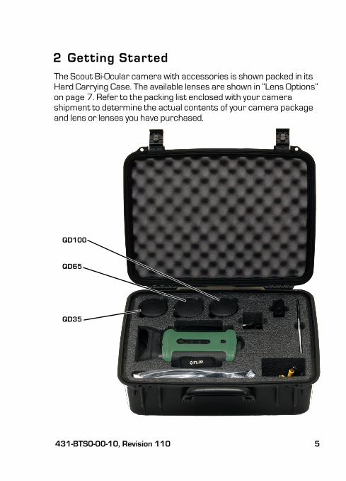
The Scout Bi-Ocular camera with accessories is shown packed in its Hard Carrying Case. The available lenses are shown in “Lens Options” on page 7. Refer to the packing list enclosed with your camera shipment to determine the actual contents of your camera package and lens or lenses you have purchased.
QD100
QD65
QD35
431-BTS0-00-10, Revision 110 5
2—Getting Started Scout Bi-Ocular Operator’s Manual
431-BTS0-00-10 Scout Bi-Oc Ops Manual.book Page 6 Thursday, March 29, 2012 1:27 PM
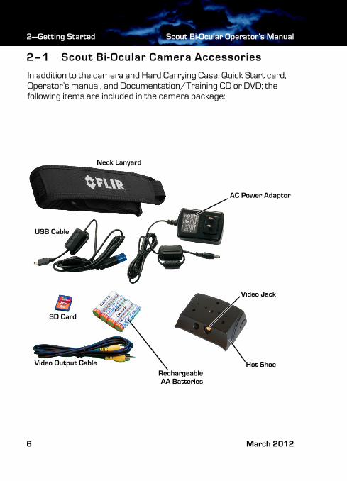
2–1 Scout Bi-Ocular Camera Accessories
In addition to the camera and Hard Carrying Case, Quick Start card, Operator’s manual, and Documentation/Training CD or DVD; the following items are included in the camera package:
Neck Lanyard
Hot ShoeVideo Output Cable
SD Card
AC Power Adaptor
USB Cable
RechargeableAA Batteries
Video Jack
6 March 2012
Scout Bi-Ocular Operator’s Manual 2—Getting Started
431-BTS0-00-10 Scout Bi-Oc Ops Manual.book Page 7 Thursday, March 29, 2012 1:27 PM
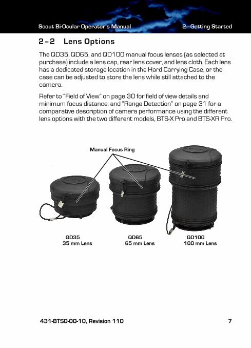
2–2 Lens Options
The QD35, QD65, and QD100 manual focus lenses (as selected at purchase) include a lens cap, rear lens cover, and lens cloth. Each lens has a dedicated storage location in the Hard Carrying Case, or the case can be adjusted to store the lens while still attached to the camera.
Refer to “Field of View” on page 30 for field of view details and minimum focus distance; and “Range Detection” on page 31 for a comparative description of camera performance using the different lens options with the two different models, BTS-X Pro and BTS-XR Pro.
QD65QD35 QD100100 mm Lens65 mm Lens35 mm Lens
Manual Focus Ring
431-BTS0-00-10, Revision 110 7

2—Getting Started Scout Bi-Ocular Operator’s Manual
431-BTS0-00-10 Scout Bi-Oc Ops Manual.book Page 8 Thursday, March 29, 2012 1:27 PM
8 March 2012
431-BTS0-00-10 Scout Bi-Oc Ops Manual.book Page 9 Thursday, March 29, 2012 1:27 PM
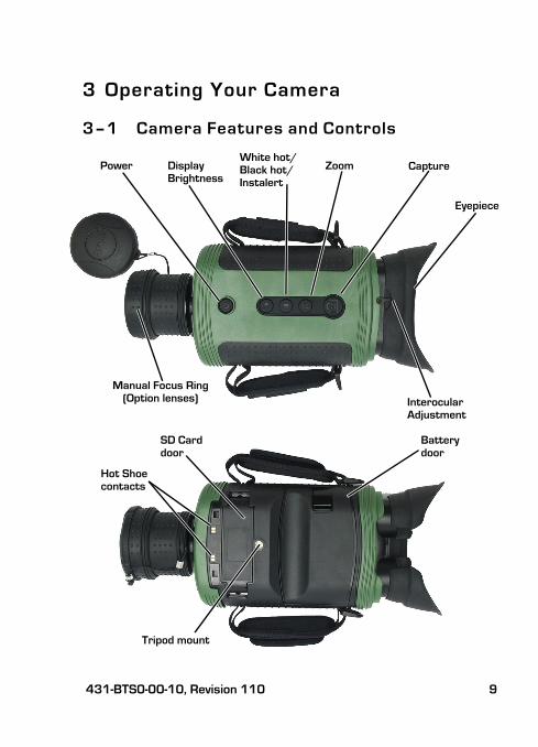
3 Operating Your Camera
3–1 Camera Features and Controls
Power ZoomWhite hot/
Display Black hot/
Eyepiece
CaptureBrightness
SD Carddoor
Batterydoor
Tripod mount
Hot Shoe contacts
InterocularAdjustment
Instalert
Manual Focus Ring(Option lenses)
431-BTS0-00-10, Revision 110 9
3—Operating Your Camera Scout Bi-Ocular Operator’s Manual
431-BTS0-00-10 Scout Bi-Oc Ops Manual.book Page 10 Thursday, March 29, 2012 1:27 PM
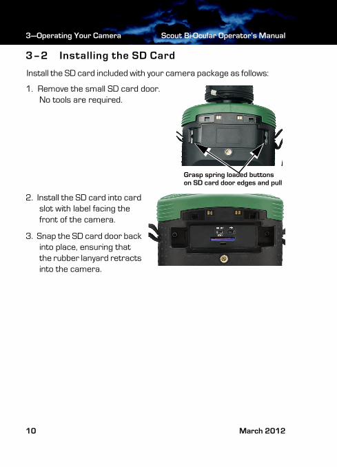
3–2 Installing the SD Card
Install the SD card included with your camera package as follows:
1. Remove the small SD card door. No tools are required.
2. Install the SD card into card slot with label facing the front of the camera.
3. Snap the SD card door back into place, ensuring that the rubber lanyard retracts into the camera.
Grasp spring loaded buttons on SD card door edges and pull
10 March 2012
Scout Bi-Ocular Operator’s Manual 3—Operating Your Camera
431-BTS0-00-10 Scout Bi-Oc Ops Manual.book Page 11 Thursday, March 29, 2012 1:27 PM
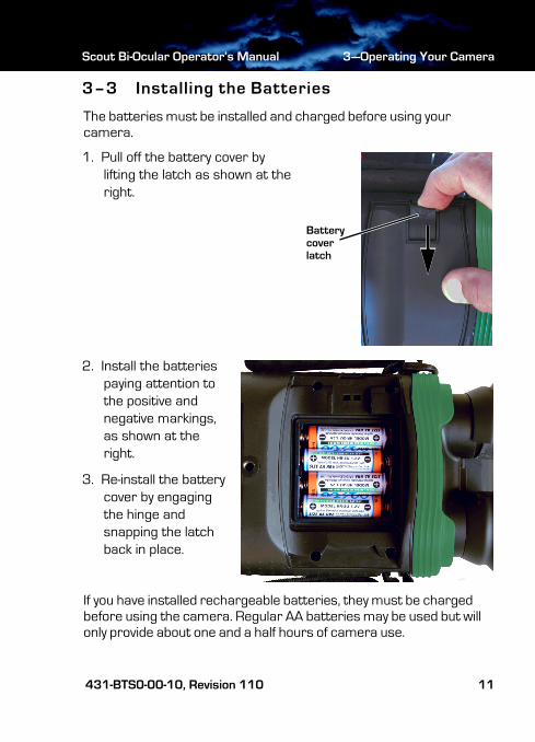
3–3 Installing the Batteries
The batteries must be installed and charged before using your camera.
1. Pull off the battery cover by lifting the latch as shown at the right.
2. Install the batteries paying attention to the positive and negative markings, as shown at the right.
3. Re-install the battery cover by engaging the hinge and snapping the latch back in place.
If you have installed rechargeable batteries, they must be charged before using the camera. Regular AA batteries may be used but will only provide about one and a half hours of camera use.
Batterycoverlatch
431-BTS0-00-10, Revision 110 11
3—Operating Your Camera Scout Bi-Ocular Operator’s Manual
431-BTS0-00-10 Scout Bi-Oc Ops Manual.book Page 12 Thursday, March 29, 2012 1:27 PM
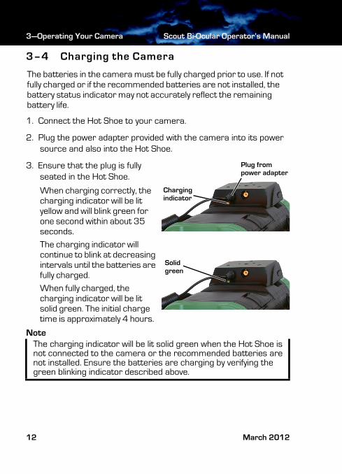
3–4 Charging the Camera
The batteries in the camera must be fully charged prior to use. If not fully charged or if the recommended batteries are not installed, the battery status indicator may not accurately reflect the remaining battery life.
1. Connect the Hot Shoe to your camera.
2. Plug the power adapter provided with the camera into its power source and also into the Hot Shoe.
3. Ensure that the plug is fully seated in the Hot Shoe.
When charging correctly, the charging indicator will be lit yellow and will blink green for one second within about 35 seconds.
The charging indicator will continue to blink at decreasing intervals until the batteries are fully charged.
When fully charged, the charging indicator will be lit solid green. The initial charge time is approximately 4 hours.
NoteThe charging indicator will be lit solid green when the Hot Shoe is not connected to the camera or the recommended batteries are not installed. Ensure the batteries are charging by verifying the green blinking indicator described above.
Plug from
Chargingindicator
Solidgreen
power adapter
12 March 2012
Scout Bi-Ocular Operator’s Manual 3—Operating Your Camera
431-BTS0-00-10 Scout Bi-Oc Ops Manual.book Page 13 Thursday, March 29, 2012 1:27 PM
3–5 Scout Bi-Ocular Power Management
Your Scout Bi-Ocular camera is equipped with a power management system that provides up to five hours of continuous operation and up to five days of standby time between battery charges. To make the best use of the camera and to assure it is always ready when you need it, it is important to understand the basic power states of the camera.
The Scout Bi-Ocular camera is designed to operate much like your cell phone:
• It is rarely turned off unless you do not plan to use it for a few days or more.
• When near a power source (AC power or a car cigarette lighter) or when not in use, it is recommended that you keep a charger plugged into the camera.
• When the camera is turned on from the Off state, it takes about 90 seconds to become operational.
• In Standby, it is always ready to go. Press the Power button and the camera will come on in about two seconds.
• It will automatically put itself in Standby to conserve the battery.
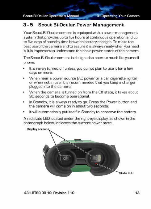
A red state LED located under the right-eye display, as shown in the photograph below, indicates the current power state.
State LED
Display screens
431-BTS0-00-10, Revision 110 13
3—Operating Your Camera Scout Bi-Ocular Operator’s Manual
431-BTS0-00-10 Scout Bi-Oc Ops Manual.book Page 14 Thursday, March 29, 2012 1:27 PM
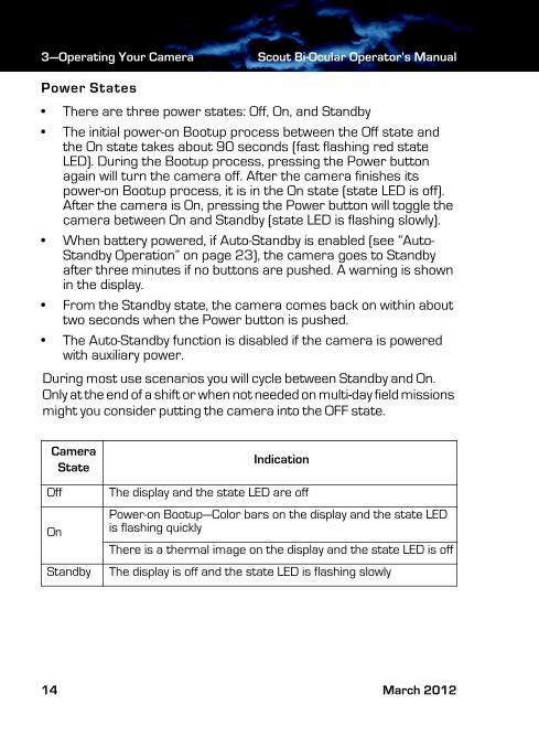
Power States
• There are three power states: Off, On, and Standby
• The initial power-on Bootup process between the Off state and the On state takes about 90 seconds (fast flashing red state LED). During the Bootup process, pressing the Power button again will turn the camera off. After the camera finishes its power-on Bootup process, it is in the On state (state LED is off). After the camera is On, pressing the Power button will toggle the camera between On and Standby (state LED is flashing slowly).
• When battery powered, if Auto-Standby is enabled (see “Auto-Standby Operation” on page 23), the camera goes to Standby after three minutes if no buttons are pushed. A warning is shown in the display.
• From the Standby state, the camera comes back on within about two seconds when the Power button is pushed.
• The Auto-Standby function is disabled if the camera is powered with auxiliary power.
During most use scenarios you will cycle between Standby and On. Only at the end of a shift or when not needed on multi-day field missions might you consider putting the camera into the OFF state.
CameraState
Indication
Off The display and the state LED are off
On
Power-on Bootup—Color bars on the display and the state LED is flashing quickly
There is a thermal image on the display and the state LED is off
Standby The display is off and the state LED is flashing slowly
14 March 2012
Scout Bi-Ocular Operator’s Manual 3—Operating Your Camera
431-BTS0-00-10 Scout Bi-Oc Ops Manual.book Page 15 Thursday, March 29, 2012 1:27 PM
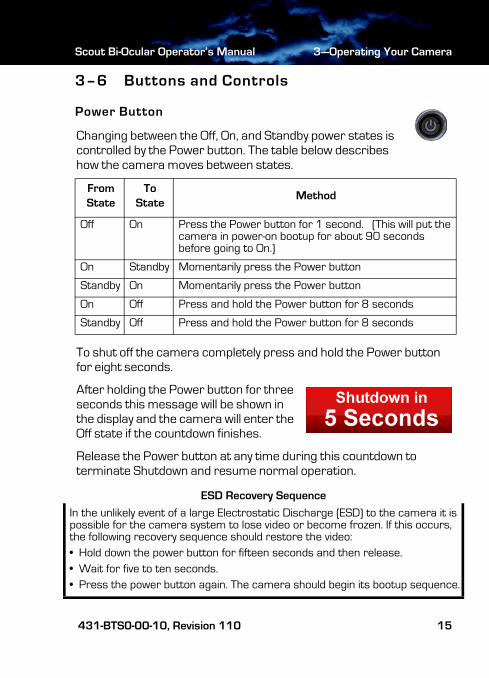
3–6 Buttons and Controls
Power Button
Changing between the Off, On, and Standby power states is controlled by the Power button. The table below describes how the camera moves between states.
To shut off the camera completely press and hold the Power button for eight seconds.
After holding the Power button for three seconds this message will be shown in the display and the camera will enter the Off state if the countdown finishes.
Release the Power button at any time during this countdown to terminate Shutdown and resume normal operation.
ESD Recovery Sequence
From State
To State
Method
Off On Press the Power button for 1 second. (This will put the camera in power-on bootup for about 90 seconds before going to On.)
On Standby Momentarily press the Power button
Standby On Momentarily press the Power button
On Off Press and hold the Power button for 8 seconds
Standby Off Press and hold the Power button for 8 seconds
In the unlikely event of a large Electrostatic Discharge (ESD) to the camera it is possible for the camera system to lose video or become frozen. If this occurs, the following recovery sequence should restore the video:
• Hold down the power button for fifteen seconds and then release.
• Wait for five to ten seconds.
• Press the power button again. The camera should begin its bootup sequence.
431-BTS0-00-10, Revision 110 15
3—Operating Your Camera Scout Bi-Ocular Operator’s Manual
431-BTS0-00-10 Scout Bi-Oc Ops Manual.book Page 16 Thursday, March 29, 2012 1:27 PM
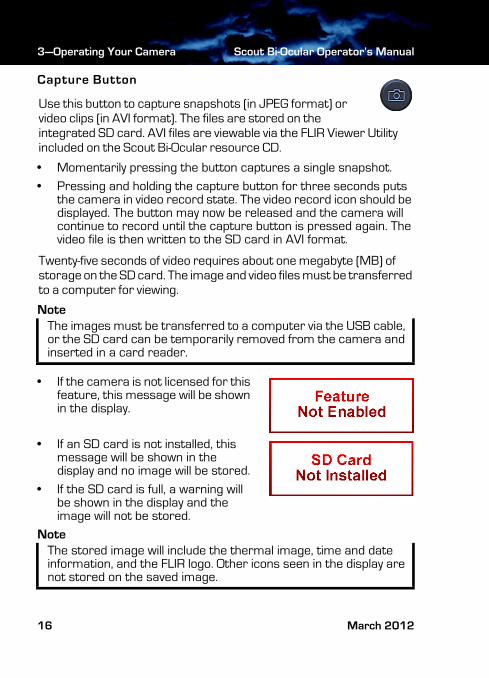
Capture Button
Use this button to capture snapshots (in JPEG format) or video clips (in AVI format). The files are stored on the integrated SD card. AVI files are viewable via the FLIR Viewer Utility included on the Scout Bi-Ocular resource CD.
• Momentarily pressing the button captures a single snapshot.
• Pressing and holding the capture button for three seconds puts the camera in video record state. The video record icon should be displayed. The button may now be released and the camera will continue to record until the capture button is pressed again. The video file is then written to the SD card in AVI format.
Twenty-five seconds of video requires about one megabyte (MB) of storage on the SD card. The image and video files must be transferred to a computer for viewing.
Note
• If the camera is not licensed for this feature, this message will be shown in the display.
• If an SD card is not installed, this message will be shown in the display and no image will be stored.
• If the SD card is full, a warning will be shown in the display and the image will not be stored.
Note
The images must be transferred to a computer via the USB cable, or the SD card can be temporarily removed from the camera and inserted in a card reader.
The stored image will include the thermal image, time and date information, and the FLIR logo. Other icons seen in the display are not stored on the saved image.
16 March 2012
Scout Bi-Ocular Operator’s Manual 3—Operating Your Camera
431-BTS0-00-10 Scout Bi-Oc Ops Manual.book Page 17 Thursday, March 29, 2012 1:27 PM
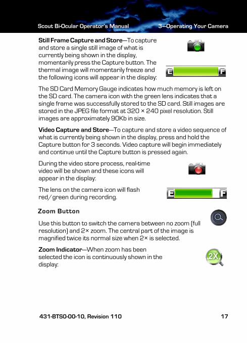
Still Frame Capture and Store—To capture and store a single still image of what is currently being shown in the display, momentarily press the Capture button. The thermal image will momentarily freeze and the following icons will appear in the display:
The SD Card Memory Gauge indicates how much memory is left on the SD card. The camera icon with the green lens indicates that a single frame was successfully stored to the SD card. Still images are stored in the JPEG file format at 320 × 240 pixel resolution. Still images are approximately 90Kb in size.
Video Capture and Store—To capture and store a video sequence of what is currently being shown in the display, press and hold the Capture button for 3 seconds. Video capture will begin immediately and continue until the Capture button is pressed again.
During the video store process, real-time video will be shown and these icons will appear in the display:
The lens on the camera icon will flash red/green during recording.
Zoom Button
Use this button to switch the camera between no zoom (full resolution) and 2× zoom. The central part of the image is magnified twice its normal size when 2× is selected.
Zoom Indicator—When zoom has been selected the icon is continuously shown in the display:
431-BTS0-00-10, Revision 110 17
3—Operating Your Camera Scout Bi-Ocular Operator’s Manual
431-BTS0-00-10 Scout Bi-Oc Ops Manual.book Page 18 Thursday, March 29, 2012 1:27 PM
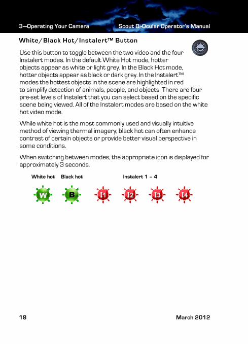
White/Black Hot/Instalert™ Button
Use this button to toggle between the two video and the four Instalert modes. In the default White Hot mode, hotter objects appear as white or light grey. In the Black Hot mode, hotter objects appear as black or dark grey. In the Instalert™ modes the hottest objects in the scene are highlighted in red to simplify detection of animals, people, and objects. There are four pre-set levels of Instalert that you can select based on the specific scene being viewed. All of the Instalert modes are based on the white hot video mode.
While white hot is the most commonly used and visually intuitive method of viewing thermal imagery; black hot can often enhance contrast of certain objects or provide better visual perspective in some conditions.
When switching between modes, the appropriate icon is displayed for approximately 3 seconds.
Black hotWhite hot Instalert 1 – 4
18 March 2012
Scout Bi-Ocular Operator’s Manual 3—Operating Your Camera
431-BTS0-00-10 Scout Bi-Oc Ops Manual.book Page 19 Thursday, March 29, 2012 1:27 PM
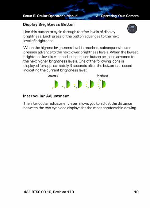
Display Brightness Button
Use this button to cycle through the five levels of display brightness. Each press of the button advances to the next level of brightness.
When the highest brightness level is reached, subsequent button presses advance to the next lower brightness levels. When the lowest brightness level is reached, subsequent button presses advance to the next higher brightness levels. One of the following icons is displayed for approximately 3 seconds after the button is pressed indicating the current brightness level:
Interocular Adjustment
The interocular adjustment lever allows you to adjust the distance between the two eyepiece displays for the most comfortable viewing.
HighestLowest
431-BTS0-00-10, Revision 110 19
3—Operating Your Camera Scout Bi-Ocular Operator’s Manual
431-BTS0-00-10 Scout Bi-Oc Ops Manual.book Page 20 Thursday, March 29, 2012 1:27 PM
3–7 Batteries
Your Scout Bi-Ocular camera is equipped with a sophisticated power system that accommodates a wide variety of AA battery types. This includes rechargeable and non-rechargeable batteries.
The camera is optimized for operation with the 2700 mAh rechargeable NiMh batteries that were supplied with your camera. It is recommended that you use these batteries in all but emergency situations.
Note
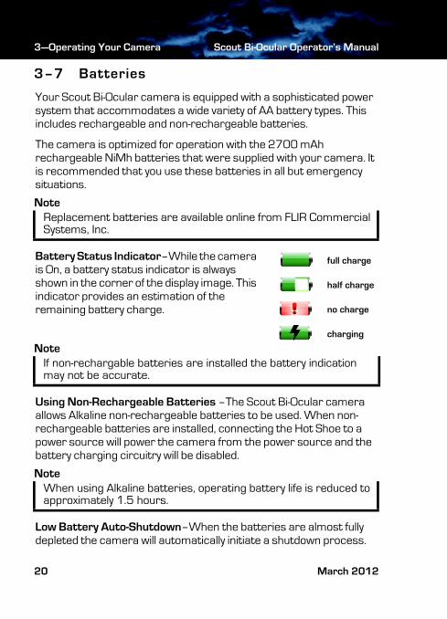
Battery Status Indicator–While the camera is On, a battery status indicator is always shown in the corner of the display image. This indicator provides an estimation of the remaining battery charge.
Note
Using Non-Rechargeable Batteries –The Scout Bi-Ocular camera allows Alkaline non-rechargeable batteries to be used. When non-rechargeable batteries are installed, connecting the Hot Shoe to a power source will power the camera from the power source and the battery charging circuitry will be disabled.
Note
Low Battery Auto-Shutdown–When the batteries are almost fully depleted the camera will automatically initiate a shutdown process.
Replacement batteries are available online from FLIR Commercial Systems, Inc.
If non-rechargable batteries are installed the battery indication may not be accurate.
When using Alkaline batteries, operating battery life is reduced to approximately 1.5 hours.
full charge
half charge
no charge
charging
20 March 2012
Scout Bi-Ocular Operator’s Manual 3—Operating Your Camera
431-BTS0-00-10 Scout Bi-Oc Ops Manual.book Page 21 Thursday, March 29, 2012 1:27 PM
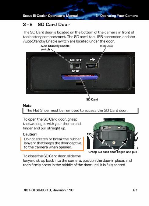
3–8 SD Card Door
The SD Card door is located on the bottom of the camera in front of the battery compartment. The SD card, the USB connector, and the Auto-Standby Enable switch are located under the door.
Note
To open the SD Card door, grasp the two edges with your thumb and finger and pull straight up.
Caution!
To close the SD Card door, slide the lanyard strap back into the camera, position the door in place, and then firmly press in the middle of the door until it is fully seated.
The Hot Shoe must be removed to access the SD Card door.
Do not stretch or break the rubber lanyard that keeps the door captive to the camera when opened.
mini-USBAuto-Standby Enableswitch
SD Card
Grasp SD card door edges and pull
431-BTS0-00-10, Revision 110 21
3—Operating Your Camera Scout Bi-Ocular Operator’s Manual
431-BTS0-00-10 Scout Bi-Oc Ops Manual.book Page 22 Thursday, March 29, 2012 1:27 PM
SD Card Capacity and Type
The Scout Bi-Ocular camera supports storing images and video on standard 1-Gb and 2-Gb SD cards or up to 32-Gb on SDHC cards.
Installing an SD Card
To install an SD card, insert the card into the slot and press on the SD card until its edge is nearly flush with the surface and release.
To remove an SD card, use this same motion.
Downloading Stored Files via USB
The Scout Bi-Ocular camera also supports downloading stored images and video via the USB port.
With the camera on, plug the USB cable into the USB connector on the camera and a USB port on your computer.
Allow up to two minutes for the USB connection to be recognized by the computer’s operating system.
22 March 2012
Scout Bi-Ocular Operator’s Manual 3—Operating Your Camera
431-BTS0-00-10 Scout Bi-Oc Ops Manual.book Page 23 Thursday, March 29, 2012 1:27 PM
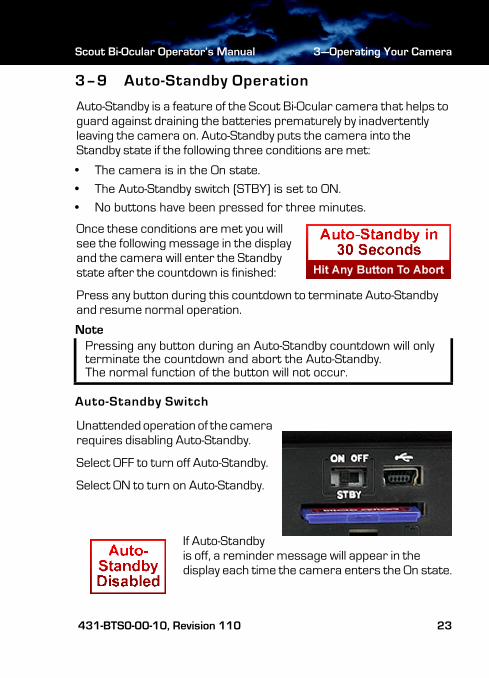
3–9 Auto-Standby Operation
Auto-Standby is a feature of the Scout Bi-Ocular camera that helps to guard against draining the batteries prematurely by inadvertently leaving the camera on. Auto-Standby puts the camera into the Standby state if the following three conditions are met:
• The camera is in the On state.
• The Auto-Standby switch (STBY) is set to ON.
• No buttons have been pressed for three minutes.
Once these conditions are met you will see the following message in the display and the camera will enter the Standby state after the countdown is finished:
Press any button during this countdown to terminate Auto-Standby and resume normal operation.
Note
Auto-Standby Switch
Unattended operation of the camera requires disabling Auto-Standby.
Select OFF to turn off Auto-Standby.
Select ON to turn on Auto-Standby.
If Auto-Standby is off, a reminder message will appear in the display each time the camera enters the On state.
Pressing any button during an Auto-Standby countdown will only terminate the countdown and abort the Auto-Standby. The normal function of the button will not occur.
431-BTS0-00-10, Revision 110 23
3—Operating Your Camera Scout Bi-Ocular Operator’s Manual
431-BTS0-00-10 Scout Bi-Oc Ops Manual.book Page 24 Thursday, March 29, 2012 1:27 PM
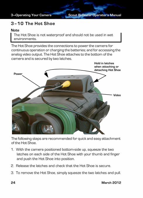
3–10 The Hot Shoe
Note
The Hot Shoe provides the connections to power the camera for continuous operation or charging the batteries; and for accessing the analog video output. The Hot Shoe attaches to the bottom of the camera and is secured by two latches.
The following steps are recommended for quick and easy attachment of the Hot Shoe.
1. With the camera positioned bottom-side up, squeeze the two latches on each side of the Hot Shoe with your thumb and finger and push the Hot Shoe into position.
2. Release the latches and check that the Hot Shoe is secure.
3. To remove the Hot Shoe, simply squeeze the two latches and pull.
The Hot Shoe is not waterproof and should not be used in wet environments.
Video
Power
Hold in latcheswhen attaching ordetaching Hot Shoe
24 March 2012
Scout Bi-Ocular Operator’s Manual 3—Operating Your Camera
431-BTS0-00-10 Scout Bi-Oc Ops Manual.book Page 25 Thursday, March 29, 2012 1:27 PM
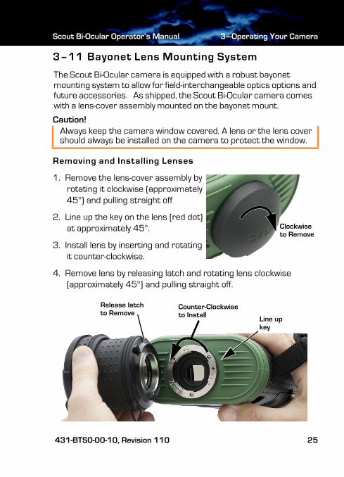
3–11 Bayonet Lens Mounting System
The Scout Bi-Ocular camera is equipped with a robust bayonet mounting system to allow for field-interchangeable optics options and future accessories. As shipped, the Scout Bi-Ocular camera comes with a lens-cover assembly mounted on the bayonet mount.
Caution!
Removing and Installing Lenses
1. Remove the lens-cover assembly by rotating it clockwise (approximately 45°) and pulling straight off
2. Line up the key on the lens (red dot) at approximately 45°.
3. Install lens by inserting and rotating it counter-clockwise.
4. Remove lens by releasing latch and rotating lens clockwise (approximately 45°) and pulling straight off.
Always keep the camera window covered. A lens or the lens cover should always be installed on the camera to protect the window.
Clockwiseto Remove
Counter-Clockwiseto Install
Release latch to Remove
Line upkey
431-BTS0-00-10, Revision 110 25
3—Operating Your Camera Scout Bi-Ocular Operator’s Manual
431-BTS0-00-10 Scout Bi-Oc Ops Manual.book Page 26 Thursday, March 29, 2012 1:27 PM
3–12 Installing Software Upgrades
Your Scout Bi-Ocular camera may require software upgrades during it’s lifetime. The upgrade process requires an SD card loaded with the upgrade file. After receiving the upgrade file from FLIR Commercial Systems, Inc., load it onto your SD card.
Caution!
Use the following procedure to install the upgrade:
1. Ensure that the camera battery is fully charged. (The software installation will not start if the battery charge is less than 50%.)
2. With the camera off, install the SD card loaded with the upgrade file. Refer to “SD Card Door” on page 21.
3. Install the Hot Shoe and connect to a power source. Refer to “The Hot Shoe” on page 24.
4. Turn on the camera. During its Bootup process, the camera will check the SD card for a valid upgrade file.
5. Watch the display. When a valid file is found, a message will be shown for about ten seconds directing you to “Press and hold Capture button for 2 seconds to initiate update.”If you ignore the message, the camera will resume normal operation and enter the On state.
6. While the message is displayed, press and hold the Capture button for two seconds.The software upgrade takes about four minutes. When finished you will see this prompt to restart the camera. SW Upgraded: Please Shutdown & Restart now
During a software installation, the camera must remain powered on. Turning off the camera, or losing power for any reason, may damage the system files and require that the camera be returned to the factory for repair.
26 March 2012
Scout Bi-Ocular Operator’s Manual 3—Operating Your Camera
431-BTS0-00-10 Scout Bi-Oc Ops Manual.book Page 27 Thursday, March 29, 2012 1:27 PM
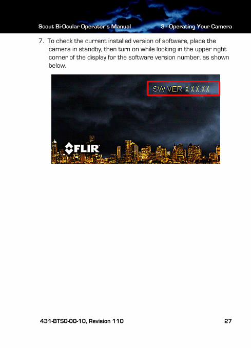
7. To check the current installed version of software, place the camera in standby, then turn on while looking in the upper right corner of the display for the software version number, as shown below.
431-BTS0-00-10, Revision 110 27

3—Operating Your Camera Scout Bi-Ocular Operator’s Manual
431-BTS0-00-10 Scout Bi-Oc Ops Manual.book Page 28 Thursday, March 29, 2012 1:27 PM
28 March 2012
431-BTS0-00-10 Scout Bi-Oc Ops Manual.book Page 29 Thursday, March 29, 2012 1:27 PM
4 Technical Data
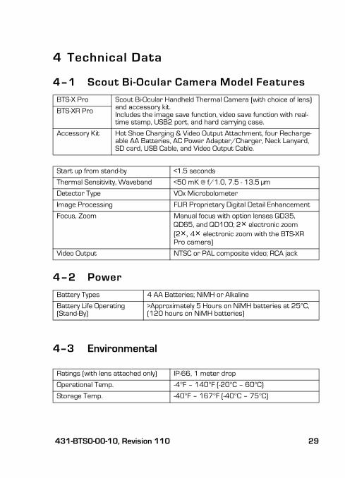
4–1 Scout Bi-Ocular Camera Model Features
4–2 Power
4–3 Environmental
BTS-X Pro Scout Bi-Ocular Handheld Thermal Camera (with choice of lens) and accessory kit. Includes the image save function, video save function with real-time stamp, USB2 port, and hard carrying case.
BTS-XR Pro
Accessory Kit Hot Shoe Charging & Video Output Attachment, four Recharge-able AA Batteries, AC Power Adapter/Charger, Neck Lanyard, SD card, USB Cable, and Video Output Cable.
Start up from stand-by <1.5 seconds
Thermal Sensitivity, Waveband <50 mK @ f/1.0, 7.5 - 13.5 μm
Detector Type VOx Microbolometer
Image Processing FLIR Proprietary Digital Detail Enhancement
Focus, Zoom Manual focus with option lenses QD35, QD65, and QD100; 2× electronic zoom
(2×, 4× electronic zoom with the BTS-XR Pro camera)
Video Output NTSC or PAL composite video; RCA jack
Battery Types 4 AA Batteries; NiMH or Alkaline
Battery Life Operating (Stand-By)
>Approximately 5 Hours on NiMH batteries at 25°C,(120 hours on NiMH batteries)
Ratings (with lens attached only) IP-66, 1 meter drop
Operational Temp. -4°F – 140°F (-20°C – 60°C)
Storage Temp. -40°F – 167°F (-40°C – 75°C)
431-BTS0-00-10, Revision 110 29
4—Technical Data Scout Bi-Ocular Operator’s Manual
431-BTS0-00-10 Scout Bi-Oc Ops Manual.book Page 30 Thursday, March 29, 2012 1:27 PM
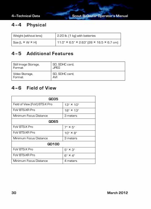
4–4 Physical
4–5 Additional Features
4–6 Field of View
Weight (without lens) 2.20 lb. (1 kg) with batteries
Size (L × W × H) 11.0” × 6.5” × 2.63” (28 × 16.5 × 6.7 cm)
Still Image Storage, Format
SD, SDHC card,JPEG
Video Storage,Format
SD, SDHC card, AVI
QD35
Field of View (FoV) BTS-X Pro 13° × 10°
FoV BTS-XR Pro 18° × 13°
Minimum Focus Distance 3 meters
QD65
FoV BTS-X Pro 7° × 5°
FoV BTS-XR Pro 10° × 8°
Minimum Focus Distance 3 meters
QD100
FoV BTS-X Pro 5° × 3°
FoV BTS-XR Pro 6° × 4°
Minimum Focus Distance 4 meters
30 March 2012
Scout Bi-Ocular Operator’s Manual 4—Technical Data
431-BTS0-00-10 Scout Bi-Oc Ops Manual.book Page 31 Thursday, March 29, 2012 1:27 PM
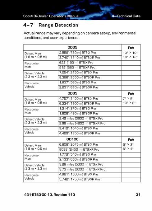
4–7 Range Detection
Actual range may vary depending on camera set-up, environmental conditions, and user experience.
QD35 FoV
13° × 10°18° × 13°
Detect Man(1.8 m × 0.5 m)
2,559’ (780 m) BTS-X Pro
3,740’ (1140 m) BTS-XR Pro
RecognizeMan
623’ (190 m) BTS-X Pro
919’ (280 m) BTS-XR Pro
Detect Vehicle(2.3 m × 2.3 m)
7,054’ (2150 m) BTS-X Pro
8,366’ (2550 m) BTS-XR Pro
RecognizeVehicle
1,837’ (560 m) BTS-X Pro
2,231’ (680 m) BTS-XR Pro
QD65 FoV
7° × 5°10° × 8°
Detect Man(1.8 m × 0.5 m)
4,757’ (1450 m) BTS-X Pro
6,234’ (1900 m) BTS-XR Pro
RecognizeMan
1,214’ (370 m) BTS-X Pro
1,608’ (490 m) BTS-XR Pro
Detect Vehicle(2.3 m × 2.3 m)
2.42 miles (3900 m) BTS-X Pro
2.98 miles (4800 m) BTS-XR Pro
RecognizeVehicle
3,412’ (1040 m) BTS-X Pro
4,429’ (1350 m) BTS-XR Pro
QD100 FoV
5° × 3°6° × 4°
Detect Man(1.8 m × 0.5 m)
6,808’ (2075 m) BTS-X Pro
8038’ (2450 m) BTS-XR Pro
RecognizeMan
1,772’ (540 m) BTS-X Pro
2,133’ (650 m) BTS-XR Pro
Detect Vehicle(2.3 m × 2.3 m)
3.29 miles (5300 m) BTS-X Pro
3.73 miles (6000 m) BTS-XR Pro
RecognizeVehicle
4,921’ (1500 m) BTS-X Pro
5,742’ (1750 m) BTS-XR Pro
431-BTS0-00-10, Revision 110 31

4—Technical Data Scout Bi-Ocular Operator’s Manual
431-BTS0-00-10 Scout Bi-Oc Ops Manual.book Page 32 Thursday, March 29, 2012 1:27 PM
32 March 2012

431-BTS0-00-10 Scout Bi-Oc Ops Manual.book Page i Thursday, March 29, 2012 1:27 PM

www.flir.com
Santa Barbara Portland
FLIR Commercial Systems, Inc.World HeadquartersFLIR Systems, Inc.70 Castilian Dr.Goleta, CA 93117USAPH: +1.888.747.FLIR (+1.888.747.3547)
FLIR Corporate HeadquartersFLIR Systems, Inc.27700A SW Parkway Ave.Wilsonville, OR 97070USA
Europe
CVS Eurasian HeadquartersFLIR Commercial Systems B.V.Charles Petitweg 214847 NW Teteringen - BredaThe NetherlandsPH: + 31 (0) 765 79 41 94FX: + 31 (0) 765 79 41 [email protected]
431-BTS0-00-10 Scout Bi-Oc Ops Manual.book Page ii Thursday, March 29, 2012 1:27 PM