Embed Size (px)
Citation preview

AN IMPLEMENTATION OF SOFTWARE DEFINED RADIOS FOR
FEDERATED AEROSPACE NETWORKS:
INFORMING SATELLITE IMPLEMENTATIONS USING AN INTER-BALLOON COMMUNICATIONS EXPERIMENT
Rustam Akhtyamov, Ignasi Lluch, Hripsime Matevosyan, Dominik Knoll, Udrivolf Pica,
Marco Lisi and Alessandro Golkar
June 2015

Outline
2
1. Problem background;
2. Experimental Approach;
3. Experimental campaign results;
4. Limitations and future work;
5. Conclusions
June 2015

Background: FSS needs
3
FSS concept requires a single, unique and universal TT&C transponder that can be reusable for the maximum number of spacecraft designs with the minimum recurring cost
June 2015
Federated Satellites Systems (FSS) are networks of spacecraft trading previously inefficiently allocated and unused resources: downlink bandwidth, storage, processing power, and instrument time

4
Background: Software defined radio (SDR) technology
Tailored solutions Commercial off-the-shelf solutions (COTS)
RF coverage custom from 70 MHz – 6 GHz already today HDLs VHDL, Verilog VHDL, Verilog
graphical programming environments
- GNU Radio, Simulink, LabVIEW
Examples
SDR TT&C Transponder, developed under ESA ARTES
Program
USRP N210, developed by Ettus Research
June 2015

Goal and objectives of the work
5
Goal To understand the performance of a Commercial Off The Shelf (COTS) Software Defined Radio (SDR) system as a key technology for Federated Satellite Systems (FSS). In particular: what is the performance of such communications system in a near-space environment? Specific objectives 1.Demonstrate the operations of COTS SDRs and single-board computers in environments with characteristics out of industrial range;
2. Experimentally characterize the long range performance of such system; 3.Demonstrate Federated Satellite Systems concept on a High Altitude Balloon (HAB) network flight.
June 2015

Experimental set-up
6 June 2015
HAB2 32 km Ceiling Altitude
5 element Yagi on Celestron tracking mount Ping for status/ Receive broadcasts
HAB1
3kg platforms
6,6 m/s Ascent Rate
Each HAB broadcasts its telemetry data comprising coordinates, altitude, time, and relays data from the other HAB upon receiving.
Tracking Ground Station (GS)
2 Stratospheric Balloons (HABs)

Ground Station structure
7 June 2015
All electronics were covered by a foam box for protection. The GS antenna is a 5 element Yagi mounted on an azimuth – elevation
tracking mount.
Tracking Laptop Matlab
BladeRF Software
Defined Radio
USB RF amplifier
RF switch
Coax
Coax
TTL
5V
24V
5V
Receiver Laptop GNU Radio
Power BUS
Lithium Polymer 11.1V 4000 mAh
Electronics deck mounted on tripod
CELESTRON AUTOMATED TRIPOD
Manual command
USB to com
Tracking Ground Station
8
External and internal views of the Tracking Ground Station

HAB payload structure
9 June 2015
Raspberry Pi 2 BladeRF Software Defined Radio Arduino
MEGA2560
USB
RF amplifier
Power BUS
GPS
GSM
Gyroscope, Compass,
Barometer, Thermometer
I2C
UART
UART
RF switch
GoPRO Independent Recovery System (SPOT)
Coax
Coax
TTL Auxiliary
USB battery
Lithium Polymer 11.1V 5500 mAh
Structure: Double deck detachable
Electronics support
5V
12V
5V
24V
5V
UART
Sensor bus
Communications subsystem

HAB payload: mounting desk view
10
The inferior (left) and superior (right) decks of the HAB platforms

HAB payload: foam container view
11
Foam container for electronics and ground metal plane

Communications module structure
12 June 2015
• An RF 20-500MHZ 1.5W power amplifier is used for signal amplification.
• In order to operate with a single antenna, the RPi2 controls an absorptive SPDT Solid State RF Switch ZFSWA2-63DR+ that connects the TX and RX ports of BladeRF to the omnidirectional antenna.
• The RF chain is completed with a ground metal base plate of 350x350 mm, which is required for the omnidirectional monopole
BladeRF SDR USB
Coax
Coax
TTL
RPi2
RF switch
RF amp

Communications protocol (pure ALOHA)
ID
{9 bytes}
DATA (Time; Lat; Long; Alt)
{21..52 bytes}
Secondary ID
{10 bytes}
Retransmitted data
(ping confirmation)
{27..61 bytes}
13
BladeRF
RF Front End
PC / RPi2
USB 3.0
RF IF
RF IF
LNA
RF amp
RX
TX
A D
A D
FPGA •Data rate conversion •Timing
GNU Radio Signal Processing
• Synchronization • Modulation • Demodulation
Bash script
Structure of the message generated by Bash script
June 2015

Communications protocol (pure ALOHA)
14
Time profile of operations
1..5 s – reading data from the Sensor Bus, forming messages
2 s – TX script initialization
8 s – TX script execution
2 s – RX script initialization
8…23 s – RX script execution
Bash script flow diagram
June 2015

GNU Radio flow graphs
15
Transmitter script
File Source Packet Encoder GMSK Mod Polyphase Synthesizer Sink
Receiver script
Source Xlating FIR Filter GMSK Demod Packet Decoder File Sink
June 2015

Radio link parameters
Central Frequency, Hz 446043750 Bandwidth, Hz 12500
Modulation GMSK Data rate 3.3 kbps Power, W 0.5
16
Expected range > 100 km
June 2015

17 June 2015
• Two HABs were launched in Moscow Region on April, 21st; • Maximum altitudes were 32 and 31 km; • Flight durations were 2:29:17 and 2:40:24; • Flight ground distances were 104 and 95 km.
Experimental campaign

Experimental campaign: general results
• HAB2 was tracked by GS during the whole flight; • HAB2(TX)-GS and HAB2(TX)-HAB1(RX) radio links were
operational till the landing (loss of direct line of sight); • HAB1(TX)-GS radio link was operational for 15 minutes,
because of cable misconnection. However data were recovering through HAB1(TX)-HAB2(RX) radio link for 45 minutes, thanks to Federated approach;
• I/Q data were recorded on the ground and on balloons.
18 June 2015

Experimental campaign: radio links
19
HAB2 (TX) – HAB1 (RX) link: Operational as predicted Max distance – 16 km BER – 0,3 HAB2(TX) – GS link: Operational as predicted Max distance – 90 km BER – 0,63 HAB1(TX) – HAB2(RX) link: Misbehavior Max distance – 4 km HAB1(TX) – GS link: Misbehavior Max distance – 11 km
June 2015
Antenna pointing error

Known Limitations
• Russian Federation Radio Regulation law; • GNU Radio bugs; • Absence of an internal clock in RPi2; • Selected Protocol limitations; • Insertion losses of cables and adapters.
20 June 2015

Future work
21
This work paves the way to future research in COTS SDR to realize Software Defined Networks:
June 2015
• VHDL-based communications protocols (higher utilization of BladeRF FPGA).
• the evolution of the code written in GNU Radio to enhance the usage of embedded systems.
An improvement of the current communications protocol is required:
• An upgrade to Slotted ALOHA • Internet Protocol could be adapted and implemented.
These upgrades would increase the channel utilization and give the possibility to add more nodes into the system. In order to increase the
reliability and agility of the tracking system, it should be fully automated

Conclusions
22
1. Despite frequency band and power limitation, the designed system based upon Nuand's BladeRF and single-board computer RPi2 can establish radio links at more than 90km distance with a margin larger than 10 dB.
2. We experimentally demonstrated that our Federated Approach substantially increased the resilience of the ad-hoc network. In our case it increased time of operations by a factor of three.
3. Our experimental system can be evolved to implement mobile ad-hoc networks on small satellites.
June 2015

23
I would like to thank our MONSTER team! MObile Networking for Space Technology Experimental Research
June 2015

24
Thank you!
June 2015

Backup slides
25 June 2015
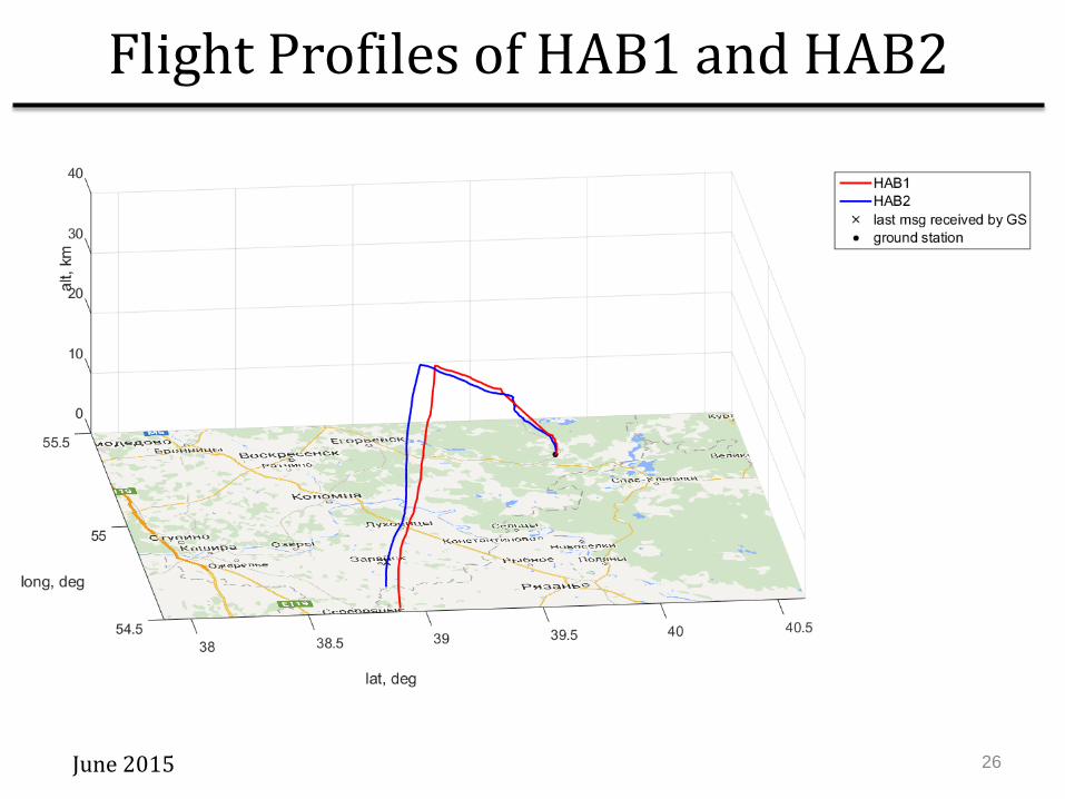
Flight Profiles of HAB1 and HAB2
26 June 2015

27
Myriad-RF UmTRX Zepto-SDR
HackRF USRP B210 BladeRF
COTS SDRs
June 2015
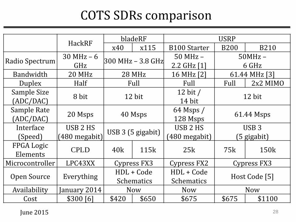
COTS SDRs comparison
HackRF bladeRF USRP x40 x115 B100 Starter B200 B210
Radio Spectrum 30 MHz – 6 GHz 300 MHz – 3.8 GHz 50 MHz –
2.2 GHz [1] 50MHz –
6 GHz Bandwidth 20 MHz 28 MHz 16 MHz [2] 61.44 MHz [3]
Duplex Half Full Full Full 2x2 MIMO Sample Size (ADC/DAC) 8 bit 12 bit 12 bit /
14 bit 12 bit
Sample Rate (ADC/DAC) 20 Msps 40 Msps 64 Msps /
128 Msps 61.44 Msps
Interface (Speed)
USB 2 HS (480 megabit) USB 3 (5 gigabit) USB 2 HS
(480 megabit) USB 3
(5 gigabit) FPGA Logic Elements CPLD 40k 115k 25k 75k 150k
Microcontroller LPC43XX Cypress FX3 Cypress FX2 Cypress FX3
Open Source Everything HDL + Code Schematics
HDL + Code Schematics Host Code [5]
Availability January 2014 Now Now Now Cost $300 [6] $420 $650 $675 $675 $1100
28 June 2015

RF switch
29
Absorptive SPDT Solid State RF Switch ZFSWA2-63DR+
June 2015

Compliance with Russian Radio regulations (SCRF protocol #05-10)
30
Frequency 446-446.1 MHz RF power < 0.5 W Level of side lobes < 0.25 μW
June 2015