Embed Size (px)
Citation preview
International Journal of Control Theory and Computer Modeling (IJCTCM) Vol.5, No.1, January 2015
DOI : 10.5121/ijctcm.2015.5102 15
MECHANIZATION AND ERROR ANALYSIS OF
AIDING SYSTEMS IN CIVILIAN AND MILITARY
VEHICLE NAVIGATION USING MATLAB SOFTWARE
Kunjal Prasad, B. Kumudha,and P.Keerthana.
Final Year Student, Department of ECE, SA Engineering College,India
ABSTRACT
In present scenario GPS is widely used to provide extremely accurate position information for navigation.
From, where the GPS does not give continuous localization in environments where signal blockages are
present, Inertial Navigation System comes into action. Because of sensors present in INS and time
integration process, errors get accumulated over time. Henceforth, an aiding system is integrated with INS.
The aim of this paper is to model VMS and RADAR and aid it with INS in order to overcome its errors. VMS
is aided to INS to achieve acceptable accuracy and ease of implementation, much needed in civilian
navigation. Different trajectories are generated to offer solutions in a practical scenario. Whereas, for
highly accurate positioning in military navigation a reliable aiding system, Radar has been opted. The
Kalman filter is designed and modeled as the integrating element in INS/RADAR, to provide an optimal
estimate of navigation solutions. An error analysis has been done for both INS aided VMS and INS aided
Radar systems. The navigation performance of VMS and Radar aiding system is compared and their merits
have been brought out. We besides give the readers a more honest insight of the demand for an aiding
system in different environments based on various simulation results.
1.INTRODUCTION
Inertial Navigation System (INS) is a self sustained dead-reckoning navigation system, which is
used to determine attitude, velocity, and position of a moving vehicle from the prior knowledge of
the states and measurements of the land vehicle’s motion. It is an navigating aid that uses motion
sensors (accelerometers) and rotation sensors (gyroscopes) with gravity computer to compute the
location and orientation values respectively. Pure inertial navigation system errors grow over
time. To control the error growth some form of external aiding is necessary. Altimeter, Vehicle
Motion Sensor (VMS),Radar and Global Navigation Satellite Systems (GNSS) can be used as
aiding sources.
Civilian vehicle navigation has very rigid need in context of size, cost, reliability and ease of
implementation of the integrated system. Vehicle Motion Sensor (VMS) aids the Inertial
navigation system, which performs satisfactorily for these attributes with acceptable accuracy.
The primary use of VMS is to Convert vehicle's odometer cable shaft revolutions into pulse trains
representing forward and reverse vehicle motion.
Kinematic model which describes the motion of the vehicle with constant velocity input is used to
generate the trajectory. This paper showcases different trajectories (such as 'linear', 'S' and '8')
which can be generated by varying acceleration components in x, y, z direction.
International Journal of Control Theory and Computer Modeling (IJCTCM) Vol.5, No.1, January 2015
16
For terrestrial defense applications, particularly for combat vehicles, navigation information is
mandatory for completing the mission and operational effectiveness. Attributes such as accurate
positioning, high data rates, reliability are accomplished by an aiding system called Radar. Radar
measures range, direction and speed of objects by transmitting and receiving radio signals.
Kalman filter is a recursive data processing algorithm, which is used as the binding element for
INS/Radar. Hence, Radar aiding outperforms other aids in military navigation.
Error analysis provides us the clear view of position and velocity errors in both the aiding
systems. It likewise helps us understand the divergence of the estimated values of the true values.
The remainder of this paper is organized as follows. Initially this paper provides an overview of
application oriented stand-alone INS, INS aided with VMS and Radar system. While in second, a
brief description about the integration of INS/VMS for different trajectories in civilian navigation
has been talked about. In third Radar aiding for defense application with KalmanEstimator has
been elaborated. Finally, error analysis is done and its results are used to explain various
characteristics of the two aiding systems depending upon various attributes.
2.RELATED WORK
This section provides an up-to-date survey of most major contributions to the pool of INS and its
integrated systems. It also includes a thorough overview of the limitations of standalone INS to
that of its integrated system, and ways to overcome it.
In an urban environment, automotive applications cannot rely on GPS based geolocalization only,
since satellite signal outages are frequent. Hence, inertial navigation system is adopted. But, still
INS also have internal accumulated errors (sensor errors) which makes it less efficient. Thus, to
overcome rapid navigation error drift, a self-retained
dynamic-assisted error rectification method can be used in the absence of aiding sensors. Fuzzy
logic is one of the vehicle dynamic identification system which is highly recommendable.
Through an experiment it has been found out that this method is extremely suited for ground
vehicle navigation, where severe GPS outages, frequent vehicle halt and turning dynamics subsist.
An efficient method to improve the positioning accuracy and reliability is the multi-sensor
integrated positioning system. Vehicle Motion Sensor is used as an integrating aid to standalone
INS, which improves the error performance and independent ability of the system in civilian
applications.
Alignment of the vehicle body frame (VBF) with respect to INS body frame plays a crucial part in
INS mechanization. Misalignment between the frames incurs serious errors in the integration of
INS/VMS. The operation of VMS requires to the point scale factor to ensure navigation accuracy.
Scale factor of VMS is affected by skidding, temperature, inflation and abrasion of vehicle tires.
Strong tracking Kalman filter is employed to overcome the in-motion alignment errors of
SINS/VMS integration system.
The ability of RADAR to estimate the vehicle’s location with a high accuracy which, makes it a
very good aiding part to INS in military application. Radar can be abbreviated as Radio Detection
and Ranging, which can also be used for civilian purposes. It records and processes signal
International Journal of Control Theory and Computer Modeling (IJCTCM) Vol.5, No.1, January 2015
17
information, which uses radio-frequencies to locate and track vehicles. And the integration of
INS/RADAR is achieved by using a non-linear Kalman filter. In the open loop system, INS is the
primary source of data, and RADAR provides discrete aiding data to support the ideas. In case of
abrupt faults, the robust Kalman filter algorithm is suggested to overcome the malfunctioning of
INS/RADAR open loop system.
From the above discussion, some important conclusions have been made.They are summarized as
follows.
• Stand-alone INS provides satisfactorily navigation results during GPS outages.
• VMS aiding is highly beneficial for civilian vehicles because of ease of implementation.
• However, VMS as an aiding system cannot be implemented in military applications,
because of its high sensitivity to varying environments.
• Radar aiding is aptly suited for a robust environment without compromising on accuracy.
• In the context of civilian users, implementation complexity of Radar prohibits them from
its usage. Moreover, acceptable accuracy is required in contrast of defense applications.
3.AID FOR CIVILIAN NAVIGATION
A. Stand-Alone INS
The inertial navigation system is a selfcontained within the vehicle, does not depend on the
transmission of signals from the vehicle or reception from the external source. Sensors
(Accelerometers and Gyroscopes) present in the INS are used to determine the acceleration and
orientation of the vehicle in which they are installed.
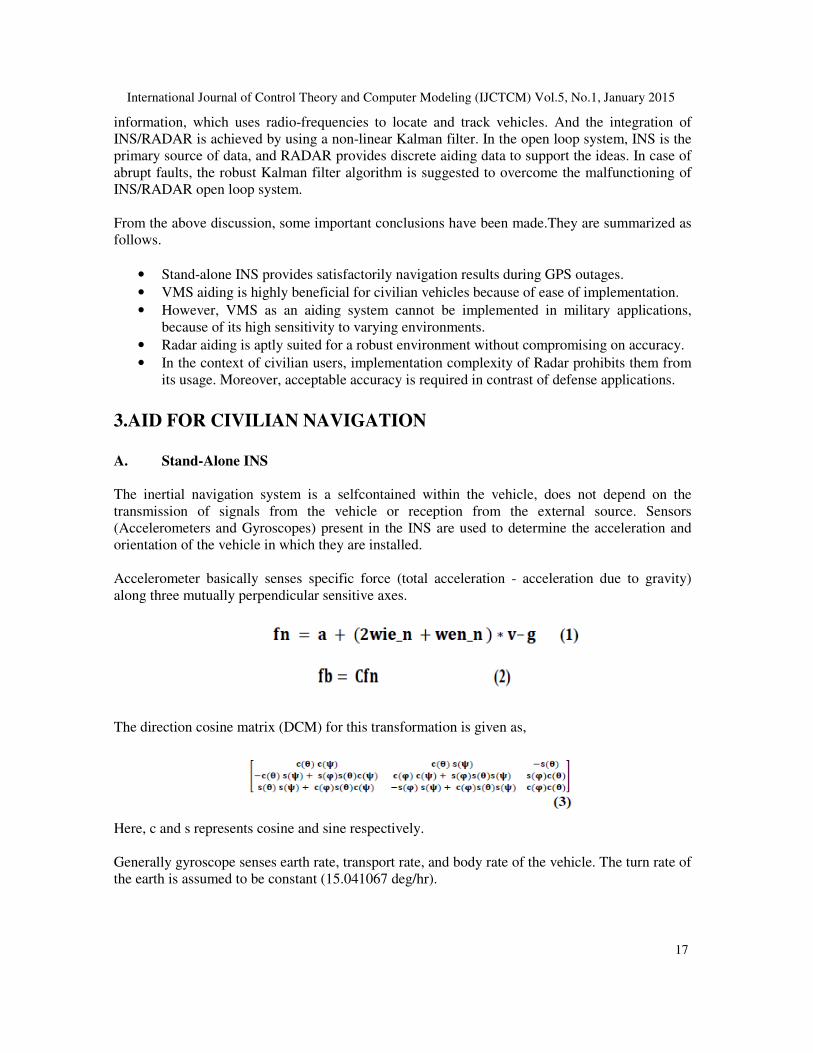
Accelerometer basically senses specific force (total acceleration - acceleration due to gravity)
along three mutually perpendicular sensitive axes.
The direction cosine matrix (DCM) for this transformation is given as,
Here, c and s represents cosine and sine respectively.
Generally gyroscope senses earth rate, transport rate, and body rate of the vehicle. The turn rate of
the earth is assumed to be constant (15.041067 deg/hr).
International Journal of Control Theory and Computer Modeling (IJCTCM) Vol.5, No.1, January 2015
18
where ,
The sensors in INS are subjected to errors which limits the overall accuracy of the total integrating
system. The errors which have a significant effect upon the accuracy of the system are biased
errors, gravity-dependent errors and these errors have been modelled. Even with the careful
calibration, the residual errors caused by the unpredictable error components will always be
present, restricting the accuracy of the inertial system performance.
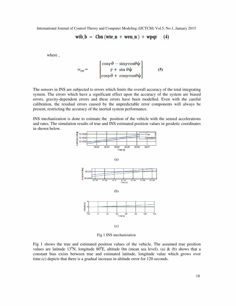
INS mechanization is done to estimate the position of the vehicle with the sensed accelerations
and rates. The simulation results of true and INS estimated position values in geodetic coordinates
in shown below.
(a)
(b)
(c)
Fig 1 INS mechanization
Fig 1 shows the true and estimated position values of the vehicle. The assumed true position
values are latitude 130N, longitude 80
0E, altitude 0m (mean sea level). (a) & (b) shows that a
constant bias exists between true and estimated latitude, longitude value which grows over
time.(c) depicts that there is a gradual increase in altitude error for 120 seconds.
International Journal of Control Theory and Computer Modeling (IJCTCM) Vol.5, No.1, January 2015
19
B. Trajectory Generation
Trajectory generation is done to define movement of the vehicle along different curved and non-
curved path. Based on the application, different trajectories are generated and its modelling is
explained via various simulation plots.
Generally, most of the civilian system goes through various intersections, crossroads and
roundabouts. Hence, it has become paramount importance to simulate different trajectories to
effectively model a navigation system. Few important trajectories are discussed below.
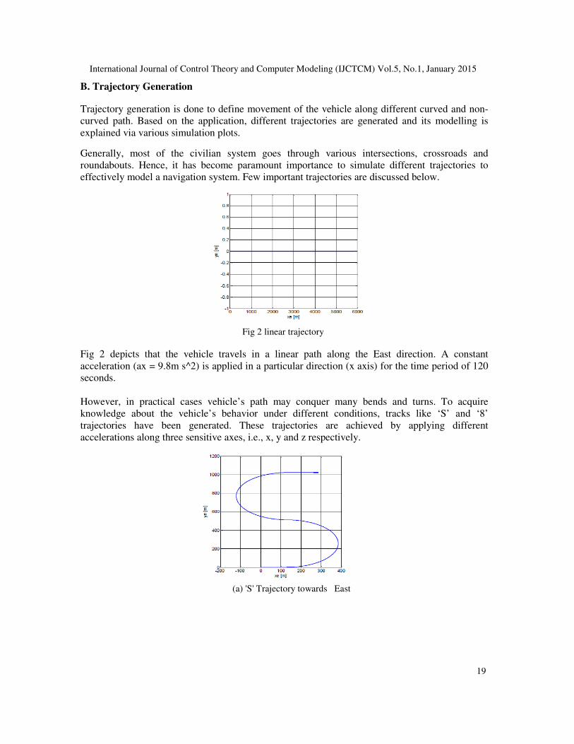
Fig 2 linear trajectory
Fig 2 depicts that the vehicle travels in a linear path along the East direction. A constant
acceleration (ax = 9.8m s^2) is applied in a particular direction (x axis) for the time period of 120
seconds.
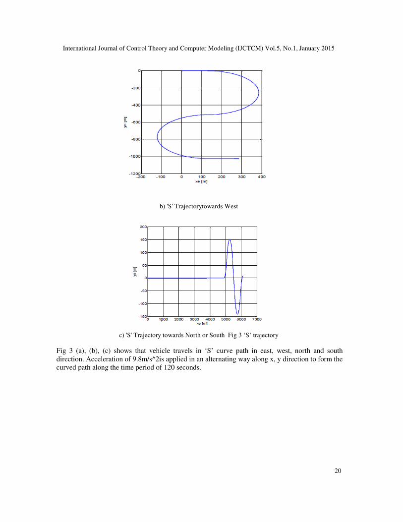
However, in practical cases vehicle’s path may conquer many bends and turns. To acquire
knowledge about the vehicle’s behavior under different conditions, tracks like ‘S’ and ‘8’
trajectories have been generated. These trajectories are achieved by applying different
accelerations along three sensitive axes, i.e., x, y and z respectively.
(a) 'S' Trajectory towards East
International Journal of Control Theory and Computer Modeling (IJCTCM) Vol.5, No.1, January 2015
20
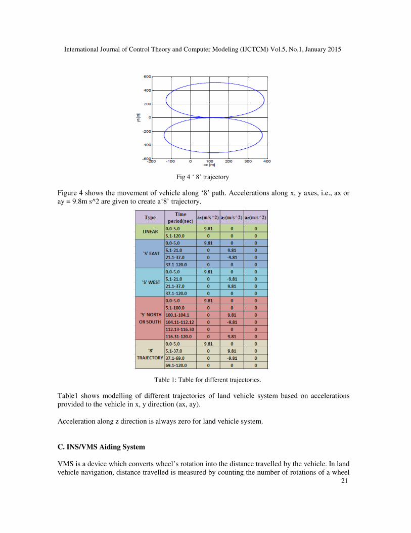
b) 'S' Trajectorytowards West
c) 'S' Trajectory towards North or South Fig 3 ‘S’ trajectory
Fig 3 (a), (b), (c) shows that vehicle travels in ‘S’ curve path in east, west, north and south
direction. Acceleration of 9.8m/s^2is applied in an alternating way along x, y direction to form the
curved path along the time period of 120 seconds.
International Journal of Control Theory and Computer Modeling (IJCTCM) Vol.5, No.1, January 2015
21
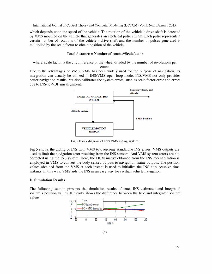
Fig 4 ‘ 8’ trajectory
Figure 4 shows the movement of vehicle along ‘8’ path. Accelerations along x, y axes, i.e., ax or
ay = 9.8m s^2 are given to create a‘8’ trajectory.
Table 1: Table for different trajectories.
Table1 shows modelling of different trajectories of land vehicle system based on accelerations
provided to the vehicle in x, y direction (ax, ay).
Acceleration along z direction is always zero for land vehicle system.
C. INS/VMS Aiding System
VMS is a device which converts wheel’s rotation into the distance travelled by the vehicle. In land
vehicle navigation, distance travelled is measured by counting the number of rotations of a wheel
International Journal of Control Theory and Computer Modeling (IJCTCM) Vol.5, No.1, January 2015
22
which depends upon the speed of the vehicle. The rotation of the vehicle’s drive shaft is detected
by VMS mounted on the vehicle that generates an electrical pulse stream. Each pulse represents a
certain number of rotations of the vehicle’s drive shaft and the number of pulses generated is
multiplied by the scale factor to obtain position of the vehicle.
Total distance = Number of counts*Scalefactor
where, scale factor is the circumference of the wheel divided by the number of revolutions per
count.
Due to the advantages of VMS, VMS has been widely used for the purpose of navigation. Its
integration can usually be utilized in INS/VMS open loop mode. INS/VMS not only provides
better navigation results, but also calibrates the system errors, such as scale factor error and errors
due to INS-to-VBF misalignment.
Fig 5 Block diagram of INS VMS aiding system
Fig 5 shows the aiding of INS with VMS to overcome standalone INS errors. VMS outputs are
used to limit the navigation error resulting from the INS sensors. And VMS system errors are not
corrected using the INS system. Here, the DCM matrix obtained from the INS mechanization is
employed in VMS to convert the body sensed outputs to navigation frame outputs. The position
values obtained from the VMS at each instant is used to initialize the INS at successive time
instants. In this way, VMS aids the INS in an easy way for civilian vehicle navigation.
D. Simulation Results
The following section presents the simulation results of true, INS estimated and integrated
system’s position values. It clearly shows the difference between the true and integrated system
values.
(a)
International Journal of Control Theory and Computer Modeling (IJCTCM) Vol.5, No.1, January 2015
23
(b)
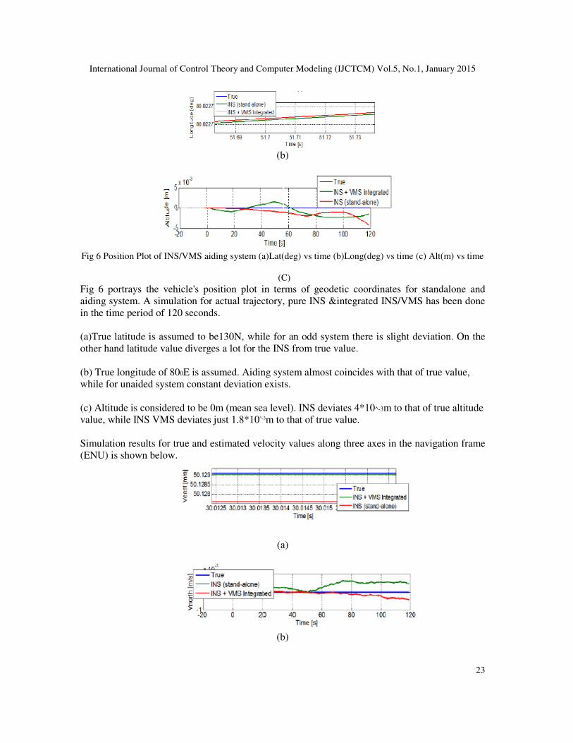
Fig 6 Position Plot of INS/VMS aiding system (a)Lat(deg) vs time (b)Long(deg) vs time (c) Alt(m) vs time
(C)
Fig 6 portrays the vehicle's position plot in terms of geodetic coordinates for standalone and
aiding system. A simulation for actual trajectory, pure INS &integrated INS/VMS has been done
in the time period of 120 seconds.
(a)True latitude is assumed to be130N, while for an odd system there is slight deviation. On the
other hand latitude value diverges a lot for the INS from true value.
(b) True longitude of 800E is assumed. Aiding system almost coincides with that of true value,
while for unaided system constant deviation exists.
(c) Altitude is considered to be 0m (mean sea level). INS deviates 4*10^-3m to that of true altitude
value, while INS VMS deviates just 1.8*10^-3m to that of true value.
Simulation results for true and estimated velocity values along three axes in the navigation frame
(ENU) is shown below.
(a)
(b)
International Journal of Control Theory and Computer Modeling (IJCTCM) Vol.5, No.1, January 2015
24
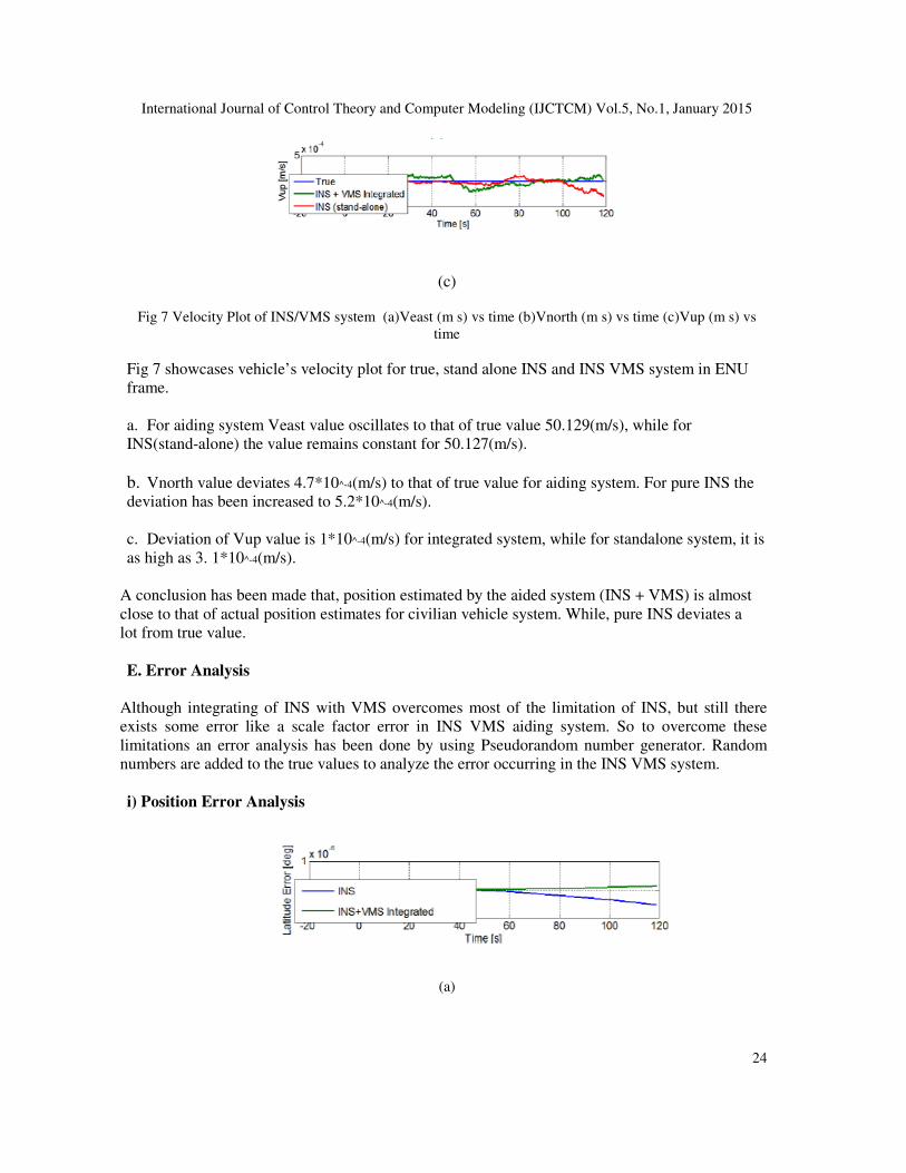
(c)
Fig 7 Velocity Plot of INS/VMS system (a)Veast (m s) vs time (b)Vnorth (m s) vs time (c)Vup (m s) vs
time
Fig 7 showcases vehicle’s velocity plot for true, stand alone INS and INS VMS system in ENU
frame.
a. For aiding system Veast value oscillates to that of true value 50.129(m/s), while for
INS(stand-alone) the value remains constant for 50.127(m/s).
b. Vnorth value deviates 4.7*10^-4(m/s) to that of true value for aiding system. For pure INS the
deviation has been increased to 5.2*10^-4(m/s).
c. Deviation of Vup value is 1*10^-4(m/s) for integrated system, while for standalone system, it is
as high as 3. 1*10^-4(m/s).
A conclusion has been made that, position estimated by the aided system (INS + VMS) is almost
close to that of actual position estimates for civilian vehicle system. While, pure INS deviates a
lot from true value.
E. Error Analysis
Although integrating of INS with VMS overcomes most of the limitation of INS, but still there
exists some error like a scale factor error in INS VMS aiding system. So to overcome these
limitations an error analysis has been done by using Pseudorandom number generator. Random
numbers are added to the true values to analyze the error occurring in the INS VMS system.
i) Position Error Analysis
(a)
International Journal of Control Theory and Computer Modeling (IJCTCM) Vol.5, No.1, January 2015
25
(b)
(c)
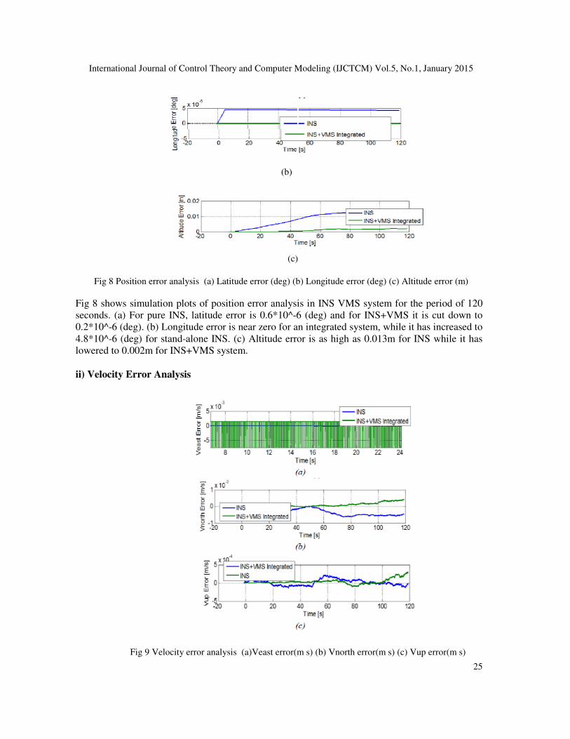
Fig 8 Position error analysis (a) Latitude error (deg) (b) Longitude error (deg) (c) Altitude error (m)
Fig 8 shows simulation plots of position error analysis in INS VMS system for the period of 120
seconds. (a) For pure INS, latitude error is 0.6*10^-6 (deg) and for INS+VMS it is cut down to
0.2*10^-6 (deg). (b) Longitude error is near zero for an integrated system, while it has increased to
4.8*10^-6 (deg) for stand-alone INS. (c) Altitude error is as high as 0.013m for INS while it has
lowered to 0.002m for INS+VMS system.
ii) Velocity Error Analysis
Fig 9 Velocity error analysis (a)Veast error(m s) (b) Vnorth error(m s) (c) Vup error(m s)
International Journal of Control Theory and Computer Modeling (IJCTCM) Vol.5, No.1, January 2015
26
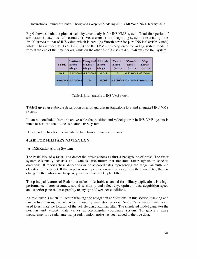
Fig 9 shows simulation plots of velocity error analysis for INS VMS system. Total time period of
simulation is taken as 120 seconds. (a) Veast error of the integrating system is oscillating by ±
2*10^-3(m/s) to that of INS value, which is zero. (b) Vnorth error for pure INS is 0.8*10^-3 (m/s)
while it has reduced to 0.4*10^-3(m/s) for INS+VMS. (c) Vup error for aiding system tends to
zero at the end of the time period, while on the other hand it rises to 4*10^-4(m/s) for INS system.
Table 2: Error analysis of INS VMS system
Table 2 gives an elaborate description of error analysis in standalone INS and integrated INS VMS
system.
It can be concluded from the above table that position and velocity error in INS VMS system is
much lesser than that of the standalone INS system.
Hence, aiding has become inevitable to optimize error performance.
4 .AID FOR MILITARY NAVIGATION
A. INS/Radar Aiding System:
The basic idea of a radar is to detect the target echoes against a background of noise. The radar
system essentially consists of a wireless transmitter that transmits radar signals in specific
directions. It reports these detections in polar coordinates representing the range, azimuth and
elevation of the target. If the target is moving either towards or away from the transmitter, there is
change in the radio wave frequency, induced due to Doppler Effect.
The principal features of Radar that makes it desirable as an aid for military applications is a high
performance, better accuracy, sound sensitivity and selectivity, optimum data acquisition speed
and superior penetration capability to any type of weather conditions.
Kalman filter is much utilized in tracking and navigation applications. In this section, tracking of a
land vehicle through radar has been done by simulation process. Noisy Radar measurements are
used to estimate the location of the vehicle using Kalman filter. The simulated model generates the
position and velocity data values in Rectangular coordinate system. To generate noisy
measurements by radar antenna, pseudo random noise has been added to the true data.
International Journal of Control Theory and Computer Modeling (IJCTCM) Vol.5, No.1, January 2015
27
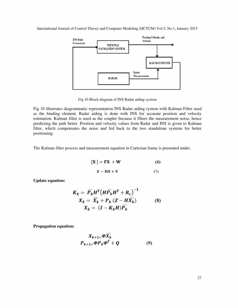
Fig 10 Block diagram of INS Radar aiding system
Fig 10 illustrates diagrammatic representation INS Radar aiding system with Kalman Filter used
as the binding element. Radar aiding is done with INS for accurate position and velocity
estimation. Kalman filter is used as the coupler because it filters the measurement noise, hence
predicting the path better. Position and velocity values from Radar and INS is given to Kalman
filter, which compensates the noise and fed back to the two standalone systems for better
positioning.
The Kalman filter process and measurement equation in Cartesian frame is presented under.
Update equation:
Propagation equation:
International Journal of Control Theory and Computer Modeling (IJCTCM) Vol.5, No.1, January 2015
28
B. Simulation Results:
(a)
(b)
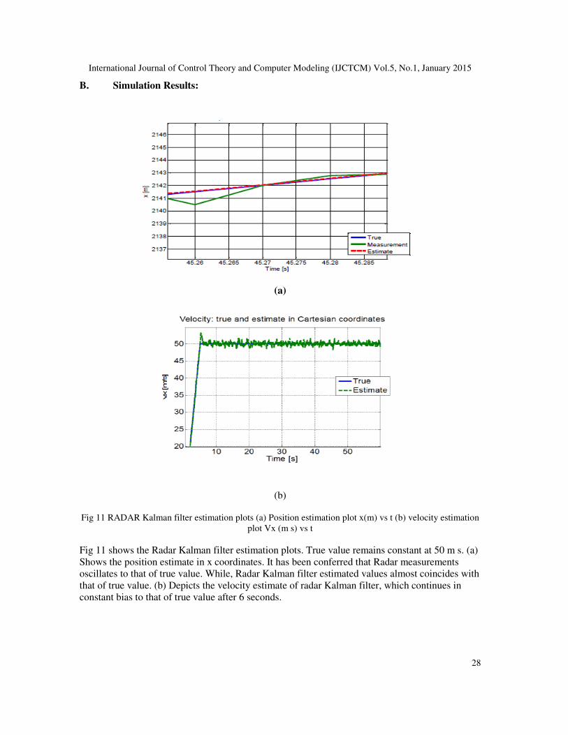
Fig 11 RADAR Kalman filter estimation plots (a) Position estimation plot x(m) vs t (b) velocity estimation
plot Vx (m s) vs t
Fig 11 shows the Radar Kalman filter estimation plots. True value remains constant at 50 m s. (a)
Shows the position estimate in x coordinates. It has been conferred that Radar measurements
oscillates to that of true value. While, Radar Kalman filter estimated values almost coincides with
that of true value. (b) Depicts the velocity estimate of radar Kalman filter, which continues in
constant bias to that of true value after 6 seconds.
International Journal of Control Theory and Computer Modeling (IJCTCM) Vol.5, No.1, January 2015
29
C. ErrorAnalysis(±2σuncertainity)
(a)
(b)
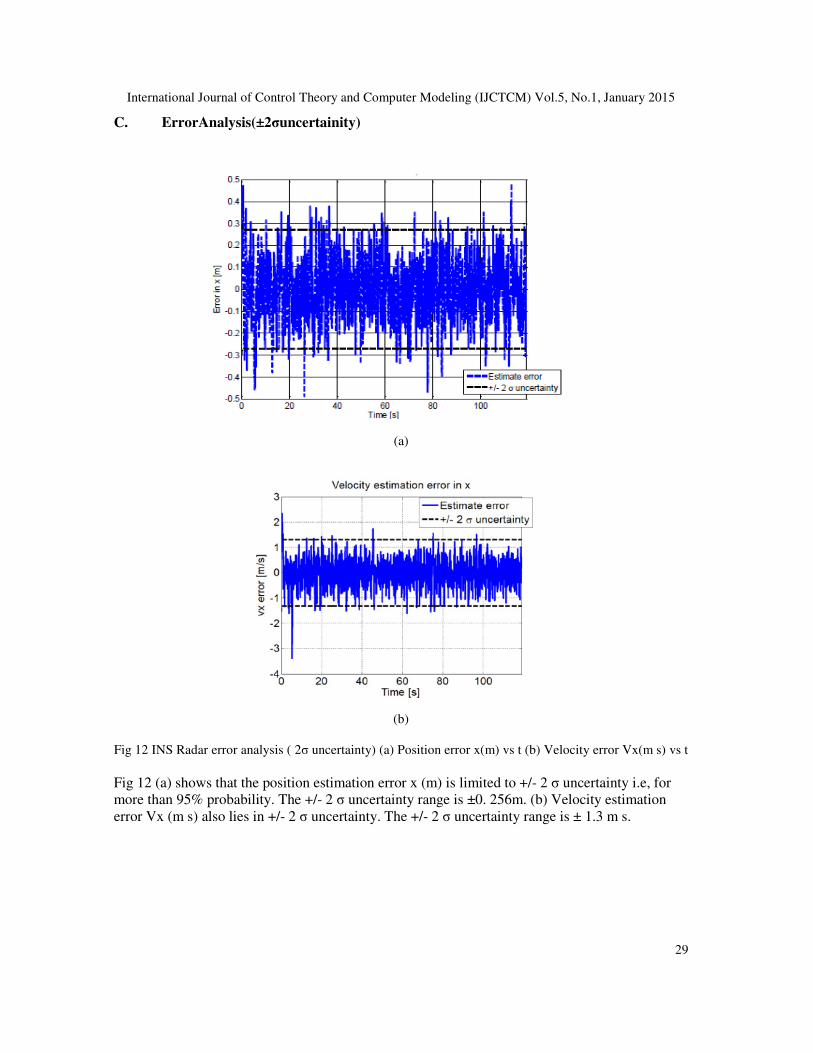
Fig 12 INS Radar error analysis ( 2σ uncertainty) (a) Position error x(m) vs t (b) Velocity error Vx(m s) vs t
Fig 12 (a) shows that the position estimation error x (m) is limited to +/- 2 σ uncertainty i.e, for
more than 95% probability. The +/- 2 σ uncertainty range is ±0. 256m. (b) Velocity estimation
error Vx (m s) also lies in +/- 2 σ uncertainty. The +/- 2 σ uncertainty range is ± 1.3 m s.
International Journal of Control Theory and Computer Modeling (IJCTCM) Vol.5, No.1, January 2015
30
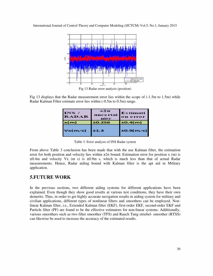
Fig 13 Radar error analysis (position)
Fig 13 displays that the Radar measurement error lies within the scope of (-1.5m to 1.5m) while
Radar Kalman Filter estimate error lies within (-0.5m to 0.5m) range.
Table 3: Error analysis of INS Radar system
From above Table 3 conclusion has been made that with the use Kalman filter, the estimation
error for both position and velocity lies within ±2σ bound. Estimation error for position x (m) is
±0.4m and velocity Vx (m s) is ±0.9m s, which is much less than that of actual Radar
measurements. Hence, Radar aiding bound with Kalman filter is the apt aid in Military
application.
5.FUTURE WORK
In the previous sections, two different aiding systems for different applications have been
explained. Even though they show good results at various test conditions, they have their own
demerits. Thus, in order to get highly accurate navigation results in aiding system for military and
civilian applications, different types of nonlinear filters and smoothers can be employed. Non-
linear Kalman filter, i.e., Extended Kalman filter (EKF), first-order EKF, second-order EKF and
Particle filter (PF) are found to be the effective estimators for non-linear systems. Additionally,
various smoothers such as two filter smoother (TFS) and Rauch Tung striebel- smoother (RTSS)
can likewise be used to increase the accuracy of the estimated results.
International Journal of Control Theory and Computer Modeling (IJCTCM) Vol.5, No.1, January 2015
31
6.CONCLUSION
The paper has presented the integrated navigation system for both civilian and military
applications. It shows that integrated systems provide superior performance than the stand-alone
system. Different types of trajectories are generated to check the output under different path
constraints. Error analysis is also done to verify those results. Finally, topics for future research
has been identified.
REFERENCES
[1] P.Keerthana,B. Kumudha and Kunjal Prasad. Survey of Inertial Navigation Sensor with Aiding
Systems. International Journal of Enhanced Research in Science Technology & Engineering. ISSN:
2319-7463 Vol.3 Issue4 April 2014
[2] J.H. Wang and Y. Gao. Land vehicle dynamics-aided inertial navigation. IEEE Trans. Aerosp.
Electron. Syst, 46 (4): 1638-1653, 2010.
[3] David H. Titterton and John L. Weston. Strapdown Inertial Navigation Technology.
[4] Z.F. Syed, Priyanka Aggarwal, X.Niu and N. EI-shimmy. Civilian Vehicle Navigation: Required
Alignment of the Inertial Sensors for Acceptable Navigation Accuracies. IEEE Trans. Weh. Techno.,
57(6): 30402-30412,2008.
[5] Pavel Davidson, Jani Hautamäki, Jussi Collin, and Jarmo Takala, Department Of Computer systems,
Tampere University of Technology. Improved Vehicle Positioning in Urban Environment through
Integration of GPS and Low-Cost Inertial Sensors.
[6] R. M. Rogers. Applied Mathematics in Integrated Navigation Systems. American Institute of
Aeronautics and Astronautics, Inc, Virginia, 3rd edition, 2003.
[7] Qingzhe Wang, Mengyin Fu, Zhihong Deng and Hongbin Ma, 2012 American Control Conference.
Comparison of Loosely-coupled and Tightly- coupled mode for INS/VMS.
[8] Mathematical Model and Matlab Simulation of
Strapdown Inertial Navigation System.Wen Zhang, Mounir Ghogho, and Baolun Yuan.