Embed Size (px)
Citation preview

University of Engineering and Technology
Peshawar, Pakistan
CE-409: Introduction to Structural Dynamics and
Earthquake Engineering
MODULE 5:
UNDAMPED & DAMPED VIBRATIONS IN S.D.O.F
SYSTEMS SUBJECTED TO HARMONIC FORCES
Prof. Dr. Akhtar Naeem Khan & Prof. Dr. Mohammad Javed
[email protected] [email protected]
1
CE-409: MODULE 5 (Fall-2013) 2
Harmonic force A harmonic force is one whose variation which with time is
defined by any one of the following equations
t)Cos(p t)Sin(p p(t) oo or Where po is the amplitude or maximum value of force and ω is its frequency
also called as exciting frequency or forcing frequency; T=2π/ω is the exciting
period or forcing period.
The equations used in this module are strictly applicable to po sin (ωt)
Time variation of harmonic force
CE-409: MODULE 5 (Fall-2013) 3
A common source of such a sinusoidal force is unbalance in a
rotating machines (such as turbines, electric motors and electric
generators, as well as fans, or rotating shafts).
Unbalance cloth in a rotating drum of a washing machine is also
an harmonic force.
When the wheels of a car are not balanced, harmonic forces are
developed in the rotating wheels. If the rotational speed of the wheels
is close to the natural frequency of the car’s suspension system in
vertical direction , amplitude of vertical displacement in the car’s
suspension system increases and violent shaking occur in car due to
match of frequency of the force (due to vertical component of
harmonic forces acting at unbalanced mass centre) with natural
frequency of car’s suspension system in vertical direction, ωn
Harmonic forces
3

CE-409: MODULE 5 (Fall-2013) 4
Response of undamped systems subjected
to harmonic forces

CE-409: MODULE 5 (Fall-2013) 5
Response of undamped systems to harmonic forces
The equation of motion for harmonic vibration of undamped
system is: t)Sin(pku um o The solution to the equation is made up of two parts.
The first part is the solution which correspond to forced
vibration and is known as the Particular Solution. The
corresponding vibration is known as Steady state vibration, for its
present because of the applied force no matter what the initial
conditions .
The second part is the solution to the free vibration, which does
not require any forcing function, this part is known as the
Complimentary solution. The corresponding vibration is known as
Transient Vibration, which depends on the initial conditions
CE-409: MODULE 5 (Fall-2013) 6
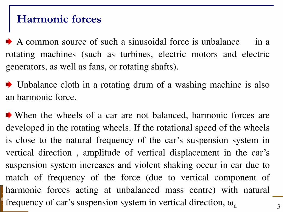
Particular solution of undamped harmonic vibrations
n2
n
op wheret)Sin(
-1
1.
k
p (t)u
up(t) is the displacements corresponding to the Particular
solution (i.e due to forced vibration).
ratiofrequency as termedisωω
n
n2
op wheret)Sin(
r-1
1
k
p (t)u
It can be derived that the particular solution of undamped
vibration is as follows:
For the sack of simplicity, we will use rω in our lectures to represent ω/ωn
CE-409: MODULE 5 (Fall-2013) 7
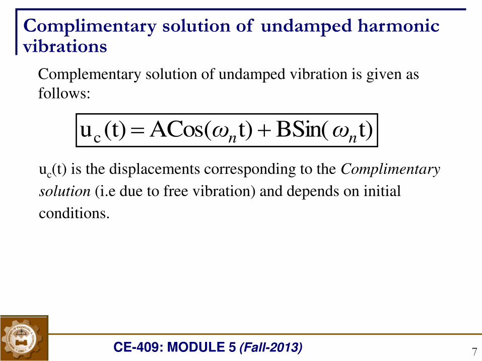
Complimentary solution of undamped harmonic vibrations
t)BSin( t)ACos( (t)uc nn ωω uc(t) is the displacements corresponding to the Complimentary
solution (i.e due to free vibration) and depends on initial
conditions.
Complementary solution of undamped vibration is given as
follows:
CE-409: MODULE 5 (Fall-2013) 8
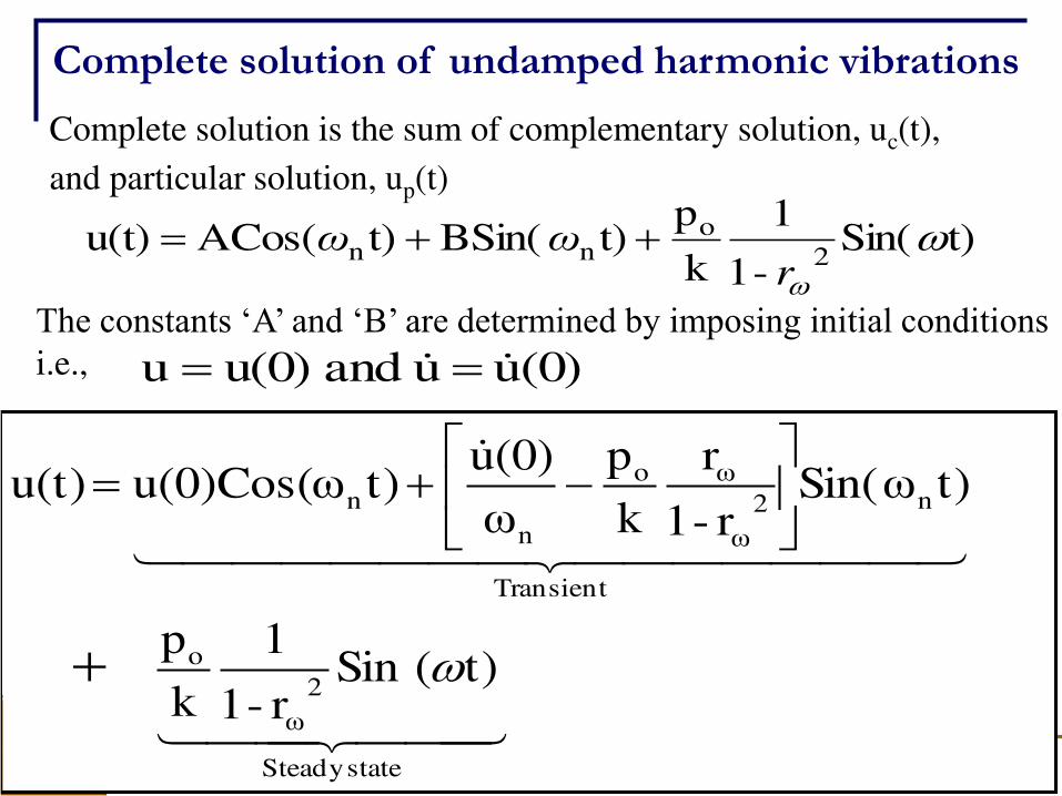
Complete solution of undamped harmonic vibrations
Complete solution is the sum of complementary solution, uc(t),
and particular solution, up(t)
t)Sin(-1
1
k
p t)BSin( t)ACos( u(t)
2
onn
rωω
The constants ‘A’ and ‘B’ are determined by imposing initial conditions i.e., (0)u u and u(0)u
stateSteady
2
ω
o
Transient
n2
ω
ωo
n
n
t)(Sin r-1
1
k
p
t)Sin(ωr-1
r
k
p
ω(0)u
t)u(0)Cos(ω u(t)
CE-409: MODULE 5 (Fall-2013) 9
Complete solution of undamped harmonic vibrations
The transient vibration exist even if . In such case the
complementary part of solution given on previous slide specializes to:
0(0)u u(0)
t)Sin(ωr-1
r
k
p
ω0
t)Cos(ω*0 (t)u n2
ω
ωo
n
nc
t)Sin(ωrt)(Sin r-1
1
k
p u(t)or nω2
ω
o
t)Sin(ω1r
r
k
p (t)uor n2
ω
ωoc
The complete solution is then specialized to the following form
CE-409: MODULE 5 (Fall-2013) 10
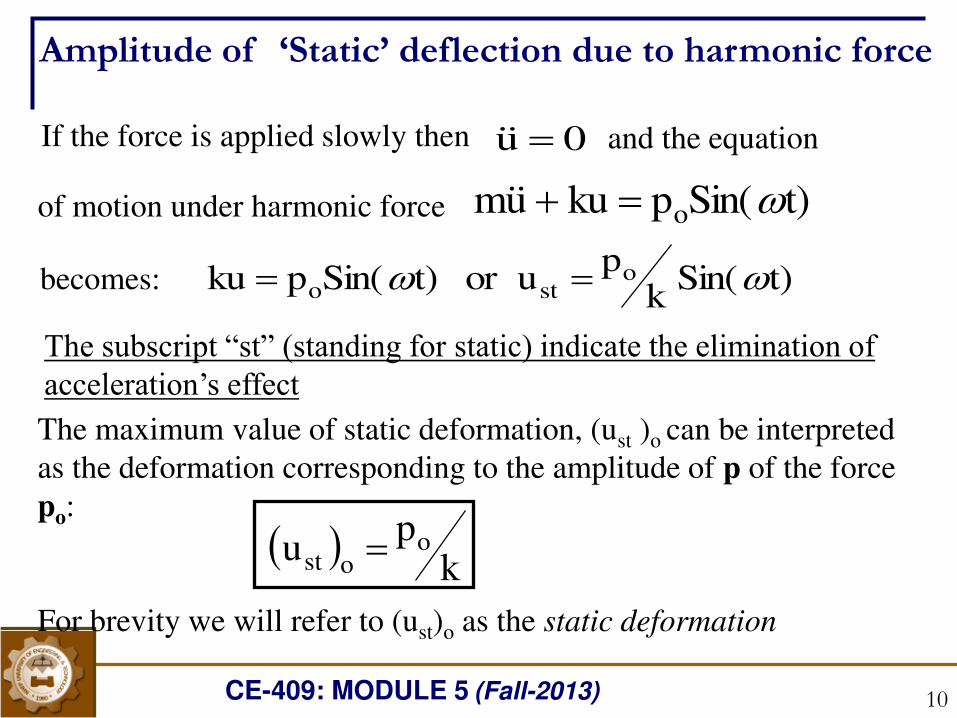
t)Sin(pku um o If the force is applied slowly then 0u of motion under harmonic force
and the equation
becomes: t)Sin(k
p uor t)Sin(pku o
sto The subscript “st” (standing for static) indicate the elimination of acceleration’s effect The maximum value of static deformation, (ust )o can be interpreted
as the deformation corresponding to the amplitude of p of the force
po:
For brevity we will refer to (ust)o as the static deformation
k
p u o
ost
Amplitude of ‘Static’ deflection due to harmonic force
CE-409: MODULE 5 (Fall-2013) 11
:as written becan t)Sin(r-1
1
k
p (t)u
2
op
t)Sin(r-1
1u (t)u
2ostp
ost
o u k
p where
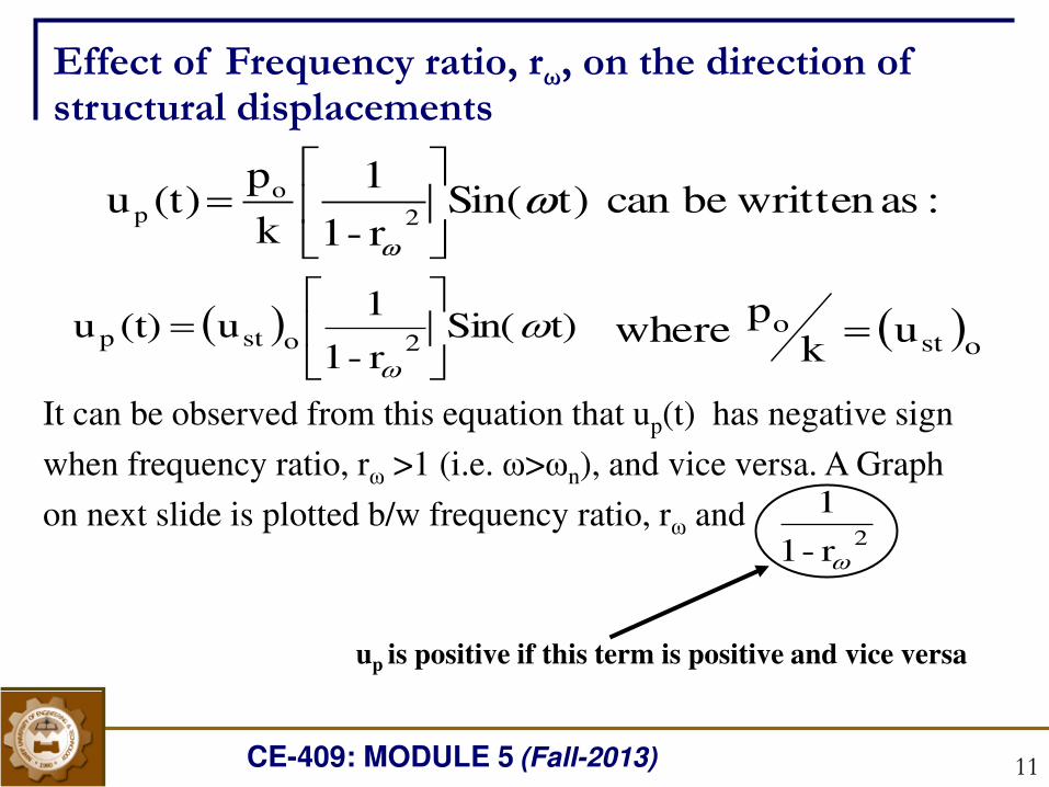
Effect of Frequency ratio, rω, on the direction of structural displacements
r-1
12
It can be observed from this equation that up(t) has negative sign
when frequency ratio, rω >1 (i.e. ω>ωn), and vice versa. A Graph
on next slide is plotted b/w frequency ratio, rω and
up is positive if this term is positive and vice versa
CE-409: MODULE 5 (Fall-2013) 12
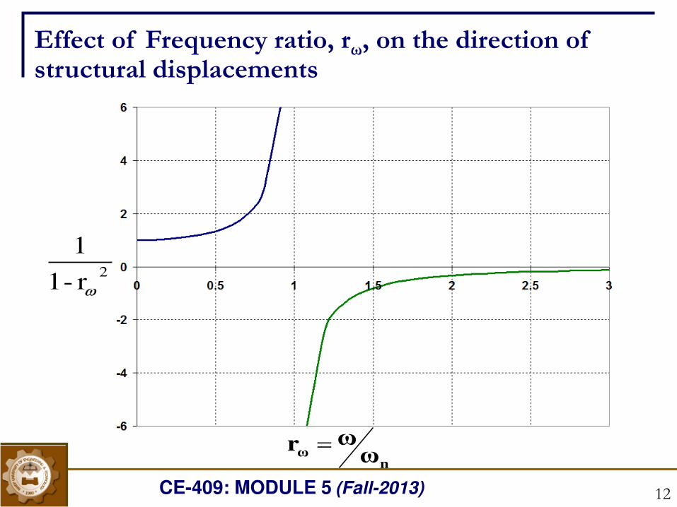
Effect of Frequency ratio, rω, on the direction of structural displacements
r-1
12
ωωr
nω
CE-409: MODULE 5 (Fall-2013) 13
Following observation can be made from the plot given on
previous slide
When rω < 1 ( i.e ω < ωn ), the displacement is positive,
indicating that up(t) and p(t) has same directions. The displacement
is said to be in phase with the applied force.
When rω > 1 ( i.e ω > ωn ), the displacement is negative ,
indicating that the u(t) and p(t) has apposite direction directions.
The displacement is said to be out of phase with the applied force.
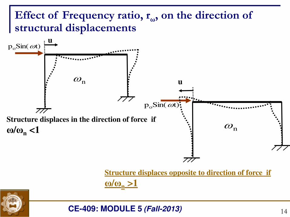
Effect of Frequency ratio, rω, on the direction of structural displacements
CE-409: MODULE 5 (Fall-2013) 14
Structure displaces in the direction of force if
ω/ωn <1
t)Sin(po
n
u
t)Sin(po
n
u
Effect of Frequency ratio, rω, on the direction of structural displacements
Structure displaces opposite to direction of force if
ω/ωn >1
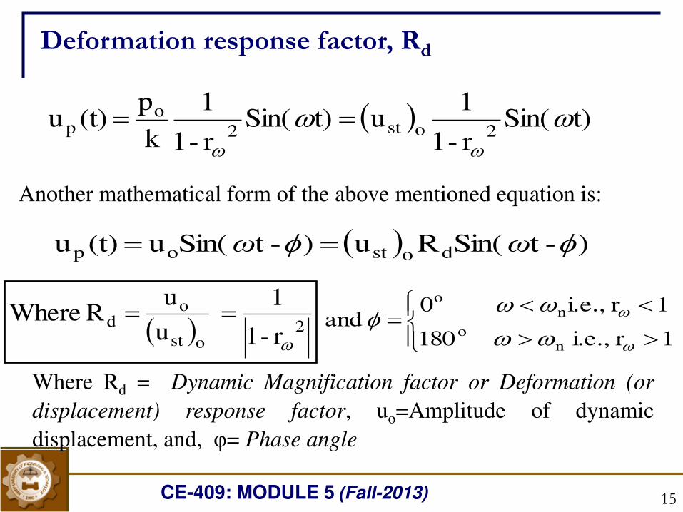
CE-409: MODULE 5 (Fall-2013) 15
t)Sin(r-1
1u t)Sin(
r-1
1
k
p (t)u
2ost2
op
Where Rd = Dynamic Magnification factor or Deformation (or
displacement) response factor, uo=Amplitude of dynamic
displacement, and, φ= Phase angle
Deformation response factor, Rd
2ost
od
r-1
1
u
u R Where
Another mathematical form of the above mentioned equation is:
)-tSin(Ru )-tSin(u (t)u dostop ωω
1r i.e., 180
1r i.e., 0 and
no
no
CE-409: MODULE 5 (Fall-2013) 16
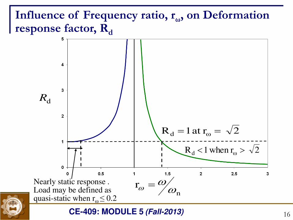
Influence of Frequency ratio, rω, on Deformation response factor, Rd
rn
dR
Nearly static response . Load may be defined as quasi-static when rω ≤ 0.2
2 rat 1R ωd 2 r when 1R ωd
CE-409: MODULE 5 (Fall-2013) 17
Following observation can be made from the plot
When rω is small ( i.e force is ‘slowly varying’), Rd is only slightly
greater than 1 or in the other words amplitude of dynamic deformation,
uo, is almost same as amplitude of static deformation, (ust)o.
and the dynamic
deformation amplitude is less than static deformation
When become smaller and
becomes zero as
When rω is close to 1.0, Rd is many times larger than 1
1),2 (i.e 2rWhen n dR
dR ,2beyond increases r r
Influence of Frequency ratio, rω, on Deformation response factor, Rd
CE-409: MODULE 5 (Fall-2013) 18
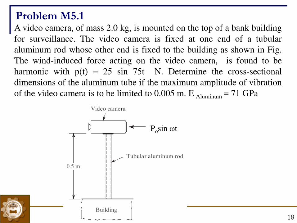
A video camera, of mass 2.0 kg, is mounted on the top of a bank building
for surveillance. The video camera is fixed at one end of a tubular
aluminum rod whose other end is fixed to the building as shown in Fig.
The wind-induced force acting on the video camera, is found to be
harmonic with p(t) = 25 sin 75t N. Determine the cross-sectional
dimensions of the aluminum tube if the maximum amplitude of vibration
of the video camera is to be limited to 0.005 m. E Aluminum = 71 GPa
Posin ωt
Problem M5.1
CE-409: MODULE 5 (Fall-2013) 19
Response of damped systems under
Harmonic forces
CE-409: MODULE 5 (Fall-2013) 20
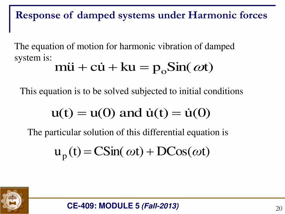
Response of damped systems under Harmonic forces
The equation of motion for harmonic vibration of damped
system is: t)Sin(pku uc um o
This equation is to be solved subjected to initial conditions
(0)u(t)u and u(0)u(t) The particular solution of this differential equation is
t)DCos( t)CSin( (t)up ωω
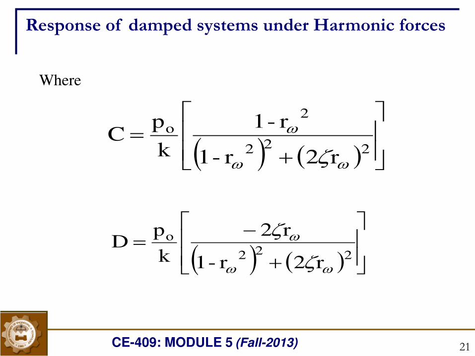
CE-409: MODULE 5 (Fall-2013) 21
Where
222
2o
r2r-1
r-1
k
pC
222
o
r2r-1
r2
k
pD
Response of damped systems under Harmonic forces
CE-409: MODULE 5 (Fall-2013) 22
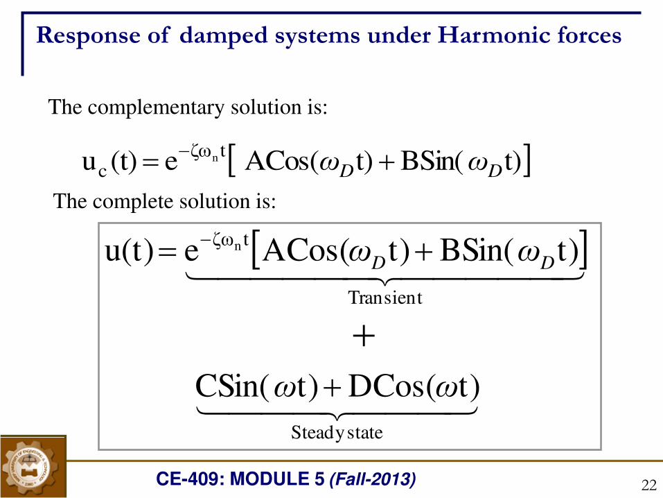
The complementary solution is:
t)BSin( t)ACos( e (t)utζω
cn
DD ωω The complete solution is:
stateSteady
Transient
tζω
t)DCos( t)CSin(
t)BSin( t)ACos(eu(t) n
ωω
ωω DD
Response of damped systems under Harmonic forces
CE-409: MODULE 5 (Fall-2013) 23
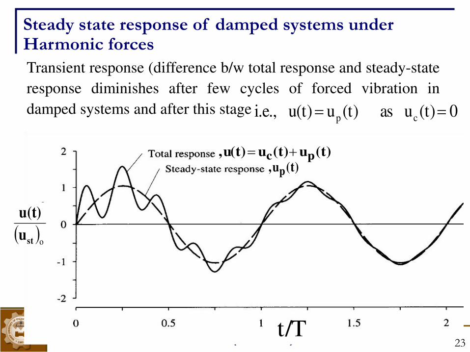
Transient response (difference b/w total response and steady-state
response diminishes after few cycles of forced vibration in
damped systems and after this stage
u
u(t)
st o
t/T
Steady state response of damped systems under Harmonic forces
0 (t)u as (t)u u(t) i.e., cp (t)u(t)u u(t), pc
(t)u, p
23
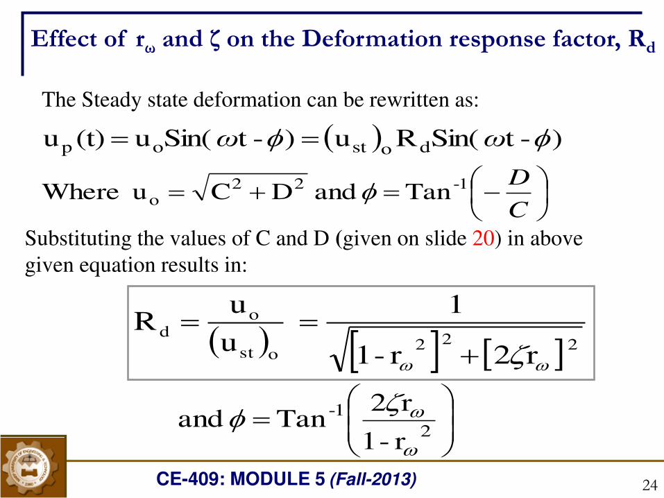
CE-409: MODULE 5 (Fall-2013) 24
2 2 2ost
od
r2r-1
1
u
uR
Substituting the values of C and D (given on slide 20) in above
given equation results in:
Effect of rω and ζ on the Deformation response factor, Rd
)-tSin(Ru )-tSin(u (t)u dostop ωω The Steady state deformation can be rewritten as:
Tan and DCu Where 1-22o
C
D
r-1
r2Tan and
2
1-
CE-409: MODULE 5 (Fall-2013) 25
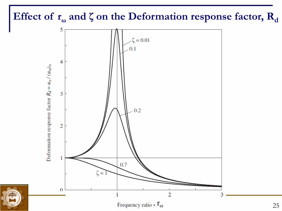
Effect of rω and ζ on the Deformation response factor, Rd
, rω
CE-409: MODULE 5 (Fall-2013) 26
Following observation can be made from the plot
Damping reduce Rd for all values of frequency ratio, rω. However rate
of reduction highly depend on the magnitude of rω (around 0.5 to 1.5)
If the rω is around 0.2 and below, ( i.e force is ‘slowly varying’), Rd is
only slightly greater than 1 and thus unaffected by damping. Thus
1r provided/k p uu oosto If the rω very high, around 2 and above,( i.e force is ‘rapidly varying’),
Rd tends to zero. In other words Rd is unaffected by damping. uo can be
approximated as: 1r provided /mp 2
o uo
Effect of rω and ζ on the Deformation response factor, Rd
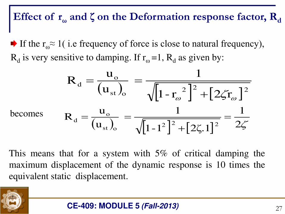
CE-409: MODULE 5 (Fall-2013) 27
If the rω≈ 1( i.e frequency of force is close to natural frequency), Rd is very sensitive to damping. If rω =1, Rd as given by:
2 2 2ost
od
r2r-1
1
u
uR
21
1.2ζ1-1
1
u
uR
2 2 2ost
od becomes
This means that for a system with 5% of critical damping the
maximum displacement of the dynamic response is 10 times the
equivalent static displacement.
Effect of rω and ζ on the Deformation response factor, Rd
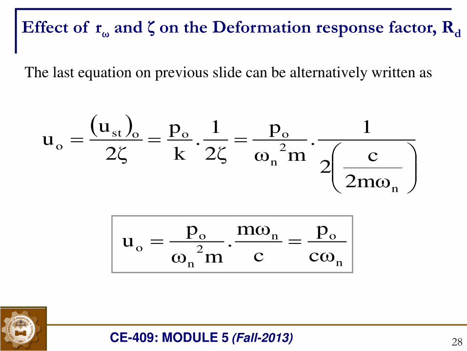
CE-409: MODULE 5 (Fall-2013) 28
n
2
n
ooost
o
2mωc
2
1.
mωp
2ζ1
.k
p
2ζu
u
The last equation on previous slide can be alternatively written as
n
on
2
n
oo
cωp
c
mω.
mωp
u
Effect of rω and ζ on the Deformation response factor, Rd
CE-409: MODULE 5 (Fall-2013) 29
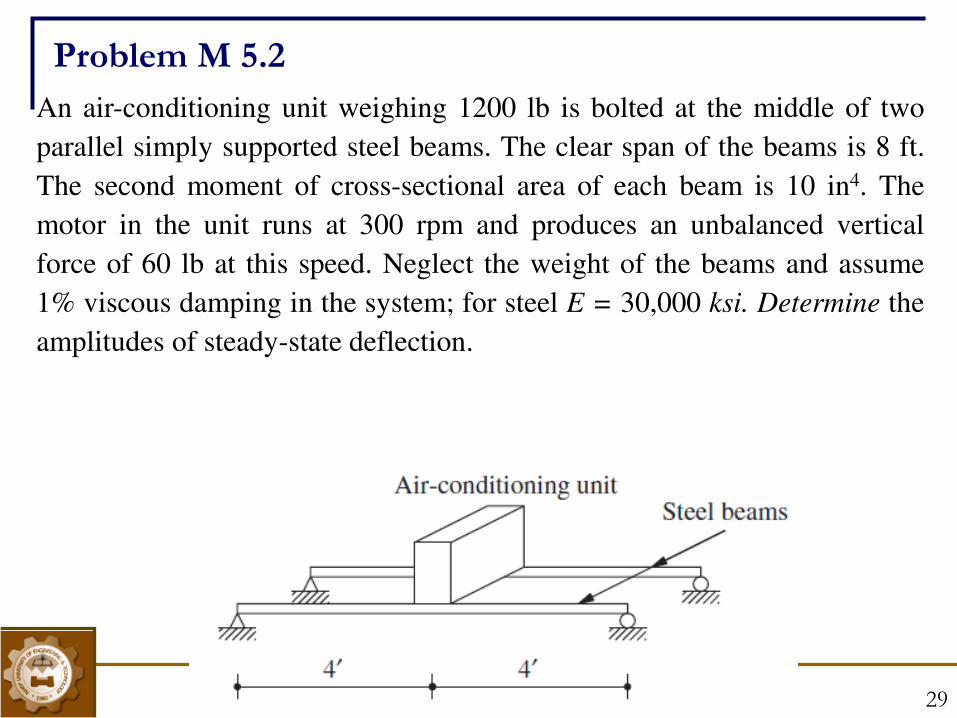
An air-conditioning unit weighing 1200 lb is bolted at the middle of two
parallel simply supported steel beams. The clear span of the beams is 8 ft.
The second moment of cross-sectional area of each beam is 10 in4. The
motor in the unit runs at 300 rpm and produces an unbalanced vertical
force of 60 lb at this speed. Neglect the weight of the beams and assume
1% viscous damping in the system; for steel E = 30,000 ksi. Determine the
amplitudes of steady-state deflection.
Problem M 5.2
CE-409: MODULE 5 (Fall-2013) 30
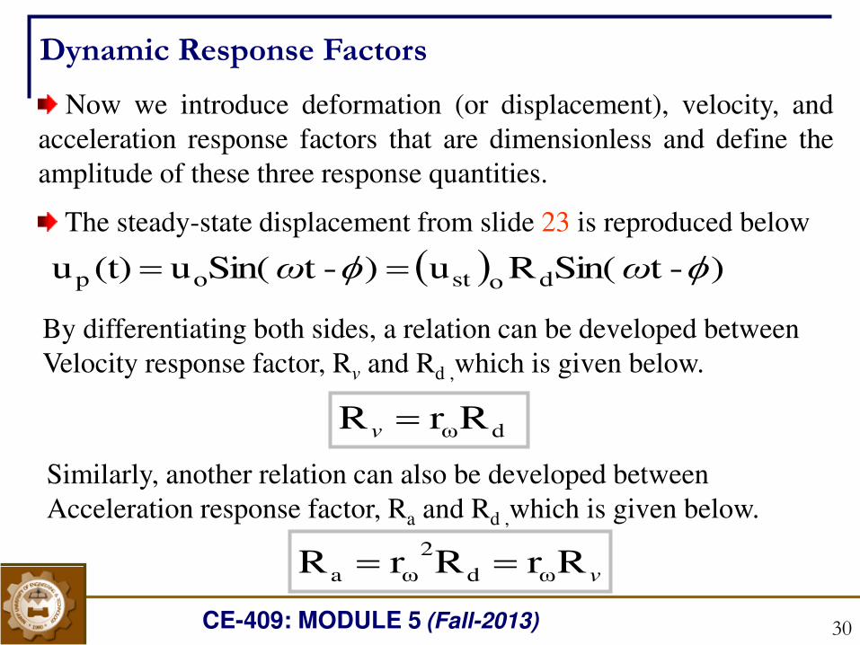
Dynamic Response Factors
Now we introduce deformation (or displacement), velocity, and
acceleration response factors that are dimensionless and define the
amplitude of these three response quantities.
The steady-state displacement from slide 23 is reproduced below )-tSin(Ru )-tSin(u (t)u dostop ωω By differentiating both sides, a relation can be developed between
Velocity response factor, Rv and Rd ,which is given below.
RrR dωv
Similarly, another relation can also be developed between
Acceleration response factor, Ra and Rd ,which is given below.
vRrRrR ωd
2
ωa
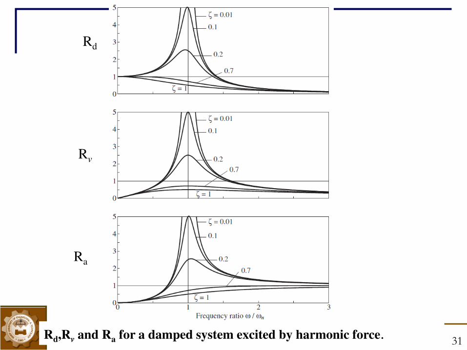
CE-409: MODULE 5 (Fall-2013) 31 Rd,R
v and Ra for a damped system excited by harmonic force.
Rd
Rv
Ra
CE-409: MODULE 5 (Fall-2013) 32
1. A spring-mass-damper system is subjected to a harmonic force. The
amplitude is found to be 20 mm at resonance and 10 mm at a frequency
0.75 times the resonant frequency. Find the damping ratio of the system.
2. An air compressor of mass 100 kg is mounted on an elastic foundation.
It has been observed that, when a harmonic force of amplitude 100 N is
applied to the compressor, the maximum steady-state displacement of 5
mm occurred at a frequency of 300 rpm. Determine the equivalent
stiffness and damping constant of the foundation.
3. A 50-kg machine tool is mounted on an elastic foundation. An
experiment is run to determine the stiffness and damping properties of
the foundation. When the tool is excited with a harmonic force of
magnitude 8000 N at a variety of frequencies, the maximum steady–state amplitude obtained is 2.5 mm, occurring at a frequency of 32 Hz.
Use this information to determine the stiffness and damping ratio of the
foundation.
Problems
32
CE-409: MODULE 5 (Fall-2013) 33
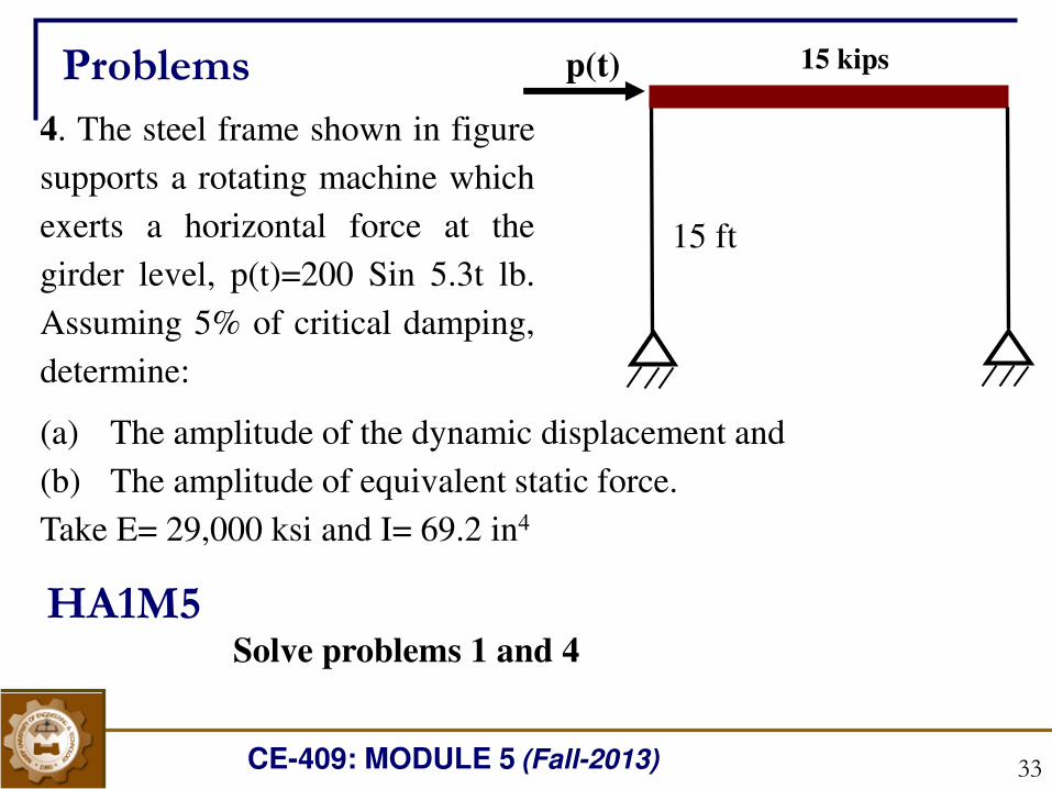
4. The steel frame shown in figure
supports a rotating machine which
exerts a horizontal force at the
girder level, p(t)=200 Sin 5.3t lb.
Assuming 5% of critical damping,
determine:
(a) The amplitude of the dynamic displacement and
(b) The amplitude of equivalent static force.
Take E= 29,000 ksi and I= 69.2 in4
p(t) 15 kips
15 ft
HA1M5
Problems
Solve problems 1 and 4
CE-409: MODULE 5 (Fall-2013) 34
Vibration Isolation
CE-409: MODULE 5 (Fall-2013) 35
High vibration levels can cause machinery failure, as well as
objectionable noise levels.
A common source of objectionable noise in buildings is the
vibration of machines that are mounted on floors or walls. A typical
problem is a rotating machine (such as a pump, AC compressor,
blower, engine, etc) mounted on a roof, or on a floor above the
ground floor.
The problem is usually most apparent in the immediate vicinity
of the vibration source. However, mechanical vibrations can
transmit for long distances, and by very circuitous routes through
the structure of a building, sometimes resurfacing hundreds of feet
from the source.
Vibration Isolation
CE-409: MODULE 5 (Fall-2013) 36
A related problem is the isolation of vibration-sensitive
machines from the normally occurring disturbances in a building
(car or bus traffic, slamming doors, foot traffic, elevators…).
Examples of sensitive machines include surgical microscopes,
electronic equipment, lasers, and computer disk drives.
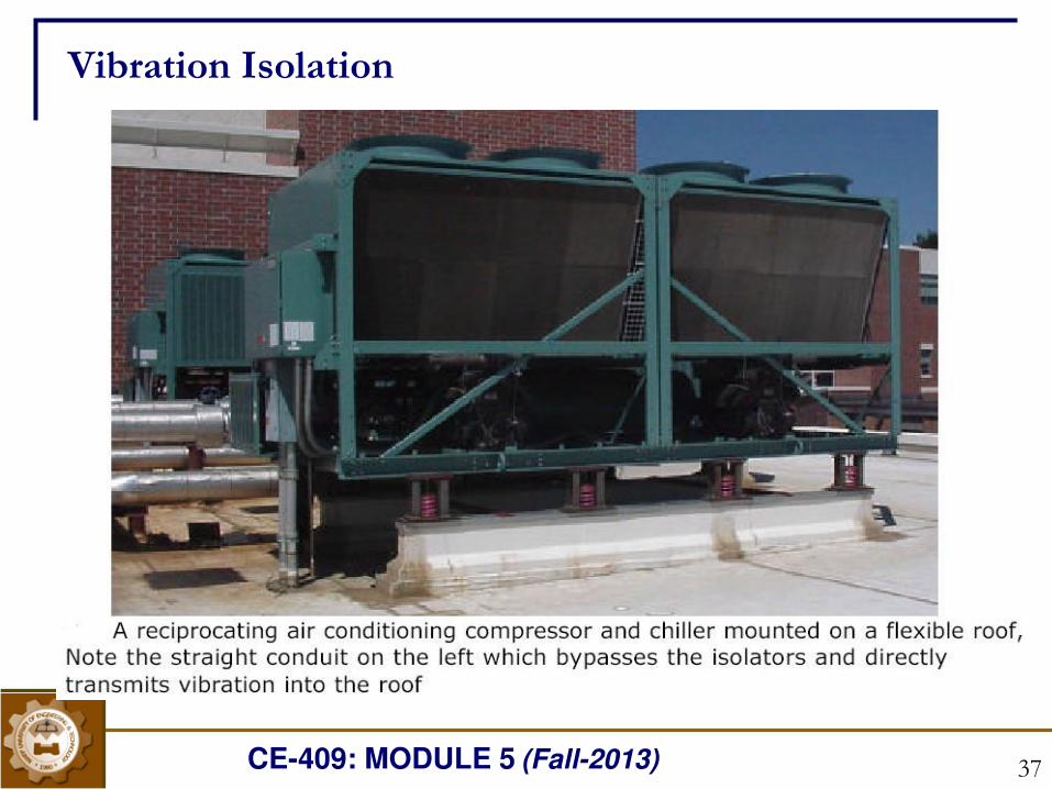
A common example of a vibration source is shown in figure, a
large reciprocating air conditioning compressor weighing 20,000
pounds, mounted on a roof. Annoying noise levels at multiples of
the compressor rotational frequency, predominantly 60 and 120
Hz, were measured in the rooms directly below the compressor.
Also, this type of compressor (reciprocating) is notorious for
high vibration levels. Centrifugal or scroll type compressors are
much quieter, but more expensive.
Vibration Isolation
CE-409: MODULE 5 (Fall-2013) 37
Vibration Isolation
CE-409: MODULE 5 (Fall-2013) 38
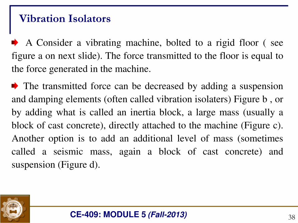
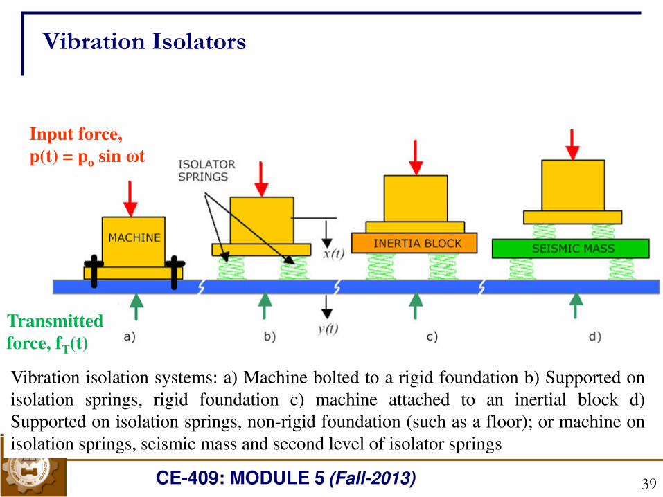
A Consider a vibrating machine, bolted to a rigid floor ( see
figure a on next slide). The force transmitted to the floor is equal to
the force generated in the machine.
The transmitted force can be decreased by adding a suspension
and damping elements (often called vibration isolaters) Figure b , or
by adding what is called an inertia block, a large mass (usually a
block of cast concrete), directly attached to the machine (Figure c).
Another option is to add an additional level of mass (sometimes
called a seismic mass, again a block of cast concrete) and
suspension (Figure d).
Vibration Isolators
CE-409: MODULE 5 (Fall-2013) 39
Vibration Isolators
Vibration isolation systems: a) Machine bolted to a rigid foundation b) Supported on
isolation springs, rigid foundation c) machine attached to an inertial block d)
Supported on isolation springs, non-rigid foundation (such as a floor); or machine on
isolation springs, seismic mass and second level of isolator springs
Input force,
p(t) = po sin ωt
Transmitted
force, fT(t)
CE-409: MODULE 5 (Fall-2013) 40
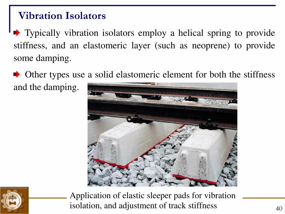
Typically vibration isolators employ a helical spring to provide
stiffness, and an elastomeric layer (such as neoprene) to provide
some damping.
Other types use a solid elastomeric element for both the stiffness
and the damping.
Vibration Isolators
Application of elastic sleeper pads for vibration
isolation, and adjustment of track stiffness
CE-409: MODULE 5 (Fall-2013) 41
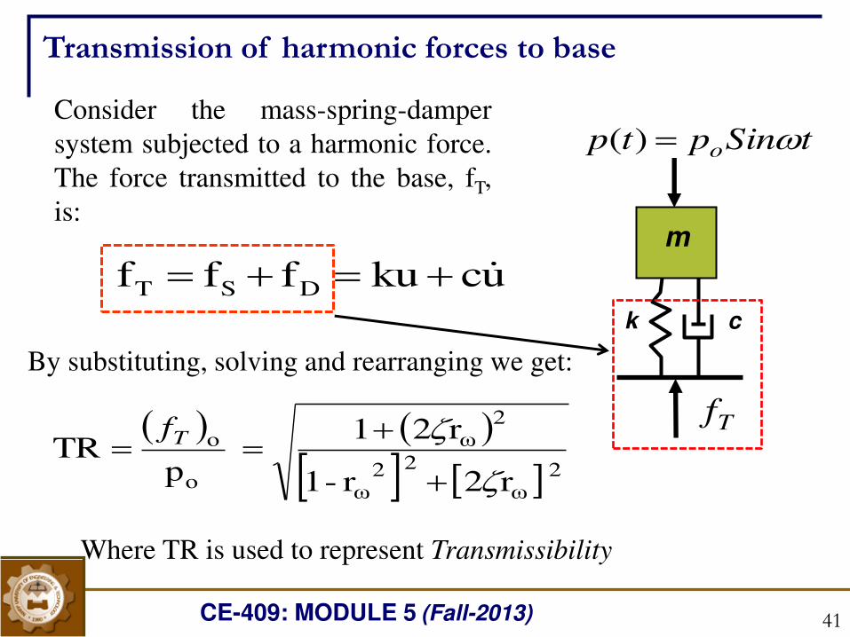
Consider the mass-spring-damper
system subjected to a harmonic force.
The force transmitted to the base, fT,
is:
uckufff DST
By substituting, solving and rearranging we get:
2 ω
2 2ω
2ω
o
o
r2r-1
r21
pTR
Tf
Transmission of harmonic forces to base
Where TR is used to represent Transmissibility
m
k c
tSinptp o )(
Tf
CE-409: MODULE 5 (Fall-2013) 42
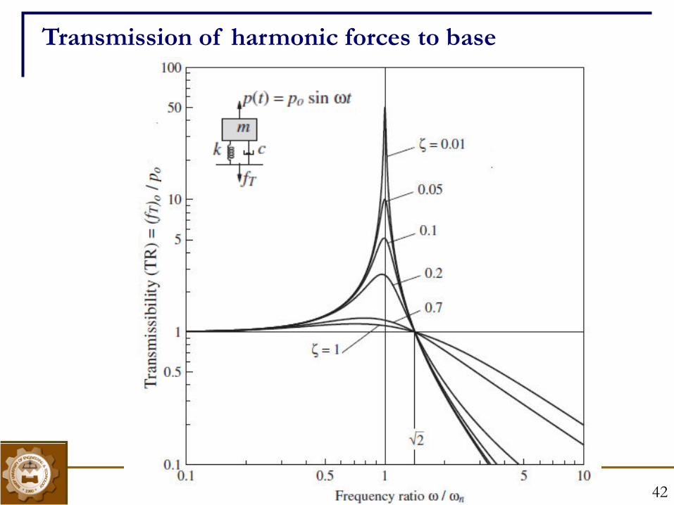
Transmission of harmonic forces to base
CE-409: MODULE 5 (Fall-2013) 43
The magnitude of transmitted force reduces with increase
in . The force transmitted to base can be
decreased by decreasing the value of ωn in such a way so that
The force transmitted to the base can also be reduced by
decreasing damping ratio. Although damping reduces the
amplitude of mass for all frequencies, it reduces maximum
force transmitted to the foundation only if . Below
that value, the addition of damping increases the transmitted
force
2beyond rω
2 rω
2 rω
Transmission of harmonic forces to base
CE-409: MODULE 5 (Fall-2013) 44
If the speed of a machine (forcing frequency) varies, we must
compromise in choosing the amount of damping to minimize the
transmitted force.
The amount of damping should be sufficient to limit the
amplitude of displacement and the transmitted force, while passing
through the resonance, but not so much to increase unnecessarily
the force transmitted at the operating speed (see the effect of
damping on force transmission, from the graph, when )
Luckily, natural rubber is a very satisfactory material and is
often used for the isolation of vibration
2 rω
Transmission of harmonic forces to base
CE-409: MODULE 5 (Fall-2013) 45
A rotating machine with a 600 kg mass operating at a constant
speed produces harmonic force in vertical direction. The
harmonic force is expressed as p(t)= 5000 Sin 150t, where p(t)
is in N. If the damping ratio of isolators at the foundation of
machine is 7.5%, determine the stiffness of isolators so that the
Transmissibility at the operating speed does not exceed 0.15.
Also determine the amplitude of force transmitted to the
foundation
Problem M 5.3
CE-409: MODULE 5 (Fall-2013) 46
2 ω
2 2ω
2ω
go
ot
r2r-1
r21
u
uTR
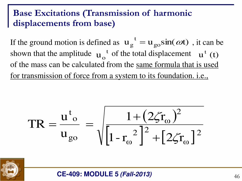
Base Excitations (Transmission of harmonic displacements from base)
If the ground motion is defined as , it can be
shown that the amplitude of the total displacement
of the mass can be calculated from the same formula that is used
for transmission of force from a system to its foundation. i.e.,
t)sin(uu got
g u
to (t) u t
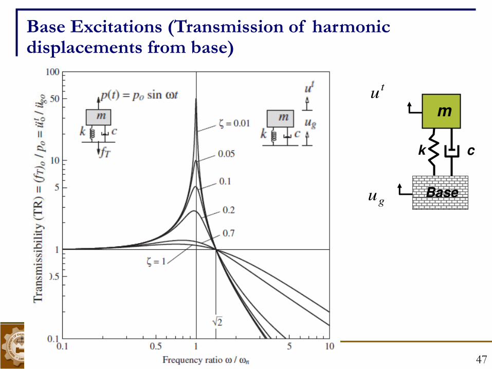
CE-409: MODULE 5 (Fall-2013) 47
m
k c
Base
tu
ug
Base Excitations (Transmission of harmonic displacements from base)
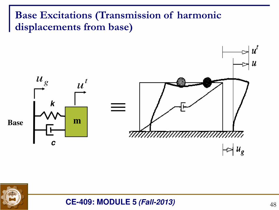
CE-409: MODULE 5 (Fall-2013) 48
tu
ug
k
c
m Base
Base Excitations (Transmission of harmonic displacements from base)
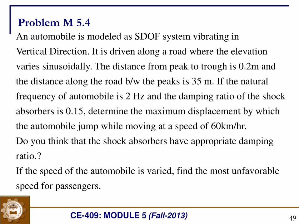
CE-409: MODULE 5 (Fall-2013)
An automobile is modeled as SDOF system vibrating in
Vertical Direction. It is driven along a road where the elevation
varies sinusoidally. The distance from peak to trough is 0.2m and
the distance along the road b/w the peaks is 35 m. If the natural
frequency of automobile is 2 Hz and the damping ratio of the shock
absorbers is 0.15, determine the maximum displacement by which
the automobile jump while moving at a speed of 60km/hr.
Do you think that the shock absorbers have appropriate damping
ratio.?
If the speed of the automobile is varied, find the most unfavorable
speed for passengers.
Problem M 5.4
49
CE-409: MODULE 5 (Fall-2013) 50
m
k c
Base
tu
ug
tu
ug
k
c
m Base
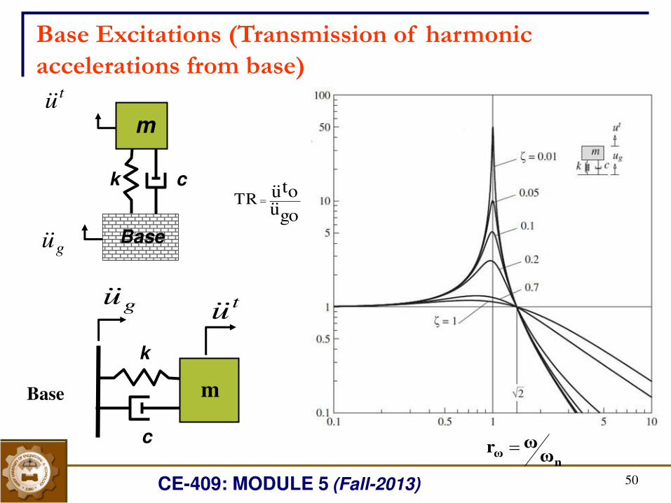
Base Excitations (Transmission of harmonic
accelerations from base)
gouotuTR
nω ωωr
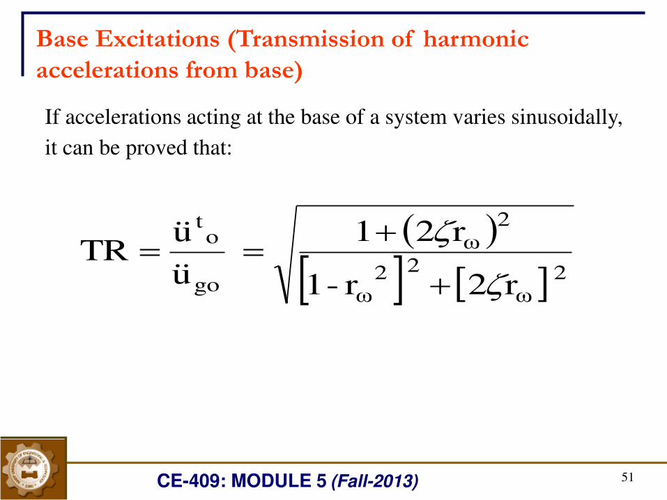
CE-409: MODULE 5 (Fall-2013) 51
2 ω
2 2ω
2ω
go
ot
r2r-1
r21
u
uTR
Base Excitations (Transmission of harmonic
accelerations from base)
If accelerations acting at the base of a system varies sinusoidally,
it can be proved that:
CE-409: MODULE 5 (Fall-2013) 52
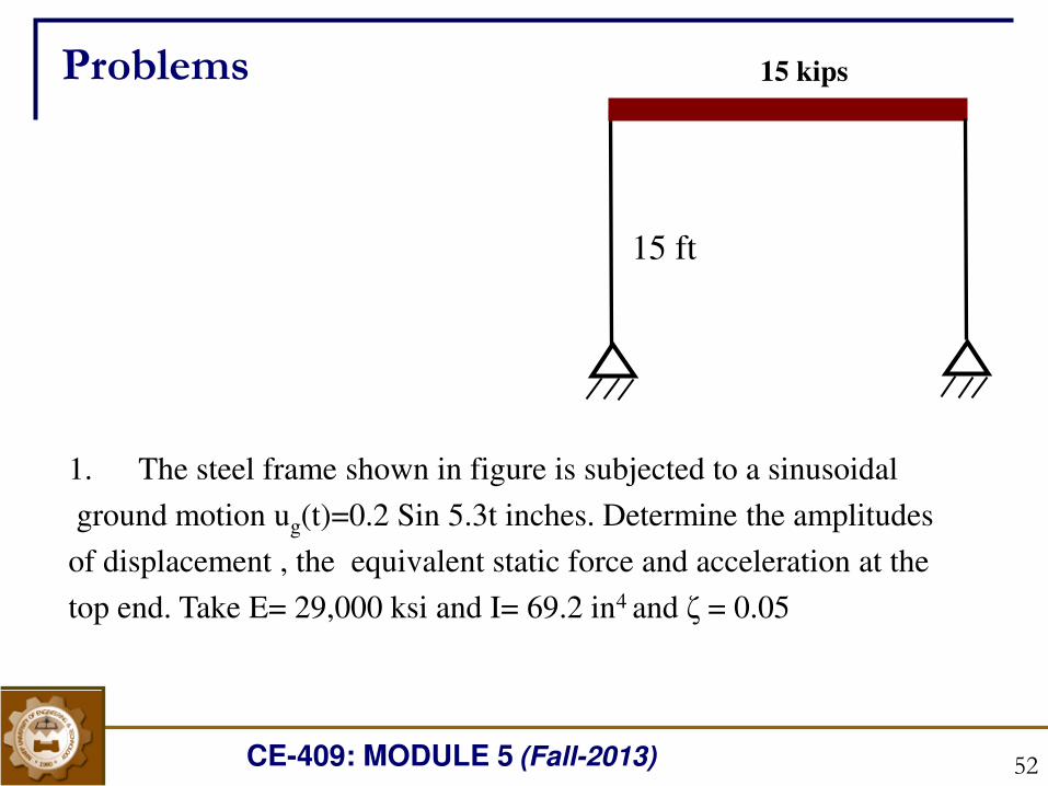
1. The steel frame shown in figure is subjected to a sinusoidal
ground motion ug(t)=0.2 Sin 5.3t inches. Determine the amplitudes
of displacement , the equivalent static force and acceleration at the
top end. Take E= 29,000 ksi and I= 69.2 in4 and ζ = 0.05
15 kips
15 ft
Problems
CE-409: MODULE 5 (Fall-2013) 53
2: A delicate instrument is to be spring mounted to the floor of a test
laboratory where it has been determined that the floor vibrates freely with
harmonic motion of amplitude 0.1in at 10 cycles per second, If the
instrument weighs 100lb, determine the stiffness of isolation springs
required to reduce the vertical motion amplitude of the instrument to 0.01
in. neglect damping.
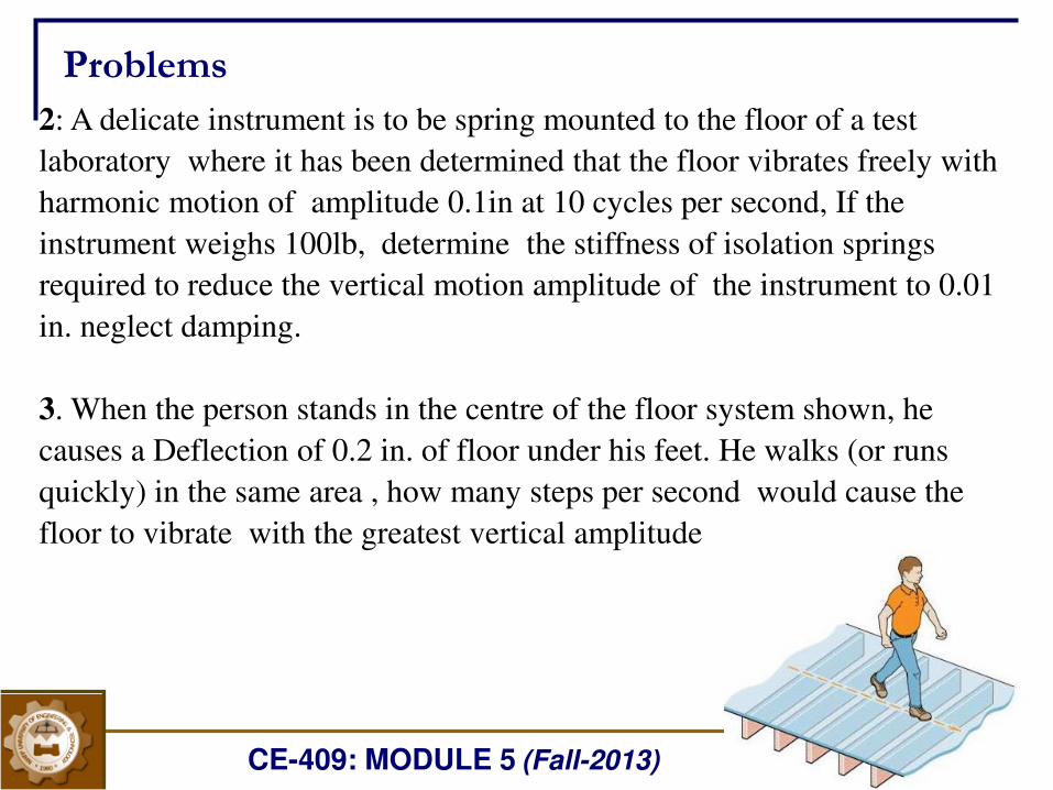
3. When the person stands in the centre of the floor system shown, he
causes a Deflection of 0.2 in. of floor under his feet. He walks (or runs
quickly) in the same area , how many steps per second would cause the
floor to vibrate with the greatest vertical amplitude
53
Problems
CE-409: MODULE 5 (Fall-2013) 54
Problems
54
4. What is the required column stiffness of single one-story structure to limit
its acceleration amplitude to 2.1 m/s2 during an earthquake whose
acceleration amplitude is 150 mm/s2 at a frequency of 50 rad/s? The mass of
structure is 1800 kg. Assume a damping ratio of 0.05.
5. A 10-kg laser flow-measuring device is used on a table in a laboratory.
Because of operation of other equipment, the table is subject to vibration.
Accelerometer measurements show that the dominant component of the
table vibrations is at 300 Hz and has an amplitude of 4.3 m/s2. For effective
operation, the laser can be subject to an acceleration amplitude of 0.7 m/s2.
(a) Design an undamped isolator to reduce the transmitted acceleration, to
an acceptable amplitude.
(b) Design the isolator such that it has a damping ratio of 0.04.
CE-409: MODULE 5 (Fall-2013) 55
6. A 150-kg engine operates at speeds between 1000 and 2000 rpm. It is
desired to achieve at least 85 percent isolation at all speeds. The only
readily available isolator has a stiffness of 5x 10⁵ N/m. How much mass
must be added to the engine to achieve the desired isolation?
Problems
HA2M5
Solve problems 3,4 and 6