Embed Size (px)
Citation preview

P
MH HBM
ROFESSIONAL DIGITAL TWO-WAY RADIOS
OTOTRBOTM
ANDHELD CONTROLEADASIC SERVICE ANUAL


i
ForewordThis manual covers all MOTOTRBOTM Handheld control, unless otherwise specified. It includes all the information necessary to maintain peak product performance and maximum working time, using levels 1 and 2 maintenance procedures. This level of service goes down to the board replacement level and is typical of some local service centers, Motorola Authorized Dealers, self-maintained customers, and distributors.
Product Safety and RF Exposure Compliance
ATTENTION!
This radio that comes with the control head is restricted to occupational use only to satisfy ICNIRP/FCC RF energy exposure requirements. Before using this product, read the RF energy awareness information and operating instructions in the Product Safety and RF Exposure booklet enclosed with your radio to ensure compliance with RF energy exposure limits.
For a list of Motorola-approved antennas, and other accessories, visit the following web site which lists approved accessories: http://www.motorolasolutions.com
Computer Software CopyrightsThe Motorola products described in this manual may include copyrighted Motorola computer programs stored in semiconductor memories or other media. Laws in the United States and other countries preserve for Motorola certain exclusive rights for copyrighted computer programs, including, but not limited to, the exclusive right to copy or reproduce in any form the copyrighted computer program. Accordingly, any copyrighted Motorola computer programs contained in the Motorola products described in this manual may not be copied, reproduced, modified, reverse-engineered, or distributed in any manner without the express written permission of Motorola. Furthermore, the purchase of Motorola products shall not be deemed to grant either directly or by implication, estoppel, or otherwise, any license under the copyrights, patents or patent applications of Motorola, except for the normal non-exclusive license to use that arises by operation of law in the sale of a product.
Document CopyrightsNo duplication or distribution of this document or any portion thereof shall take place without the express written permission of Motorola. No part of this manual may be reproduced, distributed, or transmitted in any form or by any means, electronic or mechanical, for any purpose without the express written permission of Motorola.
DisclaimerThe information in this document is carefully examined, and is believed to be entirely reliable. However, no responsibility is assumed for inaccuracies. Furthermore, Motorola reserves the right to make changes to any products herein to improve readability, function, or design. Motorola does not assume any liability arising out of the applications or use of any product or circuit described herein; nor does it cover any license under its patent rights nor the rights of others.
TrademarksMOTOROLA, MOTO, MOTOROLA SOLUTIONS and the Stylized M logo are trademarks or registered trademarks of Motorola Trademark Holdings, LLC and are used under license. All other trademarks are the property of their respective owners.
© 2014 Motorola Solutions, Inc. All rights reserved.
These servicing instructions are for use by qualified personnel only. To reduce the risk of electric shock, do not perform any servicing other than that contained in the Operating Instructions unless you are qualified to do so. Refer all servicing to qualified service personnel.
Before using this product, read the operating instructions for safe usage contained in the Product Safety and RF Exposure booklet enclosed with your radio.
!C a u t i o n
!C a u t i o n

ii
Notes

iii
Document History
The following major changes have been implemented in this manual since the previous edition.
Edition Description Date
MN001182A01-A Initial Release. Oct. 2014

iv
Notes

Table of Contents v
Table of Contents
Foreword..........................................................................................................i
Product Safety and RF Exposure Compliance .............................................................................................iComputer Software Copyrights ....................................................................................................................iDocument Copyrights ...................................................................................................................................iDisclaimer.....................................................................................................................................................iTrademarks ..................................................................................................................................................i
Document History ........................................................................................ iii
Warranty and Service Support.....................................................................xi
Warranty Period and Return Instructions ...................................................................................................xiAfter Warranty Period .....................................................................................................................xi
Chapter 1 Introduction ......................................................................... 1-1
1.1 Notations Used in This Manual .................................................................................................... 1-11.2 Control Head Description............................................................................................................. 1-1
1.2.1 MOTOTRBOTM Handheld Control Head ........................................................................ 1-21.3 Specifications............................................................................................................................... 1-4
Chapter 2 Service Aids......................................................................... 2-1
2.1 Service Aids................................................................................................................................. 2-12.2 Programming Cables ................................................................................................................... 2-2
Chapter 3 Performance Checking ....................................................... 3-1
3.1 Handheld Control Head Test Mode ............................................................................................. 3-13.1.1 Entering Display Radio Test Mode .................................................................................. 3-13.1.2 Color Display Test Mode ................................................................................................. 3-13.1.3 LED Test Mode................................................................................................................ 3-23.1.4 Backlight Test Mode ........................................................................................................ 3-23.1.5 Speaker Tone Test Mode ................................................................................................ 3-23.1.6 Earpiece Tone Test Mode ............................................................................................... 3-23.1.7 Audio Loopback Test Mode............................................................................................. 3-23.1.8 Audio Loopback Earpiece Test Mode.............................................................................. 3-23.1.9 Button/Knob/PTT Test Mode ........................................................................................... 3-3
Chapter 4 Control Head Programming ............................................... 4-1
4.1 Introduction .................................................................................................................................. 4-14.2 Customer Programming Software Setup ..................................................................................... 4-14.3 Software Version ......................................................................................................................... 4-2
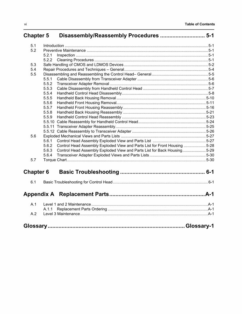
vi Table of Contents
Chapter 5 Disassembly/Reassembly Procedures ............................. 5-1
5.1 Introduction .................................................................................................................................. 5-15.2 Preventive Maintenance .............................................................................................................. 5-1
5.2.1 Inspection ........................................................................................................................ 5-15.2.2 Cleaning Procedures ....................................................................................................... 5-1
5.3 Safe Handling of CMOS and LDMOS Devices ............................................................................ 5-25.4 Repair Procedures and Techniques – General............................................................................ 5-45.5 Disassembling and Reassembling the Control Head– General ................................................... 5-5
5.5.1 Cable Disassembly from Transceiver Adapter ................................................................ 5-65.5.2 Transceiver Adapter Removal ......................................................................................... 5-65.5.3 Cable Disassembly from Handheld Control Head ........................................................... 5-75.5.4 Handheld Control Head Disassembly.............................................................................. 5-85.5.5 Handheld Back Housing Removal ................................................................................. 5-105.5.6 Handheld Front Housing Removal................................................................................. 5-115.5.7 Handheld Front Housing Reassembly ........................................................................... 5-165.5.8 Handheld Back Housing Reassembly ........................................................................... 5-215.5.9 Handheld Control Head Reassembly ............................................................................ 5-235.5.10 Cable Reassembly for Handheld Control Head............................................................. 5-245.5.11 Transceiver Adapter Reassembly.................................................................................. 5-255.5.12 Cable Reassembly to Transceiver Adapter ................................................................... 5-26
5.6 Exploded Mechanical Views and Parts Lists ............................................................................. 5-275.6.1 Control Head Assembly Exploded View and Parts List ................................................ 5-275.6.2 Control Head Assembly Exploded View and Parts List for Front Housing .................... 5-285.6.3 Control Head Assembly Exploded View and Parts List for Back Housing..................... 5-295.6.4 Transceiver Adapter Exploded Views and Parts Lists ................................................... 5-30
5.7 Torque Chart .............................................................................................................................. 5-30
Chapter 6 Basic Troubleshooting ....................................................... 6-1
6.1 Basic Troubleshooting for Control Head ...................................................................................... 6-1
Appendix A Replacement Parts..............................................................A-1
A.1 Level 1 and 2 Maintenance..........................................................................................................A-1A.1.1 Replacement Parts Ordering ...........................................................................................A-1
A.2 Level 3 Maintenance....................................................................................................................A-1
Glossary.........................................................................................Glossary-1

List of Figures vii
List of Figures
Figure 1-1 MOTOTRBOTM Handheld Control Head............................................................................. 1-2Figure 2-1 MOTOTRBOTM Handheld Control Head Front Programming Cable 30009477001 ........... 2-2Figure 2-2 Mobile & Repeater Rear Programming Cable PMKN4010_ ................................................ 2-2Figure 2-3 Mobile & Repeater Rear Accessory Programming and Test Cable PMKN4016_................ 2-3Figure 4-1 Customer Programming Software Setup from Front Connector .......................................... 4-1Figure 4-2 Customer Programming Software Setup from Rear Accessory Connector ......................... 4-2Figure 4-3 Customer Programming Software Setup with Test Box Connection .................................... 4-2Figure 5-1 Cable Removal .................................................................................................................... 5-6Figure 5-2 Transceiver Adapter Removal.............................................................................................. 5-6Figure 5-3 Control Head Removal......................................................................................................... 5-7Figure 5-4 Collar twisting....................................................................................................................... 5-7Figure 5-5 Cable Removal .................................................................................................................... 5-8Figure 5-6 Screws Removal .................................................................................................................. 5-8Figure 5-7 Back Housing Removal ....................................................................................................... 5-9Figure 5-8 Speaker and Mic Wire Removal........................................................................................... 5-9Figure 5-9 Back Housing Screws Removal ......................................................................................... 5-10Figure 5-10 Insulation Cap Assembly Removal .................................................................................... 5-10Figure 5-11 O-ring Removal .................................................................................................................. 5-11Figure 5-12 Speaker and Mic Wire Removal......................................................................................... 5-11Figure 5-13 Speaker Retainer Removal ................................................................................................ 5-12Figure 5-14 Speaker and Mic Boot Removal......................................................................................... 5-12Figure 5-15 Keypad and Retainer Removal .......................................................................................... 5-13Figure 5-16 Color Display Removal....................................................................................................... 5-13Figure 5-17 Keypad Board Removal ..................................................................................................... 5-14Figure 5-18 Keypad Removal................................................................................................................ 5-14Figure 5-19 PTT Paddle Removal ......................................................................................................... 5-15Figure 5-20 PTT Paddle Reassembly ................................................................................................... 5-16Figure 5-21 Back Housing Reassembly ................................................................................................ 5-16Figure 5-22 Keypad Board Reassembly................................................................................................ 5-17Figure 5-23 Color Display Reassembly ................................................................................................. 5-17Figure 5-24 Keypad and Retainer Reassembly..................................................................................... 5-18Figure 5-25 Speaker Retainer Reassembly........................................................................................... 5-18Figure 5-26 Speaker Reassembly ......................................................................................................... 5-19Figure 5-27 Latching Speaker Retainer to Housing Slot ....................................................................... 5-20Figure 5-28 Speaker Retainer Reassembly........................................................................................... 5-20Figure 5-29 Mic Reassembly................................................................................................................. 5-21Figure 5-30 O-ring Reassembly ............................................................................................................ 5-21Figure 5-31 Hang-up Board Assembly .................................................................................................. 5-22Figure 5-32 Main Board Reassembly .................................................................................................... 5-22Figure 5-33 Front and Back Housing Reassembly................................................................................ 5-23Figure 5-34 Back Housing Reassembly ................................................................................................ 5-23Figure 5-35 Back Housing Reassembly ................................................................................................ 5-24Figure 5-36 Handheld Control Head Cable Installation ......................................................................... 5-24Figure 5-37 Transceiver Adapter Attachment........................................................................................ 5-25Figure 5-38 Transceiver Adapter to Chassis Attachment ...................................................................... 5-25Figure 5-39 Cable Reassembly to Transceiver Adapter........................................................................ 5-26Figure 5-40 Control Head Assembly Exploded View for PMLN7032_ .................................................. 5-27Figure 5-41 Control Head Assembly Exploded View for Front Housing for 0104063J14...................... 5-28Figure 5-42 Control Head Assembly Exploded View for HCH Back Housing for 0104063J17 ............. 5-29Figure 5-43 Transceiver Adapter Exploded View for PMLN7033_........................................................ 5-30

viii List of Figures
Notes

Related Publications ix
List of Tables
Table 1-1 MOTOTRBOTM Handheld Control Head............................................................................. 1-3Table 2-1 Service Aids ......................................................................................................................... 2-1Table 3-1 Front Panel Access Test Mode Displays.............................................................................. 3-1Table 4-1 Radio Software Program Kit................................................................................................. 4-1Table 5-1 Lead Free Solder Wire Part Number List ............................................................................. 5-4Table 5-2 Lead Free Solder Paste Part Number List ........................................................................... 5-4Table 5-3 Control Head Exploded View Parts List (PMLN7032_)...................................................... 5-27Table 5-4 Control Head Exploded View Parts List (0104063J14) ...................................................... 5-28Table 5-5 Control Head Exploded View Parts List (0104063J17) ...................................................... 5-29Table 5-6 Transceiver Adapter (PMLN7033_) Exploded View Parts List........................................... 5-30Table 5-7 Torque Specifications for Nuts and Screws........................................................................ 5-30Table 6-1 Basic Troubleshooting for Control Head .............................................................................. 6-1

x List of Tables
Notes
Warranty and Service Support xi
Warranty and Service Support
Motorola offers long term support for its products. This support includes full exchange and/or repair of the product during the warranty period, and service/ repair or spare parts support out of warranty. MOTOTRBOTM Handheld Control Head One (1) Year.
Warranty Period and Return Instructions
The terms and conditions of warranty are defined fully in the Motorola Dealer or Distributor or Reseller contract. These conditions may change from time to time and the following notes are for guidance purposes only. In instances where the product is covered under a "return for replacement" or "return for repair" warranty, a check of the product should be performed prior to shipping the unit back to Motorola. This is to ensure that the product has been correctly programmed or has not been subjected to damage outside the terms of the warranty.
Prior to shipping any radio back to the appropriate Motorola warranty depot, please contact Customer Resources or your Motorola dealer, distributor or reseller. All returns must be accompanied by a Warranty Claim Form, available from your Customer Service representative or Motorola Online Extranet (MOL) or your Motorola dealer, distributor or reseller. Products should be shipped back in the original packaging, or correctly packaged to ensure no damage occurs in transit.
After Warranty Period
After the Warranty period, Motorola continues to support its products in two ways.
1. Motorola's Managed Technical Services (MTS) offers a repair service to both end users and dealers at competitive prices.
2. MTS supplies individual parts and modules that can be purchased by dealers who are technically capable of performing fault analysis and repair.

xii Warranty and Service Support
Notes

Chapter 1 Introduction
1.1 Notations Used in This ManualThroughout the text in this publication, you will notice the use of note and caution notations. These notations are used to emphasize that safety hazards exist, and due care must be taken and observed.
NOTE: An operational procedure, practice, or condition that is essential to emphasize.
1.2 Control Head DescriptionThe control head used with the radio has logic circuitry that operates the standard and optional features built into the system.
The following illustration show the handheld control head.
CAUTION indicates a potentially hazardous situation which, if not avoided, might result in equipment damage.
!C a u t i o n

1-2 Introduction: Control Head Description
Figure 1-1 MOTOTRBOTM Handheld Control Head
1.2.1 MOTOTRBOTM Handheld Control Head
NOTE: * These buttons are programmable.
Item No.
Description Function
1 LED INDICATORS - Red Red light-emitting diodes indicate operating status.
2 LED INDICATORS - Yellow Yellow light-emitting diodes indicate operating status.
3 LED INDICATORS - Green Green light-emitting diodes indicate operating status.
4 CHANNEL UP Press buttons to change channels.
5 CHANNEL DOWN Press buttons to change channels.
6 POWER BUTTON Turns the radio on and off.
7 5-LINE COLOR LCD (Liquid Crystal Display) DISPLAY
132x90 display provides visual information about radio features.
8 PROGRAMMABLE SIDE BUTTON 1 * Buttons are field programmable using the CPS.
9 MICROPHONE Audio output and input
61
5 4
8
109
7
111213
14 1516
17181920212223
23

Introduction: Control Head Description 1-3
Table 1-1 MOTOTRBOTM Handheld Control Head
10 PUSH-TO-TALK (PTT) BUTTON Press to initiate talk.
11 SPEAKER Audio output and input.
12 PROGRAMMABLE SIDE BUTTON 2* Buttons are field programmable using the CPS.
13 PROGRAMMABLE SIDE BUTTON 3* Buttons are field programmable using the CPS.
14 VOLUME BUTTON DOWN To adjust speaker volume.
15 PROGRAMMABLE FRONT BUTTON P3* Buttons are field programmable using the CPS.
16 PROGRAMMABLE FRONT BUTTON P4* Buttons are field programmable using the CPS.
17 FULL KEYPAD Allows user to input characters for various text base operations.
18 VOLUME BUTTON UP To adjust speaker volume.
19 MENU/OK BUTTON One button to provide menu navigation and selection interface.
20 BACK/HOME BUTTON Press button to navigate to home page.
21 4 WAY NAVIGATION BUTTON Press buttons to scroll Up/Down/Left/Right.
22 PROGRAMMABLE FRONT BUTTON P2* Buttons are field programmable using the CPS.
23 PROGRAMMABLE FRONT BUTTON P1* Buttons are field programmable using the CPS.
Item No.
Description Function

1-4 Introduction: Specifications
1.3 Specifications
Military Standards 810C, D, E, F & G
MIL-STD 810C MIL-STD 810D MIL-STD 810E MIL-STD 810F MIL-STD 810G
Method Proc./Cat Method Proc./Cat Method Proc./Cat Method Proc./Cat Method Proc./Cat
Low Pressure
500.1 I 500.2 II 500.3 II 500.4 II 500.5 II
High Temperature
501.1 I, II 501.2 I/A1,II/A1
501.3 I/A1, II/AI
501.4 I/HOT, II/HOT
501.5 I/AI, II
Low Temperature
502.1 I 502.2 I/C3,II/C1
502.3 I/C3, II/C1
502.4 I/C3,II/C1
502.5 I/C3, II
Temperature Shock
503.1 – 503.2 I/A1/C2 503.3 I/AI/C2 503.4 I 503.5 I/C
Solar Radiation
505.1 II 505.2 I 505.3 I 505.4 I 505.5 I/A1
Rain 506.1 I, II 506.2 I, II 506.3 I, II 506.4 I, III 506.5 I, III
Humidity 507.1 II 507.2 II 507.3 II 507.4 – 507.5 II - Aggra-vated
Salt Fog 509.1 I 509.2 I 509.3 I 509.4 – 509.5 –
Dust 510.1 I 510.2 I 510.3 I 510.4 I 510.5 I
Vibration 514.2 VIII/F,Curve-W
514.3 I/10,II/3
514.4 I/10, II/3
514.5 I/24, II/5 514.6 I/24, II/3
Shock 516.2 I, III, XI, V
516.3 I, V, VI 516.4 I, V, VI 516.5 I, V, VI 516.6 I, V, VI
Environmental Specifications
Operating Temperature -30°C to +60°C
Storage Temperature -40°C to +85°C
Temperature Shock Per MIL-STD
Humidity Per MIL-STD
ESD IEC 61000-4-2 Level 3
Water and Dust Intrusion IP54, MIL-STD

Chapter 2 Service Aids
2.1 Service AidsTable 2-1 lists the service aids recommended for working on the control head. While all of these items are available from Motorola, most are standard workshop equipment items, and any equivalent item capable of the same performance may be substituted for the item listed.
Table 2-1 Service Aids
MotorolaPart Number
Description Application
N/A Small flat blade screwdriver To unlatch the flex connector.
6686119B01 Control head dismantling tool To disengage the transceiver adapter from brick.
RSX4043A Torque driver (2-36lbs-in or 0.4-4.0 N-m)
To ensure the driver bit is tighten at specified torque as indicated in Table 5-7.
6680387A72 TORX™ T8 To tighten/loosen the T8 screw head.
N/A TORX Plus™ 6IP To tighten/loosen the 6IP screw head.
N/A Phillips no.2 To tighten/loosen the PH2 screw head
30009477001 MOTOTRBOTM Handheld Control Head Front Programming Cable
Connects the radio to a USB port for radio programming and data applications.
N/A Plastic Tweezer To remove the PTT Paddle.

2-2 Service Aids: Programming Cables
2.2 Programming Cables
Figure 2-1 MOTOTRBOTM Handheld Control Head Front Programming Cable 30009477001
Figure 2-2 Mobile & Repeater Rear Programming Cable PMKN4010_

Service Aids: Programming Cables 2-3
Figure 2-3 Mobile & Repeater Rear Accessory Programming and Test Cable PMKN4016_
TABLE 2-3: WIRE DIAGRAM
26 PIN ACCESSORY PORT CONNECTOR USB DB25P
PIN NO. DESCRIPTION
3 VCC (5v) 1
2 DATA - 2
1 DATA + 3
4GND 4
DRAIN WIRE AND BRAID SHELL
7SPEAKER -9
71EXT MIC11
17 DIGI IN I (EXT PTT) 20
61GND61
1SPEAKER +01
DB 25 CONNECTOR
11
14 25
13
1 4
915±15CABLE
1455±24CABLE
TO MOBILE RADIOACCESSORYCONNECTOR
VIEWED FROM FRONT (PIN END)OF CONNECTOR
1
2 26
25
13
14 25
USB CONNECTOR

2-4 Service Aids: Programming Cables
Notes

Chapter 3 Performance Checking
3.1 Handheld Control Head Test Mode
3.1.1 Entering Display Radio Test Mode
1. Turn the radio on.
2. Within ten seconds after self test is complete, press button P2, five times in succession.
3. The radio beeps and will show a series of displays that will give information regarding various version numbers and subscriber specific information. The displays are described inTable 3-1.
NOTE: The radio stops at each display for 2 seconds before moving to the next information display. If the information cannot fit into 1 line, the radio display scrolls automatically character by
character after 1 second to view the whole information. If the Top Navigation Button () is
pressed before the last information display, the radio shall suspend the information display
until the user presses Bottom Navigation Button () to resume the information display. The
radio beeps for each button press. After the last display, RF Test Mode will be displayed.
3.1.2 Color Display Test Mode
1. Press and hold button P1 in RF Test Mode. The radio beeps once and momentarily displays ‘Display Test Mode’.
2. On the next button press, the negative image of Display Test Mode will appear.
3. With each successive button press, the display background will change from Red, to Green, and then to Blue.
4. With each successive button press, a horizontal bar will increase in size and change color, from Red, to Green, to Blue, to Black, back to Red, to Green, to Blue, to Black, and finally, the entire display background will change to Red.
5. With each successive button press, vertical bars will grow and change color, from Red, to Green, to Blue, to Black, back to Red, and finally, the entire display background will change to Green.
Table 3-1 Front Panel Access Test Mode Displays
Name of Display Description Appears
Service Mode The literal string indicates the radio has entered test mode. Always
Host Version The version of host firmware. Always
DSP Version The version of DSP firmware. Always
Model Number The radio’s model number as programmed in the codeplug. Always
MSN The radio’s serial number as programmed in the codeplug. Always
FLASHCODE The FLASH codes as programmed in the codeplug. Always
RF Band The radio’s band. Always
3-2 Performance Checking: Handheld Control Head Test Mode
6. On the next button press, the display will clear and 12 icons will appear at the top of the display.
3.1.3 LED Test Mode
1. Press and hold button P1 after Display Test Mode. The radio beeps once and displays “LED Test Mode”.
2. Upon any button press, the radio lights on the red LED and displays “Red LED On”.
3. Consequently, upon any button press, the red LED is turned off and the radio lights on the green LED and displays “Green LED On”.
4. Consequently, upon any button press, the green LED is turned off and the radio shall light on the yellow LED and displays “Yellow LED On”.
3.1.4 Backlight Test Mode
1. Press and hold button P1 after LED Test Mode. The radio beeps once and displays“Backlight Test Mode”.
2. The radio lights on both LCD and keypad backlight together.
3.1.5 Speaker Tone Test Mode
1. Press and hold button P1 after Backlight Test Mode. The radio beeps once and displays “Speaker Tone Test Mode”.
2. The radio generates a 1 kHz tone with the internal speaker.
3.1.6 Earpiece Tone Test Mode
1. Press and hold button P1 after Speaker Tone Test Mode. The radio beeps once and displays “Earpiece Tone Test Mode”.
2. The radio generates a 1 kHz tone with the earpiece.
NOTE: Not applicable for Handheld. Click next to proceed to Audio Loopback Test Mode.
3.1.7 Audio Loopback Test Mode
1. Press and hold button P1 after Earpiece Tone Test Mode. The radio beeps once and displays “Audio Loopback Test Mode”.
NOTE: Expect a loud feedback noise.
2. The radio shall route any audio on the mic to the internal speaker.
3.1.8 Audio Loopback Earpiece Test Mode
1. Press and hold button P1 after Audio Loopback Test Mode. The radio beeps once and displays “Audio Loopback Earpiece Test Mode”.
2. The radio shall route any audio on the mic to the accessory earpiece.
NOTE: Not applicable for Handheld. Click next to proceed to Button/Knob/PTT Test Mode.

Performance Checking: Handheld Control Head Test Mode 3-3
3.1.9 Button/Knob/PTT Test Mode
1. Press and hold button P1 after Audio Loopback Earpiece Test Mode. The radio beeps once and displays “Button Test” (line 1).
2. The radio also displays the button/knob/PTT Button Command Opcode (BCO) and state (BCO/state) on the screen (line 2) upon any button state changes.
3. The radio must be powered off to end Test Mode.

3-4 Performance Checking: Handheld Control Head Test Mode
Notes
Chapter 4 Control Head Programming
4.1 IntroductionThis chapter provides an overview of the MOTOTRBOTM Customer Programming Software (CPS), which is designed for use on a Windows 7/Vista operating system. These programs are available in one kit as listed in Table 4-1. An Installation Guide is also included with the kit.
NOTE: Refer to the appropriate program on-line help files for the programming procedures.
Table 4-1 Radio Software Program Kit
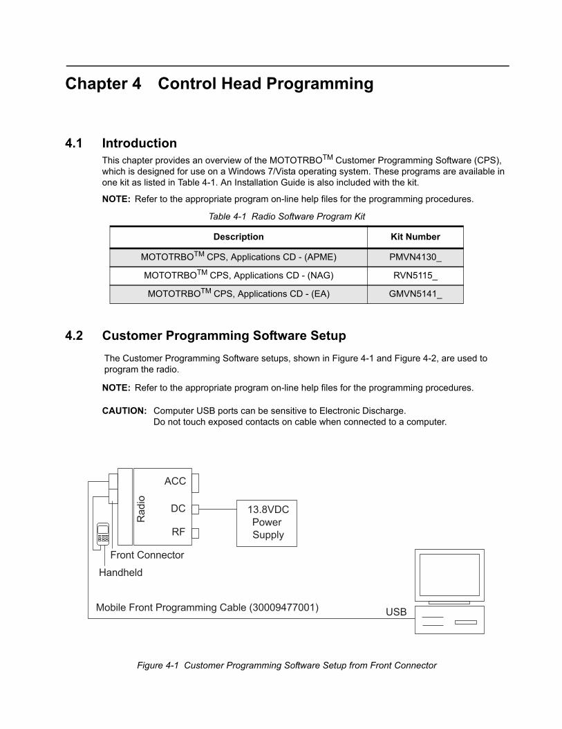
4.2 Customer Programming Software Setup
The Customer Programming Software setups, shown in Figure 4-1 and Figure 4-2, are used to program the radio.
NOTE: Refer to the appropriate program on-line help files for the programming procedures.
CAUTION: Computer USB ports can be sensitive to Electronic Discharge. Do not touch exposed contacts on cable when connected to a computer.
Description Kit Number
MOTOTRBOTM CPS, Applications CD - (APME) PMVN4130_
MOTOTRBOTM CPS, Applications CD - (NAG) RVN5115_
MOTOTRBOTM CPS, Applications CD - (EA) GMVN5141_
Figure 4-1 Customer Programming Software Setup from Front Connector
Power Supply
13.8VDC
Mobile Front Programming Cable (30009477001)
Front Connector
Handheld
Rad
io
DC
RF
ACC
USB

4-2 Control Head Programming: Software Version
Figure 4-2 Customer Programming Software Setup from Rear Accessory Connector
Figure 4-3 Customer Programming Software Setup with Test Box Connection
4.3 Software VersionFirmware version MOTOTRBOTM 2.4 R02.40.00 or later MUST be programmed into the radio for proper operation of the control head configuration. The control head must be attached to the radio to perform firmware upgrade at the same time. This is to ensure that both the control head and radio have the same software version.
DC
RF
ACC
PowerSupply
13.8 VDC
Rear Accessory Connector
USB
Mobile & Repeater Rear Programming Cable PMKN4010_
Rad
io
Front Connector
Handheld
DC
RF
ACC
PowerSupply
13.8 VDC
Rear Accessory Connector
USB
No Connection
Test Box RLN4460_
Rad
io
Mobile & Repeater Rear Accessory Programming and Test Cable PMKN4016_
Front Connector
Handheld

Chapter 5 Disassembly/Reassembly Procedures
5.1 Introduction
This chapter provides details about the following:
• Preventive maintenance (inspection and cleaning).
• Safe handling of CMOS and LDMOS devices.
• Repair procedures and techniques.
• Disassembly and reassembly of the Control Head.
5.2 Preventive MaintenancePeriodic visual inspection and cleaning is recommended.
5.2.1 Inspection
Check that the external surfaces of the Control Head are clean, and that all external controls and switches are functional. It is not recommended to inspect the interior electronic circuitry.
5.2.2 Cleaning Procedures
The following procedures describe the recommended cleaning agents and the methods to be used when cleaning the external and internal surfaces of the Control Head. These surfaces should be cleaned whenever a periodic visual inspection reveals the presence of smudges, grease, and/or grime.
NOTE: Internal surfaces should be cleaned only when the Control Head is disassembled for service or repair.
The only recommended agent for cleaning the external Control Head surfaces is a 0.5% solution of a mild dishwashing detergent in water. The only factory recommended liquid for cleaning the printed circuit boards and their components is isopropyl alcohol (100% by volume).
Use all chemicals as prescribed by the manufacturer. Be sure to follow all safety precautions as defined on the label or material safety data sheet.
The effects of certain chemicals and their vapors can have harmful results on certain plastics. Avoid using aerosol sprays, tuner cleaners and other chemicals.
!C a u t i o n

5-2 Disassembly/Reassembly Procedures: Safe Handling of CMOS and LDMOS Devices
Cleaning External Plastic Surfaces
Apply the 0.5% detergent-water solution sparingly with a stiff, non-metallic, short-bristled brush to work all loose dirt away from the Control Head. Use a soft, absorbent, lintless cloth or tissue to remove the solution and dry the Control Head. Make sure that no water remains entrapped near the connectors, cracks, or crevices.
Cleaning Internal Circuit Boards and Components
Isopropyl alcohol (100%) may be applied with a stiff, non-metallic, short-bristled brush to dislodge embedded or caked materials located in hard-to-reach areas. The brush stroke should direct the dislodged material out and away from the inside of the Control Head. Make sure that controls or tunable components are not soaked with alcohol. Do not use high-pressure air to hasten the drying process since this could cause the liquid to collect in unwanted places. Once the cleaning process is complete, use a soft, absorbent, lintless cloth to dry the area. Do not brush or apply any isopropyl alcohol to the frame, control head and housing assembly.
NOTE: Always use a fresh supply of alcohol and a clean container to prevent contamination by dissolved material (from previous usage).
5.3 Safe Handling of CMOS and LDMOS DevicesComplementary Metal Oxide Semiconductor (CMOS) and Laterally Diffused Metal Oxide Semiconductor (LDMOS) devices are used in this Control Head, and are susceptible to damage by electrostatic or high voltage charges. Damage can be latent, resulting in failures occurring weeks or months later. Therefore, special precautions must be taken to prevent device damage during disassembly, troubleshooting, and repair.
Handling precautions are mandatory for CMOS/LDMOS circuits and are especially important in low humidity conditions.

Disassembly/Reassembly Procedures: Safe Handling of CMOS and LDMOS Devices 5-3
DO NOT attempt to disassemble the Control Head without first referring to the following CAUTION statement.
This Control Head contains static-sensitive devices. Do not open the Control Head unless you are properly grounded. Take the following precautions when working on this unit:
• Store and transport all CMOS/LDMOS devices in conductive material so that all exposed leads are shorted together. Do not insert CMOS/LDMOS devices into conventional plastic “snow” trays used for storage and transportation of other semiconductor devices.
• Ground the working surface of the service bench to protect the CMOS/LDMOS device. We recommend using a wrist strap, two ground cords, a table mat, a floor mat, ESD shoes, and an ESD chair.
• Wear a conductive wrist strap in series with a 100k resistor to ground. (Replacement wrist straps that connect to the bench top covering are Motorola part number 4280385A59).
• Do not wear nylon clothing while handling CMOS/LDMOS devices.
• Do not insert or remove CMOS/LDMOS devices with power applied. Check all power supplies used for testing CMOS/LDMOS devices to be certain that there are no voltage transients present.
• When straightening CMOS/LDMOS pins, provide ground straps for the apparatus used.
• When soldering, use a grounded soldering iron.
• If at all possible, handle CMOS/LDMOS devices by the package and not by the leads. Prior to touching the unit, touch an electrical ground to remove any static charge that you may have accumulated. The package and substrate may be electrically common. If so, the reaction of a discharge to the case would cause the same damage as touching the leads.
!C a u t i o n

5-4 Disassembly/Reassembly Procedures: Repair Procedures and Techniques – General
5.4 Repair Procedures and Techniques – General
Any rework or repair on Environmentally Preferred Products must be done using the appropriate lead-free solder wire and lead-free solder paste as stated in the following table:
Parts Replacement and Substitution
Check the parts list for the proper Motorola part number and order the part from the nearest Motorola Radio Products and Solutions Organization listed in Appendix A of this manual.
Rigid Circuit Boards
This Control Head uses bonded, multi-layer, printed circuit boards. Since the inner layers are not accessible, some special considerations are required when soldering and unsoldering components. The printed-through holes may interconnect multiple layers of the printed circuit. Therefore, exercise care to avoid pulling the plated circuit out of the hole.
When soldering near a connector:
• Avoid accidentally getting solder in the connector.
• Be careful not to form solder bridges between the connector pins.
• Examine your work closely for shorts due to solder bridges.
NOTE Environmentally Preferred Products (EPP) (refer to the marking on the printed circuitboards – examples shown below) were developed and assembled using environmentallypreferred components and solder assembly techniques to comply with the EuropeanUnion’s Restriction of Hazardous Substances (ROHS) Directive 2002/95/EC andWaste Electrical and Electronic Equipment (WEEE) Directive 2002/96/EC. To maintain product compliance and reliability, use only the Motorola specified parts in thismanual.
Table 5-1 Lead Free Solder Wire Part Number List
Motorola Part Number
Alloy Flux TypeFlux Content
by WeightMelting Point
Supplier Part number
Diameter Weight
1088929Y01 95.5Sn/3.8Ag/0.7Cu RMA Version 2.7–3.2% 217°C 52171 0.015” 1lb spool
Table 5-2 Lead Free Solder Paste Part Number List
Motorola Part Number
Manufacturer Part Number
Viscosity Type Composition & Percent MetalLiquid
Temperature
1085674C03 NC-SMQ230 900–1000KCPs Brookfield (5rpm)
Type 3 (-325/+500)
(95.5%Sn-3.8%Ag-0.7%Cu) 89.3%
217°C

Disassembly/Reassembly Procedures: Disassembling and Reassembling the Control Head– General 5-5
5.5 Disassembling and Reassembling the Control Head– GeneralSince these Control Head may be disassembled and reassembled with the use of only ten screws (board to housing), it is important to pay particular attention to the snaps and tabs, and how parts align with each other.
The following tools are required for disassembling and assembling the Control Head:
• Small Flat Blade Screwdriver
• Control Head Dismantling Tool (Motorola Part No. 6686119B01)
• Torque Driver (2-36 lbs-in or 0.2-4.0 N-m), (Motorola Part No. RSX4043A)
• TORX™ T8 Driver Bit (Motorola Part No. 6680387A72)
• TORX Plus™ 6IP Driver Bit
• Phillips No.2 Screwdriver
• Plastic Tweezer
If a unit requires more complete testing or service than is customarily performed at the basic level, please send Control Head to a Motorola Service Center listed in Appendix A.
The following disassembly procedures should be performed only if necessary.

5-6 Disassembly/Reassembly Procedures: Disassembling and Reassembling the Control Head– General
5.5.1 Cable Disassembly from Transceiver Adapter
1. Unscrew the jack screws counter clockwise by using Phillips no.2 screwdriver and remove the cable from transceiver adapter as shown in Figure 5-1.
Figure 5-1 Cable Removal
5.5.2 Transceiver Adapter Removal
1. Disengage the transceiver adapter from brick with a dismantle tool as shown in Figure 5-2.
Figure 5-2 Transceiver Adapter Removal
Jack Screws
Cable Transceiver adapter
Brick
Transceiver adapter
Dismantle tool
Brick

Disassembly/Reassembly Procedures: Disassembling and Reassembling the Control Head– General 5-7
2. Remove the control head flex from brick as shown in Figure 5-3.
Figure 5-3 Control Head Removal
5.5.3 Cable Disassembly from Handheld Control Head
1. Disassemble the cable from the connector and unlock the cable by twisting the collar clockwise as shown in Figure 5-4.
Figure 5-4 Collar twisting
Transceiver adapter
Control Head Flex
Snap-fit Catch
Cable
Collar
5-8 Disassembly/Reassembly Procedures: Disassembling and Reassembling the Control Head– General
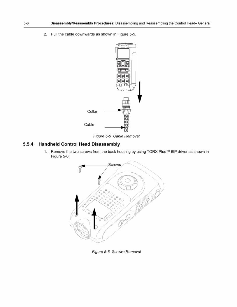
2. Pull the cable downwards as shown in Figure 5-5.
Figure 5-5 Cable Removal
5.5.4 Handheld Control Head Disassembly
1. Remove the two screws from the back housing by using TORX Plus™ 6IP driver as shown in Figure 5-6.
Figure 5-6 Screws Removal
Collar
Cable
Screws

Disassembly/Reassembly Procedures: Disassembling and Reassembling the Control Head– General 5-9
2. Separate the back housing from the front housing by pulling it upwards as shown in Figure 5-7.
Figure 5-7 Back Housing Removal
3. Disassemble the back housing from the front housing. Unplug the speaker & mic wire from the 4 pin connector. After that, lift the 20 pin connector latch and release the keypad flex as shown in Figure 5-8.
Figure 5-8 Speaker and Mic Wire Removal
Front Housing
Back Housing
Keypad Flex
Speaker and
4 Pin connector
20 Pin connector
Mic wire
5-10 Disassembly/Reassembly Procedures: Disassembling and Reassembling the Control Head– General
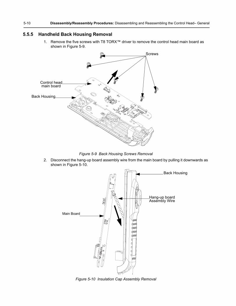
5.5.5 Handheld Back Housing Removal
1. Remove the five screws with T8 TORX™ driver to remove the control head main board as shown in Figure 5-9.
Figure 5-9 Back Housing Screws Removal
2. Disconnect the hang-up board assembly wire from the main board by pulling it downwards as shown in Figure 5-10.
Figure 5-10 Insulation Cap Assembly Removal
Screws
Back Housing
Control headmain board
Back Housing
Hang-up boardAssembly Wire
Main Board

Disassembly/Reassembly Procedures: Disassembling and Reassembling the Control Head– General 5-11
3. Remove the O-ring by releasing all the tabs from the catches on the back housing as shown in Figure 5-11
Figure 5-11 O-ring Removal
5.5.6 Handheld Front Housing Removal
1. Remove speaker and mic wire by pulling it to the right. Remove the mic together with mic boot from the speaker tray mic slot as shown in Figure 5-12.
Figure 5-12 Speaker and Mic Wire Removal
Tab
Back Housing
O-Ring
Speaker and Mic wire
Front Housing
Mic
Mic boot

5-12 Disassembly/Reassembly Procedures: Disassembling and Reassembling the Control Head– General
2. Remove the screw with TORX Plus™ 6IP driver to remove speaker retainer as shown in Figure 5-13.
Figure 5-13 Speaker Retainer Removal
3. Remove the speaker and mic wire from speaker tray as shown in Figure 5-14.
Figure 5-14 Speaker and Mic Boot Removal
Speaker Retainer
Screw
Front Housing
Speaker and Mic wire
Front Housing
Speaker Tray
Speaker

Disassembly/Reassembly Procedures: Disassembling and Reassembling the Control Head– General 5-13
4. Remove the three (3) screws with TORX Plus™ 6IP driver and remove the keypad and display retainer from the front housing as shown in Figure 5-15.
Figure 5-15 Keypad and Retainer Removal
5. Remove the 26 pin connector latch by using the flat-blade screwdriver and release the color display flex from keypad board. After that, remove the color display, then remove the PTT flex from the 20 pin connector as seen in Figure 5-16.
Figure 5-16 Color Display Removal
Keypad and Display
Front Housing
Retainer
Screws
Front Housing
Color Display Flex
Color Display
26 Pin Connector Keypad Board
PTT Flex

5-14 Disassembly/Reassembly Procedures: Disassembling and Reassembling the Control Head– General
6. Remove the keypad board (together with speaker tray and keypad flex) from the front housing as shown in Figure 5-17.
Figure 5-17 Keypad Board Removal
7. Remove keypad from the front housing as shown in Figure 5-18.
Figure 5-18 Keypad Removal
Front Housing
Speaker Tray
Keypad PCBA
Keypad Flex
Keypad
Front Housing

Disassembly/Reassembly Procedures: Disassembling and Reassembling the Control Head– General 5-15
8. Release the PTT Paddle with the plastic tweezer by inserting it into the middle point of the PTT Paddle as shown in Figure 5-19.
Figure 5-19 PTT Paddle Removal
Middle point ofPTT Paddle
Plastic Tweezer
PTT Paddle

5-16 Disassembly/Reassembly Procedures: Disassembling and Reassembling the Control Head– General
5.5.7 Handheld Front Housing Reassembly
1. Reassemble the PTT Paddle by inserting the bottom tab (thinner tab) to the bottom of the catch. Then slightly bend the PTT paddle to insert the top tab (wider tab) into the top catch as shown in Figure 5-20.
Figure 5-20 PTT Paddle Reassembly
2. Reassemble the keypad to front housing. Ensure that the sealing rib on the keypad is fully inserted into the housing groove at keypad area as show in Figure 5-21.
Figure 5-21 Back Housing Reassembly
NOTE: Pinching of sealing rib is not allowed.
Thinner Tab
PTT Paddle
Wider Tab
Keypad
Front Housing
Sealing Rib
Housing Groove

Disassembly/Reassembly Procedures: Disassembling and Reassembling the Control Head– General 5-17
3. Reassemble the keypad board (together with speaker tray and keypad flex) to the front housing as shown in Figure 5-22.
NOTE: Please ensure that the PTT Flex is not hidden when reassembling the keypad board.
Figure 5-22 Keypad Board Reassembly
4. Reassemble the color display to the front housing. Reconnect the color display flex to the 26 pin connector and PTT flex to 20 pin connector as shown in Figure 5-23.
Figure 5-23 Color Display Reassembly
Front Housing
Speaker Tray
Keypad Flex
Keypad PCBA
Front Housing
Color Display
Color Display Flex
26 Pin Connector Keypad Board
PTT Flex

5-18 Disassembly/Reassembly Procedures: Disassembling and Reassembling the Control Head– General
5. Remove keypad flex before assembling the keypad and display retainer to the front housing. Insert the keypad and display retainer onto housing slot and fasten the screws (following the sequence shown) with TORX Plus™ 6IP driver, using torque of 1.5~1.7 lb.in. After the three screws are fasten, ensure that the keypad flex is outside of the keypad and display retainer as shown in Figure 5-24.
NOTE: Please ensure that the Keypad Flex is not hidden when reassembling.
Figure 5-24 Keypad and Retainer Reassembly
6. Reassemble the speaker and cross the mic wire through the internal speaker retainer as shown in Figure 5-25.
Figure 5-25 Speaker Retainer Reassembly
Front Housing
Keypad Flex
Keypad and DisplayRetainer
1
2
3
Latch into housing slot Screws
Speaker and Mic Wire
Speaker
Speaker retainer

Disassembly/Reassembly Procedures: Disassembling and Reassembling the Control Head– General 5-19
7. Reassemble the speaker and mic wire together with the speaker retainer onto speaker tray and insert it into the keypad board as shown in Figure 5-26.
Figure 5-26 Speaker Reassembly
Speaker
Keypad Board
Front Housing
Speaker Tray
Speaker and Mic Wire
Speaker Retainer
To latch intohousing lot

5-20 Disassembly/Reassembly Procedures: Disassembling and Reassembling the Control Head– General
8. Latch in the speaker retainer onto the housing slot. After that, reassemble the mic to the mic slot as shown in Figure 5-27.
Figure 5-27 Latching Speaker Retainer to Housing Slot
9. Fasten the screw with TORX Plus™ 6IP driver (1.5~1.7 lb.in.) to secure the speaker retainer to the front housing as shown in Figure 5-28.
Figure 5-28 Speaker Retainer Reassembly
Housing Slot for speakerretainer to latch on
Front Housing
Speaker Retainer
Screw
Speaker and Mic Wire

Disassembly/Reassembly Procedures: Disassembling and Reassembling the Control Head– General 5-21
10. Reassemble the mic by inserting it down the housing mic slot. Ensure that the mic (with mic boot) is totally inserted into the housing slot as shown in Figure 5-31.
Figure 5-29 Mic Reassembly
5.5.8 Handheld Back Housing Reassembly
1. Reassemble the O-ring by latching all the tabs onto the back housing as shown in Figure 5-30.
NOTE: Pinching and poor assembly is not allowed as this is critical for good sealing performance.
Figure 5-30 O-ring Reassembly
Front Housing
Mic
Mic Boot
Speaker and Mic Wire
O-Ring
Back Housing
Tabs

5-22 Disassembly/Reassembly Procedures: Disassembling and Reassembling the Control Head– General
2. Ensure that the hang-up board is connected to the main board as shown in Figure 5-31
Figure 5-31 Hang-up Board Assembly
3. Fasten the five screws with T8 TORX™ driver (3.6~4.4 lb.in) to reassemble the main board onto the back housing following the sequence shown in Figure 5-32.
Figure 5-32 Main Board Reassembly
Hang-up Board Assembly Wire
Back Housing
Main Board
Back Housing
Screws
Main Board
1
5
4
2
3

Disassembly/Reassembly Procedures: Disassembling and Reassembling the Control Head– General 5-23
5.5.9 Handheld Control Head Reassembly
1. Reassemble the back housing to the front housing and plug the speaker and mic wire to the 4 pin connector to the board. After that, insert the keypad flex into the 20 pin connector by locking the latch as shown in Figure 5-33.
Figure 5-33 Front and Back Housing Reassembly
2. Latch in the back housing onto the front housing as shown in Figure 5-34.
Figure 5-34 Back Housing Reassembly
Speaker and Mic Wire
4 Pin Connector
Keypad Flex20 Pin Connector
Back Housing
Front Housing

5-24 Disassembly/Reassembly Procedures: Disassembling and Reassembling the Control Head– General
3. Fasten the two screws with TORX Plus™ 6IP driver with the torque of (2.9~3.1 lb.in) as shown in Figure 5-35.
Figure 5-35 Back Housing Reassembly
5.5.10 Cable Reassembly for Handheld Control Head
1. Reassemble the cable to the handheld connector and twist the collar of the cable counter clockwise as shown in Figure 5-36.
Figure 5-36 Handheld Control Head Cable Installation
Screws
Collar
Cable

Disassembly/Reassembly Procedures: Disassembling and Reassembling the Control Head– General 5-25
5.5.11 Transceiver Adapter Reassembly
1. Reattach the control head flex to chassis as shown in Figure 5-37.
Figure 5-37 Transceiver Adapter Attachment
2. Reattach the transceiver adapter to chassis by snapping the transceiver into the chassis catch as shown in Figure 5-38.
Figure 5-38 Transceiver Adapter to Chassis Attachment
Control Head Flex
Transceiver adapter
Snap-fit catch
Transceiver adapter
Brick

5-26 Disassembly/Reassembly Procedures: Disassembling and Reassembling the Control Head– General
5.5.12 Cable Reassembly to Transceiver Adapter
1. Lift the dust cover before inserting the cable to transceiver adapter and tighten the two jack screws clockwise by using Phillips no.2 screwdriver (1.9~2.1 lb.in) as shown in Figure 5-39.
Figure 5-39 Cable Reassembly to Transceiver Adapter
Jack Screws
Cable Transceiver adapter
Brick

Disassembly/Reassembly Procedures: Exploded Mechanical Views and Parts Lists 5-27
5.6 Exploded Mechanical Views and Parts Lists
5.6.1 Control Head Assembly Exploded View and Parts List
Figure 5-40 Control Head Assembly Exploded View for PMLN7032_
NOTE:
PMKN4173_* is not structured under PMLN7032_
PMKN4174_* is not structured under PMLN7032_
Table 5-3 Control Head Exploded View Parts List (PMLN7032_)
Item No. Description Part Number
1 Front Housing Assembly 0104063J14
2 Back Housing Assembly 0104063J17
3 3 Meter Main Coiled Cable PMKN4173_*
4 5 Meter Straight Extension Cable PMKN4174_*
2
34
1

5-28 Disassembly/Reassembly Procedures: Exploded Mechanical Views and Parts Lists
5.6.2 Control Head Assembly Exploded View and Parts List for Front Housing
Figure 5-41 Control Head Assembly Exploded View for Front Housing for 0104063J14
Table 5-4 Control Head Exploded View Parts List (0104063J14)
Item No. Description Part Number
1 PTT Paddle HN000328A01
2 Front Housing USW Accessory 0104063J15
3 Keypad KP000035A01
4 Speaker and Mic Assembly 0104063J16
4
3
2
1

Disassembly/Reassembly Procedures: Exploded Mechanical Views and Parts Lists 5-29
5.6.3 Control Head Assembly Exploded View and Parts List for Back Housing
Figure 5-42 Control Head Assembly Exploded View for HCH Back Housing for 0104063J17
Table 5-5 Control Head Exploded View Parts List (0104063J17)
Item No. Description Part Number
1 Back Housing Sub-Assembly 0104063J37
2 O-Ring SL000085A01
2
1

5-30 Disassembly/Reassembly Procedures: Torque Chart
5.6.4 Transceiver Adapter Exploded Views and Parts Lists
Figure 5-43 Transceiver Adapter Exploded View for PMLN7033_
Table 5-6 Transceiver Adapter (PMLN7033_) Exploded View Parts List
5.7 Torque ChartTable 5-7 lists the various nuts and screws by part number and description, followed by the torque values in different units of measure. Torque all screws to the recommended value when assembling the control head.
Item No. Description Part Number
1 Transceiver Adapter PMLN7033_
Table 5-7 Torque Specifications for Nuts and Screws
Part Number Description Driver/SocketTorque
lbs-in
0310944A02 Main Board Screw Torx™ T8 3.6 ~ 4.4
0371370L01 Brick Board Screw Torx™ T10 6 ~ 7
0375375A01 Back Kit - Front Kit Screw Torx Plus ™ 6IP 2.9 ~ 3.1
0385273D06 Main Retainer Screw Torx Plus ™ 6IP 1.5 ~ 1.7
Attached with Cable Cable Jack Screw Phillips no.2 1.9 ~ 2.1
1

Chapter 6 Basic Troubleshooting
6.1 Basic Troubleshooting for Control HeadTable 6-1 Basic Troubleshooting for Control Head
Symptom Potential Cause
Red LED blinking 1. Control Head software mismatch with radio software.
Corrective Action:1. If there is no intention to upgrade the radio software, then perform a recovery process using CPS / Depot Tool with the package that has the current firmware of the radio. a. CPS is required to save the current radio codeplug before starting recovery process. b. Recovery process will flash the Control Head with the matching software.2. If there is any plan to upgrade the radio software, then perform a normal upgrade process. a. The Control Head software will be upgraded via the default upgrade process.
Audio failure 1. Incorrect speaker installation
Corrective Action:1. Ensure volume is not muted or at a low volume level.2. Check all interface cable connections if connected securely.3. Confirm audio output when attaching external speaker.4. Disassemble handheld unit to verify speaker/mic assembly connection.
Unable to turn on Control head 1. Cable attached may be loose.2. Flexes inside control head may be loose.3. Fuse F4000M1 may be blown.
Corrective Action:1. Ensure radio is connected to the power supply according to the specifications specified.2. Check all interface cable connections if connected securely.3. Confirm screen activity after pressing power on button, if screen is unresponsive then check fuse F4000M1 connectivity on the radio board.4. If screen flickers once and remains blank after pressing power on, then verify radio with display model.

6-2 Basic Troubleshooting: Basic Troubleshooting for Control Head
Notes

Appendix A Replacement Parts
A.1 Level 1 and 2 Maintenance
This manual covers Level 1 and 2 Maintenance:
Level 1 maintenance is the assessment and/or repair of fault in terms of faulty accessory or physical aspect of product; not including opening of the unit. Limited to replacement of antenna, battery, handset, external microphones, external knobs, all related frequency programming to customers’ and in some cases alignment/tuning, by Customer Programming Software (CPS).
Level 2 maintenance includes all Level I activities plus: Assessment that require opening the Subscriber Product and rectifying a fault by replacement of a board or module, or replacement of major mechanical parts (like Front Housing Kit or Control Head Board), followed by alignment/tuning to ensure the replacement of board/module/major mechanical parts are within Subscriber Product’s specifications as per the service manual. It does not incorporate discrete component replacement.
A.1.1 Replacement Parts Ordering
Some replacement parts, spare parts, and/or product information can be ordered directly. While parts may be assigned with a Motorola part number, this does not guarantee that they are available from Motorola Radio Products and Solutions Organization (RPSO). Some parts may have become obsolete and no longer available in the market due to cancellations by the supplier. If no Motorola part number is assigned, the part is normally not available from Motorola, or is not a user-serviceable part. Part numbers appended with an asterisk are serviceable by Motorola Depot only.
Orders for replacement parts, kits, and assemblies should be placed directly on Motorola’s local distribution organization or via Motorola Online. For Level 2 maintenance, only Motorola Service Centers or Authorized Motorola Service Dealers can perform these functions. Any tampering by non-authorized Motorola Service Centers voids the warranty of your radio. To find out more about Motorola Service Centers, please visit http://www.motorolasolutions.com
A.2 Level 3 MaintenanceThe Level 3 Maintenance can only be done at the Motorola Service Center/Depot since it can deeply affect the performance of the radio. To find out more about Motorola Service Center, please visithttp://www.motorolasolutions.com

A-2 Replacement Parts: Level 3 Maintenance
Notes
Glossary Glossary
This glossary contains an alphabetical listing of terms and their definitions that are applicable to portable and mobile subscriber radio products. All terms do not necessarily apply to all radios, and some terms are merely generic in nature.
Term Definition
Analog Refers to a continuously variable signal or a circuit or device designed to handle such signals.
Band Frequencies allowed for a specific purpose.
CMOS Complementary Metal Oxide Semiconductor.
CPS Customer Programming Software: Software with a graphical user interface containing the feature set of a radio.
Default A pre-defined set of parameters.
DM Refers to Digital Professional Radio model names in the MOTOTRBOTM Professional Digital Two-Way Radio System.
Digital Refers to data that is stored or transmitted as a sequence of discrete symbols from a finite set; most commonly this means binary data represented using electronic or electromagnetic signals.
DPL Digital Private-Line: A type of digital communications that utilizes privacy call, as well as memory channel and busy channel lock out to enhance communication efficiency.
FCC Federal Communications Commission.
Frequency Number of times a complete electromagnetic-wave cycle occurs in a fixed unit of time (usually one second).
GPIO General-Purpose Input/Output.
GPS Global Positioning System.
IC Integrated Circuit: An assembly of interconnected components on a small semiconductor chip, usually made of silicon. One chip can contain millions of microscopic components and perform many functions.
IF Intermediate Frequency.
kHz kilohertz: One thousand cycles per second. Used especially as a radio frequency unit.
LCD Liquid-Crystal Display: An LCD uses two sheets of polarizing material with a liquid-crystal solution between them. An electric current passed through the liquid causes the crystals to align so that light cannot pass through them.
LDMOS Laterally Diffused Metal Oxide Semiconductor.
LED Light Emitting Diode: An electronic device that lights up when electricity is passed through it.

Glossary-2
MDC Motorola Digital Communications.
MHz Megahertz: One million cycles per second. Used especially as a radio frequency unit.
Paging One-way communication that alerts the receiver to retrieve a message.
PC Board Printed Circuit Board. Also referred to as a PCB.
PL Private-Line Tone Squelch: A continuous sub-audible tone that is transmitted along with the carrier.
Programming Cable A cable that allows the CPS to communicate directly with the radio using USB.
Receiver Electronic device that amplifies RF signals. A receiver separates the audio signal from the RF carrier, amplifies it, and converts it back to the original sound waves.
Repeater Remote transmit/receive facility that re-transmits received signals in order to improve communications range and coverage (conventional operation).
RF Radio Frequency: The portion of the electromagnetic spectrum between audio sound and infrared light (approximately 10 kHz to 10 GHz).
RX Receive.
Signal An electrically transmitted electromagnetic wave.
Spectrum Frequency range within which radiation has specific characteristics.
Squelch Muting of audio circuits when received signal levels fall below a pre-determined value. With carrier squelch, all channel activity that exceeds the radio’s preset squelch level can be heard.
TOT Time-out Timer: A timer that limits the length of a transmission.
TPL Tone Private Line.
Transceiver Transmitter-receiver. A device that both transmits and receives analog or digital signals. Also abbreviated as XCVR.
Transmitter Electronic equipment that generates and amplifies an RF carrier signal, modulates the signal, and then radiates it into space.
TX Transmit.
UHF Ultra-High Frequency.
USB Universal Serial Bus: An external bus standard that supports data transfer rates of 12 Mbps.
VHF Very High Frequency.
VIP Vehicle Interface Port.
Term Definition


Motorola Solutions Malaysia Sdn Bhd (Co. No. 455657-H)Plot 2 Bayan Lepas Techonoplex Industrial ParkMukim 12 S.W.D 11900 Penang, Malaysia
MOTOROLA, MOTO, MOTOROLA SOLUTIONS and the Stylized M logo are trademarks or registered trademarks of Motorola Trademark Holdings, LLC and are used under license.All other trademarks are the property of their respective owners. © 2014 Motorola Solutions, Inc. All rights reserved.October 2014.
www.motorolasolutions.com
*MN001182A01*MN001182A01-A