Embed Size (px)
DESCRIPTION
Learn about Model-In-the-Loop real-time simulation, by OPAL-RT
Citation preview

International Symposium onIndustrial Electronics
ISTANBUL
Authors: Vahid Jalili-Marandi, Jean Belanger, Fabio Jose Ayres
Presenter: Simon Abourida
2
Electric Power System
Real-Time Digital Simulator
ISIE 2014 - Model-In-the-Loop Real-Time Simulation in Phasor Domain
Real-TimePhasor-Domain
Model
Motivation: To model the impact of DC systems (VSC) and their controllers in the phasor-domain simulation
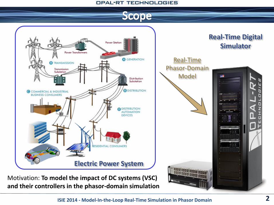
Design, and analysis of power system stability and performance
Test a variety of difficult operating scenarios on the real power grid: faults, load rejection, and islanded operation
Testing components (control, monitoring, protection, etc) hardware in a closed-loop with the simulator
Sample Applications: Closed-Loop testing of devices
Protective relay testing
Phasor Measurement Units and Wide Area Monitoring
Solar and Wind Farm integration Testing
FACTS Control-in-the-loop testing (HIL, Power HIL)
…
3ISIE 2014 - Model-In-the-Loop Real-Time Simulation in Phasor Domain
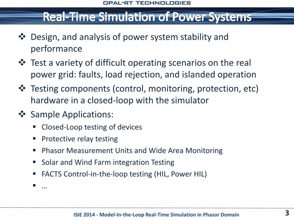
Hardware-In-the-Loop (HIL): Test and validate new components before installing them in the field
Create realistic set-up to test and prototype the final application of a new component
The design iteration is slow at this point
Model-In-the-Loop (MIL) One level before HIL simulation
Model of new component is developed and connected to the simulation tool
The development iterations are fast
4ISIE 2014 - Model-In-the-Loop Real-Time Simulation in Phasor Domain
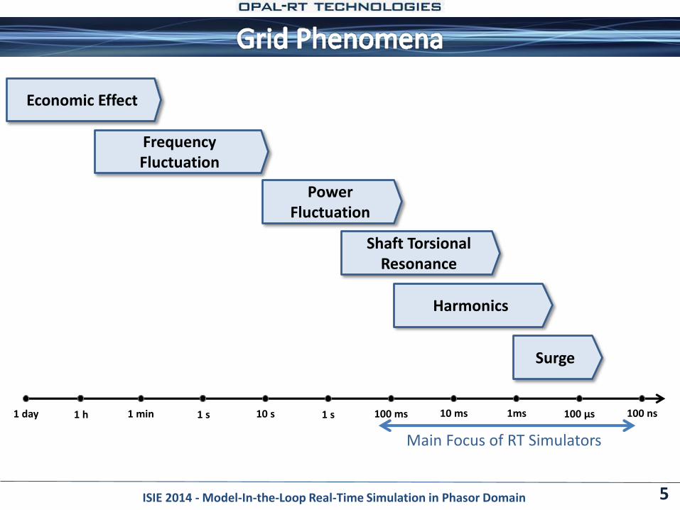
5
10 s 1 s 100 ms 10 ms 1ms 100 µs 100 ns1 min 1 s1 day 1 h
Economic Effect
Frequency Fluctuation
Power Fluctuation
Shaft Torsional Resonance
Harmonics
Surge
Main Focus of RT Simulators
ISIE 2014 - Model-In-the-Loop Real-Time Simulation in Phasor Domain
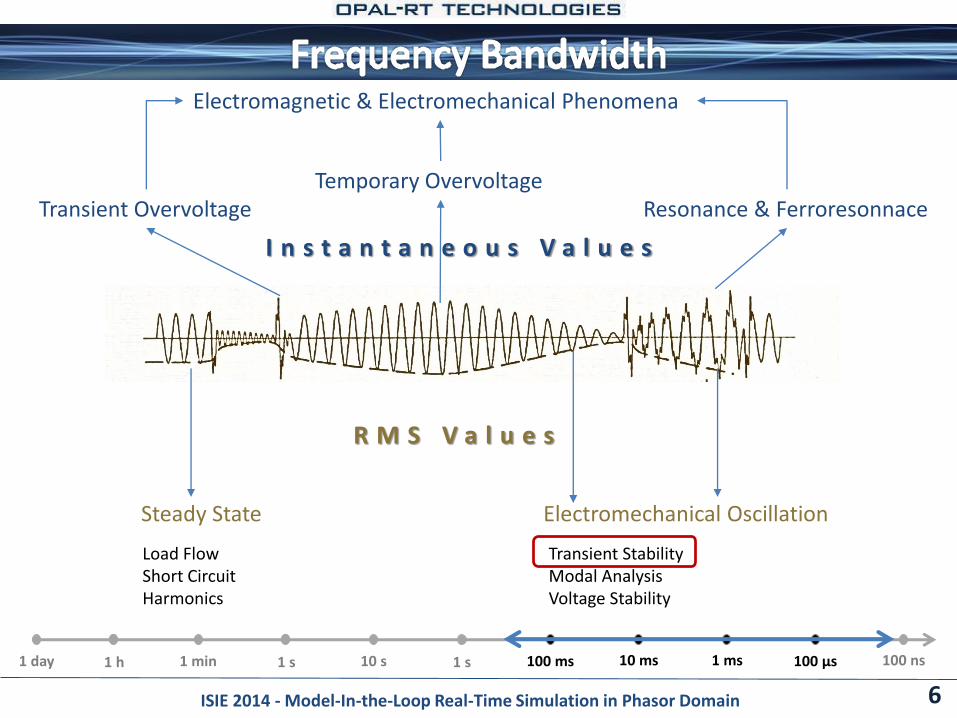
6
I n s t a n t a n e o u s V a l u e s
R M S V a l u e s
Steady State Electromechanical Oscillation
Transient OvervoltageTemporary Overvoltage
Resonance & Ferroresonnace
Electromagnetic & Electromechanical Phenomena
Load FlowShort CircuitHarmonics
Transient StabilityModal AnalysisVoltage Stability
ISIE 2014 - Model-In-the-Loop Real-Time Simulation in Phasor Domain
10 s 1 s 100 ms 10 ms 1 ms 100 µs 100 ns1 min 1 s1 day 1 h
7
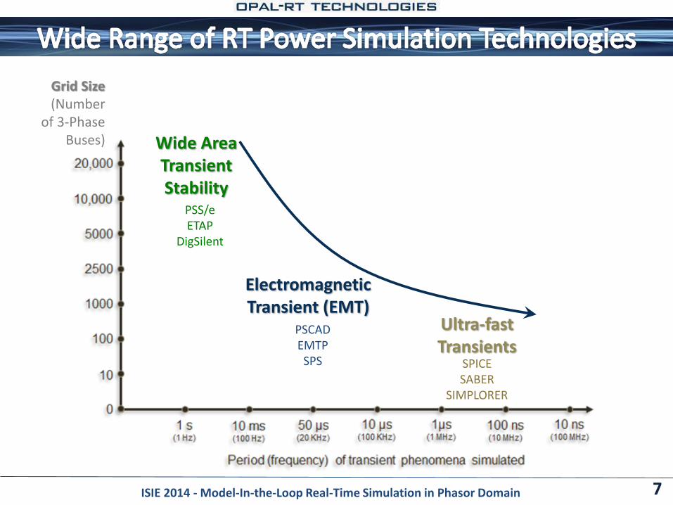
Wide Area Transient Stability
Ultra-fast Transients
Electromagnetic Transient (EMT)
Grid Size(Number
of 3-PhaseBuses)
PSS/eETAP
DigSilent
PSCADEMTP
SPS SPICESABER
SIMPLORER
ISIE 2014 - Model-In-the-Loop Real-Time Simulation in Phasor Domain
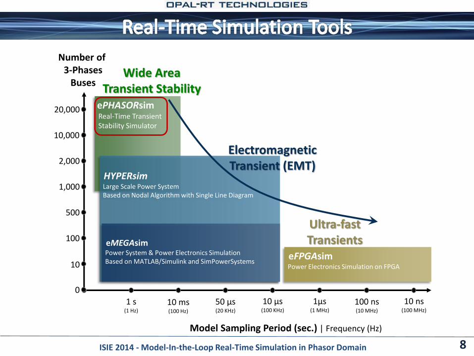
ePHASORsimReal-Time TransientStability Simulator
HYPERsimLarge Scale Power SystemBased on Nodal Algorithm with Single Line Diagram
eFPGAsimPower Electronics Simulation on FPGA
10,000
2,000
1,000
500
100
10
0
20,000
1 s(1 Hz)
10 ms(100 Hz)
50 µs(20 KHz)
10 µs(100 KHz)
1µs(1 MHz)
100 ns(10 MHz)
10 ns(100 MHz)
Model Sampling Period (sec.) | Frequency (Hz)
Number of3-Phases
Buses
eMEGAsimPower System & Power Electronics SimulationBased on MATLAB/Simulink and SimPowerSystems
8
Wide Area Transient Stability
Ultra-fast Transients
Electromagnetic Transient (EMT)
ISIE 2014 - Model-In-the-Loop Real-Time Simulation in Phasor Domain
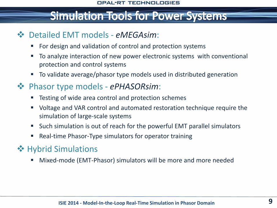
Detailed EMT models - eMEGAsim: For design and validation of control and protection systems
To analyze interaction of new power electronic systems with conventional protection and control systems
To validate average/phasor type models used in distributed generation
Phasor type models - ePHASORsim: Testing of wide area control and protection schemes
Voltage and VAR control and automated restoration technique require the simulation of large-scale systems
Such simulation is out of reach for the powerful EMT parallel simulators
Real-time Phasor-Type simulators for operator training
Hybrid Simulations Mixed-mode (EMT-Phasor) simulators will be more and more needed
9
1. EMT simulation
ISIE 2014 - Model-In-the-Loop Real-Time Simulation in Phasor Domain
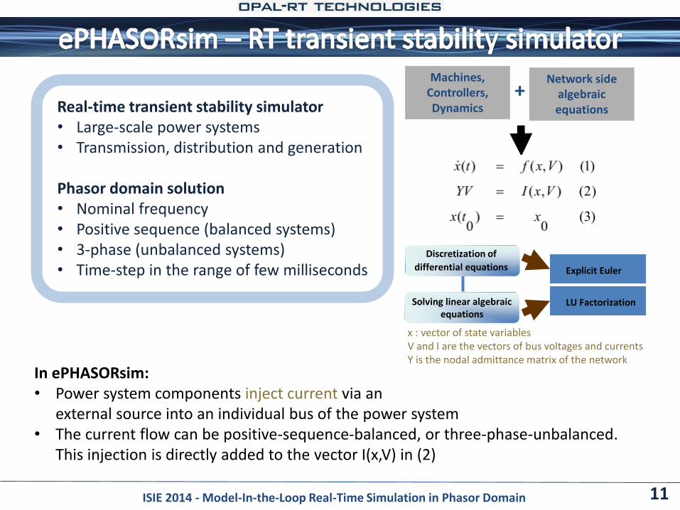
Real-time transient stability simulator• Large-scale power systems • Transmission, distribution and generation
Phasor domain solution • Nominal frequency• Positive sequence (balanced systems)• 3-phase (unbalanced systems)• Time-step in the range of few milliseconds
11ISIE 2014 - Model-In-the-Loop Real-Time Simulation in Phasor Domain
In ePHASORsim:• Power system components inject current via an
external source into an individual bus of the power system• The current flow can be positive-sequence-balanced, or three-phase-unbalanced.
This injection is directly added to the vector I(x,V) in (2)
00 )(
),,(0
),,(
xtx
tVxg
tVxfx
Machines, Controllers, Dynamics
Network side algebraic equations
+
Discretization of
differential equations
Solving linear algebraicequations
Explicit Euler
LU Factorization
x : vector of state variablesV and I are the vectors of bus voltages and currentsY is the nodal admittance matrix of the network
Solver built as a MATLAB/Simulink S-function + library of coded models
The network description (components, parameters,…) are defined in Excel
Convenient for large networks (20,000 bus)
Operation Commands can be sent to solver directly or via Distributed Network Protocol (DNP3):
Apply faults on buses, with variable fault location
In-service/Out-of-service commands for loads, C banks, transmission lines, …
Adjust tap position, reference for controllers
Change load profile
Open and reclose breakers
Etc.
Data Import: the tool offers importing from PSS/e load flow cases (*.raw) and dynamic data files (*.dyr) for a list of components open to add import from other third party simulation package
12ISIE 2014 - Model-In-the-Loop Real-Time Simulation in Phasor Domain
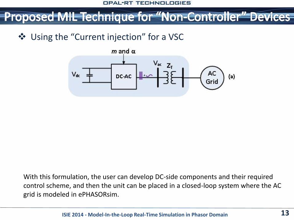
Using the “Current injection” for a VSC
13ISIE 2014 - Model-In-the-Loop Real-Time Simulation in Phasor Domain
With this formulation, the user can develop DC-side components and their required control scheme, and then the unit can be placed in a closed-loop system where the AC grid is modeled in ePHASORsim.
Static Synchronous Compensator (STATCOM) Shunt-connected device used to regulate the voltage of an AC bus
It consists of three parts: DC source, voltage-source-converter (VSC), and controller
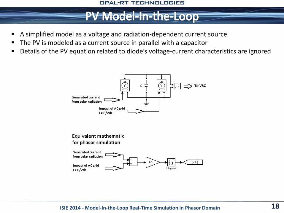
Simple Photovoltaic cell (PV) A simplified model as a voltage and radiation-dependent current
source
The PV is modeled as a current source in parallel with a capacitor
Details of the PV equation related to diode’s voltage-current characteristics are ignored
14ISIE 2014 - Model-In-the-Loop Real-Time Simulation in Phasor Domain
15ISIE 2014 - Model-In-the-Loop Real-Time Simulation in Phasor Domain
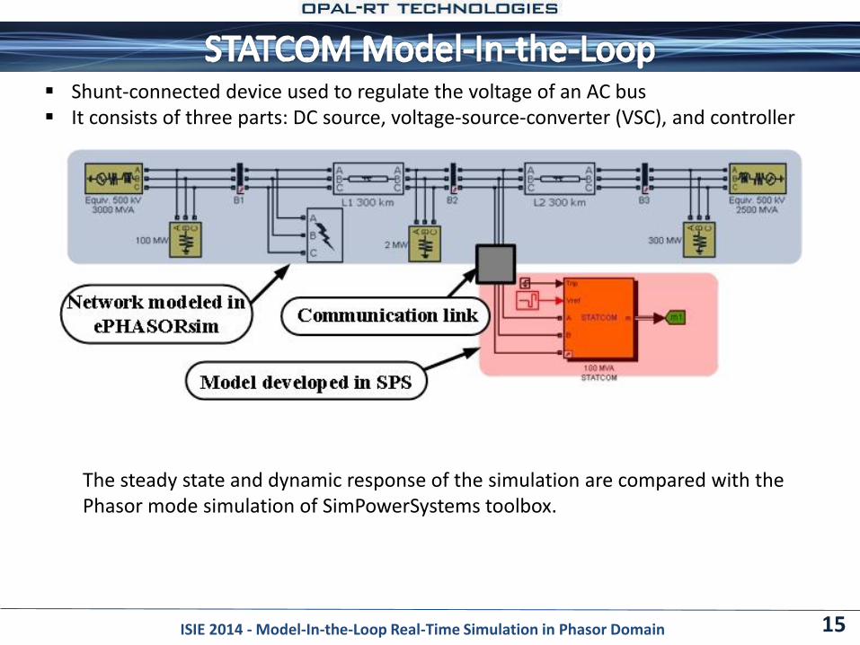
The steady state and dynamic response of the simulation are compared with the Phasor mode simulation of SimPowerSystems toolbox.
Shunt-connected device used to regulate the voltage of an AC bus It consists of three parts: DC source, voltage-source-converter (VSC), and controller
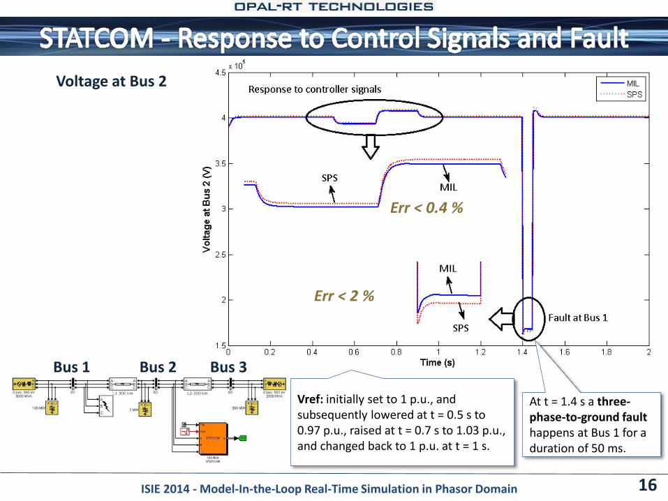
Voltage at Bus 2
16ISIE 2014 - Model-In-the-Loop Real-Time Simulation in Phasor Domain
Bus 2 Bus 3Bus 1
At t = 1.4 s a three-phase-to-ground faulthappens at Bus 1 for a duration of 50 ms.
Vref: initially set to 1 p.u., and subsequently lowered at t = 0.5 s to 0.97 p.u., raised at t = 0.7 s to 1.03 p.u., and changed back to 1 p.u. at t = 1 s.
Err < 0.4 %
Err < 2 %
17ISIE 2014 - Model-In-the-Loop Real-Time Simulation in Phasor Domain
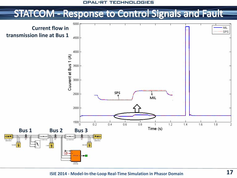
Current flow intransmission line at Bus 1
Bus 2 Bus 3Bus 1
18ISIE 2014 - Model-In-the-Loop Real-Time Simulation in Phasor Domain
A simplified model as a voltage and radiation-dependent current source The PV is modeled as a current source in parallel with a capacitor Details of the PV equation related to diode’s voltage-current characteristics are ignored
19ISIE 2014 - Model-In-the-Loop Real-Time Simulation in Phasor Domain
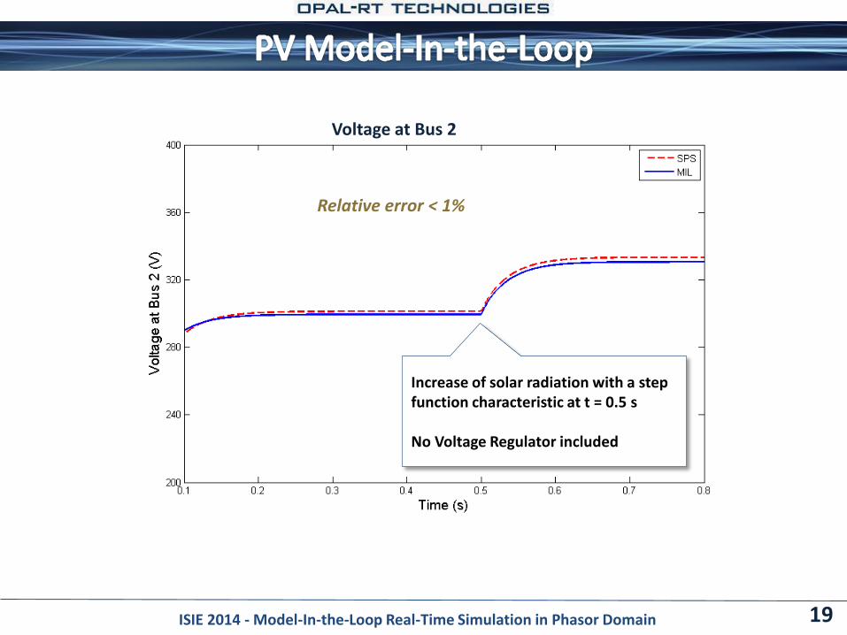
Voltage at Bus 2
Relative error < 1%
Increase of solar radiation with a step function characteristic at t = 0.5 s
No Voltage Regulator included
Application of ePHASORsim to perform MIL simulation
How to integrate power system components with VSC (such as STATCOM and PV) with the rest of the power system Test and tune the controllers
Useful for large-scale system and wide area control
Future Work:
Parallel processing and high-performance programming techniques (100,000 buses)
Add more built-in components to the library
Add more third party network format
20ISIE 2014 - Model-In-the-Loop Real-Time Simulation in Phasor Domain
A single platform that handles the RT simulation of: Transient stability (time step = 5 - 10 ms) - Phasors
Electromagnetic transients (time step = 20 – 50 us) - Instantaneous
Ultra-Fast transients (time step < 1 us) – Instantaneous (VSC, MMC)
Works with: Single line diagram modeling, or
Simulink / SimPowerSystems modeling
Applications: Closed-Loop testing of Physical devices
Protective relay testing
Phasor Measurement Units and Wide Area Monitoring
Solar and Wind Farm integration Testing
FACTS Control-in-the-loop testing (HIL, Power HIL)
…
21ISIE 2014 - Model-In-the-Loop Real-Time Simulation in Phasor Domain
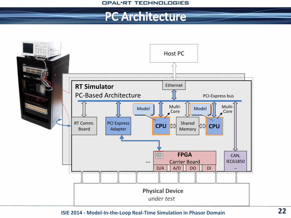
22
Host PC
RT SimulatorPC-Based Architecture
Physical Device under test
… FPGA
Carrier BoardD/A A/D
CAN, IEC61850
…DO DI
RT Comm. Board
Ethernet
CPUPCI Express
AdapterShared
Memory CPU
Multi-Core
Multi-Core
PCI-Express bus
Model Model
ISIE 2014 - Model-In-the-Loop Real-Time Simulation in Phasor Domain
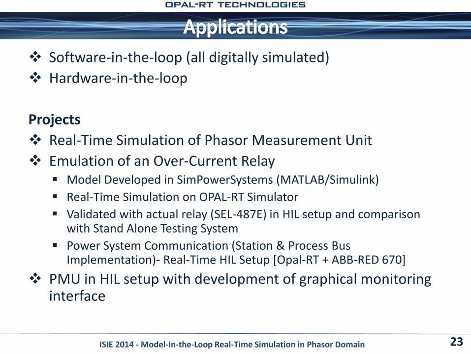
Software-in-the-loop (all digitally simulated)
Hardware-in-the-loop
Projects
Real-Time Simulation of Phasor Measurement Unit
Emulation of an Over-Current Relay Model Developed in SimPowerSystems (MATLAB/Simulink)
Real-Time Simulation on OPAL-RT Simulator
Validated with actual relay (SEL-487E) in HIL setup and comparison with Stand Alone Testing System
Power System Communication (Station & Process Bus Implementation)- Real-Time HIL Setup [Opal-RT + ABB-RED 670]
PMU in HIL setup with development of graphical monitoring interface
23ISIE 2014 - Model-In-the-Loop Real-Time Simulation in Phasor Domain