Embed Size (px)
Citation preview
Project 07 Product Flaw Identification & Re-design 11/10/2009 University at Buffalo Ryan R. Bierl

2
Table of Contents 1 Introduction .......................................................................................................................................... 3
2 Requirements ........................................................................................................................................ 3
3 Results ................................................................................................................................................... 3
3.1 Phase 1 .......................................................................................................................................... 3
3.1.1 Problem Identification .......................................................................................................... 3
3.1.2 Product Redesign .................................................................................................................. 4
3.2 Phase 2 .......................................................................................................................................... 5
3.2.1 CAD Models ........................................................................................................................... 5
4 Comparison ........................................................................................................................................... 9
4.1.1 Original Design ...................................................................................................................... 9
4.1.2 New Design ........................................................................................................................... 9
4.1.3 New Design Specifications .................................................................................................. 10
4.1.4 How the Product is Assembled ........................................................................................... 12
5 Discussion ............................................................................................................................................ 13
6 Conclusion ........................................................................................................................................... 13
7 References .......................................................................................................................................... 13
3
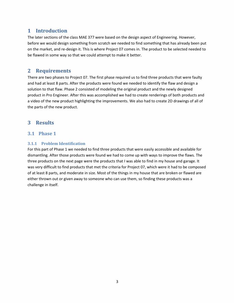
1 Introduction The later sections of the class MAE 377 were based on the design aspect of Engineering. However,
before we would design something from scratch we needed to find something that has already been put
on the market, and re-design it. This is where Project 07 comes in. The product to be selected needed to
be flawed in some way so that we could attempt to make it better.
2 Requirements There are two phases to Project 07. The first phase required us to find three products that were faulty
and had at least 8 parts. After the products were found we needed to identify the flaw and design a
solution to that flaw. Phase 2 consisted of modeling the original product and the newly designed
product in Pro Engineer. After this was accomplished we had to create renderings of both products and
a video of the new product highlighting the improvements. We also had to create 2D drawings of all of
the parts of the new product.
3 Results
3.1 Phase 1
3.1.1 Problem Identification
For this part of Phase 1 we needed to find three products that were easily accessible and available for
dismantling. After those products were found we had to come up with ways to improve the flaws. The
three products on the next page were the products that I was able to find in my house and garage. It
was very difficult to find products that met the criteria for Project 07, which were it had to be composed
of at least 8 parts, and moderate in size. Most of the things in my house that are broken or flawed are
either thrown out or given away to someone who can use them, so finding these products was a
challenge in itself.
4
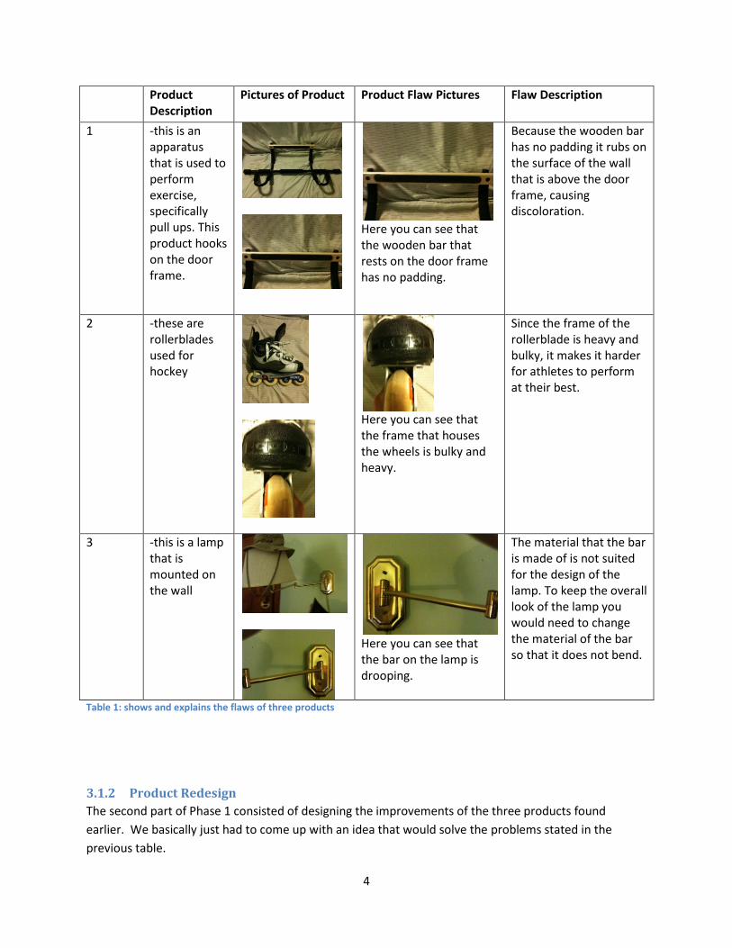
Product Description
Pictures of Product Product Flaw Pictures Flaw Description
1 -this is an apparatus that is used to perform exercise, specifically pull ups. This product hooks on the door frame.
Here you can see that the wooden bar that rests on the door frame has no padding.
Because the wooden bar has no padding it rubs on the surface of the wall that is above the door frame, causing discoloration.
2 -these are rollerblades used for hockey
Here you can see that the frame that houses the wheels is bulky and heavy.
Since the frame of the rollerblade is heavy and bulky, it makes it harder for athletes to perform at their best.
3 -this is a lamp that is mounted on the wall
Here you can see that the bar on the lamp is drooping.
The material that the bar is made of is not suited for the design of the lamp. To keep the overall look of the lamp you would need to change the material of the bar so that it does not bend.
Table 1: shows and explains the flaws of three products
3.1.2 Product Redesign
The second part of Phase 1 consisted of designing the improvements of the three products found
earlier. We basically just had to come up with an idea that would solve the problems stated in the
previous table.
5
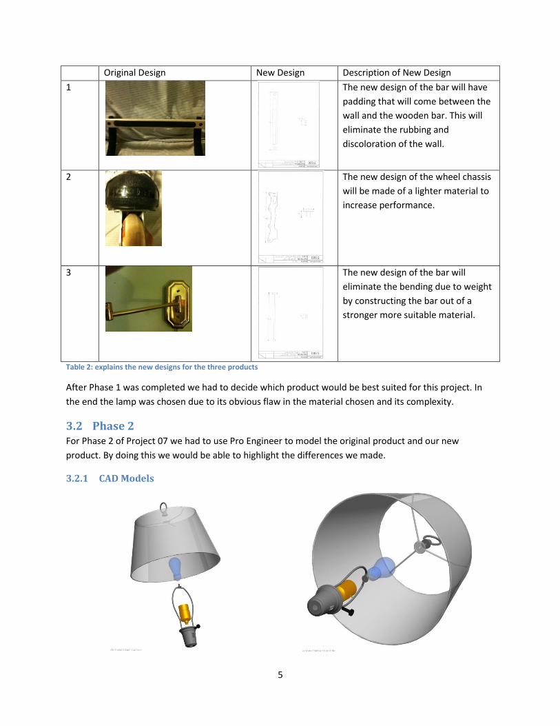
Original Design New Design Description of New Design
1
The new design of the bar will have
padding that will come between the
wall and the wooden bar. This will
eliminate the rubbing and
discoloration of the wall.
2
The new design of the wheel chassis
will be made of a lighter material to
increase performance.
3
The new design of the bar will
eliminate the bending due to weight
by constructing the bar out of a
stronger more suitable material.
Table 2: explains the new designs for the three products
After Phase 1 was completed we had to decide which product would be best suited for this project. In
the end the lamp was chosen due to its obvious flaw in the material chosen and its complexity.
3.2 Phase 2 For Phase 2 of Project 07 we had to use Pro Engineer to model the original product and our new
product. By doing this we would be able to highlight the differences we made.
3.2.1 CAD Models

6
(a) (b) Figure 1(a) image of the exploded shade assembly of the product (b) same assembly at a different view
(a) (b) Figure 2(a) shade assembly (b) shade assembly in different view
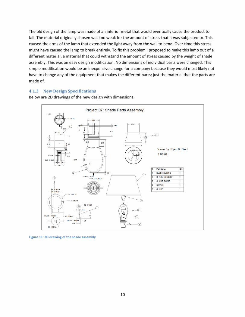
The shade assembly consisted of a shade, shade holder, shade clamp, bulb housing, and a switch. These
parts involved some complex modeling tools such as sweep and helical sweep.
(a) (b)
Figure 3(a-b) various views of the exploded arm assembly
(a) (b)
Figure 4(a-b) various views of the arm assembly

7
The arm assembly consisted of the far arm, close arm, arm connectors, arm screws, gold washers,
casing, and bracket and large hex nuts. These parts did not require any advanced features in Pro
Engineer, except for helical sweep to make threads.
(a) (b)
Figure 5(a-b) various views of the exploded mount assembly
(a) (b)
Figure 6(a-b) various views of the mount assembly
The mount assembly consisted of 4 screws, two bolts, two small hex nuts, two bolt covers and a wall
mount. The hardest part of this assembly was creating the raised radiuses on the two holes for the bolts.
To create them I sketched the cross section of the protrusion and revolved it about an internal axis, then
rounded it.
8
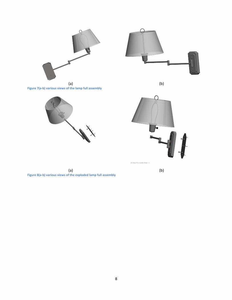
(a) (b) Figure 7(a-b) various views of the lamp full assembly
(a) (b)
Figure 8(a-b) various views of the exploded lamp full assembly
9
4 Comparison
4.1.1 Original Design
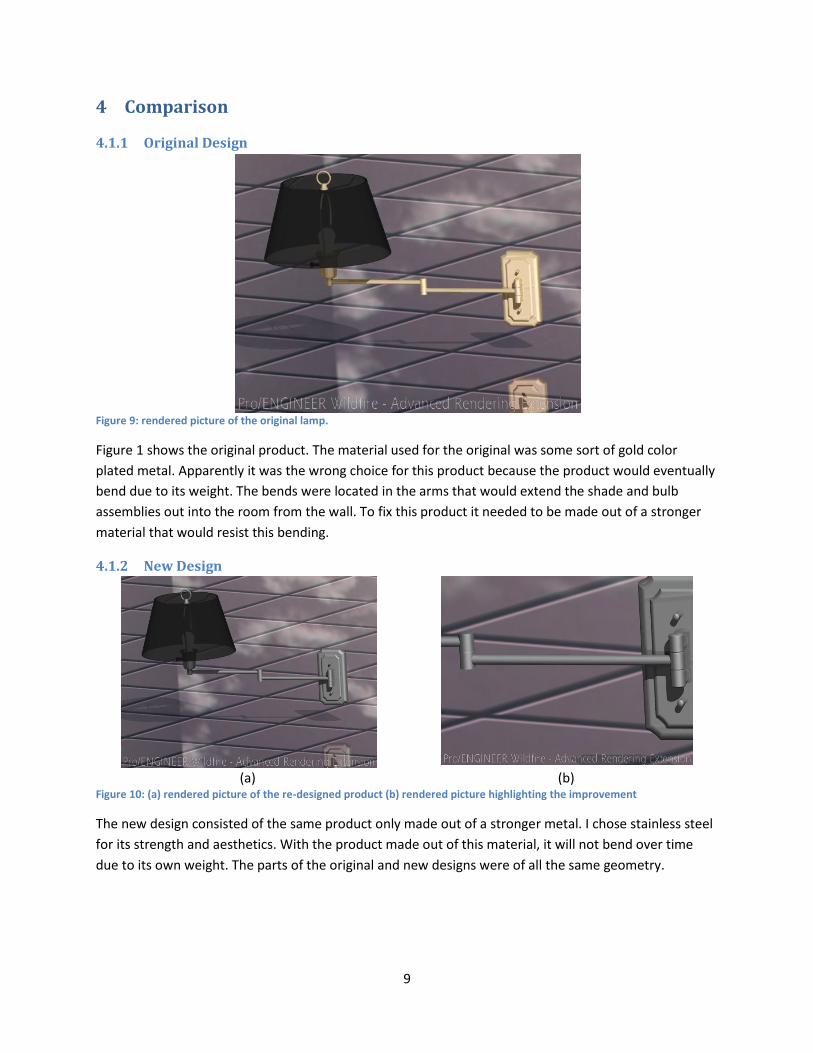
Figure 9: rendered picture of the original lamp.
Figure 1 shows the original product. The material used for the original was some sort of gold color
plated metal. Apparently it was the wrong choice for this product because the product would eventually
bend due to its weight. The bends were located in the arms that would extend the shade and bulb
assemblies out into the room from the wall. To fix this product it needed to be made out of a stronger
material that would resist this bending.
4.1.2 New Design
(a) (b)
Figure 10: (a) rendered picture of the re-designed product (b) rendered picture highlighting the improvement
The new design consisted of the same product only made out of a stronger metal. I chose stainless steel
for its strength and aesthetics. With the product made out of this material, it will not bend over time
due to its own weight. The parts of the original and new designs were of all the same geometry.
10
The old design of the lamp was made of an inferior metal that would eventually cause the product to
fail. The material originally chosen was too weak for the amount of stress that it was subjected to. This
caused the arms of the lamp that extended the light away from the wall to bend. Over time this stress
might have caused the lamp to break entirely. To fix this problem I proposed to make this lamp out of a
different material, a material that could withstand the amount of stress caused by the weight of shade
assembly. This was an easy design modification. No dimensions of individual parts were changed. This
simple modification would be an inexpensive change for a company because they would most likely not
have to change any of the equipment that makes the different parts; just the material that the parts are
made of.
4.1.3 New Design Specifications
Below are 2D drawings of the new design with dimensions:
Figure 11: 2D drawing of the shade assembly

11
Figure 12: 2D drawing of the arm assembly
Figure 13: 2D drawing of the mount assembly
12
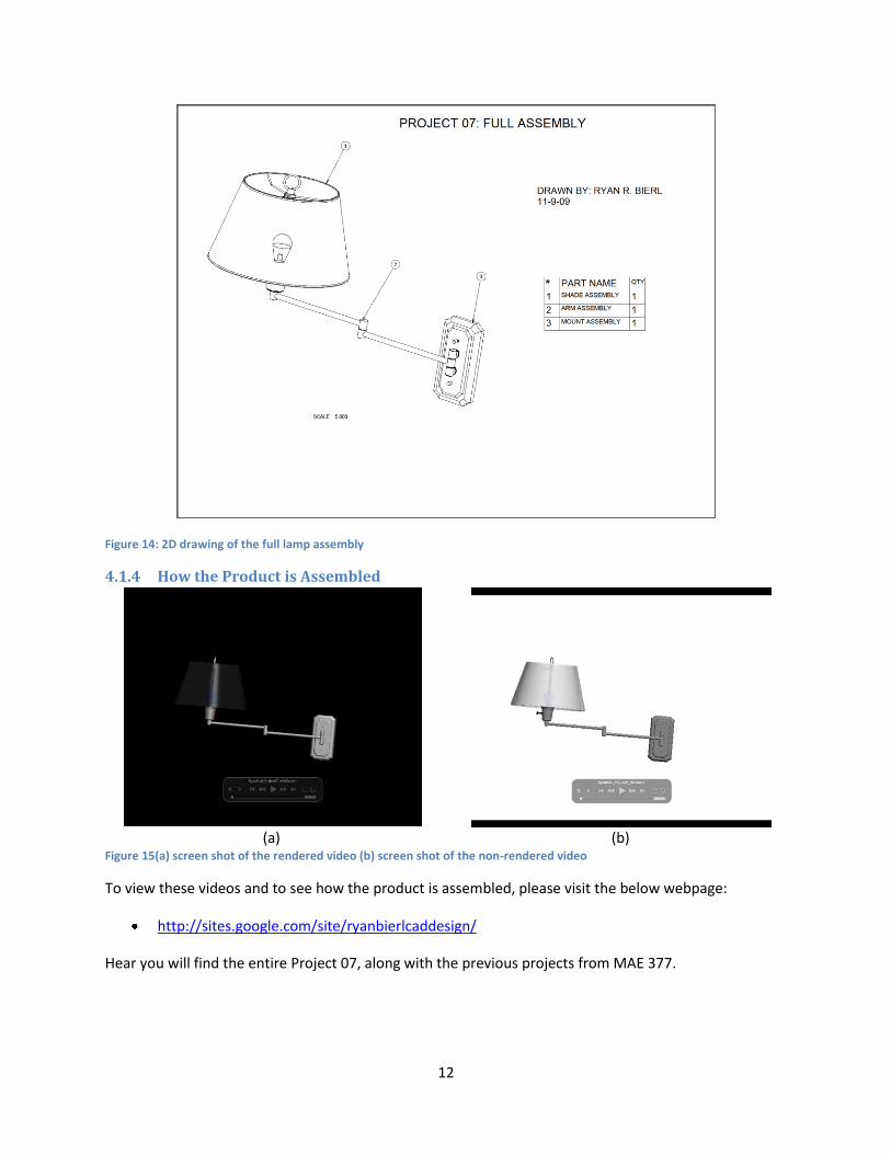
Figure 14: 2D drawing of the full lamp assembly
4.1.4 How the Product is Assembled
(a) (b)
Figure 15(a) screen shot of the rendered video (b) screen shot of the non-rendered video
To view these videos and to see how the product is assembled, please visit the below webpage:
http://sites.google.com/site/ryanbierlcaddesign/
Hear you will find the entire Project 07, along with the previous projects from MAE 377.
13
5 Discussion Project 07 was a very involved process. It took many hours to complete it up to the standards set in
class. The modeling involved was not much more advanced than in other previous projects. The only
difference was that instead of reading a tutorial on the steps to generate a part, we had to examine our
dimensioned drawings and then figure out what steps needed to be done. There were a lot of parts that
required helical sweep cuts and protrusions due to the large amount of screws, bolts and nuts in the
product. Also to create the top part of the shade holder I needed to use a sweep.
6 Conclusion The goals of Project 07 were to get us more involved in the re-design process and to test our skills in
modeling using Pro Engineer. I believe that these goals were met and that I completed this project
according to the standards set in class. Some of the problems I had included problems with modeling
and rendering the videos. The one problem I had with the modeling involved the helical sweep feature
when I was creating the threads on various parts. I tried to create these features, at first, by memory but
I found out that this was not adequate. When creating the sweep profile I thought you had to first start
outside of the part and create a line that went as far as you wanted the sweep to go; this was not the
case. I had to play around with it a couple times and it seemed as if it behaved a different way every
time I tried to put threads on a part, which was annoying.
7 References The references below were used in the creation of this product:
Machinery’s Handbook on UBLearns.