Embed Size (px)
Citation preview

Electrical test equipmentfor high and low voltage
systems

ElectricalTestTools
PowerTest1557 1
IRT1557 3
ERT1557 5
PowerCheck1557 7
DO7 9
DO7Plus 11
HighVoltageTestTools
HV Indicators 13
HVPhasingUnits 15
HaloHook 17
TypeLPlus 18
SDR11 19
SDR35 20
AGL5 21
LLT 22
ProvingUnits 23
WorldLeadingElectricalTestSolutions 24
Tel: +44 (0) 191 587 8741Fax: +44 (0) 191 586 0227Email: [email protected]: www.seaward.co.uk
Contents

Leading the world in electricaltest equipment for high andlow voltage systemsAt Seaward Group, we have over 70 years’ experience inthe design and manufacture of innovative electrical testinstrumentation.
Today, our first-class range of industrial test and measurementequipment serves a wide variety of testing and precisionmeasurement applications meeting many internationalstandards for both low and high voltage electrical installations.
Customers worldwide rely on the quality of our low voltage andhigh voltage test tools to assure the safety and performanceof the whole electrical system from distribution and overheadcables, right down to the domestic plug socket in your houseor business premises.
The range includes multi and single function installation testers,high voltage indicators and phasing units, soft discharge rods,ammeters and a host of accessories.
An international service and calibration operation and freetechnical support line mean that our customers are offereda complete solution to their test and measurement needs.
www.seaward.co.uk/powertest1557Tel: +44 (0) 191 587 8741
PowerTest1557Multi-Function installation testerwith integral probe
The PowerTest 1557 is a robust multi-function installation tester with integral probe,allowing the instrument to be held and the results to be read at the same time for bothsafety and convenience.
The PowerTest 1557 is also very fast, performing non-trip earth loop, line loop,PFC and PSC tests with one press of a button in under 5 seconds.
The lightweight, handheld and battery powered PowerTest 1557 is supplied in adurable carrying case with a 2 year warranty, 6 x AA alkaline batteries, test lead set,shrouded safety plugs, shrouded safety test probes and a red cordless shroudedsafety test probe.
Key Features: Fast non-trip loop test in 5 seconds Measures earth loop, line loop,
PFC and PSCwith one press of a button Integral probemakes reading results
easy and safe Auto RCD test Robust with long battery life
Ideal for: Electrical Contractors Training Institutions Electrical Engineers Power System Engineers
Part No: 328A910
Find out more:
Electrical Test Tools
1

TESTS
Earth Continuity
Test Current >200mADisplay Range 0.00ohm - 199ohmResolution 0.01ohm maximumTest Lead Compensation Null lead resistance 0.00ohm -
10.00ohmLive Circuit Detection Test inhibit if >30V detected
Insulation Resistance
Test Voltage 100V, 250V, 500VDisplay Range 0.05Mohm – 199MohmResolution 0.01Mohm maximumLive Circuit Detection Test inhibit if >30V detected
Loop/Line Impedance
Supply Voltage 195 - 253V/340-440V,45Hz-65HzTest Current 15mA (non tripping for RCD protected
circuits)Display Range 0.01ohm - 2000ohmResolution 0.01ohm maximumLoop Impedance Phase to EarthLine Impedance Phase to Neutral/Phase to PhasePFC/PSC Range 0 – 26kA
RCD Trip Time
Supply Voltage 195 – 253V, 45 – 65HzTest Currents 10, 30, 100, 300, 500mATrip Time Ranges 0ms – 2000ms at 1/2 In
0ms – 300ms at In general0ms – 500ms at In selective0ms – 40ms at 5x In
Auto Test Auto sequence for 1/2 In, In and5x In at 0° and 180°
RCD Type General (G), Selective (S), Pulsed (A),AC (AC)
RCD Trip Current (Ramp Test)
Supply Voltage 195 – 253V, 45 – 65HzTest Currents 10, 30, 100, 300, 500mARamp Current Range 1/2 In to 1.1 In
Voltage/Frequency Measurement
Display Range 0 – 440VResolution 1VFrequency Measuring Range 45 – 65Hz
ADDITIONAL INFORMATION
Compliance IEC 61010-1 300V CAT III, EN 61557Weight & Dimensions 0.95kg / 26cm x 10cm x 5.5cmPower Supply 6 x AA Alkaline Batteries (supplied)
6 x AA NiMH Rechargeable Batteries (optional)
ACCESSORIES
Hardware
PowerCheck 1557 (369A910)
Technical Specification
2

www.seaward.co.uk/irt1557Tel: +44 (0) 191 587 8741
Find out more:
IRT1557Insulation resistance and continuity tester
The IRT 1557 is a handheld insulation resistance and continuity tester with an easyto use rotary switch for selecting tests.
The IRT 1557 measures earth continuity insulation resistance at 250V, 500V and 1000Vand voltages up to 10000AC or DC.
The insulation resistance measurement features automatic discharge of capacitivecircuits and provides an automatic warning if accidentally connected to live circuits.
The IRT 1557 includes voltage measurements up to 1000AC or DC and has a safetyrating of 600V CAT III / 1000V CAT II. It is supplied as standard with one eachof 1.5m black and red test lead, one each of black and red crocodile clip,and a carry case.
Key Features: Handheld with integral probe for
easy and safe results reading Automatic discharge of
capacitive circuits Dual safety rating Continuous test mode Robust with long battery life Clear large LCD display
Ideal for: Electricians Telecomms Engineers Power System Engineers Electrical Contractors
Part No: 365A910
Electrical Test Tools
3

Technical Specification
TESTS
Insulation Resistance
Display Range 0.001Mohm - 1999MohmAnalogue Bar Graph 0ohm - infinityTest Voltage 250v; 500v; 1000vNominal Current 1mA minimum per EN 61557Audible/Visible Warning Inhibited if 30 V AC or DC at inputs
Continuity
Display Range 0.00ohm - 19.99ohmOpen Circuit Test Voltage 4V DC nominalTest Current 200mA,Audible and Visible Warning Inhibited if 30 V AC or DC at inputs
Resistance
Display Range 0ohm - 2000ohmTest Current 25µA nominalAudible and Visible Warning Inhibited if 30 V AC or DC at inputs
Voltage
Display Range 0V - 1000V DC/AC to 400HzAnalog Bar Graph 0 - 1000VAudible/Visible Warning 30 V AC or DC at inputs
ADDITIONAL INFORMATION
Safety Rating IEC 61010-1, 600V CAT III/ 1000V CAT II
Weight & Dimension 0.8kg / 26cm x 10cm x 5.5cmCompliance EN 61557-1, -2, -4, -10
ACCESSORIES
Hardware
PowerCheck 1557 (369A910)
4
www.seaward.co.uk/ert1557Tel: +44 (0) 191 587 8741
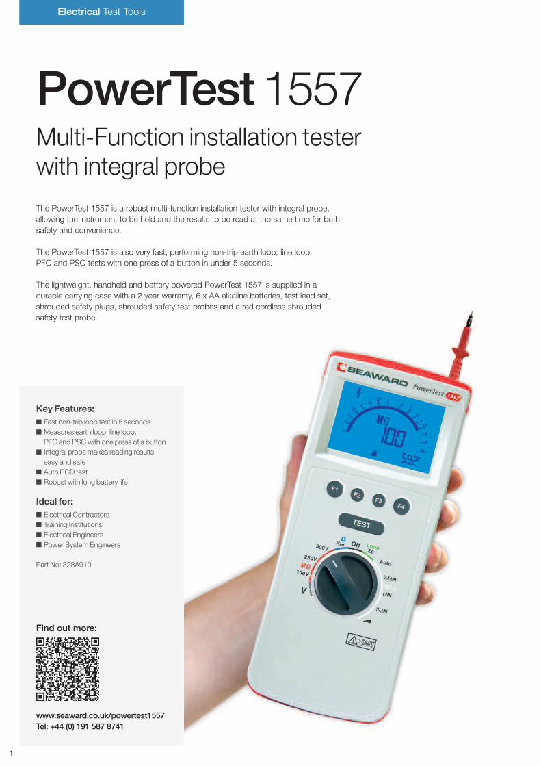
ERT1557Advanced earth resistance testerwith internal memory
The ERT 1557 is a versatile professional instrument, ideal fortesting earth systems and lightning protection installations at thetime of installation or periodically. Earth measurements can bemade using ground spikes or a combination of current clampsmaking the ERT 1557 ideal for a multitude of applications;including measuring earth resistance, the resistance of individualearthing rods, lightning grounding installations and determiningsoil resistivity.
The ERT 1557 has advanced electronic measuring circuitrywhich offers accurate measurement even in situations wherehigh levels of external noise can influence readings.
Earth resistance measurement is carried out using 2, 3and 4-wire methods or a combination of current clamps.
The ERT has an internal memory for 500 test results which youcan download to your PC. Its user-friendly features include alarge rotary dial for test selection, large LCD and simple pushbutton test activation. The unit is supplied with four earth spikesand full test lead set. The ERT is one of the most competitiveearth resistance testers on the market.
It is supplied as standard with one each of 5m black and greentest lead, one each of 20m red and blue test lead, USB toMiniDIN Lead Assembly and 4 x test spikes.
Key Features: Current clampmeasurement 2, 3 and 4-wire measurement methods Earth resistance and soil resistivity
measurement Internal memory for 500 test results
for data management
Ideal for: Telecomms Engineers Power Systems Engineers Electricians Electrical Contractors
Part No: 362A910
Find out more:
Electrical Test Tools
5

ADDITIONAL INFORMATION
Weight & Dimensions 0.8kg / 26cm x 10cm x 55mmMemory 500 memory locationsCommunication USBCompliance EN 61557-1, -5, IEC61010-1, 300V CAT II
ACCESSORIES
ERT Current Clamp (278A923)
Technical Specification
6
TESTS
Earth Resistance 2, 3 and 4 wire method
Display Range 0.00ohm - 50.0kohmMeasuring Frequency 125 Hz +/- 1 HzMeasuring Current <20mA effectiveMeasuring Voltage <50V effective sine wave
Earth Resistance using current clamp
Display Range 0.0ohm - 2.00kohmMeasuring Frequency 125 Hz +/- 1 HzMeasuring Current <20mA effectiveMeasuring Voltage <50V effective sine wave
Specific Earth Resistance (p)
Display Range 0.00ohm – 1999kohmMeasuring Frequency 125 Hz +/- 1 HzMeasuring Current <20mA effectiveMeasuring Voltage <50V effective sine wave
www.seaward.co.uk/powercheck1557Tel: +44 (0) 191 587 8741
7
Find out more:
Electrical Test Tools
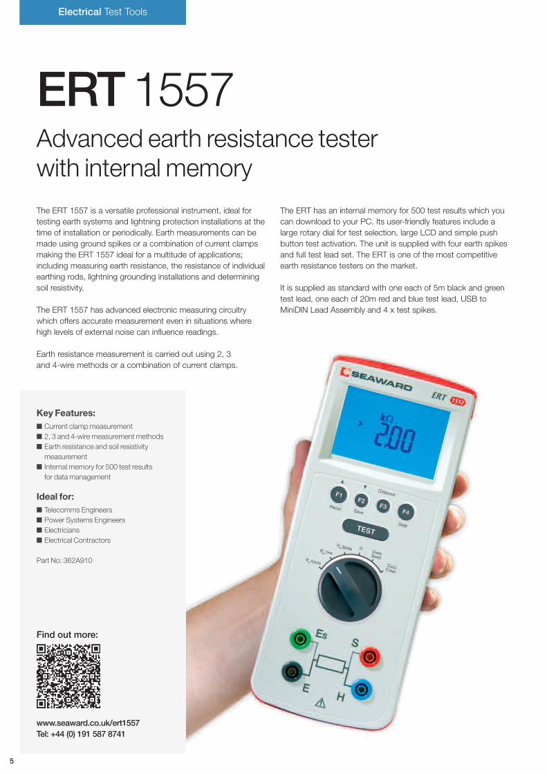
PowerCheck1557Advanced comprehensiveverification checkbox
The PowerCheck 1557 is an extremely rugged and comprehensive verification checkboxsuitable for use with all multi-function and single function installation and portable appliancetesters.
This rugged unit fully checks the earth continuity, insulation resistance, RCD trip time,RCD trip current, loop, PE conductor current, touch current and flash tests of your testinstrumentation to ensure accurate measurement and correct operation betweencalibration intervals.
This simple to use instrument is built into a rugged enclosure capable of withstanding themost demanding use and conditions and is supplied with comprehensive guidance andrecord keeping sheets.
Suitable for use on earth continuity or earth bond testers up to 25A, the PowerCheck 1557also verifies loop impedance or RCD testers on RCD protected circuits - without trippingthe RCD.
Key Features: Rugged and robust portable unit Does not trip building RCDs Compatible with all installation
and PAT testers Confirms the performance
of testers between calibrationintervals
Ideal for: Electricians Service Engineers Electrical Contractors
Part No: 369A910

8
Technical Specification
TESTS
Earth Continuity Verification
Test Current In >200mA indicationTest Voltage 4V < Un > 24V indicationTest Resistances 0.5ohm and 2ohm
Insulation Resistance Verification
Open Circuit Test Voltage: 250V < Un < 375V indication500V < Un < 750V indication1000V < Un < 1500 indication
Test Current In >1mA into 1000ohm/VMax Test Current Ik <2mATest Resistances 0.25Mohm, 0.5Mohm, 1.0Mohm
Earth Loop Verification
Test Values Loop, Loop+1ohm, Loop+180ohm
RCD Verification
Trip Current 10mA, 30mA, 100mATrip Times 20ms, 40ms, 500msTest Current multiplier 1/2n, In and 5 In verification
Voltage Verification
Test Voltage 240V AC rms test output
PAT FUNCTIONS
Earth Continuity Verification
Test Resistances 0.2ohm and 2ohm
Insulation Resistance Verification
Test Resistances 500kohm, 1Mohm and 2Mohm
PE Conductor Current
Test Currents 0.1mA, 0.25mA and 0.5mA
Flash Test current
Test Currents 0.5mA, 1mA and 1.5mA
ADDITIONAL INFORMATION
Power Supply 230V AC ±10%Weight & Dimensions 1kg / 21cm x 14.5cm 8.5cm
www.seaward.co.uk/do7Tel: +44 (0) 191 587 8741
9
Find out more:
Electrical Test Tools
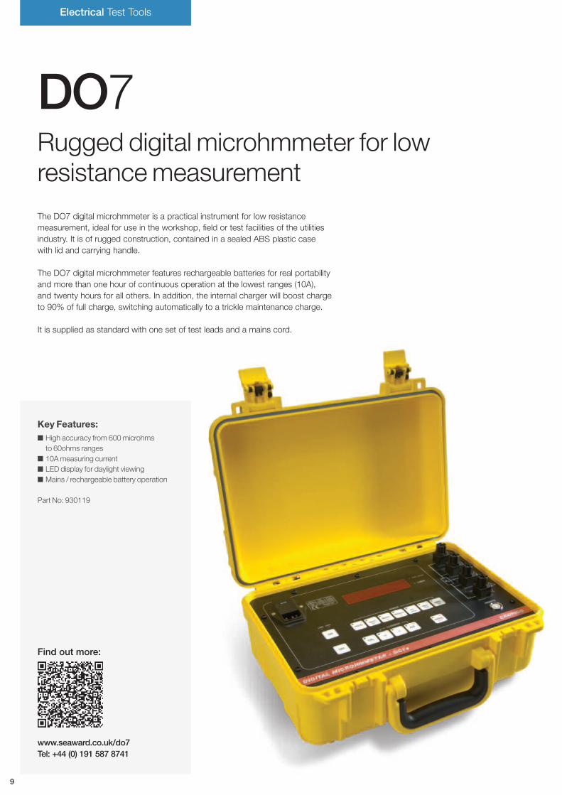
DO7Rugged digital microhmmeter for lowresistancemeasurement
The DO7 digital microhmmeter is a practical instrument for low resistancemeasurement, ideal for use in the workshop, field or test facilities of the utilitiesindustry. It is of rugged construction, contained in a sealed ABS plastic casewith lid and carrying handle.
The DO7 digital microhmmeter features rechargeable batteries for real portabilityand more than one hour of continuous operation at the lowest ranges (10A),and twenty hours for all others. In addition, the internal charger will boost chargeto 90% of full charge, switching automatically to a trickle maintenance charge.
It is supplied as standard with one set of test leads and a mains cord.
Key Features: High accuracy from 600microhms
to 60ohms ranges 10Ameasuring current LED display for daylight viewing Mains / rechargeable battery operation
Part No: 930119
10
Technical Specification
ADDITIONAL INFORMATION
Measurement
4 Terminal Kelvin / Thomson principle eliminates errors due to
lead resistance. Open circuit measurement voltage = 2V dc
Display
0.8” LED 6000 count with automatic decimal point and
polarity indication
Ranges
6 push button selected with LED indication
Terminals
6mm binding posts accept spade tags and 4 mm banana plugs
Working Temperature
0°C to 40°C rel. humidity 80% max. non-condensing
Storage Temperature
-20 to +50°C
Mains Supply
100 / 120 / 220 / 240 Volts
+10% - 13% 47Hz to 63Hz. max 80VA
Safety
EN 61010-1 Protective Class 1
Dimensions
343mm x 327mm x 152mm (W D H) approx
Mass
8kg approx
Protection
415 Vrms maximum at input terminals
Calibration
Digital, security key protected
Battery
Sealed lead acid, rechargeable cells giving a minimum of 1 hour of
continuous measurement on the lowest 10 amp ranges and 20 hours
on all other ranges. Internal charger with battery
state indicator
Average
Automatic average and display of measurement with forward
and reverse current
DO7 OPTIONS
DO7-RS Remote start plugHS01 Duplex handspikes with 3 metre lead lengthHS01-RS Duplex handspikes with 3 metre lead length
with remote start buttonHS02 Duplex handspikes with 3 and 15 metre
lead lengthHS02-RS Duplex handspikes with 3 and 15 metre lead
length with remote start buttonLS03 Lead set with 3 metre leads terminated in large
Kelvin clips type KC3LS04 Lead set with 3 metre and 15 metre lead length
terminated in large Kelvin clips type KC3LS05 Lead set with 4 x 1 metre leads terminated in
banana plugs, 4 x crocodile clips, 4 x testprobes and 2 x Kelvin clips type KC1 inminiature Kelvin clips type KC2
MTS2 Calibration standardRSL01 RS232 cable
Range Resolution Typical Current Accuracy at 20°C ±5°C, 1 Year Temp Coefficient/°C
60Ω 10mΩ 1mA ±(0.15% Rdg +0.05% FS) 40ppm Rdg + 30ppm FS
6Ω 1mΩ 10mA ±(0.15% Rdg +0.05% FS) 40ppm Rdg + 30ppm FS
600mΩ 100µΩ 100mA ±(0.15% Rdg +0.05% FS) 40ppm Rdg + 30ppm FS
60mΩ 10µΩ 1A ±(0.15% Rdg +0.05% FS) 40ppm Rdg + 30ppm FS
6mΩ 1µΩ 10A ±(0.2% Rdg +0.01% FS) 40ppm Rdg + 30ppm FS
600µΩ 0.1µΩ 10A ±(0.2% Rdg +0.2% FS) 40ppm Rdg + 250ppm FS
TESTS
www.seaward.co.uk/do7plusTel: +44 (0) 191 587 8741
11
Find out more:
Electrical Test Tools
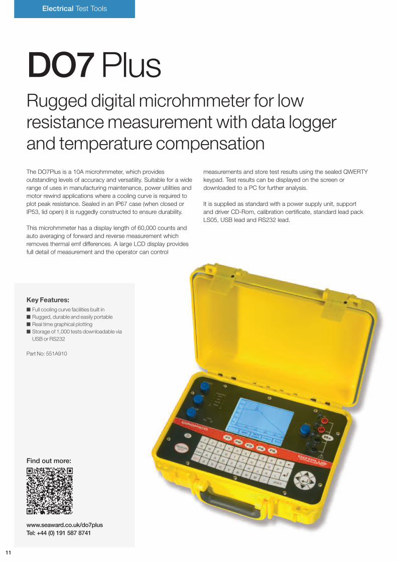
DO7PlusRugged digital microhmmeter for lowresistancemeasurement with data loggerand temperature compensationThe DO7Plus is a 10A microhmmeter, which providesoutstanding levels of accuracy and versatility. Suitable for a widerange of uses in manufacturing maintenance, power utilities andmotor rewind applications where a cooling curve is required toplot peak resistance. Sealed in an IP67 case (when closed orIP53, lid open) it is ruggedly constructed to ensure durability.
This microhmmeter has a display length of 60,000 counts andauto averaging of forward and reverse measurement whichremoves thermal emf differences. A large LCD display providesfull detail of measurement and the operator can control
measurements and store test results using the sealed QWERTYkeypad. Test results can be displayed on the screen ordownloaded to a PC for further analysis.
It is supplied as standard with a power supply unit, supportand driver CD-Rom, calibration certificate, standard lead packLS05, USB lead and RS232 lead.
Key Features: Full cooling curve facilities built in Rugged, durable and easily portable Real time graphical plotting Storage of 1,000 tests downloadable via
USB or RS232
Part No: 551A910
12
Technical Specification
ADDITIONAL INFORMATION
Measurement
4 terminal Kelvin / Thompson principle eliminates errors due to lead
resistance
Display
60,000 count + sign LCD graphics panel with backlight select
display value of °C or °F
Ranges
7 resistance ranges
Terminals
4mm safety sockets
Working Temperature
0 deg C to 40 deg C
Storage Temperature
-20 deg C to +50 deg C
Safety
Conforms to EN 61010-1:2001 50V Cat 3
Dimensions
358mm X 269mm X 155mm (W D H) approx
Mass
6kg (instrument only)
Calibration
Digital password protected, manual or via remote interface
Battery
Internal, fixed NiMh battery pack, Gas gauge circuits to monitor
battery capacity. Internal automatic FAST / TRICKLE battery
charger. DC input from 9V to 36V.
Mains Supply
External mains psu 90V – 253V, 47Hz to 63Hz with
interchangeable plugs.
DO7 PLUS OPTIONS
LS03-P Lead set with 3 metre leads and terminatedwith large Kelvin clips type KC3
LS04-P Lead set with 3 metres and 15 metres leadlength terminated in large Kelvin clips type KC3
HS01-P 2 x Duplex handspike with 3 metre lead lengthHS02-P Duplex handspikes with 3 and 15 metre
lead lengthCH01 Concentric handspikes 3M lead lengthC02 1 metre cable clamp with metal base for the
precise measurement of 1 metre cable samples0.1…100mm2
CO2A 1 metre cable clamp with metal base for theprecise measurement of 1 metre cable samples1…1000mm2
PT02-DO7 Plus PT100 temperature probe with 1 metre lead
Range Current Resolution FSV Uncertainty
6.0000 mΩ 10 A 100 nΩ 60 mV 0.05% Rdg +0.01%FS
60.000 mΩ 1 A 1 µΩ 60 mV 0.05% Rdg +0.01%FS
600.00 mΩ 100 mA 10 µΩ 60 mV 0.05% Rdg +0.01%FS
6.0000 Ω 10 mA 100 µΩ 60 mV 0.05% Rdg +0.01%FS
60.000 Ω 1 mA 1 mΩ 60 mV 0.05% Rdg +0.01%FS
600.00 Ω 100 µA 10 mΩ 60 mV 0.05% Rdg +0.01%FS
6.0000 kΩ 100 µA 100 mΩ 600 mV 0.05% Rdg +0.01%FS
TESTS
www.seaward.co.uk/hvindicatorsTel: +44 (0) 191 587 8741
13
Find out more:
High Voltage Test Tools
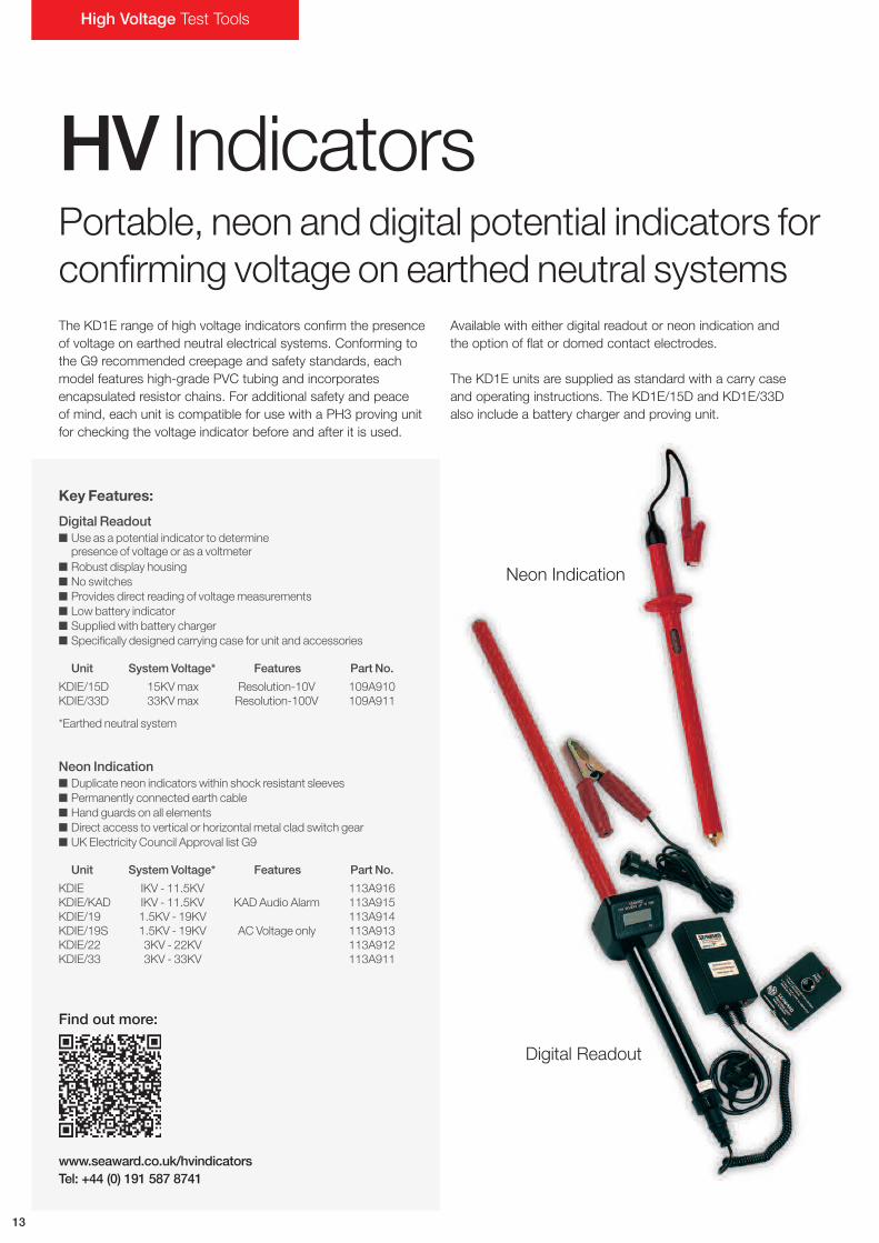
HV IndicatorsPortable, neon and digital potential indicators forconfirming voltage on earthed neutral systemsThe KD1E range of high voltage indicators confirm the presenceof voltage on earthed neutral electrical systems. Conforming tothe G9 recommended creepage and safety standards, eachmodel features high-grade PVC tubing and incorporatesencapsulated resistor chains. For additional safety and peaceof mind, each unit is compatible for use with a PH3 proving unitfor checking the voltage indicator before and after it is used.
Available with either digital readout or neon indication andthe option of flat or domed contact electrodes.
The KD1E units are supplied as standard with a carry caseand operating instructions. The KD1E/15D and KD1E/33Dalso include a battery charger and proving unit.
Key Features:
Digital Readout Use as a potential indicator to determine
presence of voltage or as a voltmeter Robust display housing No switches Provides direct reading of voltagemeasurements Low battery indicator Supplied with battery charger Specifically designed carrying case for unit and accessories
Unit System Voltage* Features Part No.
KDIE/15D 15KVmax Resolution-10V 109A910KDIE/33D 33KVmax Resolution-100V 109A911
*Earthed neutral system
Neon Indication Duplicate neon indicators within shock resistant sleeves Permanently connected earth cable Hand guards on all elements Direct access to vertical or horizontal metal clad switch gear UK Electricity Council Approval list G9
Unit System Voltage* Features Part No.
KDIE IKV - 11.5KV 113A916KDIE/KAD IKV - 11.5KV KAD Audio Alarm 113A915KDIE/19 1.5KV - 19KV 113A914KDIE/19S 1.5KV - 19KV AC Voltage only 113A913KDIE/22 3KV - 22KV 113A912KDIE/33 3KV - 33KV 113A911
Neon Indication
Digital Readout
14
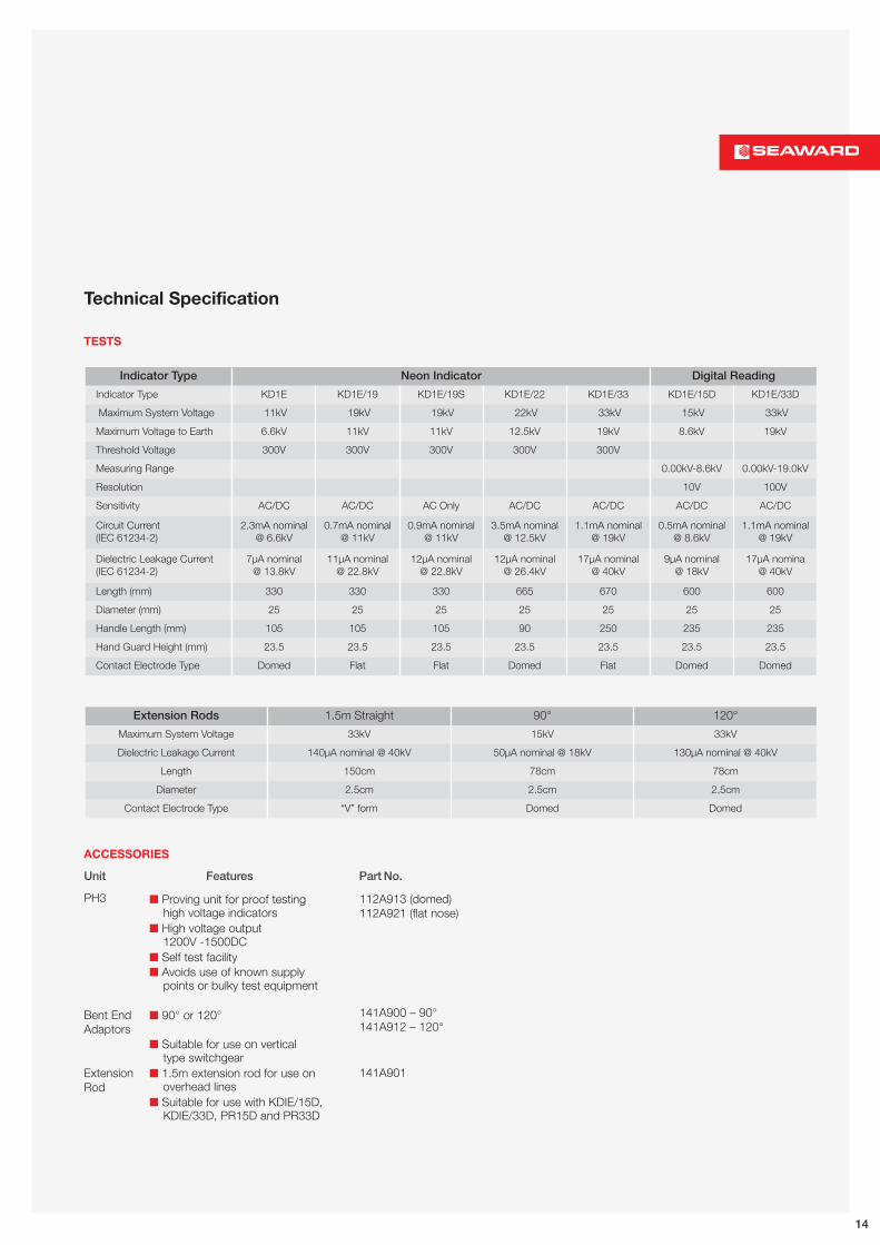
Technical Specification
TESTS
Indicator Type Neon Indicator Digital Reading
Indicator Type KD1E KD1E/19 KD1E/19S KD1E/22 KD1E/33 KD1E/15D KD1E/33D
Maximum System Voltage 11kV 19kV 19kV 22kV 33kV 15kV 33kV
Maximum Voltage to Earth 6.6kV 11kV 11kV 12.5kV 19kV 8.6kV 19kV
Threshold Voltage 300V 300V 300V 300V 300V
Measuring Range 0.00kV-8.6kV 0.00kV-19.0kV
Resolution 10V 100V
Sensitivity AC/DC AC/DC AC Only AC/DC AC/DC AC/DC AC/DC
Circuit Current(IEC 61234-2)
2.3mA nominal@ 6.6kV
0.7mA nominal@ 11kV
0.9mA nominal@ 11kV
3.5mA nominal@ 12.5kV
1.1mA nominal@ 19kV
0.5mA nominal@ 8.6kV
1.1mA nominal@ 19kV
Dielectric Leakage Current(IEC 61234-2)
7µA nominal@ 13.8kV
11µA nominal@ 22.8kV
12µA nominal@ 22.8kV
12µA nominal@ 26.4kV
17µA nominal@ 40kV
9µA nominal@ 18kV
17µA nomina@ 40kV
Length (mm) 330 330 330 665 670 600 600
Diameter (mm) 25 25 25 25 25 25 25
Handle Length (mm) 105 105 105 90 250 235 235
Hand Guard Height (mm) 23.5 23.5 23.5 23.5 23.5 23.5 23.5
Contact Electrode Type Domed Flat Flat Domed Flat Domed Domed
Extension Rods 1.5m Straight 90° 120°
Maximum System Voltage 33kV 15kV 33kV
Dielectric Leakage Current 140µA nominal @ 40kV 50µA nominal @ 18kV 130µA nominal @ 40kV
Length 150cm 78cm 78cm
Diameter 2.5cm 2.5cm 2.5cm
Contact Electrode Type “V” form Domed Domed
ACCESSORIES
Unit Features Part No.
Proving unit for proof testinghigh voltage indicators
High voltage output1200V -1500DC
Self test facility Avoids use of known supply
points or bulky test equipment
90° or 120°
Suitable for use on verticaltype switchgear
1.5m extension rod for use onoverhead lines
Suitable for use with KDIE/15D,KDIE/33D, PR15D and PR33D
PH3
Bent EndAdaptors
ExtensionRod
112A913 (domed)112A921 (flat nose)
141A900 – 90°141A912 – 120°
141A901

High Voltage Test Tools
HVPhasingUnitsPhasing rods for use on systems up to3kV, 11kV or 15kV
Key Features:
PR15D / PR33D Provides ameans of phase angle comparison and indication
of phase angle voltage at the point of intended paralleling oftwo circuits on neutral earthed systems. Both units aredigital instruments
Chart provides ameans of checking phase angle differenceof circuits paralleled
Kit comprises two elements with resistor chains, one withdigital indicator and the second a phasing rod
Unit Voltage* Features Part No.
PR15D 15kVmax Resolution-10V 109A912PR33D 33kVmax Resolution-100V 109A913
*Earthed neutral system
PR11 For use on 1kV to 11.5kV systems PVC hand guards on handles of elements Neon indicator enclosed in shock resistant sleeve Direct areas possible to all types of switch gear Complies with UK Electricity Council Engineering
recommendation G9
Part No: 113A910
The PR11 provides a means of phase comparison at the pointof paralleling two circuits, without the interposition of voltagetransformers or secondary wiring earthed neutral systems.A neon type instrument, it is designed for use on earthedneutral systems up to 11kV. It is supplied as standard witha carry case and operating instructions.
The PR15D / PR33D units enable phase angle comparison onearthed neutral systems up to 15KV and 33KV respectively.
The digital reading instruments provide voltage measurementsand are supplied with a detachable earth lead, allowing thedigital leg to be used as a voltage indicator, independentlyfrom the phasing leg.
The PR15D and PR33D are supplied as standard with a PH3proving unit, PSU100 battery charger, 2 x 1.5m straightextension rod, 3m earth lead and a carry case.
PR11
PR15D/PR33D
15
www.seaward.co.uk/phasingunitsTel: +44 (0) 191 587 8741
Find out more:
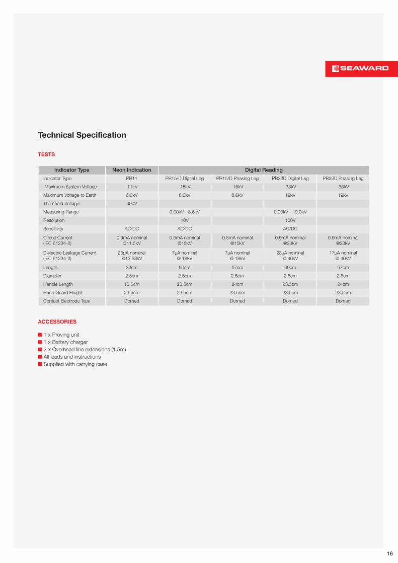
Technical Specification
TESTS
ACCESSORIES
Indicator Type Neon Indication Digital Reading
Indicator Type PR11 PR15/D Digital Leg PR15/D Phasing Leg PR33D Digital Leg PR33D Phasing Leg
Maximum System Voltage 11kV 15kV 15kV 33kV 33kV
Maximum Voltage to Earth 6.6kV 8.6kV 8.6kV 19kV 19kV
Threshold Voltage 300V
Measuring Range 0.00kV - 8.6kV 0.00kV - 19.0kV
Resolution 10V 100V
Sensitivity AC/DC AC/DC AC/DC
Circuit Current(IEC 61234-2)
0.9mA [email protected]
0.5mA nominal@15kV
0.5mA nominal@15kV
0.9mA nominal@33kV
0.9mA nominal@33kV
Dielectric Leakage Current(IEC 61234-2)
25µA [email protected]
7µA nominal@ 18kV
7µA nominal@ 18kV
23µA nominal@ 40kV
17µA nominal@ 40kV
Length 33cm 60cm 67cm 60cm 67cm
Diameter 2.5cm 2.5cm 2.5cm 2.5cm 2.5cm
Handle Length 10.5cm 23.5cm 24cm 23.5cm 24cm
Hand Guard Height 23.5cm 23.5cm 23.5cm 23.5cm 23.5cm
Contact Electrode Type Domed Domed Domed Domed Domed
1 x Proving unit 1 x Battery charger 2 x Overhead line extensions (1.5m) All leads and instructions Supplied with carrying case
16
www.seaward.co.uk/halohookTel: +44 (0) 191 587 8741
Find out more:
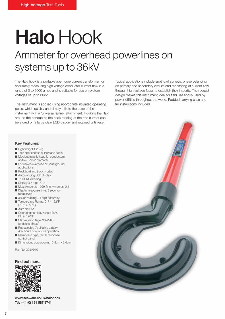
HaloHookAmmeter for overhead powerlines onsystems up to 36kVThe Halo hook is a portable open core current transformer foraccurately measuring high voltage conductor current flow in arange of 0 to 2000 amps and is suitable for use on systemvoltages of up to 36kV.
The instrument is applied using appropriate insulated operatingpoles, which quickly and simply affix to the base of theinstrument with a ‘universal spline’ attachment. Hooking the Haloaround the conductor, the peak reading of the rms current canbe stored on a large clear LCD display and retained until reset.
Typical applications include spot load surveys, phase balancingon primary and secondary circuits and monitoring of current flowthrough high voltage fuses to establish their integrity. The ruggeddesign makes this instrument ideal for field use and is used bypower utilities throughout the world. Padded carrying case andfull instructions included.
Key Features: Lightweight 1.28 kg Take spot checks quickly and easily Moulded plastic head for conductors
up to 5.8cm in diameter For use on overhead or underground
applications Peak hold and trackmodes Auto-ranging LCD display True RMS reading Display 3.5 digit LCD Max. Amperes: 1999 Min. Amperes: 0.1 Display response time: 3 seconds
to full scale 3% off reading ± 1 digit accuracy: Temperature Range: 0°F – 122°F
(-18°C - 50°C) Auto shut off Operating humidity range: 80%
RH at 120°F Maximum voltage: 36kV AC
(phase to phase) Replaceable 9V alkaline battery -
40+ hours continuous operation Membrane type, tactile response
control panel Dimensions core opening: 5.8cm x 9.4cm
Part No: 205A910
High Voltage Test Tools
17

www.seaward.co.uk/typelplusTel: +44 (0) 191 587 8741
Find out more:
TypeLPlusLarge jaw clampmeter with continuousreadout and store functionThe lightweight Type L Plus large jaw current clamp meter isdesigned for the measurement of current in large diameterconductors and fuses. Its 100mm jaw opening allows for usein most difficult situations, and is suitable for porcelain fusecarriers in distribution systems.
It has high levels of insulation providing maximum safetyand protection to the user. It has a measurement range of0A to 2000A and values are shown on the large 3.5 digitLCD display.
The unit is easily controlled with two functional buttons and anOFF button. The TRACK button enables a continuous readout,whilst STORE holds the current value by freezing the display,making it ideally suited for monitoring maximum demand inelectrical distribution networks.
It is supplied as standard with a carry case and operatinginstructions.
Key Features: 3.5” digit LCD display with
1.2cm high characters 0 – 2000 ampsmeasurement range 50 – 600 volts AC 50 HZ voltage range 10cm x 14cm internal jaw dimensions 0°C - +40°C operating temperature range - 20°C - +°C storage range 9 volt PP3 IEC number 6LF22 battery 3% accuracy of full scale on all ranges
for a conductor positioned at the centreof the jaws
Part No: 275A910
18
www.seaward.co.uk/sdr11Tel: +44 (0) 191 587 8741
Find out more:
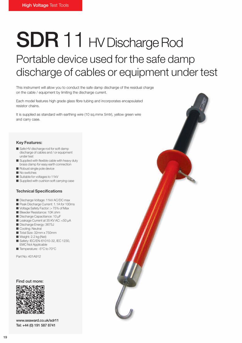
Key Features: Safe HV discharge rod for soft damp
discharge of cables and / or equipmentunder test
Supplied with flexible cable with heavy dutybrass clamp for easy earth connection
Robust single pole device No switches Suitable for voltages to 11kV Supplied with cushion soft carrying case
Technical Specifications
Discharge Voltage: 11kV AC/DCmax Peak Discharge Current: 1.1A for 100ms Voltage Safety Factor: > 75% of Max Bleeder Resistance: 10K ohm Discharge Capacitance: 10 µF Leakage Current at 35 KV AC: <50 µA Discharge Energy: 3675J Cooling: Neutral Total Size: 32mm x 750mm Weight: 2.2 kg (Net) Safety: IEC/EN-61010-32, IEC 1230,
EMCNot Applicable Temperature: -5°C to 70°C
Part No: 401A912
High Voltage Test Tools
19
SDR11 HVDischargeRodPortable device used for the safe dampdischarge of cables or equipment under testThis instrument will allow you to conduct the safe damp discharge of the residual chargeon the cable / equipment by limiting the discharge current.
Each model features high grade glass fibre tubing and incorporates encapsulatedresistor chains.
It is supplied as standard with earthing wire (10 sq.mmx 5mtr), yellow green wireand carry case.
www.seaward.co.uk/sdr35Tel: +44 (0) 191 587 8741
Find out more:
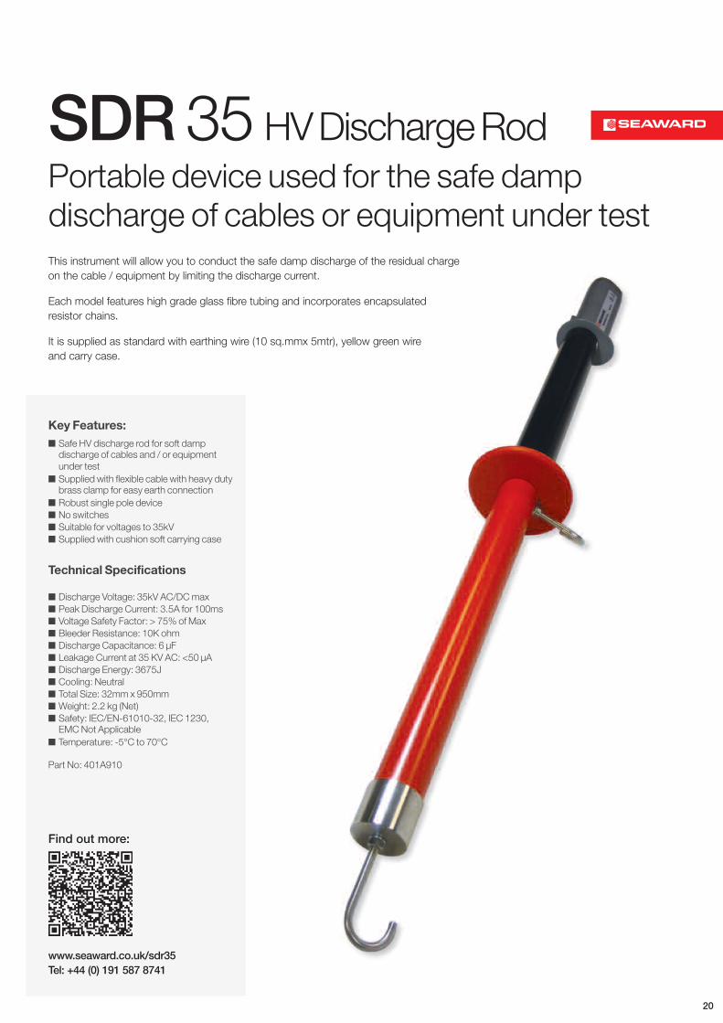
Key Features: Safe HV discharge rod for soft damp
discharge of cables and / or equipmentunder test
Supplied with flexible cable with heavy dutybrass clamp for easy earth connection
Robust single pole device No switches Suitable for voltages to 35kV Supplied with cushion soft carrying case
Technical Specifications
Discharge Voltage: 35kV AC/DCmax Peak Discharge Current: 3.5A for 100ms Voltage Safety Factor: > 75% of Max Bleeder Resistance: 10K ohm Discharge Capacitance: 6 µF Leakage Current at 35 KV AC: <50 µA Discharge Energy: 3675J Cooling: Neutral Total Size: 32mm x 950mm Weight: 2.2 kg (Net) Safety: IEC/EN-61010-32, IEC 1230,
EMCNot Applicable Temperature: -5°C to 70°C
Part No: 401A910
SDR35 HVDischargeRodPortable device used for the safe dampdischarge of cables or equipment under testThis instrument will allow you to conduct the safe damp discharge of the residual chargeon the cable / equipment by limiting the discharge current.
Each model features high grade glass fibre tubing and incorporates encapsulatedresistor chains.
It is supplied as standard with earthing wire (10 sq.mmx 5mtr), yellow green wireand carry case.
20
www.seaward.co.uk/agl5Tel: +44 (0) 191 587 8741
Find out more:
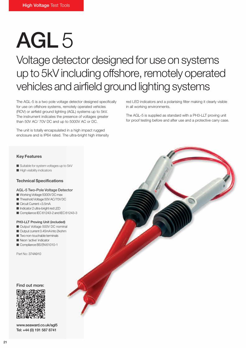
AGL5Voltagedetector designed for useon systemsup to5kV includingoffshore, remotely operatedvehicles andairfield ground lighting systemsThe AGL-5 is a two pole voltage detector designed specificallyfor use on offshore systems, remotely operated vehicles(ROV) or airfield ground lighting (AGL) systems up to 5kV.The instrument indicates the presence of voltages greaterthan 50V AC/ 70V DC and up to 5000V AC or DC.
The unit is totally encapsulated in a high impact ruggedenclosure and is IP64 rated. The ultra-bright high intensity
red LED indicators and a polarising filter making it clearly visiblein all working environments.
The AGL-5 is supplied as standard with a PH3-LLT proving unitfor proof testing before and after use and a protective carry case.
Key Features
Suitable for system voltages up to 5kV High visibility indicators
Technical Specifications
AGL-5 Two-Pole Voltage Detector WorkingVoltage5000VDCmax ThresholdVoltage50VAC/70VDC Circuit Current <3.5mA Indicator 2 ultra-bright redLED Compliance IEC61243-2 and IEC61243-3
PH3-LLT Proving Unit (included) Output Voltage 500V DC nominal Output current 0.45mA into 2kohm Twonon-touchable terminals Neon ‘active’ indicator ComplianceBSEN61010-1
Part No: 374A910
High Voltage Test Tools
21
www.seaward.co.uk/lltTel: +44 (0) 191 587 8741
Find out more:
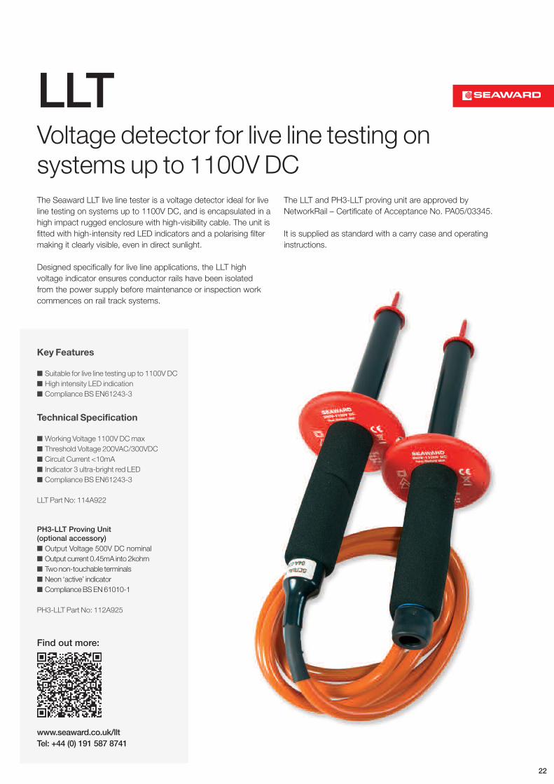
LLTVoltage detector for live line testing onsystems up to 1100V DCThe Seaward LLT live line tester is a voltage detector ideal for liveline testing on systems up to 1100V DC, and is encapsulated in ahigh impact rugged enclosure with high-visibility cable. The unit isfitted with high-intensity red LED indicators and a polarising filtermaking it clearly visible, even in direct sunlight.
Designed specifically for live line applications, the LLT highvoltage indicator ensures conductor rails have been isolatedfrom the power supply before maintenance or inspection workcommences on rail track systems.
The LLT and PH3-LLT proving unit are approved byNetworkRail – Certificate of Acceptance No. PA05/03345.
It is supplied as standard with a carry case and operatinginstructions.
Key Features
Suitable for live line testing up to 1100V DC High intensity LED indication Compliance BS EN61243-3
Technical Specification
Working Voltage 1100V DCmax Threshold Voltage 200VAC/300VDC Circuit Current <10mA Indicator 3 ultra-bright red LED Compliance BS EN61243-3
LLT Part No: 114A922
PH3-LLT Proving Unit(optional accessory) Output Voltage 500V DC nominal Output current 0.45mA into 2kohm Twonon-touchable terminals Neon ‘active’ indicator ComplianceBSEN61010-1
PH3-LLT Part No: 112A925
22
www.seaward.co.uk/provingunitsTel: +44 (0) 191 587 8741
Find out more:
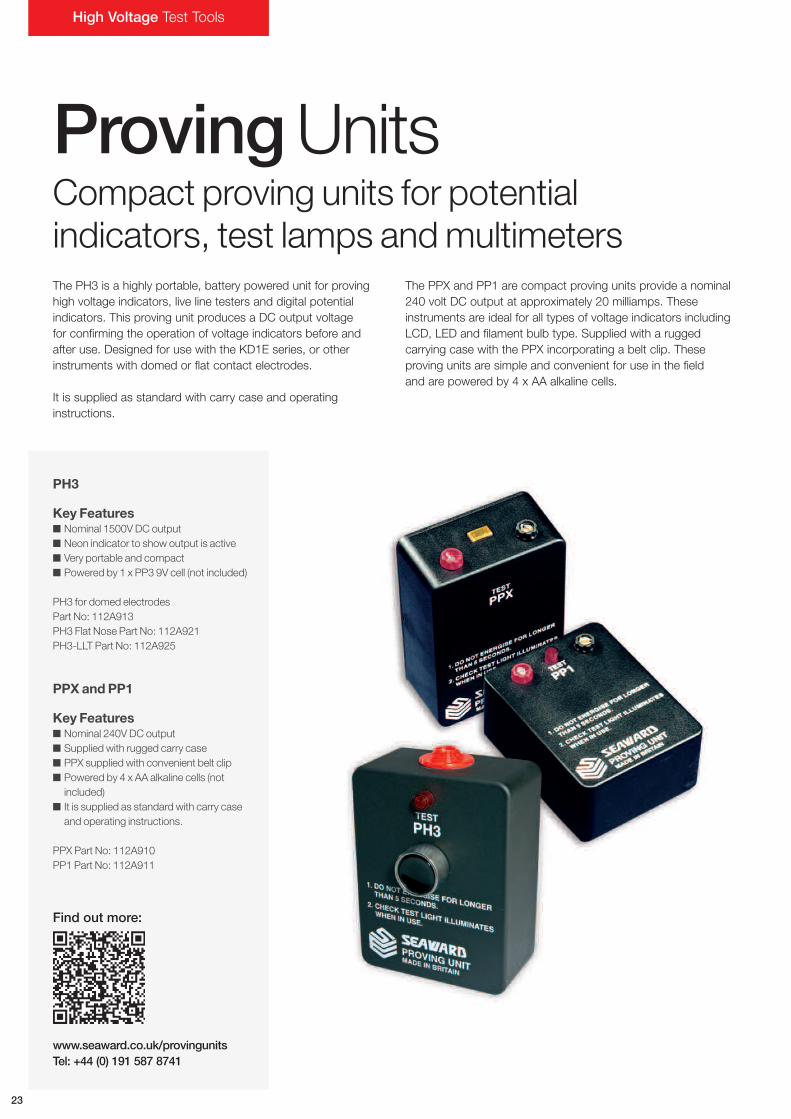
ProvingUnitsCompact proving units for potentialindicators, test lamps andmultimetersThe PH3 is a highly portable, battery powered unit for provinghigh voltage indicators, live line testers and digital potentialindicators. This proving unit produces a DC output voltagefor confirming the operation of voltage indicators before andafter use. Designed for use with the KD1E series, or otherinstruments with domed or flat contact electrodes.
It is supplied as standard with carry case and operatinginstructions.
The PPX and PP1 are compact proving units provide a nominal240 volt DC output at approximately 20 milliamps. Theseinstruments are ideal for all types of voltage indicators includingLCD, LED and filament bulb type. Supplied with a ruggedcarrying case with the PPX incorporating a belt clip. Theseproving units are simple and convenient for use in the fieldand are powered by 4 x AA alkaline cells.
PH3
Key Features Nominal 1500V DC output Neon indicator to show output is active Very portable and compact Powered by 1 x PP3 9V cell (not included)
PH3 for domed electrodesPart No: 112A913PH3 Flat Nose Part No: 112A921PH3-LLT Part No: 112A925
PPX and PP1
Key Features Nominal 240V DC output Supplied with rugged carry case PPX supplied with convenient belt clip Powered by 4 x AA alkaline cells (not
included) It is supplied as standard with carry case
and operating instructions.
PPX Part No: 112A910PP1 Part No: 112A911
23
High Voltage Test Tools

24
World LeadingElectricalTest SolutionsSeaward Group provides electrical test and measurement instruments and services. Our products meet the demands of all types ofsafety legislation and standards. We are an international market leader in a number of highly technical market sectors. We pride ourselveson high quality product design and manufacturing.
We believe in putting you, the international customer, at the heart of everything we do. Our multi-lingual customer services department,overseas technical support centres and global distribution network all help us to excel.
Rigel Medical, a Seaward Group company, currently holds The Queen’s Award for Enterprise, one of the most prestigious awards thata UK-based company can achieve.
Seaward Clare Cropico Rigel Solar Calibrationhouse
PAT, installation andhigh voltage testand measurement
solutions
www.seaward.co.uk
Test solutionsfor electrical
manufacturers andhire companies
www.clare.co.uk
High precisionresistance andtemperaturemeasurementinstruments
www.cropico.com
Advanced solutionsfor testing biomedical
equipment
www.rigelmedical.com
Safe, efficienttest solutions for PV
installers
www.seawardsolar.com
Taking care of your testand measurement
equipment
www.calibrationhouse.com
Our six brands operate to the same high standards; innovating and enhancing electrical safety testing in their individual markets.
www.seaward-group.com

Seaward, Bracken Hill, South West Industrial Estate,Peterlee, County Durham, SR8 2SW United Kingdom
Tel: +44 (0) 191 586 3511 Fax: +44 (0) 191 586 0227Email: [email protected] Web: www.seaward.co.uk
l@SeawardGroup iFind Seaward Group on Linkedin
Rev 1