Embed Size (px)
DESCRIPTION
This session will cover concepts behind Solid Edge’s simulation capabilities, that which is included in standard Solid Edge along with the advanced features available with Solid Edge Premium. This session is targeted toward designers and engineers who need an overview of simulation functionality. Key topics will include simulation options, setting up simulation studies, model preparation, the application of boundary conditions including forces and constraints, meshing, solving, and examining results. Additional topics will include the new features available in Solid Edge ST5. Examples of various component types will be presented and will include “thick” parts, sheet metal parts, and assemblies. Anyone interested in learning about Solid Edge’s engineering analysis capabilities should attend this session.
Citation preview
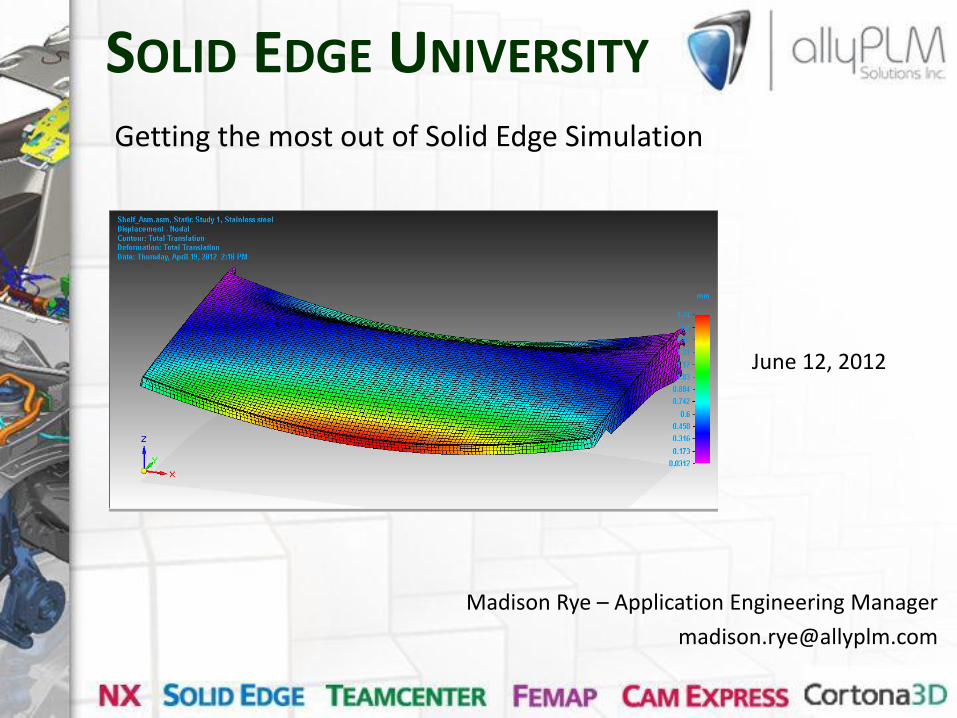
Madison Rye – Application Engineering Manager
SOLID EDGE UNIVERSITY
June 12, 2012
Getting the most out of Solid Edge Simulation

• HQ: Cincinnati
• Software – Design
– Manufacturing
– Analysis
– Data Management
• Services – Training
– Support
– Mentoring
Ally PLM Solutions
Cincinnati
Pittsburgh
Philadelphia
St. Louis

Agenda
• Intro
• Analysis Steps
• Structural Demo
• Modal Demo
• Thermal Demo
• Results Validation/Verification

Scalable Simulation capabilities Full range of applications for all user levels
Solid Edge Simulation Express
Embedded in Solid Edge
Part validation
Statics / Modal
NX Nastran Solver
Multi-discipline engineer
Solid Edge Simulation
Embedded in Solid Edge
Part / Assembly validation
Statics / Modal / Buckling
NX Nastran Solver
Multi-discipline engineer
Femap
CAD independent
System simulation
Statics, Modal, Buckling, Dynamics, Heat transfer, non-linear, more...
Solver independent, NX Nastran
Multi-discipline engineer, Analyst
Problem Complexity
Use
r

Simulation Steps
• Problem description
• Simplification
• Preprocessing
• Solving
• Post-Processing
• Results verification

• Design Engineer • Someone that splits time between Design and Analysis • Not a dedicated analyst – this is the domain of Femap • Often the “super designer” being asked to do more, faster
• Geometry Focused – Designers work with geometry, not nodes
• Process Oriented – Wizards or commands that step you through
• Synchronous – Easy geometry modification for analysis
• Built in Solver – SE Simulation uses NX Nastran
Vision for Solid Edge Simulation

• Integrated with Solid Edge • Familiar user interface backed by Femap Technology • Assembly Support • Full Complement of Loads and Constraints • Seamlessly Upgradeable from SE Simulation Femap • Custom Control of NX Nastran Solve • Extensive Post Processing and Report Generation • Easy Geometry modification using Synchronous modeling • Linear Statics, Modal, Buckling • Tetrahedral and Surface elements • Mesh Control
Benefits of Simulation

• Total Load Option • Reduce Time for Processing Results • United Bodies supports Manifold Topology • Meshing Improvements Integration • Display Mesh Size • Beam Support of Curved Frames • Results Display of Mixed and Shell Elements • Results “Show” Group • Plate Thickness
New in ST5 Simulation

• Steady State Heat Transfer Overview • Steady State/Transient • Conduction/Convection/Radiation • Pre-processing Interface • Temperature Load • Heat Flux Load • Heat Generation Load • Convection Load • Radiation Load • Iso Lines and Surfaces • Map Results from Output
New in ST5 Simulation

• Linear Static
• Modal
• Thermal
Demos

• Use Simulation early in the design process
• Reduce physical prototypes
• Compare many different designs easily
• Carefully consider the simplifications
• Validate results
Summary and Questions