Embed Size (px)
Citation preview

SHERLOG CRXFault Recorder and Power
Quality Measuring System
SH
ER
LO
G C
RX
_E
NG
_2
01
20
8

SHERLOG CRX
Digital fault recording
Fault location
Disturbance recording
Continuous recording
Power quality monitoring
Event recording
Synchrophasor measurement
Sequence of event recording
Real-time monitoring
Overview of Applications
Front and Back View
Device Structure and Modules

Power supply units
CPU module
Relays module
Analog and binary inputs
Interface module FO
Synchronisation module
Modules
Device Structure and Modules

Power Supply Units
Device Structure and Modules
Power supply units

Wide-range power supply unit
(85-265 V 45-65Hz / 90-350 VDC)
DC power supply units
9…18 VDC
18…36 VDC
36...72 VDC
Power supply module
Power Supply Units
Device Structure and Modules
Properties
LED status display
Potential-free monitoring contact
E-mail alert in case of power failure
Built-in, maintenance-free UPS
Redundant operation with 2 independent
power supply modules

CPU module
Relays module
Basic Device
Device Structure and Modules

CPU module
DSP-processor for real-time signal processing
2 GB flash data memory
NTP / SNTP time synchronisation
Interfaces
Ethernet (RJ45)
RS 232
RS 485
USB (Host)
KoCoS-Interlink interface for networking a number of SHERLOGs
CPU Module
Device Structure and Modules

Relays module
For output and indication of alarm and status signals
8 potential-free relay contacts
2 electronic relay outputs
NC/NO configurable
Configurable functions
Switching capacity up to 300V / 8A / 50W
Relays Module with 8 Switching Outputs
Device Structure and Modules

Option: FO interface module
Option: synchronisation module
Device Options
Device Structure and Modules

FO interface module
Additional Ethernet interface (RJ45)
Optical Ethernet interface (ST II)
Optical KoCoS-Interlink interface
Fibre-optic loop for
cross-triggering and
time synchronisation
FO Interface Module
Device Structure and Modules
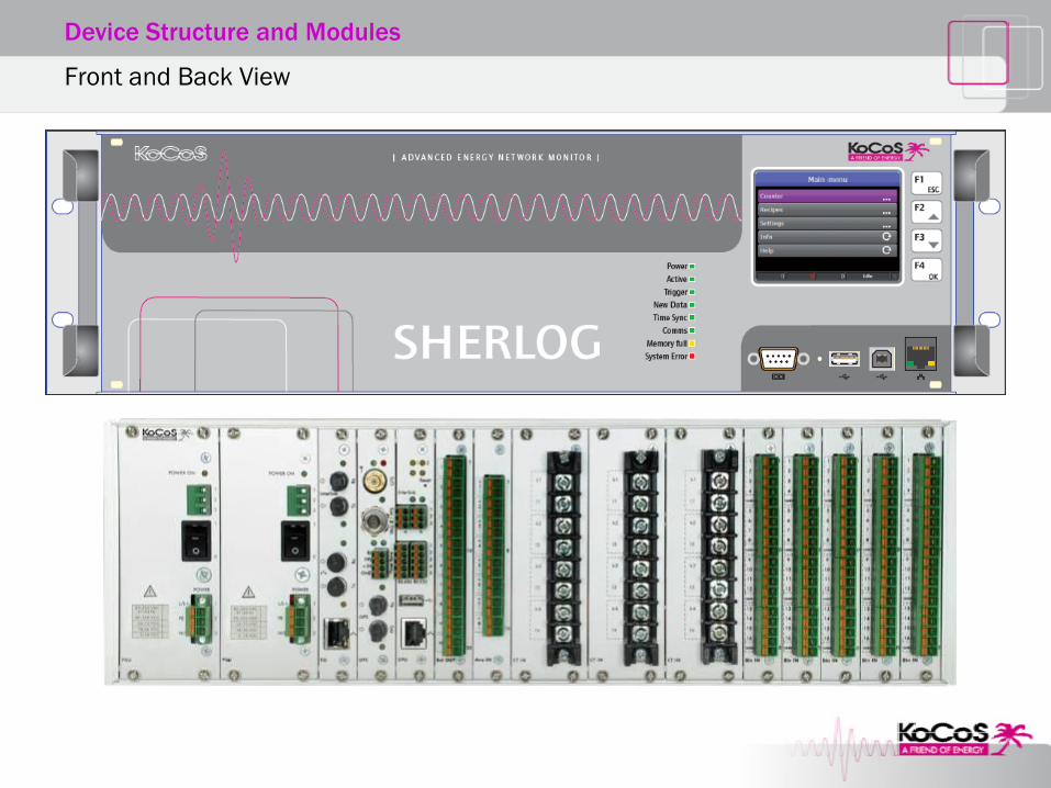
Synchronisation module
Internal GPS receiver
Optical and electrical input for external GPS clocks
IRIG-B input
DCF-77 input
Seconds and minutes pulse input (pps/ppm)
Synchronisation Module
Device Structure and Modules

Externe GPS Uhr
GPS
Antenne
GPS
Antenne
DCF 77
Antenne
Glasfaser Leitung
4-Draht Leitung
Legende
2-Draht Leitung
Coaxial Leitung
Ethernet
Interner GPS
Empfänger
Glasfaser
GPS Eingang
Interner DCF 77
Empfänger
NMEA RMC
PPS/PPM
Elektrischer
GPS Eingang
NMEA RMC
PPS/PPM
SHERLOG
Interlink
Zeitsync.Datum/Zeit/PPS
CrosstriggerKriterium/Quelle
SH
ER
LO
G C
RX
IRIG-B Eingang
NTP/SNTP
Sta
nd
ard
Op
tio
na
les S
yn
ch
ron
isa
tio
nsm
od
ul
Interner GPS
Empfänger
Glasfaser
GPS Eingang
Interner DCF 77
Empfänger
NMEA RMC
PPS/PPM
Elektrischer
GPS Eingang
NMEA RMC
PPS/PPM
SHERLOG
Interlink
Zeitsync.Datum/Zeit/PPS
CrosstriggerKriterium/Quelle
SH
ER
LO
G C
RX
IRIG-B Eingang
NTP/SNTP
Sta
nd
ard
Op
tio
na
les S
yn
ch
ron
isa
tio
nsm
od
ul
Interner GPS
Empfänger
Glasfaser
GPS Eingang
Interner DCF 77
Empfänger
NMEA RMC
PPS/PPM
Elektrischer
GPS Eingang
NMEA RMC
PPS/PPM
SHERLOG
Interlink
Zeitsync.Datum/Zeit/PPS
CrosstriggerKriterium/Quelle
SH
ER
LO
G C
RX
IRIG-B Eingang
NTP/SNTP
Sta
nd
ard
Op
tio
na
les S
yn
ch
ron
isa
tio
nsm
od
ul
SHERLOG
Interlink
Zeitsync.Datum/Zeit/PPS
CrosstriggerKriterum/Quelle
NTP/SNTP
Op
tio
na
l
SH
E
SHERLOG
Interlink
Zeitsync.Datum/Zeit/PPS
CrosstriggerKriterum/Quelle
NTP/SNTP
Op
tio
na
l
SH
E
SHERLOG
Interlink
Zeitsync.Datum/Zeit/PPS
CrosstriggerKriterum/Quelle
NTP/SNTP
Op
tio
na
l
SH
E
Zweidraht-Bus
Glasfaser-Ring
zu weiteren SHERLOGs
Example of Application – Time Synchronisation and Interlink interface
Device Structure and Modules

Analog and Binary Inputs
Device Structure and Modules
12 slots for
analog and binary inputs

8-channel universal module
8 galvanically isolated analog inputs
4 selectable measuring ranges per input
Analog Module with 8 Universal Inputs
Device Structure and Modules
Measuring ranges:
300 V
700 mV
200 mV
20 mA
R R R R
k1 l1 k2 l2 k3 l3 k4 l4
X1 X2 X3 X4 X5 X6 X7 X8
L1
L2
L3
N
PE
k l
K L
k l
K L
k l
K L
k l
K L
SHERLOG CRX Analogmodul mit 8 Universaleingängen
U1 U2 U3 UEN I1 INI2 I3
1+ 1- 2+ 2- 3+ 3- 4+ 4- 5+ 5- 6+ 6- 7+ 7- 8+ 8-
Device Structure and Modules
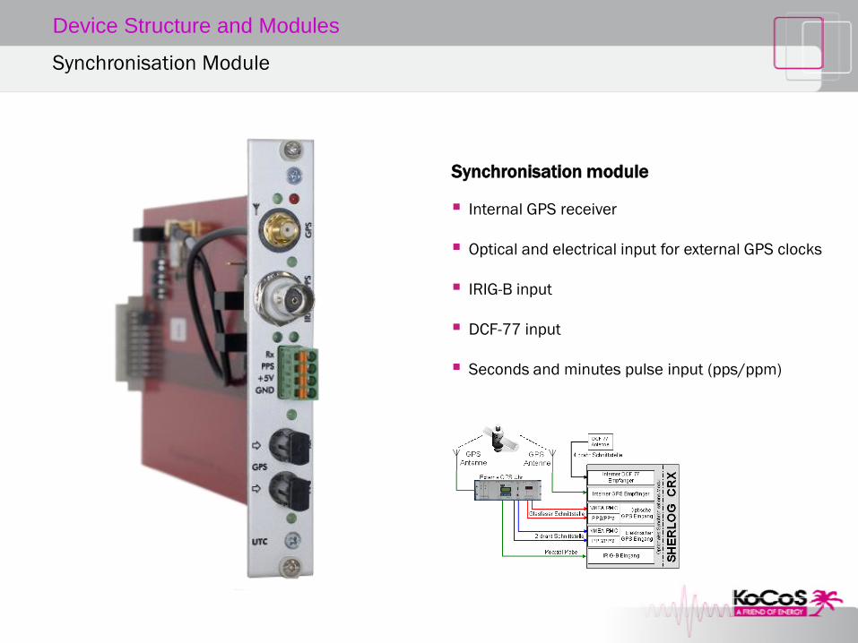
Analog Module with 8 Universal Inputs – Example of Application

4-channel current module
4 high-current inputs
3 selectable measuring ranges per input
Analog Module with 4 Current Inputs
Device Structure and Modules
Measuring ranges:
10 A
40 A
200 A

L2
L3
N
PE
k l
K L
k l
K L
k l
K L
k l
K L
SHERLOG CRX Analogmodul mit 4 Hochstromeingängen
I1 INI2 I3
k1 I1 k2 i2 k3 i3 k4 i4
Device Structure and Modules
Analog Module with 4 Current Inputs – Example of Application

Features
A/D converter and calibration data on board
Digital signal output
Modules can be replaced without calibration
Analog Modules – Common Features
Device Structure and Modules
Switchable measuring ranges
No different variants
Simple stock and spare parts management
200 kHz sampling frequency per channel
High-quality components for high measurement
accuracy and temperature stability
Recommended calibration cycle: 5 years

Binary module
For acquisition of protection commands,
switching status and status signals
16 binary inputs per module
Max. 128 binary inputs per device
Activation range from 24 V to 300V DC
Resolution 0.1 ms
Groups of 4 inputs with a common reference point
(GND)
Easier to use and to wire
4 different potentials possible per module
Binary Module with 16 Inputs
Device Structure and Modules

Binary Module with 16 Inputs
Device Structure and Modules

Device Structure and Modules
Examples of Configuration

Concept
SHERLOG Operating Software
Features
All applications in one software package
Configuration of the measuring system
Automatic device and data handling
Evaluation and report creation
Maintenance and commissioning tools
Clearly designed user interface
Can be operated intuitively
Short familiarisation period
Enables users to work effectively

Concept
SHERLOG Operating Software
Parameterisation
Graphical parameterisation of measurement signals
Bus bars
Lines
Transformation ratios
Fault location parameters

Concept
SHERLOG Operating Software
Device management
Well structured device management sorted by
Region
Measurement location
Voltage level
Bay

Concept
SHERLOG Operating Software
Evaluation
Evaluation of power system faults
Graphical view of the fault characteristic
Vector analysis
Harmonic analysis
Nyquist plots
Formula editor for mathematical signal analysis
Typification of power system faults
Automatic fault location
Generation of fault reports
Data export for third party systems

Licence Model
SHERLOG Operating Software
Software concept
A single software package for all applications
No need for optional software modules
No sales advice required
Quick and easy offer creation
Licence model
One software licence per PC workstation
Licence packages for more than one workstation
Clear and unambiguous
Cost effective for companies of all sizes

Licence Model
SHERLOG Operating Software
Licence packages available for:
one PC workstation
5 PC workstations
15 PC workstations

Device Structure and Modules
Standard Offer
Quantity Name Art. No. Optional Accessories Notes
1 SHERLOG CRX Basic Device 11675 Always required
1 or 2 Power Supply Unit 85…265VAC / 90…350 VDC
11676 1 power supply always required
Up to 2 power supply units can be combined as required in each SHERLOG CRX
Alternative Power Supply Unit 9…18 VDC 11690
Alternative Power Supply Unit 18…36 VDC 11691
Alternative Power Supply Unit 36…72 VDC 11692
Analog and Binary Inputs (max. 12 module slots, max. 32 analog inputs, max. 6 analog modules)
1 or > Analog Module with 8 Universal Inputs 11682 - AC/DC current sensor- AC current sensor
At least one required (max. 4 modules)
1 or > Analog Module with 4 Current Inputs 11683 max. 4 modules
1 or > Binary Module with 16 Inputs 11686 max. 8 modules
Device Options
1 FO Interface Module 11684 Fibre-optic interfaces
1 Synchronisation Module 11678 - GPS antenna- DCF 77- antenna
Time synchronisation
Software
1 or > SHERLOG Operating Software 116871168811689
Single user licenceLicence for 5 workstationsLicence for 15 workstations

How to Create an Offer
Information Required From Customer for a Detailed Offer
SHERLOG measuring instrument
Power supply to the device
Number of voltage inputs
Number of current inputs
Direct current connection
Measurement via external sensors
Number of binary inputs
Time synchronisation
NTP/SNTP
Others (GPS, DCF 77, IRIG-B)
Fibre-optic interfaces required?
SHERLOG software
Number of PC workstations

Device Structure and Modules
Offer Preparation
SHERLOG measuring instrument
Power supply to the device
Number of voltage inputs
Number of current inputs
Direct current measurement
Measurement via external sensors
Number of binary inputs
Time synchronisation
NTP/SNTP
Others (GPS, DCF 77, IRIG-B)
Fibre-optic interfaces required?
SHERLOG software
Number of PC workstations
85-265 VAC 45-65Hz / 90-350 VDC
9…18 VDC
18…36 VDC
36...72 VDC
One or two power supply modules can be selected from the list below:
Device Structure and Modules
Offer Preparation
SHERLOG measuring instrument
Power supply to the device
Number of voltage inputs
Number of current inputs
Direct current measurement
Measurement via external sensors
Number of binary inputs
Time synchronisation
NTP/SNTP
Others (GPS, DCF 77, IRIG-B)
Fibre-optic interfaces required?
SHERLOG software
Number of PC workstations
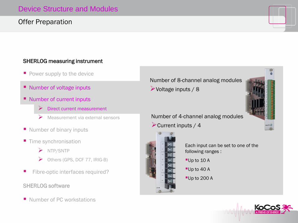
Number of 8-channel analog modules
Voltage inputs / 8
Each input can be set to one of the
following ranges :
Up to 10 A
Up to 40 A
Up to 200 A
Number of 4-channel analog modules
Current inputs / 4

Device Structure and Modules
SHERLOG measuring instrument
Power supply to the device
Number of voltage inputs
Number of current inputs
Direct current measurement
Measurement via external sensors
Number of binary inputs
Time synchronisation
NTP/SNTP
Others (GPS, DCF 77, IRIG-B)
Fibre-optic interfaces required?
SHERLOG software
Number of PC workstations
Number of 8-channel analog modules
Sum of the voltage and current inputs
Number of external current sensors
Number of current inputs / 4
Measuring range selection:
1 mOhm for measuring up to 200 A
2 mOhm for measuring up to 100 A
5 mOhm for measuring up to 40 A
10 mOhm for measuring up to 20 A
Offer Preparation

Device Structure and Modules
Offer Preparation
SHERLOG measuring instrument
Power supply to the device
Number of voltage inputs
Number of current inputs
Direct current measurement
Measurement via external sensors
Number of binary inputs
Time synchronisation
NTP/SNTP
Others (GPS, DCF 77, IRIG-B)
Fibre-optic interfaces required?
SHERLOG software
Number of PC workstations
Number of 16-channel binary modules
Number of binary inputs / 16

Device Structure and Modules
Offer Preparation
SHERLOG measuring instrument
Power supply to the device
Number of voltage inputs
Number of current inputs
Direct current measurement
Measurement via external sensors
Number of binary inputs
Time synchronisation
NTP/SNTP
Others (GPS, DCF 77, IRIG-B)
Fibre-optic interfaces required?
SHERLOG software
Number of PC workstations
Standard equipment
No additional material required

Device Structure and Modules
Offer Preparation
SHERLOG measuring instrument
Power supply to the device
Number of voltage inputs
Number of current inputs
Direct current measurement
Measurement via external sensors
Number of binary inputs
Time synchronisation
NTP/SNTP
Others (GPS, DCF 77, IRIG-B)
Fibre-optic interfaces required?
SHERLOG software
Number of PC workstations
Optional synchronisation module
Is only required for one SHERLOG per plant
Other SHERLOGs are synchronised with one another via the KoCoS–Interlink interface
Major cost savings
Info:
KoCoS-Interlink interface
Electric 2-wire interface is part of the standard scope of delivery
Max. distance between 2 SHERLOGs: 500m

Device Structure and Modules
SHERLOG measuring instrument
Power supply to the device
Number of voltage inputs
Number of current inputs
Direct current measurement
Measurement via external sensors
Number of binary inputs
Time synchronisation
NTP/SNTP
Others (GPS, DCF 77, IRIG-B)
Fibre-optic interfaces required?
SHERLOG software
Number of PC workstations
Accessories for synchronisation module
GPS antenna with magnetic base with 30m antenna lead
GPS antenna for installation on a building with surge protector and 60m antenna lead
DCF-77 antenna module
Offer Preparation

Device Structure and Modules
Offer Preparation
SHERLOG measuring instrument
Power supply to the device
Number of voltage inputs
Number of current inputs
Direct current measurement
Measurement via external sensors
Number of binary inputs
Time synchronisation
NTP/SNTP
Others (GPS, DCF 77, IRIG-B)
Fibre-optic interfaces required?
SHERLOG software
Number of PC workstations
Optional FO interface module
To connect SHERLOG to an Ethernet fibre-optic network
Fibre-optic loop for
cross-triggering and
time synchronisation
KoCoS-Interlink-Interface by fibre optic cable
Max. distance between 2 SHERLOGs: 2000m

Device Structure and Modules
Offer Preparation
SHERLOG measuring instrument
Power supply to the device
Number of voltage inputs
Number of current inputs
Direct current measurement
Measurement via external sensors
Number of binary inputs
Time synchronisation
NTP/SNTP
Others (GPS, DCF 77, IRIG-B)
Fibre-optic interfaces required?
SHERLOG software
Number of PC workstations
SHERLOG software
One licence per PC workstation required
Software packages (licence packages)
One PC workstation
5 PC workstations
15 PC workstations