Embed Size (px)
Citation preview

Mario Cesana [email protected] Camarri [email protected] Resadi [email protected]

• Acronym• System Description• Functionality• Application description• Advantages• Calculated Savings• User Interface• Junction Box• Certifications
Contents

SolarPV moduleIntegratedManagement
Patent Pending
Acronym
System Description
• SPIM is an electronic device embedded into the PVmodule Junction Box.
• This devices enables the PV module to became anintelligent entity capable to communicate in a wirelessnetwork
• Each PV module is seen in the network as a single uniquenode
• The network is driven by an external ‘master coordinator’that is controlling up to 200 PV modules.
Functionality
• Monitor and mesure the functional parameters of a every singlePV module during operations
• Enable the possibility to compare any PV module actual fieldperformances with the expected performances
• Stop the power production of any PV module in case it isremoved from its original position and reinstalled elsewere.(theft deterrent)
• Measure the production of any single PV module regardless ofthe size of the installation.
has been designed to:
Functionality
periodically checks and monitors all PV Module electrical parameters, such as: current, voltage, power and temperature. SPIM compares the measured values in the PV field Module with those specified by the manufacturer and in case of failure SPIM informs the Network Master and the customer with a message of Failure Alarm: therefore the user can obtain faster and easy maintenance.PV Module electrical parameters are stored in a database of the HOST controller; these values can be reviewed by the user in any moment and connected to the solar meter of the PV plant: therefore the customer can distinguish the performance of a PV Module from another.During the day the Master Unit automatically checks the presence and integrity of the PV plant and in case of theft gives an alarm. At the same time, the SPIM in the stolen PV Module blocks its functionality and its power supply.

Application Description
Slave device is inserted in a dedicated Junction Box and electrically connected to the PV module that controls.
The system is composed by two units:
SLAVE Device
MASTER Device
Master device is connected to an HOST system (i.e. Computer/server etc) and it is interfaced by a dedicated User Interface Software, available also as a Web Service appplication. Such a system allows the user to know in any moment the functionality and status of any single PV module in the PV plant.

Application Description: Network
BUS RS485
USB/ETH
S2 S..
S200S1
S2 S..
S200S1
S2 S..
S200S1

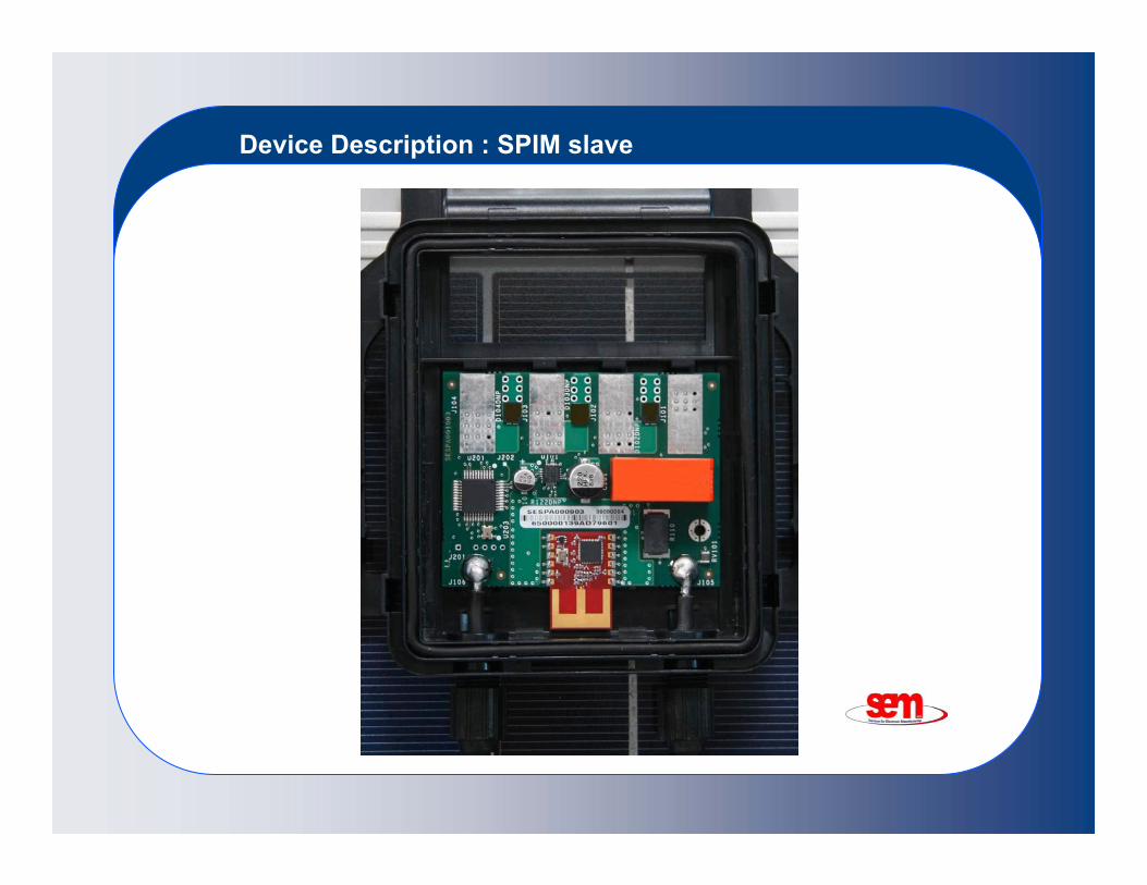
Device Description: SPIM slave
Lenght: 75 mmWidth: 80 mmHeight: 17 mmV(p): 3,3 VI(p): 50 mAPower: <1% of PV ModuleEnergy: < 0,1% of PV ModuleModule V(max): 40 V (others upon request)Module V(min): 14 VModule I(max): 9 ASystem V(max): 1000 VTemp. range: da -40°C a + 85°CEnvironment: IP 65UL: V0In Compliance with 2002/95/CEPowered by the PV module

Device Description: SPIM slave
Device Description : SPIM slave

Device Description :Spim Master
Lenght: 150 mmWidth: 110 mmHeight : 70 mmV(p): 3,3 VI(p): 50 mAPower: 220 V Ca (with ext. Pwr. Supply or other)PC interface: USB 2.0Nbr of SPIM Slave driven: 200 Temp. range: da -40°C a + 85°CEnvironment: IP 56UL: V0In Compliance with: 2002/95/CE

Device Description: SPIM master

Device Description : SPIM Master

Advantages
• No cabling needed to monitor the installation of the all solar plant.• Easy user friendly interface to manage and control the solar plantperformances
• Faster reset/ maintenance thanks to the ability to pin-point thedefective PV module very precisely in the solar plant
• Performances control down to the single PV module and ability tocompare the real actual values with those specified by themanufacturer, easy documented claim in case of failure
• Monitor of the electrical productivity at single PV module levelconnecting to the solar meter of the PV plant. This makes possible toknow and monitor in real time the energy production of the single PVmodule and of the total PV plant as well
• Thefts Deterrent thanks to the prompt inhibition of any functions of PVmodules that are removed from their original point of installation

Advantages
grants immediate savings with reduction of the reaction times to maintenance, real full
time monitoring and management of the energy production, inhibition of functionality in case of theft.

Estimated Savings
Assumed scenario:
• 1.0 Mw solar Plant• DC voltage 800 V• PV Modules 220Wp 37V Voc.• Each PV module series = 20 PV Modules =4.4 Kwp
The application of the SPIM device will virtually reduce to zero the reaction time to identify a potential failing PV module on a series and will cut down the average maintenance times in a half.
Assuming a standard defect rate of 0.1%/year on a 5000 PV modules installation we can then forecast 5 maintenance calls/year.Over a 25 year life we can in such a case forecast 125 total maintenance calls.That can be estimated in a saving of about 25 K€ or 0.025 €/Wp

Estimated Savings
SPIM can also replace the use of an ‘intelligent’ PV module series end box.That can be replaced with a simple connection device.This change has been estimated in a saving of about 33K€ or 0.033 €/Wp
Also the data transmission cabling is not needed anymore with anestimated saving of 0.0025 €/Wp
SPIM will also grant the total control in performance of the solar plant so the customer can get this figure in real time.This will give warranty on producibility. This is an estimated saving of 0.05 €/Wp
Theft deterrent, can reduce the theft insurance premium. Estimated in 0.02 €/Wp

Estimated Savings
0,13Total savings
0,02Saving on insurances
0,05Warrenty on producibility
0,0025Data transmission cabling
0,033Saving on End string boxes
0,025Saving on maintenance calls
Euro/WpSavings

User Interface
The control software designed and bundled with the Spimdevice is easy installable on any Windows based Computer. It enables the user to know in any moment the presence, conditions and functionality on any PV module installed.
The programmed monitoring checks automatically the presence and integrity of the PV plant; the electrical parameters are stored in a database and can be reviewed by the user/customer in any moment.
The device can be applied to any PV module and it is able to manage any size of solar plant.
User interface Software built in Visual Basic 6.0® and running under Windows Xp®.

User Interface

Junction Box
Dimensions: 160 x 170 x 29 mmAuto-estinguish rating: UL94-V0Protection rating: IP 65UV Rays: f1Connectors protection rating : IP 67Designed according to IEC61730
is installed into a Junction box with the following caracteristics:
Certifications
In compliance with RF standards
ETSI EN 300 328 V1.7.1 (2006-10)
ETSI EN 301 489-1: 2008
ETSI EN 301 489-17:2008
IEC 61215