Embed Size (px)
Citation preview
S I T U A T I O N
F E A T U R E S
D E S C R I P T I O N
A P P L I C AT I O N N O T E S
S I T U A T I O N
F E A T U R E S
D E S C R I P T I O N
A P P L I C AT I O N N O T E S
Contact: Sonora Design Associates 805.644.8913 www.sonoradesign.com [email protected]
Revised Sep 24 2013
DBS signals need amplifi cation to a constant level for
multiple distribution locations.
M o d e l TA M P 6 -T 2 4 i n c l u d e s p ow e r a d a p to r
PS241000A. DC power is directed to the 18 V input for
line powering of amplifi ers above. Model TAMP6-T12 includes power adaptor PS121000A.
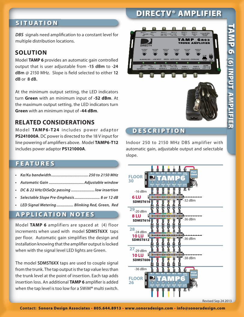
Model TAMP 6 amplif iers are spaced at (4) f loor
increments when used with model SDMST6XX taps
per floor. Automatic gain simplifies the design and
installation knowing that the amplifi er output is locked
when with the signal level LED lights are Green.
The model SDMST6XX taps are used to couple signal
from the trunk. The tap output is the tap value less than
the trunk level at the point of insertion. Each tap adds
insertion loss. An additional TAMP 6 amplifi er is added
when the tap level is too low for a SWiM® multi switch.
DIRECTV® AMPLIFIER
Model TAMP 6 provides an automatic gain controlled
output that is user adjustable from -15 dBm to -24 dBm @ 2150 MHz. Slope is fi eld selected to either 12 dB or 8 dB.
At the minimum output setting, the LED indicators
turn Green with an minimum input of -52 dBm. At
the maximum output setting, the LED indicators turn
Green with an minimum input of -44 dBm.
SOLUTION
RELATED CONSIDERATIONS
Indoor 250 to 2150 MHz DBS amplif ier with
automatic gain, adjustable output and selectable
slope.
• Ka/Ku bandwidth ................................... 250 to 2150 MHz
• Automatic Gain ................................. Adjustable window
• DC & 22 kHz/DiSeQc passing ...................... low insertion
• Selectable Slope Pre-Emphasis ........................ 8 or 12 dB
• LED Signal Metering ................ Blinking Red, Green, Red
TA
MP
6 (6
) INP
UT
AM
PL
IFIE
R
-16 dBm
-20 dBm
-24 dBm
-29 dBm
-36 dBm
SDMST616 -32 dBm
FLEX 1 FLEX 2
FLEX 1 FLEX 2
SDMST616 -36 dBm
FLEX 1 FLEX 2
FLEX 1 FLEX 2
SDMST612 -36 dBm
FLEX 1 FLEX 2
FLEX 1 FLEX 2
SDMST606-38 dBm
FLEX 1 FLEX 2
FLEX 1 FLEX 2
SLOPETERM = 8 dBCAP = 12 dB
TAMP6 IN 1 IN 2 IN 3 IN 4 IN 5 IN 6
OUT1
OUT2
OUT3
OUT4
OUT5
OUT6
VDC12-29
PS241000A
SLOPETERM = 8 dBCAP = 12 dB
TAMP6 IN 1 IN 2 IN 3 IN 4 IN 5 IN 6
OUT1
OUT2
OUT3
OUT4
OUT5
OUT6
VDC12-29
PS241000A
29
28
27
FLOOR30
FLOOR26
6 LU
8 LU
10 LU
10 LU

Contact: Sonora Design Associates 805.644.8913 www.sonoradesign.com [email protected]
Revised Sep 24 2013
2
TAMP_6R03 Trunk Amplifi er
• Maximum Gain 30 dB @ 2150 MHz
• Automatic Gain Control 25 dB
• 9 dB Adjustable Output Control
• 8 / 12 dB Selectable Slope Control
• F-Connector Power Input
• Variable Color Signal Indicators
M u l t i - S a t e l l i t e Tr u n k A m p l i f i e r f e a t u r i n g automatic gain, adjustable output, selectable slope compensation, input level detecting LED indicators and 10 to 29 VDC powering
Parameter UNIT TAMP_6R03System Impedance Ohm 75
Operating Frequency Range MHz 250 - 2150
Flatness in operating frequency dB ± 0.5 dB over 36 MHz
ALC Output Power Level dBm 0 dBm minimum
ALC Output Power Attenuation dBm 9 dB variable pot
ALC Control Range dB 24 minimum
Slope: Frequency
Linearity
Low Setting
High Setting
Slope set by Terminator to a F connector
MHz
dB
dB
dB
250 to 2150
± 1 dB away inverted from RG-6 slope
8
12
75 Ohm = Low, None = High
Noise Figure @ min ALC attenuation dB 10 max @ 2150 MHz
Distortion (2) Tones
Output per Tone
IM2 , IM3
dBm
dBm
dBc
0 dBm composite
-3 dBm
< - 40 , < - 45
Input Level (Colored LED Indicator)
Red Blinking: Signal below AGC window
Green : Signal Inside AGC window
Red : Signal is above AGC window
dBm
dBm
dBm
Composite Power
Input Signal < - 24
Input Signal @ - 24 to +1
Input Signal > +1
Isolation Satellite to Satellite dB > 35 dB
Input Return Loss dB >10
Output Return Loss dB >10
Number of Inputs Each 6 SCTE Indoor F
Number of Outputs Each 6 SCTE Indoor F
Non harmonic spurious emissions dBm -80 max
DC Input Voltage VDC 10 to 29 from SMPS Power Adaptor
DC Power pass (any Output to Input) mA 1000 (min)
DC block on Output ports does NOT pass DC to output ports
Max Power Consumption W 7.5 (max.)
DC to Port 1 Input when 29V present V
mA
20 to 24
200 to 400
Power Supply LED color Green with external supply
RED, coax line powered
Lightning Surge Protection 32 V p-p, max shunt current 200 A;
8 msec, 1.5 kW max dissipation
Ground Screws Each 2 Green Screw Ground pt.
Dimensions L x W x H inch 5.35 x 8.54 x 0.9
Environmental Requirements Indoor Only
Operating Temperature range ºC -34 to + 60
Storage Temperature ºC -50 to + 85
Humidity Shall survive 95% relative humidity
over operating temperature
TAMP6 (6)TRUNK AMPLIFIER

Contact: Sonora Design Associates 805.644.8913 www.sonoradesign.com [email protected]
Revised Sep 24 2013
3
SONORA revised our model SD SA-6AL to include
features requested by DIRECTV®. Model TAMP_6R03 is a direct replacement for the SD SA-6AL. The new
features include selectable slope compensation and
adjustable automatic gain output level.
Model SD SA-6AL provides 12 dB of cable slope pre-
emphasis. The automatic gain control provides an
output level of -18 dBm at the 2150 MHz transponder
when the input signal is greater than -47 dBm. Signal
level LEDs glow GREEN when the amplifi er is operating
within the automatic gain window.
Model TAMP_6R03 provides either 8 dB or 12 dB of cable
slope pre-emphasis. A weather sealed F cap is shipped
on the units lower right F connector. With the F-cap in
place, the slope pre-emphasis is 12 dB. Replacing the
F-cap with a standard 75 ohm terminator changes the
slope pre-emphasis to 8 dB.
12 to 29 VDCAMPLIFIER
POWERSat 99º / 101º
18V 13VSat 103º / 110º / 119º18V / 22k 13V / 22k
FLEX 118V
FLEX 218V
Sat 99º / 101º18V 13V
Sat 103º / 110º / 119º18V / 22k 13V / 22k FLEX 1 FLEX 2
BLINKING RED = LOW INPUT GREEN = AUTO GAIN SOLID RED = OVERLOAD
SLOPE TERM = 8 dB
FCAP = 12 dB
OUTPUT LEVEL
OUTPUT LEVEL
OUTPUT LEVEL
OUTPUT LEVEL
OUTPUT LEVEL
OUTPUT LEVEL
TAMP_6 R03TRUNK AMPLIFIER
OUTPUT 1 OUTPUT 2 OUTPUT 3 OUTPUT 4 OUTPUT 5 OUTPUT 6
INPUT 1 INPUT 2 INPUT 3 INPUT 4 INPUT 5 INPUT 6
FCAP
12 dB
TERM
8 dB
The TAMP_6R03 automatic gain control window is
adjustable with variable potentiometers per channel.
With the potentiometers rotated fully clockwise, the unit
provides an output level of -15 dBm at the 2150 MHz
transponder when the input signal is greater than -44 dBm. Signal level LEDs glow GREEN when the amplifi er
is operating within the automatic gain window.
With the potentiometers rotated fully counter-clockwise, the unit provides an output level of -24 dBmat the 2150 MHz transponder when the input signal is
greater than -53 dBm. Signal level LEDs glow GREEN
when the amplifi er is operating within the automatic
gain window.
TAMP6 ADJUSTMENTS
Contact: Sonora Design Associates 805.644.8913 www.sonoradesign.com [email protected]
Revised Sep 24 2013
4
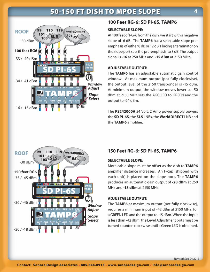
100 Feet RG-6: SD PI-6S, TAMP6SELECTABLE SLOPE:At 100 feet of RG-6 from the dish, we start with a negative
slope of 6 dB. The TAMP6 has a selectable slope pre-
emphasis of either 8 dB or 12 dB. Placing a terminator on
the slope port sets the pre-emphasis to 8 dB. The output
signal is -16 at 250 MHz and -15 dBm at 2150 MHz.
ADJUSTABLE OUTPUT:The TAMP6 has an adjustable automatic gain control
window. At maximum output (pot fully clockwise),
the output level of the 2150 transponder is -15 dBm.
At minimum output, the window moves lower so -50
dBm at 2150 MHz sets the AGC LED to GREEN and the
output to -24 dBm.
The PS242000A 24 Volt, 2 Amp power supply powers
the SD PI-6S, the SL5 LNBs, the WorldDIRECT LNB and
the TAMP6 amplifi er.
150 Feet RG-6: SD PI-6S, TAMP6
SELECTABLE SLOPE:More cable slope must be off set as the dish to TAMP6 amplifi er distance increases. An F-cap (shipped with
each unit) is placed on the slope port. The TAMP6produces an automatic gain output of -20 dBm at 250
MHz and -18 dBm at 2150 MHz.
ADJUSTABLE OUTPUT:The TAMP6 at maximum output (pot fully clockwise),
requires a minimum input of -42 dBm at 2150 MHz for
a GREEN LED and the output to -15 dBm. When the input
is less than -42 dBm, the Level Adjustment pots must be
turned counter-clockwise until a Green LED is obtained.
ROOF101
99
SL5103
110 119 worldDIRECT10195
DC
DC
SD PI-6SFLEX 1 FLEX 2
FLEX 2
PS242000A
SLOPETERM = 8 dBCAP = 12 dB
TAMP6 IN 1 IN 2 IN 3 IN 4 IN 5 IN 6
OUT1
OUT2
OUT3
OUT4
OUT5
OUT6
VDC12-29
SlopeSelect
WindowAdjust
-33 / -40 dBm
-34 / -41 dBm
-16 / -15 dBm
-30 dBm
100 feet RG6
ROOF101
99
SL5103
110 119 worldDIRECT10195
DC
DC
SD PI-6SFLEX 1 FLEX 2
FLEX 2
PS242000A
SLOPETERM = 8 dBCAP = 12 dB
TAMP6 IN 1 IN 2 IN 3 IN 4 IN 5 IN 6
OUT1
OUT2
OUT3
OUT4
OUT5
OUT6
VDC12-29
SlopeSelect
WindowAdjust
-35 / -45 dBm
-36 / -46 dBm
-20 / -18 dBm
-30 dBm
150 feet RG6
50-150 FT DISH TO MPOE SLOPE

Contact: Sonora Design Associates 805.644.8913 www.sonoradesign.com [email protected]
Revised Sep 24 2013
5200 FEET DISH TO MPOE
ROOF101
99
SL5103
110 119 worldDIRECT10195
-36 / -49 dBm
-37 / -50 dBm
-47 / -51 dBm
-28 / -24 dBm
-30 dBm
200 feet RG6
DC
DC
SD PI-6SFLEX 1 FLEX 2
FLEX 2 PS242000A
S E Q 4 0 9
SLOPETERM = 8 dBCAP = 12 dB
TAMP6 IN 1 IN 2 IN 3 IN 4 IN 5 IN 6
OUT1
OUT2
OUT3
OUT4
OUT5
OUT6
VDC12-29
SlopeSelect
WindowAdjust
ROOF101
99
SL5103
110 119 worldDIRECT10195
-36 / -49 dBm
-27 / -35 dBm
-28 / -36 dBm
-19 / -15 dBm
-30 dBm
200 feet RG6
DC
DC
SD PI-6SFLEX 1 FLEX 2
FLEX 2
DC
DC
LA146RFLEX 1 FLEX 2
FLEX 1 FLEX 2
PS242000A
SlopeSelect
WindowAdjust
SLOPETERM = 8 dBCAP = 12 dB
TAMP6 IN 1 IN 2 IN 3 IN 4 IN 5 IN 6
OUT1
OUT2
OUT3
OUT4
OUT5
OUT6
VDC12-29
200 Feet: SD LA146R, SD PI-6S, TAMP6At 200 feet the signal to the SD PI-6S-T is -36 dBm at
250 MHz and -49 dBm at 2150 MHz. The slope is 13 dB.
Model LA146R is used as an active equalizer. It provides
5 dB of pre-emphasis. The signal out of the LA146R has
a negative 8 dB of slope. (-27 dBm at 250 MHz & -35 dBm
at 2150 MHz)
If we set the TAMP6 at 12 dB slope pre-emphasis
produces an automatic gain output of -15 dBm at 250
MHz and -19 dBm at 2150 MHz. (At maximum output
pot setting)
Models LA146R & TAMP6 have energy saving regulators
that conserve current from model PS242000A. The
two amplifi ers and LNBs can be powered by the single
supply. The total current is 760 mA.
200 Feet RG-6: SD PI-6S, SEQ409, TAMP6SELECTABLE SLOPE:We want to start the signal slope pre-emphasized out
of the amplifi er. A 200 foot dish to amplifi er distance
exceeds the slope pre-emphasis of the amplifier.
Additional slope compensation is required. Model
SEQ409 provides 9 dB of additional slope pre-emphasis.
ADJUSTABLE OUTPUT:The TAMP6 at maximum output (pot fully clockwise),
requires a minimum input of -44 dBm at 2150 MHz for
a GREEN LED and the output to -15 dBm. When the
input is less than -44 dBm, the Level Adjustment pots
must be turned counter-clockwise until a Green LED
is obtained. The LEDs are Green but the output is -24
dBm at 2150 MHz.
Contact: Sonora Design Associates 805.644.8913 www.sonoradesign.com [email protected]
Revised Sep 24 2013
6300 FEET DISH TO MPOE
ROOF101
99
SL5103
110 119 worldDIRECT10195
-41 / -59 dBm
-32 / -45 dBm
-43 / -47 dBm
-33 / -46 dBm
-24 / -20 dBm
-30 dBm
300 feet RG6
DC
DC
SD PI-6SFLEX 1 FLEX 2
FLEX 2
DC
DC
LA146RFLEX 1 FLEX 2
FLEX 1 FLEX 2
PS242000A
S E Q 4 0 9
SLOPETERM = 8 dBCAP = 12 dB
TAMP6 IN 1 IN 2 IN 3 IN 4 IN 5 IN 6
OUT1
OUT2
OUT3
OUT4
OUT5
OUT6
VDC12-29
SlopeSelect
WindowAdjust
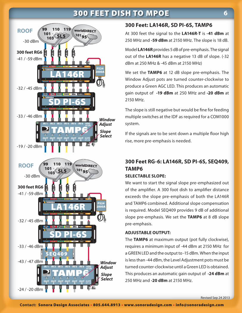
300 Feet: LA146R, SD PI-6S, TAMP6At 300 feet the signal to the LA146R-T is -41 dBm at
250 MHz and -59 dBm at 2150 MHz. The slope is 18 dB.
Model LA146R provides 5 dB of pre-emphasis. The signal
out of the LA146R has a negative 13 dB of slope. (-32
dBm at 250 MHz & -45 dBm at 2150 MHz)
We set the TAMP6 at 12 dB slope pre-emphasis. The
Window Adjust pots are turned counter-clockwise to
produce a Green AGC LED. This produces an automatic
gain output of -19 dBm at 250 MHz and -20 dBm at
2150 MHz.
The slope is still negative but would be fi ne for feeding
multiple switches at the IDF as required for a COM1000
system.
If the signals are to be sent down a multiple fl oor high
rise, more pre-emphasis is needed.
300 Feet RG-6: LA146R, SD PI-6S, SEQ409, TAMP6SELECTABLE SLOPE:We want to start the signal slope pre-emphasized out
of the amplifi er. A 300 foot dish to amplifi er distance
exceeds the slope pre-emphasis of both the LA146R
and TAMP6 combined. Additional slope compensation
is required. Model SEQ409 provides 9 dB of additional
slope pre-emphasis. We set the TAMP6 at 8 dB slope
pre-emphasis.
ADJUSTABLE OUTPUT:The TAMP6 at maximum output (pot fully clockwise),
requires a minimum input of -44 dBm at 2150 MHz for
a GREEN LED and the output to -15 dBm. When the input
is less than -44 dBm, the Level Adjustment pots must be
turned counter-clockwise until a Green LED is obtained.
This produces an automatic gain output of -24 dBm at
250 MHz and -20 dBm at 2150 MHz.
ROOF101
99
SL5103
110 119 worldDIRECT10195
-41 / -59 dBm
-32 / -45 dBm
-33 / -46 dBm
-19 / -20 dBm
-30 dBm
300 feet RG6
DC
DC
SD PI-6SFLEX 1 FLEX 2
FLEX 2
DC
DC
LA146RFLEX 1 FLEX 2
FLEX 1 FLEX 2
PS242000A
SLOPETERM = 8 dBCAP = 12 dB
TAMP6 IN 1 IN 2 IN 3 IN 4 IN 5 IN 6
OUT1
OUT2
OUT3
OUT4
OUT5
OUT6
VDC12-29
SlopeSelect
WindowAdjust
Contact: Sonora Design Associates 805.644.8913 www.sonoradesign.com [email protected]
Revised Sep 24 2013
7
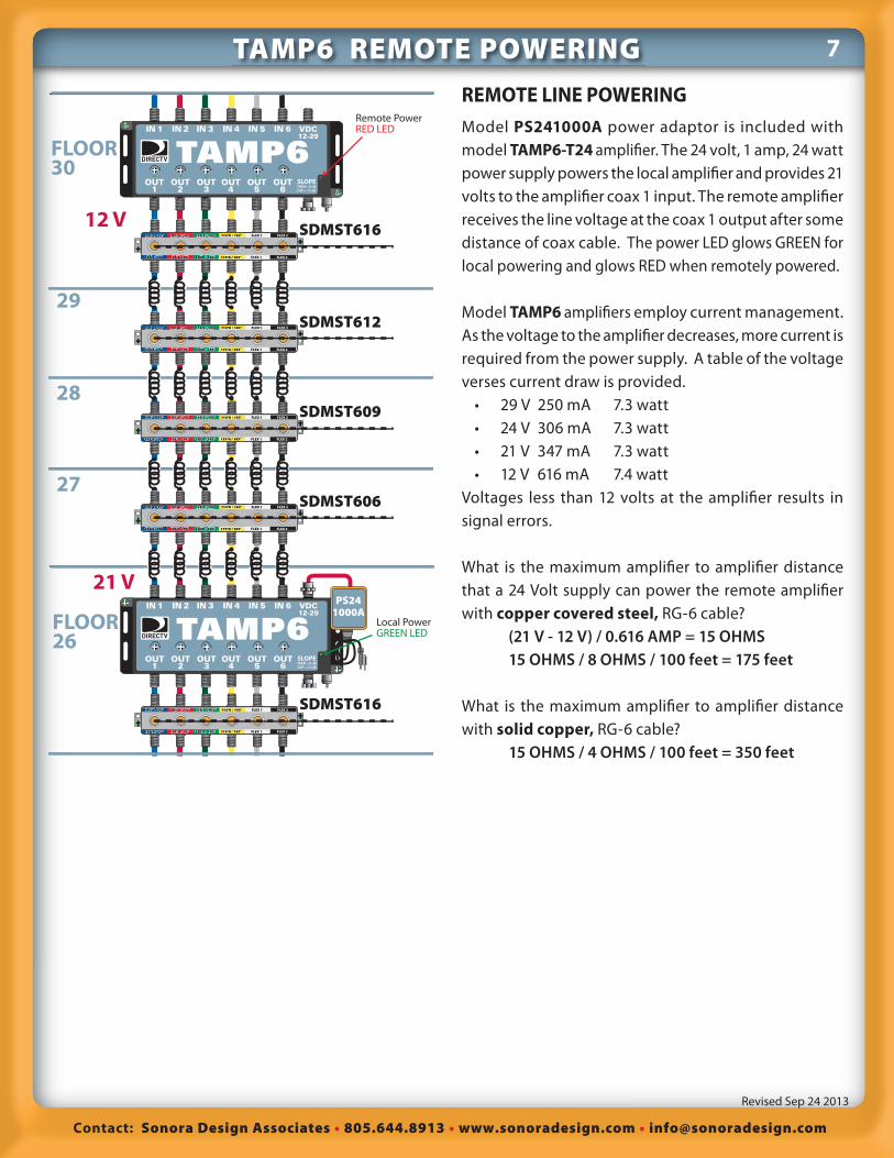
REMOTE LINE POWERINGModel PS241000A power adaptor is included with
model TAMP6-T24 amplifi er. The 24 volt, 1 amp, 24 watt
power supply powers the local amplifi er and provides 21
volts to the amplifi er coax 1 input. The remote amplifi er
receives the line voltage at the coax 1 output after some
distance of coax cable. The power LED glows GREEN for
local powering and glows RED when remotely powered.
Model TAMP6 amplifi ers employ current management.
As the voltage to the amplifi er decreases, more current is
required from the power supply. A table of the voltage
verses current draw is provided.
• 29 V 250 mA 7.3 watt
• 24 V 306 mA 7.3 watt
• 21 V 347 mA 7.3 watt
• 12 V 616 mA 7.4 watt
Voltages less than 12 volts at the amplifi er results in
signal errors.
What is the maximum amplifi er to amplifi er distance
that a 24 Volt supply can power the remote amplifi er
with copper covered steel, RG-6 cable?
(21 V - 12 V) / 0.616 AMP = 15 OHMS 15 OHMS / 8 OHMS / 100 feet = 175 feet
What is the maximum amplifi er to amplifi er distance
with solid copper, RG-6 cable?
15 OHMS / 4 OHMS / 100 feet = 350 feet
29
28
27
FLOOR30
FLOOR26
12 V
21 V
SLOPETERM = 8 dBCAP = 12 dB
TAMP6 IN 1 IN 2 IN 3 IN 4 IN 5 IN 6
OUT1
OUT2
OUT3
OUT4
OUT5
OUT6
VDC12-29
SLOPETERM = 8 dBCAP = 12 dB
TAMP6 IN 1 IN 2 IN 3 IN 4 IN 5 IN 6
OUT1
OUT2
OUT3
OUT4
OUT5
OUT6
VDC12-29
PS241000A
SDMST616FLEX 1 FLEX 2
FLEX 1 FLEX 2
SDMST616FLEX 1 FLEX 2
FLEX 1 FLEX 2
SDMST612FLEX 1 FLEX 2
FLEX 1 FLEX 2
SDMST609FLEX 1 FLEX 2
FLEX 1 FLEX 2
SDMST606FLEX 1 FLEX 2
FLEX 1 FLEX 2
Remote PowerRED LED
Local PowerGREEN LED
TAMP6 REMOTE POWERING

Contact: Sonora Design Associates 805.644.8913 www.sonoradesign.com [email protected]
Revised Sep 24 2013
8Tap Per Floor, Tap on Alternate Floors
-16 dBm
-20 dBm
-24 dBm
-29 dBm
-36 dBm
SDMST616 -32 dBm
FLEX 1 FLEX 2
FLEX 1 FLEX 2
SDMST616 -36 dBm
FLEX 1 FLEX 2
FLEX 1 FLEX 2
SDMST612 -36 dBm
FLEX 1 FLEX 2
FLEX 1 FLEX 2
SDMST606-38 dBm
FLEX 1 FLEX 2
FLEX 1 FLEX 2
SLOPETERM = 8 dBCAP = 12 dB
TAMP6 IN 1 IN 2 IN 3 IN 4 IN 5 IN 6
OUT1
OUT2
OUT3
OUT4
OUT5
OUT6
VDC12-29
PS241000A
SLOPETERM = 8 dBCAP = 12 dB
TAMP6 IN 1 IN 2 IN 3 IN 4 IN 5 IN 6
OUT1
OUT2
OUT3
OUT4
OUT5
OUT6
VDC12-29
PS241000A
29
28
27
FLOOR30
FLOOR26
6 LU
8 LU
10 LU
10 LU
Ta p p e r A l t e r n a t i n g F l o o r s , 6 Floor, 20 dB Amplifi er SpacingA minimum IDF input of -37 dBm is budgeted.
SD MST6xx / 2 Floors, 21 dB Spacing
MHz/ dB 250 1450 2150RG-6 110 ft 3.4 8.7 10.7
MST616 1.0 1.2 2.0
MST612 1.4 1.7 3.0
MST606 3.6 4.5 5.0
TOTAL 9.4 16.1 20.7
The TAMP6 internal slope compensation off sets 12 dB of the 11 dB slope.
Tap per Floor: 16, 16, 12, 9 dB Taps, 4 Floor Amplifi er, 20 dB SpacingHigher tap values are used on the fl oors closest to the
amplifi er to conserve trunk signal level. Lower tap values
have higher trunk insertion loss A minimum IDF input
of -38 dBm is budgeted. SD MST6xx / Floor, 20 dB Spacing
MHz/ dB 250 1450 2150RG-6 80 ft 2.5 6.3 7.7
MST616 1.0 1.2 2.0
MST616 1.0 1.2 2.0
MST612 1.4 1.7 3.0
MST606 3.6 4.5 5.0
TOTAL 9.5 14.9 19.7
The TAMP6-T12 internal slope compensation off set is
set to 12 dB for the 10 dB slope.
29
31
28
27
26
25
FLOOR30
FLOOR24
16 LU
20 LU
24 LU
24 LU
-45 dBm
SLOPETERM = 8 dBCAP = 12 dB
TAMP6 IN 1 IN 2 IN 3 IN 4 IN 5 IN 6
OUT1
OUT2
OUT3
OUT4
OUT5
OUT6
VDC12-29
PS241000A
SLOPETERM = 8 dBCAP = 12 dB
TAMP6 IN 1 IN 2 IN 3 IN 4 IN 5 IN 6
OUT1
OUT2
OUT3
OUT4
OUT5
OUT6
VDC12-29
PS241000A
-18 dBm
-24 dBm
-31 dBm
-18 dBm
-39 dBm
SDMST616-34 dBm
FLEX 1 FLEX 2
FLEX 1 FLEX 2
SDMST612 -36 dBm
FLEX 1 FLEX 2
FLEX 1 FLEX 2
SDMST606 -37 dBm
FLEX 1 FLEX 2
FLEX 1 FLEX 2
SDMST616 -34 dBm
FLEX 1 FLEX 2
FLEX 1 FLEX 2
SWMBOX-xx
SWMBOX-xx
SWMBOX-xx
SWMBOX-xx
18 ft RG6 per floor2 floor tap spacing20 dB Amp spacing

Contact: Sonora Design Associates 805.644.8913 www.sonoradesign.com [email protected]
Revised Sep 24 2013
9
Tap per (3) Floors, 9 Floor, 22 dB Amp SpacingIncreasing the spacing between taps allows for fewer
taps between amplif iers and increased amplif ier
spacing. A minimum IDF input of -39 dBm is budgeted.
SD MST6xx / 3 Floors, RG6, 23 dB Spacing
MHz/ dB 250 1450 2150RG-6 135 ft 4.2 10.7 13.1
MST616 1.0 1.2 2.0
MST612 1.4 1.7 3.0
MST606 3.6 4.5 5.0
TOTAL 10.2 18.1 23.1
The TAMP6 internal slope compensation off sets 12 dB
of the 13 dB slope.
The number of Living Units served by each IDF is
annotated on the design. The number represents the
100% of the units subscribing for service. Units on
alternating fl oors may be served by either the IDF above
or the IDF below. This is important when some LU require
(8) tuners for HR34 Genie® service.
We design the trunk for 100% of the fl oors receiving
signal. We design the IDF to be scalable to serve up to 100% of the LU with up to (8) tuners per LU. At each
IDF closet we design for a minimum signal level to
support multiple SWM switches. SWM32 switches may
be cascaded to serve up to 64 tuners. The limit is one
switch in cascade.
S W M 3 2
FLEX 2 18 V18 V13 V13 V18 V / 22 K18 V / 22 K13 V / 22 K13 V / 22 KFLEX 1
FLEX 2 18 V18 V13 V13 V18 V / 22 K18 V / 22 K13 V / 22 K13 V / 22 KFLEX 1
S W M 3 2
FLEX 2 18 V18 V13 V13 V18 V / 22 K18 V / 22 K13 V / 22 K13 V / 22 KFLEX 1
FLEX 2 18 V18 V13 V13 V18 V / 22 K18 V / 22 K13 V / 22 K13 V / 22 KFLEX 1
S W M 3 2
FLEX 2 18 V18 V13 V13 V18 V / 22 K18 V / 22 K13 V / 22 K13 V / 22 KFLEX 1
FLEX 2 18 V18 V13 V13 V18 V / 22 K18 V / 22 K13 V / 22 K13 V / 22 KFLEX 1
S W M 3 2
FLEX 2 18 V18 V13 V13 V18 V / 22 K18 V / 22 K13 V / 22 K13 V / 22 KFLEX 1
FLEX 2 18 V18 V13 V13 V18 V / 22 K18 V / 22 K13 V / 22 K13 V / 22 KFLEX 1
S W M 3 2
FLEX 2 18 V18 V13 V13 V18 V / 22 K18 V / 22 K13 V / 22 K13 V / 22 KFLEX 1
FLEX 2 18 V18 V13 V13 V18 V / 22 K18 V / 22 K13 V / 22 K13 V / 22 KFLEX 1
S W M 3 2
FLEX 2 18 V18 V13 V13 V18 V / 22 K18 V / 22 K13 V / 22 K13 V / 22 KFLEX 1
FLEX 2 18 V18 V13 V13 V18 V / 22 K18 V / 22 K13 V / 22 K13 V / 22 KFLEX 1
SD SWM-E1
Model SD SWME1 may be used to split the input signal
to (2) sets of SWM32 switches. The minimum input to
the SD SWME1 is -40 dBm so that each SWM32 has a
minimum of -45 dBm.
29, 28
27
26, 25
24
23, 22
FLOOR30
FLOOR21
-42 dBm
-18 dBm
-25 dBm
-33 dBm
-18 dBm
-42 dBm
SDMST616 -34 dBm
FLEX 1 FLEX 2
FLEX 1 FLEX 2
SDMST612 -37 dBm
FLEX 1 FLEX 2
FLEX 1 FLEX 2
SDMST606 -39 dBm
FLEX 1 FLEX 2
FLEX 1 FLEX 2
SDMST616 -34 dBm
FLEX 1 FLEX 2
FLEX 1 FLEX 2
15 ft RG6 per floor3 floor Tap spacing23 dB Amp Spacing
SLOPETERM = 8 dBCAP = 12 dB
TAMP6 IN 1 IN 2 IN 3 IN 4 IN 5 IN 6
OUT1
OUT2
OUT3
OUT4
OUT5
OUT6
VDC12-29
PS241000A
SLOPETERM = 8 dBCAP = 12 dB
TAMP6 IN 1 IN 2 IN 3 IN 4 IN 5 IN 6
OUT1
OUT2
OUT3
OUT4
OUT5
OUT6
VDC12-29
PS241000A
SWMBOX-xx
SWMBOX-xx
14 LU
18 LU
20 LU
24 LU
SWMBOX-xx
SWMBOX-xx
Tap Per (3) Floors