Embed Size (px)
Citation preview

WWW.HANTECH.VN
Programmable Logic Controller
XGT series

XGT Series
1. Features
XGT are innovation-driven PLC series representing the most recent technology.
ü Speed Innovation ………… Fast XGT is equipped with the fastest CPU speed (0.028 ㎲/step) and guarantees super-speedy
processing time through improved Backplane Interface. Also it maximizes maintenance
convenience by speedy up/down loading using USB.
ü Size Innovation ………… Compact
XGT has the highest quality but the smallest size (dimension 27 * 98 * 90) of modules fulfilling cost-
efficiency and various applications.
ü Network Innovation ………… Flexible
XGT system, based on Fast Ethernet & Open Fieldbus guarantees reliability and high speed
transmission. Its Field device interface can overcome system configuration's limitations.
ü Software Innovation ………… Comfortable
XG5000 Package supports Multi PLC Multi Programming through its enhanced user interface. It
also provides powerful monitoring and diagnosis functions.
ü Engineering & Programming Innovation ………… Easy
XGT provides user-friendly engineering environment through Programless Setup driven by
command structures and parameters inherited from MASTER-K Series.
1
XGT Series
2. Specifications
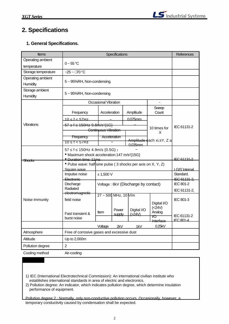
1. General Specifications.
Items Operating ambient
0 ~ 55 °C temperature
Specifications
References
Storage temperature Operating ambient Humidity Storage ambient Humidity
−25 ~ +70 °C 5 ~ 95%RH, Non-condensing. 5 ~ 95%RH, Non-condensing
Occasional Vibration
- Sweep
Frequency
10 ≤ f < 57Hz
Acceleration
−
Amplitude
0.075mm
Count
Vibrations 57 ≤ f ≤ 150Hz 9.8m/s2{1G} Continuous Vibration
− 10 times for
X
IEC 61131-2
Frequency 10 ≤ f < 57Hz
Acceleration − Amplitude each xi,sY, Z a
0.035mm 57 ≤ f ≤ 150Hz 4.9m/s {0.5G} 2 −
Shocks
• Maximum shock acceleration:147 m/s2{15G} • Duration time: 11ms • Pulse wave: half sine pulse ( 3 shocks per axis on X, Y, Z) Square wave
IEC 61131-2 LGIS' Internal
Impulse noise Electronic Discharge Radiated electromagnetic
± 1,500 V Voltage : 8kV (Discharge by contact)
27 ~ 500 MHz, 10 V/m
Standard. IEC 61131-2, IEC 801-2 IEC 61131-2,
Noise Immunity field noise Fast transient & burst noise
Item Voltage
Power supply
2kV
Digital I/O (>24V)
1kV
Digital I/O (<24V) Analog I/O Interface
0.25kV
IEC 801-3
IEC 61131-2 IEC 801-4
Atmosphere
Altitude
Pollution degree
Cooling method
REMARK
Free of corrosive gases and excessive dust
Up to 2,000m
2
Air-cooling
1) IEC (International Electrotechnical Commission): An international civilian institute who
establishes international standards in area of electric and electronics. 2) Pollution degree: An indicator, which indicates pollution degree, which determine insulation
performance of equipment.
Pollution degree 2 : Normally, only non-conductive pollution occurs. Occasionally, however, a temporary conductivity caused by condensation shall be expected.
2

XGT Series
2. CPU Specifications.
Specifications
Items Remarks XGT-CPUE XGT-CPUS XGT-CPUA XGT-CPUH
Operation method
I/O Updating Method
Program Languages
Basic Instructions
Cyclic, Fixed Time driven, Interrupt, Fixed Scan
Program refresh per 1 scan, Direct update by instruction Ladder Diagram Instruction List 42
Instructions Processing speed
Application Instructions
LD
MOV
Floating
717 0.084 ㎲/Step
0.252 ㎲/Step ±: 1.442 ㎲(S) 2.87 ㎲(D) X: 1.948 ㎲(S), 4.168 ㎲(D) ÷: 1.974 ㎲(S), 4.2 ㎲(D)
0.028 ㎲/Step
0.084 ㎲/Step ±: 0.602 ㎲, 1.078 ㎲(D) X: 1.106 ㎲(S), 2.394 ㎲(D) ÷: 1.134 ㎲(S), 2.66 ㎲(D)
S: Short D: Double
Program Capacity(Step) 16Steps 32K Steps 32Steps 64K Steps
I/O Capacity(Points) 1536 3072 3072 6144
P
M K L
F T
P00000 ~ P2047F (32,768 Points)
M00000 ~ M2047F (32,768 Points) K00000 ~ K2047F (32,768 Points) L00000 ~ L8191F (131,072 Points)
F00000 ~ F2047F (32,768 Points)
100ms: T0000 ~ T0999 10ms: T1000 ~ T1499
16K Byte
Changeable boundary by
Data 1ms: T1500 ~ T1999 basic parameter Memory
C S
D
C0000 ~ C2047 S00.00 ~ S99.99
D0000 ~ D19999
0.1ms: T2000 ~ T2047
D0000 ~ D32767
Special module U Z
N
U00.0 ~ U01.31 U00.0 ~ U03.31 U00.0 ~ U03.31 U0.0 ~ U7F.31
128 Words
N00000 ~ N28,672 (28,672 Words)
Refresh area.
Index
Word Only 32Kwords/BLK
File Register
R ZR
1 Block 2 Blocks
FLASH area: 32 Blocks (1Mbyte/BLK)
(R0 ~ R32767) Controlled by R registers
3
XGT Series
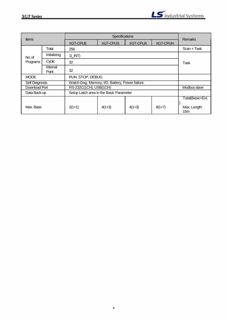
Specifications Items Remarks No. of Programs
Total Initializing
Cyclic Internal Point
XGT-CPUE 256
1(_INT)
32 32
XGT-CPUS XGT-CPUA XGT-CPUH Scan + Task Task
MODE RUN, STOP, DEBUG Self Diagnosis Watch-Dog, Memory, I/O, Battery, Power failure. Download Port RS-232C(1CH), USB(1CH) Modbus slave Data Back-up Setup Latch area in the Basic Parameter
Total(Basic+Ext. )
Max. Base 2(1+1) 4(1+3) 4(1+3) 8(1+7) Max. Length: 15m
4
XGT Series
3. Basic Usage of XG5000.
XG5000 is a software for programming and engineering XGT series PLC which provides you user- friendly engineering environment through Programless Setup driven by command structures and
parameters inherited from MASTER-K Series.
1. Project Construction.
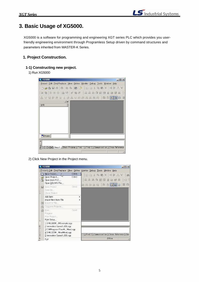
1-1) Constructing new project.
1) Run XG5000
2) Click New Project in the Project menu.
5
XGT Series
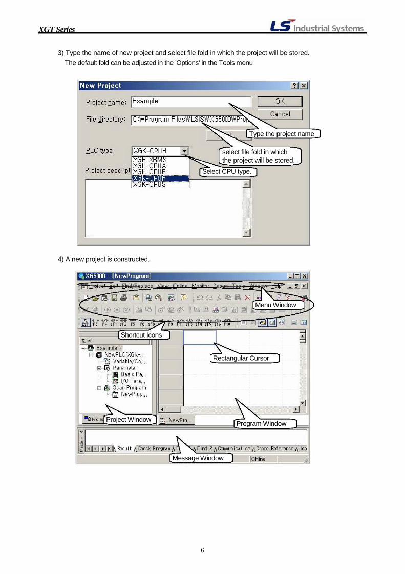
3) Type the name of new project and select file fold in which the project will be stored. The default fold can be adjusted in the 'Options' in the Tools menu
Type the project name
select file fold in which the project will be stored.
Select CPU type.
4) A new project is constructed.
Menu Window
Shortcut Icons
Rectangular Cursor
Project Window
Message Window
Program Window
6
XGT Series
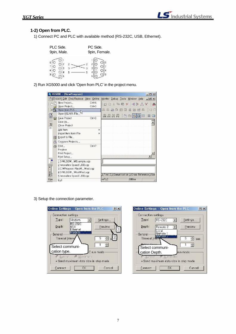
1-2) Open from PLC. 1) Connect PC and PLC with available method (RS-232C, USB, Ethernet).
PLC Side. PC Side. 9pin, Male. 9pin, Female.
2) Run XG5000 and click 'Open from PLC' in the project menu. 3) Setup the connection parameter.
Select communi- cation type.
②
①
Select communi- cation Depth.
7
XGT Series
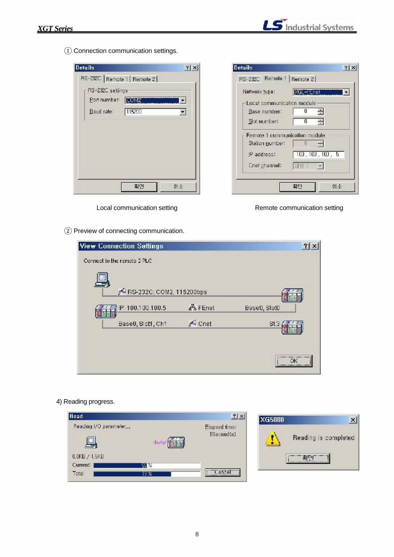
① Connection communication settings.
Local communication setting Remote communication setting
② Preview of connecting communication.
4) Reading progress.
8

XGT Series
1-3) Open from KGLWIN file. 1) Run XG5000 and click Open KGLWIN File in the project menu. 2) Select KGLWIN file(*.kpr, *.prj) to open. 3) Define the project information of XGT PLC.
9

XGT Series
4) KGLWIN program and XG5000 program
KGLWIN program
XG5000 program
10

XGT Series
2. Property modification.
2-1) Project Property Modification and description.
①
②
① Click the left side button of mouse after selecting the Project name by clicking. ②
Click 'Properties', than a dialog depicted below will be displayed.
③④
⑤
③ Rename the Project if necessary. ④ Input the description of Project such as the usage, configuration of the Project, etc…
⑤ The folder where the Project file is stored in the computer.
There are 2 types of passwords in the XGT series PLC. One is password for project open which is designated in the Project Property dialog. And the other is password for online connection which is
designated in the PLC information dialog of Online menu. Since the password for Project open does
not be transferred to PLC, the password for Project open does not be asked when the uploaded
project is opened.
11
XGT Series
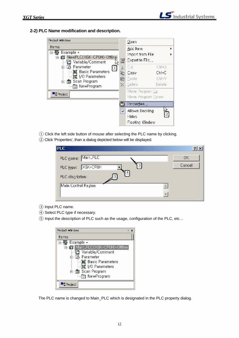
2-2) PLC Name modification and description.
①
②
① Click the left side button of mouse after selecting the PLC name by clicking. ② Click 'Properties', than a dialog depicted below will be displayed.
③
④ ⑤
③ Input PLC name. ④ Select PLC type if necessary. ⑤ Input the description of PLC such as the usage, configuration of the PLC, etc…
The PLC name is changed to Main_PLC which is designated in the PLC property dialog.
12
XGT Series
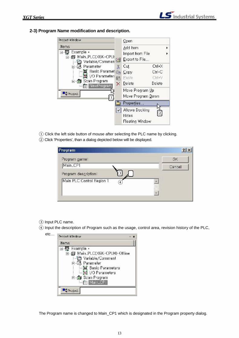
2-3) Program Name modification and description.
①
②
① Click the left side button of mouse after selecting the PLC name by clicking. ② Click 'Properties', than a dialog depicted below will be displayed.
③ ④
③ Input PLC name. ④ Input the description of Program such as the usage, control area, revision history of the PLC,
etc…
The Program name is changed to Main_CP1 which is designated in the Program property dialog.
13

XGT Series
3. PLC Items.
3-1) Variable/Comment
Variable or comment can be defined in block prior to programming.
Double Click
1) Add Variable/Comment in the View Variable tab of Variable/Comment dialog.
① Variable registration.
A Variable is a string that can access the designated data memory address instead of device. A Variable can be composed of characters, numbers and special character '_' (under bar) and
the maximum length of a variable is limitless. A number can not be used as the first character of a
variable.
② Comment registration.
A Comment is a brief explanation for device. Characters, numbers, all kinds of special characters can be used and the maximum length of a comment is limitless.
③ Automatic number increment.
If a variable or comment of which the last digit is number is registered, the number will be increased automatically when the variable or comment is dragged. Device address also increased by dragging. Prior to dragging, lines must be inserted to the variable/comment table.
- Line Insertion.
Select line number and click the right
Select Insert line
Line is added in the
side mouse
button of 14
table
XGT Series
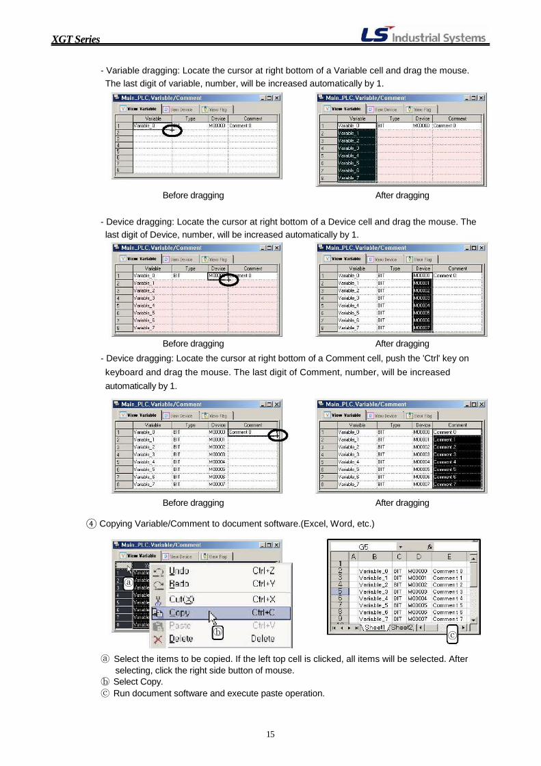
- Variable dragging: Locate the cursor at right bottom of a Variable cell and drag the mouse. The last digit of variable, number, will be increased automatically by 1.
Before dragging After dragging
- Device dragging: Locate the cursor at right bottom of a Device cell and drag the mouse. The last digit of Device, number, will be increased automatically by 1.
Before dragging After dragging
- Device dragging: Locate the cursor at right bottom of a Comment cell, push the 'Ctrl' key on keyboard and drag the mouse. The last digit of Comment, number, will be increased
automatically by 1.
Before dragging After dragging
④ Copying Variable/Comment to document software.(Excel, Word, etc.)
ⓐ
ⓑ ⓒ
ⓐ Select the items to be copied. If the left top cell is clicked, all items will be selected. After selecting, click the right side button of mouse.
ⓑ Select Copy. ⓒ Run document software and execute paste operation.
15

XGT Series
2) Add Variable/Comment in the View Device tab of Variable/Comment dialog.
ⓐ ⓑ
ⓐ Select the device area to register variable or comments. ⓑ Select data type
3-2) Basic Parameters.
Double Click
1) Basic Operation Setup - Fixed period operation: Defines whether fixed scan time function is used or not.
When this option is checked(use), the scan time must be larger than max. scan time which can be
seen 'PLC Information' in the Online menu. - Assign fixed points to I/O slot (64): Defines I/O address mapping method.
If this option is checked, 1 slot charges 4 words(64 points) in P area. And this option is
unchecked, 1 slot charges memory capacity of module installed in the slot. - Standard Input Filter: Defines response time of digital input.
More shorter input filter time, more faster its response time. But If this parameter is setup with
too small value, the system can be affected by electrical noise.
16

XGT Series
2) Device Area Setup
- Latch area: There are 2 kinds of Latch area. Latch area 1 is non-volatile memory area when PLC goes to stop mode or PLC power turn off. The data in the Latch 1 area can be deleted by Overall reset in the Online menu, or resetting with reset switch located in the CPU module.
Latch area 2 is non-volatile memory area when PLC goes to stop mode or PLC power is turned off. And the data in the Latch area 2 does not deleted when Overall reset is performed with XG5000 or Reset switch in the CPU is turned on. The only way to delete the data in the Latch area 2 is moving the data "0" to Latch area 2 or
Latch2 clear function of Online menu.
- Timer Boundary: There are 4 kinds of timer of which setting units are 100ms, 10ms, 1ms and
0.1ms, respectively. The boundary of each kinds of timer can be adjusted with this parameter.
3) Error Operation Setup
CPU operation can be setup when some kinds of error occurred.
17

XGT Series
4) MODBUS Setup
RS-232C communication port in the CPU can be used as slave module of MODBUS communication. The MODBUS communication parameter can be setup in the MODBUS setup in the
Basic Parameter Setup. The pin assignment of MODBUS communication is 7 for Tx, 8 for Rx and 5 for SG. When the built-in MODBUS communication port of CPU is used, there are some restrictions on the
communication memory map. To communicate all data memory map of a CPU, Cnet module is
necessary.
MODBUS Parameter Setup PC PLC MODBUS
(XG5000) 235
235
785
MA S T E R
Tx Rx SG
Cable connection for XG5000 and MODBUS Communication
3-3) I/O Parameters The usage of I/O Parameters is let the CPU recognize the kinds of installed modules on the slots. And let the users recognize the I/O address of the installed modules. If special modules such as A/D, D/A, etc. are used, the operations of special modules can be setup
with I/O parameters. There are 2 methods of configuration of I/O parameters. The one is manual configuration and the
other is automatic configuration. The method of manual configuration is configuring the I/O parameters by selecting installed I/O
modules in the 'I/O parameters' dialog. And method of automatic configuration is configuring the I/O
parameters by reading I/O information and synchronizing the read I/O information with I/O
Parameters on the Online state. The automatic configuration of I/O Parameters is available when the
CPU is STOP mode.
18

XGT Series
3-4) Add program. 1) Scan Program
A total program for a PLC can be divided into maximum 256 smaller programs. Making a program
smaller gives variety profit for debugging, program and management of systems.
Click
Click
Click right side button of mouse after selecting 'Scan Program'
Program file name
Description for program.
Program Main_CP2 is added in the PLC
19
XGT Series
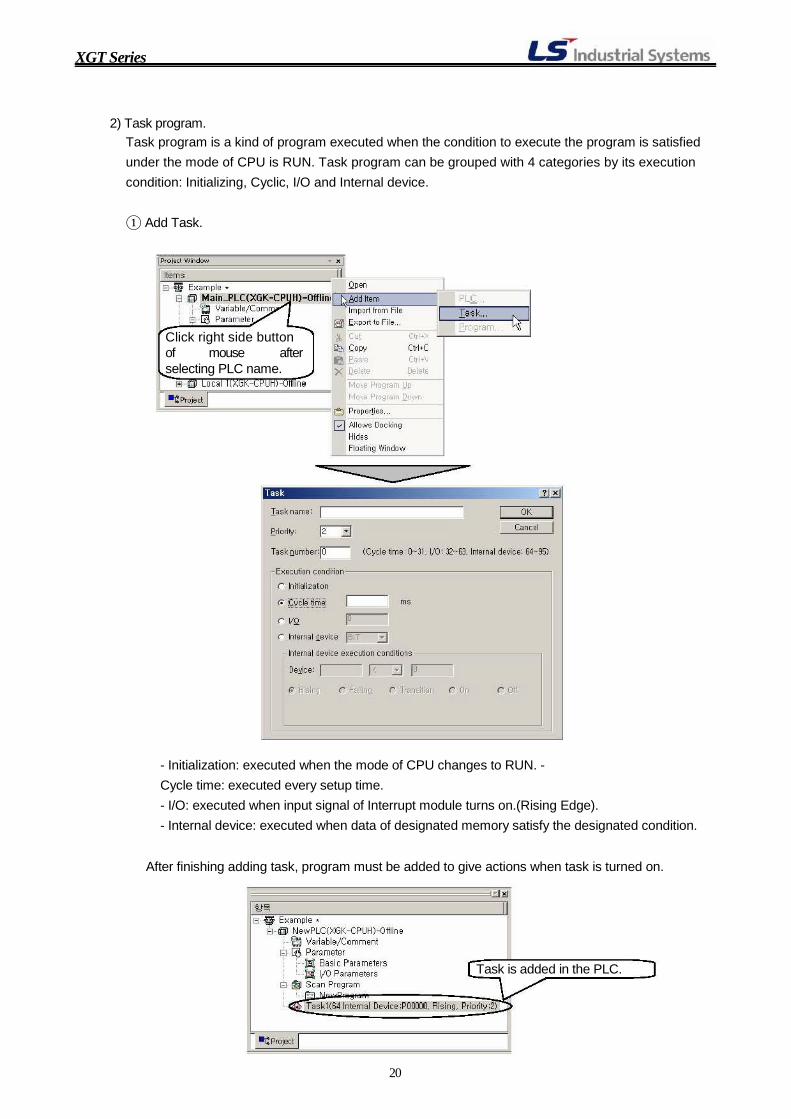
2) Task program. Task program is a kind of program executed when the condition to execute the program is satisfied
under the mode of CPU is RUN. Task program can be grouped with 4 categories by its execution
condition: Initializing, Cyclic, I/O and Internal device.
① Add Task.
Click right side button of mouse after selecting PLC name.
- Initialization: executed when the mode of CPU changes to RUN. -
Cycle time: executed every setup time. - I/O: executed when input signal of Interrupt module turns on.(Rising Edge). - Internal device: executed when data of designated memory satisfy the designated condition.
After finishing adding task, program must be added to give actions when task is turned on.
Task is added in the PLC.
20
XGT Series
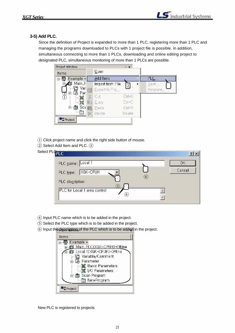
3-5) Add PLC. Since the definition of Project is expanded to more than 1 PLC, registering more than 1 PLC and managing the programs downloaded to PLCs with 1 project file is possible. in addition,
simultaneous connecting to more than 1 PLCs, downloading and online editing project to
designated PLC, simultaneous monitoring of more than 1 PLCs are possible.
② ③ ①
① Click project name and click the right side button of mouse. ② Select Add Item and PLC. ③
Select PLC.
④
⑤
⑥
④ Input PLC name which is to be added in the project. ⑤ Select the PLC type which is to be added in the project. ⑥ Input the description of the PLC which is to be added in the project.
New PLC is registered to projects
21

XGT Series
4. Programming There are 2 types of program, Scan and Task program, in the XGT series PLC. Scan program is executed as long as the mode of CPU is RUN. And Task program is executed when the condition to
execute the program is satisfied under the mode of CPU is RUN.
4-1) Data Memory Map of XGK PLC.
Prior to programming, checking data memory structure is essential for harmonious programming.
The data memory map of XGK PLC is table below.
Specifications
Items Remarks XGT-CPUE XGT-CPUS XGT-CPUA XGT-CPUH
P
M
K
L
F T
P00000 ~ P2047F (32,768 Points)
M00000 ~ M2047F (32,768 Points)
K00000 ~ K2047F (32,768 Points)
L00000 ~ L8191F (131,072 Points)
F00000 ~ F2047F (32,768 Points)
100ms: T0000 ~ T0999 10ms: T1000 ~ T1499
16K Byte Total 2048 P. Changeable
Data 1ms: T1500 ~ T1999 boundary by Memory
C S
0.1ms: T2000 ~ T2047 C0000 ~ C2047 (2048 Points)
S00.00 ~ S127.99 (128 Groups X 100 Steps)
basic parameter
D D0000 ~ D19999 D0000 ~ D32767 Sp c
U U00.0 ~ U01.31 U00.0 ~ U03.31 U00.0 ~ U03.31 U0.0 ~ U7F.31 Refeeisal module
r h area.
File Register
Z
N R
1 Block
128 Words
N00000 ~ N28,672
2 Blocks
Index 32Kwords/BLK (R0 ~ R32767) Controlled by
ZR FLASH area: 32 Blocks (1Mbyte/BLK) R registers

22
XGT Series
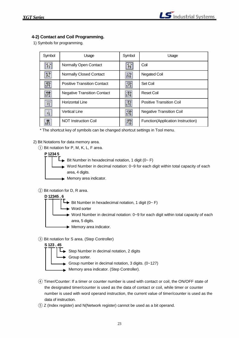
4-2) Contact and Coil Programming. 1) Symbols for programming.
Symbol Usage Symbol Usage
Normally Open Contact Coil Normally Closed Contact Negated Coil Positive Transition Contact Set Coil Negative Transition Contact Reset Coil Horizontal Line Positive Transition Coil Vertical Line Negative Transition Coil NOT Instruction Coil Function(Application Instruction)
* The shortcut key of symbols can be changed shortcut settings in Tool menu.
2) Bit Notations for data memory area. ① Bit notation for P, M, K, L, F area.
P 1234 5 Bit Number in hexadecimal notation, 1 digit (0~ F) Word Number in decimal notation: 0~9 for each digit within total capacity of each
area, 4 digits. Memory area indicator.
② Bit notation for D, R area.
D 12345 . 6 Bit Number in hexadecimal notation, 1 digit (0~ F) Word sorter Word Number in decimal notation: 0~9 for each digit within total capacity of each
area, 5 digits. Memory area indicator.
③ Bit notation for S area. (Step Controller)
S 123 . 45 Step Number in decimal notation, 2 digits Group sorter. Group number in decimal notation, 3 digits. (0~127)
Memory area indicator. (Step Controller).
④ Timer/Counter: If a timer or counter number is used with contact or coil, the ON/OFF state of
the designated timer/counter is used as the data of contact or coil, while timer or counter number is used with word operand instruction, the current value of timer/counter is used as the
data of instruction. ⑤ Z (Index register) and N(Network register) cannot be used as a bit operand.
23

XGT Series
3) Steps for Programming with contact and Coil. ① Double Click Program name in the Project window so that program window is activated.
Tool Bar
Program Window
② Click a symbol of program element to select in the Tool Bar and click again in the program window to call variable input dialog.
Click in the program window
Click Symbol in the Tool Bar
③ Type the device address or variable if variable is registered in the Variable/Device field of project window prior to programming. If a device whose variable or comment is not registered is input in the Variable/Device field of Input Variable/Device dialog, 'Add Variable/Comment' dialog will be displayed when 'Add to
Symbol' option is checked. And if Variable and Comment is not necessary, release the 'Add to Symbol' option.
Input device address whose Confirm that 'Add to Symbol' Variable or Comment is not Option is checked if Variable registered. or Comment is necessary.
24

XGT Series
'Add Variable/Comment' dialog will be displayed automatically when a device address is input under the state that 'Add to Symbol' option is checked.
NOC is registered in the program
④ Display Option. There are 4 display options, Variable, Device, Device and Variable, Device and Comment. The View option can be changed in the 'View' menu of XG5000.
- Variable View - Device View - Device and Variable View
25
XGT Series
- Device and Comment View
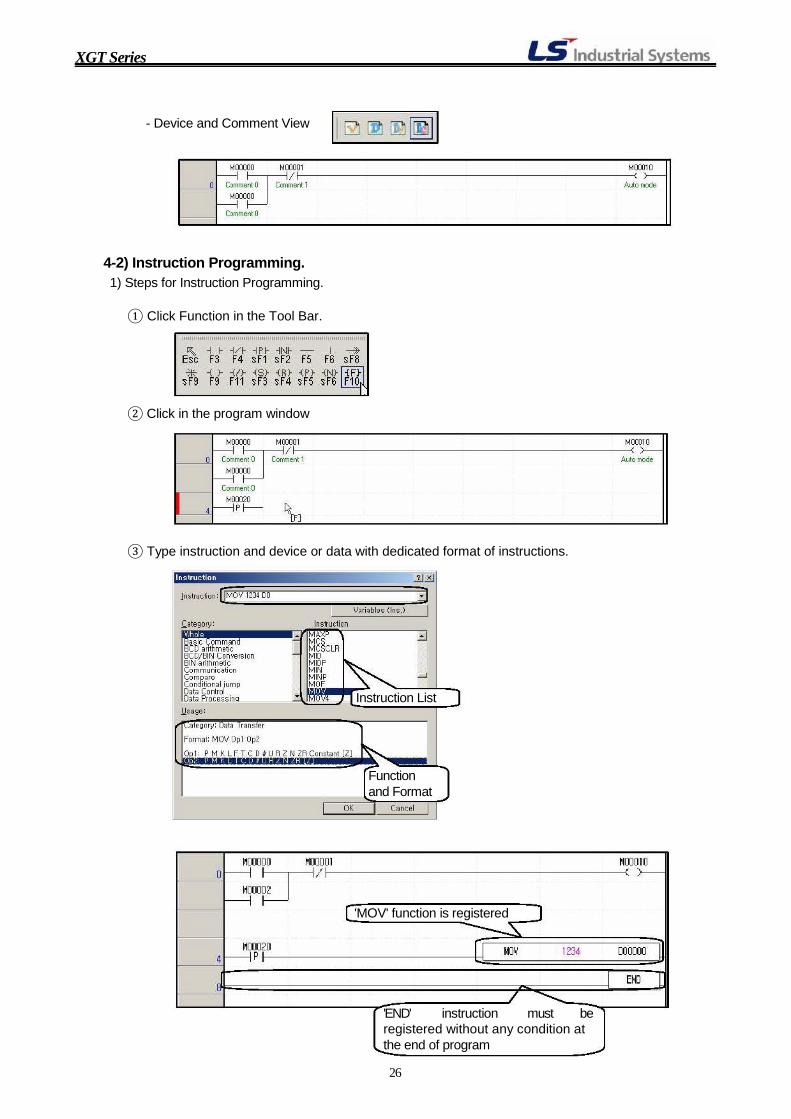
4-2) Instruction Programming. 1) Steps for Instruction Programming.
① Click Function in the Tool Bar. ② Click in the program window ③ Type instruction and device or data with dedicated format of instructions.
Instruction List
Function and Format
'MOV' function is registered
'END' instruction must be registered without any condition at the end of program 26
XGT Series
2) Structures of XGK Instructions. The basic structure of XGK Instructions is 'Prefix + Basic Instruction + Suffix' structure.
① Basic Instruction: Basic Instruction operates 1 word (16 bits) data and its data type is signed
decimal. In some cases, such as MUL (multiplication), although the data size of operand is 1 word data, the result may be 2 words data. And with 1 instruction, more than 2 results may be
created. For example, DIV instruction creates 2 results, the quotient and the remainder, and the
result is stored in 1 word data memory area, respectively.
② Prefix: Prefix mainly designates the size or data type of operands. Available characters for
prefix are D (Double word), R (32-bit Floating), L (64-bit Floating), $ (String), B (bit) and G (Group). Available number of prefix for a basic instruction is 1.
③ Suffix: Suffix designates the size, data type of operands and condition of execution. Available
characters for suffix are 4(Nibble: 4 bits data size), 8(Byte: 8 bits data size), B(BCD data type), P(Edge trigger) and U(Unsigned decimal type). And more than 1 suffices are avail for a basic
instruction. DADDUP D00000 D00002 D00010 => D ADD U P D00000 D00002 D00010 Add Double words of which data are Unsigned integer value at the rising edge of execution
condition.
D: Prefix designating the data size as double word. ADD: Basic Instruction for addition. U: Suffix designating the data type as Unsigned decimal. P: Suffix designating execution condition of rising edge trigger. (Execute 1 time at the rising
edge of execution condition.) Using suffix P is equal to using the condition with Positive Transition Contact. And it is
recommended that avoiding simultaneous use of Positive Transition Contact and suffix P.
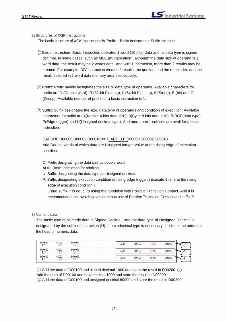
3) Numeric data. The basic type of Numeric data is Signed Decimal. And the data type of Unsigned Decimal is
designated by the suffix of instruction (U). If hexadecimal type is necessary, 'h' should be added at
the head of numeric data.
① ②
③
① Add the data of D00100 and signed decimal 1000 and store the result in D00200. ② Add the data of D00100 and hexadecimal 1000 and store the result in D00200. ③ Add the data of D00100 and unsigned decimal 60000 and store the result in D00200.
27

XGT Series
5. Connection and Download. 5-1) Connection.
XGT series PLC supports various methods of connection between XG5000 and PLC. The 3 representative connection methods will be explained here. Please refer to the XG5000 manual for
details of connection.
1) Local Connection.
Local connection means that connection is established between PC(XG5000) and PLC directly.
Available methods for local connection are RS-232C and USB communication. Connection method
can be designated in the 'Connection Settings…' of online menu.
① RS-232C connection: The RS-232C connection is the most widely used connection method. The
cable connection diagram is depicted and connection steps are explained below. PC PLC
(XG5000) 2 2 3 35 5
ⓐ Select RS-232C in the Type and Local in the Depth in Connection settings and click Settings button to setup details of RS-232C communication.
ⓑ Select the Port number available in the computer and Baud rate. 115200 is recommended for fast communication between XG5000 and PLC. And if connection is broken frequently, the Baud rate may be reduced to 38400.
ⓒ Preview of Connection.
28

XGT Series
② USB Connection: USB connection is increasing due to fast communication speed and non-serial port laptop computer. The USB cable is sold by LSIS ( Part name: USB-301A) and connection steps are explained below.
ⓐ USB Driver setup: USB driver file for XGT PLC is included in XG5000. If XGT PLC is
connected to computer for the first time, windows will find the driver file for XGT PLC. Please designate the 'Driver' folder of XG5000.
ⓑ Select USB in the Type and Local in the Depth in Connection settings. If USB is selected in
the Type, Settings… button will be disabled.
ⓒ Preview of Connection.
2) Remote1 Connection via Fast Ethernet module. Remote 1 connection means that computer (XG5000) and PLC is connected via communication
module of PLC. Communication module, such as Cnet, FEnet and so on, is installed and computer is
connected to network, various methods for connection will be available with easy.
① FEnet: It is available when LAN card is installed in the PC and FEnet module is installed in the
PLC. The connection steps are explained below.
ⓐ Select Ethernet in the Type and Remote 1 in the Depth in Connection settings and click
Settings button to setup details of FEnet communication.
ⓑ Set the IP address of PLC Ethernet module. It should be noted for successful communication that the IP address group of computer must be same as the PLC IP address. In other words, the front 3 digit of IP address must be matched each other.
29

XGT Series
ⓒ Preview of Connection.
3) Multi-PLC project. (Multi-PLC Multi-Program, MPMP) Because the definition of project in the XGT system is extended to PLC systems connected with
various kinds of networks, each PLC included in the project file must be connected to designated
PLC system. If connection method of PLC included in the project file is designated, the connection method will be
remembered by the PLC file and connection is possible when connection is necessary without
changing of 'Online Settings'. It is assumed in this example that Project is composed of 2 PLCs, named Main_PLC and Remote 1
respectively, connected via Fast Ethernet communication each other and Local PLC named
Main_PLC is connected to PC via USB communication.
① Local Connection Setting.
ⓐ Select Main_PLC in the Project window and select USB in Type and Local in Depth.
② Remote Connection Setting. ⓐ Select Remote 1 PLC in the Project window, select USB in Type and Remote 1 in Depth and
click 'Settings…' button to setup 'Remote 1 connection settings'.
30

XGT Series
ⓑ Select XGL-FEnet in the Network type, base and slot number where the applicable network module is installed in the 'Local PLC' in the 'Local communication module' and input the IP address of Fast Ethernet module installed 'Remote 1' PLC.
Base and slot number where the network module is installed in Local PLC
Input the IP address of Fast Ethernet module installed 'Remote 1' PLC.
ⓒ Preview of Local Connection.
ⓓ Preview of Remote1 Connection. ⓔ Simultaneous connection of Local and Remote 1 PLC.
If a project is composed of more than 2 PLCs, all online functions of XG5000 is possible simultaneously for all PLCs included in the project.
2 PLCs are connected simultaneously to XG5000 and the status of CPU is displayed.
31
XGT Series
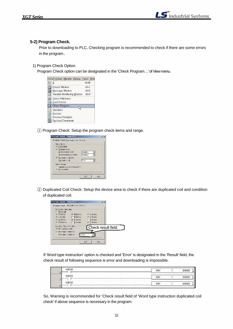
5-2) Program Check. Prior to downloading to PLC, Checking program is recommended to check if there are some errors in the program..
1) Program Check Option.
Program Check option can be designated in the 'Check Program…' of View menu.
① Program Check: Setup the program check items and range. ② Duplicated Coil Check: Setup the device area to check if there are duplicated coil and condition
of duplicated coil.
Check result field.
If 'Word type instruction' option is checked and 'Error' is designated in the 'Result' field, the check result of following sequence is error and downloading is impossible.
So, Warning is recommended for 'Check result field of 'Word type instruction duplicated coil check' if above sequence is necessary in the program.
32

XGT Series
5-3) Downloading project. 1) Select PLC in the Project window which will be downloaded to and Click connection settings in
the Online menu.
Select PLC
Select connection method and setup communication parameter by clicking Setting button.
2) Stop PLC by clicking Stop in the Change Mode from Online menu. 3) Click Write in the Online menu. 4) When writing is finished run the PLC by clicking RUN the Change Mode from Online menu.
33

XGT Series
5) Click Start/Stop Monitoring in the Monitor menu to monitor the data of PLC.
Ladder monitoring is executed automatically when Monitoring is started.
34

XGT Series
6. Online Wroks. Because XG5000 is the essential tool for programming, configuring and managing XGT system, it has various and powerful functions for programming, configuring and managing XGT system.
6-1) Monitoring.
XG5000 has various monitoring functions such as System, Device, Special module, Trend monitoring and Data trace and so on. Some monitoring functions the most widely used will be
explained here.
1) Start/Stop Monitoring and Ladder Monitoring.
Monitoring function must be executed to monitor data of PLC. Click 'Start/Stop Monitoring' in the
Monitor menu or short cut icon of Start/Stop Monitoring ( ) in the Online Toolbar after
connection is established. When monitoring is started, ladder monitoring will be executed
automatically.
① Click 'Start/Stop Monitoring' in the Monitor menu after connection is established. ② Ladder monitoring will be executed automatically.
2) Variable Monitoring. It is possible to monitor the data of desired memory address with Variable Monitoring function of
XG5000. The steps for Variable Monitoring are enumerated below.
① Activate Variable Monitoring window by clicking 'Variable Monitoring window' in the View menu.
35
XGT Series
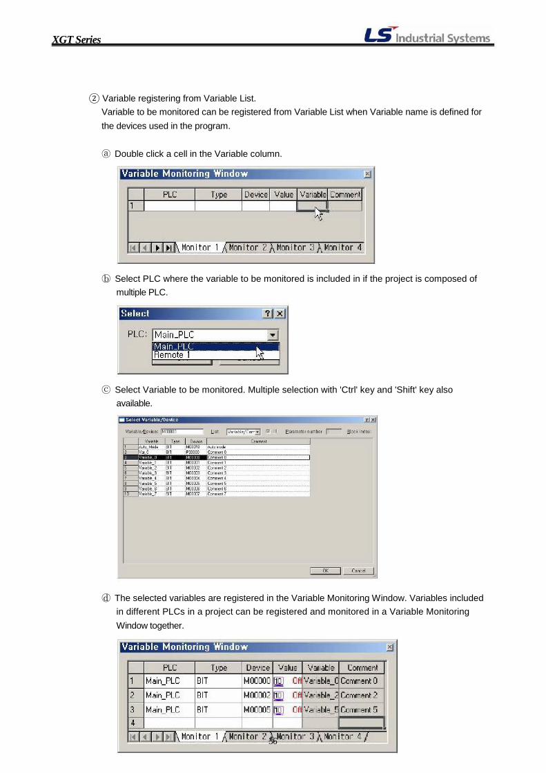
② Variable registering from Variable List. Variable to be monitored can be registered from Variable List when Variable name is defined for the devices used in the program.
ⓐ Double click a cell in the Variable column.
ⓑ Select PLC where the variable to be monitored is included in if the project is composed of
multiple PLC.
ⓒ Select Variable to be monitored. Multiple selection with 'Ctrl' key and 'Shift' key also available.
ⓓ The selected variables are registered in the Variable Monitoring Window. Variables included in different PLCs in a project can be registered and monitored in a Variable Monitoring Window together.
36

XGT Series
③ Variable registering by Device address. If variable name is not defined for the devices used in the program, variables to be monitored can be registered with device address.
ⓐ Select PLC to be monitored if the project is composed of multi PLC.
ⓑ Select data type in the Type column.
ⓒ Input the device address to be monitored on Device column.
ⓓ The desired M00020 bit device is registered and monitored.
37

XGT Series
④ Multiple Variable registering by Device address. Multiple device addresses to be monitored can be registered at a time just like registering variables from variable list.
ⓐ Select a cell in the Device column and click the right side button of mouse and select
'Register All…' in the pop-up menu.
ⓑ Select PLC where the variable to be monitored is included in if the project is composed of multiple PLC.
ⓒ Input the start device address and select data type and the number of address to be monitored. The maximum number of address can be registered at a time is 100.
ⓓ The device addresses D00000 ~ D00002 is registered and monitored in the 'Variable Monitoring Window'.
38

XGT Series
6-2) Custom Events
User defined events are registered in PLC, which will monitor the registered events and record the event history if generated. The event history can be used to operate and debug the system.
1) Steps to setup custom events. ① Set the event condition and its associated device setup.
ⓐ Double click the first row in the 'Custom Event' dialog.
ⓑ Setup the condition, type and message in the 'Event Settings' dialog for custom events. ⓒ Register the memory address of which data will be stored when custom events occurred.
39

XGT Series
40
XGT Series
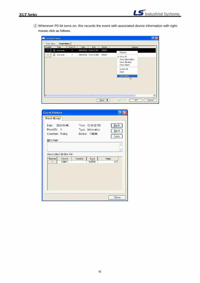
② Whenever P0 bit turns on, this records the event with associated device information with right- mouse click as follows.
41

XGT Series
6-3) Data Traces
'Data Traces' function is very useful to see how meaning data change from when a specific conditions is met.
1) Steps to setup Data Trace.
① Select [Monitor]-[Data Traces] in XG5000. In Data Traces window, select [Trace]-[Trace Settings] where set Trace setup condition and Bit and Word device to trace with sample settings.
② Input bit device address to be trended in the 'Bit device settings' window if necessary. ③ Input word device address to be trended in the 'Word device settings' window, if
necessary.
42

XGT Series
④ PLC program for Data Traces. ⑤ In Data Trances windows, select Read Trace Data to read trend data stored in the
PLC.
43

XGT Series
⑥ Select Data in the View menu of Data Trace window to see data in table format.
44

XGT Series
6-4) Online Editing. Programs can be edited and modified while a PLC is running. Doing so, the real system can be modified without stopping the system. Online editing is possible when online editing is started by
selecting 'Start Online Editing' in the Online menu.
1) Steps for Online Editing.
① Confirm that connection status is online state and PLC is running by checking the status bar
located at the bottom of XG5000.
PLC name PLC mode Connection and communication status
② Select 'Start Online Editing' in the Online menu of shortcut icon for 'Start Online Editing'.
( )
③ The '*' mark will be displayed at the front of online editing program in the project window and
the background color will be changed to cyan color. All functions for editing program are possible while this state is kept.
④ Write modified program when program is modified to apply to operation of system by clicking 'Write Modified Program' and click 'End Online Editing' when online editing is finished.
45

XGT Series
2) Restrictions of Online Editing. Although XG5000 offers powerful online editing functions, restrictions also exist in online editing
function. The restrictions of online editing are enumerated below.
① The items included in the program such as device, variable and instructions and so on, can be
edited while online editing. In other words, parameters cannot be edited while online editing. To be exact, parameters can
be edited while online editing, but cannot be downloaded to PLC while PLC is running. If
parameters are modified while online editing, the mode of PLC must be changed to STOP mode
to download the modified parameters after finishing online editing.
② One program can be edited in one PLC at a time when multiple programs are included in one
PLC. In other words, simultaneous online editing of more than 2 programs in one PLC is prohibited.
46


![[05]Ch.2 Overview and Basics of XGT Panel](https://img.pdfslide.net/doc/110x75/552e26175503462c158b4866/05ch2-overview-and-basics-of-xgt-panel.jpg)