Embed Size (px)
DESCRIPTION
Zigbee Based Two Way Wireless Chatting System..
Citation preview
ZIGBEE BASED TWO WAY WIRELESS CHATTING SYSTEM
Presented By:
P.SHASHIDHAR REDDY 10TC1A0442
SK.PRUDVIRAJ 10TC1A0446
R.RAGHUNATH REDDY 10TC1A0445
N.PUSHPALATHA 10TC1A0433
Under Extreme Guidance of G.L. SINGH
CONTENTS:
Introduction Block Diagram Zigbee Module AT89S52 Micro Controller Regulated Power Supply LCD Conclusion
INTRODUCTION:
To generate signal in No-signal area. Wireless transmission of data between two devices. Over come the draw backs of Bluetooth, wifi. To perform high level communication. It’s highly preferable in rural areas.
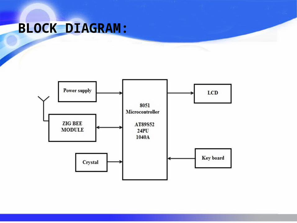
BLOCK DIAGRAM:
ZIGBEE
MODULE
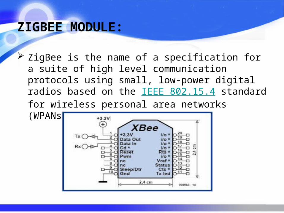
ZIGBEE MODULE:
ZigBee is the name of a specification for a suite of high level communication protocols using small, low-power digital radios based on the IEEE 802.15.4 standard for wireless personal area networks (WPANs).
WHY ZIGBEE…???
Standards based Low cost Can be used globally Reliable and self healing Supports large number of nodes Easy to deploy Very long battery life Secure
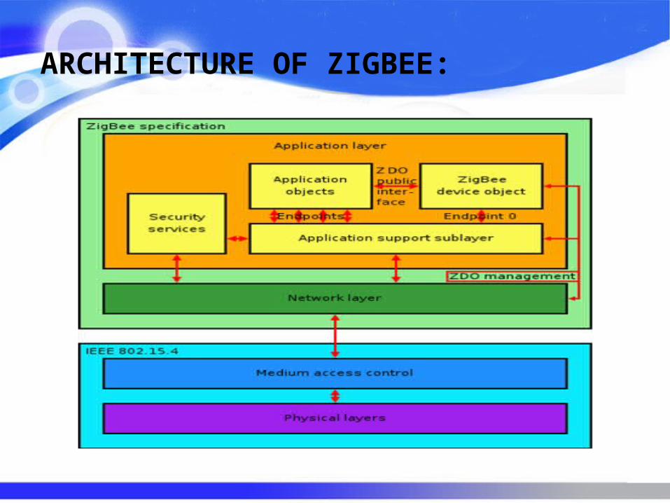
ARCHITECTURE OF ZIGBEE:
PEER-TO-PEER DATA TRANSFER:
The devices are free to communicate with any other device within their communication range.
In a peer-to-peer PAN the devices can “either receive constantly or synchronize with each other.”
If they are receiving constantly, to transmit data they use un-slotted CSMA-CA. In the second case, synchronization must be achieved first.
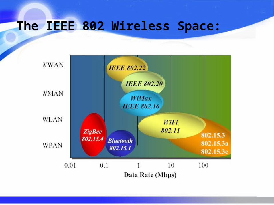
The IEEE 802 Wireless Space:
MICRO
CONTROLLER
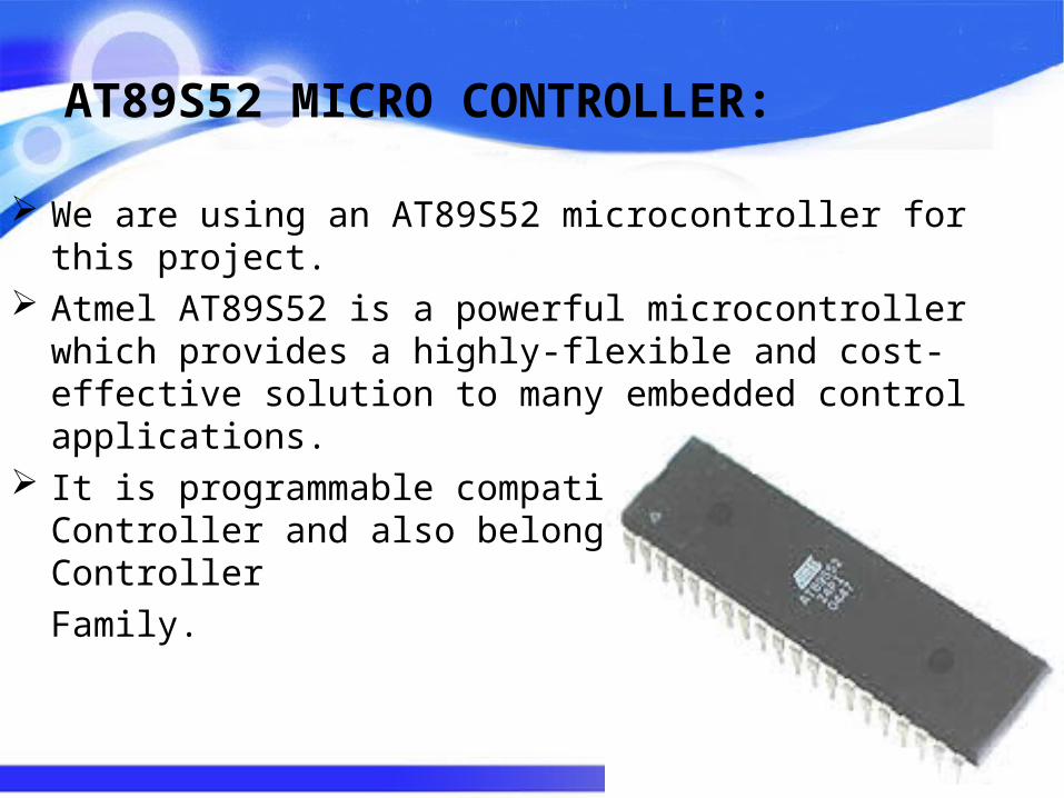
AT89S52 MICRO CONTROLLER:
We are using an AT89S52 microcontroller for this project. Atmel AT89S52 is a powerful microcontroller which provides a
highly-flexible and cost-effective solution to many embedded control applications.
It is programmable compatible with 8051 Micro Controller and also belongs to 8051 Micro Controller
Family.
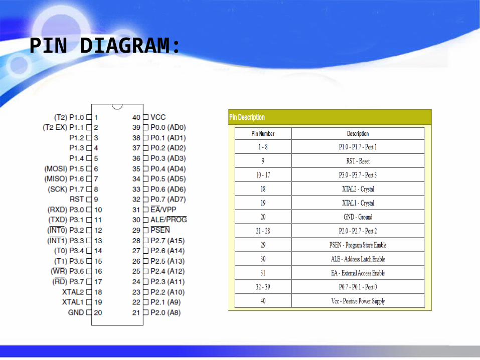
PIN DIAGRAM:
FEATURES:
4.0V to 5.5V Operating Range Fully Static Operation: 0 Hz to 33 MHz Three-level Program Memory Lock 256 x 8-bit Internal RAM 32 Programmable I/O Lines Three 16-bit Timer/Counters Eight Interrupt Sources Full Duplex UART Serial Channel Fast Programming Time
POWER
SUPPLY
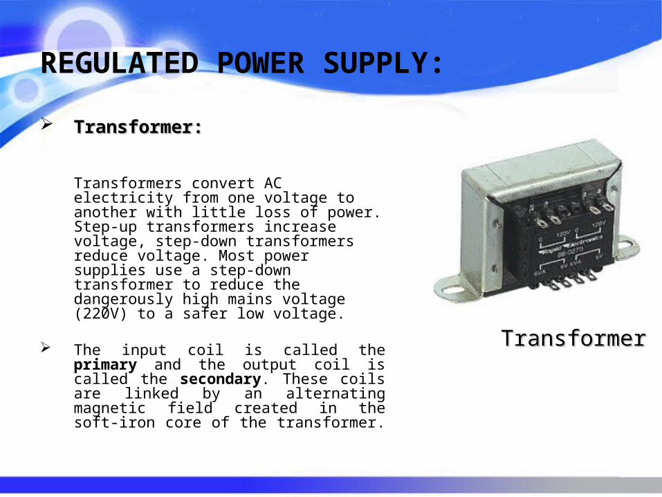
REGULATED POWER SUPPLY:
TransformerTransformer:: Transformers convert AC
electricity from one voltage to another with little loss of power. Step-up transformers increase voltage, step-down transformers reduce voltage. Most power supplies use a step-down transformer to reduce the dangerously high mains voltage (220V) to a safer low voltage.
The input coil is called the primary and the output coil is called the secondary. These coils are linked by an alternating magnetic field created in the soft-iron core of the transformer.
TransformerTransformer
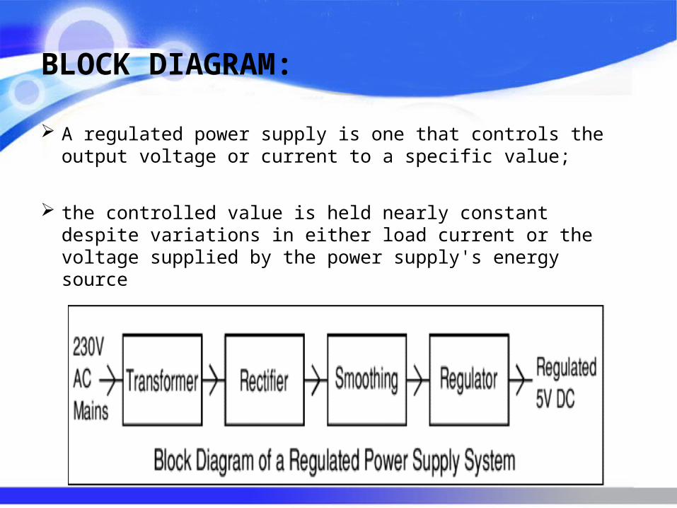
BLOCK DIAGRAM:
A regulated power supply is one that controls the output voltage or current to a specific value;
the controlled value is held nearly constant despite variations in either load current or the voltage supplied by the power supply's energy source
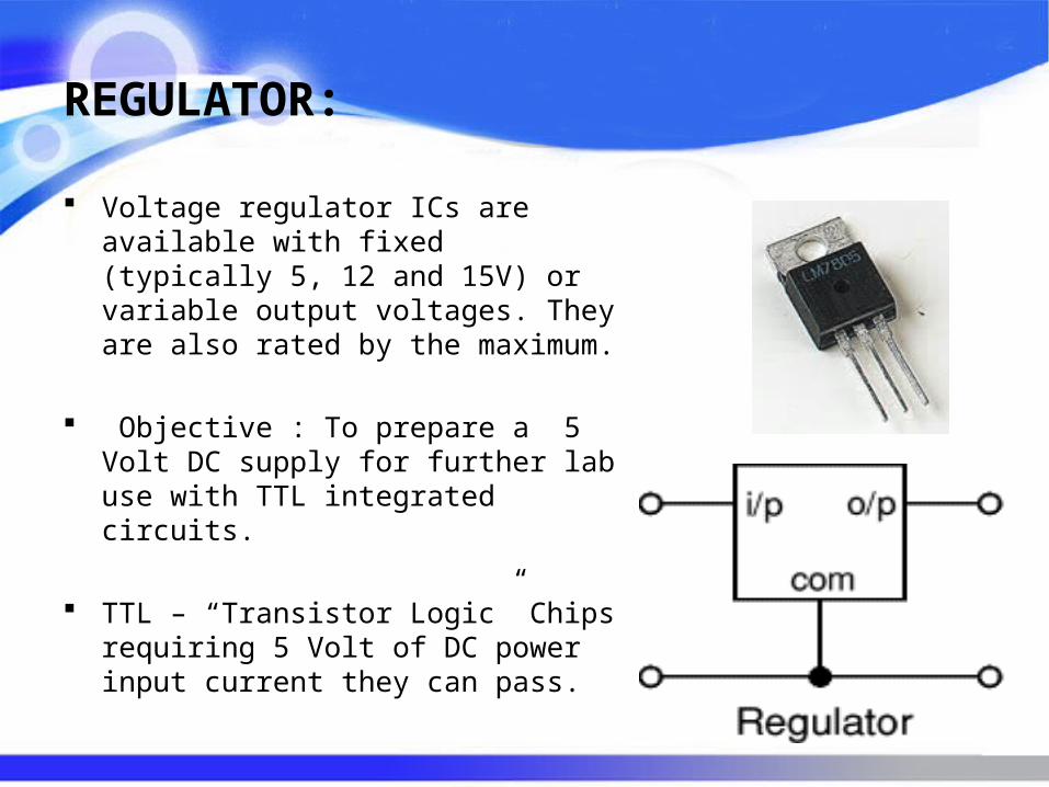
REGULATOR:
Voltage regulator ICs are available with fixed (typically 5, 12 and 15V) or variable output voltages. They are also rated by the maximum.
Objective : To prepare a 5 Volt DC supply for further lab use with TTL integrated circuits.
TTL – “Transistor Logic” Chips requiring 5 Volt of DC power input current they can pass.
LCD (Liquid
Crystal
Display)
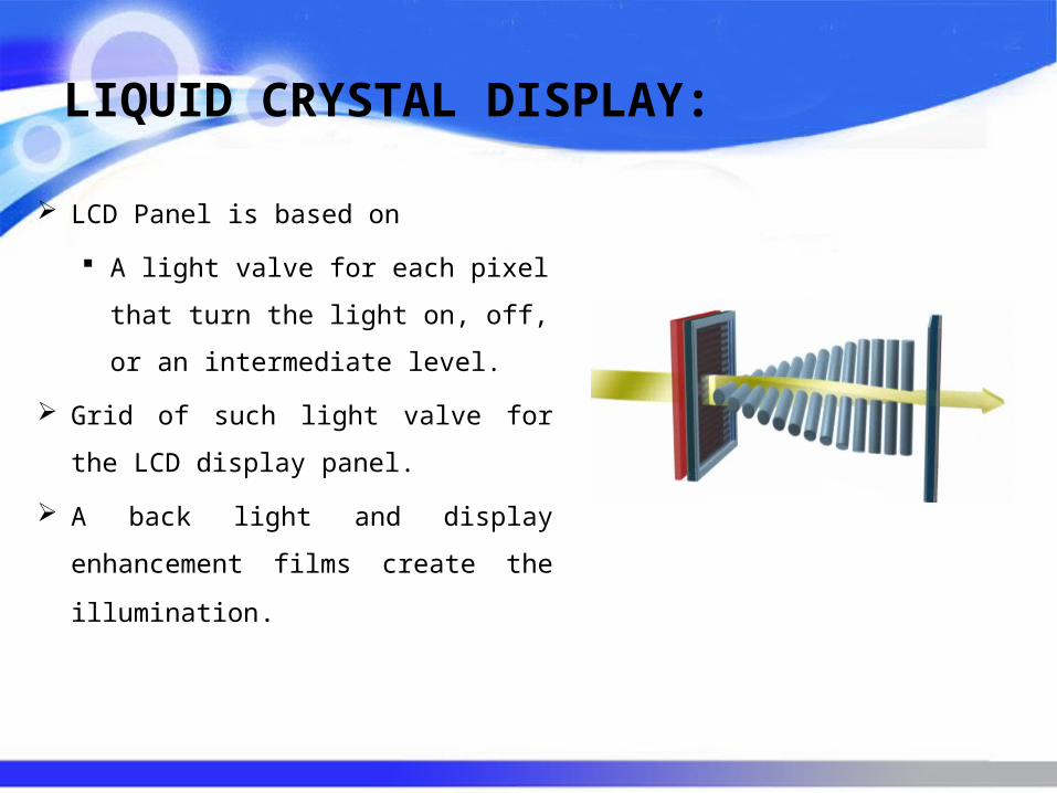
LIQUID CRYSTAL DISPLAY:
LCD Panel is based on
A light valve for each pixel that
turn the light on, off, or an
intermediate level.
Grid of such light valve for the LCD
display panel.
A back light and display enhancement
films create the illumination.
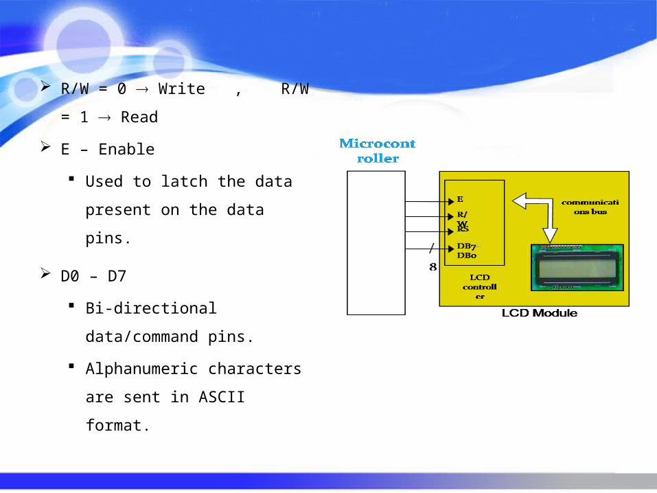
R/W = 0 Write , R/W = 1
Read
E – Enable
Used to latch the data present
on the data pins.
D0 – D7
Bi-directional data/command
pins.
Alphanumeric characters are
sent in ASCII format.
APPLICATIONS:
Data Transfer Between Two Devices. In Digital Libraries. For Communication In Rural Areas.

CONCLUSIO
N
CONCLUSION:
Our project is designed mainly for communication between two devices and enjoy the high-quality wireless communication.
Further scope for this project is improvising the security of the system.