Embed Size (px)
Citation preview

© 2008 Pearson Education, Inc.Pearson Prentice Hall - Upper Saddle River, NJ 07458
Automotive Technology: Principles, Diagnosis, and Service, 3rd EditionBy James D. Halderman
© 2009 Pearson Education, Inc.Pearson Prentice Hall - Upper Saddle River, NJ 07458
start

© 2008 Pearson Education, Inc.Pearson Prentice Hall - Upper Saddle River, NJ 07458
Automotive Technology: Principles, Diagnosis, and Service, 3rd EditionBy James D. Halderman
© 2009 Pearson Education, Inc.Pearson Prentice Hall - Upper Saddle River, NJ 07458
• Prepare for ASE Brakes (A5) certification test content area “D” (Power Assist Units Diagnosis and Repair).
• List the parts of a vacuum brake booster.
• Describe how a vacuum brake booster operates.
• Explain how to test a vacuum brake booster.
• Describe how a hydraulic or electrohydraulic brake booster operates.
After studying Chapter 80, the reader should be able to:
OBJECTIVES:

© 2008 Pearson Education, Inc.Pearson Prentice Hall - Upper Saddle River, NJ 07458
Automotive Technology: Principles, Diagnosis, and Service, 3rd EditionBy James D. Halderman
© 2009 Pearson Education, Inc.Pearson Prentice Hall - Upper Saddle River, NJ 07458
atmospheric pressure • brake assist system (BAS)
dual-diaphragm vacuum booster
inches of mercury (in. Hg)
millimeters of mercury (mm Hg)
power chamber • pressure differential
supplemental brake assist (SBA)
tandem-diaphragm vacuum booster • vacuum
KEY TERMS:

© 2008 Pearson Education, Inc.Pearson Prentice Hall - Upper Saddle River, NJ 07458
Automotive Technology: Principles, Diagnosis, and Service, 3rd EditionBy James D. Halderman
© 2009 Pearson Education, Inc.Pearson Prentice Hall - Upper Saddle River, NJ 07458
THE NEED FOR POWER BRAKE ASSIST
To double the stopping power of a disc brake, the driver must double the force on the brake pedal. This is the reason that most vehicles equipped with disc brakes are power assisted. The most commonly used power-assisted units are vacuum operated.
When a power booster is fitted, brake pedal ratio is decreased and the master cylinder bore size is increased. The effect of these changes is to reduce pedal effort, greatly increasing pedal reserve.
Power boosters do not alter the hydraulic system and allow braking even if the booster fails or its power supply is cut off. All boosters have a power reserve that provides assist for at least one hard stop, and sometimes several light brake applications, even after power is lost. See Figure 80–1.
Continued

© 2008 Pearson Education, Inc.Pearson Prentice Hall - Upper Saddle River, NJ 07458
Automotive Technology: Principles, Diagnosis, and Service, 3rd EditionBy James D. Halderman
© 2009 Pearson Education, Inc.Pearson Prentice Hall - Upper Saddle River, NJ 07458
Figure 80–1 Typical vacuum brake booster assembly. The vacuum hose attaches to the intake manifold of the engine. The brake pedal travel sensor is an input sensor for the antilock braking system.
Continued

© 2008 Pearson Education, Inc.Pearson Prentice Hall - Upper Saddle River, NJ 07458
Automotive Technology: Principles, Diagnosis, and Service, 3rd EditionBy James D. Halderman
© 2009 Pearson Education, Inc.Pearson Prentice Hall - Upper Saddle River, NJ 07458
Figure 80–2 A wide brake pedal allows two foot braking if power assist is lost.
Because power brake systems are designed with the added force of the booster taken into account, the amount of brake pedal pressure required to slow or stop a vehicle is much higher than in a nonboosted system once the reserve is used up.
For this reason, some vehicles with power brakes have a brake pedal that is wide enough to allow two-foot braking should the booster fail.
Continued
© 2008 Pearson Education, Inc.Pearson Prentice Hall - Upper Saddle River, NJ 07458
Automotive Technology: Principles, Diagnosis, and Service, 3rd EditionBy James D. Halderman
© 2009 Pearson Education, Inc.Pearson Prentice Hall - Upper Saddle River, NJ 07458
PRINCIPLES OF VACUUM
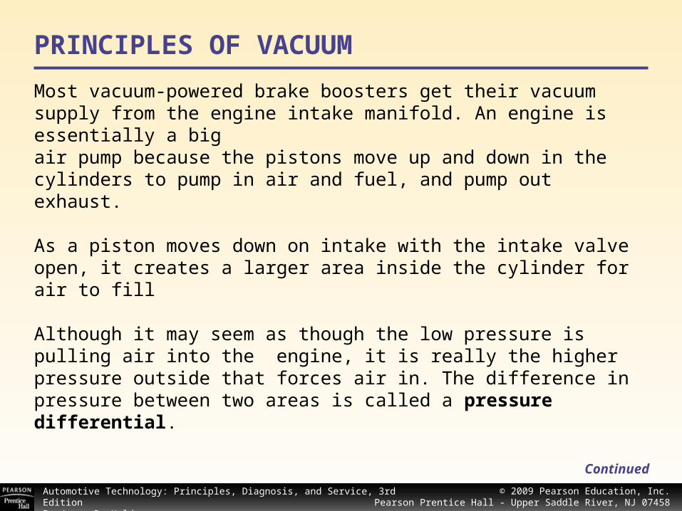
Most vacuum-powered brake boosters get their vacuum supply from the engine intake manifold. An engine is essentially a bigair pump because the pistons move up and down in thecylinders to pump in air and fuel, and pump out exhaust.
As a piston moves down on intake with the intake valve open, it creates a larger area inside the cylinder for air to fill
Although it may seem as though the low pressure is pulling air into the engine, it is really the higher pressure outside that forces air in. The difference in pressure between two areas is called a pressure differential.
Continued

© 2008 Pearson Education, Inc.Pearson Prentice Hall - Upper Saddle River, NJ 07458
Automotive Technology: Principles, Diagnosis, and Service, 3rd EditionBy James D. Halderman
© 2009 Pearson Education, Inc.Pearson Prentice Hall - Upper Saddle River, NJ 07458
Figure 80–3 Atmospheric pressure varies with altitude.
Gasoline-powered internal-combustion engines normally operate with a low-pressure area, or partial vacuum, in the intake manifold.
The term vacuum is used to refer to any pressure lower than atmospheric pressure.
Atmospheric pressure varies with altitude, but is about 14.7 pounds per square inch (psi) at sea level.
Continued

© 2008 Pearson Education, Inc.Pearson Prentice Hall - Upper Saddle River, NJ 07458
Automotive Technology: Principles, Diagnosis, and Service, 3rd EditionBy James D. Halderman
© 2009 Pearson Education, Inc.Pearson Prentice Hall - Upper Saddle River, NJ 07458
Measuring Vacuum Vacuum is measured in inches of mercury (in. Hg) or in millimeters of mercury (mm Hg), a figure that indicates how far a column of mercury will rise when a vacuumis applied at one end, and atmospheric pressure at the other.
Vacuum is a measurement of the pressure differential between the lower pressure inside the tube, and the higher pressure outside it.
Manifold vacuum varies with throttle position. The lowest vacuum (highest pressure) occurs when the throttle is wideopen with the engine under load.
The highest manifold vacuum (lowest pressure) may be as much as 24 in. Hg (610 mm Hg). Vacuum at idle typically falls between 15 and 20 in. Hg (381 and 508 mm Hg). Most vacuum brake boosters operate with vacuum levels in this range.
Continued

© 2008 Pearson Education, Inc.Pearson Prentice Hall - Upper Saddle River, NJ 07458
Automotive Technology: Principles, Diagnosis, and Service, 3rd EditionBy James D. Halderman
© 2009 Pearson Education, Inc.Pearson Prentice Hall - Upper Saddle River, NJ 07458
Booster Vacuum Supply Vacuum boosters get their vacuum supply from the engine intake manifold. Diesel engines, however, run unthrottled (engine speed is controlled strictly by the amount of fuel injected) and have little or no intake manifold vacuum.
Continued
Figure 80–4 A belt-driven auxiliary vacuum pump.
If a vehicle with a diesel engine is equipped with a vacuum-powered brake booster, it must also be fitted with an auxiliary vacuum pump.
Some small gasoline-poweredand diesel engines use a belt-driven add-on pump.

© 2008 Pearson Education, Inc.Pearson Prentice Hall - Upper Saddle River, NJ 07458
Automotive Technology: Principles, Diagnosis, and Service, 3rd EditionBy James D. Halderman
© 2009 Pearson Education, Inc.Pearson Prentice Hall - Upper Saddle River, NJ 07458
Figure 80–5 An electrically powered vacuum pump.
An electrically powered vacuum pump is turned on and off by a pressure switch on the booster. This means they operate only when needed, and thus reduce power drain on the engine.
Continued

© 2008 Pearson Education, Inc.Pearson Prentice Hall - Upper Saddle River, NJ 07458
Automotive Technology: Principles, Diagnosis, and Service, 3rd EditionBy James D. Halderman
© 2009 Pearson Education, Inc.Pearson Prentice Hall - Upper Saddle River, NJ 07458
VACUUM BOOSTER THEORY
Vacuum boosters use pressure differential to increase brake application force. The typical booster has a power chamber separated into two smaller chambers by a flexible diaphragm.
In an attempt to equalize pressure in the two chambers, the higher pressure exerts force that moves the diaphragm toward the lower pressure. Rods attached to the diaphragm transmit this force, plus force the driver exerts on the brake pedal, to the master cylinder.
The amount of force created in this manner is proportional to the difference in pressure between the two sides. In other words, the greater the pressure differential, the greater the force.
Continued
© 2008 Pearson Education, Inc.Pearson Prentice Hall - Upper Saddle River, NJ 07458
Automotive Technology: Principles, Diagnosis, and Service, 3rd EditionBy James D. Halderman
© 2009 Pearson Education, Inc.Pearson Prentice Hall - Upper Saddle River, NJ 07458
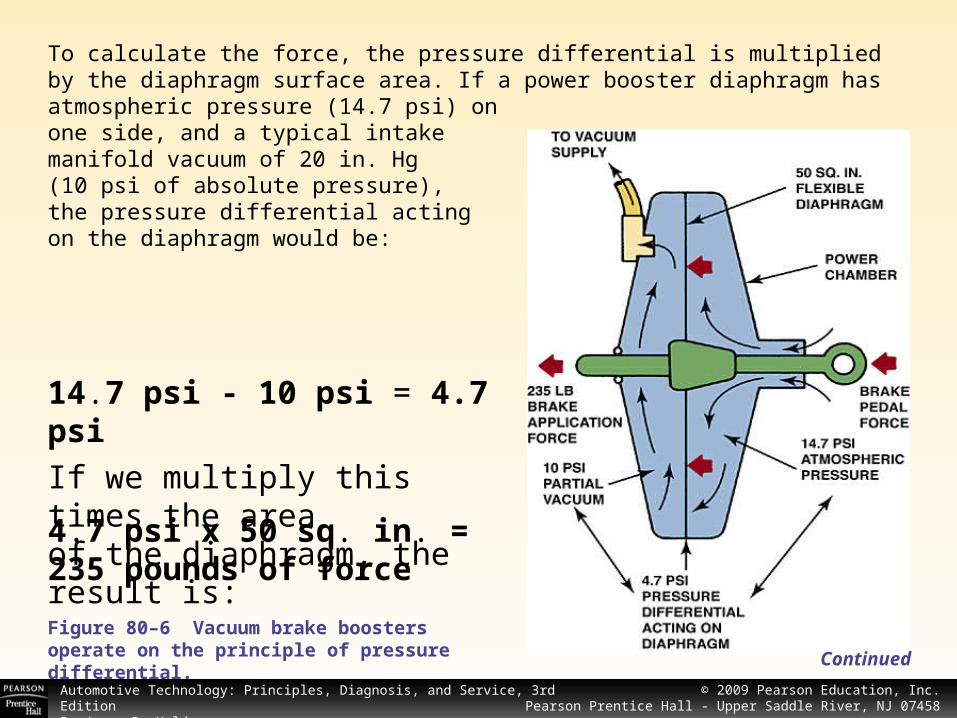
To calculate the force, the pressure differential is multiplied by the diaphragm surface area. If a power booster diaphragm has atmospheric pressure (14.7 psi) onone side, and a typical intake manifold vacuum of 20 in. Hg(10 psi of absolute pressure),the pressure differential actingon the diaphragm would be:
Continued
Figure 80–6 Vacuum brake boosters operate on the principle of pressure differential.
14.7 psi - 10 psi = 4.7 psi
If we multiply this times the areaof the diaphragm, the result is:
4.7 psi x 50 sq. in. = 235 pounds of force

© 2008 Pearson Education, Inc.Pearson Prentice Hall - Upper Saddle River, NJ 07458
Automotive Technology: Principles, Diagnosis, and Service, 3rd EditionBy James D. Halderman
© 2009 Pearson Education, Inc.Pearson Prentice Hall - Upper Saddle River, NJ 07458
Check the Vacuum, Then the Brakes - Part 1
A customer complained of very rough idle and an occasional pulsating brake pedal. The customer was certain the engine required serious work since there were over 100,000 miles on the vehicle. During the troubleshooting procedure, a spray cleaner was used to find any vacuum leaks. A large hole was found melted through a large vacuum hose next to the vacuum hose feeding the vacuum-operated power brake booster.
After repairing the vacuum leak, the vehicle was test driven again to help diagnose the cause of the pulsating brake pedal. The engine idled very smoothly after the leak was repaired and brake pulsation was also cured.
The vacuum leak resulted in lower-than-normal vacuum being applied to the vacuum booster. During braking, when engine vacuum is normally higher (deceleration), the vacuum booster would assist, then not assist when the vacuum was lost. This on-and-off supply of vacuum to the vacuum booster was noticed by the driver as a brake pulsation. Always check vacuum at the booster whenever diagnosing any brake problems.
© 2008 Pearson Education, Inc.Pearson Prentice Hall - Upper Saddle River, NJ 07458
Automotive Technology: Principles, Diagnosis, and Service, 3rd EditionBy James D. Halderman
© 2009 Pearson Education, Inc.Pearson Prentice Hall - Upper Saddle River, NJ 07458
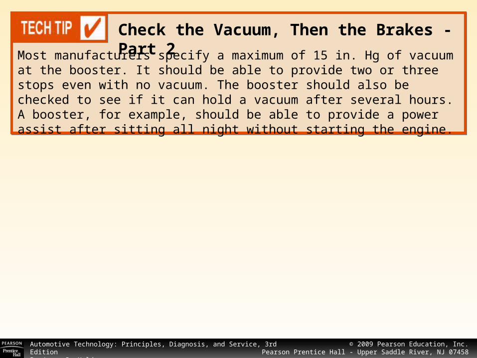
Check the Vacuum, Then the Brakes - Part 2
Most manufacturers specify a maximum of 15 in. Hg of vacuum at the booster. It should be able to provide two or three stops even with no vacuum. The booster should also be checked to see if it can hold a vacuum after several hours. A booster, for example, should be able to provide a power assist after sitting all night without starting the engine.

© 2008 Pearson Education, Inc.Pearson Prentice Hall - Upper Saddle River, NJ 07458
Automotive Technology: Principles, Diagnosis, and Service, 3rd EditionBy James D. Halderman
© 2009 Pearson Education, Inc.Pearson Prentice Hall - Upper Saddle River, NJ 07458
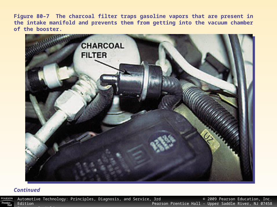
CHARCOAL FILTER
The vacuum hose leading from the engine to the power booster should run downward without any low places.
If a dip or sag occurs in the hose, condensed fuel vapors and/or moisture accumulate that block or restrict vacuum to the booster.
Many manufacturers use a small charcoal filter in the vacuum line between the engine and booster. The filter attracts and holds fuel vapors and keeps fumes from entering the vacuum booster.
Without this filter, gasoline fumes can enter the vacuum booster, where it can deteriorate the rubber diaphragm and other rubber components of the booster. See Figure 80–7.
Continued
© 2008 Pearson Education, Inc.Pearson Prentice Hall - Upper Saddle River, NJ 07458
Automotive Technology: Principles, Diagnosis, and Service, 3rd EditionBy James D. Halderman
© 2009 Pearson Education, Inc.Pearson Prentice Hall - Upper Saddle River, NJ 07458
Figure 80–7 The charcoal filter traps gasoline vapors that are present in the intake manifold and prevents them from getting into the vacuum chamber of the booster.
Continued

© 2008 Pearson Education, Inc.Pearson Prentice Hall - Upper Saddle River, NJ 07458
Automotive Technology: Principles, Diagnosis, and Service, 3rd EditionBy James D. Halderman
© 2009 Pearson Education, Inc.Pearson Prentice Hall - Upper Saddle River, NJ 07458
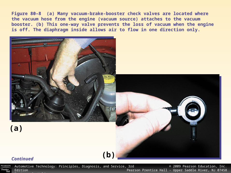
VACUUM CHECK VALVE
All vacuum boosters use a one-way vacuum check valve. This valve allows air to flow in only one direction—from the booster toward the engine.
This valve prevents loss of vacuum when the engine stops.
Without this check valve, the vacuum stored in the vacuum booster would simply be lost through the hose and intakemanifold of the engine.
See Figures 80–8 and 80–9.
Continued
© 2008 Pearson Education, Inc.Pearson Prentice Hall - Upper Saddle River, NJ 07458
Automotive Technology: Principles, Diagnosis, and Service, 3rd EditionBy James D. Halderman
© 2009 Pearson Education, Inc.Pearson Prentice Hall - Upper Saddle River, NJ 07458
Figure 80–8 (a) Many vacuum-brake-booster check valves are located where the vacuum hose from the engine (vacuum source) attaches to the vacuum booster. (b) This one-way valve prevents the loss of vacuum when the engine is off. The diaphragm inside allows air to flow in one direction only.
(a)
(b)Continued

© 2008 Pearson Education, Inc.Pearson Prentice Hall - Upper Saddle River, NJ 07458
Automotive Technology: Principles, Diagnosis, and Service, 3rd EditionBy James D. Halderman
© 2009 Pearson Education, Inc.Pearson Prentice Hall - Upper Saddle River, NJ 07458
Figure 80–9 Not all check valves are located at the vacuum line to the booster housing connection. This vehicle uses an inline check valve located between the intake manifold of the engine and the vacuum brake booster.
Continued
© 2008 Pearson Education, Inc.Pearson Prentice Hall - Upper Saddle River, NJ 07458
Automotive Technology: Principles, Diagnosis, and Service, 3rd EditionBy James D. Halderman
© 2009 Pearson Education, Inc.Pearson Prentice Hall - Upper Saddle River, NJ 07458
CAUTION: Sometimes an engine backfire can destroy or blow the vacuum check valve out of the booster housing. If this occurs, all power assist will be lost and a much greater-than-normal force must be exerted on the brake pedal to stop the vehicle. Be sure to repair the cause of the backfire before replacing the damaged or missing check valve. Normal causes of backfire include an excessively lean air–fuel ratio or incorrect firing order or ignition timing.
CAUTION: Sometimes an engine backfire can destroy or blow the vacuum check valve out of the booster housing. If this occurs, all power assist will be lost and a much greater-than-normal force must be exerted on the brake pedal to stop the vehicle. Be sure to repair the cause of the backfire before replacing the damaged or missing check valve. Normal causes of backfire include an excessively lean air–fuel ratio or incorrect firing order or ignition timing.
© 2008 Pearson Education, Inc.Pearson Prentice Hall - Upper Saddle River, NJ 07458
Automotive Technology: Principles, Diagnosis, and Service, 3rd EditionBy James D. Halderman
© 2009 Pearson Education, Inc.Pearson Prentice Hall - Upper Saddle River, NJ 07458
VACUUM BRAKE BOOSTER OPERATION
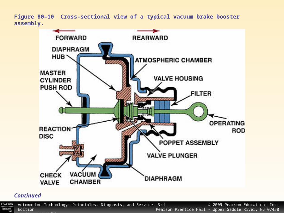
A vacuum power-brake booster contains a rubber diaphragm(s) connected to the brake pedal at one end and to the master cylinder at the other end. When the brakes are off or released, there is equal vacuum on both sides of the diaphragm.
The vacuum power unit contains the power-piston assembly, which houses the control valve and reaction mechanism, and the power-piston return spring.
An air filter, air silencer, and filter retainer are assembled around the valve operating rod, inside the hub of the power piston. The pushrod that operates the air valve projects out of the end.
See Figure 80–10.Continued
© 2008 Pearson Education, Inc.Pearson Prentice Hall - Upper Saddle River, NJ 07458
Automotive Technology: Principles, Diagnosis, and Service, 3rd EditionBy James D. Halderman
© 2009 Pearson Education, Inc.Pearson Prentice Hall - Upper Saddle River, NJ 07458
Figure 80–10 Cross-sectional view of a typical vacuum brake booster assembly.
Continued
© 2008 Pearson Education, Inc.Pearson Prentice Hall - Upper Saddle River, NJ 07458
Automotive Technology: Principles, Diagnosis, and Service, 3rd EditionBy James D. Halderman
© 2009 Pearson Education, Inc.Pearson Prentice Hall - Upper Saddle River, NJ 07458
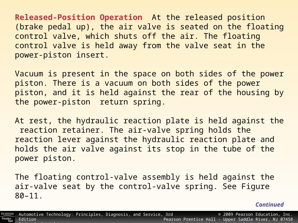
Released-Position Operation At the released position (brake pedal up), the air valve is seated on the floating control valve, which shuts off the air. The floating control valve is held away from the valve seat in the power-piston insert.
Vacuum is present in the space on both sides of the power piston. There is a vacuum on both sides of the power piston, and it is held against the rear of the housing by the power-piston return spring.
At rest, the hydraulic reaction plate is held against the reaction retainer. The air-valve spring holds the reaction lever against the hydraulic reaction plate and holds the air valve against its stop in the tube of the power piston.
The floating control-valve assembly is held against the air-valve seat by the control-valve spring. See Figure 80–11.
Continued

© 2008 Pearson Education, Inc.Pearson Prentice Hall - Upper Saddle River, NJ 07458
Automotive Technology: Principles, Diagnosis, and Service, 3rd EditionBy James D. Halderman
© 2009 Pearson Education, Inc.Pearson Prentice Hall - Upper Saddle River, NJ 07458
Figure 80–11 In the release position (brake pedal up), the vacuum is directed to both sides of the diaphragm.
Continued
© 2008 Pearson Education, Inc.Pearson Prentice Hall - Upper Saddle River, NJ 07458
Automotive Technology: Principles, Diagnosis, and Service, 3rd EditionBy James D. Halderman
© 2009 Pearson Education, Inc.Pearson Prentice Hall - Upper Saddle River, NJ 07458
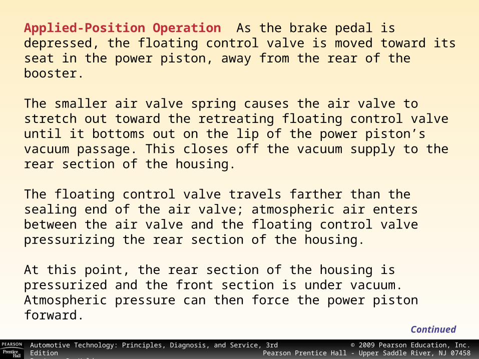
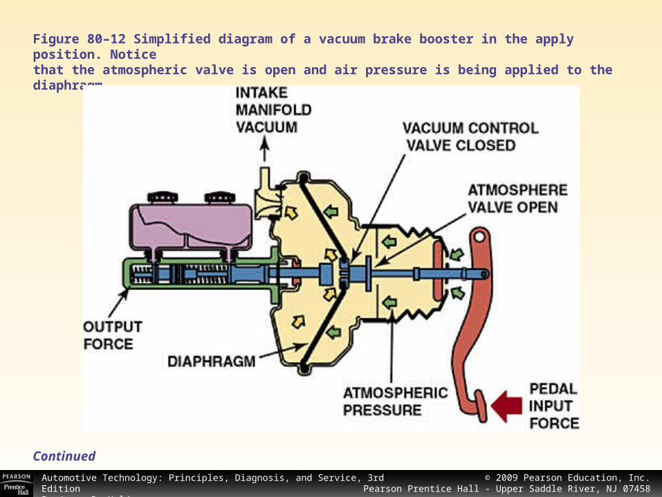
Applied-Position Operation As the brake pedal is depressed, the floating control valve is moved toward its seat in the power piston, away from the rear of the booster.
The smaller air valve spring causes the air valve to stretch out toward the retreating floating control valve until it bottoms out on the lip of the power piston’s vacuum passage. This closes off the vacuum supply to the rear section of the housing.
The floating control valve travels farther than the sealing end of the air valve; atmospheric air enters between the air valve and the floating control valve pressurizing the rear section of the housing.
At this point, the rear section of the housing is pressurized and the front section is under vacuum. Atmospheric pressure can then force the power piston forward.
Continued
© 2008 Pearson Education, Inc.Pearson Prentice Hall - Upper Saddle River, NJ 07458
Automotive Technology: Principles, Diagnosis, and Service, 3rd EditionBy James D. Halderman
© 2009 Pearson Education, Inc.Pearson Prentice Hall - Upper Saddle River, NJ 07458
NOTE: This movement of air into the rear chamber of the brake booster may be heard inside the vehicle as a hissing noise. The loudness of this airflow varies from vehicle to vehicle and should be considered normal.
NOTE: This movement of air into the rear chamber of the brake booster may be heard inside the vehicle as a hissing noise. The loudness of this airflow varies from vehicle to vehicle and should be considered normal.
As back-pressure builds up on the end of the master cylinder piston, the floating control valve is pushed back off of its seat in the power piston applying back pressure to the brake pedal.
The power piston return spring also generates some brake pedal force. Approximately 30% of the brake load is applied back to the brake pedal.
This gives the driver a feel that is proportional to the degree of brake application.
See Figure 80-12.Continued
© 2008 Pearson Education, Inc.Pearson Prentice Hall - Upper Saddle River, NJ 07458
Automotive Technology: Principles, Diagnosis, and Service, 3rd EditionBy James D. Halderman
© 2009 Pearson Education, Inc.Pearson Prentice Hall - Upper Saddle River, NJ 07458
Figure 80–12 Simplified diagram of a vacuum brake booster in the apply position. Noticethat the atmospheric valve is open and air pressure is being applied to the diaphragm.
Continued
© 2008 Pearson Education, Inc.Pearson Prentice Hall - Upper Saddle River, NJ 07458
Automotive Technology: Principles, Diagnosis, and Service, 3rd EditionBy James D. Halderman
© 2009 Pearson Education, Inc.Pearson Prentice Hall - Upper Saddle River, NJ 07458
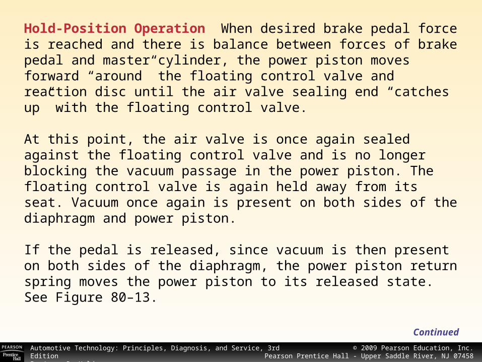
Hold-Position Operation When desired brake pedal force is reached and there is balance between forces of brake pedal and master cylinder, the power piston moves forward “around” the floating control valve and reaction disc until the air valve sealing end “catches up” with the floating control valve.
At this point, the air valve is once again sealed against the floating control valve and is no longer blocking the vacuum passage in the power piston. The floating control valve is again held away from its seat. Vacuum once again is present on both sides of the diaphragm and power piston.
If the pedal is released, since vacuum is then present on both sides of the diaphragm, the power piston return spring moves the power piston to its released state. See Figure 80–13.
Continued
© 2008 Pearson Education, Inc.Pearson Prentice Hall - Upper Saddle River, NJ 07458
Automotive Technology: Principles, Diagnosis, and Service, 3rd EditionBy James D. Halderman
© 2009 Pearson Education, Inc.Pearson Prentice Hall - Upper Saddle River, NJ 07458
Figure 80–13 Cross section of a vacuum brake booster in the hold position with both vacuum and atmospheric valves closed. Note that the reaction force from the brake fluid pressure is transferred back to the driver as a reaction force to the brake pedal.
Continued

© 2008 Pearson Education, Inc.Pearson Prentice Hall - Upper Saddle River, NJ 07458
Automotive Technology: Principles, Diagnosis, and Service, 3rd EditionBy James D. Halderman
© 2009 Pearson Education, Inc.Pearson Prentice Hall - Upper Saddle River, NJ 07458
Vacuum-Failure Mode In case of vacuum source interruption, the brake operates as a standard brake.
As the pedal is pushed down, the operating rod forces the floating control valve against the power piston and reaction disc. Thisforce is then applied to the pushrod and subsequently thehydraulic reaction plate fastened to the master cylinderpiston rod, which applies pressure in the master cylinder.
For safety in the event of a stalled engine and a loss of vacuum, a power brake booster should have adequate storage of vacuum for several power- assisted stops.
Continued

© 2008 Pearson Education, Inc.Pearson Prentice Hall - Upper Saddle River, NJ 07458
Automotive Technology: Principles, Diagnosis, and Service, 3rd EditionBy James D. Halderman
© 2009 Pearson Education, Inc.Pearson Prentice Hall - Upper Saddle River, NJ 07458
A Low, Soft Brake Pedal is Not a Power Booster Problem
Some service technicians tend to blame the power-brake booster if the vehicle has a low, soft brake pedal. A defective power-brake booster causes a hard brake pedal, not a soft brake pedal. A soft or spongy brake pedal is usually caused by air being trapped somewhere in the hydraulic system.
Many times, the technician has bled the system and, therefore, thinks that the system is free of any trapped air. According to remanufacturers of master cylinders and power-brake boosters, most of the returned parts under warranty are not defective. Incorrect or improper bleeding procedures account for much of the problem.

© 2008 Pearson Education, Inc.Pearson Prentice Hall - Upper Saddle River, NJ 07458
Automotive Technology: Principles, Diagnosis, and Service, 3rd EditionBy James D. Halderman
© 2009 Pearson Education, Inc.Pearson Prentice Hall - Upper Saddle River, NJ 07458
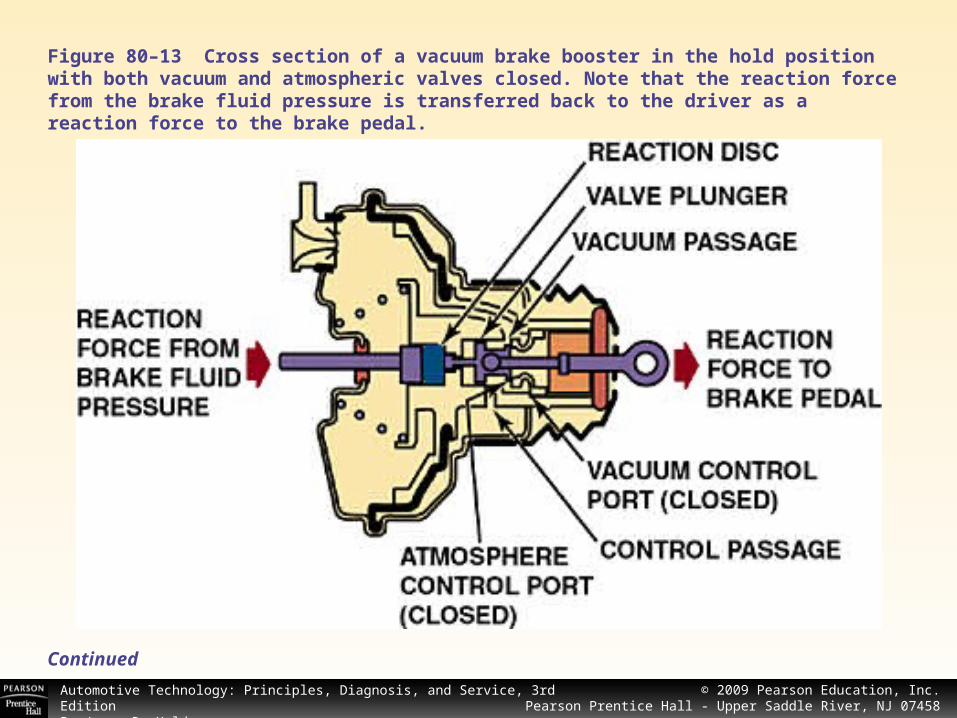
To provide power assist, air pressure must work against a rubber diaphragm. The larger the area of the diaphragm, the more force can be exerted.
Instead of increasing the diameter, vacuum booster manufacturers used two smaller-diameter diaphragms and placed one in front of the other.
These designs increased the total area without increasing the physical diameter of the booster. This style is called a dual-diaphragm or tandem-diaphragm vacuum booster.
See Figure 80–14
DUAL- (TANDEM-) DIAPHRAGM VACUUM BOOSTERS
Continued
© 2008 Pearson Education, Inc.Pearson Prentice Hall - Upper Saddle River, NJ 07458
Automotive Technology: Principles, Diagnosis, and Service, 3rd EditionBy James D. Halderman
© 2009 Pearson Education, Inc.Pearson Prentice Hall - Upper Saddle River, NJ 07458
Figure 80–14 Cutaway showing a dual-diaphragm (tandem) vacuum brake booster.
Continued

© 2008 Pearson Education, Inc.Pearson Prentice Hall - Upper Saddle River, NJ 07458
Automotive Technology: Principles, Diagnosis, and Service, 3rd EditionBy James D. Halderman
© 2009 Pearson Education, Inc.Pearson Prentice Hall - Upper Saddle River, NJ 07458
BRAKE ASSIST SYSTEM
Some vehicles are equipped with a brake assist system (BAS) that applies the brakes with maximum force if the system detects the driver is making a panic stop.
Tests performed by engineers have indicated that it is normal for a person to first apply the brakes rapidly during a panic situation.
It was also found that the driver would tend to reduce the force applied to the brake pedal. As a result, the vehicle did not brake with the maximum effort.
Continued
© 2008 Pearson Education, Inc.Pearson Prentice Hall - Upper Saddle River, NJ 07458
Automotive Technology: Principles, Diagnosis, and Service, 3rd EditionBy James D. Halderman
© 2009 Pearson Education, Inc.Pearson Prentice Hall - Upper Saddle River, NJ 07458
Operation The brake assist system opens an air valve on the rear part of the vacuum booster assembly. More air at atmospheric pressure can flow into the rear chamber of the vacuum booster. BAS function works with the electronic stability control (ESC) system to ensure maximum braking efficiency during evasive or emergency situations.
If the speed of the brake pedal application exceeds a limit as determined by the brake pedal travel sensor, the ABS controller energizes the BAS solenoid valve. When the solenoid valve opens, additional air enters the driver’s side of the booster.
The additional pressure applies the brakes faster and with more force. The BAS solenoid is de-energized when the brake pedal is released and normal braking returns. See Figures 80–15 and 80–16.
Continued

© 2008 Pearson Education, Inc.Pearson Prentice Hall - Upper Saddle River, NJ 07458
Automotive Technology: Principles, Diagnosis, and Service, 3rd EditionBy James D. Halderman
© 2009 Pearson Education, Inc.Pearson Prentice Hall - Upper Saddle River, NJ 07458
Figure 80–15 A typical brake assist system uses a brake pedal travel sensor and a BAS solenoid to apply the brakes during a panic condition.
Continued

© 2008 Pearson Education, Inc.Pearson Prentice Hall - Upper Saddle River, NJ 07458
Automotive Technology: Principles, Diagnosis, and Service, 3rd EditionBy James D. Halderman
© 2009 Pearson Education, Inc.Pearson Prentice Hall - Upper Saddle River, NJ 07458
Figure 80–16When the brake assist function operates, the brake force is much higher than normal.
Continued

© 2008 Pearson Education, Inc.Pearson Prentice Hall - Upper Saddle River, NJ 07458
Automotive Technology: Principles, Diagnosis, and Service, 3rd EditionBy James D. Halderman
© 2009 Pearson Education, Inc.Pearson Prentice Hall - Upper Saddle River, NJ 07458
VACUUM BOOSTER OPERATION TEST
With the engine “off,” apply the brakes several times to deplete the vacuum. With your foot on the brake pedal, start the engine.
The brake pedal should drop. If the brake pedal does not drop, check for proper vacuum source to the booster. If there is proper vacuum, repair or replacement of the power booster is required.

© 2008 Pearson Education, Inc.Pearson Prentice Hall - Upper Saddle River, NJ 07458
Automotive Technology: Principles, Diagnosis, and Service, 3rd EditionBy James D. Halderman
© 2009 Pearson Education, Inc.Pearson Prentice Hall - Upper Saddle River, NJ 07458
VACUUM BOOSTER LEAK TEST
To test if the vacuum booster can hold a vacuum, run the engine to build up a vacuum in the booster, then turn the engine off. Wait one minute, then depress the brake pedal several times. There should be two or more power-assisted brake applications.
If applications are not power assisted, either the vacuum check valve or the booster is leaking. To test the check valve, remove the valve from the booster and blow through the check valve.
If air passes through, the valve is defective and must be replaced. If the check valve is okay, the vacuum booster is leaking and should be repaired or replaced based on the manufacturer’s recommendations.
© 2008 Pearson Education, Inc.Pearson Prentice Hall - Upper Saddle River, NJ 07458
Automotive Technology: Principles, Diagnosis, and Service, 3rd EditionBy James D. Halderman
© 2009 Pearson Education, Inc.Pearson Prentice Hall - Upper Saddle River, NJ 07458
HYDRAULIC SYSTEM LEAK TEST
An internal or external hydraulic leak can also cause a brake system problem. To test if the hydraulic system (and not the booster) is leaking, depress and release the brake pedal (service brakes) several times. This should deplete residual power assist.
After depleting the power-assist unit, depress and then hold the brake pedal depressed with medium force (20 to 35 lb. or 88 to 154 N). The brake pedal should not fall away. If the pedal falls, the hydraulic brake system is leaking.
Check for external leakage at wheel cylinders, calipers, hydraulic lines, and hoses. If there is no external leak, there may be an internal leak inside the master cylinder.
Continued
© 2008 Pearson Education, Inc.Pearson Prentice Hall - Upper Saddle River, NJ 07458
Automotive Technology: Principles, Diagnosis, and Service, 3rd EditionBy James D. Halderman
© 2009 Pearson Education, Inc.Pearson Prentice Hall - Upper Saddle River, NJ 07458
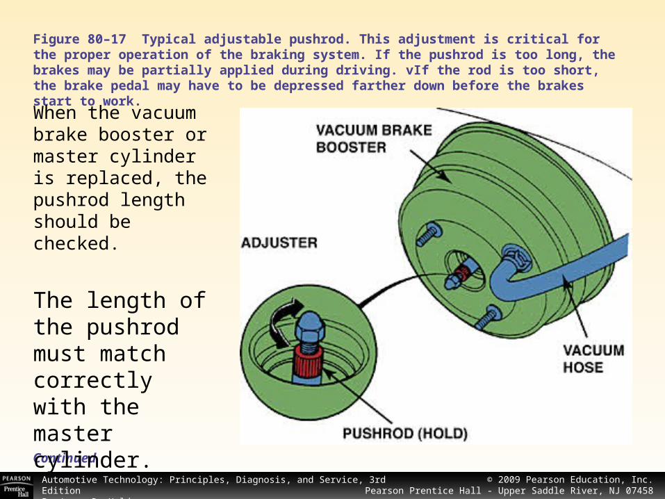
Figure 80–17 Typical adjustable pushrod. This adjustment is critical for the proper operation of the braking system. If the pushrod is too long, the brakes may be partially applied during driving. vIf the rod is too short, the brake pedal may have to be depressed farther down before the brakes start to work.
Continued
When the vacuum brake booster or master cylinder is replaced, the pushrod length should be checked.
The length of the pushrod must match correctly with the master cylinder.

© 2008 Pearson Education, Inc.Pearson Prentice Hall - Upper Saddle River, NJ 07458
Automotive Technology: Principles, Diagnosis, and Service, 3rd EditionBy James D. Halderman
© 2009 Pearson Education, Inc.Pearson Prentice Hall - Upper Saddle River, NJ 07458
PUSHROD CLEARANCE ADJUSTMENT
If the pushrod is too long and the master cylinder is installed, the rod may be applying a force on the primary piston of the master cylinder even though the brake pedal is not applied.
This can cause the brakes to overheat, causing the brake fluid to boil. If brake fluid boils, a total loss of braking force can occur.
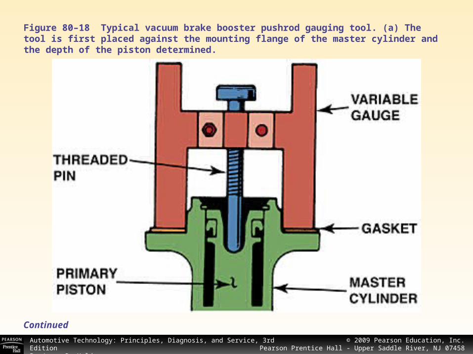
Pushrod clearance check and adjustment is very important. A gauge is used to measure the position of the master cylinder piston, and then the other end of the gauge is used to determine the proper pushrod clearance.
See Figure 80–18.
Continued
© 2008 Pearson Education, Inc.Pearson Prentice Hall - Upper Saddle River, NJ 07458
Automotive Technology: Principles, Diagnosis, and Service, 3rd EditionBy James D. Halderman
© 2009 Pearson Education, Inc.Pearson Prentice Hall - Upper Saddle River, NJ 07458
Figure 80–18 Typical vacuum brake booster pushrod gauging tool. (a) The tool is first placed against the mounting flange of the master cylinder and the depth of the piston determined.
Continued

© 2008 Pearson Education, Inc.Pearson Prentice Hall - Upper Saddle River, NJ 07458
Automotive Technology: Principles, Diagnosis, and Service, 3rd EditionBy James D. Halderman
© 2009 Pearson Education, Inc.Pearson Prentice Hall - Upper Saddle River, NJ 07458
Figure 80–18 (b) The gauge is then turned upside down and used to gauge the pushrod length. Some vacuum brake boosters do not use adjustable pushrods. If found to be the incorrect length, a replacement pushrod of the correct length should be installed.

© 2008 Pearson Education, Inc.Pearson Prentice Hall - Upper Saddle River, NJ 07458
Automotive Technology: Principles, Diagnosis, and Service, 3rd EditionBy James D. Halderman
© 2009 Pearson Education, Inc.Pearson Prentice Hall - Upper Saddle River, NJ 07458
Some vehicle manufacturers recommend that the vacuum brake booster be disassembled and overhauled if defective.
VACUUM BOOSTER DISASSEMBLY AND SERVICE
Continued
CAUTION: Some vehicle manufacturers recommend that the vacuum brake booster be replaced as an assembly if tested to be leaking or defective. Always follow the manufacturer’s recommendations.
CAUTION: Some vehicle manufacturers recommend that the vacuum brake booster be replaced as an assembly if tested to be leaking or defective. Always follow the manufacturer’s recommendations.
A rebuilding kit is available that includes all necessary parts and the proper silicone grease. The manufacturer warns that all parts included in the kit be replaced.
© 2008 Pearson Education, Inc.Pearson Prentice Hall - Upper Saddle River, NJ 07458
Automotive Technology: Principles, Diagnosis, and Service, 3rd EditionBy James D. Halderman
© 2009 Pearson Education, Inc.Pearson Prentice Hall - Upper Saddle River, NJ 07458
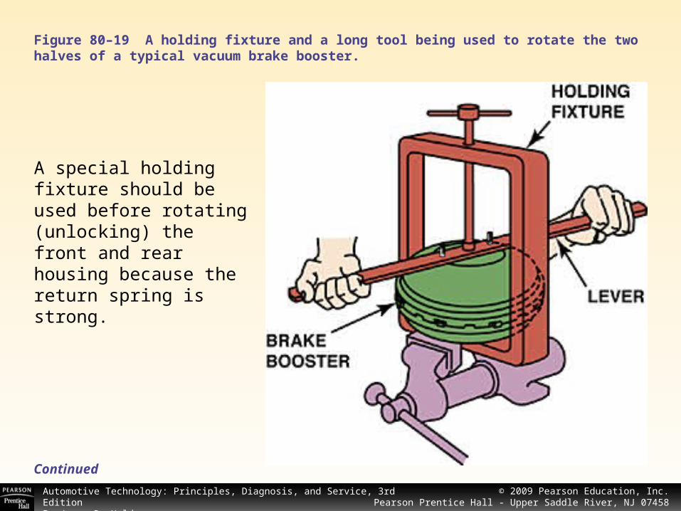
Figure 80–19 A holding fixture and a long tool being used to rotate the two halves of a typical vacuum brake booster.
A special holding fixture should beused before rotating (unlocking) the front and rear housing because the return spring is strong.
Continued
© 2008 Pearson Education, Inc.Pearson Prentice Hall - Upper Saddle River, NJ 07458
Automotive Technology: Principles, Diagnosis, and Service, 3rd EditionBy James D. Halderman
© 2009 Pearson Education, Inc.Pearson Prentice Hall - Upper Saddle River, NJ 07458
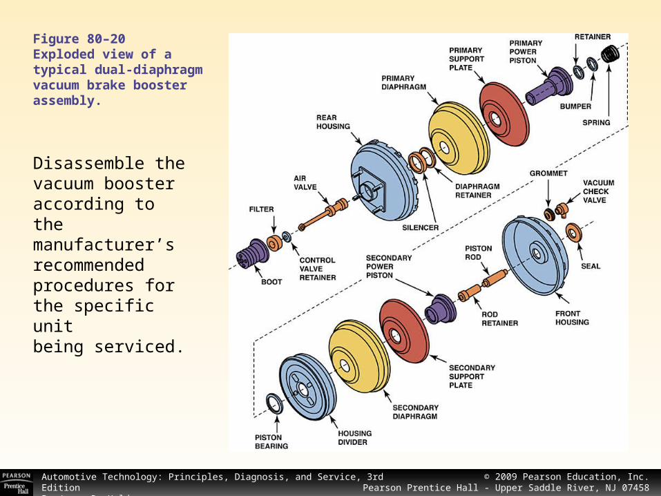
Figure 80–20Exploded view of a typical dual-diaphragm vacuum brake booster assembly.
Disassemble the vacuum booster according to the manufacturer’s recommended procedures forthe specific unitbeing serviced.
© 2008 Pearson Education, Inc.Pearson Prentice Hall - Upper Saddle River, NJ 07458
Automotive Technology: Principles, Diagnosis, and Service, 3rd EditionBy James D. Halderman
© 2009 Pearson Education, Inc.Pearson Prentice Hall - Upper Saddle River, NJ 07458
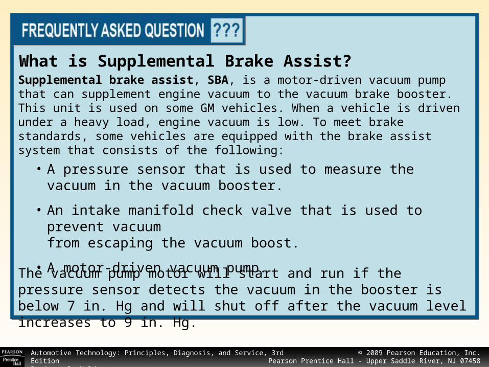
What is Supplemental Brake Assist?Supplemental brake assist, SBA, is a motor-driven vacuum pump that can supplement engine vacuum to the vacuum brake booster. This unit is used on some GM vehicles. When a vehicle is driven under a heavy load, engine vacuum is low. To meet brake standards, some vehicles are equipped with the brake assist system that consists of the following:
The vacuum pump motor will start and run if the pressure sensor detects the vacuum in the booster is below 7 in. Hg and will shut off after the vacuum level increases to 9 in. Hg.
• A pressure sensor that is used to measure the vacuum in the vacuum booster.
• An intake manifold check valve that is used to prevent vacuumfrom escaping the vacuum boost.
• A motor-driven vacuum pump.

© 2008 Pearson Education, Inc.Pearson Prentice Hall - Upper Saddle River, NJ 07458
Automotive Technology: Principles, Diagnosis, and Service, 3rd EditionBy James D. Halderman
© 2009 Pearson Education, Inc.Pearson Prentice Hall - Upper Saddle River, NJ 07458
HYDRO-BOOST HYDRAULIC BRAKE BOOSTER
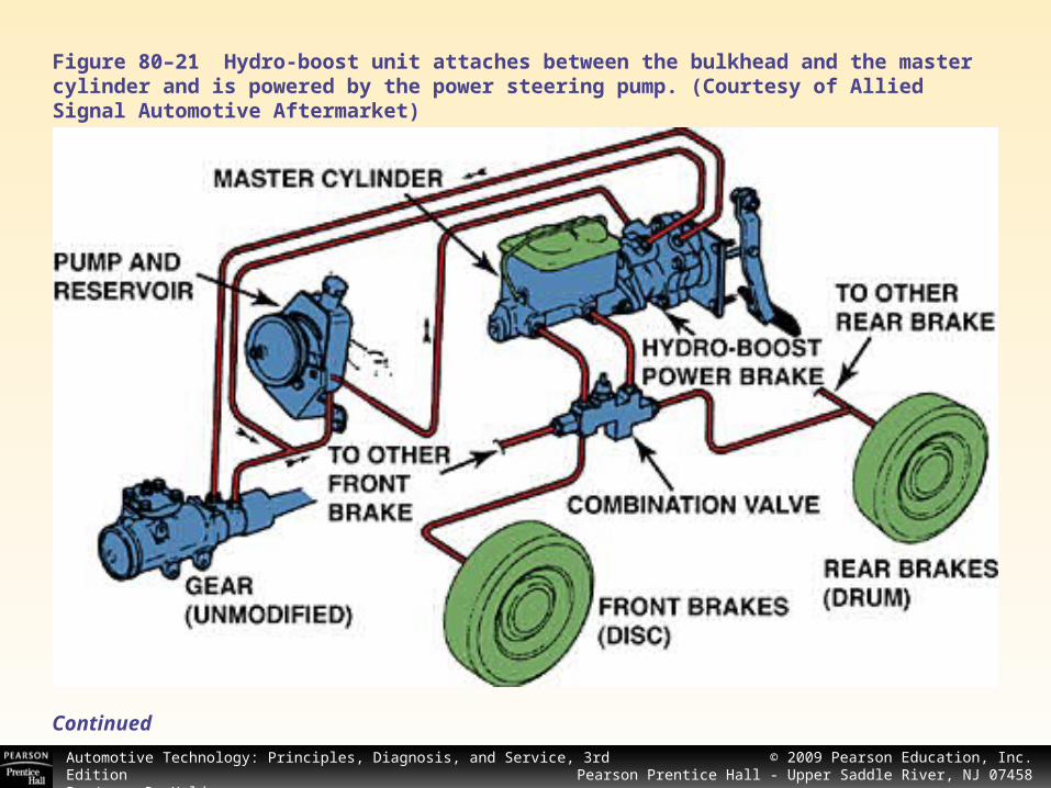
Hydro-boost is a hydraulically operated power-assist unit built by Bendix. The hydro-boost system uses the pressurized hydraulic fluid from the vehicle’s power steering pump as a power source rather than using engine vacuum as is used with vacuum boosters.
Continued
Figure 80–22 Exploded view of the hydro-boost unit. (Courtesy of Allied Signal Automotive Aftermarket)
© 2008 Pearson Education, Inc.Pearson Prentice Hall - Upper Saddle River, NJ 07458
Automotive Technology: Principles, Diagnosis, and Service, 3rd EditionBy James D. Halderman
© 2009 Pearson Education, Inc.Pearson Prentice Hall - Upper Saddle River, NJ 07458
Figure 80–21 Hydro-boost unit attaches between the bulkhead and the master cylinder and is powered by the power steering pump. (Courtesy of Allied Signal Automotive Aftermarket)
Continued

© 2008 Pearson Education, Inc.Pearson Prentice Hall - Upper Saddle River, NJ 07458
Automotive Technology: Principles, Diagnosis, and Service, 3rd EditionBy James D. Halderman
© 2009 Pearson Education, Inc.Pearson Prentice Hall - Upper Saddle River, NJ 07458
Figure 80–23A hydro-boost hydraulic booster in the unapplied position.
Operation Fluid pressure from the power steering pump enters the unit and is directed by a spool valve.
Continued
© 2008 Pearson Education, Inc.Pearson Prentice Hall - Upper Saddle River, NJ 07458
Automotive Technology: Principles, Diagnosis, and Service, 3rd EditionBy James D. Halderman
© 2009 Pearson Education, Inc.Pearson Prentice Hall - Upper Saddle River, NJ 07458
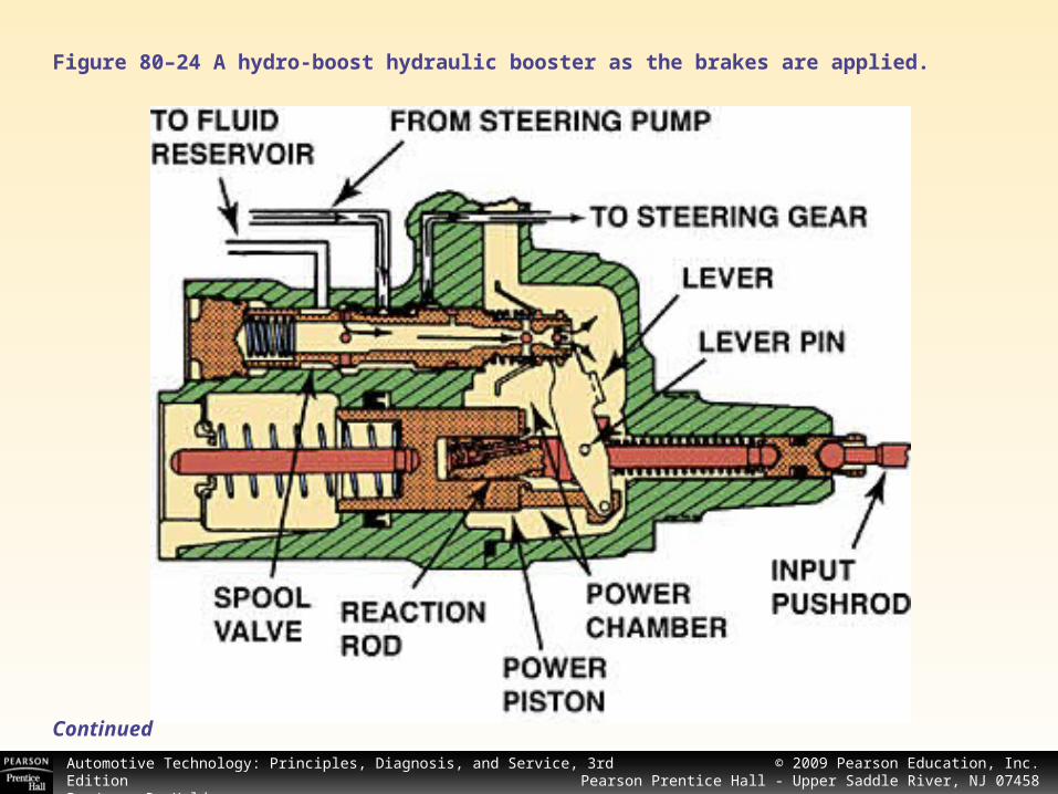
When the brake pedal is depressed, the lever and primary valve are moved. The valve closes off the return port, causing pressure to build in the boost pressure chamber.
The hydraulic pressure pushes on the power piston, which applies force to the output rod that connects to the master cylinder piston.
In the event of a power steering pump failure, power assist is still available for several brake applications. See Figure 80–24
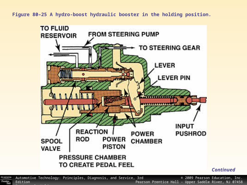
During operation, hydraulic fluid under pressure from the power steering pump pressurizes an accumulator. See Figure 80–25.
Continued
© 2008 Pearson Education, Inc.Pearson Prentice Hall - Upper Saddle River, NJ 07458
Automotive Technology: Principles, Diagnosis, and Service, 3rd EditionBy James D. Halderman
© 2009 Pearson Education, Inc.Pearson Prentice Hall - Upper Saddle River, NJ 07458
Figure 80–24 A hydro-boost hydraulic booster as the brakes are applied.
Continued
© 2008 Pearson Education, Inc.Pearson Prentice Hall - Upper Saddle River, NJ 07458
Automotive Technology: Principles, Diagnosis, and Service, 3rd EditionBy James D. Halderman
© 2009 Pearson Education, Inc.Pearson Prentice Hall - Upper Saddle River, NJ 07458
Figure 80–25 A hydro-boost hydraulic booster in the holding position.
Continued
© 2008 Pearson Education, Inc.Pearson Prentice Hall - Upper Saddle River, NJ 07458
Automotive Technology: Principles, Diagnosis, and Service, 3rd EditionBy James D. Halderman
© 2009 Pearson Education, Inc.Pearson Prentice Hall - Upper Saddle River, NJ 07458
Diagnosis Power for hydro-boost units comes from the power steering pump. The first step of troubleshooting is to perform a thorough visual inspection, including the following:
Continued
1. Checking for proper power steering fluid level
2. Checking for leaks from the unit or power steering pump
3. Checking the condition and tightness of the power steering drive belt
4. Checking for proper operation of the base brake system
© 2008 Pearson Education, Inc.Pearson Prentice Hall - Upper Saddle River, NJ 07458
Automotive Technology: Principles, Diagnosis, and Service, 3rd EditionBy James D. Halderman
© 2009 Pearson Education, Inc.Pearson Prentice Hall - Upper Saddle River, NJ 07458
After checking all of the visual components, check for proper pressure and volume from the power steering pump using a power steering pump tester.
The pump should be capable of producing a minimum of 2 gallons (7.5 liters) with a maximum pressure of 150 psi (1000 kPa) with the steering in the straight-ahead position.
With the engine “off,” the accumulator should be able to supply a minimum of two power-assisted brake applications.
See Figures 80–26 and 80–27.
Continued

© 2008 Pearson Education, Inc.Pearson Prentice Hall - Upper Saddle River, NJ 07458
Automotive Technology: Principles, Diagnosis, and Service, 3rd EditionBy James D. Halderman
© 2009 Pearson Education, Inc.Pearson Prentice Hall - Upper Saddle River, NJ 07458
Figure 80–26 A typical hydro-boost hydraulic line arrangement showing the pump, steering gear, and brake booster assembly.
Continued

© 2008 Pearson Education, Inc.Pearson Prentice Hall - Upper Saddle River, NJ 07458
Automotive Technology: Principles, Diagnosis, and Service, 3rd EditionBy James D. Halderman
© 2009 Pearson Education, Inc.Pearson Prentice Hall - Upper Saddle River, NJ 07458
Figure 80–27 Pressure and flow analyzer installation to check the power steering pump output.
Continued

© 2008 Pearson Education, Inc.Pearson Prentice Hall - Upper Saddle River, NJ 07458
Automotive Technology: Principles, Diagnosis, and Service, 3rd EditionBy James D. Halderman
© 2009 Pearson Education, Inc.Pearson Prentice Hall - Upper Saddle River, NJ 07458
HYDRO-BOOST FUNCTION TEST
With the engine off, apply the brake pedal several times until the accumulator is depleted completely. Depress the service brake pedal and start the engine. The pedal should fall and then push back against the driver’s foot.
Continued

© 2008 Pearson Education, Inc.Pearson Prentice Hall - Upper Saddle River, NJ 07458
Automotive Technology: Principles, Diagnosis, and Service, 3rd EditionBy James D. Halderman
© 2009 Pearson Education, Inc.Pearson Prentice Hall - Upper Saddle River, NJ 07458
The Hydro-Boost Accumulator Test
The accumulator stores hydraulic fluid under pressure to provide a reserve in the event of a failure of the power steering system. The accumulator is designed to provide three or more power-assisted stops with the engine off. If the accumulator fails, it does not hold pressure. To easily check whether the accumulator has lost its charge, grasp the accumulator with your hand and try to twist or move it. The accumulator should have so much pressure that it should not move or wiggle.If the accumulator moves, it has lostits ability to hold pressure and thehydro-boost unit should be replaced.
Figure 80–28 The accumulator should be able to hold pressure and feel tight when hand force is used to try to move it.
© 2008 Pearson Education, Inc.Pearson Prentice Hall - Upper Saddle River, NJ 07458
Automotive Technology: Principles, Diagnosis, and Service, 3rd EditionBy James D. Halderman
© 2009 Pearson Education, Inc.Pearson Prentice Hall - Upper Saddle River, NJ 07458
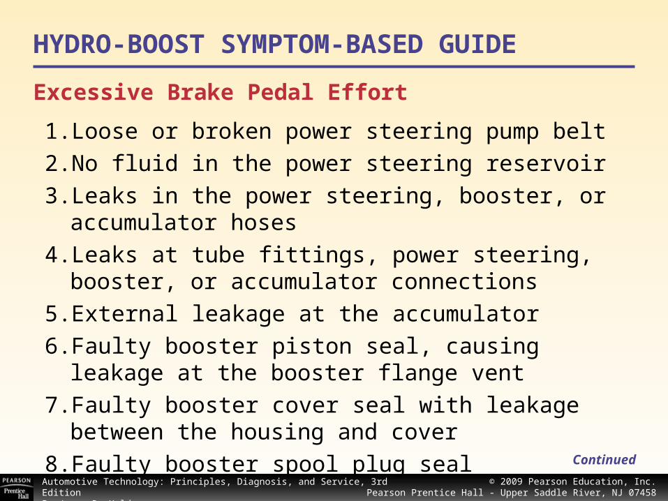
Excessive Brake Pedal Effort
1. Loose or broken power steering pump belt
2. No fluid in the power steering reservoir
3. Leaks in the power steering, booster, or accumulator hoses
4. Leaks at tube fittings, power steering, booster, or accumulator connections
5. External leakage at the accumulator
6. Faulty booster piston seal, causing leakage at the booster flange vent
7. Faulty booster cover seal with leakage between the housing and cover
8. Faulty booster spool plug seal
HYDRO-BOOST SYMPTOM-BASED GUIDE
Continued

© 2008 Pearson Education, Inc.Pearson Prentice Hall - Upper Saddle River, NJ 07458
Automotive Technology: Principles, Diagnosis, and Service, 3rd EditionBy James D. Halderman
© 2009 Pearson Education, Inc.Pearson Prentice Hall - Upper Saddle River, NJ 07458
Slow Brake Pedal Return
Continued
1. Excessive seal friction in the booster
2. Faulty spool action
3. Broken piston return spring
4. Restriction in the return line from the booster to the pump reservoir
5. Broken spool return spring
Grabby Brakes
1. Broken spool return spring
2. Faulty spool action caused by contamination in the system

© 2008 Pearson Education, Inc.Pearson Prentice Hall - Upper Saddle River, NJ 07458
Automotive Technology: Principles, Diagnosis, and Service, 3rd EditionBy James D. Halderman
© 2009 Pearson Education, Inc.Pearson Prentice Hall - Upper Saddle River, NJ 07458
Booster Chatters—Pedal Vibrates
1. Power steering pump belt slipping
2. Low fluid level in the power steering pump reservoir
3. Faulty spool operation caused by contamination in the system
© 2008 Pearson Education, Inc.Pearson Prentice Hall - Upper Saddle River, NJ 07458
Automotive Technology: Principles, Diagnosis, and Service, 3rd EditionBy James D. Halderman
© 2009 Pearson Education, Inc.Pearson Prentice Hall - Upper Saddle River, NJ 07458
SUMMARY
Continued
1. Vacuum brake boosters use air pressure acting on a diaphragm to assist the driver’s force on the brake master cylinder.
2. At rest, there is vacuum on both sides of the vacuum booster diaphragm. When the brake pedal is depressed, atmospheric air pressure is exerted on the back side of the diaphragm.
3. The use of two diaphragms in tandem allows a smaller-diameter booster with the same area. The larger the area of the booster diaphragm, the more air pressure force can be applied to the master cylinder.

© 2008 Pearson Education, Inc.Pearson Prentice Hall - Upper Saddle River, NJ 07458
Automotive Technology: Principles, Diagnosis, and Service, 3rd EditionBy James D. Halderman
© 2009 Pearson Education, Inc.Pearson Prentice Hall - Upper Saddle River, NJ 07458
SUMMARY
4. Hydraulic-operated brake boosters use either an electric motor driven pump or the engine-driven power steering pump.
5. When replacing a vacuum brake booster, always check for proper pushrod clearance.
6. To be assured of power-assisted brake application in the event of failure, hydraulic power-assisted brake systems use an accumulator to provide pressure to the system.
(cont.)

© 2008 Pearson Education, Inc.Pearson Prentice Hall - Upper Saddle River, NJ 07458
Automotive Technology: Principles, Diagnosis, and Service, 3rd EditionBy James D. Halderman
© 2009 Pearson Education, Inc.Pearson Prentice Hall - Upper Saddle River, NJ 07458
end