Embed Size (px)
DESCRIPTION
Ledge profile and it's impact on VSS Aluminum reduction cells. Importance of minimum protrusion into the shadow of the anode.
Citation preview
ggordon Page 1 5/30/2014 G:\CFAC\(N) CFAC\Training\Ledge\Ledge Master.doc
LEDGE PROFILE There is a need for our ledge and muck measuring to be less subjective. We need to understand what the ledge should be like and use the same terminology.
Our ledge usually looks similar to the 2 examples here, having too much toe, and not enough saddle, or too much ledge period. The first example shows a sloped ledge that allows undissolved ore to slide below the metal/bath interface. The will require additional power clean the pot bottom. The second example shows a high hard ledge. This condition will reflect heat back up the anode. This
additional heat will raise the bake zone. This will be manifest by a wet/hot top. If this condition is left unchecked it will quite possibly result in spikes and/or shatter. If a probing rod is inserted at a 45° it will not touch bottom block, in either case. A technician measuring rod will rest on the saddle also. Ratio control will play a key role in ledge shape. A low ratio pot will usually have a larger ledge, while a high ratio will generally have a smaller ledge. As the ledge grows upward it gets close to the anode, there will be a decrease in heat flow out the sidewall. A considerable amount of this heat will be reflected back up in to the anode, visibly heating the anode top. There will be considerable disruption to the bake zone. This can cause spikes and or shatter a few weeks later. Normally anode/ledge clearance would be greater than 6”
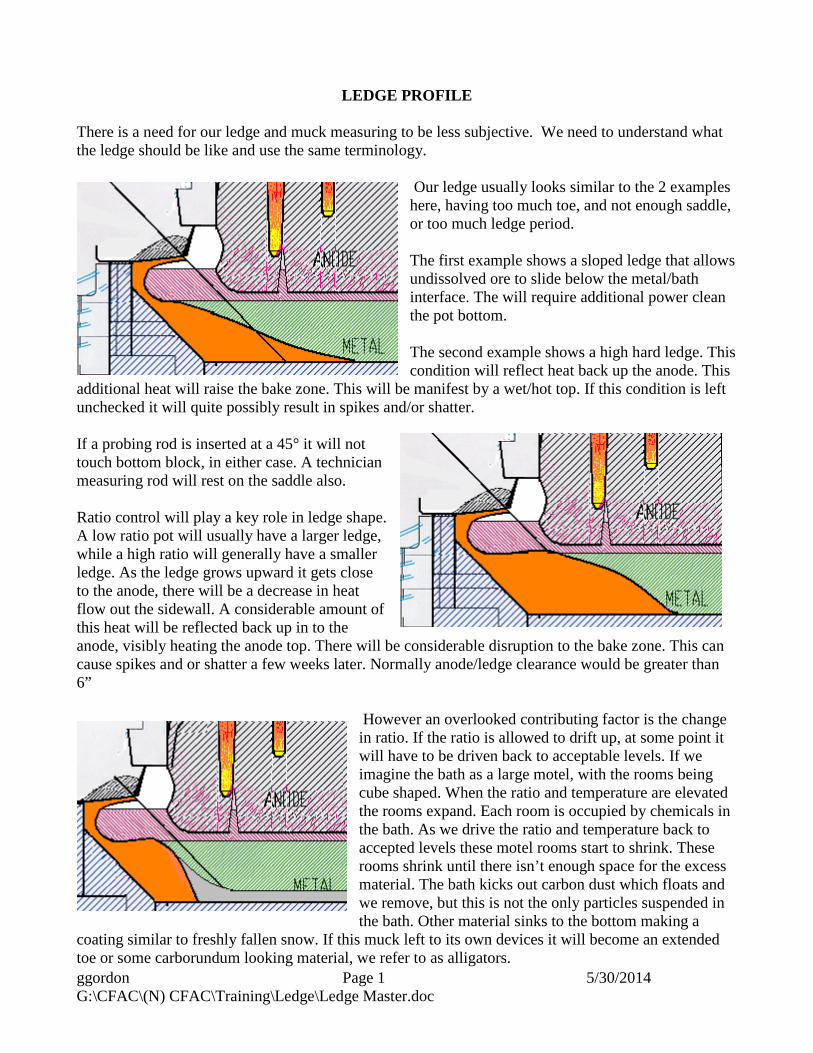
However an overlooked contributing factor is the change in ratio. If the ratio is allowed to drift up, at some point it will have to be driven back to acceptable levels. If we imagine the bath as a large motel, with the rooms being cube shaped. When the ratio and temperature are elevated the rooms expand. Each room is occupied by chemicals in the bath. As we drive the ratio and temperature back to accepted levels these motel rooms start to shrink. These rooms shrink until there isn’t enough space for the excess material. The bath kicks out carbon dust which floats and we remove, but this is not the only particles suspended in the bath. Other material sinks to the bottom making a
coating similar to freshly fallen snow. If this muck left to its own devices it will become an extended toe or some carborundum looking material, we refer to as alligators.
ggordon Page 2 5/30/2014 G:\CFAC\(N) CFAC\Training\Ledge\Ledge Master.doc
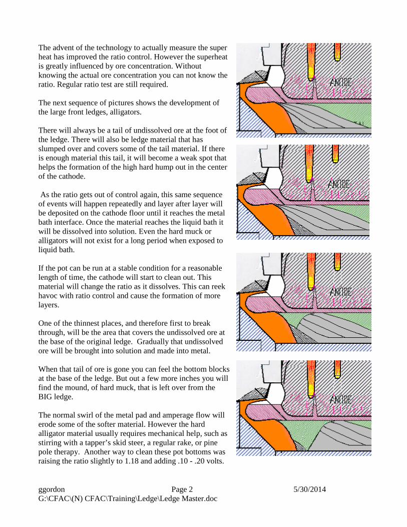
The advent of the technology to actually measure the super heat has improved the ratio control. However the superheat is greatly influenced by ore concentration. Without knowing the actual ore concentration you can not know the ratio. Regular ratio test are still required. The next sequence of pictures shows the development of the large front ledges, alligators. There will always be a tail of undissolved ore at the foot of the ledge. There will also be ledge material that has slumped over and covers some of the tail material. If there is enough material this tail, it will become a weak spot that helps the formation of the high hard hump out in the center of the cathode. As the ratio gets out of control again, this same sequence of events will happen repeatedly and layer after layer will be deposited on the cathode floor until it reaches the metal bath interface. Once the material reaches the liquid bath it will be dissolved into solution. Even the hard muck or alligators will not exist for a long period when exposed to liquid bath. If the pot can be run at a stable condition for a reasonable length of time, the cathode will start to clean out. This material will change the ratio as it dissolves. This can reek havoc with ratio control and cause the formation of more layers. One of the thinnest places, and therefore first to break through, will be the area that covers the undissolved ore at the base of the original ledge. Gradually that undissolved ore will be brought into solution and made into metal. When that tail of ore is gone you can feel the bottom blocks at the base of the ledge. But out a few more inches you will find the mound, of hard muck, that is left over from the BIG ledge. The normal swirl of the metal pad and amperage flow will erode some of the softer material. However the hard alligator material usually requires mechanical help, such as stirring with a tapper’s skid steer, a regular rake, or pine pole therapy. Another way to clean these pot bottoms was raising the ratio slightly to 1.18 and adding .10 - .20 volts.
ggordon Page 3 5/30/2014 G:\CFAC\(N) CFAC\Training\Ledge\Ledge Master.doc
It is critical to maintain a ratio slightly higher but it must not be allowed to reach 1.20. The faster the ratio is moved down the more material will fall to the cathode floor. The voltage would be reduced first. Then the ratio would be gradually brought to 1.14. The proper ledge profile would be similar to the one pictured below, left. Beyond the saddle, this ledge drops off rather steeply. This ledge doesn’t encroach under the anode shadow very far. Another benefit to this profile would be somewhat better control of the metal pad movement. There isn’t a gradual slope for the metal ride up and eventually contact the anode and be reoxidized, reducing current efficiency. For optimal Cathode Voltage Drop the ledge should look more like this. With a probing rod at 45° angle it should not contact any part of the ledge. The ledge should not extend under the shadow of the anode, more than 4”-5”. The pot also requires a minimum of 6” clearance between the corner of the anode and the edge of the ledge.
There is no need for ledge behind the skirt, not much material will be drifting into the bath and/or onto the top of the ledge from this area. The two areas that need work are the saddle and the extended toe. More Rand Breaks will help define the saddle portion, while Amperage, and metal pad movement, will erode the lower ledge. There would always be a small toe of muck at the base of the ledge.
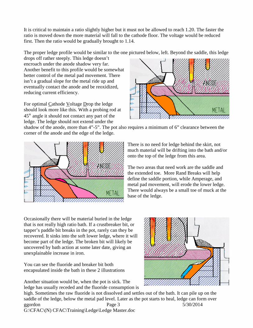
Occasionally there will be material buried in the ledge that is not really high ratio bath. If a crustbreaker bit, or tapper’s paddle bit breaks in the pot, rarely can they be recovered. It sinks into the soft lower ledge, where it will become part of the ledge. The broken bit will likely be uncovered by bath action at some later date, giving an unexplainable increase in iron. You can see the fluoride and breaker bit both encapsulated inside the bath in these 2 illustrations Another situation would be, when the pot is sick. The ledge has usually receded and the fluoride consumption is high. Sometimes the raw fluoride is not dissolved and settles out of the bath. It can pile up on the saddle of the ledge, below the metal pad level. Later as the pot starts to heal, ledge can form over
ggordon Page 4 5/30/2014 G:\CFAC\(N) CFAC\Training\Ledge\Ledge Master.doc
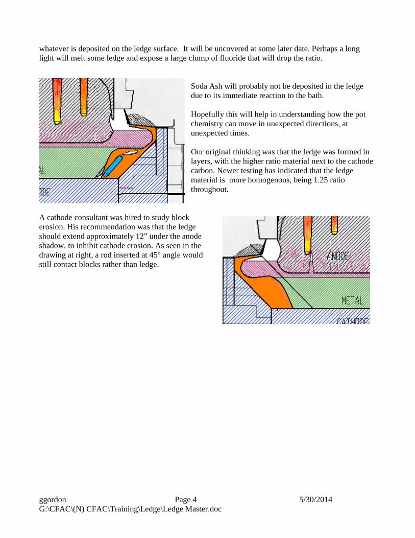
whatever is deposited on the ledge surface. It will be uncovered at some later date. Perhaps a long light will melt some ledge and expose a large clump of fluoride that will drop the ratio.
Soda Ash will probably not be deposited in the ledge due to its immediate reaction to the bath. Hopefully this will help in understanding how the pot chemistry can move in unexpected directions, at unexpected times. Our original thinking was that the ledge was formed in layers, with the higher ratio material next to the cathode carbon. Newer testing has indicated that the ledge material is more homogenous, being 1.25 ratio throughout.
A cathode consultant was hired to study block erosion. His recommendation was that the ledge should extend approximately 12” under the anode shadow, to inhibit cathode erosion. As seen in the drawing at right, a rod inserted at 45° angle would still contact blocks rather than ledge.
ggordon Page 5 5/30/2014 G:\CFAC\(N) CFAC\Training\Ledge\Ledge Master.doc
Measuring the Ledge
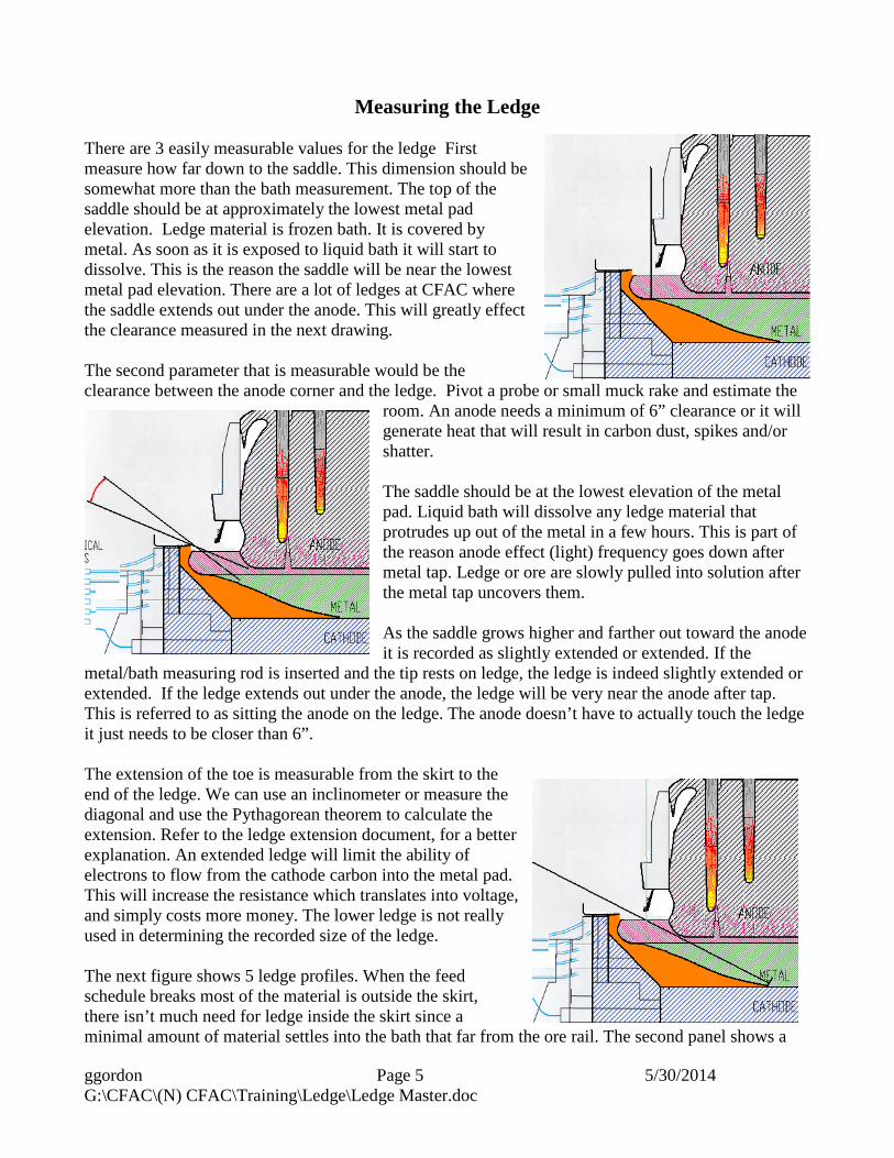
There are 3 easily measurable values for the ledge First measure how far down to the saddle. This dimension should be somewhat more than the bath measurement. The top of the saddle should be at approximately the lowest metal pad elevation. Ledge material is frozen bath. It is covered by metal. As soon as it is exposed to liquid bath it will start to dissolve. This is the reason the saddle will be near the lowest metal pad elevation. There are a lot of ledges at CFAC where the saddle extends out under the anode. This will greatly effect the clearance measured in the next drawing. The second parameter that is measurable would be the clearance between the anode corner and the ledge. Pivot a probe or small muck rake and estimate the
room. An anode needs a minimum of 6” clearance or it will generate heat that will result in carbon dust, spikes and/or shatter. The saddle should be at the lowest elevation of the metal pad. Liquid bath will dissolve any ledge material that protrudes up out of the metal in a few hours. This is part of the reason anode effect (light) frequency goes down after metal tap. Ledge or ore are slowly pulled into solution after the metal tap uncovers them. As the saddle grows higher and farther out toward the anode it is recorded as slightly extended or extended. If the
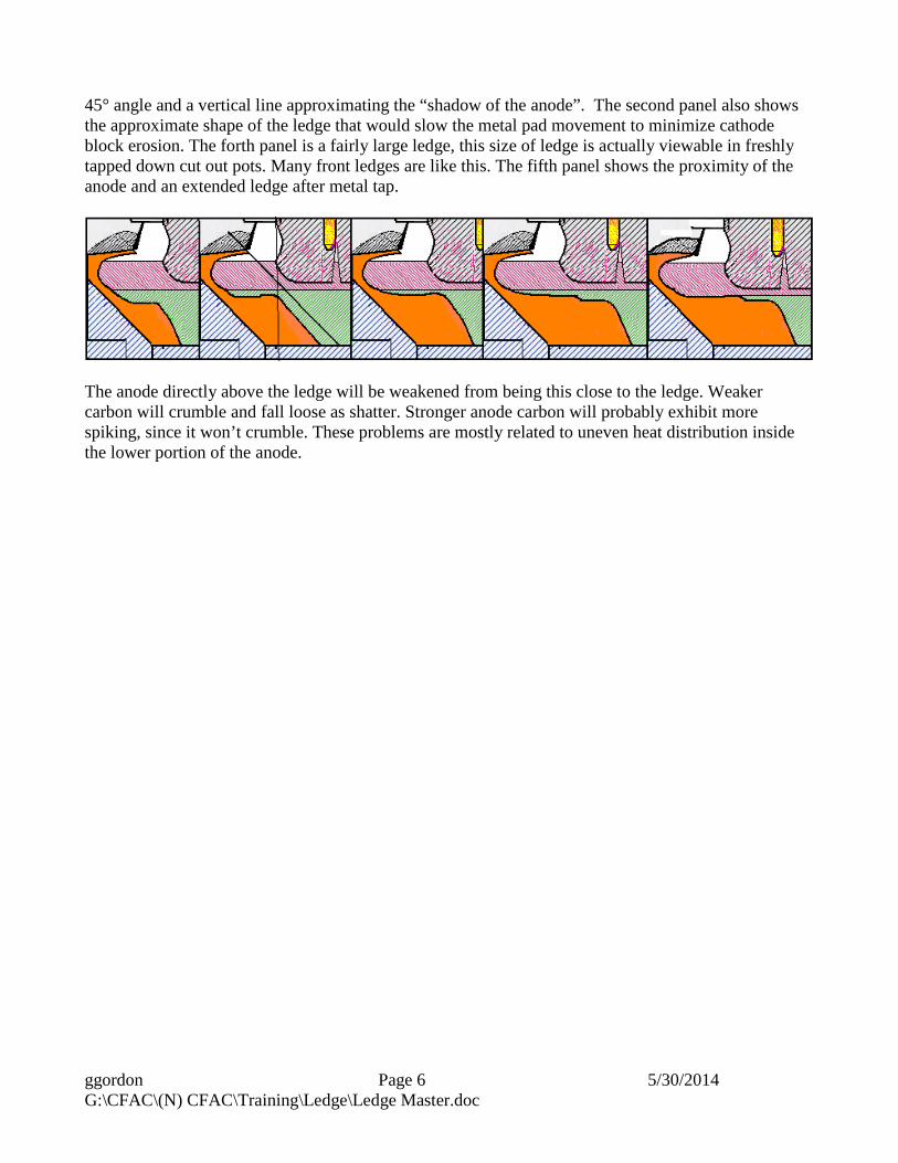
metal/bath measuring rod is inserted and the tip rests on ledge, the ledge is indeed slightly extended or extended. If the ledge extends out under the anode, the ledge will be very near the anode after tap. This is referred to as sitting the anode on the ledge. The anode doesn’t have to actually touch the ledge it just needs to be closer than 6”. The extension of the toe is measurable from the skirt to the end of the ledge. We can use an inclinometer or measure the diagonal and use the Pythagorean theorem to calculate the extension. Refer to the ledge extension document, for a better explanation. An extended ledge will limit the ability of electrons to flow from the cathode carbon into the metal pad. This will increase the resistance which translates into voltage, and simply costs more money. The lower ledge is not really used in determining the recorded size of the ledge. The next figure shows 5 ledge profiles. When the feed schedule breaks most of the material is outside the skirt, there isn’t much need for ledge inside the skirt since a minimal amount of material settles into the bath that far from the ore rail. The second panel shows a
ggordon Page 6 5/30/2014 G:\CFAC\(N) CFAC\Training\Ledge\Ledge Master.doc
45° angle and a vertical line approximating the “shadow of the anode”. The second panel also shows the approximate shape of the ledge that would slow the metal pad movement to minimize cathode block erosion. The forth panel is a fairly large ledge, this size of ledge is actually viewable in freshly tapped down cut out pots. Many front ledges are like this. The fifth panel shows the proximity of the anode and an extended ledge after metal tap.
The anode directly above the ledge will be weakened from being this close to the ledge. Weaker carbon will crumble and fall loose as shatter. Stronger anode carbon will probably exhibit more spiking, since it won’t crumble. These problems are mostly related to uneven heat distribution inside the lower portion of the anode.
ggordon Page 7 5/30/2014 G:\CFAC\(N) CFAC\Training\Ledge\Ledge Master.doc
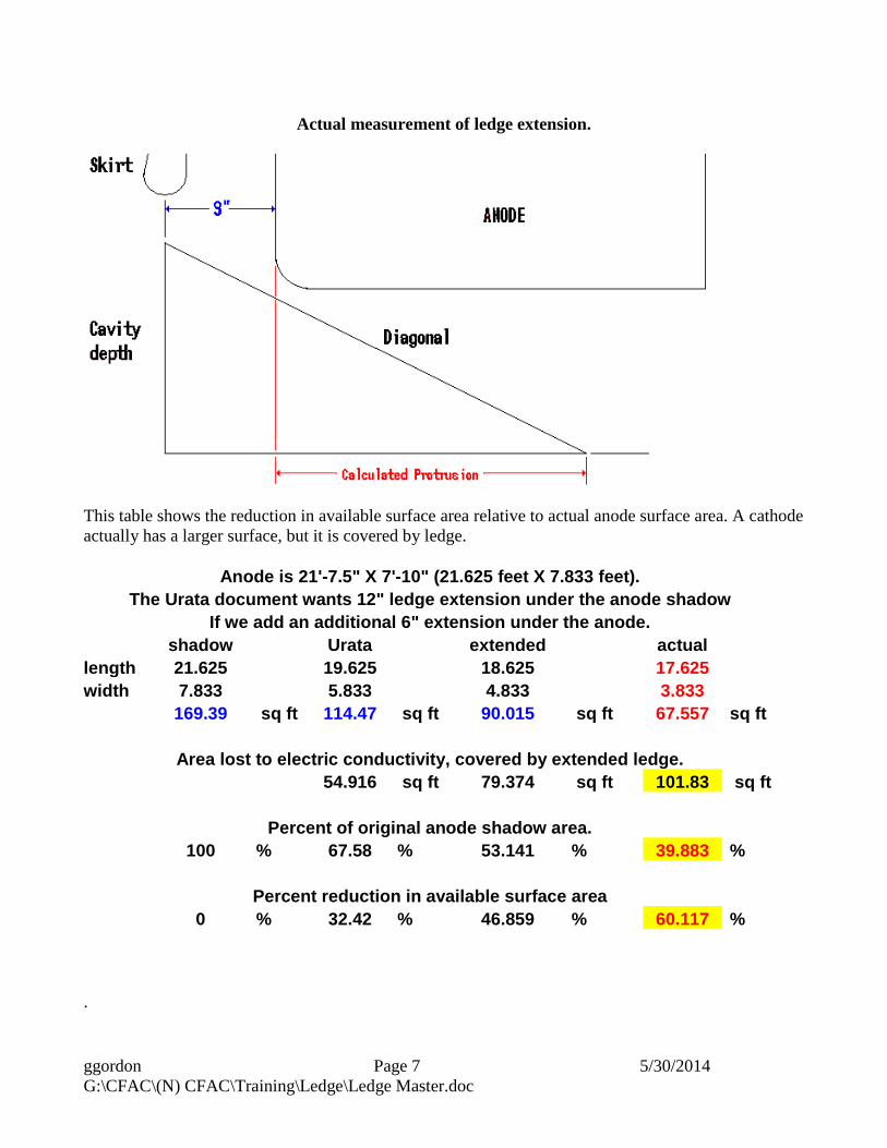
Actual measurement of ledge extension.
This table shows the reduction in available surface area relative to actual anode surface area. A cathode actually has a larger surface, but it is covered by ledge.
.
Anode is 21'-7.5" X 7'-10" (21.625 feet X 7.833 feet). The Urata document wants 12" ledge extension under the anode shadow
If we add an additional 6" extension under the anode. shadow Urata extended actual length 21.625 19.625 18.625 17.625 width 7.833 5.833 4.833 3.833 169.39 sq ft 114.47 sq ft 90.015 sq ft 67.557 sq ft
Area lost to electric conductivity, covered by extended ledge. 54.916 sq ft 79.374 sq ft 101.83 sq ft
Percent of original anode shadow area.
100 % 67.58 % 53.141 % 39.883 %
Percent reduction in available surface area 0 % 32.42 % 46.859 % 60.117 %
ggordon Page 8 5/30/2014 G:\CFAC\(N) CFAC\Training\Ledge\Ledge Master.doc
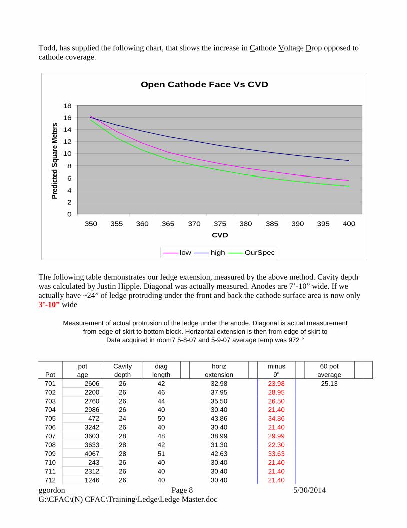
Todd, has supplied the following chart, that shows the increase in Cathode Voltage Drop opposed to cathode coverage.
Open Cathode Face Vs CVD
0
2
4
6
8
10
12
14
16
18
350 355 360 365 370 375 380 385 390 395 400
CVD
Pred
icte
d Sq
uare
Met
ers
low high OurSpec
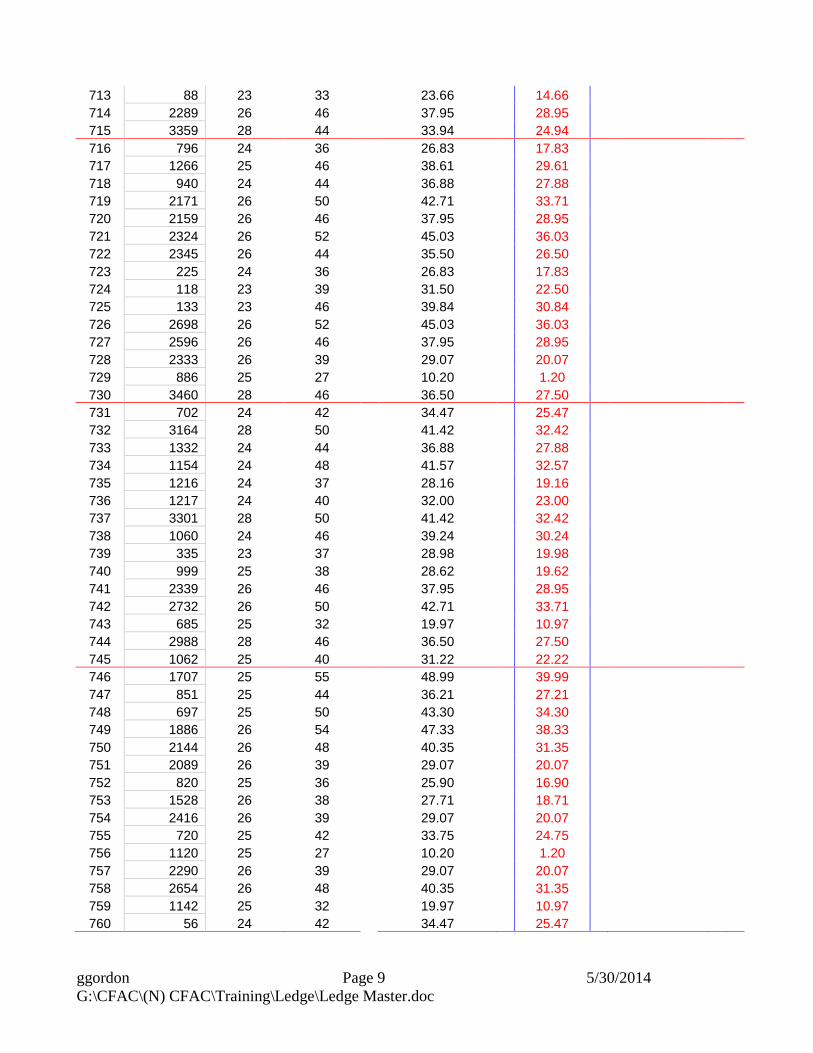
The following table demonstrates our ledge extension, measured by the above method. Cavity depth was calculated by Justin Hipple. Diagonal was actually measured. Anodes are 7’-10” wide. If we actually have ~24” of ledge protruding under the front and back the cathode surface area is now only 3’-10” wide
Measurement of actual protrusion of the ledge under the anode. Diagonal is actual measurement from edge of skirt to bottom block. Horizontal extension is then from edge of skirt to
Data acquired in room7 5-8-07 and 5-9-07 average temp was 972 °
pot Cavity diag horiz minus 60 pot Pot age depth length extension 9" average 701 2606 26 42 32.98 23.98 25.13 702 2200 26 46 37.95 28.95 703 2760 26 44 35.50 26.50 704 2986 26 40 30.40 21.40 705 472 24 50 43.86 34.86 706 3242 26 40 30.40 21.40 707 3603 28 48 38.99 29.99 708 3633 28 42 31.30 22.30 709 4067 28 51 42.63 33.63 710 243 26 40 30.40 21.40 711 2312 26 40 30.40 21.40 712 1246 26 40 30.40 21.40
ggordon Page 9 5/30/2014 G:\CFAC\(N) CFAC\Training\Ledge\Ledge Master.doc
713 88 23 33 23.66 14.66 714 2289 26 46 37.95 28.95 715 3359 28 44 33.94 24.94 716 796 24 36 26.83 17.83 717 1266 25 46 38.61 29.61 718 940 24 44 36.88 27.88 719 2171 26 50 42.71 33.71 720 2159 26 46 37.95 28.95 721 2324 26 52 45.03 36.03 722 2345 26 44 35.50 26.50 723 225 24 36 26.83 17.83 724 118 23 39 31.50 22.50 725 133 23 46 39.84 30.84 726 2698 26 52 45.03 36.03 727 2596 26 46 37.95 28.95 728 2333 26 39 29.07 20.07 729 886 25 27 10.20 1.20 730 3460 28 46 36.50 27.50 731 702 24 42 34.47 25.47 732 3164 28 50 41.42 32.42 733 1332 24 44 36.88 27.88 734 1154 24 48 41.57 32.57 735 1216 24 37 28.16 19.16 736 1217 24 40 32.00 23.00 737 3301 28 50 41.42 32.42 738 1060 24 46 39.24 30.24 739 335 23 37 28.98 19.98 740 999 25 38 28.62 19.62 741 2339 26 46 37.95 28.95 742 2732 26 50 42.71 33.71 743 685 25 32 19.97 10.97 744 2988 28 46 36.50 27.50 745 1062 25 40 31.22 22.22 746 1707 25 55 48.99 39.99 747 851 25 44 36.21 27.21 748 697 25 50 43.30 34.30 749 1886 26 54 47.33 38.33 750 2144 26 48 40.35 31.35 751 2089 26 39 29.07 20.07 752 820 25 36 25.90 16.90 753 1528 26 38 27.71 18.71 754 2416 26 39 29.07 20.07 755 720 25 42 33.75 24.75 756 1120 25 27 10.20 1.20 757 2290 26 39 29.07 20.07 758 2654 26 48 40.35 31.35 759 1142 25 32 19.97 10.97 760 56 24 42 34.47 25.47

ggordon Page 10 5/30/2014 G:\CFAC\(N) CFAC\Training\Ledge\Ledge Master.doc