Embed Size (px)
Citation preview

الرحيم الرحمن الله بسم
OUR PROJECT IS 2 DEVICES :
1.DIGITAL VOLTMETER.
2.CONTROL VOLTAGE POWER SUPPLY.

DIGITAL VOLTMETER
Components :
1.Pic Microcontroller (16F877A).
2. Two resistors (1200 , 330 ohm ).
3.Diode.
4. Two seven segment .

Purpose :
Measuring positive voltages.

Schematic Circuit

Schematic of this process.

In our case … the vertical axis has values from 0 to 5 (volts) … and ADC samples the signal from 0 to 1023 ( 1024 value) … approximately , one sample is 0.0049 ... (5/1024) …. And every value of voltage has an equivalent value of sampling…
So , the pic reads the value of sampling and multiply it with 0.0049 to get the real value of voltage.
We used mikroC IDE …it has many built in functions …
one of them : ADC_READ() … we used this function to do these steps…
After we could determine the value of voltage , we display it on the 2 seven segment .

The 2 common anode seven segment are connected on the same lines..
We used an algorithm to display the 2 numbers on the 2 sev seg.
The algorithm briefly : turn on the first and turn off the second…. and send the data of the first one..
Then turn off the first and turn on the second and send the data of the second…and so on …
This operation is performed very fast …(high frequency) …
So we see the 2 seven segment are on and the number is displayed..

Finally: we put a diode in the input voltage to protect our pic from the negative voltage .
For sure we take in consideration the voltage drop on the diode ..

CONTROL VOLTAGE POWER SUPPLY.
COMPONENTS: 1.FIXED 15/-15 VOLT POWER SUPPLY COMPONENTS.
2.pic16F877A.
3.DAC 0808.
4.op-amp 741.
5.Push buttons.

Purpose:
Control the voltage by push buttons …
The output range is from 0 to 10 volts.

Brief Algorithm :
The 2 push buttons increase and decrease the voltage by giving a signal to the pic…and the pic send out a signal to the DAC…and the DAC send a signal to the op-amp … and the op-amp give us the wanted voltage.

Schematic circuit
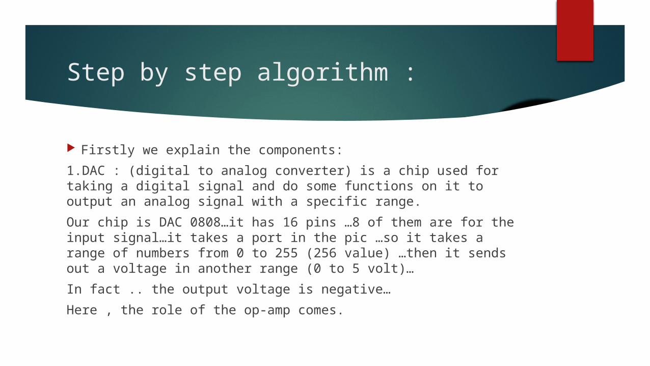
Step by step algorithm :
Firstly we explain the components:
1.DAC : (digital to analog converter) is a chip used for taking a digital signal and do some functions on it to output an analog signal with a specific range.
Our chip is DAC 0808…it has 16 pins …8 of them are for the input signal…it takes a port in the pic …so it takes a range of numbers from 0 to 255 (256 value) …then it sends out a voltage in another range (0 to 5 volt)…
In fact .. the output voltage is negative…
Here , the role of the op-amp comes.

2.The op-amp: (operational amplifier ) is a chip used for many purposes…
Explicitly we deal with the op-amp as a black box …we don’t know yet the internal construction of this IC.
In our case ..we used it for 2 purposes…
For inverting and amplifying….
Briefly , the op-amp has 2 input terminals (positive and negative) and an output terminal…

In our case : the positive terminal is connected to the ground …and the negative is connected to the output with a resistor…
Typically , the op-amp makes feedback from the output to the input many times in order to make the two terminals have the same voltage.
So , the 2 input terminals have 0 volt.

In addition to the op-amp input terminals have a very high impedance …so that no current enters it and no voltage is wasted..

Biasing required
the DAC requires 10 volt and -15 volt biasing. (those are taken from the power supply).
the op-amp requires 10 volt biasing .(from the power supply too).
The pic requires 5 volt biasing. (from the supply too ).

For more information about :
1.Microcontroller : ask ahmad.
2.About pcb and software : ask sabry.
3.About electronic components : ask sherbiny.