Embed Size (px)
Citation preview
I
國 立 交 通 大 學
資訊科學與工程研究所
碩 士 論 文
應用於多天線偵測之可變可重疊之叢集演算法
The Study of Variable and Overlapped
Cluster-based
MIMO Detection
研 究 生:陳柏丞
指導教授:許騰尹 教授
中 華 民 國 一 百 年 六 月
II
應 用 於 多 天 線 偵 測 之 可 變 重 疊 之 叢 集 演 算 法
The Study of Variable and Overlapped Cluster-based MIMO Detection
研 究 生:陳柏丞 Student:Po-Cheng Chen
指導教授:許騰尹 Advisor:Terng-Yin Hsu
國 立 交 通 大 學
資 訊 科 學 與 工 程 研 究 所 碩 士 論 文
A Thesis
Submitted to Institute of Computer Science and Engineering
College of Computer Science
National Chiao Tung University
in partial Fulfillment of the Requirements
for the Degree of
Master
in
Computer Science
July 2011
Hsinchu, Taiwan, Republic of China
中華民國一百年六月
I
應用於多天線偵測之可變可重疊之叢集演算法
陳柏丞
國立交通大學資訊科學與工程研究所碩士班
指導教授:許騰尹
摘要
在這篇論文裡,我們推薦一個具有高輸出率、固定複雜度的硬性輸出球體解
碼器,並支援高維度 64QAM、256QAM 調變的 4T4R 和 8T8R 多輸入多輸出通
訊系統。
本論文提出一基於可變可重疊之叢集的 MIMO 偵測方法(Variable and
Overlapped Cluster-based MIMO Detection Algorithm),在 PER 在 0.08下與最大
相似算法誤差在 0.5dB 以內,較 K best 球體解碼器演算法低複雜度,可硬體實作
的演算法。
本演算法是在偵測前,以基礎等化器找出的可能落點為依據,決策出該每個
天線維度上可能候選星群,並以寬度優先搜尋的分支分界的方法,結合
MMSE-SQRD解碼的系統架構來解碼,而本叢集分群法為以下兩種:
重疊叢集法(Overlap cluster),為一減少複雜度並維持偵測效能之方法,在叢
集的決策上,為了減少在邊界情況(Boundary condition)下的決策失誤,兩個不同
的群可能會有相同的候選星群,藉此在叢集上有更高的準確性。
可變叢集法(Dynamic cluster),為適應不同天線的通道衰減效應,而改進的
叢集法。在決策的候選星群時,利用排序 QR 分解(Sorted QR Decomposition)演
算法之通道路徑的範數(norm)資訊,使低通道衰減之天線有低數量之候選星群,
高通道衰減天線維度擁有較多數量之候選星群候選星群,而此法符合實際天線陣
列在真實情況下的傳輸環境。
實作於 IEEE 802.11n的通訊平台上,提供 4T4R和 8T8R在高維度 64QAM、
256QAM 調變,在符合 TGN-E 所規範的通道模型中進行模擬。模擬結果指出此
演算法與傳統 K-best 球體解碼器,若維持 PER 在 0.08的誤差 0.5dB 之內,以較
低的複雜度完成相同的系統效能;若維持約略相同複雜度之下,具有較佳的系統
效能表現。因此,此演算法為多輸入多輸出系統提供了具有低複雜度、接近效能
最佳化的偵測演算法。
II
The Study of Variable and Overlapped
Cluster-based MIMO Detection
by
Po-Cheng Chen
Department of Computer Science
National Chiao Tung University
Advisor:Terng-Yin Hsu
Abstract
Recently, multiple-input multiple-output (MIMO) architecture has been applied
widely in many wireless communication systems because of its high spectrum
efficiency. Various approaches are explored for the MIMO detection, the ZFD, the
MMSED, V-BLAST, the maximum likelihood detection (MLD) as well as the Sphere
Decode detection (SD).
We propose the Variable and Overlapped Cluster-based MIMO Detection
algorithm by partitioning the transmitted MIMO signal vectors into vary clusters with
estimated symbol in each dimension in 64-QAM/256-QAM and finding out the result
signal by comparing the received signal with all the candidates above. And the
proposed method, step A) as well as B), are demonstrating in the following.
In A), we demonstrate overlap clustering algorithm that the estimated signal got
by linear detectors, as ZFD or MMSED, and then pick out the possible constellation
points falling on each antenna according to the range which the estimated signal is in.
After overlap clustering algorithm in step A, we enlarge/narrow the possible
constellations points according to the column norm of H included channel gain
information.
Moving on B), we have all the candidates signals compare with the received
signal, and then apply BFS with best K candidates in the searching space of MMSE
SQRD. Eventually, the detection signal with the least accumulative square Euclidean
distance is delivered.
Through simulation in IEEE 802.11n platform with TGN channel E, it indicates
the complexity of proposed algorithm is less than the K-best SD with the same
performance. Hence, the proposed algorithm provides a near-optimal solution with
low computation complexity design for wireless MIMO system.
III
誌謝
論文止筆於此,代表求學的生涯將在此落幕了,遙想當時在找指導教授時,
和金毛碰巧路過許騰尹老師的辦公室,因之前沒有上過許老師的課,帶點陌生與
膽怯的心而敲了門,沒想到在短短兩小時的生動對話中,就被老師的年輕風趣所
吸引,不顧學長姊們口中的傳聞,硬體很操喔、那間實驗室很精實、很恐怖不要
問,就下定決心跟許騰尹了。
如今能順利將本論文如期完成,在研究這條路上給予我無限的發展自由,最
重要的要感謝指導教授許騰尹老師,在這兩年多來的如師如友的照顧,尤以在我
對通訊和硬體完全沒有概念時,婉如大海中的一條迷船,看不到未來在哪裡,且
常會誤入暴風雨與漩渦中,老師會適時的點出大方向,引導走向對的航道,並且
因材施教地指導我們該如何做,才有機會在未來的職場上生存下來。除此之外,
經驗豐富的學長 Jason,在討論時常會一語道破徵結點,並且在我不懂的時候能
夠不厭其煩的教導我,更常是在晚上邊帶小孩子時跟我分析實驗數據。Panda學
長、具啟發性的 A伏龍,幽默風趣的小賢大哥,在我突發其想時,會給我最有
力的協助。學長姊鴻偉、建安、蘇蘇、于萱、卉萱、貴英、阿德,在帶 DLab 時
陪著我和金毛渡過了開心的一年半,那段打打鬧鬧聊天的時光真的很開心。現今
實驗室也多了些有趣的生力軍,包子和建亞身為實驗室的活寶,讓我們在研究苦
悶無力時可以適度放鬆心情、輕鬆一下。還有包括了 Kent、魯魯米、柏良、金
毛、老翁、小王子、大師、姚哥、色魔、PASS、流川、阿古、培宇、彭彭,這
兩年騎單車、架網站、看煙火、衝蜂炮、打球、對抗 IC 競賽、跑步跳繩、打三
國紀錄連贏五十六場、吃大餐、游泳重訓、一起努力畢業,蕭博文、甄、maud
學姊,無拘無束地聊天共享心事。這兩年,能有大家的陪伴,過得開心與踏實。
最後此篇論文,要對我的家人致上最後的謝意,為了從小體弱多病又鼻過敏
的的我,家人耐心地帶我處處尋醫吃藥;在求學這段日子,家人的關心處處可見,
每週回家都看得到的補品或愛吃的菜餚,阿嬤也都會特地煮拿手菜給我吃,讓我
不胖也不行。
IV
Table of Contents
摘要 ...........................................................................................................................................................I
Abstract .................................................................................................................................................. II
誌謝 ........................................................................................................................................................ III
Table of Contents .................................................................................................................................. Ⅴ
List of Figures ....................................................................................................................................... Ⅵ
List of Tables ......................................................................................................................................... Ⅷ
Chapter 1 Introduction .......................................................................................................................... 1
Chapter 2 System Assumptions ............................................................................................................. 3
2.1 MIMO System Description .......................................................................................................... 3
2.2 Motivation and Problem Statement ............................................................................................. 5
Chapter 3 Variable and Overlapped Cluster-based MIMO Detection .............................................. 6
3.1 Introduction ................................................................................................................................. 6
3.2 Variable and Overlapped Cluster-based MIMO Detection .......................................................... 8
3.2.1 Steps of the Variable and Overlapped Cluster-based MIMO Detection ....................... 8
3.2.2 Sorted QR Decomposition ........................................................................................... 10
3.2.3 Pre-estimating .............................................................................................................. 11
3.2.4 Overlap Clustering Algorithm ...................................................................................... 11
3.2.5 Dynamic Clustering Algorithm .................................................................................... 13
3.2.6 Detail Matching ............................................................................................................ 14
Chapter 4 Simulation Results .............................................................................................................. 16
4.1 Performance Evaluation ........................................................................................................... 16
4.2 Complexity Evaluation ............................................................................................................. 21
Chapter 5 Hardware Implementaion and Measurement .................................................................. 23
5.1 Introduction .............................................................................................................................. 23
5.2 Design Flow ............................................................................................................................. 23
5.3 Proposed Achitecture ............................................................................................................... 24
5.3.1 Word-Length Determination ........................................................................................ 26
5.3.2 Sorting Design .............................................................................................................. 29
5.4 Complexity Analysis ................................................................................................................ 31
Chapter 6 Future Works and Conclusion ........................................................................................... 33

V
Bibliography.......................................................................................................................................... 34
VI
List of Figures
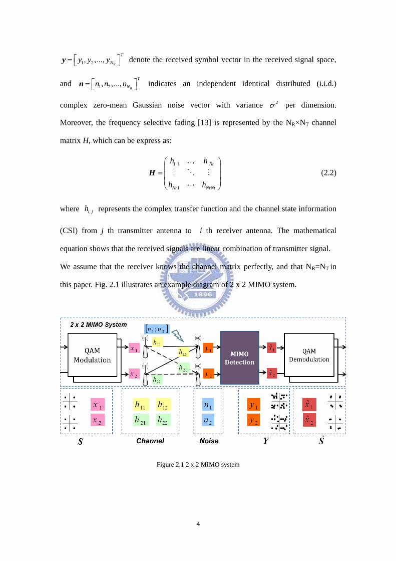
Figure 2.1 2 x 2 MIMO system ................................................................................................................ 4
Figure 3.1 The multilevel cluster-based MIMO detection algorithm ....................................................... 6
Figure 3.2 (a) Example of multilevel partitions with mean symbols in 64-QAM constellation. (b)
Example of multilevel cluster tree in 64-QAM constellation. .................................................................. 7
Figure 3.3 (a) Example of 4 clusters in 16-QAM constellation. (b) Example of 5 overlapped clusters in
16-QAM constellation. ............................................................................................................................. 8
Figure 3.4 The workflow of the Variable and Overlapped Cluster-based MIMO Detection .................... 9
Figure 3.5 The graphic representation of the Variable and Overlapped Cluster-based MIMO Detection
................................................................................................................................................................ 10
Figure 3.6 (a) Illustration of Overlap Clustering Algorithm applying in first quadrant in 64QAM ....... 12
Figure 3.6 (b) Illustration of Overlap Clustering Algorithm in 64QAM ................................................ 12
Figure 3.7 Illustration of Dynamic Clustering Algorithm in 64QAM .................................................... 14
Figure 3.8 Illustration of Detail Matching in 64QAM ............................................................................ 15
Figure 4.1 Performance in the VACO, 4T4R 64QAM ........................................................................... 18
Figure 4.2 Performance in the VACO, 8T8R 256QAM ......................................................................... 18
Figure 4.3 Performance in the VACO with the same complexity, 4T4R 64QAM .................................. 21
Figure 5.1 The design flow ..................................................................................................................... 23
Figure 5.2 VLSI architecture of the VACO for 6T6R 256-QAM MIMO system. .................................. 26
Figure 5.3 The parallel architecture of the VACO .................................................................................. 27
Figure 5.4 The signal distribution of variable R. .................................................................................... 28
Figure 5.5 Performance comparisons between float point and fixed point............................................. 29
Figure 5.6 VLSI structure of the sorting unit. ......................................................................................... 30
Figure 5.7 (a) The original design of sorting .......................................................................................... 30
Figure 5.7 (b) The alternative sorting design .......................................................................................... 30
Figure 5.7 (c) The updated sorting design .............................................................................................. 31
VII
List of Tables
Table 4.1 Simulation parameters ............................................................................................................ 16
Table 4.2 Performance & complexity reduction table, 4T4R 64QAM ................................................... 19
Table 4.3 Performance & complexity reduction table, 8T8R 256QAM ................................................. 20
Table 4.4 Performance & complexity table, 4T4R 64QAM ................................................................... 22
Table 5.1 The proposed design specification .......................................................................................... 25
Table 5.2 (a) Buffer number needed in each stage .................................................................................. 28
Table 5.2 (b) Word lengths needed in each buffers ................................................................................. 28
Table 5.3 The summary of systhesis results............................................................................................ 32
1
Chapter 1
Introduction
Recently, orthogonal frequency division multiplexing (OFDM), which
simplifies the receiver design, has become a widely used technique for broadband
wireless systems. Multiple-input multiple-output (MIMO) channels offer improved
capacity and potential for improved reliability compared to single input single-output
(SISO) channels. The MIMO technique in combination with OFDM (MIMO-OFDM)
has been identified as a promising approach for high spectral efficiency in wideband
systems. For high data rate is the tendency of the wireless communication system, the
MIMO-OFDM technique has been a spotlight for its ability to increase data rate.
Many new systems such as 802.11n, TGac, 3GPP LTE and WiMax adopt the
technique to increase data throughput and system performance.
To exploit the spectrum efficiency, large number of antennas and high order
QAM constellations are often employed, which leads a challenge to design the MIMO
detection with acceptable complexity and sub-optimal performance.
There are several conventional signal detection approaches for MIMO-OFDM
SDM system [1]. The linear detections, such as the ZFD and the MMSED, uses the
inverse of estimated channel response to extract the desired signals. Both of these two
approaches are easy to implementation, but enlarge performance degradation with the
enhancing channel noise. Another category is the nonlinear approaches such as
V-BLAST and the maximum likelihood detection (MLD). The V-BLAST algorithm
uses ordered successive interference cancellation with QR decomposition [2]. The
MLD algorithm reaches the optimal performance mathematically with the
2
unacceptable computation complexity [3][4].
Sphere decoding (SD) [5] algorithm can reduce the unacceptable computation
complexity by confining the number of constellation points to be searched,
Fincke-Pohst [6] and Schnorr-Euchner [7] are two of the most common
computationally efficient search strategies for realizing the ML detection.
Some methods [8]-[10] reduce the search set by employing the multilevel
structure of the N-QAM constellations. The multilevel structure decomposes N-QAM
demodulation into a sequence of sub-demodulations with a hierarchical order, which
has been widely investigated for complexity reduction purpose [11]. Also, the original
K-best sphere decoder (K-best SD) [12], whose complexity is proportional to the
number of transmit antennas, gives us the basis of our proposal algorithm.
In this paper, we propose the Variable and Overlapped Cluster-based (VACO)
MIMO Detection by partitioning the transmitted MIMO signal vectors into vary
clusters with estimated symbol in each dimension in N-QAM and finding out the
result signal by comparing the received signal. The overlap clustering algorithm pick
out the possible constellation points according to the estimated signal got by linear
detectors, as ZFD or MMSED. And then we enlarge/narrow the set of the possible
constellations points according to the channel gain information. Hence, we have all
the candidates signals compare with the received signal, and then apply breadth-first
searching with best K candidates in the searching space of SQRD. Eventually, the
detection signal with the least accumulative square Euclidean distance is delivered.
The remainder of this paper is organized as follows. The system assumptions
with problem statement are addressed in Chapter 2. The proposed Variable and
Overlapped Cluster-based MIMO Detection algorithm is described on example in
Chapter 3. Performance and complexity are evaluated and compared with different
approaches in Chapter 4. Finally, Chapter 5 gives conclusions.
3
Chapter 2
System Assumptions
2.1 MIMO System Description
MIMO system consists of multiple transmitter antennas and receiver antennas.
Signals are mixed from each transmitter antenna and received by multiply receiver
antennas. In this section, the system architecture used in this thesis will be described.
The research is designed for a coded MIMO system. The MIMO system has Nt
transmitter antennas and Nr receiver antennas and is denoted as Nt×Nr. The MIMO
technique is spatial multiplexing, which means independent data streams are
transmitted from each transmitter antenna, and a MIMO detector is in the receiver and
decodes the mixed signal. The data bit symbols are modulated to Nt-dimensional data
symbol vector 1 2, ,...,
T
T
Nx x x x ( *T
means transpose), whose entries ix is
mapped in the complex constellation. Each data symbol is transmitted by one of the
Nt transmitter antennas, respectively. The rich-scattering environment additive white
Gaussian noise (AWGN) is assumed here. Assuming perfect timing and frequency
synchronization, the received baseband signal for NT×NR MIMO system is modeled
as following:
H y x n (2.1)
where 1 2, ,...,
T
T
Nx x x x , ix is the transmitted signal modulated with N-QAM
constellation in the i-th transmitted antenna in the transmitted signal space;
4
1 2, ,...,R
T
Ny y y y denote the received symbol vector in the received signal space,
and 1 2, ,...,
R
T
Nn n n n indicates an independent identical distributed (i.i.d.)
complex zero-mean Gaussian noise vector with variance 2 per dimension.
Moreover, the frequency selective fading [13] is represented by the NR×NT channel
matrix H, which can be express as:
1 1 1
1
Nt
Nr NrNt
h h
h h
H (2.2)
where ,i jh represents the complex transfer function and the channel state information
(CSI) from j th transmitter antenna to i th receiver antenna. The mathematical
equation shows that the received signals are linear combination of transmitter signal.
We assume that the receiver knows the channel matrix perfectly, and that NR=NT in
this paper. Fig. 2.1 illustrates an example diagram of 2 x 2 MIMO system.
Figure 2.1 2 x 2 MIMO system
5
2.2 Motivation and Problem Statement
While employing large number of antennas and high order QAM constellations
in MIMO-OFDM systems, it leads a challenge to design the MIMO detection with
acceptable complexity and sub-optimal performance. Especially occurred in the
maximum-likelihood detector (MLD) [3], it requires unacceptable computation to
exhausted search the all combinations of each likelihood symbols.
To overcome the complexity problem, the Variable and Overlapped
Cluster-based MIMO algorithm tries to restrict the extending constellation points
according to the pre-estimated signal of the N-QAM constellations, and then keeps
the shorted K paths of the likelihood candidates which can reduce the search space
and computation complexity significantly.
In this thesis, we make a comparison in complexity and performance between
our proposal algorithm and the well-known K-best SD. The K-best SD is the most
attractive one of the MIMO Detection algorithms in recently researches, because of its
optimal performance as well as its complexity which is proportional to the number of
transmit antennas and is lower than the optimal maximum-likelihood detector.
The aim of the Variable and Overlapped Cluster-based method is to design an
MIMO Detection algorithm with nearly ML performance and low complexity cost in
large number of antennas and high order QAM constellations.
6
Chapter 3
Variable and Overlapped
Cluster-based MIMO Detection
3.1 Introduction
In the beginning, we describe the basic idea of cluster-based MIMO Detection
algorithm, which employed standard detectors, ZFD or MMSED, to estimate the N
transmitted symbol, and then pick out possible constellation points falling on each
antenna. After pruning the search space, we only need to detect correct transmitted
signal vector by computing the candidates left in the corresponding clusters.
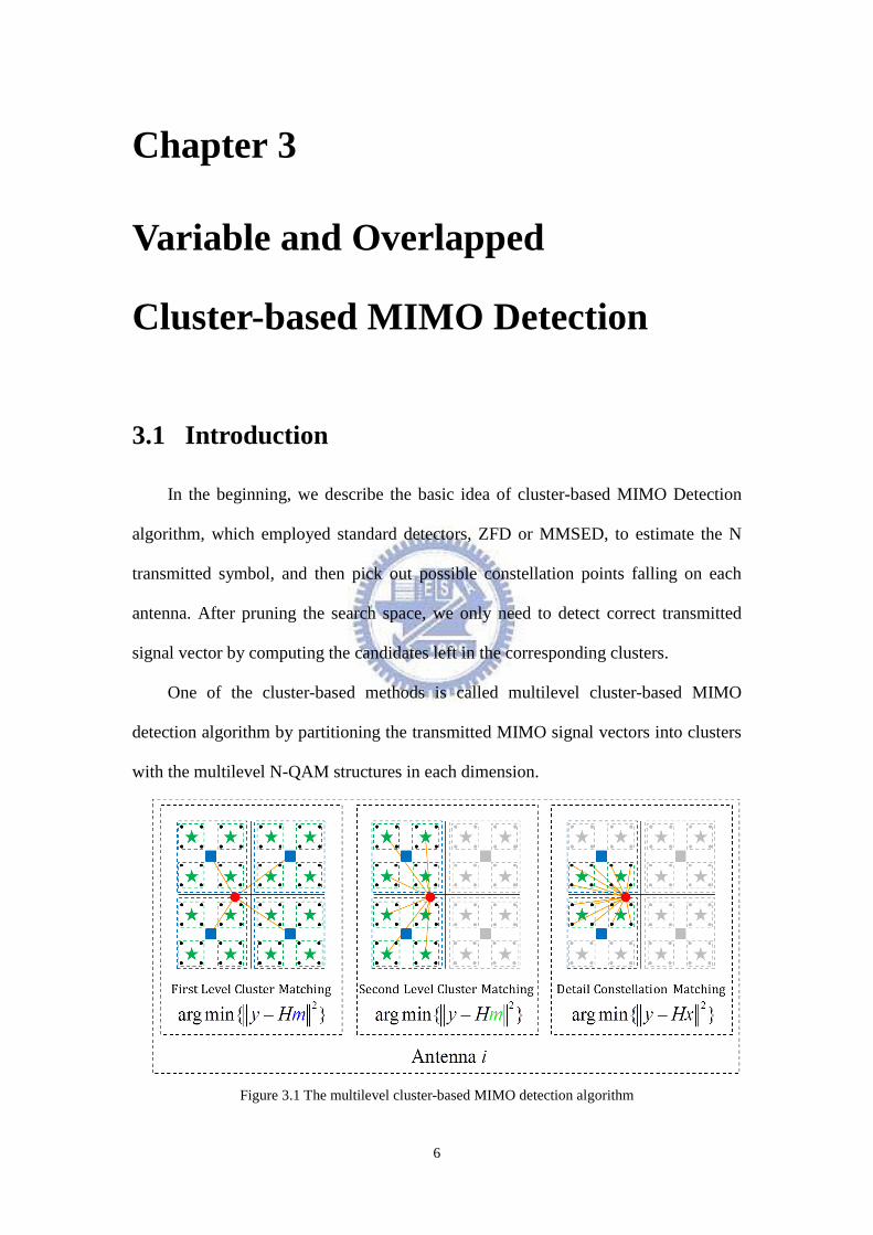
One of the cluster-based methods is called multilevel cluster-based MIMO
detection algorithm by partitioning the transmitted MIMO signal vectors into clusters
with the multilevel N-QAM structures in each dimension.
Figure 3.1 The multilevel cluster-based MIMO detection algorithm
7
… … …
… …
… …
… …
… …
Cluster
matching
Detail
matching
\…
256
…
256\
\…
256
…
…
…
…
…
…
…
… …
… …
… …
\…
256
… …
…
256\
256\
…
…
…
\…
256
…
\…
256
…
\…
256
… … …
… … …
… … 256
\
(a) (b)
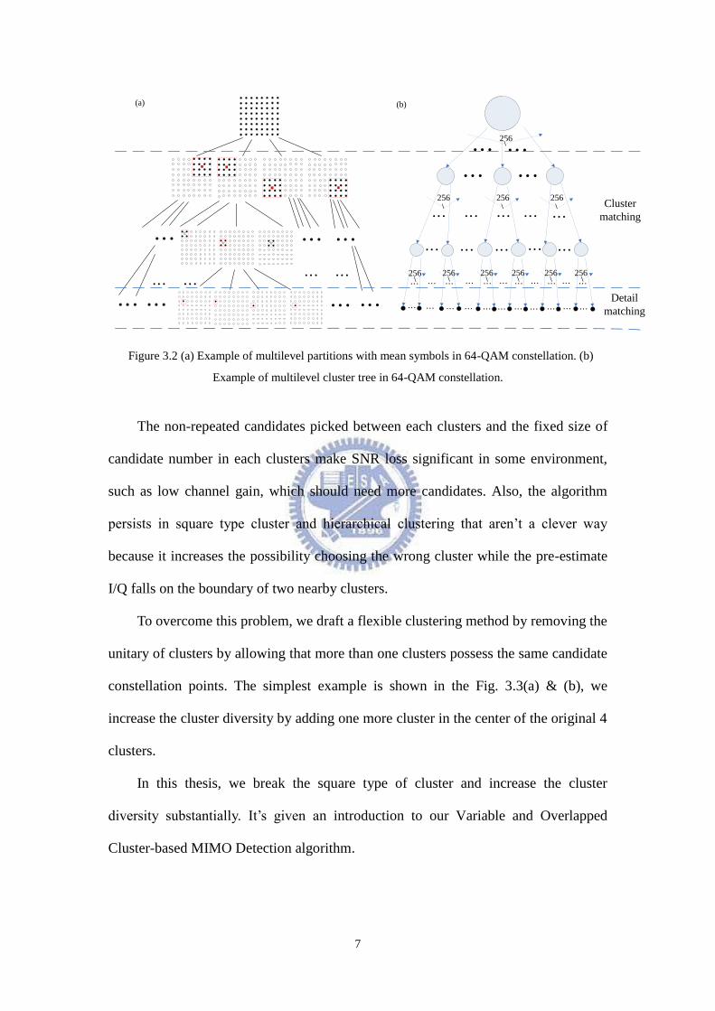
Figure 3.2 (a) Example of multilevel partitions with mean symbols in 64-QAM constellation. (b)
Example of multilevel cluster tree in 64-QAM constellation.
The non-repeated candidates picked between each clusters and the fixed size of
candidate number in each clusters make SNR loss significant in some environment,
such as low channel gain, which should need more candidates. Also, the algorithm
persists in square type cluster and hierarchical clustering that aren‟t a clever way
because it increases the possibility choosing the wrong cluster while the pre-estimate
I/Q falls on the boundary of two nearby clusters.
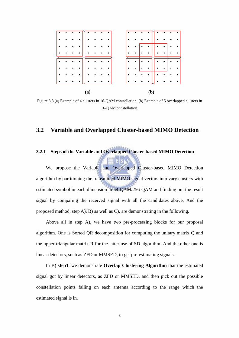
To overcome this problem, we draft a flexible clustering method by removing the
unitary of clusters by allowing that more than one clusters possess the same candidate
constellation points. The simplest example is shown in the Fig. 3.3(a) & (b), we
increase the cluster diversity by adding one more cluster in the center of the original 4
clusters.
In this thesis, we break the square type of cluster and increase the cluster
diversity substantially. It‟s given an introduction to our Variable and Overlapped
Cluster-based MIMO Detection algorithm.
8
(a) (b)
Figure 3.3 (a) Example of 4 clusters in 16-QAM constellation. (b) Example of 5 overlapped clusters in
16-QAM constellation.
3.2 Variable and Overlapped Cluster-based MIMO Detection
3.2.1 Steps of the Variable and Overlapped Cluster-based MIMO Detection
We propose the Variable and Overlapped Cluster-based MIMO Detection
algorithm by partitioning the transmitted MIMO signal vectors into vary clusters with
estimated symbol in each dimension in 64-QAM/256-QAM and finding out the result
signal by comparing the received signal with all the candidates above. And the
proposed method, step A), B) as well as C), are demonstrating in the following.
Above all in step A), we have two pre-processing blocks for our proposal
algorithm. One is Sorted QR decomposition for computing the unitary matrix Q and
the upper-triangular matrix R for the latter use of SD algorithm. And the other one is
linear detectors, such as ZFD or MMSED, to get pre-estimating signals.
In B) step1, we demonstrate Overlap Clustering Algorithm that the estimated
signal got by linear detectors, as ZFD or MMSED, and then pick out the possible
constellation points falling on each antenna according to the range which the
estimated signal is in.
9
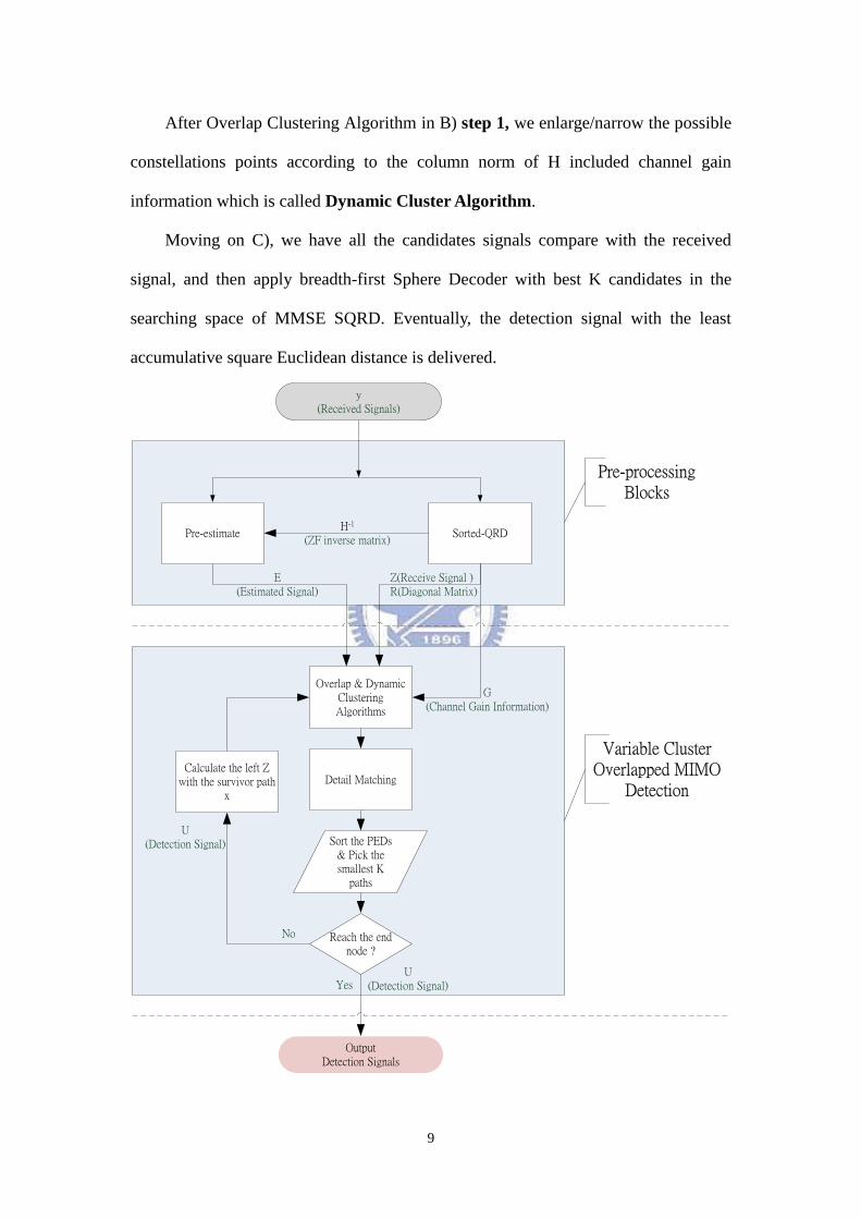
After Overlap Clustering Algorithm in B) step 1, we enlarge/narrow the possible
constellations points according to the column norm of H included channel gain
information which is called Dynamic Cluster Algorithm.
Moving on C), we have all the candidates signals compare with the received
signal, and then apply breadth-first Sphere Decoder with best K candidates in the
searching space of MMSE SQRD. Eventually, the detection signal with the least
accumulative square Euclidean distance is delivered.
Sorted-QRDPre-estimate
Reach the end node ?
Calculate the left Z with the survivor path
x
Overlap & Dynamic Clustering Algorithms
Detail Matching
Sort the PEDs & Pick the smallest K
paths
Pre-processing Blocks
Variable Cluster Overlapped MIMO
Detection
No
Yes
G(Channel Gain Information)
Z(Receive Signal )R(Diagonal Matrix)
H-1
(ZF inverse matrix)
E(Estimated Signal)
U(Detection Signal)
U(Detection Signal)
y(Received Signals)
OutputDetection Signals
10
Figure 3.4 The workflow of the Variable and Overlapped Cluster-based MIMO Detection
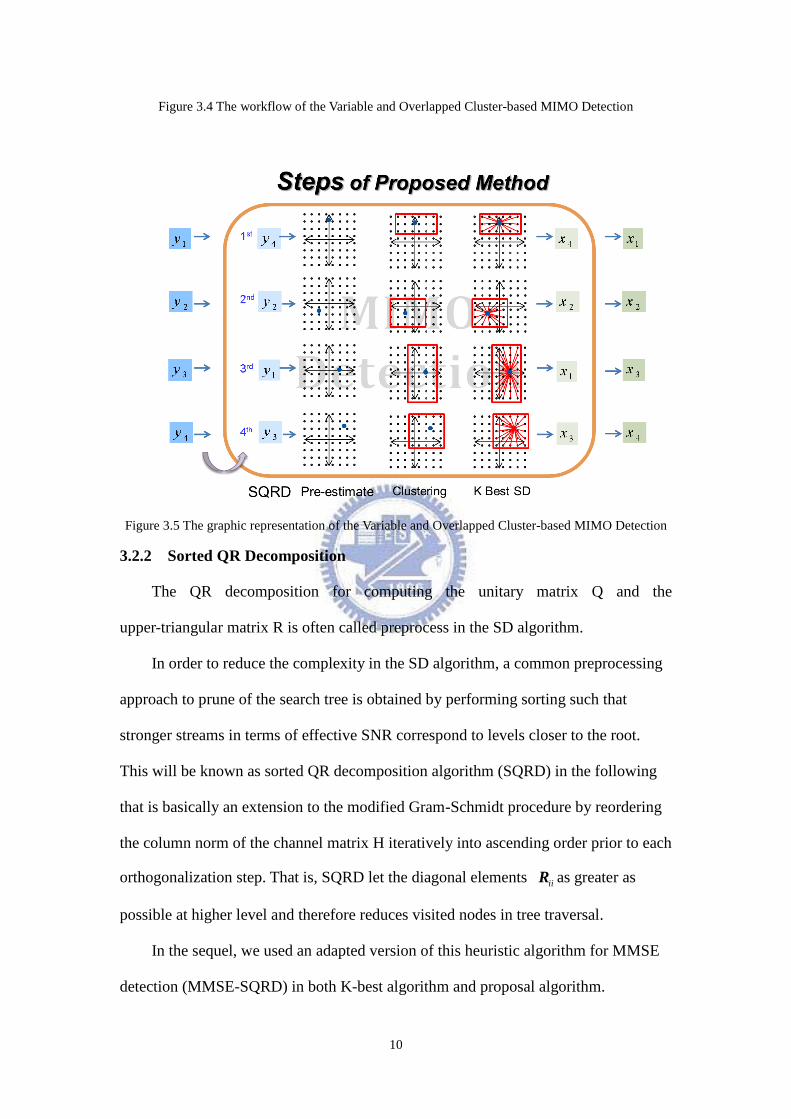
Figure 3.5 The graphic representation of the Variable and Overlapped Cluster-based MIMO Detection
3.2.2 Sorted QR Decomposition
The QR decomposition for computing the unitary matrix Q and the
upper-triangular matrix R is often called preprocess in the SD algorithm.
In order to reduce the complexity in the SD algorithm, a common preprocessing
approach to prune of the search tree is obtained by performing sorting such that
stronger streams in terms of effective SNR correspond to levels closer to the root.
This will be known as sorted QR decomposition algorithm (SQRD) in the following
that is basically an extension to the modified Gram-Schmidt procedure by reordering
the column norm of the channel matrix H iteratively into ascending order prior to each
orthogonalization step. That is, SQRD let the diagonal elements iiR as greater as
possible at higher level and therefore reduces visited nodes in tree traversal.
In the sequel, we used an adapted version of this heuristic algorithm for MMSE
detection (MMSE-SQRD) in both K-best algorithm and proposal algorithm.
11
3.2.3 Pre-estimating
A Pre-estimating method is also a preprocessing block which is needed to
estimate the transmitted signal vector, the calculation of Pre-estimating is much less
complex than the calculation of the squared Euclidean distance. The transmitted
signal vector ( ˆMMSEx ) can be estimated through minimum mean-squared error (MMSE)
approach (2 1ˆ ( )H H
MMSE H H H x I y ), where 2 is a noise variance and I is
an identity matrix), which needs very little computation complexity.
3.2.4 Overlap Clustering Algorithm
The Overlap Clustering Algorithm employs the standard detectors, ZFD or
MMSED, to estimate the N transmitted symbol, and then pick out possible
constellation points 1 2{ , ,... }k
i i iC C C falling on each antenna.
To increase the cluster diversity, we take the real/imaginary part of pre-estimate
I/Q as reference value'x , and then confine range of the spanning candidates
1 2{ , ,... }k
i i iC C C according to the boundary values '
1 2x x x given in following (3.1)
and Fig. 3.5. That‟s said, we first separate the I/Q to real and imaginary parts and then
compute the distance individually with the confine range of the spanning candidates.
1 2 '
1 2{ , ,... | }k
i i iC C C x x x (3.1)
'
1
Total candidates
is the estimated signal and ... are boundary values
i
n
N
x x x
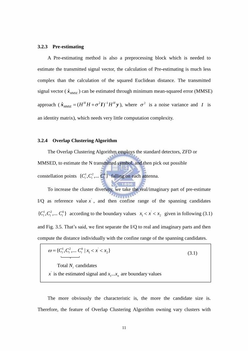
The more obviously the characteristic is, the more the candidate size is.
Therefore, the feature of Overlap Clustering Algorithm owning vary clusters with
12
flexible size of spanning candidates is reasonable to deploy in practical
communication environment.
For example, the candidate I/Qs are (+5,+5), (+5,+7), (+7,+5) and (+7,+7) while
the real and imaginary values of estimated I/Q are both larger than 6.5. The candidate
I/Qs are(+5,-3) ,(+5,-1), (+5,+1), (+5,+3),(+5,+5),(+5,-3) ,(+7,-1), (+7,+1), (+7,+3)
and (+7,+5) while the real value is greater than 6.5 as well as the imaginary one is
between 0 and 3.5.
Figure 3.6 (a) Illustration of Overlap Clustering Algorithm applying in first quadrant in 64QAM
13
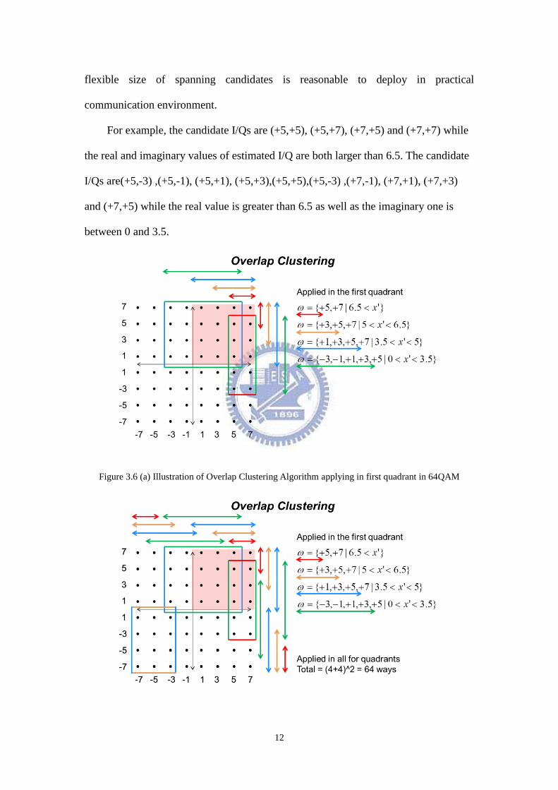
Figure 3.6 (b) Illustration of Overlap Clustering Algorithm in 64QAM
In the Fig. 3.5, it just represents the Overlap clustering Algorithm applying in
first quadrant where the reference values are positive. While joining with the left ones,
we will have a complete Overlap clustering Algorithm and the whole picture is shown
in Fig. 3.6.
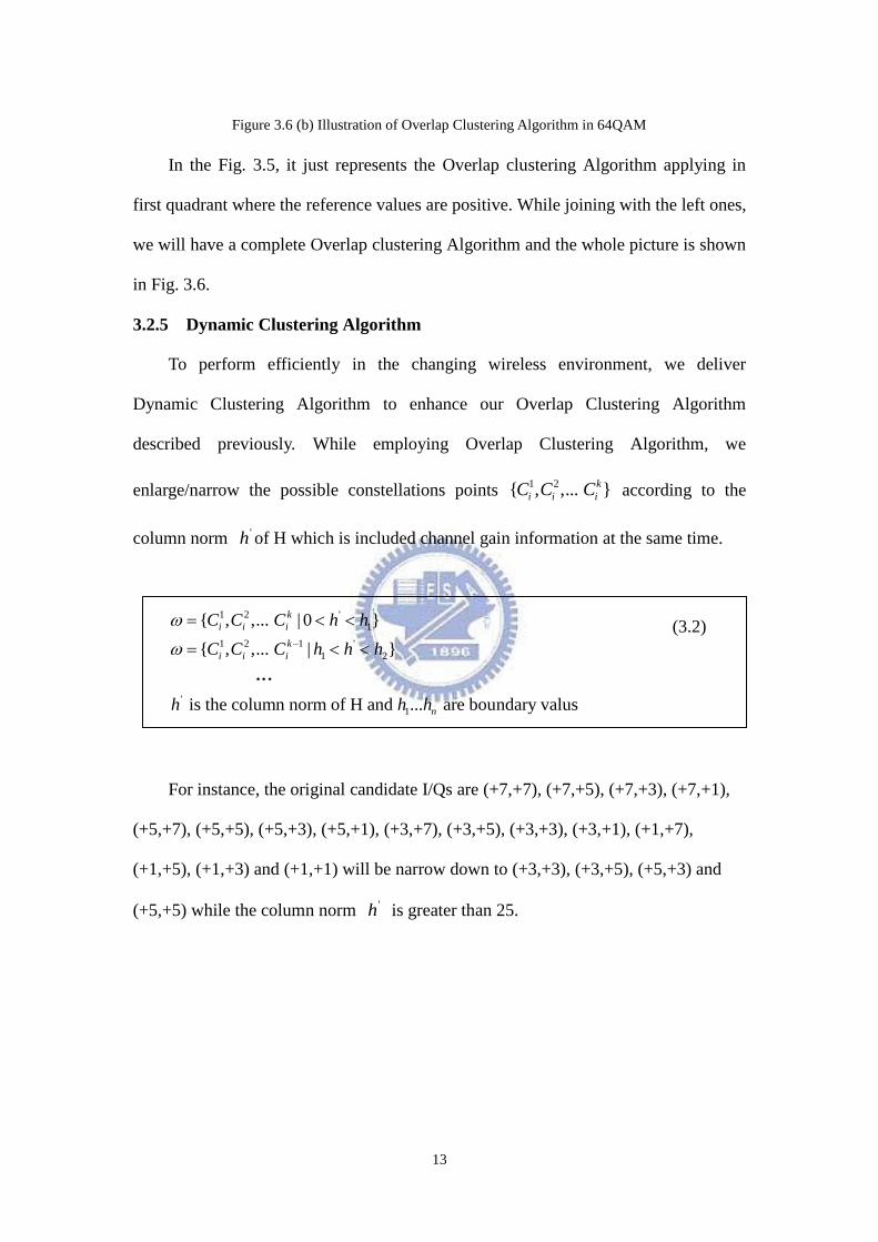
3.2.5 Dynamic Clustering Algorithm
To perform efficiently in the changing wireless environment, we deliver
Dynamic Clustering Algorithm to enhance our Overlap Clustering Algorithm
described previously. While employing Overlap Clustering Algorithm, we
enlarge/narrow the possible constellations points 1 2{ , ,... }k
i i iC C C according to the
column norm 'h of H which is included channel gain information at the same time.
1 2 '
1
1 2 1 '
1 2
'
1
{ , ,... | 0 }
{ , ,... | }
is the column norm of H and ... are boundary valus
k
i i i
k
i i i
n
C C C h h
C C C h h h
h h h
For instance, the original candidate I/Qs are (+7,+7), (+7,+5), (+7,+3), (+7,+1),
(+5,+7), (+5,+5), (+5,+3), (+5,+1), (+3,+7), (+3,+5), (+3,+3), (+3,+1), (+1,+7),
(+1,+5), (+1,+3) and (+1,+1) will be narrow down to (+3,+3), (+3,+5), (+5,+3) and
(+5,+5) while the column norm 'h is greater than 25.
…
(3.2)
14
Figure 3.7 Illustration of Dynamic Clustering Algorithm in 64QAM
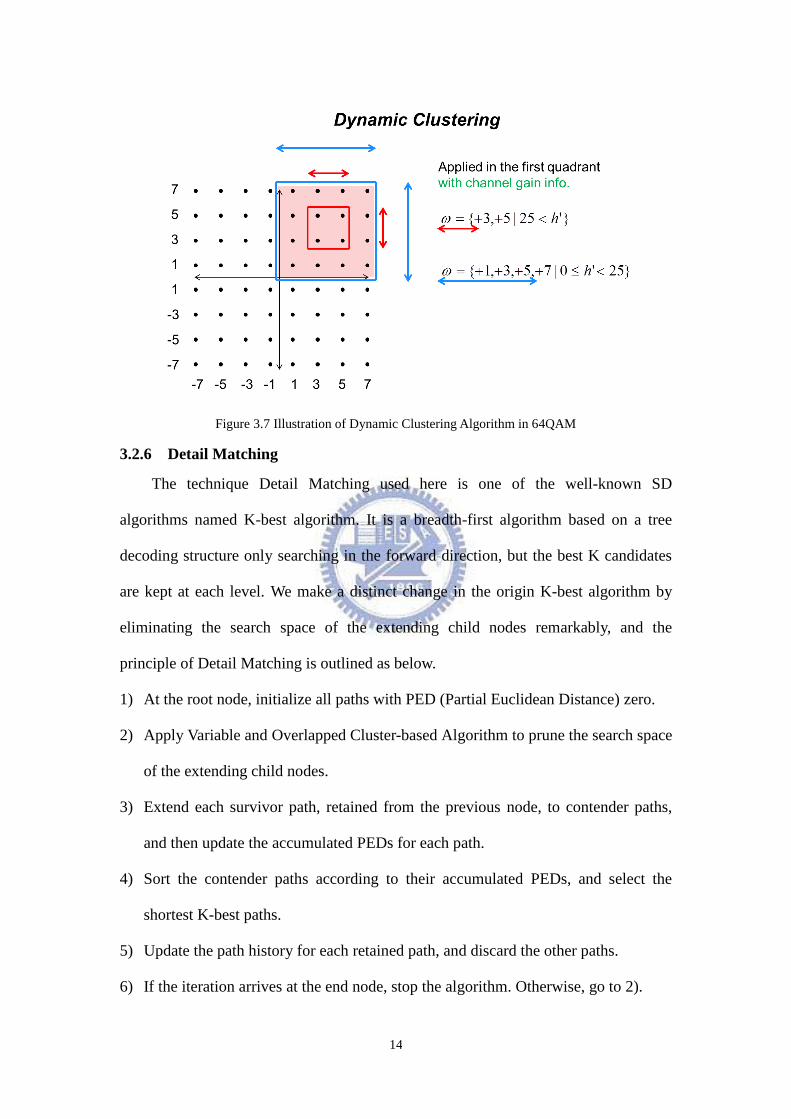
3.2.6 Detail Matching
The technique Detail Matching used here is one of the well-known SD
algorithms named K-best algorithm. It is a breadth-first algorithm based on a tree
decoding structure only searching in the forward direction, but the best K candidates
are kept at each level. We make a distinct change in the origin K-best algorithm by
eliminating the search space of the extending child nodes remarkably, and the
principle of Detail Matching is outlined as below.
1) At the root node, initialize all paths with PED (Partial Euclidean Distance) zero.
2) Apply Variable and Overlapped Cluster-based Algorithm to prune the search space
of the extending child nodes.
3) Extend each survivor path, retained from the previous node, to contender paths,
and then update the accumulated PEDs for each path.
4) Sort the contender paths according to their accumulated PEDs, and select the
shortest K-best paths.
5) Update the path history for each retained path, and discard the other paths.
6) If the iteration arrives at the end node, stop the algorithm. Otherwise, go to 2).
15
The best path at the final iteration is the hard decision output of the decoder. The
advantage of the K-best algorithm over the sequential algorithm is its fixed decoding
throughput, since it is easily implemented in a parallel and a pipelined fashion.
Meanwhile, a strict K-best algorithm should keep as large as possible without
compromising on the optimality, compared with the exhaustive-search ML algorithm.
However, limitation can reduce the complexity of the breadth-first algorithm.
Therefore, there is a tradeoff between complexity and performance in to select a
proper K value.
Figure 3.8 Illustration of Detail Matching in 64QAM
16
Chapter 4
Simulation Results
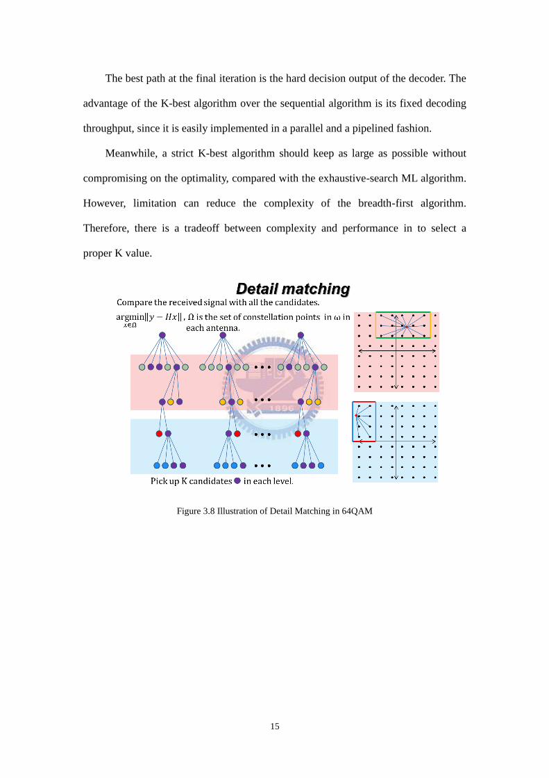
This section compares performance and complexity between K-best SD and the
Variable and Overlapped Cluster-based Algorithm in MIMO detection. Note that the
performance comparison is considered under packet error rate (PER) 0.08 and
normalizes to the ML detection methods.
A typical MIMO-OFDM system is based on IEEE 802.11n Wireless LANs, TGn
Sync Proposal Technical Specification [10] which is used as the reference design
platform. The simulation model is mainly based on TGn multipath specification of
mode E, which is the multipath fast-fading channel model of 15-taps and 100ns Root
Mean Square (RMS) delay. The major simulation parameters are shown in Table 4.1.
Environment Description
Parameter Value
Simulation Platform IEEE 802.11n
Signal Bandwidth 40 MHz
Number of subcarries 108 subcarriers
FFT size 128 points
Number of antenna 4 Tx 4 Rx / 8 Tx 8 Rx
Forward Error Correction Convolution and Viterbi
(Coding Rate 2/3)
Packet size 1024 Bytes per Tx antenna
Channel Model TGN-E with AWGN
RMS delay spread 100 ns
Subcarrier modulation 64QAM/256QAM
Preprocessing Block SQRD、ZFD
Signal Detection K-best SD Algorithm
Variable and Overlapped Cluster-based
Table 4.1 Simulation parameters
17
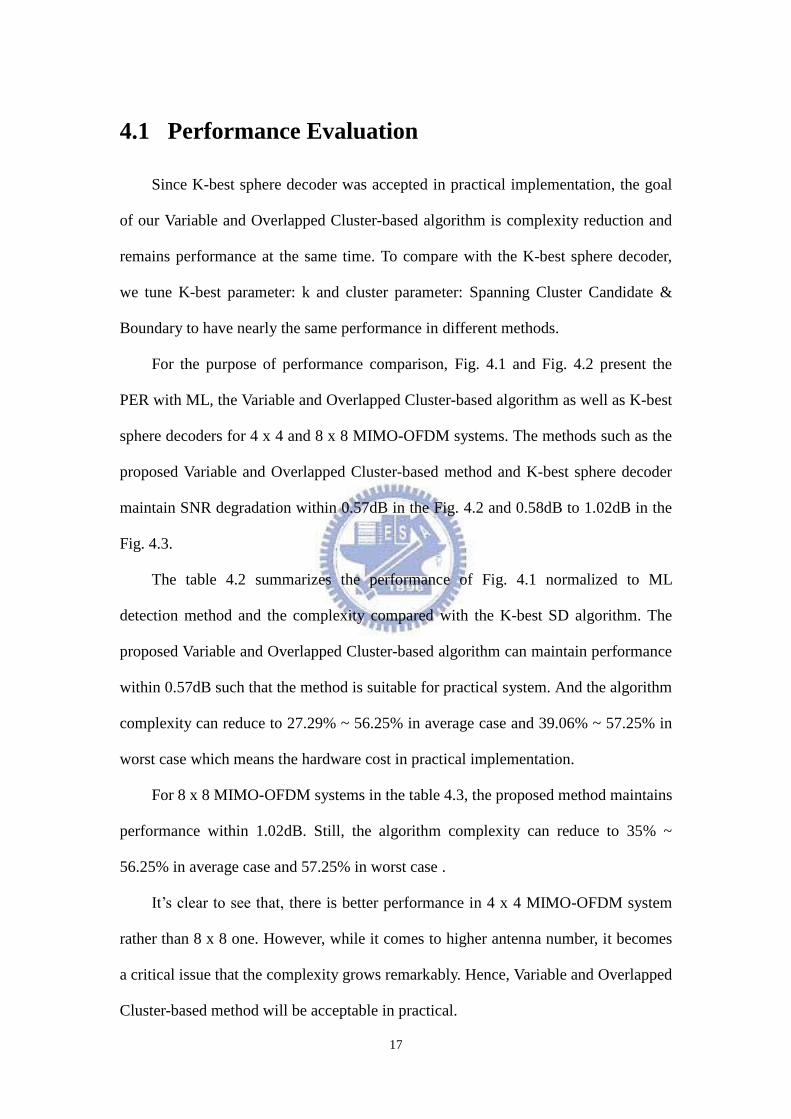
4.1 Performance Evaluation
Since K-best sphere decoder was accepted in practical implementation, the goal
of our Variable and Overlapped Cluster-based algorithm is complexity reduction and
remains performance at the same time. To compare with the K-best sphere decoder,
we tune K-best parameter: k and cluster parameter: Spanning Cluster Candidate &
Boundary to have nearly the same performance in different methods.
For the purpose of performance comparison, Fig. 4.1 and Fig. 4.2 present the
PER with ML, the Variable and Overlapped Cluster-based algorithm as well as K-best
sphere decoders for 4 x 4 and 8 x 8 MIMO-OFDM systems. The methods such as the
proposed Variable and Overlapped Cluster-based method and K-best sphere decoder
maintain SNR degradation within 0.57dB in the Fig. 4.2 and 0.58dB to 1.02dB in the
Fig. 4.3.
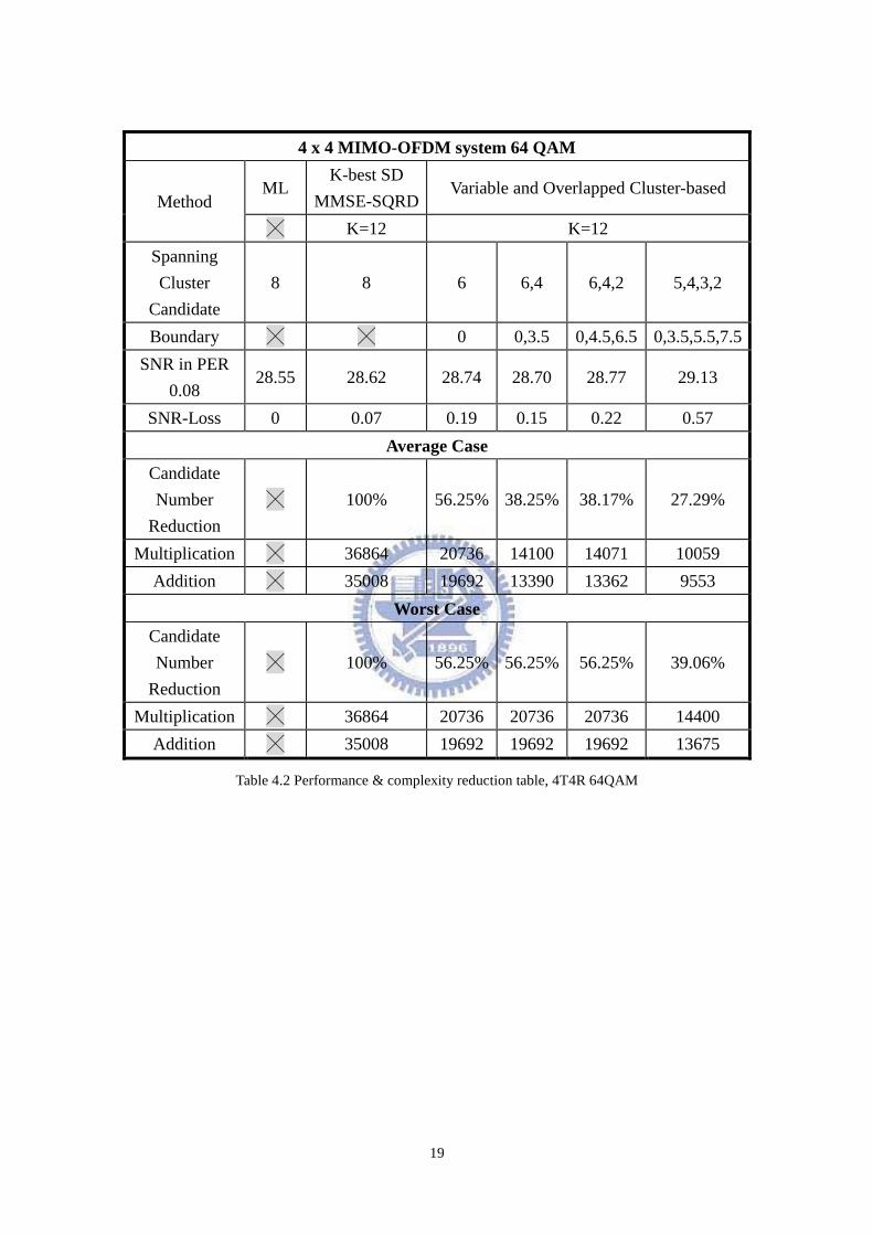
The table 4.2 summarizes the performance of Fig. 4.1 normalized to ML
detection method and the complexity compared with the K-best SD algorithm. The
proposed Variable and Overlapped Cluster-based algorithm can maintain performance
within 0.57dB such that the method is suitable for practical system. And the algorithm
complexity can reduce to 27.29% ~ 56.25% in average case and 39.06% ~ 57.25% in
worst case which means the hardware cost in practical implementation.
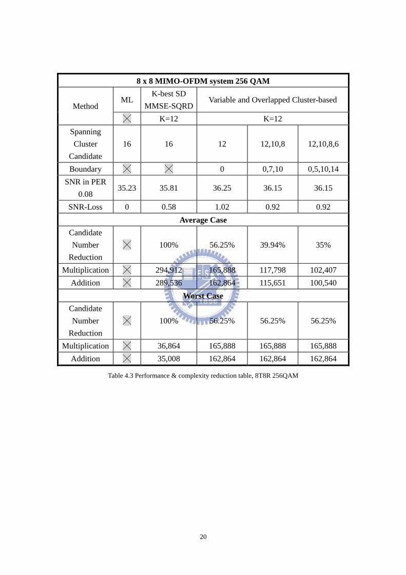
For 8 x 8 MIMO-OFDM systems in the table 4.3, the proposed method maintains
performance within 1.02dB. Still, the algorithm complexity can reduce to 35% ~
56.25% in average case and 57.25% in worst case .
It‟s clear to see that, there is better performance in 4 x 4 MIMO-OFDM system
rather than 8 x 8 one. However, while it comes to higher antenna number, it becomes
a critical issue that the complexity grows remarkably. Hence, Variable and Overlapped
Cluster-based method will be acceptable in practical.
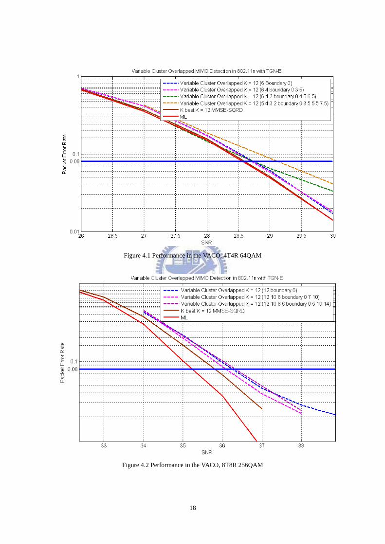
18
Figure 4.1 Performance in the VACO, 4T4R 64QAM
Figure 4.2 Performance in the VACO, 8T8R 256QAM
19
4 x 4 MIMO-OFDM system 64 QAM
Method ML
K-best SD
MMSE-SQRD Variable and Overlapped Cluster-based
╳ K=12 K=12
Spanning
Cluster
Candidate
8 8 6 6,4 6,4,2 5,4,3,2
Boundary ╳ ╳ 0 0,3.5 0,4.5,6.5 0,3.5,5.5,7.5
SNR in PER
0.08 28.55 28.62 28.74 28.70 28.77 29.13
SNR-Loss 0 0.07 0.19 0.15 0.22 0.57
Average Case
Candidate
Number
Reduction
╳ 100% 56.25% 38.25% 38.17% 27.29%
Multiplication ╳ 36864 20736 14100 14071 10059
Addition ╳ 35008 19692 13390 13362 9553
Worst Case
Candidate
Number
Reduction
╳ 100% 56.25% 56.25% 56.25% 39.06%
Multiplication ╳ 36864 20736 20736 20736 14400
Addition ╳ 35008 19692 19692 19692 13675
Table 4.2 Performance & complexity reduction table, 4T4R 64QAM
20
8 x 8 MIMO-OFDM system 256 QAM
Method ML
K-best SD
MMSE-SQRD Variable and Overlapped Cluster-based
╳ K=12 K=12
Spanning
Cluster
Candidate
16 16 12 12,10,8 12,10,8,6
Boundary ╳ ╳ 0 0,7,10 0,5,10,14
SNR in PER
0.08 35.23 35.81 36.25 36.15 36.15
SNR-Loss 0 0.58 1.02 0.92 0.92
Average Case
Candidate
Number
Reduction
╳ 100% 56.25% 39.94% 35%
Multiplication ╳ 294,912 165,888 117,798 102,407
Addition ╳ 289,536 162,864 115,651 100,540
Worst Case
Candidate
Number
Reduction
╳ 100% 56.25% 56.25% 56.25%
Multiplication ╳ 36,864 165,888 165,888 165,888
Addition ╳ 35,008 162,864 162,864 162,864
Table 4.3 Performance & complexity reduction table, 8T8R 256QAM
21
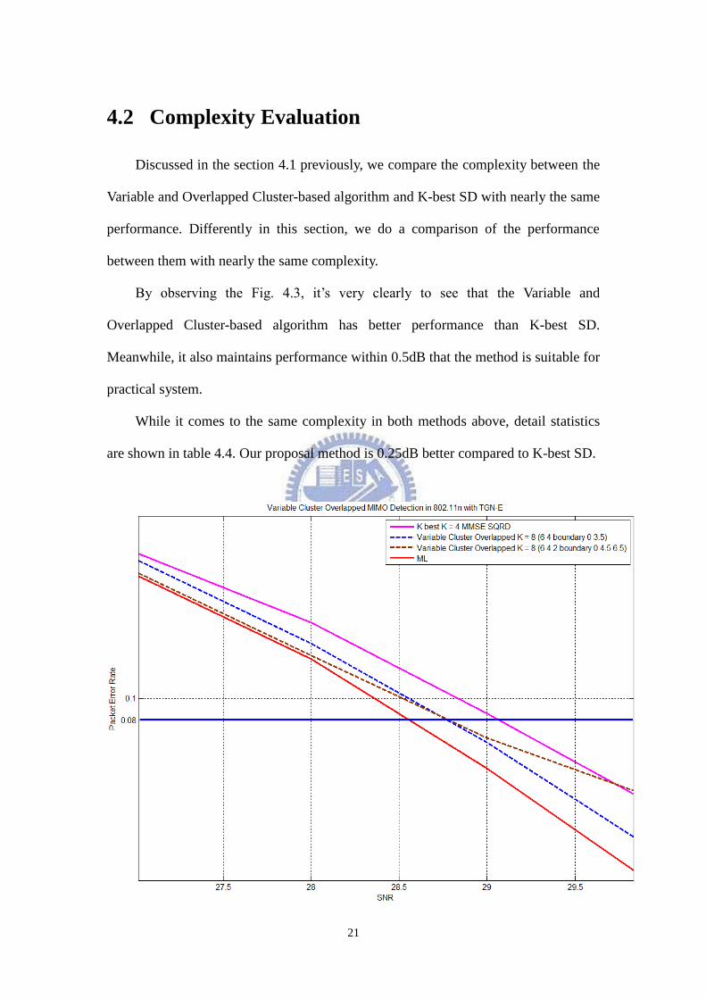
4.2 Complexity Evaluation
Discussed in the section 4.1 previously, we compare the complexity between the
Variable and Overlapped Cluster-based algorithm and K-best SD with nearly the same
performance. Differently in this section, we do a comparison of the performance
between them with nearly the same complexity.
By observing the Fig. 4.3, it‟s very clearly to see that the Variable and
Overlapped Cluster-based algorithm has better performance than K-best SD.
Meanwhile, it also maintains performance within 0.5dB that the method is suitable for
practical system.
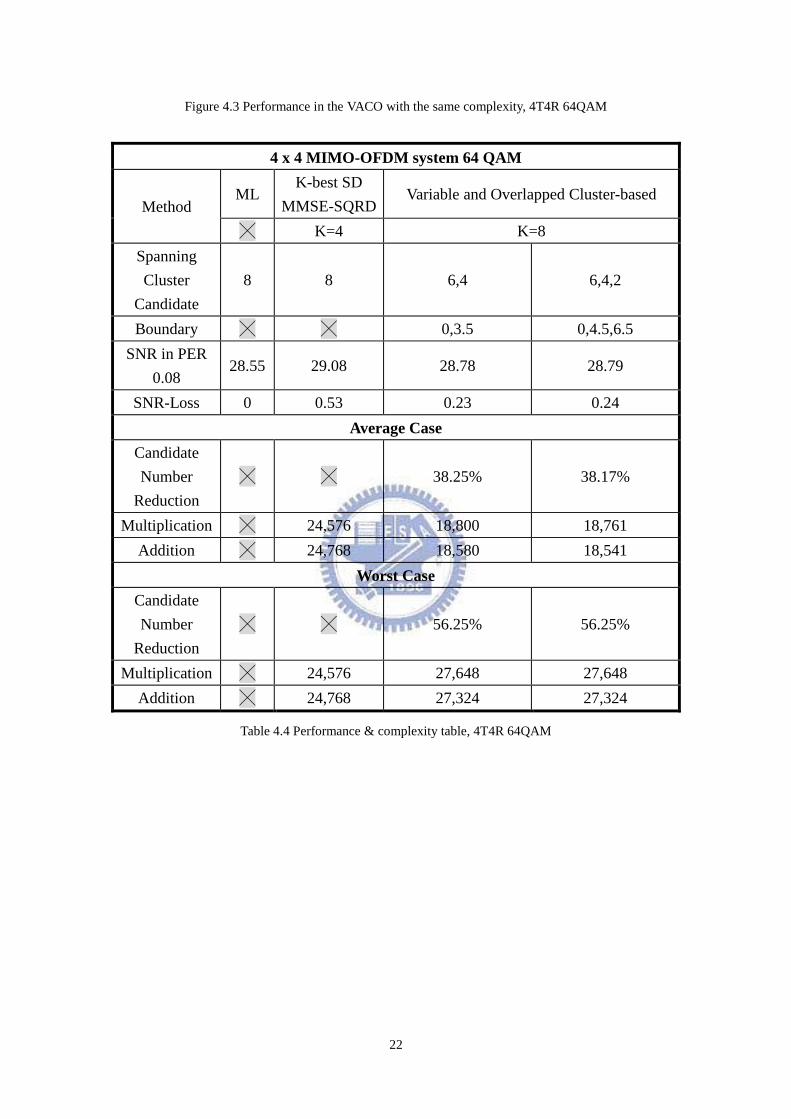
While it comes to the same complexity in both methods above, detail statistics
are shown in table 4.4. Our proposal method is 0.25dB better compared to K-best SD.
22
Figure 4.3 Performance in the VACO with the same complexity, 4T4R 64QAM
4 x 4 MIMO-OFDM system 64 QAM
Method ML
K-best SD
MMSE-SQRD Variable and Overlapped Cluster-based
╳ K=4 K=8
Spanning
Cluster
Candidate
8 8 6,4 6,4,2
Boundary ╳ ╳ 0,3.5 0,4.5,6.5
SNR in PER
0.08 28.55 29.08 28.78 28.79
SNR-Loss 0 0.53 0.23 0.24
Average Case
Candidate
Number
Reduction
╳ ╳ 38.25% 38.17%
Multiplication ╳ 24,576 18,800 18,761
Addition ╳ 24,768 18,580 18,541
Worst Case
Candidate
Number
Reduction
╳ ╳ 56.25% 56.25%
Multiplication ╳ 24,576 27,648 27,648
Addition ╳ 24,768 27,324 27,324
Table 4.4 Performance & complexity table, 4T4R 64QAM
23
Chapter 5
Hardware Implementation and
Measurement
5.1 Introduction
The Variable and Overlapped Cluster-based algorithm is a modified method of
K-best SD, thus it inherits the K-best SD advantage so that it is very suitable to
parallel and design in pipeline. In this chapter, our proposed hardware architecture is
presented.
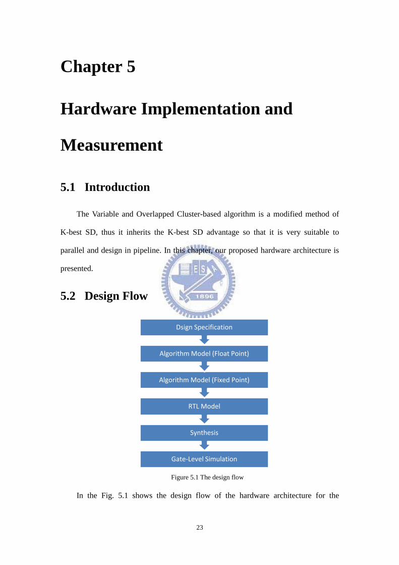
5.2 Design Flow
Figure 5.1 The design flow
In the Fig. 5.1 shows the design flow of the hardware architecture for the
Gate-Level Simulation
Synthesis
RTL Model
Algorithm Model (Fixed Point)
Algorithm Model (Float Point)
Dsign Specification
24
Variable and Overlapped Cluster-based algorithm. In the step of algorithm design,
Matlab is used to build up and experiment the detecting algorithm. After the algorithm
model is determined, the measurement of the bit length and accuracy is applied so that
we need to convert the variable from float point to fixed point. Meanwhile, the
performance loss is taken carefully and the golden pattern is generated for logic
design. After the algorithm simulations, the hardware design is implemented by
Register Transfer Level (RTL) with the Verilog. The Verilog tool helps us code in
behavior language and confirm the correctness of hardware design. Then, the RTL
code will be synthesized by Design Compiler to gate-level netlist. Finally, the
gate-level simulation helps us to verify whether the behavior of gate-level is fit in
with our requirements.
5.3 Proposed Architecture
Table 5.1 gives the detail specification of the Variable and Overlapped
Cluster-based algorithm, where achieving GigaLAN is our goal here.
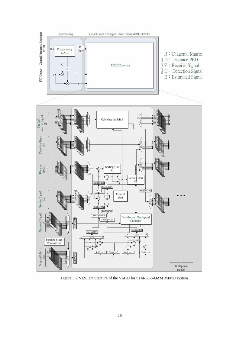
The Fig. 5.2 illustrates overviews of the VACO. In the top architecture diagram,
there is a preprocessing block including common sorted QR decomposition (SQRD).
And the MIMO Detection is implemented with the Variable and Overlapped
Cluster-based algorithm.
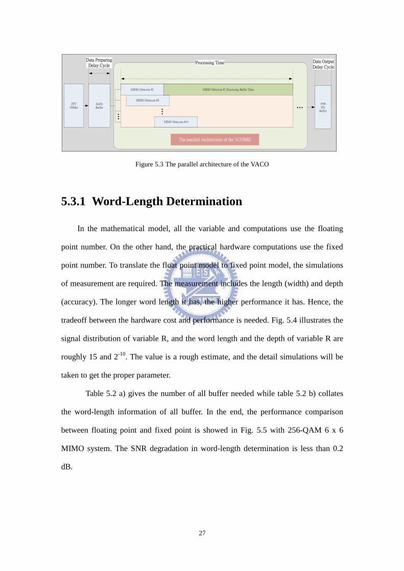
The Fig. 5.3 shows the parallel architecture of the proposed architecture. Due to
the reason that there‟s not enough time to process the input I/Qs while using only one
set of MIMO Detector. (Roughly 4 clock cycle time to process one level I/Qs which is
absolutely impossible). With 14 sets of MIMO detector in parallel architecture, there‟s
is enough time to finish this work. (Up to 56 clock cycle time)
As shown in block diagram of Fig. 5.2, the architecture consists of twelve
pipeline stages. Each stage has a processing element (PE), which implements the
25
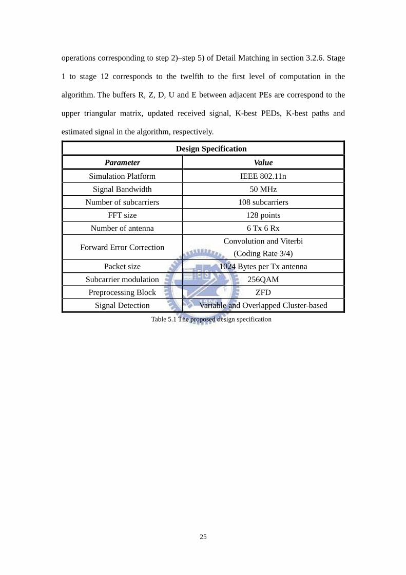
operations corresponding to step 2)–step 5) of Detail Matching in section 3.2.6. Stage
1 to stage 12 corresponds to the twelfth to the first level of computation in the
algorithm. The buffers R, Z, D, U and E between adjacent PEs are correspond to the
upper triangular matrix, updated received signal, K-best PEDs, K-best paths and
estimated signal in the algorithm, respectively.
Design Specification
Parameter Value
Simulation Platform IEEE 802.11n
Signal Bandwidth 50 MHz
Number of subcarriers 108 subcarriers
FFT size 128 points
Number of antenna 6 Tx 6 Rx
Forward Error Correction Convolution and Viterbi
(Coding Rate 3/4)
Packet size 1024 Bytes per Tx antenna
Subcarrier modulation 256QAM
Preprocessing Block ZFD
Signal Detection Variable and Overlapped Cluster-based
Table 5.1 The proposed design specification
26
Figure 5.2 VLSI architecture of the VACO for 6T6R 256-QAM MIMO system
H
y
H-1
R(Diag)
R:Diagonal MatrixD:Distance PEDZ:Receive SignalU:Detection SignalE:Estimated Signal
e
Q
z
Proprocessing Variable and Overlapped Cluster-based MIMO Detector
PreprocessingSQRD
MIMO Detection
FF
T O
utpu
tC
hann
el F
requ
ency
Res
pons
es
(CF
R)
Har
d D
ecis
ion
Dia
gona
l M
atri
x(R
)R
ecei
ve S
igna
l(Z
)E
stim
ated
Sig
nal
(E)
Control
Unit
Bu
ffer(56
)B
uffer(5
6)
Bu
ffer(56)
Bu
ffer(12)
Bu
ffer(56)
Bu
ffer(56)
Bu
ffer(56
)B
uffer(1
2)
Bu
ffer(56
)B
uffer(5
6)
Bu
ffer(56)
MU
X
Bu
ffer(15)
Bu
ffer(56)
Bu
ffer(56)
Bu
ffer(56)
Bu
ffer(12)
Bu
ffer(56)
Bu
ffer(56)
Bu
ffer(56)
Bu
ffer(12)
Bu
ffer(56)
Bu
ffer(56)
Bu
ffer(56)
MU
X
Bu
ffer(15)
Bu
ffer(15)
Bu
ffer(15)
Bu
ffer(56)
Bu
ffer(56)
Bu
ffer(56)
Bu
ffer(12)
Bu
ffer(56)
Bu
ffer(56)
Bu
ffer(56)
MU
X
Bu
ffer(20)
Buffer(20)
Buffer(20)
MU
X
Sorting Unit
#1
Sorting Unit
#2
Dis
tanc
e (P
ED
)
( )2
( )2
Buffer(20)
Buffer(20)
Variable and Overlapped Clustering
Shift <<1Shift <<2 Shift <<3 Shift <<4
MUXMUX
Buffer(19)Buffer(19)
Add Signed Bit
Add Signed Bit
Bu
ffer(56)
Bu
ffer(56)
Bu
ffer(56)
Bu
ffer(12)
Bu
ffer(56)
Bu
ffer(56)
Bu
ffer(56)
MU
X
Bu
ffer(15)
Bu
ffer(56)
Bu
ffer(56)
Bu
ffer(56)
Bu
ffer(12)
Bu
ffer(56)
Bu
ffer(56)
Bu
ffer(56)
Bu
ffer(15)
Bu
ffer(56)
Bu
ffer(56)
Bu
ffer(56)
Bu
ffer(12)
Bu
ffer(56)
Bu
ffer(56)
Bu
ffer(56)
Bu
ffer(20)
Bu
ffer(56)
Bu
ffer(56)
Bu
ffer(56)
Bu
ffer(12)
Bu
ffer(56)
Bu
ffer(56)
Bu
ffer(56)
Bu
ffer(3)
Bu
ffer(56)
Bu
ffer(56)
Bu
ffer(56)
Bu
ffer(12)
Bu
ffer(56)
Bu
ffer(56)
Bu
ffer(56)
Bu
ffer(3x2)
Bu
ffer(56)
Bu
ffer(56)
Bu
ffer(56
)B
uffer(1
2)
Bu
ffer(56)
Bu
ffer(56)
Bu
ffer(56)
Bu
ffer(3)
MU
X
Det
ecti
on S
igna
l(U
)
DE
MU
X
Bu
ffer(56)
Bu
ffer(56)
Bu
ffer(56)
Bu
ffer(12)
Bu
ffer(56)
Bu
ffer(56)
Bu
ffer(56)
Bu
ffer(20)
Bu
ffer(56)
Bu
ffer(56)
Bu
ffer(56)
Bu
ffer(12)
Bu
ffer(56)
Bu
ffer(56)
Bu
ffer(56)
Bu
ffer(15)
DE
MU
X
The
Lef
tR
ecei
ve S
igna
l(Z
)
Bu
ffer(56)
Bu
ffer(56)
Bu
ffer(56)
Bu
ffer(12)
Bu
ffer(56)
Bu
ffer(56)
Bu
ffer(56)
Bu
ffer(15x1
1)
Bu
ffer(56)
Bu
ffer(56)
Bu
ffer(56)
Bu
ffer(12)
Bu
ffer(56)
Bu
ffer(56)
Bu
ffer(56)
Bu
ffer(15x1
1)
Calculate the left Z Bu
ffer(56)
Bu
ffer(56)
Bu
ffer(56)
Bu
ffer(12)
Bu
ffer(56)
Bu
ffer(56)
Bu
ffer(56)
Bu
ffer(15x
10)
DE
MU
XD
EM
UXM
UX
Buffer(15) …
Pipeline Stage
Control Unit
11 stages in parallel
27
MIMO Detecion #1
MIMO Detecion #2
MIMO Detecion #14
FFT 50Mhz
6xI/QBuffer
Data PreparingDelay Cycle
MIMO Detecion #1 Processing Buffer Time
14x6I/Q
Buffer
Data OutputDelay Cycle
...
Processing Time
...
...
The parallel Architecture of the VCOMD
Figure 5.3 The parallel architecture of the VACO
5.3.1 Word-Length Determination
In the mathematical model, all the variable and computations use the floating
point number. On the other hand, the practical hardware computations use the fixed
point number. To translate the float point model to fixed point model, the simulations
of measurement are required. The measurement includes the length (width) and depth
(accuracy). The longer word length it has, the higher performance it has. Hence, the
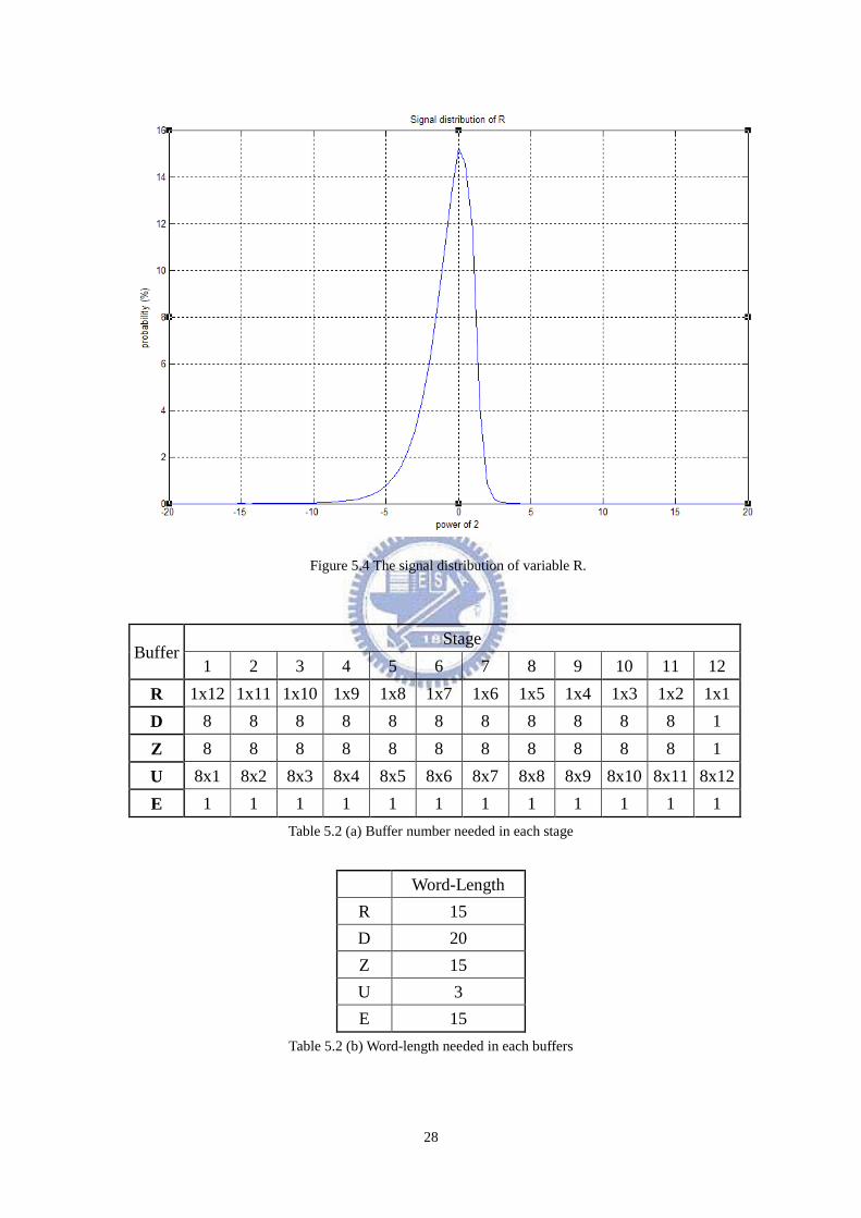
tradeoff between the hardware cost and performance is needed. Fig. 5.4 illustrates the
signal distribution of variable R, and the word length and the depth of variable R are
roughly 15 and 2-10
. The value is a rough estimate, and the detail simulations will be
taken to get the proper parameter.
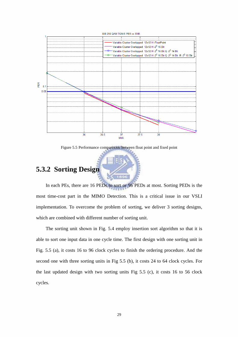
Table 5.2 a) gives the number of all buffer needed while table 5.2 b) collates
the word-length information of all buffer. In the end, the performance comparison
between floating point and fixed point is showed in Fig. 5.5 with 256-QAM 6 x 6
MIMO system. The SNR degradation in word-length determination is less than 0.2
dB.
28
Figure 5.4 The signal distribution of variable R.
Buffer Stage
1 2 3 4 5 6 7 8 9 10 11 12
R 1x12 1x11 1x10 1x9 1x8 1x7 1x6 1x5 1x4 1x3 1x2 1x1
D 8 8 8 8 8 8 8 8 8 8 8 1
Z 8 8 8 8 8 8 8 8 8 8 8 1
U 8x1 8x2 8x3 8x4 8x5 8x6 8x7 8x8 8x9 8x10 8x11 8x12
E 1 1 1 1 1 1 1 1 1 1 1 1
Table 5.2 (a) Buffer number needed in each stage
Word-Length
R 15
D 20
Z 15
U 3
E 15
Table 5.2 (b) Word-length needed in each buffers
29
Figure 5.5 Performance comparisons between float point and fixed point
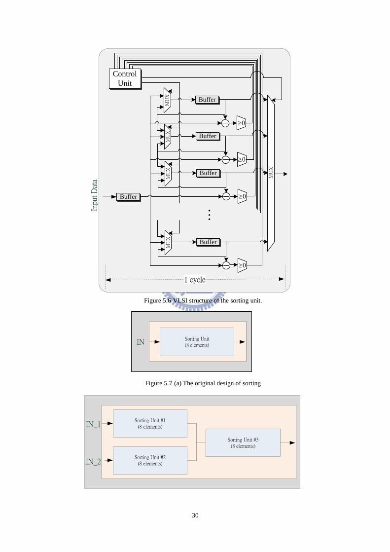
5.3.2 Sorting Design
In each PEs, there are 16 PEDs to sort or 96 PEDs at most. Sorting PEDs is the
most time-cost part in the MIMO Detection. This is a critical issue in our VSLI
implementation. To overcome the problem of sorting, we deliver 3 sorting designs,
which are combined with different number of sorting unit.
The sorting unit shown in Fig. 5.4 employ insertion sort algorithm so that it is
able to sort one input data in one cycle time. The first design with one sorting unit in
Fig. 5.5 (a), it costs 16 to 96 clock cycles to finish the ordering procedure. And the
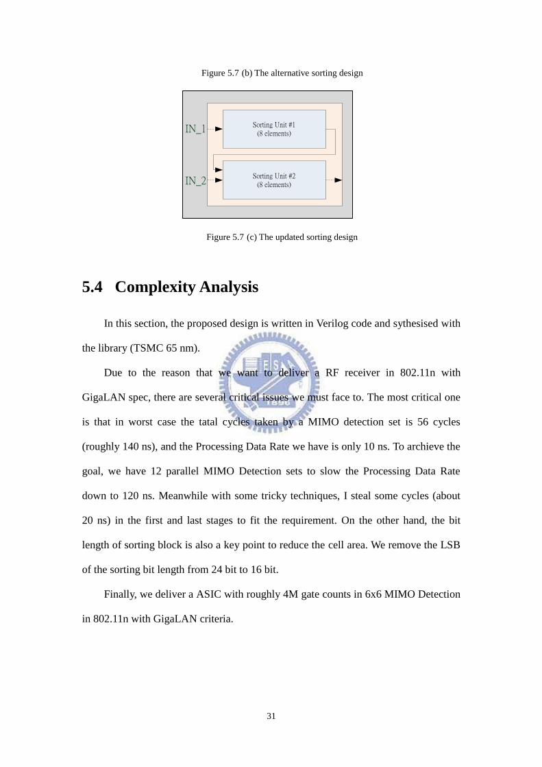
second one with three sorting units in Fig 5.5 (b), it costs 24 to 64 clock cycles. For
the last updated design with two sorting units Fig 5.5 (c), it costs 16 to 56 clock
cycles.
30
1 cycle
MU
X
MU
X
Buffer
Buffer
0
MU
X
Buffer
0M
UX
Buffer
0
…
MU
X
Buffer
0
Control
Unit
Inpu
t D
ata
Figure 5.6 VLSI structure of the sorting unit.
Sorting Unit(8 elements)IN
Figure 5.7 (a) The original design of sorting
Sorting Unit #2(8 elements)
Sorting Unit #1(8 elements)
Sorting Unit #3(8 elements)
IN_1
IN_2
31
Figure 5.7 (b) The alternative sorting design
Sorting Unit #2(8 elements)
Sorting Unit #1(8 elements)
IN_1
IN_2
Figure 5.7 (c) The updated sorting design
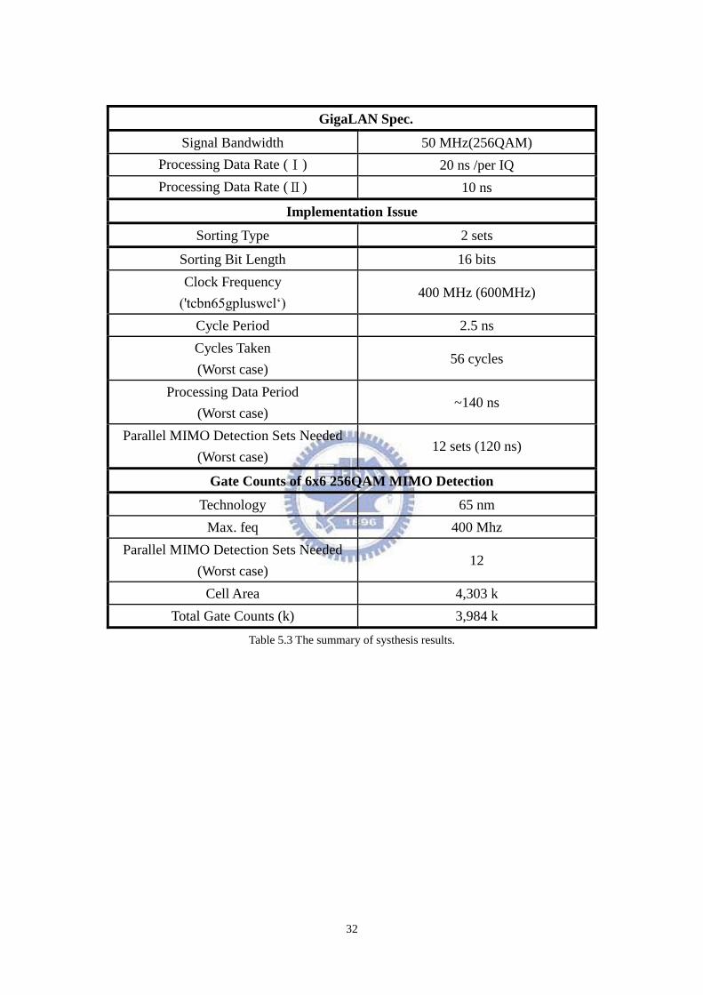
5.4 Complexity Analysis
In this section, the proposed design is written in Verilog code and sythesised with
the library (TSMC 65 nm).
Due to the reason that we want to deliver a RF receiver in 802.11n with
GigaLAN spec, there are several critical issues we must face to. The most critical one
is that in worst case the tatal cycles taken by a MIMO detection set is 56 cycles
(roughly 140 ns), and the Processing Data Rate we have is only 10 ns. To archieve the
goal, we have 12 parallel MIMO Detection sets to slow the Processing Data Rate
down to 120 ns. Meanwhile with some tricky techniques, I steal some cycles (about
20 ns) in the first and last stages to fit the requirement. On the other hand, the bit
length of sorting block is also a key point to reduce the cell area. We remove the LSB
of the sorting bit length from 24 bit to 16 bit.
Finally, we deliver a ASIC with roughly 4M gate counts in 6x6 MIMO Detection
in 802.11n with GigaLAN criteria.
32
GigaLAN Spec.
Signal Bandwidth 50 MHz(256QAM)
Processing Data Rate (Ⅰ) 20 ns /per IQ
Processing Data Rate (Ⅱ) 10 ns
Implementation Issue
Sorting Type 2 sets
Sorting Bit Length 16 bits
Clock Frequency
('tcbn65gpluswcl„) 400 MHz (600MHz)
Cycle Period 2.5 ns
Cycles Taken
(Worst case) 56 cycles
Processing Data Period
(Worst case) ~140 ns
Parallel MIMO Detection Sets Needed
(Worst case) 12 sets (120 ns)
Gate Counts of 6x6 256QAM MIMO Detection
Technology 65 nm
Max. feq 400 Mhz
Parallel MIMO Detection Sets Needed
(Worst case) 12
Cell Area 4,303 k
Total Gate Counts (k) 3,984 k
Table 5.3 The summary of systhesis results.
33
Chapter 6 Future Works and
Conclusion
The Variable and Overlapped Cluster-based algorithm presents a near ML
performance, low-complexity MIMO detection design, which uses a pre-estimate
signal and channel gain information to reduce hardware cost of MIMO-OFDM
wireless system. Simulations and measurements indicate that the proposed method
can reduce complexity to 27.29% ~56.25% (where the K-best SD is regard as 100%)
while still achieving 8% PER with 0.57 dB (4T4R) and 1.02 dB (8T8R) SNR loss
compared with MLD in frequency-selective fading of TGN-E channel [10].
Without any specific preamble, pilot format and STBC coding skills, the Variable
and Overlapped Cluster-based detection algorithm can provide near ML performance
with relatively low complexity especially in higher antenna scheme.
This study is now working in both 802.11n and TGac MIMO-OFDM systems.
Nevertheless, this study does not only deliver an efficient solution for OFDM-based
MIMO receivers, but is also well-suited method for next-generation wireless LAN
discussed in IEEE 802.11 VHT study group.
34
Bibliography
[1] T. D. Chiueh and P. Y. Tsai, OFDM Baseband Receiver Design for Wireless
Communications. Wiley, September 2007.
[2] P.W. Wolniansky, G.J. Foschini, G.D. Golden, and R.A. Valenzuela,“V-BLAST:
An architecture for realizing very high data rates over the rich-scattering wireless
channel,” Proc. IEEE ISSSE 1998, pp.295–300, Sept. 1998.
[3] X. Zhu and R. D. Murch, “Performance analysis of maximum likelihood
detection in a MIMO antenna system,” IEEE Trans. Commun., vol. 50, pp.
187–191, Feb. 2002.
[4] Y. de Jong and T. Willink. "Iterative tree search detection for MIMO wireless
systems," Communications, IEEE Transactions on, 53(6):930–935, June 2005.
[5] E. Viterbo and J. Boutros, “A universal lattice code decoder for fading channels,”
IEEE Trans. Inf. Theory, vol.45, no.5, pp.1639–1642, July 1999.
[6] U. Fincle and M. Phost, "Improved methods for calculating vectors for short
length in a lattice,includeing complexity analysis," Math. Comput., vol. 44, pp.
463-471, April. 1985.
[7] C. Schnorr and M. Euchnerr, "Lattice basis reduction: improved practical
algorihtms and solving subset sum problems," Mathematical Programming, vol.
66, pp. 181-191, 1994.
[8] Yugang Jia; Andrieu, C.; Piechocki, R.J.; Sandell, M., "Depth-First and
Breadth-First Search Based Multilevel SGA Algorithms for Near Optimal
Symbol Detection in MIMO Systems," Wireless Communications, IEEE
Transactions on , vol.7, no.3, pp.1052-1061, March 2008
[9] "Symbol De-mapping Methods in Multiple-Input Multiple-Output Systems," US
Patent 7,308,047, 2007
[10] Rupp, M.; Gritsh, G.; Weinrichter, H., "Approximate ML detection for MIMO
systems with very low complexity," ICASSP '04. IEEE International Conference
on , vol.4, no., pp. iv-809-12 vol.4, 17-21 May 2004
[11] Y. de Jong and T. Willink. "Iterative tree search detection for MIMO wireless
systems," Communications, IEEE Transactions on, 53(6):930–935, June 2005.
[12] G.A. Awater, A. van Zelst, and R. van Nee, “Reduced complexity space division
multiplexing receivers,” Proc. IEEE VTC 2000, pp.11–15, May 2000.
[13] 802.11n standard, "TGn Sync Proposal Technical Specification", IEEE
802.11-04/0889r7, July 2005
[14] Takafumi FUJITA, Atsushi OHTA, TakeshiONIZAWA, and Takatoshi
SUGIYAMA,“A Reduced-Complexity Signal Detection Scheme Employing ZF
35
and K-Best Algorithms for OFDM_SDM”,IEICE TRANS. COMMUN.,
VOL.E88–B, NO.1 JANUARY 2005.
[15] Tao Cui and Chintha Tellambura,"Approximate ML Detection for MIMO
Systems Using Multistage Sphere Decoding”, Signals, Systems and Computers,
2004. Conference Record of the Thirty-Eighth Asilomar Conference on Nov.
2004.
[16] H. C. Chang, Y. C. Liao, and H. C. Chang, “Low Complexity Prediction
Techniques of K-best Sphere Decoding for MIMO Systems,” , IEEE Workshop
on Signal Processing Systems, pp. 45 – 49, Oct. 2007.
[17] Hun Seok Kim , Weijun Zhu , Jatin Bhatia , Karim Mohammed , Anish Shah ,
Babak Daneshrad, A practical, hardware friendly MMSE detector for
MIMO-OFDM-based systems, EURASIP Journal on Advances in Signal
Processing, 2008, p.1-14, January 2008.
[18] Q. Li and Z. Wang, “An improved K-best sphere decoding architecture for
MIMO systems,” Fortieth Asilomar Conference on Signals, Systems and
Computers, pp.2190-2194, Oct.-Nov., 2006.
[19] L. Qingwei and W. Zhongfeng, “Improved K-Best sphere decoding algorithms
for MIMO systems,” in Proceedings of the IEEE International Symposium on
Circuits and Systems (ISCAS '06), pp. 1159–1162, May 2006.
[20] D. Wübben, R. Bohnke, V. Kuhn, and K.D. Kammeyer, “MMSE extension of
V-BLAST based on sorted QR decomposition,” Proc. IEEE VTC Fall, 2003,
vol.1, pp.508–512, 2003.
[21] D. Wübben, R. Bohnke, J. Rinas, V. Kuhn, and K.D. Kammeyer, “Efficient
algorithm for decoding layered space-time codes,” Electron. Lett., vol.37, no.22,
pp.1348–1350, Oct. 2001.
[22] Z. Guo and P. Nilsson, “Algorithm and implementation of the K-best sphere
decoding for MIMO detection,” IEEE J. Sel. Areas Commun., vol. 24, pp.
491-503, Mar. 2006.
[23] G. Chuang, P. A. Ting, J. Y. Hsu, J. Y. Lai, S. C. Lo, Y. C. Hsiao, T. D. Chiueh,
"A MIMO WiMAX SoC in 90nm CMOS for 300Km/h mobility," accepted by
IEEE International Solid-State Circuits Conference (ISSCC), San Francisco, CA,
February 2011.
[24] A. Wiesel, X. Mestre, A. Pages, and J. R. Fonollosa, “Efficient implementation
of sphere demodulation,” in Proceedings of the IEEE Workshop on Signal
Processing Advances in Wireless Communications (SPAWC '03), pp. 36–40,
June 2003.
[25] M. Damen, H.El Gamal, and G. Caire, “On maximum-likelihood detection and
the search for the closest lattice point,” IEEE Trans. Inf. Theory, vol. 49, no. 10,
36
pp. 2389-2402, Oct. 2003.
[26] C. Studer, A. Burg, and H. Bölcskei, ''Soft-Output Sphere Decoding: Algorithms
and VLSI Implementation,'' IEEE Journal on Selected Areas in Communications,
Vol. 26, No. 2, pp. 290-300, Feb. 2008
[27] C. K. Singh, S. H. Prasad, and P. T. Balsara, “VLSI Architecture for Matrix
Inversion using Modified Gram-Schmidt based QR Decomposition,” in Proc. Int.
Conf. VLSI Design, Jan. 2007, pp. 836-841.
[28] P. Luethi, A. Burg, S. Haene, D. Perels, N. Felber, and W. Fichtner, “VLSI
Implementation of a High-Speed Iterative Sorted MMSE QR Decomposition,” in
Proc.
[29] Salmela, P., Burian, A., Sorokin, H., and Takala, J., “Complex-Valued QR
Decomposition Implementation for MIMO Deceivers”, in IEEE int. conf. on
Acoustics, Speech and Signal Processing, Mar. 2008, pp. 1433-1436.
[30] Shariat-Yazdi R. and Kwasniewski T., “Reconfigurable K-best MIMO detector
architecture and FPGA implementation”, Proceedings of International
Symposium on Intelligent Signal Processing and Communication Systems
(ISPACS 2007), November 2007.
[31] S. Chen, T. Zhang, and Y. Xin, "Relaxed K-best MIMO signal detector design
and VLSI implementation,” IEEE Transactions on Very Large Scale Integration
(VLSI) Systems, vol. 15, no. 3, pp. 328-337, Mar. 2007.
[32] A.Burg, M.Borgmann, H.Bolcskei, J.C.Hansen, and A.Brug,”VLSI
implementation of MIMO detection using the sphere decoder algorithm,” IEEE
Journal of Solid-State Circuits, vol.40, no.7, JULY 2005.


![維•彼•扎伊采夫 2013. 俄羅斯科學院東方文獻研究所收藏的契丹大字手稿書 [Chinese version]](https://img.pdfslide.net/doc/110x75/63188763bc8291e22e0eb344/-2013-.jpg)


![敦煌西域古藏文雇佣契约研究* [日] 武内绍人 / 著 杨铭 杨公卫 / 译](https://img.pdfslide.net/doc/110x75/63460e7a596bdb97a909373f/--1684275887.jpg)


![法藏:阐释、因果与分体关系 [Fazang: Hermeneutics, Causation, and Mereology]](https://img.pdfslide.net/doc/110x75/635c7130eab478482e01560b/-fazang-hermeneutics-causation-and-mereology.jpg)

