Embed Size (px)
Citation preview

. Faculty of Engineering
Department of Electrical & Electronics Engineering
Cellular Hardware
Graduation Project EE 400
Student : Arshad Hussain Malik (971287)
Supervisor : Jamal Fathi
Nicosia 2001
CONTENTS
ACKNOWLEDGEMENT
ABSTRACT 11
INTRODUCTION l1l
1. MOBILE WORLD 1 1.1 GSM Overview
1.1.1 Introduction 1 1.1.2 Highlights 3 1.1.3 GSM Requirements 3 1.1.4 GSM Features 4 1.1.5 Statistics 7
1.2 Telecommunication Standard Characteristics 7 1.3 Cellular Phone Hardware Accessories 8
1.3 .1 Antenna Information 8 1.3 .2 Battery Information 15 1.3.3 IRDA 23
2. SMART CARDS 26 2.1 Smart Card Overview 26 2.2 Introduction to Smart Cards in Wireless Communications 28 2.3 Enhanced Security Benefits 29 2.4 Easing Logistical Issues 30 2.5 Providing Value-Added Services 31 2.6 Marketing Opportunities 33 2. 7 Customer Benefits 35 2.8 Factors Driving Smart-Card Acceptance 37
3. THE GSM SYSTEM 39 3.1 History of the cellular mobile radio and GSM 39 3.2 Cellular systems 42
3 .2.1 The cellular structure 42

3.2.2 Cluster 44 3 .2.3 Types of cells 44
3.3 The transition from analog to digital technology 45
3 .3 .1 The capacity of the system 45 3 .3 .2 Compatibility with other systems 46
3.3.3 Aspects ofquality 46 3 .4 The GSM network 47
3.4.1 Architecture of the GSM network 47
3.4.2 The geographical areas of the GSM network 51
3.4.3 The GSM functions 52 3.5 The GSM radio interface 57
3.5.1 Frequency allocation 58 3.5.2 Multiple access scheme 58
3.5.3 From source information to radio waves 63 3.5.4 Discontinuous transmission (DTX) 69 3. 5. 5 Timing advance 70 3.5.6 Power control 70 3.5.7 Discontinuous reception 70 3.5.8 Multipath and equalization 71
3. 6 GSM services 71 3.6.1 Teleservices 72 3.6.2 Bearer services 72 3.6.3 Supplementary Services 72
4. GSM PRODUCT DESIGN 74 4.1 Baseband-chip set for GSM Phase 2 [ AD20msp41 O] 74 4.2 RF Performance 75
4.2.1 FTA 76 4.2.2 Handset definition 77 4.2.3 Transmitter 78 4.2.4 Receiver 82
4.2.5 Blocking
4.2.6 Making the trek
4.3 Physical Layer Protocol
4.3 .1 The GSM airlink
4.3.2 Synchronization
4.3.3 Temporary reception gap
4.3.4 Timing advance adjustment
4.3.5 Cell selection and handover
4.3.6 Ingenuity ' 5. GSM PHONE ELECTRONICS
5.1 RF Design of a TDMA Cellular/PCS Handset, (Receivers)
5 .1.1 Main RF Specifications
5 .1.2 Handset Block Diagram
5 .1.3 RF Module Description
5.1.4 Antenna and Front-End Sections
5 .1. 5 Receiver
5.1.6 Receiver Design Trade-Otfs
5 .1. 7 Receiver Architectures
5.1.8 Receiver Spurious Responses
5.2 RF Design of a TDMA Cellular/PCS Handset, (Transmitters)
5.2.1 Frequency Synthesizer Design Trade-Offs
5 .2.2 The Transmitter
5.2.3 Transmitter Design Trade-Offs
5 .2.4 Handset TRX Frequency Plan
5.2.5 RF Module Integration
83
84
89
89
91
93
94
94
97
99
99
100
100
101
101
103
105
105
106
111
112
113
115
116
116
CONCLUSION REFERENCES
118
119
ACKNOWLEDGEMENT
First of all I am happy to complete the task, which I had given with blessing of God. I
would like to thank my dearest parents for their moral and financial support to complete my
ambition and without my father's Mr. Sher Bahadur Malik endless support; I would
never achieve my ambition.
I wish to thank my supervisor Mr. Jamal Fatih for intellectual support, encouragement,
and enthusiasm, which made this project possible, and his patience for correcting both my
stylistic and scientific errors.
My sincerest thanks go to my teachers Prof. Dr. Fakhreddin Mamedov and Mr. Shanol
Bektash, who shared their suggestions and evaluations throughout the completion of my
professional degree.
A bundle of thanks go to Miss. Bee Turk, who has given me a lot of moral support and
strong passion in order to achieve my professional degree.
ABSTRACT
GSM, the Global System for Mobile communications, is a digital cellular
communications system, which has rapidly gained acceptance and market share worldwide,
although it was initially developed in a European context. In addition to digital
transmission, GSM incorporates many advanced services and features, including ISDN
compatibility and worldwide roaming in other GSM networks. The advanced services and
architecture of GSM have made it a model for future third-generation cellular systems, such
as UMTS. This project will give an overview of the services offered by GSM, the system
architecture, the radio transmission structure, the signaling functional architecture and the
general cellular handset information.
11
INTRODUCTION
Communication, It goes without saying that it is a basic need of this world. There are
many ways of communication such as phone, Internet, mobile, pager etc. Mobile it is a very
easy way to communicate you don't need a computer or wire line, so mobile have become
very important part of our life. There are a big growing number of customers of the
telecommunication administration and operators would like to have modem communication
facilities at their disposal wherever and whenever they need them.
In order to meet this demand on an international scale, the European
Telecommunication Standards Institute (ETST) has specified the Global System for Mobile
Communication (GSM) and the Digital Communication System (DCS) on the basis of the
Global System For Mobile Communication (GSM). Chapter 3 contains the information
about the history of cellular mobile radio according to the GSM. The basic GSM networks
and cellular systems are defined to understand the interfacing between cell structures an
cellular handsets. The GSM radio interfacing and the transition from analog to digital
technology is explained.
Chapter 2 presents a business case for the use of smart cards or subscriber identity
modules (SIMs) in the marketing and network operations of wireless communications
operators. The business case focuses on the SIM card's marketing, financial, and technical
benefits to network operators as well as benefits to wireless consumers. Some key external
factors likely to accelerate customer acceptance and the SIM card's basic functionality in
wireless communications are also discussed.
Time-to-market pressure makes the primary goal of handset development the
successful completion of full type approval (FTA). In chapter 4, the phase error, transmit
power, RF output spectrum, receiver sensitivity, and blocking performance are addressed.
Operational characteristics of the physical layer, time-division multiple access, which
handles airlink management, channel maintenance, and cell transfers, can be difficult to
111
verify prior to full type approval. This discussion is described to understand physical layer
operation.
Chapter 5 describes a typical RF architecture and focuses on key RF design
considerations and trade-offs as applied to a typical dual-band TDMA transceiver RF
section. It will continue with a discussion of frequency synthesizers and their application in
the example design. The focus will then shift to the handset's transmitter section,
transmitter design trade-offs, and the handset receive/transmit frequency plan.
lV
CHAPTERl
MOBILE WORLD
1.1 GSM Overview
1.1.1 Introduction
The development of GSM started in the early 1980s. It was seen then as the mainstay
of the plans for Europe's mobile communication infrastructure for the 1990s. Today, GSM
and its DCS 1800 and PCS 1900 versions have spread far beyond Western Europe with networks installed across all continents.
The story begins in 1982 when the European Conference of Posts and
Telecommunications Administrations (CEPT), consisting then of the telecommunication
administrations of twenty six nations made two very significant decisions. The first was to
establish a team with the title "Groupe Speciale Mobile" (hence the term "GSM", which
today stands for Global System for Mobile Communications) to develop a set of common
standards for a future pan-European cellular network. The second was to recommend that
two blocks of frequencies in the 900 MHz band be set aside for the system.
The CEPT made these decisions in an attempt to solve the problems created by the
uncoordinated development of individual national mobile communication systems using
incompatible standards. The impossibility of using the same terminal in different countries
whilst traveling across Europe was one of these problems; another was the difficulty of
establishing a Europe-wide mobile communications industry that would be competitive in
world markets due to the lack of a sufficiently larger home market with common standards
with its attendant economies of scale.
1
By 1986 it was clear that some of these analogue cellular networks would run out of
capacity by the early 1990s. As a result, a directive was issued for two blocks of
frequencies in the 900 MHz band, albeit somewhat smaller than recommended by the
CEPT, to be reserved absolutely for a pan-European service to be opened in 1991.
In the meantime the GSM members were making excellent progress with the
development of agreed standards. One major decision was to adopt a digital rather than an
analogue system.
The digital system would offer improved spectrum efficiency, better quality
transmission and new services with enhanced features including security. It would also
permit the use of Very Large Scale Integration (VLSI) technology, which would lead to
smaller and cheaper mobiles, including hand held terminals. Finally, a digital approach
would complement the development of the Integrated Services Digital Network (ISDN)
with which GSM would have to interface.
GSM initially stood for Groupe Special Mobile, the CEPT (Conference of European
Posts & Telegraphs) formed the group to develop a Pan-European cellular system to
replace the many systems already in place in Europe that were all incompatible.
The main features of GSM were to be International Roaming ability, good sound
quality, small cheap handsets and ability to handle high volumes of users. GSM was taken
over in 1989 by the ETSI (European Telecommunications Standards Institute) and they
finalized the GSM standard in 1990. GSM service started in 1991. It was also renamed this
year to Global System for Mobile communications (GSM).
Today there are approx. 105 countries with GSM networks or planned networks and
many more are planned with around 32 million subscribers worldwide on the 139 networks.
This accounts for over 25% of the world's cellular market.
2
The MoU "Memorandum of Understanding" has over 210 members from 105
countries, this organization meets ever three to four months to look at new or better
implementations to the GSM system [1].
1.1.2 Highlights
1982 CEPT forms Groupe Speciale Mobile (GSM) and recommends reservation of
frequencies in 900 MHz band for future pan-European cellular system.
1987 Memorandum of Understanding (MoU) signed in Copenhagen by operators from
thirteen European countries.
1992 First commercial GSM networks start to come into service.
1992 First international roaming agreement signed between Telecom Finland's and
Vodafone (UK's) GSM networks.
1992 Australian operators are first non-European operators to sign the MoU.
1993 Status report: thirty GSM networks in ( end) service worldwide with more than one
million customers. Seventy MoU members from forty five countries.
1994 Status report: sixty GSM networks in service ( end) worldwide with more than four
million customers. Over one hundred MoU members from sixty countries.
1995 Status report: one hundred and twenty ( end) GSM networks in service worldwide
with more than twelve million customers. Over one hundred and fifty MoU members from
ninety countries [ 1].
1.1.3 GSM Requirements
The quality of Voice in the GSM system must be better then that achieved by the 900MHz
analogue systems over all the operating conditions.
The system must offer encryption of user information.
The system must operate in the entire frequency band 890-915MHz and 935-960MHz.
An international standardized signaling system must be used to allow the interconnection of
mobile switching center's and location registers.
3
Minimize modifications to the existing fixed public networks.
Design the system so handset costs are minimized.
Handsets must be able to be used in all participating countries.
Maximum flexibility for other services like ISDN.
System should maximize the functions and services available to cater for the special nature
of mobile communications [ 1].
1.1.4 GSM Features
Quality
With digital, sound quality is sharp and clear. Background sounds and static are vastly
reduced .and crossed-line conversations are also eliminated. In comparison with analogue
there are also far fewer dropouts, and overall the quality is more like that of a fixed
telephone.
Security
Unlike analogue, everything you say and send within the digital network is safe and
secure. Some features are user authentication that prohibits unauthorized access, encryption
key distribution that guarantees the privacy of the call and caller identification restrictions
that can prevent the delivery of the calling users number to the receiver.
Convenience
With digital, better technology means better battery life. You get up to twice as much
talk time from' each battery charge, compared with analogue. In addition the digital service
allows more calls to be handled at any one time, therefore reducing congestion in areas of
dense population and high .usage.
Roaming
With digital, you are able to use your mobile phone, and number in other countries
around the world who operate a GSM network. You can just take your SIM card and use
4
another GSM phone. Your home carrier must have a roaming agreement in place and must
be notified before leaving so that you can be activated in that country. All you need to do is
switch on the phone at your destination and you will automatically log into the network.
Dependent on the country you can still use your old SIM, but some countries will require
you to get a loan SIM from your carrier before going there. This will give you a new
number whilst in that country but you can easily set up a diversion to the new number if
need be.
GSM Phase 1 features
Call Forwarding
All Calls
No Answer
Engaged
Unreachable
Call Barring
Outgoing - Bar certain outgoing calls(e.g. ISD)
Incoming - Bar certain incoming calls (Useful if in another country)
Global roaming - Visit any other country with GSM and a roaming agreement and use your
phone and existing number
GSM Phase 2 features
SMS - Short Message Service - Allows you to send text messages from phones
Multi Party Calling - Talk to five other parties as well as yourself at the same time
Call Holding - Place a call on Hold
Call Waiting - Notifies you of another call whilst on a call
Mobile Data Services - Allows handsets to communicate with computers
Mobile Fax Service - Allows handsets to send, retrieve and receive faxes
Calling Line Identity Service - This facility allows you to see the telephone number of the
incoming caller on our handset before answering
Advice of Charge - Allows you to keep track of call costs
5

Cell Broadcast - Allows you to subscribe to local news channels
Mobile Terminating Fax - Another number you are issued with that receives faxes that you
can then download to the nearest fax machine.
GSM Phase 2 + features Available by 1998
Upgrade and improvements to existing services
Majority of the upgrade concerns data transmission, including bearer services and packet
switched data at 64 kbit/s and above
DECT access to GSM
PMR/Public Access Mobile Radio (P AMR)-like capabilities
GSM in the local loop
Virtual Private Networks
Packet Radio
SIM enhancements
Premium rate services ( eg Stock prices sent to your phone)
GSM 96 features
In fact, there is no such thing as GSM 96. In MoU SERO there is a document called
SE.03. In SE.03 you find the date for implementation of services. The date is 'coded' E in
case this is essential at the start of operation of a GSM network. Services of that kind are:
TSll (basic speech), TS12 (emergency calls/112), SMS MT, Call-forwarding/Call barring
services and data/fax. Then there are E96 services, savvies to be implemented for roamers
before end 1996. The only service in this section is ODB Phase 2. (ODB=Operator
Determined Barring). E97 is SMS MO (Short Message/Mobile Originated). The list for
E98 is longer. One reason is to put pressure on suppliers. Services included are CAMEL (to
support PNP as a start), SOR, USSD, HSCSD and GPRS [1].
6
1.1.5 Statistics
GSM Association total members (October 2000) - 493
GSM Networks on Air (September 2000) - 373
GSM Countries on Air (September 2000) - 159
GSM Total Subscribers - 380.5 million (to end of September 2000)
World Subscriber Growth - 655 million (to end of December 2000)
SMS messages sent per month - 9 Billion (to end of August 2000)
SMS forecast to year end 2000 - 10 Billion per month
GSM accounts for 68% of the World's digital market and 59.9% of the World's wireless
market [1].
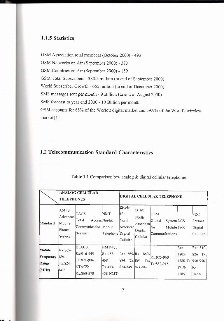
1.2 Telecommunication Standard Characteristics
Table 1.1 Comparison b/w analog & digital cellular telephones
r. ANALOG CELLULAR DIGITAL CELLULAR TELEPHONE
TELEPHONES
IS-54/- AMPS IS-95
TACS NMT 136 GSM PDC Advanced !North Total Access Nordic North Global System DCS Personal Standard Mobile American Communication Mobile American for Mobile 1800 Digital
Phone Digital System Telephone Digital Communications Cellular
Service Cellular Cellular
ET ACS: NMT-450: Rx: Rx: 810- Mobile Rx:869- Rx:916-949 Rx:463- Rx: 869- Rx: 869- 1805- 826 Tx: Frequency 894 Rx:925-960 Tx:871-904 468 894 Tx: 894 Tx: 1880 Tx: 940-956
Range Tx:824- Tx:880-915 NT ACS: Tx:453- 824-849 824-849 1710- Rx:
(MHz) 849 Rx:860-870 458 NMT- 1785 1429-
7

Tx:915-925 900: 1453 Tx:
Rx:935- 1477- 960 1501
Tx:890-
915
Multiple TDMA/ CDMA/ TDMA/ TDMA/ Access FDMA FDMA FDMA TDMA/FDM FDM FDM FDM FDM Method
Duplex FDD FDD FDD FDD FDD FDD FDD FDD Method
NMT-450: 832 (3 20(798 374 (81600 ( Number of ETACS:1240 124 (8 users 832 200 NMT- users users users users Channels NTACS:400 /channel) 900: 1999 /channel) I/channel) /channel) /channel)
NMT-450: ETACS: 25kHz
Channel 25kHz 30kHz NT ACS: 30kHz 1250kHz 200kHz 200kHz 25kHz Spacing NMT-900:
12.5kHz 12.5kHz
GMSK (7l;4 QPSK GMSK (0.3 (0.3 ( 77 /4 Modulation FM FM FM DQPSK) /OQPSK Gaussian Filter), Gaussian DQPSK)
Filter)
Channel 1.2288 270.833 n/a n/a n/a 48.6 kb/s 270.833 kb/s 42 kb/s Bit Rate Mb/s kb/s
1.3 Cellular Phone Hardware Accessories
1.3.1 Antenna Information
Antenna
Getting energy out from a transmitter and in to a receiver is critically dependent upon
the ability of the transmitter to pass energy (radio signals) from its antenna to free space,
similarly the same is true of a receiver.
8
There are a number of factors involved including:
Frequency (wavelength).
Gain.
Impedance.
Polarization.
Frequency
Each antenna has a resonant frequency, the frequency at which it is most efficient at
either transmitting or receiving energy. The resonant frequency is set by the physical length
of the antenna. Frequency and wavelength are related, the wavelength (in meters) is equal
to the speed of light (in meters/sec) divided by the frequency (in Hertz - Hz).
Similarly the frequency is equal to the speed of light divided by the wavelength. So in
the good old days when Radio 4 was the Long Wave it transmitted on a wavelength of
1500m. The speed of light is 300,000,000 meters a second so 300,000,000 I 1,500 = 200,000Hz or 200 kHz. If we find an old radio, we will find 1500m on the dial, newer ones
have 200 kHz (and yes, thank to some interfering French politicians Radio 4 is now on 198
kHz which took away a lovely stable frequency reference - but that's another story). A
frequency of 1800 MHz (GSM 1800) equates to a wavelength of: -
300,000,000 I 1,800,000,000 = 0.167m
or a wavelength of about 16.7cm. At 900 MHz everything is twice as big, so 900 MHz
gives a wavelength of 33.4cm. Antennae are usually referred to by the fraction of a·
wavelength represented by their physical length, so a full wave antenna at 1800 MHz
would be 16.7cm long (In practice it would be a slightly different length to allow for
corrections for end effects). A half wave antenna at 1800 MHz would be 8.4cm and so on.
Most phone antennae are about 1/4 wavelength long.
Gain
The basic pattern of energy coming from a "perfect" antenna with no gain is a bit like a
ball (with the antenna in the middle), the antenna radiates equally in all directions (the
"isotropic" antenna). This isn't always what is wanted. In most mobile phone antennae we
9
want most of the energy coming out near the ground and not too much going vertically into
space.
A standard dipole radiation pattern is not isotropic - it looks bit like a doughnut with
the antenna in place of the hole.
An antenna can only put out what is put in to it, so when you see adverts for antennae
with "gain" (for example 3dB gain) what it means is that the energy is being directed more
in one direction than others (It also means the area the energy was redirected from will get
less.)
Going back to the doughnut, if you press down on the top of the ball it gets wider and
shorter, the wider axis is showing gain, the shorter one loss.
You can also put directivity in the azimuth pattern - but for phones this is not a good
idea! The most common antenna with gain in azimuth is the common TV antenna (a Yagi
antenna design for the curious) which typically has a beamwidth of about 15 to 20°.
Antenna gain is usually expressed in decibels and refers to the gain of the design over
the radiation in that direction given by a perfect isotropic antenna or a dipole. As the
isotropic antenna and dipole differ anyway it is important to know which is being referred
to when comparing antennae. Usually if antenna is described as having "3dB gain" it
means compared with a dipole. If it says "3dBi gain" it means compared with an isotropic
radiator.
The most common mobile antenna design to show gain is the co-linear. In most cases
this will give about 3dB gain over a dipole. Treat all claims for greater gain from non
directi?nal antennas with severe suspicion!
10
Impedance
Impedance is to AC circuits roughly what resistance is to DC circuits. It isn't just the
length of the antenna, which matters but also how you get power into it. For maximum
transfer of power the source, transmission line, and load must all have the same
impedance In the case of your phone this means the phone, antenna lead, and antenna
should all have the same value of impedance.
This value is 50 ohms for most phones so the transmitter and receiver in the phone
have a 50 ohm characteristic impedance, the cable is 50 ohms and the antenna impedance
should be 50 ohms.
At the base of a 1/4 wave antenna the impedance is indeed about 50 ohms, however at
the base of a 1/2 wave one it is several thousand ohms. Making dual frequency antennae
(for use on both 900 and 1800 MHz) is a compromise between length, thickness (which
also affects impedance) and gain. Nearly all dual frequency antennae will work quite well
at one of the frequencies and less well at the other. All are outperformed by single
frequency antennas.
Polarization
Polarization is the alignment of the electrical part of the radio frequency energy in
space. , A vertical antenna produces a vertically polarized signal, a horizontal one a
horizontally polarized one, and a spiral antenna a circularly polarized one (left or right hand
depending upon the way the spiral goes). In theory a horizontal receiving antenna will
receive no energy from a vertical transmitter antenna ( and this works - many continuous
wave tracking radar's use a left hand circularly polarized signal to transmit and a right hand
one to receive so they can transmit and receive on the same frequency at the same time.
The signal from the transmitter strikes many objects along its way and is reflected from
them, these reflections are often twisted because of the irregular nature of the reflecting
object. By the time the signal reaches you it has lost much of its initial polarization and
become scattered. However it will usually still be the case that most of the signal will
11
maintain its original polarization and the more vertical you keep the antenna the better your
chances of a good signal.
Special Antennas and Signal Amplifiers
The Co-linear
The true co-linear design is a series of dipoles stacked end to end and fed by different
cables such that the radiation patterns inter-react to give a lower angle of radiation with
more power in the lower angles than the higher. The antenna called a collinear in mobile
phones achieves a similar effect by being partial multiples of wavelengths long and having
tuning and loading coils built in (the single coiled twist in the 1800 MHz antenna shown
above and the thicker tube about 1/3 of the way up the 900MHz antenna. The extra length
of the co-linear explains why your antenna is longer than you expected based on the
calculations.
The Yagi
The Yagi antenna design is probably the most common antenna with gain - nearly all
TV antennae are Yagis. Its use in mobile phones is very limited because it gives directional
gain in azimuth - you need to know where the base station is and point at it! However it
does have its uses, models for 900MHz are made mainly for the Nordic market where
mobile phones are the communication method of choice for the popular remote weekend
houses. Fitted to a house and pointing at the nearest base station it gives excellent gain and
will often turn a no hope signal into a strong one.
Signal Amplifiers\
Touted by some as the secret panacea for all ills the linear amplifier (AKA "Burner",
Power Booster, Power Amplifier) came to infamy in the heyday of CB radio when they
were brought over from the USA and fitted illegally to Ford Caprice and Cortinas by
numbers of CB enthusiasts. In general there were two main effects - the car battery ran
down very quickly and every receiver for miles around was jammed by the spurious out of
band emissions. Some of these amplifiers were quite impressive - lkW (1000 Watt) linears
sitting on the boot of ratty Fords were not unknown!
12

Somewhat more civilized amplifiers were fitted to car kits for analogue phones taking
their power up to 5 Watts. However since the advent of GSM and PCN the benefits to be
gained from these quite expensive boxes have become much less.
As far as PCN is concerned the only benefit is to overcome losses in installations
where long cable runs must be employed, for example if you need an antenna on the roof of
your house. In this situation the amplifier incorporates both a received signal pre-amplifier
and a transmitted signal power amplifier. It is designed to overcome the quite significant
losses, which occur in co-axial cables at 1800MHz.
Car Antenna
If you use your cellphone in your motor vehicle, an external cellphone antenna is a
must!'
That's because cars insulate cellphones from the external GSM signal, an unwanted
artifact known as the "Faraday Cage." This Cage can sometimes result in poor voice quality
and even dropped calls. A well-installed external car antenna usually fixes the problem.
And if you're in a rural area that's on the periphery of the GSM coverage range, or even in
a building that tends to block GSM signals, there are some novel antenna solutions
available.
External antennas are available at around US$20, but are invariably professionally
fitted as part of the complete installation of a cellphone car kit. Your installer is likely to
provide you either with a semi-permanent stick-on antennae design that simply sticks onto
the front or back car windows using adhesive tape, magically transferring the GSM signal
through the glass and then via a cable to and from the external antenna socket on your GSM
cellphone or it's special car kit. Some installers also provide permanent boot (trunk) and car
roof mount designs, but these tend to be more expensive as they invariably necessitate
some car-body drilling and additional wiring. There are however many do-it-yourself clip
on designs available that don't really require any_ detailed technical knowledge and can be
installed in minutes. The most popular though are the installed stick-on types. These
13
external antenna housings usually consist of a base with a screw-on antenna rod. Some rods
have an enclosed coil in the middle. Antenna efficacy is usually measured in decibels ( dB) -
the higher the rated dB specification, usually the better it's performance. Longer rods of
around 50cm usually have a dB level of around 5dB, the smaller 9cm types around 3dB or
less.
Whatever their length, the antenna rods should be attached to a position able, swivel
type joint on the base to allow the rod to be positioned backwards and forwards, left to right
to optimize efficacy. The base positioning of the antenna on the car is also important: some
installers prefer the front or back window, while others drill on the car boot or roof. The
back window however is the most popular antenna position, although this invariably
depends on the vehicle's shape.
Your external antenna should also feature a position lock "memory" to ensure that the
antenna rod stays in the position you set it - especially when used in high-wind areas. Some
of the longer antennas tend to create high-pitched whistle effects in winds. Make sure that
you can also unscrew the rod: this feature is especially useful if you want to prevent the
antenna being mangled by a car-wash behemoth. Smaller, low profile 9 cm front-window
mounted antennas are perfect for avoiding these situations.
There are also a number of easily fitted removable/portable car antenna solutions. One
design simply clips on to the top of a wind-up side window, allowing you to switch cars
and still have external antenna support. Once you've placed the clip onto the top of the
window, you then simply plug (hard wire) the attached antenna cable into the phone's
antenna socket. You can use it with the window open or closed as the cable signal is
relayed to the antenna's external rod via the window clip-on.
There is however another side window clip-on design available that does not use any
hard wiring. Instead it uses a special cordless pick-up rod inside the car - also connected to
it's external rod via the window clip-on - to "passively" relay the GSM signal to and from
14
the cellphone. With both these clip-on designs, the back right passenger window rs
recommended.
There is yet another flat "patch" passive antenna type that simply sticks down flat onto
any window. This solution, although not the most effective, is useful in offices where GSM
signals may be blocked by an abundance of concrete and steel in the wall.
If you 're in a fixed rural location on the coverage fringe, there are special 1 OdB comer
reflector antennas that can be attached to poles or buildings.
No field assembly or tuning is required and they easily attached to your cellphone
using ordinary cable connections.
If necessary, you might also want to consider special booster devices that increase the
power of you cellphone from the average 2W to up to a powerful 8W [ 1].
1.3.2 Battery Information
There are three major types of batteries in use in Mobile Phones today. These are Ni
Cad, Ni-MH and Li-Ion. Ni-MH is becoming more common as the standard battery and Li
Ion which is a lot more recent entry is becoming common on high end phones and an
option on low end phones. Some battery details concerning these types are discussed below:
Battery comparison
Battery types
Memory Effect 1
Memory Effect 2
Memory Effect 3
Self-discharge
Battery Life
15
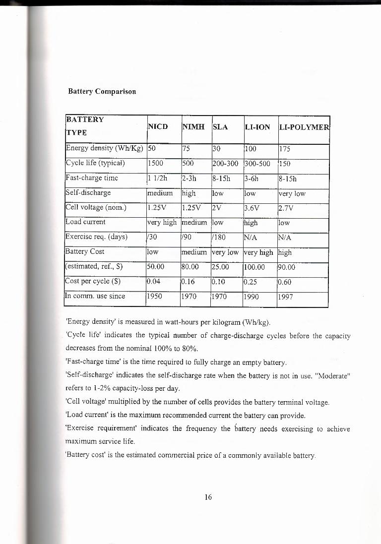
Battery Comparison
BATTERY LI-POLYMER NICD NIMH SLA LI-ION
TYPE '
Energy density (Wh/Kg) 50 75 30 100 175
Cycle life (typical) 1500 500 200-300 300-500 150
Fast-charge time 1 112h 2-3h 8-15h 3-6h 8-15h
Self-discharge medium high low low very low
Cell voltage (nom.) 1.25V 1.25V 2V 3.6V 2.7V
Load cw-rent very high medium low high low
Exercise req. (days) 130 190 /180 NIA NIA
Battery Cost low medium very low very high high
( estimated, ref., $) 50.00 80.00 25.00 100.00 90.00
Cost per cycle ($) 0.04 0.16 0.10 0.25 0.60
In comm. use since 1950 1970 1970 1990 1997
'Energy density' is measured in watt-hours per kilogram (Wh/kg). ,
. 'Cycle life' indicates the typical number of charge-discharge cycles before the capacity
decreases from the nominal 100% to 80%.
'Fast-charge time' is the time required to fully charge an empty battery.
'Self-discharge' indicates the self-discharge rate when the battery is not in use. "Moderate"
refers to 1-2% capacity-loss per day.
'Cell voltage' multiplied by the number of cells provides the battery terminal voltage.
'Load current-is the maximum recommended cw-rent the battery can provide.
'Exercise requirement' indicates the frequency the battery needs exercising to achieve
maximum service life.
'Battery cost' is the estimated commercial price of a commonly available battery.
16
'Cost-per-cycle' indicates the operating cost derived by taking the average price of a
commercial battery and dividing it by the cycle count.
'In commercial use since' is the approximate year when the battery became commercially
available.
Battery Types
Ni-Cad (Nickel Cadmium)
The basic voltage for Ni-Cads is 1.25V, which makes them unsuitable for certain
applications. The number of times they can be recharged is also limited; bad charging
habits reduce this even more.
The main problem with Ni-Cads is the dendrite growths; miniature metal spikes which
eventually short circuit the cell. This can be reduced by PCR charging.
Self-discharge rate is 1 % per day.
The lifetime is approx 1000 recharges in a cellular phone battery.
Ni-MH (Nickel Metal Hydride)
This newer rechargeable cell is free from toxic elements such as cadmium, they have
around 30 to 50% more capacity than good Ni-Cad cells. They cost about twice as much as
Ni-Cads, but have a shorter service life, up to 500 cycles compared with 1000 for Ni-Cad.
They also have the same voltage per cell as Ni-Cads that is 1.25V per cell.
They use hydrides (metals capable of storing hydrogen) as the negative material in lieu of
cadmium. They have higher capacity for the same size cell; and don't use toxic cadmium.
They also are advertised as not suffering from memory.
They are trickier to charge. Delta V works, but the voltage drop is very small (2.5
m V /cell).lt is far better to charge them to a point where the voltage stops rising.
They still suffer from memory effect, but it is much harder to see then it is with Ni-Cads.
Self-discharge rate is 3 to 10% per day.
The lifetime is approx 500 recharges in a cellular phone battery.
17
Li-Ion (Lithium Ion)
No Memory effect is evident with these batteries, any problems with these cells can
normally be contributed to poor charges and poor charging techniques.
Li-Ion batteries are very light.
Self-Discharge is 1 to 2% per month.
The lifetime is approx 300 to 500 recharges in a cellular phone battery. This figure varies a
lot as they are still really being developed and early batteries did not last very long.
Memory Effect 1
A lot of people consider the memory effect a myth; in fact the term memory effect is
not really correct.
A more accurate word would be voltage depression, this is where the discharge voltage
for a load is lower this what it should be, this gives the false appearance of a lowered
capacity.
Memory is also hard to reproduce, which makes it hard to study. Originally, memory
effect was seen in spacecraft batteries subjected to a repeated discharge/charge cycle that
was a fixed percentage of total capacity (due to the earth's shadow). After many cycles,
when called upon to provide the full capacity, the battery failed to do so.
Ordinarily, and under moderate charging currents, the cadmium that is deposited is
microcrystalline (i.e. very small crystals). Now, metallurgical thermodynamics states that
grain boundaries (boundaries between the crystals) are high-energy regions, and given time,
the tendency of metals is for the grains to coalesce and form larger crystals. This is bad for
the battery since it makes the cadmium harder to dissolve during high current discharge,
and leads to high internal resistance and voltage depression.
The trick to avoiding memory is avoiding forming large crystal cadmium. Very slow
charging is bad, as slow growth aids large crystal growth. High temperatures are bad, since
the nucleating and growth of crystals is exponentially driven by temperature. The problem
18
is that given time, one will get growth of cadmium crystals, and thus, one needs to reform
the material. Partial cycling of the cells means that the material deep with the plate never
gets reformed. This leads to a growth of the crystals. By a proper execution of a
discharge/charge cycle, one destroys the large crystal cadmium and replaces it with a
microcrystalline form best for discharge.
This does not mean that one needs to cycle one's battery each time it is used. This does
more harm than good, and unless it is done on a per cell basis, one risks reversing the cells
and that really kills them. Perhaps once in a while, use the pack until it is 90% discharged,
or to a cell voltage of 1.0V under light load. Here, about 95% of the cells capacity is used,
and for all intensive purposes, is discharged. At this point, recharge it properly, and that's it.
The more common "memory effect" isn't memory at all, but voltage depression caused
by overcharging. Positive plate electrochemistry is very complicated, but overcharging
changes the crystal structure of the nickelic hydroxide from beta-Nickelic Hydroxide to
gamrna-Nickelic hydroxide. The electrochemical potential of the gamma form is about 40
to 50 m V less than the beta form. This results in a lower discharge voltage. Don't
overcharge. Leaving cells on a trickle charger encourages formation of gamma nickelic
hydroxide. Expect the cells to discharge at a lower voltage.
Memory Effect 2
These notes also apply to Ni-MH batteries.
Among the many users of batteries in both the industrial and consumer sectors, the idea
of a memory phenomenon in nickel-cadmium batteries has been widely misused and
understood. The term 'memory' has become a catch-all 'buzzword' that is used to describe a
raft of application problems, being most often confused with simple voltage depression.
To the well informed, however, 'memory' is a term applied to a specific phenomenon
encountered very infrequently in field applications. Specifically, the term 'memory' came
from an aerospace nickel-cadmium application in which the cells were repeatedly
discharged to 25% of available capacity (plus or minus 1 %) by exacting computer control,
19
then recharged to 100% capacity without overcharge. This long term, repetitive cycle
regime, with no provisions for overcharge, resulted in a loss of capacity beyond the 25%
discharge point. Hence the birth of a "memory" phenomenon, whereby nickel-cadmium
batteries purportedly lose capacity if repeatedly discharged to a specific level of capacity.
The 'memory' phenomenon observed in this original aerospace application was
eliminated by simply reprogramming the computer to allow for overcharging. In fact,
'memory' is always a completely reversible condition; even in those rare cases where
'memory' cannot be avoided, it can easily be erased. Unfortunately, the idea of memory
related loss of capacity has been with us since. Realistically, however, 'memory' cannot
exist if any one of the following conditions holds:
1.Batteries achieve full overcharge.
2.Discharge is not exactly the same each cycle - plus or minus 2-3%
3.Discharge is to less than 1.0 volt per cell.
The existence of any one of these conditions eliminates the possibility of 'memory'. GE
has not verified true 'memory' in any field application with the single exception of the
satellite application noted above. Lack of empirical evidence notwithstanding, 'memory' is
still blamed regularly for poor battery performance that is caused by a number of simple,
correctable application problems.
1. Cutoff voltage too high - basically, since Ni-Cads have such a flat voltage .vs. discharge
characteristic, using voltage sensing to determine when the battery is nearly empty can be
tricky; an improper setting coupled with a slight voltage depression can cause many
products to call a battery "dead" even when nearly the full capacity remains useable.
2. High temperature conditions - Ni-Cads suffer under high-temp conditions; such
environments reduce both the charge that will be accepted by the cells when charging, and
the voltage across the battery when charged (and the latter, of course, ties back into the
above problem).
3. Voltage depression due to long-term overcharge - Self-explanatory. Ni-Cads can drop
0.1-0.15 V/cell if exposed to a long-term (i.e., a period of months) overcharge. Such an
20
overcharge is not unheard-of in consumer gear, especially. If the user gets in the habit of
leaving the unit in a charger of simplistic design
4. MiscellaneousOperation below O deg. C High discharge rates (above SC) in a battery not
specifically designed for such use Inadequate charging time or a defective charger One or
more defective or worn-out cells (Ni-Cads do have a finite life; they won't keep charging
and discharging forever no matter how well we baby them.)
Memory Effect 3
The Ni-Cad memory effect business is an urban myth, but it still keeps coming up. In
summary, if you overcharge a Ni-Cad battery, it develops a voltage depression, which
makes the battery appear to go flat earlier than you would expect. Since the discharge curve
is so steep, sensitive devices, which rely on battery voltage to detect when it is almost flat,
. will report that it is almost flat early due to the voltage depression, when in fact the cell still
has significant charge. The voltage depression can be rectified by discharging the cell to its
full discharge level.
Many people misinterpret this phenomenon and conclude that the battery somehow
remembers its last discharge level on the next charging cycle. This is not the case. The only
effect that the current charge level has on the next charging cycle is that it's much easier to
overcharge a Ni-Cad cell whose current charge state is unknown, than it is to overcharge
one which is known to be flat.
The so-called "memory effect" is a simple case of user error in overcharging the cell. If
you don't ever overcharge a Ni-Cad cell, there's no need to discharge it before recharging it
agam.
Self Discharge
All batteries discharge over time, it varies as to the type of battery. Ni-Cad batteries
discharge at approx 1 % per day, Ni-MH discharge at approx 3 to 10% a day and Li-Ion less
then 1-2 % per month. This is the main reason why most devices that are not used often use
Ni-Cad batteries.
21
To keep your batteries topped up do not use a trickle charger, this will damage the
batteries. If you want to stop your batteries from self discharging (whilst off your phone)
then a power supply that can deliver 1 to 2 mA is idea.
Battery Life
There are quite a few factors to take into account when looking into battery life.
Batteries deteriorate over time and when new will not achieve their full potential for at least
two or three full charge/discharge cycles.
The Network
The number one cause of poor battery life is the network that you're connected to.
Every so often (10 minutes to 2 hours), the network checks all the phones in a certain cell;
this is called the PLU (periodic location update). This causes the phone to transmit where it
is so that the network can route calls etc. Every time you move around or drive somewhere
you change cells, particularly in poor coverage areas. If you leave coverage area the phone
will continually try and find a network resulting in more power drain.
In poor signal areas, GSM phones will use a lot more power when transmitting;
whereas in good signal strength areas the phone will use as little as is necessary.
Another power user is Cell Broadcast (normally used to tell you what suburb you're in;
or weather etc).
There are products coming out to help combat all this power drain, one of these is the
phase 2 sim card that uses less power and supports sleep mode on some handsets.
With all of these factors alone you can use up to 50% of your phone's quoted standby time.
The Battery
Batteries play a large role in keeping your phone going. The type and the capacity of
your battery will adjust your standby times. If your battery is continually letting you down
22
and you've tried all of these tips, consider upgrading to the next size and/or a different type
of battery.
Treat your batteries well as recommended in the battery tech topic and they will reward
you with years of faithful service, always use good quality batteries (like genuine) and
always use top quality chargers (again genuine are a good choice).
The Phone
Use of the phone can also influence the power consumption, things like turning off the
backlight, not playing with the phone (and turning the backlight on), lower ring tones,
turning off the vibrate option and so on will make your standby time improve.
Manufacturers are starting to use 3.3v technology instead of the more common 6v
technology, this will enable components to be smaller and thus use less battery power [1].
1.3.3 IRDA
There's much confusion on the infra-red implementation of the phones, especially
Nokia 61xx. A large group of people thinks that an infra-red port automatically means that
data communication (e-mail or fax) must be possible. Others say that you need an lrDA
implementation for that. As pointing, an IrDA equipped computer to a 61 xx doesn't work
the general conclusion is that the 61xx is not fully IrDA compliant. Reality is a bit different ·
and can be explained as follows.
The IrDA specification and its supplements can be described as a construction set and
divided into two levels of services. The base level service allows two IrDA devices to
detect each other's presence and lock in. The equivalent of plugging in a cable to connect
two devices. This link can then be used by higher-level services and IrDA describes ,a
number of them. One of these higher-level services is a printer service. Use a standard
parallel printer cable and there's a separate line for the printer to signal to the computer that
it's out of paper. This signal is replaced in the IrDA printing service by a message the
23
printer can send to the computer. The printing service is defined in such a way that it looks
just like a normal printer. So that you don't have to take special measures in your computer
application to print via IrDA.
There's also a higher-level service for file transfer allowing you to shuttle files between
devices. This one is more complicated, and a bit of a mess, because manufacturers wanted
to have their earlier proprietary transfer mechanisms incorporated into the IrDA standard.
Nokia has implemented the base level service plus the high level printing service in the
61xx. This makes the 61xx IrDA compliant as printing works according the specification.
While Nokia did not implement the file transfer service, and a number of others, as these
are of no use. References to "full IrDA compliance" are therefore a bit silly. Though you
can't blame people for not digging into all the IrDA documents.
Now, you may ask "What about a high level GSM data communication service then?".
Well ... there's no such thing within the IrDA documents. There is a new IrDA document
called "Specifications for Ir Mobile Communications (IrMC)" which was accepted last
September. However, IrMC deals with the exchange of: phone book or contact diary
information, calendar information, alphanumeric messages, and device information. To
which it adds object control interfaces for call control and the transfer of voice streams.
Thus nothing about such data communication tasks a sending/receiving fax and e-mail or
browsing the World Wide Web. In other words, the IrDA standard is incomplete when it
comes to GSM phones.
However, this doesn't mean that it's impossible to build a phone that allows full data
communication via Ir DA. The Ericsson SH888 and Nokia 8810 prove that. There are two
high level IrDA services you can use. One that allows a device to behave itself as if it is a
modem. Plus a service that allows the Internet TCP/IP protocol to be run over IrDA. You're
not finished then. It's all very well to behave as if you are a modem but you have to act as a
modem as, well. Not that there's signals to modulate and demodulate as GSM is a digital
network. What you need to be is the intermediary between the computer and the GSM
network. Translating computer data streams into GSM streams and vice versa. This is what
24
all those PCM CIA data cards do and the SH888 and 8810 have the data card electronics
and firmware built into the phone.
There you have the items distinguishing the 6110 (and the others) from the 8810.
1) There's no GSM data adapter built into the 61 xx, and,
2) It therefore doesn't have the additionally required IrDA services implemented. The 61xx
belongs to the class of "data ready" phones that rely on an external GSM data adapter. Such
adapters are in PC-Cards (PCM CIA) or, in the form of software, in the Nokia Cellular Data
Suite. While the SH888 and 8810 belong to the class of "data phones" [1].
25
CHAPTER2
SMART CARDS
2.1 Smart Card Overview
The smart card is one of the latest additions to the world of information technology
(IT). The size of a credit card, it has an embedded silicon chip that enables it to store data
and communicate via a reader with a workstation or network. The chip also contains
advanced security features that protect the card's data.
Smart cards come in two varieties: microprocessor and memory. Memory cards simply
store data and can be viewed as small floppy disks with optional security. Memory cards
depend on the security of a card reader for their processing. A microprocessor card can add,
delete, and manipulate information in its memory on the card. It is like a miniature
computer with an input and output port, operating system, and hard disk with built-in
security features.
Smart cards have two different types of interfaces. Contact smart cards must be
inserted into a smart-card reader. The reader makes contact with the card module's
electrical connectors that transfer data to and from the chip. Contactless smart cards are
passed near a reader with an antenna to carry out a transaction. They have an electronic
microchip and an antenna embedded inside the card, which allow it to communicate
without a physical contact. Contactless cards are an ideal solution when transactions must
be processed quickly, as in mass transit or toll collection.
26
A third category now emerging is a dual interface card. It features a single chip that
enables a contact and contactless interface with a high level of security.
Two characteristics make smart cards especially well suited for applications in which
security-sensitive or personal data is involved. First, because a smart card contains both the
data and the means to process it, information can be processed to and from a network
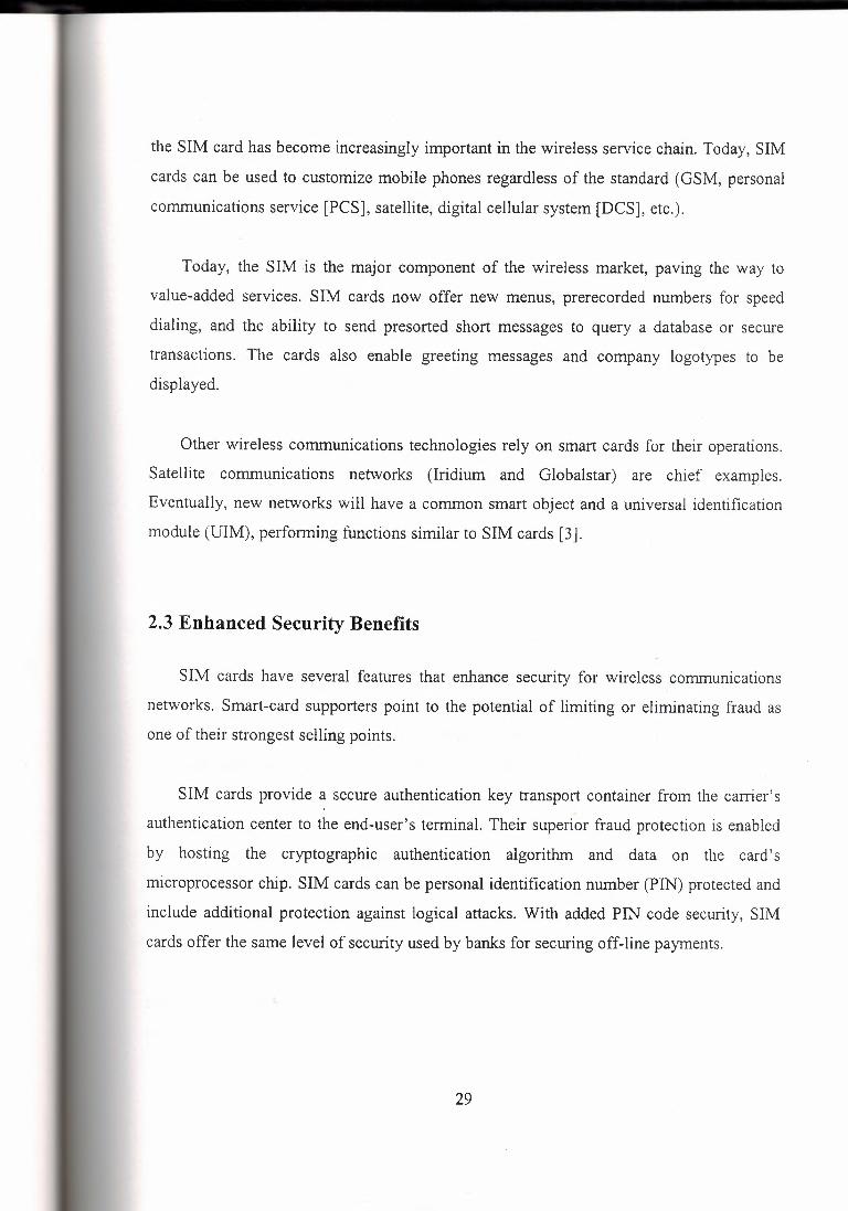
without divulging the card's data. Secondly, because smart cards are portable, users can
carry data with them on the smart card rather than entrusting that information on network
storage or a backend server where the information could be sold or accessed by unknown
persons (see Figure 2.1).
Should Network and End~ User
Specific Data be 1
stored in a phone' v' cra rem ovable ~1 smart card?
Network (Switch)
hnormation
l Handset
Distnb111od Smart Card
Low Po:rtabfH:ty / De:,ee of Personalization
High
Figure 2.1 Information and Personalization
A smart card can restrict the use of information to an authorized person with a
password. However, if this information is to be transmitted by radio frequency or telephone
lines, additional protection is necessary. One form of protection is ciphering (scrambling
data). Some smart cards are capable of ciphering and deciphering, so the stored information
can be transmitted without compromising confidentiality. Smart cards can cipher into
billions of foreign languages and choose a different language at random every time they
27
communicate. This process ensures that only authenticated cards and computers are used
and makes hacking or eavesdropping virtually impossible.
The top five applications for smart cards throughout the world currently are as follows:
Public telephony-prepaid phone memory cards using contact technology
Mobile telephony-mobile phone terminals featuring subscriber identification and
directory services
Banking--debit/credit payment cards and electronic purse
Loyalty-storage of loyalty points in retail and gas industries
Pay-TV-access key to TV broadcast services through a digital set-top box
The benefits of using smart cards depend on the application. In general, applications
supported by smart cards benefit consumers where their lifestyles intersect with
information access and payment-related processing technologies. These benefits include the
ability to manage or control expenditures more effectively, reduce fraud and paperwork,
and eliminate the need to complete redundant, time-consuming forms. The smart card also
provides the convenience of having one card with the ability to access multiple services,
networks, and the Internet [3].
2.2 Introduction to Smart Cards in Wireless Communications
Smart cards provide secure user authentication, secure roaming, and a platform for
value-added services in wireless communications. Presently, smart cards are used mainly in
the Global System for Mobile Communications (GSM) standard in the form of a SIM card.
GSM is an established standard first developed in Europe. In 1998, the GSM Association
announced that there are now more than 100 million GSM subscribers. In the last few
years, GSM has made significant inroads into the wireless markets of the Americas.
Initially, the SIM was specified as a part of the GSM standard to secure access to the
mobile network and store basic network information. As the years have passed, the role of
28
the SIM card has become increasingly important in the wireless service chain. Today, SIM
cards can be used to customize mobile phones regardless of the standard (GSM, personal
communications service [PCS], satellite, digital cellular system [DCS], etc.).
Today, the SIM is the major component of the wireless market, paving the way to
value-added services. SIM cards now offer new menus, prerecorded numbers for speed
dialing, and the ability to send presorted short messages to query a database or secure
transactions. The cards also enable greeting messages and company logotypes to be
displayed.
Other wireless communications technologies rely on smart cards for their operations.
Satellite communications networks (Iridium and Globalstar) are chief examples.
Eventually, new networks will have a common smart object and a universal identification
module (UIM), performing functions similar to SIM cards [3].
2.3 Enhanced Security Benefits
SIM cards have several features that enhance security for wireless communications
networks. Smart-card supporters point to the potential of limiting or eliminating fraud as
one of their strongest selling points.
SIM cards provide a secure authentication key transport container from the carrier's
authentication center to the end-user's terminal. Their superior fraud protection is enabled
by hosting the cryptographic authentication algorithm and data on the card's
microprocessor chip. SIM cards can be personal identification number (PIN) protected and
include additional protection against logical attacks. With added PIN code security, SIM
cards offer the same level of security used by banks for securing off-line payments.
29

Because the home network-authentication algorithm also resides in the card, SIM
cards make secure roaming possible. They can also include various authentication
mechanisms for internetwork roaming of different types.
Complete fraud protection (with the exclusion of subscription fraud) can only be
provided in the context of a complete security framework that includes terminal
authentication, an authentication center, and authentication key management. Smart cards
are an essential piece of this environment, but only the complete architecture can allow
fraud reduction and secure roaming.
Finally, it should be noted that biometric smart-card applications such as voice or
fingerprint recognition could be added to provide maximum fraud prevention. Smart cards
could then combine the three basic security blocks of possession, knowledge, and
characteristics [3].
2.4 Easing Logistical Issues
All subscribers may easily personalize and depersonalize their mobile phone by simply
inserting or removing their smart cards. The card's functions are automatically enabled by
the electronic data interchange (EDI) links already set between carriers and secure
personalization centers. No sophisticated programming of the handset is necessary.
By placing subscription information on a SIM card, as opposed to a mobile handset, it
becomes easier to create a global market and a distribution network of phones. These
noncarrier-specific phones can increase the diversity, number, and competition in the
distribution channel, which can ultimately help lower the cost of customer acquisition.
Smart cards make it easier for households and companies to increase the number of
subscriptions, thereby increasing usage. They also help to create a market for ready-to-use
pre-owned handsets that require no programming before use.
30

Additionally, managing fraud is also eased by smart cards. In a handset-centric system,
if a phone is cloned, the customer must go to a service center to have the handset
reprogrammed, or a new phone must be issued to the customer. In a smart card-based
system, the situation can be handled by merely issuing a new card; customers can continue
using their current phones. The savings in terms of cost and convenience to both carrier and
customer can be substantial [3].
2.5 Providing Value-Added Services
One of the most compelling benefits of smart cards is the potential for packaging and
bundling various complementary services around basic mobile telephony services. These
services can greatly reduce churn and increase usage and brand recognition (see Figure
2.2).
Travel Svcs
Conunu:nkatio:ns Svcs flnmdal Svcs
Figure 2.2 Service Bundling with Smart Cards
The SIM card's chip can be programmed to carry multiple applications. The activation
of new applications can be downloaded to the card over the air, in real time, thereby
reducing the time (and cost) to market.
31

Providing value-added services such as mobile banking, Web browsing, or travel
services creates a high cost of exit for the customer. Long-distance companies have
successfully used joint programs with airline companies to ensure the long-term loyalty of
their customers. The more services a customer receives, the more difficult it is for the
customer to leave the service provider. Smart cards provide an excellent vehicle for
surrounding the core wireless service with these other valuable services, and packaging
and service-bundling opportunities are numerous. Examples of such opportunities are as
follows:
GSM Cellnet and Barclaycard, Europe's largest credit-card issuer, developed a
wireless, financial-services smart card. The SIM card activates the user's Cellnet GSM
phone and also provides a Barclays services menu. The services available via this alliance
include the following:
Access to Barclays credit-card information
Access to Barclays checking-account information
Access to Barclays customer care
Initially, the Barclaycard services will be provided via live customer service
representatives who will answer calls from customers. Future enhancements will enable
users to pay household bills, shop, and access financial information services while on the
move.
Swedish bank PostGirot implemented a utility bill-payment application in the Telia
Mobitel SIM card. Mobile phone users accessed the service by simple menu navigation and
keying information such as origin and destination bank-account numbers, date of payment,
and amount, which enables them to pay their utility bills away from home [3].
32
2.6 Marketing Opportunities
In addition to the value-added services they can provide, smart cards provide many
marketing opportunities to network operators.
Brand Recognition
Smart cards provide a means for greater brand exposure and reinforcement. The cards
can be considered mini-billboards, providing frequent opportunities for the customer to be
exposed to a brand name. Compared to other advertising media, they provide a cost
effective vehicle for achieving a high number of brand exposures to a targeted audience.
Network operators with limited brand recognition can co-brand their cards with companies
with greater brand equity to strengthen their market positions.
Customer Loyalty Programs
Smart cards can play an extremely valuable role in a carrier's customer retention
efforts. The data on a smart card is a digital representation of the customer's habits; i.e.,
number of calls, services accessed, merchandise purchases, etc. This rich database of
customer information makes it possible for network operators to develop highly targeted or
one-to-one marketing. Carriers are then able to provide services and offerings particularly
suited to their customers, increasing customer loyalty to the carrier.
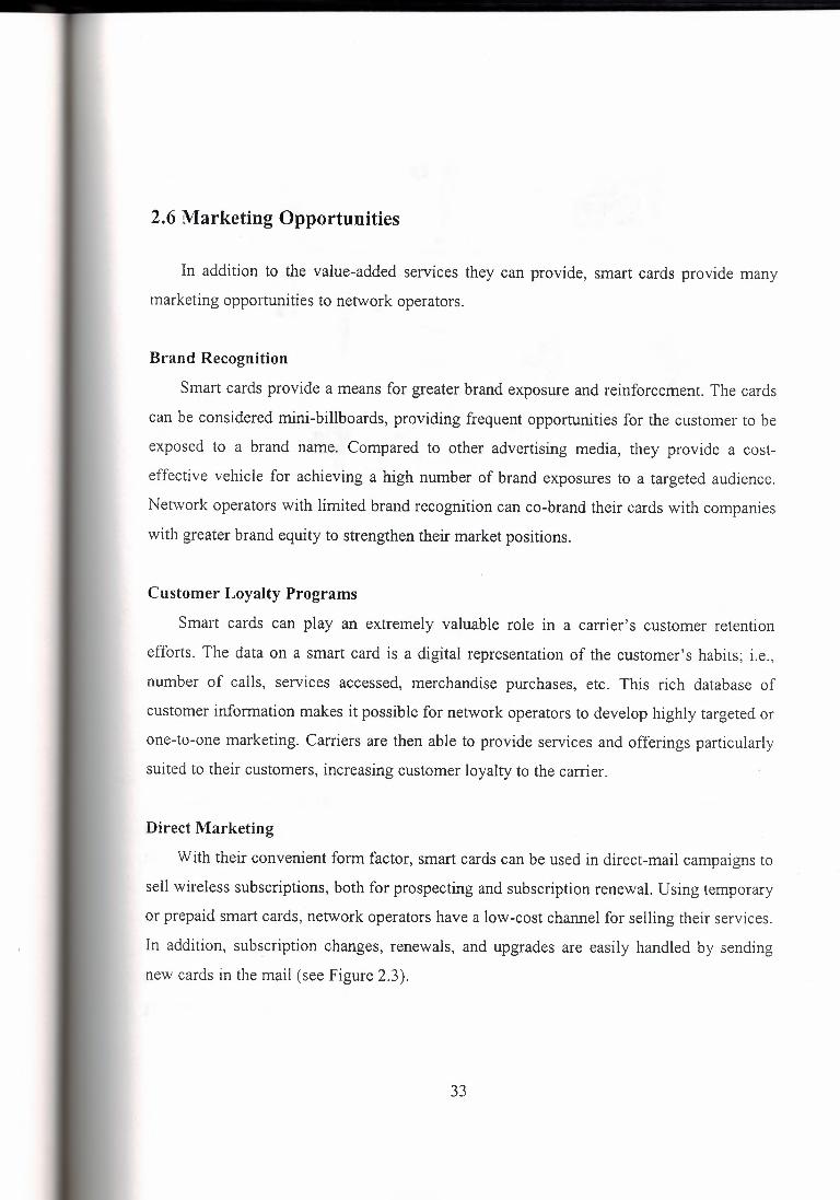
Direct Marketing
With their convenient form factor, smart cards can be used in direct-mail campaigns to
sell wireless subscriptions, both for prospecting and subscription renewal. Using temporary
or prepaid smart cards, network operators have a low-cost channel for selling their services.
In addition, subscription changes, renewals, and upgrades are easily handled by sending
new cards in the mail (see Figure 2.3).
33
•• Direct Mail ~h Prnp:3id Smart CaI<::! s.in1 to P=pw
Proo.pl(!<;( Revli.ws Prepai · -
w • Prospe01 G0<.s to Chann~I I
1 ater Buys,
& ~A
Via.Mail J B~e<s Regu1a1 Gu~,cm.ir
« / •••• ,,., "'"'""' Pn;:,sp~,;t':; ?r<i,p 3id Card G ~Iii> Acti11at.;d Cve-r th"' Air Via Shm Message Cnann~I
Figure 2.3 A Direct Marketing Scenario
Advertising
Two services, used in conjunction with smart cards, provide network operators with
possibilities for highly targeted advertising. Short message service (SMS) and cell
broadcast leverage smart cards to send advertising or informational messages that appear on
the handset display to wireless users.
Trial Subscriptions
Smart cards are an ideal vehicle for trial subscriptions. Programmed as prepaid cards,
they can attract new customers to try wireless services with limited, defined financial risk
for both the network operator and the consumer.
Incidental Revenues
Network operators issuing smart cards can generate additional revenue by selling
memory space on the card to other companies. For example, available space can be sold to
gas stations so that the smart card can also be used as a debit card for gas purchases. The
34
card's surface can also be used for imprinting the participating company's brand, for which
the carrier can receive fees for space advertising [3].
2. 7 Customer Benefits
Full Portability of Services
The smart card effectively breaks the link between the subscriber and the terminal,
allowing the use of any properly equipped terminal and helping to realize the wireless
promise of any-time, anywhere communications. In fact, subscribers need not be
constrained to using voice terminals only. A variety of other mobile communications
devices such as personal digital assistants (PDAs) and personal intelligent communicators
(PI Cs) are available that may have voice communications added as an integral part of their
capabilities. If these other devices are equipped for smart cards; the potential for
communications is increased. Similarly, data communications applications could benefit
from the security features inherent in smart cards.
International Roaming
Wireless customers often require the ability to place and receive calls when traveling
abroad. For these customers, international roaming enabled by smart cards is quite
valuable. For example, Ameritech, AT&T, and GTE have all instituted international
roaming programs using GSM phones and smart cards. The program uses co-branded smart
tr,.icards, which corporate customers bring with them when they travel abroad. Customers are
given a telephone number from a GSM carrier, which allows them to be contacted in any of
the countries that have international roaming agreements.
Intersystem Roaming
The incompatibility of different communications radio interfaces and authentication
protocols (time division multiple access [TDMA], code division multiple access [CDMA],
GSM, personal digital cellular [PDC], mobile satellite systems, etc.) requires subscribers to
make choices that constrain them to use only one particular type of handset that works with
35
only one radio interface. With a smart card, it becomes possible for subscribers to use one
handset for different interfaces and protocols. This feature is already implemented among
the three frequencies used by the GSM platform (900, 1800, and 1900 MHz). American
National Standards Institute (ANSI) telephone industry price index (Tl P 1 ).3 has
recommended standards for a user identity module, a smart card that can be used with the
major radio access methods. Thus, it becomes conceivable to have current GSM smart
cards modified so that they can work with a CDMA handset. For example, North American
GSM operators have designed a process to which the SIM holds both the GSM and
advanced mobile phone service (AMPS) authentication algorithm and data to provide
authentication on both networks in interroaming situations.
Multiple Services on a Single Card
As mentioned earlier, maximum value is realized by the subscriber when multiple
applications are stored on a single card (see Figure 2.4). A multiapplication smart card
could provide access to airline reservation and ticketing systems and information networks,
as well as a mobile telephone service. Considering the many cards that the average person
carries these days (i.e., numerous credit cards, debit cards, employee ID cards), integrating
more applications into a single card ( or at least fewer cards) has obvious appeal and
benefits. It is important to note that there is clear interest on the part other industries to
package their services with mobile telephony. For example, research by Citibank indicates
clearly that a substantial percentage of the company's customers would like to be able to
conduct its banking on a variety of platforms, including wireless. Such services are already
available using a standardized toolbox for smart-card application creation .
. ,\
36

ATJ.ts I Fin'I S11C11
t < ••• \
M\at. f.. Application \ ... Smart card Enttrtoinmellt & Info Svcs
POAa f Portable PC.s Travel SVC$
Figure 2.4 Smart Card-A Key to Information Services
Separation of Business and Personal Calls
The smart card allows customers to be billed separately for personal and business calls
made on a single phone. For example, Airtel, a Spanish GSM operator, uses a SIM card
with two sets of subscription information-one for corporate and the other for personal use.
Airtel's dual SIM cards have been well received in the corporate market [3].
2.8 Factors Driving Smart-Card Acceptance
Other Industries and Institutions
Certain industries, in particular information technology (IT), government, and financial
services, will lead the way to mass-market acceptance of smart cards.
Large IT players are deploying public key infrastructure (PKI) to provide secure
logical access to information. PKI is becoming the way to secure messaging and browsing
of private information, leading the way to secure electronic commerce. Smart cards are the
ideal vehicle to transport the digital certificate associated with the trusted third parties of
PKI infrastructures. They provide secure certificate portability and can combine other
security applications such as disk file encryption and secure computer log-on. The inclusion
37
of smart-card readers in the equipment listed in the PC99 recommendation has already
driven large computer manufacturers to integrate smart-card readers into their product offer
(for example, Hewlett Packard and Compaq).
Government agencies around the world are relying on smart-card technology to secure
off-line portable information; including identification documents and electronic benefit
transfer systems. A Brazilian province has issued its drivers licenses on smart cards to
allow the police to view securely stored ticket information immediately. The U.S.
government is a major early adopter of smart cards. It has instituted numerous smart card
identification programs for its defense department and recently announced that it will
further explore the nationwide use of smart cards for electronic benefit transfers as a fraud
reduction tool.
In the financial industry, large players such as Barclays and Citibank currently use SIM
cards to provide banking information to mobile users via their GSM phones. Electronic
purse systems based on VisaCash, Mondex, Proton, and other schemes are deployed around
the world and account for tens of millions of cards in Asia, Europe, and Latin America.
Major U.S. banks are considering or conducting trials of smart card-based systems. The
push by these major financial services firms will serve to accelerate consumer acceptance.
Consumers Primed to Use Smart Cards
Research conducted by the Smart Card Forum, an interindustry association dedicated
to advancing multiapplication smart cards, has generated the following statistics:
45 percent of consumers are favorably disposed to using smart cards
25 percent of households would actually obtain these smart cards
44 percent of consumers are likely to use identification-type smart cards (telephone cards,
gas cards, automated teller machine [ATM] cards, etc.) [3].
38
CHAPTER3
THE GSM SYSTEM
The Global System for Mobile communications is a digital cellular communications
system. It was developed in order to create a common European mobile telephone standard
but it has been rapidly accepted worldwide. GSM was designed to be compatible with
ISDN services.
3.1 History of the cellular mobile radio and GSM
The idea of cell-based mobile radio systems appeared at Bell Laboratories (in USA) in
the early 1970s. However, mobile cellular systems were not introduced for commercial use
until the 1980s. During the early 1980s, analog cellular telephone systems experienced a
very rapid growth in Europe, particularly in Scandinavia and the United Kingdom. Today
cellular systems still represent one of the fastest growing telecommunications systems.
But in the beginnings of cellular systems, each country developed its own system,
which was an undesirable situation for the following reasons:
The equipment was limited to operate only within the boundaries of each country.
The market for each mobile equipment was limited.
In order to overcome these problems, the Conference of European Posts and
Telecommunications (CEPT) formed, in 1982, the Groupe Special Mobile (GSM) in order
to develop a pan-European mobile cellular radio system (the GSM acronym became later
the acronym for Global System for Mobile communications). The standardized system had
to meet certain criteria:
39
Spectrum efficiency
International roaming
Low mobile and base stations costs
Good subjective voice quality
Compatibility with other systems such as ISDN (Integrated Services Digital Network)
Ability to support new services
Unlike the existing cellular systems, which were developed using an analog
technology, the GSM system was developed using a digital technology.
In 1989 the responsibility for the GSM specifications passed from the CEPT to the
European Telecommunications Standards Institute (ETSI). The aim of the GSM
specifications is to describe the functionality and the interface for each component of the
system, and to provide guidance on the design of the system. These specifications will then
standardize the system in order to guarantee the proper interworking between the different
elements of the GSM system. In 1990, the phase I of the GSM specifications was published
but the commercial use of GSM did not start until mid-1991.
The most important events in the development of the GSM system are presented in the
table3.l.
40
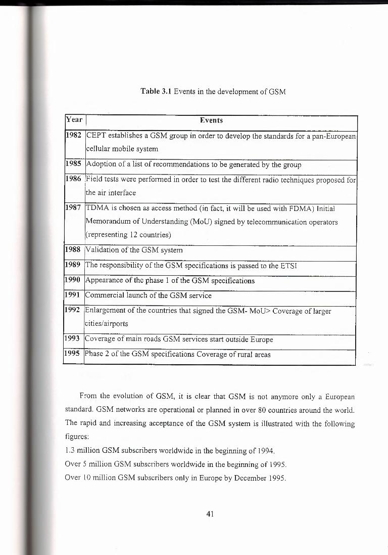
Table 3.1 Events in the development of GSM
[Year Events
1982 CEPT establishes a GSM group in order to develop the standards for a pan-European
cellular mobile system
1985 Adoption of a list of recommendations to be generated by the group
1986 Field tests were performed in order to test the different radio techniques proposed for
the air interface
1987 TDMA is chosen as access method (in fact, it will be used with FDMA) Initial
Memorandum of Understanding (MoU) signed by telecommunication operators
( representing 12 countries)
1988 Validation of the GSM system
1989 The responsibility of the GSM specifications is passed to the ETSI
1990 Appearance of the phase 1 of the GSM specifications
1991 Commercial launch of the GSM service
1992 Enlargement of the countries that signed the GSM- MoU> Coverage of larger
cities/airports
1993 Coverage of main roads GSM services start outside Europe
1995 Phase 2 of the GSM specifications Coverage of rural areas
From the evolution of GSM, it is clear that GSM is not anymore only a European
standard. GSM networks are operational or planned in over 80 countries around the world.
The rapid and increasing acceptance of the GSM system is illustrated with the following
figures:
1.3 million GSM subscribers worldwide in the beginning of 1994.
Over 5 million GSM subscribers worldwide in the beginning of 1995.
Over 10 million GSM subscribers only in Europe by December 1995.
41
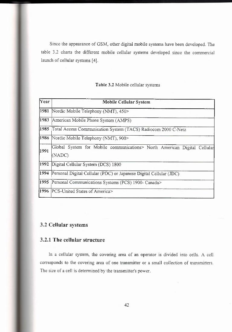
Since the appearance of GSM, other digital mobile systems have been developed. The
table 3.2 charts the different mobile cellular systems developed since the commercial
launch of cellular systems [ 4].
Table 3.2 Mobile cellular systems
Year Mobile Cellular System
1981 Nordic Mobile Telephony (NMT), 450>
1983 American Mobile Phone System (AMPS)
1985 Total Access Communication System (TACS) Radiocom 2000 C-Netz
1986 Nordic Mobile Telephony (NMT), 900>
1991 Global System for Mobile communications> North American Digital Cellular
(NADC)
1992 Digital Cellular System (DCS) 1800
1994 Personal Digital Cellular (PDC) or Japanese Digital Cellular (JDC)
1995 Personal Communications Systems (PCS) 1900- Canada>
1996 PCS-United States of America>
3.2 Cellular systems
3.2.1 The cellular structure
In a cellular system, the covering area of an operator is divided into cells. A cell
corresponds to the covering area of one transmitter or a small collection of transmitters.
The size of a cell is determined by the transmitter's power.
42
The concept of cellular systems is the use of low power transmitters in order to enable
the efficient reuse of the frequencies. In fact, if the transmitters used are very powerful, the
frequencies cannot be reused for hundred of kilometers as they are limited to the covering
area of the transmitter.
The frequency band allocated to a cellular mobile radio system is distributed over a
group of cells and this distribution is repeated in all the covering area of an operator. The
whole number of radio channels available can then be used in each group of cells that form
the covering area of an operator. Frequencies used in a cell will be reused several cells
away. The distance between the cells using the same frequency must be sufficient to avoid
interference. The frequency reuse will increase considerably the capacity in number of
users.
In order to work properly, a cellular system must verify the following two mam
conditions:
The power level of a transmitter within a single cell must be limited in order to reduce
the interference with the transmitters of neighboring cells. The interference will not
produce any damage to the system if a distance of about 2.5 to 3 times the diameter of a
cell is reserved between transmitters. The receiver filters must also be very performant.
Neighboring cells cannot share the same channels. In order to reduce the interference,
the frequencies must be reused only within a certain pattern.
In order to exchange the information needed to maintain the communication links
within the cellular network, several radio channels are reserved for the signaling
information [4].
43

3.2.2 Cluster
The cells are grouped into clusters. The number of cells in a cluster must be determined
so that the cluster can be repeated continuously within the covering area of an operator. The
typical clusters contain 4, 7, 12 or 21 cells. The number of cells in each cluster is very
important. The smaller the number of cells per cluster is, the bigger the number of channels
per cell will be. The capacity of each cell will be therefore increased. However a balance
must be found in order to avoid the interference that could occur between neighboring
clusters. This interference is produced by the small size of the clusters (the size of the
cluster is defined by the number of cells per cluster). The total number of channels per cell
depends on the number of available channels and the type of cluster used [ 4].
3.2.3 Types of cells
The density of population in a country is so varied that different types of cells are used:
Macrocells
Microcells
Selective cells
Umbrella cells
Mac roe ells
The macrocells are large cells for remote and sparsely populated areas.
Microcells
These cells are used for densely populated areas. By splitting the existing areas into
smaller cells, the number of channels available is increased as well as the capacity of the
cells. The power level of the transmitters used in these cells is then decreased, reducing the
possibility of interference between neighboring cells.
44
Selective cells
It is not always useful to define a cell with a full coverage of 360 degrees. In some
cases, cells with a particular shape and coverage are needed. These cells are called selective
cells. A typical example of selective, cells is the cells that may be located at the entrances of
tunnels where coverage of 360 degrees is not needed. In this case, a selective cell with
coverage of 120 degrees is used.
Umbrella cells
A freeway crossing very small cells produces an important number of handovers
among the different small neighboring cells. In order to solve this problem, the concept of
umbrella cells is introduced. An umbrella cell covers several microcells. The power level
inside an umbrella cell is increased comparing to the power levels used in the microcells
that form the umbrella cell. When the speed of the mobile is too high, the mobile is handed
off to the umbrella cell. The mobile will then stay longer in the same cell (in this case the
umbrella cell). This will reduce the number of handovers and the work of the network.
A too important number of handover demands and the propagation characteristics of a
mobile can help to detect its high speed [ 4].
3.3 The transition from analog to digital technology
In the 1980s most mobile cellular systems were based on analog systems. The GSM
system can be considered as the first digital cellular system. The different reasons that
explain this transition from analog to digital technology are presented in this chapter [ 4].
3.3.1 The capacity of the system
As it is explained previously, cellular systems have experienced a very important
growth. Analog systems were not able to cope with this increasing demand. In order to
45
overcome this problem, new frequency bands and new technologies were proposed. But the
possibility of using new frequency bands was rejected by a big number of countries
because of the restricted spectrum ( even if later on, other frequency bands have been
allocated for the development of mobile cellular radio). The new analog technologies
proposed were able to overcome the problem to a certain degree but the costs were too
important.
The digital radio was, therefore, the best option (but not the perfect one) to handle the
capacity needs in a cost-efficiency way [ 4].
3.3.2 Compatibility with other systems
The decision of adopting a digital technology for GSM was made in the course of
developing the standard. During the development of GSM, the telecommunications
industry converted to digital methods. The ISDN network is an example of this evolution.
In order to make GSM compatible with the services offered by ISDN, it was decide that the
digital technology was the best option.
Additionally, a digital system allows, easily than an analog one, the implementation of
future improvements and the change of its own characteristics [ 4].
3.3.3 Aspects of quality
The quality of the service can be considerably improved using a digital technology
rather than an analog one. In fact, analog systems pass the physical disturbances in radio
transmission ( such as fades, multipath reception, spurious signals or interferences) to the
receiver. These disturbances decrease the quality of the communication because they
produce effects such as fadeouts, crosstalks, hisses, etc. On the other hand, digital systems
avoid these effects transforming the signal into bits. This transformation combined with
other techniques, su9h as digital coding, improves the quality of the transmission. The
46
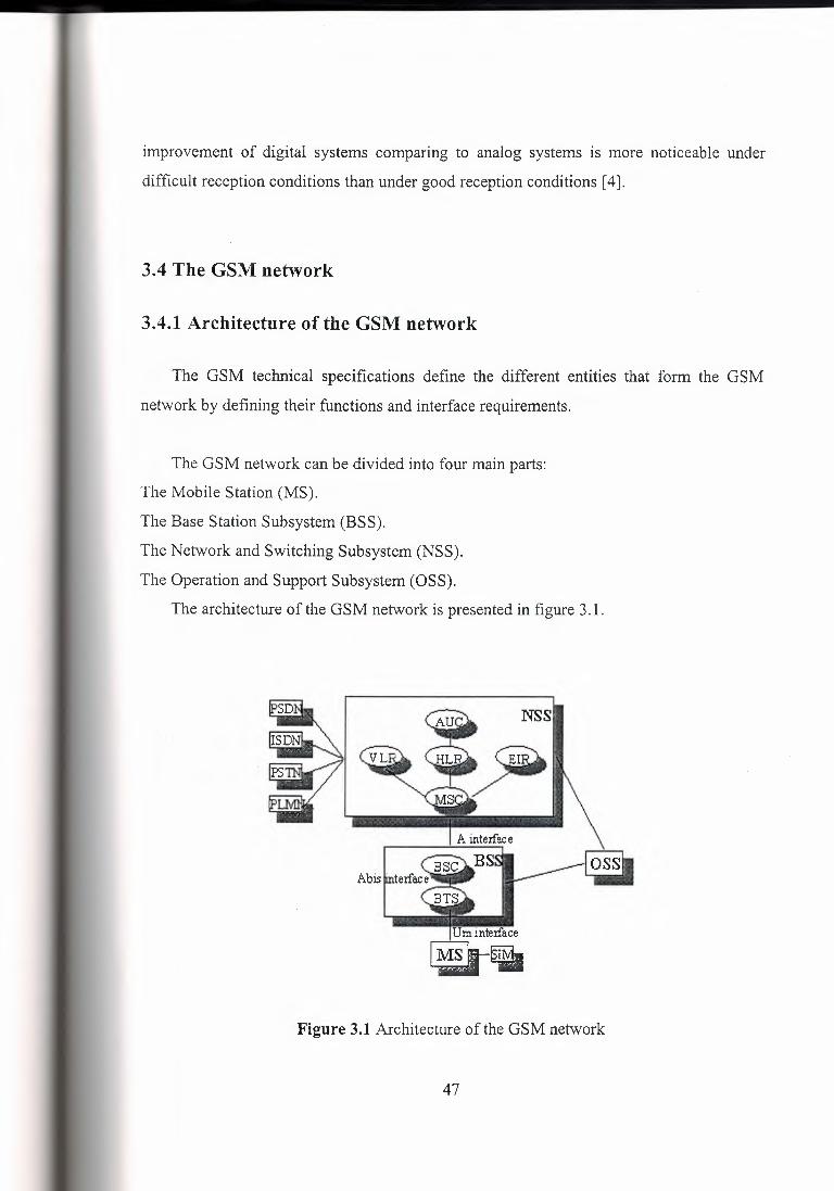
improvement of digital systems comparing to analog systems is more noticeable under
difficult reception conditions than under good reception conditions [ 4].
3.4 The GSM network
3.4.1 Architecture of the GSM network
The GSM technical specifications define the different entities that form the GSM
network by defining their functions and interface requirements.
The GSM network can be divided into four main parts:
The Mobile Station (MS).
The Base Station Subsystem (BSS).
The Network and Switching Subsystem (NSS).
The Operation and Support Subsystem (OSS).
The architecture of the GSM network is presented in figure 3 .1.
? NSS
~)ii»
Um inte:rface
~~
Figure 3.1 Architecture of the GSM network
47
Mobile Station
A Mobile Station consists of two main elements:
The mobile equipment or terminal.
The Subscriber Identity Module (SIM).
The Terminal
There are different types of terminals distinguished principally by their power and
application:
The 'fixed' terminals are the ones installed in cars. Their maximum allowed output
power is 20 W.
The GSM portable terminals can also be installed in vehicles. Their maximum allowed
output power is 8W.
The handheld terminals have experienced the biggest success thanks to their weight
and volume, which are continuously decreasing. These terminals can emit up to 2 W. The
evolution of technologies allows to decrease the maximum allowed power to 0.8 W.
The SIM
The SIM is a smart card that identifies the terminal. By inserting the SIM card into the
terminal, the user can have access to all the subscribed services. Without the SIM card, the
terminal is not operational.
The SIM card is protected by a four-digit Personal Identification Number (PIN). In
order to identify the subscriber to the system, the SIM card contains some parameters of the
user such as its International Mobile Subscriber Identity (IMSI).
Another advantage of the SIM card is the mobility of the users. In fact, the only
element that personalizes a terminal is the SIM card. Therefore, the user can have access to
its subscribed services in any terminal using its SIM card.
48

The Base Station Subsystem
The BSS connects the Mobile Station and the NSS. It is in charge of the transmission
and reception. The BSS can be divided into two parts:
The Base Transceiver Station (BTS) or Base Station.
The Base Station Controller (BSC).
The Base Transceiver Station
The BTS corresponds to the transceivers and antennas used in each cell of the network.
A BTS is usually placed in the center of a cell. Its transmitting power defines the size of a
cell. Each BTS has between one and sixteen transceivers depending on the density of users
in the cell.
The Base Station Controller
The BSC controls a group of BTS and manages their radio resources. A BSC is
principally in charge of handovers, frequency hopping, exchange functions and control of
the radio frequency power levels of the BTSs.
The Network and Switching Subsystem
Its main role is to manage the communications between the mobile users and other
users, such as mobile users, ISDN users, fixed telephony users, etc. It also includes data
bases needed in order to store information about the subscribers and to manage their
mobility. The different components of the NSS are described below.
The Mobile services Switching Center (MSC)
It is the central component of the NSS. The MSC performs the switching functions of
the network. It also provides connection to other networks.
The Gateway Mobile services Switching Center (GMSC)
A gateway is a node interconnecting two networks. The GMSC is the interface
between the mobile cellular network and the PSTN. It is in charge of routing calls from the
49
fixed network towards a GSM user. The GMSC is often implemented in the same machines
as the MSC.
Home Location Register (HLR)
The HLR is considered as a very important database that stores information of the
subscribers belonging to the covering area of a MSC. It also stores the current location of
these subscribers and the services to which they have access. The location of the subscriber
corresponds to the SS7 address of the Visitor Location Register (VLR) associated to the
terminal.
Visitor Location Register (VLR)
The VLR contains information from a subscriber's HLR necessary in order to provide
the subscribed services to visiting users. When a subscriber enters the covering area of a
new MSC, the VLR associated to this MSC will request information about the new
subscriber to its corresponding HLR. The VLR will then have enough information in order
to assure the subscribed services without needing to ask the HLR each time a
communication is established.
The VLR is always implemented together with a MSC; so the area under control of the
MSC is also the area under control of the VLR.
The Authentication Center (AuC)
The AuC register is used for security purposes. It provides the parameters needed for
authentication and encryption functions. These parameters help to verify the user's identity.
The Equipment Identity Register (EIR)
The EIR is also used for security purposes. It is a register containing information about
thy mobile equipments. More particularly, it contains a list of all valid terminals. A terminal
is identified by its International Mobile Equipment Identity (IMEI). The EIR allows then to
50
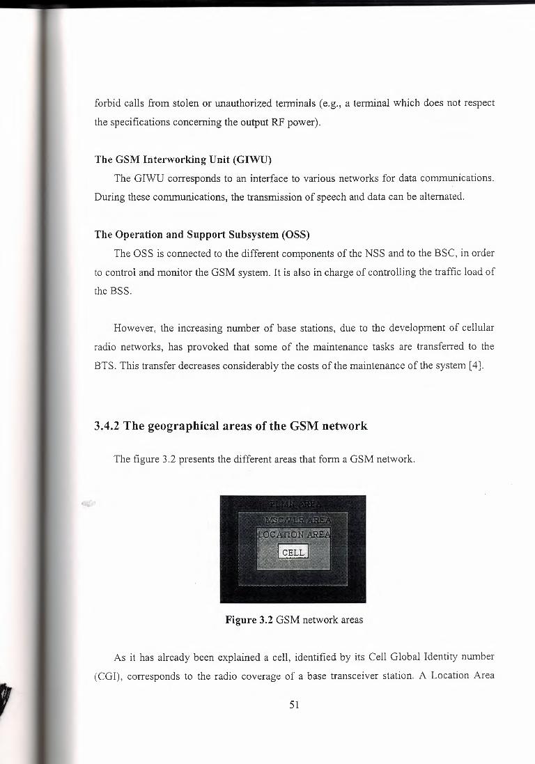
forbid calls from stolen or unauthorized terminals ( e.g., a terminal which does not respect
the specifications concerning the output RF power).
The GSM Interworking Unit (GIWU)
The GIWU corresponds to an interface to various networks for data communications.
During these communications, the transmission of speech and data can be alternated.
The Operation and Support Subsystem (OSS)
The OSS is connected to the different components of the NSS and to the BSC, in order
to control and monitor the GSM system. It is also in charge of controlling the traffic load of
the BSS.
However, the increasing number of base stations, due to the development of cellular
radio networks, has provoked that some of the maintenance tasks are transferred to the
BTS. This transfer decreases considerably the costs of the maintenance of the system [ 4].
3.4.2 The geographical areas of the GSM network
,
The figure 3.2 presents the different areas that form a GSM network.
Figure 3.2 GSM network areas
As it has already been explained a cell, identified by its Cell Global Identity number
(CGI), corresponds to the radio coverage of a base transceiver station. A Location Area
51
(LA), identified by its Location Area Identity (LAI) number, is a group of cells served by a
single MSC/VLR. A group of location areas under the control of the same MSCNLR
defines the MSC/VLR area. A Public Land Mobile Network (PLMN) is the area served by
one network operator [ 4].
3.4.3 The GSM functions
In this paragraph, the description of the GSM network is focused on the different
functions to fulfill by the network and not on its physical components. In GSM, five main
functions can be defined:
Transmission.
Radio Resources management (RR).
Mobility Management (MM).
Communication Management (CM).
Operation, Administration and Maintenance (OAM).
Transmission
The transmission function includes two sub-functions:
The first one is related to the means needed for the transmission of user information.
The second one is related to the means needed for the transmission of signaling
information.
Not all the components of the GSM network are strongly related with the transmission
functions. The MS, the BTS and the BSC, among others, are deeply concerned with
transmission. But other components, such as the registers HLR, VLR or EIR, are only
concerned with the transmission for their signaling needs with other components of the
GSM network.
52
Radio Resources management (RR)
The role of the RR function is to establish, maintain and release communication links
between mobile stations and the MSC. The elements that are mainly concerned with the RR
function are the mobile station and the base station. However, as the RR function is also in
charge of maintaining a connection even if the user moves from one cell to another, the
MSC, in charge of handovers, is also concerned with the RR functions.
The RR is also responsible for the management of the frequency spectrum and the
reaction of the network to changing radio environment conditions. Some of the main RR
procedures that assure its responsibilities are:
Channel assignment, change and release.
Handover.
Frequency hopping.
Power-level control.
Discontinuous transmission and reception.
Timing advance.
Some of these procedures are described in section 5. In this paragraph only the
handover, which represents one of the most important responsibilities of the RR, is
described.
Handover
The user movements can produce the need to change the channel or cell, especially
when the quality of the communication is decreasing. This procedure of changing the
resources is called handover. Four different types of handovers can be distinguished:
Handover of channels in the same cell.
Handover of cells controlled by the same BSC.
Handover of cells belonging to the same MSC but controlled by different BS Cs.
Handover of cells controlled by different MSCs.
53
Handovers are mainly controlled by the MSC. However in order to avoid unnecessary
signaling information, the first two types of handovers are managed by the concerned BSC
(in this case, the MSC is only notified of the handover).
The mobile station is the active participant in this procedure. In order to perform the
handover, the mobile station controls continuously its own signal strength and the signal
strength of the neighboring cells. The list of cells that must be monitored by the mobile
station is given by the base station. The power measurements allow to decide which is the
best cell in order to maintain the quality of the communication link. Two basic algorithms
are used for the handover:
The 'minimum acceptable performance' algorithm. When the quality of the
transmission decreases (i.e. the signal is deteriorated), the power level of the mobile is
increased. This is done until the increase of the power level has no effect on the quality of
the signal. When this happens, a handover is performed.
The 'power budget' algorithm. This algorithm performs a handover, instead of
continuously increasing the power level, in order to obtain a good communication quality.
Mobility Management
The MM function is in charge of all the aspects related with the mobility of the user,
specially the location management and the authentication and security.
Location management
When a mobile station is powered on, it performs a location update procedure by
indicating its IMSI to the network. The first location update procedure is called the IMSI
attach procedure.
The mobile station also performs location updating, in order to indicate its current
location, when it moves to a new Location Area or a different PLMN. This location
updating message is sent to the new MSC/VLR, which gives the location information to the
54

subscriber's HLR. If the mobile station is authorized in the new MSC/VLR, the subscriber's
HLR cancels the registration of the mobile station with the old MSC/VLR.
A location updating is also performed periodically. If after the updating time period,
the mobile station has not registered, it is then deregistered.
When a mobile station is powered off, it performs an IMSI detach procedure in order to
tell the network that it is no longer connected.
Authentication and security
The authentication procedure involves the SIM card and the Authentication Center. A
secret key, stored in the SIM card and the AuC, and a ciphering algorithm called A3 are
used in order to verify the authenticity of the user. The mobile station and the AuC compute
a SRES using the secret key, the algorithm A3 and a random number generated by the
AuC. If the two computed SRES are the same, the subscriber is authenticated. The different
services to which the subscriber has access are also checked.
Another security procedure is to check the equipment identity. If the IMEi number of
the mobile is authorized in the EIR, the mobile station is allowed to connect the network.
In order to assure user confidentiality, the user is registered with a Temporary Mobile
Subscriber Identity (TMSI) after its first location update procedure. Enciphering is another
option to guarantee a very strong security.
Communication Management (CM)
The CM function is responsible for:
Call control.
Supplementary Services management.
Short Message Services management.
55
Call Control (CC)
The CC is responsible for call establishing, maintaining and releasing as well as for
selecting the type of service. One of the most important functions of the CC is the call
routing. In order to reach a mobile subscriber, a user dials the Mobile Subscriber ISDN
(MSISDN) number, which includes:
a country code
a national destination code identifying the subscriber's operator
a code corresponding to the subscriber's HLR
The call is then passed to the GMSC (if the call is originated from a fixed network),
which knows the HLR corresponding to a certain MISDN number. The GMSC asks the
HLR for information helping to the call routing. The HLR requests this information from
the subscriber's current VLR. This VLR allocates temporarily a Mobile Station Roaming
Number (MSRN) for the call. The MSRN number is the information returned by the HLR
to the GMSC. Thanks to the MSRN number, the call is routed to subscriber's current
MSC/VLR. In the subscriber's current LA, the mobile is paged.
Supplementary Services management
The mobile station and the HLR are the only components of the GSM network
involved with this function. The different Supplementary Services (SS) to which the users
have access are presented section 3.6.3.
Short Message Services management
In order to support these services, a GSM network is in contact with a Short Message
Service Center through the two following interfaces:
The SMS-GMSC for Mobile Terminating Short Messages (SMS-MT/PP). It has the same
role as the GMSC.
The SMS-IWMSC for Mobile Originating Short Messages (SMS-MO/PP).
56

Operation, Administration and Maintenance (OAM)
The OAM function allows the operator to monitor and control the system as well as to
modify the configuration of the elements of the system. Not only the OSS is part of the
OAM, also the BSS and NSS participate in its functions as it is shown in the following
examples:
The components of the BSS and NSS provide the operator with all the information it
needs. This information is then passed to the OSS, which is in charge of analyzing it and
control the network.
The self-test tasks, usually incorporated in the components of the BSS and NSS, also
contribute to the OAM functions.
The BSC, in charge of controlling several BTSs, is another example of an OAM
function performed outside the OSS [ 4].
3.5 The GSM radio interface
The radio interface is the interface between the mobile stations and the fixed
infrastructure. It is one of the most important interfaces of the GSM system.
One of the main objectives of GSM is roaming. Therefore, in order to obtain a
complete compatibility between mobile stations and networks of different manufacturers
and operators, the radio interface must be completely defined.
The spectrum efficiency depends on the radio interface and the transmission, more
particularly in aspects such as the capacity of the system and the techniques used in order to
decrease the interference and to improve the frequency reuse scheme. The specification of
the radio interface has then an important influence on the spectrum efficiency [ 4].
57
3.5.1 Frequency allocation
Two frequency bands, of 25 Mhz each one, have been allocated for the GSM system:
The band 890-915 Mhz has been allocated for the uplink direction (transmitting from the
mobile station to the base station).
The band 935-960 Mhz has been allocated for the downlink direction (transmitting
from the base station to the mobile station).
But not all the countries can use the whole GSM frequency bands. This is due
principally to military reasons and to the existence of previous analog systems using part of
the two 25 Mhz frequency bands [4].
3.5.2 Multiple access scheme
The multiple access scheme defines how different simultaneous communications,
between different mobile stations situated in different cells, share the GSM radio spectrum.
A mix of Frequency Division Multiple Access (FDMA) and Time Division Multiple
Access (TDMA), combined with frequency hopping, has been adopted as the multiple
access scheme for GSM [ 4].
FDMA and TDMA
Using FDMA, a frequency is assigned to a user. So the larger the number of users in a
FDMA system, the larger the number of available frequencies must be. The limited
available radio spectrum and the fact that a user will not free its assigned frequency until he
does not need it anymore, explain why the number of users in a FDMA system can be
"quickly" limited.
58
t i.....~ ,:
~~, (.< .. ~ \\ it' ·~\\
i c. ~- \1 '<..:'",, rn \
.. ·-~1 ;r;h .. "\ ·1-~ ~~
' ' ,., \ ,(,, . '\-~ ~ 'r-' -{/ ~,"lfOq.,A M{,
On the other hand, TDMA allows several users to share the same chann·el~~8f the
users, sharing the common channel, is assigned their own burst within a group of bursts
called a frame. Usually TDMA is used with a FDMA structure.
In GSM, a 25 Mhz frequency band is divided, using a FDMA scheme, into 124 carrier
frequencies spaced one from each other by a 200 khz frequency band. Normally a 25 Mhz
frequency band can provide 125 carrier frequencies but the first carrier frequency is used as
a guard band between GSM and other services working on lower frequencies. Each carrier
frequency is then divided in time using a TDMA scheme. This scheme splits the radio
channel, with a width of 200 khz, into 8 bursts. A burst is the unit of time in a TDMA
system, and it lasts approximately 0.577 ms. A TDMA frame is formed with 8 bursts and
lasts, consequently, 4.615 ms. Each of the eight bursts, that form a TDMA frame, are then
assigned to a single user.
Channel structure
A channel corresponds to the recurrence of one burst every frame. It is defined by its
frequency and the position of its corresponding burst within a TDMA frame. In GSM there
are two types of channels:
The traffic channels used to transport speech and data information.
The control channels used for network management messages and some channel
maintenance tasks.
Traffic channels (TCH)
Full-rate traffic channels (TCH/F) are defined using a group of 26 TDMA frames
called a 26-Multiframe. The 26-Multiframe lasts consequently 120 ms. In this 26-
Multiframe structure, the traffic channels for the downlink and uplink are separated by 3
bursts. As a consequence, the mobiles will not need to transmit and receive at the same
time, which simplifies considerably the electronics of the system.
The frames that form the 26-Multiframe structure have different functions:
24 frames are reserved to traffic.
59
1 frame is used for the Slow Associated Control Channel (SACCH).
The last frame is unused. This idle frame allows the mobile station to perform other
functions, such as measuring the signal strength of neighboring cells. Half-rate traffic
channels (TCH/H), which double the capacity of the system, are also grouped in a 26-
Multiframe but the internal structure is different.
Control channels
According to their functions, four different classes of control channels are defined:
Broadcast channels.
Common control channels.
Dedicated control channels.
Associated control channels.
Broadcast channels (BCH)
The BCH channels are used, by the base station, to provide the mobile station with the
sufficient information it needs to synchronize with the network. Three different types of
BCHs can be distinguished:
The Broadcast Control Channel (BCCH), which gives to the mobile station the
parameters needed in order to identify and access the network.
The Synchronization Channel (SCH), which gives to the mobile station the training
sequence needed in order to demodulate the information transmitted by the base station.
The Frequency-Correction Channel (FCCH), which supplies the mobile station with
the frequency reference of the system in order to synchronize it with the network.
Common Control Channels (CCCH)
The CCCH channels help to establish the calls from the mobile station or the network.
Three different types of CCCH can be defined:
60

The Paging Channel (PCH). It is used to alert the mobile station of an incoming call.
The Random Access Channel (RACH), which is used by the mobile station to request
access to the network.
The Access Grant Channel (AGCH). It is used, by the base station, to inform the mobile
station about which channel it should use. This channel is the answer of a base station to a
RACH from the mobile station.
Dedicated Control Channels (DCCH)
The DCCH channels are used for message exchange between several mobiles or a
mobile and the network. Two different types of DCCH can be defined:
The Standalone Dedicated Control Channel (SDCCH), which is used in order to exchange
signaling information in the downlink and uplink directions.
The Slow Associated Control Channel (SACCH). It is used for channel maintenance and
channel control.
Associated Control Channels
The Fast Associated Control Channels (F ACCH) replace all or part of a traffic channel
when urgent signaling information must be transmitted. The F ACCH channels carry the
same information as the SDCCH channels.
Burst structure
As it has been stated before, the burst is the unit in time of a TDMA system. Four
different types of bursts can be distinguished in GSM:
The frequency-correction burst is used on the FCCH. It has the same length as the normal
burst but a different structure.
The synchronization burst is used on the SCH. It has the same length as the normal burst
but a different structure.
61
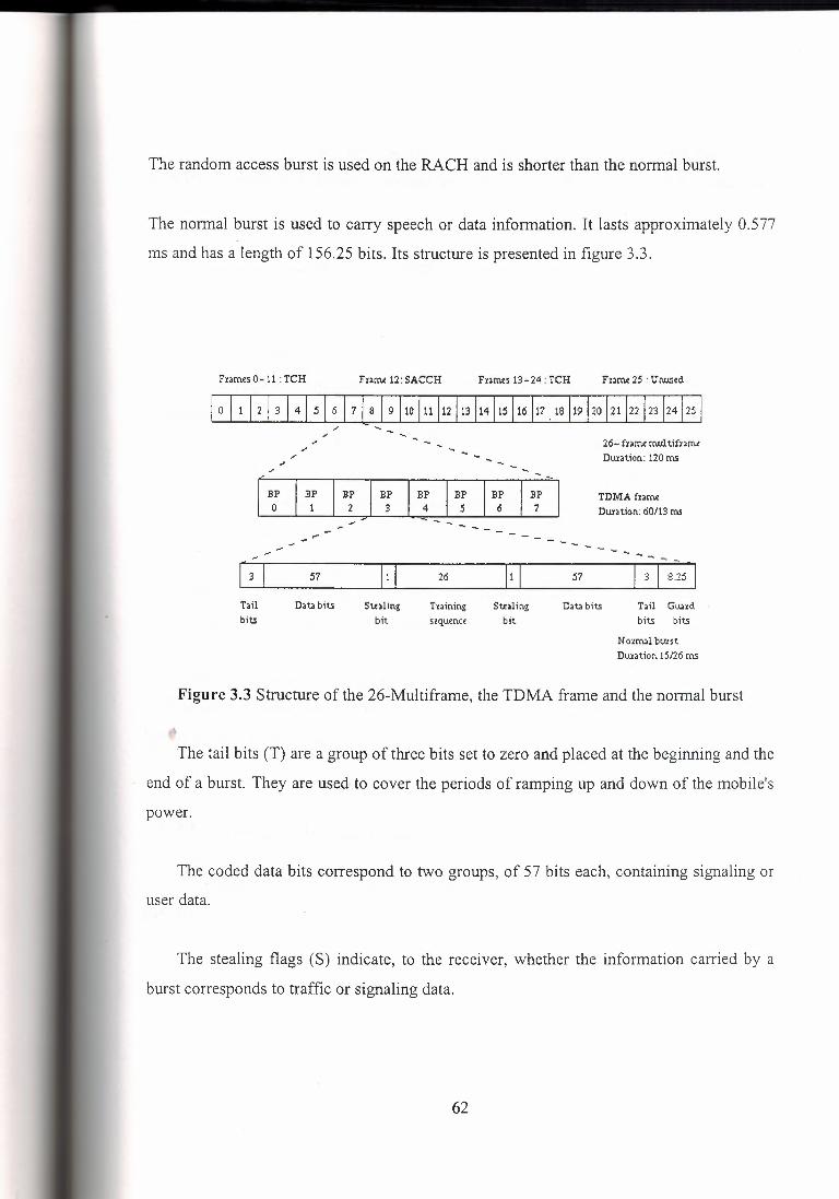
The random access burst is used on the RACH and is shorter than the normal burst.
The normal burst is used to carry speech or data information. It lasts approximately 0.577
ms and has a length of 156.25 bits. Its structure is presented in figure 3.3.
Frames 0-11 : TCH Frnru 12: SACCH Fumes 13-24: TCH Frame 25 : Unused
0 1112 I 3 1415I61718 I 9110 l11 l12 l13 l14l15 l16 l17 l18 l19 J20 l21 l22 l23 l24l25
26- fx;,me mul tifx,rru Duration: 120 ms
[ B: I B~ I B: I B: I B: I B: I B: I B: -
I ;, - ------ .... _ - - - .-- - ,... ,... ~
I 3 I 57 I 1 I 26 I 1 I Tail Dat. bits Stealing Txaining Stealing bits bit sequence bit
TDMA fzarne Duration: 60/13 ms
- - ---- .
57 0 8.25
Dat. bits Tail Gu.axd bits bits
N ozrnal btnst Duration 15/26 rns
Figure 3.3 Structure of the 26-Multiframe, the TDMA frame and the normal burst
The tail bits (T) are a group of three bits set to zero and placed at the beginning and the
end of a burst. They are used to cover the periods of ramping up and down of the mobile's
power.
The coded data bits correspond to two groups, of 57 bits each, containing signaling or
user data.
The stealing flags (S) indicate, to the receiver, whether the information carried by a
burst corresponds to traffic or signaling data.
62
The training sequence has a length of 26 bits. It is used to synchronize the receiver
with the incoming information, avoiding then the negative effects produced by a multipath
propagation.
The guard period (GP), with a length of 8.25 bits, is used to avoid a possible overlap of
two mobiles during the ramping time.
Frequency hopping
The propagation conditions and therefore the multipath fading depend on the radio
frequency. In order to avoid important differences in the quality of the channels, the slow
frequency hopping is introduced. The slow frequency hopping changes the frequency with
every TDMA frame. A fast frequency hopping changes the frequency many times per
frame but it is not used in GSM. The frequency hopping also reduces the effects of co
channel interference.
There are different types of frequency hopping algorithms. The algorithm selected is
sent through the Broadcast Control Channels.
Even if frequency hopping can be very useful for the system, a base station does not
have to support it necessarily On the other hand, a mobile station has to accept frequency
hopping when a base station decides to use it.
3.5.3 From source information to radio waves
The figure 3 .4 presents the different operations that have to be performed in order to
pass from the speech source to radio waves and vice versa.
63
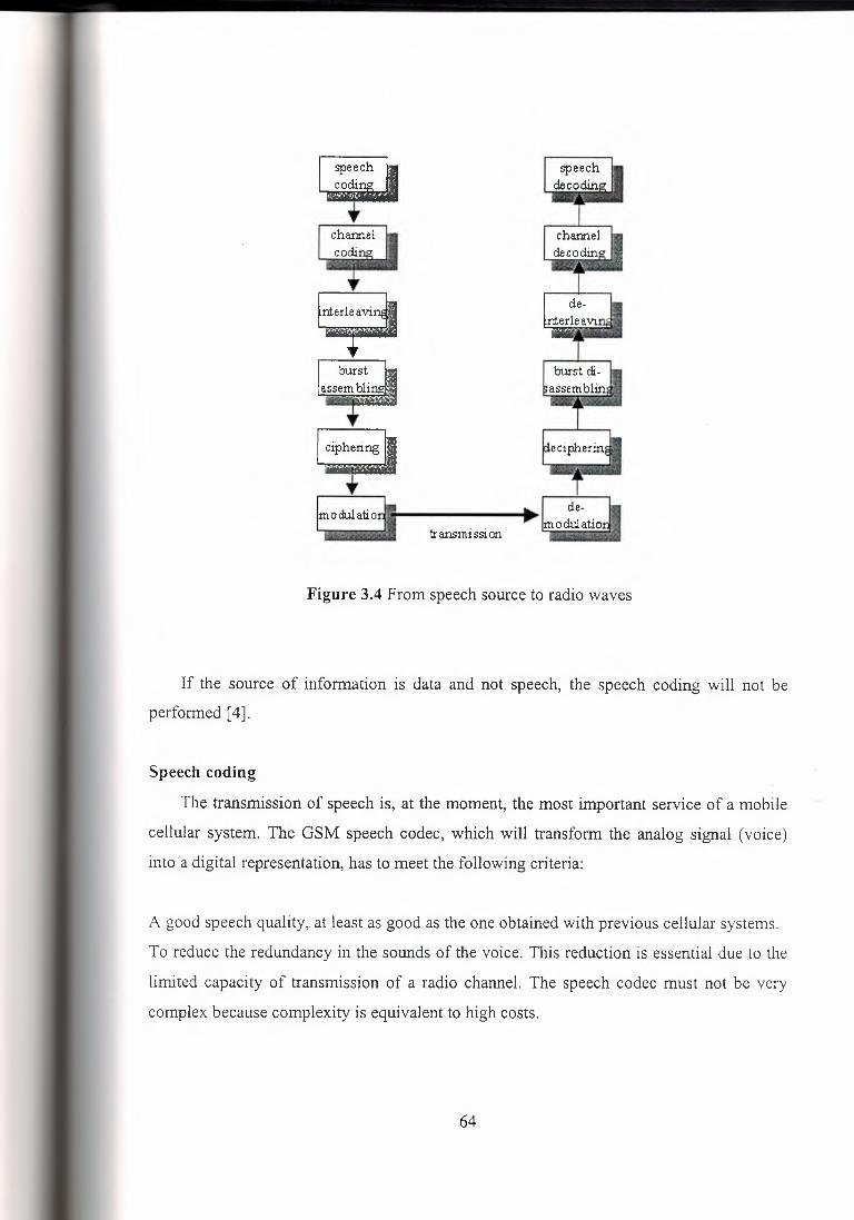
~ --r-
transmission
Figure 3.4 From speech source to radio waves
If the source of information is data and not speech, the speech coding will not be
performed [ 4].
Speech coding
The transmission of speech is, at the moment, the most important service of a mobile
cellular system. The GSM speech codec, which will transform the analog signal (voice)
into a digital representation, has to meet the following criteria:
A good speech quality, at least as good as the one obtained with previous cellular systems.
To reduce the redundancy in the sounds of the voice. This reduction is essential due to the
limited capacity of transmission of a radio channel. The speech codec must not be very
complex because complexity is equivalent to high costs.
64
The final choice for the GSM speech codec is a codec named RPE-L TP (Regular Pulse
Excitation Long-Term Prediction). This codec uses the information from previous samples
(this information does not change very quickly) in order to predict the current sample. The
speech signal is divided into blocks of 20 ms. These blocks are then passed to the speech
codec, which has a rate of 13 kbps, in order to obtain blocks of 260 bits.
Channel coding
Channel coding adds redundancy bits to the original information in order to detect and
correct, if possible, errors occurred during the transmission.
Channel coding for the GSM data TCH channels
The channel coding is performed using two codes: a block code and a convolutional
code.
The block code corresponds to the block code defined in the GSM Recommendations
05.03. The block code receives an input block of 240 bits and adds four zero tail bits at the
end of the input block. The output of the block code is consequently a block of 244 bits.
A convolutional code adds redundancy bits in order to protect the information. A
convolutional encoder contains memory. This property differentiates a convolutional code
from a block code. A convolutional code can be defined by three variables: n, k and K. The
value n corresponds to the number of bits at the output of the encoder, k to the number of
bits at the input of the block and K to the memory of the encoder. The ratio, R, of the code
is defined as follows: R = kin. Let's consider a convolutional code with the following
values: k is equal to 1, n to 2 and K to 5. This convolutional code uses then a rate of R = 1 /2 and a delay of K = 5, which means that it will add a redundant bit for each input bit. The
convolutional code uses 5 consecutive bits in order to compute the redundancy bit. As the
convolutional code is a 1/2 rate convolutional code, a block of 488 bits is generated. These
488 bits are punctured in order to produce a block of 456 bits. Thirty-two bits, obtained as
follows, are not transmitted:
C (11 + 15 j) for j = 0, 1... 31
65
The block of 456 bits produced by the convolutional code is then passed to the interleaver.
Channel coding for the GSM speech channels
Before applying the channel coding, the 260 bits of a GSM speech frame are divided in
three different classes according to their function and importance. The most important class
is the class Ia containing 50 bits. Next in importance is the class lb, which contains 132
bits. The least important is the class II, which contains the remaining 78 bits. The different
classes are coded differently. First of all, the class Ia bits are block-coded. Three parity bits,
used for error detection, are added to the 50 class Ia bits. The resultant53 bits are added to
the class lb bits. Four zero bits are added to this block of 185 bits (50+ 3+ 132). A
convolutional code, with r = 1/2 and K = 5, is then applied, obtaining an output block of
3 78 bits. The class II bits are added, without any protection, to the output block of the
convolutional coder. An output block of 456 bits is finally obtained.
Channel coding for the GSM control channels
In GSM the signaling information is just contained in 184 bits. Forty parity bits,
obtained using a fire code, and four zero bits are added to the 184 bits before applying the
convolutional code (r = 1/2 and K = 5). The output of the convolutional code is then a block of 456 bits, which does not need to be punctured.
Interleaving
An interleaving rearranges a group of bits in a particular way. It is used in combination
with FEC codes in order to improve the performance of the error correction mechanisms.
The interleaving decreases the possibility of losing whole bursts during the transmission, by
dispersing the errors. Being the errors less concentrated, it is then easier to correct them.
Interleaving for the GSM control channels
A burst in GSM transmits two blocks of 57 data bits each. Therefore the 456 bits
corresponding to the output of the channel coder fit into four bursts ( 4* 114 = 456). The 456 bits are divided into eight blocks of 57 bits. The first block of 57 bits contains the bit
numbers (0, 8, 16, .... .448), the second one the bit numbers (1, 9, 17, .... .449), etc. The last
66
block of 57 bits will then contain the bit numbers (7, 15, .... .455). The first four blocks of
57 bits are placed in the even-numbered bits of four bursts. The other four blocks of 57 bits
are placed in the odd-numbered bits of the same four bursts. Therefore the interleaving
depth of the GSM interleaving for control channels is four and a new data block starts
every four bursts. The interleaver for control channels is called a block rectangular
interleaver.
Interleaving for the GSM speech channels
The block of 456 bits, obtained after the channel coding, is then divided in eight blocks
of 57 bits in the same way as it is explained in the previous paragraph. But these eight
blocks of 57 bits are distributed differently. The first four blocks of 57 bits are placed in the
even-numbered bits of four consecutive bursts. The other four blocks of 57 bits are placed
in the odd-numbered bits of the next four bursts. The interleaving depth of the GSM
interleaving for speech channels is then eight. A new data block also starts every four
bursts. The interleaver for speech channels is called a block diagonal interleaver.
Interleaving for the GSM data TCH channels
A particular interleaving scheme, with an interleaving depth equal to 22, is applied to
the block of 456 bits obtained after the channel coding. The block is divided into 16 blocks
of 24 bits each, 2 blocks of 18 bits each, 2 blocks of 12 bits each and 2 blocks of 6 bits
each. It is spread over 22 bursts in the following way:
the first and the twenty-second bursts carry one block of 6 bits each
the second and the twenty-first bursts carry one block of 12 bits each
the third and the twentieth bursts carry one block of 18 bits each
... from the fourth to the nineteenth burst, a block of 24 bits is placed in each burst
A burst will then carry information from five or six consecutive data blocks. The data
blocks are said to be interleaved diagonally. A new data block starts every four bursts.
67
Burst assembling
The burst assembling procedure is in charge of grouping the bits into bursts. Section
3.5.2 presents the different bursts structures and describes in detail the structure of the
normal burst.
Ciphering
Ciphering is used to protect signaling and user data. First of all, a ciphering key is
computed using the algorithm A8 stored on the SIM card, the subscriber key and a random
number delivered by the network (this random number is the same as the one used for the
authentication procedure). Secondly, a 114-bit sequence is produced using the ciphering
key, an algorithm called A5 and the burst numbers. This bit sequence is then XORed with
the two 57 bit blocks of data included in a normal burst.
In order to decipher correctly, the receiver has to use the same algorithm AS for the
deciphering procedure.
Modulation
The modulation chosen for the GSM system is the Gaussian Modulation Shift Keying
(GMSK).
The aim of this section is not to describe precisely the GMSK modulation as it is too
long and it implies the presentation of too many mathematical concepts. Therefore, only
brief aspects of the GMSK modulation are presented in this section.
The GMSK modulation has been chosen as a compromise between spectrum
efficiency, complexity and low spurious radiations (that reduce the possibilities of adjacent
channel interference). The GMSK modulation has a rate of 270 5/6 kbauds and a BT
product equal to 0.3. Figure 3.5 presents the principle of a GMSK modulator.
68
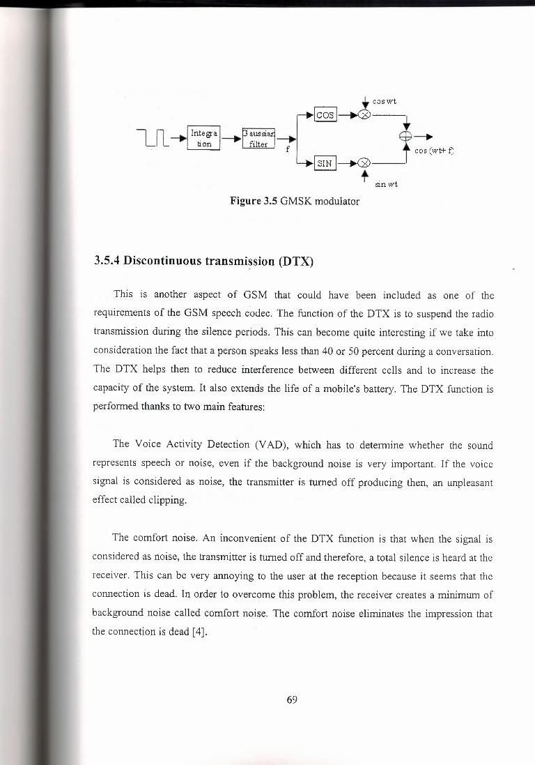
,. cos wt
[~~ . '--'-==c:......J---: t ~wet ~
I SIN 1--.G>-- t sin wt
Figure 3.5 GMSK modulator
3.5.4 Discontinuous transmi~sion (DTX)
This is another aspect of GSM that could have been included as one of the
requirements of the GSM speech codec. The function of the DTX is to suspend the radio
transmission during the silence periods. This can become quite interesting if we take into
consideration the fact that a person speaks less than 40 or 50 percent during a conversation.
The DTX helps then to reduce interference between different cells and to increase the
capacity of the system. It also extends the life of a mobile's battery. The DTX function is
performed thanks to two main features:
The Voice Activity Detection (V AD), which has to determine whether the sound
represents speech or noise, even if the background noise is very important. If the voice
signal is considered as noise, the transmitter is turned off producing then, an unpleasant
effect called clipping.
The comfort noise. An inconvenient of the DTX function is that when the signal is
considered as noise, the transmitter is turned off and therefore, a total silence is heard at the
receiver. This can be very annoying to the user at the reception because it seems that the
connection is dead. In order to overcome this problem, the receiver creates a minimum of
background noise called comfort noise. The comfort noise eliminates the impression that
the connection is dead [ 4].
69
3.5.5 Timing advance
The timing of the bursts transmissions is very important. Mobiles are at different
distances from the base stations. Their delay depends, consequently, on their distance. The
aim of the timing advance is that the signals coming from the different mobile stations
arrive to the base station at the right time. The base station measures the timing delay of the
mobile stations. If the bursts corresponding to a mobile station arrive too late and overlap
with other bursts, the base station tells, this mobile, to advance the transmission of its bursts
[ 4].
3.5.6 Power control
At the same time the base stations perform the timing measurements, they also perform
measurements on the power level of the different mobile stations. These power levels are
adjusted so that the power is nearly the same for each burst.
A base station also controls its power level. The mobile station measures the strength
and the quality of the signal between itself and the base station. If the mobile station does
not receive correctly the signal, the base station changes its power level [ 4].
3.5.7 Discontinuous reception
It is a method used to conserve the mobile station's power. The paging channel is
divided into subchannels corresponding to single mobile stations. Each mobile station will
then only 'listen' to its subchannel and will stay in the sleep mode during the other
subchannels of the paging channel [ 4].
70

3.5.8 Multipath and equalization
At the GSM frequency bands, radio waves reflect from buildings, cars, hills, etc. So
not only the 'right' signal (the output signal of the emitter) is received by an antenna, but
also many reflected signals, which corrupt the information, with different phases.
An equalizer is in charge of extracting the 'right' signal from the received signal. It
estimates the channel impulse response of'the GSM system and then constructs an inverse
filter. The receiver knows which training sequence it must wait for. The equalizer will then,
comparing the received training sequence with the training sequence it was expecting,
compute the coefficients of the channel impulse response. In order to extract the 'right'
signal, the received signal is passed through the inverse filter [ 4 J.
3.6 GSM services
It is important to note that all the GSM services were not introduced since the
appearance of GSM but they have been introduced in a regular way. The GSM
Memorandum of Understanding (MoU) defined four classes for the introduction of the
different GSM services:
E 1: introduced at the start of the service.
E2: introduced at the end of 19'91.
Eh: introduced on availability of half-rate channels.
A: these services are optional.
Three categories of services can be distinguished:
Teleservices.
Bearer services.
Supplementary Services.
71
3.6.1 Teleservices
- Telephony (El® Eh).
- Facsimile group 3 (E 1).
- Emergency calls (El® Eh).
- Teletex.
- Short Message Services (E 1, E2, A). Using these services, a message of a maximum of
160 alphanumeric characters can be sent to or from a mobile station. If the mobile is
powered off, the message is stored. With the SMS Cell Broadcast (SMS-CB), a message of
a maximum of 93 characters can be broadcast to all mobiles in a certain geographical area.
- Fax mail. Thanks to this service, the subscriber can receive fax messages at any fax
machine.
- Voice mail. This service corresponds to an answering machine [ 4].
3.6.2 Bearer services
A bearer service is used for transporting user data. Some of the bearer services are
listed below:
Asynchronous and synchronous data, 300-9600 bps (El).
Alternate speech and data, 300-9600 bps (El).
Asynchronous PAD (packet-switched, packet assembler/disassembler) access, 300-9600
bps (El).
Synchronous dedicated packet data access, 2400-9600 bps (E2) [4].
3.6.3 Supplementary Services
- Call Forwarding (El). The subscriber can forward incoming calls to another number if the
called mobile i~ busy (CFB), unreachable (CFNRc) or if there is no reply (CFNRy). Call
forwarding can also be applied unconditionally (CFU).
- Call Barring. There are different types of 'call barring' services:
72
Barring of All Outgoing Calls, BAOC (El).
Barring of Outgoing International Calls, BOIC (El).
Barring of Outgoing International Calls except those directed toward the Home PLMN
Country, BOIC-exHC (E 1).
Barring of All Incoming Calls, BAIC (E 1)
Barring of incoming calls when roaming (A).
- Call hold (E2). Puts an active call on hold.
- Call Waiting, CW (E2). Informs the user, during a conversation, about another incoming
call. The user can answer, reject or ignore this incoming call.
- Advice of Charge, AoC (E2). Provides the user with an online charge information.
- Multiparty service (E2). Possibility of establishing a multiparty conversation.
- Closed User Group, CUG (A). It corresponds to a group of users with limited possibilities
of calling ( only the people of the group and certain numbers).
- Calling Line Identification Presentation, CLIP (A). It supplies the called user with the
ISDN of the calling user.
- Calling Line Identification Restriction, CLIR (A). It enables the calling user to restrict the
presentation.
- Connected Line identification Presentation, CoLP (A). It supplies the calling user with the
directory number he gets if his call is forwarded.
- Connected Line identification Restriction, CoLR (A). It enables the called user to restrict
the presentation.
- Operator determined barring (A). Restrictions of different services and call types by the
operator [ 4].
73

CHAPTER4
GSM PRODUCT DESIGN
4.1 Baseband-chipset for GSM Phase 2 [AD20msp4l0]
Analog Devices, Inc. and The Technology Partnership of Cambridge, England, have
announced a GSM chipset, integrating all the circuitry and software required to implement
the baseband portion of a Phase 2 handset. The package includes the AD20msp410 three
device chipset and a fully compatible Phase 2 software suite, and builds on the partners'
five years experience in GSM. A complete GSM handset can be made simply with the
addition of a radio subsystem and some basic memory, keyboard, and display. Reference
designs for all of these are available.
The three-device set consists of a digital ASIC (the Physical Layer Processor or PLP),
an Algorithm Signal Processor (ASP) and a dedicated mixed-signal device (Baseband
Converter or BBC). The PLP performs all channel coding functions and includes an H8 16-
bit microcontroller, which also runs the complete Protocol Stack and application software.
The ASP is based on the ADSP-2171 DSP, and performs speech coding and soft decision
equalization. The· BBC includes CODECs and implements all mixed-signal radio, audio,
and auxiliary functions of the terminal.
Both size and power are at a premium in handsets; the three sub-micron low power
CMOS parts operate from 3 V or 5 V and include several power saving modes, to provide
over two hours of talk time and in excess of 40 hours standby. The devices are packaged in
compact TQFP form, to occupy less than 12 sq cm of board space and are just 1.4 mm high
(small enough to fit in a type 2 PCMCIA card).
74

The system is fully GSM Phase 2 compliant, supports data services, and offers an easy
future migration path to half rate speech. It is targeted for use in GSM, E-GSM, and PCN
(DCS-1800) handsets.
All parts of the system, including an evaluation board, will be available for sampling in
the spring. The chipsets and software will be available separately or together; chipset prices
will be under $50 in OEM quantities.
The Technology Partnership Ltd. is a product development and engineering company
based in the UK's Silicon Fen. Formed in 1988 and now 165 people strong; it has an
impressive record in GSM product development, having worked with over 20 companies
around the world in this field. In 1993 they were honored with a UK Government award for
export achievement.
Analog Devices, Inc., with fiscal 1993 revenues of $666 million, is a leading
manufacturer of precision high-performance integrated circuits used in analog and digital
signal processing. The company has a wide range of devices for communications
applications, and is one of the leading manufacturers of GSM components, for both base
stations and terminals, with customers that include five of the seven major equipment
suppliers [ 5].
4.2 RF Performance
Time-to-market pressure makes the primary goal of handset development the
successful completion of full type approval (FTA). The phase error, transmit power, RF
output spectrum, receiver sensitivity, and blocking performance are addressed.
Big money and big risk - these are what you can expect when entering the not so new
market of digital cellular phones. In fact, digital cellular has been in commercial existence
since 1992 when it made its debut in Europe. With the acceptance of the Global System for
75
Mobile Communications (GSM) standard came FTA, the mandatory 5-week verification
process used to force compliance to the GSM specification and guarantee interoperability
with all GSM networks worldwide. Presently, test facilities are located primarily in Europe,
an inconvenience for companies developing handsets in North America. With test agencies
thousands of miles away, and given the complexities of GSM, mandatory test scenarios are
very difficult to execute. However, preparation of the handset for type approval is essential
for the successful introduction of a handset to the marketplace. In this two-part series, the
two most problematic areas of FT A testing are examined and discussed, with emphasis
given to pre-emptive design or test activity that will hopefully assist in your preparatory
efforts before crossing the pond for FT A [ 5].
4.2.1 FTA
Despite the importance of quality, time-to-market pressure makes the primary goal of
handset development the successful completion of FT A. GSM test houses are equipped
with at least one $3 .5 million test system (plus other less expensive test gear), charge
approximately $1000/hour for system test time, and require 4-months advance notice for
booking test time. Few handset manufacturers can afford such a test system and rely upon
less expensive equipment to replicate the required test scenarios; the end result is
incomplete test coverage of the handset before attempting FTA. A majority of operational
areas of the handset can be tested, yet problems still tend to remain undetected in the area
of RF performance and Layer 1 operation (which is primarily responsible for managing the
radio interface).
The first round of agency testing should target defects related to hardware anyway,
since they may require a board spin to correct problems. This is very important because,
prior to the final FT A run, the test authority takes a picture of the circuit board!
76

In this article the phase error, transmit power, RF output spectrum, receiver sensitivity,
and blocking performance will be addressed simply because they seem to be the most
difficult in passing FT A [ 5].
4.2.2 Handset definition
A basic handset is shown in Figure 4.1 , which illustrates both hardware and software
components. Control software resides in Layer 3 and is responsible for all control
functions, such as call setup, mobility tracking, and handover activity. The man machine
interface (MMI) and subscriber ID module (SIM) operations are also managed, yet they can
be considered as applications sitting above the stack. Layer 2 is responsible for control
message flow control and retransmission. Layer 1 manages the airlink and controls the RF
hardware in response to network messages and airlink conditions. Additionally, all audio
functions are handled by this layer in support of voice traffic. The RF section is shown in
Figure 4.2 ; it is the performance of this hardware that will be the focus of most of the
remaining discussion.
As a development facility in North America, it is difficult to use an FTA test house as a
debug option; conceivably, such a facility could serve as a source of rental equipment,
given the prohibitive cost of owning such hardware. Without this option, there are limited
solutions for comprehensive test coverage. For very basic measurements.i-the Hewlett
Packard (HP) 8922, Rohde and Schwarz CMD 55, or Racal 6103 provide useful insight
into fundamental operation and basic RF hardware performance. Bit-error rate (BER), burst
shape, and output spectrum in real-time can be assessed using this equipment, yet holes are
left in terms of test coverage. Ingenuity is required in stringing together general-purpose
test gear to measure RF performance. Basically, without access to the full suite of FTA test
equipment, your purpose will be to build confidence in the RF performance of your
handset, which can be done economically [5].
77

4.2.3 Transmitter
Operationally, time-division multiple access (TDMA) transmissions are unique, in that
they are time limited. Transmit power-amplifier (PA) control, spectral emission resulting
from a burst, battery power, and temperature are design issues to be considered very
seriously. Figure 4.3 is an illustration of a GSM power-time mask to be applied against the
handset's transmitted signal. Compliance with this mask ensures minimal interference with
channels in adjacent time slots. However, as shown by the dashed line in Figure 4.3 , bursts
falling within mask limits may still exceed spurious emissions requirements outlined in the
GSM specification. As illustrated in Figure 4.4a, transmitted signal energy in the main lobe
follows the power profile as outlined in the power-time mask (which is based upon energy
contained in the entire signal). Side lobe activity ( Figure 4.4b ) shows significant spurious
emission during ramp up and ramp down intervals.
Another critical factor to be considered regarding transmitter performance is phase
error. Average phase error must be within 5° root-mean-square (RMS) with the peak not
exceeding 20°; FTA measurements are taken on a set of 20 transmitted bursts with
frequency hopping invoked. Phase error can be attributed to relative I/Q modulation-phase
inaccuracy, a characteristic generally governed by the RF ASIC used for modulation.
Modulation spurs originate from the nonlinear up-conversion process, as well as remixed
transmitted signals. Phase noise is also associated with the "sources" section (Figure 4.2 )
and can result from power supply noise, frequency pulling caused by insufficient power
during a transmit burst, or the voltage-controlled oscillator (VCO) settling after being
retuned under processor control.
It should be noted that the FT A tester will log excessive phase error if transmit burst
timing is inaccurate with respect to the assigned TDMA time slot, since test results are
based upon readings taken at the beginning of a time slot. If the burst is not present, noise is
measured as signal and phase errors are registered. While the handset is in a call, burst
78
timing for each transmission is difficult to measure since economical in-house testing
cannot mimic the FT A system test.
Three types of test measurements can be made in-house to increase confidence in
achieving success during pre-FT A testing. RMS phase-error measurements made by taking
singular samples at fixed frequencies and using the maximum phase-error values, are an
adequate measure of phase performance. These measurements are to be made at different
frequencies in the GSM band. Varying the supply voltage from minimum to maximum is
mandatory during phase-error testing. It is recommended that phase-error margins be at
least 1.5° for RMS phase error and 5° for peak phase error. The dynamics of frequency
hopping, as used by the system tester in Europe, tend to affect these measurements
somewhat; adding up to 0.5° to measurements taken in house is very likely.
Another measurement worth taking is the verification of settling time after retuning the
local oscillator (LO), preferably over the broadest range of frequencies. This will ensure
that the settling time is well within the time required before the transmitter is turned on in
preparation to transmit a burst. Layer 1 protocol software tunes the LO frequently since it is
responsible for exploring the GSM band for adjacent cells and LO settling time must expire
before the PA is activated.
Finally, burst timing during a call ( or control channel session) must be measured. The
Rohde and Schwarz CRTC02 is very useful for looking at transmit timing issues since it
creates a log of protocol activity based upon a complete test session. Examining this log
can reveal burst-timing problems not captured by other types of equipment that are
primarily designed to operate in real-time only.
As a matter of design, the VCO must be centered so that its operation is linear across
the range of frequencies that it tunes. This becomes critical when testing over the range of
temperatures required by specification. Shielding and isolation of the VCO through the
possible use of additional amplifiers in the control loop may be necessary to prevent
transmitted energy from entering the VCO and being remixed, causing unwanted
79

intermodulation components. And finally, power supply isolation of the sources section
from the remaining RF circuitry is mandatory. Voltage regulators with very good isolation
segregate the sources section from both digital and RF contamination, which is coupled
onto the power lines. Keep in mind that the voltage regulators that are chosen should not
inhibit large amounts of current from being drawn from the battery during a transmit burst.
During FTA, a modified "battery" must be attached to the mobile unit (in place of the
actual one), providing an interface between the system tester variable-de power source and
the handset itself (allowing automated adjustment of power). A large capacitor (10,000 uf')
placed across the power supply lines at the handset is required to reduce noise, ensuring a
steady source of power during transmit cycles when the unit is drawing significant current.
Without this modification, significant potential exists for increased LO phase noise
resulting from dirty power supply lines or an inadequate current supply. The test authority
allows such modifications because they understand the need for an interface to account for
a noise or voltage drop that results from line resistance during a large current draw.
As mentioned earlier, the transmit burst must fall within mask limits with emissions
not exceeding those set out in the GSM specification, and they vary depending on the
frequency band examined. Burst shape is defined by values in processor memory that are
used in controlling the transmit PA. A DAC converts these values, which then ramp up and
ramp down the PA power output. Determination of the ramp values is a delicate operation
and is part of the calibration. process. Several sets of DAC values are required to support
many different power time masks. Maximum power output, minimum power output, and all
levels in between have their own DAC table in memory. Additionally, a correction factor
can be applied to these values when temperature is taken into account or when the battery
voltage is on the low side; the applied factor acts to compensate for these dynamics.
Several concomitant test problems arise in Europe - one is that the FTA system tester
is very finicky regarding burst shape within the time slot assigned for the transmission. If
there is any significant deviation from the specified slot time, the FT A tester eagerly
proffers an "error" verdict, with no debug information provided. Typically, a pass or fail
80
verdict is given based upon the test results obtained; 'error' is an indication that the test
cannot be executed as a result of unexpected handset behavior. Because debug information
from the test system is nonexistent, there is a great need for good debug tools on the target
side. In some instances, even these tools are inadequate, as they do not provide insight into
spectral performance or burst timing. While in Europe, setting up a "mini lab" at the test
site to investigate RF problems is suggested - as is a lot of thinking and trial-and-error
testing.
Preparatory activity to heighten confidence in burst performance measurements prior to
going to FTA includes measuring both short and normal transmit bursts, making sure they
meet the power time mask. If the mask is met, an examination of the spectral emission is
next. The only safeguard to gain confidence in meeting the emission is to have sufficient
margin between the in-house measured emission and the specified emission mask - 3 dB
margin is recommended. There is a reason for such a healthy figure. During FT A, the
transmitter is tested in a dynamic environment that tends to accentuate emissions slightly.
From experience, it has been found that a margin of 1 dB within the tested emissions band
is very risky.
Temperature compensation of the burst shape, if required, can be supported through the
use of a thermistor. As different temperature levels are detected in the transmitter, different
ramp, up and ramp down curves can be calculated through the application of a correction
factor to pre-existing ramp tables. Also, as battery depletion progresses, a correction must
be applied to the ramp values to account for lower levels of delivered power. By
monitoring the battery voltage during a transmit cycle, the handset can make a correction to
the burst shape that will take effect on the next transmit cycle.
One very important point needs to be made: Stable software, with respect to all levels
of protocol operation, is mandatory for transmitter testing, since the handset must hold a
call for at least 7 hours to allow the completion of one very long test (for transmitter output
RF spectrum). It is easy to believe that because hardware performance is being tested, the
81

need for supporting software is not that great, but nothing could be further from the truth -
software plays very heavily in the equation and has to be very stable [5].
4.2.4 Receiver
Receiver performance measurements under static conditions are all easily verified
through several means. Parameters measured include sensitivity, blocking, dynamic range,
selectivity, and intermodulation. Performance degrades noticeably once frequency hopping
is invoked, a feature prevalent in GSM that is used to improve BER performance while in a
fading environment. FT A invokes frequency hopping as a means of verifying RF
performance across the GSM receive band. Operations internal to the handset, such as low
noise amplifier (LNA) cycling and automatic gain control (AGC) adjustment, can degrade
receiver performance. For the purposes of this discussion, only sensitivity and blocking are
reviewed, as they seem to be the most problematic.
Sensitivity is the ability of the receiver to decode a signal with a low signal-to-noise
ratio (SNR), which can also be translated as a maximum acceptable BER at a given level.
Under static conditions BER must be less than 2.44% at a signal input level of -102 dBm.
FT A testing proceeds under varying propagation conditions. A single test can take 5 hours
and enc,ompass both temperature and voltage extremes. Signaling channel performance, for
example, is measured as frame-error rate (FER). With support from Layer 2 signaling, the
system simulator can estimate the FER from lost frames. Without software stability, test
results can be inconsistent or even worse - unexecutable.
Receiver sensitivity is generally governed by the noise figure of the front-end LNA.
Contributing to SNR degradation is the purity ( or lack thereof) of the LO source. Referring
back to Figure 4.2 , the spectral purity of the sources section can be contaminated by the
effects of the loop filter used in maintaining lock to the reference signal. Filter response can
raise the noise floor within the pass band, desensitizing the receiver. Desensitization can
also occur on particular channels, due to interfering signals generated by the phone itself.
82
These signals are usually harmonics of on-board clocks. For example, channel 5 (936 MHz)
and channel 70 (949 MHz) correspond to the 72nd and 73rd harmonics of the 13-MHz
reference clock used in a GSM mobile phone and are likely to be desensitized. Careful
routing of the 13-MHz reference and power supply decoupling can help minimize the
source of interference and improve receiver sensitivity on these channels [ 5].
4.2.5 Blocking
In-band blocking refers to receiver immunity when interference is present. Because the
LNA filter is wide enough to allow signal energy in between 935 MHz and 960 MHz, the
interference must be eliminated at IF. It is this blocking ability that is examined. Out-of
band blocking refers to interfering signals appearing outside of the receive band. Front-end
filtering reduces the amount of energy entering the handset to begin with. There is one
significant element that has to be considered when making these measurements - the
sideband noise component associated with the signal generator acting as the interfering
noise source. Interfering signal levels are very high (0 dBm), and any noise falling within
the receiver passband (935 MHz to 960 MHz) is amplified by the handset. The net result is
that extraneous noise from the interfering signal generator heightens the noise floor in the
receiver itself, giving rise to inaccurate BER readings. By placing a notch filter (tuned to
the channel under test) at the output of the interfering signal generator, the noise introduced
into the front end of the handset is eliminated.
As was mentioned, LO harmonics, frequency products internal to the sources circuitry,
or the reference frequency itself contribute unfavorably to blocking performance. Two
issues must be addressed when investigating blocking characteristics: the actual frequency
plan of the transceiver under test and the performance characteristics of the test equipment
in use. Frequency components used in deriving different LO frequencies can find their way
through power lines or leakage as a result of close proximity to sensitive circuits. The result
is that interfering signals conveniently located will be downconverted and appear in the
baseband, degrading performance [ 5].
83

4.2.6 Making the trek
Having experienced the trials of pre-FT A on foreign soil, this discussion does not do
justice to the challenges to be expected when time-to-market is pushing development. A
distilled set of issues relating to RF hardware has been presented, with the intention of
informing handset developers targeting the GSM world market or PCS 1900 domestic
market prior to making the trek overseas. Section 4.3 will deal with specific protocol test
issues as they are related to airlink control and will build on the information presented here,
taking on more of a systems flavor. Interoperation of RF hardware and protocol will be
examined in order to provide insight into the workings of GSM with respect to airlink management [5].
84
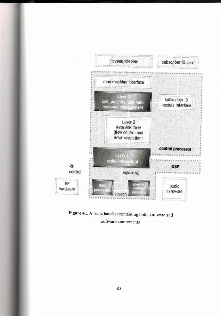
RF control
Rf harttwar'S aumo
harm~,~
Figure 4.1 A basic handset containing both hardware and
software components
85
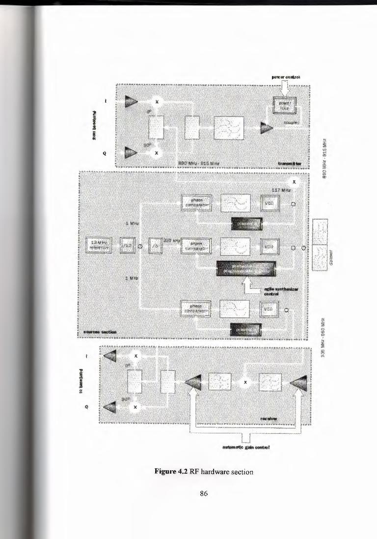
•••nr« rl
Figure 4.2 RF hardware section
86
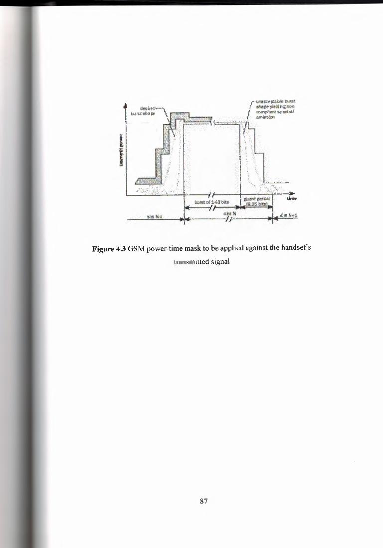
rli!'llii,:i:(':~bt:•b.1nR t -~)Jlti~l!'J::>I> , w;m~• s.l)mlit~
miiilic«ii ·.
Figure 4.3 GSM power-time mask to be applied against the handset's
transmitted signal
87
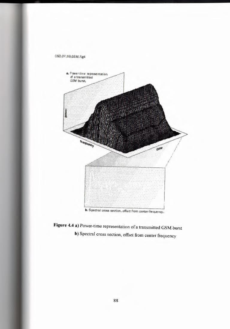
Figure 4.4 a) Power-time representation of a transmitted GSM burst
b) Spectral cross section, offset from center frequency
88
4.3 Physical Layer Protocol
Operational characteristics of the Layer 1 time-division multiple access, which handles
airlink management, channel maintenance, and cell transfers, can be difficult to verify prior
to full type approval. This discussion is devoted to understanding Layer 1 operation and
ensuring spec compliance.
Communication systems rely upon protocols for their very survival. It is with this in
mind that we turn our attention to physical layer operation in a time-division multiple
access (TDMA) system. Last month, the RF performance of a Global System for Mobile
Communications (GSM) handset was examined with attention given to hardware. Full type
approval (FT A) in Europe, a very painful process, was discussed at length in Section 4.2 -
and many of the same issues hold true for protocol testing, especially as it applies to the
physical layer, or Layer 1 (Ll). Ll is primarily responsible for airlink management,
encompassing GSM channel acquisition, channel maintenance in a hostile RF environment,
and cell transfers when the current channel becomes ineligible for use. Operational
characteristics of L 1 can be difficult to verify prior to attempting FT A. The following
discussion is devoted to understanding L 1 operation and methods of ensuring spec
compliance ( or at least building confidence in being able to pass FT A tests) [ 5].
4.3.1 The GSM airlink
GSM airlink operation can be very confusing; therefore, some of the fundamental
concepts of operation are presented in preparation for further discussion of L 1 and the
problems generally associated with this component of the handset.
Communication between the mobile handset and base station (BTS) is supported by
both a physical channel and several logical channels. The physical channel is defined by
frequency as well as by time. Two frequencies support duplex communication between the
89
mobile handset and the network, with eight repetitive time slot periods providing eight
unique access points in time (577-µs slot duration) for an equal number of mobile handset
units. This scheme is referred to as TDMA since data is sent in time-limited bursts under
strict network control. One of these slots is used for a single mobile handset, leaving the
potential for another seven mobile handsets to gain access to the network on the same
frequency pair, each using different slot assignments. Figure 4.5 portrays a typical session
whereby the BTS transmits a burst to the mobile handset within one time slot, and then
receives from the mobile handset a related burst three time slots later. In TDMA, timing is
everything for correct operation, and this poses a problem.
In the realm of mobile communications, slot timing varies as a function of distance
between the BTS and mobile handset, as a result of inherent propagation delay. Figure 4.5
shows a manifestation of timing delay and the need for active control by the network to
adjust burst timing, eliminating adjacent channel interference. A timing advance (TA) is
calculated by the BTS, sent to the mobile handset in a control message, and then used to
reposition the burst transmitted by the mobile handset.
Logical channels are multiplexed on a physical channel and form a channel
combination over a single multiframe (a frame structure defined by different logical
channels) or a group of multiframes (a group of twenty-six frames or fifty-one frames).
Two important channel combinations are· illustrated in Figure 4.6. The first channel
combination, the control channel, is broadcasted by the BTS and is unique to each cell.
Within this channel, significant amounts of network-related information are passed to the
mobile handset for its use. An activated mobile handset first searches for a suitable GSM
control channel, synchronizes to the network (in both time and frequency), extracts network
system information, and, if the cell is suitable, "camps" on that cell while searching for and
monitoring control channels of surrounding cells. Control channels are fifty-one
multiframes in length before they repeat themselves, whereas voice channels are twenty-six
multiframes in length. Length differences assist the mobile handset in monitoring control
channels of surrounding cells while in a voice call, which brings us to the second channel
combination. This combination supports the actual call with the traffic channel (TCH)
90
carrying digitized voice information. The slow-associated control channel (SACCH) is a
logical channel that contains control information necessary in the management of the
airlink.
The response time of the mobile handset to a network command sent to it on the
SACCH channel can be linked to the data structure associated with the channel itself
Figure 4. 7 illustrates the encoding of a SACCH message and its transmission in four bursts.
Data is encoded, interleaved:Jnd formatted into four bursts with each being sent in one 26-
slot multiframe. Once the fourth burst is received, the mobile handset L 1 performs de
interleaving and channel decoding and extracts a 2-byte L 1 header containing timing
advance and transmit power-level commands to be used by the mobile handset. SACCH
messages sent back to the BTS (delayed by three time slots) contain reports of values
currently being using by the mobile handset for power and timing advance.
As can be seen, the airlink requires significant effort in terms of its management, which
is generally handled by the Ll protocol. There are two basic categories of Ll operation: bit
manipulation and airlink surveillance. Bit manipulation operations are handled by the DSP;
these include data/voice encoding, interleaving, burst building/transmission, filtering, and
signal equalization. Airlink surveillance is managed by the Ll (with help from the L3) and
is responsible for cell selection, channel synchronization, timing and power adjustments,
surrounding cell monitoring, and cell handovers. Assuming that the RF hardware of the
handset works perfectly to spec, discussion will be directed toward L 1 management of the
airlink and how it can be verified before attempting FTA [5].
4.3.2 Synchronization
As discussed earlier, burst timing within the allocated slot is critical for successful
operation of TOMA systems. A major task of the L 1 is to keep its internal time base in line
with that of the signal received from the BTS; this is much different than the forced
adjustment of slot timing as presented previously. Synchronization is a graceful approach to
91
maintaining lock with the network timing standard. Deviation from the network results
from both an imperfect channel as well as diverse clock references.
Timing error (the difference between the actual and expected time of arrival of the BTS
burst) is a function of varying propagation delay as well as mobile handset reference-clock
inaccuracy. As an example, a relative 10-ppm clock error between a network and a mobile
handset results in an error of 2.71 bit-times every second (the time difference between the
network clock and the mobile handset clock increases by 2. 71 bit-time every second). This
is not good for mobile handsets using adjacent slots. To compensate for this clock
difference, L 1 estimates both signal timing and frequency error. When necessary, it adjusts
the time base accordingly to maintain synchronization with the network, in a manner
similar to that of a phase-locked loop (PLL). For timing errors greater than ±2 µs (0.54 bit
time), the time base is adjusted in steps of 1/4 bit-time at least every 2 sec (not exceeding
once every second), until the error is less than ±0.5 bit-time.
Testing this operational feature requires adjusting the BTS timing, and then measuring
the response on the mobile handset itself. The reception-time tracking speed is implicitly
measured on the transmit bursts. As mentioned, error in the phone time base will be
reflected in the timing of the transmit burst (being delayed by three burst time slots). The
FTA test method has the system tester suddenly shifting its time base by 2 bit-times; it then
records the time of arrival of the bursts transmitted by the mobile handset with the
expectation .that transmitted bursts will eventually, through incremental adjustment, align
with the expected receive time at the BTS.
A simple "home grown" test setup with some software is required to detect potential
problems in this area before going to FTA. The first step is to shift the received signal by 2
bit-times (7.38 µs), which can be done by suddenly shifting the GSM test set or shifting the
internal mobile handset time-base. Overwriting the timing correction that L 1 would apply
works effectively, resulting in the mobile handset now having a 2 bit-time receive timing
error. Both mobile handset and tester-frame interrupt signals can then be compared using
an oscilloscope, with the tester frame interrupt as the trigger. Quarter-bit time adjustments
92
of the mobile handset interrupt should be observed, every 1 sec to 2 sec until the timing
references are aligned again (approximately 8 sec later) [5].
4.3.3 Temporary reception gap
In some instances, network synchronization must be maintained even in the absence of
a GSM signal with which it is to maintain lock. It is not uncommon to have a call
established only to find that while traveling, the RF link to the BTS is lost temporarily -
perhaps as a result of being in a tunnel. The mobile handset will continue to transmit voice
to the BTS for up to 30 sec before declaring the link down and disabling the transmitter.
During the time when the BTS signal is absent, the mobile handset must ensure that
transmit burst timing is accurate to prevent interference with other mobile handsets.
Failure in this area can result from reference clock drift or erroneous time base and
frequency adjustments resulting from false receive slot measurements. During a "reception
gap," frequency error, as measured on receive slots, must be ignored. Filtering (the running
average) of the frequency and timing error is another source causal to timing drift and
should be verified.
A test setup similar to that used for investigating receive timing can be used to examine
the mobile handset's response to a reception gap lasting 30 sec or even longer. By using the
BTS simulator frame interrupt signal as a trigger, the frame interrupt of the mobile handset
can be monitored on an oscilloscope. After establishing a call and ensuring that
synchronization between the mobile handset and the network is achieved, break the RF
connection between the BTS simulator and the mobile handset. Both frame interrupt signals
should remain within 3.69 µs of one another over the duration. Transmit burst timing and
frequency error will also be recorded on the GSM test set [5].
93

4.3.4 Timing advance adjustment
The network instructs and consequently controls the mobile handset with respect to the
burst timing adjustment, counteracting the effects of propagation delay as outlined earlier.
During a call, for example, the mobile handset may receive a new timing advance value.
This value is applied on the next twenty-six slot multiframe following the reporting period.
Failure to adjust the TA on the boundary of the new frame yields a failure at FT A.
Unfortunately, there is only one piece of available test equipment capable of attempting
this measurement, the CRTC02 (GSM-BTS simulator). By collecting the protocol log as
recorded during an actual traffic session, you can examine the received burst placement (the
burst as transmitted by the mobile handset) as it responds to new TA information, as sent to
the mobile handset by the CRT02. With adjustments in the TA, bursts sent by the mobile
handset shift in position and do so on the first frame of the twenty-six slot multiframe
following a reporting period.
Transmit power adjustment by the mobile handset follows the same principle as the
timing advances. Power-level information is sent to the mobile handset via the SACCH
logical channel and is acted upon. Incremental adjustments are made for requested changes
that are very large. During FT A, the system tester verifies that these incremental power
:> changes are taken, which,· unfortunately, is the only method available to verify this
operational feature [5].
4.3.5 Cell selection and handover
Selecting an appropriate cell on which to camp and maintain a list of potential cells for
use as handover sites is one of the most challenging aspects of Ll operation. This activity is
managed during idle periods when the mobile handset is not in use ( cell reselection), as
well as during periods when the mobile handset is supporting a call (handovers).
94
Basically, L 1 begins to first assess the spectrum by scanning all channels within the
GSM band, sorting them in descending order of power level. From the list of the strongest
signals, it determines which signals are associated with the control channel and, after
reading information within this channel, makes a decision about whether it's suitable for
use. The mobile handset camps on the best cell candidate and continues monitoring a list of
surrounding cells belonging to the same network. Cell suitability is determined by whether
the following stipulations are met:
• It's a member of a particular network provider.
• It's not barred or forbidden for use by mobile handsets.
• It doesn't belong to a forbidden location area.
• Its RF signal strength is sufficient.
If all available GSM cells fail the first requirement (the network provider is not
supported), the mobile handset attempts to select any GSM cell and then enters a limited
service mode where only emergency calls may be allowed (this is determined by the
network provider). The search for a suitable cell may resume periodically, as well as upon a
user's request.
A different scenario is followed when the mobile handset is occupied in a call and is on
a traffic channel. The surrounding cells are still monitored with the intention of prioritizing
them as before; however, the transfer of the traffic channel to a new cell is initiated by the
network based on mg bile handset power and quality measurement reports sent. .on the
SACCH.
In-house testing requires the multicell capability, consisting of a serving cell and as
many as six surrounding cells. Some of the neighboring cells have to support both a traffic
channel and a control channel in the case of handover testing. Moreover, network
parameters such as output power need to be changed dynamically during test, without
interruption to the downlink BTS signal. On the mobile handset side, reports from the L 1
containing information with respect to surrounding cell activity must be made available
95

containing the control channels that are available and the signal strength of each channel
found.
To support cell selection and reselection tests, a multicell configuration can be
designed using a collection of passive RF components. Using this scheme, a single GSM
signal can be made to appear as several signals at different frequencies through the process
of mixing and combining. RF signal strength of any select channel can be adjusted
manually using a narrowband passband-filter. The ensuing results of adjusting any one of
the multiple channels should be recorded by the mobile handset under test. Deviation in the
channel radio signal strength indicator (RSSI) value should be seen, as well as a new
channel order.
This approach works well with one important caveat: Precautionary measures should
be taken with regard to the test setup. Newly generated GSM channels are replicas of the
singular input channel. Testing cell reselection with unique network defining parameters or
with different identities is impossible with this device. This setup requires that two signal
sources be synchronized to the same reference signal. This ensures that all generated
signals have the same relative frequency error. If the relative error is very different from
one cell to another, it can cause failure with respect to the L 1 synchronization algorithm
(timing and frequency error tracking) as it attempts to lock to surrounding cells. This
solution may not be perfect, but it's better than nothing. It is also less expensive than a $3.5
million FTA test system!
The previous configuration cannot be used for handover testing since an additional
traffic channel would be needed. It can be very useful, however, to test mobile handset call
activity in a more strenuous environment, with up to six surrounding cells to monitor.
Handover testing can partially be tested on several pieces of commercial equipment that
can simulate both control and TCHs. A built-out Anite system ( costing several hundred
thousand dollars) can support some of this test activity. Deficiencies or holes in the tests
can be plugged at pre-FT A while on the system tester [5].
96

4.3.6 Ingenuity
Preparation for FT A requires tenacity as well as creativity since fully capable test
systems are cost prohibitive. Through the use of existing GSM test equipment and
ingenuity, many of the basic features that are put to the test during an FT A run can
be exercised in-house to the point of at least ensuring basic operation during a full
system test in Europe. When considering the many approaches presented in this two
part series, you will have accomplished two very important tasks. Phone stability will
have been established - without it doesn't even consider attempting a pre-FTA
session. Under such conditions, results at the test facility will inevitably be very
disappointing since test verdicts will fall into the "error'' category. Pass or fail
information is what you want - not data indicating that your handset is completely
out of spec or unresponsive to the injected stimulus. Secondly, by cycling through the
basic operation of the handset - whether it be related to RF performance or LI
protocol operation - you will have become very knowledgeable about your product's
operation. While at the test facility, debugging problems in one of these two areas will
be mueh easier a:ml itte-vim1'lt faster, Q~M ha:mlset devel~~mettt ma:r be the ttuiel{est way to riches, but it's not the easiest [5].
Figure 4.5 A manifestation of timing delay
97
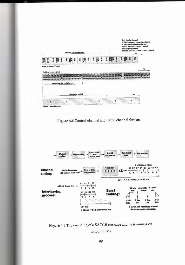
'ftlt bffi< <INnnel Fttlll\,"'-·.,,........, .•••••••••.• ~ .....,r,...,.,llioRdlwNI ace11, broM<asl. .am1r.o1 ......., PCH, !lllliil& dllnnoi u,c(II, -~ ••••••• .-..i
;;it. ,,., •... ___...
..•.. .,_. _,.,..
Figure 4.6 Control channel and traffic channel formats
Channel coding:
(;iiphj~i! {fl 11~-tK " iU Wk) '
# of lllk .-lllodc 51' 57 57 57 57 ff 5'I' :57
x.2--1 I I I I l I I I ABCOit;fGK
J
Burst building;
ff Wo lllidlniflle 5-'7 lftfii . • I t:1, bit*! I wh
ti1 t t ~ 3.1111 111111 111111 aw l!fh. ~ ~ Wt5
4 lllffb,arlf ll'K4Dll!Y ofl>·!ffllll 1h wMil; conlNII rlljltlHIP>
1:M.t;itt 4 ~. !If 114 ~fl&
Figure 4. 7 The encoding of a SACCH message and its transmission
in four bursts
98
CHAPTERS
GSM PHONE ELECTRONICS
5.1 RF Design of a TOMA Cellular/PCS Handset, (Receivers)
TIA/EIA/ANSI-136 is the applicable cellular/PCS standard in the North-American
market for dual-band time-division multiple access (TDMA)-based handsets. Presently, the
standards are being upgraded to provide a smooth transition into the third-generation (3G)
line of wireless data/voice terminals. The Universal Wireless Communications
Consortium's new UWCC-136 standard will allow multimedia capabilities and services
such as wireless Internet access in future data-centric handsets. This added functionality
translates into the need for higher bit rates and increased RF bandwidth.
The mobile station transmission frequency bands are presently allocated from 824.04
to 848.97 MHz for cellular service and from 1,850.01 to 1,909.95 MHz in the PCS band.
The mobile receiver section operates in the 869.04- to 893.97-MHz frequency range for
cellular and in the 1,930.05- to 1,989.99-MHz frequency range for PCS. The present RF
channel bandwidth is 30 kHz, with plans to extend it to 200 kHz and even to 1.6 MHz. The
200-kHz bandwidth will feature higher-order digital modulation schemes like 8-PSK to
make it compatible with future generations of TD MA-based, GSM-enhanced data rates for
GSM evolution (EDGE) data-capable handsets.
Most of today's TDMA handsets accommodate dual-band tri-mode capabilities (FM
based analog service in the cellular band, and /4 DQPSK-based digital service in both
cellular and PCS bands). The new standards set the requirements for multi-band, multi
bandwidth, and multi-timeslot operation, which will lead to more complex mobile and
basestation designs. Three critical design variables N cost, size, and power consumption N
99
will be greatly impacted. Most of the future handset designs targeted for the US market
require dual-band operation as a single operator may own spectrum in cellular and PCS
bands [6].
5.1.1 Main RF Specifications
Requirements for such a dual-band handset include a receiver sensitivity of at least -
116 dBm in analog mode (for 12 dB signal + noise + distortion/ noise + distortion [SINAD]) and -110 dBm for 3% bit error rate (BER) in digital mode (in static conditions).
The maximum input level specification is -25 dBm for 3% BER.
The transmitter output power level for a Class IV handset is limited to 600 mW
effective radiated power (ERP, referenced to a half-wave dipole). Error vector magnitude
(EVM) is a quantitative indication of the digital modulation quality. The EVM root-mean
square (RMS) value is specified to be 12.5% maximum.
The adjacent channel (fc ± 30 kHz)/altemate channels (fc ± 60/90 kHz) power ratio
(ACPR) specifications reflect the transmitter's linearity (fc is the desired RF channel
frequency). Emission power levels should not exceed -26 dBc and -45 dBc for adjacent and
alternate channels, respectively [6].
5.1.2 Handset Block Diagram
A block diagram that illustrates the main functional blocks in a typical handset is
shown in Figure 5.1. From a hardware standpoint, two main sections become apparent: the
logic and the transceiver sections. The latter is the radio section of the handset.
The logic section includes a microprocessor, DSP baseband processor, memory,
display, power management functions, and the vocoder. On the transmit side, the purpose
100

of the logic section is to efficiently digitize the voice in terms of bit rate (this example uses
a 7.4-kbps algebraic code-excited linear prediction [ACELP] algorithm), to provide
channel-coding functions and to provide the digital modulation I&Q baseband signals for
the transceiver. The logic section receive side provides channel filtering
equalization/decoding and ACELP speech decoding. The resident software serves the call
processing and user interface functions [6].
5.1.3 RF Module Description
The RF module's basic objectives are to modulate high-frequency RF carriers with the
analog and I&Q digital signals coming from the handset's baseband section, and to
demodulate the received analog and/or digitally modulated RF signals.
Four functional sections can be identified in a typical dual-band RF module: the front
end, the receiver, the frequency synthesizers, and the transmitter (see Figure 5.2).
Dual paths for the RF signal down-conversion to a common intermediate frequency
(IF) in the cellular and PCS bands receive sections, and dual paths for the transmitting
section can be clearly seen in the dual-conversion receive and transmit architecture depicted
in Figure 5.2 [6].
5.1.4 Antenna and Front-End Sections
A common antenna serves both receive and transmit operations in both bands. Design
compromises for dual-band operation focus on antenna gain, radiation patterns, and a
common matching network.
101
The received signal from the antenna is routed through the low-pass filter section of the
input diplexer for the cellular band operation. The PCS band transmit and receive paths are
served through the high-pass filter section of the diplexer.
The diplexer separates the cellular and PCS bands, while the duplexer separates the
transmit and receive sections in the cellular band. This leads to different frequency
selectivity requirements (such as different insertion losses, size, and cost).
In the cellular band, the duplexer's jobs are:
Preventing transmitter noise in the receive band from desensitizing the receiver in the full
duplex analog mode.
Attenuating the power amplifier (PA) output signal to avoid driving the low-noise amplifier
(LNA) into compression.
Attenuating the receiver's spurious responses (first image and others).
Attenuating first local oscillator (LO) feed-through using the first mixer LO-RF ports.
Attenuating transmitter output harmonics and other undesired spurious products.
The receiver's (broadband) frequency selectivity is shared between the duplexer and
the image filter, with trade-offs in terms of size and insertion loss.
The PCS receiving, path is different from the cellular path. Instead of a duplexer, a
transmit-receive (T/R) switch is provided. This is feasible because of the present digital
half-duplex mode of operation in the PCS band (nonsimultaneous receive and transmit
functions). Future digital-mode multi-timeslot operation will mandate, in some operating
modes, simultaneous transmit and receive operation. Thus, the use of a duplexer in the PCS
band will be required [ 6].
102
5.1.5 Receiver
The receiver is based on a double-conversion, superheterodyne architecture that
provides, at a relatively low cost, the high dynamic range and selectivity required for this
application .
. The LNA's main purpose is to increase the level of the weak incoming RF signal
without significantly degrading the signal-to-noise ratio (SNR) and without introducing
nonlinearities that generate undesired intermodulation products. Two different LNAs with a
one-step attenuation gain control are shown, one for each band (see Figure 5.2). Under
strong-signal conditions, this reduction in gain prevents overloading the active stages,
The LNA output signal is routed through a 25-MHz-bandwidth bandpass filter that
provides additional attenuation for the first image, signal image noise, and other receiver
spurious responses in the cellular band. In the PCS band, the LNA is preceded and followed
by two 60-MHz bandwidth image filters. Careful attention must be paid to the LNA output
mixer RF input isolation to avoid degradation of the first image rejection.
The received RF signals are then routed to the first mixers (Ml-PCS and Ml-CELL)
where they are down-converted to a common first IF. In a practical scenario, only the
selected band receiver front end is powered up, to minimize power consumption.
The first IF filter is generally a 30-kHz narrowband surface acoustic wave (SAW) filter
with a center frequency typically above 100 MHz. Steep out-of-band attenuation and
amplitude and phase linearity in the pass band are important. The second image rejection is
determined by this filter. Its out-of-band attenuation characteristics contribute to the
alternate channel rejection (fc ± 60 kHz) and the receiver's overall intermodulation (IM)
performance. The IF signal is then applied to the input of the second mixer (M2), which
provides the final down-conversion to the last IF (typically 450 kHz).
103
The second IF filter is generally a 30-kHz narrowband ceramic filters with a 450-kHz
center frequency. Its steep attenuation allows it to meet the adjacent/alternate channel
rejection specifications. Good amplitude and group delay characteristics in the pass band
are required to avoid degrading the BER in digital mode.
The 450-kHz output signal is split and fed into:
FM IF amplifier, limiter, quadrature demodulator, and received signal strength indicator
(RSSI) sections.
The automatic gain control (AGC) and I&Q demodulation stages.
In analog mode, the received signal is frequency demodulated to produce the base band
audio signals: supervisory audio tone (SAT), signaling tone (ST), and wideband data
required for call setup and control. The RSSI provides a de voltage output proportional to
the received signal strength. This information can be used to determine such things as the
strongest channel for mobile-assisted hand-off operations (MAHO) and signal strength.
In digital mode, the p/4 DQPSK digitally modulated signal is demodulated into its base
band I&Q components, respectively. The demodulated audio signals, RSSI, and the digital
mode I&Q demodulated signals are digitized in the handset logic section for further
processing in the digital domain.
Both front-end and second IF gain-controlled stages keep the receiving chain linear in
digital mode across an input signal range of about -115 dBm up to -25 dBm (90 dB
dynamic range). This configuration keeps the I&Q demodulated signal amplitudes to a near
constant level that properly fits within the available ADC dynamic range.
The down-conversion to base band can be implemented with a 450-kHz third LO
signal provided by the synthesizer section (L0#3) [6].
104
5.1.6 Receiver Design Trade-Offs
Design trade-offs for the receiver include:
Discrete versus integrated front ends (LNAs, mixers, and LO buffers). The discrete
option allows the designer to tailor the gain, noise figure (NF), third-order input intercept
point (IIP3), and power consumption for optimum performance, at the expense of increased
parts count and size. Printed circuit board (PCB) component placement also becomes more
flexible in a discrete design approach. An integrated RF ASIC reduces development time,
but the final cost may be higher because of lower RF IC yields, packaging limitations, RF
isolation, and testing issues.
The RF gain distribution is implemented in order to achieve an optimum dynamic
range (IIP3/NF trade-off).
A higher IIP3 leads to higher current consumption (shorter standby time). Good strong
signal performance is of paramount importance in a mobile cellular environment.
Use of shared components in both frequency bands reduces parts count, size, and cost, but
increases the difficulty of optimizing the performance in each band independently [6].
5.1. 7 Receiver Architectures
Two basic receiver architectures are available: superheterodyne and direct conversion
(or low-IF). The latter architecture eliminates the IF stages, mixers, filters, and associated
LOs, providing the flexibility to accommodate different bandwidths and standards.
Direct conversion has potential advantages in terms of reducing cost, PCB real estate,
and power consumption. However, its present performance for TDMA applications (with
the non-unity peak-to-average power ratio envelope p/4 DQPSK modulation format) lags
behind the time-proven superheterodyne topologies that allow excellent dynamic range and
105

selectivity, with shorter and less risky development cycles for a given performance level.
Disadvantages of the superheterodyne approach are a high parts count and integration
difficulties due to the high-Q filters, which should be placed off-chip.
A practical direct conversion approach requires the efficient resolution of several
issues: time-varying de offsets, LO leakage through the antenna, gain/phase matching and
second-order nonlinear distortions in the down-converting quadrature mixers, and proper
operation under the TDMA dynamics [6].
5.1.8 Receiver Spurious Responses
The main purpose of an RF receiver is to receive the desired signal while at the same
time rejecting undesired (spurious) signals that can be present at the receiver input at much
higher power levels.
The three most important receiver spurious responses are the 1st Image, 2nd Image,
and Half-IF. Undesired strong RF signals at certain frequencies can cause serious
degradation in the BER or SINAD. In severe cases they can lead to dropped calls. Their
frequency location is explained in Figure 5.3, Figure 5.4, and Figure 5.5. A numeric
example is added to help clarify the topic. Two factors determine their frequency location:
the receiver frequency plan and the desired tuned channel frequency. A significant part of
the receiver design is eliminating or attenuating these undesired signals. The filters'
attenuation requirements and the first mixer linearity specifications are dictated by the
required level of spurious suppression.
In the 1st Image, a desired low-level RF signal at 1,930 MHz is down-converted to a
100-MHz first IF with a first LO set at 2,030 MHz (see Figure 5.3). An out-of-band strong
undesired signal at 2,130 MHz is also down-converted to the 1st IF, because the difference
between the LO and this interfering RF signal is also 100 MHz. The frequency location of
the 1st Image is 2,130 MHz in this particular scenario. The only way to attenuate this
106
strong undesired signal is by providing enough selectivity in the two front-end filters. A
higher first IF will also help. In certain cases, a narrowband LNA also contributes to reject
the 1st Image response.
In the 2nd Image, the same frequency plan (LO and IF frequencies) as illustrated in
Figure 5.3 is used (see Figure 5.4). An out-of-band strong undesired signal at 1930.9 MHz
is down-converted to the first IF stage as a 99.1-MHz signal (99.1 = 2,030 G 1,930.9). The desired signal is down-converted to 100 MHz. Both the desired (100 MHz) and the
undesired signal (99.1 MHz) will be mixed with the fixed L0#2 (99.55 MHz) down to 450
kHz. This will degrade the carrier-to-interference (C/I) ratio. The RF frequency location of
the 2nd Image is 1930.9 MHz in this particular scenario. The only way to attenuate this
strong undesired signal is by providing enough attenuation in the first IF filter (more than
60 dB at 99.1 MHz in this example). In most cases, this high level of attenuation is
provided by a single SAW IF filter. To meet this difficult requirement, close attention must
be paid to the PCB layout design around this filter to provide high isolation between the
filter's input and output ports. Otherwise, the resulting IF filter + PCB total attenuation might not be enough to achieve the required attenuation level.
The Half-IF spurious response is sometimes very troublesome to attenuate (see Figure
5.5). Its RF frequency location is half the first IF frequency (50 MHz) away from the
desired signal. In the numerical example, it is located at 1,980 MHz, because the desired
signal is at 1,9.30 MHz and the IF is 100 MHz. The two RF filters cannot attenuate it
because this frequency falls in their pass band region.
The first mixer's LO is set at 2,030 MHz. Its second harmonic is 2 x 2,030 = 4,060
MHz. The RF undesired signal (Half IF) second harmonic is located at 3,960 MHz (2 x
1980). The mixing ( difference product) of both LO and RF second harmonics leads to a
new (undesired) 100-MHz IF signal that will interfere with the desired IF signal. The level
of this (2,2) fourth-order product (2 x LO G 2 x RF) is determined by the first mixer's
second-order intercept point (IP2).
107
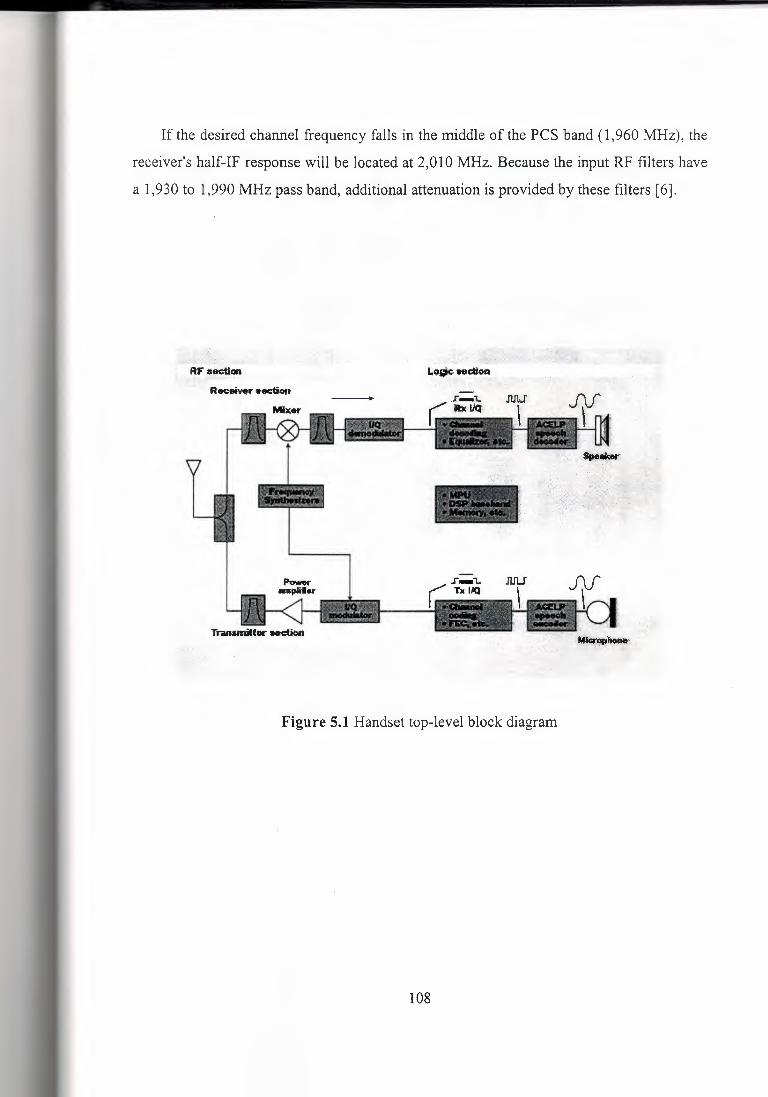
If the desired channel frequency falls in the middle of the PCS band (1,960 MHz), the
receiver's half-IF response will be located at 2,010 MHz. Because the input RF filters have
a 1,930 to 1,990 MHz pass band, additional attenuation is provided by these filters [6].
Rf' aec;tion
Figure 5.1 Handset top-level block diagram
108
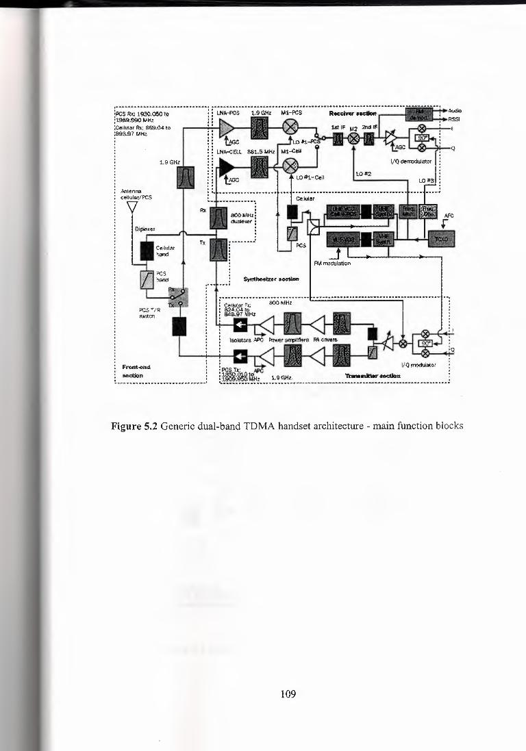
•••••••• .;o. ••.••. ;,o ••••••••••••• ,I;,¥ .•••.••.••••.••.•••••••••••••.••.••
.:PCS~;; i930.COOto :19B9.990 MHl! :C<Jrn~•t ~ 813$.04 IQ :Slta97MHz .
1.9 GHZ
Mt¢nm -::fjjlulal(/i'CS
\J
•PCS l'./R 8'"''.td1
Front,,omt : ~n :. ,. ¥ .. ,.,.. .. _ ...• _ ,.. .. ,,. "'"'"' ·-·· .. ~
•. .,; ••..••.••.•••.•.•••••••••••••••••.••.•.••.•••••.•••••••• ·"' .••.••••••••.••••••.•••• lll ••.•••.••••.•.••••••.••• "'"" lf, .••.•••••••••..• "'""" ••••••.••. , .•••••••..•.•• ,. i . ----· .
: .....••... ,,. .• , ... ,. ,. . ~"'1\1Jf,: a.J:97 L~Hz
I
Figure 5.2 Generic dual-band TDMA handset architecture - main function blocks
109

t st li'iilp f'tflPll1cy •So+2xll'1 ,; 1,930 + 2 x 100 MHz 2,130MHz
CJft ihacild 1M g,Mt.r than -10 dB Cfor 3'"4 8ER)
1,S3QMl-tt dB8ired ;:l'.;S RF sigt\!\1 (SD) -:ID.2 dBm
v:.>1 :2,030 MHz
t.O:.t <;i9.55MHz
Figure 5.3 First image receiver spurious response concept
.,.,,
}';_· '';:~tmago,RF froquoncy =S'b +Zx4F2 = t,930·· + 2 x 4S~HcH'z 1,PO;$J MHz
CIR' shollld bo· PNier .thal ~tOd8•lfl:i4"13.l'.<\o BER>
-45 dBm
1..B<JO MHZ desired ?\'.:S RF SiZOO (S (;j -10.2dBrr l01
2,030MHz
!Fi 10'.J MH? 130 kl-tz:8,\1)
I U):2
99.55 MHz
F«ll'lt".end,J>a~sslifte(S,. £,~.;00Jn,t989;00,Mfiz, (app.roit ·oo MH.z;:.oa~k!tl'I)..
Figure 5.4 Second image receiver spurious response concept
110
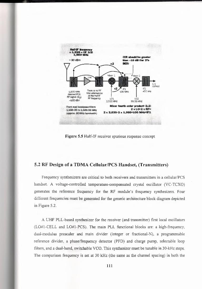
OI.R,lhoudbo gr,e«Wr 1batt ~10'd8(for :I% BER)
1.930 MHz desir&dP'~ RF:S~(SD) -tm®rr
'ft-Era IS ro RF filler atterruah::.-1 at1heHaff4f RF ~n,,-y. lD1
2,030MHz L{)2
!:'f3.f.6MH!
MJ:i(ar ·~corder, ~(2;:Zh 2'x,t.<>-2·:irRF.ii;;,
2x :z,.030,,2•,c 1,9:80=1®1MHzrlf,;·fJ
Figure 5.5 Half-IF receiver spurious response concept
5.2 RF Design of a TOMA Cellular/PCS Handset, (Transmitters)
Frequency synthesizers are critical to both receivers and transmitters in a cellular/PCS
handset. A voltage-controlled temperature-compensated crystal oscillator (VC-TCXO)
generates the reference frequency for the RF module's frequency synthesizers. Four
different frequencies must be generated for the generic architecture block diagram depicted
in Figure 5.2.
A UHF PLL-based synthesizer for the receiver (and transmitter) first local oscillators
(LO#l-CELL and LO#l-PCS). The main PLL functional blocks are: a high-frequency,
dual-modulus prescaler and main divider (integer or fractional-N), a programmable
reference divider, a phase/frequency detector (PFD) and charge pump, selectable loop
filters, and a dual-band, switchable VCO. This synthesizer must be tunable in 30-kHz steps.
The comparison frequency is set at 30 kHz (the same as the channel spacing) in both the
111
cellular and PCS bands when an integer main divider is used. It must provide a fast lock-in
time (less than 2 ms) with low phase noise and spurious levels. Its performance impacts the
transmitter's error vector magnitude (EVM) and the receiver alternate channel selectivity,
among other key specifications. Some output filtering is provided to avoid degradation of
the receiver sensitivity caused by broadband noise. There are a total of 832 channels in the
cellular band and 2,000 in the PCS band. Physical size, power consumption, and cost are
also important design considerations.
A VHF PLL-based synthesizer for the transmitter's IF offset LO. The VHF synthesizer
handles the 45-MHz offset between the cellular transmit/receive frequencies and the 80.04-
MHz offset in the PCS band.
Two additional fixed-frequency synthesizers provide the receiver's second and third
local oscillators (L0#2 and L0#3).
A VC-TCXO generates the reference frequency for the TRX module. In digital mode,
the output transmit frequency is tightly maintained within ±200 Hz of the received
frequency by using an automatic frequency control (AFC) closed-loop approach under
software control [6].
5.2.1 Frequency Synthesizer Design Trade-Offs
For frequency synthesizers, different PLL bandwidths in analog to digital modes and in
cellular/PCS bands are chosen to obtain the best possible performance trade-off. The loop
filter transfer function is a critical factor in defining the loop bandwidth, which in tum
defines the compromises between the single sideband (SSB) phase noise profile ( or RMS
phase error), spurious levels, and lock-in time.
In digital mode, a fast lock-in time of less than 2 ms is required to satisfy mobile
assisted hand-off operation (MAHO) requirements as indicated for the main UHF
112

synthesizer. This requires a wide loop bandwidth (at least a couple of kHz). To achieve a
low EVM, the total RMS phase error has to be minimized. The loop bandwidth must be
adjusted to meet this goal. A loop bandwidth that is too wide will lead to a high level of
spurious sidebands and a reduced PLL phase margin (potential instabilities).
In analog mode, the UHF synthesizer requires:
A VCO with extremely low phase noise at ±60-kHz carrier offset (better than -105 dBc/Hz)
to achieve an adequate receiver al-ternate channel rejection (60 dB or more)
A slightly narrower loop bandwidth to achieve a low level of comparison frequency-related
output spurious products, while still meeting the lock-in time requirements in channel-scan
mode.
In the presented architecture, the transmitter's frequency modulation (in analog mode)
is implemented by directly modulating the VHF PLL by voice, supervisory audio tone
(SAT), signaling tone (ST), or wideband data. A narrow loop bandwidth is required to
achieve a relatively constant FM deviation down to the lowest audio frequencies to be
transmitted ( about 300 Hz). The trade-off is a long lock-in or settling time. Alternatively, a
direct I&Q FM approach can be used [ 6].
5.2.2 The Transmitter
The dual-band transmitter section should be able to provide a nominal output power
level at the antenna output port of +27.8 dBm in the cellular and the six PCS sub-bands in
both analog (FM) and digital modulation formats (/4 DQPSK and, in the future, 3/8-offset
8-PSK modulations).
An indirect quadrature modulator performs the RF carrier modulation by the I&Q
baseband input signals and up-conversion to the output transmit frequency. The intended
transmit frequencies are available at the output of this last up-conversion. Both LO hlHF
and VHF frequencies generated in the synthesizer section are used for the above two
purposes.
113
The I&Q modulator amplitude/ phase quadrature accuracy and linearity characteristics
determine the resulting EVM. In the block diagram, the following stages and the power
amplifier (PA) also add some degradation to the EVM (see Figure 5.2).
A voltage gain-controlled amplifier (VGA) of approximately 45 dB follows the I&Q
modulator and up-converting mixer. This control range is adequate to set the nine different,
required RF output power levels in digital mode. Maximum RF levels of about -10 dBm are
typically obtained at its output. A total net gain of at least 40 dB must then be provided by
the diplexer, the SAW bandpass filters, the PA driver, and the PA to get at least+ 30 dBm at
the PA output.
A diplexer is placed at the I&Q modulator output to provide band separation. The
cellular band FM and /4 DQPSK modulated RF signal are then routed into the SAW filters,
the PA driver, and the PA.
The bandpass filter's purpose is to reject spurious frequencies and attenuate noise in
the 869- to 894-MHz receive band to prevent receiver desensitization in full-duplex analog
mode. This desensitization is the result of insufficient isolation between the duplexer's
transmit (Tx) and receive (Rx) ports.
Output spurious frequencies (such as the sum product) must be attenuated further down
in the transmit chain to avoid exceeding FCC conducted emissions regulations, which allow
a maximum output level of about -13 dBm. Emissions levels in the receive band must be
kept below the -80-dBm limit in cellular and PCS bands.
PA drivers fixed-gain stages are required to provide enough gain and linearity to drive
the output P As. After a second bandpass filter (BPF) stage (generally a SAW -based device) ' the PAs are shown (see Figure 5.2). They provide a maximum output power of about +30
dBm in both bands.
114
The automatic power control (APC) loop keeps the output power levels within the
tolerances prescribed in the standard (within +2/-4 dB for the eight upper output power
levels). Its operation is based on a negative-feedback-loop system that compares the RF
detected level with a reference voltage generated in the base band logic section. This
reference voltage allows the selection of the nine different, required RF power levels. The
APC loop transient behavior and compensation for output power variations across
frequency bands and under environmental conditions should also be considered.
Other components of the transmitter include isolators, which prevent potential damage
to the PA under antenna-induced high voltage standing-wave ratio (VSWR) conditions and
alternate channel power ratio (ACPR) degradation caused by reflected RF energy, and a
low-pass filter for attenuating harmonics in the PCS path [6].
5.2.3 Transmitter Design Trade-Offs
Several sometimes-conflicting requirements must be considered in the selection of both
the architecture and parts of the transmitter. For example, very strict linearity (ACPR)
requirements in digital mode conflict with the need for a high power-added efficiency
(PAE) in the PA; the latter is critical to providing an extended battery life (40% efficiencies
are typical in the linear digital mode and over 50% in analog mode). The present 33% duty
cycle in TDMA mode compensates for the lower efficiency in linear mode.
In addition to these requirements, the PA selection process must factor in whether or
not the design must use a MOSFET drain/collector switch, a V gg negative supply-voltage
generator for GaAs MESFET/pHEMT devices as opposed to single-supply devices like
GaAs HBTs, and the availability of on-chip output matching networks. Of course, PCB
space and cost are always important considerations.
A transmit/receive switch can be used instead of a duplexer in TDMA half-duplex
mode, yielding smaller after-PA insertion losses and significant PCB space savings.
115
Future operation under the General Packet Data Radio Service (GPRS) standard with
multi-timeslot data will require, in certain cases, extended PA duty cycles with a
corresponding power consumption increase. This requirement will impact the new wireless
data terminal's battery life, and attention must be paid to the packaging and related thermal
issues [6].
5.2.4 Handset TRX Frequency Plan
Many factors determine the handset receiver and transmitter optimum frequency plan.
From the receiver standpoint, the goal is to· keep the receiver spurious responses far away
from the passband (which makes it easier to attenuate). This strategy leads to simpler front
end filters with lower insertion loss, reduced cost, and smaller size. A higher first IF
simplifies the l " and Half-IF image rejection problem, but a larger and more expensive IF
SAW filter might be required.
Readily available standard parts like filters and VC-TCXOs usually lead to a lower
cost solution. The frequency plan also affects the level of transmitter output spurious
products and the associated filtering requirements [ 6].
5.2.5 RF Module Integration
Regarding active parts integration, efforts are being carried out in several areas:
developing dual- band receiver integrated front ends; putting dual-band PAs in the same
package; and incorporating the transmitter I&Q indirect modulator, the voltage gam
controlled amplifiers, the PA drivers, and the dual synthesizers on the same chip.
A fully integrated solution (putting a receiver-synthesizer and transmitter into a single
ASIC, with the possible exclusion of the PAs and LNAs) is not the best approach. A set of
two RF ASICs is a more effective and versatile solution than the "radio-on-a-chip without
passive parts" approach. PCB layout routing becomes easier in a properly partitioned
116
transceiver, and simplifies addressing critical RF isolation/shielding problems during the
RF module integration stage. Also, lower-risk development cycles are achieved. A two
chip approach would only incorporate a single ASIC for the receiving section (this can be
replaced by a direct conversion architecture in the future), and a second IC to provide the
frequency synthesis and transmitter functionality.
Currently, a large number of passive parts (over a couple of hundred for a typical dual
band TOMA RF module) can be found in transceivers. Clearly, further integration requires
solving the passive parts integration problem in a cost-effective manner that is compatible
with today's extremely short development schedules.
Several manufacturers are striving to reduce the packaging siz.e of VCOs, filters,
isolators, and SAW duplexers. They are also trying to reduce the footprint of standard
components like resistors, capacitors, and inductors. Many 0603 package sizes have been
shrunk to 0402 and some to the microscopic 0201 (0.5 x 0.25 mm) size.
Looking into the future, promising developments have been reported in the areas of
low-temperature co-fired cera- mic (L TCC) RF modules and micro-electromechanical
(MEMs) devices that incorporate high-Q filters and RF switches. The most effective
solution is a moving target: it will be a combination of forthcoming new standards
requirements, transceiver architectures, and the availability, performance, and cost of new
active and passive parts. Wider-bandwidth services, higher integration, lower power
consumption, lower cost, and better performance will ensure that the RF design of future
TDMA handsets will remain ever more challenging [6].
117
CONCLUSION
As of my project was about the general cellular hardware architecture working mechanism and general layout.
It goes without saying that the development of the broad band and the revolution of
microchip opened up new horizons for the GSM industry to step out of their boundaries and
become global to meet the grounding demand of the market.
The current cellular hardware systems are fully equipped with all the technicalities to
integrate within the GSM operators aboard to create international roaming, messages,
internet, and e-mail services which gives all the research in technological and services
sectors, it demands high level of expertise in different fields because of complex nature.
By the data collected by internet, I have found that now more than half of the world is
using GSM cellular handsets and others are using different like wise Dual GSM, NMT 450,
NMT 900 Networks compatible handsets. The development of GSM is the first step
towards a true personal communication system that will allow communication anywhere,
anytime, and with anyone. The functional architecture of GSM, employing intelligent
networking principles, and its ideology, which provides enough standardization to ensure
compatibility, but still allows manufacturers and operators freedom, has been widely
adopted in the development of future wireless systems.
Moreover, I have found that the supplier of base-station and switching system can be of
different. As in Turkey there are three main operators Turk Telecom, Telsim, Turkcell and
for that they are using Nokia, Motorola and Ericsson.
Turk Telecom is using Nokia's base-station and its switching system, while the Telsim
is using Nokia's switching system and Motorola's base-station. Also the Siemens base
stations and switching systems are famous and still using by many countries.
118
REFERENCES
[1] http://www.mobileworld.org
[2] http://www.ou.edu/engineering/emc
[3] http://www.iec.org/tutorials/smartcard
[ 4] http://www.comms.eee.strath.ac.uk/-gozalvez/gsm
[5] http://www.csdmag.com
[6] http://www.uwcc.org/edge/articles
[7] D900 Mobile Communication System SIEMENS catalogue.
[8] Kennedy, Davis, Electronic Communication Systems, McGraw-Hill International,
New York, 1994.
[9] Schilling, Taub, Principles of Communication Systems, McGraw-Hill International,
New Jersey, 1969.
[10] Rice, Modem Electronic Communication, Prentice Hall books company,
New York,1993.
[11] Calhoun G., Digital Cellular Radio, Artech House, 1988.
[12] Hadden A., "Development of the DCS 1800 standard". Proceedings of the Mobile
Radio Conference, Nice, November, 1991.
[13] Rhee Man Young, Cellular Mobile Communications and Network Security, Prentice
Hall International Editions, 1999.
[14] "Telsim", Cellular Company (Technical Notes).
119


![I ll]~!IJ.IIJ,!11~ 11 - Near East University Docs](https://img.pdfslide.net/doc/110x75/633bf42df16ef4e656016483/i-llijiij11-11-near-east-university-docs.jpg)


