Embed Size (px)
Citation preview
RPI-FSN6-EFRPI-FSN3(P)E(-f)
–SERVICE MANUAL
–INDOOR UNITS SYSTEM FREE SERIES& COMPLEMENTARY SYSTEMS
SMGB0137 rev.0 - 05/2021
MODELS
SYSTEM FREE
RCI-FSR RCIM-FSRE
KPI-(E/X)4EDX-Interface - EXV-E2Econofresh - EF456FSN6E
COMPLEMENTARY SYSTEMS
RCD-FSRRPC-FSR
RPK-FSR(H)MRPF-FSN2ERPFI-FSN2E
RPI(L/H)-FSRE

Contents
SMGB0137 rev.0 - 05/2021I
123456789
C o n t e n t s
General information
Optional accessories
Electrical and control settings
Control system
Optional functions
Commissioning
Servicing
Troubleshooting
Maintenance notes

General Index
SMGB0137 rev.0 - 05/2021III
General Index
1. General information ................................................................................................... 11.1 General information .................................................................................................................................2
1.1.1 Introduction ...................................................................................................................................................... 2
1.2 Applied symbols ......................................................................................................................................3
1.3 Norms and Regulations ...........................................................................................................................3
1.4 Productclassificationandline-up ............................................................................................................41.4.1 Classificationofindoorunitmodels ................................................................................................................. 41.4.2 ClassificationofKPImodels ............................................................................................................................ 41.4.3 ClassificationofDX-Interfacemodels ............................................................................................................. 41.4.4 ClassificationofEconofreshmodels ............................................................................................................... 41.4.5 Productline-up:indoorunits ............................................................................................................................ 51.4.6 Productline-up:KPIenergyrecoveryunit ..................................................................................................... 101.4.7 Productline-up:DX-Interface ........................................................................................................................ 101.4.8 Productline-up:Econofresh .......................................................................................................................... 101.4.9 Accessory code list .........................................................................................................................................111.4.10 Multi-Kits ...................................................................................................................................................... 131.4.11 Individualremotecontrols ............................................................................................................................ 131.4.12 Receiverkitforcombinationwithwirelessremotecontrolswitch ................................................................ 141.4.13 Centralised remote controls ........................................................................................................................ 151.4.14 Building air conditioning controls ................................................................................................................. 151.4.15 Gatewaysforbuildingmanagementsystems(BMS) .................................................................................. 161.4.16 Controlsupportdevices ............................................................................................................................... 171.4.17 Control accessories ..................................................................................................................................... 17
2. Optional accessories ............................................................................................... 192.1 Ductadapter-Outdoorairinlet .............................................................................................................20
2.1.1 ForRCI-FSRindoorunits:OACI-160K2andPD-75A ................................................................................... 202.1.2 ForRCIM-FSREindoorunits:PD-75C .......................................................................................................... 232.1.3 ForRCD-FSRindoorunits:PD-150D ........................................................................................................... 24
2.2 T-ductconnectionposition.....................................................................................................................252.2.1 ForRCI-FSRindoorunits:TKCI-160k ........................................................................................................... 25
2.3 Branchpipe(PDF-71C,PDF-160CI) .....................................................................................................26
2.4 Outletairflowinterlock ..........................................................................................................................272.4.1 ForRCI-FSRindoorunits:PI-160SL1 ........................................................................................................... 27
2.5 Filter box................................................................................................................................................292.5.1 ForRCI-FSRindoorunits:B-160H2 .............................................................................................................. 292.5.2 ForRCD-FSRindoorunits:BD-90HandBD-160HD ................................................................................... 30
2.6 Anti-bacteriafilter .................................................................................................................................312.6.1 ForRCI-FSR:F-160L-K ................................................................................................................................ 312.6.2 ForRCD-FSRindoorunits:F-90MD-K1andF-160MD-K1(Antibacteriallonglifeairfilter) .......................... 32
2.7 Deodorisingfilter ...................................................................................................................................322.7.1 ForRCI-FSRindoorunits:F-71L-D1andF-160L-D1 ................................................................................... 32
General Index
SMGB0137 rev.0 - 05/2021IV
2.8 AirInletDirectionChange .....................................................................................................................342.8.1 ForRPI(L/H)-(0.4-6.0)FSREunits ................................................................................................................. 34
2.9 Disconnectabledrainpump ...................................................................................................................352.9.1 ForRPIL-(0.4-1.5)FSREunits ....................................................................................................................... 35
3. Electrical and control settings ................................................................................ 373.1 Unitelectricalwiringandconnection .....................................................................................................38
3.1.1 Transmissionwiringbetweenoutdoorandindoorunit .................................................................................. 383.1.2 ElectricalconnectionofRCIunits .................................................................................................................. 383.1.3 ElectricalconnectionofRCIMunits ............................................................................................................... 403.1.4 ElectricalconnectionofRCDunits ................................................................................................................ 423.1.5 ElectricalconnectionofRPCunits ................................................................................................................ 443.1.6 ElectricalconnectionofRPIunits .................................................................................................................. 453.1.7 ElectricalconnectionofRPKunits ................................................................................................................ 493.1.8 ElectricalconnectionofRPF(I)units ............................................................................................................. 523.1.9 ElectricalconnectionofKPIunits .................................................................................................................. 543.1.10 Econofreshelectricalwiringconnection ...................................................................................................... 553.1.11 DX-Interfaceelectricalwiring ....................................................................................................................... 56
3.2 SettingofDIPswitchesandRSWswitches ..........................................................................................59
3.3 Wiringdiagrams ....................................................................................................................................623.3.1 RCI-(1.0-6.0)FSR .......................................................................................................................................... 623.3.2 RCIM-(0.4-2.5)FSRE ..................................................................................................................................... 633.3.3 RCD-(0.8-6.0)FSR ......................................................................................................................................... 64
3.3.3.1 RCD-(0.8-3.0)FSR ........................................................................................................................... 643.3.3.2 RCD-(4.0-6.0)FSR ........................................................................................................................... 65
3.3.4 RPC-(1.5-6.0)FSR ......................................................................................................................................... 663.3.5 RPI(L/H)-(0.4-6.0)FSRE ............................................................................................................................... 673.3.6 RPI-(4.0-6.0)FSN6E-EF ................................................................................................................................ 683.3.7 RPI-(8.0/10.0)FSN3E(-f) ................................................................................................................................ 693.3.8 RPI-(16.0/20.0)FSN3PE(-f) ........................................................................................................................... 703.3.9 RPK-(0.4-1.5)FSRM ...................................................................................................................................... 713.3.10 RPK-(0.4-1.5)FSRHM ................................................................................................................................. 723.3.11 RPK-(2.0-4.0)FSRM .................................................................................................................................... 733.3.12 RPF(I)-(1.0-2.5)FSN2E ............................................................................................................................... 743.3.13 KPI-(252-2002)E4EenergyrecoveryunitandKPI-(502-1002)X4Eactiveunit ........................................... 753.3.14 DX-InterfaceEXV-(2.0-10.0)E2 ................................................................................................................... 76
4. Control system ......................................................................................................... 774.1 PrintedcircuitboardsforRCI-FSRindoorunits(PI153) .......................................................................78
4.2 PrintedcircuitboardsforRCIM-FSREindoorunits(PI153) ..................................................................79
4.3 PrintedcircuitboardsforRCD-FSR(PI153) .........................................................................................80
4.4 PrintedcircuitboardforRPC-FSR(PI153) ...........................................................................................81
4.5 PrintedcircuitboardforRPI(L/H)-(0.4-6.0)FSRE(PI161) .....................................................................82
4.6 PrintedcircuitboardforRPI-(4.0-6.0)FSN6E-EF(PI114-PI117) ...........................................................83
General Index
SMGB0137 rev.0 - 05/2021V
4.7 PrintedcircuitboardforRPI-(8.0-20.0)FSN3(P)E(-f)units(PI065-PI005) ............................................84
4.8 PrintedcircuitboardforRPK-FSR(H)Munits ........................................................................................854.8.1 ForRPK-(0.4-1.5)FSR(H)M(PI151-PI154) ................................................................................................... 854.8.2 ForRPK-(2.0-4.0)FSRM(PI151-PI154) ........................................................................................................ 86
4.9 PrintedcircuitboardforRPF(I)-FSN2Eunits(PI073) ...........................................................................87
4.10 Printed circuit board for complementary systems .................................................................................884.10.1 PrintedcircuitboardforKPI(PI073) ............................................................................................................ 884.10.2 PrintedcircuitboardforDX-Interface(PI073) ............................................................................................. 89
4.11 Safetyprotectionandcontrol.................................................................................................................90
4.12 Indoorelectronicexpansionvalvecontrol .............................................................................................91
4.13 Thermistor .............................................................................................................................................92
5. Optional functions ................................................................................................... 935.1 Indoor units input and output signals.....................................................................................................94
5.1.1 Availableports ............................................................................................................................................... 945.1.2 Optionalsignalconfiguration ......................................................................................................................... 965.1.3 Programmingwithremotecontroller ............................................................................................................. 985.1.4 Descriptionofoptionalinputsignals .............................................................................................................. 985.1.5 Descriptionofoptionaloutputsignals .......................................................................................................... 104
5.2 OptionalfunctionsthroughRemotecontrol .........................................................................................1075.2.1 Listofoptionalremotecontrolfunctions(PC-ARFP1E) .............................................................................. 1075.2.2 Descriptionoftheoptionalremotecontrolfunctions(PC-ARFP1E) ............................................................ 1265.2.3 OptionalfunctionsforPC-ARH1Eremotecontrols ..................................................................................... 1425.2.4 Descriptionoftheoptionalremotecontrolfunctions(PC-ARH1E) .............................................................. 1565.2.5 Alarm indication ........................................................................................................................................... 1705.2.6 Settingsonwirelessremotecontrols ........................................................................................................... 170
5.3 Complementary systems .....................................................................................................................1715.3.1 KPIandDX-Interface .................................................................................................................................. 171
5.3.1.1 7-segmentsdisplaymainmenus .................................................................................................... 1715.3.2 EconofreshKit ............................................................................................................................................. 174
6. Commissioning ...................................................................................................... 1756.1 Checkspriortothetestrun .................................................................................................................176
6.1.1 Checkpoints ................................................................................................................................................ 1766.1.2 Checkprocedure ......................................................................................................................................... 176
6.2 Testrunprocedureusingthewirelessremotecontrol .........................................................................177
6.3 Testrunchecklist ................................................................................................................................178
7. Servicing ................................................................................................................. 1797.1 RCI-(1.0-6.0)FSR-4-waycassette .....................................................................................................182
7.1.1 Removingairfilterandairinletgrille ........................................................................................................... 1827.1.2 Removingelectricalboxcover .................................................................................................................... 1827.1.3 Removingoptionalairpanel ........................................................................................................................ 183
General Index
SMGB0137 rev.0 - 05/2021VI
7.1.4 Removingturbofanandfanmotor .............................................................................................................. 1847.1.5 Removingprintedcircuitboard(PCB1) ....................................................................................................... 1857.1.6 Removingdrainpan .................................................................................................................................... 1867.1.7 Removingantibacterialagent ...................................................................................................................... 1867.1.8 Removingdrain-upmechanism ................................................................................................................... 1877.1.9 Removingfloatswitch ................................................................................................................................. 1887.1.10 Removingthermistorsforliquidpipeandgaspipe ................................................................................... 1897.1.11 Removingelectronicexpansionvalvecoil ................................................................................................. 1907.1.12 Removingautolouvermotorsandlouver .................................................................................................. 191
7.2 RCIM-(0.4-2.5)FSRE-4-waycassette(compact)...............................................................................1927.2.1 Removaloftheairfilter ............................................................................................................................... 1927.2.2 Removaloftheairinletgrille ....................................................................................................................... 1927.2.3 Removaloftheelectricalboxcover ............................................................................................................ 1927.2.4 Removaloftheoptionalairpanel ................................................................................................................ 1937.2.5 Removalofthefanrunnerandthefanmotor .............................................................................................. 1947.2.6 Removaloftheprintedcircuitboard(PCB) ................................................................................................. 1957.2.7 Removalofthedrainpan ............................................................................................................................ 1967.2.8 Removalofthedrainmechanism ................................................................................................................ 1977.2.9 Removalofthefloatswitch ......................................................................................................................... 1977.2.10 Removalofthethermistorsfromtheliquidandgaspipes ........................................................................ 1987.2.11 Removaloftheelectronicexpansionvalvecoil ......................................................................................... 1987.2.12 Removaloftheinletairthermistor ............................................................................................................. 1997.2.13 Removaloftheautomaticlouvermotor ..................................................................................................... 200
7.3 RCD-(0.8-6.0)FSR-2-waycassette ...................................................................................................2017.3.1 Removaloftheairfilterandtheairinletgrille ............................................................................................. 2017.3.2 Removaloftheelectricalbox ...................................................................................................................... 2037.3.3 Removaloftheoptionalairpanel ................................................................................................................ 2047.3.4 Removalofthefanductandthefan ........................................................................................................... 2047.3.5 Removaloftheprintedcircuitboard(PCB) ................................................................................................. 2067.3.6 Removalofthefloatswitch ......................................................................................................................... 2077.3.7 Removalofthedrainmechanism ................................................................................................................ 2077.3.8 Removalofthedrainpan ............................................................................................................................ 2077.3.9 Removalofthethermistorsfromtheliquidandgaspipes .......................................................................... 2087.3.10 Removaloftheelectronicexpansionvalvecoil ......................................................................................... 2097.3.11 Removaloftheautomaticlouvermotor ..................................................................................................... 2107.3.12 Removetheantibacterialagentcase ........................................................................................................211
7.4 RPC-(1.5-6.0)FSR-Ceilingtype .........................................................................................................2127.4.1 Removingairfilterandairinletgrille ........................................................................................................... 2127.4.2 Removingsidecover ................................................................................................................................... 2127.4.3 Removinglouver ......................................................................................................................................... 2137.4.4 Removalofthefanmotor ............................................................................................................................ 2137.4.5 Removingbearing(ExceptforRPC-(1.5-2.0)FSR) ..................................................................................... 2157.4.6 Removingcoupling(ExceptforRPC-(1.5-2.0)FSR) .................................................................................... 2167.4.7 Removingautolouvermotor ....................................................................................................................... 2177.4.8 Removalofthethermistorsfromtheliquidandgaspipes .......................................................................... 2177.4.9 Removingelectronicexpansionvalvecoil ................................................................................................... 2187.4.10 Removaloftheprintedcircuitboard(PCB) ............................................................................................... 220
7.5 RPI(L/H)-(0.4-6.0)FSRE-Ductedindoorunit......................................................................................2217.5.1 Removaloftheelectricalbox ...................................................................................................................... 2217.5.2 Mounttheelectricalboxontherightside .................................................................................................... 222
General Index
SMGB0137 rev.0 - 05/2021VII
7.5.3 Mounttheelectricalboxonthewall ............................................................................................................ 2237.5.4 Removalofthemotorcover ........................................................................................................................ 2247.5.5 Removaloftheservicecover ...................................................................................................................... 2257.5.6 Removalofthedrainpan ............................................................................................................................ 2257.5.7 Removaloftheinletandoutletairthermistors ............................................................................................ 2267.5.8 Removalofthethermistorsfromtheliquidandgaspipes .......................................................................... 2277.5.9 Removalofthefanparts ............................................................................................................................. 2297.5.10 Removalofthedrainmechanism .............................................................................................................. 2327.5.11 Removalofthefloatswitch ........................................................................................................................ 2337.5.12 Removaloftheairfilter ............................................................................................................................. 234
7.6 RPI-(8.0-20.0)FSN3(P)E(-f)-Ductedindoorunit ................................................................................2357.6.1 Removaloftheelectricalboxcover ............................................................................................................ 2357.6.2 Removalofelectricalcomponents .............................................................................................................. 2357.6.3 Removaloftheinletandoutletairthermistors ............................................................................................ 2367.6.4 Removalofthethermistorsfromtheliquidandgaspipes .......................................................................... 2377.6.5 Removalofthedrainpan ............................................................................................................................ 2377.6.6 Fanremoval ................................................................................................................................................ 2387.6.7 Removalofthefloatswitch ......................................................................................................................... 2417.6.8 Removaloftheairfilter ............................................................................................................................... 242
7.7 RPK-FSR(H)M-Wallmounted ...........................................................................................................2437.7.1 Removaloftheairfilter ............................................................................................................................... 2437.7.2 Removalofthefrontpanel .......................................................................................................................... 2437.7.3 Removetheelectricalboxcover ................................................................................................................. 2487.7.4 Removetheswitchcover ........................................................................................................................... 2497.7.5 ReplacingDIPSwitchPCB(PCB2) ............................................................................................................. 2497.7.6 Replacing PCB1 for control ......................................................................................................................... 2507.7.7 RemovingASmotor .................................................................................................................................... 2517.7.8 Removingdrainpan .................................................................................................................................... 2527.7.9 Removingheatexchanger .......................................................................................................................... 2537.7.10 Removingthermistorsforfreezeprotection,gaspipe,outletairandinletair ........................................... 2577.7.11 Removingfanandfanmotor ..................................................................................................................... 2617.7.12 Removingelectronicexpansionvalvecoil ................................................................................................. 2647.7.13 RemovingHorizontalLouver ..................................................................................................................... 266
7.8 RPF(I)-(1.0-2.5)FSN2E-FloorandFloorconcealedtype...................................................................2677.8.1 Removaloftheairinletgrille ....................................................................................................................... 2677.8.2 Removaloftheairfilter ............................................................................................................................... 2677.8.3 Removaloftheairoutletgrille ..................................................................................................................... 2677.8.4 Removalofthefrontpanel .......................................................................................................................... 2687.8.5 Removalofthefanmotor ............................................................................................................................ 2687.8.6 Removaloftheprintedcircuitboard(PCB) ................................................................................................. 2697.8.7 Removalofthethermistorsfromtheliquidandgaspiping ......................................................................... 269
7.9 KPI-(252-2002)(E/X)4E-Energyrecoveryandactiveenergyrecoveryventilationunits ....................2707.9.1 Systemdescription ...................................................................................................................................... 2707.9.2 Structureandpartnames ............................................................................................................................ 2707.9.3 Servicecoverlocation ................................................................................................................................. 2707.9.4 Removalofheatexchanger ........................................................................................................................ 2717.9.5 Removaloftheairfilter ............................................................................................................................... 2717.9.6 Removalofthefloatswitch(X4Eseriesonly) ............................................................................................. 2727.9.7 Removalofthedampermotor ..................................................................................................................... 2737.9.8 Removaloftheelectricalbox ...................................................................................................................... 2747.9.9 RemovalofthePCB .................................................................................................................................... 274
General Index
SMGB0137 rev.0 - 05/2021VIII
7.9.10 Removalofthefanmotor .......................................................................................................................... 2757.9.11 RemovaloftheDX-CoilModule(X4Eseriesonly) .................................................................................... 276
7.10 DX-Interface ........................................................................................................................................2777.10.1 Structureandpartnames .......................................................................................................................... 2777.10.2 Removaloftheelectricalcomponents ...................................................................................................... 277
8. Troubleshooting ..................................................................................................... 2798.1 Electronicexpansionvalvecheckprocedure ......................................................................................280
8.2 Procedureforcheckingfanmotorsinindoorunits ..............................................................................280
8.3 Inspectionofothercomponents ..........................................................................................................282
8.4 Alarmcodesdisplayedintheremotecontrolswitch ...........................................................................283
8.5 DX-InterfaceEXV-(2.0-10.0)E2orKPI-(E/X)4Ealarmcodes..............................................................286
9. Maintenance notes ................................................................................................. 2879.1 Regularequipmentmaintenance ........................................................................................................288
9.1.1 Necessarytools,equipmentandconsumableforregularmaintenance ...................................................... 288
9.2 Indoor cleaning ....................................................................................................................................2899.2.1 Cleaningthebuilt-in4-wayindoorunitRCI(M) ............................................................................................ 2899.2.2 Cleaningthebuilt-in2-wayindoorunit(RCD) ............................................................................................. 2929.2.3 Cleaningofthewall-typeindoorunit(RPK) ................................................................................................ 2949.2.4 CleaningthefloorconsoleandfloorconcealedconsoleindoorunitRPF(I) ................................................ 2959.2.5 Cleaningoftheceiling-typeindoorunit(RPC) ............................................................................................ 296
9.3 CleaningofKPIunits ...........................................................................................................................299
9.4 Econofreshkit......................................................................................................................................301
9.5 Collectionofrefrigeranttoreplacetheindoorunit...............................................................................301
9.6 Cleaningagentsforheatexchanger ...................................................................................................3029.6.1 Recommendedspecificationsofcleaningagentsforaluminiumfins .......................................................... 3029.6.2 Particularitiesandbenefits .......................................................................................................................... 3029.6.3 To consider .................................................................................................................................................. 302
1 General information
SMGB0137 rev.0 - 05/20211
1
1 . G e n e r a l i n f o r m a t i o n
Index
1.1 General information .................................................................................................................................2
1.1.1 Introduction ...................................................................................................................................................... 2
1.2 Applied symbols ......................................................................................................................................3
1.3 Norms and Regulations ...........................................................................................................................3
1.4 Productclassificationandline-up ............................................................................................................4
1.4.1 Classificationofindoorunitmodels ................................................................................................................. 4
1.4.2 ClassificationofKPImodels ............................................................................................................................ 4
1.4.3 ClassificationofDX-Interfacemodels ............................................................................................................. 4
1.4.4 ClassificationofEconofreshmodels ............................................................................................................... 4
1.4.5 Productline-up:indoorunits ............................................................................................................................ 5
1.4.6 Productline-up:KPIenergyrecoveryunit ..................................................................................................... 10
1.4.7 Productline-up:DX-Interface ........................................................................................................................ 10
1.4.8 Productline-up:Econofresh .......................................................................................................................... 10
1.4.9 Accessory code list .........................................................................................................................................11
1.4.10 Multi-Kits ...................................................................................................................................................... 13
1.4.11 Individualremotecontrols ............................................................................................................................ 13
1.4.12 Receiverkitforcombinationwithwirelessremotecontrolswitch ................................................................ 14
1.4.13 Centralised remote controls ........................................................................................................................ 15
1.4.14 Building air conditioning controls ................................................................................................................. 15
1.4.15 Gatewaysforbuildingmanagementsystems(BMS) .................................................................................. 16
1.4.16 Controlsupportdevices ............................................................................................................................... 17
1.4.17 Control accessories ..................................................................................................................................... 17
1 General information
General information
SMGB0137 rev.0 - 05/20212
1.1 General information©Copyright2021JohnsonControls-HitachiAirConditioningSpain,S.A.U.-Allrightsreserved.
Nopartofthispublicationmaybereproduced,copied,filmedortransmittedinanyshapeorformwithoutthepermissionofJohnsonControls-HitachiAirConditioningSpain,S.A.U.
Withinthepolicyofcontinuousimprovementofitsproducts,JohnsonControls-HitachiAirConditioningSpain,S.A.U.reservestherighttomakechangesatanytimewithoutpriornotificationandwithoutbeingcompelledtointroducethemintoproductspreviouslysold.Thisdocumentmaythereforehavebeensubjecttoamendmentsduringthelifeoftheproduct.
Hitachimakeseveryefforttooffercorrect,up-to-datedocumentation.Despitethis,printingerrorscannotbecontrolledbyHitachiandarenotitsresponsibility.
Asaresult,someoftheimagesordatausedtoillustratethisdocumentmaynotrefertospecificmodels.Noclaimswillbeacceptedbasedonthedata,illustrationsanddescriptionsincludedinthismanual.
Notypeofmodificationmustbemadetotheequipmentwithoutprior,writtenauthorizationfromthemanufacturer.
1.1.1 Introduction
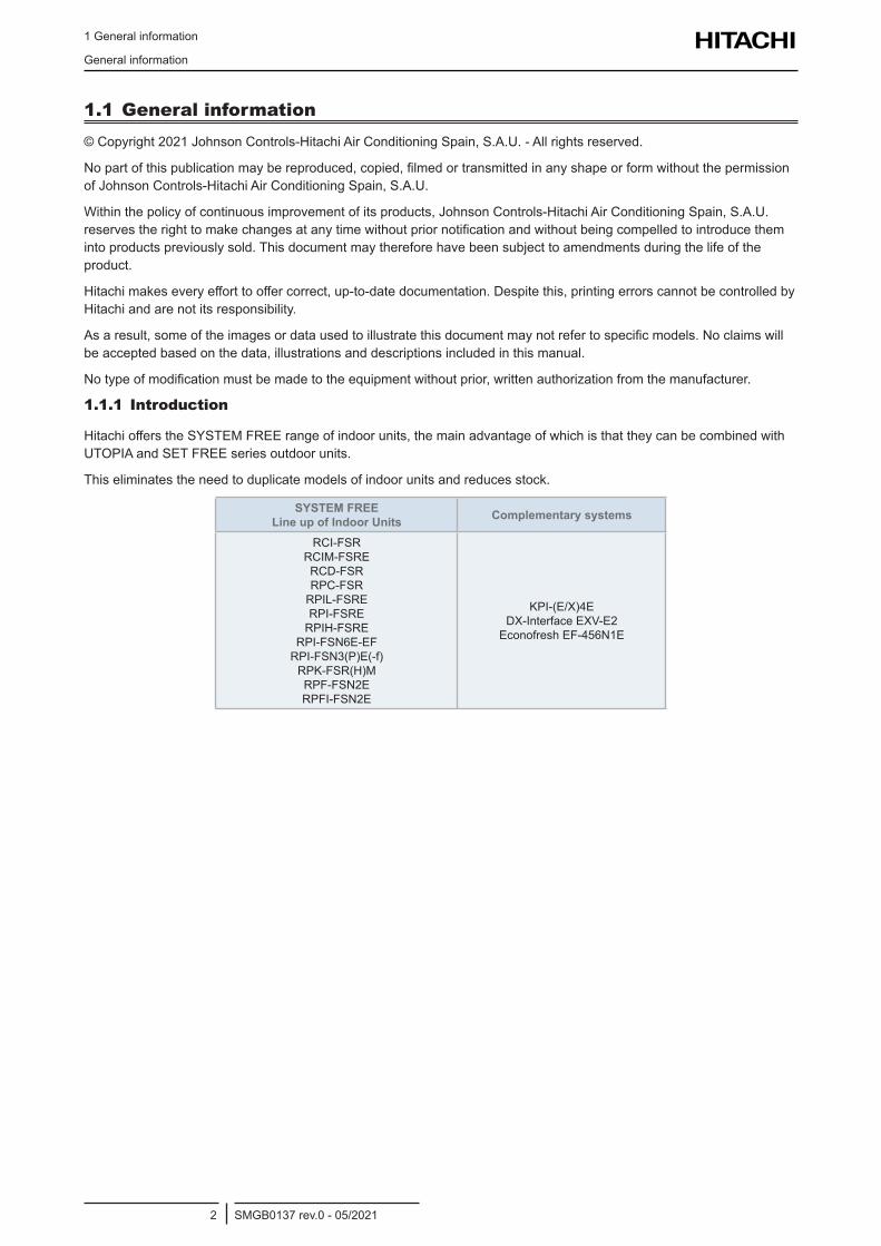
HitachiofferstheSYSTEMFREErangeofindoorunits,themainadvantageofwhichisthattheycanbecombinedwithUTOPIAandSETFREEseriesoutdoorunits.
Thiseliminatestheneedtoduplicatemodelsofindoorunitsandreducesstock.
SYSTEM FREE Line up of Indoor Units Complementary systems
RCI-FSR RCIM-FSRE RCD-FSR RPC-FSR RPIL-FSRE RPI-FSRE RPIH-FSRE
RPI-FSN6E-EF RPI-FSN3(P)E(-f) RPK-FSR(H)M RPF-FSN2E RPFI-FSN2E
KPI-(E/X)4E DX-InterfaceEXV-E2 EconofreshEF-456N1E
1 General information
Applied symbols
SMGB0137 rev.0 - 05/20213
1
1.2 Applied symbolsDuringnormalheatpumpsystemdesignworkorunitinstallation,greaterattentionmustbepaidincertainsituationsrequiringparticularcareinordertoavoiddamagetotheunit,theinstallationorthebuildingorproperty.
Situationsthatposearisktothesafetyofthoseinthesurroundingareaortotheunititselfareclearlyindicatedinthismanual.
Aseriesofspecialsymbolsareusedtoclearlyidentifythesesituations.
Paycloseattentiontothesesymbolsandtothemessagesfollowingthem,asyoursafetyandthatofothersdependsonit.
! D A N G E R• Thetextfollowingthissymbolcontainsinformationandinstructionsrelatingdirectlytoyoursafety,inadditiontohazards
orunsafepracticeswhichcouldresultinseverepersonalinjuriesordeath.• Nottakingtheseinstructionsintoaccountcouldleadtoserious,veryseriousorevenfatalinjuriestoyouandothersinthe
proximitiesoftheunit.
Inthetextsfollowingthedangersymbolyoucanalsofindinformationonsafeproceduresduringunitinstallation.
! C A U T I O N• Thetextfollowingthissymbolcontainsinformationandinstructionsrelatingdirectlytoyoursafety,inadditiontohazardsorunsafe
practiceswhichcouldresultinminorpersonalinjuryorproductorpropertydamage• Nottakingtheseinstructionsintoaccountcouldleadtominorinjuriestoyouandothersintheproximitiesoftheunit.• Nottakingtheseinstructionsintoaccountcouldleadtounitdamage.
Inthetextsfollowingthecautionsymbolyoucanalsofindinformationonsafeproceduresduringunitinstallation.
? N O T E• Thetextfollowingthissymbolcontainsinformationorinstructionsthatmaybeofuseorthatrequireamorethoroughexplanation.• Instructionsregardinginspectionstobemadeonunitpartsorsystemsmayalsobeincluded.
1.3 Norms and RegulationsFollowingRegulationEUNº517/2014onCertainFluorinatedGreenhousegases,itismandatorytofillinthelabelattachedtotheunitwiththetotalamountofrefrigerantchargedontheinstallation.
DonotventR32intotheatmosphere:R32isfluorinatedgreenhousegascoveredbytheKyotoprotocolglobalwarmingpotential(GWP)R32=675.
DonotventR410Aintotheatmosphere:R410AarefluorinatedgreenhousegasescoveredbytheKyotoprotocolglobalwarmingpotential(GWP)R410A=2088.
TnofCO2equivalentoffluorinatedgreenhousegasescontainediscalculatedbyindicatedGWP*TotalCharge(inkg)indicatedintheproductlabelanddividedby1000.
Appropriaterefrigerant
Therefrigerantusedineachunitisidentifiedonthespecificationlabelandmanualsoftheunit.Hitachishallnotbeheldliableforanyfailure,trouble,malfunctionoraccidentcausedbyunitsillegallychargedwithrefrigerantsotherthanthespecifiedone.
Consequencesofchargingnon-specifiedrefrigerant
Itmaycausemechanicalfailure,malfunctionandotheraccidents.
Itmaycauseoperationalfailureofprotectionandsafetydevicesofairconditioners.
Itmayalsocauselubricationfailureoftheslidingpartofthecompressorduetodeteriorationofrefrigerantoil.
Inparticular,hydrocarbonrefrigerants(suchaspropane,R441A,R443A,GF-08,etc.)arenotallowed,sincethesearecombustibleandmaycausemajoraccidentssuchasfireandexplosionincaseofimproperhandling.
Onceanon-specifiedrefrigeranthasbeencharged,nofurtherservicing(includingdrainingofrefrigerant)shallbeperformed,evenincaseofmalfunction.Improperhandlingofrefrigerantmaybeacauseoffireandexplosion,andservicinginsuchcasesmaybeconsideredanillegalact.
Endclientsandcostumersshallbeinformedthatservicingisnotapproved,andtheinstallerwhochargedthenonspecifiedrefrigerantshallbeaskedtofixtheunit.
Hitachiwillacceptnoresponsibilityforunitsthathavebeenchargedwithnon-specifiedrefrigerantonce.
1 General information
Productclassificationandline-up
SMGB0137 rev.0 - 05/20214
1.4 Product classification and line-up
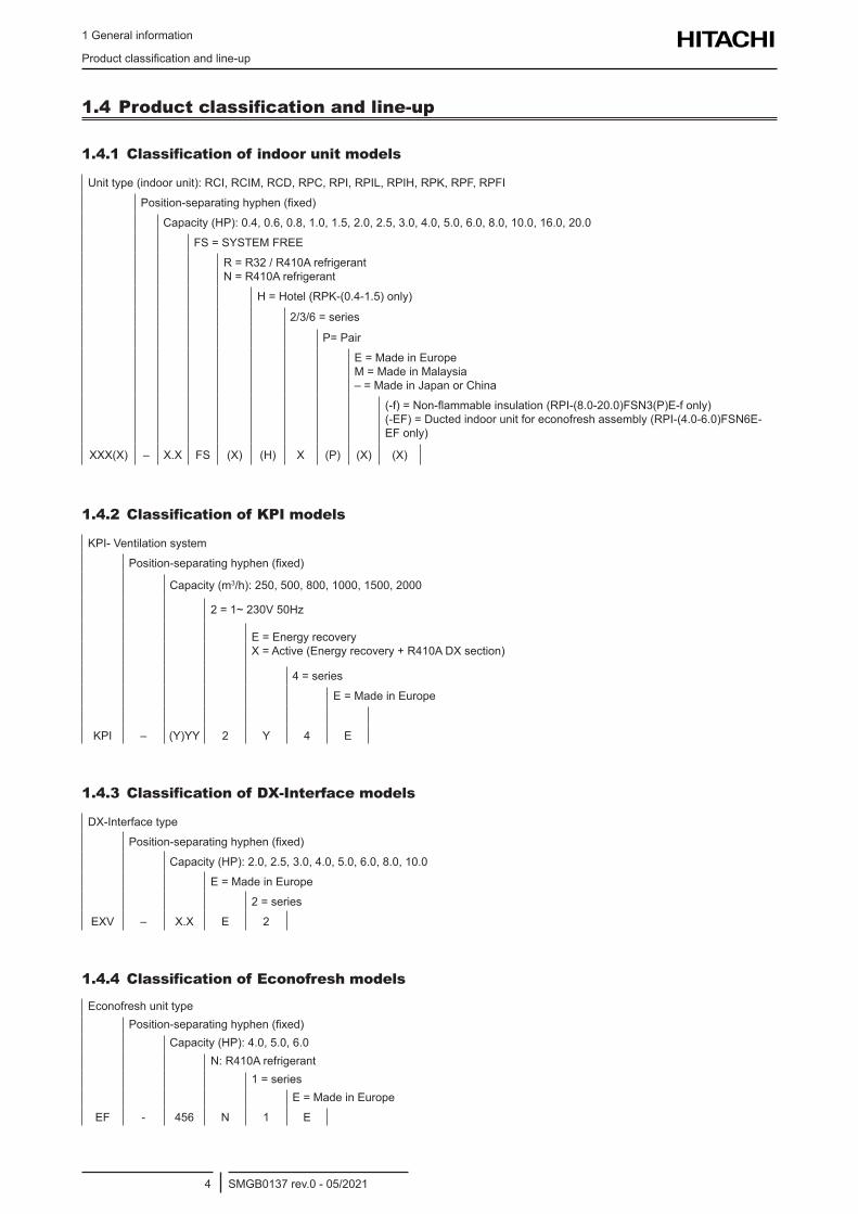
1.4.1 Classification of indoor unit models
Unittype(indoorunit):RCI,RCIM,RCD,RPC,RPI,RPIL,RPIH,RPK,RPF,RPFI
Position-separatinghyphen(fixed)
Capacity(HP):0.4,0.6,0.8,1.0,1.5,2.0,2.5,3.0,4.0,5.0,6.0,8.0,10.0,16.0,20.0
FS=SYSTEMFREE
R=R32/R410Arefrigerant N=R410Arefrigerant
H=Hotel(RPK-(0.4-1.5)only)
2/3/6=series
P=Pair
E=MadeinEurope M=MadeinMalaysia –=MadeinJapanorChina
(-f)=Non-flammableinsulation(RPI-(8.0-20.0)FSN3(P)E-fonly) (-EF)=Ductedindoorunitforeconofreshassembly(RPI-(4.0-6.0)FSN6E-EFonly)
XXX(X) – X.X FS (X) (H) X (P) (X) (X)
1.4.2 Classification of KPI models
KPI-Ventilationsystem
Position-separatinghyphen(fixed)
Capacity(m3/h):250,500,800,1000,1500,2000
2=1~230V50Hz
E=Energyrecovery X=Active(Energyrecovery+R410ADXsection)
4=series
E=MadeinEurope
KPI – (Y)YY 2 Y 4 E
1.4.3 Classification of DX-Interface models
DX-Interfacetype
Position-separatinghyphen(fixed)
Capacity(HP):2.0,2.5,3.0,4.0,5.0,6.0,8.0,10.0
E=MadeinEurope
2=series
EXV – X.X E 2
1.4.4 Classification of Econofresh models
EconofreshunittypePosition-separatinghyphen(fixed)
Capacity(HP):4.0,5.0,6.0N:R410Arefrigerant
1=seriesE=MadeinEurope
EF - 456 N 1 E
1 General information
Productclassificationandline-up
SMGB0137 rev.0 - 05/20215
1
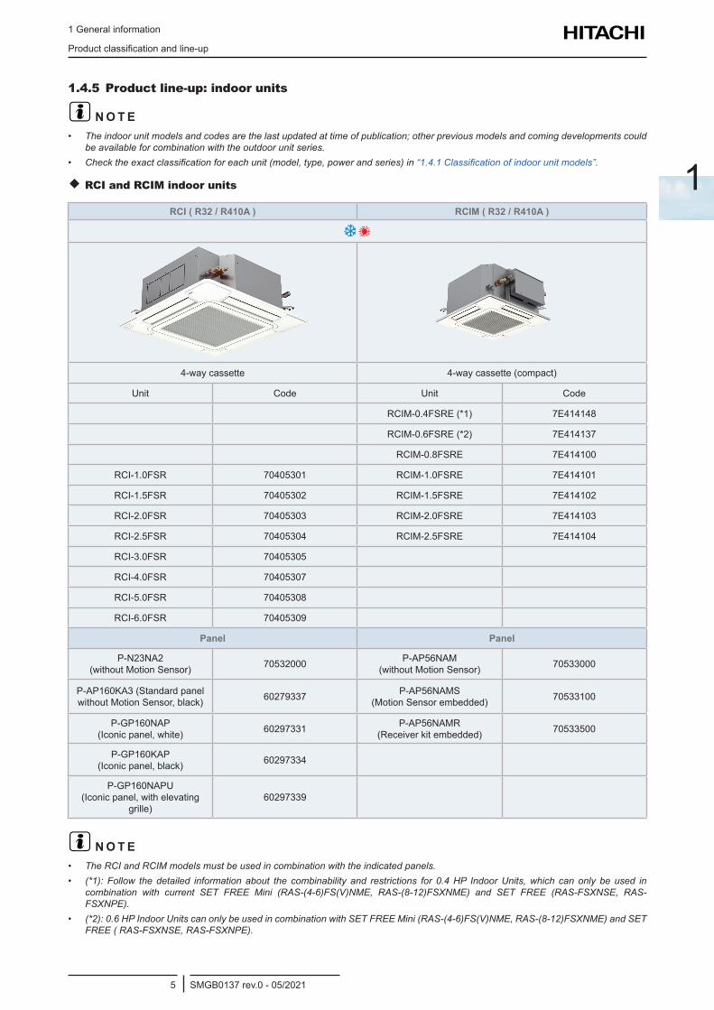
1.4.5 Product line-up: indoor units
? N O T E• Theindoorunitmodelsandcodesarethelastupdatedattimeofpublication;otherpreviousmodelsandcomingdevelopmentscould
beavailableforcombinationwiththeoutdoorunitseries.• Checktheexactclassificationforeachunit(model,type,powerandseries)in“1.4.1Classificationofindoorunitmodels”.
RCI and RCIM indoor units
RCI ( R32 / R410A ) RCIM ( R32 / R410A )
4-waycassette 4-waycassette(compact)
Unit Code Unit Code
RCIM-0.4FSRE(*1) 7E414148
RCIM-0.6FSRE(*2) 7E414137
RCIM-0.8FSRE 7E414100
RCI-1.0FSR 70405301 RCIM-1.0FSRE 7E414101
RCI-1.5FSR 70405302 RCIM-1.5FSRE 7E414102
RCI-2.0FSR 70405303 RCIM-2.0FSRE 7E414103
RCI-2.5FSR 70405304 RCIM-2.5FSRE 7E414104
RCI-3.0FSR 70405305
RCI-4.0FSR 70405307
RCI-5.0FSR 70405308
RCI-6.0FSR 70405309
Panel Panel
P-N23NA2 (withoutMotionSensor) 70532000 P-AP56NAM
(withoutMotionSensor) 70533000
P-AP160KA3(StandardpanelwithoutMotionSensor,black) 60279337 P-AP56NAMS
(MotionSensorembedded) 70533100
P-GP160NAP (Iconicpanel,white) 60297331 P-AP56NAMR
(Receiverkitembedded) 70533500
P-GP160KAP (Iconicpanel,black) 60297334
P-GP160NAPU (Iconicpanel,withelevating
grille)60297339
? N O T E• TheRCIandRCIMmodelsmustbeusedincombinationwiththeindicatedpanels.• (*1): Follow thedetailed informationabout the combinability and restrictions for 0.4HP IndoorUnits,which canonly beused in
combination with current SET FREE Mini (RAS-(4-6)FS(V)NME, RAS-(8-12)FSXNME) and SET FREE (RAS-FSXNSE, RAS-FSXNPE).
• (*2):0.6HPIndoorUnitscanonlybeusedincombinationwithSETFREEMini(RAS-(4-6)FS(V)NME,RAS-(8-12)FSXNME)andSETFREE(RAS-FSXNSE,RAS-FSXNPE).
1 General information
Productclassificationandline-up
SMGB0137 rev.0 - 05/20216
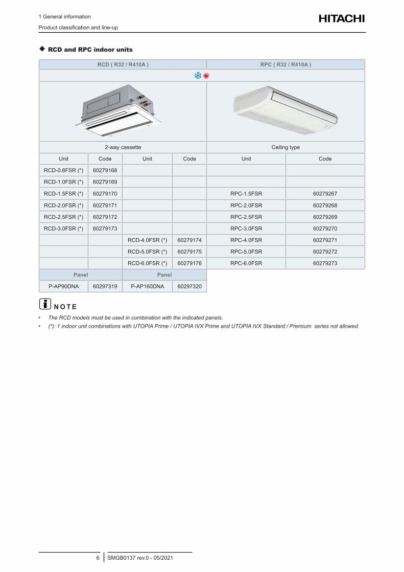
RCD and RPC indoor units
RCD ( R32 / R410A ) RPC ( R32 / R410A )
2-waycassette Ceiling type
Unit Code Unit Code Unit Code
RCD-0.8FSR(*) 60279168
RCD-1.0FSR(*) 60279169
RCD-1.5FSR(*) 60279170 RPC-1.5FSR 60279267
RCD-2.0FSR(*) 60279171 RPC-2.0FSR 60279268
RCD-2.5FSR(*) 60279172 RPC-2.5FSR 60279269
RCD-3.0FSR(*) 60279173 RPC-3.0FSR 60279270
RCD-4.0FSR(*) 60279174 RPC-4.0FSR 60279271
RCD-5.0FSR(*) 60279175 RPC-5.0FSR 60279272
RCD-6.0FSR(*) 60279176 RPC-6.0FSR 60279273
Panel Panel
P-AP90DNA 60297319 P-AP160DNA 60297320
? N O T E• TheRCDmodelsmustbeusedincombinationwiththeindicatedpanels.• (*):1indoorunitcombinationswithUTOPIAPrime/UTOPIAIVXPrimeandUTOPIAIVXStandard/Premiumseriesnotallowed.
1 General information
Productclassificationandline-up
SMGB0137 rev.0 - 05/20217
1
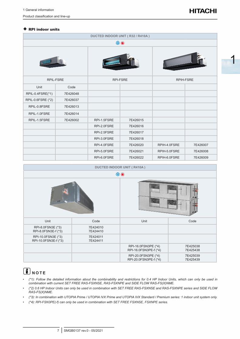
RPI indoor units
DUCTED INDOOR UNIT ( R32 / R410A )
RPIL-FSRE RPI-FSRE RPIH-FSRE
Unit Code
RPIL-0.4FSRE(*1) 7E426048
RPIL-0.6FSRE(*2) 7E426037
RPIL-0.8FSRE 7E426013
RPIL-1.0FSRE 7E426014
RPIL-1.5FSRE 7E426002 RPI-1.5FSRE 7E426015
RPI-2.0FSRE 7E426016
RPI-2.5FSRE 7E426017
RPI-3.0FSRE 7E426018
RPI-4.0FSRE 7E426020 RPIH-4.0FSRE 7E426007
RPI-5.0FSRE 7E426021 RPIH-5.0FSRE 7E426008
RPI-6.0FSRE 7E426022 RPIH-6.0FSRE 7E426009
DUCTED INDOOR UNIT ( R410A )
Unit Code Unit Code
RPI-8.0FSN3E(*3) RPI-8.0FSN3E-f(*3)
7E424010 7E424410
RPI-10.0FSN3E(*3) RPI-10.0FSN3E-f(*3)
7E424011 7E424411
RPI-16.0FSN3PE(*4) RPI-16.0FSN3PE-f(*4)
7E425038 7E425438
RPI-20.0FSN3PE(*4) RPI-20.0FSN3PE-f(*4)
7E425039 7E425439
? N O T E• (*1): Follow thedetailed informationabout the combinability and restrictions for 0.4HP IndoorUnits,which canonly beused in
combinationwithcurrentSETFREERAS-FSXNSE,RAS-FSXNPEandSIDEFLOWRAS-FS(X)NME.• (*2)0.6HPIndoorUnitscanonlybeusedincombinationwithSETFREERAS-FSXNSEandRAS-FSXNPEseriesandSIDEFLOW
RAS-FS(X)NME.• (*3):IncombinationwithUTOPIAPrime/UTOPIAIVXPrimeandUTOPIAIVXStandard/Premiumseries:1indoorunitsystemonly.• (*4):RPI-FSN3PE(-f)canonlybeusedincombinationwithSETFREEFSXNSE,FSXNPEseries.
1 General information
Productclassificationandline-up
SMGB0137 rev.0 - 05/20218
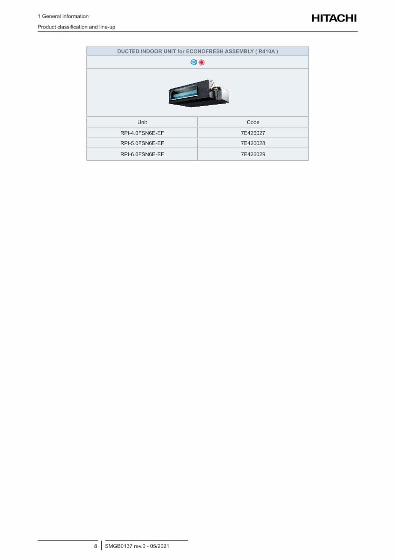
DUCTED INDOOR UNIT for ECONOFRESH ASSEMBLY ( R410A )
Unit Code
RPI-4.0FSN6E-EF 7E426027
RPI-5.0FSN6E-EF 7E426028
RPI-6.0FSN6E-EF 7E426029
1 General information
Productclassificationandline-up
SMGB0137 rev.0 - 05/20219
1
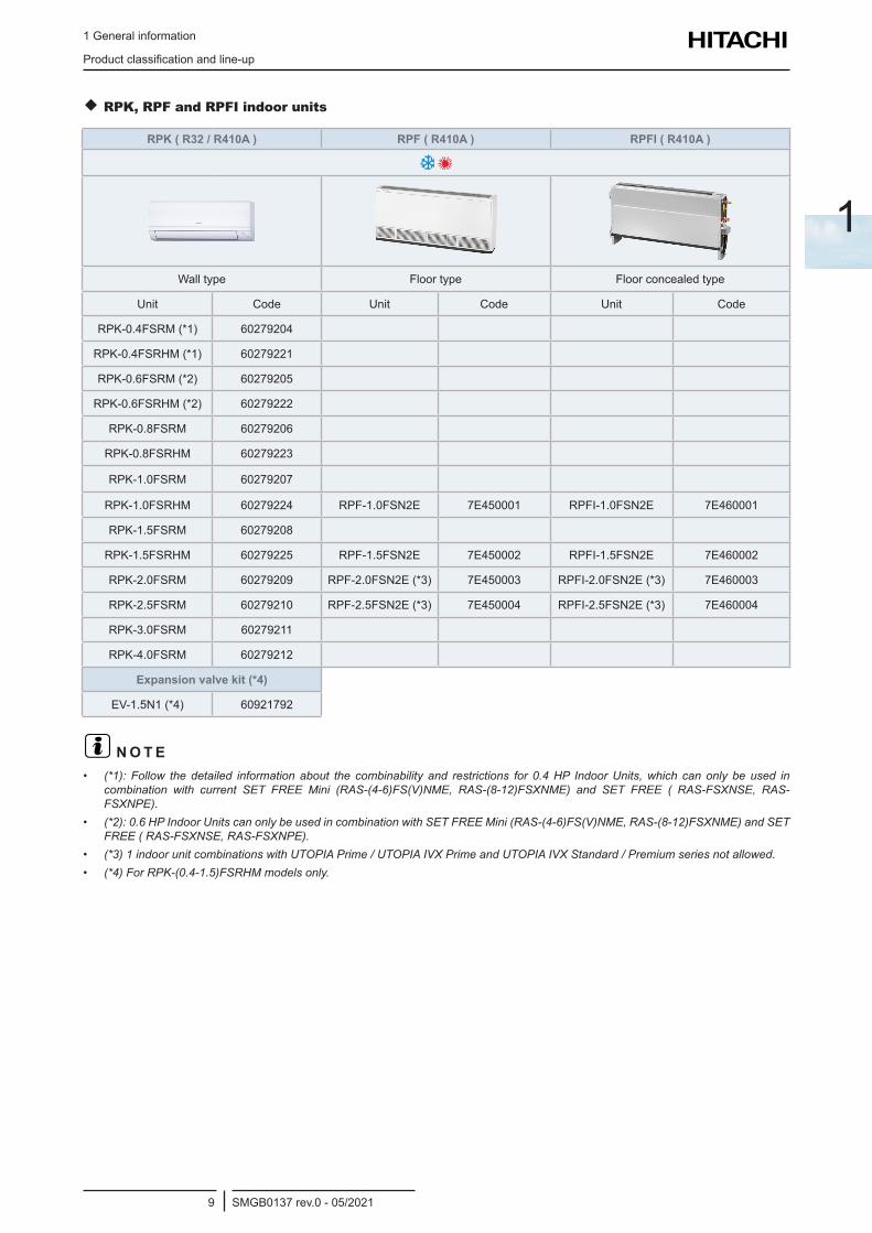
RPK, RPF and RPFI indoor units
RPK ( R32 / R410A ) RPF ( R410A ) RPFI ( R410A )
Wall type Floortype Floorconcealedtype
Unit Code Unit Code Unit Code
RPK-0.4FSRM(*1) 60279204
RPK-0.4FSRHM(*1) 60279221
RPK-0.6FSRM(*2) 60279205
RPK-0.6FSRHM(*2) 60279222
RPK-0.8FSRM 60279206
RPK-0.8FSRHM 60279223
RPK-1.0FSRM 60279207
RPK-1.0FSRHM 60279224 RPF-1.0FSN2E 7E450001 RPFI-1.0FSN2E 7E460001
RPK-1.5FSRM 60279208
RPK-1.5FSRHM 60279225 RPF-1.5FSN2E 7E450002 RPFI-1.5FSN2E 7E460002
RPK-2.0FSRM 60279209 RPF-2.0FSN2E(*3) 7E450003 RPFI-2.0FSN2E(*3) 7E460003
RPK-2.5FSRM 60279210 RPF-2.5FSN2E(*3) 7E450004 RPFI-2.5FSN2E(*3) 7E460004
RPK-3.0FSRM 60279211
RPK-4.0FSRM 60279212
Expansion valve kit (*4)
EV-1.5N1(*4) 60921792
? N O T E• (*1): Follow thedetailed informationabout the combinability and restrictions for 0.4HP IndoorUnits,which canonly beused in
combination with current SET FREE Mini (RAS-(4-6)FS(V)NME, RAS-(8-12)FSXNME) and SET FREE ( RAS-FSXNSE, RAS-FSXNPE).
• (*2):0.6HPIndoorUnitscanonlybeusedincombinationwithSETFREEMini(RAS-(4-6)FS(V)NME,RAS-(8-12)FSXNME)andSETFREE(RAS-FSXNSE,RAS-FSXNPE).
• (*3)1indoorunitcombinationswithUTOPIAPrime/UTOPIAIVXPrimeandUTOPIAIVXStandard/Premiumseriesnotallowed.• (*4)ForRPK-(0.4-1.5)FSRHMmodelsonly.
1 General information
Productclassificationandline-up
SMGB0137 rev.0 - 05/202110
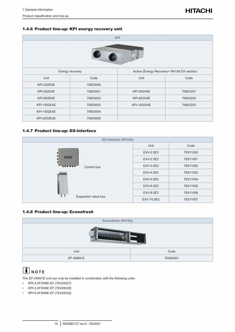
1.4.6 Product line-up: KPI energy recovery unit
KPI
Energyrecovery Active(EnergyRecovery+R410ADXsection)
Unit Code Unit Code
KPI-252E4E 70603000
KPI-502E4E 70603001 KPI-502X4E 70603201
KPI-802E4E 70603002 KPI-802X4E 70603202
KPI-1002E4E 70603003 KPI-1002X4E 70603203
KPI-1502E4E 70603004
KPI-2002E4E 70603005
1.4.7 Product line-up: DX-Interface
DX-Interface (R410A)
Controlbox
Expansionvalvebox
Unit Code
EXV-2.0E2 7E611000
EXV-2.5E2 7E611001
EXV-3.0E2 7E611002
EXV-4.0E2 7E611003
EXV-5.0E2 7E611004
EXV-6.0E2 7E611005
EXV-8.0E2 7E611006
EXV-10.0E2 7E611007
1.4.8 Product line-up: Econofresh
Econofresh (R410A)
Unit Code
EF-456N1E 7E560001
? N O T ETheEF-456N1Eunitcanonlybeinstalledincombinationwiththefollowingunits:• RPI-4.0FSN6E-EF(7E426027)• RPI-5.0FSN6E-EF(7E426028)• RPI-6.0FSN6E-EF(7E426029)
1 General information
Productclassificationandline-up
SMGB0137 rev.0 - 05/202111
1
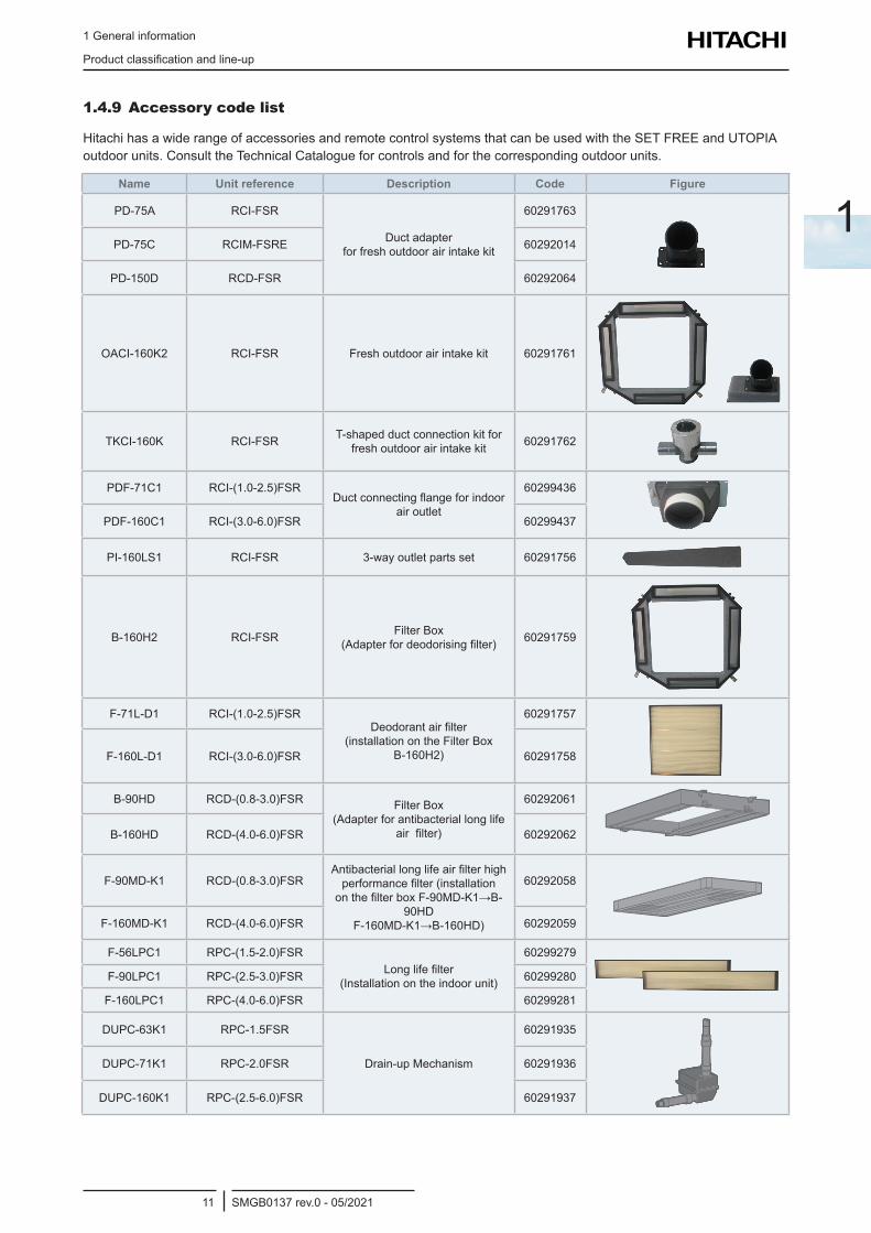
1.4.9 Accessory code list
HitachihasawiderangeofaccessoriesandremotecontrolsystemsthatcanbeusedwiththeSETFREEandUTOPIAoutdoorunits.ConsulttheTechnicalCatalogueforcontrolsandforthecorrespondingoutdoorunits.
Name Unit reference Description Code Figure
PD-75A RCI-FSR
Ductadapter forfreshoutdoorairintakekit
60291763
PD-75C RCIM-FSRE 60292014
PD-150D RCD-FSR 60292064
OACI-160K2 RCI-FSR Freshoutdoorairintakekit 60291761
TKCI-160K RCI-FSR T-shapedductconnectionkitforfreshoutdoorairintakekit 60291762
PDF-71C1 RCI-(1.0-2.5)FSRDuctconnectingflangeforindoor
air outlet
60299436
PDF-160C1 RCI-(3.0-6.0)FSR 60299437
PI-160LS1 RCI-FSR 3-wayoutletpartsset 60291756
B-160H2 RCI-FSR FilterBox (Adapterfordeodorisingfilter) 60291759
F-71L-D1 RCI-(1.0-2.5)FSRDeodorantairfilter
(installationontheFilterBoxB-160H2)
60291757
F-160L-D1 RCI-(3.0-6.0)FSR 60291758
B-90HD RCD-(0.8-3.0)FSR FilterBox (Adapterforantibacteriallonglife
airfilter)
60292061
B-160HD RCD-(4.0-6.0)FSR 60292062
F-90MD-K1 RCD-(0.8-3.0)FSRAntibacteriallonglifeairfilterhighperformancefilter(installationonthefilterboxF-90MD-K1→B-
90HD F-160MD-K1→B-160HD)
60292058
F-160MD-K1 RCD-(4.0-6.0)FSR 60292059
F-56LPC1 RPC-(1.5-2.0)FSRLonglifefilter
(Installationontheindoorunit)
60299279
F-90LPC1 RPC-(2.5-3.0)FSR 60299280
F-160LPC1 RPC-(4.0-6.0)FSR 60299281
DUPC-63K1 RPC-1.5FSR
Drain-upMechanism
60291935
DUPC-71K1 RPC-2.0FSR 60291936
DUPC-160K1 RPC-(2.5-6.0)FSR 60291937
1 General information
Productclassificationandline-up
SMGB0137 rev.0 - 05/202112
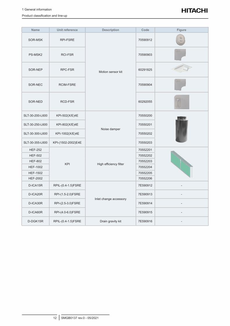
Name Unit reference Description Code Figure
SOR-MSK RPI-FSRE
Motionsensorkit
70590912
PS-MSK2 RCI-FSR 70590903
SOR-NEP RPC-FSR 60291825
SOR-NEC RCIM-FSRE 70590904
SOR-NED RCD-FSR 60292055
SLT-30-200-L600 KPI-502(X/E)4E
Noise damper
70550200
SLT-30-250-L600 KPI-802(X/E)4E 70550201
SLT-30-300-L600 KPI-1002(X/E)4E 70550202
SLT-30-355-L600 KPI-(1502-2002)E4E 70550203
HEF-252
KPI Highefficiencyfilter
70552201
HEF-502 70552202
HEF-802 70552203
HEF-1002 70552204
HEF-1502 70552205
HEF-2002 70552206
D-ICA15R RPIL-(0.4-1.5)FSRE
Inletchangeaccessory
7E590912 -
D-ICA20R RPI-(1.5-2.0)FSRE 7E590913 -
D-ICA30R RPI-(2.5-3.0)FSRE 7E590914 -
D-ICA60R RPI-(4.0-6.0)FSRE 7E590915 -
D-DGK15R RPIL-(0.4-1.5)FSRE Draingravitykit 7E590916 -
1 General information
Productclassificationandline-up
SMGB0137 rev.0 - 05/202113
1
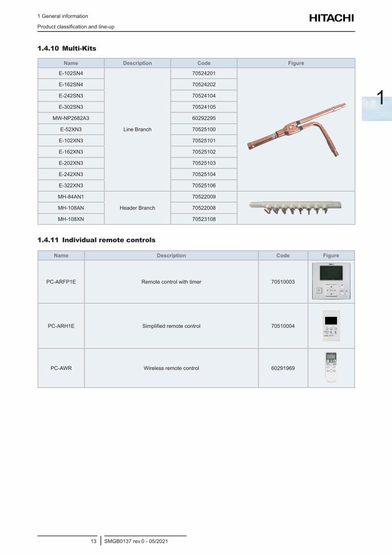
1.4.10 Multi-Kits
Name Description Code Figure
E-102SN4
LineBranch
70524201
E-162SN4 70524202
E-242SN3 70524104
E-302SN3 70524105
MW-NP2682A3 60292295
E-52XN3 70525100
E-102XN3 70525101
E-162XN3 70525102
E-202XN3 70525103
E-242XN3 70525104
E-322XN3 70525106
MH-84AN1
HeaderBranch
70522009
MH-108AN 70522008
MH-108XN 70523108
1.4.11 Individual remote controls
Name Description Code Figure
PC-ARFP1E Remotecontrolwithtimer 70510003
PC-ARH1E Simplifiedremotecontrol 70510004
PC-AWR Wireless remote control 60291969
1 General information
Productclassificationandline-up
SMGB0137 rev.0 - 05/202114
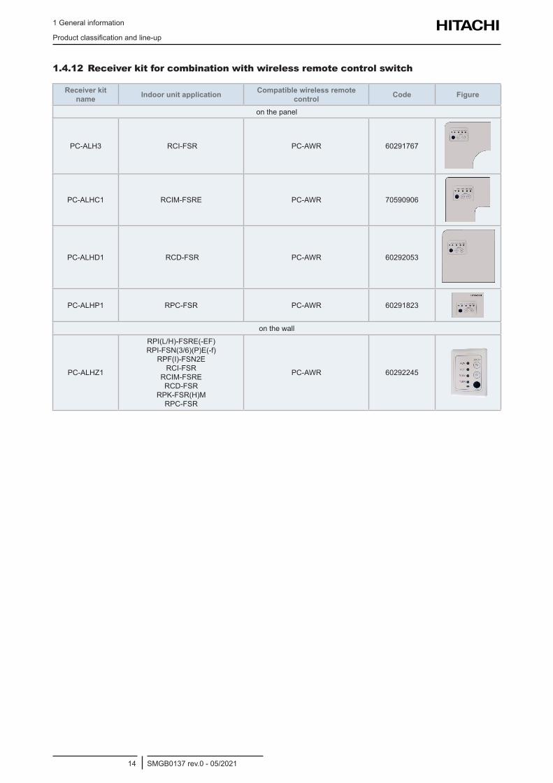
1.4.12 Receiver kit for combination with wireless remote control switch
Receiver kit name Indoor unit application Compatible wireless remote
control Code Figure
onthepanel
PC-ALH3 RCI-FSR PC-AWR 60291767
PC-ALHC1 RCIM-FSRE PC-AWR 70590906
PC-ALHD1 RCD-FSR PC-AWR 60292053
PC-ALHP1 RPC-FSR PC-AWR 60291823
onthewall
PC-ALHZ1
RPI(L/H)-FSRE(-EF) RPI-FSN(3/6)(P)E(-f)
RPF(I)-FSN2E RCI-FSR
RCIM-FSRE RCD-FSR
RPK-FSR(H)M RPC-FSR
PC-AWR 60292245
1 General information
Productclassificationandline-up
SMGB0137 rev.0 - 05/202115
1
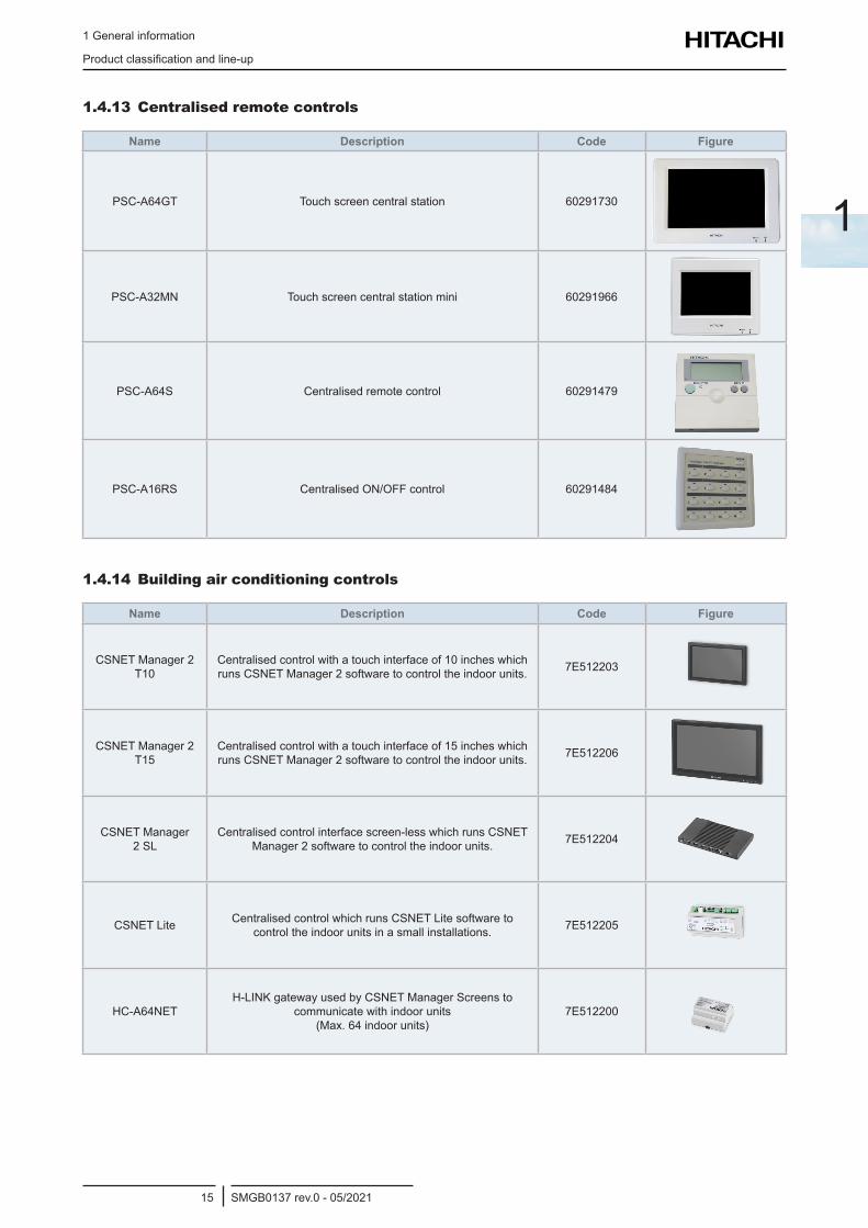
1.4.13 Centralised remote controls
Name Description Code Figure
PSC-A64GT Touchscreencentralstation 60291730
PSC-A32MN Touchscreencentralstationmini 60291966
PSC-A64S Centralised remote control 60291479
PSC-A16RS CentralisedON/OFFcontrol 60291484
1.4.14 Building air conditioning controls
Name Description Code Figure
CSNETManager2T10
Centralisedcontrolwithatouchinterfaceof10incheswhichrunsCSNETManager2softwaretocontroltheindoorunits. 7E512203
CSNETManager2T15
Centralisedcontrolwithatouchinterfaceof15incheswhichrunsCSNETManager2softwaretocontroltheindoorunits. 7E512206
CSNETManager2SL
Centralisedcontrolinterfacescreen-lesswhichrunsCSNETManager2softwaretocontroltheindoorunits. 7E512204
CSNETLite CentralisedcontrolwhichrunsCSNETLitesoftwaretocontroltheindoorunitsinasmallinstallations. 7E512205
HC-A64NETH-LINKgatewayusedbyCSNETManagerScreensto
communicatewithindoorunits (Max.64indoorunits)
7E512200
1 General information
Productclassificationandline-up
SMGB0137 rev.0 - 05/202116
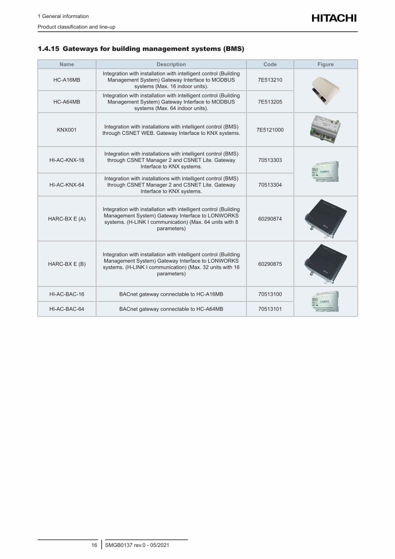
1.4.15 Gateways for building management systems (BMS)
Name Description Code Figure
HC-A16MBIntegrationwithinstallationwithintelligentcontrol(BuildingManagementSystem)GatewayInterfacetoMODBUS
systems(Max.16indoorunits).7E513210
HC-A64MBIntegrationwithinstallationwithintelligentcontrol(BuildingManagementSystem)GatewayInterfacetoMODBUS
systems(Max.64indoorunits).7E513205
KNX001 Integrationwithinstallationswithintelligentcontrol(BMS)throughCSNETWEB.GatewayInterfacetoKNXsystems. 7E5121000
HI-AC-KNX-16Integrationwithinstallationswithintelligentcontrol(BMS)throughCSNETManager2andCSNETLite.Gateway
InterfacetoKNXsystems.70513303
HI-AC-KNX-64Integrationwithinstallationswithintelligentcontrol(BMS)throughCSNETManager2andCSNETLite.Gateway
InterfacetoKNXsystems.70513304
HARC-BXE(A)
Integrationwithinstallationwithintelligentcontrol(BuildingManagementSystem)GatewayInterfacetoLONWORKSsystems.(H-LINKIcommunication)(Max.64unitswith8
parameters)
60290874
HARC-BXE(B)
Integrationwithinstallationwithintelligentcontrol(BuildingManagementSystem)GatewayInterfacetoLONWORKSsystems.(H-LINKIcommunication)(Max.32unitswith16
parameters)
60290875
HI-AC-BAC-16 BACnetgatewayconnectabletoHC-A16MB 70513100
HI-AC-BAC-64 BACnetgatewayconnectabletoHC-A64MB 70513101
1 General information
Productclassificationandline-up
SMGB0137 rev.0 - 05/202117
1
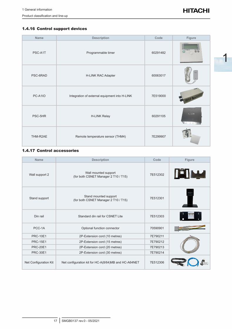
1.4.16 Control support devices
Name Description Code Figure
PSC-A1T Programmable timer 60291482
PSC-6RAD H-LINKRACAdapter 60063017
PC-A1IO IntegrationofexternalequipmentintoH-LINK 7E519000
PSC-5HR H-LINKRelay 60291105
THM-R2AE Remotetemperaturesensor(THM4) 7E299907
1.4.17 Control accessories
Name Description Code Figure
Wall support 2 Wall mounted support (forbothCSNETManager2T10/T15) 7E512302
Standsupport Standmountedsupport (forbothCSNETManager2T10/T15) 7E512301
Dinrail StandarddinrailforCSNETLite 7E512303
PCC-1A Optionalfunctionconnector 70590901
PRC-10E1 2P-Extensioncord(10metres) 7E790211
PRC-15E1 2P-Extensioncord(15metres) 7E790212
PRC-20E1 2P-Extensioncord(20metres) 7E790213
PRC-30E1 2P-Extensioncord(30metres) 7E790214
NetConfigurationKit NetconfigurationkitforHC-A(8/64)MBandHC-A64NET 7E512306

2 Optional accessories
SMGB0137 rev.0 - 05/202119
2
2 . O p t i o n a l a c c e s s o r i e s
Index
2.1 Duct adapter - Outdoor air inlet .............................................................................................................20
2.1.1 For RCI-FSR indoor units: OACI-160K2 and PD-75A ................................................................................... 20
2.1.2 For RCIM-FSRE indoor units: PD-75C .......................................................................................................... 23
2.1.3 For RCD-FSR indoor units: PD-150D ........................................................................................................... 24
2.2 T-duct connection position.....................................................................................................................25
2.2.1 For RCI-FSR indoor units: TKCI-160k ........................................................................................................... 25
2.3 Branch pipe (PDF-71C, PDF-160CI) .....................................................................................................26
2.4 Outletairflowinterlock ..........................................................................................................................27
2.4.1 For RCI-FSR indoor units: PI-160SL1 ........................................................................................................... 27
2.5 Filter box................................................................................................................................................29
2.5.1 For RCI-FSR indoor units: B-160H2 .............................................................................................................. 29
2.5.2 For RCD-FSR indoor units: BD-90H and BD-160HD ................................................................................... 30
2.6 Anti-bacteriafilter .................................................................................................................................31
2.6.1 For RCI-FSR: F-160L-K ................................................................................................................................ 31
2.6.2 ForRCD-FSRindoorunits:F-90MD-K1andF-160MD-K1(Antibacteriallonglifeairfilter) .......................... 32
2.7 Deodorisingfilter ...................................................................................................................................32
2.7.1 For RCI-FSR indoor units: F-71L-D1 and F-160L-D1 ................................................................................... 32
2.8 Air Inlet Direction Change .....................................................................................................................34
2.8.1 For RPI(L/H)-(0.4-6.0)FSRE units ................................................................................................................. 34
2.9 Disconnectable drain pump ...................................................................................................................35
2.9.1 For RPIL-(0.4-1.5)FSRE units ....................................................................................................................... 35
2 Optional accessories
Duct adapter - Outdoor air inlet
SMGB0137 rev.0 - 05/202120
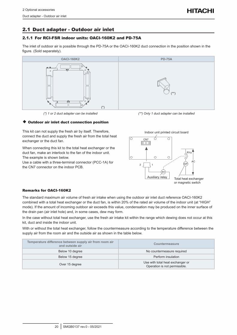
2.1 Duct adapter - Outdoor air inlet2.1.1 For RCI-FSR indoor units: OACI-160K2 and PD-75A
TheinletofoutdoorairispossiblethroughthePD-75AortheOACI-160K2ductconnectioninthepositionshowninthefigure.(Soldseparately).
OACI-160K2 PD-75A
(*)
(**)
(*) 1 or 2 duct adapter can be installed (**) Only 1 duct adapter can be installed
Outdoor air inlet duct connection position
Thiskitcannotsupplythefreshairbyitself.Therefore,connecttheductandsupplythefreshairfromthetotalheatexchanger or the duct fan.
When connecting this kit to the total heat exchanger or the duct fan, make an interlock to the fan of the indoor unit. Theexampleisshownbelow.Useacablewithathree-terminalconnector(PCC-1A)forthe CN7 connector on the indoor PCB.
CN7
12
RY
52FAC
RYa
Indoor Unit Printed Circuit Board
Total Heat Exchangeror Magnetic Switch
Auxiliary Relay Total heat exchanger ormagneticswitch
Indoor unit printed circuit board
Auxiliaryrelay
Remarks for OACI-160K2
ThestandardmaximumairvolumeoffreshairintakewhenusingtheoutdoorairinletductreferenceOACI-160K2combinedwithatotalheatexchangerortheductfan,iswithin20%oftheratedairvolumeoftheindoorunit(at“HIGH”mode).Iftheamountofincomingoutdoorairexceedsthisvalue,condensationmaybeproducedontheinnersurfaceofthedrainpan(airinlethole)and,insomecases,dewmayform.Inthecasewithouttotalheatexchanger,usethefreshairintakekitwithintherangewhichdewingdoesnotoccuratthiskit, duct and inside the indoor unit.Withorwithoutthetotalheatexchanger,followthecountermeasureaccordingtothetemperaturedifferencebetweenthesupplyairfromtheroomairandtheoutsideairasshowninthetablebelow.
Temperature difference between supply air from room air and outside air Countermeasure
Below10degree No countermeasure required
Below15degree Perform insulation
Over 15 degree Usewithtotalheatexchangeror Operation is not permissible.
2 Optional accessories
Duct adapter - Outdoor air inlet
SMGB0137 rev.0 - 05/202121
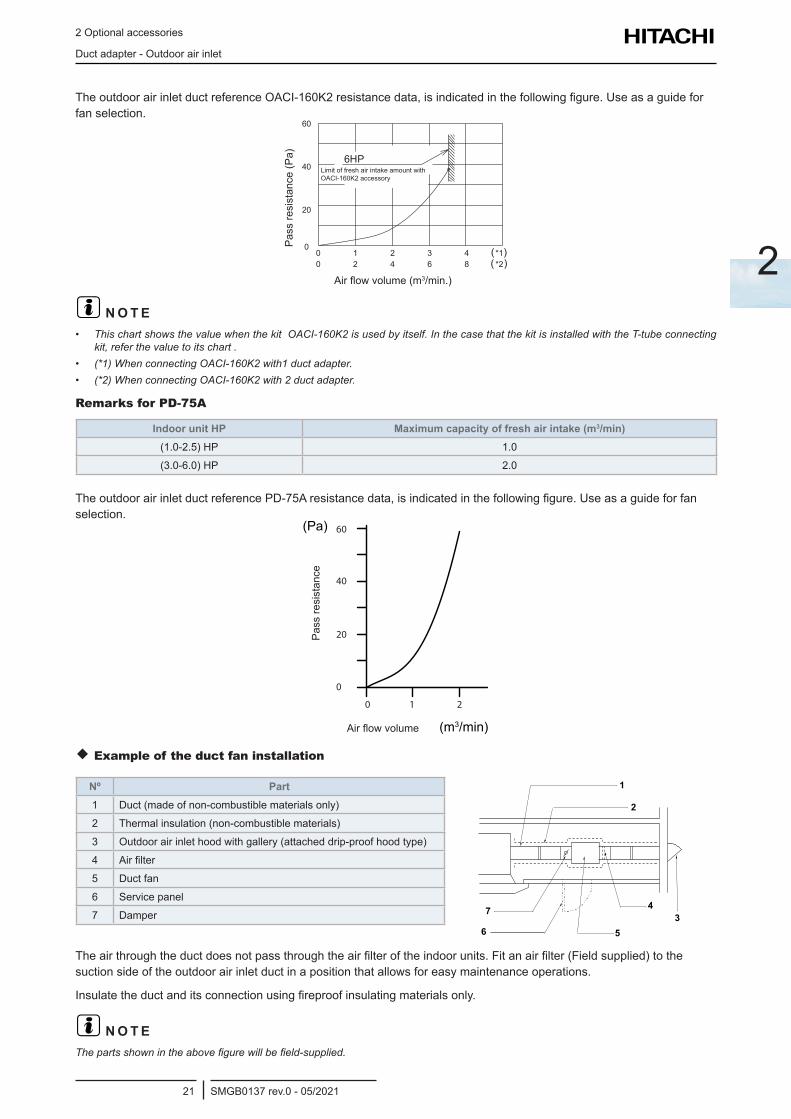
2
TheoutdoorairinletductreferenceOACI-160K2resistancedata,isindicatedinthefollowingfigure.Useasaguideforfan selection.
Pass
resi
stan
ce (P
a)Airflowvolume(m3/min.)
LimitoffreshairintakeamountwithOACI-160K2accessory
? N O T E• This chart shows the value when the kit OACI-160K2 is used by itself. In the case that the kit is installed with the T-tube connecting
kit, refer the value to its chart .• (*1) When connecting OACI-160K2 with1 duct adapter.• (*2) When connecting OACI-160K2 with 2 duct adapter.
Remarks for PD-75A
Indoor unit HP Maximum capacity of fresh air intake (m3/min)(1.0-2.5) HP 1.0
(3.0-6.0) HP 2.0
TheoutdoorairinletductreferencePD-75Aresistancedata,isindicatedinthefollowingfigure.Useasaguideforfanselection.
40
20
0
0 1 2
60
Airflowvolume
Pass
resi
stan
ce
Example of the duct fan installation
Nº Part1 Duct(madeofnon-combustiblematerialsonly)
2 Thermal insulation (non-combustible materials)
3 Outdoorairinlethoodwithgallery(attacheddrip-proofhoodtype)
4 Airfilter
5 Duct fan
6 Service panel
7 Damper
Theairthroughtheductdoesnotpassthroughtheairfilteroftheindoorunits.Fitanairfilter(Fieldsupplied)tothesuctionsideoftheoutdoorairinletductinapositionthatallowsforeasymaintenanceoperations.
Insulatetheductanditsconnectionusingfireproofinsulatingmaterialsonly.
? N O T EThepartsshownintheabovefigurewillbefield-supplied.
2 Optional accessories
Duct adapter - Outdoor air inlet
SMGB0137 rev.0 - 05/202122
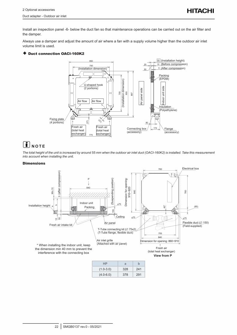
Installaninspectionpanel-6-belowtheductfansothatmaintenanceoperationscanbecarriedoutontheairfilterandthe damper.
Alwaysuseadamperandadjusttheamountofairwhereafanwithasupplyvolumehigherthantheoutdoorairinletvolume limit is used.
Duct connection OACI-160K2
20
50
10
5
55
80
174
850
700
887
775
(37)
850
700
(37)
(Installation dimension)
Airflow Airflow
(Inst
alla
tion
dim
ensi
on)
U-shaped hook (2 portions)
Fixing plate (4 portions)
Connecting box (accessory)
Flange (accessory)
Insulation (Polyethylene)
Packing (EPDM)
(Installation height)(Before compression)(After compression)
Air p
anel
sid
e
Indo
or u
nit s
ide
Fresh air (total heat exchanger)
Fresh air (total heat exchanger)
? N O T EThe total height of the unit is increased by around 55 mm when the outdoor air inlet duct (OACI-160K2) is installed. Take this measurement into account when installing the unit.
Dimensions
a b12
55M
in.1
0
505
840
155
φ75
P
φ75 φ75
760
840
760
705
840
40* (85)Installation height
Fresh air intake kit
Indoor unitPacking
Air panel
Ceiling
Air inlet grille (Attachedwithairpanel)
T-Tube connecting kit (∅ 75x2) (T-Tubeflange,flexibleduct)
Flexible duct (∅ 150) (Field-supplied)
Electrical box
View from P
(Sus
pend
ing
posi
tion)
Dim
ensi
on fo
r ope
ning
: 91
0~92
0
Dimension for opening: 860~910
Fresh air (total heat exchanger)
(afte
r com
pres
sion
)
* When installing the indoor unit, keep the dimension min 40 mm to prevent the interferencewiththeconnectingbox
HP a b(1.0-3.0) 328 241
(4.0-6.0) 378 291
2 Optional accessories
Duct adapter - Outdoor air inlet
SMGB0137 rev.0 - 05/202123
2
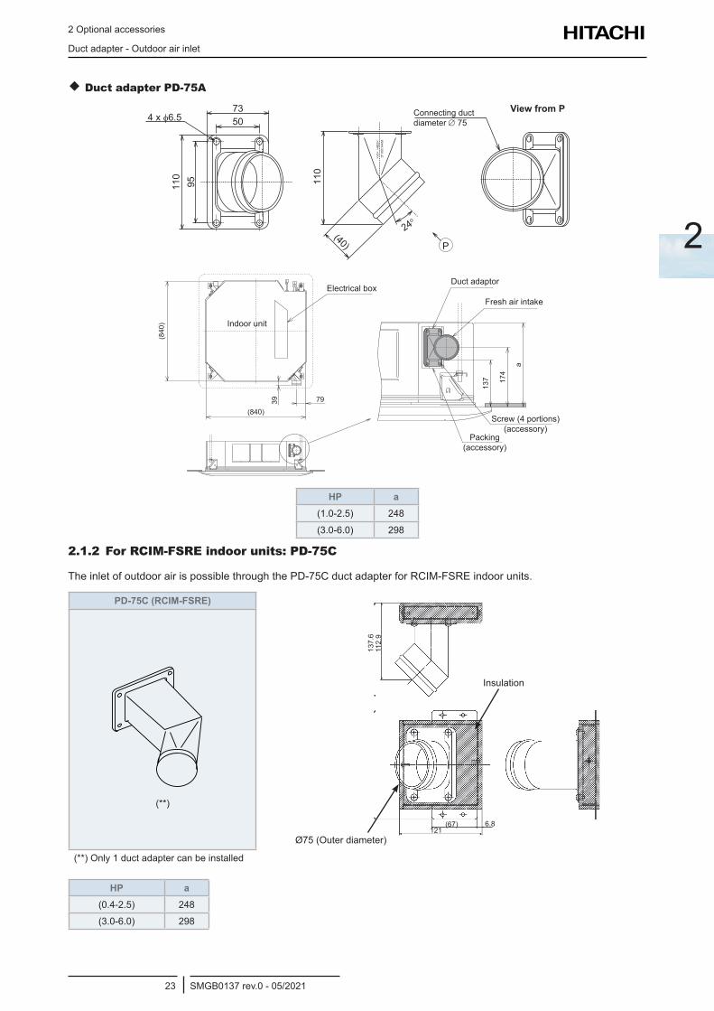
Duct adapter PD-75A
7350
110
(40)
110
95
24o
P
4 x φ6.5
>V0<
>A
BS
<D
# 90C
1445
8
Connecting duct diameter ∅ 75
View from P
(840)
39 79
a
174
137
(840
)
Electrical boxDuct adaptor
Fresh air intake
Screw(4portions) (accessory)
Packing (accessory)
Indoor unit
HP a(1.0-2.5) 248
(3.0-6.0) 298
2.1.2 For RCIM-FSRE indoor units: PD-75C
The inlet of outdoor air is possible through the PD-75C duct adapter for RCIM-FSRE indoor units.
PD-75C (RCIM-FSRE)
Ø75 (Outer diameter)
137.
6
121(67) 6.8
Insulation
112.
9
(**)
(**)Only1ductadaptercanbeinstalled
HP a(0.4-2.5) 248
(3.0-6.0) 298
2 Optional accessories
Duct adapter - Outdoor air inlet
SMGB0137 rev.0 - 05/202124
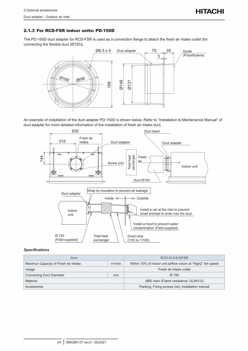
2.1.3 For RCD-FSR indoor units: PD-150D
ThePD-150DductadapterforRCD-FSRisusedasaconnectionflangetoattachthefreshairintakeoutlet(forconnectingtheflexibleduct(Ø150)).
3570
168
Ø168 Ø188
3
Ø137
Ø148
Ø6.5 x 4 Duct adapter Guide (Polyethylene)
AnexampleofinstallationoftheductadapterPD-150Disshownbelow.Referto“Installation&MaintenanceManual”ofduct adapter for more detailed information of the installation of fresh air intake duct.
630
315
144
Duct adapter Duct adapter
Indoor unit
Fresh air
Duct Ø150
Duct band
Screw(x4)
Fresh air intake
Tota
l hea
t ex
chan
ger
Indoor unit
Duct adapterWrapbyinsulationtopreventairleakage
Inside Outside
Install a net at the inlet to prevent small animals to enter into the duct
Installahoodtopreventwatercontamination (Field supplied)
Down-slop (1/50 to 1/100)
Ø 150 (Field supplied)
Total heat exchanger
Specifications
Item RCD-(0.8-6.0)FSRMaximunCapacityofFreshAirIntake m3/min Within10%ofindoorunitairflowvolumat“High2”fanspeed
Usage Fresh air intake outlet
Connecting Duct Diameter mm Ø 150
Material ABS resin (Flame resistance: UL94V-0)
Accessories Packing,Fixingscrews(x4),Installationmanual
2 Optional accessories
T-duct connection position
SMGB0137 rev.0 - 05/202125
2
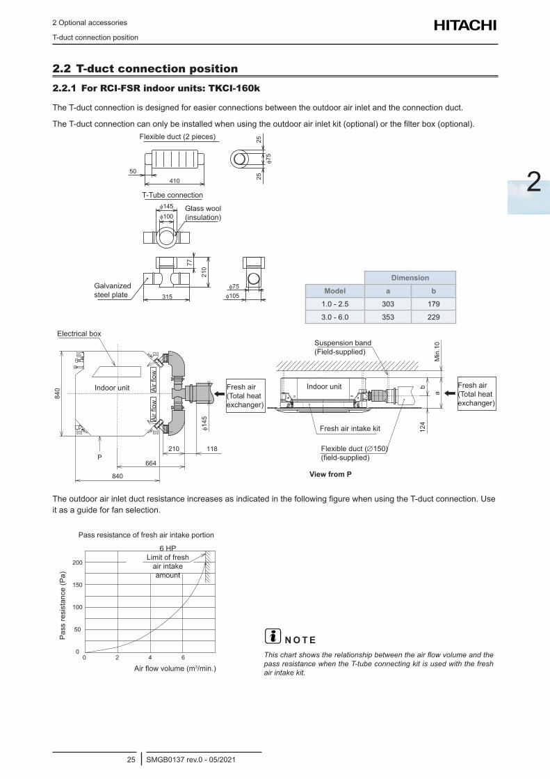
2.2 T-duct connection position2.2.1 For RCI-FSR indoor units: TKCI-160k
TheT-ductconnectionisdesignedforeasierconnectionsbetweentheoutdoorairinletandtheconnectionduct.
TheT-ductconnectioncanonlybeinstalledwhenusingtheoutdoorairinletkit(optional)orthefilterbox(optional).
210
77
50410
25φ7
5
φ75φ105
φ145
φ100
315
25
Flexible duct (2 pieces)
T-Tube connection
Glasswool (insulation)
Galvanizedsteel plate
DimensionModel a b
1.0 - 2.5 303 179
3.0 - 6.0 353 229
840
664P
210 118
φ145
124
Min
.10
a
b
840
Electrical box
Airflow
Fresh air intake kit
View from P
Flexible duct (∅150) (field-supplied)
Airflow
Fresh air (Total heat exchanger)
Suspension band (Field-supplied)
Fresh air (Total heat exchanger)
Indoor unitIndoor unit
TheoutdoorairinletductresistanceincreasesasindicatedinthefollowingfigurewhenusingtheT-ductconnection.Useit as a guide for fan selection.
0 2 4 6
50
100
150
200
0
Pass resistance of fresh air intake portion
Airflowvolume(m3/min.)
Pass
resi
stan
ce (P
a)
6 HP Limit of fresh
air intake amount
? N O T EThischartshowstherelationshipbetweentheairflowvolumeandthepass resistance when the T-tube connecting kit is used with the fresh air intake kit.
2 Optional accessories
Branch pipe (PDF-71C, PDF-160CI)
SMGB0137 rev.0 - 05/202126
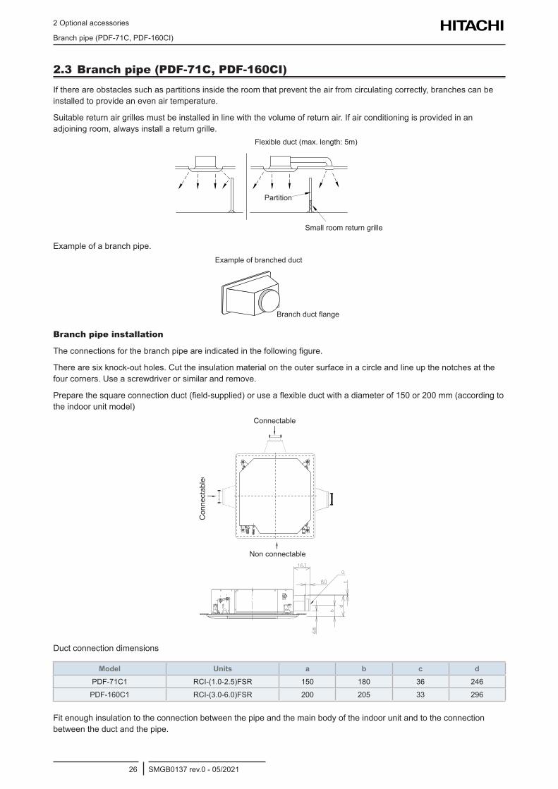
2.3 Branch pipe (PDF-71C, PDF-160CI)Ifthereareobstaclessuchaspartitionsinsidetheroomthatpreventtheairfromcirculatingcorrectly,branchescanbeinstalled to provide an even air temperature.
Suitablereturnairgrillesmustbeinstalledinlinewiththevolumeofreturnair.Ifairconditioningisprovidedinanadjoiningroom,alwaysinstallareturngrille.
Partition
Small room return grille
Flexible duct (max. length: 5m)
Example of a branch pipe.
Branchductflange
Example of branched duct
Branch pipe installation
Theconnectionsforthebranchpipeareindicatedinthefollowingfigure.
There are six knock-out holes. Cut the insulation material on the outer surface in a circle and line up the notches at the fourcorners.Useascrewdriverorsimilarandremove.
Preparethesquareconnectionduct(field-supplied)oruseaflexibleductwithadiameterof150or200mm(accordingtothe indoor unit model)
Non connectable
Connectable
Con
nect
able
Duct connection dimensions
Model Units a b c dPDF-71C1 RCI-(1.0-2.5)FSR 150 180 36 246
PDF-160C1 RCI-(3.0-6.0)FSR 200 205 33 296
Fitenoughinsulationtotheconnectionbetweenthepipeandthemainbodyoftheindoorunitandtotheconnectionbetweentheductandthepipe.
2 Optional accessories
Outletairflowinterlock
SMGB0137 rev.0 - 05/202127
2
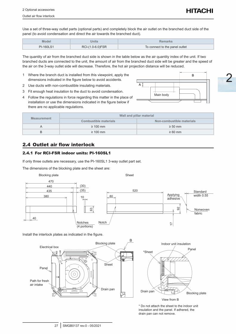
Useasetofthree-wayoutletparts(optionalparts)andcompletelyblocktheairoutletonthebranchedductsideofthepanel(toavoidcondensationanddirecttheairtowardsthebranchedduct).
Model Units RemarksPI-160LS1 RCI-(1.0-6.0)FSR To connect to the panel outlet
Thequantityofairfromthebranchedductsideisshowninthetablebelowastheairquantityindexoftheunit.Iftwobranchedductsareconnectedtotheunit,theamountofairfromthebranchedductsidewillbegreaterandthespeedoftheaironthe3-wayoutletsidewilldecrease.Therefore,thehotairprojectiondistancewillbereduced.
1 Wherethebranchductisinstalledfromthisviewpoint,applythedimensionsindicatedinthefigurebelowtoavoidaccidents.
2 Useductswithnon-combustibleinsulatingmaterials.3 Fit enough heat insulation to the duct to avoid condensation.4 Followtheregulationsinforceregardingthismatterintheplaceof
installationorusethedimensionsindicatedinthefigurebelowifthere are no applicable regulations.
Mainbody
MeasurementWall and pillar material
Combustible materials Non-combustible materialsA ≥100mm ≥50mm
B ≥100mm ≥60mm
2.4 Outlet air flow interlock2.4.1 For RCI-FSR indoor units: PI-160SL1
Ifonlythreeoutletsarenecessary,usethePI-160SL13-wayoutletpartset.
The dimensions of the blocking plate and the sheet are:
470440435
380
40
(30)(35)
10
63
80
520
17
92SheetBlocking plate
Notch
Applyingadhesive
Standard width0.55
Nonwovenfabric
Notches (4 portions)
Installtheinterlockplatesasindicatedinthefigure.B
Blocking plate
*Sheet
Sheet
Panel
Panel
Electrical box
Drain pan Drain pan Blocking plate
Indoor unit insulation
ViewfromB
Path for fresh air intake
* Do not attach the sheet to the indoor unit insulation and the panel. If adhered, the drain pan can not remove.
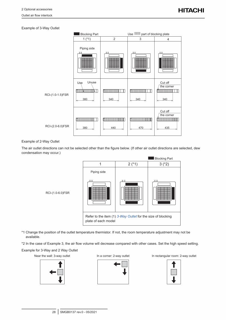
2 Optional accessories
Outletairflowinterlock
SMGB0137 rev.0 - 05/202128
Exampleof3-WayOutlet
380
4 32 1 (*1)
340
435470440380
340 340380
4 32 1 (*1)
340
435470440380
340 340
Blocking Part
Piping side
Use Unuse Cutoffthe corner
Cutoffthe corner
RCI-(1.0-1.5)FSR
RCI-(2.0-6.0)FSR
Use
380
4 32 1 (*1)
340
435470440380
340 340
part of blocking plate
Exampleof2-WayOutlet
Theairoutletdirectionscannotbeselectedotherthanthefigurebelow.(Ifotherairoutletdirectionsareselected,dewcondensationmayoccur.)
3 (*2) 2 (*1) 1
380
4 32 1 (*1)
340
435470440380
340 340
Blocking Part
Piping side
RCI-(1.0-6.0)FSR
Refer to the item (1) 3-Way Outletforthesizeofblockingplate of each model
*1Changethepositionoftheoutlettemperaturethermistor.Ifnot,theroomtemperatureadjustmentmaynotbeavailable.
*2InthecaseofExample3,theairflowvolumewilldecreasecomparedwithothercases.Setthehighspeedsetting.
Examplefor3-Wayand2WayOutletNearthewall:3-wayoutlet Inacorner:2-wayoutlet Inrectangularroom:2-wayoutlet• Near the Wall: 3-Way Outlet • In a Corner: 2-Way Outlet • In Rectangular Room: 2-Way Outlet• Near the Wall: 3-Way Outlet • In a Corner: 2-Way Outlet • In Rectangular Room: 2-Way Outlet• Near the Wall: 3-Way Outlet • In a Corner: 2-Way Outlet • In Rectangular Room: 2-Way Outlet
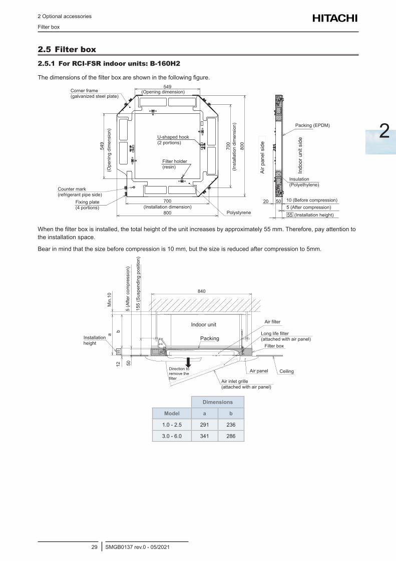
2 Optional accessories
Filter box
SMGB0137 rev.0 - 05/202129
2
2.5 Filter box2.5.1 For RCI-FSR indoor units: B-160H2
Thedimensionsofthefilterboxareshowninthefollowingfigure.
20 50 10 5
55
549
549
700
800
700
800
(Opening dimension)
(Inst
alla
tion
dim
ensi
on)
(Ope
ning
dim
ensi
on)
Filter holder (resin)
U-shaped hook (2 portions)
Corner frame (galvanizedsteelplate)
Counter mark (refrigerant pipe side)
Fixing plate (4 portions)
Polystyrene(Installation dimension)
Indo
or u
nit s
ide
Air p
anel
sid
e
Packing (EPDM)
10 (Before compression)5 (After compression)
(Installation height)
Insulation (Polyethylene)
Whenthefilterboxisinstalled,thetotalheightoftheunitincreasesbyapproximately55mm.Therefore,payattentiontothe installation space.
Bearinmindthatthesizebeforecompressionis10mm,butthesizeisreducedaftercompressionto5mm.
840
5512 50
a
b
5 155Min
.10
Packing
Indoor unit Airfilter
Longlifefilter (attachedwithairpanel)
Filter box
CeilingAir panel
Air inlet grille (attachedwithairpanel)
Direction to remove the filter
Installation height
155
(Sus
pend
ing
posi
tion)
5 (A
fter c
ompr
essi
on)
Dimensions
Model a b
1.0 - 2.5 291 236
3.0 - 6.0 341 286
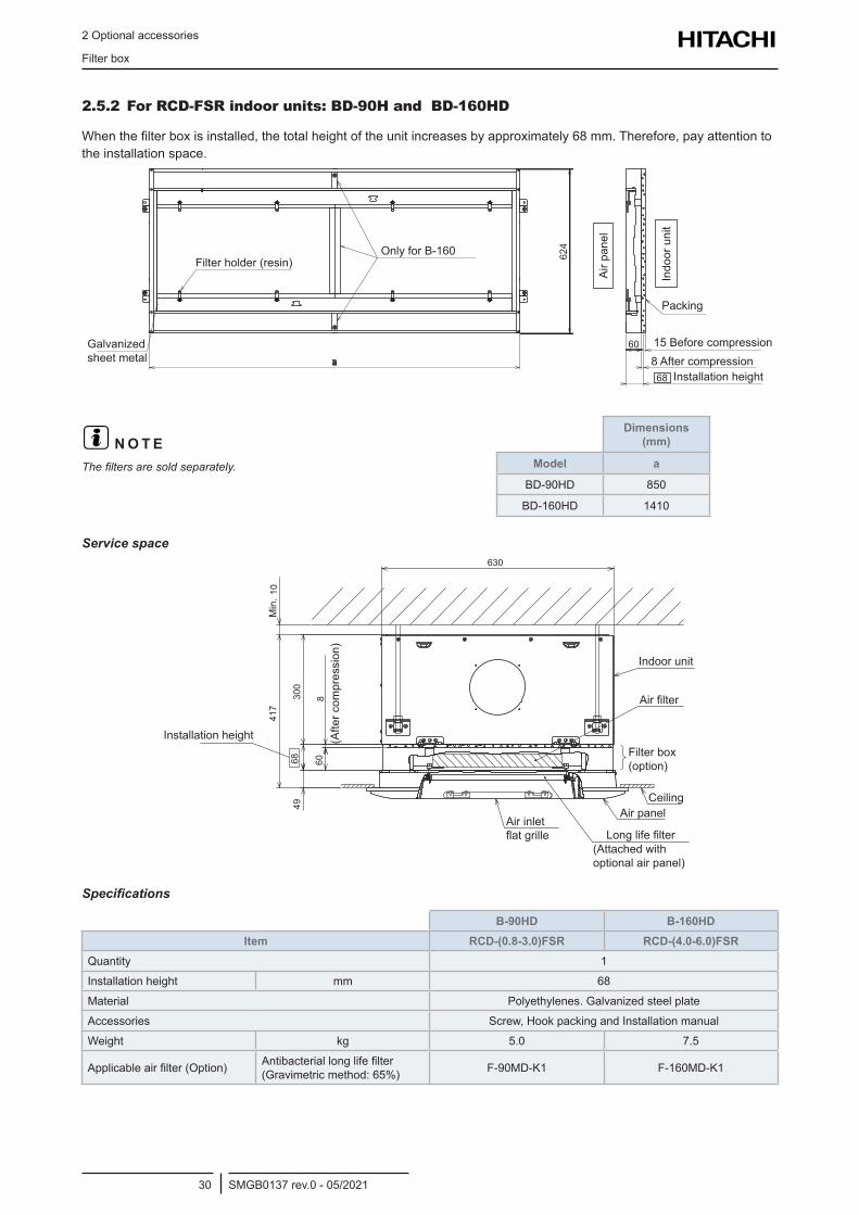
2 Optional accessories
Filter box
SMGB0137 rev.0 - 05/202130
2.5.2 For RCD-FSR indoor units: BD-90H and BD-160HD
Whenthefilterboxisinstalled,thetotalheightoftheunitincreasesbyapproximately68mm.Therefore,payattentiontothe installation space.
60
624
68
Filter holder (resin)OnlyforB-160
Galvanizedsheet metal
Air p
anel
Indo
or u
nit
Packing
15 Before compression8 After compression
Installation height
? N O T EThefiltersaresoldseparately.
Dimensions (mm)
Model a
BD-90HD 850
BD-160HD 1410
Service space
41
7
630
830
04
9
60
68
10
LonglifefilterAir inlet flatgrille
Air panel
(Attachedwithoptional air panel)
Ceiling
Filter box (option)
Airfilter
Indoor unit
Installation height (Afte
r com
pres
sion
)
Min
.
Specifications
B-90HD B-160HDItem RCD-(0.8-3.0)FSR RCD-(4.0-6.0)FSR
Quantity 1
Installation height mm 68
Material Polyethylenes.Galvanizedsteelplate
Accessories Screw,HookpackingandInstallationmanual
Weight kg 5.0 7.5
Applicableairfilter(Option) Antibacteriallonglifefilter(Gravimetricmethod:65%) F-90MD-K1 F-160MD-K1
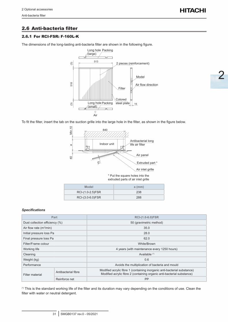
2 Optional accessories
Anti-bacteriafilter
SMGB0137 rev.0 - 05/202131
2
2.6 Anti-bacteria filter 2.6.1 For RCI-FSR: F-160L-K
Thedimensionsofthelong-lastinganti-bacteriafilterareshowninthefollowingfigure.
(3)
518
513
15
F-16
0L-K
AIR
FL
OW
(3)
Long hole (large)
Packing
Model
2 pieces (reinforcement)
AirflowdirectionFilter
Colored steel plate
Air
Long hole (small)
Packing
Tofitthefilter,insertthetabonthesuctiongrilleintothelargeholeinthefilter,asshowninthefigurebelow.
40a
Min
.10
15
840
Indoor unitAntibacterial long lifeairfilter
Air panel
Extruded part *
Air inlet grille
* Put the square holes into the extruded parts of air inlet grille
Model a (mm)RCI-(1.0-2.5)FSR 238
RCI-(3.0-6.0)FSR 288
Specifications
Part RCI-(1.0-6.0)FSRDustcollectionefficiency(%) 50 (gravimetric method)
Airflowrate(m3/min) 35.0
Initial pressure loss Pa 28.0
Final pressure loss Pa 62.0
Filter/Frame colour White/Brown
Working life 4years(withmaintenanceevery1250hours)
Cleaning Available (*)
Weight (kg) 0.6
Performance Avoids the multiplication of bacteria and mould
Filter materialAntibacterialfibre Modifiedacrylicfibre1(containinginorganicanti-bacterialsubstance)
Modifiedacrylicfibre2(containingorganicanti-bacterialsubstance)
Reinforce net PP
(*)Thisisthestandardworkinglifeofthefilteranditsdurationmayvarydependingontheconditionsofuse.Cleanthefilterwithwaterorneutraldetergent.
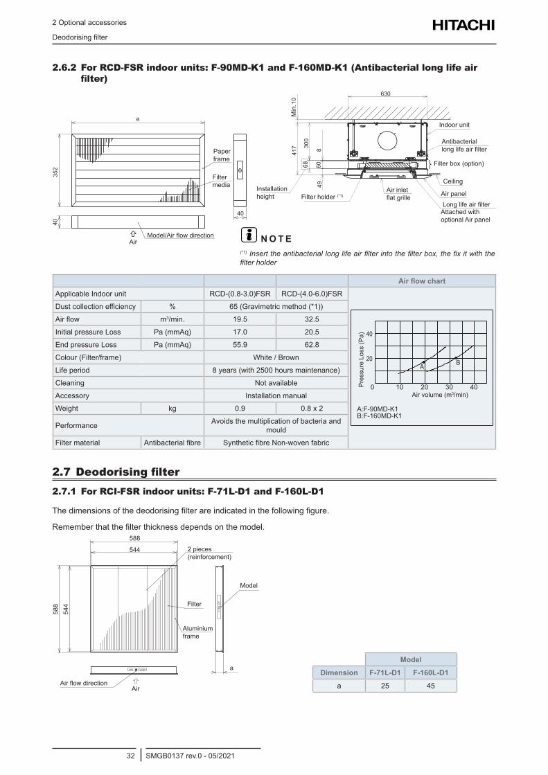
2 Optional accessories
Deodorisingfilter
SMGB0137 rev.0 - 05/202132
2.6.2 For RCD-FSR indoor units: F-90MD-K1 and F-160MD-K1 (Antibacterial long life air filter)
35
2
a
40
40
P
68
49
60
41
7 30
0
8
630
10
Indoor unit
Antibacterial longlifeairfilter
Filter box (option)
Ceiling
Air panelLonglifeairfilterAttachedwithoptional Air panel
Air inlet flatgrilleFilter holder (*1)
Installation height
Min
.
Paper frame
Filter media
Model/AirflowdirectionAir ? N O T E
(*1)Inserttheantibacteriallonglifeairfilterintothefilterbox,thefixitwiththefilterholder
Air flow chartApplicable Indoor unit RCD-(0.8-3.0)FSR RCD-(4.0-6.0)FSR
2010 30 400
20
40
B:F-160MD-K1
A:F-90MD-K1
AB
Air volume (m3/min)
Pres
sure
Los
s (P
a)
Dustcollectionefficiency % 65(Gravimetricmethod(*1))
Airflow m3/min. 19.5 32.5
Initial pressure Loss Pa (mmAq) 17.0 20.5
End pressure Loss Pa (mmAq) 55.9 62.8
Colour (Filter/frame) White/Brown
Life period 8years(with2500hoursmaintenance)
Cleaning Not available
Accessory Installation manual
Weight kg 0.9 0.8 x 2
Performance Avoids the multiplication of bacteria and mould
Filter material Antibacterialfibre SyntheticfibreNon-wovenfabric
2.7 Deodorising filter2.7.1 For RCI-FSR indoor units: F-71L-D1 and F-160L-D1
Thedimensionsofthedeodorisingfilterareindicatedinthefollowingfigure.
Rememberthatthefilterthicknessdependsonthemodel.588
544
588
544
AIR FLOW
F-16
0L-D
1
a
2 pieces (reinforcement)
Model
Filter
Aluminium frame
AirAirflowdirection
ModelDimension F-71L-D1 F-160L-D1
a 25 45
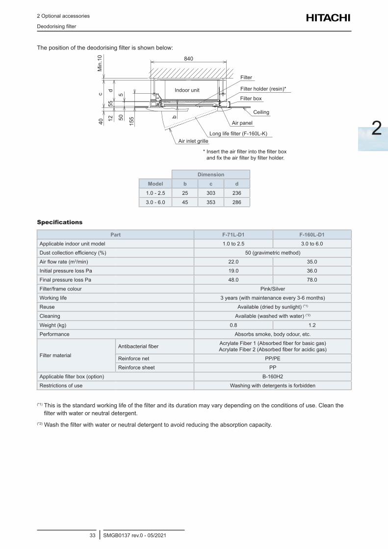
2 Optional accessories
Deodorisingfilter
SMGB0137 rev.0 - 05/202133
2
Thepositionofthedeodorisingfilterisshownbelow:
40c
Min
.10
1255
d
505
155
840
b
Filter
Filter holder (resin)*
Filter box
Ceiling
Air panel
Longlifefilter(F-160L-K)Air inlet grille
Indoor unit
*Inserttheairfilterintothefilterboxandfixtheairfilterbyfilterholder.
DimensionModel b c d
1.0 - 2.5 25 303 236
3.0 - 6.0 45 353 286
Specifications
Part F-71L-D1 F-160L-D1Applicable indoor unit model 1.0 to 2.5 3.0 to 6.0
Dustcollectionefficiency(%) 50 (gravimetric method)
Airflowrate(m3/min) 22.0 35.0
Initial pressure loss Pa 19.0 36.0
Final pressure loss Pa 48.0 78.0
Filter/frame colour Pink/Silver
Working life 3years(withmaintenanceevery3-6months)
Reuse Available(driedbysunlight)(*1)
Cleaning Available(washedwithwater)(*2)
Weight (kg) 0.8 1.2
Performance Absorbssmoke,bodyodour,etc.
Filter material
Antibacterialfiber AcrylateFiber1(Absorbedfiberforbasicgas) AcrylateFiber2(Absorbedfiberforacidicgas)
Reinforce net PP/PE
Reinforce sheet PP
Applicablefilterbox(option) B-160H2
Restrictions of use Washingwithdetergentsisforbidden
(*1)Thisisthestandardworkinglifeofthefilteranditsdurationmayvarydependingontheconditionsofuse.Cleanthefilterwithwaterorneutraldetergent.
(*2)Washthefilterwithwaterorneutraldetergenttoavoidreducingtheabsorptioncapacity.
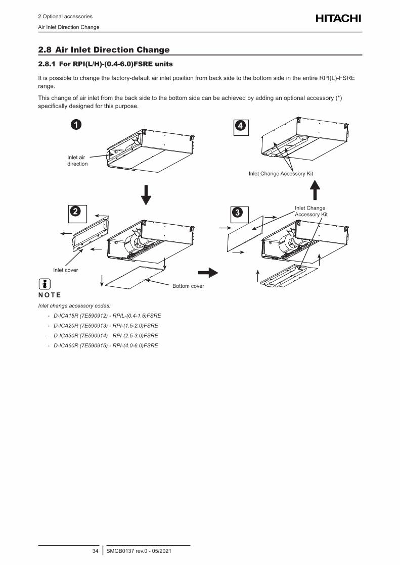
2 Optional accessories
Air Inlet Direction Change
SMGB0137 rev.0 - 05/202134
2.8 Air Inlet Direction Change2.8.1 For RPI(L/H)-(0.4-6.0)FSRE units
Itispossibletochangethefactory-defaultairinletpositionfrombacksidetothebottomsideintheentireRPI(L)-FSRErange.
Thischangeofairinletfromthebacksidetothebottomsidecanbeachievedbyaddinganoptionalaccessory(*)specificallydesignedforthispurpose.
?
Inlet air direction
Inlet cover
Bottom cover
InletChangeAccessoryKit
Inlet Change AccessoryKit
N O T EInlet change accessory codes:
- D-ICA15R (7E590912) - RPIL-(0.4-1.5)FSRE
- D-ICA20R (7E590913) - RPI-(1.5-2.0)FSRE
- D-ICA30R (7E590914) - RPI-(2.5-3.0)FSRE
- D-ICA60R (7E590915) - RPI-(4.0-6.0)FSRE
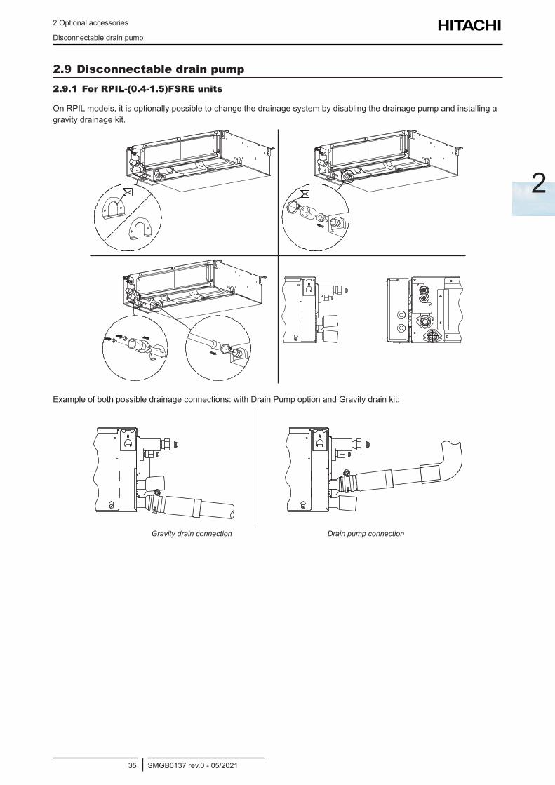
2 Optional accessories
Disconnectable drain pump
SMGB0137 rev.0 - 05/202135
2
2.9 Disconnectable drain pump2.9.1 For RPIL-(0.4-1.5)FSRE units
OnRPILmodels,itisoptionallypossibletochangethedrainagesystembydisablingthedrainagepumpandinstallingagravitydrainagekit.
Exampleofbothpossibledrainageconnections:withDrainPumpoptionandGravitydrainkit:
Gravity drain connection Drain pump connection

3 Electrical and control settings
SMGB0137 rev.0 - 05/202137
3
3 . E l e c t r i c a l a n d c o n t r o l s e t t i n g s
Index
3.1 Unit electrical wiring and connection .....................................................................................................38
3.1.1 Transmission wiring between outdoor and indoor unit .................................................................................. 38
3.1.2 Electrical connection of RCI units .................................................................................................................. 38
3.1.3 Electrical connection of RCIM units ............................................................................................................... 40
3.1.4 Electrical connection of RCD units ................................................................................................................ 42
3.1.5 Electrical connection of RPC units ................................................................................................................ 44
3.1.6 Electrical connection of RPI units .................................................................................................................. 45
3.1.7 Electrical connection of RPK units ................................................................................................................ 49
3.1.8 Electrical connection of RPF(I) units ............................................................................................................. 52
3.1.9 Electrical connection of KPI units .................................................................................................................. 54
3.1.10 Econofresh electrical wiring connection ...................................................................................................... 55
3.1.11 DX-Interface electrical wiring ....................................................................................................................... 56
3.2 Setting of DIP switches and RSW switches ..........................................................................................59
3.3 Wiring diagrams ....................................................................................................................................62
3.3.1 RCI-(1.0-6.0)FSR .......................................................................................................................................... 62
3.3.2 RCIM-(0.4-2.5)FSRE ..................................................................................................................................... 63
3.3.3 RCD-(0.8-6.0)FSR ......................................................................................................................................... 64
3.3.3.1 RCD-(0.8-3.0)FSR ........................................................................................................................... 64
3.3.3.2 RCD-(4.0-6.0)FSR ........................................................................................................................... 65
3.3.4 RPC-(1.5-6.0)FSR ......................................................................................................................................... 66
3.3.5 RPI(L/H)-(0.4-6.0)FSRE ............................................................................................................................... 67
3.3.6 RPI-(4.0-6.0)FSN6E-EF ................................................................................................................................ 68
3.3.7 RPI-(8.0/10.0)FSN3E(-f) ................................................................................................................................ 69
3.3.8 RPI-(16.0/20.0)FSN3PE(-f) ........................................................................................................................... 70
3.3.9 RPK-(0.4-1.5)FSRM ...................................................................................................................................... 71
3.3.10 RPK-(0.4-1.5)FSRHM ................................................................................................................................. 72
3.3.11 RPK-(2.0-4.0)FSRM .................................................................................................................................... 73
3.3.12 RPF(I)-(1.0-2.5)FSN2E ............................................................................................................................... 74
3.3.13 KPI-(252-2002)E4E energy recovery unit and KPI-(502-1002)X4E active unit ........................................... 75
3.3.14 DX-Interface EXV-(2.0-10.0)E2 ................................................................................................................... 76
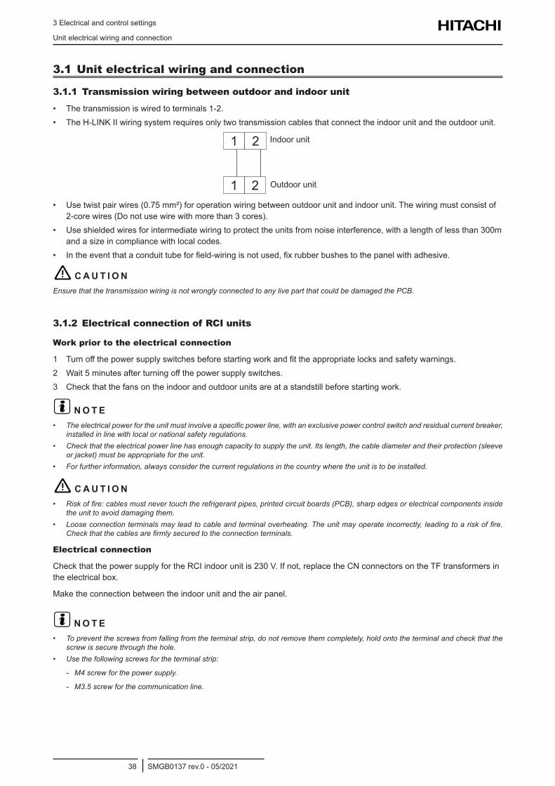
3 Electrical and control settings
Unit electrical wiring and connection
SMGB0137 rev.0 - 05/202138
3.1 Unit electrical wiring and connection
3.1.1 Transmission wiring between outdoor and indoor unit
• The transmission is wired to terminals 1-2. • The H-LINK II wiring system requires only two transmission cables that connect the indoor unit and the outdoor unit.
1
1
2
2
Indoor unit
Outdoor unit
• Use twist pair wires (0.75 mm²) for operation wiring between outdoor unit and indoor unit. The wiring must consist of 2-core wires (Do not use wire with more than 3 cores).
• Use shielded wires for intermediate wiring to protect the units from noise interference, with a length of less than 300m and a size in compliance with local codes.
• Intheeventthataconduittubeforfield-wiringisnotused,fixrubberbushestothepanelwithadhesive.
! C A U T I O NEnsure that the transmission wiring is not wrongly connected to any live part that could be damaged the PCB.
3.1.2 Electrical connection of RCI units
Work prior to the electrical connection
1 Turnoffthepowersupplyswitchesbeforestartingworkandfittheappropriatelocksandsafetywarnings.2 Wait5minutesafterturningoffthepowersupplyswitches.3 Checkthatthefansontheindoorandoutdoorunitsareatastandstillbeforestartingwork.
? N O T E• Theelectricalpowerfortheunitmustinvolveaspecificpowerline,withanexclusivepowercontrolswitchandresidualcurrentbreaker,
installed in line with local or national safety regulations.• Checkthattheelectricalpowerlinehasenoughcapacitytosupplytheunit.Itslength,thecablediameterandtheirprotection(sleeve
orjacket)mustbeappropriatefortheunit.• Forfurtherinformation,alwaysconsiderthecurrentregulationsinthecountrywheretheunitistobeinstalled.
! C A U T I O N• Riskoffire:cablesmustnevertouchtherefrigerantpipes,printedcircuitboards(PCB),sharpedgesorelectricalcomponentsinside
the unit to avoid damaging them.• Looseconnectionterminalsmayleadtocableandterminaloverheating.Theunitmayoperateincorrectly,leadingtoariskoffire.
Checkthatthecablesarefirmlysecuredtotheconnectionterminals.
Electrical connection
CheckthatthepowersupplyfortheRCIindoorunitis230V.Ifnot,replacetheCNconnectorsontheTFtransformersintheelectricalbox.
Maketheconnectionbetweentheindoorunitandtheairpanel.
? N O T E• Topreventthescrewsfromfallingfromtheterminalstrip,donotremovethemcompletely,holdontotheterminalandcheckthatthe
screw is secure through the hole.• Usethefollowingscrewsfortheterminalstrip:
- M4 screw for the power supply.
- M3.5 screw for the communication line.
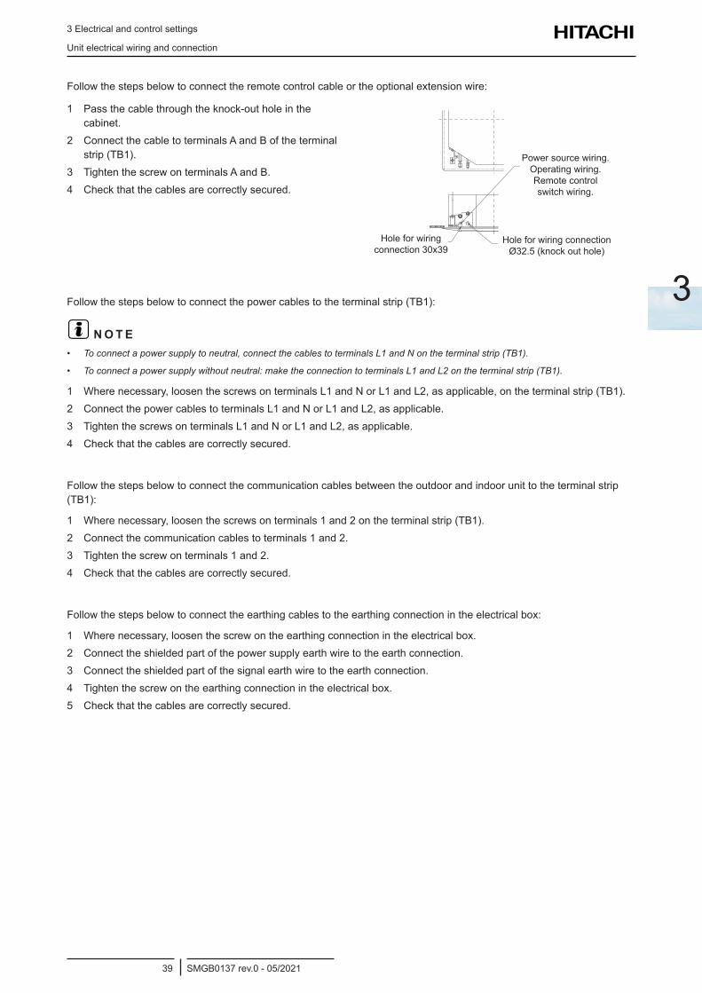
3 Electrical and control settings
Unit electrical wiring and connection
SMGB0137 rev.0 - 05/202139
3
Followthestepsbelowtoconnecttheremotecontrolcableortheoptionalextensionwire:
1 Passthecablethroughtheknock-outholeinthecabinet.
2 Connect the cable to terminals A and B of the terminal strip (TB1).
3 Tighten the screw on terminals A and B.4 Checkthatthecablesarecorrectlysecured.
Power source wiring. Operating wiring. Remote control switch wiring.
Hole for wiring connection Ø32.5(knockouthole)
Hole for wiring connection30x39
Followthestepsbelowtoconnectthepowercablestotheterminalstrip(TB1):
? N O T E• Toconnectapowersupplytoneutral,connectthecablestoterminalsL1andNontheterminalstrip(TB1).
• Toconnectapowersupplywithoutneutral:maketheconnectiontoterminalsL1andL2ontheterminalstrip(TB1).
1 Where necessary, loosen the screws on terminals L1 and N or L1 and L2, as applicable, on the terminal strip (TB1).2 Connect the power cables to terminals L1 and N or L1 and L2, as applicable.3 Tighten the screws on terminals L1 and N or L1 and L2, as applicable.4 Checkthatthecablesarecorrectlysecured.
Follow the steps below to connect the communication cables between the outdoor and indoor unit to the terminal strip (TB1):
1 Where necessary, loosen the screws on terminals 1 and 2 on the terminal strip (TB1).2 Connect the communication cables to terminals 1 and 2.3 Tighten the screw on terminals 1 and 2.4 Checkthatthecablesarecorrectlysecured.
Followthestepsbelowtoconnecttheearthingcablestotheearthingconnectionintheelectricalbox:
1 Wherenecessary,loosenthescrewontheearthingconnectionintheelectricalbox.2 Connect the shielded part of the power supply earth wire to the earth connection.3 Connect the shielded part of the signal earth wire to the earth connection.4 Tightenthescrewontheearthingconnectionintheelectricalbox.5 Checkthatthecablesarecorrectlysecured.
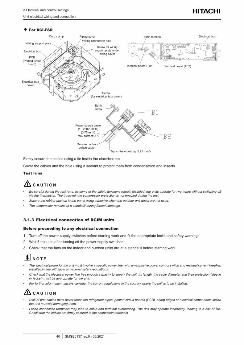
3 Electrical and control settings
Unit electrical wiring and connection
SMGB0137 rev.0 - 05/202140
For RCI-FSR
Piping coverCord clamp
Wiring support plate
Electricalbox
PCB (Printed circuit
board)
Electricalboxcover
Screw (forelectricalboxcover)
Screw for wiring support plate under
piping cover
Wiring connection holeElectricalboxEarth terminal
Terminal board (TB2)Terminal board (TB1)
Transmission wiring (0.75 mm2)
Earth screw
Power source cable (1~ 230V 50Hz)
(0.75 mm2) Maxcurrent:5A
Remote control switch cable
Firmlysecurethecablesusingatieinsidetheelectricalbox.
Cover the cables and the hole using a sealant to protect them from condensation and insects.
Test runs
! C A U T I O N• Becarefulduringthetestruns,assomeofthesafetyfunctionsremaindisabled:theunitsoperatefortwohourswithoutswitchingoff
via the thermostat. The three-minute compressor protection is not enabled during the test.• Secure the rubber bushes to the panel using adhesive when the outdoor unit ducts are not used.• The compressor remains at a standstill during forced stoppage.
3.1.3 Electrical connection of RCIM units
Before proceeding to any electrical connection
1 Turnoffthepowersupplyswitchesbeforestartingworkandfittheappropriatelocksandsafetywarnings.2 Wait5minutesafterturningoffthepowersupplyswitches.3 Checkthatthefansontheindoorandoutdoorunitsareatastandstillbeforestartingwork.
? N O T E• Theelectricalpowerfortheunitmustinvolveaspecificpowerline,withanexclusivepowercontrolswitchandresidualcurrentbreaker,
installed in line with local or national safety regulations.• Checkthattheelectricalpowerlinehasenoughcapacitytosupplytheunit.Itslength,thecablediameterandtheirprotection(sleeve
orjacket)mustbeappropriatefortheunit.• Forfurtherinformation,alwaysconsiderthecurrentregulationsinthecountrywheretheunitistobeinstalled.
! C A U T I O N• Riskoffire:cablesmustnevertouchtherefrigerantpipes,printedcircuitboards(PCB),sharpedgesorelectricalcomponentsinside
the unit to avoid damaging them.• Looseconnectionterminalsmayleadtocableandterminaloverheating.Theunitmayoperateincorrectly,leadingtoariskoffire.
Checkthatthecablesarefirmlysecuredtotheconnectionterminals.
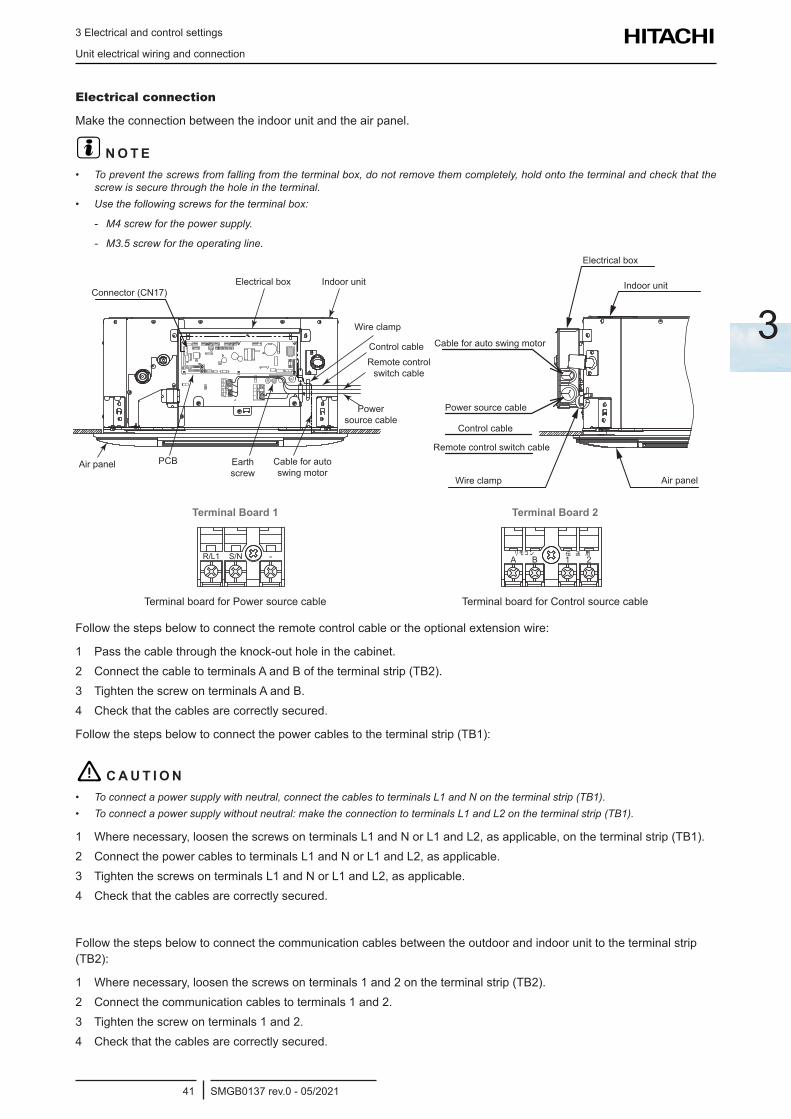
3 Electrical and control settings
Unit electrical wiring and connection
SMGB0137 rev.0 - 05/202141
3
Electrical connection
Maketheconnectionbetweentheindoorunitandtheairpanel.
? N O T E• Topreventthescrewsfromfallingfromtheterminalbox,donotremovethemcompletely,holdontotheterminalandcheckthatthe
screw is secure through the hole in the terminal.• Usethefollowingscrewsfortheterminalbox:
- M4 screw for the power supply.
- M3.5 screw for the operating line.Electricalbox
Remote control switch cable
Control cable
Power source cable
Indoor unit
Air panel
Cable for auto swing motor
Wire clamp
Electricalbox
Wire clamp
Air panel
Indoor unitConnector (CN17)
Earth screw
Control cableRemote control
switch cable
Power source cable
PCB Cable for auto swing motor
Terminal Board 1 Terminal Board 2
-S/NR/L1
Terminal board for Power source cable
A B 1 2
Terminal board for Control source cable
Followthestepsbelowtoconnecttheremotecontrolcableortheoptionalextensionwire:
1 Passthecablethroughtheknock-outholeinthecabinet.2 Connect the cable to terminals A and B of the terminal strip (TB2).3 Tighten the screw on terminals A and B.4 Checkthatthecablesarecorrectlysecured.
Followthestepsbelowtoconnectthepowercablestotheterminalstrip(TB1):
! C A U T I O N• Toconnectapowersupplywithneutral,connectthecablestoterminalsL1andNontheterminalstrip(TB1).• Toconnectapowersupplywithoutneutral:maketheconnectiontoterminalsL1andL2ontheterminalstrip(TB1).
1 Where necessary, loosen the screws on terminals L1 and N or L1 and L2, as applicable, on the terminal strip (TB1).2 Connect the power cables to terminals L1 and N or L1 and L2, as applicable.3 Tighten the screws on terminals L1 and N or L1 and L2, as applicable.4 Checkthatthecablesarecorrectlysecured.
Follow the steps below to connect the communication cables between the outdoor and indoor unit to the terminal strip (TB2):
1 Where necessary, loosen the screws on terminals 1 and 2 on the terminal strip (TB2).2 Connect the communication cables to terminals 1 and 2.3 Tighten the screw on terminals 1 and 2.4 Checkthatthecablesarecorrectlysecured.
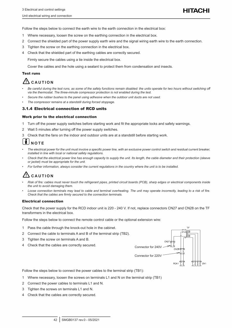
3 Electrical and control settings
Unit electrical wiring and connection
SMGB0137 rev.0 - 05/202142
Followthestepsbelowtoconnecttheearthwiretotheearthconnectionintheelectricalbox:
1 Wherenecessary,loosenthescrewontheearthingconnectionintheelectricalbox.2 Connect the shielded part of the power supply earth wire and the signal wiring earth wire to the earth connection.3 Tightenthescrewontheearthingconnectionintheelectricalbox.4 Checkthattheshieldedpartoftheearthingcablesarecorrectlysecured.
Firmlysecurethecablesusingatieinsidetheelectricalbox.
Cover the cables and the hole using a sealant to protect them from condensation and insects.
Test runs
! C A U T I O N• Becarefulduringthetestruns,assomeofthesafetyfunctionsremaindisabled:theunitsoperatefortwohourswithoutswitchingoff
via the thermostat. The three-minute compressor protection is not enabled during the test.• Secure the rubber bushes to the panel using adhesive when the outdoor unit ducts are not used.• The compressor remains at a standstill during forced stoppage.
3.1.4 Electrical connection of RCD units
Work prior to the electrical connection
1 Turnoffthepowersupplyswitchesbeforestartingworkandfittheappropriatelocksandsafetywarnings.2 Wait5minutesafterturningoffthepowersupplyswitches.3 Checkthatthefansontheindoorandoutdoorunitsareatastandstillbeforestartingwork.
? N O T E• Theelectricalpowerfortheunitmustinvolveaspecificpowerline,withanexclusivepowercontrolswitchandresidualcurrentbreaker,
installed in line with local or national safety regulations.• Checkthattheelectricalpowerlinehasenoughcapacitytosupplytheunit.Itslength,thecablediameterandtheirprotection(sleeve
orjacket)mustbeappropriatefortheunit.• Forfurtherinformation,alwaysconsiderthecurrentregulationsinthecountrywheretheunitistobeinstalled.
! C A U T I O N• Riskoffire:cablesmustnevertouchtherefrigerantpipes,printedcircuitboards(PCB),sharpedgesorelectricalcomponentsinside
the unit to avoid damaging them.• Looseconnectionterminalsmayleadtocableandterminaloverheating.Theunitmayoperateincorrectly,leadingtoariskoffire.
Checkthatthecablesarefirmlysecuredtotheconnectionterminals.
Electrical connection
CheckthatthepowersupplyfortheRCDindoorunitis220-240V.Ifnot,replaceconnectorsCN27andCN28ontheTFtransformersintheelectricalbox.
Followthestepsbelowtoconnecttheremotecontrolcableortheoptionalextensionwire:
1 Passthecablethroughtheknock-outholeinthecabinet.2 Connect the cable to terminals A and B of the terminal strip (TB2).3 Tighten the screw on terminals A and B.4 Checkthatthecablesarecorrectlysecured. Connector for 240V
Connector for 220V
Followthestepsbelowtoconnectthepowercablestotheterminalstrip(TB1):
1 Where necessary, loosen the screws on terminals L1 and N on the terminal strip (TB1)2 Connect the power cables to terminals L1 and N.3 Tighten the screws on terminals L1 and N.4 Checkthatthecablesarecorrectlysecured.

3 Electrical and control settings
Unit electrical wiring and connection
SMGB0137 rev.0 - 05/202143
3
Follow the steps below to connect the communication cables between the outdoor and indoor unit to the terminal strip (TB2):
1 Where necessary, loosen the screws on terminals 1 and 2 on the terminal strip (TB2).2 Connect the communication cables to terminals 1 and 2.3 Tighten the screw on terminals 1 and 2.4 Checkthatthecablesarecorrectlysecured.
Nº Part1 Control Cable
2 Remote Control Cable
3 Power Source Cable
4 Earth Screw
1
2
3
4
1N 220-240V/50Hz
Nº Part1 Connector for the swing louver motor
2 Fan motor connector
3 Terminal strip (TB2)
4 Terminal strip (TB1)
5 Wiring
6 Power wiring
Followthestepsbelowtoconnecttheearthwiretotheearthconnectionintheelectricalbox:
1 Where necessary, loosen the screw on the earthing connection intheelectricalbox.
2 Connect the shielded part of the power supply earth wire and the signal wiring earth wire to the earth connection.
3 Tighten the screw on the earthing connection in the electrical box.
4 Checkthattheshieldedpartoftheearthingcablesarecorrectly secured.
90
445
50
Wiring hole (30-39)
Wiring hole (Ø32.5knock-outhole)
Nº Part1 Tie
2 Communication wiring between the indoor and outdoor units and between indoor units
3 Operating control wiring. In the case of group operations using a remote control
4 Remote control wiringPower source
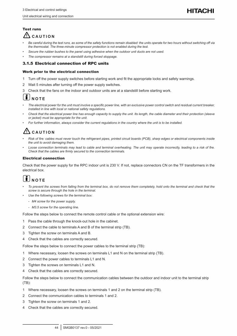
3 Electrical and control settings
Unit electrical wiring and connection
SMGB0137 rev.0 - 05/202144
Test runs
! C A U T I O N• Becarefulduringthetestruns,assomeofthesafetyfunctionsremaindisabled:theunitsoperatefortwohourswithoutswitchingoffvia
the thermostat. The three-minute compressor protection is not enabled during the test.• Secure the rubber bushes to the panel using adhesive when the outdoor unit ducts are not used.• The compressor remains at a standstill during forced stoppage.
3.1.5 Electrical connection of RPC units
Work prior to the electrical connection
1 Turnoffthepowersupplyswitchesbeforestartingworkandfittheappropriatelocksandsafetywarnings.2 Wait5minutesafterturningoffthepowersupplyswitches.3 Checkthatthefansontheindoorandoutdoorunitsareatastandstillbeforestartingwork.
? N O T E• Theelectricalpowerfortheunitmustinvolveaspecificpowerline,withanexclusivepowercontrolswitchandresidualcurrentbreaker,
installed in line with local or national safety regulations.• Checkthattheelectricalpowerlinehasenoughcapacitytosupplytheunit.Itslength,thecablediameterandtheirprotection(sleeve
orjacket)mustbeappropriatefortheunit.• Forfurtherinformation,alwaysconsiderthecurrentregulationsinthecountrywheretheunitistobeinstalled.
! C A U T I O N• Riskoffire:cablesmustnevertouchtherefrigerantpipes,printedcircuitboards(PCB),sharpedgesorelectricalcomponentsinside
the unit to avoid damaging them.• Looseconnectionterminalsmayleadtocableandterminaloverheating.Theunitmayoperateincorrectly,leadingtoariskoffire.
Checkthatthecablesarefirmlysecuredtotheconnectionterminals.
Electrical connection
CheckthatthepowersupplyfortheRPCindoorunitis230V.Ifnot,replaceconnectorsCNontheTFtransformersintheelectricalbox.
? N O T E• Topreventthescrewsfromfallingfromtheterminalbox,donotremovethemcompletely,holdontotheterminalandcheckthatthe
screw is secure through the hole in the terminal.• Usethefollowingscrewsfortheterminalbox:
- M4 screw for the power supply.
- M3.5 screw for the operating line.
Followthestepsbelowtoconnecttheremotecontrolcableortheoptionalextensionwire:
1 Passthecablethroughtheknock-outholeinthecabinet.2 Connect the cable to terminals A and B of the terminal strip (TB).3 Tighten the screw on terminals A and B.4 Checkthatthecablesarecorrectlysecured.
Followthestepsbelowtoconnectthepowercablestotheterminalstrip(TB):
1 Where necessary, loosen the screws on terminals L1 and N on the terminal strip (TB).2 Connect the power cables to terminals L1 and N.3 Tighten the screws on terminals L1 and N.4 Checkthatthecablesarecorrectlysecured.
Follow the steps below to connect the communication cables between the outdoor and indoor unit to the terminal strip (TB):
1 Where necessary, loosen the screws on terminals 1 and 2 on the terminal strip (TB).2 Connect the communication cables to terminals 1 and 2.3 Tighten the screw on terminals 1 and 2.4 Checkthatthecablesarecorrectlysecured.
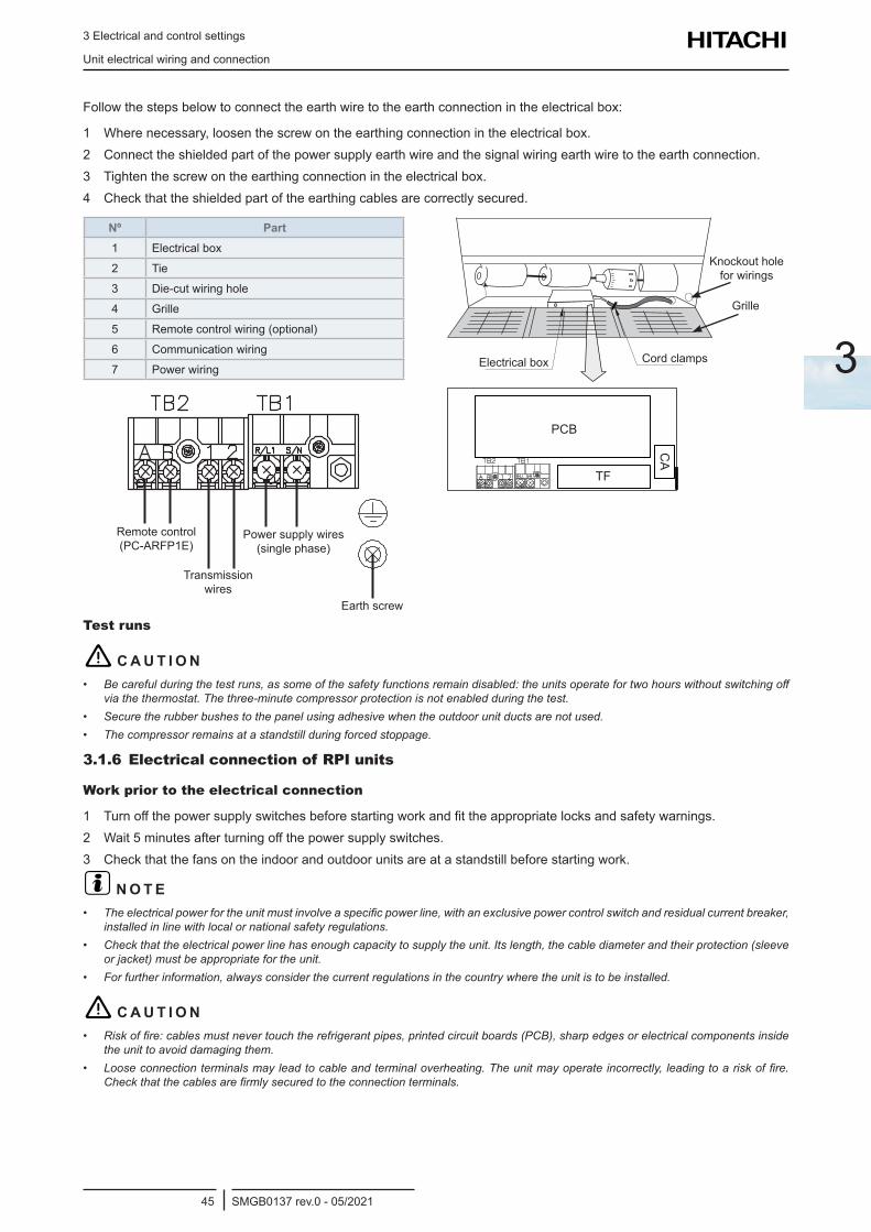
3 Electrical and control settings
Unit electrical wiring and connection
SMGB0137 rev.0 - 05/202145
3
Followthestepsbelowtoconnecttheearthwiretotheearthconnectionintheelectricalbox:
1 Wherenecessary,loosenthescrewontheearthingconnectionintheelectricalbox.2 Connect the shielded part of the power supply earth wire and the signal wiring earth wire to the earth connection.3 Tightenthescrewontheearthingconnectionintheelectricalbox.4 Checkthattheshieldedpartoftheearthingcablesarecorrectlysecured.
Nº Part1 Electricalbox
2 Tie
3 Die-cut wiring hole
4 Grille
5 Remote control wiring (optional)
6 Communication wiring
7 Power wiring
Remote control (PC-ARFP1E)
Power supply wires (single phase)
Transmission wires
Earth screw
Cord clamps
Knockoutholefor wirings
Grille
Electricalbox
Test runs
! C A U T I O N• Becarefulduringthetestruns,assomeofthesafetyfunctionsremaindisabled:theunitsoperatefortwohourswithoutswitchingoff
via the thermostat. The three-minute compressor protection is not enabled during the test.• Secure the rubber bushes to the panel using adhesive when the outdoor unit ducts are not used.• The compressor remains at a standstill during forced stoppage.
3.1.6 Electrical connection of RPI units
Work prior to the electrical connection
1 Turnoffthepowersupplyswitchesbeforestartingworkandfittheappropriatelocksandsafetywarnings.2 Wait5minutesafterturningoffthepowersupplyswitches.3 Checkthatthefansontheindoorandoutdoorunitsareatastandstillbeforestartingwork.
? N O T E• Theelectricalpowerfortheunitmustinvolveaspecificpowerline,withanexclusivepowercontrolswitchandresidualcurrentbreaker,
installed in line with local or national safety regulations.• Checkthattheelectricalpowerlinehasenoughcapacitytosupplytheunit.Itslength,thecablediameterandtheirprotection(sleeve
orjacket)mustbeappropriatefortheunit.• Forfurtherinformation,alwaysconsiderthecurrentregulationsinthecountrywheretheunitistobeinstalled.
! C A U T I O N• Riskoffire:cablesmustnevertouchtherefrigerantpipes,printedcircuitboards(PCB),sharpedgesorelectricalcomponentsinside
the unit to avoid damaging them.• Looseconnectionterminalsmayleadtocableandterminaloverheating.Theunitmayoperateincorrectly,leadingtoariskoffire.
Checkthatthecablesarefirmlysecuredtotheconnectionterminals.
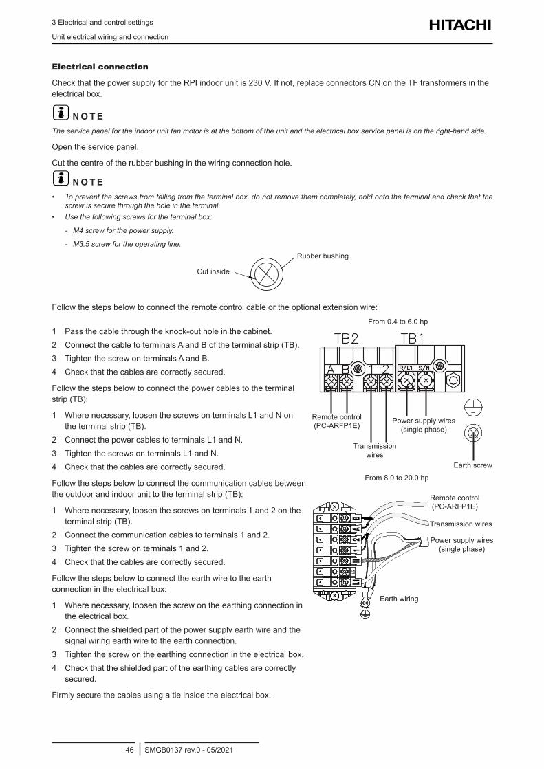
3 Electrical and control settings
Unit electrical wiring and connection
SMGB0137 rev.0 - 05/202146
Electrical connection
CheckthatthepowersupplyfortheRPIindoorunitis230V.Ifnot,replaceconnectorsCNontheTFtransformersintheelectricalbox.
? N O T ETheservicepanelfortheindoorunitfanmotorisatthebottomoftheunitandtheelectricalboxservicepanelisontheright-handside.
Open the service panel.
Cut the centre of the rubber bushing in the wiring connection hole.
? N O T E• Topreventthescrewsfromfallingfromtheterminalbox,donotremovethemcompletely,holdontotheterminalandcheckthatthe
screw is secure through the hole in the terminal.• Usethefollowingscrewsfortheterminalbox:
- M4 screw for the power supply.
- M3.5 screw for the operating line.
Cut inside
Rubber bushing
Followthestepsbelowtoconnecttheremotecontrolcableortheoptionalextensionwire:
1 Passthecablethroughtheknock-outholeinthecabinet.2 Connect the cable to terminals A and B of the terminal strip (TB).3 Tighten the screw on terminals A and B.4 Checkthatthecablesarecorrectlysecured.
Follow the steps below to connect the power cables to the terminal strip(TB):
1 Where necessary, loosen the screws on terminals L1 and N on the terminal strip (TB).
2 Connect the power cables to terminals L1 and N.3 Tighten the screws on terminals L1 and N.4 Checkthatthecablesarecorrectlysecured.
Remote control (PC-ARFP1E)
Power supply wires (single phase)
Transmission wires
Earth screw
From 0.4 to 6.0 hp
Follow the steps below to connect the communication cables between theoutdoorandindoorunittotheterminalstrip(TB):
1 Where necessary, loosen the screws on terminals 1 and 2 on the terminal strip (TB).
2 Connect the communication cables to terminals 1 and 2.3 Tighten the screw on terminals 1 and 2.4 Checkthatthecablesarecorrectlysecured.
Follow the steps below to connect the earth wire to the earth connectionintheelectricalbox:
1 Where necessary, loosen the screw on the earthing connection in theelectricalbox.
2 Connect the shielded part of the power supply earth wire and the signal wiring earth wire to the earth connection.
3 Tightenthescrewontheearthingconnectionintheelectricalbox.4 Checkthattheshieldedpartoftheearthingcablesarecorrectly
secured.
Firmlysecurethecablesusingatieinsidetheelectricalbox.
Earth wiring
Remote control (PC-ARFP1E)
Transmission wires
Power supply wires (single phase)
From 8.0 to 20.0 hp
3 Electrical and control settings
Unit electrical wiring and connection
SMGB0137 rev.0 - 05/202147
3
RPI(L/H)-(0.4-6.0)FSRE Terminal board location
Cover the cables and the hole using a sealant to protect them from condensation and insects.
Nº PartPCB Printed circuit board
TB Terminal strip
Wiring connection
Electrical box
PCB
TB
RPI-(8.0/10.0)FSN3E(-f) Terminal board connections
Nº PartPCB1 Printed circuit board
PCB2 Printed circuit board
TF Transformer
TB Terminal strip
FUSE Fuse
Service panel for
electricalbox
Wiring connection
FUSE
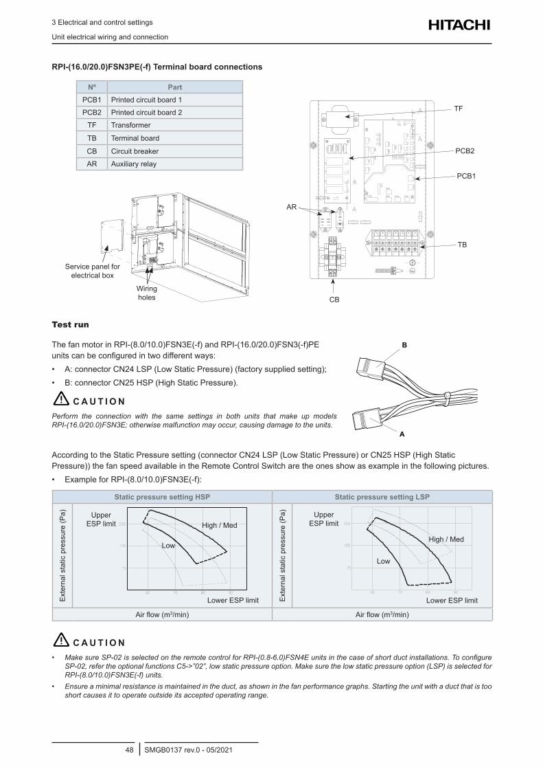
3 Electrical and control settings
Unit electrical wiring and connection
SMGB0137 rev.0 - 05/202148
RPI-(16.0/20.0)FSN3PE(-f) Terminal board connections
Nº PartPCB1 Printed circuit board 1
PCB2 Printed circuit board 2
TF Transformer
TB Terminal board
CB Circuitbreaker
AR Auxiliaryrelay
Wiring holes
Service panel for electricalbox
CB
AR
TB
PCB1
PCB2
TF
Test run
The fan motor in RPI-(8.0/10.0)FSN3E(-f) and RPI-(16.0/20.0)FSN3(-f)PE unitscanbeconfiguredintwodifferentways:• A:connectorCN24LSP(LowStaticPressure)(factorysuppliedsetting);• B:connectorCN25HSP(HighStaticPressure).
! C A U T I O NPerform the connection with the same settings in both units that make up models RPI-(16.0/20.0)FSN3E;otherwisemalfunctionmayoccur,causingdamagetotheunits.
According to the Static Pressure setting (connector CN24 LSP (Low Static Pressure) or CN25 HSP (High Static Pressure))thefanspeedavailableintheRemoteControlSwitcharetheonesshowasexampleinthefollowingpictures.• ExampleforRPI-(8.0/10.0)FSN3E(-f):
Static pressure setting HSP Static pressure setting LSP
Externalstaticpressure(Pa)
Lower ESP limit
Low
High / MedUpper
ESP limit
Externalstaticpressure(Pa)
Lower ESP limit
Low
High / Med
Upper ESP limit
Airflow(m3/min) Airflow(m3/min)
! C A U T I O N• MakesureSP-02isselectedontheremotecontrolforRPI-(0.8-6.0)FSN4Eunitsinthecaseofshortductinstallations.Toconfigure
SP-02,refertheoptionalfunctionsC5->”02”,lowstaticpressureoption.Makesurethelowstaticpressureoption(LSP)isselectedforRPI-(8.0/10.0)FSN3E(-f)units.
• Ensureaminimalresistanceismaintainedintheduct,asshowninthefanperformancegraphs.Startingtheunitwithaductthatistooshort causes it to operate outside its accepted operating range.
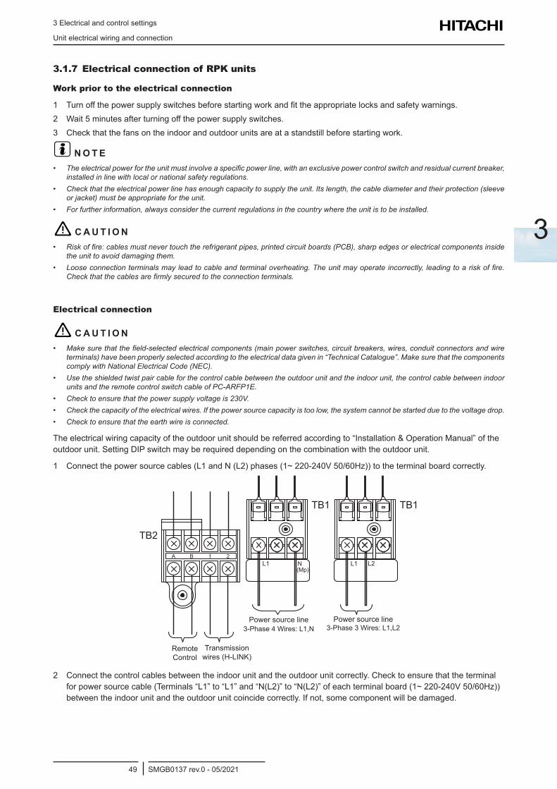
3 Electrical and control settings
Unit electrical wiring and connection
SMGB0137 rev.0 - 05/202149
3
3.1.7 Electrical connection of RPK units
Work prior to the electrical connection
1 Turnoffthepowersupplyswitchesbeforestartingworkandfittheappropriatelocksandsafetywarnings.2 Wait5minutesafterturningoffthepowersupplyswitches.3 Checkthatthefansontheindoorandoutdoorunitsareatastandstillbeforestartingwork.
? N O T E• Theelectricalpowerfortheunitmustinvolveaspecificpowerline,withanexclusivepowercontrolswitchandresidualcurrentbreaker,
installed in line with local or national safety regulations.• Checkthattheelectricalpowerlinehasenoughcapacitytosupplytheunit.Itslength,thecablediameterandtheirprotection(sleeve
orjacket)mustbeappropriatefortheunit.• Forfurtherinformation,alwaysconsiderthecurrentregulationsinthecountrywheretheunitistobeinstalled.
! C A U T I O N• Riskoffire:cablesmustnevertouchtherefrigerantpipes,printedcircuitboards(PCB),sharpedgesorelectricalcomponentsinside
the unit to avoid damaging them.• Looseconnectionterminalsmayleadtocableandterminaloverheating.Theunitmayoperateincorrectly,leadingtoariskoffire.
Checkthatthecablesarefirmlysecuredtotheconnectionterminals.
Electrical connection
! C A U T I O N• Makesurethatthefield-selectedelectricalcomponents(mainpowerswitches,circuitbreakers,wires,conduitconnectorsandwire
terminals)havebeenproperlyselectedaccordingtotheelectricaldatagivenin“TechnicalCatalogue”.MakesurethatthecomponentscomplywithNationalElectricalCode(NEC).
• Usetheshieldedtwistpaircableforthecontrolcablebetweentheoutdoorunitandtheindoorunit,thecontrolcablebetweenindoorunitsandtheremotecontrolswitchcableofPC-ARFP1E.
• Checktoensurethatthepowersupplyvoltageis230V.• Checkthecapacityoftheelectricalwires.Ifthepowersourcecapacityistoolow,thesystemcannotbestartedduetothevoltagedrop.• Checktoensurethattheearthwireisconnected.
The electrical wiring capacity of the outdoor unit should be referred according to “Installation & Operation Manual” of the outdoor unit. Setting DIP switch may be required depending on the combination with the outdoor unit.
1 Connect the power source cables (L1 and N (L2) phases (1~ 220-240V 50/60Hz)) to the terminal board correctly.
A B 1 2L1
(Mp)N
TB2
TB1
L1
TB1
L2
Remote Control
Transmission wires (H-LINK)
Power source line 3-Phase4Wires:L1,N
Power source line 3-Phase3Wires:L1,L2
2 Connectthecontrolcablesbetweentheindoorunitandtheoutdoorunitcorrectly.Checktoensurethattheterminalfor power source cable (Terminals “L1” to “L1” and “N(L2)” to “N(L2)” of each terminal board (1~ 220-240V 50/60Hz)) between the indoor unit and the outdoor unit coincide correctly. If not, some component will be damaged.
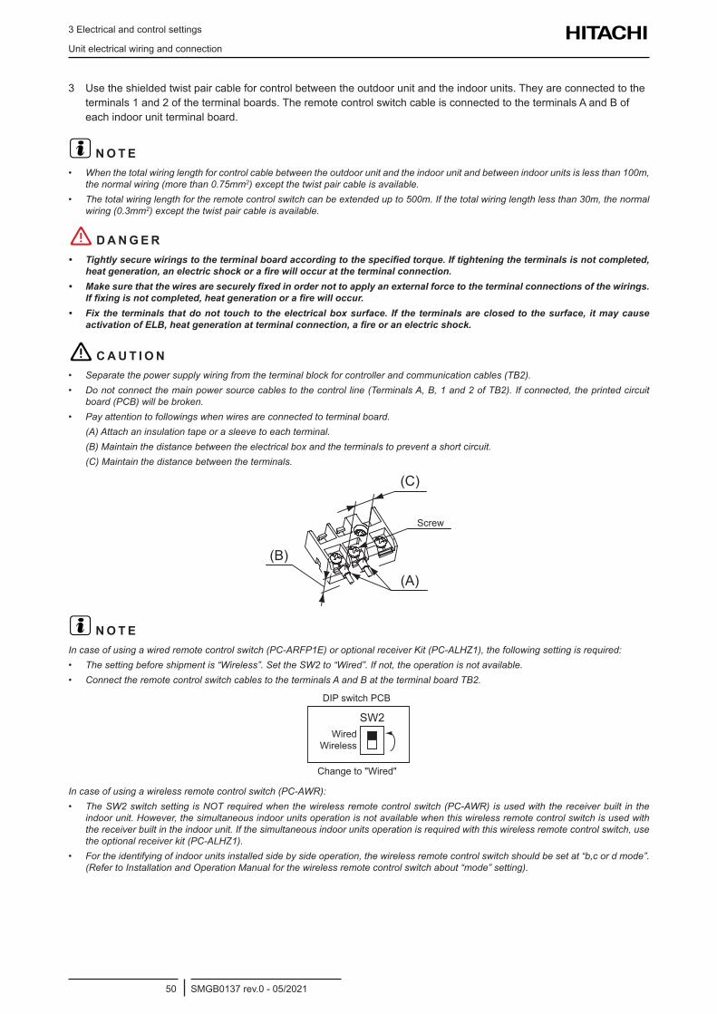
3 Electrical and control settings
Unit electrical wiring and connection
SMGB0137 rev.0 - 05/202150
3 Use the shielded twist pair cable for control between the outdoor unit and the indoor units. They are connected to the terminals 1 and 2 of the terminal boards. The remote control switch cable is connected to the terminals A and B of each indoor unit terminal board.
? N O T E• Whenthetotalwiringlengthforcontrolcablebetweentheoutdoorunitandtheindoorunitandbetweenindoorunitsislessthan100m,
thenormalwiring(morethan0.75mm2)exceptthetwistpaircableisavailable.• Thetotalwiringlengthfortheremotecontrolswitchcanbeextendedupto500m.Ifthetotalwiringlengthlessthan30m,thenormal
wiring(0.3mm2)exceptthetwistpaircableisavailable.
! D A N G E R• Tightlysecurewiringstotheterminalboardaccordingtothespecifiedtorque.Iftighteningtheterminalsisnotcompleted,
heatgeneration,anelectricshockorafirewilloccurattheterminalconnection.• Makesurethatthewiresaresecurelyfixedinordernottoapplyanexternalforcetotheterminalconnectionsofthewirings.
Iffixingisnotcompleted,heatgenerationorafirewilloccur.• Fixtheterminalsthatdonottouchtotheelectricalboxsurface. If theterminalsareclosedtothesurface, itmaycause
activationofELB,heatgenerationatterminalconnection,afireoranelectricshock.
! C A U T I O N• Separatethepowersupplywiringfromtheterminalblockforcontrollerandcommunicationcables(TB2).• Donotconnectthemainpowersourcecablestothecontrolline(TerminalsA,B,1and2ofTB2).Ifconnected,theprintedcircuit
board(PCB)willbebroken.• Pay attention to followings when wires are connected to terminal board.
(A)Attachaninsulationtapeorasleevetoeachterminal.(B)Maintainthedistancebetweentheelectricalboxandtheterminalstopreventashortcircuit.(C)Maintainthedistancebetweentheterminals.
(A)
(B)
(C)
Screw
? N O T EIncaseofusingawiredremotecontrolswitch(PC-ARFP1E)oroptionalreceiverKit(PC-ALHZ1),thefollowingsettingisrequired:• Thesettingbeforeshipmentis“Wireless”.SettheSW2to“Wired”.Ifnot,theoperationisnotavailable.• ConnecttheremotecontrolswitchcablestotheterminalsAandBattheterminalboardTB2.
SW2
DIP switch PCB
Wired Wireless
Change to "Wired"
Incaseofusingawirelessremotecontrolswitch(PC-AWR):• TheSW2switchsetting isNOTrequiredwhenthewirelessremotecontrolswitch(PC-AWR)isusedwiththereceiverbuilt inthe
indoorunit.However,thesimultaneousindoorunitsoperationisnotavailablewhenthiswirelessremotecontrolswitchisusedwiththereceiverbuiltintheindoorunit.Ifthesimultaneousindoorunitsoperationisrequiredwiththiswirelessremotecontrolswitch,usetheoptionalreceiverkit(PC-ALHZ1).
• Fortheidentifyingofindoorunitsinstalledsidebysideoperation,thewirelessremotecontrolswitchshouldbesetat“b,cordmode”.(RefertoInstallationandOperationManualforthewirelessremotecontrolswitchabout“mode”setting).

3 Electrical and control settings
Unit electrical wiring and connection
SMGB0137 rev.0 - 05/202151
3
Terminal board connections
Electrical boxcover
Switch cover
A 1 2
Screw for earth wiring connection
Electricalboxcover
Wireforreceiverkitorwiredremotecontrol
Terminal board for remote control switch cable and transmission wire
Terminal board for power source
Fixthewiresby cord clamp
DIP switch location
PCB2
Switch cover
DSW5 RSW1
RSW2DSW6
DSW9 DSW2S
W2
DSW3
Test runs
! C A U T I O N• Becarefulduringthetestruns,assomeofthesafetyfunctionsremaindisabled:theunitsoperatefortwohourswithoutswitchingoff
via the thermostat. The three-minute compressor protection is not enabled during the test.• Secure the rubber bushes to the panel using adhesive when the outdoor unit ducts are not used.• The compressor remains at a standstill during forced stoppage.
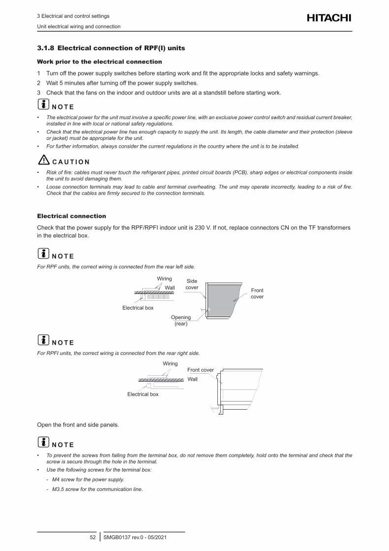
3 Electrical and control settings
Unit electrical wiring and connection
SMGB0137 rev.0 - 05/202152
3.1.8 Electrical connection of RPF(I) units
Work prior to the electrical connection
1 Turnoffthepowersupplyswitchesbeforestartingworkandfittheappropriatelocksandsafetywarnings.2 Wait5minutesafterturningoffthepowersupplyswitches.3 Checkthatthefansontheindoorandoutdoorunitsareatastandstillbeforestartingwork.
? N O T E• Theelectricalpowerfortheunitmustinvolveaspecificpowerline,withanexclusivepowercontrolswitchandresidualcurrentbreaker,
installed in line with local or national safety regulations.• Checkthattheelectricalpowerlinehasenoughcapacitytosupplytheunit.Itslength,thecablediameterandtheirprotection(sleeve
orjacket)mustbeappropriatefortheunit.• Forfurtherinformation,alwaysconsiderthecurrentregulationsinthecountrywheretheunitistobeinstalled.
! C A U T I O N• Riskoffire:cablesmustnevertouchtherefrigerantpipes,printedcircuitboards(PCB),sharpedgesorelectricalcomponentsinside
the unit to avoid damaging them.• Looseconnectionterminalsmayleadtocableandterminaloverheating.Theunitmayoperateincorrectly,leadingtoariskoffire.
Checkthatthecablesarefirmlysecuredtotheconnectionterminals.
Electrical connection
CheckthatthepowersupplyfortheRPF/RPFIindoorunitis230V.Ifnot,replaceconnectorsCNontheTFtransformersintheelectricalbox.
? N O T EForRPFunits,thecorrectwiringisconnectedfromtherearleftside.
Wiring
WallSide cover Front
cover
Opening (rear)
Electricalbox
? N O T EForRPFIunits,thecorrectwiringisconnectedfromtherearrightside.
Wiring
Wall
Front cover
Electricalbox
Open the front and side panels.
? N O T E• Topreventthescrewsfromfallingfromtheterminalbox,donotremovethemcompletely,holdontotheterminalandcheckthatthe
screw is secure through the hole in the terminal.• Usethefollowingscrewsfortheterminalbox:
- M4 screw for the power supply.
- M3.5 screw for the communication line.
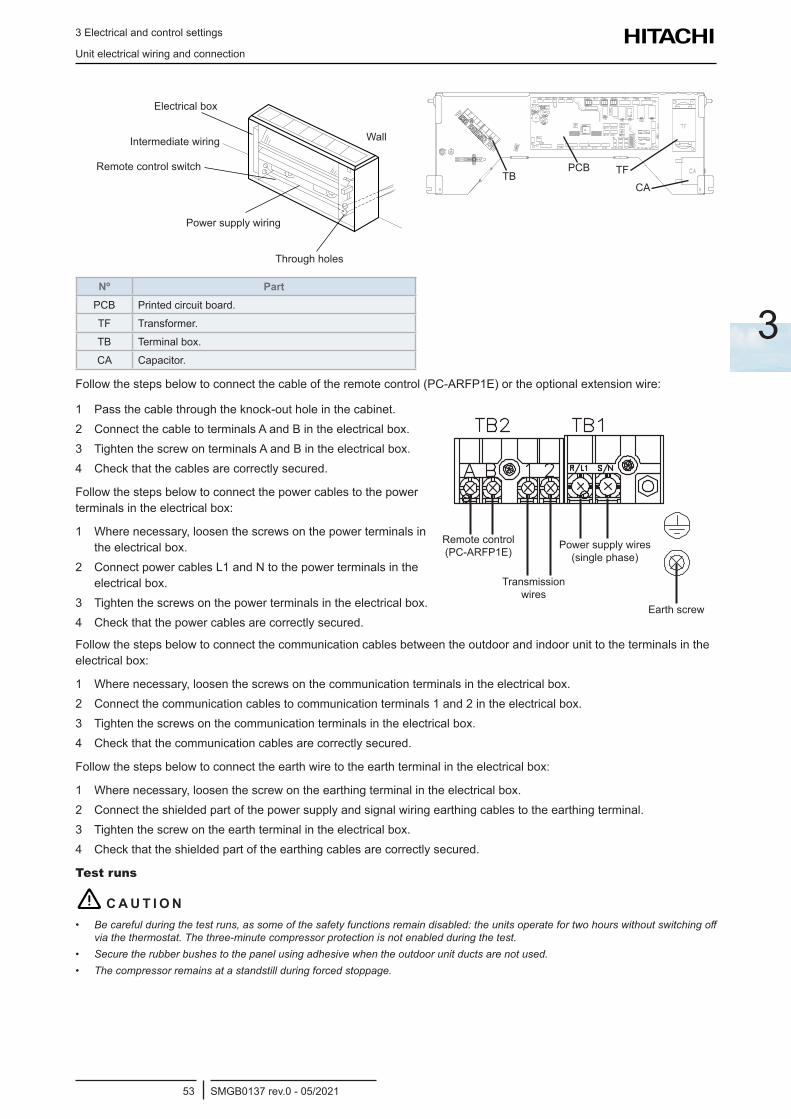
3 Electrical and control settings
Unit electrical wiring and connection
SMGB0137 rev.0 - 05/202153
3
Wall
Power supply wiring
Through holes
Remote control switch
Electricalbox
Intermediate wiring
Nº PartPCB Printed circuit board.
TF Transformer.
TB Terminalbox.
CA Capacitor.
PCB TFCA
TB
Followthestepsbelowtoconnectthecableoftheremotecontrol(PC-ARFP1E)ortheoptionalextensionwire:
1 Passthecablethroughtheknock-outholeinthecabinet.2 ConnectthecabletoterminalsAandBintheelectricalbox.3 TightenthescrewonterminalsAandBintheelectricalbox.4 Checkthatthecablesarecorrectlysecured.
Follow the steps below to connect the power cables to the power terminalsintheelectricalbox:
1 Where necessary, loosen the screws on the power terminals in theelectricalbox.
2 Connect power cables L1 and N to the power terminals in the electricalbox.
3 Tightenthescrewsonthepowerterminalsintheelectricalbox.4 Checkthatthepowercablesarecorrectlysecured.
Remote control (PC-ARFP1E)
Power supply wires (single phase)
Transmission wires
Earth screw
Follow the steps below to connect the communication cables between the outdoor and indoor unit to the terminals in the electricalbox:
1 Wherenecessary,loosenthescrewsonthecommunicationterminalsintheelectricalbox.2 Connectthecommunicationcablestocommunicationterminals1and2intheelectricalbox.3 Tightenthescrewsonthecommunicationterminalsintheelectricalbox.4 Checkthatthecommunicationcablesarecorrectlysecured.
Followthestepsbelowtoconnecttheearthwiretotheearthterminalintheelectricalbox:
1 Wherenecessary,loosenthescrewontheearthingterminalintheelectricalbox.2 Connect the shielded part of the power supply and signal wiring earthing cables to the earthing terminal.3 Tightenthescrewontheearthterminalintheelectricalbox.4 Checkthattheshieldedpartoftheearthingcablesarecorrectlysecured.
Test runs
! C A U T I O N• Becarefulduringthetestruns,assomeofthesafetyfunctionsremaindisabled:theunitsoperatefortwohourswithoutswitchingoff
via the thermostat. The three-minute compressor protection is not enabled during the test.• Secure the rubber bushes to the panel using adhesive when the outdoor unit ducts are not used.• The compressor remains at a standstill during forced stoppage.
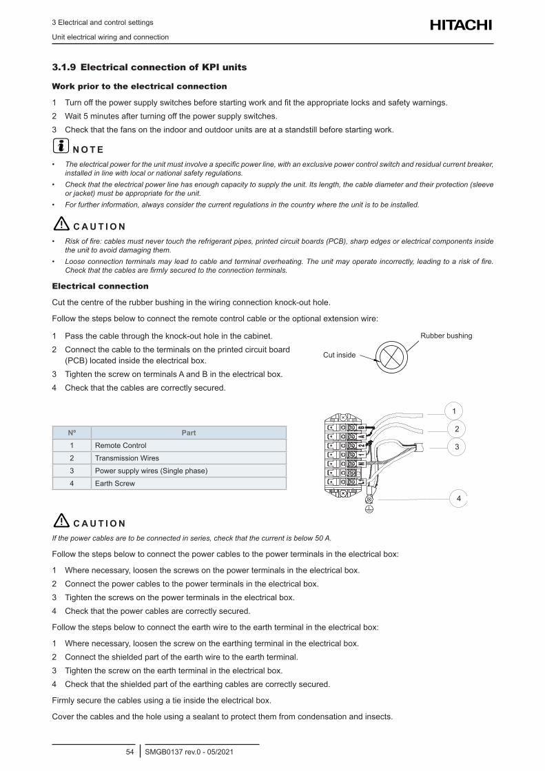
3 Electrical and control settings
Unit electrical wiring and connection
SMGB0137 rev.0 - 05/202154
3.1.9 Electrical connection of KPI units
Work prior to the electrical connection
1 Turnoffthepowersupplyswitchesbeforestartingworkandfittheappropriatelocksandsafetywarnings.2 Wait5minutesafterturningoffthepowersupplyswitches.3 Checkthatthefansontheindoorandoutdoorunitsareatastandstillbeforestartingwork.
? N O T E• Theelectricalpowerfortheunitmustinvolveaspecificpowerline,withanexclusivepowercontrolswitchandresidualcurrentbreaker,
installed in line with local or national safety regulations.• Checkthattheelectricalpowerlinehasenoughcapacitytosupplytheunit.Itslength,thecablediameterandtheirprotection(sleeve
orjacket)mustbeappropriatefortheunit.• Forfurtherinformation,alwaysconsiderthecurrentregulationsinthecountrywheretheunitistobeinstalled.
! C A U T I O N• Riskoffire:cablesmustnevertouchtherefrigerantpipes,printedcircuitboards(PCB),sharpedgesorelectricalcomponentsinside
the unit to avoid damaging them.• Looseconnectionterminalsmayleadtocableandterminaloverheating.Theunitmayoperateincorrectly,leadingtoariskoffire.
Checkthatthecablesarefirmlysecuredtotheconnectionterminals.
Electrical connection
Cutthecentreoftherubberbushinginthewiringconnectionknock-outhole.
Followthestepsbelowtoconnecttheremotecontrolcableortheoptionalextensionwire:
1 Passthecablethroughtheknock-outholeinthecabinet.2 Connect the cable to the terminals on the printed circuit board
(PCB)locatedinsidetheelectricalbox.3 TightenthescrewonterminalsAandBintheelectricalbox.4 Checkthatthecablesarecorrectlysecured.
Cut inside
Rubber bushing
Nº Part1 Remote Control
2 Transmission Wires
3 Power supply wires (Single phase)
4 Earth Screw
1
4
3
2
! C A U T I O NIfthepowercablesaretobeconnectedinseries,checkthatthecurrentisbelow50A.
Followthestepsbelowtoconnectthepowercablestothepowerterminalsintheelectricalbox:
1 Wherenecessary,loosenthescrewsonthepowerterminalsintheelectricalbox.2 Connectthepowercablestothepowerterminalsintheelectricalbox.3 Tightenthescrewsonthepowerterminalsintheelectricalbox.4 Checkthatthepowercablesarecorrectlysecured.
Followthestepsbelowtoconnecttheearthwiretotheearthterminalintheelectricalbox:
1 Wherenecessary,loosenthescrewontheearthingterminalintheelectricalbox.2 Connect the shielded part of the earth wire to the earth terminal.3 Tightenthescrewontheearthterminalintheelectricalbox.4 Checkthattheshieldedpartoftheearthingcablesarecorrectlysecured.
Firmlysecurethecablesusingatieinsidetheelectricalbox.
Cover the cables and the hole using a sealant to protect them from condensation and insects.
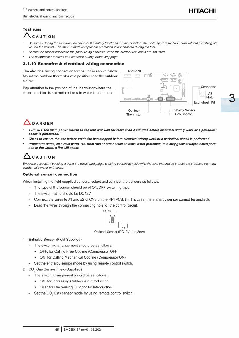
3 Electrical and control settings
Unit electrical wiring and connection
SMGB0137 rev.0 - 05/202155
3
Test runs
! C A U T I O N• Becarefulduringthetestruns,assomeofthesafetyfunctionsremaindisabled:theunitsoperatefortwohourswithoutswitchingoff
via the thermostat. The three-minute compressor protection is not enabled during the test.• Secure the rubber bushes to the panel using adhesive when the outdoor unit ducts are not used.• The compressor remains at a standstill during forced stoppage.
3.1.10 Econofresh electrical wiring connection
The electrical wiring connection for the unit is shown below. Mount the outdoor thermistor at a position near the outdoor air inlet.
Pay attention to the position of the thermistor where the direct sunshine is not radiated or rain water is not touched.
RPI PCB
Connector
AS Motor
Econofresh Kit
Outdoor Thermistor
Enthalpy Sensor Gas Sensor
! D A N G E R• TurnOFFthemainpowerswitchtotheunitandwaitformorethan3minutesbeforeelectricalwiringworkoraperiodical
checkisperformed.• Checktoensurethattheindoorunit’sfanhasstoppedbeforeelectricalwiringworkoraperiodicalcheckisperformed.• Protectthewires,electricalparts,etc.fromratsorothersmallanimals.Ifnotprotected,ratsmaygnawatunprotectedparts
andattheworst,afirewilloccur.
! C A U T I O NWraptheaccessorypackingaroundthewires,andplugthewiringconnectionholewiththesealmaterialtoprotecttheproductsfromanycondensate water or insects.
Optional sensor connection
Wheninstallingthefield-suppliedsensors,selectandconnectthesensorsasfollows. - The type of the sensor should be of ON/OFF switching type. - The switch rating should be DC12V. - Connect the wires to #1 and #2 of CN3 on the RPI PCB. (In this case, the enthalpy sensor cannot be applied). - Lead the wires through the connecting hole for the control circuit.
RPI PCB
CN3
2 1
Optional Sensor (DC12V, 1 to 2mA)
1 Enthalpy Sensor (Field-Supplied) - The switching arrangement should be as follows.
OFF:forCallingFreeCooling(CompressorOFF) ON:forCallingMechanicalCooling(CompressorON)
- Set the enthalpy sensor mode by using remote control switch.2 CO2 Gas Sensor (Field-Supplied)
- The switch arrangement should be as follows. ON:forIncreasingOutdoorAirIntroduction OFF:forDecreasingOutdoorAirIntroduction
- Set the CO2 Gas sensor mode by using remote control switch.
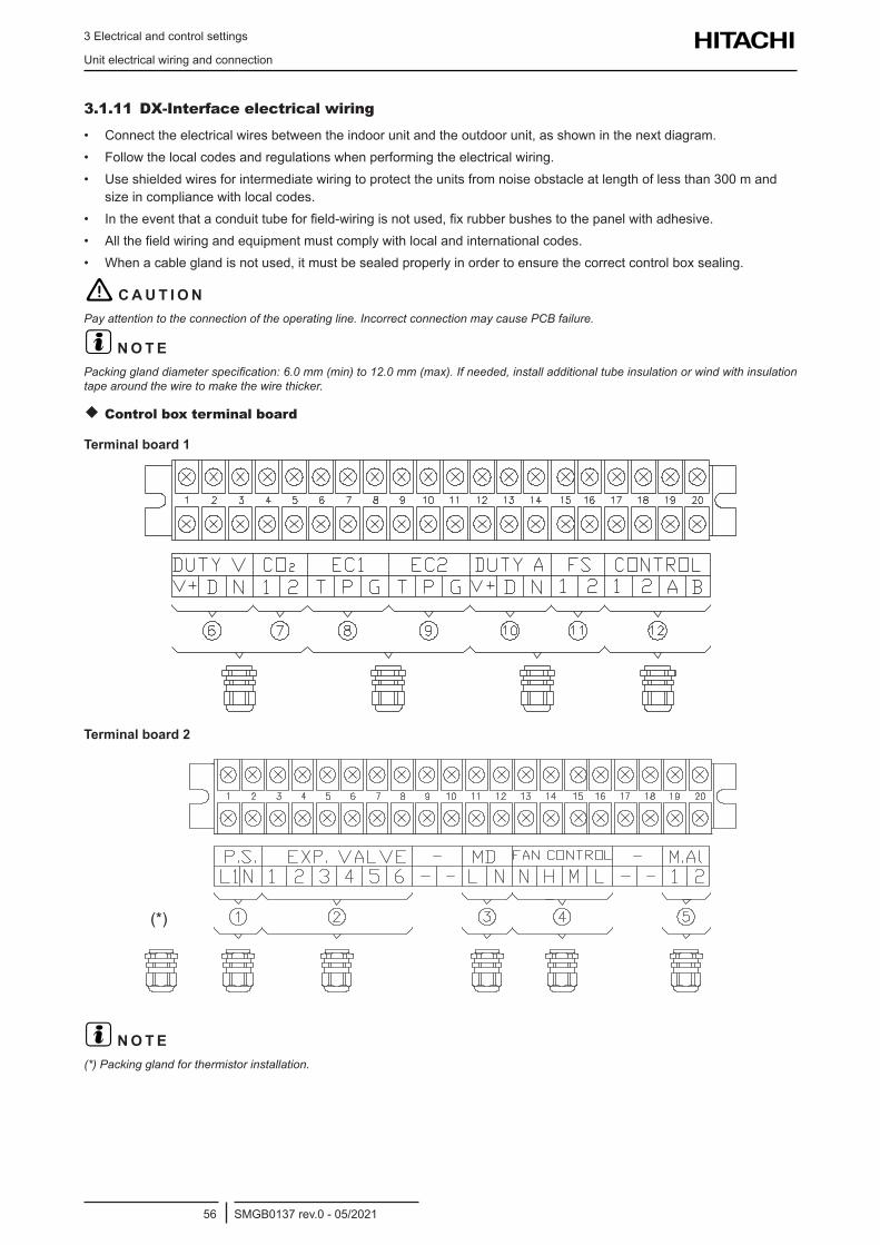
3 Electrical and control settings
Unit electrical wiring and connection
SMGB0137 rev.0 - 05/202156
3.1.11 DX-Interface electrical wiring
• Connecttheelectricalwiresbetweentheindoorunitandtheoutdoorunit,asshowninthenextdiagram.• Follow the local codes and regulations when performing the electrical wiring.• Use shielded wires for intermediate wiring to protect the units from noise obstacle at length of less than 300 m and
size in compliance with local codes.• Intheeventthataconduittubeforfield-wiringisnotused,fixrubberbushestothepanelwithadhesive.• Allthefieldwiringandequipmentmustcomplywithlocalandinternationalcodes.• Whenacableglandisnotused,itmustbesealedproperlyinordertoensurethecorrectcontrolboxsealing.
! C A U T I O NPayattentiontotheconnectionoftheoperatingline.IncorrectconnectionmaycausePCBfailure.
? N O T EPackingglanddiameterspecification:6.0mm(min)to12.0mm(max).Ifneeded,installadditionaltubeinsulationorwindwithinsulationtapearoundthewiretomakethewirethicker.
Control box terminal board
Terminal board 1
Terminal board 2
(*)
? N O T E(*)Packingglandforthermistorinstallation.
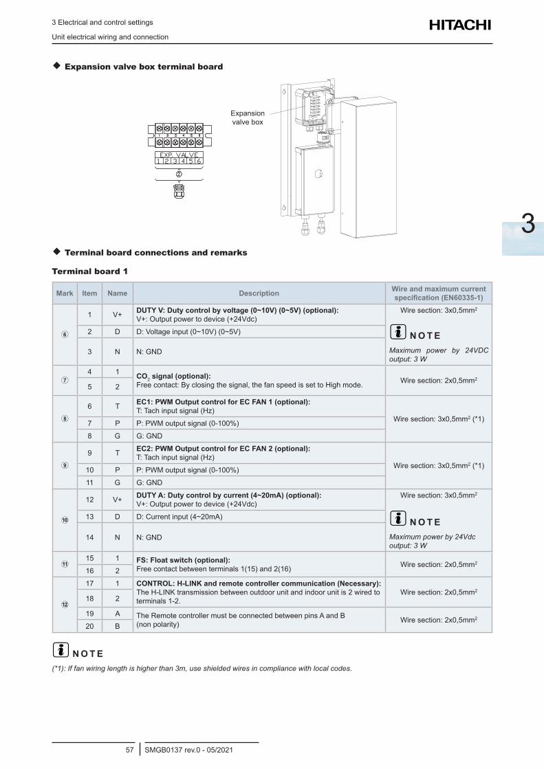
3 Electrical and control settings
Unit electrical wiring and connection
SMGB0137 rev.0 - 05/202157
3
Expansion valve box terminal board
Exp. valveboxExpansionvalvebox
Terminal board connections and remarks
Terminal board 1
Mark Item Name Description Wire and maximum current specification (EN60335-1)
1 V+ DUTY V: Duty control by voltage (0~10V) (0~5V) (optional): V+:Outputpowertodevice(+24Vdc)
Wiresection:3x0,5mm2
? N O T EMaximum power by 24VDCoutput:3W
2 D D:Voltageinput(0~10V)(0~5V)
3 N N:GND
4 1 CO2 signal (optional):
Freecontact:Byclosingthesignal,thefanspeedissettoHighmode. Wiresection:2x0,5mm2
5 2
6 T EC1: PWM Output control for EC FAN 1 (optional): T:Tachinputsignal(Hz)
Wiresection:3x0,5mm2 (*1)7 P P:PWMoutputsignal(0-100%)
8 G G:GND
9 T EC2: PWM Output control for EC FAN 2 (optional): T:Tachinputsignal(Hz)
Wiresection:3x0,5mm2 (*1)10 P P:PWMoutputsignal(0-100%)
11 G G:GND
12 V+ DUTY A: Duty control by current (4~20mA) (optional): V+:Outputpowertodevice(+24Vdc)
Wiresection:3x0,5mm2
? N O T EMaximumpowerby24Vdcoutput:3W
13 D D:Currentinput(4~20mA)
14 N N:GND
15 1 FS: Float switch (optional):
Free contact between terminals 1(15) and 2(16) Wiresection:2x0,5mm2
16 2
17 1 CONTROL: H-LINK and remote controller communication (Necessary): The H-LINK transmission between outdoor unit and indoor unit is 2 wired to terminals 1-2.
Wiresection:2x0,5mm2
18 2
19 A The Remote controller must be connected between pins A and B (non polarity) Wiresection:2x0,5mm2
20 B
? N O T E(*1):Iffanwiringlengthishigherthan3m,useshieldedwiresincompliancewithlocalcodes.
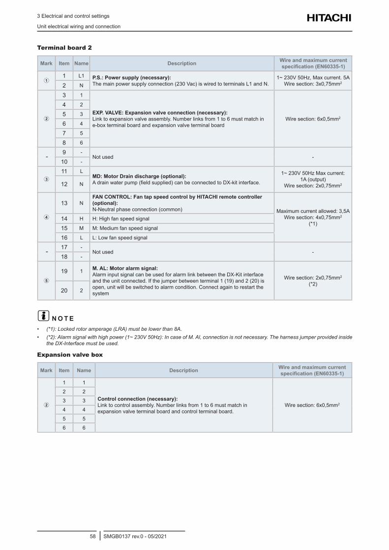
3 Electrical and control settings
Unit electrical wiring and connection
SMGB0137 rev.0 - 05/202158
Terminal board 2
Mark Item Name Description Wire and maximum current specification (EN60335-1)
1 L1 P.S.: Power supply (necessary):
The main power supply connection (230 Vac) is wired to terminals L1 and N.1~230V50Hz,Maxcurrent.5A
Wiresection:3x0,75mm22 N
3 1
EXP. VALVE: Expansion valve connection (necessary): Linktoexpansionvalveassembly.Numberlinksfrom1to6mustmatchine-boxterminalboardandexpansionvalveterminalboard
Wiresection:6x0,5mm2
4 2
5 3
6 4
7 5
8 6
-9 -
Not used -10 -
11 LMD: Motor Drain discharge (optional): Adrainwaterpump(fieldsupplied)canbeconnectedtoDX-kitinterface.
1~230V50HzMaxcurrent: 1A (output)
Wiresection:2x0,75mm212 N
13 NFAN CONTROL: Fan tap speed control by HITACHI remote controller (optional): N-Neutral phase connection (common) Maximumcurrentallowed:3,5A
Wiresection:4x0,75mm2 (*1)
14 H H:Highfanspeedsignal
15 M M:Mediumfanspeedsignal
16 L L:Lowfanspeedsignal
-17 -
Not used -18 -
19 1 M. AL: Motor alarm signal: AlarminputsignalcanbeusedforalarmlinkbetweentheDX-Kitinterfaceand the unit connected. If the jumper between terminal 1 (19) and 2 (20) is open, unit will be switched to alarm condition. Connect again to restart the system
Wiresection:2x0,75mm2 (*2)
20 2
? N O T E• (*1):Lockedrotoramperage(LRA)mustbelowerthan8A.• (*2):Alarmsignalwithhighpower(1~230V50Hz):IncaseofM.Al,connectionisnotnecessary.Theharnessjumperprovidedinside
theDX-Interfacemustbeused.
Expansion valve box
Mark Item Name Description Wire and maximum current specification (EN60335-1)
1 1
Control connection (necessary): Linktocontrolassembly.Numberlinksfrom1to6mustmatchinexpansionvalveterminalboardandcontrolterminalboard.
Wiresection:6x0,5mm2
2 2
3 3
4 4
5 5
6 6
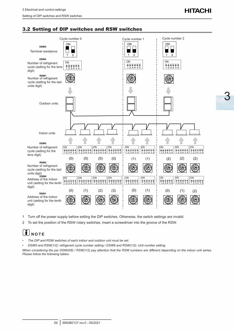
3 Electrical and control settings
Setting of DIP switches and RSW switches
SMGB0137 rev.0 - 05/202159
3
3.2 Setting of DIP switches and RSW switches
Cycle number 0 Cycle number 1 Cycle number 2
Terminal resistance
Number of refrigerant cycle (setting for the tens digit)
Number of refrigerant cycle (setting for the last units digit)
Outdoor units
Indoor units
Number of refrigerant cycle (setting for the last units digit)
Number of refrigerant cycle (setting for the tens digit)
Address of the indoor unit (setting for the tenth digit)
Address of the indoor unit (setting for the tenth digit)
1 TurnoffthepowersupplybeforesettingtheDIPswitches.Otherwise,theswitchsettingsareinvalid.2 To set the position of the RSW rotary switches, insert a screwdriver into the groove of the RSW.
? N O T E• TheDIPandRSWswitchesofeachindoorandoutdoorunitmustbeset.• DSW5andRSW(1/2):refrigerantcyclenumbersetting/DSW6andRSW(1/2):UnitnumbersettingWhenconsideringtheparDSW(5/6)/RSW(1/2)payattentionthattheRSWnumbersaredifferentdependingontheindoorunitseries.Pleasefollowthefollowingtables:
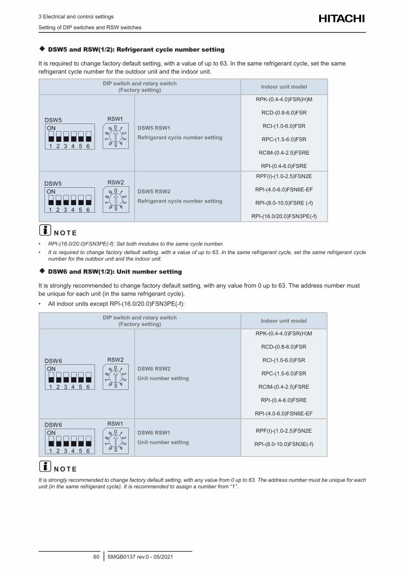
3 Electrical and control settings
Setting of DIP switches and RSW switches
SMGB0137 rev.0 - 05/202160
DSW5 and RSW(1/2): Refrigerant cycle number setting
It is required to change factory default setting, with a value of up to 63. In the same refrigerant cycle, set the same refrigerant cycle number for the outdoor unit and the indoor unit.
DIP switch and rotary switch (Factory setting) Indoor unit model
DSW5 RSW1 Refrigerant cycle number setting
RPK-(0.4-4.0)FSR(H)M
RCD-(0.8-6.0)FSR
RCI-(1.0-6.0)FSR
RPC-(1.5-6.0)FSR
RCIM-(0.4-2.5)FSRE
RPI-(0.4-6.0)FSRE
DSW5 RSW2 Refrigerant cycle number setting
RPF(I)-(1.0-2.5)FSN2E
RPI-(4.0-6.0)FSN6E-EF
RPI-(8.0-10.0)FSRE (-f)
RPI-(16.0/20.0)FSN3PE(-f)
? N O T E• RPI-(16.0/20.0)FSN3PE(-f):Setbothmodulestothesamecyclenumber.• Itisrequiredtochangefactorydefaultsetting,withavalueofupto63.Inthesamerefrigerantcycle,setthesamerefrigerantcycle
number for the outdoor unit and the indoor unit.
DSW6 and RSW(1/2): Unit number setting
It is strongly recommended to change factory default setting, with any value from 0 up to 63. The address number must be unique for each unit (in the same refrigerant cycle).• AllindoorunitsexceptRPI-(16.0/20.0)FSN3PE(-f):
DIP switch and rotary switch (Factory setting) Indoor unit model
DSW6 RSW2 Unit number setting
RPK-(0.4-4.0)FSR(H)M
RCD-(0.8-6.0)FSR
RCI-(1.0-6.0)FSR
RPC-(1.5-6.0)FSR
RCIM-(0.4-2.5)FSRE
RPI-(0.4-6.0)FSRE
RPI-(4.0-6.0)FSN6E-EF
DSW6 RSW1 Unit number setting
RPF(I)-(1.0-2.5)FSN2E
RPI-(8.0-10.0)FSN3E(-f)
? N O T EItisstronglyrecommendedtochangefactorydefaultsetting,withanyvaluefrom0upto63.Theaddressnumbermustbeuniqueforeachunit(inthesamerefrigerantcycle).Itisrecommendedtoassignanumberfrom“1”.
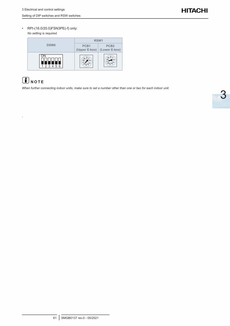
3 Electrical and control settings
Setting of DIP switches and RSW switches
SMGB0137 rev.0 - 05/202161
3
• RPI-(16.0/20.0)FSN3PE(-f)only:Nosettingisrequired.
DSW6RSW1
PCB1 (Upper E-box)
PCB2 (Lower E-box)
1 2 3 4 5 6
ON
? N O T EWhenfurtherconnectingindoorunits,makesuretosetanumberotherthanoneortwoforeachindoorunit.
.
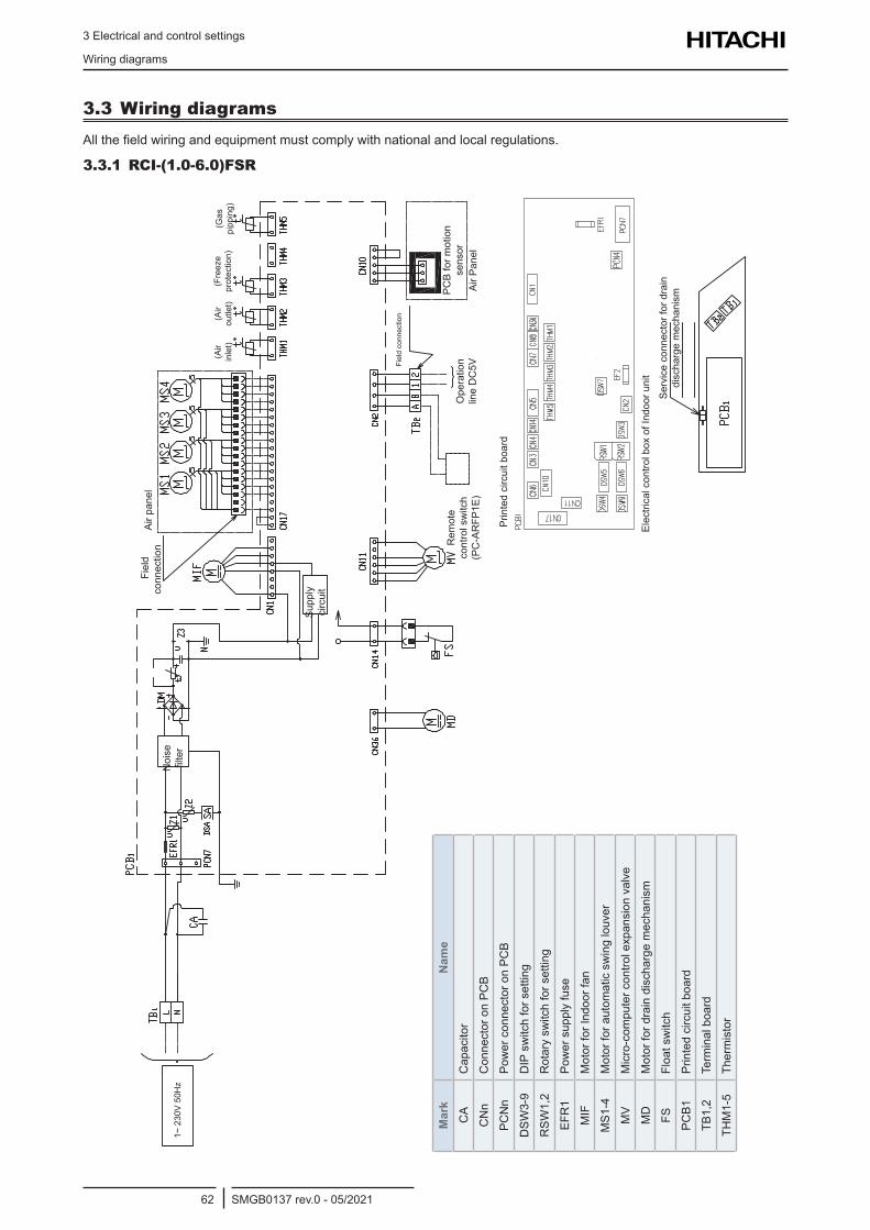
3 Electrical and control settings
Wiring diagrams
SMGB0137 rev.0 - 05/202162
3.3 Wiring diagramsAllthefieldwiringandequipmentmustcomplywithnationalandlocalregulations.
3.3.1 RCI-(1.0-6.0)FSR1~
230
V 50
Hz
Noi
se
filter
Fie
ld
conn
ectio
n Ai
r pan
el
Supp
ly
circ
uit
(Gas
pi
ppin
g)(F
reez
e pr
otec
tion)
(Air
outle
t)(A
ir in
let)
Rem
ote
cont
rol s
witc
h (P
C-A
RFP
1E)
Prin
ted
circ
uit b
oard
ElectricalcontrolboxofIndoorunit
Serv
ice
conn
ecto
r for
dra
in
disc
harg
e m
echa
nism
Ope
ratio
n lin
e D
C5V F
ield
con
nect
ion
PCB
for m
otio
n se
nsor
Air P
anel
Mar
kN
ame
CA
Cap
acito
r
CN
nC
onne
ctor
on
PCB
PCN
nPo
wer
con
nect
or o
n PC
B
DSW
3-9
DIP
sw
itch
for s
ettin
g
RSW
1,2
Rot
ary
switc
h fo
r set
ting
EFR
1Po
wer
sup
ply
fuse
MIF
Mot
or fo
r Ind
oor f
an
MS1
-4M
otor
for a
utom
atic
sw
ing
louv
er
MV
Micro-com
putercontrolexpansionvalve
MD
Mot
or fo
r dra
in d
isch
arge
mec
hani
sm
FSFl
oat s
witc
h
PCB1
Prin
ted
circ
uit b
oard
TB1,
2Te
rmin
al b
oard
THM
1-5
Ther
mis
tor
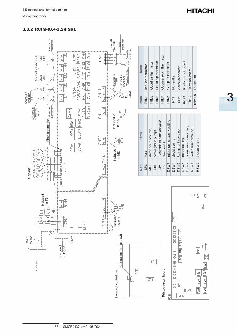
3 Electrical and control settings
Wiring diagrams
SMGB0137 rev.0 - 05/202163
3
3.3.2 RCIM-(0.4-2.5)FSRE
Electricalcontrolbox
Mai
n sw
itch
Air p
anel
Fiel
d co
nnec
tion
Incl
uded
in
TB1
Incl
uded
in
PC
B1
Incl
uded
in
MFE
Connectorforfloatswitch
Incl
uded
in
MD
Incl
uded
in
MV
Arra
nged
in
drai
n pu
mp
assy
Air
inle
tAi
r ou
tlet
Incl
uded
in
ther
mis
tor
Incl
uded
in
ther
mis
tor
Liqu
id
pipe
Gas
pi
pe
Arra
nged
in
evap
sta
y 3
unit
Arra
nged
in E
VAP
UN
IT
Incl
uded
in
TB2
Incl
uded
in
EVAP
UN
ITW
ired
cont
rolle
rO
pera
tion
line
DC
5V
Fiel
d co
nnec
tion
Incl
uded
in
FS
Exp.
Valv
e
Earth
Prin
ted
circ
uit b
oard1~
230
V 50
Hz
Mar
kN
ame
EF2
Fuse
MFE
Mot
or (f
or in
door
fan)
MD
Mot
or (d
rain
pum
p)M
VElectronicexpansionvalve
FSFl
oat s
witc
hD
SW3
Indo
or u
nit c
apac
ity s
ettin
gD
SW4
Mod
el s
ettin
gD
SW5
Ref
riger
ant c
ycle
no.
DSW
6In
door
uni
t no.
DSW
7Tr
ansm
issi
on re
cove
ryR
SW1
Ref
riger
ant c
ycle
no.
RSW
2In
door
uni
t no
Mar
kN
ame
THM
1In
let a
ir th
erm
isto
r
THM
2O
utle
t air
ther
mis
tor
THM
3Li
quid
pip
ther
mis
tor
THM
4O
ptio
nal r
oom
ther
mis
tor
THM
5G
as p
ipe
ther
mis
tor
NF1
Noisefilter
CN
7Ae
rial c
onne
ctor
PCB1
Prin
ted
circ
uit b
oard
TB1,
2Te
rmin
al b
oard
THM
1-5
Ther
mis
tor
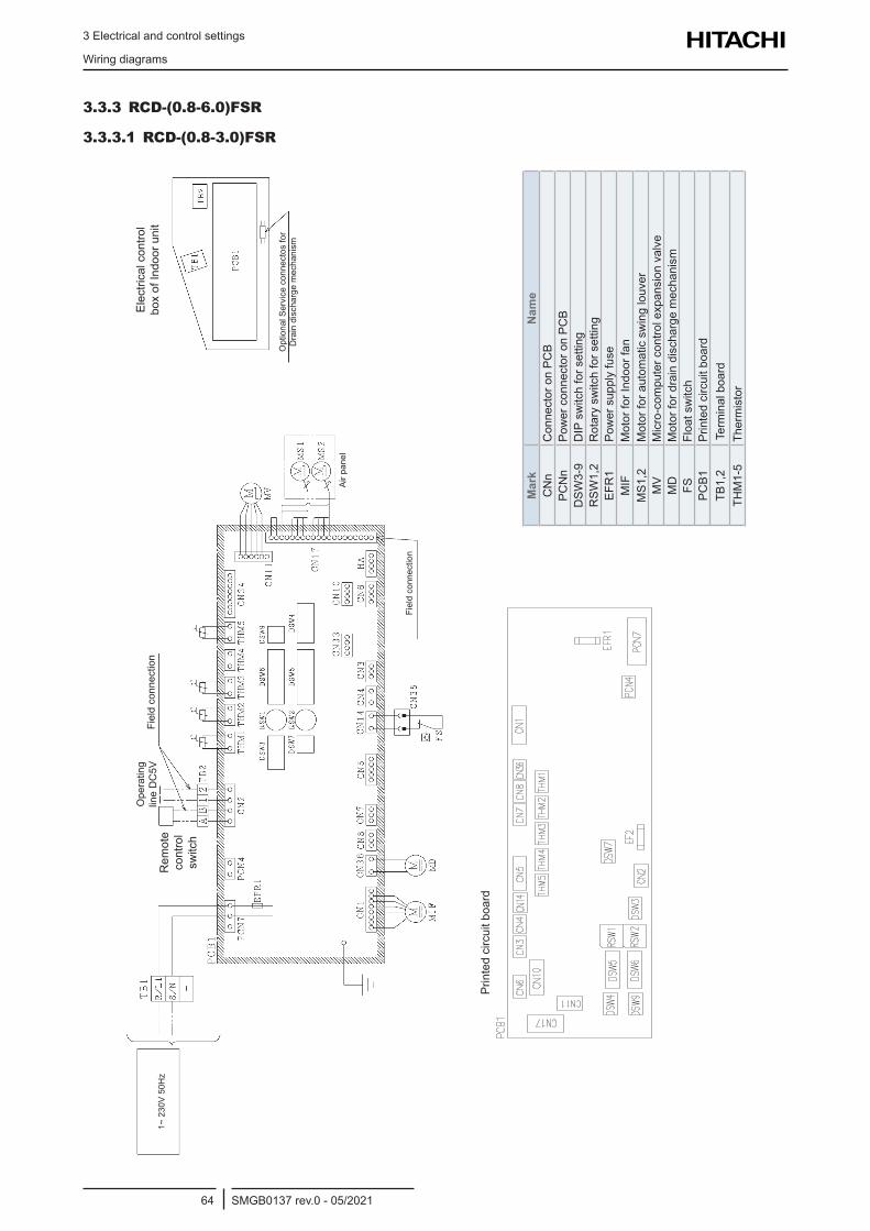
3 Electrical and control settings
Wiring diagrams
SMGB0137 rev.0 - 05/202164
3.3.3 RCD-(0.8-6.0)FSR
3.3.3.1 RCD-(0.8-3.0)FSR
Mar
kN
ame
CN
nC
onne
ctor
on
PCB
PCN
nPo
wer
con
nect
or o
n PC
BD
SW3-
9D
IP s
witc
h fo
r set
ting
RSW
1,2
Rot
ary
switc
h fo
r set
ting
EFR
1Po
wer
sup
ply
fuse
MIF
Mot
or fo
r Ind
oor f
anM
S1,2
Mot
or fo
r aut
omat
ic s
win
g lo
uver
MV
Micro-com
putercontrolexpansionvalve
MD
Mot
or fo
r dra
in d
isch
arge
mec
hani
smFS
Floa
t sw
itch
PCB1
Prin
ted
circ
uit b
oard
TB1,
2Te
rmin
al b
oard
THM
1-5
Ther
mis
tor
Fiel
d co
nnec
tion
Rem
ote
cont
rol
switc
h
Ope
ratin
g lin
e D
C5V
Fiel
d co
nnec
tion
Air p
anel
Elec
trica
l con
trol
boxofIndoorunit
Opt
iona
l Ser
vice
con
nect
os fo
r D
rain
dis
char
ge m
echa
nism
Prin
ted
circ
uit b
oard
1~ 2
30V
50H
z
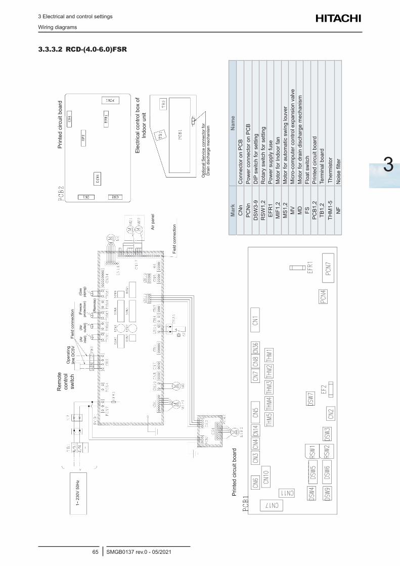
3 Electrical and control settings
Wiring diagrams
SMGB0137 rev.0 - 05/202165
3
3.3.3.2 RCD-(4.0-6.0)FSR
Fiel
d co
nnec
tion
Ope
ratin
g lin
e D
C5V
Fiel
d co
nnec
tion
Rem
ote
cont
rol
switc
h
Air p
anel
Opt
iona
l Ser
vice
con
nect
or fo
r D
rain
dis
char
ge m
echa
nism
Prin
ted
circ
uit b
oard
Prin
ted
circ
uit b
oard
Electricalcontrolboxof
Indo
or u
nit
(Air
inle
t)(A
ir ou
tlet)
(Fre
eze
prot
ectio
n)
(Rem
ote)
(Gas
pi
ping
)
Mar
kN
ame
CN
nC
onne
ctor
on
PCB
PCN
nPo
wer
con
nect
or o
n PC
BD
SW3-
9D
IP s
witc
h fo
r set
ting
RSW
1,2
Rot
ary
switc
h fo
r set
ting
EFR
1Po
wer
sup
ply
fuse
MIF
1,2
Mot
or fo
r Ind
oor f
anM
S1,2
Mot
or fo
r aut
omat
ic s
win
g lo
uver
MV
Micro-com
putercontrolexpansionvalve
MD
Mot
or fo
r dra
in d
isch
arge
mec
hani
smFS
Floa
t sw
itch
PCB1
,2Pr
inte
d ci
rcui
t boa
rdTB
1,2
Term
inal
boa
rdTH
M1-
5Th
erm
isto
rN
FNoisefilter
1~ 2
30V
50H
z
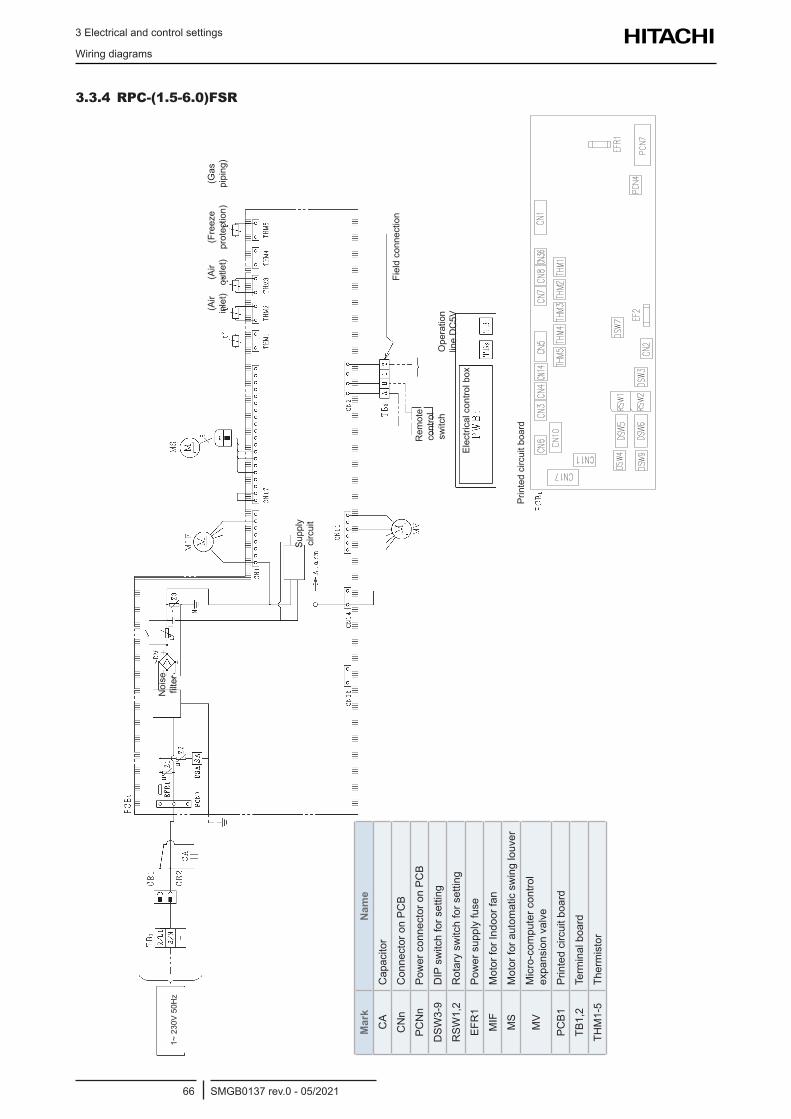
3 Electrical and control settings
Wiring diagrams
SMGB0137 rev.0 - 05/202166
3.3.4 RPC-(1.5-6.0)FSR
Noi
se
filter
Supp
ly
circ
uit
Rem
ote
cont
rol
switc
hO
pera
tion
line
DC
5V
Fie
ld c
onne
ctio
n
Electricalcontrolbox
Prin
ted
circ
uit b
oard
(Air
inle
t)(A
ir ou
tlet)
(Fre
eze
prot
ectio
n)(G
as
pipi
ng)
Mar
kN
ame
CA
Cap
acito
r
CN
nC
onne
ctor
on
PCB
PCN
nPo
wer
con
nect
or o
n PC
B
DSW
3-9
DIP
sw
itch
for s
ettin
g
RSW
1,2
Rot
ary
switc
h fo
r set
ting
EFR
1Po
wer
sup
ply
fuse
MIF
Mot
or fo
r Ind
oor f
an
MS
Mot
or fo
r aut
omat
ic s
win
g lo
uver
MV
Mic
ro-c
ompu
ter c
ontro
l expansionvalve
PCB1
Prin
ted
circ
uit b
oard
TB1,
2Te
rmin
al b
oard
THM
1-5
Ther
mis
tor
1~ 2
30V
50H
z
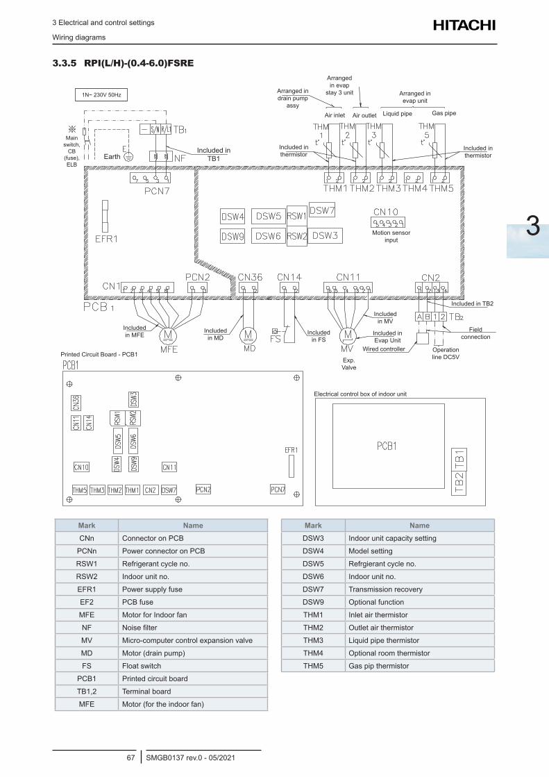
3 Electrical and control settings
Wiring diagrams
SMGB0137 rev.0 - 05/202167
3
3.3.5 RPI(L/H)-(0.4-6.0)FSRE
Main switch,
CB (fuse), ELB
Arranged in drain pump
assy
Included in thermistor
Included in thermistor
Included in TB2
Included in Evap Unit
Included in MV
Included in MD
Included in MFE
Exp.Valve
Field connection
Operation line DC5V
Wired controller
Electricalcontrolboxofindoorunit
Printed Circuit Board - PCB1
Included in FS
Motion sensor input
Air inlet Air outlet Liquid pipe Gas pipe
Arranged in evap
stay 3 unit Arranged in evap unit
Included in TB1Earth
1N~ 230V 50Hz
Mark NameCNn Connector on PCB
PCNn Power connector on PCB
RSW1 Refrigerant cycle no.
RSW2 Indoor unit no.
EFR1 Power supply fuse
EF2 PCB fuse
MFE Motor for Indoor fan
NF Noisefilter
MV Micro-computercontrolexpansionvalve
MD Motor (drain pump)
FS Float switch
PCB1 Printed circuit board
TB1,2 Terminal board
MFE Motor (for the indoor fan)
Mark NameDSW3 Indoor unit capacity setting
DSW4 Model setting
DSW5 Refrgierant cycle no.
DSW6 Indoor unit no.
DSW7 Transmission recovery
DSW9 Optional function
THM1 Inlet air thermistor
THM2 Outlet air thermistor
THM3 Liquid pipe thermistor
THM4 Optional room thermistor
THM5 Gas pip thermistor
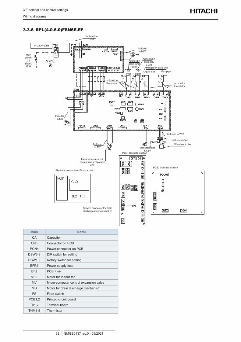
3 Electrical and control settings
Wiring diagrams
SMGB0137 rev.0 - 05/202168
3.3.6 RPI-(4.0-6.0)FSN6E-EF
Main switch,
CB (fuse), ELB
Arranged in drain pump
assy
Included in thermistor Included in
thermistor
Included in TB2
Expansionvalvecoilcomes from evaporator
unit
Included in MV
Included in MD
Included in MFE
Field connection
Operation line DC5V
Wired controller
Electricalcontrolboxofindoorunit
PCB1Socketslocation
PCB2Socketslocation
Service connector for drain discharge mechanism (FS)
Air inlet
Air outlet
Liquid pipe Gas pipe
Arranged in evap stay
3 unitArranged in evap unit
Included in TB1
1~ 230V 50Hz
Mark NameCA Capacitor
CNn Connector on PCB
PCNn Power connector on PCB
DSW3-9 DIP switch for setting
RSW1,2 Rotary switch for setting
EFR1 Power supply fuse
EF2 PCB fuse
MFE Motor for Indoor fan
MV Micro-computercontrolexpansionvalve
MD Motor for drain discharge mechanism
FS Float switch
PCB1,2 Printed circuit board
TB1,2 Terminal board
THM1-5 Thermistor
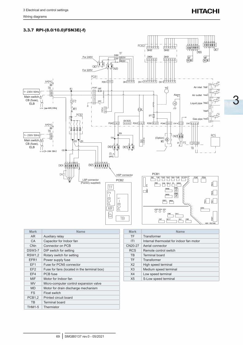
3 Electrical and control settings
Wiring diagrams
SMGB0137 rev.0 - 05/202169
3
3.3.7 RPI-(8.0/10.0)FSN3E(-f)
LSP connector (Factory supplied)
HSP connector PCB1
(Option)
PCB2
Main switch, CB (fuse),
ELB
Air inlet
Alarm Air outlet
Liquid pipe
Gas pipe
For 240V
For 220V
Main switch, CB (fuse),
ELB
1~ 230V 50Hz
1~ 230V 50Hz
Mark NameAR AuxiliaryrelayCA Capacitor for Indoor fan
CNn Connector on PCBDSW3-7 DIP switch for settingRSW1,2 Rotary switch for setting
EFR1 Power supply fuseEF1 Fuse for PCN5 connectorEF2 Fuseforfans(locatedintheterminalbox)EF4 PCB fuseMIF Motor for Indoor fanMV Micro-computercontrolexpansionvalveMD Motor for drain discharge mechanismFS Float switch
PCB1,2 Printed circuit boardTB Terminal board
THM1-5 Thermistor
Mark NameTF TransformerITI Internal thermostat for indoor fan motor
CN20-27 Aerial connectorRCS Remote control switchTB Terminal boardTF TransformerX2 High speed terminalX3 Medium speed terminalX4 Low speed terminalX5 S-Low speed terminal
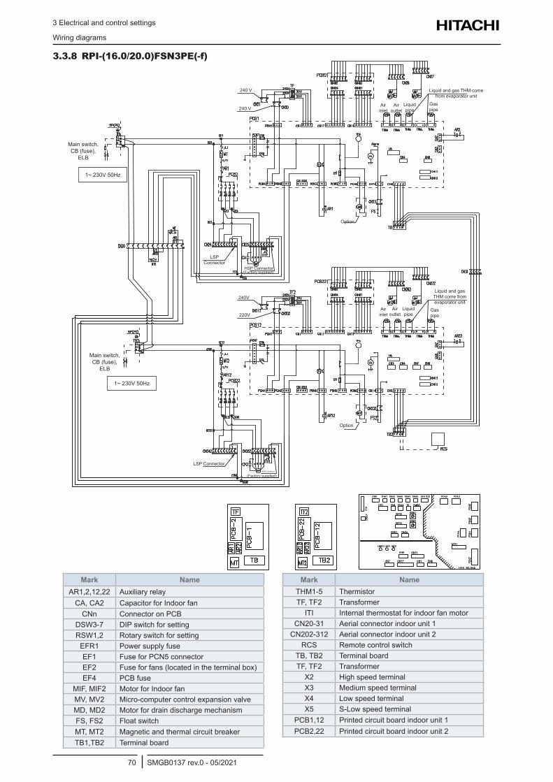
3 Electrical and control settings
Wiring diagrams
SMGB0137 rev.0 - 05/202170
3.3.8 RPI-(16.0/20.0)FSN3PE(-f)
Mark NameAR1,2,12,22 Auxiliaryrelay
CA, CA2 Capacitor for Indoor fanCNn Connector on PCB
DSW3-7 DIP switch for settingRSW1,2 Rotary switch for setting
EFR1 Power supply fuseEF1 Fuse for PCN5 connectorEF2 Fuseforfans(locatedintheterminalbox)EF4 PCB fuse
MIF, MIF2 Motor for Indoor fanMV, MV2 Micro-computercontrolexpansionvalveMD, MD2 Motor for drain discharge mechanismFS, FS2 Float switchMT, MT2 MagneticandthermalcircuitbreakerTB1,TB2 Terminal board
Mark NameTHM1-5 ThermistorTF, TF2 Transformer
ITI Internal thermostat for indoor fan motorCN20-31 Aerial connector indoor unit 1
CN202-312 Aerial connector indoor unit 2RCS Remote control switch
TB, TB2 Terminal boardTF, TF2 Transformer
X2 High speed terminalX3 Medium speed terminalX4 Low speed terminalX5 S-Low speed terminal
PCB1,12 Printed circuit board indoor unit 1PCB2,22 Printed circuit board indoor unit 2
Main switch, CB (fuse),
ELB
Main switch, CB (fuse),
ELB
240 V
240 V
LSP Connector
LSP Connector
Option
Option
HSP Connector
HSP Connector
(Factory supplied)
(Factory supplied)
240V
220V
Air inlet
Air inlet
Air outlet
Air outlet
Liquid pipe
Liquid pipe
Gas pipe
Gas pipe
Liquid and gas THM come from evaporator unit
Liquid and gas THM come from evaporator unit
1~ 230V 50Hz
1~ 230V 50Hz
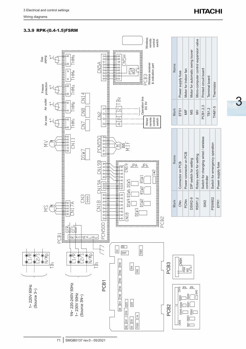
3 Electrical and control settings
Wiring diagrams
SMGB0137 rev.0 - 05/202171
3
3.3.9 RPK-(0.4-1.5)FSRM
Mar
kN
ame
CN
nC
onne
ctor
on
PCB
PCN
nPo
wer
con
nect
or o
n PC
B
DSW
2-9
DIP
sw
itch
for s
ettin
g
RSW
1,2
Rot
ary
switc
h fo
r set
ting
SW2
Switc
h fo
r cha
ngin
g w
ired
/ wire
less
co
ntro
ller
PSW
802
Switc
h fo
r em
erge
ncy
oper
atio
n
EFR
1Po
wer
sup
ply
fuse
Mar
kN
ame
EFS1
Pow
er s
uppl
y fu
se
MIF
Mot
or fo
r Ind
oor f
an
MS
Mot
or fo
r aut
omat
ic s
win
g lo
uver
MV
Micro-com
putercontrolexpansionvalve
PCB1
,2,3
Prin
ted
circ
uit b
oard
TB1,
2Te
rmin
al b
oard
THM
1-5
Ther
mis
tor
PCB1
PCB2
PCB3
Air i
nlet
Air o
utle
tFr
eeze
pr
otec
tion
Gas
pi
ping
Wire
d re
mot
e co
ntro
l sw
itch
Wire
less
re
mot
e co
ntro
l sw
itch
Ope
ratio
n lin
e D
C 5
VW
irele
ss re
ceiv
er
& in
dica
tion
part
1~ 2
20V
60H
z (S
ourc
e 3~
)
1N~
220-
240V
50H
z 1~
230
V 50
Hz
(Sou
rce
3N~)
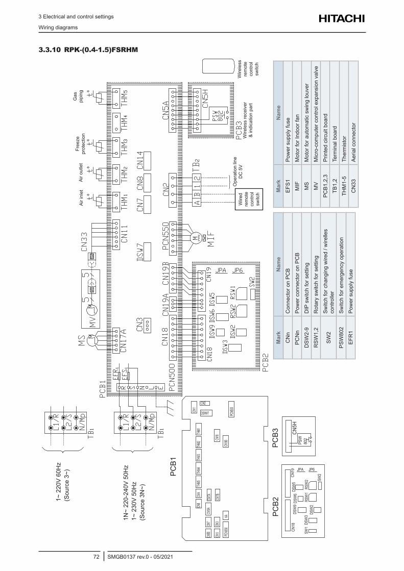
3 Electrical and control settings
Wiring diagrams
SMGB0137 rev.0 - 05/202172
3.3.10 RPK-(0.4-1.5)FSRHM
PC
B1
PC
B2
PC
B3
Wire
less
re
mot
e co
ntro
l sw
itch
Wire
less
rece
iver
&
indi
catio
n pa
rt
Gas
pi
ping
Free
ze
prot
ectio
nAi
r out
let
Air i
nlet
Ope
ratio
n lin
e D
C 5
VW
ired
rem
ote
cont
rol
switc
h
Mar
kN
ame
CN
nC
onne
ctor
on
PCB
PCN
nPo
wer
con
nect
or o
n PC
B
DSW
2-9
DIP
sw
itch
for s
ettin
g
RSW
1,2
Rot
ary
switc
h fo
r set
ting
SW2
Switc
h fo
r cha
ngin
g w
ired
/ wire
lles
cont
rolle
r
PSW
802
Switc
h fo
r em
erge
ncy
oper
atio
n
EFR
1Po
wer
sup
ply
fuse
Mar
kN
ame
EFS1
Pow
er s
uppl
y fu
se
MIF
Mot
or fo
r Ind
oor f
an
MS
Mot
or fo
r aut
omat
ic s
win
g lo
uver
MV
Micro-com
putercontrolexpansionvalve
PCB1
,2,3
Prin
ted
circ
uit b
oard
TB1,
2Te
rmin
al b
oard
THM
1-5
Ther
mis
tor
CN
33Ae
rial c
onne
ctor
1~ 2
20V
60H
z (S
ourc
e 3~
)
1N~
220-
240V
50H
z 1~
230
V 50
Hz
(Sou
rce
3N~)
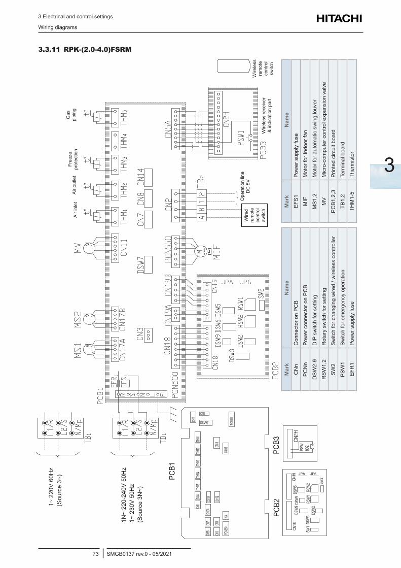
3 Electrical and control settings
Wiring diagrams
SMGB0137 rev.0 - 05/202173
3
3.3.11 RPK-(2.0-4.0)FSRM
PCB1
PCB2
PCB3
Air i
nlet
Air o
utle
tFr
eeze
pr
otec
tion
Gas
pi
ping
Wire
d re
mot
e co
ntro
l sw
itch
Wire
less
re
mot
e co
ntro
l sw
itch
Ope
ratio
n lin
e D
C 5
V
Wire
less
rece
iver
&
indi
catio
n pa
rt
Mar
kN
ame
CN
nC
onne
ctor
on
PCB
PCN
nPo
wer
con
nect
or o
n PC
B
DSW
2-9
DIP
sw
itch
for s
ettin
g
RSW
1,2
Rot
ary
switc
h fo
r set
ting
SW2
Switc
h fo
r cha
ngin
g w
ired
/ wire
less
con
trolle
r
PSW
1Sw
itch
for e
mer
genc
y op
erat
ion
EFR
1Po
wer
sup
ply
fuse
Mar
kN
ame
EFS1
Pow
er s
uppl
y fu
se
MIF
Mot
or fo
r Ind
oor f
an
MS1
,2M
otor
for a
utom
atic
sw
ing
louv
er
MV
Micro-com
putercontrolexpansionvalve
PCB1
,2,3
Prin
ted
circ
uit b
oard
TB1,
2Te
rmin
al b
oard
THM
1-5
Ther
mis
tor
1~ 2
20V
60H
z (S
ourc
e 3~
)
1N~
220-
240V
50H
z 1~
230
V 50
Hz
(Sou
rce
3N~)
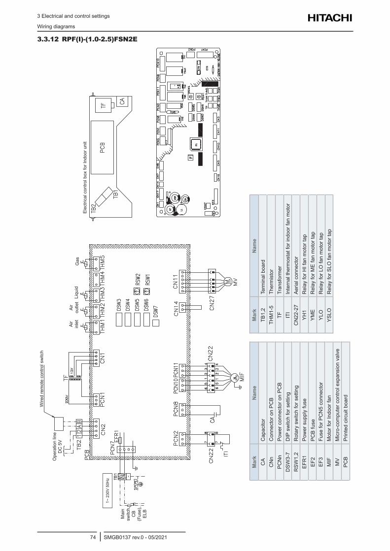
3 Electrical and control settings
Wiring diagrams
SMGB0137 rev.0 - 05/202174
3.3.12 RPF(I)-(1.0-2.5)FSN2E
Air
inle
tAi
r ou
tlet
Liqu
idG
as
Mai
n sw
itch,
C
B (F
use)
, EL
B
ElectricalcontrolboxforIndoorunit
Ope
ratio
n lin
e D
C 5
V
Wire
d re
mot
e co
ntro
l sw
itch
Mar
kN
ame
CA
Cap
acito
rC
Nn
Con
nect
or o
n PC
BPC
Nn
Pow
er c
onne
ctor
on
PCB
DSW
3-7
DIP
sw
itch
for s
ettin
gR
SW1,
2R
otar
y sw
itch
for s
ettin
gEF
R1
Pow
er s
uppl
y fu
seEF
2PC
B fu
seEF
3Fu
se fo
r PC
N5
conn
ecto
rM
IFM
otor
for I
ndoo
r fan
MV
Micro-com
putercontrolexpansionvalve
PCB
Prin
ted
circ
uit b
oard
Mar
kN
ame
TB1,
2Te
rmin
al b
oard
THM
1-5
Ther
mis
tor
TFTr
ansf
orm
erIT
IIn
tern
al th
erm
osta
t for
indo
or fa
n m
otor
CN
22-2
7Ae
rial c
onne
ctor
YH1
Rel
ay fo
r HI f
an m
otor
tap
YME
Rel
ay fo
r ME
fan
mot
or ta
pYL
OR
elay
for L
O fa
n m
otor
tap
YSLO
Rel
ay fo
r SLO
fan
mot
or ta
p
1~ 2
30V
50H
z
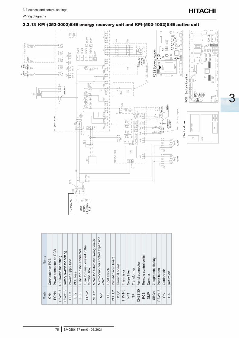
3 Electrical and control settings
Wiring diagrams
SMGB0137 rev.0 - 05/202175
3
3.3.13 KPI-(252-2002)E4E energy recovery unit and KPI-(502-1002)X4E active unit
Mar
kN
ame
CN
nC
onne
ctor
on
PCB
PCN
nPo
wer
con
nect
or o
n PC
BD
SW3-
7D
IP s
witc
h fo
r set
ting
RSW
1,2
Rot
ary
switc
h fo
r set
ting
EFR
1Po
wer
sup
ply
fuse
EF2
PCB
fuse
EF3
Fuse
for P
CN
5 co
nnec
tor
EF1-
2Fu
se fo
r fan
s (lo
cate
d in
the
terminalbox)
MS1
,2M
otor
for a
utom
atic
sw
ing
louv
er
MV
Micro-com
putercontrolexpansion
valv
eFS
Floa
t sw
itch
PCB1
,2Pr
inte
d ci
rcui
t boa
rdTB
1,2
Term
inal
boa
rdTH
M1-
5Th
erm
isto
rN
F1Noisefilter
TFTr
ansf
orm
erC
N23
-30
Aeria
l con
nect
orR
CS
Rem
ote
cont
rol s
witc
hD
MP
Dam
per
SEG
n7-
segm
ents
dis
play
PSW
1-3
Push
but
ton
OA
Out
door
air
RA
Ret
urn
air
1~ 2
30V
50
Hz
Mai
n sw
itch,
C
B (fu
se),
ELB
(Mai
n PC
B)
Air
Out
let
Air
inle
t
Liqu
idG
as<B
lue>
<Red
>
For 2
30V
fan
fan
Opt
ion
Inle
tO
utle
tD
X C
oil
CO
2 se
nsor
O
N/O
FF
CO
2 Se
nsor
PCB1
SocketslocationPCB2
Socketslocation
Electricalbox
Rel
ay fo
r auxiliary
heat
er
1~ 2
30V
50H
z
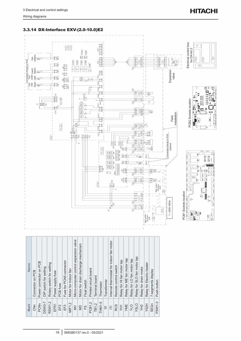
3 Electrical and control settings
Wiring diagrams
SMGB0137 rev.0 - 05/202176
3.3.14 DX-Interface EXV-(2.0-10.0)E2
Mai
n sw
itch,
C
B (fu
se),
ELB
Mai
n sw
itch,
C
B (fu
se),
ELB
Con
nect
ed d
irect
ly to
PC
BO
ptio
nal
Fiel
d in
stal
latio
n
Expansion
valv
e
Opt
ion
Coi
l in
let
Coi
l ou
tlet
Liqu
idG
as(b
lue)
(red)
(black)
(yel
low
)
Con
nect
ed d
irect
ly to
PC
B
Electricalcontrolbox
for D
X-Ki
t 2PC
B2Socketslocation
PCB1
Socketslocation
Mar
kN
ame
CN
nC
onne
ctor
on
PCB
PCN
nPo
wer
con
nect
or o
n PC
BD
SW3-
7D
IP s
witc
h fo
r set
ting
RSW
1,2
Rot
ary
switc
h fo
r set
ting
EFR
1Po
wer
sup
ply
fuse
EF2
PCB
fuse
EF3
Fuse
for P
CN
5 co
nnec
tor
MIF
1,2
Mot
or fo
r Ind
oor f
anM
VMicro-com
putercontrolexpansionvalve
MD
Mot
or fo
r dra
in d
isch
arge
mec
hani
smFS
Floa
t sw
itch
PCB1
,2Pr
inte
d ci
rcui
t boa
rdTB
1,2
Term
inal
boa
rdTH
M1-
5Th
erm
isto
rTF
Tran
sfor
mer
ITI
Inte
rnal
ther
mos
tat f
or in
door
fan
mot
orR
CS
Rem
ote
cont
rol s
witc
hYH
1R
elay
for H
I fan
mot
or ta
pYM
ER
elay
for M
E fa
n m
otor
tap
YLO
Rel
ay fo
r LO
fan
mot
or ta
pYS
LOR
elay
for S
LO fa
n m
otor
tap
YH2
Rel
ay fo
r dra
in m
otor
Y52H
Rel
ay fo
r Ele
ctric
hea
ter
SEG
n7-
segm
ents
dis
play
PSW
1-3
Push
but
ton
1~ 2
30V
50H
z
4 Control system
SMGB0137 rev.0 - 05/202177
4
4 . C o n t r o l s y s t e m
Index
4.1 Printed circuit boards for RCI-FSR indoor units (PI153) .......................................................................78
4.2 Printed circuit boards for RCIM-FSRE indoor units (PI153) ..................................................................79
4.3 Printed circuit boards for RCD-FSR (PI153) .........................................................................................80
4.4 Printed circuit board for RPC-FSR (PI153) ...........................................................................................81
4.5 Printed circuit board for RPI(L/H)-(0.4-6.0)FSRE (PI161) .....................................................................82
4.6 Printed circuit board for RPI-(4.0-6.0)FSN6E-EF (PI114-PI117) ...........................................................83
4.7 Printed circuit board for RPI-(8.0-20.0)FSN3(P)E(-f) units (PI065-PI005) ............................................84
4.8 Printed circuit board for RPK-FSR(H)M units ........................................................................................85
4.8.1 For RPK-(0.4-1.5)FSR(H)M (PI151-PI154) ................................................................................................... 85
4.8.2 For RPK-(2.0-4.0)FSRM (PI151-PI154) ........................................................................................................ 86
4.9 Printed circuit board for RPF(I)-FSN2E units (PI073) ...........................................................................87
4.10 Printed circuit board for complementary systems .................................................................................88
4.10.1 Printed circuit board for KPI (PI073) ............................................................................................................ 88
4.10.2 Printed circuit board for DX-Interface (PI073) ............................................................................................. 89
4.11 Safety protection and control.................................................................................................................90
4.12 Indoor electronic expansion valve control .............................................................................................91
4.13 Thermistor .............................................................................................................................................92
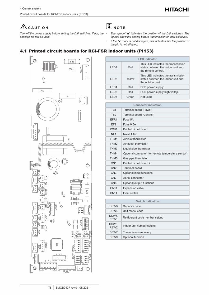
4 Control system
Printed circuit boards for RCI-FSR indoor units (PI153)
SMGB0137 rev.0 - 05/202178
! C A U T I O NTurn off the power supply before setting the DIP switches. If not, the settings will not be valid.
? N O T E• The symbol “” indicates the position of the DIP switches. The
figures show the setting before transmission or after selection.• If the “” mark is not displayed, this indicates that the position of
the pin is not affected.
4.1 Printed circuit boards for RCI-FSR indoor units (PI153)
TR1
LED
4
L3
LED
5LE
D1
LED
3
LED
6
LED indicator
LED1 RedThis LED indicates the transmission status between the indoor unit and the remote control.
LED3 YellowThis LED indicates the transmission status between the indoor unit and the outdoor unit.
LED4 Red PCB power supply
LED5 Red PCB power supply high voltaje
LED6 Green Not used
Connector indicationTB1 Terminal board (Power)
TB2 Terminal board (Control)
EFR1 Fuse 5A
EF2 Fuse 0.5A
PCB1 Printed circuit board
NF1 Noise filter
THM1 Air inlet thermistor
THM2 Air outlet thermistor
THM3 Liquid pipe thermistor
THM4 Optional connector (for remote temperature sensor)
THM5 Gas pipe thermistor
CN1 Printed circuit board 2
CN2 Terminal board
CN3 Optional input functions
CN7 Aerial connector
CN8 Optional output functions
CN11 Expansion valve
CN14 Float switch
Switch indicationDSW3 Capacity code
DSW4 Unit model code
DSW5, RSW1 Refrigerant cycle number setting
DSW6, RSW2 Indoor unit number setting
DSW7 Transmission recovery
DSW9 Optional function
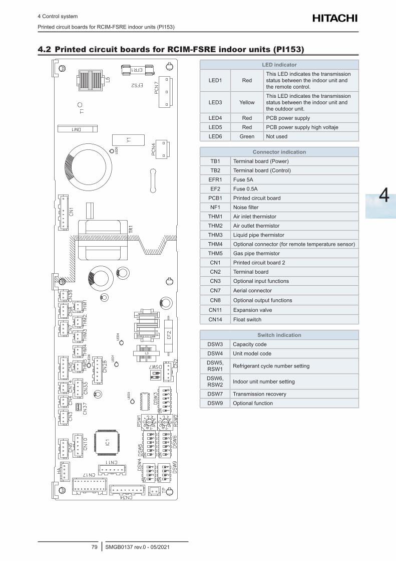
4 Control system
Printed circuit boards for RCIM-FSRE indoor units (PI153)
SMGB0137 rev.0 - 05/202179
4
4.2 Printed circuit boards for RCIM-FSRE indoor units (PI153)
TR1
LED
4
L3
LED
5LE
D1
LED
3
LED
6
LED indicator
LED1 RedThis LED indicates the transmission status between the indoor unit and the remote control.
LED3 YellowThis LED indicates the transmission status between the indoor unit and the outdoor unit.
LED4 Red PCB power supply
LED5 Red PCB power supply high voltaje
LED6 Green Not used
Connector indicationTB1 Terminal board (Power)
TB2 Terminal board (Control)
EFR1 Fuse 5A
EF2 Fuse 0.5A
PCB1 Printed circuit board
NF1 Noise filter
THM1 Air inlet thermistor
THM2 Air outlet thermistor
THM3 Liquid pipe thermistor
THM4 Optional connector (for remote temperature sensor)
THM5 Gas pipe thermistor
CN1 Printed circuit board 2
CN2 Terminal board
CN3 Optional input functions
CN7 Aerial connector
CN8 Optional output functions
CN11 Expansion valve
CN14 Float switch
Switch indicationDSW3 Capacity code
DSW4 Unit model code
DSW5, RSW1 Refrigerant cycle number setting
DSW6, RSW2 Indoor unit number setting
DSW7 Transmission recovery
DSW9 Optional function
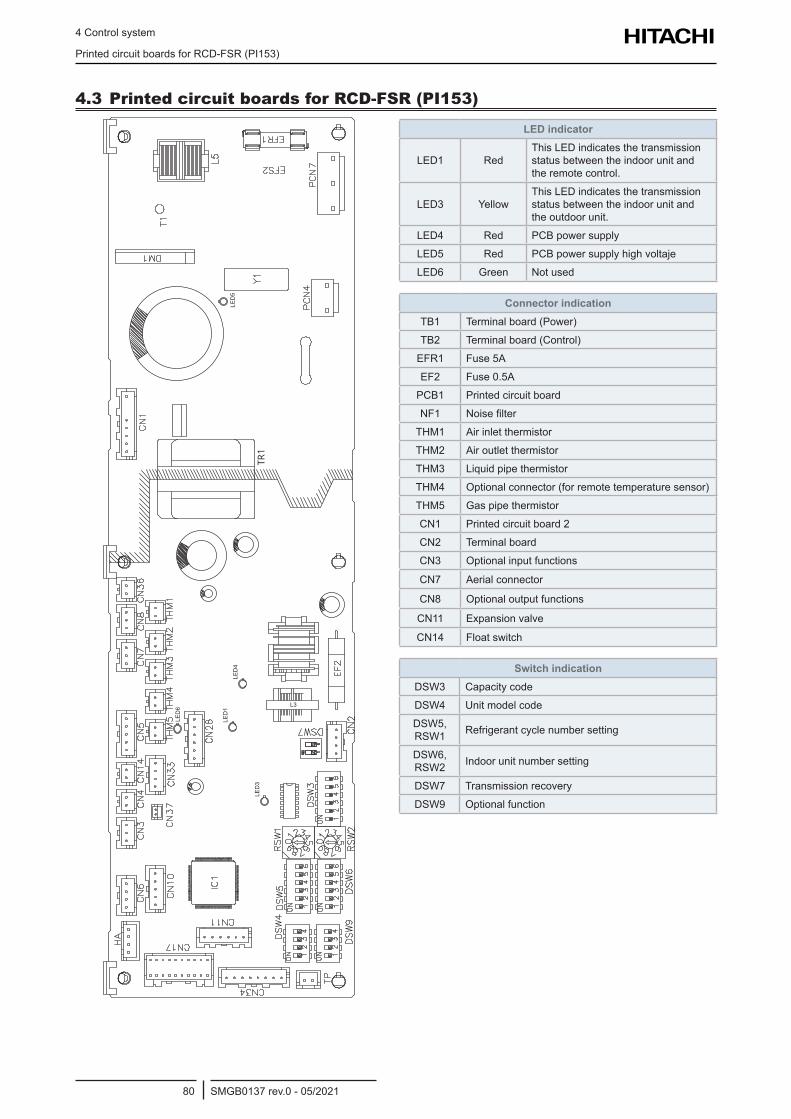
4 Control system
Printed circuit boards for RCD-FSR (PI153)
SMGB0137 rev.0 - 05/202180
4.3 Printed circuit boards for RCD-FSR (PI153)
TR1
LED
4
L3
LED
5LE
D1
LED
3
LED
6
LED indicator
LED1 RedThis LED indicates the transmission status between the indoor unit and the remote control.
LED3 YellowThis LED indicates the transmission status between the indoor unit and the outdoor unit.
LED4 Red PCB power supply
LED5 Red PCB power supply high voltaje
LED6 Green Not used
Connector indicationTB1 Terminal board (Power)
TB2 Terminal board (Control)
EFR1 Fuse 5A
EF2 Fuse 0.5A
PCB1 Printed circuit board
NF1 Noise filter
THM1 Air inlet thermistor
THM2 Air outlet thermistor
THM3 Liquid pipe thermistor
THM4 Optional connector (for remote temperature sensor)
THM5 Gas pipe thermistor
CN1 Printed circuit board 2
CN2 Terminal board
CN3 Optional input functions
CN7 Aerial connector
CN8 Optional output functions
CN11 Expansion valve
CN14 Float switch
Switch indicationDSW3 Capacity code
DSW4 Unit model code
DSW5, RSW1 Refrigerant cycle number setting
DSW6, RSW2 Indoor unit number setting
DSW7 Transmission recovery
DSW9 Optional function
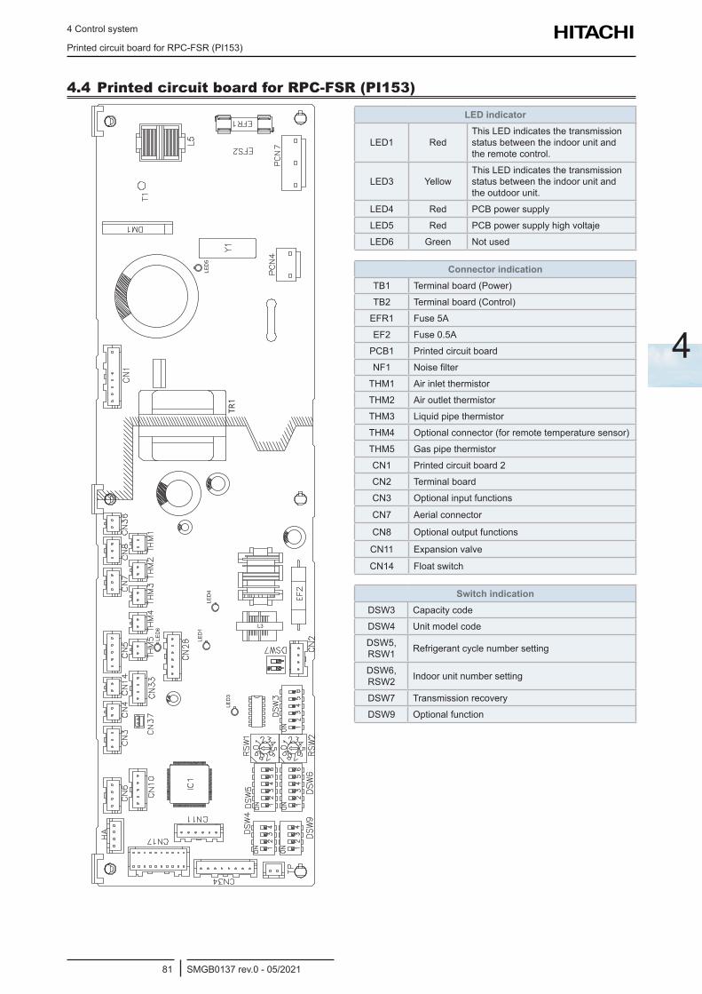
4 Control system
Printed circuit board for RPC-FSR (PI153)
SMGB0137 rev.0 - 05/202181
4
4.4 Printed circuit board for RPC-FSR (PI153)
TR1
LED
4
L3
LED
5LE
D1
LED
3
LED
6
LED indicator
LED1 RedThis LED indicates the transmission status between the indoor unit and the remote control.
LED3 YellowThis LED indicates the transmission status between the indoor unit and the outdoor unit.
LED4 Red PCB power supply
LED5 Red PCB power supply high voltaje
LED6 Green Not used
Connector indicationTB1 Terminal board (Power)
TB2 Terminal board (Control)
EFR1 Fuse 5A
EF2 Fuse 0.5A
PCB1 Printed circuit board
NF1 Noise filter
THM1 Air inlet thermistor
THM2 Air outlet thermistor
THM3 Liquid pipe thermistor
THM4 Optional connector (for remote temperature sensor)
THM5 Gas pipe thermistor
CN1 Printed circuit board 2
CN2 Terminal board
CN3 Optional input functions
CN7 Aerial connector
CN8 Optional output functions
CN11 Expansion valve
CN14 Float switch
Switch indicationDSW3 Capacity code
DSW4 Unit model code
DSW5, RSW1 Refrigerant cycle number setting
DSW6, RSW2 Indoor unit number setting
DSW7 Transmission recovery
DSW9 Optional function
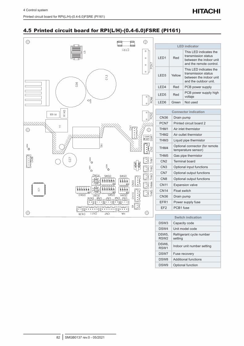
4 Control system
Printed circuit board for RPI(L/H)-(0.4-6.0)FSRE (PI161)
SMGB0137 rev.0 - 05/202182
4.5 Printed circuit board for RPI(L/H)-(0.4-6.0)FSRE (PI161)
THM4
PCN6
TPCN33
CN14 CN4CN8
CN7 HA
CN7 CN3
L3
LED
5
LED
6
LED
1LE
D3
LED
4
LED indicator
LED1 Red
This LED indicates the transmission status between the indoor unit and the remote control.
LED3 Yellow
This LED indicates the transmission status between the indoor unit and the outdoor unit.
LED4 Red PCB power supply
LED5 Red PCB power supply high voltaje
LED6 Green Not used
Connector indicationCN36 Drain pump
PCN7 Printed circuit board 2
THM1 Air inlet thermistor
THM2 Air outlet thermistor
THM3 Liquid pipe thermistor
THM4 Optional connector (for remote temperature sensor)
THM5 Gas pipe thermistor
CN2 Terminal board
CN3 Optional input functions
CN7 Optional output functions
CN8 Optional output functions
CN11 Expansion valve
CN14 Float switch
CN36 Drain pump
EFR1 Power supply fuse
EF2 PCB1 fuse
Switch indicationDSW3 Capacity code
DSW4 Unit model code
DSW5, RSW2
Refrigerant cycle number setting
DSW6, RSW1 Indoor unit number setting
DSW7 Fuse recovery
DSW8 Additional functions
DSW9 Optional function
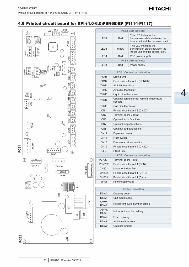
4 Control system
Printed circuit board for RPI-(4.0-6.0)FSN6E-EF (PI114-PI117)
SMGB0137 rev.0 - 05/202183
4
4.6 Printed circuit board for RPI-(4.0-6.0)FSN6E-EF (PI114-PI117)
CN
1
PC
N7
CN
19TH
M1
CN
14CN
28
TP
DS
W8
THM
2TH
M3
THM
4TH
M5
THU
1C
N3
CN33
CN7 CN8
CN17
CN11
PCN6
CN2
DSW
7
DS
W9
DS
W3
DS
W4
DS
W5
RSW2 RSW1
HA
DS
W6
LED1
LED4
LED3
PC
N20
1
PCN202CN203
EFR1
DM
1
L1R
2
HT1
TR1
CN
202
CN
201
R1
EFS1
LED
1
PCB1
PCB2
PCB1 LED indicator
LED1 RedThis LED indicates the transmission status between the indoor unit and the remote control.
LED3 YellowThis LED indicates the transmission status between the indoor unit and the outdoor unit.
LED4 Red PCB power supply
PCB2 LED indicatorLED1 Red Power supply
PCB1 Connector indicationPCN6 Drain pump
PCN7 Printed circuit board 2 (PCN202)
THM1 Air inlet thermistor
THM2 Air outlet thermistor
THM3 Liquid pipe thermistor
THM4 Optional connector (for remote temperature sensor)
THM5 Gas pipe thermistor
CN1 Printed circuit board 2 (CN203)
CN2 Terminal board 2 (TB2)
CN3 Optional input functions
CN7 Optional output functions
CN8 Optional output functions
CN11 Expansion valve
CN14 Float switch
CN17 Econofresh kit connection
CN19 Printed circuit board 2 (CN202)
EF2 PCB1 fuse
PCB1 Connector indicationPCN201 Terminal board 1 (TB1)
PCN202 Printed circuit board 1 (PCN7)
CN201 Motor for indoor fan
CN202 Printed circuit board 1 (CN19)
CN203 Printed circuit board 1 (CN1)
EFR1 Power supply fuse
Switch indicationDSW3 Capacity code
DSW4 Unit model code
DSW5, RSW2 Refrigerant cycle number setting
DSW6, RSW1 Indoor unit number setting
DSW7 Fuse recovery
DSW8 Additional functions
DSW9 Optional function
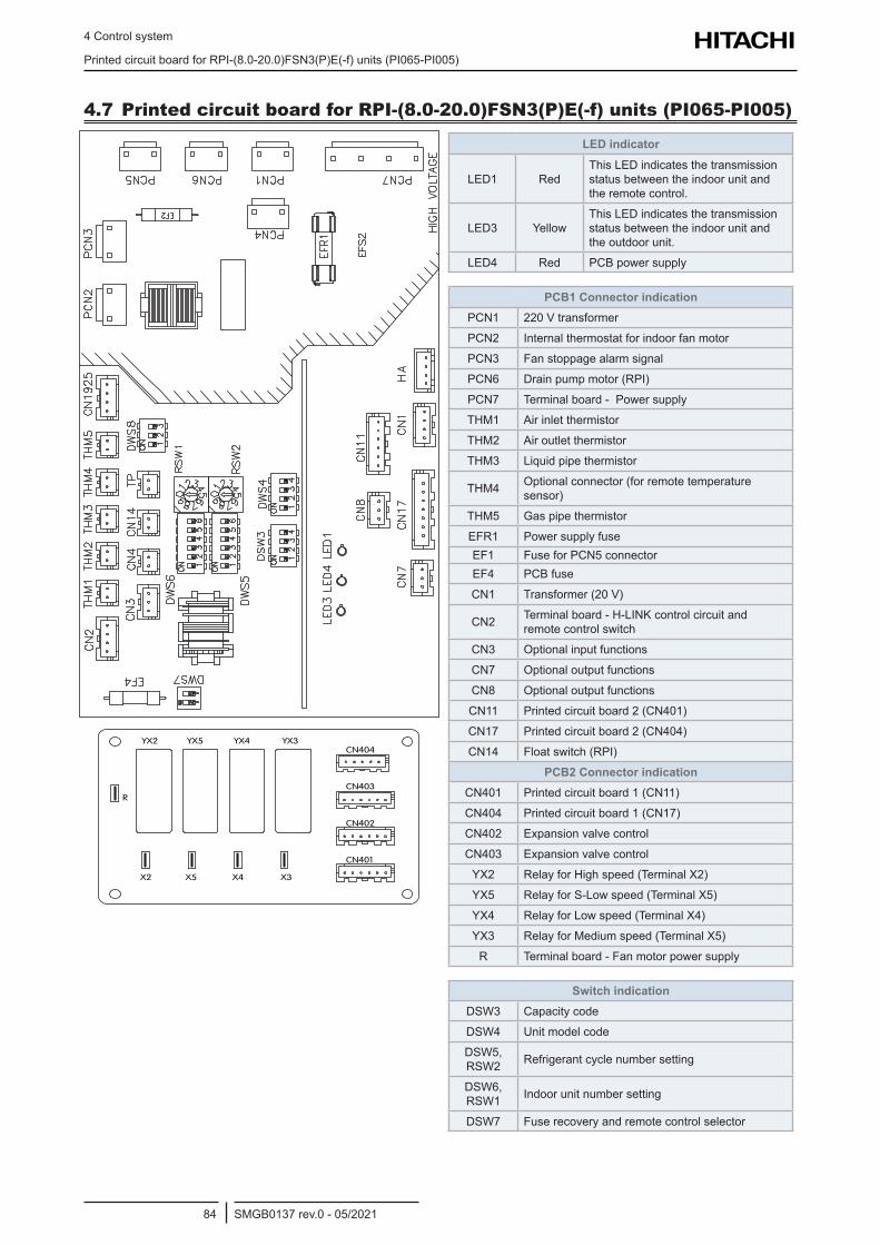
4 Control system
Printed circuit board for RPI-(8.0-20.0)FSN3(P)E(-f) units (PI065-PI005)
SMGB0137 rev.0 - 05/202184
4.7 Printed circuit board for RPI-(8.0-20.0)FSN3(P)E(-f) units (PI065-PI005)
CN403
CN404
CN401
CN402
YX2 YX5 YX4 YX3
X2 X5 X4 X3
R
LED indicator
LED1 RedThis LED indicates the transmission status between the indoor unit and the remote control.
LED3 YellowThis LED indicates the transmission status between the indoor unit and the outdoor unit.
LED4 Red PCB power supply
PCB1 Connector indicationPCN1 220 V transformer
PCN2 Internal thermostat for indoor fan motor
PCN3 Fan stoppage alarm signal
PCN6 Drain pump motor (RPI)
PCN7 Terminal board - Power supply
THM1 Air inlet thermistor
THM2 Air outlet thermistor
THM3 Liquid pipe thermistor
THM4 Optional connector (for remote temperature sensor)
THM5 Gas pipe thermistor
EFR1 Power supply fuseEF1 Fuse for PCN5 connectorEF4 PCB fuse
CN1 Transformer (20 V)
CN2 Terminal board - H-LINK control circuit and remote control switch
CN3 Optional input functions
CN7 Optional output functions
CN8 Optional output functions
CN11 Printed circuit board 2 (CN401)
CN17 Printed circuit board 2 (CN404)
CN14 Float switch (RPI)
PCB2 Connector indicationCN401 Printed circuit board 1 (CN11)
CN404 Printed circuit board 1 (CN17)
CN402 Expansion valve control
CN403 Expansion valve control
YX2 Relay for High speed (Terminal X2)
YX5 Relay for S-Low speed (Terminal X5)
YX4 Relay for Low speed (Terminal X4)
YX3 Relay for Medium speed (Terminal X5)
R Terminal board - Fan motor power supply
Switch indicationDSW3 Capacity code
DSW4 Unit model code
DSW5, RSW2 Refrigerant cycle number setting
DSW6, RSW1 Indoor unit number setting
DSW7 Fuse recovery and remote control selector
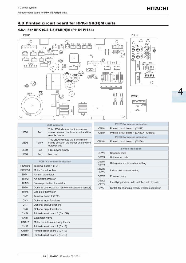
4 Control system
Printed circuit board for RPK-FSR(H)M units
SMGB0137 rev.0 - 05/202185
4
4.8 Printed circuit board for RPK-FSR(H)M units4.8.1 For RPK-(0.4-1.5)FSR(H)M (PI151-PI154)
PCB1 PCB2
PCB3
LED indicator
LED1 RedThis LED indicates the transmission status between the indoor unit and the remote control.
LED3 YellowThis LED indicates the transmission status between the indoor unit and the outdoor unit.
LED4 Red PCB power supply
LED2 Red Not used
PCB1 Connector indicationPCN500 Terminal board 1 (TB1)
PCN550 Motor for indoor fan
THM1 Air inlet thermistor
THM2 Air outlet thermistor
THM3 Freeze protection thermistor
THM4 Optional connector (for remote temperature sensor)
THM5 Gas pipe thermistor
CN2 Terminal board 2 (TB2)
CN3 Optional input functions
CN7 Optional output functions
CN8 Optional output functions
CN5A Printed circuit board 3 (CN10H)
CN11 Expansion valve
CN17A Motor for automatic swing louver
CN18 Printed circuit board 2 (CN18)
CN19A Printed circuit board 2 (CN19)
CN19B Printed circuit board 2 (CN19)
PCB2 Connector indicationCN18 Printed circuit board 1 (CN18)
CN19 Printed circuit board 1 (CN19A - CN19B)
PCB3 Connector indicationCN10H Printed circuit board 1 (CN5A)
Switch indicationDSW3 Capacity code
DSW4 Unit model code
DSW5, RSW1 Refrigerant cycle number setting
DSW6, RSW2 Indoor unit number setting
DSW7 Fuse recovery
DSW2, DSW9 Identifying indoor units installed side by side
SW2 Switch for changing wired / wireless controller
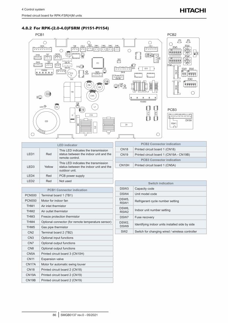
4 Control system
Printed circuit board for RPK-FSR(H)M units
SMGB0137 rev.0 - 05/202186
4.8.2 For RPK-(2.0-4.0)FSRM (PI151-PI154)PCB1 PCB2
PCB3
LED indicator
LED1 RedThis LED indicates the transmission status between the indoor unit and the remote control.
LED3 YellowThis LED indicates the transmission status between the indoor unit and the outdoor unit.
LED4 Red PCB power supply
LED2 Red Not used
PCB1 Connector indicationPCN500 Terminal board 1 (TB1)
PCN550 Motor for indoor fan
THM1 Air inlet thermistor
THM2 Air outlet thermistor
THM3 Freeze protection thermistor
THM4 Optional connector (for remote temperature sensor)
THM5 Gas pipe thermistor
CN2 Terminal board 2 (TB2)
CN3 Optional input functions
CN7 Optional output functions
CN8 Optional output functions
CN5A Printed circuit board 3 (CN10H)
CN11 Expansion valve
CN17A Motor for automatic swing louver
CN18 Printed circuit board 2 (CN18)
CN19A Printed circuit board 2 (CN19)
CN19B Printed circuit board 2 (CN19)
PCB2 Connector indicationCN18 Printed circuit board 1 (CN18)
CN19 Printed circuit board 1 (CN19A - CN19B)
PCB3 Connector indicationCN10H Printed circuit board 1 (CN5A)
Switch indicationDSW3 Capacity code
DSW4 Unit model code
DSW5, RSW1 Refrigerant cycle number setting
DSW6, RSW2 Indoor unit number setting
DSW7 Fuse recovery
DSW2, DSW9 Identifying indoor units installed side by side
SW2 Switch for changing wired / wireless controller
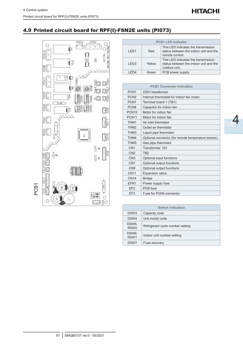
4 Control system
Printed circuit board for RPF(I)-FSN2E units (PI073)
SMGB0137 rev.0 - 05/202187
4
4.9 Printed circuit board for RPF(I)-FSN2E units (PI073)PC
B1
PCB1 LED indicator
LED1 RedThis LED indicates the transmission status between the indoor unit and the remote control.
LED3 YellowThis LED indicates the transmission status between the indoor unit and the outdoor unit.
LED4 Green PCB power supply
PCB1 Connector indicationPCN1 230V transformerPCN2 Internal thermostat for indoor fan motorPCN7 Terminal board 1 (TB1)PCN8 Capacitor for indoor fan
PCN10 Motor for indoor fanPCN11 Motor for indoor fanTHM1 Air inlet thermistorTHM2 Outlet air thermistorTHM3 Liquid pipe thermistorTHM4 Optional connector (for remote temperature sensor)THM5 Gas pipe thermistorCN1 Transformer 12VCN2 TB2CN3 Optional input functionsCN7 Optional output functionsCN8 Optional output functionsCN11 Expansion valveCN14 BridgeEFR1 Power supply fuseEF2 PCB fuseEF3 Fuse for PCN5 connector
Switch indicationDSW3 Capacity codeDSW4 Unit model codeDSW5, RSW2 Refrigerant cycle number setting
DSW6, RSW1 Indoor unit number setting
DSW7 Fuse recovery
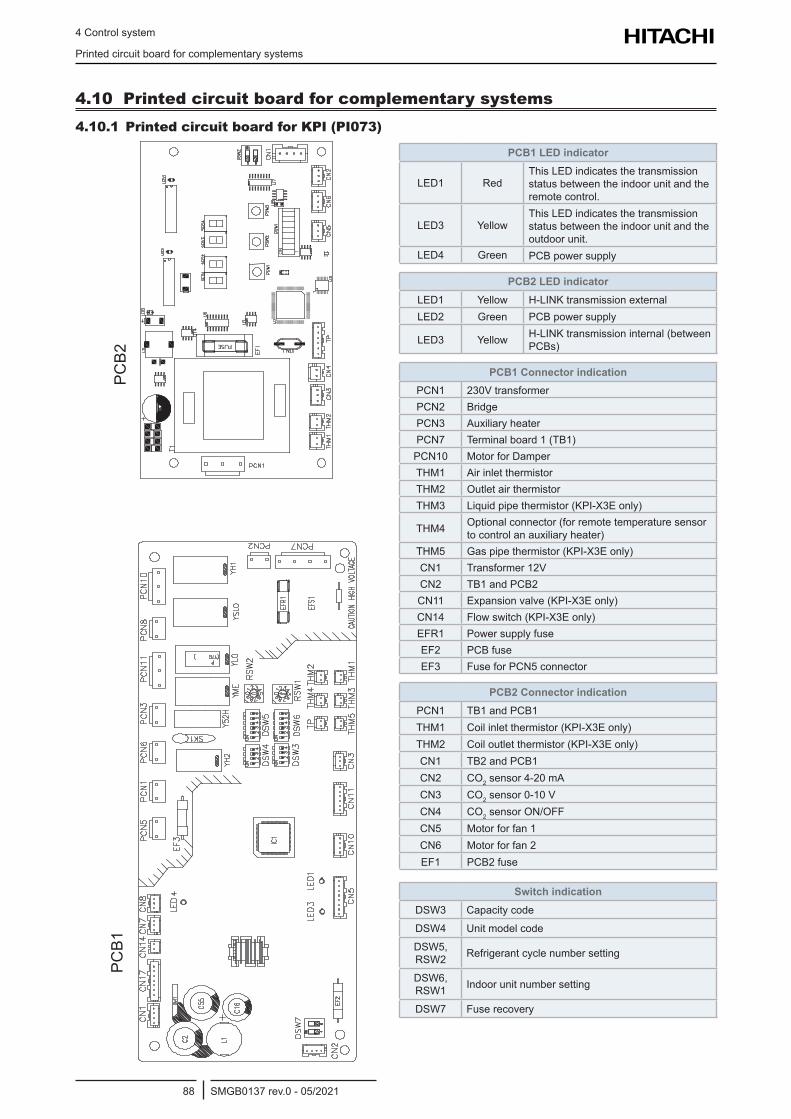
4 Control system
Printed circuit board for complementary systems
SMGB0137 rev.0 - 05/202188
4.10 Printed circuit board for complementary systems4.10.1 Printed circuit board for KPI (PI073)
FUSE
PCB1
PC
B2
PCB1 LED indicator
LED1 RedThis LED indicates the transmission status between the indoor unit and the remote control.
LED3 YellowThis LED indicates the transmission status between the indoor unit and the outdoor unit.
LED4 Green PCB power supply
PCB2 LED indicatorLED1 Yellow H-LINK transmission externalLED2 Green PCB power supply
LED3 Yellow H-LINK transmission internal (between PCBs)
PCB1 Connector indication PCN1 230V transformerPCN2 BridgePCN3 Auxiliary heaterPCN7 Terminal board 1 (TB1)
PCN10 Motor for DamperTHM1 Air inlet thermistorTHM2 Outlet air thermistorTHM3 Liquid pipe thermistor (KPI-X3E only)
THM4 Optional connector (for remote temperature sensor to control an auxiliary heater)
THM5 Gas pipe thermistor (KPI-X3E only)CN1 Transformer 12VCN2 TB1 and PCB2CN11 Expansion valve (KPI-X3E only)CN14 Flow switch (KPI-X3E only)EFR1 Power supply fuseEF2 PCB fuseEF3 Fuse for PCN5 connector
PCB2 Connector indication PCN1 TB1 and PCB1THM1 Coil inlet thermistor (KPI-X3E only)THM2 Coil outlet thermistor (KPI-X3E only)CN1 TB2 and PCB1CN2 CO2 sensor 4-20 mACN3 CO2 sensor 0-10 VCN4 CO2 sensor ON/OFFCN5 Motor for fan 1CN6 Motor for fan 2EF1 PCB2 fuse
Switch indicationDSW3 Capacity code
DSW4 Unit model code
DSW5, RSW2 Refrigerant cycle number setting
DSW6, RSW1 Indoor unit number setting
DSW7 Fuse recovery
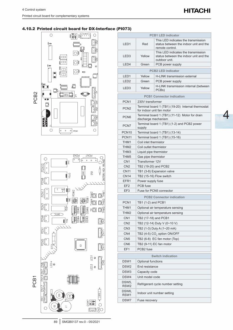
4 Control system
Printed circuit board for complementary systems
SMGB0137 rev.0 - 05/202189
4
4.10.2 Printed circuit board for DX-Interface (PI073)
FUSE
PCB1
PC
B2
PCB1 LED indicator
LED1 RedThis LED indicates the transmission status between the indoor unit and the remote control.
LED3 YellowThis LED indicates the transmission status between the indoor unit and the outdoor unit.
LED4 Green PCB power supply
PCB2 LED indicatorLED1 Yellow H-LINK transmission externalLED2 Green PCB power supply
LED3 Yellow H-LINK transmission internal (between PCBs)
PCB1 Connector indicationPCN1 230V transformer
PCN2 Terminal board 1 (TB1) (19-20) Internal thermostat for indoor unit fan motor
PCN6 Terminal board 1 (TB1) (11-12) Motor for drain discharge mechanism
PCN7 Terminal board 1 (TB1) (1-2) and PCB2 power supply
PCN10 Terminal board 1 (TB1) (13-14) PCN11 Terminal board 1 (TB1) (15-16)THM1 Coil inlet thermistorTHM2 Coil outlet thermistorTHM3 Liquid pipe thermistorTHM5 Gas pipe thermistorCN1 Transformer 12VCN2 TB2 (19-20) and PCB2CN11 TB1 (3-8) Expansion valveCN14 TB2 (15-16) Flow switchEFR1 Power supply fuseEF2 PCB fuseEF3 Fuse for PCN5 connector
PCB2 Connector indicationPCN1 TB1 (1-2) and PCB1THM1 Optional air temperature sensingTHM2 Optional air temperature sensingCN1 TB2 (17-18) and PCB1CN2 TB2 (12-14) Duty V (0~10 V)CN3 TB2 (1-3) Duty A (1~20 mA)CN4 TB2 (4-5) CO2 option ON/OFFCN5 TB2 (6-8) EC fan motor (Top)CN6 TB2 (9-11) EC fan motorEF1 PCB2 fuse
Switch indicationDSW1 Optional functionsDSW2 End resistanceDSW3 Capacity codeDSW4 Unit model codeDSW5, RSW2 Refrigerant cycle number setting
DSW6, RSW1 Indoor unit number setting
DSW7 Fuse recovery
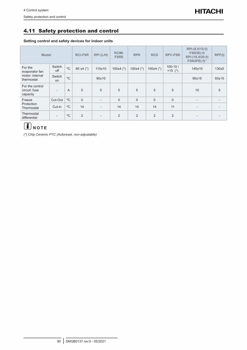
4 Control system
Safety protection and control
SMGB0137 rev.0 - 05/202190
4.11 Safety protection and control
Setting control and safety devices for indoor units
Model RCI-FSR RPI (L/H) RCIM-FSRE RPK RCD RPC-FSR
RPI-(8.0/10.0)FSN3E(-f)
RPI-(16.0/20.0)FSN3PE(-f)”
RPF(I)
For the evaporator fan motor: internal thermostat
Switch off ºC 80 ±4 (*) 110±10 100±4 (*) 100±4 (*) 100±4 (*) 100-10 /
+15 (*) 140±10 130±5
Switch on ºC 90±10 90±15 93±15
For the control circuit: fuse capacity
- A 5 5 5 5 5 5 10 5
Freeze Protection Thermostat
Cut-Out ºC 0 - 0 0 0 0 - -
Cut-in ºC 14 - 14 14 14 11 - -
Thermostat differential - ºC 2 - 2 2 2 2 - -
? N O T E(*) Chip Ceramic PTC (Autoreset, non-adjustable)
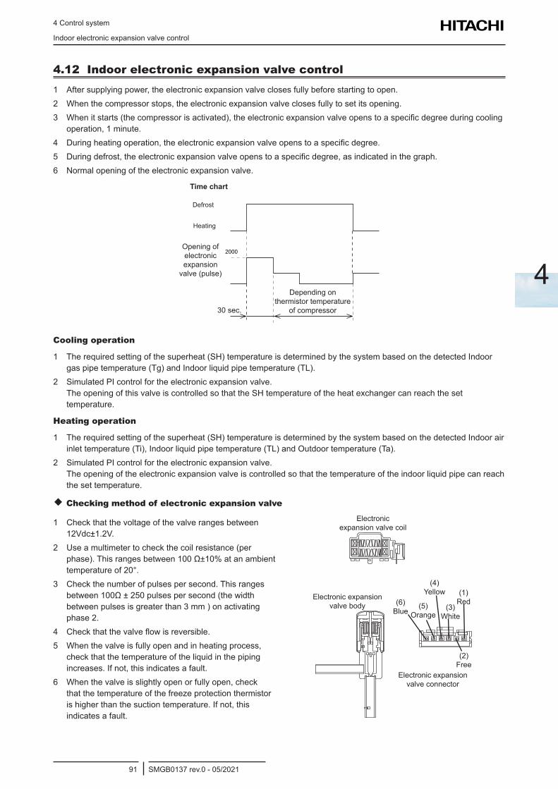
4 Control system
Indoor electronic expansion valve control
SMGB0137 rev.0 - 05/202191
4
4.12 Indoor electronic expansion valve control1 After supplying power, the electronic expansion valve closes fully before starting to open.2 When the compressor stops, the electronic expansion valve closes fully to set its opening.3 When it starts (the compressor is activated), the electronic expansion valve opens to a specific degree during cooling
operation, 1 minute.4 During heating operation, the electronic expansion valve opens to a specific degree.5 During defrost, the electronic expansion valve opens to a specific degree, as indicated in the graph.6 Normal opening of the electronic expansion valve.
Time chart
Defrost
Heating
Opening of electronic expansion
valve (pulse)
Depending on thermistor temperature
of compressor30 sec.
Cooling operation
1 The required setting of the superheat (SH) temperature is determined by the system based on the detected Indoor gas pipe temperature (Tg) and Indoor liquid pipe temperature (TL).
2 Simulated PI control for the electronic expansion valve. The opening of this valve is controlled so that the SH temperature of the heat exchanger can reach the set temperature.
Heating operation
1 The required setting of the superheat (SH) temperature is determined by the system based on the detected Indoor air inlet temperature (Ti), Indoor liquid pipe temperature (TL) and Outdoor temperature (Ta).
2 Simulated PI control for the electronic expansion valve. The opening of the electronic expansion valve is controlled so that the temperature of the indoor liquid pipe can reach the set temperature.
Checking method of electronic expansion valve
1 Check that the voltage of the valve ranges between 12Vdc±1.2V.
2 Use a multimeter to check the coil resistance (per phase). This ranges between 100 Ω±10% at an ambient temperature of 20°.
3 Check the number of pulses per second. This ranges between 100Ω ± 250 pulses per second (the width between pulses is greater than 3 mm ) on activating phase 2.
4 Check that the valve flow is reversible.5 When the valve is fully open and in heating process,
check that the temperature of the liquid in the piping increases. If not, this indicates a fault.
6 When the valve is slightly open or fully open, check that the temperature of the freeze protection thermistor is higher than the suction temperature. If not, this indicates a fault.
Electronic expansion valve coil
Electronic expansion valve body
Electronic expansion valve connector
(6) Blue
(5) Orange
(4) Yellow
(3) White
(1) Red
(2) Free
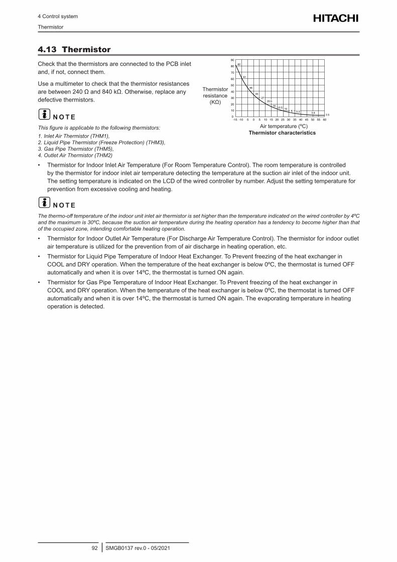
4 Control system
Thermistor
SMGB0137 rev.0 - 05/202192
4.13 ThermistorCheck that the thermistors are connected to the PCB inlet and, if not, connect them.
Use a multimeter to check that the thermistor resistances are between 240 Ω and 840 kΩ. Otherwise, replace any defective thermistors.
? N O T EThis figure is applicable to the following thermistors:1. Inlet Air Thermistor (THM1), 2. Liquid Pipe Thermistor (Freeze Protection) (THM3), 3. Gas Pipe Thermistor (THM5), 4. Outlet Air Thermistor (THM2)
Thermistor resistance
(KΩ)
Air temperature (ºC)Thermistor characteristics
• Thermistor for Indoor Inlet Air Temperature (For Room Temperature Control). The room temperature is controlled by the thermistor for indoor inlet air temperature detecting the temperature at the suction air inlet of the indoor unit. The setting temperature is indicated on the LCD of the wired controller by number. Adjust the setting temperature for prevention from excessive cooling and heating.
? N O T EThe thermo-off temperature of the indoor unit inlet air thermistor is set higher than the temperature indicated on the wired controller by 4ºC and the maximum is 30ºC, because the suction air temperature during the heating operation has a tendency to become higher than that of the occupied zone, intending comfortable heating operation.
• Thermistor for Indoor Outlet Air Temperature (For Discharge Air Temperature Control). The thermistor for indoor outlet air temperature is utilized for the prevention from of air discharge in heating operation, etc.
• Thermistor for Liquid Pipe Temperature of Indoor Heat Exchanger. To Prevent freezing of the heat exchanger in COOL and DRY operation. When the temperature of the heat exchanger is below 0ºC, the thermostat is turned OFF automatically and when it is over 14ºC, the thermostat is turned ON again.
• Thermistor for Gas Pipe Temperature of Indoor Heat Exchanger. To Prevent freezing of the heat exchanger in COOL and DRY operation. When the temperature of the heat exchanger is below 0ºC, the thermostat is turned OFF automatically and when it is over 14ºC, the thermostat is turned ON again. The evaporating temperature in heating operation is detected.
5 Optional functions
SMGB0137 rev.0 - 05/202193
5
5 . O p t i o n a l f u n c t i o n s
Index
5.1 Indoor units input and output signals.....................................................................................................94
5.1.1 Available ports ............................................................................................................................................... 94
5.1.2 Optional signal configuration ......................................................................................................................... 96
5.1.3 Programming with remote controller ............................................................................................................. 98
5.1.4 Description of optional input signals .............................................................................................................. 98
5.1.5 Description of optional output signals .......................................................................................................... 104
5.2 Optional functions through Remote control .........................................................................................107
5.2.1 List of optional remote control functions (PC-ARFP1E) .............................................................................. 107
5.2.2 Description of the optional remote control functions (PC-ARFP1E) ............................................................ 126
5.2.3 Optional functions for PC-ARH1E remote controls ..................................................................................... 142
5.2.4 Description of the optional remote control functions (PC-ARH1E) .............................................................. 156
5.2.5 Alarm indication ........................................................................................................................................... 170
5.2.6 Settings on wireless remote controls ........................................................................................................... 170
5.3 Complementary systems .....................................................................................................................171
5.3.1 KPI and DX-Interface .................................................................................................................................. 171
5.3.1.1 7-segments display main menus .................................................................................................... 171
5.3.2 Econofresh Kit ............................................................................................................................................. 174
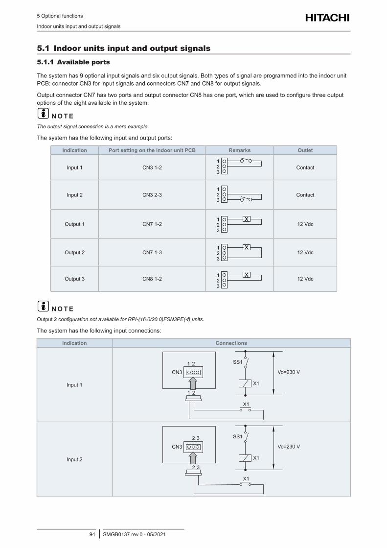
5 Optional functions
Indoor units input and output signals
SMGB0137 rev.0 - 05/202194
5.1 Indoor units input and output signals5.1.1 Available ports
The system has 9 optional input signals and six output signals. Both types of signal are programmed into the indoor unit PCB: connector CN3 for input signals and connectors CN7 and CN8 for output signals.
Output connector CN7 has two ports and output connector CN8 has one port, which are used to configure three output options of the eight available in the system.
? N O T EThe output signal connection is a mere example.
The system has the following input and output ports:
Indication Port setting on the indoor unit PCB Remarks Outlet
Input 1 CN3 1-2 Contact
Input 2 CN3 2-3 Contact
Output 1 CN7 1-2 12 Vdc
Output 2 CN7 1-3 12 Vdc
Output 3 CN8 1-2 12 Vdc
? N O T EOutput 2 configuration not available for RPI-(16.0/20.0)FSN3PE(-f) units.
The system has the following input connections:
Indication Connections
Input 1
Input 2
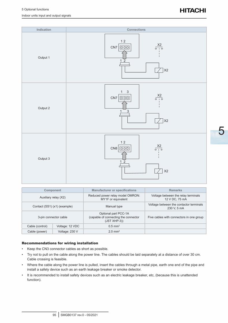
5 Optional functions
Indoor units input and output signals
SMGB0137 rev.0 - 05/202195
5
Indication Connections
Output 1
Output 2
Output 3
Component Manufacturer or specifications Remarks
Auxiliary relay (X2) Reduced power relay model OMRON: MY1F or equivalent
Voltage between the relay terminals 12 V DC, 75 mA
Contact (SS1) (x1) (example) Manual type Voltage between the contactor terminals 230 V, 5 mA
3-pin connector cableOptional part PCC-1A
(capable of connecting the connector (JST XHP-3))
Five cables with connectors in one group
Cable (control) Voltage: 12 VDC 0.5 mm2
Cable (power) Voltage: 230 V 2.0 mm2
Recommendations for wiring installation• Keep the CN3 connector cables as short as possible.• Try not to pull on the cable along the power line. The cables should be laid separately at a distance of over 30 cm.
Cable crossing is feasible.• Where the cable along the power line is pulled, insert the cables through a metal pipe, earth one end of the pipe and
install a safety device such as an earth leakage breaker or smoke detector.• It is recommended to install safety devices such as an electric leakage breaker, etc, (because this is unattended
function).
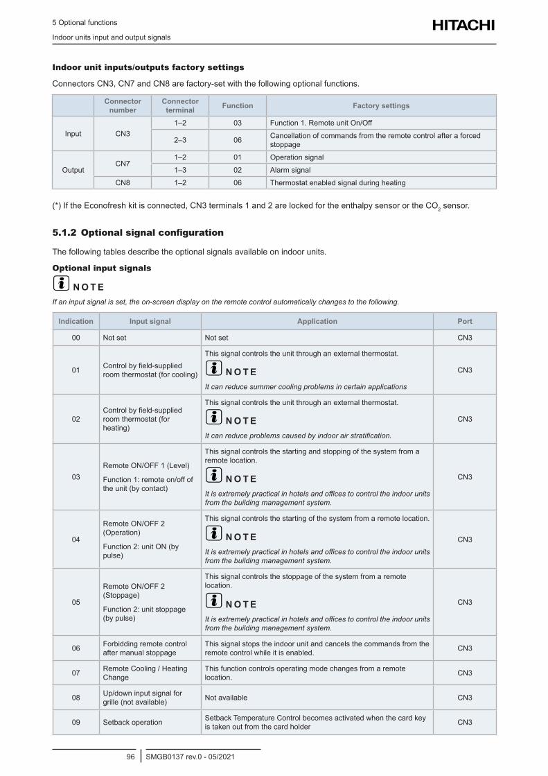
5 Optional functions
Indoor units input and output signals
SMGB0137 rev.0 - 05/202196
Indoor unit inputs/outputs factory settings
Connectors CN3, CN7 and CN8 are factory-set with the following optional functions.
Connector number
Connector terminal Function Factory settings
Input CN31–2 03 Function 1. Remote unit On/Off
2–3 06 Cancellation of commands from the remote control after a forced stoppage
OutputCN7
1–2 01 Operation signal
1–3 02 Alarm signal
CN8 1–2 06 Thermostat enabled signal during heating
(*) If the Econofresh kit is connected, CN3 terminals 1 and 2 are locked for the enthalpy sensor or the CO2 sensor.
5.1.2 Optional signal configuration
The following tables describe the optional signals available on indoor units.
Optional input signals
? N O T EIf an input signal is set, the on-screen display on the remote control automatically changes to the following.
Indication Input signal Application Port
00 Not set Not set CN3
01 Control by field-supplied room thermostat (for cooling)
This signal controls the unit through an external thermostat.
? N O T EIt can reduce summer cooling problems in certain applications
CN3
02Control by field-supplied room thermostat (for heating)
This signal controls the unit through an external thermostat.
? N O T EIt can reduce problems caused by indoor air stratification.
CN3
03Remote ON/OFF 1 (Level)
Function 1: remote on/off of the unit (by contact)
This signal controls the starting and stopping of the system from a remote location.
? N O T EIt is extremely practical in hotels and offices to control the indoor units from the building management system.
CN3
04
Remote ON/OFF 2 (Operation)
Function 2: unit ON (by pulse)
This signal controls the starting of the system from a remote location.
? N O T EIt is extremely practical in hotels and offices to control the indoor units from the building management system.
CN3
05
Remote ON/OFF 2 (Stoppage)
Function 2: unit stoppage (by pulse)
This signal controls the stoppage of the system from a remote location.
? N O T EIt is extremely practical in hotels and offices to control the indoor units from the building management system.
CN3
06 Forbidding remote control after manual stoppage
This signal stops the indoor unit and cancels the commands from the remote control while it is enabled. CN3
07 Remote Cooling / Heating Change
This function controls operating mode changes from a remote location. CN3
08 Up/down input signal for grille (not available) Not available CN3
09 Setback operation Setback Temperature Control becomes activated when the card key is taken out from the card holder CN3
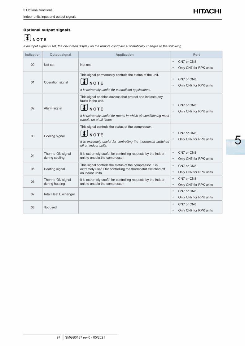
5 Optional functions
Indoor units input and output signals
SMGB0137 rev.0 - 05/202197
5
Optional output signals
? N O T EIf an input signal is set, the on-screen display on the remote controller automatically changes to the following.
Indication Output signal Application Port
00 Not set Not set• CN7 or CN8
• Only CN7 for RPK units
01 Operation signal
This signal permanently controls the status of the unit.
? N O T EIt is extremely useful for centralised applications.
• CN7 or CN8
• Only CN7 for RPK units
02 Alarm signal
This signal enables devices that protect and indicate any faults in the unit.
? N O T EIt is extremely useful for rooms in which air conditioning must remain on at all times.
• CN7 or CN8
• Only CN7 for RPK units
03 Cooling signal
This signal controls the status of the compressor.
? N O T EIt is extremely useful for controlling the thermostat switched off on indoor units.
• CN7 or CN8
• Only CN7 for RPK units
04 Thermo-ON signal during cooling
It is extremely useful for controlling requests by the indoor unit to enable the compressor.
• CN7 or CN8
• Only CN7 for RPK units
05 Heating signalThis signal controls the status of the compressor. It is extremely useful for controlling the thermostat switched off on indoor units.
• CN7 or CN8
• Only CN7 for RPK units
06 Thermo-ON signal during heating
It is extremely useful for controlling requests by the indoor unit to enable the compressor.
• CN7 or CN8
• Only CN7 for RPK units
07 Total Heat Exchanger• CN7 or CN8
• Only CN7 for RPK units
08 Not used• CN7 or CN8
• Only CN7 for RPK units
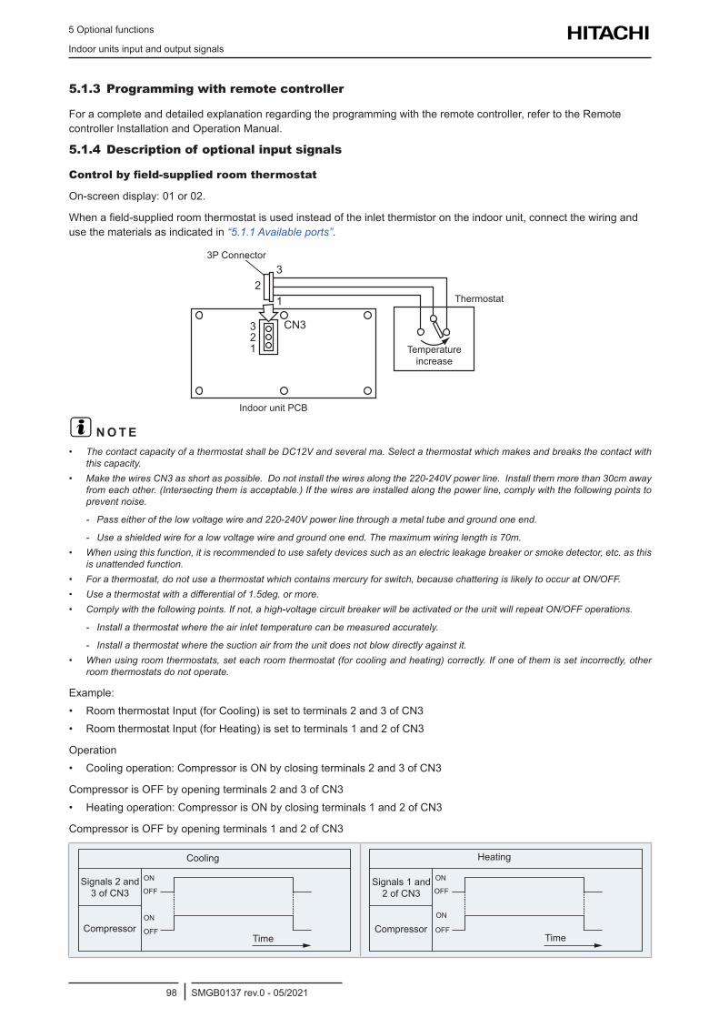
5 Optional functions
Indoor units input and output signals
SMGB0137 rev.0 - 05/202198
5.1.3 Programming with remote controller
For a complete and detailed explanation regarding the programming with the remote controller, refer to the Remote controller Installation and Operation Manual.
5.1.4 Description of optional input signals
Control by field-supplied room thermostat
On-screen display: 01 or 02.
When a field-supplied room thermostat is used instead of the inlet thermistor on the indoor unit, connect the wiring and use the materials as indicated in “5.1.1 Available ports”.
2
CN3321
3
1
3P Connector
Indoor unit PCB
Thermostat
Temperature increase
? N O T E• The contact capacity of a thermostat shall be DC12V and several ma. Select a thermostat which makes and breaks the contact with
this capacity.• Make the wires CN3 as short as possible. Do not install the wires along the 220-240V power line. Install them more than 30cm away
from each other. (Intersecting them is acceptable.) If the wires are installed along the power line, comply with the following points to prevent noise.
- Pass either of the low voltage wire and 220-240V power line through a metal tube and ground one end.
- Use a shielded wire for a low voltage wire and ground one end. The maximum wiring length is 70m.• When using this function, it is recommended to use safety devices such as an electric leakage breaker or smoke detector, etc. as this
is unattended function. • For a thermostat, do not use a thermostat which contains mercury for switch, because chattering is likely to occur at ON/OFF.• Use a thermostat with a differential of 1.5deg. or more.• Comply with the following points. If not, a high-voltage circuit breaker will be activated or the unit will repeat ON/OFF operations.
- Install a thermostat where the air inlet temperature can be measured accurately.
- Install a thermostat where the suction air from the unit does not blow directly against it.• When using room thermostats, set each room thermostat (for cooling and heating) correctly. If one of them is set incorrectly, other
room thermostats do not operate.
Example: • Room thermostat Input (for Cooling) is set to terminals 2 and 3 of CN3• Room thermostat Input (for Heating) is set to terminals 1 and 2 of CN3
Operation• Cooling operation: Compressor is ON by closing terminals 2 and 3 of CN3
Compressor is OFF by opening terminals 2 and 3 of CN3• Heating operation: Compressor is ON by closing terminals 1 and 2 of CN3
Compressor is OFF by opening terminals 1 and 2 of CN3
Cooling
Signals 2 and 3 of CN3
CompressorTime
ON
ON
OFF
OFF
Heating
Signals 1 and 2 of CN3
CompressorTime
ON
ON
OFF
OFF
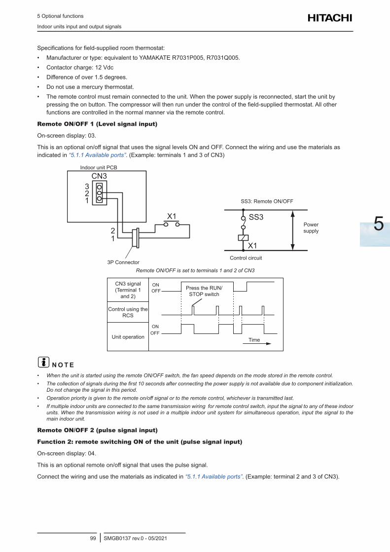
5 Optional functions
Indoor units input and output signals
SMGB0137 rev.0 - 05/202199
5
Specifications for field-supplied room thermostat:• Manufacturer or type: equivalent to YAMAKATE R7031P005, R7031Q005.• Contactor charge: 12 Vdc• Difference of over 1.5 degrees.• Do not use a mercury thermostat.• The remote control must remain connected to the unit. When the power supply is reconnected, start the unit by
pressing the on button. The compressor will then run under the control of the field-supplied thermostat. All other functions are controlled in the normal manner via the remote control.
Remote ON/OFF 1 (Level signal input)
On-screen display: 03.
This is an optional on/off signal that uses the signal levels ON and OFF. Connect the wiring and use the materials as indicated in “5.1.1 Available ports”. (Example: terminals 1 and 3 of CN3)
SS3
X1
CN3
X1
321
21
3P Connector
Indoor unit PCB
SS3: Remote ON/OFF
Control circuit
Power supply
Remote ON/OFF is set to terminals 1 and 2 of CN3
Press the RUN/STOP switch
Control using the RCS
CN3 signal (Terminal 1
and 2)
TimeUnit operation
ON
ON
OFF
OFF
? N O T E• When the unit is started using the remote ON/OFF switch, the fan speed depends on the mode stored in the remote control.• The collection of signals during the first 10 seconds after connecting the power supply is not available due to component initialization.
Do not change the signal in this period.• Operation priority is given to the remote on/off signal or to the remote control, whichever is transmitted last.• If multiple indoor units are connected to the same transmission wiring for remote control switch, input the signal to any of these indoor
units. When the transmission wiring is not used in a multiple indoor unit system for simultaneous operation, input the signal to the main indoor unit.
Remote ON/OFF 2 (pulse signal input)
Function 2: remote switching ON of the unit (pulse signal input)
On-screen display: 04.
This is an optional remote on/off signal that uses the pulse signal.
Connect the wiring and use the materials as indicated in “5.1.1 Available ports”. (Example: terminal 2 and 3 of CN3).
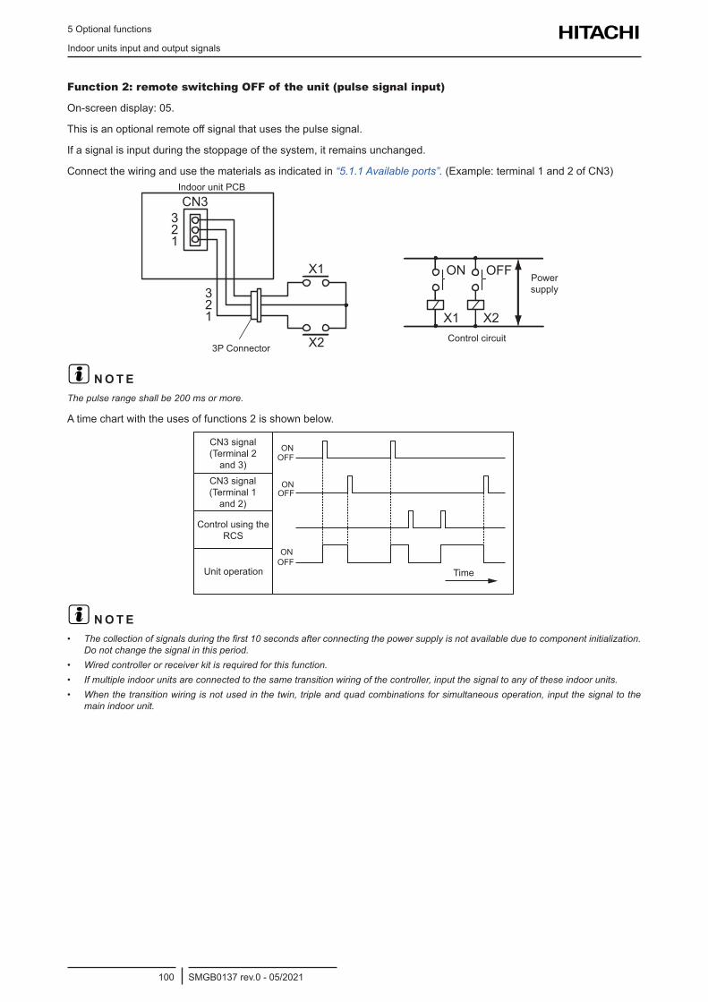
5 Optional functions
Indoor units input and output signals
SMGB0137 rev.0 - 05/2021100
Function 2: remote switching OFF of the unit (pulse signal input)
On-screen display: 05.
This is an optional remote off signal that uses the pulse signal.
If a signal is input during the stoppage of the system, it remains unchanged.
Connect the wiring and use the materials as indicated in “5.1.1 Available ports”. (Example: terminal 1 and 2 of CN3)
ON
X1
OFF
X2
CN3
X1
X2
321
321
3P Connector
Indoor unit PCB
Control circuit
Power supply
? N O T EThe pulse range shall be 200 ms or more.
A time chart with the uses of functions 2 is shown below.
Control using the RCS
CN3 signal (Terminal 2
and 3)
TimeUnit operation
CN3 signal (Terminal 1
and 2)
ON
ON
ON
OFF
OFF
OFF
? N O T E• The collection of signals during the first 10 seconds after connecting the power supply is not available due to component initialization.
Do not change the signal in this period.• Wired controller or receiver kit is required for this function.• If multiple indoor units are connected to the same transition wiring of the controller, input the signal to any of these indoor units.• When the transition wiring is not used in the twin, triple and quad combinations for simultaneous operation, input the signal to the
main indoor unit.
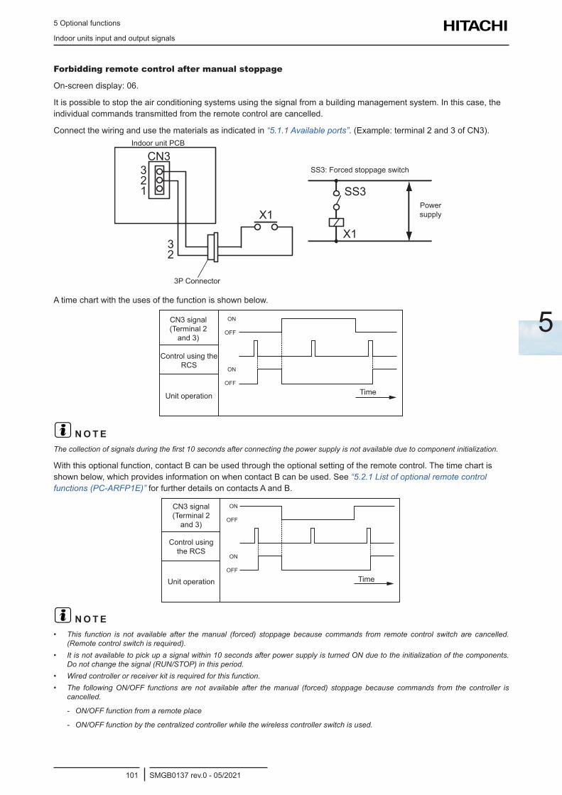
5 Optional functions
Indoor units input and output signals
SMGB0137 rev.0 - 05/2021101
5
Forbidding remote control after manual stoppage
On-screen display: 06.
It is possible to stop the air conditioning systems using the signal from a building management system. In this case, the individual commands transmitted from the remote control are cancelled.
Connect the wiring and use the materials as indicated in “5.1.1 Available ports”. (Example: terminal 2 and 3 of CN3).
SS3
X1
CN3
X1
321
32
3P Connector
Indoor unit PCB
SS3: Forced stoppage switch
Power supply
A time chart with the uses of the function is shown below.
Control using the RCS
CN3 signal (Terminal 2
and 3)
TimeUnit operation
ON
ON
OFF
OFF
? N O T EThe collection of signals during the first 10 seconds after connecting the power supply is not available due to component initialization.
With this optional function, contact B can be used through the optional setting of the remote control. The time chart is shown below, which provides information on when contact B can be used. See “5.2.1 List of optional remote control functions (PC-ARFP1E)” for further details on contacts A and B.
Control using the RCS
CN3 signal (Terminal 2
and 3)
TimeUnit operation
ON
ON
OFF
OFF
? N O T E• This function is not available after the manual (forced) stoppage because commands from remote control switch are cancelled.
(Remote control switch is required).• It is not available to pick up a signal within 10 seconds after power supply is turned ON due to the initialization of the components.
Do not change the signal (RUN/STOP) in this period.• Wired controller or receiver kit is required for this function.• The following ON/OFF functions are not available after the manual (forced) stoppage because commands from the controller is
cancelled.
- ON/OFF function from a remote place
- ON/OFF function by the centralized controller while the wireless controller switch is used.
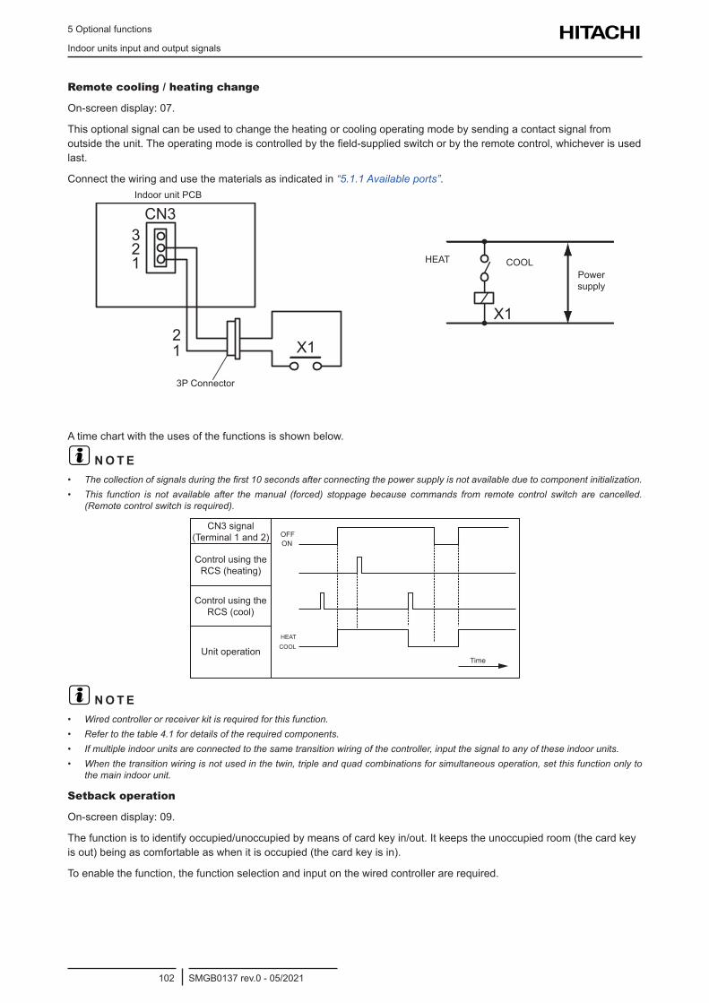
5 Optional functions
Indoor units input and output signals
SMGB0137 rev.0 - 05/2021102
Remote cooling / heating change
On-screen display: 07.
This optional signal can be used to change the heating or cooling operating mode by sending a contact signal from outside the unit. The operating mode is controlled by the field-supplied switch or by the remote control, whichever is used last.
Connect the wiring and use the materials as indicated in “5.1.1 Available ports”.
CN3
X1
321
21
X1
3P Connector
Indoor unit PCB
HEAT COOL Power supply
A time chart with the uses of the functions is shown below.
? N O T E• The collection of signals during the first 10 seconds after connecting the power supply is not available due to component initialization.• This function is not available after the manual (forced) stoppage because commands from remote control switch are cancelled.
(Remote control switch is required).
Control using the RCS (cool)
CN3 signal (Terminal 1 and 2)
Time
ON
Unit operation
Control using the RCS (heating)
OFF
HEATCOOL
? N O T E• Wired controller or receiver kit is required for this function.• Refer to the table 4.1 for details of the required components.• If multiple indoor units are connected to the same transition wiring of the controller, input the signal to any of these indoor units.• When the transition wiring is not used in the twin, triple and quad combinations for simultaneous operation, set this function only to
the main indoor unit.
Setback operation
On-screen display: 09.
The function is to identify occupied/unoccupied by means of card key in/out. It keeps the unoccupied room (the card key is out) being as comfortable as when it is occupied (the card key is in).
To enable the function, the function selection and input on the wired controller are required.
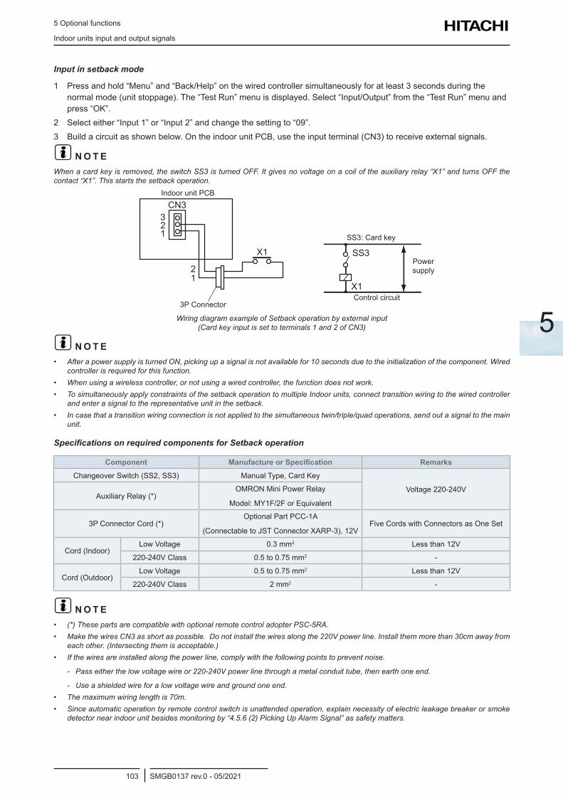
5 Optional functions
Indoor units input and output signals
SMGB0137 rev.0 - 05/2021103
5
Input in setback mode
1 Press and hold “Menu” and “Back/Help” on the wired controller simultaneously for at least 3 seconds during the normal mode (unit stoppage). The “Test Run” menu is displayed. Select “Input/Output” from the “Test Run” menu and press “OK”.
2 Select either “Input 1” or “Input 2” and change the setting to “09”.3 Build a circuit as shown below. On the indoor unit PCB, use the input terminal (CN3) to receive external signals.
? N O T EWhen a card key is removed, the switch SS3 is turned OFF. It gives no voltage on a coil of the auxiliary relay “X1” and turns OFF the contact “X1”. This starts the setback operation.
SS3
X1
CN3
X1
321
21
3P Connector
Indoor unit PCB
SS3: Card key
Power supply
Control circuit
Wiring diagram example of Setback operation by external input (Card key input is set to terminals 1 and 2 of CN3)
? N O T E• After a power supply is turned ON, picking up a signal is not available for 10 seconds due to the initialization of the component. Wired
controller is required for this function.• When using a wireless controller, or not using a wired controller, the function does not work.• To simultaneously apply constraints of the setback operation to multiple Indoor units, connect transition wiring to the wired controller
and enter a signal to the representative unit in the setback.• In case that a transition wiring connection is not applied to the simultaneous twin/triple/quad operations, send out a signal to the main
unit.
Specifications on required components for Setback operation
Component Manufacture or Specification RemarksChangeover Switch (SS2, SS3) Manual Type, Card Key
Voltage 220-240VAuxiliary Relay (*)
OMRON Mini Power Relay
Model: MY1F/2F or Equivalent
3P Connector Cord (*)Optional Part PCC-1A
(Connectable to JST Connector XARP-3), 12VFive Cords with Connectors as One Set
Cord (Indoor)Low Voltage 0.3 mm2 Less than 12V
220-240V Class 0.5 to 0.75 mm2 -
Cord (Outdoor)Low Voltage 0.5 to 0.75 mm2 Less than 12V
220-240V Class 2 mm2 -
? N O T E• (*) These parts are compatible with optional remote control adopter PSC-5RA.• Make the wires CN3 as short as possible. Do not install the wires along the 220V power line. Install them more than 30cm away from
each other. (Intersecting them is acceptable.)• If the wires are installed along the power line, comply with the following points to prevent noise.
- Pass either the low voltage wire or 220-240V power line through a metal conduit tube, then earth one end.
- Use a shielded wire for a low voltage wire and ground one end.• The maximum wiring length is 70m.• Since automatic operation by remote control switch is unattended operation, explain necessity of electric leakage breaker or smoke
detector near indoor unit besides monitoring by “4.5.6 (2) Picking Up Alarm Signal” as safety matters.
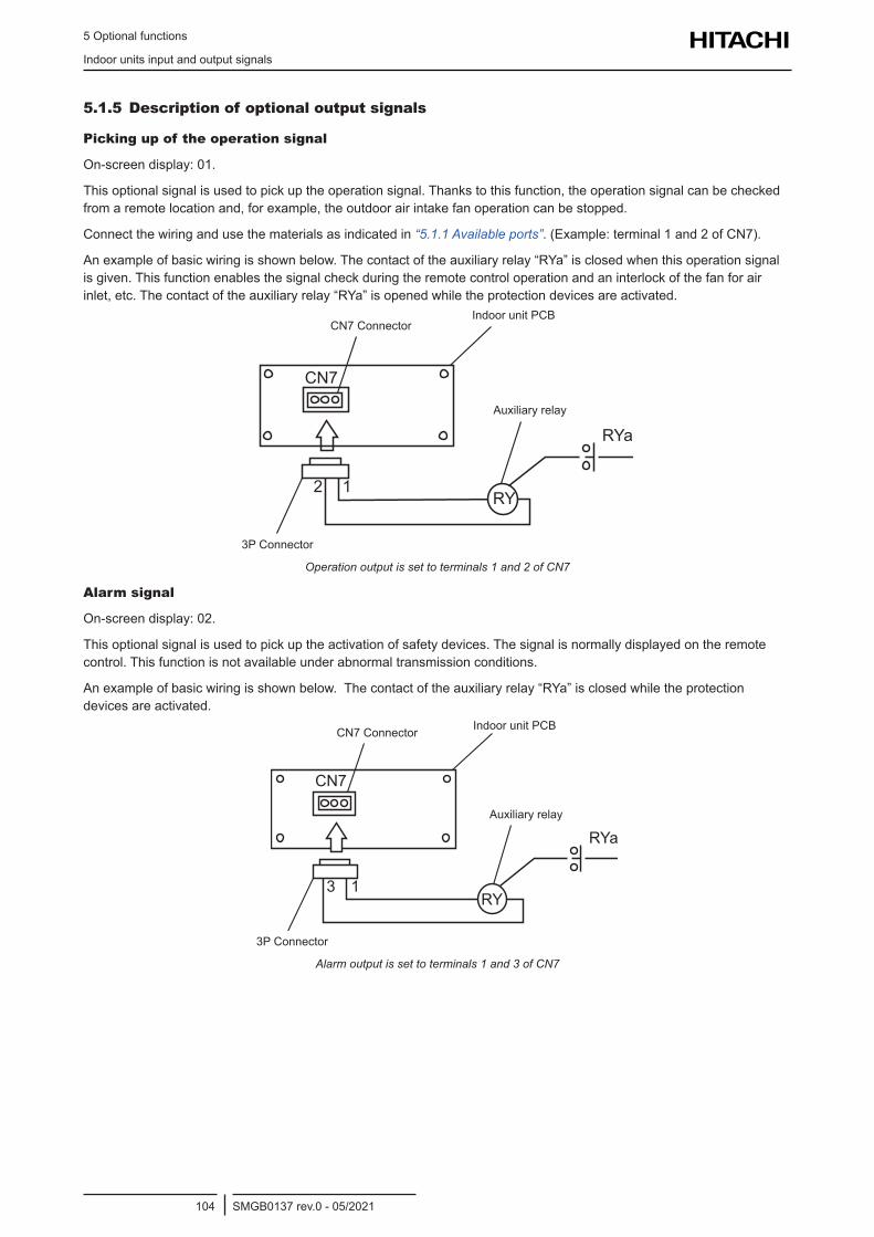
5 Optional functions
Indoor units input and output signals
SMGB0137 rev.0 - 05/2021104
5.1.5 Description of optional output signals
Picking up of the operation signal
On-screen display: 01.
This optional signal is used to pick up the operation signal. Thanks to this function, the operation signal can be checked from a remote location and, for example, the outdoor air intake fan operation can be stopped.
Connect the wiring and use the materials as indicated in “5.1.1 Available ports”. (Example: terminal 1 and 2 of CN7).
An example of basic wiring is shown below. The contact of the auxiliary relay “RYa” is closed when this operation signal is given. This function enables the signal check during the remote control operation and an interlock of the fan for air inlet, etc. The contact of the auxiliary relay “RYa” is opened while the protection devices are activated.
RY
CN7
12
RYa
3P Connector
CN7 ConnectorIndoor unit PCB
Auxiliary relay
Operation output is set to terminals 1 and 2 of CN7
Alarm signal
On-screen display: 02.
This optional signal is used to pick up the activation of safety devices. The signal is normally displayed on the remote control. This function is not available under abnormal transmission conditions.
An example of basic wiring is shown below. The contact of the auxiliary relay “RYa” is closed while the protection devices are activated.
CN7
RYa
13RY
3P Connector
CN7 Connector Indoor unit PCB
Auxiliary relay
Alarm output is set to terminals 1 and 3 of CN7
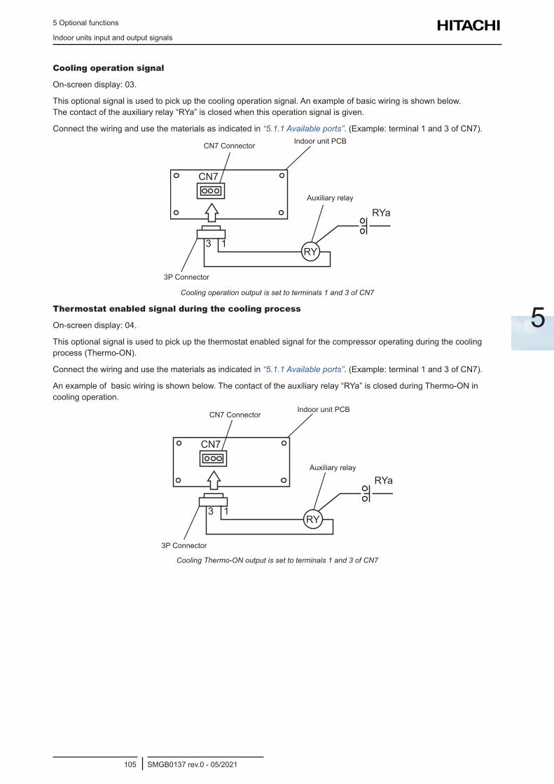
5 Optional functions
Indoor units input and output signals
SMGB0137 rev.0 - 05/2021105
5
Cooling operation signal
On-screen display: 03.
This optional signal is used to pick up the cooling operation signal. An example of basic wiring is shown below. The contact of the auxiliary relay “RYa” is closed when this operation signal is given.
Connect the wiring and use the materials as indicated in “5.1.1 Available ports”. (Example: terminal 1 and 3 of CN7).
CN7
RYa
13RY
3P Connector
CN7 Connector Indoor unit PCB
Auxiliary relay
Cooling operation output is set to terminals 1 and 3 of CN7
Thermostat enabled signal during the cooling process
On-screen display: 04.
This optional signal is used to pick up the thermostat enabled signal for the compressor operating during the cooling process (Thermo-ON).
Connect the wiring and use the materials as indicated in “5.1.1 Available ports”. (Example: terminal 1 and 3 of CN7).
An example of basic wiring is shown below. The contact of the auxiliary relay “RYa” is closed during Thermo-ON in cooling operation.
CN7
RYa
13RY
3P Connector
CN7 ConnectorIndoor unit PCB
Auxiliary relay
Cooling Thermo-ON output is set to terminals 1 and 3 of CN7
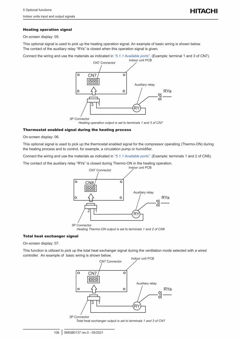
5 Optional functions
Indoor units input and output signals
SMGB0137 rev.0 - 05/2021106
Heating operation signal
On-screen display: 05.
This optional signal is used to pick up the heating operation signal. An example of basic wiring is shown below. The contact of the auxiliary relay “RYa” is closed when this operation signal is given.
Connect the wiring and use the materials as indicated in “5.1.1 Available ports”. (Example: terminal 1 and 3 of CN7).
CN7
RYa
13RY
3P Connector
CN7 ConnectorIndoor unit PCB
Auxiliary relay
Heating operation output is set to terminals 1 and 3 of CN7
Thermostat enabled signal during the heating process
On-screen display: 06.
This optional signal is used to pick up the thermostat enabled signal for the compressor operating (Thermo-ON) during the heating process and to control, for example, a circulation pump or humidifier.
Connect the wiring and use the materials as indicated in “5.1.1 Available ports”. (Example: terminals 1 and 2 of CN8).
The contact of the auxiliary relay “RYa” is closed during Thermo-ON in the heating operation.
RY
CN8
12
RYa
3P Connector
CN7 ConnectorIndoor unit PCB
Auxiliary relay
Heating Thermo-ON output is set to terminals 1 and 2 of CN8
Total heat exchanger signal
On-screen display: 07.
This function is utilized to pick up the total heat exchanger signal during the ventilation mode selected with a wired controller. An example of basic wiring is shown below.
CN7
RYa
13RY
3P Connector
CN7 ConnectorIndoor unit PCB
Auxiliary relay
Total heat exchanger output is set to terminals 1 and 3 of CN7
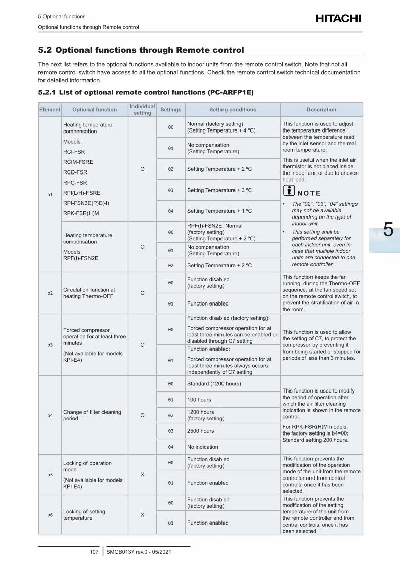
5 Optional functions
Optional functions through Remote control
SMGB0137 rev.0 - 05/2021107
5
5.2 Optional functions through Remote controlThe next list refers to the optional functions available to indoor units from the remote control switch. Note that not all remote control switch have access to all the optional functions. Check the remote control switch technical documentation for detailed information.
5.2.1 List of optional remote control functions (PC-ARFP1E)
Element Optional function Individual setting Settings Setting conditions Description
b1
Heating temperature compensation
Models:
RCI-FSR
RCIM-FSRE
RCD-FSR
RPC-FSR
RPI(L/H)-FSRE
RPI-FSN3E(P)E(-f)
RPK-FSR(H)M
O
00Normal (factory setting) (Setting Temperature + 4 ºC)
This function is used to adjust the temperature difference between the temperature read by the inlet sensor and the real room temperature.
This is useful when the inlet air thermistor is not placed inside the indoor unit or due to uneven heat load.
? N O T E• The “02”, “03”, “04” settings
may not be available depending on the type of indoor unit.
• This setting shall be performed separately for each indoor unit, even in case that multiple indoor units are connected to one remote controller.
01No compensation (Setting Temperature)
02 Setting Temperature + 2 ºC
03 Setting Temperature + 3 ºC
04 Setting Temperature + 1 ºC
Heating temperature compensation
Models: RPF(I)-FSN2E
O
00RPF(I)-FSN2E: Normal (factory setting) (Setting Temperature + 2 ºC)
01No compensation (Setting Temperature)
02 Setting Temperature + 2 ºC
b2Circulation function at heating Thermo-OFF O
00Function disabled (factory setting)
This function keeps the fan running during the Thermo-OFF sequence, at the fan speed set on the remote control switch, to prevent the stratification of air in the room.
01 Function enabled
b3
Forced compressor operation for at least three minutes
(Not available for models KPI-E4)
O
00
Function disabled (factory setting):
Forced compressor operation for at least three minutes can be enabled or disabled through C7 setting
This function is used to allow the setting of C7, to protect the compressor by preventing it from being started or stopped for periods of less than 3 minutes.01
Function enabled:
Forced compressor operation for at least three minutes always occurs independently of C7 setting
b4Change of filter cleaning period O
00 Standard (1200 hours) This function is used to modify the period of operation after which the air filter cleaning indication is shown in the remote control.
For RPK-FSR(H)M models, the factory setting is b4=00: Standard setting 200 hours.
01 100 hours
021200 hours (factory setting)
03 2500 hours
04 No indication
b5
Locking of operation mode
(Not available for models KPI-E4)
X
00Function disabled (factory setting)
This function prevents the modification of the operation mode of the unit from the remote controller and from central controls, once it has been selected.
01 Function enabled
b6Locking of setting temperature X
00Function disabled (factory setting)
This function prevents the modification of the setting temperature of the unit from the remote controller and from central controls, once it has been selected.
01 Function enabled
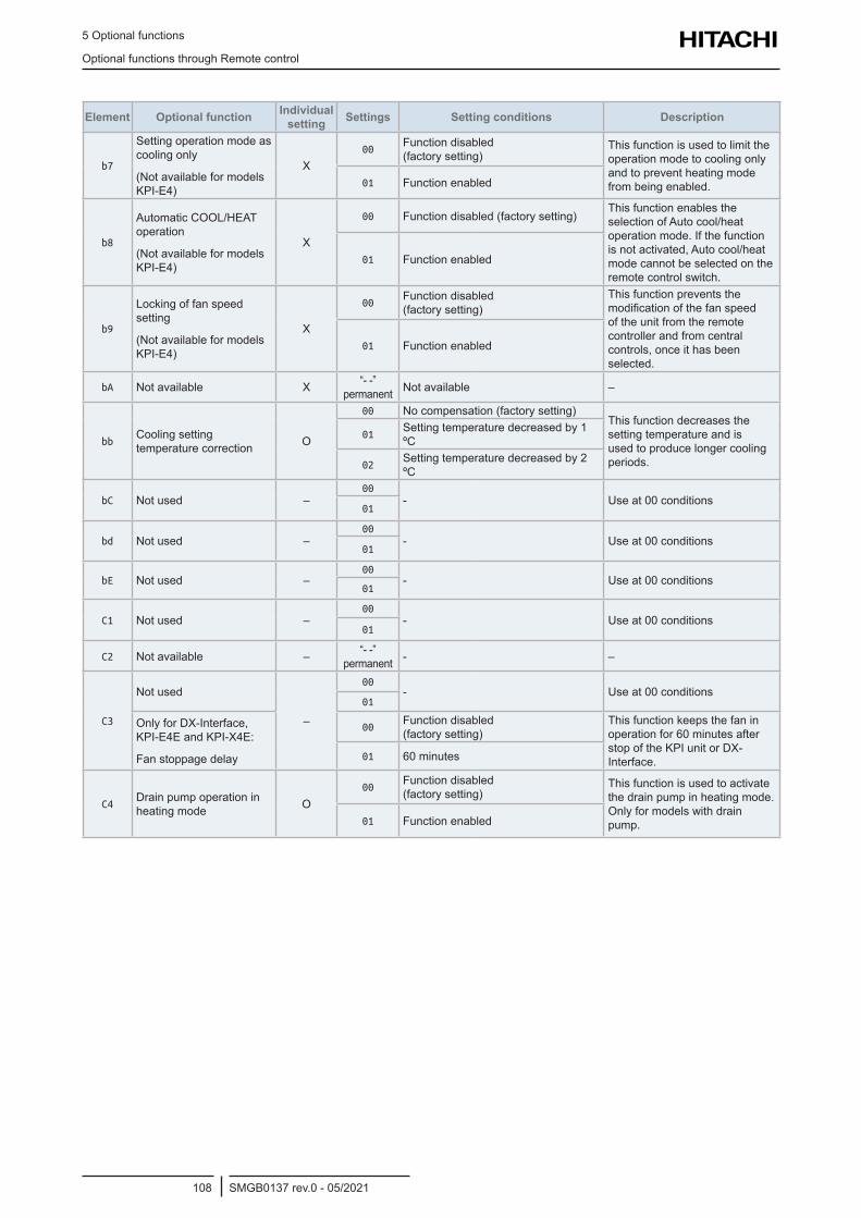
5 Optional functions
Optional functions through Remote control
SMGB0137 rev.0 - 05/2021108
Element Optional function Individual setting Settings Setting conditions Description
b7
Setting operation mode as cooling only
(Not available for models KPI-E4)
X00
Function disabled (factory setting)
This function is used to limit the operation mode to cooling only and to prevent heating mode from being enabled.01 Function enabled
b8
Automatic COOL/HEAT operation
(Not available for models KPI-E4)
X
00 Function disabled (factory setting)This function enables the selection of Auto cool/heat operation mode. If the function is not activated, Auto cool/heat mode cannot be selected on the remote control switch.
01 Function enabled
b9
Locking of fan speed setting
(Not available for models KPI-E4)
X
00Function disabled (factory setting)
This function prevents the modification of the fan speed of the unit from the remote controller and from central controls, once it has been selected.
01 Function enabled
bA Not available X “- -” permanent Not available –
bbCooling setting temperature correction O
00 No compensation (factory setting)This function decreases the setting temperature and is used to produce longer cooling periods.
01Setting temperature decreased by 1 ºC
02Setting temperature decreased by 2 ºC
bC Not used –00
- Use at 00 conditions01
bd Not used –00
- Use at 00 conditions01
bE Not used –00
- Use at 00 conditions01
C1 Not used –00
- Use at 00 conditions01
C2 Not available – “- -” permanent - –
C3
Not used
–
00- Use at 00 conditions
01
Only for DX-Interface, KPI-E4E and KPI-X4E:
Fan stoppage delay
00Function disabled (factory setting)
This function keeps the fan in operation for 60 minutes after stop of the KPI unit or DX-Interface.01 60 minutes
C4Drain pump operation in heating mode O
00Function disabled (factory setting)
This function is used to activate the drain pump in heating mode. Only for models with drain pump.01 Function enabled
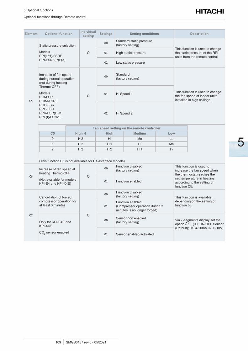
5 Optional functions
Optional functions through Remote control
SMGB0137 rev.0 - 05/2021109
5
Element Optional function Individual setting Settings Setting conditions Description
C5
Static pressure selection
Models RPI(L/H)-FSRE RPI-FSN3(P)E(-f)
O
00Standard static pressure (factory setting)
This function is used to change the static pressure of the RPI units from the remote control.
01 High static pressure
02 Low static pressure
Increase of fan speed during normal operation (not during heating Thermo-OFF)
Models RCI-FSR RCIM-FSRE RCD-FSR RPC-FSR RPK-FSR(H)M RPF(I)-FSN2E
O
00Standard (factory setting)
This function is used to change the fan speed of indoor units installed in high ceilings.
01 Hi Speed 1
02 Hi Speed 2
Fan speed setting on the remote controllerC5 High H High Medium Low0 Hi2 Hi Me Lo1 Hi2 Hi1 Hi Me2 Hi2 Hi2 Hi1 Hi
(This function C5 is not available for DX-Interface models)
C6
Increase of fan speed at heating Thermo-OFF
(Not available for models KPI-E4 and KPI-X4E)
O
00Function disabled (factory setting)
This function is used to increase the fan speed when the thermostat reaches the set temperature in heating according to the setting of function C5.
01 Function enabled
C7
Cancellation of forced compressor operation for at least 3 minutes
O
00Function disabled (factory setting) This function is available
depending on the setting of function b3.01
Function enabled (Compressor operation during 3 minutes is no longer forced)
Only for KPI-E4E and KPI-X4E
CO2 sensor enabled
00Sensor non enabled (factory setting) Via 7-segments display set the
option Ct (00: ON/OFF Sensor (Default); 01: 4-20mA 02: 0-10V)
01 Sensor enabled/activated
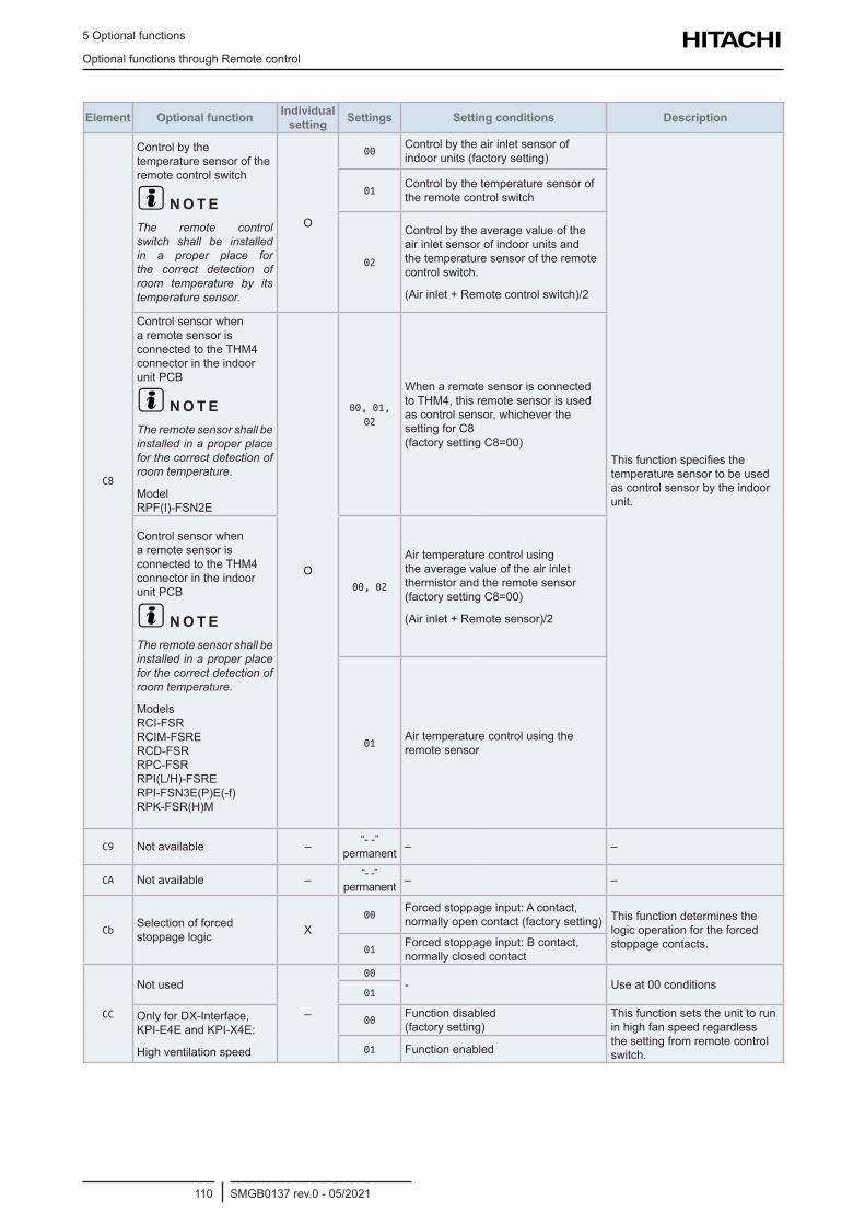
5 Optional functions
Optional functions through Remote control
SMGB0137 rev.0 - 05/2021110
Element Optional function Individual setting Settings Setting conditions Description
C8
Control by the temperature sensor of the remote control switch
? N O T EThe remote control switch shall be installed in a proper place for the correct detection of room temperature by its temperature sensor.
O
00Control by the air inlet sensor of indoor units (factory setting)
This function specifies the temperature sensor to be used as control sensor by the indoor unit.
01Control by the temperature sensor of the remote control switch
02
Control by the average value of the air inlet sensor of indoor units and the temperature sensor of the remote control switch.
(Air inlet + Remote control switch)/2
Control sensor when a remote sensor is connected to the THM4 connector in the indoor unit PCB
? N O T EThe remote sensor shall be installed in a proper place for the correct detection of room temperature.
Model RPF(I)-FSN2E
O
00, 01, 02
When a remote sensor is connected to THM4, this remote sensor is used as control sensor, whichever the setting for C8 (factory setting C8=00)
Control sensor when a remote sensor is connected to the THM4 connector in the indoor unit PCB
? N O T EThe remote sensor shall be installed in a proper place for the correct detection of room temperature.
Models RCI-FSR RCIM-FSRE RCD-FSR RPC-FSR RPI(L/H)-FSRE RPI-FSN3E(P)E(-f) RPK-FSR(H)M
00, 02
Air temperature control using the average value of the air inlet thermistor and the remote sensor (factory setting C8=00)
(Air inlet + Remote sensor)/2
01Air temperature control using the remote sensor
C9 Not available – “- -” permanent – –
CA Not available – “- -” permanent – –
CbSelection of forced stoppage logic X
00Forced stoppage input: A contact, normally open contact (factory setting) This function determines the
logic operation for the forced stoppage contacts.01
Forced stoppage input: B contact, normally closed contact
CC
Not used
–
00- Use at 00 conditions
01
Only for DX-Interface, KPI-E4E and KPI-X4E:
High ventilation speed
00Function disabled (factory setting)
This function sets the unit to run in high fan speed regardless the setting from remote control switch.01 Function enabled
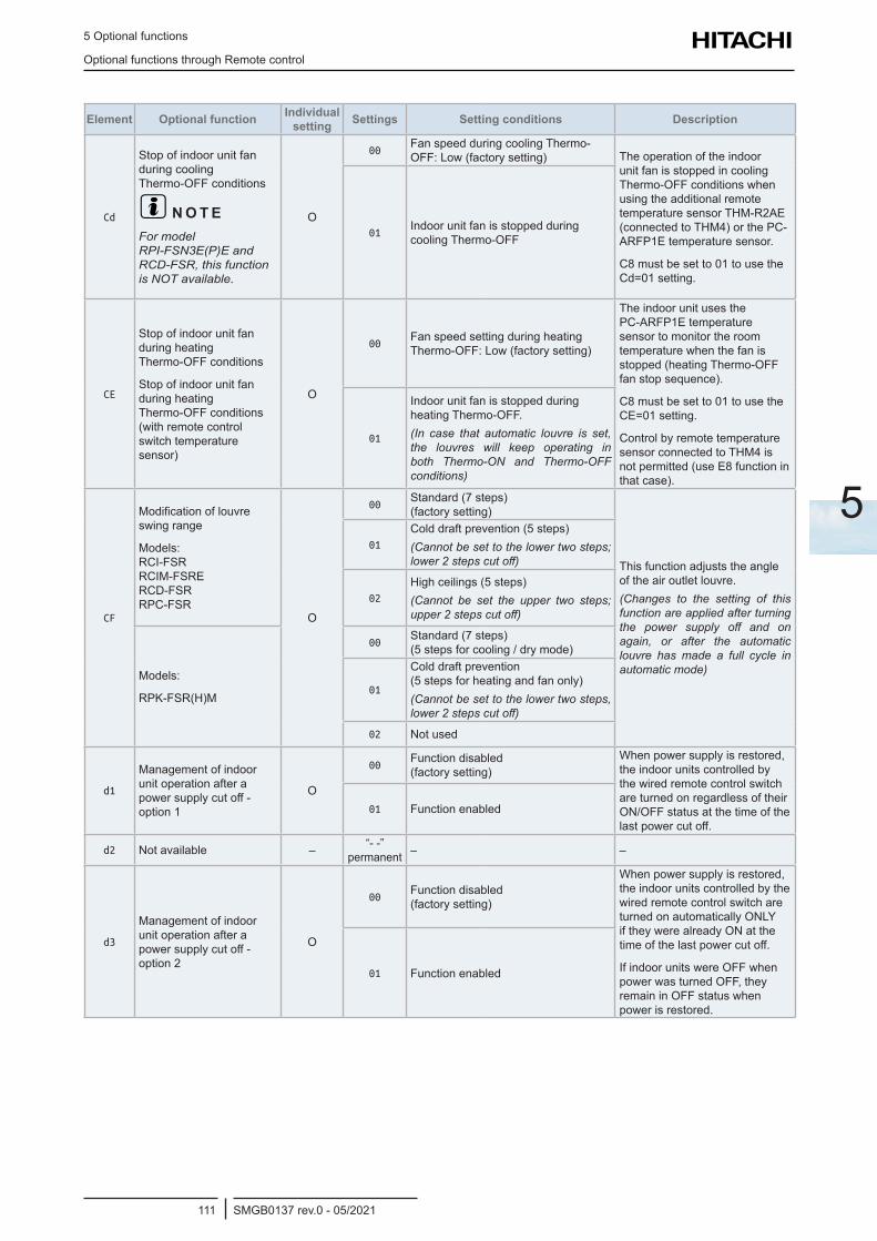
5 Optional functions
Optional functions through Remote control
SMGB0137 rev.0 - 05/2021111
5
Element Optional function Individual setting Settings Setting conditions Description
Cd
Stop of indoor unit fan during cooling Thermo-OFF conditions
? N O T EFor model RPI-FSN3E(P)E and RCD-FSR, this function is NOT available.
O
00Fan speed during cooling Thermo-OFF: Low (factory setting) The operation of the indoor
unit fan is stopped in cooling Thermo-OFF conditions when using the additional remote temperature sensor THM-R2AE (connected to THM4) or the PC-ARFP1E temperature sensor.
C8 must be set to 01 to use the Cd=01 setting.
01Indoor unit fan is stopped during cooling Thermo-OFF
CE
Stop of indoor unit fan during heating Thermo-OFF conditions
Stop of indoor unit fan during heating Thermo-OFF conditions (with remote control switch temperature sensor)
O
00Fan speed setting during heating Thermo-OFF: Low (factory setting)
The indoor unit uses the PC-ARFP1E temperature sensor to monitor the room temperature when the fan is stopped (heating Thermo-OFF fan stop sequence).
C8 must be set to 01 to use the CE=01 setting.
Control by remote temperature sensor connected to THM4 is not permitted (use E8 function in that case).
01
Indoor unit fan is stopped during heating Thermo-OFF.(In case that automatic louvre is set, the louvres will keep operating in both Thermo-ON and Thermo-OFF conditions)
CF
Modification of louvre swing range
Models: RCI-FSR RCIM-FSRE RCD-FSR RPC-FSR
O
00Standard (7 steps) (factory setting)
This function adjusts the angle of the air outlet louvre.(Changes to the setting of this function are applied after turning the power supply off and on again, or after the automatic louvre has made a full cycle in automatic mode)
01
Cold draft prevention (5 steps)(Cannot be set to the lower two steps; lower 2 steps cut off)
02
High ceilings (5 steps)(Cannot be set the upper two steps; upper 2 steps cut off)
Models:
RPK-FSR(H)M
00Standard (7 steps) (5 steps for cooling / dry mode)
01
Cold draft prevention (5 steps for heating and fan only)(Cannot be set to the lower two steps, lower 2 steps cut off)
02 Not used
d1
Management of indoor unit operation after a power supply cut off - option 1
O
00Function disabled (factory setting)
When power supply is restored, the indoor units controlled by the wired remote control switch are turned on regardless of their ON/OFF status at the time of the last power cut off.
01 Function enabled
d2 Not available – “- -” permanent – –
d3
Management of indoor unit operation after a power supply cut off - option 2
O
00Function disabled (factory setting)
When power supply is restored, the indoor units controlled by the wired remote control switch are turned on automatically ONLY if they were already ON at the time of the last power cut off.
If indoor units were OFF when power was turned OFF, they remain in OFF status when power is restored.
01 Function enabled
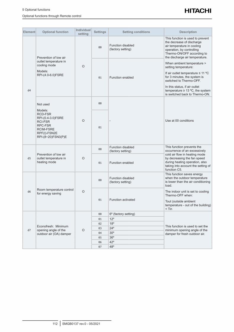
5 Optional functions
Optional functions through Remote control
SMGB0137 rev.0 - 05/2021112
Element Optional function Individual setting Settings Setting conditions Description
d4
Prevention of low air outlet temperature in cooling mode
Models: RPI-(4.0-6.0)FSRE
O
00Function disabled (factory setting)
This function is used to prevent the decrease of discharge air temperature in cooling operation, by controlling Thermo-ON/OFF according to the discharge air temperature.
When ambient temperature > setting temperature:
If air outlet temperature ≤ 11 ºC for 3 minutes, the system is switched to Thermo-OFF.
In this status, if air outlet temperature ≥ 13 ºC, the system is switched back to Thermo-ON.
01 Function enabled
Not used
Models: RCD-FSR RPI-(0.4-3.0)FSRE RCI-FSR RPC-FSR RCIM-FSRE RPF(I)-FSN2E RPI-(8~20)FSN3(P)E
O
00
- Use at 00 conditions
01
d5Prevention of low air outlet temperature in heating mode
O
00Function disabled (factory setting)
This function prevents the occurrence of an excessively cold air flow in heating mode by decreasing the fan speed during heating operation, also taking into account the setting of function C5.
01 Function enabled
d6Room temperature control for energy saving O
00Function disabled (factory setting)
This function saves energy when the outdoor temperature is lower than the air conditioning load.
The indoor unit is set to cooling Thermo-OFF when:
Tout (outside ambient temperature - out of the building) < Tin
01 Function activated
d7Econofresh: Minimum opening angle of the outdoor air (OA) damper
O
00 6º (factory setting)
This function is used to set the minimum opening angle of the damper for fresh outdoor air.
01 12º02 18º03 24º04 30º05 36º06 42º07 48º
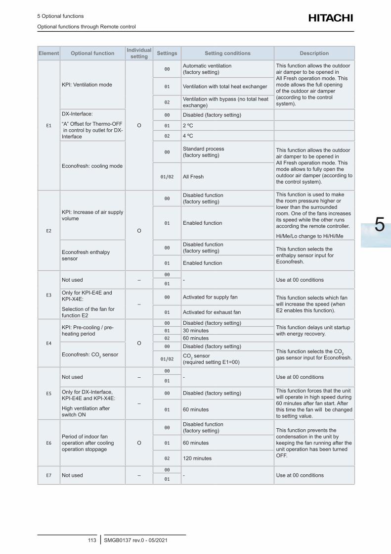
5 Optional functions
Optional functions through Remote control
SMGB0137 rev.0 - 05/2021113
5
Element Optional function Individual setting Settings Setting conditions Description
E1
KPI: Ventilation mode
O
00Automatic ventilation (factory setting)
This function allows the outdoor air damper to be opened in All Fresh operation mode. This mode allows the full opening of the outdoor air damper (according to the control system).
01 Ventilation with total heat exchanger
02Ventilation with bypass (no total heat exchange)
DX-Interface:
“A” Offset for Thermo-OFF in control by outlet for DX-Interface
00 Disabled (factory setting)
01 2 ºC
02 4 ºC
Econofresh: cooling mode
00Standard process (factory setting)
This function allows the outdoor air damper to be opened in All Fresh operation mode. This mode allows to fully open the outdoor air damper (according to the control system).
01/02 All Fresh
E2
KPI: Increase of air supply volume
O
00Disabled function (factory setting)
This function is used to make the room pressure higher or lower than the surrounded room. One of the fans increases its speed while the other runs according the remote controller.
Hi/Me/Lo change to Hi/Hi/Me
01 Enabled function
Econofresh enthalpy sensor
00Disabled function (factory setting) This function selects the
enthalpy sensor input for Econofresh.01 Enabled function
E3
Not used –00
- Use at 00 conditions01
Only for KPI-E4E and KPI-X4E:
Selection of the fan for function E2
–00 Activated for supply fan This function selects which fan
will increase the speed (when E2 enables this function).01 Activated for exhaust fan
E4
KPI: Pre-cooling / pre-heating period
O
00 Disabled (factory setting)This function delays unit startup with energy recovery.01 30 minutes
02 60 minutes
Econofresh: CO2 sensor00 Disabled (factory setting)
This function selects the CO2 gas sensor input for Econofresh.01/02
CO2 sensor (required setting E1=00)
E5
Not used –00
- Use at 00 conditions01
Only for DX-Interface, KPI-E4E and KPI-X4E:
High ventilation after switch ON
–
00 Disabled (factory setting) This function forces that the unit will operate in high speed during 60 minutes after fan start. After this time the fan will be changed to setting value.
01 60 minutes
E6Period of indoor fan operation after cooling operation stoppage
O
00Disabled function (factory setting) This function prevents the
condensation in the unit by keeping the fan running after the unit operation has been turned OFF.
01 60 minutes
02 120 minutes
E7 Not used –00
- Use at 00 conditions01
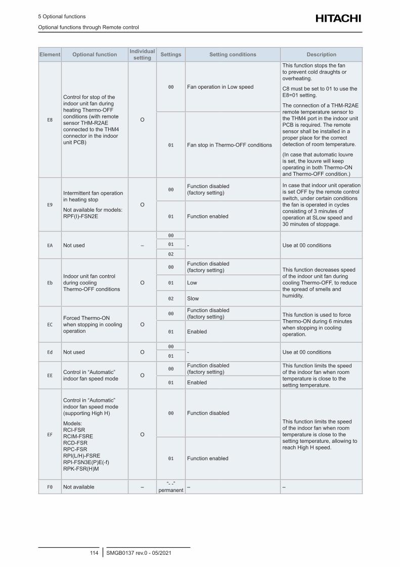
5 Optional functions
Optional functions through Remote control
SMGB0137 rev.0 - 05/2021114
Element Optional function Individual setting Settings Setting conditions Description
E8
Control for stop of the indoor unit fan during heating Thermo-OFF conditions (with remote sensor THM-R2AE connected to the THM4 connector in the indoor unit PCB)
O
00 Fan operation in Low speed
This function stops the fan to prevent cold draughts or overheating.
C8 must be set to 01 to use the E8=01 setting.
The connection of a THM-R2AE remote temperature sensor to the THM4 port in the indoor unit PCB is required. The remote sensor shall be installed in a proper place for the correct detection of room temperature.
(In case that automatic louvre is set, the louvre will keep operating in both Thermo-ON and Thermo-OFF condition.)
01 Fan stop in Thermo-OFF conditions
E9
Intermittent fan operation in heating stop
Not available for models: RPF(I)-FSN2E
O
00Function disabled (factory setting)
In case that indoor unit operation is set OFF by the remote control switch, under certain conditions the fan is operated in cycles consisting of 3 minutes of operation at SLow speed and 30 minutes of stoppage.
01 Function enabled
EA Not used –
00
- Use at 00 conditions01
02
EbIndoor unit fan control during cooling Thermo-OFF conditions
O
00Function disabled (factory setting) This function decreases speed
of the indoor unit fan during cooling Thermo-OFF, to reduce the spread of smells and humidity.
01 Low
02 Slow
ECForced Thermo-ON when stopping in cooling operation
O
00Function disabled (factory setting) This function is used to force
Thermo-ON during 6 minutes when stopping in cooling operation.01 Enabled
Ed Not used O00
- Use at 00 conditions01
EEControl in “Automatic” indoor fan speed mode O
00Function disabled (factory setting)
This function limits the speed of the indoor fan when room temperature is close to the setting temperature.01 Enabled
EF
Control in “Automatic” indoor fan speed mode (supporting High H)
Models: RCI-FSR RCIM-FSRE RCD-FSR RPC-FSR RPI(L/H)-FSRE RPI-FSN3E(P)E(-f) RPK-FSR(H)M
O
00 Function disabledThis function limits the speed of the indoor fan when room temperature is close to the setting temperature, allowing to reach High H speed.
01 Function enabled
F0 Not available – “- -” permanent – –
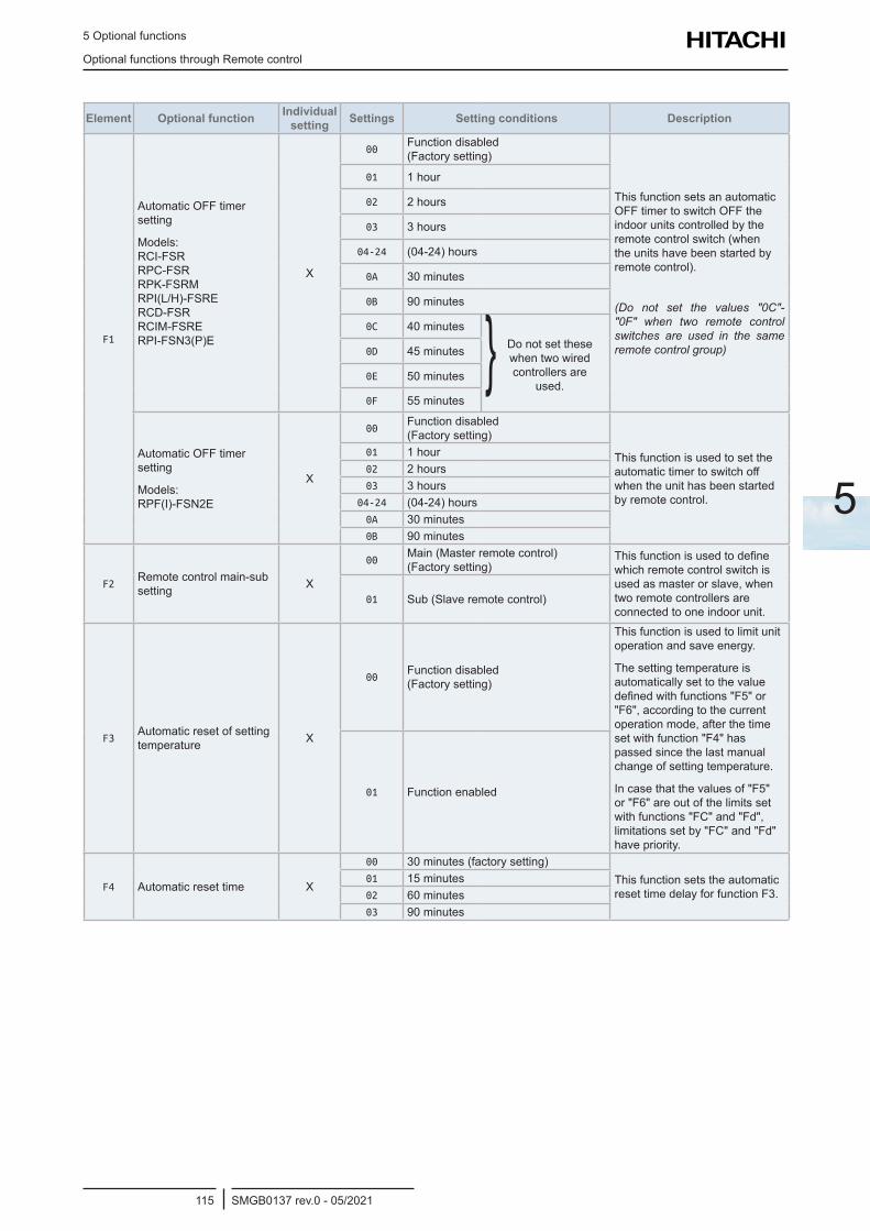
5 Optional functions
Optional functions through Remote control
SMGB0137 rev.0 - 05/2021115
5
Element Optional function Individual setting Settings Setting conditions Description
F1
Automatic OFF timer setting
Models: RCI-FSR RPC-FSR RPK-FSRM RPI(L/H)-FSRE RCD-FSR RCIM-FSRE RPI-FSN3(P)E
X
00Function disabled (Factory setting)
This function sets an automatic OFF timer to switch OFF the indoor units controlled by the remote control switch (when the units have been started by remote control).
(Do not set the values "0C"-"0F" when two remote control switches are used in the same remote control group)
01 1 hour
02 2 hours
03 3 hours
04-24 (04-24) hours
0A 30 minutes
0B 90 minutes
0C 40 minutes Do not set these when two wired controllers are
used.
0D 45 minutes
0E 50 minutes
0F 55 minutes
Automatic OFF timer setting
Models: RPF(I)-FSN2E
X
00Function disabled (Factory setting)
This function is used to set the automatic timer to switch off when the unit has been started by remote control.
01 1 hour02 2 hours03 3 hours
04-24 (04-24) hours0A 30 minutes0B 90 minutes
F2Remote control main-sub setting X
00Main (Master remote control) (Factory setting)
This function is used to define which remote control switch is used as master or slave, when two remote controllers are connected to one indoor unit.
01 Sub (Slave remote control)
F3Automatic reset of setting temperature X
00Function disabled (Factory setting)
This function is used to limit unit operation and save energy.
The setting temperature is automatically set to the value defined with functions "F5" or "F6", according to the current operation mode, after the time set with function "F4" has passed since the last manual change of setting temperature.
In case that the values of "F5" or "F6" are out of the limits set with functions "FC" and "Fd", limitations set by "FC" and "Fd" have priority.
01 Function enabled
F4 Automatic reset time X
00 30 minutes (factory setting)This function sets the automatic reset time delay for function F3.
01 15 minutes02 60 minutes03 90 minutes
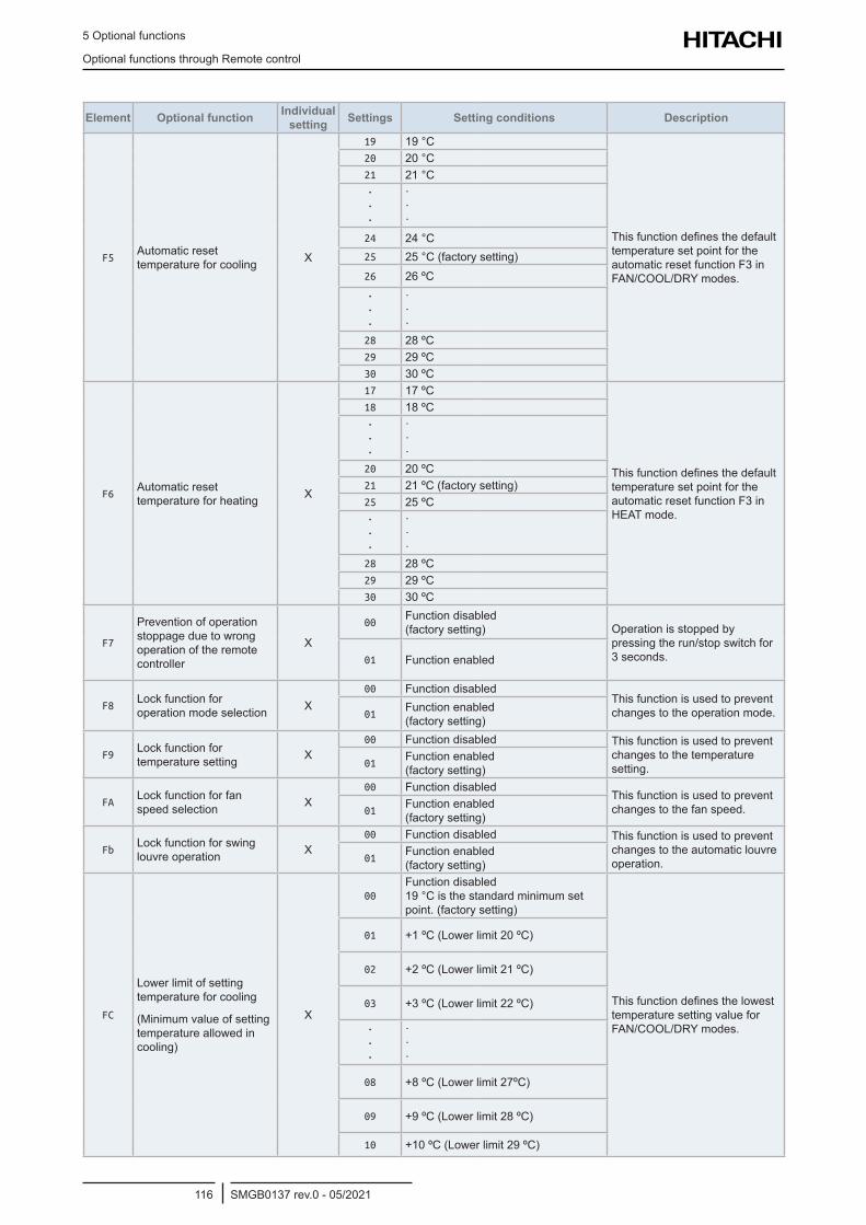
5 Optional functions
Optional functions through Remote control
SMGB0137 rev.0 - 05/2021116
Element Optional function Individual setting Settings Setting conditions Description
F5Automatic reset temperature for cooling X
19 19 °C
This function defines the default temperature set point for the automatic reset function F3 in FAN/COOL/DRY modes.
20 20 °C21 21 °C· · ·
· · ·
24 24 °C25 25 °C (factory setting)26 26 ºC· · ·
· · ·
28 28 ºC29 29 ºC30 30 ºC
F6Automatic reset temperature for heating X
17 17 ºC
This function defines the default temperature set point for the automatic reset function F3 in HEAT mode.
18 18 ºC· · ·
· · ·
20 20 ºC21 21 ºC (factory setting)25 25 ºC· · ·
· · ·
28 28 ºC29 29 ºC30 30 ºC
F7
Prevention of operation stoppage due to wrong operation of the remote controller
X
00Function disabled (factory setting) Operation is stopped by
pressing the run/stop switch for 3 seconds.01 Function enabled
F8Lock function for operation mode selection X
00 Function disabledThis function is used to prevent changes to the operation mode.01
Function enabled (factory setting)
F9Lock function for temperature setting X
00 Function disabled This function is used to prevent changes to the temperature setting.01
Function enabled (factory setting)
FALock function for fan speed selection X
00 Function disabledThis function is used to prevent changes to the fan speed.01
Function enabled (factory setting)
FbLock function for swing louvre operation X
00 Function disabled This function is used to prevent changes to the automatic louvre operation.01
Function enabled (factory setting)
FC
Lower limit of setting temperature for cooling
(Minimum value of setting temperature allowed in cooling)
X
00Function disabled 19 °C is the standard minimum set point. (factory setting)
This function defines the lowest temperature setting value for FAN/COOL/DRY modes.
01 +1 ºC (Lower limit 20 ºC)
02 +2 ºC (Lower limit 21 ºC)
03 +3 ºC (Lower limit 22 ºC)
· · ·
· · ·
08 +8 ºC (Lower limit 27ºC)
09 +9 ºC (Lower limit 28 ºC)
10 +10 ºC (Lower limit 29 ºC)
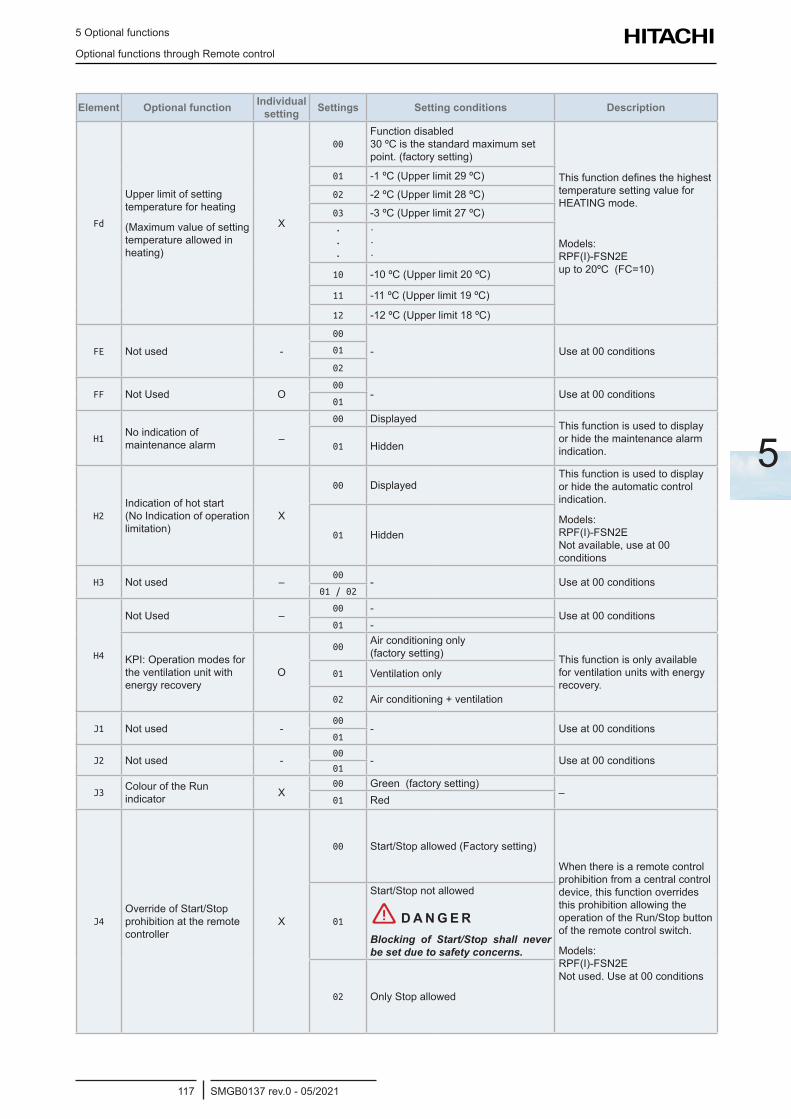
5 Optional functions
Optional functions through Remote control
SMGB0137 rev.0 - 05/2021117
5
Element Optional function Individual setting Settings Setting conditions Description
Fd
Upper limit of setting temperature for heating
(Maximum value of setting temperature allowed in heating)
X
00Function disabled 30 ºC is the standard maximum set point. (factory setting)
This function defines the highest temperature setting value for HEATING mode.
Models: RPF(I)-FSN2E up to 20ºC (FC=10)
01 -1 ºC (Upper limit 29 ºC)
02 -2 ºC (Upper limit 28 ºC)
03 -3 ºC (Upper limit 27 ºC)· · ·
· · ·
10 -10 ºC (Upper limit 20 ºC)
11 -11 ºC (Upper limit 19 ºC)
12 -12 ºC (Upper limit 18 ºC)
FE Not used -00
- Use at 00 conditions01
02
FF Not Used O00
- Use at 00 conditions01
H1No indication of maintenance alarm –
00 Displayed This function is used to display or hide the maintenance alarm indication.01 Hidden
H2Indication of hot start (No Indication of operation limitation)
X
00 DisplayedThis function is used to display or hide the automatic control indication.
Models: RPF(I)-FSN2E Not available, use at 00 conditions
01 Hidden
H3 Not used –00
- Use at 00 conditions01 / 02
H4
Not Used –00 -
Use at 00 conditions01 -
KPI: Operation modes for the ventilation unit with energy recovery
O
00Air conditioning only (factory setting) This function is only available
for ventilation units with energy recovery.
01 Ventilation only
02 Air conditioning + ventilation
J1 Not used -00
- Use at 00 conditions 01
J2 Not used -00
- Use at 00 conditions01
J3Colour of the Run indicator X
00 Green (factory setting)–
01 Red
J4Override of Start/Stop prohibition at the remote controller
X
00 Start/Stop allowed (Factory setting)
When there is a remote control prohibition from a central control device, this function overrides this prohibition allowing the operation of the Run/Stop button of the remote control switch.
Models: RPF(I)-FSN2E Not used. Use at 00 conditions
01
Start/Stop not allowed
! D A N G E RBlocking of Start/Stop shall never be set due to safety concerns.
02 Only Stop allowed
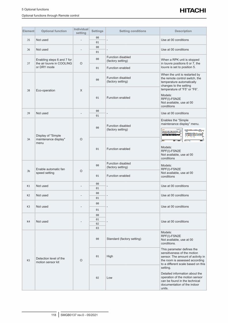
5 Optional functions
Optional functions through Remote control
SMGB0137 rev.0 - 05/2021118
Element Optional function Individual setting Settings Setting conditions Description
J5 Not used -00
- Use at 00 conditions01
J6 Not used -00
- Use at 00 conditions01
J7Enabling steps 6 and 7 for the air louvre in COOLING or DRY mode
O00
Function disabled (factory setting) When a RPK unit is stopped
in louvre positions 6 or 7, the louvre is set to position 5.01 Function enabled
J8 Eco-operation X
00Function disabled (factory setting)
When the unit is restarted by the remote control switch, the temperature automatically changes to the setting temperature of “F5” or “F6”.
Models: RPF(I)-FSN2E Not available, use at 00 conditions
01 Function enabled
J9 Not used -00
- Use at 00 conditions01
JADisplay of "Simple maintenance display" menu
O
00Function disabled (factory setting)
Enables the “Simple maintenance display” menu.
Models: RPF(I)-FSN2E Not available, use at 00 conditions
01 Function enabled
JbEnable automatic fan speed setting O
00Function disabled (factory setting) Models:
RPF(I)-FSN2E Not available, use at 00 conditions01 Function enabled
K1 Not used -00
- Use at 00 conditions01
K2 Not used -00
- Use at 00 conditions01
K3 Not used -00
- Use at 00 conditions01
K4 Not used -
00
- Use at 00 conditions01
02
03
K5Detection level of the motion sensor kit O
00 Standard (factory setting)
Models: RPF(I)-FSN2E Not available, use at 00 conditions.
This parameter defines the sensitiveness of the motion sensor. The amount of activity in the room is assessed according to a different scale based on this setting.
Detailed information about the operation of the motion sensor can be found in the technical documentation of the indoor units.
01 High
02 Low
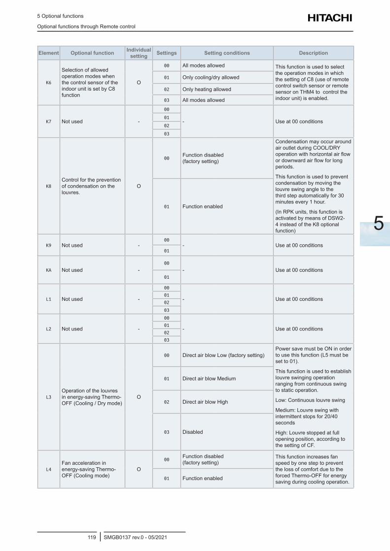
5 Optional functions
Optional functions through Remote control
SMGB0137 rev.0 - 05/2021119
5
Element Optional function Individual setting Settings Setting conditions Description
K6
Selection of allowed operation modes when the control sensor of the indoor unit is set by C8 function
O
00 All modes allowed This function is used to select the operation modes in which the setting of C8 (use of remote control switch sensor or remote sensor on THM4 to control the indoor unit) is enabled.
01 Only cooling/dry allowed
02 Only heating allowed
03 All modes allowed
K7 Not used -
00
- Use at 00 conditions01
02
03
K8Control for the prevention of condensation on the louvres.
O
00Function disabled (factory setting)
Condensation may occur around air outlet during COOL/DRY operation with horizontal air flow or downward air flow for long periods.
This function is used to prevent condensation by moving the louvre swing angle to the third step automatically for 30 minutes every 1 hour.
(In RPK units, this function is activated by means of DSW2-4 instead of the K8 optional function)
01 Function enabled
K9 Not used -00
- Use at 00 conditions01
KA Not used -00
- Use at 00 conditions01
L1 Not used -
00
- Use at 00 conditions01
02
03
L2 Not used -
00
- Use at 00 conditions01
02
03
L3Operation of the louvres in energy-saving Thermo-OFF (Cooling / Dry mode)
O
00 Direct air blow Low (factory setting)Power save must be ON in order to use this function (L5 must be set to 01).
This function is used to establish louvre swinging operation ranging from continuous swing to static operation.
Low: Continuous louvre swing
Medium: Louvre swing with intermittent stops for 20/40 seconds
High: Louvre stopped at full opening position, according to the setting of CF.
01 Direct air blow Medium
02 Direct air blow High
03 Disabled
L4Fan acceleration in energy-saving Thermo-OFF (Cooling mode)
O
00Function disabled (factory setting)
This function increases fan speed by one step to prevent the loss of comfort due to the forced Thermo-OFF for energy saving during cooling operation.
01 Function enabled
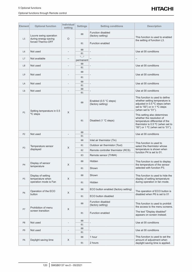
5 Optional functions
Optional functions through Remote control
SMGB0137 rev.0 - 05/2021120
Element Optional function Individual setting Settings Setting conditions Description
L5Louvre swing operation during energy-saving forced Thermo-OFF
O
00Function disabled (factory setting) This function is used to enabled
the setting of function L3.01 Function enabled
L6 Not used -00
- Use at 00 conditions01
L7 Not available – “- -” permanent – –
L8 Not used -00
- Use at 00 conditions01
L9 Not used -00
- Use at 00 conditions01
LA Not used -00
- Use at 00 conditions01
Lb Not used -00
- Use at 00 conditions01
P1Setting temperature in 0.5 ºC steps X
00Enabled (0.5 °C steps) (factory setting)
This function is used to define whether setting temperature is adjusted in 0.5 ºC steps (when set to “00”) or in 1 ºC steps (when set to “01”).
This setting also determines whether the resolution of temperature differential of the thermistor is 0.5 ºC (when set to “00”) or 1 ºC (when set to “01”).
01 Disabled (1 °C steps)
P2 Not used -00
- Use at 00 conditions01
P3Temperature sensor displayed X
00 Inlet air thermistor (Tin)This function is used to select the thermistor whose temperature is shown when function P4 is set to 01.
01 Outdoor air thermistor (Tout)
02 Remote controller thermistor (RCS)
03 Remote sensor (THM4)
P4Display of sensor temperature X
00 Hidden This function is used to display the temperature of the sensor selected with function P3.01 Shown
P5Display of setting temperature when operation mode is Fan
X00 Shown This function is used to hide the
display of setting temperature during operation in fan mode.01 Hidden
P6Operation of the ECO button X
00 ECO button enabled (factory setting)The operation of ECO button is disabled when P6 is set to 01
01 ECO button disabled
P7Prohibition of menu screen transition X
00Function disabled (factory setting) This function is used to prohibit
the access to the menu screens.
The text "Display disabled" appears on screen instead.
01 Function enabled
P8 Not used -00
- Use at 00 conditions01
P9 Not used -00
- Use at 00 conditions01
PA Daylight saving time X00 1 hour This function is used to set the
amount of adjustment when daylight saving time is applied.01 2 hours
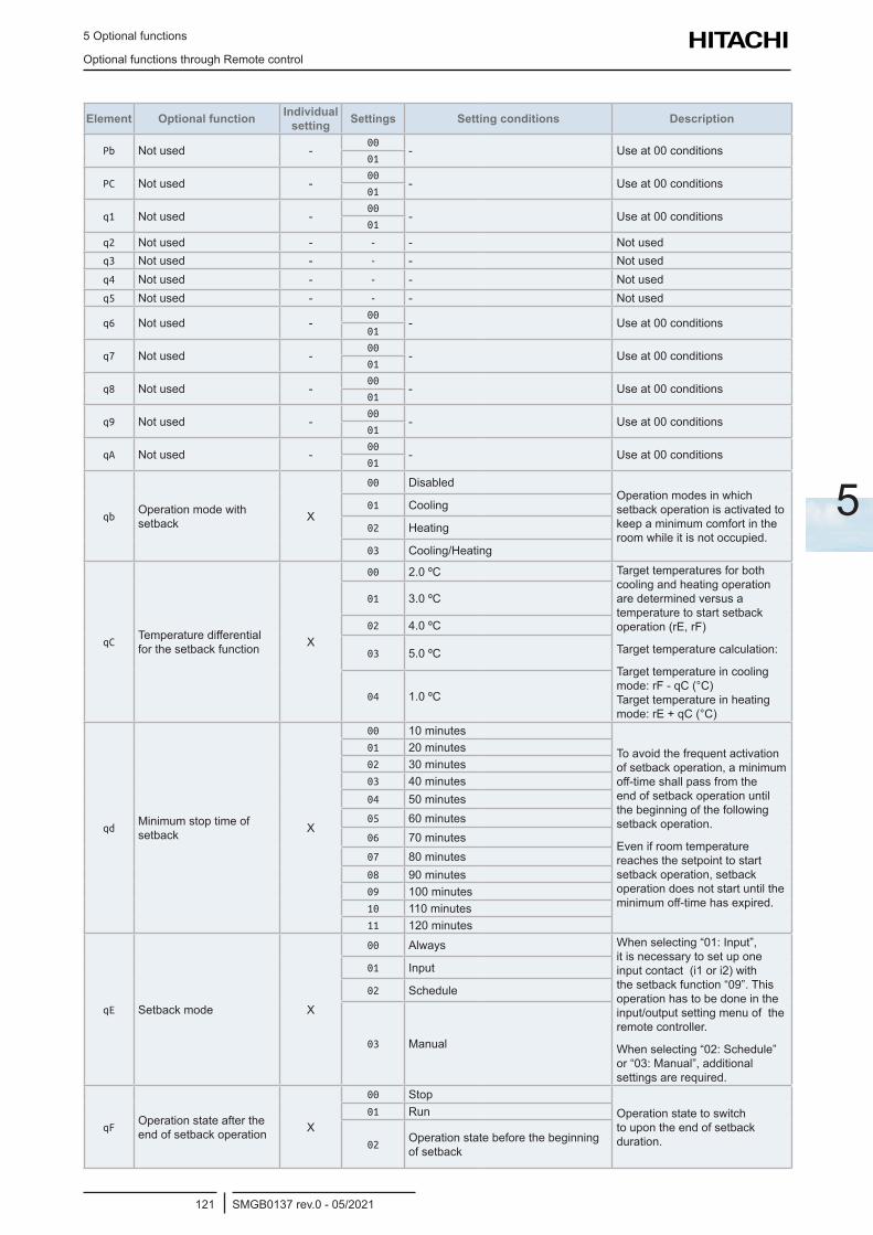
5 Optional functions
Optional functions through Remote control
SMGB0137 rev.0 - 05/2021121
5
Element Optional function Individual setting Settings Setting conditions Description
Pb Not used -00
- Use at 00 conditions01
PC Not used -00
- Use at 00 conditions01
q1 Not used -00
- Use at 00 conditions01
q2 Not used - - - Not usedq3 Not used - - - Not usedq4 Not used - - - Not usedq5 Not used - - - Not used
q6 Not used -00
- Use at 00 conditions01
q7 Not used -00
- Use at 00 conditions01
q8 Not used -00
- Use at 00 conditions01
q9 Not used -00
- Use at 00 conditions01
qA Not used -00
- Use at 00 conditions01
qbOperation mode with setback X
00 DisabledOperation modes in which setback operation is activated to keep a minimum comfort in the room while it is not occupied.
01 Cooling
02 Heating
03 Cooling/Heating
qCTemperature differential for the setback function X
00 2.0 ºC Target temperatures for both cooling and heating operation are determined versus a temperature to start setback operation (rE, rF)
Target temperature calculation:
Target temperature in cooling mode: rF - qC (°C) Target temperature in heating mode: rE + qC (°C)
01 3.0 ºC
02 4.0 ºC
03 5.0 ºC
04 1.0 ºC
qdMinimum stop time of setback X
00 10 minutes
To avoid the frequent activation of setback operation, a minimum off-time shall pass from the end of setback operation until the beginning of the following setback operation.
Even if room temperature reaches the setpoint to start setback operation, setback operation does not start until the minimum off-time has expired.
01 20 minutes02 30 minutes03 40 minutes04 50 minutes05 60 minutes06 70 minutes07 80 minutes08 90 minutes09 100 minutes10 110 minutes11 120 minutes
qE Setback mode X
00 Always When selecting “01: Input”, it is necessary to set up one input contact (i1 or i2) with the setback function “09”. This operation has to be done in the input/output setting menu of the remote controller.
When selecting “02: Schedule” or “03: Manual”, additional settings are required.
01 Input
02 Schedule
03 Manual
qFOperation state after the end of setback operation X
00 StopOperation state to switch to upon the end of setback duration.
01 Run
02Operation state before the beginning of setback
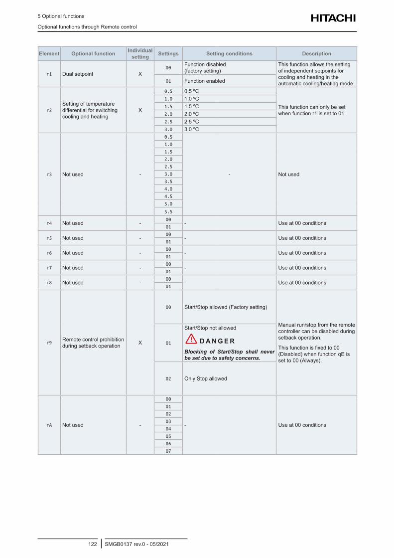
5 Optional functions
Optional functions through Remote control
SMGB0137 rev.0 - 05/2021122
Element Optional function Individual setting Settings Setting conditions Description
r1 Dual setpoint X00
Function disabled (factory setting)
This function allows the setting of independent setpoints for cooling and heating in the automatic cooling/heating mode.01 Function enabled
r2Setting of temperature differential for switching cooling and heating
X
0.5 0.5 ºC
This function can only be set when function r1 is set to 01.
1.0 1.0 ºC1.5 1.5 ºC2.0 2.0 ºC2.5 2.5 ºC3.0 3.0 ºC
r3 Not used -
0.5
- Not used
1.0
1.5
2.0
2.5
3.0
3.5
4.0
4.5
5.0
5.5
r4 Not used -00
- Use at 00 conditions01
r5 Not used -00
- Use at 00 conditions01
r6 Not used -00
- Use at 00 conditions01
r7 Not used -00
- Use at 00 conditions01
r8 Not used -00
- Use at 00 conditions01
r9Remote control prohibition during setback operation X
00 Start/Stop allowed (Factory setting)
Manual run/stop from the remote controller can be disabled during setback operation.
This function is fixed to 00 (Disabled) when function qE is set to 00 (Always).
01
Start/Stop not allowed
! D A N G E RBlocking of Start/Stop shall never be set due to safety concerns.
02 Only Stop allowed
rA Not used -
00
- Use at 00 conditions
01
02
03
04
05
06
07
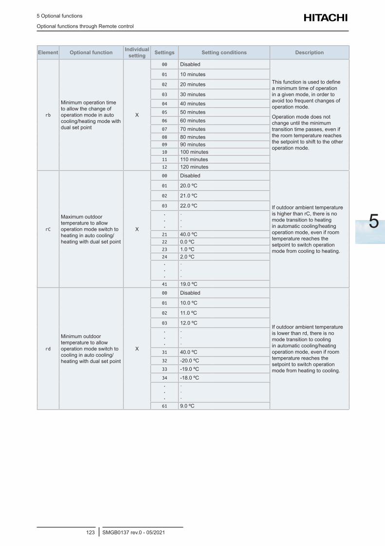
5 Optional functions
Optional functions through Remote control
SMGB0137 rev.0 - 05/2021123
5
Element Optional function Individual setting Settings Setting conditions Description
rb
Minimum operation time to allow the change of operation mode in auto cooling/heating mode with dual set point
X
00 Disabled
This function is used to define a minimum time of operation in a given mode, in order to avoid too frequent changes of operation mode.
Operation mode does not change until the minimum transition time passes, even if the room temperature reaches the setpoint to shift to the other operation mode.
01 10 minutes
02 20 minutes
03 30 minutes
04 40 minutes05 50 minutes06 60 minutes07 70 minutes08 80 minutes09 90 minutes10 100 minutes11 110 minutes12 120 minutes
rC
Maximum outdoor temperature to allow operation mode switch to heating in auto cooling/heating with dual set point
X
00 Disabled
If outdoor ambient temperature is higher than rC, there is no mode transition to heating in automatic cooling/heating operation mode, even if room temperature reaches the setpoint to switch operation mode from cooling to heating.
01 20.0 ºC
02 21.0 ºC
03 22.0 ºC· · ·
· · ·
21 40.0 ºC22 0.0 ºC23 1.0 ºC24 2.0 ºC· · ·
· · ·
41 19.0 ºC
rd
Minimum outdoor temperature to allow operation mode switch to cooling in auto cooling/heating with dual set point
X
00 Disabled
If outdoor ambient temperature is lower than rd, there is no mode transition to cooling in automatic cooling/heating operation mode, even if room temperature reaches the setpoint to switch operation mode from heating to cooling.
01 10.0 ºC
02 11.0 ºC
03 12.0 ºC· · ·
· · ·
31 40.0 ºC32 -20.0 ºC33 -19.0 ºC34 -18.0 ºC· · ·
· · ·
61 9.0 ºC
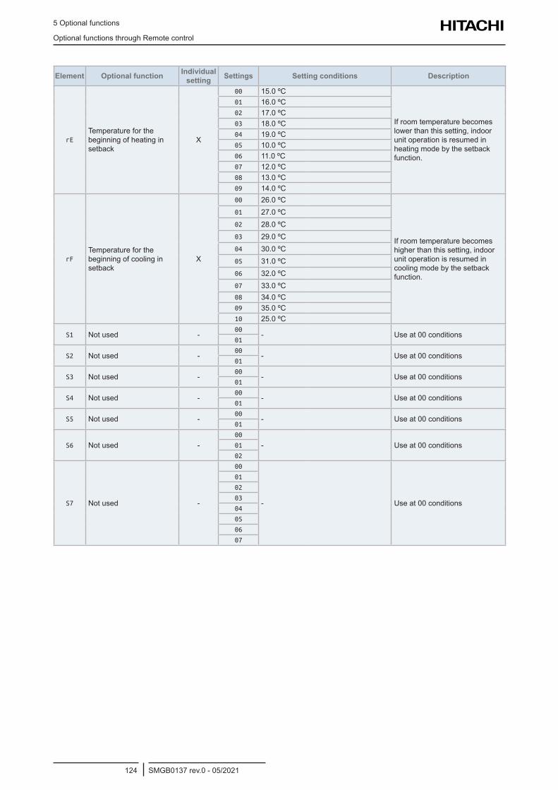
5 Optional functions
Optional functions through Remote control
SMGB0137 rev.0 - 05/2021124
Element Optional function Individual setting Settings Setting conditions Description
rETemperature for the beginning of heating in setback
X
00 15.0 ºC
If room temperature becomes lower than this setting, indoor unit operation is resumed in heating mode by the setback function.
01 16.0 ºC02 17.0 ºC03 18.0 ºC04 19.0 ºC05 10.0 ºC06 11.0 ºC07 12.0 ºC08 13.0 ºC09 14.0 ºC
rFTemperature for the beginning of cooling in setback
X
00 26.0 ºC
If room temperature becomes higher than this setting, indoor unit operation is resumed in cooling mode by the setback function.
01 27.0 ºC02 28.0 ºC03 29.0 ºC04 30.0 ºC05 31.0 ºC06 32.0 ºC07 33.0 ºC08 34.0 ºC09 35.0 ºC10 25.0 ºC
S1 Not used -00
- Use at 00 conditions01
S2 Not used -00
- Use at 00 conditions01
S3 Not used -00
- Use at 00 conditions01
S4 Not used -00
- Use at 00 conditions01
S5 Not used -00
- Use at 00 conditions01
S6 Not used -00
- Use at 00 conditions01
02
S7 Not used -
00
- Use at 00 conditions
01
02
03
04
05
06
07
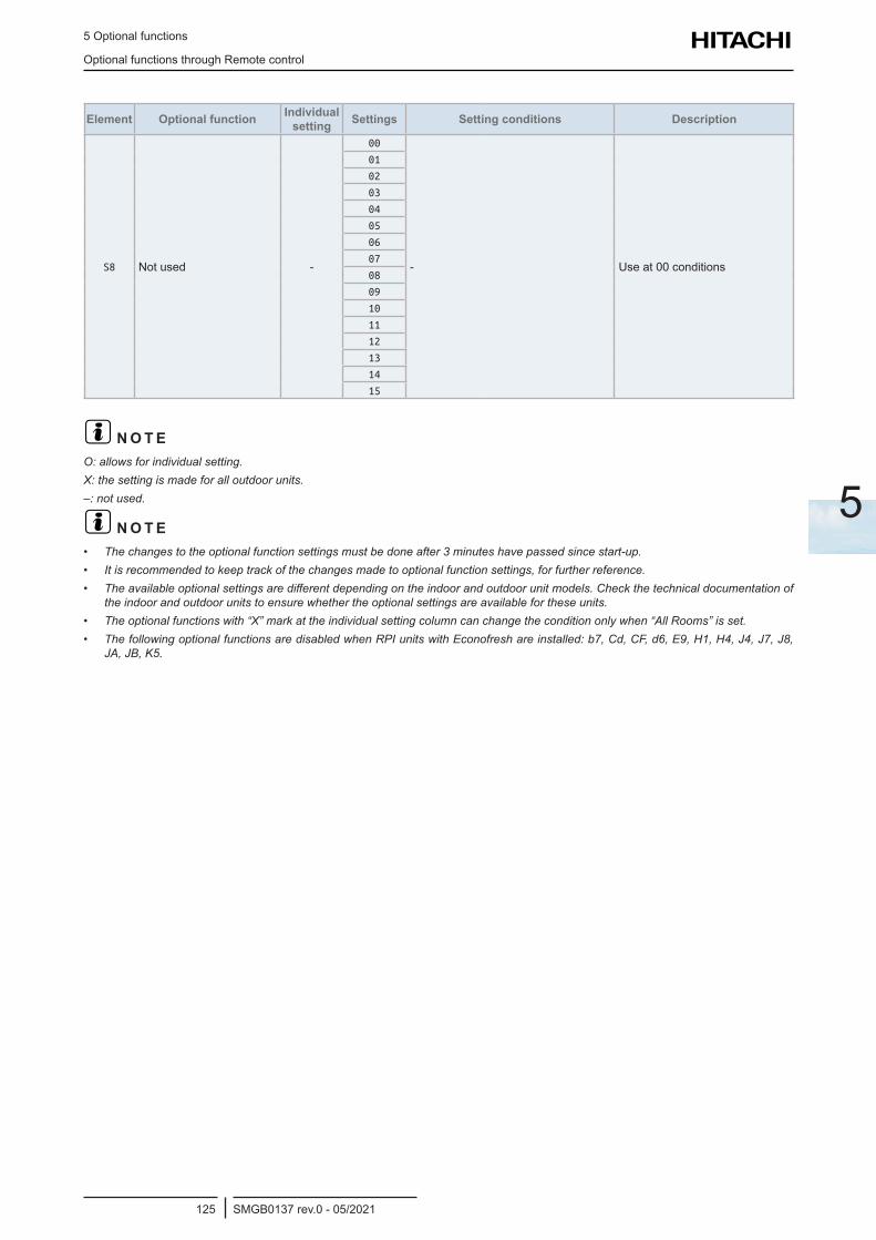
5 Optional functions
Optional functions through Remote control
SMGB0137 rev.0 - 05/2021125
5
Element Optional function Individual setting Settings Setting conditions Description
S8 Not used -
00
- Use at 00 conditions
01
02
03
04
05
06
07
08
09
10
11
12
13
14
15
? N O T EO: allows for individual setting.X: the setting is made for all outdoor units.–: not used.
? N O T E• The changes to the optional function settings must be done after 3 minutes have passed since start-up.• It is recommended to keep track of the changes made to optional function settings, for further reference.• The available optional settings are different depending on the indoor and outdoor unit models. Check the technical documentation of
the indoor and outdoor units to ensure whether the optional settings are available for these units.• The optional functions with “X” mark at the individual setting column can change the condition only when “All Rooms” is set.• The following optional functions are disabled when RPI units with Econofresh are installed: b7, Cd, CF, d6, E9, H1, H4, J4, J7, J8,
JA, JB, K5.
5 Optional functions
Optional functions through Remote control
SMGB0137 rev.0 - 05/2021126
5.2.2 Description of the optional remote control functions (PC-ARFP1E)
b1 – Removal of heating temperature compensation
This function is used to adjust the difference of temperature between the setting temperature of the remote control switch and the inlet air temperature of the indoor unit.
This is useful when the inlet air thermistor is not placed inside the indoor unit or due to uneven Heat Load or for example in standard heating mode, the suction air temperature is greater than that of the room, therefore the setting temperature used according to the factory setting is calibrated to the indicated temperature +4 °C, but depending on the room conditions can be necessary to compensate a smaller value.
b2 – Circulator function at heating Thermo-OFF
This function means that the fan unit remains running after the air conditioning system has stopped in heating mode to prevent the air in the room from stratifying.
This function is useful when the air in the room is stratified (hot air accumulates at the ceiling). Air stratification may occur if has been selected fan speed changes to LOW when the thermostat of the unit is stopped. This function prevents air stratification in the room after stopping the air conditioning system.
This function maintains the fan speed, whether the thermostat is on or off. Hence, the air movement in the room is kept at the same level to ensure even air distribution.
? N O T E• If the indoor unit has an automatic louver, this function also remains active when the heating thermostat is switched off.• Everyone has a different perception of coolness, heat and air flow and, therefore, this issue should be discussed with the client and
the unit set according to the results of the conversation.
b3 – Forced compressor operation for at least three minutes
This function is used to allow the setting of C7 (Cancellation of the forced compressor operation for at least 3 minutes) preventing it from being started or stopped the compressor for periods of less than 3 minutes.
? N O T E• In the case of SET FREE units, forced compressor operation for at least 3 minutes is standard, even when the setting is not available.• The compressor stops immediately when the safety device is activated or ON/OFF is pressed.• To cancel this function, see C7 – Cancellation of the forced compressor operation for at least three minutes.• When this function is cancelled, the mode enabling operations for a minimum of 3 minutes remains available.
b4 – Change the filter cleaning period
This function is used to modify the period during which the remote control indicates the air filter replacement. The filter cleaning period can be changed depending on the condition of the filter.
? N O T E• The remaining number of hours before cleaning the filter is factory-set for all indoor unit models b2=02 (1200 hours).• For RPK-FSR(H)M models Factory-Setting is b4=00: Standard setting 200 hrs.
b5 – Locking of operation mode
This function is used when the operating mode does not have to be changed. Once the unit operating mode has been selected, this function prevents it from being modified from the remote control.
b6 – Locking of setting temperature
This function is used when the temperature setting does not have to be changed. Once the unit temperature has been selected, this function prevents it from being modified from the remote control.
b7 – Setting operation mode as cooling only
This function is available to use refrigeration mode only and to prevent heating mode from being enabled. When this function is selected, heating operation and the automatic COOL/HEAT operation are cancelled.
5 Optional functions
Optional functions through Remote control
SMGB0137 rev.0 - 05/2021127
5
b8 – Automatic COOL/HEAT operation
This function allows the automatic change from the cooling to the heating mode for the units with the same refrigerant cycle.
? N O T EThis function is not valid when the outdoor unit is an exclusive cooling model or when the function to set operations as an exclusive cooling unit is enabled.
b9 – Locking of fan speed
Once the unit fan speed has been selected, this function prevents it from being modified from the remote control.
? N O T EWhen this function is enabled, the fan speed cannot be changed using the remote control.
bA – Not available
bb – Cooling setting temperature correction
This function decrease the temperature and it is used to obtain longer cooling periods. When this function is enabled, the air conditioning system is switched on/off with the temperature condition below the temperature indicated on the remote control.
? N O T EThe lower set temperature limit after offset is 19ºC.
bC – Not used
bd – Not used
bE – Not used
C1 – Not used
C2 – Not available
C3 – Not used
C4 – Drain pump operation in heating mode
This function is used to activate the drain pump in heating mode.
C5 – Increasing fan speed / Static pressure selection
This function is used to change the indoor units fan speed installed in high ceilings.
For RPI units this function is used to change the static pressure from the remote control.
C6 – Increasing speed at heating Thermo-OFF
This function is used to increase the fan speed when the thermostat reaches the set temperature in heating using function C5.
? N O T EThe fan speed does not increase when the thermostat is switched off with the function setting (C5).
C7 – Cancellation of the forced compressor operation for at least 3 minutes
This function is available when b3 (Forced compressor operation for at least three minutes through C7 setting) is set 00 (C7 setting possible).
This function allows that the compressor are not forced 3 minutes operation.
? N O T EIn the case of SET FREE units, the forced compressor operation for at least 3 minutes fixed as a standard function.
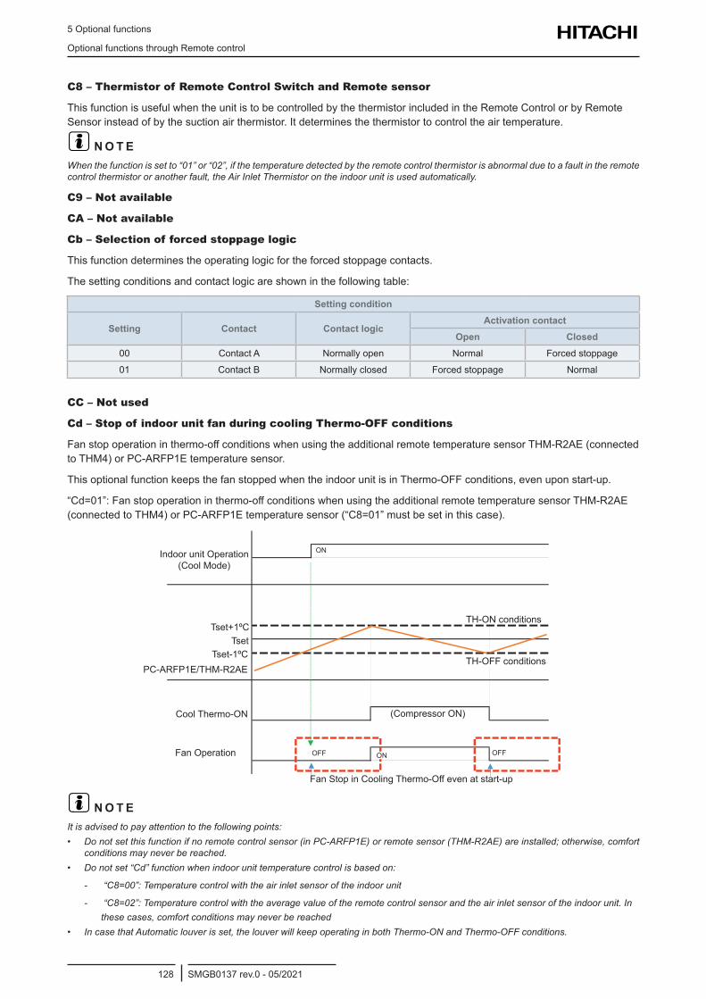
5 Optional functions
Optional functions through Remote control
SMGB0137 rev.0 - 05/2021128
C8 – Thermistor of Remote Control Switch and Remote sensor
This function is useful when the unit is to be controlled by the thermistor included in the Remote Control or by Remote Sensor instead of by the suction air thermistor. It determines the thermistor to control the air temperature.
? N O T EWhen the function is set to “01” or “02”, if the temperature detected by the remote control thermistor is abnormal due to a fault in the remote control thermistor or another fault, the Air Inlet Thermistor on the indoor unit is used automatically.
C9 – Not available
CA – Not available
Cb – Selection of forced stoppage logic
This function determines the operating logic for the forced stoppage contacts.
The setting conditions and contact logic are shown in the following table:
Setting condition
Setting Contact Contact logicActivation contact
Open Closed00 Contact A Normally open Normal Forced stoppage
01 Contact B Normally closed Forced stoppage Normal
CC – Not used
Cd – Stop of indoor unit fan during cooling Thermo-OFF conditions
Fan stop operation in thermo-off conditions when using the additional remote temperature sensor THM-R2AE (connected to THM4) or PC-ARFP1E temperature sensor.
This optional function keeps the fan stopped when the indoor unit is in Thermo-OFF conditions, even upon start-up.
“Cd=01”: Fan stop operation in thermo-off conditions when using the additional remote temperature sensor THM-R2AE (connected to THM4) or PC-ARFP1E temperature sensor (“C8=01” must be set in this case).
Indoor unit Operation (Cool Mode)
Tset+1ºC
Tset-1ºCPC-ARFP1E/THM-R2AE
Cool Thermo-ON
Fan Operation
Fan Stop in Cooling Thermo-Off even at start-up
(Compressor ON)
TH-ON conditions
TH-OFF conditions
OFF OFFON
Tset
ON
? N O T EIt is advised to pay attention to the following points:• Do not set this function if no remote control sensor (in PC-ARFP1E) or remote sensor (THM-R2AE) are installed; otherwise, comfort
conditions may never be reached.• Do not set “Cd” function when indoor unit temperature control is based on:
- “C8=00”: Temperature control with the air inlet sensor of the indoor unit
- “C8=02”: Temperature control with the average value of the remote control sensor and the air inlet sensor of the indoor unit. In these cases, comfort conditions may never be reached
• In case that Automatic louver is set, the louver will keep operating in both Thermo-ON and Thermo-OFF conditions.
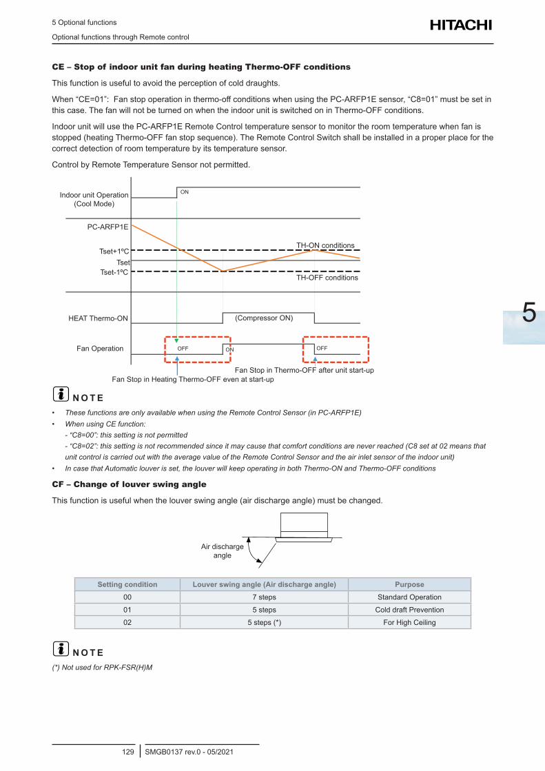
5 Optional functions
Optional functions through Remote control
SMGB0137 rev.0 - 05/2021129
5
CE – Stop of indoor unit fan during heating Thermo-OFF conditions
This function is useful to avoid the perception of cold draughts.
When “CE=01”: Fan stop operation in thermo-off conditions when using the PC-ARFP1E sensor, “C8=01” must be set in this case. The fan will not be turned on when the indoor unit is switched on in Thermo-OFF conditions.
Indoor unit will use the PC-ARFP1E Remote Control temperature sensor to monitor the room temperature when fan is stopped (heating Thermo-OFF fan stop sequence). The Remote Control Switch shall be installed in a proper place for the correct detection of room temperature by its temperature sensor.
Control by Remote Temperature Sensor not permitted.
Indoor unit Operation (Cool Mode)
Tset+1ºC
Tset-1ºC
PC-ARFP1E
HEAT Thermo-ON
Fan Operation
Fan Stop in Heating Thermo-OFF even at start-up
(Compressor ON)
TH-ON conditions
TH-OFF conditions
OFF OFFON
Tset
ON
Fan Stop in Thermo-OFF after unit start-up
? N O T E• These functions are only available when using the Remote Control Sensor (in PC-ARFP1E)• When using CE function:
- “C8=00”: this setting is not permitted - “C8=02”: this setting is not recommended since it may cause that comfort conditions are never reached (C8 set at 02 means that unit control is carried out with the average value of the Remote Control Sensor and the air inlet sensor of the indoor unit)
• In case that Automatic louver is set, the louver will keep operating in both Thermo-ON and Thermo-OFF conditions
CF – Change of louver swing angle
This function is useful when the louver swing angle (air discharge angle) must be changed.
Air discharge angle
Setting condition Louver swing angle (Air discharge angle) Purpose00 7 steps Standard Operation
01 5 steps Cold draft Prevention
02 5 steps (*) For High Ceiling
? N O T E(*) Not used for RPK-FSR(H)M
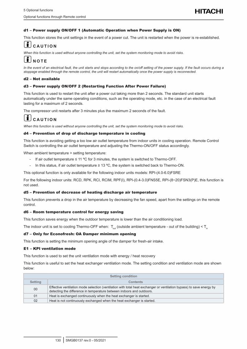
5 Optional functions
Optional functions through Remote control
SMGB0137 rev.0 - 05/2021130
d1 – Power supply ON/OFF 1 (Automatic Operation when Power Supply is ON)
This function stores the unit settings in the event of a power cut. The unit is restarted when the power is re-established.
? C A U T I O NWhen this function is used without anyone controlling the unit, set the system monitoring mode to avoid risks.
? N O T EIn the event of an electrical fault, the unit starts and stops according to the on/off setting of the power supply. If the fault occurs during a stoppage enabled through the remote control, the unit will restart automatically once the power supply is reconnected.
d2 – Not available
d3 – Power supply ON/OFF 2 (Restarting Function After Power Failure)
This function is used to restart the unit after a power cut taking more than 2 seconds. The standard unit starts automatically under the same operating conditions, such as the operating mode, etc. in the case of an electrical fault lasting for a maximum of 2 seconds.
The compressor unit restarts after 3 minutes plus the maximum 2 seconds of the fault.
? C A U T I O NWhen this function is used without anyone controlling the unit, set the system monitoring mode to avoid risks.
d4 – Prevention of drop of discharge temperature in cooling
This function is avoiding getting a too low air outlet temperature from indoor units in cooling operation. Remote Control Switch is controlling the air outlet temperature and adjusting the Thermo-ON/OFF status accordingly.
When ambient temperature > setting temperature: - If air outlet temperature ≤ 11 ºC for 3 minutes, the system is switched to Thermo-OFF. - In this status, if air outlet temperature ≥ 13 ºC, the system is switched back to Thermo-ON.
This optional function is only available for the following indoor units models: RPI-(4.0-6.0)FSRE
For the following indoor units: RCD, RPK, RCI, RCIM, RPF(I), RPI-(0.4-3.0)FNS5E, RPI-(8~20)FSN3(P)E, this function is not used.
d5 – Prevention of decrease of heating discharge air temperature
This function prevents a drop in the air temperature by decreasing the fan speed, apart from the settings on the remote control.
d6 – Room temperature control for energy saving
This function saves energy when the outdoor temperature is lower than the air conditioning load.
The indoor unit is set to cooling Thermo-OFF when: Tout (outside ambient temperature - out of the building) < Tin
d7 – Only for Econofresh: OA Damper minimum opening
This function is setting the minimum opening angle of the damper for fresh-air intake.
E1 – KPI ventilation mode
This function is used to set the unit ventilation mode with energy / heat recovery
This function is useful to set the heat exchanger ventilation mode. The setting condition and ventilation mode are shown below:
Setting conditionSetting Contents
00 Effective ventilation mode selection (ventilation with total heat exchanger or ventilation bypass) to save energy by detecting the difference in temperature between indoors and outdoors.
01 Heat is exchanged continuously when the heat exchanger is started.02 Heat is not continuously exchanged when the heat exchanger is started.
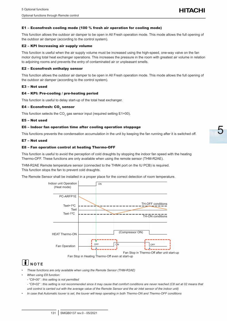
5 Optional functions
Optional functions through Remote control
SMGB0137 rev.0 - 05/2021131
5
E1 – Econofresh cooling mode (100 % fresh air operation for cooling mode)
This function allows the outdoor air damper to be open in All Fresh operation mode. This mode allows the full opening of the outdoor air damper (according to the control system).
E2 – KPI Increasing air supply volume
This function is useful when the air supply volume must be increased using the high-speed, one-way valve on the fan motor during total heat exchanger operations. This increases the pressure in the room with greatest air volume in relation to adjoining rooms and prevents the entry of contaminated air or unpleasant smells.
E2 – Econofresh enthalpy sensor
This function allows the outdoor air damper to be open in All Fresh operation mode. This mode allows the full opening of the outdoor air damper (according to the control system).
E3 – Not used
E4 – KPI: Pre-cooling / pre-heating period
This function is useful to delay start-up of the total heat exchanger.
E4 – Econofresh: CO2 sensor
This function selects the CO2 gas sensor input (required setting E1=00).
E5 – Not used
E6 – Indoor fan operation time after cooling operation stoppage
This functions prevents the condensation accumulation in the unit by keeping the fan running after it is switched off.
E7 – Not used
E8 – Fan operation control at heating Thermo-OFF
This function is useful to avoid the perception of cold draughts by stopping the indoor fan speed with the heating Thermo-OFF. These functions are only available when using the remote sensor (THM-R2AE).
THM-R2AE Remote temperature sensor (connected to the THM4 port on the IU PCB) is required. This function stops the fan to prevent cold draughts.
The Remote Sensor shall be installed in a proper place for the correct detection of room temperature.
Indoor unit Operation (Heat mode)
PC-ARFP1E
Tset+1ºC
Tset-1ºC
HEAT Thermo-ON
TH-OFF conditions
TH-ON conditions
(Compressor ON)
OFFOFF ONFan Operation
Fan Stop in Heating Thermo-Off even at start-upFan Stop in Thermo-Off after unit start-up
Tset
ON
? N O T E• These functions are only available when using the Remote Sensor (THM-R2AE)• When using E8 function:
- “C8=00” : this setting is not permitted - “C8=02” : this setting is not recommended since it may cause that comfort conditions are never reached (C8 set at 02 means that unit control is carried out with the average value of the Remote Sensor and the air inlet sensor of the indoor unit)
• In case that Automatic louver is set, the louver will keep operating in both Thermo-ON and Thermo-OFF conditions
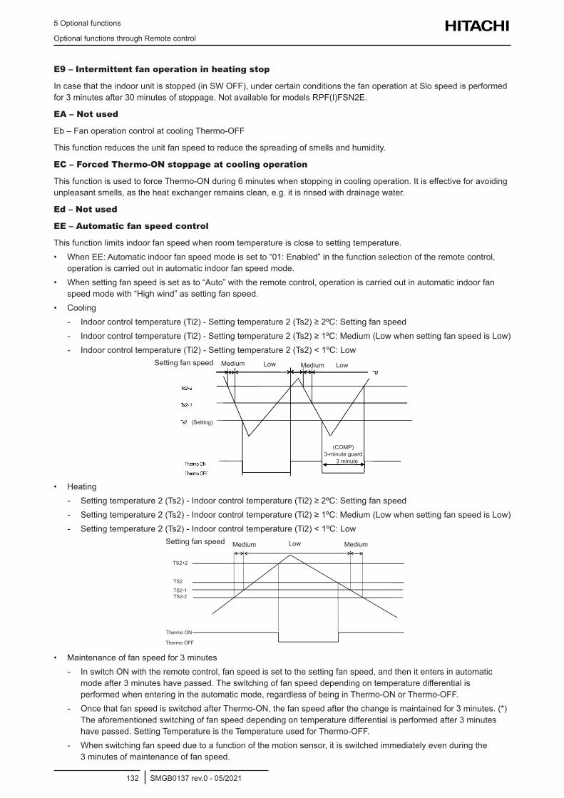
5 Optional functions
Optional functions through Remote control
SMGB0137 rev.0 - 05/2021132
E9 – Intermittent fan operation in heating stop
In case that the indoor unit is stopped (in SW OFF), under certain conditions the fan operation at Slo speed is performed for 3 minutes after 30 minutes of stoppage. Not available for models RPF(I)FSN2E.
EA – Not used
Eb – Fan operation control at cooling Thermo-OFF
This function reduces the unit fan speed to reduce the spreading of smells and humidity.
EC – Forced Thermo-ON stoppage at cooling operation
This function is used to force Thermo-ON during 6 minutes when stopping in cooling operation. It is effective for avoiding unpleasant smells, as the heat exchanger remains clean, e.g. it is rinsed with drainage water.
Ed – Not used
EE – Automatic fan speed control
This function limits indoor fan speed when room temperature is close to setting temperature.• When EE: Automatic indoor fan speed mode is set to “01: Enabled” in the function selection of the remote control,
operation is carried out in automatic indoor fan speed mode.• When setting fan speed is set as to “Auto” with the remote control, operation is carried out in automatic indoor fan
speed mode with “High wind” as setting fan speed.• Cooling
- Indoor control temperature (Ti2) - Setting temperature 2 (Ts2) ≥ 2ºC: Setting fan speed - Indoor control temperature (Ti2) - Setting temperature 2 (Ts2) ≥ 1ºC: Medium (Low when setting fan speed is Low) - Indoor control temperature (Ti2) - Setting temperature 2 (Ts2) < 1ºC: Low
Setting fan speed Medium Low Medium Low
(COMP) 3-minute guard
3 minute
(Setting)
• Heating - Setting temperature 2 (Ts2) - Indoor control temperature (Ti2) ≥ 2ºC: Setting fan speed - Setting temperature 2 (Ts2) - Indoor control temperature (Ti2) ≥ 1ºC: Medium (Low when setting fan speed is Low) - Setting temperature 2 (Ts2) - Indoor control temperature (Ti2) < 1ºC: Low
TS2+2
TS2-1TS2-2
Thermo ON
Thermo OFF
TS2
Setting fan speed Low MediumMedium
• Maintenance of fan speed for 3 minutes - In switch ON with the remote control, fan speed is set to the setting fan speed, and then it enters in automatic
mode after 3 minutes have passed. The switching of fan speed depending on temperature differential is performed when entering in the automatic mode, regardless of being in Thermo-ON or Thermo-OFF.
- Once that fan speed is switched after Thermo-ON, the fan speed after the change is maintained for 3 minutes. (*) The aforementioned switching of fan speed depending on temperature differential is performed after 3 minutes have passed. Setting Temperature is the Temperature used for Thermo-OFF.
- When switching fan speed due to a function of the motion sensor, it is switched immediately even during the 3 minutes of maintenance of fan speed.
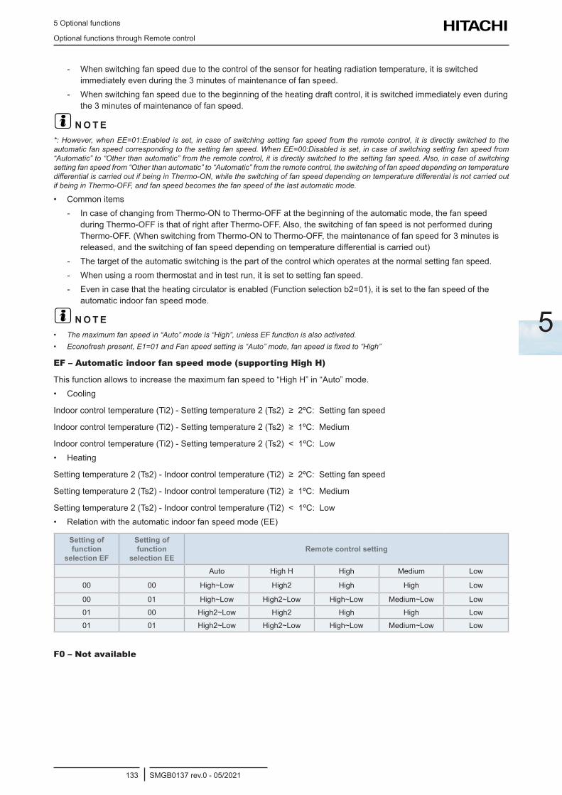
5 Optional functions
Optional functions through Remote control
SMGB0137 rev.0 - 05/2021133
5
- When switching fan speed due to the control of the sensor for heating radiation temperature, it is switched immediately even during the 3 minutes of maintenance of fan speed.
- When switching fan speed due to the beginning of the heating draft control, it is switched immediately even during the 3 minutes of maintenance of fan speed.
? N O T E*: However, when EE=01:Enabled is set, in case of switching setting fan speed from the remote control, it is directly switched to the automatic fan speed corresponding to the setting fan speed. When EE=00:Disabled is set, in case of switching setting fan speed from “Automatic” to “Other than automatic” from the remote control, it is directly switched to the setting fan speed. Also, in case of switching setting fan speed from “Other than automatic” to “Automatic” from the remote control, the switching of fan speed depending on temperature differential is carried out if being in Thermo-ON, while the switching of fan speed depending on temperature differential is not carried out if being in Thermo-OFF, and fan speed becomes the fan speed of the last automatic mode.
• Common items - In case of changing from Thermo-ON to Thermo-OFF at the beginning of the automatic mode, the fan speed
during Thermo-OFF is that of right after Thermo-OFF. Also, the switching of fan speed is not performed during Thermo-OFF. (When switching from Thermo-ON to Thermo-OFF, the maintenance of fan speed for 3 minutes is released, and the switching of fan speed depending on temperature differential is carried out)
- The target of the automatic switching is the part of the control which operates at the normal setting fan speed. - When using a room thermostat and in test run, it is set to setting fan speed. - Even in case that the heating circulator is enabled (Function selection b2=01), it is set to the fan speed of the
automatic indoor fan speed mode.
? N O T E• The maximum fan speed in “Auto” mode is “High”, unless EF function is also activated.• Econofresh present, E1=01 and Fan speed setting is “Auto” mode, fan speed is fixed to “High”
EF – Automatic indoor fan speed mode (supporting High H)
This function allows to increase the maximum fan speed to “High H” in “Auto” mode. • Cooling
Indoor control temperature (Ti2) - Setting temperature 2 (Ts2) ≥ 2ºC: Setting fan speed
Indoor control temperature (Ti2) - Setting temperature 2 (Ts2) ≥ 1ºC: Medium
Indoor control temperature (Ti2) - Setting temperature 2 (Ts2) < 1ºC: Low• Heating
Setting temperature 2 (Ts2) - Indoor control temperature (Ti2) ≥ 2ºC: Setting fan speed
Setting temperature 2 (Ts2) - Indoor control temperature (Ti2) ≥ 1ºC: Medium
Setting temperature 2 (Ts2) - Indoor control temperature (Ti2) < 1ºC: Low• Relation with the automatic indoor fan speed mode (EE)
Setting of function
selection EF
Setting of function
selection EERemote control setting
Auto High H High Medium Low
00 00 High~Low High2 High High Low
00 01 High~Low High2~Low High~Low Medium~Low Low
01 00 High2~Low High2 High High Low
01 01 High2~Low High2~Low High~Low Medium~Low Low
F0 – Not available
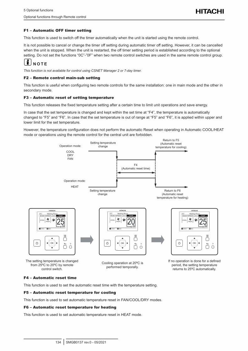
5 Optional functions
Optional functions through Remote control
SMGB0137 rev.0 - 05/2021134
F1 – Automatic OFF timer setting
This function is used to switch off the timer automatically when the unit is started using the remote control.
It is not possible to cancel or change the timer off setting during automatic timer off setting. However, it can be cancelled when the unit is stopped. When the unit is restarted, the off timer setting period is established according to the optional setting. Do not set the functions “0C”-”0F” when two remote control switches are used in the same remote control group.
? N O T EThis function is not available for control using CSNET Manager 2 or 7-day timer.
F2 – Remote control main-sub setting
This function is useful when configuring two remote controls for the same installation: one in main mode and the other in secondary mode.
F3 – Automatic reset of setting temperature
This function releases the fixed temperature setting after a certain time to limit unit operations and save energy.
In case that the set temperature is changed and kept within the set time at “F4”, the temperature is automatically changed to “F5” and “F6”. In case that the set temperature is out of range at “F5” and “F6”, it is applied within upper and lower limit for the set temperature.
However, the temperature configuration does not perform the automatic Reset when operating in Automatic COOL/HEAT mode or operations using the remote control for the central unit are forbidden.
Setting temperature change
Setting temperature change
Return to F5 (Automatic reset
temperature for cooling)
Return to F6 (Automatic reset
temperature for heating)
F4 (Automatic reset time)
Operation mode:
COOL DRY FAN
Operation mode:
HEAT
A/C
COOLHIGH
LOUV. ADJ
Meeting Room
MODE SPEED LOUV. TEMP
OK?
25
A/C
COOLHIGH
LOUV. ADJ
Meeting Room
MODE SPEED LOUV. TEMP
OK?
20
A/C
COOLHIGH
LOUV. ADJ
Meeting Room
MODE SPEED LOUV. TEMP
OK?
25
The setting temperature is changed from 25ºC to 20ºC by remote
control switch.
Cooling operation at 20ºC is performed temporally.
If no operation is done for a defined period, the setting temperature returns to 25ºC automatically.
F4 – Automatic reset time
This function is used to set the automatic reset time with the temperature setting.
F5 – Automatic reset temperature for cooling
This function is used to set automatic temperature reset in FAN/COOL/DRY modes.
F6 – Automatic reset temperature for heating
This function is used to set automatic temperature reset in HEAT mode.
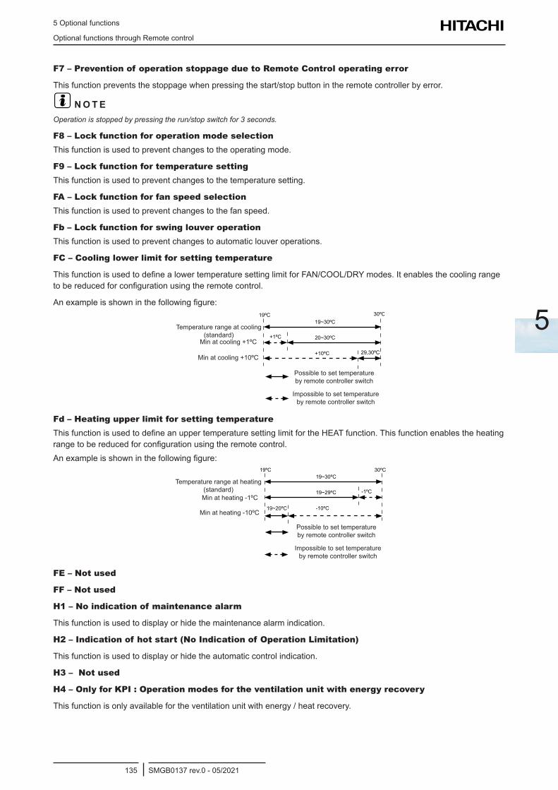
5 Optional functions
Optional functions through Remote control
SMGB0137 rev.0 - 05/2021135
5
F7 – Prevention of operation stoppage due to Remote Control operating error
This function prevents the stoppage when pressing the start/stop button in the remote controller by error.
? N O T EOperation is stopped by pressing the run/stop switch for 3 seconds.
F8 – Lock function for operation mode selectionThis function is used to prevent changes to the operating mode.
F9 – Lock function for temperature settingThis function is used to prevent changes to the temperature setting.
FA – Lock function for fan speed selectionThis function is used to prevent changes to the fan speed.
Fb – Lock function for swing louver operationThis function is used to prevent changes to automatic louver operations.
FC – Cooling lower limit for setting temperature
This function is used to define a lower temperature setting limit for FAN/COOL/DRY modes. It enables the cooling range to be reduced for configuration using the remote control.
An example is shown in the following figure:
Temperature range at cooling (standard)
Min at cooling +1ºC
Min at cooling +10ºC
Possible to set temperature by remote controller switch
Impossible to set temperature by remote controller switch
Fd – Heating upper limit for setting temperatureThis function is used to define an upper temperature setting limit for the HEAT function. This function enables the heating range to be reduced for configuration using the remote control.An example is shown in the following figure:
Temperature range at heating (standard)Min at heating -1ºC
Min at heating -10ºC
Possible to set temperature by remote controller switch
Impossible to set temperature by remote controller switch
FE – Not used
FF – Not used
H1 – No indication of maintenance alarm
This function is used to display or hide the maintenance alarm indication.
H2 – Indication of hot start (No Indication of Operation Limitation)
This function is used to display or hide the automatic control indication.
H3 – Not used
H4 – Only for KPI : Operation modes for the ventilation unit with energy recovery
This function is only available for the ventilation unit with energy / heat recovery.
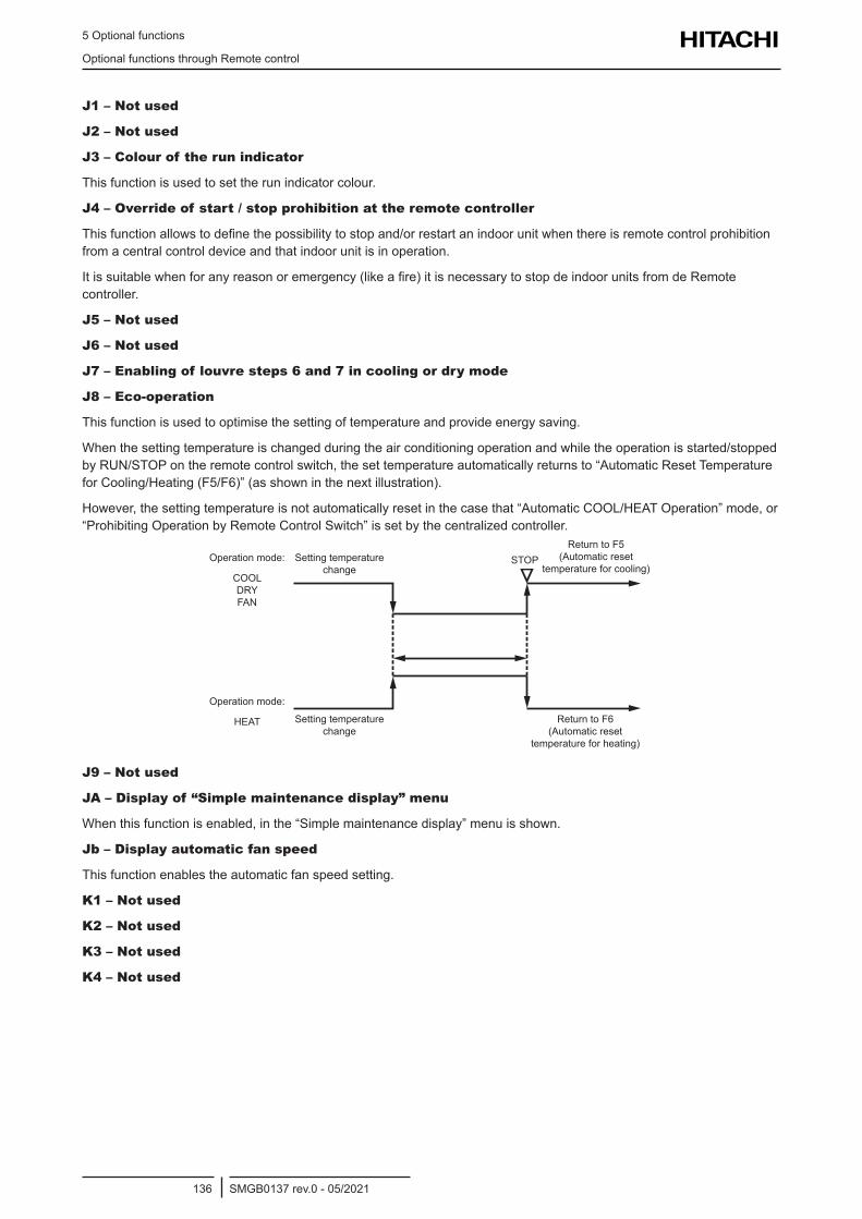
5 Optional functions
Optional functions through Remote control
SMGB0137 rev.0 - 05/2021136
J1 – Not used
J2 – Not used
J3 – Colour of the run indicator
This function is used to set the run indicator colour.
J4 – Override of start / stop prohibition at the remote controller
This function allows to define the possibility to stop and/or restart an indoor unit when there is remote control prohibition from a central control device and that indoor unit is in operation.
It is suitable when for any reason or emergency (like a fire) it is necessary to stop de indoor units from de Remote controller.
J5 – Not used
J6 – Not used
J7 – Enabling of louvre steps 6 and 7 in cooling or dry mode
J8 – Eco-operation
This function is used to optimise the setting of temperature and provide energy saving.
When the setting temperature is changed during the air conditioning operation and while the operation is started/stopped by RUN/STOP on the remote control switch, the set temperature automatically returns to “Automatic Reset Temperature for Cooling/Heating (F5/F6)” (as shown in the next illustration).
However, the setting temperature is not automatically reset in the case that “Automatic COOL/HEAT Operation” mode, or “Prohibiting Operation by Remote Control Switch” is set by the centralized controller.
Setting temperature change
Setting temperature change
Return to F5 (Automatic reset
temperature for cooling)
Return to F6 (Automatic reset
temperature for heating)
Operation mode:
COOL DRY FAN
Operation mode:
HEAT
STOP
J9 – Not used
JA – Display of “Simple maintenance display” menu
When this function is enabled, in the “Simple maintenance display” menu is shown.
Jb – Display automatic fan speed
This function enables the automatic fan speed setting.
K1 – Not used
K2 – Not used
K3 – Not used
K4 – Not used
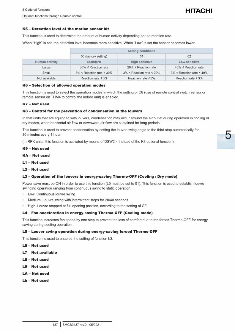
5 Optional functions
Optional functions through Remote control
SMGB0137 rev.0 - 05/2021137
5
K5 – Detection level of the motion sensor kit
This function is used to determine the amount of human activity depending on the reaction rate.
When “High” is set, the detection level becomes more sensitive. When “Low” is set the sensor becomes lower.
Setting conditions00 (factory setting) 01 02
Human activity Standard High sensitive Low sensitiveLarge 30% ≤ Reaction rate 20% ≤ Reaction rate 40% ≤ Reaction rate
Small 3% < Reaction rate < 30% 3% < Reaction rate < 20% 3% < Reaction rate < 40%
Not available Reaction rate ≤ 3% Reaction rate ≤ 3% Reaction rate ≤ 3%
K6 – Selection of allowed operation modes
This function is used to select the operation modes in which the setting of C8 (use of remote control switch sensor or remote sensor on THM4 to control the indoor unit) is enabled.
K7 – Not used
K8 – Control for the prevention of condensation in the louvers
In that units that are equipped with louvers, condensation may occur around the air outlet during operation in cooling or dry modes, when horizontal air flow or downward air flow are sustained for long periods.
This function is used to prevent condensation by setting the louver swing angle to the third step automatically for 30 minutes every 1 hour.
(In RPK units, this function is activated by means of DSW2-4 instead of the K8 optional function)
K9 – Not used
KA – Not used
L1 – Not used
L2 – Not used
L3 – Operation of the louvers in energy-saving Thermo-OFF (Cooling / Dry mode)
Power save must be ON in order to use this function (L5 must be set to 01). This function is used to establish louvre swinging operation ranging from continuous swing to static operation.• Low: Continuous louvre swing• Medium: Louvre swing with intermittent stops for 20/40 seconds• High: Louvre stopped at full opening position, according to the setting of CF.
L4 – Fan acceleration in energy-saving Thermo-OFF (Cooling mode)
This function increases fan speed by one step to prevent the loss of comfort due to the forced Thermo-OFF for energy saving during cooling operation.
L5 – Louver swing operation during energy-saving forced Thermo-OFF
This function is used to enabled the setting of function L3.
L6 – Not used
L7 – Not available
L8 – Not used
L9 – Not used
LA – Not used
Lb – Not used
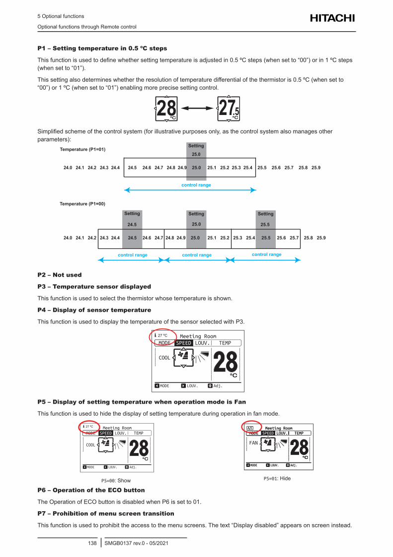
5 Optional functions
Optional functions through Remote control
SMGB0137 rev.0 - 05/2021138
P1 – Setting temperature in 0.5 ºC steps
This function is used to define whether setting temperature is adjusted in 0.5 ºC steps (when set to “00”) or in 1 ºC steps (when set to “01”).
This setting also determines whether the resolution of temperature differential of the thermistor is 0.5 ºC (when set to “00”) or 1 ºC (when set to “01”) enabling more precise setting control.
28 27.5Simplified scheme of the control system (for illustrative purposes only, as the control system also manages other parameters):
24.0 24.1 24.2 24.3 24.4 24.5 24.6 24.7 24.8 24.9 25.0 25.1 25.2 25.3 25.4 25.5 25.6 25.7 25.8 25.9
24.0 24.1 24.2 24.3 24.4 24.5 24.6 24.7 24.8 24.9 25.0 25.1 25.2 25.3 25.4 25.5 25.6 25.7 25.8 25.9
25.0
25.0 24.5 25.5
Setting
SettingSettingSetting
control range control range control range
control range
Temperature (P1=01)
Temperature (P1=00)
P2 – Not used
P3 – Temperature sensor displayed
This function is used to select the thermistor whose temperature is shown.
P4 – Display of sensor temperature
This function is used to display the temperature of the sensor selected with P3.
A/C
MODE SPEED LOUV. TEMP
COOL
Meeting Room
MODE Adj.LOUV.
27 ºC
P5 – Display of setting temperature when operation mode is Fan
This function is used to hide the display of setting temperature during operation in fan mode.
A/C
MODE SPEED LOUV. TEMP
COOL
Meeting Room
MODE Adj.LOUV.
27 ºC
P5=00: Show
A/C
MODE SPEED LOUV. TEMP
COOL
Meeting Room
MODE Adj.LOUV.
FAN
A/C
MODE SPEED LOUV. TEMP
COOL
Meeting Room
MODE Adj.LOUV.
FAN
P5=01: Hide
P6 – Operation of the ECO button
The Operation of ECO button is disabled when P6 is set to 01.
P7 – Prohibition of menu screen transition
This function is used to prohibit the access to the menu screens. The text “Display disabled” appears on screen instead.
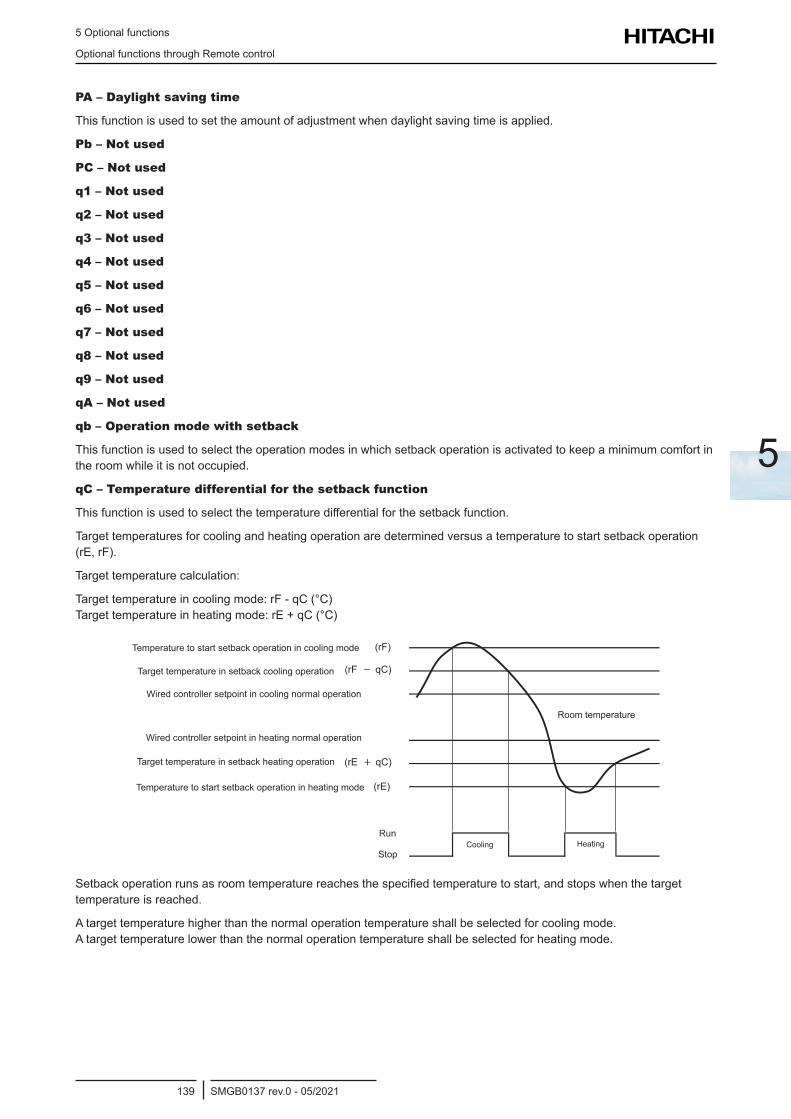
5 Optional functions
Optional functions through Remote control
SMGB0137 rev.0 - 05/2021139
5
PA – Daylight saving time
This function is used to set the amount of adjustment when daylight saving time is applied.
Pb – Not used
PC – Not used
q1 – Not used
q2 – Not used
q3 – Not used
q4 – Not used
q5 – Not used
q6 – Not used
q7 – Not used
q8 – Not used
q9 – Not used
qA – Not used
qb – Operation mode with setback
This function is used to select the operation modes in which setback operation is activated to keep a minimum comfort in the room while it is not occupied.
qC – Temperature differential for the setback function
This function is used to select the temperature differential for the setback function.
Target temperatures for cooling and heating operation are determined versus a temperature to start setback operation (rE, rF).
Target temperature calculation:
Target temperature in cooling mode: rF - qC (°C) Target temperature in heating mode: rE + qC (°C)
HeatingCoolingRun
Stop
Target temp. in setback cooling operation (rF - qC)
Wired Controller setpoint in cooling normal operation
Wired Controller setpoint in heating normal operation
Temp. to start setback operation in heating mode (rE)
Target temp. in setback heating operation (rE + qC)
room temperature
Temp. to start setback operation in cooling mode (rF)Temperature to start setback operation in cooling mode
Target temperature in setback cooling operation
Wired controller setpoint in cooling normal operation
Wired controller setpoint in heating normal operation
Target temperature in setback heating operation
Temperature to start setback operation in heating mode
Room temperature
HeatingCoolingStop
Run
Setback operation runs as room temperature reaches the specified temperature to start, and stops when the target temperature is reached.
A target temperature higher than the normal operation temperature shall be selected for cooling mode. A target temperature lower than the normal operation temperature shall be selected for heating mode.
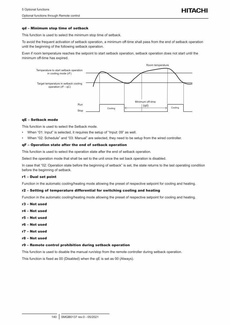
5 Optional functions
Optional functions through Remote control
SMGB0137 rev.0 - 05/2021140
qd – Minimum stop time of setback
This function is used to select the minimum stop time of setback.
To avoid the frequent activation of setback operation, a minimum off-time shall pass from the end of setback operation until the beginning of the following setback operation.
Even if room temperature reaches the setpoint to start setback operation, setback operation does not start until the minimum off-time has expired.
CoolingCoolingRun
Stop
Temp. to start setback operation in
Target temp. in setback cooling
room temperature
cooling mode (rF)
operation (rF - qC)
(qd)Minimum off-time
Temperature to start setback operation in cooling mode (rF)
Target temperature in setback cooling operation (rF - qC)
Minimum off-time
Room temperature
CoolingStop
RunCooling
qE – Setback mode
This function is used to select the Setback mode.• When “01: Input” is selected, it requires the setup of “Input: 09” as well. • When “02: Schedule” and “03: Manual” are selected, they need to be setup from the wired controller.
qF – Operation state after the end of setback operation
This function is used to select the operation state after the end of setback operation.
Select the operation mode that shall be set to the unit once the set back operation is disabled.
In case that “02: Operation state before the beginning of setback” is set, the state returns to the last operating condition before the beginning of setback.
r1 – Dual set point
Function in the automatic cooling/heating mode allowing the preset of respective setpoint for cooling and heating.
r2 – Setting of temperature differential for switching cooling and heating
Function in the automatic cooling/heating mode allowing the preset of respective setpoint for cooling and heating.
r3 – Not used
r4 – Not used
r5 – Not used
r6 – Not used
r7 – Not used
r8 – Not used
r9 – Remote control prohibition during setback operation
This function is used to disable the manual run/stop from the remote controller during setback operation.
This function is fixed as 00 (Disabled) when the qE is set as 00 (Always).
5 Optional functions
Optional functions through Remote control
SMGB0137 rev.0 - 05/2021141
5
rb – Minimum operation time to allow the change of operation mode in automatic cooling/heating mode with dual set point
This function is used to define a minimum time of operation in a given mode, in order to avoid too frequent changes of operation mode.
Operation mode does not change until the minimum transition time passes, even if the room temperature reaches the setpoint to shift to the other operation mode.
rC – Maximum outdoor temperature to allow operation mode switch to heating in auto cooling/heating with dual set point
If outdoor ambient temperature is higher than rC, there is no mode transition to heating in automatic cooling/heating operation mode, even if room temperature reaches the setpoint to switch operation mode from cooling to heating.
rd – Minimum outdoor temperature to allow cooling operation in automatic cooling/heating mode with dual set point
If outdoor ambient temperature is lower than rd, there is no mode transition to cooling in automatic cooling/heating operation mode, even though room temperature has reached the setpoint to switch operation mode from heating to cooling.
rE – Temperature for the beginning of heating in setback
This function is used to select the room temperature used to determine the start of heating operation during setback.
rF – Temperature for the beginning of cooling in setback
This function is used to select the room temperature used to determine the start of cooling operation during setback.
s1 – Not used
s2 – Not used
s3 – Not used
s4 – Not used
s5 – Not used
s6 – Not used
s7 – Not used
s8 – Not used
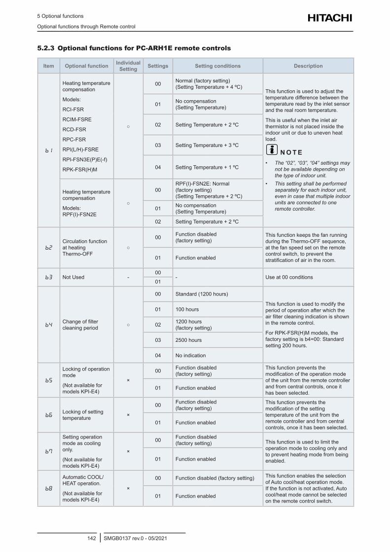
5 Optional functions
Optional functions through Remote control
SMGB0137 rev.0 - 05/2021142
5.2.3 Optional functions for PC-ARH1E remote controls
Item Optional function Individual Setting Settings Setting conditions Description
b1
Heating temperature compensation
Models:
RCI-FSR
RCIM-FSRE
RCD-FSR
RPC-FSR
RPI(L/H)-FSRE
RPI-FSN3E(P)E(-f)
RPK-FSR(H)M
00 Normal (factory setting) (Setting Temperature + 4 ºC)
This function is used to adjust the temperature difference between the temperature read by the inlet sensor and the real room temperature.
This is useful when the inlet air thermistor is not placed inside the indoor unit or due to uneven heat load.
? N O T E • The “02”, “03”, “04” settings may
not be available depending on the type of indoor unit.
• This setting shall be performed separately for each indoor unit, even in case that multiple indoor units are connected to one remote controller.
01 No compensation (Setting Temperature)
02 Setting Temperature + 2 ºC
03 Setting Temperature + 3 ºC
04 Setting Temperature + 1 ºC
Heating temperature compensation
Models: RPF(I)-FSN2E
00RPF(I)-FSN2E: Normal (factory setting) (Setting Temperature + 2 ºC)
01 No compensation (Setting Temperature)
02 Setting Temperature + 2 ºC
b2
Circulation function at heating Thermo-OFF
00 Function disabled (factory setting)
This function keeps the fan running during the Thermo-OFF sequence, at the fan speed set on the remote control switch, to prevent the stratification of air in the room.01 Function enabled
b3 Not Used -00
- Use at 00 conditions01
b4Change of filter cleaning period
00 Standard (1200 hours)
This function is used to modify the period of operation after which the air filter cleaning indication is shown in the remote control.
For RPK-FSR(H)M models, the factory setting is b4=00: Standard setting 200 hours.
01 100 hours
02 1200 hours (factory setting)
03 2500 hours
04 No indication
b5
Locking of operation mode
(Not available for models KPI-E4)
×
00 Function disabled (factory setting)
This function prevents the modification of the operation mode of the unit from the remote controller and from central controls, once it has been selected.
01 Function enabled
b6Locking of setting temperature ×
00 Function disabled (factory setting)
This function prevents the modification of the setting temperature of the unit from the remote controller and from central controls, once it has been selected.
01 Function enabled
b7
Setting operation mode as cooling only.
(Not available for models KPI-E4)
×
00 Function disabled (factory setting) This function is used to limit the
operation mode to cooling only and to prevent heating mode from being enabled.01 Function enabled
b8
Automatic COOL/HEAT operation.
(Not available for models KPI-E4)
×
00 Function disabled (factory setting) This function enables the selection of Auto cool/heat operation mode. If the function is not activated, Auto cool/heat mode cannot be selected on the remote control switch.
01 Function enabled
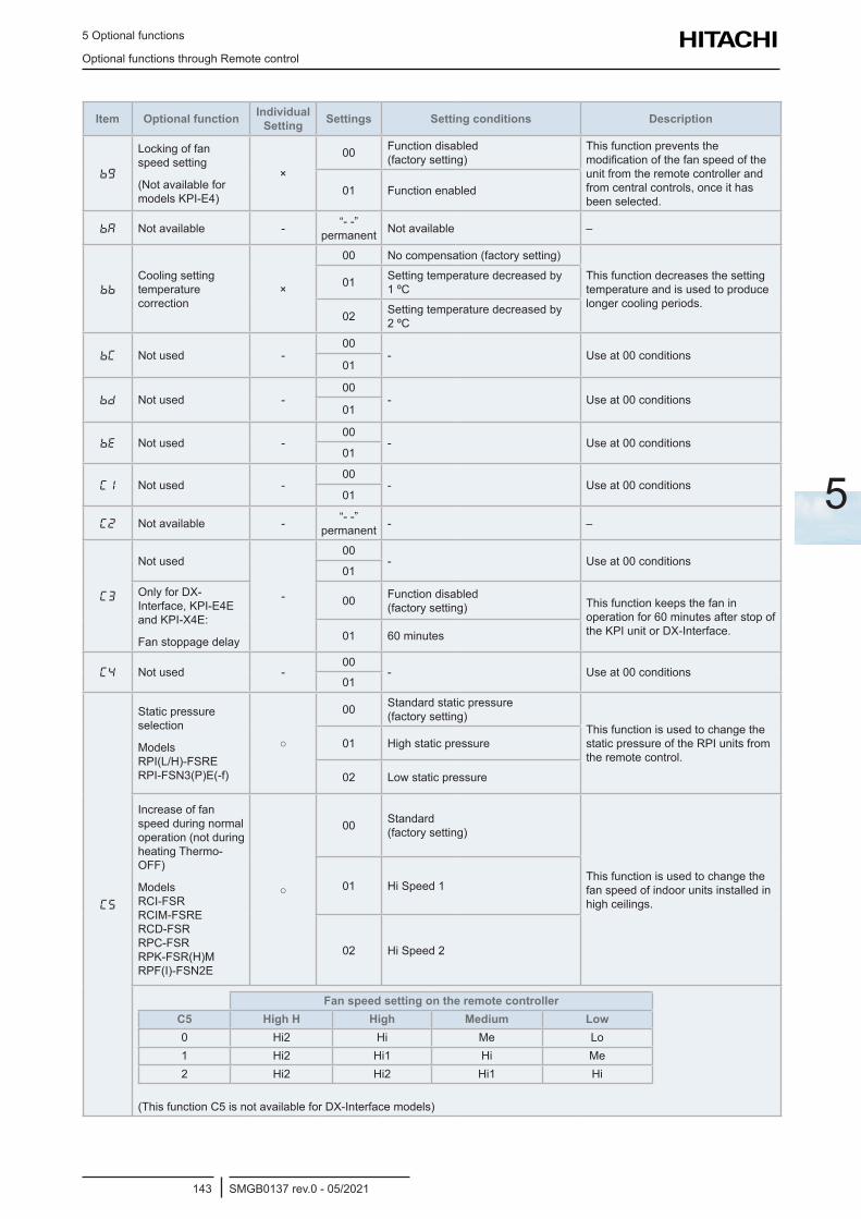
5 Optional functions
Optional functions through Remote control
SMGB0137 rev.0 - 05/2021143
5
Item Optional function Individual Setting Settings Setting conditions Description
bg
Locking of fan speed setting
(Not available for models KPI-E4)
×
00 Function disabled (factory setting)
This function prevents the modification of the fan speed of the unit from the remote controller and from central controls, once it has been selected.
01 Function enabled
bA Not available - “- -” permanent Not available –
bb
Cooling setting temperature correction
×
00 No compensation (factory setting)
This function decreases the setting temperature and is used to produce longer cooling periods.
01 Setting temperature decreased by 1 ºC
02 Setting temperature decreased by 2 ºC
bC Not used -00
- Use at 00 conditions01
bd Not used -00
- Use at 00 conditions01
bE Not used -00
- Use at 00 conditions01
C1 Not used -00
- Use at 00 conditions01
C2 Not available - “- -” permanent - –
C3
Not used
-
00- Use at 00 conditions
01
Only for DX-Interface, KPI-E4E and KPI-X4E:
Fan stoppage delay
00 Function disabled (factory setting) This function keeps the fan in
operation for 60 minutes after stop of the KPI unit or DX-Interface.01 60 minutes
C4 Not used -00
- Use at 00 conditions01
C5
Static pressure selection
Models RPI(L/H)-FSRE RPI-FSN3(P)E(-f)
00 Standard static pressure (factory setting)
This function is used to change the static pressure of the RPI units from the remote control.
01 High static pressure
02 Low static pressure
Increase of fan speed during normal operation (not during heating Thermo-OFF)
Models RCI-FSR RCIM-FSRE RCD-FSR RPC-FSR RPK-FSR(H)M RPF(I)-FSN2E
00 Standard (factory setting)
This function is used to change the fan speed of indoor units installed in high ceilings.
01 Hi Speed 1
02 Hi Speed 2
Fan speed setting on the remote controllerC5 High H High Medium Low0 Hi2 Hi Me Lo1 Hi2 Hi1 Hi Me2 Hi2 Hi2 Hi1 Hi
(This function C5 is not available for DX-Interface models)
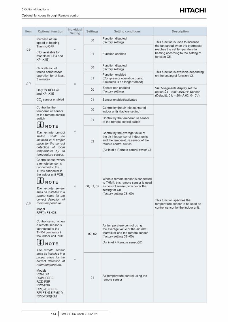
5 Optional functions
Optional functions through Remote control
SMGB0137 rev.0 - 05/2021144
Item Optional function Individual Setting Settings Setting conditions Description
C6
Increase of fan speed at heating Thermo-OFF
(Not available for models KPI-E4 and KPI-X4E)
00 Function disabled (factory setting) This function is used to increase
the fan speed when the thermostat reaches the set temperature in heating according to the setting of function C5.
01 Function enabled
C7
Cancellation of forced compressor operation for at least 3 minutes
00 Function disabled (factory setting)
This function is available depending on the setting of function b3.
01Function enabled (Compressor operation during 3 minutes is no longer forced)
Only for KPI-E4E and KPI-X4E
CO2 sensor enabled
00 Sensor non enabled (factory setting)
Via 7-segments display set the option Ct (00: ON/OFF Sensor (Default); 01: 4-20mA 02: 0-10V).
01 Sensor enabled/activated
C8
Control by the temperature sensor of the remote control switch
? N O T EThe remote control switch shall be installed in a proper place for the correct detection of room temperature by its temperature sensor.
00 Control by the air inlet sensor of indoor units (factory setting)
This function specifies the temperature sensor to be used as control sensor by the indoor unit.
01 Control by the temperature sensor of the remote control switch
02
Control by the average value of the air inlet sensor of indoor units and the temperature sensor of the remote control switch
(Air inlet + Remote control switch)/2
Control sensor when a remote sensor is connected to the THM4 connector in the indoor unit PCB
? N O T EThe remote sensor shall be installed in a proper place for the correct detection of room temperature.
Model RPF(I)-FSN2E
00, 01, 02
When a remote sensor is connected to THM4, this remote sensor is used as control sensor, whichever the setting for C8 (factory setting C8=00)
Control sensor when a remote sensor is connected to the THM4 connector in the indoor unit PCB
? N O T EThe remote sensor shall be installed in a proper place for the correct detection of room temperature.
Models RCI-FSR RCIM-FSRE RCD-FSR RPC-FSR RPI(L/H)-FSRE RPI-FSN3E(P)E(-f) RPK-FSR(H)M
00, 02
Air temperature control using the average value of the air inlet thermistor and the remote sensor (factory setting C8=00)
(Air inlet + Remote sensor)/2
01 Air temperature control using the remote sensor
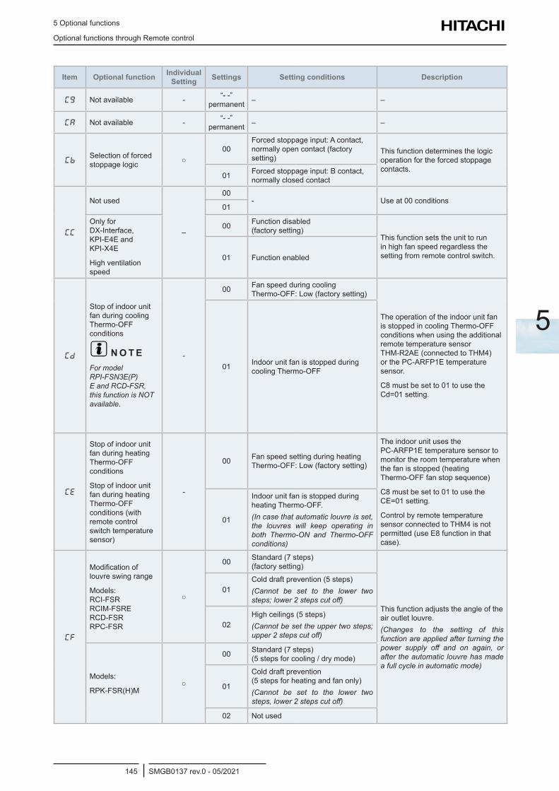
5 Optional functions
Optional functions through Remote control
SMGB0137 rev.0 - 05/2021145
5
Item Optional function Individual Setting Settings Setting conditions Description
Cg Not available - “- -” permanent – –
CA Not available - “- -” permanent – –
CbSelection of forced stoppage logic
00Forced stoppage input: A contact, normally open contact (factory setting)
This function determines the logic operation for the forced stoppage contacts.
01 Forced stoppage input: B contact, normally closed contact
CC
Not used
–
00- Use at 00 conditions
01
Only for DX-Interface, KPI-E4E and KPI-X4E
High ventilation speed
00 Function disabled (factory setting)
This function sets the unit to run in high fan speed regardless the setting from remote control switch.01 Function enabled
Cd
Stop of indoor unit fan during cooling Thermo-OFF conditions
? N O T EFor model RPI-FSN3E(P)E and RCD-FSR, this function is NOT available.
-
00 Fan speed during cooling Thermo-OFF: Low (factory setting)
The operation of the indoor unit fan is stopped in cooling Thermo-OFF conditions when using the additional remote temperature sensor THM-R2AE (connected to THM4) or the PC-ARFP1E temperature sensor.
C8 must be set to 01 to use the Cd=01 setting.
01 Indoor unit fan is stopped during cooling Thermo-OFF
CE
Stop of indoor unit fan during heating Thermo-OFF conditions
Stop of indoor unit fan during heating Thermo-OFF conditions (with remote control switch temperature sensor)
-
00 Fan speed setting during heating Thermo-OFF: Low (factory setting)
The indoor unit uses the PC-ARFP1E temperature sensor to monitor the room temperature when the fan is stopped (heating Thermo-OFF fan stop sequence)
C8 must be set to 01 to use the CE=01 setting.
Control by remote temperature sensor connected to THM4 is not permitted (use E8 function in that case).
01
Indoor unit fan is stopped during heating Thermo-OFF.(In case that automatic louvre is set, the louvres will keep operating in both Thermo-ON and Thermo-OFF conditions)
CF
Modification of louvre swing range
Models: RCI-FSR RCIM-FSRE RCD-FSR RPC-FSR
00 Standard (7 steps) (factory setting)
This function adjusts the angle of the air outlet louvre.(Changes to the setting of this function are applied after turning the power supply off and on again, or after the automatic louvre has made a full cycle in automatic mode)
01Cold draft prevention (5 steps)(Cannot be set to the lower two steps; lower 2 steps cut off)
02High ceilings (5 steps)(Cannot be set the upper two steps; upper 2 steps cut off)
Models:
RPK-FSR(H)M
00 Standard (7 steps) (5 steps for cooling / dry mode)
01
Cold draft prevention (5 steps for heating and fan only)(Cannot be set to the lower two steps, lower 2 steps cut off)
02 Not used
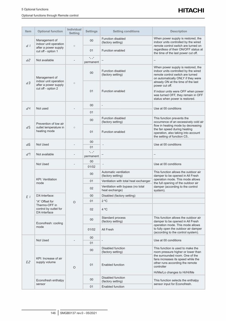
5 Optional functions
Optional functions through Remote control
SMGB0137 rev.0 - 05/2021146
Item Optional function Individual Setting Settings Setting conditions Description
d1
Management of indoor unit operation after a power supply cut off - option 1
00 Function disabled (factory setting)
When power supply is restored, the indoor units controlled by the wired remote control switch are turned on regardless of their ON/OFF status at the time of the last power cut off.
01 Function enabled
d2 Not available - “- -” permanent – –
d3
Management of indoor unit operation after a power supply cut off - option 2
00 Function disabled (factory setting)
When power supply is restored, the indoor units controlled by the wired remote control switch are turned on automatically ONLY if they were already ON at the time of the last power cut off.
If indoor units were OFF when power was turned OFF, they remain in OFF status when power is restored.
01 Function enabled
d4 Not used -00 -
Use at 00 conditions01
d5
Prevention of low air outlet temperature in heating mode
00 Function disabled (factory setting)
This function prevents the occurrence of an excessively cold air flow in heating mode by decreasing the fan speed during heating operation, also taking into account the setting of function C5..
01 Function enabled
d6 Not Used -00
- Use at 00 conditions01
d7 Not available - “- -” permanent – –
e1
Not Used -00
- Use at 00 conditions01/02
KPI: Ventilation mode
O
00 Automatic ventilation (factory setting)
This function allows the outdoor air damper to be opened in All Fresh operation mode. This mode allows the full opening of the outdoor air damper (according to the control system).
01 Ventilation with total heat exchanger
02 Ventilation with bypass (no total heat exchange)
DX-Interface:
“A” Offset for Thermo-OFF in control by outlet for DX-Interface
00 Disabled (factory setting)
01 2 ºC
02 4 ºC
Econofresh: cooling mode
00 Standard process (factory setting)
This function allows the outdoor air damper to be opened in All Fresh operation mode. This mode allows to fully open the outdoor air damper (according to the control system).
01/02 All Fresh
e2
Not Used -00
- Use at 00 conditions01
KPI: Increase of air supply volume
O
00 Disabled function (factory setting)
This function is used to make the room pressure higher or lower than the surrounded room. One of the fans increases its speed while the other runs according the remote controller
Hi/Me/Lo changes to Hi/Hi/Me
01 Enabled function
Econofresh enthalpy sensor
00 Disabled function (factory setting) This function selects the enthalpy
sensor input for Econofresh.01 Enabled function
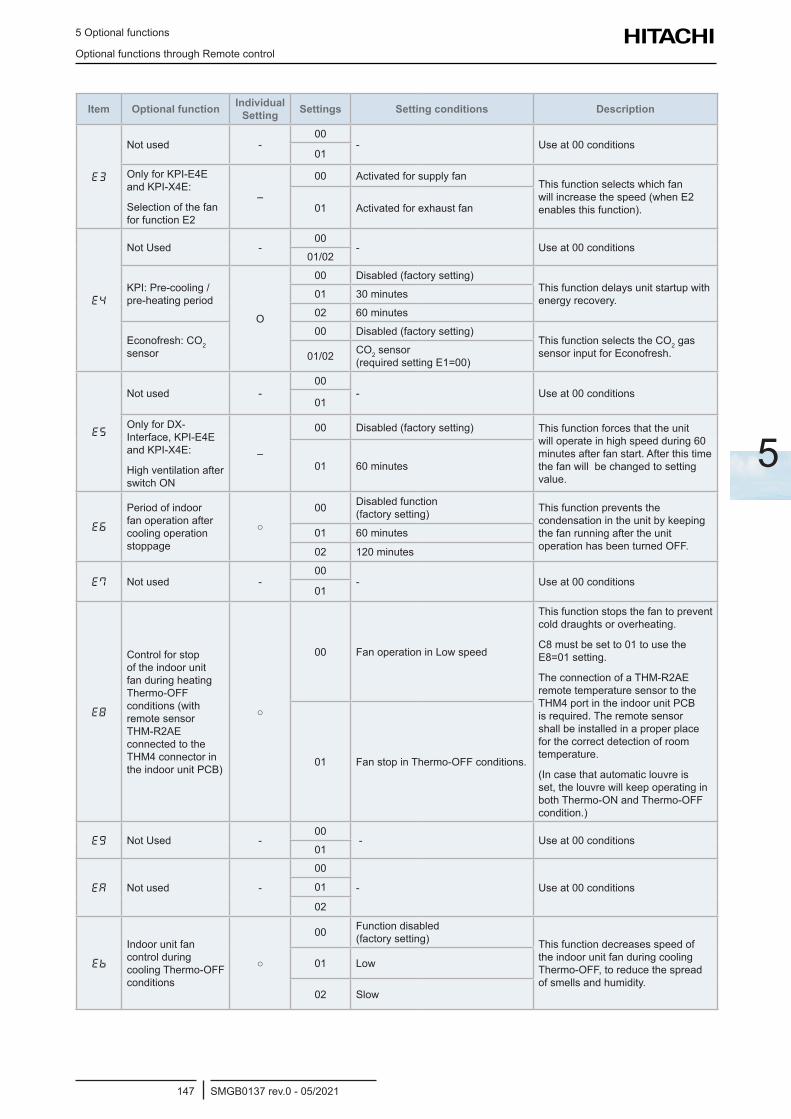
5 Optional functions
Optional functions through Remote control
SMGB0137 rev.0 - 05/2021147
5
Item Optional function Individual Setting Settings Setting conditions Description
E3
Not used -00
- Use at 00 conditions01
Only for KPI-E4E and KPI-X4E:
Selection of the fan for function E2
–
00 Activated for supply fanThis function selects which fan will increase the speed (when E2 enables this function).01 Activated for exhaust fan
e4
Not Used -00
- Use at 00 conditions01/02
KPI: Pre-cooling / pre-heating period
O
00 Disabled (factory setting)This function delays unit startup with energy recovery.01 30 minutes
02 60 minutes
Econofresh: CO2 sensor
00 Disabled (factory setting)This function selects the CO2 gas sensor input for Econofresh.01/02 CO2 sensor
(required setting E1=00)
E5
Not used -00
- Use at 00 conditions01
Only for DX-Interface, KPI-E4E and KPI-X4E:
High ventilation after switch ON
–
00 Disabled (factory setting) This function forces that the unit will operate in high speed during 60 minutes after fan start. After this time the fan will be changed to setting value.
01 60 minutes
E6
Period of indoor fan operation after cooling operation stoppage
00 Disabled function (factory setting) This function prevents the
condensation in the unit by keeping the fan running after the unit operation has been turned OFF.
01 60 minutes
02 120 minutes
E7 Not used -00
- Use at 00 conditions01
E8
Control for stop of the indoor unit fan during heating Thermo-OFF conditions (with remote sensor THM-R2AE connected to the THM4 connector in the indoor unit PCB)
00 Fan operation in Low speed
This function stops the fan to prevent cold draughts or overheating.
C8 must be set to 01 to use the E8=01 setting.
The connection of a THM-R2AE remote temperature sensor to the THM4 port in the indoor unit PCB is required. The remote sensor shall be installed in a proper place for the correct detection of room temperature.
(In case that automatic louvre is set, the louvre will keep operating in both Thermo-ON and Thermo-OFF condition.)
01 Fan stop in Thermo-OFF conditions.
eg Not Used -00
- Use at 00 conditions01
EA Not used -
00
- Use at 00 conditions01
02
Eb
Indoor unit fan control during cooling Thermo-OFF conditions
00 Function disabled (factory setting) This function decreases speed of
the indoor unit fan during cooling Thermo-OFF, to reduce the spread of smells and humidity.
01 Low
02 Slow
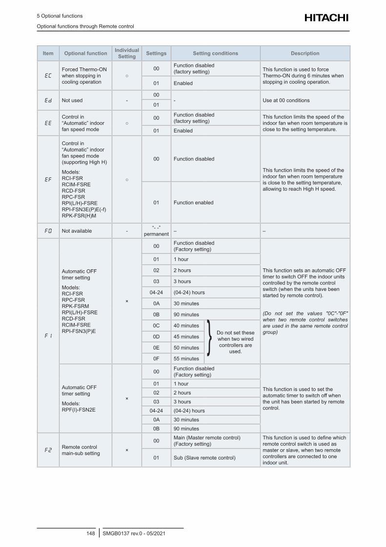
5 Optional functions
Optional functions through Remote control
SMGB0137 rev.0 - 05/2021148
Item Optional function Individual Setting Settings Setting conditions Description
EC
Forced Thermo-ON when stopping in cooling operation
00 Function disabled
(factory setting) This function is used to force Thermo-ON during 6 minutes when stopping in cooling operation.01 Enabled
Ed Not used -00
- Use at 00 conditions01
EE
Control in “Automatic” indoor fan speed mode
00 Function disabled
(factory setting)This function limits the speed of the indoor fan when room temperature is close to the setting temperature.01 Enabled
EF
Control in “Automatic” indoor fan speed mode (supporting High H)
Models: RCI-FSR RCIM-FSRE RCD-FSR RPC-FSR RPI(L/H)-FSRE RPI-FSN3E(P)E(-f) RPK-FSR(H)M
00 Function disabled
This function limits the speed of the indoor fan when room temperature is close to the setting temperature, allowing to reach High H speed.
01 Function enabled
F0 Not available - “- -” permanent – –
F1
Automatic OFF timer setting
Models: RCI-FSR RPC-FSR RPK-FSRM RPI(L/H)-FSRE RCD-FSR RCIM-FSRE RPI-FSN3(P)E
×
00 Function disabled (Factory setting)
This function sets an automatic OFF timer to switch OFF the indoor units controlled by the remote control switch (when the units have been started by remote control).
(Do not set the values "0C"-"0F" when two remote control switches are used in the same remote control group)
01 1 hour
02 2 hours
03 3 hours
04-24 (04-24) hours
0A 30 minutes
0B 90 minutes
0C 40 minutes Do not set these when two wired controllers are
used.
0D 45 minutes
0E 50 minutes
0F 55 minutes
Automatic OFF timer setting
Models: RPF(I)-FSN2E
×
00 Function disabled (Factory setting)
This function is used to set the automatic timer to switch off when the unit has been started by remote control.
01 1 hour
02 2 hours
03 3 hours
04-24 (04-24) hours
0A 30 minutes
0B 90 minutes
F2Remote control main-sub setting ×
00 Main (Master remote control) (Factory setting)
This function is used to define which remote control switch is used as master or slave, when two remote controllers are connected to one indoor unit.
01 Sub (Slave remote control)
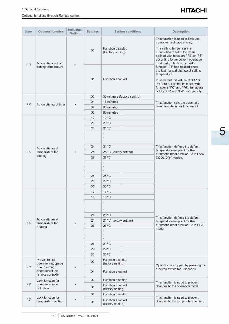
5 Optional functions
Optional functions through Remote control
SMGB0137 rev.0 - 05/2021149
5
Item Optional function Individual Setting Settings Setting conditions Description
F3Automatic reset of setting temperature ×
00 Function disabled (Factory setting)
This function is used to limit unit operation and save energy.
The setting temperature is automatically set to the value defined with functions "F5" or "F6", according to the current operation mode, after the time set with function "F4" has passed since the last manual change of setting temperature.
In case that the values of "F5" or "F6" are out of the limits set with functions "FC" and "Fd", limitations set by "FC" and "Fd" have priority.
01 Function enabled
F4 Automatic reset time ×
00 30 minutes (factory setting)
This function sets the automatic reset time delay for function F3.
01 15 minutes
02 60 minutes
03 90 minutes
F5
Automatic reset temperature for cooling
×
19 19 °C
This function defines the default temperature set point for the automatic reset function F3 in FAN/COOL/DRY modes.
20 20 °C
21 21 °C
· · ·
· · ·
24 24 °C
25 25 °C (factory setting)
26 26 ºC
· · ·
· · ·
28 28 ºC
29 29 ºC
30 30 ºC
F6
Automatic reset temperature for heating
×
17 17 ºC
This function defines the default temperature set point for the automatic reset function F3 in HEAT mode.
18 18 ºC
· · ·
· · ·
20 20 ºC
21 21 ºC (factory setting)
25 25 ºC
· · ·
· · ·
28 28 ºC
29 29 ºC
30 30 ºC
F7
Prevention of operation stoppage due to wrong operation of the remote controller
×
00 Function disabled (factory setting) Operation is stopped by pressing the
run/stop switch for 3 seconds.01 Function enabled
F8
Lock function for operation mode selection
×00 Function disabled
This function is used to prevent changes to the operation mode.01 Function enabled
(factory setting)
FgLock function for temperature setting ×
00 Function disabledThis function is used to prevent changes to the temperature setting.01 Function enabled
(factory setting)
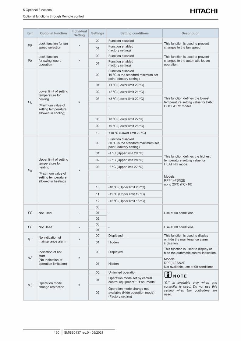
5 Optional functions
Optional functions through Remote control
SMGB0137 rev.0 - 05/2021150
Item Optional function Individual Setting Settings Setting conditions Description
FALock function for fan speed selection ×
00 Function disabledThis function is used to prevent changes to the fan speed.01 Function enabled
(factory setting)
Fb
Lock function for swing louvre operation
×00 Function disabled This function is used to prevent
changes to the automatic louvre operation.01 Function enabled
(factory setting)
FC
Lower limit of setting temperature for cooling
(Minimum value of setting temperature allowed in cooling)
×
00Function disabled 19 °C is the standard minimum set point. (factory setting)
This function defines the lowest temperature setting value for FAN/COOL/DRY modes.
01 +1 ºC (Lower limit 20 ºC)
02 +2 ºC (Lower limit 21 ºC)
03 +3 ºC (Lower limit 22 ºC)
· · ·
· · ·
08 +8 ºC (Lower limit 27ºC)
09 +9 ºC (Lower limit 28 ºC)
10 +10 ºC (Lower limit 29 ºC)
Fd
Upper limit of setting temperature for heating
(Maximum value of setting temperature allowed in heating)
×
00Function disabled 30 ºC is the standard maximum set point. (factory setting)
This function defines the highest temperature setting value for HEATING mode.
Models: RPF(I)-FSN2E up to 20ºC (FC=10)
01 -1 ºC (Upper limit 29 ºC)
02 -2 ºC (Upper limit 28 ºC)
03 -3 ºC (Upper limit 27 ºC)
· · ·
· · ·
10 -10 ºC (Upper limit 20 ºC)
11 -11 ºC (Upper limit 19 ºC)
12 -12 ºC (Upper limit 18 ºC)
FE Not used -
00
- Use at 00 conditions01
02
FF Not Used -00
- Use at 00 conditions01
H1No indication of maintenance alarm ×
00 Displayed This function is used to display or hide the maintenance alarm indication.01 Hidden
H2
Indication of hot start (No Indication of operation limitation)
×
00 DisplayedThis function is used to display or hide the automatic control indication.
Models: RPF(I)-FSN2E Not available, use at 00 conditions
01 Hidden
H3Operation mode change restriction ×
00 Unlimited operation? N O T E“01” is available only when one controller is used. Do not use this setting when two controllers are used.
01 Operation mode set by central control equipment + “Fan” mode
02Operation mode change not available (Hide operation mode)(Factory setting)
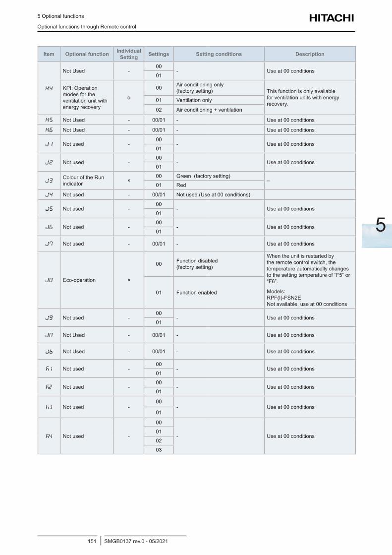
5 Optional functions
Optional functions through Remote control
SMGB0137 rev.0 - 05/2021151
5
Item Optional function Individual Setting Settings Setting conditions Description
H4
Not Used -00
- Use at 00 conditions01
KPI: Operation modes for the ventilation unit with energy recovery
o
00 Air conditioning only (factory setting) This function is only available
for ventilation units with energy recovery.
01 Ventilation only
02 Air conditioning + ventilation
H5 Not Used - 00/01 - Use at 00 conditions
H6 Not Used - 00/01 - Use at 00 conditions
J1 Not used -00
- Use at 00 conditions 01
J2 Not used -00
- Use at 00 conditions01
J3Colour of the Run indicator ×
00 Green (factory setting)–
01 Red
j4 Not used - 00/01 Not used (Use at 00 conditions)
J5 Not used -00
- Use at 00 conditions01
J6 Not used -00
- Use at 00 conditions01
j7 Not used - 00/01 - Use at 00 conditions
J8 Eco-operation ×
00 Function disabled (factory setting)
When the unit is restarted by the remote control switch, the temperature automatically changes to the setting temperature of “F5” or “F6”.
Models: RPF(I)-FSN2E Not available, use at 00 conditions
01 Function enabled
Jg Not used -00
- Use at 00 conditions01
jA Not Used - 00/01 - Use at 00 conditions
jb Not Used - 00/01 - Use at 00 conditions
k1 Not used -00
- Use at 00 conditions01
k2 Not used -00
- Use at 00 conditions01
k3 Not used -00
- Use at 00 conditions01
k4 Not used -
00
- Use at 00 conditions01
02
03
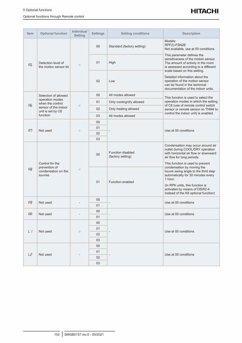
5 Optional functions
Optional functions through Remote control
SMGB0137 rev.0 - 05/2021152
Item Optional function Individual Setting Settings Setting conditions Description
k5Detection level of the motion sensor kit
00 Standard (factory setting)Models: RPF(I)-FSN2E Not available, use at 00 conditions.
This parameter defines the sensitiveness of the motion sensor. The amount of activity in the room is assessed according to a different scale based on this setting.
Detailed information about the operation of the motion sensor can be found in the technical documentation of the indoor units.
01 High
02 Low
k6
Selection of allowed operation modes when the control sensor of the indoor unit is set by C8 function
00 All modes allowedThis function is used to select the operation modes in which the setting of C8 (use of remote control switch sensor or remote sensor on THM4 to control the indoor unit) is enabled.
01 Only cooling/dry allowed
02 Only heating allowed
03 All modes allowed
k7 Not used
00
- Use at 00 conditions01
02
03
k8
Control for the prevention of condensation on the louvres
00 Function disabled (factory setting)
Condensation may occur around air outlet during COOL/DRY operation with horizontal air flow or downward air flow for long periods.
This function is used to prevent condensation by moving the louvre swing angle to the third step automatically for 30 minutes every 1 hour.
(In RPK units, this function is activated by means of DSW2-4 instead of the K8 optional function)
01 Function enabled
kg Not used -00
- Use at 00 conditions01
kA Not used -00
- Use at 00 conditions01
L1 Not used
00
- Use at 00 conditions01
02
03
L2 Not used -
00
- Use at 00 conditions01
02
03
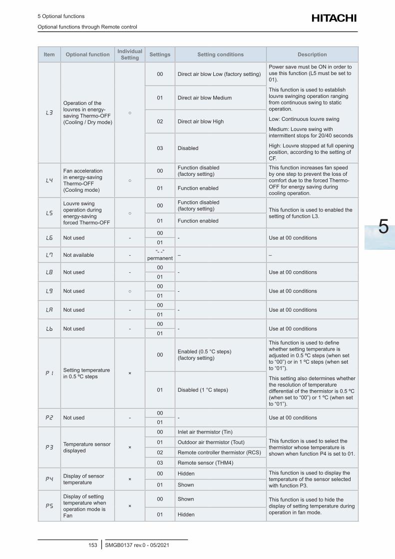
5 Optional functions
Optional functions through Remote control
SMGB0137 rev.0 - 05/2021153
5
Item Optional function Individual Setting Settings Setting conditions Description
L3
Operation of the louvres in energy-saving Thermo-OFF (Cooling / Dry mode)
00 Direct air blow Low (factory setting)Power save must be ON in order to use this function (L5 must be set to 01).
This function is used to establish louvre swinging operation ranging from continuous swing to static operation.
Low: Continuous louvre swing
Medium: Louvre swing with intermittent stops for 20/40 seconds
High: Louvre stopped at full opening position, according to the setting of CF.
01 Direct air blow Medium
02 Direct air blow High
03 Disabled
L4
Fan acceleration in energy-saving Thermo-OFF (Cooling mode)
00 Function disabled (factory setting)
This function increases fan speed by one step to prevent the loss of comfort due to the forced Thermo-OFF for energy saving during cooling operation.
01 Function enabled
L5
Louvre swing operation during energy-saving forced Thermo-OFF
00 Function disabled
(factory setting) This function is used to enabled the setting of function L3.
01 Function enabled
L6 Not used -00
- Use at 00 conditions01
L7 Not available - “- -” permanent – –
L8 Not used -00
- Use at 00 conditions01
Lg Not used 00
- Use at 00 conditions01
LA Not used -00
- Use at 00 conditions01
Lb Not used -00
- Use at 00 conditions01
P1Setting temperature in 0.5 ºC steps ×
00 Enabled (0.5 °C steps) (factory setting)
This function is used to define whether setting temperature is adjusted in 0.5 ºC steps (when set to “00”) or in 1 ºC steps (when set to “01”).
This setting also determines whether the resolution of temperature differential of the thermistor is 0.5 ºC (when set to “00”) or 1 ºC (when set to “01”).
01 Disabled (1 °C steps)
P2 Not used -00
- Use at 00 conditions01
P3Temperature sensor displayed ×
00 Inlet air thermistor (Tin)This function is used to select the thermistor whose temperature is shown when function P4 is set to 01.
01 Outdoor air thermistor (Tout)
02 Remote controller thermistor (RCS)
03 Remote sensor (THM4)
P4Display of sensor temperature ×
00 Hidden This function is used to display the temperature of the sensor selected with function P3.01 Shown
P5
Display of setting temperature when operation mode is Fan
×00 Shown This function is used to hide the
display of setting temperature during operation in fan mode.01 Hidden
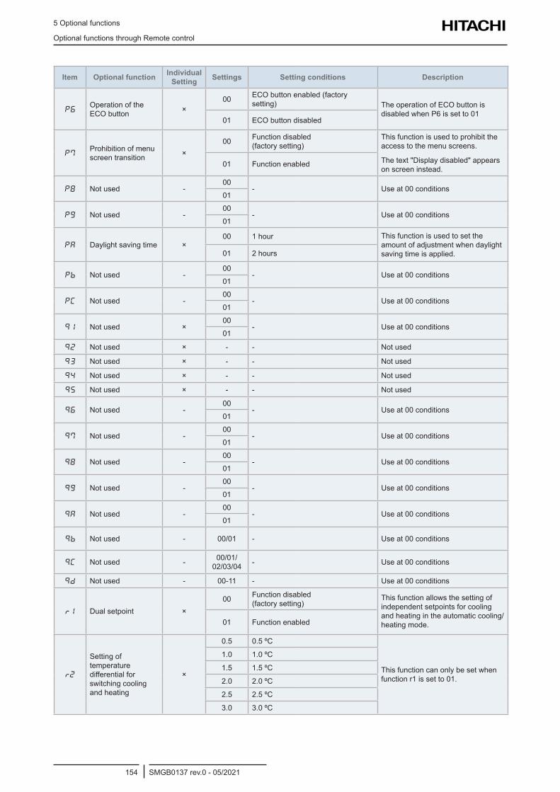
5 Optional functions
Optional functions through Remote control
SMGB0137 rev.0 - 05/2021154
Item Optional function Individual Setting Settings Setting conditions Description
P6Operation of the ECO button ×
00 ECO button enabled (factory setting) The operation of ECO button is
disabled when P6 is set to 0101 ECO button disabled
P7Prohibition of menu screen transition ×
00 Function disabled (factory setting)
This function is used to prohibit the access to the menu screens.
The text "Display disabled" appears on screen instead.
01 Function enabled
P8 Not used -00
- Use at 00 conditions01
Pg Not used -00
- Use at 00 conditions01
PA Daylight saving time ×00 1 hour This function is used to set the
amount of adjustment when daylight saving time is applied.01 2 hours
Pb Not used -00
- Use at 00 conditions01
PC Not used -00
- Use at 00 conditions01
91 Not used ×00
- Use at 00 conditions01
92 Not used × - - Not used
93 Not used × - - Not used
94 Not used × - - Not used
95 Not used × - - Not used
96 Not used -00
- Use at 00 conditions01
97 Not used -00
- Use at 00 conditions01
98 Not used -00
- Use at 00 conditions01
9g Not used -00
- Use at 00 conditions01
9A Not used -00
- Use at 00 conditions01
9b Not used - 00/01 - Use at 00 conditions
9C Not used - 00/01/ 02/03/04 - Use at 00 conditions
9d Not used - 00-11 - Use at 00 conditions
r1 Dual setpoint ×00 Function disabled
(factory setting)This function allows the setting of independent setpoints for cooling and heating in the automatic cooling/heating mode.01 Function enabled
r2
Setting of temperature differential for switching cooling and heating
×
0.5 0.5 ºC
This function can only be set when function r1 is set to 01.
1.0 1.0 ºC
1.5 1.5 ºC
2.0 2.0 ºC
2.5 2.5 ºC
3.0 3.0 ºC
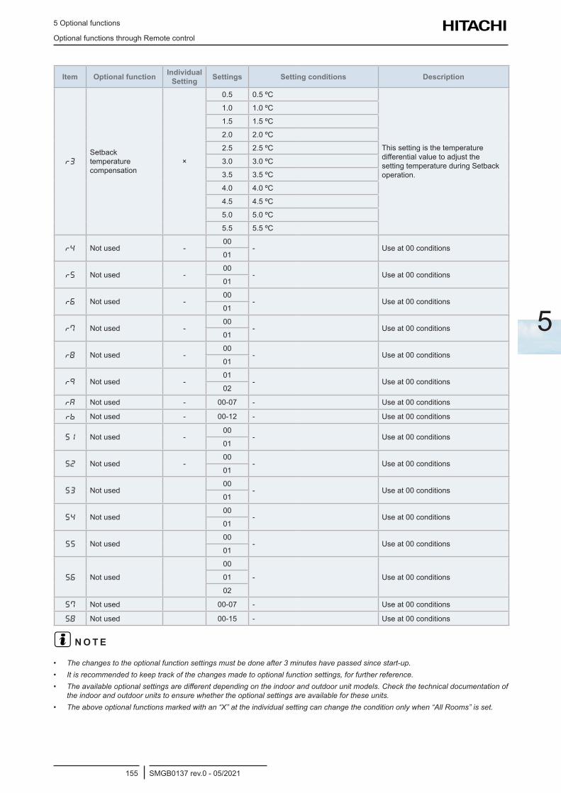
5 Optional functions
Optional functions through Remote control
SMGB0137 rev.0 - 05/2021155
5
Item Optional function Individual Setting Settings Setting conditions Description
r3
Setback temperature compensation
×
0.5 0.5 ºC
This setting is the temperature differential value to adjust the setting temperature during Setback operation.
1.0 1.0 ºC
1.5 1.5 ºC
2.0 2.0 ºC
2.5 2.5 ºC
3.0 3.0 ºC
3.5 3.5 ºC
4.0 4.0 ºC
4.5 4.5 ºC
5.0 5.0 ºC
5.5 5.5 ºC
r4 Not used -00
- Use at 00 conditions01
r5 Not used -00
- Use at 00 conditions01
r6 Not used -00
- Use at 00 conditions01
r7 Not used -00
- Use at 00 conditions01
r8 Not used -00
- Use at 00 conditions01
r9 Not used -01
- Use at 00 conditions02
rA Not used - 00-07 - Use at 00 conditions
rb Not used - 00-12 - Use at 00 conditions
S1 Not used -00
- Use at 00 conditions01
S2 Not used -00
- Use at 00 conditions01
S3 Not used00
- Use at 00 conditions01
S4 Not used00
- Use at 00 conditions01
S5 Not used00
- Use at 00 conditions01
S6 Not used
00
- Use at 00 conditions01
02
S7 Not used 00-07 - Use at 00 conditions
S8 Not used 00-15 - Use at 00 conditions
? N O T E
• The changes to the optional function settings must be done after 3 minutes have passed since start-up.• It is recommended to keep track of the changes made to optional function settings, for further reference.• The available optional settings are different depending on the indoor and outdoor unit models. Check the technical documentation of
the indoor and outdoor units to ensure whether the optional settings are available for these units.• The above optional functions marked with an “X” at the individual setting can change the condition only when “All Rooms” is set.
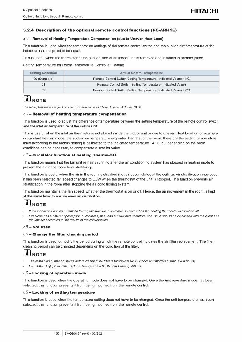
5 Optional functions
Optional functions through Remote control
SMGB0137 rev.0 - 05/2021156
5.2.4 Description of the optional remote control functions (PC-ARH1E)
b1 – Removal of Heating Temperature Compensation (due to Uneven Heat Load)
This function is used when the temperature settings of the remote control switch and the suction air temperature of the indoor unit are required to be equal.
This is useful when the thermistor at the suction side of an indoor unit is removed and installed in another place.
Setting Temperature for Room Temperature Control at Heating
Setting Condition Actual Control Temperature00 (Standard) Remote Control Switch Setting Temperature (Indicated Value) +4ºC
01 Remote Control Switch Setting Temperature (Indicated Value)
02 Remote Control Switch Setting Temperature (Indicated Value) +2ºC
? N O T EThe setting temperature upper limit after compensation is as follows: Inverter Multi Unit: 34 ºC
b1 – Removal of heating temperature compensation
This function is used to adjust the difference of temperature between the setting temperature of the remote control switch and the inlet air temperature of the indoor unit.
This is useful when the inlet air thermistor is not placed inside the indoor unit or due to uneven Heat Load or for example in standard heating mode, the suction air temperature is greater than that of the room, therefore the setting temperature used according to the factory setting is calibrated to the indicated temperature +4 °C, but depending on the room conditions can be necessary to compensate a smaller value.
b2 – Circulator function at heating Thermo-OFF
This function means that the fan unit remains running after the air conditioning system has stopped in heating mode to prevent the air in the room from stratifying.
This function is useful when the air in the room is stratified (hot air accumulates at the ceiling). Air stratification may occur if has been selected fan speed changes to LOW when the thermostat of the unit is stopped. This function prevents air stratification in the room after stopping the air conditioning system.
This function maintains the fan speed, whether the thermostat is on or off. Hence, the air movement in the room is kept at the same level to ensure even air distribution.
? N O T E• If the indoor unit has an automatic louver, this function also remains active when the heating thermostat is switched off.• Everyone has a different perception of coolness, heat and air flow and, therefore, this issue should be discussed with the client and
the unit set according to the results of the conversation.
b3 – Not used
b4 – Change the filter cleaning period
This function is used to modify the period during which the remote control indicates the air filter replacement. The filter cleaning period can be changed depending on the condition of the filter.
? N O T E• The remaining number of hours before cleaning the filter is factory-set for all indoor unit models b2=02 (1200 hours).• For RPK-FSR(H)M models Factory-Setting is b4=00: Standard setting 200 hrs.
b5 – Locking of operation mode
This function is used when the operating mode does not have to be changed. Once the unit operating mode has been selected, this function prevents it from being modified from the remote control.
b6 – Locking of setting temperature
This function is used when the temperature setting does not have to be changed. Once the unit temperature has been selected, this function prevents it from being modified from the remote control.
5 Optional functions
Optional functions through Remote control
SMGB0137 rev.0 - 05/2021157
5
b7 – Setting operation mode as cooling only
This function is available to use refrigeration mode only and to prevent heating mode from being enabled. When this function is selected, heating operation and the automatic COOL/HEAT operation are cancelled.
b8 – Automatic COOL/HEAT operation
This function allows the automatic change from the cooling to the heating mode for the units with the same refrigerant cycle.
? N O T EThis function is not valid when the outdoor unit is an exclusive cooling model or when the function to set operations as an exclusive cooling unit is enabled.
bg – Locking of fan speed
Once the unit fan speed has been selected, this function prevents it from being modified from the remote control.
? N O T EWhen this function is enabled, the fan speed cannot be changed using the remote control.
bA – Not available
bb – Cooling setting temperature correction
This function decrease the temperature and it is used to obtain longer cooling periods. When this function is enabled, the air conditioning system is switched on/off with the temperature condition below the temperature indicated on the remote control.
? N O T EThe lower set temperature limit after offset is 19ºC.
bC – Not used
bd – Not used
bE – Not used
C1 – Not used
C2 – Not available
C3 – Not used
C4 – Not used
C5 – Increasing fan speed / Static pressure selection
This function is used to change the indoor units fan speed installed in high ceilings.
For RPI units this function is used to change the static pressure from the remote control.
C6 – Increasing speed at heating Thermo-OFF
This function is used to increase the fan speed when the thermostat reaches the set temperature in heating using function C5.
? N O T EThe fan speed does not increase when the thermostat is switched off with the function setting (C5).
C7 – Cancellation of the forced compressor operation for at least 3 minutes
This function is available when b3 (Forced compressor operation for at least three minutes through C7 setting) is set 00 (C7 setting possible).
This function allows that the compressor are not forced 3 minutes operation.
? N O T EIn the case of SET FREE units, the forced compressor operation for at least 3 minutes fixed as a standard function.
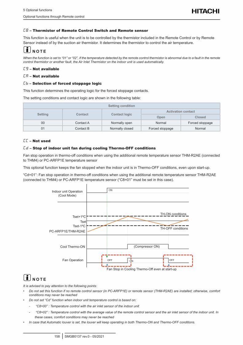
5 Optional functions
Optional functions through Remote control
SMGB0137 rev.0 - 05/2021158
C8 – Thermistor of Remote Control Switch and Remote sensor
This function is useful when the unit is to be controlled by the thermistor included in the Remote Control or by Remote Sensor instead of by the suction air thermistor. It determines the thermistor to control the air temperature.
? N O T EWhen the function is set to “01” or “02”, if the temperature detected by the remote control thermistor is abnormal due to a fault in the remote control thermistor or another fault, the Air Inlet Thermistor on the indoor unit is used automatically.
Cg – Not available
CA – Not available
Cb – Selection of forced stoppage logic
This function determines the operating logic for the forced stoppage contacts.
The setting conditions and contact logic are shown in the following table:
Setting condition
Setting Contact Contact logicActivation contact
Open Closed00 Contact A Normally open Normal Forced stoppage
01 Contact B Normally closed Forced stoppage Normal
CC – Not used
Cd – Stop of indoor unit fan during cooling Thermo-OFF conditions
Fan stop operation in thermo-off conditions when using the additional remote temperature sensor THM-R2AE (connected to THM4) or PC-ARFP1E temperature sensor
This optional function keeps the fan stopped when the indoor unit is in Thermo-OFF conditions, even upon start-up.
“Cd=01”: Fan stop operation in thermo-off conditions when using the additional remote temperature sensor THM-R2AE (connected to THM4) or PC-ARFP1E temperature sensor (“C8=01” must be set in this case).
Indoor unit Operation (Cool Mode)
Tset+1ºC
Tset-1ºCPC-ARFP1E/THM-R2AE
Cool Thermo-ON
Fan Operation
Fan Stop in Cooling Thermo-Off even at start-up
(Compressor ON)
TH-ON conditions
TH-OFF conditions
OFF OFFON
Tset
ON
? N O T EIt is advised to pay attention to the following points:• Do not set this function if no remote control sensor (in PC-ARFP1E) or remote sensor (THM-R2AE) are installed; otherwise, comfort
conditions may never be reached• Do not set “Cd” function when indoor unit temperature control is based on:
- “C8=00” : Temperature control with the air inlet sensor of the indoor unit
- “C8=02” : Temperature control with the average value of the remote control sensor and the air inlet sensor of the indoor unit. In these cases, comfort conditions may never be reached
• In case that Automatic louver is set, the louver will keep operating in both Thermo-ON and Thermo-OFF conditions.
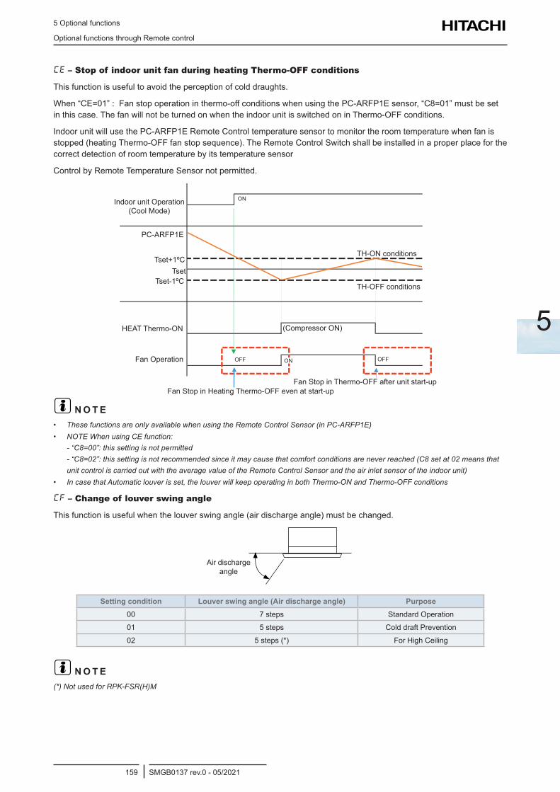
5 Optional functions
Optional functions through Remote control
SMGB0137 rev.0 - 05/2021159
5
CE – Stop of indoor unit fan during heating Thermo-OFF conditions
This function is useful to avoid the perception of cold draughts.
When “CE=01” : Fan stop operation in thermo-off conditions when using the PC-ARFP1E sensor, “C8=01” must be set in this case. The fan will not be turned on when the indoor unit is switched on in Thermo-OFF conditions.
Indoor unit will use the PC-ARFP1E Remote Control temperature sensor to monitor the room temperature when fan is stopped (heating Thermo-OFF fan stop sequence). The Remote Control Switch shall be installed in a proper place for the correct detection of room temperature by its temperature sensor
Control by Remote Temperature Sensor not permitted.
Indoor unit Operation (Cool Mode)
Tset+1ºC
Tset-1ºC
PC-ARFP1E
HEAT Thermo-ON
Fan Operation
Fan Stop in Heating Thermo-OFF even at start-up
(Compressor ON)
TH-ON conditions
TH-OFF conditions
OFF OFFON
Tset
ON
Fan Stop in Thermo-OFF after unit start-up
? N O T E• These functions are only available when using the Remote Control Sensor (in PC-ARFP1E)• NOTE When using CE function:
- “C8=00”: this setting is not permitted - “C8=02”: this setting is not recommended since it may cause that comfort conditions are never reached (C8 set at 02 means that unit control is carried out with the average value of the Remote Control Sensor and the air inlet sensor of the indoor unit)
• In case that Automatic louver is set, the louver will keep operating in both Thermo-ON and Thermo-OFF conditions
CF – Change of louver swing angle
This function is useful when the louver swing angle (air discharge angle) must be changed.
Air discharge angle
Setting condition Louver swing angle (Air discharge angle) Purpose00 7 steps Standard Operation
01 5 steps Cold draft Prevention
02 5 steps (*) For High Ceiling
? N O T E(*) Not used for RPK-FSR(H)M
5 Optional functions
Optional functions through Remote control
SMGB0137 rev.0 - 05/2021160
d1 – Power supply ON/OFF 1 (Automatic Operation when Power Supply is ON)
This function stores the unit settings in the event of a power cut. The unit is restarted when the power is re-established.
? C A U T I O NWhen this function is used without anyone controlling the unit, set the system monitoring mode to avoid risks.
? N O T EIn the event of an electrical fault, the unit starts and stops according to the on/off setting of the power supply. If the fault occurs during a stoppage enabled through the remote control, the unit will restart automatically once the power supply is reconnected.
d2 – Not available
d3 – Power supply ON/OFF 2 (Restarting Function After Power Failure)
This function is used to restart the unit after a power cut taking more than 2 seconds. The standard unit starts automatically under the same operating conditions, such as the operating mode, etc. in the case of an electrical fault lasting for a maximum of 2 seconds.
The compressor unit restarts after 3 minutes plus the maximum 2 seconds of the fault.
? C A U T I O NWhen this function is used without anyone controlling the unit, set the system monitoring mode to avoid risks.
d4 – Not used
d5 – Prevention of decrease of heating discharge air temperature
This function prevents a drop in the air temperature by decreasing the fan speed, apart from the settings on the remote control.
d6 – Not used
d7 – Not used
E1 – Not used
E2 – Not used
E3 – Not used
E4 – Not used
E5 – Not used
E6 – Indoor fan operation time after cooling operation stoppage
This functions prevents the condensation accumulation in the unit by keeping the fan running after it is switched off.
E7 – Not used
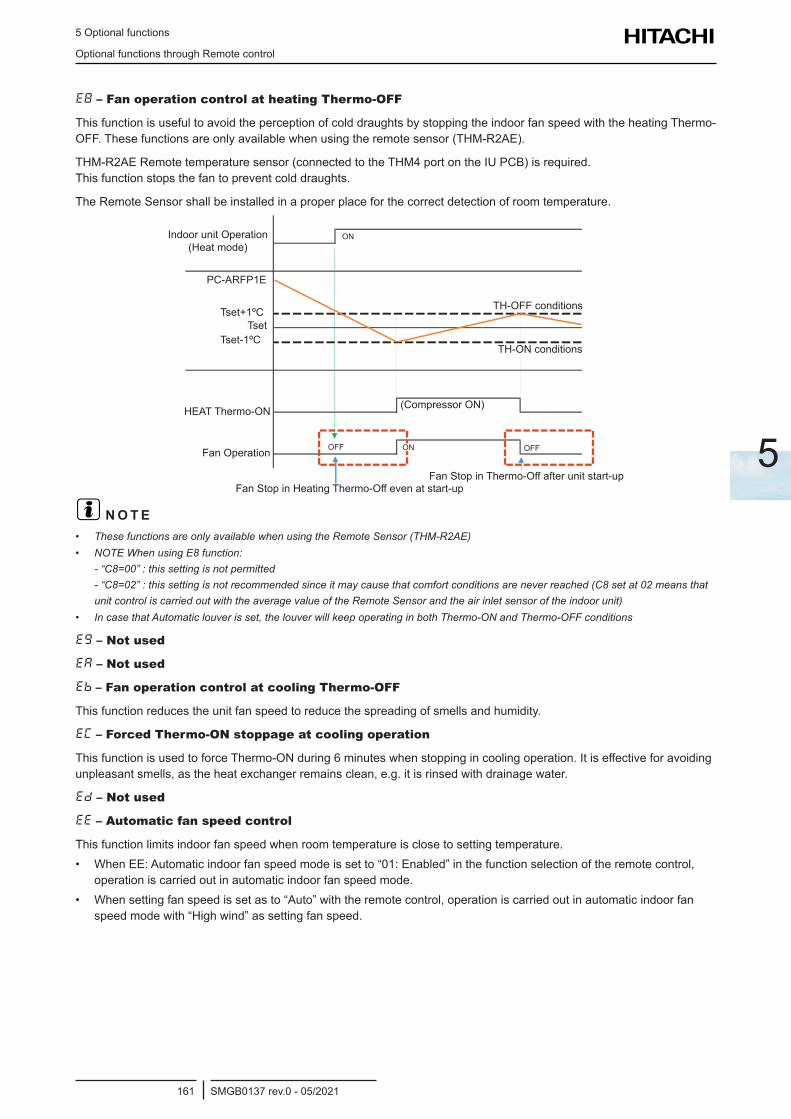
5 Optional functions
Optional functions through Remote control
SMGB0137 rev.0 - 05/2021161
5
E8 – Fan operation control at heating Thermo-OFF
This function is useful to avoid the perception of cold draughts by stopping the indoor fan speed with the heating Thermo-OFF. These functions are only available when using the remote sensor (THM-R2AE).
THM-R2AE Remote temperature sensor (connected to the THM4 port on the IU PCB) is required. This function stops the fan to prevent cold draughts.
The Remote Sensor shall be installed in a proper place for the correct detection of room temperature.
Indoor unit Operation (Heat mode)
PC-ARFP1E
Tset+1ºC
Tset-1ºC
HEAT Thermo-ON
TH-OFF conditions
TH-ON conditions
(Compressor ON)
OFFOFF ONFan Operation
Fan Stop in Heating Thermo-Off even at start-upFan Stop in Thermo-Off after unit start-up
Tset
ON
? N O T E• These functions are only available when using the Remote Sensor (THM-R2AE)• NOTE When using E8 function:
- “C8=00” : this setting is not permitted - “C8=02” : this setting is not recommended since it may cause that comfort conditions are never reached (C8 set at 02 means that unit control is carried out with the average value of the Remote Sensor and the air inlet sensor of the indoor unit)
• In case that Automatic louver is set, the louver will keep operating in both Thermo-ON and Thermo-OFF conditions
Eg – Not used
EA – Not used
Eb – Fan operation control at cooling Thermo-OFF
This function reduces the unit fan speed to reduce the spreading of smells and humidity.
EC – Forced Thermo-ON stoppage at cooling operation
This function is used to force Thermo-ON during 6 minutes when stopping in cooling operation. It is effective for avoiding unpleasant smells, as the heat exchanger remains clean, e.g. it is rinsed with drainage water.
Ed – Not used
EE – Automatic fan speed control
This function limits indoor fan speed when room temperature is close to setting temperature.• When EE: Automatic indoor fan speed mode is set to “01: Enabled” in the function selection of the remote control,
operation is carried out in automatic indoor fan speed mode.• When setting fan speed is set as to “Auto” with the remote control, operation is carried out in automatic indoor fan
speed mode with “High wind” as setting fan speed.
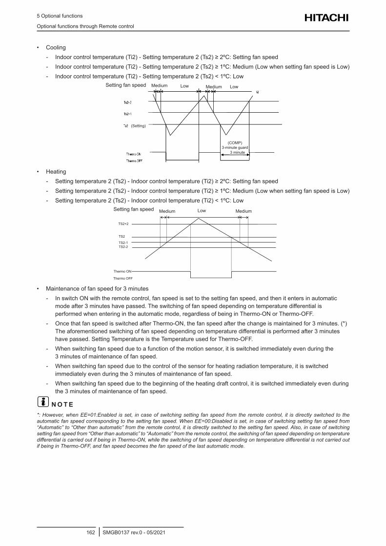
5 Optional functions
Optional functions through Remote control
SMGB0137 rev.0 - 05/2021162
• Cooling - Indoor control temperature (Ti2) - Setting temperature 2 (Ts2) ≥ 2ºC: Setting fan speed - Indoor control temperature (Ti2) - Setting temperature 2 (Ts2) ≥ 1ºC: Medium (Low when setting fan speed is Low) - Indoor control temperature (Ti2) - Setting temperature 2 (Ts2) < 1ºC: Low
Setting fan speed Medium Low Medium Low
(COMP) 3-minute guard
3 minute
(Setting)
• Heating - Setting temperature 2 (Ts2) - Indoor control temperature (Ti2) ≥ 2ºC: Setting fan speed - Setting temperature 2 (Ts2) - Indoor control temperature (Ti2) ≥ 1ºC: Medium (Low when setting fan speed is Low) - Setting temperature 2 (Ts2) - Indoor control temperature (Ti2) < 1ºC: Low
TS2+2
TS2-1TS2-2
Thermo ON
Thermo OFF
TS2
Setting fan speed Low MediumMedium
• Maintenance of fan speed for 3 minutes - In switch ON with the remote control, fan speed is set to the setting fan speed, and then it enters in automatic
mode after 3 minutes have passed. The switching of fan speed depending on temperature differential is performed when entering in the automatic mode, regardless of being in Thermo-ON or Thermo-OFF.
- Once that fan speed is switched after Thermo-ON, the fan speed after the change is maintained for 3 minutes. (*) The aforementioned switching of fan speed depending on temperature differential is performed after 3 minutes have passed. Setting Temperature is the Temperature used for Thermo-OFF.
- When switching fan speed due to a function of the motion sensor, it is switched immediately even during the 3 minutes of maintenance of fan speed.
- When switching fan speed due to the control of the sensor for heating radiation temperature, it is switched immediately even during the 3 minutes of maintenance of fan speed.
- When switching fan speed due to the beginning of the heating draft control, it is switched immediately even during the 3 minutes of maintenance of fan speed.
? N O T E*: However, when EE=01:Enabled is set, in case of switching setting fan speed from the remote control, it is directly switched to the automatic fan speed corresponding to the setting fan speed. When EE=00:Disabled is set, in case of switching setting fan speed from “Automatic” to “Other than automatic” from the remote control, it is directly switched to the setting fan speed. Also, in case of switching setting fan speed from “Other than automatic” to “Automatic” from the remote control, the switching of fan speed depending on temperature differential is carried out if being in Thermo-ON, while the switching of fan speed depending on temperature differential is not carried out if being in Thermo-OFF, and fan speed becomes the fan speed of the last automatic mode.
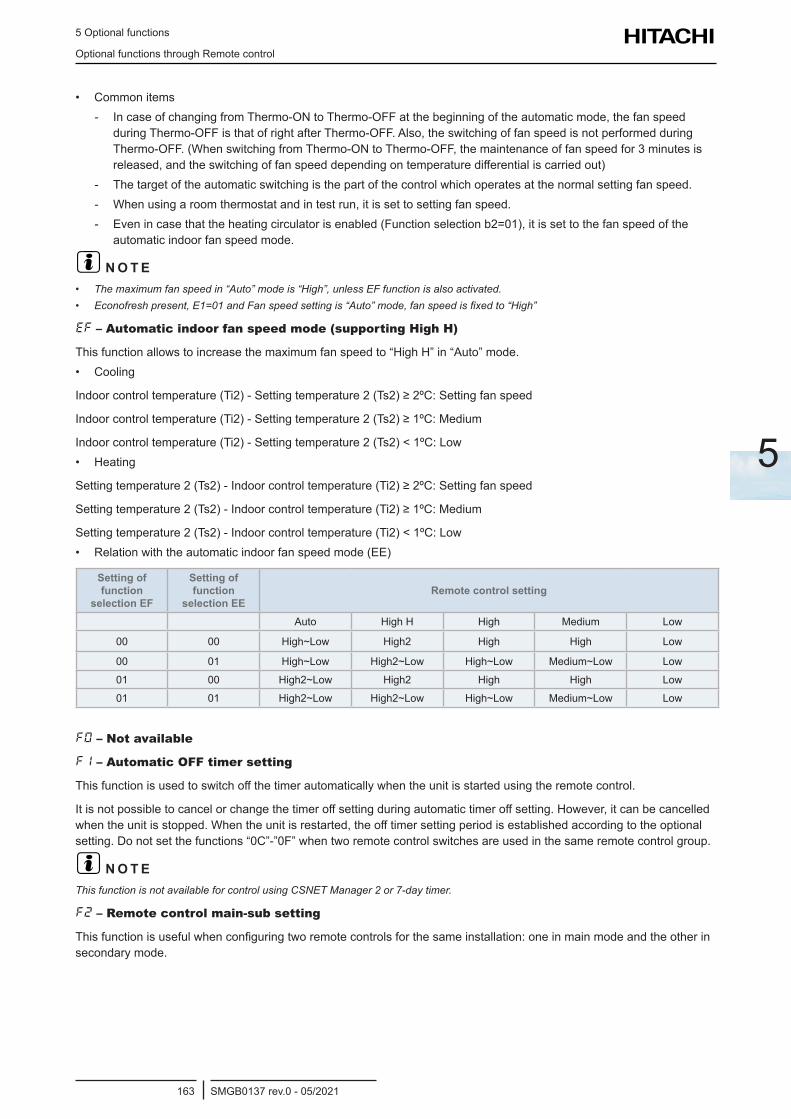
5 Optional functions
Optional functions through Remote control
SMGB0137 rev.0 - 05/2021163
5
• Common items - In case of changing from Thermo-ON to Thermo-OFF at the beginning of the automatic mode, the fan speed
during Thermo-OFF is that of right after Thermo-OFF. Also, the switching of fan speed is not performed during Thermo-OFF. (When switching from Thermo-ON to Thermo-OFF, the maintenance of fan speed for 3 minutes is released, and the switching of fan speed depending on temperature differential is carried out)
- The target of the automatic switching is the part of the control which operates at the normal setting fan speed. - When using a room thermostat and in test run, it is set to setting fan speed. - Even in case that the heating circulator is enabled (Function selection b2=01), it is set to the fan speed of the
automatic indoor fan speed mode.
? N O T E• The maximum fan speed in “Auto” mode is “High”, unless EF function is also activated.• Econofresh present, E1=01 and Fan speed setting is “Auto” mode, fan speed is fixed to “High”
EF – Automatic indoor fan speed mode (supporting High H)
This function allows to increase the maximum fan speed to “High H” in “Auto” mode. • Cooling
Indoor control temperature (Ti2) - Setting temperature 2 (Ts2) ≥ 2ºC: Setting fan speed
Indoor control temperature (Ti2) - Setting temperature 2 (Ts2) ≥ 1ºC: Medium
Indoor control temperature (Ti2) - Setting temperature 2 (Ts2) < 1ºC: Low• Heating
Setting temperature 2 (Ts2) - Indoor control temperature (Ti2) ≥ 2ºC: Setting fan speed
Setting temperature 2 (Ts2) - Indoor control temperature (Ti2) ≥ 1ºC: Medium
Setting temperature 2 (Ts2) - Indoor control temperature (Ti2) < 1ºC: Low• Relation with the automatic indoor fan speed mode (EE)
Setting of function
selection EF
Setting of function
selection EERemote control setting
Auto High H High Medium Low
00 00 High~Low High2 High High Low
00 01 High~Low High2~Low High~Low Medium~Low Low
01 00 High2~Low High2 High High Low
01 01 High2~Low High2~Low High~Low Medium~Low Low
F0 – Not available
F1 – Automatic OFF timer setting
This function is used to switch off the timer automatically when the unit is started using the remote control.
It is not possible to cancel or change the timer off setting during automatic timer off setting. However, it can be cancelled when the unit is stopped. When the unit is restarted, the off timer setting period is established according to the optional setting. Do not set the functions “0C”-”0F” when two remote control switches are used in the same remote control group.
? N O T EThis function is not available for control using CSNET Manager 2 or 7-day timer.
F2 – Remote control main-sub setting
This function is useful when configuring two remote controls for the same installation: one in main mode and the other in secondary mode.
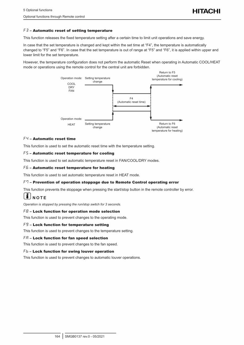
5 Optional functions
Optional functions through Remote control
SMGB0137 rev.0 - 05/2021164
F3 – Automatic reset of setting temperature
This function releases the fixed temperature setting after a certain time to limit unit operations and save energy.
In case that the set temperature is changed and kept within the set time at “F4”, the temperature is automatically changed to “F5” and “F6”. In case that the set temperature is out of range at “F5” and “F6”, it is applied within upper and lower limit for the set temperature.
However, the temperature configuration does not perform the automatic Reset when operating in Automatic COOL/HEAT mode or operations using the remote control for the central unit are forbidden.
Setting temperature change
Setting temperature change
Return to F5 (Automatic reset
temperature for cooling)
Return to F6 (Automatic reset
temperature for heating)
F4 (Automatic reset time)
Operation mode:
COOL DRY FAN
Operation mode:
HEAT
F4 – Automatic reset time
This function is used to set the automatic reset time with the temperature setting.
F5 – Automatic reset temperature for cooling
This function is used to set automatic temperature reset in FAN/COOL/DRY modes.
F6 – Automatic reset temperature for heating
This function is used to set automatic temperature reset in HEAT mode.
F7 – Prevention of operation stoppage due to Remote Control operating error
This function prevents the stoppage when pressing the start/stop button in the remote controller by error.
? N O T EOperation is stopped by pressing the run/stop switch for 3 seconds.
F8 – Lock function for operation mode selectionThis function is used to prevent changes to the operating mode.
Fg – Lock function for temperature settingThis function is used to prevent changes to the temperature setting.
FA – Lock function for fan speed selectionThis function is used to prevent changes to the fan speed.
Fb – Lock function for swing louver operationThis function is used to prevent changes to automatic louver operations.
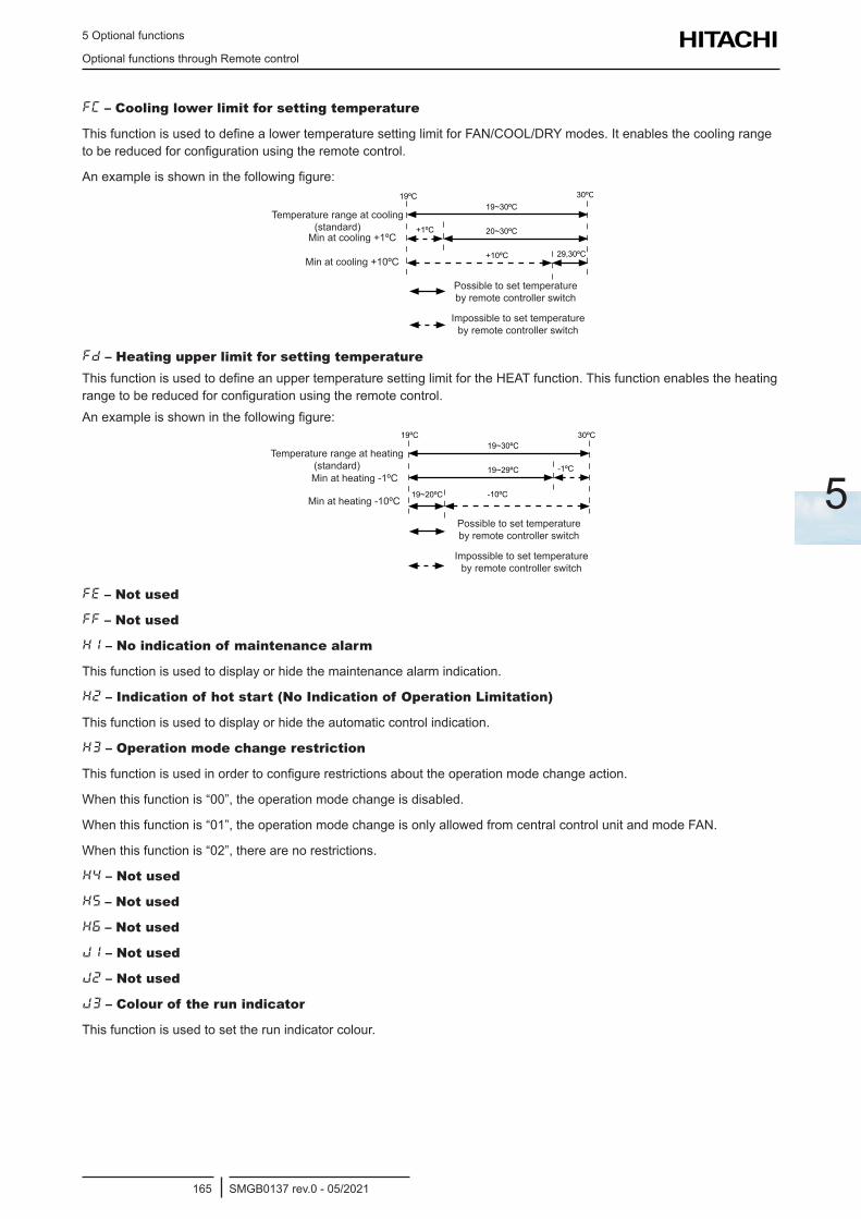
5 Optional functions
Optional functions through Remote control
SMGB0137 rev.0 - 05/2021165
5
FC – Cooling lower limit for setting temperature
This function is used to define a lower temperature setting limit for FAN/COOL/DRY modes. It enables the cooling range to be reduced for configuration using the remote control.
An example is shown in the following figure:
Temperature range at cooling (standard)
Min at cooling +1ºC
Min at cooling +10ºC
Possible to set temperature by remote controller switch
Impossible to set temperature by remote controller switch
Fd – Heating upper limit for setting temperatureThis function is used to define an upper temperature setting limit for the HEAT function. This function enables the heating range to be reduced for configuration using the remote control.An example is shown in the following figure:
Temperature range at heating (standard)Min at heating -1ºC
Min at heating -10ºC
Possible to set temperature by remote controller switch
Impossible to set temperature by remote controller switch
FE – Not used
FF – Not used
H1 – No indication of maintenance alarm
This function is used to display or hide the maintenance alarm indication.
H2 – Indication of hot start (No Indication of Operation Limitation)
This function is used to display or hide the automatic control indication.
H3 – Operation mode change restriction
This function is used in order to configure restrictions about the operation mode change action.
When this function is “00”, the operation mode change is disabled.
When this function is “01”, the operation mode change is only allowed from central control unit and mode FAN.
When this function is “02”, there are no restrictions.
H4 – Not used
H5 – Not used
H6 – Not used
J1 – Not used
J2 – Not used
J3 – Colour of the run indicator
This function is used to set the run indicator colour.
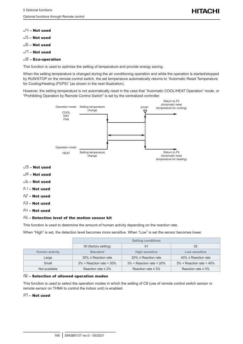
5 Optional functions
Optional functions through Remote control
SMGB0137 rev.0 - 05/2021166
J4 – Not used
J5 – Not used
J6 – Not used
J7 – Not used
J8 – Eco-operation
This function is used to optimise the setting of temperature and provide energy saving.
When the setting temperature is changed during the air conditioning operation and while the operation is started/stopped by RUN/STOP on the remote control switch, the set temperature automatically returns to “Automatic Reset Temperature for Cooling/Heating (F5/F6)” (as shown in the next illustration).
However, the setting temperature is not automatically reset in the case that “Automatic COOL/HEAT Operation” mode, or “Prohibiting Operation by Remote Control Switch” is set by the centralized controller.
Setting temperature change
Setting temperature change
Return to F5 (Automatic reset
temperature for cooling)
Return to F6 (Automatic reset
temperature for heating)
Operation mode:
COOL DRY FAN
Operation mode:
HEAT
STOP
Jg – Not used
JA – Not used
Jb – Not used
k1 – Not used
k2 – Not used
k3 – Not used
k4 – Not used
k5 – Detection level of the motion sensor kit
This function is used to determine the amount of human activity depending on the reaction rate.
When “High” is set, the detection level becomes more sensitive. When “Low” is set the sensor becomes lower.
Setting conditions00 (factory setting) 01 02
Human activity Standard High sensitive Low sensitiveLarge 30% ≤ Reaction rate 20% ≤ Reaction rate 40% ≤ Reaction rate
Small 3% < Reaction rate < 30% 3% < Reaction rate < 20% 3% < Reaction rate < 40%
Not available Reaction rate ≤ 3% Reaction rate ≤ 3% Reaction rate ≤ 3%
k6 – Selection of allowed operation modes
This function is used to select the operation modes in which the setting of C8 (use of remote control switch sensor or remote sensor on THM4 to control the indoor unit) is enabled.
k7 – Not used
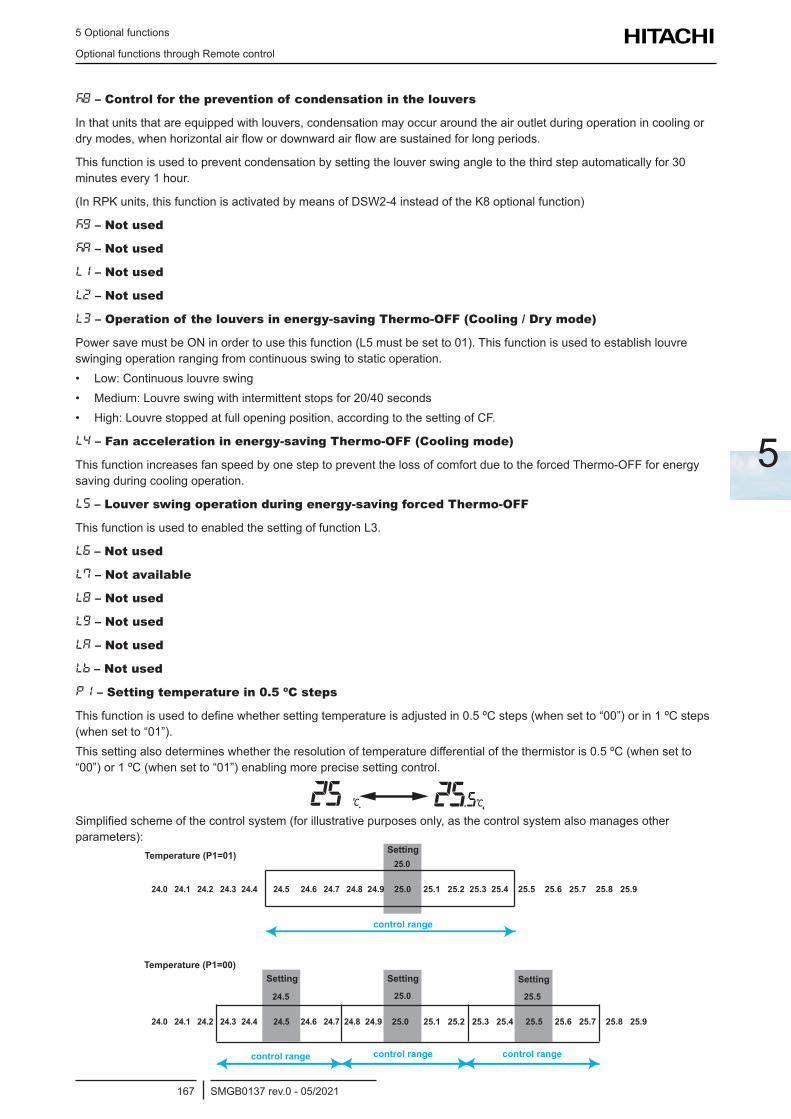
5 Optional functions
Optional functions through Remote control
SMGB0137 rev.0 - 05/2021167
5
k8 – Control for the prevention of condensation in the louvers
In that units that are equipped with louvers, condensation may occur around the air outlet during operation in cooling or dry modes, when horizontal air flow or downward air flow are sustained for long periods.
This function is used to prevent condensation by setting the louver swing angle to the third step automatically for 30 minutes every 1 hour.
(In RPK units, this function is activated by means of DSW2-4 instead of the K8 optional function)
kg – Not used
kA – Not used
L1 – Not used
L2 – Not used
L3 – Operation of the louvers in energy-saving Thermo-OFF (Cooling / Dry mode)
Power save must be ON in order to use this function (L5 must be set to 01). This function is used to establish louvre swinging operation ranging from continuous swing to static operation.• Low: Continuous louvre swing• Medium: Louvre swing with intermittent stops for 20/40 seconds• High: Louvre stopped at full opening position, according to the setting of CF.
L4 – Fan acceleration in energy-saving Thermo-OFF (Cooling mode)
This function increases fan speed by one step to prevent the loss of comfort due to the forced Thermo-OFF for energy saving during cooling operation.
L5 – Louver swing operation during energy-saving forced Thermo-OFF
This function is used to enabled the setting of function L3.
L6 – Not used
L7 – Not available
L8 – Not used
Lg – Not used
LA – Not used
Lb – Not used
P1 – Setting temperature in 0.5 ºC steps
This function is used to define whether setting temperature is adjusted in 0.5 ºC steps (when set to “00”) or in 1 ºC steps (when set to “01”).This setting also determines whether the resolution of temperature differential of the thermistor is 0.5 ºC (when set to “00”) or 1 ºC (when set to “01”) enabling more precise setting control.
Simplified scheme of the control system (for illustrative purposes only, as the control system also manages other parameters):
24.0 24.1 24.2 24.3 24.4 24.5 24.6 24.7 24.8 24.9 25.0 25.1 25.2 25.3 25.4 25.5 25.6 25.7 25.8 25.9
24.0 24.1 24.2 24.3 24.4 24.5 24.6 24.7 24.8 24.9 25.0 25.1 25.2 25.3 25.4 25.5 25.6 25.7 25.8 25.9
25.0
25.0 24.5 25.5
Setting
SettingSettingSetting
control range control range control range
control range
Temperature (P1=01)
Temperature (P1=00)
5 Optional functions
Optional functions through Remote control
SMGB0137 rev.0 - 05/2021168
P2 – Not used
P3 – Temperature sensor displayed
This function is used to select the thermistor whose temperature is shown.
P4 – Display of sensor temperature
This function is used to display the temperature of the sensor selected with P3.
P5 – Display of setting temperature when operation mode is Fan
This function is used to hide the display of setting temperature during operation in fan mode.
P6 – Operation of the ECO button
The Operation of ECO button is disabled when P6 is set to 01.
P7 – Prohibition of menu screen transition
This function is used to prohibit the access to the menu screens. The text “Display disabled” appears on screen instead.
PA – Daylight saving time
This function is used to set the amount of adjustment when daylight saving time is applied.
Pb – Not used
PC – Not used
91 – Not used
92 – Not used
93 – Not used
94 – Not used
95 – Not used
96 – Not used
97 – Not used
98 – Not used
9g – Not used
9A – Not used
9b – Not used
9C – Not used
9d – Not used
9e – Not used
9F – Not used
r1 – Dual set point
Function in the automatic cooling/heating mode allowing the preset of respective setpoint for cooling and heating.
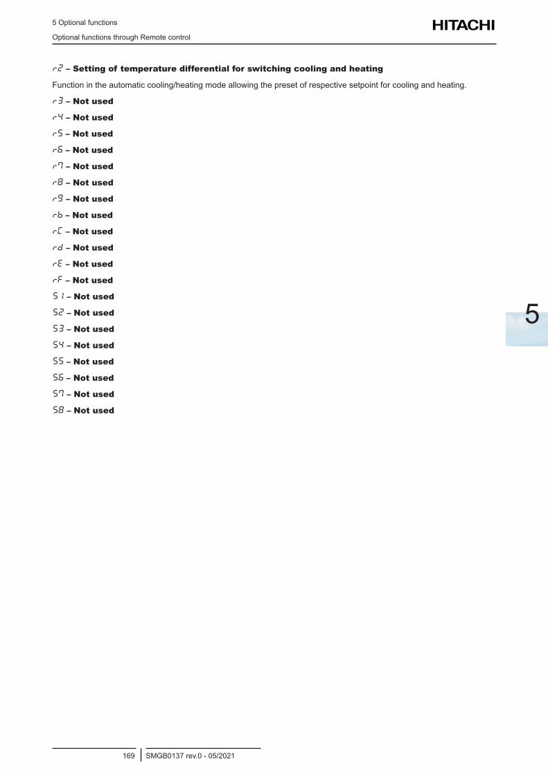
5 Optional functions
Optional functions through Remote control
SMGB0137 rev.0 - 05/2021169
5
r2 – Setting of temperature differential for switching cooling and heating
Function in the automatic cooling/heating mode allowing the preset of respective setpoint for cooling and heating.
r3 – Not used
r4 – Not used
r5 – Not used
r6 – Not used
r7 – Not used
r8 – Not used
rg – Not used
rb – Not used
rC – Not used
rd – Not used
re – Not used
rf – Not used
s1 – Not used
s2 – Not used
s3 – Not used
s4 – Not used
s5 – Not used
s6 – Not used
s7 – Not used
s8 – Not used
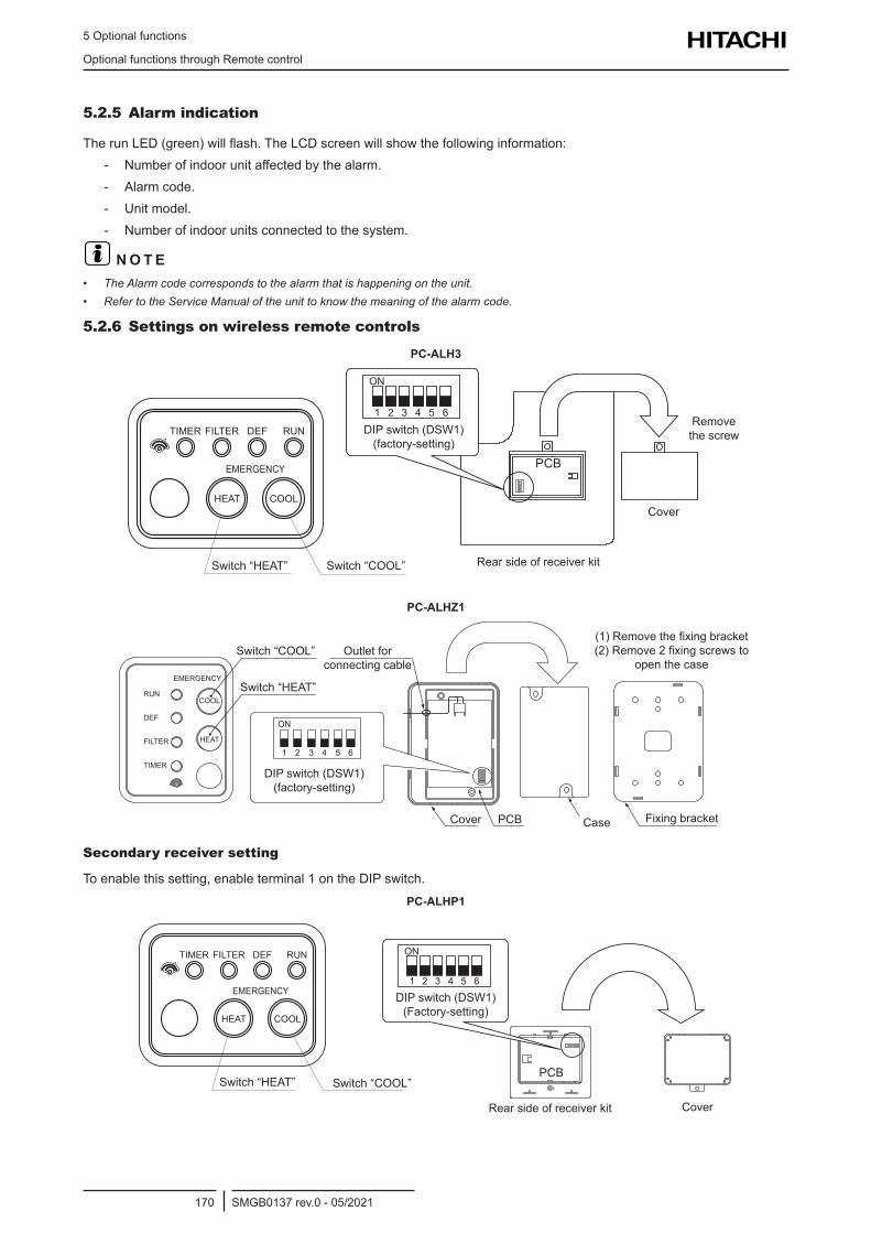
5 Optional functions
Optional functions through Remote control
SMGB0137 rev.0 - 05/2021170
5.2.5 Alarm indication
The run LED (green) will flash. The LCD screen will show the following information: - Number of indoor unit affected by the alarm. - Alarm code. - Unit model. - Number of indoor units connected to the system.
? N O T E• The Alarm code corresponds to the alarm that is happening on the unit. • Refer to the Service Manual of the unit to know the meaning of the alarm code.
5.2.6 Settings on wireless remote controls
PC-ALH3
Switch “HEAT” Switch “COOL”
DIP switch (DSW1) (factory-setting)
Rear side of receiver kit
Cover
Remove the screw
PC-ALHZ1
Switch “HEAT”
Switch “COOL”
DIP switch (DSW1) (factory-setting)
Outlet for connecting cable
Cover
(1) Remove the fixing bracket (2) Remove 2 fixing screws to
open the case
PCB Fixing bracketCase
Secondary receiver setting
To enable this setting, enable terminal 1 on the DIP switch.PC-ALHP1PC-ALHP1
DIP switch (DSW1) (Factory-setting)
Switch “HEAT” Switch “COOL”
Rear side of receiver kit Cover
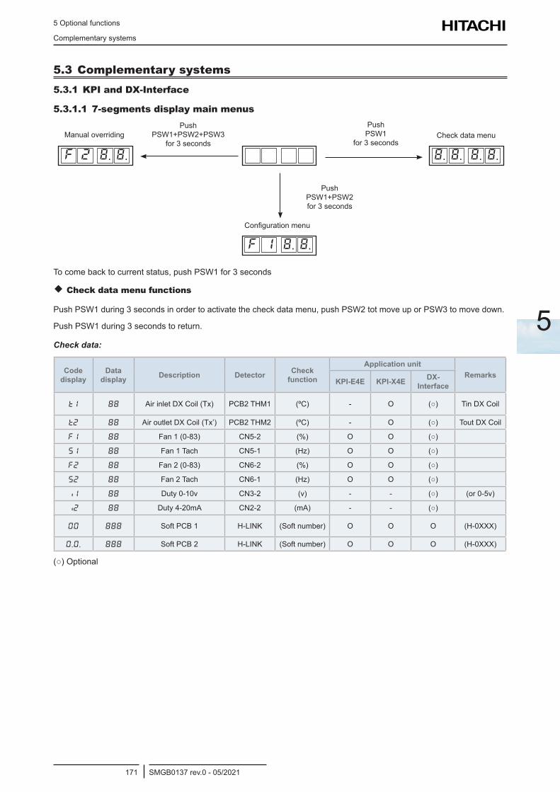
5 Optional functions
Complementary systems
SMGB0137 rev.0 - 05/2021171
5
5.3 Complementary systems5.3.1 KPI and DX-Interface
5.3.1.1 7-segments display main menus
F 2 8. 8.
F 1 8. 8.
8. 8. 8. 8.
Manual overriding Check data menu
Configuration menu
Push PSW1+PSW2+PSW3
for 3 seconds
Push PSW1
for 3 seconds
Push PSW1+PSW2 for 3 seconds
To come back to current status, push PSW1 for 3 seconds
Check data menu functions
Push PSW1 during 3 seconds in order to activate the check data menu, push PSW2 tot move up or PSW3 to move down.
Push PSW1 during 3 seconds to return.
Check data:
Code display
Data display Description Detector Check
function
Application unitRemarks
KPI-E4E KPI-X4E DX-Interface
t1 Air inlet DX Coil (Tx) PCB2 THM1 (ºC) - O () Tin DX Coil
t2 Air outlet DX Coil (Tx’) PCB2 THM2 (ºC) - O () Tout DX Coil
F1 Fan 1 (0-83) CN5-2 (%) O O ()
s1 Fan 1 Tach CN5-1 (Hz) O O ()
f2 88 Fan 2 (0-83) CN6-2 (%) O O ()
s2 Fan 2 Tach CN6-1 (Hz) O O ()
1 Duty 0-10v CN3-2 (v) - - () (or 0-5v)
2 Duty 4-20mA CN2-2 (mA) - - ()
00 Soft PCB 1 H-LINK (Soft number) O O O (H-0XXX)
0.0. Soft PCB 2 H-LINK (Soft number) O O O (H-0XXX)
() Optional
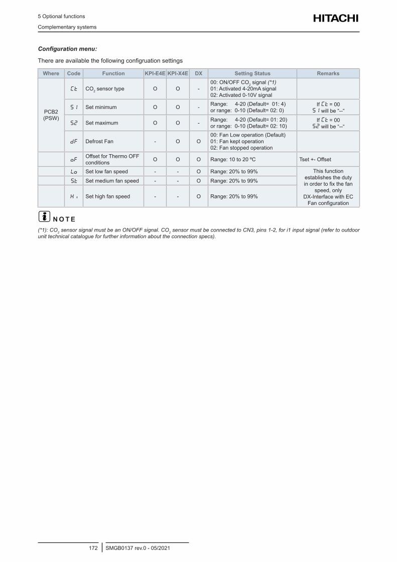
5 Optional functions
Complementary systems
SMGB0137 rev.0 - 05/2021172
Configuration menu:
There are available the following configruation settings
Where Code Function KPI-E4E KPI-X4E DX Setting Status Remarks
PCB2 (PSW)
Ct CO2 sensor type O O -00: ON/OFF CO2 signal (*1) 01: Activated 4-20mA signal 02: Activated 0-10V signal
S1 Set minimum O O - Range: 4-20 (Default= 01: 4) or range: 0-10 (Default= 02: 0)
If Ct = 00 S1 will be “--“
S2 Set maximum O O - Range: 4-20 (Default= 01: 20) or range: 0-10 (Default= 02: 10)
If Ct = 00 S2 will be “--“
dF Defrost Fan - O O00: Fan Low operation (Default) 01: Fan kept operation 02: Fan stopped operation
ofOffset for Thermo OFF conditions O O O Range: 10 to 20 ºC Tset +- Offset
Lo Set low fan speed - - O Range: 20% to 99% This function establishes the duty in order to fix the fan
speed, only DX-Interface with EC Fan configuration
St Set medium fan speed - - O Range: 20% to 99%
H Set high fan speed - - O Range: 20% to 99%
? N O T E(*1): CO2 sensor signal must be an ON/OFF signal. CO2 sensor must be connected to CN3, pins 1-2, for i1 input signal (refer to outdoor unit technical catalogue for further information about the connection specs).
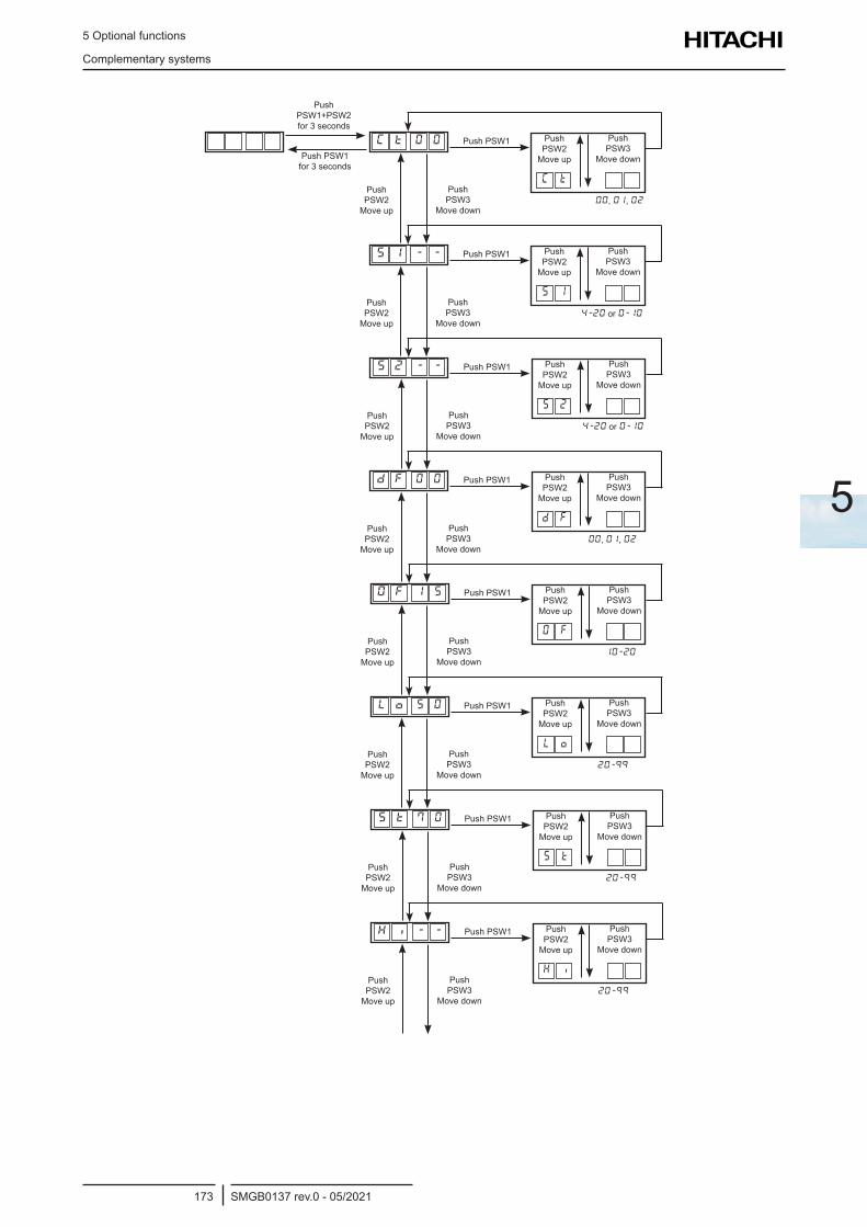
5 Optional functions
Complementary systems
SMGB0137 rev.0 - 05/2021173
5
Push PSW1+PSW2 for 3 seconds
Push PSW1 for 3 seconds
C t 0 0
C t
Push PSW1 Push PSW2
Move up
Push PSW3
Move down
00, 01, 02Push PSW2
Move up
Push PSW3
Move down
S 1 - -
s 1
Push PSW1 Push PSW2
Move up
Push PSW3
Move down
4-20 or 0-10Push PSW2
Move up
Push PSW3
Move down
s 2 - -
s 2
Push PSW1 Push PSW2
Move up
Push PSW3
Move down
4-20 or 0-10Push PSW2
Move up
Push PSW3
Move down
d F 0 0
d F
Push PSW1 Push PSW2
Move up
Push PSW3
Move down
00, 01, 02Push PSW2
Move up
Push PSW3
Move down
O F 1 5
O F
Push PSW1 Push PSW2
Move up
Push PSW3
Move down
10-20
Push PSW2
Move up
Push PSW3
Move down
L o 5 0
L o
Push PSW1 Push PSW2
Move up
Push PSW3
Move down
20-99
Push PSW2
Move up
Push PSW3
Move down
S t 7 0
S t
Push PSW1 Push PSW2
Move up
Push PSW3
Move down
20-99
Push PSW2
Move up
Push PSW3
Move down
H - -
H i
Push PSW1 Push PSW2
Move up
Push PSW3
Move down
20-99
Push PSW2
Move up
Push PSW3
Move down
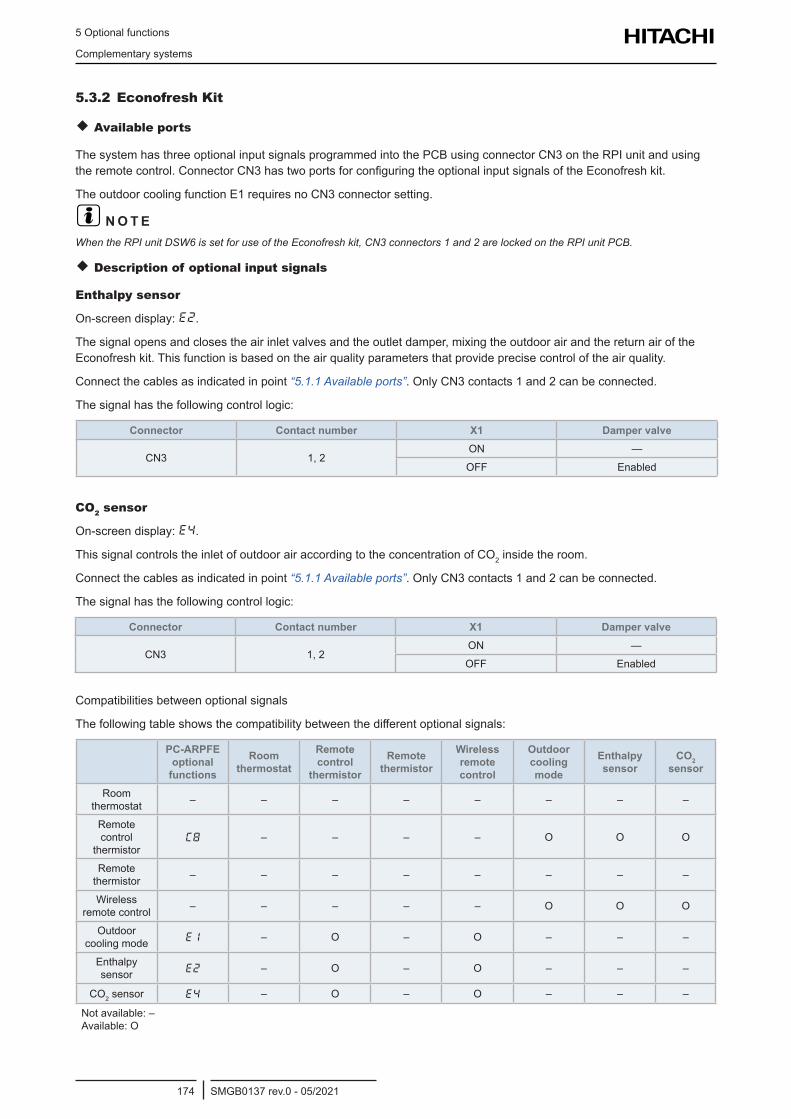
5 Optional functions
Complementary systems
SMGB0137 rev.0 - 05/2021174
5.3.2 Econofresh Kit
Available ports
The system has three optional input signals programmed into the PCB using connector CN3 on the RPI unit and using the remote control. Connector CN3 has two ports for configuring the optional input signals of the Econofresh kit.
The outdoor cooling function E1 requires no CN3 connector setting.
? N O T EWhen the RPI unit DSW6 is set for use of the Econofresh kit, CN3 connectors 1 and 2 are locked on the RPI unit PCB.
Description of optional input signals
Enthalpy sensor
On-screen display: E2.
The signal opens and closes the air inlet valves and the outlet damper, mixing the outdoor air and the return air of the Econofresh kit. This function is based on the air quality parameters that provide precise control of the air quality.
Connect the cables as indicated in point “5.1.1 Available ports”. Only CN3 contacts 1 and 2 can be connected.
The signal has the following control logic:
Connector Contact number X1 Damper valve
CN3 1, 2ON —
OFF Enabled
CO2 sensor
On-screen display: E4.
This signal controls the inlet of outdoor air according to the concentration of CO2 inside the room.
Connect the cables as indicated in point “5.1.1 Available ports”. Only CN3 contacts 1 and 2 can be connected.
The signal has the following control logic:
Connector Contact number X1 Damper valve
CN3 1, 2ON —
OFF Enabled
Compatibilities between optional signals
The following table shows the compatibility between the different optional signals:
PC-ARPFE optional
functions
Room thermostat
Remote control
thermistor
Remote thermistor
Wireless remote control
Outdoor cooling mode
Enthalpy sensor
CO2 sensor
Room thermostat – – – – – – – –
Remote control
thermistorC8 – – – – O O O
Remote thermistor – – – – – – – –
Wireless remote control – – – – – O O O
Outdoor cooling mode E1 – O – O – – –
Enthalpy sensor E2 – O – O – – –
CO2 sensor E4 – O – O – – –
Not available: – Available: O
6 Commissioning
SMGB0137 rev.0 - 05/2021175
6
6 . C o m m i s s i o n i n g
Index
6.1 Checks prior to the test run .................................................................................................................176
6.1.1 Check points ................................................................................................................................................ 176
6.1.2 Check procedure ......................................................................................................................................... 176
6.2 Test run procedure using the wireless remote control .........................................................................177
6.3 Test run check list ................................................................................................................................178
6 Commissioning
Checks prior to the test run
SMGB0137 rev.0 - 05/2021176
6.1 Checks prior to the test run• Once installation is complete, carry out the test run in line with the procedure described below. The system can be
handed over to the client once the test has been correctly completed.• Prior instructions to carry out the test run:
1 Verify the check points described in Check points.2 Carry out the check procedure described in Check procedure.3 Carry out the test run on the indoor units individually and in order.4 Check that the wiring and refrigerant piping connections are connect.5 Start the indoor units individually and in order. Check that they are correctly numbered.6 Carry out the test in line with the instructions given in section Test procedure using the remote control.
! C A U T I O N• Bearthefollowinginmindwhilethesystemisrunning:
- Donottouchanycomponentinthedischargegasarea.Thecompressorchamberandthepipingareattemperaturesofover90ºC.Theymaycauseburns.
- Donottouchthemagneticbreakers.Thiscouldcauseaseriousaccident.• Waitformorethanthreeminutesbeforetouchingelectricalcomponentsafterturningoffthemainswitch.• Checkthatthegasandliquidlinestopvalvesarefullyopen.
6.1.1 Check points
• Donotstartthesystemuntilallofthecheckpointshavebeenverified.
1 Use a multimeter to measure the resistance between earth and the electrical component terminal. Check that the resistanceisabove1MΩ.Otherwise,donotstartthesystem,locatetheelectricalleakandrepair.Donotapplyvoltage to transmission terminals 1 and 2.
2 Check that the outdoor unit stop valves are fully open. If so, start the system.3 Check that the power supply switch has been on for over 12 hours to heat up the compressor oil.
6.1.2 Check procedure
Check:
1 The gas and liquid line stop valves are fully open.2 That there are no refrigerant leaks.
? N O T EFlarenutsmaysometimesloosenduetovibrationsduringtransportation.
3 Refrigerant piping and wiring form part of the same system.4 The setting of the DIP switches on the printed circuit board of the indoor units is correct. Pay particular attention to
thesetdifferentinheightbetweentheindoorandoutdoorunits.Seethewiringdiagramsforfurtherdetails.5 The power supply switch has been on for over 12 hours to heat up the compressor oil.6 The wiring is correctly connected. See the wiring diagrams for further details.7 Each terminal (L1, L2, L3, N or L1 and N) is correctly connected to the power supply.8 Thefield-suppliedelectriccomponents(mainpowerswitchprotectionfuse,circuitbreakerwithoutfuse,residual
current breaker, wires, piping connectors and wire terminals) have been selected correctly in line with the electrical data given in the technical catalogue and in national and local regulations.
9 The power supply wiring terminal connection (L1 to L1 and N to N). Check the connection of the terminal boards running at 380 Vac. An incorrect connection may damage components.
10 Intermediatewireterminalsbetweentheindoorunit(operationalline:terminalsofeveryterminalboardfor12V)fitcorrectly. An incorrect connection may damage components.
11 The crankcase checker has been on for more than four hours. The device will not work unless it has been on for more than four hours.
6 Commissioning
Test run procedure using the wireless remote control
SMGB0137 rev.0 - 05/2021177
6
12 The operating temperature:• Cooling operation
a. Indoor DB 21.5ºC and higher.
b. Indoor WB 16ºC and higher.
c. Outdoor DB 0ºC and higher.• Heating operation
a. Indoor DB 27ºC and below.13 Use shielded cables for the installation to avoid electrical noise. This must be less than 1000 m in length and meet
with national and local regulations.14 Disconnect the KPI unit if it is connected to the indoor unit control. Otherwise the unit will not carry out the test run.
6.2 Test run procedure using the wireless remote controlFrom the remote controller switch can be carry out the test run procedure. Please follow the remote control switch technical documentation for details.
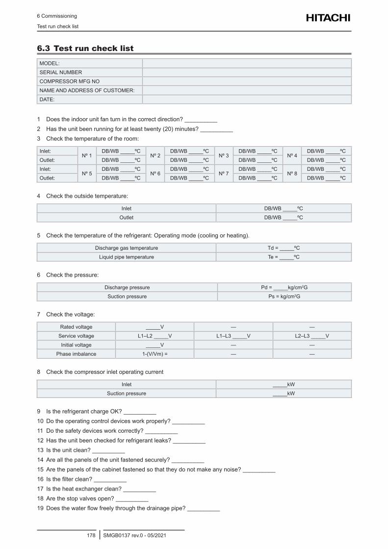
6 Commissioning
Test run check list
SMGB0137 rev.0 - 05/2021178
6.3 Test run check list
MODEL:
SERIAL NUMBER
COMPRESSOR MFG NO
NAME AND ADDRESS OF CUSTOMER:
DATE:
1 Does the indoor unit fan turn in the correct direction? __________2 Has the unit been running for at least twenty (20) minutes? __________3 Check the temperature of the room:
Inlet:Nº 1
DB/WB _____ºCNº 2
DB/WB _____ºCNº 3
DB/WB _____ºCNº 4
DB/WB _____ºC
Outlet: DB/WB _____ºC DB/WB _____ºC DB/WB _____ºC DB/WB _____ºC
Inlet:Nº 5
DB/WB _____ºCNº 6
DB/WB _____ºCNº 7
DB/WB _____ºCNº 8
DB/WB _____ºC
Outlet: DB/WB _____ºC DB/WB _____ºC DB/WB _____ºC DB/WB _____ºC
4 Check the outside temperature:
Inlet DB/WB _____ºC
Outlet DB/WB _____ºC
5 Check the temperature of the refrigerant: Operating mode (cooling or heating).
Discharge gas temperature Td = _____ºC
Liquid pipe temperature Te = _____ºC
6 Check the pressure:
Discharge pressure Pd = _____kg/cm2G
Suction pressure Ps = kg/cm2G
7 Check the voltage:
Rated voltage _____V — —
Service voltage L1–L2 _____V L1–L3 _____V L2–L3 _____V
Initial voltage _____V — —
Phase imbalance 1-(V/Vm)= — —
8 Check the compressor inlet operating current
Inlet _____kW
Suction pressure _____kW
9 Is the refrigerant charge OK? __________10 Do the operating control devices work properly? __________11 Do the safety devices work correctly? __________12 Has the unit been checked for refrigerant leaks? __________13 Is the unit clean? __________14 Are all the panels of the unit fastened securely? __________15 Are the panels of the cabinet fastened so that they do not make any noise? __________16 Isthefilterclean?__________17 Is the heat exchanger clean? __________18 Are the stop valves open? __________19 Doesthewaterflowfreelythroughthedrainagepipe?__________
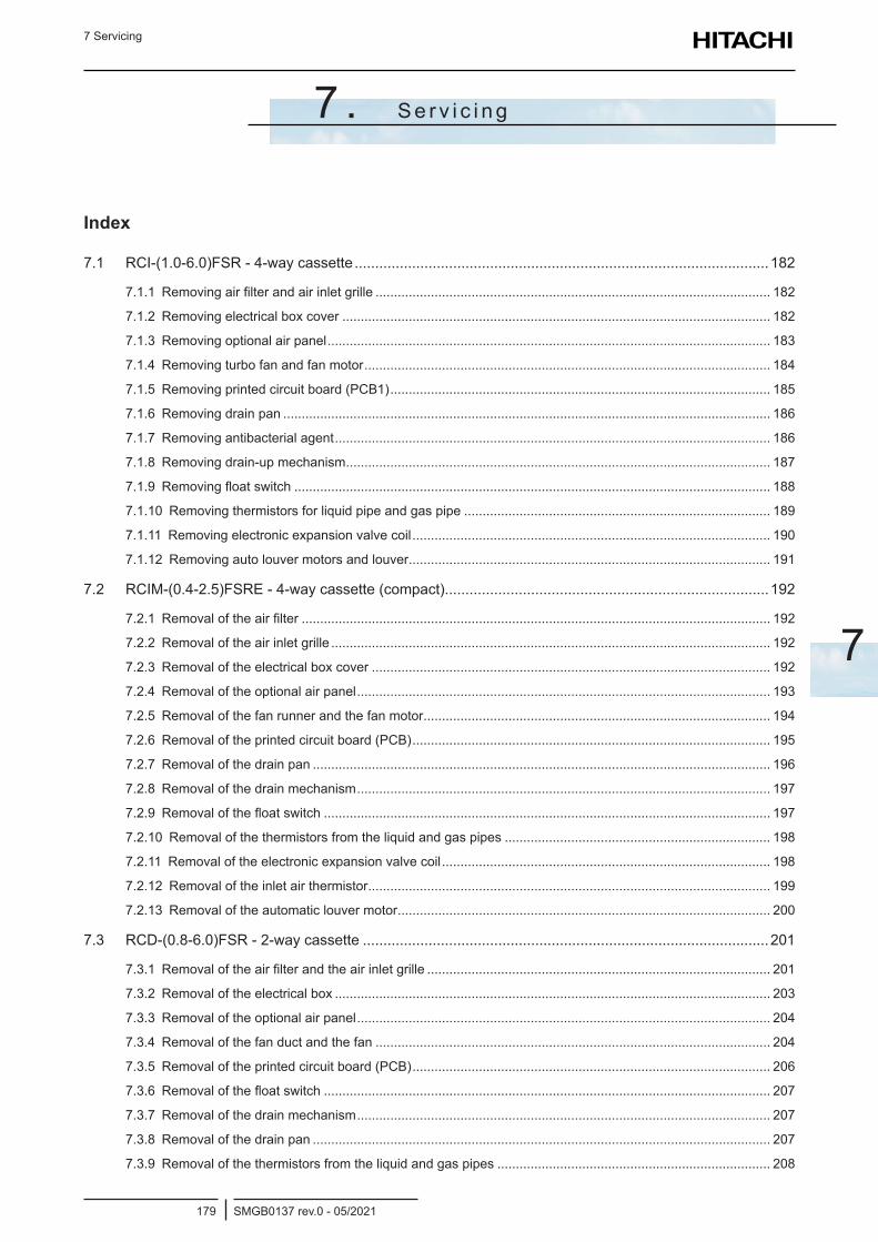
7 Servicing
SMGB0137 rev.0 - 05/2021179
7
7 . S e r v i c i n g
Index
7.1 RCI-(1.0-6.0)FSR - 4-way cassette .....................................................................................................182
7.1.1 Removing air filter and air inlet grille ........................................................................................................... 182
7.1.2 Removing electrical box cover .................................................................................................................... 182
7.1.3 Removing optional air panel ........................................................................................................................ 183
7.1.4 Removing turbo fan and fan motor .............................................................................................................. 184
7.1.5 Removing printed circuit board (PCB1) ....................................................................................................... 185
7.1.6 Removing drain pan .................................................................................................................................... 186
7.1.7 Removing antibacterial agent ...................................................................................................................... 186
7.1.8 Removing drain-up mechanism ................................................................................................................... 187
7.1.9 Removing float switch ................................................................................................................................. 188
7.1.10 Removing thermistors for liquid pipe and gas pipe ................................................................................... 189
7.1.11 Removing electronic expansion valve coil ................................................................................................. 190
7.1.12 Removing auto louver motors and louver .................................................................................................. 191
7.2 RCIM-(0.4-2.5)FSRE - 4-way cassette (compact)...............................................................................192
7.2.1 Removal of the air filter ............................................................................................................................... 192
7.2.2 Removal of the air inlet grille ....................................................................................................................... 192
7.2.3 Removal of the electrical box cover ............................................................................................................ 192
7.2.4 Removal of the optional air panel ................................................................................................................ 193
7.2.5 Removal of the fan runner and the fan motor .............................................................................................. 194
7.2.6 Removal of the printed circuit board (PCB) ................................................................................................. 195
7.2.7 Removal of the drain pan ............................................................................................................................ 196
7.2.8 Removal of the drain mechanism ................................................................................................................ 197
7.2.9 Removal of the float switch ......................................................................................................................... 197
7.2.10 Removal of the thermistors from the liquid and gas pipes ........................................................................ 198
7.2.11 Removal of the electronic expansion valve coil ......................................................................................... 198
7.2.12 Removal of the inlet air thermistor ............................................................................................................. 199
7.2.13 Removal of the automatic louver motor ..................................................................................................... 200
7.3 RCD-(0.8-6.0)FSR - 2-way cassette ...................................................................................................201
7.3.1 Removal of the air filter and the air inlet grille ............................................................................................. 201
7.3.2 Removal of the electrical box ...................................................................................................................... 203
7.3.3 Removal of the optional air panel ................................................................................................................ 204
7.3.4 Removal of the fan duct and the fan ........................................................................................................... 204
7.3.5 Removal of the printed circuit board (PCB) ................................................................................................. 206
7.3.6 Removal of the float switch ......................................................................................................................... 207
7.3.7 Removal of the drain mechanism ................................................................................................................ 207
7.3.8 Removal of the drain pan ............................................................................................................................ 207
7.3.9 Removal of the thermistors from the liquid and gas pipes .......................................................................... 208
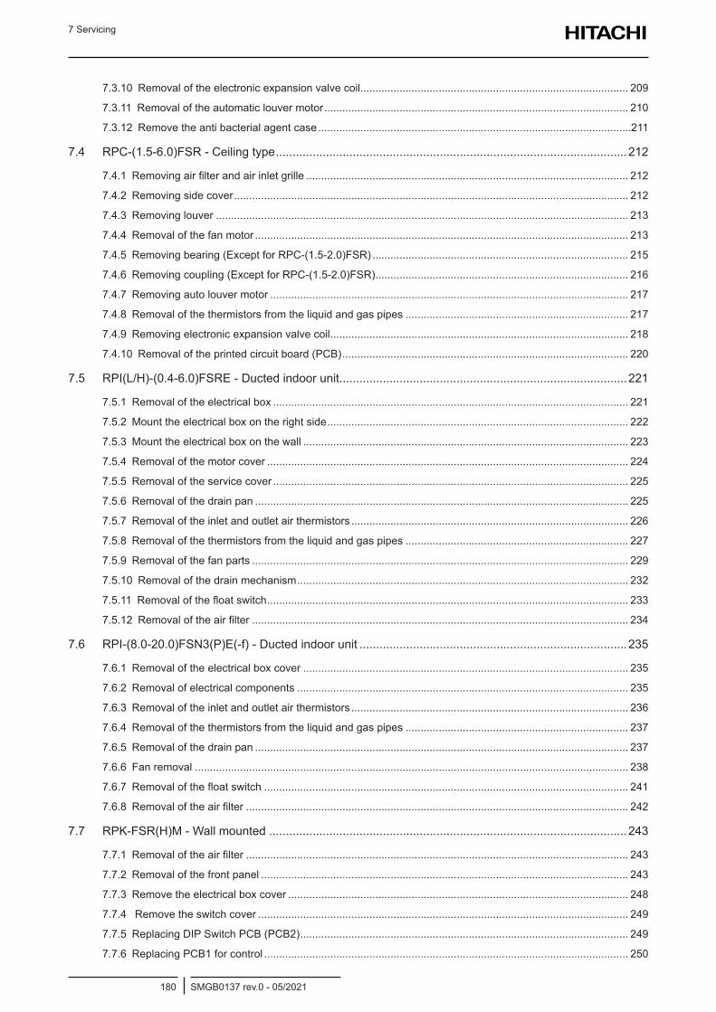
7 Servicing
SMGB0137 rev.0 - 05/2021180
7.3.10 Removal of the electronic expansion valve coil ......................................................................................... 209
7.3.11 Removal of the automatic louver motor ..................................................................................................... 210
7.3.12 Remove the anti bacterial agent case ........................................................................................................211
7.4 RPC-(1.5-6.0)FSR - Ceiling type .........................................................................................................212
7.4.1 Removing air filter and air inlet grille ........................................................................................................... 212
7.4.2 Removing side cover ................................................................................................................................... 212
7.4.3 Removing louver ......................................................................................................................................... 213
7.4.4 Removal of the fan motor ............................................................................................................................ 213
7.4.5 Removing bearing (Except for RPC-(1.5-2.0)FSR) ..................................................................................... 215
7.4.6 Removing coupling (Except for RPC-(1.5-2.0)FSR) .................................................................................... 216
7.4.7 Removing auto louver motor ....................................................................................................................... 217
7.4.8 Removal of the thermistors from the liquid and gas pipes .......................................................................... 217
7.4.9 Removing electronic expansion valve coil ................................................................................................... 218
7.4.10 Removal of the printed circuit board (PCB) ............................................................................................... 220
7.5 RPI(L/H)-(0.4-6.0)FSRE - Ducted indoor unit......................................................................................221
7.5.1 Removal of the electrical box ...................................................................................................................... 221
7.5.2 Mount the electrical box on the right side .................................................................................................... 222
7.5.3 Mount the electrical box on the wall ............................................................................................................ 223
7.5.4 Removal of the motor cover ........................................................................................................................ 224
7.5.5 Removal of the service cover ...................................................................................................................... 225
7.5.6 Removal of the drain pan ............................................................................................................................ 225
7.5.7 Removal of the inlet and outlet air thermistors ............................................................................................ 226
7.5.8 Removal of the thermistors from the liquid and gas pipes .......................................................................... 227
7.5.9 Removal of the fan parts ............................................................................................................................. 229
7.5.10 Removal of the drain mechanism .............................................................................................................. 232
7.5.11 Removal of the float switch ........................................................................................................................ 233
7.5.12 Removal of the air filter ............................................................................................................................. 234
7.6 RPI-(8.0-20.0)FSN3(P)E(-f) - Ducted indoor unit ................................................................................235
7.6.1 Removal of the electrical box cover ............................................................................................................ 235
7.6.2 Removal of electrical components .............................................................................................................. 235
7.6.3 Removal of the inlet and outlet air thermistors ............................................................................................ 236
7.6.4 Removal of the thermistors from the liquid and gas pipes .......................................................................... 237
7.6.5 Removal of the drain pan ............................................................................................................................ 237
7.6.6 Fan removal ................................................................................................................................................ 238
7.6.7 Removal of the float switch ......................................................................................................................... 241
7.6.8 Removal of the air filter ............................................................................................................................... 242
7.7 RPK-FSR(H)M - Wall mounted ...........................................................................................................243
7.7.1 Removal of the air filter ............................................................................................................................... 243
7.7.2 Removal of the front panel .......................................................................................................................... 243
7.7.3 Remove the electrical box cover ................................................................................................................. 248
7.7.4 Remove the switch cover ........................................................................................................................... 249
7.7.5 Replacing DIP Switch PCB (PCB2) ............................................................................................................. 249
7.7.6 Replacing PCB1 for control ......................................................................................................................... 250
7 Servicing
SMGB0137 rev.0 - 05/2021181
7
7.7.7 Removing AS motor .................................................................................................................................... 251
7.7.8 Removing drain pan .................................................................................................................................... 252
7.7.9 Removing heat exchanger .......................................................................................................................... 253
7.7.10 Removing thermistors for freeze protection, gas pipe, outlet air and inlet air ........................................... 257
7.7.11 Removing fan and fan motor ..................................................................................................................... 261
7.7.12 Removing electronic expansion valve coil ................................................................................................. 264
7.7.13 Removing Horizontal Louver ..................................................................................................................... 266
7.8 RPF(I)-(1.0-2.5)FSN2E - Floor and Floor concealed type...................................................................267
7.8.1 Removal of the air inlet grille ....................................................................................................................... 267
7.8.2 Removal of the air filter ............................................................................................................................... 267
7.8.3 Removal of the air outlet grille ..................................................................................................................... 267
7.8.4 Removal of the front panel .......................................................................................................................... 268
7.8.5 Removal of the fan motor ............................................................................................................................ 268
7.8.6 Removal of the printed circuit board (PCB) ................................................................................................. 269
7.8.7 Removal of the thermistors from the liquid and gas piping ......................................................................... 269
7.9 KPI-(252-2002)(E/X)4E - Energy recovery and active energy recovery ventilation units ....................270
7.9.1 System description ...................................................................................................................................... 270
7.9.2 Structure and part names ............................................................................................................................ 270
7.9.3 Service cover location ................................................................................................................................. 270
7.9.4 Removal of heat exchanger ........................................................................................................................ 271
7.9.5 Removal of the air filter ............................................................................................................................... 271
7.9.6 Removal of the float switch (X4E series only) ............................................................................................. 272
7.9.7 Removal of the damper motor ..................................................................................................................... 273
7.9.8 Removal of the electrical box ...................................................................................................................... 274
7.9.9 Removal of the PCB .................................................................................................................................... 274
7.9.10 Removal of the fan motor .......................................................................................................................... 275
7.9.11 Removal of the DX-Coil Module (X4E series only) .................................................................................... 276
7.10 DX-Interface ........................................................................................................................................277
7.10.1 Structure and part names .......................................................................................................................... 277
7.10.2 Removal of the electrical components ...................................................................................................... 277
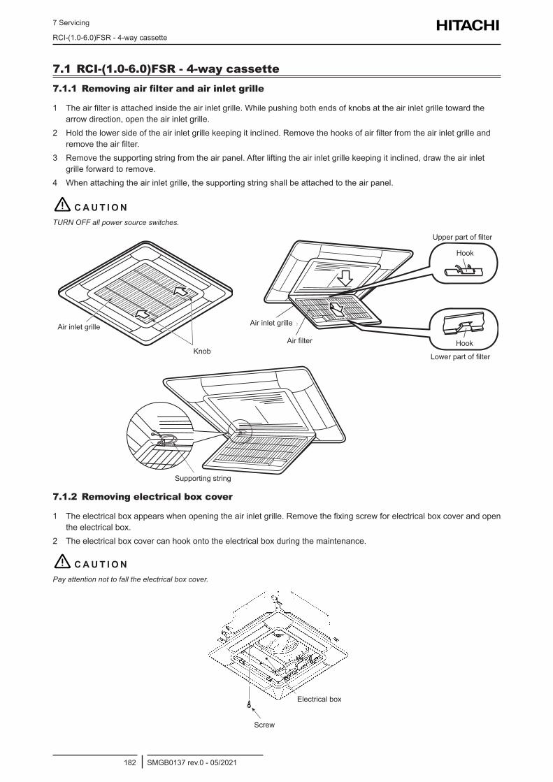
7 Servicing
RCI-(1.0-6.0)FSR - 4-way cassette
SMGB0137 rev.0 - 05/2021182
7.1 RCI-(1.0-6.0)FSR - 4-way cassette7.1.1 Removing air filter and air inlet grille
1 The air filter is attached inside the air inlet grille. While pushing both ends of knobs at the air inlet grille toward the arrow direction, open the air inlet grille.
2 Hold the lower side of the air inlet grille keeping it inclined. Remove the hooks of air filter from the air inlet grille and remove the air filter.
3 Remove the supporting string from the air panel. After lifting the air inlet grille keeping it inclined, draw the air inlet grille forward to remove.
4 When attaching the air inlet grille, the supporting string shall be attached to the air panel.
! C A U T I O NTURN OFF all power source switches.
Knob
Air Inlet Grille
Upper Part of Filter
Hook
Hook
Lower Part of Filter
Air Filter
Air Inlet Grille
Supporting String
Air inlet grille Air inlet grille
Air filterKnob
Hook
Hook
Upper part of filter
Lower part of filter
Supporting string
7.1.2 Removing electrical box cover
1 The electrical box appears when opening the air inlet grille. Remove the fixing screw for electrical box cover and open the electrical box.
2 The electrical box cover can hook onto the electrical box during the maintenance.
! C A U T I O NPay attention not to fall the electrical box cover.
Electrical Box
ScrewScrew
Electrical box
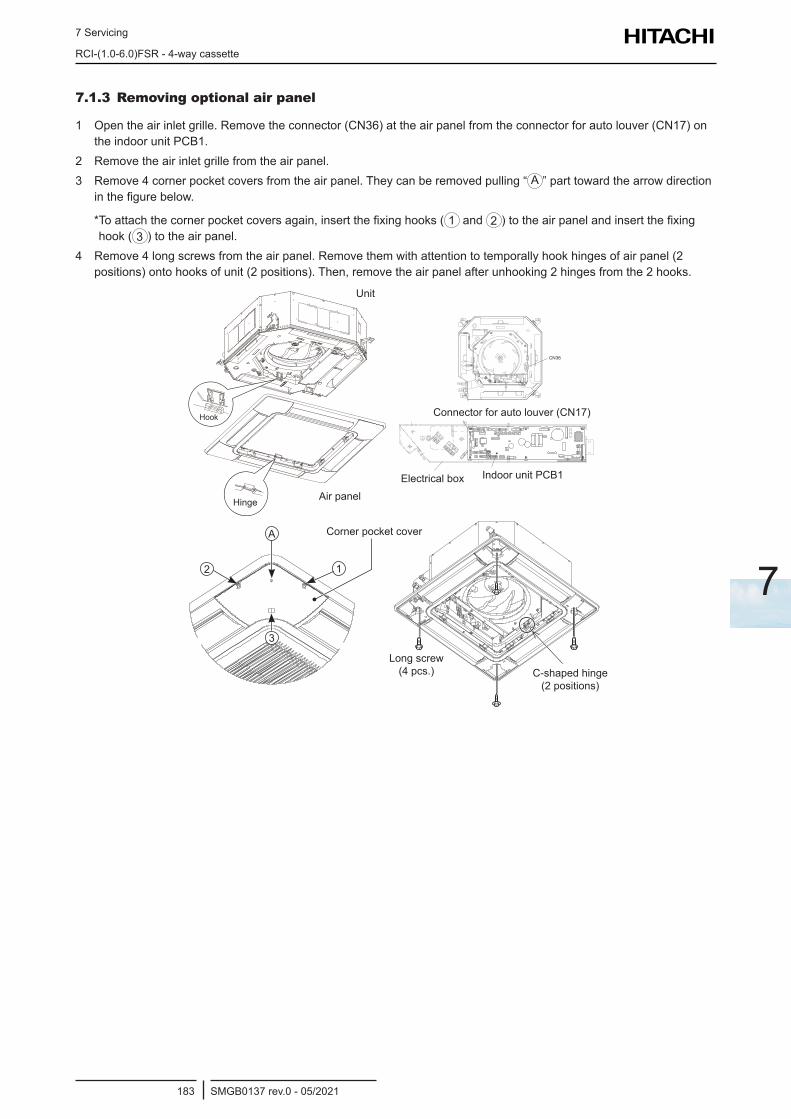
7 Servicing
RCI-(1.0-6.0)FSR - 4-way cassette
SMGB0137 rev.0 - 05/2021183
7
7.1.3 Removing optional air panel
1 Open the air inlet grille. Remove the connector (CN36) at the air panel from the connector for auto louver (CN17) on the indoor unit PCB1.
2 Remove the air inlet grille from the air panel.3 Remove 4 corner pocket covers from the air panel. They can be removed pulling “ A ” part toward the arrow direction
in the figure below.
* To attach the corner pocket covers again, insert the fixing hooks ( 1 and 2 ) to the air panel and insert the fixing hook ( 3 ) to the air panel.
4 Remove 4 long screws from the air panel. Remove them with attention to temporally hook hinges of air panel (2 positions) onto hooks of unit (2 positions). Then, remove the air panel after unhooking 2 hinges from the 2 hooks.
Hook
Hinge
Unit
Air Panel
Unit
Air panelHinge
Hook
>PS<
HS-HB
HITACHI AIR( / )CONDITIONERModel
S/N
R/L1
2
1
B
A
K
DRAIN
>PS
<O
A
OA
INLE
T
D
N112
CN36
Electrical box Indoor unit PCB1
Connector for auto louver (CN17)
A
12
3
Corner Pocket CoverCorner pocket cover
C-shaped Hinge(2 Portions)
Long Screw(4 pcs.)
Long screw (4 pcs.) C-shaped hinge
(2 positions)
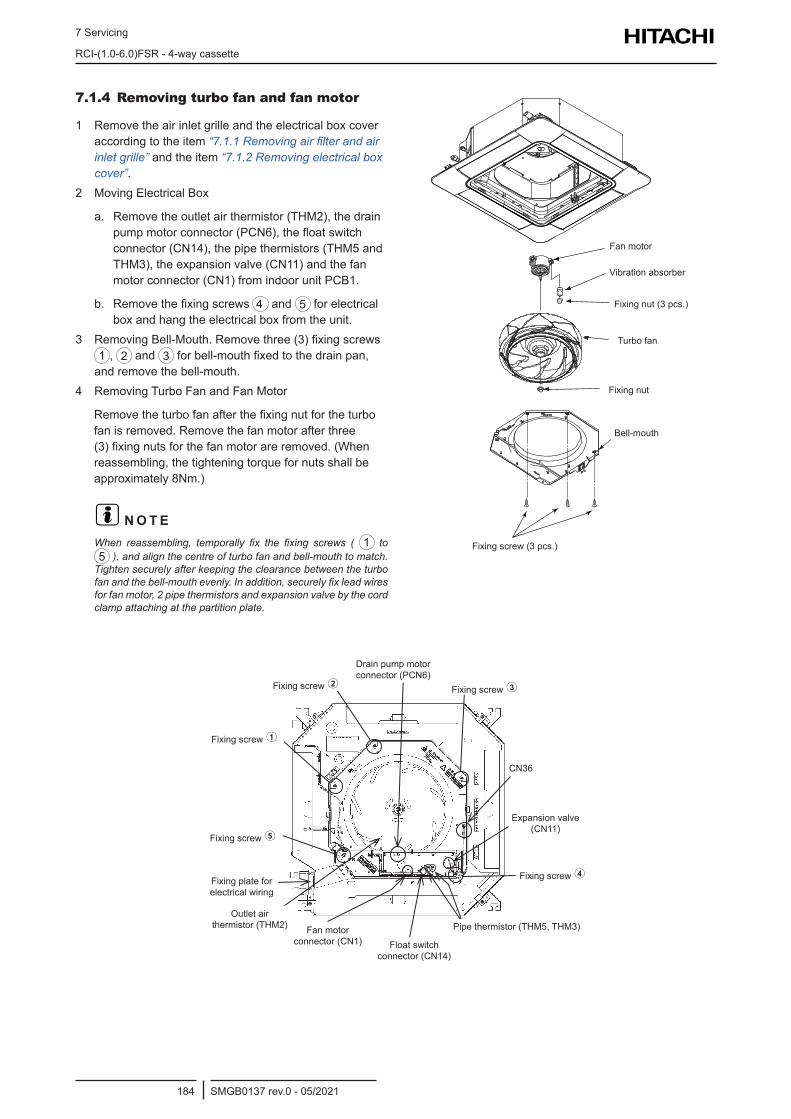
7 Servicing
RCI-(1.0-6.0)FSR - 4-way cassette
SMGB0137 rev.0 - 05/2021184
Fixing screw
Fixing screw
Fixing plate for electrical wiring
Outlet air thermistor (THM2) Fan motor
connector (CN1) Float switch connector (CN14)
Pipe thermistor (THM5, THM3)
Fixing screw Fixing screw
Fixing screw
Expansion valve (CN11)
Drain pump motor connector (PCN6)
CN36
7.1.4 Removing turbo fan and fan motor
1 Remove the air inlet grille and the electrical box cover according to the item “7.1.1 Removing air filter and air inlet grille” and the item “7.1.2 Removing electrical box cover”.
2 Moving Electrical Box
a. Remove the outlet air thermistor (THM2), the drain pump motor connector (PCN6), the float switch connector (CN14), the pipe thermistors (THM5 and THM3), the expansion valve (CN11) and the fan motor connector (CN1) from indoor unit PCB1.
b. Remove the fixing screws 4 and 5 for electrical box and hang the electrical box from the unit.
3 Removing Bell-Mouth. Remove three (3) fixing screws 1 , 2 and 3 for bell-mouth fixed to the drain pan, and remove the bell-mouth.
4 Removing Turbo Fan and Fan Motor
Remove the turbo fan after the fixing nut for the turbo fan is removed. Remove the fan motor after three (3) fixing nuts for the fan motor are removed. (When reassembling, the tightening torque for nuts shall be approximately 8Nm.)
? N O T EWhen reassembling, temporally fix the fixing screws ( 1 to 5 ), and align the centre of turbo fan and bell-mouth to match.
Tighten securely after keeping the clearance between the turbo fan and the bell-mouth evenly. In addition, securely fix lead wires for fan motor, 2 pipe thermistors and expansion valve by the cord clamp attaching at the partition plate.
Fan Motor
Turbo Fan
Fixing Nut
Bell-Mouth
Fixing Screw (3 pcs.)
Fixing Nut (3 pcs.)
Vibration Absorber
Fan motor
Vibration absorber
Fixing nut (3 pcs.)
Turbo fan
Fixing nut
Bell-mouth
Fixing screw (3 pcs.)
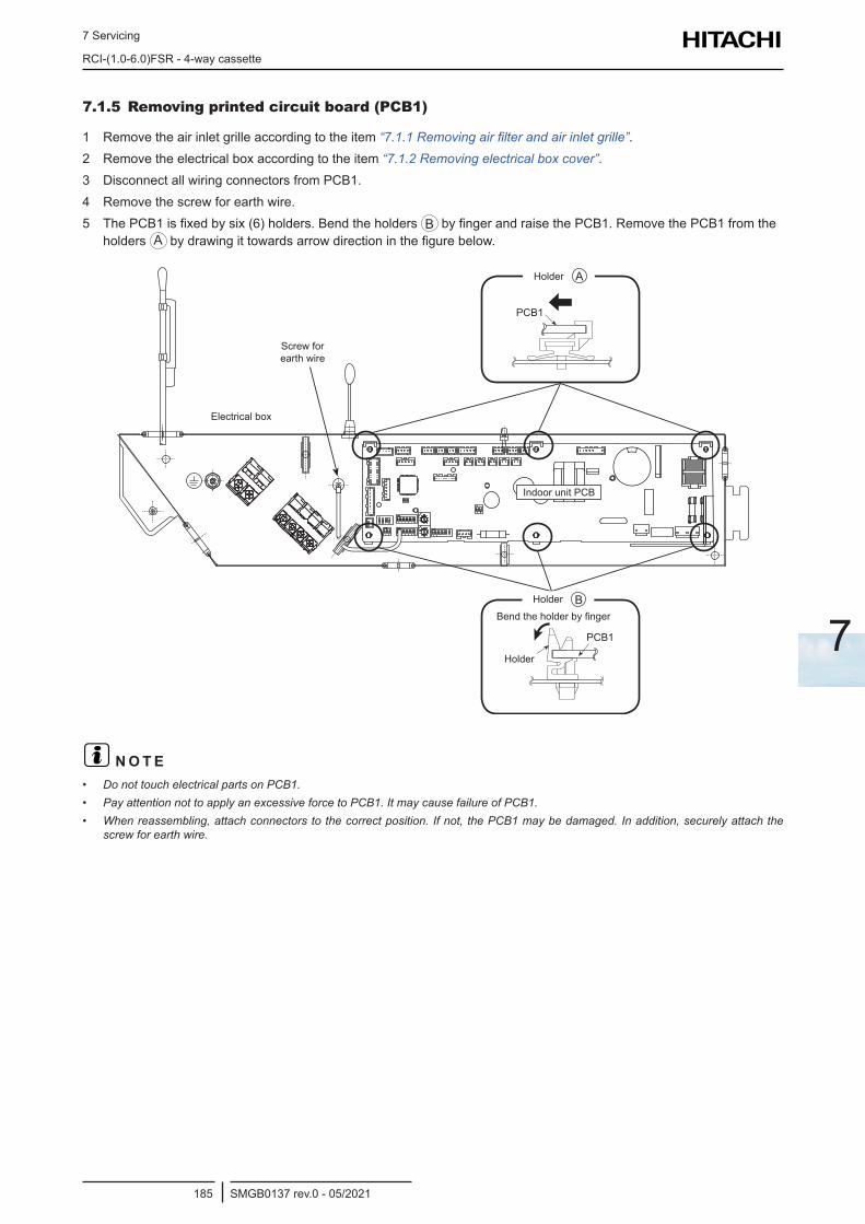
7 Servicing
RCI-(1.0-6.0)FSR - 4-way cassette
SMGB0137 rev.0 - 05/2021185
7
7.1.5 Removing printed circuit board (PCB1)
1 Remove the air inlet grille according to the item “7.1.1 Removing air filter and air inlet grille”.2 Remove the electrical box according to the item “7.1.2 Removing electrical box cover”.3 Disconnect all wiring connectors from PCB1.4 Remove the screw for earth wire.5 The PCB1 is fixed by six (6) holders. Bend the holders B by finger and raise the PCB1. Remove the PCB1 from the
holders A by drawing it towards arrow direction in the figure below.
Indoor Unit PCB
Electrical Box
Holder B
Screw forEarth Wire
PCB1
PCB1
Holder
Bend the holder by finger.
Holder AHolder
Screw for earth wire
Electrical box
Holder
Holder
Bend the holder by finger
Indoor unit PCB
? N O T E• Do not touch electrical parts on PCB1.• Pay attention not to apply an excessive force to PCB1. It may cause failure of PCB1.• When reassembling, attach connectors to the correct position. If not, the PCB1 may be damaged. In addition, securely attach the
screw for earth wire.
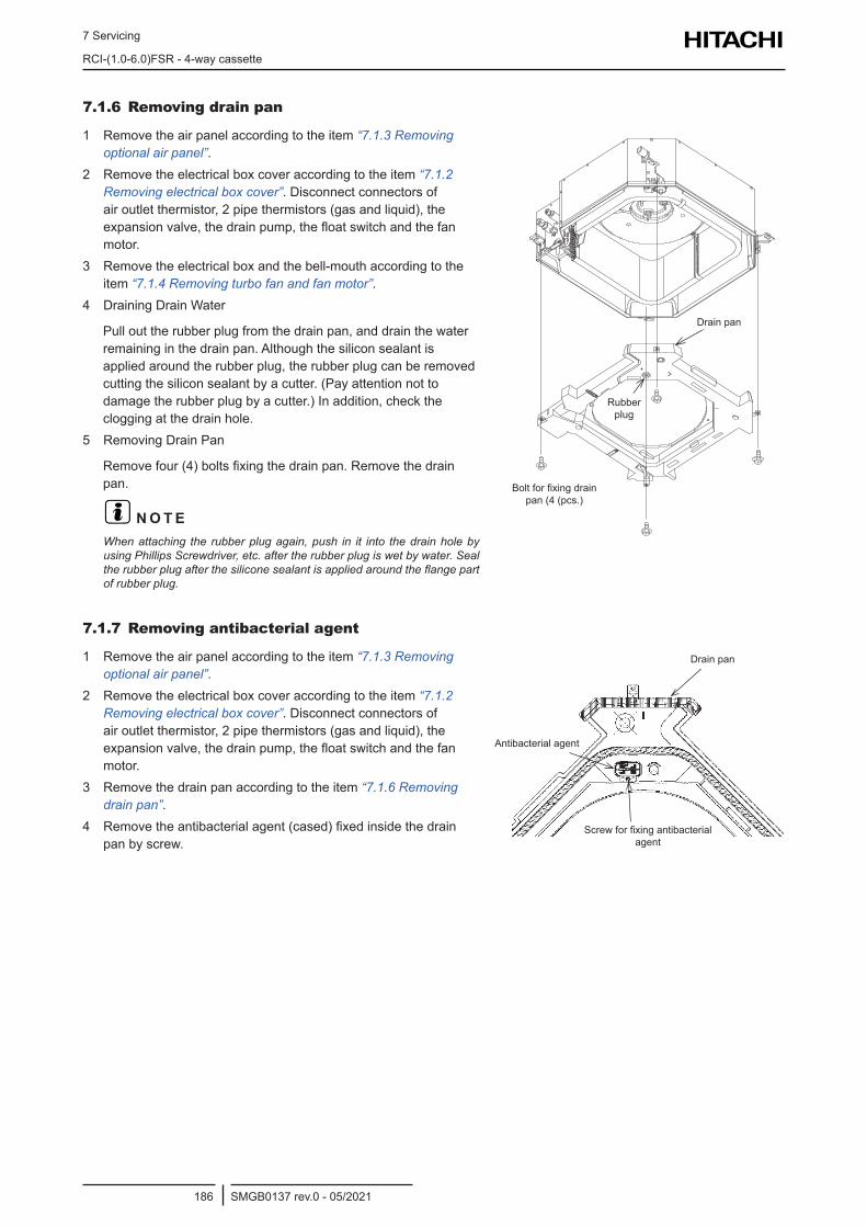
7 Servicing
RCI-(1.0-6.0)FSR - 4-way cassette
SMGB0137 rev.0 - 05/2021186
7.1.6 Removing drain pan
1 Remove the air panel according to the item “7.1.3 Removing optional air panel”.
2 Remove the electrical box cover according to the item “7.1.2 Removing electrical box cover”. Disconnect connectors of air outlet thermistor, 2 pipe thermistors (gas and liquid), the expansion valve, the drain pump, the float switch and the fan motor.
3 Remove the electrical box and the bell-mouth according to the item “7.1.4 Removing turbo fan and fan motor”.
4 Draining Drain Water
Pull out the rubber plug from the drain pan, and drain the water remaining in the drain pan. Although the silicon sealant is applied around the rubber plug, the rubber plug can be removed cutting the silicon sealant by a cutter. (Pay attention not to damage the rubber plug by a cutter.) In addition, check the clogging at the drain hole.
5 Removing Drain Pan
Remove four (4) bolts fixing the drain pan. Remove the drain pan.
? N O T EWhen attaching the rubber plug again, push in it into the drain hole by using Phillips Screwdriver, etc. after the rubber plug is wet by water. Seal the rubber plug after the silicone sealant is applied around the flange part of rubber plug.
Bolt forFixing Drain Pan(4 pcs.)
Drain Pan
RubberPlug
Drain pan
Rubber plug
Bolt for fixing drain pan (4 (pcs.)
7.1.7 Removing antibacterial agent
1 Remove the air panel according to the item “7.1.3 Removing optional air panel”.
2 Remove the electrical box cover according to the item “7.1.2 Removing electrical box cover”. Disconnect connectors of air outlet thermistor, 2 pipe thermistors (gas and liquid), the expansion valve, the drain pump, the float switch and the fan motor.
3 Remove the drain pan according to the item “7.1.6 Removing drain pan”.
4 Remove the antibacterial agent (cased) fixed inside the drain pan by screw.
Drain Pan
Antibacterial Agent
Screw forFixing Antibacterial Agent
Drain pan
Antibacterial agent
Screw for fixing antibacterial agent
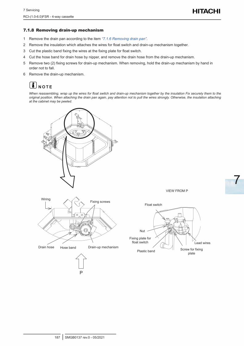
7 Servicing
RCI-(1.0-6.0)FSR - 4-way cassette
SMGB0137 rev.0 - 05/2021187
7
7.1.8 Removing drain-up mechanism
1 Remove the drain pan according to the item “7.1.6 Removing drain pan”.2 Remove the insulation which attaches the wires for float switch and drain-up mechanism together.3 Cut the plastic band fixing the wires at the fixing plate for float switch.4 Cut the hose band for drain hose by nipper, and remove the drain hose from the drain-up mechanism.5 Remove two (2) fixing screws for drain-up mechanism. When removing, hold the drain-up mechanism by hand in
order not to fall.6 Remove the drain-up mechanism.
? N O T EWhen reassembling, wrap up the wires for float switch and drain-up mechanism together by the insulation Fix securely them to the original position. When attaching the drain pan again, pay attention not to pull the wires strongly. Otherwise, the insulation attaching at the cabinet may be peeled.
P
WiringFixing screws
Float switch
Drain-up mechanismHose bandDrain hose
Nut
Fixing plate for float switch
Plastic band
Lead wires
Screw for fixing plate
VIEW FROM P
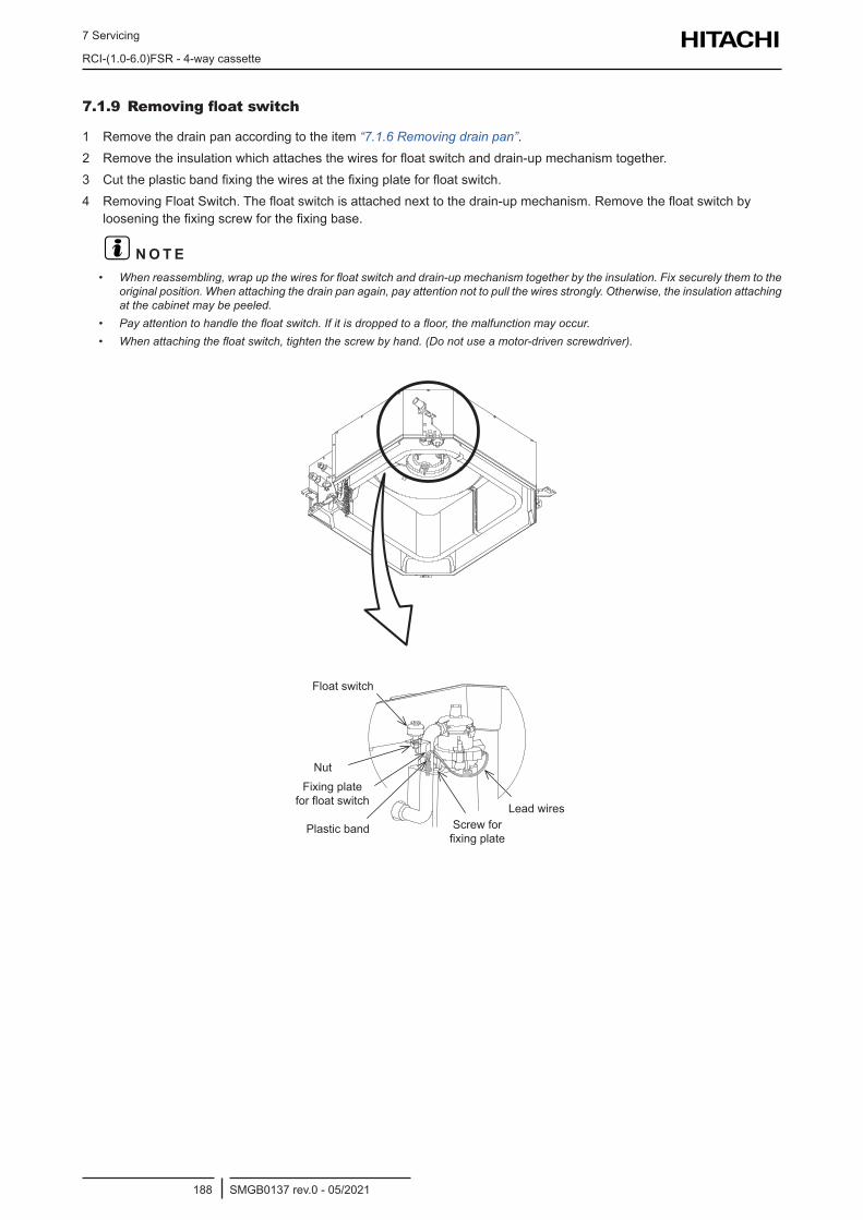
7 Servicing
RCI-(1.0-6.0)FSR - 4-way cassette
SMGB0137 rev.0 - 05/2021188
7.1.9 Removing float switch
1 Remove the drain pan according to the item “7.1.6 Removing drain pan”.2 Remove the insulation which attaches the wires for float switch and drain-up mechanism together.3 Cut the plastic band fixing the wires at the fixing plate for float switch.4 Removing Float Switch. The float switch is attached next to the drain-up mechanism. Remove the float switch by
loosening the fixing screw for the fixing base.
? N O T E• When reassembling, wrap up the wires for float switch and drain-up mechanism together by the insulation. Fix securely them to the
original position. When attaching the drain pan again, pay attention not to pull the wires strongly. Otherwise, the insulation attaching at the cabinet may be peeled.
• Pay attention to handle the float switch. If it is dropped to a floor, the malfunction may occur.• When attaching the float switch, tighten the screw by hand. (Do not use a motor-driven screwdriver).
Float switch
NutFixing plate
for float switch
Plastic band
Lead wiresScrew for fixing plate
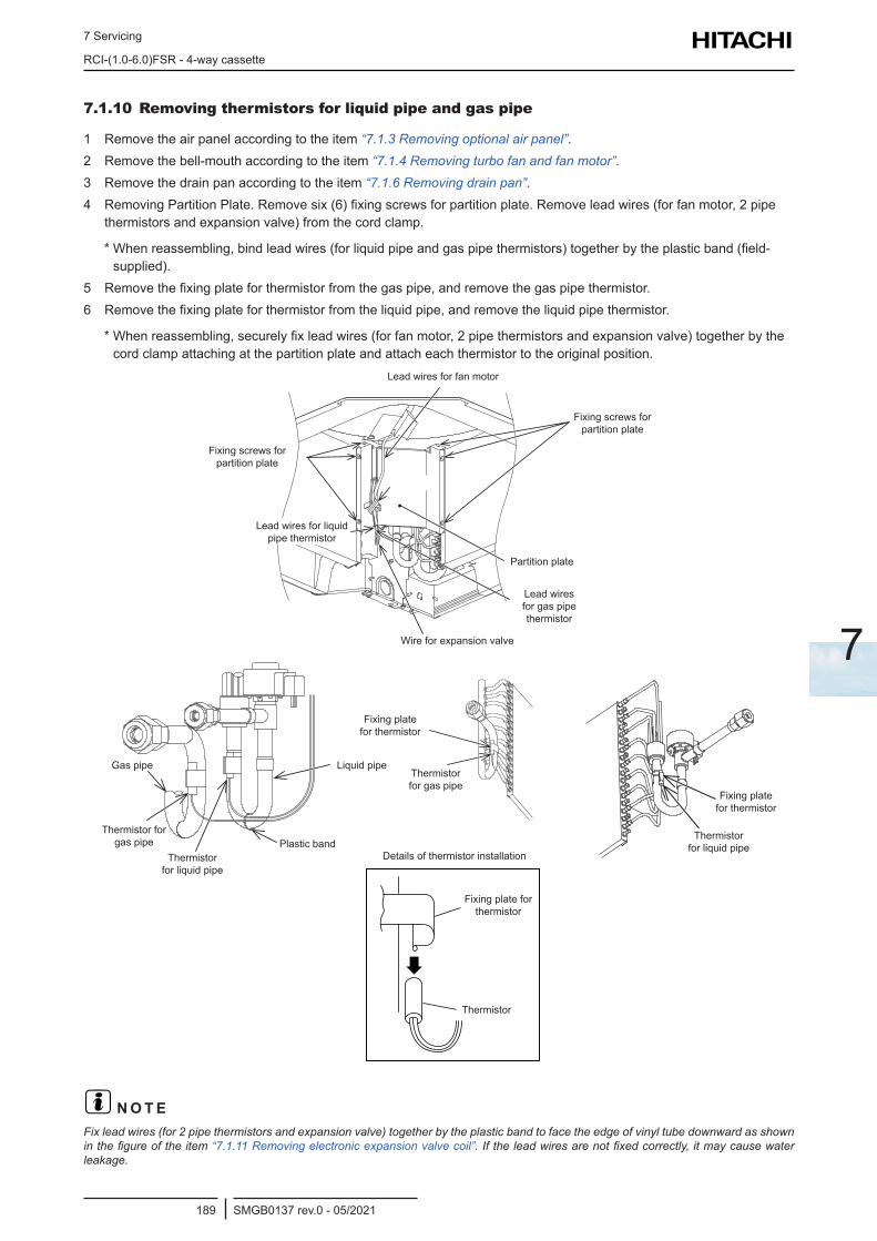
7 Servicing
RCI-(1.0-6.0)FSR - 4-way cassette
SMGB0137 rev.0 - 05/2021189
7
7.1.10 Removing thermistors for liquid pipe and gas pipe
1 Remove the air panel according to the item “7.1.3 Removing optional air panel”.2 Remove the bell-mouth according to the item “7.1.4 Removing turbo fan and fan motor”.3 Remove the drain pan according to the item “7.1.6 Removing drain pan”.4 Removing Partition Plate. Remove six (6) fixing screws for partition plate. Remove lead wires (for fan motor, 2 pipe
thermistors and expansion valve) from the cord clamp.
* When reassembling, bind lead wires (for liquid pipe and gas pipe thermistors) together by the plastic band (field-supplied).
5 Remove the fixing plate for thermistor from the gas pipe, and remove the gas pipe thermistor.6 Remove the fixing plate for thermistor from the liquid pipe, and remove the liquid pipe thermistor.
* When reassembling, securely fix lead wires (for fan motor, 2 pipe thermistors and expansion valve) together by the cord clamp attaching at the partition plate and attach each thermistor to the original position.
Lead wires for fan motor
Fixing screws for partition plate
Partition plate
Lead wires for gas pipe thermistor
Wire for expansion valve
Lead wires for liquid pipe thermistor
Fixing screws for partition plate
Gas pipe Liquid pipe
Plastic bandThermistor
for liquid pipe
Thermistor for gas pipe
Fixing plate for thermistor
Thermistor for gas pipe
Fixing plate for thermistor
Thermistor for liquid pipe
Fixing plate for thermistor
Thermistor
Details of thermistor installation
? N O T EFix lead wires (for 2 pipe thermistors and expansion valve) together by the plastic band to face the edge of vinyl tube downward as shown in the figure of the item “7.1.11 Removing electronic expansion valve coil”. If the lead wires are not fixed correctly, it may cause water leakage.
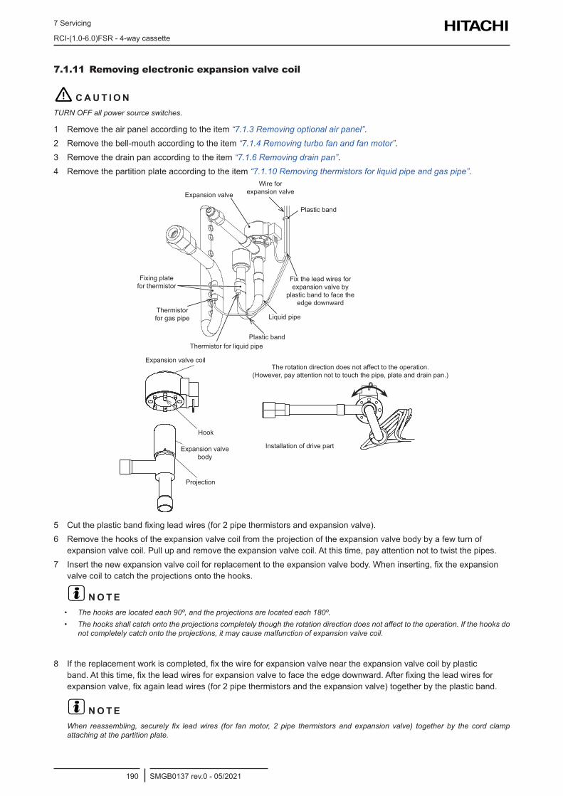
7 Servicing
RCI-(1.0-6.0)FSR - 4-way cassette
SMGB0137 rev.0 - 05/2021190
7.1.11 Removing electronic expansion valve coil
! C A U T I O NTURN OFF all power source switches.
1 Remove the air panel according to the item “7.1.3 Removing optional air panel”.2 Remove the bell-mouth according to the item “7.1.4 Removing turbo fan and fan motor”.3 Remove the drain pan according to the item “7.1.6 Removing drain pan”.4 Remove the partition plate according to the item “7.1.10 Removing thermistors for liquid pipe and gas pipe”.
The rotation direction does not affect to the operation. (However, pay attention not to touch the pipe, plate and drain pan.)
Installation of drive part
Expansion valveWire for
expansion valve
Plastic band
Plastic band
Liquid pipe
Thermistor for liquid pipe
Thermistor for gas pipe
Fixing plate for thermistor
Fix the lead wires for expansion valve by
plastic band to face the edge downward
Expansion valve coil
Hook
Projection
Expansion valve body
5 Cut the plastic band fixing lead wires (for 2 pipe thermistors and expansion valve).6 Remove the hooks of the expansion valve coil from the projection of the expansion valve body by a few turn of
expansion valve coil. Pull up and remove the expansion valve coil. At this time, pay attention not to twist the pipes.7 Insert the new expansion valve coil for replacement to the expansion valve body. When inserting, fix the expansion
valve coil to catch the projections onto the hooks.
? N O T E• The hooks are located each 90º, and the projections are located each 180º.• The hooks shall catch onto the projections completely though the rotation direction does not affect to the operation. If the hooks do
not completely catch onto the projections, it may cause malfunction of expansion valve coil.
8 If the replacement work is completed, fix the wire for expansion valve near the expansion valve coil by plastic band. At this time, fix the lead wires for expansion valve to face the edge downward. After fixing the lead wires for expansion valve, fix again lead wires (for 2 pipe thermistors and the expansion valve) together by the plastic band.
? N O T EWhen reassembling, securely fix lead wires (for fan motor, 2 pipe thermistors and expansion valve) together by the cord clamp attaching at the partition plate.
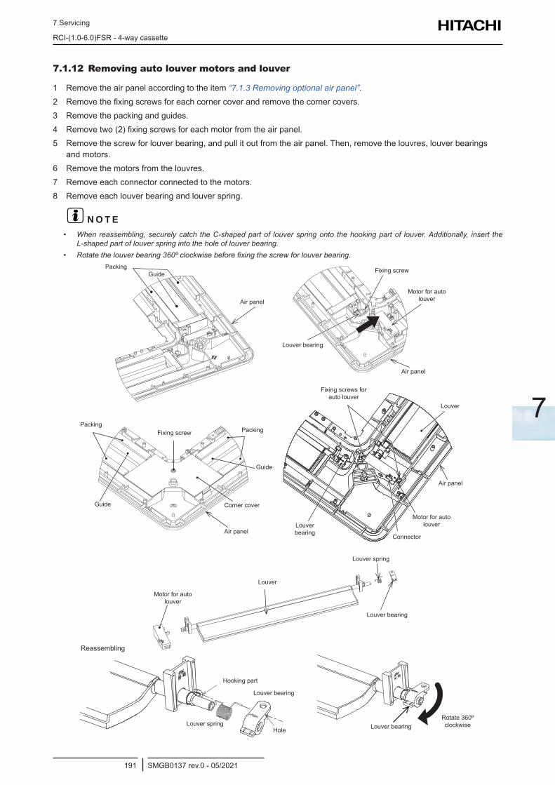
7 Servicing
RCI-(1.0-6.0)FSR - 4-way cassette
SMGB0137 rev.0 - 05/2021191
7
7.1.12 Removing auto louver motors and louver
1 Remove the air panel according to the item “7.1.3 Removing optional air panel”.2 Remove the fixing screws for each corner cover and remove the corner covers.3 Remove the packing and guides.4 Remove two (2) fixing screws for each motor from the air panel.5 Remove the screw for louver bearing, and pull it out from the air panel. Then, remove the louvres, louver bearings
and motors.6 Remove the motors from the louvres.7 Remove each connector connected to the motors.8 Remove each louver bearing and louver spring.
? N O T E• When reassembling, securely catch the C-shaped part of louver spring onto the hooking part of louver. Additionally, insert the
L-shaped part of louver spring into the hole of louver bearing.• Rotate the louver bearing 360º clockwise before fixing the screw for louver bearing.
Air panel
PackingGuide
Louver bearing
Air panel
Motor for auto louver
Fixing screw
Louver bearing
Fixing screws for auto louver
Louver
Air panel
Motor for auto louver
Connector
Louver bearing
Guide
Fixing screw Packing
Corner cover
Air panel
Guide
Packing
Louver
Louver spring
Motor for auto louver
Reassembling
Hooking part
Louver bearing
Louver springHole Louver bearing
Rotate 360º clockwise
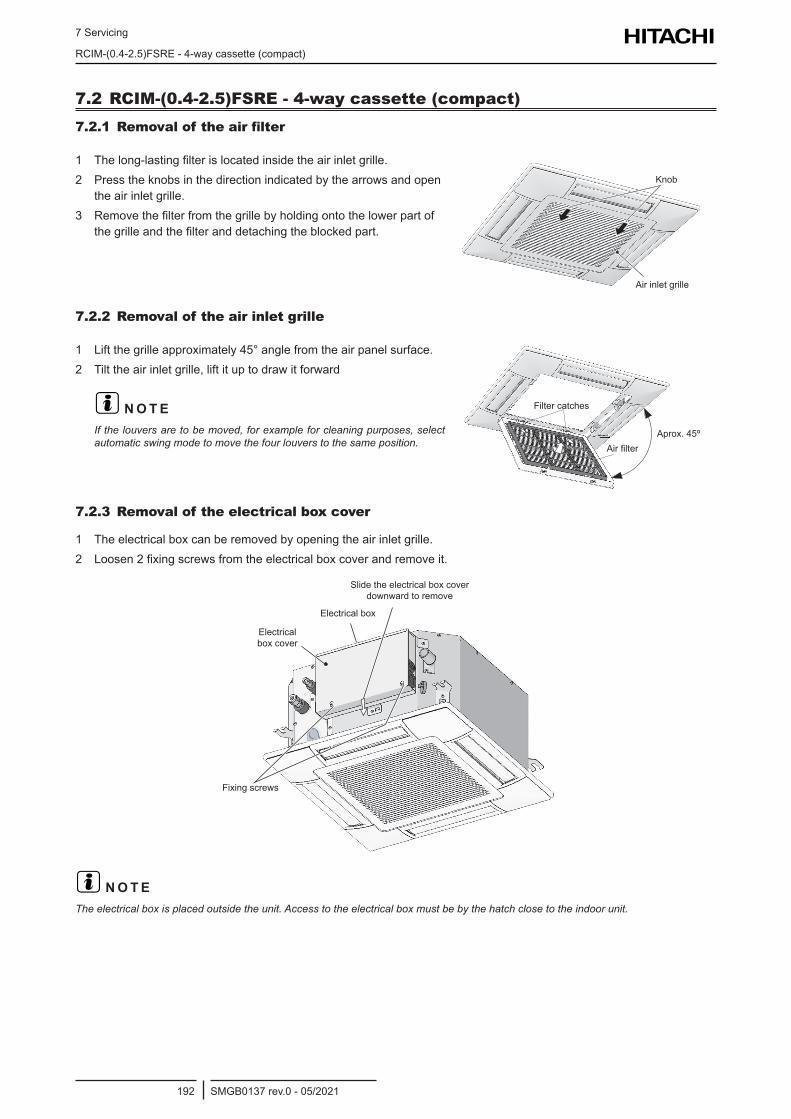
7 Servicing
RCIM-(0.4-2.5)FSRE - 4-way cassette (compact)
SMGB0137 rev.0 - 05/2021192
7.2 RCIM-(0.4-2.5)FSRE - 4-way cassette (compact)7.2.1 Removal of the air filter
1 The long-lasting filter is located inside the air inlet grille.2 Press the knobs in the direction indicated by the arrows and open
the air inlet grille.3 Remove the filter from the grille by holding onto the lower part of
the grille and the filter and detaching the blocked part.
Knob
Air inlet grille
7.2.2 Removal of the air inlet grille
1 Lift the grille approximately 45° angle from the air panel surface.2 Tilt the air inlet grille, lift it up to draw it forward
? N O T EIf the louvers are to be moved, for example for cleaning purposes, select automatic swing mode to move the four louvers to the same position.
Filter catches
Air filterAprox. 45º
7.2.3 Removal of the electrical box cover
1 The electrical box can be removed by opening the air inlet grille.2 Loosen 2 fixing screws from the electrical box cover and remove it.
Electrical box cover
Electrical box
Slide the electrical box cover downward to remove
Fixing screws
? N O T EThe electrical box is placed outside the unit. Access to the electrical box must be by the hatch close to the indoor unit.
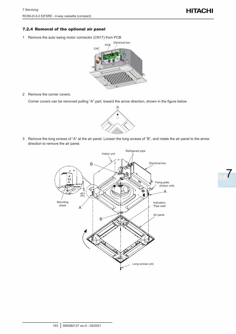
7 Servicing
RCIM-(0.4-2.5)FSRE - 4-way cassette (compact)
SMGB0137 rev.0 - 05/2021193
7
7.2.4 Removal of the optional air panel
1 Remove the auto swing motor connector (CN17) from PCB
CN7PCB
Electrical box
2 Remove the corner covers.
Corner covers can be removed pulling “A” part, toward the arrow direction, shown in the figure below.A
3 Remove the long screws of “A” at the air panel. Loosen the long screws of “B”, and rotate the air panel to the arrow direction to remove the air panel.
Electrical box
Indoor unitRefrigerant pipe
Mounting sheet
Long screws (x4)
Air panel
Indication: “Pipe side”
Fixing plate(Indoor unit)
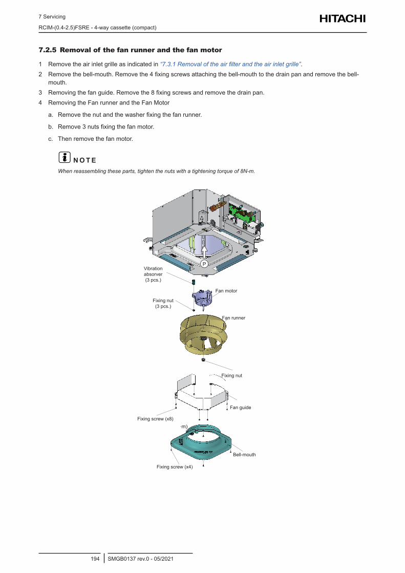
7 Servicing
RCIM-(0.4-2.5)FSRE - 4-way cassette (compact)
SMGB0137 rev.0 - 05/2021194
7.2.5 Removal of the fan runner and the fan motor
1 Remove the air inlet grille as indicated in “7.3.1 Removal of the air filter and the air inlet grille”.2 Remove the bell-mouth. Remove the 4 fixing screws attaching the bell-mouth to the drain pan and remove the bell-
mouth.3 Removing the fan guide. Remove the 8 fixing screws and remove the drain pan.4 Removing the Fan runner and the Fan Motor
a. Remove the nut and the washer fixing the fan runner.
b. Remove 3 nuts fixing the fan motor.
c. Then remove the fan motor.
? N O T EWhen reassembling these parts, tighten the nuts with a tightening torque of 8N-m.
Vibration absorver (3 pcs.)
Fixing nut (3 pcs.)
Fan motor
Fan runner
Bell-mouth
Fixing nut
Fan guide
Fixing screw (x8)
Fixing screw (x4)
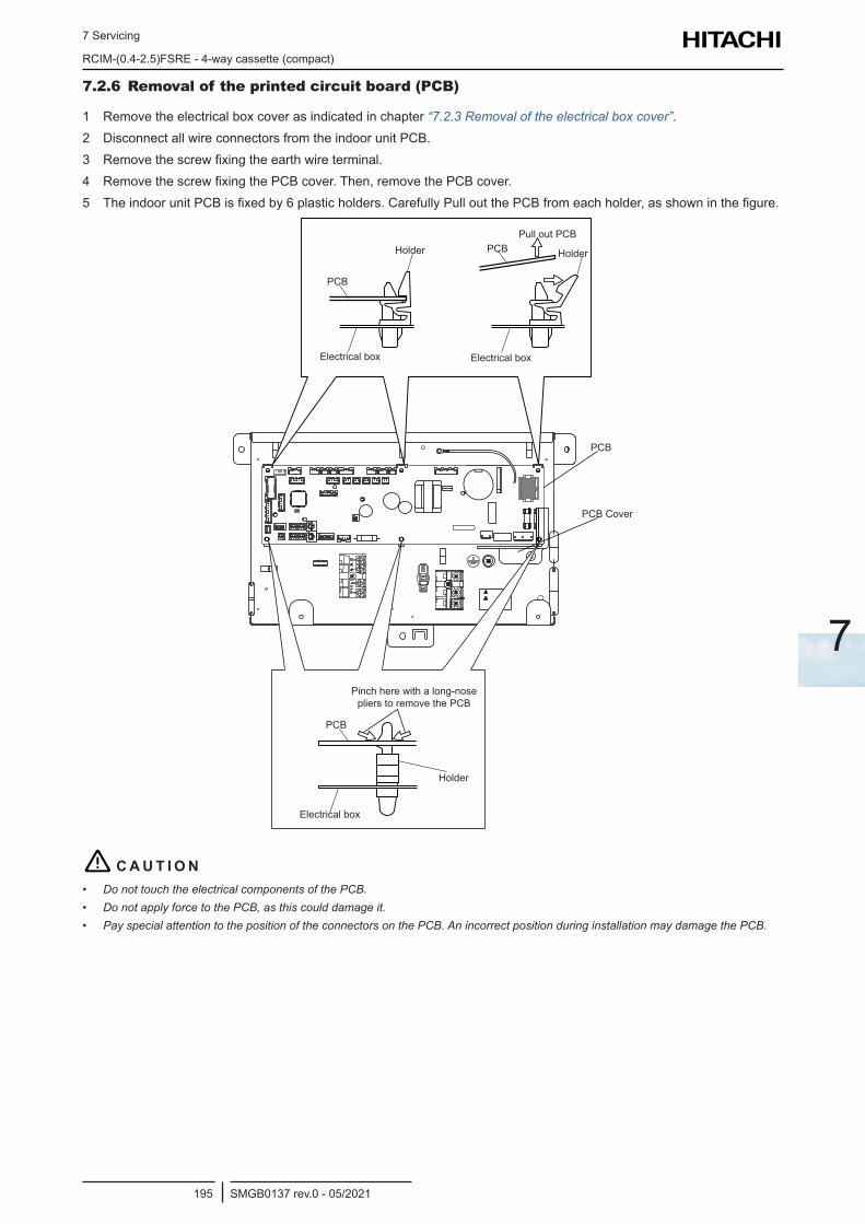
7 Servicing
RCIM-(0.4-2.5)FSRE - 4-way cassette (compact)
SMGB0137 rev.0 - 05/2021195
7
7.2.6 Removal of the printed circuit board (PCB)
1 Remove the electrical box cover as indicated in chapter “7.2.3 Removal of the electrical box cover”.2 Disconnect all wire connectors from the indoor unit PCB.3 Remove the screw fixing the earth wire terminal.4 Remove the screw fixing the PCB cover. Then, remove the PCB cover.5 The indoor unit PCB is fixed by 6 plastic holders. Carefully Pull out the PCB from each holder, as shown in the figure.
Holder
PCB
Electrical box
Pull out PCBPCB Holder
Electrical box
Holder
PCB
Electrical box
Pinch here with a long-nose pliers to remove the PCB
PCB
PCB Cover
! C A U T I O N• Do not touch the electrical components of the PCB.• Do not apply force to the PCB, as this could damage it.• Pay special attention to the position of the connectors on the PCB. An incorrect position during installation may damage the PCB.
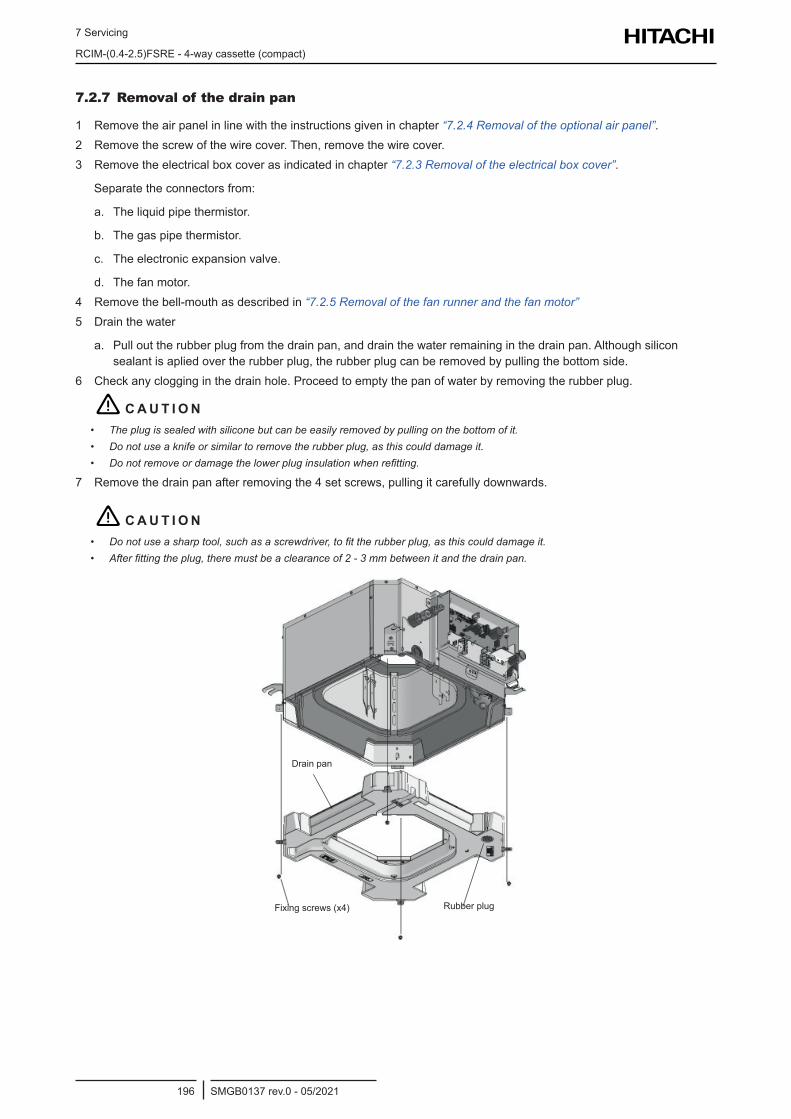
7 Servicing
RCIM-(0.4-2.5)FSRE - 4-way cassette (compact)
SMGB0137 rev.0 - 05/2021196
7.2.7 Removal of the drain pan
1 Remove the air panel in line with the instructions given in chapter “7.2.4 Removal of the optional air panel”.2 Remove the screw of the wire cover. Then, remove the wire cover.3 Remove the electrical box cover as indicated in chapter “7.2.3 Removal of the electrical box cover”.
Separate the connectors from:
a. The liquid pipe thermistor.
b. The gas pipe thermistor.
c. The electronic expansion valve.
d. The fan motor.4 Remove the bell-mouth as described in “7.2.5 Removal of the fan runner and the fan motor” 5 Drain the water
a. Pull out the rubber plug from the drain pan, and drain the water remaining in the drain pan. Although silicon sealant is aplied over the rubber plug, the rubber plug can be removed by pulling the bottom side.
6 Check any clogging in the drain hole. Proceed to empty the pan of water by removing the rubber plug.
! C A U T I O N• The plug is sealed with silicone but can be easily removed by pulling on the bottom of it.• Do not use a knife or similar to remove the rubber plug, as this could damage it.• Do not remove or damage the lower plug insulation when refitting.
7 Remove the drain pan after removing the 4 set screws, pulling it carefully downwards.
! C A U T I O N• Do not use a sharp tool, such as a screwdriver, to fit the rubber plug, as this could damage it.• After fitting the plug, there must be a clearance of 2 - 3 mm between it and the drain pan.
Drain pan
Rubber plugFixing screws (x4)
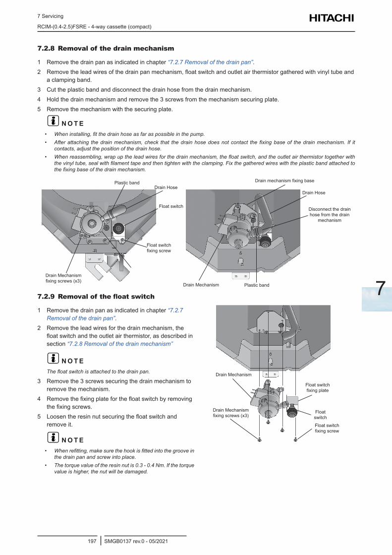
7 Servicing
RCIM-(0.4-2.5)FSRE - 4-way cassette (compact)
SMGB0137 rev.0 - 05/2021197
7
7.2.8 Removal of the drain mechanism
1 Remove the drain pan as indicated in chapter “7.2.7 Removal of the drain pan”.2 Remove the lead wires of the drain pan mechanism, float switch and outlet air thermistor gathered with vinyl tube and
a clamping band.3 Cut the plastic band and disconnect the drain hose from the drain mechanism.4 Hold the drain mechanism and remove the 3 screws from the mechanism securing plate.5 Remove the mechanism with the securing plate.
? N O T E• When installing, fit the drain hose as far as possible in the pump.• After attaching the drain mechanism, check that the drain hose does not contact the fixing base of the drain mechanism. If it
contacts, adjust the position of the drain hose.• When reassembling, wrap up the lead wires for the drain mechanism, the float switch, and the outlet air thermistor together with
the vinyl tube, seal with filament tape and then tighten with the clamping. Fix the gathered wires with the plastic band attached to the fixing base of the drain mechanism.
Plastic bandDrain Hose
Float switch
Float switch fixing screw
Drain Mechanism fixing screws (x3)
Drain Hose
Drain mechanism fixing base
Plastic bandDrain Mechanism
Disconnect the drain hose from the drain
mechanism
7.2.9 Removal of the float switch
1 Remove the drain pan as indicated in chapter “7.2.7 Removal of the drain pan”.
2 Remove the lead wires for the drain mechanism, the float switch and the outlet air thermistor, as described in section “7.2.8 Removal of the drain mechanism”
? N O T EThe float switch is attached to the drain pan.
3 Remove the 3 screws securing the drain mechanism to remove the mechanism.
4 Remove the fixing plate for the float switch by removing the fixing screws.
5 Loosen the resin nut securing the float switch and remove it.
? N O T E• When refitting, make sure the hook is fitted into the groove in
the drain pan and screw into place.• The torque value of the resin nut is 0.3 - 0.4 Nm. If the torque
value is higher, the nut will be damaged.
Drain Mechanism
Drain Mechanism fixing screws (x3)
Float switch fixing plate
Float switch
Float switch fixing screw
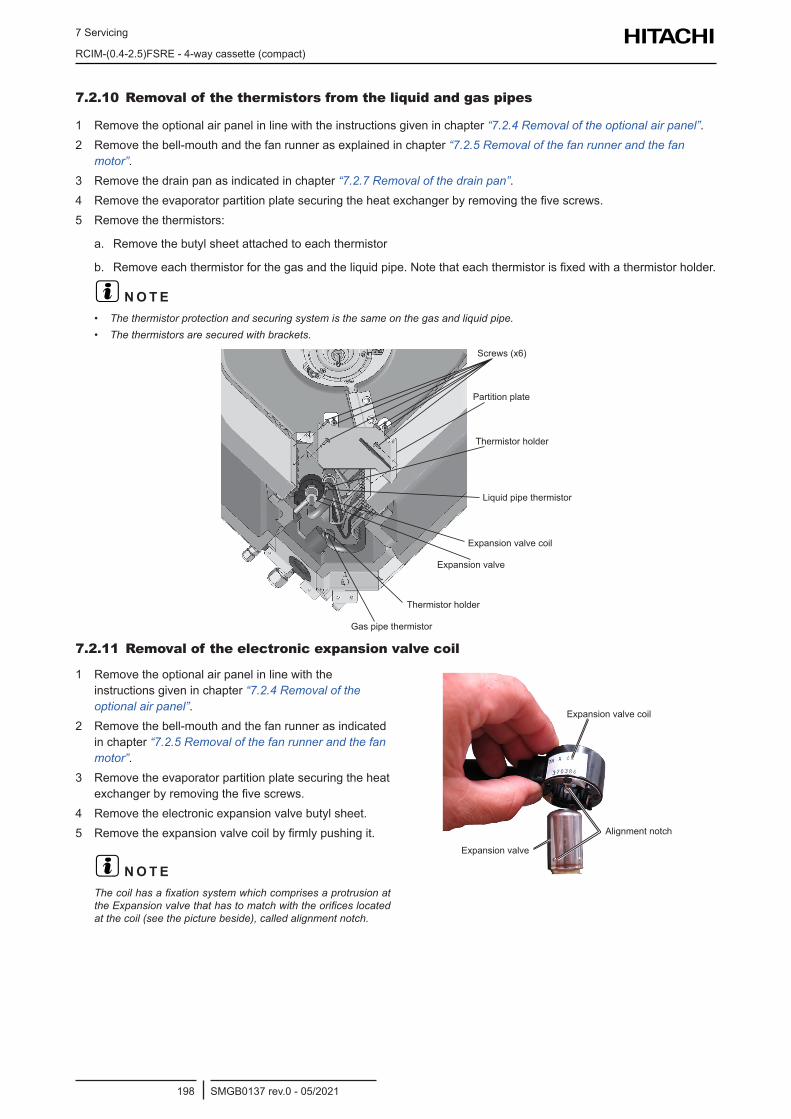
7 Servicing
RCIM-(0.4-2.5)FSRE - 4-way cassette (compact)
SMGB0137 rev.0 - 05/2021198
7.2.10 Removal of the thermistors from the liquid and gas pipes
1 Remove the optional air panel in line with the instructions given in chapter “7.2.4 Removal of the optional air panel”.2 Remove the bell-mouth and the fan runner as explained in chapter “7.2.5 Removal of the fan runner and the fan
motor”.3 Remove the drain pan as indicated in chapter “7.2.7 Removal of the drain pan”.4 Remove the evaporator partition plate securing the heat exchanger by removing the five screws.5 Remove the thermistors:
a. Remove the butyl sheet attached to each thermistor
b. Remove each thermistor for the gas and the liquid pipe. Note that each thermistor is fixed with a thermistor holder.
? N O T E• The thermistor protection and securing system is the same on the gas and liquid pipe.• The thermistors are secured with brackets.
Gas pipe thermistor
Thermistor holder
Expansion valve coil
Expansion valve
Liquid pipe thermistor
Thermistor holder
Partition plate
Screws (x6)
7.2.11 Removal of the electronic expansion valve coil
1 Remove the optional air panel in line with the instructions given in chapter “7.2.4 Removal of the optional air panel”.
2 Remove the bell-mouth and the fan runner as indicated in chapter “7.2.5 Removal of the fan runner and the fan motor”.
3 Remove the evaporator partition plate securing the heat exchanger by removing the five screws.
4 Remove the electronic expansion valve butyl sheet.5 Remove the expansion valve coil by firmly pushing it.
? N O T EThe coil has a fixation system which comprises a protrusion at the Expansion valve that has to match with the orifices located at the coil (see the picture beside), called alignment notch.
Expansion valve coil
Expansion valve
Alignment notch
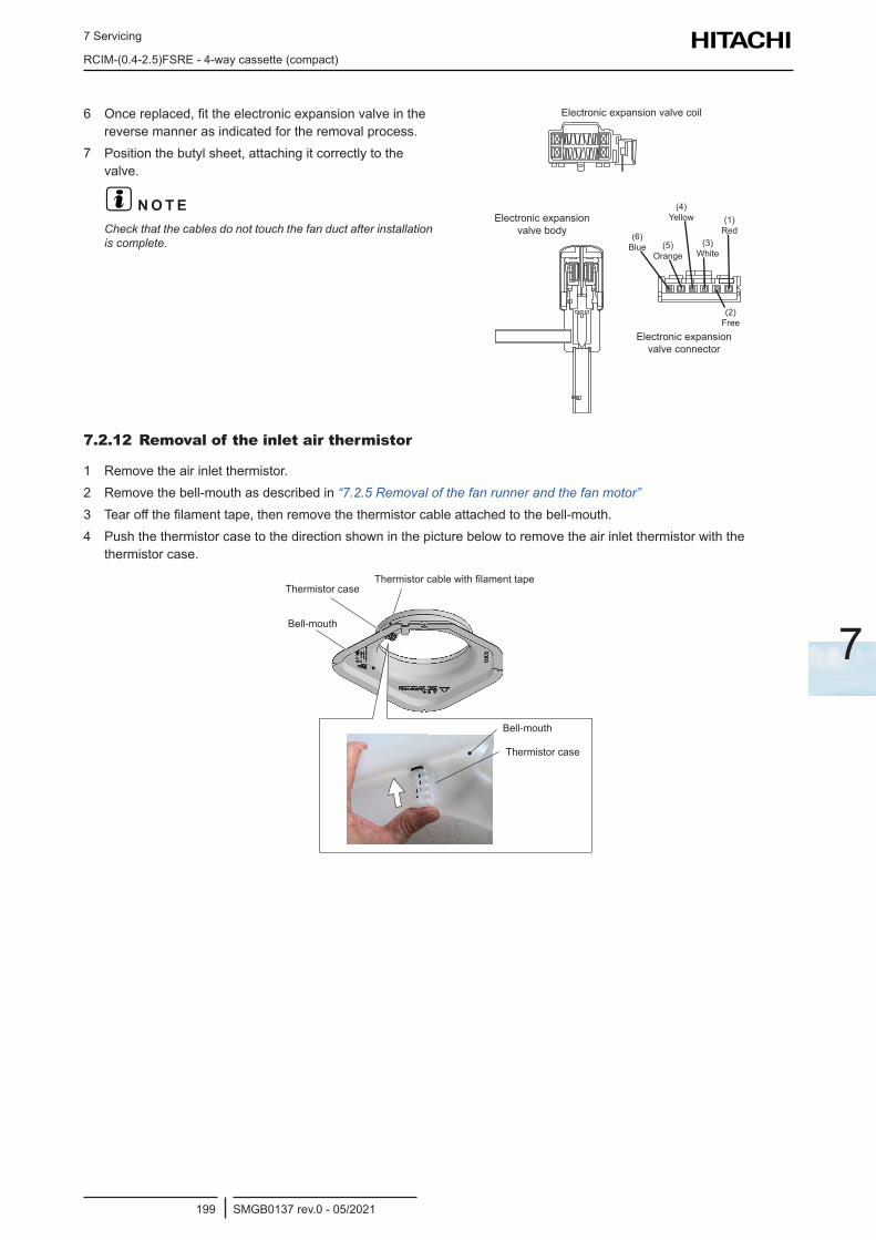
7 Servicing
RCIM-(0.4-2.5)FSRE - 4-way cassette (compact)
SMGB0137 rev.0 - 05/2021199
7
6 Once replaced, fit the electronic expansion valve in the reverse manner as indicated for the removal process.
7 Position the butyl sheet, attaching it correctly to the valve.
? N O T ECheck that the cables do not touch the fan duct after installation is complete.
Electronic expansion valve coil
Electronic expansion valve body
Electronic expansion valve connector
(6) Blue (5)
Orange
(4) Yellow
(3) White
(1) Red
(2) Free
7.2.12 Removal of the inlet air thermistor
1 Remove the air inlet thermistor.2 Remove the bell-mouth as described in “7.2.5 Removal of the fan runner and the fan motor”3 Tear off the filament tape, then remove the thermistor cable attached to the bell-mouth.4 Push the thermistor case to the direction shown in the picture below to remove the air inlet thermistor with the
thermistor case.
Thermistor cable with filament tapeThermistor case
Bell-mouth
Thermistor case
Bell-mouth
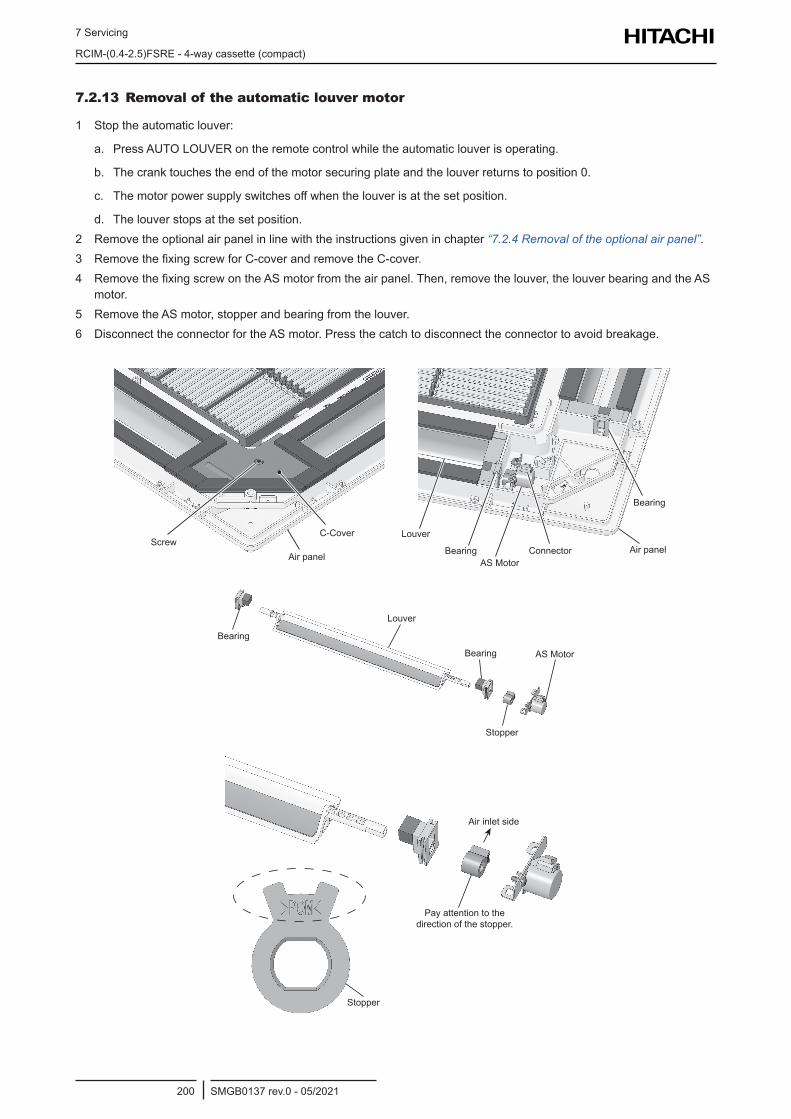
7 Servicing
RCIM-(0.4-2.5)FSRE - 4-way cassette (compact)
SMGB0137 rev.0 - 05/2021200
7.2.13 Removal of the automatic louver motor
1 Stop the automatic louver:
a. Press AUTO LOUVER on the remote control while the automatic louver is operating.
b. The crank touches the end of the motor securing plate and the louver returns to position 0.
c. The motor power supply switches off when the louver is at the set position.
d. The louver stops at the set position.2 Remove the optional air panel in line with the instructions given in chapter “7.2.4 Removal of the optional air panel”.3 Remove the fixing screw for C-cover and remove the C-cover.4 Remove the fixing screw on the AS motor from the air panel. Then, remove the louver, the louver bearing and the AS
motor.5 Remove the AS motor, stopper and bearing from the louver.6 Disconnect the connector for the AS motor. Press the catch to disconnect the connector to avoid breakage.
ScrewAir panel
C-Cover Louver
BearingAS Motor
Connector Air panel
Bearing
Bearing
Bearing
Louver
AS Motor
Stopper
Stopper
Air inlet side
Pay attention to the direction of the stopper.
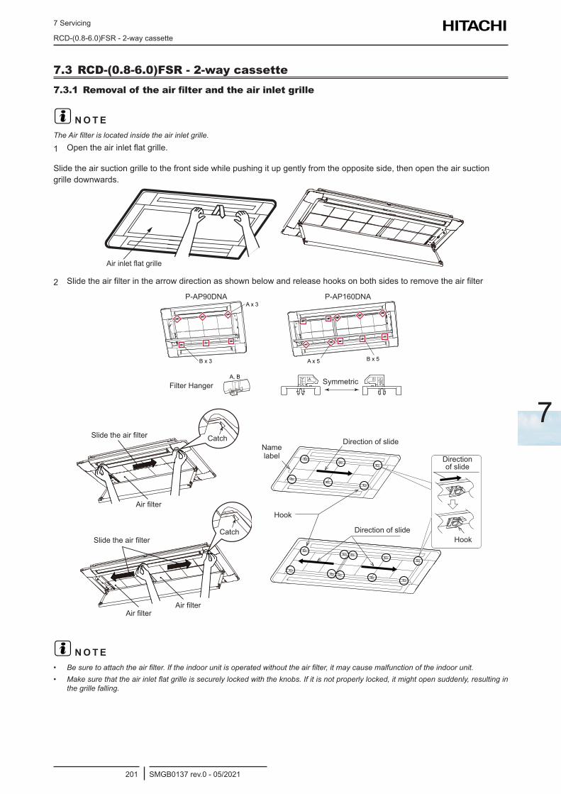
7 Servicing
RCD-(0.8-6.0)FSR - 2-way cassette
SMGB0137 rev.0 - 05/2021201
7
7.3 RCD-(0.8-6.0)FSR - 2-way cassette7.3.1 Removal of the air filter and the air inlet grille
? N O T EThe Air filter is located inside the air inlet grille.
1 Open the air inlet flat grille.
Slide the air suction grille to the front side while pushing it up gently from the opposite side, then open the air suction grille downwards.
Air inlet flat grille
2 Slide the air filter in the arrow direction as shown below and release hooks on both sides to remove the air filter
A, B
A x 5 B x 5
A x 3
B x 3
SymmetricFilter Hanger
P-AP160DNAP-AP90DNA
Air filterAir filter
Catch
Air filter
Catch
Slide the air filter
Slide the air filter
Hook
Name label Direction
of slide
Hook
Direction of slide
Direction of slide
? N O T E• Be sure to attach the air filter. If the indoor unit is operated without the air filter, it may cause malfunction of the indoor unit.• Make sure that the air inlet flat grille is securely locked with the knobs. If it is not properly locked, it might open suddenly, resulting in
the grille falling.
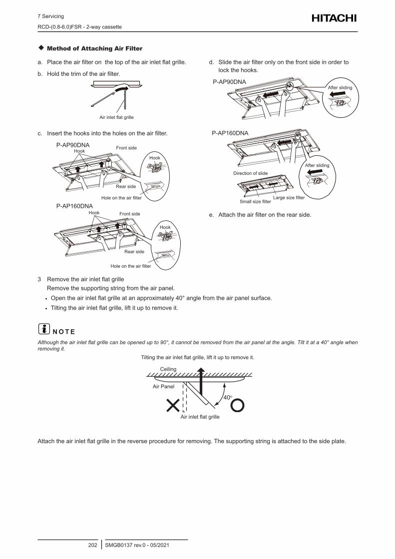
7 Servicing
RCD-(0.8-6.0)FSR - 2-way cassette
SMGB0137 rev.0 - 05/2021202
Method of Attaching Air Filter
a. Place the air filter on the top of the air inlet flat grille.
b. Hold the trim of the air filter.
Air inlet flat grille
c. Insert the hooks into the holes on the air filter.
P-AP90DNA
P-AP160DNA
Front sideHook
Rear side
Hole on the air filter
Hook
Hook
Front sideHook
Rear side
Hole on the air filter
d. Slide the air filter only on the front side in order to lock the hooks.
P-AP90DNA
P-AP160DNA
After sliding
Direction of slide
Large size filterSmall size filter
After sliding
e. Attach the air filter on the rear side.
3 Remove the air inlet flat grilleRemove the supporting string from the air panel.
• Open the air inlet flat grille at an approximately 40° angle from the air panel surface.
• Tilting the air inlet flat grille, lift it up to remove it.
? N O T EAlthough the air inlet flat grille can be opened up to 90°, it cannot be removed from the air panel at the angle. Tilt it at a 40° angle when removing it.
40o
Air inlet flat grille
Air Panel
Ceiling
Tilting the air inlet flat grille, lift it up to remove it.
Attach the air inlet flat grille in the reverse procedure for removing. The supporting string is attached to the side plate.
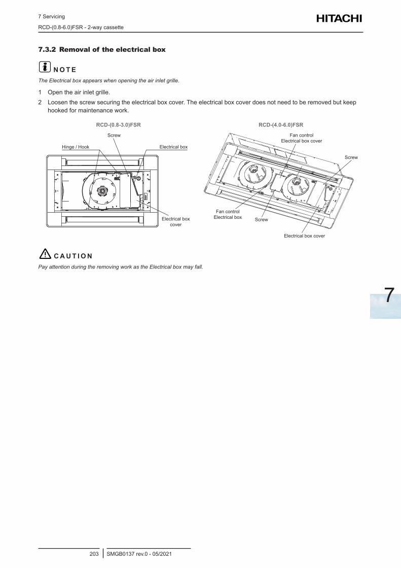
7 Servicing
RCD-(0.8-6.0)FSR - 2-way cassette
SMGB0137 rev.0 - 05/2021203
7
7.3.2 Removal of the electrical box
? N O T EThe Electrical box appears when opening the air inlet grille.
1 Open the air inlet grille.2 Loosen the screw securing the electrical box cover. The electrical box cover does not need to be removed but keep
hooked for maintenance work.
RCD-(0.8-3.0)FSR RCD-(4.0-6.0)FSR
Screw
・ ・@・ョ・サ・@・ヤ
Electrical box
Electrical box cover
Hinge / Hook
Screw
Screw
Fan control Electrical box cover
Fan control Electrical box
Electrical box cover
! C A U T I O NPay attention during the removing work as the Electrical box may fall.
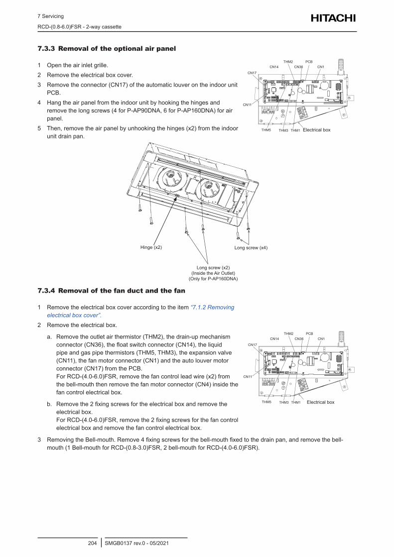
7 Servicing
RCD-(0.8-6.0)FSR - 2-way cassette
SMGB0137 rev.0 - 05/2021204
7.3.3 Removal of the optional air panel
1 Open the air inlet grille.2 Remove the electrical box cover.3 Remove the connector (CN17) of the automatic louver on the indoor unit
PCB.4 Hang the air panel from the indoor unit by hooking the hinges and
remove the long screws (4 for P-AP90DNA, 6 for P-AP160DNA) for air panel.
5 Then, remove the air panel by unhooking the hinges (x2) from the indoor unit drain pan.
CN17
PCBCN14
THM2CN36 CN1
CN11
THM5 THM3 THM1 Electrical box
Hinge (x2)
Long screw (x2) (Inside the Air Outlet) (Only for P-AP160DNA)
Long screw (x4)
7.3.4 Removal of the fan duct and the fan
1 Remove the electrical box cover according to the item “7.1.2 Removing electrical box cover”.
2 Remove the electrical box.
a. Remove the outlet air thermistor (THM2), the drain-up mechanism connector (CN36), the float switch connector (CN14), the liquid pipe and gas pipe thermistors (THM5, THM3), the expansion valve (CN11), the fan motor connector (CN1) and the auto louver motor connector (CN17) from the PCB. For RCD-(4.0-6.0)FSR, remove the fan control lead wire (x2) from the bell-mouth then remove the fan motor connector (CN4) inside the fan control electrical box.
b. Remove the 2 fixing screws for the electrical box and remove the electrical box. For RCD-(4.0-6.0)FSR, remove the 2 fixing screws for the fan control electrical box and remove the fan control electrical box.
CN17
PCBCN14
THM2CN36 CN1
CN11
THM5 THM3 THM1 Electrical box
3 Removing the Bell-mouth. Remove 4 fixing screws for the bell-mouth fixed to the drain pan, and remove the bell-mouth (1 Bell-mouth for RCD-(0.8-3.0)FSR, 2 bell-mouth for RCD-(4.0-6.0)FSR).
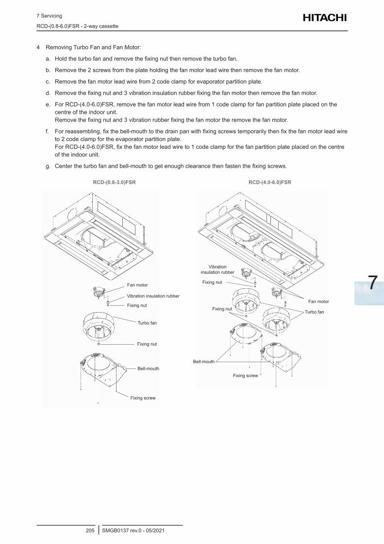
7 Servicing
RCD-(0.8-6.0)FSR - 2-way cassette
SMGB0137 rev.0 - 05/2021205
7
4 Removing Turbo Fan and Fan Motor:
a. Hold the turbo fan and remove the fixing nut then remove the turbo fan.
b. Remove the 2 screws from the plate holding the fan motor lead wire then remove the fan motor.
c. Remove the fan motor lead wire from 2 code clamp for evaporator partition plate.
d. Remove the fixing nut and 3 vibration insulation rubber fixing the fan motor then remove the fan motor.
e. For RCD-(4.0-6.0)FSR, remove the fan motor lead wire from 1 code clamp for fan partition plate placed on the centre of the indoor unit. Remove the fixing nut and 3 vibration rubber fixing the fan motor the remove the fan motor.
f. For reassembling, fix the bell-mouth to the drain pan with fixing screws temporarily then fix the fan motor lead wire to 2 code clamp for the evaporator partition plate. For RCD-(4.0-6.0)FSR, fix the fan motor lead wire to 1 code clamp for the fan partition plate placed on the centre of the indoor unit.
g. Center the turbo fan and bell-mouth to get enough clearance then fasten the fixing screws.
RCD-(0.8-3.0)FSR RCD-(4.0-6.0)FSR
Fan motor
Fixing nut
Fixing nut
Bell-mouth
Vibration insulation rubber
Turbo fan
Fixing screw
Fan motor
Turbo fanFixing nut
Fixing nut
Vibration insulation rubber
Bell-mouth
Fixing screw
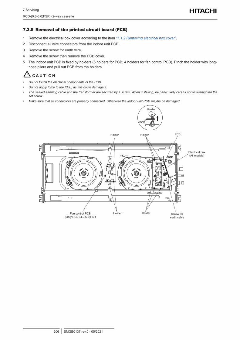
7 Servicing
RCD-(0.8-6.0)FSR - 2-way cassette
SMGB0137 rev.0 - 05/2021206
7.3.5 Removal of the printed circuit board (PCB)
1 Remove the electrical box cover according to the item “7.1.2 Removing electrical box cover”.2 Disconnect all wire connectors from the indoor unit PCB.3 Remove the screw for earth wire.4 Remove the screw then remove the PCB cover.5 The indoor unit PCB is fixed by holders (6 holders for PCB, 4 holders for fan control PCB). Pinch the holder with long-
nose pliers and pull out PCB from the holders.
! C A U T I O N• Do not touch the electrical components of the PCB.• Do not apply force to the PCB, as this could damage it.• The sealed earthing cable and the transformer are secured by a screw. When installing, be particularly careful not to overtighten the
set screw.• Make sure that all connectors are properly connected. Otherwise the Indoor unit PCB maybe be damaged.
Holder
Holder
HolderFan control PCB (Only RCD-(4.0-6.0)FSR
Holder PCB
PCB
Holder Screw for earth cable
Electrical box (All models)
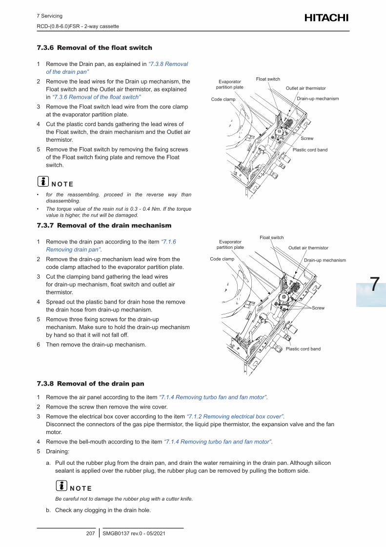
7 Servicing
RCD-(0.8-6.0)FSR - 2-way cassette
SMGB0137 rev.0 - 05/2021207
7
7.3.6 Removal of the float switch
1 Remove the Drain pan, as explained in “7.3.8 Removal of the drain pan”
2 Remove the lead wires for the Drain up mechanism, the Float switch and the Outlet air thermistor, as explained in “7.3.6 Removal of the float switch”
3 Remove the Float switch lead wire from the core clamp at the evaporator partition plate.
4 Cut the plastic cord bands gathering the lead wires of the Float switch, the drain mechanism and the Outlet air thermistor.
5 Remove the Float switch by removing the fixing screws of the Float switch fixing plate and remove the Float switch.
? N O T E• for the reassembling, proceed in the reverse way than
disassembling.• The torque value of the resin nut is 0.3 - 0.4 Nm. If the torque
value is higher, the nut will be damaged.
Float switchEvaporator partition plate
Code clamp
Outlet air thermistor
Drain-up mechanism
Screw
Plastic cord band
7.3.7 Removal of the drain mechanism
1 Remove the drain pan according to the item “7.1.6 Removing drain pan”.
2 Remove the drain-up mechanism lead wire from the code clamp attached to the evaporator partition plate.
3 Cut the clamping band gathering the lead wires for drain-up mechanism, float switch and outlet air thermistor.
4 Spread out the plastic band for drain hose the remove the drain hose from drain-up mechanism.
5 Remove three fixing screws for the drain-up mechanism. Make sure to hold the drain-up mechanism by hand so that it will not fall off.
6 Then remove the drain-up mechanism.
Float switchEvaporator partition plate
Code clamp
Outlet air thermistor
Drain-up mechanism
Screw
Plastic cord band
7.3.8 Removal of the drain pan
1 Remove the air panel according to the item “7.1.4 Removing turbo fan and fan motor”.2 Remove the screw then remove the wire cover.3 Remove the electrical box cover according to the item “7.1.2 Removing electrical box cover”.
Disconnect the connectors of the gas pipe thermistor, the liquid pipe thermistor, the expansion valve and the fan motor.
4 Remove the bell-mouth according to the item “7.1.4 Removing turbo fan and fan motor”.5 Draining:
a. Pull out the rubber plug from the drain pan, and drain the water remaining in the drain pan. Although silicon sealant is applied over the rubber plug, the rubber plug can be removed by pulling the bottom side.
? N O T EBe careful not to damage the rubber plug with a cutter knife.
b. Check any clogging in the drain hole.
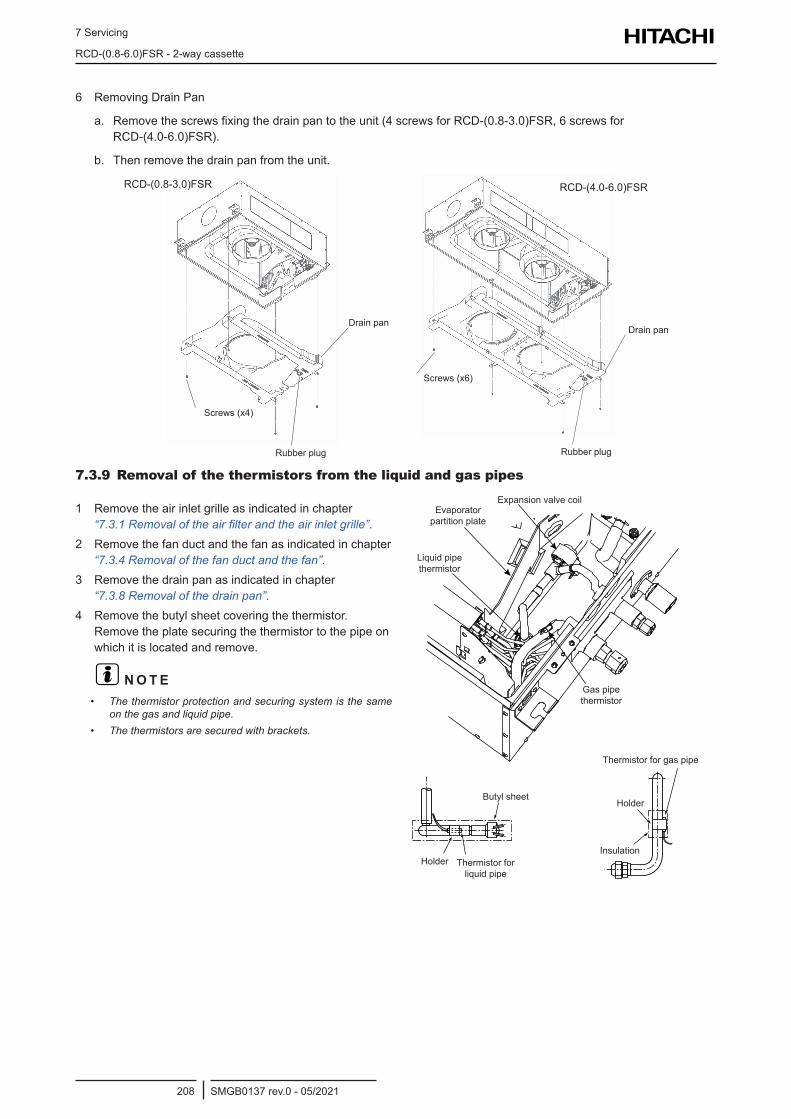
7 Servicing
RCD-(0.8-6.0)FSR - 2-way cassette
SMGB0137 rev.0 - 05/2021208
6 Removing Drain Pan
a. Remove the screws fixing the drain pan to the unit (4 screws for RCD-(0.8-3.0)FSR, 6 screws for RCD-(4.0-6.0)FSR).
b. Then remove the drain pan from the unit.
Drain pan
Screws (x4)
Rubber plug
RCD-(0.8-3.0)FSR
Drain pan
Rubber plug
Screws (x6)
RCD-(4.0-6.0)FSR
7.3.9 Removal of the thermistors from the liquid and gas pipes
1 Remove the air inlet grille as indicated in chapter “7.3.1 Removal of the air filter and the air inlet grille”.
2 Remove the fan duct and the fan as indicated in chapter “7.3.4 Removal of the fan duct and the fan”.
3 Remove the drain pan as indicated in chapter “7.3.8 Removal of the drain pan”.
4 Remove the butyl sheet covering the thermistor. Remove the plate securing the thermistor to the pipe on which it is located and remove.
? N O T E• The thermistor protection and securing system is the same
on the gas and liquid pipe.• The thermistors are secured with brackets.
Expansion valve coilEvaporator partition plate
Liquid pipe thermistor
Gas pipe thermistor
Insulation
Holder
Thermistor for gas pipe
Holder Thermistor for liquid pipe
Butyl sheet
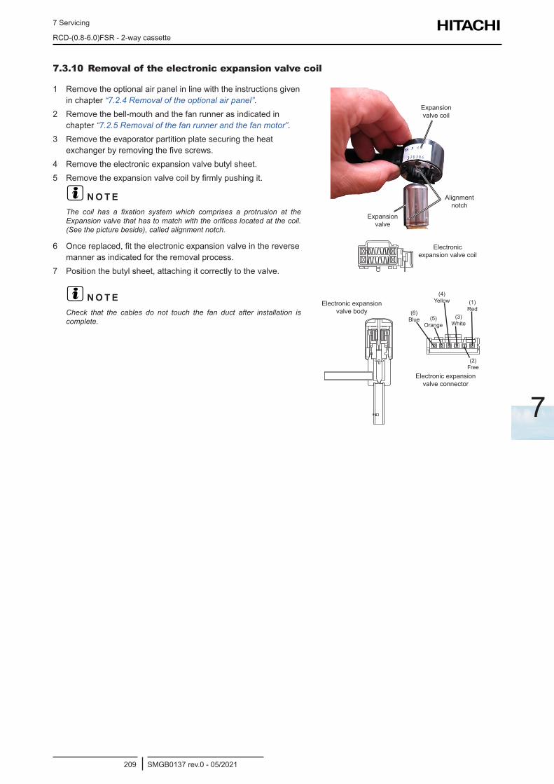
7 Servicing
RCD-(0.8-6.0)FSR - 2-way cassette
SMGB0137 rev.0 - 05/2021209
7
7.3.10 Removal of the electronic expansion valve coil
1 Remove the optional air panel in line with the instructions given in chapter “7.2.4 Removal of the optional air panel”.
2 Remove the bell-mouth and the fan runner as indicated in chapter “7.2.5 Removal of the fan runner and the fan motor”.
3 Remove the evaporator partition plate securing the heat exchanger by removing the five screws.
4 Remove the electronic expansion valve butyl sheet.5 Remove the expansion valve coil by firmly pushing it.
? N O T EThe coil has a fixation system which comprises a protrusion at the Expansion valve that has to match with the orifices located at the coil. (See the picture beside), called alignment notch.
Expansion valve coil
Expansion valve
Alignment notch
6 Once replaced, fit the electronic expansion valve in the reverse manner as indicated for the removal process.
7 Position the butyl sheet, attaching it correctly to the valve.
? N O T ECheck that the cables do not touch the fan duct after installation is complete.
Electronic expansion valve coil
Electronic expansion valve body
Electronic expansion valve connector
(6) Blue (5)
Orange
(4) Yellow
(3) White
(1) Red
(2) Free
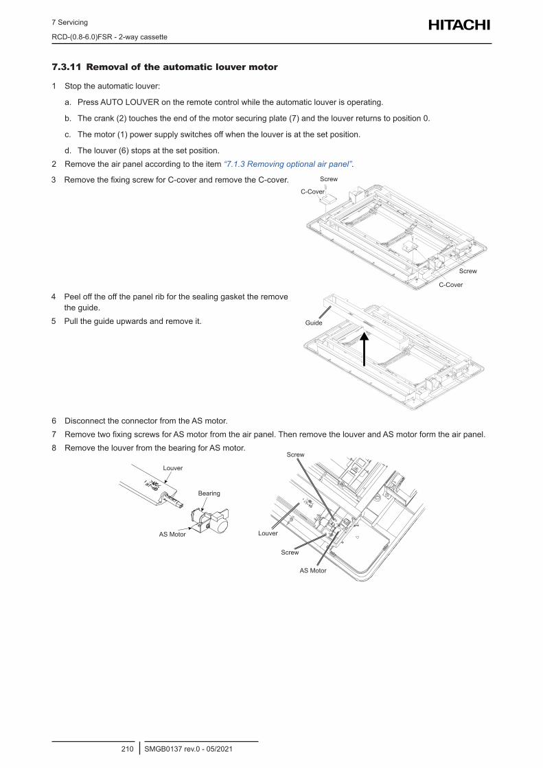
7 Servicing
RCD-(0.8-6.0)FSR - 2-way cassette
SMGB0137 rev.0 - 05/2021210
7.3.11 Removal of the automatic louver motor
1 Stop the automatic louver:
a. Press AUTO LOUVER on the remote control while the automatic louver is operating.
b. The crank (2) touches the end of the motor securing plate (7) and the louver returns to position 0.
c. The motor (1) power supply switches off when the louver is at the set position.
d. The louver (6) stops at the set position.2 Remove the air panel according to the item “7.1.3 Removing optional air panel”.
3 Remove the fixing screw for C-cover and remove the C-cover.C-Cover
C-Cover
Screw
Screw
4 Peel off the off the panel rib for the sealing gasket the remove the guide.
5 Pull the guide upwards and remove it. Guide
6 Disconnect the connector from the AS motor.7 Remove two fixing screws for AS motor from the air panel. Then remove the louver and AS motor form the air panel.8 Remove the louver from the bearing for AS motor.
Louver
Bearing
AS Motor
Screw
Screw
AS Motor
Louver
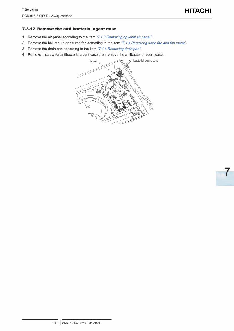
7 Servicing
RCD-(0.8-6.0)FSR - 2-way cassette
SMGB0137 rev.0 - 05/2021211
7
7.3.12 Remove the anti bacterial agent case
1 Remove the air panel according to the item “7.1.3 Removing optional air panel”.2 Remove the bell-mouth and turbo fan according to the item “7.1.4 Removing turbo fan and fan motor”.3 Remove the drain pan according to the item “7.1.6 Removing drain pan”.4 Remove 1 screw for antibacterial agent case then remove the antibacterial agent case.
Screw Antibacterial agent case
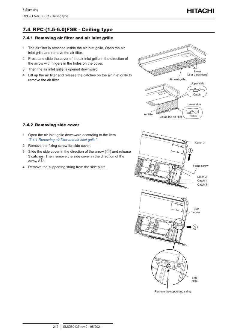
7 Servicing
RPC-(1.5-6.0)FSR - Ceiling type
SMGB0137 rev.0 - 05/2021212
7.4 RPC-(1.5-6.0)FSR - Ceiling type7.4.1 Removing air filter and air inlet grille
1 The air filter is attached inside the air inlet grille. Open the air inlet grille and remove the air filter.
2 Press and slide the cover of the air inlet grille in the direction of the arrow with fingers in the holes on the cover.
3 Then the air inlet grille is opened downward.4 Lift up the air filter and release the catches on the air inlet grille to
remove the air filter.
Holes(2 or 3 Portions)
Air Inlet Grille
Holes (2 or 3 positions)
Air inlet grille
Lower side
Upper side
Catch
CatchAir filterLift up the air filter
7.4.2 Removing side cover
1 Open the air inlet grille downward according to the item “7.4.1 Removing air filter and air inlet grille”.
2 Remove the fixing screw for side cover.3 Slide the side cover in the direction of the arrow ( 1 ) and release
3 catches. Then remove the side cover in the direction of the arrow ( 2 ).
4 Remove the supporting string from the side plate.
2
1
Removethe supporting string.
Side Plate
Side Cover
Catch 1Catch 2
Catch 3
Fixing Screw
Catch 3
Catch 3
Catch 3Catch 1Catch 2
Fixing screw
Side cover
Side plate
Remove the supporting string
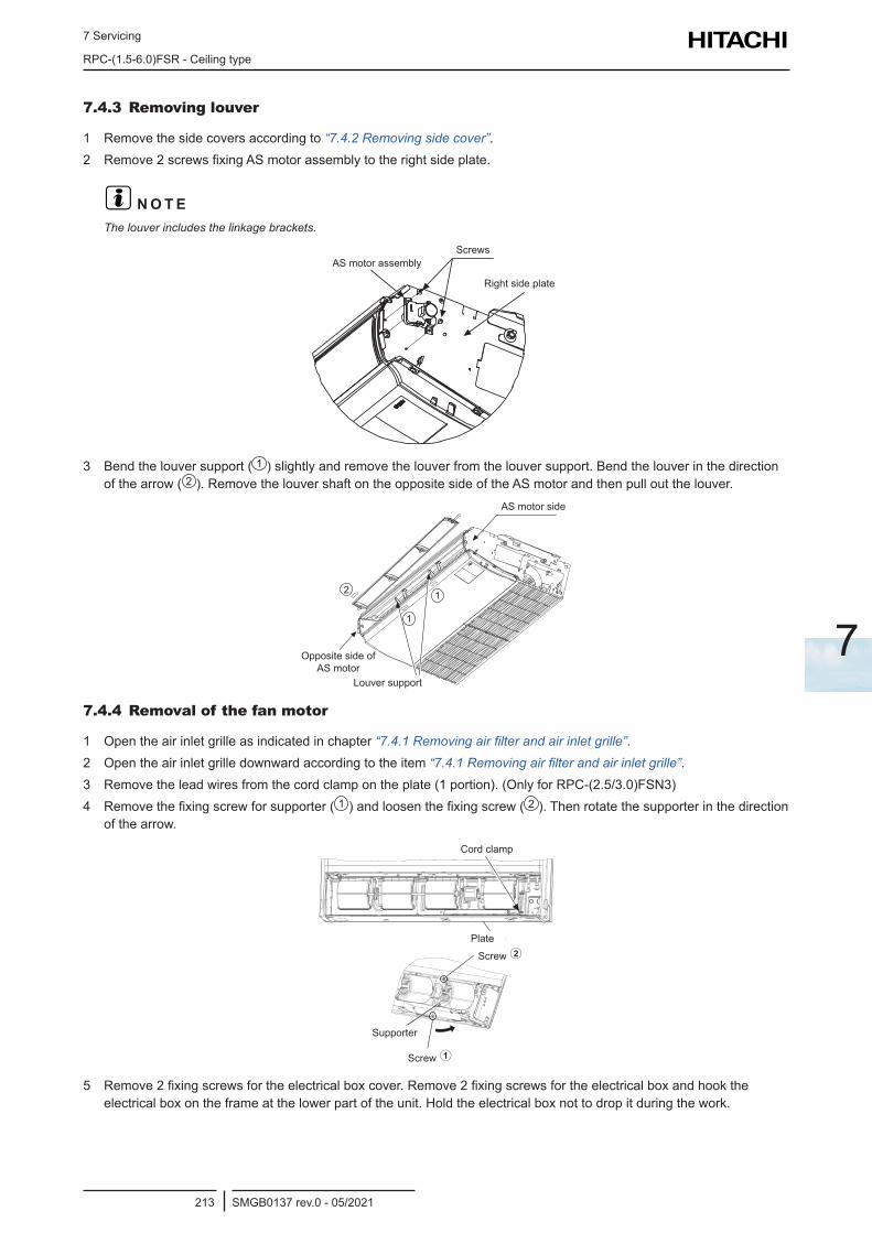
7 Servicing
RPC-(1.5-6.0)FSR - Ceiling type
SMGB0137 rev.0 - 05/2021213
7
7.4.3 Removing louver
1 Remove the side covers according to “7.4.2 Removing side cover”.2 Remove 2 screws fixing AS motor assembly to the right side plate.
? N O T EThe louver includes the linkage brackets.
AS Motor AssemblyScrews
Right Side PlateRight side plate
ScrewsAS motor assembly
3 Bend the louver support ( 1 ) slightly and remove the louver from the louver support. Bend the louver in the direction of the arrow ( 2 ). Remove the louver shaft on the opposite side of the AS motor and then pull out the louver.
2 1
AS Motor Side
Opposite Sideof AS Motor
Louver Support
1
Louver support
AS motor side
Opposite side of AS motor
7.4.4 Removal of the fan motor
1 Open the air inlet grille as indicated in chapter “7.4.1 Removing air filter and air inlet grille”.2 Open the air inlet grille downward according to the item “7.4.1 Removing air filter and air inlet grille”.3 Remove the lead wires from the cord clamp on the plate (1 portion). (Only for RPC-(2.5/3.0)FSN3)4 Remove the fixing screw for supporter ( 1 ) and loosen the fixing screw ( 2 ). Then rotate the supporter in the direction
of the arrow.
Cord Clamp
Plate
Supporter
Screw 1
2Screw
Cord clamp
Plate
Screw
Supporter
Screw
5 Remove 2 fixing screws for the electrical box cover. Remove 2 fixing screws for the electrical box and hook the electrical box on the frame at the lower part of the unit. Hold the electrical box not to drop it during the work.
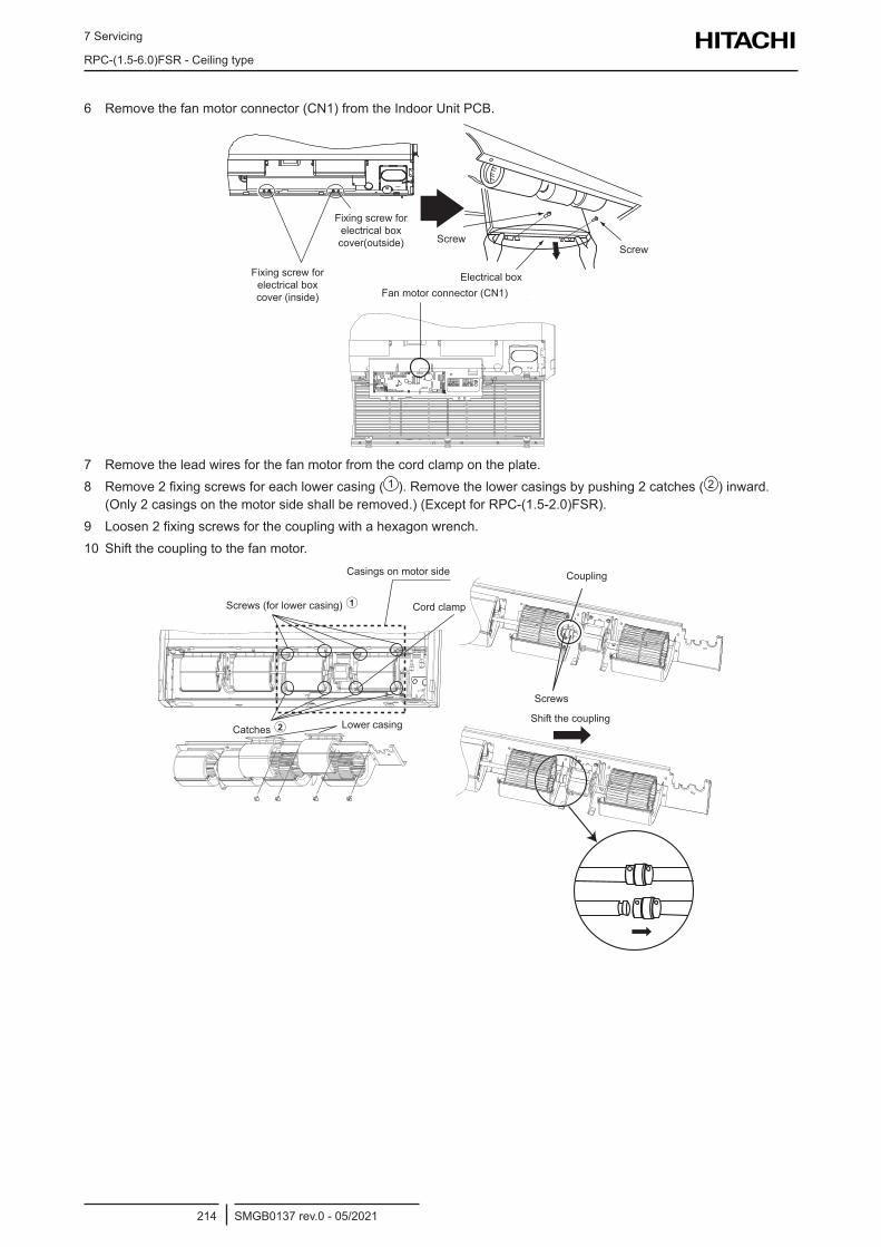
7 Servicing
RPC-(1.5-6.0)FSR - Ceiling type
SMGB0137 rev.0 - 05/2021214
6 Remove the fan motor connector (CN1) from the Indoor Unit PCB.
Fan Motor Connector (CN1)Fan motor connector (CN1)Electrical box
ScrewScrew
Fixing screw for electrical box cover(outside)
Fixing screw for electrical box cover (inside)
7 Remove the lead wires for the fan motor from the cord clamp on the plate.8 Remove 2 fixing screws for each lower casing ( 1 ). Remove the lower casings by pushing 2 catches ( 2 ) inward.
(Only 2 casings on the motor side shall be removed.) (Except for RPC-(1.5-2.0)FSR).9 Loosen 2 fixing screws for the coupling with a hexagon wrench.10 Shift the coupling to the fan motor.
Shift the coupling
Coupling
Screws
Casings on motor side
Screws (for lower casing)
Catches Lower casing
Cord clamp
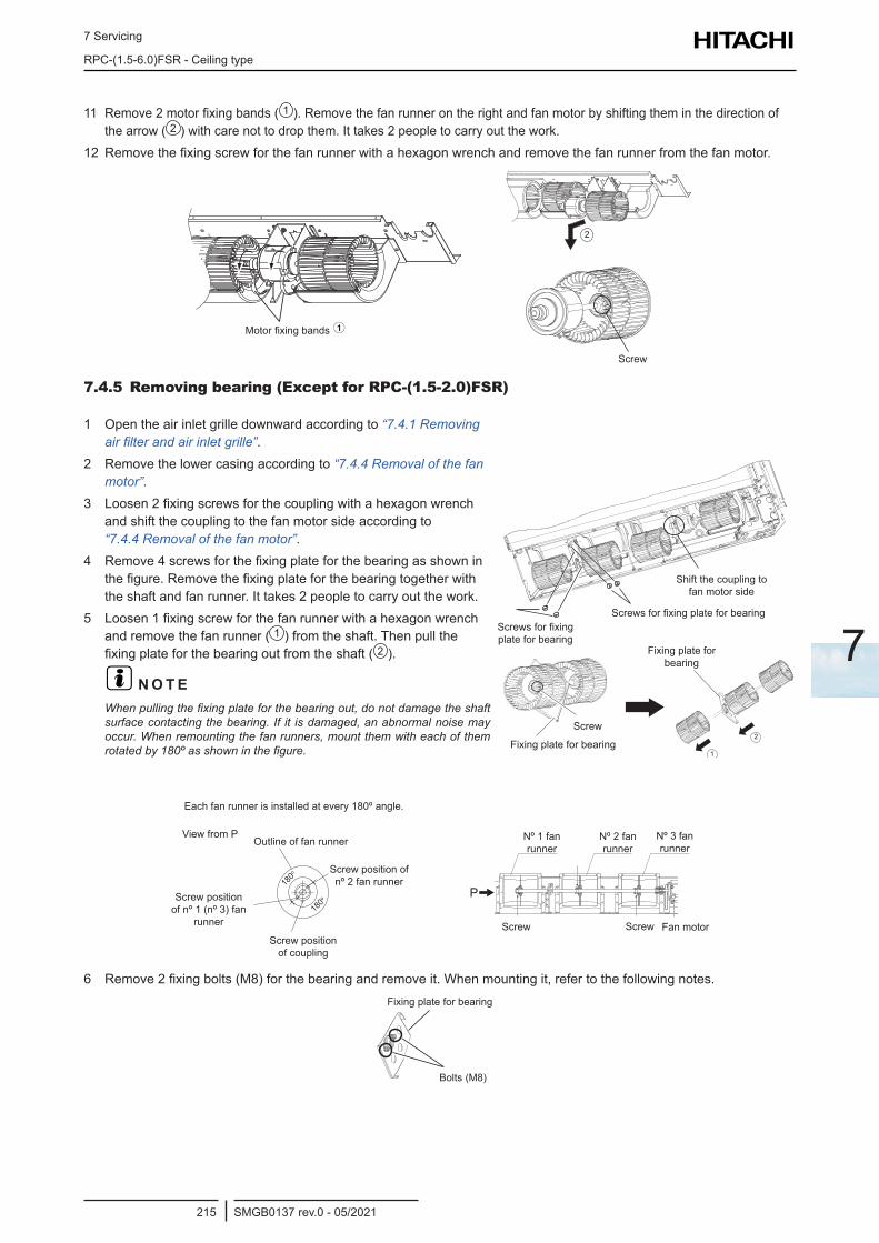
7 Servicing
RPC-(1.5-6.0)FSR - Ceiling type
SMGB0137 rev.0 - 05/2021215
7
11 Remove 2 motor fixing bands ( 1 ). Remove the fan runner on the right and fan motor by shifting them in the direction of the arrow ( 2 ) with care not to drop them. It takes 2 people to carry out the work.
12 Remove the fixing screw for the fan runner with a hexagon wrench and remove the fan runner from the fan motor.
Motor fixing bands Motor Fixing Bands 1
Screw
2
Screw
7.4.5 Removing bearing (Except for RPC-(1.5-2.0)FSR)
1 Open the air inlet grille downward according to “7.4.1 Removing air filter and air inlet grille”.
2 Remove the lower casing according to “7.4.4 Removal of the fan motor”.
3 Loosen 2 fixing screws for the coupling with a hexagon wrench and shift the coupling to the fan motor side according to “7.4.4 Removal of the fan motor”.
4 Remove 4 screws for the fixing plate for the bearing as shown in the figure. Remove the fixing plate for the bearing together with the shaft and fan runner. It takes 2 people to carry out the work.
5 Loosen 1 fixing screw for the fan runner with a hexagon wrench and remove the fan runner ( 1 ) from the shaft. Then pull the fixing plate for the bearing out from the shaft ( 2 ).
? N O T EWhen pulling the fixing plate for the bearing out, do not damage the shaft surface contacting the bearing. If it is damaged, an abnormal noise may occur. When remounting the fan runners, mount them with each of them rotated by 180º as shown in the figure. 1
2
Shift the coupling to fan motor side
Screws for fixing plate for bearingScrews for fixing plate for bearing
Fixing plate for bearing
Fixing plate for bearing
Screw
180o
180o
Each fan runner is installed at every 180º angle.
View from POutline of fan runner
Screw position of nº 2 fan runner
Screw position of coupling
Screw position of nº 1 (nº 3) fan
runner
P
Nº 1 fan runner
Nº 2 fan runner
Nº 3 fan runner
Screw Screw Fan motor
6 Remove 2 fixing bolts (M8) for the bearing and remove it. When mounting it, refer to the following notes.
Fixing Plate for Bearing
Bolts (M8)
Fixing plate for bearing
Bolts (M8)
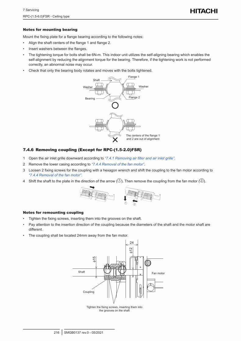
7 Servicing
RPC-(1.5-6.0)FSR - Ceiling type
SMGB0137 rev.0 - 05/2021216
Notes for mounting bearing
Mount the fixing plate for a flange bearing according to the following notes:• Align the shaft centers of the flange 1 and flange 2.• Insert washers between the flanges.• The tightening torque for bolts shall be 6N-m. This indoor unit utilizes the self-aligning bearing which enables the
self-alignment by reducing the alignment torque for the bearing. Therefore, if the tightening work is not performed correctly, an abnormal noise may occur.
• Check that only the bearing body rotates and moves with the bolts tightened.
The centers of the flange 1 and 2 are out of alignment
Flange 1
Flange 2
WasherWasher
Shaft
Bearing
7.4.6 Removing coupling (Except for RPC-(1.5-2.0)FSR)
1 Open the air inlet grille downward according to “7.4.1 Removing air filter and air inlet grille”.2 Remove the lower casing according to “7.4.4 Removal of the fan motor”.3 Loosen 2 fixing screws for the coupling with a hexagon wrench and shift the coupling to the fan motor according to
“7.4.4 Removal of the fan motor”.4 Shift the shaft to the plate in the direction of the arrow ( 1 ). Then remove the coupling from the fan motor ( 2 ).
12
Notes for remounting coupling• Tighten the fixing screws, inserting them into the grooves on the shaft.• Pay attention to the insertion direction of the coupling because the diameters of the shaft and the motor shaft are
different.• The coupling shall be located 24mm away from the fan motor.
Coupling
Fan MotorShaft
φ15
φ12
24
Tighten the fixing screws,inserting them into the grooves on the shaft.
Tighten the fixing screws, inserting them into the grooves on the shaft
Fan motor
Coupling
Shaft
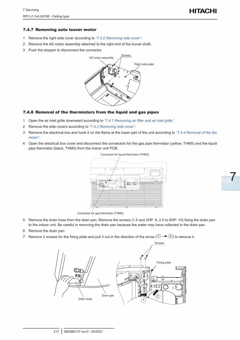
7 Servicing
RPC-(1.5-6.0)FSR - Ceiling type
SMGB0137 rev.0 - 05/2021217
7
7.4.7 Removing auto louver motor
1 Remove the right side cover according to “7.4.2 Removing side cover”.2 Remove the AS motor assembly attached to the right end of the louver shaft.3 Push the stopper to disconnect the connector.
AS Motor AssemblyScrews
Right Side Plate
ScrewsAS motor assembly
Right side plate
7.4.8 Removal of the thermistors from the liquid and gas pipes
1 Open the air inlet grille downward according to “7.4.1 Removing air filter and air inlet grille”.2 Remove the side covers according to “7.4.2 Removing side cover”.3 Remove the electrical box and hook it on the flame at the lower part of the unit according to “7.4.4 Removal of the fan
motor”.4 Open the electrical box cover and disconnect the connectors for the gas pipe thermistor (yellow, THM5) and the liquid
pipe thermistor (black, THM3) from the indoor unit PCB.Connector for Liquid Thermistor (THM3)
Connector for Gas Thermistor (THM5)
Connector for liquid thermistor (THM3)
Connector for gas thermistor (THM5)
5 Remove the drain hose from the drain pan. Remove the screws (1.5 and 2HP: 9, 2.5 to 6HP: 10) fixing the drain pan to the indoor unit. Be careful in removing the drain pan because the water may have collected in the drain pan.
6 Remove the drain pan.7 Remove 2 screws for the fixing plate and pull it out in the direction of the arrow ( 1 2 ) to remove it.
Drain Hose
Drain PanDrain panDrain hose
Screws
Fixing Plate
21
Screws
Fixing plate
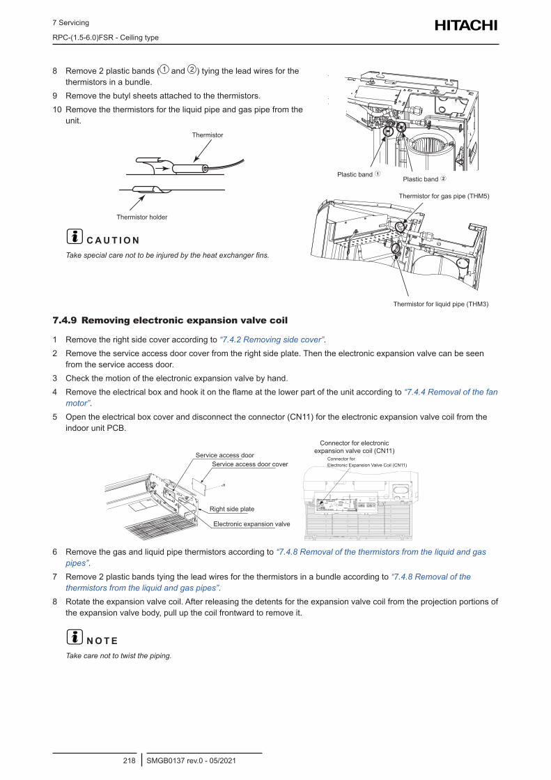
7 Servicing
RPC-(1.5-6.0)FSR - Ceiling type
SMGB0137 rev.0 - 05/2021218
8 Remove 2 plastic bands ( 1 and 2 ) tying the lead wires for the thermistors in a bundle.
9 Remove the butyl sheets attached to the thermistors. 10 Remove the thermistors for the liquid pipe and gas pipe from the
unit.
Thermistor
Thermistor Holder
Thermistor
Thermistor holder
? C A U T I O NTake special care not to be injured by the heat exchanger fins.
Plastic Band 12Plastic Band
Plastic band Plastic band
Thermistor for Gas Pipe (THM5)
Thermistor for Liquid Pipe (THM3)
Thermistor for gas pipe (THM5)
Thermistor for liquid pipe (THM3)
7.4.9 Removing electronic expansion valve coil
1 Remove the right side cover according to “7.4.2 Removing side cover”.2 Remove the service access door cover from the right side plate. Then the electronic expansion valve can be seen
from the service access door.3 Check the motion of the electronic expansion valve by hand.4 Remove the electrical box and hook it on the flame at the lower part of the unit according to “7.4.4 Removal of the fan
motor”.5 Open the electrical box cover and disconnect the connector (CN11) for the electronic expansion valve coil from the
indoor unit PCB.
Service Access Door
Service Access Door Cover
Electronic Expansion Valve
Right Side Plate
Service access doorService access door cover
Right side plate
Electronic expansion valve
Connector forElectronic Expansion Valve Coil (CN11)
Connector for electronic expansion valve coil (CN11)
6 Remove the gas and liquid pipe thermistors according to “7.4.8 Removal of the thermistors from the liquid and gas pipes”.
7 Remove 2 plastic bands tying the lead wires for the thermistors in a bundle according to “7.4.8 Removal of the thermistors from the liquid and gas pipes”.
8 Rotate the expansion valve coil. After releasing the detents for the expansion valve coil from the projection portions of the expansion valve body, pull up the coil frontward to remove it.
? N O T ETake care not to twist the piping.
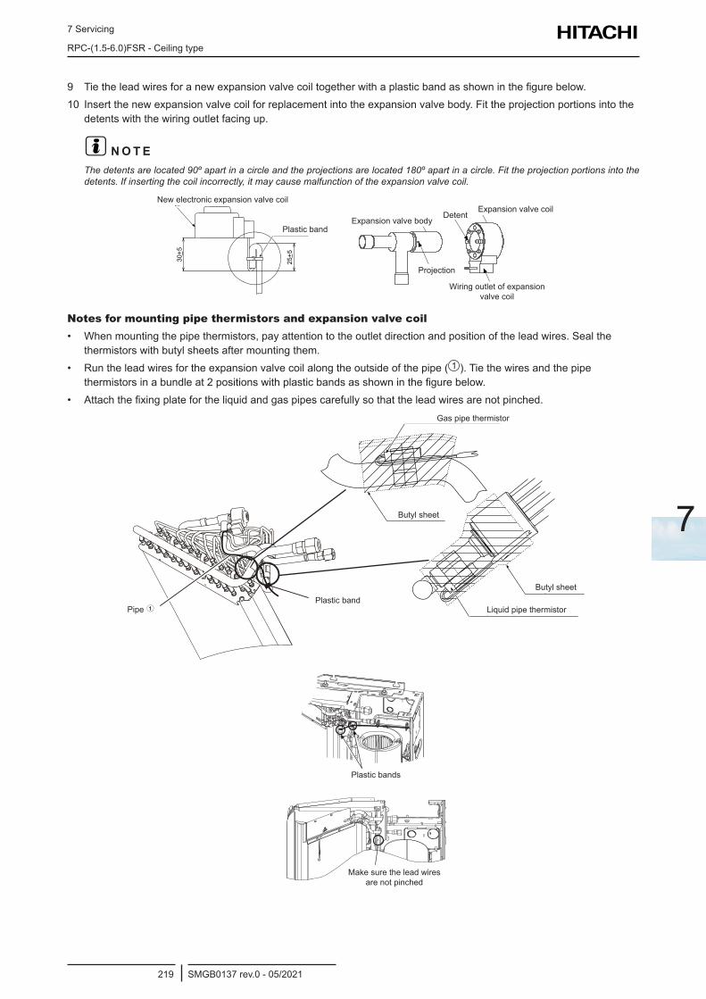
7 Servicing
RPC-(1.5-6.0)FSR - Ceiling type
SMGB0137 rev.0 - 05/2021219
7
9 Tie the lead wires for a new expansion valve coil together with a plastic band as shown in the figure below.10 Insert the new expansion valve coil for replacement into the expansion valve body. Fit the projection portions into the
detents with the wiring outlet facing up.
? N O T EThe detents are located 90º apart in a circle and the projections are located 180º apart in a circle. Fit the projection portions into the detents. If inserting the coil incorrectly, it may cause malfunction of the expansion valve coil.
Plastic Band
New Electronic ExpansionValve Coil
30+5
25+5
Plastic band
New electronic expansion valve coil
Projection
DetentExpansion Valve Body
Expansion Valve Coil
Wiring Outletof Expansion Valve Coil
Projection
Expansion valve bodyExpansion valve coil
Detent
Wiring outlet of expansion valve coil
Notes for mounting pipe thermistors and expansion valve coil• When mounting the pipe thermistors, pay attention to the outlet direction and position of the lead wires. Seal the
thermistors with butyl sheets after mounting them.• Run the lead wires for the expansion valve coil along the outside of the pipe ( 1 ). Tie the wires and the pipe
thermistors in a bundle at 2 positions with plastic bands as shown in the figure below.• Attach the fixing plate for the liquid and gas pipes carefully so that the lead wires are not pinched.
Butyl Sheet
Liquid Pipe Thermistor
Gas Pipe Thermistor
Butyl Sheet
Plastic Band1Pipe
Gas pipe thermistor
Butyl sheet
Butyl sheet
Liquid pipe thermistorPlastic band
Pipe
Plastic Bands
Make sure the lead wiresare not pinched.
Plastic bands
Make sure the lead wires are not pinched
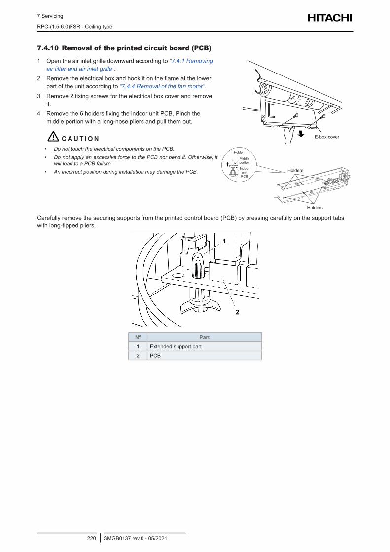
7 Servicing
RPC-(1.5-6.0)FSR - Ceiling type
SMGB0137 rev.0 - 05/2021220
7.4.10 Removal of the printed circuit board (PCB)
1 Open the air inlet grille downward according to “7.4.1 Removing air filter and air inlet grille”.
2 Remove the electrical box and hook it on the flame at the lower part of the unit according to “7.4.4 Removal of the fan motor”.
3 Remove 2 fixing screws for the electrical box cover and remove it.
4 Remove the 6 holders fixing the indoor unit PCB. Pinch the middle portion with a long-nose pliers and pull them out.
! C A U T I O N• Do not touch the electrical components on the PCB.• Do not apply an excessive force to the PCB nor bend it. Otherwise, it
will lead to a PCB failure• An incorrect position during installation may damage the PCB.
E-box cover
Holders
Holders
Holder
Middle portion
Indoor unit PCB
Carefully remove the securing supports from the printed control board (PCB) by pressing carefully on the support tabs with long-tipped pliers.
Nº Part1 Extended support part
2 PCB
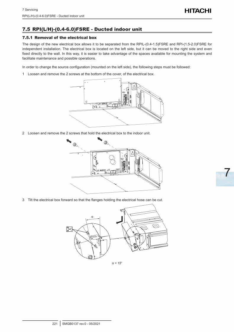
7 Servicing
RPI(L/H)-(0.4-6.0)FSRE - Ducted indoor unit
SMGB0137 rev.0 - 05/2021221
7
7.5 RPI(L/H)-(0.4-6.0)FSRE - Ducted indoor unit7.5.1 Removal of the electrical boxThe design of the new electrical box allows it to be separated from the RPIL-(0.4-1.5)FSRE and RPI-(1.5-2.0)FSRE for independent installation. The electrical box is located on the left side, but it can be moved to the right side and even fixed directly to the wall. In this way, it is easier to take advantage of the spaces available for mounting the system and facilitate maintenance and possible operations.
In order to change the source configuration (mounted on the left side), the following steps must be followed:
1 Loosen and remove the 2 screws at the bottom of the cover, of the electrical box.
2 Loosen and remove the 2 screws that hold the electrical box to the indoor unit.
3 Tilt the electrical box forward so that the flanges holding the electrical hose can be cut.
α
α = 15°
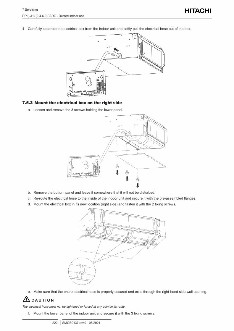
7 Servicing
RPI(L/H)-(0.4-6.0)FSRE - Ducted indoor unit
SMGB0137 rev.0 - 05/2021222
4 Carefully separate the electrical box from the indoor unit and softly pull the electrical hose out of the box.
7.5.2 Mount the electrical box on the right side
a. Loosen and remove the 3 screws holding the lower panel.
b. Remove the bottom panel and leave it somewhere that it will not be disturbed.c. Re-route the electrical hose to the inside of the indoor unit and secure it with the pre-assembled flanges.d. Mount the electrical box in its new location (right side) and fasten it with the 2 fixing screws.
e. Make sure that the entire electrical hose is properly secured and exits through the right-hand side wall opening.
! C A U T I O NThe electrical hose must not be tightened or forced at any point in its route.
f. Mount the lower panel of the indoor unit and secure it with the 3 fixing screws.
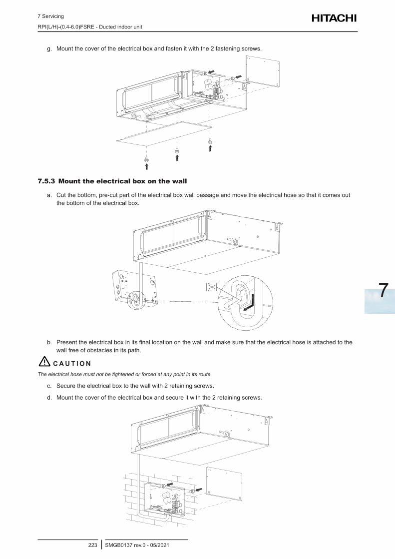
7 Servicing
RPI(L/H)-(0.4-6.0)FSRE - Ducted indoor unit
SMGB0137 rev.0 - 05/2021223
7
g. Mount the cover of the electrical box and fasten it with the 2 fastening screws.
7.5.3 Mount the electrical box on the wall
a. Cut the bottom, pre-cut part of the electrical box wall passage and move the electrical hose so that it comes out the bottom of the electrical box.
b. Present the electrical box in its final location on the wall and make sure that the electrical hose is attached to the wall free of obstacles in its path.
! C A U T I O NThe electrical hose must not be tightened or forced at any point in its route.
c. Secure the electrical box to the wall with 2 retaining screws.
d. Mount the cover of the electrical box and secure it with the 2 retaining screws.
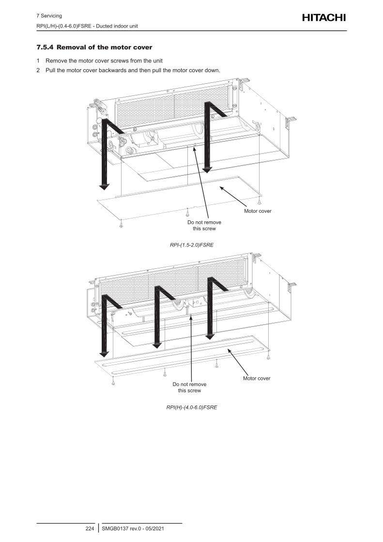
7 Servicing
RPI(L/H)-(0.4-6.0)FSRE - Ducted indoor unit
SMGB0137 rev.0 - 05/2021224
7.5.4 Removal of the motor cover
1 Remove the motor cover screws from the unit2 Pull the motor cover backwards and then pull the motor cover down.
Motor cover
Do not remove this screw
RPI-(1.5-2.0)FSRE
Motor coverDo not remove this screw
RPI(H)-(4.0-6.0)FSRE
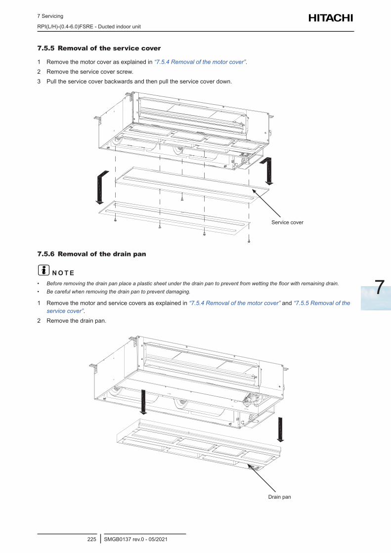
7 Servicing
RPI(L/H)-(0.4-6.0)FSRE - Ducted indoor unit
SMGB0137 rev.0 - 05/2021225
7
7.5.5 Removal of the service cover
1 Remove the motor cover as explained in “7.5.4 Removal of the motor cover”.2 Remove the service cover screw.3 Pull the service cover backwards and then pull the service cover down.
Service cover
7.5.6 Removal of the drain pan
? N O T E• Before removing the drain pan place a plastic sheet under the drain pan to prevent from wetting the floor with remaining drain.• Be careful when removing the drain pan to prevent damaging.
1 Remove the motor and service covers as explained in “7.5.4 Removal of the motor cover” and “7.5.5 Removal of the service cover”.
2 Remove the drain pan.
Drain pan
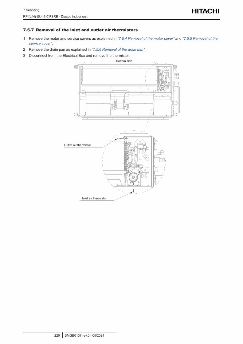
7 Servicing
RPI(L/H)-(0.4-6.0)FSRE - Ducted indoor unit
SMGB0137 rev.0 - 05/2021226
7.5.7 Removal of the inlet and outlet air thermistors
1 Remove the motor and service covers as explained in “7.5.4 Removal of the motor cover” and “7.5.5 Removal of the service cover”.
2 Remove the drain pan as explained in “7.5.6 Removal of the drain pan”.3 Disconnect from the Electrical Box and remove the thermistor.
Bottom side
Outlet air thermistor
Inlet air thermistor
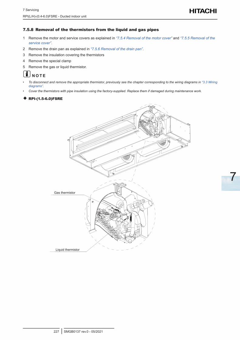
7 Servicing
RPI(L/H)-(0.4-6.0)FSRE - Ducted indoor unit
SMGB0137 rev.0 - 05/2021227
7
7.5.8 Removal of the thermistors from the liquid and gas pipes
1 Remove the motor and service covers as explained in “7.5.4 Removal of the motor cover” and “7.5.5 Removal of the service cover”.
2 Remove the drain pan as explained in “7.5.6 Removal of the drain pan”.3 Remove the insulation covering the thermistors4 Remove the special clamp5 Remove the gas or liquid thermistor.
? N O T E• To disconnect and remove the appropriate thermistor, previously see the chapter corresponding to the wiring diagrams in “3.3 Wiring
diagrams”.• Cover the thermistors with pipe insulation using the factory-supplied. Replace them if damaged during maintenance work.
RPI-(1.5-6.0)FSRE
Liquid thermistor
Gas thermistor
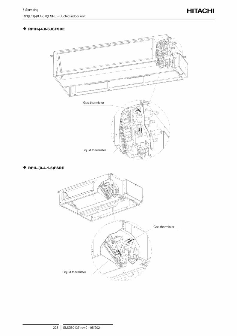
7 Servicing
RPI(L/H)-(0.4-6.0)FSRE - Ducted indoor unit
SMGB0137 rev.0 - 05/2021228
RPIH-(4.0-6.0)FSRE
Liquid thermistor
Gas thermistor
RPIL-(0.4-1.5)FSRE
Liquid thermistor
Gas thermistor
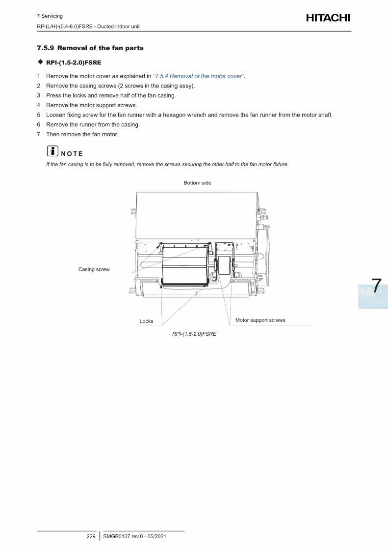
7 Servicing
RPI(L/H)-(0.4-6.0)FSRE - Ducted indoor unit
SMGB0137 rev.0 - 05/2021229
7
7.5.9 Removal of the fan parts
RPI-(1.5-2.0)FSRE
1 Remove the motor cover as explained in “7.5.4 Removal of the motor cover”.2 Remove the casing screws (2 screws in the casing assy).3 Press the locks and remove half of the fan casing.4 Remove the motor support screws.5 Loosen fixing screw for the fan runner with a hexagon wrench and remove the fan runner from the motor shaft.6 Remove the runner from the casing.7 Then remove the fan motor.
? N O T EIf the fan casing is to be fully removed, remove the screws securing the other half to the fan motor fixture.
Locks Motor support screws
Casing screw
Bottom side
RPI-(1.5-2.0)FSRE
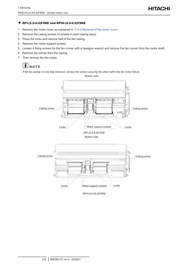
7 Servicing
RPI(L/H)-(0.4-6.0)FSRE - Ducted indoor unit
SMGB0137 rev.0 - 05/2021230
RPI-(2.5-6.0)FSRE and RPIH-(4.0-6.0)FSRE
1 Remove the motor cover as explained in “7.5.4 Removal of the motor cover”.2 Remove the casing screws (4 screws in each casing assy).3 Press the locks and remove half of the fan casing.4 Remove the motor support screws.5 Loosen 4 fixing screws for the fan runner with a hexagon wrench and remove the fan runner from the motor shaft.6 Remove the runner from the casing.7 Then remove the fan motor.
? N O T EIf the fan casing is to be fully removed, remove the screws securing the other half to the fan motor fixture.
Locks LocksMotor support screws
Casing screw Casing screw
Bottom side
RPI-(2.5-6.0)FSRE
Locks LocksMotor support screws
Casing screw Casing screw
Bottom side
RPIH-(4.0-6.0)FSRE
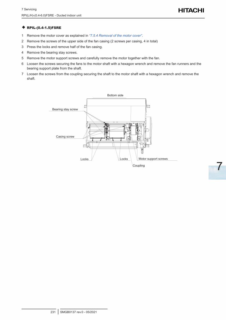
7 Servicing
RPI(L/H)-(0.4-6.0)FSRE - Ducted indoor unit
SMGB0137 rev.0 - 05/2021231
7
RPIL-(0.4-1.5)FSRE
1 Remove the motor cover as explained in “7.5.4 Removal of the motor cover”.2 Remove the screws of the upper side of the fan casing (2 screws per casing, 4 in total)3 Press the locks and remove half of the fan casing.4 Remove the bearing stay screws.5 Remove the motor support screws and carefully remove the motor together with the fan.6 Loosen the screws securing the fans to the motor shaft with a hexagon wrench and remove the fan runners and the
bearing support plate from the shaft.7 Loosen the screws from the coupling securing the shaft to the motor shaft with a hexagon wrench and remove the
shaft.
Locks
Coupling
Locks Motor support screws
Casing screw
Bearing stay screw
Bottom side
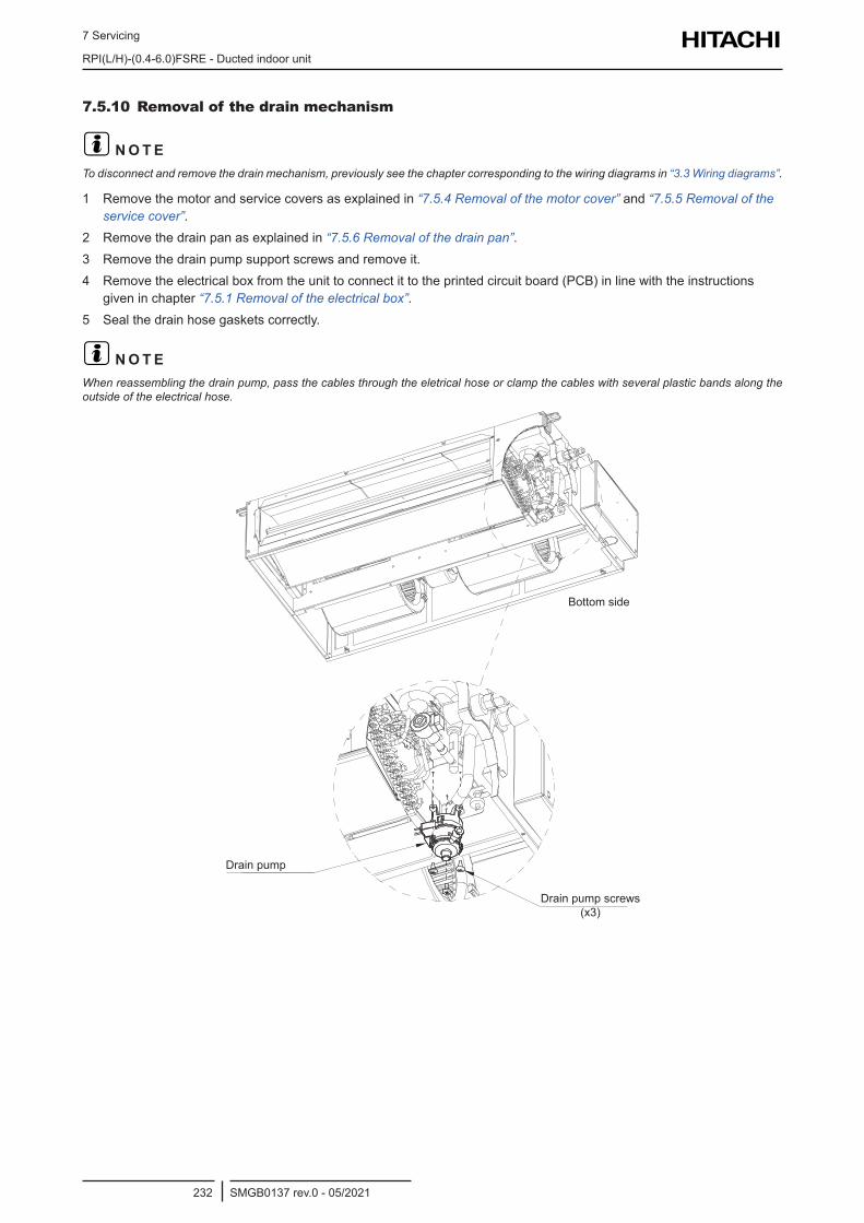
7 Servicing
RPI(L/H)-(0.4-6.0)FSRE - Ducted indoor unit
SMGB0137 rev.0 - 05/2021232
7.5.10 Removal of the drain mechanism
? N O T ETo disconnect and remove the drain mechanism, previously see the chapter corresponding to the wiring diagrams in “3.3 Wiring diagrams”.
1 Remove the motor and service covers as explained in “7.5.4 Removal of the motor cover” and “7.5.5 Removal of the service cover”.
2 Remove the drain pan as explained in “7.5.6 Removal of the drain pan”.3 Remove the drain pump support screws and remove it.4 Remove the electrical box from the unit to connect it to the printed circuit board (PCB) in line with the instructions
given in chapter “7.5.1 Removal of the electrical box”.5 Seal the drain hose gaskets correctly.
? N O T EWhen reassembling the drain pump, pass the cables through the eletrical hose or clamp the cables with several plastic bands along the outside of the electrical hose.
Bottom side
Drain pump
Drain pump screws (x3)
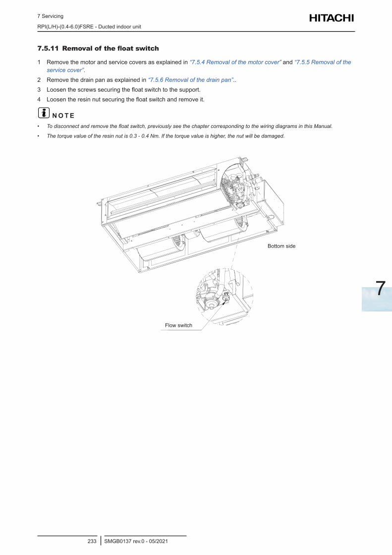
7 Servicing
RPI(L/H)-(0.4-6.0)FSRE - Ducted indoor unit
SMGB0137 rev.0 - 05/2021233
7
7.5.11 Removal of the float switch
1 Remove the motor and service covers as explained in “7.5.4 Removal of the motor cover” and “7.5.5 Removal of the service cover”.
2 Remove the drain pan as explained in “7.5.6 Removal of the drain pan”..3 Loosen the screws securing the float switch to the support.4 Loosen the resin nut securing the float switch and remove it.
? N O T E• To disconnect and remove the float switch, previously see the chapter corresponding to the wiring diagrams in this Manual.
• The torque value of the resin nut is 0.3 - 0.4 Nm. If the torque value is higher, the nut will be damaged.
Flow switch
Bottom side

7 Servicing
RPI(L/H)-(0.4-6.0)FSRE - Ducted indoor unit
SMGB0137 rev.0 - 05/2021234
7.5.12 Removal of the air filterThere are two options for filter extraction, depending on the location of the unit:
Lower extraction
1 Turn 90° the locking bolt and remove the lower air filter support from the unit.2 Pull down the air filter.
Inlet air
Inlet air Filter
Inlet air
Inlet air Filter
RPIL-FSRE RPI(H)-FSRE
Lateral extraction
1 Turn 90° the locking bolt and remove the lateral Air Filter support from the unit.2 Pull the Air Filter and fold it over the joint as much as you need for the extraction.
Optionally, the RPI-(1.5~2.0)FSRE unit allows access to the filter from the opposite side for proper maintenance.
1 Turn 90° the locking bolt and remove the lateral air filter support from the unit.2 Pull the air filter and fold it over the joint as much as you need for the extraction.
Inlet air
Inlet air Filter
Inlet air
Inlet air Filter
Inlet air
Inlet air Filter
RPIL-FSRE RPI(H)-FSRE Right side
RPI(H)-FSRE Left side
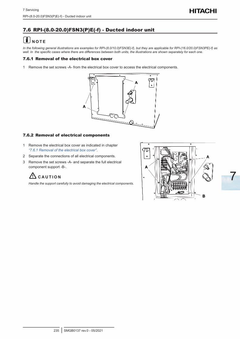
7 Servicing
RPI-(8.0-20.0)FSN3(P)E(-f) - Ducted indoor unit
SMGB0137 rev.0 - 05/2021235
7
7.6 RPI-(8.0-20.0)FSN3(P)E(-f) - Ducted indoor unit
? N O T EIn the following general illustrations are examples for RPI-(8.0/10.0)FSN3E(-f), but they are applicable for RPI-(16.0/20.0)FSN3PE(-f) as well. In the specific cases where there are differences between both units, the illustrations are shown separately for each one.
7.6.1 Removal of the electrical box cover
1 Remove the set screws -A- from the electrical box cover to access the electrical components.
7.6.2 Removal of electrical components
1 Remove the electrical box cover as indicated in chapter “7.6.1 Removal of the electrical box cover”.
2 Separate the connections of all electrical components.3 Remove the set screws -A- and separate the full electrical
component support -B-.
! C A U T I O NHandle the support carefully to avoid damaging the electrical components.
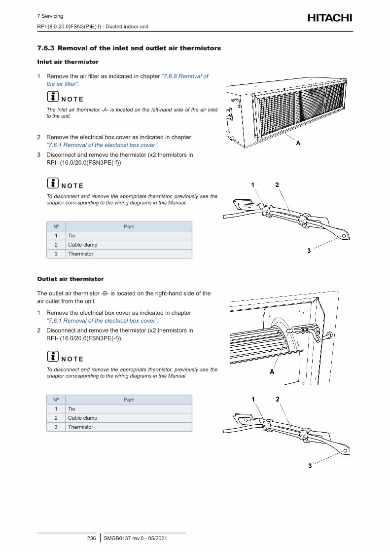
7 Servicing
RPI-(8.0-20.0)FSN3(P)E(-f) - Ducted indoor unit
SMGB0137 rev.0 - 05/2021236
7.6.3 Removal of the inlet and outlet air thermistors
Inlet air thermistor
1 Remove the air filter as indicated in chapter “7.6.8 Removal of the air filter”.
? N O T EThe inlet air thermistor -A- is located on the left-hand side of the air inlet to the unit.
2 Remove the electrical box cover as indicated in chapter “7.6.1 Removal of the electrical box cover”.
3 Disconnect and remove the thermistor (x2 thermistors in RPI- (16.0/20.0)FSN3PE(-f))
? N O T ETo disconnect and remove the appropriate thermistor, previously see the chapter corresponding to the wiring diagrams in this Manual.
Nº Part1 Tie
2 Cable clamp
3 Thermistor
Outlet air thermistor
The outlet air thermistor -B- is located on the right-hand side of the air outlet from the unit.
1 Remove the electrical box cover as indicated in chapter “7.6.1 Removal of the electrical box cover”.
2 Disconnect and remove the thermistor (x2 thermistors in RPI- (16.0/20.0)FSN3PE(-f)).
? N O T ETo disconnect and remove the appropriate thermistor, previously see the chapter corresponding to the wiring diagrams in this Manual.
Nº Part1 Tie
2 Cable clamp
3 Thermistor
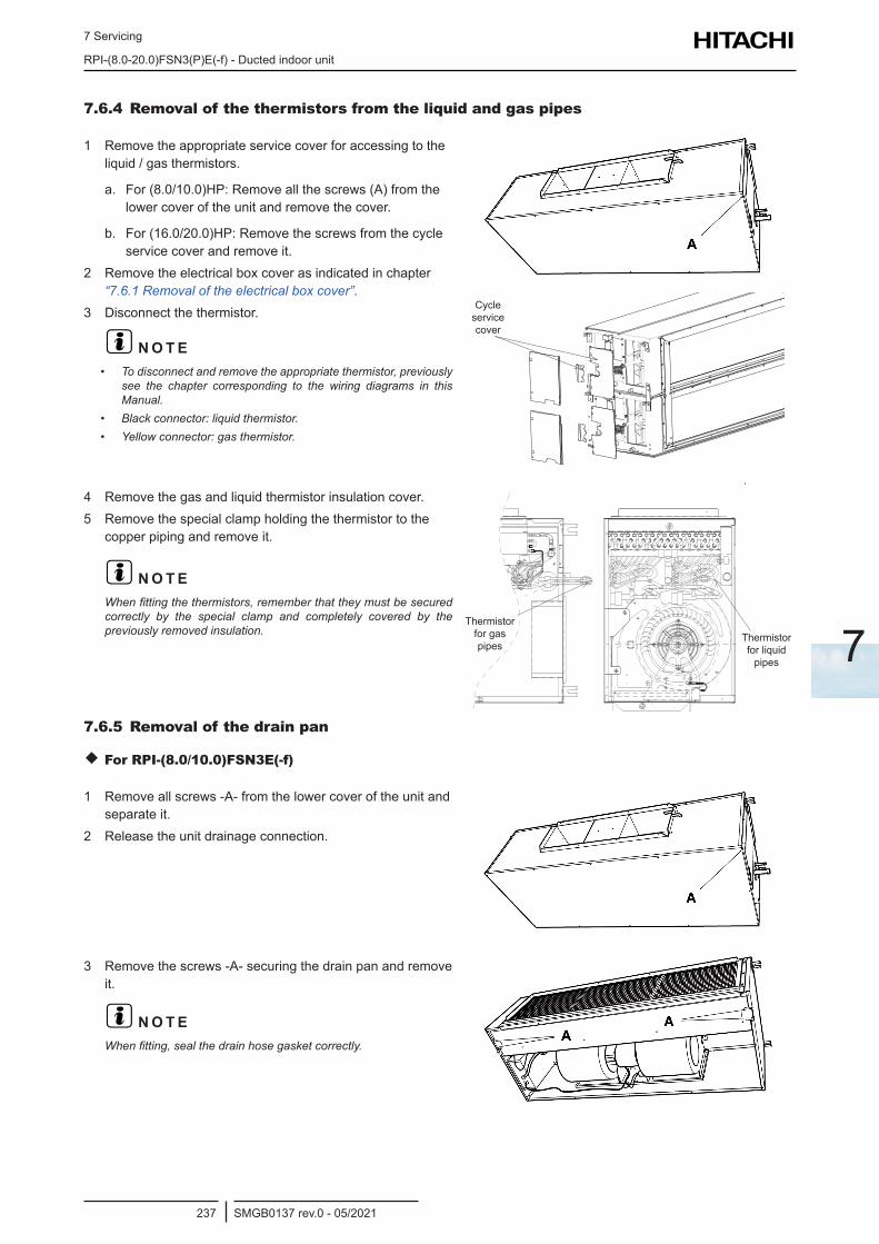
7 Servicing
RPI-(8.0-20.0)FSN3(P)E(-f) - Ducted indoor unit
SMGB0137 rev.0 - 05/2021237
7
7.6.4 Removal of the thermistors from the liquid and gas pipes
1 Remove the appropriate service cover for accessing to the liquid / gas thermistors.
a. For (8.0/10.0)HP: Remove all the screws (A) from the lower cover of the unit and remove the cover.
b. For (16.0/20.0)HP: Remove the screws from the cycle service cover and remove it.
2 Remove the electrical box cover as indicated in chapter “7.6.1 Removal of the electrical box cover”.
3 Disconnect the thermistor.
? N O T E• To disconnect and remove the appropriate thermistor, previously
see the chapter corresponding to the wiring diagrams in this Manual.
• Black connector: liquid thermistor.• Yellow connector: gas thermistor.
Cycle service cover
4 Remove the gas and liquid thermistor insulation cover.5 Remove the special clamp holding the thermistor to the
copper piping and remove it.
? N O T EWhen fitting the thermistors, remember that they must be secured correctly by the special clamp and completely covered by the previously removed insulation.
Thermistor for gas pipes
Thermistor for liquid
pipes
7.6.5 Removal of the drain pan
For RPI-(8.0/10.0)FSN3E(-f)
1 Remove all screws -A- from the lower cover of the unit and separate it.
2 Release the unit drainage connection.
3 Remove the screws -A- securing the drain pan and remove it.
? N O T EWhen fitting, seal the drain hose gasket correctly.
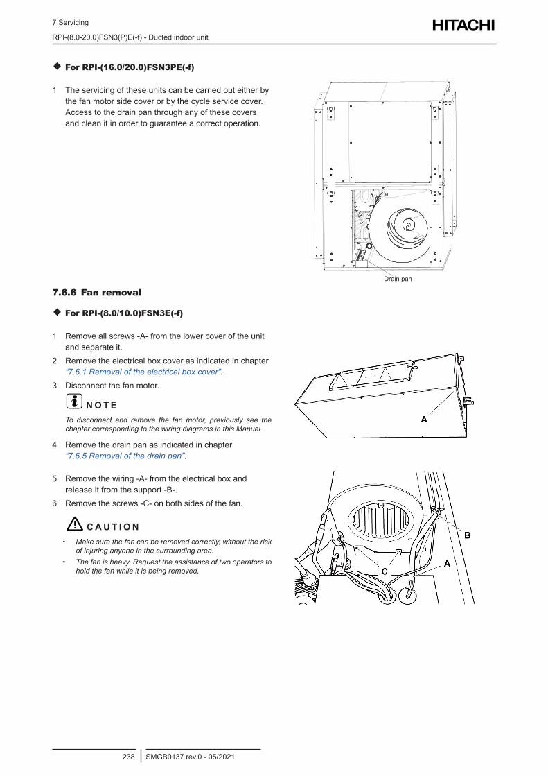
7 Servicing
RPI-(8.0-20.0)FSN3(P)E(-f) - Ducted indoor unit
SMGB0137 rev.0 - 05/2021238
For RPI-(16.0/20.0)FSN3PE(-f)
1 The servicing of these units can be carried out either by the fan motor side cover or by the cycle service cover. Access to the drain pan through any of these covers and clean it in order to guarantee a correct operation.
Drain pan
7.6.6 Fan removal
For RPI-(8.0/10.0)FSN3E(-f)
1 Remove all screws -A- from the lower cover of the unit and separate it.
2 Remove the electrical box cover as indicated in chapter “7.6.1 Removal of the electrical box cover”.
3 Disconnect the fan motor.
? N O T ETo disconnect and remove the fan motor, previously see the chapter corresponding to the wiring diagrams in this Manual.
4 Remove the drain pan as indicated in chapter “7.6.5 Removal of the drain pan”.
5 Remove the wiring -A- from the electrical box and release it from the support -B-.
6 Remove the screws -C- on both sides of the fan.
! C A U T I O N• Make sure the fan can be removed correctly, without the risk
of injuring anyone in the surrounding area.• The fan is heavy. Request the assistance of two operators to
hold the fan while it is being removed.
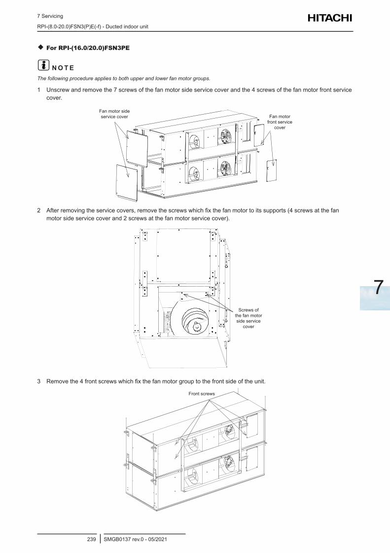
7 Servicing
RPI-(8.0-20.0)FSN3(P)E(-f) - Ducted indoor unit
SMGB0137 rev.0 - 05/2021239
7
For RPI-(16.0/20.0)FSN3PE
? N O T EThe following procedure applies to both upper and lower fan motor groups.
1 Unscrew and remove the 7 screws of the fan motor side service cover and the 4 screws of the fan motor front service cover.
Fan motor side service cover Fan motor
front service cover
2 After removing the service covers, remove the screws which fix the fan motor to its supports (4 screws at the fan motor side service cover and 2 screws at the fan motor service cover).
Screws of the fan motor side service
cover
3 Remove the 4 front screws which fix the fan motor group to the front side of the unit.
Front screws
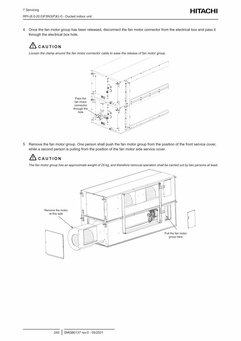
7 Servicing
RPI-(8.0-20.0)FSN3(P)E(-f) - Ducted indoor unit
SMGB0137 rev.0 - 05/2021240
4 Once the fan motor group has been released, disconnect the fan motor connector from the electrical box and pass it through the electrical box hole.
! C A U T I O NLoosen the clamp around the fan motor connector cable to ease the release of fan motor group.
Pass the fan motor connector through the
hole
5 Remove the fan motor group. One person shall push the fan motor group from the position of the front service cover, while a second person is pulling from the position of the fan motor side service cover.
! C A U T I O NThe fan motor group has an approximate weight of 25 kg, and therefore removal operation shall be carried out by two persons at least.
Pull the fan motor group here
Remove the motor at this side
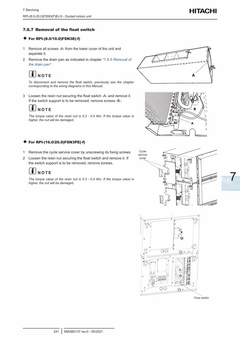
7 Servicing
RPI-(8.0-20.0)FSN3(P)E(-f) - Ducted indoor unit
SMGB0137 rev.0 - 05/2021241
7
7.6.7 Removal of the float switch
For RPI-(8.0/10.0)FSN3E(-f)
1 Remove all screws -A- from the lower cover of the unit and separate it.
2 Remove the drain pan as indicated in chapter “7.6.5 Removal of the drain pan”.
? N O T ETo disconnect and remove the float switch, previously see the chapter corresponding to the wiring diagrams in this Manual.
3 Loosen the resin nut securing the float switch -A- and remove it. If the switch support is to be removed, remove screws -B-.
? N O T EThe torque value of the resin nut is 0.3 - 0.4 Nm. If the torque value is higher, the nut will be damaged.
For RPI-(16.0/20.0)FSN3PE(-f)
1 Remove the cycle service cover by unscrewing its fixing screws2 Loosen the resin nut securing the float switch and remove it. If
the switch support is to be removed, remove screws.
? N O T EThe torque value of the resin nut is 0.3 - 0.4 Nm. If the torque value is higher, the nut will be damaged.
Cycle service cover
Flow switch
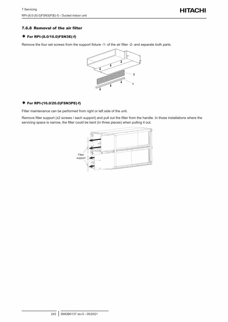
7 Servicing
RPI-(8.0-20.0)FSN3(P)E(-f) - Ducted indoor unit
SMGB0137 rev.0 - 05/2021242
7.6.8 Removal of the air filter
For RPI-(8.0/10.0)FSN3E(-f)
Remove the four set screws from the support fixture -1- of the air filter -2- and separate both parts.
2
1
For RPI-(16.0/20.0)FSN3PE(-f)
Filter maintenance can be performed from right or left side of the unit.
Remove filter support (x2 screws / each support) and pull out the filter from the handle. In those installations where the servicing space is narrow, the filter could be bent (in three pieces) when pulling it out.
Filter support
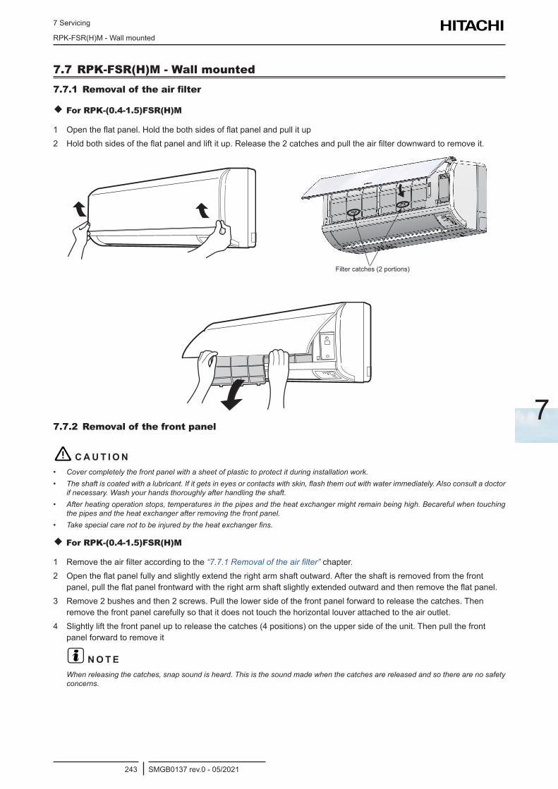
7 Servicing
RPK-FSR(H)M - Wall mounted
SMGB0137 rev.0 - 05/2021243
7
7.7 RPK-FSR(H)M - Wall mounted7.7.1 Removal of the air filter
For RPK-(0.4-1.5)FSR(H)M
1 Open the flat panel. Hold the both sides of flat panel and pull it up2 Hold both sides of the flat panel and lift it up. Release the 2 catches and pull the air filter downward to remove it.
Filter Catches (2 portions)Filter catches (2 portions)
7.7.2 Removal of the front panel
! C A U T I O N• Cover completely the front panel with a sheet of plastic to protect it during installation work.• The shaft is coated with a lubricant. If it gets in eyes or contacts with skin, flash them out with water immediately. Also consult a doctor
if necessary. Wash your hands thoroughly after handling the shaft.• After heating operation stops, temperatures in the pipes and the heat exchanger might remain being high. Becareful when touching
the pipes and the heat exchanger after removing the front panel.• Take special care not to be injured by the heat exchanger fins.
For RPK-(0.4-1.5)FSR(H)M
1 Remove the air filter according to the “7.7.1 Removal of the air filter” chapter.2 Open the flat panel fully and slightly extend the right arm shaft outward. After the shaft is removed from the front
panel, pull the flat panel frontward with the right arm shaft slightly extended outward and then remove the flat panel.3 Remove 2 bushes and then 2 screws. Pull the lower side of the front panel forward to release the catches. Then
remove the front panel carefully so that it does not touch the horizontal louver attached to the air outlet.4 Slightly lift the front panel up to release the catches (4 positions) on the upper side of the unit. Then pull the front
panel forward to remove it
? N O T EWhen releasing the catches, snap sound is heard. This is the sound made when the catches are released and so there are no safety concerns.
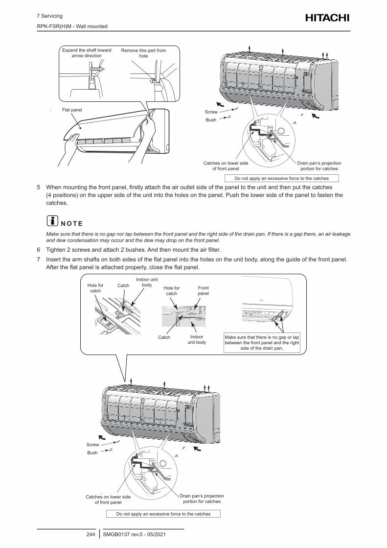
7 Servicing
RPK-FSR(H)M - Wall mounted
SMGB0137 rev.0 - 05/2021244
Flat panel
Expand the shaft
toward arrow direction
Remove this part
from hole
Flat panel
Expand the shaft toward arrow direction
Remove this part from hole
ScrewBush
Catches on Lower Side of Front Panel
Drain Pan’ s ProjectionPortion for Catches
Do not apply an excessive force to the catches.
Catches on lower side of front panel
Drain pan’s projection portion for catches
Do not apply an excessive force to the catches
Screw
Bush
5 When mounting the front panel, firstly attach the air outlet side of the panel to the unit and then put the catches (4 positions) on the upper side of the unit into the holes on the panel. Push the lower side of the panel to fasten the catches.
? N O T EMake sure that there is no gap nor lap between the front panel and the right side of the drain pan. If there is a gap there, an air leakage and dew condensation may occur and the dew may drop on the front panel.
6 Tighten 2 screws and attach 2 bushes. And then mount the air filter.7 Insert the arm shafts on both sides of the flat panel into the holes on the unit body, along the guide of the front panel.
After the flat panel is attached properly, close the flat panel.
ScrewBush
Catches on Lower Side of Front Panel
Drain Pan’ s ProjectionPortion for Catches
Do not apply an excessive force to the catches.
Catches on lower side of front panel
Drain pan’s projection portion for catches
Do not apply an excessive force to the catches
Screw
Bush
Hole for catch
CatchIndoor unit
body
Catch Indoor unit body
Hole for catch
Front panel
Make sure that there is no gap or lap between the front panel and the right
side of the drain pan.
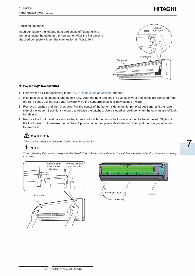
7 Servicing
RPK-FSR(H)M - Wall mounted
SMGB0137 rev.0 - 05/2021245
7
Attaching flat panel.
Insert completely the left and right arm shafts of flat panel into the holes along the guide at the front panel. After the flat panel is attached completely, insert the catches for air filter to fix it.
Flat panelFront panel
HoleGuide at front panel
For RPK-(2.0-4.0)FSRM
1 Remove the air filter according to the “7.7.1 Removal of the air filter” chapter.2 Hold both sides of flat panel and open it fully. After the right arm shaft is pushed inward and shafts are removed from
the front panel, pull the flat panel forward while the right arm shaft is slightly pushed inward.3 Remove 3 bushes and then 3 screws. Pull the center of the bottom side in the flat panel (2 positions) and the lower
side of the louver (2 positions) forward to release the catches. Use a slotted screwdriver when the catches are difficult to release.
4 Remove the front panel carefully so that it does not touch the horizontal louver attached to the air outlet. Slightly lift the front panel up to release the catches (4 positions) on the upper side of the unit. Then pull the front panel forward to remove it.
! C A U T I O NTake special care not to be injured by the heat exchanger fins.
? N O T EWhen releasing the catches, snap sound is heard. This is the sound made when the catches are released and so there are no safety concerns.
Flat panel
Push the shaft toward arrow direction
Remove this part from the hole
Bush (3 pieces)
Screw (3 pieces)
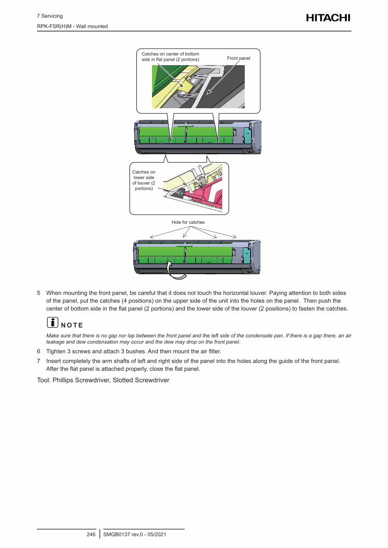
7 Servicing
RPK-FSR(H)M - Wall mounted
SMGB0137 rev.0 - 05/2021246
Catches on center of bottom side in flat panel (2 portions)
Catches on lower side of louver (2 portions)
Front panel
Hole for catches
5 When mounting the front panel, be careful that it does not touch the horizontal louver. Paying attention to both sides of the panel, put the catches (4 positions) on the upper side of the unit into the holes on the panel. Then push the center of bottom side in the flat panel (2 portions) and the lower side of the louver (2 positions) to fasten the catches.
? N O T EMake sure that there is no gap nor lap between the front panel and the left side of the condensate pan. If there is a gap there, an air leakage and dew condensation may occur and the dew may drop on the front panel.
6 Tighten 3 screws and attach 3 bushes. And then mount the air filter.7 Insert completely the arm shafts of left and right side of the panel into the holes along the guide of the front panel.
After the flat panel is attached properly, close the flat panel.
Tool: Phillips Screwdriver, Slotted Screwdriver
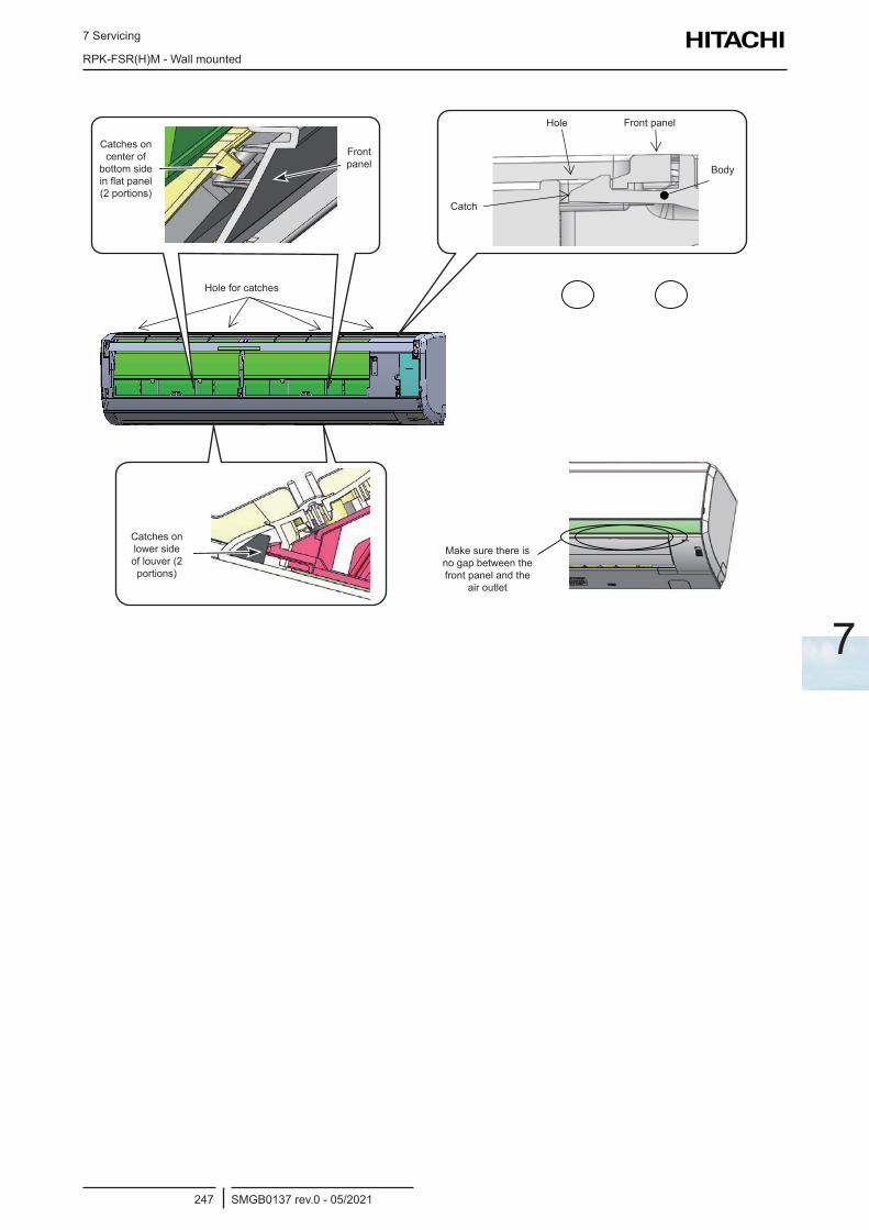
7 Servicing
RPK-FSR(H)M - Wall mounted
SMGB0137 rev.0 - 05/2021247
7
ツメツメ
前面パネルと
吹出口にすき
間がないことを
確認してくださ
上部長穴(4ヶ所)
下側中央ツメ
(2ヶ所)
ツメ
前面パネルと
吹出口にすき
間がないことを
確認してくださ
上部長穴(4ヶ所)
下側中央ツメ
(2ヶ所)
ツメ
前面パネルと
吹出口にすき
間がないことを
確認してくださ
上部長穴(4ヶ所)
下側中央ツメ
(2ヶ所)
ツメ
前面パネルと
吹出口にすき
間がないことを
確認してくださ
上部長穴(4ヶ所)
下側中央ツメ
(2ヶ所)
ツメ
前面パネルと
吹出口にすき
間がないことを
確認してくださ
上部長穴(4ヶ所)
下側中央ツメ
(2ヶ所)
上部長穴前面パネル
ツメ
ボディ
上部長穴(4ヶ所)
下側中央ツメ
(2ヶ所)
Hole for catches
Catches on lower side of louver (2 portions)
Make sure there is no gap between the front panel and the
air outlet
Catches on center of
bottom side in flat panel (2 portions)
Front panel
Hole Front panel
Body
Catch
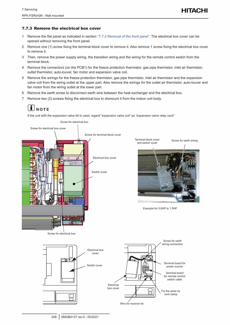
7 Servicing
RPK-FSR(H)M - Wall mounted
SMGB0137 rev.0 - 05/2021248
7.7.3 Remove the electrical box cover
1 Remove the flat panel as indicated in section “7.7.2 Removal of the front panel”. The electrical box cover can be opened without removing the front panel.
2 Remove one (1) screw fixing the terminal block cover to remove it. Also remove 1 screw fixing the electrical box cover to remove it.
3 Then, remove the power supply wiring, the transition wiring and the wiring for the remote control switch from the terminal block.
4 Remove the connectors (on the PCB1) for the freeze protection thermistor, gas pipe thermistor, inlet air thermistor, outlet thermistor, auto-louver, fan motor and expansion valve coil.
5 Remove the wirings for the freeze protection thermistor, gas pipe thermistor, inlet air thermistor and the expansion valve coil from the wiring outlet at the upper part. Also remove the wirings for the outlet air thermistor, auto-louver and fan motor from the wiring outlet at the lower part.
6 Remove the earth screw to disconnect earth wire between the heat exchanger and the electrical box.7 Remove two (2) screws fixing the electrical box to dismount it from the indoor unit body.
? N O T EIf the unit with the expansion valve kit is used, regard “expansion valve coil” as “expansion valve relay cord”
Screw for electrical box
Screw for electrical box cover
Screw for terminal block cover
Switch cover
Terminal block cover and switch cover
Screw for electrical box
Screw for earth wiring
Electrical box cover
Example for 0.6HP to 1.5HP
Electrical box cover
Switch cover
A 1 2
Screw for earth wiring connection
Electrical box cover
Wire for receiver kit
Terminal board for remote control
switch cable
Terminal board for power source
Fix the wires by cord clamp
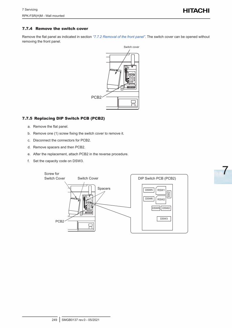
7 Servicing
RPK-FSR(H)M - Wall mounted
SMGB0137 rev.0 - 05/2021249
7
7.7.4 Remove the switch cover
Remove the flat panel as indicated in section “7.7.2 Removal of the front panel”. The switch cover can be opened without removing the front panel.
PCB2
Switch cover
7.7.5 Replacing DIP Switch PCB (PCB2)
a. Remove the flat panel.
b. Remove one (1) screw fixing the switch cover to remove it.
c. Disconnect the connectors for PCB2.
d. Remove spacers and then PCB2.
e. After the replacement, attach PCB2 in the reverse procedure.
f. Set the capacity code on DSW3.
Switch Cover
PCB2
Screw forSwitch Cover
Spacers DSW5 RSW1
RSW2DSW6
DSW9 DSW2
SW
2
DSW3
DIP Switch PCB (PCB2)Screw for Switch Cover Switch Cover
Spacers
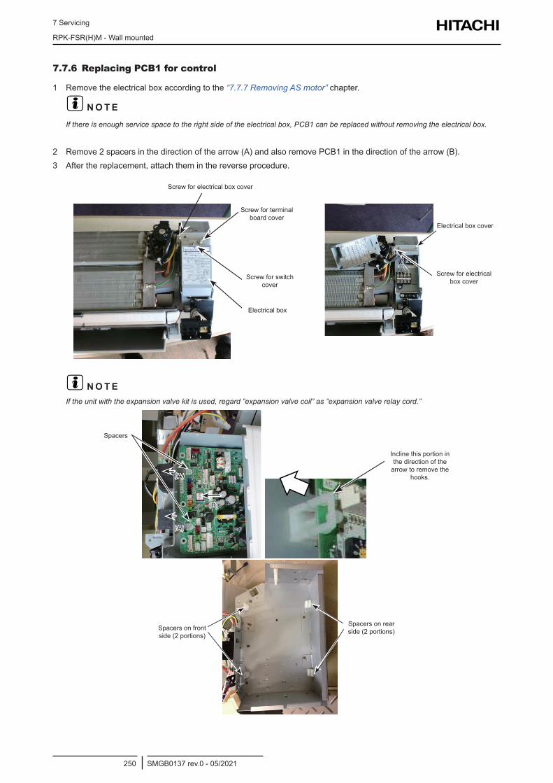
7 Servicing
RPK-FSR(H)M - Wall mounted
SMGB0137 rev.0 - 05/2021250
7.7.6 Replacing PCB1 for control
1 Remove the electrical box according to the “7.7.7 Removing AS motor” chapter.
? N O T EIf there is enough service space to the right side of the electrical box, PCB1 can be replaced without removing the electrical box.
2 Remove 2 spacers in the direction of the arrow (A) and also remove PCB1 in the direction of the arrow (B).3 After the replacement, attach them in the reverse procedure.
Screw for electrical box cover
Screw for terminal board cover
Screw for switch cover
Electrical box
Electrical box cover
Screw for electrical box cover
? N O T EIf the unit with the expansion valve kit is used, regard “expansion valve coil” as “expansion valve relay cord.”
Specers
(A)
(A)
(B)
Spacers
Incline this portion in the direction of the arrow to remove the
hooks.
Spacers onFront Side(2 Portions)
Spacers onRear Side(2 Portions)
Spacers on front side (2 portions)
Spacers on rear side (2 portions)
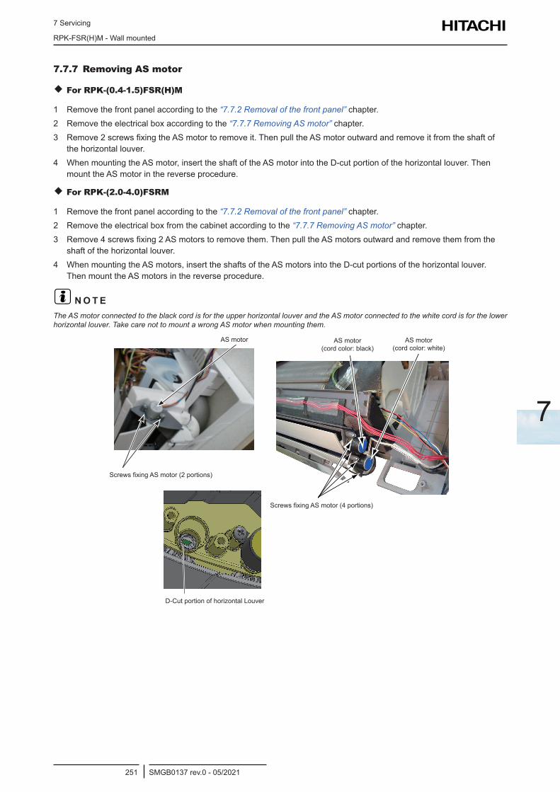
7 Servicing
RPK-FSR(H)M - Wall mounted
SMGB0137 rev.0 - 05/2021251
7
7.7.7 Removing AS motor
For RPK-(0.4-1.5)FSR(H)M
1 Remove the front panel according to the “7.7.2 Removal of the front panel” chapter.2 Remove the electrical box according to the “7.7.7 Removing AS motor” chapter.3 Remove 2 screws fixing the AS motor to remove it. Then pull the AS motor outward and remove it from the shaft of
the horizontal louver.4 When mounting the AS motor, insert the shaft of the AS motor into the D-cut portion of the horizontal louver. Then
mount the AS motor in the reverse procedure.
For RPK-(2.0-4.0)FSRM
1 Remove the front panel according to the “7.7.2 Removal of the front panel” chapter.2 Remove the electrical box from the cabinet according to the “7.7.7 Removing AS motor” chapter.3 Remove 4 screws fixing 2 AS motors to remove them. Then pull the AS motors outward and remove them from the
shaft of the horizontal louver.4 When mounting the AS motors, insert the shafts of the AS motors into the D-cut portions of the horizontal louver.
Then mount the AS motors in the reverse procedure.
? N O T EThe AS motor connected to the black cord is for the upper horizontal louver and the AS motor connected to the white cord is for the lower horizontal louver. Take care not to mount a wrong AS motor when mounting them.
AS Motor
Screws Fixing AS Motor(2 Portions)
AS motor
Screws fixing AS motor (2 portions)
AS Motor (Cord Color: Black)
Screws Fixing AS Motor (4 Portions)
AS Motor(Cord Color: White)
Screws fixing AS motor (4 portions)
AS motor (cord color: black)
AS motor (cord color: white)
D-Cut Portion of Horizontal LouverD-Cut portion of horizontal Louver
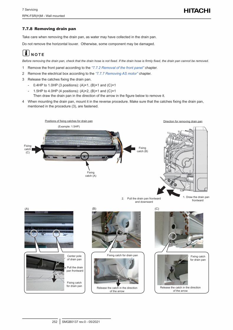
7 Servicing
RPK-FSR(H)M - Wall mounted
SMGB0137 rev.0 - 05/2021252
7.7.8 Removing drain pan
Take care when removing the drain pan, as water may have collected in the drain pan.
Do not remove the horizontal louver. Otherwise, some component may be damaged.
? N O T EBefore removing the drain pan, check that the drain hose is not fixed. If the drain hose is firmly fixed, the drain pan cannot be removed.
1 Remove the front panel according to the “7.7.2 Removal of the front panel” chapter.2 Remove the electrical box according to the “7.7.7 Removing AS motor” chapter.3 Release the catches fixing the drain pan.
- 0.4HP to 1.0HP (3 positions): (A)×1, (B)×1 and (C)×1 - 1.5HP to 4.0HP (4 positions): (A)×2, (B)×1 and (C)×1
Then draw the drain pan in the direction of the arrow in the figure below to remove it.4 When mounting the drain pan, mount it in the reverse procedure. Make sure that the catches fixing the drain pan,
mentioned in the procedure (3), are fastened.
Fixing catch (C)
Fixing catch (B)
Fixing catch (A)
Positions of fixing catches for drain pan
(Example: 1.5HP)
Direction for removing drain pan
2. Pull the drain pan frontward and downward
1. Draw the drain pan frontward
(A) (B) (C)
Center pole of drain pan
Pull the drain pan frontward
Fixing catch for drain pan
Fixing catch for drain pan
Release the catch in the direction of the arrow
Release the catch in the direction of the arrow
Fixing catch for drain pan
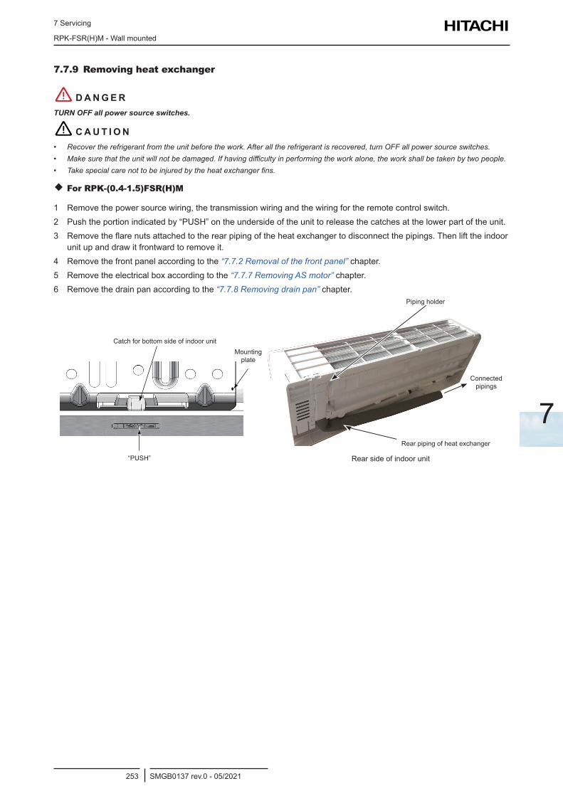
7 Servicing
RPK-FSR(H)M - Wall mounted
SMGB0137 rev.0 - 05/2021253
7
7.7.9 Removing heat exchanger
! D A N G E RTURN OFF all power source switches.
! C A U T I O N• Recover the refrigerant from the unit before the work. After all the refrigerant is recovered, turn OFF all power source switches.• Make sure that the unit will not be damaged. If having difficulty in performing the work alone, the work shall be taken by two people.• Take special care not to be injured by the heat exchanger fins.
For RPK-(0.4-1.5)FSR(H)M
1 Remove the power source wiring, the transmission wiring and the wiring for the remote control switch.2 Push the portion indicated by “PUSH” on the underside of the unit to release the catches at the lower part of the unit.3 Remove the flare nuts attached to the rear piping of the heat exchanger to disconnect the pipings. Then lift the indoor
unit up and draw it frontward to remove it.4 Remove the front panel according to the “7.7.2 Removal of the front panel” chapter.5 Remove the electrical box according to the “7.7.7 Removing AS motor” chapter.6 Remove the drain pan according to the “7.7.8 Removing drain pan” chapter.
Mounting plate
“PUSH”
Catch for bottom side of indoor unit
Rear side of indoor unit
Piping holder
Connected pipings
Rear piping of heat exchanger
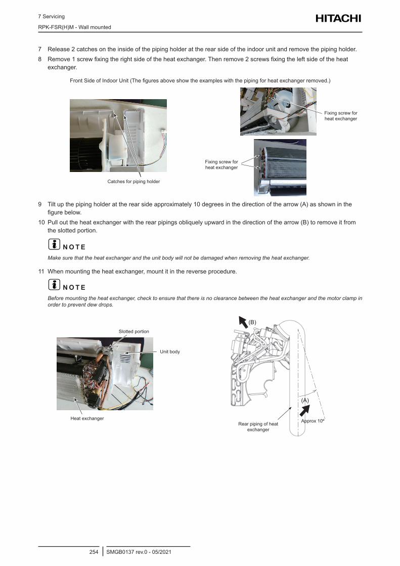
7 Servicing
RPK-FSR(H)M - Wall mounted
SMGB0137 rev.0 - 05/2021254
7 Release 2 catches on the inside of the piping holder at the rear side of the indoor unit and remove the piping holder.8 Remove 1 screw fixing the right side of the heat exchanger. Then remove 2 screws fixing the left side of the heat
exchanger.
Front Side of Indoor Unit (The figures above show the examples with the piping for heat exchanger removed.)
Catches for Piping HolderCatches for piping holder
Fixing Screwfor Heat ExchangerFixing screw for heat exchanger
Fixing Screwfor Heat Exchanger
Fixing screw for heat exchanger
9 Tilt up the piping holder at the rear side approximately 10 degrees in the direction of the arrow (A) as shown in the figure below.
10 Pull out the heat exchanger with the rear pipings obliquely upward in the direction of the arrow (B) to remove it from the slotted portion.
? N O T EMake sure that the heat exchanger and the unit body will not be damaged when removing the heat exchanger.
11 When mounting the heat exchanger, mount it in the reverse procedure.
? N O T EBefore mounting the heat exchanger, check to ensure that there is no clearance between the heat exchanger and the motor clamp in order to prevent dew drops.
Heat Exchanger
Slotted Portion
Unit Body
Slotted portion
Heat exchanger
Unit body
(B)
(A)
Rear piping of heat exchanger
Approx 10º
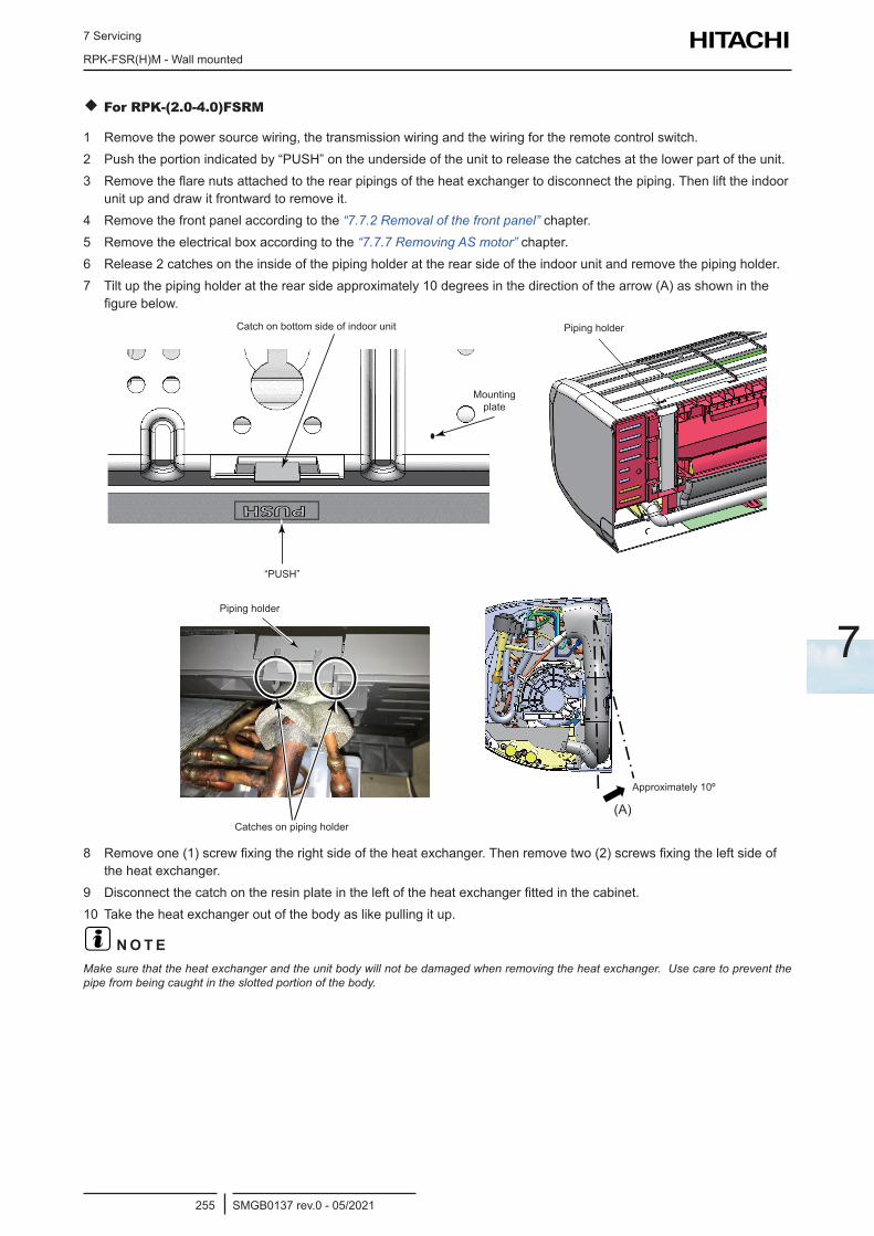
7 Servicing
RPK-FSR(H)M - Wall mounted
SMGB0137 rev.0 - 05/2021255
7
For RPK-(2.0-4.0)FSRM
1 Remove the power source wiring, the transmission wiring and the wiring for the remote control switch.2 Push the portion indicated by “PUSH” on the underside of the unit to release the catches at the lower part of the unit.3 Remove the flare nuts attached to the rear pipings of the heat exchanger to disconnect the piping. Then lift the indoor
unit up and draw it frontward to remove it.4 Remove the front panel according to the “7.7.2 Removal of the front panel” chapter.5 Remove the electrical box according to the “7.7.7 Removing AS motor” chapter.6 Release 2 catches on the inside of the piping holder at the rear side of the indoor unit and remove the piping holder.7 Tilt up the piping holder at the rear side approximately 10 degrees in the direction of the arrow (A) as shown in the
figure below.Catch on bottom side of indoor unit
Mounting plate
“PUSH”
Piping holder
Piping holder
Catches on piping holder(A)
Approximately 10º
8 Remove one (1) screw fixing the right side of the heat exchanger. Then remove two (2) screws fixing the left side of the heat exchanger.
9 Disconnect the catch on the resin plate in the left of the heat exchanger fitted in the cabinet.10 Take the heat exchanger out of the body as like pulling it up.
? N O T EMake sure that the heat exchanger and the unit body will not be damaged when removing the heat exchanger. Use care to prevent the pipe from being caught in the slotted portion of the body.
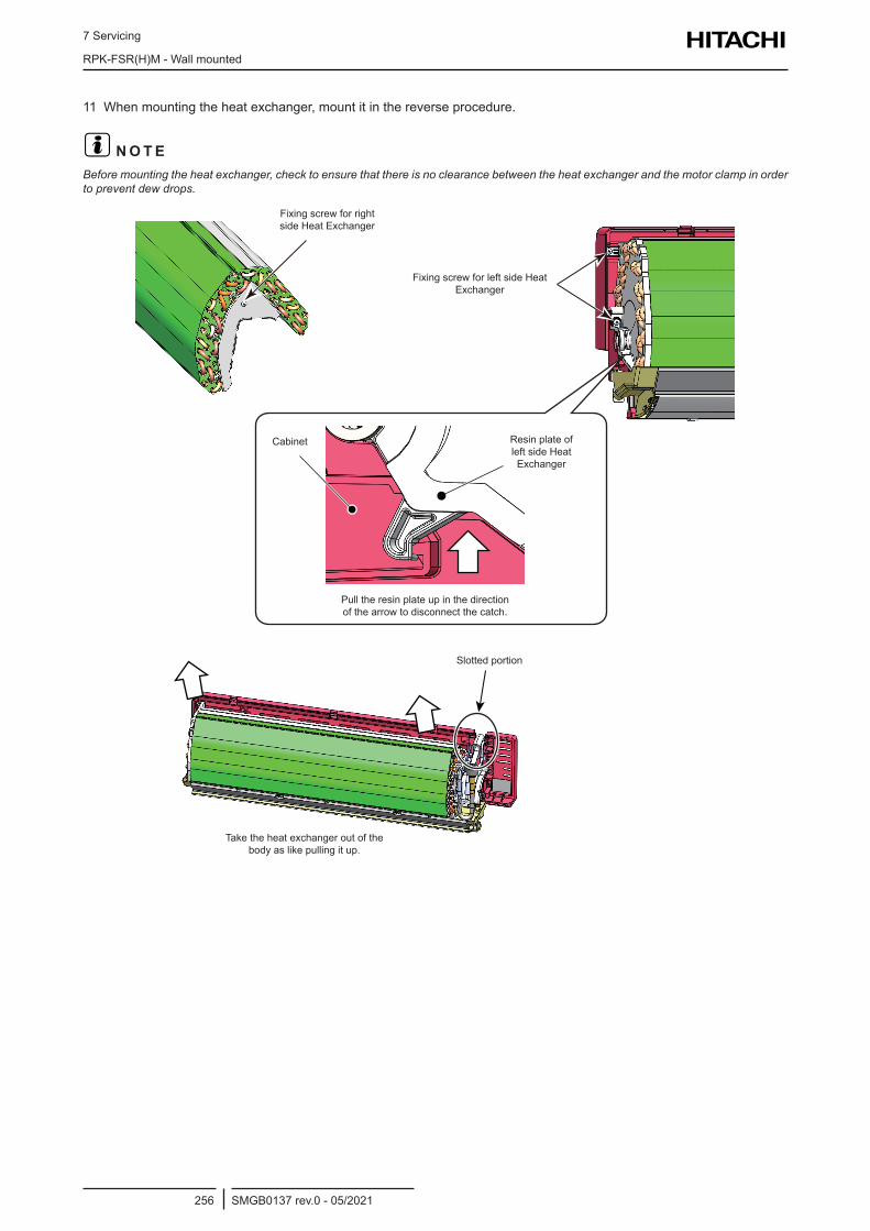
7 Servicing
RPK-FSR(H)M - Wall mounted
SMGB0137 rev.0 - 05/2021256
11 When mounting the heat exchanger, mount it in the reverse procedure.
? N O T EBefore mounting the heat exchanger, check to ensure that there is no clearance between the heat exchanger and the motor clamp in order to prevent dew drops.
Fixing screw for right side Heat Exchanger
Fixing screw for left side Heat Exchanger
Cabinet Resin plate of left side Heat Exchanger
Pull the resin plate up in the direction of the arrow to disconnect the catch.
Slotted portion
Take the heat exchanger out of the body as like pulling it up.
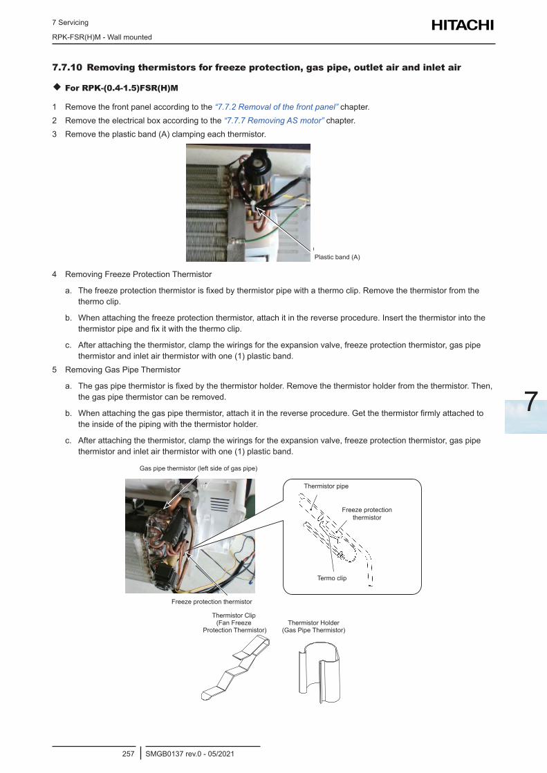
7 Servicing
RPK-FSR(H)M - Wall mounted
SMGB0137 rev.0 - 05/2021257
7
7.7.10 Removing thermistors for freeze protection, gas pipe, outlet air and inlet air
For RPK-(0.4-1.5)FSR(H)M
1 Remove the front panel according to the “7.7.2 Removal of the front panel” chapter.2 Remove the electrical box according to the “7.7.7 Removing AS motor” chapter.3 Remove the plastic band (A) clamping each thermistor.
Plastic Band (A)Plastic band (A)
4 Removing Freeze Protection Thermistor
a. The freeze protection thermistor is fixed by thermistor pipe with a thermo clip. Remove the thermistor from the thermo clip.
b. When attaching the freeze protection thermistor, attach it in the reverse procedure. Insert the thermistor into the thermistor pipe and fix it with the thermo clip.
c. After attaching the thermistor, clamp the wirings for the expansion valve, freeze protection thermistor, gas pipe thermistor and inlet air thermistor with one (1) plastic band.
5 Removing Gas Pipe Thermistor
a. The gas pipe thermistor is fixed by the thermistor holder. Remove the thermistor holder from the thermistor. Then, the gas pipe thermistor can be removed.
b. When attaching the gas pipe thermistor, attach it in the reverse procedure. Get the thermistor firmly attached to the inside of the piping with the thermistor holder.
c. After attaching the thermistor, clamp the wirings for the expansion valve, freeze protection thermistor, gas pipe thermistor and inlet air thermistor with one (1) plastic band.
Termo ClipTermo clip
Gas pipe thermistor (left side of gas pipe)
Freeze protection thermistor
Thermistor pipe
Freeze protection thermistor
Thermistor Clip(Fan Freeze
Protection Thermistor)Thermistor Holder
(Gas Pipe Thermistor)
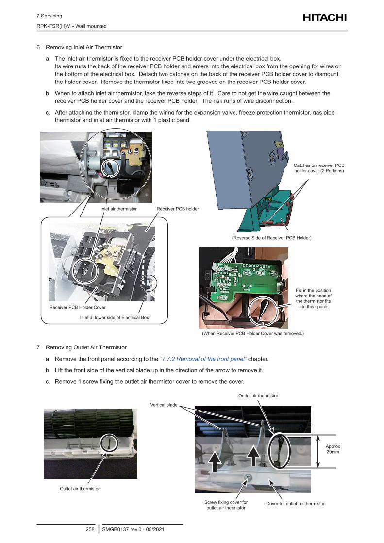
7 Servicing
RPK-FSR(H)M - Wall mounted
SMGB0137 rev.0 - 05/2021258
6 Removing Inlet Air Thermistor
a. The inlet air thermistor is fixed to the receiver PCB holder cover under the electrical box. Its wire runs the back of the receiver PCB holder and enters into the electrical box from the opening for wires on the bottom of the electrical box. Detach two catches on the back of the receiver PCB holder cover to dismount the holder cover. Remove the thermistor fixed into two grooves on the receiver PCB holder cover.
b. When to attach inlet air thermistor, take the reverse steps of it. Care to not get the wire caught between the receiver PCB holder cover and the receiver PCB holder. The risk runs of wire disconnection.
c. After attaching the thermistor, clamp the wiring for the expansion valve, freeze protection thermistor, gas pipe thermistor and inlet air thermistor with 1 plastic band.
Inlet air thermistor Receiver PCB holder
Catches on receiver PCB holder cover (2 Portions)
(Reverse Side of Receiver PCB Holder)
(When Receiver PCB Holder Cover was removed.)
Receiver PCB Holder Cover
Inlet at lower side of Electrical Box
Fix in the position where the head of the thermistor fits into this space.
7 Removing Outlet Air Thermistor
a. Remove the front panel according to the “7.7.2 Removal of the front panel” chapter.
b. Lift the front side of the vertical blade up in the direction of the arrow to remove it.
c. Remove 1 screw fixing the outlet air thermistor cover to remove the cover.
Outlet Air ThermistorOutlet air thermistor
Vertical blade
Outlet air thermistor
Screw fixing cover for outlet air thermistor
Cover for outlet air thermistor
Approx 29mm
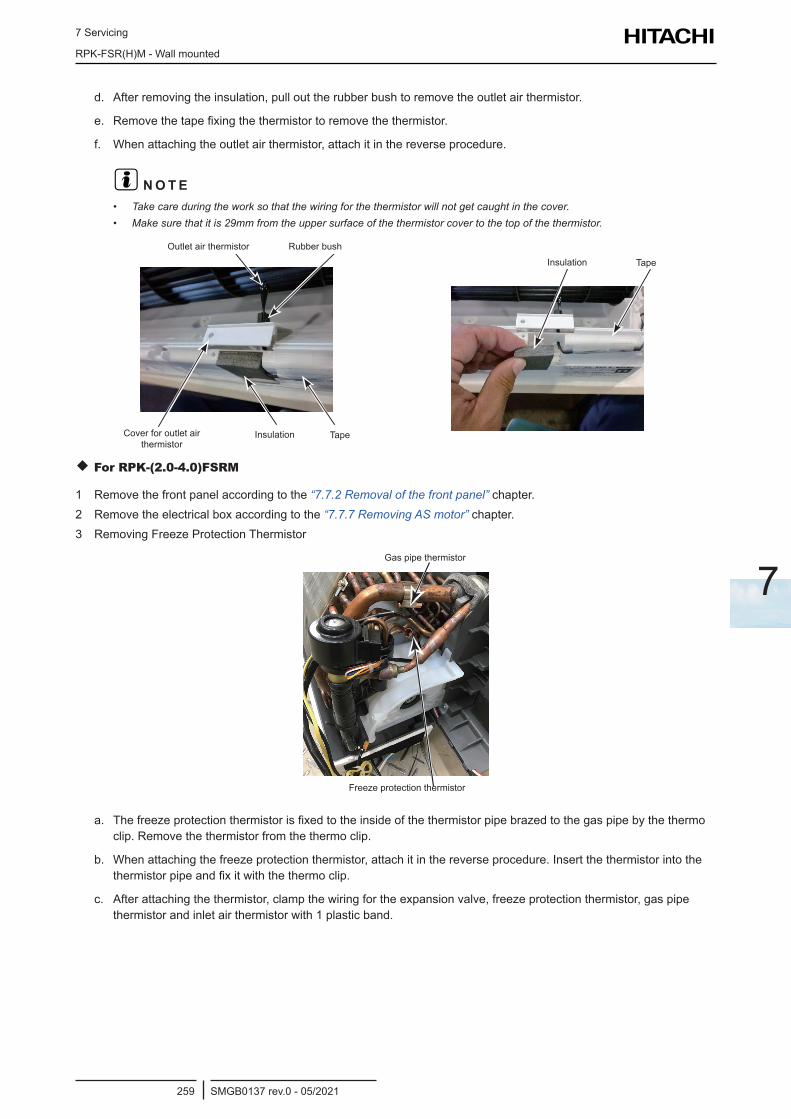
7 Servicing
RPK-FSR(H)M - Wall mounted
SMGB0137 rev.0 - 05/2021259
7
d. After removing the insulation, pull out the rubber bush to remove the outlet air thermistor.
e. Remove the tape fixing the thermistor to remove the thermistor.
f. When attaching the outlet air thermistor, attach it in the reverse procedure.
? N O T E• Take care during the work so that the wiring for the thermistor will not get caught in the cover.• Make sure that it is 29mm from the upper surface of the thermistor cover to the top of the thermistor.
Outlet Air Thermistor
Cover forOutlet Air Thermistor
Rubber Bush
TapeInsulation TapeInsulation
Rubber bushOutlet air thermistor
Cover for outlet air thermistor
Insulation TapeInsulation Tape
For RPK-(2.0-4.0)FSRM
1 Remove the front panel according to the “7.7.2 Removal of the front panel” chapter.2 Remove the electrical box according to the “7.7.7 Removing AS motor” chapter.3 Removing Freeze Protection Thermistor
Gas pipe thermistor
Freeze protection thermistor
a. The freeze protection thermistor is fixed to the inside of the thermistor pipe brazed to the gas pipe by the thermo clip. Remove the thermistor from the thermo clip.
b. When attaching the freeze protection thermistor, attach it in the reverse procedure. Insert the thermistor into the thermistor pipe and fix it with the thermo clip.
c. After attaching the thermistor, clamp the wiring for the expansion valve, freeze protection thermistor, gas pipe thermistor and inlet air thermistor with 1 plastic band.
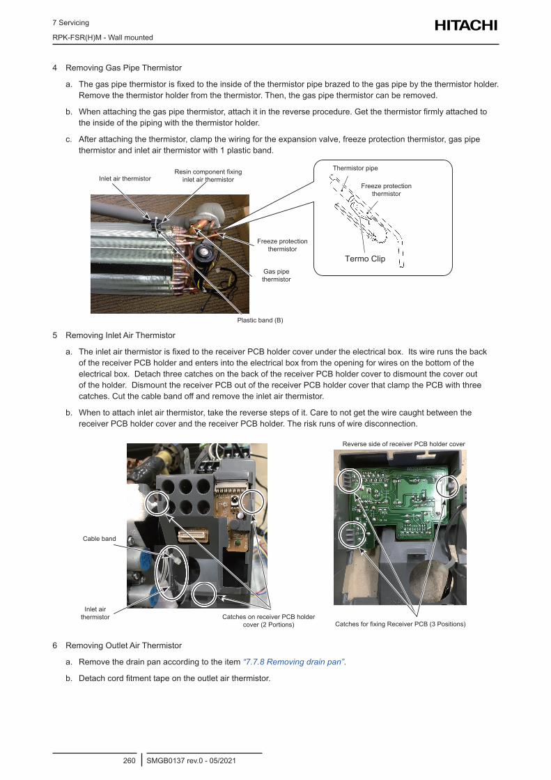
7 Servicing
RPK-FSR(H)M - Wall mounted
SMGB0137 rev.0 - 05/2021260
4 Removing Gas Pipe Thermistor
a. The gas pipe thermistor is fixed to the inside of the thermistor pipe brazed to the gas pipe by the thermistor holder. Remove the thermistor holder from the thermistor. Then, the gas pipe thermistor can be removed.
b. When attaching the gas pipe thermistor, attach it in the reverse procedure. Get the thermistor firmly attached to the inside of the piping with the thermistor holder.
c. After attaching the thermistor, clamp the wiring for the expansion valve, freeze protection thermistor, gas pipe thermistor and inlet air thermistor with 1 plastic band.
Termo Clip
Inlet air thermistorResin component fixing
inlet air thermistor
Freeze protection thermistor
Gas pipe thermistor
Plastic band (B)
Freeze protection thermistor
Thermistor pipe
5 Removing Inlet Air Thermistor
a. The inlet air thermistor is fixed to the receiver PCB holder cover under the electrical box. Its wire runs the back of the receiver PCB holder and enters into the electrical box from the opening for wires on the bottom of the electrical box. Detach three catches on the back of the receiver PCB holder cover to dismount the cover out of the holder. Dismount the receiver PCB out of the receiver PCB holder cover that clamp the PCB with three catches. Cut the cable band off and remove the inlet air thermistor.
b. When to attach inlet air thermistor, take the reverse steps of it. Care to not get the wire caught between the receiver PCB holder cover and the receiver PCB holder. The risk runs of wire disconnection.
Cable band
Inlet air thermistor Catches on receiver PCB holder
cover (2 Portions) Catches for fixing Receiver PCB (3 Positions)
Reverse side of receiver PCB holder cover
6 Removing Outlet Air Thermistor
a. Remove the drain pan according to the item “7.7.8 Removing drain pan”.
b. Detach cord fitment tape on the outlet air thermistor.
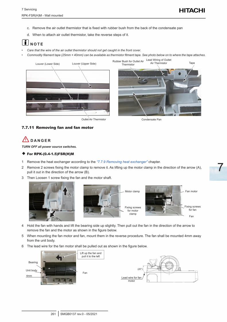
7 Servicing
RPK-FSR(H)M - Wall mounted
SMGB0137 rev.0 - 05/2021261
7
c. Remove the air outlet thermistor that is fixed with rubber bush from the back of the condensate pan
d. When to attach air outlet thermistor, take the reverse steps of it.
? N O T E• Care that the wire of the air outlet thermistor should not get caught in the front cover.• Commodity filament tape (25mm × 40mm) can be available as thermistor fitment tape. See photo below on to where the tape attaches.
Louver (Lower Side) Louver (Upper Side)
Outlet Air Thermistor
Rubber Bush for Outlet Air Thermistor
Lead Wiring of Outlet Air Thermistor Tape
Condensate Pan
7.7.11 Removing fan and fan motor
! D A N G E RTURN OFF all power source switches.
For RPK-(0.4-1.5)FSR(H)M
1 Remove the heat exchanger according to the “7.7.9 Removing heat exchanger” chapter.2 Remove 2 screws fixing the motor clamp to remove it. As lifting up the motor clamp in the direction of the arrow (A),
pull it out in the direction of the arrow (B).3 Then Loosen 1 screw fixing the fan and the motor shaft.
(A)
(B)
Motor Clamp
Fixing Screws forMotor Clamp
Motor clamp
Fixing screws for motor clamp
Fan Motor
Fixing Screw for Fan
Fan
Fan motor
Fan
Fixing screws for fan
4 Hold the fan with hands and lift the bearing side up slightly. Then pull out the fan in the direction of the arrow to remove the fan and the motor as shown in the figure below.
5 When mounting the fan motor and fan, mount them in the reverse procedure. The fan shall be mounted 4mm away from the unit body.
6 The lead wire for the fan motor shall be pulled out as shown in the figure below.
4mm
(20°)
FanUnit body
Bearing
Lift up the fan and pull it to the left
Lead wire for fan motor
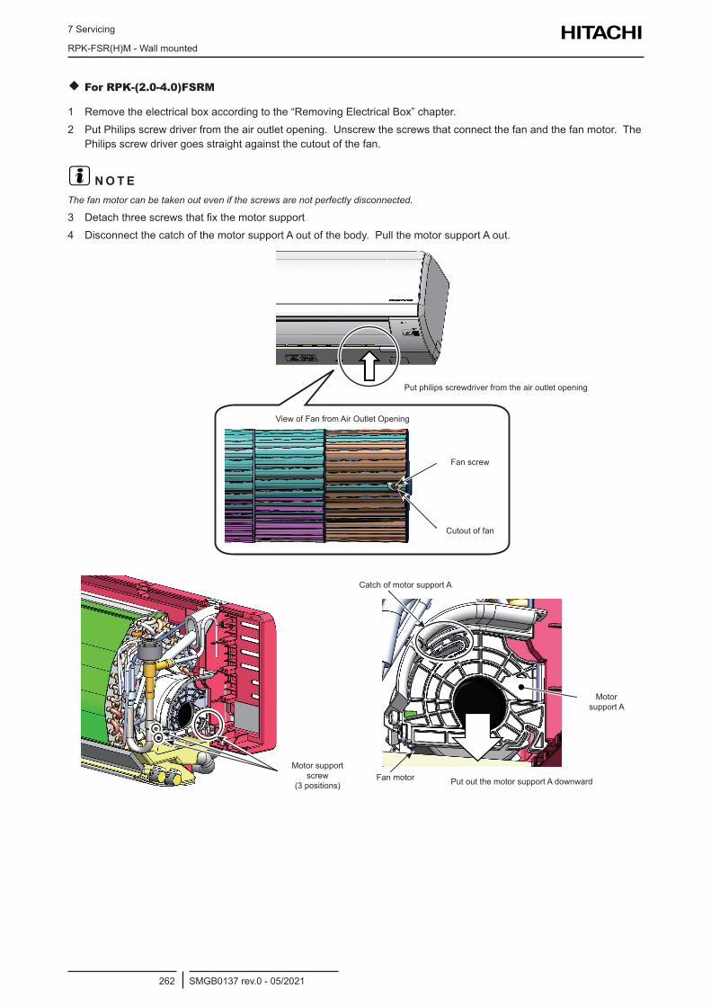
7 Servicing
RPK-FSR(H)M - Wall mounted
SMGB0137 rev.0 - 05/2021262
For RPK-(2.0-4.0)FSRM
1 Remove the electrical box according to the “Removing Electrical Box” chapter.2 Put Philips screw driver from the air outlet opening. Unscrew the screws that connect the fan and the fan motor. The
Philips screw driver goes straight against the cutout of the fan.
? N O T EThe fan motor can be taken out even if the screws are not perfectly disconnected.
3 Detach three screws that fix the motor support4 Disconnect the catch of the motor support A out of the body. Pull the motor support A out.
Put philips screwdriver from the air outlet opening
View of Fan from Air Outlet Opening
Fan screw
Cutout of fan
Catch of motor support A
Motor support screw
(3 positions)Fan motor Put out the motor support A downward
Motor support A

7 Servicing
RPK-FSR(H)M - Wall mounted
SMGB0137 rev.0 - 05/2021263
7
5 Twist away the motor support B out of the rubber bush. Pull the motor support B out to avoid catch being caught therein.
6 Remove the motor wire out of the clamp to pull the fan motor out.7 When to mount fan motor and fan, take the reverse steps of it. Degree of pulling out of fan motor lead wire is
approximately 20°. See illustration below.8 From the view of downward of the body, fan places in where the right edge of the fan’s cutout contact the body. After
mounting, rotate the fan by the hand to check for no friction.
Fan motor
Motor support B
Body
Catch
Cutout of fan
Twist in the direction of the arrows to avoid catch being
caught therein.
Fan places in where the right edge of the fan’s cutout contacts the body
Cross section
(20°)
Fan Motor Lead Wire
(Approx. 20°)
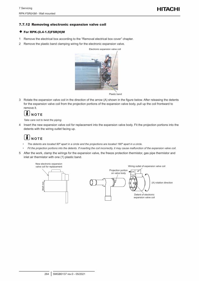
7 Servicing
RPK-FSR(H)M - Wall mounted
SMGB0137 rev.0 - 05/2021264
7.7.12 Removing electronic expansion valve coil
For RPK-(0.4-1.5)FSR(H)M
1 Remove the electrical box according to the “Removal electrical box cover” chapter.2 Remove the plastic band clamping wiring for the electronic expansion valve.
Electronic Expansion Valve Coil
Plastic Band
Electronic expansion valve coil
Plastic band
3 Rotate the expansion valve coil in the direction of the arrow (A) shown in the figure below. After releasing the detents for the expansion valve coil from the projection portions of the expansion valve body, pull up the coil frontward to remove it.
? N O T ETake care not to twist the piping.
4 Insert the new expansion valve coil for replacement into the expansion valve body. Fit the projection portions into the detents with the wiring outlet facing up.
? N O T E• The detents are located 90º apart in a circle and the projections are located 180º apart in a circle.• Fit the projection portions into the detents. If inserting the coil incorrectly, it may cause malfunction of the expansion valve coil.
5 After the work, clamp the wirings for the expansion valve, the freeze protection thermistor, gas pipe thermistor and inlet air thermistor with one (1) plastic band.
30±5
mm
New electronic expansion valve coil for replacement
Projection portion on valve body
Detent of electronic expansion valve coil
Wiring outlet of expansion valve coil
(A) rotation direction
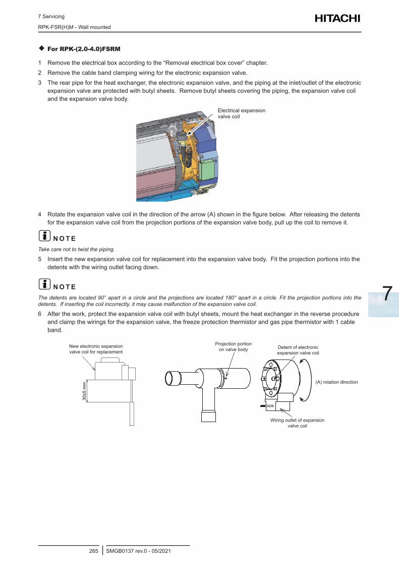
7 Servicing
RPK-FSR(H)M - Wall mounted
SMGB0137 rev.0 - 05/2021265
7
For RPK-(2.0-4.0)FSRM
1 Remove the electrical box according to the “Removal electrical box cover” chapter.2 Remove the cable band clamping wiring for the electronic expansion valve.3 The rear pipe for the heat exchanger, the electronic expansion valve, and the piping at the inlet/outlet of the electronic
expansion valve are protected with butyl sheets. Remove butyl sheets covering the piping, the expansion valve coil and the expansion valve body.
Electrical expansion valve coil
4 Rotate the expansion valve coil in the direction of the arrow (A) shown in the figure below. After releasing the detents for the expansion valve coil from the projection portions of the expansion valve body, pull up the coil to remove it.
? N O T ETake care not to twist the piping.
5 Insert the new expansion valve coil for replacement into the expansion valve body. Fit the projection portions into the detents with the wiring outlet facing down.
? N O T EThe detents are located 90° apart in a circle and the projections are located 180° apart in a circle. Fit the projection portions into the detents. If inserting the coil incorrectly, it may cause malfunction of the expansion valve coil.
6 After the work, protect the expansion valve coil with butyl sheets, mount the heat exchanger in the reverse procedure and clamp the wirings for the expansion valve, the freeze protection thermistor and gas pipe thermistor with 1 cable band.
30±5
mm
New electronic expansion valve coil for replacement
Projection portion on valve body Detent of electronic
expansion valve coil
Wiring outlet of expansion valve coil
(A) rotation direction
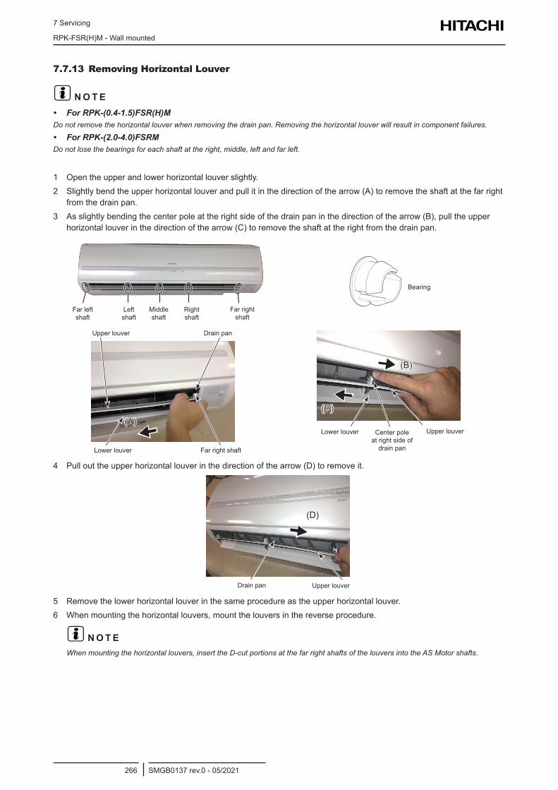
7 Servicing
RPK-FSR(H)M - Wall mounted
SMGB0137 rev.0 - 05/2021266
7.7.13 Removing Horizontal Louver
? N O T E• For RPK-(0.4-1.5)FSR(H)MDo not remove the horizontal louver when removing the drain pan. Removing the horizontal louver will result in component failures.
• For RPK-(2.0-4.0)FSRMDo not lose the bearings for each shaft at the right, middle, left and far left.
1 Open the upper and lower horizontal louver slightly.2 Slightly bend the upper horizontal louver and pull it in the direction of the arrow (A) to remove the shaft at the far right
from the drain pan.3 As slightly bending the center pole at the right side of the drain pan in the direction of the arrow (B), pull the upper
horizontal louver in the direction of the arrow (C) to remove the shaft at the right from the drain pan.
Far LeftShaft
LeftShaft
MiddleShaft
RightShaft
Far RightShaft
Far left shaft
Far right shaft
Right shaft
Middle shaft
Left shaft
BearingBearing
Upper Louver
Lower Louver
Drain Pan
Far Right Shaft
(A)
Far right shaftLower louver
Upper louver Drain pan
Lower Louver Upper LouverCenter Pole at Right Sideof Drain Pan
(C)
(B)
Lower louver Upper louverCenter pole at right side of drain pan
4 Pull out the upper horizontal louver in the direction of the arrow (D) to remove it.
Drain Pan Upper Louver
(D)
Upper louverDrain pan
5 Remove the lower horizontal louver in the same procedure as the upper horizontal louver.6 When mounting the horizontal louvers, mount the louvers in the reverse procedure.
? N O T EWhen mounting the horizontal louvers, insert the D-cut portions at the far right shafts of the louvers into the AS Motor shafts.
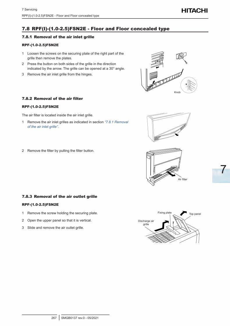
7 Servicing
RPF(I)-(1.0-2.5)FSN2E - Floor and Floor concealed type
SMGB0137 rev.0 - 05/2021267
7
7.8 RPF(I)-(1.0-2.5)FSN2E - Floor and Floor concealed type7.8.1 Removal of the air inlet grille
RPF-(1.0-2.5)FSN2E
1 Loosen the screws on the securing plate of the right part of the grille then remove the plates.
2 Press the button on both sides of the grille in the direction indicated by the arrow. The grille can be opened at a 30° angle.
3 Remove the air inlet grille from the hinges.
Knob
7.8.2 Removal of the air filter
RPF-(1.0-2.5)FSN2E
The air filter is located inside the air inlet grille.
1 Remove the air inlet grilles as indicated in section “7.8.1 Removal of the air inlet grille”.
2 Remove the filter by pulling the filter button.
Air filter
7.8.3 Removal of the air outlet grille
RPF-(1.0-2.5)FSN2E
1 Remove the screw holding the securing plate.
2 Open the upper panel so that it is vertical.
3 Slide and remove the air outlet grille.
Top panelFixing plate
Discharge air grille
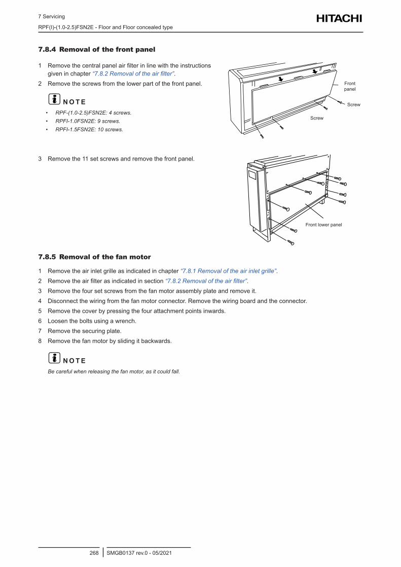
7 Servicing
RPF(I)-(1.0-2.5)FSN2E - Floor and Floor concealed type
SMGB0137 rev.0 - 05/2021268
7.8.4 Removal of the front panel
1 Remove the central panel air filter in line with the instructions given in chapter “7.8.2 Removal of the air filter”.
2 Remove the screws from the lower part of the front panel.
? N O T E• RPF-(1.0-2.5)FSN2E: 4 screws.• RPFI-1.0FSN2E: 9 screws.• RPFI-1.5FSN2E: 10 screws.
Front panel
Screw
Screw
3 Remove the 11 set screws and remove the front panel.
Front lower panel
7.8.5 Removal of the fan motor
1 Remove the air inlet grille as indicated in chapter “7.8.1 Removal of the air inlet grille”.2 Remove the air filter as indicated in section “7.8.2 Removal of the air filter”.3 Remove the four set screws from the fan motor assembly plate and remove it.4 Disconnect the wiring from the fan motor connector. Remove the wiring board and the connector.5 Remove the cover by pressing the four attachment points inwards.6 Loosen the bolts using a wrench.7 Remove the securing plate.8 Remove the fan motor by sliding it backwards.
? N O T EBe careful when releasing the fan motor, as it could fall.
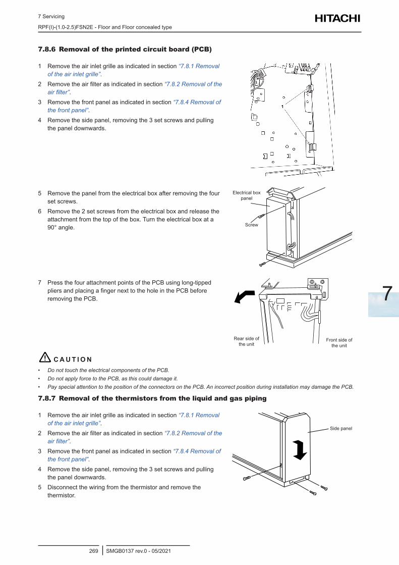
7 Servicing
RPF(I)-(1.0-2.5)FSN2E - Floor and Floor concealed type
SMGB0137 rev.0 - 05/2021269
7
7.8.6 Removal of the printed circuit board (PCB)
1 Remove the air inlet grille as indicated in section “7.8.1 Removal of the air inlet grille”.
2 Remove the air filter as indicated in section “7.8.2 Removal of the air filter”.
3 Remove the front panel as indicated in section “7.8.4 Removal of the front panel”.
4 Remove the side panel, removing the 3 set screws and pulling the panel downwards.
5 Remove the panel from the electrical box after removing the four set screws.
6 Remove the 2 set screws from the electrical box and release the attachment from the top of the box. Turn the electrical box at a 90° angle.
Electrical box panel
Screw
7 Press the four attachment points of the PCB using long-tipped pliers and placing a finger next to the hole in the PCB before removing the PCB.
Rear side of the unit
Front side of the unit
! C A U T I O N• Do not touch the electrical components of the PCB.• Do not apply force to the PCB, as this could damage it.• Pay special attention to the position of the connectors on the PCB. An incorrect position during installation may damage the PCB.
7.8.7 Removal of the thermistors from the liquid and gas piping
1 Remove the air inlet grille as indicated in section “7.8.1 Removal of the air inlet grille”.
2 Remove the air filter as indicated in section “7.8.2 Removal of the air filter”.
3 Remove the front panel as indicated in section “7.8.4 Removal of the front panel”.
4 Remove the side panel, removing the 3 set screws and pulling the panel downwards.
5 Disconnect the wiring from the thermistor and remove the thermistor.
Side panel
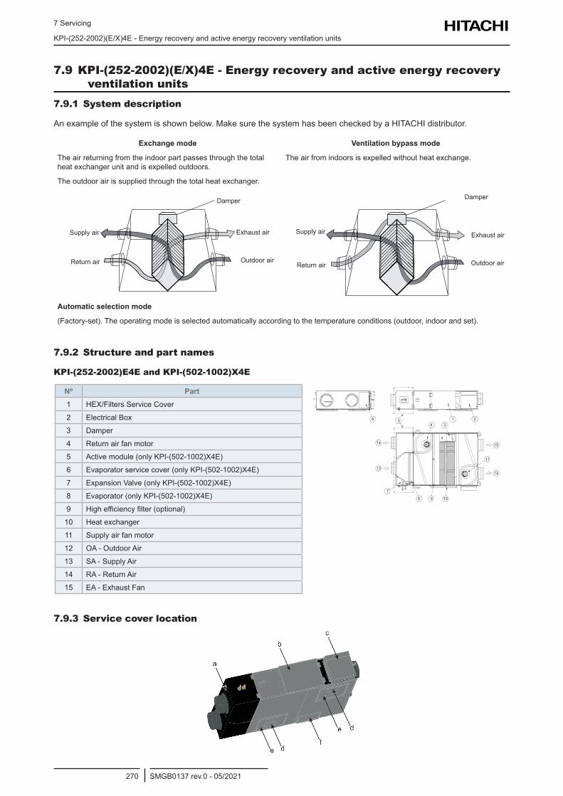
7 Servicing
KPI-(252-2002)(E/X)4E - Energy recovery and active energy recovery ventilation units
SMGB0137 rev.0 - 05/2021270
7.9 KPI-(252-2002)(E/X)4E - Energy recovery and active energy recovery ventilation units
7.9.1 System description
An example of the system is shown below. Make sure the system has been checked by a HITACHI distributor.
Exchange mode
The air returning from the indoor part passes through the total heat exchanger unit and is expelled outdoors.
The outdoor air is supplied through the total heat exchanger.
Ventilation bypass mode
The air from indoors is expelled without heat exchange.
Damper
Exhaust air
Outdoor air
Supply air
Return air
Damper
Exhaust air
Outdoor air
Supply air
Return air
Automatic selection mode
(Factory-set). The operating mode is selected automatically according to the temperature conditions (outdoor, indoor and set).
7.9.2 Structure and part names
KPI-(252-2002)E4E and KPI-(502-1002)X4E
Nº Part1 HEX/Filters Service Cover
2 Electrical Box
3 Damper
4 Return air fan motor
5 Active module (only KPI-(502-1002)X4E)
6 Evaporator service cover (only KPI-(502-1002)X4E)
7 Expansion Valve (only KPI-(502-1002)X4E)
8 Evaporator (only KPI-(502-1002)X4E)
9 High efficiency filter (optional)
10 Heat exchanger
11 Supply air fan motor
12 OA - Outdoor Air
13 SA - Supply Air
14 RA - Return Air
15 EA - Exhaust Fan
7.9.3 Service cover location
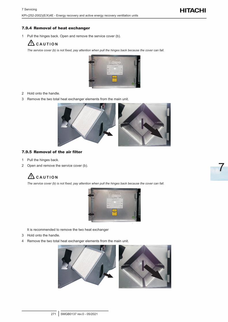
7 Servicing
KPI-(252-2002)(E/X)4E - Energy recovery and active energy recovery ventilation units
SMGB0137 rev.0 - 05/2021271
7
7.9.4 Removal of heat exchanger
1 Pull the hinges back. Open and remove the service cover (b).
! C A U T I O NThe service cover (b) is not fixed, pay attention when pull the hinges back because the cover can fall.
2 Hold onto the handle.3 Remove the two total heat exchanger elements from the main unit.
7.9.5 Removal of the air filter
1 Pull the hinges back. 2 Open and remove the service cover (b).
! C A U T I O NThe service cover (b) is not fixed, pay attention when pull the hinges back because the cover can fall.
It is recommended to remove the two heat exchanger3 Hold onto the handle.4 Remove the two total heat exchanger elements from the main unit.
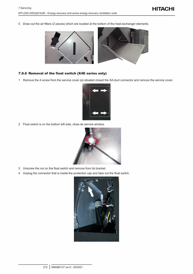
7 Servicing
KPI-(252-2002)(E/X)4E - Energy recovery and active energy recovery ventilation units
SMGB0137 rev.0 - 05/2021272
5 Draw out the air filters (2 pieces) which are located at the bottom of the heat exchanger elements.
7.9.6 Removal of the float switch (X4E series only)
1 Remove the 4 screw from the service cover (a) situated closed the SA duct connector and remove the service cover.
2 Float switch is on the bottom left side, close de service window.
3 Unscrew the nut on the float switch and remove from its bracket.4 Unplug the connector that is inside the protection cap and take out the float switch.
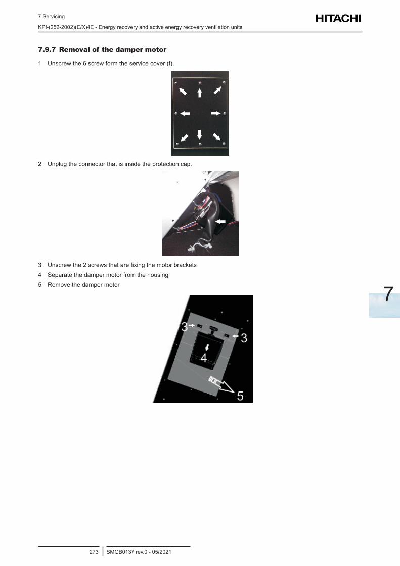
7 Servicing
KPI-(252-2002)(E/X)4E - Energy recovery and active energy recovery ventilation units
SMGB0137 rev.0 - 05/2021273
7
7.9.7 Removal of the damper motor
1 Unscrew the 6 screw form the service cover (f).
2 Unplug the connector that is inside the protection cap.
3 Unscrew the 2 screws that are fixing the motor brackets4 Separate the damper motor from the housing 5 Remove the damper motor
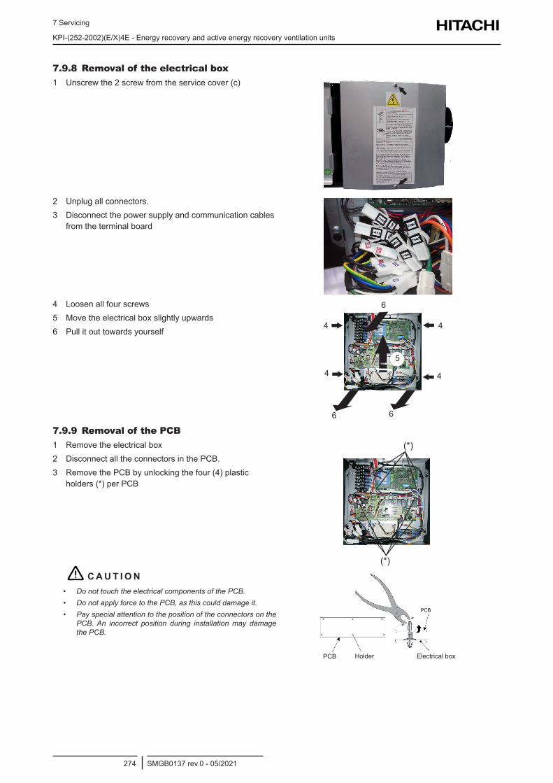
7 Servicing
KPI-(252-2002)(E/X)4E - Energy recovery and active energy recovery ventilation units
SMGB0137 rev.0 - 05/2021274
7.9.8 Removal of the electrical box1 Unscrew the 2 screw from the service cover (c)
2 Unplug all connectors.3 Disconnect the power supply and communication cables
from the terminal board
4 Loosen all four screws 5 Move the electrical box slightly upwards6 Pull it out towards yourself
4
5
6
4
4
4
66
7.9.9 Removal of the PCB1 Remove the electrical box2 Disconnect all the connectors in the PCB.3 Remove the PCB by unlocking the four (4) plastic
holders (*) per PCB
(*)
(*)
! C A U T I O N• Do not touch the electrical components of the PCB.• Do not apply force to the PCB, as this could damage it.• Pay special attention to the position of the connectors on the
PCB. An incorrect position during installation may damage the PCB.
PCB Holder Electrical box
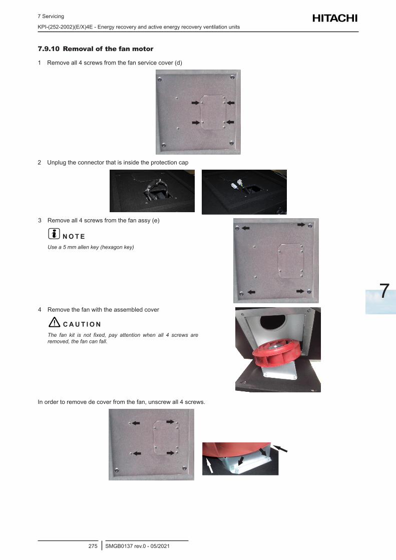
7 Servicing
KPI-(252-2002)(E/X)4E - Energy recovery and active energy recovery ventilation units
SMGB0137 rev.0 - 05/2021275
7
7.9.10 Removal of the fan motor
1 Remove all 4 screws from the fan service cover (d)
2 Unplug the connector that is inside the protection cap
3 Remove all 4 screws from the fan assy (e)
? N O T EUse a 5 mm allen key (hexagon key)
4 Remove the fan with the assembled cover
! C A U T I O NThe fan kit is not fixed, pay attention when all 4 screws are removed, the fan can fall.
In order to remove de cover from the fan, unscrew all 4 screws.
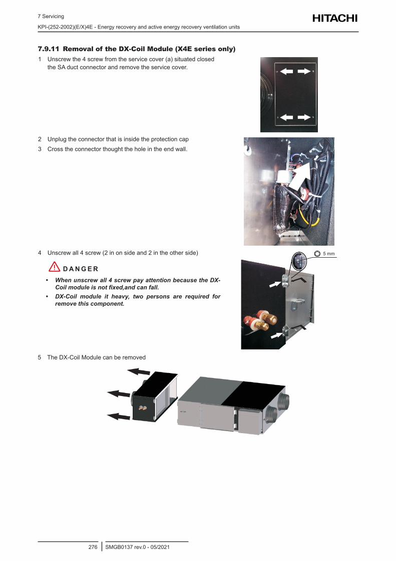
7 Servicing
KPI-(252-2002)(E/X)4E - Energy recovery and active energy recovery ventilation units
SMGB0137 rev.0 - 05/2021276
7.9.11 Removal of the DX-Coil Module (X4E series only)1 Unscrew the 4 screw from the service cover (a) situated closed
the SA duct connector and remove the service cover.
2 Unplug the connector that is inside the protection cap3 Cross the connector thought the hole in the end wall.
4 Unscrew all 4 screw (2 in on side and 2 in the other side)
! D A N G E R• When unscrew all 4 screw pay attention because the DX-
Coilmoduleisnotfixed,andcanfall.• DX-Coil module it heavy, two persons are required for
remove this component.
5 mm
5 The DX-Coil Module can be removed
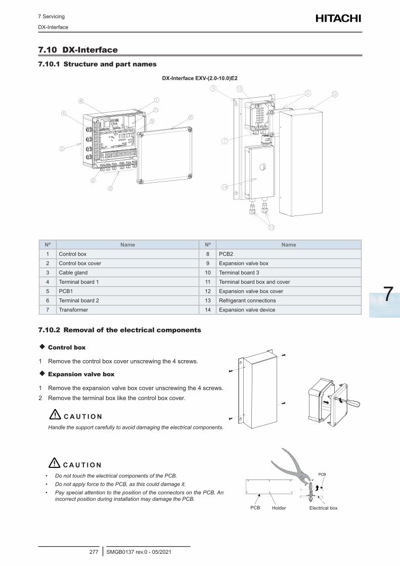
7 Servicing
DX-Interface
SMGB0137 rev.0 - 05/2021277
7
7.10 DX-Interface7.10.1 Structure and part names
DX-Interface EXV-(2.0-10.0)E2
Nº Name Nº Name1 Control box 8 PCB2
2 Control box cover 9 Expansion valve box
3 Cable gland 10 Terminal board 3
4 Terminal board 1 11 Terminal board box and cover
5 PCB1 12 Expansion valve box cover
6 Terminal board 2 13 Refrigerant connections
7 Transformer 14 Expansion valve device
7.10.2 Removal of the electrical components
Control box
1 Remove the control box cover unscrewing the 4 screws.
Expansion valve box
1 Remove the expansion valve box cover unscrewing the 4 screws.2 Remove the terminal box like the control box cover.
! C A U T I O NHandle the support carefully to avoid damaging the electrical components.
! C A U T I O N• Do not touch the electrical components of the PCB.• Do not apply force to the PCB, as this could damage it.• Pay special attention to the position of the connectors on the PCB. An
incorrect position during installation may damage the PCB.PCB Holder Electrical box

8 Troubleshooting
SMGB0137 rev.0 - 05/2021279
8
8 . Tr o u b l e s h o o t i n g
Index
8.1 Electronic expansion valve check procedure ......................................................................................280
8.2 Procedure for checking fan motors in indoor units ..............................................................................280
8.3 Inspection of other components ..........................................................................................................282
8.4 Alarm codes displayed in the remote control switch ...........................................................................283
8.5 DX-Interface EXV-(2.0-10.0)E2 or KPI-(E/X)4E alarm codes..............................................................286
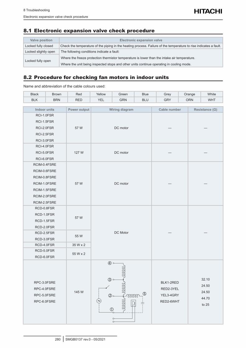
8 Troubleshooting
Electronic expansion valve check procedure
SMGB0137 rev.0 - 05/2021280
8.1 Electronic expansion valve check procedure
Valve position Electronic expansion valveLocked fully closed Check the temperature of the piping in the heating process. Failure of the temperature to rise indicates a fault.
Locked slightly open The following conditions indicate a fault:
Where the freeze protection thermistor temperature is lower than the intake air temperature.
Where the unit being inspected stops and other units continue operating in cooling mode.Locked fully open
8.2 Procedure for checking fan motors in indoor unitsName and abbreviation of the cable colours used:
Black Brown Red Yellow Green Blue Grey Orange White
BLK BRN RED YEL GRN BLU GRY ORN WHT
Indoor units Power output Wiring diagram Cable number Resistance (Ω)RCI-1.0FSR
RCI-1.5FSR
RCI-2.0FSR
RCI-2.5FSR
RCI-3.0FSR
57 W DC motor — —
RCI-4.0FSR
RCI-5.0FSR
RCI-6.0FSR
127 W DC motor — —
RCIM-0.4FSRE
RCIM-0.6FSRE
RCIM-0.8FSRE
RCIM-1.0FSRE
RCIM-1.5FSRE
RCIM-2.0FSRE
RCIM-2.5FSRE
57 W DC motor — —
RCD-0.8FSR
RCD-1.0FSR
RCD-1.5FSR
RCD-2.0FSR
57 W
DC Motor — —RCD-2.5FSR
RCD-3.0FSR55 W
RCD-4.0FSR 35 W x 2
RCD-5.0FSR
RCD-6.0FSR55 W x 2
RPC-3.0FSRE
RPC-4.0FSRE
RPC-5.0FSRE
RPC-6.0FSRE
145 W
BLK1-2RED
RED2-3YEL
YEL3-4GRY
RED2-6WHT
32.10
24.50
24.50
44.70
to 25
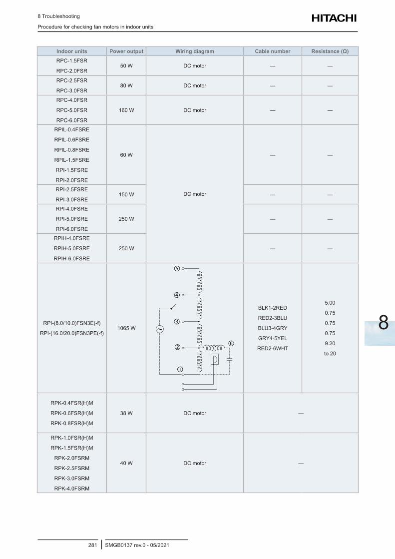
8 Troubleshooting
Procedure for checking fan motors in indoor units
SMGB0137 rev.0 - 05/2021281
8
Indoor units Power output Wiring diagram Cable number Resistance (Ω)RPC-1.5FSR
RPC-2.0FSR50 W DC motor — —
RPC-2.5FSR
RPC-3.0FSR80 W DC motor — —
RPC-4.0FSR
RPC-5.0FSR
RPC-6.0FSR
160 W DC motor — —
RPIL-0.4FSRE
RPIL-0.6FSRE
RPIL-0.8FSRE
RPIL-1.5FSRE
RPI-1.5FSRE
RPI-2.0FSRE
60 W
DC motor
— —
RPI-2.5FSRE
RPI-3.0FSRE150 W — —
RPI-4.0FSRE
RPI-5.0FSRE
RPI-6.0FSRE
250 W — —
RPIH-4.0FSRE
RPIH-5.0FSRE
RPIH-6.0FSRE
250 W — —
RPI-(8.0/10.0)FSN3E(-f)
RPI-(16.0/20.0)FSN3PE(-f)1065 W
BLK1-2RED
RED2-3BLU
BLU3-4GRY
GRY4-5YEL
RED2-6WHT
5.00
0.75
0.75
0.75
9.20
to 20
RPK-0.4FSR(H)M
RPK-0.6FSR(H)M
RPK-0.8FSR(H)M
38 W DC motor —
RPK-1.0FSR(H)M
RPK-1.5FSR(H)M
RPK-2.0FSRM
RPK-2.5FSRM
RPK-3.0FSRM
RPK-4.0FSRM
40 W DC motor —
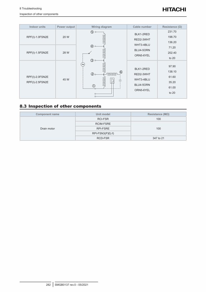
8 Troubleshooting
Inspection of other components
SMGB0137 rev.0 - 05/2021282
Indoor units Power output Wiring diagram Cable number Resistance (Ω)
RPF(I)-1.0FSN2E 20 WBLK1-2RED
RED2-3WHT
WHT3-4BLU
BLU4-5ORN
ORN5-6YEL
231.70
198.70
136.20
71.20
202.40
to 20
RPF(I)-1.5FSN2E 28 W
RPF(I)-2.0FSN2E
RPF(I)-2.5FSN2E45 W
BLK1-2RED
RED2-3WHT
WHT3-4BLU
BLU4-5ORN
ORN5-6YEL
97.90
138.10
61.60
35.20
61.00
to 20
8.3 Inspection of other components
Component name Unit model Resistance (MΩ)
Drain motor
RCI-FSR 100
RCIM-FSRE
100RPI-FSRE
RPI-FSN3(P)E(-f)
RCD-FSR 347 to 21
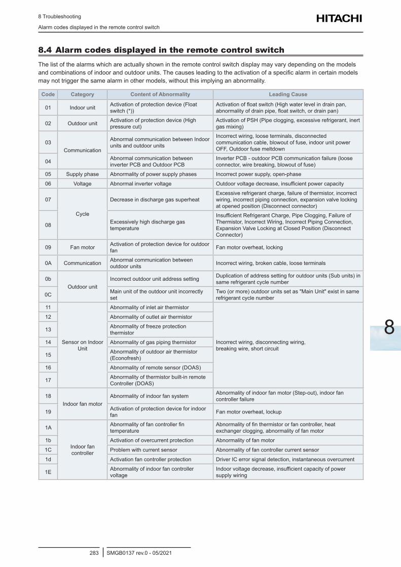
8 Troubleshooting
Alarm codes displayed in the remote control switch
SMGB0137 rev.0 - 05/2021283
8
8.4 Alarm codes displayed in the remote control switchThe list of the alarms which are actually shown in the remote control switch display may vary depending on the models and combinations of indoor and outdoor units. The causes leading to the activation of a specific alarm in certain models may not trigger the same alarm in other models, without this implying an abnormality.
Code Category Content of Abnormality Leading Cause
01 Indoor unit Activation of protection device (Float switch (*))
Activation of float switch (High water level in drain pan, abnormality of drain pipe, float switch, or drain pan)
02 Outdoor unit Activation of protection device (High pressure cut)
Activation of PSH (Pipe clogging, excessive refrigerant, inert gas mixing)
03Communication
Abnormal communication between Indoor units and outdoor units
Incorrect wiring, loose terminals, disconnected communication cable, blowout of fuse, indoor unit power OFF, Outdoor fuse meltdown
04 Abnormal communication between inverter PCB and Outdoor PCB
Inverter PCB - outdoor PCB communication failure (loose connector, wire breaking, blowout of fuse)
05 Supply phase Abnormality of power supply phases Incorrect power supply, open-phase
06 Voltage Abnormal inverter voltage Outdoor voltage decrease, insufficient power capacity
07
Cycle
Decrease in discharge gas superheatExcessive refrigerant charge, failure of thermistor, incorrect wiring, incorrect piping connection, expansion valve locking at opened position (Disconnect connector)
08 Excessively high discharge gas temperature
Insufficient Refrigerant Charge, Pipe Clogging, Failure of Thermistor, Incorrect Wiring, Incorrect Piping Connection, Expansion Valve Locking at Closed Position (Disconnect Connector)
09 Fan motor Activation of protection device for outdoor fan Fan motor overheat, locking
0A Communication Abnormal communication between outdoor units Incorrect wiring, broken cable, loose terminals
0bOutdoor unit
Incorrect outdoor unit address setting Duplication of address setting for outdoor units (Sub units) in same refrigerant cycle number
0C Main unit of the outdoor unit incorrectly set
Two (or more) outdoor units set as "Main Unit" exist in same refrigerant cycle number
11
Sensor on Indoor Unit
Abnormality of inlet air thermistor
Incorrect wiring, disconnecting wiring, breaking wire, short circuit
12 Abnormality of outlet air thermistor
13 Abnormality of freeze protection thermistor
14 Abnormality of gas piping thermistor
15 Abnormality of outdoor air thermistor (Econofresh)
16 Abnormality of remote sensor (DOAS)
17 Abnormality of thermistor built-in remote Controller (DOAS)
18Indoor fan motor
Abnormality of indoor fan system Abnormality of indoor fan motor (Step-out), indoor fan controller failure
19 Activation of protection device for indoor fan Fan motor overheat, lockup
1A
Indoor fan controller
Abnormality of fan controller fin temperature
Abnormality of fin thermistor or fan controller, heat exchanger clogging, abnormality of fan motor
1b Activation of overcurrent protection Abnormality of fan motor
1C Problem with current sensor Abnormality of fan controller current sensor
1d Activation fan controller protection Driver IC error signal detection, instantaneous overcurrent
1E Abnormality of indoor fan controller voltage
Indoor voltage decrease, insufficient capacity of power supply wiring
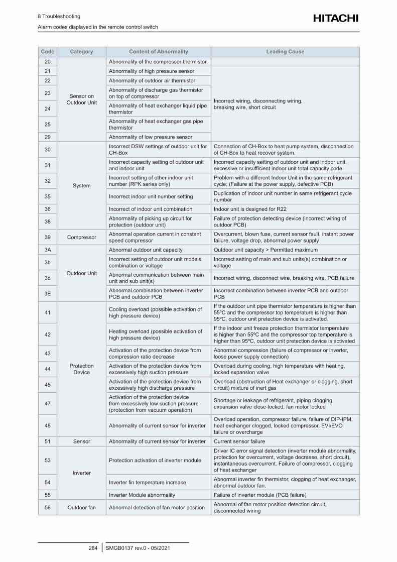
8 Troubleshooting
Alarm codes displayed in the remote control switch
SMGB0137 rev.0 - 05/2021284
Code Category Content of Abnormality Leading Cause
20
Sensor on Outdoor Unit
Abnormality of the compressor thermistor
21 Abnormality of high pressure sensor
Incorrect wiring, disconnecting wiring, breaking wire, short circuit
22 Abnormality of outdoor air thermistor
23 Abnormality of discharge gas thermistor on top of compressor
24 Abnormality of heat exchanger liquid pipe thermistor
25 Abnormality of heat exchanger gas pipe thermistor
29 Abnormality of low pressure sensor
30
System
Incorrect DSW settings of outdoor unit for CH-Box
Connection of CH-Box to heat pump system, disconnection of CH-Box to heat recover system.
31 Incorrect capacity setting of outdoor unit and indoor unit
Incorrect capacity setting of outdoor unit and indoor unit, excessive or insufficient indoor unit total capacity code
32 Incorrect setting of other indoor unit number (RPK series only)
Problem with a different Indoor Unit in the same refrigerant cycle; (Failure at the power supply, defective PCB)
35 Incorrect indoor unit number setting Duplication of indoor unit number in same refrigerant cycle number
36 Incorrect of indoor unit combination Indoor unit is designed for R22
38 Abnormality of picking up circuit for protection (outdoor unit)
Failure of protection detecting device (incorrect wiring of outdoor PCB)
39 Compressor Abnormal operation current in constant speed compressor
Overcurrent, blown fuse, current sensor fault, instant power failure, voltage drop, abnormal power supply
3A
Outdoor Unit
Abnormal outdoor unit capacity Outdoor unit capacity > Permitted maximum
3b Incorrect setting of outdoor unit models combination or voltage
Incorrect setting of main and sub units(s) combination or voltage
3d Abnormal communication between main unit and sub unit(s) Incorrect wiring, disconnect wire, breaking wire, PCB failure
3E Abnormal combination between inverter PCB and outdoor PCB
Incorrect combination between inverter PCB and outdoor PCB
41
Protection Device
Cooling overload (possible activation of high pressure device)
If the outdoor unit pipe thermistor temperature is higher than 55ºC and the compressor top temperature is higher than 95ºC, outdoor unit pretection device is activated.
42 Heating overload (possible activation of high pressure device)
If the indoor unit freeze protection thermistor temperature is higher than 55ºC and the compressor top temperature is higher than 95ºC, outdoor unit pretection device is activated
43 Activation of the protection device from compression ratio decrease
Abnormal compression (failure of compressor or inverter, loose power supply connection)
44 Activation of the protection device from excessively high suction pressure
Overload during cooling, high temperature with heating, locked expansion valve
45 Activation of the protection device from excessively high discharge pressure
Overload (obstruction of Heat exchanger or clogging, short circuit) mixture of inert gas
47Activation of the protection device from excessively low suction pressure (protection from vacuum operation)
Shortage or leakage of refrigerant, piping clogging, expansion valve close-locked, fan motor locked
48 Abnormality of current sensor for inverterOverload operation, compressor failure, failure of DIP-IPM, heat exchanger clogged, locked compressor, EVI/EVO failure or overcharge
51 Sensor Abnormality of current sensor for inverter Current sensor failure
53
Inverter
Protection activation of inverter module
Driver IC error signal detection (inverter module abnormality, protection for overcurrent, voltage decrease, short circuit), instantaneous overcurrent. Failure of compressor, clogging of heat exchanger
54 Inverter fin temperature increase Abnormal inverter fin thermistor, clogging of heat exchanger, abnormal outdoor fan.
55 Inverter Module abnormality Failure of inverter module (PCB failure)
56 Outdoor fan Abnormal detection of fan motor position Abnormal of fan motor position detection circuit, disconnected wiring
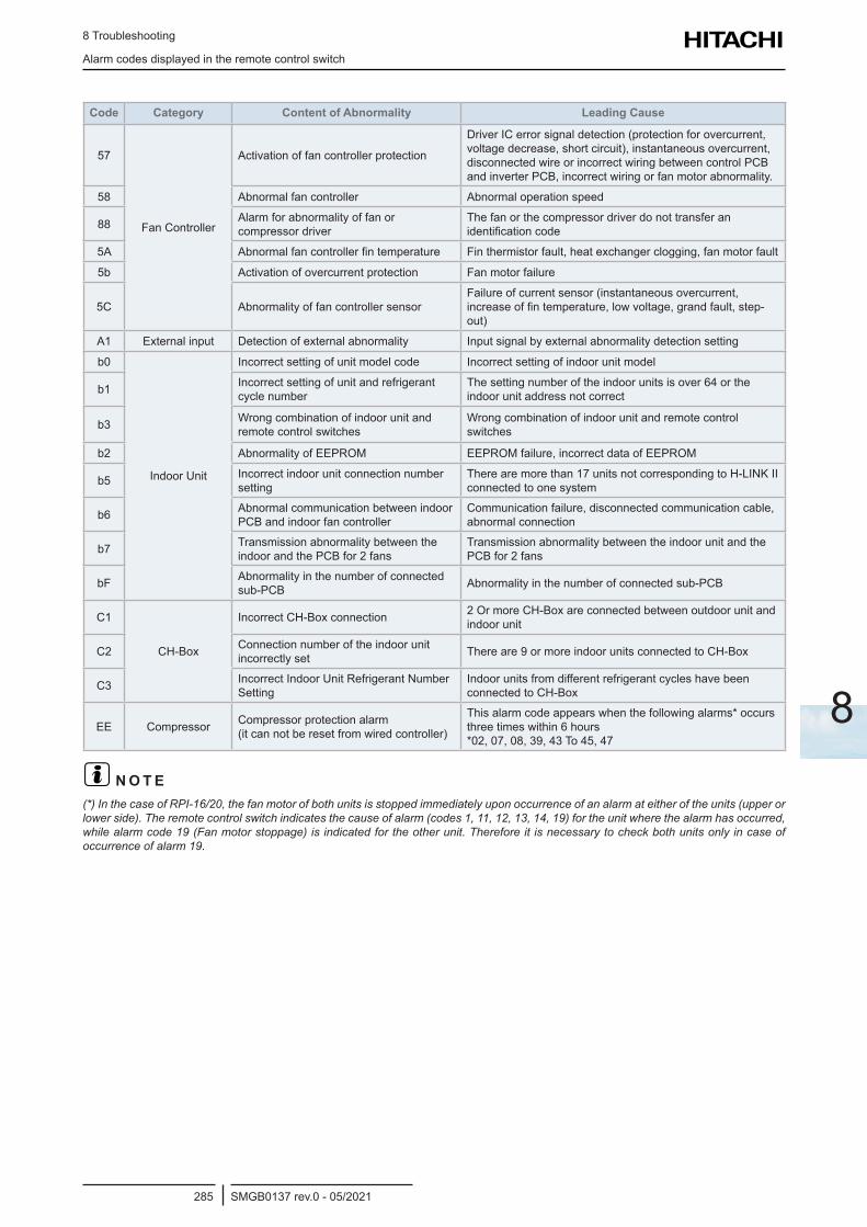
8 Troubleshooting
Alarm codes displayed in the remote control switch
SMGB0137 rev.0 - 05/2021285
8
Code Category Content of Abnormality Leading Cause
57
Fan Controller
Activation of fan controller protection
Driver IC error signal detection (protection for overcurrent, voltage decrease, short circuit), instantaneous overcurrent, disconnected wire or incorrect wiring between control PCB and inverter PCB, incorrect wiring or fan motor abnormality.
58 Abnormal fan controller Abnormal operation speed
88 Alarm for abnormality of fan or compressor driver
The fan or the compressor driver do not transfer an identification code
5A Abnormal fan controller fin temperature Fin thermistor fault, heat exchanger clogging, fan motor fault
5b Activation of overcurrent protection Fan motor failure
5C Abnormality of fan controller sensorFailure of current sensor (instantaneous overcurrent, increase of fin temperature, low voltage, grand fault, step-out)
A1 External input Detection of external abnormality Input signal by external abnormality detection setting
b0
Indoor Unit
Incorrect setting of unit model code Incorrect setting of indoor unit model
b1 Incorrect setting of unit and refrigerant cycle number
The setting number of the indoor units is over 64 or the indoor unit address not correct
b3 Wrong combination of indoor unit and remote control switches
Wrong combination of indoor unit and remote control switches
b2 Abnormality of EEPROM EEPROM failure, incorrect data of EEPROM
b5 Incorrect indoor unit connection number setting
There are more than 17 units not corresponding to H-LINK II connected to one system
b6 Abnormal communication between indoor PCB and indoor fan controller
Communication failure, disconnected communication cable, abnormal connection
b7 Transmission abnormality between the indoor and the PCB for 2 fans
Transmission abnormality between the indoor unit and the PCB for 2 fans
bF Abnormality in the number of connected sub-PCB Abnormality in the number of connected sub-PCB
C1
CH-Box
Incorrect CH-Box connection 2 Or more CH-Box are connected between outdoor unit and indoor unit
C2 Connection number of the indoor unit incorrectly set There are 9 or more indoor units connected to CH-Box
C3 Incorrect Indoor Unit Refrigerant Number Setting
Indoor units from different refrigerant cycles have been connected to CH-Box
EE Compressor Compressor protection alarm (it can not be reset from wired controller)
This alarm code appears when the following alarms* occurs three times within 6 hours *02, 07, 08, 39, 43 To 45, 47
? N O T E(*) In the case of RPI-16/20, the fan motor of both units is stopped immediately upon occurrence of an alarm at either of the units (upper or lower side). The remote control switch indicates the cause of alarm (codes 1, 11, 12, 13, 14, 19) for the unit where the alarm has occurred, while alarm code 19 (Fan motor stoppage) is indicated for the other unit. Therefore it is necessary to check both units only in case of occurrence of alarm 19.
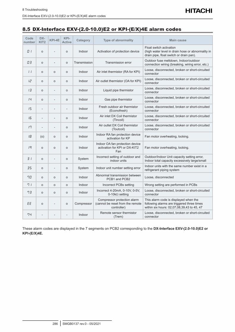
8 Troubleshooting
DX-Interface EXV-(2.0-10.0)E2 or KPI-(E/X)4E alarm codes
SMGB0137 rev.0 - 05/2021286
8.5 DX-Interface EXV-(2.0-10.0)E2 or KPI-(E/X)4E alarm codes
Code number
DX-KIT2 KPI-4E KPI-
Active Category Type of abnormality Main cause
01 o - o Indoor Activation of protection deviceFloat switch activation (high water level in drain hose or abnormality in drain pipe, float switch or drain pan).
03 o - o Transmission Transmission error Outdoor fuse meltdown, Indoor/outdoor connection wiring (breaking, wiring error, etc.)
11 o o o Indoor Air inlet thermistor (RA for KPI) Loose, disconnected, broken or short-circuited connector
12 o o o Indoor Air outlet thermistor (OA for KPI) Loose, disconnected, broken or short-circuited connector
13 o - o Indoor Liquid pipe thermistor Loose, disconnected, broken or short-circuited connector
14 o - o Indoor Gas pipe thermistor Loose, disconnected, broken or short-circuited connector
15 - - - Indoor Fresh outdoor air thermistor (Econofresh)
Loose, disconnected, broken or short-circuited connector
16 - - o Indoor Air inlet DX Coil thermistor (Tincoil)
Loose, disconnected, broken or short-circuited connector
17 - - o Indoor Air outlet DX Coil thermistor (Toutcoil)
Loose, disconnected, broken or short-circuited connector
18 (o) o o Indoor Indoor RA fan protection device activation for KP Fan motor overheating, locking.
19 o o o IndoorIndoor OA fan protection device
activation for KPI or DX-KIT2 Fan
Fan motor overheating, locking.
31 o - o System Incorrect setting of outdoor and indoor units
Outdoor/Indoor Unit capacity setting error, Indoor total capacity excessively large/small
35 o - o System Indoor unit number setting error Indoor units with the same number exist in a refrigerant piping system
70 o o o Indoor Abnormal transmission between PCB1 and PCB2 Loose, disconnected
71 o o o Indoor Incorrect PCBs setting Wrong setting are performed in PCBs
73 o o o Indoor Incorrect 4-20mA, 0-10V, 0-5V, 0-10kΩ setting
Loose, disconnected, broken or short-circuited connector
EE o - o CompressorCompressor protection alarm
(cannot be reset from the remote controller)
This alarm code is displayed when the following alarms are triggered three times within six hours: 02,07,08,39,43 to 45, 47
74 - - - Indoor Remote sensor thermistor (Trem)
Loose, disconnected, broken or short-circuited connector
These alarm codes are displayed in the 7 segments on PCB2 corresponding to the DX-Interface EXV-(2.0-10.0)E2 or KPI-(E/X)4E.
9 Maintenance notes
SMGB0137 rev.0 - 05/2021287
9
Index
9.1 Regular equipment maintenance ........................................................................................................288
9.1.1 Necessary tools, equipment and consumable for regular maintenance ...................................................... 288
9.2 Indoor cleaning ....................................................................................................................................289
9.2.1 Cleaning the built-in 4-way indoor unit RCI(M) ............................................................................................ 289
9.2.2 Cleaning the built-in 2-way indoor unit (RCD) ............................................................................................. 292
9.2.3 Cleaning of the wall-type indoor unit (RPK) ................................................................................................ 294
9.2.4 Cleaning the floor console and floor concealed console indoor unit RPF(I) ................................................ 295
9.2.5 Cleaning of the ceiling-type indoor unit (RPC) ............................................................................................ 296
9.3 Cleaning of KPI units ...........................................................................................................................299
9.4 Econofresh kit......................................................................................................................................301
9.5 Collection of refrigerant to replace the indoor unit...............................................................................301
9.6 Cleaning agents for heat exchanger ...................................................................................................302
9.6.1 Recommended specifications of cleaning agents for aluminium fins .......................................................... 302
9.6.2 Particularities and benefits .......................................................................................................................... 302
9.6.3 To consider .................................................................................................................................................. 302
9 . M a i n t e n a n c e n o t e s
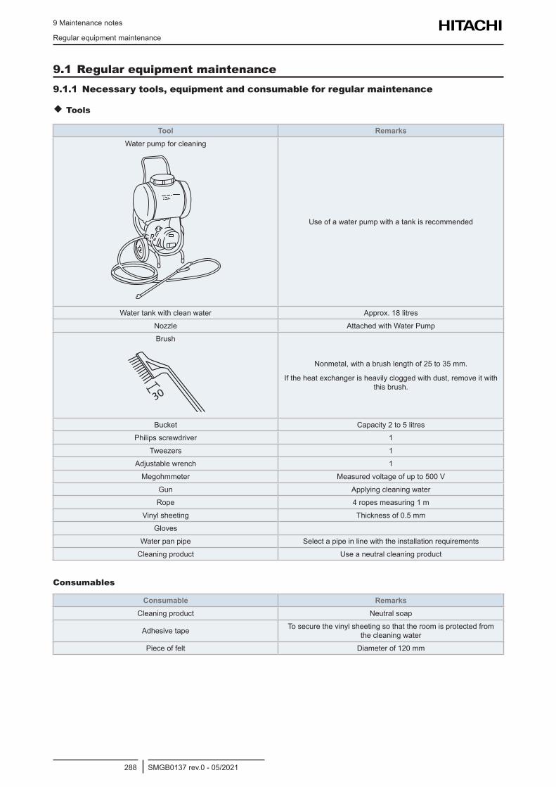
9 Maintenance notes
Regular equipment maintenance
SMGB0137 rev.0 - 05/2021288
9.1 Regular equipment maintenance9.1.1 Necessary tools, equipment and consumable for regular maintenance
Tools
Tool RemarksWater pump for cleaning
Use of a water pump with a tank is recommended
Water tank with clean water Approx. 18 litres
Nozzle Attached with Water Pump
Brush
30
Nonmetal, with a brush length of 25 to 35 mm.
If the heat exchanger is heavily clogged with dust, remove it with this brush.
Bucket Capacity 2 to 5 litres
Philips screwdriver 1
Tweezers 1
Adjustable wrench 1
Megohmmeter Measured voltage of up to 500 V
Gun Applying cleaning water
Rope 4 ropes measuring 1 m
Vinyl sheeting Thickness of 0.5 mm
Gloves
Water pan pipe Select a pipe in line with the installation requirements
Cleaning product Use a neutral cleaning product
Consumables
Consumable RemarksCleaning product Neutral soap
Adhesive tape To secure the vinyl sheeting so that the room is protected from the cleaning water
Piece of felt Diameter of 120 mm
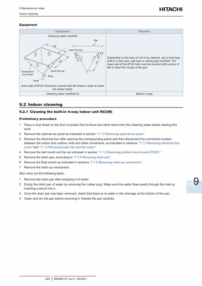
9 Maintenance notes
Indoor cleaning
SMGB0137 rev.0 - 05/2021289
9
Equipment
Equipment RemarksCleaning water manifold
Transparent vinyl sheet
Hose
Boss
Insert the bar
Insert the bar
Bar
Inner side of Ø120 should be covered with felt sheet in order to insert the spray nozzle
Depending on the type of unit to be cleaned, use a duct-type, built-in 2-way type, wall type or ceiling type manifold. The lower part of the Ø120 hole must be covered with a piece of felt to insert the nozzle of the gun
Cleaning water manifold kit Built-in 4-way
9.2 Indoor cleaning9.2.1 Cleaning the built-in 4-way indoor unit RCI(M)
Preliminary procedure
1 Place a vinyl sheet on the floor to protect the furniture and other items from the cleaning water before starting this work.
2 Remove the optional air panel as indicated in section “7.1.3 Removing optional air panel”.3 Remove the electrical box after opening the corresponding panel and then disconnect the connectors located
between the indoor and outdoor units and other connectors, as indicated in sections “7.1.2 Removing electrical box cover” and “7.1.4 Removing turbo fan and fan motor”.
4 Remove the bell mouth and fan as indicated in section “7.1.5 Removing printed circuit board (PCB1)”.5 Remove the drain pan, according to “7.1.6 Removing drain pan”.6 Remove the float switch as indicated in sections “7.1.8 Removing drain-up mechanism”.7 Remove the drain-up mechanism.
Also carry out the following tasks:
1 Remove the drain pan after emptying it of water.2 Empty the drain pan of water by removing the rubber plug. Make sure the water flows easily through the hole by
inserting a pencil into it.3 Once the drain pan has been removed, check that there is no water in the drainage at the bottom of the pan.4 Clean and dry the pan before removing it. Handle the pan carefully.
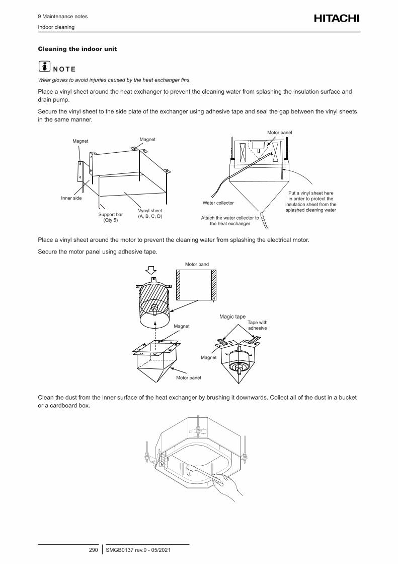
9 Maintenance notes
Indoor cleaning
SMGB0137 rev.0 - 05/2021290
Cleaning the indoor unit
? N O T EWear gloves to avoid injuries caused by the heat exchanger fins.
Place a vinyl sheet around the heat exchanger to prevent the cleaning water from splashing the insulation surface and drain pump.
Secure the vinyl sheet to the side plate of the exchanger using adhesive tape and seal the gap between the vinyl sheets in the same manner.
Inner side
Magnet Magnet
Support bar (Qty 5)
Vynyl sheet (A, B, C, D)
Water collector
Motor panel
Attach the water collector to the heat exchanger
Put a vinyl sheet here in order to protect the
insulation sheet from the splashed cleaning water
Place a vinyl sheet around the motor to prevent the cleaning water from splashing the electrical motor.
Secure the motor panel using adhesive tape.
Motor band
Magnet
Magnet
Magic tapeTape with adhesive
Motor panel
Clean the dust from the inner surface of the heat exchanger by brushing it downwards. Collect all of the dust in a bucket or a cardboard box.
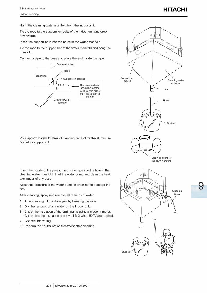
9 Maintenance notes
Indoor cleaning
SMGB0137 rev.0 - 05/2021291
9
Hang the cleaning water manifold from the indoor unit.
Tie the rope to the suspension bolts of the indoor unit and drop downwards.
Insert the support bars into the holes in the water manifold.
Tie the rope to the support bar of the water manifold and hang the manifold.
Connect a pipe to the boss and place the end inside the pipe.
Suspension bolt
Suspension bracket
Rope
Indoor unit
Cleaning water collector
The water collector should be located
20 to 30 mm higher than the bottom of
the unit
Support bar (Qty 8)
Boss
Hose
Bucket
Cleaning water collector
Pour approximately 15 litres of cleaning product for the aluminium fins into a supply tank.
Cleaning agent for the aluminium fins
Insert the nozzle of the pressurised water gun into the hole in the cleaning water manifold. Start the water pump and clean the heat exchanger of any dust.
Adjust the pressure of the water pump in order not to damage the fins.
After cleaning, spray and remove all remains of water.
1 After cleaning, fit the drain pan by lowering the rope.2 Dry the remains of any water on the indoor unit.3 Check the insulation of the drain pump using a megohmmeter.
Check that the insulation is above 1 MΩ when 500V are applied.4 Connect the wiring.5 Perform the neutralisation treatment after cleaning.
Cleaning spray
Bucket
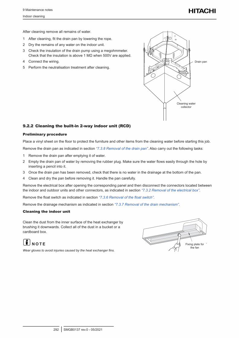
9 Maintenance notes
Indoor cleaning
SMGB0137 rev.0 - 05/2021292
After cleaning remove all remains of water.
1 After cleaning, fit the drain pan by lowering the rope.2 Dry the remains of any water on the indoor unit.3 Check the insulation of the drain pump using a megohmmeter.
Check that the insulation is above 1 MΩ when 500V are applied.4 Connect the wiring.5 Perform the neutralisation treatment after cleaning.
Drain pan
Cleaning water collector
9.2.2 Cleaning the built-in 2-way indoor unit (RCD)
Preliminary procedure
Place a vinyl sheet on the floor to protect the furniture and other items from the cleaning water before starting this job.
Remove the drain pan as indicated in section “7.3.8 Removal of the drain pan”. Also carry out the following tasks:
1 Remove the drain pan after emptying it of water.2 Empty the drain pan of water by removing the rubber plug. Make sure the water flows easily through the hole by
inserting a pencil into it.3 Once the drain pan has been removed, check that there is no water in the drainage at the bottom of the pan.4 Clean and dry the pan before removing it. Handle the pan carefully.
Remove the electrical box after opening the corresponding panel and then disconnect the connectors located between the indoor and outdoor units and other connectors, as indicated in section “7.3.2 Removal of the electrical box”.
Remove the float switch as indicated in section “7.3.6 Removal of the float switch”.
Remove the drainage mechanism as indicated in section “7.3.7 Removal of the drain mechanism”.
Cleaning the indoor unit
Clean the dust from the inner surface of the heat exchanger by brushing it downwards. Collect all of the dust in a bucket or a cardboard box.
? N O T EWear gloves to avoid injuries caused by the heat exchanger fins.
Fixing plate for the fan
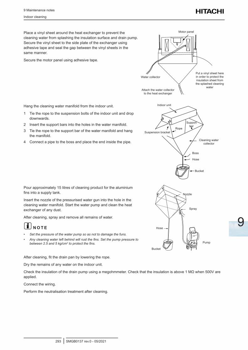
9 Maintenance notes
Indoor cleaning
SMGB0137 rev.0 - 05/2021293
9
Place a vinyl sheet around the heat exchanger to prevent the cleaning water from splashing the insulation surface and drain pump. Secure the vinyl sheet to the side plate of the exchanger using adhesive tape and seal the gap between the vinyl sheets in the same manner.
Secure the motor panel using adhesive tape.
Water collector
Motor panel
Attach the water collector to the heat exchanger
Put a vinyl sheet here in order to protect the insulation sheet from the splashed cleaning
water
Hang the cleaning water manifold from the indoor unit.
1 Tie the rope to the suspension bolts of the indoor unit and drop downwards.
2 Insert the support bars into the holes in the water manifold.3 Tie the rope to the support bar of the water manifold and hang
the manifold.4 Connect a pipe to the boss and place the end inside the pipe. Cleaning water
collector
Suspension bracket
Indoor unit
Rope
Support bar
Boss
Hose
Bucket
Pour approximately 15 litres of cleaning product for the aluminium fins into a supply tank.
Insert the nozzle of the pressurised water gun into the hole in the cleaning water manifold. Start the water pump and clean the heat exchanger of any dust.
After cleaning, spray and remove all remains of water.
? N O T E• Set the pressure of the water pump so as not to damage the funs.• Any cleaning water left behind will rust the fins. Set the pump pressure to
between 2.5 and 5 kg/cm3 to protect the fins.
Spray
Bucket
Hose
Pump
Nozzle
After cleaning, fit the drain pan by lowering the rope.
Dry the remains of any water on the indoor unit.
Check the insulation of the drain pump using a megohmmeter. Check that the insulation is above 1 MΩ when 500V are applied.
Connect the wiring.
Perform the neutralisation treatment after cleaning.
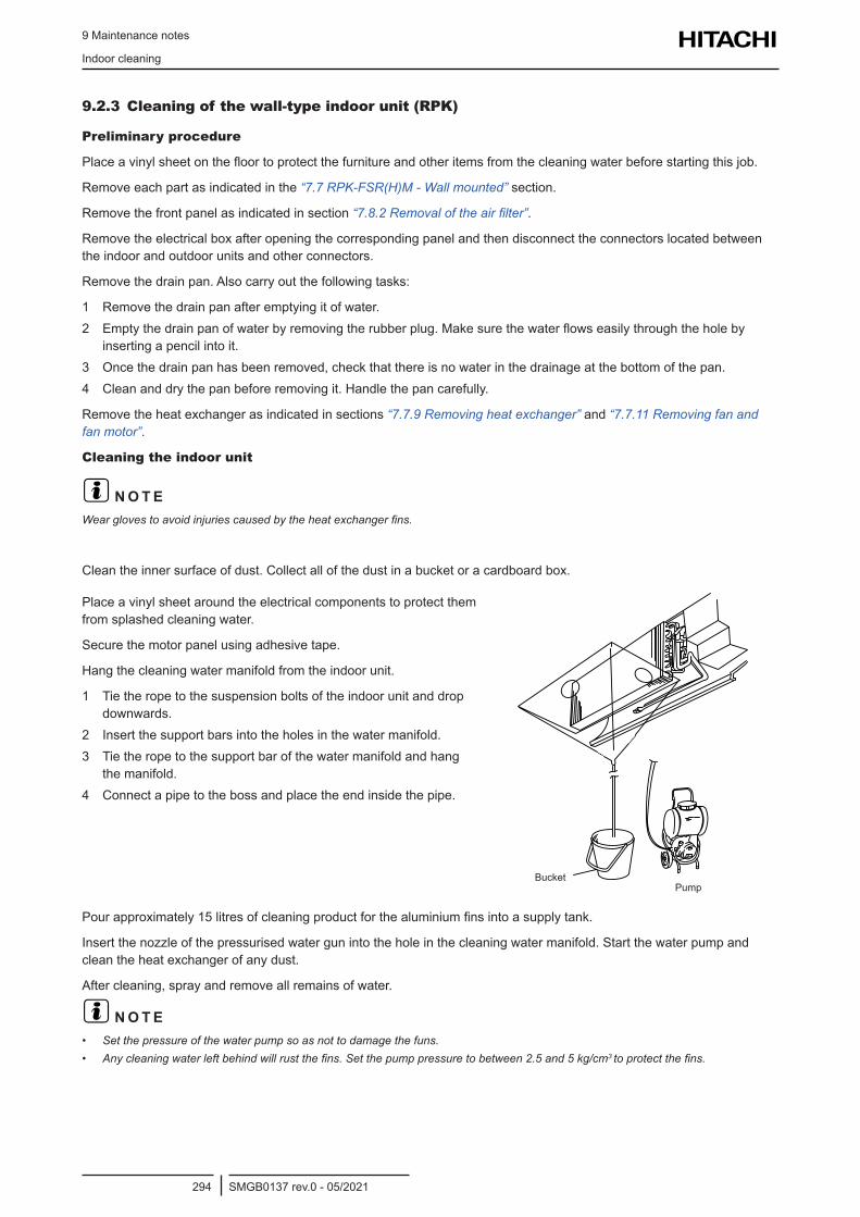
9 Maintenance notes
Indoor cleaning
SMGB0137 rev.0 - 05/2021294
9.2.3 Cleaning of the wall-type indoor unit (RPK)
Preliminary procedure
Place a vinyl sheet on the floor to protect the furniture and other items from the cleaning water before starting this job.
Remove each part as indicated in the “7.7 RPK-FSR(H)M - Wall mounted” section.
Remove the front panel as indicated in section “7.8.2 Removal of the air filter”.
Remove the electrical box after opening the corresponding panel and then disconnect the connectors located between the indoor and outdoor units and other connectors.
Remove the drain pan. Also carry out the following tasks:
1 Remove the drain pan after emptying it of water.2 Empty the drain pan of water by removing the rubber plug. Make sure the water flows easily through the hole by
inserting a pencil into it.3 Once the drain pan has been removed, check that there is no water in the drainage at the bottom of the pan.4 Clean and dry the pan before removing it. Handle the pan carefully.
Remove the heat exchanger as indicated in sections “7.7.9 Removing heat exchanger” and “7.7.11 Removing fan and fan motor”.
Cleaning the indoor unit
? N O T EWear gloves to avoid injuries caused by the heat exchanger fins.
Clean the inner surface of dust. Collect all of the dust in a bucket or a cardboard box.
Place a vinyl sheet around the electrical components to protect them from splashed cleaning water.
Secure the motor panel using adhesive tape.
Hang the cleaning water manifold from the indoor unit.
1 Tie the rope to the suspension bolts of the indoor unit and drop downwards.
2 Insert the support bars into the holes in the water manifold.3 Tie the rope to the support bar of the water manifold and hang
the manifold.4 Connect a pipe to the boss and place the end inside the pipe.
BucketPump
Pour approximately 15 litres of cleaning product for the aluminium fins into a supply tank.
Insert the nozzle of the pressurised water gun into the hole in the cleaning water manifold. Start the water pump and clean the heat exchanger of any dust.
After cleaning, spray and remove all remains of water.
? N O T E• Set the pressure of the water pump so as not to damage the funs.• Any cleaning water left behind will rust the fins. Set the pump pressure to between 2.5 and 5 kg/cm3 to protect the fins.
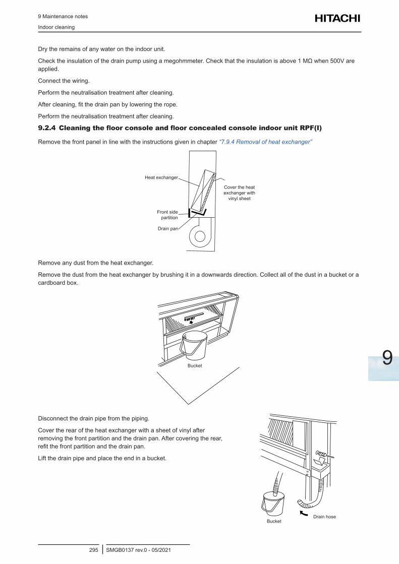
9 Maintenance notes
Indoor cleaning
SMGB0137 rev.0 - 05/2021295
9
Dry the remains of any water on the indoor unit.
Check the insulation of the drain pump using a megohmmeter. Check that the insulation is above 1 MΩ when 500V are applied.
Connect the wiring.
Perform the neutralisation treatment after cleaning.
After cleaning, fit the drain pan by lowering the rope.
Perform the neutralisation treatment after cleaning.
9.2.4 Cleaning the floor console and floor concealed console indoor unit RPF(I)
Remove the front panel in line with the instructions given in chapter “7.9.4 Removal of heat exchanger”
Drain pan
Front side partition
Heat exchanger
Cover the heat exchanger with
vinyl sheet
Remove any dust from the heat exchanger.
Remove the dust from the heat exchanger by brushing it in a downwards direction. Collect all of the dust in a bucket or a cardboard box.
Bucket
Disconnect the drain pipe from the piping.
Cover the rear of the heat exchanger with a sheet of vinyl after removing the front partition and the drain pan. After covering the rear, refit the front partition and the drain pan.
Lift the drain pipe and place the end in a bucket.
BucketDrain hose
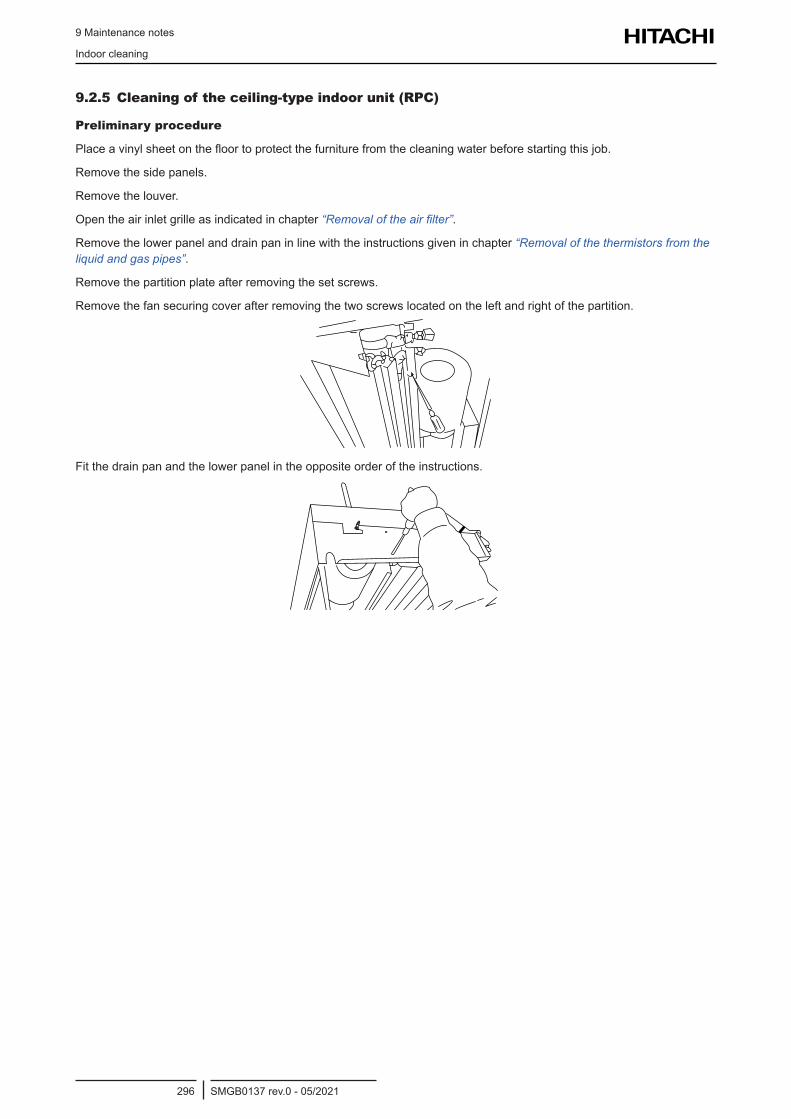
9 Maintenance notes
Indoor cleaning
SMGB0137 rev.0 - 05/2021296
9.2.5 Cleaning of the ceiling-type indoor unit (RPC)
Preliminary procedure
Place a vinyl sheet on the floor to protect the furniture from the cleaning water before starting this job.
Remove the side panels.
Remove the louver.
Open the air inlet grille as indicated in chapter “Removal of the air filter”.
Remove the lower panel and drain pan in line with the instructions given in chapter “Removal of the thermistors from the liquid and gas pipes”.
Remove the partition plate after removing the set screws.
Remove the fan securing cover after removing the two screws located on the left and right of the partition.
Fit the drain pan and the lower panel in the opposite order of the instructions.
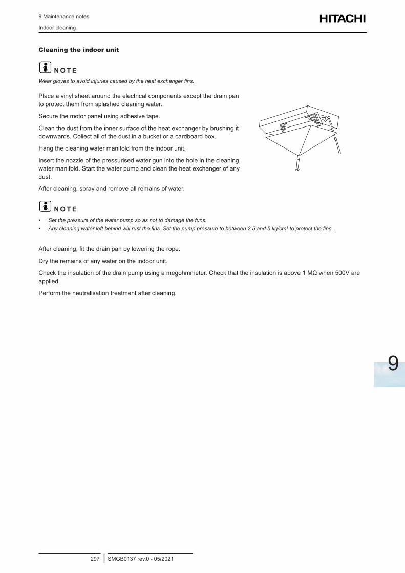
9 Maintenance notes
Indoor cleaning
SMGB0137 rev.0 - 05/2021297
9
Cleaning the indoor unit
? N O T EWear gloves to avoid injuries caused by the heat exchanger fins.
Place a vinyl sheet around the electrical components except the drain pan to protect them from splashed cleaning water.
Secure the motor panel using adhesive tape.
Clean the dust from the inner surface of the heat exchanger by brushing it downwards. Collect all of the dust in a bucket or a cardboard box.
Hang the cleaning water manifold from the indoor unit.
Insert the nozzle of the pressurised water gun into the hole in the cleaning water manifold. Start the water pump and clean the heat exchanger of any dust.
After cleaning, spray and remove all remains of water.
? N O T E• Set the pressure of the water pump so as not to damage the funs.• Any cleaning water left behind will rust the fins. Set the pump pressure to between 2.5 and 5 kg/cm3 to protect the fins.
After cleaning, fit the drain pan by lowering the rope.
Dry the remains of any water on the indoor unit.
Check the insulation of the drain pump using a megohmmeter. Check that the insulation is above 1 MΩ when 500V are applied.
Perform the neutralisation treatment after cleaning.
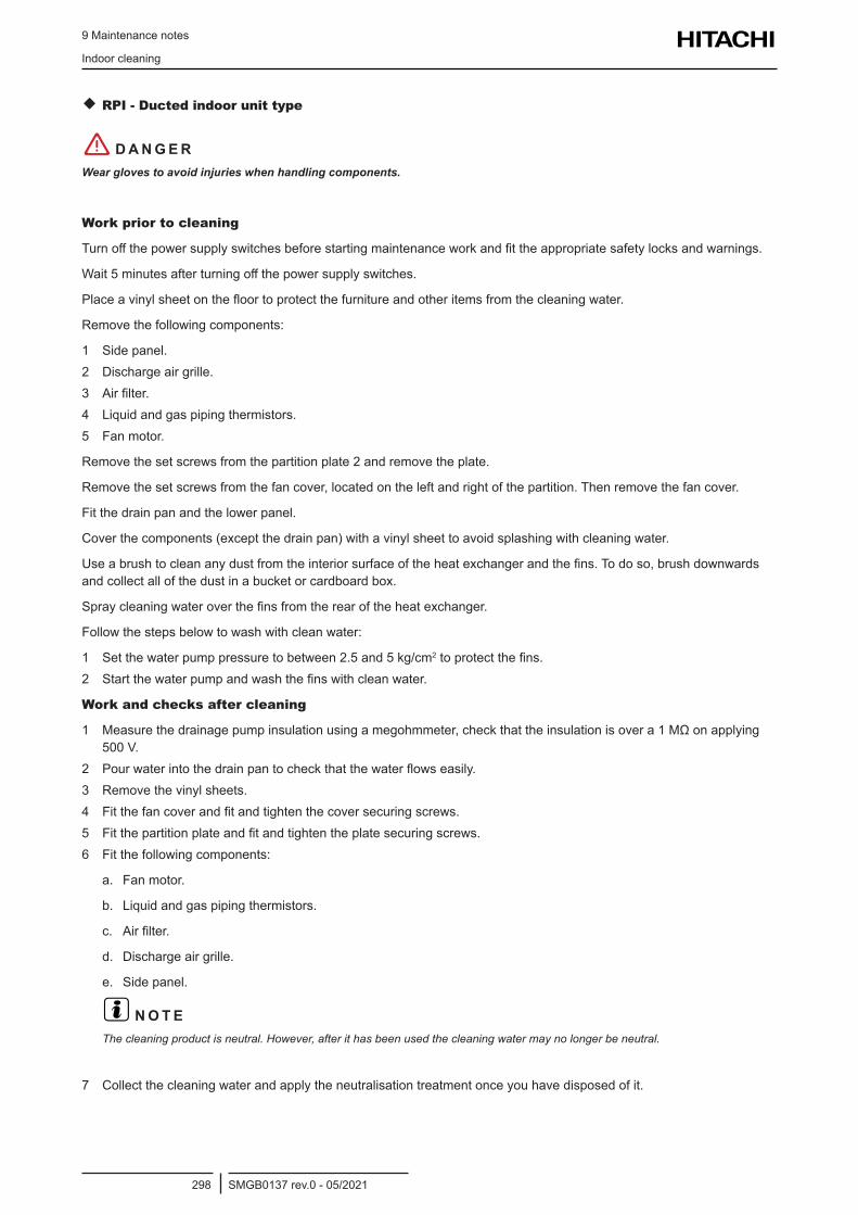
9 Maintenance notes
Indoor cleaning
SMGB0137 rev.0 - 05/2021298
RPI - Ducted indoor unit type
! D A N G E RWear gloves to avoid injuries when handling components.
Work prior to cleaning
Turn off the power supply switches before starting maintenance work and fit the appropriate safety locks and warnings.
Wait 5 minutes after turning off the power supply switches.
Place a vinyl sheet on the floor to protect the furniture and other items from the cleaning water.
Remove the following components:
1 Side panel.2 Discharge air grille.3 Air filter.4 Liquid and gas piping thermistors.5 Fan motor.
Remove the set screws from the partition plate 2 and remove the plate.
Remove the set screws from the fan cover, located on the left and right of the partition. Then remove the fan cover.
Fit the drain pan and the lower panel.
Cover the components (except the drain pan) with a vinyl sheet to avoid splashing with cleaning water.
Use a brush to clean any dust from the interior surface of the heat exchanger and the fins. To do so, brush downwards and collect all of the dust in a bucket or cardboard box.
Spray cleaning water over the fins from the rear of the heat exchanger.
Follow the steps below to wash with clean water:
1 Set the water pump pressure to between 2.5 and 5 kg/cm2 to protect the fins.2 Start the water pump and wash the fins with clean water.
Work and checks after cleaning
1 Measure the drainage pump insulation using a megohmmeter, check that the insulation is over a 1 MΩ on applying 500 V.
2 Pour water into the drain pan to check that the water flows easily.3 Remove the vinyl sheets.4 Fit the fan cover and fit and tighten the cover securing screws.5 Fit the partition plate and fit and tighten the plate securing screws.6 Fit the following components:
a. Fan motor.
b. Liquid and gas piping thermistors.
c. Air filter.
d. Discharge air grille.
e. Side panel.
? N O T EThe cleaning product is neutral. However, after it has been used the cleaning water may no longer be neutral.
7 Collect the cleaning water and apply the neutralisation treatment once you have disposed of it.
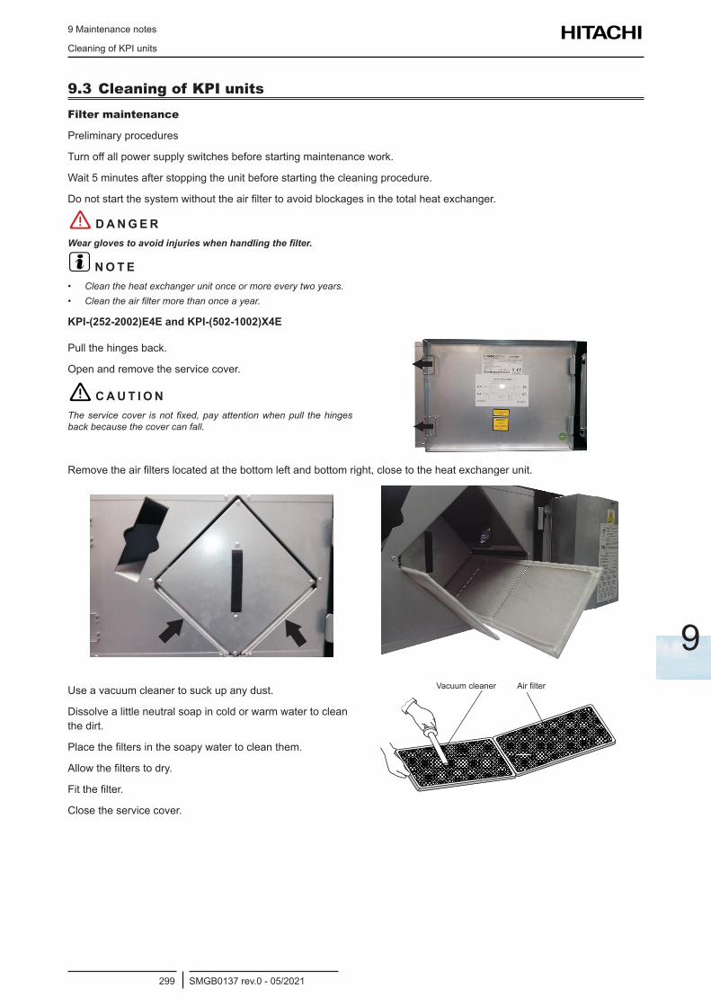
9 Maintenance notes
Cleaning of KPI units
SMGB0137 rev.0 - 05/2021299
9
9.3 Cleaning of KPI unitsFilter maintenance
Preliminary procedures
Turn off all power supply switches before starting maintenance work.
Wait 5 minutes after stopping the unit before starting the cleaning procedure.
Do not start the system without the air filter to avoid blockages in the total heat exchanger.
! D A N G E RWear gloves to avoid injuries when handling the filter.
? N O T E• Clean the heat exchanger unit once or more every two years.• Clean the air filter more than once a year.
KPI-(252-2002)E4E and KPI-(502-1002)X4E
Pull the hinges back.
Open and remove the service cover.
! C A U T I O NThe service cover is not fixed, pay attention when pull the hinges back because the cover can fall.
Remove the air filters located at the bottom left and bottom right, close to the heat exchanger unit.
Use a vacuum cleaner to suck up any dust.
Dissolve a little neutral soap in cold or warm water to clean the dirt.
Place the filters in the soapy water to clean them.
Allow the filters to dry.
Fit the filter.
Close the service cover.
Vacuum cleaner Air filter
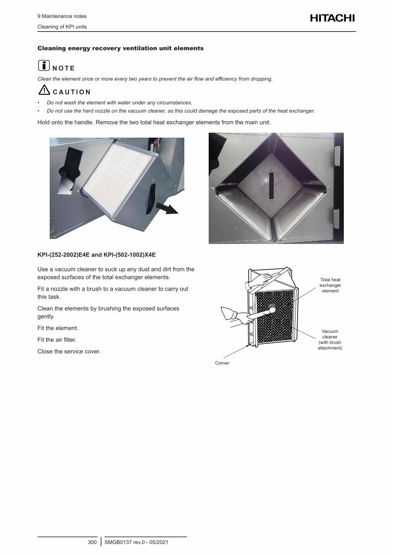
9 Maintenance notes
Cleaning of KPI units
SMGB0137 rev.0 - 05/2021300
Cleaning energy recovery ventilation unit elements
? N O T EClean the element once or more every two years to prevent the air flow and efficiency from dropping.
! C A U T I O N• Do not wash the element with water under any circumstances.• Do not use the hard nozzle on the vacuum cleaner, as this could damage the exposed parts of the heat exchanger.
Hold onto the handle. Remove the two total heat exchanger elements from the main unit.
KPI-(252-2002)E4E and KPI-(502-1002)X4E
Use a vacuum cleaner to suck up any dust and dirt from the exposed surfaces of the total exchanger elements.
Fit a nozzle with a brush to a vacuum cleaner to carry out this task.
Clean the elements by brushing the exposed surfaces gently.
Fit the element.
Fit the air filter.
Close the service cover.
Corner
Total heat exchanger element
Vacuum cleaner
(with brush attachment)
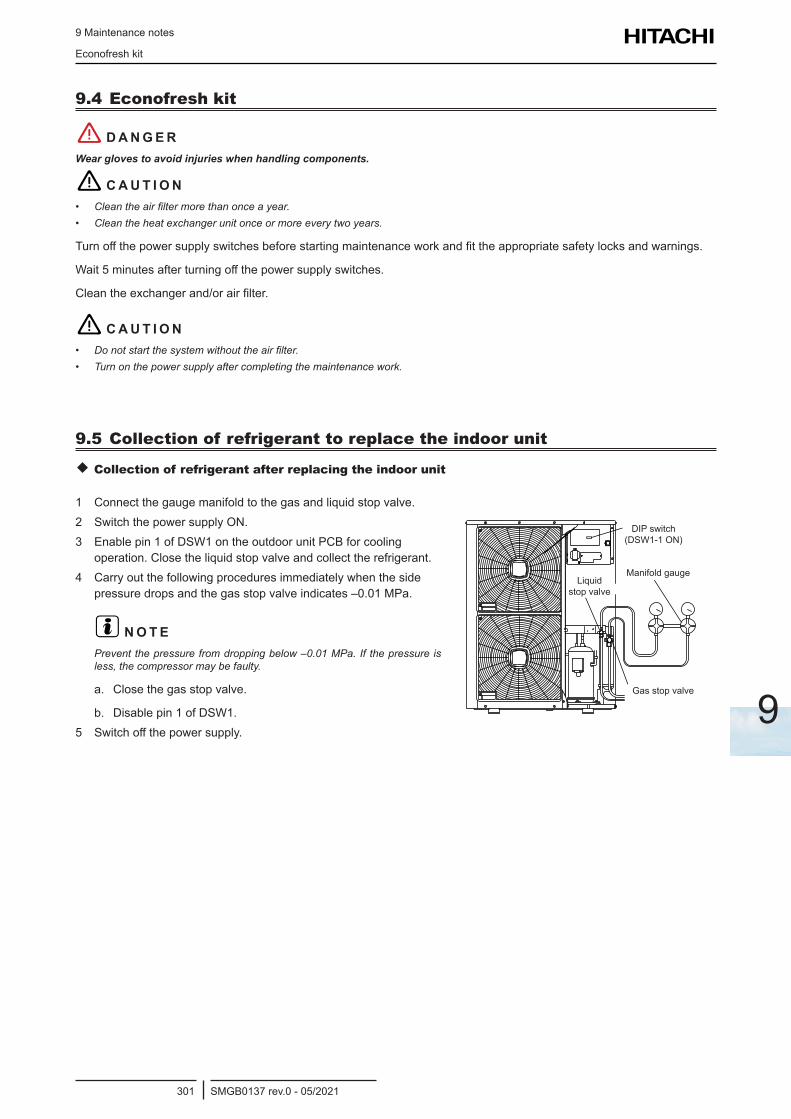
9 Maintenance notes
Econofresh kit
SMGB0137 rev.0 - 05/2021301
9
9.4 Econofresh kit
! D A N G E RWear gloves to avoid injuries when handling components.
! C A U T I O N• Clean the air filter more than once a year.• Clean the heat exchanger unit once or more every two years.
Turn off the power supply switches before starting maintenance work and fit the appropriate safety locks and warnings.
Wait 5 minutes after turning off the power supply switches.
Clean the exchanger and/or air filter.
! C A U T I O N• Do not start the system without the air filter.• Turn on the power supply after completing the maintenance work.
9.5 Collection of refrigerant to replace the indoor unit
Collection of refrigerant after replacing the indoor unit
1 Connect the gauge manifold to the gas and liquid stop valve.2 Switch the power supply ON.3 Enable pin 1 of DSW1 on the outdoor unit PCB for cooling
operation. Close the liquid stop valve and collect the refrigerant.4 Carry out the following procedures immediately when the side
pressure drops and the gas stop valve indicates –0.01 MPa.
? N O T EPrevent the pressure from dropping below –0.01 MPa. If the pressure is less, the compressor may be faulty.
a. Close the gas stop valve.
b. Disable pin 1 of DSW1.5 Switch off the power supply.
Gas stop valve
Liquid stop valve
Manifold gauge
DIP switch (DSW1-1 ON)
9 Maintenance notes
Cleaning agents for heat exchanger
SMGB0137 rev.0 - 05/2021302
9.6 Cleaning agents for heat exchangerThe aluminium fin surfaces of the heat exchanger for all the indoor units of packaged air conditioners are coated with a hydrophilic coating to prevent the increase of airstream resistance due the occurrence of condensing water during cooling operation.
However, if the Aluminium fin’s hydrophilic is decreased by the adhesion of contaminants, etc., the following phenomenon will happen.
Dew will adhere between each aluminium fin space (Bridging Phenomenon)
Increase of airstream resistance
Decrease of the airflow volume
Decrease of cooling capacity
In some cases, dew may be splashed from the indoor unit
In order to avoid the malfunction of the unit, we recommend the use of cleaning agent for the aluminium fins.
9.6.1 Recommended specifications of cleaning agents for aluminium fins
Effect on hydrophilic coating No effect
Effectiveness against specific types of dirt
Grease and Oil Specially effective
Tar Effective
White powder (*1) Ineffective
Possibility of occurrence of cracking (*2) Low
pH of the solution Alkaline or Weak alkaline
Requirement of dilution Yes or No
Personal Protection Equipment (PPE) to be used in handling (*3) Mask, Glasses, Gloves
(*1): The hydroxide caused by the reaction of aluminium fins and the water condensed on the surface of the fins.
(*2): The possibility of occurrence of cracking was also examined taking into account the results of the examination of the possibility of occurrence of cracking in Acrylonitrile Butadiene Styrene (ABS) and Polystyrene (PS).
(*3): Personal Protection Equipment (PPE) must be used whenever manipulating chemical products, in order to ensure safety.
9.6.2 Particularities and benefits
HITACHI has ben tested the effect of cleaning benefits using special fin cleaners for hydrophilic coated fins on the indoor units. Those tests were focused on the wettability, and confirmed as follows:• Cleaning aluminium fins makes its hydrophilicity possible to recover.• The hydrophilic coating is not damaged even if it’s washed repeatedly by using special cleaning special agents for
hydrophilic aluminium coatings.
9.6.3 To consider
Before washing aluminium fins, protect the fan motor, the electrical box, the connectors and, in general, all the wiring of being splashed with the cleaning products and water. In addition, before starting an air-conditioning operation, after washing the aluminium fins, be sure that there is no splashing water on those items.
If the cleaning agents are used incorrectly, it will cause damage to aluminium fins. When using those products, pay special attention to the indications referred on each instructions manual


Printed in SpainSMGB0137 rev.0 - 05/2021
Johnson Controls-Hitachi Air Conditioning Spain, S.A.U.Ronda Shimizu, 1 - Políg. Ind. Can Torrella08233 Vacarisses (Barcelona) Spain
© Copyright 2021 Johnson Controls-Hitachi Air Conditioning Spain, S.A.U. – All rights reserved.
Johnson Controls-Hitachi Air Conditioning Spain, S.A.U. is certified with: ISO 9001 of AENOR, Spain for its Quality Management accordance with the standard.ISO 14001 of AENOR Spain for its Environmental Management systems accordance with the standard.
EC97J1107JQA-1084
Hitachi certifies that our products have met EU consumer safety, health and environmental requirements.
Hitachi air conditioning products are manufactured according to:ISO 9001 of JQA, Japan for its Quality Management accordance with the standard.ISO 14001 of JACO, Japan for its Environmental Management accordance with the standard.
Hitachi participates in the Eurovent Certification Programme; the certified data of certified models are listed in the Eurovent Certification Online Directory (www.eurovent-certification.com).
Hitachi air conditioning products are manufactured according to:ISO 9001 of Malaysia, for its Quality Management accordance with the standard.ISO 14001 of Malaysia, for its Environmental Management systems accordance with the standard.

