Embed Size (px)
Citation preview

— A B B M E A SU R EM ENT & A N A LY TI C S | I NS TRUC TI O N M A N UA L
SpiritIT Flow-XHigh accuracy flow computers
Mechanical installation,electrical installation and connection diagrams
Measurement made easy
IntroductionWelcome to the exciting world of SpiritIT Flow-X!
This manual is the installation manual for all SpiritIT Flow-X models.
There are three reference manuals:• Volume I – This Installation manual, with the
installation instructions.• Volume II – The Operation and Configuration
manual. This manual consists of a general part and one of the following application-specific parts:
– IIA - Operation and configuration – IIB - Gas Metric application – IIC - Liquid Metric application – IID - Gas US customary units application – IIE - Liquid US customary units application
• Volume III - The manuals for solutions that exceed our standard applications. This volume consists of 1 part:
– IIIB - Function reference
For more informationAll publications of SpiritIT Flow-X are available for free download from:
Search for:
SpiritIT Flow-X instruction manual IM/FlowX-EN
SpiritIT Flow-X configuration manual CM/FlowX-EN
SpiritIT Flow-X gas metric application manual
CM/FlowX/GM-EN
SpiritIT Flow-X liquid metric application manual
CM/FlowX/LM-EN
SpiritIT Flow-X gas USC application manual
CM/FlowX/GU-EN
SpiritIT Flow-X liquid USC application manual
CM/FlowX/LU-EN
SpiritIT Flow-X function reference manual
CM/FlowX/FR-EN
—Flow-X/P with Flow-X/M module

2 S P I R I T I T F L O W - X I N S T R U C T I O N M A N U A L | I M / F L O W X - E N
Contents
1 Manual introduction ................................................ 3 Purpose of this manual........................................................... 3 Overview .................................................................................... 3 Document conventions .......................................................... 3 Abbreviations ........................................................................... 4 Terms and definitions............................................................. 5
2 Hazardous area certification .................................. 6 Class I Division 2 ....................................................................... 6 IECEx and ATEX ........................................................................ 6
3 Regulatory compliance ............................................ 8 EU Directives ............................................................................. 8 UL / CSA ..................................................................................... 8 IEC Standards ........................................................................... 8
4 The SpiritIT Flow-X products ................................... 9 Introduction .............................................................................. 9 Flow modules ............................................................................ 9 Nameplate ................................................................................. 9 Enclosures ................................................................................. 9 Multi-module mode ............................................................... 10 Security .................................................................................... 11 Break-out board ..................................................................... 11 Advantages ............................................................................. 11 Maintenance and cleaning instructions............................ 12 Recycling information in accordance with the WEEE .... 13
5 Getting started ...................................................... 14 Location ................................................................................... 14 Capabilities ............................................................................. 14 Number of modules............................................................... 14 Redundancy ............................................................................. 14 Fast Data exchange ............................................................... 14 Display requirements ............................................................ 14 Power supply ........................................................................... 15 Cabinet space ......................................................................... 15 Cost ........................................................................................... 15
6 Mechanical installation ......................................... 16 Introduction ............................................................................ 16 Forced ventilation .................................................................. 16 Flow-X/P .................................................................................. 16 Flow-X/C .................................................................................. 16 Flow-X/C installation example instructions .................... 17 Flow-X/R .................................................................................. 19 Flow-X/S .................................................................................. 19 Flow-X/K .................................................................................. 19 Flow-X/B .................................................................................. 19
7 Electrical installation ............................................ 20 Introduction ........................................................................... 20 Location of connectors ....................................................... 20 Enclosure connector details ................................................ 21 Break-out board connection details .................................. 23 Connection diagrams .......................................................... 24 Honeywell Enraf Calibron small volume prover ..............29
Serial communication .......................................................... 29 Proving signals....................................................................... 30 Earth ground connection .................................................... 32
8 Operator Panels ..................................................... 34 Introduction ........................................................................... 34 Flow-X/P & Flow-X/C touch screen ................................... 34 Touchscreen panel PC .......................................................... 34 Flow-X/M LCD display .......................................................... 34 SpiritIT Flow-X web interface .............................................. 34 Graphical User Interface Layout ........................................ 35
9 Software ................................................................. 36 Introduction ........................................................................... 36 Set up ....................................................................................... 36 Software installation ............................................................ 37
10 Technical specifications ....................................... 38 General ..................................................................................... 38 Flow-X/M I/O specifications .............................................. 38 Power consumption ............................................................. 41 Weight ...................................................................................... 41
11 Drawings ................................................................ 42 Flow-X/P Panel version 1 mounted enclosure ................ 42 Flow-X/P Panel version 1 mounting bracket ................... 43 Flow-X/P Panel version 2 mounted enclosure ................ 44 Flow-X/P Panel version 2 mounting bracket ................... 45 Flow-X/C Compact panel mount enclosure .................... 46 Flow-X/C installation guides .............................................. 47 Flow-X/R Rack mount enclosure ....................................... 50 Flow-X/S Single module enclosure ....................................51 Flow-X/K enclosure .............................................................. 52 Flow-X/B breakout board ................................................... 53 7” touch panel PC .................................................................. 54
12 Configuration sheet .............................................. 55
13 I/O Diagnostics and calibration .......................... 56 I/O diagnostics ...................................................................... 56 I/O calibration ........................................................................ 56 Calibration points ................................................................. 56 Analog input calibration ...................................................... 56 PT100 input calibration........................................................ 57 Analog output calibration ................................................... 57
14 Revisions ................................................................ 58

S P I R I T I T F L O W - X I N S T R U C T I O N M A N U A L | I M / F L O W X - E N 3
1 Manual introduction
Purpose of this manual
This SpiritIT Flow-X reference manual is written for a variety of
readers:
• The application developer, who is interested in all details
required to develop a complete flow measurement solution
with a SpiritIT Flow-X product.
• The Instrumentation engineer, who selects the appropriate
flow computer model, assigns inputs and outputs and designs
transmitter loops and flow computer functionality
• A more generally interested reader, who investigates whether
the capabilities and features of Spirit IT Flow-X will satisfy
his/her project requirements.
This manual expects the reader to be commonly acquainted with
flow measurement principles, such as turbine, orifice and
ultrasonic measurements. This manual is not an introduction to
these techniques.
Overview
This installation manual concerns the hardware related aspects
of the SpiritIT Flow-X product suite, as they are required for
design and installation of flow metering solutions.
In this first chapter, an introduction is given to this manual.
Various terms and definitions as used throughout this book are
given.
Chapters 2 and 3 describe the hazardous area certificates and
regulatory compliance respectively.
In chapter 4: ‘SpiritIT Flow-X products’ the user is presented with
an overview of the Spirit IT Flow-X module and models.
In chapter 5: ‘Getting started’, an overview of design
considerations is presented to assist in enclosure selection.
In the next chapters, fully detailed information is given on all
installation aspects.
In chapter 6: ‘Mechanical installation’, the mechanical details are
given for all models.
In chapter 7: ‘Electrical installation,’ electrical details are
provided: typical loop diagrams, communication, power supply,
earthing.
Chapter 8 briefly describes the operator panels.
Chapter 9 briefly describes software installation.
Chapter 10 lists the full technical specifications
Chapter 11 holds the detailed drawings including dimensions.
Chapter 12 describes a configuration sheet, which is
downloadable from our website.
Chapter 13 describes how to diagnose and calibrate the flow
computer IO.
Document conventions
When the book symbol as displayed at the left appears
in the text in this manual, a reference is made to another
section of the manual. At the referred section, more
detailed, or other relevant information is given.
When in this manual a symbol as displayed at the left
appears in the text, certain specific operating
instructions are given to the user. In such as case, the
user is assumed to perform some action, such as the
selection of a certain object, worksheet, or typing on
the keyboard.
A symbol as displayed at the left indicates that the user
may read further on the subject in one of the sample
workbooks as installed on your machine.
When an important remark is made in the manual
requiring special attention, the symbol as displayed to
the left appears in the text
This symbol is shown when a safety-related warning is
raised.
4 S P I R I T I T F L O W - X I N S T R U C T I O N M A N U A L | I M / F L O W X - E N
Abbreviations
Throughout this document the following abbreviations are used:
ADC Analog to Digital converter
AI Analog Input
AO Analog Output
API Application Programming Interface
An interface that allows an application to interact with another application or operating system, in our case, Spirit IT Flow-X. Most of the Spirit IT
Flow-X API is implemented through Excel worksheet functions.
ASCII American Standard Code for Information Interchange.
A set of standard numerical values for printable, control, and special characters used by PCs and most other computers. Other commonly used
codes for character sets are ANSI (used by Windows 3.1+), Unicode (used by Windows 95 and Windows NT), and EBCDIC (Extended Binary-Coded
Decimal Interchange Code, used by IBM for mainframe computers).
CPU Central Processing Unit
DAC Digital to Analog Converter
DCS Distributed Control System
DDE Dynamic Data Exchange
A relatively old mechanism for exchanging simple data among processes in MS-Windows.
DI Digital Input
DO Digital Output
EGU Engineering Units
EIA Electrical Industries Association
FET Field Effect Transistor
GC Gas Chromatograph
GUI Graphical User Interface
HART Highway Addressable Remote Transducer.
A protocol defined by the HART Communication Foundation to exchange information between process control devices such as transmitters and
computers using a two-wire 4-20mA signal on which a digital signal is superimposed using Frequency Shift Keying at 1200 bps.
HMI Human Machine Interface.
Also referred to as a GUI or MMI. This is a process that displays graphics and allows people to interface with the control system in graphic form.
It may contain trends, alarm summaries, pictures, and animations.
I/O Input/Output
IEEE Institute for Electrical and Electronics Engineers
ISO International Standards Organization
MMI Man Machine Interface (see HMI)
MIC Machine Identification Code. License code of Spirit IT Flow-X which uniquely identifies you computer.
OEM Original Equipment Manufacturer
P&ID Piping and Instrumentation Diagram
PC Personal Computer
PCB Printed Circuit Board
PLC Programmable Logic Controller.
A specialized device used to provide high-speed, low-level control of a process. It is programmed using Ladder Logic, or some form of structured
language, so that engineers can program it. PLC hardware may have good redundancy and fail-over capabilities.
RS232 EIA standard for point to point serial communications in computer equipment
RS422 EIA standard for two- and four-wire differential unidirectional multi-drop serial
RS485 EIA standard for two-wire differential bidirectional multi-drop serial communications in computer equipment
RTU Remote Terminal Unit
SCADA Supervisory Control and Data Acquisition
SQL Standard Query Language
SVC Supervisory Computer
TCP/IP Transmission Control Protocol/Internet Protocol.
Transmission Control Protocol/Internet Protocol. The control mechanism used by programs that want to speak over the Internet. It was
established in 1968 to help remote tasks communicate over the original ARPANET.
TTL Transistor-Transistor Logic
UART Universal Asynchronous Receiver & Transmitter
URL Uniform Resource Locator.
The global address for documents and resources on the World Wide Web.
XML Extensible Markup Language. A specification for Web
documents that allows developers to create custom tags that enable the definition, transmission, validation and interpretation of data
contained therein.

S P I R I T I T F L O W - X I N S T R U C T I O N M A N U A L | I M / F L O W X - E N 5
Terms and definitions
Throughout this manual the following additional terms and definitions are used:
Asynchronous A type of message passing where the sending task does not wait for a reply before continuing processing. If the receiving task cannot
take the message immediately, the message often waits on a queue until it can be received.
Client/server A network architecture in which each computer or process on the network is either a client or a server. Clients rely on servers for
resources, such as files, devices, and even processing power.
Another type of network architecture is known as a peer-to-peer architecture. Both client/server and peer-to-peer architectures are widely
used, and each has unique advantages and disadvantages. Client/server architectures are sometimes called two-tier architectures
Device driver A program that sends and receives data to and from the outside world. Typically a device driver will communicate with a hardware
interface card that receives field device messages and maps their content into a region of memory on the card. The device driver then
reads this memory and delivers the contents to the spreadsheet.
Engineering units Engineering units as used throughout this manual refers in general to the units of a tag, for example ‘bar’, or ‘ºC’, and not to a type of unit,
as with ‘metric’ units, or ‘imperial’ units.
Ethernet A LAN protocol developed by Xerox in cooperation with DEC and Intel in 1976. Standard Ethernet supports data transfer rates of 10 Mbps.
The Ethernet specification served as the basis for the IEEE 802.3 standard, which specifies physical and lower software layers. A newer
version, called 100-Base-T or Fast Ethernet supports data transfer rates of 100 Mbps, while the newest version, Gigabit Ethernet supports
rates of 1 gigabit (1000 megabits) per second.
Event Anything that happens that is significant to a program, such as a mouse click, a change in a data point value, or a command from a user.
Exception Any condition, such as a hardware interrupt or software error-handler, that changes a program's flow of control.
Fieldbus A set of communication protocols that various hardware manufacturers use to make their field devices talk to other field devices. Fieldbus
protocols are often supported by manufacturers of sensor hardware. There are debates as to which of the different fieldbus protocols is
the best. Popular types of fieldbus protocol include Modbus, Hart, Profibus, Devicenet, InterBus, and CANopen.
Kernel The core of Spirit IT Flow-X that handles basic functions, such as hardware and/or software interfaces, or resource allocation.
Peer-to-peer A type of network in which each workstation has equivalent capabilities and responsibilities. This differs from client/server architectures,
in which some computers are dedicated to serving the others. Peer-to-peer networks are generally simpler, but they usually do not offer
the same performance under heavy loads. Peer-to-peer is sometimes shortened to the term P2P.
Polling A method of updating data in a system, where one task sends a message to a second task on a regular basis, to check if a data point has
changed. If so, the change in data is sent to the first task. This method is most effective when there are few data points in the system.
Otherwise, exception handling is generally faster.
Process visualization
software
A system for monitoring and controlling for production processes, and managing related data. Typically such a system is connected to
external devices, which are in turn connected to sensors and production machinery.
The term ‘process visualization software’ in this document is generally used for software with which SCADA software, HMI software, or
supervisory computer software applications can be built. In this document, although strictly not correct, the terms ‘SCADA, ‘HMI,
‘supervisory’, and ‘process visualization’ are alternately used, and refer to the computer software applications that can be realized with
Spirit IT eXLerate, a PC-based supervisory software.
Protocol An agreed-up format for transmitting data between two devices. In this context, a protocol mostly references to the Data Link Layer in the
OSI 7-Layer Communication Model.
Query In SCADA/HMI terms a message from a computer to a client in a master/client configuration utilizing the message protocol with the
purpose to request for information. Usually, more than 1 data-point is transmitted in a single query.
Real-time The characteristic of determinism applied to computer hardware and/or software. A real-time process must perform a task in a
determined length of time.
The phrase "real-time" does not directly relate to how fast the program responds, even though many people believe that real-time means
real-fast.
Resource Any component of a computing machine that can be utilized by software. Examples include: RAM, disk space, CPU time, real-world time,
serial devices, network devices, and other hardware, as well as O/S objects such as semaphores, timers, file descriptors, files, etc.
Synchronous A type of message passing where the sending task waits for a reply before continuing processing.
Tag A ‘tag’ as used within this document refers to a data point existing in the tag database, with a number of properties, such as its assigned
I/O address, current value, engineering units, description, alias name, and many others.
Web Server A computer that has server software installed on it and is used to deliver web pages to an intranet/Internet.

6 S P I R I T I T F L O W - X I N S T R U C T I O N M A N U A L | I M / F L O W X - E N
2 Hazardous area certification
Hazardous area certifications only apply for newer versions of Flow-X/M modules and Flow-X/S and Flow-X/K enclosures.
Before installing or using these products, confirm that the required certification appears on the product labeling.
Class I Division 2
Standards
• UL 121201:2017 Ed.9+R:26Aug2019
• CSA C22.2#213:2017 Ed.3+U1;U2
Hazardous ratings
• For Use in Class I Division 2, Groups A, B, C, D; Class I Zone 2 Group IIC
• Temperature Code: T4
• Ambient Temperature Range: -40°C ≤ Ta ≤ +75°C
IECEx and ATEX
Schedules of Limitations 1. The Product shall be installed in a suitable “Ex” certified, at least IP54 enclosure.
2. The end use enclosure shall be tool secured and shall not be opened in the presence of ignitable concentration of explosive
gas atmosphere and do not connect/ disconnect this device unless the power has been switched off or the area is deemed
to be non-hazardous. Grounding/Bonding wire shall be provided.
3. The maximum surface temperature measured according test conducted per IEC/EN 60079-0 clause 26.5.1 was 120.58˚C.
Flow Computer does not have any surface that achieves a temperature greater than T4(135°C) with a 5K safety factor when
operated at an ambient of 75°C. The test data may be referred for temperature code evaluations.
4. The product shall only be powered by a circuit not exceeding 24VDC.
5. The external enclosure and enclosure parts of the product have not been evaluated per the requirement of the clauses
included in the certificate i.e. IEC/EN 60079-0, IEC/EN 60079-7. Additional evaluations and tests shall be conducted as
deemed necessary.
6. External plugs, sockets, cable glands, or field wiring connections have not been evaluated under this certificate . It is
required to be evaluated as part of the final enclosure. Additional evaluations and tests shall be conducted as deemed
necessary.
7. Evaluation of Earthing/bonding details of the external enclosure and enclosure parts have not been considered under this
certificate. Additional evaluations and tests shall be conducted as deemed necessary.
Routine Test
1. In accordance with EN 60079-7, Clause 7.1, a routine dielectric strength test will be required between the input connections
and metal enclosure part. A test voltage of 500V r.m.s. is to be applied between the points. The voltage shall be increased
steadily to the specified value in a period of 10 seconds and then maintained for at least 60 seconds. The applied voltage
shall remain constant during the test. The leakage current shall not exceed 5mA r.m.s.

S P I R I T I T F L O W - X I N S T R U C T I O N M A N U A L | I M / F L O W X - E N 7
Rating and marking information
ABB b.v.
Achtseweg Zuid 151A / Strijp-TQ Entrance 5 5651GW Eindhoven, The Netherlands
PN: <Part Number>
SN: <Serial Number>
Year: <yyyy>
Power: 24 VDC 0,4A
Class I Division 2, Groups A, B, C, D; Class I Zone 2 Group IIC
T4, -40°C ≤ Ta ≤ +75°C
IECEx ETL 20.0073U
Ex ec IIC Gc, -40°C ≤ Ta ≤ +75C
ATEX certificate number: ITS20ATEX305961U
II 3 G Ex ec IIC Gc, -40°C ≤ Ta ≤ +75°C
Refer to Instruction Manual for Routine test and Schedule of Limitations
Reportez-vous au manuel d'instructions pour le test de routine et le calendrier des limitations.

8 S P I R I T I T F L O W - X I N S T R U C T I O N M A N U A L | I M / F L O W X - E N
3 Regulatory compliance
EU Directives
• 2014/32/EU Measuring Instruments Directive
• 2014/30/EU Electromagnetic Compatibility Directive
• 2012/19/EU WEEE Directive (WEEE 2)
• 2011/65/EU RoHS
UL / CSA
• ANSI/UL std. 61010-1
• CAN/CSA C22.2 No 61010-1-12
IEC Standards
The Flow-X flow computer is tested for and compliant with the following IEC standards, which are referenced by several international
standards and metrology authorities.
• IEC 60068-2-1
• IEC 60068-2-2
• IEC 60068-2-3
• IEC 60068-2-31
• IEC 60068-2-36
• IEC 60654-2
• IEC 61000-4-2 :2008
• IEC 61000-4-3 :2006 + A1.2007 + A2:2010
• IEC 61000-4-4:2012
• IEC 61000-4-5:2015+ A1:2017
• IEC 61000-4-6 :2014
• IEC 61000-4-8:2009
• IEC 61000-4-17:1999 + A1:2001 + A2:2008
• IEC 61000-4-29:2000
• IEC 61000-6-2:2016
• IEC 61000-6-4:2001+ A1:2011
For compliance with IEC 61000-4-4 in case of a flow meter providing a pulse output signal, the Flow-X flow computer must
be connected to a dual pulse signal with a phase shift between the pulse signals to allow the device to detect and filter out
simultaneous interfering pulses.
For compliance with IEC 61000-4-29 the Flow-X flow computer must be connected to either a dual (redundant) power supply
or an uninterruptible power supply (UPS).

S P I R I T I T F L O W - X I N S T R U C T I O N M A N U A L | I M / F L O W X - E N 9
4 The SpiritIT Flow-X products
Introduction
This chapter provides an overview of available models in the
SpiritIT Flow-X product suite.
Flow modules
All products are based on the same flow module (Flow-X/M). A
module usually represents one stream in your metering system.
The module has its own 4-line display and 4 navigation buttons
to allow inspection of values and changing of parameters if
required.
Figure 4-1 Flow-X/M Module
Flow modules are to be mounted in one of the following
enclosures:
• A Panel mounted flow computer (maximum 4 modules),
Flow-X/P
• A Panel mounted internal single module flow computer,
Flow-X/C
• A Rack frame, holding maximum 8 modules, Flow-X/R
• A single enclosure, Flow-X/S
• A single rack enclosure, Flow-X/K
These enclosures are described in more detail below.
Never mount or unmount a module while the enclosure
is powered, as this may cause damage to the module.
Before a module is mounted or unmounted, the enclosure must
be powered down.
A single module has the following I/O capabilities:
Signal type v1
Nr3
v2
Nr3
Description
Analog Input 61 61 Analog transmitter input, high accuracy
4-20mA, 0-20mA, 0-5V, 1-5V
Inputs are fully floating (optically isolated)
HART input 41 41 Independent HART loop inputs, on top of the 4-20mA
signals (Analog inputs)
Support includes multi-drop for each transmitter
loop
4-wire PRT
inputs
2 2 High accuracy PT-100 inputs
Pulse inputs 12 42 High speed single or dual pulse input. Frequency
range 0-5kHz (dual pulse) or 0-10kHz (single pulse)
Density 42 42 Periodic time input, 100μs - 5000μs.
Signal type v1
Nr3
v2
Nr3
Description
Digital Inputs 162 162 Digital status inputs
Digital
Outputs
162 162 Digital output, open collector
Pulse
Outputs
42 42 Open collector, max. 100 Hz
Frequency
Outputs
42 42 Open collector, max. 10 kHz (Only available for Flow-
X/C device type)
Sphere
detector
inputs
42 42 Supports 1, 2 and 4 detector configurations mode
0.5ms detect update rate
Analog
Outputs
4 4 Analog output for flow control, pressure control
4-20mA, outputs floating.
Prover
Outputs
12 12 Pulse output for proving applications
The output represents the corrected pulse signal
Serial 2 2 RS485/RS232 serial input for ultrasonic meter,
printer or generic, 115kb
Ethernet 2 2 RJ45 Ethernet interface, TCP/IP
Power supply 2 2 External, 20 - 32 VDC, nominal 24 VDC, with
redundant connections
1 The maximum number of Analog inputs plus Hart inputs is 6 2 There are in total 16 in- and outputs available for these functions 3 Flow X hardware version 1 or version 2.
Table 4-1 Summary of Flow-X/M inputs and outputs
A full description of all specifications, including accuracies and
acceptable signal levels, is to be found in Chapter 7 – Technical
Specifications.
Nameplate
The Flow-X/M nameplate contains the following information: CE
marking, MID approval number, notified body, serial number,
year of build, operating temperature according to MID approval
and test certificate number.
Figure 4-2 Flow-X/M nameplate
For newer Flow-X/M, Flow-X/S and Flow-X/K products the ATEX
and IECEx hazardous area ratings are indicated as well.
Enclosures
Flow-X/P
This is a Panel mounted flow computer with up to four streams
and an additional station module with a 7” multi-lingual color
touch-screen and additional serial (3x) and Ethernet interfaces
(2x). This flow computer can be used in both horizontal and
vertical position. Field connections are available in standard 37-
pin and 9-pin D-Sub type connectors at the rear.

1 0 S P I R I T I T F L O W - X I N S T R U C T I O N M A N U A L | I M / F L O W X - E N
Figure 4-3 Flow-X/P Panel version
Flow-X/C This is a Compact panel mounted flow computer with one
integrated Flow-X/M module with a 7” multi-lingual color touch
screen and one additional serial port and Ethernet interfaces
(2x). This flow computer can be used in both horizontal and
vertical position. Field connections are available in standard 37-
pin and one 9-pin D-Sub type connector at the rear.
Figure 4-4 Flow-X/C Compact panel version
Flow-X/R
The Flow-X/R is a Rack model with up to 8 streams for dense
flow metering systems in 19” cabinets. Stream modules can be
used as 8-stream application, as separate streams, or
combinations. Field connections are available in standard 37-
pole D-Sub type connectors; Ethernet connections are either
individually used per stream module via dual RJ45 connectors, or
to only one module when the modules operate in Multi-Module
Mode (See paragraph on Multi-module mode on page 10).
Figure 4-5 Flow-X/R Rack version
Flow-X/S
This is a Single stream, DIN rail enclosure with direct screw
terminals for field connections. Interfaces include dual Ethernet
with built-in web-server via RJ45 connectors. Graphical LCD
display with 4 lines for local display of measured & calculated
data. The Flow-X/S may be mounted in 3 ways: Horizontally on
Din-rail, vertically on Din-rail, and Wall mounted.
Figure 4-6 Flow-X/S Single enclosure
Flow-X/K
This is a single stream, DIN rail enclosure with standard 37-pole
D-Sub type connectors for field connection. Interfaces include
dual Ethernet with built-in web-server via RJ45 connectors. It has
graphical LCD display with 4 lines for local display of measured &
calculated data. The Flow-X/K may be mounted in 2 ways:
mounted on a DIN-rail and Wall mounted. In combination with a
DIN-adapter it is possible to mount 7 Flow-X/K enclosures next
to each other in a 19” cabinet.
Figure 4-7 Flow-X/K enclosure
Multi-module mode
The Flow-X/P and Flow-X/R enclosures usually accommodate
more than one module. These modules may be used in
standalone mode, where each module is acting as an
independent flow computer. The other option is to use modules
in Multi-Module mode, where they exchange data over the
Ethernet. In this setup, the modules act together as one flow
computer.

S P I R I T I T F L O W - X I N S T R U C T I O N M A N U A L | I M / F L O W X - E N 1 1
Security
Metrological seal
All enclosures have the option of locking the flow computer with
a lead seal by an authorized body, to prevent access to the
tamper switch of the individual modules (see below). In a Flow-
X/P (Panel) and a Flow-X/R, one bar is used to seal all installed
modules with one lead seal.
Tamper switch
The Flow-X/C flow computer as well as each Flow-X/M module
have a mechanical tamper switch to prevent changing of the
application and vital parameters within that application.
Figure 4-8 Flow-X/M module with tamper switch
Passwords
Access to the parameters and functions from the front
panel or through a PC-connection is protected by
passwords. For a full description of password
protection, user groups and access rights see Volume II,
Operation and configuration manual.
Break-out board
Flow-X/B
The Flow-X/B break-out board allows for convenient connection to
the measurement and control signals and protects the flow
computer from harmful field signals.
For fully wired I/O, two Flow-X/Bs are required per module.
Figure 4-9 Flow-X/B break-out board
Advantages
The SpiritIT Flow-X product suite provides a flexible, scalable
platform to create your flow metering solutions. Where in other
systems, flexibility also implies extensive configuration for even
the simplest application, our SpiritIT Flow-Xpress Basic
configuration software guarantees easy configuration, and the
SpiritIT Flow-Xpress Professional configuration software allows
detailed configuration with unparalleled freedom.

1 2 S P I R I T I T F L O W - X I N S T R U C T I O N M A N U A L | I M / F L O W X - E N
Maintenance and cleaning instructions
Important - please read the following notes:
Safe operation of this product can only be guaranteed if
it is properly installed, commissioned, used and
maintained by qualified personnel in compliance with
the operating instructions. General installation and safety
instructions for pipeline and plant construction, as well as the
proper use of tools and safety equipment must also be complied
with.
Every effort has been made during the design of the flow
computer to ensure the safety of the user but the following
precautions must be followed:
1 Ensure correct installation. Safety may be compromised if the
installation of the product is not carried out as specified in
this manual.
2 The flow computer is designed as an installation category I
product (24V max). The flow computer may not be used for
measurements within measurement categories II, III and IV.
3 A disconnecting device (switch or circuit breaker) must be
included in the installation. It must:
– Have a rating with sufficient breaking capacity.
– Be in close proximity to the equipment, within easy reach of
the operator but not cause difficulty in operating.
– Be marked as the disconnecting device for the flow
computer.
– Not interrupt a protective earth conductor.
– Not be incorporated into a mains supply cord.
4 This product is designed and constructed to withstand the
forces encountered during normal use. Use of the product
other than as a flow computer, or failure to install the product
in accordance with these Instructions, product modifications
or repair could:
– Cause damage to the product / property.
– Cause injury or fatality to personnel.
– Invalidate the marking.
5 Spirit IT Flow-X products are not intended to withstand
external stresses that may be induced by any system to which
they are fitted. It is the responsibility of the installer to
consider these stresses and take adequate precautions to
minimize them.
6 Environmental protection of the Spirit IT Flow-X enclosures is
in accordance with IEC 60529 IP50. The flow computer should
be installed in a dry and clean room.
7 Dust the flow computer by wiping the screen and the body
with a soft, clean antistatic cloth. For more difficult cleaning
situations, use a 50/50 mix of water and Isopropyl alcohol.
CAUTION: Spray the cleaner onto a cloth and use the
damp cloth to gently wipe the surface. Never spray the
cleaner directly on the screen surface. It may run behind
the bezel and may result in fire, electric shock or damage to the
electronics.
CAUTION: Do not use cleaners that contain any
petroleum based materials such as benzene, thinner, or
any volatile substance to clean the screen or body. These
chemicals may damage the flow computer.
These instructions must be stored in a safe place near the
installation of the flow computer at all times.
Figure 4-10 Flow-X/R label
S P I R I T I T F L O W - X I N S T R U C T I O N M A N U A L | I M / F L O W X - E N 1 3
Recycling information in accordance with
the WEEE
The product is marked with the wheelie bin symbol. It indicates
that at the end of life the product should enter the recycling
system. The figure below shows the wheelie bin symbol
indicating separate collection for electrical and electronic
equipment (EEE).
For disposal in the European Union
You should dispose of it separately at an appropriate collection
point and not place it in the normal waste stream.
If you wish to discard electrical and electronic equipment (EEE),
please contact your dealer or supplier for further information.
Disposing of this product correctly will help save valuable
resources and prevent any potential negative effects on human
health and the environment, which could otherwise arise from
inappropriate waste handling.
For disposal in countries outside of the European Union
The crossed –out wheeled bin symbol is only valid in the
European Union (EU) and means that used electrical and
electronic equipment (WEEE) should not be mixed with general
household waste.
If you wish to discard this product please contact your local
authorities or dealer and ask for the correct method of disposal.
Disposing of this product correctly will help save valuable
resources and prevent any potential negative effects on human
health and the environment, which could otherwise arise from
inappropriate waste handling.
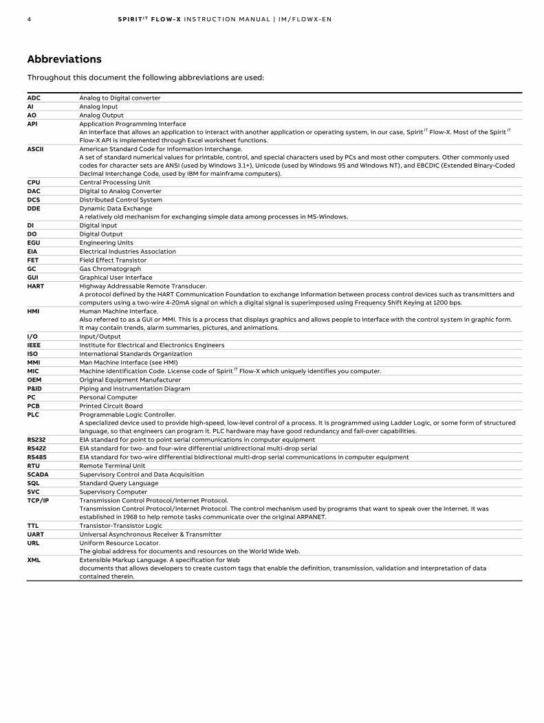
Information for waste treatment facilities
In accordance with WEEE 2 Annex VII the following components
need to be removed from the different Flow-X products and
treated separately.
Model Product
number
Components
Flow-X/M 6557-xxxx-
xxxx
1 x Digital board
1 x Analog board
1 x Power board
1 x Display board
1 x SD card (board) (*)
1 x Liquid Crystal display
1 x Battery (on Digital board)
(*) Either a regular SD card or an SD card
board with a micro-SD card will be present
in the SD card slot Flow-X/M Other 1 x Digital board
1 x Analog board
1 x Power board
1 x Display board
1 x micro SD card
1 x Liquid Crystal display
Model Product
number
Components
Flow-X/P 6557-xxxx-
xxxx
1 x Digital board
1 x Power board
1 x Display board
1 x SD card (board) (*)
1 x Liquid Crystal display
1 x Battery (on digital board)
(*) Either a regular SD card or an SD card
board with a micro-SD card will be present
in the SD card slot Flow-X/P Other 1 x Digital board
1 x Power board
1 x Display board
1 x micro SD card
1 x Liquid Crystal display
Flow-X/C All 1 x Digital board
1 x Power board
1 x Display board
1 x micro SD card
1 x Liquid Crystal display
Flow-X/S
Flow-X/K
Flow-X/R
Flow-X/B
All 1 x Printed Circuit Board
Flow-X/T All 1x Liquid Crystal Display
Any Printed Circuit Boards
Refer to the Flow-X datasheet DS/FLOWX-EN for information
about the different Flow-X models
1 4 S P I R I T I T F L O W - X I N S T R U C T I O N M A N U A L | I M / F L O W X - E N
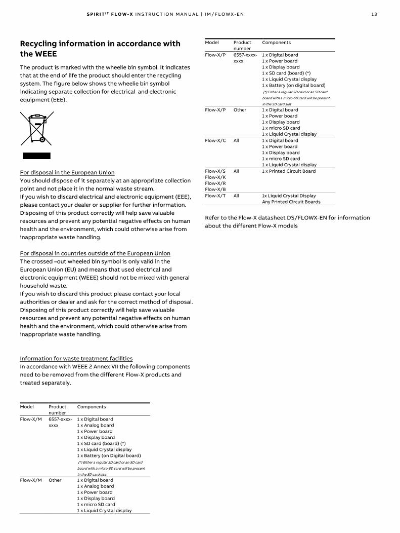
5 Getting started
This chapter provides a short overview of considerations to be
made in selecting the appropriate SpiritIT Flow-X products.
Location
All SpiritIT Flow-X products are designed to operate in a
temperature and humidity controlled environment such as a
control room, rack room or auxiliary room, or an analyzer house.
Newer Flow-X/M, X/S and X/M products have an ambient
extended temperature range and are therefore suitable for
outdoor installation as well.
Caution
SpiritIT Flow-X products are neither intrinsically safe nor
explosion-proof and can therefore only be used in a designated
non-hazardous (safe) area or, in case of newer Flow-X/M, X/S
and X/M products, in a Class I Division 2 and ATEX / IECEx Zone 2
hazardous area in a certified end-use enclosure.
For other devices always refer to documentation supplied by the
manufacturer for details of installation in a hazardous area.
If connected to a device that resides in a hazardous area, it may
be required to interpose safety barriers or galvanic isolators
between the device and the SpiritIT Flow-X flow computer. Refer
to the device documentation for adequate information.
Capabilities
The SpiritIT Flow-X supports an extensive list of International
standard calculations for Natural gas, hydrocarbon liquids, and
other applications: For example:
• AGA3, AGA5, AGA7, AGA8, AGA10
• API chapters 11.1, 11.2, and 21.1, API 2540, API 1952 tables
• ISO 5167 (all editions), ISO 6976 (all editions)
• NX19, SGERG, PTZ calculations
• GPA 2172 / TP15 / TP16 / TP25 / TP27
• ASME 1967 (IFC-1967) steam tables, IAPWS-IF97 steam density
• GERG 2008
Number of modules
Basically, one module is needed for each flow meter. Additional
modules may be needed for station and /or proving
functionality.
A Flow-X/P contains an extra module (Module 0) that controls
the touch screen and handles station and /or proving
functionality (if applicable).
The Flow-X/C is a compact version and similar to a Flow-X/P
with one module. This module is integrated in the enclosure of
the Flow-X/C.
An overview of the available I/O per module may be found in
Chapter 7 – Technical Specifications.
Station functionality (calculating station totals and / or handling
station densitometers, gas chromatographs, BS&W analyzers
etc.) and / or proving functionality may also be calculated in any
module in the same enclosure, including the Flow-X/P Panel
display module.
Special consideration applies to serial ports. Every module has 2
serial ports. If more ports are required, the Flow-X/P may be
considered as it has 3 extra serial ports. Alternatively, a second
module may be added in a Flow-X/R (rack) enclosure to provide
more serial communication ports.
Redundancy
If, for increased availability, a redundant solution is required, 2
modules per stream may be used.
To obtain maximum availability, two identical SpiritIT Flow-X
enclosures can be used that operate in redundancy mode.
All modules have integrated support for dual 24V power supply.
Fast Data exchange
Modules placed in a Flow-X/P (Panel) or Flow-X/R (Rack)
enclosure are capable of fast data exchange with the modules
next to it, over the Ethernet. This is the so-called Multi-Module
Mode. Examples are one module communicating to a Gas
Chromatograph and making this data available to 4 other
modules, and additionally serving as a Modbus Slave to one
central DCS connection. Each Module is capable of using the
data from other modules as if it exists in its own data space. For
this purpose, the Flow-X/P includes two dedicated Ethernet
switches. As an alternative it is possible to set up a Modbus
TCP/IP link using Ethernet for data exchange between modules.
Display requirements
Obviously, the Flow-X/P (Panel) and Flow-X/C (Compact) flow
computers have the best display features. The touch screen has
the largest display area available on the flow computer market
and allows for effective and user-friendly data display and
navigation through pages. Its multi-language-support is unique
and includes non-western fonts.
This display feature is not always required. Each individual
module is equipped with a local black and white graphical
display, allowing for data display and parameter setting at the
module itself. The display supports 4 to 8 lines for data and/or
parameters. This feature enables the stand-alone use of the flow
modules, including in fiscal applications.
Apart from these physical displays, each module incorporates a
web server, allowing display pages to be accessed through a
standard web browser over Ethernet.

S P I R I T I T F L O W - X I N S T R U C T I O N M A N U A L | I M / F L O W X - E N 1 5
Power supply
All models require 24 VDC and support redundant power supply.
Cabinet space
Cabinet space may be at a premium, especially offshore. The
Flow-X/R is the most efficient enclosure to use when every
square inch counts.
Cost
Probably the most obvious design consideration is cost. We
understand very well that you are looking for the best metering
solution for the best price - in the long term. We are a company
too, and cost matters to us too.
If you are designing an architecture and feel that it is possibly
less than optimum, please contact our local vendor or our
headquarters to discuss your ideas.
One of the design goals of the SpiritIT Flow-X product suite was
scalability – customers do not want to pay for hardware they
don’t use. Our modular concept and the available enclosures
ensure that your hardware investment is tailored to your specific
needs to the maximum extent.
We are not aiming at selling to you the largest number of flow
modules in a single project, but, we do aim at selling many
modules to you over the years. And you will only consider this
when you are assured that SpiritIT Flow-X solutions bring the
best quality for the best price.

1 6 S P I R I T I T F L O W - X I N S T R U C T I O N M A N U A L | I M / F L O W X - E N
6 Mechanical installation
Introduction
This chapter describes the mechanical aspects of all enclosures.
Drawings contains full drawings with sizes.
Forced ventilation
For Flow-X/P and Flow-X/R models, forced ventilation in
the cabinet is always recommended.
For a Flow-X/R in a 19” rack, please ensure air flow at the front is
not blocked by Ethernet switches or other devices mounted
below or above the Flow-X/R.
For a Flow-X/R in a 19” rack with 3 or more modules adjacent to
each other it is recommended to install a 19” rackmount
ventilator unit, as shown in Figure 6-1 directly underneath the
X/R enclosure.
Figure 6-1 19” ventilator unit
Flow-X/P
The panel mounted Flow-X/P requires a mounting bracket, which
is part of the delivery. The bracket is designed to allow full
access to the mounted flow modules. This rack is fixed to the
back of the panel in which the Flow-X/P is to be mounted. The
flow computer slides in at the front of the panel, and the screw
fixes the two together.
Figure 6-2 Flow-X/P Figure 6-3 Flow-X/P mounted
Mounting bracket (side view)
All connectors for power, field wiring and communication are
located at the back of the Flow-X/P. For each module, 2 sub-D
connectors (37-pin) contain all field signals. Additional
connectors exist for 3 the serial ports of the display module, and
2 Ethernet RJ-45 connections. A 24VDC Power connector
completes the lot. See page 20 for connector details.
The modules that are inserted into the Flow-X/P are locked in
place with a bar with the possibility to seal to prevent any
unnoticed unauthorized access.
Figure 6-4 Flow-X/P version 1
rear view (mounted)
Figure 6-5 Flow-X/P version 2
rear view (mounted)
Note: 3 (three) 9-pins D-sub connectors are male and the 8 (eight) 37-pin D-sub connectors female
Flow-X/C
The panel mounted Flow-X/C requires a mounting bracket,
which is part of the delivery. After mounting the bracket to your
cabinet/construction the Flow-X/C can then be slidden into the
bracket and fasten with a knurled screw. The Flow-X/C can be
installed horizontally and vertically.
Figure 6-6 Flow-X/C Mounting bracket
Figure 6-7 Flow-X/C mounted Figure 6-8. Flow-X/C rear view
(side view) (mounted)

S P I R I T I T F L O W - X I N S T R U C T I O N M A N U A L | I M / F L O W X - E N 1 7
The Flow-X/C Bracket can be fixed to any construction, but for
an easy installation three installation cases will be described
later in this chapter. The installation of the Flow-X/C is very
similar to the Flow-X/P.
Front mount
The Bracket can be mounted in two different ways. The first
method is by using the holes in the front of the bracket to mount
the bracket to a front plate. In this case you need flat head
screws (M4) and (flange) nuts. For more information, read
chapter Bracket to blanking plate (front mounting) on page 17.
Bottom mount
The second method is to use the slots on the bottom side of the
bracket. You need for this construction screws (M4) with a low
head (maximum of 3 mm), washers and nuts. For more
information, read chapter Bracket to Rittal Component Shelf
(bottom mounting) on page 18.
Figure 6-9 Mounting instructions M4 screw with low head
Minimal Distance
Due to heat control, we advice you to add free space around the
Flow X/C.
Figure 6-10 Minimal Distance around Flow-X/C (Brackets) (in mm)
Blanking Plate
The installtion of the Flow-X/C can be finished with an blanking
plate. The measurements for the cut-out of the blanking plate
can be found on page 47.
The maximum distance the Flow-X/C can come out of the
bracket is 23 mm:
Figure 6-11 Maximum distance of the Flow-X/C out of the Bracket
Flow-X/C installation example instructions
The installation with the Flow-X/C Bracket can be used for any
custom installation solution. For convenience, there are also
standard solutions available; one front mounting construction
and two based on standard components of Rittal.
The cabinet installation examples we provide are based on an
installation in a 19 inch (swing) frame and in the door of the
cabinet.
Bracket to blanking plate (front mounting)
At the front of the bracket there are 5 M4 holes to mount the
bracket directly to a plate. For this construction we advise you to
use an 8 mm (anodized) aluminium plate. This plate can be
mounted to a 19” inch (swing) frame or to the at the back of the
door.
Figure 6-12 Example of front mounting in a 19” frame
Figure 6-13 Example of front mounting in a door
On pages 47 & 49 you can find the measurements for a front
installation.

1 8 S P I R I T I T F L O W - X I N S T R U C T I O N M A N U A L | I M / F L O W X - E N
Bracket to Rittal Component Shelf (bottom mounting)
The other two solutions, we provide, are based on the Rittal
Component Shelf (7119.140).
The Bracket will be mounted to the shelf using the slots on the
bracket and the slots on the Component Shelf.
• M4x8 Screw with a flat head (maximum of 3 mm)
• M4 Nut
• M4 Washer with a large outer diameter (minimum of 10 mm)
Figure 6-14 Mounting Bracket to Rittal Component Shelf
Shelf - 19 inch Frame Installation
By using the Rittal Component Shelf it is possible to easily install
the Flow-X/Cs into a 19”inch (swing) frame.
Figure 6-15 Installation of Flow-X/C Bracket on to a 19 inch (swing)
frame
Position
The height that is needed for the installation is (in U):
Vertical Flow-X/Cs
1U + (6U * Flow-X/P rows)
(e.g. 1 Flow-X/C; 1U+6U=7U)
Horizontal Flow-X/Cs
1U + (4U * Flow-X/P rows)
(e.g. 2 Flow-X/C; 1U+8U=9U)
It is possible to place three vertical Flow-X/Cs next to each other
and only one horizontal Flow-X/C on a shelf.
The precise dimensions can be found on page 47.
Shelf - Door Installation
Flow-X/Cs can be installed into the door of the standard
cabinets of Rittal (TS, CM and AE). The only width of the cabinet
door that is usable is 800 mm.
Figure 6-16 Installation of Flow-X/C Bracket on to a cabinet door
The door should have the 25 mm mounting profiles on which the
Rittal Door Profiles can be mounted. To attach the Rittal Shelf to
these profiles you also need two Rittal Adapters (7246.010).
Rittal Door Profiles:
Amount of shelfs with
Vertical
Flow-X/Cs
Amount of shelfs with
Horizontal Flow-X/Cs
400 mm 4594.000 1 1
500 mm 4309.000 1 2
600 mm 4596.000 1 3
800 mm 4598.000 2 4
900 mm 4579.000 3 5
1000 mm 4599.000 3 5
Table 6-1 Amount of shelfs with Flow-X/Cs able to fit on the Rittal
Door Profiles
It is possible to fit three vertical Flow-X/Cs next to each other
and only one horizontal Flow-X/C on a shelf.
Figure 6-17 Flow-X/Cs mounted to the Rittal Door Profiles

S P I R I T I T F L O W - X I N S T R U C T I O N M A N U A L | I M / F L O W X - E N 1 9
Flow-X/R
The rack version Flow-X/R requires 8 height units in a 19” rack.
The connections are made through 2 sub-D connectors for each
module. There is one power connector for each module
(supporting redundant 24V power supply, as all other models).
The 2 Ethernet RJ-45 connections for each module are located
below the modules.
Figure 6-18 Flow-X/R Rack enclosure
Note: the 37-pin D-sub connectors are female
Flow-X/S
The single module Flow-X/S may be mounted on Din-rail, both
horizontally and vertically, or directly on a backplane.
Connections are made through screw terminals. For screw
terminal assignments see page 22.
Figure 6-19 Mounting options for Flow-X/S
Figure 6-20 Flow-X/S mounting sequence (DIN-rail, vertical position)
Flow-X/K
The single module Flow-X/K may be mounted on Din-rail or
directly on a backplane/wall. The connections are made through
2 sub-D connectors. There is one power connector and 2
Ethernet RJ-45 connections below the module. See page 20 for
connector details.
Note: the 37-pin D-sub connectors are female
Figure 6-21 Flow-X/K mounting sequence (DIN-rail)
Flow-X/B
The break-out board Flow-X/B may be mounted directly on a
backplane/wall, either horizontally or vertically. The connections
to the SpiritIT Flow-X enclosures are made through a sub-D
connector. The connections to the field equipment are made
through screw terminals. See page 23 for connector details.
Note: the 37-pin D-sub connector is female
Figure 6-22 Flow-X/B

2 0 S P I R I T I T F L O W - X I N S T R U C T I O N M A N U A L | I M / F L O W X - E N
7 Electrical installation
Introduction
This chapter provides details on all aspects of the electrical
installation, including field wiring, communication, power supply
and earthing. Since all models use the same Flow-X/M module,
the connection diagrams this chapter apply to all models.
Caution
SpiritIT Flow-X products are neither intrinsically safe nor
explosion-proof and can therefore only be used in a designated
non-hazardous (safe) area or, in case of newer Flow-X/M, X/S
and X/M products, in a Class I Division 2 and ATEX / IECEx Zone 2
hazardous area in a certified end-use enclosure.
For other devices always refer to documentation supplied by the
manufacturer for details of installation in a hazardous area.
When connected to a device that resides in a hazardous area,
safety barriers or galvanic isolators may be required to be
interposed between the device and the SpiritIT Flow-X flow
computer. Refer to the device documentation for adequate
information.
The SpiritIT Flow-X modules are fully configurable through
software. No dipswitches or jumpers need to be set inside.
There are no user-replaceable fuses or other components inside.
Opening a module will void any warranty.
For easy reference, the connector details are presented first.
Loop diagrams and additional connection drawings are to be
found below.
Location of connectors
Flow-X/P
The Flow-X/P flow computer is the panel-mounted version that
has a touch-screen and can contain up to 4 Flow-X/M flow
modules.
The power, I/O and communication terminals are on the back of
the flow computer. The touch-screen module processes the two
RJ45 connectors (for Ethernet) and three 9-pin D-sub male
connectors (for serial communications). These connections are
functional even with no flow module installed. The supported
serial interfaces are
Port Flow-X/P version 1 Flow-X/P version 2
COM 1 RS232 RS232/RS485
COM 2 RS232/RS485 RS232/RS485
COM 3 RS232/RS485 RS232
There are eight 37-pin D-sub female connectors for the I/O and
serial communication ports of the 4 flow modules. Only the
connections for the actual installed flow modules can be used.
The port connectors are described on page 21.
For the power connection, see page 21.
The 39-pin D-sub connectors are the serial ports of the Display
module. These ports may be used to communicate to devices
such as a gas chromatograph, or a DCS. In Flow-X/P version 1,
Com 1 is RS-232 only, Com 2 and Com 3 may be individually
configured for RS-232 or RS-485. In Flow-X/P version 2, Com 3 is
RS-232 only and Com 1 and Com 2 are configurable. For
connector details, see page 22.
LAN1 and LAN2 are Ethernet connectors, to connect your Flow-
X/P to your network. The modules are used in Multi-module
mode. The individual Ethernet connections of each module are
not used in a Flow-X/P.
Flow-X/R
The rack-mount Flow-X/R supports up to 8 modules. Each
module has its own set of D-sub 37 connectors (Port A and Port
B). For the pin-out see page 21.
Each module has its own power supply connector, from which it
receives power. At the bottom, 2 Ethernet connections (LAN A
and LAN B) are available for each module. When the modules are
in Multi-Module Mode, only one pair of Ethernet connections will
be used. When the modules are in individual mode, the Ethernet
connections of each individual module are used.
Flow-X/C The Flow-X/C flow computer is the panel-mounted version that
has a touch-screen and an integral Flow-X/M flow module.
The power, I/O and communication terminals are on the back of
the flow computer. There are two 37-pin D-sub female
connectors for the I/O and two serial ports, supporting RS232
and RS485. Furthermore, it has two RJ45 connectors (for
Ethernet) and one 9-pin D-sub male connector, providing a third
serial port that supports RS232 only.
The port connectors are described on page 21.
For the power connection, see page 21.
The 9-pin D-sub connector can be used as a generic serial port to
communicate to devices such as a flow meter, gas
chromatograph or a DCS. The port supports RS-232 only. For
connector details, see page 22.
LAN1 and LAN2 are Ethernet connectors, to connect your Flow-
X/C to your network.
One USB port can be found at the front, which is reserved for
future usage.
Flow-X/S
The Flow-X/S has room for 1 module. The module is connected
through 2 terminal strips with 39 terminals each. The connection
details for the terminals are listed on page 22.
In addition, the Flow-X/S enclosure has a 24V power connector
and 2 Ethernet connectors (ETH 1 and ETH 2). For the power
connector see page 21.

S P I R I T I T F L O W - X I N S T R U C T I O N M A N U A L | I M / F L O W X - E N 2 1
Figure 7-1 Flow-X/S connectors and terminals
Flow-X/K
The Flow-X/K has room for 1 module. The module is connected
through two D-sub 37 connectors (Port A and Port B). For the
pin-out see page 21.
In addition, the Flow-X/K enclosure has a 24V power connector
and 2 Ethernet connectors (LAN A and LAN B). For the power
connector see page 21.
Flow-X/B
The Flow-X/B board connects through a D-sub 37 connector to a
Flow-X/R, Flow-X/K, Flow-X/P or Flow-X/C enclosure. A fully
wired Flow-X/M module or Flow-X/C requires two Flow-X/B
boards. The D sub 37 connector is electrically connected to the
earth connection of the Flow-X/B. For the pin-out see chapter D-
sub 37 connectors on page 21.
Flow-X/B contains different types of inputs and outputs to
connect field signals. The protection depends on the type of
input/output.
All field signal connectors on the Flow-X/B have connectors with
screw terminals in the contra part of the connector.
• All signals related to one input or output are combined in one
connector.
• Each connector has per pin a short descriptive name at the
side the wires leaving the connector.
• Each connector has the input/output name at the other side
of the connector. This name is also affixed on the contra part
of the connector
• All inputs/outputs have the type and number of the A
connector affixed next to the connector. The input/output
number of the B Connector is between parentheses.
For more elaborate information on the connectors of the Flow-
X/B, see chapter Break-out board connection details on page 23.
Enclosure connector details
Power supply
The SpiritIT Flow-X flow computer provides redundant power
connections that may be connected to two power supplies. The
two power supplies may operate independently and there is no
need for a redundant power supply. When the in-use power
supply fails, the flow computer will automatically switch to the
other power supply without any loss of power.
The Flow-X/P and /S flow computers use an 8-pin terminal block
for connecting one or two external 24 Vdc power supplies, while
the Flow-X/R, /C and /K use a 4-pin terminal block. The primary
connection must always be used, the secondary is optional.
The primary power supply must be connected to a (the) '24 Vdc -
Primary' terminal and one of the '0 - Vdc' terminals. The optional
secondary power supply must be connected to a (the) '24 Vdc -
Secondary' terminals and one of the '0 V' terminals.
Figure 7-2: Flow-X/P version 1 & Flow-X/S power terminal block
Pin Description Indication on Flow-X
1 24 V – Primary + 1
2 24 V – Primary + 1
3 24 V – Secondary + 2
4 24 V – Secondary + 2
5 0 V -
6 0 V -
7 0 V -
8 0 V -
Table 7-1: Flow-X/P & Flow-X/S power supply connector pin layout
Figure 7-3: Flow-X/R, Flow-X/C, Flow-X/K & Flow-X/P version 2
power terminal block
Pin Description Indication on Flow-X
1 24 V – Primary + 1
2 24 V – Secondary + 2
3 0 V -
4 0 V -
Table 7-1: Flow-X/R, Flow-X/C & Flow-X/K power supply
connector pin layout
D-sub 37 connectors
These connectors are used with the Flow-X/P (Panel), Flow-X/C,
Flow-X/K and Flow-X/R (Rack) models. The mounted connectors
are female, so a connecting cable must have male connectors.
Figure 7-4: 37-pin D-sub female connector
Never plug or unplug a connector while the flow
computer is running, as this may cause damage to the
inputs and outputs. Before a connector is plugged or unpluged,
the flow computer must be switched off.

2 2 S P I R I T I T F L O W - X I N S T R U C T I O N M A N U A L | I M / F L O W X - E N
CONNECTOR A
Pin Function Pin Function
1 Com 1 - | Sig+| Tx+ *
2 Com 1 Tx| Sig- | Tx- * 20 Digital 4
3 Com 1 - | - | Rx- * 21 0 V (Common)
4 Com 1 Rx| - | Rx+ * 22 Digital 5
5 24V out 23 0 V (Common)
6 Digital 1 24 Digital 6
7 0 V (Common) (Common) 25 0 V (Common)
8 Digital 2 26 Digital 7
9 0 V (Common) 27 0 V (Common)
10 Digital 3 28 Digital 8
11 0 V (Common) 29 0 V (Common)
12 Analog output 1 30 Analog output 2
13 Analog output common 31 Analog output common
14 Analog input common 32 Analog input 1
15 PRT 1 power + 33 Analog input common
16 PRT 1 signal + 34 Analog input 2
17 PRT 1 signal - 35 Analog input common
18 PRT 1 power - 36 Analog input 3
19 Analog input common 37 Analog input common
* RS-232 | RS-485 2 wire | RS-485 4 wire
Table 7-2 37-pin D-sub connector A pin-out Flow-X/P, Flow-X/C Flow-
X/K and Flow-X/R
CONNECTOR B
Pin Function Pin Function
1 Com 2 - | Sig+| Tx+ *
2 Com 2 Tx| Sig- | Tx- * 20 Digital 12
3 Com 2 - | - | Rx- * 21 0 V (Common)
4 Com 2 Rx| - | Rx+ * 22 Digital 13
5 24V out 23 0 V (Common)
6 Digital 9 24 Digital 14
7 0 V (Common) 25 0 V (Common)
8 Digital 10 26 Digital 15
9 0 V (Common) 27 0 V (Common)
10 Digital 11 28 Digital 16
11 0 V (Common) 29 0 V (Common)
12 Analog output 3 30 Analog output 4
13 Analog output common 31 Analog output common
14 Analog input common 32 Analog input 4
15 PRT 2 power + 33 Analog input common
16 PRT 2 signal + 34 Analog input 5
17 PRT 2 signal - 35 Analog input common
18 PRT 2 power - 36 Analog input 6
19 Analog input common 37 Analog input common
* RS-232 | RS-485 2 wire | RS-485 4 wire
Table 7-3 37-pin D-sub connector B pin-out Flow-X/P, Flow-X/C Flow-
X/K and Flow-X/R
D-sub 9 connectors (serial communication)
Three D-sub 9-pin connectors are available on the Flow-X/P and
one on the Flow-X/C. The connectors are male, so the
connecting cable must have a female connector.
Never plug or unplug a connector while the flow
computer is running, as this may cause damage to the
inputs. Before a connector is plugged or unpluged, the flow
computer must be switched off.
The 9-pin D-sub male connectors have the following pin
connections.
Figure 7-5 9-pin D-sub connector pin numbering
Pin X/P v1 COM 1 /
X/P v2 COM 3 /
X/C COM 3
X/P v1 COM 2 /
X/P v1 COM 3 /
X/P v2 COM 1 /
X/P v2 COM 2
(RS-232 only) 232 | 485( 2wire) | 485 (4 wire)
1 - | - | Rx-
2 Rx Rx | - | Rx+
3 Tx Tx | Sig- | Tx-
4 - | Sig+| Tx+
5 0 V 0 V
6
7 RTS
8 CTS
9
Table 7-4 9-pin D-sub connector pin connections for Flow-X/P &
Flow-X/C
Screw terminals
These connectors are used with the Flow-X/S (Single) model.
Never connect or disconnect any wires while the flow
computer is running, as this may cause damage to the
inputs and outputs. Before a wire is connected or disconnected,
the flow computer must be switched off.
X1A / X2A TERMINAL STRIP
Pin Function Pin Function
1 24VDC out 21 Digital 9
2 0 V (Common) 22 0 V (Common)
3 Digital 1 23 Digital 10
4 0 V (Common) 24 0 V (Common)
5 Digital 2 25 Digital 11
6 0 V (Common) 26 0 V (Common)
7 Digital 3 27 Digital 12
8 0 V (Common) 28 0 V (Common)
9 Digital 4 29 Digital 13
10 0 V (Common) 30 0 V (Common)
11 Digital 5 31 Digital 14
12 0 V (Common) 32 0 V (Common)
13 Digital 6 33 Digital 15
14 0 V (Common) 34 0 V (Common)
15 Digital 7 35 Digital 16
16 0 V (Common) 36 0 V (Common)
17 Digital 8 37 24VDC out
18 0 V (Common) 38 0 V (Common)
19 24VDC out 39 24VDC out
20 0 V (Common)
Table 7-5 Screw terminal A pin-out for Flow-X/S
X1B / X2B TERMINAL STRIP
Pin Function Pin Function
1 PRT 1 power + 21 Analog input 6
2 PRT 1 signal + 22 Analog input common
3 PRT 1 signal - 23 Analog output 1

S P I R I T I T F L O W - X I N S T R U C T I O N M A N U A L | I M / F L O W X - E N 2 3
X1B / X2B TERMINAL STRIP
4 PRT 1 power - 24 Analog output common
5 Analog input common 25 Analog output 2
6 PRT 2 power + 26 Analog output common
7 PRT 2 signal + 27 Analog output 3
8 PRT 2 signal - 28 Analog output common
9 PRT 2 power - 29 Analog output 4
10 Analog input common 30 Analog output common
11 Analog input 1 31 0 V (Common)
12 Analog input common 32 COM 1 - | Sig+| Tx+ *
13 Analog input 2 33 COM 1 Tx | Sig- | Tx- *
14 Analog input common 34 COM 1 - | - | Rx- *
15 Analog input 3 35 COM 1 Rx | - | Rx+ *
16 Analog input common 36 COM 2 - | Sig+| Tx+ *
17 Analog input 4 37 COM 2 Tx | Sig- | Tx- *
18 Analog input common 38 COM 2 - | - | Rx- *
19 Analog input 5 39 COM 2 Rx | - | Rx+ *
20 Analog input common
* RS-232 | RS-485 2 wire | RS-485 4 wire
Table 7-6 Screw terminal B pin-out for Flow-X/S
Ethernet
The Flow-X/K, Flow-X/C, Flow-X/S and Flow-X/P flow computers
provide two standard RJ-45 Ethernet connections.
The Flow-X/R rack provides 16 Ethernet connections, 2 for each
flow module in the corresponding slot. Whether or not these
Ethernet plugs can be used for communication depends on the
software configuration. When the corresponding flow module
operates autonomously, so not in a multi-module configuration,
the two Ethernet connections can be used to communicate with
the flow module. This is also true when the flow module is the
'first' flow computer in a multi-module configuration. 'First'
means first in the software application, which does not
necessarily correspond with the physical position within the
rack.
Break-out board connection details
Power supply
The power supply of the Flow-X/B can be either from an external
24V DC power supply or a Flow-X/M module.
There are two separate connectors for both, both with a
separate fuse and a red indicator LED (which will light up when
the fuse is blown). The external power supply connection is
protected by a 1.6 A (fast) fuse and the Flow-X/M power
connection by a 500 mA (fast) fuse.
By setting a jumper you can select the power source for the
board. A green indicator LED will light in case the selected power
supply is not blown.
The available separated flow computer grounds are all available
on one connector. These grounds are:
• DIG_GND: Digital ground (two screw terminals)
• AO_GND: Analog output ground
• AI_GND: Analog input ground
Serial communication
Each Flow-X/B has one serial communication connection.
The serial connection terminals are combined in one 5-pin
connector. The signals on the connector pins depend on the
communication protocol:
Function
COM 1 - | Sig+| Tx+ *
COM 1 Tx | Sig- | Tx- *
COM 1 - | - | Rx- *
COM 1 Rx | - | Rx+ *
* RS-232 | RS-485 2 wire | RS-485 4 wire
The Flow-X/B does not contain protection serial communication
signals.
PRT inputs
A Flow-X/B has one PRT connection. The signals are combined in
one 4 pin connector. The available PRT connector pins are:
Function
PRT_PWR -
PRT_SIG -
PRT_SIG +
PRT_PWR +
The Flow-X/B does not contain protection of the PRT input
signals.
Analog inputs
Three analog input connections are available on a Flow-X/B.
Every Analog input connection has a separate 3 pin connector:
Function
AI_GND
AI_Sig_N (where N is the Analog output number)
AI_24_V_Out_N (where N is the Analog output number)
All AI_24_V_Out_N (where N is the analog input number) are fuse
(1.6 A) protected.
A red indicator led will light in case the AI_N fuse is blown.
The (leaking) current through the led does not influence the
Analog Input value (is flow computer measurement).
All AI_24_V_Out_N (where N is the analog input number) provide
power from the same source selected using the jumper
described in section Power supply
Each Analog input has a high precision resistor of 250 Ω between
the AI_SIG and AI_GND that can be enabled/disabled using a
jumper. The precision of the resistor is that high that the
accuracy of the Analog Input is equal to the Flow computer
Analog input accuracy.
Analog outputs
Two analog output connections are available on a Flow-X/B.
Every analog output has a separate three pin connector:
Function
AO_GND
AO_Sig_N (Where N is the Analog output number)
24_V_Out

2 4 S P I R I T I T F L O W - X I N S T R U C T I O N M A N U A L | I M / F L O W X - E N
Analog output signals (AO_Sig_N) are not protected. They are
directly connected to the Analog outputs of the D-Sub 37
connector from the flow computer.
The 24_V_Out pin of the Analog output connectors provides
power from the same source as other 24_V_Out pins available in
other connectors.
Digital inputs / outputs Flow-X/B
A Flow-X/B has 8 Digital IO connections. Each digital IO
connection has a 5 pin connector:
Function
24_V_out
DIG_SIG_N (Where N is the Digital IO port number)
EXT_SIG_N (Where N is the Digital IO port number)
EXT_RET_N (Where N is the Digital IO port number)
DIG_GND
DIO Relays Each DIO has the option to split the field and flow computer
signals using a relay.
Only mount 1 relay maximum for each DIOx channel, depending
on signal-direction (see text and arrows on PCB, in front of each
relay-socket).
The EXT_SIG and EXT_RET signals are connected to the coil of a
relay if the DIO is used as Digital Input. The _SIG and _RET
signals indicate the logical current flow.
The EXT_SIG and EXT_RET signals are connected to a relay
contact in case the DIO is used as Digital Output. In this case the
polarity of _DIG and _RET is not important.
The input relay and kickback diodes are protected against
polarity swap up to 1000 VDC.
The relays can be replaced easily. They are 5 mm pitch SPNO or
SPST (in which case the NS-contact is unconnected). Metal clip is
meant for 26mm high relays. In case output- is used, relay coil
must be rated 24VDC. Kickback-diodes for both input- and
output-relay are present on PCB and always enabled.
Wrong mounting of the relay or wrong configuration of the DIO
does not damage the Flow-X DIO.
Preferable use a single relay and switch configuration between
input or output (ext signals connected to coil for Digital Input or
relay contact for Digital Output)
Direct connections Each Flow-X/M DIO can be directly connected using the DIG_SIG
connection in combination with the 24_V_OUT and/or DIG_GND.
These connections are not protected individually.
A pull-up resistor in combination with a green LED can be
enabled or disabled with a jumper.
Connection diagrams
Ground wiring
The SpiritIT Flow-X flow computer uses the following separate
ground connections:
• one common ground for the power supply and the digital
signals ('0 V')
• one isolated common ground for the analog inputs ('Analog
input common')
• one isolated common ground for the analog outputs ('Analog
output common')
• chassis ground (through the chassis grounding screw)
Figure 7-6 Spirit IT Flow-X power supply wiring
The separate common ground for analog inputs and analog
outputs accommodate for applications with isolated (floating)
analog signals.
Figure 7-7 Isolated analog signal ground
If no isolated analog signal ground is available, then the analog
input and/or output common ground must be connected to the
common ground (0 V).
Figure 7-8 Common analog signal ground
Fuses
Each digital I/O channel is protected for over-voltage and over-
current by a polyfuse that resets automatically a few seconds
after the fault situation has cleared.
The 24 VDC power supply is protected by a polyfuse as well,
which is rated Imax 2.2 Ampere and Vmax 30 Vdc.
0V
24V Primary
24V Secondary
0V
+
-
+
-
0V(external)
8-pin Power supply
terminal block
One of severalAnalog inputcommonconnections
Isolated analoginput common
One of severalAnalog outputcommonconnections
Isolated analogoutput common
One of severalAnalog inputcommonconnections
One of several0V connections
One of severalAnalog outputcommonconnections
One of several0V connections

S P I R I T I T F L O W - X I N S T R U C T I O N M A N U A L | I M / F L O W X - E N 2 5
Caution
Analog inputs have limited overvoltage and no
overcurrent protection in order to meet the high accuracy
specifications.
Digital signals
Each Flow-X/M module provides 16 general-purpose digital
channels that are all sampled and processed at 10 MHz.
Each channel can be individually and independently configured
as one of the following types of digital I/O:
• Digital input
• Digital output
• Pulse input
• Time period input (typically used for densitometers)
• Pulse output (for driving electro-mechanical counters)
• Detector input (for meter proving)
• Prover bus output (to support separate prover flow
computers)
The following schematic illustrates the electrical circuit as used
for each digital signal
Figure 7-9 Digital channel circuit
Each digital channel has two field terminals, one terminal for the
signal itself and one ground terminal. The ground terminal is
only to be used when required by the application. All ground
terminals are internally connected to the main power return
terminal.
Each digital input channel supports two threshold levels for
signal activation. For digital channels 1 through 8 the threshold
level is selectable between 1.25 V and 12 V and for channels 9
through 16 between 3.6 V and 12 V. The default is 12 V for all 16
channels.
An 8 ms debounce filter is used to filter on digital status input
signals, such as valve positions. Both the unfiltered and filtered
signals are available in the software.
The FET is used for output signals and connects the input signal
to the common ground. When the channel is configured as an
input, the FET will be left in the open state permanently.
Digital inputs
When connected to a device that resides in a hazardous
area, safety barriers or galvanic isolators may be
required to be interposed between the device and the Spirit IT
Flow-X flow computer. Refer to the device documentation for
adequate information.
Each of the 16 digital channels of a Flow-X/M flow module can be
configured to operate as a digital input.
Digital inputs are sampled at 20 MHz, so all 16 channels can be
used for fast signals such as prover detector switches.
The digital input signal is sampled both unfiltered and with an 8
ms debounce period, which effectively ignores any state
changes shorter than 8 ms.
The digital input circuit can be either externally or internally
powered.
Because the digital inputs are floating, an external pull-up
resistor is required if the loop is internally powered.
Figure 7-10 Internally powered digital input
When externally powered, the external source should have a
connection to the common ground of the Spirit IT Flow-X flow
computer (“0 V"). Only when this is not already arranged
externally, an additional connection is required as shown in the
following figure. Also a pull-up resistor may be required
depending on the application.
Figure 7-11 Externally powered digital input
FET
Vref1.2, 3.5or 12V
Debounce
filter
0V
Digital[1..16]
Unfiltered signal(used for all
type of inputs)
Filtered signal(used for digital
input only)
Digital[1..16]
24V out
0V
Pull-upresistor(min. 470Ohm,typically 10or 47 kOhm)
+V(external)
Digital [1..16]
Pull-upresistor
0V
0V(external)

2 6 S P I R I T I T F L O W - X I N S T R U C T I O N M A N U A L | I M / F L O W X - E N
Pulse inputs
When connected to a device that resides in a hazardous
area, safety barriers or galvanic isolators may be
required to be interposed between the device and the Spirit IT
Flow-X flow computer. Refer to the device documentation for
adequate information.
Each digital channel can be configured as a pulse input.
Depending on the type of pulse signal a single- or dual pulse
input will be allowed for each flow module. Each flow module,
depending on the hardware version, supports one or multiple
pulse input.(single or dual).
To accommodate for different type of pre-amplifiers each pulse
input channel supports two threshold levels for signal activation.
For channels 1 through 8 the threshold level is selectable
between 1.25 V and 12 V and for channels 9 through 16 between
3.6V and 12 V. The default is 12 V for all 16 channels.
Both single and dual pulse inputs are supported. In dual pulse
mode, ISO 6651 pulse integrity checking at level B is always
enabled. Level A support (correction) may optionally also be
enabled.
It is common practice to use pre-amplifiers to condition signal
level from the meter pickup-coils. The following figures illustrate
typical wiring when using pre-amplifiers.
Figure 7-12 Pre-amplifier with open-collector output
Figure 7-13 Pre-amplifier with voltage output
Time period inputs
When connected to a device that resides in a hazardous
area, safety barriers or galvanic isolators may be
required to be interposed between the device and the Spirit IT
Flow-X flow computer. Refer to the device documentation for
adequate information.
Each digital channel can be configured as a time period input,
typically used to connect densitometers (also called density
transducers or density meters) and specific gravity transducers.
Each Flow-X/M module supports 4 time period inputs.
Time period inputs have to be connected to one of 16 digital
channels provided by each flow module. Make sure that the used
digital channel number has been set up properly in the Spirit IT
Flow-X configuration.
For Solartron densitometers a 1 micro-Farad capacitor is
required between the pull-up resistor and the digital channel as
shown in the following figure.
Figure 7-14 Solartron densitometer connection (loop powered by
Flow-X)
Note : When the loop is externally powered a second 1 uF
capacitor needs to be installed between the Solartron ‘SIG-‘ and
the Flow-X ‘Common‘. The capacitor should not have a polarity
(+/-), electrolytical capacitors should not be used.
Digital outputs
When connected to a device that resides in a hazardous
area, safety barriers or galvanic isolators may be
required to be interposed between the device and the Spirit IT
Flow-X flow computer. Refer to the device documentation for
adequate information.
Each digital channel can be configured to operate as a digital
output in which case it acts as an open collector. When the
digital output is activated, the digital signal is connected to the
flow computer common ground.
Figure 7-15 Internally powered digital output
+V(external)
Opencollectoroutput
Digital[1..16]
0V
0V(external)
Pull-upresistor
Digital[1..16]
0V
Voltageoutput
0V(external)
+V(external)
Sig +
24V out
Digital[1..16]
SolartronDensitometer Flow-X
CommonSig -
1 uF
470 Ohm
Digital[1..16]
Load24V out

S P I R I T I T F L O W - X I N S T R U C T I O N M A N U A L | I M / F L O W X - E N 2 7
Figure 7-16 Externally powered digital output
To connect a digital output of one Spirit IT Flow-X flow computer
to a digital input of another Spirit IT Flow-X flow computer an
external resistor is required.
Figure 7-17 Connecting a digital output to a digital input
Pulse outputs
When connected to a device that resides in a hazardous
area, safety barriers or galvanic isolators may be
required to be interposed between the device and the Spirit IT
Flow-X flow computer. Refer to the device documentation for
adequate information.
Each flow module has pulse outputs available. These outputs can
be used to increase external flow counters. The complete
definition can be done by the Spirit IT Flow-Xpress configuration
software.
Prover bus output
When connected to a device that resides in a hazardous
area, safety barriers or galvanic isolators may be
required to be interposed between the device and the Spirit IT
Flow-X flow computer. Refer to the device documentation for
adequate information.
Each flow module has a prover bus output. The prover bus
output can be configured using the Spirit IT Flow-Xpress
configuration software.
Analog signals Analog inputs
When connected to a device that resides in a hazardous
area, safety barriers or galvanic isolators may be
required to be interposed between the device and the Spirit IT
Flow-X flow computer. Below paragraph contains application
examples with barriers. Always refer to the device
documentation for adequate information.
Each flow module provides 6 analog inputs. Each analog input is
software configurable as 4-20 mA, 0-20 mA, 1-5 Volt or 0-5 Volt
input.
Before physically connecting the analog signals to the
flow computer, please make sure the analog input
modes (voltage/current) and ranges are correctly configured. An
incorrect configuration may cause damage to the inputs.
For each flow module the first 4 analog inputs can also be used
as HART inputs.
The analog input circuits are floating in relation to the other type
of I/O, with a single common ground shared between the analog
inputs of the same flow module.
When the analog input channel is used as a mA input, the internal
resistor of 250 Ω is activated.
When the loop is internally powered through one of the several
'24 Vdc out' terminals of the Spirit IT Flow-X flow computer, the
common analog input ground must be referenced to the same
reference ground as the power supply as shown below.
Figure 7-18 Internally powered mA input
When the mA loop is externally powered then the grounding
method depends on whether the application uses an isolated
power supply and isolated grounding for analog inputs, refer to
section 'Ground wiring'.
+V(external)
0V(external)
Digital[1..16]
0V
Load
Digital[1..16]
24V out
Digital[1..16]
Digital output Digital input
Pull-upresistor(min. 470 Ohm,typically 10 or 47kOhm)
(0)4-20 mA
transm.
+
-
24V out
Analog input
signal
Analog input
common
0V

2 8 S P I R I T I T F L O W - X I N S T R U C T I O N M A N U A L | I M / F L O W X - E N
Figure 7-19 Externally powered mA input
When the analog input is configured for measuring 0 to 5 Vdc or
1 to 5 Vdc the internal resistor is disconnected and the voltage
differential between the analog input terminal and common
analog input ground is measured.
Figure 7-20 Vdc input
Pt100 input
When connected to a device that resides in a hazardous
area, safety barriers or galvanic isolators may be
required to be interposed between the device and the Spirit IT
Flow-X flow computer. Refer to the device documentation for
adequate information.
Each Flow-X/M flow module provides two PT100 inputs.
Figure 7-21 PT100 input
HART inputs
When connected to a device that resides in a hazardous
area, safety barriers or galvanic isolators may be
required to be interposed between the device and the Spirit IT
Flow-X flow computer. Refer to the device documentation for
adequate information.
The first 4 analog input circuits of each Flow-X/M flow module
have an on-board HART modem to facilitate HART
communication.
The SpiritIT Flow-X flow computer uses an internal 250 Ω resistor
for its analog inputs, which is adequate for HART
communication.
The flow computer supports both a single HART transmitter and
multiple HART transmitter per loop.
If of a single HART device in the loop, the 4-20 mA signal is
measured in parallel and available in the software.
Figure 7-22 HART loop (single transmitter)
Figure 7-23 HART loop (multi-drop)
In systems with HART inputs where a separate external analog
input common is used, it is required to connect the analog input
common and the 0 V with a 47 µF bipolar capacitor in-between.
Barriers
When devices are located in a hazardous area, safety barriers are
required. For analog inputs, selected MTL Barriers have been
tested with Flow-X/M. Other brands may work as well, but a test
is recommended. Below schematics provide application
examples that have been proved to function.
In all cases, refer to the barrier and device documentation to
ensure proper application of barrier and field wiring.
Analog input[1..6]
Analog inputcommon
(0)4-20 mAtransm.
+
-
Analog power +
Analog power -
Analog input[1..6]
Analog inputcommon
0-5 Vsource
Pt100
PRT power +[1..2]
PRT signal +[1..2]
PRT signal -[1..2]
PRT power -[1..2]
(0)4-20 mA
transm.
+
-
24V out
Analog input
signal
Analog input
common
0V
4-20 mA
transm.
Multidrop
+
-
24V out
Analog input
signal
Analog input
common
0V
+ + +
-- -

S P I R I T I T F L O W - X I N S T R U C T I O N M A N U A L | I M / F L O W X - E N 2 9
Figure 7-24 Analog 4-20 mA transmitter with barrier
Above figure shows a 4-20 mA transmitter, externally powered.
The barrier is MTL, type 7787+. The Flow-X/M is configured as 1-
5V input, requiring an external precision resistor of 250 Ohm to
convert the 4-20 mA into 1-5 V. If the flow computer is
configured as 4-20 mA, the resistor must be omitted.
Figure 7-25 PT-100 with barrier
The above figure shows a 4-wire PRT-application with 2 MTL
7755ac barriers.
Analog outputs
When connected to a device that resides in a hazardous
area, safety barriers or galvanic isolators may be
required to be interposed between the device and the Spirit IT
Flow-X flow computer. Below paragraph contains application
examples with barriers. Always refer to the device
documentation for adequate information.
The 4-20 mA analog output circuits are floating in relation to the
other type of I/O, with a single common ground shared between
the analog outputs of the same flow module.
Each analog output can drive a load up to 650 Ohm.
Figure 7-26 Analog output
Below figure shows a 4-20 mA control in a hazardous area,
separated from the safe area by an MTL barrier type 7728+.
Figure 7-27 Analog 4-20 mA control with barrier
Honeywell Enraf Calibron small volume
prover
The following diagram applies for the connection of the SpiritIT
Flow-X to the 401D board of a Honeywell Enraf Calibron small
volume prover.
Figure 7-28 : Connection diagram for Honeywell Enraf Calibron
prover
Note: on the SpiritIT Flow-X the polarity of the digital channel
used for the Prover Run Command digital output must be set to
‘Inverted’ (refer to display ‘IO\Module <x>\Configuration\Digital
IO settings’)
Serial communication
Each Flow-X/M flow module provides 2 serial ports. Furthermore
the Flow-X/P provides an additional 3 serial ports and the Flow-
X/C one (COM3). Each serial port is capable of either RS-232 or
RS-485 communications, with the exception of COM1 of the
version 1 Flow-X/P, COM3 of the version 2 Flow-X/P or COM3 of
the Flow-X/C, which are RS-232 only.
For RS-232 communications 3 terminals are used: Tx, Rx and 0 V.
Hardware Flow control is not supported (except for COM1 of the
Flow-X/P display module which does support flow control).
Analog input [1..6]1-5 V
Analog input common
4-20 mAtransm.
+
-
Analog power +
Analog power -
250 Ω
MTL Barrier7787+
Pt100
PRT power + [1..2]
PRT signal -[1..2]
PRT power -[1..2]
MTL Barrier7755ac
MTL Barrier7755ac
PRT signal + [1..2]
Analog output[1..4]
Analog outputcommon
Load(650 Ohm
max.)
4-20 mAcontrol
Analog output [1..4]4-20 mA
Analog output common
+
-
MTL Barrier7728+

3 0 S P I R I T I T F L O W - X I N S T R U C T I O N M A N U A L | I M / F L O W X - E N
Figure 7-29 RS-232 connection
For RS-485 communications both half-duplex (2-wire) and full-
duplex (4-wire) modes are supported.
Flow-X
Tx+
Tx-
Rx+
External
Tx/Rx-
Tx/Rx+
Rx+
Figure 7-30 2-wire RS-485 connection
For a 2-wire RS-485 connection the Tx+ and Tx-
terminals must be connected, while the Rx+ and Rx-
terminals may remain unconnected (no need for jumpers).
Flow-X
Tx+
Tx-
Rx+
External
Rx-
Rx+
Rx+Tx-
Tx+
Figure 7-31 4-wire RS-485 connection
RS-485 connections need terminating resistors to
reduce voltage reflections that can cause the receiver to
misread the logic level.
Proving signals
The connection of the prover signals depends on the SpiritIT
Flow-X type and the prover set-up.
Flow-X/P
Ball prover / Compact prover
• Connect the flow pulse signals to the corresponding modules
• Connect all detector signals to all run modules
• All applicable prove signals (except the detector signals) may
be distributed over the available modules (they only have to be
connected once):
– prover pressure(s)
– prover temperature(s)
– prover densitometer
– 4-way valve commands and statuses
– prover commands and statuses
Master meter proving based on pulses
• Connect the flow pulse signals to the corresponding run
module(s) and master meter module
• Connect a digital output of the “Master Meter” module to a
digital input (prove detector in) of itself and all run modules
Master meter proving based on totals
• No connections to be made (except from the pulse inputs in
case of pulse meters)
X/P
Ball / Compact prover
Figure 7-32: Proving with a ball or compact prover on an X/P flow
computer.
Flow-X
Tx
Rx
0VGnd
External
Tx
Rx
Prover pressure(s)*
Prover temperature(s)*
Prover densitometer*
4-way valve commands*
Prove start command*
Plenum pressure commands*
* Connect to one of the run modules
PANEL RUN X RUN Y
Pu
lse
in
Pu
lse
in
Pro
ve
de
tec
tor(
s)
in
Pro
ve
de
tec
tor(
s)
in

S P I R I T I T F L O W - X I N S T R U C T I O N M A N U A L | I M / F L O W X - E N 3 1
X/P
Master meter pulses
Figure 7-33: Master meter proving based on pulses on an X/P flow
computer.
X/P
Master meter totals
Figure 7-34: Master meter proving based on totalizers on an X/P flow
computer.
Prover flow computer with remote runs
Ball prover / Compact prover
• Connect the flow pulse signals to the corresponding run
modules
• Connect the prover bus pulse output of the run modules to the
prover bus pulse input of the prover module
• Connect all detector signals to the prover module
• Connect all applicable prove signals (except the detector
signals) to the prover module:
– prover pressure(s)
– prover temperature(s)
– prover densitometer
– 4-way valve commands and statuses
– prover commands and statuses
Master meter proving based on pulses
• Connect the flow pulse signals to the corresponding run
module(s) and master meter module
• Connect the prover bus pulse output of the run modules to the
‘prover bus pulse input’ of the prover module
• Connect a digital output of the prover module to a digital input
(prove detector in) of itself
Master meter proving based on totals
• No connections to be made (except from the pulse inputs in
case of pulse meters)
Remote
Ball / Compact prover
Figure 7-35: Prover flow computer with one local run and remote run
flow computers.
Remote
Master meter pulses
Figure 7-36: Master meter proving based on pulses on a prover flow
computer with remote runs
Remote
Master meter totals
Figure 7-37: Master meter proving based on totalizers on a proving
flow computer with remote runs.
PANEL RUN Xmaster
meter
RUN Y
Pu
lse
in
Pu
lse
in
Pro
ve
de
tec
tor
inD
igit
al
ou
t
Pro
ve
de
tec
tor
in
PANEL RUN Xmaster
meter
RUN Y
(Pu
lse
in
)
(Pu
lse
in
)
Prover pressure(s)
Prover temperature(s)
Prover densitometer
4-way valve commands
Prove start command
Plenum pressure commands
RUN 1 Prover
RUN X RUN Y
Pro
ve d
ete
cto
r(s)
in
Pu
lse
in
Pu
lse
in
Pu
lse
in
Pro
ve
r b
us
pu
lse
ou
t
Pro
ve
r b
us
pu
lse
ou
t
Pro
ve
r b
us
pu
lse
in
RUN Xmaster
meter
RUN Y RUN Z
Pu
lse
in
Pu
lse
in
Pro
ve
r b
us
pu
lse
ou
t
Pro
ve
r b
us
pu
lse
ou
t
Pu
lse
in
Pro
ve
r b
us
pu
lse
in
Pro
ve
de
tec
tor
inD
igit
al
ou
t
RUN Xmaster
meter
RUN Y RUN Z
(Pu
lse
in
)
(Pu
lse
in
)
(Pu
lse
in
)

3 2 S P I R I T I T F L O W - X I N S T R U C T I O N M A N U A L | I M / F L O W X - E N
Remote prover IO
Ball prover / Compact prover
• Connect the flow pulse signals to the corresponding run
modules
• Connect the detector signals to each run module
• Connect all applicable prove signals (except the detector
signals) to the remote prover IO module:
– prover pressure(s)
– prover temperature(s)
– prover densitometer
– 4-way valve commands and statuses
– prover commands and statuses
Figure 7-38: Single stream flow computers using a common prover
IO server module.
Earth ground connection
The chassis must be connected to a good earth ground to
prevent human contact with dangerous voltages and to
minimize the effects of electrical transients.
For the correct operation of the device it is important to
ensure the device power supply ground (0V) is
connected to the protective earth close to or directly on the
device.
The following pictures show the location of the threaded stud
for the connection of the earth ground wire for the different
SpiritIT Flow-X enclosures.
Figure 7-39 Flow-X/S earth ground connection
Figure 7-40 Flow-X/P earth ground connection
Prover pressure(s)
Prover temperature(s)
Prover densitometer
4-way valve commands
Prove start command
Plenum pressure commands
prover IO
RUN X RUN Y
Pu
lse
in
Pu
lse
in
Pro
ve
de
tec
tor(
s)
in
Pro
ve
de
tec
tor(
s)
in

S P I R I T I T F L O W - X I N S T R U C T I O N M A N U A L | I M / F L O W X - E N 3 3
Figure 7-41 Flow-X/C earth ground connection
Figure 7-42 Flow-X/R earth ground connection
Figure 7-43 Flow-X/K earth ground connection
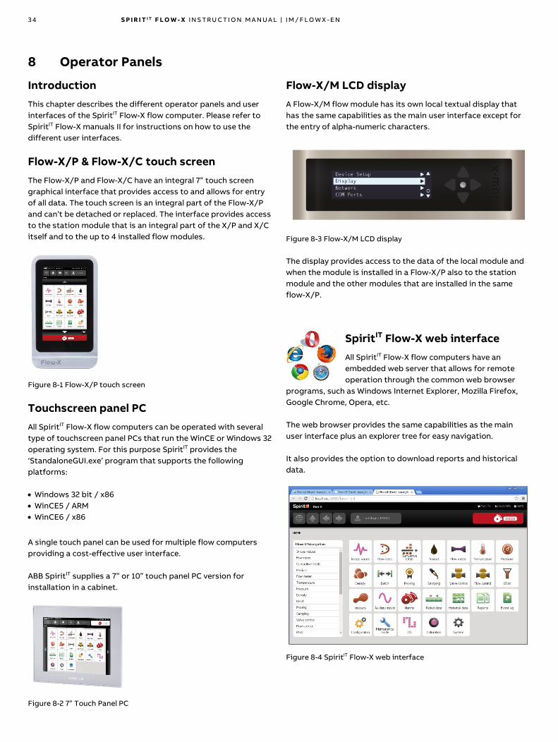
3 4 S P I R I T I T F L O W - X I N S T R U C T I O N M A N U A L | I M / F L O W X - E N
8 Operator Panels
Introduction
This chapter describes the different operator panels and user
interfaces of the SpiritIT Flow-X flow computer. Please refer to
SpiritIT Flow-X manuals II for instructions on how to use the
different user interfaces.
Flow-X/P & Flow-X/C touch screen
The Flow-X/P and Flow-X/C have an integral 7” touch screen
graphical interface that provides access to and allows for entry
of all data. The touch screen is an integral part of the Flow-X/P
and can’t be detached or replaced. The interface provides access
to the station module that is an integral part of the X/P and X/C
itself and to the up to 4 installed flow modules.
Figure 8-1 Flow-X/P touch screen
Touchscreen panel PC
All SpiritIT Flow-X flow computers can be operated with several
type of touchscreen panel PCs that run the WinCE or Windows 32
operating system. For this purpose SpiritIT provides the
‘StandaloneGUI.exe’ program that supports the following
platforms:
• Windows 32 bit / x86
• WinCE5 / ARM
• WinCE6 / x86
A single touch panel can be used for multiple flow computers
providing a cost-effective user interface.
ABB SpiritIT supplies a 7” or 10” touch panel PC version for
installation in a cabinet.
Figure 8-2 7” Touch Panel PC
Flow-X/M LCD display
A Flow-X/M flow module has its own local textual display that
has the same capabilities as the main user interface except for
the entry of alpha-numeric characters.
Figure 8-3 Flow-X/M LCD display
The display provides access to the data of the local module and
when the module is installed in a Flow-X/P also to the station
module and the other modules that are installed in the same
flow-X/P.
SpiritIT Flow-X web interface
All SpiritIT Flow-X flow computers have an
embedded web server that allows for remote
operation through the common web browser
programs, such as Windows Internet Explorer, Mozilla Firefox,
Google Chrome, Opera, etc.
The web browser provides the same capabilities as the main
user interface plus an explorer tree for easy navigation.
It also provides the option to download reports and historical
data.
Figure 8-4 SpiritIT Flow-X web interface

S P I R I T I T F L O W - X I N S T R U C T I O N M A N U A L | I M / F L O W X - E N 3 5
Graphical User Interface Layout
All the SpiritIT Flow-X Graphical User Interfaces have the
following layout and buttons.

3 6 S P I R I T I T F L O W - X I N S T R U C T I O N M A N U A L | I M / F L O W X - E N
9 Software
Introduction
Configuration of the SpiritIT Flow-X is described in manual II-A,
Operation and configuration. This chapter only describes the
requirements and set up for configuration.
Set up
The flow modules are configured through our SpiritIT Flow-
Xpress software. This software may be run in Basic mode, or,
depending on your license, in Pro mode.
Requirements for the use of SpiritIT Flow-Xpress are:
Aspect Requirement
Operating
system:
Windows 7
Windows Server 2008 R2
Windows Server 2012
Windows 8.1
Windows Server 2012 R2
Windows 10
Windows Server 2016
Additional
software
Microsoft Excel 2007 (minimum SP2), Excel 2010,
Excel 2013, Excel 2016, Excel 2019 or Excel 365 (up
to and including the versions based on 2019).
Microsoft .NET Framework 4.5.1 (or compatible).
Connection Standard Ethernet connection with RJ-45
connector, capable of 100baseT (100Mbit)
Hardware CD-player for software installation only (local or
shared from another computer)
If you want to connect a laptop or desktop PC directly to your
SpiritIT Flow-X model, (see Figure 9-1) you will need an ethernet
cross cable (CAT 5), available from any computer store. If you use
a network hub or switch, you may use standard Ethernet cables
(CAT 5). See Figure 9-2. The length of the ethernet cables
between the Flow-X device and any other device must be less
than 10 meters
Figure 9-1 Direct Ethernet connection without switch
Figure 9-2 Ethernet connection with switch
If you want to fabricate your cables yourself, please use the
following information:
ETHERNET STANDARD CABLE (EIQ/TIA-568B)
Connector A Connector B
Pin Color Pin Color
1 White/Orange 1 White/Orange
2 Orange 2 Orange
3 White/Green 3 White/Green
4 Blue 4 Blue
5 White/Blue 5 White/Blue
6 Green 6 Green
7 White/Brown 7 White/Brown
8 Brown 8 Brown
Table 9-1 Ethernet RJ-45 straight cable pin-out
ETHERNET CROSS CABLE EIQ/TIA-568A and B)
Connector A Connector B
Pin Color Pin Color
1 White/Orange 1 White/Green
2 Orange 2 Green
3 White/Green 3 White/Orange
4 Blue 4 Blue
5 White/Blue 5 White/Blue
6 Green 6 Orange
7 White/Brown 7 White/Brown
8 Brown 8 Brown
Table 9-2 Ethernet RJ-45 cross cable pin-out

S P I R I T I T F L O W - X I N S T R U C T I O N M A N U A L | I M / F L O W X - E N 3 7
Software installation
Software installation is quite straightforward.
You will need administrator rights in order to install. Refer to
your system administrator if you are not sure you have these
rights on the account you use.
Insert the CD in your CD-drive while your computer is running.
The CD will normally autostart and present the installation Start-
up display. Follow the instructions from there.
If autostart is disabled on your system, use Explorer to navigate
to your CD-drive and start setup.exe.
Note: Any existing version will automatically be
replaced. If a version of 1.7.x or earlier was installed then
the user will have to confirm this.
After installation, you will need to get a license from ABB SpiritIT
based on the unique Machine ID that your computer will provide,
in order to use the configuration software. Depending on your
license you may be able to run SpiritIT Flow-Xpress in Basic mode
or also in Professional mode.
Refer to Volume II-A of this manual set for detailed
installation instructions and for use of the SpiritIT Flow-
Xpress software to configure your modules.

3 8 S P I R I T I T F L O W - X I N S T R U C T I O N M A N U A L | I M / F L O W X - E N
10 Technical specifications
General
Version 1 Hardware
Item Type Description Quantity
Temperature Operating Operating range temperature 0 .. 60 °C
Temperature Storage Storage range temperature -20 .. 70 °C
Processor Freescale i.MX processor with math coprocessor, and FPGA 400 MHz
Memory RAM Program memory 128 MB
Storage SLC Storage memory for data logging, OS and firmware 1024 MB
Clock RTC Real time clock with internal lithium cell
Accuracy better than 1 s/day
Version 2 Hardware
Item Type Description Quantity
Temperature Operating Operating range temperature 0 .. 60 °C
Temperature Storage Storage range temperature -20 .. 70 °C
Processor Freescale i.MX6 processor with math coprocessor, and FPGA 800 MHz
Memory RAM Program memory 512 MB
Storage SLC Storage memory for data logging, OS and firmware 1024 MB
Clock RTC Real time clock with gold cap
Accuracy better than 1 s/day
Other specifications
Item Type
MTBF 5 years minimum
EMC EN 61326-1997 industrial locations
EN 55011
Casing EN 60950
Table 10-1 General Specifications
Flow-X/M I/O specifications
Signal V1 Nr V2 Nr Type Description
Analog signals1
Analog input 61 61 4-20mA
0-20mA
0-5V
1-5V
High accuracy analog transmitter input
0.002% FS (full scale) at calibration temperature, 0.008% FS for ambient range 0-60 °C
Long-term stability 0.01% FS / year.
Resolution 24 bits.
Inputs are fully floating (optically isolated).
Overvoltage protection is 6 Vdc for ‘mA’ modes and 26 Vdc for ‘V’ modes.
Temperature input 2 2 PRT Analog PT100 input. -220 - 220 deg.C. for 100 ohms input.
Resolution 0.02 deg.C
Max. error Between 0-50 degC :0.05 deg.C,
Between -220 - +220 degC: 0.5 deg.C
Hart modems 41 41 HART Loop inputs for HART transmitters, on top of the first 4 analog input signals.
Analog output 4 4 4-20mA Analog output for PID, pressure control valve. 12 bits ADC, 0.075% fs. Update rate 0.1s.
Digital signals
Dual pulse input 12 42 High impedance High speed turbine/PD/USM meter input, pulse count. Trigger level 0.5V. Max. level 30 V.
Frequency range 0-10kHz for single and dual pulse.
Compliant with ISO6551, IP252, and API 5.5. True Level A implementation.
Density 42 42 High impedance Periodic time input, 100us - 5000us.
Accuracy 30ns, resolution 2 ns
Digital input 162 162 High impedance Digital status input, or prover inputs. 0.5ms detect update rate for 2 inputs, others 250ms
max.
Digital output 162 162 Open collector Digital output for relays etc. (0.5A DC). Rating 100mA @24V. Update rate at cycle time.
Prover output 12 12 Open collector Two related pulse outputs, for proving applications. One output is the highest value of the
dual pulse inputs, and the other output the difference between the dual input pulses. The
outputs are On-Off-HighZ.
Pulse output 42 42 Open collector Max. 100Hz

S P I R I T I T F L O W - X I N S T R U C T I O N M A N U A L | I M / F L O W X - E N 3 9
Signal V1 Nr V2 Nr Type Description
Sphere detector inputs 42 42 High impedance Supports 1, 2, 3 and 4 detector configurations mode
0.05 μs detect update rate.
Communication
Serial 2 2 RS485/422/232 Multi-purpose serial communication interface
Minimum 300 baud, maximum 256000 baud
Ethernet 2 2 RJ45
100 Mbit/s
Ethernet interface - TCP/IP
Table 10-2 Flow-module I/O Specifications
NOTES:
(1) Total number of analog inputs + HART inputs = 6
(2) Total number of digital inputs + digital outputs + pulse outputs + density inputs + sphere detector inputs = 16
Liquid calculations
API 5, 6, 23, 24, 53, 54, 59 and 60 tables (A.B. D and E)
API 11.1 1980 (API 2540) and 2004/2007
API 1952 historical tables
API 11.2.1, 11.2.2, 12.2, 21.1, 21.2
API 11.3.2.1 Ethylene (API-2565)
GPA TP15, TP16, TP25, TP27
Propylene (API 11.3.3.2)
Butadiene (ASTM D1550)
Asphalt (ASTM D4311)
Ethylene (IUPAC 1988, NIST 1045, API 2565)
Carbon dioxide (NIST)
OIML R22
Gas calculations
AGA3, AGA5, AGA7, AGA8 (Part 1 and 2), AGA9, AGA10, AGA11
AGA-NX19
SGERG-88 and SGERG 2015
GERG-2008
GPA 2172 and GPA 2145
IAPWS-IF97 (steam and water)
ISO 6976 (all editions)
Gas viscosity
GSSSD MR113
Flow calculations
ISO 5167 (all editions)
ISO/TR15377
ISO 6976
AGA3
GOST 8-586
V-cone
Table 10-3 Flow and fluid property calculations
Metering functions
Retroactive meter factors, batch recalculations (meter factor, BS&W, density, etc.)
Unlimited number of period and batch totals and flow and time weighted averages. Periods can be of any type. Maintenance totalizers are supported
Calibration curve up to unlimited number of points (linear and polynomial).
Prover support: uni-directional, bi-directional (2 / 4 detector inputs), compact prover, master meter, dual chronometry, pulse interpolation.
Control functionality:
• Flow and pressure control
• Valve control
• Batching / liquid loading control
• Sampling control
API 21.1 and 21.2 compliant
All common spreadsheet functions to obtain maximum flexibility.
Table 10-4 Metering functions

4 0 S P I R I T I T F L O W - X I N S T R U C T I O N M A N U A L | I M / F L O W X - E N
Standard Supported Devices
Ultrasonic Flow Meters
• Sick-Maihak,
• Daniel
• Cameron
• Elster-Instromet
• GE
• FMC
• Krohne
• Any Modbus-supporting Ultrasonic meter
Coriolis flow meters
• ABB CoriolisMaster
• MicroMotion
• Endress + Hauser
Any Modbus-supporting Coriolis meter
Gas chromatographs
• ABB
• Daniel
• Instromet
• Siemens
• Any Modbus-supporting Gas chromatograph
• Yamatake
Densitometers
• Solartron
• Sarasota
• UGC
• Densitrak
• Anton Paar
Table 10-5 Standard supported devices

S P I R I T I T F L O W - X I N S T R U C T I O N M A N U A L | I M / F L O W X - E N 4 1
Power consumption
Values at 24 Vdc excluding supply of external transmitter loops.
Nominal Peak at start up
Flow-X/P0 0.4 A 0.8 A
Flow-X/C 0.6 A 1.0 A
Flow-X/M (flow module) 0.4 A 0.8 A
The power supply input circuits of the Flow-X/P0 and the Flow-
X/M flow modules are equipped with an auto-fuse rated at 30
Vdc and 1.1 A each.
E.g. a Flow-X/P4, which is a Flow-X/P with 4 Flow-X/M flow
modules has a nominal power consumption of 2.0 A (0.4A of
Flow-X/P0 + 4 * 0.4 A for each flow module) and a peak
consumption of 4.0 A at startup.
Weight
Individual component Enclosure Weight in kg Weight in lbs
Flow-X/S (without flow module) 1.7 3.7
Flow-X/K (without flow module) 0.9 2.0
Flow-X/R (without flow modules) 5.0 11.0
Flow-X/B 1.2 2.6
Version 1
Enclosure Weight in kg Weight in lbs
Flow-X/M (single flow module) 0.8 1.7
Flow-X/P0 (without flow modules) 3.7 8.2
Version 2
Enclosure Weight in kg Weight in lbs
Flow-X/M (single flow module) 0.9 1.9
Flow-X/P0 (without flow modules) 4.1 8.9
Flow-X/C 2.7 6.0
Combined product
Version 1
Enclosure Weight in kg Weight in lbs
Flow-X/S including flow module 2.5 5.4
Flow-X/K including flow module 1.7 3.6
Flow-X/P1 4.5 9.8
Flow-X/P2 5.2 11.5
Flow-X/P3 6.0 13.1
Flow-X/P4 6.7 14.8
Flow-X/R1 5.8 12.7
Flow-X/R2 6.5 14.3
Flow-X/R3 7.3 16.0
Flow-X/R4 8.0 17.6
Flow-X/R5 8.8 19.3
Flow-X/R6 9.5 20.9
Flow-X/R7 10.3 22.6
Flow-X/R8 11.0 24.3
Version 2
Enclosure Weight in kg Weight in lbs
Flow-X/S including flow module 2.6 5.7
Flow-X/K including flow module 1.8 3.9
Flow-X/P1 4.9 10.9
Flow-X/P2 5.5 12.0
Flow-X/P3 6.3 14.0
Flow-X/P4 7.2 15.9
Enclosure Weight in kg Weight in lbs
Flow-X/R1 5.9 13.0
Flow-X/R2 6.8 14.9
Flow-X/R3 7.6 16.8
Flow-X/R4 8.5 18.8
Flow-X/R5 9.4 20.7
Flow-X/R6 10.3 22.7
Flow-X/R7 11.2 24.6
Flow-X/R8 12.0 26.5

4 2 S P I R I T I T F L O W - X I N S T R U C T I O N M A N U A L | I M / F L O W X - E N
11 Drawings
All sizes are in mm. Sizes in square brackets e.g. [5] are inches.
Flow-X/P Panel version 1 mounted enclosure
Figure 11-1 Flow-X/P Front view dimensions Figure 11-2 Flow-X/P Side view dimensions
Figure 11-3 Flow-X/P rear view

S P I R I T I T F L O W - X I N S T R U C T I O N M A N U A L | I M / F L O W X - E N 4 3
Flow-X/P Panel version 1 mounting bracket
Figure 11-4 Flow-X/P Bracket Front side dimensions Figure 11-5 Flow-X/P Bracket Back view dimensions

4 4 S P I R I T I T F L O W - X I N S T R U C T I O N M A N U A L | I M / F L O W X - E N
Flow-X/P Panel version 2 mounted enclosure
Figure 11-6 Flow-X/P version 2 Front view dimensions Figure 11-7 Flow-X/P version 2 right side view dimensions
Figure 11-8 Flow-X/P version 2 rear view dimensions Figure 11-9 Flow-X/P version 2 left side view dimensions

S P I R I T I T F L O W - X I N S T R U C T I O N M A N U A L | I M / F L O W X - E N 4 5
Flow-X/P Panel version 2 mounting bracket
Figure 11-10 Flow-X/P version 2 bracket front view
dimensions
Figure 11-11 Flow-X/P version 2 bracket right side view
dimensions
Figure 11-12 Flow-X/P version 2 bracket rear view dimensions

4 6 S P I R I T I T F L O W - X I N S T R U C T I O N M A N U A L | I M / F L O W X - E N
Flow-X/C Compact panel mount enclosure
Figure 11-13 Flow-X/C Front view dimensions Figure 11-14 Flow-X/C rear view
Figure 11-15 Flow-X/C Side view dimensions Figure 11-16 Flow-X/C Bracket dimensions

S P I R I T I T F L O W - X I N S T R U C T I O N M A N U A L | I M / F L O W X - E N 4 7
Figure 11-17 Flow-X/C position & cut out (vertical & horizontal position)
Flow-X/C installation guides
Figure 11-18 Blanking plate 19 inch installation, Front, vertical Flow-X/C

4 8 S P I R I T I T F L O W - X I N S T R U C T I O N M A N U A L | I M / F L O W X - E N
Figure 11-19 Blanking plate 19 inch installation, Front, horizontal Flow-X/C
Figure 11-20 Blanking plate 19 inch installation with shelf, vertical Flow-X/C

S P I R I T I T F L O W - X I N S T R U C T I O N M A N U A L | I M / F L O W X - E N 4 9
Figure 11-21 Blanking plate 19 inch installation with shelf, horizontal Flow-X/C
Figure 11-22 Cut out Door - Front installation, vertical Flow-X/C

5 0 S P I R I T I T F L O W - X I N S T R U C T I O N M A N U A L | I M / F L O W X - E N
Figure 11-23 Cut out Door - Front installation, horizontal Flow-X/C
Flow-X/R Rack mount enclosure
Figure 11-24 Flow-X/R Side view dimensions Figure 11-25 Flow-X/R Side view dimensions

S P I R I T I T F L O W - X I N S T R U C T I O N M A N U A L | I M / F L O W X - E N 5 1
Flow-X/S Single module enclosure
Figure 11-26 Flow-X/S horizontally dimensions
Figure 11-27 Flow-X/S vertically dimensions
Figure 11-28 Flow-X/S DIN rail mount side view dimensions

5 2 S P I R I T I T F L O W - X I N S T R U C T I O N M A N U A L | I M / F L O W X - E N
Figure 11-29 Flow-X/S Wall mount dimensions Figure 11-30 Flow-X/S Wall mounted side view dimensions
Flow-X/K enclosure
Figure 11-31 Flow-X/K Din rail mounted front view dimensions Figure 11-32 Flow-X/K Din rail mounted side view dimensions

S P I R I T I T F L O W - X I N S T R U C T I O N M A N U A L | I M / F L O W X - E N 5 3
Figure 11-33 Flow-X/K wall mounted side view dimensions Figure 11-34 Flow-X/K wall mounted dimensions
Flow-X/B breakout board
Figure 11-35 Flow-X/B front view dimensions Figure 11-36 Flow-X/B side view dimensions
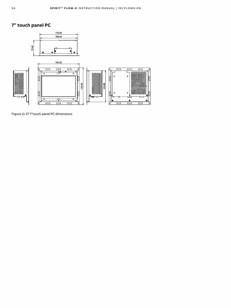
5 4 S P I R I T I T F L O W - X I N S T R U C T I O N M A N U A L | I M / F L O W X - E N
7” touch panel PC
Figure 11-37 7“touch panel PC dimensions

S P I R I T I T F L O W - X I N S T R U C T I O N M A N U A L | I M / F L O W X - E N 5 5
12 Configuration sheet
From our website you can download an Excel workbook that
helps you to configure your flow computer. The sheet
automatically provides connection details (sub-D 37 pin-outs,
screw terminal pin-outs) with tag names.
.

5 6 S P I R I T I T F L O W - X I N S T R U C T I O N M A N U A L | I M / F L O W X - E N
13 I/O Diagnostics and calibration
This chapter describes the diagnostics and calibration features
for the digital and analog I/O.
I/O diagnostics
A SpiritIT Flow-X flow computer with a standard SpiritIT
application provides a set of displays with diagnostic
information on the digital and analog I/O of the flow modules
that are part of the SpiritIT Flow-X flow computer.
To access the diagnostics displays:
• On the LCD or web display select Diagnostics, IO from the
main menu.
• Select the applicable flow module (only in case of a flow
computer with more than one flow module)
• Select the type of I/O
I/O calibration
The analog inputs, PT100 inputs and analog outputs can be
calibrated at up to 5 calibration points.
Calibration points
For each type of I/O up to 5 calibration points can be defined.
For analog inputs and analog outputs, the calibration points are
defined as percentage of span, while for PT100 inputs the
calibration points are defined in ᵒC (metric applications) or ᵒF
(metric applications). The number of calibration points may
range from 1 through 5.
The reference values should be in an ascending order, e.g. 0, 50,
100 %. Non-used reference values shall be set to 0. If a reference
value is smaller than or equal to the previous value, then this
point and any further points are not taken into account.
Typical calibration points for analog inputs and outputs are:
• 0, 0, 0, 0, 0
A single offset value is applied over the entire range
• 0, 100, 0, 0, 0
Calibration at 2 points, low and high range
• 0, 50, 100, 0, 0
Calibration at 3 points, low, mid and high range
• 0, 25, 50, 75, 100
Calibration at 5 points, low and high range and 3 mid ranges
Display → IO, Module <x>, Calibration, Settings
Display → Calibration, Module <x>, Settings
With x the applicable module number, i.e. the flow module to
which the signal is physically connected
Analog
input cal.
point 1..5
750 The calibration points for the calibration
of the 6 analog inputs
PT100
calibration
point 1..5
750 The calibration points for the calibration
of the 2 PT100 inputs
Analog
output cal.
point 1..5
750 The calibration points for the calibration
of the 4 analog outputs
Inactivity
timeout
limit
750 The input selected for calibration is
automatically reset in case of inactivity
longer than this limit. Enter 0 to disable
the automatic reset function.
If the calibration points are modified, the calibration of all
applicable inputs initially remains unaltered. At the start of the
next calibration of one of these inputs, any of the points that
have been altered, added or removed since the last calibration
are reset for this input only. E.g. when an analog input has been
calibrated at 5 points (reference values at 0, 25, 50, 75 and 100
%) and the number of calibrations has been redefined to 3
points (e.g. 0, 50, 100, 0, 0 %), then at the start of the next
calibration the 2nd and 3th calibration values will be reset to 50
and 100 % respectively and the 4th and 5th calibration values will
be reset to zero (= not used).
Analog input calibration
The procedure to calibrate an analog input is based on a loop
calibrator that, depending on the type of input, can provide a 4-
20 mA, 0-20 mA, 1-5 Vdc, or 0-5 Vdc signal.
During calibration the process input (e.g. pressure,
temperature) that uses the analog input will follow the
calibration value. So, before putting an input into calibration,
please be sure that one of the following conditions is met:
• There’s no flow
• The run has been set to maintenance mode
• The process value has been set to override mode
• The input has been frozen using the ‘Freeze all analog and
PT100 inputs’ command
1 Go to the analog input calibration display.
Display → IO, <Module x>, Calibration, Analog inputs
Display → Calibration, Module <x>, Analog inputs
With x the applicable module number, i.e. the flow module to
which the signal is physically connected.
2 Select the analog input (1-6) to be calibrated.
The calibration display shows the required reference value for
the 1st calibration point.

S P I R I T I T F L O W - X I N S T R U C T I O N M A N U A L | I M / F L O W X - E N 5 7
3 Disconnect the transmitter signal and connect the loop
calibrator
4 The calibration display shows the raw input value as it is read
directly from the loop calibrator and the corrected input value
based on the previous calibration.
5 Adjust the loop calibrator such that it outputs the required
reference value
6 Wait for the signal to stabilize and issue the 'Recalibrate this
point'.
Note: recalibration is optional at every calibration point. If the
corrected signal is close enough to the reference value you
may decide to skip re-calibration of the calibration point.
7 Check that the corrected value corresponds with the
reference value and issue the 'Go to next calibration point'
command on the display.
8 Repeat steps 4 through 7 for the remaining calibration points
9 Disconnect the current loop calibrator and reconnect the
transmitter.
10 Set the "Selected analog input" to 'None' or alternatively
select the next analog input to be calibrated. The live input
signal will now be used again.
PT100 input calibration
The procedure to calibrate a PT100 input is based on a decade
box that is suitable for PT100 calibration
During calibration the process input (temperature) that
uses the PT100 input will follow the calibration value. So,
before putting an input into calibration, please be sure that one
of the following conditions is met:
• There’s no flow
• The run has been set to maintenance mode
• The process value has been set to override mode
• The input has been frozen using the ‘Freeze all analog and
PT100 inputs’ command
1 Go to the PT100 input calibration display.
Display → IO, <Module x>, Calibration, PT100 inputs
Display → Calibration, Module <x>, PT100 inputs
With x the applicable module number, i.e. the flow module to
which the signal is physically connected.
2 Select the channel number (1-2) of the PT100 input to be
calibrated.
The calibration display shows the required reference value for
the 1st calibration.
3 Disconnect the PT100 element and connect decade box.
4 Adjust the decade box such that it outputs the required
reference value as indicated on the calibration display)
5 The calibration display shows the raw input value and the
corrected input value based on the previous calibration.
6 Wait for the signal to stabilize and issue the 'Recalibrate this
point'.
Note: recalibration is optional at every calibration point. If the
corrected signal is close enough to the reference value you
may decide to skip re-calibration of the calibration point.
7 Check that the corrected value corresponds with the
reference value and issue the 'Go to next calibration point'
command on the display.
8 Repeat steps 4 through 6 for the remaining calibration points
9 Disconnect the decade box and reconnect the PT100 element.
10 Set the 'Selected PT100 input' to 'None' or alternatively select
the next PT100 input to be calibrated. The live input signal will
now be used again.
Analog output calibration
The procedure to calibrate an analog output is based on a 4-20
mA meter.
1 Connect the mA meter in series with the load.
2 Go to the analog output calibration
display.
Display → IO, <Module x>, Calibration, Analog
outputs
Display → Calibration, Module <x>, Analog outputs
With x the applicable module number, i.e. the flow module to
which the signal is physically connected.
3 Select the channel number (1-4) of the analog output to be
calibrated. This disables the setpoint that is controlled by the
application and adjusts the analog output to the 1st
calibration point.
4 If the actual output as measured by a reference meter is not
correct, you can increase or decrease it by using the ‘Increase
output’ and ‘Decrease output’ buttons until the indication on
the mA meter matches the reference value.
5 Issue the 'Recalibrate this point' command.
Note: recalibration is optional at every calibration point. If the
output signal is close enough to the reference value you may
decide to skip re-calibration of the calibration point.
6 Check on the mA meter that the output signal corresponds to
the reference value and issue the 'Go to next calibration point'
command on the display.
7 Repeat steps 4 through 6 for the remaining calibration points
8 Set the 'Selected analog output' to 'None' or alternatively
select the next analog output to be calibrated. The analog
output will now be controlled by the application software
again.
9 Disconnect the mA meter.

14 Revisions
Revision A
Date April 2017
• Initial release of the Flow-X Manual Volume I - Installation.
• D-sub 37 pinout corrected.
• RS-485 connections specified.
• Added schematic for analog output.
• Updated the XP bracket drawing.
• Added power consumption specifications.
• Updated Flow-X/R data.
• Added HART multi-drop schematic.
• Added MTL Barrier schematics for analog signals.
• Added connection diagram for Solartron densitometer.
• Added maintenance and cleaning instructions.
• Added chapter for description of operator panels and user
interfaces.
• Added wiring diagram for Honeywell Enraf Calibron prover.
• Added paragraph on prover signals connection.
• Added earth ground connection paragraph and diagrams.
• Updated the software setup requirements and installation
information.
• Added recommendation for forced ventilation.
• Added a caution notification for the fact that analog inputs
don’t have overvoltage and overcurrent protection for
reason of accuracy.
• Added Flow-X/K specifications.
• Updated the supported Windows and Excel versions.
Revision B
Date November 2017
• Flow X/C related changes.
• Supported baudrate range for Serial communication is
updated.
• Update to new ABB lay-out.
• Document code: IM/FlowX-EN.
• Reintroduce revisions chapter.
Revision C
Date March 2018
• Added Flow-X/B specifications.
• Updated drawings in Drawings chapter
Revision D
Date June 2018
• Flow-X/P version 2 hardware specific information added.
• Supported Liquid and Gas calculations updated.
• Added WEEE guideline.
• Corrected Flow-X/C picture.
Revision E
Date October 2018
• Added recycling information in accordance with WEEE.
• Windows 8 removed from software requirements.
Revision F
Date February 2019
• Added section with regulatory compliance.
Revision G
Date September 2019
• Updated the supported Excel versions.
Revision H
Date April 2020
• Updated I/O specifications for Flow-X/M.
Revision I
Date October 2020
• Added Hazardous Area installation requirements
• Updated power consumption specifications

—We reserve the right to make technical changes or modify the contents of this document without prior notice. With regard to purchase orders, the agreed particulars shall prevail. ABB AG does not accept any responsibility whatsoever for potential errors or possible lack of information in this document.We reserve all rights in this document and in the subject matter and illustrations contained therein. Any reproduction, disclosure to third parties or utilization of its contents – in whole or in parts – is forbidden without prior written consent of ABB.© ABB 2020
IM/F
low
X-E
N R
ev. I
10
.20
20
ABB Inc.Measurement & Analytics7051 Industrial BoulevardBartlesville OK 74006United States of AmericaPhone: +1 800 442 3097
ABB LimitedMeasurement & AnalyticsOldends Lane, StonehouseGloucestershire, GL10 3TAUnited KingdomPhone: +44 7730 019 180
—ABB B.V.Measurement & AnalyticsAchtseweg Zuid 151A 5651 GW EindhovenThe NetherlandsPhone: +31 40 236 9445Mail: [email protected]
ABB Malaysia Sdn Bhd.Measurement & AnalyticsLot 608, Jalan SS 13/1K47500 Subang JayaSelangor Darul Ehsan, MalaysiaPhone: +60 3 5628 4888
abb.com/midstream