Embed Size (px)
Citation preview

SCU
100
Use
r m
anua
l
INSITE PRO M COMPACT
SCU100User manual


3SCU100 INSITE PRO M COMPACT USER MANUAL
Table of Contents
1.General Information..............................................................................................5
1.1.Use and Storage of the manual ............................................................................51.2.Cleaning.....................................................................................................................61.3.Installation to mains ...............................................................................................61.4.Disconnection from mains or connections to mains .......................................61.5.Safety warnings .......................................................................................................61.6.Disposal ....................................................................................................................61.7.Service and maintenance .......................................................................................61.8.Cyber Security disclaimer ......................................................................................7
2.System overview ..................................................................................................8
2.1.Sub-distribution Control Unit SCU100 ................................................................82.2.Current sensors .....................................................................................................102.3.I/O modules ........................................................................................................... 122.4.Accessories ............................................................................................................ 132.5.Current transformer ............................................................................................. 13
3.Packaging contents ............................................................................................ 15
3.1.Control unit .............................................................................................................153.2.I/O modules ...........................................................................................................15
4.Technical characteristics / specifications ...................................................... 16
4.1.Overall dimensions and technical data sub-distribution control unit ........164.2.Overall dimensions and technical data I/O modules ..................................... 174.3.Compatible devices ..............................................................................................18
5.Main functionalities and measurements ......................................................... 19
5.1.Measurements .......................................................................................................195.2.Memory architecture ........................................................................................... 20
6.Installation .......................................................................................................... 21
6.1.Control Unit ............................................................................................................ 216.2.Assembly of connectors, current sensors and I/O modules ........................226.3.Meters connection ................................................................................................26
7.Wiring diagram .................................................................................................... 27
7.1.Control unit .............................................................................................................27
8.Access to control unit ........................................................................................30
8.1.Network connection ............................................................................................ 308.2.Control unit login ................................................................................................. 34

4 SCU100 INSITE PRO M COMPACT USER MANUAL
9.Web User Interface .............................................................................................35
9.1.Structure .................................................................................................................35
10.Web UI - Configuration .....................................................................................36
10.1.Devices ..................................................................................................................3610.2.Groups ...................................................................................................................5310.3.Tree view .............................................................................................................. 5410.4.Events ................................................................................................................... 5610.5.Automation ..........................................................................................................5710.6.Export/Import .................................................................................................... 58
11.WebUI - Settings ...............................................................................................60
11.1.Users ...................................................................................................................... 6011.2.Email - FTP ............................................................................................................6111.3.Communication ...................................................................................................6211.4.SSL certificate ......................................................................................................7511.5.Views .....................................................................................................................7611.6.General...................................................................................................................77
12.WebUI – Monitor ............................................................................................... 80
12.1.Dashboard ........................................................................................................... 8012.2.Real-time values ..................................................................................................82
13.WebUI – Analytics ..............................................................................................86
13.1.Historical values .................................................................................................. 8613.2.Benchmark ............................................................................................................8713.3.Events log .............................................................................................................8713.4.Alarms .................................................................................................................. 8813.5.Data export ......................................................................................................... 89
14.WebUI – Control .................................................................................................90
14.1.Control .................................................................................................................. 90
15.Modbus TCP/RTU communication interface ................................................. 91
15.1.Control unit mains and sensors readings .......................................................9115.2.Meters ...................................................................................................................9715.3.I/O modules ........................................................................................................ 9815.4. External Modbus alarm registers for IOM ...............................................99
16.Simple Network Management Protocol – SNMP .........................................100
16.1.SNMP objects .....................................................................................................102

5SCU100 INSITE PRO M COMPACT USER MANUAL
1.General Information
This manual contains all the safety information, the technical aspects and the operating necessary to ensure the correct use of the device and maintain it in safe conditions.
1.1.Use and Storage of the manual
Storing
The manual must be stored close to the device; safe from liquids and anything else which may compromise its legibility. The manual and the declaration of conformity are both an integral part of the device until it is dismantled. If the manual is lost or illegible please request a copy from the manufacturer.
Copyright
The copyright of this manual is the property of ABB Ltd. This manual contains texts, designs and illustrations of a technical nature which must not be disclosed or transmitted to third parties, even partially, without the written authorisation of ABB Ltd.
Liability disclaimer
The information contained in this document is subject to change without notice and cannot be considered as an obligation by ABB Ltd. ABB Ltd. is not liable for any errors that may appear in this document. ABB Ltd. is not liable under any circumstances for any direct, indirect, special, incidental or consequential damage of any kind that may arise from using this document. ABB Ltd. is also not liable for incidental or consequential damage that may arise from using the software or hardware mentioned in this document.
Brand
ABB Ltd. is a registered trademark of ABB Group. All other brands or product names mentioned in this document are trademarks or registered trademarks of their respective owners.
Meaning of symbols
Warning – can result in death or serious personal injury
Non-safety related, but useful and important information
CE conformity mark Torque
Observe the accompanying documents
Disposal
Installation, electrotechnical expertise
Equipment protected throughoutby reinforced insulation

6 SCU100 INSITE PRO M COMPACT USER MANUAL
1.2.Cleaning
Use a dry cloth.
1.3.Installation to mains
Installation of device to mains shall include a switch or circuit breaker for the connection to mains. The switch or circuit breaker must be suitably located and easily reachable and must be marked as the disconnecting device for the device.
1.4.Disconnection from mains or connections to mains
Switch off circuit breaker or switch before disconnecting from the mains supply or connecting to the mains supply. Same applies for all other connections (L1, L2, L3, N).
1.5.Safety warnings
Attention: Non-adherence to the following points can lead to serious injury or death. Use the suitable personal protection devices and adhere to the current regulations governing electrical safety.
This device must be installed exclusively by qualified personnel who have read all of the information relative to the installation.
Check that the voltage on the main side is compatible with the range permitted by the device.
Ensure that all current and voltage supplies are disconnected prior to carrying out any controls, visual inspections and tests on the device.
Always assume that all circuits are under voltage until they are completely disconnected, subjected to tests and labelled.
Disconnect all of the power supply prior to working on the device.
Always use a suitable voltage detection device to check that the supply is interrupted.
Pay attention to any dangers and carefully check the work area ensuring that no instruments or foreign objects have been left inside the compartment in which the device is housed.
The correct use of this device depends on a correct manipulation, installation and use.
Failure to adhere to the basic installation information can lead to injuries as well as damage to the electric instruments or to any other product.
The tests carried out at a high voltage can damage the device’s electronic components.
1.6.Disposal
Defective devices must be disposed of as special waste at the appropriate collection points set up for this purpose. National or regional regulations on the disposal of special waste must be followed.
1.7.Service and maintenance
The device undergoes several safety assessments before shipment and will be sealed. If a device is opened, the safety assessments have to be repeated. A warranty will be provided for unopened devices only.

7SCU100 INSITE PRO M COMPACT USER MANUAL
1.8.Cyber Security disclaimer
Sub-distribution Control Unit SCU100 is designed to be connected and to communicate information and data via a network interface, which should be connected to a secure network. It is your sole responsibility to provide and continuously ensure a secure connection between the product and your network or any other network (as the case may be) and to establish and maintain appropriate measures (such as but not limited to the installation of firewalls, application of authentication measures, encryption of data, installation of antivirus programs, etc.) to protect the Sub-distribution Control Unit SCU100 product, the network, its system and interfaces against any kind of security breaches, unauthorized access, interference, intrusion, leakage and/or theft of data or information. ABB S.p.A. and its affiliates are not liable for damages and/ or losses related to such security breaches, unauthorized access, interference, intrusion, leakage and/or theft of data or information.
Although ABB S.p.A. provides functionality testing on the products and updates that we release, you should institute your own testing program for any product updates or other major system updates (to include but not limited to code changes, configuration file changes, third party software updates or patches, hardware change out, etc.) to ensure that the security measures that you have implemented have not been compromised and system functionality in your environment is as expected.

8 SCU100 INSITE PRO M COMPACT USER MANUAL
2.System overview
InSite pro M compact is a monitoring system which brings complete overview of the system performances and enables energy and asset management.
The system consists of a Sub-distribution Control Unit (SCU100) and field devices connected to the control unit: energy and power meters, current sensors, digital input and output modules (I/O modules).
The input measurements and data from meters are transmitted via Modbus RTU communication protocol. The input measurements and information from current sensors and I/O modules are transmitted throught a flat cable, the InSite bus. All gathered data can be displayed or analyzed via LAN interface with the integrated web server or Modbus TCP or SNMP protocols or via RS485 interface, such as Modbus RTU.
2.1.Sub-distribution Control Unit SCU100
Insite Bus interface with up to 96 sensors/digital channels - ports from 1 to 3
Modbus RTUadapter - port 4
Terminal RS-485Modbus (RTU) for data export - port 5
Input for current transformer
Link to User Manual
RJ45-socket for LANconnection
Reset button
Terminal L1, L2, L3, NWire gauge max 2.5 mm2
LEDs
Reset button
There is a recessed button to restart the device or for resetting it to factory settings.
• Pressing the button for 3 to less than 6 seconds restarts the device with current settings• Pressing the button for more than 10 seconds resets the device to the factory settings
Do not switch off the device during the reset process.

9SCU100 INSITE PRO M COMPACT USER MANUAL
LEDs
Two LEDs indicate respectively the status of the device and the one of the network.
• LED Status
Display FunctionOff Device is offGreen on Device is readyGreen flashing slowly Firmware is ready, Web server is loadingOrange flashing slowly Firmware update ongoingOrange on BootingRed on Booting error
• LED Network
Display FunctionOff LAN is not connectedGreen on LAN is connectedGreen flashing Network traffic

10 SCU100 INSITE PRO M COMPACT USER MANUAL
2.2.Current sensors
Push buttonLED LED
Push button
CMS - Bus interface Opening for
the electrical conductor
CMS - Bus interface
• Current sensors LED Status
Display Function
OnSensor is online and in measurement mode. There is a feature in the configuration to switch off the LED of all the sensors after a specified time.
Off
Sensor is not connected to InSite Bus or LED is switched off in the configuration. Sensor is not assigned. Sensor in assign process or in “setting/branches” mode. This sensor is the sensor corresponding to the yellow-marked row on the screen for webserver settings.
Flashing slowly (1Hz)
Flashing fast (2Hz)

11SCU100 INSITE PRO M COMPACT USER MANUAL
Sensors overview
System Pro M, SMISSLINE S800 DIN rail Cable tie
Mounting method
for all MCBs, RCDs, RCBOs with twin terminals
for MCBs (S200, SMISSLINE) and RCBOs (SMISSLINE)
for fuse holders E90 (1000VDC)
for all S800 devices with cage terminals
universally usable
universally usable
Open-core sensorsAC accuracy* of ≤ ± 1.0%
The laying method influences the accuracy.18-mm overall widthCMS-120xx (80 A) CMS-120PS CMS-120LA - CMS-120DR CMS-120CA
CMS-121xx (40 A) CMS-121PS CMS-121LA CMS-121FH CMS-121DR CMS-121CA
CMS-122xx (20 A) CMS-122PS CMS-122LA CMS-122FH CMS-122DR CMS-122CA
Solid-core sensors
AC accuracy* of ≤ ± 0.5%18-mm overall widthCMS-100xx (80 A) CMS-100PS CMS-100S8 CMS-100DR CMS-100CA
CMS-101xx (40 A) CMS-101PS CMS-101S8 CMS-101DR CMS-101CA
CMS-102xx (20 A) CMS-102PS CMS-102S8 CMS-102DR CMS-102CA
25-mm overall widthCMS-200xx (160 A) CMS-200S8 CMS-200DR CMS-200CA
CMS-201xx (80 A) CMS-201S8 CMS-201DR CMS-201CA
CMS-202xx (40 A) CMS-202S8 CMS-202DR CMS-202CA
* All accuracy specifications refer to the relevant full scale value and apply to 25°C

12 SCU100 INSITE PRO M COMPACT USER MANUAL
2.3.I/O modules
The range of I/O modules is composed of:
• Input Module with 4 inputs• Output Module with 4 outputs• Input and Output Module with 2 inputs and 2 outputs
LED
InSite-bus Interface
Push button
Screwless terminals
• Module LED Status:
Display Function
OnModule is online and in normal operation mode. There is a feature in the configuration to switch off the LED after a specified time.
Off
Module is not connected to InSite Bus or LED is switched off in the configuration.Module is not assigned.Module in assign process or in “setting/I/O module” mode. This module is the module corresponding to the yellow-marked row on the screen for webserver configuration.
Flashing slowly (1Hz)
Flashing fast (2Hz)

13SCU100 INSITE PRO M COMPACT USER MANUAL
Sub-distribution Control Unit SCU100
Modbus Adapter screwless terminal
Example: CT PRO XT 250
2.4.Accessories
Modbus RTU Adapter
The Modbus RTU Adapter enables a simple connection from the 4th port of the SCU100 to the external ABB energy and power meters.
Only meters equipped with Modbus RTU communication can be connected.
2.5.Current transformer
To measure current of mains (IMAINS ) a current transformer is needed to transform the primary to x/5A secondary currents

14 SCU100 INSITE PRO M COMPACT USER MANUAL
InSite Flat Cable
The INS105 flat cable is a 4-pin cable for connecting multiple sensors and I/O modules to one control unit.
Please take into account that possible cable length of the InSite flat cable depends on the number and shape of sensors, and on the number of I/O modules connected.
• Do not exceed a total flat cable length of 32m for each InSite-Bus lines of each control unit. • Flat cables longer than approx. 15m could require a 120Ω terminating resistor between the two inner
wires at the far end. • For the flat cable, please consider: • Use within closed housings only • Keep a distance of min. 5.5 mm to uninsulated live parts • Where necessary, additional protection against mechanical stress or UV radiation must be ensured.• Interactive guide for calculation of maximum cable length under consideration of devices placement is
available as a separate tool, available at link at pag. 22.
Connector set
The INS135 connector set contains connector housings and connectors to connect the flat cable to the sensors.
35 x Connector
35 x Connector housing

15SCU100 INSITE PRO M COMPACT USER MANUAL
3.Packaging contents
3.1.Control unit
Packaging contents1 Sub-distribution Control Unit SCU100
2Modbus RTU Adapter: includes the device to be mounted on the right side of the control unit + segment of flat cable + connector
3 Installation manual
The following items are not included in the delivery product:• Current sensors• I/O modules• Current transformer (CT)• InSite bus• Connectors set
3.2.I/O modules
Packaging contents1 Digital module (Input, Output, Input/Output)2 Installation manual
1
2
3
1
2

16
87
162 64,2
SCU100 INSITE PRO M COMPACT USER MANUAL
4.Technical characteristics / specifications
4.1.Overall dimensions and technical data sub-distribution control unit
IEC61010-1Supply voltage [VAC] 90-240 (L1-N)Voltage measurement range [VAC] 90-240 (L1-N, L2-N, L3-N)
UL 508 / CSA C22.2 No. 14Supply voltage [VAC] 80-277 (L1-N)Voltage measurement range [VAC] 80-277 (L1-N, L2-N, L3-N)
GeneralFrequency [Hz] 50 / 60
Power consumption (L1-N) [VA] 5 .. 45(depending on number of sensors and I/O modules)
Current measurement rangeCurrent transformer (secondary wire of CT)
[A] nominal: 5max.: 6
Data refresh time 1sec / 30 sec (depending on type of data)Operating temperature [°C] -25 .. +60Storage temperature [°C] -40 .. +85LAN (RJ45 connector) [Mbit/s] 100Modbus RTU [Baud] RS485 2-wire, 2400..115200
Cable cross section* 1.0.. 2.5 mm² (max. 0.8 Nm)
Stripping length [mm] 10Tightening torque of screws [Nm] 0.5..0.8Mounting DIN-rail 35 mm DIN50022Dimensions [mm] 160.0 x 87.0 x 64.9 (9 DIN modules)Overvoltage category IIPollution degree 2Altitude [m] 2000Safety class IP20
Main circuit accuracyVoltage ± 1 %Current ± 1 %Harmonic component (up to 2500Hz) ± 1 %Active power ± 2 %Apparent power ± 2 %Reactive power ± 2 %Power factor ± 2 %StandardsElectrical safety IEC 61010-1EMC IEC 61326-1*Line protection is recommended (acc. IEC61439) min. 6A, max 8A for 1mm2, 12A for 1.5mm2, 20A for 2.5mm2.
Do not operate the equipment outside the specified technical data and not intended use.

17
87
35,865
SCU100 INSITE PRO M COMPACT USER MANUAL
4.2.Overall dimensions and technical data I/O modules
Input moduleDM11
Output moduleDM00
Input and Output moduleDM10
Number of digital channels 4 Input 4 Output 2 Input + 2 Output
Voltage* active input:22-26 VDC
relay output:24VDC-240 VAC
active input:22-26 VDCrelay output:24VDC-240 VAC
Current* active input:4mA
relay output:5mA-2.5AMax 4.5A (<5sec)
active input:4mA Relay output:5mA-2.5AMax 4.5A (<5sec)
Pulse minimum duration** [ms] 5 n/a 5Pulse frequency** [Hz] 100 n/a 100Screwless terminals cross section [mm2] 0,08...2,5 0,08...2,5 0,08...2,5
Using ferrules [mm2] 0,25...1,5 0,25...1,5 0,25...1,5Stripping length [mm] 5 ... 6 5 ... 6 5 ... 6Operating temperature [°C] -25…+60Bearing temperature [°C] -40…+85Mounting method 35 mm DIN rail (DIN 50022) or SMISSLINE TP plug baseDimensions [mm] 36x88x65 36x88x65 36x88x65
Overvoltage category II acc. to (IEC61010-1)
Pollution degree 2Altitude m 2000Safety class IP20IK code IK06(1J)Standards compliance IEC 61010EMC IEC 61326-1*relay output values reported are applicable to resistive load
**applicable only to active inputs
Every active input is protect by 400V silicon diodes with fuse resistor against misunderstanding in connections like connecting 230Vac mains instead relays/transistor output of meter.
There is one fuse per 2 active input channels.
Do not operate the equipment outside the specified technical data and not intended use.

18 SCU100 INSITE PRO M COMPACT USER MANUAL
4.3.Compatible devices
Devices compatible with I/O Modules include Molded Case Circuit Breakers (MCCBs), accessories of DIN-Rail protection devices, overvoltage Protection devices and meters pulse output.
ABB ranges compatible with I/O Modules are:
Molded Case Circuit BreakerTmax XT
Miniature Circuit Breakers Residual Current DevicesS 200 RCCBs – F 200SN 201 RCD-blocks – DDA 200, DDA 800S200 80-100A RCBOs – DS 201, DS 202, DS 203, DS 200, DS800S 750 DR eRCBOs – DSE, DSNS 700S 800
I/O modules allow to:
• read contacts status of MCCBs via input channels• read contacts status of OVRs with integrated auxiliary contact via input channels• to read contacts status of accessories for Miniature Circuit Breakers (MCBs) and Residual Current
Devices (RCDs) via input channels• to switch accessories for Miniature Circuit Breakers (MCBs) and Residual Current Devices (RCDs) via
output channels• to switch contactors via output channels
Some examples of ABB accessories are:
• Signal/Auxiliary contact (S2C-S/H6R)• Shunt trip for S 200 MCB (S2C-A…)• Motor operating device (S2C-CM…)
Generally, all devices equipped with a digital output or input with technical characteristics compatible with table 4.3 can be connected in the system.

19SCU100 INSITE PRO M COMPACT USER MANUAL
5.Main functionalities and measurements
5.1.Measurements
Measurements in the system are given by connected devices and the SCU100 control unit itself.
The principle of measurement for AC of the SCU100 control unit includes measurement on the mains and branches. On the mains side, all values are measured directly. On the branches, current is measured by the sensors while voltage, power factor as well as active power and energy are calculated using measured mains values.
For further information, please refer to the following table.
Mains Branches/Sensors
Measurement of
IMAINS (Current) [A] ITRMS, IAC, IDC (Current TRMS, AC, DC) [A]
Measured mains values used for calculation
UMAINS (Voltage) [V] UMAINS (Voltage) [V]
PF (Power Factor) PF (Power Factor) (manual configuration is possible)
THD (Voltage, Current) (%)
Calculation ofPower: – active [W]– apparent [VA]– reactive [var]
PSENS (Active power) [W]PSENS= UMAINS · IAC · PF
Energy [kWh] EnergySENS [kWh]
With respect to I/O modules, collected and calculated data is reported in the following table.
I/O ModulesData received Calculation ofChannel contacts statusChange of channel contacts status Number of changes of contacts status (counter)Pulses Summed quantities from meters pulse output

20
SCU100
SCU100 - Bus
L1/Supply
L2
L2 L3 NL1
L3N/Supply
A I1
I2
I3
I4/N
BABABAB
SCU100 - BusFlat Cable 1/O Modules with accessories
Input Output
1 2 3 4
Sensors
S2C
-H11
L
S201
S2C-H01
S2C
-CM
1
1 3 5 7 1 3 5 7
2 4 6 8 2 4 6 8
13 21
14 22
13
2
1 6 7 8
1 2 3 4 5
12...30V AC
Commonreference
12...48V DC
9 10 11
14
10 S
econ
ds
1000latest values(2.8 hours)
1000latest values(250 hours)
1000latest values
(42 days)
1000latest values(143 weeks)
1000latest values(19.2 years)
15 S
econ
ds
1 H
our
1 D
ay
1 W
eek
SCU100 INSITE PRO M COMPACT USER MANUAL
Attention: Referring to the diagram in the figure aside, please note that N on the supply has to be connected in order to avoid damage of the device. Twisting the phase and neutral can damage the device.
5.2.Memory architecture
SCU100 control unit has an internal memory where measured and computed values are stored.
Stored data includes measurements from control unit itself, energy and power meters, current sensors and I/O modules
The measured values of the main power network and those of the current sensors are stored in the following memory areas:

21SCU100 INSITE PRO M COMPACT USER MANUAL
6.Installation
Warranty
Safe operation is ensured if assembly work has been carried out according to these user instructions.
Furthermore, the instructions in the manual must be observed.
Authorized Personnel
Assembly, connection, and removal work should only be carried out by authorized and qualified personnel.
6.1.Control Unit
Assembly on 35mm DIN-Rail
To assemble the control unit, perform steps 1 and 2. The device can be mounted horizontally or vertically. To disconnect, perform steps 3, 4 and 5.
The SCU100 can be mounted on all 35 mm DIN rails (DIN50022).The device can be installed for single or three phase use.For commissioning a connection via LAN has to be established.
4
1
2
3
5

22 SCU100 INSITE PRO M COMPACT USER MANUAL
6.2.Assembly of connectors, current sensors and I/O modules
Assembly of connectors
Flat cable – Assembly of Connectors
Use the connectors only once.Connect up to 32 current sensors, or 8 I/O modules (one module corresponds to 4 sensors), or a combination of current sensors and I/O modules, to each InSite Bus interface of the control unit. Consider the maximum flat cable length. Flat cable should not exert force on the sensor, otherwise measuring errors may occur Keep a distance of 5.5mm minimum between the flat cable and uninsulated live parts.
To check if specific combinations of devices can be connected and to calculate maximum flat cable length, please refer to the interactive tool available at this link:https://search-ext.abb.com/library/Download.aspx?DocumentID=9AKK107680A1691&LanguageCode=en&DocumentPartId=&Action=Launch
1. Mark the desired placement of the connector with a pen: 2. Press the flat cable into the cable duct of the connector housing. 3. Insert the connector into the connector housing at the marked position. 4. Press together using parallel pliers. Repeat the process at all other marks.
Attention: Pay attention to the correct orientation of the cable. Make sure that the cable is properly inserted into the connector housing.
2
1
3
4
4

23
click
SCU100 INSITE PRO M COMPACT USER MANUAL
Assembly of current sensors
• Position of the cable for current sensors
The cable must not bend directly above the sensor. If you use open-core sensors, make sure the cable is at the correct position, otherwise measuring errors may occur.
• Mounting of System pro M compact and SMISSLINE Sensors
Sensors fit to all ABB installation devices with twin terminals.Flat cable should not exert force on the sensor, otherwise measuring errors may occur.
1. Unscrew the terminal of the installation device. Plug in the metal pin of the sensor into rear terminal connection.
2. Put the cable through the opening of the sensor into the installed device. The cable has to be insulated within the sensor!
3. Then tighten the screw.
Sensors fit ABB MCBs (S200, SMISSLINE) and RCBOs (SMISSLINE). Flat cable should not exert force on the sensor, otherwise measuring errors may occur.
1. Insert the sensor on the existing device, in order to have the cable passing through the opening of the sensor.
2. Snap the adapter of the sensor on the upper screw hole of the already installed device.
2
2
1
1
3

24 SCU100 INSITE PRO M COMPACT USER MANUAL
• Mounting Sensors on DIN-Rails
Sensors can be mounted on all 35-mm DIN-Rails (DIN50022).The cable should not exert force on the sensor, otherwise measuring errors may occur.
1. Snap in the bracket on the DIN-rail. 2. Insert the cable into the installed device through the opening on the sensor. The cable has to be
insulated within the sensor. 3. Fix the cable with a cable tie. 4. Snap in the sensor on the bracket.
• Mounting of cable tie sensors
The cable should not exert force on the sensor, otherwise measuring errors may occur.
1. Insert the cable into the installed device through the opening on the sensor. 2. Fix the cable with a cable tie.
1
1
3
4
2
2

25SCU100 INSITE PRO M COMPACT USER MANUAL
Assembly of I/O modules
• Assembly on 35mm DIN-Rail
To assemble of the control unit, perform steps 1 and 2. The device can be mounted horizontally or vertically. To disconnect, perform steps 3, 4 and 5.
Final connection
Finally, connect the current sensors and the I/O modules to the control unit.
Plug in the cable, check the correct connection direction. (Picture to the right)
Attention: When plugging in the InSite flat cable on the sensors and I/O modules, check the correct connection direction.
1
23 4
5

26
SCU100
SCU100 INSITE PRO M COMPACT USER MANUAL
6.3.Meters connection
Connect up to 16 energy and/or power meters.
Meters shall be connected in daisy chain configuration.
A and B terminals of the Modbus Adapter are wired as follows
Modbus RTU adapter Port 4
Modbus adapter MA100 DIN rail terminal
with terminationresistor 120 Ohm
A
B
A
B
Attention: Do not to invert A and B communication terminals as this will prevent communication.
To make the connection, follow the procedure below.
1. To connect energy and power meters, mount the Modbus Adapter on the DIN-Rail and open the terminal with the screwdriver
2. While holding the terminal open, insert the wire for Modbus communication in the terminal.3. Remove the screwdriver4. Repeat the procedure for the second cable.
1a1b
2
3a3b
4

27
0,56 - 0,8 Nm4 lb-in
0,56 - 0,8 Nm4 lb-in
0,56 - 0,8 Nm4 lb-in
10 mm 0,39 inØ max. 2,5 mm2
1 x AWG 24-14
SCU100 INSITE PRO M COMPACT USER MANUAL
7.Wiring diagram
The operations to carry out for the correct connection and wiring of the control unit and the I/O modules are described in this section.
7.1.Control unit
Connection of SCU100 is based on the type of electric line available.
The SCU100 includes an own power supply on L1-N. No external power supply is required.
The contacts l1, l2, l3, l4/ N are provided for connecting the external current transformer.
Installation to mains
Installation of SCU100 to mains shall include a switch or a circuit breaker for the connection to them.
The switch or circuit breaker must be suitably located and easily reachable and must be marked as the disconnecting device for the SCU100.
Disconnection from mains or connection to mains
Switch off circuit breaker or switch before disconnecting from the mains supply or connecting to the mains supply. Same applies for all other connections (L1, L2, L3, N).
Attention: The installation and the cabling of the device must be carried out by qualified personnel. Danger of electrocution, burning and electric arc. Use the personal protection devices suitable to adhere to the current regulations governing electrical safety. Prior to carrying out any connections check the sectioning of the electric supply with the voltage detection device.

28
L1
L1
L2
L2
L3
L3
N
N l1A B A B A B A B
l2 l3 l4/N
L1
A B
N
S1 S2
P1 P2
Supply
L1
L1
L2
L2
L3
L3
N
N l1A B A B A B A B
l2 l3 l4/N
L1
A B
N
S1 S2
P1 P2
Supply
SCU100 INSITE PRO M COMPACT USER MANUAL
Three phase plus neutral
Attention: Please, referring to the diagram in the figure aside, notice that N on the supply has to be connected in order to avoid damage of the device.
Attention: Make sure that N is not mixed up with the phases L1, L2, L3.
Attention: CT output should not be connected to the earth. It is not possible to connect more than one SCU in series with the same CT.
Single phase neutral
Attention: Please, referring to the diagram in the figure aside, notice that N on the supply has to be connected in order to avoid damage of the device.
Attention: Make sure that N is not mixed up with the phases L1, L2, L3.
Attention: CT output should not be connected to the earth. It is not possible to connect more than one SCU100 in series with the same CT.
If the single phase installation has been adopted for both voltage and current it will not possible to measure power and energy for L2 and L3 also at branch level.

29
Input
signal/auxilliarycontacts
InSite bus
1
2
3
4
5
6
7
8
Output
+24
... 2
30 V
Neu
tral
1
2
3
4
5
6
7
8
SCU100 INSITE PRO M COMPACT USER MANUAL
I/O modules
Connection of input and output channels to accessories and external devices is represented in the figure below.
For sake of representation, connection to signal/auxiliary contacts and to loads is shown.
For output channels external power supply with overcurrent protection (by fuse or internal functionality) is required.- 24VDC is maximum value of DC, can also be lower.- 230VAC is maximum value of AC, can also be lower.Do not connect AC to DC to the input terminal: no external supply of input is allowed, it will permanently damage the device.
1
2
3
4
5

30 SCU100 INSITE PRO M COMPACT USER MANUAL
8.Access to control unit
Static access with default factory setting Details
1 Access to web user interface with default IP of control unit 192.168.1.200:8000
2 Define static IP address for PC, for example:Make sure the IP address in the assigned LAN is not used twice. If it is used twice, an adjustment is required.
192.168.1.5192.168.1.x (x = 2…199, 201…255)
3 Subnet Mask 255.255.255.0
4 DHCP accessNote: If you change after initial commissioning for DHCP access
Hostname: Insite
5 Download latest software version here:https://search-ext.abb.com/library/Download.aspx?DocumentID=9AK-K107680A3552&LanguageCode=en&DocumentPartId=&Action=Launch
For the first setup you have to use the direct LAN connection. Follow instructions under section “Direct LAN Connection”
Check the internal time of the device. If it is not correct, it has to be set manually. For further information about manual time setting, see “Settings-General-Time”.
8.1.Network connection
The following sections show the steps needed to set up the SCU100 control unit.
The control unit can be used in different operating modes:
• LAN connection via router• Direct LAN connection• Additionally, data are available through serial port Modbus RTU (RS485). For further information,
consult the dedicated document.
LAN connection via router
The SCU100 control unit is connected to the router using a RJ45 cable (network).
RJ45 socket for LAN connection

31SCU100 INSITE PRO M COMPACT USER MANUAL
Accessing the Web UI via IP address
Port 8000 to be added to the IP address 192.168.1.200 to define the port number (e.g. 192.168.1.200:8000) to access your web browser. Defining the port number is important because without a port number access is not possible.
In case of DHCP, the system administrator can read the IP address assigned to the SCU100 device by DHCP on the router.
Direct LAN connection
For network connection, an access with static address may be necessary in the first step.IP Address: 192.168.1.200:8000 / Subnet Mask: 255.255.255.0
The control unit is set up using a web interface. To connect a PC or laptop to the SCU100 without DHCP, you need to configure the LAN interface with a static IP address. Using the example of Windows, the following shows the configuration steps.
Select Control Panel → Network and Sharing Center →

32 SCU100 INSITE PRO M COMPACT USER MANUAL
→ Change adapter settings (on the left) → Ethernet
→ With right click select Properties → double click Internet Protocol Version 4 (TCP/IPv4)

33SCU100 INSITE PRO M COMPACT USER MANUAL
→ Enter IP Address: 192.168.1.5 and Subnet Mask: 255.255.255.0 and confirm with OK.
Make sure that the IP address on the LAN is not already taken. In case it is taken, adjustments are
necessary. (192.168.1.x; x = 2…199, 201…255)
→ Now connect your device to the SCU100 control unit

34 SCU100 INSITE PRO M COMPACT USER MANUAL
8.2.Control unit login
The web user interface is designed for use on browser-based devices. The recommended web browser is Google Chrome, other supported web browsers are Safari, Firefox, Opera, Internet Explorer.
Start screen (login)
Insert the IP address of the device in the browser address bar.
To access the web browser, it is also important to define port number 8000.
Factory settings with:
• Default IP: 192.168.1.200:8000• Default login → username: admin, password: admin
Please note that the control unit uses a secure https:// connection and port 7999.
First, it is necessary to confirm the secure connection. Later on you won’t be asked to confirm it provided that you upload the SSL Certificate as described in the dedicated section.
At first login, user will be prompted to change the administrator login data. It is highly recommended to change the administrator login password to improve cyber security. The new password must contain minimum 8 characters, at least one uppercase letter and one number.

35SCU100 INSITE PRO M COMPACT USER MANUAL
9.Web User Interface
Here the Web User Interface (WebUI) structure is shown. It is divided into two main areas: Operation and Settings area.
On the one hand, the Operation area covers all pages where collected data is displayed and the system is controlled.
On the other hand, the Settings area covers all pages where the system can be configured.
9.1.Structure
System WebUI structure
Operation area
MonitorDashboard
Real-time values
Real-time values
Control unit
Current sensors
Meters
Inputs/Outputs
Modbus RTU devices
Modbus TCP devices
Analytics
Historical values
Benchmark
Events log
Alarms
Data export
Control
Settings area
Configuration
Devices
Control UnitCurrent sensorsMetersInputs/OutputsModbus TCP SlavesModbus RTU DevicesSlave Control Units
GroupsTree viewEventsAutomationExport/Import
Setting
Users
Email, FTPEmailFTP
Communication
IPSNMPSNMP trapModbusVPNRest APICloud gateway clientMinergie API
SSL certificateUploadGenerate
Views
General
TimeSessionFirmware updateSystem

36 SCU100 INSITE PRO M COMPACT USER MANUAL
10.Web UI - Configuration
In order to start the configuration of the system, follow the instructions and indications detailed in this chapter, both “Configuration” and “Settings” menu.
Safe shutdown: to make sure all settings are saved, it is recommended to carry out a safe shutdown before power off (Settings → General → System / Safe shutdown).
10.1.Devices
Control Unit:
It is possible to set frequency, external CT ratio for phases and neutral, and reference DC voltage, if needed.
The CT ratio for L1, L2, L3 has to be the same, while it can be different for N.
The CT ratio is calculated dividing the primary rated current by the standard secondary current (5A).
Current of mains are measured by CTs.DC voltage reference is needed to calculate DC power at branches level, in case the current sensor measures DC current (see section “WebUI Configuration – Devices – Current sensors).

37SCU100 INSITE PRO M COMPACT USER MANUAL
Current Sensors
The menu allows to have access to the information briefly listed below together with the buttons you can use. It is possible to use Selection Filter and Sort Function on Phase, Node and Group labels to find desired values. It is also possible to add new sensors by own defined ID number, to change the ID number and to set a LED off timeout if desired.
ButtonsAdd
Add and assign new current sensor
Create a new sensor ID and then assign it to the physical sensor by clicking the pushbutton of the sensor (Note: Wait for confirmation before assigning the next sensor)
Assign current sensor (already added)
If a sensor ID has already been created but is unassigned, it is here possible to assign it to the physical sensor by clicking the pushbutton of the sensor.
Add new current sensor (no assigning)
Create a new branch ID without assigning it to the physical sensor.
Identify Clicking the pushbutton of the current sensor allows to display the sensor ID number.
Change ID Select the current ID number of the current sensor and define the new ID number of it.
Set threshold Set the current threshold value (mA) below which the measures of all configured sensors are zeroed
Remove allRemove all sensors and their settings.To remove one single sensor click on the “X” symbol under the Action column

38 SCU100 INSITE PRO M COMPACT USER MANUAL
Sensors DefinitionsID Sensor identification number (at this time it cannot be modified)
Phase
Selects the corresponding sensor phase for the calculation of sensor active power and energy. It is possible to choose: - L1, L2, L3, N for alternate current measurements - DC for direct current measurements.
DC voltage source
Defines voltage source for DC power and energy calculation. This option can be configured by clicking on pen icon, only when DC phase is selected for specific sensor. Refer to “DC voltage source” paragraph for further information.
AC voltage source
Defines voltage source for AC power and energy calculation. This option can be configured by clicking on pen icon, only when L1, L2, L3 or N phase is selected for specific sensor. Refer to “AC voltage source” paragraph for further information.
NodeDefines the node in which the sensor is assigned in the “Tree view” configuration. It is automatically filled once the sensor is configured in the “Tree view” page.
GroupDefines the group in which the sensor is added in the “Groups” configuration. It is automatically filled once the sensor is added in the “Groups” page.
Name Defines the name of the sensor. It must be unique and can be composed by up to 64 characters.
Power Factor
Defines power factor source for AC power and energy calculation, it allows to use mains’, user predefined or external source of power factor. This option can be configured by clicking on pen icon, only when L1, L2, L3 or N phase is selected for specific sensor. Refer to “Power factor source” paragraph for further information.
Action Remove the single sensor.
[Click a row]
By clicking a row, the row is highlighted in light blue and the corresponding box is checked. Additionally the LED of the selected sensor will start to blink.After removing checkboxes row is not highlighted anymore.
Make sure to select the correct phase on which the current sensor is installed in the phase column.If needed, change the Power Factor (PF) from Auto to a manual value corresponding to the PF of the measured load.

39SCU100 INSITE PRO M COMPACT USER MANUAL
DC voltage source
When the pen icon is pressed, following prompt will appear
User will be asked to specify the value of “per branch” DC voltage, used in power and energy calculations for specific sensor. Following options are available:
• Constant mains value – Global DC voltage value configured on page “Configuration - Devices - Control Unit”
• Constant sensor value – Numeric value in volts assigned to specific sensor by “Value” input field
• RTU register – Value stored in third party Modbus RTU device register, that is periodically read by control unit. Any register with unit “V” can be selected. Refer to chapter 10.3 for further information.
Sensor status dot indicator colors
Sensors status dot indicator colors● Green sensor is assigned and operational
● Red sensor is unassigned or not responding
● Yellow
sensor is assigned and operational, but the RTU register assigned as voltage source is not responding or was removed from configuration by user. In this situation only electric current is being measured
AC voltage source
When the pen icon is pressed, following prompt will appear
User will be asked to specify the value of “per branch” AC voltage, used in power and energy calculations for specific sensor. Following options are available:
***una sorta di tabella come le precedenti contenente le seguenti voci***:
Constant mains value – Global AC voltage value configured on page “Configuration - Devices - Control Unit”
Constant sensor value – Numeric value in volts assigned to specific sensor by “Value” input field
RTU register – Value stored in third party Modbus RTU device register, that is periodically read by control unit. Any register with unit “V” can be selected. Refer to chapter 10.3 for further information.

40 SCU100 INSITE PRO M COMPACT USER MANUAL
Power factor source
When the pen icon is pressed, following prompt will appear
User will be asked to specify the value of “per branch” power factor, used in power and energy calculations for specific sensor. Following options are available:
***una sorta di tabella come le precedenti contenente le seguenti voci***:
Constant mains value – Global power factor value configured on page “Configuration - Devices - Control Unit”
Constant sensor value – Numeric value in assigned to specific sensor by “Value” input field
RTU register – Value stored in third party Modbus RTU device register, that is periodically read by control unit. Any register with unit “-” can be selected. Refer to chapter 10.3 for further information.

41SCU100 INSITE PRO M COMPACT USER MANUAL
Meters
The menu allows to have access to the information briefly listed below together with the buttons you can use. It is also possible to add new meters. To do so click on “Add meter”: it is possible to detect automatically the type of meter connected by clicking on “Detect model” (not valid for IM300 model) or to select the model from different options. Default values for each parameter will appear according to the meter selected: these values can be changed manually if required as well as the ID number of the device.
ButtonsAdd
Slave ID Assign an ID number (between 1 and 16)Detect model Meter type auto detection (not available for IM300)Baud rate Select the baud rate among the ratings (from 2400 to 115200)Bytesize Select the Byte size among the ones available (7, 8 or 9)Parity Select the parity among the ones available (none, odd, even)Stop bits Select the Stop bit among the ones available (1 or 2)Type Select between 1 phase or 3 phaseMeter name Set the name of the meterSerial number Insert the Serial Number of the meter

42 SCU100 INSITE PRO M COMPACT USER MANUAL
Inputs/Outputs
It is possible to configure I/O ports of both I/O modules and connected meters (if available). If “Modules” has been selected as a source:
ButtonsAdd
Add and assign new I/O Module
Create a new I/O Module ID and then assign it to the physical module by clicking the pushbutton on it (Note: Wait for confirmation before assigning the next sensor)
Add new I/O Module (automatically)
Create a new I/O Module ID by automatically assigning it to the physical module randomly (Note: wait for confirmation pop-up window before configuring the modules detected)
Assign I/O module (already added)
If a I/O Module ID has already been created but is unassigned, it is here possible to assign it to the physical module by clicking the pushbutton on it.
Add new I/O Module (no assigning)
Create a new I/O Module ID without assigning it to the physical module. It is possible to select the type of the module to be add (Input, Output, Input/Output)
Identify Clicking the pushbutton of the I/O Module allows to display the sensor ID number.
Change ID Select the current ID number of the I/O Module and define the new ID number of it.
Remove allRemove all I/O Modules and their settings.To remove one single module click on the “X” symbol under the Action column

43SCU100 INSITE PRO M COMPACT USER MANUAL
It is possible to assign addresses to the I/O modules automatically. In order to start auto-assignment process it is required to select option “Add new I/O Modules (automatically)”: the process runs automatically according to the following steps
1. Starting of the auto-assignment process
2. Assigning addresses to the I/O modules.
3. Information about number of addedd I/O modules

44 SCU100 INSITE PRO M COMPACT USER MANUAL
4. WebUI loads all added I/O modules.
I/O Modules Definitions
IDModule identification number (at this time it cannot be modified): it starts from 97 and the last digit indicates the channel number of the module
Module type It is automatically recognized when the module is added and assigned.
Module name It is possible to define the module name (max 30 ASCII characters)
Channel typeIt is possible to select the channel type from dropdown menu. If a new channel type is needed it is possible to create a new one by typing a new one.
Device typeIt is possible to select the device type from dropdown menu. If a new device type is needed it is possible to create a new one by typing a new one.
Channel tag name It is possible to define the channel tag name (max 30 ASCII characters)
NodeDefines the node in which the channel is assigned in the “Tree view” configuration. It is automatically filled once the channel is configured in the “Tree view” page
GroupDefines the group in which the channel is added in the “Groups” configuration. It is automatically filled once the channel is added in the “Groups” page
Pulse weightIn case of pulse type channel it is possible to define the weight for the received pulses. The minimum number is -10000
Pulse unit In case of pulse type channel it is possible to select the unit of measurement from the dropdown menu
ActionReset Resets all the settings of the related moduleRemove Removes the related module
[Click a row] By clicking a row, the row is highlighted in light blue and the corresponding box is checked. Additionally the LED of the selected sensor will start to blink.

45SCU100 INSITE PRO M COMPACT USER MANUAL
To add meter IO ports to Insite select “Meters” as a source, click to “Add/Rescan”, then choose meter from the list.
ButtonsAdd/Rescan
Add new I/O ports from meters
Create a new I/O port from the selected meter (if already connected and configured). Once created it is possible to select the Channel Type, the Device Type and change the Channel tag name
Remove allRemove all the meters and their I/O settings.To remove one single I/O port click on the “X” symbol under the Action column
In the following table supported port features are listed (in particular meter model vs. port configuration):
Port Configuration Monitor Value Monitor Counter ControlInput / Pulse input EQ/IM300/M4M/M1M EQ/M4M/M1M -Tariff Input EQ/M4M - -Communication Output
EQ/M4M/IM300 - EQ/M4M/IM300
• IM300 IOs are not configurable.• EQmeter/M4M IOs can be configurable only in terms of their functionality (ex. Input/Tariff Input),
but also in terms of their type (Input/Output) depending on meter configuration.• When EQmeter/M4M IO is configured to not supported type (ex. Pulse output) it will not be
detected.• Functionality may depend on meter software version

46 SCU100 INSITE PRO M COMPACT USER MANUAL
• Limitations
• User is responsible for proper port configuration
Y IM300 Outputs are set to pulse by default. After writing “1” output will change to “0” after “Pulse Length” time (can be changed via meter UI or registers 0x40081, 0x40088)
Y EQmeter/M4M outputs are set to Pulse Output by default (Can be changed via meter UI or configuration registers), hence they will not be detected if the configuration is not changed
• Historical data is not supported
• Changes in IO port configuration are not auto detected: user must follow procedure described for adding meter IO ports in order to refresh IO configuration
• Up to 4 ports for EQmeter and M4M are supported
• Register descriptions in external Modbus match naming scheme from corresponding meters user manuals. Port numbering in WebUI is the same for all meter types - follows EQmeter/M4M Scheme. For IM300 IO external Modbus registers port numbering is separate for inputs and outputs.
Example:
Input/Output X - description and number in external Modbus
(x) – port number in webui
Ports names in EQmeter/M4M
(Number is associated with IO slot - every port index is unique)
Input OutputInput 1 (1)Input 2 (2)
Output 3 (3)Output 4 (4)
Ports names in IM300(Separate indexes for inputs and outputs)
Input OutputInput 1 (3) Output 1 (1)Input 2 (4) Output 2 (2)Input 3 (5)Input 4 (6)

47SCU100 INSITE PRO M COMPACT USER MANUAL
Modbus TCP Slaves
In this section it is possible to add external Modbus TCP devices connected in the same LAN of SCU100 whose registers you want to be read by InSite Rest API interface. The values read are included in Rest API only and are not shown in WebUI.
To add a new Modbus TCP slave click “Add”, fill in the required fields (“Device IP”, “Name” and “Port”) that identify the device and define the specs of the holding register you want to be read. To add new registers click “Add register”. When the configuration is finished click “Add Modbus TCP slave” to complete the process.
If device is working in “Master” mode, it is possible to add multiple devices with same IP address but different Modbus IDs. Maximum number of devices is 32, 4 registers per each device.
Registers are read based on configured resolutions. For connected device each register is read 3 times before response is set to “NOT CONNECTED”.
If device is not responding, reading will be retried every 5min. Each not responding device can delay initial and other readings by ~2s.
Values read from devices are available via Rest API, it has to be enabled (Settings->Communication->Rest API – read Rest API manual section).
POST: /api/gateway/data
Get all data from all configured Modbus TCP devices:
{
“data”: [ { “protocol”: “tcp” “type”: “online” } ]}
Get all data from one device:
{ “data”: [ { “protocol”: “tcp”, “slave_ip”: “192.168.1.200” } ]}

48 SCU100 INSITE PRO M COMPACT USER MANUAL
Get all data from one device with selected modbus_id:
{ “data”: [ { “protocol”: “tcp”, “slave_ip”: “192.168.1.200”, “modbus_id”: 1 } ]}
Get one register from one device:
{ “data”: [ { “protocol”: “tcp”, “slave_ip”: “192.168.1.200”, “modbus_id”: 1, “addresses”: [36866] } ]}
Response example:
{ “ip”: “192.168.1.200”, “id”: “insite”, “data”: [ { “slave_ip”: “192.168.1.200”, “modbus_id”: null, “timestamp”: 1593174314, “values”: { “36866”: 242.32, “36868”: 241.68 } } ]}
Get historical data
e.g
{ “data”: [ { “protocol”: “tcp”,“type”: “historical”,“begin_timestamp”: 1593586022,“end_timestamp”: 1593589022 } ]}

49SCU100 INSITE PRO M COMPACT USER MANUAL
Historical data for Modbus TCP Slaves are configurable: user can select how many days are stored in database (maximum 366 days if there is enough space for all the data).
Modbus RTU Devices
In this section it is possible to add Modbus RTU devices connected to the SCU100.
ButtonsAdd
Slave ID Assign an ID number (between 1 and 16)
Device name Set the name of the device
Baud rate Select the baud rate among the ratings (from 2400 to 115200)
Bytesize Select the Byte size among the ones available (7, 8 or 9)
Parity Select the parity among the ones available (none, odd, even)
Stop bits Select the Stop bit among the ones available (1 or 2)
Device Select device from which registers should be copied (leave empty if registers should not be copied from other device

50 SCU100 INSITE PRO M COMPACT USER MANUAL
Clicking on “Set historical data” user can select how many days are stored in database, maximum 366 days if there is enough space for all the data (same as for Modbus TCP Slaves)
Add register
ButtonsAdd
Address Assign register address (between 0 and 65535)
Category Select the category of the register
Value Select the value of the register
Name Set the name of the register (Only for category „Custom”)
Insite address Address of the register in SCU100 modbus register map based on Category/Value
Datapoint type Type of the data based on Category/Value
Multiplier Set the multiplier of the register among the ones available (1, 0.1, 0.01, 0.001)
No. Registers Set the number of registersWord/byte order
Select the word/byte order among the ones available (Big-endian, Little-endian, Big-endian byte swap, Little-endian byte swap)
Unit Select the unit of the register (select unit or create new by putting it and pressing enter)
Resolution Select the resolution how often register will be read and stored in historical values (possible resolution 10s, 30s, 900s).
For float type of values technical standard for floating-point arithmetic is used - The IEEE Standard for Floating-Point Arithmetic (IEEE 754)

51SCU100 INSITE PRO M COMPACT USER MANUAL
Slave Control Units
In this section it is possible to add Slave Control Units.
REST API must be enabled in Slave Control Unit and the REST API Authorization token must be provided.
Data from Slave Control Unit can be selected and presented in each dashboard widgets.
Up to 12 Slave Control Units can be added.
Buttons
***una sorta di tabella come le precedenti contenente le seguenti voci***:
Add Slave Control Unit
Name - Set the name of the Slave Control Unit
IP address - Set the IP address of the Slave Control Unit
Authorization token - Set the Authorization token of the Slave Control Unit (REST API must be enabled)

52 SCU100 INSITE PRO M COMPACT USER MANUAL
Configured Slave Control Units can be selected as source of the data for dashboard widget
It is required to get device configuration by clicking on “Get device configuration”.
After device configuration is received, the rest of widget configuration is similar as it is for Local Control Unit.

53SCU100 INSITE PRO M COMPACT USER MANUAL
10.2.Groups
This page allows to create or remove groups of devices.
By clicking on “Add new”, it is possible to create a new group by selecting the type of the devices.
Once a group type has been selected, it is required to type the name of the group and add a description. For each group it is possible to associate one or more items.
Please note that it is possible to associate a device to a single group only.
By clicking on the pencil icon “Edit” it is possible to edit all the fields of the selected group.
By clicking on x icon “Remove”, the selected group will be deleted.

54 SCU100 INSITE PRO M COMPACT USER MANUAL
10.3.Tree view
This page allows to replicate the structure of the existing electrical network by designing a tree-view scheme between nodes.
The icon identifies a virtual single node or sub-node while the icon indicates a physical node.
To create a virtual node click on the setting icon, click “add node”, select “node” from the dropdown menu and set the node name.

55SCU100 INSITE PRO M COMPACT USER MANUAL
To create a physical node just click on the setting icon, click “add node”, select a node type from the dropdown menu (Current sensors, Meters or I/O Modules) and add the available item.
In the list are shown only devices already configured in “Configuration – Devices”.
Please note that it is possible to associate a device to a single group only.
To edit or remove a single virtual or physical node just click on the setting icon and select the action.
It is possible to modify the existing tree-view by dragging the selected virtual or physical node and replacing it in the new position inside the scheme.

56 SCU100 INSITE PRO M COMPACT USER MANUAL
10.4.Events
This page allows to set events. When a new device is added the events “Communication failure” and “Communication restore” are automatically configured in order to monitor the connection status for that device. If an event occurs, it is shown in the “Analytics – Events log” section. An event can occur after exceeding the selected threshold values (cross-up), after measuring values lower than the selected threshold values (cross-down) for a determined period (time delay) or if a certain status changes (status change). The email report is sent after 1 minute from the first event occurance and consists of all events that occured in this period. The next report can only be sent after at least 30 minutes since the first alarm occurance and only in case event conditions are still ongoing.
If a SNMP trap is set up, a notification of the event will be sent.
When adding or editing an event, please set the following: Name Set the name of the event
Category Select the type of the device (Control unit, Meters, Current sensors, I/O Modules, Modbus RTU Devices, Modbus TCP Slaves)
Device Select the devices already defined in “Configuration – Devices” according to the Category selected
Event Type
Type of event: “No event”, “Cross-up”, “Cross-down”, “Communication failure” and “Communication restore”. “Status change”, “Status change to close”, “Status change to open” only in case of I/O Modules devices
Measure Set the specific measure to monitor according to the device selected
Threshold Threshold of selected measure
Time delay Define for how long the event criteria should be fulfilled in order to consider the occurrence as an event
Email notification If the box is selected, an email will be sent when an event occurs. The email address has to be defined in “Settings – Email, FTP”.
SNMP trap If the box is selected, notification of event will be sent via SNMP trap. SNMP trap settings have to be defined in “Settings – Communication / SNMP trap”
AlarmIf the box is selected, notification of alarm will be raised. No. raised alarms is visible in top bar of the WebUI, details of alarms can be found in “Analytics – Alarms”

57SCU100 INSITE PRO M COMPACT USER MANUAL
10.5.Automation
This page allows to set automatic actions on selected devices if a specific configured event occurs.
The automatic action can be set only for I/O Modules which have output channels already configured in “Configuration – Devices – I/O Modules”
When adding or editing an automation, please set the following:IFName Set the name of the automationCategory Select the type of the device
Device Select the devices already defined in “Configuration – Devices” according to the Category selected
Type
Type of alarm: “Cross-up”, “Cross-down”, “Communication failure” and “Communication restore”. “Status change”, “Status change to close”, “Status change to open” only in case of I/O Modules devices
Measure Set the specific measure to monitor according to the device selected
Threshold Threshold of selected measure
Time delay Define for how long the event criteria should be fulfilled in order to consider the occurrence as an event
Send alarm If the box is selected, then alarm will be shown in alarms log.
THEN
Device Select the I/O Module with output channels already defined in “Configuration – Devices”
Channel Select the output channel of the I/O Module already selected
Action Set the action (open/close) to be performed by the channel if the condition previously configured occurs

58 SCU100 INSITE PRO M COMPACT USER MANUAL
10.6.Export/Import
Export
This page allows the export of complete settings of devices/groups/tree view and of historical values by checking the corresponding boxes and then clicking on “Download now”.
Import of historical values from previous versions is not possible anymore. The import/export of historical values is now encrypted and can`t be preview by user.Export/import functionality should be only used in case of device replacement. The configuration for exported/imported device must be the same for selected type of device. To export historical values for selected device, device type must be selected and for Meters, I/O Modules, Modbus RTU Devices a selection of devices from a list is required. For each device there will be generated two files: *.enc and *.signature. Both files along with public key and symmetric key are needed to import historical values.

59SCU100 INSITE PRO M COMPACT USER MANUAL
Import:
This page allows the import of settings and/or historical values. It is possible to choose to include or exclude devices/groups/tree view in the import. Before starting the import, clicking on “Import”, make sure the settings’ file you want to import has been drag and dropped in the corresponding “Drag and drop” window.
Importing settings from older firmware version with selected option “including devices” will clear all the devices, even if the tab did not exists in imported file. Then only settings existing in the imported file will be applied to the device.
To import historical values for selected device, load same Public key and Symmetric key and *.enc and *.signature which were used/generated during export. The configuration of the imported type of devices must be the same as it was when data was exported. It is recommended to first import setting from previous device and then import historical values for each device.
60 SCU100 INSITE PRO M COMPACT USER MANUAL
11.WebUI - Settings
11.1.Users
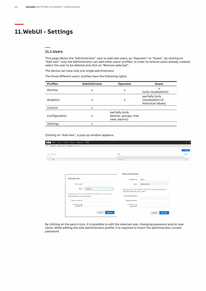
This page allows the “Administrator” user to add new users, as “Operator” or “Guest”, by clicking on “Add new”: only the Administrator can add other users’ profiles. In order to remove users already created, select the user to be deleted and click on “Remove selected”.
The device can have only one single administrator.
The three different users’ profiles have the following rights:
Profiles Administrator Operator Guest
Monitor x x x (only visualization)
Analytics x xpartially (only visualization of historical values)
Control x
Configuration xpartially (only devices, groups, tree view, alarms)
Settings x
Clicking on “Add new”, a pop-up window appears:
By clicking on the pencil-icon, it is possible to edit the selected user, changing password and/or user name. While editing the sole administrator profile, it is required to insert the administrator current password.
61SCU100 INSITE PRO M COMPACT USER MANUAL
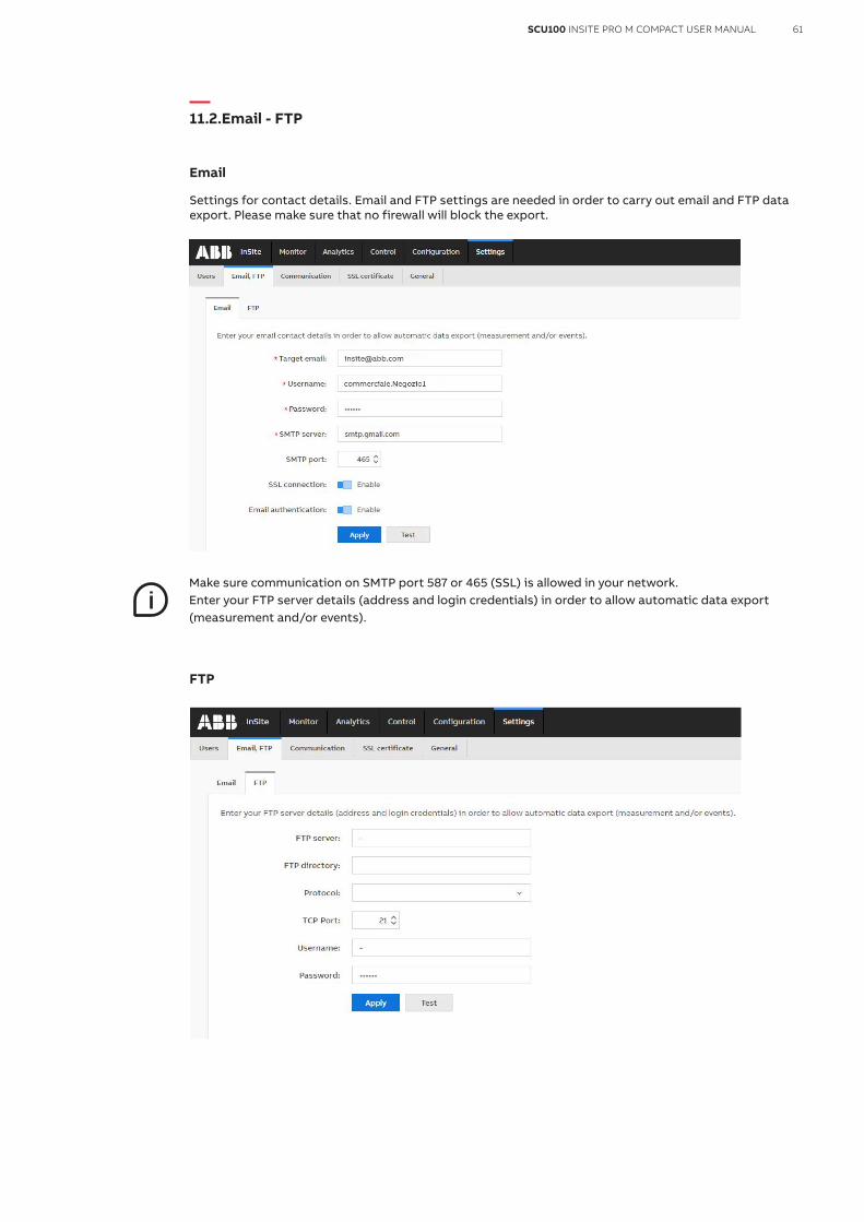
11.2.Email - FTP
Settings for contact details. Email and FTP settings are needed in order to carry out email and FTP data export. Please make sure that no firewall will block the export.
Make sure communication on SMTP port 587 or 465 (SSL) is allowed in your network.Enter your FTP server details (address and login credentials) in order to allow automatic data export(measurement and/or events).
FTP

62 SCU100 INSITE PRO M COMPACT USER MANUAL
11.3.Communication
IP
The following information have to be set to correctly have access to the user interface via IP:
IP Mode DHCP or static (Note: With DHCP you can find and define an IP address via the router by MAC address or device/host name - insite) The fallback IP address is: 192.168.1.200:8000
IP Address Current IP address of device or possibility to define a new IP address Subnet Mask Current Subnet Mask or possibility to define another Subnet Mask Gateway Current Gateway or possibility to define another Gateway Address DNS Server Default: 8.8.8.8 or possibility to define another DNS Server Host name Insite or possibility to define another Host Name MAC Address Shows the MAC Address of the device Apply By clicking the Apply pushbutton changes are stored
Inappropriate settings may cause the user interface to become inaccessible. In order to be able to restore device access to the fallback IP, please use the reset button.(The device is visible when DHCP is active).

63SCU100 INSITE PRO M COMPACT USER MANUAL
SNMP
To enable version 3 mark the v.3 checkbox, enter UDP port number (161 standard), authentication and privacy password (at least 8 signs), security name and engine ID (at least 12 characters in hexadecimal format). Port number must be 161 or greater than 1024 (the same as for versions v.1/2c).
Username and password perform the authentication needed to authenticate and encrypt the request to access data using SNMPv3. For the authentication the MD5 protocol is used and messages are additionally encrypted with the DES algorithm.
SNMP trap
Manage SNMP trap settings. Remember to enable “SNMP trap” in “Configuration - Alarms”.

64 SCU100 INSITE PRO M COMPACT USER MANUAL
Modbus
Here you can make changes to the MODBUS TCP and MODBUS RTU settings and download the .xlsx file of the register map associated to the firmware version onboard.
Modbus TCP settingsEnable Modbus TCP Enable Modbus TCP communicationTCP port Configure TCP port (502 standard)
Modbus RTU settingsModbus ID Select Modbus IDBaud rate Select baud rateParity Select parity setting: “None”, “Odd” or “Even”
For MODBUS RTU select “Master” to read data from meters connected to the 5th port, select “Slave” to read data from the SCU-100 control unit on the 5th port and data from meters connected to the 4th port.”

65SCU100 INSITE PRO M COMPACT USER MANUAL
VPN
SCU100 can be connected to VPN network through VPN server. The Open VPN client version 2.4.7 is used “AS IS” without any modifications and as a standalone component. The source code can be downloaded here:
https://swupdate.openvpn.org/community/releases/openvpn-2.4.7.tar.gz
https://github.com/OpenVPN/openvpn.git
To enable the VPN client it is needed to upload the configuration file (.ovpn format) in the “VPN configuration” page area: it has to include information about IP address of VPN server, client certificate and key. If proxy server is used in the target network, its address should be included in the configuration file.

66 SCU100 INSITE PRO M COMPACT USER MANUAL
After uploading it, a connection to the VPN server can be initialized by pressing “Start VPN client” button. When the connection will be successful the status will change to Connected, otherwise debugging of the connection will be possible by downloading the VPN log file.
VPN client can be started automatically during device startup: to activate it, use “Start VPN client during device startup” option. The VPN client will start only if the configuration file was previously uploaded to the device.
Rest API
Rest API allows user to get online/historical values directly from Control Unit without accessing to the WebUI. It can be enabled by administrator in this section: to access data through Rest API an authorization token has to be provided in Authorization header in every request. The token has to be generated in this page.
The highest number that can be get properly via Rest API is 2⁵³-1 (9007199254740991)
Available Rest Api endpoints:
GET: /api/gateway/systemInformation
Endpoint returns system information which can be used for diagnosis purpose. A request has to be sent with Authorization header e.g.:
Authorization: 4936258d59b4e00df81f73fab2a0214c
Response example:
{ “ip”: “192.168.1.200”, “hostname”: “insite”, “softwareVersion”: “1.1.0”, “deviceTime”: 1593173477, “voltageL1”: 242.08}

67SCU100 INSITE PRO M COMPACT USER MANUAL
GET /api/gateway/metadata
Endpoint returns system devices metadata which contains all configured devices with available registers. A request has to be sent
with Authorization header e.g.:
Authorization: 4936258d59b4e00df81f73fab2a0214c
JSON body reply:
{
“ip”: “192.168.1.200”,
“id”: “insite”,
“modbus_rtu_devices”: [
{
“modbus_id”: 1,
“name”: “Meter 1”,
“registers”: [
{
“cu_register_address”: 37638,
“description”: “Active import L1”,
“data_type”: “Unsigned integer”,
“size”: 4,
“byte_order”: “Big-endian”,
“resolution”: 30,
“multiplier”: 0.01,
“rest_api_online”: true,
“rest_api_historical”: true,
“unit”: “V”
},
{
“cu_register_address”: 37746,
“description”: “Active import total”,
“data_type”: “Unsigned integer”,
“size”: 2,
“byte_order”: “Big-endian”,
“resolution”: 10,
“multiplier”: 0.1,
“rest_api_online”: true,
“rest_api_historical”: true,
“unit”: “V”
}]
}],
“modbus_tcp_devices”: [
{
“ip”: “192.168.1.200”,
“modbus_id”: null,
“name”: “Device 1”,
“registers”: [
{

68 SCU100 INSITE PRO M COMPACT USER MANUAL
“address”: 37638,
“data_type”: “Unsigned integer”,
“size”: 4,
“byte_order”: “Big-endian”,
“resolution”: 30,
“multiplier”: 0.01,
“rest_api_online”: true,
“rest_api_historical”: true
},
{
“address”: 37638,
“data_type”: “Unsigned integer”,
“size”: 4,
“byte_order”: “Big-endian”,
“resolution”: 30,
“multiplier”: 0.01,
“rest_api_online”: true,
“rest_api_historical”: true
}]
}],
“current_sensors”: [
{
“modbus_id”: null,
“name”: “Current sensor 1”,
“serial_number”: “72363327058420020”,
“registers”: [
{
“cu_register_address”: 0,
“register_description”: “TRMS value of Sensor 1”,
“data_type”: “unsigned”,
“size”: 1,
“unit”: “A”,
“rest_api_online”: true,
“rest_api_historical”: true
},
{
“cu_register_address”: 256,
“register_description”: “AC value of Sensor 1”,
“data_type”: “unsigned”,
“size”: 1,
“unit”: “A”,
“rest_api_online”: true,
“rest_api_historical”: true
}]
}]
}

69SCU100 INSITE PRO M COMPACT USER MANUAL
POST: /api/gateway/data
The endpoint allows to get data from control unit: available online and historical values can be read from the Insite_register_map.xlsx file in tabs SCU100 mains and sensors and SCU100 meters, IOs, system view. Variables are identified by Modbus register address and have to be provided in a JSON body of a POST request.
Below partial extracts of the .xlsx file as an example:
Following variables have to be provided in the JSON body:
• “data”: list of objects with identifiers for requested data. The data object has to include: ° “addresses”: list of Modbus addresses for requested control unit variables ° “type”: data type (“online” or “historical”). If historical data is selected then “begin_timestamp” and
“end_timestamp” have to be provided.
As the reply returned is JSON with following variables:
• “ip”: IP address of the control unit• “id”: the hostname of the control unit• “data”: list of objects with available control unit data. Each object has “timestamp” and “values”
identifiers. For online data returned is single object with current timestamp. For historical data returned is a list of objects with timestamps available for selected time range. In the “value” provided are available registers and values.

70 SCU100 INSITE PRO M COMPACT USER MANUAL
Examples
Reading online data
Authorization header: 4936258d59b4e00df81f73fab2a0214c
JSON body request:
{ “data”: [ { “protocol”: “rtu”, “addresses”:[36866, 36868], “type”: “online” } ]}
JSON body reply:{ “ip”: “192.168.1.200”, “id”: “insite”, “data”: [ { “timestamp”: 1593174314, “values”: { “36866”: 242.32, “36868”: 241.68
} } ]}
Reading historical data
Authorization header: 4936258d59b4e00df81f73fab2a0214c
JSON body request:
{ “data”: [ { “protocol”: “rtu”, “addresses”:[36866], “type”: “historical”, “begin_timestamp”: 1593174621, “end_timestamp”: 1593174721 } ]}
JSON body reply:{ “ip”: “192.168.1.200”, “id”: “insite”, “data”: [ { “timestamp”: 1593174720, “values”: { “36866”: 242.16 } }, { “timestamp”: 1593174710, “values”: { “36866”: 242.14 } } ]}

71SCU100 INSITE PRO M COMPACT USER MANUAL
Mixed request for online and historical data
Requested data can be mixed (online with historical or multiple historical time ranges) e.g:
{ “data”: [ { “_comment”: “Query multiple registers for online data”, “protocol”: “rtu”, “addresses”: [36866, 36868], “type”: “online” }, { “_comment”: “Query multiple registers for historical data”, “protocol”: “rtu”, “addresses”: [36866, 36868], “type”: “historical”, “begin_timestamp”: 1593586022, “end_timestamp”: 1593589022 }, { “_comment”: “Query for other time range”, “protocol”: “rtu”, “addresses”: [36866, 36868], “type”: “historical”, “begin_timestamp”: 1594023345, “end_timestamp”: 1594022345 } ]}
JSON body reply:
{ “ip”: “10.3.101.49” “id”: “insite”, “data”: [ { “timestamp”: 1594022797, “values”: { “36866”: 234.56, “36868”: 234.82 } }, { “timestamp”: 1593588600, “values”: { “36866”: 233.86, “36868”: 234.1 } }, { “timestamp”: 1593587700, “values”: { “36866”: 234.06, “36868”: 234.31 } }, { “timestamp”: 1593586800, “values”: { “36866”: 233.93, “36868”: 234.18 } } ] }

72 SCU100 INSITE PRO M COMPACT USER MANUAL
Cloud gateway client
SCU100 can be connected to cloud gateway client. To enable the cloud gateway client is needed to upload the certificate files, in the “Client configuration” page area: it has to include information about port and host, cloud gateway certificate, client certificate and key.
After uploading it, a connection to the cloud gateway client can be initialized by pressing “Start client” button.
When the connection will be successful the status will change to Authorized, otherwise debugging of the connection will be possible by downloading the cloud gateway client log file.
It is possible to connect multiple SCU100 to same cloud gateway client. Each SCU100 should have a unique hostname.
Cloud gateway client can be started automatically during device startup: to activate it, use “Start during device startup” option. The cloud gateway client will start only if the configuration files were previously uploaded to the device.

73SCU100 INSITE PRO M COMPACT USER MANUAL
Minergie API
SCU100 can periodically send selected data to Minergie Monitoring through Minergie API. Configured data will be send automatically every day (SCU100 time 01:00 UTC), samples with resolution 15min from previous day will be send.
To enable the Minergie API correct credentials must be set:
With correct credentials it will be possible to add new Minergie object by using UUID

74 SCU100 INSITE PRO M COMPACT USER MANUAL
Then the data serie assigned to the Minergie object can be added
pnLabel, cLabel, dLabel are read and filled automatically from Minergie API and filled when ID is selected
It is possible to assign one value to one data serie. Values can be selected based on type: Control Unit/Meters/Modbus RTU Devices/Modbus TCP Slaves/Groups.
To check if configuration is correct “send test data” button can be used. Up to 10 measurements for each data serie assigned to Minergie object will be send to Minergie API for test purpose (it will not be saved or stored in Minergie). The result of test will be presented in modal as JSON response from Minergie API.

75SCU100 INSITE PRO M COMPACT USER MANUAL
11.4.SSL certificate
In this section it is possible to upload or generate a .pem file containing a private key and a public certificate in order to provide a secure connection via the web browser.
Upload
It is possible to browse, upload or download the currently in place certificate.
For this purpose, please drag and drop the .pem file to the browser or click to browse, then push the upload button and wait for the uploading to finish. After a successful uploading process, the web server reboots.
It is also possible to download a currently used certificate by clicking download certificate.
Generate
In order to generate a SSL certificate, following configurations must be considered:
IP address Indicates your currently configured IP address on the device
Subnet mask Indicates your currently configured subnet mask on the device
Gateway Indicates your currently configured gateway on the device
Select whole subnet If checked, you can generate a certificate for the whole subnet. The minimal subnet mask is 255.255.252.0.
Domain / IP You can manually type in IP addresses and insert them to the table with the Add button
After configuration of domains/IP addresses table, please click the Generate button. When the generating process finishes, the web server reboots and due to a certificate change the page has to be reloaded manually.
Follow the passages reported below to import the downloaded certificate into your web browser.

76 SCU100 INSITE PRO M COMPACT USER MANUAL
Certificate Import Wizard
It is necessary at first to open the Certificate Import Wizard according to the browser you are using and then to install the certificate.
11.5.Views
This page allows to change system start page.
Select the page and (if it is enabled) subpage from dropdowns and then click “Apply”. Selected page from now will be your home page.
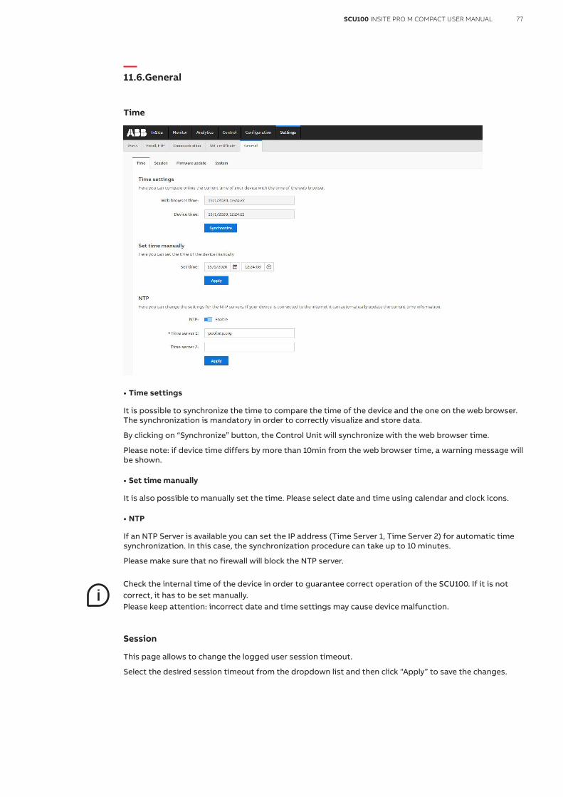
77SCU100 INSITE PRO M COMPACT USER MANUAL
11.6.General
Time
• Time settings
It is possible to synchronize the time to compare the time of the device and the one on the web browser. The synchronization is mandatory in order to correctly visualize and store data.
By clicking on “Synchronize” button, the Control Unit will synchronize with the web browser time.
Please note: if device time differs by more than 10min from the web browser time, a warning message will be shown.
• Set time manually
It is also possible to manually set the time. Please select date and time using calendar and clock icons.
• NTP
If an NTP Server is available you can set the IP address (Time Server 1, Time Server 2) for automatic time synchronization. In this case, the synchronization procedure can take up to 10 minutes.
Please make sure that no firewall will block the NTP server.
Check the internal time of the device in order to guarantee correct operation of the SCU100. If it is notcorrect, it has to be set manually.Please keep attention: incorrect date and time settings may cause device malfunction.
Session
This page allows to change the logged user session timeout.
Select the desired session timeout from the dropdown list and then click “Apply” to save the changes.

78 SCU100 INSITE PRO M COMPACT USER MANUAL
Firmware update
Using this menu you can update the firmware of the control unit.
It is highly recommended to update the firmware to the latest version for security and functionality reasons. Please check the ABB website for current SW revision and to download the latest version of the firmware.
After browsing the downloaded file, please use the “Update file” button to submit the new firmware to the device. In addition, you can find the installed firmware version and the serial number of the device at the bottom of the web page.

79SCU100 INSITE PRO M COMPACT USER MANUAL
System
In this section it is possible to carry out a system reset (to restart the device with the current settings), to restore the default settings and to carry out a safe shutdown. After any change in the settings we recommend you to do a safe shutdown. To do so, push the ‘’Shutdown’’ button. If the Status LED is shining green without flashing, and if the network LED is out, you can turn off the power supply. For starting the device, turn on the power supply. The SCU100 will automatically start.

80 SCU100 INSITE PRO M COMPACT USER MANUAL
12.WebUI – Monitor
12.1.Dashboard
“In the Dashboard section it is possible to create and customize different dashboards in order to have an immediate and easily visible summary of the desired set of measurement data and system information.
It’s possible to create up to 10 different dashboards: to create a new one click on “+” button aside the dashboard tabs, define a name and select the size (“Auto” or “Custom”). In every moment it is possible to change the size parameters (number and dimensions of columns and rows) by selecting the desired dashboard and clicking on the setting icon on the right side of the screen. To delete it click on the bin icon.

81SCU100 INSITE PRO M COMPACT USER MANUAL
The dashboard interface is based on pre-defined widget logic. To add a new widget to the dashboard click on “Add widget”.
ButtonsAdd
WidgetSelect the widget among pre-defined categories: “Instantaneous Values”, “Device status”, “Energy”, “Alarms log”, “Device time” and “Firmware version”
Data sourceSelect the data source of the data to display. “Local Control Unit” to display data from current Control Unit, “Slave Control Unit” to display data from previously added “Slave Control Unit
Title Type the title of the widgetType Select the source of information (device type)Display Select the way to display data: “Chart – linear” or “Table”Y axis Select if the Y axis should be autoscaled or set min/max values manuallyView Select the parameter to be displayed
Once the widget has been created it is possible to move it to the desired area of the dashboard and modify its size.”

82 SCU100 INSITE PRO M COMPACT USER MANUAL
12.2.Real-time values
Control Unit
The “Real-time Values” section shows all measured values by control unit reporting the trend of the last 10s.
If no graph is visible, it is necessary to synchronize the device time with the “Set time manually” button in the Settings – General / Time menu.

83SCU100 INSITE PRO M COMPACT USER MANUAL
Current sensors
Here it is possible to visualize “Real-time values” for the current sensors.
Sensors have to be first assigned and configured (please refer to Configuration - Devices – Current sensors).
In case of DC sensor measurement, please refer to “Configuration - Devices – Current sensors” and configure “Phase” as DC and voltage setting in “Configuration-Devices-Control Unit”.Accordingly, when “DC” is displayed under “Phase”, DC current and active power values are displayed on this page.
Meters
Here it is possible to visualize “Real-time values” for the meters.
In the “Values” dropdown list it is possible to select the parameters accordingly with the “Meter” selected. Available values showed are: “Energy values”, “Instantaneous Values”, “Power Quality Values”, “Harmonics”, “Maximum Values”.

84 SCU100 INSITE PRO M COMPACT USER MANUAL
Inputs/Outputs
Here it is possible to visualize “Real-time values” for each digital channel of the I/O modules and connected meters. “Real-time values” are “Status” and “Counter”.
Only Administrator and Operator users are allowed to perform Reset of the counters
To monitor meter ports to Insite via Modbus, read registers with following description:
“Output X” (X – port number 1-4) – values 1/0 – on/off
“Input Current State X” (X – port number 1-4) – values 1/0 – on/off
“Input X Counter” (X – port number 1-4) – 4 registers = unit64 little endian byte swap
Modbus RTU Devices
In the “Values” dropdown list it is possible to select the parameters accordingly with the “ Modbus RTU Device” selected. Available values showed are: “Energy values”, “Instantaneous Values”, “Power Quality Values”,“Harmonics”, “Maximum Values”, ”Custom”
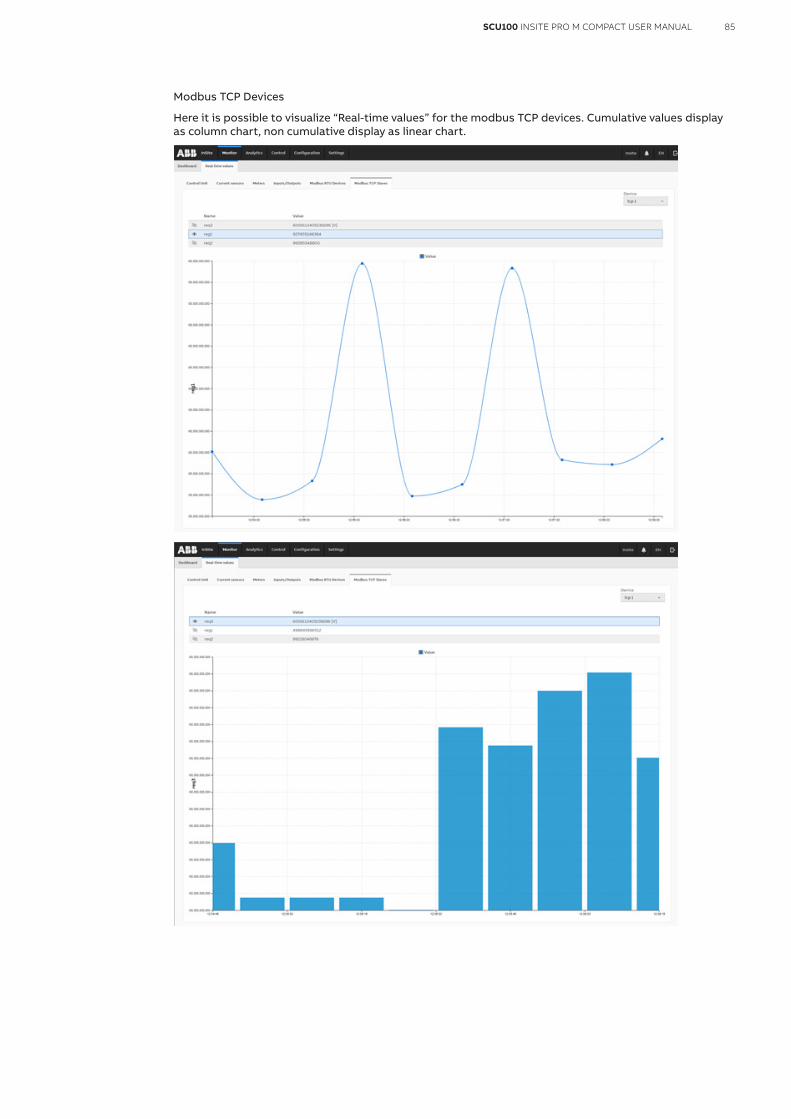
85SCU100 INSITE PRO M COMPACT USER MANUAL
Modbus TCP Devices
Here it is possible to visualize “Real-time values” for the modbus TCP devices. Cumulative values display as column chart, non cumulative display as linear chart.
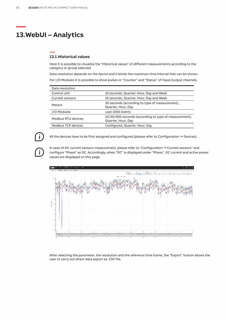
86 SCU100 INSITE PRO M COMPACT USER MANUAL
13.WebUI – Analytics
13.1.Historical values
Here it is possible to visualize the “Historical values” of different measurements according to the category or group selected.
Data resolution depends on the device and it binds the maximum time interval that can be shown.
For I/O Modules it is possible to show pulses or “Counter” and “Status” of input/output channels.
Data resolution Control unit 10 seconds, Quarter, Hour, Day and WeekCurrent sensors 10 seconds, Quarter, Hour, Day and Week
Meters 30 seconds (according to type of measurement), Quarter, Hour, Day
I/O Modules Last 1000 events
Modbus RTU devices 10/30/900 seconds (according to type of measurement), Quarter, Hour, Day
Modbus TCP devices Configured, Quarter, Hour, Day
All the devices have to be first assigned and configured (please refer to Configuration → Devices).
In case of DC current sensors measurement, please refer to “Configuration → Current sensors” and configure “Phase” as DC. Accordingly, when “DC” is displayed under “Phase”, DC current and active power values are displayed on this page.
After selecting the parameter, the resolution and the reference time frame, the “Export” button allows the user to carry out direct data export as .CSV file.

87SCU100 INSITE PRO M COMPACT USER MANUAL
13.2.Benchmark
Here it is possible to make comparisons between:
• Measurements of two different devices in the same time interval (By device)• Measurements of one single device in two different time intervals (By period)
As in “Historical values” the resolution depends on the device selected and binds the maximum time interval that can be shown.
13.3.Events log
Here it is possible to show all the events that occurred. Here the table is automatically refreshed every second and displays the 100 latest events. Scrolling the table, more events are loaded.
Rows can be sorted and/or filtered by clicking at headers and selecting desired value from drop-down lists.
Events must previously be set in the “Events” configuration menu.
Event status is updated automatically every second to obtain new events occurrences.
It is possible to visualize and export occurrences according to user-defined start and end date/time.

88 SCU100 INSITE PRO M COMPACT USER MANUAL
13.4.Alarms
Here it is possible to show all the alarms that occurred. Here the table is automatically refreshed every second and displays the 100 latest events. Scrolling the table, more alarms are loaded.
Rows can be sorted by clicking at headers.
Alarms must previously be set in the “Event” configuration.
It is possible to export occurrences of all or only acknowledged alarms.
It is possible to mark alarms as acknowledged.
The current number of not acknowledged alarms is displayed in the top bar of the WebUI.

89SCU100 INSITE PRO M COMPACT USER MANUAL
13.5.Data export
In order to carry out data export via email and/or FTP, contact data for email and FTP server need to be configured (see Settings → Email, FTP). Here you can export and/or download measurement and/or historical alarms of the configured devices and edit data export settings:
Settings
Data Select type of data: “Total energy”, “Energy per phase”, “Instantaneous Values”, “Harmonics”, “Custom values”.
Export last For Meters/Modbus RTU Devices select no. of days for exported data
Frequency It indicates how often you would like to receive notifications.
Export time Time, when the data shall be exported.
Export option Two options can be selected: “One-time export” and “Perodic exporting”.
Export via email If selected, mains and branches values will be exported as csv file by email. Please note that email configuration is needed.
Export via FTP If selected, mains and branches values will be exported as csv file by FTP. Please note that FTP configuration is needed.
Data stack Export data stack of last 1000 (or selected no.days) of configured, 10 sec, 30sec, 15 minutes, hour, day and week values depending on selected type of device.
Historical events If selected, historical events wil be exported as .csv file via FTP according to the defined event log size.
Several files can be generated depending on selected Data/Data stacks
For Meters/Modbus RTU Devices each file for each selected device/data/data stack. Also files are splitted for 30s samples for Meters (maximum 30days with 30s samples in single file), for RTU Devices (30s samples same as for meters, 10s samples – maximum 10 days with 30s samples in single file)
Exporting large number of days for low resolution sample (10s/30s) can take several minutes.

90 SCU100 INSITE PRO M COMPACT USER MANUAL
14.WebUI – Control
14.1.Control
Here it is possible to change the status (open/close) of each single output port of the active modules and meters. A confirmation message is shown before completing the action.
Only Administrator user is allowed to perform control of devices
To control meter output ports to Insite via Modbus, write registers with following description:
“Output X” (X – port number 1-4) – values 1/0 – on/off

91SCU100 INSITE PRO M COMPACT USER MANUAL
15.Modbus TCP/RTU communication interface
15.1.Control unit mains and sensors readings
Introducing MODBUS protocol
The Modbus serial line protocol is a Master-Slaves protocol. This means that only one master and one or more slave nodes (max. 247) can be connected to the same serial bus. A Modbus communication is always initiated by the master and there is only one transaction at the same time.
For further information: www.modbus.org
If you intend to use Modbus, you should only use ASCII characters in the Web UI. Unicode characters will not be displayed in Modbus.
Modbus frame description (RTU mode)
Address PDU Frame Error CheckAddress Field Function Code Data CRC1 byte 1 byte 0 - 252 bytes 2 bytes CRCL, CRCH
ADU Application DataPDU Protocol Data UnitStopbit 1Address Field contains the slave addressFunction Code: indicates what kind of action to performData contains request and response parametersCRC contains the value generated by the cyclic redundancy check
(standard CRC-16 defined by CCITT)
The maximum size for a Modbus RTU frame is 256 bytes.
In RTU mode, message frames are separated by a silent interval of at least 3.5 character times. The entire message frame must be transmitted as a continuous string of characters. If a silent interval of more than 1.5 character times occurs between two characters, the message frame is declared as incomplete and should be discarded by the receiver.
Modbus Data Encoding Modbus uses a big-endian allocation for addresses and data items. This means that, when a numerical quantity larger than a single byte is transmitted, the most significant byte is sent first. Example: 1234h → first 12h then 34h

92 SCU100 INSITE PRO M COMPACT USER MANUAL
Communication to InSite
Physical Interface RS-485
To communicate with the InSite from an upper system, all devices (masters & slaves) must have the same data rate and data format. These settings are defined over the Web UI, as described in the dedicated chapter.
Parameter Values Default ValuesData rate 2400, 4800, 9600, 19200, 38400, 57600,
115200 Bit/s19200 Bit/s
Data format even parity, odd parity, without parity even parity
This interface (port 5) can also be considered as an additional port for meters connection: to read them you have to select “Master” on WebUI configuration tab (Settings->Communication->Modbus).
Otherwise, if this 5th port interface is used to read data from the SCU-100 control unit and data from meters connected to the 4th port select “Slave”.
Control unit’s MODBUS-ID
E245
CMS-700Control UnitEnergy Monitor 96
Status
Network
Reset
A BRS485
CMC-BUSLAN
Fallback IP 169.168.42.42;admin, adminL1/Supply L2L3
N
CTl1
A B
12
3
A B
l2
A B
l3
A B
l4/N
A B
E245
CMS-700Control UnitEnergy Monitor 96
Status
Network
Reset
A BRS485
CMC-BUSLAN
Fallback IP 169.168.42.42;admin, adminL1/Supply L2L3
N
CTl1
A B
12
3
A B
l2
A B
l3
A B
l4/N
A B
E245
CMS-700Control UnitEnergy Monitor 96
Status
Network
Reset
A BRS485
CMC-BUSLAN
Fallback IP 169.168.42.42;admin, adminL1/Supply L2L3
N
CTl1
A B
12
3
A B
l2
A B
l3
A B
l4/N
A B
E245
CMS-700Control UnitEnergy Monitor 96
Status
Network
Reset
A BRS485
CMC-BUSLAN
Fallback IP 169.168.42.42;admin, adminL1/Supply L2L3
N
CTl1
A B
12
3
A B
l2
A B
l3
A B
l4/N
A B
E245
CMS-700Control UnitEnergy Monitor 96
Status
Network
Reset
A BRS485
CMC-BUSLAN
Fallback IP 169.168.42.42;admin, adminL1/Supply L2L3
N
CTl1
A B
12
3
A B
l2
A B
l3
A B
l4/N
A B
You can connect up to 247 control units to one Modbus RTU line. Each control unit must have a unique Modbus ID (address).
Function Code
• Read operation on registers with access code “R” or “RW” is defined by function 03h “Read Holding Registers”
• Write operation on registers with access code “W” or “RW” is defined by function 06h “Write Single Register”
Do not apply functions other than those specified.
Modbus RTU
InSite systems

93SCU100 INSITE PRO M COMPACT USER MANUAL
Error Codes
Modbus protocol defines a common way of error reporting. Every request (read or write) sent in unicast mode is expected to return a value in packet of the same structure. In case of a message delivery error (not a CRC problem but a message execution problem), the generated response contains a function code with MSB (80h) set and a single byte representing the error code, called “exception code”.
The following default exception codes are available:
Code Name Description
01h Illegal function Function is not supported
02h Illegal data address Register address is out of control unit’s range, or trying to write into a read only register
03h Illegal data value Value is out of range
04h Slave device failure Unrecoverable error occurred while the control unit was attempting to perform the requested action, for example, time-out
06h Slave device busy Control unit is currently in User Interface Configuration Mode. Unable to execute the requested action .
Data and Control Registers
A register is always a two-byte (16-bit) value, which can be interpreted as either signed or unsigned values or which has a special format.
In case of data represented in more than one register the concatenated registers will contain information with MSB in the lowest address and LSB in the highest address within concatenated addresses.
Do not use registers other than those specified.
Format of one-word register for current values
unsigned = 16-bit unsigned integer notation, resolution 0.01 A
signed = 6-bit signed integer notation, resolution 0.01 A
0000h…7FEFh = 0.00 … 327.51 A
8000h…FFFFh = -327.66 … -0.01 A
Values with special meanings
Special values (hex) Special values (dec) Meaning
7FF0 32'752 Data pending, acquisition in progress
7FF1 … 7FFB 32'753 … 32'763 Reserved
7FFC 32'764 The sensor is known but not accessible at the moment
7FFD 32'765 Data type TrueRMS / AC / DC is disabled
7FFE 32'766 Overload (beyond full range)
7FFF 32'767 Forbidden (no sensor with ID xx)
Format of double-word register for branch power and energy values
unsigned = 32-bit unsigned integer notation,
signed = 32-bit signed integer notation

94 SCU100 INSITE PRO M COMPACT USER MANUAL
Values with special meanings: Calculated branch power and energy values
Special values (hex) Special values (dec) Meaning
FFFF 7FF0 4'294'934'512 Data pending, acquisition in progress
FFFF 7FF1 … FFFF 7FFB 4'294'934'513 … 4'294'934'523 Reserved
FFFF 7FFC 4'294'934'524 The sensor is known but not accessible at the moment
FFFF 7FFD 4'294'934'525 Data type TrueRMS / AC / DC is disabled
FFFF 7FFE 4'294'934'526 Overload (beyond full range)
FFFF 7FFE 4'294'934'527 Forbidden (no sensor with ID xx)
bit mask = bit-wise operation
special = as specified in register description
Access
R (03) = Register can be read by function 03
W (06) = Register can be written by function 06
Trigger hold, reset min and max values
Write operation on this register triggers the hold measurement of all sensors, and/or resets
the min and max values of all sensors.
Address (hex)
Address (dec)
Word (16-bit)
Description Resolution and unit
Format 1 Access 2
3010 12'304 1 Trigger hold, reset min and max values
Bit Mask W (06)
The commands have the following bit format: 0000 0000 000T 000R
• T 1 = Trigger hold measurement• R 1 = Reset min and max values
The Command will be acknowledged by the response message on Modbus and by a short message.

95SCU100 INSITE PRO M COMPACT USER MANUAL
Show sensor
“Write operation on this register starts or stops fast LED blinking of one specified sensor for diagnostic purpose.”
Address (hex)
Address (dec)
Word (16-bit)
Description Resolution and unit
Format 1 Access 2
3011 12'305 1 Show Sensor Special W (06)
Start / stop command is in the following bit format position: 000S 0000 0CCC CCCC
• C Sensor ID• S 1 = Starts fast LED blinking
0 = Stops fast LED blinking
Data written has to specify a known sensor ID.
Example: 0x1017 means “Start fast LED blinking of sensor with ID 23”
When sensor is addressed correctly, common response will follow
When the sensor ID is not used in the system, and exception response with Modbus exception code 03h “Illegal data value” will follow. (If fast LED blinking was already active, it will be stopped)
Return to normal display content is possible by sending the stop command.

96 SCU100 INSITE PRO M COMPACT USER MANUAL
Polarity of sensors (for DC currents)
These registers contain the configured nominal current value and the DC polarity information of each sensor with following bit format:
000P RRRR RRRR RRRR
• R Reserved for future use• P DC polarity information 0 = direct, DC current coming out of the cone is displayed positive
1 = reverse, DC current coming out of the cone is displayed negative This setting has influence on all DC values of the specified sensor.
• 0000h DC polarity direct • 1000h DC polarity reverse
This data has to be set user while system configuration. Factory default value is 0000h.
Serial number (SID), version and bus line of sensors
These registers contain system information about each sensor.
This data has to be set user while system configuration. Factory default value is 0000h.
Serial number (SID), version and bus line of sensors
These registers contain system information about each sensor.
Offset Words Data
0h 4 Unique Serial Number (SID)
4h 2 HW version
6h 3 SW version
9h 1 Measurement Range (0.1A steps)
Ah 1 Enabled Data Types (as in InSite Bus Protocol defined)
Bh 4 Reserved
Fh 1 ID of internal bus line sensor is connected to 0: no sensor, 1: line 1, 2: line 2
• Each sensor has a unique serial number needed for setup procedure on internal InSite bus.• HW and SW version of sensor are readable for diagnosis purpose.• “ID of internal bus line” identifies the Control Unit’s internal bus line the sensor is connected to.
This data is not hold always in registers but will be prepared on read request.

97SCU100 INSITE PRO M COMPACT USER MANUAL
15.2.Meters
Insite pro M allows to connect up to 16 meters with RS-485 interface. Supported are ABB M4M, M2M, M1M, DMTME, IM300 and EQ meters with Modbus RTU communication protocol. Each meter can be assigned to Modbus ID from 1 to 16.
Proper meter support may depend on its firmware version. Please update the meter with latest firmware version before connecting it to control unit.
Data from meters are available on the control unit WebUI and using Modbus TCP or Modbus RTU protocol. When accessing through Modbus protocol, registers of each connected meter are mapped to control unit static register map. The map is attached in the Excel file in the tab cu insite:
External Modbus address
Slave Modbus ID
External Modbus data type
Category Quantity Registers
37062 1 Unsigned integer
Energies Ph/Tariff
Active import L1..L3, tar 1..8 96
37158 1 Unsigned integer
Energies Ph/Tariff
Active export L1..L3, tar 1..8 96
37254 1 Unsigned integer
Energies Ph/Tariff
Reactive import L1..L3, tar 1..8 96
37350 1 Unsigned integer
Energies Ph/Tariff
Reactive export L1..L3, tar 1..8 96
37446 1 Unsigned integer
Energies Ph/Tariff
Apparent import L1..L3, tar 1..8
96
37542 1 Unsigned integer
Energies Ph/Tariff
Apparent export L1..L3, tar 1..8 96
37638 1 Unsigned integer
Energies phases
Active import L1 4
37642 1 Unsigned integer
Energies phases
Active import L2 4
37650 1 Unsigned integer
Energies phases
Active export L1 4
Control unit register map provides information about address for each quantity, number of registers on which it is presented and data type. The details for each register depend from meter type which is connected to specific slave Modbus ID and are available in the Excel file in the tab meters.
E.g. EQ meter is connected to Modbus ID 1. The Active import L1 variable is available on the control unit register address 37638. It can be read from the meters tab in Excel file that the unit for this register is kWh, register is not writable, quantity is refreshed every 30 seconds for Modbus and WebUI and stored every 900 seconds on the internal flash memory. The multiplier for this register is 0.01. To retrieve this quantity the EQ meter Modbus register 5460 is queried.
Category Quantity External Modbus data type
External Modbus registers
Unit Writable EQ meter registers
M4M address
Energies phases
Active import L1
Unsigned integer
0 kWh 4 5460
Energies phases
Active import L2
Unsigned integer
0 kWh 4 5464
Energies phases
Active import L3
Unsigned integer
0 kWh 4 5468
M4M multiplier
M2M address
M2M multiplier
EQ meter Modbus
EQ meter webserver
EQ meter storage
EQ meter address
EQ meter multiplier
0,01 1074 0,1 30 30 900 5460 0,01
0,01 1076 0,1 30 30 900 5464 0,01
0,01 1078 0,1 30 30 900 5468 0,01

98 SCU100 INSITE PRO M COMPACT USER MANUAL
If the register address for quantity is 0, then it means that meter is not queried for this value and it is calculated by control unit, using other available data.
If frequency for data refresh for Modbus, webserver or storage is 0, then data are requested/stored on demand (when changed).
More details about each quantity is available in user manual for specific meter and can be accessed using meter address from meters tab in the Excel file.
15.3.I/O modules
Insite pro M allows to connect up to 24 I/O modules. I/O modules can be assigned to Modbus ID from 97 to 120 and can be read/control using web UI and Modbus TCP/RTU protocols. Registers of each connected I/O module are statically mapped in the control unit register map available in the attached Excel file in the tab cu insite.
External Modbus address
Slave Modbus ID
External Modbus data type
Category Quantity Registers
58502 97 Unsigned integer IO module I/O configuration 1
58503 97 Unsigned integer IO module Pulse Counter Port 0 2
58505 97 Unsigned integer IO module Pulse Counter Port 1 2
58507 97 Unsigned integer IO module Pulse Counter Port 2 2
58509 97 Unsigned integer IO module Pulse Counter Port 3 2
58511 97 Unsigned integer IO module Status Contacts Port 0 1
58512 97 Unsigned integer IO module Status Contacts Port 1 1
58513 97 Unsigned integer IO module Status Contacts Port 2 1
58514 97 Unsigned integer IO module Status Contacts Port 3 1
Control unit register map, provides information about address for each quantity, number of registers on which it is presented and data type. The details for each registers are available in the Excel file in the tab I/O modules.
E.g. Output module is connected to Modbus ID 97. Status of contacts can be read from control unit register address 58511, size of the quantity is 1 register and data type is unsigned integer. Additionally it can be read from Excel file tab I/O modules that this register is writable and is and data available by Modbus or WebUI is refreshed every 1 second.
Category Quantity External Modbus data type
IO module address
External Modbus registers
IO module I/O configuration Unsigned integer
40 1
IO module Pulse Counter Port 0
Unsigned integer
50 2
IO module Pulse Counter Port 1
Unsigned integer
52 2
IO module Pulse Counter Port 2
Unsigned integer
54 2
IO module Pulse Counter Port 3
Unsigned integer
56 2
IO module Status Contacts Port 0
Unsigned integer
0 1
IO module Status Contacts Port 1
Unsigned integer
1 1
IO module Status Contacts Port 2
Unsigned integer
2 1
IO module Status Contacts Port 3
Unsigned integer
3 1

99SCU100 INSITE PRO M COMPACT USER MANUAL
Writable IO module Modbus
IO module webserver
IO module storage
External Modbus
x 0 0 0 1
1 1 1 1
1 1 1 1
1 1 1 1
1 1 1 1
x 1 1 1 1
x 1 1 1 1
x 1 1 1 1
x 1 1 1 1
15.4. External Modbus alarm registers for IOM
There are five alarm registers assigned to single IO module in the external Modbus registers map.
Alarm status Port 0 1
Alarm status Port 1 1
Alarm status Port 2 1
Alarm status Port 3 1
Alarm status module 1
Possible alarm values for Alarm status Port x registers are:
NO_EVENT = 0CROSS_UP = 1CROSS_DOWN = 2STATUS_CHANGE = 3
Possible alarm values for Alarm status module register are:
NO_EVENT = 0COMMUNICATION_FAIL = 4COMMUNICATION_RESTORE = 5
Alarms are cleared when master/slave configuration for Modbus RTU is changed. Once value is written to the register it is maintained until next alarm occurs; this next alarm overwrites register value.

100 SCU100 INSITE PRO M COMPACT USER MANUAL
16.Simple Network Management Protocol – SNMP
Reading of values
The protocol is applicable for the following items:
• Mains parameters• Calculated values• Measured branch current valuesIf you need to record the values of a subsequent measurement, you have to use the SNMP protocol and the external storage system. Historical data in the device is stored with a resolution of 10s.
Special values for error codes
In a fail situation you get error codes. Values with special meanings for branch current values (one word, 16bit) are summarized below.
Special values (hex) Special values (dec)
Meaning
7FF0 32'752 Data pending, acquisition in progress
7FF1 … 7FFB 32'753 … 32'763 Reserved
7FFC 32'764 The sensor is known but not accessible at the moment
7FFD 32'765 Data type TrueRMS / AC / DC is disabled
7FFE 32'766 Overload (beyond full range)
7FFE 32'767 Forbidden (no sensor with ID xx)

101SCU100 INSITE PRO M COMPACT USER MANUAL
Values with special meanings for calculated branch power and energy values (double word, 32bit) are reported below:
Special values (hex) Special values (dec)
Meaning
7FF0 32'752 Data pending, acquisition in progress
7FF1 … 7FFB 32'753 … 32'763 Reserved
7FFC 32'764 The sensor is known but not accessible at the moment
7FFD 32'765 Data type TrueRMS / AC / DC is disabled
7FFE 32'766 Overload (beyond full range)
7FFE 32'767 Forbidden (no sensor with ID xx)
MIB
To retrieve data from the device using the SNMP object identifier (OID), the MIB file downloaded from the webui should be copied to the correct location on the client station. The SNMPv2-MIB is distributed with the net-snmp package.
The NET-SNMP package can be downloaded from the link:
https://sourceforge.net/projects/net-snmp/files/net-snmp/5.8/
In the downloaded zip package, MIB files are available in directory: net-snmp-5.8.zip\net-snmp-5.8\mibs\
The information obout system is available in the SNMPv2-MIB and is presented in Table 1.
snmpwalk -v2c -ccommunity ip_address:port SNMPv2-MIB::system
SNMPv2-MIB::sysDescr.0 = STRING: InSite pro M
SNMPv2-MIB::sysObjectID.0 = OID: SNMPv2-SMI::enterprises.8072.3.2.10
SNMPv2-MIB::sysUpTime.0 = Timeticks: (6242832) 17:20:28.32
SNMPv2-MIB::sysName.0 = STRING: InSite
SNMPv2-MIB::sysLocation.0 = TRING: Location of the InSite pro M Control Unit
SNMPv2-MIB::sysServices.0 = INTEGER: 72
To print all SNMP variables available in SCU-100:
# snmpwalk -v3 -e engine_id -u security_name -a MD5 -A password -x DES -X password -l authPriv 192.168.1.200:161 INSITE::insite
INSITE::tRMSsens1 = INTEGER: 0
INSITE::tRMSsens2 = INTEGER: 0

102 SCU100 INSITE PRO M COMPACT USER MANUAL
16.1.SNMP objects
SNMP Object Identifier SMI Data Type SMI Data Type Example Value
SNMPv2-MIB::sysDescr.0 STRING ABBCircuitMeasurementSy stemInsite
SNMPv2-MIB::sysUpTime.0 Timeticks (117750) 0:19:37.50
SNMPv2-MIB::sysName.0 STRING CMS700
SNMPv2-MIB::sysLocation.0 STRING Location of the Insite
SNMPv2-MIB::sysServices.0 INTEGER 72
All objects are read-only.
To return all TRMSsens values in a single snmpget request, please use the “TRMSsensAll” variable name.
Examples
Some examples of usage on the Linux system using snmpget program from NET-SNMP
package are presented below. The ‘#’ is the Linux command prompt.
SNMPv1
# snmpget -v1 -c community_name 192.168.1.200:161 SNMPv2-MIB::sysUpTime.0
SNMPv2-MIB::sysUpTime.0 = Timeticks: (38471) 0:06:24.71
SNMPv2c
# snmpwalk -v2c -c community_name 192.168.1.200:161 SNMPv2-MIB::system
SNMPv2-MIB::sysDescr.0 = STRING: InSite pro M
SNMPv2-MIB::sysObjectID.0 = OID: SNMPv2-SMI::enterprises.8072.3.2.10
SNMPv2-MIB::sysUpTime.0 = Timeticks: (6353707) 17:38:57.07
SNMPv2-MIB::sysName.0 = STRING: InSite
SNMPv2-MIB::sysLocation.0 = STRING: Location of the InSite pro M Control Unit
SNMPv2-MIB::sysServices.0 = INTEGER: 72
# snmpget -v2c -c community_name 192.168.1.200:161 INSITE::tRMSsens1
INSITE::tRMSsens1 = INTEGER: 32767
# snmpwalk -v2c -c community_name 192.168.1.200:161 INSITE::tRMSsens
INSITE::tRMSsens1 = INTEGER: 32767
INSITE::tRMSsens2 = INTEGER: 32767
INSITE::tRMSsens3 = INTEGER: 32767
INSITE::tRMSsens4 = INTEGER: 32767
INSITE::tRMSsens5 = INTEGER: 32767
INSITE::tRMSsens6 = INTEGER: 32767
INSITE::tRMSsens7 = INTEGER: 32767
INSITE::tRMSsens8 = INTEGER: 32767
INSITE::tRMSsens9 = INTEGER: 32767
INSITE::tRMSsens10 = INTEGER: 32767
INSITE::tRMSsens11 = INTEGER: 32767
INSITE::tRMSsens12 = INTEGER: 32767
INSITE::tRMSsens13 = INTEGER: 32767

103SCU100 INSITE PRO M COMPACT USER MANUAL
SNMPv3
# snmpget -v3 -e engine_id -u security_name -a MD5 -A password -x DES -X password -l authPriv 192.168.1.200:161 INSITE::tRMSsens1
INSITE::tRMSsens1 = INTEGER: 32767
# snmpgetnext -v3 -e engine_id -u security_name -a MD5 -A password -x DES -X password -l authPriv 192.168.1.200:161 INSITE::tRMSsens1
INSITE::tRMSsens2 = INTEGER: 32767
# snmpwalk -v3 -e engine_id -u security_name -a MD5 -A password -x DES -X password -l authPriv 192.168.1.200:161 INSITE::tRMSsens
INSITE::tRMSsens1 = INTEGER: 32767
INSITE::tRMSsens2 = INTEGER: 32767
INSITE::tRMSsens3 = INTEGER: 32767
INSITE::tRMSsens4 = INTEGER: 32767
INSITE::tRMSsens5 = INTEGER: 32767
INSITE::tRMSsens6 = INTEGER: 32767
INSITE::tRMSsens7 = INTEGER: 32767
INSITE::tRMSsens8 = INTEGER: 32767
INSITE::tRMSsens9 = INTEGER: 32767
INSITE::tRMSsens10 = INTEGER: 32767

104 SCU100 INSITE PRO M COMPACT USER MANUAL
Modbus Standard TCP Port: 502
Standard SNMP UDP Port: 161
• Modbus map (according to firmware version 1.1.0)
Addr. (hex)
Addr.(dec)
Word (16-bit)
Description Resolution (1-bit value)
Unit Format Access SNMP Variable Name
Ongoing measurement values: These registers contain the actual measured data.0000 0 1 TRMS value of Sensor 1 0.01 A unsigned R (03) tRMSsens1
0001 1 1 TRMS value of Sensor 2 0.01 A unsigned R (03) tRMSsens2
… … 1 … 0.01 A unsigned R (03) …
005F 95 1 TRMS value of Sensor 96 0.01 A unsigned R (03) tRMSsens96
0100 256 1 AC value of Sensor 1 0.01 A unsigned R (03) aCsens1
0101 257 1 AC value of Sensor 2 0.01 A unsigned R (03) aCsens2
… … 1 … 0.01 A unsigned R (03) …
005F 351 1 AC value of Sensor 96 0.01 A unsigned R (03) aCsens96
0200 512 1 DC value of Sensor 1 0.01 A signed R (03) dCsens1
0201 513 1 DC value of Sensor 2 0.01 A signed R (03) dCsens2
… … 1 … 0.01 A signed R (03) …
025F 607 1 DC value of Sensor 96 0.01 A signed R (03) dCsens96
Minimum measured values: These registers contain the minimum measured values since last system start / reset.0400 1'024 1 TRMS min value of Sensor 1 0.01 A unsigned R (03) mINTRMSsens1
0401 1'025 1 TRMS min value of Sensor 2 0.01 A unsigned R (03) mINTRMSsens2
… … 1 … 0.01 A unsigned R (03) …
045F 1'119 1TRMS min value of Sensor 96 0.01 A unsigned R (03) mINTRMSsens96
0500 1'280 1 AC min value of Sensor 1 0.01 A unsigned R (03) mINACsens1
0501 1'281 1 AC min value of Sensor 2 0.01 A unsigned R (03) mINACsens2
… … 1 … 0.01 A unsigned R (03) …
055F 1'375 1 AC min value of Sensor 96 0.01 A unsigned R (03) mINACsens96
0600 1'536 1 DC min value of Sensor 1 0.01 A signed R (03) mINACsens97
0601 1'537 1 DC min value of Sensor 2 0.01 A signed R (03) mINACsens98
… … 1 … 0.01 A signed R (03) …
065F 1'631 1 DC min value of Sensor 96 0.01 A signed R (03) mINACsens192
Maximum measured values: These registers contain the maximum measured values since last system start / reset.
0800 2'048 1TRMS max value of Sensor 1 0.01 A unsigned R (03) mAXTRMSsens1
0801 2'049 1TRMS max value of Sensor 2 0.01 A unsigned R (03) mAXTRMSsens2
… … 1 … 0.01 A unsigned R (03) …
085F 2'143 1TRMS max value of Sensor 96 0.01 A unsigned R (03) mAXTRMSsens96
0900 2'304 1 AC max value of Sensor 1 0.01 A unsigned R (03) mAXACsens1
0901 2'305 1 AC max value of Sensor 2 0.01 A unsigned R (03) mAXACsens2
… 1 … 0.01 A unsigned R (03) …
095F 2'399 1 AC max value of Sensor 96 0.01 A unsigned R (03) mAXACsens96
0A00 2'560 1 DC max value of Sensor 1 0.01 A signed R (03) mAXDCsens1
0A01 2'561 1 DC max value of Sensor 2 0.01 A signed R (03) mAXDCsens2
… … 1 … 0.01 A signed R (03) …
0A5F 2'655 1 DC max value of Sensor 96 0.01 A signed R (03) mAXDCsens96

105SCU100 INSITE PRO M COMPACT USER MANUAL
Addr. (hex)
Addr. (dec)
Word (16-bit)
Description Resolution (1-bit value)
Unit Format Access SNMP Variable Name
Measured hold values: These registers contain the hold values captured at a given time during the execution of a “trigger hold measurement” request.0C00 3'072 1 TRMS hold value of Sensor 1 0.01 A unsigned R (03) hOLDTRMSsens10C01 3'073 1 TRMS hold value of Sensor 2 0.01 A unsigned R (03) hOLDTRMSsens2… … 1 … 0.01 A unsigned R (03) …0C5F 3'167 1 TRMS hold value of Sensor 96 0.01 A unsigned R (03) hOLDTRMSsens96
0D00 3'328 1 AC hold value of Sensor 1 0.01 A unsigned R (03) hOLDACsens10D01 3'329 1 AC hold value of Sensor 2 0.01 A unsigned R (03) hOLDACsens2… … 1 … 0.01 A unsigned R (03) …0D5F 3'423 1 AC hold value of Sensor 96 0.01 A unsigned R (03) hOLDACsens960E00 3'584 1 DC hold value of Sensor 1 0.01 A signed R (03) hOLDDCsens10E01 3'585 1 DC hold value of Sensor 2 0.01 A signed R (03) hOLDDCsens2… 1 … 0.01 A signed R (03) …0E5F 3'679 1 DC hold value of Sensor 96 0.01 A signed R (03) hOLDDCsens96
Serial number (SID), version and bus line
1000 4'096 16SID, version, bus line of sensor 1 special R (03) sIDsens1
1010 4'112 16SID, version, bus line of sensor 2 special R (03) sIDsens2
… … 16 … special R (03) …
15F0 5'616 16SID, version, bus line of sensor 96 special R (03) sIDsens96
Polarity of sensors (for DC currents)
2000 8'192 1 Polarity of sensor 1 specialRW (03,06,10) pOLsens1
2001 8'193 1 Polarity of sensor 2 specialRW (03,06,10) pOLsens2
… … 1 … specialRW (03,06,10) …
205F 8'287 1 Polarity of sensor 96 specialRW (03,06,10) pOLsens96
Calculated values of sensors
2200 8'704 2Active Power value of Sensor 1 1 W unsigned R (03) psens1
2202 8'706 2Active Power value of Sensor 2 1 W unsigned R (03) psens2
… … 2 … 1 W unsigned R (03) …22BE 8'894 2 P value of Sensor 96 1 W unsigned R (03) psens96
2300 8'960 2Active Energy value of Sensor 1 0.1 Wh unsigned R (03) whsens1
2302 8'962 2Active Energy value of Sensor 2 0.1 Wh unsigned R (03) whsens2
… … 2 … 0.1 Wh unsigned R (03) …
23BE 9'150 2Active Energy value of Sensor 96 0.1 Wh unsigned R (03) whsens96
Calculated values of groups
2400 9'216 2Active Power value of Group 1 1 W unsigned R (03) pGroup1
2402 9'218 2Active Power value of Group 2 1 W unsigned R (03) pGroup2
… … … … … … … … …
24BE 9'406 2Active Power value of Group 96 1 W unsigned R (03) pGroup96
2500 9'472 2Active Energy value of Group 1 100 Wh unsigned R (03) whGroup1
2502 9'472 2Active Energy value of Group 2 100 Wh unsigned R (03) whGroup2
... ... 2 ... 100 Wh unsigned R (03) …
25BE 9'662 2Active Energy value of Group 96 100 Wh unsigned R (03) whGroup96
Control registers3001 12'289 1 Physical assignment of
sensor time-out, UI mode0.1 s unsigned RW
(03,06)uiTIMEOUTsens
3002 12'290 1 Physical assignment of sensor time-out, UI mode
0.1 s unsigned RW (03,06)
busTIMEOUTsens

106 SCU100 INSITE PRO M COMPACT USER MANUAL
Addr. (hex)
Addr. (dec)
Word (16-bit)
Description Resolution (1-bit value)
Unit Format Access SNMPVariable Name
Branches
3200 12'800 64 Branch name of Sensor 1 64 letter stringRW (03,10) branchNamesens1
3240 12'864 64 Branch name of Sensor 2 64 letter stringRW (03,10) branchNamesens2
… … 64 … 64 letter stringRW (03,10) …
49C0 18'880 64 Branch name of Sensor 96 64 letter stringRW (03,10) branchNamesens96
5200 20'992 64 Name of Group 1* 64 letter stringRW (03,10) groupName1
5240 21'056 64 Name of Group 2 64 letter stringRW (03,10) groupName2
… … 64 … 64 letter stringRW (03,10) …
69C0 27'072 64 Name of Group 96 64 letter stringRW (03,10) groupName96
7200 29'184 1 Phase assigned to Sensor 1 1 shortRW (03,06) phasesens1
7201 29'185 1 Phase assigned to Sensor 2 1 shortRW (03,06) phasesens2
… … 1 … 1 shortRW (03,06) …
725F 29'279 1Phase assigned to Sensor 96 1 short
RW (03,06) phasesens96
7280 29'312 1Group number of Sensor 1** 1 short
RW (03,06) groupsens1
7281 29'313 1 Group number of Sensor 2 1 shortRW (03,06) groupsens2
… … 1 … 1 shortRW (03,06) …
72DF 29'407 1Group number of Sensor 96 1 short
RW (03,06) groupsens96
7300 29'440 1 Power Factor of Sensor 1 0.01 unsignedRW (03,06) powerFactorsens1
7301 29'441 1 Power Factor of Sensor 2 0.01 unsignedRW (03,06) powerFactorsens2
… … 1 … 0.01 unsignedRW (03,06) …
735F 29'535 1 Power Factor of Sensor 96 0.01 unsignedRW (03,06) powerFactorsens96
Alarm/Event Status – only Status8000 32'768 1 Number of current alarms unsigned R (03)8001 32'769 1 Alarm Status Branch 1 unsigned R (03)8002 32'770 1 Alarm Status Branch 2 unsigned R (03)... ... 1 unsigned R (03)8060 32'864 1 Alarm Status Branch 96 unsigned R (03)
8061 32'865 1 Alarm Status Line L1 unsigned R (03)8062 32'866 1 Alarm Status Line L2 unsigned R (03)8063 32'867 1 Alarm Status Line L3 unsigned R (03)8064 32'868 1 Alarm Status Line L4/N unsigned R (03)
Alarm/Event Status – Status and Threshold8100 33'024 1 Number of current alarms unsigned R (03)8101 33'025 1 Alarm Status Branch 1 unsigned R (03)8102 33'026 2 Alarm Threshold Branch 1 signed R (03)8104 33'028 1 Alarm Status Branch 2 unsigned R (03)8105 33'029 2 Alarm Threshold Branch 2 signed R (03)... ... R (03)821E 33'310 1 AlarmStatusBranch96 unsigned R (03)821F 33'311 2 AlarmThresholdBranch96 signed R (03)... ...8221 33'313 1 AlarmStatusLine L1 unsigned R (03)8222 33'314 2 AlarmThresholdLine L1 signed R (03)8224 33'316 1 AlarmStatusLine L2 unsigned R (03)8225 33'317 2 AlarmThresholdLine L2 signed R (03)8227 33'319 1 AlarmStatusLine L3 unsigned R (03)8228 33'320 2 AlarmThresholdLine L3 signed R (03)822A 33'322 1 AlarmStatusLine L4/N unsigned R (03)822B 33'323 2 AlarmThresholdLine L4/N signed R (03)

107SCU100 INSITE PRO M COMPACT USER MANUAL
Addr.
(hex)
Addr.
(dec)
Word
(16-bit)
Description Resolution
(1-bit
value)
Unit Format Access SNMP
Variable
Name
Mains measurement registers9002 36'866 2 PHASE VOLTAGE L1-N 0.01 V unsigned R (03) uL19004 36'868 2 PHASE VOLTAGE L2-N 0.01 V unsigned R (03) uL29006 36'870 2 PHASE VOLTAGE L3-N 0.01 V unsigned R (03) uL39010 36'880 2 LINE CURRENT L1 0.01 A unsigned R (03) iL19012 36'882 2 LINE CURRENT L2 0.01 A unsigned R (03) iL29014 36'884 2 LINE CURRENT L3 0.01 A unsigned R (03) iL39016 36886 2 LINE CURRENT L4/N 0,01 A unsigned R (03) iL4N9018 36'888 2 POWER FACTOR L1 0,01 signed R (03) pfL1901A 36'890 2 POWER FACTOR L2 0,01 signed R (03) pfL2901C 36'892 2 POWER FACTOR L3 0,01 signed R (03) pfL3
9026 36'902 23-PHASE SUM APPARENT POWER 1 VA unsigned R (03) s3
9028 36'904 2 APPARENT POWER L1 1 VA unsigned R (03) sL1902A 36'906 2 APPARENT POWER L2 1 VA unsigned R (03) sL2902C 36'908 2 APPARENT POWER L3 1 VA unsigned R (03) sL3
902E 36'910 23-PHASE SUM ACTIVE POWER 1 W signed R (03) p3
9030 36'912 2 ACTIVE POWER L1 1 W signed R (03) pL19032 36'914 2 ACTIVE POWER L2 1 W signed R (03) pL29034 36'916 2 ACTIVE POWER L3 1 W signed R (03) pL3
9036 36'918 23-PHASE SUM REACTIVE POWER 1 VAr signed R(03) q3
9038 36'920 2 REACTIVE POWER L1 1 VAr signed R (03) qL1903A 36'922 2 REACTIVE POWER L2 1 VAr signed R (03) qL2903C 36'924 2 REACTIVE POWER L3 1 VAr signed R (03) qL3
903E 36'926 23-PHASE SYS ACTIVE ENERGY 0.01 Wh unsigned R (03) wh3
9040 36'928 23-PHASE SYS REACTIVE ENERGY 0.01 Varh unsigned R (03) qh3
9074 36'980 2 ACTIVE ENERGY L1 0.01 Wh unsigned R (03) whL19076 36'982 2 ACTIVE ENERGY L2 0.01 Wh unsigned R (03) whL29078 36'984 2 ACTIVE ENERGY L3 0.01 Wh unsigned R (03) whL3907A 36'986 2 REACTIVE ENERGY L1 0.01 Varh unsigned R (03) qhL1907C 36'988 2 REACTIVE ENERGY L2 0.01 Varh unsigned R (03) qhL2907E 36'990 2 REACTIVE ENERGY L3 0.01 Varh unsigned R (03) qhL3
90A6 37'030 23-PHASE SYS APPARENT ENERGY 0.01 VAh unsigned R (03) sh3
90A8 37'032 2 APPARENT ENERGY L1 0,01 VAh unsigned R (03) shL190AA 37'034 2 APPARENT ENERGY L2 0,01 VAh unsigned R (03) shL290AC 37'036 2 APPARENT ENERGY L3 0,01 VAh unsigned R (03) shL3908E 37006 2 LINE CURRENT THD L4/N 0,01 % unsigned R (03) thdIL4N
9090 37008 1 CT ratio L1L2L3 0,10.1-6000 unsigned RW (03,06) cTratioL1L2L3
9091 37009 1 CT ratio N 0,10.1-6000 unsigned RW (03,06) cTratioN
9082 36'994 2 VOLTAGE THD L1 0.01 % unsigned R (03) thdUL19084 36'996 2 VOLTAGE THD L2 0.01 % unsigned R (03) thdUL29086 36'998 2 VOLTAGE THD L3 0.01 % unsigned R (03) thdUL3

108 SCU100 INSITE PRO M COMPACT USER MANUAL
Addr. (hex)
Addr. (dec)
Word (16-bit)
Description Resolution (1-bit value)
Unit Format Access SNMP Variable Name
Mains measurement registers90AE 37'038 2 ACTIVE ENERGY L1 100Wh 100 Wh unsigned R (03) whL1-100
90B0 37'040 2 ACTIVE ENERGY L2 100Wh 100 Wh unsigned R (03) whL2-100
90B2 37'042 2 ACTIVE ENERGY L3 100Wh 100 Wh unsigned R (03) whL3-100
90B4 37'044 23-PHASE SUM ACTIVE ENERGY 100Wh 100 Wh unsigned R (03) wh3-100
90B6 37'046 2REACTIVE ENERGY L1 100varh 100 varh unsigned R (03) qhL1-100
90B8 37'048 2REACTIVE ENERGY L2 100varh 100 varh unsigned R (03) qhL2-100
90BA 37'050 2REACTIVE ENERGY L3 100varh 100 varh unsigned R (03) qhL3-100
90BC 37'052 23-PHASE SUM REACTIVE ENERGY 100varh 100 varh unsigned R (03) qh3-100
90BE 37'054 2APPARENT ENERGY L1 100VAh 100 VAh unsigned R (03) shL1-100
90C0 37'056 2APPARENT ENERGY L2 100VAh 100 VAh unsigned R (03) shL2-100
90C2 37'058 2APPARENT ENERGY L3 100VAh 100 VAh unsigned R (03) shL3-100
90C4 37'060 23-PHASE SUM APPARENT ENERGY 100VAh 100 VAh unsigned R (03) sh3-100
9088 37'000 2 CURRENT THD L1 0.01 % unsigned R (03) thdIL1
908A 37'002 2 CURRENT THD L2 0.01 % unsigned R (03) thdIL2
908C 37'004 2 CURRENT THD L3 0.01 % unsigned R (03) thdIL3
*) 96 group names with max. 64 characters can be defined in the Web-UI. The register contains the group name included in the group name list. The register indicates the number of the group within the group name list.
**) The register indicates the number of the group in the group name list.

109SCU100 INSITE PRO M COMPACT USER MANUAL
These registers contain the general overview of the system, from numbers of channels and connected devices to SCU100 configuration.Addr. (hex)
Addr. (dec)
Word (16-bit)
Slave Modbus ID
Category Description Unit Format Access
FBDE 6447 8 1 0 System view Nr of connected meters - Unsigned RFBDF 64479 1 0 System view Nr of sensors - Unsigned RFBE0 64480 1 0 System view Nr of IO modules - Unsigned RFBE1 64481 1 0 System view Nr of Input channels - Unsigned RFBE2 64482 1 0 System view Nr of pulse channels - Unsigned RFBE3 64483 1 0 System view Nr of Output channels - Unsigned RFBE4 64484 6 0 System view Control unit serial number text String RFBEA 64490 2 0 System view FW version text String RFBEC 64492 1 0 System view Modbus mapping version - Unsigned RFBED 64493 1 0 System view Slave ID - Unsigned RFBEE 64494 2 0 System view IP address - Unsigned RFBF0 64496 2 0 System view Sub-net mask - Unsigned RFBF2 64498 3 0 System view MAC address - Unsigned R
FBF5 64501 3 0 System view Alarm status -Unsigned (yet unsup.) R
FBF7 64503 3 0 System view Control unit tag name text String R
Active, reactive and apparent energy per phase, both import and export, of EQ meter/M4M/M2M with Slave ID = 1
Addr. (hex)
Addr. (dec)
Word (16-bit)
Slave Modbus ID
Category Description Unit Format Access EQ Meter Resolution
M4MRes.
M2MRes.
90C6 37062 96 1Energies Ph/Tariff
Active import L1..L3, tar 1..8 kWh Unsigned R 1 1 0.1
9126 3715 8 96 1Energies Ph/Tariff
Active export L1..L3, tar 1..8 kWh Unsigned R 1 1 0.1
9186 37254 96 1Energies Ph/Tariff
Reactive import L1..L3, tar 1..8 kvarh Unsigned R 1 1 0.1
91E6 37350 96 1Energies Ph/Tariff
Reactive export L1..L3, tar 1..8 kvarh Unsigned R 1 1 0.1
9246 37446 96 1Energies Ph/Tariff
Apparent import L1..L3, tar 1..8 kVAh Unsigned R 1 1 0.1
92A6 37542 96 1Energies Ph/Tariff
Apparent export L1..L3, tar 1..8 kVAh Unsigned R 1 1 0.1
9306 37638 4 1Energies phases Active import L1 kWh Unsigned R 0.01 0.01 0.1
930A 37642 4 1Energies phases Active import L2 kWh Unsigned R 0.01 0.01 0.1
930E 37646 4 1Energies phases Active import L3 kWh Unsigned R 0.01 0.01 0.1
9312 37650 4 1Energies phases Active export L1 kWh Unsigned R 0.01 0.01 0.1
9316 37654 4 1Energies phases Active export L2 kWh Unsigned R 0.01 0.01 0.1
931A 37658 4 1Energies phases Active export L3 kWh Unsigned R 0.01 0.01 0.1
931E 37662 4 1Energies phases Active net L1 kWh Signed R 0.01 0.01 -
9322 37666 4 1Energies phases Active net L2 kWh Signed R 0.01 0.01 -
9326 37670 4 1Energies phases Active net L3 kWh Signed R 0.01 0.01 -
932A 37674 4 1Energies phases
Reactive import L1 kvarh Unsigned R 0.01 0.01 0.1
932E 37678 4 1Energies phases
Reactive import L2 kvarh Unsigned R 0.01 0.01 0.1
9332 37682 4 1Energies phases
Reactive import L3 kvarh Unsigned R 0.01 0.01 0.1
9336 37686 4 1Energies phases
Reactive export L1 kvarh Unsigned R 0.01 0.01 0.1
933A 37690 4 1Energies phases
Reactive export L2 kvarh Unsigned R 0.01 0.01 0.1
933E 37694 4 1Energies phases
Reactive export L3 kvarh Unsigned R 0.01 0.01 0.1

110 SCU100 INSITE PRO M COMPACT USER MANUAL
Addr. (hex)
Addr. (dec)
Word (16-bit)
Slave Modbus ID
Category Description Unit Format Access EQ Meter Resolution
M4MRes.
M2MRes.
9342 37698 4 1Energies phases Reactive net L1 kvarh Signed R 0.01 0.01 -
9346 37702 4 1Energies phases Reactive net L2 kvarh Signed R 0.01 0.01 -
934A 37706 4 1Energies phases Reactive net L3 kvarh Signed R 0.01 0.01 -
934E 37710 4 1Energies phases
Apparent import L1 kVAh Unsigned R 0.01 0.01 0.1
9352 37714 4 1Energies phases
Apparent import L2 kVAh Unsigned R 0.01 0.01 0.1
9356 37718 4 1Energies phases
Apparent import L3 kVAh Unsigned R 0.01 0.01 0.1
935A 37722 4 1Energies phases
Apparent export L1 kVAh Unsigned R 0.01 0.01 0.1
935E 37726 4 1Energies phases
Apparent export L2 kVAh Unsigned R 0.01 0.01 0.1
9362 37730 4 1Energies phases
Apparent export L3 kVAh Unsigned R 0.01 0.01 0.1
9366 37734 4 1Energies phases Apparent net L1 kVAh Signed R 0.01 0.01 -
936A 37738 4 1Energies phases Apparent net L2 kVAh Signed R 0.01 0.01 -
936E 37742 4 1Energies phases Apparent net L3 kVAh Signed R 0.01 0.01 -
9372 37746 4 1Energies Resettable Active import total kWh Unsigned R 0.01 - -
9376 37750 4 1Energies Resettable Active export total kWh Unsigned R 0.01 - -
937A 37754 4 1Energies Resettable
Reactive import total kvarh Unsigned R 0.01 - -
937E 37758 4 1Energies Resettable
Reactive export total kvarh Unsigned R 0.01 - -
Current and voltage harmonics up to 15th.
Addr. (hex)
Addr. (dec)
Word (16-bit)
Slave Modbus ID
Category Description Unit Format Access EQ Meter Resolution
M4MRes.
M2MRes.
9382 37762 2 1 HarmonicsVoltage harmonics THD L1-N % Unsigned R 0.1 0.1 0.1
9384 37764 2 1 HarmonicsVoltage harmonics THD L2-N % Unsigned R 0.1 0.1 0.1
9386 37766 2 1 HarmonicsVoltage harmonics THD L3-N % Unsigned R 0.1 0.1 0.1
9388 37768 1 1 HarmonicsVoltage harmonics 3rd L1-N % Unsigned R - 0.1 -
9389 37769 1 1 HarmonicsVoltage harmonics 3rd L2-N % Unsigned R - 0.1 -
938A 37770 1 1 HarmonicsVoltage harmonics 3rd L3-N % Unsigned R - 0.1 -
938B 37771 1 1 HarmonicsVoltage harmonics 5th L1-N % Unsigned R - 0.1 -
938C 37772 1 1 HarmonicsVoltage harmonics 5th L2-N % Unsigned R - 0.1 -
938D 37773 1 1 HarmonicsVoltage harmonics 5th L3-N % Unsigned R - 0.1 -
… … 1 1 Harmonics … % Unsigned R - 0.1 -
939A 37786 1 1 HarmonicsVoltage harmonics 15th L1-N % Unsigned R - 0.1 -
939B 37787 1 1 HarmonicsVoltage harmonics 15th L2-N % Unsigned R - 0.1 -
939C 37788 1 1 HarmonicsVoltage harmonics 15th L3-N % Unsigned R - 0.1 -
939D 37789 1 1 HarmonicsVoltage harmonics THD L1-L2 % Unsigned R - 0.1 -
939E 37790 1 1 HarmonicsVoltage harmonics THD L3-L2 % Unsigned R - 0.1 -

111SCU100 INSITE PRO M COMPACT USER MANUAL
Addr. (hex)
Addr. (dec)
Word (16-bit)
Slave Modbus ID
Category Description Unit Format Access EQ Meter Resolution
M4MRes.
M2MRes.
939F 37791 1 1 HarmonicsVoltage harmonics THD L1-L3 % Unsigned R - 0.1 -
93A0 37792 1 1 HarmonicsVoltage harmonics 3rd L1-L2 % Unsigned R - 0.1 -
93A1 37793 1 1 HarmonicsVoltage harmonics 3rd L3-L2 % Unsigned R - 0.1 -
93A2 37794 1 1 HarmonicsVoltage harmonics 3rd L1-L3 % Unsigned R - 0.1 -
93A3 37795 1 1 HarmonicsVoltage harmonics 5th L1-L2 % Unsigned R - 0.1 -
93A4 37796 1 1 HarmonicsVoltage harmonics 5th L3-L2 % Unsigned R - 0.1 -
93A5 37797 1 1 HarmonicsVoltage harmonics 5th L1-L3 % Unsigned R - 0.1 -
… … 1 1 Harmonics ... % Unsigned R - 0.1 -
93B2 37810 1 1 HarmonicsVoltage harmonics 15th L1-L2 % Unsigned R - 0.1 -
93B3 37811 1 1 HarmonicsVoltage harmonics 15th L3-L2 % Unsigned R - 0.1 -
93B4 37812 1 1 HarmonicsVoltage harmonics 15th L1-L3 % Unsigned R - 0.1 -
93B5 37813 2 1 HarmonicsCurrent harmonics THD L1 % Unsigned R 0.1 0.1 0.1
93B7 37815 2 1 HarmonicsCurrent harmonics THD L2 % Unsigned R 0.1 0.1 0.1
93B9 37817 2 1 HarmonicsCurrent harmonics THD L3 % Unsigned R 0.1 0.1 0.1
93BB 37819 1 1 HarmonicsCurrent harmonics THD N % Unsigned R 0.1 0.1 -
93BC 37820 1 1 HarmonicsCurrent harmonics 3rd L1 % Unsigned R - 0.1 -
93BD 37821 1 1 HarmonicsCurrent harmonics 3rd L2 % Unsigned R - 0.1 -
93BE 37822 1 1 HarmonicsCurrent harmonics 3rd L3 % Unsigned R - 0.1 -
93BF 37823 1 1 HarmonicsCurrent harmonics 3rd N % Unsigned R - 0.1 -
93C0 37824 1 1 HarmonicsCurrent harmonics 5th L1 % Unsigned R - 0.1 -
93C1 37825 1 1 HarmonicsCurrent harmonics 5th L2 % Unsigned R - 0.1 -
93C2 37826 1 1 HarmonicsCurrent harmonics 5th L3 % Unsigned R - 0.1 -
93C3 37827 1 1 HarmonicsCurrent harmonics 5th N % Unsigned R - 0.1 -
… … 1 1 Harmonics … % Unsigned R - 0.1 -
93D4 37844 1 1 HarmonicsCurrent harmonics 15th L1 % Unsigned R - 0.1 -
93D5 37845 1 1 HarmonicsCurrent harmonics 15th L2 % Unsigned R - 0.1 -
93D6 37846 1 1 HarmonicsCurrent harmonics 15th L3 % Unsigned R - 0.1 -
93D7 37847 1 1 HarmonicsCurrent harmonics 15th N % Unsigned R - 0.1 -
I/O status and counter register
Addr. (hex)
Addr. (dec)
Word (16-bit)
Slave Modbus ID
Category Description Unit Format Access EQ Meter Resolution
M4MRes.
M2MRes.
93D8 37848 8 1 I/OAnalogue outputs 1-2 - Unsigned R - 1 -
93E0 37856 4 1 I/O Output 5-6 - Unsigned R - 1 -93E4 37860 4 1 I/O Input 1 Counter - Unsigned R 1 1 -93E8 37864 4 1 I/O Input 2 Counter - Unsigned R 1 1 -93EC 37868 4 1 I/O Input 3 Counter - Unsigned R 1 1 -93F0 37872 4 1 I/O Input 4 Counter - Unsigned R 1 1 -93F4 37876 4 1 I/O Input 5-6 Counter - Unsigned R - 1 -

112 SCU100 INSITE PRO M COMPACT USER MANUAL
Addr. (hex)
Addr. (dec)
Word (16-bit)
Slave Modbus ID
Category Description Unit Format Access EQ Meter Resolution
M4MRes.
M2MRes.
93F8 37880 2 1 I/O
AVER. ACTIVE POWER from PULSES INPUT (CH1) -
Unsigned long R - - 1
93FA 37882 2 1 I/O
AVER. REACT. POWER from PULSES INPUT (CH2) -
Unsigned long R - - 1
93FC 37884 2 1 I/O
ACTIVE ENERGY from PULSES INPUT (CH1) -
Unsigned long R - - 1
93FE 37886 2 1 I/O
REACTIVE ENERGY from PULSES INPUT (CH2) -
Unsigned long R - - 1
9400 37888 1 1 I/O Output 1 - Unsigned R 1 1 -9401 37889 1 1 I/O Output 2 - Unsigned R 1 1 -9402 37890 1 1 I/O Output 3 - Unsigned R 1 1 -9403 37891 1 1 I/O Output 4 - Unsigned R 1 1 -
9404 37892 1 1 I/OInput 1 Current state - Unsigned R 1 1 -
9405 37893 1 1 I/OInput 2 Current state - Unsigned R 1 1 -
9406 37894 1 1 I/OInput 3 Current state - Unsigned R 1 1 -
9407 37895 1 1 I/OInput 4 Current state - Unsigned R 1 1 -
9408 37896 1 1 I/OInput 5-6 Current state - Unsigned R - 1 -
9409 37897 1 1 I/O Input 1 Stored - Unsigned R 1 1 -
940A 37898 1 1 I/O Input 2 Stored - Unsigned R 1 1 -
940B 37899 1 1 I/O Input 3 Stored - Unsigned R 1 1 -
940C 37900 1 1 I/O Input 4 Stored - Unsigned R 1 1 -
940D 37901 1 1 I/O Input 5-6 Stored - Unsigned R - 1 -
Instantaneous values
Addr. (hex)
Addr. (dec)
Word (16-bit)
Slave Modbus ID
Category Description Unit Format Access EQ Meter Resolution
M4MRes.
M2MRes.
940E 37902 2 1 Instantaneous Voltages L1 V Unsigned R 0.1 0.1 19410 37904 2 1 Instantaneous Voltages L2 V Unsigned R 0.1 0.1 19412 37906 2 1 Instantaneous Voltages L3 V Unsigned R 0.1 0.1 19414 37908 2 1 Instantaneous Voltages L1-L2 V Unsigned R 0.1 0.1 19416 37910 2 1 Instantaneous Voltages L3-L2 V Unsigned R 0.1 0.1 19418 37912 2 1 Instantaneous Voltages L1-L3 V Unsigned R 0.1 0.1 1
941A 37914 2 1 Instantaneous
Three phase system voltage V Unsigned R - 1 1
941C 37916 2 1 Instantaneous Currents L1 A Unsigned R 0.01 0.01 0.001941E 37918 2 1 Instantaneous Currents L2 A Unsigned R 0.01 0.01 0.0019420 37920 2 1 Instantaneous Currents L3 A Unsigned R 0.01 0.01 0.0019422 37922 2 1 Instantaneous Currents N A Unsigned R 0.01 0.01 -
9424 37924 2 1 InstantaneousThree phase system current A Unsigned R - 1 1
9426 37926 2 1 InstantaneousActive Power Total W Signed R 0.01 0.01 1
9428 37928 2 1 InstantaneousActive Power L1 W Signed R 0.01 0.01 1
942A 37930 2 1 InstantaneousActive Power L2 W Signed R 0.01 0.01 1
942C 37932 2 1 InstantaneousActive Power L3 W Signed R 0.01 0.01 1

113SCU100 INSITE PRO M COMPACT USER MANUAL
Addr. (hex)
Addr. (dec)
Word (16-bit)
Slave Modbus ID
Category Description Unit Format Access EQ Meter Resolution
M4MRes.
M2MRes.
942E 37934 2 1 InstantaneousReactive Power Total var Signed R 0.01 0.01 1
9430 37936 2 1 InstantaneousReactive Power L1 var Signed R 0.01 0.01 1
9432 37938 2 1 InstantaneousReactive Power L2 var Signed R 0.01 0.01 1
9434 37940 2 1 InstantaneousReactive Power L3 var Signed R 0.01 0.01 1
9436 37942 2 1 InstantaneousApparent Power Total VA Unsigned R 0.01 0.01 1
9438 37944 2 1 InstantaneousApparent Power L1 VA Unsigned R 0.01 0.01 1
943A 37946 2 1 InstantaneousApparent Power L2 VA Unsigned R 0.01 0.01 1
943C 37948 2 1 InstantaneousApparent Power L3 VA Unsigned R 0.01 0.01 1
943E 37950 2 1 InstantaneousCos phi 3-phase -
Signed long R - 1 1
9440 37952 2 1 Instantaneous Cos phi L1 -Signed long R - 1 0.001
9442 37954 2 1 Instantaneous Cos phi L2 -Signed long R - 1 0.001
9444 37956 2 1 Instantaneous Cos phi L3 -Signed long R - 1 0.001
9446 37958 2 1 Instantaneous Frequency Hz Unsigned R 0.01 0.01 0.001
9448 37960 1 1 InstantaneousPhase angle Power Total deg Signed R 0.1 0.1 -
9449 37961 1 1 InstantaneousPhase angle Power L1 deg Signed R 0.1 0.1 -
944A 37962 1 1 InstantaneousPhase angle Power L2 deg Signed R 0.1 0.1 -
944B 37963 1 1 InstantaneousPhase angle Power L3 deg Signed R 0.1 0.1 -
944C 37964 1 1 InstantaneousPhase angle Voltage L1 deg Signed R 0.1 0.1 -
944D 37965 1 1 InstantaneousPhase angle Voltage L2 deg Signed R 0.1 0.1 -
944E 37966 1 1 InstantaneousPhase angle Voltage L3 deg Signed R 0.1 0.1 -
944F 37967 1 1 InstantaneousPhase angle Voltage L1-L2 deg Signed R - 0.1 -
9450 37968 1 1 InstantaneousPhase angle Voltage L3-L2 deg Signed R - 0.1 -
9451 37969 1 1 InstantaneousPhase angle Voltage L1-L3 deg Signed R - 0.1 -
9452 37970 1 1 InstantaneousPhase angle Current L1 deg Signed R 0.1 0.1 -
9453 37971 1 1 InstantaneousPhase angle Current L2 deg Signed R 0.1 0.1 -
9454 37972 1 1 InstantaneousPhase angle Current L3 deg Signed R 0.1 0.1 -
9455 37973 2 1 InstantaneousPower factor Total - Signed R 0.001 0.001 0.001
9457 37975 2 1 Instantaneous Power factor L1 - Signed R 0.001 0.001 0.001
9459 37977 2 1 InstantaneousPower factor L2 - Signed R 0.001 0.001 0.001
945B 37979 2 1 InstantaneousPower factor L3 - Signed R 0.001 0.001 0.001
945D 37981 1 1 InstantaneousCurrent quadrant Total - Unsigned R 1 1 -
945E 37982 1 1 InstantaneousCurrent quadrant L1 - Unsigned R 1 1 -
945F 37983 1 1 InstantaneousCurrent quadrant L2 - Unsigned R 1 1 -
9460 37984 1 1 InstantaneousCurrent quadrant L3 - Unsigned R 1 1 -

114 SCU100 INSITE PRO M COMPACT USER MANUAL
Maximum values
Addr. (hex)
Addr. (dec)
Word (16-bit)
Slave Modbus ID
Category Description Unit Format Access EQ Meter Resolution
M4MRes.
M2MRes.
9461 37985 2 1Maximum values
MAX LINE CURRENT L1 mA
Unsigned long R - - 1
9463 37987 2 1Maximum values
MAX LINE CURRENT L2 mA
Unsigned long R - - 1
9465 37989 2 1Maximum values
MAX LINE CURRENT L3 mA
Unsigned long R - - 1
9467 37991 2 1Maximum values
MAX 3-PHASE SYS. ACTIVE POWER W
Signed long R - - 1
9469 37993 2 1Maximum values
MAX 3-PHASE S. APPARENT POWER VA Signed R - - 1
946B 37995 2 1Maximum values
MAX 3-PHASE SYS. ACTIVE POWER 15' AVER W
Signed long R - - 1
946D 37997 2 1Maximum values
MAX ACTIVE POWER 15' AVER L1 W
Signed long R - - 1
946F 37999 2 1Maximum values
MAX ACTIVE POWER 15' AVER L2 W
Signed long R - - 1
9471 38001 2 1Maximum values
MAX ACTIVE POWER 15' AVER L3 W
Signed long R - - 1
9473 38003 2 1Maximum values
MAX 3-PHASE SYS. APPARENT POWER 15' AVER VA
Unsigned long R - - 1
9475 38005 2 1Maximum values
MAX APPARENT POWER 15' AVER L1 VA
Unsigned long R - - 1
9477 38007 2 1Maximum values
MAX APPARENT POWER 15' AVER L2 VA
Unsigned long R - - 1
9479 38009 2 1Maximum values
MAX APPARENT POWER 15' AVER L3 VA
Unsigned long R - - 1
Reset operations
Addr. (hex)
Addr. (dec)
Word (16-bit)
Slave Modbus ID
Category Description Unit Format Access EQ Meter Resolution
M4MRes.
M2MRes.
947B 38011 8 1 Operations
Reset tariff registers Tariff quantity 1..8 All tariff Registers - Unsigned R/W 1 1 -
9483 38019 5 1 Operations
Reset power fail counter All, L1..L3, Any - Unsigned R/W 1 1 -
9488 38024 5 1 Operations
Reset power outage time All, L1..L3, Any - Unsigned R/W 1 1 -
948D 38029 4 1 OperationsReset input 5-8 counters - Unsigned R/W 1 1 -
9491 38033 4 1 OperationsReset stored states Input 5-8 - Unsigned R/W 1 1 -
9495 38037 1 1 OperationsReset input 1 counters - Unsigned R/W 1 1 -
9496 38038 1 1 OperationsReset input 2 counters - Unsigned R/W 1 1 -
9497 38039 1 1 OperationsReset input 3 counters - Unsigned R/W 1 1 -
9498 38040 1 1 OperationsReset input 4 counters - Unsigned R/W 1 1 -
9499 38041 1 1 OperationsReset stored states Input 1 - Unsigned R/W 1 1 -
949A 38042 1 1 OperationsReset stored states Input 2 - Unsigned R/W 1 1 -
949B 38043 1 1 OperationsReset stored states Input 3 - Unsigned R/W 1 1 -

115SCU100 INSITE PRO M COMPACT USER MANUAL
Addr. (hex)
Addr. (dec)
Word (16-bit)
Slave Modbus ID
Category Description Unit Format Access EQ Meter Resolution
M4MRes.
M2MRes.
949C 38044 1 1 OperationsReset stored states Input 4 - Unsigned R/W 1 1 -
949D 38045 1 1 Operations
Reset active energy import Resettable energy reg - Unsigned R/W 1 1 -
949E 38046 1 1 Operations
Reset active energy export Resettable energy reg - Unsigned R/W 1 1 -
949F 38047 1 1 Operations
Reset reactive energy import Resettable energy reg - Unsigned R/W 1 1 -
94A0 38048 1 1 Operations
Reset reactive energy export Resettable energy reg - Unsigned R/W 1 1 -
94A1 38049 1 1 Operations
Reset Previous values All channels - Unsigned R/W 1 1 -
94A2 38050 1 1 OperationsReset Demand All channels - Unsigned R/W 1 1 -
94A3 38051 1 1 OperationsReset Load profile channel 1 - Unsigned R/W - 1 -
94A4 38052 1 1 OperationsReset Load profile channel 2 - Unsigned R/W - 1 -
94A5 38053 1 1 OperationsReset Load profile channel 3 - Unsigned R/W - 1 -
94A6 38054 1 1 OperationsReset Load profile channel 4 - Unsigned R/W - 1 -
94A7 38055 1 1 OperationsReset Load profile channel 5 - Unsigned R/W - 1 -
94A8 38056 1 1 OperationsReset Load profile channel 6 - Unsigned R/W - 1 -
94A9 38057 1 1 OperationsReset Load profile channel 7 - Unsigned R/W - 1 -
94AA 38058 1 1 OperationsReset Load profile channel 8 - Unsigned R/W - 1 -
94AB 38059 1 1 Operations Reset System log - Unsigned R/W 1 1 -94AC 38060 1 1 Operations Reset Event log - Unsigned R/W 1 1 -
94AD 38061 1 1 OperationsReset Net quality log - Unsigned R/W 1 1 -
94AE 38062 1 1 Operations
Reset Communication log - Unsigned R/W 1 1 -
94AF 38063 1 1 Operations
Reset maintenance timer - Unsigned R/W 1 1 -
94B0 38064 1 1 Operations Freeze Demand - Unsigned R/W 1 1 -
Miscellaneous info and settings
Addr. (hex)
Addr. (dec)
Word (16-bit)
Slave Modbus ID
Category Description Unit Format Access EQ Meter Resolution
M4MRes.
M2MRes.
94B1 38065 15 1 OtherPower outage time(s) - Unsigned R 1 1 -
94C0 38080 5 1 OtherPower fail counters - Unsigned R 1 1 -
94C5 38085 4 1 OtherCurrent tariff (1-4) - Unsigned R/W 1 1 -
94C9 38089 4 1 OtherCurrent tariff (5-8) - Unsigned R/W 1 1 1
94CD 38093 4 1 Other Error flags - Unsigned R 1 1 -94D1 38097 4 1 Other Information flags - Unsigned R 1 1 -94D5 38101 4 1 Other Warning flags - Unsigned R 1 1 -94D9 38105 4 1 Other Alarm flags - Unsigned R 1 1 -
94DD 38109 4 1 Other
Reset counter (resettable active energy import) - Unsigned R 1 1 -
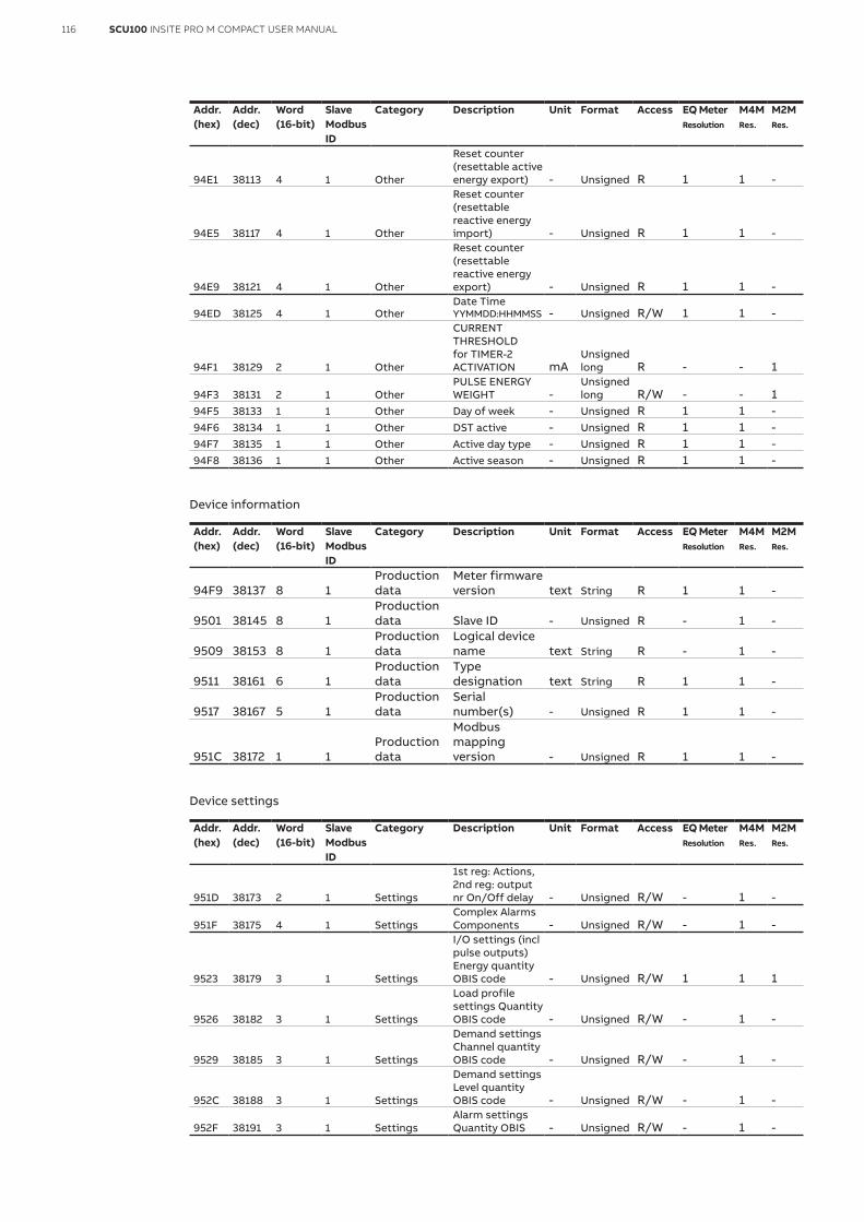
116 SCU100 INSITE PRO M COMPACT USER MANUAL
Addr. (hex)
Addr. (dec)
Word (16-bit)
Slave Modbus ID
Category Description Unit Format Access EQ Meter Resolution
M4MRes.
M2MRes.
94E1 38113 4 1 Other
Reset counter (resettable active energy export) - Unsigned R 1 1 -
94E5 38117 4 1 Other
Reset counter (resettable reactive energy import) - Unsigned R 1 1 -
94E9 38121 4 1 Other
Reset counter (resettable reactive energy export) - Unsigned R 1 1 -
94ED 38125 4 1 OtherDate Time YYMMDD:HHMMSS - Unsigned R/W 1 1 -
94F1 38129 2 1 Other
CURRENT THRESHOLD for TIMER-2 ACTIVATION mA
Unsigned long R - - 1
94F3 38131 2 1 OtherPULSE ENERGY WEIGHT -
Unsigned long R/W - - 1
94F5 38133 1 1 Other Day of week - Unsigned R 1 1 -94F6 38134 1 1 Other DST active - Unsigned R 1 1 -94F7 38135 1 1 Other Active day type - Unsigned R 1 1 -94F8 38136 1 1 Other Active season - Unsigned R 1 1 -
Device information
Addr. (hex)
Addr. (dec)
Word (16-bit)
Slave Modbus ID
Category Description Unit Format Access EQ Meter Resolution
M4MRes.
M2MRes.
94F9 38137 8 1Production data
Meter firmware version text String R 1 1 -
9501 38145 8 1Production data Slave ID - Unsigned R - 1 -
9509 38153 8 1Production data
Logical device name text String R - 1 -
9511 38161 6 1Production data
Type designation text String R 1 1 -
9517 38167 5 1Production data
Serial number(s) - Unsigned R 1 1 -
951C 38172 1 1Production data
Modbus mapping version - Unsigned R 1 1 -
Device settings
Addr. (hex)
Addr. (dec)
Word (16-bit)
Slave Modbus ID
Category Description Unit Format Access EQ Meter Resolution
M4MRes.
M2MRes.
951D 38173 2 1 Settings
1st reg: Actions, 2nd reg: output nr On/Off delay - Unsigned R/W - 1 -
951F 38175 4 1 SettingsComplex Alarms Components - Unsigned R/W - 1 -
9523 38179 3 1 Settings
I/O settings (incl pulse outputs) Energy quantity OBIS code - Unsigned R/W 1 1 1
9526 38182 3 1 Settings
Load profile settings Quantity OBIS code - Unsigned R/W - 1 -
9529 38185 3 1 Settings
Demand settings Channel quantity OBIS code - Unsigned R/W - 1 -
952C 38188 3 1 Settings
Demand settings Level quantity OBIS code - Unsigned R/W - 1 -
952F 38191 3 1 SettingsAlarm settings Quantity OBIS - Unsigned R/W - 1 -

117SCU100 INSITE PRO M COMPACT USER MANUAL
Addr. (hex)
Addr. (dec)
Word (16-bit)
Slave Modbus ID
Category Description Unit Format Access EQ Meter Resolution
M4MRes.
M2MRes.
9532 38194 2 1 SettingsVT ratio (Numerator) - Unsigned R/W 1 1 -
9534 38196 2 1 SettingsVT ratio (Denominator) - Unsigned R/W 1 1 -
9536 38198 2 1 Settings
Neutral current transf ratio (Numerator) - Unsigned R/W - 1 -
9538 38200 2 1 Settings
Neutral current transf ratio (Denominator) - Unsigned R/W - 1 -
953A 38202 2 1 SettingsCurrent transformer ratio - Unsigned R/W - - 1
953C 38204 2 1 SettingsVoltage transformer ratio -
Unsigned long R/W - - 1
953E 38206 2 1 Settings
I/O settings (incl pulse outputs) Pulses / kWh - Unsigned R/W 1 1 1
9540 38208 2 1 Settings
I/O settings (incl pulse outputs) Pulses / kvarh - Unsigned R/W 1 1 1
9542 38210 2 1 Settings
I/O settings (incl pulse outputs) Pulse length (ms) - Unsigned R/W 1 1 1
9544 38212 2 1 SettingsLoad profile settings Period - Unsigned R/W - 1 -
9546 38214 2 1 Settings
Load profile settings Channel entries - Unsigned R/W - 1 -
9548 38216 2 1 Settings
Actions registers: On/Off thresholds - Unsigned R/W - 1 -
954A 38218 2 1 Settings
Actions: bit0=log, bit1=output, bit2=reg. Alarm action on/off - Unsigned R/W - 1 -
954C 38220 2 1 SettingsComplex Alarms Actions - Unsigned R/W - 1 -
954E 38222 2 1 SettingsCO2 conversion factor act energy - Unsigned R/W 0.001 1 -
9550 38224 2 1 Settings
Currency conversion factor act en. - Unsigned R/W 0.01 1 -
9552 38226 2 1 Settings
DST start (month, day of month, day of week, hour) - Unsigned R/W 1 1 -
9554 38228 2 1 Settings
DST end (month, day of month, day of week, hour) - Unsigned R/W 1 1 -
9556 38230 2 1 SettingsCT L1,L2,L3 ratio (Numerator) - Unsigned R/W 1 1 -
9558 38232 2 1 SettingsCT L1,L2,L3 ratio (Denominator) - Unsigned R/W 1 1 -
955A 38234 1 1 Settings
I/O settings (incl pulse outputs) I/O signal mode port 1 - Unsigned R/W - 1 -
955B 38235 1 1 Settings
I/O settings (incl pulse outputs) I/O signal mode port 2 - Unsigned R/W - 1 -
955C 38236 1 1 Settings
I/O settings (incl pulse outputs) I/O signal mode port 3 - Unsigned R/W - 1 -

118 SCU100 INSITE PRO M COMPACT USER MANUAL
Addr. (hex)
Addr. (dec)
Word (16-bit)
Slave Modbus ID
Category Description Unit Format Access EQ Meter Resolution
M4MRes.
M2MRes.
955D 38237 1 1 Settings
I/O settings (incl pulse outputs) I/O signal mode port 4 - Unsigned R/W - 1 -
955E 38238 1 1 Settings
I/O settings (incl pulse outputs) I/O signal mode port 5 - Unsigned R/W - 1 -
955F 38239 1 1 Settings
I/O settings (incl pulse outputs) I/O signal mode port 6 - Unsigned R/W - 1 -
9560 38240 1 1 Settings
I/O settings (incl pulse outputs) Instance nr (1-6) - Unsigned R/W - 1 -
9561 38241 1 1 Settings
I/O settings (incl pulse outputs) I/O nr (port nr) (1-6) - Unsigned R/W 1 1 1
9562 38242 1 1 Settings
I/O settings (incl pulse outputs) Turn off pulse output - Unsigned R/W - 1 -
9563 38243 1 1 Settings
Load profile settings Channel nr (1-8) - Unsigned R/W - 1 -
9564 38244 1 1 Settings
Load profile settings Search type Raw=0, Smart=1 - Unsigned R/W - 1 -
9565 38245 1 1 Settings
Demand settings Nr of quantities - start config - Unsigned R/W - 1 -
9566 38246 1 1 Settings
Demand settings Channel nr (R only) auto updated - Unsigned R/W - 1 -
9567 38247 1 1 SettingsDemand settings Levels - Unsigned R/W - 1 -
9568 38248 1 1 Settings
Demand settings Interval (minutes) - Unsigned R/W - 1 -
9569 38249 1 1 Settings
Demand settings Sub interval (minutes) - Unsigned R/W - 1 -
956A 38250 1 1 Settings
MSB: 0=Da,1=We, 2=Mo,LSB:1=mon, 7=sun Period (day/week/month + week day) - Unsigned R/W - 1 -
956B 38251 1 1 SettingsAlarm settings Channel nr (1-25) - Unsigned R/W - 1 -
956C 38252 1 1 Settings Hysteresis - Unsigned R/W - 1 -
956D 38253 1 1 Settings
Type 0-None;1cross up;2-cross down - Unsigned R/W - 1 -
956E 38254 1 1 SettingsComplex Alarms Channel nr - Unsigned R/W - 1 -
956F 38255 1 1 SettingsComplex Alarms Operators - Unsigned R/W - 1 -
9570 38256 1 1 Settings
LED source 0 = Active energy, 1 = Reactive energy - Unsigned R/W 1 1 -
9571 38257 1 1 SettingsNumber of elements 1-3 - Unsigned R 1 - -
9572 38258 1 1 Settings
DST enabled (0 = disabled, 1 = enabled) - Unsigned R/W 1 1 -

119SCU100 INSITE PRO M COMPACT USER MANUAL
Total active, reactive and apparent energy (import, export and net)
Addr. (hex)
Addr. (dec)
Word (16-bit)
Slave Modbus ID
Category Description Unit Format Access EQ Meter Resolution
M4MRes.
M2MRes.
9573 38259 4 1Total energies Active import kWh Unsigned R 0.01 0.01 0.1
9577 38263 4 1Total energies Active export kWh Unsigned R 0.01 0.01 0.1
957B 38267 4 1Total energies Active net kWh Signed R 0.01 0.01 -
957F 38271 4 1Total energies Reactive import kvarh Unsigned R 0.01 0.01 0.1
9583 38275 4 1Total energies Reactive export kvarh Unsigned R 0.01 0.01 0.1
9587 38279 4 1Total energies Reactive net kvarh Signed R 0.01 0.01 -
958B 38283 4 1Total energies Apparent import kVAh Unsigned R 0.01 0.01 0.1
958F 38287 4 1Total energies Apparent export kVAh Unsigned R 0.01 0.01 0.1
9593 38291 4 1Total energies Apparent net kVAh Signed R 0.01 0.01 -
9597 38295 2 1Total energies
3PHASE SYS. ACTIVE POWER 15' AVER W
Unsigned long R - 1 1
9599 38297 2 1Total energies
3PHASE SYS. APPARENT POWER 15' AVER VA
Unsigned long R - 1 1
Unbalances voltage and current
Addr. (hex)
Addr. (dec)
Word (16-bit)
Slave Modbus ID
Category Description Unit Format Access EQ Meter Resolution
M4MRes.
M2MRes.
959B 38299 2 1 UnbalancesUnbalances Phase voltage % Unsigned R - 0.1 -
959D 38301 2 1 UnbalancesUnbalances Line voltage % Unsigned R - 1 -
959F 38303 2 1 UnbalancesUnbalances Current % Unsigned R - 0.1 -
Naming, status and counters of ports of IO module with ID = 97
Addr. (hex)
Addr. (dec)
Word (16-bit)
Slave Modbus ID
Category Description Unit Format Access
E4B6 58550 1 97 IO module I/O configuration - Unsigned R/WE4B7 58551 2 97 IO module Pulse Counter Port 0 - Unsigned RE4B9 58553 2 97 IO module Pulse Counter Port 1 - Unsigned RE4BB 58555 2 97 IO module Pulse Counter Port 2 - Unsigned RE4BD 58557 2 97 IO module Pulse Counter Port 3 - Unsigned RE4BF 58559 1 97 IO module Status Contacts Port 0 - Unsigned R/WE4C0 58560 1 97 IO module Status Contacts Port 1 - Unsigned R/WE4C1 58561 1 97 IO module Status Contacts Port 2 - Unsigned R/WE4C2 58562 1 97 IO module Status Contacts Port 3 - Unsigned R/W
E4C3 58563 2 97 IO module Pulse value Port 0 -Unsigned (yet unsup. R
E4C5 58565 2 97 IO module Pulse value Port 1 -Unsigned (yet unsup.) R
E4C7 58567 2 97 IO module Pulse value Port 2 -Unsigned (yet unsup.) R
E4C9 58569 2 97 IO module Pulse value Port 3 -Unsigned (yet unsup.) R
E4CB 58571 3 97 IO module Pulse unit Port 0 - String RE4CE 58574 3 97 IO module Pulse unit Port 1 - String RE4D1 58577 3 97 IO module Pulse unit Port 2 - String RE4D4 58580 3 97 IO module Pulse unit Port 3 - String R
E4D7 58583 8 97 IO module Pulse medium Port 0 -String (yet unsup.) R

120 SCU100 INSITE PRO M COMPACT USER MANUAL
Addr. (hex)
Addr. (dec)
Word (16-bit)
Slave Modbus ID
Category Description Unit Format Access
E4DF 58591 8 97 IO module Pulse medium Port 1 -String (yet unsup.) R
E4E7 58599 8 97 IO module Pulse medium Port 2 -String (yet unsup.) R
E4EF 58607 8 97 IO module Pulse medium Port 3 -String (yet unsup.) R
E4F7 58615 15 97 IO module Tag Name Port 0 text String RE506 58630 15 97 IO module Tag Name Port 1 text String RE515 58645 15 97 IO module Tag Name Port 2 text String RE524 58660 15 97 IO module Tag Name Port 3 text String RE533 58675 15 97 IO module Module Tag Name text String RE542 58690 4 97 IO module SID of the module - Unsigned long R
E546 58694 1 97 IO module Alarm status Port 0 -Unsigned (yet unsupported) R
E547 58695 1 97 IO module Alarm status Port 1 -Unsigned (yet unsupported) R
E548 58696 1 97 IO module Alarm status Port 2 -Unsigned (yet unsupported) R
E549 58697 1 97 IO module Alarm status Port 3 -Unsigned (yet unsupported) R
E54A 58698 1 97 IO module Alarm status module -Unsigned (yet unsupported) R
For the complete Modbus and SNMP map please refer to the one available for downloading on the ABB InSite pro M compact webpage

Note

ABB S.p.AElectrification businessViale dell’Industria, 1820009 Vittuone (MI) Italynew.abb.com/low-voltage
© Copyright 2018 ABB. All rights reserved.Due to possible changes in design and materials, the features and sizes contained in this catalog re to be considered as binding only after confirmation by ABB. 9A
KK
1076
80A
1167
Rev
. E -
Feb
ruar
y 20
22


