Embed Size (px)
Citation preview
1. Answer all questions (1X12=12 Marks)
a. Distinguish between method and message in object? Method is defined as the implementation of an operation. It specifies the algorithm or procedure associated with an operation. Messages is Smalltalk t0 represent two-way communications between the objects of the system
b. What is interaction diagram?Mention its types? Interaction diagrams are models that describe how a group of objects collaborate in some behavior - typically a single use-case They are two types 1.Interaction sequence diagram 2.Interaction collobaration diagram
c. What is collobaration diagram? A collaboration diagram, also called a communication diagram or interaction diagram, is an illustration of the relationships and interactions among software objects
d. Define patterns? In software development, a pattern (or design pattern) is a written document that describes a general solution to a design problem that recurs repeatedly in many projects.
e. Define modular design? Modular design, or "modularity in design", is a designapproach that subdivides a system into smaller parts calledmodules or skids, that can be independently created and then used in different systems.
f. What is use case diagram? A use case is a list of actions or event steps typically defining the interactions between a role (known in the Unified Modeling Language as an actor) and a system to achieve a goal. The actor can be a human or other external system.
g. Define class diagram? A class diagram is an illustration of the relationships and source code dependencies among classes in the Unified Modeling Language (UML).
h. Give the guide lines for naming classes? Class names should be nouns in Upper case, with the first letter of every word capitalized. Use whole words — avoid acronyms and abbreviations
i. What is aggregation? Aggregation is special form of association that specifies a whole-part relationship between the aggregate (whole) and a component part composition.
j. What is meant by CRC cards? Class-responsibility-collaboration (CRC) cards are a brainstorming tool used in the design of object-oriented software used to identify classes.
k. What is metaphor? The idea that the user is carrying on a dialogue with the system is a metaphor.
l. What is Reusability? Reusability is the use of existing assets in some form within the software product development process.
2.a) Explain about object oriented analysis of design model ? 6M
Object-oriented analysis (OOA) and design (OOD) are techniques which have evolved since 1988 to support the creation of object-oriented software targeted at languages like Smalltalk, C++ and Eiffel.
A contrast is drawn between the older structured systems analysis and design and the newer OOA&D. The aims and goals of SSA&D are different from the aims and goals of OOA&D.
A large number of OO methods for analysis and design have been put forward. These can roughly be categorised as:
Relationship and attribute centred approaches Behaviour centred approaches High industrial profile approaches Synthesized approaches
No one approach has all the best techniques. Very few approaches cover all aspects inequaldepth
Purposes of Analysis and Design
Analysis looks at a system in terms of problem-domain concepts and seeks to elicit natural interactions and discover natural constraints. The aim is for the Software Engineer to raise his understanding of the problem domain, communicate with the Client (the domain expert) and sometimes reveal inconsistencies and incompleteness in the Client's awareness of the problem domain.
Design has the task of converting the analysis model into concepts and abstractions present in the programming style of the target language. Such concepts can include procedures, modules, objects, or processes and vary from language to language. The design model may have to integrate with existing subsystems or aim to use components from an existing software library.
Analysis and design are often assumed to be completely independent from the chosen
programming language.
However, this is not the case!To see this, we need to step back and consider analysis,
design and programming as human conceptual activities.
2.b) Explain usecase modelling with an example ? 6M Purpose-----2M Notations----2M Any relevant example------2M
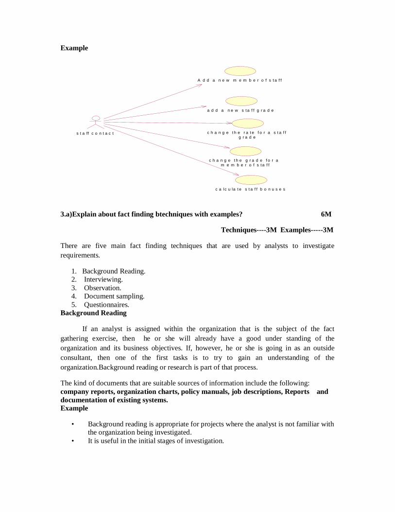
Use cases are descriptions of the functionality of the system from the users' pers-pective. Use case diagrams are used to show the functionality that the system will provide and to show which users will communicate with the system in some way to use that functionality. The following figure shows an example of a use case diagram.
Purpose Of Use case diagrams
The use case model is called as the requirements model; which also include a problem domain object model and user interface descriptions in this requirements model.
Use cases specify the functionality that the system will offer from the users' perspective. They are used to document the scope of the system and the developer's understanding of what it is that the users require.
Use cases are supported by behavior specifications. These specify the behaviour of each use case either using UML diagrams, such as collaboration diagrams or sequence diagrams or in text form as use case descriptions.
Textual use case descriptions provide a description of the interaction between the users of the system called actors, and the high level functions within the system called use cases.
Notation of USE CASE Diagrams
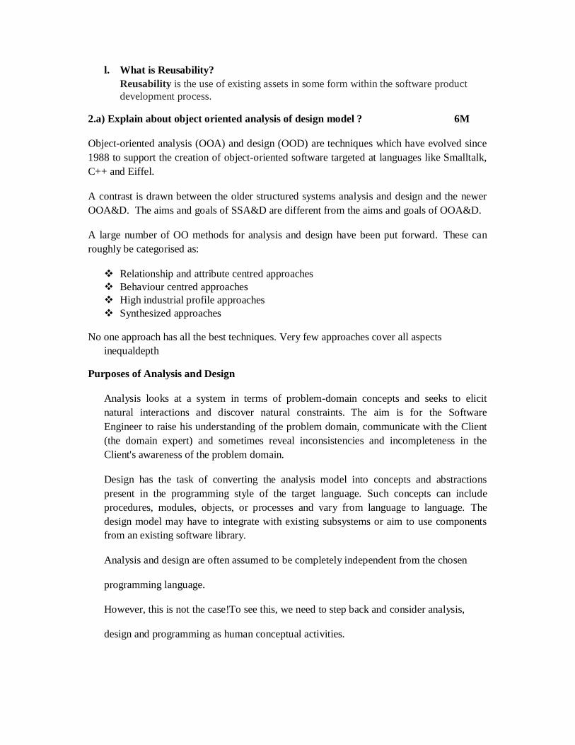
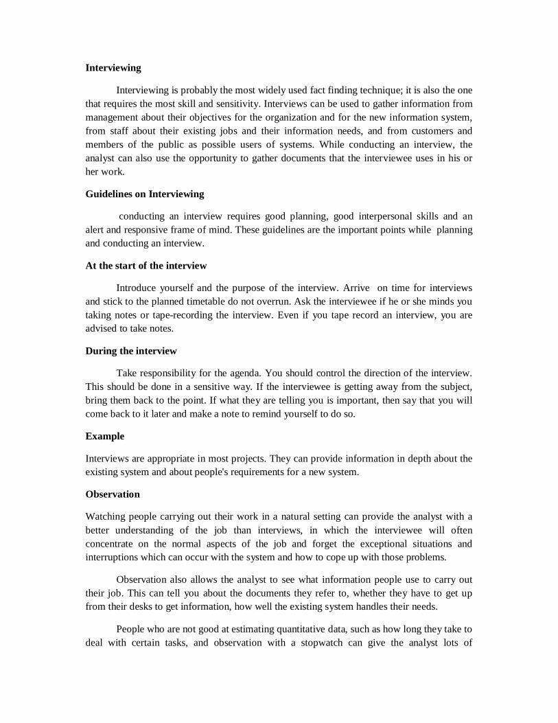
Use case diagrams show three aspects of the system: actors, use cases and relationships of the system or sub-system boundary.
The following Figure shows the elements of the notation.
Communication Association USE CASE
Actor
S t a f f C o n t a c t C h a n g e a C l i e n t c o n t a c t
Example
3.a)Explain about fact finding btechniques with examples? 6M
Techniques----3M Examples-----3M
There are five main fact finding techniques that are used by analysts to investigate requirements.
1. Background Reading. 2. Interviewing. 3. Observation. 4. Document sampling. 5. Questionnaires.
Background Reading
If an analyst is assigned within the organization that is the subject of the fact gathering exercise, then he or she will already have a good under standing of the organization and its business objectives. If, however, he or she is going in as an outside consultant, then one of the first tasks is to try to gain an understanding of the organization.Background reading or research is part of that process.
The kind of documents that are suitable sources of information include the following: company reports, organization charts, policy manuals, job descriptions, Reports and documentation of existing systems. Example
• Background reading is appropriate for projects where the analyst is not familiar with the organization being investigated. • It is useful in the initial stages of investigation.
A d d a n e w m e m b e r o f s t a f f
a d d a n e w s ta f f g r a d e
c h a n g e t h e r a t e f o r a s t a f f g r a d e
c h a n g e t h e g r a d e f o r a m e m b e r o f s t a f f
s t a ff c o n t a c t
c a lc u la t e s t a f f b o n u s e s
Interviewing
Interviewing is probably the most widely used fact finding technique; it is also the one that requires the most skill and sensitivity. Interviews can be used to gather information from management about their objectives for the organization and for the new information system, from staff about their existing jobs and their information needs, and from customers and members of the public as possible users of systems. While conducting an interview, the analyst can also use the opportunity to gather documents that the interviewee uses in his or her work.
Guidelines on Interviewing
conducting an interview requires good planning, good interpersonal skills and an alert and responsive frame of mind. These guidelines are the important points while planning and conducting an interview.
At the start of the interview
Introduce yourself and the purpose of the interview. Arrive on time for interviews and stick to the planned timetable do not overrun. Ask the interviewee if he or she minds you taking notes or tape-recording the interview. Even if you tape record an interview, you are advised to take notes.
During the interview
Take responsibility for the agenda. You should control the direction of the interview. This should be done in a sensitive way. If the interviewee is getting away from the subject, bring them back to the point. If what they are telling you is important, then say that you will come back to it later and make a note to remind yourself to do so.
Example
Interviews are appropriate in most projects. They can provide information in depth about the existing system and about people's requirements for a new system.
Observation
Watching people carrying out their work in a natural setting can provide the analyst with a better understanding of the job than interviews, in which the interviewee will often concentrate on the normal aspects of the job and forget the exceptional situations and interruptions which can occur with the system and how to cope up with those problems.
Observation also allows the analyst to see what information people use to carry out their job. This can tell you about the documents they refer to, whether they have to get up from their desks to get information, how well the existing system handles their needs.
People who are not good at estimating quantitative data, such as how long they take to deal with certain tasks, and observation with a stopwatch can give the analyst lots of
quantitative data, not just about typical times to perform a task but also about the statistical distribution of those times.
Example
• Observation is essential for gathering quantitative data about people's jobs. • It can verify or disprove assertions made by interviewees, and is often useful in • situations where different interviewees have provided conflicting information about
the way the system works. • Observation may be the best way to follow items through some kind of process from
start to finish. Document sampling
First, the analyst will collect copies of blank and completed documents during the course of interviews and observation sessions. These will be used to determine the information that is used by people in their work, and the inputs to and outputs from processes which they carry out, either manually or using an existing computer system. From an existing system, the analyst may need to collect screen shots in order to understand the inputs and outputs of the existing system.
Second, the analyst may carry out a statistical analysis of documents in order to find out about patterns of data. For example, many documents such as order forms contain a header section and a number of lines of detail. The analyst may want to know the distribution of the number of lines in an order. This will help later in estimating volumes of data to be held in the system and in deciding how many lines should be displayed on screen at one time. While this kind of statistical sampling can give a picture of data volumes, the analyst should be alert to seasonal patterns of activity, which may mean that there are peaks and troughs in the amount of data being processed.
Example
The first type of document sampling is almost always appropriate. Paper-based documents give a good idea of what is happening in the current system. They also provide supporting evidence for the information gathered from interviews or observation.
The statistical approach is appropriate in situations where large volumes of data are being processed, and particularly where error rates are high, and a reduction in errors is one of the criteria for usability.
Questionnaires
Questionnaires are a research instrument that can be applied to fact finding in system development projects. They consist of a series of written questions. The questionnaire designer usually limits the range of replies that respondents can make by giving them a choice of options.
YES/NO questions only give the respondent two options. If there are more options, the multiple choice type of question is often used when the answer is factual, whereas scaled
questions are used if the answer involves an element of subjectivity. Some questions do not have a fixed number of responses, and must be left open-ended for the respondent to enter what they like.
Example
Multiple choice questions Yes/ No questions Feed back questions 3.b) Explain about requirement analysis ? 6M
The most important factor for the success of an IS project is whether the software product satisfies its users' requirements. Models constructed from an analysis perspective focuses on determining these requirements. This means Requirement Model includes gathering and documenting facts and requests.
The use case model gives a perspective on many user requirements and models them in terms of what the software system can do for the user. Before the design of software which satisfies user requirements, we must analyze both the logical structure of the problem situation, and also the ways that its logical elements interact with each other. We must also need to verify the way in which different, possibly conflicting, requirements affect each other. Then we must communicate this under standing clearly and unambiguously to those who will design and build the software.
We do all of this by building further models, and these must meet several objectives.
• They must contain an overall description of what the software should do. • They must represent any people, physical things and concepts that are important to the
analyst's understanding of what is going on in the application domain. • They must show connections and interactions among these people, things and
concepts. • They must show the business situation in enough detail to evaluate possible designs. • Ideally, they should also be organized in such a way that they will be useful later for
designing the software. 4.a) Explain software development patterns? 8M
Pattern -----2M Architectural—2M Design patterns----2M Analysis patterns---2M
Pattern : Each pattern describes a problem which occurs over and over again in our environment, and then describes the core of a solution to that problem, in such a way that you can use this solution a million times over, without ever doing it the same way twice.
Coplien identifies the critical aspects of a pattern as follows.
• It solves a problem. • It is a proven concept. • The solution is not obvious. • It describes a relationship. • The pattern has a significant human component.
Architectural patterns – Responsibilities
1. Addresses some of the issues concerning the structural organization of software systems.
2. Architectural patterns also describes the structure and relationship of major components of a software system.
3. These patterns identifies subsystems, their responsibilities and their interrelationships.
Design patterns – Responsibilities
1. These patterns identify the interrelationships among a group of software components describing their responsibilites, collaborations and structural relationships.
2. Idioms describe how to implement particular aspects of a software system in a given programming language.
Analysis patterns : Resposibilities
1. These are defined as describing groups of concepts that represent common constructions in domain modelling. These patterns may be applicable in one domain or in many domains.
2. The use of analysis patterns is an advanced approach that is principally of use to experienced analysts,. They are closely related to design patterns also.
3. An analysis pattern is essentially a structure of classes and associations that is found to occur over and over again in many different modelling situations.
4. b) Explain sequence diagram with example? 4M
Basic concepts and notations----2M Any relevant Example----2M
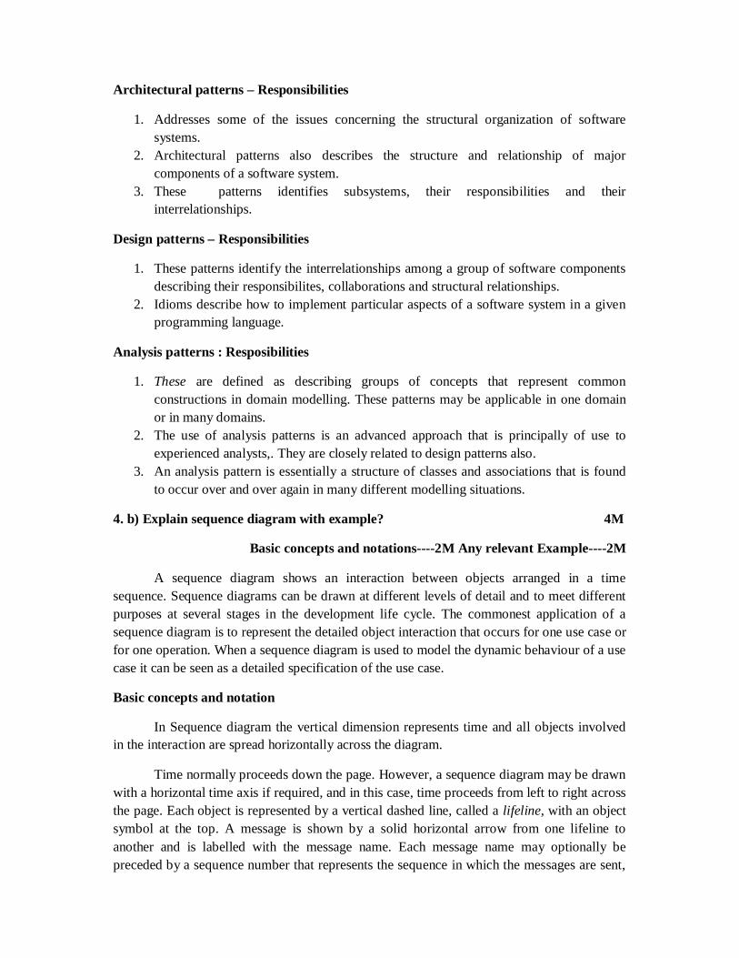
A sequence diagram shows an interaction between objects arranged in a time sequence. Sequence diagrams can be drawn at different levels of detail and to meet different purposes at several stages in the development life cycle. The commonest application of a sequence diagram is to represent the detailed object interaction that occurs for one use case or for one operation. When a sequence diagram is used to model the dynamic behaviour of a use case it can be seen as a detailed specification of the use case.
Basic concepts and notation
In Sequence diagram the vertical dimension represents time and all objects involved in the interaction are spread horizontally across the diagram.
Time normally proceeds down the page. However, a sequence diagram may be drawn with a horizontal time axis if required, and in this case, time proceeds from left to right across the page. Each object is represented by a vertical dashed line, called a lifeline, with an object symbol at the top. A message is shown by a solid horizontal arrow from one lifeline to another and is labelled with the message name. Each message name may optionally be preceded by a sequence number that represents the sequence in which the messages are sent,
but this is not usually necessary on a sequence diagram since the message sequence is already conveyed by their relative positions along time axis.
Example
5.a) Explain about object interaction and collaboration ? 6M
When an object sends a message to another object, an operation is invoked in the receiving object.
For example, in the Agate case study there is a requirement to be able to determine the current cost of the advertisements for an advertising campaign. This responsibility is assigned to the Campaign class. For a particular campaign this might be achieved if the Campaign object sends a message to each of its Advert objects asking them for their current cost.
In a programming language, sending the message getCost () to an Advert object, might use the following syntax.
advertCost = anAdvert.getCost()
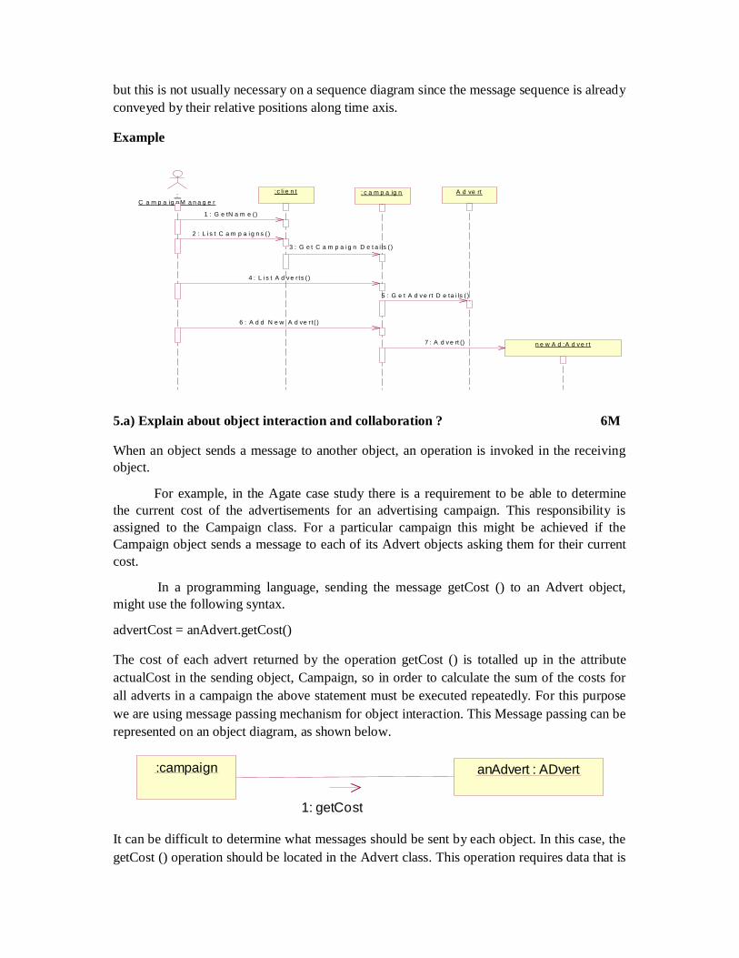
The cost of each advert returned by the operation getCost () is totalled up in the attribute actualCost in the sending object, Campaign, so in order to calculate the sum of the costs for all adverts in a campaign the above statement must be executed repeatedly. For this purpose we are using message passing mechanism for object interaction. This Message passing can be represented on an object diagram, as shown below.
It can be difficult to determine what messages should be sent by each object. In this case, the getCost () operation should be located in the Advert class. This operation requires data that is
n e w A d :A d v e r t
: C a m p a ig n M a n a g e r
:c li e n t : c a m p a ig n A d ve rt
1 : G e tN a m e ()
2 : L i s t C a m p a i g n s ( )
3 : G e t C a m p a i g n D e t a i ls ( )
4 : L i s t A d v e r ts ( )
5 : G e t A d v e rt D e ta i ls ( )
6 : A d d N e w A d ve r t( )
7 : A d v e rt ()
:campaign anAdvert : ADvert
1: getCost
stored in the advertCost attribute, and this has been placed in Advert. We can also see that an operation that calculates the cost of a Campaign must be able to find out the cost of each Advert involved.
But this is a simple collaboration and the allocation of these operations is largely dictated by the presence of particular attributes in the classes. More complex requirements may involve the performance of complex tasks, such that an object receiving one message must itself send messages that initiate further collaboration with other objects.
The objective of OOAD to distribute system functionality appropriately among its classes. This does not mean that all classes have exactly equal levels of responsibility but rather that each class should have appropriate responsibilities. Where responsibilities are evenly distributed, each class tends not to be complex and easy to develop , test and maintain.
An appropriate distribution of responsibility among classes has the important side effect of producing a system that is more resilient to changes in its requirements. When the users' requirements for a system change it is reasonable to expect that the application will need some modification, but ideally the change in the application should be of no greater magnitude than the change in the requirements.
5.b Define Event, State and Transition and discuss preparation of State chart diagram with example? 6M Definitions----2M preparation---2M example----2M Event
An event is an occurrence of a stimulus that can trigger a state change and that is relevant to the object or to an application.
State
All objects will have a state in a system. The current state of an object is a result of the events that have occurred to the object, and is determined by the current value of the object's attributes and the links that it has with other objects. Some attributes and links of an object are significant for the determination of its state while others are not.
Transition
Movement from one state to another is called a transition, and is triggered by an event
Preparation of State chart diagram
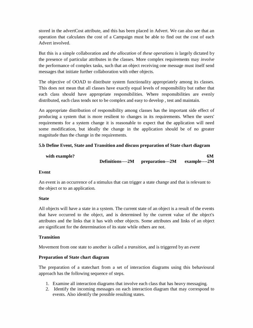
The preparation of a statechart from a set of interaction diagrams using this behavioural approach has the following sequence of steps.
1. Examine all interaction diagrams that involve each class that has heavy messaging. 2. Identify the incoming messages on each interaction diagram that may correspond to
events. Also identify the possible resulting states.
3. Document these events and states on a statechart. 4. Elaborate the statechart as necessary to cater for additional interactions as these
become evident, and add any exceptions. 5. Develop any nested statecharts if already identified. 6. Review the statechart to ensure consistency with use cases. In particular, check that
any constraints that are implied by the state chart are appropriate. 7. Iterate steps 4, 5 and 6 until the statechart captures the necessary level of detail. 8. Check the consistency of the state chart with the class diagram, with interaction
diagrams and with any other statecharts. Example
6.a) Explain about major elements of system design and software architecture? 6M
The major elements of system Design
The system design activity specifies the context within which detailed design will occur. A major part of system design is defining the system architecture. The meaning and scope of the term architecture for computerized information systems is much debated but it is generally accepted that it is an important feature of the delivered system.
The architecture of a system is concerned with its overall structure, the relationships among its major components and their interactions. If the system being considered contains human, software and hardware elements then its architecture includes how these elements are structured and how they interact.
On the other hand, if the system being considered comprises software and hardware, then its architecture only concerns these elements. It is important to consider the structure of the software elements of the system and this is termed the software architecture. The hardware architecture of a system describes computers and peripherals required for the system and how software is allocated to them.
During system design we need to consider the following activities.
Sub-systems and major components are identified.
C o m m is s io ne d
C o m p le te d
A c ti ve
P a id
/ a s s ig nM a na g e r( ); A s s ig nS ta ff( )
a utho rize d (a utho ri za tio nC o d e )[c o ntra c ts ig ne d ] / s e t c a m p a ig n a c tive
c a m p a ig n c o m p le te d () / p re p a re fina l s ta te m e nt()
p a ym e nt re c e ive d (p a ym e nt) [ p a ym e ntd ue - p a ym e nt > ze ro ]
p ay m e nt re c e ive d (p a yme nt ) [ pa ym e ntd ue - p a ym e nt < = ze ro ]
a rc hive C a m p a ig n() / una s s ig nS ta ff(); U na s s ig nM a na g e r()
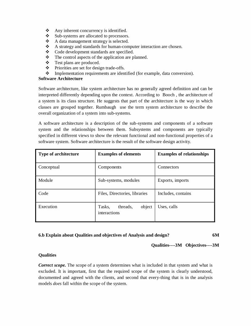
Any inherent concurrency is identified. Sub-systems are allocated to processors. A data management strategy is selected. A strategy and standards for human-computer interaction are chosen. Code development standards are specified. The control aspects of the application are planned. Test plans are produced. Priorities are set for design trade-offs. Implementation requirements are identified (for example, data conversion).
Software Architecture
Software architecture, like system architecture has no generally agreed definition and can be interpreted differently depending upon the context. According to Booch , the architecture of a system is its class structure. He suggests that part of the architecture is the way in which classes are grouped together. Rumbaugh use the term system architecture to describe the overall organization of a system into sub-systems.
A software architecture is a description of the sub-systems and components of a software system and the relationships between them. Subsystems and components are typically specified in different views to show the relevant functional and non-functional properties of a software system. Software architecture is the result of the software design activity.
Type of architecture Examples of elements Examples of relationships
Conceptual Components Connectors
Module Sub-systems, modules Exports, imports
Code Files, Directories, libraries Includes, contains
Execution Tasks, threads, object interactions
Uses, calls
6.b Explain about Qualities and objectives of Analysis and design? 6M
Qualities----3M Objectives----3M
Qualities
Correct scope. The scope of a system determines what is included in that system and what is excluded. It is important, first that the required scope of the system is clearly understood, documented and agreed with the clients, and second that every-thing that is in the analysis models does fall within the scope of the system.
Completeness. Just as there is a requirement that everything that is in the analysis models is within the scope of the system, so everything that is within the scope of the system should be documented in the analysis models. Everything that is known about the system from the requirements capture should be documented and included in appropriate diagrams. Often the completeness of the analysis is dependent on the skills and experience of the analyst. Knowing what questions to ask in order to list out requirements comes with time and experience. However, analysis patterns and strategies, can help the less experienced analyst to identify likely issues.
Correct content. The analysis documentation should be correct and accurate in what it describes. This applies to textual information, diagrams and also to quantitative features of the non-functional requirements. Examples include correct descriptions of attributes and any operations that are known at this stage, correct representation of associations between classes, particularly the multiplicity of associations, and accurate information about volumes of data.
Consistency. Where the analysis documentation includes different models that refer to the same things (use cases, classes, attributes or operations) the same name should be used consistently for the same thing. Errors of consistency can result in errors being made by designers, for example, creating two attributes with different names that are used in different parts of the system but should be the same attribute.
Objectives of Design
Functional. When we use a computer system, we expect it to perform correctly and completely those functions that it is claimed to perform; when an information system is developed for an organization, the staff of that organization will expect it to meet their documented requirements fully and according to specification.
Efficient. It is not enough that a system performs the required functionality; it should also do so efficiently, in terms both of time and resources. Those resources can include disk storage, processor time and network capacity. This is why design is not just about producing any solution, but about producing the best solution.
Economical, Linked to efficiency is the idea that a design should be economical. This applies not only to the fixed costs of the hardware and software that will be required to run it, but also to the running costs of the system. The cost of memory and disk storage is very low compared to 20 years ago, and most small businesses using Microsoft Windows probably now require more disk space for their programs than they do for their data.
Flexible. It is the ability to adapt changing business requirements as time passes.
Manageable. A good design should allow the project manager to estimate the amount of work involved in implementing the various sub-systems.If implementation of these sub-systems is completed then forwarded for testing will not have any affects on other parts of the system.
7. a Briefly discuss about Design patterns. 6M
Creational patterns---2M Structural patterns---2M Behavioral patterns---2M
Types of Design Patterns
Patterns are classified according to their scope and purpose into the following three main categories.
1. Creational patterns 2. Structural patterns 3. Behavioural patterns.
The scope of a pattern may be primarily at either the class level or at the object level. Patterns that are principally concerned with objects describe relationships that may change at run-time and hence are more dynamic. Patterns that relate primarily to classes tend to be static and identify relationships between classes and their subclasses that are defined at compile-time.
Changeability involves several different aspects - maintainability, extensibility, restructuring and portability.
Maintainability is concerned with the ease with which errors in the information system can be corrected.
Extensibility addresses the inclusion of new features and the replacement of existing components with new improved versions. It also involves the removal of unwanted features.
Restructuring focuses on the reorganization of software components and their relationships to provide increased flexibility.
Portability deals with modifying the system so that it may execute in different operating environments, such as different operating systems or different hardwa
Creational patterns
A creational design pattern is concerned with the construction of object instances. In general, creational patterns separate the operation of an application from how its objects are created. This decoupling of object creation from the operation of the application gives the designer considerable flexibility in configuring all aspects of object creation. This configuration may be dynamic or static .
For example, when dynamic configuration is appropriate, an object-oriented system may use composition to make a complex object by aggregating simpler component objects. Depending upon circumstances different components may be used to construct the composite and, irrespective of its components, the composite will fulfill the same purpose in the application.
Creating composite objects is not simply a matter of creating a single entity but also involves creating all the component objects. The separation of the creation of a composite object from its use within the application provides design flexibility. By changing the method of
construction of a composite object, alternative implementations may be introduced without affecting the current use.
Eg : Singleton Pattern
Structural patterns
Structural patterns address issues concerned with the way in which classes and objects are organized. Structural patterns offer effective ways of using object-oriented constructs such as inheritance, aggregation and composition to satisfy particular requirements. If there , a requirement for a particular aspect of the application to be extensible. In order to achieve this, the application should be designed with constructs that minimize the sideeffects of future change. Alternatively it may be necessary to provide the same interface for a series of objects of different classes also.
Eg : Composite Pattern
Behavioural patterns
Behavioural patterns addresses the problems that arise when assigning responsibilities to classes and when designing algorithms. Behavioural patterns specifies static relationships between objects and classes and how the objects of one class communicates with another. Behavioural patterns may use inheritance structures to spread behaviour across the subclasses or they may use aggregation and composition to build complex behaviour from simpler components.
Eg: The State pattern uses both of these techniques.
7. b Explain various approaches to user interface design? 6M
Three approaches each ---2M
Approaches to USERINTERFACE Design
There are many different ways of designing and implementing the elements of the user interface that support the interaction with users by using formal and informal approaches. The following are the factors to be considered while designing User Interface the nature of the task that the user is carrying out, the type of user, the amount of training that the user will have undertaken, the frequency of use the hardware and software architecture of the system.
1.Structured approaches
Structured approaches to user interface design have been developed in response to the growth in the use of structured approaches to systems analysis and design. Structured analysis and design methodologies have a number of characteristics. They are based on a model of the systems development life cycle, which is broken down into stages, each of which is further broken down into steps that are broken down into tasks. Specific analysis and design
techniques are used, and the methodology specifies which techniques should be used in which step. Each step is described in terms of its inputs , the techniques applied and the deliverables that are produced as outputs (diagrams and documentation).
Benefits of Structured approaches
They make management of projects easier. The breakdown of the project into stages and steps makes planning and estimating easier, and thus assists management control of the project.
They provide for standards in diagrams and documentation that improves understanding between the project staff in different roles means between analyst, designer and programmer.
They improve the quality of delivered systems. Because the specification of the system is comprehensive, it is more likely to lead to a system that functions correctly.
2. Ethnographic approaches
The term ethnography is applied to a range of techniques used in sociology and anthropology and reflects a particular philosophy about how scientific enquiry should be carried out.
In HCI this means that the professional charged with carrying out the user interface design spends time with the users immersed in their everyday working life. Only by spending time in this way can the real requirements of the users be understood and documented.
Ethnographic methods also concentrates on how different users interpret their experience of using systems subjectively, and it is this subjective interpretation that the HCI professional must understand rather than assuming that the system can be assessed objectively.
Ethnographic approaches use a range of techniques to capture data: interviews, discussions, prototyping sessions and videos of users at work or using new systems. These data are analysed from different perspectives to gain insights into the behaviour of the users.
3. Scenario-based approaches.
Scenario-based design has been developed by John Carroll and others . It is less formal than the structured approaches but more clearly defined than most ethnographic approaches. Scenarios are step-by-step descriptions of a user's actions that can be used as a tool in requirements gathering, interface design and evaluation. Use cases are similar to scenarios.
Among these three approaches, scenario-based design fits best with use case modeling. Scenarios can be textual narrative describing a user's actions or they can be in the form of storyboards video mock-ups or even prototypes.
Scenarios provide a means of communication that can be used by professionals and end-users to communicate about the design of the users' interaction with the system. They are simple enough that users can produce them without the need for the kind of training that they would need to understand class diagrams, for example. Scenarios can be used with use cases. The use cases can provide a description of the typical interaction.
8.a Explain about modeling User Interface Design using state chart? 6M
Diagram----1M each point description ----1M
This process involves five tasks
Describe the high level requirements and main user tasks Describe the user interface behaviour Define user interface rules Draw the state chart Prepare an event action table
Describe the high-level requirements and main user tasks
The requirement here is that the users must be able to check whether the budget for an advertising campaign has been exceeded or not .This is calculated by summing the cost of all the adverts in a campaign ,adding a percentage for overheads and subtracting the result from the planned budget .A negative value indicates that the budget has been overspent .this information is used by a campaign manager.
Describe the user interface behaviour
There are five elements of the user interface the client dropdown,the campaign dropdown,the budget textfield,the check button and the close button.These are shown in following figure
The client dropdown displays a list of clients .When a client is selected,their campaigns will be displayed in yhe campaign dropdown.
The campaign dropdown displays alist of campaigns belonging to the client selected in the client dropdown .When a campaign is selected the check button is enabled.
The budget textfield displays the result of the calculation to check the budget.
The chek button causes the calculation of the budget balance to take place.
The close button closes the window and exits the use case.
Define user interface rules
User interface objects with constant behaviour
The client dropdown has constant behaviour.whenever a client is selected ,a list of campaigns is loaded into the campaign dropdown .
The budget textfield is initially empty.it is cleared whenever a new clientis selected or a new campaign is selected.it is not editable.
The close button may be pressed at any time to close the window User interface objects with varying behaviour
The campaign dropdown is initially disabled .no campaign can be selected until a client has been selected .Once it has been loaded with a list of campaign .It is enabled.
The check button is initially disabled .It is enabled when a campaign is selected .It is disabled whenever a new client is selected.
entry and exit events
The window is entered from the main window when the check campaign budget menu item is selected
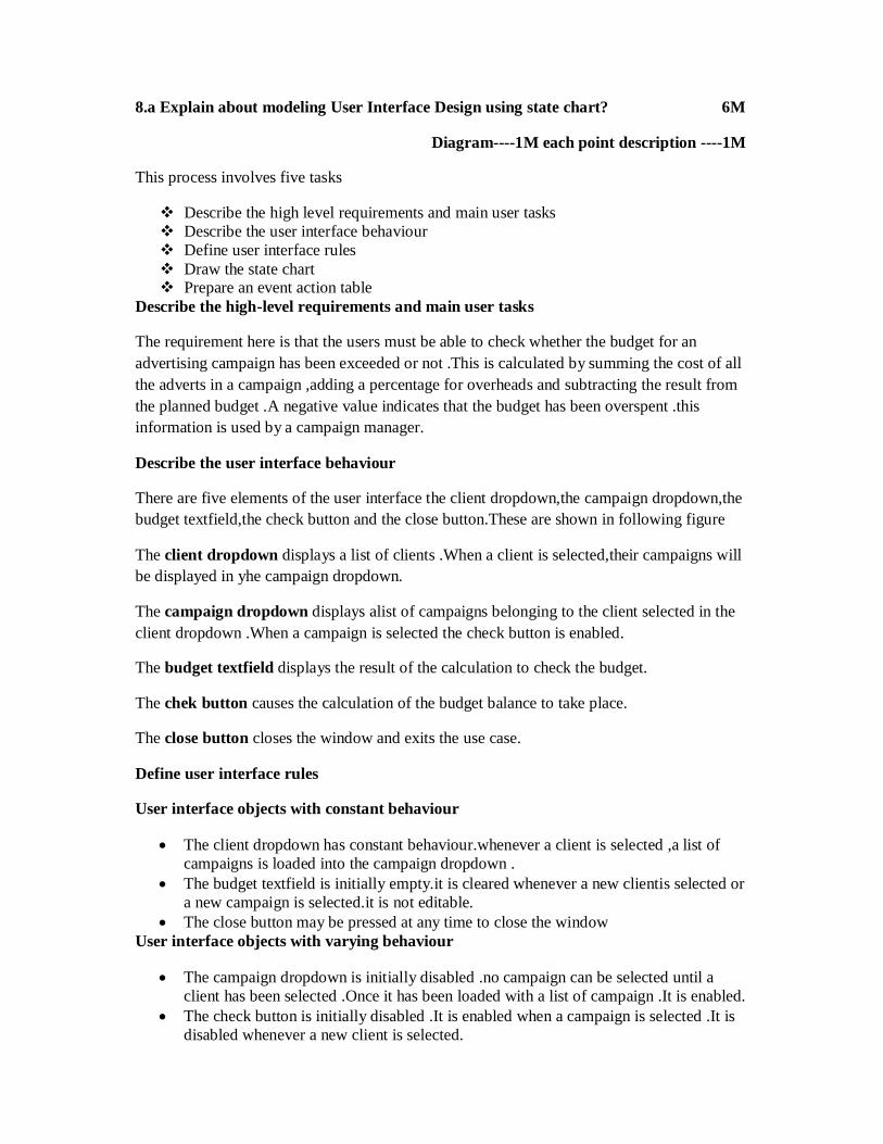
draw the statechart
At the top level ,there are three states the application can be in .It can be in the main window (and we are assuming that this is modelled in detail elsewhere),in the check budget window or in alert dialogue .The figure given below shows these top-level states .
prepare an event-action table
UML statechart notation allows you to label transitions and states with actions .On a transition the action can be an action of the object itself or it can involve a message being sent to another object .Within states,entry and exit actions can be documented,as well as do actions that are carried out continuously while the object is in the state and event actions that are carried out if a particular event occurs while the object is that state.
The use of these actions on statechart diagrams can make them very cluttered and difficult to read ,especially if there are also guard conditions on the transitions as well as actions .UML allows you to put actions both on transitions and on states ,although some authors on the subject suggest that you use either actions on transitions or actions on states ,but not both.
8.b Explain about designing classes? 6M
DESIGNING CLASSES:
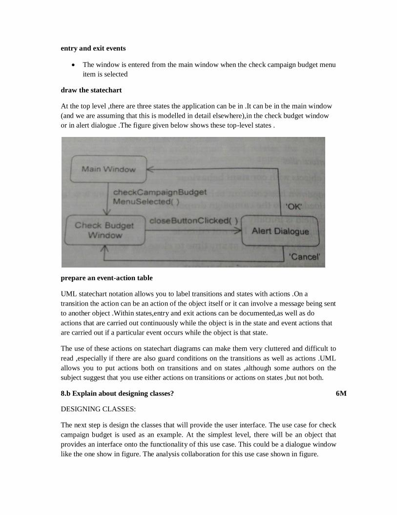
The next step is design the classes that will provide the user interface. The use case for check campaign budget is used as an example. At the simplest level, there will be an object that provides an interface onto the functionality of this use case. This could be a dialogue window like the one show in figure. The analysis collaboration for this use case shown in figure.
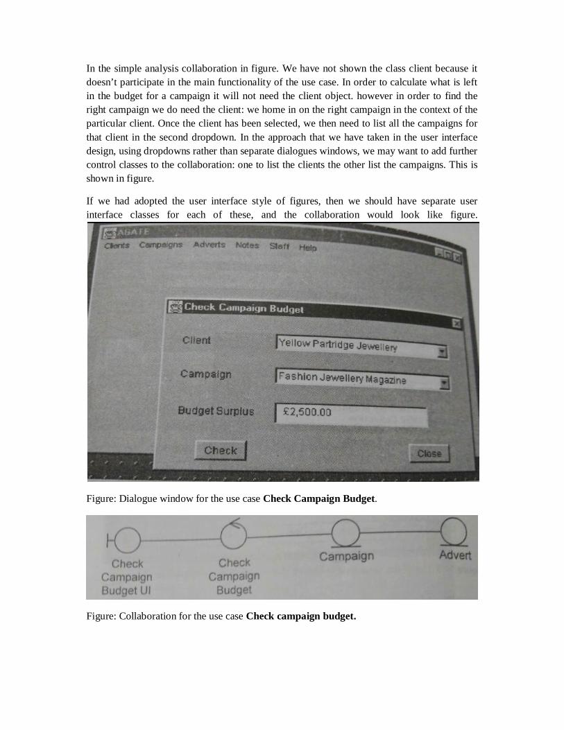
In the simple analysis collaboration in figure. We have not shown the class client because it doesn’t participate in the main functionality of the use case. In order to calculate what is left in the budget for a campaign it will not need the client object. however in order to find the right campaign we do need the client: we home in on the right campaign in the context of the particular client. Once the client has been selected, we then need to list all the campaigns for that client in the second dropdown. In the approach that we have taken in the user interface design, using dropdowns rather than separate dialogues windows, we may want to add further control classes to the collaboration: one to list the clients the other list the campaigns. This is shown in figure.
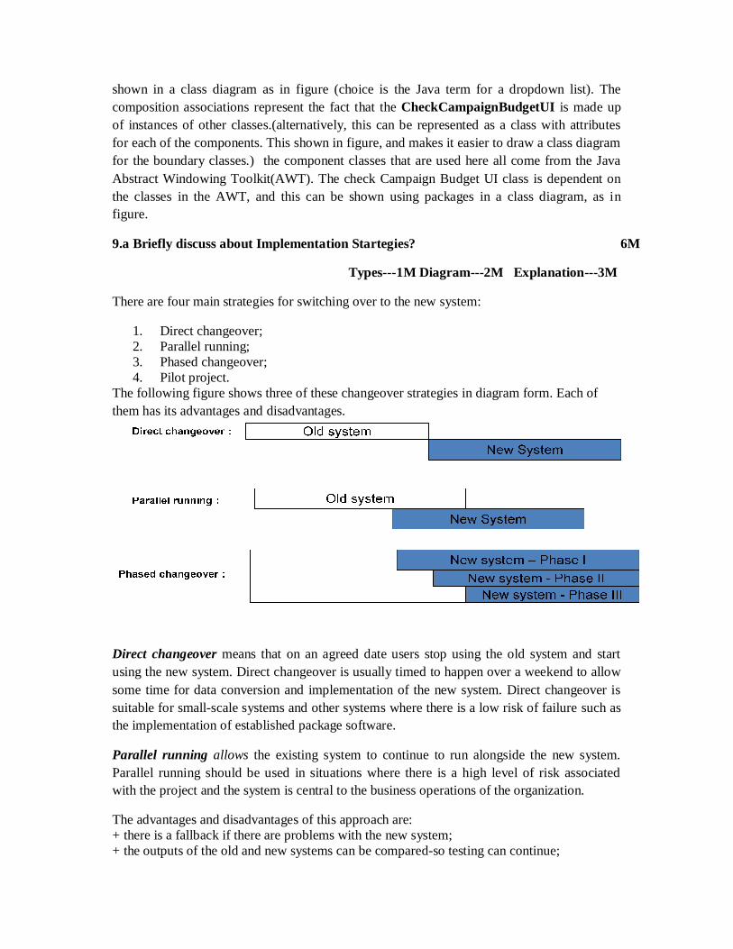
If we had adopted the user interface style of figures, then we should have separate user interface classes for each of these, and the collaboration would look like figure.
Figure: Dialogue window for the use case Check Campaign Budget.
Figure: Collaboration for the use case Check campaign budget.
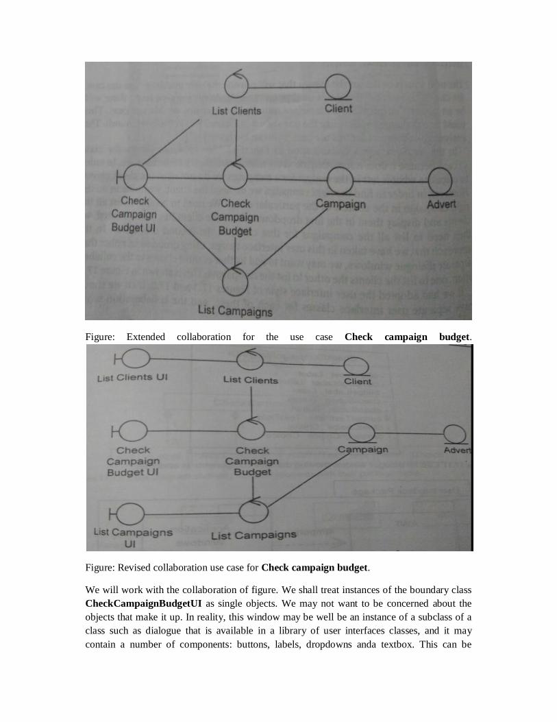
Figure: Extended collaboration for the use case Check campaign budget.
Figure: Revised collaboration use case for Check campaign budget.
We will work with the collaboration of figure. We shall treat instances of the boundary class CheckCampaignBudgetUI as single objects. We may not want to be concerned about the objects that make it up. In reality, this window may be well be an instance of a subclass of a class such as dialogue that is available in a library of user interfaces classes, and it may contain a number of components: buttons, labels, dropdowns anda textbox. This can be
shown in a class diagram as in figure (choice is the Java term for a dropdown list). The composition associations represent the fact that the CheckCampaignBudgetUI is made up of instances of other classes.(alternatively, this can be represented as a class with attributes for each of the components. This shown in figure, and makes it easier to draw a class diagram for the boundary classes.) the component classes that are used here all come from the Java Abstract Windowing Toolkit(AWT). The check Campaign Budget UI class is dependent on the classes in the AWT, and this can be shown using packages in a class diagram, as in figure.
9.a Briefly discuss about Implementation Startegies? 6M
Types---1M Diagram---2M Explanation---3M
There are four main strategies for switching over to the new system:
1. Direct changeover; 2. Parallel running; 3. Phased changeover; 4. Pilot project.
The following figure shows three of these changeover strategies in diagram form. Each of them has its advantages and disadvantages.
Direct changeover means that on an agreed date users stop using the old system and start using the new system. Direct changeover is usually timed to happen over a weekend to allow some time for data conversion and implementation of the new system. Direct changeover is suitable for small-scale systems and other systems where there is a low risk of failure such as the implementation of established package software.
Parallel running allows the existing system to continue to run alongside the new system. Parallel running should be used in situations where there is a high level of risk associated with the project and the system is central to the business operations of the organization.
The advantages and disadvantages of this approach are: + there is a fallback if there are problems with the new system; + the outputs of the old and new systems can be compared-so testing can continue;
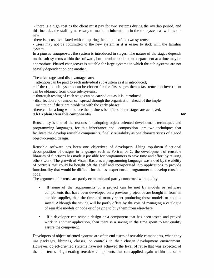
- there is a high cost as the client must pay for two systems during the overlap period, and this includes the staffing necessary to maintain information in the old system as well as the new -there is a cost associated with comparing the outputs of the two systems; - users may not be committed to the new system as it is easier to stick with the familiar system. In a phased changeover, the system is introduced in stages. The nature of the stages depends on the sub-systems within the software, but introduction into one department at a time may be appropriate. Phased changeover is suitable for large systems in which the sub-systems are not heavily dependent on one another.
The advantages and disadvantages are: + attention can be paid to each individual sub-system as it is introduced; + if the right sub-systems can be chosen for the first stages then a fast return on investment can be obtained from those sub-systems; + thorough testing of each stage can be carried out as it is introduced; - disaffection and rumour can spread through the organization ahead of the imple- mentation if there are problems with the early phases; -there can be a long wait before the business benefits of later stages are achieved. 9.b Explain Reusable components? 6M
Reusability is one of the reasons for adopting object-oriented development techniques and programming languages, for this inheritance and composition are two techniques that facilitate the develop reusable components, finally reusability as one characteristics of a good object-oriented design.
Reusable software has been one objectives of developers .Using top-down functional decomposition of designs in languages such as Fortran or C, the development of reusable libraries of functions has made it possible for programmers to save time and effort by reusing others work. The growth of Visual Basic as a programming language was aided by the ability of controls that could be bought off the shelf and incorporated into applications to provide functionality that would be difficult for the less experienced programmer to develop reusable code. The arguments for reuse are partly economic and partly concerned with quality.
• If some of the requirements of a project can be met by models or software components that have been developed on a previous project or are bought in from an outside supplier, then the time and money spent producing those models or code is saved. Although the saving will be partly offset by the cost of managing a catalogue of reusable models or code or of paying to buy them from elsewhere.
• If a developer can reuse a design or a component that has been tested and proved work in another application, then there is a saving in the time spent to test quality assure the component.
Developers of object-oriented systems are often end-users of reusable components, when they use packages, libraries, classes, or controls in their chosen development environment. However, object-oriented systems have not achieved the level of reuse that was expected of them in terms of generating reusable components that can applied again within the same
organization. There are a number of reasons for this . some are technical and some are concerned with organizational culture.
1. Inappropriate choice of projects for reuse. Not all organizations or projects within those organizations are necessarily suitable to take advantage of or act as to sources of reusable components.
2. Planning for reuse too late. If reuse is appropriate, it is something that needs to be planned for even before a project starts, not an after project starts. By the time a project has been completed, it is likely that anything that might have been reusable will have been designed in such a way that it cannot easily be extracted from the rest of the system. To achieve reuse, the organization needs to be structured to support it, with the people and tools in place to make it possible.
3. level of coupling between different classes in an object-oriented design. Many people have thought of classes as the unit of reuse in object-oriented developments. However, when we come to design classes for different systems, it may be possible to identify similar classes that could be developed in a way that makes them of use in more than one system, but more often than not, the implementations of these classes will include attributes and associations that tie them into other classes in the particular application of which they are a part.
4. lack of standards for reusable components. This has changed recently with developments in the technology of repositories in which to store components and the introduction of standards such as the Object Management Group's CORBA version 2.0 and the W3C's SOAP (Simple Object Access Protocol).
Scheme prepared by Signature of the HOD, IT Dept.
Paper Evaluators:
S.No Name Of the College Name of the Faculty Signature


![LONG ANSWER QUESTIONS [4 MARKS] - Studycloud](https://img.pdfslide.net/doc/110x75/631cea6b7051d371800fb146/long-answer-questions-4-marks-studycloud.jpg)