Embed Size (px)
Citation preview

www.vidyarthiplus.com
1 UCE-THIRUKKUVALAI www.vidyarthiplus.com
1
www.vidyarthiplus.com
2 UCE-THIRUKKUVALAI www.vidyarthiplus.com
CE 1351-DESIGN OF REINFORCED CONCRETE
STRUCTURES UNIT -1 RETAINING WALL
EXPECTED TWO MARKS
1. Define Retaining Wall.
A retaining wall is a wall, often made of concrete, built for the purpose of retaining, or
holding back, a soil mass (or other material).
2. What are the Types of Retaining Walls?
Gravity wall: A simple retaining wall depending on its weight to achieve its stability.
Cantilever wall: a taller wall with extended toe and heel to offset the large lateral pressure
tending to overturn the wall. A cantilever wall has part of the base extending underneath
the backfill, and the weight of the soil above this part of the base helps prevent
overturning.
Other types: retaining wall with anchor retaining wall with stepped back
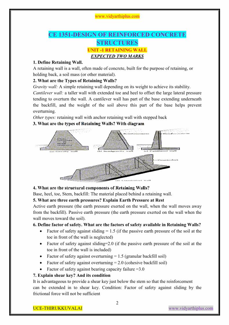
3. What are the types of Retaining Walls? With diagram
4. What are the structural components of Retaining Walls?
Base, heel, toe, Stem, backfill: The material placed behind a retaining wall.
5. What are three earth pressures? Explain Earth Pressure at Rest
Active earth pressure (the earth pressure exerted on the wall, when the wall moves away
from the backfill). Passive earth pressure (the earth pressure exerted on the wall when the
wall moves toward the soil).
6. Define factor of safety. What are the factors of safety available in Retaining Walls?
Factor of safety against sliding = 1.5 (if the passive earth pressure of the soil at the
toe in front of the wall is neglected)
Factor of safety against sliding=2.0 (if the passive earth pressure of the soil at the
toe in front of the wall is included)
Factor of safety against overturning = 1.5 (granular backfill soil)
Factor of safety against overturning = 2.0 (cohesive backfill soil)
Factor of safety against bearing capacity failure =3.0
7. Explain shear key? And its condition
It is advantageous to provide a shear key just below the stem so that the reinforcement
can be extended in to shear key. Condition: Factor of safety against sliding by the
frictional force will not be sufficient
www.vidyarthiplus.com
3 UCE-THIRUKKUVALAI www.vidyarthiplus.com
8. Define Active and Passive Earth Pressure. (May 2011)
Active Earth Pressure: It is the pressure that at all times are tending to move or overturn
the retaining wall”
Passive Earth Pressure: “It is reactionary pressures that will react in the form of a
resistance to movement of the wall.
9. What are the Effects of Active and Passive Earth Pressure?
Active Earth Pressure:
It is composed of the earth wedge being retained together with any hydrostatic pressure
caused by the presence of groundwater. This pressure can be reduced by:
The use of subsoil drainage behind the wall.
Inserting drainage openings called weep holes through the thickness of the stem to enable
the water to drain away.
Passive Earth Pressure:
It builds up in front of the toe to resist the movement of the wall if it tries to move
forward.
This pressure can be increased by enlarging the depth of the toe or by forming a rib on
the underside of the base.
10. What are the factors to be considered while designing the Retaining Walls?
Overturning doesn’t occur
Sliding doesn’t occur
The soil on which the wall rests mustn’t be overloaded
The materials used in construction are not overstressed.
11. What are the forces or pressure that has to be calculated while designing the
Retaining Walls?
Height Of Water Table
Nature & Type Of Soil
Subsoil Water Movements
Type Of Wall
Material Used In The Construction Of Wall
12. What are types of gravity Retaining Walls?
Massive Gravity Wall
Counter fort Wall
Cantilever Gravity Wall
13. Write down the formula for Factor of Safety of Retaining Walls?
Hence the factor of safety can be expresses by the relation,
www.vidyarthiplus.com
4 UCE-THIRUKKUVALAI www.vidyarthiplus.com
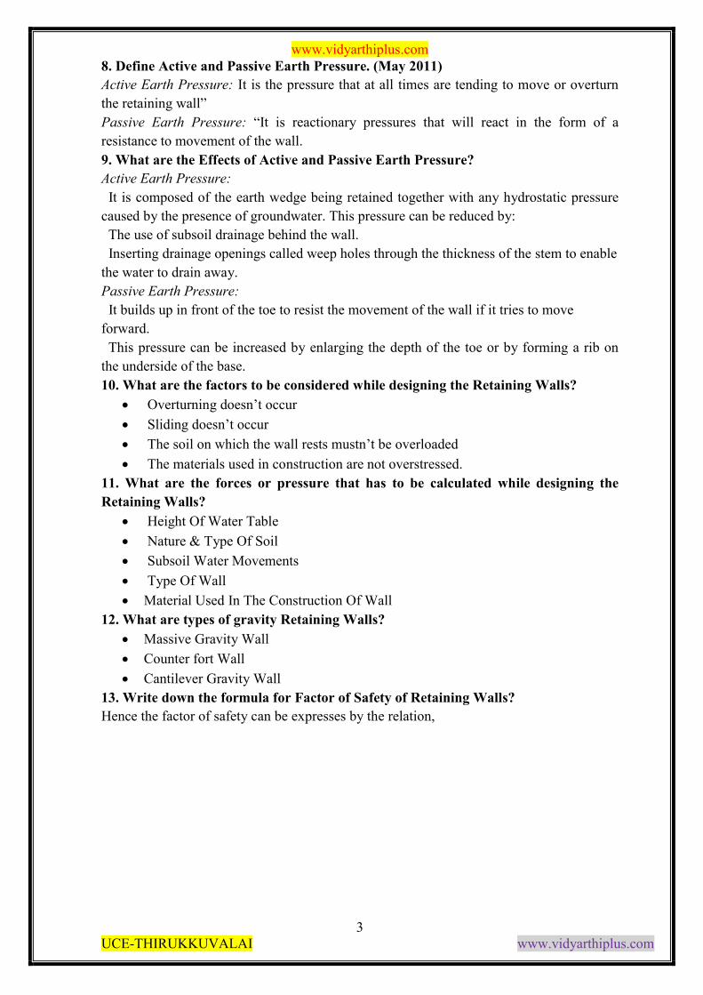
14. Draw the effective surcharge on a level back fill in Retaining Walls?
15. Write down the formula for Factor of Safety against sliding of Retaining Walls?
F= μR
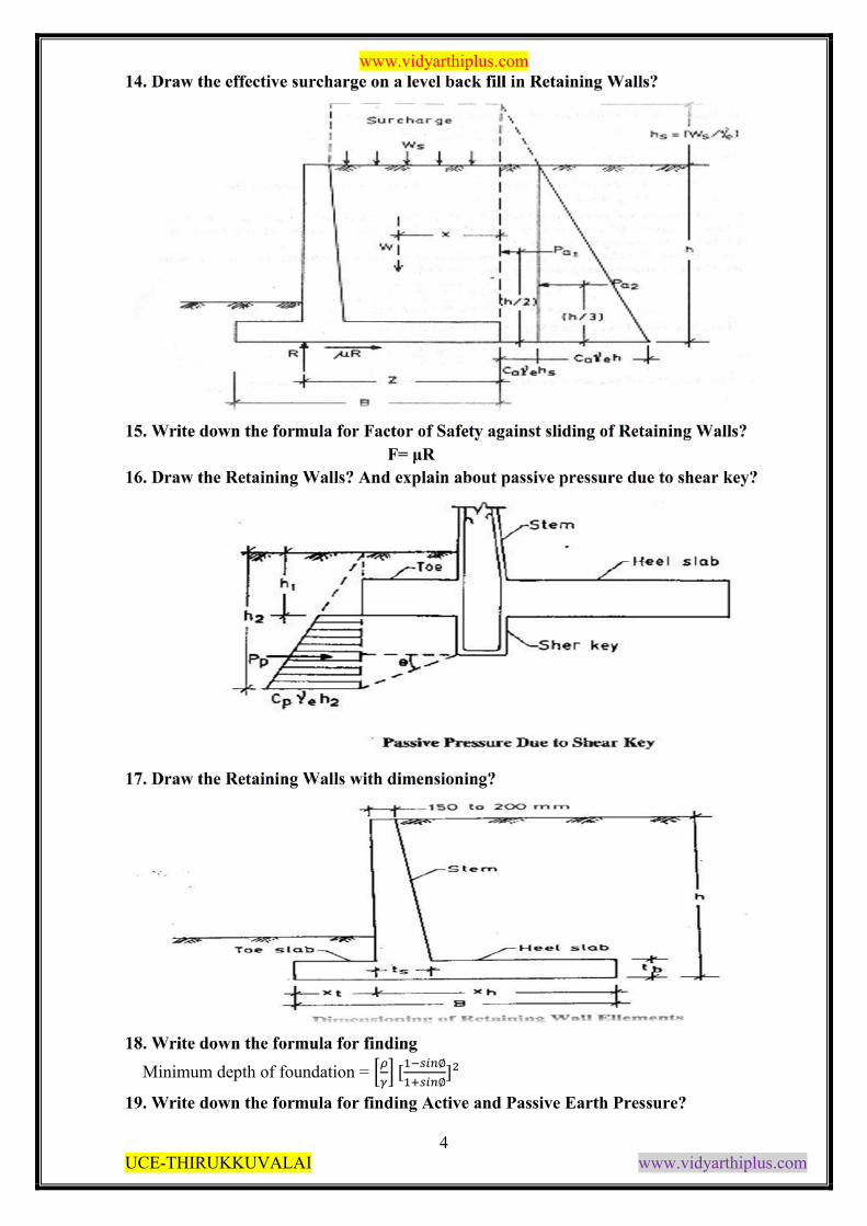
16. Draw the Retaining Walls? And explain about passive pressure due to shear key?
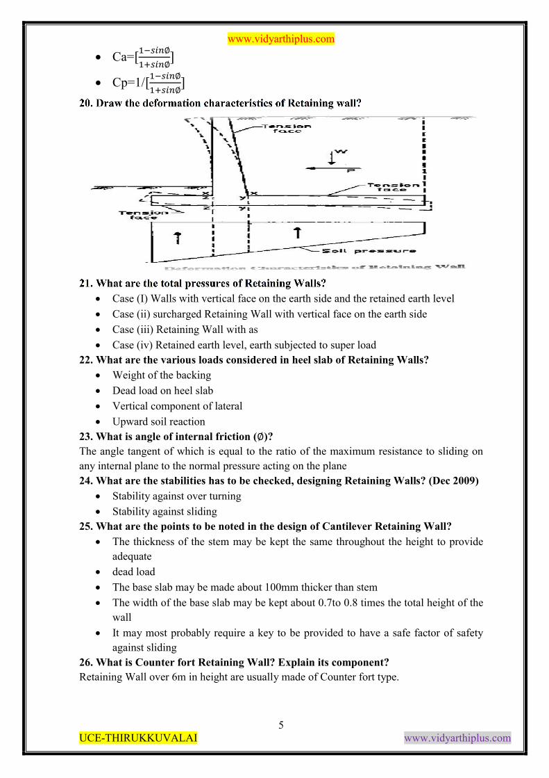
17. Draw the Retaining Walls with dimensioning?
18. Write down the formula for finding
Minimum depth of foundation = ��
�� [�����∅
�����∅]²
19. Write down the formula for finding Active and Passive Earth Pressure?
www.vidyarthiplus.com
5 UCE-THIRUKKUVALAI www.vidyarthiplus.com
Ca=[�����∅
�����∅]
Cp=1/[�����∅
�����∅]
20. Draw the deformation characteristics of Retaining wall?
21. What are the total pressures of Retaining Walls?
Case (I) Walls with vertical face on the earth side and the retained earth level
Case (ii) surcharged Retaining Wall with vertical face on the earth side
Case (iii) Retaining Wall with as
Case (iv) Retained earth level, earth subjected to super load
22. What are the various loads considered in heel slab of Retaining Walls?
Weight of the backing
Dead load on heel slab
Vertical component of lateral
Upward soil reaction
23. What is angle of internal friction (∅)?
The angle tangent of which is equal to the ratio of the maximum resistance to sliding on
any internal plane to the normal pressure acting on the plane
24. What are the stabilities has to be checked, designing Retaining Walls? (Dec 2009)
Stability against over turning
Stability against sliding
25. What are the points to be noted in the design of Cantilever Retaining Wall?
The thickness of the stem may be kept the same throughout the height to provide
adequate
dead load
The base slab may be made about 100mm thicker than stem
The width of the base slab may be kept about 0.7to 0.8 times the total height of the
wall
It may most probably require a key to be provided to have a safe factor of safety
against sliding
26. What is Counter fort Retaining Wall? Explain its component?
Retaining Wall over 6m in height are usually made of Counter fort type.
www.vidyarthiplus.com
6 UCE-THIRUKKUVALAI www.vidyarthiplus.com
Upright slab : its design as a continuous slab spanning horizontally on the Counter
fort subjected to lateral earth pressure
Base slab: the width of the base slab may be taken as 0.6H to0.7H where H= over
all height of the retaining wall.
Heel slab: the Heel slab should be designed as a continuous horizontal slab with
counter fort as the supports.
27. What are the loads acting on the heel slab of the Counter fort Retaining Wall?
Dead load of the strip
Weight of the earth above the strip
Vertical components of the lateral pressure in the case of the earth surcharged at an
angle.
28. What is spacing of the Counter fort in Counter fort Retaining Wall?
The spacing the Counter fort is 3m to 3.5m
9
EXPECTED 16 MARKS QUESTIONS:
1. Design a cantilever retaining wall to retain earth embankment 4m high above G.L. The
density of earth is 18KN / m3 and its angle of repose is 30 degrees. The embankment is
horizontal at its top. The safe bearing capacity of the oil may be taken as 200KN / m2 and
the co-efficient of friction between the soil and concrete is 0.5. Adopt M20 grade of
concrete and Fe 415 HYSD bars.
2. Design a counter fort retaining wall to suit the following data:
Height of the wall = 6m
SBC of the soil at site = 160 KN / m2
Angle of internal friction = 33 degree
Density of soil = 16 KN / m3
Spacing of counter fort = 3m c / c
Grade of concrete = M20
Grade of steel = Fe 415 HYSD bars
3. Design the stem of a reinforced concrete cantilever type retaining wall to retain earth
with the top of the wall to a height of 5m. The density of soil is 14KN/m3 and the angle of
repose is 30 degrees. Adopt M20 grade concrete and Fe 415 HYSD bars. Sketch the details
of reinforcements in the retaining wall. Assume SBC of soil as 180 KN / m2.
4. Design a cantilever type retaining wall to support a bank of earth above GL on the toe
side of the wall. The backfill surface is inclined at an angle of 15 degrees with the
horizontal. Assume that good soil for foundation at a depth of 1.25m below GL with a
SBC of 160KN/m2. The granular soil in the backfill has a unit weight of 16KN/m3 and an
angle of shearing resistance of 30 degree. Assume co-efficient of friction between the soil
and concrete to be 0.5 fck = 20 and fy = 415N/mm2.
5. Design a counter fort type retaining wall to suit the following data:
Safe bearing capacity of soil = 200KN/m2
Height of the soil above GL = 7m
www.vidyarthiplus.com
7 UCE-THIRUKKUVALAI www.vidyarthiplus.com
Unit weight of soil = 18 KN/m2
Angle of internal friction = 30º
Spacing of counter fort = 3m centers
Grade of concrete = M20
Grade of steel = Fe 415 HYSD bars
6. A reinforced concrete retaining wall of cantilever type is required to retain a granular
fill to a height of 4m above GL with the top of the wall. The depth of foundation may be
taken as 1.2m below G.L. The unit weight of fill is 14KN / m3 and angle of internal
friction is 30º. The Safe bearing capacity of soil is 200KN/m2. The base slab is to be
400mm thick. Adopt Grade of concrete = M20, Grade of steel = Fe 415 HYSD bars.
7. A cantilever type retaining wall is to be designed to retain an earthen embankment with
a horizontal top 4m above G.L. Density of soil = 18Kn/m3. Angle of repose = 30degree.
SBC of soil = 200 KN/m2. Co-efficient of friction between the soil and concrete = .5.
Adopt Grade of concrete = M20, Grade of steel = Fe 415 HYSD bars.
10
UNIT -II WATER TANKS
EXPECTED TWO MARKS
1. Define Domes.
A dome consists of ma shell which is generated by the revolution geometrical curve above
the axis a conical dome is obtained by revolving a triangle round a centre pivot Domes are
used to roof circular areas. They are used in building and water tanks.
2. What are the different types of Domes?
(a)Spherical domes
(b)Conical domes
3. What are the stresses acting on domes?
(a)Meridional thrust
(b)Hoop stress
4. Define Meridional thrust (T)
For purpose of analysis let us consider the domes as formed by a series of horizontal rings
of decreasing diameters place one above others. Hence we apply load on dome it get
resisted by their horizontal rings. There will thus be a thrust of one ring on the other. This
thrust is called Meridional thrust
5. Define Hoop stress (f)
Let “T” be the thrust per unit run on the ring. The horizontal component of this thrust will
produce a hoop tension.
6. What is the formula for Meridional thrust of the spherical domes?
T= [wR/ (1+cos�)] + [W/2�R.sin²�]
7. What is the formula for Hoop stress of the spherical domes?
f = wR/t (cos�-(1/1+cos�))] + [W/2�Rt. sin²�]
8. What is the formula for Meridional thrust of the conical domes? Wh/t tan²�
T= [wh/2.sec² �] + [W sec �/ (2�h.tan �)]
www.vidyarthiplus.com
8 UCE-THIRUKKUVALAI www.vidyarthiplus.com
9. What is the formula for Hoop stress of the conical domes?
f= Wh/t tan²�
10. Define water tank
A water tank is used to store water to tide over the daily requirements.
11. What are the classifications based on under three heads?
Tanks Resisting On Ground
Elevated Tanks Supported On Staging
Underground Water Tanks
12. What are the classifications based on shape point of view?
Circular tank
Rectangular tank
Spherical tank
Circular tank with conical bottom
13. What are the joints in water tanks?
Movement joints
Contraction joints
Expansion joints
Sliding joints
Construction joints
Temporary joints
14. Define underground water tank?
Under ground water tank are used in water purification purpose. The walls of such tanks
are subjected to water pressure due to water stored in the tank and earth pressure.
15. What are the effects in circular water tank due to wall restrained at the base?
(a) Deformation of wall
(b) Load distribution
(c) Approximate B.M
16. What are the methods available for analysis of circular water tank?
(a) Dr.Reissner’s method
(b) Carpenter’s simplication of Dr.Reissner’s method
17. What are the steps involved in design of circular tanks?
(a) The domes
(b) Ring beam supporting the domes
(c) Cylindrical wall
(d) Ring beam supporting the domess
(e) Conical slab
(f) Floor of the tank
(g) The ring girder
(h) Column
(i) Foundation
18. What are the components of the water tank?
(a) Roof slab
(b) Roof beams
(c) Floor slab
www.vidyarthiplus.com
9 UCE-THIRUKKUVALAI www.vidyarthiplus.com
(d) Vertical wall
(e) Floor beams
(f) Columns
(g) Braces
(h) Foundation
19. What are the components to design the small over head circular tanks?
(a) Cylindrical wall
(b) Circular slab
(c) Supporting beams and columns
20. What are the conditions has to be considered while designing the underground
water tank?
(a) Tank is full and the surrounding soil is dry
(b) Tank is empty and the surrounding soil is water logged
(c) Tank is full and surrounding soil is water logged
(d) Tank is dry surrounding soil is dry
21. What are the critical cases has to be considered while designing the underground
water tank?
a) When the tank is full
b) When the tank is empty
22. Define conical domes?
The thrust and hoop stress in the conical domes can be determined on lines similar to those
of the spherical dome.
23. Define domes with openings.
If an opening is provided in a dome sufficient trimming reinforcement should be provided
all round the opening. The reinforcement reaching the opening should be wall anchored to
the trimming reinforcement.
24. What are the different loading conditions available in domes?
a) Uniformly distributed load of ‘w’ per unit area of the dome surface
b) Concentrated load on the crown of the domes
25. Define ring beams and its advantages?
Often the ring beam at the base is made by thickening the edges and providing adequate
hoop steel to resist the hoop tension.
a) Sometimes no thickening of the edge may become necessary and the requisition
amount of hoop steel will be sufficient
b) Often a ring beam section may be based of an architectural consideration
c) A minimum of 0.3% of gross area shall be provided as the reinforced in each
principal
d) direction for the dome section
13
EXPECTED 16 MARKS QUESTIONS:
1. A reinforced concrete dome of 6m base diameter with a rise of 1.25m is to be designed
for a water tank. The uniformly distributed live load including finishes on dome may be
taken as 2KN/m2. Adopt M20 concrete and grade I steel, design the dome and ring beam.
Permissible tensile stress in steel = 100N/mm2.
www.vidyarthiplus.com
10 UCE-THIRUKKUVALAI www.vidyarthiplus.com
2. Design a circular water tank with a flexible base for a capacity of 500,000 liters. The
depth of water is to be 4m. Free board = 200mm. Use M20 concrete and grade I steel.
Permissible direct tensile stress in concrete = 1.2N/mm2. Permissible direct tensile stress
in steel = 100 N/mm2. Sketch the details of reinforcements in tank walls.
3. Design a circular water tank with a fixed base for a capacity of 400,000 liters. The depth
of water is to be 4m. Free board = 200mm. Use M20 concrete and grade I steel.
Permissible direct tensile stress in concrete = 1.2N/mm2. Permissible direct tensile stress
in steel = 100 N/mm2. Sketch the details of reinforcements in tank walls. Adopt IS code
tables for co-efficient.
4. A rectangular RC water tank with an open top is required to store 80,000 liters of water.
The inside dimensions of tank may be taken as 6m * 4m. The tank rests on walls on all
four sides. Design the side walls of the tank using M20 concrete and grade I steel.
5. A reinforced concrete water tank resting on ground is 6m x 2m with a maximum depth
of 2.5m. Using M20 concrete and grade I steel. Design the tank walls.
6. Design an over head flat bottomed RCC cylindrical water tank to store 100Kl of water.
The top of the tank is covered with a dome. Height of staging = 12m above GL. Provide
2m depth of foundation. Intensity of wind pressure may be taken as KN/m2. SBC of the
soil at site is 100 KN/m2.Adopt M20 concrete and grade I steel. design the following:
a) Size of tank
b) Ring beam at junction of dome and side walls
c) side wall of tank
d) bottom ring girder
e) Tank floor slab
f) Bracing at 4m intervals
g) RC columns assuming six column supports
h) Foundation for the tank.
i)
7. Design the side walls of a square of RCC tank of capacity 70,000 litters of water. Depth
of water in the tank = 2.8m. Free board = 0.2m.Adopt M20 concrete and grade I steel.
Tensile stresses in steel limited to 100N/mm2 at water face and 125N/mm2 away from
face. Sketch the details of reinforcements in the walls of the tank.
8. Design an RC tank of internal dimensions 10m x 3m x 3m. The tank is to be provided
under ground. The soil surrounding the tank is likely to get wet. Angle of repose of soil in
dry state is 30º and in wet state is 6º. Soil weight = 20KN/m3. Adopt M20 concrete and
grade I steel.
UNIT -3 SELECTED TOPICS
EXPECTED TWO MARKS
1.Define Stair Cases.
www.vidyarthiplus.com
11 UCE-THIRUKKUVALAI www.vidyarthiplus.com
Staircase flights are generally designed as slabs spanning between wall supports or landing
beams or as cantilever from a longitudinal inclined beam. The staircase fulfills the
function of access between the various floors in the building. Generally the fl landings
between the floor levels
2. What are the structural components of the Stair?
a) TREAD: The horizontal portion of a step where the foot rests is referred to as tread 250
to 300 mm is the typical dimensions of a tread.
b) RISER: It is the vertical distance between the adjacent treads or the vertical projection
of the step with the value of 150 to 190 mm depending upon the type of building. The
width of the stairs is generally 1 to 1.5 m and in any case not less than provided with larger
widths to facilitate free passage to users and prevent overcrowding.
c) GOING: It is the horizontal projection plan of an inclined flight of steps between the
first and the last riser. A typical flight in a flight should not exceed 10 to 12.
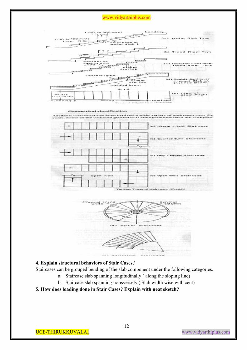
3. Draw the various types of Stair Cases? And Explain its components
www.vidyarthiplus.com
12 UCE-THIRUKKUVALAI www.vidyarthiplus.com
4. Explain structural behaviors of Stair Cases?
Staircases can be grouped bending of the slab component under the following categories.
a. Staircase slab spanning longitudinally ( along the sloping line)
b. Staircase slab spanning transversely ( Slab width wise with cent)
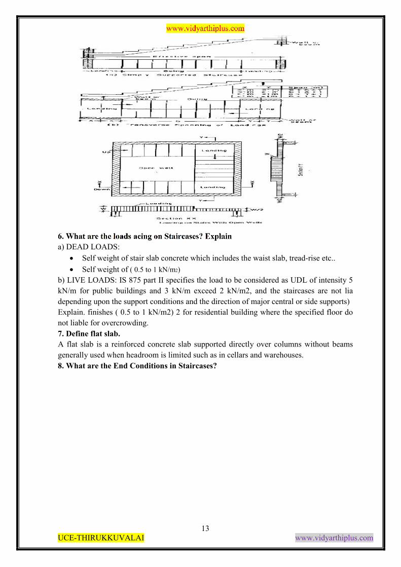
5. How does loading done in Stair Cases? Explain with neat sketch?
www.vidyarthiplus.com
13 UCE-THIRUKKUVALAI www.vidyarthiplus.com
6. What are the loads acing on Staircases? Explain
a) DEAD LOADS:
Self weight of stair slab concrete which includes the waist slab, tread-rise etc..
Self weight of ( 0.5 to 1 kN/m2)
b) LIVE LOADS: IS 875 part II specifies the load to be considered as UDL of intensity 5
kN/m for public buildings and 3 kN/m exceed 2 kN/m2, and the staircases are not lia
depending upon the support conditions and the direction of major central or side supports)
Explain. finishes ( 0.5 to 1 kN/m2) 2 for residential building where the specified floor do
not liable for overcrowding.
7. Define flat slab.
A flat slab is a reinforced concrete slab supported directly over columns without beams
generally used when headroom is limited such as in cellars and warehouses.
8. What are the End Conditions in Staircases?
www.vidyarthiplus.com
14 UCE-THIRUKKUVALAI www.vidyarthiplus.com
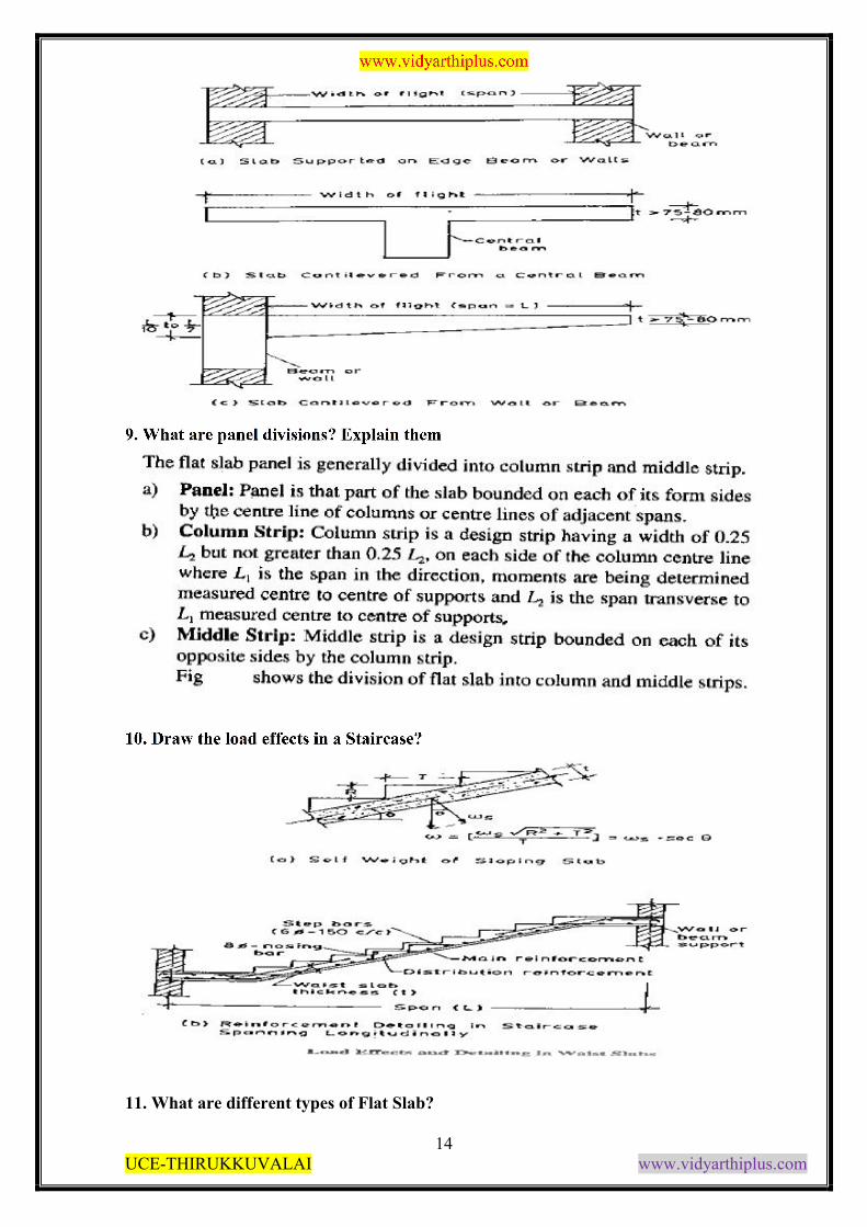
9. What are panel divisions? Explain them
10. Draw the load effects in a Staircase?
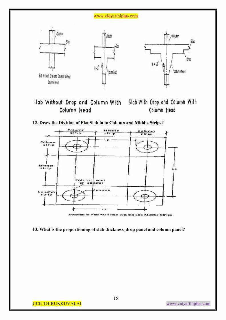
11. What are different types of Flat Slab?
www.vidyarthiplus.com
15 UCE-THIRUKKUVALAI www.vidyarthiplus.com
12. Draw the Division of Flat Slab in to Column and Middle Strips?
13. What is the proportioning of slab thickness, drop panel and column panel?
www.vidyarthiplus.com
16 UCE-THIRUKKUVALAI www.vidyarthiplus.com
14. Write about the Direct Design Method?
20
15. What is Total Design Moment for a Span?
www.vidyarthiplus.com
17 UCE-THIRUKKUVALAI www.vidyarthiplus.com
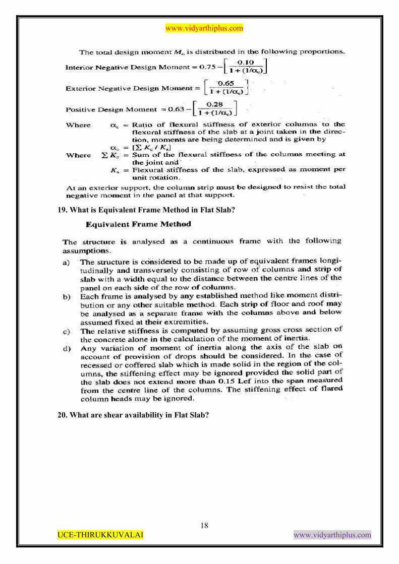
16. What are moments in interior panel of a Flat Slab?
17. What are the design moments in Flat Slab?
18. What are moments in exterior panel of a Flat Slab?
www.vidyarthiplus.com
18 UCE-THIRUKKUVALAI www.vidyarthiplus.com
19. What is Equivalent Frame Method in Flat Slab?
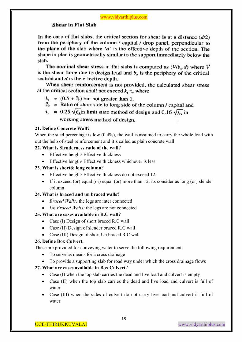
20. What are shear availability in Flat Slab?
www.vidyarthiplus.com
19 UCE-THIRUKKUVALAI www.vidyarthiplus.com
21. Define Concrete Wall?
When the steel percentage is low (0.4%), the wall is assumed to carry the whole load with
out the help of steel reinforcement and it’s called as plain concrete wall
22. What is Slenderness ratio of the wall?
Effective height/ Effective thickness
Effective length/ Effective thickness whichever is less.
23. What is short& long column?
Effective height/ Effective thickness do not exceed 12.
If it exceed (or) equal (or) equal (or) more than 12, its consider as long (or) slender
column
24. What is braced and un braced walls?
Braced Walls: the legs are inter connected
Un Braced Walls: the legs are not connected
25. What are cases available in R.C wall?
Case (I) Design of short braced R.C wall
Case (II) Design of slender braced R.C wall
Case (III) Design of short Un braced R.C wall
26. Define Box Culvert.
These are provided for conveying water to serve the following requirements
To serve as means for a cross drainage
To provide a supporting slab for road way under which the cross drainage flows
27. What are cases available in Box Culvert?
Case (I) when the top slab carries the dead and live load and culvert is empty
Case (II) when the top slab carries the dead and live load and culvert is full of
water
Case (III) when the sides of culvert do not carry live load and culvert is full of
water.
23
www.vidyarthiplus.com
20 UCE-THIRUKKUVALAI www.vidyarthiplus.com
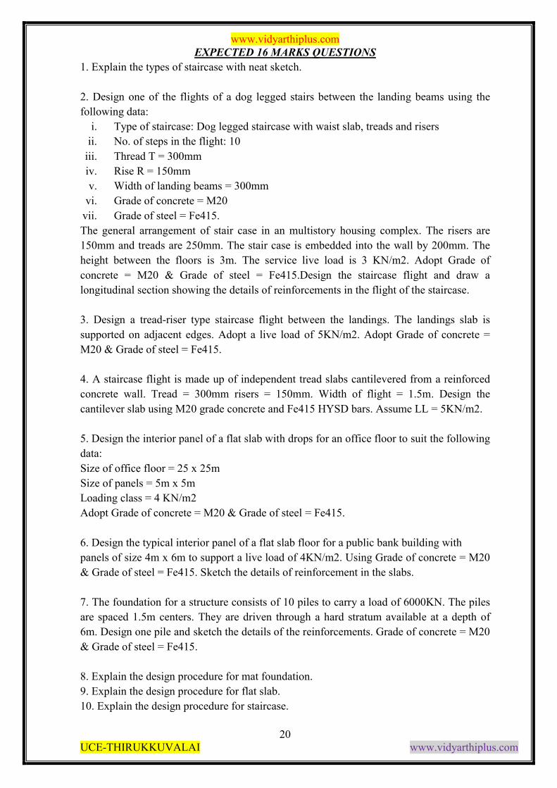
EXPECTED 16 MARKS QUESTIONS
1. Explain the types of staircase with neat sketch.
2. Design one of the flights of a dog legged stairs between the landing beams using the
following data:
i. Type of staircase: Dog legged staircase with waist slab, treads and risers
ii. No. of steps in the flight: 10
iii. Thread T = 300mm
iv. Rise R = 150mm
v. Width of landing beams = 300mm
vi. Grade of concrete = M20
vii. Grade of steel = Fe415.
The general arrangement of stair case in an multistory housing complex. The risers are
150mm and treads are 250mm. The stair case is embedded into the wall by 200mm. The
height between the floors is 3m. The service live load is 3 KN/m2. Adopt Grade of
concrete = M20 & Grade of steel = Fe415.Design the staircase flight and draw a
longitudinal section showing the details of reinforcements in the flight of the staircase.
3. Design a tread-riser type staircase flight between the landings. The landings slab is
supported on adjacent edges. Adopt a live load of 5KN/m2. Adopt Grade of concrete =
M20 & Grade of steel = Fe415.
4. A staircase flight is made up of independent tread slabs cantilevered from a reinforced
concrete wall. Tread = 300mm risers = 150mm. Width of flight = 1.5m. Design the
cantilever slab using M20 grade concrete and Fe415 HYSD bars. Assume LL = 5KN/m2.
5. Design the interior panel of a flat slab with drops for an office floor to suit the following
data:
Size of office floor = 25 x 25m
Size of panels = 5m x 5m
Loading class = 4 KN/m2
Adopt Grade of concrete = M20 & Grade of steel = Fe415.
6. Design the typical interior panel of a flat slab floor for a public bank building with
panels of size 4m x 6m to support a live load of 4KN/m2. Using Grade of concrete = M20
& Grade of steel = Fe415. Sketch the details of reinforcement in the slabs.
7. The foundation for a structure consists of 10 piles to carry a load of 6000KN. The piles
are spaced 1.5m centers. They are driven through a hard stratum available at a depth of
6m. Design one pile and sketch the details of the reinforcements. Grade of concrete = M20
& Grade of steel = Fe415.
8. Explain the design procedure for mat foundation.
9. Explain the design procedure for flat slab.
10. Explain the design procedure for staircase.
www.vidyarthiplus.com
21 UCE-THIRUKKUVALAI www.vidyarthiplus.com
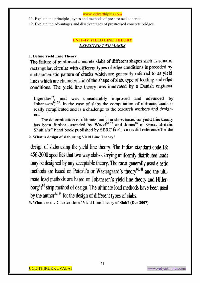
11. Explain the principles, types and methods of pre stressed concrete.
12. Explain the advantages and disadvantages of prestressed concrete bridges.
25
UNIT–IV YIELD LINE THEORY
EXPECTED TWO MARKS
1. Define Yield Line Theory.
2. What is design of slab using Yield Line Theory?
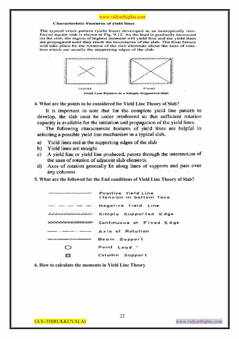
3. What are the Charter tics of Yield Line Theory of Slab? (Dec 2007)
www.vidyarthiplus.com
22 UCE-THIRUKKUVALAI www.vidyarthiplus.com
4. What are the points to be considered for Yield Line Theory of Slab?
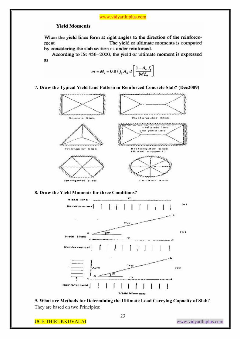
5. What are the followed for the End conditions of Yield Line Theory of Slab?
6. How to calculate the moments in Yield Line Theory
www.vidyarthiplus.com
23 UCE-THIRUKKUVALAI www.vidyarthiplus.com
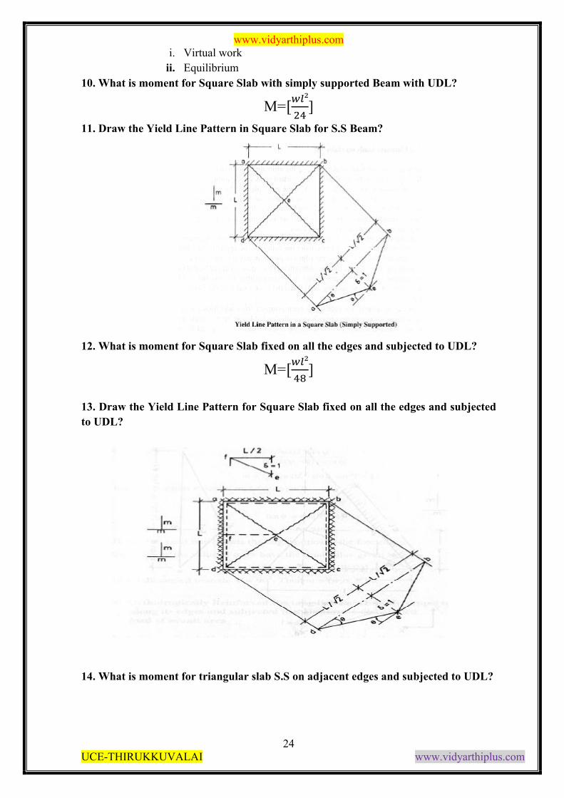
7. Draw the Typical Yield Line Pattern in Reinforced Concrete Slab? (Dec2009)
8. Draw the Yield Moments for three Conditions?
9. What are Methods for Determining the Ultimate Load Carrying Capacity of Slab?
They are based on two Principles:
www.vidyarthiplus.com
24 UCE-THIRUKKUVALAI www.vidyarthiplus.com
i. Virtual work
ii. Equilibrium
10. What is moment for Square Slab with simply supported Beam with UDL?
M=[��²
��]
11. Draw the Yield Line Pattern in Square Slab for S.S Beam?
12. What is moment for Square Slab fixed on all the edges and subjected to UDL?
M=[��²
��]
13. Draw the Yield Line Pattern for Square Slab fixed on all the edges and subjected
to UDL?
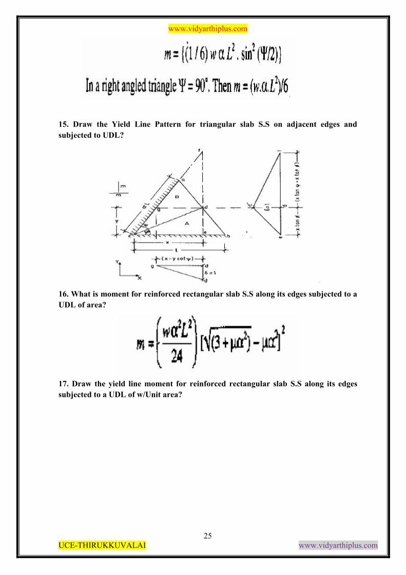
14. What is moment for triangular slab S.S on adjacent edges and subjected to UDL?
www.vidyarthiplus.com
25 UCE-THIRUKKUVALAI www.vidyarthiplus.com
15. Draw the Yield Line Pattern for triangular slab S.S on adjacent edges and
subjected to UDL?
16. What is moment for reinforced rectangular slab S.S along its edges subjected to a
UDL of area?
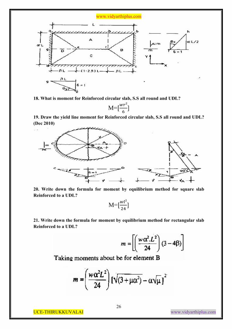
17. Draw the yield line moment for reinforced rectangular slab S.S along its edges
subjected to a UDL of w/Unit area?
www.vidyarthiplus.com
26 UCE-THIRUKKUVALAI www.vidyarthiplus.com
18. What is moment for Reinforced circular slab, S.S all round and UDL?
M=[��²
�]
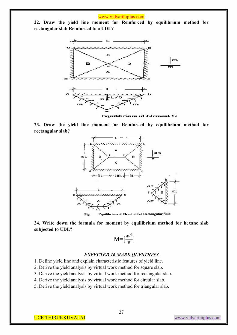
19. Draw the yield line moment for Reinforced circular slab, S.S all round and UDL?
(Dec 2010)
20. Write down the formula for moment by equilibrium method for square slab
Reinforced to a UDL?
M=[��²
��]
21. Write down the formula for moment by equilibrium method for rectangular slab
Reinforced to a UDL?
www.vidyarthiplus.com
27 UCE-THIRUKKUVALAI www.vidyarthiplus.com
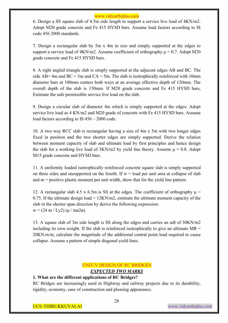
22. Draw the yield line moment for Reinforced by equilibrium method for
rectangular slab Reinforced to a UDL?
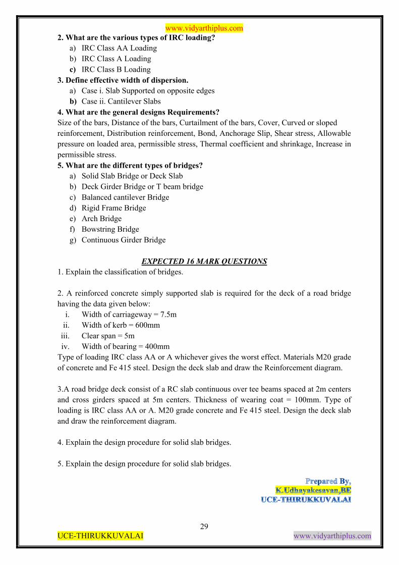
23. Draw the yield line moment for Reinforced by equilibrium method for
rectangular slab?
24. Write down the formula for moment by equilibrium method for hexane slab
subjected to UDL?
32 M=[��²
�]
EXPECTED 16 MARK QUESTIONS
1. Define yield line and explain characteristic features of yield line.
2. Derive the yield analysis by virtual work method for square slab.
3. Derive the yield analysis by virtual work method for rectangular slab.
4. Derive the yield analysis by virtual work method for circular slab.
5. Derive the yield analysis by virtual work method for triangular slab.
www.vidyarthiplus.com
28 UCE-THIRUKKUVALAI www.vidyarthiplus.com
6. Design a SS square slab of 4.5m side length to support a service live load of 4KN/m2.
Adopt M20 grade concrete and Fe 415 HYSD bars. Assume load factors according to IS
code 456 2000 standards.
7. Design a rectangular slab by 5m x 4m in size and simply supported at the edges to
support a service load of 4KN/m2. Assume coefficient of orthography μ = 0.7. Adopt M20
grade concrete and Fe 415 HYSD bars.
8. A right angled triangle slab is simply supported at the adjacent edges AB and BC. The
side AB= 4m and BC = 3m and CA = 5m. The slab is isotrophically reinforced with 10mm
diameter bars at 100mm centers both ways at an average effective depth of 120mm. The
overall depth of the slab is 150mm. If M20 grade concrete and Fe 415 HYSD bars,
Estimate the safe permissible service live load on the slab.
9. Design a circular slab of diameter 4m which is simply supported at the edges. Adopt
service live load as 4 KN/m2 and M20 grade of concrete with Fe 415 HYSD bars. Assume
load factors according to IS 456 – 2000 code.
10. A two way RCC slab is rectangular having a size of 4m x 5m with two longer edges
fixed in position and the two shorter edges are simply supported. Derive the relation
between moment capacity of slab and ultimate load by first principles and hence design
the slab for a working live load of 3KN/m2 by yield line theory. Assume μ = 0.8. Adopt
M15 grade concrete and HYSD bars.
11. A uniformly loaded isotrophically reinforced concrete square slab is simply supported
on three sides and unsupported on the fourth. If w = load per unit area at collapse of slab
and m = positive plastic moment per unit width, show that for the yield line pattern.
12. A rectangular slab 4.5 x 6.5m is SS at the edges. The coefficient of orthography μ =
0.75. If the ultimate design load = 12KN/m2, estimate the ultimate moment capacity of the
slab in the shorter span direction by derive the following expression:
w = (24 m / Ly2) (μ / tan2ø).
13. A square slab of 3m side length is SS along the edges and carries an udl of 30KN/m2
including its own weight. If the slab is reinforced isotrophically to give an ultimate MR =
20KN.m/m, calculate the magnitude of the additional central point load required to cause
collapse. Assume a pattern of simple diagonal yield lines.
34
UNIT-V DESIGN OF RC BRIDGES
EXPECTED TWO MARKS
1. What are the different applications of RC Bridges?
RC Bridges are increasingly used in Highway and railway projects due to its durability,
rigidity, economy, ease of construction and pleasing appearance.
www.vidyarthiplus.com
29 UCE-THIRUKKUVALAI www.vidyarthiplus.com
2. What are the various types of IRC loading?
a) IRC Class AA Loading
b) IRC Class A Loading
c) IRC Class B Loading
3. Define effective width of dispersion.
a) Case i. Slab Supported on opposite edges
b) Case ii. Cantilever Slabs
4. What are the general designs Requirements?
Size of the bars, Distance of the bars, Curtailment of the bars, Cover, Curved or sloped
reinforcement, Distribution reinforcement, Bond, Anchorage Slip, Shear stress, Allowable
pressure on loaded area, permissible stress, Thermal coefficient and shrinkage, Increase in
permissible stress.
5. What are the different types of bridges?
a) Solid Slab Bridge or Deck Slab
b) Deck Girder Bridge or T beam bridge
c) Balanced cantilever Bridge
d) Rigid Frame Bridge
e) Arch Bridge
f) Bowstring Bridge
g) Continuous Girder Bridge
35
EXPECTED 16 MARK QUESTIONS
1. Explain the classification of bridges.
2. A reinforced concrete simply supported slab is required for the deck of a road bridge
having the data given below:
i. Width of carriageway = 7.5m
ii. Width of kerb = 600mm
iii. Clear span = 5m
iv. Width of bearing = 400mm
Type of loading IRC class AA or A whichever gives the worst effect. Materials M20 grade
of concrete and Fe 415 steel. Design the deck slab and draw the Reinforcement diagram.
3.A road bridge deck consist of a RC slab continuous over tee beams spaced at 2m centers
and cross girders spaced at 5m centers. Thickness of wearing coat = 100mm. Type of
loading is IRC class AA or A. M20 grade concrete and Fe 415 steel. Design the deck slab
and draw the reinforcement diagram.
4. Explain the design procedure for solid slab bridges.
5. Explain the design procedure for solid slab bridges.
![[1] RPP SD KELAS 3 SEMESTER 1 - Sayangi Hewan dan Tumbuhan di Sekitar www](https://img.pdfslide.net/doc/110x75/631ce2c3665120b3330c1300/1-rpp-sd-kelas-3-semester-1-sayangi-hewan-dan-tumbuhan-di-sekitar-www.jpg)


![[2] RPP SD KELAS 1 SEMESTER 1 - Kegemaranku www](https://img.pdfslide.net/doc/110x75/6320b6f14d56c588170f7291/2-rpp-sd-kelas-1-semester-1-kegemaranku-www.jpg)


![Ky-thuat-giai-nhanh-luong-giac - www MATHVN com[1]](https://img.pdfslide.net/doc/110x75/634dbcd17c06afa1b60d40e0/ky-thuat-giai-nhanh-luong-giac-www-mathvn-com1.jpg)


![[1] RPP SD KELAS 2 SEMESTER 1 - Hidup Rukun www](https://img.pdfslide.net/doc/110x75/631d1a5f665120b3330c2e4f/1-rpp-sd-kelas-2-semester-1-hidup-rukun-www.jpg)


