Embed Size (px)
Citation preview
UML basics
Paolo Ciancarini
The soul never thinks
without an image Aristotle, De Anima
Agenda
• Evolution of UML: UML 1.* and UML 2.* • Structures, behaviors, interactions • The basic diagrams of UML 1.*
UML is a modeling language
• A modeling language allows the specification, the visualization, and the documentation of the development of a software system
• The models are artifacts which clients and developers use to communicate
• UML 1.* is a modeling language • UML 2.* is also a programming language
Meaning of models for software
• A model is a description of the structure and meaning of a system
• A model is always an abstraction at some level: it captures the essential aspects of a system and ignores some details
• Important: a model can be also generator of potential configurations of systems
Roots of UML
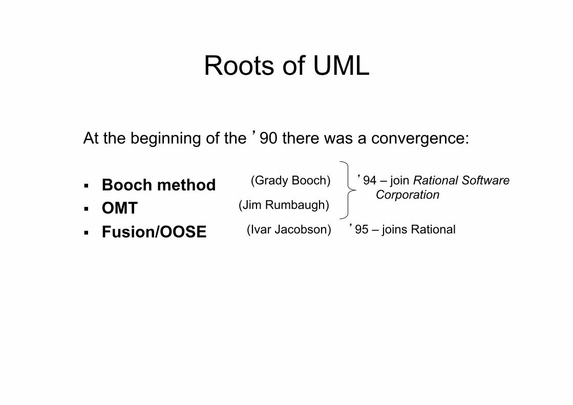
At the beginning of the ’90 there was a convergence: § Booch method § OMT § Fusion/OOSE
’94 – join Rational Software Corporation
(Grady Booch)
(Jim Rumbaugh)
’95 – joins Rational (Ivar Jacobson)
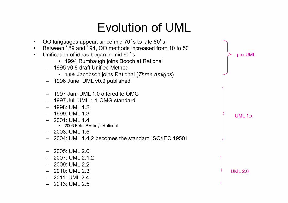
Evolution of UML • OO languages appear, since mid 70’s to late 80’s • Between ’89 and ’94, OO methods increased from 10 to 50 • Unification of ideas began in mid 90’s
• 1994 Rumbaugh joins Booch at Rational – 1995 v0.8 draft Unified Method
• 1995 Jacobson joins Rational (Three Amigos) – 1996 June: UML v0.9 published – 1997 Jan: UML 1.0 offered to OMG – 1997 Jul: UML 1.1 OMG standard – 1998: UML 1.2 – 1999: UML 1.3 – 2001: UML 1.4
• 2003 Feb: IBM buys Rational – 2003: UML 1.5 – 2004: UML 1.4.2 becomes the standard ISO/IEC 19501
– 2005: UML 2.0 – 2007: UML 2.1.2 – 2009: UML 2.2 – 2010: UML 2.3 – 2011: UML 2.4 – 2013: UML 2.5
pre-UML
UML 1.x
UML 2.0
OMG • Object Management Group, founded in 1989 • Consortium of 800 industries (eg. IBM, HP, Apple, etc.)
and interested universities (Bologna is member) • Produces specifications of reference architectures, eg.
CORBA • Other specifications: UML, various MDA technologies • UML as managed by OMG is a standard de facto in
continuous evolution • UML1.4 is a ISO standard de jure
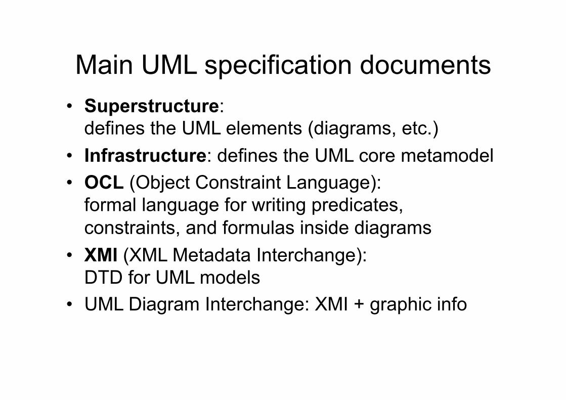
Main UML specification documents • Superstructure:
defines the UML elements (diagrams, etc.) • Infrastructure: defines the UML core metamodel • OCL (Object Constraint Language):
formal language for writing predicates, constraints, and formulas inside diagrams
• XMI (XML Metadata Interchange): DTD for UML models
• UML Diagram Interchange: XMI + graphic info
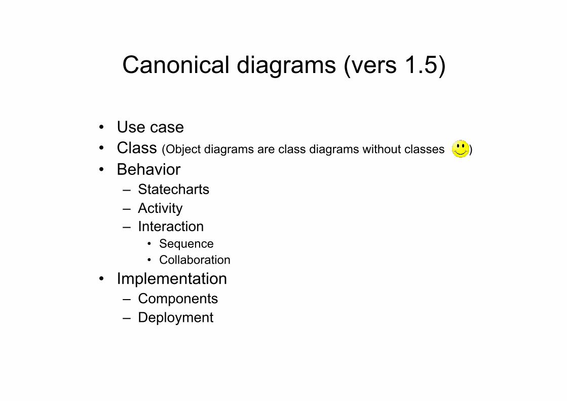
Canonical diagrams (vers 1.5)
• Use case • Class (Object diagrams are class diagrams without classes ) • Behavior
– Statecharts – Activity – Interaction
• Sequence • Collaboration
• Implementation – Components – Deployment
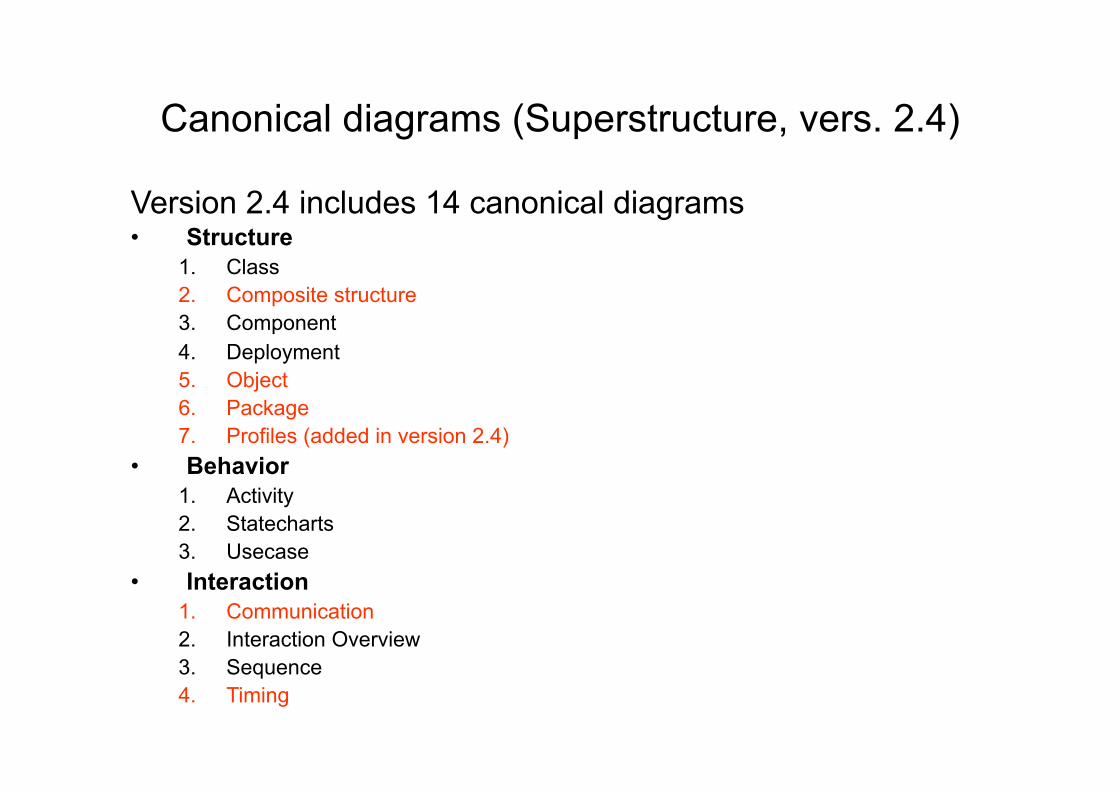
Canonical diagrams (Superstructure, vers. 2.4) Version 2.4 includes 14 canonical diagrams • Structure
1. Class 2. Composite structure 3. Component 4. Deployment 5. Object 6. Package 7. Profiles (added in version 2.4)
• Behavior 1. Activity 2. Statecharts 3. Usecase
• Interaction 1. Communication 2. Interaction Overview 3. Sequence 4. Timing
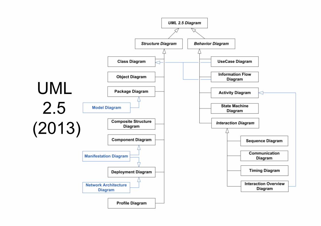
UML 2.5
(2013)
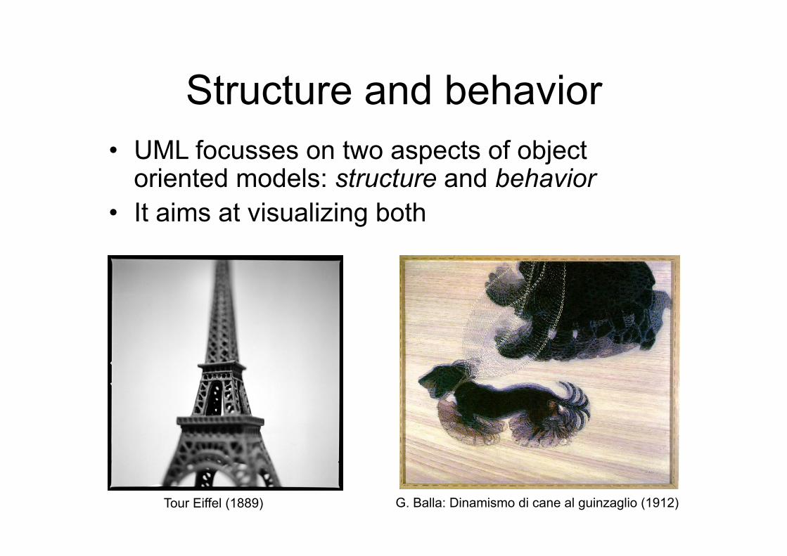
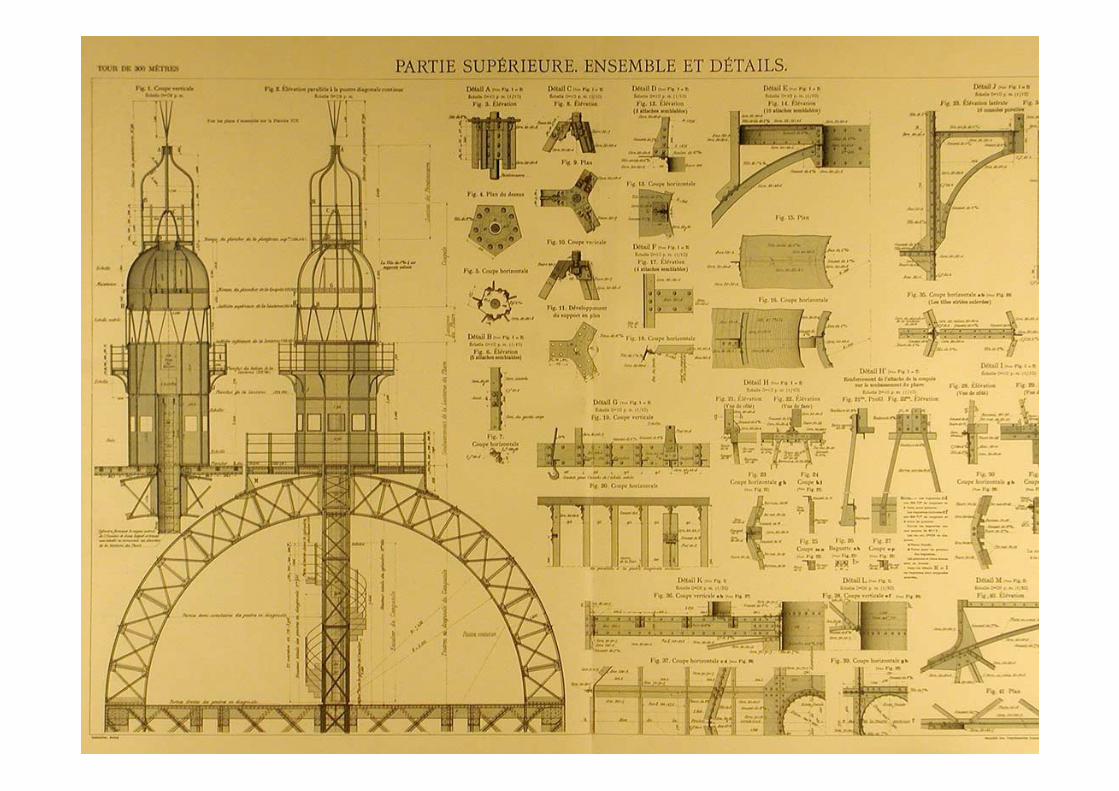
Structure and behavior • UML focusses on two aspects of object
oriented models: structure and behavior • It aims at visualizing both
Tour Eiffel (1889) G. Balla: Dinamismo di cane al guinzaglio (1912)
Describing the structure of software
• The description of structure offers an account of what a system is made of, in terms of both its parts and the relationships among them
• A structure may be a hierarchy featuring one-to-many relationships, a network featuring many-to-many links, or a lattice featuring connections between components that are neighbors in space
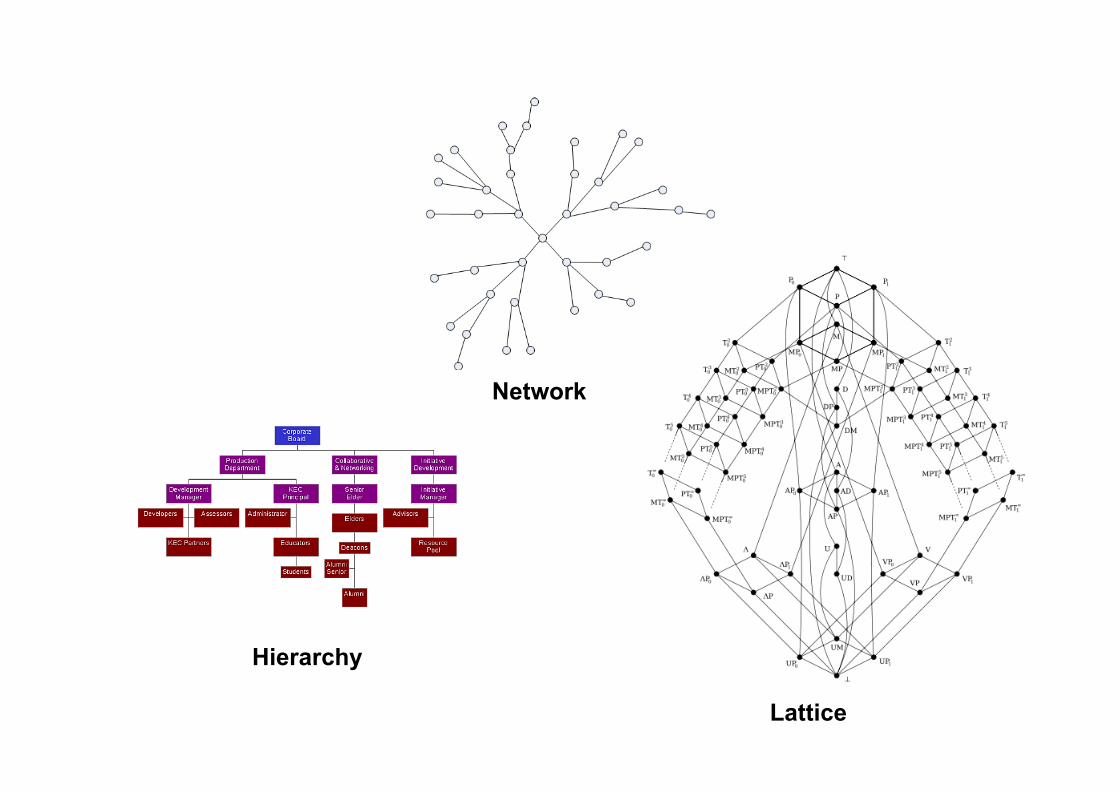
Hierarchy
Lattice
Network
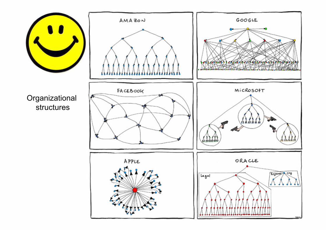
Organizational structures
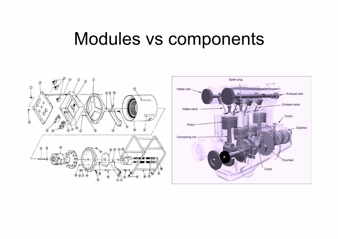
Modules vs components
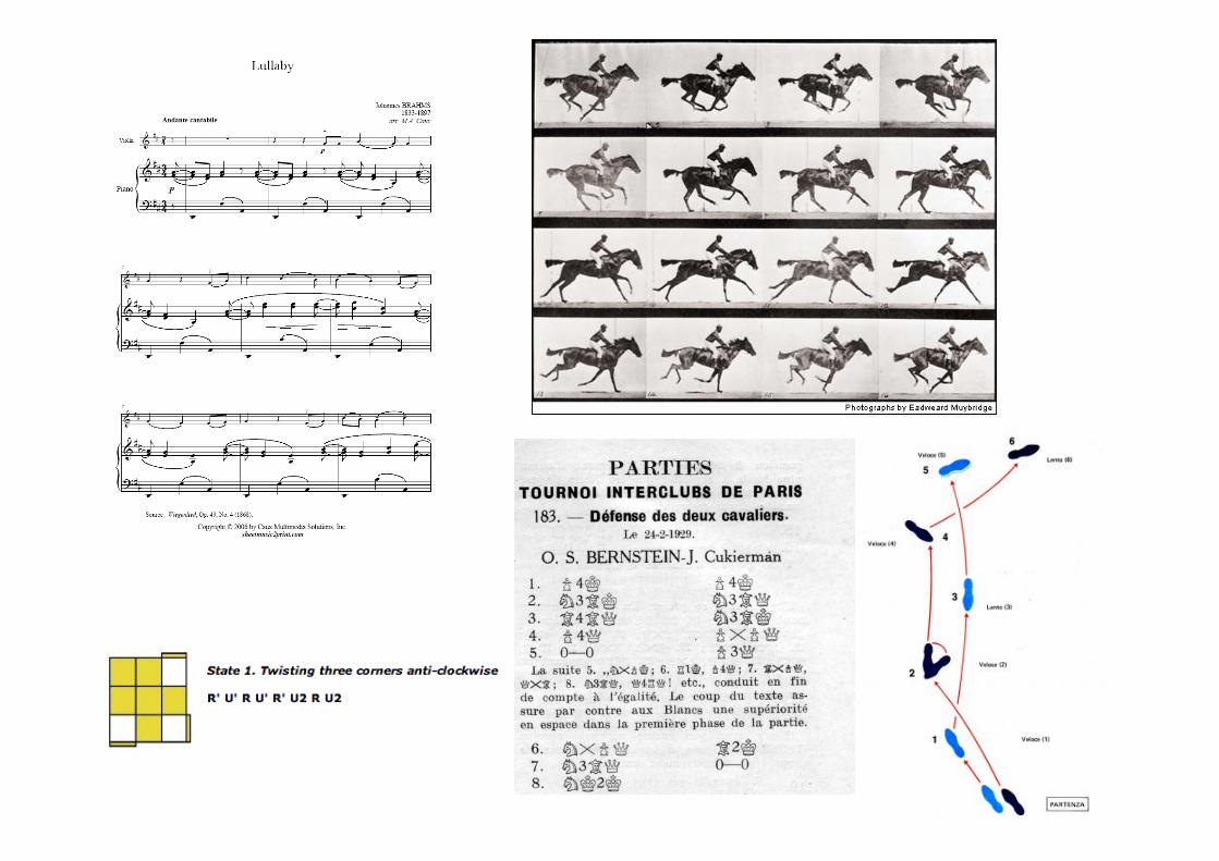
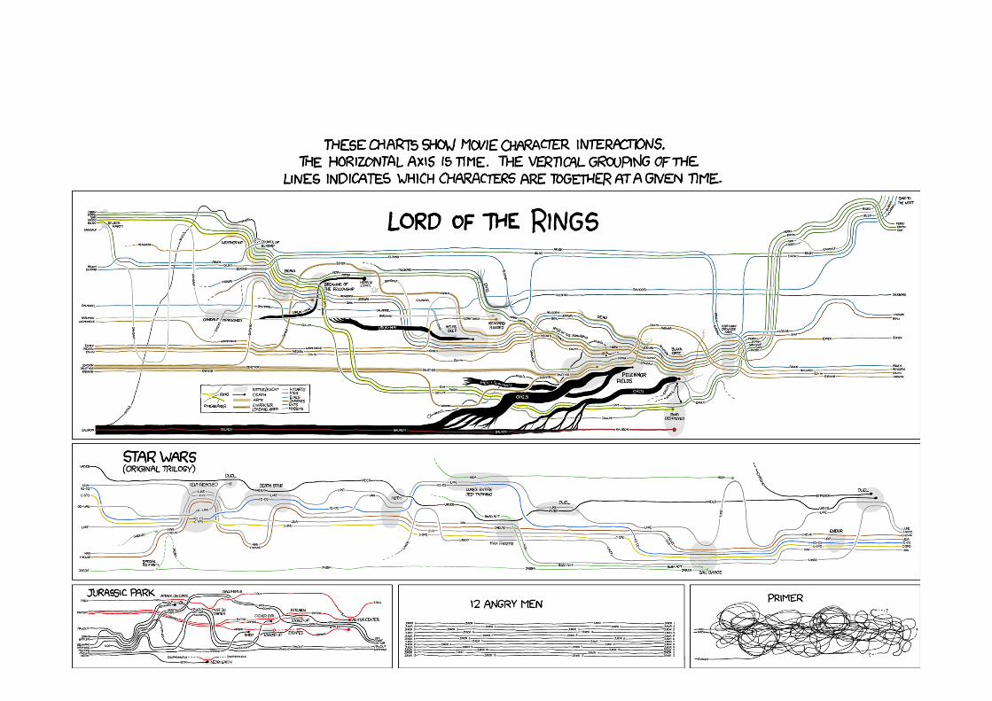
Discuss • Which ways do you know to pictorially
describe “behaviors” - or actions?
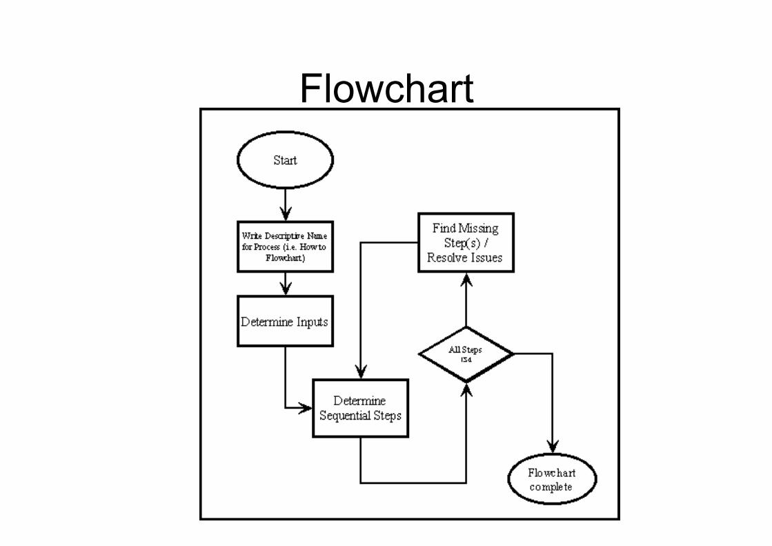
Flowchart
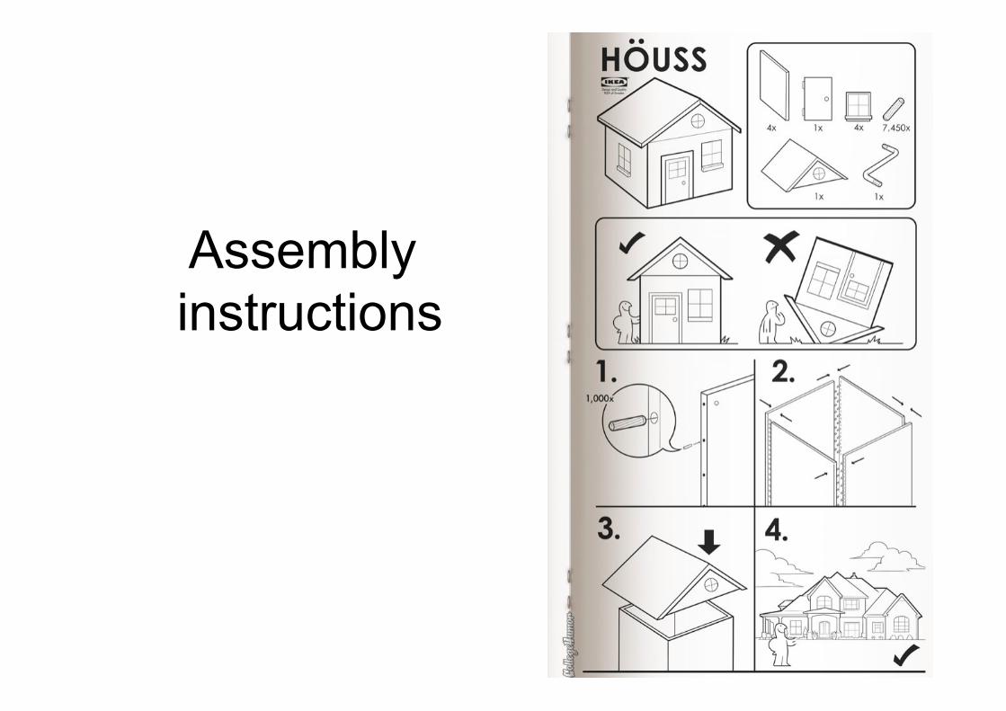
Assembly instructions
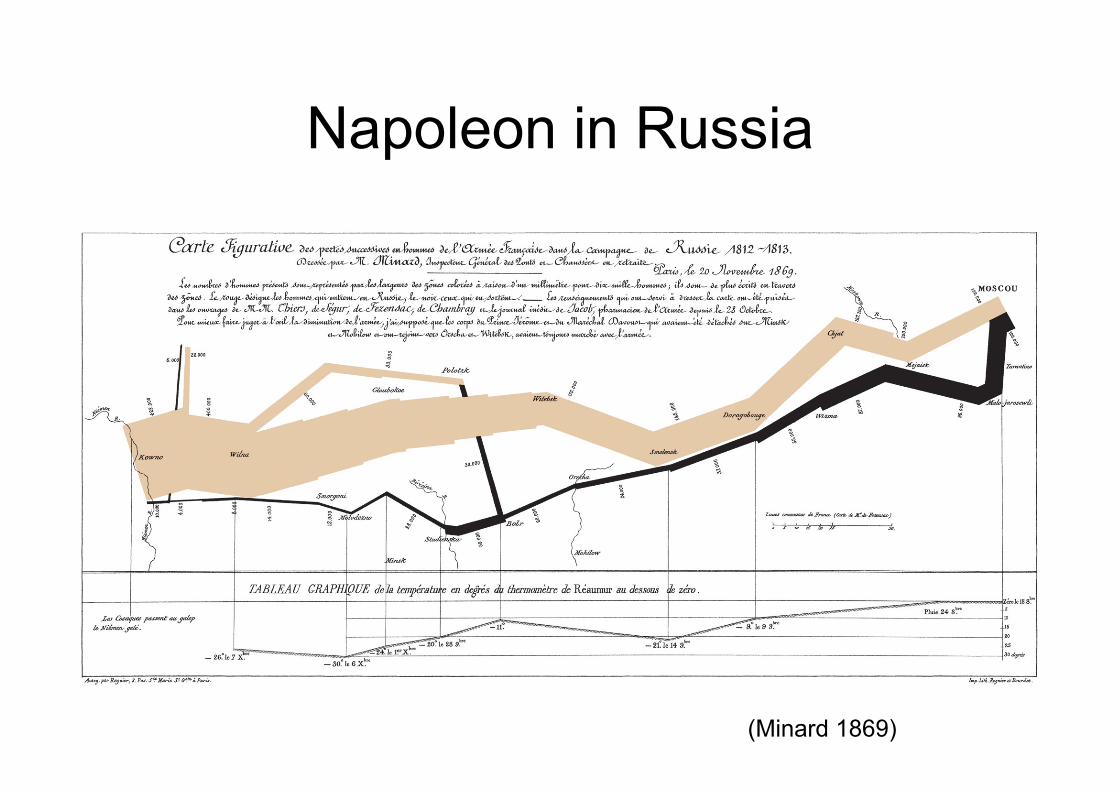
Napoleon in Russia
(Minard 1869)
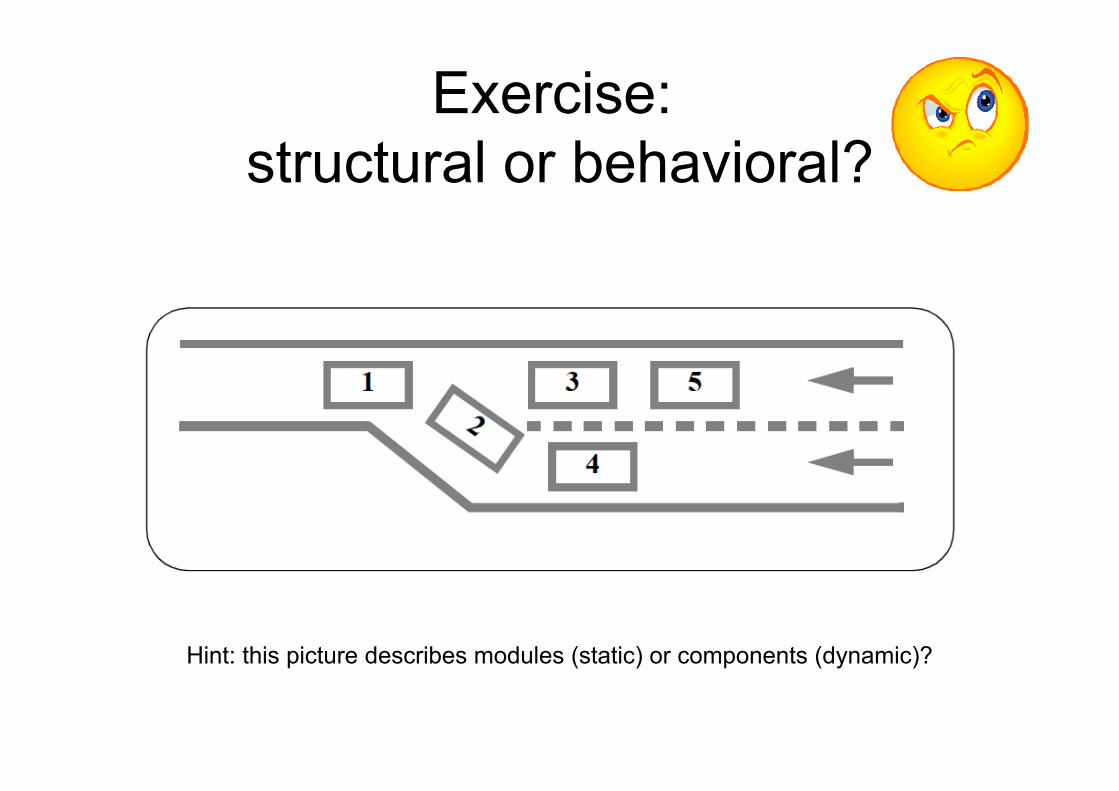
Exercise: structural or behavioral?
Hint: this picture describes modules (static) or components (dynamic)?
Discuss • Are structures and behaviors all we
need for software design?
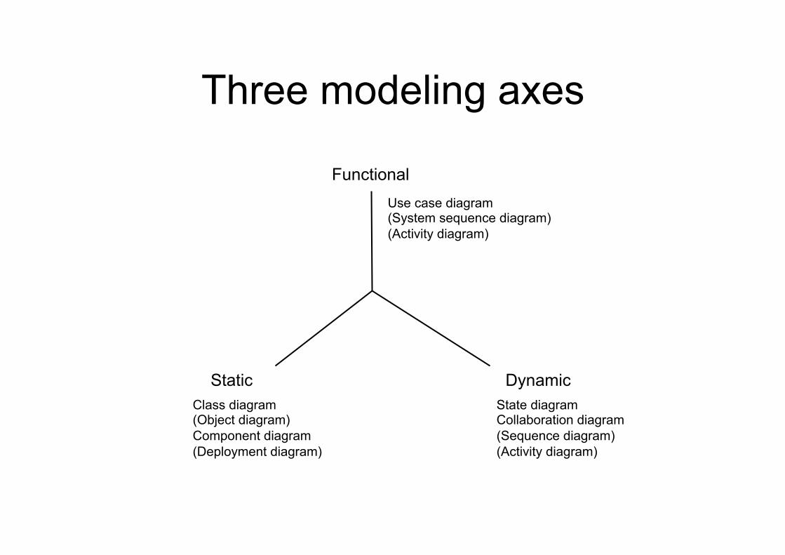
Three modeling axes
Functional
Dynamic Static
Use case diagram (System sequence diagram) (Activity diagram)
State diagram Collaboration diagram (Sequence diagram) (Activity diagram)
Class diagram (Object diagram) Component diagram (Deployment diagram)
Example
• A chess program could be “stand-alone”, “client-server”, “agent based”, etc.
• Its behavior should always be coherent with the rules of chess
• What is its goal? To play and win a chess game against an opponent
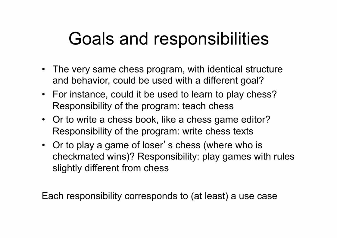
Goals and responsibilities • The very same chess program, with identical structure
and behavior, could be used with a different goal? • For instance, could it be used to learn to play chess?
Responsibility of the program: teach chess • Or to write a chess book, like a chess game editor?
Responsibility of the program: write chess texts • Or to play a game of loser’s chess (where who is
checkmated wins)? Responsibility: play games with rules slightly different from chess
Each responsibility corresponds to (at least) a use case
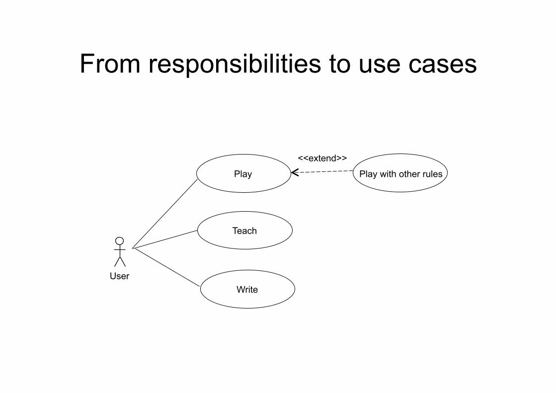
From responsibilities to use cases
Play
Teach
Write
Play with other rules
<<extend>>
User
Use Case diagram
– It describes the externally observable behavior of a system, as related to requirements
– It describes the main interactions between the system and external entities, including users and other systems
– It is a summary of the main scenarios where the system will be used
– It describes the main user roles
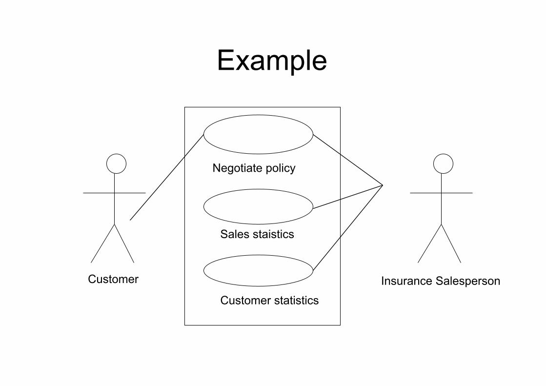
Example
Insurance Salesperson Customer
Negotiate policy
Sales staistics
Customer statistics
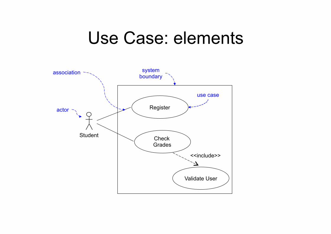
Use Case: elements
Check Grades
Register actor
system boundary
use case
Validate User
<<include>>
Student
association
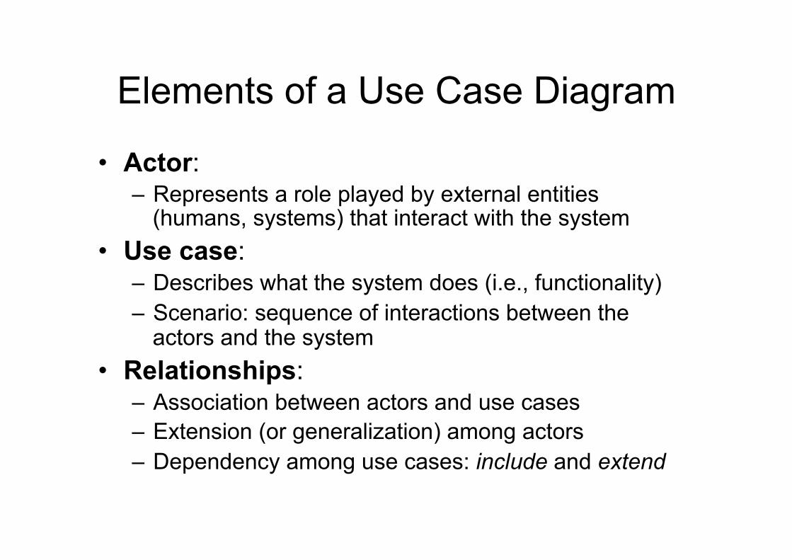
Elements of a Use Case Diagram
• Actor: – Represents a role played by external entities
(humans, systems) that interact with the system • Use case:
– Describes what the system does (i.e., functionality) – Scenario: sequence of interactions between the
actors and the system • Relationships:
– Association between actors and use cases – Extension (or generalization) among actors – Dependency among use cases: include and extend
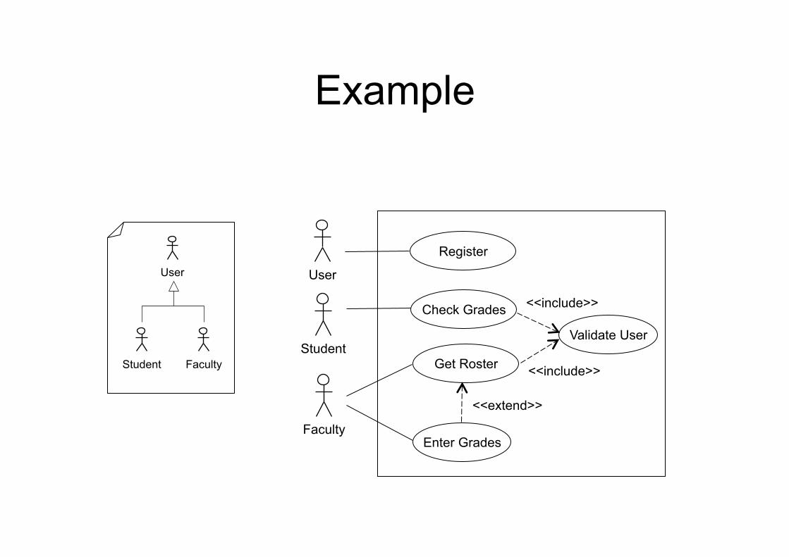
Example
<<include>>
User
Student
Faculty Enter Grades
Validate User
Check Grades
Get Roster
Register
<<include>>
<<extend>>
User
Student Faculty
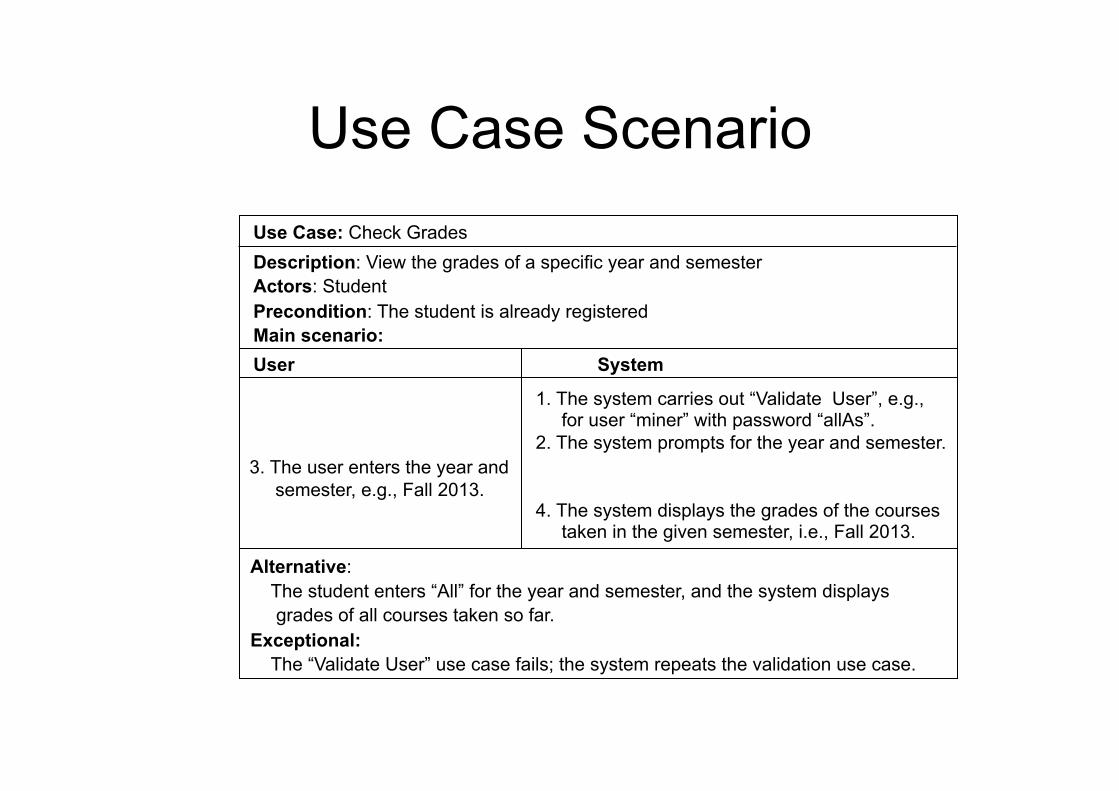
Use Case Scenario Use Case: Check Grades
Description: View the grades of a specific year and semester Actors: Student Precondition: The student is already registered Main scenario:
User System
3. The user enters the year and semester, e.g., Fall 2013.
1. The system carries out “Validate User”, e.g., for user “miner” with password “allAs”. 2. The system prompts for the year and semester. 4. The system displays the grades of the courses taken in the given semester, i.e., Fall 2013.
Alternative: The student enters “All” for the year and semester, and the system displays grades of all courses taken so far. Exceptional: The “Validate User” use case fails; the system repeats the validation use case.

<<extend>> vs <<include>>
• A use case B is included in use cases C and D when these have some common steps represented by B
• A use case B extends a use case C when B applies optionally, under some condition (usually specified in the scenario)
• Note: the lower diagram is formally correct but should be avoided, because the main functions should NOT be described as extensions of logon
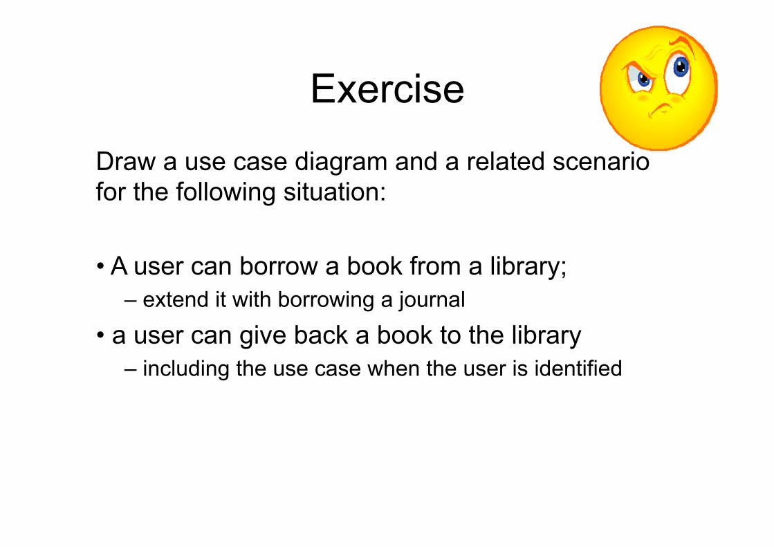
Exercise
Draw a use case diagram and a related scenario for the following situation: • A user can borrow a book from a library;
– extend it with borrowing a journal
• a user can give back a book to the library – including the use case when the user is identified
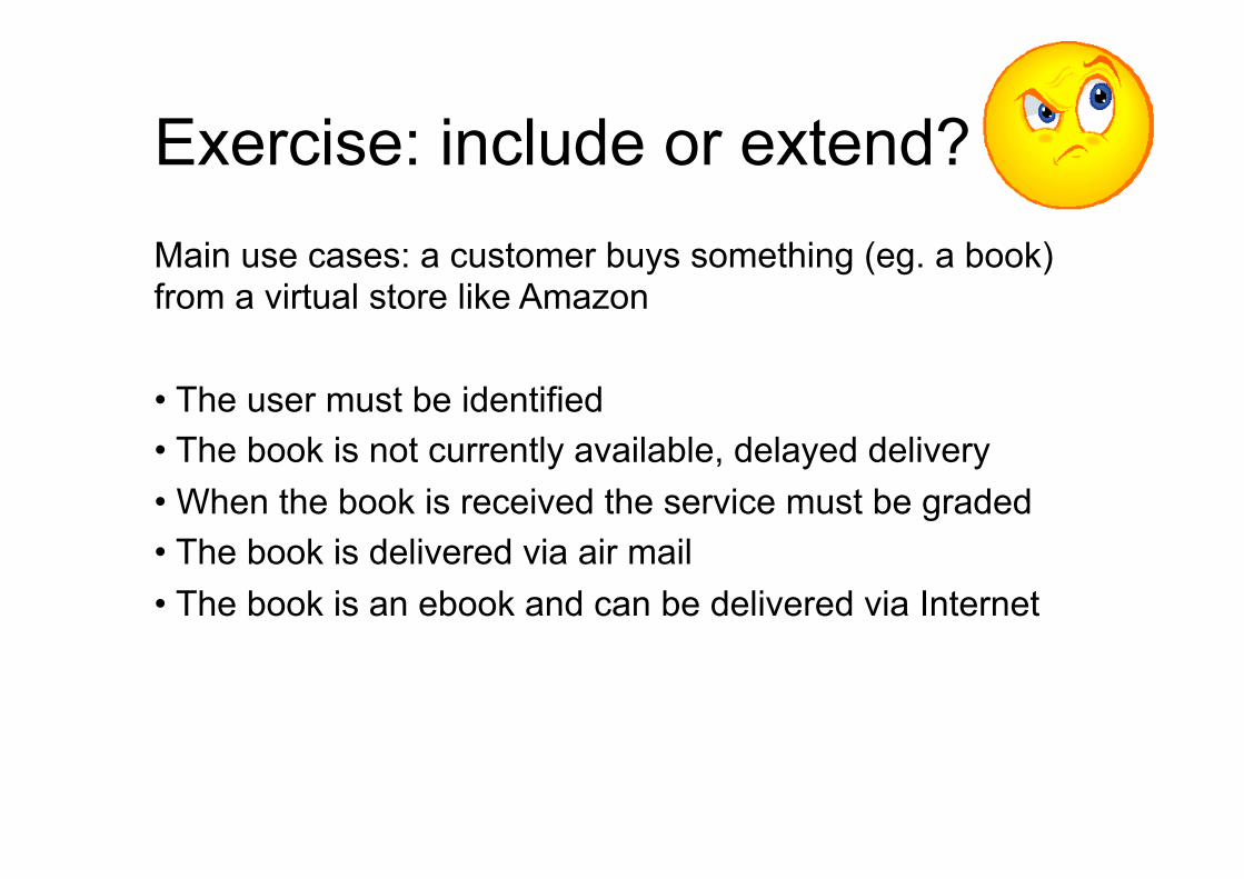
Exercise: include or extend? Main use cases: a customer buys something (eg. a book) from a virtual store like Amazon • The user must be identified • The book is not currently available, delayed delivery • When the book is received the service must be graded • The book is delivered via air mail • The book is an ebook and can be delivered via Internet
Structure diagrams
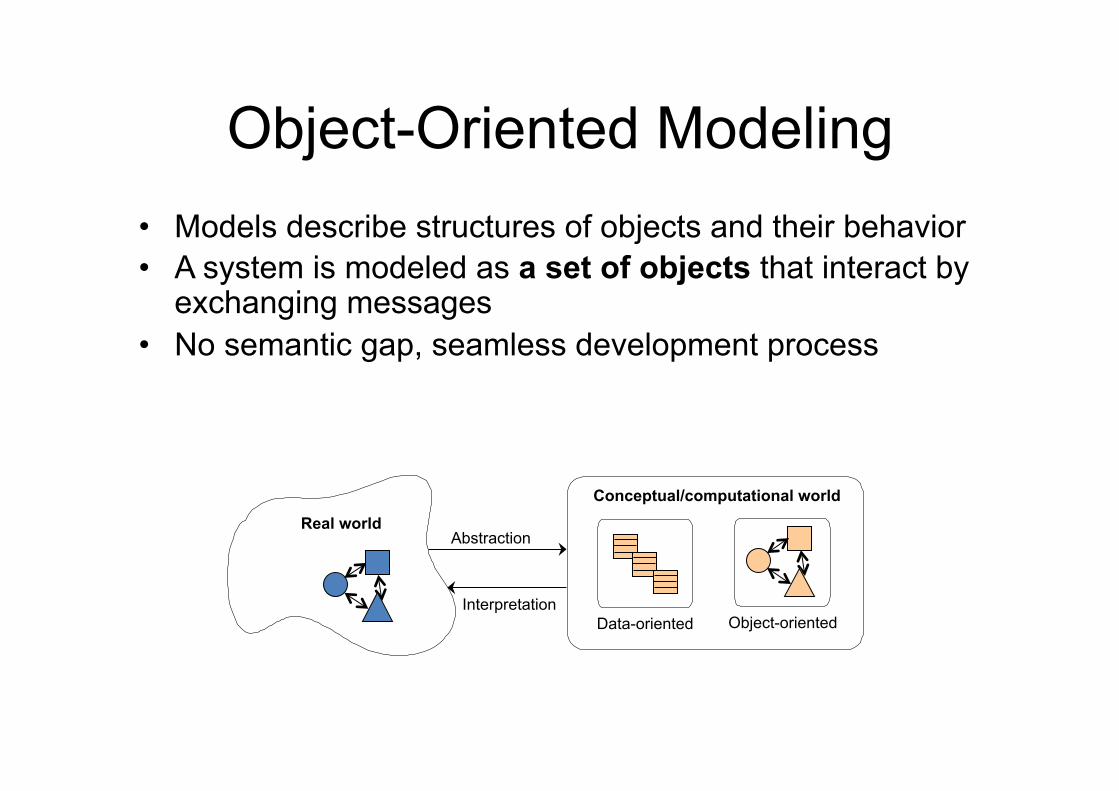
Object-Oriented Modeling • Models describe structures of objects and their behavior • A system is modeled as a set of objects that interact by
exchanging messages • No semantic gap, seamless development process
Data-oriented
Conceptual/computational world Real world
Abstraction
Interpretation Object-oriented
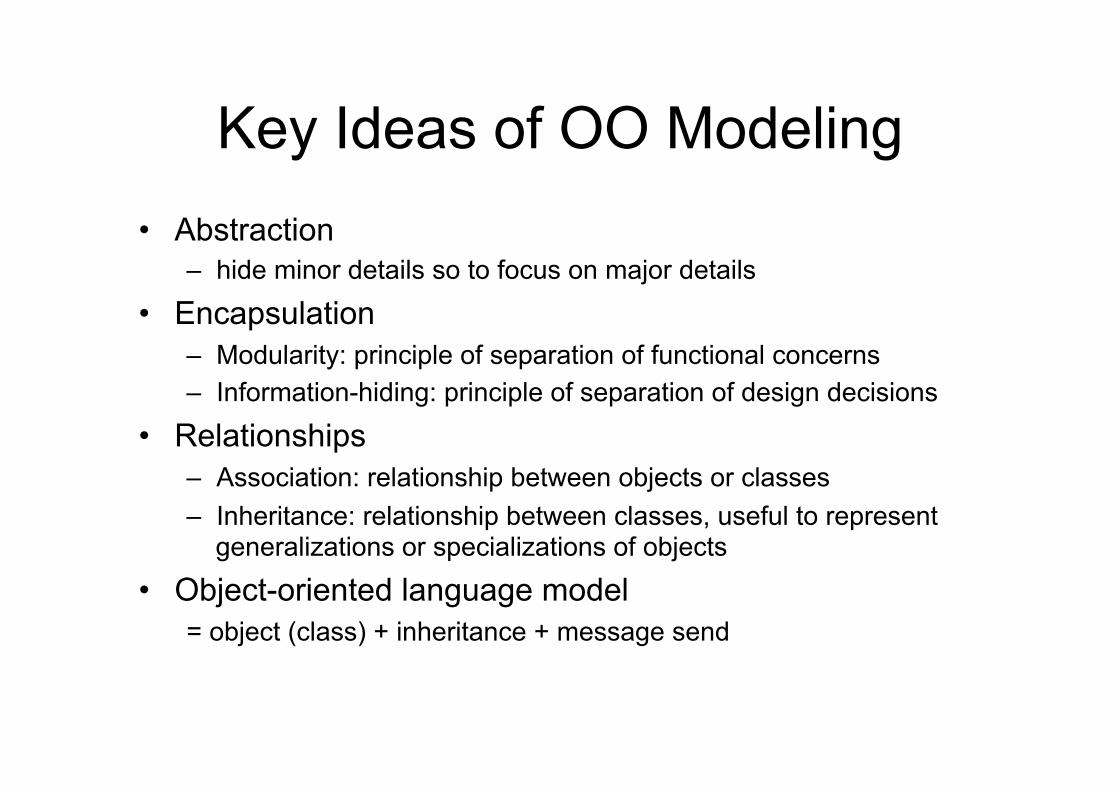
Key Ideas of OO Modeling • Abstraction
– hide minor details so to focus on major details
• Encapsulation – Modularity: principle of separation of functional concerns – Information-hiding: principle of separation of design decisions
• Relationships – Association: relationship between objects or classes – Inheritance: relationship between classes, useful to represent
generalizations or specializations of objects
• Object-oriented language model = object (class) + inheritance + message send
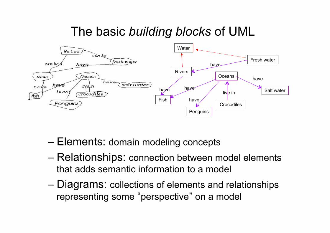
The basic building blocks of UML
– Elements: domain modeling concepts – Relationships: connection between model elements
that adds semantic information to a model – Diagrams: collections of elements and relationships
representing some “perspective” on a model
Water
Rivers Oceans
Fish
Penguins Crocodiles
Fresh water
Salt water have have
have live in
have
have
Main idea
• With UML we model systems made of objects which have relationships among them
• Objects are instances of classes • Classes define the structure of objects and
their relationships
Example
• A university is an organization where some persons work, some other study
• There are several types of roles and grouping entities
• We say nothing about behaviors, for the moment
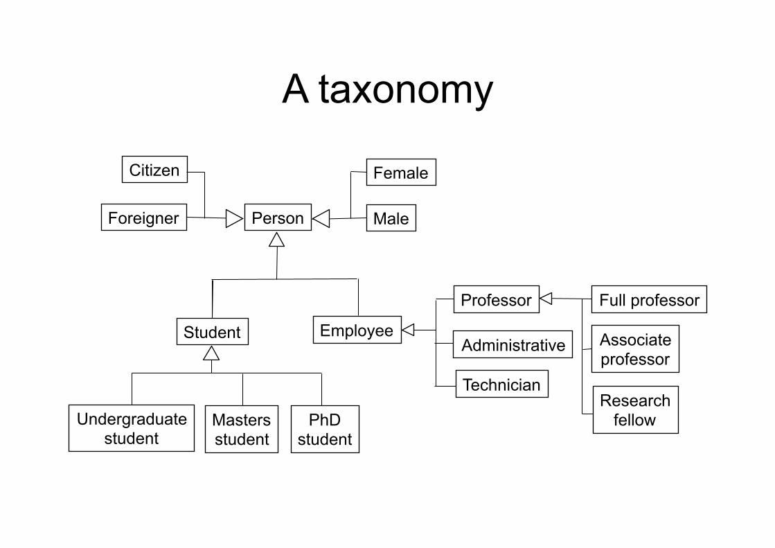
A taxonomy
Person
Professor
Employee
Male
Female
Foreigner
Citizen
Student
PhD student
Masters student
Undergraduate student
Administrative Associate professor
Full professor
Research fellow
Technician
Class
• Is the description of a set of objects • Defines the structure of the states and the
behaviors shared by all the objects of the class (called instances)
• Defines a template for creating instances – Names and types of all fields – Names, signatures, and implementations of all
methods
Class diagram • Most common diagram in OO modeling • A class diagram is a graph including:
– Nodes representing classes (types of objects) • Nodes can have just a name, or expose some internal structure
– Links representing relationships among classes • Inheritance • Association • Aggregation or composition • Dependency
– Links can have multiplicities and/or names for roles played by participants
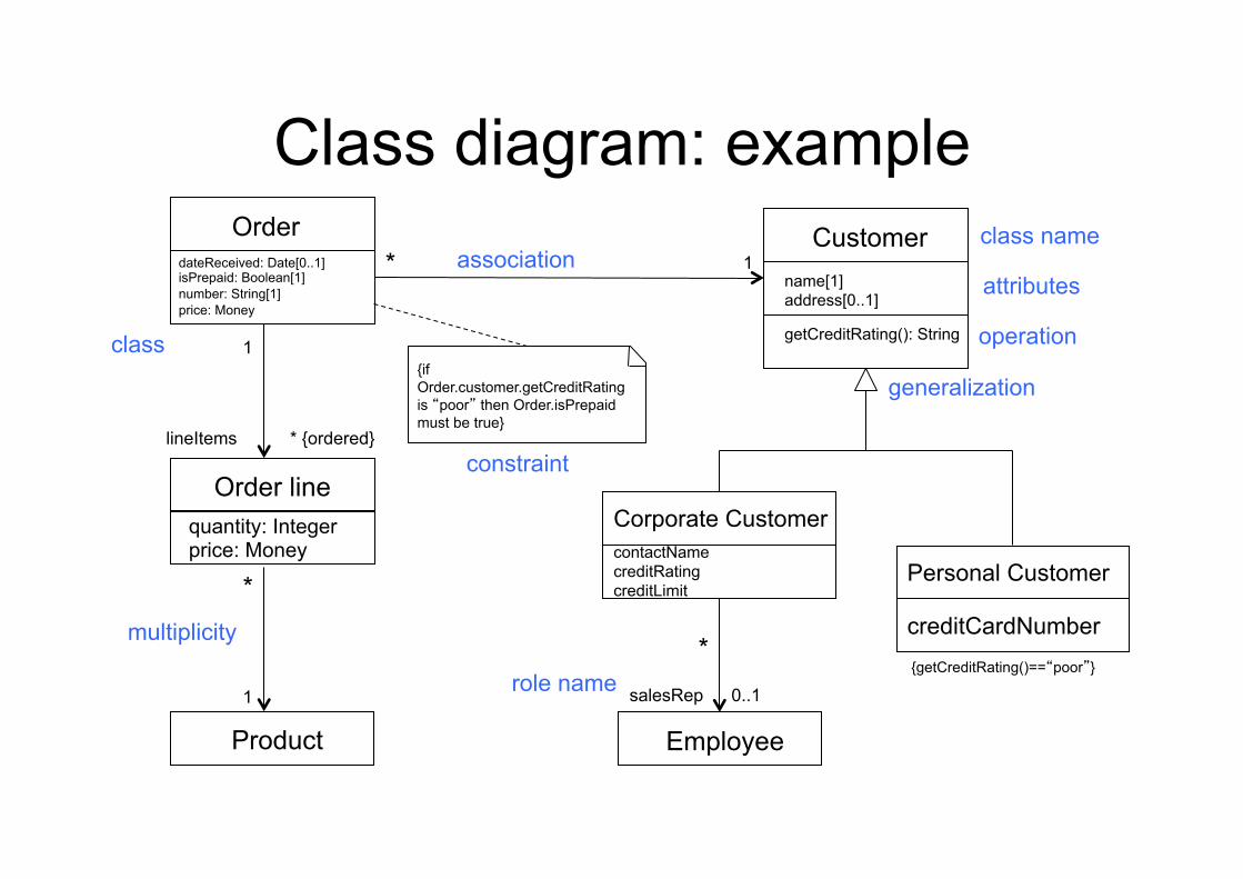
Class diagram: example dateReceived: Date[0..1] isPrepaid: Boolean[1] number: String[1] price: Money
contactName creditRating creditLimit
Employee
Order line
Product
quantity: Integer price: Money
Customer name[1] address[0..1]
getCreditRating(): String
*
* {ordered}
*
*
1
0..1 salesRep
lineItems
1
1
creditCardNumber
Personal Customer
{getCreditRating()==“poor”}
{if Order.customer.getCreditRating is “poor” then Order.isPrepaid must be true}
Order
generalization
association
role name
constraint
attributes
operation class
multiplicity
class name
Corporate Customer
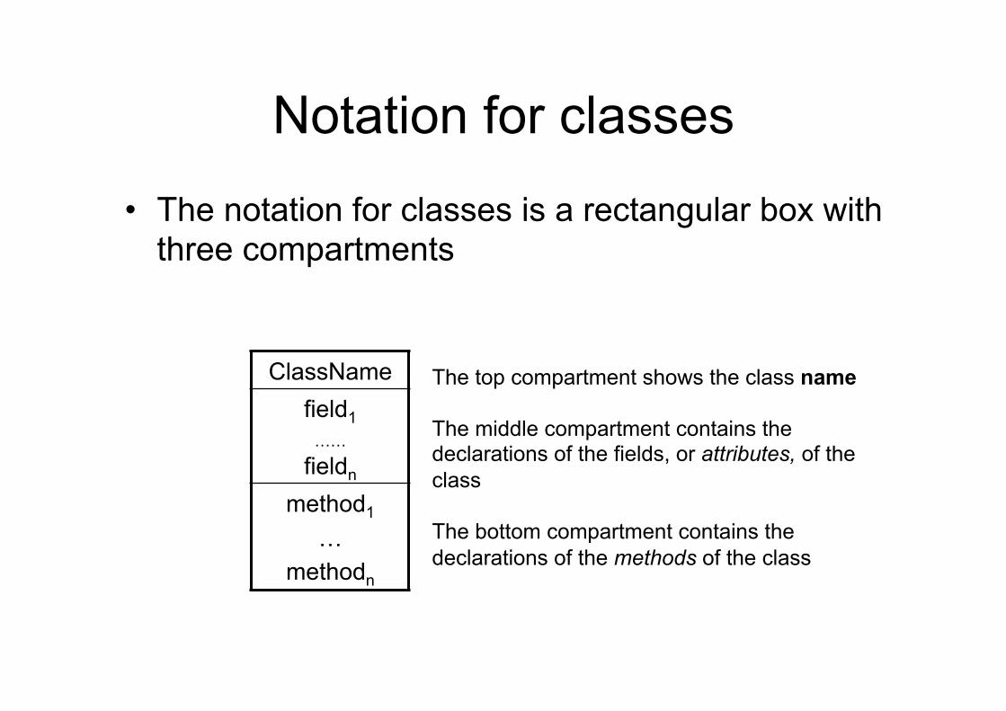
Notation for classes
• The notation for classes is a rectangular box with three compartments
ClassName field1
……
fieldn method1
… methodn
The top compartment shows the class name The middle compartment contains the declarations of the fields, or attributes, of the class The bottom compartment contains the declarations of the methods of the class
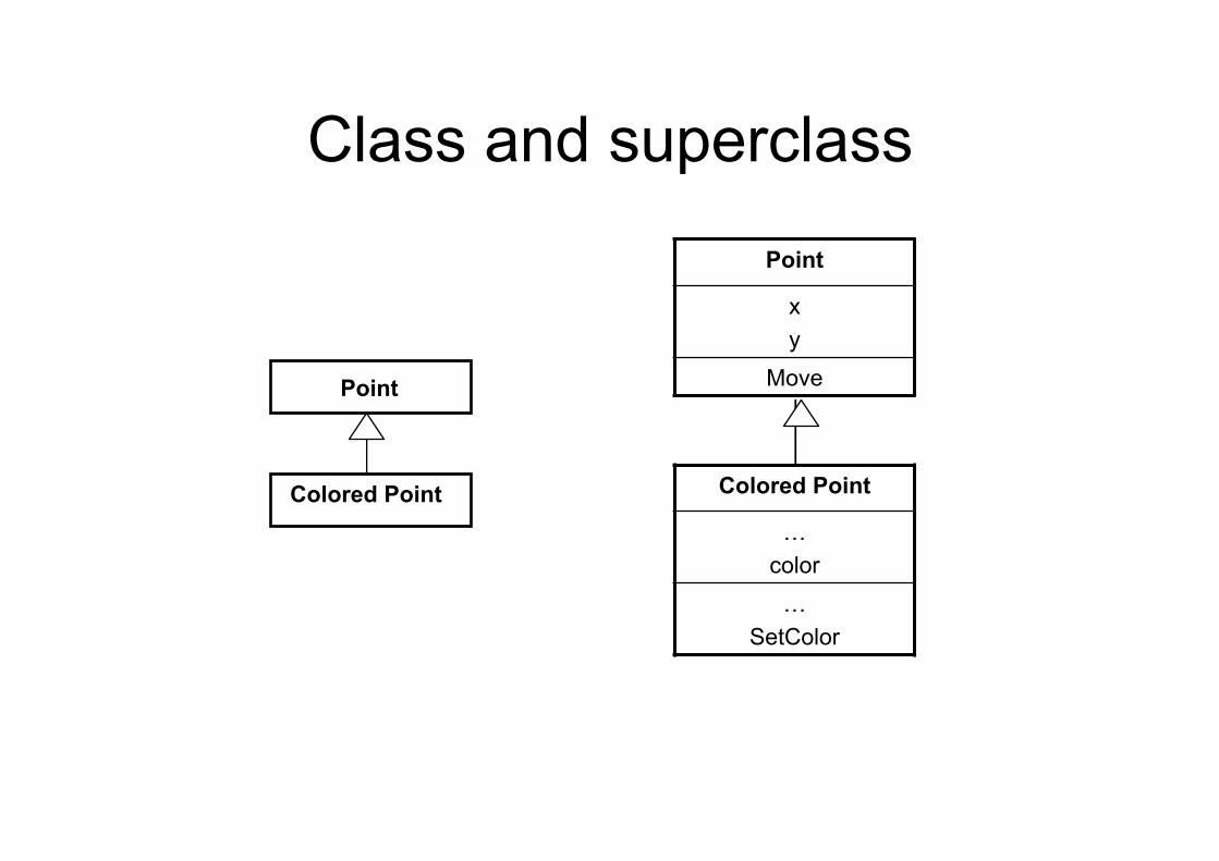
Example
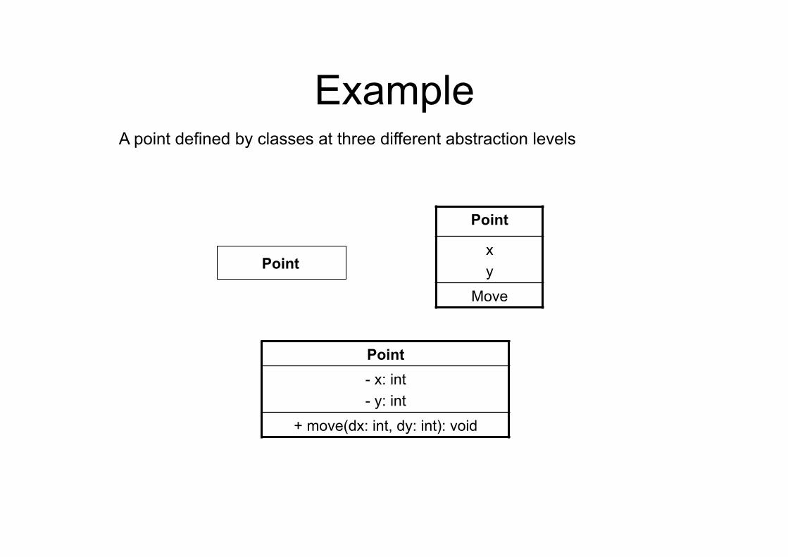
Point - x: int - y: int
+ move(dx: int, dy: int): void
Point
x y
Move
Point
A point defined by classes at three different abstraction levels
Example
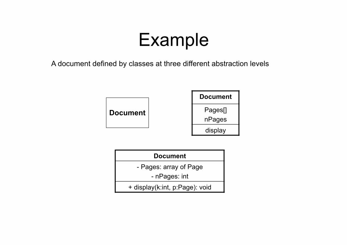
Document - Pages: array of Page
- nPages: int
+ display(k:int, p:Page): void
Document
Pages[] nPages
display
Document
A document defined by classes at three different abstraction levels
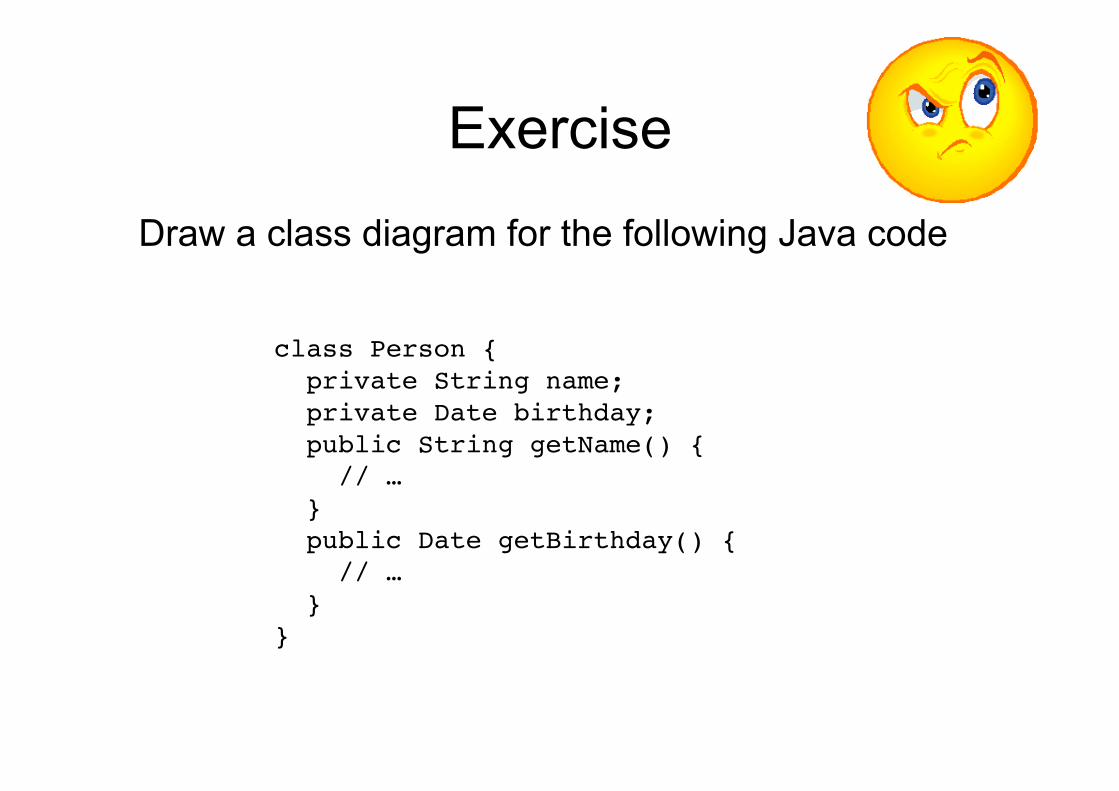
Exercise
Draw a class diagram for the following Java code
class Person {! private String name;! private Date birthday;! public String getName() {! // …! }! public Date getBirthday() {! // …! } !}!
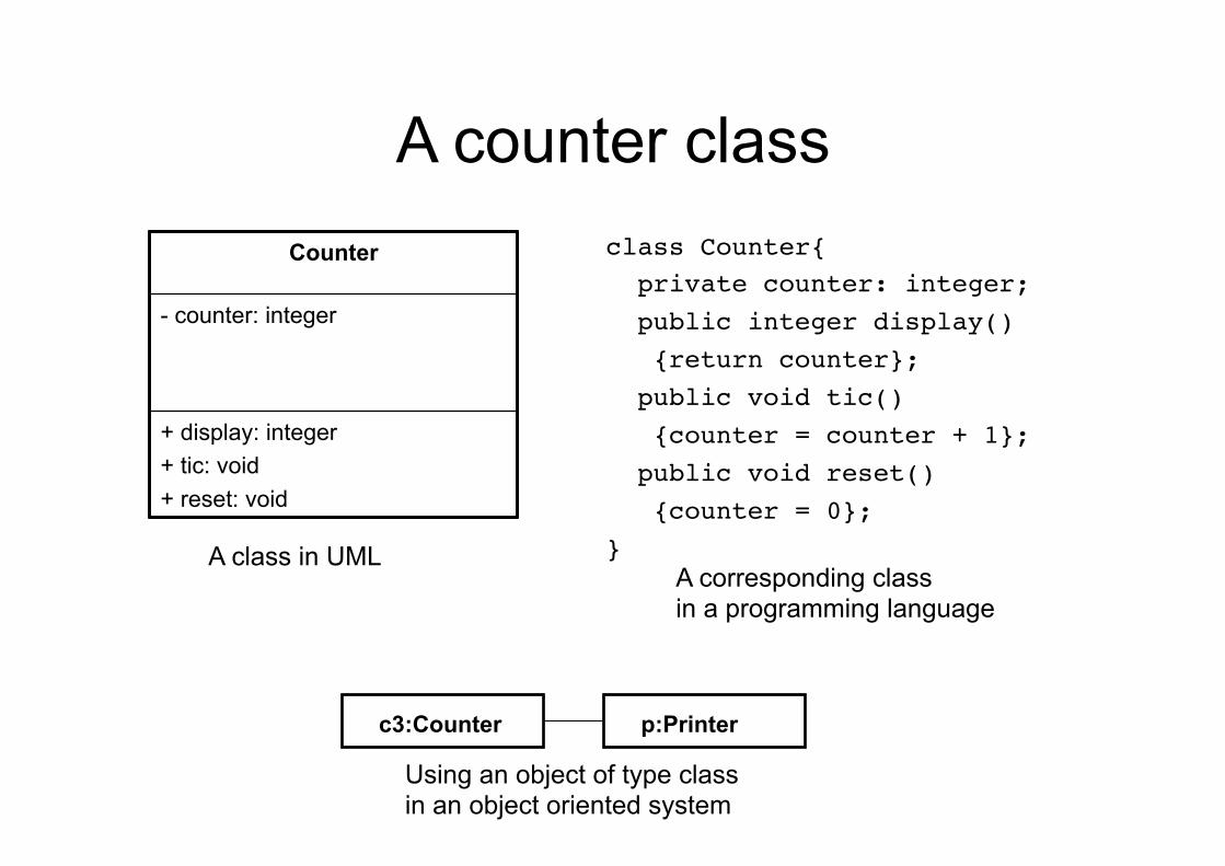
A counter class class Counter{! private counter: integer;! public integer display()! {return counter};! public void tic()! {counter = counter + 1};! public void reset()! {counter = 0};!}!
Counter
- counter: integer
+ display: integer + tic: void + reset: void
c3:Counter p:Printer
A class in UML A corresponding class in a programming language
Using an object of type class in an object oriented system
Object diagram
• An object diagram represents a “snapshot” of a system composed by set of objects
• An object diagram looks like a class diagram • However, there is a difference: values are
allocated to attributes and method parameters • While a class diagram represents an abstraction
on source code, an object diagram is an abstraction of running code
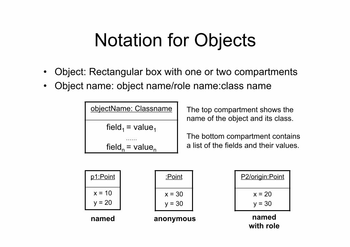
Notation for Objects • Object: Rectangular box with one or two compartments • Object name: object name/role name:class name
objectName: Classname
field1 = value1 ……
fieldn = valuen
The top compartment shows the name of the object and its class. The bottom compartment contains a list of the fields and their values.
p1:Point
x = 10 y = 20
:Point
x = 30 y = 30
P2/origin:Point
x = 20 y = 30
named anonymous named with role
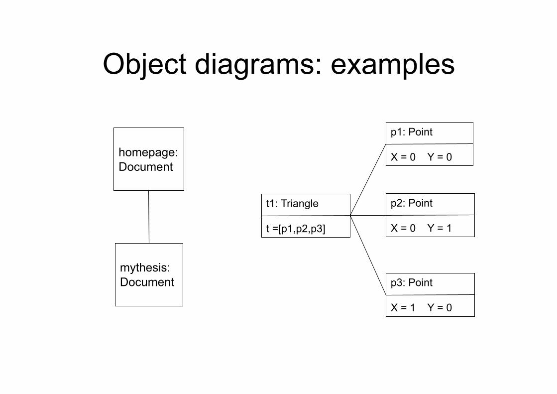
Object diagrams: examples
homepage: Document
mythesis: Document
p1: Point X = 0 Y = 0
p2: Point X = 0 Y = 1
p3: Point X = 1 Y = 0
t1: Triangle t =[p1,p2,p3]
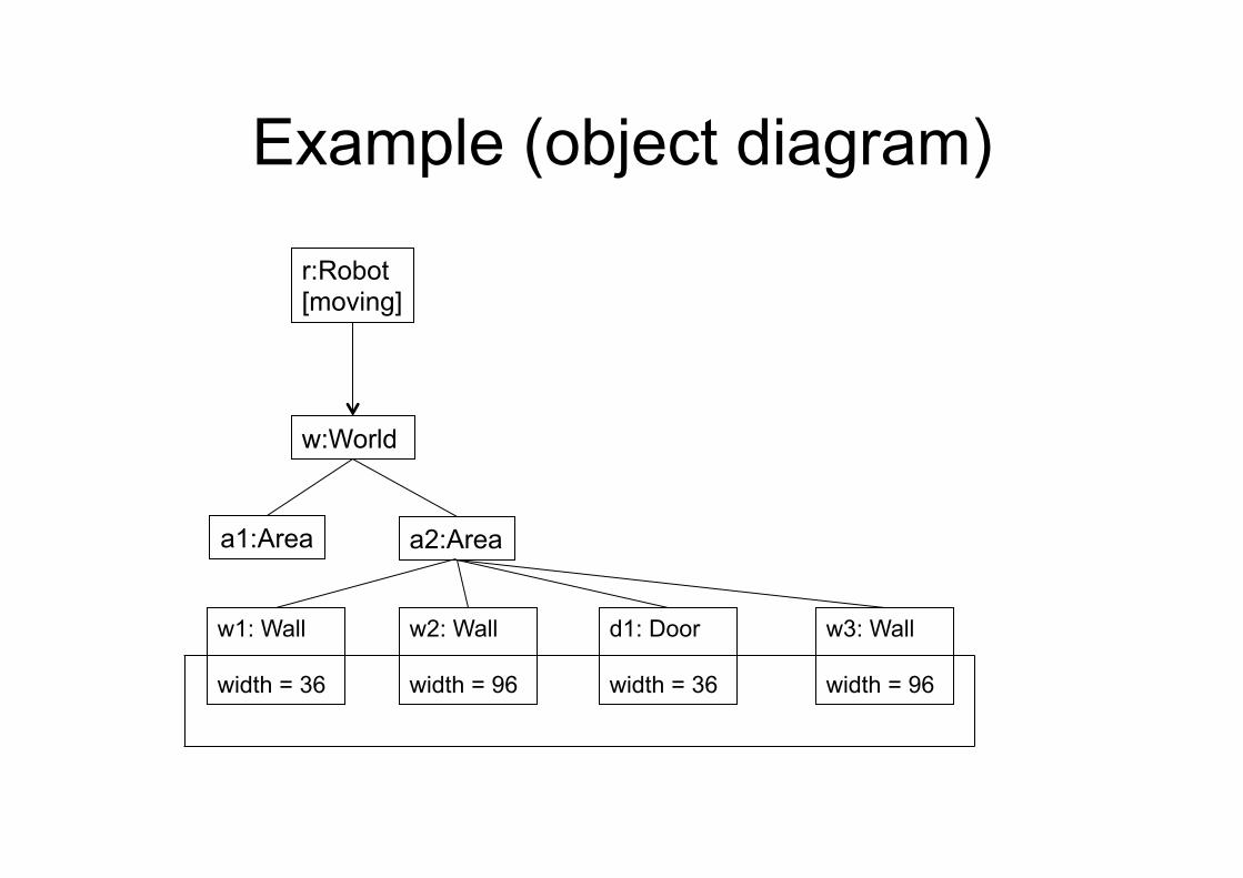
Example (object diagram)
r:Robot [moving]
w:World
a1:Area a2:Area
w1: Wall width = 36
w2: Wall width = 96
d1: Door width = 36
w3: Wall width = 96
59
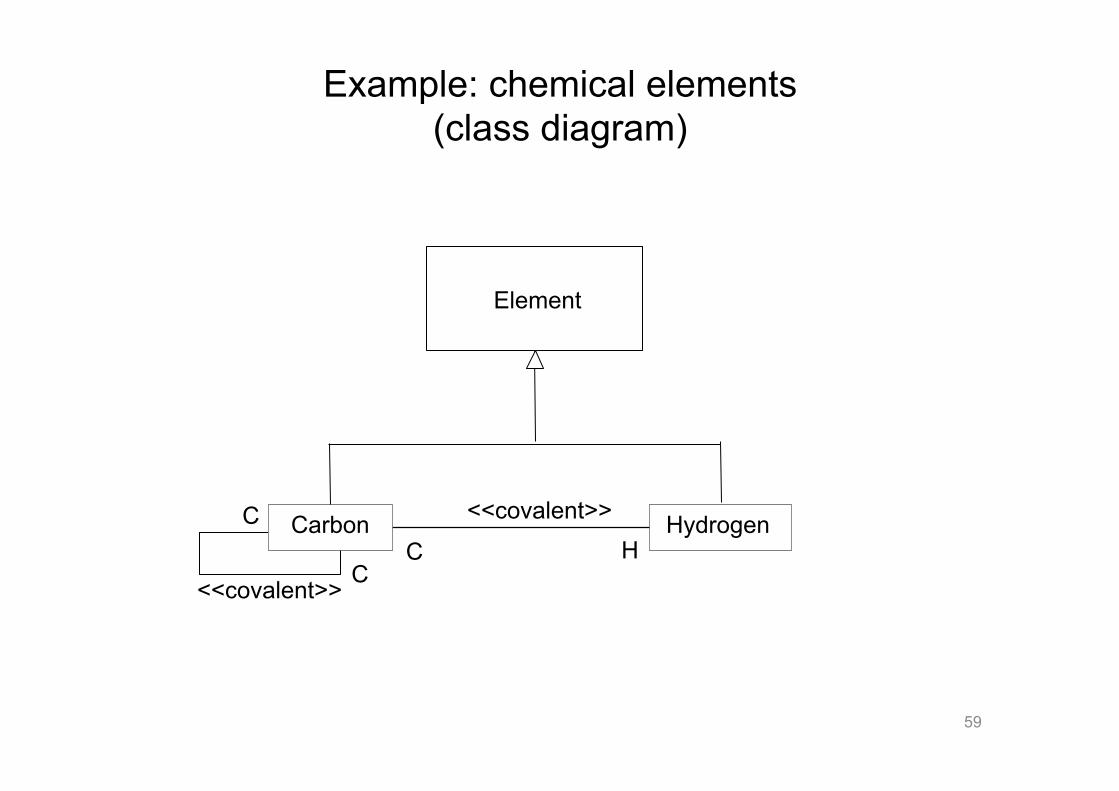
Example: chemical elements (class diagram)
Hydrogen
Element
Carbon
<<covalent>>
C <<covalent>>
C C H
60
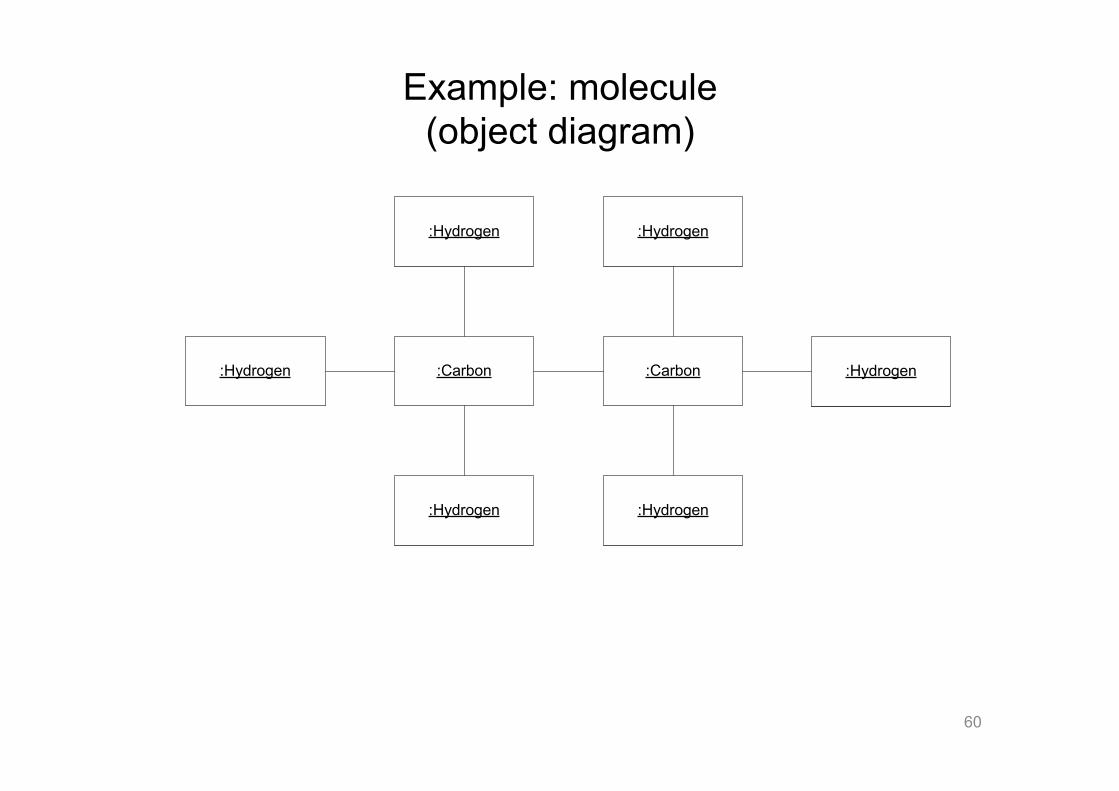
Example: molecule (object diagram)
:Carbon :Carbon
:Hydrogen
:Hydrogen
:Hydrogen
:Hydrogen
:Hydrogen:Hydrogen
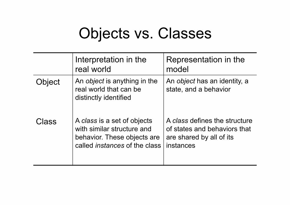
Objects vs. Classes Interpretation in the real world
Representation in the model
Object An object is anything in the real world that can be distinctly identified
An object has an identity, a state, and a behavior
Class A class is a set of objects with similar structure and behavior. These objects are called instances of the class
A class defines the structure of states and behaviors that are shared by all of its instances
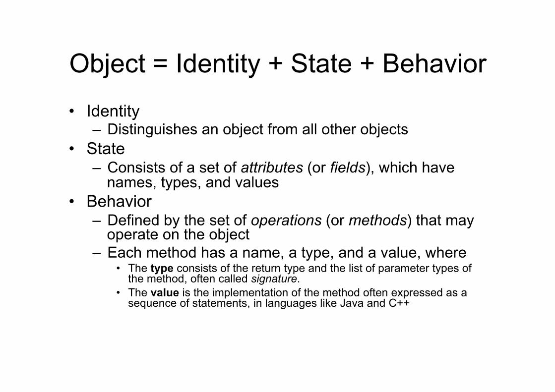
Object = Identity + State + Behavior
• Identity – Distinguishes an object from all other objects
• State – Consists of a set of attributes (or fields), which have
names, types, and values • Behavior
– Defined by the set of operations (or methods) that may operate on the object
– Each method has a name, a type, and a value, where • The type consists of the return type and the list of parameter types of
the method, often called signature. • The value is the implementation of the method often expressed as a
sequence of statements, in languages like Java and C++
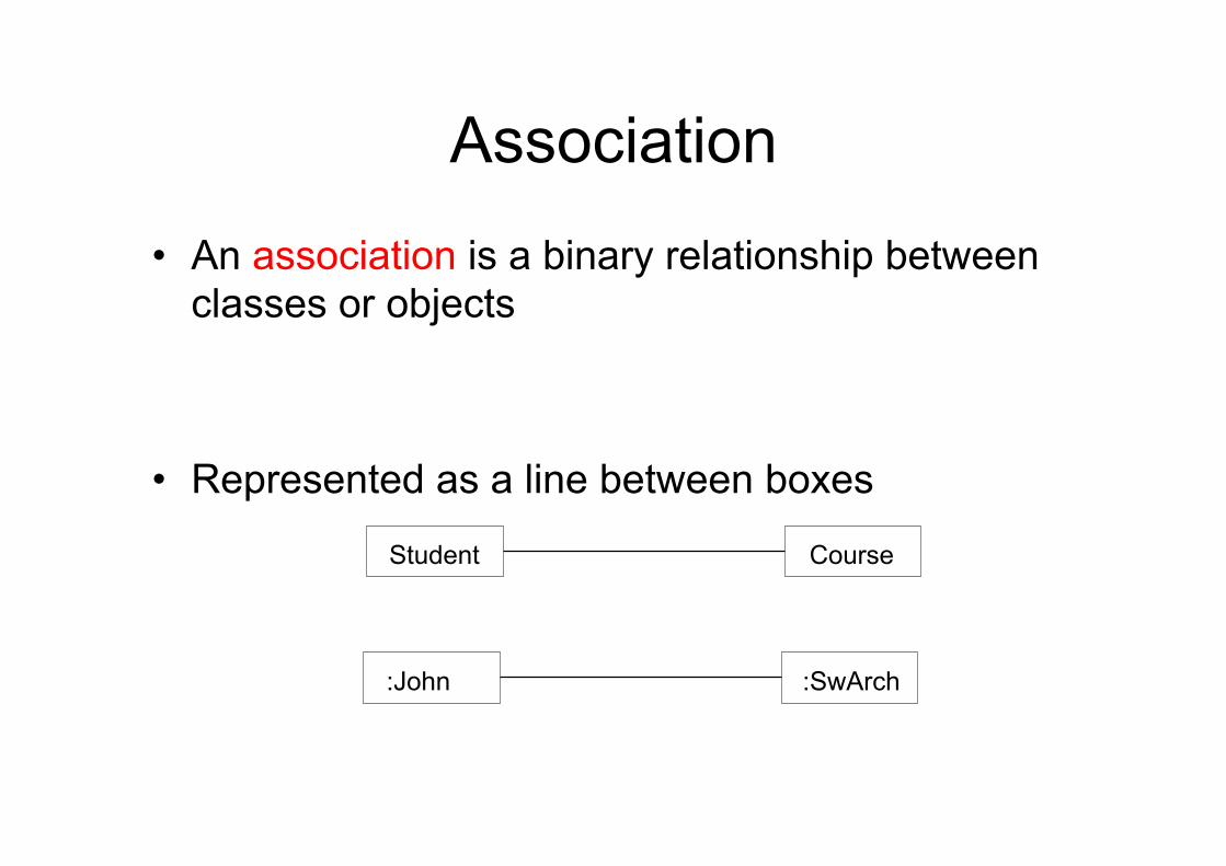
Association
• An association is a binary relationship between classes or objects
• Represented as a line between boxes
Student Course
:John :SwArch
Association and roles
• The simplest relationship among classes is the association
• An association represents a structural relationship that connects two classes
• It means that the two classes “know” each other: all objects in a class have some relationship with some object(s) in the other class
• An association can have a name, which usually describes its role
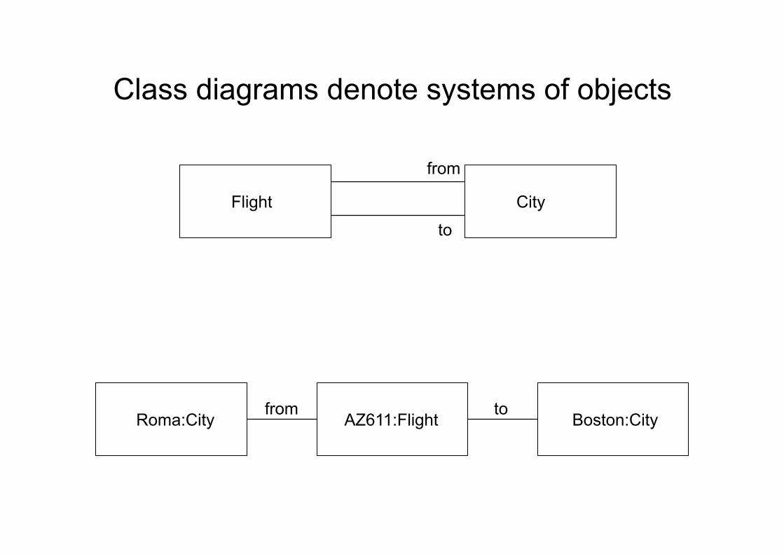
AZ611:Flight Boston:City from to
Roma:City
Flight City
from
to
Class diagrams denote systems of objects
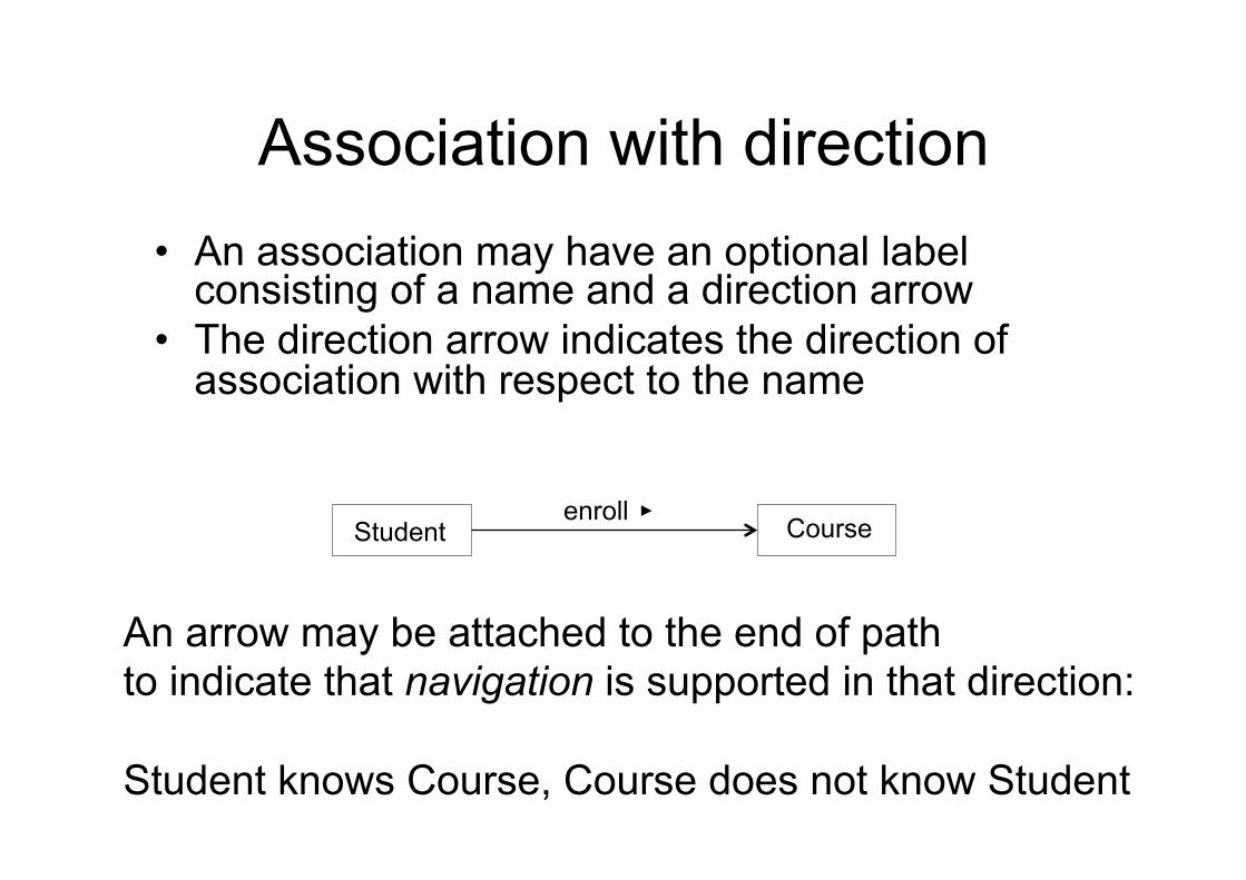
Association with direction • An association may have an optional label
consisting of a name and a direction arrow • The direction arrow indicates the direction of
association with respect to the name
Student Course enroll
An arrow may be attached to the end of path to indicate that navigation is supported in that direction: Student knows Course, Course does not know Student
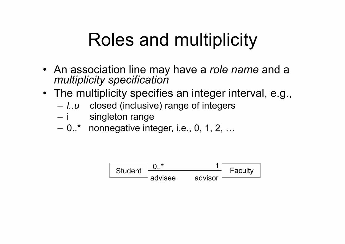
Roles and multiplicity • An association line may have a role name and a
multiplicity specification • The multiplicity specifies an integer interval, e.g.,
– l..u closed (inclusive) range of integers – i singleton range – 0..* nonnegative integer, i.e., 0, 1, 2, …
Student Faculty advisee advisor
1 0..*
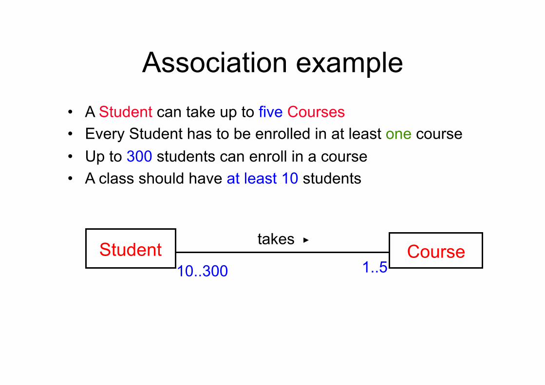
Association example • A Student can take up to five Courses • Every Student has to be enrolled in at least one course • Up to 300 students can enroll in a course • A class should have at least 10 students
Student Course takes
10..300 1..5
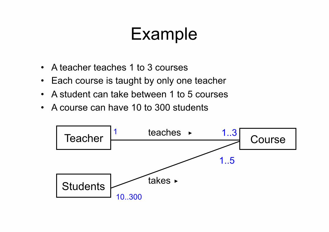
Association - Multiplicity • A teacher teaches 1 to 3 courses • Each course is taught by only one teacher • A student can take between 1 to 5 courses • A course can have 10 to 300 students
Teacher Course teaches 1..3
Example
1
Students takes
1..5
10..300
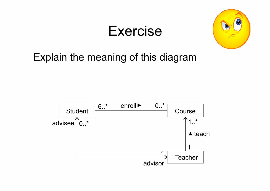
Exercise
Explain the meaning of this diagram
Student Course enroll
advisee
advisor Teacher
teach
1..*
6..*
0..*
1 1
0..*
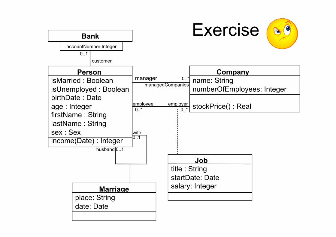
Person isMarried : Boolean isUnemployed : Boolean birthDate : Date age : Integer firstName : String lastName : String sex : Sex income(Date) : Integer
Bank
Marriage place: String date: Date
Company name: String numberOfEmployees: Integer stockPrice() : Real
Job title : String startDate: Date salary: Integer
manager
employee employer 0..* 0..*
0..* managedCompanies
wife
husband 0..1
0..1
customer
accountNumber:Integer 0..1
Exercise
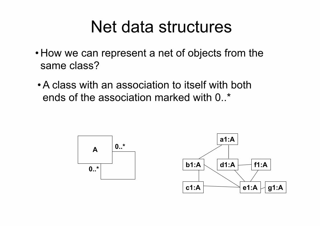
Net data structures • How we can represent a net of objects from the same class?
A
0..*
0..*
a1:A
b1:A d1:A f1:A
g1:A e1:A c1:A
• A class with an association to itself with both ends of the association marked with 0..*
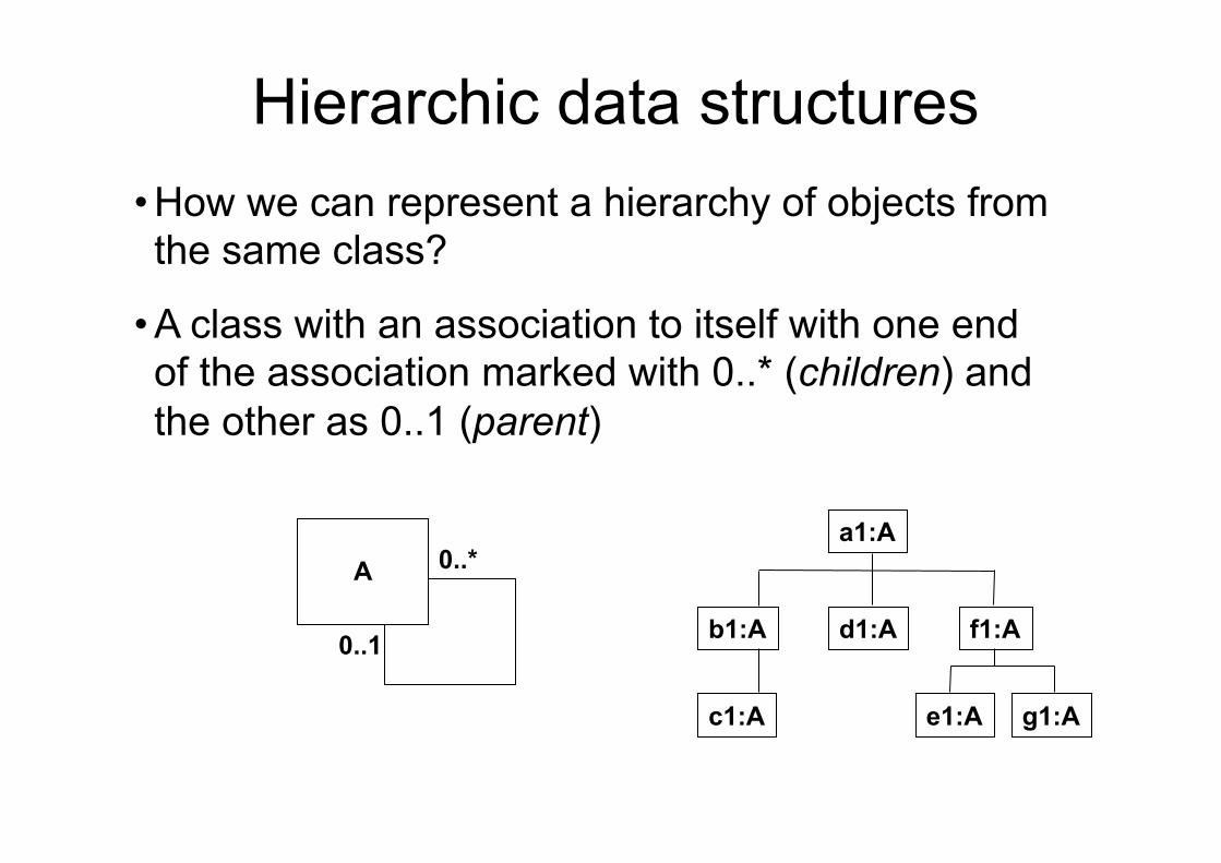
Hierarchic data structures • How we can represent a hierarchy of objects from the same class?
A
0..*
0..1
a1:A
b1:A d1:A f1:A
g1:A e1:A c1:A
• A class with an association to itself with one end of the association marked with 0..* (children) and the other as 0..1 (parent)
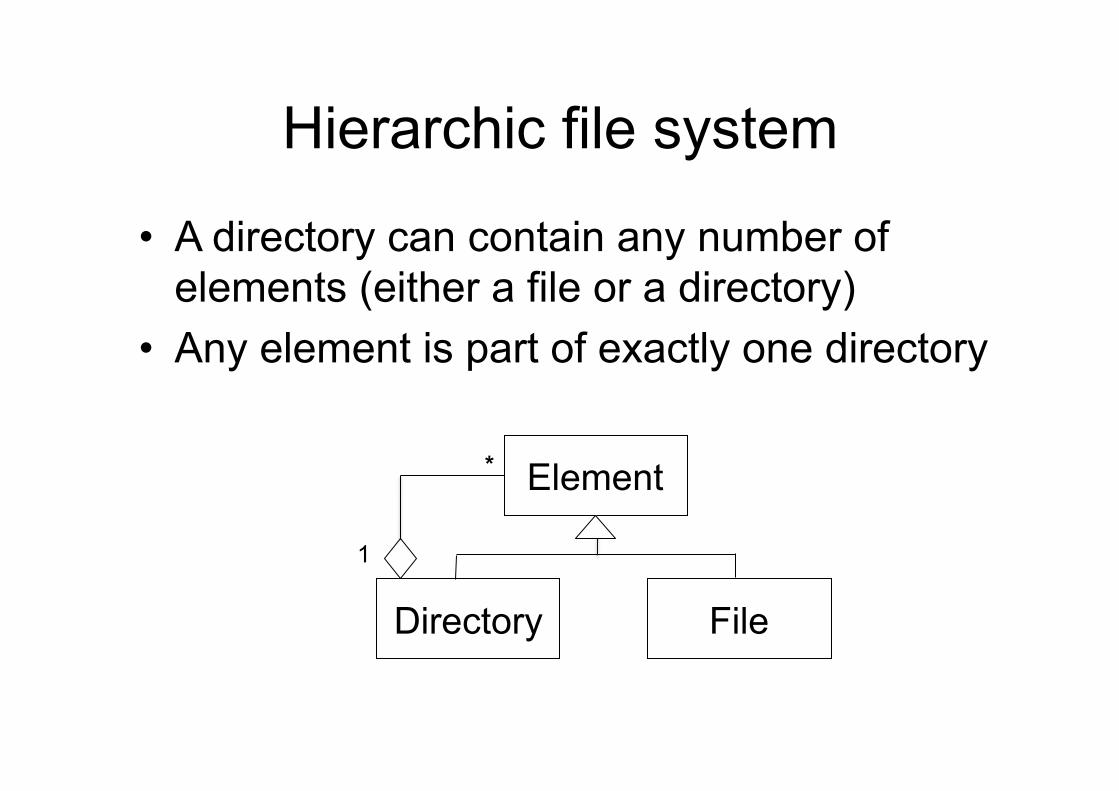
Hierarchic file system
• A directory can contain any number of elements (either a file or a directory)
• Any element is part of exactly one directory
Element
Directory File
1
*
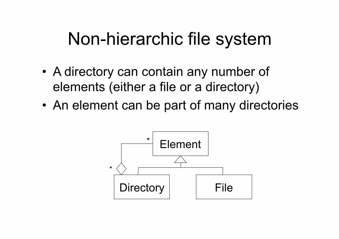
Non-hierarchic file system
• A directory can contain any number of elements (either a file or a directory)
• An element can be part of many directories
Element
Directory File
*
*
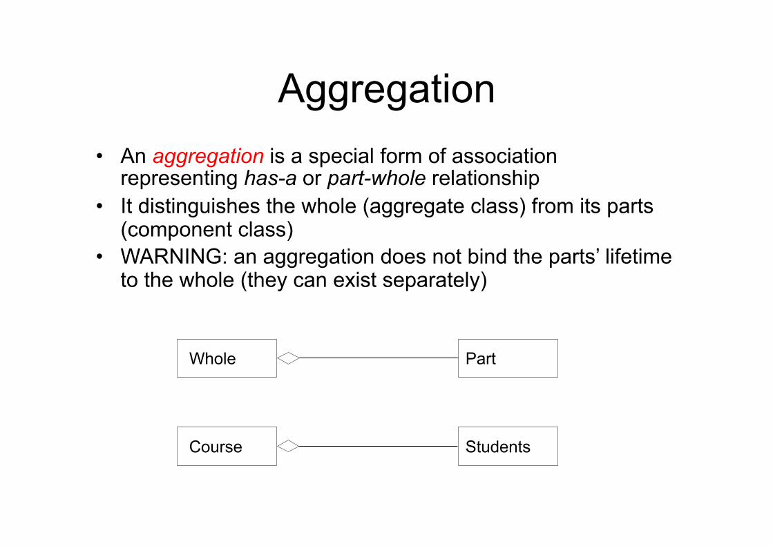
Aggregation • An aggregation is a special form of association
representing has-a or part-whole relationship • It distinguishes the whole (aggregate class) from its parts
(component class) • WARNING: an aggregation does not bind the parts’ lifetime
to the whole (they can exist separately)
Whole Part
Course Students
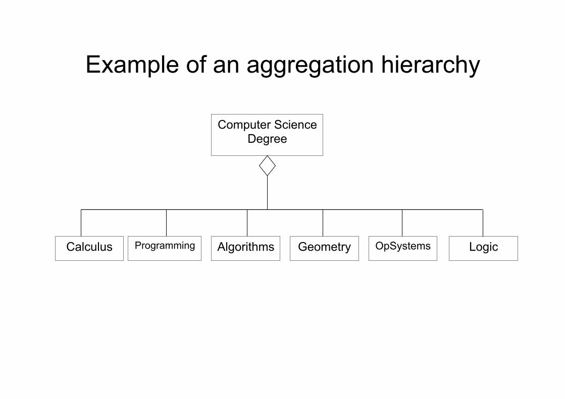
Example of an aggregation hierarchy
Computer Science Degree
Calculus Logic OpSystems Geometry Algorithms Programming
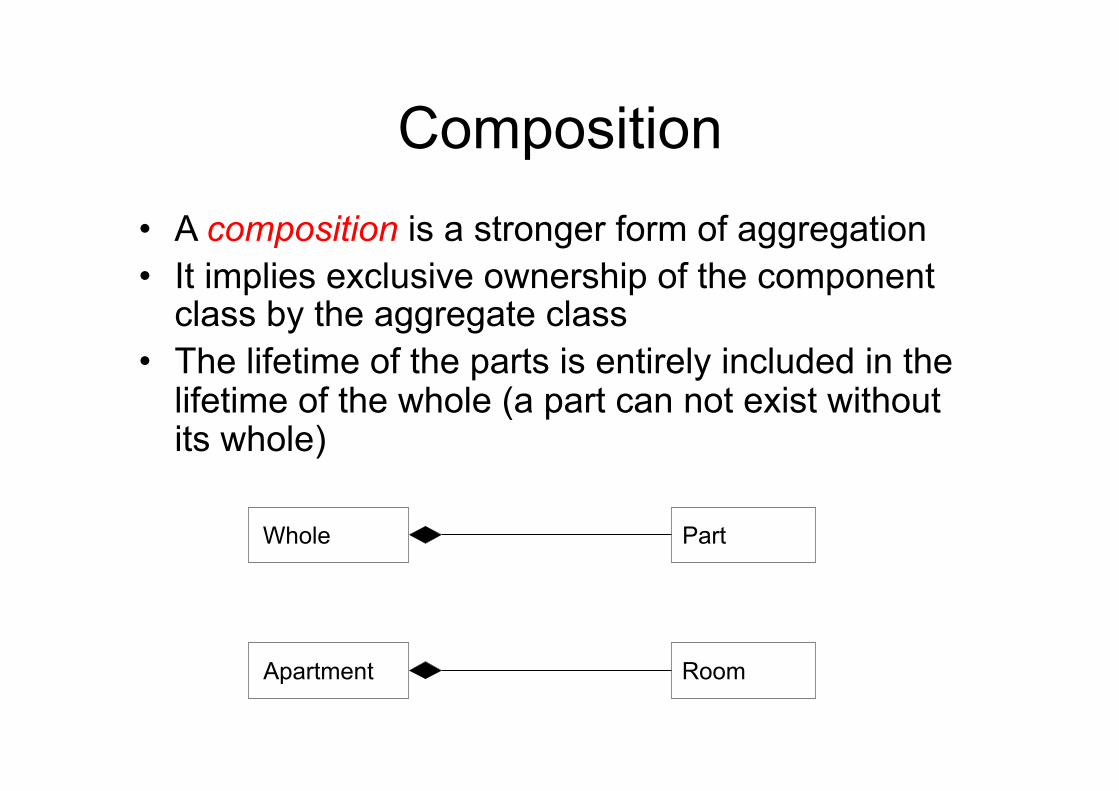
Composition • A composition is a stronger form of aggregation • It implies exclusive ownership of the component
class by the aggregate class • The lifetime of the parts is entirely included in the
lifetime of the whole (a part can not exist without its whole)
Whole Part
Apartment Room
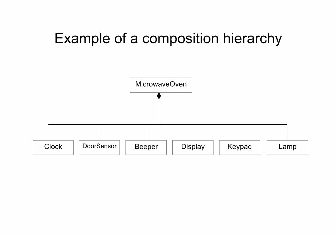
Example of a composition hierarchy
MicrowaveOven
Clock Lamp Keypad Display Beeper DoorSensor
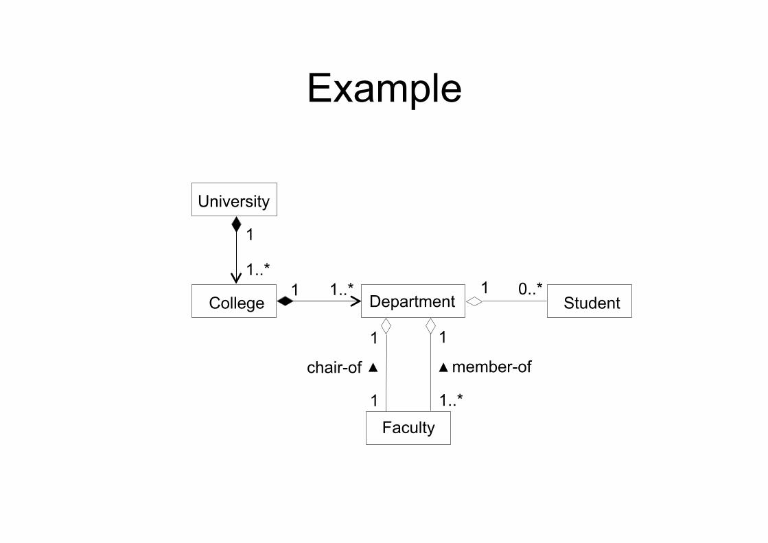
Example
Department
member-of
Faculty
College
chair-of
Student
1
1 1
1
1 1
1..*
0..* 1..*
1..*
University
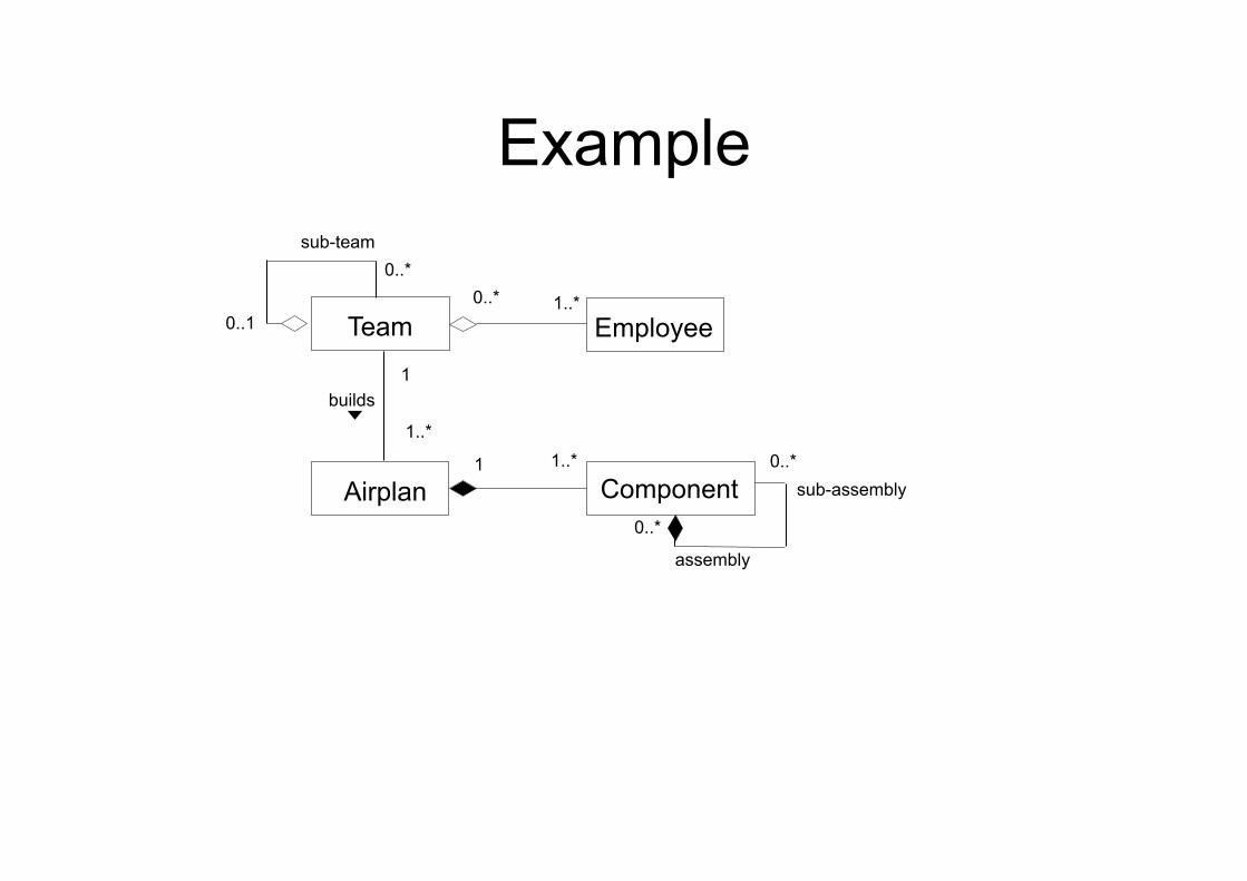
Example
Component Airplan
builds
Employee 1
1
0..*
1..*
1..* Team
1..*
0..*
0..1
sub-team
sub-assembly
assembly
0..*
0..*
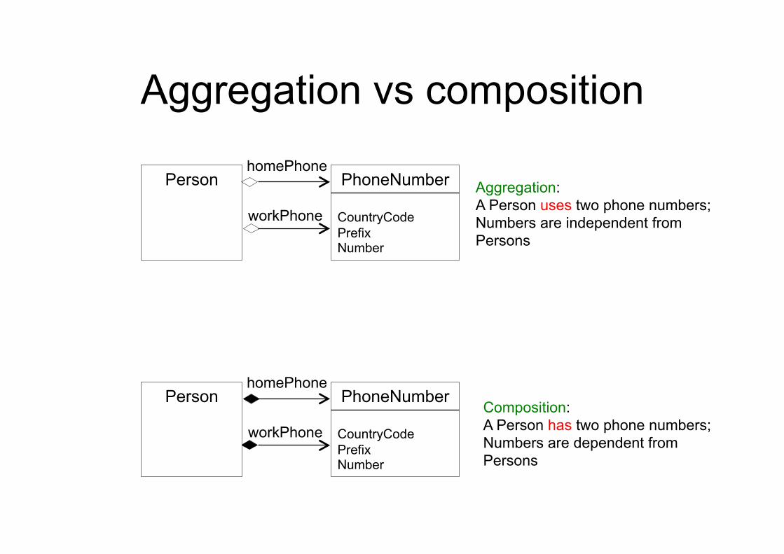
Aggregation vs composition
Person PhoneNumber
CountryCode Prefix Number
homePhone Aggregation: A Person uses two phone numbers; Numbers are independent from Persons
workPhone
Person PhoneNumber
CountryCode Prefix Number
homePhone
workPhone
Composition: A Person has two phone numbers; Numbers are dependent from Persons
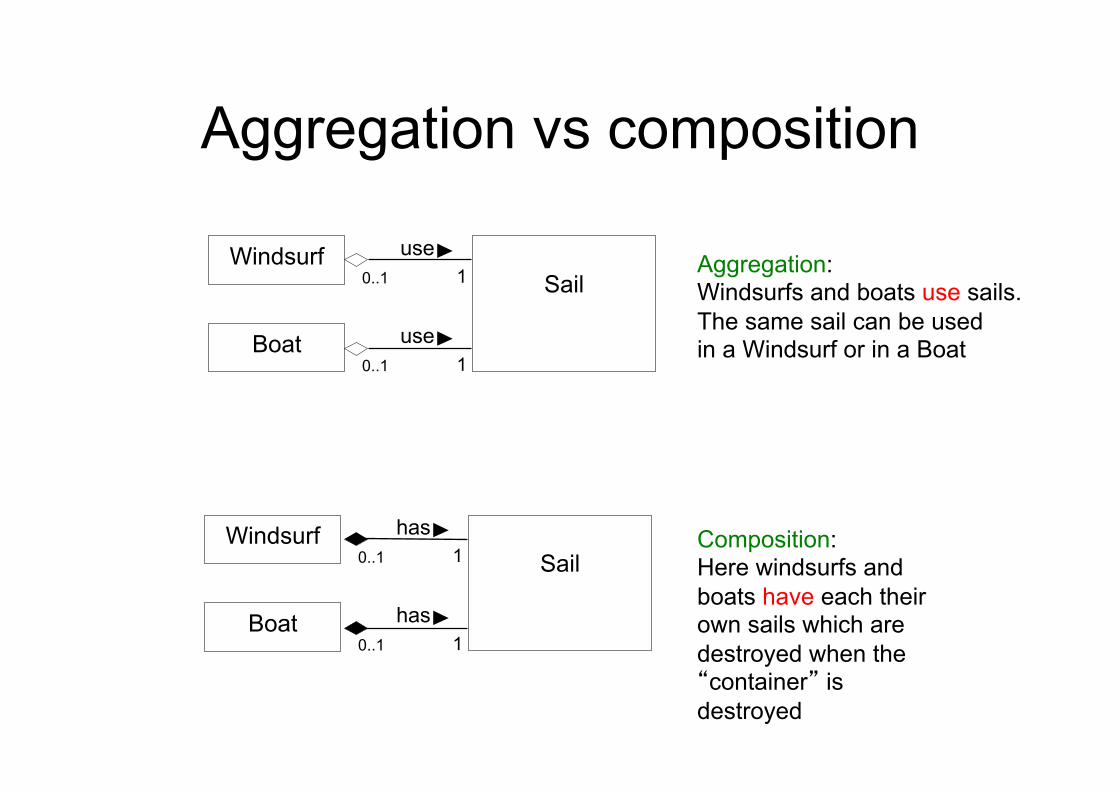
Aggregation vs composition
Windsurf
Boat
Sail
use
use 1
1 0..1
0..1
Windsurf
Boat
Sail
has
has 1
1 0..1
0..1
Aggregation: Windsurfs and boats use sails. The same sail can be used in a Windsurf or in a Boat
Composition: Here windsurfs and boats have each their own sails which are destroyed when the “container” is destroyed
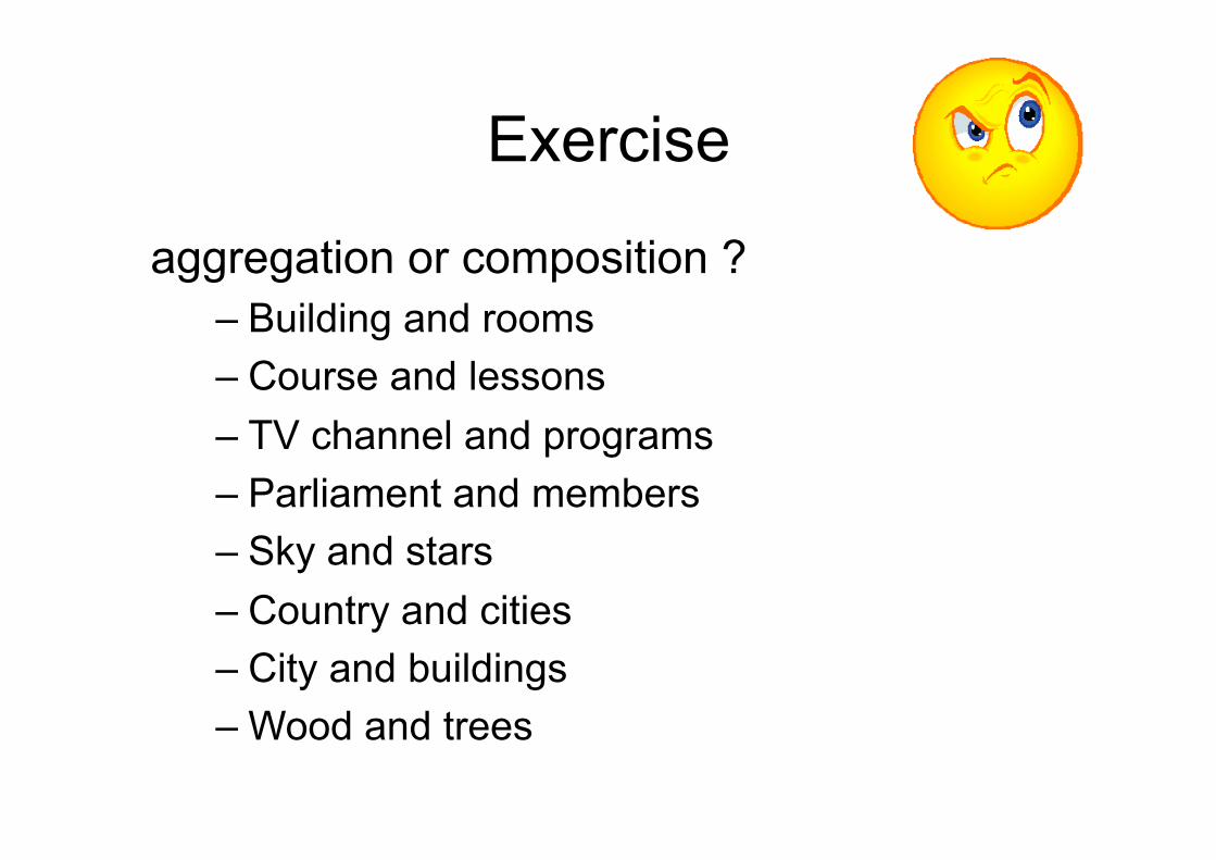
Exercise
aggregation or composition ? – Building and rooms – Course and lessons – TV channel and programs – Parliament and members – Sky and stars – Country and cities – City and buildings – Wood and trees
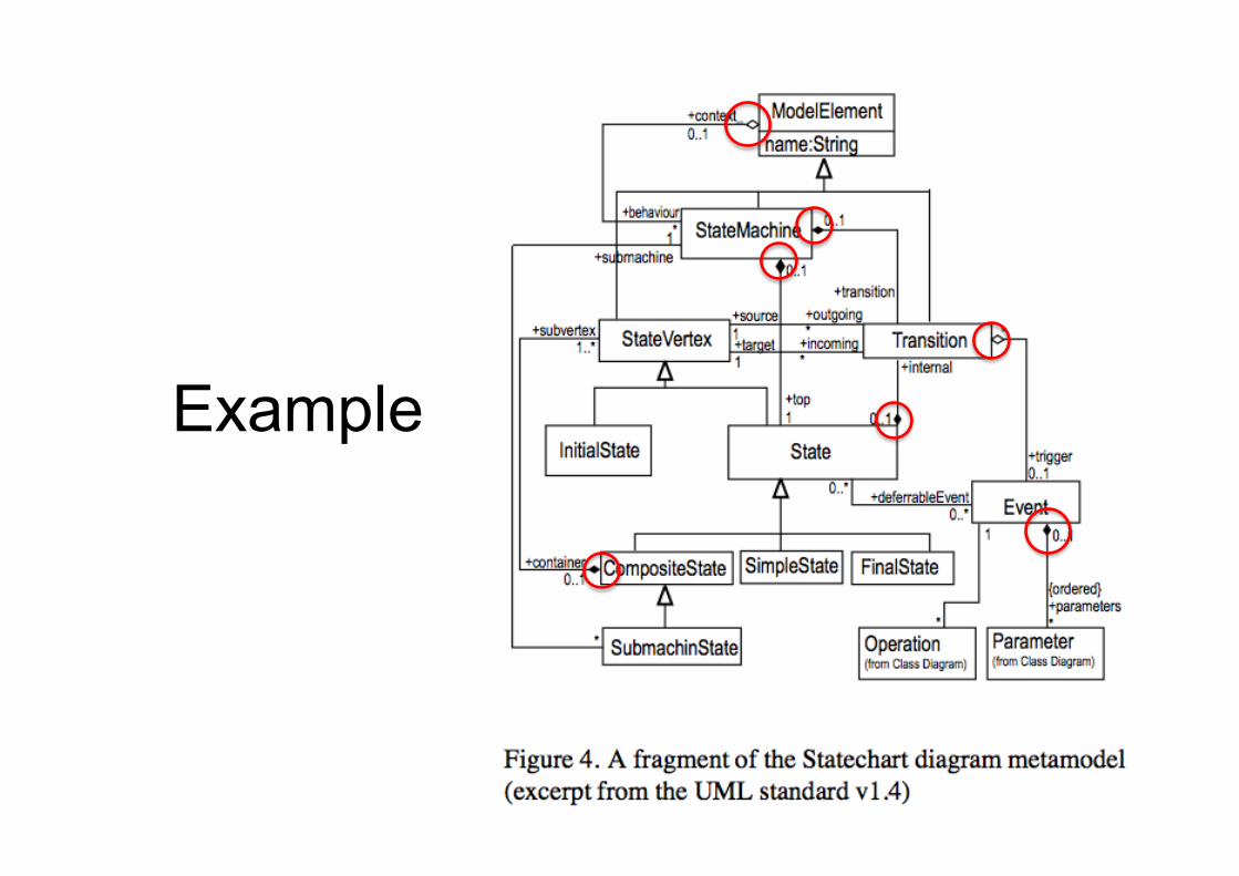
Example
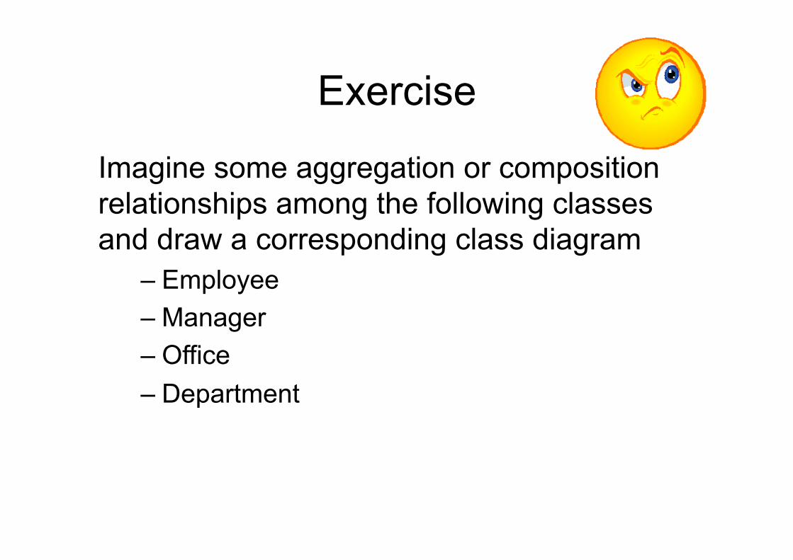
Exercise
Imagine some aggregation or composition relationships among the following classes and draw a corresponding class diagram
– Employee – Manager – Office – Department
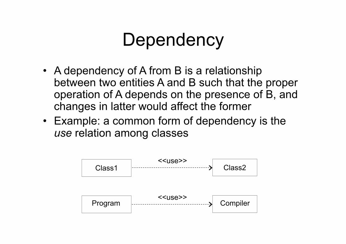
Dependency • A dependency of A from B is a relationship
between two entities A and B such that the proper operation of A depends on the presence of B, and changes in latter would affect the former
• Example: a common form of dependency is the use relation among classes
Class1 Class2 <<use>>
Program Compiler <<use>>
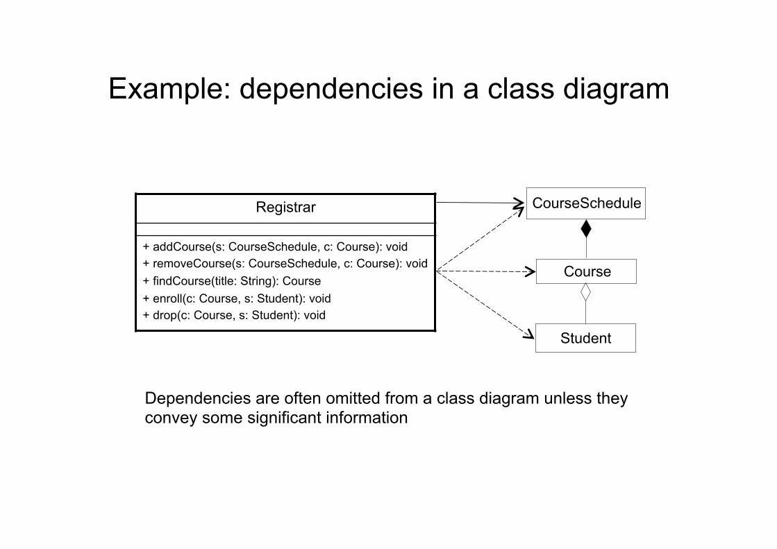
Example: dependencies in a class diagram
Registrar
+ addCourse(s: CourseSchedule, c: Course): void + removeCourse(s: CourseSchedule, c: Course): void + findCourse(title: String): Course + enroll(c: Course, s: Student): void + drop(c: Course, s: Student): void
CourseSchedule
Course
Student
Dependencies are often omitted from a class diagram unless they convey some significant information
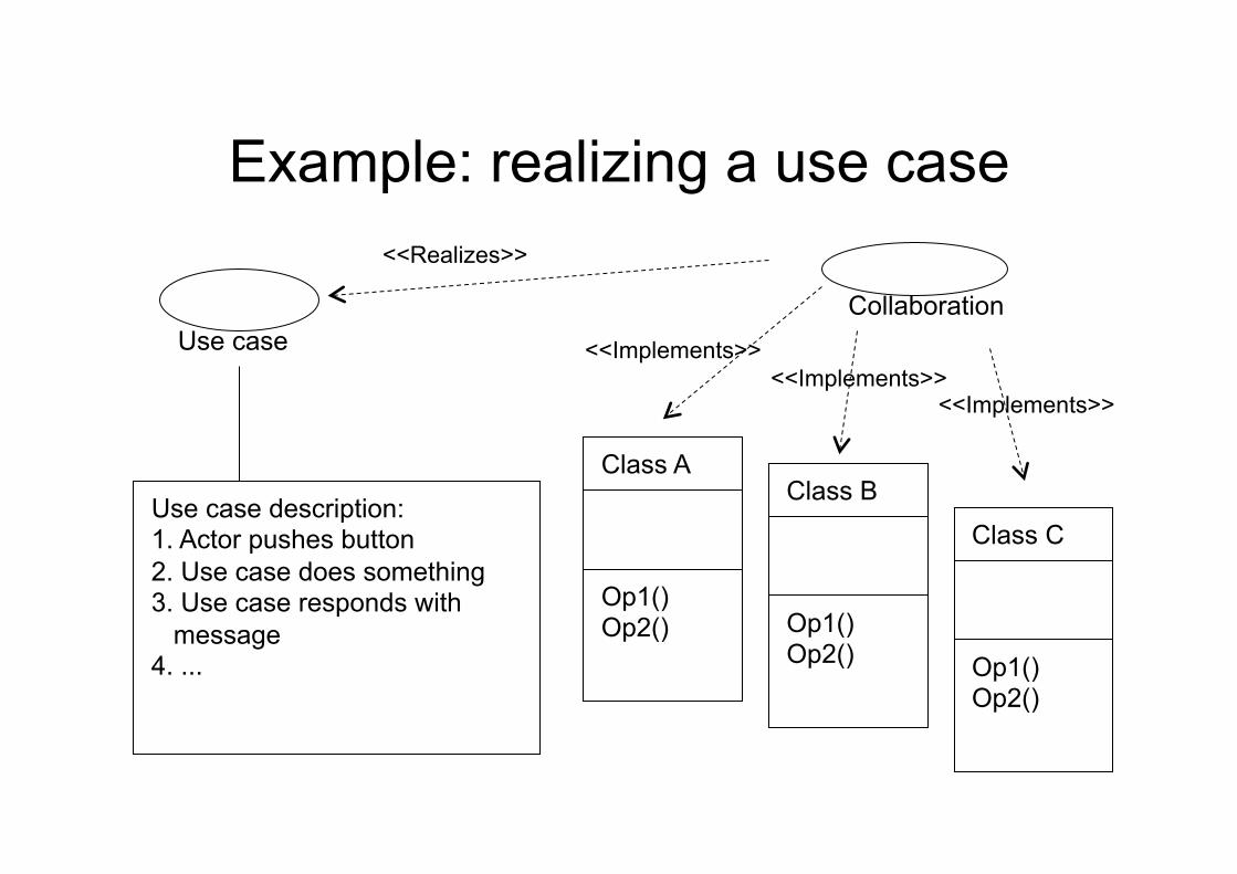
Use case description: 1. Actor pushes button 2. Use case does something 3. Use case responds with message 4. ...
Use case
Class A
Op1() Op2()
Class B
Op1() Op2()
Class C
Op1() Op2()
Collaboration
<<Implements>> <<Implements>>
<<Implements>>
<<Realizes>>
Example: realizing a use case
Class and superclass
Point
Colored Point
Point
x y
Move
Colored Point
… color
… SetColor
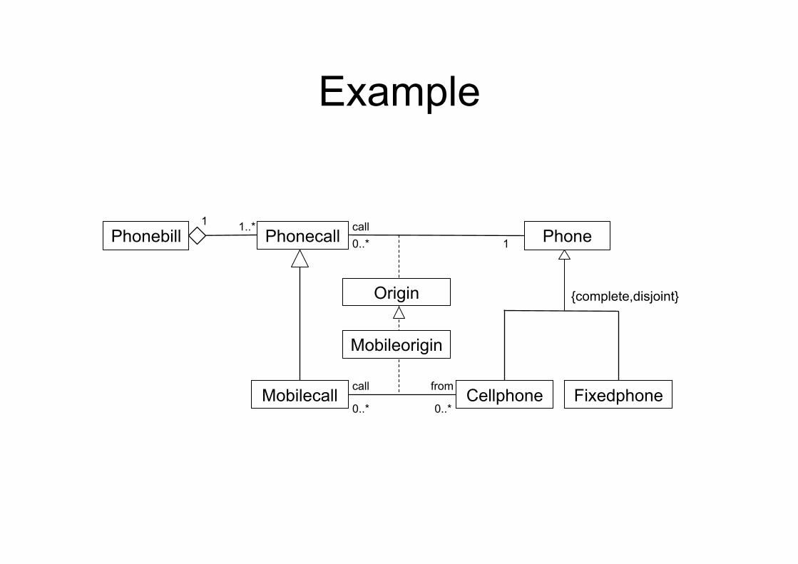
Example
Phonebill
Cellphone Fixedphone Mobilecall
Phonecall Phone call
from
1 1..* 0..* 1
0..* 0..*
call
Origin
Mobileorigin
{complete,disjoint}
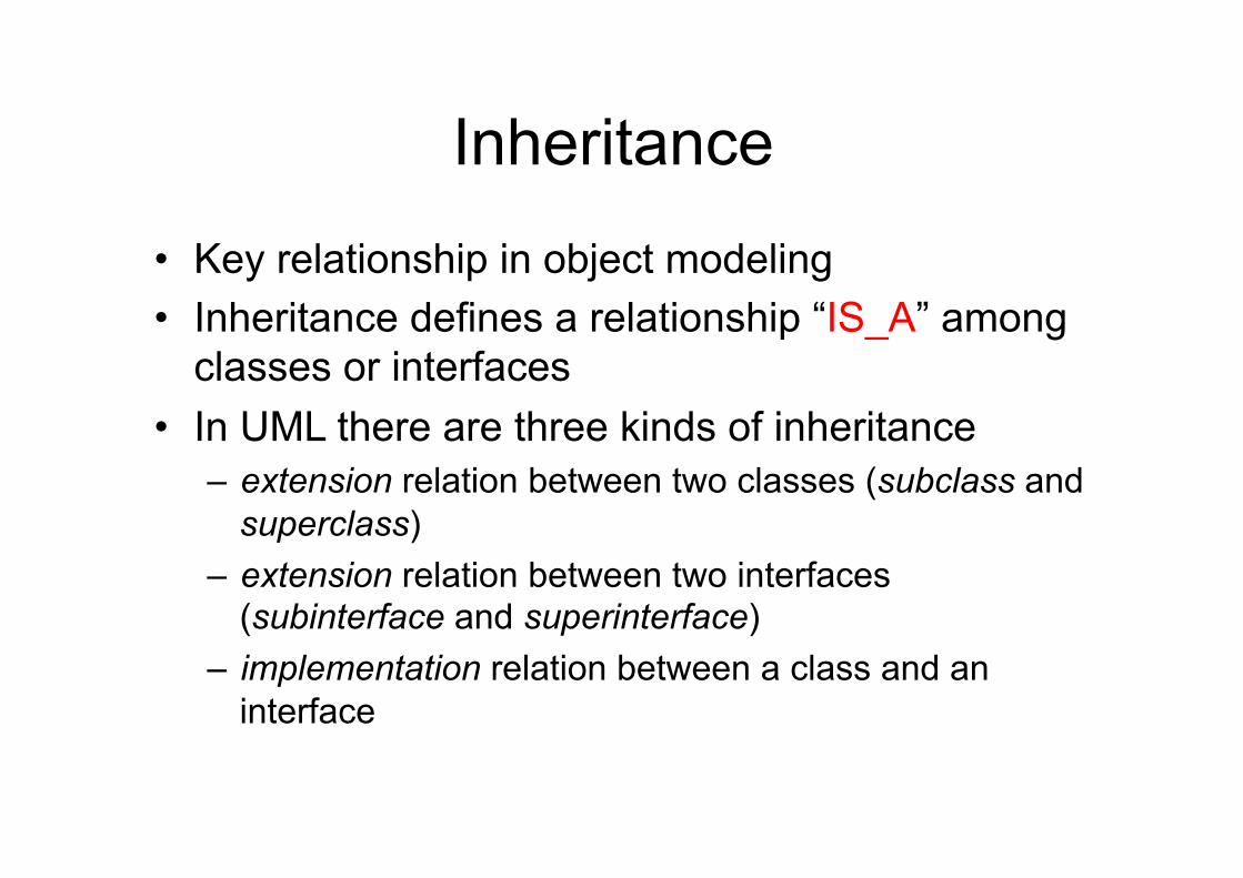
Inheritance
• Key relationship in object modeling • Inheritance defines a relationship “IS_A” among
classes or interfaces • In UML there are three kinds of inheritance
– extension relation between two classes (subclass and superclass)
– extension relation between two interfaces (subinterface and superinterface)
– implementation relation between a class and an interface
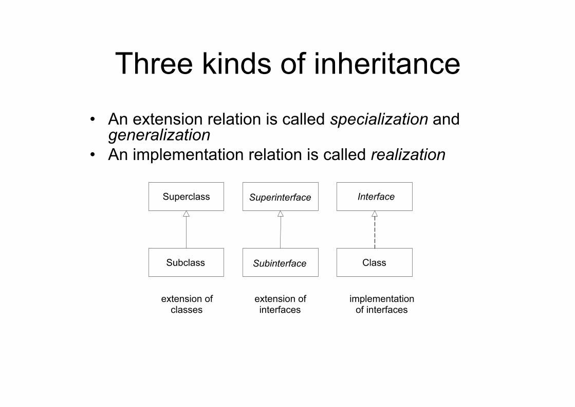
Three kinds of inheritance
• An extension relation is called specialization and generalization
• An implementation relation is called realization
Superclass
Subclass
Superinterface
Subinterface
Interface
Class
extension of classes
implementation of interfaces
extension of interfaces
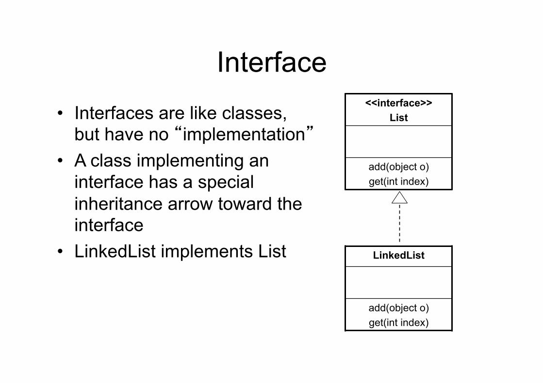
Interface
• Interfaces are like classes, but have no “implementation”
• A class implementing an interface has a special inheritance arrow toward the interface
• LinkedList implements List
<<interface>> List
add(object o) get(int index)
LinkedList
add(object o) get(int index)
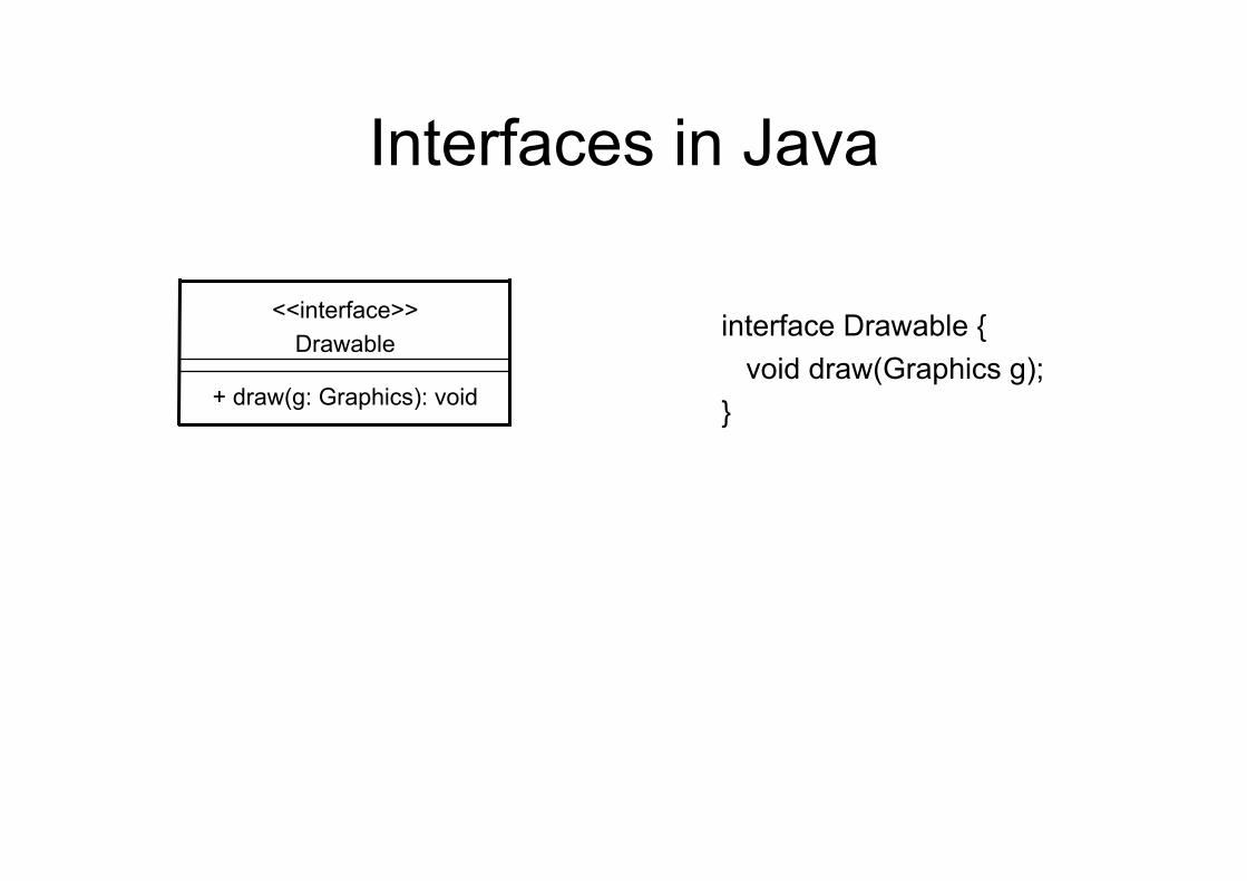
Interfaces in Java
interface Drawable {
void draw(Graphics g); } + draw(g: Graphics): void
<<interface>> Drawable
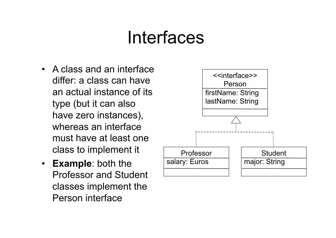
Interfaces • A class and an interface
differ: a class can have an actual instance of its type (but it can also have zero instances), whereas an interface must have at least one class to implement it
• Example: both the Professor and Student classes implement the Person interface
<<interface>> Person
firstName: String lastName: String
Professor salary: Euros
Student major: String
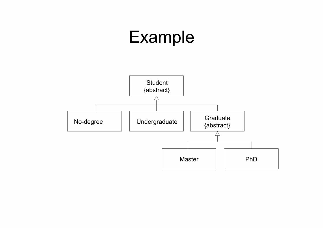
Example
Student {abstract}
Undergraduate Graduate {abstract} No-degree
Master PhD
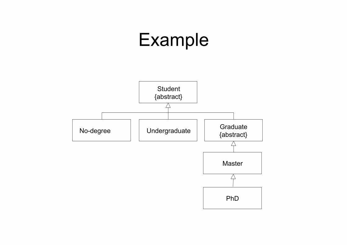
Example
Student {abstract}
Undergraduate Graduate {abstract} No-degree
Master
PhD
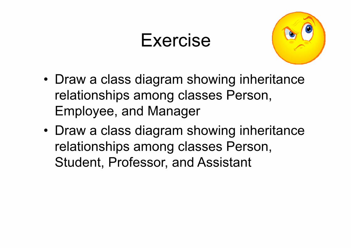
Exercise
• Draw a class diagram showing inheritance relationships among classes Person, Employee, and Manager
• Draw a class diagram showing inheritance relationships among classes Person, Student, Professor, and Assistant
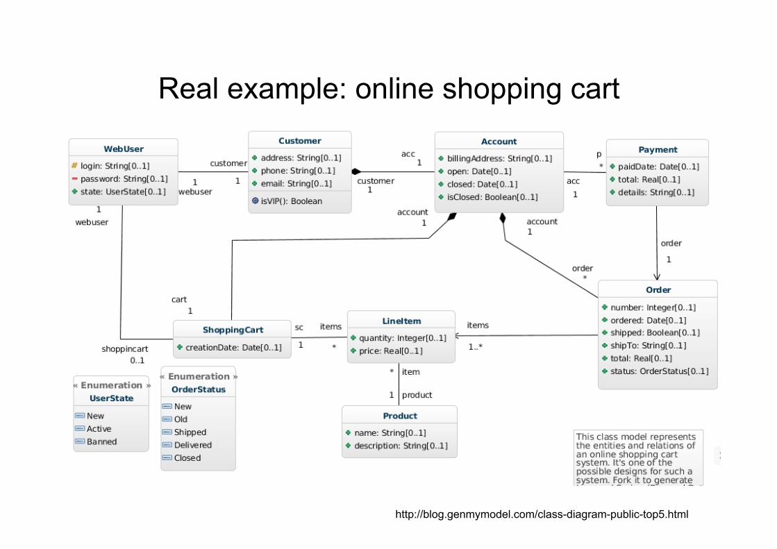
Real example: online shopping cart
http://blog.genmymodel.com/class-diagram-public-top5.html
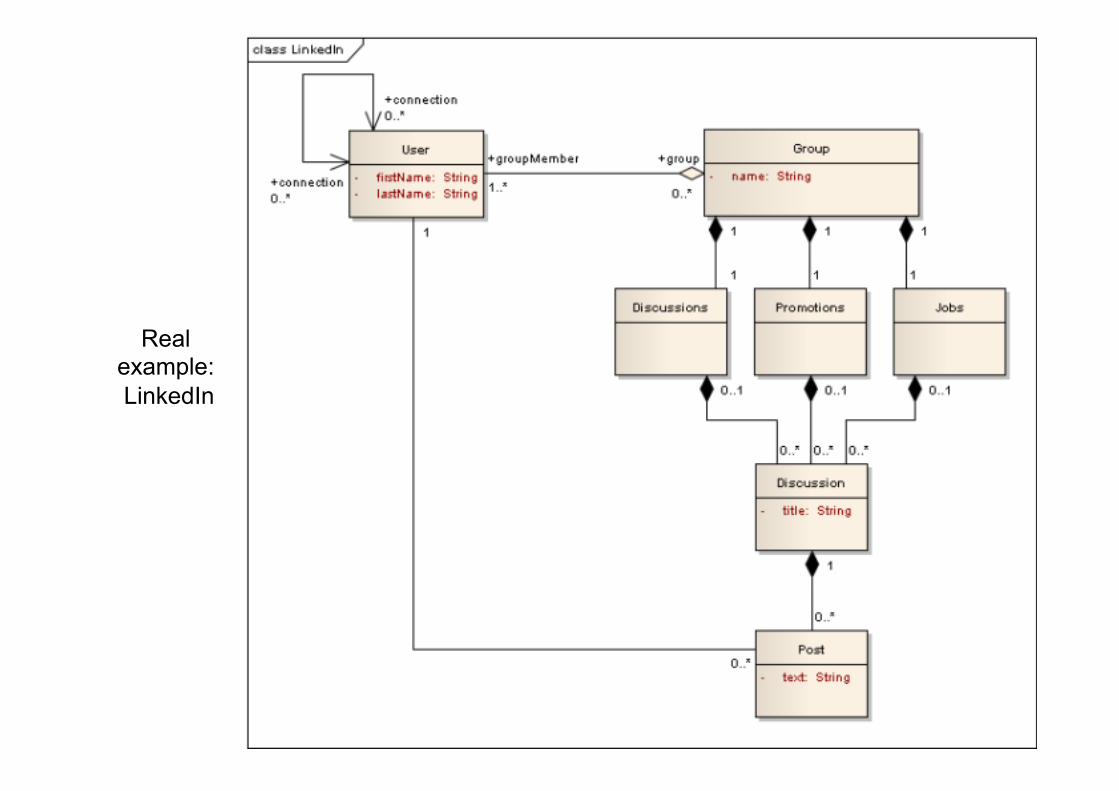
Real example: LinkedIn
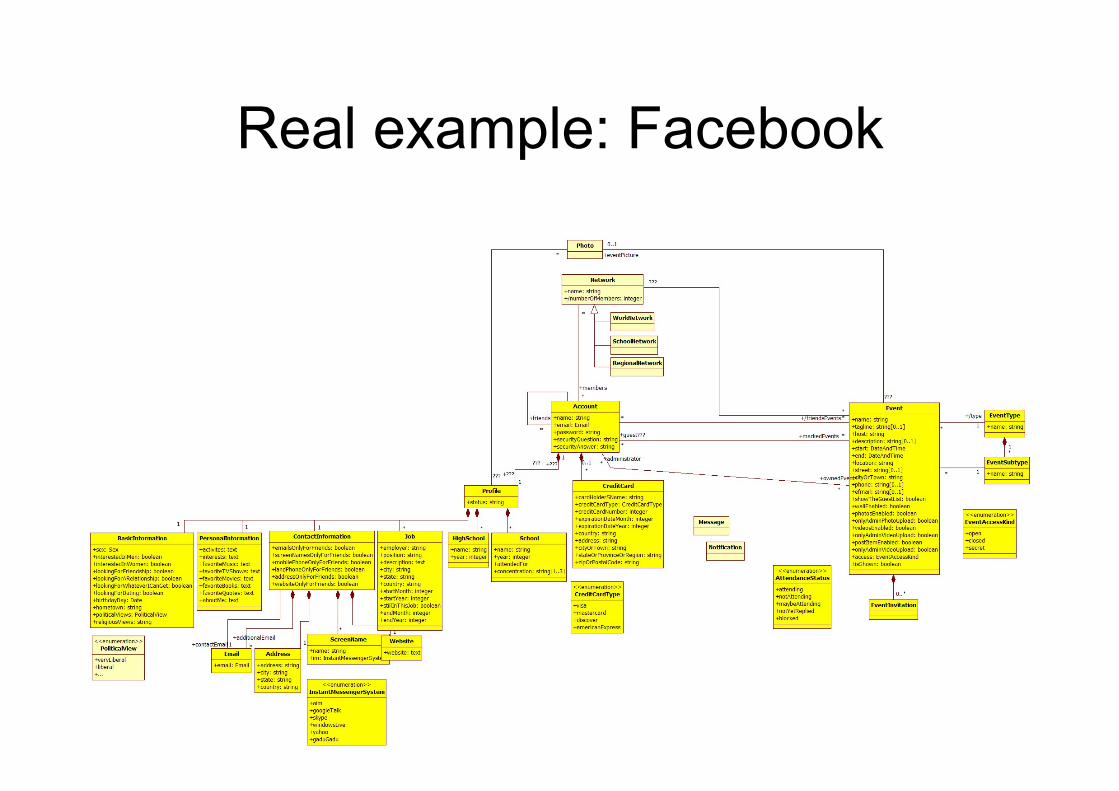
Real example: Facebook
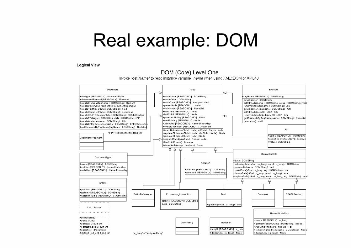
Real example: DOM
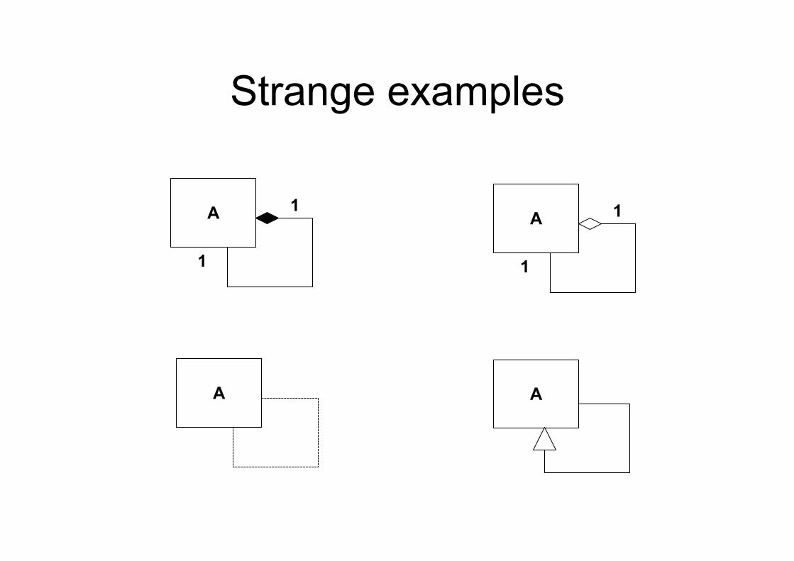
Strange examples
A
1
1
A
1
1
A
A
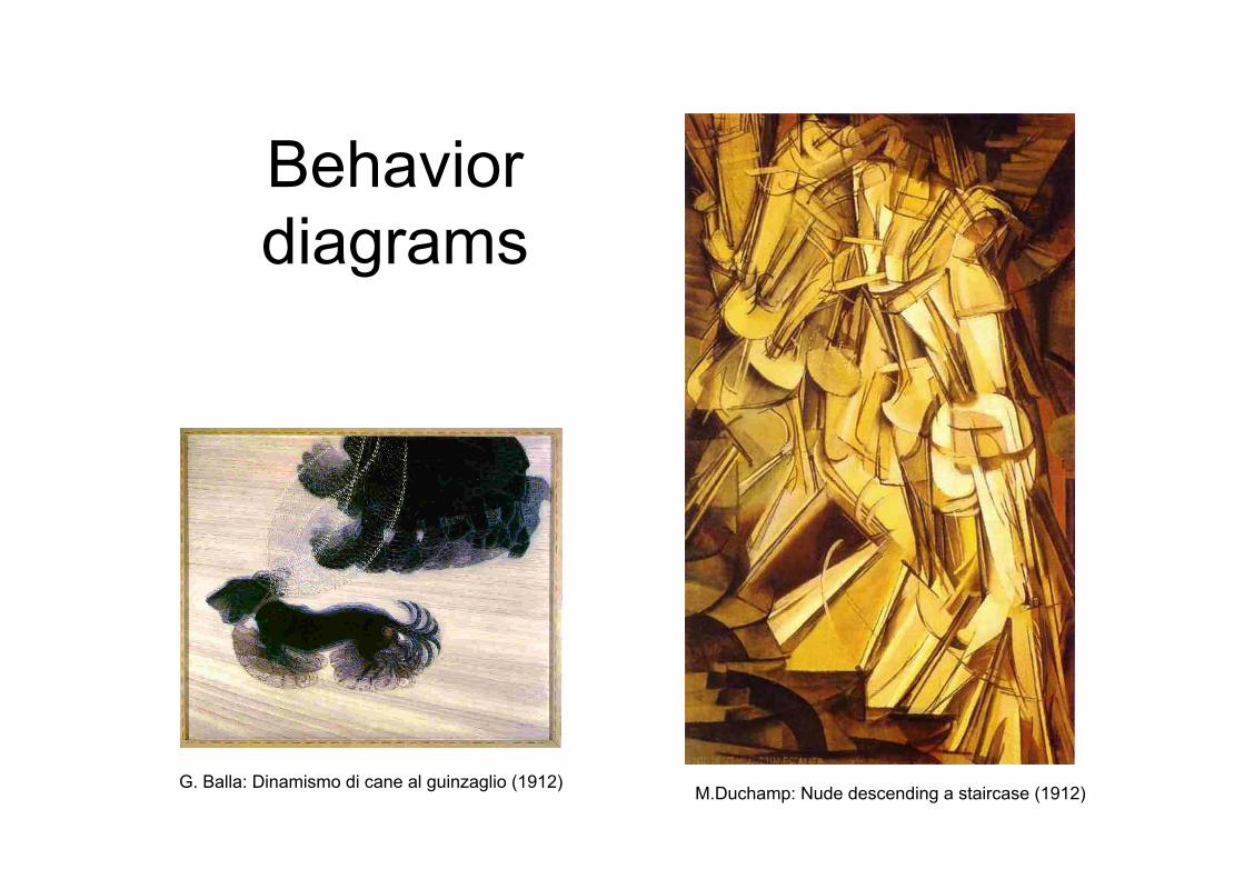
Behavior diagrams
M.Duchamp: Nude descending a staircase (1912) G. Balla: Dinamismo di cane al guinzaglio (1912)
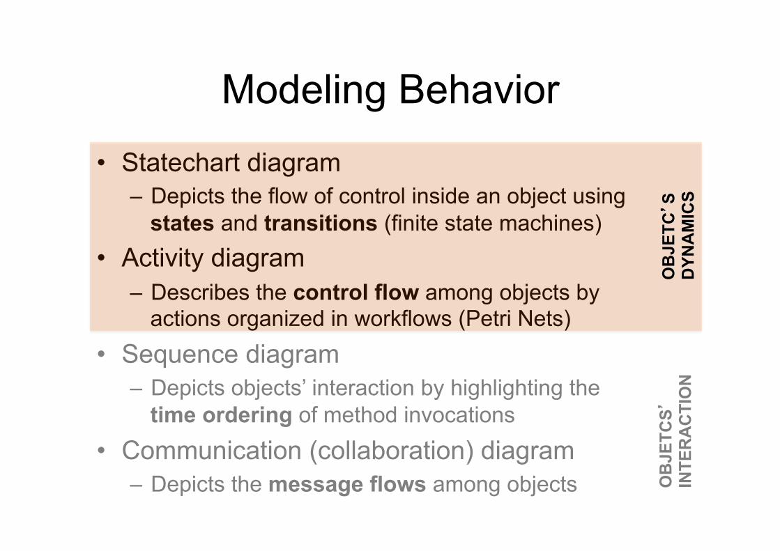
Modeling Behavior
• Statechart diagram – Depicts the flow of control inside an object using
states and transitions (finite state machines) • Activity diagram
– Describes the control flow among objects by actions organized in workflows (Petri Nets)
• Sequence diagram – Depicts objects’ interaction by highlighting the
time ordering of method invocations • Communication (collaboration) diagram
– Depicts the message flows among objects OB
JETC
S’
INTE
RA
CTI
ON
O
BJE
TC’S
DYN
AM
ICS
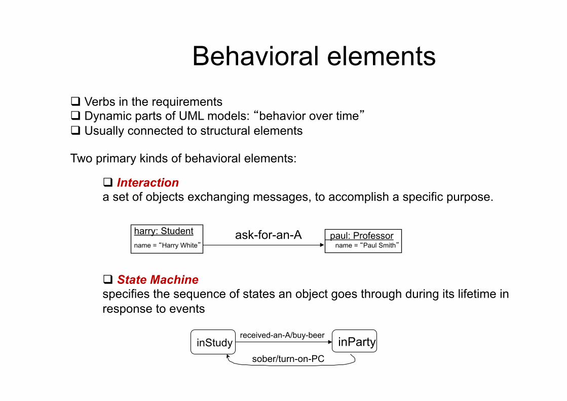
Behavioral elements
Two primary kinds of behavioral elements:
q Verbs in the requirements q Dynamic parts of UML models: “behavior over time” q Usually connected to structural elements
q Interaction a set of objects exchanging messages, to accomplish a specific purpose.
ask-for-an-A
q State Machine specifies the sequence of states an object goes through during its lifetime in response to events
inParty inStudy
harry: Student name = “Harry White”
paul: Professor name = “Paul Smith”
received-an-A/buy-beer
sober/turn-on-PC
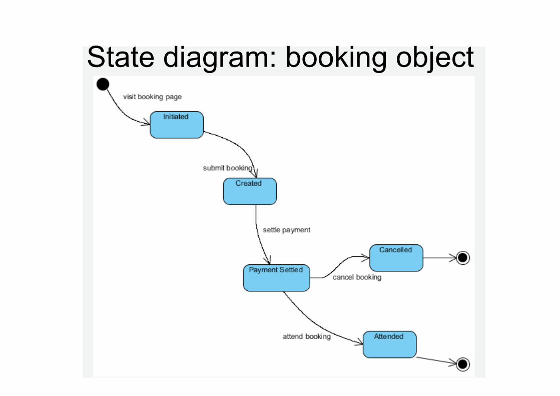
State diagram: booking object
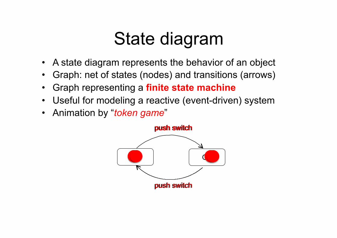
State diagram • A state diagram represents the behavior of an object • Graph: net of states (nodes) and transitions (arrows) • Graph representing a finite state machine • Useful for modeling a reactive (event-driven) system • Animation by “token game”
Off On
push switch push switch
push switch push switch
push switch
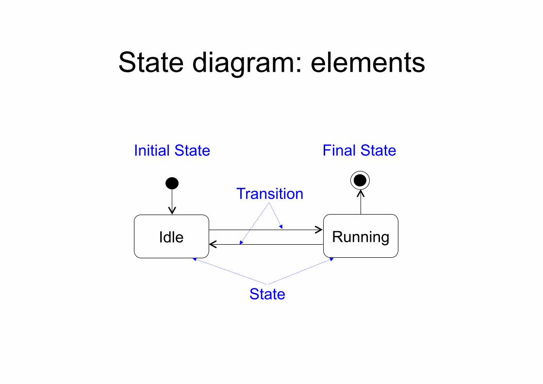
State diagram: elements
Idle
Initial State
Running
Final State
State
Transition
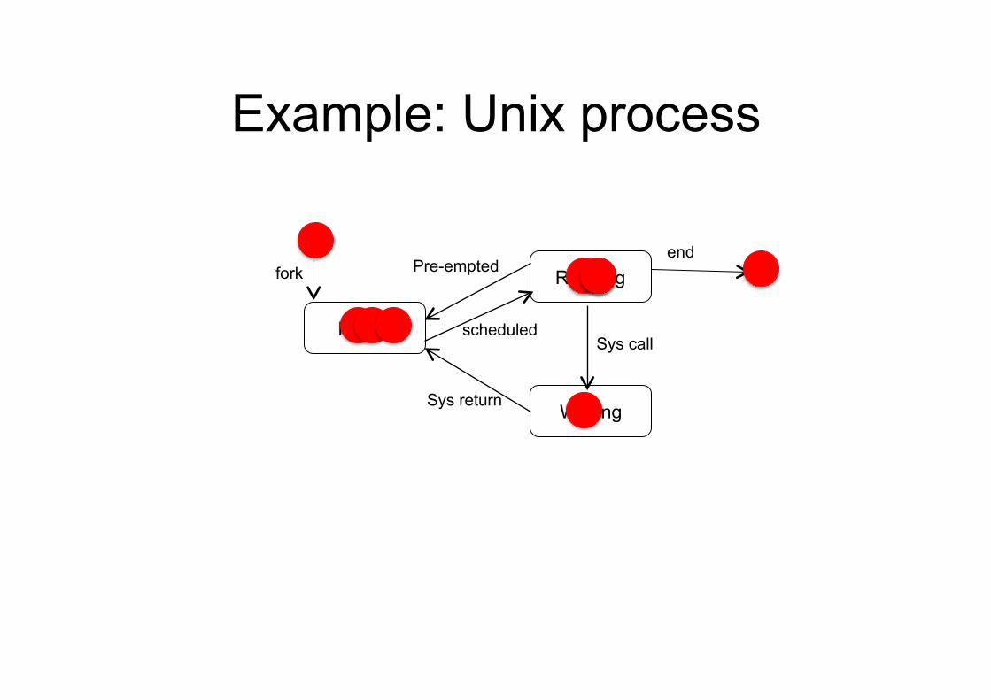
Example: Unix process
Ready
Running
Waiting
Sys call
Sys return
Pre-empted
scheduled
end fork
State
• Situation in the life of an object (or system) during which it: – Satisfies some condition, – Performs some activity, or – Waits for some events
• Set of values of properties that affect the behavior of the object (or system) – Determines the response to an event, – Thus, different states may produce different
responses to the same event
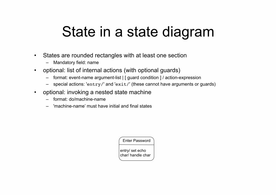
State in a state diagram • States are rounded rectangles with at least one section
– Mandatory field: name
• optional: list of internal actions (with optional guards) – format: event-name argument-list | [ guard condition ] / action-expression – special actions: 'entry/' and 'exit/' (these cannot have arguments or guards)
• optional: invoking a nested state machine – format: do/machine-name – 'machine-name’ must have initial and final states
Enter Password
entry/ set echo char/ handle char
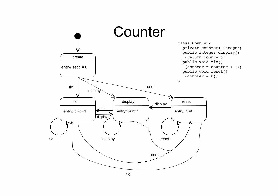
Counter create
entry/ set c = 0
tic entry/ c:=c+1
tic
display entry/ print c
display
reset entry/ c:=0
reset
tic display
reset
reset
tic display
display
tic
class Counter{! private counter: integer;! public integer display()! {return counter};! public void tic()! {counter = counter + 1};! public void reset()! {counter = 0};!}
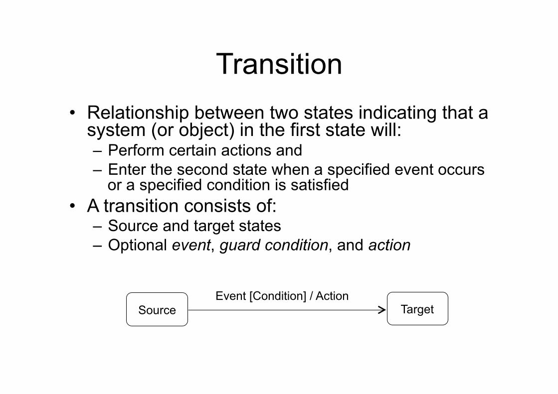
Transition • Relationship between two states indicating that a
system (or object) in the first state will: – Perform certain actions and – Enter the second state when a specified event occurs
or a specified condition is satisfied • A transition consists of:
– Source and target states – Optional event, guard condition, and action
Source Event [Condition] / Action
Target
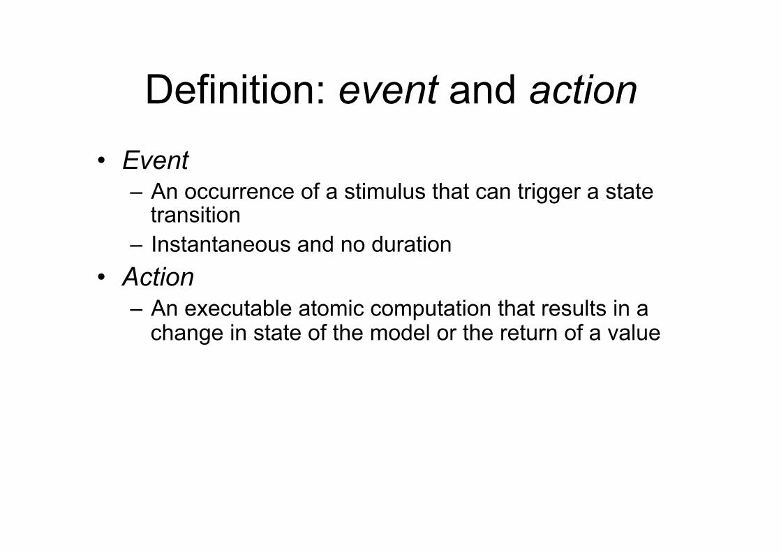
Definition: event and action • Event
– An occurrence of a stimulus that can trigger a state transition
– Instantaneous and no duration • Action
– An executable atomic computation that results in a change in state of the model or the return of a value
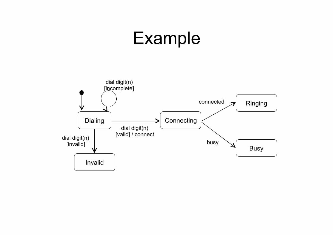
Example
dial digit(n) [incomplete]
Dialing Connecting
busy
connected
dial digit(n) [valid] / connect dial digit(n)
[invalid]
Invalid
Ringing
Busy
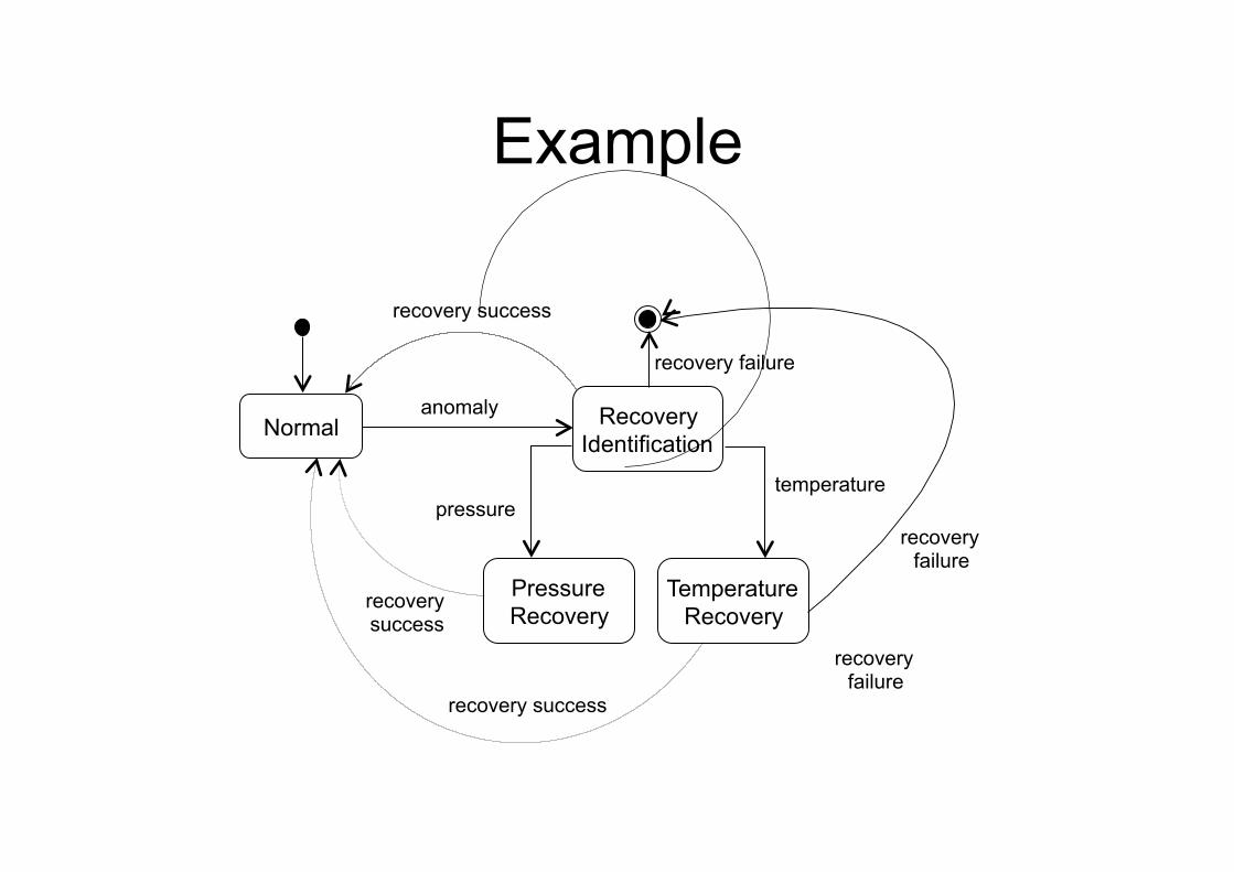
Example
anomaly Normal Recovery
Identification
Pressure Recovery
Temperature Recovery
recovery success
recovery success
recovery success
temperature pressure
recovery failure
recovery failure
recovery failure
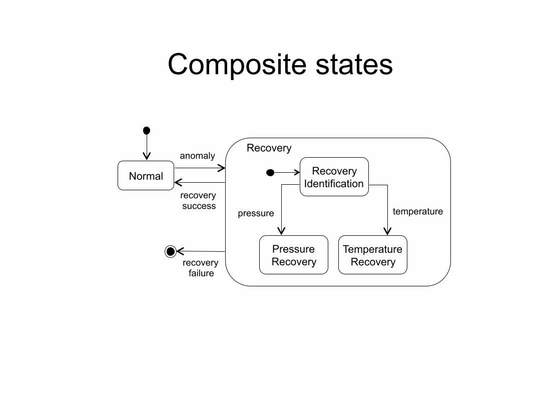
Composite states
anomaly
Normal Recovery Identification
Pressure Recovery
Temperature Recovery
recovery success temperature pressure
Recovery
recovery failure
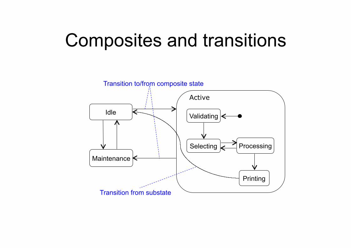
Composites and transitions
Idle
Maintenance
Printing
Selecting Processing
Validating
Transition from substate
Transition to/from composite state
Active
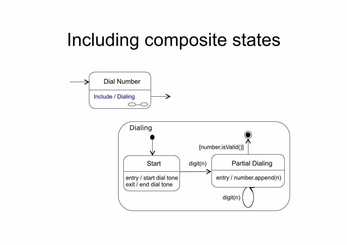
Including composite states
Start entry / start dial tone exit / end dial tone
Partial Dialing entry / number.append(n)
digit(n)
digit(n)
[number.isValid()]
Dialing
Dial Number Include / Dialing
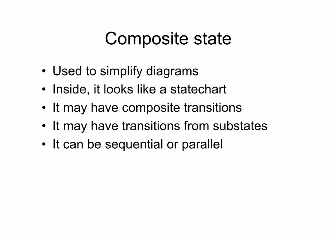
Composite state
• Used to simplify diagrams • Inside, it looks like a statechart • It may have composite transitions • It may have transitions from substates • It can be sequential or parallel
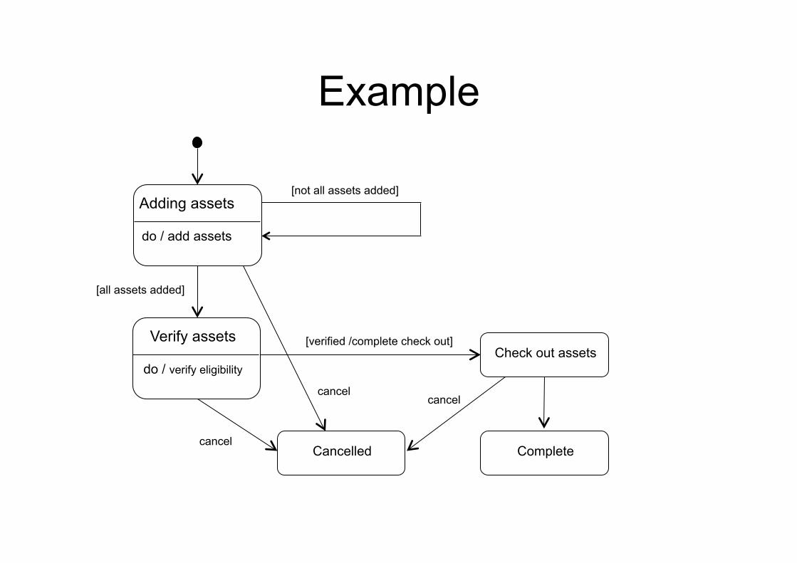
Example
Adding assets
do / add assets
Verify assets
do / verify eligibility Check out assets
Complete
[not all assets added]
[all assets added]
[verified /complete check out]
Cancelled cancel
cancel cancel
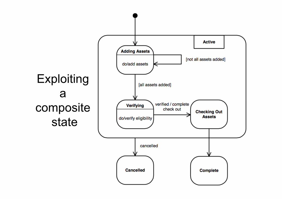
Exploiting a
composite state
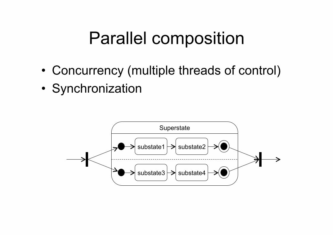
Parallel composition
• Concurrency (multiple threads of control) • Synchronization
substate1 substate2
Superstate
substate3 substate4
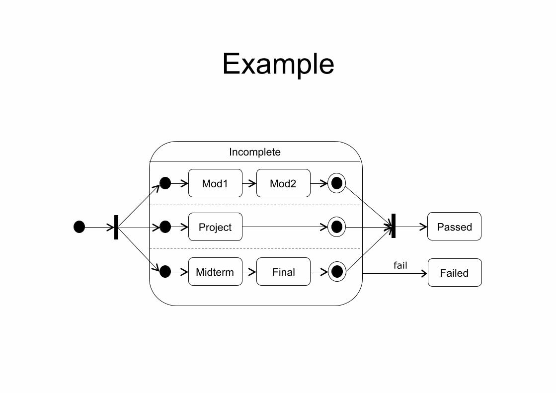
Example
Mod1 Mod2
Incomplete
Project
Midterm Final
Passed
Failed fail
Protocol state machine • Normally we use a state diagram to show the internal
behavior of all objects of a class • Sometimes, however, we want to show a complex
protocol (set of rules governing communication) when using an interface for a class
• For example, when we access a database we need to use operations like open, close and query. But these operations must be called in the right order: we cannot query the database before we open it
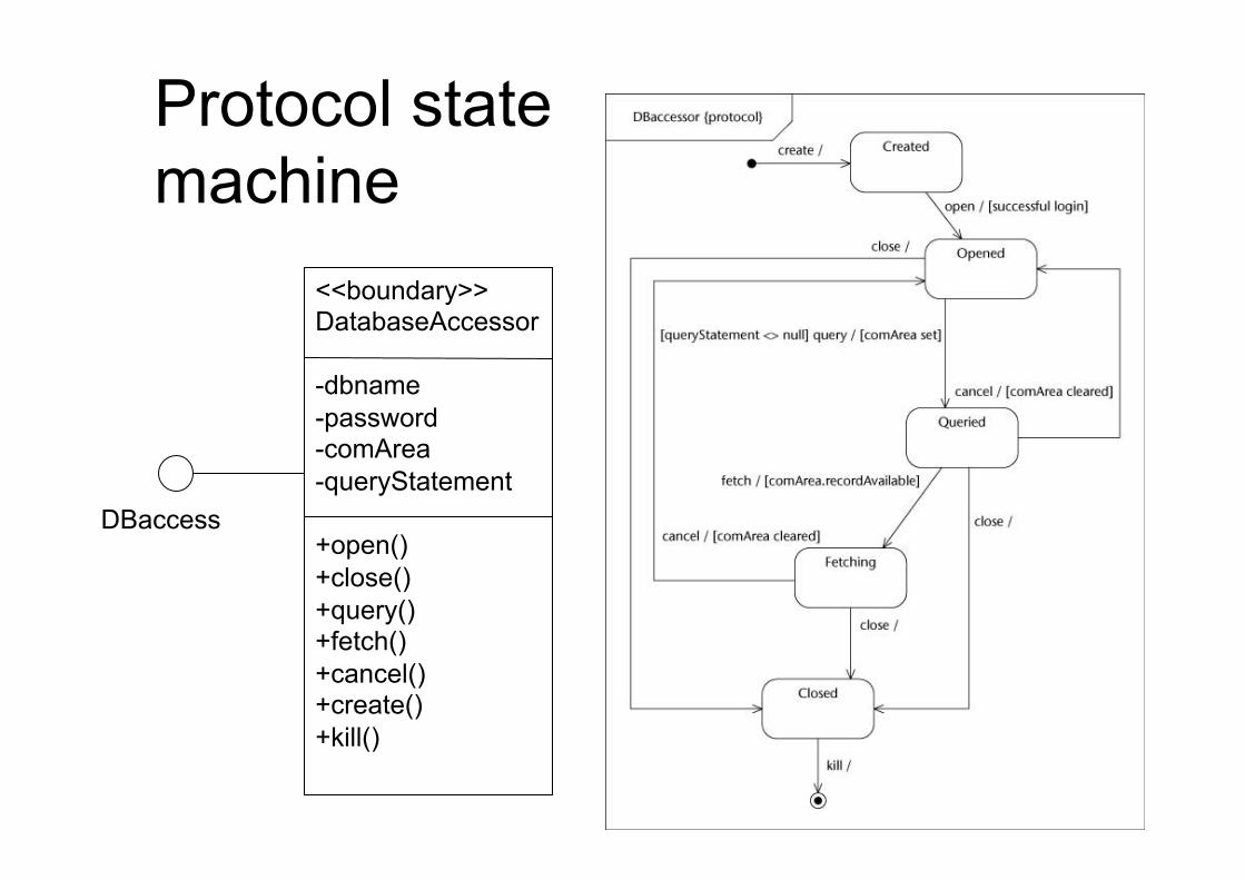
Protocol state machine
<<boundary>> DatabaseAccessor -dbname -password -comArea -queryStatement +open() +close() +query() +fetch() +cancel() +create() +kill()
DBaccess
Behavioral vs protocol state machine
• Two kinds of state machines: behavioral state machines and protocol state machines
• Behavioral state machines can be used to model the behavior of individual entities (e.g., class instances)
• Protocol state machines are used to express usage protocols and can be used to specify the legal usage scenarios of classifiers, interfaces, and ports
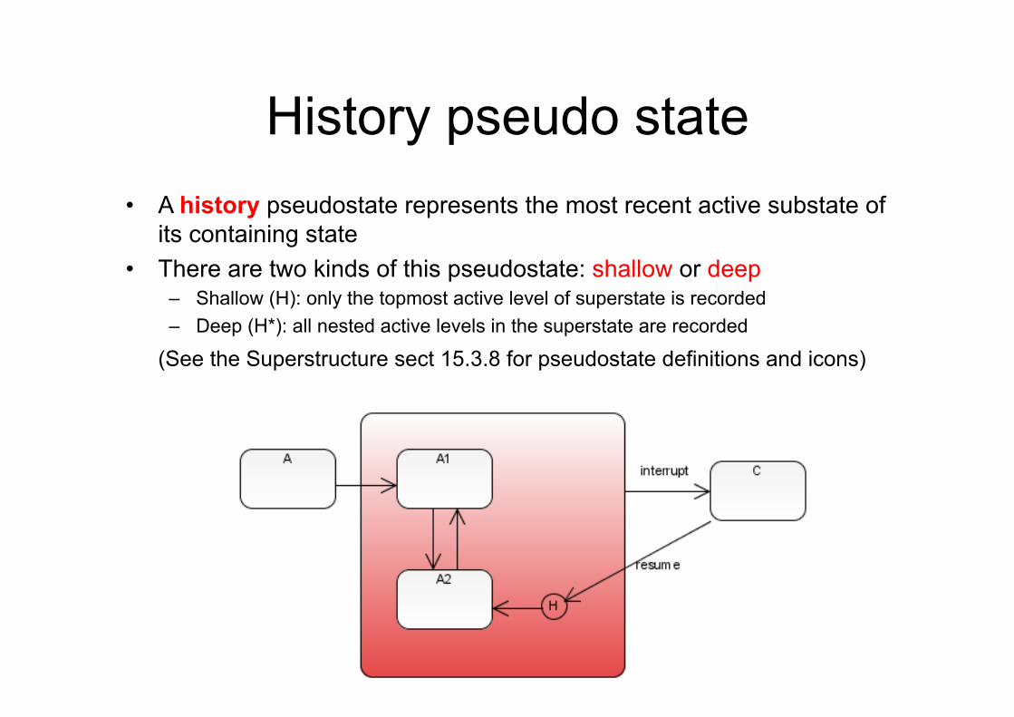
History pseudo state • A history pseudostate represents the most recent active substate of
its containing state • There are two kinds of this pseudostate: shallow or deep
– Shallow (H): only the topmost active level of superstate is recorded – Deep (H*): all nested active levels in the superstate are recorded
(See the Superstructure sect 15.3.8 for pseudostate definitions and icons)

Consistency among diagrams
*
Student
0..*
*
1
practices attends
UniversityCourse Sport
Name Surname Age Role
new enrollment to a different course
change career
change role
studies end studying
Student
Graduate Sportsman
Exercise: Cellular Phone
• Draw a statechart describing the operation of a cellular phone. Assume that the phone has keys for:
– power on and off – keypad locking and unlocking – 0-9, #, and * – talk (or send) and end
Model the following operations: – power on/off – keypad locking/unlocking – making calls (e.g., dialing, connecting, talking), – receiving calls (e.g., ringing, talking)
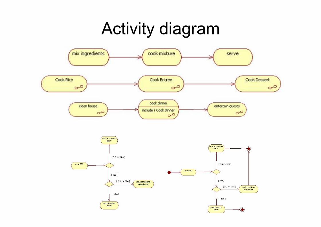
Activity diagrams
• Activity diagrams represent workflows of actions of several objects (but objects are not shown)
• Actions are composed by sequence, choice, iteration, and concurrency
• AD can be used to describe the activities of the components of a system
• In UML1 AD are based on State Diagrams in UML2 they have a different semantics
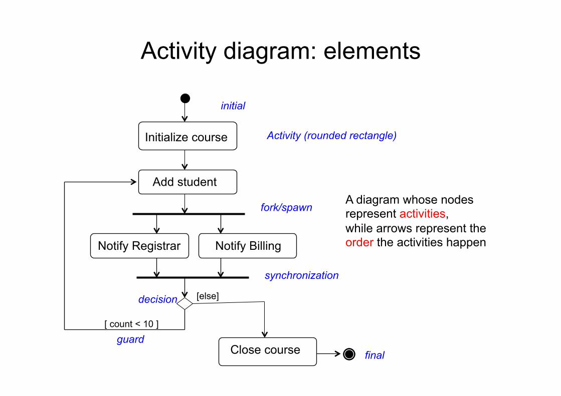
Activity diagram: elements
synchronization
Initialize course
[ count < 10 ]
A diagram whose nodes represent activities, while arrows represent the order the activities happen
Add student
Close course
[else]
Notify Registrar Notify Billing
fork/spawn
Activity (rounded rectangle)
guard
initial
final
decision
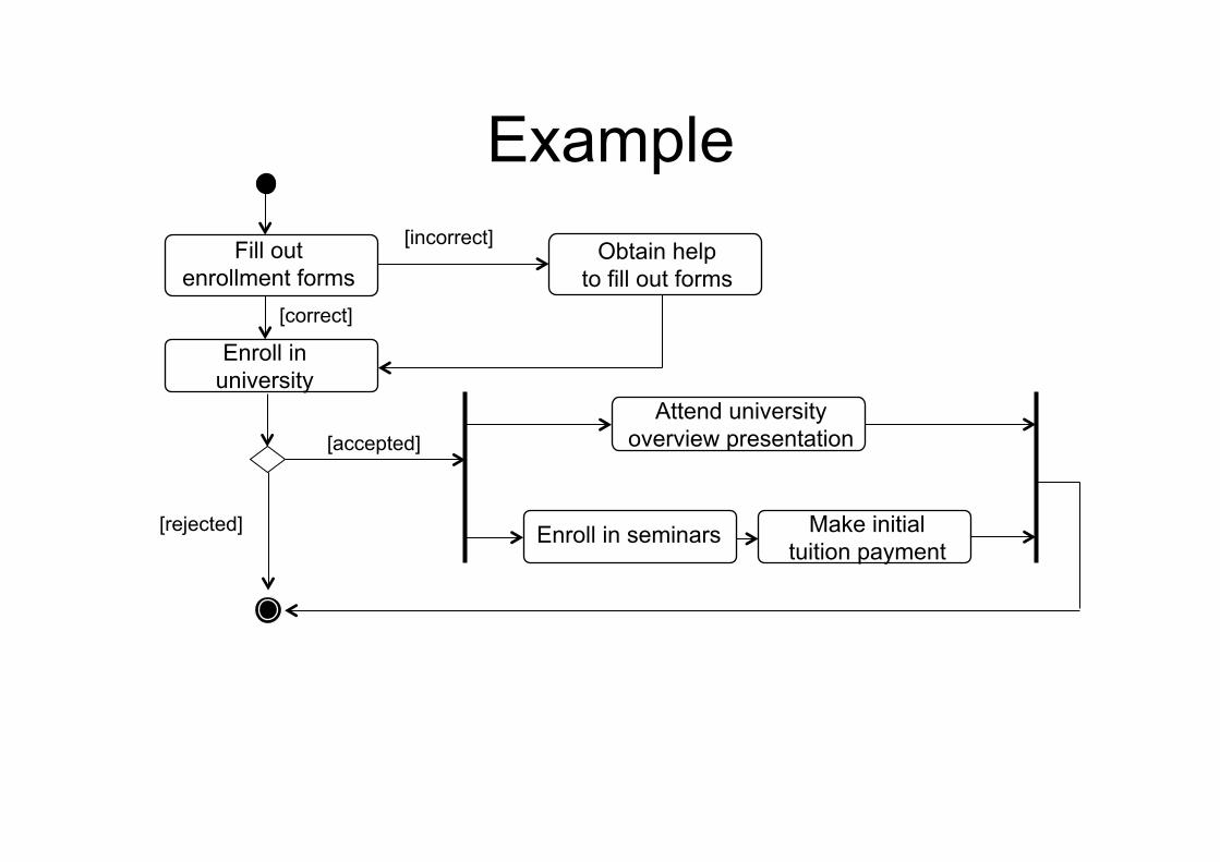
Example Fill out
enrollment forms
Enroll in university
Enroll in seminars Make initial tuition payment
Attend university overview presentation
Obtain help to fill out forms
[correct]
[incorrect]
[accepted]
[rejected]
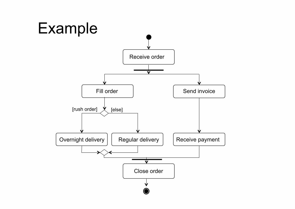
Example Receive order
Fill order
[else] [rush order]
Send invoice
Overnight delivery Regular delivery Receive payment
Close order
Activity diagram
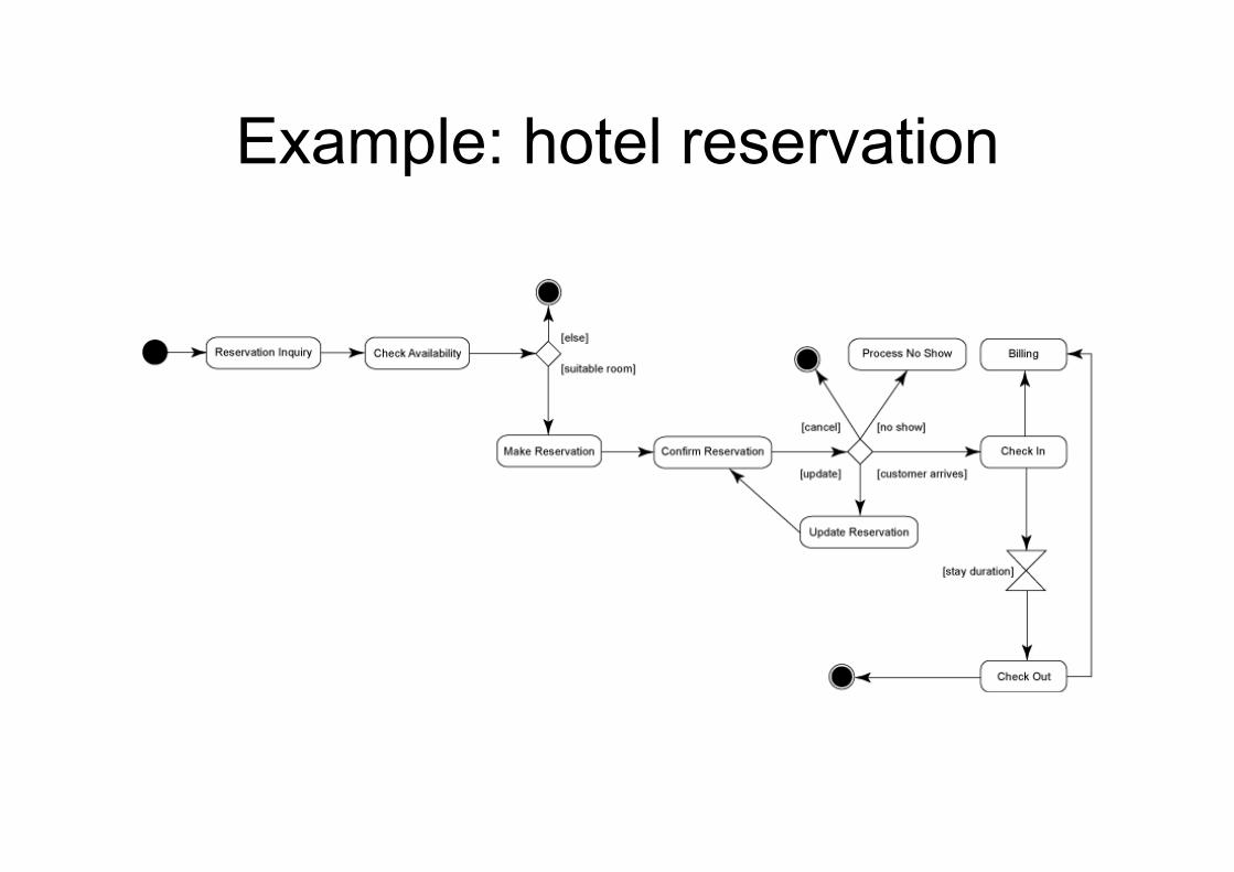
Example: hotel reservation
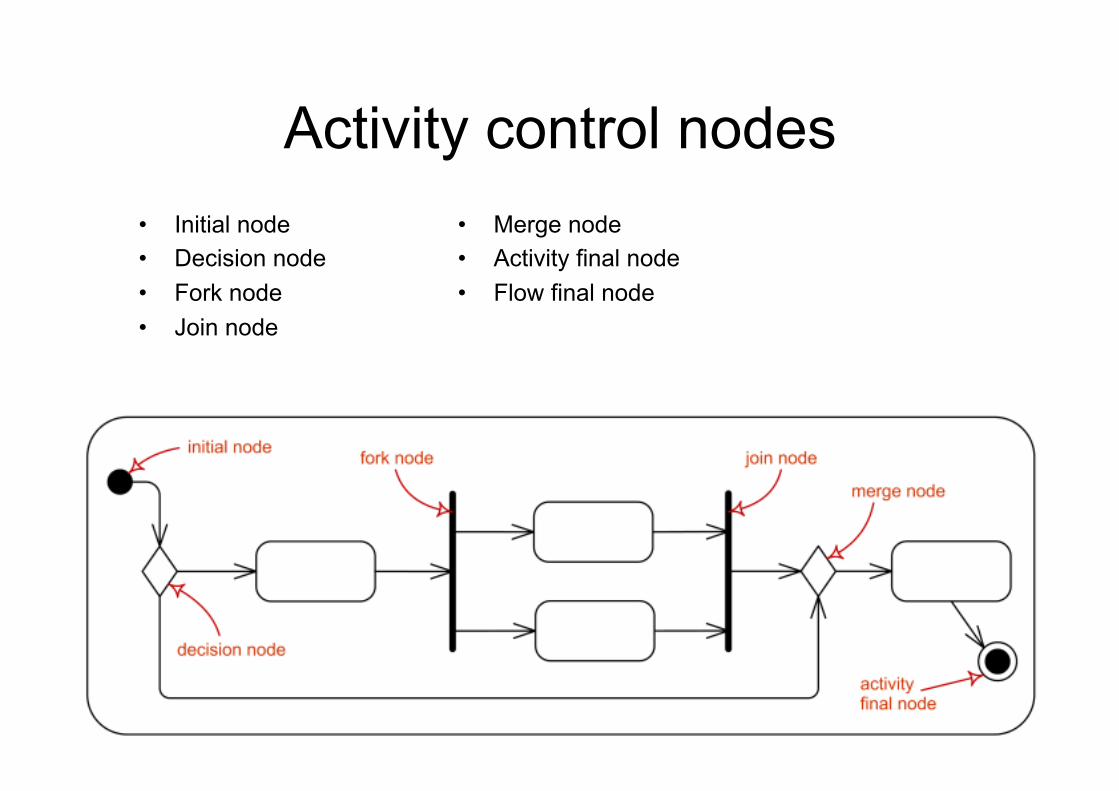
Activity control nodes • Initial node • Decision node • Fork node • Join node
• Merge node • Activity final node • Flow final node
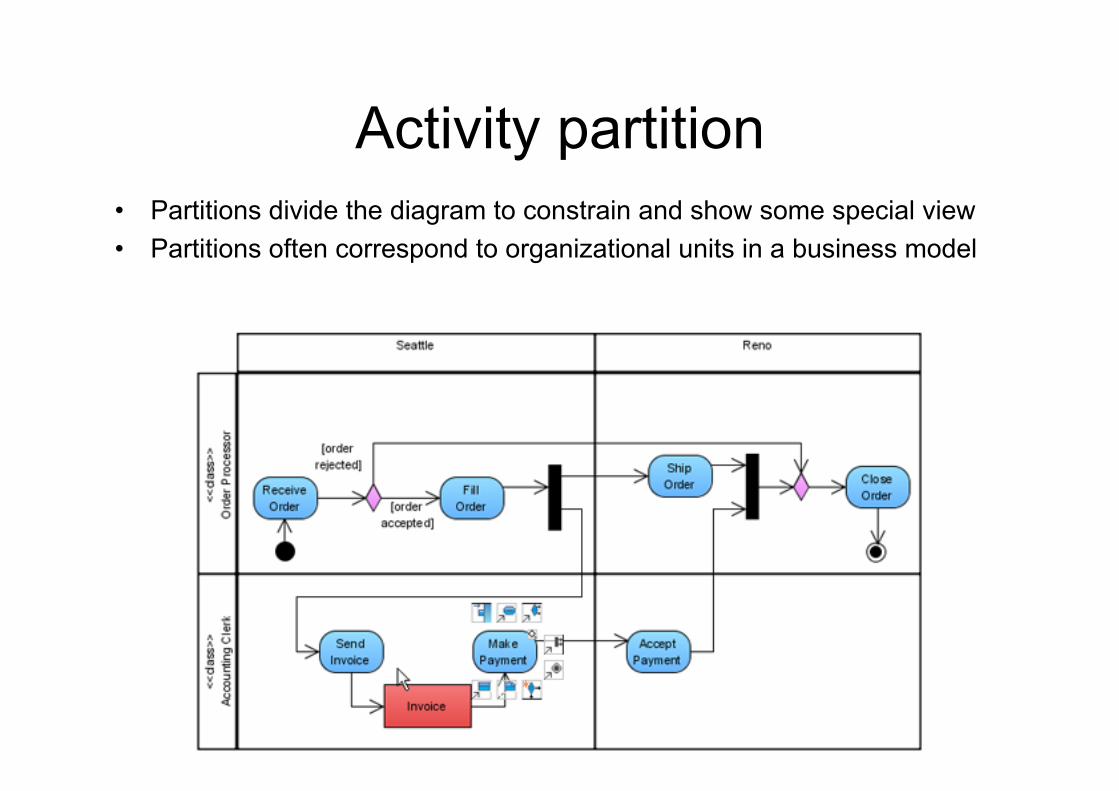
Activity partition • Partitions divide the diagram to constrain and show some special view • Partitions often correspond to organizational units in a business model
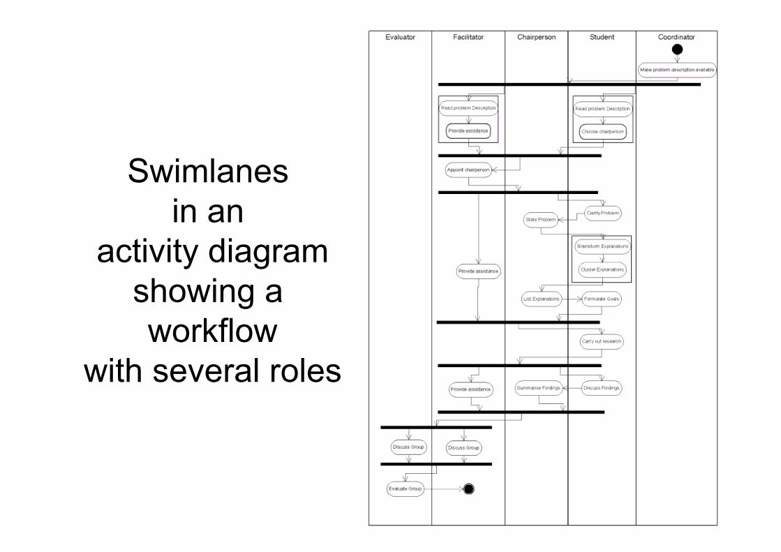
Swimlanes in an
activity diagram showing a workflow
with several roles
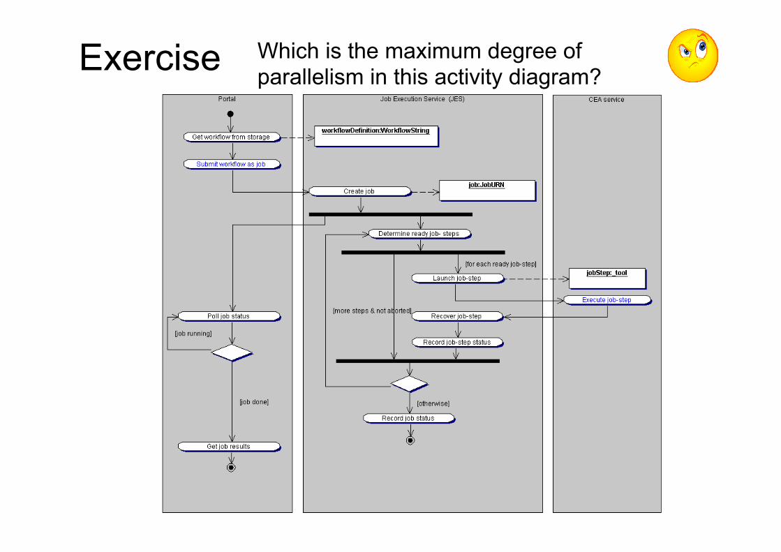
Exercise Which is the maximum degree of parallelism in this activity diagram?
What an AD does not show?
• Objects (but they can be inferred) • States • Messages • Data passed between steps • User interface
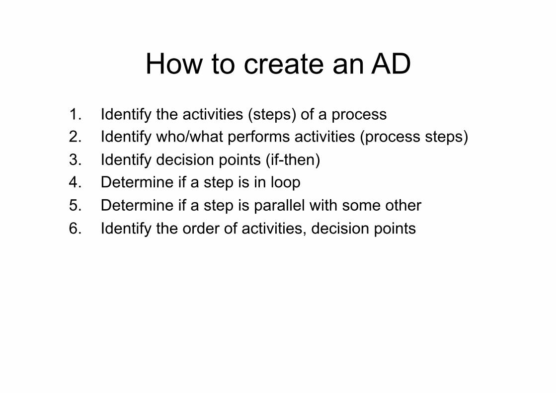
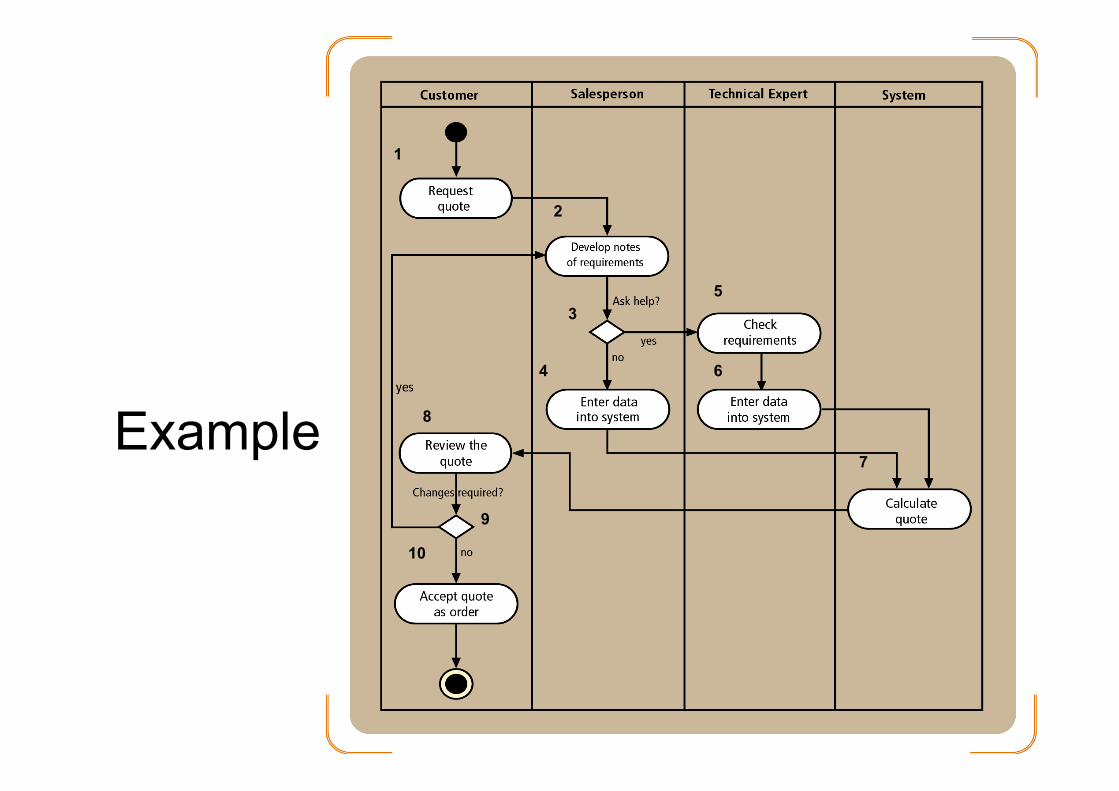
How to create an AD 1. Identify the activities (steps) of a process 2. Identify who/what performs activities (process steps) 3. Identify decision points (if-then) 4. Determine if a step is in loop 5. Determine if a step is parallel with some other 6. Identify the order of activities, decision points
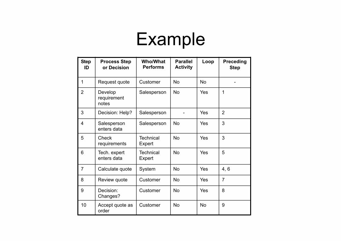
Example Step
ID Process Step or Decision
Who/What Performs
Parallel Activity
Loop Preceding Step
1 Request quote Customer No No -
2 Develop requirement notes
Salesperson No Yes 1
3 Decision: Help? Salesperson - Yes 2
4 Salesperson enters data
Salesperson No Yes 3
5 Check requirements
Technical Expert
No Yes 3
6 Tech. expert enters data
Technical Expert
No Yes 5
7 Calculate quote System No Yes 4, 6
8 Review quote Customer No Yes 7
9 Decision: Changes?
Customer No Yes 8
10 Accept quote as order
Customer No No 9
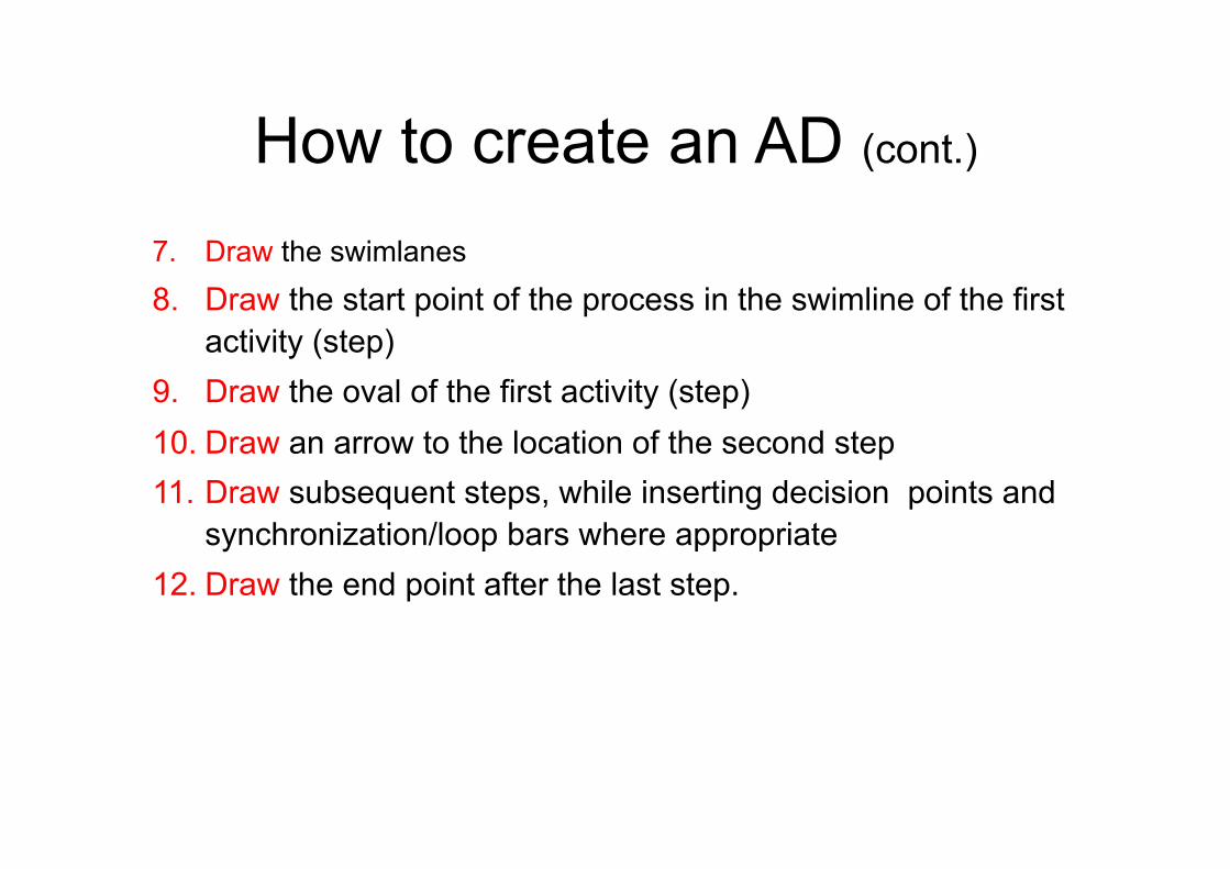
How to create an AD (cont.)
7. Draw the swimlanes
8. Draw the start point of the process in the swimline of the first activity (step)
9. Draw the oval of the first activity (step) 10. Draw an arrow to the location of the second step 11. Draw subsequent steps, while inserting decision points and
synchronization/loop bars where appropriate 12. Draw the end point after the last step.
Example
1
2
3
4
5
6
7
8
9
10
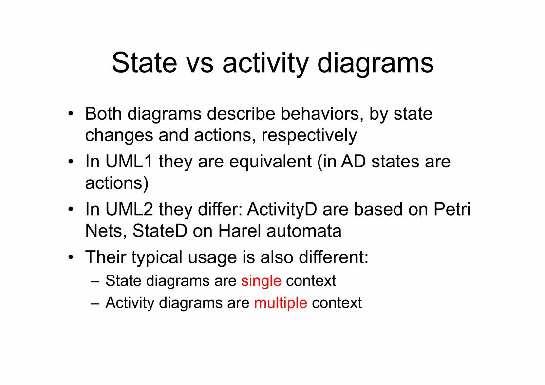
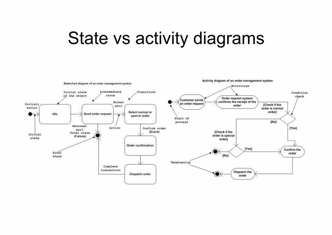
State vs activity diagrams
• Both diagrams describe behaviors, by state changes and actions, respectively
• In UML1 they are equivalent (in AD states are actions)
• In UML2 they differ: ActivityD are based on Petri Nets, StateD on Harel automata
• Their typical usage is also different: – State diagrams are single context – Activity diagrams are multiple context
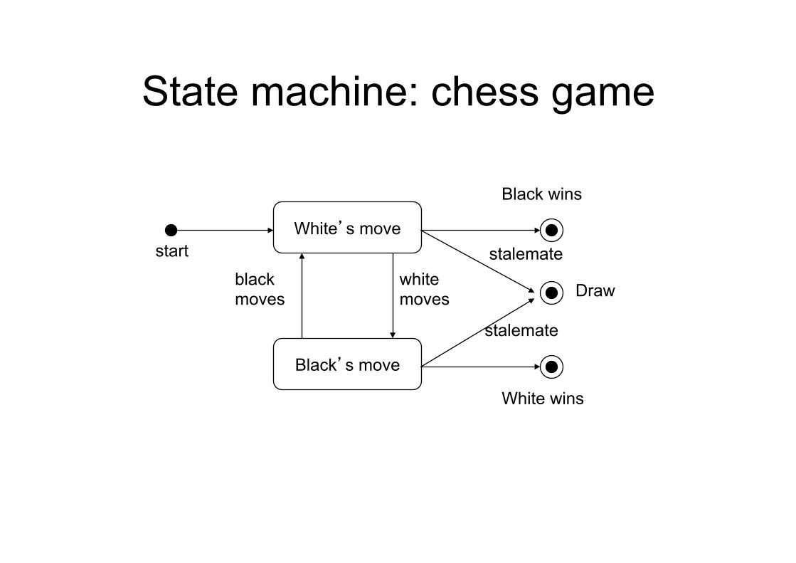
State machine: chess game
White’s move
Black’s move
start
white moves
black moves
Black wins
Draw
White wins
stalemate
stalemate
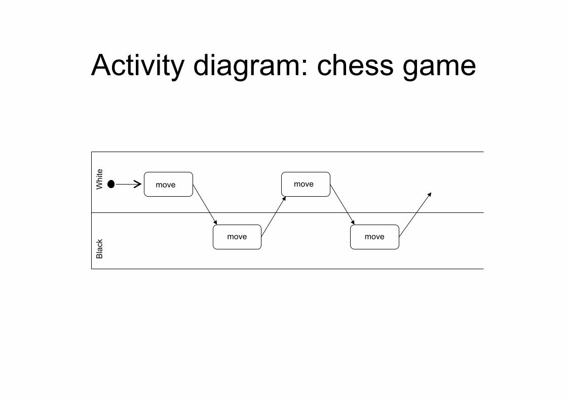
Activity diagram: chess game
move
move
move
move
Whi
te
Bla
ck
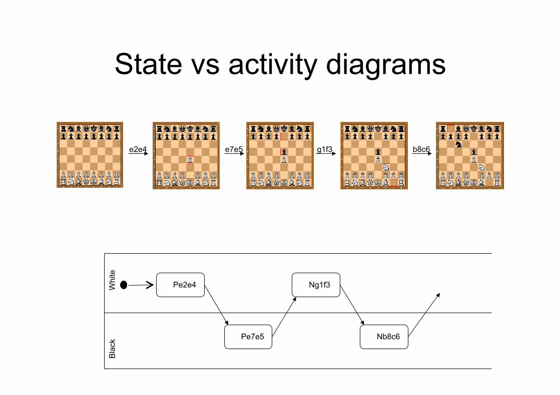
State vs activity diagrams
e2e4 e7e5 g1f3 b8c6
Pe2e4
Pe7e5
Ng1f3
Nb8c6
Whi
te
Bla
ck
State vs activity diagrams
Activity diagram vs flowchart
• An activity diagram shows the order in which to do tasks
• The key difference between an activity diagram and a flowchart is that the activity diagram can describe parallel processes, while flowcharts are sequential
Behavior diagrams: interaction
Balla: Dinamismo di cane al guinzaglio, 1912
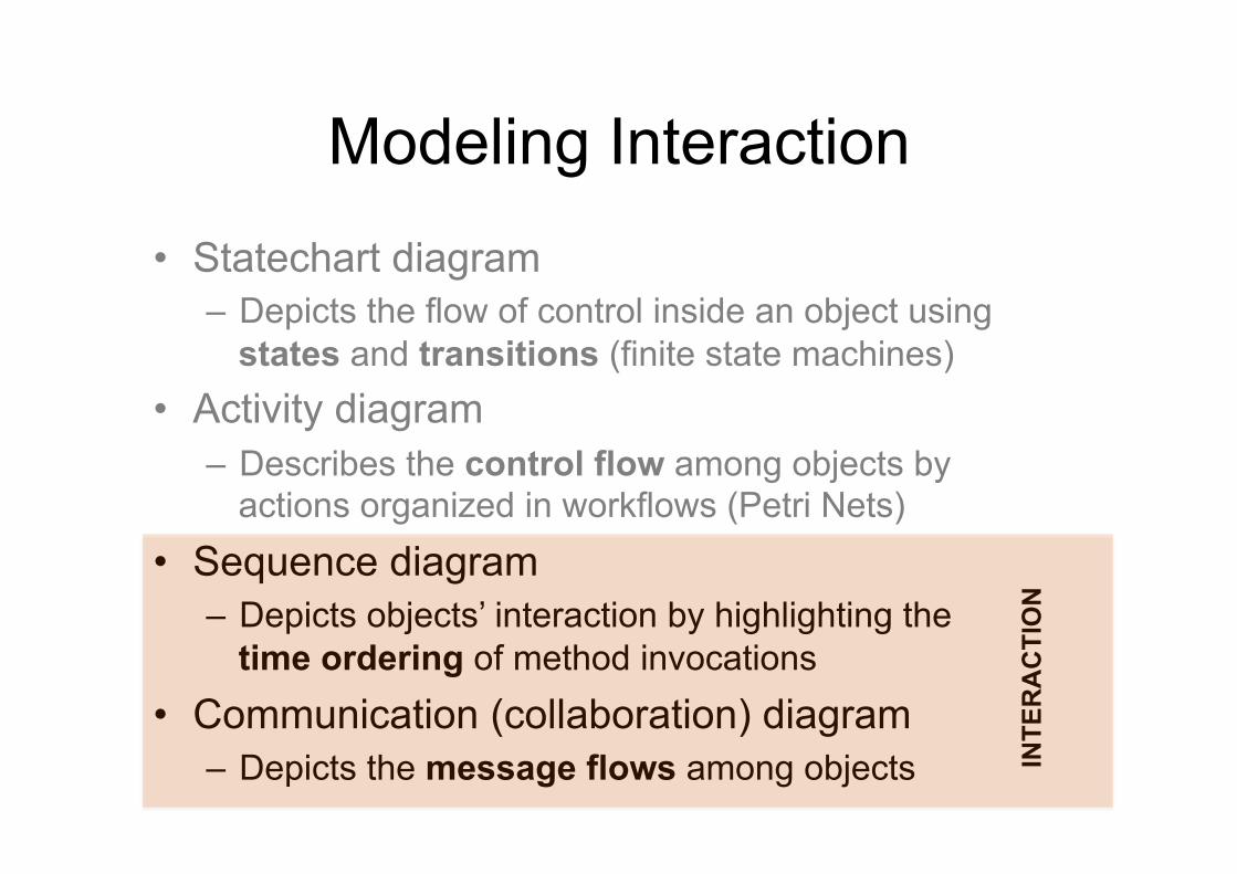
Modeling Interaction
• Statechart diagram – Depicts the flow of control inside an object using
states and transitions (finite state machines) • Activity diagram
– Describes the control flow among objects by actions organized in workflows (Petri Nets)
• Sequence diagram – Depicts objects’ interaction by highlighting the
time ordering of method invocations • Communication (collaboration) diagram
– Depicts the message flows among objects INTE
RA
CTI
ON
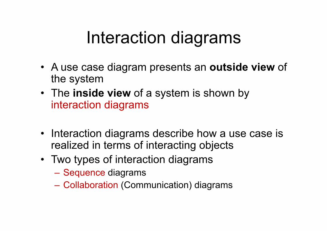
Interaction diagrams • A use case diagram presents an outside view of
the system • The inside view of a system is shown by
interaction diagrams
• Interaction diagrams describe how a use case is realized in terms of interacting objects
• Two types of interaction diagrams – Sequence diagrams – Collaboration (Communication) diagrams
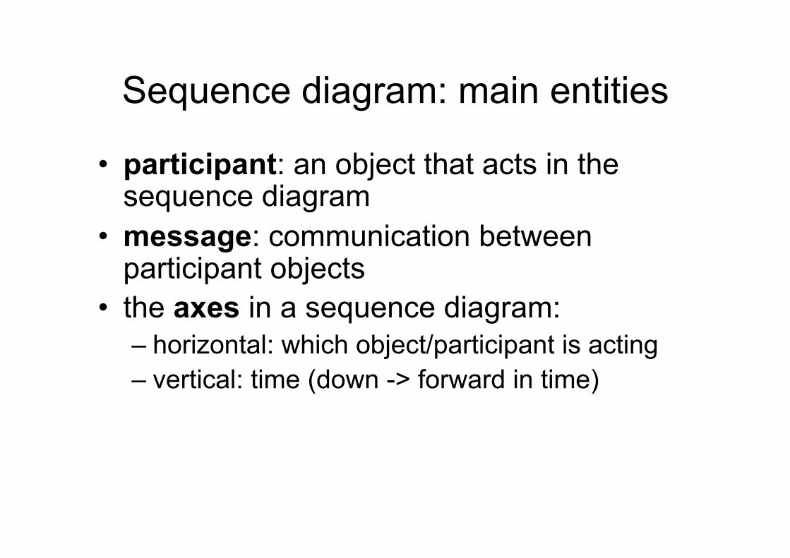
Sequence diagram: main entities
• participant: an object that acts in the sequence diagram
• message: communication between participant objects
• the axes in a sequence diagram: – horizontal: which object/participant is acting – vertical: time (down -> forward in time)
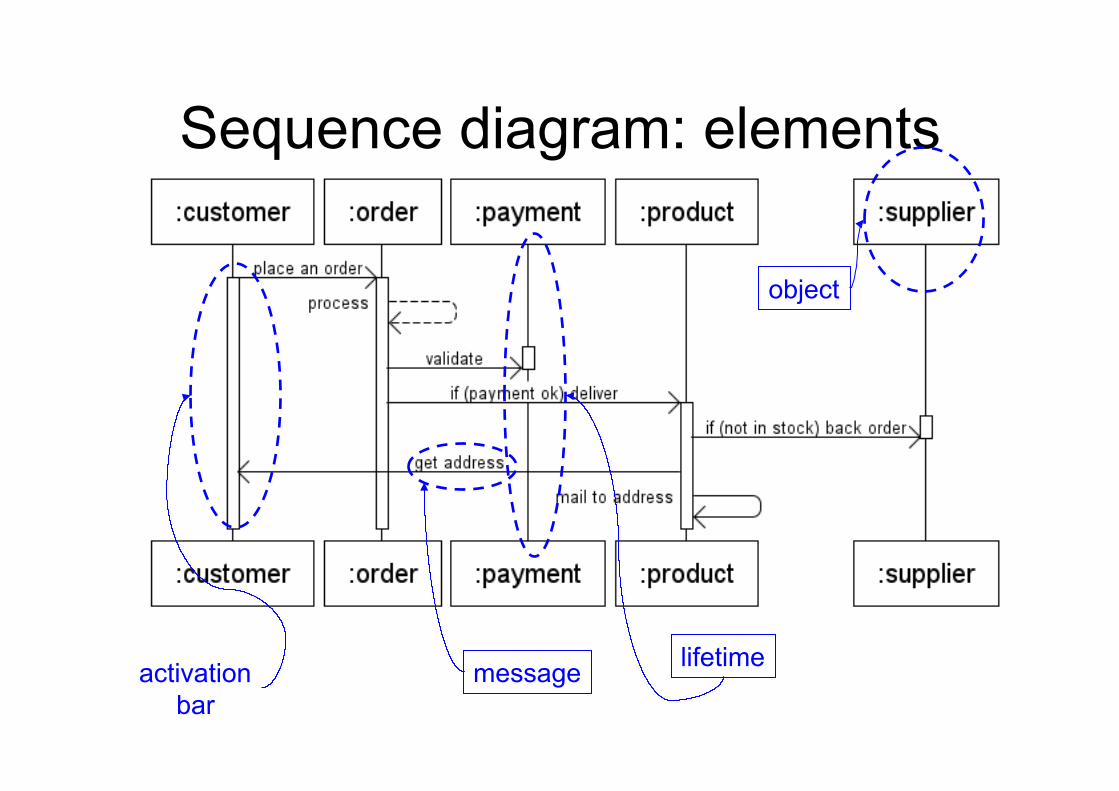
Sequence diagram: elements
message lifetime activation bar
object
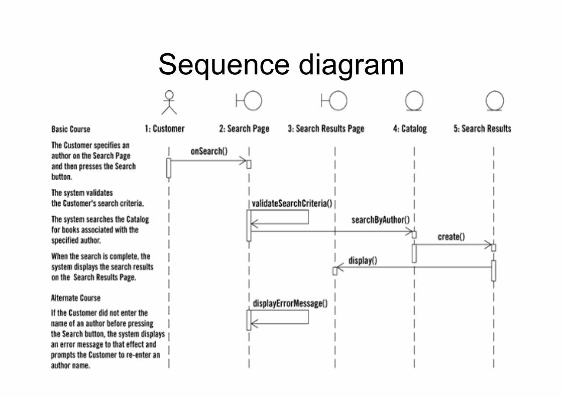
Sequence diagram
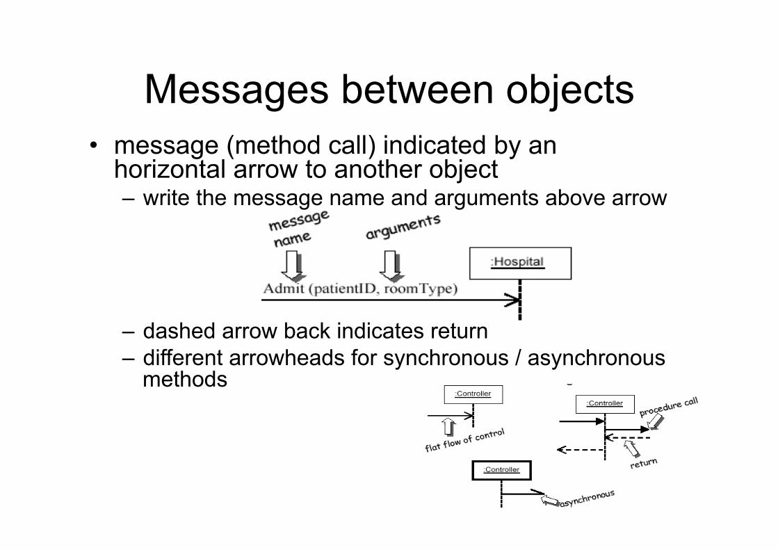
• message (method call) indicated by an horizontal arrow to another object – write the message name and arguments above arrow
– dashed arrow back indicates return – different arrowheads for synchronous / asynchronous
methods
Messages between objects
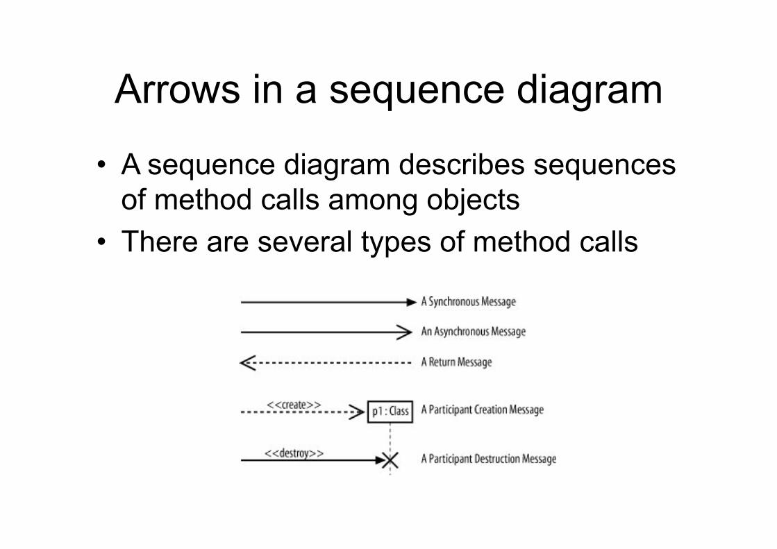
Arrows in a sequence diagram
• A sequence diagram describes sequences of method calls among objects
• There are several types of method calls
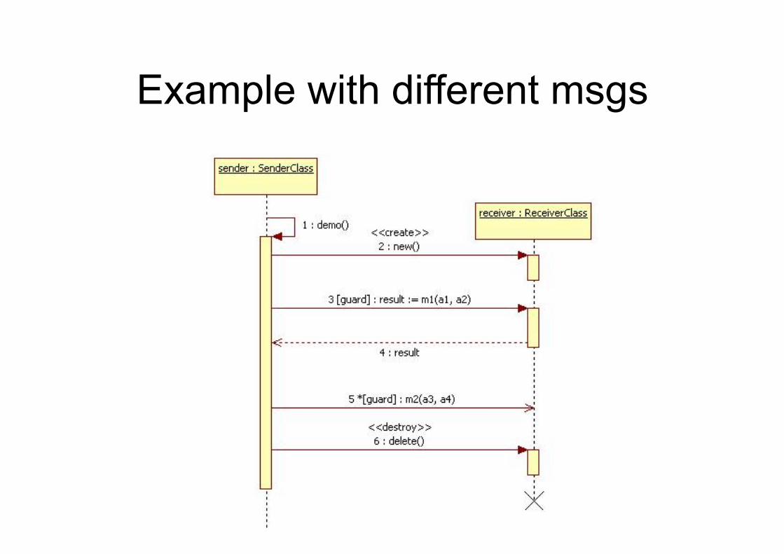
Example with different msgs
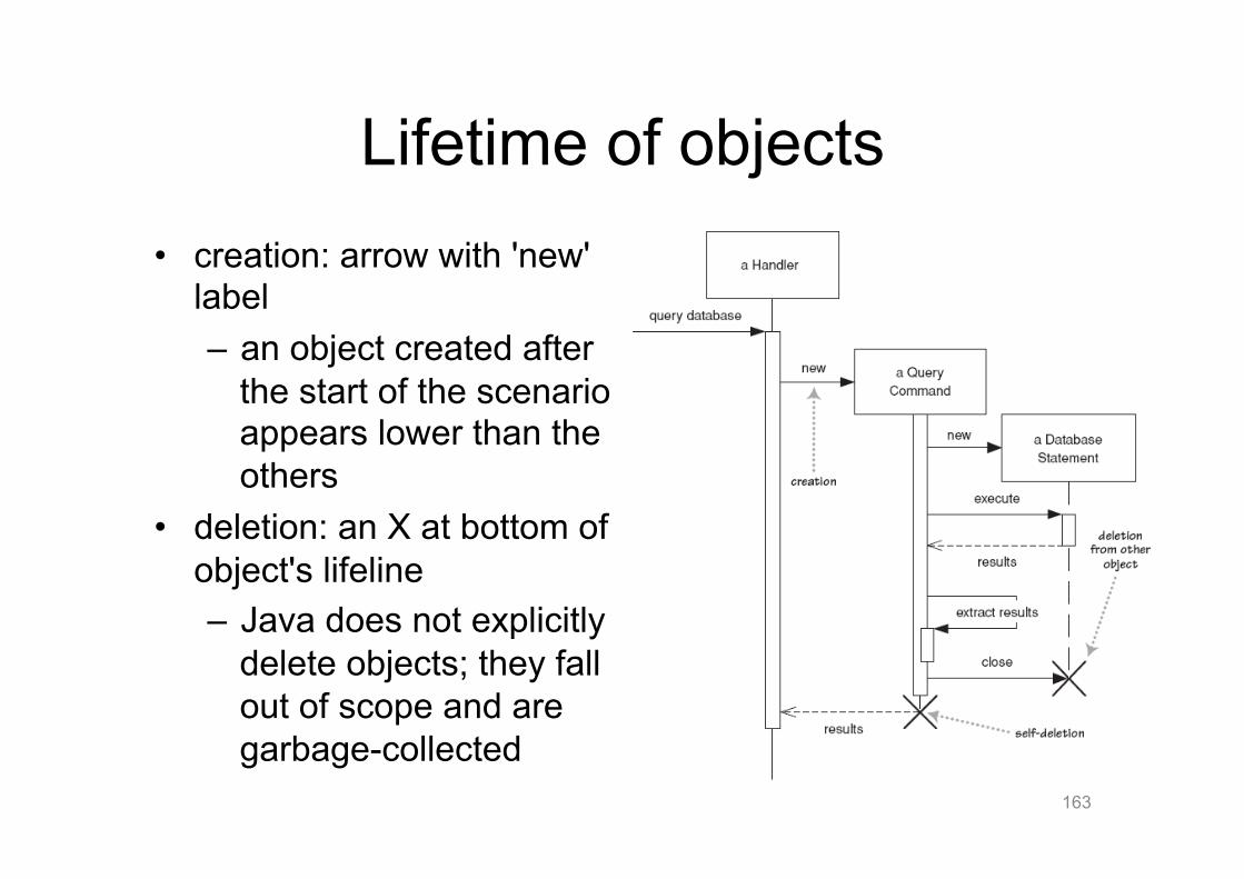
Lifetime of objects • creation: arrow with 'new'
label – an object created after
the start of the scenario appears lower than the others
• deletion: an X at bottom of object's lifeline – Java does not explicitly
delete objects; they fall out of scope and are garbage-collected
163
Indicating method calls
Activation
Nesting
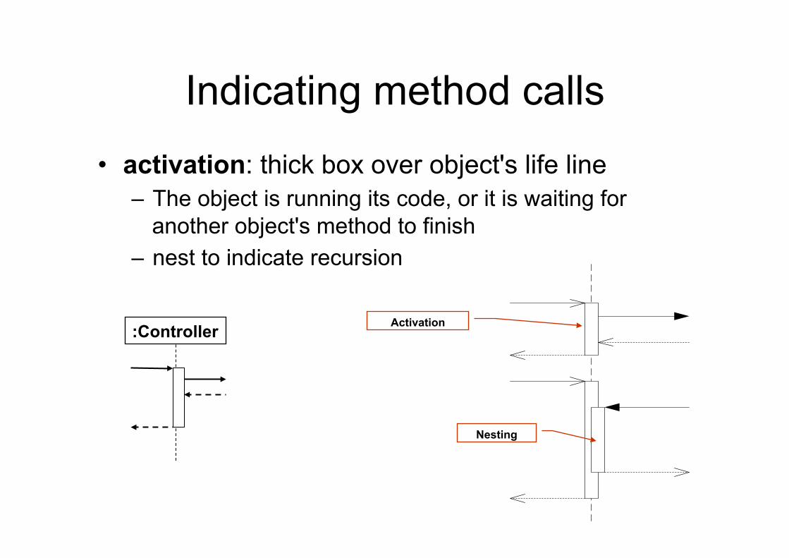
:Controller
• activation: thick box over object's life line – The object is running its code, or it is waiting for
another object's method to finish – nest to indicate recursion
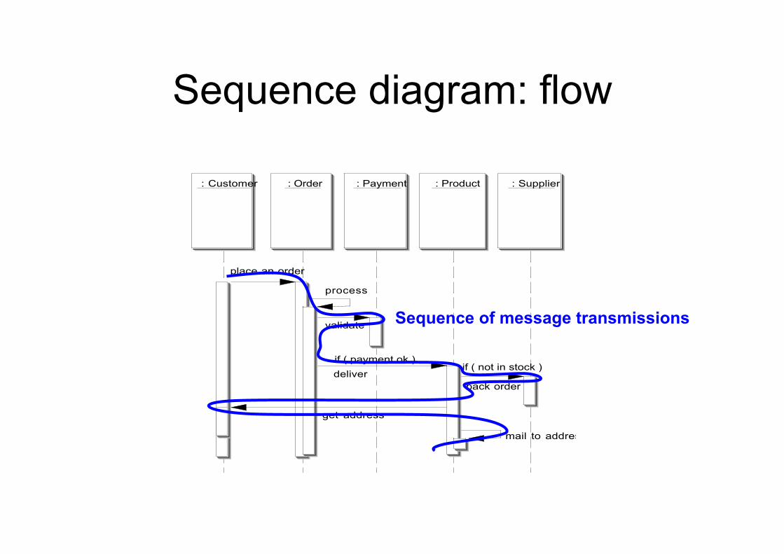
Sequence diagram: flow
: Customer : Order : Payment : Product : Supplier
place an order
process
validate
deliverif ( payment ok )
back order
if ( not in stock )
get address
mail to address
Sequence of message transmissions
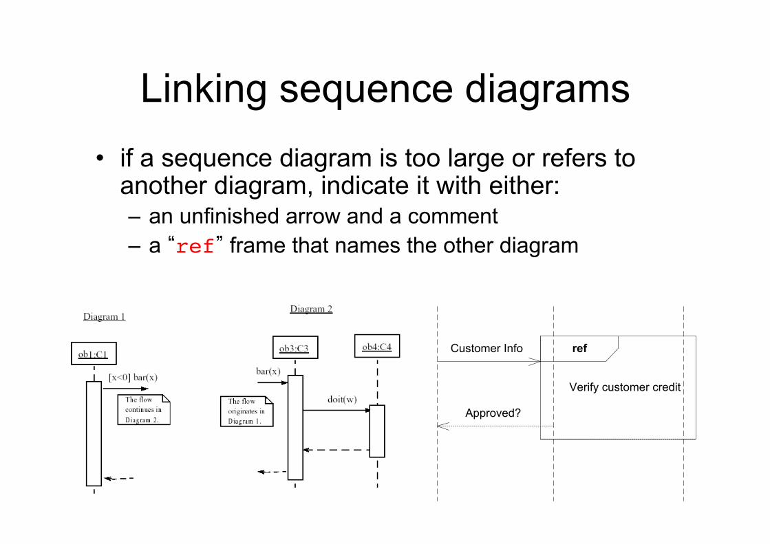
Linking sequence diagrams • if a sequence diagram is too large or refers to
another diagram, indicate it with either: – an unfinished arrow and a comment – a “ref” frame that names the other diagram
Verify customer credit
refCustomer Info
Approved?
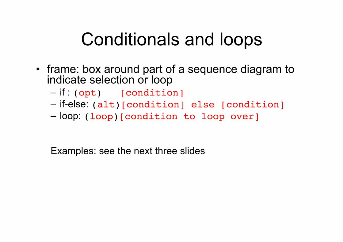
Conditionals and loops • frame: box around part of a sequence diagram to
indicate selection or loop – if : (opt) [condition]!– if-else: (alt)[condition] else [condition] – loop: (loop)[condition to loop over]! Examples: see the next three slides
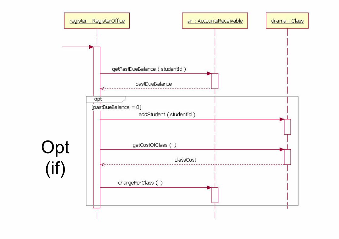
Opt (if)
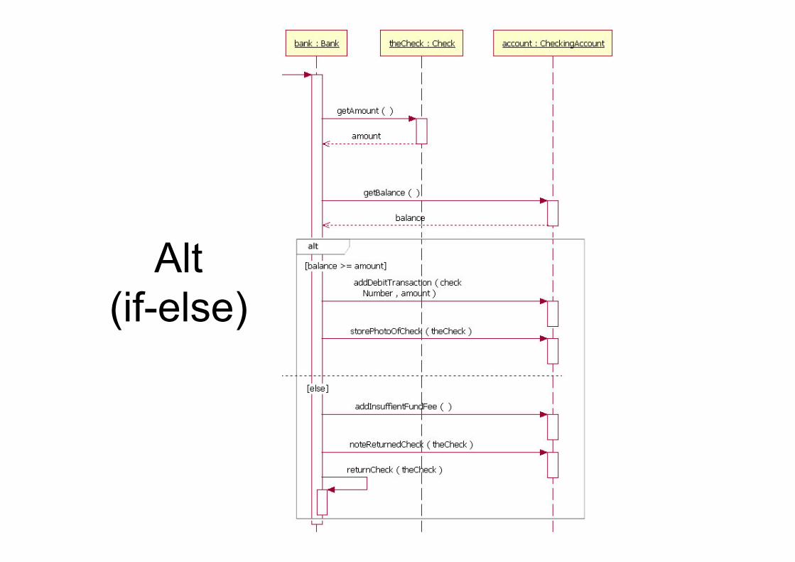
Alt (if-else)
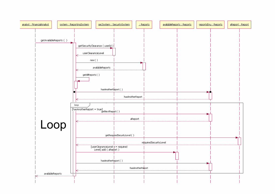
Loop
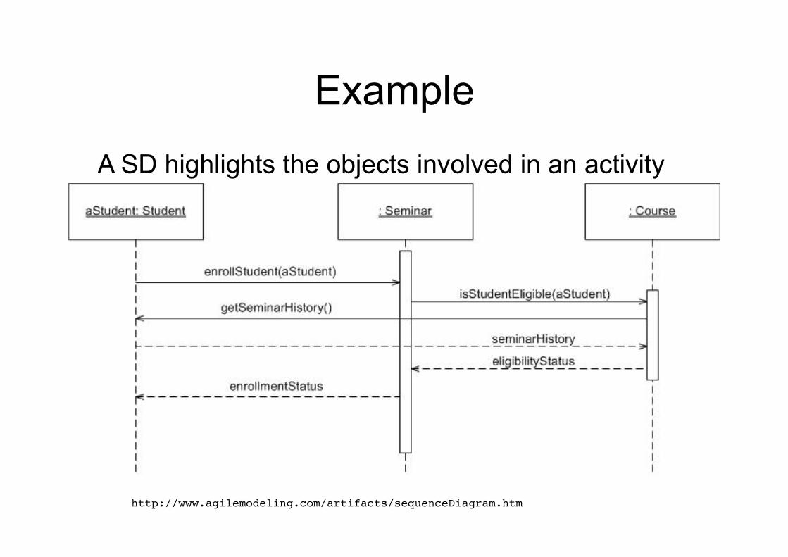
Example
A SD highlights the objects involved in an activity and the time ordering of method calls among them
http://www.agilemodeling.com/artifacts/sequenceDiagram.htm!
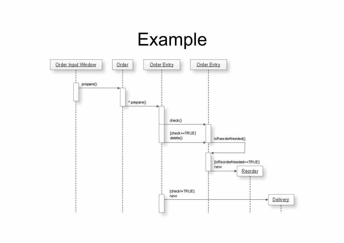
Example
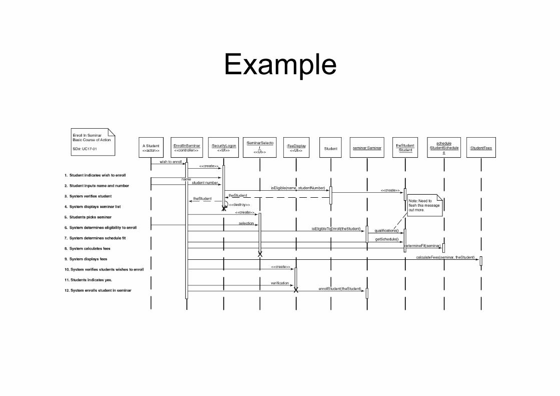
Example
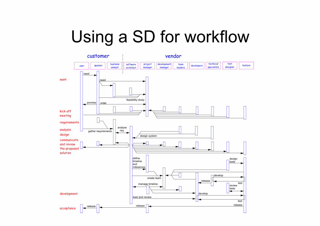
Using a SD for workflow
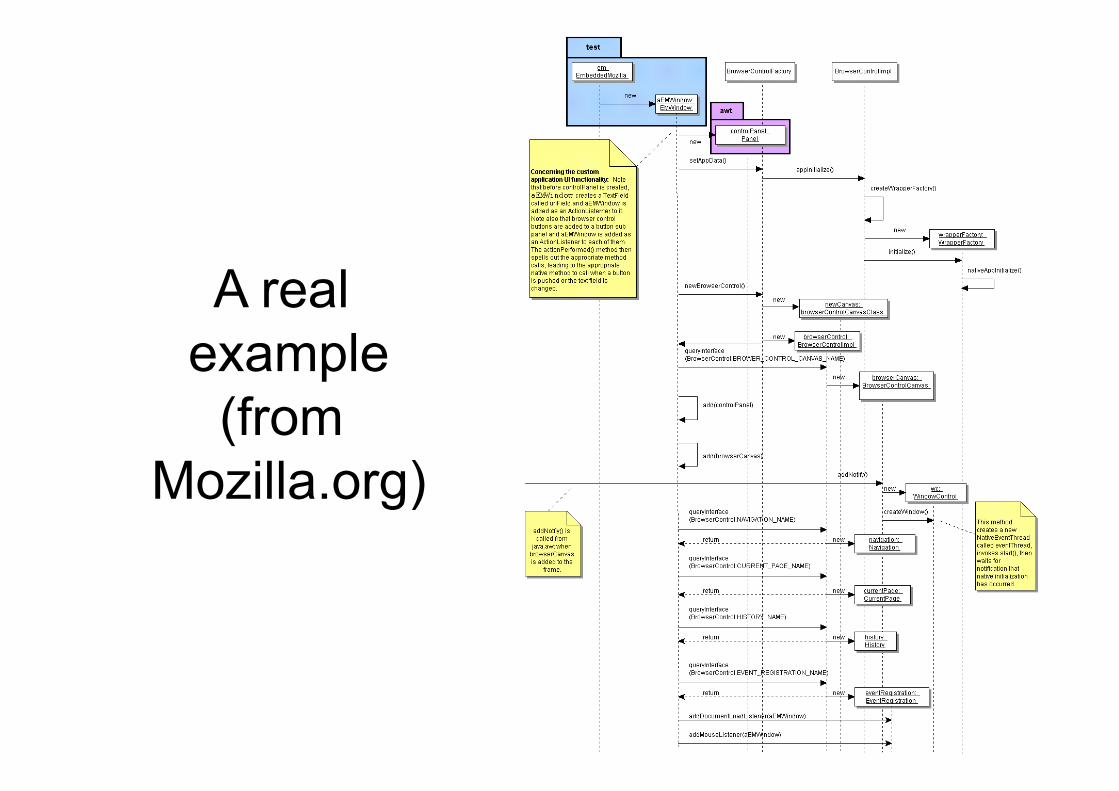
A real example
(from Mozilla.org)
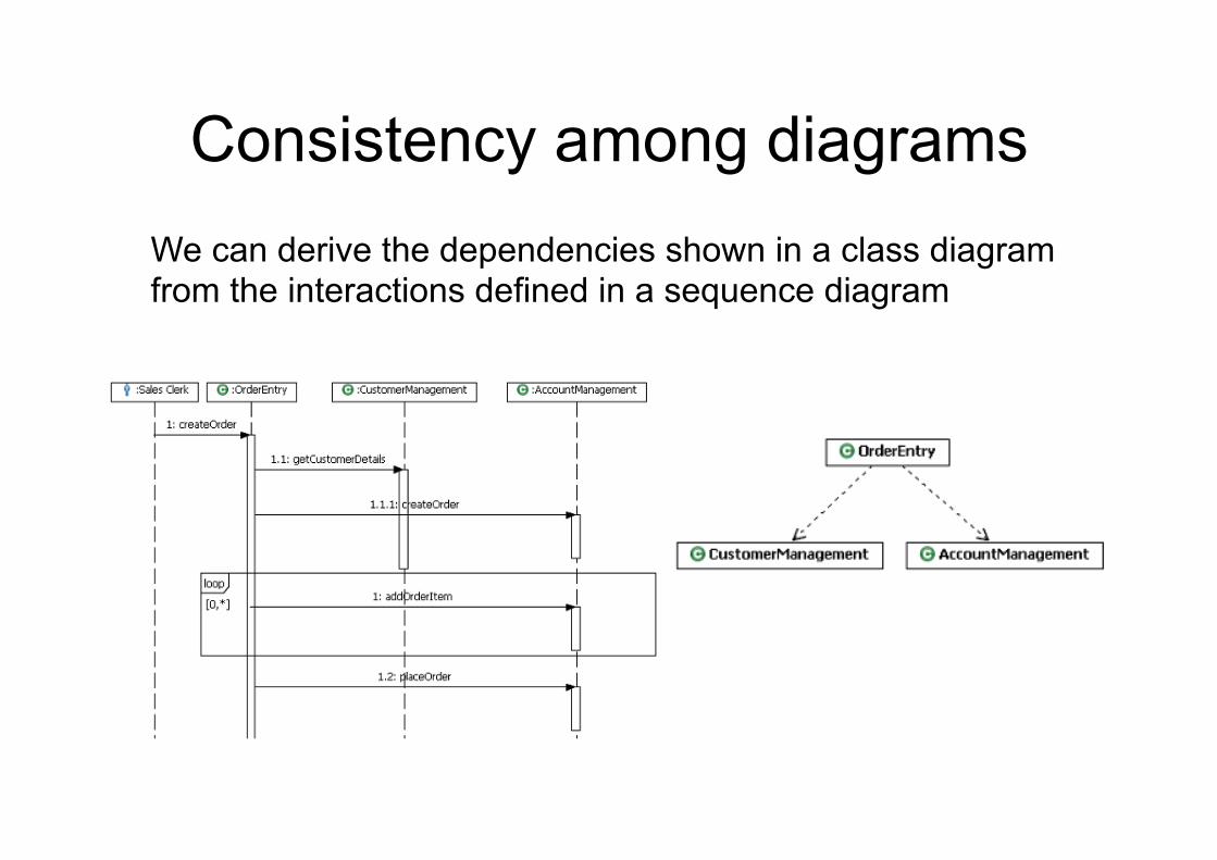
Consistency among diagrams We can derive the dependencies shown in a class diagram from the interactions defined in a sequence diagram
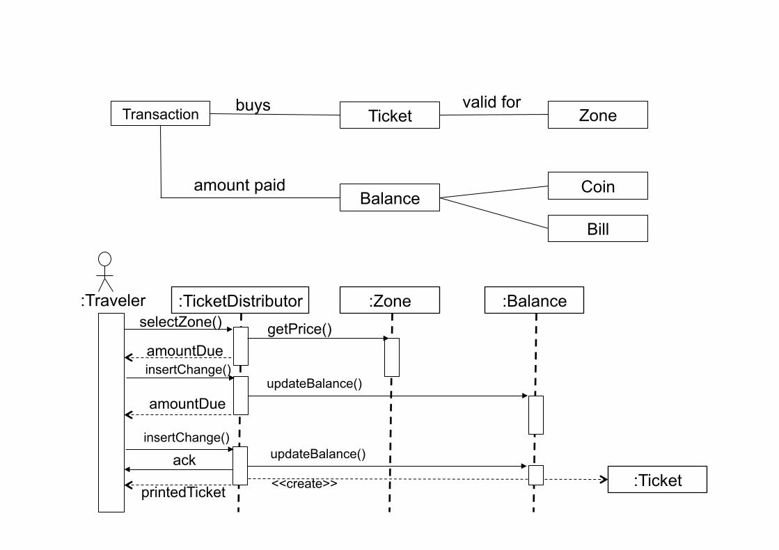
Transaction Ticket valid for
Balance
Zone buys
Coin
Bill
amount paid
:TicketDistributor :Zone :Balance
:Ticket
getPrice()
updateBalance()
updateBalance()
<<create>>
:Traveler
amountDue
amountDue
insertChange()
insertChange()
printedTicket
ack
selectZone()
Exercise Draw a sequence diagram showing how a customer interacts with a travel agency, a station and a train to reach some destination Draw a sequence diagram to show how a user prints a document on a printer, and a counter keeps a count of printed pages
Communication (collaboration) diagram
• Communication diagrams show the message flow between objects in an application
• They also show implicitly the basic associations between classes
• Communication diagrams are drawn in the same way as sequence diagrams (and can be semantically equivalent to them)
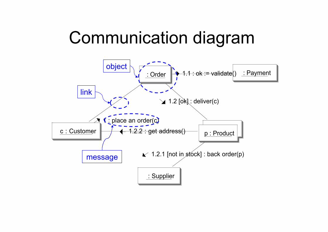
Communication diagram
p : Product
: Order : Payment
c : Customer
: Supplier
1.1 : ok := validate()
1.2 [ok] : deliver(c)
1.2.1 [not in stock] : back order(p)
1.2.2 : get address()
1 : place an order(c)
object
link
message
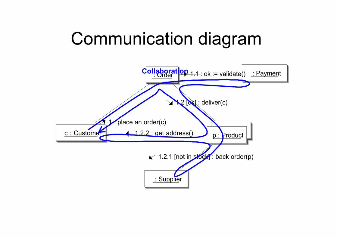
Communication diagram
p : Product
: Order : Payment
c : Customer
: Supplier
1.1 : ok := validate()
1.2 [ok] : deliver(c)
1.2.1 [not in stock] : back order(p)
1.2.2 : get address()
1 : place an order(c)
Collaboration
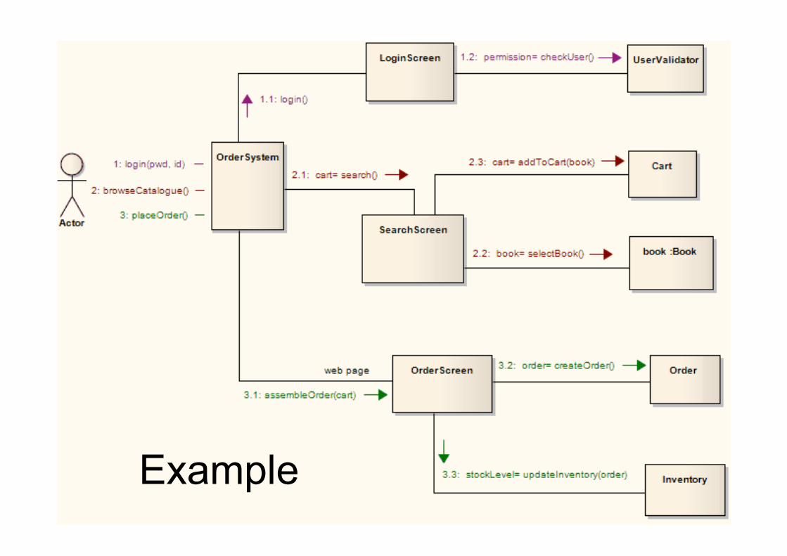
Example
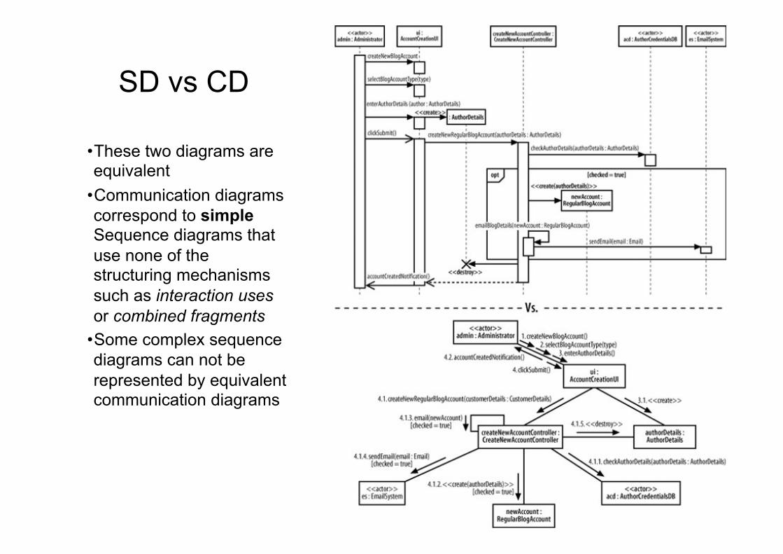
SD vs CD
• These two diagrams are equivalent
• Communication diagrams correspond to simple Sequence diagrams that use none of the structuring mechanisms such as interaction uses or combined fragments
• Some complex sequence diagrams can not be represented by equivalent communication diagrams
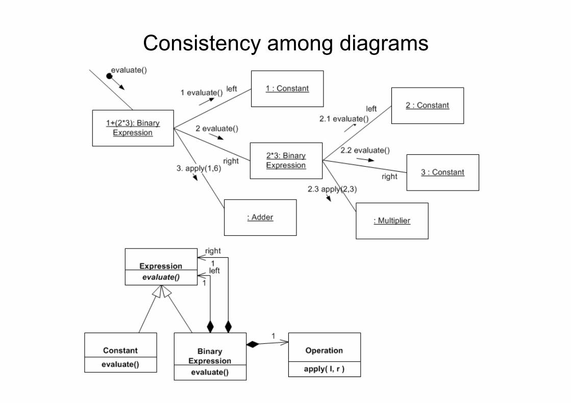
Consistency among diagrams
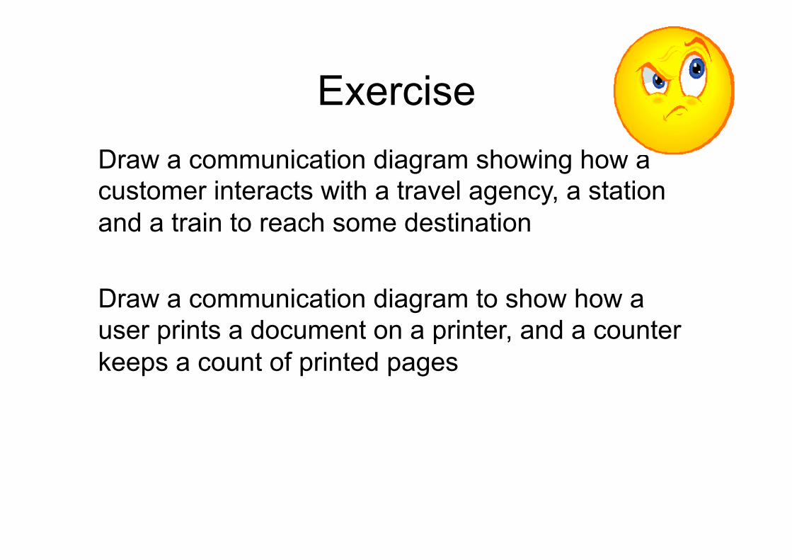
Exercise Draw a communication diagram showing how a customer interacts with a travel agency, a station and a train to reach some destination Draw a communication diagram to show how a user prints a document on a printer, and a counter keeps a count of printed pages
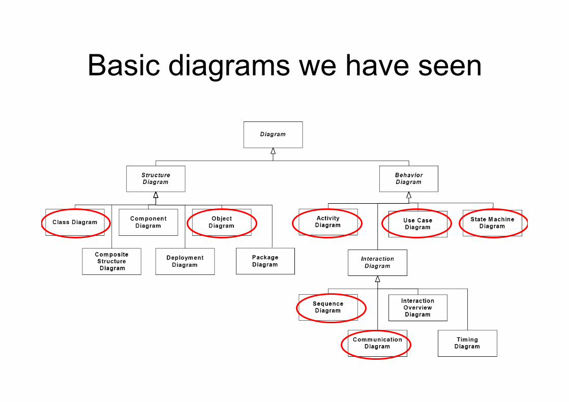
Basic diagrams we have seen
Other diagrams
Diagrams we have seen in this lecture: • Use case, class, object, statechart, activity,
interaction (sequence and collaboration) We could add (using UML 1.*): • Component, Deployment We could add (using UML 2.*): • Composite structure, Profiles, Package,
Interaction Overview, Timing
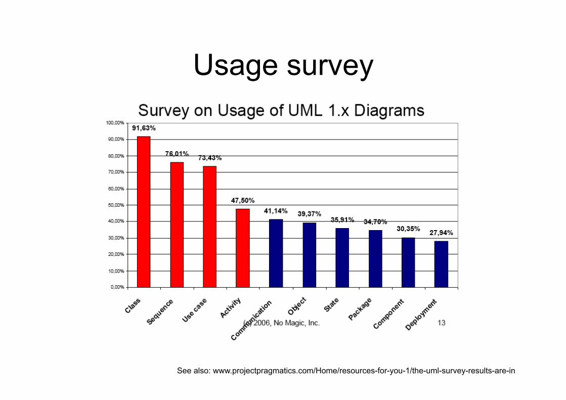
Usage survey
See also: www.projectpragmatics.com/Home/resources-for-you-1/the-uml-survey-results-are-in
Main diagrams
The main diagrams that are used in most views are : • Use case diagram • Class diagram • Sequence diagram • Activity diagram
Discuss • Which diagrams are most useful in each
lifecycle phase?
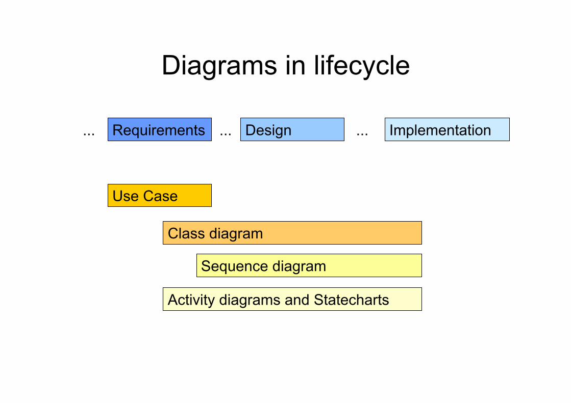
Diagrams in lifecycle
Requirements Design Implementation ... ... ...
Use Case
Class diagram
Activity diagrams and Statecharts
Sequence diagram
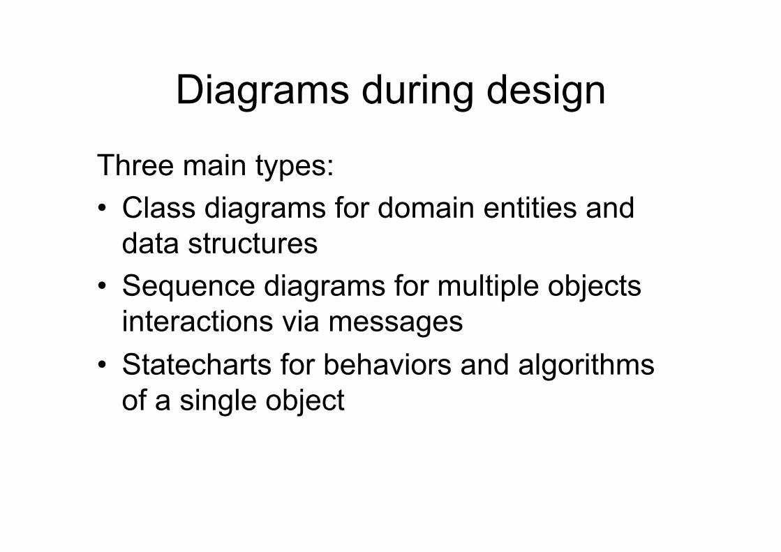
Diagrams during design
Three main types: • Class diagrams for domain entities and
data structures • Sequence diagrams for multiple objects
interactions via messages • Statecharts for behaviors and algorithms
of a single object
Exercise
Draw, on some game-playing domain (eg. Chess): – A class diagram – An object diagram – A statechart – A sequence diagram – A communication diagram – An activity diagram
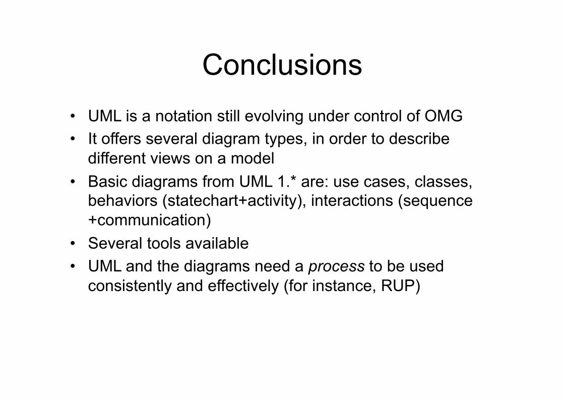
Conclusions • UML is a notation still evolving under control of OMG • It offers several diagram types, in order to describe
different views on a model • Basic diagrams from UML 1.* are: use cases, classes,
behaviors (statechart+activity), interactions (sequence+communication)
• Several tools available • UML and the diagrams need a process to be used
consistently and effectively (for instance, RUP)
Summary
• UML includes a number of diagram-based notations to model software systems using an object oriented approach
• UML is not a process (it needs a process, like for instance the RUP)
• It is not proprietary: it is an OMG (Object Management Group) and ISO standard
Caveat emptor When Jim, Ivar, and I began our journey that became manifest in the UML, we never intended it to become a programming language…UML was to be a language for visualizing, specifying, constructing, and documenting the artifacts of a software-intensive system—in short, a graphical language to help reason about the design of a system as it unfolds. Most diagrams should be thrown away, but there are a few that should be preserved, and in all, one should only use a graphical notation for those things that cannot easily be reasoned about in code. As I've also often said, the code is the truth, but it is not the whole truth, and there are things such as rationale, cross-cutting concerns, and patterns that cannot easily be recovered or seen from code… These are the things for which a graphical notation adds value, and any such notation should be used only if it has predictive power or reasoning power (meaning, you can ask questions about it).
Grady Booch
Self test questions
• Which are the UML 1.* canonical diagrams? • What is a use case? • What is a class diagram? What is an object diagram? • How do we describe a tree-like data structure in a
class diagram? • What is an interaction diagram? • What is a protocol state machine? • What is the difference between statecharts and
activity diagrams?
Readings
• On use cases www.ibm.com/developerworks/rational/library/5383.html!
• On class diagrams www.ibm.com/developerworks/rational/library/content/
RationalEdge/sep04/bell/index.html!
• On activity diagrams www.ibm.com/developerworks/rational/library/2802.html!
• On sequence diagrams www.ibm.com/developerworks/rational/library/3101.html!!
UML Specification Documents
• OMG, UML Specification version 1.5, 2003 • OMG, UML Superstructure version 2.4.1, 2011 • Rumbaugh, Jacobson, Booch, The UML Reference
Manual, Addison Wesley, 1999 and 2004 (2nd ed)
References on using UML
• Booch, Rumbaugh, Jacobson, The UML User Guide, Addison Wesley, 1998 and 2005 (2ed)
• Fowler, UML Distilled, 3ed, Addison Wesley, 2003 • Pilone and Pitman, UML 2.0 in a Nutshell, OReilly, 2005 • Ambler, The Elements of UML 2.0 Style, Cambridge
University Press, 2005"
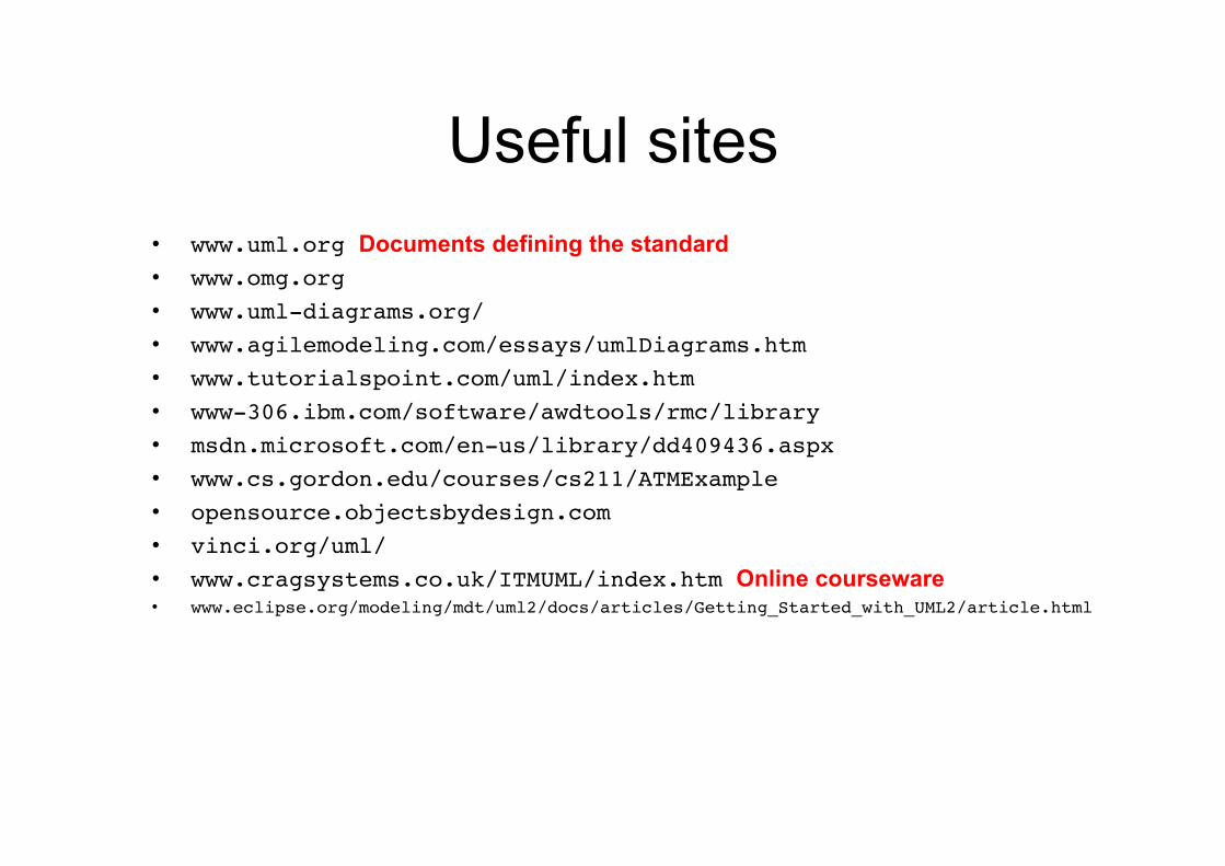
Useful sites • www.uml.org Documents defining the standard!• www.omg.org!• www.uml-diagrams.org/!• www.agilemodeling.com/essays/umlDiagrams.htm!• www.tutorialspoint.com/uml/index.htm!• www-306.ibm.com/software/awdtools/rmc/library!• msdn.microsoft.com/en-us/library/dd409436.aspx!• www.cs.gordon.edu/courses/cs211/ATMExample!• opensource.objectsbydesign.com!• vinci.org/uml/!• www.cragsystems.co.uk/ITMUML/index.htm Online courseware • www.eclipse.org/modeling/mdt/uml2/docs/articles/Getting_Started_with_UML2/article.html
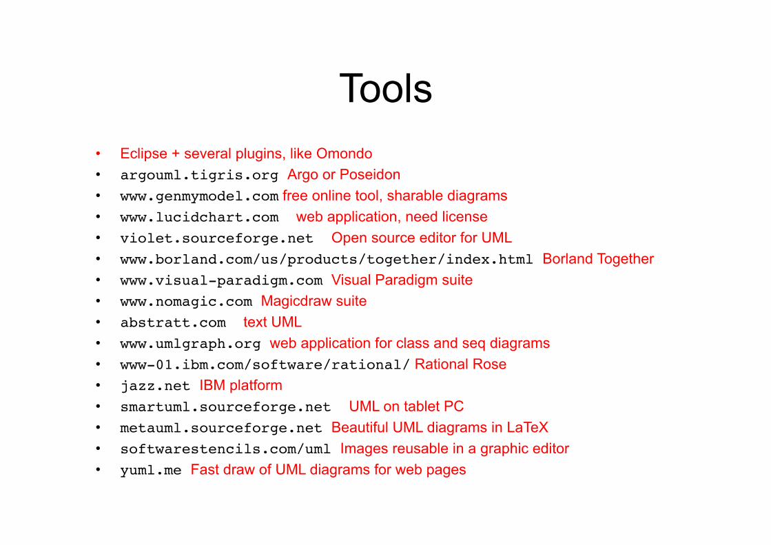
Tools • Eclipse + several plugins, like Omondo • argouml.tigris.org Argo or Poseidon • www.genmymodel.com free online tool, sharable diagrams • www.lucidchart.com web application, need license!• violet.sourceforge.net Open source editor for UML!• www.borland.com/us/products/together/index.html Borland Together • www.visual-paradigm.com Visual Paradigm suite!• www.nomagic.com Magicdraw suite!• abstratt.com text UML!• www.umlgraph.org web application for class and seq diagrams!• www-01.ibm.com/software/rational/ Rational Rose • jazz.net IBM platform • smartuml.sourceforge.net UML on tablet PC!• metauml.sourceforge.net Beautiful UML diagrams in LaTeX • softwarestencils.com/uml Images reusable in a graphic editor!• yuml.me Fast draw of UML diagrams for web pages!

UML blogs and fan clubs • www.linkedin.com/groups/UML-Lovers-143183/about • bulldozer00.com/uml-and-sysml/ • geertbellekens.wordpress.com/about-geert-bellekens/
Questions?


