Embed Size (px)
Citation preview

Heath 1
BASICS OF PIPELINING
APPENDIX A
Heath 2
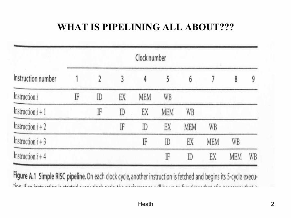
WHAT IS PIPELINING ALL ABOUT???
Heath 3
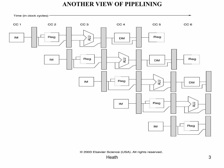
ANOTHER VIEW OF PIPELINING
Heath 4
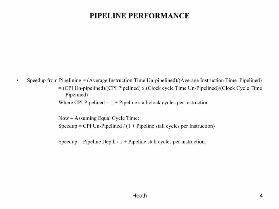
PIPELINE PERFORMANCE
• Speedup from Pipelining = (Average Instruction Time Un-pipelined)/(Average Instruction Time Pipelined)= (CPI Un-pipelined)/(CPI Pipelined) x (Clock cycle Time Un-Pipelined)/(Clock Cycle Time
Pipelined)Where CPI Pipelined = 1 + Pipeline stall clock cycles per instruction.
Now – Assuming Equal Cycle Time:Speedup = CPI Un-Pipelined / (1 + Pipeline stall cycles per Instruction)
Speedup = Pipeline Depth / 1 + Pipeline stall cycles per instruction.
Heath 5
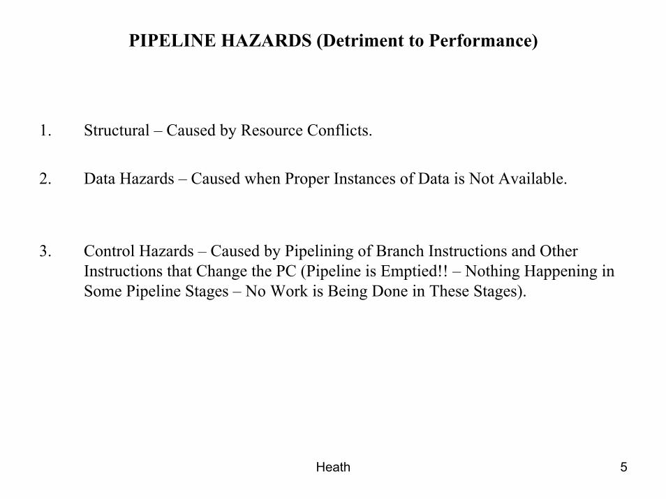
PIPELINE HAZARDS (Detriment to Performance)
1. Structural – Caused by Resource Conflicts.
2. Data Hazards – Caused when Proper Instances of Data is Not Available.
3. Control Hazards – Caused by Pipelining of Branch Instructions and Other Instructions that Change the PC (Pipeline is Emptied!! – Nothing Happening in Some Pipeline Stages – No Work is Being Done in These Stages).
Heath 6
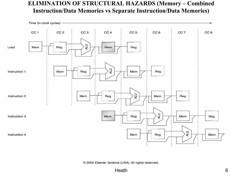
ELIMINATION OF STRUCTURAL HAZARDS (Memory – Combined Instruction/Data Memories vs Separate Instruction/Data Memories)
Heath 7
DATA HAZARDS
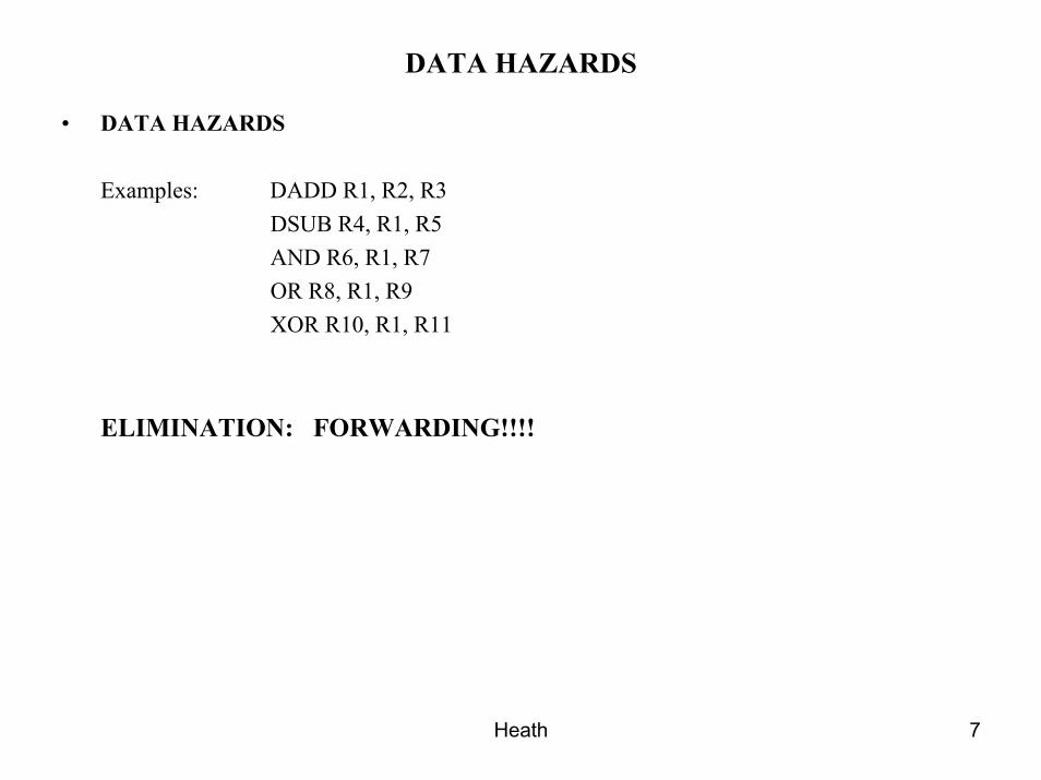
• DATA HAZARDS
Examples: DADD R1, R2, R3DSUB R4, R1, R5AND R6, R1, R7OR R8, R1, R9XOR R10, R1, R11
ELIMINATION: FORWARDING!!!!
Heath 8
FORWARDING CONCEPT
Heath 9
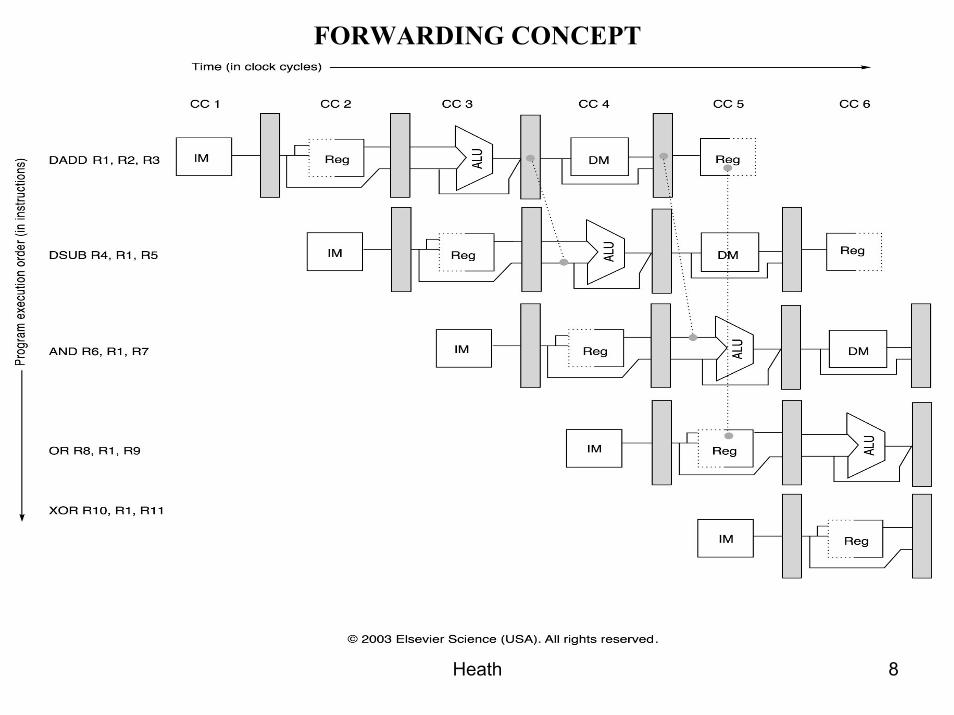
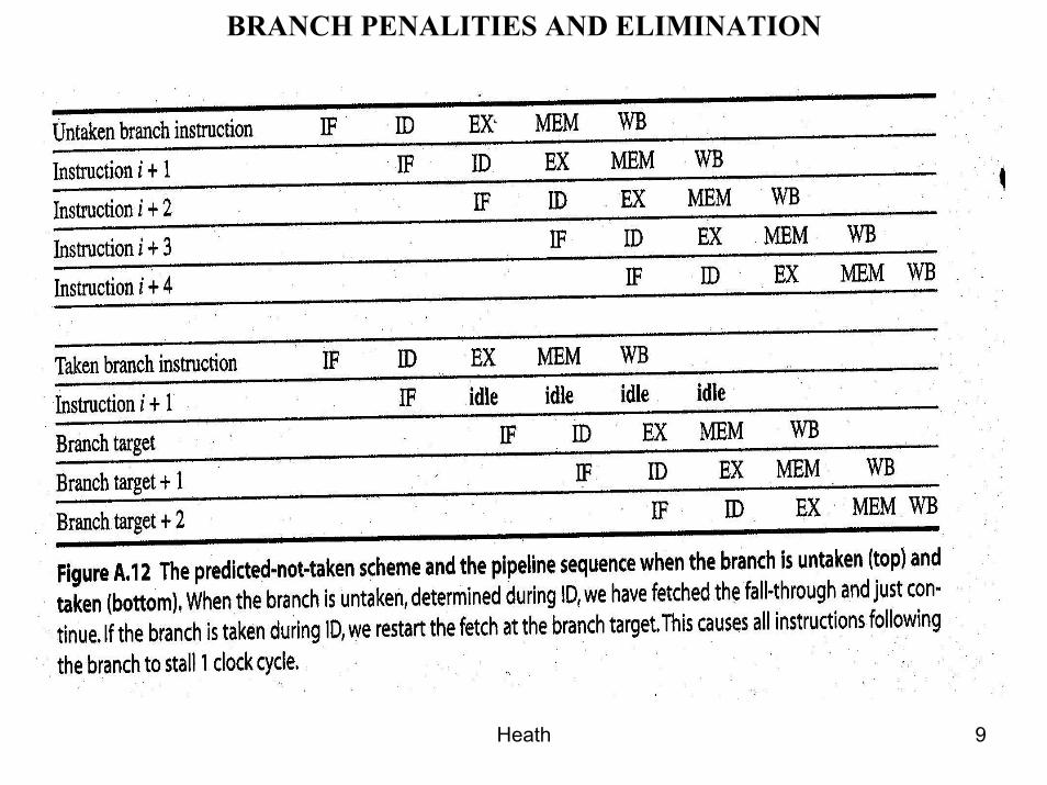
BRANCH PENALITIES AND ELIMINATION
Heath 10
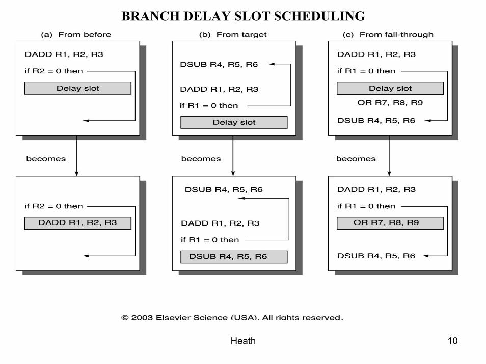
BRANCH DELAY SLOT SCHEDULING
Heath 11
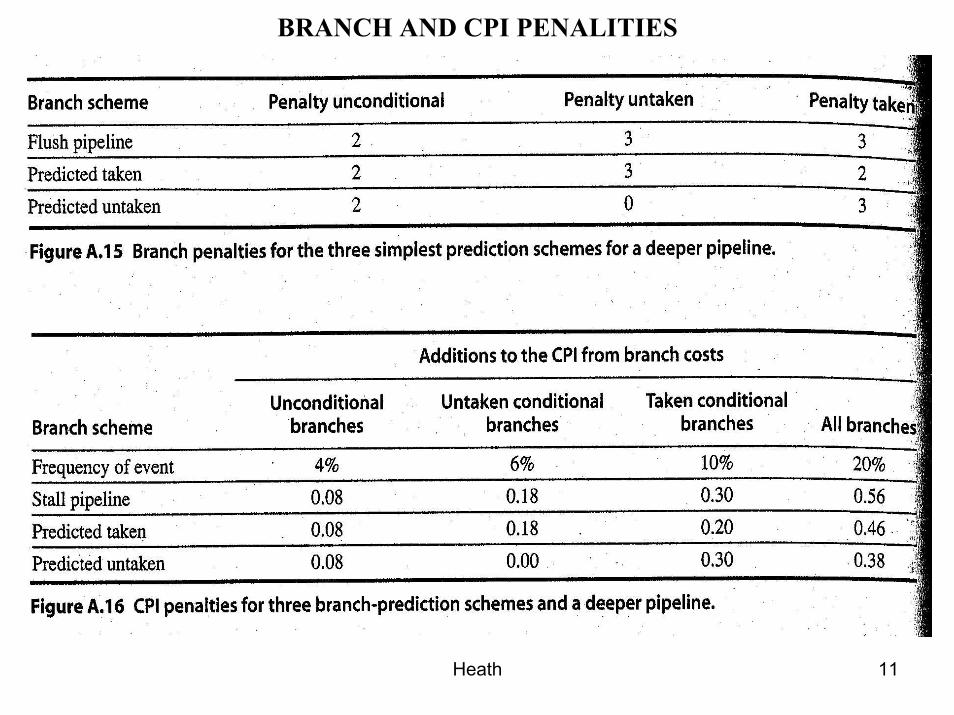
BRANCH AND CPI PENALITIES
Heath 12
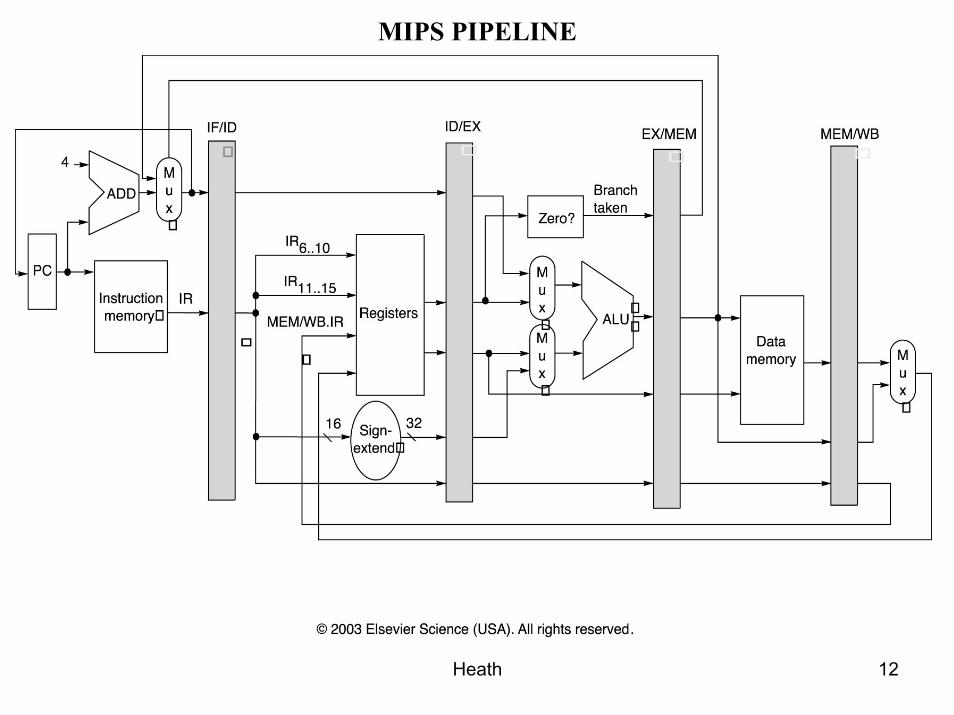
MIPS PIPELINE
Heath 13
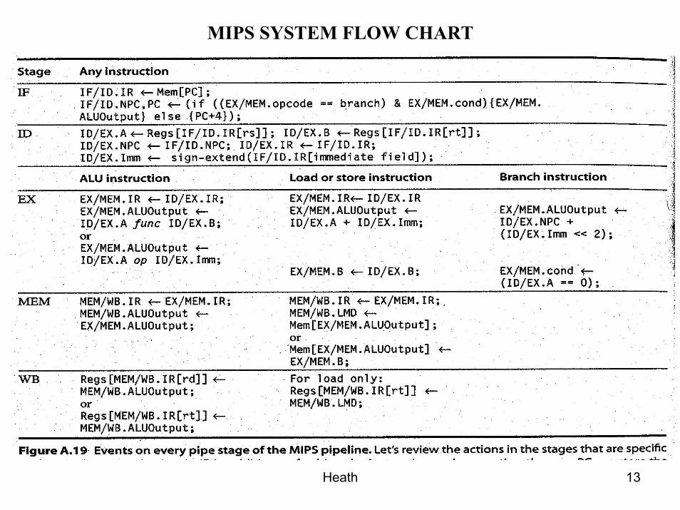
MIPS SYSTEM FLOW CHART
Heath 14
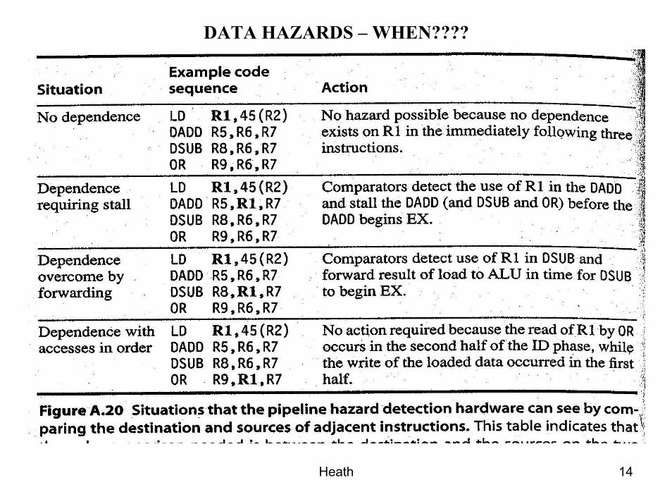
DATA HAZARDS – WHEN????
Heath 15
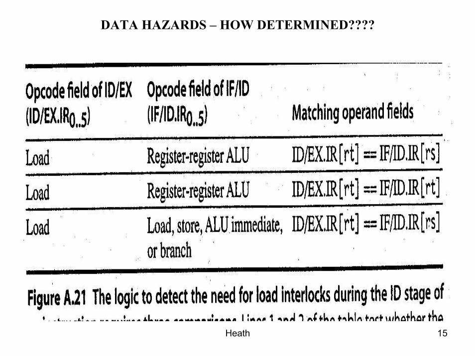
DATA HAZARDS – HOW DETERMINED????
Heath 16
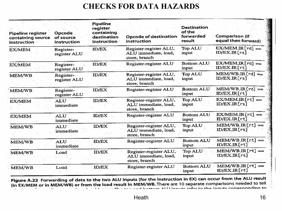
CHECKS FOR DATA HAZARDS
Heath 17
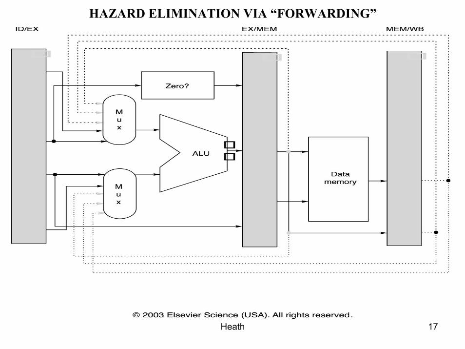
HAZARD ELIMINATION VIA “FORWARDING”
Heath 18
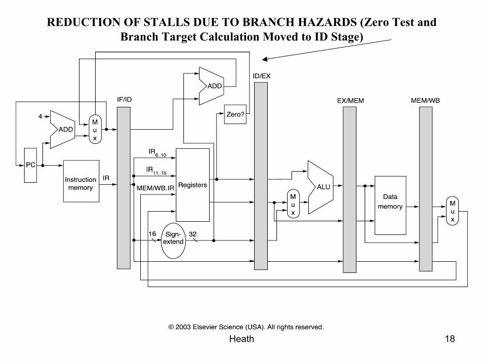
REDUCTION OF STALLS DUE TO BRANCH HAZARDS (Zero Test and Branch Target Calculation Moved to ID Stage)
Heath 19
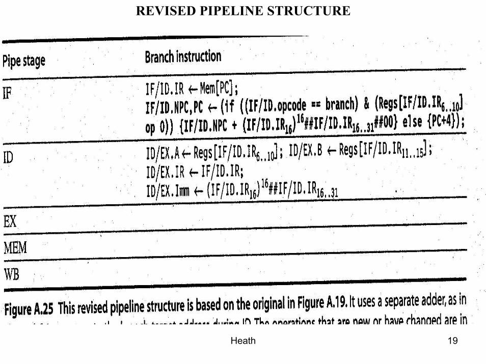
REVISED PIPELINE STRUCTURE
Heath 20
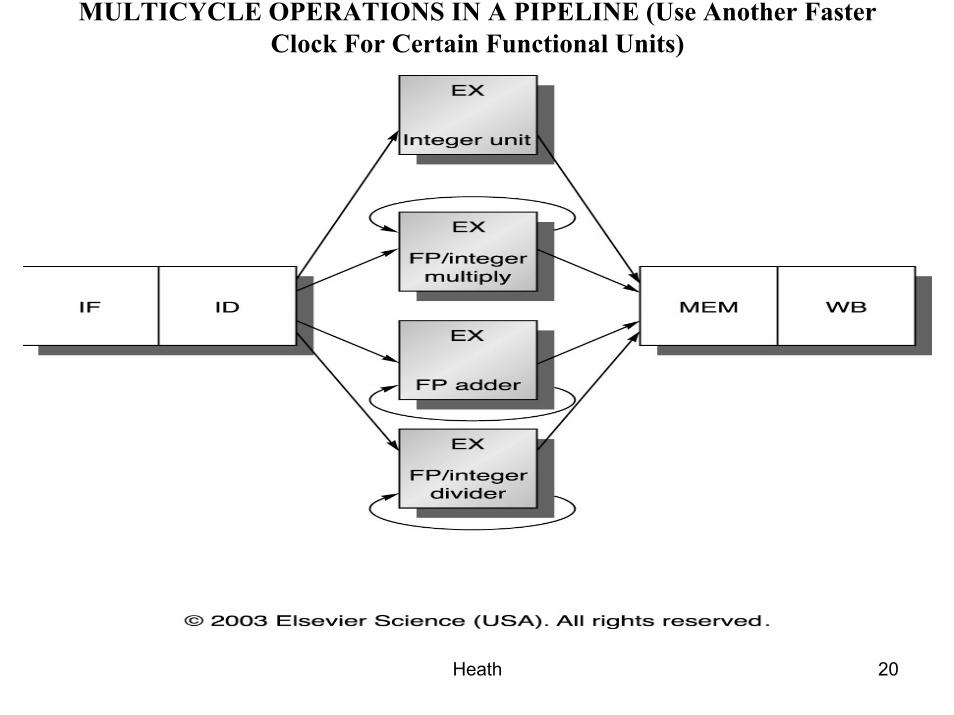
MULTICYCLE OPERATIONS IN A PIPELINE (Use Another Faster Clock For Certain Functional Units)
Heath 21
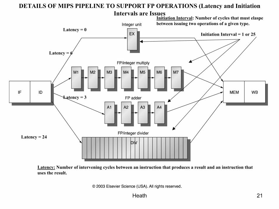
DETAILS OF MIPS PIPELINE TO SUPPORT FP OPERATIONS (Latency and Initiation Intervals are Issues
Initiation Interval = 1 or 25Latency = 0
Latency = 6
Latency = 3
Latency = 24
Latency: Number of intervening cycles between an instruction that produces a result and an instruction that uses the result.
Initiation Interval: Number of cycles that must elaspebetween issuing two operations of a given type.
Heath 22
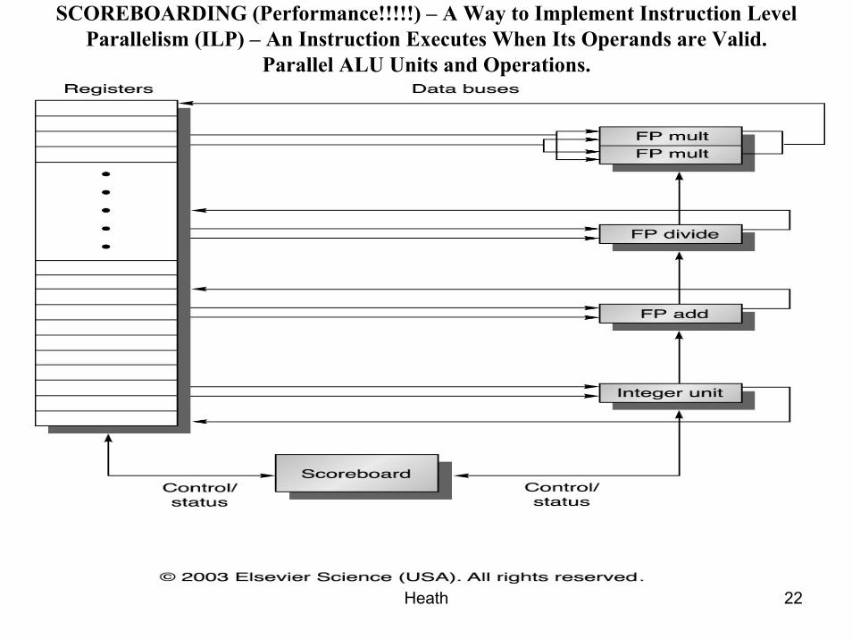
SCOREBOARDING (Performance!!!!!) – A Way to Implement Instruction Level Parallelism (ILP) – An Instruction Executes When Its Operands are Valid.
Parallel ALU Units and Operations.
Heath 23
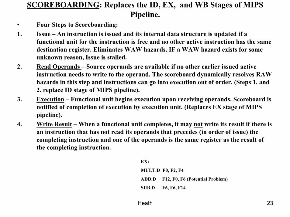
SCOREBOARDING: Replaces the ID, EX, and WB Stages of MIPS Pipeline.
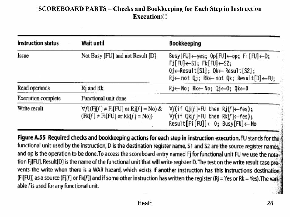
• Four Steps to Scoreboarding:1. Issue – An instruction is issued and its internal data structure is updated if a
functional unit for the instruction is free and no other active instruction has the same destination register. Eliminates WAW hazards. IF a WAW hazard exists for some unknown reason, Issue is stalled.
2. Read Operands – Source operands are available if no other earlier issued activeinstruction needs to write to the operand. The scoreboard dynamically resolves RAW hazards in this step and instructions can go into execution out of order. (Steps 1. and 2. replace ID stage of MIPS pipeline).
3. Execution – Functional unit begins execution upon receiving operands. Scoreboard is notified of completion of execution by execution unit. (Replaces EX stage of MIPS pipeline).
4. Write Result – When a functional unit completes, it may not write its result if there is an instruction that has not read its operands that precedes (in order of issue) the completing instruction and one of the operands is the same register as the result of the completing instruction.
EX:
MULT.D F0, F2, F4
ADD.D F12, F0, F6 (Potential Problem)
SUB.D F6, F6, F14

Heath 24
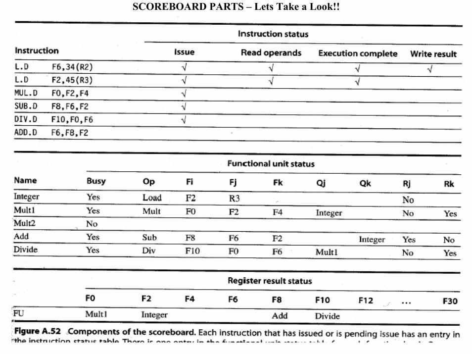
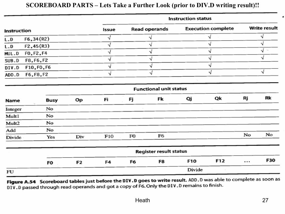
EXAMPLE SCOREBOARD• Instruction SequenceL.D F6, 34(R2)L.D F2, 45(R3)MUL.D F0, F2, F4SUB.DF8, F6, F2DIV.D F10, F0, F6ADD.D F6, F8, F2
THREE (3) PARTS TO SCOREBOARD1. Instruction Status (Issue, Read Operands, Execution Complete, or Write Result)2. Functional Unit Status (Indicated by Nine (9) Fields) –• Busy-Indicates if unit is busy or not.• Op-Operation to be performed by functional unit.• Fi-Destination register.• Fj, Fk-Source-register numbers• Qj, Qk-Fct. Units producing source registers Fj, Fk.• Rj, Rk-Flags indicating when Fj, Fk are ready and not yet read. Set to No after
opernads are read.3. Register Result Status-Indicates which functional unit will write each register and if
the register is the destination of an active instruction.
Heath 25
SCOREBOARD PARTS – Lets Take a Look!!
Heath 26
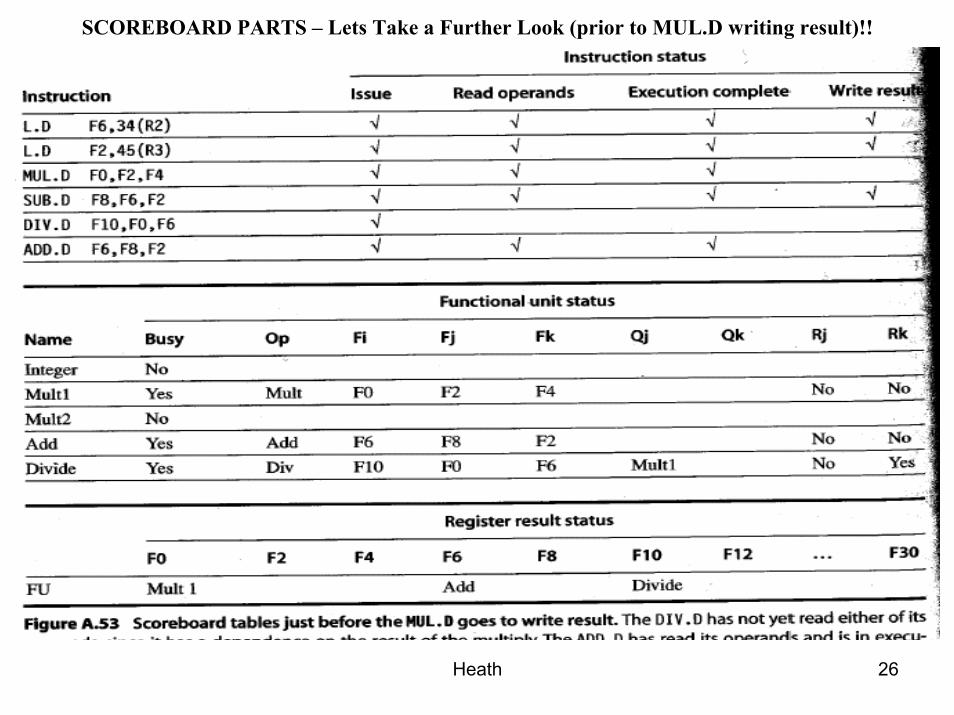
SCOREBOARD PARTS – Lets Take a Further Look (prior to MUL.D writing result)!!
Heath 27
SCOREBOARD PARTS – Lets Take a Further Look (prior to DIV.D writing result)!!
Heath 28
SCOREBOARD PARTS – Checks and Bookkeeping for Each Step in Instruction Execution)!!


