Embed Size (px)
Citation preview

eng i
Declaration of Conformity ‑ For Recreational CraftPropulsion Engines with the Requirements of Directive94/25/EC as amended by Directive 2003/44/EC
Name of engine manufacturer: Mercury MarineAddress: W6250 Pioneer Road, P.O. Box 1939Town: Fond du Lac, WI Post Code: 54936‑1939 Country: USA
Name of authorized representative: Brunswick Marine in EMEA Inc.Address: Parc Industriel de Petit‑RechainTown: Verviers Post Code: B‑4800 Country: Belgium
Name of notified body for exhaust emission assessment: DetNorske Veritas ASAddress: Veritasveien 1
Town: Hovik Post Code:1322
Country:Norway ID Number: 0575
Name of notified body for noise emission assessment: Det NorskeVeritas ASAddress: Veritasveien 1
Town: Hovik Post Code:1322
Country:Norway ID Number: 0575
Conformity assessmentmodule used for exhaustemissions:
☐ B+C
☐ B+D
☐ B+E
☐ B+F ☐ G ☒ H
Conformity assessmentmodule used for noiseemissions:
☐ A ☐ Aa ☐ G ☒ H
Other Community Directives applied: Safety of Machinery Directive2006/42/EC; Electromagnetic Compatibility Directive 2004/108/EC
Description of Engines and Essential Requirements
Engine Type Fuel Type Combustion Cycle☒ Outboard engine ☒ Petrol ☒ 4 stroke
© 2
013
Mer
cury
Mar
ine
135/
150/
175/
200
Vera
do F
ourS
troke
90-8
M00
8758
4 12
13

ii eng
Identification of Engines Covered by This Declaration of Conformity
Name of engine familyUnique engineidentification number:starting serial number
EC Module Hcertificate number
Verado 6 cylinder 200, 225,250, 275, 300, 350 hp
0P401000 or1B227000 RCD‑H‑2 Rev 4
Verado 4 cylinder 135, 150,175, 200 hp
0P401000 or1B227000 RCD‑H‑2 Rev 4
L4NA 4 cylinder 80, 100, 115hp
0P401000 or1B227000 RCD‑H‑2 Rev 4
150 HP FourStroke (3.0L) 0P401000 or1B227000 RCD‑H‑2 Rev 4
Essentialrequirements Standards
Othernormativedocument/
method
Technicalfile
Please specify inmore detail(* = mandatorystandard)
Annex 1.B—Exhaust EmissionsB.1 engineidentification ☐ ☐ ☒
B.2 exhaustemissionrequirements
☒* ☐ ☐ * EN ISO8178‑1:1996
B.3 durability ☐ ☐ ☒ EN ISO8178‑1:1996
B.4 owner'smanual ☒ ☐ ☐ ISO 8665: 2006
Annex 1.C—Noise EmissionsC.1 Noiseemission levels ☒* ☐ ☐ EN ISO 14509
C.2 Owner'smanual ☐ ☒ ☐ Owner's manual
This declaration of conformity is issued under the sole responsibility of themanufacturer. I declare on behalf of the engine manufacturer that the enginesmentioned preceding complies with all applicable essential requirements inthe way specified.

eng iii
Name / function:Mark D. Schwabero, President,Mercury Marine
Date and place of issue:September 04, 2012Fond du Lac, Wisconsin, USA
WelcomeYou have selected one of the finest outboards available. It incorporatesnumerous design features to ensure operating ease and durability.With proper care and maintenance, you will thoroughly enjoy using this productfor many boating seasons. To ensure maximum performance and carefree use,we ask that you thoroughly read this manual.The Operation, Maintenance and Warranty Manual contains specificinstructions for using and maintaining your product. We suggest that thismanual remain with the product for ready reference whenever you are on thewater.Thank you for purchasing one of our products. We sincerely hope your boatingwill be pleasant!Mercury Marine
EPA Emissions RegulationsOutboards sold by Mercury Marine in the United States are certified to theUnited States Environmental Protection Agency as conforming to therequirements of the regulations for the control of air pollution from newoutboard motors. This certification is contingent on certain adjustments beingset to factory standards. For this reason, the factory procedure for servicing theproduct must be strictly followed and, wherever practicable, returned to theoriginal intent of the design. Maintenance, replacement, or repair of theemission control devices and systems may be performed by any marine enginerepair establishment or individual.Engines are labeled with an Emission Control Information decal as permanentevidence of EPA certification.
! WARNINGThe engine exhaust from this product contains chemicals known to the stateof California to cause cancer, birth defects or other reproductive harm.

iv eng
Warranty MessageThe product you have purchased comes with a limited warranty from MercuryMarine. The terms of the warranty are set forth in the Warranty Informationsection of this manual. The warranty statement contains a description of what iscovered, what is not covered, the duration of coverage, how to best obtainwarranty coverage, important disclaimers and limitations of damages, and otherrelated information. Please review this important information.The description and specifications contained herein were in effect at the timethis manual was approved for printing. Mercury Marine, whose policy is one ofcontinued improvement, reserves the right to discontinue models at any time, tochange specifications, designs, methods, or procedures without notice andwithout incurring obligation.Mercury Marine, Fond du Lac, Wisconsin U.S.A.
Mercury Premier ServiceMercury evaluates the service performance of its dealers and assigns itshighest rating of Mercury Premier to those demonstrating an exceptionalcommitment to service.Earning a Mercury Premier Service rating means a dealer:• Achieves a high 12‑month service Customer Satisfaction Index (CSI)
score for warranty service.• Possesses all of the necessary service tools, test equipment, manuals,
and parts books.• Employs at least one certified or master technician.• Provides timely service for all Mercury Marine customers.• Offers extended service hours and mobile service, when appropriate.• Uses, displays, and stocks an adequate inventory of genuine Mercury
Precision Parts.• Offers a clean, neat shop with well‑organized tools and service literature.
Copyright and Trademark Information© MERCURY MARINE. All rights reserved. Reproduction in whole or inpart without permission is prohibited.Alpha, Axius, Bravo One, Bravo Two, Bravo Three, Circle M with Waves Logo,K‑planes, Mariner, MerCathode, MerCruiser, Mercury, Mercury with WavesLogo, Mercury Marine, Mercury Precision Parts, Mercury Propellers, MercuryRacing, MotorGuide, OptiMax, Quicksilver, SeaCore, Skyhook, SmartCraft,Sport‑Jet, Verado, VesselView, Zero Effort, Zeus, #1 On the Water and We'reDriven to Win are registered trademarks of Brunswick Corporation. Pro XS is atrademark of Brunswick Corporation. Mercury Product Protection is a registeredservice mark of Brunswick Corporation.

eng v
WARRANTY INFORMATION
Warranty Registration United States and Canada.............................................. 1Transfer of Warranty United States and Canada................................................1Transfer of Mercury Product Protection (Extended Service Coverage) PlanUnited States and Canada..................................................................................2Outboard Limited Warranty.................................................................................23 Year Limited Warranty Against Corrosion....................................................... 5Warranty Coverage and Exclusions................................................................... 7U.S. EPA Emissions Limited Warranty............................................................... 9Emission Control System Components.............................................................. 9California Emissions Limited Warranty............................................................. 10California Air Resources Board Explanation of Your California Emission ControlWarranty Statement.......................................................................................... 12Emission Certification Star Label...................................................................... 13Warranty Policy—Australia and New Zealand.................................................. 14
General Information
Boater's Responsibilities................................................................................... 18Before Operating Your Outboard...................................................................... 18Boat Horsepower Capacity............................................................................... 18High‑Speed and High‑Performance Boat Operation........................................ 19Outboard Remote Control Models ................................................................... 19Lanyard Stop Switch......................................................................................... 19Protecting People in the Water......................................................................... 22Passenger Safety Message ‑ Pontoon Boats and Deck Boats.........................22Wave and Wake Jumping................................................................................. 24Impact with Underwater Hazards......................................................................25Exhaust Emissions........................................................................................... 26Selecting Accessories for Your Outboard......................................................... 28Safe Boating Recommendations...................................................................... 28Recording Serial Number................................................................................. 30135/150/175/200 Verado FourStroke Specifications........................................ 31Component Identification.................................................................................. 33Propeller Selection............................................................................................34
Transporting
Trailering Boat/Outboard.................................................................................. 36

vi eng
Fuel and Oil
Fuel Recommendations.................................................................................... 37Fuel Additives................................................................................................... 38Low Permeation Fuel Hose Requirement ........................................................ 38EPA Pressurized Portable Fuel Tank Requirements........................................ 38Fuel Demand Valve (FDV) Requirement.......................................................... 39Mercury Marine's Pressurized Portable Fuel Tank........................................... 39Filling Fuel Tank............................................................................................... 40Engine Oil Recommendations.......................................................................... 41Checking and Adding Engine Oil...................................................................... 41
Features and Controls
Panel Mount Control Features and Operation.................................................. 44Slim Binnacle Control Features and Operation................................................ 47Features and Operation.................................................................................... 51Dual Console Control with CAN Trackpad Features and Operation.................56Shadow Mode Control with CAN Trackpad Features and Operation............... 65Warning System............................................................................................... 72Power Trim and Tilt...........................................................................................75
Operation
Important Daily Inspection Before Each Use ................................................... 79Prestarting Check List.......................................................................................79Operating in Freezing Temperatures................................................................ 80Operating in Saltwater or Polluted Water......................................................... 80Operating at High Elevations............................................................................ 80Effects of Elevation and Weather on Performance........................................... 80Setting Trim Angle While Running Engine at Idle Speed................................. 81Engine Break‑in Procedure...............................................................................81Starting the Engine........................................................................................... 82Gear Shifting..................................................................................................... 84Stopping the Engine......................................................................................... 85

eng vii
Maintenance
Outboard Care.................................................................................................. 87EPA Emissions Regulations............................................................................. 87Inspection and Maintenance Schedule............................................................. 88Flushing the Cooling System............................................................................ 90Top Cowl Removal and Installation.................................................................. 91Cleaning Care for Top and Bottom Cowls........................................................ 92Cleaning Care for the Powerhead (Saltwater Use)...........................................92Battery Inspection ............................................................................................ 93Verado Engine Battery Specifications.............................................................. 93Air Filter............................................................................................................ 95Fuel System...................................................................................................... 99Corrosion Control Anode................................................................................ 102Propeller Replacement................................................................................... 103Spark Plug Inspection and Replacement........................................................105Fuses.............................................................................................................. 109Steering Link Rod Fasteners.......................................................................... 110DTS Wiring System........................................................................................ 112Accessory Drive Belt Inspection..................................................................... 112Lubrication Points........................................................................................... 112Checking Power Trim Fluid.............................................................................115Checking Power Steering Fluid...................................................................... 116Changing Engine Oil....................................................................................... 116Gearcase Lubrication......................................................................................119
Storage
Storage Preparation........................................................................................122Protecting External Outboard Components.................................................... 122Protecting Internal Engine Components......................................................... 123Gearcase........................................................................................................ 123Positioning Outboard for Storage................................................................... 123Battery Storage............................................................................................... 123
Troubleshooting
Starter Motor Will Not Crank the Engine.........................................................124Engine Will Not Start.......................................................................................124Engine Starts But Will Not Shift Into Gear...................................................... 124Engine Runs Erratically.................................................................................. 124Performance Loss...........................................................................................125Battery Will Not Hold Charge.......................................................................... 125

viii eng
Owner Service Assistance
Local Repair Service.......................................................................................126Service Away from Home............................................................................... 126Parts and Accessories Inquiries..................................................................... 126Service Assistance......................................................................................... 126Ordering Literature..........................................................................................129
Outboard Installation
Mercury Marine Validated Engine Mounting Hardware.................................. 131Accessories Mounted to the Transom Clamp Bracket.................................... 131Installing Outboard..........................................................................................135Propeller Selection..........................................................................................136
Maintenance Log
Maintenance Log............................................................................................ 137

WARRANTY INFORMATION
eng 1
Warranty Registration United States and CanadaTo be eligible for warranty coverage, the product must be registered withMercury Marine.At the time of sale, the selling dealer should complete the warranty registrationand immediately submit it to Mercury Marine via MercNET, e‑mail, or mail.Upon receipt of this warranty registration, Mercury Marine will record theregistration.A copy of the warranty registration should be provided to you by your sellingdealer.NOTE: Registration lists must be maintained by Mercury Marine and any dealerof Mercury Marine products sold in the United States, should a safety recallnotification under the Federal Safety Act be required.You may change your registered address at any time, including at time ofwarranty claim, by calling Mercury Marine or sending a letter or fax with yourname, old address, new address, and engine serial number to MercuryMarine’s warranty registration department. Your dealer can also process thischange of information.Mercury MarineAttn: Warranty Registration DepartmentW6250 Pioneer RoadP.O. Box 1939Fond du Lac, WI 54936-1939920-929-5054Fax +1 920 907 6663
OUTSIDE UNITED STATES AND CANADAFor products purchased outside the United States and Canada, contact thedistributor in your country, or the Marine Power Service Center closest to you.
Transfer of Warranty United States and CanadaThe limited warranty is transferable to a subsequent purchaser, but only for theremainder of the unused portion of the limited warranty. This will not apply toproducts used for commercial applications.To transfer the warranty to the subsequent owner, send or fax a copy of the billof sale or purchase agreement, new owner’s name, address, and engine serialnumber to Mercury Marine’s warranty registration department. In the UnitedStates and Canada, mail to:Mercury MarineAttn: Warranty Registration DepartmentW6250 Pioneer RoadP.O. Box 1939Fond du Lac, WI 54936-1939920-929-5054Fax +1 920 907 6663

WARRANTY INFORMATION
2 eng
Upon processing the transfer of warranty, Mercury Marine will record the newowner's information.There is no charge for this service.
OUTSIDE THE UNITED STATES AND CANADAFor products purchased outside the United States and Canada, contact thedistributor in your country, or the Marine Power Service Center closest to you.
Transfer of Mercury Product Protection (Extended ServiceCoverage) Plan United States and CanadaThe remaining coverage period of the Product Protection Plan is transferable tothe subsequent purchaser of the engine within thirty (30) days from the date ofsale. Contracts not transferred within thirty (30) days of the subsequentpurchase will no longer be valid and the product will no longer be eligible forcoverage under the terms of the contract.To transfer the plan to the subsequent owner, contact Mercury ProductProtection or an authorized dealer to receive a Request for Transfer form.Submit to Mercury Product Protection a receipt/bill of sale, a completedRequest of Transfer form, and a check payable to Mercury Marine in theamount of $50.00 (per engine) to cover the transfer fee.Plan coverage is not transferable from one product to another product or fornoneligible applications.The certified preowned engine plans are not transferable.For help or assistance, contact Mercury Product Protection Department at1‑888‑427‑5373 from 7:30 a.m. to 4:30 p.m. CST, Monday–Friday or e‑[email protected].
Outboard Limited WarrantyUNITED STATES, CANADA, EUROPE, MIDDLE EAST, AFRICA, ANDTHE CONFEDERATION OF INDEPENDENT STATESWHAT IS COVERED: Mercury Marine warrants its new products to be free ofdefects in material and workmanship during the period described below.

WARRANTY INFORMATION
eng 3
DURATION OF COVERAGE: This Limited Warranty provides coverage forthree (3) years from the date the product is first sold to a recreational use retailpurchaser, or the date on which the product is first put into service, whicheveroccurs first. Commercial users of these products receive warranty coverage ofone (1) year from the date of first retail sale, or one (1) year from the date onwhich the product was first put into service, whichever occurs first. Commercialuse is defined as any work or employment related use of the product, or anyuse of the product which generates income, for any part of the warranty period,even if the product is only occasionally used for such purposes. The repair orreplacement of parts, or the performance of service under this warranty, doesnot extend the life of this warranty beyond its original expiration date.Unexpired warranty coverage can be transferred from one recreational usecustomer to a subsequent recreational use customer upon proper reregistrationof the product. Unexpired warranty coverage cannot be transferred either to orfrom a commercial use customer. Warranty coverage may be terminated forused repossessed product; or product purchased at auction, from a salvageyard, or from an insurance company.CONDITIONS THAT MUST BE MET IN ORDER TO OBTAIN WARRANTYCOVERAGE: Warranty coverage is available only to retail customers thatpurchase from a Dealer authorized by Mercury Marine to distribute the productin the country in which the sale occurred, and then only after the MercuryMarine specified predelivery inspection process is completed and documented.Warranty coverage becomes available upon proper registration of the productby the authorized dealer. Inaccurate warranty registration information regardingrecreational use, or subsequent change of use from recreational to commercial(unless properly reregistered) may void the warranty at the sole discretion ofMercury Marine. Routine maintenance outlined in the Operation andMaintenance Manual must be timely performed in order to maintain warrantycoverage. Mercury Marine reserves the right to make warranty coveragecontingent upon proof of proper maintenance.WHAT MERCURY WILL DO: Mercury's sole and exclusive obligation underthis warranty is limited to, at our option, repairing a defective part, replacingsuch part or parts with new or Mercury Marine certified remanufactured parts,or refunding the purchase price of the Mercury product. Mercury reserves theright to improve or modify products from time to time without assuming anobligation to modify products previously manufactured.

WARRANTY INFORMATION
4 eng
HOW TO OBTAIN WARRANTY COVERAGE: The customer must provideMercury with a reasonable opportunity to repair, and reasonable access to theproduct for warranty service. Warranty claims shall be made by delivering theproduct for inspection to a Mercury dealer authorized to service the product. Ifpurchaser cannot deliver the product to such a dealer, written notice must begiven to Mercury. We will then arrange for the inspection and any coveredrepair. Purchaser, in that case, shall pay for all related transportation chargesand/or travel time. If the service provided is not covered by this warranty,purchaser shall pay for all related labor and material, and any other expensesassociated with that service. Purchaser shall not, unless requested by Mercury,ship the product or parts of the product directly to Mercury. Proof of registeredownership must be presented to the dealer at the time warranty service isrequested in order to obtain coverage.WHAT IS NOT COVERED: This limited warranty does not cover routinemaintenance items, tune‑ups, adjustments, normal wear and tear, damagecaused by abuse, abnormal use, use of a propeller or gear ratio that does notallow the engine to run in its recommended wide‑open throttle RPM range (seethe Operation and Maintenance Manual), operation of the product in a mannerinconsistent with the recommended operation/duty cycle section of theOperation and Maintenance Manual, neglect, accident, submersion, improperinstallation (proper installation specifications and techniques are set forth in theinstallation instructions for the product), improper service, use of an accessoryor part not manufactured or sold by us, jet pump impellers and liners, operationwith fuels, oils or lubricants which are not suitable for use with the product (seethe Operation and Maintenance Manual), alteration or removal of parts, waterentering the engine through the fuel intake, air intake or exhaust system, ordamage to the product from insufficient cooling water caused by blockage ofthe cooling system by a foreign body, running the engine out of water,mounting the engine too high on the transom, or running the boat with theengine trimmed out too far. Use of the product for racing or other competitiveactivity, or operating with a racing type lower unit, at any point, even by a priorowner of the product, voids the warranty.Expenses related to haul‑out, launch, towing, storage, telephone, rental,inconvenience, slip fees, insurance coverage, loan payments, loss of time, lossof income, or any other type of incidental or consequential damages are notcovered by this warranty. Also, expenses associated with the removal and/orreplacement of boat partitions or material caused by boat design for access tothe product are not covered by this warranty.No individual or entity, including Mercury Marine authorized dealers, has beengiven authority by Mercury Marine to make any affirmation, representation orwarranty regarding the product, other than those contained in this limitedwarranty, and if made, shall not be enforceable against Mercury Marine.For additional information regarding events and circumstances covered by thiswarranty, and those that are not, see the Warranty Coverage section of theOperation and Maintenance Manual, incorporated by reference into thiswarranty.

WARRANTY INFORMATION
eng 5
DISCLAIMERS AND LIMITATIONS:
THE IMPLIED WARRANTIES OF MERCHANTABILITY AND FITNESS FORA PARTICULAR PURPOSE ARE EXPRESSLY DISCLAIMED. TO THEEXTENT THAT THEY CANNOT BE DISCLAIMED, THE IMPLIEDWARRANTIES ARE LIMITED IN DURATION TO THE LIFE OF THEEXPRESS WARRANTY. INCIDENTAL AND CONSEQUENTIAL DAMAGESARE EXCLUDED FROM COVERAGE UNDER THIS WARRANTY. SOMESTATES/COUNTRIES DO NOT ALLOW FOR THE DISCLAIMERS,LIMITATIONS AND EXCLUSIONS IDENTIFIED ABOVE, AS A RESULT,THEY MAY NOT APPLY TO YOU. THIS WARRANTY GIVES YOUSPECIFIC LEGAL RIGHTS, AND YOU MAY ALSO HAVE OTHER LEGALRIGHTS WHICH VARY FROM STATE TO STATE AND COUNTRY TOCOUNTRY.
3 Year Limited Warranty Against CorrosionWHAT IS COVERED: Mercury Marine warrants that each new Mercury,Mariner, Mercury Racing, Sport‑Jet, M2 Jet Drive, Tracker by Mercury MarineOutboard, Mercury MerCruiser Inboard or Sterndrive Engine (Product) will notbe rendered inoperative as a direct result of corrosion for the period of timedescribed below.DURATION OF COVERAGE: This limited corrosion warranty providescoverage for three (3) years from either the date the product is first sold, or thedate on which the product is first put into service, whichever occurs first. Therepair or replacement of parts, or the performance of service under thiswarranty, does not extend the life of this warranty beyond its original expirationdate. Unexpired warranty coverage can be transferred to subsequent(noncommercial use) purchaser upon proper reregistration of the product.CONDITIONS THAT MUST BE MET IN ORDER TO OBTAIN WARRANTYCOVERAGE: Warranty coverage is available only to retail customers thatpurchase from a Dealer authorized by Mercury Marine to distribute the productin the country in which the sale occurred, and then only after the MercuryMarine specified predelivery inspection process is completed and documented.Warranty coverage becomes available upon proper registration of the productby the authorized dealer. Corrosion prevention devices specified in theOperation and Maintenance Manual must be in use on the boat, and routinemaintenance outlined in the Operation and Maintenance Manual must be timelyperformed (including, without limitation, the replacement of sacrificial anodes,use of specified lubricants, and touch‑up of nicks and scratches) in order tomaintain warranty coverage. Mercury Marine reserves the right to makewarranty coverage contingent upon proof of proper maintenance.

WARRANTY INFORMATION
6 eng
WHAT MERCURY WILL DO: Mercury's sole and exclusive obligation underthis warranty is limited to, at our option, repairing a corroded part, replacingsuch part or parts with new or Mercury Marine certified remanufactured parts,or refunding the purchase price of the Mercury product. Mercury reserves theright to improve or modify products from time to time without assuming anobligation to modify products previously manufactured.HOW TO OBTAIN WARRANTY COVERAGE: The customer must provideMercury with a reasonable opportunity to repair, and reasonable access to theproduct for warranty service. Warranty claims shall be made by delivering theproduct for inspection to a Mercury dealer authorized to service the product. Ifpurchaser cannot deliver the product to such a dealer, written notice must begiven to Mercury. We will then arrange for the inspection and any coveredrepair. Purchaser, in that case, shall pay for all related transportation chargesand/or travel time. If the service provided is not covered by this warranty,purchaser shall pay for all related labor and material, and any other expensesassociated with that service. Purchaser shall not, unless requested by Mercury,ship the product or parts of the product directly to Mercury. Proof of registeredownership must be presented to the dealer at the time warranty service isrequested in order to obtain coverage.WHAT IS NOT COVERED: This limited warranty does not cover electricalsystem corrosion; corrosion resulting from damage, corrosion which causespurely cosmetic damage, abuse, or improper service; corrosion to accessories,instruments, steering systems; corrosion to factory installed jet drive unit;damage due to marine growth; product sold with less than a one year limitedProduct warranty; replacement parts (parts purchased by customer); productsused in a commercial application. Commercial use is defined as any work oremployment related use of the product, or any use of the product whichgenerates income, for any part of the warranty period, even if the product isonly occasionally used for such purposes.Corrosion damage caused by stray electrical currents (onshore powerconnections, nearby boats, submerged metal) is not covered by this corrosionwarranty and should be protected against by the use of a corrosion protectionsystem, such as the Mercury Precision Parts or Quicksilver MerCathodesystem and/or Galvanic Isolator. Corrosion damage caused by improperapplication of copper base antifouling paints is also not covered by this limitedwarranty. If antifouling protection is required, Tri‑Butyl‑Tin‑Adipate (TBTA) baseantifouling paints are recommended on Outboard and MerCruiser boatingapplications. In areas where TBTA base paints are prohibited by law, copperbase paints can be used on the hull and transom. Do not apply paint to theoutboard or MerCruiser product. In addition, care must be taken to avoid anelectrical interconnection between the warranted product and the paint. ForMerCruiser product, an unpainted gap of at least 38 mm (1.5 in.) should be leftaround the transom assembly. Refer to the Operation and Maintenance Manualfor additional details.

WARRANTY INFORMATION
eng 7
For additional information regarding events and circumstances covered by thiswarranty, and those that are not, see the Warranty Coverage section of theOperation and Maintenance Manual, incorporated by reference into thiswarranty.
DISCLAIMERS AND LIMITATIONS:
THE IMPLIED WARRANTIES OF MERCHANTABILITY AND FITNESS FORA PARTICULAR PURPOSE ARE EXPRESSLY DISCLAIMED. TO THEEXTENT THAT THEY CANNOT BE DISCLAIMED, THE IMPLIEDWARRANTIES ARE LIMITED IN DURATION TO THE LIFE OF THEEXPRESS WARRANTY. INCIDENTAL AND CONSEQUENTIAL DAMAGESARE EXCLUDED FROM COVERAGE UNDER THIS WARRANTY. SOMESTATES/COUNTRIES DO NOT ALLOW FOR THE DISCLAIMERS,LIMITATIONS AND EXCLUSIONS IDENTIFIED ABOVE, AS A RESULT,THEY MAY NOT APPLY TO YOU. THIS WARRANTY GIVES YOUSPECIFIC LEGAL RIGHTS, AND YOU MAY ALSO HAVE OTHER LEGALRIGHTS WHICH VARY FROM STATE TO STATE AND COUNTRY TOCOUNTRY.
Warranty Coverage and ExclusionsThe purpose of this section is to help eliminate some of the more commonmisunderstandings regarding warranty coverage. The following informationexplains some of the types of services that are not covered by warranty. Theprovisions set forth following have been incorporated by reference into theThree Year Limited Warranty Against Corrosion Failure, the InternationalLimited Outboard Warranty, and the United States and Canada LimitedOutboard Warranty.Keep in mind that warranty covers repairs that are needed within the warrantyperiod because of defects in material and workmanship. Installation errors,accidents, normal wear, and a variety of other causes that affect the productare not covered.Warranty is limited to defects in material or workmanship, but only when theconsumer sale is made in the country to which distribution is authorized by us.Should you have any questions concerning warranty coverage, contact yourauthorized dealer. They will be pleased to answer any questions that you mayhave.
GENERAL EXCLUSIONS FROM WARRANTY1. Minor adjustments and tune‑ups, including checking, cleaning, or
adjusting spark plugs, ignition components, carburetor settings, filters,belts, controls, and checking lubrication made in connection with normalservices.
2. Factory installed jet drive units ‑ Specific parts excluded from the warrantyare: the jet drive impeller and jet drive liner damaged by impact or wear,and water damaged driveshaft bearings as a result of impropermaintenance.

WARRANTY INFORMATION
8 eng
3. Damage caused by neglect, lack of maintenance, accident, abnormaloperation, or improper installation or service.
4. Haul‑out, launch, towing charges, removal and/or replacement of boatpartitions or material because of boat design for necessary access to theproduct, all related transportation charges and/or travel time, etc.Reasonable access must be provided to the product for warranty service.Customer must deliver product to an authorized dealer.
5. Additional service work requested by customer other than that necessaryto satisfy the warranty obligation.
6. Labor performed by other than an authorized dealer may be covered onlyunder the following circumstances: when performed on emergency basis(providing there are no authorized dealers in the area who can performthe work required or have no facilities to haul‑out, etc., and prior factoryapproval has been given to have the work performed at this facility).
7. All incidental and/or consequential damages (storage charges, telephoneor rental charges of any type, inconvenience or loss of time or income)are the owner's responsibility.
8. Use of other than Mercury Precision or Quicksilver parts when makingwarranty repairs.
9. Oils, lubricants, or fluids changed as a matter of normal maintenance iscustomer's responsibility unless loss or contamination of same is causedby product failure that would be eligible for warranty consideration.
10. Participating in or preparing for racing or other competitive activity oroperating with a racing type lower unit.
11. Engine noise does not necessarily indicate a serious engine problem. Ifdiagnosis indicates a serious internal engine condition which could resultin a failure, condition responsible for noise should be corrected under thewarranty.
12. Lower unit and/or propeller damage caused by striking a submergedobject is considered a marine hazard.
13. Water entering engine through the fuel intake, air intake, or exhaustsystem or submersion.
14. Failure of any parts caused by lack of cooling water, which results fromstarting motor out of water, foreign material blocking inlet holes, motorbeing mounted too high, or trimmed too far out.
15. Use of fuels and lubricants which are not suitable for use with or on theproduct. Refer to the Maintenance section.
16. Our limited warranty does not apply to any damage to our productscaused by the installation or use of parts and accessories which are notmanufactured or sold by us. Failures which are not related to the use ofthose parts or accessories are covered under warranty if they otherwisemeet the terms of the limited warranty for that product.

WARRANTY INFORMATION
eng 9
U.S. EPA Emissions Limited WarrantyConsistent with the obligations created by 40 CFR Part 1045, Subpart B,Mercury Marine provides a five year or 175 hours of engine use warranty,whichever occurs first, to the retail customer, that the engine is designed, built,and equipped so as to conform at the time of sale with applicable regulationsunder section 213 of the Clean Air Act, and that the engine is free from defectsin materials and workmanship that cause the engine to fail to conform withapplicable regulations. This emission‑related warranty covers all thecomponents listed in the Emission Control System Components.
Emission Control System ComponentsThe EPA and California emission‑related warranty covers all the following list ofcomponents:
COMPONENTS OF THE EMISSIONS CONTROL SYSTEM:1. Fuel metering system
a. Carburetor and internal parts (and/or pressure regulator or fuelinjection system)
b. Cold start enrichment systemc. Intake valves
2. Air induction systema. Intake manifoldb. Turbocharger or supercharger systems (where applicable)
3. Ignition systema. Spark plugsb. Magneto or electronic ignition systemc. Spark advance/retard systemd. Ignition coil and/or control modulee. Ignition wires
4. Lubrication system (4‑Stroke engines excluded)a. Oil pump and internal partsb. Oil injectorsc. Oil meter
5. Exhaust systema. Exhaust manifoldb. Exhaust valves
6. Miscellaneous items used in above systemsa. Hoses, clamps, fittings, tubing, sealing gaskets or devices, and
mounting hardwareb. Pulleys, belts, and idlersc. Vacuum, temperature, check and time sensitive valves and switches

WARRANTY INFORMATION
10 eng
d. Electronic controlsThe emission‑related warranty does not cover components whose failure wouldnot increase an engine's emissions on any regulated pollutant.
California Emissions Limited WarrantyThe California Air Resources Board has promulgated air emission regulationsfor outboard engines. The regulations apply to all outboard engines sold toretail consumers in California, and which were manufactured for the 2001model year and later. Mercury Marine, in compliance with those regulations,provides this limited warranty for the emission control systems (see thecomponents listed in the Emission Control System Components), andfurther warrants that the outboard engine was designed, built, and equipped toconform with all applicable regulations adopted by the California Air ResourcesBoard pursuant to its authority in Chapters 1 and 2, Part 5, Division 26 of theHealth and Safety Code. For information regarding the limited warranty for thenonemission‑related components of the outboard, please see the limitedwarranty statement for your outboard.WHAT IS COVERED: Mercury Marine warrants the components of theemissions control systems (see the components listed in the Emission ControlSystem Components) of its new, 2001 model year and later outboards, soldby a California dealer to retail customers residing in California, to be free fromdefects in material or workmanship, that cause the failure of a warranted part tobe identical in all material respects to that part as described in the application ofMercury Marine for certification from the California Air Resources Board, for theperiod of time, and under the conditions, identified below. The cost to diagnosea warranty failure is covered under the warranty (if the warranty claim isapproved). Damage to other engine components caused by the failure of awarranted part will also be repaired under warranty.DURATION OF COVERAGE: This limited warranty provides coverage for thecomponents of the emissions control systems of new, 2001 model year andlater outboards, sold to retail customers in California for four (4) years fromeither the date the product is first sold, or first put into service, whicheveroccurs first, or the accumulation of 250 hours of engine operation (asdetermined by the engine's hour meter, if any). Emission‑related normalmaintenance items such as spark plugs and filters, that are on the warrantedparts list, are warranted up to their first required replacement interval only.Refer to Emission Control System Components and MaintenanceSchedule. The repair or replacement of parts, or the performance of serviceunder this warranty, does not extend the life of this warranty beyond its originalexpiration date. Unexpired warranty coverage can be transferred to asubsequent purchaser. (See instructions on transfer of warranty.)

WARRANTY INFORMATION
eng 11
HOW TO OBTAIN WARRANTY COVERAGE: The customer must provideMercury with a reasonable opportunity to repair and reasonable access to theproduct for warranty service. Warranty claims shall be made by delivering theproduct for inspection to a Mercury dealer authorized to service the product. Ifpurchaser cannot deliver the product to such a dealer, please notify MercuryMarine and Mercury will then arrange for the inspection and any covered repair.Purchaser, in that case, shall pay for all related transportation charges and/ortravel time. If the service provided is not covered by this warranty, purchasershall pay for all related labor and material, and any other expenses associatedwith that service. Purchaser shall not, unless requested by Mercury, ship theproduct or parts of the product directly to Mercury.WHAT MERCURY WILL DO: Mercury Marine's sole and exclusive obligationunder this warranty is limited to, at our expense and at our option, repairing orreplacing defective parts with new or Mercury Marine certified remanufacturedparts, or refunding the purchase price of the Mercury product. Mercury reservesthe right to improve or modify products from time to time without assuming anobligation to modify products previously manufactured.WHAT IS NOT COVERED: This limited warranty does not cover routinemaintenance items, tune‑ups, adjustments, normal wear and tear, damagecaused by abuse, abnormal use, use of a propeller or gear ratio that does notallow the engine to run in its recommended wide‑open throttle RPM range (seeGeneral Information ‑ Specifications), operation of the product in a mannerinconsistent with the recommended operation procedures, neglect, accident,submersion, improper installation (proper installation specifications andtechniques are set forth in the installation instructions for the product), improperservice, jet pump impellers and liners, operation with fuels, oils, or lubricantswhich are not suitable for use with the product (see Fuel and Oil), alteration orremoval of parts.Expenses related to haul‑out, launch, towing, storage, telephone, rental,inconvenience, slip fees, insurance coverage, loan payments, loss of time, lossof income, or any other type of incidental or consequential damages are notcovered by this warranty. Also, expenses associated with the removal and/orreplacement of boat partitions or material caused by boat design for access tothe product are not covered by this warranty.Nonwarranty maintenance, replacement, or repair of emission control devicesand systems may be performed by any marine engine repair establishment orindividual. The use of non‑Mercury parts for nonwarranty maintenance orrepairs will not be grounds for disallowing other warranty work. The use ofadd‑on (as defined at section 1900 (b)(1) and (b)(10) of Title 13 of theCalifornia Code of Regulations) or modified parts not exempted by theCalifornia Air Resources Board may be grounds for disallowing a warrantyclaim, at the discretion of Mercury Marine. Failures of warranted parts causedby the use of a nonexempted add‑on or modified part will not be covered.

WARRANTY INFORMATION
12 eng
DISCLAIMERS AND LIMITATIONSTHE IMPLIED WARRANTIES OF MERCHANTABILITY AND FITNESS FORA PARTICULAR PURPOSE ARE EXPRESSLY DISCLAIMED. TO THEEXTENT THAT THEY CANNOT BE DISCLAIMED, THE IMPLIEDWARRANTIES ARE LIMITED IN DURATION TO THE LIFE OF THEEXPRESS WARRANTY. INCIDENTAL AND CONSEQUENTIAL DAMAGESARE EXCLUDED FROM COVERAGE UNDER THIS WARRANTY. SOMESTATES/COUNTRIES DO NOT ALLOW FOR THE DISCLAIMERS,LIMITATIONS AND EXCLUSIONS IDENTIFIED ABOVE, AS A RESULT,THEY MAY NOT APPLY TO YOU. THIS WARRANTY GIVES YOUSPECIFIC LEGAL RIGHTS, AND YOU MAY ALSO HAVE OTHER LEGALRIGHTS WHICH VARY FROM STATE TO STATE AND COUNTRY TOCOUNTRY.
If you have any questions regarding your warranty rights and responsibilities,you should contact Mercury Marine at 1‑920‑929‑5040.
California Air Resources Board Explanation of Your CaliforniaEmission Control Warranty StatementYOUR WARRANTY RIGHTS AND OBLIGATIONS: The California AirResources Board is pleased to explain the emission control system warranty onyour 2014–2015 model year outboard engine. In California, new outboardengines must be designed, built, and equipped to meet the State's stringentanti‑smog standards. Mercury Marine must warrant the emission controlsystem on your outboard engine for the periods of time listed below, providedthere has been no abuse, neglect, or improper maintenance of your outboardengine.Your emission control system may include parts such as the carburetor or fuelinjection system, the ignition system, and catalytic converter. Also included maybe hoses, belts, connectors, and other emission‑related assemblies.Where a warrantable condition exists, Mercury Marine will repair your outboardengine at no cost to you, including diagnosis, parts, and labor.MANUFACTURER'S WARRANTY COVERAGE: Select emission control partsfrom model year 2001 and later outboard engines are warranted for four (4)years, or for 250 hours of use, whichever first occurs. However, warrantycoverage based on the hourly period is only permitted for outboard engines andpersonal watercraft equipped with hour meters as defined in s 2441(a)(13) ortheir equivalent. If any emission‑related part on your engine is defective underwarranty, the part will be repaired or replaced by Mercury Marine.OWNER'S WARRANTY RESPONSIBILITIES: As the outboard engine owner,you are responsible for the performance of the required maintenance listed inthe Maintenance section. Mercury Marine recommends that you retain allreceipts covering maintenance on your outboard engine, but Mercury Marinecannot deny warranty solely for the lack of receipts or your failure to ensure theperformance of all scheduled maintenance.

WARRANTY INFORMATION
eng 13
As the outboard engine owner, you should, however, be aware that MercuryMarine may deny you warranty coverage if your outboard engine or a part hasfailed due to abuse, neglect, improper maintenance, or unapprovedmodifications.You are responsible for presenting your outboard to a Mercury dealerauthorized to service the product as soon as a problem exists. The warrantyrepairs will be completed in a reasonable amount of time, not to exceed 30days.If you have any questions regarding your warranty rights and responsibilities,you should contact Mercury Marine at 1‑920‑929‑5040.
Emission Certification Star LabelOutboards are labeled on the cowl with one of the following star labels.The symbol for a cleaner marine engine means:Cleaner air and water ‑ for a healthier lifestyle and environment.Better fuel economy ‑ burns up to 30–40 percent less gas and oil thanconventional carbureted two‑stroke engines, saving money and resources.Longer emission warranty ‑ protects consumer for worry‑free operation.
22531
One Star ‑ Low EmissionThe One Star label identifies engines that meetthe Air Resources Board's 2001 exhaustemissions standards. Engines meeting thesestandards have 75% lower emissions thanconventional carbureted two‑stroke engines.These engines are equivalent to the U.S. EPA's2006 standards for marine engines.
42537
Two Stars ‑ Very Low EmissionThe Two Star label identifies engines that meetthe Air Resources Board's Personal Watercraftand Outboard marine engine 2004 exhaustemissions standards. Engines meeting thesestandards have 20% lower emissions than OneStar ‑ Low Emission engines.
42538
Three Stars ‑ Ultra Low EmissionThe Three Star label identifies engines that meetthe Air Resources Board's Personal Watercraftand Outboard marine engine 2008 exhaustemissions standards or the Sterndrive andInboard marine engine 2003‑2008 exhaustemission standards. Engines meeting thesestandards have 65% lower emissions than OneStar ‑ Low Emission engines.

WARRANTY INFORMATION
14 eng
42539
Four Stars ‑ Super Ultra Low EmissionThe Four Star label identifies engines that meetthe Air Resources Board's Sterndrive and Inboardmarine engine 2009 exhaust emission standards.Personal Watercraft and Outboard marine enginesmay also comply with these standards. Enginesmeeting these standards have 90% loweremissions than One Star ‑ Low Emission engines.
Warranty Policy—Australia and New Zealand
MERCURY/MARINER OUTBOARD LIMITED WARRANTY–AUSTRALIAAND NEW ZEALAND POLICYThis limited warranty is given by Marine Power International Pty Ltd ACN 003100 007 of 41–71 Bessemer Drive, Dandenong South, Victoria 3175 Australia(telephone (61) (3) 9791 5822) e‑mail: [email protected].
What is CoveredMercury Marine warrants its new products to be free of defects in material andworkmanship during the period described following. The benefits to theconsumer given by the warranty are in addition to other rights and remedies ofthe consumer under a law in relation to the goods or services to which thewarranty relates.
Guarantees Under Australian Consumer LawOur goods come with guarantees that cannot be excluded under the AustralianConsumer Law. You are entitled to a replacement or refund for a major failureand compensation for any other reasonably foreseeable loss or damage. Youare also entitled to have the goods repaired or replaced if the goods fail to be ofacceptable quality and the failure does not amount to a major failure.
Warranty Period for Recreational UseThis Limited Warranty provides coverage for three (3) years from the date theproduct is first sold to a recreational use retail purchaser, or the date on whichthe product is first put into service, whichever occurs first. Unexpired warrantycoverage can be transferred to a subsequent recreational use customer uponproper registration of the product.
Warranty Period for Commercial UseCommercial users of these products receive warranty coverage under thisLimited Warranty of one (1) year from the date of first retail sale, or one (1) yearfrom the date on which the product was first put into service, whichever occursfirst. Commercial use is defined as any work or employment related use of theproduct, or any use of the product which generates income, for any part of thewarranty period, even if the product is only occasionally used for suchpurposes. Unexpired warranty coverage cannot be transferred either to or froma commercial use customer.

WARRANTY INFORMATION
eng 15
Conditions That Must Be Met to Obtain Warranty CoverageWarranty coverage under this Limited Warranty is available only to retailcustomers that purchase from a Dealer authorized by Mercury Marine todistribute the product in the country in which the sale occurred, and then onlyafter the Mercury Marine specified predelivery inspection process is completedand documented. Warranty coverage becomes available upon properregistration of the product by the authorized dealer. Inaccurate warrantyregistration information regarding recreational use, or subsequent change ofuse from recreational to commercial (unless properly registered) may void thewarranty at the sole discretion of Mercury Marine. Routine maintenanceoutlined in the Operation and Maintenance Manual must be timely performed inorder to maintain warranty coverage. Mercury Marine reserves the right tomake warranty coverage contingent upon proof of proper maintenance.
What Mercury Will DoMercury Marine's sole and exclusive obligation under this Limited Warranty islimited to, at our option, repairing a defective part, replacing such part or partswith new or Mercury Marine certified remanufactured parts, or refunding thepurchase price of the Mercury Marine product. Mercury Marine reserves theright to improve or modify products from time to time without assuming anobligation to modify products previously manufactured.
How to Obtain Warranty Coverage Under This Limited WarrantyThe customer must provide Mercury Marine with a reasonable opportunity torepair and reasonable access to the product for warranty service. Warrantyclaims shall be made by delivering the product for inspection to a MercuryMarine dealer authorized to service the product. A list of dealers and theircontact details is available at www.mercurymarine.com.au. If the purchasercannot deliver the product to such a dealer, written notice must be given toMercury Marine at the address shown above. Mercury Marine will then arrangefor the inspection and any covered repair. This Limited Warranty will not coverthe purchaser for all related transportation charges and travel time. If theservice provided is not covered by this limited warranty, the purchaser shall payfor all related labor and material and any other expenses associated with thatservice, provided that a consumer will not be obligated to pay where the servicehas been carried out to remedy a failure of an acceptable quality guaranteewhich is binding on Mercury Marine under the Australian Consumer Law. Thepurchaser shall not, unless requested by Mercury Marine, ship the product orparts of the product directly to Mercury Marine. Proof of registered ownershipmust be presented to the dealer at the time warranty service is requested inorder to obtain coverage under this Limited Warranty.

WARRANTY INFORMATION
16 eng
What is Not CoveredThis limited warranty does not cover routine maintenance items, tune‑ups,adjustments, normal wear and tear, damage caused by abuse, abnormal use,use of a propeller or gear ratio that does not allow the engine to run in itsrecommended wide‑open throttle RPM range (see the Operation andMaintenance Manual), operation of the product in a manner inconsistent withthe recommended operation/duty cycle section of the Operation andMaintenance Manual, neglect, accident, submersion, improper installation(proper installation specifications and techniques are set forth in the installationinstructions for the product), improper service, use of an accessory or part notmanufactured or sold by us, jet pump impellers and liners, operation with fuels,oils or lubricants that are not suitable for use with the product (see theOperation and Maintenance Manual), alteration or removal of parts, waterentering the engine through the fuel intake, air intake or exhaust system, ordamage to the product from insufficient cooling water caused by blockage ofthe cooling system by a foreign body, running the engine out of water,mounting the engine too high on the transom, or running the boat with theengine trimmed out too far. Use of the product for racing or other competitiveactivity, or operating with a racing type lower unit, at any point, even by a priorowner of the product, voids the warranty.Expenses related to haul‑out, launch, towing, storage, telephone, rental,inconvenience, slip fees, insurance coverage, loan payments, loss of time, lossof income, or any other type of incidental or consequential damages are notcovered by this Limited Warranty. Also, expenses associated with the removaland/or replacement of boat partitions or material caused by boat design foraccess to the product are not covered by this warranty.No individual or entity, including Mercury Marine authorized dealers, has beengiven authority by Mercury Marine to make any affirmation, representation orwarranty regarding the product, other than those contained in this limitedwarranty, and if made, shall not be enforceable against Mercury Marine. Foradditional information regarding events and circumstances covered by thiswarranty, and those that are not, see the Warranty Coverage section of theOperation and Maintenance Manual, incorporated by reference into thiswarranty.
Expense of Claiming This Limited WarrantyThis Limited Warranty does not cover any expenses you may incur claiming thewarranty.
WARRANTY INFORMATION
eng 17
DISCLAIMERS AND LIMITATIONS:
EXCEPT FOR APPLICABLE GUARANTEES AND OTHER RIGHTS ANDREMEDIES THAT A CONSUMER MAY HAVE UNDER THE AUSTRALIANCONSUMER LAW OR OTHER LAW IN RELATION TO WHICH THEPRODUCTS RELATE, THE IMPLIED WARRANTIES OFMERCHANTABILITY AND FITNESS FOR A PARTICULAR PURPOSE AREEXPRESSLY DISCLAIMED. TO THE EXTENT THAT THEY CANNOT BEDISCLAIMED, THE IMPLIED WARRANTIES ARE LIMITED IN DURATIONTO THE LIFE OF THE EXPRESS WARRANTY. INCIDENTAL ANDCONSEQUENTIAL DAMAGES ARE EXCLUDED FROM COVERAGEUNDER THIS LIMITED WARRANTY.
TRANSFER OF WARRANTY—AUSTRALIA AND NEW ZEALANDPOLICYThe limited warranty is transferable to a subsequent purchaser, but only for theremainder of the unused portion of the limited warranty. This will not apply toproducts used for commercial applications.To transfer the warranty to the subsequent owner, send or fax a copy of the Billof Sale or Purchase Agreement, new owner’s name, address, and hullidentification number (HIN) to Mercury Marine’s Warranty RegistrationDepartment. In Australia and New Zealand, mail to:
Mercury MarineAttn: Warranty Registration DepartmentBrunswick Asia Pacific GroupPrivate Bag 1420Dandenong South, Victoria 3164Australia
Upon processing the transfer of warranty, Mercury Marine will send registrationverification to the new owner of the product by mail. There is no charge for thisservice.You may change your address at any time, including at the time of the warrantyclaim, by calling Mercury Marine or sending a letter or fax with your name, oldaddress, new address, and hull identification number (HIN) to Mercury Marine’sWarranty Registration Department.

GENERAL INFORMATION
18 eng
Boater's ResponsibilitiesThe operator (driver) is responsible for the correct and safe operation of theboat and the safety of its occupants and general public. It is stronglyrecommended that each operator read and understand this entire manualbefore operating the outboard.Be sure that at least one additional person onboard is instructed in the basicsof starting and operating the outboard and boat handling in case the driver isunable to operate the boat.
Before Operating Your OutboardRead this manual carefully. Learn how to operate your outboard properly. If youhave any questions, contact your dealer.Safety and operating information that is practiced, along with using goodcommon sense, can help prevent personal injury and product damage.This manual as well as safety labels posted on the outboard use the followingsafety alerts to draw your attention to special safety instructions that should befollowed.
! DANGERIndicates a hazardous situation which, if not avoided, will result in death orserious injury.
! WARNINGIndicates a hazardous situation which, if not avoided, could result in death orserious injury.
! CAUTIONIndicates a hazardous situation which, if not avoided, could result in minor ormoderate injury.
NOTICEIndicates a situation which, if not avoided, could result in engine or majorcomponent failure.
Boat Horsepower Capacity
! WARNINGExceeding the boat's maximum horsepower rating can cause serious injuryor death. Overpowering the boat can affect boat control and flotationcharacteristics or break the transom. Do not install an engine that exceedsthe boat's maximum power rating.

GENERAL INFORMATION
eng 19
Do not overpower or overload your boat. Most boats will carry a requiredcapacity plate indicating the maximum acceptable power and load asdetermined by the manufacturer following certain federal guidelines. If in doubt,contact your dealer or the boat manufacturer.
U.S. COAST GUARD CAPACITYMAXIMUM HORSEPOWER XXXMAXIMUM PERSON CAPACITY (POUNDS) XXXMAXIMUM WEIGHT CAPACITY XXX
26777
High‑Speed and High‑Performance Boat OperationIf your outboard is to be used on a high‑speed or high‑performance boat withwhich you are unfamiliar, we recommend that you do not operate it at its highspeed capability without first requesting an initial orientation and familiarizationdemonstration ride with your dealer or an operator experienced with your boat/outboard combination. For additional information, obtain a copy of ourHi‑Performance Boat Operation booklet from your dealer, distributor, orMercury Marine.
Outboard Remote Control ModelsThe outboard must be equipped with a Mercury remote control designed fordigital throttle and shift. Start‑in‑gear protection is provided by the remotecontrol system.
Lanyard Stop SwitchThe purpose of a lanyard stop switch is to turn off the engine when the operatormoves far enough away from the operator's position (as in accidental ejectionfrom the operator's position) to activate the switch. Tiller handle outboards andsome remote control units are equipped with a lanyard stop switch. A lanyardstop switch can be installed as an accessory ‑ generally on the dashboard orside adjacent to the operator's position.A decal near the lanyard stop switch is a visual reminder for the operator toattach the lanyard to their personal flotation device (PFD) or wrist.

GENERAL INFORMATION
20 eng
The lanyard cord is usually 122–152 cm (4–5 feet) in length when stretched out,with an element on one end made to be inserted into the switch and a clip onthe other end for attaching to the operator's PFD or wrist. The lanyard is coiledto make its at‑rest condition as short as possible to minimize the likelihood oflanyard entanglement with nearby objects. Its stretched‑out length is made tominimize the likelihood of accidental activation should the operator choose tomove around in an area close to the normal operator's position. If it is desiredto have a shorter lanyard, wrap the lanyard around the operator's wrist or leg,or tie a knot in the lanyard.
a - Lanyard cord clipb - Lanyard decalc - Lanyard stop switch
Read the following Safety Information before proceeding.Important Safety Information: The purpose of a lanyard stop switch is to stopthe engine when the operator moves far enough away from the operator'sposition to activate the switch. This would occur if the operator accidentally fallsoverboard or moves within the boat a sufficient distance from the operator'sposition. Falling overboard and accidental ejections are more likely to occur incertain types of boats such as low sided inflatables, bass boats, highperformance boats, and light, sensitive handling fishing boats operated by ahand tiller. Falling overboard and accidental ejections are also likely to occur asa result of poor operating practices such as sitting on the back of the seat orgunwale at planing speeds, standing at planing speeds, sitting on elevatedfishing boat decks, operating at planing speeds in shallow or obstacle infestedwaters, releasing your grip on a steering wheel or tiller handle that is pulling inone direction, drinking alcohol or consuming drugs, or daring high speed boatmaneuvers.While activation of the lanyard stop switch will stop the engine immediately, aboat will continue to coast for some distance depending upon the velocity anddegree of any turn at shut down. However, the boat will not complete a fullcircle. While the boat is coasting, it can cause injury to anyone in the boat'spath as seriously as the boat would when under power.
ca
b
53910
OFF
RUN
ATTACH LANYARD

GENERAL INFORMATION
eng 21
We strongly recommend that other occupants be instructed on proper startingand operating procedures should they be required to operate the engine in anemergency (if the operator is accidentally ejected).
! WARNINGIf the operator falls out of the boat, stop the engine immediately to reduce thepossibility of serious injury or death from being struck by the boat. Alwaysproperly connect the operator to the stop switch using a lanyard.
! WARNINGAvoid serious injury or death from deceleration forces resulting fromaccidental or unintended stop switch activation. The boat operator shouldnever leave the operator's station without first disconnecting the stop switchlanyard from the operator.
Accidental or unintended activation of the switch during normal operation isalso a possibility. This could cause any, or all, of the following potentiallyhazardous situations:• Occupants could be thrown forward due to unexpected loss of forward
motion ‑ a particular concern for passengers in the front of the boat whocould be ejected over the bow and possibly struck by the gearcase orpropeller.
• Loss of power and directional control in heavy seas, strong current, orhigh winds.
• Loss of control when docking.
KEEP THE LANYARD STOP SWITCH AND LANYARD CORD IN GOODOPERATING CONDITIONBefore each use, check to ensure the lanyard stop switch works properly. Startthe engine and stop it by pulling the lanyard cord. If the engine does not stop,have the switch repaired before operating the boat.Before each use, visually inspect the lanyard cord to ensure it is in goodworking condition and that there are no breaks, cuts, or wear to the cord.Check that the clips on the ends of the cord are in good condition. Replace anydamaged or worn lanyard cords.

GENERAL INFORMATION
22 eng
Protecting People in the WaterWHILE YOU ARE CRUISINGIt is very difficult for a person standing or floating in the water to take quickaction to avoid a boat heading in his/her direction, even at slow speed.
21604
Always slow down and exercise extreme caution any time you are boating in anarea where there might be people in the water.Whenever a boat is moving (coasting) and the outboard gear shift is in neutralposition, there is sufficient force by the water on the propeller to cause thepropeller to rotate. This neutral propeller rotation can cause serious injury.
WHILE THE BOAT IS STATIONARY
! WARNINGA spinning propeller, a moving boat, or any solid device attached to the boatcan cause serious injury or death to swimmers. Stop the engine immediatelywhenever anyone in the water is near your boat.
Shift the outboard into neutral and shut off the engine before allowing people toswim or be in the water near your boat.
Passenger Safety Message ‑ Pontoon Boats and Deck BoatsWhenever the boat is in motion, observe the location of all passengers. Do notallow any passengers to stand or use seats other than those designated fortraveling faster than idle speed. A sudden reduction in boat speed, such asplunging into a large wave or wake, a sudden throttle reduction, or a sharpchange of boat direction, could throw them over the front of the boat. Fallingover the front of the boat between the two pontoons will position them to be runover by the outboard.
BOATS HAVING AN OPEN FRONT DECKNo one should ever be on the deck in front of the fence while the boat is inmotion. Keep all passengers behind the front fence or enclosure.

GENERAL INFORMATION
eng 23
Persons on the front deck could easily be thrown overboard or personsdangling their feet over the front edge could get their legs caught by a waveand pulled into the water.
26782
! WARNINGSitting or standing in an area of the boat not designed for passengers atspeeds above idle can cause serious injury or death. Stay back from the frontend of deck boats or raised platforms and remain seated while the boat is inmotion.
BOATS WITH FRONT MOUNTED, RAISED PEDESTAL FISHING SEATSElevated fishing seats are not intended for use when the boat is traveling fasterthan idle or trolling speed. Sit only in seats designated for traveling at fasterspeeds.Any unexpected, sudden reduction in boat speed could result in the elevatedpassenger falling over the front of the boat.
26783

GENERAL INFORMATION
24 eng
Wave and Wake JumpingOperating recreational boats over waves and wake is a natural part of boating.However, when this activity is done with sufficient speed to force the boat hullpartially or completely out of the water, certain hazards arise, particularly whenthe boat enters the water.
26784
The primary concern is the boat changing direction while in the midst of thejump. In such case, the landing may cause the boat to veer violently in a newdirection. Such a sharp change in direction can cause occupants to be thrownout of their seats, or out of the boat.
! WARNINGWave or wake jumping can cause serious injury or death from occupantsbeing thrown within or out of the boat. Avoid wave or wake jumping wheneverpossible.
There is another less common hazardous result from allowing your boat tolaunch off a wave or wake. If the bow of your boat pitches down far enoughwhile airborne, upon water contact it may penetrate under the water surfaceand submarine for an instant. This will bring the boat to a nearly instantaneousstop and can send the occupants flying forward. The boat may also steersharply to one side.

GENERAL INFORMATION
eng 25
Impact with Underwater HazardsReduce speed and proceed with caution whenever you drive a boat in shallowwater areas, or in areas where you suspect underwater obstacles may existwhich could be struck by the outboard or the boat bottom. The most importantthing you can do to help reduce injury or impact damage from striking afloating or underwater object is to control the boat speed. Under theseconditions, boat speed should be kept to a minimum planing speed of24 to 40 km/h (15 to 25 mph).
26785
Striking a floating or underwater object could result in an infinite number ofsituations. Some of these situations could result in the following:• Part of the outboard or the entire outboard could break loose and fly into
the boat.• The boat could move suddenly in a new direction. Such a sharp change in
direction can cause occupants to be thrown out of their seats or out of theboat.
• A rapid reduction in speed. This will cause occupants to be thrownforward, or even out of the boat.
• Impact damage to the outboard and/or boat.Keep in mind, the most important thing you can do to help reduce injury orimpact damage during an impact is control the boat speed. Boat speed shouldbe kept to a minimum planing speed when driving in waters known to haveunderwater obstacles.After striking a submerged object, stop the engine as soon as possible andinspect it for any broken or loose parts. If damage is present or suspected, theoutboard should be taken to an authorized dealer for a thorough inspection andnecessary repair.The boat should also be checked for any hull fractures, transom fractures, orwater leaks.Operating a damaged outboard could cause additional damage to other partsof the outboard, or could affect control of the boat. If continued running isnecessary, do so at greatly reduced speeds.

GENERAL INFORMATION
26 eng
! WARNINGOperating a boat or engine with impact damage can result in productdamage, serious injury, or death. If the vessel experiences any form ofimpact, have an authorized Mercury Marine dealer inspect and repair thevessel or power package.
Exhaust EmissionsBE ALERT TO CARBON MONOXIDE POISONINGCarbon monoxide (CO) is a deadly gas that is present in the exhaust fumes ofall internal combustion engines, including the engines that propel boats, andthe generators that power boat accessories. By itself, CO is odorless, colorless,and tasteless, but if you can smell or taste engine exhaust, you are inhalingCO.Early symptoms of carbon monoxide poisoning, which are similar to thesymptoms of seasickness and intoxication, include headache, dizziness,drowsiness, and nausea.
! WARNINGInhaling engine exhaust gases can result in carbon monoxide poisoning,which can lead to unconsciousness, brain damage, or death. Avoid exposureto carbon monoxide.Stay clear from exhaust areas when engine is running. Keep the boatwell‑ventilated while at rest or underway.
STAY CLEAR OF EXHAUST AREAS
41127
Engine exhaust gases contain harmful carbon monoxide. Avoid areas ofconcentrated engine exhaust gases. When engines are running, keepswimmers away from the boat, and do not sit, lie, or stand on swim platforms orboarding ladders. While underway, do not allow passengers to be positionedimmediately behind the boat (platform dragging, teak/body surfing). Thisdangerous practice not only places a person in an area of high engine exhaustconcentration, but also subjects them to the possibility of injury from the boatpropeller.

GENERAL INFORMATION
eng 27
GOOD VENTILATIONVentilate the passenger area, open side curtains or forward hatches to removefumes.Example of desired air flow through the boat:
21622
POOR VENTILATIONUnder certain running and/or wind conditions, permanently enclosed or canvasenclosed cabins or cockpits with insufficient ventilation may draw in carbonmonoxide. Install one or more carbon monoxide detectors in your boat.Although the occurrence is rare, on a very calm day, swimmers andpassengers in an open area of a stationary boat that contains, or is near, arunning engine may be exposed to a hazardous level of carbon monoxide.1. Examples of poor ventilation while the boat is stationary:
a - Operating the engine when the boat is moored in a confined spaceb - Mooring close to another boat that has its engine operating
2. Examples of poor ventilation while the boat is moving:
a - Operating the boat with the trim angle of the bow too highb - Operating the boat with no forward hatches open (station wagon effect)
21626
ab
a b
21628

GENERAL INFORMATION
28 eng
Selecting Accessories for Your OutboardGenuine Mercury Precision or Quicksilver Accessories have been specificallydesigned and tested for your outboard. These accessories are available fromMercury Marine dealers.IMPORTANT: Check with your dealer before installing accessories. The misuseof approved accessories or the use of nonapproved accessories can damagethe product.Some accessories not manufactured or sold by Mercury Marine are notdesigned to be safely used with your outboard or outboard operating system.Read the installation, operation and maintenance manuals for all your selectedaccessories.Refer to Outboard Installation ‑ Accessories Mounted to the TransomClamp Bracket for important information on mounting accessories to thetransom clamp bracket.
Safe Boating RecommendationsTo safely enjoy the waterways, familiarize yourself with local and all othergovernmental boating regulations and restrictions and consider the followingsuggestions.Know and obey all nautical rules and laws of the waterways.• We recommend that all powerboat operators complete a boating safety
course. In the U.S., the U.S. Coast Guard Auxiliary, the Power Squadron,the Red Cross, and your state or provincial boating law enforcementagency provide courses. For more information in the U.S., call the BoatU.S. Foundation at 1‑800‑336‑BOAT (2628).
Perform safety checks and required maintenance.• Follow a regular schedule and ensure that all repairs are properly made.Check safety equipment onboard.• Here are some suggestions of the types of safety equipment to carry
when boating:Approved fire extinguishers
Signal devices: flashlight, rockets or flares, flag, and whistle or horn
Tools necessary for minor repairs
Anchor and extra anchor line
Manual bilge pump and extra drain plugs
Drinking water
Radio
Paddle or oar
Spare propeller, thrust hubs, and an appropriate wrench

GENERAL INFORMATION
eng 29
First aid kit and instructions
Waterproof storage containers
Spare operating equipment, batteries, bulbs, and fuses
Compass and map or chart of the area
Personal flotation device (one per person onboard)
Watch for signs of weather change and avoid foul weather and rough‑seaboating.Tell someone where you are going and when you expect to return.Passenger boarding.• Stop the engine whenever passengers are boarding, unloading, or are
near the back (stern) of the boat. Shifting the drive unit into neutral is notsufficient.
Use personal flotation devices.• Federal law requires that there be a U.S. Coast Guard‑approved life
jacket (personal flotation device), correctly sized and readily accessiblefor every person onboard, plus a throwable cushion or ring. We stronglyadvise that everyone wear a life jacket at all times while in the boat.
Prepare other boat operators.• Instruct at least one person onboard in the basics of starting and
operating the engine and boat handling in case the driver becomesdisabled or falls overboard.
Do not overload your boat.• Most boats are rated and certified for maximum load (weight) capacities
(refer to your boat's capacity plate). Know your boat's operating andloading limitations. Know if your boat will float if it is full of water. When indoubt, contact your authorized Mercury Marine dealer or the boatmanufacturer.
Ensure that everyone in the boat is properly seated.• Do not allow anyone to sit or ride on any part of the boat that was not
intended for such use. This includes the backs of seats, gunwales,transom, bow, decks, raised fishing seats, and any rotating fishing seat.Passengers should not sit or ride anywhere that sudden unexpectedacceleration, sudden stopping, unexpected loss of boat control, or suddenboat movement could cause a person to be thrown overboard or into theboat. Ensure that all passengers have a proper seat and are in it beforeany boat movement.
Never operate a boat while under the influence of alcohol or drugs. It isthe law.• Alcohol or drugs can impair your judgment and greatly reduce your ability
to react quickly.Know your boating area and avoid hazardous locations.

GENERAL INFORMATION
30 eng
Be alert.• The operator of the boat is responsible by law to maintain a proper
lookout by sight and hearing. The operator must have an unobstructedview particularly to the front. No passengers, load, or fishing seats shouldblock the operator's view when the boat is above idle or planing transitionspeed. Watch out for others, the water, and your wake.
Never drive your boat directly behind a water skier.• Your boat traveling at 40 km/h (25 mph) will overtake a fallen skier who is
61 m (200 ft) in front of you in five seconds.Watch fallen skiers.• When using your boat for waterskiing or similar activities, always keep a
fallen or down skier on the operator's side of the boat while returning toattend to the skier. The operator should always have the down skier insight and never back up to the skier or anyone in the water.
Report accidents.• Boat operators are required by law to file a boating accident report with
their state boating law enforcement agency when their boat is involved incertain boating accidents. A boating accident must be reported if 1) thereis loss of life or probable loss of life, 2) there is personal injury requiringmedical treatment beyond first aid, 3) there is damage to boats or otherproperty where the damage value exceeds $500.00, or 4) there iscomplete loss of the boat. Seek further assistance from local lawenforcement.
Recording Serial NumberIt is important to record this number for future reference. The serial number islocated on the outboard as shown.
a - Serial numberb - Model designationc - Year manufacturedd - Certified Europe Insignia (as applicable)
a
XX
OTXXXXXX
XXXX
ab
cd29688

GENERAL INFORMATION
eng 31
135/150/175/200 Verado FourStroke Specifications
Models 135 150 175 200
Horsepower 135 150 175 200
Kilowatts 99.3 110 129 147
Full throttle RPMrange 5200–6400 5800–6400
Idle speed in neutralgear1. 650 RPM
Number of cylinders 4
Piston displacement 1,731 cc (105.6 cid)
Cylinder bore 82 mm (3.23 in.)
Stroke 82 mm (3.23 in.)
Valve clearance(cold)
Intake valve 0.150–0.230 mm (0.0059–0.009 in.)
Exhaust valve 0.350–0.430 mm (0.0137–0.0169 in.)
Recommended sparkplug NGK ILFR6G‑E
Spark plug gap 0.8 mm (0.0315 in.)
Spark plug hex size 16 mm
Gear ratio 2.08:1
Recommendedgasoline Refer to Fuel and Oil
Recommended oil Refer to Fuel and Oil
Right‑hand rotationgearcase lubricantcapacity
970 mL (32.8 fl oz)
Left‑hand rotationgearcase lubricantcapacity
900 mL (30.4 fl oz)
Engine oil capacitywith oil filterreplacement
6.0 liter (6.3 US qt)
Required battery type 12 volt AGM (absorbed glass mat) battery
1. With engine fully warmed up.

GENERAL INFORMATION
32 eng
Models 135 150 175 200
Required USA (SAE)starting battery rating
800 minimum marine cranking amps (MCA) with aminimum reserve capacity of 135 minutes RC25
rating
Required International(EN) starting batteryrating
975 minimum cold cranking amps (CCA) with aminimum of 65 amp hours (Ah)
Emission controlsystem Electronic engine control (EC)
Sound at drivers ear(ICOMIA 39‑94) dBA 82.7
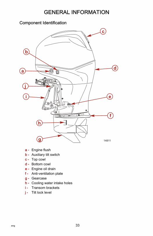
GENERAL INFORMATION
eng 33
Component Identification
a - Engine flushb - Auxiliary tilt switchc - Top cowld - Bottom cowle - Engine oil drainf - Anti‑ventilation plateg - Gearcaseh - Cooling water intake holesi - Transom bracketsj - Tilt lock level
a
b
c
d
e
f
g
h
i
14811
j

GENERAL INFORMATION
34 eng
Propeller SelectionThe propeller on your outboard is one of the most important components in thepropulsion system. An improper propeller choice can significantly affect theperformance of your boat and could result in damage to the outboard engine.When choosing a propeller, a full selection of aluminum and stainless steelpropellers specifically designed for your outboard are available throughMercury Marine. To view the entire product offering and find the correctpropeller that is best suited for your application, visitwww.mercmarinepropellers.com or see your local authorized Mercury dealer.
SELECTING THE CORRECT PROPELLERAn accurate tachometer for measuring engine speed is important in choosingthe correct propeller.Choose a propeller for your boating application that will allow the engine tooperate within the specified full throttle operating range. When operating theboat at full throttle under normal load conditions, the engine RPM should be inthe upper half of the recommended full throttle RPM range. Refer toSpecifications. If engine RPM is above that range, select a propeller ofincreased pitch in order to reduce engine RPM. If engine RPM is below therecommended range, select a propeller of reduced pitch to increase engineRPM.IMPORTANT: To ensure proper fit, and performance, Mercury Marinerecommends the use of Mercury or Quicksilver branded propellers andmounting hardware.Propellers are designated by the diameter, pitch, number of blades, andmaterial. The diameter and pitch are stamped (cast) into the side or the end ofthe propeller hub. The first number represents the diameter of the propeller andthe second number represents the pitch. For example, 14x19 represents apropeller with a 14 inch diameter and 19 inches of pitch.
a - Diameterb - Pitch ‑ Travel during one revolution
a
b22669

GENERAL INFORMATION
eng 35
The following are some propeller basics that will help you determine the correctpropeller for your boating application.Diameter ‑ The diameter is the distance across the imaginary circle that ismade when the propeller rotates. The correct diameter for each propeller hasbeen predetermined for the design of your outboard. However, when more thanone diameter is available for the same pitch, use a larger diameter for heavyboat applications and a smaller diameter for lighter applications.Pitch ‑ The pitch is the theoretical distance, in inches, that a propeller travelsforward during one revolution. Pitch can be thought of similar to gears in a car.The lower the gear, the faster the car will accelerate, but with lower overall topspeed. Likewise, a lower pitch propeller will accelerate quickly, but top‑endspeed will be reduced. The higher the propeller pitch the faster the boat willusually go; though typically slowing acceleration.Determining the correct pitch size ‑ First, check the full throttle RPM undernormal load condition. If the full throttle RPM is within the recommended range,select a replacement or upgrade propeller with the same pitch as the currentpropeller.• Adding 1 inch of pitch will reduce the full throttle RPM by 150 to 200• Subtracting 1 inch of pitch will increase full throttle RPM by 150 to 200• Upgrading from a 3‑blade propeller to a 4‑blade propeller will generally
decrease full throttle RPM by 50 to 100IMPORTANT: Avoid damage to the engine. Never use a propeller that allowsthe engine to exceed the recommended full throttle RPM range when undernormal full throttle operation.
PROPELLER MATERIALMost propellers manufactured by Mercury Marine are made from eitheraluminum or stainless steel. Aluminum is suitable for general purpose use andis standard equipment on many new boats. Stainless steel is over five timesmore durable than aluminum and typically provides performance gains inacceleration and top end speed due to design efficiencies. Stainless steelpropellers also come in a larger variety of sizes and styles that allow you to dialin the ultimate performance for your boat.
3 BLADE VS. 4 BLADEAvailable in many sizes of both aluminum and stainless, 3 and 4‑bladepropellers have unique performance characteristics. In general, 3‑bladepropellers offer good all around performance and higher top speed than4‑blade propellers. However, 4‑blade propellers are usually faster to plane andmore efficient at cruising speeds, but lack the top end speed of a 3‑bladepropeller.
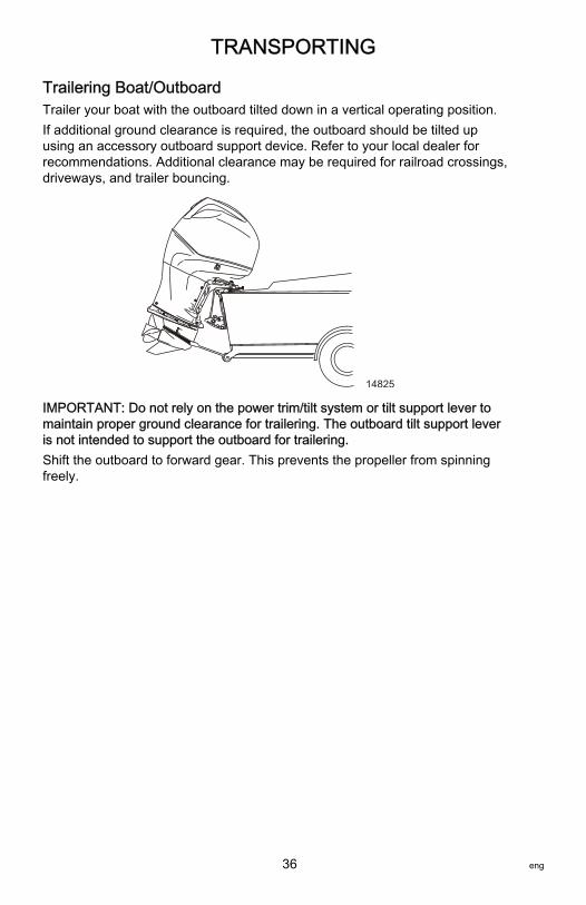
TRANSPORTING
36 eng
Trailering Boat/OutboardTrailer your boat with the outboard tilted down in a vertical operating position.If additional ground clearance is required, the outboard should be tilted upusing an accessory outboard support device. Refer to your local dealer forrecommendations. Additional clearance may be required for railroad crossings,driveways, and trailer bouncing.
14825
IMPORTANT: Do not rely on the power trim/tilt system or tilt support lever tomaintain proper ground clearance for trailering. The outboard tilt support leveris not intended to support the outboard for trailering.Shift the outboard to forward gear. This prevents the propeller from spinningfreely.

FUEL AND OIL
eng 37
Fuel RecommendationsIMPORTANT: Use of improper gasoline can damage your engine. Enginedamage resulting from the use of improper gasoline is considered misuseof the engine, and damage caused thereby will not be covered under thelimited warranty.
FUEL RATINGSMercury Marine engines will operate satisfactorily when using a major brand ofunleaded gasoline meeting the following specifications:USA and Canada ‑ having a posted pump octane rating of 87 (R+M)/2minimum. Premium gasoline (92 [R+M]/2 octane) is also acceptable. Do notuse leaded gasoline.Outside USA and Canada ‑ having a posted pump octane rating of 90 RONminimum. Premium gasoline (98 RON) is also acceptable. If unleaded gasolineis not available, use a major brand of leaded gasoline.
USING REFORMULATED (OXYGENATED) GASOLINES (USA ONLY)This type of gasoline is required in certain areas of the USA. The two types ofoxygenates used in these fuels are alcohol (ethanol) or ether (MTBE or ETBE).If ethanol is the oxygenate that is used in the gasoline in your area, refer toGasolines Containing Alcohol.These reformulated gasolines are acceptable for use in your Mercury Marineengine.
GASOLINES CONTAINING ALCOHOLIf the gasoline in your area contains either methanol (methyl alcohol) or ethanol(ethyl alcohol), you should be aware of certain adverse effects that can occur.These adverse effects are more severe with methanol. Increasing thepercentage of alcohol in the fuel can also worsen these adverse effects.Some of these adverse effects are caused because the alcohol in the gasolinecan absorb moisture from the air, resulting in a separation of the water/alcoholfrom the gasoline in the fuel tank.The fuel system components on your Mercury Marine engine will withstand upto 10% alcohol content in the gasoline. We do not know what percentage yourboat's fuel system will withstand. Contact your boat manufacturer for specificrecommendations on the boat's fuel system components (fuel tanks, fuel lines,and fittings). Be aware that gasolines containing alcohol may cause increased:• Corrosion of metal parts• Deterioration of rubber or plastic parts• Fuel permeation through rubber fuel lines• Starting and operating difficulties

FUEL AND OIL
38 eng
! WARNINGFuel leakage is a fire or explosion hazard, which can cause serious injury ordeath. Periodically inspect all fuel system components for leaks, softening,hardening, swelling, or corrosion, particularly after storage. Any sign ofleakage or deterioration requires replacement before further engineoperation.
Because of possible adverse effects of alcohol in gasoline, it is recommendedthat only alcohol‑free gasoline be used where possible. If only fuel containingalcohol is available, or if the presence of alcohol is unknown, increasedinspection frequency for leaks and abnormalities is required.IMPORTANT: When operating a Mercury Marine engine on gasoline containingalcohol, storage of gasoline in the fuel tank for long periods should be avoided.Long periods of storage, common to boats, create unique problems. In cars,alcohol‑blend fuels normally are consumed before they can absorb enoughmoisture to cause trouble, but boats often sit idle long enough for phaseseparation to take place. In addition, internal corrosion may take place duringstorage if alcohol has washed protective oil films from internal components.
Fuel AdditivesTo minimize carbon deposit buildup in the engine, it is recommended to addMercury or Quicksilver Quickstor fuel stabilizer additive to the engine's fuel ateach tank fill throughout the boating season. Use additive as directed oncontainer.
Low Permeation Fuel Hose RequirementRequired for outboards manufactured for sale, sold, or offered for sale in theUnited States.• The Environmental Protection Agency (EPA) requires that any outboard
manufactured after January 1, 2009, must use low permeation fuel hosefor the primary fuel hose connecting the fuel tank to the outboard.
• Low permeation hose is USCG Type B1‑15 or Type A1‑15, defined as notexceeding 15/gm²/24 h with CE 10 fuel at 23 °C as specified in SAE J1527 ‑ marine fuel hose.
EPA Pressurized Portable Fuel Tank RequirementsThe Environmental Protection Agency (EPA) requires portable fuel systemsthat are produced after January 1, 2011, for use with outboard engines toremain fully sealed (pressurized) up to 34.4 kPa (5.0 psi). These tanks maycontain the following:• An air inlet that opens to allow air to enter as the fuel is drawn out of the
tank.• An air outlet that opens (vents) to the atmosphere if pressure exceeds
34.4 kPa (5.0 psi).

FUEL AND OIL
eng 39
Fuel Demand Valve (FDV) RequirementWhenever a pressurized fuel tank is used, a fuel demand valve is required tobe installed in the fuel hose between the fuel tank and the engine. The fueldemand valve prevents pressurized fuel from entering the engine and causinga fuel system overflow or possible fuel spillage.The fuel demand valve has a manual release. The manual release can be used(pushed in) to open (bypass) the valve in case of a fuel blockage in the valve.
a - Fuel demand valve ‑ installed in thefuel hose between the fuel tank andthe engine
b - Manual releasec - Vent/water drain holes
Mercury Marine's Pressurized Portable Fuel TankMercury Marine has created a new portable pressurized fuel tank that meetsthe preceding EPA requirements. These fuel tanks are available as anaccessory or are provided with certain portable outboard models.
SPECIAL FEATURES OF THE PORTABLE FUEL TANK• The fuel tank has a two‑way valve which allows air to enter the tank as
the fuel is drawn to the engine, and also opens to vent to the atmosphereif internal pressure in the tank exceeds 34.4 kPa (5.0 psi). A hissing noisemay be heard as the tank vents to the atmosphere. This is normal.
• The fuel tank includes a fuel demand valve that prevents pressurized fuelfrom entering the engine and causing a fuel system overflow or possiblefuel spillage.
• When installing the fuel tank cap, turn the cap to the right until you hear aclick. This signals that the fuel cap is fully seated. A built‑in deviceprevents overtightening.
• The fuel tank has a manual vent screw which should be closed fortransportation and open for operation and cap removal.
Since sealed fuel tanks are not vented, they will expand and contract as thefuel expands and contracts during heating and cooling cycles of the outside air.This is normal.
a
c
b
46273
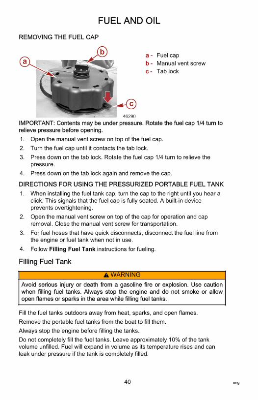
FUEL AND OIL
40 eng
REMOVING THE FUEL CAP
a - Fuel capb - Manual vent screwc - Tab lock
IMPORTANT: Contents may be under pressure. Rotate the fuel cap 1/4 turn torelieve pressure before opening.1. Open the manual vent screw on top of the fuel cap.2. Turn the fuel cap until it contacts the tab lock.3. Press down on the tab lock. Rotate the fuel cap 1/4 turn to relieve the
pressure.4. Press down on the tab lock again and remove the cap.
DIRECTIONS FOR USING THE PRESSURIZED PORTABLE FUEL TANK1. When installing the fuel tank cap, turn the cap to the right until you hear a
click. This signals that the fuel cap is fully seated. A built‑in deviceprevents overtightening.
2. Open the manual vent screw on top of the cap for operation and capremoval. Close the manual vent screw for transportation.
3. For fuel hoses that have quick disconnects, disconnect the fuel line fromthe engine or fuel tank when not in use.
4. Follow Filling Fuel Tank instructions for fueling.
Filling Fuel Tank
! WARNINGAvoid serious injury or death from a gasoline fire or explosion. Use cautionwhen filling fuel tanks. Always stop the engine and do not smoke or allowopen flames or sparks in the area while filling fuel tanks.
Fill the fuel tanks outdoors away from heat, sparks, and open flames.Remove the portable fuel tanks from the boat to fill them.Always stop the engine before filling the tanks.Do not completely fill the fuel tanks. Leave approximately 10% of the tankvolume unfilled. Fuel will expand in volume as its temperature rises and canleak under pressure if the tank is completely filled.
ab
c46290

FUEL AND OIL
eng 41
PORTABLE FUEL TANK PLACEMENT IN THE BOATPlace the fuel tank in the boat so the vent is higher than the fuel level undernormal boat operating conditions.
Engine Oil RecommendationsMercury Verado NMMA FC‑W certified SAE 25W‑40 Synthetic Blend Marine4‑Stroke Engine Oil is recommended for general, all‑temperature use. As anoptional choice, Mercury or Quicksilver NMMA FC‑W certified 25W‑40 MineralMarine 4‑Stroke Engine Oil may be used. If the recommended Mercury orQuicksilver NMMA FC‑W certified oils are not available, a major outboardmanufacturer's brand of NMMA FC‑W certified 4‑Stroke Outboard Oil of similarviscosity may be used.IMPORTANT: The use of nondetergent oils, multi‑viscosity oils (other thanMercury or Quicksilver NMMA FC‑W certified oil or a major brand NMMA FC‑Wcertified oil), synthetic oils, low quality oils, or oils that contain solid additivesare not recommended.
C
+100+80+60+40+20
0
+38+120 +49
+27+16+4-7-18
F
MERCURY VERADO ENGINE OIL
SAE 25W - 40
54654
Checking and Adding Engine OilIMPORTANT: Do not overfill. Tilt outboard out/up past vertical forapproximately one minute to allow trapped oil to drain back to the oil sump. Tiltoutboard to vertical (not tilted) position when checking engine oil. For accuratereadings, check oil only when engine is cold or after engine has not run for atleast an hour.1. Before starting (cold engine) tilt outboard out/up past vertical to allow
trapped oil to drain back to the oil sump. Allow outboard to remain tiltedfor approximately one minute.
2. Tilt outboard to vertical operating position.3. Remove the top cowl. Refer to Maintenance ‑ Top Cowl Removal and
Installation.4. Pull out the dipstick. Wipe the dipstick end with a clean rag or towel and
push it back in all the way.

FUEL AND OIL
42 eng
5. Pull the dipstick back out again and observe the oil level. Oil should be inthe operating range (cross hatched region).
IMPORTANT: Do not try to fill the oil level to the top of the operating range(cross hatched region). Oil level is correct as long as it appears in theoperating range (cross hatched region).
a - Oil level operating range
6. If the oil level is below the operating range (cross hatched region), removethe oil filler cap and add approximately 500 ml (16 oz.) of specifiedoutboard motor oil. Allow a few minutes for the added oil to drain to the oilsump and check the dipstick. Repeat the process until oil level is on theoperating range (cross hatched region). Do not try to fill to the upper endof the operation range (cross hatched region).
14770
IMPORTANT: Inspect oil for signs of contamination. Oil contaminated withwater will have a milky color to it; oil contaminated with fuel will have a strongfuel smell. If contaminated oil is noticed, have the engine checked by yourdealer.7. Push the dipstick back in all the way.
14784
a

FUEL AND OIL
eng 43
8. Install the oil fill cap hand tight.9. Install the top cowl.
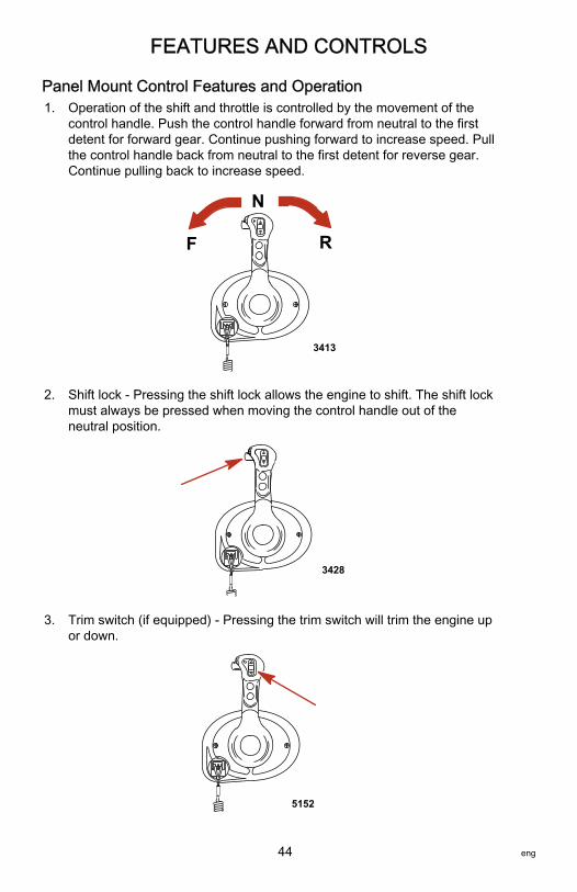
FEATURES AND CONTROLS
44 eng
Panel Mount Control Features and Operation1. Operation of the shift and throttle is controlled by the movement of the
control handle. Push the control handle forward from neutral to the firstdetent for forward gear. Continue pushing forward to increase speed. Pullthe control handle back from neutral to the first detent for reverse gear.Continue pulling back to increase speed.
F
N
R
3413
2. Shift lock ‑ Pressing the shift lock allows the engine to shift. The shift lockmust always be pressed when moving the control handle out of theneutral position.
3428
3. Trim switch (if equipped) ‑ Pressing the trim switch will trim the engine upor down.
5152

FEATURES AND CONTROLS
eng 45
4. Throttle only button ‑ Allows the boat operator to increase engine RPM forwarm‑up, without shifting the engine into gear. To engage throttle only,move the control handle into the neutral position. Press the throttle onlybutton while moving the control handle ahead to the forward detent. Thehorn indicates throttle only is engaged. Advance throttle to increaseengine RPM. To disengage, return the control handle to the neutralposition. Engine RPM is limited to prevent engine damage.
3416
5. Stop/start button ‑ Allows the boat operator to start or stop the enginewithout using the ignition key. The ignition key must be in the "ON"position to start the engine.
3414
6. Lanyard stop switch ‑ Turns the ignition off whenever the operator (whenattached to the lanyard) moves far enough away from the operator'sposition to activate the switch.
a - Lanyard stop switch
a
22964

FEATURES AND CONTROLS
46 eng
7. Control handle tension adjustment screw ‑ This screw can be adjusted toincrease or decrease the tension on the control handle (cover must beremoved). This will help prevent unwanted motion of the handle in roughwater. Turn screw clockwise to increase tension and counterclockwise todecrease tension. Adjust to tension desired.
8. Detent tension adjustment screw ‑ This screw can be adjusted to increaseor decrease the effort to move control handle out of detent positions(cover must be removed). Turning the screw clockwise will increasetension. Adjust to tension desired.
a - Detent tension adjustment screwb - Control handle tension adjustment
screw
5171
+-a
b

FEATURES AND CONTROLS
eng 47
Slim Binnacle Control Features and Operation
DTS SLIM BINNACLE SINGLE HANDLE CONSOLE FEATURES ANDOPERATION1. Operation of shift and throttle is controlled by the movement of the control
handle. Push the control handle forward from neutral to the first detent forforward gear. Continue pushing forward to increase speed. Pull thecontrol handle back from neutral to the first detent for reverse gear.Continue pushing back to increase speed.
F
N
R
12871

FEATURES AND CONTROLS
48 eng
2. Trim Switch (if equipped) ‑ When the power trim switch is activated on theERC handle, the DTS command module senses a closed circuit for eitherup or down trim. The DTS command module formulates a signal andsends it to the PCM. The PCM closes the ground circuit to the up or downtrim relay.
a - Trim switch
3. Control Handle Tension Adjustment Screw ‑ This screw can be adjustedto increase or decrease the tension on the control handle (cover must beremoved). This will help prevent unwanted motion of the remote controlhandle in rough water. Turn screw clockwise to increase tension andcounterclockwise to decrease tension. Adjust to tension desired.
4. Detent Tension Adjustment Screw ‑ This screw can be adjusted toincrease or decrease the effort to move control handle out of detentpositions (cover must be removed). Turning screw clockwise will increasetension. Adjust to tension desired.
a - Detent tension adjustment screwb - Control handle tension adjustment
screw
5. Start/stop Button ‑ Allows the boat operator to start or stop the enginewithout using the ignition key.
12874
a
ab
28556

FEATURES AND CONTROLS
eng 49
6. Neutral LED ‑ The neutral LED is illuminated when engine is in neutralgear position. It also flashes when throttle only is activated.
NOTE: Gear position is determined by sensing the position of the shift actuatoron the engine, not the position of the control handle.7. Active LED ‑ The active LED is illuminated to show the remote control is
active and ready for use.8. Throttle Only/Station Select Button ‑ Press while moving control handle to
increase engine RPM for warm‑up, without shifting the engine into gear.NOTE: When using a foot throttle with either a panel mount or single handleconsole mount control, only the foot throttle controls engine speed. Theremote control is used for shifting operations only. When the throttle onlybutton on the shift control is engaged, the shift operation of the control isdeactivated. To reactivate the shift function, move the control handle back tothe neutral position.
a - Start/stop buttonb - Throttle only/Station select buttonc - Neutral LEDd - Active LED
SLIM BINNACLE DUAL HELM STATION TRANSFERThe throttle only/station select button allows the boat operator to select whichremote control is in control of the engine operation.
STARTSTOP
12875
a
b
c
d

FEATURES AND CONTROLS
50 eng
The active light is illuminated at the remote control station that is in control ofthe engine.
! WARNINGAvoid serious injury or death from loss of boat control. The boat operatorshould never leave the active station while engine is in gear. Helm transfershould only be attempted while both stations are manned. One‑person helmtransfer should only be performed while engine is in neutral.
NOTE: Idle position is preferred when doing a station transfer. If conditions donot allow the remote control to be placed at idle position, a station transfer canbe done while in gear.NOTE: Pressing and releasing station select button at new station allows theengine control to be transferred to the new station. The control willautomatically start adjusting engine RPM and gear position to match the controlhandle setting at the new station. Adjust control handles to the desired throttleand gear position.1. Place active remote control lever to idle position.2. Proceed to the inactive helm station and position remote control lever to
the idle position.3. Press throttle only/station select button once. The "ACTIVE" light will
illuminate to indicate the remote control station is in control of the engine.
a - Active lightb - Throttle only/station select button
STARTSTOP
ab
12877

FEATURES AND CONTROLS
eng 51
4. The active light will switch off at the original remote control station.
Synchronizing Slim Binnacle Dual Helms Prior To Station TransferPressing the station select button and holding it in allows the boat operator tenseconds to match up the control handle settings at the new station with thehandle settings that are at the old (to be inactive) station. If the handles are notmatched, the neutral light will flash. The light blinks faster as the handles arenearing match position. Once light stays on solid, the handles are matched andthe button can be released. Transfer process is complete and the new station isnow in control. If the button is held for over 10 seconds, the station transfer iscancelled.
Features and Operation
DTS SLIM BINNACLE SINGLE HANDLE CONSOLE FEATURES ANDOPERATION1. Operation of shift and throttle is controlled by the movement of the control
handle. Push the control handle forward from neutral to the first detent forforward gear. Continue pushing forward to increase speed. Pull thecontrol handle back from neutral to the first detent for reverse gear.Continue pushing back to increase speed.
2. Trim Switch (if equipped) ‑ When the power trim switch is activated on theERC handle, the DTS command module senses a closed circuit for eitherup or down trim. The DTS command module formulates a signal andsends it to the PCM. The PCM closes the ground circuit to the up or downtrim relay.
a - Forwardb - Neutralc - Reversed - Trim switch
3. Detent tension adjustment screw ‑ This screw can be adjusted to increaseor decrease the effort to move control handle out of detent positions.Turning screw clockwise will increase tension. Adjust to tension desired.
a
b
cd
52360

FEATURES AND CONTROLS
52 eng
4. Control handle tension adjustment screw ‑ This screw can be adjusted toincrease or decrease the tension on the control handle. This will helpprevent unwanted motion of the remote control handle in rough water.Turn screw clockwise to increase tension and counterclockwise todecrease tension. Adjust to tension desired.
a - Caps (2)b - Detent tension
adjustmentc - Control handle
tension adjustment
NOTE: The control handle tension and detent tension screws may requireperiodic maintenance adjustment.
Special Digital Throttle and Shift (DTS) FeaturesThe DTS system features several alternate operational modes for the electronicremote control (ERC) levers.
aSTOP/START
THROTTLE - ONLY
DOCK TRANSFER
N
b
c
def
g
52365
h
Slim binnacle ERC
ab c
52313
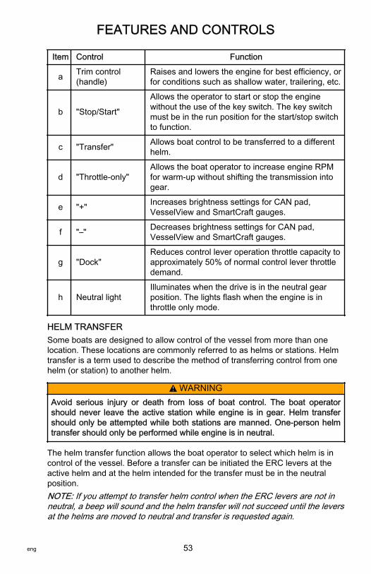
FEATURES AND CONTROLS
eng 53
Item Control Function
a Trim control(handle)
Raises and lowers the engine for best efficiency, orfor conditions such as shallow water, trailering, etc.
b "Stop/Start"
Allows the operator to start or stop the enginewithout the use of the key switch. The key switchmust be in the run position for the start/stop switchto function.
c "Transfer" Allows boat control to be transferred to a differenthelm.
d "Throttle‑only"Allows the boat operator to increase engine RPMfor warm‑up without shifting the transmission intogear.
e "+" Increases brightness settings for CAN pad,VesselView and SmartCraft gauges.
f "–" Decreases brightness settings for CAN pad,VesselView and SmartCraft gauges.
g "Dock"Reduces control lever operation throttle capacity toapproximately 50% of normal control lever throttledemand.
h Neutral lightIlluminates when the drive is in the neutral gearposition. The lights flash when the engine is inthrottle only mode.
HELM TRANSFERSome boats are designed to allow control of the vessel from more than onelocation. These locations are commonly referred to as helms or stations. Helmtransfer is a term used to describe the method of transferring control from onehelm (or station) to another helm.
! WARNINGAvoid serious injury or death from loss of boat control. The boat operatorshould never leave the active station while engine is in gear. Helm transfershould only be attempted while both stations are manned. One‑person helmtransfer should only be performed while engine is in neutral.
The helm transfer function allows the boat operator to select which helm is incontrol of the vessel. Before a transfer can be initiated the ERC levers at theactive helm and at the helm intended for the transfer must be in the neutralposition.NOTE: If you attempt to transfer helm control when the ERC levers are not inneutral, a beep will sound and the helm transfer will not succeed until the leversat the helms are moved to neutral and transfer is requested again.

FEATURES AND CONTROLS
54 eng
Some fault codes may appear on VesselView if other control or navigationfunctions are attempted after the helm transfer procedure is started. To removethe fault codes it may be necessary to cycle the key switch off and on, and thenrestart the helm transfer procedure. Ensure that other control and navigationinputs are performed after helm transfer is complete to avoid setting faultcodes.
NOTICEThe ERC levers must be in neutral to perform a helm transfer. While inneutral your vessel could drift and collide with objects nearby resulting indamage. Keep an adequate look out while performing the helm transfer.
To avoid damage, use extra care when attempting a helm transfer while thevessel is close to docks, piers, or other fixed items or when near other vessels.
REQUESTING HELM TRANSFERNOTE: Any movement of the ERC levers after pressing the transfer buttonterminates the helm transfer request. A single beep sounds and the transferbutton light turns off signaling the end of the transfer request.To request the transfer of vessel control from one helm to another:1. At the helm you are requesting be made active and with the ERC levers in
neutral, press the transfer button one time. After the transfer button ispressed, the transfer button light turns on and one beep will soundconfirming the impending transfer.
THROTTLE - ONLY
DOCK TRANSFER
52367
"Transfer" button
NOTE: If the ERC levers at the helms are not in neutral, the neutral lights willflash. Move all the ERC levers to neutral and the neutral light will stop flashing.2. With the transfer button light and neutral light on, press the transfer button
a second time to complete the helm transfer.3. When the helm transfer is complete, another beep sounds and the
transfer button light turns off.NOTE: If the helm transfer is not completed in 10 seconds, the request isautomatically cancelled, a double beep sounds and control will remain at theexisting active helm. Press the transfer button again to start the helm transfer.

FEATURES AND CONTROLS
eng 55
4. The helm where the transfer request was initiated, is now active andcontrols the vessel.
THROTTLE-ONLYThrottle‑only allows the operator to increase the engine RPM for warm‑upwithout shifting the engine into gear. To engage throttle‑only mode:
THROTTLE - ONLY
DOCK TRANSFER
52373
"Throttle-Only" button
1. Place the ERC lever in neutral.2. Press the "Throttle‑Only" button. The button light will turn on and the
neutral lights will blink.3. Place either ERC lever into gear. The warning horn will beep each time
the lever is moved in and out of gear while in throttle only, but will remainin neutral.
4. The RPM of the engines can be increased.NOTE: Pressing the "Throttle‑Only" button while the ERC lever is not in theneutral position, turns the button light off and remains in throttle‑only mode.You must place the ERC lever into the neutral position to disengagethrottle‑only mode.To disengage throttle‑only mode:1. Place the ERC lever into neutral. Throttle‑only will not disengage unless
the ERC lever is in neutral.2. Press the "Throttle‑Only" button. The button light will turn off.3. The neutral lights stop flashing and remain illuminated.

FEATURES AND CONTROLS
56 eng
DOCKDock mode reduces throttle capacity to approximately 50% of normal throttledemand, allowing finer control of engine power in close quarter situations. Ifmore power is needed for vessel maneuvering when environmental conditionsrequire more thrust, disable dock mode to return the engine control to full thrustcapability.
THROTTLE - ONLY
DOCK TRANSFER
52372
"DOCK" button
Dual Console Control with CAN Trackpad Features andOperation
DUAL-HANDLE ELECTRONIC REMOTE CONTROL (ERC)—OPERATION AND ADJUSTMENT
OperationThe electronic remote control (ERC) handle controls the shift and throttleoperation. Push the control handle forward from neutral to the first detent forforward gear. Continue pushing the handle forward to increase speed. Pull thecontrol handle from the forward position to the neutral position to decreasespeed and eventually stop. Pull the control handle back from neutral to the firstdetent for reverse gear. Continue pulling the handle back to increase speed inreverse.

FEATURES AND CONTROLS
eng 57
NOTE: In certain modes, the gear position is determined by the electronic shiftcontrol (ESC), not the position of the ERC levers. When using the joystick orwhile in Skyhook, the computer controls the shifting in and out of gears eventhough the handles are in neutral.
a - Forwardb - Neutralc - Reverse
The amount of force needed to move the handles and to move the handlesthrough the detents is adjustable to help prevent unwanted motion.
AdjustmentNOTE: The control handle tension and detent tension may require periodicmaintenance using the adjustment screws.To adjust the handle detent tension:1. Remove the side cover plugs of the handle that needs adjustment.2. Turn the adjustment screw clockwise to increase tension on the control
handle and counterclockwise to decrease tension.3. Adjust to the tension desired.To adjust handle tension:1. Remove the side cover plugs of the handle that needs adjustment.2. Turn the adjustment screw clockwise to increase tension on the control
handle and counterclockwise to decrease tension.
a
b
c
51902

FEATURES AND CONTROLS
58 eng
3. Adjust to the tension desired.
a - Detent tensionadjustment screw
b - Handle tensionadjustment screw
SPECIAL DIGITAL THROTTLE AND SHIFT (DTS) FEATURESThe DTS system features several alternate operational modes for the electronicremote control (ERC) levers. Any of the listed features can operatesimultaneously.
a
b
c
de
f
g
hi
j
51853
Dual-engine ERC
a b
51901

FEATURES AND CONTROLS
eng 59
Item Control Function
a Trim control(handle)
Raises and lowers the engines for best efficiency,or for conditions such as shallow water, trailering,etc.
b Trim control(CAN pad) Raises and lowers all the engines.
c "NEUTRAL"lights
Illuminate when the drive is in the neutral gearposition. The lights flash when the engine is inthrottle only mode.
d "TRANSFER" Allows boat control to be transferred to a differenthelm. Refer to Helm Transfer.
e "DOCK"
Available with joystick operation and the controllevers.Joystick operation reduces throttle capacity toapproximately 70% of normal joystick throttledemand.Control lever operation reduces throttle capacity toapproximately 50% of normal control lever throttledemand.
f "+" Increases brightness settings for CAN pad,VesselView and SmartCraft gauges.
g "THROTTLEONLY"
Allows the boat operator to increase engine RPMfor warm‑up without shifting the transmission intogear.
h "–" Decreases brightness settings for CAN pad,VesselView and SmartCraft gauges.
i "1 LEVER" Enables the throttle and shift functions of bothengines to be controlled by the port lever.
j "SYNC" Turns off or on the auto‑synchronization feature.Refer to Synchronizing Engines.
NOTE: Not all functions may be active.

FEATURES AND CONTROLS
60 eng
DockDock mode is available with joystick operation and remote control leveroperation. Dock mode reduces throttle capacity to approximately 70% ofnormal joystick throttle demand, allowing finer control of engine power in closequarter situations. If more power is needed for vessel maneuvering whenenvironmental conditions require more thrust, use the electronic remote controllevers.
51854
"DOCK" button
Throttle OnlyNOTE: The joystick can become active when it is moved any time the enginesare running and the ERC levers are in the neutral position. Throttle only modeshould be used to disable the joystick if the captain is not in command at thehelm. Placing the ERC in throttle only will avoid unintended gear engagement.The engines will turn using the steering wheel or the joystick and the RPM ofthe engines can be increased while in the throttle only mode, but the gearposition will remain in neutral.
51855
"THROTTLE ONLY" button
To engage throttle only mode:1. Place both ERC levers in neutral.2. Press the "THROTTLE ONLY" button. The button light will turn on and the
neutral lights will blink.

FEATURES AND CONTROLS
eng 61
3. Place either ERC lever into gear. The warning horn will beep each timethe levers are moved in and out of gear while in throttle only, but willremain in neutral.
4. The RPM of the engines can be increased.5. Throttle only mode also affects the joystick. The engines will move and
the RPM can be increased, but will remain in neutral.NOTE: Pressing the "THROTTLE ONLY" button while the ERC levers are notin the neutral position, turns the button light off and remains in throttle onlymode. You must place the ERC levers into the neutral position to disengagethrottle only mode.To disengage throttle only mode:1. Place both ERC levers into neutral. Throttle only will not disengage unless
the ERC levers are in neutral.2. Press the "THROTTLE ONLY" button. The button light will turn off.3. The neutral lights stop flashing and remain illuminated. The joystick can
now be used.
1 LeverThe outboard joystick system features the ability to command both engines witha single lever on a dual‑engine application. This feature simplifies enginemanagement during rough sea conditions by allowing you to use a single leverto command both engines simultaneously. It has no affect on the joystickfunction. It is not the same as the system feature called Sync.
51856
"1 LEVER" button
To engage 1 Lever mode:1. Place both ERC levers in neutral.2. Press the "1 LEVER" button. The button light will turn on.3. Place the starboard ERC lever into gear.4. When the handle is moved, the engines RPM and gear position is
synchronized.To disengage 1 lever mode:1. Place both ERC levers in neutral.

FEATURES AND CONTROLS
62 eng
2. Press the "1 LEVER" button. The button light turns off.
SyncSync is an automatic engine synchronization feature that is always on unless itis turned off. Sync monitors the position of both ERC levers. When both leversare within 10% of one another, the port engine synchronizes to the starboardengine's RPM. The SmartCraft system will automatically disengage sync after95% of throttle position range to allow each engine the ability to reachmaximum available RPM. Sync cannot engage until the engines are at aminimum speed.The indicator light on the "SYNC" button is on when both engines are on. Thelight is yellow at idle and 95% of throttle and when the engines are notsynchronized. The light turns red when the engines are synchronized.
51857
"SYNC" button
The RPM display of VesselView also shows an orange icon under the RPMnumbers if the engines RPMs differ more than 10% of each other, and the iconturns red when they are synchronize.To disengage sync mode:1. Place the ERC levers in any detent.2. Press the "SYNC" button. The button light turns off.To engage Sync mode, press the "SYNC" button at any time.

FEATURES AND CONTROLS
eng 63
Transfer (Boats equipped with dual helms)The "TRANSFER" button allows the boat operator to transfer control of the boatfrom the active helm to the inactive helm on boats equipped with dual helms.Refer to Helm Transfer.
51858
"TRANSFER" button
HELM TRANSFERSome boats are designed to allow control of the vessel from more than onelocation. These locations are commonly referred to as helms or stations. Helmtransfer is a term used to describe the method of transferring control from onehelm (or station) to another helm.
! WARNINGAvoid serious injury or death from loss of boat control. The boat operatorshould never leave the active station while engine is in gear. Helm transfershould only be attempted while both stations are manned. One‑person helmtransfer should only be performed while engine is in neutral.
The helm transfer function allows the boat operator to select which helm is incontrol of the vessel. Before a transfer can be initiated the ERC levers at theactive helm and at the helm intended for the transfer must be in the neutralposition.NOTE: If you attempt to transfer helm control when the ERC levers are not inneutral, a beep will sound and the helm transfer will not succeed until the leversat the helms are moved to neutral and transfer is requested again.Some fault codes may appear on VesselView if other control or navigationfunctions are attempted after the helm transfer procedure is started. To removethe fault codes it may be necessary to cycle the key switch off and on, and thenrestart the helm transfer procedure. Ensure that other control and navigationinputs are performed after helm transfer is complete to avoid setting faultcodes.

FEATURES AND CONTROLS
64 eng
NOTICEThe ERC levers must be in neutral to perform a helm transfer. While inneutral your vessel could drift and collide with objects nearby resulting indamage. Keep an adequate look out while performing the helm transfer.
To avoid damage, use extra care when attempting a helm transfer while thevessel is close to docks, piers, or other fixed items or when near other vessels.
REQUESTING HELM TRANSFERNOTE: Any movement of the joystick or ERC levers after pressing the"TRANSFER" button terminates the helm transfer request. A single beepsounds and the transfer button light turns off signaling the end of the transferrequest.To request the transfer of vessel control from one helm to another:1. At the helm you are requesting be made active and with the ERC levers in
neutral, press the "TRANSFER" button one time. After the "TRANSFER"button is pressed, the transfer button light turns on and one beep willsound confirming the impending transfer.
51858
"TRANSFER" button
NOTE: If the ERC levers at the helms are not in neutral, the neutral lights willflash. Move all the ERC levers to neutral and the neutral light will stop flashing.2. With the "TRANSFER" button light and neutral light on, press the
"TRANSFER" button a second time to complete the helm transfer.3. When the helm transfer is complete, another beep sounds and the
transfer button light turns off.NOTE: If the helm transfer is not completed in 10 seconds, the request isautomatically cancelled and a double beep sounds. Control will remain at theexisting active helm. Press the "TRANSFER" button again to restart helmtransfer.4. The helm where the transfer request was initiated is now active and
controls the vessel.

FEATURES AND CONTROLS
eng 65
Shadow Mode Control with CAN Trackpad Features andOperation
TRIPLE ENGINE THROTTLE AND SHIFT OPERATIONMovement of the handles on the remote control allows the boat operator tocontrol the engine throttle speed and gear shift positions of all three engines.The throttle and shift function is dependant on what engines are running. Referto the following table.
Port Engine CenterEngine
StarboardEngine Control Handle Function
Running Running Running
Port engine throttle and shift =controlled by port control handle
Starboard engine throttle and shift= controlled by starboard controlhandle
Center engine throttle = average ofport and starboard engines
Center engine shift = neutralunless both engines are in thesame gear
Running Running OffPort and center engine throttle andshift = controlled by port controlhandle
Off Running RunningStarboard and center enginethrottle and shift = controlled bystarboard control handle
Running Off Running
Port engine throttle and shift =controlled by port control handle
Starboard engine throttle and shift= controlled by starboard controlhandle
Running Off Off Port engine throttle and shift =controlled by port control handle
Off Off RunningStarboard engine throttle and shift= controlled by starboard controlhandle
Off (ignitionkey switchturned on)
RunningOff (ignitionkey switchturned on)
Center engine throttle and shift =neutral/idle unless both controlhandles are in the same gear
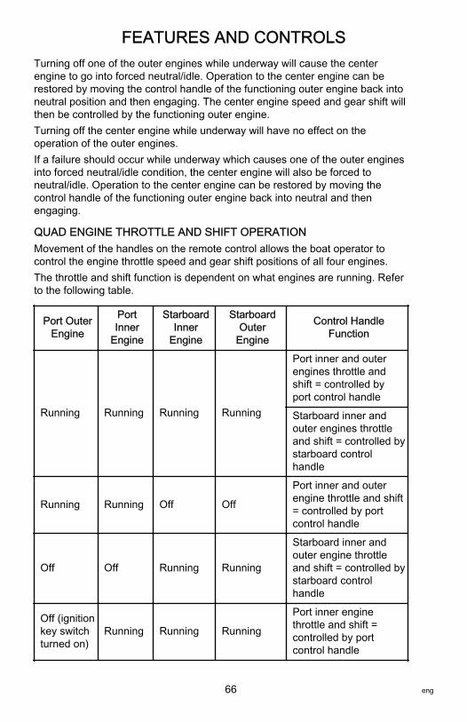
FEATURES AND CONTROLS
66 eng
Turning off one of the outer engines while underway will cause the centerengine to go into forced neutral/idle. Operation to the center engine can berestored by moving the control handle of the functioning outer engine back intoneutral position and then engaging. The center engine speed and gear shift willthen be controlled by the functioning outer engine.Turning off the center engine while underway will have no effect on theoperation of the outer engines.If a failure should occur while underway which causes one of the outer enginesinto forced neutral/idle condition, the center engine will also be forced toneutral/idle. Operation to the center engine can be restored by moving thecontrol handle of the functioning outer engine back into neutral and thenengaging.
QUAD ENGINE THROTTLE AND SHIFT OPERATIONMovement of the handles on the remote control allows the boat operator tocontrol the engine throttle speed and gear shift positions of all four engines.The throttle and shift function is dependent on what engines are running. Referto the following table.
Port OuterEngine
PortInner
Engine
StarboardInner
Engine
StarboardOuter
Engine
Control HandleFunction
Running Running Running Running
Port inner and outerengines throttle andshift = controlled byport control handle
Starboard inner andouter engines throttleand shift = controlled bystarboard controlhandle
Running Running Off Off
Port inner and outerengine throttle and shift= controlled by portcontrol handle
Off Off Running Running
Starboard inner andouter engine throttleand shift = controlled bystarboard controlhandle
Off (ignitionkey switchturned on)
Running Running Running
Port inner enginethrottle and shift =controlled by portcontrol handle

FEATURES AND CONTROLS
eng 67
Port OuterEngine
PortInner
Engine
StarboardInner
Engine
StarboardOuter
Engine
Control HandleFunction
Running Running RunningOff (ignitionkey switchturned on)
Starboard inner enginethrottle and shift =controlled by starboardcontrol handle
Off (ignitionkey switchturned off)
Running Running Running
Port inner enginethrottle and shift =controlled by starboardcontrol handle
Running Running RunningOff (ignitionkey switchturned off)
Starboard inner enginethrottle and shift =controlled by portcontrol handle
Running Off Off Running
Port outer enginethrottle and shift =controlled by portcontrol handle
Starboard outer enginethrottle and shift =controlled by starboardcontrol handle
Off (ignitionkey switchturned on)
Running RunningOff (ignitionkey switchturned on)
Port inner enginethrottle and shift =controlled by portcontrol handle
Starboard inner enginethrottle and shift =controlled by starboardcontrol handle
Turning off the starboard outer engine while underway will cause the starboardinner engine to go into forced neutral/idle. Operation to the inner engine can berestored by turning the starboard outer engine ignition key to the on positionand moving the starboard control handle back into neutral position and thenengaging. The inner engine speed and gear shift will then be controlled by thestarboard control handle.

FEATURES AND CONTROLS
68 eng
Turning off the port outer engine while underway will cause the port innerengine to go into forced neutral/idle. Operation to the inner engine can berestored by turning the port outer engine ignition key to the on position andmoving the port control handle back into neutral position and then engaging.The inner engine speed and gear shift will then be controlled by the port controlhandle.Turning off one of the inner engines while underway will have no effect on theoperation of the outer engines.If a failure should occur while underway which causes the starboard outerengines into forced neutral/idle condition, the inner starboard engine will alsobe forced to neutral/idle. Operation to the inner engine can be restored bymoving the starboard control handle back into neutral and then engaging.If a failure should occur while underway which causes the port outer enginesinto forced neutral/idle condition, the inner port engine will also be forced toneutral/idle. Operation to the inner engine can be restored by moving the portcontrol handle back into neutral and then engaging.
TRIM SWITCH AND KEY PAD FEATURES1. Trim switch (if equipped) ‑ Operates the trim for all engines. An accessory
trim switch panel is required for trimming engines individually.
22943
TRANSFER
DOCK
THROTTLE
ONLY
I LEVER
ALL
SYNC
TROLLNEUTRAL
2. Neutral lights ‑ The neutral lights illuminate when the engine is in neutralgear position. The lights will flash when the engine is in throttle onlymode.
NOTE: Gear position is determined by the position of the shift actuator on theengine, not the position of the control handle.
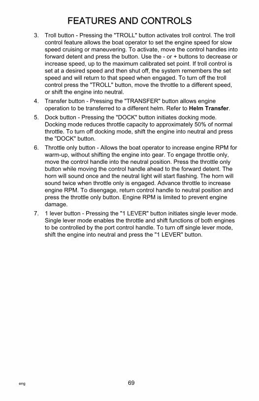
FEATURES AND CONTROLS
eng 69
3. Troll button ‑ Pressing the "TROLL" button activates troll control. The trollcontrol feature allows the boat operator to set the engine speed for slowspeed cruising or maneuvering. To activate, move the control handles intoforward detent and press the button. Use the ‑ or + buttons to decrease orincrease speed, up to the maximum calibrated set point. If troll control isset at a desired speed and then shut off, the system remembers the setspeed and will return to that speed when engaged. To turn off the trollcontrol press the "TROLL" button, move the throttle to a different speed,or shift the engine into neutral.
4. Transfer button ‑ Pressing the "TRANSFER" button allows engineoperation to be transferred to a different helm. Refer to Helm Transfer.
5. Dock button ‑ Pressing the "DOCK" button initiates docking mode.Docking mode reduces throttle capacity to approximately 50% of normalthrottle. To turn off docking mode, shift the engine into neutral and pressthe "DOCK" button.
6. Throttle only button ‑ Allows the boat operator to increase engine RPM forwarm‑up, without shifting the engine into gear. To engage throttle only,move the control handle into the neutral position. Press the throttle onlybutton while moving the control handle ahead to the forward detent. Thehorn will sound once and the neutral light will start flashing. The horn willsound twice when throttle only is engaged. Advance throttle to increaseengine RPM. To disengage, return control handle to neutral position andpress the throttle only button. Engine RPM is limited to prevent enginedamage.
7. 1 lever button ‑ Pressing the "1 LEVER" button initiates single lever mode.Single lever mode enables the throttle and shift functions of both enginesto be controlled by the port control handle. To turn off single lever mode,shift the engine into neutral and press the "1 LEVER" button.

FEATURES AND CONTROLS
70 eng
8. Sync button ‑ Pressing the "SYNC" button turns off or on the autosynchronization feature. Refer to Synchronizing Engines.
a - Neutral LEDSb - Troll buttonc - Transfer buttond - Dock buttone - Throttle onlyf - 1 lever buttong - Sync button
9. Control handle tension adjustment screw ‑ This screw can be adjusted toincrease or decrease the tension on the control handle (cover must beremoved). This will help prevent unwanted motion of the handle in roughwater. Turn the screw clockwise to increase tension and counterclockwiseto decrease tension. Adjust to tension desired.
N E U T R A L
22945
SYNC
1 LEVER
NEUTRAL
TROLL
THROTTLE ONLY
DOCK
TRANSFER
+-
a
b
c
e
g
f d

FEATURES AND CONTROLS
eng 71
10. Detent tension adjustment screw ‑ This screw can be adjusted to increaseor decrease the effort to move control handle out of detent positions(cover must be removed). Turning the screw clockwise will increasetension. Adjust to tension desired.
a - Detent tension adjustment screwb - Control handle tension adjustment
screw
SYNCHRONIZING ENGINESThe auto synchronizing feature, when engaged, will automatically adjust allengine speeds to match the speed of the starboard engine.Press the "SYNC" button on the CAN trackpad to turn auto synchronization onor off. When the sync LED is yellow, the "SYNC" button has been pressed, butthe conditions are not right for auto synchronization to engage. When the syncLED turns red, engine synchronization has been engaged. The engines willremain synchronized as long as engine speed is over 900 RPM for twoseconds, remote control handles are positioned within 10% of each other, andthe engines are below 95% throttle opening.To disengage the auto synchronization feature, press the "SYNC" button.
SYNC
1 LEVER
NEUTRAL
TROLL
THROTTLE ONLY
DOCK
TRANSFER
+-
22590
HELM TRANSFER
! WARNINGAvoid serious injury or death from loss of boat control. The boat operatorshould never leave the active station while engine is in gear. Helm transfershould only be attempted while both stations are manned. One‑person helmtransfer should only be performed while engine is in neutral.
ab
28556

FEATURES AND CONTROLS
72 eng
NOTE: Neutral position is preferred when doing a station transfer. If conditionsdo not allow the remote control to be placed in the neutral position, a helmtransfer can be done while in gear.The helm transfer function allows the boat operator to select which helm is incontrol of engine operation. Pressing the "TRANSFER" button two times allowsengine control to be transferred to a new helm. When a helm transfer isinitiated, the control will automatically start adjusting engine RPM and gearposition to match the control handle setting at the new helm. Adjust the controlhandles to the desired throttle and gear position.Once the "TRANSFER" button is pressed, the transfer LED will light up andone beep will sound. Press the "TRANSFER" button again to complete thehelm transformation. When helm transformation is complete, another beep willsound and the transfer LED will turn off.NOTE: There is a 10 second time frame to complete a helm transfer. If thehelm transfer is not completed, the action will be cancelled and a double beepwill sound. Pressing the "TRANSFER" button again will reinitiate a helmtransfer.
SYNC
1 LEVER
NEUTRAL
TROLL
THROTTLE ONLY
DOCK
TRANSFER
+-
22593
Synchronizing Helms Prior to TransferPressing the "TRANSFER" button allows the boat operator 10 seconds tomatch up the control handle settings at the new helm with the handle settingsthat are at the old (to be inactive) helm. If the handles are not matched, theneutral lights will flash. The light blinks faster as the handles are nearing matchposition. Once the light stays on continuously, the handles are matched and thebutton can be pressed again to complete the transfer. This completes thetransfer process, and gives control to the new station. If the helm transfer is notcompleted within 10 seconds, the action will be cancelled.
Warning System
WARNING HORN SIGNALSWhen the key switch is turned to the "ON" position, the horn will turn on for amoment as a test to indicate the horn is working.There are two types of warning horns to alert the operator of an active problemwithin the engine’s operating system.

FEATURES AND CONTROLS
eng 73
1. Continuous six second beep: Indicates a critical engine condition.Depending on the condition, the Engine Guardian system may engageand protect the engine by limiting power. You should return to portimmediately and contact your servicing dealer.
2. Intermittent short beeps for six seconds: Indicates a noncritical enginecondition. This condition does not require immediate attention. You maycontinue using your boat, however, depending on the nature of theproblem, the engine’s power may be limited by the Engine Guardiansystem (see Engine Guardian System following) to protect the engine.You should contact your servicing dealer at your earliest convenience.
It is important to note that in either of the above scenarios, the horn will onlysound one time. If you key the engine off and restart it, the horn will soundagain, one time, if the fault is still present. For visual display of the specificengine functions and additional engine data, refer to SmartCraft Productinformation, following.A few of the noncritical conditions indicated by the intermittent short beeps forsix seconds can be corrected by the operator. These operator correctableconditions are as follows:• Water in the engine mounted fuel filter. Refer to Maintenance – Water
Separating Fuel Filter.• Cooling system (water pressure or engine temperature) problem. Stop the
engine and check the water intake holes in the lower unit for obstruction.• Low engine oil level. Refer to Fuel and Oil – Checking and Adding
Engine Oil.
ENGINE GUARDIAN SYSTEMThe Engine Guardian system monitors the critical sensors on the engine forany early indications of problems. Engine Guardian is functional whenever yourengine is operating, so you never have to be concerned about whether or notyou are protected. The system will respond to a problem by sounding thewarning horn for six seconds and/or reducing engine power in order to provideengine protection.If Engine Guardian has been activated, reduce the engine speed. The problemwill need to be identified and corrected. The system must be reset before theengine will operate at higher speeds. Moving the throttle lever back to the idleposition will reset the Engine Guardian system. If the Engine Guardian systemhas determined the reset has not corrected the problem, Engine Guardian willremain activated, limiting the throttle. The problem must be identified andcorrected before Engine Guardian will allow the engine to reach a normaloperating RPM.

FEATURES AND CONTROLS
74 eng
OVERSPEED REV LIMITThe overspeed rev limit is set at an RPM greater than the operating range. Inthe event that the engine is operated at an RPM greater than or equal to theoverspeed limit, the PCM does not allow the engine to maintain the powerrequested by the operator. Refer to Specifications to determine this engine’sRPM limit.Upon reaching the beginning of the rev limit, Engine Guardian will cut‑out theignition to specific cylinders. If the operator does not reduce engine speed,Engine Guardian will cut‑out the ignition to all the cylinders. There is no audiblewarning while Engine Guardian overspeed limit is active.To reset the Engine Guardian protection:1. Completely reduce the throttle for three seconds.2. Engage the throttle. If the engine does not respond, repeat step one.
SMARTCRAFT PRODUCTA Mercury SmartCraft System instrument package can be purchased for thisoutboard. A few of the functions the instrument package will display are engineRPM, coolant temperature, oil pressure, water pressure, battery voltage, fuelconsumption, and engine operating hours.The SmartCraft instrument package will also aid in Engine Guardiandiagnostics. The SmartCraft Instrument package will display critical enginealarm data and potential problems.

FEATURES AND CONTROLS
eng 75
Power Trim and TiltThe outboard has a trim/tilt control called power trim. This enables the operatorto easily adjust the position of the outboard by pressing the trim switch. Movingthe outboard in closer to the boat transom is called trimming in or down. Movingthe outboard further away from the boat transom is called trimming out or up.The term trim generally refers to the adjustment of the outboard within the first20° range of travel. This is the range used while operating the boat on plane.The term tilt is generally used when referring to adjusting the outboard furtherup out of the water. With the engine turned off and ignition switch turned on, theoutboard can be tilted out of the water. At low idle speed, the outboard can alsobe tilted up past the trim range to permit, for example, shallow water operation.
a - Trim switchb - Trim rangec - Tilt range
POWER TRIM OPERATIONWith most boats, operating around the middle of the trim range will givesatisfactory results. However, to take full advantage of the trimming capabilitythere may be times when you choose to trim your outboard all the way in orout. Along with an improvement in some performance aspects comes a greaterresponsibility for the operator, and this is being aware of some potential controlhazards.The most significant control hazard is a pull or torque that can be felt on thesteering wheel or tiller handle. This steering torque results from the outboardbeing trimmed so the propeller shaft is not parallel to the water surface.
14834bc
a

FEATURES AND CONTROLS
76 eng
! WARNINGTrimming the outboard beyond a neutral steering condition may result in apull on the steering wheel or tiller handle and loss of boat control. Maintaincontrol of the boat if trimming beyond a neutral steering condition.
Consider the following lists carefully.1. Trimming in or down can:
• Lower the bow.• Result in quicker planing off, especially with a heavy load or a stern
heavy boat.• Generally improve the ride in choppy water.• Increase steering torque or pull to the right (with the normal right‑hand
rotation propeller.)• In excess, can lower the bow of some boats to a point where they
begin to plow with their bow in the water while on plane. This canresult in an unexpected turn in either direction (called bow steering oroversteering) if any turn is attempted, or if a significant wave isencountered.
! WARNINGOperating the boat at high speeds with the outboard trimmed too far undercan create excessive bow steer, resulting in the operator losing control ofthe boat. Install the trim limit pin in a position that prevents excessive trimunder and operate the boat in a safe manner.
• In rare circumstances, the owner may decide to limit the trim in. Thiscan be accomplished by purchasing a stainless steel tilt pin from yourdealer and inserting it in whatever adjustment hole in the transombrackets is desired. The nonstainless steel shipping bolt should not beused in this application other than on a temporary basis.
2. Trimming out or up can:• Lift the bow higher out of the water.• Generally increase top speed.• Increase clearance over submerged objects or a shallow bottom.• Increase steering torque or pull to the left at a normal installation
height (with the normal right‑hand rotation propeller.)• In excess, can cause boat porpoising (bouncing) or propeller
ventilation.• Cause engine overheating if any cooling water intake holes are above
the waterline.

FEATURES AND CONTROLS
eng 77
TRIM WITHOUT KEYTrim without key is a method of allowing trim operation after the ignition keyswitch is turned off. The command module and PCM remain powered and areable to process trim requests for up to 15 minutes after the key switch is turnedoff. The command module does not process any requests other than trimduring this period. Once the 15 minute period expires, the command modulesends a command through the CAN lines to shut down the PCM. Onmulti‑engine applications, the timeout is managed separately for each engine.The trim without key period may be ended at any time by moving the controlhandle to wide‑open throttle reverse (WOTR) with the key off. To end the 15minute period for the center engine in a shadow mode application, ensure allignition key switches are in the "OFF" position and both remote control handlesare in the wide‑open throttle reverse (WOTR) position.
TILTING TO FULL UP POSITION
Tilt at HelmNOTE: The trim/tilt switch will remain active for 15 minutes after the ignition keyswitch has been turned off.1. If the ignition key switch has been turned off for over 15 minutes, turn it to
the "ON" position.2. Press the trim/tilt switch to the up position. The outboard will tilt up until
the switch is released or it reaches its maximum tilt position.
Tilt at EngineThe cowl mounted auxiliary tilt switch can be used to tilt the outboard with thekey switch in the "OFF" position.
Tilt Support Lever1. Engage the tilt support lever, by rotating knob to bring the support lever
upward.2. Lower outboard to rest on the tilt support lever.3. Disengage the tilt support lever, by raising the outboard off the support
lever and rotating the tilt support lever down. Lower the outboard.
a - Tilt support leverb - Knob
b
a
27778
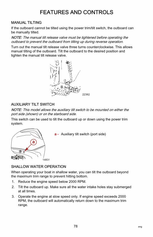
FEATURES AND CONTROLS
78 eng
MANUAL TILTINGIf the outboard cannot be tilted using the power trim/tilt switch, the outboard canbe manually tilted.NOTE: The manual tilt release valve must be tightened before operating theoutboard to prevent the outboard from tilting up during reverse operation.Turn out the manual tilt release valve three turns counterclockwise. This allowsmanual tilting of the outboard. Tilt the outboard to the desired position andtighten the manual tilt release valve.
22362
AUXILIARY TILT SWITCHNOTE: This model allows the auxiliary tilt switch to be mounted on either theport side (shown) or on the starboard side.This switch can be used to tilt the outboard up or down using the power trimsystem.
a - Auxiliary tilt switch (port side)
SHALLOW WATER OPERATIONWhen operating your boat in shallow water, you can tilt the outboard beyondthe maximum trim range to prevent hitting bottom.1. Reduce the engine speed below 2000 RPM.2. Tilt the outboard up. Make sure all the water intake holes stay submerged
at all times.3. Operate the engine at slow speed only. If engine speed exceeds 2000
RPM, the outboard will automatically return down to the maximum trimrange.
14831
a
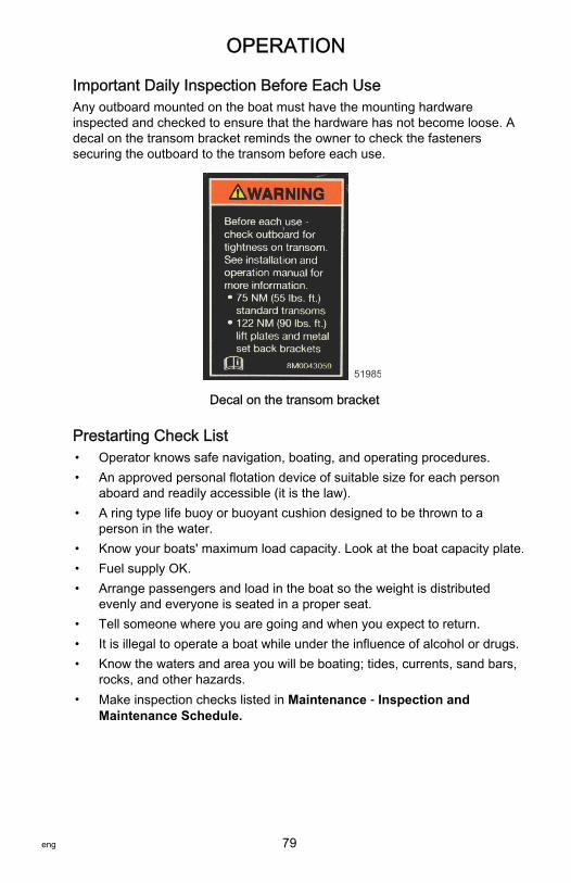
OPERATION
eng 79
Important Daily Inspection Before Each UseAny outboard mounted on the boat must have the mounting hardwareinspected and checked to ensure that the hardware has not become loose. Adecal on the transom bracket reminds the owner to check the fastenerssecuring the outboard to the transom before each use.
51985
Decal on the transom bracket
Prestarting Check List• Operator knows safe navigation, boating, and operating procedures.• An approved personal flotation device of suitable size for each person
aboard and readily accessible (it is the law).• A ring type life buoy or buoyant cushion designed to be thrown to a
person in the water.• Know your boats' maximum load capacity. Look at the boat capacity plate.• Fuel supply OK.• Arrange passengers and load in the boat so the weight is distributed
evenly and everyone is seated in a proper seat.• Tell someone where you are going and when you expect to return.• It is illegal to operate a boat while under the influence of alcohol or drugs.• Know the waters and area you will be boating; tides, currents, sand bars,
rocks, and other hazards.• Make inspection checks listed in Maintenance ‑ Inspection and
Maintenance Schedule.

OPERATION
80 eng
Operating in Freezing TemperaturesWhen using your outboard or having your outboard moored in freezing or nearfreezing temperatures, keep the outboard tilted down at all times so thegearcase is submerged. This prevents the trapped water in the gearcase fromfreezing and causing possible damage to the water pump and othercomponents.If there is a chance of ice forming on the water, the outboard should beremoved and drained completely of water. If ice should form at the water levelinside the outboard driveshaft housing, it will block water flow to the enginecausing possible damage.
Operating in Saltwater or Polluted WaterWe recommend that you flush the internal water passages of your outboardwith fresh water after each use in salt or polluted water. This will prevent abuildup of deposits from clogging the water passages. Refer to Maintenance ‑Flushing the Cooling System.If you keep your boat moored in the water, always tilt the outboard so thegearcase is completely out of water (except in freezing temperatures) when notin use.Wash the outboard exterior and flush out the exhaust outlet of the propeller andgearcase with fresh water after each use. Each month, spray Mercury Precisionor Quicksilver Corrosion Guard on external metal surfaces. Do not spray oncorrosion control anodes as this will reduce the effectiveness of the anodes.
Operating at High ElevationsYour engine automatically compensates for high elevation changes. A differentpitch propeller may help reduce some normal performance loss resulting fromreduced oxygen in the air. Consult your dealer.
Effects of Elevation and Weather on PerformanceThe following conditions lower engine performance and cannot becompensated by the engine fuel or electronic management systems:• Above sea level elevations• High temperature• Low barometric pressure• High humidityThese conditions above reduce air density to the engine, which in turn lowersthe following:• Boost pressure on supercharged engines• Horsepower and torque throughout the RPM range• Peak RPM• Cranking compression

OPERATION
eng 81
EXAMPLE: An engine running at an elevation of 8,000 feet will have over a30% power loss while a loss of engine power on a hot and humid day could beas much as 14%. These losses apply to normally aspirated and superchargedengines.Compensating for power robbing conditions:• Switch to lower pitch propeller.• Change gear ratio.Some boat performance can be improved by dropping to a lower pitchpropeller, but engine performance will still remain lower. In some cases, a gearratio reduction may be more beneficial. To optimize engine performance, propthe engine to allow it to operate at or near the top end of the recommendedmaximum RPM range at wide‑open throttle with a normal boat load.Other advantages to propeller or gear ratio changes:• Reduces the possibility of detonation• Enhances overall reliability and durability of the engine
Setting Trim Angle While Running Engine at Idle SpeedThe exhaust relief hole on the outboard can become submerged on someboats if the engine is trimmed full in while running at idle speed. This may resultin exhaust restriction, rough idle, excessive smoke, and fouled spark plugs. Ifthis condition exists, trim outboard up until exhaust relief hole is out of thewater.
a - Relief hole submerged(wrong)
b - Relief hole above waterline (correct)
Engine Break‑in ProcedureIMPORTANT: Failure to follow the engine break‑in procedures can result inpoor performance throughout the life of the engine and can cause enginedamage. Always follow break‑in procedures.1. For the first two hours of operation, run the engine at varied throttle
settings up to 4500 RPM or at three‑quarter throttle, and at full throttle forapproximately one minute every ten minutes.
2. For the next eight hours of operation, avoid continuous operation at fullthrottle for more than five minutes at a time.
a b
2729

OPERATION
82 eng
Starting the EngineBefore starting, read the Pre‑Starting Check List, special operatinginstructions, Engine Break‑in Procedure, and Gear Shifting in the Operationsection and the remote control features and operation in the Features andControls section.
NOTICEWithout sufficient cooling water, the engine, the water pump, and othercomponents will overheat and suffer damage. Provide a sufficient supply ofwater to the water inlets during operation.
1. Make sure the cooling water intake is submerged.
14836
2. Check the engine oil level.
27780
3. Open fuel tank vent on manual venting type tanks.
19748
NOTE: The engine will not start unless the lanyard is set to the "RUN"position.
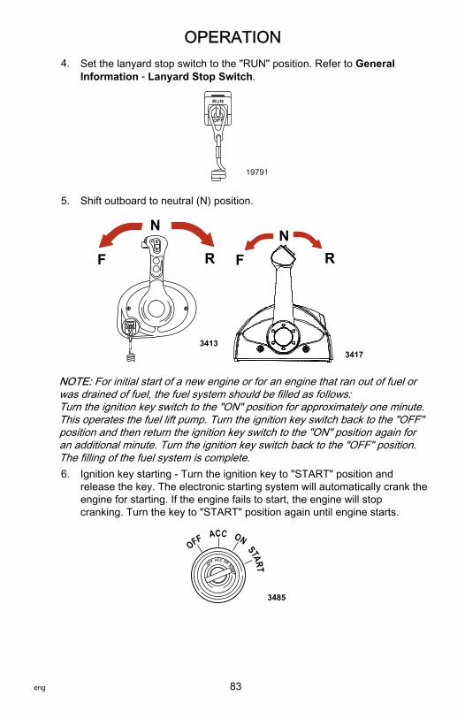
OPERATION
eng 83
4. Set the lanyard stop switch to the "RUN" position. Refer to GeneralInformation ‑ Lanyard Stop Switch.
19791
5. Shift outboard to neutral (N) position.
F
N
R
3413
FN
R
3417
NOTE: For initial start of a new engine or for an engine that ran out of fuel orwas drained of fuel, the fuel system should be filled as follows:Turn the ignition key switch to the "ON" position for approximately one minute.This operates the fuel lift pump. Turn the ignition key switch back to the "OFF"position and then return the ignition key switch to the "ON" position again foran additional minute. Turn the ignition key switch back to the "OFF" position.The filling of the fuel system is complete.6. Ignition key starting ‑ Turn the ignition key to "START" position and
release the key. The electronic starting system will automatically crank theengine for starting. If the engine fails to start, the engine will stopcranking. Turn the key to "START" position again until engine starts.
START
OFF ACC ON
START
OFF ACC ON
3485

OPERATION
84 eng
7. After engine starts, check for a steady stream of water flowing out of thewater pump indicator hole.
15301
IMPORTANT: If no water is coming out of the water pump indicator hole, stopengine and check the cooling water intake for obstruction. No obstruction mayindicate a water pump failure or blockage in the cooling system. Theseconditions will cause the engine to overheat. Have the outboard checked byyour dealer. Operating the engine while overheated will cause engine damage.
Gear Shifting
DTS PANEL MOUNT REMOTE CONTROLIMPORTANT: Never shift outboard into gear unless engine speed is at idle. Donot shift outboard into forward or reverse when the engine is not running.• The outboard has three gear shift positions to provide operation: Forward
(F), Neutral (N), and Reverse (R).
3427
F
NR
• When shifting, always stop at neutral position and allow the engine speedto return to idle.
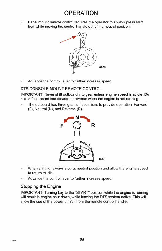
OPERATION
eng 85
• Panel mount remote control requires the operator to always press shiftlock while moving the control handle out of the neutral position.
3428
• Advance the control lever to further increase speed.
DTS CONSOLE MOUNT REMOTE CONTROLIMPORTANT: Never shift outboard into gear unless engine speed is at idle. Donot shift outboard into forward or reverse when the engine is not running.• The outboard has three gear shift positions to provide operation: Forward
(F), Neutral (N), and Reverse (R).
FN
R
3417
• When shifting, always stop at neutral position and allow the engine speedto return to idle.
• Advance the control lever to further increase speed.
Stopping the EngineIMPORTANT: Turning key to the "START" position while the engine is runningwill result in engine shut down, while leaving the DTS system active. This willallow the use of the power trim/tilt from the remote control handle.

OPERATION
86 eng
Reduce engine speed and shift outboard to neutral position. Turn ignition key to"OFF" position.
START
OFF ACC ON
START
OFF ACC ON
3482

MAINTENANCE
eng 87
Outboard CareTo keep your outboard in the best operating condition, it is important that youroutboard receive the periodic inspections and maintenance listed in theInspection and Maintenance Schedule. We urge you to keep it maintainedproperly to ensure the safety of you and your passengers, and retain itsdependability.Record maintenance performed in the Maintenance Log at the back of thisbook. Save all maintenance work orders and receipts.
SELECTING REPLACEMENT PARTS FOR YOUR OUTBOARDWe recommend using original Mercury Precision or Quicksilver replacementparts and Genuine Lubricants.
EPA Emissions RegulationsAll new outboards manufactured by Mercury Marine are certified to the UnitedStates Environmental Protection Agency, as conforming to the requirements ofthe regulations for the control of air pollution from new outboard motors. Thiscertification is contingent on certain adjustments set to factory standards. Forthis reason, the factory procedure for servicing the product must be strictlyfollowed and, wherever practicable, returned to the original intent of the design.Maintenance, replacement, or repair of the emission control devices andsystems may be performed by any marine spark ignition (SI) enginerepair establishment or individual.

MAINTENANCE
88 eng
EMISSION CERTIFICATION LABELAn emission certification label, showing emission levels and enginespecifications directly related to emissions, is placed on the engine at the timeof manufacture.
a - Idle speedb - Engine horsepowerc - Piston displacementd - Engine power ‑ kilowattse - Date of manufacturef - Family numberg - Regulated emission limit for the engine familyh - Regulated emission limit for the engine familyi - Recommended spark plug and gapj - Percent of fuel line permeation
OWNER RESPONSIBILITYThe owner/operator is required to have routine engine maintenance performedto maintain emission levels within prescribed certification standards.The owner/operator is not to modify the engine in any manner that would alterthe horsepower or allow emission levels to exceed their predetermined factoryspecifications.
Inspection and Maintenance ScheduleBEFORE EACH USE• Check engine oil level. Refer to Fuel and Oil ‑ Checking and Adding
Engine Oil.• Check that lanyard stop switch stops the engine.• Inspect the outboard for tightness to the boat transom. If any looseness of
the outboard or mounting fasteners exist, retorque the outboard mountingfasteners to 75 Nm (55 lb‑ft).
• Visually inspect the fuel system for deterioration or leaks.• Check outboard for tightness on transom.
SPARK PLUG:GAP:
EMISSION CONTROLINFORMATION
THIS ENGINE CONFORMS TOEMISSION REGULATIONS FOR SPARK IGNITION MARINE ENGINES
CALIFORNIA AND U.S. EPA
REFER TO OWNERS MANUAL FOR REQUIRED MAINTENANCE,SPECIFICATIONS, AND ADJUSTMENTS
IDLE SPEED (in gear): FAMILY:
HC+NOx:FEL:
LOW PERM/HIGH PERM:
g/kWhhp L
edcba f
g
hi
HC+NOx:FEL: g/kWhhp LCO FEL: g/kWhkw g/kWh
j43210
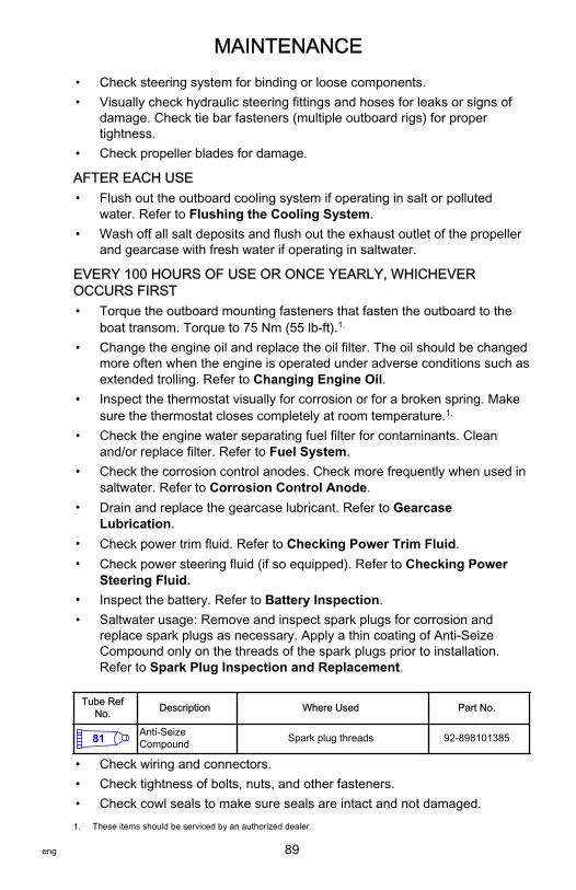
MAINTENANCE
eng 89
• Check steering system for binding or loose components.• Visually check hydraulic steering fittings and hoses for leaks or signs of
damage. Check tie bar fasteners (multiple outboard rigs) for propertightness.
• Check propeller blades for damage.
AFTER EACH USE• Flush out the outboard cooling system if operating in salt or polluted
water. Refer to Flushing the Cooling System.• Wash off all salt deposits and flush out the exhaust outlet of the propeller
and gearcase with fresh water if operating in saltwater.
EVERY 100 HOURS OF USE OR ONCE YEARLY, WHICHEVEROCCURS FIRST• Torque the outboard mounting fasteners that fasten the outboard to the
boat transom. Torque to 75 Nm (55 lb‑ft).1.
• Change the engine oil and replace the oil filter. The oil should be changedmore often when the engine is operated under adverse conditions such asextended trolling. Refer to Changing Engine Oil.
• Inspect the thermostat visually for corrosion or for a broken spring. Makesure the thermostat closes completely at room temperature.1.
• Check the engine water separating fuel filter for contaminants. Cleanand/or replace filter. Refer to Fuel System.
• Check the corrosion control anodes. Check more frequently when used insaltwater. Refer to Corrosion Control Anode.
• Drain and replace the gearcase lubricant. Refer to GearcaseLubrication.
• Check power trim fluid. Refer to Checking Power Trim Fluid.• Check power steering fluid (if so equipped). Refer to Checking Power
Steering Fluid.• Inspect the battery. Refer to Battery Inspection.• Saltwater usage: Remove and inspect spark plugs for corrosion and
replace spark plugs as necessary. Apply a thin coating of Anti‑SeizeCompound only on the threads of the spark plugs prior to installation.Refer to Spark Plug Inspection and Replacement.
Tube RefNo. Description Where Used Part No.
81 Anti-SeizeCompound Spark plug threads 92-898101385
• Check wiring and connectors.• Check tightness of bolts, nuts, and other fasteners.• Check cowl seals to make sure seals are intact and not damaged.1. These items should be serviced by an authorized dealer.

MAINTENANCE
90 eng
• Check internal cowl sound reduction foam (if equipped) to make surefoam is intact and not damaged.
• Check that the intake silencer (if equipped) is in place.• Check that the idle relief muffler (if equipped) is in place.• Check for loose hose clamps and rubber boots (if equipped) on the air
intake assembly.
EVERY 300 HOURS OF USE OR THREE YEARSIMPORTANT: The engine oil must be drained before removing the gearcase toavoid oil spillage. Perform the scheduled water pump replacement incombination with an engine oil change.• Replace water pump impeller (more often if overheating occurs or
reduced water pressure is noted).1.
• Replace high‑pressure in‑line fuel filter.1.
• Replace spark plugs at first 300 hours or three years. After that, inspectspark plugs every 300 hours or three years. Replace spark plugs asneeded. Refer to Spark Plug Inspection and Replacement.
• Replace accessory drive belt. Refer to Accessory Drive Belt Inspection.1.
BEFORE PERIODS OF STORAGE• Refer to storage procedure. Refer to Storage section.
Flushing the Cooling SystemFlush the internal water passages of the outboard with fresh water after eachuse in salt, polluted, or muddy water. This will help prevent a buildup ofdeposits from clogging the internal water passages.NOTE: The outboard can be tilted or in the vertical operating position duringflushing.1. With the engine turned off, place the outboard in either the operating
position (vertical) or in a tilted position.2. Remove the flush connector from the bottom cowl.

MAINTENANCE
eng 91
3. Remove the cover from the flush connector and thread a water hose intothe flush connector.
14810
4. Turn on the water tap (1/2 maximum) and let the water flush through thecooling system for about 15 minutes.
5. When flushing is complete, turn off water and disconnect the water hose.6. Install the cover on the flush connector. Place the flush connector back
into the bottom cowl.
Top Cowl Removal and InstallationREMOVALUnlock the top cowl by pulling out on the rear cowl latch. Lift the top cowl off theengine.
29767

MAINTENANCE
92 eng
INSTALLATIONBring the front of the cowl down first and engage the front cowl hook. Lower thecowl into the seated position and apply downward pressure to the back of thecowl to lock it in place. Ensure the cowl is securely fastened by trying to pull upon the back of the cowl.
29768
Cleaning Care for Top and Bottom CowlsIMPORTANT: Dry wiping (wiping the plastic surface when it is dry) will result inminor surface scratches. Always wet the surface before cleaning. Do not usedetergents containing hydrochloric acid. Follow the cleaning and waxingprocedure.
CLEANING AND WAXING PROCEDURE1. Before washing, rinse the cowls with clean water to remove dirt and dust
that may scratch the surface.2. Wash the cowls with clean water and a mild nonabrasive soap. Use a soft
clean cloth when washing.3. Dry thoroughly with a soft clean cloth.4. Wax the surface using a nonabrasive automotive polish (polish designed
for clear coat finishes). Remove the applied wax by hand using a cleansoft cloth.
5. To remove minor scratches, use Mercury Marine Cowl FinishingCompound (92‑859026K 1).
Cleaning Care for the Powerhead (Saltwater Use)If the outboard is operated in saltwater, remove the top cowl and flywheelcover. Inspect the powerhead and powerhead components for salt buildup.Wash off any salt buildup from the powerhead and powerhead componentswith fresh water. Keep water spray out of the air filter/intake and alternator.After washing, allow the powerhead and components to dry. Apply Quicksilveror Mercury Precision Lubricants Corrosion Guard spray on the external metalsurfaces of the powerhead and powerhead components. Do not allow theCorrosion Guard spray to come in contact with the alternator drive belt or beltpulleys.

MAINTENANCE
eng 93
IMPORTANT: Do not allow lubricant or Corrosion Guard spray to come incontact with the alternator drive belt or the belt pulleys. The alternator drive beltcould slip and be damaged if it becomes coated with any lubricant or CorrosionGuard spray.
Tube RefNo. Description Where Used Part No.
120 Corrosion Guard External metal surfaces of the powerheadand powerhead components. 92-802878 55
Battery InspectionThe battery should be inspected at periodic intervals to ensure proper enginestarting capability.IMPORTANT: Read the safety and maintenance instructions which accompanyyour battery.1. Turn off the engine before servicing the battery.2. Ensure the battery is secure against movement.3. Battery cable terminals should be clean, tight, and correctly installed.
Positive to positive and negative to negative.4. Ensure the battery is equipped with a nonconductive shield to prevent
accidental shorting of battery terminals.
Verado Engine Battery SpecificationsIMPORTANT: Verado engines require a 12‑volt absorbed glass mat (AGM)marine starting battery that meets the minimum ratings.For best performance, Mercury Marine does not recommend using the morecommon flooded (wet cell) or gel cell type lead acid batteries for startingVerado engines.Each Verado engine must be equipped with its own starting battery.If the boat application requires additional battery loads for boat accessories ormarine electronics, install an auxiliary battery, or batteries.Choose a 12‑volt absorbed glass mat (AGM) battery that meets the followingratings.
USA (SAE) Verado Starting Battery Rating
Required Verado startingbattery 12‑volt absorbed glass mat (AGM) battery
Required marine crankingamps (MCA) and reservecapacity
800 minimum marine cranking amps with aminimum reserve capacity of 135 minutes
RC25 rating

MAINTENANCE
94 eng
International (EN) Verado Starting Battery Rating
Required Verado starting battery 12‑volt absorbed glass mat (AGM)battery
Required cold cranking amps(CCA) and amp hours (Ah)
975 minimum cold cranking amps with aminimum of 65 amp hours
NOTE: Do not use an engine starting battery that does not meet the specifiedratings. If a battery that does not meet the ratings is used, the electrical systemmay perform poorly.IMPORTANT: Boating industry standards (BIA, ABYC, etc.), federal standards,and Coast Guard regulations must be adhered to when installing the battery.Ensure that the battery cable installation meets the pull test requirements andthat the positive battery terminal is properly insulated in accordance withregulations.It is recommended (required in some states) that the battery be installed in anenclosed case. Refer to regulations for your area.When connecting the engine battery, hex nuts must be used to secure thebattery leads to the battery posts. Tighten the hex nuts to the specified torque.
! WARNINGFailure to properly secure the battery leads can result in a loss of power tothe Digital Throttle and Shift (DTS) system, leading to serious injury or deathdue to loss of boat control. Secure the battery leads to the battery posts withhex nuts to avoid loose connections.
Description Nm lb‑in. lb‑ft
Hex nuts 13.5 120 –
IMPORTANT: Battery cable size and length is critical. Refer to Battery CableSize tables or engine installation manual for size requirements.

MAINTENANCE
eng 95
A decal advising against using deep cycle batteries and wing nuts should beplaced on or near the battery box for future service reference. One 5/16 in. andone 3/8 in. hex nut is supplied per battery for wing nut replacement. Metric hexnuts are not supplied.
54395
Air FilterThe air filter is located within the flywheel cover assembly. The air filterremoves airborne particles which may damage engine components. The airfilter design allows for maximum unrestricted air flow during engine operation.
AIR FILTER REMOVAL1. Remove the FSM vent hose and the engine ventilation hose from the
flywheel cover.

MAINTENANCE
96 eng
2. Remove the bolts securing the flywheel cover to the rear mounting posts.
a - Flywheel cover bolt and washer (2)b - FSM vent hosec - Crankcase ventilation hose
3. Lift the flywheel cover off the front mounting post and the intakeresonator.
4. Remove three screws holding the upper flywheel cover to the lowerflywheel cover.
14309
5. Separate the two flywheel cover subassemblies to access the air filter.
a
b
c
15247

MAINTENANCE
eng 97
6. Remove the air filter from the lower flywheel cover assembly.
a - Flywheel coversubassembly
b - Air filter
AIR FILTER INSTALLATION1. Install the air filter onto the flywheel cover subassembly.
a - Flywheel coversubassembly
b - Air filter
a b
14145
a b
14145

MAINTENANCE
98 eng
2. Install the upper half of the flywheel cover subassembly to the lowerflywheel cover subassembly. Ensure the upper flywheel cover latchopening is properly secured to the lower flywheel cover.
a - Upper flywheel cover latchopening
b - Lower flywheel cover latch
3. Push the two subassemblies together and install three screws. Tightenthe three screws to the specified torque.
14309
Description Nm lb‑in. lb‑ft
Screw 6 53 –
4. Install the flywheel cover onto the resonator and the front mounting post.5. Align the flywheel cover rear bolt holes with the rear mounting posts.
ab
14314

MAINTENANCE
eng 99
6. Secure the flywheel cover to the rear mounting posts with two bolts withwashers. Tighten bolts to the specified torque.
a - Flywheel cover bolt and washer (2)b - FSM vent hosec - Crankcase ventilation hose
Description Nm lb‑in. lb‑ft
Flywheel cover bolt 10 88.5 –
Fuel System
! WARNINGFuel is flammable and explosive. Ensure that the key switch is off and thelanyard is positioned so that the engine cannot start. Do not smoke or allowsources of spark or open flame in the area while servicing. Keep the workarea well ventilated and avoid prolonged exposure to vapors. Always checkfor leaks before attempting to start the engine, and wipe up any spilled fuelimmediately.
IMPORTANT: Use an approved container to collect and store fuel. Wipe upspilled fuel immediately. Material used to contain spilled fuel must be disposedof in an approved receptacle.Before servicing any part of the fuel system:1. Stop engine and disconnect the battery.2. Perform fuel system service in a well‑ventilated area.3. Inspect any completed service work for sign of fuel leakage.
a
b
c
15247

MAINTENANCE
100 eng
FUEL LINE INSPECTIONVisually inspect the fuel line for cracks, swelling, leaks, hardness, or other signsof deterioration or damage. If any of these conditions are found, the fuel linemust be replaced.
WATER SEPARATING FUEL FILTERNOTE: The warning system will turn on when water in the fuel filter reaches thefull level.This filter removes moisture and debris from the fuel. If the filter holderbecomes filled with water, the water can be removed. If the filter becomesplugged with debris, replace the filter.Refer to the Inspection and Maintenance Schedule for the propermaintenance interval.
Filter Removal1. Turn ignition key switch to "OFF" position.2. Remove fuel vapor purge relief valve cap located at the rear of the
engine.
14765
! CAUTIONFailure to release pressure from the fuel system will result in fuel sprayingout, which can cause a fire or explosion. Allow the engine to coolcompletely and release all fuel pressure before servicing any part of thefuel system. Always protect eyes and skin from pressurized fuel andvapors.

MAINTENANCE
eng 101
3. Place a rag or towel around the valve, release pressure by pushing coreof valve end in.
13282
4. Unscrew the filter in a counterclockwise direction to remove.
14762
Filter Draining1. Slide filter holder up to release from bracket. Hoses and wire harness can
remain attached to filter holder.

MAINTENANCE
102 eng
2. Tip the filter holder to drain any fluid into an approved container.
13468
Filter Installation1. Position filter holder onto bracket and secure filter holder in place.2. Lubricate the sealing ring on the filter with oil.3. Install the filter and tighten securely by hand.IMPORTANT: Visually inspect for fuel leakage from the filter while turning theignition key to the "RUN" position, forcing fuel into the filter.
14764
Corrosion Control AnodeThe outboard has corrosion control anodes at different locations. An anodehelps protect the outboard against galvanic corrosion by sacrificing its metal tobe slowly eroded instead of the outboard metals.

MAINTENANCE
eng 103
Each anode requires periodic inspection, especially in saltwater which willaccelerate the erosion. To maintain this corrosion protection, always replacethe anode before it is completely eroded. Never paint or apply a protectivecoating on the anode as this will reduce effectiveness of the anode.Two anodes are located on each side of the gearcase. Another anode isinstalled on the bottom of the transom bracket assembly.
14812
Propeller Replacement1. Shift outboard to neutral position.2. Straighten the bent tabs on the propeller nut retainer.
26900
3. Place a block of wood between gearcase and propeller to hold propellerand remove propeller nut.
29592

MAINTENANCE
104 eng
4. Pull propeller straight off shaft. If propeller is seized to the shaft andcannot be removed, have the propeller removed by an authorized dealer.
5. To aid in future removal of the propeller, liberally coat the propeller shaftsplines with one of the following Mercury/Quicksilver products:
Tube RefNo. Description Where Used Part No.
Extreme Grease Propeller shaft splines 8M0071842
95 2-4-C with PTFE Propeller shaft splines 92-802859A 1
6. Flo‑Torq II drive hub propellers ‑ Install forward thrust hub, replaceabledrive sleeve, propeller, thrust hub, propeller nut retainer, and propeller nutonto the shaft.
a - Propeller nutb - Propeller nut retainerc - Thrust hubd - Propellere - Replaceable drive
sleevef - Forward thrust hub
7. Flo‑Torq IV drive hub propellers ‑ Install forward thrust hub, replaceabledrive sleeve, propeller, thrust hub, propeller nut retainer, and propeller nutonto the shaft.
a - Propeller nutb - Propeller nut retainerc - Thrust hubd - Propellere - Replaceable drive sleevef - Forward thrust hub
8. Place a block of wood between gearcase and propeller and torque tospecifications.
Description Nm lb‑in. lb‑ft
Propeller nut 75 – 55
a b c
d
e f
26941
a c e
14797
b
d
f

MAINTENANCE
eng 105
9. Secure propeller nut by bending three of the tabs into the thrust hubgrooves.
26945
Spark Plug Inspection and ReplacementNOTE: To gain access to the bottom spark plug, remove the rear cover andrear cowl lock.
COWL LOCK AND REAR COVER REMOVAL1. Remove the pivot screw and flat washer from the rear cowl latch.2. Pull out on the rear corner of the latch to clear the rear cover. Remove the
rear cowl latch.
a - Rear cowl latch
3. Remove the two screws securing the rear cover. Locate the two arrows(pry points) on the rear cover. Use a thin blade screwdriver at these prypoints and pry out the cover. Remove the rear cover.
29740
a

MAINTENANCE
106 eng
4. Remove the six screws securing the cowl lock and remove the lock.Retain the two hex nuts that are used to fasten the top two screws.
a - Rear coverb - Pry point (arrow)c - Cowl lock
SPARK PLUG REMOVAL AND INSPECTION1. Disconnect the wiring harness connectors from the pencil coils.2. Remove the mounting bolts that are securing the pencil coils. Pull the
pencil coils from the spark plugs using a twisting motion.
a - Wiring harness connectorb - Pencil coilc - Bolt
a
b
c
29739
a b
c
3658

MAINTENANCE
eng 107
3. Remove the spark plugs to inspect.
20753
4. Replace the spark plug if the electrode is worn; the insulator is rough,cracked, broken, or blistered; or if the precious metal is not visible on thespark plug electrode.
IMPORTANT: The color of the plug may not accurately reflect its condition. Toaccurately diagnose a faulty plug, inspect the precious metal on the plug'selectrode. If no precious metal is visible, replace the plug.
a - Precious metal
5. Set the spark plug gap. Refer to Specifications.
27848
a
9381

MAINTENANCE
108 eng
a. All of the spark plugs should have the gap checked and corrected asnecessary before installation.
b. Measure the gap with a feeler gauge or pin gauge. Never use awedge‑type gap checking tool to inspect or to adjust the gap.
c. If an adjustment is necessary, do not pry or apply any force on thecenter electrode. This is critical with any type of spark plug that has awear surface, such as platinum or iridium added to either the groundelectrode or the center electrode.
d. When it is necessary to widen the gap, use a tool that only pulls backon the ground electrode without touching the center electrode, theporcelain, or the wear portion of the ground electrode.
e. When it is necessary to close the gap, gently tap the plug groundelectrode on a hard surface.
6. Saltwater use ‑ Apply a thin coating of Anti‑Seize Compound only onthreads of spark plugs.
SPARK PLUG INSTALLATION1. Before installing the spark plugs, clean off any dirt on the spark plug
seats. Install plugs finger‑tight, and then tighten 1/4 turn or tighten to thespecified torque.
Description Nm lb‑in. lb‑ft
Spark plug 27 – 20
2. Push the pencil coils into place over the spark plugs using a twistingmotion.
3. Secure the coils with retained bolts. Tighten to the specified torque.
Description Nm lb‑in. lb‑ft
Bolts 8 71 –
4. Connect the wiring harness connectors to the pencil coil connections.
a - Wiring harness connectorb - Pencil coilc - Bolt
5. Install the cowl lock, rear cowl, and rear cowl latch. Tighten to thespecified torque.
Description Nm lb‑in. lb‑ft
Rear cowl latch ‑ back screws (4) 15 53 –
a b
c
3658

MAINTENANCE
eng 109
Description Nm lb‑in. lb‑ft
Rear cowl latch ‑ top screws withhex nuts (2) 25 89 –
Rear cover ‑ screws (2) 15 53 –
Pivot screw 15 53 –
FusesThe electrical wiring circuits on the outboard are protected from overload byfuses in the wiring. If a fuse is blown, try to locate and correct the cause of theoverload. If the cause is not found, the fuse may blow again.Remove the fuse puller from the engine.

MAINTENANCE
110 eng
Remove the cover from the fuse holder. Remove the suspected blown fuse andlook at the silver band inside the fuse. If the band is broken, replace the fuse.Replace the fuse with a new fuse with the same amp rating.
a - Fuse pullerb - Fuse holderc - Good fused - Blown fusee - Electronic Control Module and purge valve "ECM" ‑ 20 amp fusef - Ignition coils "IGN. COILS" ‑ 20 amp fuseg - Fuel delivery "FUEL" ‑ 20 amp fuseh - Spare fuses (3)i - Diagnostics terminal ‑ 2 amp fusej - Injector power and boost valve "INJ. PWR." ‑ 20 amp fuse
Steering Link Rod FastenersIMPORTANT: The steering link rod that connects the steering cable to theengine must be fastened using special washer head bolt ("a" ‑ Part Number10‑849838) and self‑locking nylon insert locknuts ("c" & "d" ‑ Part Number11‑826709113). These locknuts must never be replaced with common nuts(non‑locking) as they will work loose and vibrate off freeing the link rod todisengage.
20 20 20
20 20 20
20
e g
h
j2
i
fc
d
ab
29731

MAINTENANCE
eng 111
! WARNINGImproper fasteners or improper installation procedures can result inloosening or disengagement of the steering link rod. This can cause asudden, unexpected loss of boat control, resulting in serious injury or deathdue to occupants being thrown within or out of the boat. Always use requiredcomponents and follow instructions and torque procedures.
a - Special washer head bolt (10‑849838)b - Flat washer (2)c - Nylon insert locknut (11‑826709113)d - Nylon insert locknut (11‑826709113)
Description Nm lb. in. lb. ft.
Special washer head bolt 27 20
Nylon insert locknut "d" 27 20
Nylon insert locknut "c" Tighten until seats, then back off 1/4turn
Assemble the steering link rod to steering cable with two flat washers andself‑locking nylon insert locknut. Tighten the locknut until it seats, then back nutoff 1/4 turn.Assemble the steering link rod to the engine with special washer head bolt andself‑locking nylon insert locknut. First torque the bolt, then torque the locknut tospecifications.
a
d
b
c
29746

MAINTENANCE
112 eng
DTS Wiring System
! WARNINGSplicing or probing will damage the wire insulation allowing water to enter thewiring. Water intrusion may lead to wiring failure and loss of throttle and shiftcontrol. To avoid the possibility of serious injury or death from loss of boatcontrol, do not splice or probe into any wire insulation of the DTS system.
• Verify the harnesses are not routed near sharp edges, hot surfaces, ormoving parts.
• Verify all unused connectors and receptacles are covered with a weathercap.
• Verify the harnesses are fastened along the routing path.
Accessory Drive Belt InspectionInspect the accessory drive belt and have it replaced by an authorized dealer ifany of the following conditions are found.• Cracks in the back of the belt or in the base of V grooves.• Excessive wear at the roots of the grooves.• Rubber portion swollen by oil.• Belt surfaces roughened.• Signs of wear on edges or outer surfaces of belt.
Lubrication Points1. Lubricate the following with Extreme Grease.
Tube RefNo. Description Where Used Part No.
Extreme Grease Trim rod ball ends 8M0071842
• Trim Rod Ball Ends ‑ Turn the ball ends to work the lubricant into theball sockets.
28458
2. Lubricate the following with Extreme Grease or 2‑4‑C with PTFE.
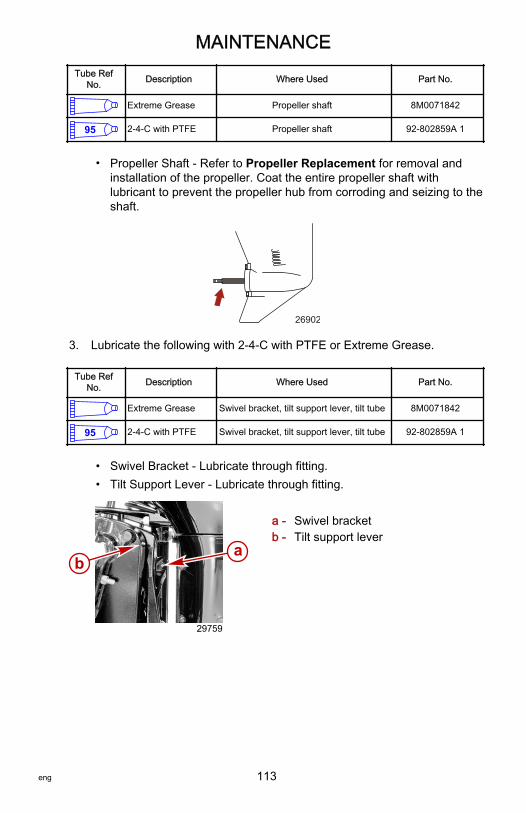
MAINTENANCE
eng 113
Tube RefNo. Description Where Used Part No.
Extreme Grease Propeller shaft 8M0071842
95 2-4-C with PTFE Propeller shaft 92-802859A 1
• Propeller Shaft ‑ Refer to Propeller Replacement for removal andinstallation of the propeller. Coat the entire propeller shaft withlubricant to prevent the propeller hub from corroding and seizing to theshaft.
26902
3. Lubricate the following with 2‑4‑C with PTFE or Extreme Grease.
Tube RefNo. Description Where Used Part No.
Extreme Grease Swivel bracket, tilt support lever, tilt tube 8M0071842
95 2-4-C with PTFE Swivel bracket, tilt support lever, tilt tube 92-802859A 1
• Swivel Bracket ‑ Lubricate through fitting.• Tilt Support Lever ‑ Lubricate through fitting.
a - Swivel bracketb - Tilt support lever
ab
29759

MAINTENANCE
114 eng
• Tilt Tube ‑ Lubricate through fitting.
a - Tilt tube fitting
4. Lubricate the following with Quicksilver or Mercury Precision Lubricants2‑4‑C with PTFE or Extreme Grease.
! WARNINGIncorrect cable lubrication can cause hydraulic lock, leading to seriousinjury or death from loss of boat control. Completely retract the end of thesteering cable before applying lubricant.
• Steering Cable ‑ Rotate the steering wheel to fully retract the steeringcable end into the outboard tilt tube. Lubricate through the fitting.
a - Fittingb - Cable end
5. Lubricate the following with Light Weight Oil.• Steering Link Rod Pivot Points ‑ Lubricate pivot points.
29765
a 29757
ba
29763

MAINTENANCE
eng 115
Checking Power Trim Fluid1. Tilt the outboard to the full up position and engage the tilt support lever.
27877
2. Remove the fill cap and check the fluid level. The fluid level should beeven with the bottom of the fill hole. Add Quicksilver or Mercury PrecisionLubricant Power Trim and Steering Fluid. If not available, use automotiveautomatic transmission fluid (ATF).
28460
Tube RefNo. Description Where Used Part No.
114 Power Trim andSteering Fluid Power trim system 92-858074K01

MAINTENANCE
116 eng
Checking Power Steering FluidRemove power steering cover and fill cap to check fluid level. The fluid levelshould be slightly below the bottom of the fill hole. Use SAE 0W‑30 syntheticpower steering fluid, if needed.
a - Power steering coverb - Fill capc - Fill/full level
Tube RefNo. Description Where Used Part No.
138Synthetic PowerSteering Fluid SAE0W-30
Power steering system 92-858077K01
Changing Engine OilENGINE OIL CAPACITYEngine oil capacity is approximately 6.0 liter (6.3 US qt).
PUMP METHODIMPORTANT: Tilt outboard out/up past vertical for approximately one minute toallow trapped oil to drain back to the oil sump.IMPORTANT: To reduce or prevent oil spillage when removing the oil filter,ensure the outboard is upright (not tilted) and the engine is cold or has not runfor at least one hour.1. Tilt outboard out/up past vertical for approximately one minute to allow
trapped oil to drain back to the oil sump.2. Place the outboard in a vertical position.3. Remove dipstick and slide adapter tube of crankcase oil pump through oil
dipstick hole, to bottom of engine oil sump.
ab
c
29315

MAINTENANCE
eng 117
Crankcase Oil Pump 91‑90265A 5
11591
Aids in the removal of engine oil withoutdraining the crankcase.
4. Pump out the engine oil into an appropriate container.
DRAIN METHOD1. Tilt outboard up to the trailer position.2. Turn the outboard so the drain hole is facing downward.3. Remove the drain plug/seal and drain the engine oil into an appropriate
container.4. Lubricate seal washer on the drain plug with oil and reinstall.
15613
CHANGING OIL FILTERIMPORTANT: To reduce or prevent oil spillage when removing the oil filter,ensure the outboard is upright (not tilted) and the engine is cold or has not runfor at least one hour.1. Remove the top cowl.2. Place a rag or towel below the oil filter to absorb any spilled oil.

MAINTENANCE
118 eng
3. Unscrew old filter using oil filter wrench and turning the filtercounterclockwise.
14772
Oil Filter Wrench 91‑802653Q02
5221
Assists in removal of oil filter.
4. Clean the oil filter mounting base.5. Apply a film of clean oil to filter gasket. Do not use grease.6. Screw new filter on until gasket contacts base, then tighten 3/4 to 1 turn.

MAINTENANCE
eng 119
OIL FILLING1. Remove the oil fill cap and add recommended oil to the midpoint of the
operating range (midpoint of cross hatched region). Adding approximately6 liter (6.3 US qt) will bring oil level to midpoint of cross hatched region.
14770
2. Install oil fill cap.3. With outboard in water or cooling water flush hose connected, idle engine
for five minutes to check for leaks at the oil filter.4. Stop engine and check oil level. Refer to Fuel and Oil ‑ Checking and
Adding Engine Oil.
Gearcase LubricationWhen adding or changing gearcase lubricant, visually check for the presence ofwater in the lubricant. If water is present, it may have settled to the bottom andwill drain out prior to the lubricant, or it may be mixed with the lubricant, giving ita milky colored appearance. If water is noticed, have the gearcase checked byyour dealer. Water in the lubricant may result in premature bearing failure or, infreezing temperatures, will turn to ice and damage the gearcase.Examine the drained gearcase lubricant for metal particles. A small amount ofmetal particles indicates normal gear wear. An excessive amount of metalfilings or larger particles (chips) may indicate abnormal gear wear and shouldbe checked by an authorized dealer.
DRAINING GEARCASE1. Place the outboard in a vertical operating position.2. Remove the propeller. Refer to Propeller Replacement.3. Place the drain pan below the outboard.

MAINTENANCE
120 eng
4. Remove the vent plug and fill/drain plug and drain lubricant.
a - Vent plugb - Fill/drain plug
GEARCASE LUBRICANT CAPACITYGearcase lubricant capacity is approximately 970 ml (32.8 fl oz) for right handrotation gearcases and 900 ml (30.4 fl oz) for left hand rotation gearcases.
GEARCASE LUBRICANT RECOMMENDATIONMercury or Quicksilver High Performance Gear Lubricant.
CHECKING LUBRICANT LEVEL AND REFILLING GEARCASE1. Place the outboard in a vertical operating position.2. Remove the vent plug/sealing washer.3. Remove the fill/drain plug. Place the lubricant tube into the fill hole and
add the lubricant until it appears at the vent hole.
a - Vent holeb - Fill hole
IMPORTANT: Replace the sealing washers if damaged.
a
b
22692
a
b
22693

MAINTENANCE
eng 121
4. Stop adding the lubricant. Install the vent plug and sealing washer beforeremoving the lubricant tube.
5. Remove the lubricant tube and install cleaned fill/drain plug and sealingwasher.

STORAGE
122 eng
Storage PreparationThe major consideration in preparing your outboard for storage is to protect itfrom rust, corrosion, and damage caused by freezing of trapped water.The following storage procedures should be followed to prepare your outboardfor out of season storage or prolonged storage (two months or longer).
NOTICEWithout sufficient cooling water, the engine, the water pump, and othercomponents will overheat and suffer damage. Provide a sufficient supply ofwater to the water inlets during operation.
FUEL SYSTEMIMPORTANT: Gasoline containing alcohol (ethanol or methanol) can cause aformation of acid during storage and can damage the fuel system. If thegasoline being used contains alcohol, it is advisable to drain as much of theremaining gasoline as possible from the fuel tank, remote fuel line, and enginefuel system.IMPORTANT: This outboard is equipped with a closed fuel system when theengine is not running. With this closed system, fuel within the engine's fuelsystem, other than the fuel tank, will remain stable during normal storageperiods without the addition of fuel treatment stabilizers.Fill the fuel tank and engine fuel system with treated (stabilized) fuel to helpprevent formation of varnish and gum. Proceed with the following instructions.• Portable fuel tank ‑ Pour the required amount of Fuel System Treatment
and Stabilizer (follow instructions on container) into fuel tank. Tip fuel tankback and forth to mix stabilizer with the fuel.
• Permanently installed fuel tank ‑ Pour the required amount of Fuel SystemTreatment and Stabilizer (follow instructions on container) into a separatecontainer and mix with approximately one liter (one quart) of gasoline.Pour this mixture into fuel tank.
Tube RefNo. Description Where Used Part No.
124Fuel SystemTreatment andStabilizer
Fuel tank 92-8M0047932
Protecting External Outboard Components• Touch up any paint nicks. See your dealer for touch‑up paint.• Spray Quicksilver or Mercury Precision Lubricants Corrosion Guard on
external metal surfaces (except corrosion control anodes).
Tube RefNo. Description Where Used Part No.
120 Corrosion Guard External metal surfaces 92-802878 55

STORAGE
eng 123
Protecting Internal Engine ComponentsIMPORTANT: Refer to Maintenance ‑ Spark Plug Inspection and Replacementfor correct procedure for removing spark plugs.• Remove pencil coils and spark plugs.• Spray approximately 30 ml (1 fl oz) of Storage Seal Rust Inhibitor into
each spark plug hole.
Tube RefNo. Description Where Used Part No.
119 Storage Seal RustInhibitor Spark plug holes 92-858081K03
• Actuate key/push button start switch to crank the engine through one startcycle, which will distribute the storage seal throughout the cylinders.
• Install spark plugs and pencil coils.
Gearcase• Drain and refill the gearcase lubricant (refer to Gearcase Lubrication).
Positioning Outboard for StorageStore outboard in an upright (vertical) position to allow water to drain out of theoutboard.
NOTICEStoring the outboard in a tilted position can damage the outboard. Watertrapped in the cooling passages or rain water collected in the propellerexhaust outlet in the gearcase can freeze. Store the outboard in the full downposition.
Battery Storage• Follow the battery manufacturer's instructions for storage and charging.• Remove the battery from the boat and check water level. Charge if
necessary.• Store the battery in a cool, dry place.• Periodically check the water level and charge the battery during storage.

TROUBLESHOOTING
124 eng
Starter Motor Will Not Crank the EnginePOSSIBLE CAUSES• Lanyard stop switch not in "RUN" position.• Blown 5 amp fuse. Check DTS power harness circuit fuse. Refer to
Maintenance section.• Outboard is not shifted to neutral position.• Shift actuator failure. "Gear Shift Diff" error message shown on System
View. Refer to Maintenance section.• Weak battery or battery connections are loose or corroded.• Ignition key switch failure.• Wiring or electrical connection faulty.• Starter motor solenoid or slave solenoid failure.
Engine Will Not StartPOSSIBLE CAUSES• Incorrect starting procedure. Refer to Operation section.• Old or contaminated gasoline.• Fuel is not reaching the engine.
• Fuel tank is empty.• Fuel tank vent not open or restricted.• Fuel line is disconnected or kinked.• Fuel filter is obstructed. Refer to Maintenance section.• Fuel pump failure.• Fuel tank filter obstructed.
• Ignition system component failure.• Spark plugs fouled or defective. Refer to Maintenance section.
Engine Starts But Will Not Shift Into Gear• Shift actuator failure. "Gear Shift Diff" error message shown on System
View. Refer to Maintenance section.
Engine Runs ErraticallyPOSSIBLE CAUSES• Overheating ‑ Warning horn not working.• Low oil pressure. Check oil level.• Spark plugs fouled or defective. Refer to Maintenance section.• Incorrect setup and adjustments.• Fuel is being restricted to the engine.

TROUBLESHOOTING
eng 125
a. Engine fuel filter is obstructed. Refer to Maintenance section.b. Fuel tank filter obstructed.c. Stuck anti‑siphon valve located on permanently built‑in type fuel tanks.d. Fuel line is kinked or pinched.
• Fuel pump failure.• Ignition system component failure.
Performance LossPOSSIBLE CAUSES• Overheating ‑ Warning horn not working.• Low oil pressure. Check oil level.• Throttle not opening fully.• Damaged propeller or improper propeller size.• Incorrect engine timing, adjustment, or setup.• Boat overloaded or load improperly distributed.• Excessive water in bilge.• Boat bottom is dirty or damaged.
Battery Will Not Hold ChargePOSSIBLE CAUSES• Battery connections are loose or corroded.• Low electrolyte level in battery.• Worn out or inefficient battery.• Excessive use of electrical accessories.• Defective rectifier, alternator, or voltage regulator.• Open circuit in the alternator output wire (fused link).

OWNER SERVICE ASSISTANCE
126 eng
Local Repair ServiceAlways return your outboard to your local authorized dealer should the need forservice arise. Only he has the factory trained mechanics, knowledge, specialtools, equipment, and genuine parts and accessories to properly service yourengine should the need occur. He knows your engine best.
Service Away from HomeIf you are away from your local dealer and the need arises for service, contactthe nearest authorized dealer. Refer to the Yellow Pages of the telephonedirectory. If, for any reason, you cannot obtain service, contact the nearestMercury Marine Service Office.
Parts and Accessories InquiriesAll inquiries concerning genuine replacement parts and accessories should bedirected to your local authorized dealer. The dealer has the necessaryinformation to order parts and accessories for you. When inquiring about partsand accessories, the dealer requires the model and serial number to order thecorrect parts.
Service AssistanceLOCAL REPAIR SERVICEIf you need service for your Mercury‑outboard‑powered boat, take it to yourauthorized dealer. Only authorized dealers specialize in Mercury products andhave factory‑trained mechanics, special tools and equipment, and genuineQuicksilver parts and accessories to properly service your engine.NOTE: Quicksilver parts and accessories are engineered and built by MercuryMarine specifically for your power package.
SERVICE AWAY FROM HOMEIf you are away from your local dealer and the need arises for service, contactthe nearest authorized dealer. If, for any reason, you cannot obtain service,contact the nearest Regional Service Center. Outside the United States andCanada, contact the nearest Marine Power International Service Center.
STOLEN POWER PACKAGEIf your power package is stolen, immediately advise the local authorities andMercury Marine of the model and serial numbers and to whom the recovery isto be reported. This information is maintained in a database at Mercury Marineto aid authorities and dealers in the recovery of stolen power packages.
ATTENTION REQUIRED AFTER SUBMERSION1. Before recovery, contact an authorized Mercury dealer.2. After recovery, immediate service by an authorized Mercury dealer is
required to reduce the possibility of serious engine damage.

OWNER SERVICE ASSISTANCE
eng 127
REPLACEMENT SERVICE PARTS
! WARNINGAvoid fire or explosion hazard. Electrical, ignition, and fuel systemcomponents on Mercury Marine products comply with federal andinternational standards to minimize risk of fire or explosion. Do not usereplacement electrical or fuel system components that do not comply withthese standards. When servicing the electrical and fuel systems, properlyinstall and tighten all components.
Marine engines are expected to operate at or near full throttle for most of theirlives. They are also expected to operate in both fresh and saltwaterenvironments. These conditions require numerous special parts.
PARTS AND ACCESSORIES INQUIRIESDirect any inquiries concerning Quicksilver replacement parts and accessoriesto your local authorized dealer. The dealer has the necessary information toorder parts and accessories for you if they are not in stock. Only authorizeddealers can purchase genuine Quicksilver parts and accessories from thefactory. Mercury Marine does not sell to unauthorized dealers or retailcustomers. When inquiring about parts and accessories, the dealer requires theengine model and serial numbers to order the correct parts.
RESOLVING A PROBLEMSatisfaction with your Mercury product is important to your dealer and to us. Ifyou ever have a problem, question or concern about your power package,contact your dealer or any authorized Mercury dealership. If you needadditional assistance:1. Talk with the dealership's sales manager or service manager. Contact the
owner of the dealership if the sales manager and service manager havebeen unable to resolve the problem.
2. If your question, concern, or problem cannot be resolved by yourdealership, please contact the Mercury Marine Service Office forassistance. Mercury Marine will work with you and your dealership toresolve all problems.
The following information will be needed by the Customer Service:• Your name and address• Your daytime telephone number• The model and serial numbers of your power package• The name and address of your dealership• The nature of the problem

OWNER SERVICE ASSISTANCE
128 eng
CONTACT INFORMATION FOR MERCURY MARINE CUSTOMERSERVICEFor assistance, call, fax, or write to the geographic office in your area. Pleaseinclude your daytime telephone number with mail and fax correspondence.
United States, Canada
Telephone English +1 920 929 5040Français +1 905 636 4751
Mercury MarineW6250 Pioneer RoadP.O. Box 1939Fond du Lac, WI 54936-1939Fax English +1 920 929 5893
Français +1 905 636 1704
Website www.mercurymarine.com
Australia, Pacific
Telephone +61 3 9791 5822 Brunswick Asia Pacific Group41–71 Bessemer DriveDandenong South, Victoria 3175Australia
Fax +61 3 9706 7228
Europe, Middle East, Africa
Telephone +32 87 32 32 11 Brunswick Marine EuropeParc Industriel de Petit-RechainB-4800 Verviers,Belgium
Fax +32 87 31 19 65
Mexico, Central America, South America, Caribbean
Telephone +1 954 744 3500 Mercury Marine11650 Interchange Circle NorthMiramar, FL 33025U.S.A.
Fax +1 954 744 3535
Japan
Telephone +072 233 8888 Kisaka Co., Ltd.4‑130 Kannabecho, Sakai‑kuSakai‑shi, Osaka 590‑0984, JapanFax +072 233 8833
Asia, Singapore
Telephone +65 65466160 Brunswick Asia Pacific GroupT/A Mercury Marine Singapore Pte Ltd29 Loyang DriveSingapore, 508944
Fax +65 65467789

OWNER SERVICE ASSISTANCE
eng 129
Ordering LiteratureBefore ordering literature, have the following information about your powerpackage available:
Model Serial Number
Horsepower Year
UNITED STATES AND CANADAFor additional literature for your Mercury Marine power package, contact yournearest Mercury Marine dealer or contact:
Mercury Marine
Telephone Fax Mail
(920) 929‑5110(USA only)
(920) 929‑4894(USA only)
Mercury MarineAttn: Publications Department
P.O. Box 1939Fond du Lac, WI 54935-1939
OUTSIDE THE UNITED STATES AND CANADAContact your nearest Mercury Marine authorized service center to orderadditional literature that is available for your particular power package.
Submit the followingorder form with paymentto:
Mercury MarineAttn: Publications DepartmentW6250 Pioneer RoadP.O. Box 1939Fond du Lac, WI 54936-1939
Ship To: (Copy this form and print or type–This is your shipping label)
Name
Address
City, State, Province
ZIP or postal code
Country
Quantity Item Stock Number Price Total
. .
. .
. .
. .

OWNER SERVICE ASSISTANCE
130 eng
Quantity Item Stock Number Price Total
. .
Total Due .

OUTBOARD INSTALLATION
eng 131
Mercury Marine Validated Engine Mounting HardwareIMPORTANT: Mercury Marine provides validated fasteners and installationinstructions, including torque specifications, with all of our outboards so theycan be properly secured to boat transoms. Improper installation of the outboardcan cause performance and reliability issues that can lead to safety concerns.Follow all of the instructions relating to the outboard installation. DO NOTmount any other accessory onto the boat with the fasteners provided with theoutboard. For example, do not mount a tow sport bars or boarding ladders ontothe boat using the mounting hardware included with the outboard. Installingother products onto the boat that utilize the outboard mounting hardware willcompromise the ability of that hardware to properly and safely secure theoutboard to the transom.Outboards that require validated mounting hardware will have the followingdecal on the transom clamp.
51965
Accessories Mounted to the Transom Clamp BracketMercury Marine has been made aware that certain aftermarket marineaccessories, such as emergency boarding ladders, shallow water anchors,transom wedge kits, and tow sport attaching devices, have been mounted tothe boat by use of the same fasteners that secure the outboard to the transomor jack plate. Using the same fastener to secure both an accessory and theengine to the boat compromises the ability of the fasteners to maintain theproper clamp load. A boat with loose engine mounting fasteners creates thepossibility of performance, durability, and safety issues.

OUTBOARD INSTALLATION
132 eng
! WARNINGAvoid serious injury or death resulting from a loss of boat control. Looseengine fasteners could cause the transom bracket to fail, resulting in a loss ofthe driver's ability to control the boat. Always ensure that the enginefasteners are tightened to the specified torque.
ACCEPTABLE ACCESSORY MOUNTING TO THE TRANSOM CLAMPBRACKETAfter the engine is mounted to the transom or jack plate in accordance with theengine installation instructions, it is acceptable to attach an accessory to theboat by use of the unused bolt holes in the transom clamp bracket as shown inFigure 1.The following list provides additional guidelines for mounting accessories to thetransom clamp bracket.• The accessory fasteners must pass through the boat transom or jack
plate.

OUTBOARD INSTALLATION
eng 133
• The installation must not create interference issues, as would anaccessory mounting plate resting in the radius of the transom clampbracket. Refer to Figure 1.
Figure 1a - Minimum clearance 3.175 mm (0.125 in.)b - Edge of accessory bracketc - Transom clamp bracket walld - Radiuse - Engine supplied mounting fastenersf - Fasteners supplied by the accessory manufacturer installed through
unused engine mounting bracket holes
b
c
d
af
54624
e

OUTBOARD INSTALLATION
134 eng
UNACCEPTABLE ACCESSORY MOUNTINGIMPORTANT: Do not use the fasteners that secure the engine to the boat(either the transom or the jack plate) for any purpose other than securing theengine to the boat.1. Do not mount an accessory to the transom clamp bracket in an
unsupported condition. Refer to Figure 2.
54625
Figure 2
2. Do not attach an accessory to the boat by use of the engine mountinghardware. Refer to Figure 3.
Figure 3a - Engine supplied mounting
fastenersb - Transom clamp bracketc - Accessory
53523
a
b c

OUTBOARD INSTALLATION
eng 135
3. Do not install wedges or plates between the transom clamp brackets andthe transom (or jack plate). Refer to Figure 4.
Figure 4a - Boat transom or jack plateb - Transom clamp bracketc - Wedge/plate
Installing Outboard
! WARNINGFailure to correctly fasten the outboard could result in the outboard propellingoff the boat transom resulting in property damage, serious injury, or death.Before operation, the outboard must be correctly installed with the requiredmounting hardware.
Have your dealer install your outboard and related accessories to ensureproper installation and good performance.The outboard must be secured to the transom with the four 12.7 mm (1/2 in.)diameter mounting bolts and locknuts provided. Install two bolts through theupper set of holes and two bolts through the lower set of holes.
27746
54058c
ba

OUTBOARD INSTALLATION
136 eng
Propeller SelectionFor best all around performance from your outboard/boat combination, select apropeller that allows the engine to operate in the upper half of therecommended full throttle RPM range with the boat normally loaded (refer toGeneral Information ‑ Specifications). This RPM range allows for betteracceleration while maintaining maximum boat speed.
22551
If changing conditions cause the RPM to drop below the recommended range,such as warmer, more humid weather, operation at higher elevations,increased boat load, or a dirty boat bottom/gearcase, a propeller change orcleaning may be required to maintain performance and ensure the outboardsdurability.Check full‑throttle RPM, using an accurate tachometer, with the engine trimmedout to a balanced‑steering condition (steering effort equal in both directions)without causing the propeller to break loose.

MAINTENANCE LOG
eng 137
Maintenance LogRecord all maintenance performed on your outboard here. Be sure to save allwork orders and receipts.
Date Maintenance Performed Engine Hours


