Embed Size (px)
Citation preview

instructables
250 to 5000 Watts PWM DC/AC 220V Power Inverter
by Nick_Zouein
This is a heavy duty design of a Pulse WidthModulator DC/AC inverter using the chip SG3524 .I've been using it as a backup to power up all myhouse when outages occur since aprox. 6 years nonstop.
If you like the work and intend to build the circuitdon't forget to click on the "I made it" button so Iknow how many people bene t from the design,Thanks.
No t e s :No t e s :
1> 1> The schematic circuit design is for a 250 wattoutput, while the pics are of my 1500 watts inverterthat i built, to increase the power of the circuit youhave to add more of the Q7 and Q8 transistors inparallel, each pair you add will increase your power by250 watts, ex: to get 750 watts of power from theinverter you need to add in parallel 2 of Q7 and 2 ofQ8 to the original design.
2>2> If you increase the power transistors you have toenlarge the T2 transformer to match the new needs,the circuit's transformer is rated 25 amps to handle250 watts of 220v, for every 1 additional amp youneed on the 220v side you have to increase 10 ampson the 12v side, of course there are limits to thethickness of the winding so if you need more than 750watts i recommend that you use a 24VDC supplyinstead of 12 volts:
DC v o lt a g e a nd Tra ns f o rm e r " T 2" s iz eDC v o lt a g e a nd Tra ns f o rm e r " T 2" s iz ere co m m e nda t io n:re co m m e nda t io n:( Po we r) ( Po we r) (( Suppl y ) Suppl y ) (( Tra n sfo rme r Wi n d i n g)Tra n sfo rme r Wi n d i n g)(750w) (12VDC) (P:24V "12-0-12" / S:220V)(1500w) (24VDC) (P:48V "24-0-24" / S:220V)
(2250w) (36VDC) (P:72V "36-0-36" / S:220V)(3000w) (48VDC) (P:96V "48-0-48" / S:220V)(3750w) (60VDC) (P:120V "60-0-60" / S:220V)(4500w) (72VDC) (P:144V "72-0-72" / S:220V)(5250w) (84VDC) (P:168V "84-0-84" / S:220V)** The transformer should be "center tapped" at theprimary side.* ** * You can make the secondary 110v if needed.* * ** * * The transformer in the pic is a custom made (48Vcenter tapped / 220v ) 2000 watts, weights like 10kilos.
Note15-Feb-16: (48V center tapped means: P:48V "24-0-24" / S:220V)
Note18-Feb-16: Test your transformer before doingthis project. Disconnect the transformer fromanything it is attached to, connect the 220v Secondaryside directly into a 220vAC outlet and test the Primaryside with your voltmeter, you should get exactly thevoltage necessary for this project as per the tableabove. If not then don't waste your time building theproject, it will not work.
****Do not supply the driver circuit with more than24VDC max. because the voltage regulator "7812" willburn. Look at the pic of how to connect the batteriesand where to take a 24vDC wire from.
3> 3> R1 is to set the PWM duty cycle to 220v. Connect avoltmeter to the AC output of your inverter and varyVR1 till the voltage reads 220V.
4 >4 > R2 is to set the frequency to 50 or 60 Hz (R2 rangeis between 40Hz to 75Hz), so guys that do not have afrequency meter are advised to blindly put thisvariable resistor mid-way which should drop you in
250 to 5000 Watts PWM DC/AC 220V Power Inverter: Page 1

the range of 50~60 Hz.If you want you can substitute the variable resistorwith a xed resistor using the following formula: F =1.3 / (RxC)in our case to get a 50Hz output we remove both the100K and the variable 100K both from pin 6 and weput instead a 260K xed resistor and we leave the0.1uF (the 104 cap) as it is, this change should give outa xed 50Hz as per the formula :1. 3 / (26 0 , 0 0 0 o hm x 0 . 0 0 0 0 0 0 1 f a ra d) =1. 3 / (26 0 , 0 0 0 o hm x 0 . 0 0 0 0 0 0 1 f a ra d) =50 Hz50 HzBut in reality it will not exactly give 50Hz because the260K resistor has a speci c error value margin so doesthe capacitor, that's why i recommend a variableresistor so that accurate calibration can be achieved.
5>5> Use either tantalum or polyester lm "as in pic" forthe 104 caps, ceramic disc caps are heat sensitive, theychange value when hot and this in turn changes thefrequency of the inverter so they are notrecommended.
6 > 6 > Pin 10 of the SG3524 can be used to auto shutdown the inverter, once a positive voltage is giveninstead of negative to pin10, the SG3524 will stoposcillating. This is useful for persons wanting to addsome cosmetic makeup to their inverter like "overloadcut-o ", "low battery cut-o " or "overheating cut-o ".
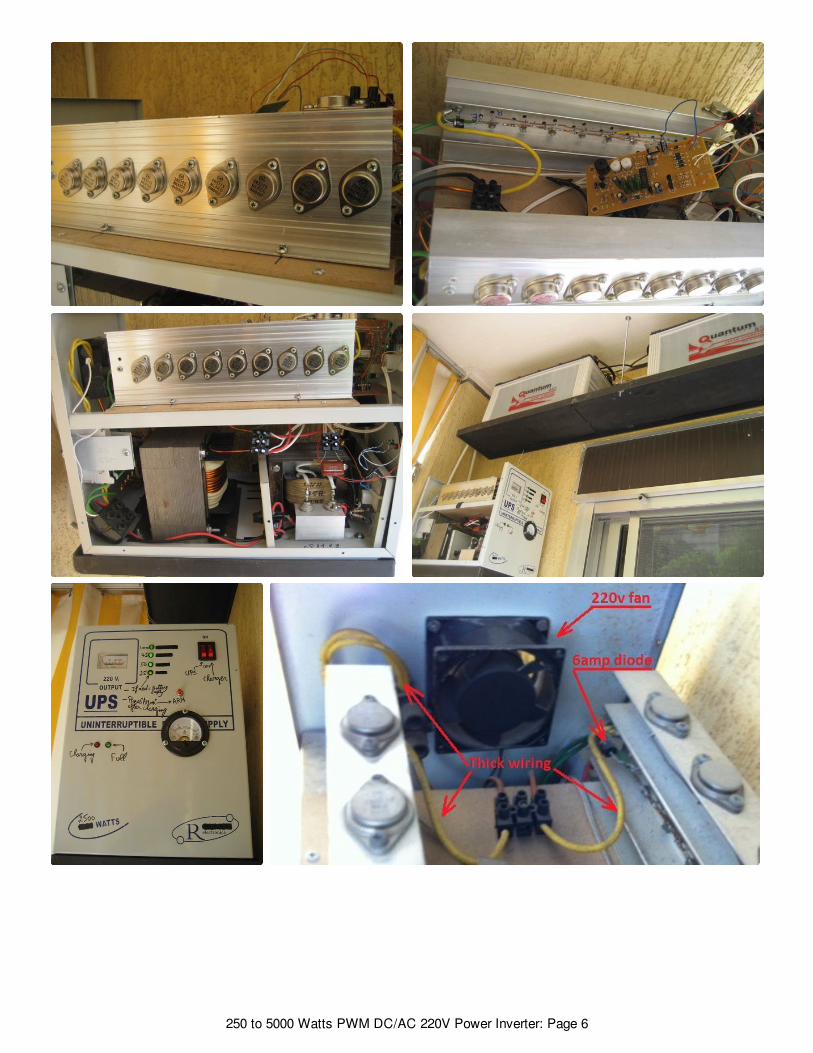
7>7> Wiring connections on the power stage sideshould be thick enough to handle the huge ampsdrain from the batteries. I marked them with thickblack lines on the schema also I included a pic so yousee how thick those wires must be. (You can make thedriving circuit section on a breadboard for testingpurposes but NO TNO T the power stage).
8 > 8 > The design does not include a battery chargersince each person will be building a custom version ofthe inverter with speci c power needs. If you areordering a custom made transformer you can askthem to take out for you an additional output wire onthe primary side to give 14v (between point 0 and thisnew wire) and use it to charge a 12v battery, of coursethis needs a separate circuit to control charging autocut-o . But anyway this is not advisable because it willshorten the life of the transformer itself since using itas a charger will toast the enamel coating layer of thecopper wires over time. Anyway .. YES can be done to
reduce cost.
9 >9 > A cooling fan will be needed to reduce heat o theheat sinks and transformer, i recommend getting a220v fan and connecting it to the output T2transformer, when you power up the circuit the fanwill start this will always give you a simple way toknow that 220v is present and everything is OK.. Youcan use a computer's old power supply fan if you like.Note that the fan must suck air out from the invertercase and NOT blow inside, so install it the correct wayor it will be useless.Also note how I xed both the heat sinks and wherethe fan is, in a way that the fan sucks hot air from likea channel between the 2 heat-sinks.
10 >10 > 2 circuit breakers are recommended instead offuses, one on the DC side and one on the AC side,depending on your designEx: for a 24vDC ( 1500 watts design ) put a 60Ampbreaker on the DC side and a 6Amp on the AC side.For every 1amp of 220vAC you will be draining like 8to 10 Amps from the 12v battery, make yourcalculations !
11>11> The 2 Heat sinks should be big enough to coolthe transistors, they are separate and should NO TNO Ttouch each other. "see the pics"
12>12> IIm po rt a nt : m po rt a nt : If you're building a big design thatuses more than 24VDC as power source, make surenot to supply the driver circuit with more than 24vmaximum. (EX: If you have 4 batteries 4x12 = 48v ,connect the v+ supply of the driver circuit to thesecond battery's (+) terminal with a thin 1 mm wirewhich is more than enough. (This supplies the drivercircuit with +24v while supplies the powertransformer with +48v) "see the batteries pic example"
13>13> "Optional" : Deep Cycle batteries are your bestchoice, consider them for best results .. read more
14 >14 > Be cautious when building this circuit it involveshigh voltage which is le t ha lle t ha l , any part you touchwhen the circuit is ON could give you a nasty painfuljolt, specially the heat-sinks, never touch them whenthe circuit is on to see if the transistors are hot !! I ate itseveral times :)
250 to 5000 Watts PWM DC/AC 220V Power Inverter: Page 2

15>15> The optional "Low voltage warning" is alreadyembedded in the PCB layout, you can disregard it andnot install it's components if you do not need it. Itdoes not a ect the functionality of the main circuit, itjust sounds a buzzer.
16 > 16 > The Motorola 2N6277 is a durable heavy dutypower transistor, it is used in many US tanks for it'sreliability but unfortunately it is a very hard to ndpart, instead you can substitute each 2N6277 with 2 x2N3773 or any equivalent, and yes equivalents worktoo.
17>17> I've included an optional "Battery level indicator"circuit diagram that has 4 LEDs, you can see itinstalled on the front panel of my inverter pic, it isfunctioning great and shows precisely how muchjuice the batteries still have. I have included a smallrelay that is powered by the last LED to auto shutothe inverter once last LED is o .
Update 18-Feb-16: There are cheap readily available,professional looking Voltage, Current, FrequencyMeter these days for a couple of $, consider them inyour project. LED meter
18 >18 > Also included an optional "Overload circuit", it isvery easy to build and can be calibrated to the desiredoverload current threshold cuto point through thepotentiometer VR1.R1 is rated 5watts for inverters upto 1000 watts. Forbigger versions of the inverter like 1000 to 3000 wattsinverters, replace R1 (1 ohm, 5watts) with (1 ohm,17watts) which should handle loads upto 10 VA.Make sure you install a proper relay to handle bigcurrent drains.
19 > Ple a s e g uy s t a ke y o ur t im e t o re a d a nd19 > Ple a s e g uy s t a ke y o ur t im e t o re a d a ndunde rs t a nd m y no t e s , bro w s e a nd re a d t heunde rs t a nd m y no t e s , bro w s e a nd re a d t hepo s t s a nd que s t io ns a s ke d by o t he rspo s t s a nd que s t io ns a s ke d by o t he rsbe ca us e t he re a re m a ny us e f ul inf o rm a t io nbe ca us e t he re a re m a ny us e f ul inf o rm a t io nlis t e d in re plie s . T he m a in re a s o n f o r m e no tlis t e d in re plie s . T he m a in re a s o n f o r m e no ta ns w e ring y o ur que s t io n is be ca us e it ha sa ns w e ring y o ur que s t io n is be ca us e it ha sa lre a dy be e n a s ke d be f o re a nd a ns w e re da lre a dy be e n a s ke d be f o re a nd a ns w e re dupo n.upo n.
20 > It w o uld be nice a nd ins piring f o r o t he rs20 > It w o uld be nice a nd ins piring f o r o t he rsif y o u t a ke s o m e pho t o s a nd s ho w us ho wif y o u t a ke s o m e pho t o s a nd s ho w us ho w
you built your version, any additions to the circuit aremostly welcomed to be listed here, we can all bene tfrom them.
21> Please click on the "I've made it" button/icon ifyou did build the circuit so I know how many peoplebene t from this design.
22> Testing the circuit on a bre a dbo a rdbre a dbo a rd w it hw it hcro co dile clips o r t hin w ire s cro co dile clips o r t hin w ire s W ILL NO T W O RKW ILL NO T W O RK! Yo u' ll g e t w ro ng v o lt a g e re a ding s . Do n' t! Yo u' ll g e t w ro ng v o lt a g e re a ding s . Do n' tco m e ba ck cry ing t ha t y o u' re g e t t ing aco m e ba ck cry ing t ha t y o u' re g e t t ing a150 v a c o ut put o r s o.150 v a c o ut put o r s o.
23> 23> (20-Apr-2020) Why do we have a feedbackvoltage to T1 and R1? explained:
Let's presume we built a 12vdc/220vac inverter, weconnect it to a 12vdc battery source and everything isworking great.. we got ourselves a nice 220vac output.But what happens if the inverter is still running "ON"and we connect a charger to the batteries?? in otherwords we need the inverter to be always ON nomatter the main electricity of the company is presentor not, like we have some equipment that needsconstant steady uninterruptible 220vac supply.
In this case: The 12vdc inverter gives out 220vac butwhen you turn on the charger the 12vdc will rise to13.5vdc which re ects on the 220vac making itdangerously 248vac on the running equipment, herecomes the function of the feedback section, itregulates the duty cycle that is generated inside theIC to maintain a steady regulated 220vac.
250 to 5000 Watts PWM DC/AC 220V Power Inverter: Page 3

250 to 5000 Watts PWM DC/AC 220V Power Inverter: Page 4

250 to 5000 Watts PWM DC/AC 220V Power Inverter: Page 5
250 to 5000 Watts PWM DC/AC 220V Power Inverter: Page 6

The circuit is working very well,..
Hi Nick, I made it...
Do you have PCB design?
250 to 5000 Watts PWM DC/AC 220V Power Inverter: Page 7

Hi Nick.Seeing that i'm not the sharpest pencil in the box...just one stupid question. The auxiliarytransformer in your circuit, is that to control the output voltage.? Let's say i have 48volt setup but iconnect the system to 60 volt will that control the output voltage to a standard 220volt or will I frymy trannies or something.? I want to use a 120v dc supply but i need to keep the primary veryclose to between 90 and 100volts.Awaiting your response.
Hi PhilipB109,No. If you have a 48v setup you can't connect to 60v. you'll burn the main transformer and probablyall the power section.The main purpose of the "auxiliary" transformer is to maintain a stable 110v or 220v output when acharger is charging the batteries.ex: A 12v gives out 220v but when you turn on the charger the 12v will rise to 13.5v which reflectson the 220v making it dangerously 248v, here comes the function of the auxiliary.
Hello Nick,is PWM inverter same with pure sine wave inverter? and, can the power transistor be replaced withIGBT ? thanks
Hola amigo si se puede reemplazar los mosfet por igtv pero sería mucha fuerza con un par demosfet estaría con 100w pero con IGTB sería el triple saludos
Hello Mr Nick, what are the voltages of the electrolytic capacitors in these schematics?
50v
Hello Broo pcb PDF sendmee
can i buy some your inverter mr nick
Hi zaalahareeth,Sorry i don't sell ... everything is listed for free.
Hi nick i made it your inverter design thanks its working my inverter now
Hey sir,am politely asking for a PDF,my email is [email protected],thank you
Anyone know how to make this circuit output a sine wave instead of square wave? Becausesquare wave isn't good for sensitive electronic households like: electric fan, TVs, etc. I readsomewhere that you could use 4017 IC to output a modified sine wave. Please reply thanks
Hi Nick, it's me again. I finally built my first inverter based on your schematic (the one withMOSFET) but I replaced the IRFP250 and use IRFZ44N instead. I also removed the feedbacktransformer and connect the bridge rectifier (I used KBP307, with 3A ratings and 600V max.voltage) directly from the main transformer.
The problem now is the inverter didn't work. I measured the voltages across the MOSFET withoutthe transformer connected to it. The probes connected at the 'Drain' pin of the MOSFET and theothers at the CT input of the transformer (or the Vcc which is 12 V in). The results are both of themhad a different voltage, one MOSFET shows 10.1 V and the other one shows 5.78 V.
When I connected the transfomer to the terminal block (which contains two MOSFETs and 12VVcc) to the the transformer primary windings (12-0-12). I measured the voltage drops at the main
250 to 5000 Watts PWM DC/AC 220V Power Inverter: Page 8

input terminal and it shows about 8V-to-11,1V while the battery is measured at 12,67 V.
And also the MOSFETs seem only work alone (The ones getting very hot and sometimes the twogetting hot together) these conditions can be swapped, I mean it can be the upper MOSFETconnected to the pin-14 or the MOSFET at the pin-11 of the SG3524 that getting hot while theother stays cold.
Here's my schematic diagram compared to yours.
there is reason he is using feedback transformer. if you don't like the additional transformer, youcan use separate power supply 12V. the ones you are using with (resistor 220K) giving you aboutonly 3V output (simulated with everycircuit) just look at the output bridge, he is using 10uF that'swhy peak voltage dropped and down to 3V with 12V 30mW load. that's why you never reach anypoint to turn this IC on.you can't "hacking" circuit with only voltage divider resistor. try with author intention first design if itworks, then you can try to build "custom" as you like.
Problem solved. I accidently shorted the power stage and it causes the FET to generates high heatdue to the high current drain. Thanks for your answer anyway.
Dear Nick,Would please be so kind to email me all the schematic diagrams for this project as I'm not able toview it on instructables please sir, my email address is [email protected]. We have a lot of poweroutages here, please help.
Hi sirI made it and works vry wellBut i have a quastion Is true 300v for regulation
Hi Ali akl,Nice to hear that you made the inverter.
Thanks a lot
It's working fine good job author
Hi I may like to learn from you please
250 to 5000 Watts PWM DC/AC 220V Power Inverter: Page 9
Pls did you make any changes? Is the output voltage regulating?
hi sir , i have a question regarding about the transformer, i want to rewind a transormer 12- 0- 12 to230vac 5000 w or 10000watts, instead of rewinding 84 -0 -84 v to 230 vac 5000w to 10000w . myquestion is what is the difference between low voltage in the primary at higher wattage output ? isthere any effect to my power output transistor? i decide to rewind a 12v in the primary sectionbecause if you rewind a higher voltage in the primary section, more batteries are needed and itsexpensive, please give me an idea. thank you very much sir.
Hi ArnelD6,From your question it's very obvious that you don't know what you're doing :)1- A single 12v battery can not give 5000w by itself.2- There is no enamel copper wire gauge that I know of to wind it as 12v/5000 w.Stick to the original design and only to the original design and charts !
I made 1000watts inverter circuit with a feedback modulation 12v DC to 220v ac.Without load 220v I plugged fan of 35watts the voltage of the battery is dropping out faster andmosfet getting hot. I seriously need help. Thanks
Hi PhilipO36,Please show us your setup, specialy your battery size, wiring between battery and transformer.
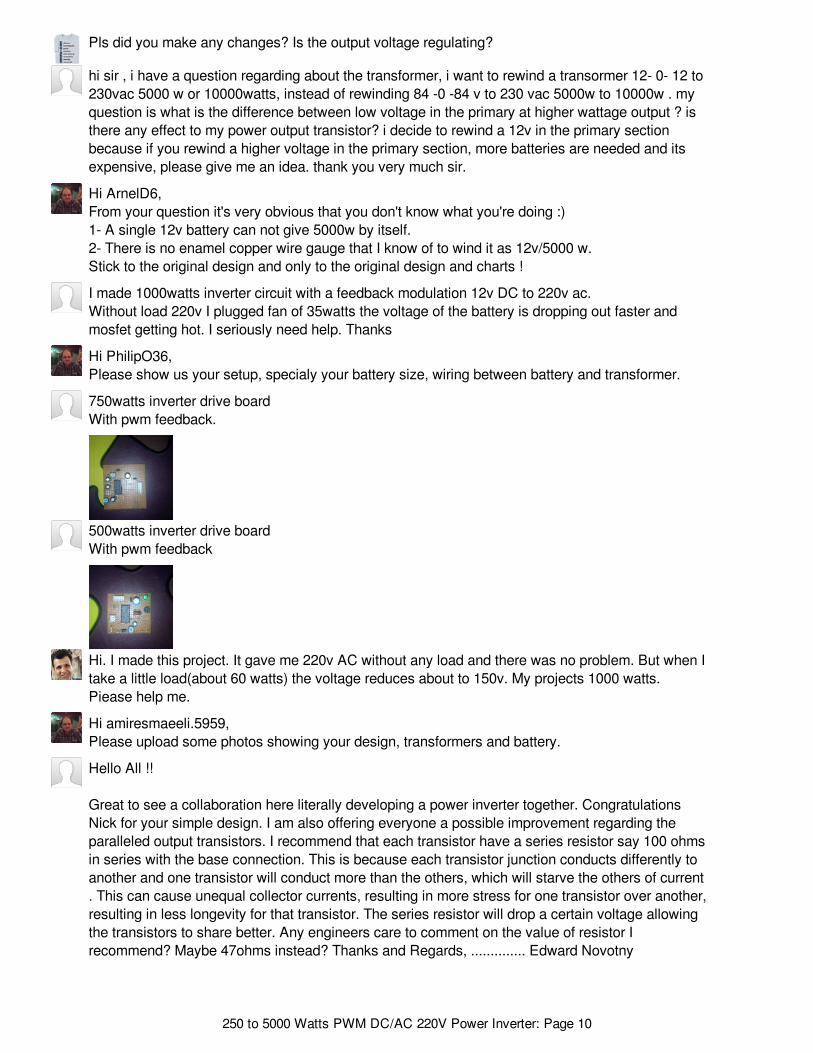
750watts inverter drive boardWith pwm feedback.
500watts inverter drive boardWith pwm feedback
Hi. I made this project. It gave me 220v AC without any load and there was no problem. But when Itake a little load(about 60 watts) the voltage reduces about to 150v. My projects 1000 watts.Piease help me.
Hi amiresmaeeli.5959,Please upload some photos showing your design, transformers and battery.
Hello All !!
Great to see a collaboration here literally developing a power inverter together. CongratulationsNick for your simple design. I am also offering everyone a possible improvement regarding theparalleled output transistors. I recommend that each transistor have a series resistor say 100 ohmsin series with the base connection. This is because each transistor junction conducts differently toanother and one transistor will conduct more than the others, which will starve the others of current. This can cause unequal collector currents, resulting in more stress for one transistor over another,resulting in less longevity for that transistor. The series resistor will drop a certain voltage allowingthe transistors to share better. Any engineers care to comment on the value of resistor Irecommend? Maybe 47ohms instead? Thanks and Regards, .............. Edward Novotny
250 to 5000 Watts PWM DC/AC 220V Power Inverter: Page 10

Hi eeezygoing,Thanks Edward for you collaboration, any advise to enhance the design is highly appreciated, Iencourage anybody who have ideas to come forward.
Best Regards,Nicolas Zouein
Hi Nick. After some research, I have found that it is better to put the low value resistor in serieswith the emitters rather than the base because importantly, .......... it protects for thermal runaway atthe same time as balancing the current in the output transistors. As the thermal runaway currentgoes up, due to constantly increasing transistor temperature, the resistors in the emitters willdecrease the 0.6 volt junction drive voltage, which then decreases the collector- emitter current tosafe levels. Resistors need only be 0.1 ohm, wire wound 5 Watt.
Thanks alot for your useful project!
Hi Sir. Is the transformer that used in your cercuit, is a special type for inverter? Or any transformerwith 220v secondary and 12v primary can be used? What type transformer I must prepare for thiscercuit??Thanks alot
Hi amiresmaeeli.5959,"any" transformer no does not work. I listed the specs of the transformer in details and evenincluded pictures and weights. read the notes properly, regards.
please I don`t understand what is meant by (E I type) choke
sir thanks for your good did. Please can give separate transformer for the charging system?
may i ask sir., is it okay to use higher amps battery for 1500w or depends., is the higher ampsbattery is the better sir? what is your recommendations and sir what is T2 transformer amps for1500w.? Thanks sir.,
Yes no problem with higher amps, actually the higher the better.Higher amps affects the length of time that the inverter runs, it does not affect the 1500w T2.
Hi,and Do not be tired.Please I need 5kva complete circuit schematic diagrams, my email is [email protected]
High, I can Help you, for more info , [email protected] want pure sine wave? or SQ wave?
Hi everyone, i made it. some parts on the board are not at the actual parts list, and also some partsare salvage from old ups, like output tranny, and the feedback tranny. on R1 i use 2ktrim instead of2.2ktrim because my feedback tranny only got 10vac on it that is why. i use bc557 instead of bc327also i use 7812 regulator with 470-ohms going to sg3524 and bc337. driver output is 2.2v,schematics 2.5v. im very happy with the result, thanks to sir NICK. soon i will upgrade this 3kvawhen custom made tranny arrive. also the frequency is @ midway stock because my minioscilloscope order still on its way. thanks
250 to 5000 Watts PWM DC/AC 220V Power Inverter: Page 11

Hi TCWS, nice to know that you have successfully constructed this project. I intend to do the sameand during doing so, I want to benefit from your experience, I hope to get favorable response fromyou. My first question is, whether to use Junction Bipolar Power Transistors or MOSFET's in thisproject and what are the pros and cons of using each, thank you.
Hello Liaquat_Ali im very sorry for the late reply, so bz at work. to be honest for now i dunno thepros and cons of each mosfet because im only using mosfets. no idea for the JBPT. as of now imrunning x12 mosfets P75NF75 6 mosfets each side with 2000VA/1200W transformer 15-0-15running 24v with that SG3524/feedback driver, it handle my 1HP waterpump, drill, mini drill, lightsand some minor stuff on my garagge. im very sorry i no have answer on your question cuz im stillon the process of using JBPT. cheers mate..
Hi TCWS, hope you are doing well. Great to hear from you, nevermind I shall do some research toknow preferably which transistors to use. Anyway, when I start to build this project and face somedifficulty of any kind, would you please help me out? By the way, another question. Whether thisproject outputs square waves, sine waves or pure sine waves since I am intending to make puresine wave inverter so that I could use it on delicate electronics equipment as well. See ya mate !
how many input voltage will you use for 5000w driver
250 to 5000 Watts PWM DC/AC 220V Power Inverter: Page 12


