Embed Size (px)
Citation preview
Instruction handbook
Read the Instruction handbook before starting any work!
Language EnglishTranslation
Document No. 5.09021.19Part No. 439683Status 07-Jul-2021
b maXX 5000
E 5.09021.19
BM5000, BM5100 Mains rectifier/Active mains rectifier
BM5300Axis units safety
Copyright This Instruction handbook may be copied by the owner in any quantity, but only for internaluse. This Instruction handbook may not be copied or reproduced, in whole or in part, for anyother purposes.The use and disclosure of information contained in this Instruction handbook are not permit-ted.Designations and company marks contained in this Instruction handbook could be trade-marks, the use of which by third parties for their own purposes could violate the rights of therights holder.
Preliminary informationWarning Insofar as this document is identified as being preliminary information, the followingapplies:this version is regarded as providing advance technical information to users of the describeddevices and their functions at an early enough time in order to adapt to any possible changesor expanded functionality. This information must be regarded as being preliminary, as it has not yet passed throughBaumüller's internal review process. In particular, this information is still subject to changes,thus no legal liability can be derived from this preliminary information. Baumüller assumes noliability for damages that might arise from this possibly faulty or incomplete version. If you detect or suspect any content errors and/or major form errors in this preliminary infor-mation, we request that you notify the Baumüller support specialist responsible for you.Please provide us, via this employee, with your insights and comments so that we can takethem into account and include them when transitioning from the preliminary information tothe final information (as reviewed by Baumüller). The conditions stipulated in the following section under „Obligatory“ are invalid in case of pre-liminary information.
Obligatory This Instruction handbook are a part of the equipment/machine. This Instruction handbookmust be available to the operator at all times and must be in legible condition. If the equip-ment/machine is sold or moved another location, these Instruction handbook must be passedon by the owner together with the equipment/machine.After any sale of the equipment/machine, this original and all copies must be handed over tothe buyer. After disposal or any other end use, this original and all copies must be destroyed.
When the present Instruction handbook are handed over, corresponding sets of instructionhandbooks of a previous version are automatically invalidated. Please note that the specifications/data/information are current values according to theprinting date. These statements are not legally binding with regard to measurements,computation or calculations.Baumüller Nürnberg GmbH reserves the right, in developing its products further, to changethe technical specifications and handling of it products concerned without prior notice.
No liability can be accepted concerning the correctness of these Instruction handbook unlessotherwise specified in the General Conditions of Sale and Delivery.
Baumüller Nürnberg GmbH
Ostendstr. 80 - 9090482 NurembergGermany
Tel. +49 9 11 54 32 - 0 Fax: +49 9 11 54 32 - 1 30
Email : [email protected]: www.baumueller.com
Table of Contents
1 General . . . . . . . . . . . . . . . . . . . . . . . . . . . . . . . . . . . . . . . . . . . . . . . . . . . . . . . . . . . . . . . . . . 91.1 Information on the instruction handbook . . . . . . . . . . . . . . . . . . . . . . . . . . . . . . . . . . . . 91.2 Key to symbols . . . . . . . . . . . . . . . . . . . . . . . . . . . . . . . . . . . . . . . . . . . . . . . . . . . . . . . 91.3 Limitation of liability . . . . . . . . . . . . . . . . . . . . . . . . . . . . . . . . . . . . . . . . . . . . . . . . . . . 101.4 Copyright protection. . . . . . . . . . . . . . . . . . . . . . . . . . . . . . . . . . . . . . . . . . . . . . . . . . . 111.5 Other applicable documents . . . . . . . . . . . . . . . . . . . . . . . . . . . . . . . . . . . . . . . . . . . . 111.6 Spare parts . . . . . . . . . . . . . . . . . . . . . . . . . . . . . . . . . . . . . . . . . . . . . . . . . . . . . . . . . 121.7 Disposal . . . . . . . . . . . . . . . . . . . . . . . . . . . . . . . . . . . . . . . . . . . . . . . . . . . . . . . . . . . . 121.8 Guarantee provisions. . . . . . . . . . . . . . . . . . . . . . . . . . . . . . . . . . . . . . . . . . . . . . . . . . 121.9 Customer service. . . . . . . . . . . . . . . . . . . . . . . . . . . . . . . . . . . . . . . . . . . . . . . . . . . . . 121.10 Terms used . . . . . . . . . . . . . . . . . . . . . . . . . . . . . . . . . . . . . . . . . . . . . . . . . . . . . . . . . 121.11 List of other applicable documents . . . . . . . . . . . . . . . . . . . . . . . . . . . . . . . . . . . . . . . 13
2 Safety . . . . . . . . . . . . . . . . . . . . . . . . . . . . . . . . . . . . . . . . . . . . . . . . . . . . . . . . . . . . . . . . . . 152.1 Contents of the Instruction handbook . . . . . . . . . . . . . . . . . . . . . . . . . . . . . . . . . . . . . 152.2 Changes and modifications to the device . . . . . . . . . . . . . . . . . . . . . . . . . . . . . . . . . . 152.3 Usage for the intended purpose . . . . . . . . . . . . . . . . . . . . . . . . . . . . . . . . . . . . . . . . . 152.4 Risk assessment according EU Directive . . . . . . . . . . . . . . . . . . . . . . . . . . . . . . . . . . 172.5 Responsibility of the operating company . . . . . . . . . . . . . . . . . . . . . . . . . . . . . . . . . . . 192.6 Protective devices . . . . . . . . . . . . . . . . . . . . . . . . . . . . . . . . . . . . . . . . . . . . . . . . . . . . 192.7 Training of the personnel . . . . . . . . . . . . . . . . . . . . . . . . . . . . . . . . . . . . . . . . . . . . . . . 202.8 Personal protective equipment . . . . . . . . . . . . . . . . . . . . . . . . . . . . . . . . . . . . . . . . . . 212.9 Special hazards . . . . . . . . . . . . . . . . . . . . . . . . . . . . . . . . . . . . . . . . . . . . . . . . . . . . . . 222.10 Fire fighting . . . . . . . . . . . . . . . . . . . . . . . . . . . . . . . . . . . . . . . . . . . . . . . . . . . . . . . . . 232.11 Safety equipment. . . . . . . . . . . . . . . . . . . . . . . . . . . . . . . . . . . . . . . . . . . . . . . . . . . . . 242.12 Conduct in case of danger or accidents . . . . . . . . . . . . . . . . . . . . . . . . . . . . . . . . . . . 242.13 Signs and labels . . . . . . . . . . . . . . . . . . . . . . . . . . . . . . . . . . . . . . . . . . . . . . . . . . . . . 25
3 Technical data . . . . . . . . . . . . . . . . . . . . . . . . . . . . . . . . . . . . . . . . . . . . . . . . . . . . . . . . . . . 293.1 Dimensions . . . . . . . . . . . . . . . . . . . . . . . . . . . . . . . . . . . . . . . . . . . . . . . . . . . . . . . . . 293.1.1 BM503X dimensions . . . . . . . . . . . . . . . . . . . . . . . . . . . . . . . . . . . . . . . . . . . . . . . . . 293.1.2 BM504X dimensions . . . . . . . . . . . . . . . . . . . . . . . . . . . . . . . . . . . . . . . . . . . . . . . . . 313.1.3 BM507X dimensions . . . . . . . . . . . . . . . . . . . . . . . . . . . . . . . . . . . . . . . . . . . . . . . . . 333.1.4 BM517X dimensions . . . . . . . . . . . . . . . . . . . . . . . . . . . . . . . . . . . . . . . . . . . . . . . . . 353.1.5 BM519X dimensions . . . . . . . . . . . . . . . . . . . . . . . . . . . . . . . . . . . . . . . . . . . . . . . . . 363.1.6 BM53XX dimensions . . . . . . . . . . . . . . . . . . . . . . . . . . . . . . . . . . . . . . . . . . . . . . . . . 383.2 Weight . . . . . . . . . . . . . . . . . . . . . . . . . . . . . . . . . . . . . . . . . . . . . . . . . . . . . . . . . . . . . 453.3 Operating conditions . . . . . . . . . . . . . . . . . . . . . . . . . . . . . . . . . . . . . . . . . . . . . . . . . . 463.3.1 Requirements for power supply / mains supply system . . . . . . . . . . . . . . . . . . . . . . 463.3.2 Requirements for control voltage / 24 V power supply . . . . . . . . . . . . . . . . . . . . . . . 473.3.3 Requirements for the motor. . . . . . . . . . . . . . . . . . . . . . . . . . . . . . . . . . . . . . . . . . . . 483.3.4 Required environmental conditions . . . . . . . . . . . . . . . . . . . . . . . . . . . . . . . . . . . . . . 493.3.5 Correction values at changed operating conditions . . . . . . . . . . . . . . . . . . . . . . . . . 503.3.5.1 Correction values for the output current of the mains inverter BM50XX, BM51XX . 513.3.5.2 Correction values for the output current of the axis units BM53XX . . . . . . . . . . . . . 523.3.5.3 Correction values input voltage . . . . . . . . . . . . . . . . . . . . . . . . . . . . . . . . . . . . . . . . 543.3.5.4 Correction values DC link voltage . . . . . . . . . . . . . . . . . . . . . . . . . . . . . . . . . . . . . . 573.3.6 Cooling . . . . . . . . . . . . . . . . . . . . . . . . . . . . . . . . . . . . . . . . . . . . . . . . . . . . . . . . . . . 583.4 Electrical data . . . . . . . . . . . . . . . . . . . . . . . . . . . . . . . . . . . . . . . . . . . . . . . . . . . . . . . 603.4.1 Electrical data BM50XX; BM51XX . . . . . . . . . . . . . . . . . . . . . . . . . . . . . . . . . . . . . . 603.4.2 Electrical data of the BM53XX. . . . . . . . . . . . . . . . . . . . . . . . . . . . . . . . . . . . . . . . . . 693.4.3 Output frequency-dependent current derating . . . . . . . . . . . . . . . . . . . . . . . . . . . . . 773.4.4 Load cycle according EN61800-6 . . . . . . . . . . . . . . . . . . . . . . . . . . . . . . . . . . . . . . . 783.4.4.1 Load cycle BM50XX . . . . . . . . . . . . . . . . . . . . . . . . . . . . . . . . . . . . . . . . . . . . . . . . 783.4.4.2 Load cycle BM51XX, BM53XX . . . . . . . . . . . . . . . . . . . . . . . . . . . . . . . . . . . . . . . . 803.4.5 Proposal for dimensioning. . . . . . . . . . . . . . . . . . . . . . . . . . . . . . . . . . . . . . . . . . . . . 84
Instruction handbook b maXX 5000
Document No.: 5.09021.19
3of 346
4of 346
Table of Contents
4 Design and Operation . . . . . . . . . . . . . . . . . . . . . . . . . . . . . . . . . . . . . . . . . . . . . . . . . . . . . 874.1 Design . . . . . . . . . . . . . . . . . . . . . . . . . . . . . . . . . . . . . . . . . . . . . . . . . . . . . . . . . . . . . 874.2 Identification of the device . . . . . . . . . . . . . . . . . . . . . . . . . . . . . . . . . . . . . . . . . . . . . . 884.2.1 Part number . . . . . . . . . . . . . . . . . . . . . . . . . . . . . . . . . . . . . . . . . . . . . . . . . . . . . . . . 884.2.2 Type plate . . . . . . . . . . . . . . . . . . . . . . . . . . . . . . . . . . . . . . . . . . . . . . . . . . . . . . . . . 894.2.3 Type code . . . . . . . . . . . . . . . . . . . . . . . . . . . . . . . . . . . . . . . . . . . . . . . . . . . . . . . . . 904.3 UL notes . . . . . . . . . . . . . . . . . . . . . . . . . . . . . . . . . . . . . . . . . . . . . . . . . . . . . . . . . . . . 944.4 Display and operating elements . . . . . . . . . . . . . . . . . . . . . . . . . . . . . . . . . . . . . . . . . . 964.4.1 LED display BM50XX-XX0X-... without safety function . . . . . . . . . . . . . . . . . . . . . . . 964.4.2 Display and operating elements BM51XX . . . . . . . . . . . . . . . . . . . . . . . . . . . . . . . . . 984.4.2.1 7-segment display BM51XX. . . . . . . . . . . . . . . . . . . . . . . . . . . . . . . . . . . . . . . . . . . 994.4.2.2 LED display BM51XX. . . . . . . . . . . . . . . . . . . . . . . . . . . . . . . . . . . . . . . . . . . . . . . 1004.4.3 Display and operating elements BM53XX . . . . . . . . . . . . . . . . . . . . . . . . . . . . . . . . 1014.4.3.1 7-segment display controller . . . . . . . . . . . . . . . . . . . . . . . . . . . . . . . . . . . . . . . . . 1024.4.3.2 LED display controller . . . . . . . . . . . . . . . . . . . . . . . . . . . . . . . . . . . . . . . . . . . . . . 1034.4.4 LED display fieldbus . . . . . . . . . . . . . . . . . . . . . . . . . . . . . . . . . . . . . . . . . . . . . . . . 1044.4.5 Setting the IP address with address switches . . . . . . . . . . . . . . . . . . . . . . . . . . . . . 106
5 Transport and Packaging . . . . . . . . . . . . . . . . . . . . . . . . . . . . . . . . . . . . . . . . . . . . . . . . . 1115.1 Safety notes for transport . . . . . . . . . . . . . . . . . . . . . . . . . . . . . . . . . . . . . . . . . . . . . . 1115.2 What to observe when transporting . . . . . . . . . . . . . . . . . . . . . . . . . . . . . . . . . . . . . . 1115.3 Transport inspection. . . . . . . . . . . . . . . . . . . . . . . . . . . . . . . . . . . . . . . . . . . . . . . . . . 1125.4 Unpacking . . . . . . . . . . . . . . . . . . . . . . . . . . . . . . . . . . . . . . . . . . . . . . . . . . . . . . . . . 1125.5 Disposal of the packaging . . . . . . . . . . . . . . . . . . . . . . . . . . . . . . . . . . . . . . . . . . . . . 112
6 Mounting . . . . . . . . . . . . . . . . . . . . . . . . . . . . . . . . . . . . . . . . . . . . . . . . . . . . . . . . . . . . . . . 1136.1 Safety notes . . . . . . . . . . . . . . . . . . . . . . . . . . . . . . . . . . . . . . . . . . . . . . . . . . . . . . . . 1136.2 Preparing for mounting. . . . . . . . . . . . . . . . . . . . . . . . . . . . . . . . . . . . . . . . . . . . . . . . 1166.2.1 Drilling pattern . . . . . . . . . . . . . . . . . . . . . . . . . . . . . . . . . . . . . . . . . . . . . . . . . . . . . 1176.2.2 Mechanical data of the mounting plate for cold plate. . . . . . . . . . . . . . . . . . . . . . . . 1196.3 Mounting instructions . . . . . . . . . . . . . . . . . . . . . . . . . . . . . . . . . . . . . . . . . . . . . . . . . 1196.3.1 Mounting with mounting rail . . . . . . . . . . . . . . . . . . . . . . . . . . . . . . . . . . . . . . . . . . . 1206.3.2 Mounting without mounting rail . . . . . . . . . . . . . . . . . . . . . . . . . . . . . . . . . . . . . . . . 1216.3.3 Mounting of the DC link bar . . . . . . . . . . . . . . . . . . . . . . . . . . . . . . . . . . . . . . . . . . . 1226.3.4 Demounting . . . . . . . . . . . . . . . . . . . . . . . . . . . . . . . . . . . . . . . . . . . . . . . . . . . . . . . 1236.3.5 Special DC link connection BM519X, BM537X . . . . . . . . . . . . . . . . . . . . . . . . . . . . 1246.4 Mounting of toroidal cores . . . . . . . . . . . . . . . . . . . . . . . . . . . . . . . . . . . . . . . . . . . . . 1256.4.1 Drilling pattern toroidal cores . . . . . . . . . . . . . . . . . . . . . . . . . . . . . . . . . . . . . . . . . . 1256.4.2 Mounting the toroidal cores . . . . . . . . . . . . . . . . . . . . . . . . . . . . . . . . . . . . . . . . . . . 1266.4.3 Connecting the water cooler . . . . . . . . . . . . . . . . . . . . . . . . . . . . . . . . . . . . . . . . . . 127
7 Installation. . . . . . . . . . . . . . . . . . . . . . . . . . . . . . . . . . . . . . . . . . . . . . . . . . . . . . . . . . . . . . 1297.1 Safety notes . . . . . . . . . . . . . . . . . . . . . . . . . . . . . . . . . . . . . . . . . . . . . . . . . . . . . . . . 1297.2 Voltage test . . . . . . . . . . . . . . . . . . . . . . . . . . . . . . . . . . . . . . . . . . . . . . . . . . . . . . . . 1317.3 Demands on the electrical mains . . . . . . . . . . . . . . . . . . . . . . . . . . . . . . . . . . . . . . . . 1327.3.1 Connection notes: IT-system or grounded phase conductor system with BM50XX 1337.4 Requirements for the connection cables . . . . . . . . . . . . . . . . . . . . . . . . . . . . . . . . . . 1347.5 Protection of the device and the cable . . . . . . . . . . . . . . . . . . . . . . . . . . . . . . . . . . . . 1347.6 PE connection and RCD compatibility . . . . . . . . . . . . . . . . . . . . . . . . . . . . . . . . . . . . 1357.7 Grounding concept of the side-by-side mounted system . . . . . . . . . . . . . . . . . . . . . . 1367.8 Installation requirements with regard to EMC . . . . . . . . . . . . . . . . . . . . . . . . . . . . . . 1387.9 Shielding plan side-by-side mounted system . . . . . . . . . . . . . . . . . . . . . . . . . . . . . . . 1397.9.1 Shielding connection mounting plate . . . . . . . . . . . . . . . . . . . . . . . . . . . . . . . . . . . . 1397.9.2 Shielding connection with shield sheet . . . . . . . . . . . . . . . . . . . . . . . . . . . . . . . . . . 1407.9.2.1 Mounting shield sheet . . . . . . . . . . . . . . . . . . . . . . . . . . . . . . . . . . . . . . . . . . . . . . 1407.9.2.2 Connecting the shield. . . . . . . . . . . . . . . . . . . . . . . . . . . . . . . . . . . . . . . . . . . . . . . 1417.10 Avoid bearing currents . . . . . . . . . . . . . . . . . . . . . . . . . . . . . . . . . . . . . . . . . . . . . . . . 1447.11 Requirements for the motor temperature sensors . . . . . . . . . . . . . . . . . . . . . . . . . . . 1477.12 Installation procedure . . . . . . . . . . . . . . . . . . . . . . . . . . . . . . . . . . . . . . . . . . . . . . . . . 148
Instruction handbook b maXX 5000
Document No.: 5.09021.19 Baumüller Nürnberg GmbH
Table of Contents
7.13 Connection diagrams . . . . . . . . . . . . . . . . . . . . . . . . . . . . . . . . . . . . . . . . . . . . . . . . . 1507.13.1 Connection diagram of BM50XX-XX0X-... mains rectifier without safety function. . 1507.13.2 Connection diagram for the BM51XX active mains rectifier unit . . . . . . . . . . . . . . . 1527.13.2.1 Connection proposal BM51XX . . . . . . . . . . . . . . . . . . . . . . . . . . . . . . . . . . . . . . . . 1547.13.2.2 Connection proposal BM51XX pulse enable control . . . . . . . . . . . . . . . . . . . . . . . 1557.13.2.3 Timing diagram for switching on BM51XX . . . . . . . . . . . . . . . . . . . . . . . . . . . . . . . 1567.13.3 Connection diagram single axis unit . . . . . . . . . . . . . . . . . . . . . . . . . . . . . . . . . . . . 1577.13.3.1 Connection diagram BM5326, BM5327, BM5328 . . . . . . . . . . . . . . . . . . . . . . . . . 1577.13.3.2 Connection diagram BM5334, BM5335 . . . . . . . . . . . . . . . . . . . . . . . . . . . . . . . . . 1587.13.3.3 Connection diagram BM537X . . . . . . . . . . . . . . . . . . . . . . . . . . . . . . . . . . . . . . . . 1597.13.4 Connection diagram for the double axis unit . . . . . . . . . . . . . . . . . . . . . . . . . . . . . . 1617.13.4.1 Connection diagram BM5323, BM5325 . . . . . . . . . . . . . . . . . . . . . . . . . . . . . . . . . 1617.13.4.2 Connection diagram BM5331, BM5332, BM5333 . . . . . . . . . . . . . . . . . . . . . . . . . 1627.14 Electrical connections. . . . . . . . . . . . . . . . . . . . . . . . . . . . . . . . . . . . . . . . . . . . . . . . . 1647.14.1 Electrical connections of the BM50XX-XX0X-... without safety function . . . . . . . . . 1647.14.2 Electrical connections of the BM51XX. . . . . . . . . . . . . . . . . . . . . . . . . . . . . . . . . . . 1667.14.3 BM519X connections. . . . . . . . . . . . . . . . . . . . . . . . . . . . . . . . . . . . . . . . . . . . . . . . 1677.14.4 Electrical connections of the single axis BM5326, BM5327, BM5328 . . . . . . . . . . . 1687.14.5 Electrical connections of the single axis BM5334, BM5335 . . . . . . . . . . . . . . . . . . 1697.14.6 Electrical connections of the single axis BM537X . . . . . . . . . . . . . . . . . . . . . . . . . . 1707.14.7 Electrical connections of the double axis BM5323, BM5325 . . . . . . . . . . . . . . . . . . 1727.14.8 Electrical connections of the double axis BM5331, BM5332, BM5333 . . . . . . . . . . 1737.14.9 Connection data. . . . . . . . . . . . . . . . . . . . . . . . . . . . . . . . . . . . . . . . . . . . . . . . . . . . 1747.15 Connections on the front side. . . . . . . . . . . . . . . . . . . . . . . . . . . . . . . . . . . . . . . . . . . 1797.15.1 Front side of mains rectifier unit BM50XX-XX0X-... without safety function . . . . . . 1797.15.2 Front side of active mains rectifier BM51XX . . . . . . . . . . . . . . . . . . . . . . . . . . . . . . 1817.15.3 Front side axis units BM53XX . . . . . . . . . . . . . . . . . . . . . . . . . . . . . . . . . . . . . . . . . 183
8 Operation. . . . . . . . . . . . . . . . . . . . . . . . . . . . . . . . . . . . . . . . . . . . . . . . . . . . . . . . . . . . . . . 2178.1 Operating concept . . . . . . . . . . . . . . . . . . . . . . . . . . . . . . . . . . . . . . . . . . . . . . . . . . . 2188.1.1 Release signals . . . . . . . . . . . . . . . . . . . . . . . . . . . . . . . . . . . . . . . . . . . . . . . . . . . . 2188.1.2 Service interface . . . . . . . . . . . . . . . . . . . . . . . . . . . . . . . . . . . . . . . . . . . . . . . . . . . 2198.2 Timing diagrams BM50XX . . . . . . . . . . . . . . . . . . . . . . . . . . . . . . . . . . . . . . . . . . . . . 2208.3 Monitoring. . . . . . . . . . . . . . . . . . . . . . . . . . . . . . . . . . . . . . . . . . . . . . . . . . . . . . . . . . 2268.3.1 Monitoring BM50XX. . . . . . . . . . . . . . . . . . . . . . . . . . . . . . . . . . . . . . . . . . . . . . . . . 2268.3.2 Monitoring BM51XX, BM53XX. . . . . . . . . . . . . . . . . . . . . . . . . . . . . . . . . . . . . . . . . 2268.4 Fieldbus communication. . . . . . . . . . . . . . . . . . . . . . . . . . . . . . . . . . . . . . . . . . . . . . . 2278.4.1 EtherCAT®. . . . . . . . . . . . . . . . . . . . . . . . . . . . . . . . . . . . . . . . . . . . . . . . . . . . . . . . 2278.4.2 VARAN. . . . . . . . . . . . . . . . . . . . . . . . . . . . . . . . . . . . . . . . . . . . . . . . . . . . . . . . . . . 2298.4.3 CANopen®. . . . . . . . . . . . . . . . . . . . . . . . . . . . . . . . . . . . . . . . . . . . . . . . . . . . . . . . 2318.4.4 POWERLINK®. . . . . . . . . . . . . . . . . . . . . . . . . . . . . . . . . . . . . . . . . . . . . . . . . . . . . 2338.4.5 EtherNet/IP®. . . . . . . . . . . . . . . . . . . . . . . . . . . . . . . . . . . . . . . . . . . . . . . . . . . . . . . 2348.4.6 Modbus/TCP . . . . . . . . . . . . . . . . . . . . . . . . . . . . . . . . . . . . . . . . . . . . . . . . . . . . . . 235
9 Maintenance . . . . . . . . . . . . . . . . . . . . . . . . . . . . . . . . . . . . . . . . . . . . . . . . . . . . . . . . . . . . 2379.1 Environmental condition . . . . . . . . . . . . . . . . . . . . . . . . . . . . . . . . . . . . . . . . . . . . . . . 2389.2 Inspection intervals - maintenance notes . . . . . . . . . . . . . . . . . . . . . . . . . . . . . . . . . . 2389.3 Repairs . . . . . . . . . . . . . . . . . . . . . . . . . . . . . . . . . . . . . . . . . . . . . . . . . . . . . . . . . . . . 242
10 Troubleshooting and Fault correction . . . . . . . . . . . . . . . . . . . . . . . . . . . . . . . . . . . . . . . 24310.1 Behavior in case of malfunctions . . . . . . . . . . . . . . . . . . . . . . . . . . . . . . . . . . . . . . . . 24310.2 Monitoring functions . . . . . . . . . . . . . . . . . . . . . . . . . . . . . . . . . . . . . . . . . . . . . . . . . . 24410.2.1 Monitoring function - explanations BM50XX . . . . . . . . . . . . . . . . . . . . . . . . . . . . . . 24710.2.2 Monitoring function - explanations BM51XX . . . . . . . . . . . . . . . . . . . . . . . . . . . . . . 24810.2.3 Monitoring function - explanations BM53XX . . . . . . . . . . . . . . . . . . . . . . . . . . . . . . 250
Instruction handbook b maXX 5000
Document No.: 5.09021.19
5of 346
6of 346
Table of Contents
10.3 Error detection . . . . . . . . . . . . . . . . . . . . . . . . . . . . . . . . . . . . . . . . . . . . . . . . . . . . . . 25310.3.1 BM50XX error detection . . . . . . . . . . . . . . . . . . . . . . . . . . . . . . . . . . . . . . . . . . . . . 25310.3.2 BM51XX and BM53XX error detection . . . . . . . . . . . . . . . . . . . . . . . . . . . . . . . . . . 25310.4 Error handling. . . . . . . . . . . . . . . . . . . . . . . . . . . . . . . . . . . . . . . . . . . . . . . . . . . . . . . 25410.4.1 Error acknowledgment of BM50XX . . . . . . . . . . . . . . . . . . . . . . . . . . . . . . . . . . . . . 25410.4.2 Error acknowledgment of BM51XX and BM53XX . . . . . . . . . . . . . . . . . . . . . . . . . . 255
11 Accessories and spare parts. . . . . . . . . . . . . . . . . . . . . . . . . . . . . . . . . . . . . . . . . . . . . . . 25711.1 Cabling . . . . . . . . . . . . . . . . . . . . . . . . . . . . . . . . . . . . . . . . . . . . . . . . . . . . . . . . . . . . 25711.1.1 Device - mains cabling. . . . . . . . . . . . . . . . . . . . . . . . . . . . . . . . . . . . . . . . . . . . . . . 25711.1.2 Cable device - motor . . . . . . . . . . . . . . . . . . . . . . . . . . . . . . . . . . . . . . . . . . . . . . . . 25811.1.3 Hybrid cable device-encoder-motor . . . . . . . . . . . . . . . . . . . . . . . . . . . . . . . . . . . . . 25911.1.4 Control voltage supply/signal cable . . . . . . . . . . . . . . . . . . . . . . . . . . . . . . . . . . . . . 26511.1.5 Signal bus cable . . . . . . . . . . . . . . . . . . . . . . . . . . . . . . . . . . . . . . . . . . . . . . . . . . . 26511.1.6 EtherCAT®, VARAN, POWERLINK®, EtherNet/IP®, Modbus® cable . . . . . . . . . . . 26511.1.7 Accessories - CANopen®. . . . . . . . . . . . . . . . . . . . . . . . . . . . . . . . . . . . . . . . . . . . . 26611.1.8 Service interface cable . . . . . . . . . . . . . . . . . . . . . . . . . . . . . . . . . . . . . . . . . . . . . . 26611.1.9 Encoder cables . . . . . . . . . . . . . . . . . . . . . . . . . . . . . . . . . . . . . . . . . . . . . . . . . . . . 26711.1.9.1 Connecting cable for Resolver . . . . . . . . . . . . . . . . . . . . . . . . . . . . . . . . . . . . . . . . 26911.1.9.2 Connecting cable for encoder with HIPERFACE® . . . . . . . . . . . . . . . . . . . . . . . . . 27011.1.9.3 Connecting cable for encoder with EnDat® or SSI. . . . . . . . . . . . . . . . . . . . . . . . . 27111.1.9.4 Connecting cable for encoder with EnDat® 2.2 . . . . . . . . . . . . . . . . . . . . . . . . . . . 27211.1.9.5 Connecting cable for sine/square-wave incremental encoder . . . . . . . . . . . . . . . . 27411.1.10 Connection cable add-on modules . . . . . . . . . . . . . . . . . . . . . . . . . . . . . . . . . . . . . 27511.2 Fuses . . . . . . . . . . . . . . . . . . . . . . . . . . . . . . . . . . . . . . . . . . . . . . . . . . . . . . . . . . . . . 27711.2.1 BM5030 . . . . . . . . . . . . . . . . . . . . . . . . . . . . . . . . . . . . . . . . . . . . . . . . . . . . . . . . . . 27811.2.2 BM5031, BM5032 . . . . . . . . . . . . . . . . . . . . . . . . . . . . . . . . . . . . . . . . . . . . . . . . . . 27811.2.3 BM5043, BM5044 . . . . . . . . . . . . . . . . . . . . . . . . . . . . . . . . . . . . . . . . . . . . . . . . . . 27911.2.4 BM5074, BM5075 . . . . . . . . . . . . . . . . . . . . . . . . . . . . . . . . . . . . . . . . . . . . . . . . . . 27911.2.5 BM5173, BM5174 . . . . . . . . . . . . . . . . . . . . . . . . . . . . . . . . . . . . . . . . . . . . . . . . . . 28011.2.6 BM5192, BM5193 . . . . . . . . . . . . . . . . . . . . . . . . . . . . . . . . . . . . . . . . . . . . . . . . . . 28011.3 Brake resistors . . . . . . . . . . . . . . . . . . . . . . . . . . . . . . . . . . . . . . . . . . . . . . . . . . . . . . 28111.3.1 Fixed tube resistors . . . . . . . . . . . . . . . . . . . . . . . . . . . . . . . . . . . . . . . . . . . . . . . . . 28411.3.2 Fixed frame resistors . . . . . . . . . . . . . . . . . . . . . . . . . . . . . . . . . . . . . . . . . . . . . . . . 28511.4 Line filters . . . . . . . . . . . . . . . . . . . . . . . . . . . . . . . . . . . . . . . . . . . . . . . . . . . . . . . . . . 28611.4.1 Baumüller mains filter type code . . . . . . . . . . . . . . . . . . . . . . . . . . . . . . . . . . . . . . . 28611.4.2 Selection of the mains filter . . . . . . . . . . . . . . . . . . . . . . . . . . . . . . . . . . . . . . . . . . . 28711.5 Power chokes. . . . . . . . . . . . . . . . . . . . . . . . . . . . . . . . . . . . . . . . . . . . . . . . . . . . . . . 29211.5.1 Power choke BM50XX. . . . . . . . . . . . . . . . . . . . . . . . . . . . . . . . . . . . . . . . . . . . . . . 29211.5.2 Power chokes for BM51XX . . . . . . . . . . . . . . . . . . . . . . . . . . . . . . . . . . . . . . . . . . . 29611.6 Spare parts. . . . . . . . . . . . . . . . . . . . . . . . . . . . . . . . . . . . . . . . . . . . . . . . . . . . . . . . . 29911.6.1 Plug connectors . . . . . . . . . . . . . . . . . . . . . . . . . . . . . . . . . . . . . . . . . . . . . . . . . . . . 29911.6.2 Accessories kit shielding . . . . . . . . . . . . . . . . . . . . . . . . . . . . . . . . . . . . . . . . . . . . . 30311.7 Connection rails . . . . . . . . . . . . . . . . . . . . . . . . . . . . . . . . . . . . . . . . . . . . . . . . . . . . . 30411.8 Toroidal cores. . . . . . . . . . . . . . . . . . . . . . . . . . . . . . . . . . . . . . . . . . . . . . . . . . . . . . . 304
12 Shutdown, Storage. . . . . . . . . . . . . . . . . . . . . . . . . . . . . . . . . . . . . . . . . . . . . . . . . . . . . . . 30712.1 Safety instructions . . . . . . . . . . . . . . . . . . . . . . . . . . . . . . . . . . . . . . . . . . . . . . . . . . . 30712.2 Requirements to the executing personnel . . . . . . . . . . . . . . . . . . . . . . . . . . . . . . . . . 30812.3 Shutdown . . . . . . . . . . . . . . . . . . . . . . . . . . . . . . . . . . . . . . . . . . . . . . . . . . . . . . . . . . 30812.4 Demounting . . . . . . . . . . . . . . . . . . . . . . . . . . . . . . . . . . . . . . . . . . . . . . . . . . . . . . . . 30812.5 Storage conditions . . . . . . . . . . . . . . . . . . . . . . . . . . . . . . . . . . . . . . . . . . . . . . . . . . . 30912.6 Recommissioning . . . . . . . . . . . . . . . . . . . . . . . . . . . . . . . . . . . . . . . . . . . . . . . . . . . . 310
Instruction handbook b maXX 5000
Document No.: 5.09021.19 Baumüller Nürnberg GmbH
Table of Contents
13 Disposal . . . . . . . . . . . . . . . . . . . . . . . . . . . . . . . . . . . . . . . . . . . . . . . . . . . . . . . . . . . . . . . 31113.1 Safety regulations . . . . . . . . . . . . . . . . . . . . . . . . . . . . . . . . . . . . . . . . . . . . . . . . . . . 31113.2 Disposal facilities/authorities . . . . . . . . . . . . . . . . . . . . . . . . . . . . . . . . . . . . . . . . . . . 313
Appendix A - Abbreviations . . . . . . . . . . . . . . . . . . . . . . . . . . . . . . . . . . . . . . . . . . . . . . . . . . . 315
Appendix B - Information according EU Eco-Design Directive 2019/1781 . . . . . . . . . . . . . . 317
Appendix C - Declaration of Conformity . . . . . . . . . . . . . . . . . . . . . . . . . . . . . . . . . . . . . . . . . 319
Appendix D - BM5030 with Safety Function . . . . . . . . . . . . . . . . . . . . . . . . . . . . . . . . . . . . . . 321
D.1 Approvals, directives and standards. . . . . . . . . . . . . . . . . . . . . . . . . . . . . . . . . . . . . . 321D.2 Function . . . . . . . . . . . . . . . . . . . . . . . . . . . . . . . . . . . . . . . . . . . . . . . . . . . . . . . . . . . 322D.3 Electrical data BM5030 with safety function . . . . . . . . . . . . . . . . . . . . . . . . . . . . . . . . 324D.4 LED display BM5030 with safety function. . . . . . . . . . . . . . . . . . . . . . . . . . . . . . . . . . 326D.5 Connection diagram BM5030 with safety function . . . . . . . . . . . . . . . . . . . . . . . . . . . 328D.6 Electrical connections BM5030 with safety function . . . . . . . . . . . . . . . . . . . . . . . . . . 330D.6.1 Connection data of BM5030 with safety function . . . . . . . . . . . . . . . . . . . . . . . . . . . 331D.6.2 Connections front side BM5030 with safety function . . . . . . . . . . . . . . . . . . . . . . . . 333D.7 Description of the safety function STO . . . . . . . . . . . . . . . . . . . . . . . . . . . . . . . . . . . . 337D.7.1 Safety related characteristics of the STO function . . . . . . . . . . . . . . . . . . . . . . . . . . 337D.7.2 Reaction time STO. . . . . . . . . . . . . . . . . . . . . . . . . . . . . . . . . . . . . . . . . . . . . . . . . . 338D.7.3 Cycle time STO . . . . . . . . . . . . . . . . . . . . . . . . . . . . . . . . . . . . . . . . . . . . . . . . . . . . 339D.7.4 Safety function STO im BM5030-XX2X-... . . . . . . . . . . . . . . . . . . . . . . . . . . . . . . . . 340
Table of Figures . . . . . . . . . . . . . . . . . . . . . . . . . . . . . . . . . . . . . . . . . . . . . . . . . . . . . . . . . . . . 341
Overview of Revisions. . . . . . . . . . . . . . . . . . . . . . . . . . . . . . . . . . . . . . . . . . . . . . . . . . . . . . . 345
Instruction handbook b maXX 5000
Document No.: 5.09021.19
7of 346

8of 346
Table of Contents
Instruction handbook b maXX 5000
Document No.: 5.09021.19 Baumüller Nürnberg GmbH
1GENERAL
1.1 Information on the instruction handbook
These instruction handbook provides important information on handling the device. A pre-requisite for safe work is compliance with all specified safety notes and procedural in-structions.
Additionally, the valid accident prevention regulations and general safety regulations ap-plicable to the scope of application the device must be complied with.
Read the instruction handbook, particularly the safety notes chapter, completely beforebeginning any work on the device. The instruction handbook is part of the product andmust be kept accessible to personnel at all times in the immediate vicinity of the device.
1.2 Key to symbols
Warning notes
Warning notes are identified by symbols in these instruction handbook. The notes are in-troduced by signal words that express the extent of the danger.
It is imperative that these notes be complied with and are conscientiously regarded in or-der to prevent accidents, personal injury and material damage.
DANGER!
....points out an immediately dangerous situation that will lead to severe injuries ordeath if not avoided.
WARNING!
....points out a potentially dangerous situation that could lead to severe injuries ordeath if not avoided.
9of 346
Instruction handbook b maXX 5000
Document No.: 5.09021.19
Limitation of liability1.3
Recommen-dations
1.3 Limitation of liability
All specifications and notes in these instruction handbook were compiled taking into ac-count the applicable standards and regulations, the state of the art and our knowledgeand experience of many years.
The manufacturer assumes no liability for damages due to:
m non-compliance with the instruction handbook
m usage for other than the intended purpose
m usage by untrained personnel
The actual scope of delivery can vary in case of optional equipment, laying claim to addi-tional order options, or on account of the latest technical changes to the explanations andrepresentations described herein.
The user bears the responsibility for performing service and initial operation in accor-dance with the safety regulations of the applicable standards and all other relevant gov-ernmental or local regulations concerning the dimensioning and protection of conductors,grounding, disconnectors, overcurrent protection, etc.
The person who carried out the mounting or installation is liable for any damage incurredwhen assembling or connecting the device.
CAUTION!
....points out a potentially dangerous situation that could lead to minor or slight inju-ries if not avoided.
NOTICE!
....points out a potentially dangerous situation that could lead to material damage ifnot avoided.
NOTE!
....highlights useful tips and recommendations, as well as information for efficient andproblem-free use.
Instruction handbook b maXX 5000
Document No.: 5.09021.19 Baumüller Nürnberg GmbH
10of 346
General 1
1.4 Copyright protectionThe instruction handbook must be treated confidentially. It is to be used exclusively bypersonnel who work with the device. The consignment of the instruction handbook to thirdpersons without the written permission of the manufacturer is prohibited.
1.5 Other applicable documents
Components of other manufacturers are integrated into the device. For these purchasedparts, hazard assessments have been performed by the respective manufacturers. Thecompliance of the design construction with the applicable European and national regula-tions has been declared for the components by the respective manufacturers.
NOTE!
The specific contents, text, drawings, images and other representations are copy-righted and subject to industrial property rights. Any prohibited usage is punishableby law.
CANopen® is a registered trademark of CAN in Automation e. V.
EnDat® is a registered trademark of Dr. Johannes Heidenhain GmbH,83301 Traunreut, Germany
EtherCAT® is a registered trademark of Beckhoff Automation GmbH, 33415 Verl, Germany
HIPERFACE®
HIPERFACE DSL®is a registered trademark of SICK STEGMANN GmbH, 78166 Donaueschingen, Germany
PROFINET® is a registered trademark of PROFIBUS International
speedtec® is a registered trademark of INTERCONTEC Produkt GmbH 94559 Niederwinkling, Germany
EtherNet/IP® is a registered trademark of Open Device Net Vendor Association
Modbus® is a registered trademark of Modicon (today Schneider Electric)
NOTE!
Please note, that BAUMÜLLER is not responsible to examine whether any (industrialproperty) rights of third parties are infringed by the application-specific use of theBAUMÜLLER products/components or the execution.
Instruction handbook b maXX 5000
Document No.: 5.09021.19
11of 346
Spare parts1.6
1.6 Spare parts
Procure spare parts through an authorized dealer or directly from the manufacturer.
Refer to ZAccessories and spare parts– as from page 257.
1.7 Disposal
Insofar as no take-back or disposal agreement has been made, please disassemble unitscorrectly and properly recycle the constituent parts.
Refer to ZDisposal– on page 311.
1.8 Guarantee provisions
The guarantee provisions are stated in a separate document of the sales documents.
The devices described herein may only be operated in accordance with the stipulatedmethods, procedures and conditions. Anything else not presented here, including the op-eration of devices in mounted positions, is not permitted and must be cleared with theplant on a case-by-case basis. If the devices are operated in any other manner than asdescribed within these instruction handbook, then all guarantee and warranty rights arerendered null and void.
1.9 Customer service
Our customer service is available to provide you with technical information.
Info on the responsible contact persons is available at all times via telephone, fax, mail orthe Internet.
1.10 Terms used
The term „device“ or the item designation BM5XXX are also used in this documentationfor the Baumüller product „b maXX 5000“. A list of the abbreviations used can be foundin ZAppendix A - Abbreviations– as from page 315.
WARNING!
False or flawed spare parts can lead to damage, malfunction or complete fail-ure, thus endangering safety.
Therefore:
m Only use original spare parts of the manufacturer.
Instruction handbook b maXX 5000
Document No.: 5.09021.19 Baumüller Nürnberg GmbH
12of 346
General 1
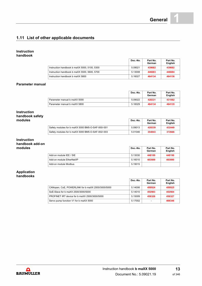
1.11 List of other applicable documentsInstruction handbook
Parameter manual
Instruction handbook safety modules
Instruction handbook add-on modules
Applicationhandbooks
Doc.-No. Part No. German
Part No.English
Instruction handbook b maXX 5000, 5100, 5300 5.09021 439682 439682
Instruction handbook b maXX 5500, 5600, 5700 5.13008 446683 446684
Instruction handbook b maXX 5800 5.16027 464134 464136
Doc.-No. Part No. German
Part No.English
Parameter manual b maXX 5000 5.09022 428331 431082
Parameter manual b maXX 5800 5.16029 464134 464135
Doc.-No. Part No. German
Part No.English
Safety modules for b maXX 5000 BM5-O-SAF-000/-001 5.09013 428339 432449
Safety modules for b maXX 5000 BM5-O-SAF-002/-003 5.01046 354843 372666
Doc.-No. Part No. German
Part No.English
Add-on module IEE / SIE 5.13030 448189 448190
Add-on module EtherNet/IP 5.16010 483089 483090
Add-on module Modbus 5.19015
Doc.-No. Part No. German
Part No.English
CANopen, CoE, POWERLINK for b maXX 2500/3000/5000 5.14006 450924 450925
SoE-Slave for b maXX 2500/3000/5000 5.14010 452983 452984
PROFINET IRT device for b maXX 2500/3000/5000 5.15009 456326 456327
Servo pump function V1 for b maXX 5000 5.17002 - 466346
Instruction handbook b maXX 5000
Document No.: 5.09021.19
13of 346

List of other applicable documents1.11
Instruction handbook b maXX 5000
Document No.: 5.09021.19 Baumüller Nürnberg GmbH
14of 346
2SAFETY
This section provides an overview of all of the important safety aspects for optimum pro-tection of personnel as well as for the safe and problem-free operation.
2.1 Contents of the Instruction handbook
Each person who is tasked with performing work on or with the device must have readand understood the instruction handbook before working with the device. This also ap-plies if the person involved with this kind of device or a similar one, or has been trainedby the manufacturer.
2.2 Changes and modifications to the device
In order to prevent hazards and to ensure optimum performance, no changes, additionsor modifications may be undertaken on the device that have not been explicitly approvedby the manufacturer.
2.3 Usage for the intended purpose
The device is conceived and constructed exclusively for usage compliant with its intendedpurpose described in these instruction handbook.
The devices of the model series b maXX 5000 are either mains rectifier or active mainsrectifier in combination with axis units with servo controller or decentralized drive solu-tions BM2500. Devices are also available in graduated design size and performanceclasses.
The device b maXX 5000 is used exclusively as a converter for controlling a motor.
A device is considered as being used compliant with its intended purpose if all notes andinformation of these instruction handbook are adhered to.
15of 346
Instruction handbook b maXX 5000
Document No.: 5.09021.19
Usage for the intended purpose2.3
WARNING!
Danger arising from usage for an unintended purpose!
Any usage that goes beyond the intended purpose and/or any non-compliant use ofthe device can lead to dangerous situations.
Therefore:
m Only use the device compliant with its intended purpose.
m Observe all specifications of these instruction handbook.
m Ensure that only qualified personnel work with/on this device.
m When configuring, ensure that the device is always operated within its specifica-tions.
m Mount the device on a wall that can sufficiently bear the load.
m The device must always be operated within a control cabinet.
m Ensure that the power supply complies with the stipulated specifications.
m The device may only be operated in a technically flawless condition.
m Only operate the device in combination with components approved by BaumüllerNürnberg GmbH.
m The device has been developed in such a manner that it fulfills the requirementsof the category C3 according to IEC 61800-3:2012.
m The device is not intended to be connected to the public mains. To operate the de-vice in primary surroundings of the category C2/C1 (residential, business and com-mercial areas, directly on a public low-voltage mains without an intermediatetransformer), special measures to reduce the transient emissions (line-internal andradiated) must be provided for and certifiable by the system builder. Otherwise,EMC interference could occur without such additional measures.
Instruction handbook b maXX 5000
Document No.: 5.09021.19 Baumüller Nürnberg GmbH
16of 346
Safety 2
2.4 Risk assessment according EU DirectiveEarth current Check the quality of the earth connection: - before connecting the device to the power supply for the first time and - within the recommended service intervals
Requirements:
m Cross section of the grounding cable according EN 61800-5-1
m Note the required torque of connection!
m Grounded mounting plate made of metal
m Mains filter, device and shielding of the motor cable are on the same HF potential
Stored electric charge
Do not touch electrically live parts before the discharge time of 15 min runs up, checkzero-potential before touching.
Electromagnetic fields
The device causes electromagnetic fields when operating.
Any person with individual device for cardiac assistance (pacemaker, defibrillator) muststay in sufficient distance to the operating device.
Burn injuries Please note that the surface of the device can heat up considerably.
m Wear safety gloves!
Radiated emission The high-frequency electromagnetic fields within the operation environment must not ex-ceed the field strength of the second environment according EN 61800-3.
Internal or external ignition source
Internal or external ignition sources are not allowed within the environment of the devices!
m Use ABC powder for extinguishing a fire!
Gas Toxic fumes can be released in case of failure.
No flammable fume or dust and no flammable/explosive gases are permitted within theenvironment of the devices!
In order to avoid damage to persons because of explosions:
m ventilate the area and
m immediate evacuation.
Transportation and mounting
Falling down of the device can cause damage to persons.
Note the weight of the device when selecting the mounting screws!
Select the fastening torques of the mounting screws according the specification of thescrew manufacturer!
m Wear safety helmets/shoes!
Instruction handbook b maXX 5000
Document No.: 5.09021.19
17of 346
Risk assessment according EU Directive2.4
Mounting Unprotected hands can be injured at the sharp edges of the device.
m Wear safety gloves!
Unprotected eyes can be injured by thrown up metal particles caused by drilling or makingcut-outs.
m Wear safety glasses!
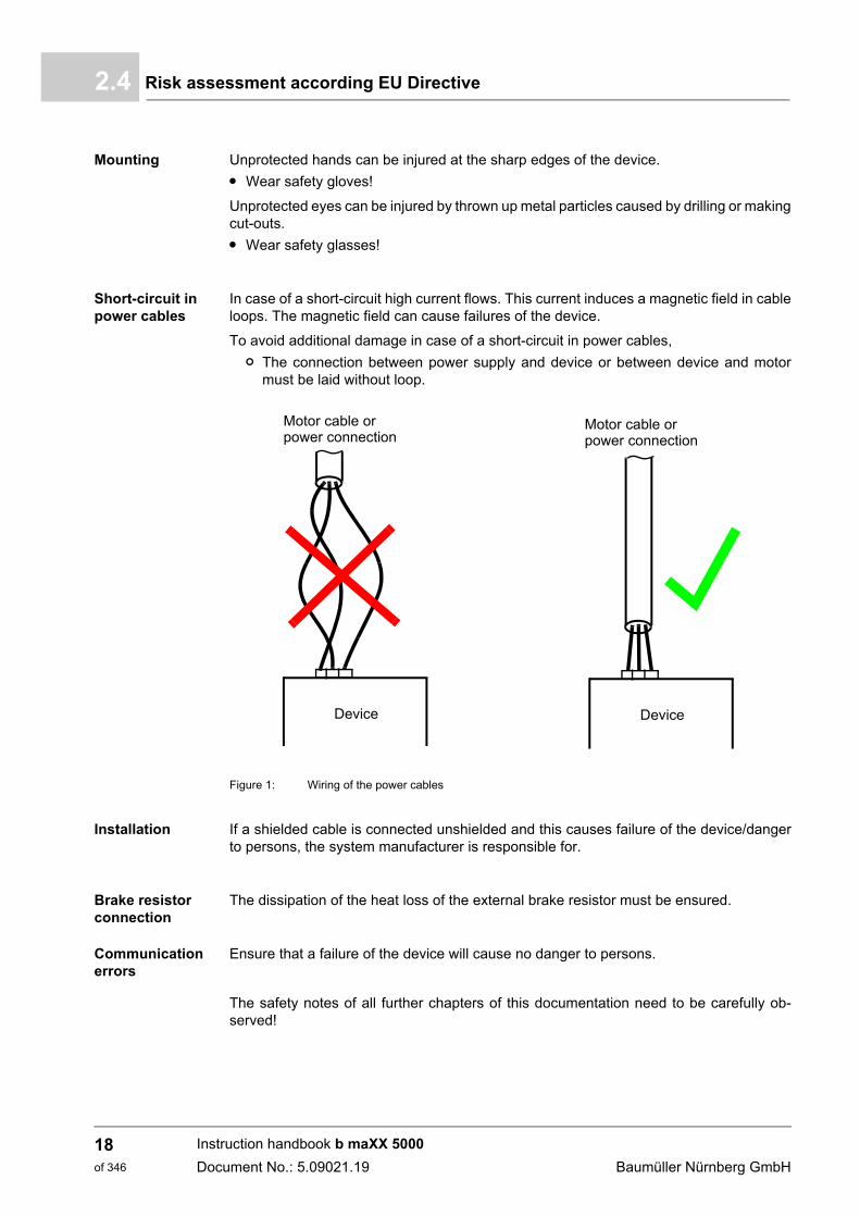
Short-circuit in power cables
In case of a short-circuit high current flows. This current induces a magnetic field in cableloops. The magnetic field can cause failures of the device.
To avoid additional damage in case of a short-circuit in power cables,
n The connection between power supply and device or between device and motormust be laid without loop.
Figure 1: Wiring of the power cables
Installation If a shielded cable is connected unshielded and this causes failure of the device/dangerto persons, the system manufacturer is responsible for.
Brake resistor connection
The dissipation of the heat loss of the external brake resistor must be ensured.
Communication errors
Ensure that a failure of the device will cause no danger to persons.
The safety notes of all further chapters of this documentation need to be carefully ob-served!
Device
Motor cable or
Device
power connectionMotor cable orpower connection
Instruction handbook b maXX 5000
Document No.: 5.09021.19 Baumüller Nürnberg GmbH
18of 346
Safety 2
2.5 Responsibility of the operating companyThe device is used in commercial areas. Thus, the proprietor of the device is subject tothe legal work safety regulations.
Along with the notes on work safety in these instruction handbook, the safety, accidentprevention and environmental protection regulations valid for the area of application ofthis device must be complied with. Whereby:
m The operating company must inform himself about the applicable work health and safe-ty regulations and ascertain, in a hazard assessment, any additional hazards that couldarise from the special working conditions in the use area of the device. These mustthen be implemented in the form of instruction handbook for operation of the device.
m These instruction handbook must be kept accessible to personnel working with the de-vice at all times in the immediate vicinity of the device.
m The specifications of the instruction handbook must be adhered to completely andwithout exception.
m The device may only be operated in a technically faultless and operationally safe con-dition.
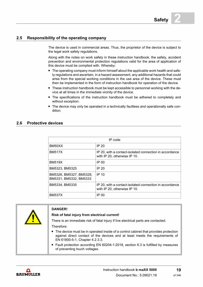
2.6 Protective devices
IP code
BM50XX IP 20
BM517X IP 20, with a contact-isolated connection in accordance with IP 20, otherwise IP 10.
BM519X IP 00
BM5323, BM5325 IP 20
BM5326, BM5327, BM5328,BM5331, BM5332, BM5333
IP 10
BM5334, BM5335 IP 20, with a contact-isolated connection in accordance with IP 20, otherwise IP 10.
BM537X IP 00
DANGER!
Risk of fatal injury from electrical current!
There is an immediate risk of fatal injury if live electrical parts are contacted.
Therefore:
m The device must be in operated inside of a control cabinet that provides protectionagainst direct contact of the devices and at least meets the requirements ofEN 61800-5-1, Chapter 4.2.3.3.
m Fault protection according EN 60204-1:2018, section 6.3 is fulfilled by measuresof preventing touch voltages.
Instruction handbook b maXX 5000
Document No.: 5.09021.19
19of 346
Training of the personnel2.7
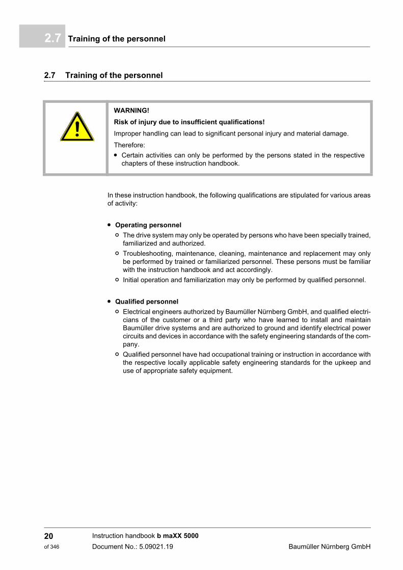
2.7 Training of the personnel
In these instruction handbook, the following qualifications are stipulated for various areasof activity:
m Operating personnel
n The drive system may only be operated by persons who have been specially trained,familiarized and authorized.
n Troubleshooting, maintenance, cleaning, maintenance and replacement may onlybe performed by trained or familiarized personnel. These persons must be familiarwith the instruction handbook and act accordingly.
n Initial operation and familiarization may only be performed by qualified personnel.
m Qualified personnel
n Electrical engineers authorized by Baumüller Nürnberg GmbH, and qualified electri-cians of the customer or a third party who have learned to install and maintainBaumüller drive systems and are authorized to ground and identify electrical powercircuits and devices in accordance with the safety engineering standards of the com-pany.
n Qualified personnel have had occupational training or instruction in accordance withthe respective locally applicable safety engineering standards for the upkeep anduse of appropriate safety equipment.
WARNING!
Risk of injury due to insufficient qualifications!
Improper handling can lead to significant personal injury and material damage.
Therefore:
m Certain activities can only be performed by the persons stated in the respectivechapters of these instruction handbook.
Instruction handbook b maXX 5000
Document No.: 5.09021.19 Baumüller Nürnberg GmbH
20of 346
Safety 2
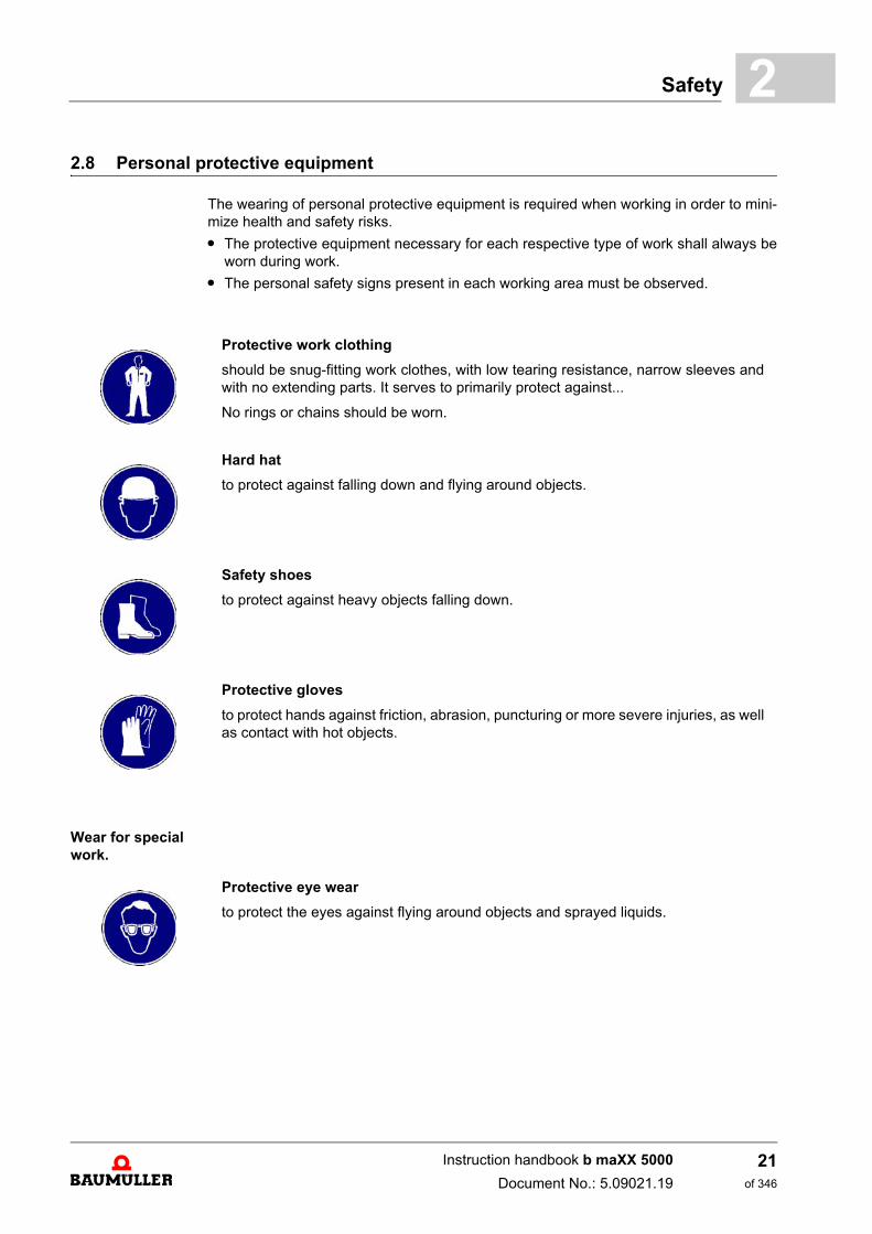
2.8 Personal protective equipmentThe wearing of personal protective equipment is required when working in order to mini-mize health and safety risks.
m The protective equipment necessary for each respective type of work shall always beworn during work.
m The personal safety signs present in each working area must be observed.
Wear for special work.
Protective work clothing
should be snug-fitting work clothes, with low tearing resistance, narrow sleeves andwith no extending parts. It serves to primarily protect against...
No rings or chains should be worn.
Hard hat
to protect against falling down and flying around objects.
Safety shoes
to protect against heavy objects falling down.
Protective gloves
to protect hands against friction, abrasion, puncturing or more severe injuries, as wellas contact with hot objects.
Protective eye wear
to protect the eyes against flying around objects and sprayed liquids.
Instruction handbook b maXX 5000
Document No.: 5.09021.19
21of 346
Special hazards2.9
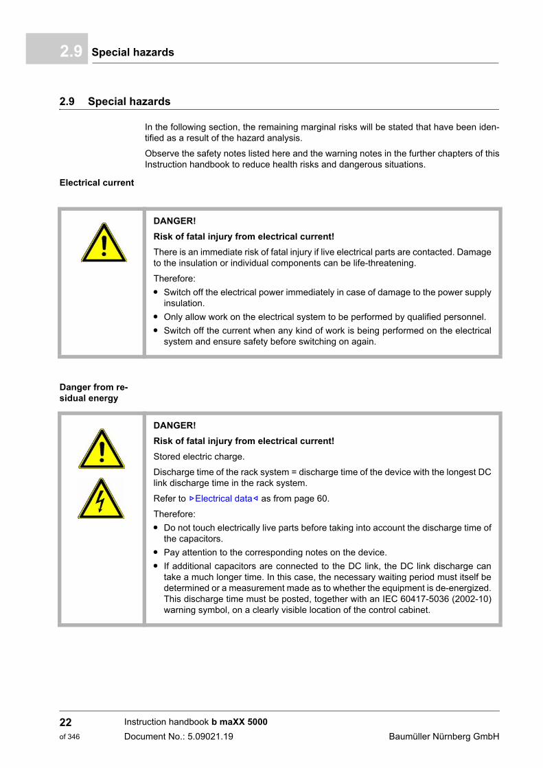
2.9 Special hazards
In the following section, the remaining marginal risks will be stated that have been iden-tified as a result of the hazard analysis.
Observe the safety notes listed here and the warning notes in the further chapters of thisInstruction handbook to reduce health risks and dangerous situations.
Electrical current
Danger from re-sidual energy
DANGER!
Risk of fatal injury from electrical current!
There is an immediate risk of fatal injury if live electrical parts are contacted. Damageto the insulation or individual components can be life-threatening.
Therefore:
m Switch off the electrical power immediately in case of damage to the power supplyinsulation.
m Only allow work on the electrical system to be performed by qualified personnel.
m Switch off the current when any kind of work is being performed on the electricalsystem and ensure safety before switching on again.
DANGER!
Risk of fatal injury from electrical current!
Stored electric charge.
Discharge time of the rack system = discharge time of the device with the longest DClink discharge time in the rack system.
Refer to ZElectrical data– as from page 60.
Therefore:
m Do not touch electrically live parts before taking into account the discharge time ofthe capacitors.
m Pay attention to the corresponding notes on the device.
m If additional capacitors are connected to the DC link, the DC link discharge cantake a much longer time. In this case, the necessary waiting period must itself bedetermined or a measurement made as to whether the equipment is de-energized.This discharge time must be posted, together with an IEC 60417-5036 (2002-10)warning symbol, on a clearly visible location of the control cabinet.
Instruction handbook b maXX 5000
Document No.: 5.09021.19 Baumüller Nürnberg GmbH
22of 346
Safety 2
Moving compo-nents2.10 Fire fighting
WARNING!
Risk of injury from moving components!
Rotating components and/or components moving linearly can result in severe injury.
Therefore:
m Do not touch moving components during operation.
m Do not open any covering during operation.
m The amount of residual mechanical energy depends on the application. Poweredcomponents still turn/move for a certain length of time even after the power supplyhas been switched off. Ensure that adequate safety measures are taken.
DANGER!
Risk of fatal injury from electrical current!
There is a risk of electric shock if an electrically-conductive, fire-extinguishing agentis used.
Therefore:
m Use the following fire-extinguishing agent:
ABC powder / CO2
Instruction handbook b maXX 5000
Document No.: 5.09021.19
23of 346
Safety equipment2.11
2.11 Safety equipment
2.12 Conduct in case of danger or accidents
Preventive measures
m Always be prepared for accidents or fire!
m Keep first-aid equipment (e.g. first-aid kits, blankets, etc.) and fire extinguishers readilyaccessible.
m Familiarize personnel with accident alarm, first aid and rescue equipment.
And if something does happen: respond properly.
m Stop operation of the device immediately with an EMERGENCY Stop.
m Initiate first aid measures.
m Evacuate persons from the danger zone.
m Notify the responsible persons at the scene of operations.
m Alarm medical personnel and/or the fire department.
m Keep access routes clear for rescue vehicles.
WARNING!
Risk of fatal injury due to non-functional safety equipment!
Safety equipment provides for the highest level of safety in a facility. Even if safetyequipment makes work processes more awkward, under no circumstances may theybe circumvented. Safety can only be ensured by intact safety equipment.
Therefore:
m Before starting to work, check whether the safety equipment in good working orderand properly installed.
Instruction handbook b maXX 5000
Document No.: 5.09021.19 Baumüller Nürnberg GmbH
24of 346
Safety 2
2.13 Signs and labelsThe following symbols and information signs are located in the working area. They referto the immediate vicinity in which they are affixed.
WARNING!
Risk of injury due to illegible symbols!
Over the course of time, stickers and symbols on the device can become dirty or oth-erwise unrecognizable.
Therefore:
m Maintain all safety, warning and operating labels on the device in easily readablecondition.
Electrical voltage
Only qualified personnel may work in work areas that identified with this sign.
Unauthorized persons may not touch working materials marked correspondingly.
DANGER!
Risk of fatal injury from electrical current!
Stored electric charge.
Discharge time of the rack system = discharge time of the device with the longest DClink discharge time in the rack system.
Refer to ZElectrical data– as from page 60.
Therefore:
m Do not touch before taking into account the discharge time of the capacitors andelectrically live parts.
m Heed corresponding notes on the equipment.
m If additional capacitors are connected to the DC link, the DC link discharge cantake a much longer time. In this case, the necessary waiting period must itself bedetermined or a measurement made as to whether the equipment is de-energized.This discharge time must be posted, together with an IEC 60417-5036 (2002-10)warning symbol, on a clearly visible location of the control cabinet.
Instruction handbook b maXX 5000
Document No.: 5.09021.19
25of 346
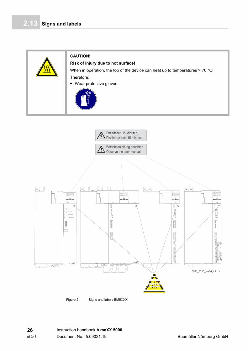
Signs and labels2.13
Figure 2: Signs and labels BM5XXX
CAUTION!
Risk of injury due to hot surface!
When in operation, the top of the device can heat up to temperatures > 70 °C!
Therefore:
m Wear protective gloves
Instruction handbook b maXX 5000
Document No.: 5.09021.19 Baumüller Nürnberg GmbH
26of 346
Safety 2
Signs and labels devices with safety levelNOTE!
Only a device with built in Safety Module SAF XXX, marked with the TÜV Rheinlandcertification label and the safety label fulfills a certified safety function within themeaning of PL classification according ISO 13849 or SIL according EN 61800.
Instruction handbook b maXX 5000
Document No.: 5.09021.19
27of 346

Signs and labels2.13
Instruction handbook b maXX 5000
Document No.: 5.09021.19 Baumüller Nürnberg GmbH
28of 346
3TECHNICAL DATA
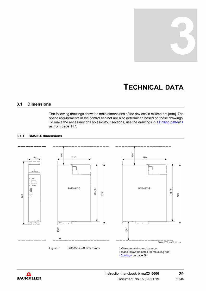
3.1 Dimensions
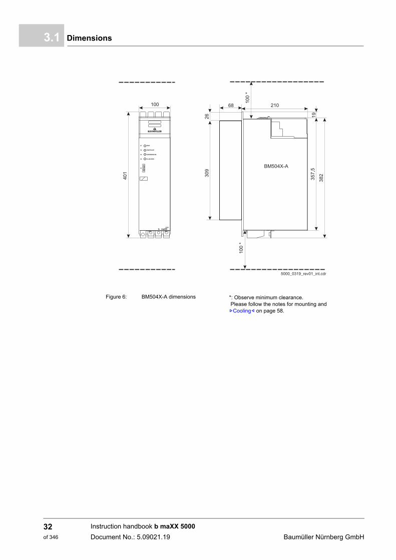
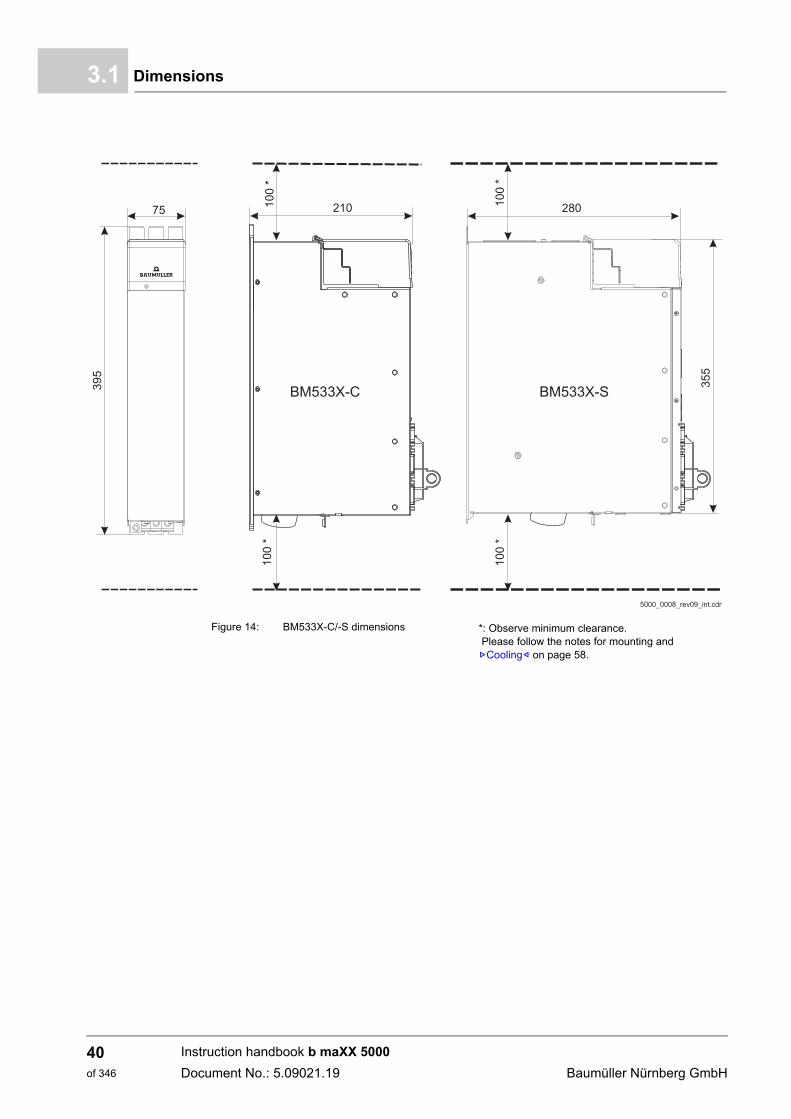
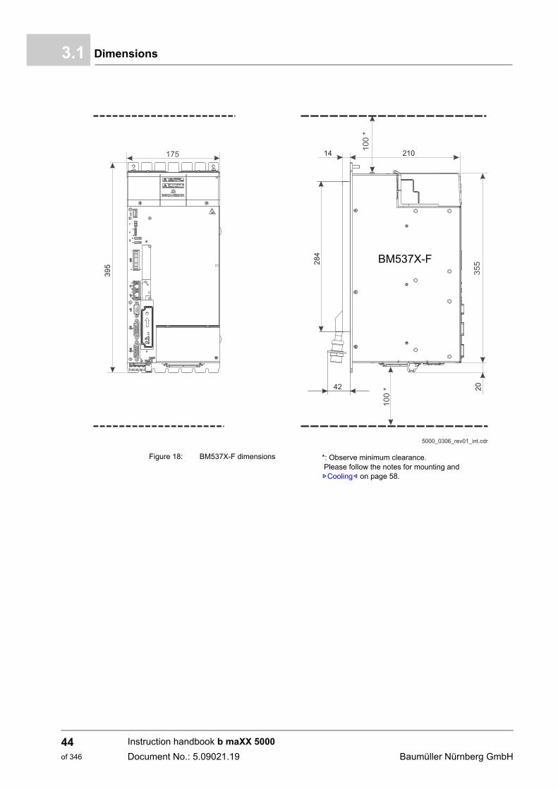
The following drawings show the main dimensions of the devices in millimeters [mm]. Thespace requirements in the control cabinet are also determined based on these drawings.To make the necessary drill holes/cutout sections, use the drawings in ZDrilling pattern–as from page 117.
3.1.1 BM503X dimensions
Figure 3: BM503X-C/-S dimensions *: Observe minimum clearance. Please follow the notes for mounting and ZCooling– on page 58.
29of 346
Instruction handbook b maXX 5000
Document No.: 5.09021.19
Dimensions3.1
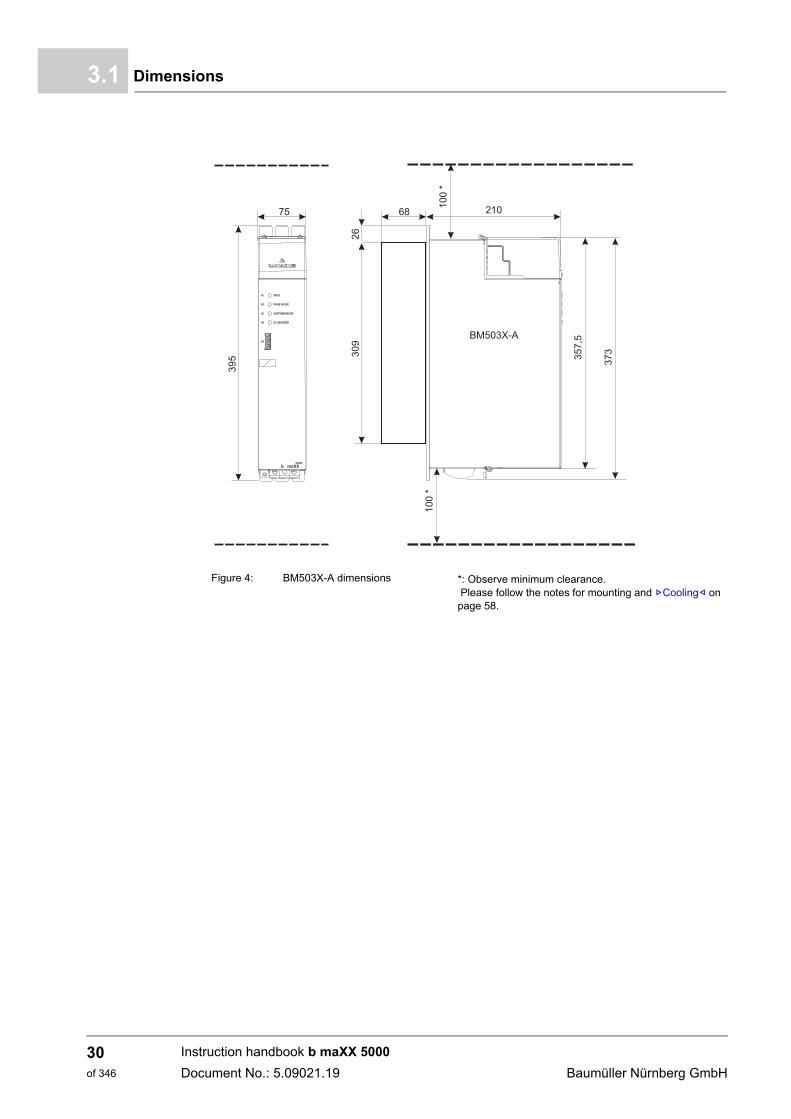
Figure 4: BM503X-A dimensions *: Observe minimum clearance. Please follow the notes for mounting and ZCooling– on page 58.
39
5 37
3
35
7,5
10
0*
10
0*
75 210
BM503X-A
READYH1
H2
H3
H4
PHASE FAILURE
OVERTEMPERATURE
DC-LINK ERROR
b maXX5000
30
92
6
68
Instruction handbook b maXX 5000
Document No.: 5.09021.19 Baumüller Nürnberg GmbH
30of 346
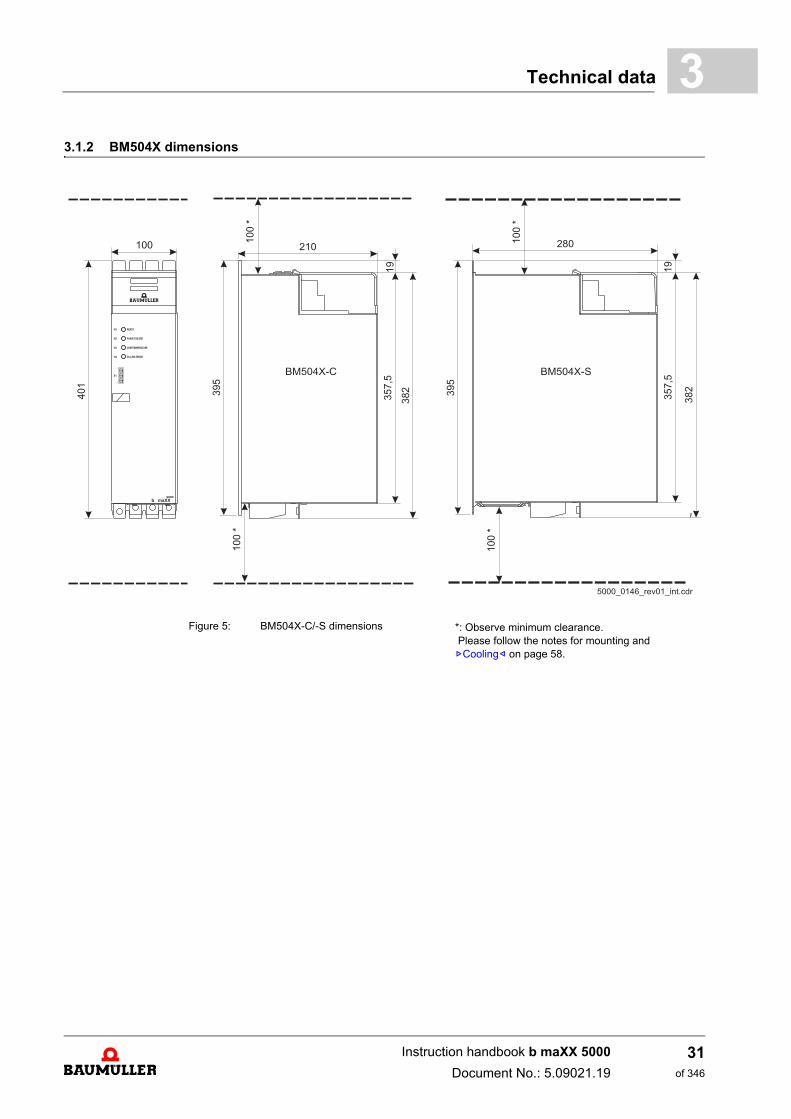
Technical data 3
3.1.2 BM504X dimensionsFigure 5: BM504X-C/-S dimensions *: Observe minimum clearance. Please follow the notes for mounting and ZCooling– on page 58.
Instruction handbook b maXX 5000
Document No.: 5.09021.19
31of 346
Dimensions3.1
Figure 6: BM504X-A dimensions *: Observe minimum clearance. Please follow the notes for mounting and ZCooling– on page 58.
Instruction handbook b maXX 5000
Document No.: 5.09021.19 Baumüller Nürnberg GmbH
32of 346
Technical data 3
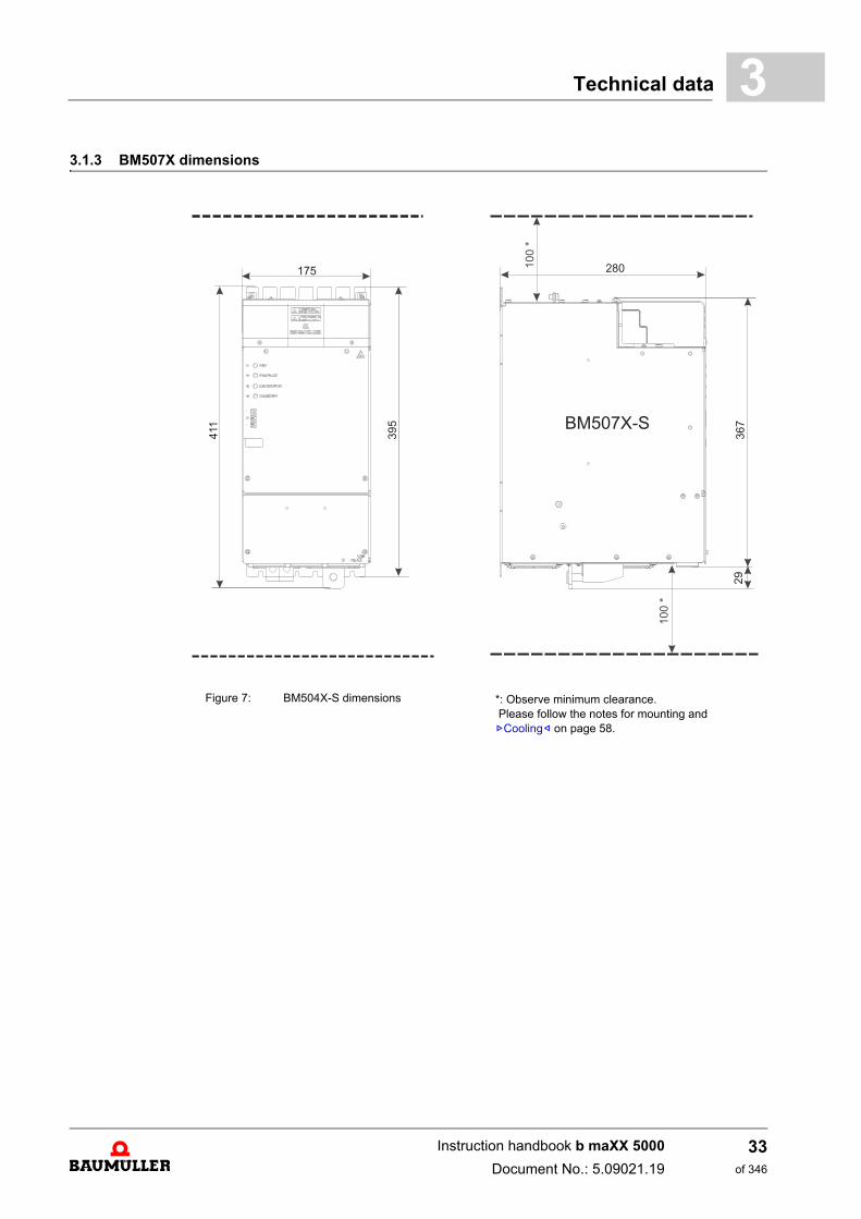
3.1.3 BM507X dimensionsFigure 7: BM504X-S dimensions *: Observe minimum clearance. Please follow the notes for mounting and ZCooling– on page 58.
Instruction handbook b maXX 5000
Document No.: 5.09021.19
33of 346
Dimensions3.1
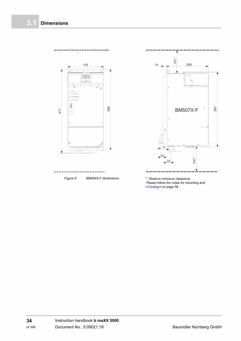
Figure 8: BM504X-F dimensions *: Observe minimum clearance. Please follow the notes for mounting and ZCooling– on page 58.
Instruction handbook b maXX 5000
Document No.: 5.09021.19 Baumüller Nürnberg GmbH
34of 346
Technical data 3
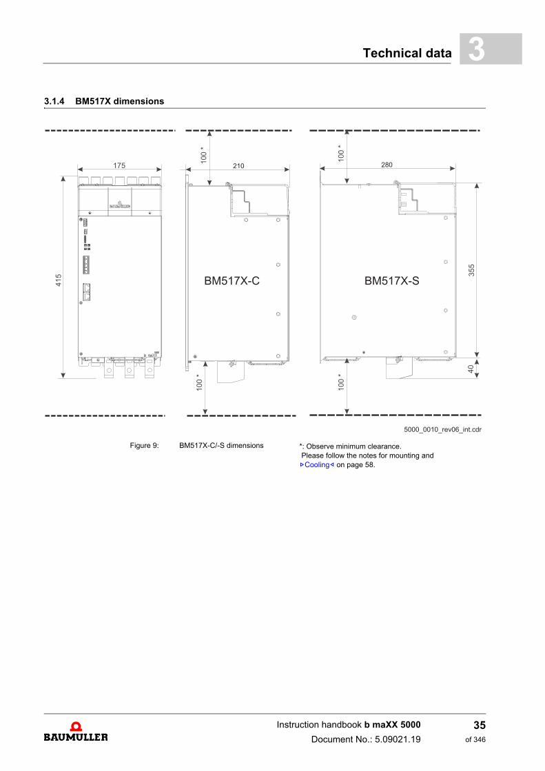
3.1.4 BM517X dimensionsFigure 9: BM517X-C/-S dimensions *: Observe minimum clearance. Please follow the notes for mounting and ZCooling– on page 58.
Instruction handbook b maXX 5000
Document No.: 5.09021.19
35of 346
Dimensions3.1
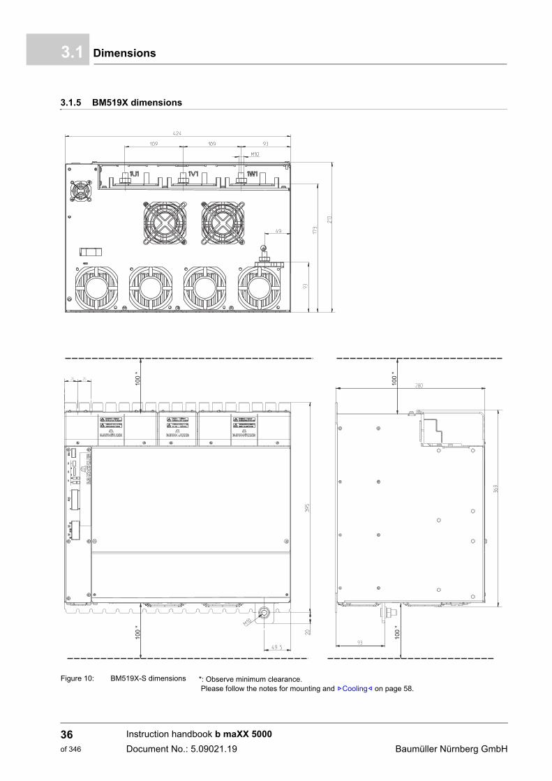
3.1.5 BM519X dimensions
Figure 10: BM519X-S dimensions *: Observe minimum clearance. Please follow the notes for mounting and ZCooling– on page 58.
BM519X-S
Instruction handbook b maXX 5000
Document No.: 5.09021.19 Baumüller Nürnberg GmbH
36of 346
Technical data 3
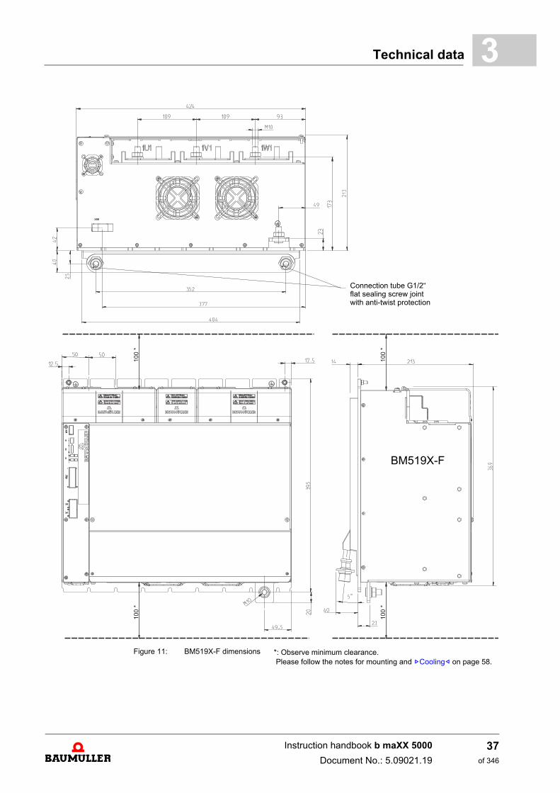
Connection tube G1/2“ flat sealing screw joint with anti-twist protection
BM519X-F
Figure 11: BM519X-F dimensions *: Observe minimum clearance. Please follow the notes for mounting and ZCooling– on page 58.
Instruction handbook b maXX 5000
Document No.: 5.09021.19
37of 346
Dimensions3.1
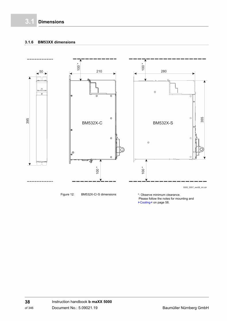
3.1.6 BM53XX dimensions
Figure 12: BM532X-C/-S dimensions *: Observe minimum clearance. Please follow the notes for mounting and ZCooling– on page 58.
Instruction handbook b maXX 5000
Document No.: 5.09021.19 Baumüller Nürnberg GmbH
38of 346
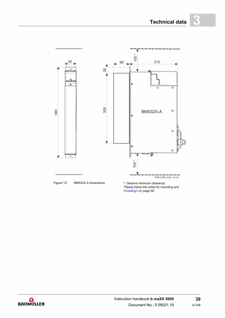
Technical data 3
Figure 13: BM532X-A dimensions *: Observe minimum clearance. Please follow the notes for mounting and ZCooling– on page 58.
Instruction handbook b maXX 5000
Document No.: 5.09021.19
39of 346
Dimensions3.1
Figure 14: BM533X-C/-S dimensions *: Observe minimum clearance. Please follow the notes for mounting and ZCooling– on page 58.
Instruction handbook b maXX 5000
Document No.: 5.09021.19 Baumüller Nürnberg GmbH
40of 346
Technical data 3
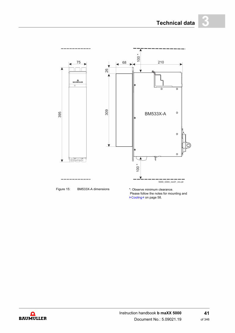
Figure 15: BM533X-A dimensions *: Observe minimum clearance. Please follow the notes for mounting and ZCooling– on page 58.
Instruction handbook b maXX 5000
Document No.: 5.09021.19
41of 346
Dimensions3.1
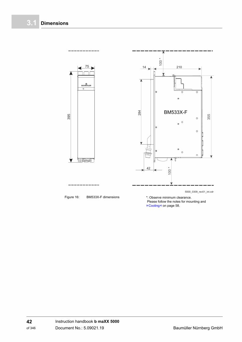
BM533X-F
Figure 16: BM533X-F dimensions *: Observe minimum clearance. Please follow the notes for mounting and ZCooling– on page 58.
Instruction handbook b maXX 5000
Document No.: 5.09021.19 Baumüller Nürnberg GmbH
42of 346
Technical data 3
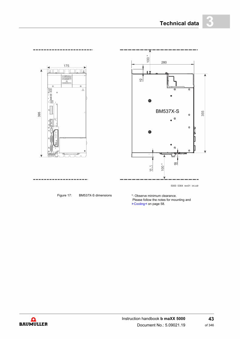
BM537X-S
Figure 17: BM537X-S dimensions *: Observe minimum clearance. Please follow the notes for mounting and ZCooling– on page 58.
Instruction handbook b maXX 5000
Document No.: 5.09021.19
43of 346
Dimensions3.1
BM537X-F
Figure 18: BM537X-F dimensions *: Observe minimum clearance. Please follow the notes for mounting and ZCooling– on page 58.
Instruction handbook b maXX 5000
Document No.: 5.09021.19 Baumüller Nürnberg GmbH
44of 346
Technical data 3
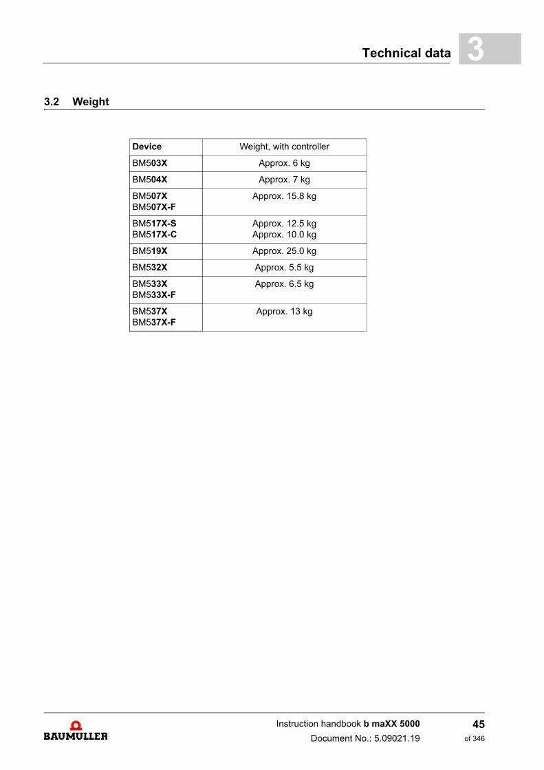
3.2 WeightDevice Weight, with controller
BM503X Approx. 6 kg
BM504X Approx. 7 kg
BM507XBM507X-F
Approx. 15.8 kg
BM517X-SBM517X-C
Approx. 12.5 kgApprox. 10.0 kg
BM519X Approx. 25.0 kg
BM532X Approx. 5.5 kg
BM533XBM533X-F
Approx. 6.5 kg
BM537XBM537X-F
Approx. 13 kg
Instruction handbook b maXX 5000
Document No.: 5.09021.19
45of 346
Operating conditions3.3
3.3 Operating conditions
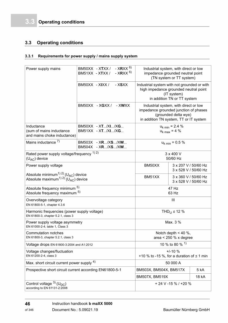
3.3.1 Requirements for power supply / mains supply system
Power supply mains BM50XX - XTXX / - XRXX 6)
BM51XX - XTXX / - XRXX 6)Industrial system, with direct or low impedance grounded neutral point
(TN system or TT system)
BM50XX - XIXX / - XSXX Industrial system with not grounded or with high impedance grounded neutral point
(IT system)in addition TN or TT system
BM50XX - XGXX / - XWXX Industrial system, with direct or low impedance grounded junction of phases
(grounded delta wye)in addition TN system, TT or IT system
Inductance (sum of mains inductance and mains choke inductance)
BM50XX - XT.../XI.../XG...BM51XX - XT.../XI.../XG...
uk min = 2.4 %uk max = 4 %
Mains inductance 7) BM503X - XR.../XS.../XW...BM504X - XR.../XS.../XW...
uk min = 0.5 %
Rated power supply voltage/frequency 1) 2)
(UAC) device3 x 400 V 50/60 Hz
Power supply voltage
Absolute minimum1) 2) (UAC) deviceAbsolute maximum1) 2) (UAC) device
BM50XX 3 x 207 V / 50/60 Hz3 x 528 V / 50/60 Hz
BM51XX 3 x 360 V / 50/60 Hz3 x 528 V / 50/60 Hz
Absolute frequency minimum 5)
Absolute frequency maximum 5)47 Hz63 Hz
Overvoltage categoryEN 61800-5-1, chapter 4.3.6
III
Harmonic frequencies (power supply voltage)EN 61800-3, chapter 5.2.1, class 3
THDU b 12 %
Power supply voltage asymmetryEN 61000-2-4, table 1, Class 3
Max. 3 %
Commutation notchesEN 61800-3, chapter 5.2.1, class 3
Notch depth < 40 %, area < 250 % x degree
Voltage drops EN 61800-3:2004 and A1:2012 10 % to 80 % 1)
Voltage changes/fluctuationEN 61200-2-4, class 3
+/-10 %+10 % to -15 %, for a duration of b 1 min
Max. short circuit current power supply 4) 50 000 A
Prospective short circuit current according EN61800-5-1 BM503X, BM504X, BM517X 5 kA
BM507X, BM519X 18 kA
Control voltage 3) (UDC)according to EN 61131-2:2008
+ 24 V -15 % / +20 %
Instruction handbook b maXX 5000
Document No.: 5.09021.19 Baumüller Nürnberg GmbH
46of 346
Technical data 3
1) In case of power supply failure ((0.9 - 0) x UAC for t > 0.1 s), the error „Power unit not ready-to-operate“ is generated.2) The rated voltage is 400 V. At an power supply voltage of less than 400 V the output power of the device is reduced, refer to correctionvalues at changed operation conditions ZCorrection values input voltage– on page 54.3) The control voltage must correspond to PELV (EN 61800-5-1, chapter 3.21) or SELV (EN 61800, chapter 3.35). With a control voltage
< 24 V the fan output is reduced. Thus, it could be necessary to reduce the output current. If UL 508C is being considered, the currentis limited to 4 A (with fuses, in accordance with UL 248) and to a voltage of max. 30 VDC.
4) Only necessary to comply with UL 508C, refer to ZUL notes– as from page 94.5) Change speed of the mains frequency max. 1 Hz/s (EN 61000-2-4, Class 3)6) The connection and/or operation of a device with the identifier BM5XXX-XTXX on IT mains or grounded delta mains is not allowed.7)
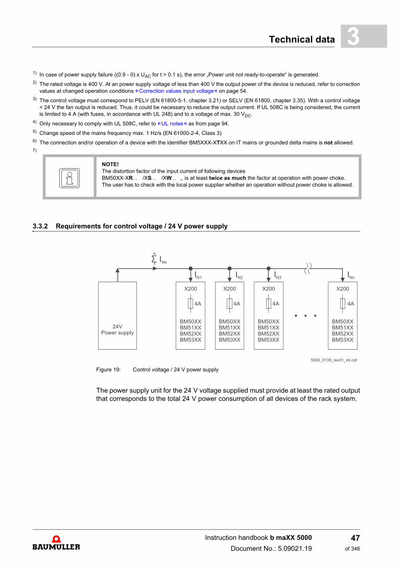
3.3.2 Requirements for control voltage / 24 V power supply
Figure 19: Control voltage / 24 V power supply
The power supply unit for the 24 V voltage supplied must provide at least the rated outputthat corresponds to the total 24 V power consumption of all devices of the rack system.
NOTE!The distortion factor of the input current of following devices BM50XX-XR /XS /XW ,, is at least twice as much the factor at operation with power choke.The user has to check with the local power supplier whether an operation without power choke is allowed.
Instruction handbook b maXX 5000
Document No.: 5.09021.19
47of 346
Operating conditions3.3
3.3.3 Requirements for the motor
The b maXX 5000 is designed to operate three phase current motors with a motor termi-nal voltage of 3 x 350 V (typical for servo motors from Baumüller) or 3 x 400 V (typical forstandard asynchronous motors and for customer-specific special motors fromBaumüller). The motors must be operated in a star connection. The rated DC link voltageis 540 VDC. It can be expected that the DC link voltage increases to up to 780 V or 800 Vin brake operation. The connected motor must be designed to handle these DC link volt-ages.
If b maXX 5000 axis units are operated with a voltage-controlled DC link (e.g. BM51XX),then the DC link voltage will be permanently (not only in brake operation) between 640 V and 760 V. The connected motor must be designed to be operated atthese voltages in continuous operation.
It is also possible to operate the devices at lower voltages, e.g. 3 x 230 V. A prerequisite,however, is that the three phase current motors used for operation with converters ratedfor an DC link voltage of up to 800 V, as the brake resistor voltage (refer to ZElectricaldata– as from page 60) remains unchanged. Thus, only three phase current motors with UDC link, rated 540 V may be used in thesecases as well.
Instruction handbook b maXX 5000
Document No.: 5.09021.19 Baumüller Nürnberg GmbH
48of 346
Technical data 3
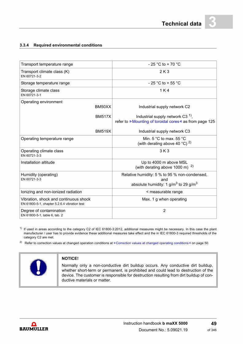
3.3.4 Required environmental conditions1) If used in areas according to the category C2 of IEC 61800-3:2012, additional measures might be necessary. In this case the plantmanufacturer / user has to provide evidence these additional measures take effect and the in IEC 61800-3 required thresholds of thecategory C2 are met.
2) Refer to correction values at changed operation conditions at ZCorrection values at changed operating conditions– on page 50.
Transport temperature range - 25 °C to + 70 °C
Transport climate class (K)EN 60721-3-2
2 K 3
Storage temperature range - 25 °C to + 55 °C
Storage climate classEN 60721-3-1
1 K 4
Operating environmentBM50XX
BM517X
BM519X
Industrial supply network C2
Industrial supply network C3 1), refer to ZMounting of toroidal cores– as from page 125
Industrial supply network C3
Operating temperature range Min. 5 °C to max. 55 °C(with derating above 40 °C) 2)
Operating climate classEN 60721-3-3
3 K 3
Installation altitude Up to 4000 m above MSL(with derating above 1000 m) 2)
Humidity (operating)EN 60721-3-3
Relative humidity: 5 % to 95 % non-condensed,and
absolute humidity: 1 g/m3 to 29 g/m3
Ionizing and non-ionized radiation < measurable range
Vibration, shock and continuous shock EN 61800-5-1, chapter 5.2.6.4 vibration test
Max. 1 g when operating
Degree of contaminationEN 61800-5-1, table 6, tab. 2
2
NOTICE!
Normally only a non-conductive dirt buildup occurs. Any conductive dirt buildup,whether short-term or permanent, is prohibited and could lead to destruction of thedevice. The customer is responsible for destruction resulting from dirt buildup of con-ductive materials or matter.
Instruction handbook b maXX 5000
Document No.: 5.09021.19
49of 346
Operating conditions3.3
3.3.5 Correction values at changed operating conditions
The correction values of the permitted output power and output current must be multi-plied, if the devices b maXX 5000 are used at operation conditions with different correc-tion values.
The following correction values are to be considered if nothing other is specified at the„Electrical data“ of the device:
NOTE!
Baumüller devices that are intended for operation in grounded delta mains or ITmains may only be operated in those types of mains up to an installation altitude of2000 m above MSL. At an installation altitude of 2000 m and higher these devices areto be operated in TN and TT mains. Power supply of this type can be accomplishedby using an isolating transformer with a secondary-side grounded neutral point, forexample.
NOTE!
The temperature of the water cooler or the cold plate temperature must be higher orequal to the surrounding temperature to prevent condensation.
Instruction handbook b maXX 5000
Document No.: 5.09021.19 Baumüller Nürnberg GmbH
50of 346
Technical data 3
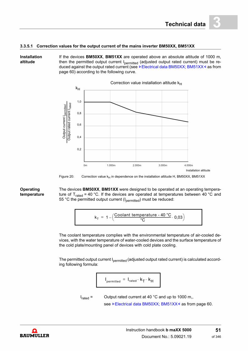
3.3.5.1 Correction values for the output current of the mains inverter BM50XX, BM51XXInstallation altitude
If the devices BM50XX, BM51XX are operated above an absolute altitude of 1000 m,then the permitted output current Ipermitted (adjusted output rated current) must be re-duced against the output rated current (see ZElectrical data BM50XX; BM51XX– as frompage 60) according to the following curve.
Figure 20: Correction value kH in dependence on the installation altitude H, BM50XX, BM51XX
Operating temperature
The devices BM50XX, BM51XX were designed to be operated at an operating tempera-ture of Trated = 40 °C. If the devices are operated at temperatures between 40 °C and55 °C the permitted output current (Ipermitted) must be reduced:
The coolant temperature complies with the environmental temperature of air-cooled de-vices, with the water temperature of water-cooled devices and the surface temperature ofthe cold plate/mounting panel of devices with cold plate cooling.
The permitted output current Ipermitted (adjusted output rated current) is calculated accord-ing following formula:
Irated = Output rated current at 40 °C and up to 1000 m,,
see ZElectrical data BM50XX; BM51XX– as from page 60.
0%
20%
40%
60%
80%
100%
120%
0m 1.000m 2.000m 3.000m 4.000m 5.000m
Out
put c
urre
nt I
perm
itted
O
utp
ut r
ated
cur
rent
I rat
ed
1,0
0,8
0,6
0,4
0,2
Installation altitude
kH
Correction value installation altitude kH
kT 1Coolant temperature - 40 °C
°C--------------------------------------------------------------------------------- 0,03 –=
Ipermitted Irated kT kH =
Instruction handbook b maXX 5000
Document No.: 5.09021.19
51of 346
Operating conditions3.3
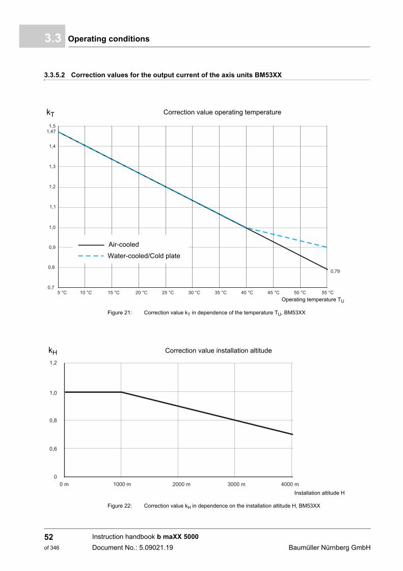
3.3.5.2 Correction values for the output current of the axis units BM53XX
Figure 21: Correction value kT in dependence of the temperature TU, BM53XX
Figure 22: Correction value kH in dependence on the installation altitude H, BM53XX
Operating temperature TU
kT Correction value operating temperature
Air-cooled
Water-cooled/Cold plate
Installation altitude H
kH Correction value installation altitude
Instruction handbook b maXX 5000
Document No.: 5.09021.19 Baumüller Nürnberg GmbH
52of 346
Technical data 3
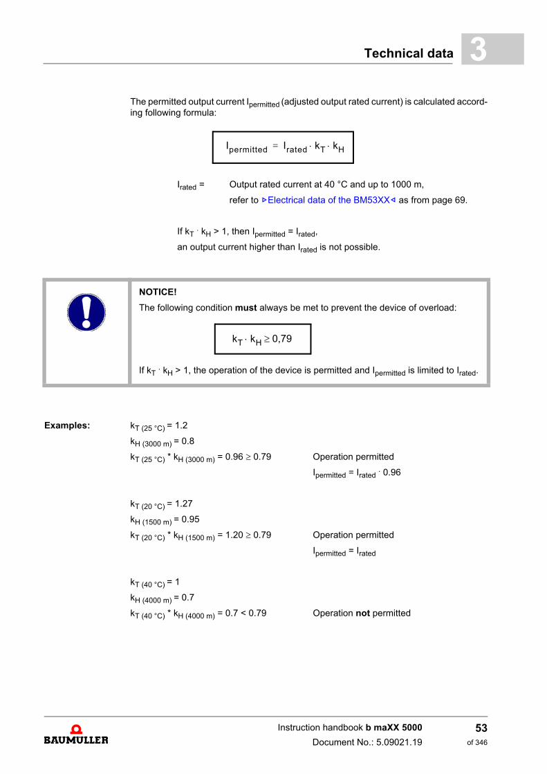
The permitted output current Ipermitted (adjusted output rated current) is calculated accord-ing following formula:Irated = Output rated current at 40 °C and up to 1000 m,
refer to ZElectrical data of the BM53XX– as from page 69.
If kT . kH > 1, then Ipermitted = Irated,
an output current higher than Irated is not possible.
Examples: kT (25 °C) = 1.2
kH (3000 m) = 0.8
kT (25 °C) * kH (3000 m) = 0.96 0.79 Operation permitted
Ipermitted = Irated . 0.96
kT (20 °C) = 1.27
kH (1500 m) = 0.95
kT (20 °C) * kH (1500 m) = 1.20 0.79 Operation permitted
Ipermitted = Irated
kT (40 °C) = 1
kH (4000 m) = 0.7
kT (40 °C) * kH (4000 m) = 0.7 < 0.79 Operation not permitted
Ipermitted Irated kT kH =
NOTICE!
The following condition must always be met to prevent the device of overload:
If kT . kH > 1, the operation of the device is permitted and Ipermitted is limited to Irated.
kT kH 0,79
Instruction handbook b maXX 5000
Document No.: 5.09021.19
53of 346
Operating conditions3.3
3.3.5.3 Correction values input voltage
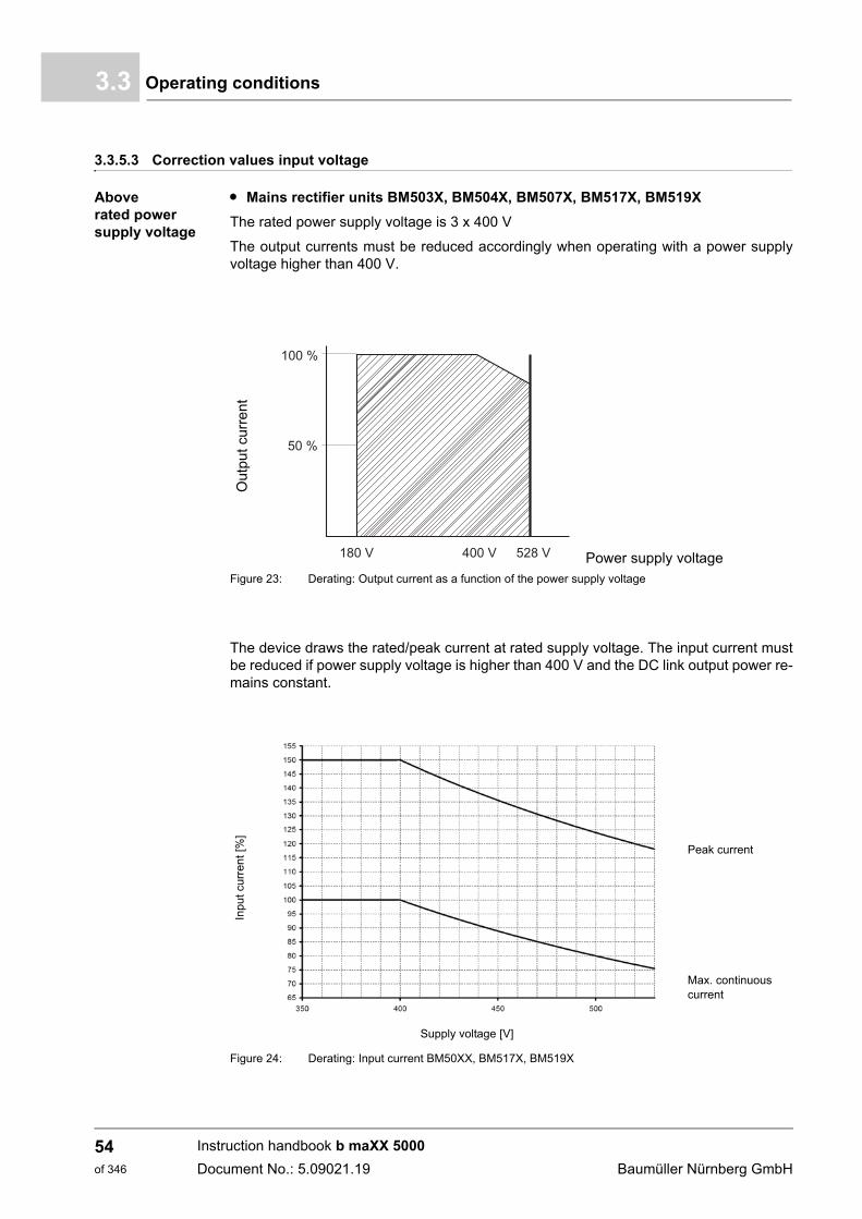
Above rated power supply voltage
m Mains rectifier units BM503X, BM504X, BM507X, BM517X, BM519X
The rated power supply voltage is 3 x 400 V
The output currents must be reduced accordingly when operating with a power supplyvoltage higher than 400 V.
Figure 23: Derating: Output current as a function of the power supply voltage
The device draws the rated/peak current at rated supply voltage. The input current mustbe reduced if power supply voltage is higher than 400 V and the DC link output power re-mains constant.
Figure 24: Derating: Input current BM50XX, BM517X, BM519X
Out
put
curr
en
t
Power supply voltage
Inpu
t cur
rent
[%]
Supply voltage [V]
Peak current
Max. continuous current
180 V 400 V 528 V
100 %
50 %
Instruction handbook b maXX 5000
Document No.: 5.09021.19 Baumüller Nürnberg GmbH
54of 346
Technical data 3
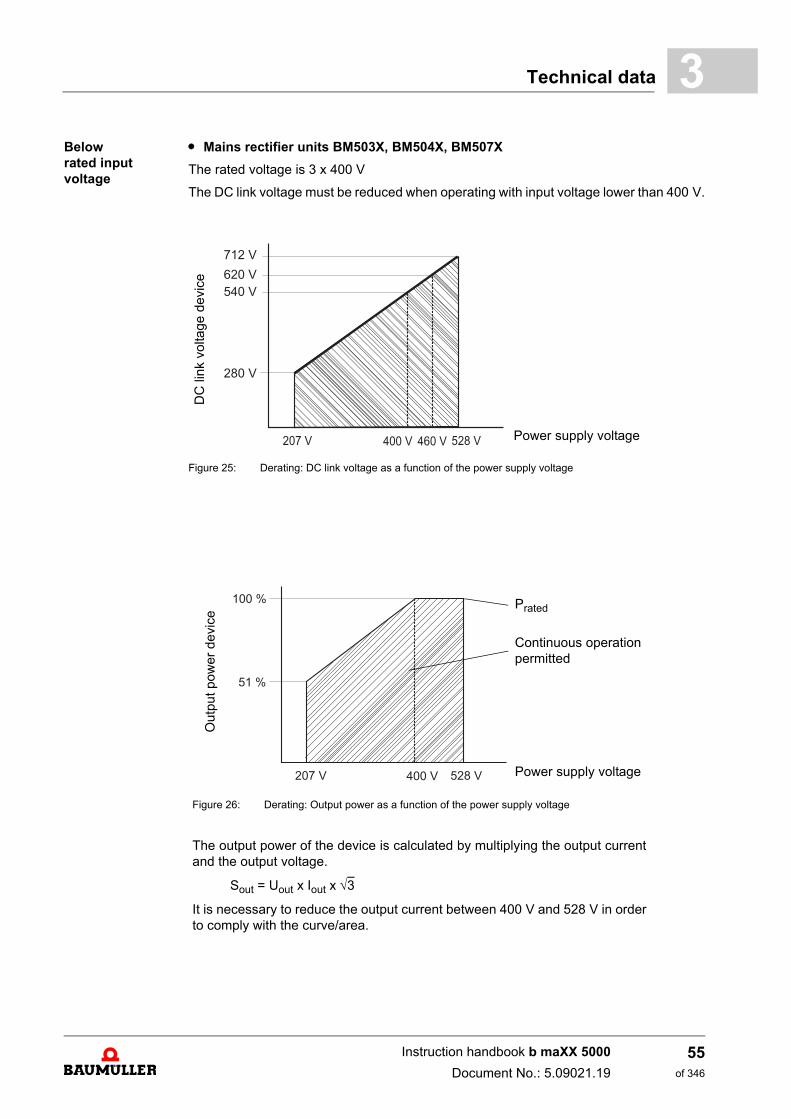
Below rated input voltagem Mains rectifier units BM503X, BM504X, BM507X
The rated voltage is 3 x 400 V
The DC link voltage must be reduced when operating with input voltage lower than 400 V.
Figure 25: Derating: DC link voltage as a function of the power supply voltage
DC
link
vol
tage
dev
ice
Power supply voltage
Out
put
pow
er d
evic
e
Prated
Continuous operation permitted
Power supply voltage
Figure 26: Derating: Output power as a function of the power supply voltage
The output power of the device is calculated by multiplying the output currentand the output voltage.
Sout = Uout x Iout x 3
It is necessary to reduce the output current between 400 V and 528 V in orderto comply with the curve/area.
207 V 400 V 528 V
100 %
51 %
Instruction handbook b maXX 5000
Document No.: 5.09021.19
55of 346
Operating conditions3.3
Below rated input voltage
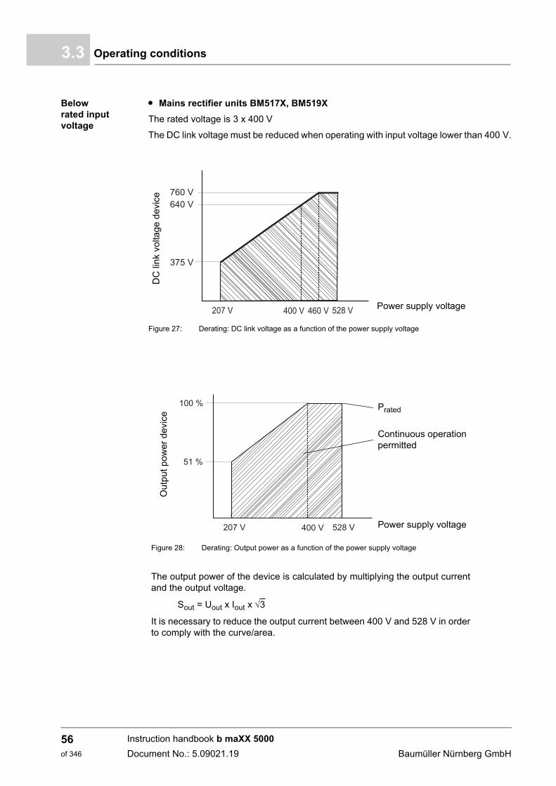
m Mains rectifier units BM517X, BM519X
The rated voltage is 3 x 400 V
The DC link voltage must be reduced when operating with input voltage lower than 400 V.
Figure 27: Derating: DC link voltage as a function of the power supply voltage
DC
link
vol
tage
dev
ice
Power supply voltage
Ou
tpu
t p
ower
dev
ice
Prated
Continuous operation permitted
Power supply voltage
Figure 28: Derating: Output power as a function of the power supply voltage
The output power of the device is calculated by multiplying the output currentand the output voltage.
Sout = Uout x Iout x 3
It is necessary to reduce the output current between 400 V and 528 V in orderto comply with the curve/area.
207 V 400 V 528 V
100 %
51 %
Instruction handbook b maXX 5000
Document No.: 5.09021.19 Baumüller Nürnberg GmbH
56of 346
Technical data 3
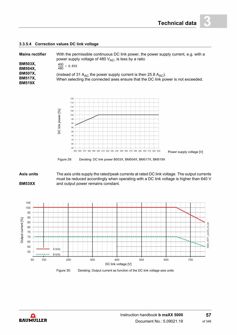
3.3.5.4 Correction values DC link voltageMains rectifier
BM503X, BM504X, BM507X,BM517X,BM519X
With the permissible continuous DC link power, the power supply current, e.g. with a power supply voltage of 480 VAC, is less by a ratio
(instead of 31 AAC the power supply current is then 25.8 AAC). When selecting the connected axes ensure that the DC link power is not exceeded.
Axis units
BM53XX
The axis units supply the rated/peak currents at rated DC link voltage. The output currentsmust be reduced accordingly when operating with a DC link voltage is higher than 640 Vand output power remains constant.
Figure 30: Derating: Output current as function of the DC link voltage axis units
DC
link
pow
er [%
]
Power supply voltage [V]
Figure 29: Derating: DC link power B503X, BM504X, BM517X, BM519X
400480---------- 0 833=
Out
put c
urre
nt [%
]
DC link voltage [V]
Instruction handbook b maXX 5000
Document No.: 5.09021.19
57of 346
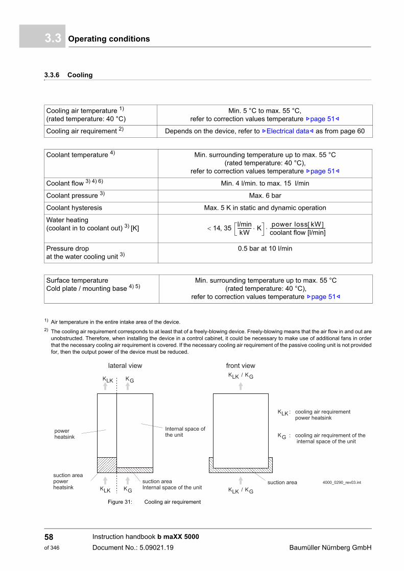
Operating conditions3.3
3.3.6 Cooling
1) Air temperature in the entire intake area of the device.2) The cooling air requirement corresponds to at least that of a freely-blowing device. Freely-blowing means that the air flow in and out are
unobstructed. Therefore, when installing the device in a control cabinet, it could be necessary to make use of additional fans in orderthat the necessary cooling air requirement is covered. If the necessary cooling air requirement of the passive cooling unit is not providedfor, then the output power of the device must be reduced.
Figure 31: Cooling air requirement
Cooling air temperature 1)
(rated temperature: 40 °C)Min. 5 °C to max. 55 °C,
refer to correction values temperature Zpage 51–
Cooling air requirement 2) Depends on the device, refer to ZElectrical data– as from page 60
Coolant temperature 4) Min. surrounding temperature up to max. 55 °C(rated temperature: 40 °C),
refer to correction values temperature Zpage 51–
Coolant flow 3) 4) 6) Min. 4 l/min. to max. 15 l/min
Coolant pressure 3) Max. 6 bar
Coolant hysteresis Max. 5 K in static and dynamic operation
Water heating(coolant in to coolant out) 3) [K]
Pressure drop at the water cooling unit 3)
0.5 bar at 10 l/min
14 35 l/minkW
------------ K power loss kW coolant flow [l/min]-------------------------------------------------
Surface temperatureCold plate / mounting base 4) 5)
Min. surrounding temperature up to max. 55 °C(rated temperature: 40 °C),
refer to correction values temperature Zpage 51–
Instruction handbook b maXX 5000
Document No.: 5.09021.19 Baumüller Nürnberg GmbH
58of 346
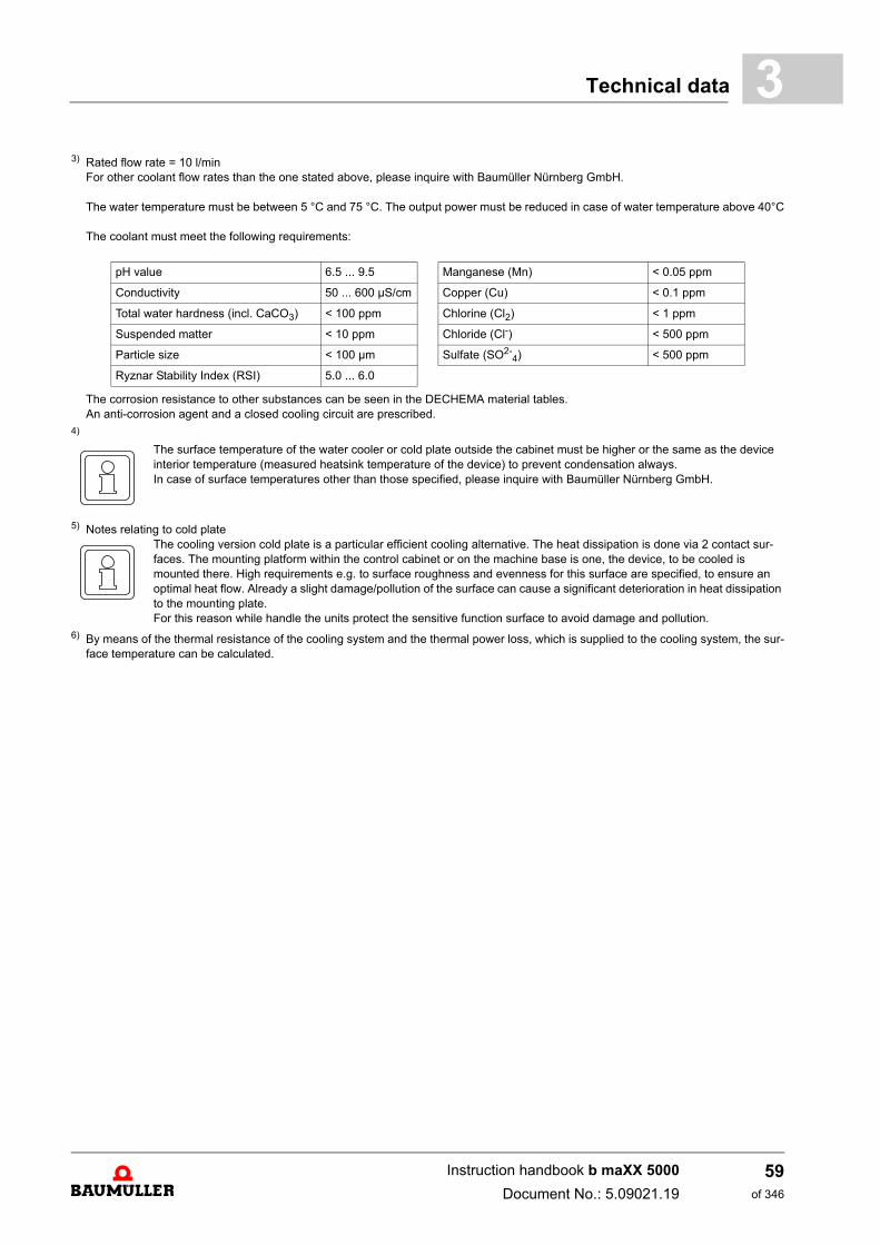
Technical data 3
3) Rated flow rate = 10 l/minFor other coolant flow rates than the one stated above, please inquire with Baumüller Nürnberg GmbH.
The water temperature must be between 5 °C and 75 °C. The output power must be reduced in case of water temperature above 40°C
The coolant must meet the following requirements:
The corrosion resistance to other substances can be seen in the DECHEMA material tables.An anti-corrosion agent and a closed cooling circuit are prescribed.
4)
The surface temperature of the water cooler or cold plate outside the cabinet must be higher or the same as the device interior temperature (measured heatsink temperature of the device) to prevent condensation always.In case of surface temperatures other than those specified, please inquire with Baumüller Nürnberg GmbH.
5) Notes relating to cold plateThe cooling version cold plate is a particular efficient cooling alternative. The heat dissipation is done via 2 contact sur-faces. The mounting platform within the control cabinet or on the machine base is one, the device, to be cooled is mounted there. High requirements e.g. to surface roughness and evenness for this surface are specified, to ensure an optimal heat flow. Already a slight damage/pollution of the surface can cause a significant deterioration in heat dissipation to the mounting plate.For this reason while handle the units protect the sensitive function surface to avoid damage and pollution.
6) By means of the thermal resistance of the cooling system and the thermal power loss, which is supplied to the cooling system, the sur-face temperature can be calculated.
pH value 6.5 ... 9.5 Manganese (Mn) < 0.05 ppm
Conductivity 50 ... 600 µS/cm Copper (Cu) < 0.1 ppm
Total water hardness (incl. CaCO3) < 100 ppm Chlorine (Cl2) < 1 ppm
Suspended matter < 10 ppm Chloride (Cl-) < 500 ppm
Particle size < 100 µm Sulfate (SO2-4) < 500 ppm
Ryznar Stability Index (RSI) 5.0 ... 6.0
Instruction handbook b maXX 5000
Document No.: 5.09021.19
59of 346
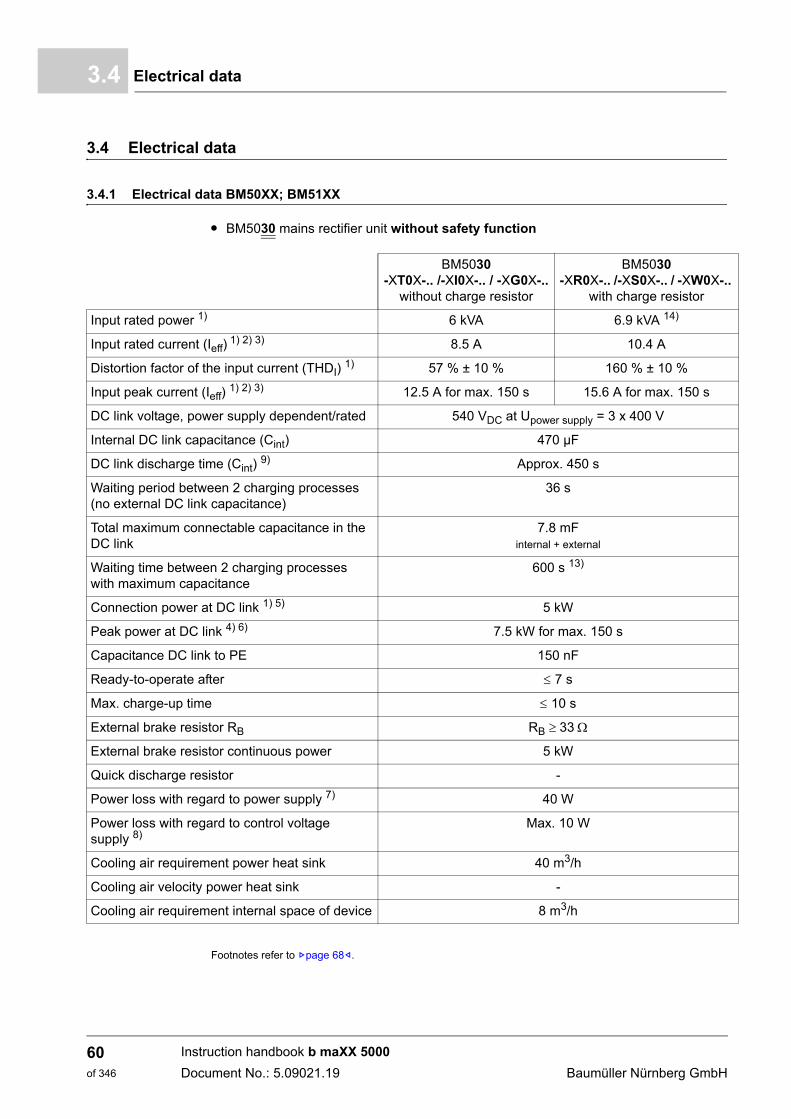
Electrical data3.4
3.4 Electrical data
3.4.1 Electrical data BM50XX; BM51XX
m BM5030 mains rectifier unit without safety function
Footnotes refer to Zpage 68–.
BM5030-XT0X-.. /-XI0X-.. / -XG0X-..
without charge resistor
BM5030-XR0X-.. /-XS0X-.. / -XW0X-..
with charge resistor
Input rated power 1) 6 kVA 6.9 kVA 14)
Input rated current (Ieff) 1) 2) 3) 8.5 A 10.4 A
Distortion factor of the input current (THDI) 1) 57 % ± 10 % 160 % ± 10 %
Input peak current (Ieff) 1) 2) 3) 12.5 A for max. 150 s 15.6 A for max. 150 s
DC link voltage, power supply dependent/rated 540 VDC at Upower supply = 3 x 400 V
Internal DC link capacitance (Cint) 470 µF
DC link discharge time (Cint) 9) Approx. 450 s
Waiting period between 2 charging processes (no external DC link capacitance)
36 s
Total maximum connectable capacitance in the DC link
7.8 mFinternal + external
Waiting time between 2 charging processes with maximum capacitance
600 s 13)
Connection power at DC link 1) 5) 5 kW
Peak power at DC link 4) 6) 7.5 kW for max. 150 s
Capacitance DC link to PE 150 nF
Ready-to-operate after 7 s
Max. charge-up time 10 s
External brake resistor RB RB 33
External brake resistor continuous power 5 kW
Quick discharge resistor -
Power loss with regard to power supply 7) 40 W
Power loss with regard to control voltage supply 8)
Max. 10 W
Cooling air requirement power heat sink 40 m3/h
Cooling air velocity power heat sink -
Cooling air requirement internal space of device 8 m3/h
Instruction handbook b maXX 5000
Document No.: 5.09021.19 Baumüller Nürnberg GmbH
60of 346
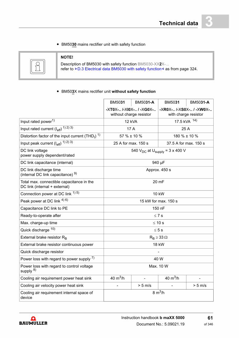
Technical data 3
m BM5030 mains rectifier unit with safety functionm BM503X mains rectifier unit without safety function
NOTE!
Description of BM5030 with safety function BM5030-XX2X-...refer to ZD.3 Electrical data BM5030 with safety function– as from page 324.
BM5031 BM5031-A BM5031 BM5031-A
-XT0X-.. /-XI0X-.. / -XG0X-..without charge resistor
-XR0X-.. /-XS0X-.. / -XW0X-..with charge resistor
Input rated power1) 12 kVA 17.5 kVA 14)
Input rated current (Ieff) 1) 2) 3) 17 A 25 A
Distortion factor of the input current (THDI) 1) 57 % ± 10 % 180 % ± 10 %
Input peak current (Ieff) 1) 2) 3) 25 A for max. 150 s 37.5 A for max. 150 s
DC link voltage power supply dependent/rated
540 VDC at Usupply = 3 x 400 V
DC link capacitance (internal) 940 µF
DC link discharge time(internal DC link capacitance) 9)
Approx. 450 s
Total max. connectible capacitance in the DC link (internal + external)
20 mF
Connection power at DC link 1) 5) 10 kW
Peak power at DC link 4) 6) 15 kW for max. 150 s
Capacitance DC link to PE 150 nF
Ready-to-operate after 7 s
Max. charge-up time 10 s
Quick discharge 10) 5 s
External brake resistor RB RB 33
External brake resistor continuous power 18 kW
Quick discharge resistor -
Power loss with regard to power supply 7) 40 W
Power loss with regard to control voltage supply 8)
Max. 10 W
Cooling air requirement power heat sink 40 m3/h - 40 m3/h -
Cooling air velocity power heat sink - > 5 m/s - > 5 m/s
Cooling air requirement internal space of device
8 m3/h
Instruction handbook b maXX 5000
Document No.: 5.09021.19
61of 346
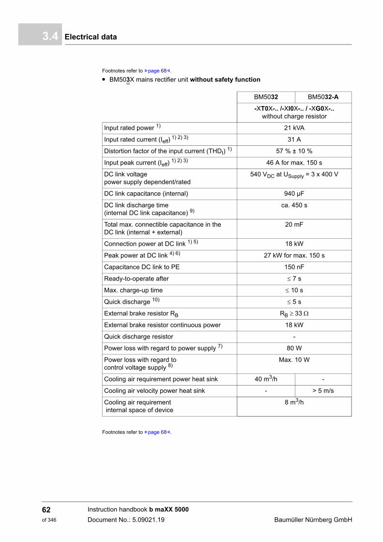
Electrical data3.4
Footnotes refer to Zpage 68–.
m BM503X mains rectifier unit without safety function
Footnotes refer to Zpage 68–.
BM5032 BM5032-A
-XT0X-.. /-XI0X-.. / -XG0X-..without charge resistor
Input rated power 1) 21 kVA
Input rated current (Ieff) 1) 2) 3) 31 A
Distortion factor of the input current (THDI) 1) 57 % ± 10 %
Input peak current (Ieff) 1) 2) 3) 46 A for max. 150 s
DC link voltage power supply dependent/rated
540 VDC at USupply = 3 x 400 V
DC link capacitance (internal) 940 µF
DC link discharge time(internal DC link capacitance) 9)
ca. 450 s
Total max. connectible capacitance in the DC link (internal + external)
20 mF
Connection power at DC link 1) 5) 18 kW
Peak power at DC link 4) 6) 27 kW for max. 150 s
Capacitance DC link to PE 150 nF
Ready-to-operate after 7 s
Max. charge-up time 10 s
Quick discharge 10) 5 s
External brake resistor RB RB 33
External brake resistor continuous power 18 kW
Quick discharge resistor -
Power loss with regard to power supply 7) 80 W
Power loss with regard to control voltage supply 8)
Max. 10 W
Cooling air requirement power heat sink 40 m3/h -
Cooling air velocity power heat sink - > 5 m/s
Cooling air requirement internal space of device
8 m3/h
Instruction handbook b maXX 5000
Document No.: 5.09021.19 Baumüller Nürnberg GmbH
62of 346
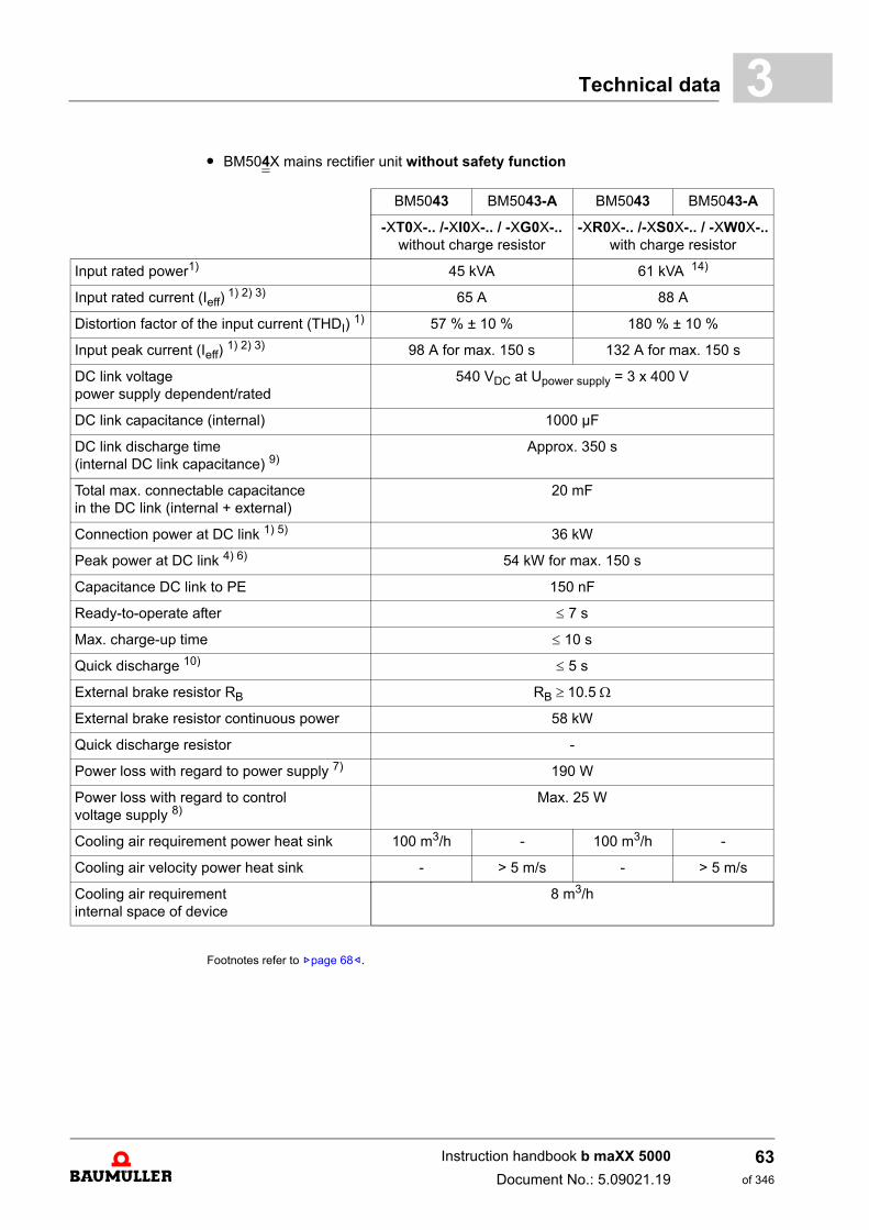
Technical data 3
m BM504X mains rectifier unit without safety functionFootnotes refer to Zpage 68–.
BM5043 BM5043-A BM5043 BM5043-A
-XT0X-.. /-XI0X-.. / -XG0X-..without charge resistor
-XR0X-.. /-XS0X-.. / -XW0X-..with charge resistor
Input rated power1) 45 kVA 61 kVA 14)
Input rated current (Ieff) 1) 2) 3) 65 A 88 A
Distortion factor of the input current (THDI) 1) 57 % ± 10 % 180 % ± 10 %
Input peak current (Ieff) 1) 2) 3) 98 A for max. 150 s 132 A for max. 150 s
DC link voltage power supply dependent/rated
540 VDC at Upower supply = 3 x 400 V
DC link capacitance (internal) 1000 µF
DC link discharge time (internal DC link capacitance) 9)
Approx. 350 s
Total max. connectable capacitance in the DC link (internal + external)
20 mF
Connection power at DC link 1) 5) 36 kW
Peak power at DC link 4) 6) 54 kW for max. 150 s
Capacitance DC link to PE 150 nF
Ready-to-operate after 7 s
Max. charge-up time 10 s
Quick discharge 10) 5 s
External brake resistor RB RB 10.5
External brake resistor continuous power 58 kW
Quick discharge resistor -
Power loss with regard to power supply 7) 190 W
Power loss with regard to control voltage supply 8)
Max. 25 W
Cooling air requirement power heat sink 100 m3/h - 100 m3/h -
Cooling air velocity power heat sink - > 5 m/s - > 5 m/s
Cooling air requirement internal space of device
8 m3/h
Instruction handbook b maXX 5000
Document No.: 5.09021.19
63of 346
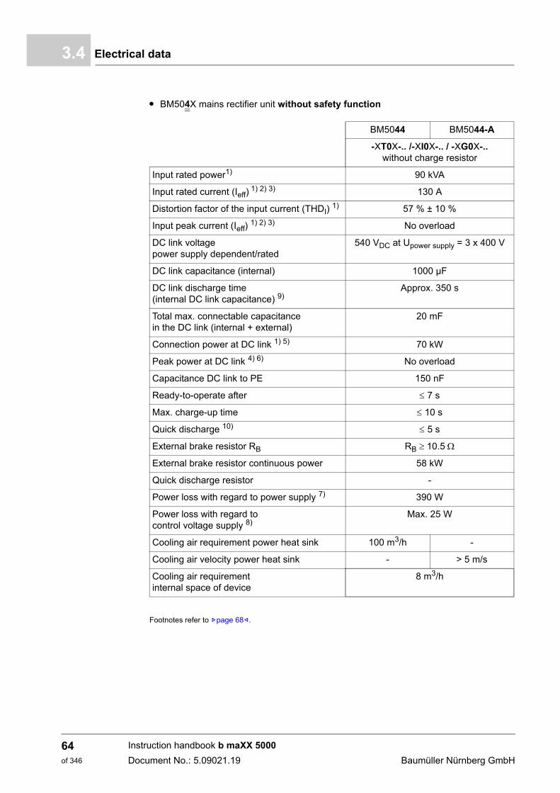
Electrical data3.4
m BM504X mains rectifier unit without safety function
Footnotes refer to Zpage 68–.
BM5044 BM5044-A
-XT0X-.. /-XI0X-.. / -XG0X-..without charge resistor
Input rated power1) 90 kVA
Input rated current (Ieff) 1) 2) 3) 130 A
Distortion factor of the input current (THDI) 1) 57 % ± 10 %
Input peak current (Ieff) 1) 2) 3) No overload
DC link voltage power supply dependent/rated
540 VDC at Upower supply = 3 x 400 V
DC link capacitance (internal) 1000 µF
DC link discharge time (internal DC link capacitance) 9)
Approx. 350 s
Total max. connectable capacitance in the DC link (internal + external)
20 mF
Connection power at DC link 1) 5) 70 kW
Peak power at DC link 4) 6) No overload
Capacitance DC link to PE 150 nF
Ready-to-operate after 7 s
Max. charge-up time 10 s
Quick discharge 10) 5 s
External brake resistor RB RB 10.5
External brake resistor continuous power 58 kW
Quick discharge resistor -
Power loss with regard to power supply 7) 390 W
Power loss with regard to control voltage supply 8)
Max. 25 W
Cooling air requirement power heat sink 100 m3/h -
Cooling air velocity power heat sink - > 5 m/s
Cooling air requirement internal space of device
8 m3/h
Instruction handbook b maXX 5000
Document No.: 5.09021.19 Baumüller Nürnberg GmbH
64of 346
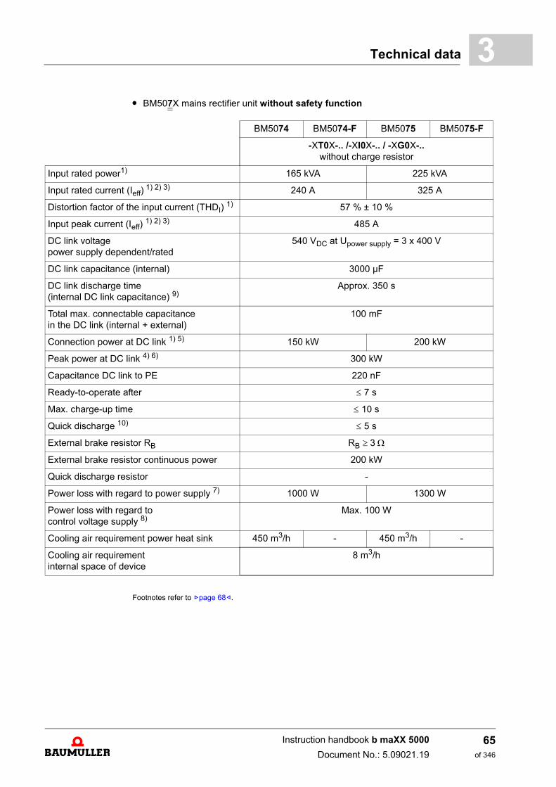
Technical data 3
m BM507X mains rectifier unit without safety functionFootnotes refer to Zpage 68–.
BM5074 BM5074-F BM5075 BM5075-F
-XT0X-.. /-XI0X-.. / -XG0X-..without charge resistor
Input rated power1) 165 kVA 225 kVA
Input rated current (Ieff) 1) 2) 3) 240 A 325 A
Distortion factor of the input current (THDI) 1) 57 % ± 10 %
Input peak current (Ieff) 1) 2) 3) 485 A
DC link voltage power supply dependent/rated
540 VDC at Upower supply = 3 x 400 V
DC link capacitance (internal) 3000 µF
DC link discharge time (internal DC link capacitance) 9)
Approx. 350 s
Total max. connectable capacitance in the DC link (internal + external)
100 mF
Connection power at DC link 1) 5) 150 kW 200 kW
Peak power at DC link 4) 6) 300 kW
Capacitance DC link to PE 220 nF
Ready-to-operate after 7 s
Max. charge-up time 10 s
Quick discharge 10) 5 s
External brake resistor RB RB 3
External brake resistor continuous power 200 kW
Quick discharge resistor -
Power loss with regard to power supply 7) 1000 W 1300 W
Power loss with regard to control voltage supply 8)
Max. 100 W
Cooling air requirement power heat sink 450 m3/h - 450 m3/h -
Cooling air requirement internal space of device
8 m3/h
Instruction handbook b maXX 5000
Document No.: 5.09021.19
65of 346
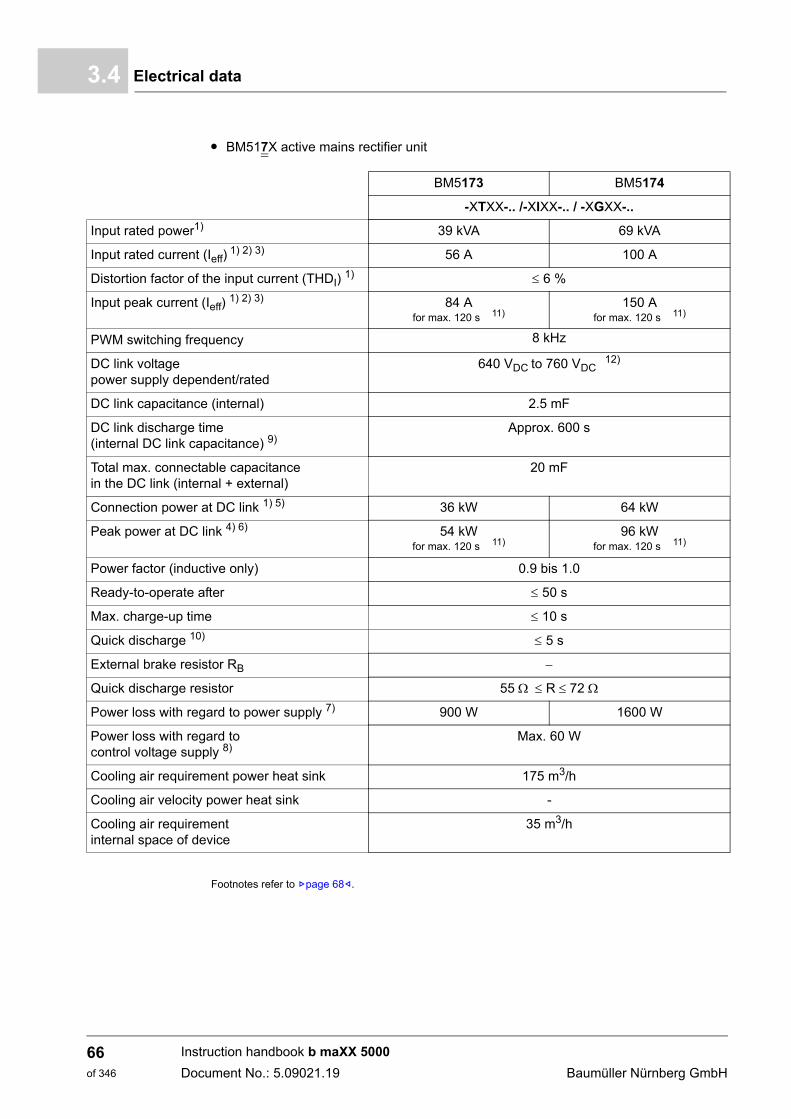
Electrical data3.4
m BM517X active mains rectifier unit
Footnotes refer to Zpage 68–.
BM5173 BM5174
-XTXX-.. /-XIXX-.. / -XGXX-..
Input rated power1) 39 kVA 69 kVA
Input rated current (Ieff) 1) 2) 3) 56 A 100 A
Distortion factor of the input current (THDI) 1) 6 %
Input peak current (Ieff) 1) 2) 3) 84 A
for max. 120 s 11)150 A
for max. 120 s 11)
PWM switching frequency 8 kHz
DC link voltage power supply dependent/rated
640 VDC to 760 VDC12)
DC link capacitance (internal) 2.5 mF
DC link discharge time(internal DC link capacitance) 9)
Approx. 600 s
Total max. connectable capacitance in the DC link (internal + external)
20 mF
Connection power at DC link 1) 5) 36 kW 64 kW
Peak power at DC link 4) 6) 54 kW for max. 120 s 11)
96 kW for max. 120 s 11)
Power factor (inductive only) 0.9 bis 1.0
Ready-to-operate after 50 s
Max. charge-up time 10 s
Quick discharge 10) 5 s
External brake resistor RB
Quick discharge resistor 55 R 72
Power loss with regard to power supply 7) 900 W 1600 W
Power loss with regard to control voltage supply 8)
Max. 60 W
Cooling air requirement power heat sink 175 m3/h
Cooling air velocity power heat sink -
Cooling air requirement internal space of device
35 m3/h
Instruction handbook b maXX 5000
Document No.: 5.09021.19 Baumüller Nürnberg GmbH
66of 346
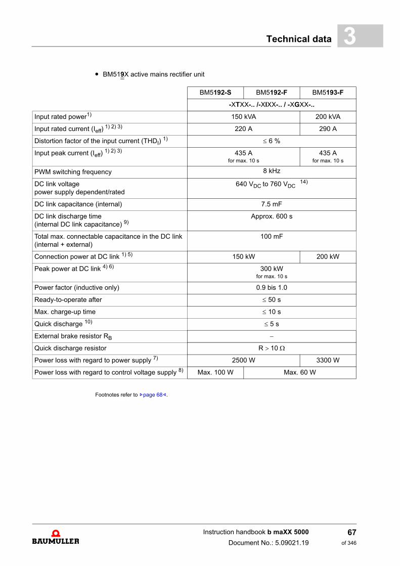
Technical data 3
m BM519X active mains rectifier unitFootnotes refer to Zpage 68–.
BM5192-S BM5192-F BM5193-F
-XTXX-.. /-XIXX-.. / -XGXX-..
Input rated power1) 150 kVA 200 kVA
Input rated current (Ieff) 1) 2) 3) 220 A 290 A
Distortion factor of the input current (THDI) 1) 6 %
Input peak current (Ieff) 1) 2) 3) 435 A
for max. 10 s435 A
for max. 10 s
PWM switching frequency 8 kHz
DC link voltage power supply dependent/rated
640 VDC to 760 VDC14)
DC link capacitance (internal) 7.5 mF
DC link discharge time(internal DC link capacitance) 9)
Approx. 600 s
Total max. connectable capacitance in the DC link(internal + external)
100 mF
Connection power at DC link 1) 5) 150 kW 200 kW
Peak power at DC link 4) 6) 300 kW for max. 10 s
Power factor (inductive only) 0.9 bis 1.0
Ready-to-operate after 50 s
Max. charge-up time 10 s
Quick discharge 10) 5 s
External brake resistor RB
Quick discharge resistor R 10
Power loss with regard to power supply 7) 2500 W 3300 W
Power loss with regard to control voltage supply 8) Max. 100 W Max. 60 W
Instruction handbook b maXX 5000
Document No.: 5.09021.19
67of 346
Electrical data3.4
1) All rated values are based on an power supply voltage of 400 V/50 Hz, a DC link voltage of 540 V (BM50XX)or 640 V (BM51XX), a control voltage of 24 V and a surrounding temperature of 40 °C.
2) The input current must be reduced between 40 °C and 55 °C, refer to correction values at changed operationconditions, ZCorrection values for the output current of the mains inverter BM50XX, BM51XX– on page 51.
3) The mains rectifier draws the rated/peak current at rated supply voltage. The input current must be reducedif power supply voltage is higher than 400 V and the DC link output power remains constant, refer to ZDer-ating: Input current BM50XX, BM517X, BM519X– on page 54.
4) The actual possible overload time depends on the preloading of the device and the heat sink temperatureand is detected by the overload monitoring of the device.
5) With the permissible continuous DC link connected power, the power supply current is reduced. When se-lecting the connected axes ensure that the DC link connected power is not exceeded, refer to ZDerating: DClink power B503X, BM504X, BM517X, BM519X– on page 57.
6) This power consumption is only permitted for a short period of time. This must be ensured by means of ap-propriate configuration of the connected axes.
7) Including external power choke8) Without loads on the digital outputs9) Residual voltage < 60 VDC10) It is necessary to connect a quick discharge resistor or a brake resistor!11) Cold plate version max. 30 s
For details refer to ZLoad cycle according EN61800-6– as from page 7812) For further information refer to parameter 141.8 DC link voltage set value at parameter manual b maXX 500013) Between the min. waiting time (internal DC link capacitance only) and the max. waiting time (maximum DC
link capacitance) can be linearly interpolated depending on the total capacitance value.14) Mains inductance uk min = 0,5 %
NOTE!The distortion factor of the input current of following devices BM50XX-XR /XS /XW ,, is at least twice as much the factor at operation with power choke.The user has to check with the local power supplier whether an operation without power choke is allowed.
Instruction handbook b maXX 5000
Document No.: 5.09021.19 Baumüller Nürnberg GmbH
68of 346
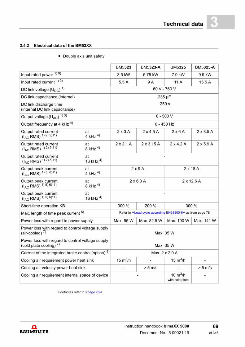
Technical data 3
3.4.2 Electrical data of the BM53XXm Double axis unit safety
Footnotes refer to Zpage 76–.
BM5323 BM5323-A BM5325 BM5325-A
Input rated power 1) 9) 3.5 kW 5.75 kW 7.0 kW 9.9 kW
Input rated current 1) 9) 5.5 A 9 A 11 A 15.5 A
DC link voltage (UDC) 1) 60 V - 760 V
DC link capacitance (internal) 235 µF
DC link discharge time (internal DC link capacitance)
250 s
Output voltage (UAC) 1) 3) 0 - 500 V
Output frequency at 4 kHz 4) 0 - 450 Hz
Output rated current (IAC RMS) 1) 2) 5)11)
at 4 kHz 4)
2 x 3 A 2 x 4.5 A 2 x 6 A 2 x 8.5 A
Output rated current (IAC RMS) 1) 2) 5)11)
at 8 kHz 4)
2 x 2.1 A 2 x 3.15 A 2 x 4.2 A 2 x 5.9 A
Output rated current (IAC RMS) 1) 2) 5)11)
at 16 kHz 4)
-
Output peak current (IAC RMS) 1) 5) 6)11)
at 4 kHz 4)
2 x 9 A 2 x 18 A
Output peak current (IAC RMS) 1) 5) 6)11)
at 8 kHz 4)
2 x 6.3 A 2 x 12.6 A
Output peak current (IAC RMS) 1) 5) 6)11)
at 16 kHz 4)
-
Short-time operation KB 300 % 200 % 300 %
Max. length of time peak current 6) Refer to ZLoad cycle according EN61800-6– as from page 78
Power loss with regard to power supply Max. 55 W Max. 82.5 W Max. 100 W Max. 141 W
Power loss with regard to control voltage supply (air-cooled) 7) Max. 35 W
Power loss with regard to control voltage supply (cold plate cooling) 7) Max. 35 W
Current of the integrated brake control (option) 8) Max. 2 x 2.0 A
Cooling air requirement power heat sink 15 m3/h - 15 m3/h -
Cooling air velocity power heat sink - > 5 m/s - > 5 m/s
Cooling air requirement internal space of device - 10 m3/hwith cold plate
-
Instruction handbook b maXX 5000
Document No.: 5.09021.19
69of 346
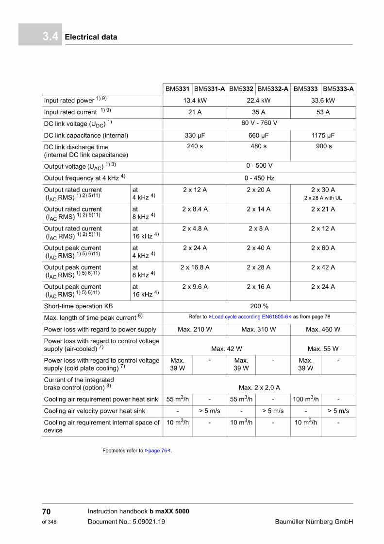
Electrical data3.4
Footnotes refer to Zpage 76–.
BM5331 BM5331-A BM5332 BM5332-A BM5333 BM5333-A
Input rated power 1) 9) 13.4 kW 22.4 kW 33.6 kW
Input rated current 1) 9) 21 A 35 A 53 A
DC link voltage (UDC) 1) 60 V - 760 V
DC link capacitance (internal) 330 µF 660 µF 1175 µF
DC link discharge time (internal DC link capacitance)
240 s 480 s 900 s
Output voltage (UAC) 1) 3) 0 - 500 V
Output frequency at 4 kHz 4) 0 - 450 Hz
Output rated current (IAC RMS) 1) 2) 5)11)
at 4 kHz 4)
2 x 12 A 2 x 20 A 2 x 30 A2 x 28 A with UL
Output rated current (IAC RMS) 1) 2) 5)11)
at 8 kHz 4)
2 x 8.4 A 2 x 14 A 2 x 21 A
Output rated current (IAC RMS) 1) 2) 5)11)
at 16 kHz 4)
2 x 4.8 A 2 x 8 A 2 x 12 A
Output peak current (IAC RMS) 1) 5) 6)11)
at 4 kHz 4)
2 x 24 A 2 x 40 A 2 x 60 A
Output peak current (IAC RMS) 1) 5) 6)11)
at 8 kHz 4)
2 x 16.8 A 2 x 28 A 2 x 42 A
Output peak current (IAC RMS) 1) 5) 6)11)
at 16 kHz 4)
2 x 9.6 A 2 x 16 A 2 x 24 A
Short-time operation KB 200 %
Max. length of time peak current 6) Refer to ZLoad cycle according EN61800-6– as from page 78
Power loss with regard to power supply Max. 210 W Max. 310 W Max. 460 W
Power loss with regard to control voltage supply (air-cooled) 7) Max. 42 W Max. 55 W
Power loss with regard to control voltage supply (cold plate cooling) 7)
Max. 39 W
- Max. 39 W
- Max. 39 W
-
Current of the integrated brake control (option) 8) Max. 2 x 2,0 A
Cooling air requirement power heat sink 55 m3/h - 55 m3/h - 100 m3/h -
Cooling air velocity power heat sink - > 5 m/s - > 5 m/s - > 5 m/s
Cooling air requirement internal space of device
10 m3/h - 10 m3/h - 10 m3/h -
Instruction handbook b maXX 5000
Document No.: 5.09021.19 Baumüller Nürnberg GmbH
70of 346
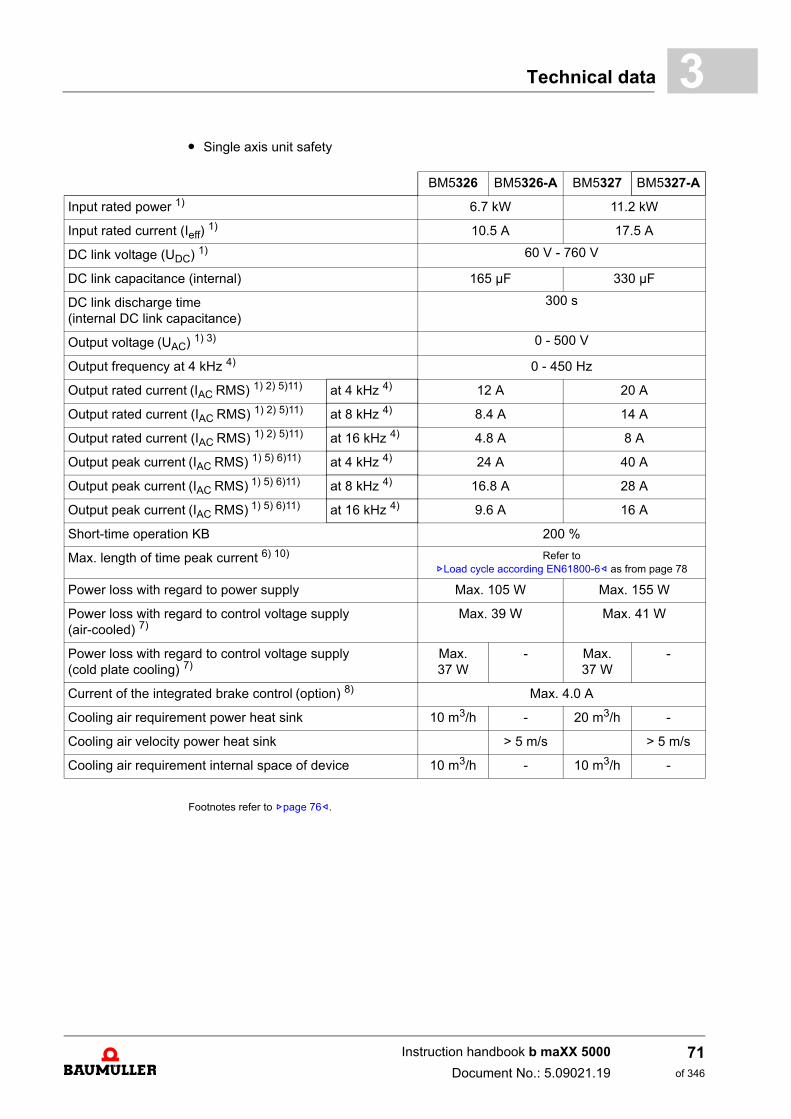
Technical data 3
m Single axis unit safetyFootnotes refer to Zpage 76–.
BM5326 BM5326-A BM5327 BM5327-A
Input rated power 1) 6.7 kW 11.2 kW
Input rated current (Ieff) 1) 10.5 A 17.5 A
DC link voltage (UDC) 1) 60 V - 760 V
DC link capacitance (internal) 165 µF 330 µF
DC link discharge time (internal DC link capacitance)
300 s
Output voltage (UAC) 1) 3) 0 - 500 V
Output frequency at 4 kHz 4) 0 - 450 Hz
Output rated current (IAC RMS) 1) 2) 5)11) at 4 kHz 4) 12 A 20 A
Output rated current (IAC RMS) 1) 2) 5)11) at 8 kHz 4) 8.4 A 14 A
Output rated current (IAC RMS) 1) 2) 5)11) at 16 kHz 4) 4.8 A 8 A
Output peak current (IAC RMS) 1) 5) 6)11) at 4 kHz 4) 24 A 40 A
Output peak current (IAC RMS) 1) 5) 6)11) at 8 kHz 4) 16.8 A 28 A
Output peak current (IAC RMS) 1) 5) 6)11) at 16 kHz 4) 9.6 A 16 A
Short-time operation KB 200 %
Max. length of time peak current 6) 10) Refer to ZLoad cycle according EN61800-6– as from page 78
Power loss with regard to power supply Max. 105 W Max. 155 W
Power loss with regard to control voltage supply (air-cooled) 7)
Max. 39 W Max. 41 W
Power loss with regard to control voltage supply (cold plate cooling) 7)
Max. 37 W
- Max. 37 W
-
Current of the integrated brake control (option) 8) Max. 4.0 A
Cooling air requirement power heat sink 10 m3/h - 20 m3/h -
Cooling air velocity power heat sink > 5 m/s > 5 m/s
Cooling air requirement internal space of device 10 m3/h - 10 m3/h -
Instruction handbook b maXX 5000
Document No.: 5.09021.19
71of 346
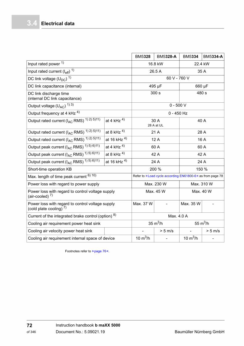
Electrical data3.4
Footnotes refer to Zpage 76–.
BM5328 BM5328-A BM5334 BM5334-A
Input rated power 1) 16.8 kW 22.4 kW
Input rated current (Ieff) 1) 26.5 A 35 A
DC link voltage (UDC) 1) 60 V - 760 V
DC link capacitance (internal) 495 µF 660 µF
DC link discharge time (internal DC link capacitance)
300 s 480 s
Output voltage (UAC) 1) 3) 0 - 500 V
Output frequency at 4 kHz 4) 0 - 450 Hz
Output rated current (IAC RMS) 1) 2) 5)11) at 4 kHz 4) 30 A28 A at UL
40 A
Output rated current (IAC RMS) 1) 2) 5)11) at 8 kHz 4) 21 A 28 A
Output rated current (IAC RMS) 1) 2) 5)11) at 16 kHz 4) 12 A 16 A
Output peak current (IAC RMS) 1) 5) 6)11) at 4 kHz 4) 60 A 60 A
Output peak current (IAC RMS) 1) 5) 6)11) at 8 kHz 4) 42 A 42 A
Output peak current (IAC RMS) 1) 5) 6)11) at 16 kHz 4) 24 A 24 A
Short-time operation KB 200 % 150 %
Max. length of time peak current 6) 10) Refer to ZLoad cycle according EN61800-6– as from page 78
Power loss with regard to power supply Max. 230 W Max. 310 W
Power loss with regard to control voltage supply (air-cooled) 7)
Max. 45 W Max. 40 W
Power loss with regard to control voltage supply (cold plate cooling) 7)
Max. 37 W - Max. 35 W -
Current of the integrated brake control (option) 8) Max. 4.0 A
Cooling air requirement power heat sink 35 m3/h 55 m3/h
Cooling air velocity power heat sink - > 5 m/s - > 5 m/s
Cooling air requirement internal space of device 10 m3/h - 10 m3/h -
Instruction handbook b maXX 5000
Document No.: 5.09021.19 Baumüller Nürnberg GmbH
72of 346
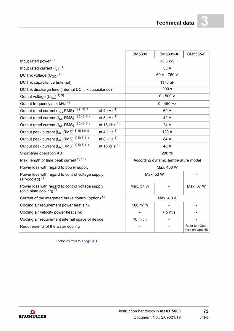
Technical data 3
Footnotes refer to Zpage 76–.
BM5335 BM5335-A BM5335-F
Input rated power 1) 33.6 kW
Input rated current (Ieff) 1) 53 A
DC link voltage (UDC) 1) 60 V - 760 V
DC link capacitance (internal) 1175 µF
DC link discharge time (internal DC link capacitance) 900 s
Output voltage (UAC) 1) 3) 0 - 500 V
Output frequency at 4 kHz 4) 0 - 450 Hz
Output rated current (IAC RMS) 1) 2) 5)11) at 4 kHz 4) 60 A
Output rated current (IAC RMS) 1) 2) 5)11) at 8 kHz 4) 42 A
Output rated current (IAC RMS) 1) 2) 5)11) at 16 kHz 4) 24 A
Output peak current (IAC RMS) 1) 5) 6)11) at 4 kHz 4) 120 A
Output peak current (IAC RMS) 1) 5) 6)11) at 8 kHz 4) 84 A
Output peak current (IAC RMS) 1) 5) 6)11) at 16 kHz 4) 48 A
Short-time operation KB 200 %
Max. length of time peak current 6) 10) According dynamic temperature model
Power loss with regard to power supply Max. 460 W
Power loss with regard to control voltage supply (air-cooled) 7)
Max. 53 W -
Power loss with regard to control voltage supply (cold plate cooling) 7)
Max. 37 W - Max. 37 W
Current of the integrated brake control (option) 8) Max. 4.0 A
Cooling air requirement power heat sink 100 m3/h - -
Cooling air velocity power heat sink - > 5 m/s -
Cooling air requirement internal space of device 10 m3/h - -
Requirements of the water cooling - - Refer to ZCool-ing– on page 58
Instruction handbook b maXX 5000
Document No.: 5.09021.19
73of 346
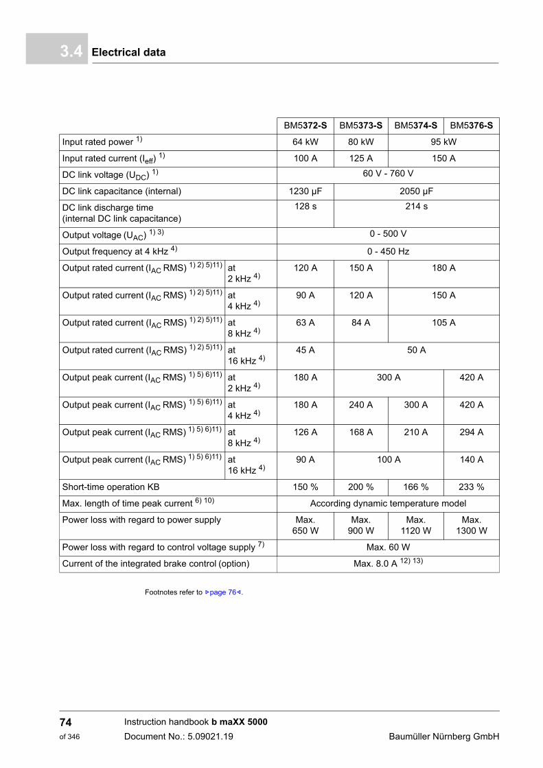
Electrical data3.4
Footnotes refer to Zpage 76–.
BM5372-S BM5373-S BM5374-S BM5376-S
Input rated power 1) 64 kW 80 kW 95 kW
Input rated current (Ieff) 1) 100 A 125 A 150 A
DC link voltage (UDC) 1) 60 V - 760 V
DC link capacitance (internal) 1230 µF 2050 µF
DC link discharge time (internal DC link capacitance)
128 s 214 s
Output voltage (UAC) 1) 3) 0 - 500 V
Output frequency at 4 kHz 4) 0 - 450 Hz
Output rated current (IAC RMS) 1) 2) 5)11) at 2 kHz 4)
120 A 150 A 180 A
Output rated current (IAC RMS) 1) 2) 5)11) at 4 kHz 4)
90 A 120 A 150 A
Output rated current (IAC RMS) 1) 2) 5)11) at 8 kHz 4)
63 A 84 A 105 A
Output rated current (IAC RMS) 1) 2) 5)11) at 16 kHz 4)
45 A 50 A
Output peak current (IAC RMS) 1) 5) 6)11) at 2 kHz 4)
180 A 300 A 420 A
Output peak current (IAC RMS) 1) 5) 6)11) at 4 kHz 4)
180 A 240 A 300 A 420 A
Output peak current (IAC RMS) 1) 5) 6)11) at 8 kHz 4)
126 A 168 A 210 A 294 A
Output peak current (IAC RMS) 1) 5) 6)11) at 16 kHz 4)
90 A 100 A 140 A
Short-time operation KB 150 % 200 % 166 % 233 %
Max. length of time peak current 6) 10) According dynamic temperature model
Power loss with regard to power supply Max. 650 W
Max. 900 W
Max. 1120 W
Max. 1300 W
Power loss with regard to control voltage supply 7) Max. 60 W
Current of the integrated brake control (option) Max. 8.0 A 12) 13)
Instruction handbook b maXX 5000
Document No.: 5.09021.19 Baumüller Nürnberg GmbH
74of 346
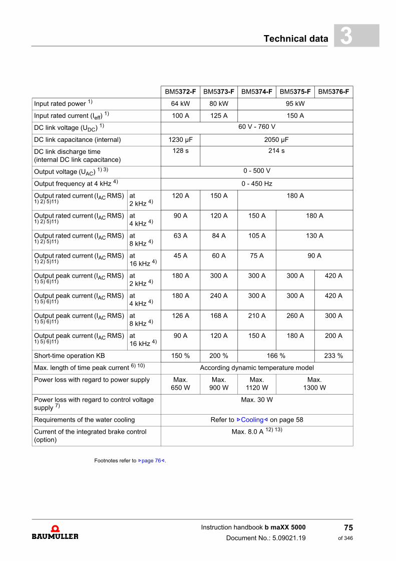
Technical data 3
Footnotes refer to Zpage 76–.
BM5372-F BM5373-F BM5374-F BM5375-F BM5376-F
Input rated power 1) 64 kW 80 kW 95 kW
Input rated current (Ieff) 1) 100 A 125 A 150 A
DC link voltage (UDC) 1) 60 V - 760 V
DC link capacitance (internal) 1230 µF 2050 µF
DC link discharge time (internal DC link capacitance)
128 s 214 s
Output voltage (UAC) 1) 3) 0 - 500 V
Output frequency at 4 kHz 4) 0 - 450 Hz
Output rated current (IAC RMS) 1) 2) 5)11)
at 2 kHz 4)
120 A 150 A 180 A
Output rated current (IAC RMS) 1) 2) 5)11)
at 4 kHz 4)
90 A 120 A 150 A 180 A
Output rated current (IAC RMS) 1) 2) 5)11)
at 8 kHz 4)
63 A 84 A 105 A 130 A
Output rated current (IAC RMS) 1) 2) 5)11)
at 16 kHz 4)
45 A 60 A 75 A 90 A
Output peak current (IAC RMS) 1) 5) 6)11)
at 2 kHz 4)
180 A 300 A 300 A 300 A 420 A
Output peak current (IAC RMS) 1) 5) 6)11)
at 4 kHz 4)
180 A 240 A 300 A 300 A 420 A
Output peak current (IAC RMS) 1) 5) 6)11)
at 8 kHz 4)
126 A 168 A 210 A 260 A 300 A
Output peak current (IAC RMS) 1) 5) 6)11)
at 16 kHz 4)
90 A 120 A 150 A 180 A 200 A
Short-time operation KB 150 % 200 % 166 % 233 %
Max. length of time peak current 6) 10) According dynamic temperature model
Power loss with regard to power supply Max. 650 W
Max. 900 W
Max. 1120 W
Max. 1300 W
Power loss with regard to control voltage supply 7)
Max. 30 W
Requirements of the water cooling Refer to ZCooling– on page 58
Current of the integrated brake control
(option)Max. 8.0 A 12) 13)
Instruction handbook b maXX 5000
Document No.: 5.09021.19
75of 346
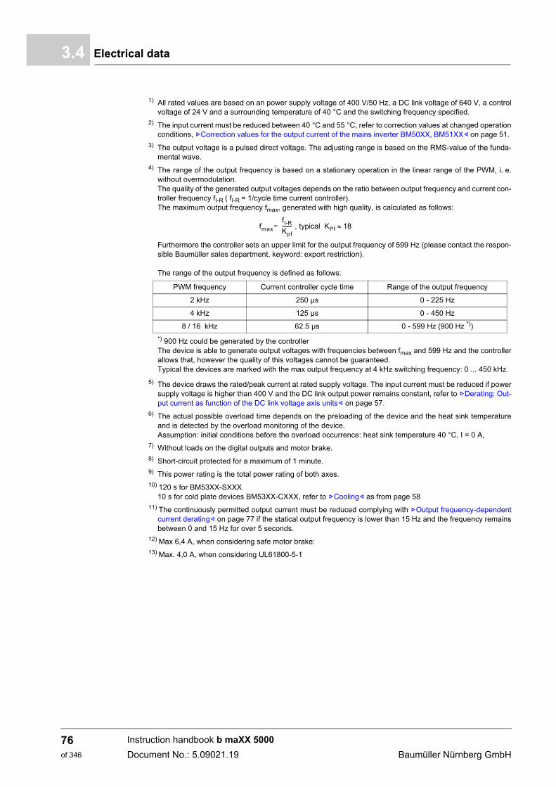
Electrical data3.4
1) All rated values are based on an power supply voltage of 400 V/50 Hz, a DC link voltage of 640 V, a controlvoltage of 24 V and a surrounding temperature of 40 °C and the switching frequency specified.
2) The input current must be reduced between 40 °C and 55 °C, refer to correction values at changed operationconditions, ZCorrection values for the output current of the mains inverter BM50XX, BM51XX– on page 51.
3) The output voltage is a pulsed direct voltage. The adjusting range is based on the RMS-value of the funda-mental wave.
4) The range of the output frequency is based on a stationary operation in the linear range of the PWM, i. e.without overmodulation.The quality of the generated output voltages depends on the ratio between output frequency and current con-troller frequency fI-R ( fI-R = 1/cycle time current controller).The maximum output frequency fmax, generated with high quality, is calculated as follows:
Furthermore the controller sets an upper limit for the output frequency of 599 Hz (please contact the respon-sible Baumüller sales department, keyword: export restriction).
The range of the output frequency is defined as follows:
*) 900 Hz could be generated by the controllerThe device is able to generate output voltages with frequencies between fmax and 599 Hz and the controllerallows that, however the quality of this voltages cannot be guaranteed.Typical the devices are marked with the max output frequency at 4 kHz switching frequency: 0 ... 450 kHz.
5) The device draws the rated/peak current at rated supply voltage. The input current must be reduced if powersupply voltage is higher than 400 V and the DC link output power remains constant, refer to ZDerating: Out-put current as function of the DC link voltage axis units– on page 57.
6) The actual possible overload time depends on the preloading of the device and the heat sink temperatureand is detected by the overload monitoring of the device.Assumption: initial conditions before the overload occurrence: heat sink temperature 40 °C, I = 0 A,
7) Without loads on the digital outputs and motor brake.8) Short-circuit protected for a maximum of 1 minute.9) This power rating is the total power rating of both axes.10) 120 s for BM53XX-SXXX
10 s for cold plate devices BM53XX-CXXX, refer to ZCooling– as from page 5811) The continuously permitted output current must be reduced complying with ZOutput frequency-dependent
current derating– on page 77 if the statical output frequency is lower than 15 Hz and the frequency remainsbetween 0 and 15 Hz for over 5 seconds.
12) Max 6,4 A, when considering safe motor brake:13) Max. 4,0 A, when considering UL61800-5-1
PWM frequency Current controller cycle time Range of the output frequency
2 kHz 250 µs 0 - 225 Hz
4 kHz 125 µs 0 - 450 Hz
8 / 16 kHz 62.5 µs 0 - 599 Hz (900 Hz *))
fmax
fI-RKpf-------- , typical KPf 18=
Instruction handbook b maXX 5000
Document No.: 5.09021.19 Baumüller Nürnberg GmbH
76of 346
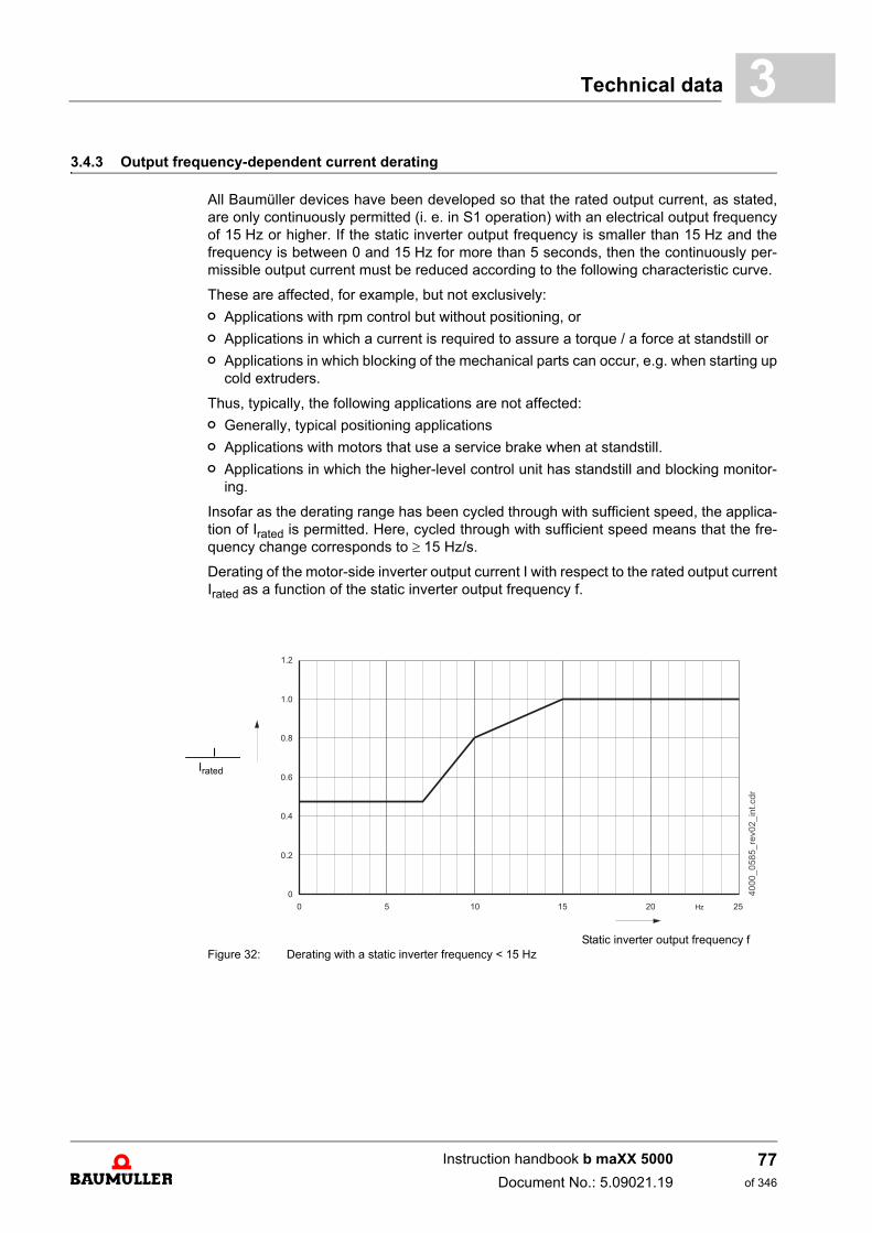
Technical data 3
3.4.3 Output frequency-dependent current deratingAll Baumüller devices have been developed so that the rated output current, as stated,are only continuously permitted (i. e. in S1 operation) with an electrical output frequencyof 15 Hz or higher. If the static inverter output frequency is smaller than 15 Hz and thefrequency is between 0 and 15 Hz for more than 5 seconds, then the continuously per-missible output current must be reduced according to the following characteristic curve.
These are affected, for example, but not exclusively:
n Applications with rpm control but without positioning, or
n Applications in which a current is required to assure a torque / a force at standstill or
n Applications in which blocking of the mechanical parts can occur, e.g. when starting upcold extruders.
Thus, typically, the following applications are not affected:
n Generally, typical positioning applications
n Applications with motors that use a service brake when at standstill.
n Applications in which the higher-level control unit has standstill and blocking monitor-ing.
Insofar as the derating range has been cycled through with sufficient speed, the applica-tion of Irated is permitted. Here, cycled through with sufficient speed means that the fre-quency change corresponds to 15 Hz/s.
Derating of the motor-side inverter output current I with respect to the rated output currentIrated as a function of the static inverter output frequency f.
Static inverter output frequency fFigure 32: Derating with a static inverter frequency < 15 Hz
I Irated
Instruction handbook b maXX 5000
Document No.: 5.09021.19
77of 346
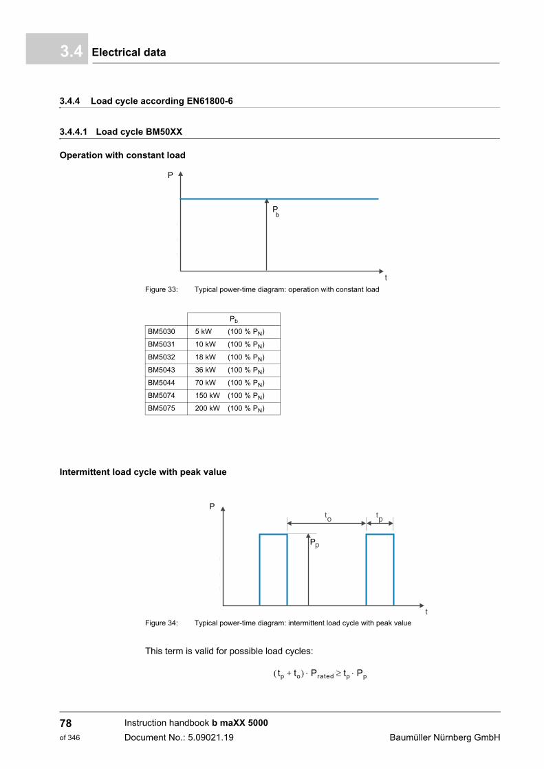
Electrical data3.4
3.4.4 Load cycle according EN61800-6
3.4.4.1 Load cycle BM50XX
Operation with constant load
Figure 33: Typical power-time diagram: operation with constant load
Intermittent load cycle with peak value
Figure 34: Typical power-time diagram: intermittent load cycle with peak value
This term is valid for possible load cycles:
P
Pb
Pb
BM5030 5 kW (100 % PN)
BM5031 10 kW (100 % PN)
BM5032 18 kW (100 % PN)
BM5043 36 kW (100 % PN)
BM5044 70 kW (100 % PN)
BM5074 150 kW (100 % PN)
BM5075 200 kW (100 % PN)
P
P
tp to+ Prated tp Pp
Instruction handbook b maXX 5000
Document No.: 5.09021.19 Baumüller Nürnberg GmbH
78of 346
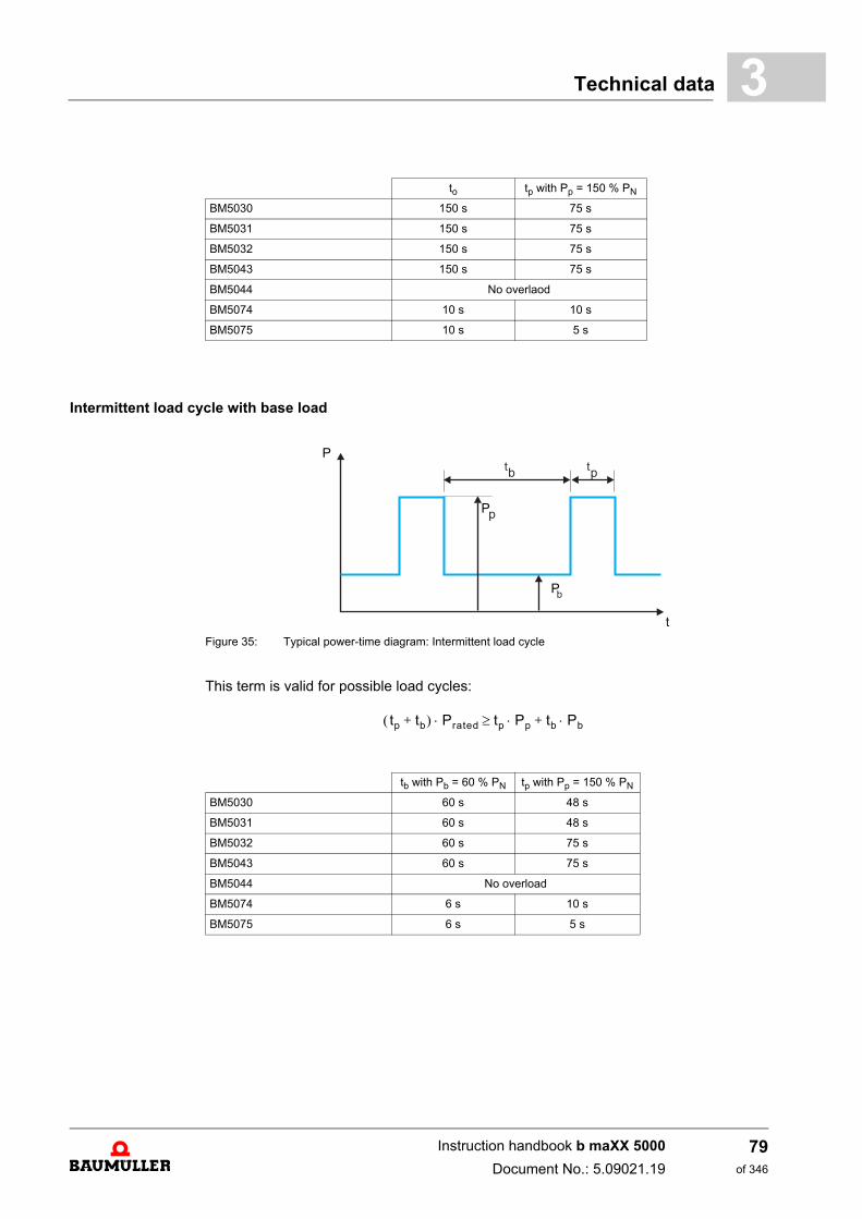
Technical data 3
Intermittent load cycle with base load
Figure 35: Typical power-time diagram: Intermittent load cycle
This term is valid for possible load cycles:
to tp with Pp = 150 % PN
BM5030 150 s 75 s
BM5031 150 s 75 s
BM5032 150 s 75 s
BM5043 150 s 75 s
BM5044 No overlaod
BM5074 10 s 10 s
BM5075 10 s 5 s
tb with Pb = 60 % PN tp with Pp = 150 % PN
BM5030 60 s 48 s
BM5031 60 s 48 s
BM5032 60 s 75 s
BM5043 60 s 75 s
BM5044 No overload
BM5074 6 s 10 s
BM5075 6 s 5 s
P
P
P
tp tb+ Prated tp Pp tb Pb+
Instruction handbook b maXX 5000
Document No.: 5.09021.19
79of 346
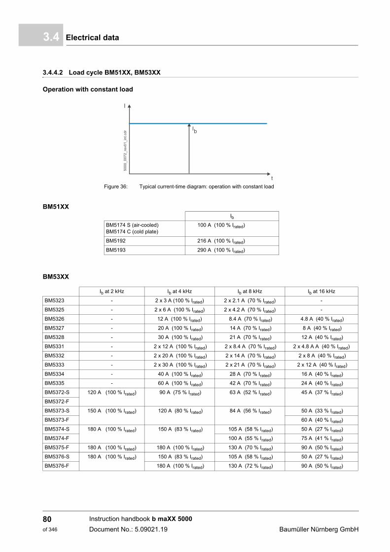
Electrical data3.4
3.4.4.2 Load cycle BM51XX, BM53XX
Operation with constant load
Figure 36: Typical current-time diagram: operation with constant load
BM51XX
BM53XX
Ib
BM5174 S (air-cooled)BM5174 C (cold plate)
100 A (100 % Irated)
BM5192 216 A (100 % Irated)
BM5193 290 A (100 % Irated)
Ib at 2 kHz Ib at 4 kHz Ib at 8 kHz Ib at 16 kHz
BM5323 - 2 x 3 A (100 % Irated) 2 x 2.1 A (70 % Irated) -
BM5325 - 2 x 6 A (100 % Irated) 2 x 4.2 A (70 % Irated) -
BM5326 - 12 A (100 % Irated) 8.4 A (70 % Irated) 4.8 A (40 % Irated)
BM5327 - 20 A (100 % Irated) 14 A (70 % Irated) 8 A (40 % Irated)
BM5328 - 30 A (100 % Irated) 21 A (70 % Irated) 12 A (40 % Irated)
BM5331 - 2 x 12 A (100 % Irated) 2 x 8.4 A (70 % Irated) 2 x 4.8 A A (40 % Irated)
BM5332 - 2 x 20 A (100 % Irated) 2 x 14 A (70 % Irated) 2 x 8 A (40 % Irated)
BM5333 - 2 x 30 A (100 % Irated) 2 x 21 A (70 % Irated) 2 x 12 A (40 % Irated)
BM5334 - 40 A (100 % Irated) 28 A (70 % Irated) 16 A (40 % Irated)
BM5335 - 60 A (100 % Irated) 42 A (70 % Irated) 24 A (40 % Irated)
BM5372-S 120 A (100 % Irated) 90 A (75 % Irated) 63 A (52 % Irated) 45 A (37 % Irated)
BM5372-F
BM5373-S 150 A (100 % Irated) 120 A (80 % Irated) 84 A (56 % Irated) 50 A (33 % Irated)
BM5373-F 60 A (40 % Irated)
BM5374-S 180 A (100 % Irated) 150 A (83 % Irated) 105 A (58 % Irated) 50 A (27 % Irated)
BM5374-F 100 A (55 % Irated) 75 A (41 % Irated)
BM5375-F 180 A (100 % Irated) 180 A (100 % Irated) 130 A (70 % Irated) 90 A (50 % Irated)
BM5376-S 180 A (100 % Irated) 150 A (83 % Irated) 105 A (58 % Irated) 50 A (27 % Irated)
BM5376-F 180 A (100 % Irated) 130 A (72 % Irated) 90 A (50 % Irated)
Instruction handbook b maXX 5000
Document No.: 5.09021.19 Baumüller Nürnberg GmbH
80of 346
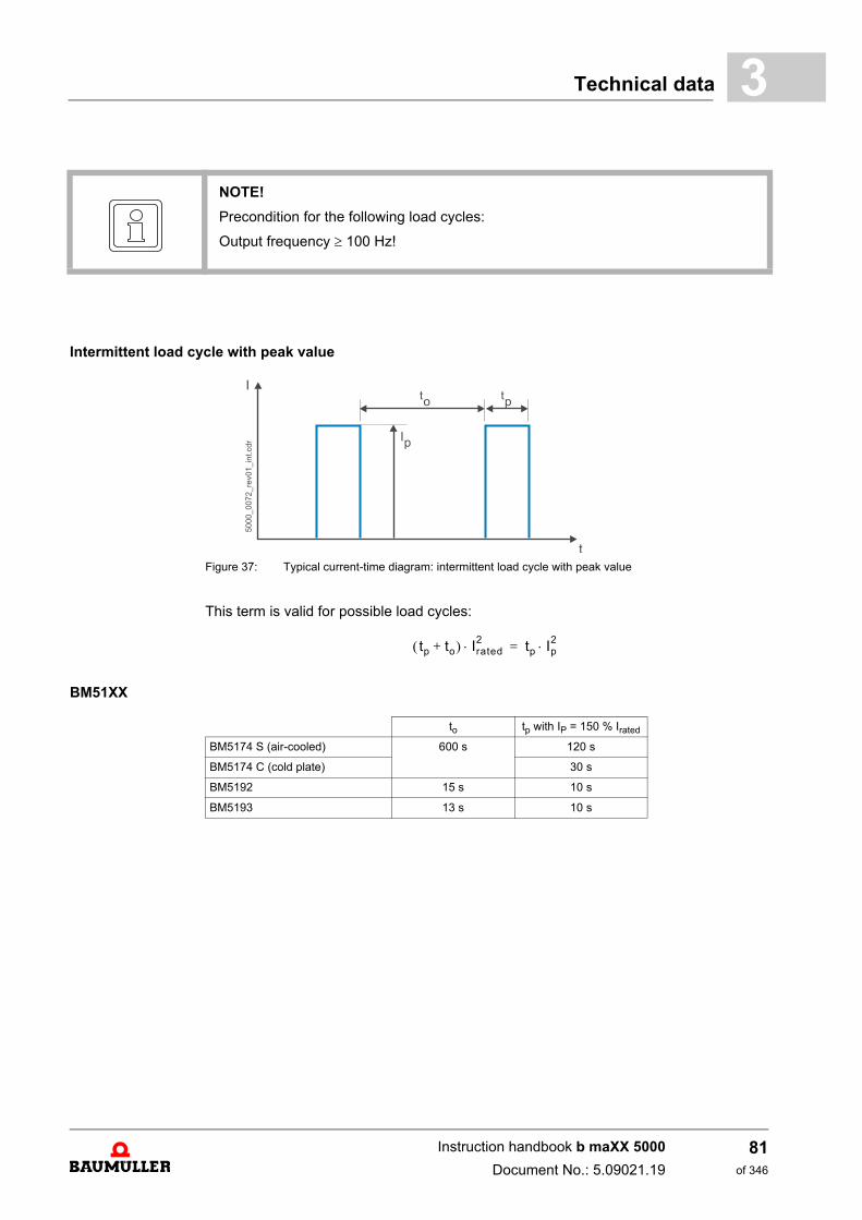
Technical data 3
Intermittent load cycle with peak value
Figure 37: Typical current-time diagram: intermittent load cycle with peak value
This term is valid for possible load cycles:
BM51XX
NOTE!
Precondition for the following load cycles:
Output frequency 100 Hz!
tp to+ Irated2 tp Ip
2=
to tp with IP = 150 % Irated
BM5174 S (air-cooled) 600 s 120 s
BM5174 C (cold plate) 30 s
BM5192 15 s 10 s
BM5193 13 s 10 s
Instruction handbook b maXX 5000
Document No.: 5.09021.19
81of 346
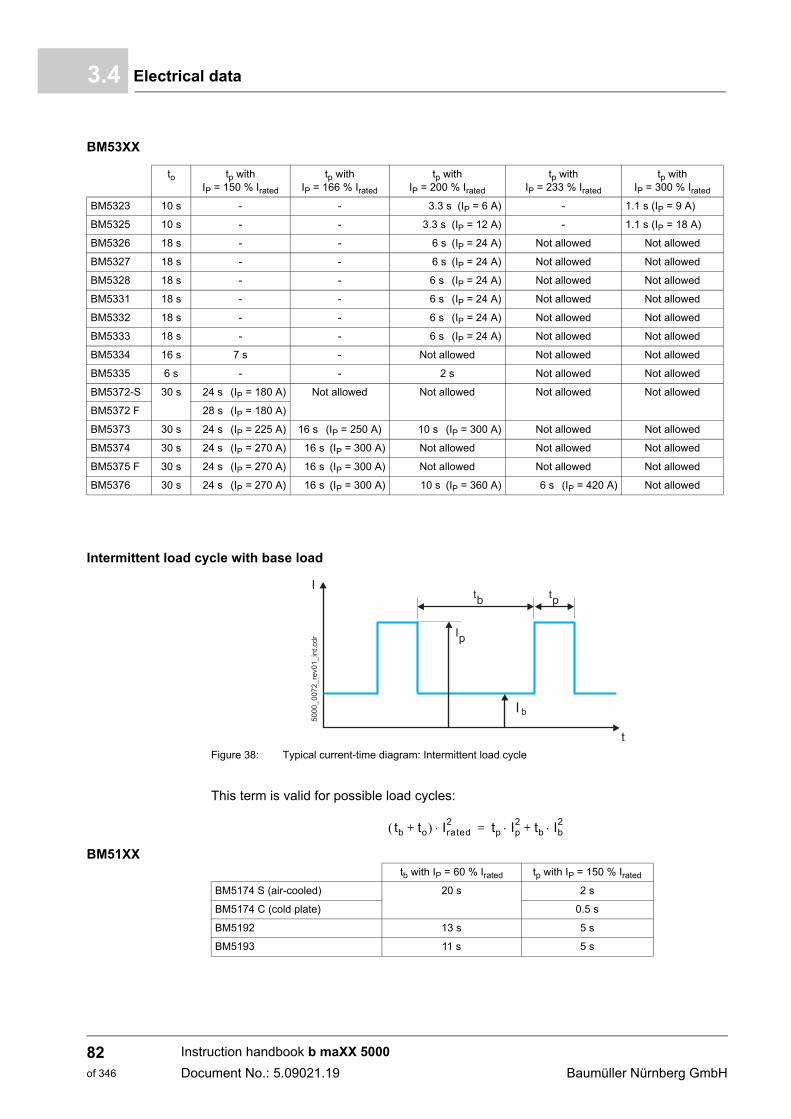
Electrical data3.4
BM53XX
Intermittent load cycle with base load
Figure 38: Typical current-time diagram: Intermittent load cycle
This term is valid for possible load cycles:
BM51XX
to tp with IP = 150 % Irated
tp with IP = 166 % Irated
tp with IP = 200 % Irated
tp with IP = 233 % Irated
tp with IP = 300 % Irated
BM5323 10 s - - 3.3 s (IP = 6 A) - 1.1 s (IP = 9 A)
BM5325 10 s - - 3.3 s (IP = 12 A) - 1.1 s (IP = 18 A)
BM5326 18 s - - 6 s (IP = 24 A) Not allowed Not allowed
BM5327 18 s - - 6 s (IP = 24 A) Not allowed Not allowed
BM5328 18 s - - 6 s (IP = 24 A) Not allowed Not allowed
BM5331 18 s - - 6 s (IP = 24 A) Not allowed Not allowed
BM5332 18 s - - 6 s (IP = 24 A) Not allowed Not allowed
BM5333 18 s - - 6 s (IP = 24 A) Not allowed Not allowed
BM5334 16 s 7 s - Not allowed Not allowed Not allowed
BM5335 6 s - - 2 s Not allowed Not allowed
BM5372-S 30 s 24 s (IP = 180 A) Not allowed Not allowed Not allowed Not allowed
BM5372 F 28 s (IP = 180 A)
BM5373 30 s 24 s (IP = 225 A) 16 s (IP = 250 A) 10 s (IP = 300 A) Not allowed Not allowed
BM5374 30 s 24 s (IP = 270 A) 16 s (IP = 300 A) Not allowed Not allowed Not allowed
BM5375 F 30 s 24 s (IP = 270 A) 16 s (IP = 300 A) Not allowed Not allowed Not allowed
BM5376 30 s 24 s (IP = 270 A) 16 s (IP = 300 A) 10 s (IP = 360 A) 6 s (IP = 420 A) Not allowed
tb to+ Irated2 tp Ip
2 tb Ib2+=
tb with IP = 60 % Irated tp with IP = 150 % Irated
BM5174 S (air-cooled) 20 s 2 s
BM5174 C (cold plate) 0.5 s
BM5192 13 s 5 s
BM5193 11 s 5 s
Instruction handbook b maXX 5000
Document No.: 5.09021.19 Baumüller Nürnberg GmbH
82of 346
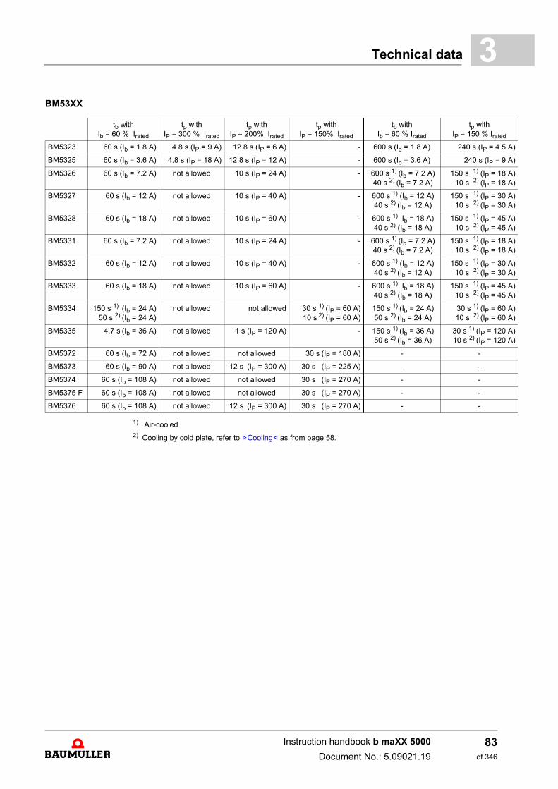
Technical data 3
A)
A)
A)A)
A)A)
A)A)
A)A)
A)A)
A)A)
A)A)
A)A)
BM53XX
1) Air-cooled2) Cooling by cold plate, refer to ZCooling– as from page 58.
tb with Ib = 60 % Irated
tp with IP = 300 % Irated
tp with IP = 200% Irated
tp with IP = 150% Irated
tb with Ib = 60 % Irated
tp with IP = 150 % Irated
BM5323 60 s (Ib = 1.8 A) 4.8 s (IP = 9 A) 12.8 s (IP = 6 A) - 600 s (Ib = 1.8 A) 240 s (IP = 4.5
BM5325 60 s (Ib = 3.6 A) 4.8 s (IP = 18 A) 12.8 s (IP = 12 A) - 600 s (Ib = 3.6 A) 240 s (IP = 9
BM5326 60 s (Ib = 7.2 A) not allowed 10 s (IP = 24 A) - 600 s 1) (Ib = 7.2 A) 40 s 2) (Ib = 7.2 A)
150 s 1) (IP = 18 10 s 2) (IP = 18
BM5327 60 s (Ib = 12 A) not allowed 10 s (IP = 40 A) - 600 s 1) (Ib = 12 A) 40 s 2) (Ib = 12 A)
150 s 1) (IP = 30 10 s 2) (IP = 30
BM5328 60 s (Ib = 18 A) not allowed 10 s (IP = 60 A) - 600 s 1) Ib = 18 A) 40 s 2) (Ib = 18 A)
150 s 1) (IP = 45 10 s 2) (IP = 45
BM5331 60 s (Ib = 7.2 A) not allowed 10 s (IP = 24 A) - 600 s 1) (Ib = 7.2 A) 40 s 2) (Ib = 7.2 A)
150 s 1) (IP = 18 10 s 2) (IP = 18
BM5332 60 s (Ib = 12 A) not allowed 10 s (IP = 40 A) - 600 s 1) (Ib = 12 A) 40 s 2) (Ib = 12 A)
150 s 1) (IP = 30 10 s 2) (IP = 30
BM5333 60 s (Ib = 18 A) not allowed 10 s (IP = 60 A) - 600 s 1) Ib = 18 A) 40 s 2) (Ib = 18 A)
150 s 1) (IP = 45 10 s 2) (IP = 45
BM5334 150 s 1) (Ib = 24 A) 50 s 2) (Ib = 24 A)
not allowed not allowed 30 s 1) (IP = 60 A) 10 s 2) (IP = 60 A)
150 s 1) (Ib = 24 A) 50 s 2) (Ib = 24 A)
30 s 1) (IP = 60 10 s 2) (IP = 60
BM5335 4.7 s (Ib = 36 A) not allowed 1 s (IP = 120 A) - 150 s 1) (Ib = 36 A) 50 s 2) (Ib = 36 A)
30 s 1) (IP = 120 10 s 2) (IP = 120
BM5372 60 s (Ib = 72 A) not allowed not allowed 30 s (IP = 180 A) - -
BM5373 60 s (Ib = 90 A) not allowed 12 s (IP = 300 A) 30 s (IP = 225 A) - -
BM5374 60 s (Ib = 108 A) not allowed not allowed 30 s (IP = 270 A) - -
BM5375 F 60 s (Ib = 108 A) not allowed not allowed 30 s (IP = 270 A) - -
BM5376 60 s (Ib = 108 A) not allowed 12 s (IP = 300 A) 30 s (IP = 270 A) - -
Instruction handbook b maXX 5000
Document No.: 5.09021.19
83of 346
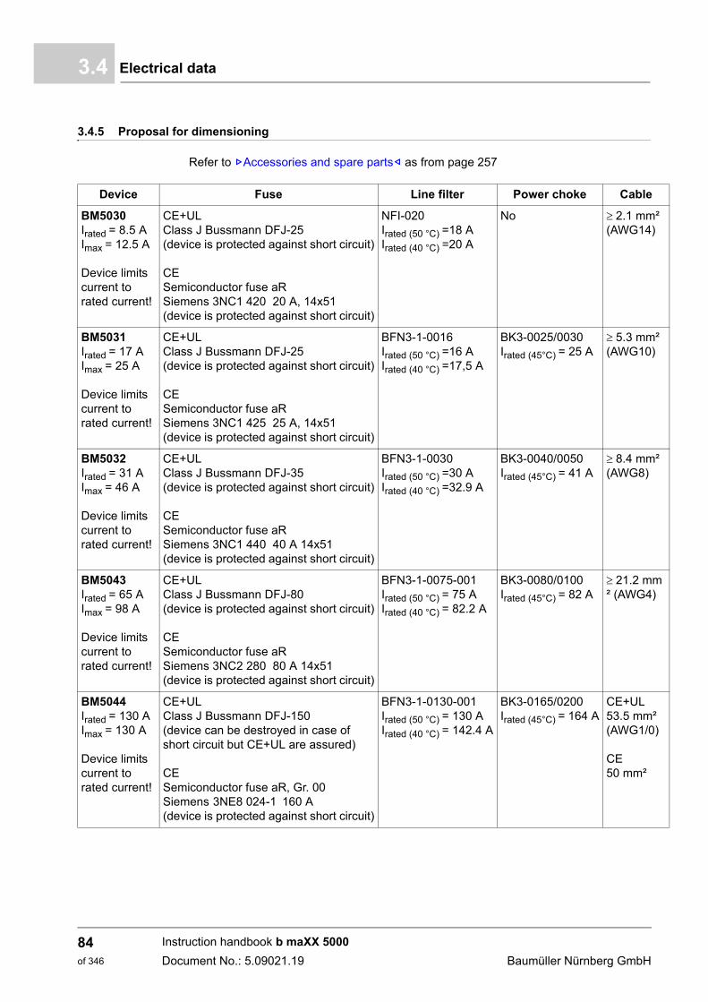
Electrical data3.4
3.4.5 Proposal for dimensioning
Refer to ZAccessories and spare parts– as from page 257
Device Fuse Line filter Power choke Cable
BM5030Irated = 8.5 AImax = 12.5 A
Device limits current to rated current!
CE+UL Class J Bussmann DFJ-25(device is protected against short circuit)
CESemiconductor fuse aR Siemens 3NC1 420 20 A, 14x51(device is protected against short circuit)
NFI-020Irated (50 °C) =18 AIrated (40 °C) =20 A
No 2.1 mm² (AWG14)
BM5031Irated = 17 AImax = 25 A
Device limits current to rated current!
CE+UL Class J Bussmann DFJ-25(device is protected against short circuit)
CESemiconductor fuse aR Siemens 3NC1 425 25 A, 14x51(device is protected against short circuit)
BFN3-1-0016Irated (50 °C) =16 AIrated (40 °C) =17,5 A
BK3-0025/0030Irated (45°C) = 25 A
5.3 mm² (AWG10)
BM5032Irated = 31 AImax = 46 A
Device limits current to rated current!
CE+UL Class J Bussmann DFJ-35(device is protected against short circuit)
CESemiconductor fuse aR Siemens 3NC1 440 40 A 14x51(device is protected against short circuit)
BFN3-1-0030Irated (50 °C) =30 AIrated (40 °C) =32.9 A
BK3-0040/0050Irated (45°C) = 41 A
8.4 mm² (AWG8)
BM5043Irated = 65 AImax = 98 A
Device limits current to rated current!
CE+UL Class J Bussmann DFJ-80(device is protected against short circuit)
CESemiconductor fuse aR Siemens 3NC2 280 80 A 14x51(device is protected against short circuit)
BFN3-1-0075-001Irated (50 °C) = 75 AIrated (40 °C) = 82.2 A
BK3-0080/0100Irated (45°C) = 82 A
21.2 mm² (AWG4)
BM5044Irated = 130 AImax = 130 A
Device limits current to rated current!
CE+UL Class J Bussmann DFJ-150(device can be destroyed in case of short circuit but CE+UL are assured)
CESemiconductor fuse aR, Gr. 00Siemens 3NE8 024-1 160 A (device is protected against short circuit)
BFN3-1-0130-001Irated (50 °C) = 130 AIrated (40 °C) = 142.4 A
BK3-0165/0200Irated (45°C) = 164 A
CE+UL53.5 mm² (AWG1/0)
CE50 mm²
Instruction handbook b maXX 5000
Document No.: 5.09021.19 Baumüller Nürnberg GmbH
84of 346
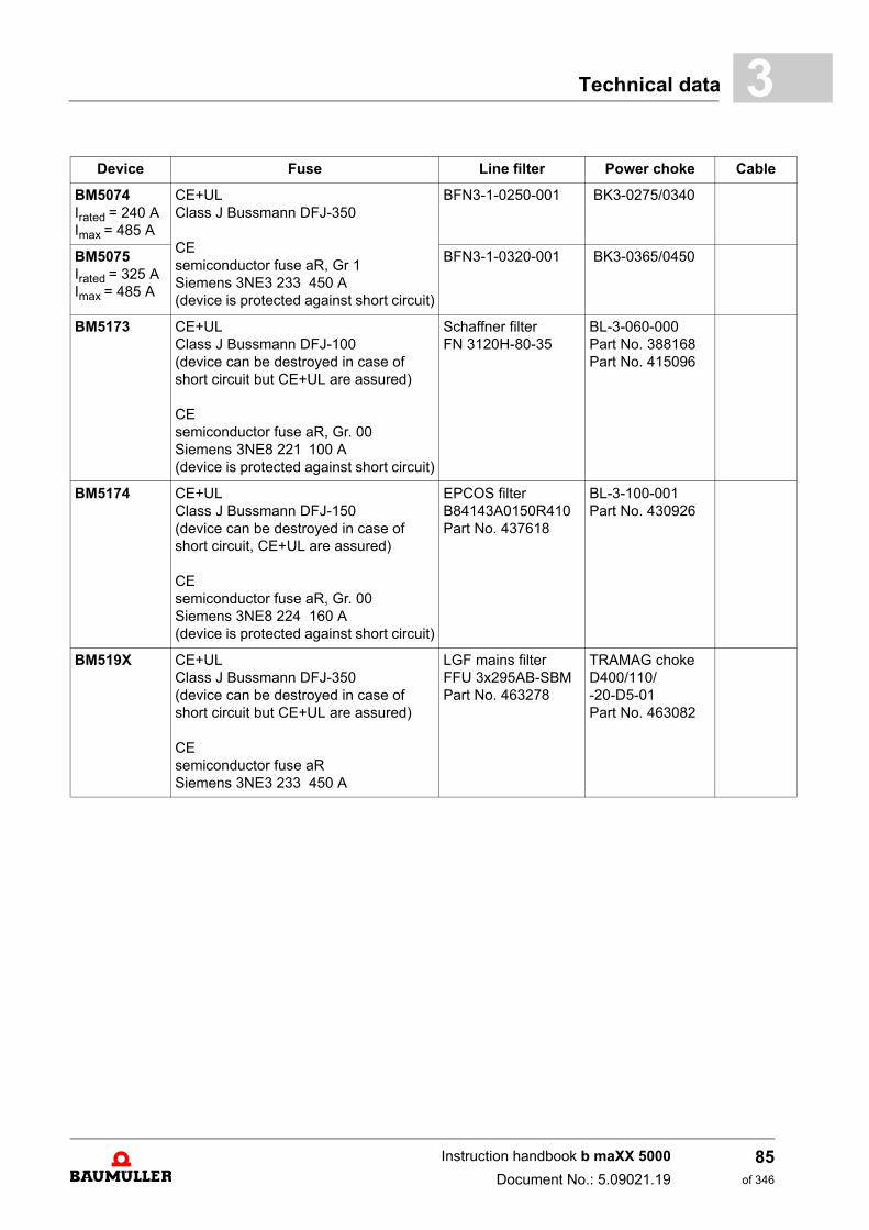
Technical data 3
BM5074Irated = 240 AImax = 485 A
CE+UL Class J Bussmann DFJ-350
CEsemiconductor fuse aR, Gr 1Siemens 3NE3 233 450 A (device is protected against short circuit)
BFN3-1-0250-001 BK3-0275/0340
BM5075Irated = 325 AImax = 485 A
BFN3-1-0320-001 BK3-0365/0450
BM5173 CE+UL Class J Bussmann DFJ-100(device can be destroyed in case of short circuit but CE+UL are assured)
CEsemiconductor fuse aR, Gr. 00Siemens 3NE8 221 100 A (device is protected against short circuit)
Schaffner filterFN 3120H-80-35
BL-3-060-000Part No. 388168Part No. 415096
BM5174 CE+UL Class J Bussmann DFJ-150(device can be destroyed in case of short circuit, CE+UL are assured)
CEsemiconductor fuse aR, Gr. 00Siemens 3NE8 224 160 A (device is protected against short circuit)
EPCOS filterB84143A0150R410Part No. 437618
BL-3-100-001Part No. 430926
BM519X CE+UL Class J Bussmann DFJ-350(device can be destroyed in case of short circuit but CE+UL are assured)
CEsemiconductor fuse aRSiemens 3NE3 233 450 A
LGF mains filterFFU 3x295AB-SBMPart No. 463278
TRAMAG choke D400/110/-20-D5-01Part No. 463082
Device Fuse Line filter Power choke Cable
Instruction handbook b maXX 5000
Document No.: 5.09021.19
85of 346

Electrical data3.4
Instruction handbook b maXX 5000
Document No.: 5.09021.19 Baumüller Nürnberg GmbH
86of 346
4DESIGN AND OPERATION
4.1 Design
The b maXX 5000 series consists of an (active) mains rectifier unit and one or more axisunits, decentralized drive solutions or multi-axis controllers. The possible number of de-vices, that can be connected depends on the connected load of the DC link of the mainsrectifier unit or is limited by the signal bus to a maximum of 12.
b maXX 50XX Mains rectifier unit
This is a mains rectifier unit for supplying axis units or decentralized drive solutionsBM2500 via the DC link.
The applied AC voltage at the three phase power system is transformed by a rectifier onthe input side into DC voltage. The DC link capacitors smooth this DC voltage.
b maXX 51XX Active mains rectifier unit
This is an active mains rectifier unit for supplying axis units via the DC link.
The applied AC voltage at the three phase power system is transformed by a rectifier onthe input side into DC voltage. The DC link capacitors smooth this DC voltage. The activemains rectifier unit can feed back excess braking energy into the mains as sinusoidalelectrical current.
b maXX 53XX Single axis unit safety, double axis unit safety
This is a motor inverter that is supplied from a mains rectifier unit or active mains rectifierunit via the DC link.
From the DC voltage at the DC link, the inverter on the output side produces a three-phase current system with variable frequency and voltage for operation of the connectedmotor.
Controller The controller unit controls the inverter of the power unit. The controller is operated eitherby means of operating software or by means of a higher-level control unit.
NOTE!
Correct operation of the b maXX axis units BM53XX can only be ensured in combi-nation with Baumüller mains rectifier units BM50XX, BM51XX or basic unitsBM4XXX / BM5XXX.
87of 346
Instruction handbook b maXX 5000
Document No.: 5.09021.19
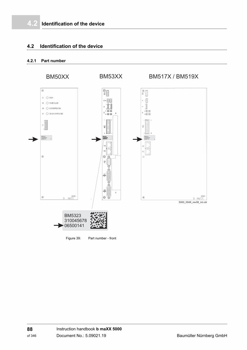
Identification of the device4.2
4.2 Identification of the device
4.2.1 Part number
Figure 39: Part number - front
Instruction handbook b maXX 5000
Document No.: 5.09021.19 Baumüller Nürnberg GmbH
88of 346
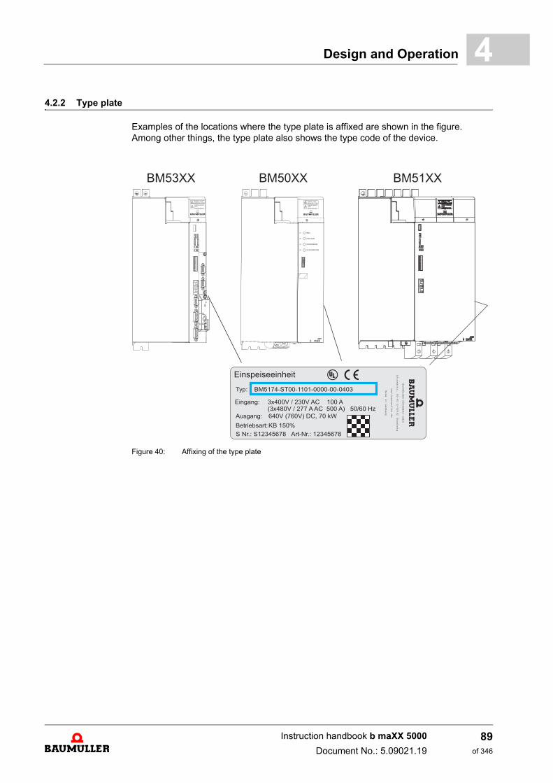
Design and Operation 4
4.2.2 Type plateExamples of the locations where the type plate is affixed are shown in the figure.Among other things, the type plate also shows the type code of the device.
Figure 40: Affixing of the type plate
Instruction handbook b maXX 5000
Document No.: 5.09021.19
89of 346
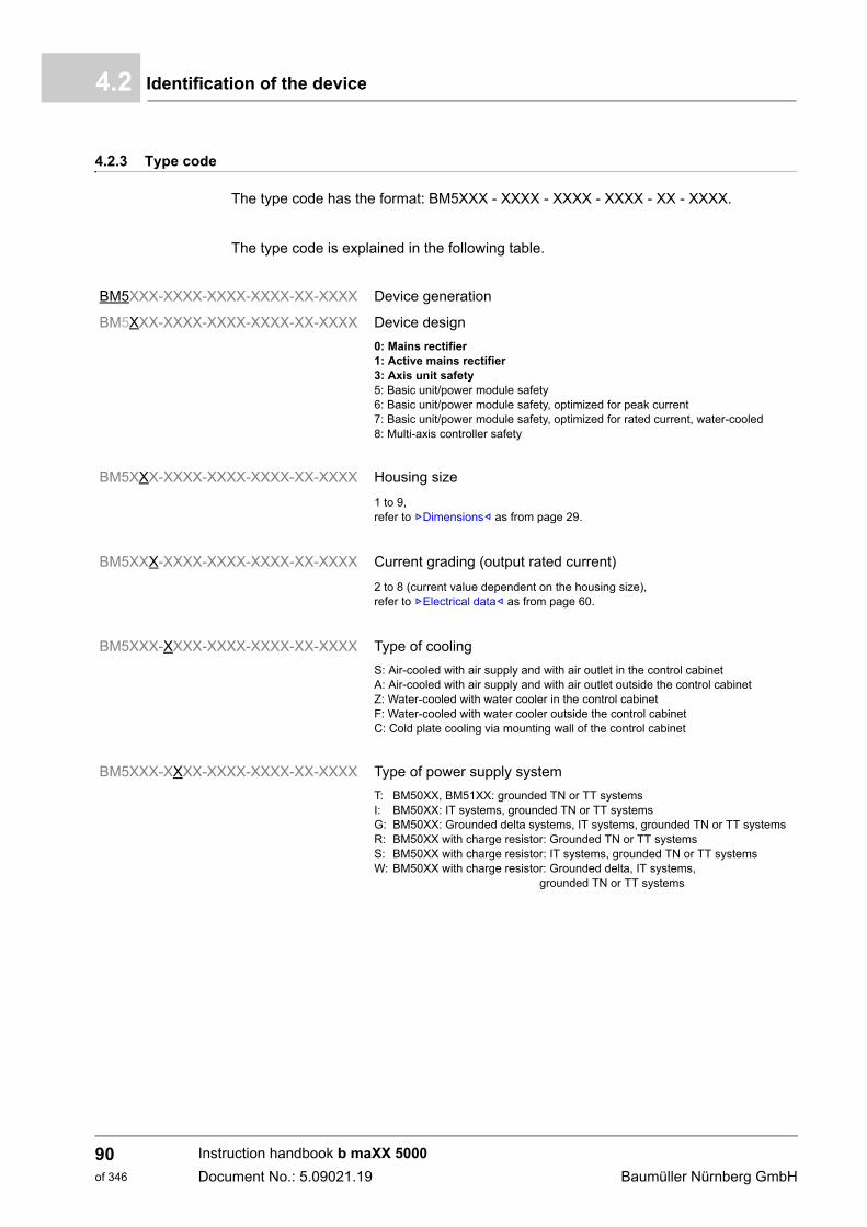
Identification of the device4.2
4.2.3 Type code
The type code has the format: BM5XXX - XXXX - XXXX - XXXX - XX - XXXX.
The type code is explained in the following table.
BM5XXX-XXXX-XXXX-XXXX-XX-XXXX Device generation
BM5XXX-XXXX-XXXX-XXXX-XX-XXXX Device design
0: Mains rectifier1: Active mains rectifier3: Axis unit safety5: Basic unit/power module safety6: Basic unit/power module safety, optimized for peak current7: Basic unit/power module safety, optimized for rated current, water-cooled8: Multi-axis controller safety
BM5XXX-XXXX-XXXX-XXXX-XX-XXXX Housing size
1 to 9,refer to ZDimensions– as from page 29.
BM5XXX-XXXX-XXXX-XXXX-XX-XXXX Current grading (output rated current)
2 to 8 (current value dependent on the housing size), refer to ZElectrical data– as from page 60.
BM5XXX-XXXX-XXXX-XXXX-XX-XXXX Type of cooling
S: Air-cooled with air supply and with air outlet in the control cabinetA: Air-cooled with air supply and with air outlet outside the control cabinet Z: Water-cooled with water cooler in the control cabinetF: Water-cooled with water cooler outside the control cabinet C: Cold plate cooling via mounting wall of the control cabinet
BM5XXX-XXXX-XXXX-XXXX-XX-XXXX Type of power supply system
T: BM50XX, BM51XX: grounded TN or TT systemsI: BM50XX: IT systems, grounded TN or TT systemsG: BM50XX: Grounded delta systems, IT systems, grounded TN or TT systemsR: BM50XX with charge resistor: Grounded TN or TT systemsS: BM50XX with charge resistor: IT systems, grounded TN or TT systemsW: BM50XX with charge resistor: Grounded delta, IT systems,
grounded TN or TT systems
Instruction handbook b maXX 5000
Document No.: 5.09021.19 Baumüller Nürnberg GmbH
90of 346
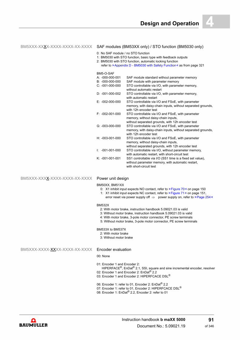
Design and Operation 4
BM5XXX-XXXX-XXXX-XXXX-XX-XXXX SAF modules (BM53XX only) / STO function (BM5030 only)
0: No SAF module / no STO function1: BM5030 with STO function, basic type with feedback outputs2: BM5030 with STO function, automatic locking function
refer to ZAppendix D - BM5030 with Safety Function– as from page 321
BM5-O-SAFA: -000-000-001 SAF module standard without parameter memoryB: -000-000-000 SAF module with parameter memoryC: -001-000-000 STO controllable via I/O, with parameter memory,
without automatic restartD: -001-000-002 STO controllable via I/O, with parameter memory,
with automatic restartE: -002-000-000 STO controllable via I/O and FSoE, with parameter
memory, with daisy-chain inputs, without separated grounds, with 12h encoder test
F: -002-001-000 STO controllable via I/O and FSoE, with parameter memory, without daisy-chain inputs, without separated grounds, with 12h encoder test
G: -003-000-000 STO controllable via I/O and FSoE, with parameter memory, with daisy-chain inputs, without separated grounds, with 12h encoder test
H: -003-001-000 STO controllable via I/O and FSoE, with parameter memory, without daisy-chain inputs, without separated grounds, with 12h encoder test
I: -001-001-000 STO controllable via I/O, without parameter memory, with automatic restart, with short-circuit test
K: -001-001-001 SS1 controllable via I/O (SS1 time is a fixed set value), without parameter memory, with automatic restart, with short-circuit test
BM5XXX-XXXX-XXXX-XXXX-XX-XXXX Power unit design
BM50XX, BM51XX0: X1 inhibit input expects NO contact, refer to ZFigure 70– on page 1501: X1 inhibit input expects NC contact, refer to ZFigure 71– on page 151, error reset via power supply off power supply on, refer to ZPage 254–
BM532X2: With motor brake, instruction handbook 5.09021.03 is valid3: Without motor brake, instruction handbook 5.09021.03 is valid4: With motor brake, 3-pole motor connector, PE screw terminals5: Without motor brake, 3-pole motor connector, PE screw terminals
BM533X to BM537X2: With motor brake3: Without motor brake
BM5XXX-XXXX-XXXX-XXXX-XX-XXXX Encoder evaluation
00: None
01: Encoder 1 and Encoder 2:HIPERFACE®, EnDat® 2.1, SSI, square and sine incremental encoder, resolver
02: Encoder 1 and Encoder 2: EnDat® 2.203: Encoder 1 and Encoder 2: HIPERFCACE DSL®
06: Encoder 1: refer to 01, Encoder 2: EnDat® 2.207: Encoder 1: refer to 01, Encoder 2: HIPERFCACE DSL®
08: Encoder 1: EnDat® 2.2, Encoder 2: refer to 01
Instruction handbook b maXX 5000
Document No.: 5.09021.19
91of 346
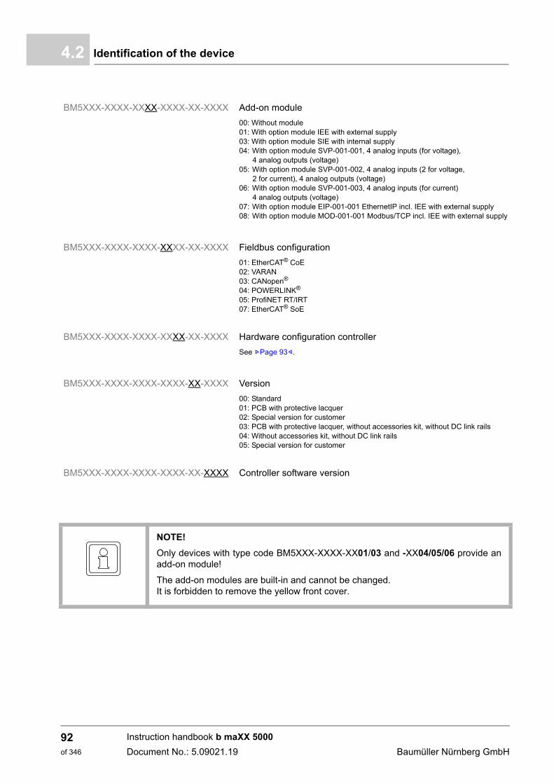
Identification of the device4.2
BM5XXX-XXXX-XXXX-XXXX-XX-XXXX Add-on module
00: Without module01: With option module IEE with external supply03: With option module SIE with internal supply04: With option module SVP-001-001, 4 analog inputs (for voltage),
4 analog outputs (voltage)05: With option module SVP-001-002, 4 analog inputs (2 for voltage,
2 for current), 4 analog outputs (voltage)06: With option module SVP-001-003, 4 analog inputs (for current)
4 analog outputs (voltage)07: With option module EIP-001-001 EthernetIP incl. IEE with external supply08: With option module MOD-001-001 Modbus/TCP incl. IEE with external supply
BM5XXX-XXXX-XXXX-XXXX-XX-XXXX Fieldbus configuration
01: EtherCAT® CoE02: VARAN03: CANopen®
04: POWERLINK®
05: ProfiNET RT/IRT07: EtherCAT® SoE
BM5XXX-XXXX-XXXX-XXXX-XX-XXXX Hardware configuration controller
See ZPage 93–.
BM5XXX-XXXX-XXXX-XXXX-XX-XXXX Version
00: Standard01: PCB with protective lacquer02: Special version for customer03: PCB with protective lacquer, without accessories kit, without DC link rails04: Without accessories kit, without DC link rails05: Special version for customer
BM5XXX-XXXX-XXXX-XXXX-XX-XXXX Controller software version
NOTE!
Only devices with type code BM5XXX-XXXX-XX01/03 and -XX04/05/06 provide anadd-on module!
The add-on modules are built-in and cannot be changed.It is forbidden to remove the yellow front cover.
Instruction handbook b maXX 5000
Document No.: 5.09021.19 Baumüller Nürnberg GmbH
92of 346
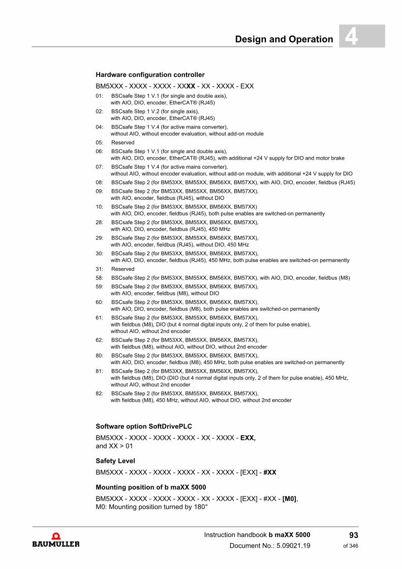
Design and Operation 4
Hardware configuration controllerBM5XXX - XXXX - XXXX - XXXX - XX - XXXX - EXX01: BSCsafe Step 1 V.1 (for single and double axis),
with AIO, DIO, encoder, EtherCAT® (RJ45)
02: BSCsafe Step 1 V.2 (for single axis),with AIO, DIO, encoder, EtherCAT® (RJ45)
04: BSCsafe Step 1 V.4 (for active mains converter), without AIO, without encoder evaluation, without add-on module
05: Reserved
06: BSCsafe Step 1 V.1 (for single and double axis), with AIO, DIO, encoder, EtherCAT® (RJ45), with additional +24 V supply for DIO and motor brake
07: BSCsafe Step 1 V.4 (for active mains converter),without AIO, without encoder evaluation, without add-on module, with additional +24 V supply for DIO
08: BSCsafe Step 2 (for BM53XX, BM55XX, BM56XX, BM57XX), with AIO, DIO, encoder, fieldbus (RJ45)
09: BSCsafe Step 2 (for BM53XX, BM55XX, BM56XX, BM57XX), with AIO, encoder, fieldbus (RJ45), without DIO
10: BSCsafe Step 2 (for BM53XX, BM55XX, BM56XX, BM57XX) with AIO, DIO, encoder, fieldbus (RJ45), both pulse enables are switched-on permanently
28: BSCsafe Step 2 (for BM53XX, BM55XX, BM56XX, BM57XX),with AIO, DIO, encoder, fieldbus (RJ45), 450 MHz
29: BSCsafe Step 2 (for BM53XX, BM55XX, BM56XX, BM57XX),with AIO, encoder, fieldbus (RJ45), without DIO, 450 MHz
30: BSCsafe Step 2 (for BM53XX, BM55XX, BM56XX, BM57XX),with AIO, DIO, encoder, fieldbus (RJ45), 450 MHz, both pulse enables are switched-on permanently
31: Reserved
58: BSCsafe Step 2 (for BM53XX, BM55XX, BM56XX, BM57XX), with AIO, DIO, encoder, fieldbus (M8)
59: BSCsafe Step 2 (for BM53XX, BM55XX, BM56XX, BM57XX),with AIO, encoder, fieldbus (M8), without DIO
60: BSCsafe Step 2 (for BM53XX, BM55XX, BM56XX, BM57XX),with AIO, DIO, encoder, fieldbus (M8), both pulse enables are switched-on permanently
61: BSCsafe Step 2 (for BM53XX, BM55XX, BM56XX, BM57XX),with fieldbus (M8), DIO (but 4 normal digital inputs only, 2 of them for pulse enable), without AIO, without 2nd encoder
62: BSCsafe Step 2 (for BM53XX, BM55XX, BM56XX, BM57XX),with fieldbus (M8), without AIO, without DIO, without 2nd encoder
80: BSCsafe Step 2 (for BM53XX, BM55XX, BM56XX, BM57XX),with AIO, DIO, encoder, fieldbus (M8), 450 MHz, both pulse enables are switched-on permanently
81: BSCsafe Step 2 (for BM53XX, BM55XX, BM56XX, BM57XX),with fieldbus (M8), DIO (DIO (but 4 normal digital inputs only, 2 of them for pulse enable), 450 MHz,without AIO, without 2nd encoder
82: BSCsafe Step 2 (for BM53XX, BM55XX, BM56XX, BM57XX),with fieldbus (M8), 450 MHz, without AIO, without DIO, without 2nd encoder
Software option SoftDrivePLC
BM5XXX - XXXX - XXXX - XXXX - XX - XXXX - EXX, and XX > 01
Safety Level
BM5XXX - XXXX - XXXX - XXXX - XX - XXXX - [EXX] - #XX
Mounting position of b maXX 5000
BM5XXX - XXXX - XXXX - XXXX - XX - XXXX - [EXX] - #XX - [M0],M0: Mounting position turned by 180°
Instruction handbook b maXX 5000
Document No.: 5.09021.19
93of 346
UL notes4.3
4.3 UL notes
The notes below must be observed in case you consider UL 508 C.
ZRequired environmental conditions– on page 49
ZDesign– on page 87
ZInstallation procedure– on page 148
ZElectrical connections– as from page 164
Connections of ZPage 174– to ZPage 175–
ZRequirements for the connection cables– on page 134
ZRequirements for the motor temperature sensors– on page 147
n Note the maximum surrounding air temperature.
n Use in a pollution degree 2 environment only.
n Axis units (BM5X23, BM5X26, BM5X27, BM5X28, BM5X31, BM5X32, BM5X33, BM5X34, BM5X35)are allowed to be used only in combination with mains rectifiers (BM5031, BM5032, BM5043, BM5044, BM5174).
n Internal overload protection operates after exceeding 200 % of the motor full load.
n Position of wiring terminals to indicate the proper connections for the power supply, load, control circuit, and similar devices refer to ZPage 164–.
n Note tightening torque values marked for field terminals.
n Use 60°/75°copper wires only.
n Drives do not provide motor overtemperature sensing.
Instruction handbook b maXX 5000
Document No.: 5.09021.19 Baumüller Nürnberg GmbH
94of 346
Design and Operation 4
ZFuses– as from page 277ZElectrical data BM50XX; BM51XX– as from page 60
ZMounting of the DC link bar– as from page 122 and ZDC link bar– on page 304
n Devices are suitable for use on a circuit capable of delivering not more than 50000 rms symmetrical amperes, 480 Volt maximum, when protected by J Class fuses rated
n BM5031/BM5032:branch circuit protection fuse rating: 600 V / max. 60 A
n BM5043/BM5044/BM5174branch circuit protection fuse rating: 600 V / max. 150 A
n Fuses must be installed on the line side of the mains rectifier (BM50XX, BM51XX)
n Integral solid state short circuit protection does not provide branch circuit protection. Branch circuit protection must be provided in accordance with the Manufacturer Instructions, National Electrical Code and any additional local codes.
n Mains rectifiers BM50XX, BM51XX are not provided with DC link preventing over-loading. Total capacity of all axis units BM53XX connected to the mains recti-fier shall not exceed the rectifiers rating.
n Proper installation of the DC link bar, refer to ZMounting of the DC link bar– as from page 122 and proper DC link bar refer to ZDC link bar– on page 304.
Instruction handbook b maXX 5000
Document No.: 5.09021.19
95of 346
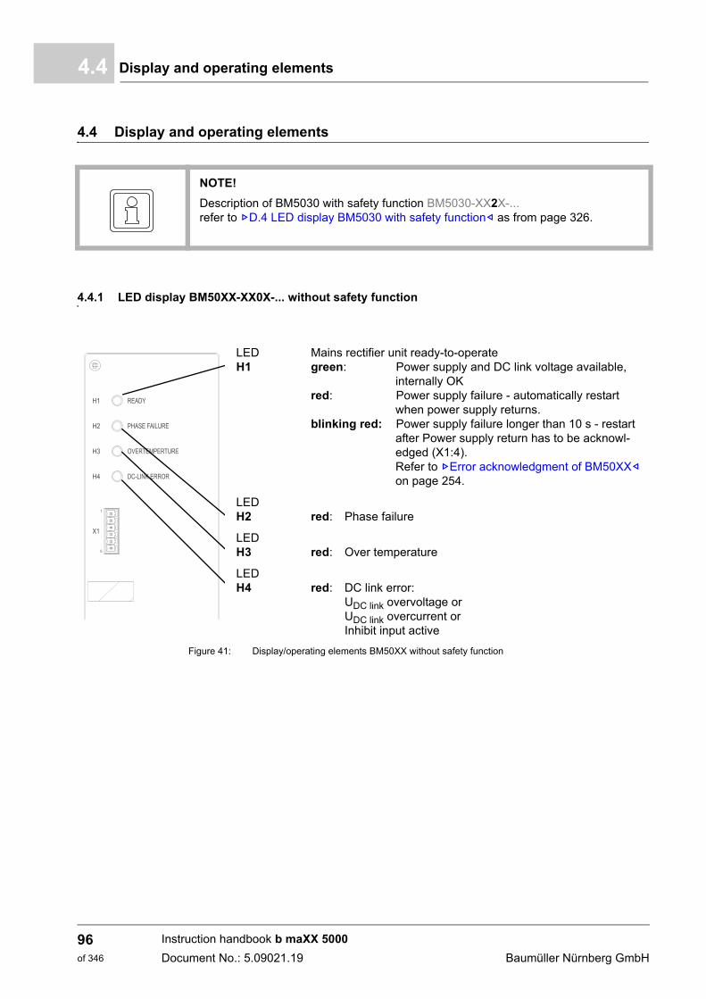
Display and operating elements4.4
4.4 Display and operating elements
4.4.1 LED display BM50XX-XX0X-... without safety function
Figure 41: Display/operating elements BM50XX without safety function
NOTE!
Description of BM5030 with safety function BM5030-XX2X-...refer to ZD.4 LED display BM5030 with safety function– as from page 326.
LEDH1
Mains rectifier unit ready-to-operategreen: Power supply and DC link voltage available,
internally OKred: Power supply failure - automatically restart
when power supply returns.blinking red: Power supply failure longer than 10 s - restart
after Power supply return has to be acknowl-edged (X1:4). Refer to ZError acknowledgment of BM50XX– on page 254.
LEDH2 red: Phase failure
LEDH3 red: Over temperature
LEDH4 red: DC link error:
UDC link overvoltage or UDC link overcurrent orInhibit input active
Instruction handbook b maXX 5000
Document No.: 5.09021.19 Baumüller Nürnberg GmbH
96of 346
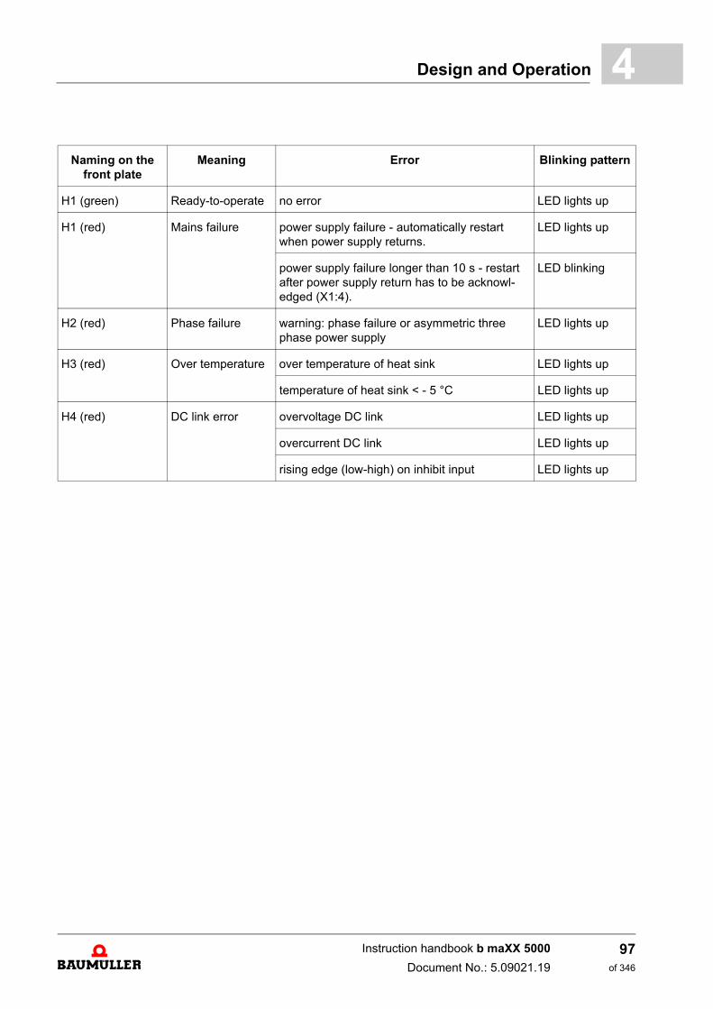
Design and Operation 4
Naming on the front plate
Meaning Error Blinking pattern
H1 (green) Ready-to-operate no error LED lights up
H1 (red) Mains failure power supply failure - automatically restart when power supply returns.
LED lights up
power supply failure longer than 10 s - restart after power supply return has to be acknowl-edged (X1:4).
LED blinking
H2 (red) Phase failure warning: phase failure or asymmetric three phase power supply
LED lights up
H3 (red) Over temperature over temperature of heat sink LED lights up
temperature of heat sink < - 5 °C LED lights up
H4 (red) DC link error overvoltage DC link LED lights up
overcurrent DC link LED lights up
rising edge (low-high) on inhibit input LED lights up
Instruction handbook b maXX 5000
Document No.: 5.09021.19
97of 346
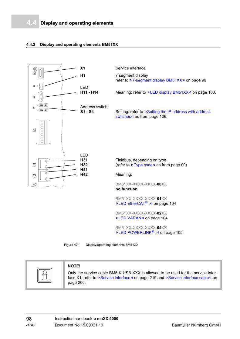
Display and operating elements4.4
4.4.2 Display and operating elements BM51XX
Figure 42: Display/operating elements BM51XX
X1 Service interface
H1 7 segment displayrefer to Z7-segment display BM51XX– on page 99
LEDH11 - H14 Meaning: refer to ZLED display BM51XX– on page 100.
Address switchS1 - S4 Setting: refer to ZSetting the IP address with address
switches– as from page 106.
LEDH31H32H41H42
Fieldbus, depending on type (refer to ZType code– as from page 90)
Meaning:
BM51XX-XXXX-XXXX-00XXno function
BM51XX-XXXX-XXXX-01XXZLED EtherCAT® .– on page 104
BM51XX-XXXX-XXXX-02XXZLED VARAN– on page 104
BM51XX-XXXX-XXXX-04XXZLED POWERLINK® .– on page 105
NOTE!
Only the service cable BM5-K-USB-XXX is allowed to be used for the service inter-face X1, refer to ZService interface– on page 219 and ZService interface cable– onpage 266.
Instruction handbook b maXX 5000
Document No.: 5.09021.19 Baumüller Nürnberg GmbH
98of 346
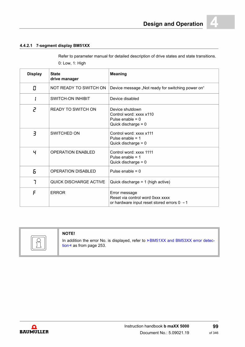
Design and Operation 4
4.4.2.1 7-segment display BM51XXRefer to parameter manual for detailed description of drive states and state transitions.
0: Low, 1: High
Display State drive manager
Meaning
0 NOT READY TO SWITCH ON Device message „Not ready for switching power on“
1 SWITCH-ON INHIBIT Device disabled
2 READY TO SWITCH ON Device shutdownControl word: xxxx x110Pulse enable = 0Quick discharge = 0
3 SWITCHED ON Control word: xxxx x111Pulse enable = 1Quick discharge = 0
4 OPERATION ENABLED Control word: xxxx 1111Pulse enable = 1Quick discharge = 0
6 OPERATION DISABLED Pulse enable = 0
7 QUICK DISCHARGE ACTIVE Quick discharge = 1 (high active)
F ERROR Error messageReset via control word 0xxx xxxxor hardware input reset stored errors 0 ➝ 1
NOTE!
In addition the error No. is displayed, refer to ZBM51XX and BM53XX error detec-tion– as from page 253.
Instruction handbook b maXX 5000
Document No.: 5.09021.19
99of 346
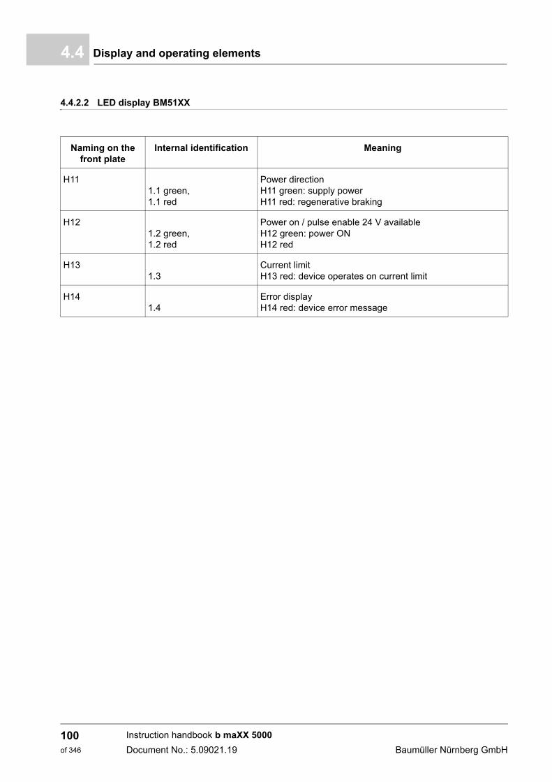
Display and operating elements4.4
4.4.2.2 LED display BM51XX
Naming on the front plate
Internal identification Meaning
H111.1 green, 1.1 red
Power directionH11 green: supply powerH11 red: regenerative braking
H121.2 green, 1.2 red
Power on / pulse enable 24 V availableH12 green: power ONH12 red
H131.3
Current limitH13 red: device operates on current limit
H141.4
Error displayH14 red: device error message
Instruction handbook b maXX 5000
Document No.: 5.09021.19 Baumüller Nürnberg GmbH
100of 346
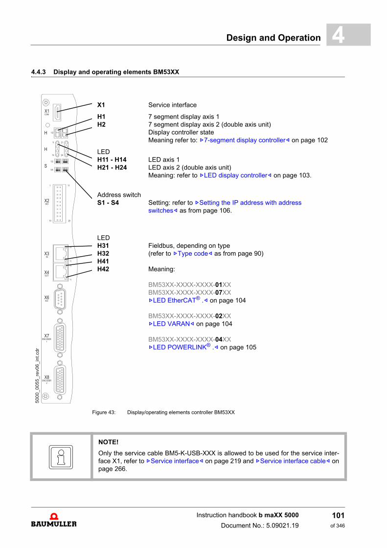
Design and Operation 4
4.4.3 Display and operating elements BM53XXFigure 43: Display/operating elements controller BM53XX
X1 Service interface
H1H2
7 segment display axis 17 segment display axis 2 (double axis unit)Display controller stateMeaning refer to: Z7-segment display controller– on page 102
LEDH11 - H14H21 - H24
LED axis 1LED axis 2 (double axis unit)Meaning: refer to ZLED display controller– on page 103.
Address switchS1 - S4 Setting: refer to ZSetting the IP address with address
switches– as from page 106.
LEDH31H32H41H42
Fieldbus, depending on type (refer to ZType code– as from page 90)
Meaning:
BM53XX-XXXX-XXXX-01XXBM53XX-XXXX-XXXX-07XXZLED EtherCAT® .– on page 104
BM53XX-XXXX-XXXX-02XXZLED VARAN– on page 104
BM53XX-XXXX-XXXX-04XXZLED POWERLINK® .– on page 105
NOTE!
Only the service cable BM5-K-USB-XXX is allowed to be used for the service inter-face X1, refer to ZService interface– on page 219 and ZService interface cable– onpage 266.
Instruction handbook b maXX 5000
Document No.: 5.09021.19
101of 346
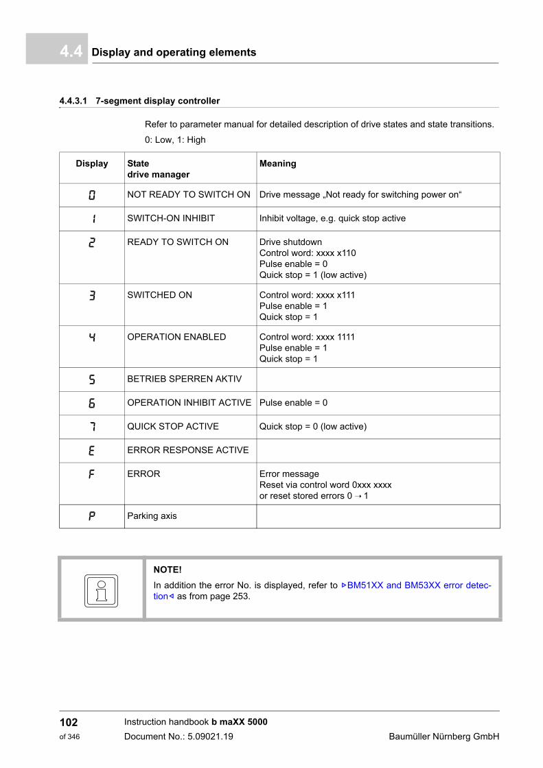
Display and operating elements4.4
4.4.3.1 7-segment display controller
Refer to parameter manual for detailed description of drive states and state transitions.
0: Low, 1: High
Display State drive manager
Meaning
0 NOT READY TO SWITCH ON Drive message „Not ready for switching power on“
1 SWITCH-ON INHIBIT Inhibit voltage, e.g. quick stop active
2 READY TO SWITCH ON Drive shutdownControl word: xxxx x110Pulse enable = 0Quick stop = 1 (low active)
3 SWITCHED ON Control word: xxxx x111Pulse enable = 1Quick stop = 1
4 OPERATION ENABLED Control word: xxxx 1111Pulse enable = 1Quick stop = 1
5 BETRIEB SPERREN AKTIV
6 OPERATION INHIBIT ACTIVE Pulse enable = 0
7 QUICK STOP ACTIVE Quick stop = 0 (low active)
E ERROR RESPONSE ACTIVE
F ERROR Error messageReset via control word 0xxx xxxxor reset stored errors 0 ➝ 1
P Parking axis
NOTE!
In addition the error No. is displayed, refer to ZBM51XX and BM53XX error detec-tion– as from page 253.
Instruction handbook b maXX 5000
Document No.: 5.09021.19 Baumüller Nürnberg GmbH
102of 346
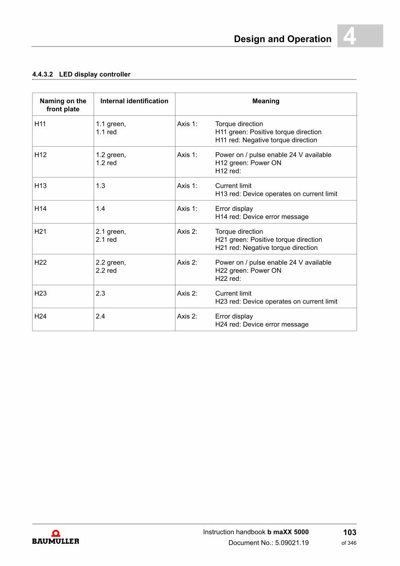
Design and Operation 4
4.4.3.2 LED display controllerNaming on the front plate
Internal identification Meaning
H11 1.1 green, 1.1 red
Axis 1: Torque direction H11 green: Positive torque directionH11 red: Negative torque direction
H12 1.2 green, 1.2 red
Axis 1: Power on / pulse enable 24 V availableH12 green: Power ONH12 red:
H13 1.3 Axis 1: Current limitH13 red: Device operates on current limit
H14 1.4 Axis 1: Error displayH14 red: Device error message
H21 2.1 green, 2.1 red
Axis 2: Torque direction H21 green: Positive torque directionH21 red: Negative torque direction
H22 2.2 green, 2.2 red
Axis 2: Power on / pulse enable 24 V availableH22 green: Power ONH22 red:
H23 2.3 Axis 2: Current limitH23 red: Device operates on current limit
H24 2.4 Axis 2: Error displayH24 red: Device error message
Instruction handbook b maXX 5000
Document No.: 5.09021.19
103of 346
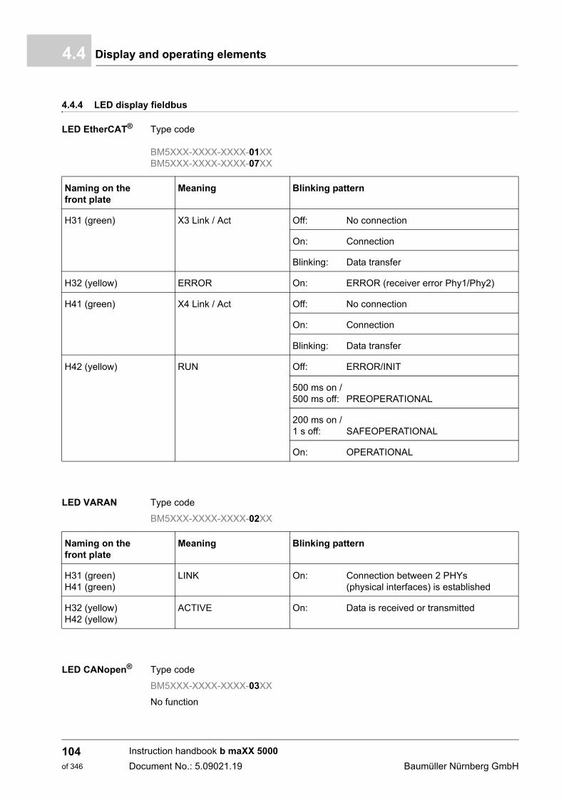
Display and operating elements4.4
4.4.4 LED display fieldbus
LED EtherCAT® . Type code
BM5XXX-XXXX-XXXX-01XXBM5XXX-XXXX-XXXX-07XX
LED VARAN Type code
BM5XXX-XXXX-XXXX-02XX
LED CANopen® Type code
BM5XXX-XXXX-XXXX-03XX
No function
Naming on the front plate
Meaning Blinking pattern
H31 (green) X3 Link / Act Off: No connection
On: Connection
Blinking: Data transfer
H32 (yellow) ERROR On: ERROR (receiver error Phy1/Phy2)
H41 (green) X4 Link / Act Off: No connection
On: Connection
Blinking: Data transfer
H42 (yellow) RUN Off: ERROR/INIT
500 ms on / 500 ms off: PREOPERATIONAL
200 ms on / 1 s off: SAFEOPERATIONAL
On: OPERATIONAL
Naming on the front plate
Meaning Blinking pattern
H31 (green)H41 (green)
LINK On: Connection between 2 PHYs (physical interfaces) is established
H32 (yellow)H42 (yellow)
ACTIVE On: Data is received or transmitted
Instruction handbook b maXX 5000
Document No.: 5.09021.19 Baumüller Nürnberg GmbH
104of 346
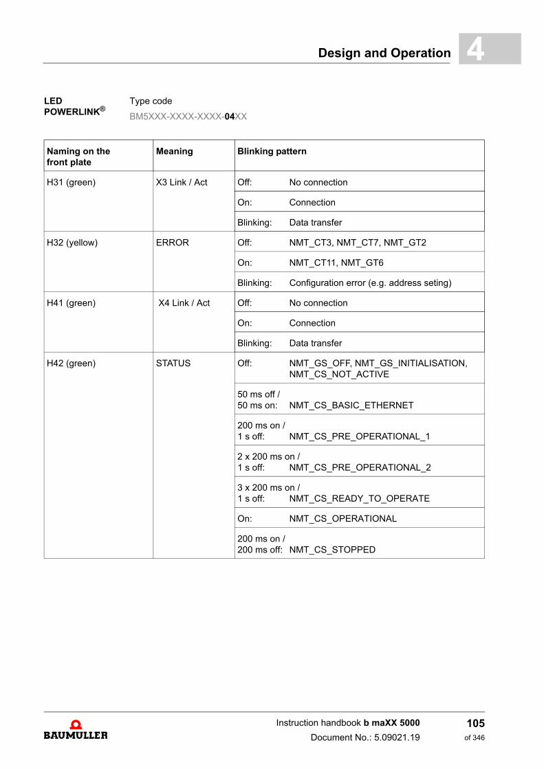
Design and Operation 4
LED POWERLINK® .Type code
BM5XXX-XXXX-XXXX-04XX
Naming on the front plate
Meaning Blinking pattern
H31 (green) X3 Link / Act Off: No connection
On: Connection
Blinking: Data transfer
H32 (yellow) ERROR Off: NMT_CT3, NMT_CT7, NMT_GT2
On: NMT_CT11, NMT_GT6
Blinking: Configuration error (e.g. address seting)
H41 (green) X4 Link / Act Off: No connection
On: Connection
Blinking: Data transfer
H42 (green) STATUS Off: NMT_GS_OFF, NMT_GS_INITIALISATION,NMT_CS_NOT_ACTIVE
50 ms off /50 ms on: NMT_CS_BASIC_ETHERNET
200 ms on /1 s off: NMT_CS_PRE_OPERATIONAL_1
2 x 200 ms on /1 s off: NMT_CS_PRE_OPERATIONAL_2
3 x 200 ms on /1 s off: NMT_CS_READY_TO_OPERATE
On: NMT_CS_OPERATIONAL
200 ms on /200 ms off: NMT_CS_STOPPED
Instruction handbook b maXX 5000
Document No.: 5.09021.19
105of 346
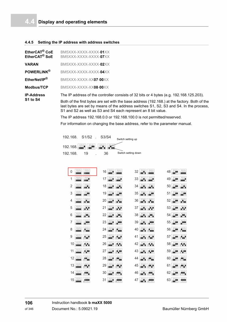
Display and operating elements4.4
4.4.5 Setting the IP address with address switches
EtherCAT® CoEEtherCAT® SoE
BM5XXX-XXXX-XXXX-01XXBM5XXX-XXXX-XXXX-07XX
VARAN BM5XXX-XXXX-XXXX-02XX
POWERLINK® BM5XXX-XXXX-XXXX-04XX
EtherNet/IP® BM5XXX-XXXX-XX07-00XX
Modbus/TCP BM5XXX-XXXX-XX08-00XX
IP-Address S1 to S4
The IP address of the controller consists of 32 bits or 4 bytes (e.g. 192.168.125.203).
Both of the first bytes are set with the base address (192.168.) at the factory. Both of thelast bytes are set by means of the address switches S1, S2, S3 and S4. In the process,S1 and S2 as well as S3 and S4 each represent an 8 bit value.
The IP address 192.168.0.0 or 192.168.100.0 is not permitted/reserved.
For information on changing the base address, refer to the parameter manual.
Switch setting up
Switch setting down
Instruction handbook b maXX 5000
Document No.: 5.09021.19 Baumüller Nürnberg GmbH
106of 346
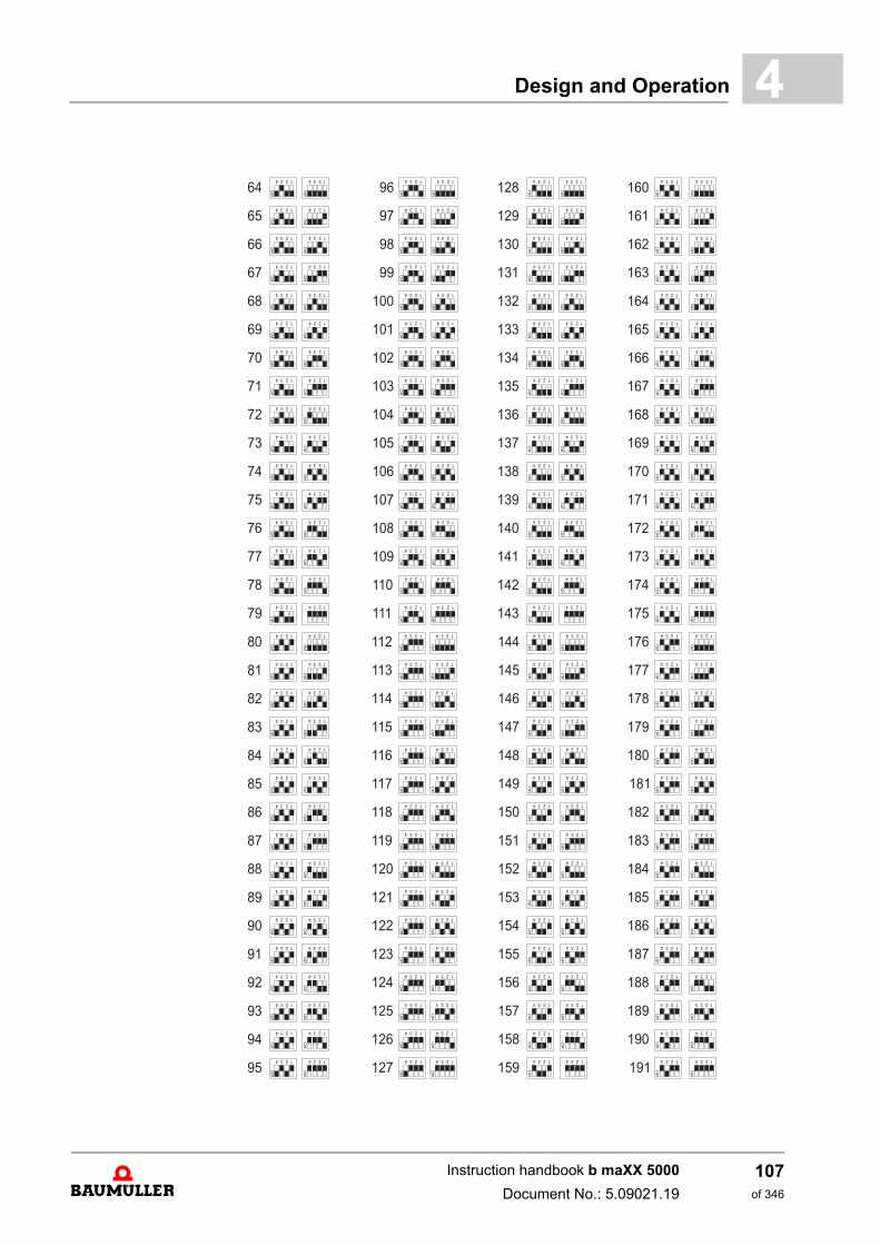
Design and Operation 4
Instruction handbook b maXX 5000
Document No.: 5.09021.19
107of 346
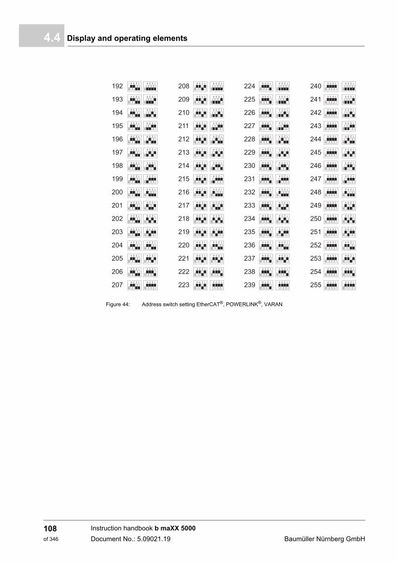
Display and operating elements4.4
Figure 44: Address switch setting EtherCAT®, POWERLINK®, VARAN
Instruction handbook b maXX 5000
Document No.: 5.09021.19 Baumüller Nürnberg GmbH
108of 346
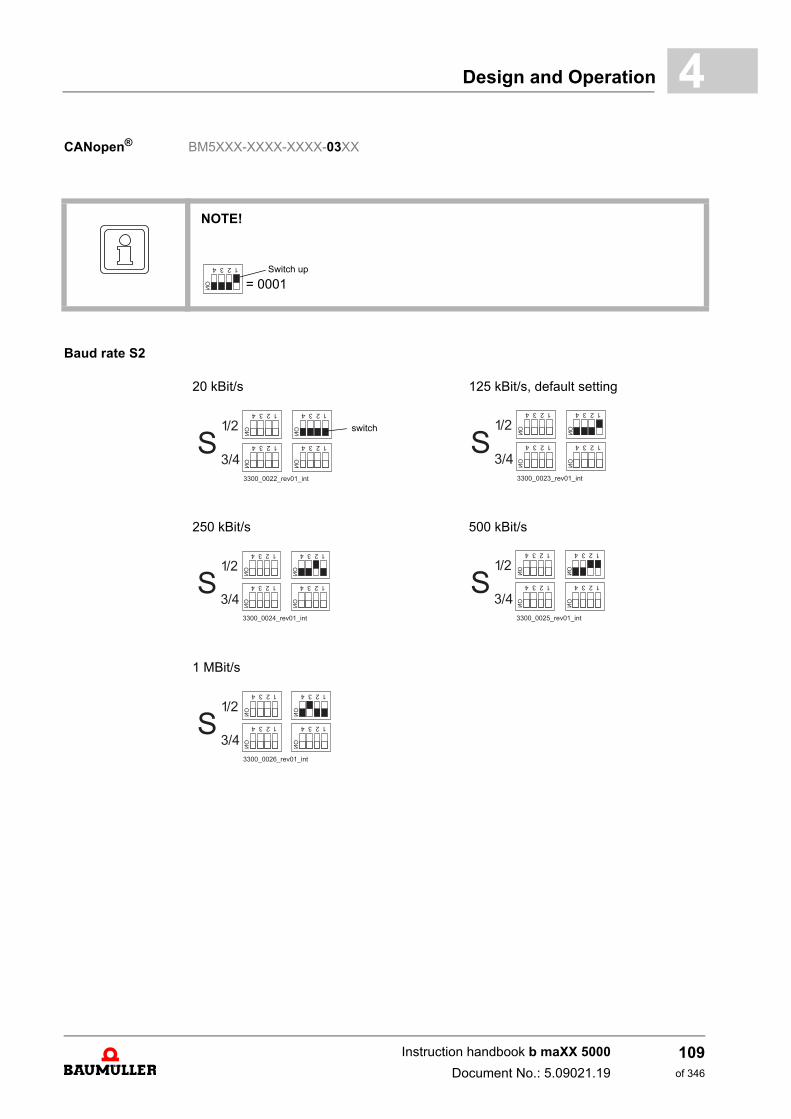
Design and Operation 4
CANopen® BM5XXX-XXXX-XXXX-03XXBaud rate S2
NOTE!
Switch up
= 0001
20 kBit/s 125 kBit/s, default setting
250 kBit/s 500 kBit/s
1 MBit/s
switch
Instruction handbook b maXX 5000
Document No.: 5.09021.19
109of 346
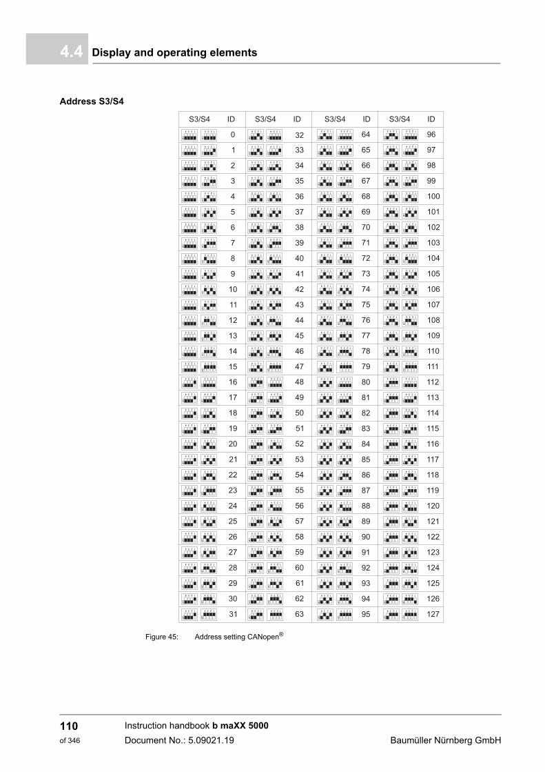
Display and operating elements4.4
Address S3/S4
Figure 45: Address setting CANopen®
Instruction handbook b maXX 5000
Document No.: 5.09021.19 Baumüller Nürnberg GmbH
110of 346
5TRANSPORT AND PACKAGING
5.1 Safety notes for transport
5.2 What to observe when transporting
For initial transport of the device, it is packed at the manufacturer's plant. If the device isto be further transported, ensure that the following conditions are met throughout the en-tire transport:
m Climate class 2 K 3 as per EN 60721-3-2
m Temperature range - 25 °C up to + 70 °C
m Vibration, shock, continuous shock class 2 M 1 as per EN 60721-3-2
NOTICE!
Damage due to unauthorized transport!
Transport handled by untrained personnel can lead to a substantial amount of mate-rial damage.
Therefore:
m The unloading of the packages upon delivery as well as the in-house transportshould only be done by trained personnel.
m Contact Baumüller Nürnberg GmbH sales office if necessary.
WARNING!
Danger of physical impact!
Secure devices against falling down.
Therefore:
m Take suitable measures, such as supports, hoists, straps, etc., to ensure that de-vice cannot fall down.
m Use appropriate means of transport.
111of 346
Instruction handbook b maXX 5000
Document No.: 5.09021.19
Transport inspection5.3
5.3 Transport inspection
Upon receiving the delivered goods, immediately examine them for completeness andtransport damage.
If there is outwardly visible transport damage, proceed as follows:
m Do not accept the delivery or conditionally accept it with reservations.
m Note the extent of the damage on the transport documents or on the delivery note ofthe transport agent.
m Immediately file a complaint with the freight carrier. Have the complaint confirmed inwriting and immediately contact the responsible representative of Baumüller NürnbergGmbH.
5.4 Unpacking
After having received the still packaged device:
h Avoid transport shocks and hard jolts, e.g. when putting an item down.
If no transport damage is visible:
h Open the packaging of the device.
h Verify the delivery scope based on the delivery note.
File a claim with the responsible Baumüller representative if the delivery is incomplete.
5.5 Disposal of the packaging
The packaging consists of cardboard, plastic, metal parts, corrugated cardboard and/orwood.
h When disposing of the packaging, comply with the national regulations valid.
NOTE!
The device may not be operated if there is visible transport damage!
NOTE!
Claim each individual deficiency as soon as it has been detected. Damage claims canonly be validly asserted within the claim registration period.
Instruction handbook b maXX 5000
Document No.: 5.09021.19 Baumüller Nürnberg GmbH
112of 346
6MOUNTING
The device is intended for mounting in a control cabinet.
Mounting comprises the following steps:
1 Mounting preparation (for drilling holes/cutting out sections, see ZDrilling pattern– as from page 117)
only with active mains rectifier to operate within C2 surrounding,for drilling holes of toroidal cores, see ZDrilling pattern toroidal cores– on page 125
2 Mountingthe device (for fixing, see ZMounting instructions– on page 119)
possibly mounting toroidal cores (see ZMounting the toroidal cores– as from page 126)
6.1 Safety notes
NOTE!
Mounting shall only be performed by employees of the manufacturer or by other qual-ified personnel.
Qualified personnel are persons who – on account of their occupational training, ex-perience, instruction and knowledge of relevant standards and stipulations, accidentprevention regulations and operating conditions – are authorized by the persons re-sponsible for the safety of the facilities to perform the respective activities that arenecessary, while at the same time recognizing and preventing any potential risks.The qualifications necessary for working with the device are, for example:
m Occupational training or instruction in accordance with the standards of safety en-gineering for the care and use of appropriate safety equipment.
113of 346
Instruction handbook b maXX 5000
Document No.: 5.09021.19
Safety notes6.1
WARNING!
Danger as a result of faulty mounting!
The mounting requires qualified personnel with adequate experience. Faulty mount-ing can lead to life-threatening situations or substantial material damage.
Therefore:
m Only allow mounting to be performed by employees of the manufacturer or by oth-er qualified personnel.
WARNING!
Danger of mechanical impact!
Secure devices against falling down.
Therefore:
m Take suitable measures, such as supports, hoists and assisting personnel, to en-sure that device cannot fall down.
m Use appropriate means of transport.
NOTICE!
Danger due to electrostatic discharge.
The connecting terminals of the device are partially at risk due from ESD.
Therefore:
Please heed the respective notes.
Instruction handbook b maXX 5000
Document No.: 5.09021.19 Baumüller Nürnberg GmbH
114of 346
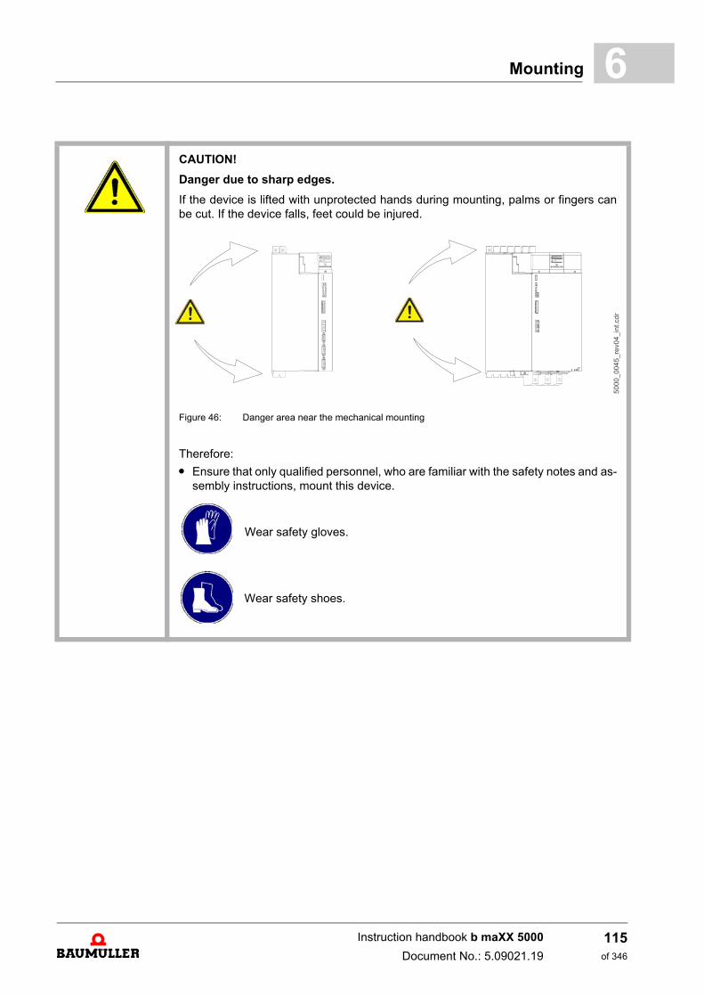
Mounting 6
CAUTION!
Danger due to sharp edges.
If the device is lifted with unprotected hands during mounting, palms or fingers canbe cut. If the device falls, feet could be injured.
Figure 46: Danger area near the mechanical mounting
Therefore:
m Ensure that only qualified personnel, who are familiar with the safety notes and as-sembly instructions, mount this device.
Wear safety gloves.
Wear safety shoes.
Instruction handbook b maXX 5000
Document No.: 5.09021.19
115of 346
Preparing for mounting6.2
6.2 Preparing for mounting
Based on the planning documents and the drilling patterns (see ZDrilling pattern– asfrom page 117), the cutout sections and the positions of the attachment drill holes can bedetermined.
h Preparing drill holes and cutout sections.
NOTICE!
Property damage due to conductive contamination.
Therefore:
m When performing installation work of any kind, it must be ensured that no foreignmaterial (e.g. drill shavings, copper strands, etc.) gets into the device as a result.
m If possible, the drilling of the holes should be done before mounting the device andthe configuring of the cables should take place outside of the control cabinet. If thisis not possible, the device must be appropriately covered.Remove this covering again prior to start!
CAUTION!
Eye injury due to flung particles.
Metal particles are flung when making the drill holes and the cutout sections.
Therefore:
Wear protective eye wear!
Instruction handbook b maXX 5000
Document No.: 5.09021.19 Baumüller Nürnberg GmbH
116of 346
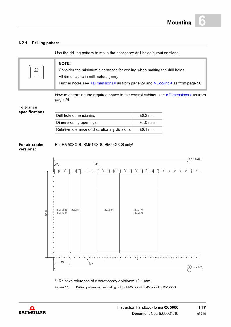
Mounting 6
6.2.1 Drilling patternUse the drilling pattern to make the necessary drill holes/cutout sections.
How to determine the required space in the control cabinet, see ZDimensions– as frompage 29.
Tolerance specifications
For air-cooled versions:
For BM50XX-S, BM51XX-S, BM53XX-S only!
*: Relative tolerance of discretionary divisions: ±0.1 mm
Figure 47: Drilling pattern with mounting rail for BM50XX-S, BM53XX-S, BM51XX-S
NOTE!
Consider the minimum clearances for cooling when making the drill holes.
All dimensions in millimeters [mm].
Further notes see ZDimensions– as from page 29 and ZCooling– as from page 58.
Drill hole dimensioning ±0.2 mm
Dimensioning openings +1.0 mm
Relative tolerance of discretionary divisions ±0.1 mm
Instruction handbook b maXX 5000
Document No.: 5.09021.19
117of 346
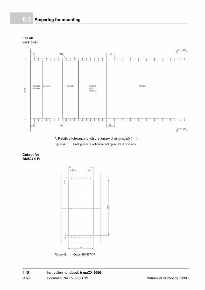
Preparing for mounting6.2
For all versions:
*: Relative tolerance of discretionary divisions: ±0.1 mm
Figure 48: Drilling pattern without mounting rail for all versions
Cutout for BM537X-F:
Figure 49: Cutout BM537X-F
351.
9
158
11.8
11.8
16.5
25
16.5
25
Instruction handbook b maXX 5000
Document No.: 5.09021.19 Baumüller Nürnberg GmbH
118of 346
Mounting 6
6.2.2 Mechanical data of the mounting plate for cold plateThe cooling version cold plate is a particular efficient cooling alternative. The heat dissi-pation is done via 2 contact surfaces. The first one is the mounting platform within the con-trol cabinet or on the machine base, the other is the cold plate on the device’s back. Highrequirements e.g. to surface roughness and evenness for this surface are specified, toensure an optimal heat flow. Already a slight damage/pollution of the surface can causea significant deterioration in heat dissipation to the mounting plate.
For this reason while handle the units protect the sensitive function surface to avoid dam-age.
6.3 Mounting instructions
There are different mounting procedure.
Each mounting procedure is described in a drawing (see ZFigure 50– on page 120 andZFigure 51– on page 121).
The screws and washers required for mounting are listed beneath the respective drawing.
Carry out mounting as follows:
1 Provide suitable transport/lifting equipment as needed.
2 Keep suitable fastening components readily available.
3 For cold plate devices
n check the surface quality of device’s rear panel/mounting plate, see ZMechanicaldata of the mounting plate for cold plate– on page 119
4 Mount the device.
5 Subsequently connect the water-cooling unit.
Surface flatness(across the entire surface)
0.05 mm
Surface roughness Ra 1.2 µm
Material of the plate (recommendation) AlMgSi 0.5
NOTICE!
Property damage due to overheating.
Scratches and burrs can inhibit the heat dissipation of cold plate devices.
Therefore
m When mounting cold plate devices, ensure that the surface quality of the mountingplate meets the specifications and ensure that the device’s rear panel/mountingplate does not have any scratches or burrs.
Instruction handbook b maXX 5000
Document No.: 5.09021.19
119of 346
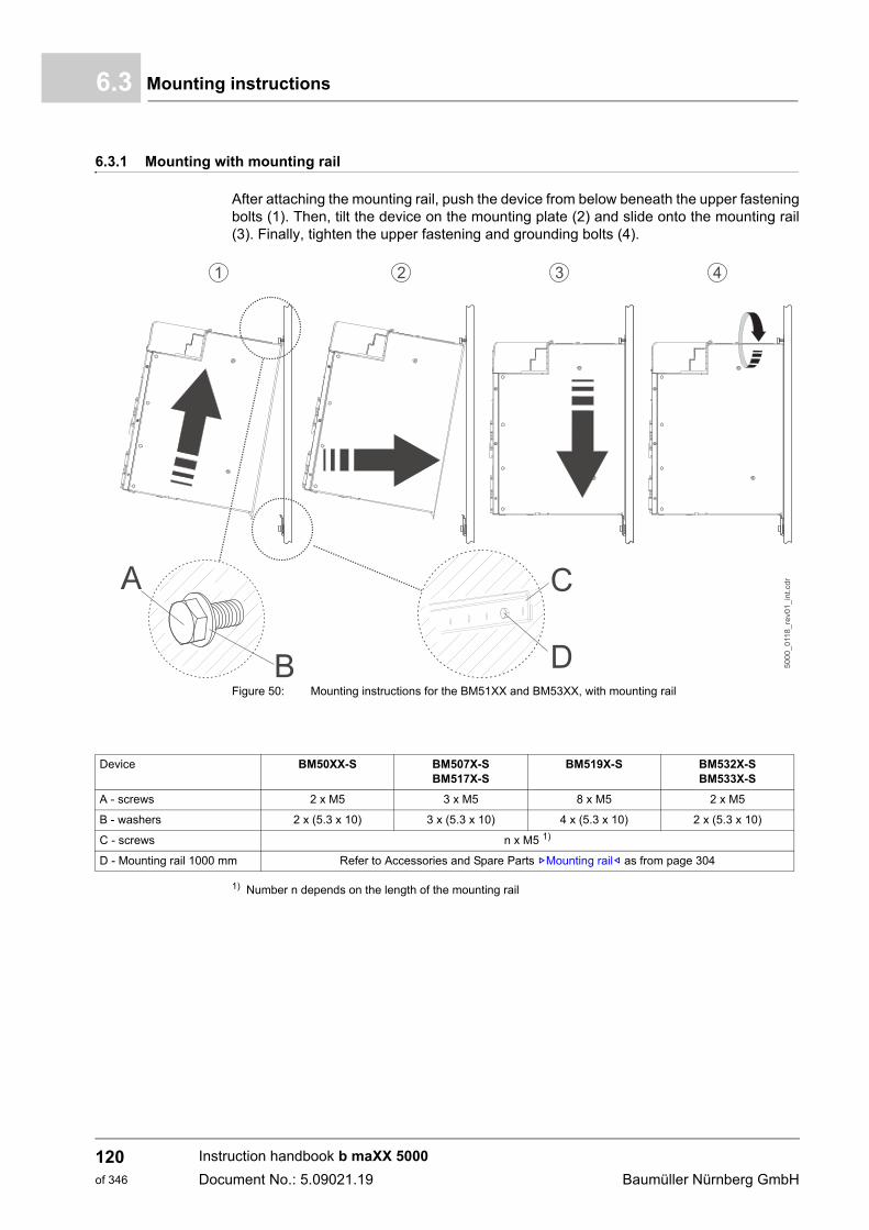
Mounting instructions6.3
6.3.1 Mounting with mounting rail
After attaching the mounting rail, push the device from below beneath the upper fasteningbolts (1). Then, tilt the device on the mounting plate (2) and slide onto the mounting rail(3). Finally, tighten the upper fastening and grounding bolts (4).
Figure 50: Mounting instructions for the BM51XX and BM53XX, with mounting rail
1) Number n depends on the length of the mounting rail
Device BM50XX-S BM507X-SBM517X-S
BM519X-S BM532X-SBM533X-S
A - screws 2 x M5 3 x M5 8 x M5 2 x M5
B - washers 2 x (5.3 x 10) 3 x (5.3 x 10) 4 x (5.3 x 10) 2 x (5.3 x 10)
C - screws n x M5 1)
D - Mounting rail 1000 mm Refer to Accessories and Spare Parts ZMounting rail– as from page 304
Instruction handbook b maXX 5000
Document No.: 5.09021.19 Baumüller Nürnberg GmbH
120of 346
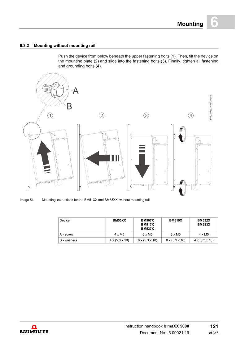
Mounting 6
6.3.2 Mounting without mounting railPush the device from below beneath the upper fastening bolts (1). Then, tilt the device onthe mounting plate (2) and slide into the fastening bolts (3). Finally, tighten all fasteningand grounding bolts (4).
Image 51: Mounting instructions for the BM51XX and BM53XX, without mounting rail
Device BM50XX BM507XBM517XBM537X
BM519X BM532XBM533X
A - screw 4 x M5 6 x M5 8 x M5 4 x M5
B - washers 4 x (5.3 x 10) 6 x (5.3 x 10) 8 x (5.3 x 10) 4 x (5.3 x 10)
Instruction handbook b maXX 5000
Document No.: 5.09021.19
121of 346
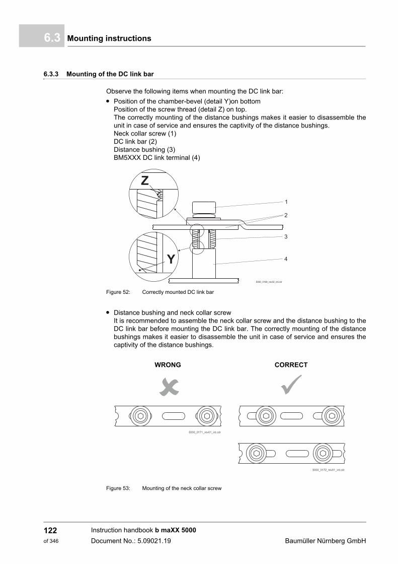
Mounting instructions6.3
6.3.3 Mounting of the DC link bar
Observe the following items when mounting the DC link bar:
m Position of the chamber-bevel (detail Y)on bottomPosition of the screw thread (detail Z) on top. The correctly mounting of the distance bushings makes it easier to disassemble theunit in case of service and ensures the captivity of the distance bushings. Neck collar screw (1)DC link bar (2)Distance bushing (3)BM5XXX DC link terminal (4)
Figure 52: Correctly mounted DC link bar
m Distance bushing and neck collar screwIt is recommended to assemble the neck collar screw and the distance bushing to theDC link bar before mounting the DC link bar. The correctly mounting of the distancebushings makes it easier to disassemble the unit in case of service and ensures thecaptivity of the distance bushings.
Figure 53: Mounting of the neck collar screw
WRONG CORRECT
Instruction handbook b maXX 5000
Document No.: 5.09021.19 Baumüller Nürnberg GmbH
122of 346
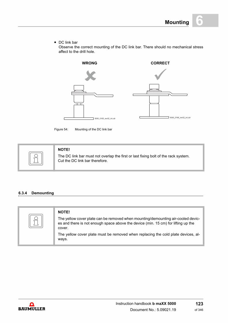
Mounting 6
m DC link barObserve the correct mounting of the DC link bar. There should no mechanical stressaffect to the drill hole.
Figure 54: Mounting of the DC link bar
6.3.4 Demounting
WRONG CORRECT
NOTE!
The DC link bar must not overlap the first or last fixing bolt of the rack system.Cut the DC link bar therefore.
NOTE!
The yellow cover plate can be removed when mounting/demounting air-cooled devic-es and there is not enough space above the device (min. 15 cm) for lifting up the cover.
The yellow cover plate must be removed when replacing the cold plate devices, al-ways.
Instruction handbook b maXX 5000
Document No.: 5.09021.19
123of 346
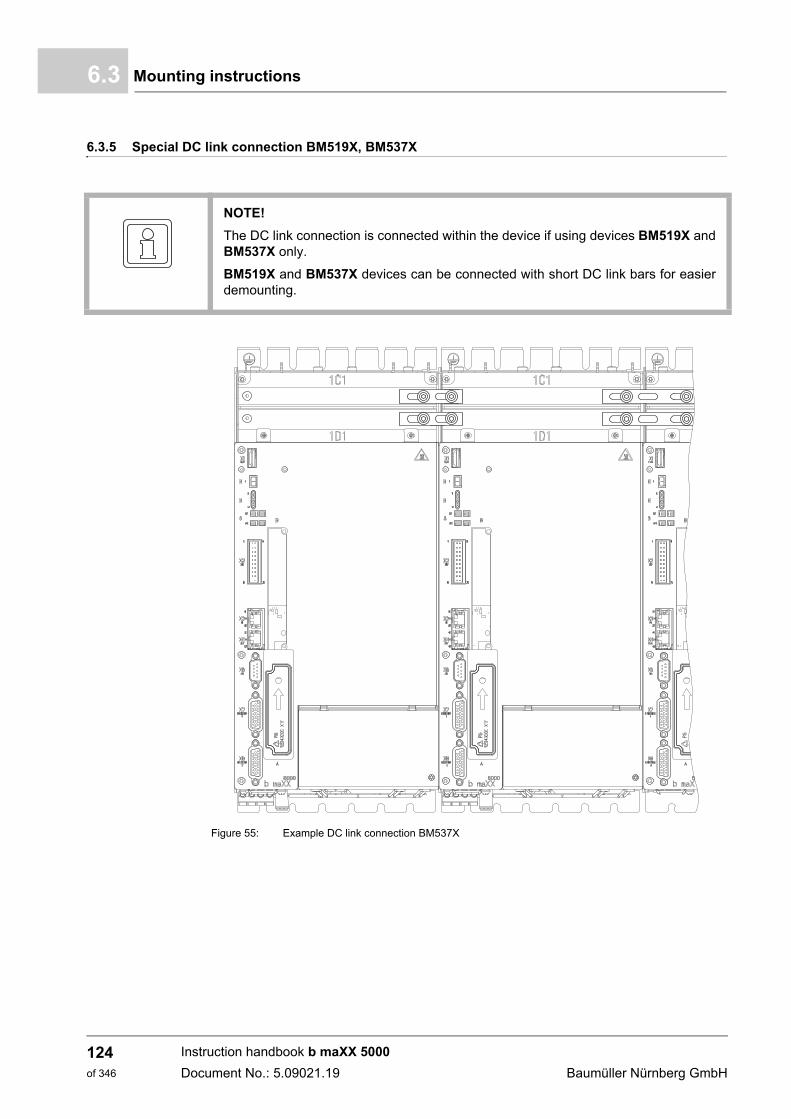
Mounting instructions6.3
6.3.5 Special DC link connection BM519X, BM537X
Figure 55: Example DC link connection BM537X
NOTE!
The DC link connection is connected within the device if using devices BM519X andBM537X only.
BM519X and BM537X devices can be connected with short DC link bars for easierdemounting.
Instruction handbook b maXX 5000
Document No.: 5.09021.19 Baumüller Nürnberg GmbH
124of 346
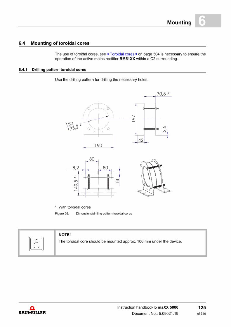
Mounting 6
6.4 Mounting of toroidal coresThe use of toroidal cores, see ZToroidal cores– on page 304 is necessary to ensure theoperation of the active mains rectifier BM51XX within a C2 surrounding.
6.4.1 Drilling pattern toroidal cores
Use the drilling pattern for drilling the necessary holes.
*: With toroidal cores
Figure 56: Dimensions/drilling pattern toroidal cores
NOTE!
The toroidal core should be mounted approx. 100 mm under the device.
Instruction handbook b maXX 5000
Document No.: 5.09021.19
125of 346
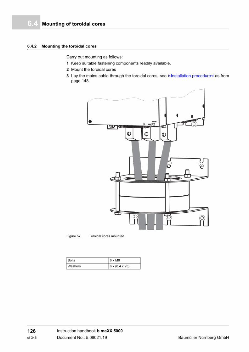
Mounting of toroidal cores6.4
6.4.2 Mounting the toroidal cores
Carry out mounting as follows:
1 Keep suitable fastening components readily available.
2 Mount the toroidal cores
3 Lay the mains cable through the toroidal cores, see ZInstallation procedure– as frompage 148.
Figure 57: Toroidal cores mounted
Bolts 6 x M8
Washers 6 x (8.4 x 25)
Instruction handbook b maXX 5000
Document No.: 5.09021.19 Baumüller Nürnberg GmbH
126of 346
Mounting 6
6.4.3 Connecting the water coolerWith water cooled devices (BM5XXX-F) you should connect the coolant circulation beforeelectric installation. The water cooler has on its bottom side two pressfitting-transitionpieces 12 mm x R 1/2‘‘ AG for flat seals.
h Connect the cooling circulation to the water cooler:
In case you refer to UL 508 C: There must be a pressure-relief valve with a threshold pres-sure of maximum 6 bar in the cooling circulation.
Tube material Outer tube- Screwing
G-AlSi9Cu3c, material No. 3.2163.01
alloy No. 226
12 mm 1/2’ AG for flat seals
Instruction handbook b maXX 5000
Document No.: 5.09021.19
127of 346
Mounting of toroidal cores6.4
Instruction handbook b maXX 5000
Document No.: 5.09021.19 Baumüller Nürnberg GmbH
128of 346
7INSTALLATION
This chapter describes the electrical installation of the device. The mechanical mountingis described in ZMounting– as from page 113.Initial commissioning is described in the parameter manual 5.09022 in the chapter Com-missioning.
Prior to installation, ensure that the technical prerequisites have been fulfilled:
1 Check the demands on the electrical mains.
2 Check the requirements for the electrical cables and the provision of correspondingcables.
3 Check the properties of the connections and the specified configuration of the respec-tive cables.
7.1 Safety notes
NOTE!
Installation shall only be performed by employees of the manufacturer or by otherqualified personnel.
Qualified personnel are persons who – on account of their occupational training, ex-perience, instruction and knowledge of relevant standards and stipulations, accidentprevention regulations and operating conditions – are authorized by the persons re-sponsible for the safety of the facilities to perform the respective activities that arenecessary, while at the same time recognizing and preventing any potential risks.The qualifications necessary for working with the device are, for example:
m Occupational training or instruction, and the authorization to commission, groundand mark electrical power circuits and devices in accordance with the standards ofthe safety engineering.
m Occupational training or instruction, in accordance with the standards of work safe-ty, for the care and use of appropriate safety equipment.
129of 346
Instruction handbook b maXX 5000
Document No.: 5.09021.19
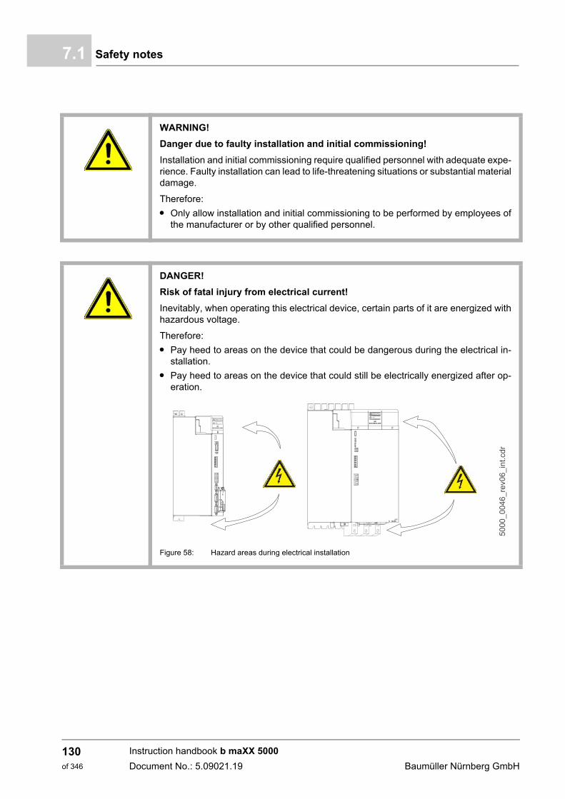
Safety notes7.1
WARNING!
Danger due to faulty installation and initial commissioning!
Installation and initial commissioning require qualified personnel with adequate expe-rience. Faulty installation can lead to life-threatening situations or substantial materialdamage.
Therefore:
m Only allow installation and initial commissioning to be performed by employees ofthe manufacturer or by other qualified personnel.
DANGER!
Risk of fatal injury from electrical current!
Inevitably, when operating this electrical device, certain parts of it are energized withhazardous voltage.
Therefore:
m Pay heed to areas on the device that could be dangerous during the electrical in-stallation.
m Pay heed to areas on the device that could still be electrically energized after op-eration.
Figure 58: Hazard areas during electrical installation
Instruction handbook b maXX 5000
Document No.: 5.09021.19 Baumüller Nürnberg GmbH
130of 346
Installation 7
Danger from residual energy7.2 Voltage test
DANGER!
Risk of fatal injury from electrical current!
Stored electric charge.
Discharge time of the modular system = discharge time of the device with the longestDC link discharge time in the modular system.
Refer to ZElectrical data– as from page 60.
Therefore:
m Do not touch before taking into account the discharge time of the capacitors andelectrically live parts.
m Heed corresponding notes on the equipment.
m If additional capacitors are connected to the DC link, the DC link discharge cantake a much longer time. In this case, the necessary waiting period must itself bedetermined or a measurement made as to whether the equipment is de-energized.This discharge time must be posted, together with an IEC 60417-5036 (2002-10)warning symbol, on a clearly visible location of the control cabinet.
DANGER!
Risk of fatal injury from electrical current!
During the routine test of these devices, a voltage test is performed by BaumüllerNürnberg GmbH in accordance with EN 61800-5-1, Section 5.2.3.2. It is thus unnec-essary for the customer to do this.
Therefore:
m Subsequent tests of the devices using high voltages may only be performed byBaumüller Nürnberg GmbH.
m Disconnect the device from the system during high-voltage testing!
Instruction handbook b maXX 5000
Document No.: 5.09021.19
131of 346
Demands on the electrical mains7.3
7.3 Demands on the electrical mains
For all important data, see ZRequirements for power supply / mains supply system– asfrom page 46.
Minor deviations from requirements in the electrical mains can lead to malfunctioning ofthe device. If the mains supply deviates too much from the requirements, the device canbe destroyed.
The devices may only be operated in industrial networks C3 without additional measures,refer to ZMounting of toroidal cores– as from page 125.
The destruction of the device can cause personal injury.
DANGER!
Risk of fatal injury from electrical current!
If the requirements for the electrical mains are not complied, the device can be dam-aged or destroyed, thereby greatly endangering individuals.
Therefore:
m Prior to installation, ensure that the demands for electrical mains the have beenfulfilled.
Instruction handbook b maXX 5000
Document No.: 5.09021.19 Baumüller Nürnberg GmbH
132of 346
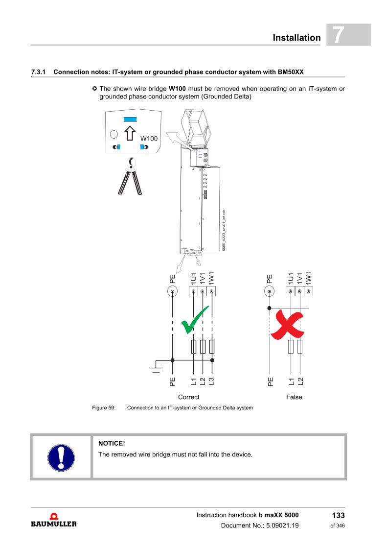
Installation 7
7.3.1 Connection notes: IT-system or grounded phase conductor system with BM50XXh The shown wire bridge W100 must be removed when operating on an IT-system orgrounded phase conductor system (Grounded Delta)
Correct False
Figure 59: Connection to an IT-system or Grounded Delta system
NOTICE!
The removed wire bridge must not fall into the device.
Instruction handbook b maXX 5000
Document No.: 5.09021.19
133of 346
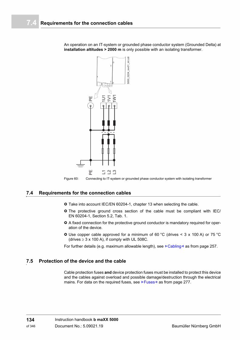
Requirements for the connection cables7.4
An operation on an IT-system or grounded phase conductor system (Grounded Delta) atinstallation altitudes > 2000 m is only possible with an isolating transformer.
Figure 60: Connecting to IT-system or grounded phase conductor system with isolating transformer
7.4 Requirements for the connection cables
h Take into account IEC/EN 60204-1, chapter 13 when selecting the cable.
h The protective ground cross section of the cable must be compliant with IEC/EN 60204-1, Section 5.2, Tab. 1.
h A fixed connection for the protective ground conductor is mandatory required for oper-ation of the device.
h Use copper cable approved for a minimum of 60 °C (drives < 3 x 100 A) or 75 °C(drives 3 x 100 A), if comply with UL 508C.
For further details (e.g. maximum allowable length), see ZCabling– as from page 257.
7.5 Protection of the device and the cable
Cable protection fuses and device protection fuses must be installed to protect this deviceand the cables against overload and possible damage/destruction through the electricalmains. For data on the required fuses, see ZFuses– as from page 277.
Instruction handbook b maXX 5000
Document No.: 5.09021.19 Baumüller Nürnberg GmbH
134of 346
Installation 7
7.6 PE connection and RCD compatibilityDepending on the functional principle, leakage current >3.5 mAAC or >10 mADC can flowthrough the protective ground conductor. Consequently, a stationary ground conductorconnection in accordance with EN 61800-5-1 is required.
DANGER!
Risk of fatal injury from electrical current!
This product can cause direct and/or alternating current in the protective ground con-ductor.
The leakage current, due to the functional principle of the device, can lead to prema-ture triggering of the fault current protective device or generally prevent triggering ofit.
Therefore:
m Wherever a differential current device (RCD) is used for protection in case of director indirect contact, only an RCD of the type B is permitted on the power supply sideof the device.
m Otherwise a different protective measure must be utilized, such as separation fromthe surrounding by means of double or enhanced isolation, or separation from thepower supply system by means of an isolating transformer, for example.
Instruction handbook b maXX 5000
Document No.: 5.09021.19
135of 346
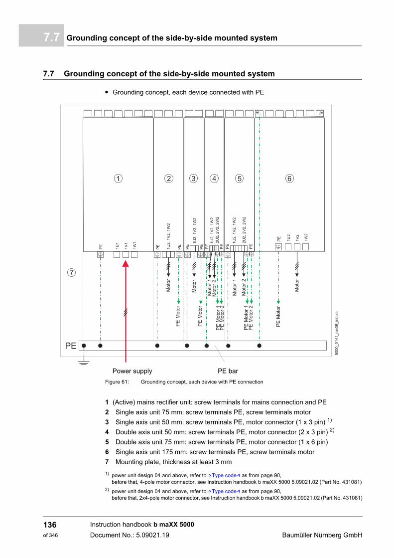
Grounding concept of the side-by-side mounted system7.7
7.7 Grounding concept of the side-by-side mounted system
m Grounding concept, each device connected with PE
Power supply PE bar
Figure 61: Grounding concept, each device with PE connection
1 (Active) mains rectifier unit: screw terminals for mains connection and PE
2 Single axis unit 75 mm: screw terminals PE, screw terminals motor
3 Single axis unit 50 mm: screw terminals PE, motor connector (1 x 3 pin) 1)
4 Double axis unit 50 mm: screw terminals PE, motor connector (2 x 3 pin) 2)
5 Double axis unit 75 mm: screw terminals PE, motor connector (1 x 6 pin)
6 Single axis unit 175 mm: screw terminals PE, screw terminals motor
7 Mounting plate, thickness at least 3 mm
1) power unit design 04 and above, refer to ZType code– as from page 90,before that, 4-pole motor connector, see Instruction handbook b maXX 5000 5.09021.02 (Part No. 431081)
2) power unit design 04 and above, refer to ZType code– as from page 90,before that, 2x4-pole motor connector, see Instruction handbook b maXX 5000 5.09021.02 (Part No. 431081)
Instruction handbook b maXX 5000
Document No.: 5.09021.19 Baumüller Nürnberg GmbH
136of 346
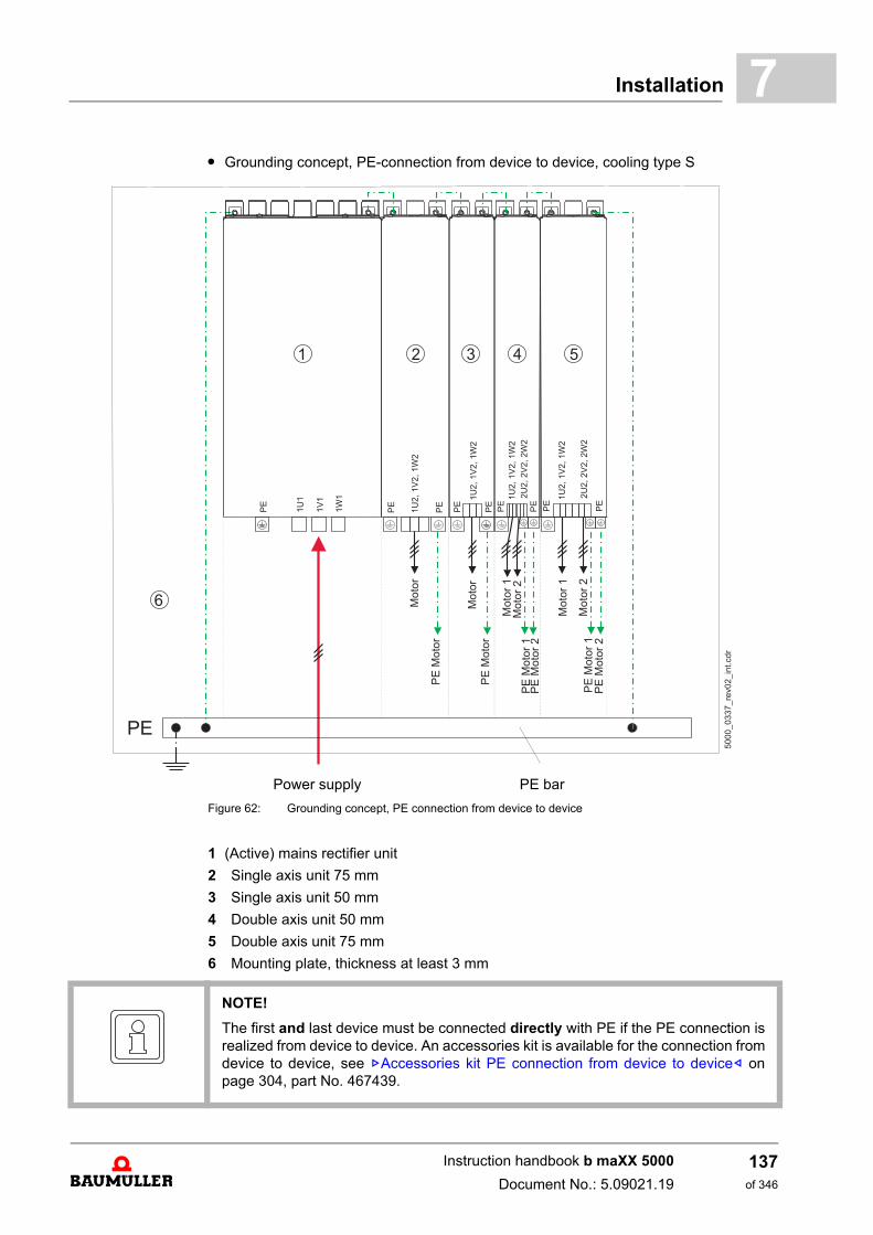
Installation 7
m Grounding concept, PE-connection from device to device, cooling type SPower supply PE bar
Figure 62: Grounding concept, PE connection from device to device
1 (Active) mains rectifier unit
2 Single axis unit 75 mm
3 Single axis unit 50 mm
4 Double axis unit 50 mm
5 Double axis unit 75 mm
6 Mounting plate, thickness at least 3 mm
NOTE!
The first and last device must be connected directly with PE if the PE connection isrealized from device to device. An accessories kit is available for the connection fromdevice to device, see ZAccessories kit PE connection from device to device– onpage 304, part No. 467439.
Instruction handbook b maXX 5000
Document No.: 5.09021.19
137of 346
Installation requirements with regard to EMC7.8
7.8 Installation requirements with regard to EMC
In order to have EMC-compliant and problem-free use within the framework of the legis-lation, the following aspects must be taken into account. In case of any questions, please contact Sales or the Applications department ofBaumüller Nürnberg GmbH.
m Only use Baumüller motor cables and Baumüller components.
m Use suitable mains filters recommended by Baumüller Nürnberg GmbH.
m Mount all components on a single mounting plate with a continuously good electrically-conductive surface (e.g. galvanized steel plate).
m Keep the ground connection device/ground plate as short as possible (< 30 cm), usingfine-stranded cables with a large cross section (>10 mm²).
m When installing, be sure to follow the correct sequence:electrical mains - fuse - filter - choke - (ferrite core) - b maXX 5000 - (motor filter) - mo-tor.
m Ensure that the motor cable is continuous, without interruption.Do not interrupt motor cables with terminals, contactors or fuses, for example.
m If possible route the cables on the surface of the grounded mounting plate (i. e. the least effective antenna height).
m When routing in parallel, minimum clearance of 20 cm should be observed betweensignal and control cables vis-à-vis the power cables.
m Cables of different EMC categories (e.g. signal cables - mains cables and/or motor ca-bles) should be crossed at a 90 ° angle.
m Contact the major cable shield when laying cables through walls, which separate dif-ferent EMC areas
m Contact all the cable’s shields on both sides surface-to-surface and also well-conduc-tive with ground, see ZShielding plan side-by-side mounted system– as from page139.
NOTE!
The emission of radio frequency interference (RFI) is to a great extent dependent onthe wiring, spatial expansiveness and the arrangement of the components in the sys-tem. Ensuring electromagnetic compatibility compliance in accordance with legal re-quirements is therefore only possible on the completely assembled system and isthus the responsibility of the system manufacturer or proprietor (Section 9 of the EMVG §6; European EMC law).
NOTE!
The important information on EMC-compliant installation can be found in these in-struction handbook. Additional notes on building a CE-compliant system, that are im-perative to take heed of, can be found in the Baumüller manual „Filters“, 5.09010. This manual can be obtained from Baumüller Nürnberg GmbH.
Instruction handbook b maXX 5000
Document No.: 5.09021.19 Baumüller Nürnberg GmbH
138of 346
Installation 7
7.9 Shielding plan side-by-side mounted systemThe shielding of the motor cable as well as of the motor temperature cable must be con-nected electrically with the mounting plate or with shield sheet (see ZShielding connec-tion with shield sheet– on page 140).
7.9.1 Shielding connection mounting plate
Establish a large-area contact between the shield and the conductive and groundedmounting plate by means of a conductive clamp.
Refer to ZConnecting the shield– as from page 141.
NOTE!
Baumüller Nürnberg GmbH recommends the shielding connection with shield sheet.
NOTE!
Pay attention to strain relief for all cables!
Instruction handbook b maXX 5000
Document No.: 5.09021.19
139of 346
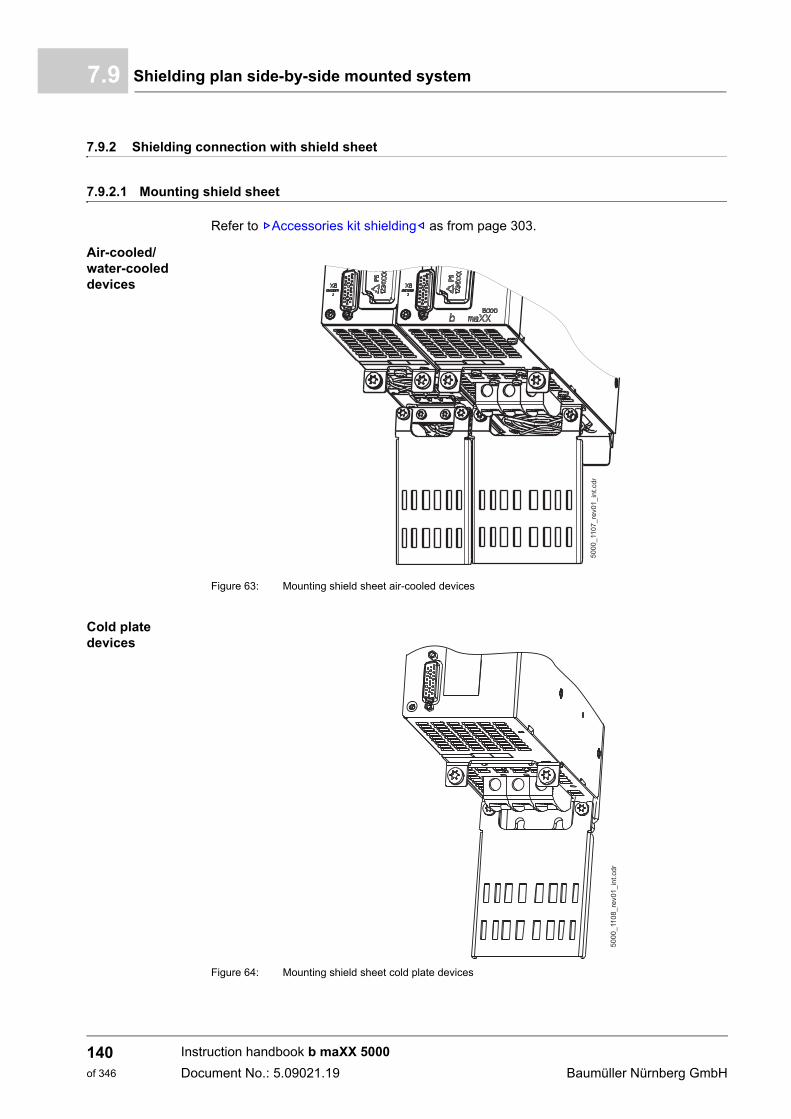
Shielding plan side-by-side mounted system7.9
7.9.2 Shielding connection with shield sheet
7.9.2.1 Mounting shield sheet
Refer to ZAccessories kit shielding– as from page 303.
Air-cooled/water-cooled devices
Figure 63: Mounting shield sheet air-cooled devices
Cold plate devices
Figure 64: Mounting shield sheet cold plate devices
Instruction handbook b maXX 5000
Document No.: 5.09021.19 Baumüller Nürnberg GmbH
140of 346
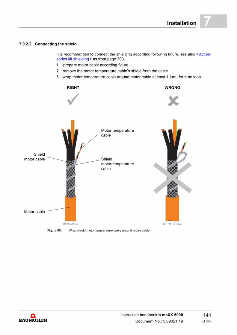
Installation 7
7.9.2.2 Connecting the shieldIt is recommended to connect the shielding according following figure, see also ZAcces-sories kit shielding– as from page 303.
1 prepare motor cable according figure
2 remove the motor temperature cable’s shield from the cable
3 wrap motor temperature cable around motor cable at least 1 turn, form no loop.
RIGHT WRONG
Shieldmotor cable
Motor cable
Motor temperaturecable
Shieldmotor temperaturecable
Figure 65: Wrap shield motor temperature cable around motor cable
������������������������������������������������������������
������������������������������������������������������������
������������������������������������������������������������
������������������������������������������������������������
Instruction handbook b maXX 5000
Document No.: 5.09021.19
141of 346
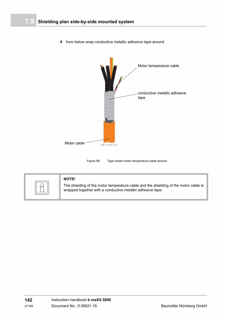
Shielding plan side-by-side mounted system7.9
4 from below wrap conductive metallic adhesive tape around
Motor cable
Motor temperature cable
conductive metallic adhesive tape
Figure 66: Tape shield motor temperature cable around
������������������������������������������������������������
������������������������������������������������������������
NOTE!
The shielding of the motor temperature cable and the shielding of the motor cable iswrapped together with a conductive metallic adhesive tape.
Instruction handbook b maXX 5000
Document No.: 5.09021.19 Baumüller Nürnberg GmbH
142of 346
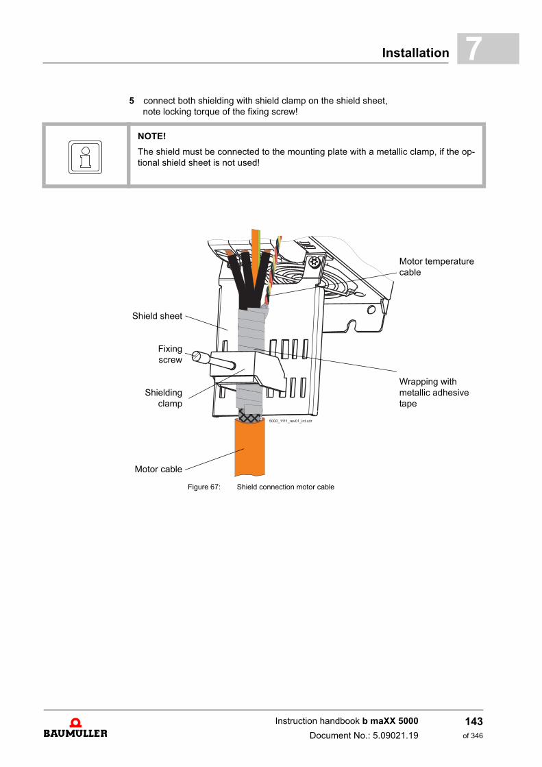
Installation 7
5 connect both shielding with shield clamp on the shield sheet,note locking torque of the fixing screw!
NOTE!
The shield must be connected to the mounting plate with a metallic clamp, if the op-tional shield sheet is not used!
Shield sheet
Fixingscrew
Shieldingclamp
Motor cable
Figure 67: Shield connection motor cable
Motor temperature cable
Wrapping with metallic adhesive tape
������������������������
������������������������
Instruction handbook b maXX 5000
Document No.: 5.09021.19
143of 346
Avoid bearing currents7.10
Locking torque of the fixing screw:
7.10 Avoid bearing currents
Device Locking torque
Single axis unit BM5326, BM5327, BM5328 0.8 Nmcable diameter 5 - 20 mm
shielding clamp width 24 mm
Double axis unit BM5323, BM5325 0.8 Nmcable diameter 3 - 14 mm
shielding clamp width 17 mm
Single axis unit BM5334, BM5335,BM537X, connection 2 x 16 mm²
1 Nmcable diameter 5 - 28 mm
shielding clamp width 31 mmDouble axis unit BM5331, BM5332, BM5333
Single axis unit BM537X, connection 50 mm² 1.5 bis 1.8 Nmcable diameter 20 - 35 mm
shielding clamp width 40 mm
NOTE
The pulsed output voltage of a converter causes additional motor bearing currents.
Bearing currents cause localized melting on ball race and rolling body as well as wearof the lubricant. This leads to a reduced service life of the bearing.
Bearing currents depend on:
m Motor speed
m Switching frequency of the converter
m Grounding
Furthermore the height of the bearing currents depends on:
m the applied bearing voltage
m the dielectric characteristic of the bearing lubrication
NOTE
The reduction of bearing currents requires the consideration of the whole speed-variable drive system and its installation!
Baumüller supports you with on-site measurements and with development and imple-mentation of suitable preventative measures.
Instruction handbook b maXX 5000
Document No.: 5.09021.19 Baumüller Nürnberg GmbH
144of 346
Installation 7
Avoiding bearing damagem Basically the grounding system must be installed appropriately to ensure a forced re-turn of the common mode current.
m The cause of bearing current damage, that means the amplitude and slope of the com-mon mode voltage is reduced by using toroidal cores.The use of toroidal cores is therefore a preferred measure.
m In addition the using of current-isolated bearings (standard for AC drives from motorsize 180 and higher) can reduce the effects of the common mode voltage.
m The shaft can be grounded (and the bearing currents redirected) by using specialgrounding rings or grounding brush(es).
m Furthermore modified motor cables (for high frequencies, cable shield with low imped-ance, symmetric cable design) can be used in order to lead the capacitive currents toa large extent back to the converter via the cable shield.
Toroidal cores
m The toroidal cores are made of nanocrystalline material. The toroidal cores cover allthree phases of the converter output. The time variable common mode current inducesa magnetic field into the toroidal core, which counteracts against the change of thecommon mode current.
m For this reason the toroidal core operates a current-compensated choke, which limitsthe rate of change and the amplitude of the common mode voltage and therefore re-duces the bearing currents significantly.
m Because of the higher amplitude and frequency of the common mode voltage when us-ing an active mains rectifier unit, there are used toroidal cores with a lower permeabilityfor optimized modulation of the cores (saturation and temperature characteristics).
NOTE
It is recommended to use toroidal cores in order to reduce/to avoid bearing currents.
Part numbers and the number of recommended toroidal cores, see ZToroidal coresfor motor cables– as from page 305 in chapter Accessories and Spare Parts.
Instruction handbook b maXX 5000
Document No.: 5.09021.19
145of 346
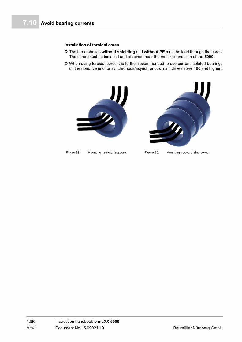
Avoid bearing currents7.10
Installation of toroidal cores
h The three phases without shielding and without PE must be lead through the cores.The cores must be installed and attached near the motor connection of the 5000.
h When using toroidal cores it is further recommended to use current isolated bearingson the nondrive end for synchronous/asynchronous main drives sizes 180 and higher.
Figure 68: Mounting - single ring core Figure 69: Mounting - several ring cores
Instruction handbook b maXX 5000
Document No.: 5.09021.19 Baumüller Nürnberg GmbH
146of 346
Installation 7
7.11 Requirements for the motor temperature sensorsTo protect the motor against impermissible overheating, a motor temperature sensor canbe connected to the b maXX device. The device switches off of the motor when a settablethreshold temperature has been exceeded.
1) Motor protection thermistor (PTC) as per DIN 44080-082
NOTICE!
The motor must be protected against overtemperature according EN 61800-5-1. The device‘s integrated monitoring function „Overtemperature Motor“ fulfills this re-quirement.The user is responsible for realization of the motor overtemperature monitoring ac-cording EN 61800-5-1 in case the used motor is not equipped with a motor tempera-ture sensor or the sensor is not connected.
NOTE!
The thermal memory of the motor and the speed-dependent electronic motor over-load protection is not available if no motor temperature sensor is used.
Type Additional requirements: Isolation
KTY84/PT1000 - SELV/PELV
MSKL 1) (PTC) R = 1 k at TProtection, Imax < 2 mA SELV/PELV
NOTE!
The motor temperature sensor should be installed in such a manner that „electricallyprotective separation“ is ensured. The motor temperature sensors integrated intoBaumüller motors meet these requirements. If third-party motors are connected, theoperating company must ensure that the temperature sensors used in the motor of athird-party manufacturer motor comply with the „electrically protective separation“function.
Instruction handbook b maXX 5000
Document No.: 5.09021.19
147of 346
Installation procedure7.12
7.12 Installation procedure
h Route all cables in an EMC-compatible manner.
h Connect cables (see ZConnection diagrams– as from page 150).(Observe the permissible torques!)
h For all connections, attentions is to be paid to strain relief
The installation comprises the following steps:
1 Connect the motor through terminals 1U2, 1V2, 1W2 and PE.Ensure the proper phases when connecting (rotational direction).Observe the permissible torques!
2 Connect the DC link - only for BM53XX, refer to ZMounting of the DC link bar– onpage 122
3 Connect fuses (F1) - not for BM53XX(if UL 508C is being considered, the UL-listed semiconductor or entire area fuses stat-ed in Chapter ZFuses– as from page 277 are to be used).
4 Connect the main contactor - not for BM53XX
5 Connect the line filters (Z1) - not for BM53XX.
6 Connect the choke (L1) to the mains filter output (not necessary for BM53XX).
7 Connect devices to the mains choke output via the mains input terminals 1U1, 1V1and 1W1 - not with BM53XX.The mains cable has to be laid through the toroidal cores to ensure an operation withina C2 environment (see also ZMounting of toroidal cores– as from page 125)
8 Connect the protective ground conductor to the PE terminal (a fixed ground conductorconnection is absolutely mandatory).
9 Connect 24 V power supply:BM50XX, BM51XX, BM53XX via terminals X200 -1, X200 -2
10 Connect the signal bus cable (see ZX300 (SELV/PELV)– as from page 178).
DANGER!
Risk of fatal injury from electrical current!
Electrically live parts are life-threatening.
Therefore:
m Make certain that the parts to be mounted (e.g. mains cables) and the mountingareas are de-energized for the entire duration of mounting the device.
NOTICE!
Internal overload protection operates exceeding 200 % of the motor rated current (fullload current).
Instruction handbook b maXX 5000
Document No.: 5.09021.19 Baumüller Nürnberg GmbH
148of 346
Installation 7
11 Connect encoders (see ZFront side axis units BM53XX– as from page 183).12 Connect the temperature sensor of the motor. (Observe the proper polarity!)
13 Connect the signal generator for the pulse enable:BM53XX via terminals X2 -20 (IF1), X2 -19 (IF2), X2 -12 (M24V)
14 Connect the signal generator for the quick stop:BM53XX via terminals X2 -13 (SH1), X2 -14 (SH2), X2 -12 (M24V)
15 Depends on the application - not for BM53XX - connect a brake resistor (RB) via theterminals Ba+ and Ba-.
16 Connect the motor brake:BM53XX via the terminals X207 and X208 (option)Assignment pre-assembled Baumüller cable see motor documentation.
NOTE!
Plugging in and pulling out encoder cables while they are energized is prohibited, andcould lead to their destruction.Therefore, always first switch off the 24 V supply voltage and lock the plug connectorsin place.
Instruction handbook b maXX 5000
Document No.: 5.09021.19
149of 346
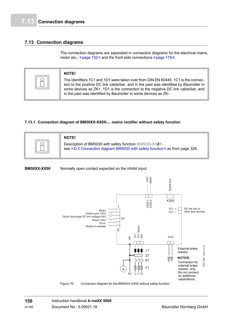
Connection diagrams7.13
7.13 Connection diagrams
The connection diagrams are separated in connection diagrams for the electrical mains,motor etc., Zpage 152– and the front side connections Zpage 179–.
7.13.1 Connection diagram of BM50XX-XX0X-... mains rectifier without safety function
BM50XX-XX00 Normally open contact expected on the inhibit input.
Figure 70: Connection diagram for the BM50XX-XX00 without safety function
NOTE!
The identifiers 1C1 and 1D1 were taken over from DIN EN 60445. 1C1 is the connec-tion to the positive DC link cable/bar, and in the past was identified by Baumüller insome devices as ZK+. 1D1 is the connection to the negative DC link cable/bar, andin the past was identified by Baumüller in some devices as ZK-.
NOTE!
Description of BM5030 with safety function BM5030-XX2X-...see ZD.5 Connection diagram BM5030 with safety function– as from page 328.
NOTICE:
Connection forexternal brakeresistor, only.Do not connectan additionalcapacitance.
External brakeresistor
Instruction handbook b maXX 5000
Document No.: 5.09021.19 Baumüller Nürnberg GmbH
150of 346
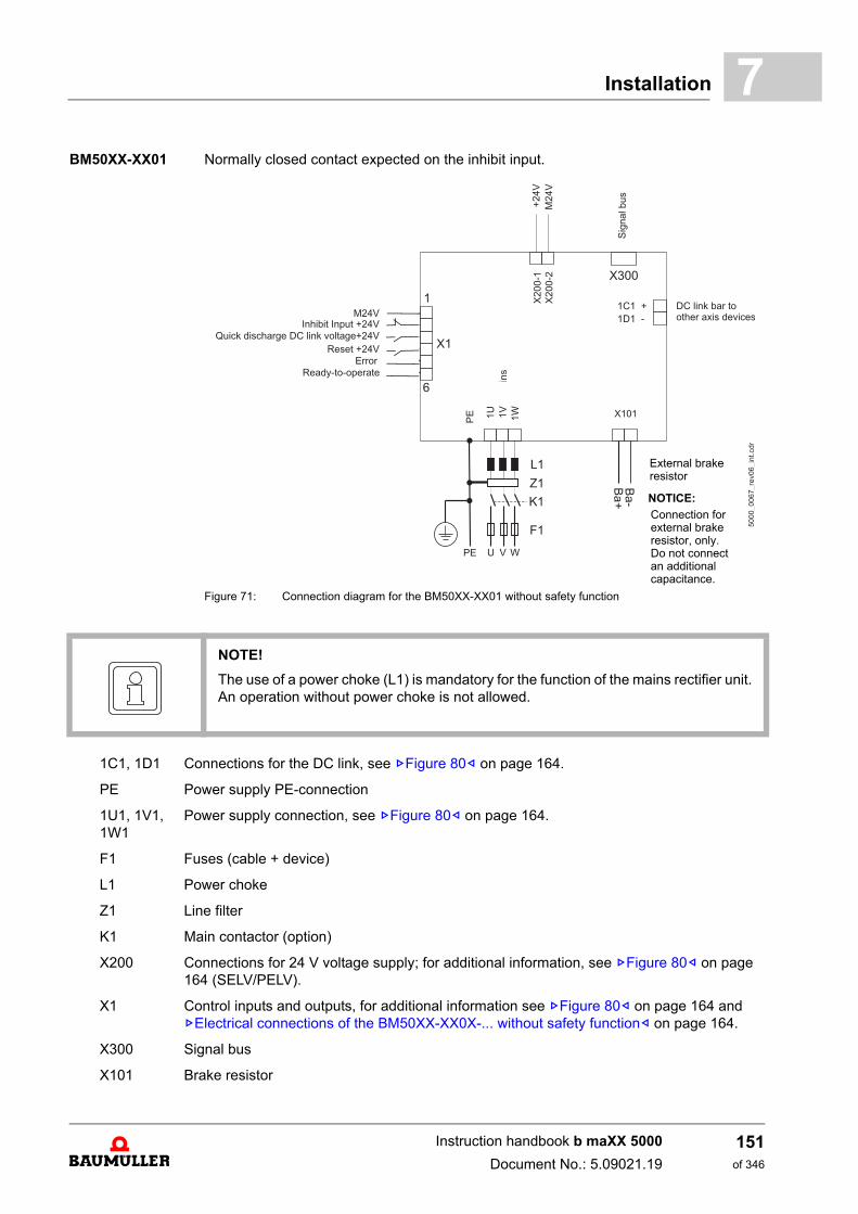
Installation 7
BM50XX-XX01 Normally closed contact expected on the inhibit input.Figure 71: Connection diagram for the BM50XX-XX01 without safety function
NOTICE:
Connection forexternal brakeresistor, only.Do not connectan additionalcapacitance.
External brakeresistor
NOTE!
The use of a power choke (L1) is mandatory for the function of the mains rectifier unit.An operation without power choke is not allowed.
1C1, 1D1 Connections for the DC link, see ZFigure 80– on page 164.
PE Power supply PE-connection
1U1, 1V1, 1W1
Power supply connection, see ZFigure 80– on page 164.
F1 Fuses (cable + device)
L1 Power choke
Z1 Line filter
K1 Main contactor (option)
X200 Connections for 24 V voltage supply; for additional information, see ZFigure 80– on page 164 (SELV/PELV).
X1 Control inputs and outputs, for additional information see ZFigure 80– on page 164 and ZElectrical connections of the BM50XX-XX0X-... without safety function– on page 164.
X300 Signal bus
X101 Brake resistor
Instruction handbook b maXX 5000
Document No.: 5.09021.19
151of 346
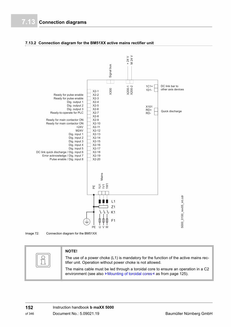
Connection diagrams7.13
7.13.2 Connection diagram for the BM51XX active mains rectifier unit
Image 72: Connection diagram for the BM51XX
NOTE!
The use of a power choke (L1) is mandatory for the function of the active mains rec-tifier unit. Operation without power choke is not allowed.
The mains cable must be led through a toroidal core to ensure an operation in a C2environment (see also ZMounting of toroidal cores– as from page 125).
Instruction handbook b maXX 5000
Document No.: 5.09021.19 Baumüller Nürnberg GmbH
152of 346
Installation 7
1C1, 1D1 Connections for the DC link, see ZFigure 82– on page 166.
PE Power supply PE-connection
1U1, 1V1, 1W1
Power supply connection, see ZFigure 82– on page 166.
F1 Fuses (cable + device)
L1 Power choke
Z1 Line filter
K1 Main contactor
X101 Quick discharge RD+, RD-
X200 Connections for 24 V voltage supply; for additional information, see ZFigure 82– on page 166 (SELV/PELV).
X2 Connections for pulse enable, etc., see ZPin assignment X2– on page 182.
X300 Signal bus
BB-HS Ready for main contactor ON (NO contact)
BB-IF Ready for pulse enable (NO contact)
Instruction handbook b maXX 5000
Document No.: 5.09021.19
153of 346
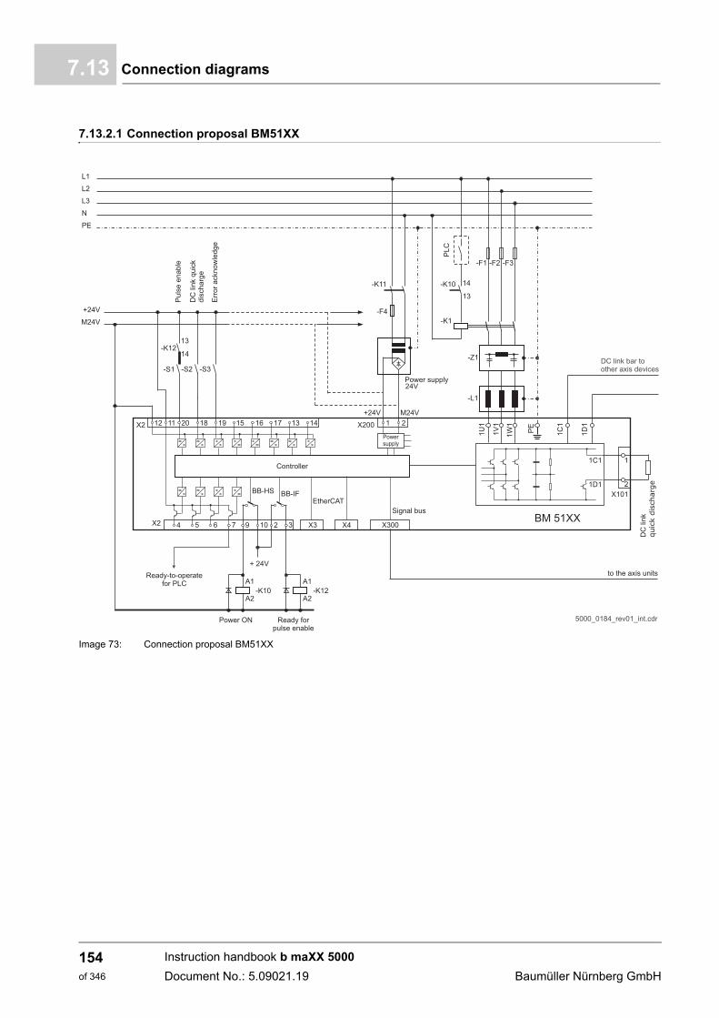
Connection diagrams7.13
7.13.2.1 Connection proposal BM51XX
Image 73: Connection proposal BM51XX
Instruction handbook b maXX 5000
Document No.: 5.09021.19 Baumüller Nürnberg GmbH
154of 346
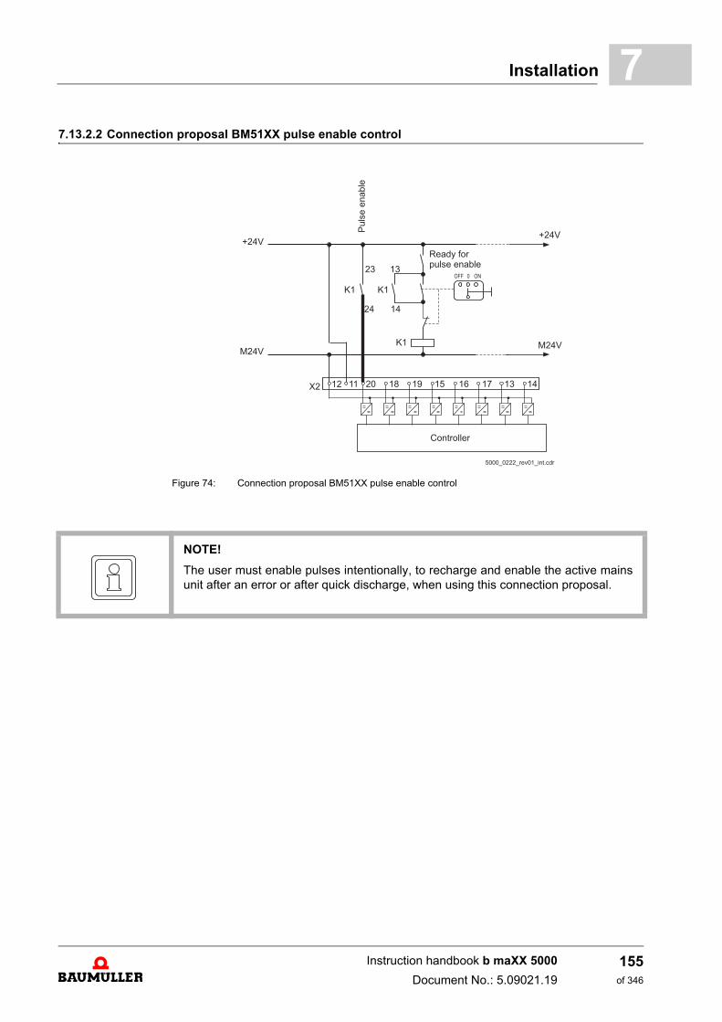
Installation 7
7.13.2.2 Connection proposal BM51XX pulse enable controlFigure 74: Connection proposal BM51XX pulse enable control
NOTE!
The user must enable pulses intentionally, to recharge and enable the active mainsunit after an error or after quick discharge, when using this connection proposal.
Instruction handbook b maXX 5000
Document No.: 5.09021.19
155of 346
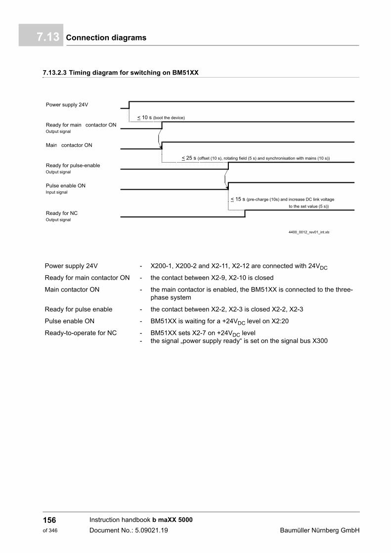
Connection diagrams7.13
7.13.2.3 Timing diagram for switching on BM51XX
Power supply 24V
< 10 s (boot the device)
Ready for mains contactor ONOutput signal
Mains contactor ON
< 25 s (offset (10 s), rotating field (5 s) and synchronisation with mains (10 s))
Ready for pulse-enableOutput signal
Pulse enable ONInput signal
< 15 s (pre-charge (10s) and increase DC link voltageto the set value (5 s))
Ready for NCOutput signal
4400_0012_rev01_int.xls
Power supply 24V - X200-1, X200-2 and X2-11, X2-12 are connected with 24VDC
Ready for main contactor ON - the contact between X2-9, X2-10 is closed
Main contactor ON - the main contactor is enabled, the BM51XX is connected to the three-phase system
Ready for pulse enable - the contact between X2-2, X2-3 is closed X2-2, X2-3
Pulse enable ON - BM51XX is waiting for a +24VDC level on X2:20
Ready-to-operate for NC --
BM51XX sets X2-7 on +24VDC levelthe signal „power supply ready“ is set on the signal bus X300
Instruction handbook b maXX 5000
Document No.: 5.09021.19 Baumüller Nürnberg GmbH
156of 346
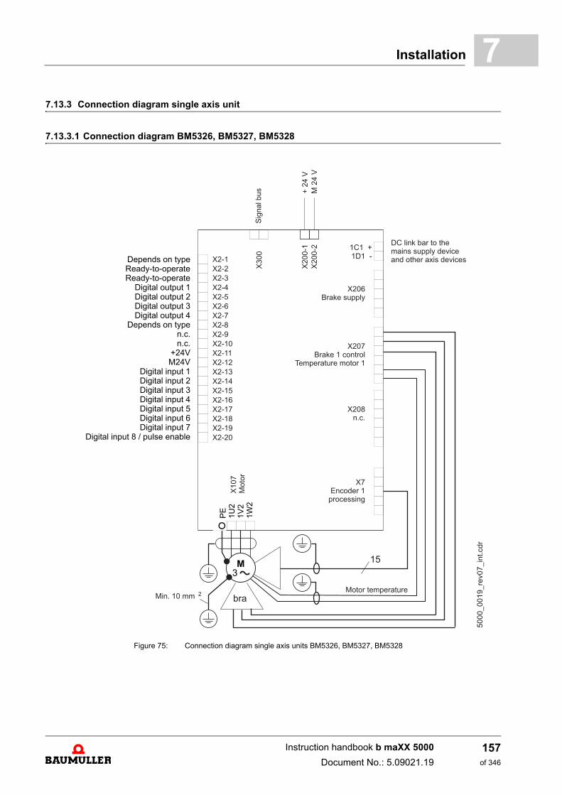
Installation 7
7.13.3 Connection diagram single axis unit7.13.3.1 Connection diagram BM5326, BM5327, BM5328
Figure 75: Connection diagram single axis units BM5326, BM5327, BM5328
M3
Depends on typeReady-to-operateReady-to-operate
Digital output 1Digital output 2Digital output 3Digital output 4
Depends on typen.c.n.c.
+24VM24V
Digital input 1Digital input 2Digital input 3Digital input 4Digital input 5Digital input 6Digital input 7
Digital input 8 / pulse enable
PE
1U2
1V2
1W2
Instruction handbook b maXX 5000
Document No.: 5.09021.19
157of 346
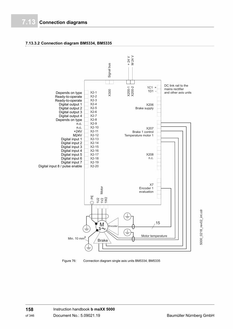
Connection diagrams7.13
7.13.3.2 Connection diagram BM5334, BM5335
Figure 76: Connection diagram single axis units BM5334, BM5335
Depends on typeReady-to-operateReady-to-operate
Digital output 1Digital output 2Digital output 3Digital output 4
Depends on typen.c.n.c.
+24VM24V
Digital input 1Digital input 2Digital input 3Digital input 4Digital input 5Digital input 6Digital input 7
Digital input 8 / pulse enable
Instruction handbook b maXX 5000
Document No.: 5.09021.19 Baumüller Nürnberg GmbH
158of 346
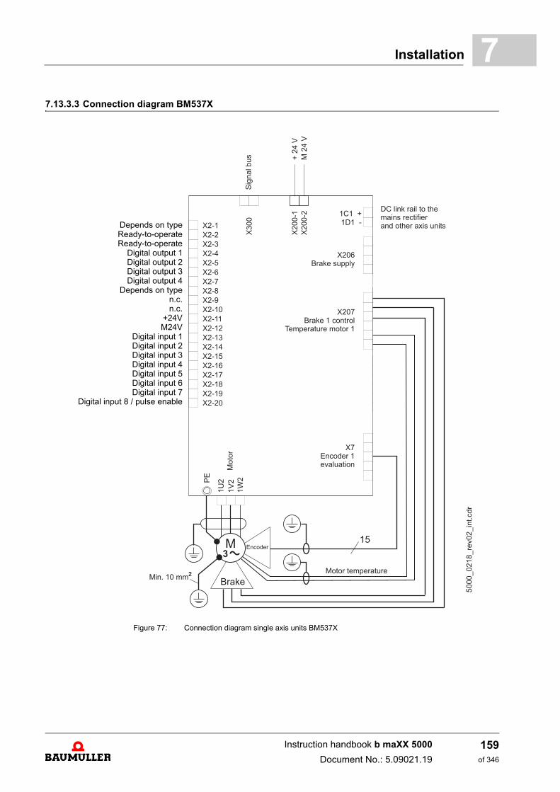
Installation 7
7.13.3.3 Connection diagram BM537XFigure 77: Connection diagram single axis units BM537X
Depends on typeReady-to-operateReady-to-operate
Digital output 1Digital output 2Digital output 3Digital output 4
Depends on typen.c.n.c.
+24VM24V
Digital input 1Digital input 2Digital input 3Digital input 4Digital input 5Digital input 6Digital input 7
Digital input 8 / pulse enable
Instruction handbook b maXX 5000
Document No.: 5.09021.19
159of 346
Connection diagrams7.13
1C1, 1D1 Connections for the DC link, see ZFigure 84– on page 168.
X2 Connections for pulse enable, etc. see ZX2 Digital inputs/outputs– on page 185
X7 Encoder evaluation
X107 Motor connection BM5326, BM5327, BM5328, see ZFigure 84– on page 168
1U2, 1V2, 1W2 Connections for the motor BM5334, BM5335, see ZFigure 85– on page 169.Connections for the motor BM537X, see ZFigure 86– on page 170
X200 Connections for 24 V voltage supply; for additional information, see ZFigure 84– on page 168 (SELV/PELV).
X206 Connection for 24 V voltage supply for the motor brake, see Table X206 on Zpage 176–. For connector assignment see ZX206/X207/X208– as from page 212.
X207 Connections for motor temperature and motor brake of motor 1, see table X207 on Zpage 177–. For connector assignment see ZX206/X207/X208– as from page 212.
X208 Connections for motor temperature and motor brake of motor 2, see table X208 on Zpage 177–. For connector assignment see ZX206/X207/X208– as from page 212.
X300 Signal bus
Instruction handbook b maXX 5000
Document No.: 5.09021.19 Baumüller Nürnberg GmbH
160of 346
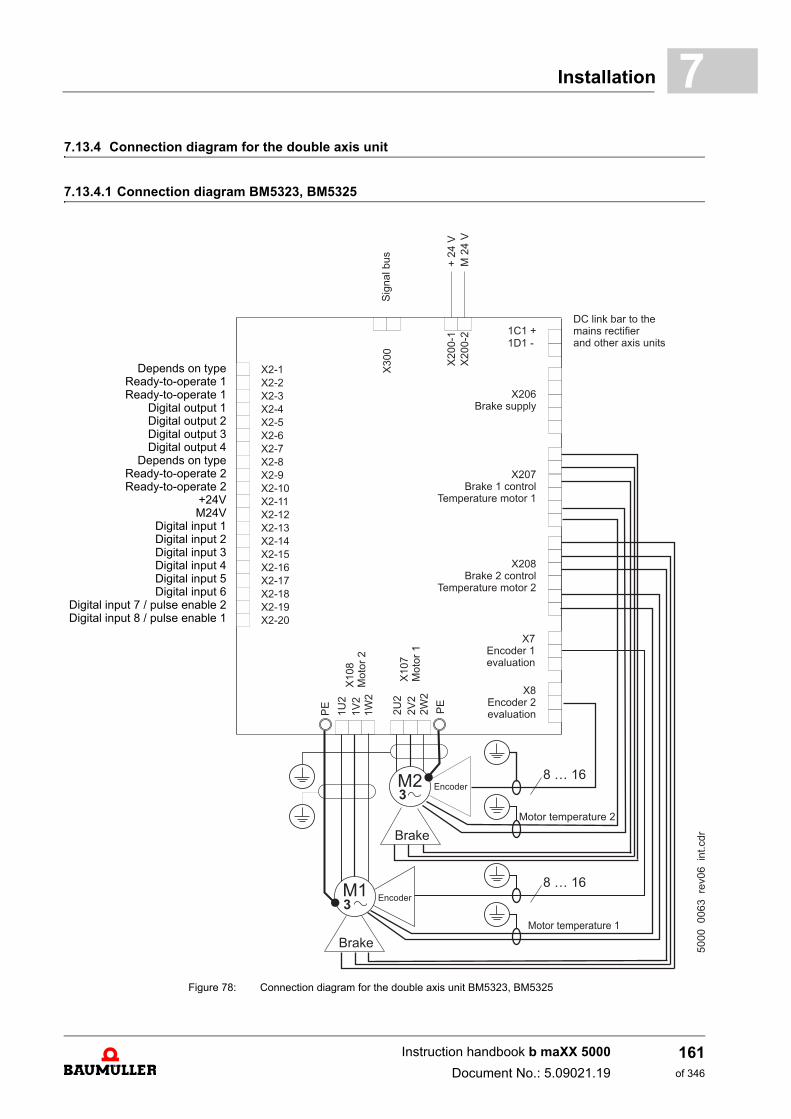
Installation 7
7.13.4 Connection diagram for the double axis unit7.13.4.1 Connection diagram BM5323, BM5325
Figure 78: Connection diagram for the double axis unit BM5323, BM5325
Depends on typeReady-to-operate 1Ready-to-operate 1
Digital output 1Digital output 2Digital output 3Digital output 4
Depends on typeReady-to-operate 2Ready-to-operate 2
+24VM24V
Digital input 1Digital input 2Digital input 3Digital input 4Digital input 5Digital input 6
Digital input 7 / pulse enable 2Digital input 8 / pulse enable 1
Instruction handbook b maXX 5000
Document No.: 5.09021.19
161of 346
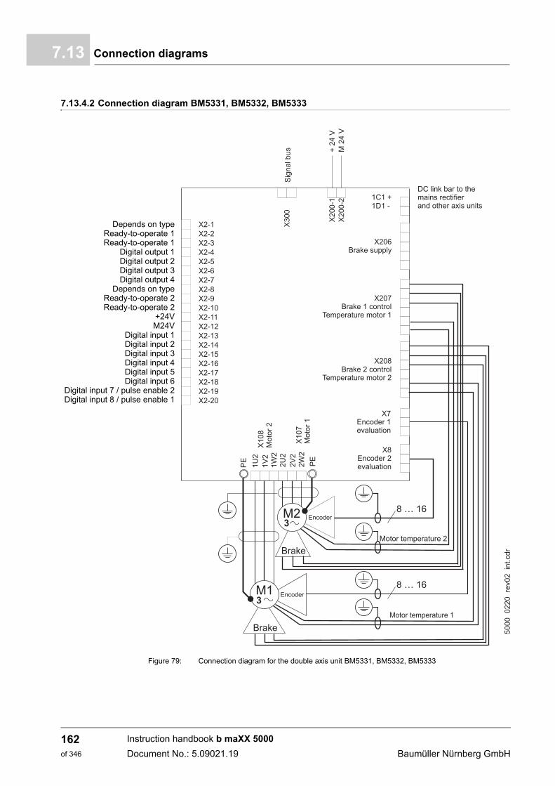
Connection diagrams7.13
7.13.4.2 Connection diagram BM5331, BM5332, BM5333
Figure 79: Connection diagram for the double axis unit BM5331, BM5332, BM5333
Depends on typeReady-to-operate 1Ready-to-operate 1
Digital output 1Digital output 2Digital output 3Digital output 4
Depends on typeReady-to-operate 2Ready-to-operate 2
+24VM24V
Digital input 1Digital input 2Digital input 3Digital input 4Digital input 5Digital input 6
Digital input 7 / pulse enable 2Digital input 8 / pulse enable 1
Instruction handbook b maXX 5000
Document No.: 5.09021.19 Baumüller Nürnberg GmbH
162of 346
Installation 7
1C1, 1D1 Connections for the DC link, see ZFigure 88– on page 172.
X2 Connections for pulse enable, etc. see ZX2 Digital inputs/outputs– on page 185
X7 Encoder evaluation 1
X8 Encoder evaluation 2
X107 BM5323, BM5325Motor connection 1
BM5331, BM5332, BM5333Motor connection 1 and 2
X108 BM5323, BM5325Motor connection 2
X200 Connections for 24 V voltage supply; for additional information, see ZFigure 88– on page 172 (SELV/PELV).
X206 Connection for 24 V voltage supply for the motor brake, see Table X206 on Zpage 176–. For connector assignment see ZX206/X207/X208– as from page 212.
X207 Connections for motor temperature and motor brake of motor 1, see table X207 on Zpage 177–. For connector assignment see ZX206/X207/X208– as from page 212.
X208 Connections for motor temperature and motor brake of motor 2, see table X208 on Zpage 177–. For connector assignment see ZX206/X207/X208– as from page 212.
X300 Signal bus
Instruction handbook b maXX 5000
Document No.: 5.09021.19
163of 346
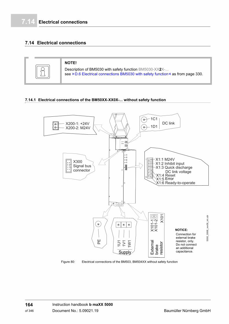
Electrical connections7.14
7.14 Electrical connections
7.14.1 Electrical connections of the BM50XX-XX0X-... without safety function
Figure 80: Electrical connections of the BM503, BM504XX without safety function
NOTE!
Description of BM5030 with safety function BM5030-XX2X-...see ZD.6 Electrical connections BM5030 with safety function– as from page 330.
Error
Ext
ern
alb
rake
resi
sto
r
NOTICE:
Connection forexternal brakeresistor, only.Do not connectan additionalcapacitance.Supply
Instruction handbook b maXX 5000
Document No.: 5.09021.19 Baumüller Nürnberg GmbH
164of 346
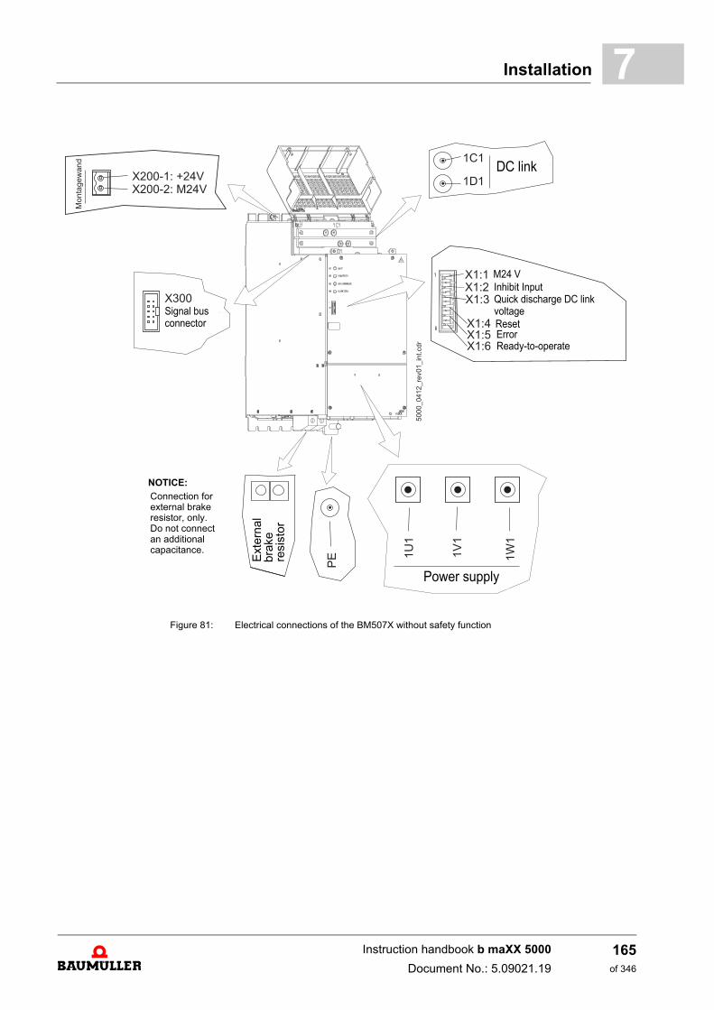
Installation 7
Figure 81: Electrical connections of the BM507X without safety function
Inhibit input
Fehler
M24 VInhibit InputQuick discharge DC link
ResetErrorReady-to-operate
voltageSignal busconnector
NOTICE:
Connection forexternal brakeresistor, only.Do not connectan additionalcapacitance.
DC link
Power supply
Ext
erna
lbr
ake
resi
sto
r
Instruction handbook b maXX 5000
Document No.: 5.09021.19
165of 346
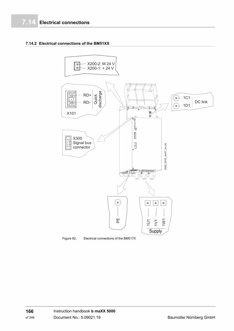
Electrical connections7.14
7.14.2 Electrical connections of the BM51XX
Figure 82: Electrical connections of the BM517X
Supply
Instruction handbook b maXX 5000
Document No.: 5.09021.19 Baumüller Nürnberg GmbH
166of 346
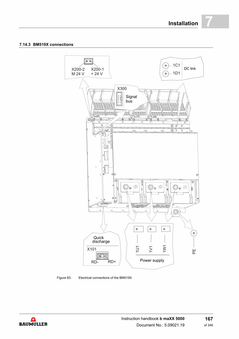
Installation 7
7.14.3 BM519X connectionsFigure 83: Electrical connections of the BM519X
DC link
Power supply
Quickdischarge
Signal bus
Instruction handbook b maXX 5000
Document No.: 5.09021.19
167of 346
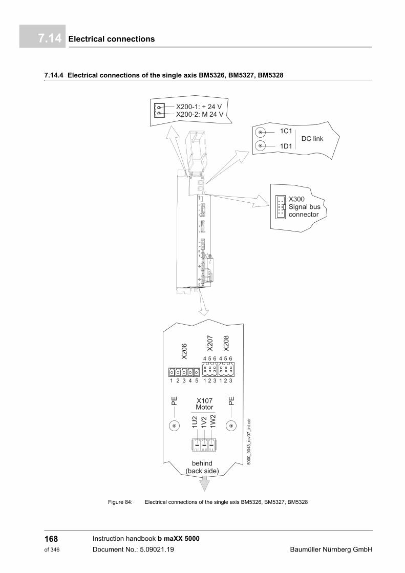
Electrical connections7.14
7.14.4 Electrical connections of the single axis BM5326, BM5327, BM5328
Figure 84: Electrical connections of the single axis BM5326, BM5327, BM5328
Instruction handbook b maXX 5000
Document No.: 5.09021.19 Baumüller Nürnberg GmbH
168of 346
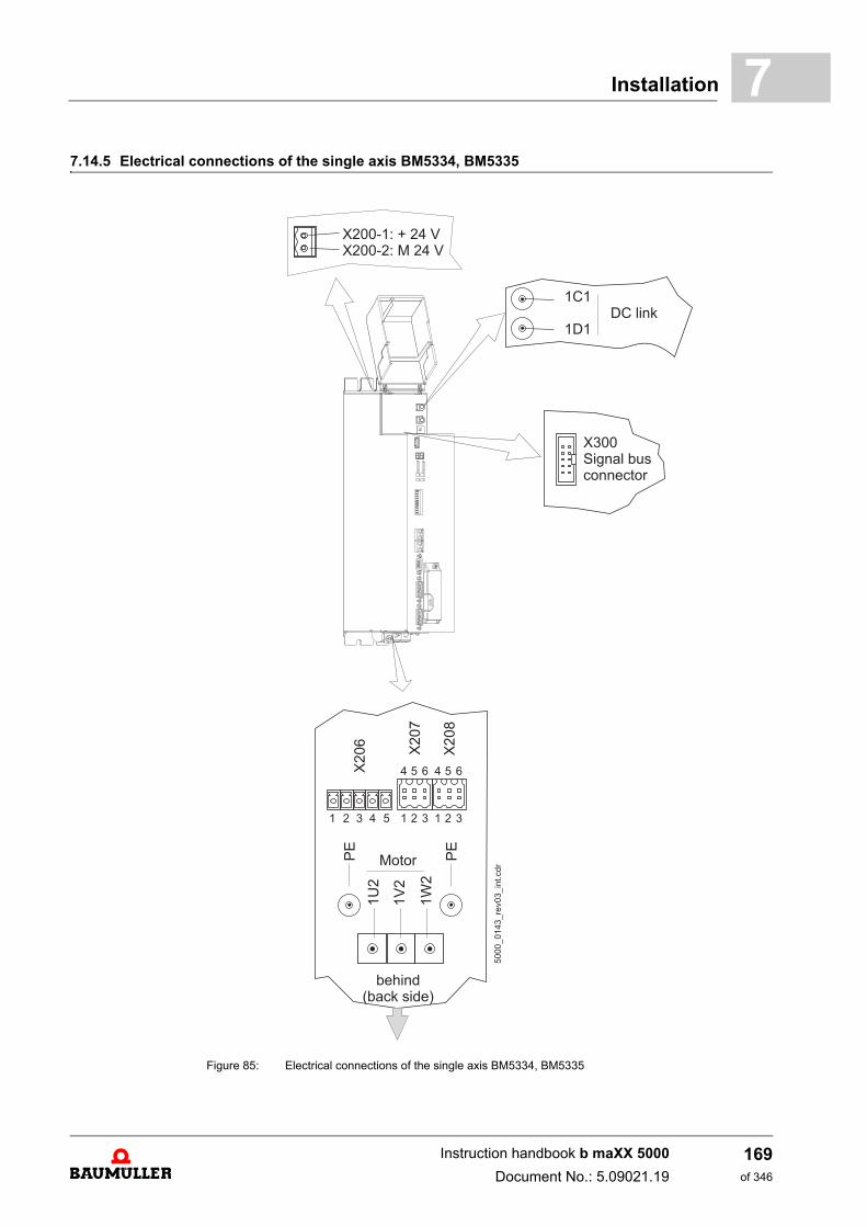
Installation 7
7.14.5 Electrical connections of the single axis BM5334, BM5335Figure 85: Electrical connections of the single axis BM5334, BM5335
Instruction handbook b maXX 5000
Document No.: 5.09021.19
169of 346
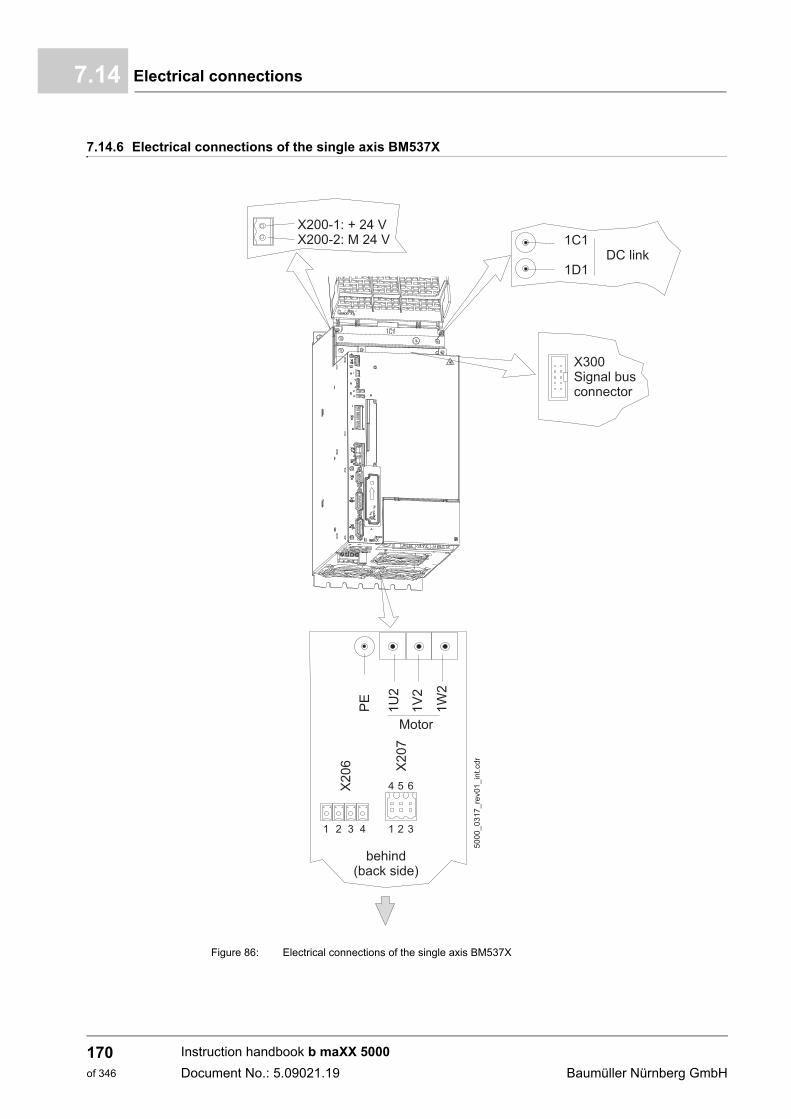
Electrical connections7.14
7.14.6 Electrical connections of the single axis BM537X
Figure 86: Electrical connections of the single axis BM537X
Instruction handbook b maXX 5000
Document No.: 5.09021.19 Baumüller Nürnberg GmbH
170of 346
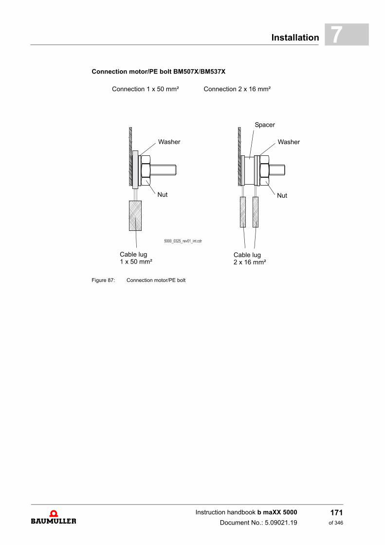
Installation 7
Connection motor/PE bolt BM507X/BM537XFigure 87: Connection motor/PE bolt
Connection 1 x 50 mm² Connection 2 x 16 mm²
Cable lug1 x 50 mm²
Cable lug2 x 16 mm²
Washer
Nut
Washer
Nut
Spacer
Instruction handbook b maXX 5000
Document No.: 5.09021.19
171of 346
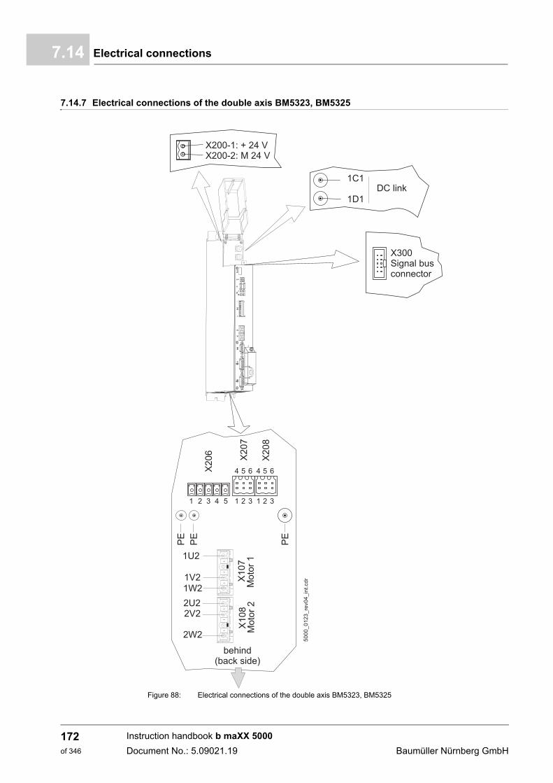
Electrical connections7.14
7.14.7 Electrical connections of the double axis BM5323, BM5325
Figure 88: Electrical connections of the double axis BM5323, BM5325
Instruction handbook b maXX 5000
Document No.: 5.09021.19 Baumüller Nürnberg GmbH
172of 346
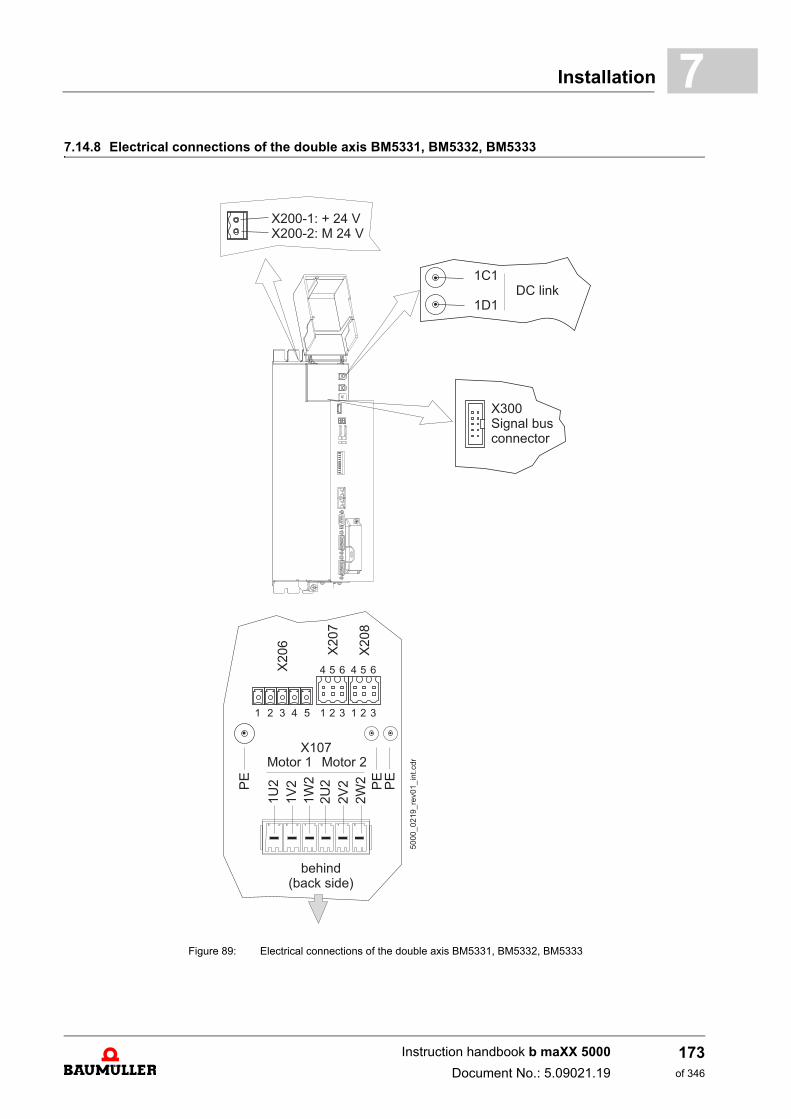
Installation 7
7.14.8 Electrical connections of the double axis BM5331, BM5332, BM5333Figure 89: Electrical connections of the double axis BM5331, BM5332, BM5333
Instruction handbook b maXX 5000
Document No.: 5.09021.19
173of 346
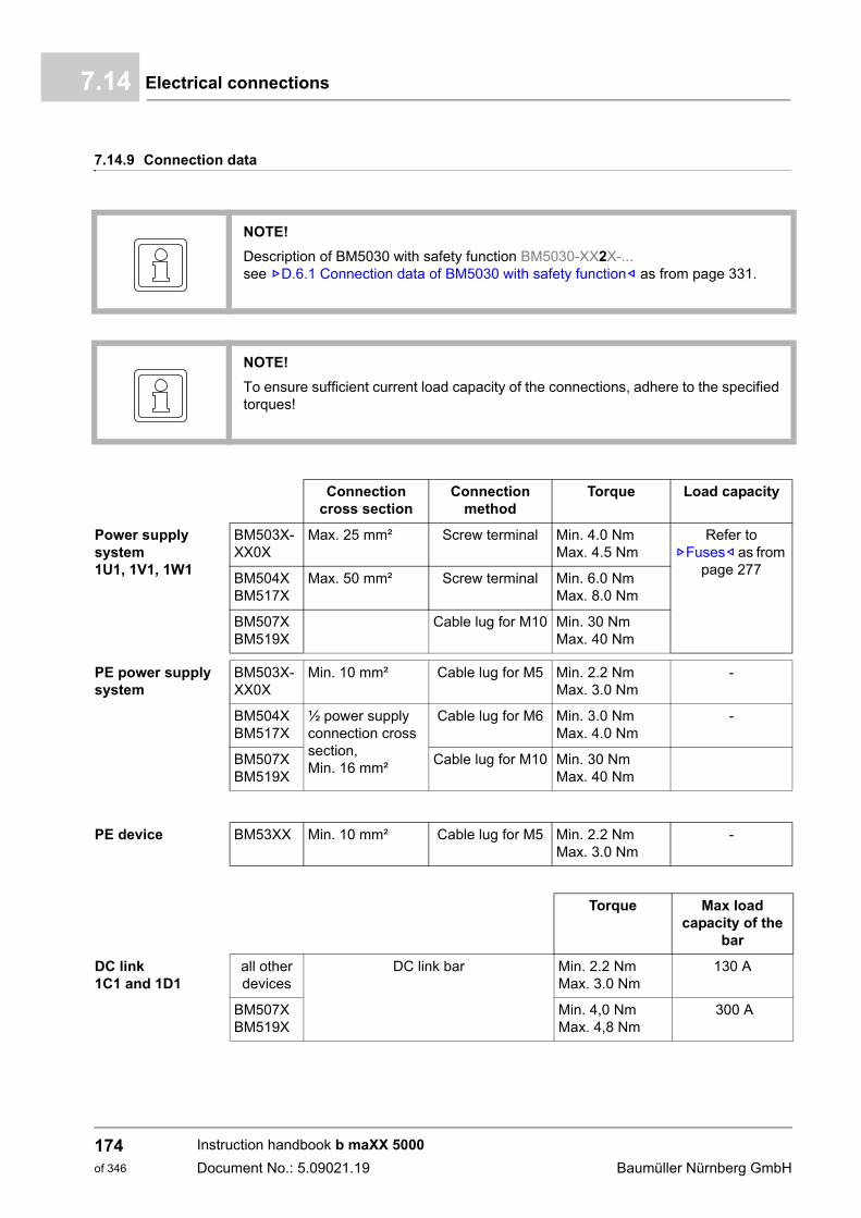
Electrical connections7.14
7.14.9 Connection data
NOTE!
Description of BM5030 with safety function BM5030-XX2X-...see ZD.6.1 Connection data of BM5030 with safety function– as from page 331.
NOTE!
To ensure sufficient current load capacity of the connections, adhere to the specifiedtorques!
Connectioncross section
Connectionmethod
Torque Load capacity
Power supply system1U1, 1V1, 1W1
BM503X-XX0X
Max. 25 mm² Screw terminal Min. 4.0 NmMax. 4.5 Nm
Refer to ZFuses– as from
page 277BM504X BM517X
Max. 50 mm² Screw terminal Min. 6.0 NmMax. 8.0 Nm
BM507XBM519X
Cable lug for M10 Min. 30 NmMax. 40 Nm
PE power supply system
BM503X-XX0X
Min. 10 mm² Cable lug for M5 Min. 2.2 NmMax. 3.0 Nm
-
BM504X BM517X
½ power supply connection cross section, Min. 16 mm²
Cable lug for M6 Min. 3.0 NmMax. 4.0 Nm
-
BM507XBM519X
Cable lug for M10 Min. 30 NmMax. 40 Nm
PE device BM53XX Min. 10 mm² Cable lug for M5 Min. 2.2 NmMax. 3.0 Nm
-
Torque Max load capacity of the
bar
DC link1C1 and 1D1
all other devices
DC link bar Min. 2.2 NmMax. 3.0 Nm
130 A
BM507XBM519X
Min. 4,0 NmMax. 4,8 Nm
300 A
Instruction handbook b maXX 5000
Document No.: 5.09021.19 Baumüller Nürnberg GmbH
174of 346
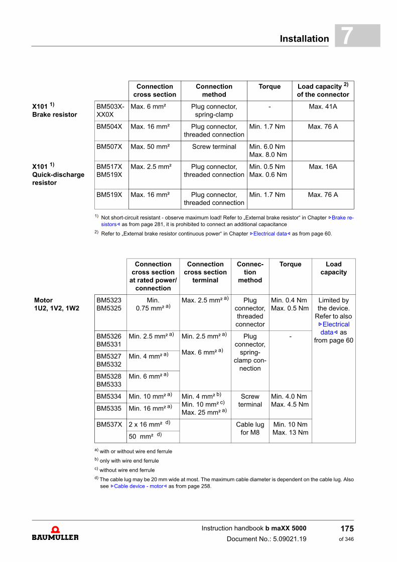
Installation 7
1) Not short-circuit resistant - observe maximum load! Refer to „External brake resistor“ in Chapter ZBrake re-sistors– as from page 281, it is prohibited to connect an additional capacitance
2) Refer to „External brake resistor continuous power“ in Chapter ZElectrical data– as from page 60.
a) with or without wire end ferruleb) only with wire end ferrulec) without wire end ferruled) The cable lug may be 20 mm wide at most. The maximum cable diameter is dependent on the cable lug. Also
see ZCable device - motor– as from page 258.
Connection cross section
Connection method
Torque Load capacity 2)
of the connector
X101 1)
Brake resistorBM503X-XX0X
Max. 6 mm² Plug connector, spring-clamp
- Max. 41A
BM504X Max. 16 mm² Plug connector, threaded connection
Min. 1.7 Nm Max. 76 A
BM507X Max. 50 mm² Screw terminal Min. 6.0 NmMax. 8.0 Nm
X101 1)
Quick-discharge resistor
BM517XBM519X
Max. 2.5 mm² Plug connector, threaded connection
Min. 0.5 NmMax. 0.6 Nm
Max. 16A
BM519X Max. 16 mm² Plug connector, threaded connection
Min. 1.7 Nm Max. 76 A
Connection cross section
at rated power/connection
Connection cross section
terminal
Connec-tion
method
Torque Load capacity
Motor1U2, 1V2, 1W2
BM5323BM5325
Min. 0.75 mm² a)
Max. 2.5 mm² a) Plugconnector, threaded connector
Min. 0.4 NmMax. 0.5 Nm
Limited by the device.
Refer to also ZElectrical data– as
from page 60BM5326BM5331
Min. 2.5 mm² a) Min. 2.5 mm² a)
Max. 6 mm² a)
Plugconnector,
spring-clamp con-
nection
-
BM5327BM5332
Min. 4 mm² a)
BM5328BM5333
Min. 6 mm² a)
BM5334 Min. 10 mm² a) Min. 4 mm² b)
Min. 10 mm² c)
Max. 25 mm² a)
Screw terminal
Min. 4.0 NmMax. 4.5 Nm
BM5335 Min. 16 mm² a)
BM537X 2 x 16 mm² d) Cable lug for M8
Min. 10 NmMax. 13 Nm
50 mm² d)
Instruction handbook b maXX 5000
Document No.: 5.09021.19
175of 346
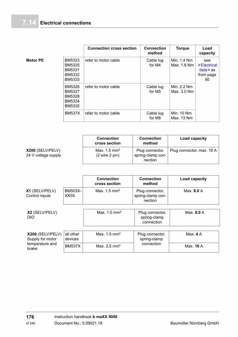
Electrical connections7.14
Connection cross section Connection method
Torque Load capacity
Motor PE BM5323BM5325BM5331BM5332BM5333
refer to motor cable Cable lug for M4
Min. 1.4 NmMax. 1.8 Nm
see ZElectrical data– as from page
60
BM5326BM5327BM5328BM5334BM5335
refer to motor cable Cable lug for M5
Min. 2.2 NmMax. 3.0 Nm
BM537X refer to motor cable Cable lug for M8
Min. 10 NmMax. 13 Nm
Connection cross section
Connection method
Load capacity
X200 (SELV/PELV)24 V voltage supply
Max. 1.5 mm²(2 wire 2 pin)
Plug connector, spring-clamp con-
nection
Plug connector, max. 16 A
Connection cross section
Connection method
Load capacity
X1 (SELV/PELV)Control inputs
BM503X-XX0X
Max. 1.5 mm² Plug connector, spring-clamp con-
nection
Max. 8.0 A
X2 (SELV/PELV)DIO
Max. 1.0 mm² Plug connector, spring-clamp connection
Max. 8.0 A
X206 (SELV/PELV)Supply for motor temperature and brake
all other devices
Max. 1.5 mm² Plug connector, spring-clamp connection
Max. 4 A
BM537X Max. 2,5 mm² Max. 16 A
Instruction handbook b maXX 5000
Document No.: 5.09021.19 Baumüller Nürnberg GmbH
176of 346
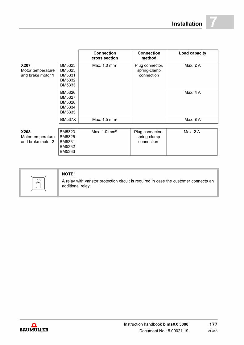
Installation 7
Connection cross section
Connection method
Load capacity
X207Motor temperature and brake motor 1
BM5323BM5325BM5331BM5332BM5333
Max. 1.0 mm² Plug connector, spring-clamp connection
Max. 2 A
BM5326BM5327BM5328BM5334BM5335
Max. 4 A
BM537X Max. 1.5 mm² Max. 8 A
X208Motor temperature and brake motor 2
BM5323BM5325BM5331BM5332BM5333
Max. 1.0 mm² Plug connector, spring-clamp connection
Max. 2 A
NOTE!
A relay with varistor protection circuit is required in case the customer connects anadditional relay.
Instruction handbook b maXX 5000
Document No.: 5.09021.19
177of 346
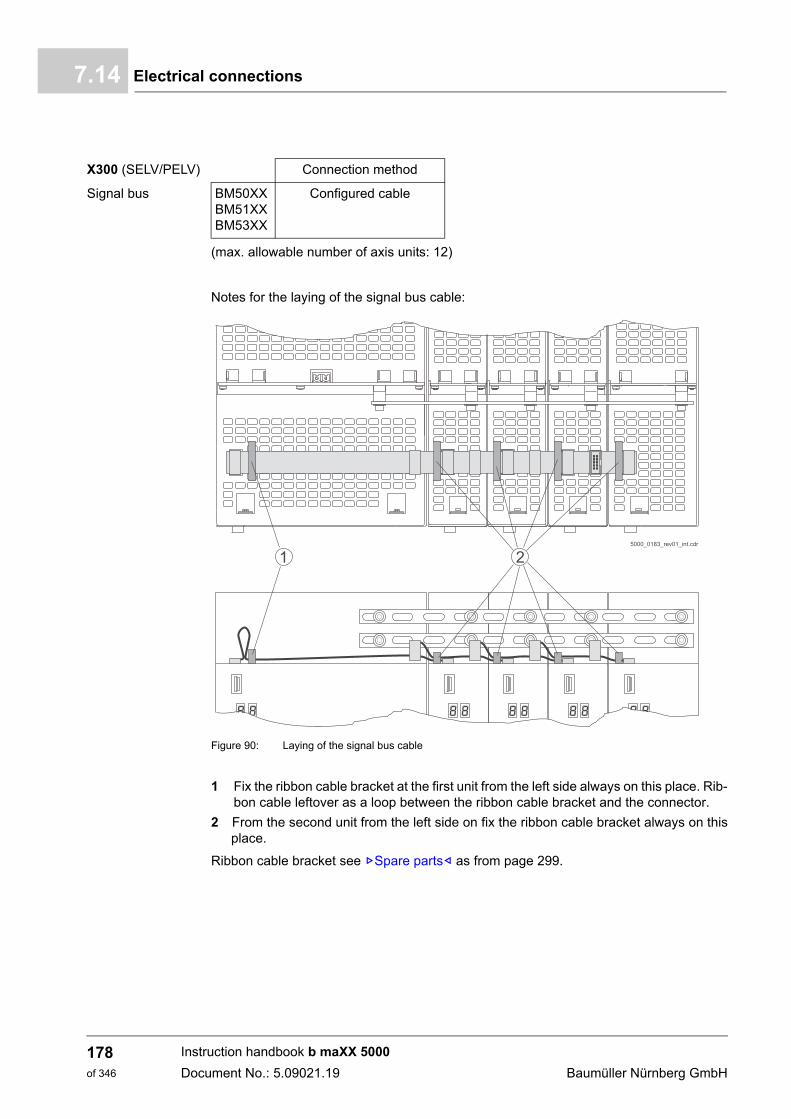
Electrical connections7.14
(max. allowable number of axis units: 12)
Notes for the laying of the signal bus cable:
Figure 90: Laying of the signal bus cable
1 Fix the ribbon cable bracket at the first unit from the left side always on this place. Rib-bon cable leftover as a loop between the ribbon cable bracket and the connector.
2 From the second unit from the left side on fix the ribbon cable bracket always on thisplace.
Ribbon cable bracket see ZSpare parts– as from page 299.
X300 (SELV/PELV) Connection method
Signal bus BM50XXBM51XXBM53XX
Configured cable
Instruction handbook b maXX 5000
Document No.: 5.09021.19 Baumüller Nürnberg GmbH
178of 346
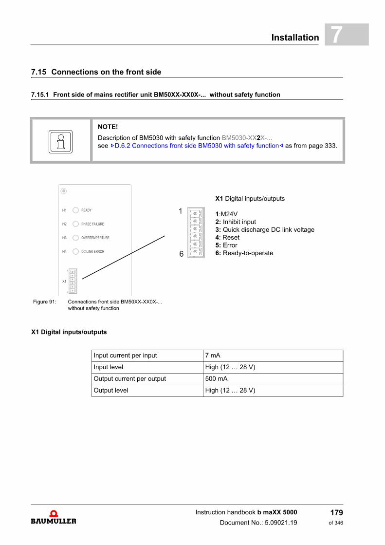
Installation 7
7.15 Connections on the front side7.15.1 Front side of mains rectifier unit BM50XX-XX0X-... without safety function
NOTE!
Description of BM5030 with safety function BM5030-XX2X-...see ZD.6.2 Connections front side BM5030 with safety function– as from page 333.
Figure 91: Connections front side BM50XX-XX0X-... without safety function
X1 Digital inputs/outputs
1:M24V2: Inhibit input3: Quick discharge DC link voltage4: Reset5: Error6: Ready-to-operate
X1 Digital inputs/outputs
Input current per input 7 mA
Input level High (12 … 28 V)
Output current per output 500 mA
Output level High (12 … 28 V)
Instruction handbook b maXX 5000
Document No.: 5.09021.19
179of 346
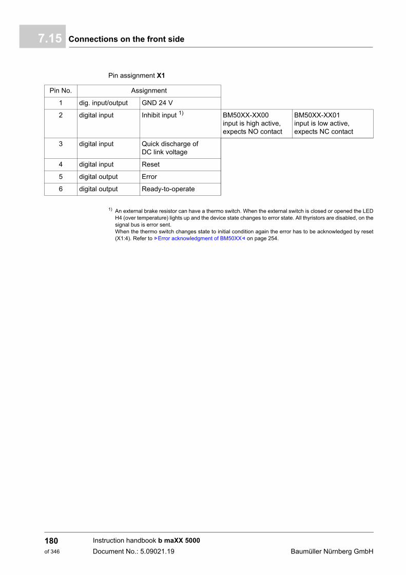
Connections on the front side7.15
Pin assignment X1
1) An external brake resistor can have a thermo switch. When the external switch is closed or opened the LEDH4 (over temperature) lights up and the device state changes to error state. All thyristors are disabled, on thesignal bus is error sent.When the thermo switch changes state to initial condition again the error has to be acknowledged by reset(X1:4). Refer to ZError acknowledgment of BM50XX– on page 254.
Pin No. Assignment
1 dig. input/output GND 24 V
2 digital input Inhibit input 1) BM50XX-XX00input is high active, expects NO contact
BM50XX-XX01input is low active, expects NC contact
3 digital input Quick discharge of DC link voltage
4 digital input Reset
5 digital output Error
6 digital output Ready-to-operate
Instruction handbook b maXX 5000
Document No.: 5.09021.19 Baumüller Nürnberg GmbH
180of 346
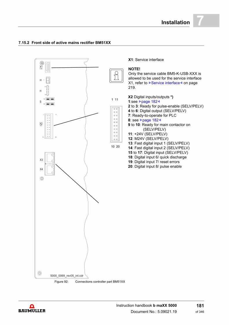
Installation 7
7.15.2 Front side of active mains rectifier BM51XXFigure 92: Connections controller part BM51XX
X1: Service interface
NOTE!Only the service cable BM5-K-USB-XXX is allowed to be used for the service interface X1, refer to ZService interface– on page 219.
X2 Digital inputs/outputs *)1:see Zpage 182–2 to 3: Ready for pulse-enable (SELV/PELV)4 to 6: Digital output (SELV/PELV)7: Ready-to-operate for PLC8: see Zpage 182–9 to 10: Ready for main contactor on (SELV/PELV)11: +24V (SELV/PELV)12: M24V (SELV/PELV)13: Fast digital input 1 (SELV/PELV)14: Fast digital input 2 (SELV/PELV)15 to 17: Digital input (SELV/PELV)18: Digital input 6/ quick discharge19: Digital input 7/ reset errors20: Digital input 8/ pulse enable
1 11
10 20
Instruction handbook b maXX 5000
Document No.: 5.09021.19
181of 346
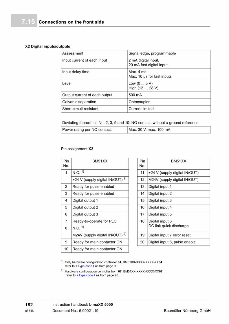
Connections on the front side7.15
Pin assignment X2
1) Only hardware configuration controller 04, BM51XX-XXXX-XXXX-XX04refer to ZType code– as from page 90.
2) Hardware configuration controller from 07, BM51XX-XXXX-XXXX-XX07 refer to ZType code– as from page 90.
X2 Digital inputs/outputs
Assessment Signal edge, programmable
Input current of each input 2 mA digital input,20 mA fast digital input
Input delay time Max. 4 msMax. 10 µs for fast inputs
Level Low (0 ... 5 V)High (12 … 28 V)
Output current of each output 500 mA
Galvanic separation Optocoupler
Short-circuit resistant Current limited
Deviating thereof pin No. 2, 3, 9 and 10: NO contact, without a ground reference
Power rating per NO contact: Max. 30 V, max. 100 mA
Pin No.
BM51XX Pin No.
BM51XX
1 N.C. 1) 11 +24 V (supply digital IN/OUT)
+24 V (supply digital IN/OUT) 2) 12 M24V (supply digital IN/OUT)
2 Ready for pulse enabled 13 Digital input 1
3 Ready for pulse enabled 14 Digital input 2
4 Digital output 1 15 Digital input 3
5 Digital output 2 16 Digital input 4
6 Digital output 3 17 Digital input 5
7 Ready-to-operate for PLC 18 Digital input 6 DC link quick discharge
8 N.C. 1)
M24V (supply digital IN/OUT) 2) 19 Digital input 7 error reset
9 Ready for main contactor ON 20 Digital input 8, pulse enable
10 Ready for main contactor ON
Instruction handbook b maXX 5000
Document No.: 5.09021.19 Baumüller Nürnberg GmbH
182of 346
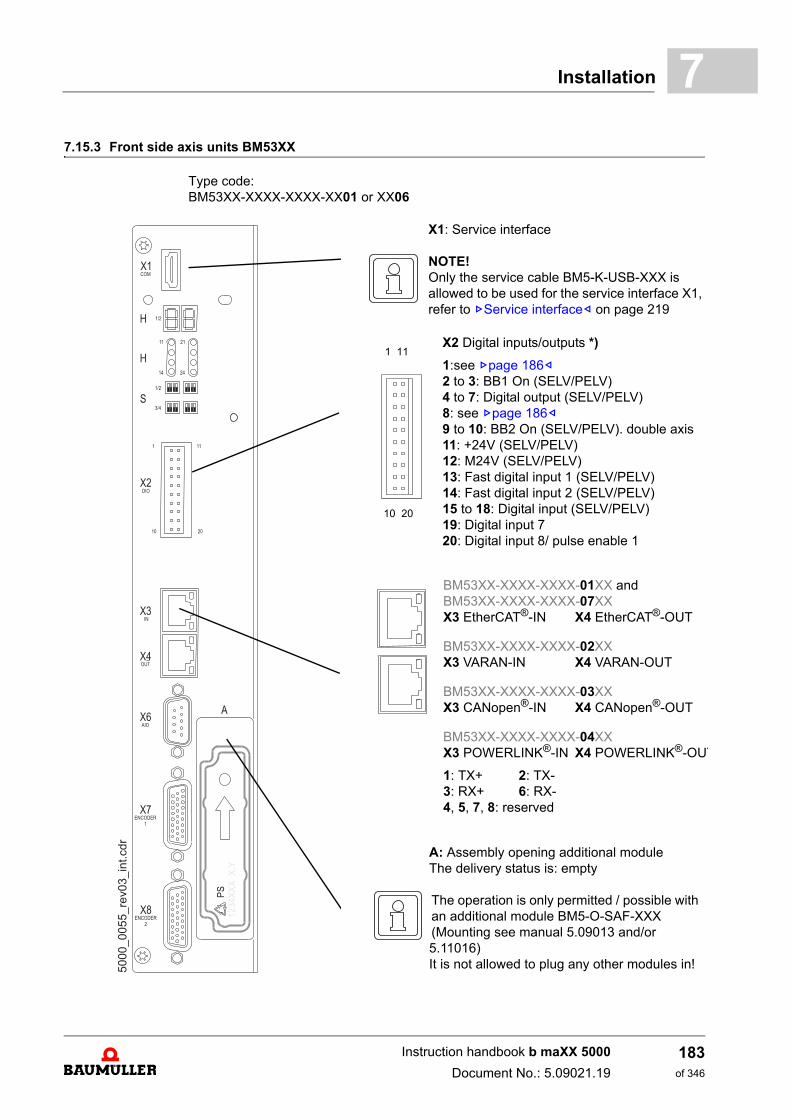
Installation 7
7.15.3 Front side axis units BM53XXType code: BM53XX-XXXX-XXXX-XX01 or XX06
X1: Service interface
NOTE!Only the service cable BM5-K-USB-XXX is allowed to be used for the service interface X1, refer to ZService interface– on page 219
X2 Digital inputs/outputs *)
1:see Zpage 186–2 to 3: BB1 On (SELV/PELV)4 to 7: Digital output (SELV/PELV)8: see Zpage 186–9 to 10: BB2 On (SELV/PELV). double axis11: +24V (SELV/PELV)12: M24V (SELV/PELV)13: Fast digital input 1 (SELV/PELV)14: Fast digital input 2 (SELV/PELV)15 to 18: Digital input (SELV/PELV)19: Digital input 720: Digital input 8/ pulse enable 1
1 11
10 20
BM53XX-XXXX-XXXX-01XX andBM53XX-XXXX-XXXX-07XXX3 EtherCAT®-IN X4 EtherCAT®-OUT
BM53XX-XXXX-XXXX-02XXX3 VARAN-IN X4 VARAN-OUT
BM53XX-XXXX-XXXX-03XXX3 CANopen®-IN X4 CANopen®-OUT
BM53XX-XXXX-XXXX-04XXX3 POWERLINK®-IN X4 POWERLINK®-OUT
1: TX+ 2: TX-3: RX+ 6: RX-4, 5, 7, 8: reserved
A: Assembly opening additional moduleThe delivery status is: empty
The operation is only permitted / possible with an additional module BM5-O-SAF-XXX (Mounting see manual 5.09013 and/or5.11016)It is not allowed to plug any other modules in!
Instruction handbook b maXX 5000
Document No.: 5.09021.19
183of 346
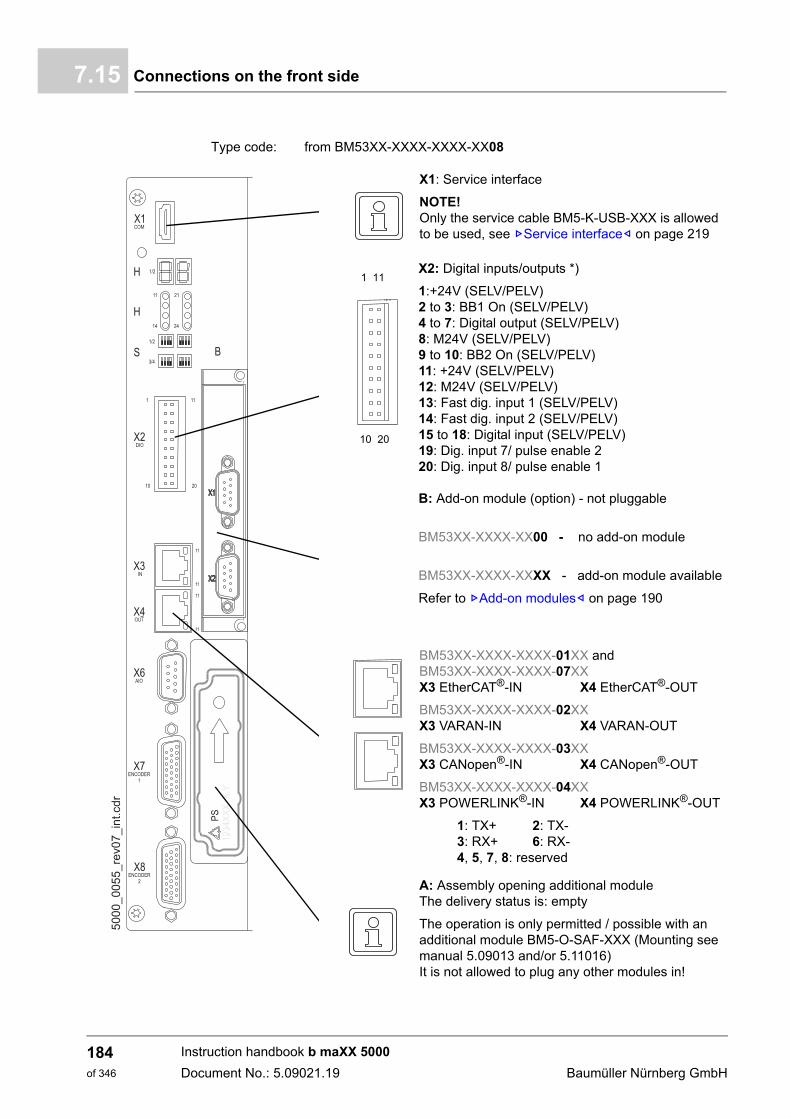
Connections on the front side7.15
Type code: from BM53XX-XXXX-XXXX-XX08
X1: Service interface
NOTE!Only the service cable BM5-K-USB-XXX is allowed to be used, see ZService interface– on page 219
X2: Digital inputs/outputs *)
1:+24V (SELV/PELV)2 to 3: BB1 On (SELV/PELV)4 to 7: Digital output (SELV/PELV)8: M24V (SELV/PELV)9 to 10: BB2 On (SELV/PELV)11: +24V (SELV/PELV)12: M24V (SELV/PELV)13: Fast dig. input 1 (SELV/PELV)14: Fast dig. input 2 (SELV/PELV)15 to 18: Digital input (SELV/PELV)19: Dig. input 7/ pulse enable 220: Dig. input 8/ pulse enable 1
1 11
10 20
B: Add-on module (option) - not pluggable
BM53XX-XXXX-XX00 - no add-on module
BM53XX-XXXX-XXXX - add-on module available
Refer to ZAdd-on modules– on page 190
BM53XX-XXXX-XXXX-01XX andBM53XX-XXXX-XXXX-07XXX3 EtherCAT®-IN X4 EtherCAT®-OUT
BM53XX-XXXX-XXXX-02XXX3 VARAN-IN X4 VARAN-OUT
BM53XX-XXXX-XXXX-03XXX3 CANopen®-IN X4 CANopen®-OUT
BM53XX-XXXX-XXXX-04XXX3 POWERLINK®-IN X4 POWERLINK®-OUT
1: TX+ 2: TX-3: RX+ 6: RX-4, 5, 7, 8: reserved
A: Assembly opening additional moduleThe delivery status is: empty
The operation is only permitted / possible with an additional module BM5-O-SAF-XXX (Mounting see manual 5.09013 and/or 5.11016)It is not allowed to plug any other modules in!
Instruction handbook b maXX 5000
Document No.: 5.09021.19 Baumüller Nürnberg GmbH
184of 346
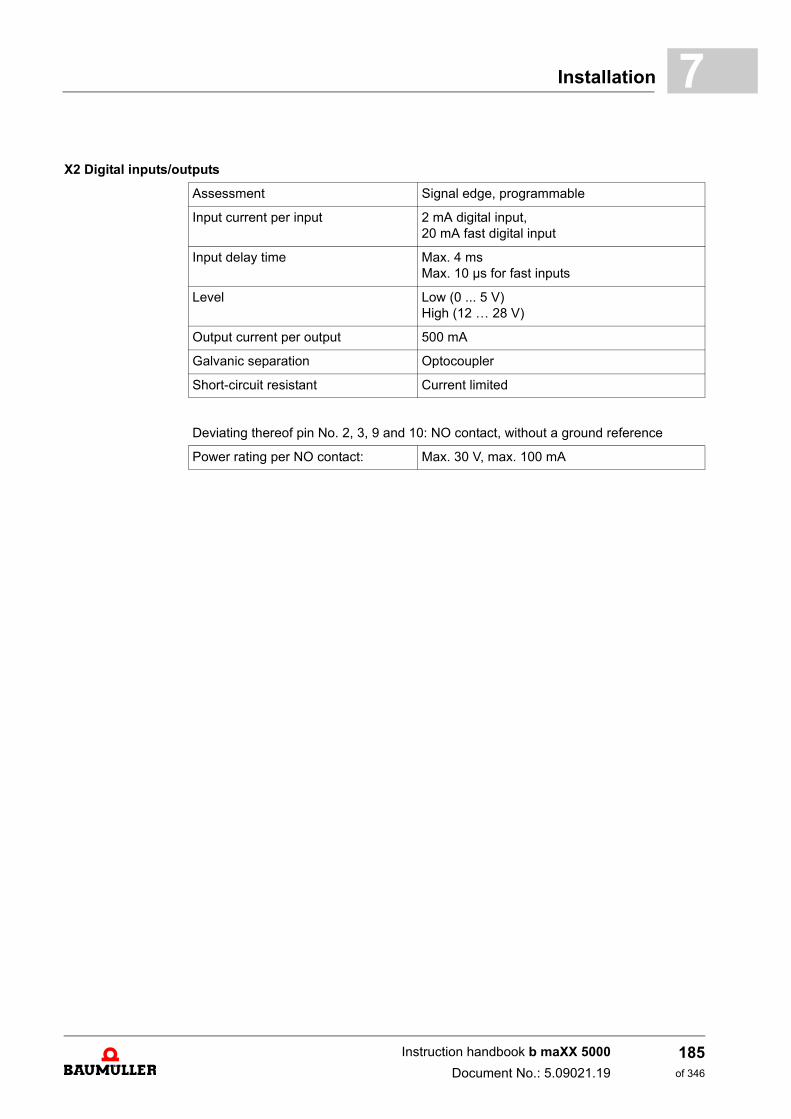
Installation 7
X2 Digital inputs/outputs
Assessment Signal edge, programmable
Input current per input 2 mA digital input,20 mA fast digital input
Input delay time Max. 4 msMax. 10 µs for fast inputs
Level Low (0 ... 5 V)High (12 … 28 V)
Output current per output 500 mA
Galvanic separation Optocoupler
Short-circuit resistant Current limited
Deviating thereof pin No. 2, 3, 9 and 10: NO contact, without a ground reference
Power rating per NO contact: Max. 30 V, max. 100 mA
Instruction handbook b maXX 5000
Document No.: 5.09021.19
185of 346
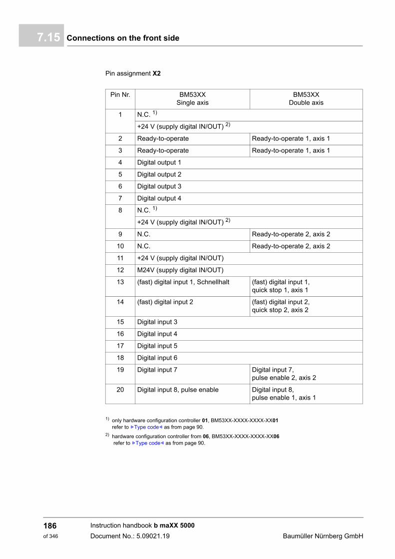
Connections on the front side7.15
Pin assignment X2
1) only hardware configuration controller 01, BM53XX-XXXX-XXXX-XX01refer to ZType code– as from page 90.
2) hardware configuration controller from 06, BM53XX-XXXX-XXXX-XX06 refer to ZType code– as from page 90.
Pin Nr. BM53XXSingle axis
BM53XXDouble axis
1 N.C. 1)
+24 V (supply digital IN/OUT) 2)
2 Ready-to-operate Ready-to-operate 1, axis 1
3 Ready-to-operate Ready-to-operate 1, axis 1
4 Digital output 1
5 Digital output 2
6 Digital output 3
7 Digital output 4
8 N.C. 1)
+24 V (supply digital IN/OUT) 2)
9 N.C. Ready-to-operate 2, axis 2
10 N.C. Ready-to-operate 2, axis 2
11 +24 V (supply digital IN/OUT)
12 M24V (supply digital IN/OUT)
13 (fast) digital input 1, Schnellhalt (fast) digital input 1, quick stop 1, axis 1
14 (fast) digital input 2 (fast) digital input 2, quick stop 2, axis 2
15 Digital input 3
16 Digital input 4
17 Digital input 5
18 Digital input 6
19 Digital input 7 Digital input 7, pulse enable 2, axis 2
20 Digital input 8, pulse enable Digital input 8, pulse enable 1, axis 1
Instruction handbook b maXX 5000
Document No.: 5.09021.19 Baumüller Nürnberg GmbH
186of 346
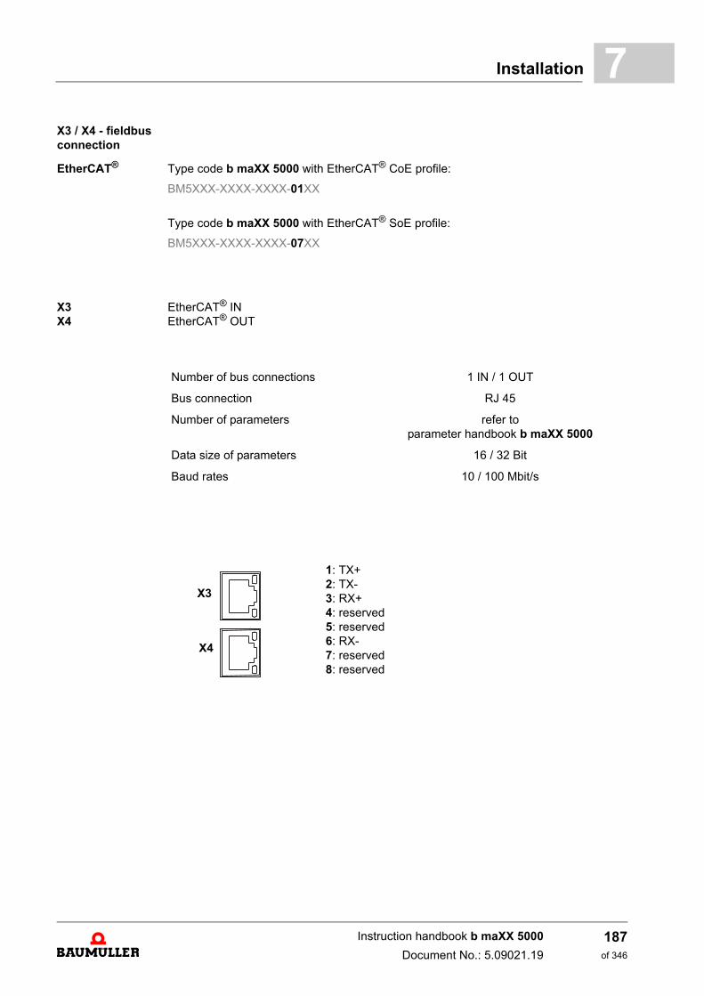
Installation 7
X3 / X4 - fieldbus connectionEtherCAT® Type code b maXX 5000 with EtherCAT® CoE profile:
BM5XXX-XXXX-XXXX-01XX
Type code b maXX 5000 with EtherCAT® SoE profile:
BM5XXX-XXXX-XXXX-07XX
X3X4
EtherCAT® INEtherCAT® OUT
Number of bus connections 1 IN / 1 OUT
Bus connection RJ 45
Number of parameters refer toparameter handbook b maXX 5000
Data size of parameters 16 / 32 Bit
Baud rates 10 / 100 Mbit/s
1: TX+2: TX-3: RX+4: reserved5: reserved6: RX-7: reserved8: reserved
X3
X4
Instruction handbook b maXX 5000
Document No.: 5.09021.19
187of 346
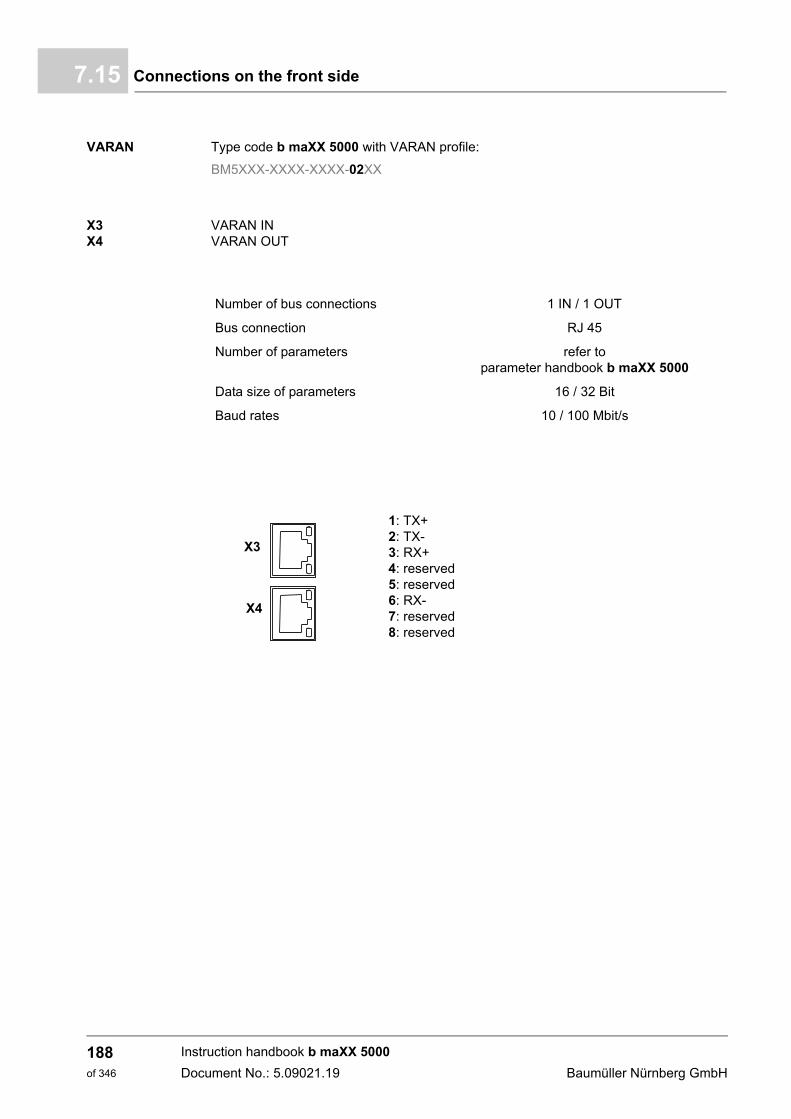
Connections on the front side7.15
VARAN Type code b maXX 5000 with VARAN profile:
BM5XXX-XXXX-XXXX-02XX
X3X4
VARAN INVARAN OUT
Number of bus connections 1 IN / 1 OUT
Bus connection RJ 45
Number of parameters refer toparameter handbook b maXX 5000
Data size of parameters 16 / 32 Bit
Baud rates 10 / 100 Mbit/s
1: TX+2: TX-3: RX+4: reserved5: reserved6: RX-7: reserved8: reserved
X3
X4
Instruction handbook b maXX 5000
Document No.: 5.09021.19 Baumüller Nürnberg GmbH
188of 346
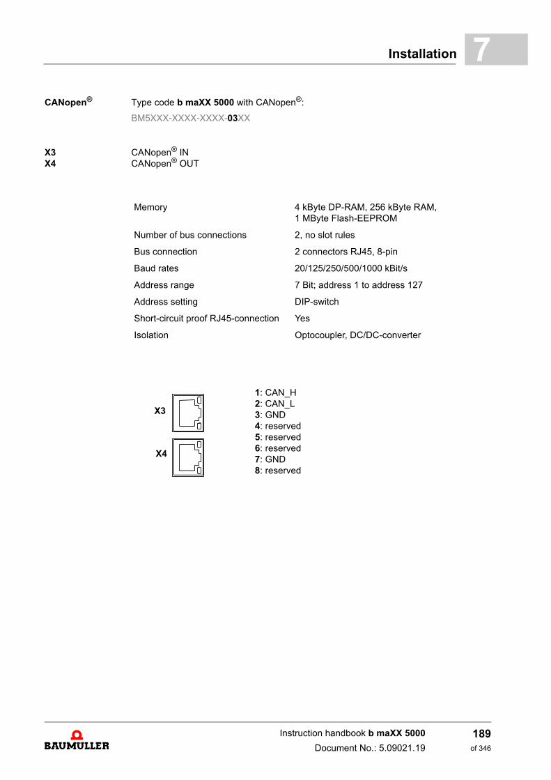
Installation 7
CANopen® Type code b maXX 5000 with CANopen®:BM5XXX-XXXX-XXXX-03XX
X3X4
CANopen® INCANopen® OUT
Memory 4 kByte DP-RAM, 256 kByte RAM, 1 MByte Flash-EEPROM
Number of bus connections 2, no slot rules
Bus connection 2 connectors RJ45, 8-pin
Baud rates 20/125/250/500/1000 kBit/s
Address range 7 Bit; address 1 to address 127
Address setting DIP-switch
Short-circuit proof RJ45-connection Yes
Isolation Optocoupler, DC/DC-converter
1: CAN_H2: CAN_L3: GND4: reserved5: reserved6: reserved7: GND8: reserved
X3
X4
Instruction handbook b maXX 5000
Document No.: 5.09021.19
189of 346
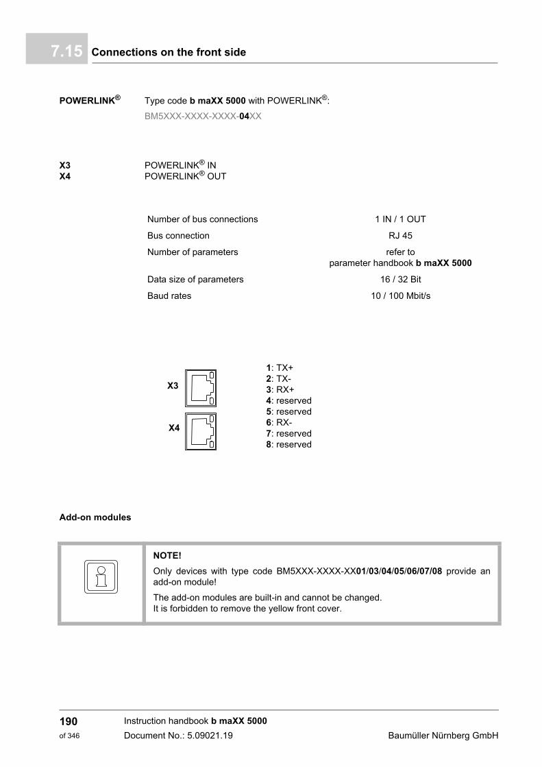
Connections on the front side7.15
POWERLINK® Type code b maXX 5000 with POWERLINK®:
BM5XXX-XXXX-XXXX-04XX
X3X4
POWERLINK® INPOWERLINK® OUT
Add-on modules
Number of bus connections 1 IN / 1 OUT
Bus connection RJ 45
Number of parameters refer toparameter handbook b maXX 5000
Data size of parameters 16 / 32 Bit
Baud rates 10 / 100 Mbit/s
1: TX+2: TX-3: RX+4: reserved5: reserved6: RX-7: reserved8: reserved
X3
X4
NOTE!
Only devices with type code BM5XXX-XXXX-XX01/03/04/05/06/07/08 provide anadd-on module!
The add-on modules are built-in and cannot be changed.It is forbidden to remove the yellow front cover.
Instruction handbook b maXX 5000
Document No.: 5.09021.19 Baumüller Nürnberg GmbH
190of 346
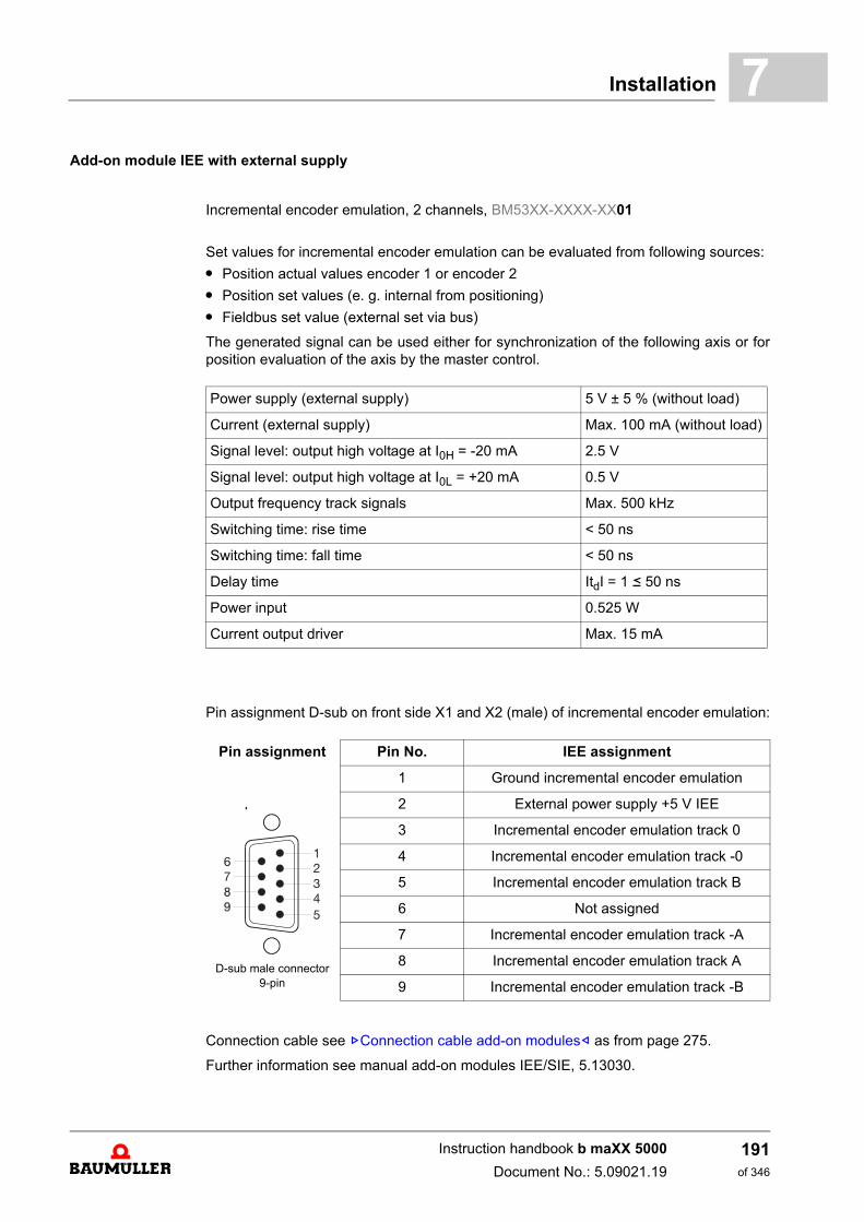
Installation 7
Add-on module IEE with external supplyIncremental encoder emulation, 2 channels, BM53XX-XXXX-XX01
Set values for incremental encoder emulation can be evaluated from following sources:
m Position actual values encoder 1 or encoder 2
m Position set values (e. g. internal from positioning)
m Fieldbus set value (external set via bus)
The generated signal can be used either for synchronization of the following axis or forposition evaluation of the axis by the master control.
Pin assignment D-sub on front side X1 and X2 (male) of incremental encoder emulation:
Connection cable see ZConnection cable add-on modules– as from page 275.
Further information see manual add-on modules IEE/SIE, 5.13030.
Power supply (external supply) 5 V ± 5 % (without load)
Current (external supply) Max. 100 mA (without load)
Signal level: output high voltage at I0H = -20 mA 2.5 V
Signal level: output high voltage at I0L = +20 mA 0.5 V
Output frequency track signals Max. 500 kHz
Switching time: rise time < 50 ns
Switching time: fall time < 50 ns
Delay time ItdI = 1 b 50 ns
Power input 0.525 W
Current output driver Max. 15 mA
Pin assignment Pin No. IEE assignment
D-sub male connector 9-pin
1 Ground incremental encoder emulation
2 External power supply +5 V IEE
3 Incremental encoder emulation track 0
4 Incremental encoder emulation track -0
5 Incremental encoder emulation track B
6 Not assigned
7 Incremental encoder emulation track -A
8 Incremental encoder emulation track A
9 Incremental encoder emulation track -B
Instruction handbook b maXX 5000
Document No.: 5.09021.19
191of 346
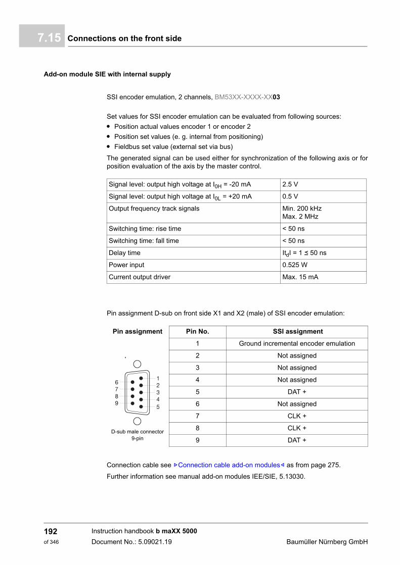
Connections on the front side7.15
Add-on module SIE with internal supply
SSI encoder emulation, 2 channels, BM53XX-XXXX-XX03
Set values for SSI encoder emulation can be evaluated from following sources:
m Position actual values encoder 1 or encoder 2
m Position set values (e. g. internal from positioning)
m Fieldbus set value (external set via bus)
The generated signal can be used either for synchronization of the following axis or forposition evaluation of the axis by the master control.
Pin assignment D-sub on front side X1 and X2 (male) of SSI encoder emulation:
Connection cable see ZConnection cable add-on modules– as from page 275.
Further information see manual add-on modules IEE/SIE, 5.13030.
Signal level: output high voltage at I0H = -20 mA 2.5 V
Signal level: output high voltage at I0L = +20 mA 0.5 V
Output frequency track signals Min. 200 kHzMax. 2 MHz
Switching time: rise time < 50 ns
Switching time: fall time < 50 ns
Delay time ItdI = 1 b 50 ns
Power input 0.525 W
Current output driver Max. 15 mA
Pin assignment Pin No. SSI assignment
D-sub male connector 9-pin
1 Ground incremental encoder emulation
2 Not assigned
3 Not assigned
4 Not assigned
5 DAT +
6 Not assigned
7 CLK +
8 CLK +
9 DAT +
Instruction handbook b maXX 5000
Document No.: 5.09021.19 Baumüller Nürnberg GmbH
192of 346
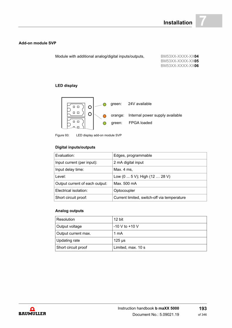
Installation 7
Add-on module SVPModule with additional analog/digital inputs/outputs, BM53XX-XXXX-XX04BM53XX-XXXX-XX05BM53XX-XXXX-XX06
LED display
Figure 93: LED display add-on module SVP
Digital inputs/outputs
Analog outputs
Evaluation: Edges, programmable
Input current (per input): 2 mA digital input
Input delay time: Max. 4 ms,
Level: Low (0 ... 5 V); High (12 … 28 V)
Output current of each output: Max. 500 mA
Electrical isolation: Optocoupler
Short circuit proof: Current limited, switch-off via temperature
green: 24V available
orange: Internal power supply available
green: FPGA loaded
Resolution 12 bit
Output voltage -10 V to +10 V
Output current max. 1 mA
Updating rate 125 µs
Short circuit proof Limited, max. 10 s
Instruction handbook b maXX 5000
Document No.: 5.09021.19
193of 346
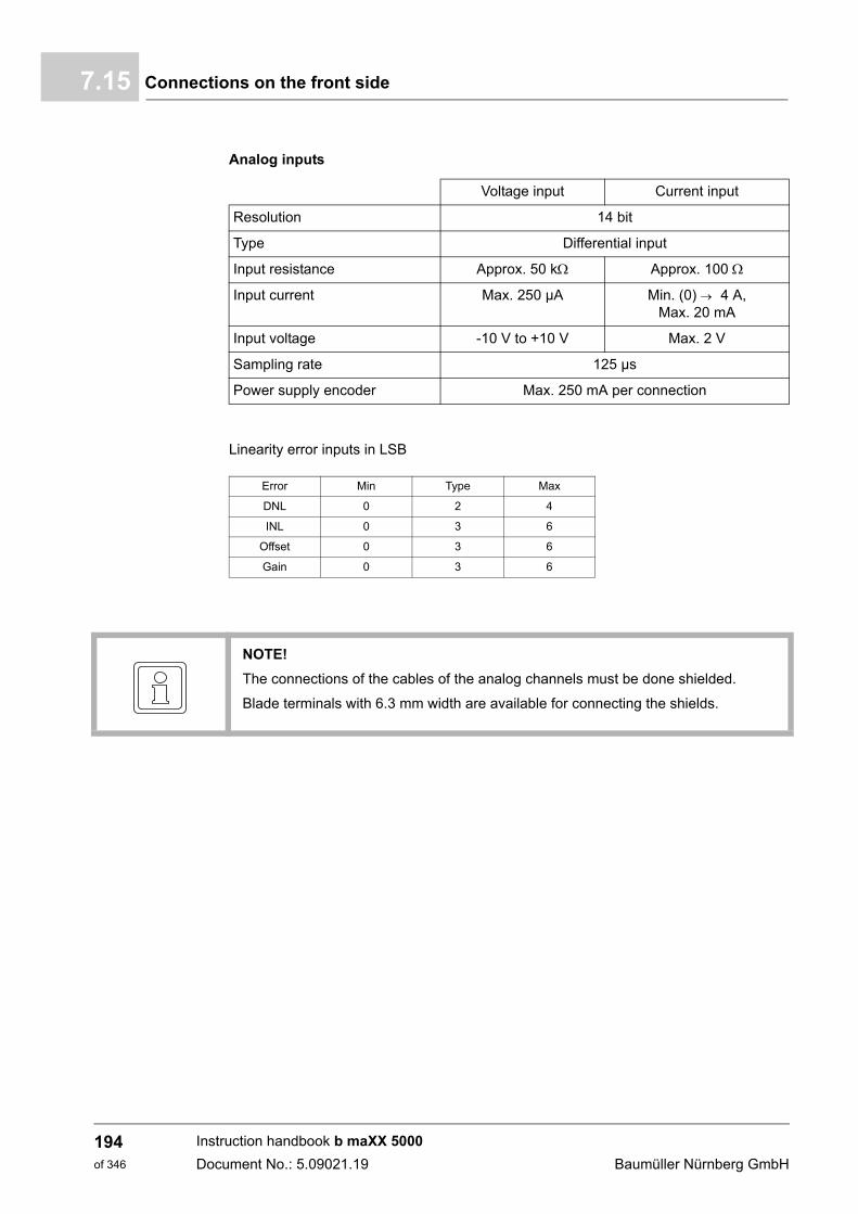
Connections on the front side7.15
Analog inputs
Linearity error inputs in LSB
Voltage input Current input
Resolution 14 bit
Type Differential input
Input resistance Approx. 50 k Approx. 100
Input current Max. 250 µA Min. (0) 4 A,Max. 20 mA
Input voltage -10 V to +10 V Max. 2 V
Sampling rate 125 µs
Power supply encoder Max. 250 mA per connection
Error Min Type Max
DNL 0 2 4
INL 0 3 6
Offset 0 3 6
Gain 0 3 6
NOTE!
The connections of the cables of the analog channels must be done shielded.
Blade terminals with 6.3 mm width are available for connecting the shields.
Instruction handbook b maXX 5000
Document No.: 5.09021.19 Baumüller Nürnberg GmbH
194of 346
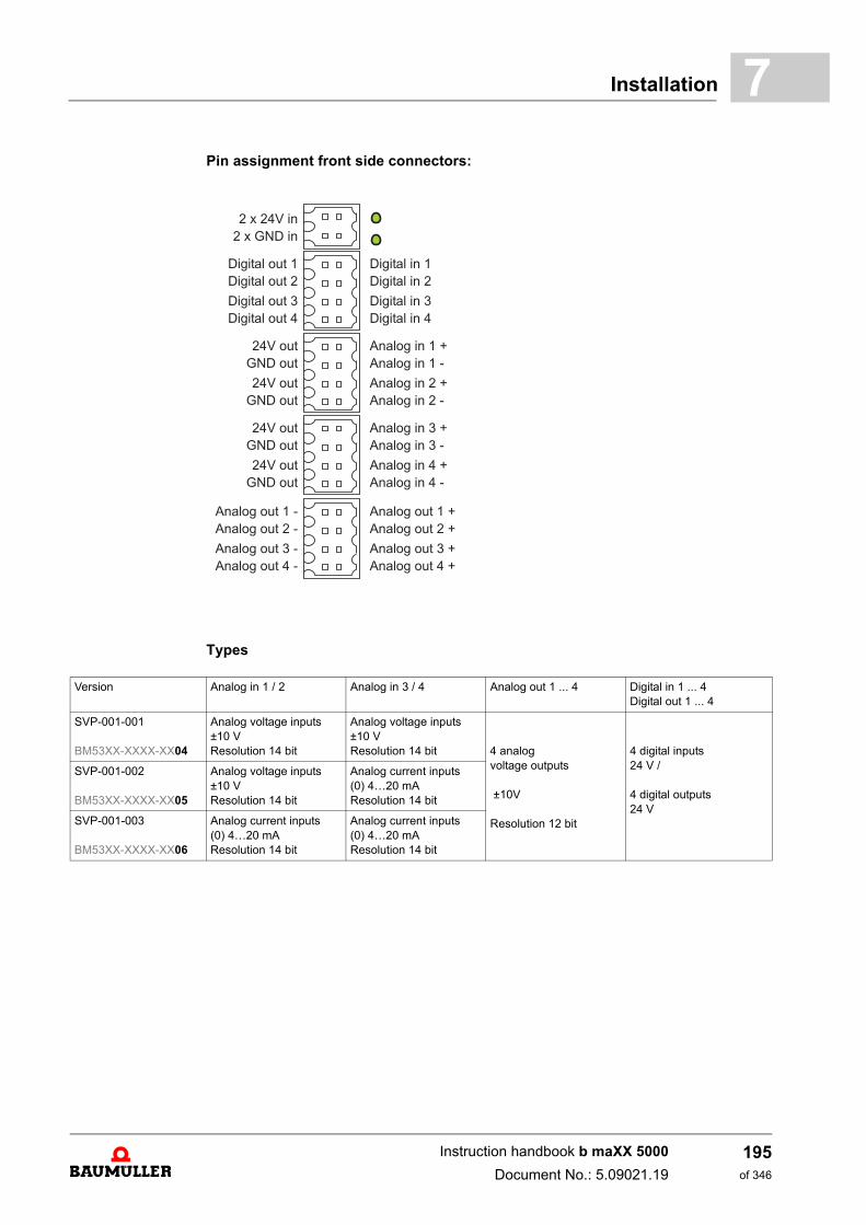
Installation 7
Pin assignment front side connectors:Types
2 x 24V in
2 x GND in
Digital out 1
Digital out 2
Digital out 3
Digital out 4
Digital in 1
Digital in 2
Digital in 3
Digital in 4
24V out
GND out
24V out
GND out
Analog in 1 +
Analog in 1 -
Analog in 2 +
Analog in 2 -
24V out
GND out
24V out
GND out
Analog in 3 +
Analog in 3 -
Analog in 4 +
Analog in 4 -
Analog out 1 -
Analog out 2 -
Analog out 3 -
Analog out 4 -
Analog out 1 +
Analog out 2 +
Analog out 3 +
Analog out 4 +
Version Analog in 1 / 2 Analog in 3 / 4 Analog out 1 ... 4 Digital in 1 ... 4Digital out 1 ... 4
SVP-001-001
BM53XX-XXXX-XX04
Analog voltage inputs ±10 V Resolution 14 bit
Analog voltage inputs ±10 V Resolution 14 bit 4 analog
voltage outputs
±10V
Resolution 12 bit
4 digital inputs 24 V /
4 digital outputs24 V
SVP-001-002
BM53XX-XXXX-XX05
Analog voltage inputs ±10 V Resolution 14 bit
Analog current inputs(0) 4…20 mAResolution 14 bit
SVP-001-003
BM53XX-XXXX-XX06
Analog current inputs(0) 4…20 mAResolution 14 bit
Analog current inputs(0) 4…20 mAResolution 14 bit
Instruction handbook b maXX 5000
Document No.: 5.09021.19
195of 346
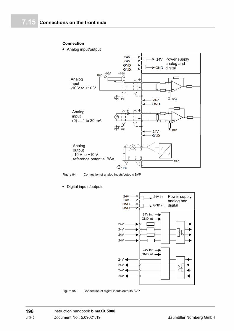
Connections on the front side7.15
Connection
m Analog input/output
Figure 94: Connection of analog inputs/outputs SVP
m Digital inputs/outputs
Figure 95: Connection of digital inputs/outputs SVP
Power supplyanalog anddigital
Analoginput-10 V to +10 V
Analoginput(0) ... 4 to 20 mA
Analogoutput-10 V to +10 Vreference potential BSA
Power supplyanalog anddigital
24V int
GND int
24V intGND int
24V
24V
24V
24V
24V intGND int
24V
24V
24V
24V
Instruction handbook b maXX 5000
Document No.: 5.09021.19 Baumüller Nürnberg GmbH
196of 346
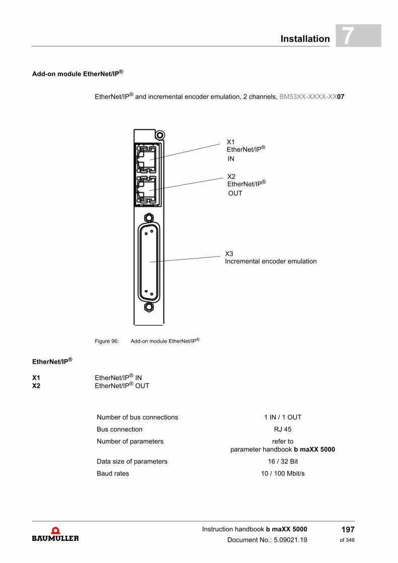
Installation 7
Add-on module EtherNet/IP®EtherNet/IP® and incremental encoder emulation, 2 channels, BM53XX-XXXX-XX07
Figure 96: Add-on module EtherNet/IP®
EtherNet/IP®
X1X2
EtherNet/IP® INEtherNet/IP® OUT
X1
X3
EtherNet/IP®
IN
X2EtherNet/IP®
OUT
Incremental encoder emulation
Number of bus connections 1 IN / 1 OUT
Bus connection RJ 45
Number of parameters refer toparameter handbook b maXX 5000
Data size of parameters 16 / 32 Bit
Baud rates 10 / 100 Mbit/s
Instruction handbook b maXX 5000
Document No.: 5.09021.19
197of 346
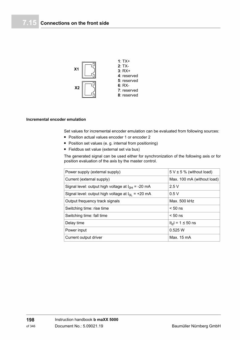
Connections on the front side7.15
Incremental encoder emulation
Set values for incremental encoder emulation can be evaluated from following sources:
m Position actual values encoder 1 or encoder 2
m Position set values (e. g. internal from positioning)
m Fieldbus set value (external set via bus)
The generated signal can be used either for synchronization of the following axis or forposition evaluation of the axis by the master control.
1: TX+2: TX-3: RX+4: reserved5: reserved6: RX-7: reserved8: reserved
X1
X2
Power supply (external supply) 5 V ± 5 % (without load)
Current (external supply) Max. 100 mA (without load)
Signal level: output high voltage at I0H = -20 mA 2.5 V
Signal level: output high voltage at I0L = +20 mA 0.5 V
Output frequency track signals Max. 500 kHz
Switching time: rise time < 50 ns
Switching time: fall time < 50 ns
Delay time ItdI = 1 b 50 ns
Power input 0.525 W
Current output driver Max. 15 mA
Instruction handbook b maXX 5000
Document No.: 5.09021.19 Baumüller Nürnberg GmbH
198of 346
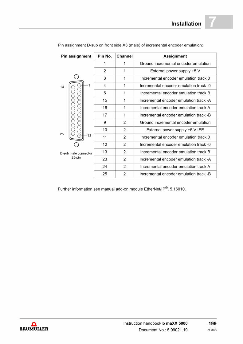
Installation 7
Pin assignment D-sub on front side X3 (male) of incremental encoder emulation:Further information see manual add-on module EtherNet/IP®, 5.16010.
Pin assignment Pin No. Channel Assignment
D-sub male connector 25-pin
1 1 Ground incremental encoder emulation
2 1 External power supply +5 V
3 1 Incremental encoder emulation track 0
4 1 Incremental encoder emulation track -0
5 1 Incremental encoder emulation track B
15 1 Incremental encoder emulation track -A
16 1 Incremental encoder emulation track A
17 1 Incremental encoder emulation track -B
9 2 Ground incremental encoder emulation
10 2 External power supply +5 V IEE
11 2 Incremental encoder emulation track 0
12 2 Incremental encoder emulation track -0
13 2 Incremental encoder emulation track B
23 2 Incremental encoder emulation track -A
24 2 Incremental encoder emulation track A
25 2 Incremental encoder emulation track -B
Instruction handbook b maXX 5000
Document No.: 5.09021.19
199of 346
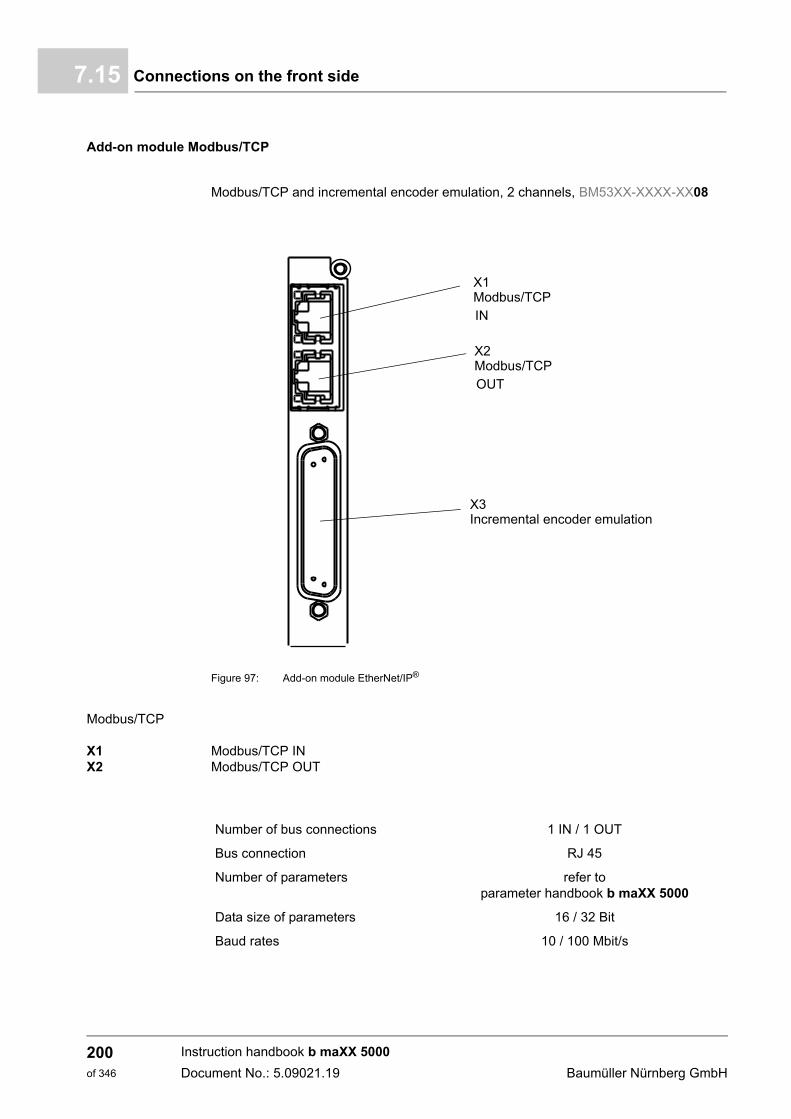
Connections on the front side7.15
Add-on module Modbus/TCP
Modbus/TCP and incremental encoder emulation, 2 channels, BM53XX-XXXX-XX08
Figure 97: Add-on module EtherNet/IP®
Modbus/TCP
X1X2
Modbus/TCP INModbus/TCP OUT
X1
X3
Modbus/TCPIN
X2Modbus/TCPOUT
Incremental encoder emulation
Number of bus connections 1 IN / 1 OUT
Bus connection RJ 45
Number of parameters refer toparameter handbook b maXX 5000
Data size of parameters 16 / 32 Bit
Baud rates 10 / 100 Mbit/s
Instruction handbook b maXX 5000
Document No.: 5.09021.19 Baumüller Nürnberg GmbH
200of 346
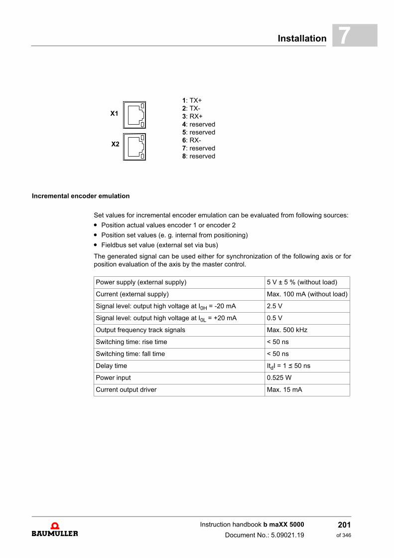
Installation 7
Incremental encoder emulation
Set values for incremental encoder emulation can be evaluated from following sources:
m Position actual values encoder 1 or encoder 2
m Position set values (e. g. internal from positioning)
m Fieldbus set value (external set via bus)
The generated signal can be used either for synchronization of the following axis or forposition evaluation of the axis by the master control.
1: TX+2: TX-3: RX+4: reserved5: reserved6: RX-7: reserved8: reserved
X1
X2
Power supply (external supply) 5 V ± 5 % (without load)
Current (external supply) Max. 100 mA (without load)
Signal level: output high voltage at I0H = -20 mA 2.5 V
Signal level: output high voltage at I0L = +20 mA 0.5 V
Output frequency track signals Max. 500 kHz
Switching time: rise time < 50 ns
Switching time: fall time < 50 ns
Delay time ItdI = 1 b 50 ns
Power input 0.525 W
Current output driver Max. 15 mA
Instruction handbook b maXX 5000
Document No.: 5.09021.19
201of 346
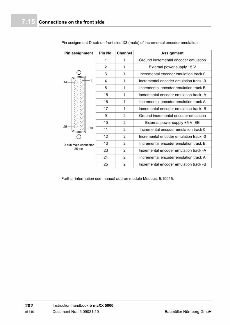
Connections on the front side7.15
Pin assignment D-sub on front side X3 (male) of incremental encoder emulation:
Further information see manual add-on module Modbus, 5.19015.
Pin assignment Pin No. Channel Assignment
D-sub male connector 25-pin
1 1 Ground incremental encoder emulation
2 1 External power supply +5 V
3 1 Incremental encoder emulation track 0
4 1 Incremental encoder emulation track -0
5 1 Incremental encoder emulation track B
15 1 Incremental encoder emulation track -A
16 1 Incremental encoder emulation track A
17 1 Incremental encoder emulation track -B
9 2 Ground incremental encoder emulation
10 2 External power supply +5 V IEE
11 2 Incremental encoder emulation track 0
12 2 Incremental encoder emulation track -0
13 2 Incremental encoder emulation track B
23 2 Incremental encoder emulation track -A
24 2 Incremental encoder emulation track A
25 2 Incremental encoder emulation track -B
Instruction handbook b maXX 5000
Document No.: 5.09021.19 Baumüller Nürnberg GmbH
202of 346
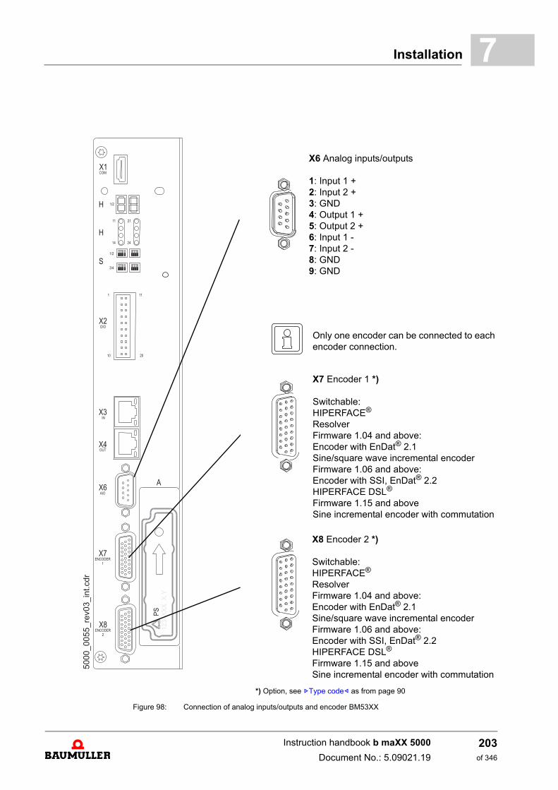
Installation 7
Figure 98: Connection of analog inputs/outputs and encoder BM53XX
*) Option, see ZType code– as from page 90
X6 Analog inputs/outputs
1: Input 1 +2: Input 2 +3: GND4: Output 1 +5: Output 2 +6: Input 1 - 7: Input 2 -8: GND9: GND
Only one encoder can be connected to each encoder connection.
X7 Encoder 1 *)
Switchable:HIPERFACE®
ResolverFirmware 1.04 and above:Encoder with EnDat® 2.1Sine/square wave incremental encoderFirmware 1.06 and above:Encoder with SSI, EnDat® 2.2HIPERFACE DSL®
Firmware 1.15 and aboveSine incremental encoder with commutation
X8 Encoder 2 *)
Switchable:HIPERFACE®
ResolverFirmware 1.04 and above:Encoder with EnDat® 2.1Sine/square wave incremental encoderFirmware 1.06 and above:Encoder with SSI, EnDat® 2.2HIPERFACE DSL®
Firmware 1.15 and aboveSine incremental encoder with commutation
Instruction handbook b maXX 5000
Document No.: 5.09021.19
203of 346
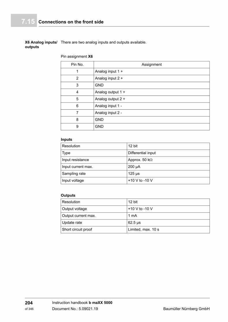
Connections on the front side7.15
X6 Analog inputs/outputs
There are two analog inputs and outputs available.
Pin assignment X6
Inputs
Outputs
Pin No. Assignment
1 Analog input 1 +
2 Analog input 2 +
3 GND
4 Analog output 1 +
5 Analog output 2 +
6 Analog input 1 -
7 Analog input 2 -
8 GND
9 GND
Resolution 12 bit
Type Differential input
Input resistance Approx. 50 k
Input current max. 200 µA
Sampling rate 125 µs
Input voltage +10 V to -10 V
Resolution 12 bit
Output voltage +10 V to -10 V
Output current max. 1 mA
Update rate 62.5 µs
Short circuit proof Limited, max. 10 s
Instruction handbook b maXX 5000
Document No.: 5.09021.19 Baumüller Nürnberg GmbH
204of 346
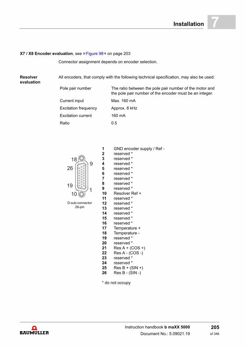
Installation 7
Connector assignment depends on encoder selection.
Resolver evaluation
All encoders, that comply with the following technical specification, may also be used:
X7 / X8 Encoder evaluation, see ZFigure 98– on page 203
Pole pair number The ratio between the pole pair number of the motor and the pole pair number of the encoder must be an integer.
Current input Max. 160 mA
Excitation frequency Approx. 8 kHz
Excitation current 160 mA
Ratio 0.5
D-sub-connector 26-pin
1 GND encoder supply / Ref -2 reserved *3 reserved *4 reserved *5 reserved *6 reserved *7 reserved *8 reserved *9 reserved *10 Resolver Ref +11 reserved *12 reserved *13 reserved *14 reserved *15 reserved *16 reserved *17 Temperature +18 Temperature -19 reserved *20 reserved *21 Res A + (COS +)22 Res A - (COS -)23 reserved *24 reserved *25 Res B + (SIN +)26 Res B - (SIN -)
* do not occupy
Instruction handbook b maXX 5000
Document No.: 5.09021.19
205of 346
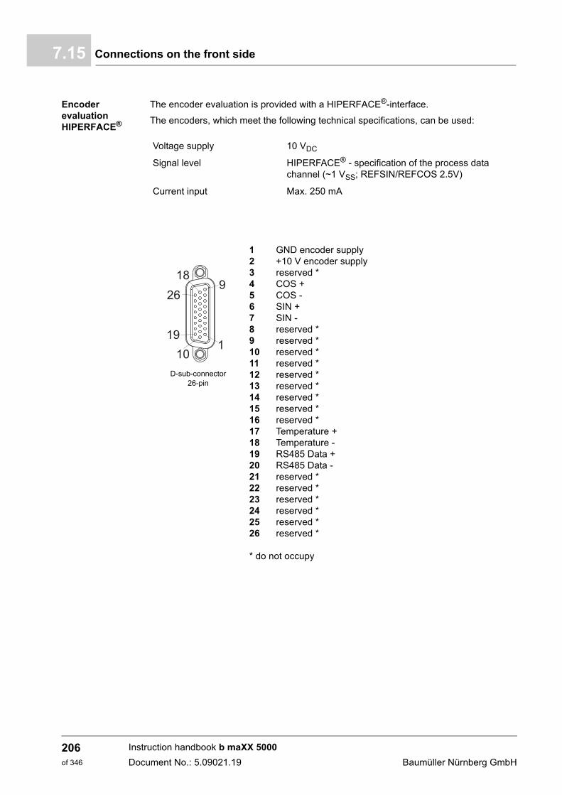
Connections on the front side7.15
Encoder evaluation HIPERFACE®
The encoder evaluation is provided with a HIPERFACE®-interface.
The encoders, which meet the following technical specifications, can be used:
Voltage supply 10 VDC
Signal level HIPERFACE® - specification of the process data channel (~1 VSS; REFSIN/REFCOS 2.5V)
Current input Max. 250 mA
D-sub-connector 26-pin
1 GND encoder supply 2 +10 V encoder supply3 reserved *4 COS +5 COS -6 SIN +7 SIN -8 reserved *9 reserved *10 reserved *11 reserved *12 reserved *13 reserved *14 reserved *15 reserved *16 reserved *17 Temperature +18 Temperature -19 RS485 Data +20 RS485 Data -21 reserved *22 reserved *23 reserved *24 reserved *25 reserved *26 reserved *
* do not occupy
Instruction handbook b maXX 5000
Document No.: 5.09021.19 Baumüller Nürnberg GmbH
206of 346
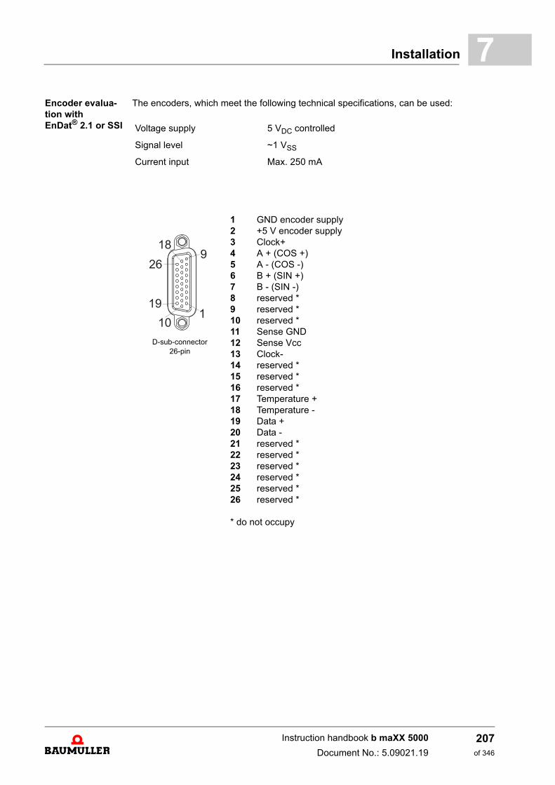
Installation 7
Encoder evalua-tion with EnDat® 2.1 or SSIThe encoders, which meet the following technical specifications, can be used:
Voltage supply 5 VDC controlled
Signal level ~1 VSS
Current input Max. 250 mA
D-sub-connector 26-pin
1 GND encoder supply2 +5 V encoder supply3 Clock+4 A + (COS +)5 A - (COS -)6 B + (SIN +)7 B - (SIN -)8 reserved *9 reserved *10 reserved *11 Sense GND12 Sense Vcc13 Clock-14 reserved *15 reserved *16 reserved *17 Temperature +18 Temperature -19 Data +20 Data -21 reserved *22 reserved *23 reserved *24 reserved *25 reserved *26 reserved *
* do not occupy
Instruction handbook b maXX 5000
Document No.: 5.09021.19
207of 346
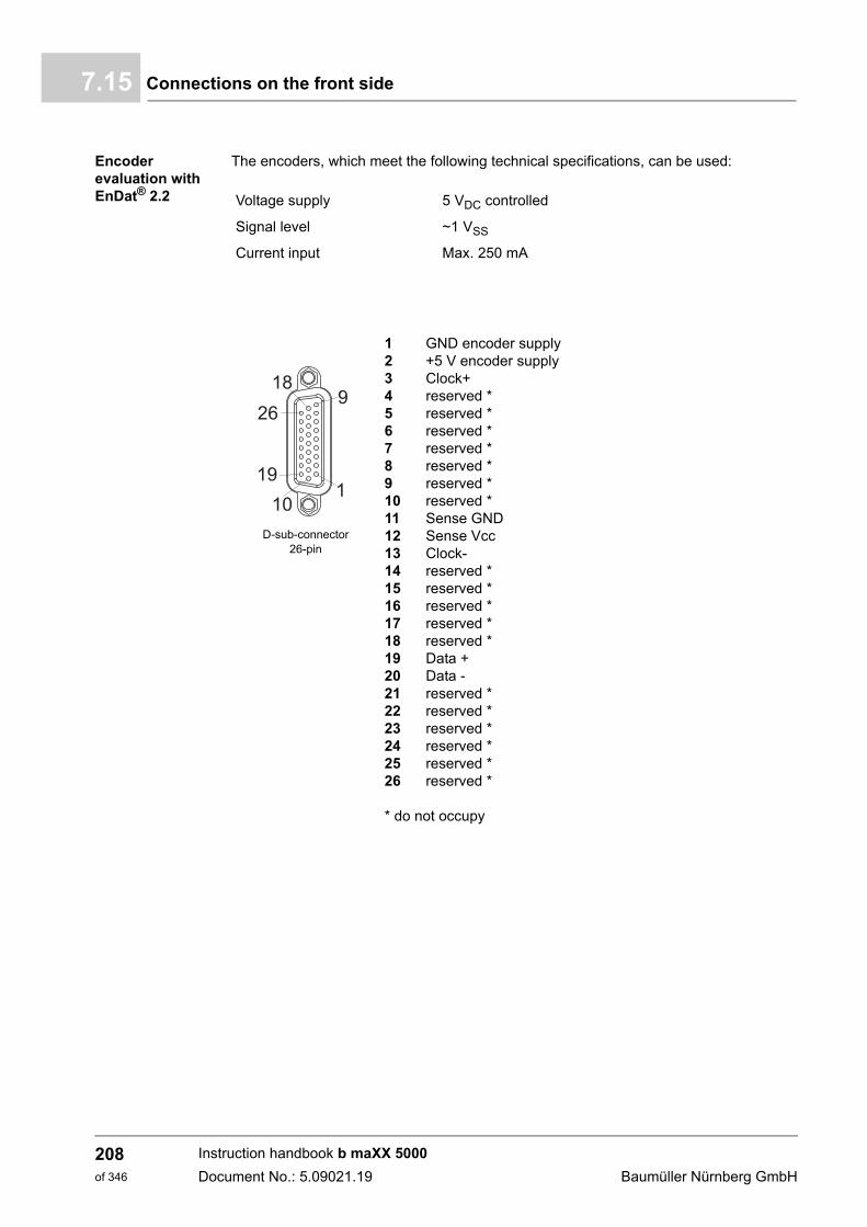
Connections on the front side7.15
Encoder evaluation with EnDat® 2.2
The encoders, which meet the following technical specifications, can be used:
Voltage supply 5 VDC controlled
Signal level ~1 VSS
Current input Max. 250 mA
D-sub-connector 26-pin
1 GND encoder supply 2 +5 V encoder supply3 Clock+4 reserved *5 reserved *6 reserved *7 reserved *8 reserved *9 reserved *10 reserved *11 Sense GND12 Sense Vcc13 Clock-14 reserved *15 reserved *16 reserved *17 reserved *18 reserved *19 Data +20 Data -21 reserved *22 reserved *23 reserved *24 reserved *25 reserved *26 reserved *
* do not occupy
Instruction handbook b maXX 5000
Document No.: 5.09021.19 Baumüller Nürnberg GmbH
208of 346
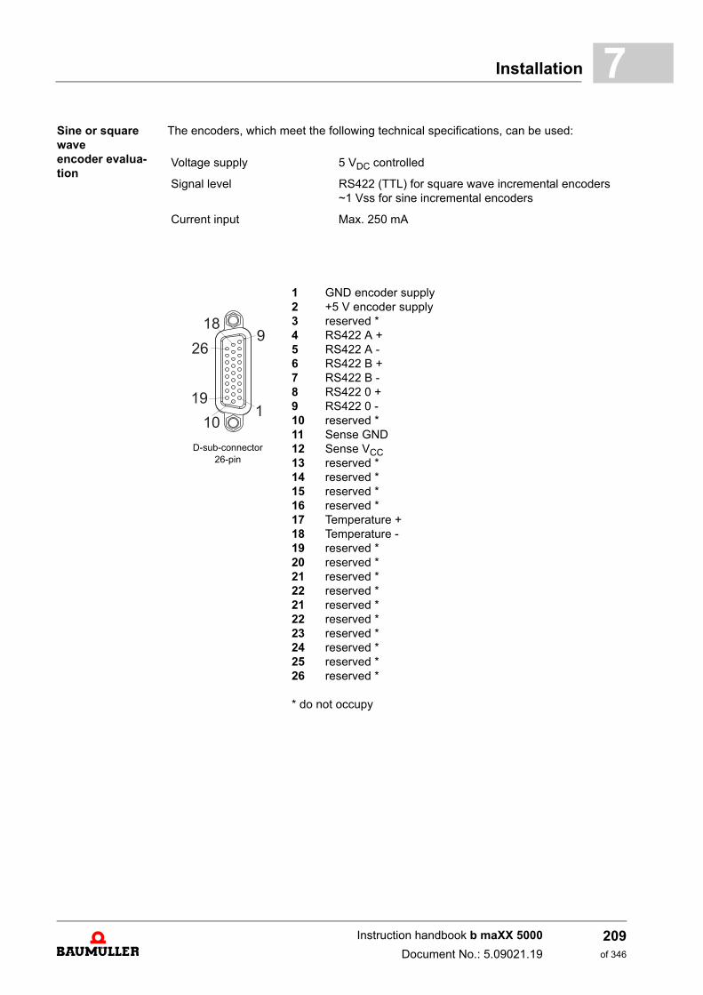
Installation 7
Sine or square waveencoder evalua-tionThe encoders, which meet the following technical specifications, can be used:
Voltage supply 5 VDC controlled
Signal level RS422 (TTL) for square wave incremental encoders~1 Vss for sine incremental encoders
Current input Max. 250 mA
D-sub-connector 26-pin
1 GND encoder supply2 +5 V encoder supply3 reserved *4 RS422 A +5 RS422 A -6 RS422 B +7 RS422 B -8 RS422 0 +9 RS422 0 -10 reserved *11 Sense GND12 Sense VCC13 reserved *14 reserved *15 reserved *16 reserved *17 Temperature +18 Temperature -19 reserved *20 reserved *21 reserved *22 reserved *21 reserved *22 reserved *23 reserved *24 reserved *25 reserved *26 reserved *
* do not occupy
Instruction handbook b maXX 5000
Document No.: 5.09021.19
209of 346
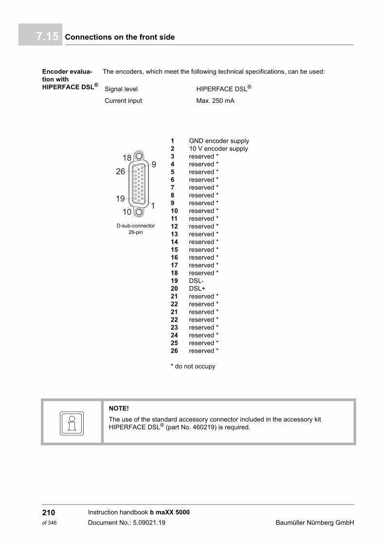
Connections on the front side7.15
Encoder evalua-tion withHIPERFACE DSL®
The encoders, which meet the following technical specifications, can be used:
Signal level HIPERFACE DSL®
Current input Max. 250 mA
D-sub-connector 26-pin
1 GND encoder supply2 10 V encoder supply3 reserved *4 reserved *5 reserved *6 reserved *7 reserved *8 reserved *9 reserved *10 reserved *11 reserved *12 reserved *13 reserved *14 reserved *15 reserved *16 reserved *17 reserved *18 reserved *19 DSL-20 DSL+21 reserved *22 reserved *21 reserved *22 reserved *23 reserved *24 reserved *25 reserved *26 reserved *
* do not occupy
NOTE!
The use of the standard accessory connector included in the accessory kit HIPERFACE DSL® (part No. 460219) is required.
Instruction handbook b maXX 5000
Document No.: 5.09021.19 Baumüller Nürnberg GmbH
210of 346
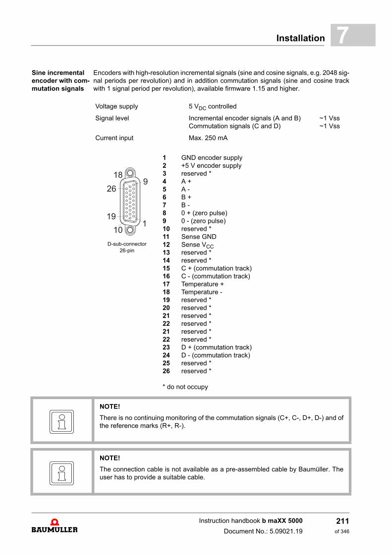
Installation 7
Sine incremental encoder with com-mutation signalsEncoders with high-resolution incremental signals (sine and cosine signals, e.g. 2048 sig-nal periods per revolution) and in addition commutation signals (sine and cosine trackwith 1 signal period per revolution), available firmware 1.15 and higher.
Voltage supply 5 VDC controlled
Signal level Incremental encoder signals (A and B) ~1 Vss Commutation signals (C and D) ~1 Vss
Current input Max. 250 mA
D-sub-connector 26-pin
1 GND encoder supply2 +5 V encoder supply3 reserved *4 A +5 A -6 B +7 B -8 0 + (zero pulse)9 0 - (zero pulse)10 reserved *11 Sense GND12 Sense VCC13 reserved *14 reserved *15 C + (commutation track)16 C - (commutation track)17 Temperature +18 Temperature -19 reserved *20 reserved *21 reserved *22 reserved *21 reserved *22 reserved *23 D + (commutation track)24 D - (commutation track)25 reserved *26 reserved *
* do not occupy
NOTE!
There is no continuing monitoring of the commutation signals (C+, C-, D+, D-) and ofthe reference marks (R+, R-).
NOTE!
The connection cable is not available as a pre-assembled cable by Baumüller. Theuser has to provide a suitable cable.
Instruction handbook b maXX 5000
Document No.: 5.09021.19
211of 346
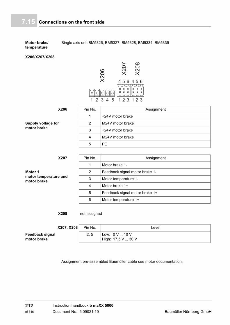
Connections on the front side7.15
Motor brake/temperature
Single axis unit BM5326, BM5327, BM5328, BM5334, BM5335
Assignment pre-assembled Baumüller cable see motor documentation.
X206/X207/X208
X206 Pin No. Assignment
1 +24V motor brake
Supply voltage for motor brake
2 M24V motor brake
3 +24V motor brake
4 M24V motor brake
5 PE
X207 Pin No. Assignment
1 Motor brake 1-
Motor 1motor temperature andmotor brake
2 Feedback signal motor brake 1-
3 Motor temperature 1-
4 Motor brake 1+
5 Feedback signal motor brake 1+
6 Motor temperature 1+
X208 not assigned
X207, X208 Pin No. Level
Feedback signalmotor brake
2, 5 Low: 0 V ... 10 VHigh: 17.5 V ... 30 V
Instruction handbook b maXX 5000
Document No.: 5.09021.19 Baumüller Nürnberg GmbH
212of 346
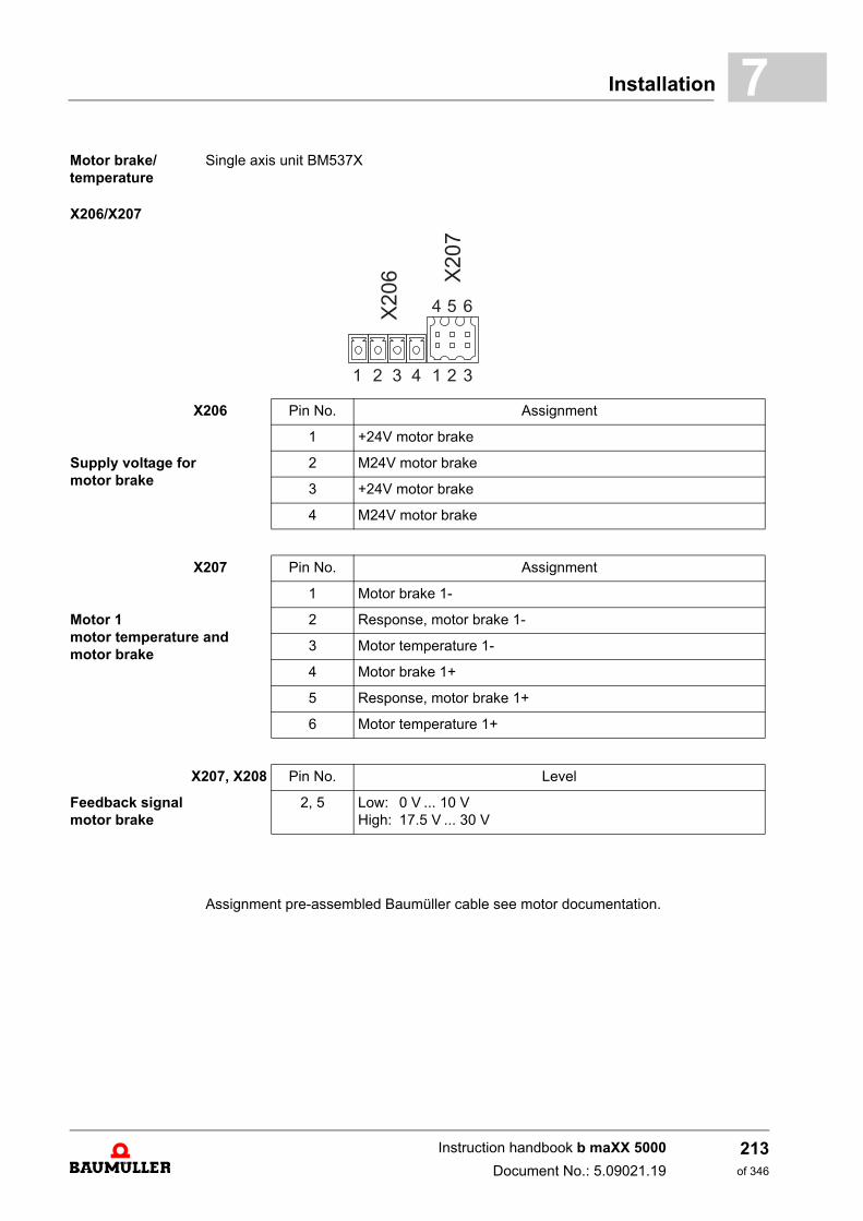
Installation 7
Motor brake/temperatureSingle axis unit BM537X
Assignment pre-assembled Baumüller cable see motor documentation.
X206/X207
X206 Pin No. Assignment
1 +24V motor brake
Supply voltage for motor brake
2 M24V motor brake
3 +24V motor brake
4 M24V motor brake
X207 Pin No. Assignment
1 Motor brake 1-
Motor 1motor temperature andmotor brake
2 Response, motor brake 1-
3 Motor temperature 1-
4 Motor brake 1+
5 Response, motor brake 1+
6 Motor temperature 1+
X207, X208 Pin No. Level
Feedback signal motor brake
2, 5 Low: 0 V ... 10 VHigh: 17.5 V ... 30 V
Instruction handbook b maXX 5000
Document No.: 5.09021.19
213of 346
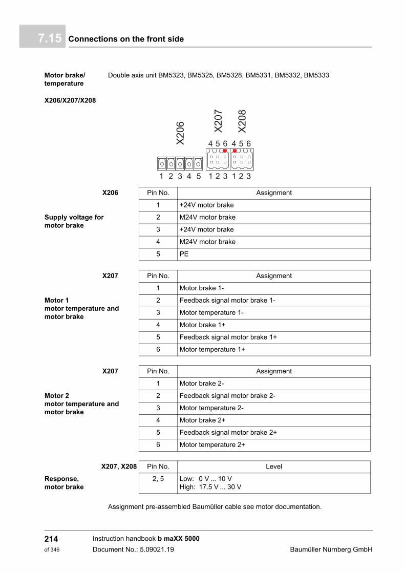
Connections on the front side7.15
Motor brake/temperature
Double axis unit BM5323, BM5325, BM5328, BM5331, BM5332, BM5333
Assignment pre-assembled Baumüller cable see motor documentation.
X206/X207/X208
X206 Pin No. Assignment
1 +24V motor brake
Supply voltage for motor brake
2 M24V motor brake
3 +24V motor brake
4 M24V motor brake
5 PE
X207 Pin No. Assignment
1 Motor brake 1-
Motor 1motor temperature andmotor brake
2 Feedback signal motor brake 1-
3 Motor temperature 1-
4 Motor brake 1+
5 Feedback signal motor brake 1+
6 Motor temperature 1+
X207 Pin No. Assignment
1 Motor brake 2-
Motor 2motor temperature andmotor brake
2 Feedback signal motor brake 2-
3 Motor temperature 2-
4 Motor brake 2+
5 Feedback signal motor brake 2+
6 Motor temperature 2+
X207, X208 Pin No. Level
Response, motor brake
2, 5 Low: 0 V ... 10 VHigh: 17.5 V ... 30 V
Instruction handbook b maXX 5000
Document No.: 5.09021.19 Baumüller Nürnberg GmbH
214of 346
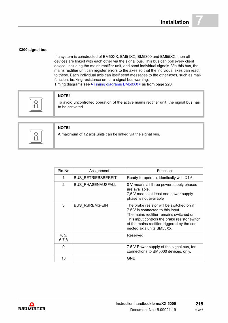
Installation 7
X300 signal bus
If a system is constructed of BM50XX, BM51XX, BM5300 and BM55XX, then all devices are linked with each other via the signal bus. This bus can poll every client device, including the mains rectifier unit, and send individual signals. Via this bus, the mains rectifier unit can register errors to the axes so that the individual axes can react to these. Each individual axis can itself send messages to the other axes, such as mal-function, braking resistance on, or a signal bus warning.Timing diagrams see ZTiming diagrams BM50XX– as from page 220.
NOTE!
To avoid uncontrolled operation of the active mains rectifier unit, the signal bus hasto be activated.
NOTE!
A maximum of 12 axis units can be linked via the signal bus.
Pin-Nr. Assignment Function
1 BUS_BETRIEBSBEREIT Ready-to-operate, identically with X1:6
2 BUS_PHASENAUSFALL 0 V means all three power supply phases are available, 7,5 V means at least one power supply phase is not available
3 BUS_RBREMS-EIN The brake resistor will be switched on if 7.5 V is connected to this input. The mains rectifier remains switched on. This input controls the brake resistor switch of the mains rectifier triggered by the con-nected axis units BM53XX.
4, 5, 6,7,8
Reserved
9 7.5 V Power supply of the signal bus, for connections to BM5000 devices, only.
10 GND
Instruction handbook b maXX 5000
Document No.: 5.09021.19
215of 346

Connections on the front side7.15
Instruction handbook b maXX 5000
Document No.: 5.09021.19 Baumüller Nürnberg GmbH
216of 346
8OPERATION
Basic information
WARNING!
Risk of injury due to improper operation!
Improper operation can lead to severe personal injury or material damage.
Therefore:
m Perform all operational steps according to the details of these instruction hand-book.
m Before beginning any work, ensure that all coverings and protective devices areinstalled and are functioning properly.
m The control cabinet in which the device is installed should be protected againstcontact with electrically live parts.Keep all doors of the control cabinet closed during operation.
NOTICE!
Environmental conditions that do not meet the requirements.
Environmental conditions that are non-compliant can lead to property damage.
Therefore:
m Ensure that the environmental conditions are kept compliant during operation (seeZRequired environmental conditions– on page 49).
217of 346
Instruction handbook b maXX 5000
Document No.: 5.09021.19
Operating concept8.1
8.1 Operating concept
After the device has been commissioned it is parameterized (i. e. adapted to the applica-tion). Once parameterization has been completed, the device can be operated with oneof the two following signal inputs:
m pulse enable
m quick stop (option)
8.1.1 Release signals
These signals must have a signal level of 24 V (DC) and be available via the terminals(ZConnections on the front side– as from page 179).
Pulse enable During operation, the „pulse enable“ signal must be continuously generated in order forthe device to provide output. A running motor will come to a standstill if the signal isswitched to 0 V.
Quick stop Only switch off the „quick stop“ signal if the system / the device must be stopped as quick-ly as possible. The reaction can be adjusted (see the parameter manual)
During operation, the „quick stop“ signal must be continuously provided in order for thedevice to provide output.
Exactly which digital input can be assessed as a quick stop signal can be parameterized.(Refer to the parameter manual b maXX 5000 5.09022)
WARNING!
Risk of injury due to insufficient qualifications!
Inevitably, when operating this electrical device, certain parts of this device are ener-gized with hazardous voltage. Improper handling can lead to significant personal in-jury and material damage.
Therefore:
m Only qualified personnel may work on this device!
Instruction handbook b maXX 5000
Document No.: 5.09021.19 Baumüller Nürnberg GmbH
218of 346
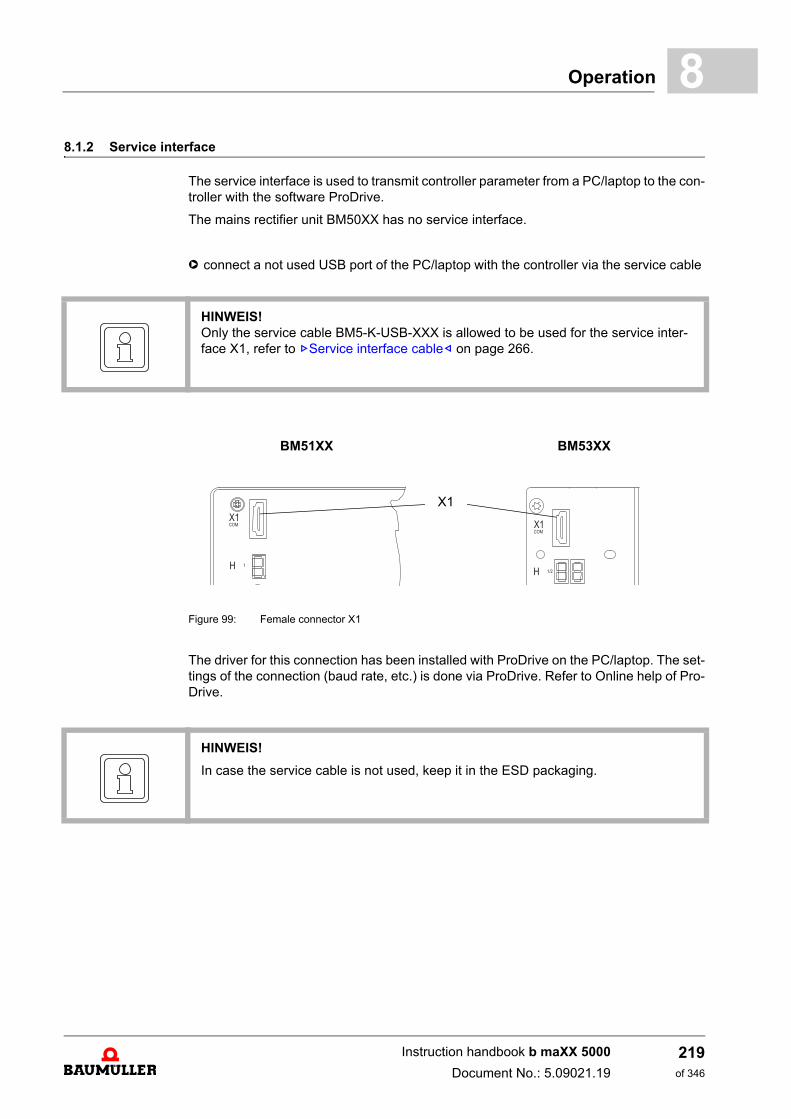
Operation 8
8.1.2 Service interfaceThe service interface is used to transmit controller parameter from a PC/laptop to the con-troller with the software ProDrive.
The mains rectifier unit BM50XX has no service interface.
h connect a not used USB port of the PC/laptop with the controller via the service cable
Figure 99: Female connector X1
The driver for this connection has been installed with ProDrive on the PC/laptop. The set-tings of the connection (baud rate, etc.) is done via ProDrive. Refer to Online help of Pro-Drive.
HINWEIS!Only the service cable BM5-K-USB-XXX is allowed to be used for the service inter-face X1, refer to ZService interface cable– on page 266.
BM51XX BM53XX
X1
HINWEIS!
In case the service cable is not used, keep it in the ESD packaging.
Instruction handbook b maXX 5000
Document No.: 5.09021.19
219of 346
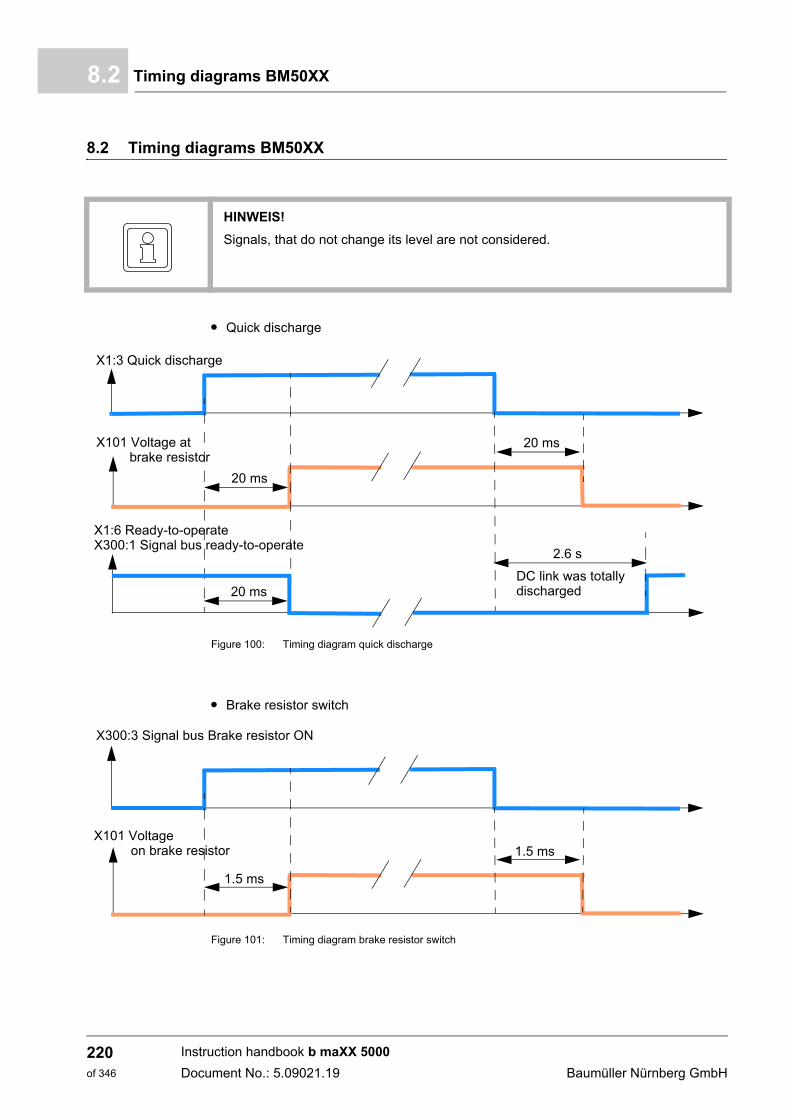
Timing diagrams BM50XX8.2
8.2 Timing diagrams BM50XX
m Quick discharge
Figure 100: Timing diagram quick discharge
m Brake resistor switch
Figure 101: Timing diagram brake resistor switch
HINWEIS!
Signals, that do not change its level are not considered.
X1:3 Quick discharge
X101 Voltage at brake resistor
20 ms
20 ms
X1:6 Ready-to-operateX300:1 Signal bus ready-to-operate
20 ms
2.6 s
DC link was totallydischarged
X300:3 Signal bus Brake resistor ON
X101 Voltage on brake resistor
1.5 ms
1.5 ms
Instruction handbook b maXX 5000
Document No.: 5.09021.19 Baumüller Nürnberg GmbH
220of 346
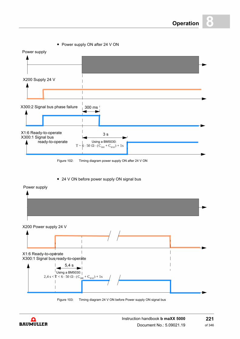
Operation 8
m Power supply ON after 24 V ONFigure 102: Timing diagram power supply ON after 24 V ON
m 24 V ON before power supply ON signal bus
Figure 103: Timing diagram 24 V ON before Power supply ON signal bus
Power supply
X200 Supply 24 V
X1:6 Ready-to-operateX300:1 Signal bus
300 msX300:2 Signal bus phase failure
ready-to-operate
3 s
Using a BM5030: T ~ 6 50 Cint Cext+ 1s+
Power supply
X200 Power supply 24 V
X1:6 Ready-to-operateX300:1 Signal bus ready-to-operate
5,4 s
Using a BM5030: 2,4 s < T < 6 50 Cint Cext+ 1s+
Instruction handbook b maXX 5000
Document No.: 5.09021.19
221of 346
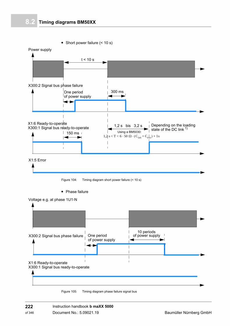
Timing diagrams BM50XX8.2
m Short power failure (< 10 s)
Figure 104: Timing diagram short power failure (< 10 s)
m Phase failure
Figure 105: Timing diagram phase failure signal bus
Power supply
X1:5 Error
X1:6 Ready-to-operate
150 ms
t < 10 s
X300:1 Signal bus ready-to-operate
X300:2 Signal bus phase failure
300 msOne period
Depending on the loadingstate of the DC link 1)
of power supply
1,2 s bis 3,2 s
Using a BM5030: 1,2 s < T < 6 50 Cint Cext+ 1s+
Voltage e.g. at phase 1U1-N
X1:6 Ready-to-operate
X300:2 Signal bus phase failure One period of power supply
X300:1 Signal bus ready-to-operate
10 periods of power supply
Instruction handbook b maXX 5000
Document No.: 5.09021.19 Baumüller Nürnberg GmbH
222of 346
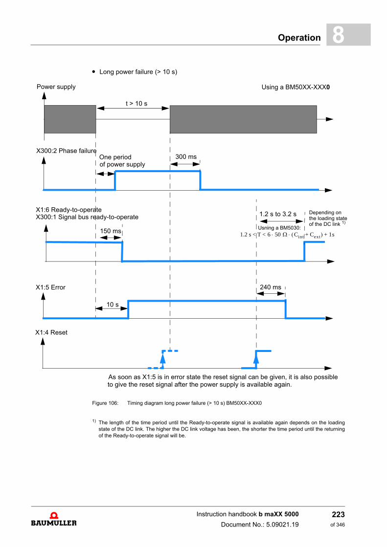
Operation 8
m Long power failure (> 10 s)Figure 106: Timing diagram long power failure (> 10 s) BM50XX-XXX0
1) The length of the time period until the Ready-to-operate signal is available again depends on the loadingstate of the DC link. The higher the DC link voltage has been, the shorter the time period until the returningof the Ready-to-operate signal will be.
Power supply
X1:5 Error
t > 10 s
Using a BM50XX-XXX0
10 s
240 ms
X1:4 Reset
As soon as X1:5 is in error state the reset signal can be given, it is also possibleto give the reset signal after the power supply is available again.
X300:2 Phase failureOne period 300 msof power supply
Depending on
150 ms
1.2 s to 3.2 s
Usning a BM5030: 1.2 s < T < 6 50 Cint Cext+ 1s+
the loading stateof the DC link 1)
X1:6 Ready-to-operateX300:1 Signal bus ready-to-operate
Instruction handbook b maXX 5000
Document No.: 5.09021.19
223of 346
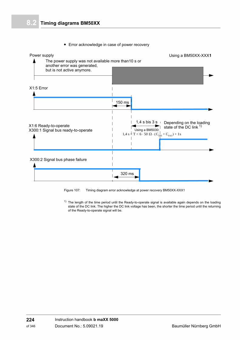
Timing diagrams BM50XX8.2
m Error acknowledge in case of power recovery
Figure 107: Timing diagram error acknowledge at power recovery BM50XX-XXX1
1) The length of the time period until the Ready-to-operate signal is available again depends on the loadingstate of the DC link. The higher the DC link voltage has been, the shorter the time period until the returningof the Ready-to-operate signal will be.
Power supply
X1:6 Ready-to-operate
X1:5 Error
150 ms
Using a BM50XX-XXX1The power supply was not available more than10 s oranother error was generated,but is not active anymore.
X300:1 Signal bus ready-to-operate
X300:2 Signal bus phase failure
320 ms
Depending on the loadingstate of the DC link 1)
1,4 s bis 3 s
Using a BM5030: 1,4 s < T < 6 50 Cint Cext+ 1s+
Instruction handbook b maXX 5000
Document No.: 5.09021.19 Baumüller Nürnberg GmbH
224of 346
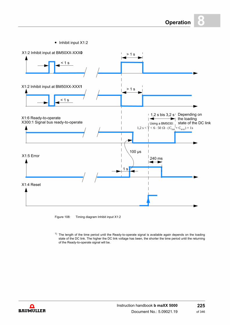
Operation 8
k
m Inhibit input X1:2
Figure 108: Timing diagram Inhibit input X1:2
1) The length of the time period until the Ready-to-operate signal is available again depends on the loadingstate of the DC link. The higher the DC link voltage has been, the shorter the time period until the returningof the Ready-to-operate signal will be.
X1:5 Error
X1:6 Ready-to-operate
X1:2 Inhibit input at BM50XX-XXX0
< 1 s
> 1 s
X1:2 Inhibit input at BM50XX-XXX1
1 s
100 µs
240 ms
X1:4 Reset
X300:1 Signal bus ready-to-operate
< 1 s
> 1 s
Depending on
state of the DC lin
1,2 s bis 3,2 s
Using a BM5030:
1,2 s < T < 6 50 Cint Cext+ 1s+
the loading
Instruction handbook b maXX 5000
Document No.: 5.09021.19
225of 346
Monitoring8.3
8.3 Monitoring
8.3.1 Monitoring BM50XX
The controller unit monitors the device during operation. If the controller unit detects astate that deviates from the normal operation condition, the device generates an errormessage.
Error message If the controller unit detects that the device is not working error-free, then this is shownvia the LEDs H1 to H4 (see ZDisplay and operating elements– as from page 96 for de-vices without safety function and see ZD.4 LED display BM5030 with safety function– asfrom page 326 for devices with safety function).
For further information see ZTroubleshooting and Fault correction– as from page 243.
8.3.2 Monitoring BM51XX, BM53XX
The controller unit monitors the device during operation. If the controller unit detects astate that deviates from the normal operation condition, the device either generates awarning or an error message.
Warning If the controller unit detects an operating condition that exceeds a warning threshold, acorresponding warning is shown on the display or, respectively, controller. The most im-portant warning message (Current limit reached) is also shown by the device through theLED H13 or H23 (see ZDisplay and operating elements– as from page 96).
Error message If the controller unit detects that the device is not working error-free, then this is shownvia the LED H14 or H24 (see ZDisplay and operating elements– as from page 96). A cor-responding error code will continue to be shown on the display and/or a controller canread out the error code on the device.
For further information see ZTroubleshooting and Fault correction– as from page 243.
Instruction handbook b maXX 5000
Document No.: 5.09021.19 Baumüller Nürnberg GmbH
226of 346
Operation 8
8.4 Fieldbus communicationDepending on the version of b maXX 5000 (see ZType plate– on page 89 and ZTypecode– as from page 90) different fieldbus systems are provided.
8.4.1 EtherCAT®.
Type code b maXX 5000 with EtherCAT®:
BM5XXX-XXXX-XXXX-01XX- CoE profile (CANopen® over EtherCAT®)BM5XXX-XXXX-XXXX-07XX- SoE profile (Servodrive profile over EtherCAT®)
Data can be transmitted to and from other nodes (e. g. from the EtherCAT® master) viathe b maXX 5000 with EtherCAT® slave.
X3 and X4 on the front side of the device are the RJ45 connections for the EtherCAT®-fieldbus (also see ZFront side of active mains rectifier BM51XX– on page 181 and ZFrontside axis units BM53XX– on page 183).
Mounting and installation.
The mounting/installation consists of the following steps:
1 De-energize the b maXX 5000 device
2 Set the b maXX 5000 IP-address,see ZSetting the IP address with address switches– as from page 106
3 Connect b maXX 5000 with Ethernet-connection cables.
n Please, observe an EMC-compatible laying of the Ethernet connection cables!
n The following cables were released for use by Baumüller:Ethernet-connection cable; Further information see ZEtherCAT®, VARAN, POWERLINK®, EtherNet/IP®, Mod-bus® cable– on page 265.
Commissioning. The following preconditions must be fulfilled before commissioning:
1 b maXX 5000 with EtherCAT® is installed correctly.
n Ethernet-connection cables are wired correctly.
2 The control cabinet is properly locked and all safety devices are operating.
3 The b maXX 5000 device is ready-to-use.
Address switch By means of the address switches S1 to S4 the IP-address is set (Refer to settings ZSetting the IP address with address switches– as from page 106). Further information about the setting possibilities of the EtherCAT® slave see „ApplicationManual“.
Instruction handbook b maXX 5000
Document No.: 5.09021.19
227of 346
Fieldbus communication8.4
Parameters The parameter settings determine the behavior of the EtherCAT® slave in operation. Parameters are set with the software ProDrive.
1 Start ProDrive
2 Click on „Project Tree“.
3 Communication settings with ProDrive
n Project Tree: Configuration/Fieldbus Slave (refer also Parameter manual b maXX 5000)
m set Synchronization to „On“
m SYNC time = Fieldbus cycle time = EtherCAT® cycle time = 125 µs to 8 ms
This setting is not necessary if using the CoE profile (CoE: CANopen® over EtherCAT®) and the EtherCAT® master has set the parameter 1C32.02 „CycleTime“ to a valid value or „Distributed Clock“ is set to Sync0.
When using the SoE profile (Servodrive profile over EtherCAT®) the fieldbus cy-cle time can be set via S parameter S-0-0002 or directly via controller parameterfieldbus cycle time. In case „Distributed Clock“ is activated the set fieldbus cycletime must be identical with the Sync0 Unit cycle. The Sync0 Unit cycle is set viathe EtherCAT® master. No synchronous operation is possible if this condition isnot fulfilled. The slave inhibits the change from PreOperational to SafeOperational and generates an error message.
Instruction handbook b maXX 5000
Document No.: 5.09021.19 Baumüller Nürnberg GmbH
228of 346
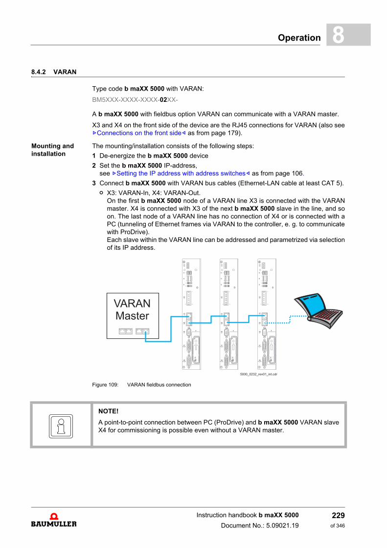
Operation 8
8.4.2 VARAN.Type code b maXX 5000 with VARAN:
BM5XXX-XXXX-XXXX-02XX-
A b maXX 5000 with fieldbus option VARAN can communicate with a VARAN master.
X3 and X4 on the front side of the device are the RJ45 connections for VARAN (also seeZConnections on the front side– as from page 179).
Mounting and installation.
The mounting/installation consists of the following steps:
1 De-energize the b maXX 5000 device
2 Set the b maXX 5000 IP-address,see ZSetting the IP address with address switches– as from page 106.
3 Connect b maXX 5000 with VARAN bus cables (Ethernet-LAN cable at least CAT 5).
n X3: VARAN-In, X4: VARAN-Out. On the first b maXX 5000 node of a VARAN line X3 is connected with the VARANmaster. X4 is connected with X3 of the next b maXX 5000 slave in the line, and soon. The last node of a VARAN line has no connection of X4 or is connected with aPC (tunneling of Ethernet frames via VARAN to the controller, e. g. to communicatewith ProDrive).Each slave within the VARAN line can be addressed and parametrized via selectionof its IP address.
Figure 109: VARAN fieldbus connection
NOTE!
A point-to-point connection between PC (ProDrive) and b maXX 5000 VARAN slaveX4 for commissioning is possible even without a VARAN master.
Instruction handbook b maXX 5000
Document No.: 5.09021.19
229of 346
Fieldbus communication8.4
n Please, observe an EMC-compatible laying of the Ethernet connection cables!
n The following cables were released for use by Baumüller:Ethernet connection cable; Further information see ZEtherCAT®, VARAN, POWERLINK®, EtherNet/IP®, Mod-bus® cable– on page 265.
Commissioning. The following preconditions must be fulfilled before commissioning:
1 b maXX 5000 with VARAN is installed correctly.
n Ethernet connection cables are wired correctly.
2 The control cabinet is properly locked and all safety devices are operating.
3 The b maXX 5000 device is ready-to-use.
4 Create a Lasal-Class2 project using the driver classes for b maXX 5000 drives for cy-clic and service data communication.
5 Start the VARAN control
Address switch By means of the address switches S1 to S4 the IP-address is set (Refer to settings ZSetting the IP address with address switches– as from page 106).
Parameters The parameter settings determine the behavior of the VARAN slave in operation. Param-eters are set with the software ProDrive.
1 Start ProDrive
2 Click on „Project Tree“.
3 Communication settings with ProDrive
n Project Tree: Configuration/Fieldbus slave (refer also Parameter manual b maXX 5000)
m set Synchronization to „On“
m set Fieldbus cycle time according VARAN cycle time (1 ms, 2 ms, 4 ms or 8 ms)
m set source sync signal to fieldbus
Instruction handbook b maXX 5000
Document No.: 5.09021.19 Baumüller Nürnberg GmbH
230of 346
Operation 8
8.4.3 CANopen®.Type code b maXX 5000 with CANopen®:
BM5XXX-XXXX-XXXX-03XX-
The data can be transmitted to all the other CAN-users (e g from CANopen® master) viathe b maXX 5000.
X3 and X4 are the RJ45 connections for CAN bus cables (also see ZConnections on thefront side– on page 179), which are on the front side of the device.
Mounting and installation
The mounting / installation consists of the following steps:
1 De-energize b maXX 5000 device
2 Set address and baud rate (transfer rate) at the b maXX 5000,see ZCANopen®– on page 109.
3 Connect b maXX 5000 with CANopen®-bus cables (and, if necessary, a terminatedconnector).
n Comply to EMC-oriented laying of CANopen® connection cables!
n Baumüller released the following cables for use:CANopen® connection cable; further information see ZAccessories - CANopen®.– on page 266.
Commissioning The following preconditions must be fulfilled before commissioning can be made:
1 b maXX 5000 with CANopen® is correctly installed.
n CANopen®-connection cables are correctly wired.
2 The control cabinet has been locked correctly and the safety devices have been putinto operation.
3 The b maXX 5000 device is ready-to-use.
Address switch By means of the address switch S1 to S4 the settings, like e.g. the baud rate (transferrate) and the address setting (slave No. /ID) are made (see ZCANopen®– on page 109). Further information about parameter setting of the CANopen® slave, see „ApplicationManual“.
NOTE!
If the b maXX 5000 device is the last bus node in the line, X4 must be terminated witha terminating connector (see ZAccessories - CANopen®.– on page 266).
Instruction handbook b maXX 5000
Document No.: 5.09021.19
231of 346
Fieldbus communication8.4
Process of commissioning
The test-commissioning is divided into the following sections:
1 Configuration of the CANopen® slave
2 Testing of the CANopen® slave
Configuring the CANopen® slave
The CANopen® is configured at the running device with ProDrive and a NMT-Master.
1 Switch on b maXX 5000 with CANopen®
2 Start ProDrive
3 Ensure, that the CANopen® slave communicates with the NMT-Master (the slave re-ports to the master with the boot-up telegram), i. e. CAN-telegrams can be send/re-ceived.
Make the following settings:
4 ProDrive: Activate communication source (see Parameter Manual: Drive manager)
5 NMT-Master: Create PDO-Mapping (see Programming Manual CANopen®“)
6 NMT-Master: with the NMT-command :=1 into the state „OPERATIONAL change“,then the cyclic communication starts.
Testing of the CANopen®-Slave
The CANopen® slave is tested, by using the total CANopen® network.
ProDrive does not indicate errors, the CANopen® slave was commissioned.
Operation Avoid a reset of the b maXX 5000 in the cyclical operation of the CANopen® slave.
WARNING!
Risk of injury due to moving parts!
Rotating and/or linearly moving parts can causesevere injuries.
If a reset of the b maXX 5000 device is released in the running cyclical operation orif the communication source is switched off, this can cause unwanted conditions inthe active application.
Therefore:
m Ensure, that the NMT master does not execute a reset, as long as theb maXX 5000 device is in the cyclical operation
m Ensure, that the CANopen® communication source only is able to communicatewith the b maXX 5000 device.
NOTE!
After a reset the booting data set is loaded in the controller. In addition the mappingis set on the CANopen®, which was saved in the controller part before the reset wasexecuted.
Instruction handbook b maXX 5000
Document No.: 5.09021.19 Baumüller Nürnberg GmbH
232of 346
Operation 8
8.4.4 POWERLINK®.Type code b maXX 5000 with POWERLINK®:
BM5XXX-XXXX-XXXX-04XX-
b maXX 5000 devices can communicate with a POWERLINK® Managing Node via thefieldbus connection POWERLINK®.
X3 and X4 on the front side of the device are the RJ45 connections for POWERLINK®
(also see ZFront side of active mains rectifier BM51XX– on page 181 and ZFront sideaxis units BM53XX– on page 183).
Mounting and in-stallation.
The mounting/installation consists of the following steps:
1 De-energize the b maXX 5000 device
2 Set the b maXX 5000 IP-address,see ZSetting the IP address with address switches– as from page 106
3 Connect b maXX 5000 with Ethernet-connection cables.
n Please, observe an EMC-compatible laying of the Ethernet connection cables!
n The following cables were released for use by Baumüller:Ethernet-connection cable; Further information see ZEtherCAT®, VARAN, POWERLINK®, EtherNet/IP®, Mod-bus® cable– on page 265.
Commissioning. The following preconditions must be fulfilled before commissioning:
1 b maXX 5000 with POWERLINK® is installed correctly.
n Ethernet-connection cables are wired correctly.
2 The control cabinet is properly locked and all safety devices are operating.
3 The b maXX 5000 device is ready-to-use.
Address switch By means of the address switches S1 to S4 the last byte of the IP-address is set (Refer to settings ZSetting the IP address with address switches– as from page 106). IP address 192.168.100.0 is not allowed.Further information about the setting possibilities of the POWERLINK® Controlled Nodesee „Application Manual“.
Parameters The parameter settings determine the behavior of the POWERLINK® Controlled Node inoperation. Parameters are set via the software ProDrive.
1 Start ProDrive
2 Click on „Project Tree“.
3 Communication settings using ProDrive
n Project Tree: Configuration/Fieldbus Slave (refer also Parameter manual b maXX 5000)
m set Synchronization to „On“
m SYNC time = Fieldbus cycle time = POWERLINK® cycle time = 500 µs to 8 ms
This setting is not necessary if using the POWERLINK® profile and the POWER-LINK® Managing Node sets a valid value in object 0x1006 „Communication cycleperiod“.
Instruction handbook b maXX 5000
Document No.: 5.09021.19
233of 346
Fieldbus communication8.4
8.4.5 EtherNet/IP®.
Type code b maXX 5000 with add-on module EtherNet/IP®:
BM5XXX-XXXX-XX07-00XX-
Devices b maXX 5000 communicate with the add-on modujle EtherNet/IP® with anEtherNet/IP® scanner.
X1 and X2 on the add-on module are the RJ45 connections for the EtherNet/IP®
(also see ZAdd-on module EtherNet/IP®– on page 197.
Mounting and installation.
The mounting/installation consists of the following steps:
1 De-energize the b maXX 5000 device
2 Set the b maXX 5000 IP-address,see ZSetting the IP address with address switches– as from page 106
3 Connect b maXX 5000 with Ethernet-connection cables.
n Please, observe an EMC-compatible laying of the Ethernet connection cables!
n The following cables were released for use by Baumüller:Ethernet-connection cable; Further information see ZEtherCAT®, VARAN, POWERLINK®, EtherNet/IP®, Mod-bus® cable– on page 265.
Commissioning. The following preconditions must be fulfilled before commissioning:
1 b maXX 5000 with EtherNet/IP® is installed correctly.
n Ethernet-connection cables are wired correctly.
2 The control cabinet is properly locked and all safety devices are operating.
3 The b maXX 5000 device is ready-to-use.
Address switch By means of the address switches S1 to S4 the IP-address is set (Refer to settings ZSetting the IP address with address switches– as from page 106).
Parameters The parameter settings determine the behavior of the EtherNet/IP® in operation. Parameters are set with the software ProDrive.
1 Start ProDrive
2 Click on „Project Tree“.
3 Communication settings with ProDrive
n Project Tree: Configuration/Fieldbus Slave (refer also Parameter manual b maXX 5000)
m set Synchronization to „On“
m SYNC time = Fieldbus cycle time = EtherNet/IP® cycle time = 500 µs to 8 ms
This setting is not necessary if a valid value is set in byte 0 of the EtherNet/IP®
scanner.
Instruction handbook b maXX 5000
Document No.: 5.09021.19 Baumüller Nürnberg GmbH
234of 346
Operation 8
8.4.6 Modbus/TCPType code b maXX 5000 with add-on module Modbus/TCP:
BM5XXX-XXXX-XX08-00XX-
Devices b maXX 5000 communicate with the add-on modujle Modbus/TCP with an Mo-dbus/TCP client.
X1 and X2 on the add-on module are the RJ45 connections for the Modbus/TCP
(also see ZAdd-on module Modbus/TCP– on page 200.
Mounting and installation.
The mounting/installation consists of the following steps:
1 De-energize the b maXX 5000 device
2 Set the b maXX 5000 IP-address,see ZSetting the IP address with address switches– as from page 106
3 Connect b maXX 5000 with Ethernet-connection cables.
n Please, observe an EMC-compatible laying of the Ethernet connection cables!
n The following cables were released for use by Baumüller:Ethernet-connection cable; Further information see ZEtherCAT®, VARAN, POWERLINK®, EtherNet/IP®, Mod-bus® cable– on page 265.
Commissioning. The following preconditions must be fulfilled before commissioning:
1 b maXX 5000 with EtherNet/IP® is installed correctly.
n Ethernet-connection cables are wired correctly.
2 The control cabinet is properly locked and all safety devices are operating.
3 The b maXX 5000 device is ready-to-use.
Address switch By means of the address switches S1 to S4 the IP-address is set (Refer to settings ZSetting the IP address with address switches– as from page 106).
Parameters The parameter settings determine the behavior of the EtherNet/IP® in operation. Parameters are set with the software ProDrive.
1 Start ProDrive
2 Click on „Project Tree“.
3 Communication settings with ProDrive
n Project Tree: Configuration/Fieldbus Slave (refer also Parameter manual b maXX 5000)
m set Synchronization to „On“
m SYNC time = Fieldbus cycle time = EtherNet/IP® cycle time = 500 µs to 8 ms
This setting is not necessary if the Modbus/TCP client sets a valid value in Mod-bus register 202..
Instruction handbook b maXX 5000
Document No.: 5.09021.19
235of 346

Fieldbus communication8.4
Instruction handbook b maXX 5000
Document No.: 5.09021.19 Baumüller Nürnberg GmbH
236of 346
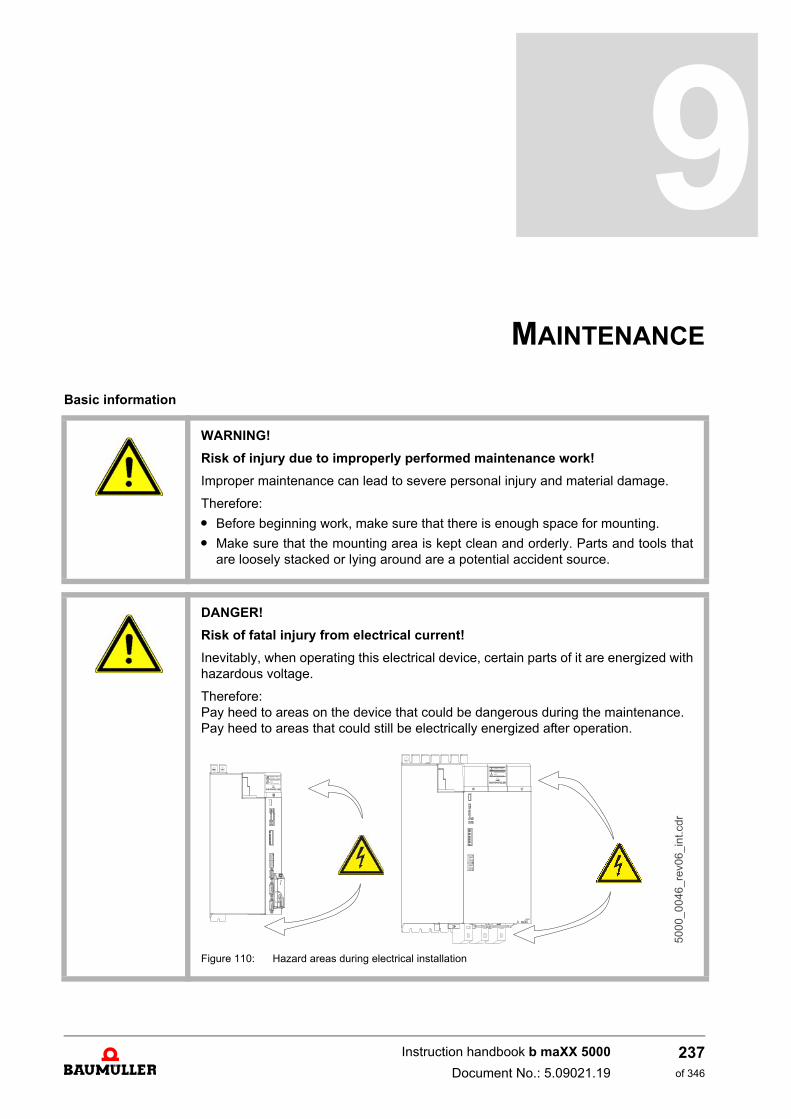
9MAINTENANCE
Basic information
WARNING!
Risk of injury due to improperly performed maintenance work!
Improper maintenance can lead to severe personal injury and material damage.
Therefore:
m Before beginning work, make sure that there is enough space for mounting.
m Make sure that the mounting area is kept clean and orderly. Parts and tools thatare loosely stacked or lying around are a potential accident source.
DANGER!
Risk of fatal injury from electrical current!
Inevitably, when operating this electrical device, certain parts of it are energized withhazardous voltage.
Therefore:Pay heed to areas on the device that could be dangerous during the maintenance.Pay heed to areas that could still be electrically energized after operation.
Figure 110: Hazard areas during electrical installation
237of 346
Instruction handbook b maXX 5000
Document No.: 5.09021.19
Environmental condition9.1
9.1 Environmental condition
If the prescribed environmental conditions are adhered to, then the device is mainte-nance-free. For the prescribed environmental conditions, see ZRequired environmentalconditions– on page 49.
9.2 Inspection intervals - maintenance notes
Preventive maintenance is prescribed to keep the device in an optimum operating condi-tion and ensure a long service life. It is recommended to have inspections performed reg-ularly by qualified personnel.
Daily inspection:
Basic check points as to whether discrepancies have occurred during operation:
m Does the motor work as desired?
m Is the operating environment normal?
m Is the cooling system working normally?
m If an unusual vibration or noise is noticed during operation.
m Does the motor overheat during operation?
Regularly sched-uled inspection:
Before checking, switch off the input voltage and wait until the device's capacitors havedischarged.
DANGER!
Risk of fatal injury from electrical current!
Therefore:
m Switch off voltage before performing work!
m Only qualified personnel may mount, install and maintain the devices.
m Please remove all metallic objects worn, such as watches or rings, for example,before beginning to work on the device.
m Only insulated tools are permitted.
Instruction handbook b maXX 5000
Document No.: 5.09021.19 Baumüller Nürnberg GmbH
238of 346
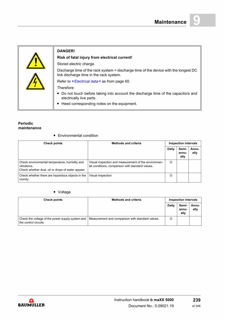
Maintenance 9
Periodic maintenance
m Environmental condition
m Voltage
DANGER!
Risk of fatal injury from electrical current!
Stored electric charge.
Discharge time of the rack system = discharge time of the device with the longest DClink discharge time in the rack system.
Refer to ZElectrical data– as from page 60.
Therefore:
m Do not touch before taking into account the discharge time of the capacitors andelectrically live parts.
m Heed corresponding notes on the equipment.
Check points Methods and criteria Inspection intervals
Daily Semi-annu-ally
Annu-ally
Check environmental temperature, humidity and vibrations.Check whether dust, oil or drops of water appear.
Visual inspection and measurement of the environmen-tal conditions, comparison with standard values.
O
Check whether there are hazardous objects in the vicinity.
Visual inspection O
Check points Methods and criteria Inspection intervals
Daily Semi-annu-ally
Annu-ally
Check the voltage of the power supply system and the control circuits
Measurement and comparison with standard values. O
Instruction handbook b maXX 5000
Document No.: 5.09021.19
239of 346
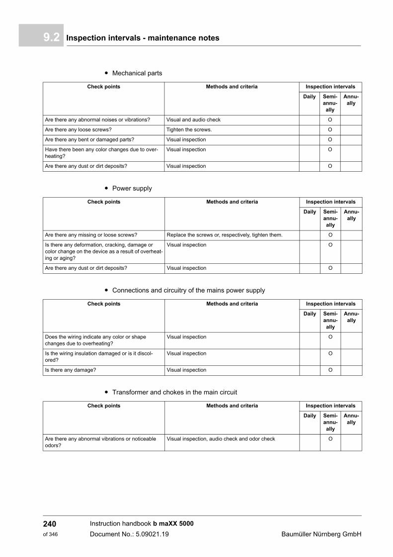
Inspection intervals - maintenance notes9.2
m Mechanical parts
m Power supply
m Connections and circuitry of the mains power supply
m Transformer and chokes in the main circuit
Check points Methods and criteria Inspection intervals
Daily Semi-annu-ally
Annu-ally
Are there any abnormal noises or vibrations? Visual and audio check O
Are there any loose screws? Tighten the screws. O
Are there any bent or damaged parts? Visual inspection O
Have there been any color changes due to over-heating?
Visual inspection O
Are there any dust or dirt deposits? Visual inspection O
Check points Methods and criteria Inspection intervals
Daily Semi-annu-ally
Annu-ally
Are there any missing or loose screws? Replace the screws or, respectively, tighten them. O
Is there any deformation, cracking, damage or color change on the device as a result of overheat-ing or aging?
Visual inspection O
Are there any dust or dirt deposits? Visual inspection O
Check points Methods and criteria Inspection intervals
Daily Semi-annu-ally
Annu-ally
Does the wiring indicate any color or shape changes due to overheating?
Visual inspection O
Is the wiring insulation damaged or is it discol-ored?
Visual inspection O
Is there any damage? Visual inspection O
Check points Methods and criteria Inspection intervals
Daily Semi-annu-ally
Annu-ally
Are there any abnormal vibrations or noticeable odors?
Visual inspection, audio check and odor check O
Instruction handbook b maXX 5000
Document No.: 5.09021.19 Baumüller Nürnberg GmbH
240of 346
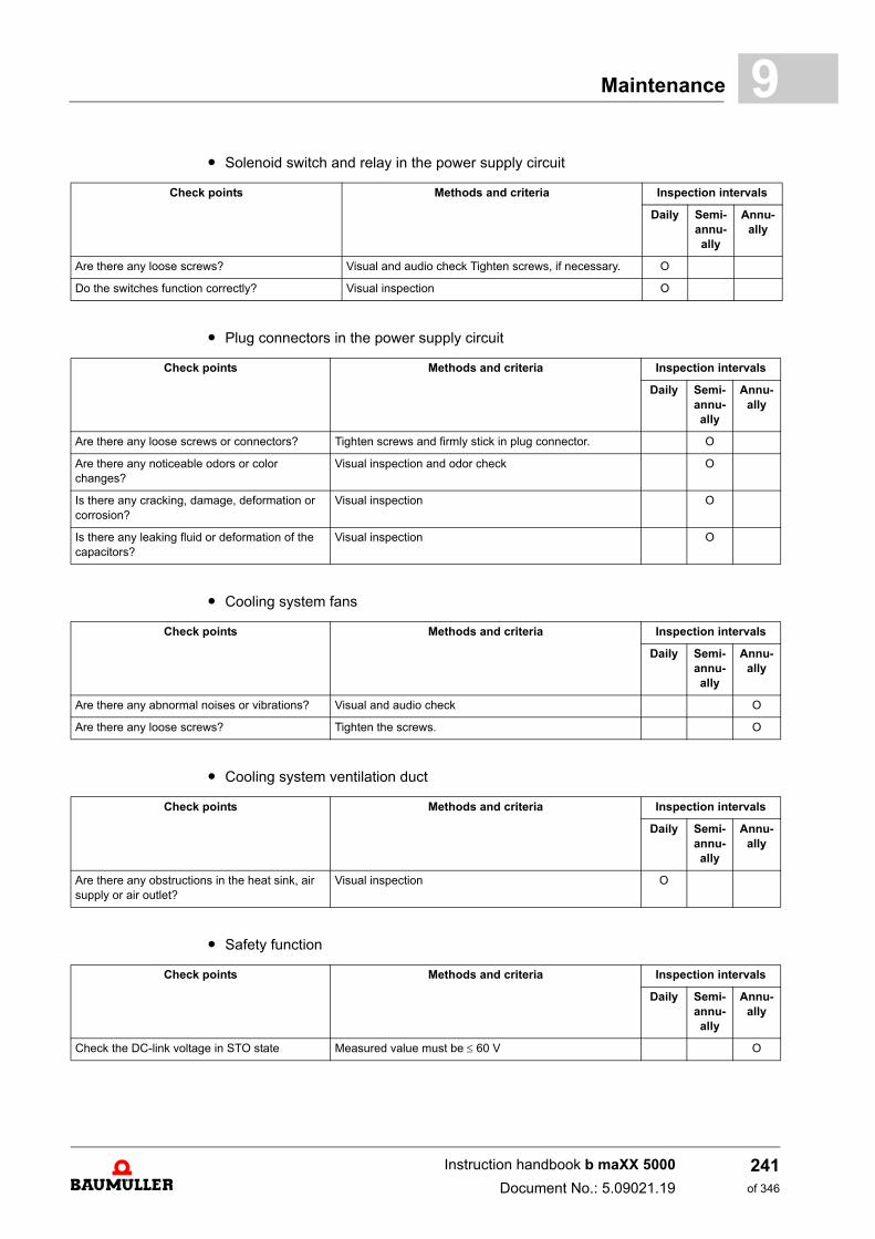
Maintenance 9
m Solenoid switch and relay in the power supply circuitm Plug connectors in the power supply circuit
m Cooling system fans
m Cooling system ventilation duct
m Safety function
Check points Methods and criteria Inspection intervals
Daily Semi-annu-ally
Annu-ally
Are there any loose screws? Visual and audio check Tighten screws, if necessary. O
Do the switches function correctly? Visual inspection O
Check points Methods and criteria Inspection intervals
Daily Semi-annu-ally
Annu-ally
Are there any loose screws or connectors? Tighten screws and firmly stick in plug connector. O
Are there any noticeable odors or color changes?
Visual inspection and odor check O
Is there any cracking, damage, deformation or corrosion?
Visual inspection O
Is there any leaking fluid or deformation of the capacitors?
Visual inspection O
Check points Methods and criteria Inspection intervals
Daily Semi-annu-ally
Annu-ally
Are there any abnormal noises or vibrations? Visual and audio check O
Are there any loose screws? Tighten the screws. O
Check points Methods and criteria Inspection intervals
Daily Semi-annu-ally
Annu-ally
Are there any obstructions in the heat sink, air supply or air outlet?
Visual inspection O
Check points Methods and criteria Inspection intervals
Daily Semi-annu-ally
Annu-ally
Check the DC-link voltage in STO state Measured value must be 60 V O
Instruction handbook b maXX 5000
Document No.: 5.09021.19
241of 346
Repairs9.3
9.3 Repairs
In case of device damage, please inform your sales office or:
Baumüller Nürnberg GmbH
Ostendstr. 80 - 90 90482 Nuremberg Germany
Tel. +49 9 11 54 32 - 0Fax: +49 9 11 54 32 - 1 30
Mail: [email protected]: www.baumueller.com
Instruction handbook b maXX 5000
Document No.: 5.09021.19 Baumüller Nürnberg GmbH
242of 346
10TROUBLESHOOTING AND
FAULT CORRECTION
10.1 Behavior in case of malfunctions
Basic information
DANGER!
Risk of fatal injury from electrical current!
Inevitably, when operating this electrical device, certain parts of it are energized withhazardous voltage.
Therefore:
m Pay heed to areas on the device that could be dangerous.
WARNING!
Risk of injury due to improper fault correction!
Therefore:
m Only qualified personnel may work on this device!
m Personnel that work with the b maXX device must be trained in the safety regula-tions and the handling of the device, and be familiar with the correct operation ofit. In particular, reacting to error indications and conditions requires that the oper-ator must have special knowledge.
243of 346
Instruction handbook b maXX 5000
Document No.: 5.09021.19
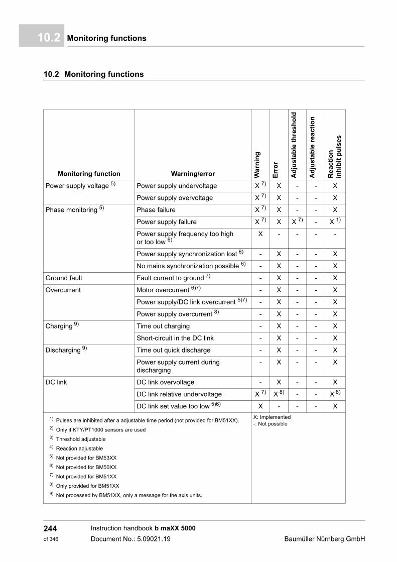
Monitoring functions10.2
10.2 Monitoring functions
Monitoring function Warning/error Wa
rnin
g
Err
or
Ad
just
able
th
resh
old
Ad
just
able
rea
ctio
n
Re
ac
tio
nin
hib
it p
uls
es
Power supply voltage 5) Power supply undervoltage X 7) X - - X
Power supply overvoltage X 7) X - - X
Phase monitoring 5) Phase failure X 7) X - - X
Power supply failure X 7) X X 7) - X 1)
Power supply frequency too high or too low 6)
X - - - -
Power supply synchronization lost 6) - X - - X
No mains synchronization possible 6) - X - - X
Ground fault Fault current to ground 7) - X - - X
Overcurrent Motor overcurrent 6)7) - X - - X
Power supply/DC link overcurrent 5)7) - X - - X
Power supply overcurrent 8) - X - - X
Charging 9) Time out charging - X - - X
Short-circuit in the DC link - X - - X
Discharging 9) Time out quick discharge - X - - X
Power supply current during discharging
- X - - X
DC link DC link overvoltage - X - - X
DC link relative undervoltage X 7) X 8) - - X 8)
DC link set value too low 5)6) X - - - X
1) Pulses are inhibited after a adjustable time period (not provided for BM51XX).2) Only if KTY/PT1000 sensors are used3) Threshold adjustable4) Reaction adjustable5) Not provided for BM53XX6) Not provided for BM50XX7) Not provided for BM51XX8) Only provided for BM51XX9) Not processed by BM51XX, only a message for the axis units.
X: Implemented-: Not possible
Instruction handbook b maXX 5000
Document No.: 5.09021.19 Baumüller Nürnberg GmbH
244of 346
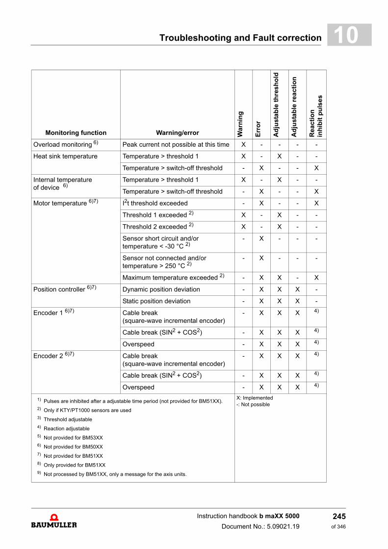
Troubleshooting and Fault correction 10
Overload monitoring 6) Peak current not possible at this time X - - - -
Heat sink temperature Temperature > threshold 1 X - X - -
Temperature > switch-off threshold - X - - X
Internal temperature of device 6)
Temperature > threshold 1 X - X - -
Temperature > switch-off threshold - X - - X
Motor temperature 6)7) I2t threshold exceeded - X - - X
Threshold 1 exceeded 2) X - X - -
Threshold 2 exceeded 2) X - X - -
Sensor short circuit and/or temperature < -30 °C 2)
- X - - -
Sensor not connected and/or temperature > 250 °C 2)
- X - - -
Maximum temperature exceeded 2) - X X - X
Position controller 6)7) Dynamic position deviation - X X X -
Static position deviation - X X X -
Encoder 1 6)7) Cable break(square-wave incremental encoder)
- X X X 4)
Cable break (SIN2 + COS2) - X X X 4)
Overspeed - X X X 4)
Encoder 2 6)7) Cable break(square-wave incremental encoder)
- X X X 4)
Cable break (SIN2 + COS2) - X X X 4)
Overspeed - X X X 4)
Monitoring function Warning/error War
nin
g
Err
or
Ad
just
ab
le t
hre
sh
old
Ad
just
ab
le r
ea
ctio
n
Rea
cti
on
inh
ibit
pu
lse
s
1) Pulses are inhibited after a adjustable time period (not provided for BM51XX).2) Only if KTY/PT1000 sensors are used3) Threshold adjustable4) Reaction adjustable5) Not provided for BM53XX6) Not provided for BM50XX7) Not provided for BM51XX8) Only provided for BM51XX9) Not processed by BM51XX, only a message for the axis units.
X: Implemented-: Not possible
Instruction handbook b maXX 5000
Document No.: 5.09021.19
245of 346
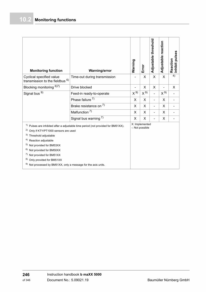
Monitoring functions10.2
Cyclical specified value transmission to the fieldbus 6)
Time-out during transmission - X X X 4)
Blocking monitoring 6)7) Drive blocked - X X - X
Signal bus 9) Feed-in ready-to-operate X 9) X 9) - X 9) -
Phase failure 7) X X - X -
Brake resistance on 7) X X - X -
Malfunction 7) X X - X -
Signal bus warning 7) X X - X -
Monitoring function Warning/error War
nin
g
Err
or
Ad
just
ab
le t
hre
sh
old
Ad
just
ab
le r
ea
ctio
n
Rea
cti
on
inh
ibit
pu
lse
s
1) Pulses are inhibited after a adjustable time period (not provided for BM51XX).2) Only if KTY/PT1000 sensors are used3) Threshold adjustable4) Reaction adjustable5) Not provided for BM53XX6) Not provided for BM50XX7) Not provided for BM51XX8) Only provided for BM51XX9) Not processed by BM51XX, only a message for the axis units.
X: Implemented-: Not possible
Instruction handbook b maXX 5000
Document No.: 5.09021.19 Baumüller Nürnberg GmbH
246of 346
Troubleshooting and Fault correction 10
10.2.1 Monitoring function - explanations BM50XXPower supply voltage
This monitoring function checks whether the power supply voltage has a value within theset voltage range (see ZRequirements for power supply / mains supply system– on page46). If the value is out of this range or 25 % above or 25 % under the default power supplymains voltage, the mains rectifier unit switches off and the LED H1 lights up.
Phase monitoring This monitoring function checks the voltage of the three power supply phases. If onephase is missing, „Phase failure“ is generated after a period of > 100 ms.
If all three phases are missing, then the error „Power supply failure“ is reported after aperiod of > 100 ms.
Phase failure During the missing of a power supply phase the rated power output is possible up to 10 s,after that time only 30 % of the rated power can be supplied for unlimited time.
if this values are exceeded the mains rectifier is shut down and has to be restarted by „re-set“ (X1:4).
At bad power supply conditions shutdown can be initiated earlier.
Overcurrent This monitoring function checks whether the peak value off the DC link current is higherthan 160 A (BM5031, BM5032) or 520 A (BM5043, BM5044). If the DC link current ex-ceeds this value the mains rectifier unit is switched off and the LED H4 lights up. Thismonitoring function provides a „disaster prevention“ in case of a short circuit of the outputside.
DC link This monitoring function checks the voltage of the DC link. If the voltage is lower than aninternally set value (approx. 50 V under the specified value), the controller generates „DClink undervoltage“ and a warning is signaled. If the voltage rises above an internally set value (approximately. 825 V), the mains recti-fier unit is switched off and the LED H4 lights up.
Overload monitoring
This monitoring function controls the present load whether the power unit can supply thepeak current at the moment. In case the peak current is not possible, the message „Powerunit monitoring active and max. torque current is limited“ (warning 206) is generated.
Heat sink tem-perature
This monitoring function checks the temperature of the heat sink. If the temperature is toohigh or below -5 °C, then the mains rectifier unit is switched off and LED H3 lights up.
Instruction handbook b maXX 5000
Document No.: 5.09021.19
247of 346
Monitoring functions10.2
10.2.2 Monitoring function - explanations BM51XX
Power supply voltage
The BM51XX provides 2 settable thresholds to check the power supply voltage. The ac-tive mains rectifier generates a message if the power supply voltage is above/below theset thresholds. This message is generated as warning by default, the reaction can bechanged to pulse inhibit.The device generates an error message and a shutdown follows if the mains voltage is inoperation out of the permitted range (refer to ZRequirements for power supply / mainssupply system– on page 46).
Phase monitoring This monitoring function checks the voltage of the three power supply phases. The error„Phase failure“ is generated if one phase is missing. The error „Power supply failure“ isgenerated, if 2 or 3 phases are missing. The active mains rectifier generates a warningfirst and disables then the active operation with the error message „Power supply syn-chronization lost“ if the power supply frequency exceeds the permitted range. The activemains rectifier changes to error state generating the message „Power supply synchroni-zation not possible“ if a synchronization to the power supply is not possible before startingactive operation.
Charging This monitoring function checks the charging of the DC link voltage. The error „TimeoutDC link“ is generated if the DC link voltage cannot be charged to power supply maximumvoltage within 10 s. The active mains rectifier stops the operation with the error message„Short circuit at DC link“ if the DC link voltage does not rise as expected while charging.
Discharging The device is not separated from the power supply successfully if a mains current is de-tected while discharging. The discharge resistor would be connected directly to the powersupply therefore the error „Power supply current during discharging“ is generated. If the DC link voltage can not be discharged within approx. 10 s, the error „Time-out quickdischarge“ is generated.
DC link This monitoring function checks the voltage at the DC link. If the voltage is lower than aninternally set value (approx. 80 V under the specified value or 87 % of the power supplypeak value), the controller generates the error „DC link undervoltage“. If the voltage risesabove an internally set value (approx. 835 V), the controller generates the error „DC linkovervoltage“ and pulses are inhibited immediately.
The user set value is too low ensuring an adequate dynamic controlling if the set U DC linkset value at the moment is lower than a threshold 40 V above the power supply peak val-ue. In this case the error „Undervoltage U DC link “ is generated.
Overload monitoring
This monitoring function checks the present load whether the power unit can supply thepeak current at the moment. In case the peak current is not possible, the message „Powerunit monitoring active and max. torque current is limited“ (warning 206) is generated.
Instruction handbook b maXX 5000
Document No.: 5.09021.19 Baumüller Nürnberg GmbH
248of 346
Troubleshooting and Fault correction 10
Cyclic set value transmission to the fieldbusThe active mains rectifier is able to exchange cyclic data with the master control. If thisdata exchange is not within a defined time period, the device will generate the errors „Ac-tual values are not received in time“ or „No data available at the moment“.
Temperature ofdevice interior
This monitoring function checks the temperature in the interior of the device.
m If the temperature is higher than the warning threshold, then the controller generates awarning.
m If the temperature is too high, then the pulses are inhibited immediately.
Heat sink temperature
This monitoring function checks the temperature of the heat sink.
m If the temperature is higher than the warning threshold, then the controller generates awarning.
m If the temperature is too high, then the pulses are inhibited immediately.
Signal bus At axis units all power units are linked together via a so called „signal bus“. The bus sig-nals can be polled and set by every client device, including the mains rectifier unit.
The mains active rectifier can report to the axis units via this bus
m Ready-to-operate for drive
This way, the individual axes can react to this signal.
Signal bus - Mains rectifier unit ready-to-operate
Shows when the mains rectifier unit is in the „ready-to-operate“ state. This signal is gen-erated after reaching the value UDC link actual = UDC link set value - 10 V.
In case of power supply errors or power supply failure, the ready-to-operate signal is can-celed again. The axis units react to this with error state.
Signal bus - Malfunction
The „Malfunction“ signal is an input for mains rectifier unit and active mains rectifier unit. This signal is not evaluated by the active mains rectifier at the moment.
Instruction handbook b maXX 5000
Document No.: 5.09021.19
249of 346
Monitoring functions10.2
10.2.3 Monitoring function - explanations BM53XX
Ground fault This monitoring function checks whether there is a short circuit between at least one mo-tor terminal and ground. If a short circuit is detected, pulses are inhibited immediately.
Overcurrent This monitoring function checks whether the motor current or the mains current is largerthan 1.3 times of the peak output current. This monitoring function provides a „disasterprevention“ in case of a short circuit of the output side.
DC link This monitoring function checks the voltage in the DC link. If the voltage drops below aninternally set value (approx. 210 V), the controller reports „DC link undervoltage“ and awarning is signaled. If the voltage rises above an internally set value (approx. 835 V), thecontroller reports the error „DC link overvoltage“ and pulses are inhibited immediately.
Overload monitoring
This monitoring function checks the present load whether the power unit can supply thepeak current at the moment. In case the peak current is not possible, the message „Powerunit monitoring active and max. torque current is limited“ (warning 206) is generated.
Internal tempera-ture of device
This monitoring function checks the temperature in the interior of the device.
m If the temperature is higher than the warning threshold, then the controller signals awarning.
m If the temperature is higher than the maximum allowable device interior temperature,then the pulses are inhibited immediately.
Heat sink temperature
This monitoring function checks the temperature of the heat sink.
m If the temperature is higher than the warning threshold, then the controller signals awarning.
m If the temperature is higher than the maximum allowable heat sink temperature, thenthe pulses are inhibited immediately.
Motor temperature
This monitoring function checks the temperature of motor. If the I²t-threshold is exceeded,then the error message „I²t overload“ is generated by the controller.
Only forKTY84 and PT1000sensor
If the set temperature threshold 1 is exceeded, then the warning „Temperature threshold1 exceeded“ is generated by the controller.
If the set temperature threshold 2 is exceeded, then the warning „Temperature threshold2 exceeded“ is generated by the controller.
If the temperature falls below the minimum measurable value, or if a short circuit occursat the sensor, then the error message „Temperature sensor short circuit“ is generated.
If the temperature is higher than the maximum measurable temperature, or if the sensoris not connected, then the error message „Temperature sensor not connected“ is gener-ated by the controller.
For all sensors
The error message „Over temperature“ is generated by the controller and the pulses areinhibited immediately if the threshold (type-specific) of the temperature switch or of thesensor is exceeded.
Position controller
This monitoring function checks the position deviation limit statically/dynamically. If thecurrent position deviation is statically/dynamically larger than the set position deviationlimit, then the error message „Static position deviation“ or „Dynamic position deviation“ isgenerated. After the monitoring period (position deviation period) an additional error mes-sage is generated and pulses are inhibited immediately. The reaction time can be set.
Instruction handbook b maXX 5000
Document No.: 5.09021.19 Baumüller Nürnberg GmbH
250of 346
Troubleshooting and Fault correction 10
Blocking monitoringThis monitoring function checks the motor speed and the motor current. If the following two conditions are met for at least the „Blocking monitoring time“, then theerror message „Drive blocked“ is generated by the controller and the pulses are inhibitedimmediately.
m Motor speed = 0
m The motor current output by the device is the same as the set maximal motor current(current limit).
Signal bus The signal bus is a connection between the supply unit and the connected axis units inthe DC link network. The ready-to-operate signal of the supply unit is signalized to theconnected axes via this connection. Furthermore the signal bus can be used to signalizean error or a warning to the other connected devices.
Signal bus - Supply unit ready-to-operate
The mains rectifier unit, the active mains rectifier unit and mono units generate this signal.The connected axis units evaluate this signal.
The signal indicates that the supply unit is in the ready-to-operate state and the DC linkis supplied. In the event of power supply errors (e.g. power supply failure), the output ofthe ready fur use signal is stopped. If the signal is not available, an error is generated atthe connected axis units.
Signal bus - Supply unit not ready-to-operate
This signal indicates also the state of the mains rectifier unit. It is required, if axis units willbe operated in a DC link network with several mono units.
In this case it can only be evaluated by the „Power supply ready-to-operate“ signalswhether at least one supplying device is ready, because the signal is a disjunction of thestates of all supplying devices. It can not be recognized whether all supplying devices areready.
In order to recognize that at least one supply unit is in state not ready-to-operate, the sig-nal „Supply not ready-to-operate“ is generated. The evaluation of this signal can be dis-abled for special applications.
Signal bus - Phase failure
The mains rectifier unit, the active mains rectifier unit and mono units generate this signalif a phase failure is recognized.
The axis units can operate at phase failure only at mains rectifier units and at mono units.Several options are selectable for further operations, see parameter 130.10 Power supplymode.
Instruction handbook b maXX 5000
Document No.: 5.09021.19
251of 346
Monitoring functions10.2
Signal bus - Brake resistor on
This signal activates the brake resistors of several supplying devices simultaneously.Both mains rectifier unit and mono units provide a brake resistor connection and an ownmonitoring of the DC link voltage. If the DC link voltage exceeds a fixed threshold, thebrake resistor is switched on.
The axis units measure the DC link voltage also and can be configured to generate the„Brake resistor on“ signal. If this signal is set, the brake resistor is switched on at themains rectifier unit and/or at the mono units.
This signal is not evaluated at the active mains rectifier unit.
Signal bus - Error
The axis units and the mono units can be configured to set the „Error“ signal on the signalbus as soon as the device is no longer in state ready-to-operate.
Furthermore each axis unit or each mono unit can be configured to generate an errormessage when detecting an „Error“ signal. A simple error reaction for all axis units/monounits is possible, using this function.
This signal is neither evaluated nor set at the active mains rectifier unit and at the mainsrectifier unit.
Signal bus - Signal bus warning
Connected devices can exchange warning states among each other with this signal. Thesignal is evaluated or set only by axis units and mono units. It is neither evaluated nor setby the active mains rectifier unit and by the mains rectifier unit.
Instruction handbook b maXX 5000
Document No.: 5.09021.19 Baumüller Nürnberg GmbH
252of 346
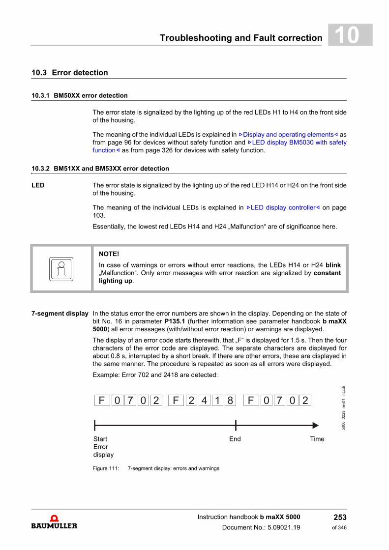
Troubleshooting and Fault correction 10
10.3 Error detection10.3.1 BM50XX error detection
The error state is signalized by the lighting up of the red LEDs H1 to H4 on the front sideof the housing.
The meaning of the individual LEDs is explained in ZDisplay and operating elements– asfrom page 96 for devices without safety function and ZLED display BM5030 with safetyfunction– as from page 326 for devices with safety function.
10.3.2 BM51XX and BM53XX error detection
LED The error state is signalized by the lighting up of the red LED H14 or H24 on the front sideof the housing.
The meaning of the individual LEDs is explained in ZLED display controller– on page103.
Essentially, the lowest red LEDs H14 and H24 „Malfunction“ are of significance here.
7-segment display In the status error the error numbers are shown in the display. Depending on the state ofbit No. 16 in parameter P135.1 (further information see parameter handbook b maXX5000) all error messages (with/without error reaction) or warnings are displayed.
The display of an error code starts therewith, that „F“ is displayed for 1.5 s. Then the fourcharacters of the error code are displayed. The separate characters are displayed forabout 0.8 s, interrupted by a short break. If there are other errors, these are displayed inthe same manner. The procedure is repeated as soon as all errors were displayed.
Example: Error 702 and 2418 are detected:
Figure 111: 7-segment display: errors and warnings
NOTE!
In case of warnings or errors without error reactions, the LEDs H14 or H24 blink„Malfunction“. Only error messages with error reaction are signalized by constantlighting up.
Start End TimeErrordisplay
Instruction handbook b maXX 5000
Document No.: 5.09021.19
253of 346
Error handling10.4
For further information on the subjects of error messages and error numbers, see „Pa-rameter manual b maXX 5000„.
10.4 Error handling
10.4.1 Error acknowledgment of BM50XX
If the red error LEDs H1 to H4 light up, then at least one error has been detected.
All error messages are reset by error acknowledgment. Individual acknowledgment of er-rors is not possible. An acknowledgment delete all errors, if deletion was possible on ac-count of the error cause.
Errors can be acknowledged via the digital input X1:4. Thereby a rising edge (low to high) is evaluated. The high level has to be applied at least100 ms.
BM50XX-XXX0 For further information, see ZFigure 70– on page 150 and ZFigure 80– on page 164.
BM50XX-XXX1 For further information, see ZFigure 71– on page 151 and ZFigure 80– on page 164.
NOTE!
The device is shipped with predefined error reactions. With regard to the error mes-sages identified with „depending on the setting“ in the „Reaction“ column, the device'serror reaction can be adjusted. Error messages that, due to safety reasons, have animmediate pulse inhibit as a consequence, may not be changed.
NOTE!
When using devices BM5XXX-XXX1 all error messages can be reset with
Power supply off Power supply on additionally.
Instruction handbook b maXX 5000
Document No.: 5.09021.19 Baumüller Nürnberg GmbH
254of 346
Troubleshooting and Fault correction 10
10.4.2 Error acknowledgment of BM51XX and BM53XXIf the red error LEDs H14 or H24 light up, at least one error has been detected.
All error messages are reset by error acknowledgment. Individual acknowledgment of er-rors is not possible. An acknowledgment delete all errors, if deletion was possible on ac-count of the error cause.
There are three methods of acknowledging an error:
m By means of write access to the control word
m Via a digital input
m Via the pulse enable input:
n BM51XXThe pulse enable input of the BM51XX is linked to an additional option therefore itis not possible to quit errors via the pulse enable input on the active mains rectifier.
n BM53XXThis is conditional upon the drive only being controlled via the hardware inputs (thus,the control of the motor is not handled via another communications channel). Fur-thermore, the option „Error acknowledgment by means of pulse enable“ must be ac-tivated. The errors are acknowledged with the first rising signal edge of the pulseenable. However, the drive has still not started. A second rising signal edge is thennecessary for the release.
For further information on the subject of error acknowledgment, see „Parameter manualb maXX 5000".
Instruction handbook b maXX 5000
Document No.: 5.09021.19
255of 346

Error handling10.4
Instruction handbook b maXX 5000
Document No.: 5.09021.19 Baumüller Nürnberg GmbH
256of 346
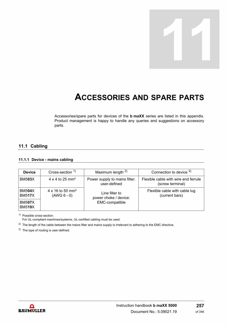
11ACCESSORIES AND SPARE PARTS
Accessories/spare parts for devices of the b maXX series are listed in this appendix.Product management is happy to handle any queries and suggestions on accessoryparts.
11.1 Cabling
11.1.1 Device - mains cabling
1) Possible cross-section.For UL-compliant machines/systems, UL-certified cabling must be used.
2) The length of the cable between the mains filter and mains supply is irrelevant to adhering to the EMC directive.3) The type of routing is user-defined.
Device Cross-section 1) Maximum length 2) Connection to device 3)
BM503X 4 x 4 to 25 mm² Power supply to mains filter: user-defined
Line filter to power choke / device:
EMC-compatible
Flexible cable with wire end ferrule(screw terminal)
BM504X BM517X
4 x 16 to 50 mm²
(AWG 6 - 0)Flexible cable with cable lug
(current bars)
BM507XBM519X
257of 346
Instruction handbook b maXX 5000
Document No.: 5.09021.19
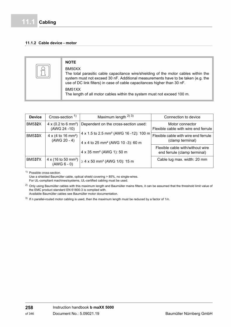
Cabling11.1
11.1.2 Cable device - motor
1) Possible cross-section.Use a shielded Baumüller cable, optical shield covering > 85%, no single-wires.For UL-compliant machines/systems, UL-certified cabling must be used.
2) Only using Baumüller cables with this maximum length and Baumüller mains filters, it can be assumed that the threshold limit value ofthe EMC product standard EN 61800-3 is complied with.Available Baumüller cables see Baumüller motor documentation.
3) If n parallel-routed motor cabling is used, then the maximum length must be reduced by a factor of 1/n.
NOTE
BM50XXThe total parasitic cable capacitance wire/shielding of the motor cables within thesystem must not exceed 30 nF. Additional measurements have to be taken (e.g. theuse of DC link filters) in case of cable capacitances higher than 30 nF.
BM51XXThe length of all motor cables within the system must not exceed 100 m.
Device Cross-section 1) Maximum length 2) 3) Connection to device
BM532X 4 x (0.2 to 6 mm²)
(AWG 24 -10)Dependent on the cross-section used:
4 x 1.5 to 2.5 mm² (AWG 16 -12): 100 m
4 x 4 to 25 mm² (AWG 10 -3): 60 m
4 x 35 mm² (AWG 1): 50 m
4 x 50 mm² (AWG 1/0): 15 m
Motor connectorFlexible cable with wire end ferrule
BM533X 4 x (4 to 16 mm²) (AWG 20 - 4)
Flexible cable with wire end ferrule (clamp terminal)
Flexible cable with/without wire end ferrule (clamp terminal)
BM537X 4 x (16 to 50 mm²)
(AWG 6 - 0)Cable lug max. width: 20 mm
Instruction handbook b maXX 5000
Document No.: 5.09021.19 Baumüller Nürnberg GmbH
258of 346
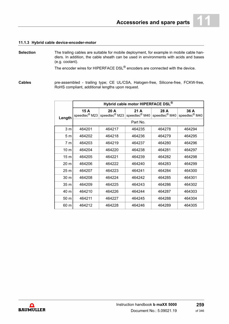
Accessories and spare parts 11
11.1.3 Hybrid cable device-encoder-motorSelection The trailing cables are suitable for mobile deployment, for example in mobile cable han-dlers. In addition, the cable sheath can be used in environments with acids and bases(e.g. coolant).
The encoder wires for HIPERFACE DSL® encoders are connected with the device.
Cables pre-assembled - trailing type; CE UL/CSA, Halogen-free, Silicone-free, FCKW-free,RoHS compliant, additional lengths upon request.
Length
Hybrid cable motor HIPERFACE DSL®
15 Aspeedtec® M23
20 Aspeedtec® M23
21 Aspeedtec® M40
28 Aspeedtec® M40
36 Aspeedtec® M40
Part No.
3 m 464201 464217 464235 464278 464294
5 m 464202 464218 464236 464279 464295
7 m 464203 464219 464237 464280 464296
10 m 464204 464220 464238 464281 464297
15 m 464205 464221 464239 464282 464298
20 m 464206 464222 464240 464283 464299
25 m 464207 464223 464241 464284 464300
30 m 464208 464224 464242 464285 464301
35 m 464209 464225 464243 464286 464302
40 m 464210 464226 464244 464287 464303
50 m 464211 464227 464245 464288 464304
60 m 464212 464228 464246 464289 464305
Instruction handbook b maXX 5000
Document No.: 5.09021.19
259of 346
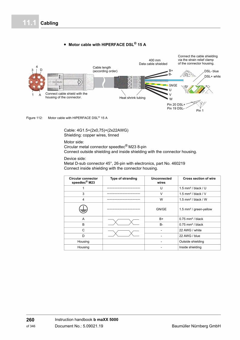
Cabling11.1
m Motor cable with HIPERFACE DSL® 15 A
Figure 112: Motor cable with HIPERFACE DSL® 15 A
Cable: 4G1.5+(2x0,75)+(2x22AWG)Shielding: copper wires, tinned
Motor side: Circular metal connector speedtec® M23 8-pinConnect outside shielding and inside shielding with the connector housing.
Device side: Metal D-sub connector 45°, 26-pin with electronics, part No. 460219Connect inside shielding with the connector housing.
Connect cable shield with thehousing of the connector.
Cable length(according order)
Heat shrink tubing
400 mmData cable shielded
Connect the cable shieldingvia the strain relief clampof the connector housing.
Pin 1
1
3
A
D4
DSL- blue
DSL+ white
Pin 19 DSL-Pin 20 DSL+
B+B-
VW
GN/GE
U
Circular connectorspeedtec® M23
Type of stranding Unconnected wires
Cross section of wire
1 U 1.5 mm² / black / U
3 V 1.5 mm² / black / V
4 W 1.5 mm² / black / W
GN/GE 1.5 mm² / green-yellow
A B+ 0.75 mm² / black
B B- 0.75 mm² / black
C - 22 AWG / white
D - 22 AWG / blue
Housing - Outside shielding
Housing - Inside shielding
Instruction handbook b maXX 5000
Document No.: 5.09021.19 Baumüller Nürnberg GmbH
260of 346
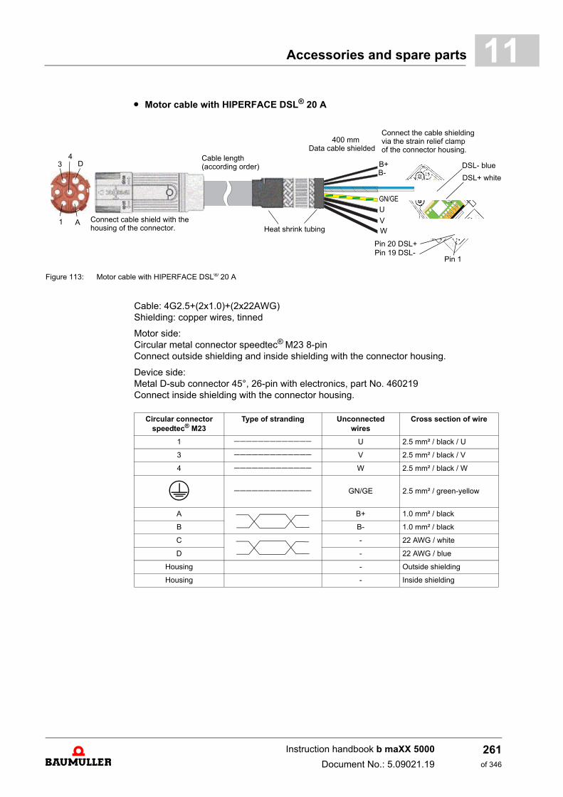
Accessories and spare parts 11
m Motor cable with HIPERFACE DSL® 20 AFigure 113: Motor cable with HIPERFACE DSL® 20 A
Cable: 4G2.5+(2x1.0)+(2x22AWG)Shielding: copper wires, tinned
Motor side: Circular metal connector speedtec® M23 8-pinConnect outside shielding and inside shielding with the connector housing.
Device side: Metal D-sub connector 45°, 26-pin with electronics, part No. 460219Connect inside shielding with the connector housing.
Connect cable shield with thehousing of the connector.
Cable length(according order)
Heat shrink tubing
Pin 1
1
3
A
D4
Connect the cable shieldingvia the strain relief clampof the connector housing.
400 mmData cable shielded
DSL- blue
DSL+ white
Pin 19 DSL-Pin 20 DSL+
B+B-
VW
GN/GE
U
Circular connectorspeedtec® M23
Type of stranding Unconnected wires
Cross section of wire
1 U 2.5 mm² / black / U
3 V 2.5 mm² / black / V
4 W 2.5 mm² / black / W
GN/GE 2.5 mm² / green-yellow
A B+ 1.0 mm² / black
B B- 1.0 mm² / black
C - 22 AWG / white
D - 22 AWG / blue
Housing - Outside shielding
Housing - Inside shielding
Instruction handbook b maXX 5000
Document No.: 5.09021.19
261of 346
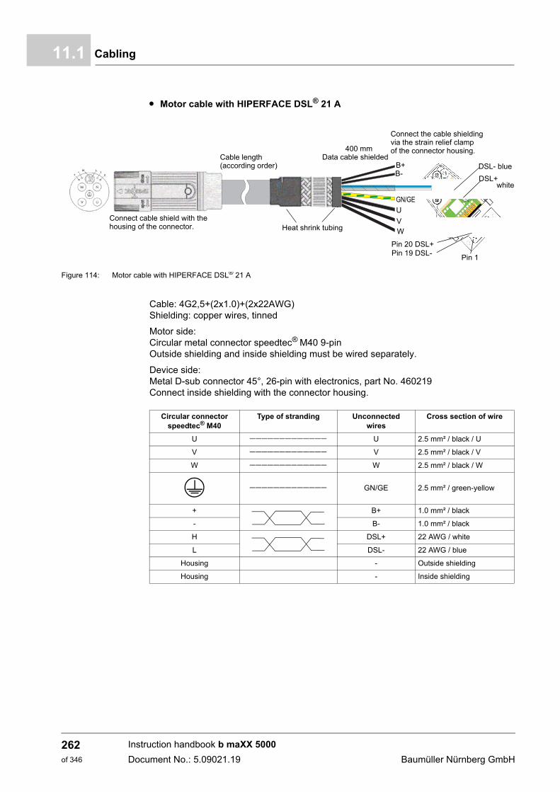
Cabling11.1
m Motor cable with HIPERFACE DSL® 21 A
Figure 114: Motor cable with HIPERFACE DSL® 21 A
Cable: 4G2,5+(2x1.0)+(2x22AWG)Shielding: copper wires, tinned
Motor side: Circular metal connector speedtec® M40 9-pinOutside shielding and inside shielding must be wired separately.
Device side: Metal D-sub connector 45°, 26-pin with electronics, part No. 460219Connect inside shielding with the connector housing.
Connect cable shield with thehousing of the connector.
Cable length(according order)
Heat shrink tubing
Pin 1
Connect the cable shieldingvia the strain relief clampof the connector housing.400 mm
Data cable shieldedDSL- blue
DSL+
Pin 19 DSL-Pin 20 DSL+
B+B-
VW
GN/GE
U
white
Circular connectorspeedtec® M40
Type of stranding Unconnected wires
Cross section of wire
U U 2.5 mm² / black / U
V V 2.5 mm² / black / V
W W 2.5 mm² / black / W
GN/GE 2.5 mm² / green-yellow
+ B+ 1.0 mm² / black
- B- 1.0 mm² / black
H DSL+ 22 AWG / white
L DSL- 22 AWG / blue
Housing - Outside shielding
Housing - Inside shielding
Instruction handbook b maXX 5000
Document No.: 5.09021.19 Baumüller Nürnberg GmbH
262of 346
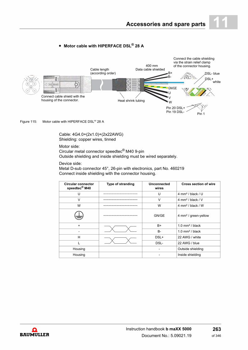
Accessories and spare parts 11
m Motor cable with HIPERFACE DSL® 28 AFigure 115: Motor cable with HIPERFACE DSL® 28 A
Cable: 4G4.0+(2x1.0)+(2x22AWG)Shielding: copper wires, tinned
Motor side: Circular metal connector speedtec® M40 9-pinOutside shielding and inside shielding must be wired separately.
Device side: Metal D-sub connector 45°, 26-pin with electronics, part No. 460219Connect inside shielding with the connector housing.
Connect cable shield with thehousing of the connector.
Cable length(according order)
Heat shrink tubing
Pin 1
Connect the cable shieldingvia the strain relief clampof the connector housing.400 mm
Data cable shieldedDSL- blue
DSL+
Pin 19 DSL-Pin 20 DSL+
B+B-
VW
GN/GE
U
white
Circular connectorspeedtec® M40
Type of stranding Unconnected wires
Cross section of wire
U U 4 mm² / black / U
V V 4 mm² / black / V
W W 4 mm² / black / W
GN/GE 4 mm² / green-yellow
+ B+ 1.0 mm² / black
- B- 1.0 mm² / black
H DSL+ 22 AWG / white
L DSL- 22 AWG / blue
Housing - Outside shielding
Housing - Inside shielding
Instruction handbook b maXX 5000
Document No.: 5.09021.19
263of 346
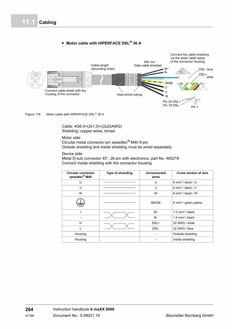
Cabling11.1
m Motor cable with HIPERFACE DSL® 36 A
Figure 116: Motor cable with HIPERFACE DSL® 36 A
Cable: 4G6.0+(2x1.0)+(2x22AWG)Shielding: copper wires, tinned
Motor side: Circular metal connector-pin speedtec® M40 9-pinOutside shielding and inside shielding must be wired separately.
Device side: Metal D-sub connector 45°, 26-pin with electronics, part No. 460219Connect inside shielding with the connector housing.
Connect cable shield with thehousing of the connector.
Cable length(according order)
Heat shrink tubing
Pin 1
Connect the cable shieldingvia the strain relief clampof the connector housing.400 mm
Data cable shieldedDSL- blue
DSL+
Pin 19 DSL-Pin 20 DSL+
B+B-
VW
GN/GE
U
white
Circular connectorspeedtec® M40
Type of stranding Unconnected wires
Cross section of wire
U U 6 mm² / black / U
V V 6 mm² / black / V
W W 6 mm² / black / W
GN/GE 6 mm² / green-yellow
+ B+ 1.0 mm² / black
- B- 1.0 mm² / black
H DSL+ 22 AWG / white
L DSL- 22 AWG / blue
Housing - Outside shielding
Housing - Inside shielding
Instruction handbook b maXX 5000
Document No.: 5.09021.19 Baumüller Nürnberg GmbH
264of 346
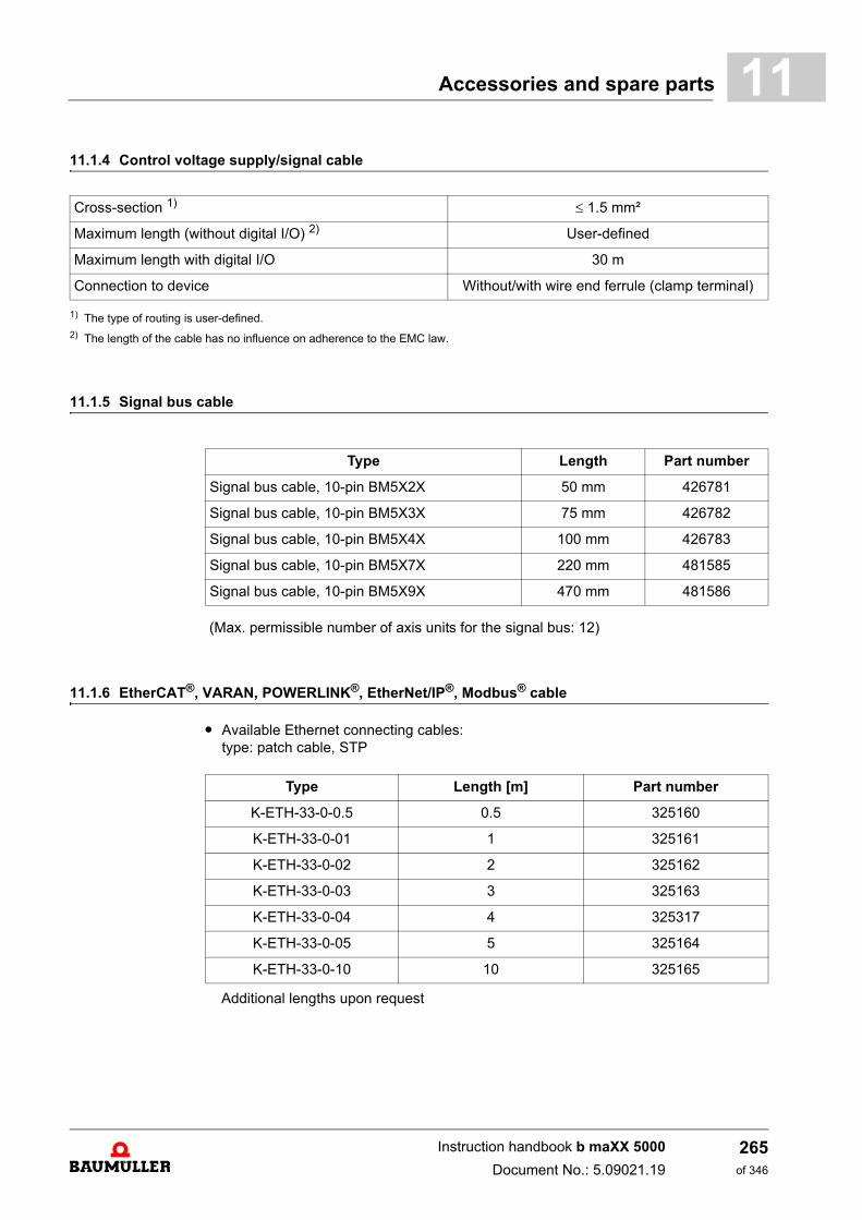
Accessories and spare parts 11
11.1.4 Control voltage supply/signal cable1) The type of routing is user-defined.2) The length of the cable has no influence on adherence to the EMC law.
11.1.5 Signal bus cable
(Max. permissible number of axis units for the signal bus: 12)
11.1.6 EtherCAT®, VARAN, POWERLINK®, EtherNet/IP®, Modbus® cable
m Available Ethernet connecting cables:type: patch cable, STP
Additional lengths upon request
Cross-section 1) 1.5 mm²
Maximum length (without digital I/O) 2) User-defined
Maximum length with digital I/O 30 m
Connection to device Without/with wire end ferrule (clamp terminal)
Type Length Part number
Signal bus cable, 10-pin BM5X2X 50 mm 426781
Signal bus cable, 10-pin BM5X3X 75 mm 426782
Signal bus cable, 10-pin BM5X4X 100 mm 426783
Signal bus cable, 10-pin BM5X7X 220 mm 481585
Signal bus cable, 10-pin BM5X9X 470 mm 481586
Type Length [m] Part number
K-ETH-33-0-0.5 0.5 325160
K-ETH-33-0-01 1 325161
K-ETH-33-0-02 2 325162
K-ETH-33-0-03 3 325163
K-ETH-33-0-04 4 325317
K-ETH-33-0-05 5 325164
K-ETH-33-0-10 10 325165
Instruction handbook b maXX 5000
Document No.: 5.09021.19
265of 346
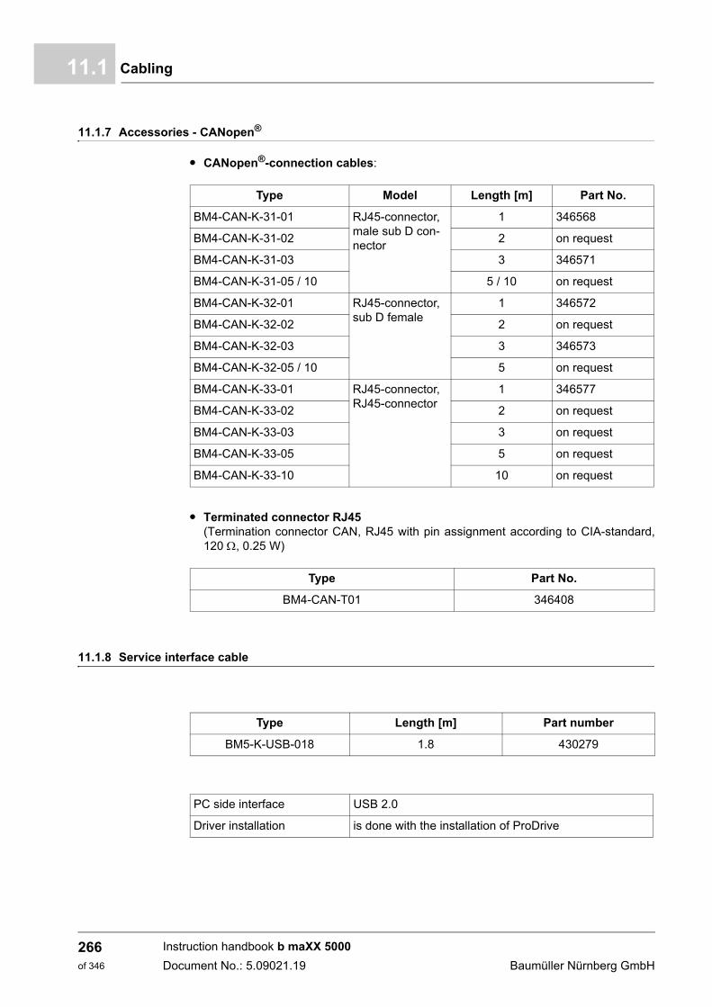
Cabling11.1
11.1.7 Accessories - CANopen®.
m CANopen®-connection cables:
m Terminated connector RJ45 (Termination connector CAN, RJ45 with pin assignment according to CIA-standard,120 , 0.25 W)
11.1.8 Service interface cable
Type Model Length [m] Part No.
BM4-CAN-K-31-01 RJ45-connector, male sub D con-nector
1 346568
BM4-CAN-K-31-02 2 on request
BM4-CAN-K-31-03 3 346571
BM4-CAN-K-31-05 / 10 5 / 10 on request
BM4-CAN-K-32-01 RJ45-connector, sub D female
1 346572
BM4-CAN-K-32-02 2 on request
BM4-CAN-K-32-03 3 346573
BM4-CAN-K-32-05 / 10 5 on request
BM4-CAN-K-33-01 RJ45-connector, RJ45-connector
1 346577
BM4-CAN-K-33-02 2 on request
BM4-CAN-K-33-03 3 on request
BM4-CAN-K-33-05 5 on request
BM4-CAN-K-33-10 10 on request
Type Part No.
BM4-CAN-T01 346408
Type Length [m] Part number
BM5-K-USB-018 1.8 430279
PC side interface USB 2.0
Driver installation is done with the installation of ProDrive
Instruction handbook b maXX 5000
Document No.: 5.09021.19 Baumüller Nürnberg GmbH
266of 346
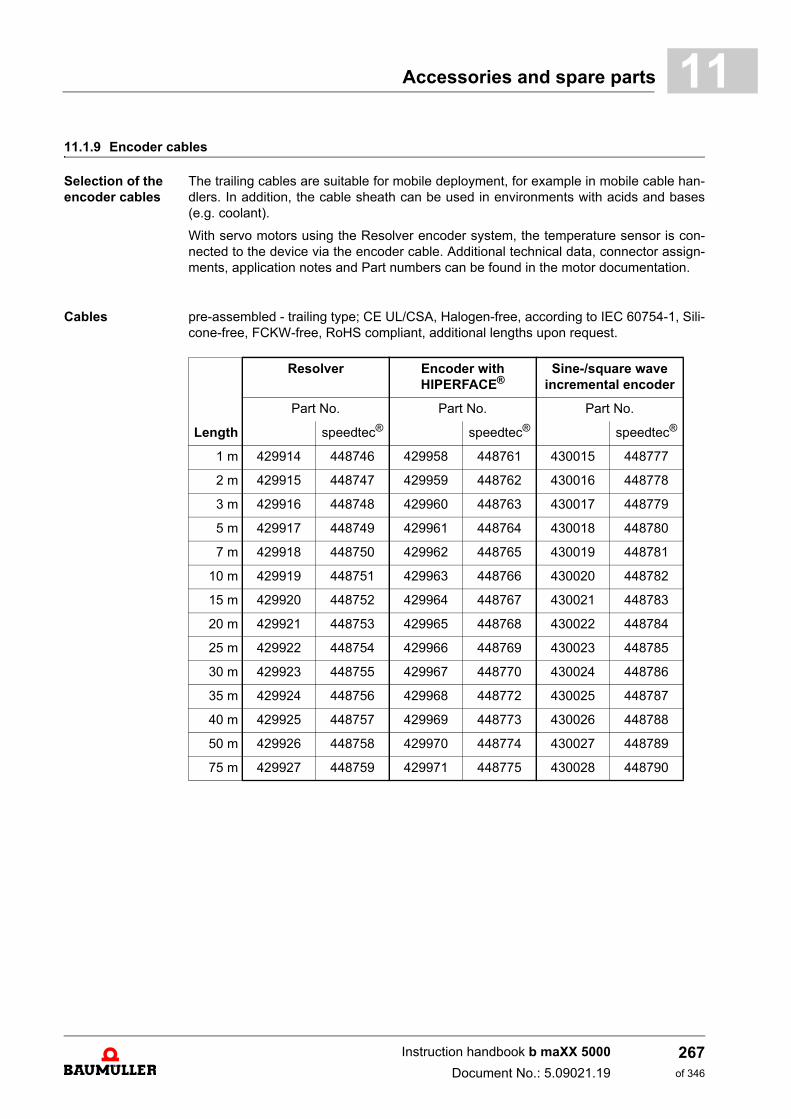
Accessories and spare parts 11
11.1.9 Encoder cablesSelection of the encoder cables
The trailing cables are suitable for mobile deployment, for example in mobile cable han-dlers. In addition, the cable sheath can be used in environments with acids and bases(e.g. coolant).
With servo motors using the Resolver encoder system, the temperature sensor is con-nected to the device via the encoder cable. Additional technical data, connector assign-ments, application notes and Part numbers can be found in the motor documentation.
Cables pre-assembled - trailing type; CE UL/CSA, Halogen-free, according to IEC 60754-1, Sili-cone-free, FCKW-free, RoHS compliant, additional lengths upon request.
Length
Resolver Encoder with HIPERFACE®
Sine-/square wave incremental encoder
Part No. Part No. Part No.
speedtec® speedtec® speedtec®
1 m 429914 448746 429958 448761 430015 448777
2 m 429915 448747 429959 448762 430016 448778
3 m 429916 448748 429960 448763 430017 448779
5 m 429917 448749 429961 448764 430018 448780
7 m 429918 448750 429962 448765 430019 448781
10 m 429919 448751 429963 448766 430020 448782
15 m 429920 448752 429964 448767 430021 448783
20 m 429921 448753 429965 448768 430022 448784
25 m 429922 448754 429966 448769 430023 448785
30 m 429923 448755 429967 448770 430024 448786
35 m 429924 448756 429968 448772 430025 448787
40 m 429925 448757 429969 448773 430026 448788
50 m 429926 448758 429970 448774 430027 448789
75 m 429927 448759 429971 448775 430028 448790
Instruction handbook b maXX 5000
Document No.: 5.09021.19
267of 346
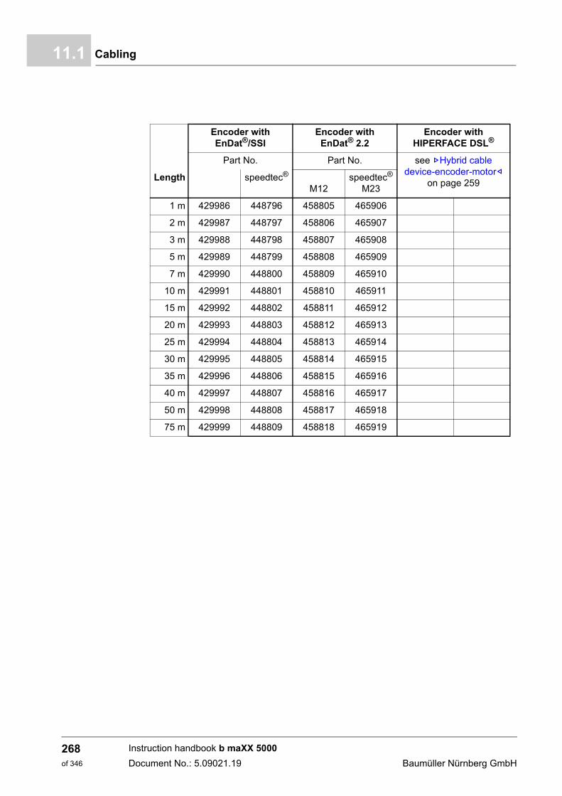
Cabling11.1
Length
Encoder with EnDat®/SSI
Encoder with EnDat® 2.2
Encoder with HIPERFACE DSL®
Part No. Part No. see ZHybrid cable device-encoder-motor–
on page 259speedtec®
M12speedtec®
M23
1 m 429986 448796 458805 465906
2 m 429987 448797 458806 465907
3 m 429988 448798 458807 465908
5 m 429989 448799 458808 465909
7 m 429990 448800 458809 465910
10 m 429991 448801 458810 465911
15 m 429992 448802 458811 465912
20 m 429993 448803 458812 465913
25 m 429994 448804 458813 465914
30 m 429995 448805 458814 465915
35 m 429996 448806 458815 465916
40 m 429997 448807 458816 465917
50 m 429998 448808 458817 465918
75 m 429999 448809 458818 465919
Instruction handbook b maXX 5000
Document No.: 5.09021.19 Baumüller Nürnberg GmbH
268of 346
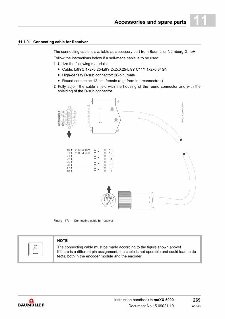
Accessories and spare parts 11
11.1.9.1 Connecting cable for ResolverThe connecting cable is available as accessory part from Baumüller Nürnberg GmbH.
Follow the instructions below if a self-made cable is to be used:
1 Utilize the following materials:
m Cable: Li9YC 1x2x0.25-Li9Y 2x2x0,25-Li9Y C11Y 1x2x0.34GN.
m High-density D-sub connector: 26-pin, male
m Round connector: 12-pin, female (e.g. from Interconnectron)
2 Fully adjoin the cable shield with the housing of the round connector and with theshielding of the D-sub connector.
Figure 117: Connecting cable for resolver
NOTE
The connecting cable must be made according to the figure shown above! If there is a different pin assignment, the cable is not operable and could lead to de-fects, both in the encoder module and the encoder!
Instruction handbook b maXX 5000
Document No.: 5.09021.19
269of 346
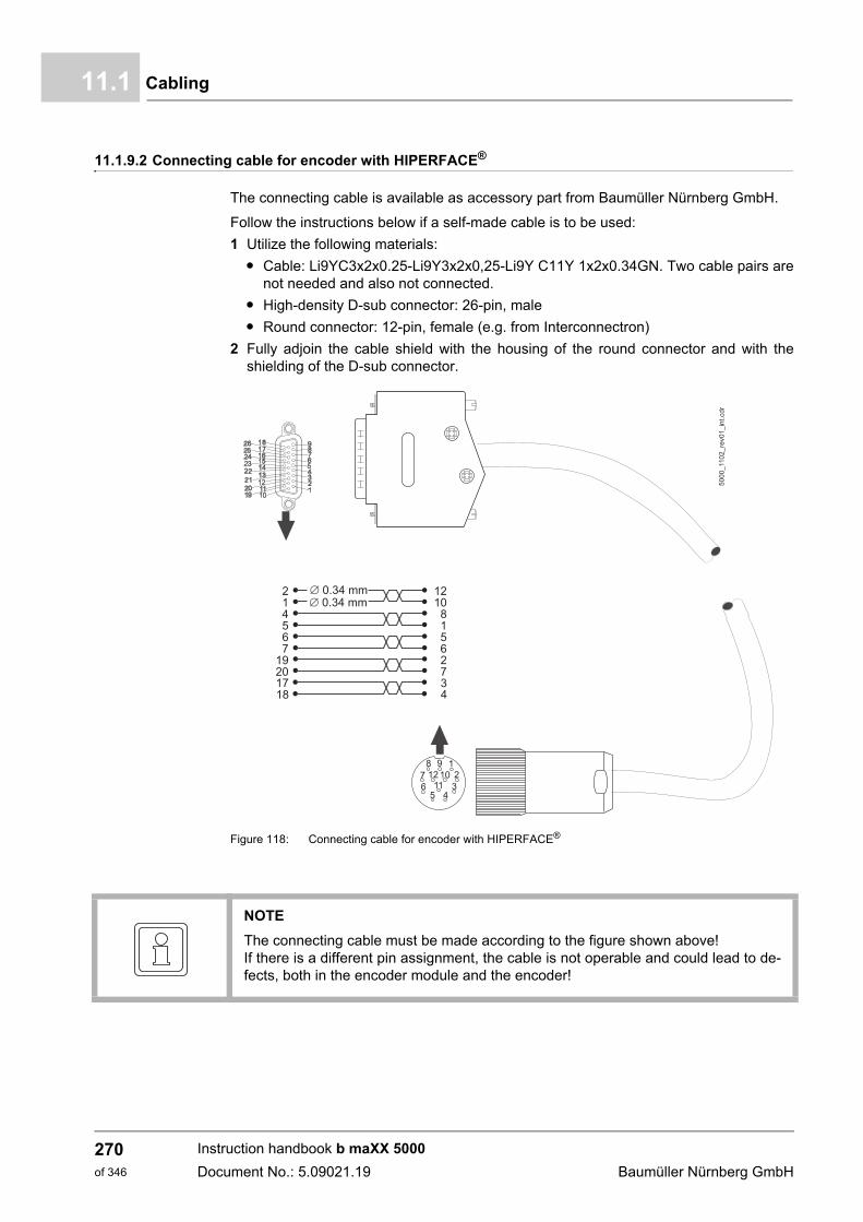
Cabling11.1
11.1.9.2 Connecting cable for encoder with HIPERFACE® .
The connecting cable is available as accessory part from Baumüller Nürnberg GmbH.
Follow the instructions below if a self-made cable is to be used:
1 Utilize the following materials:
m Cable: Li9YC3x2x0.25-Li9Y3x2x0,25-Li9Y C11Y 1x2x0.34GN. Two cable pairs arenot needed and also not connected.
m High-density D-sub connector: 26-pin, male
m Round connector: 12-pin, female (e.g. from Interconnectron)
2 Fully adjoin the cable shield with the housing of the round connector and with theshielding of the D-sub connector.
Figure 118: Connecting cable for encoder with HIPERFACE®
5000_1102_re
v01_in
t.cdr
21456
19201718
7
1210
815
2734
6
Æ 0.34 mmÆ 0.34 mm
NOTE
The connecting cable must be made according to the figure shown above! If there is a different pin assignment, the cable is not operable and could lead to de-fects, both in the encoder module and the encoder!
Instruction handbook b maXX 5000
Document No.: 5.09021.19 Baumüller Nürnberg GmbH
270of 346
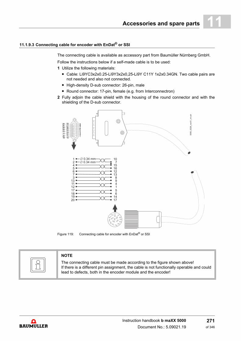
Accessories and spare parts 11
11.1.9.3 Connecting cable for encoder with EnDat® or SSIThe connecting cable is available as accessory part from Baumüller Nürnberg GmbH.
Follow the instructions below if a self-made cable is to be used:
1 Utilize the following materials:
m Cable: Li9YC3x2x0.25-Li9Y3x2x0,25-Li9Y C11Y 1x2x0.34GN. Two cable pairs arenot needed and also not connected.
m High-density D-sub connector: 26-pin, male
m Round connector: 17-pin, female (e.g. from Interconnectron)
2 Fully adjoin the cable shield with the housing of the round connector and with theshielding of the D-sub connector.
Figure 119: Connecting cable for encoder with EnDat® or SSI
NOTE
The connecting cable must be made according to the figure shown above! If there is a different pin assignment, the cable is not functionally operable and couldlead to defects, both in the encoder module and the encoder!
Instruction handbook b maXX 5000
Document No.: 5.09021.19
271of 346
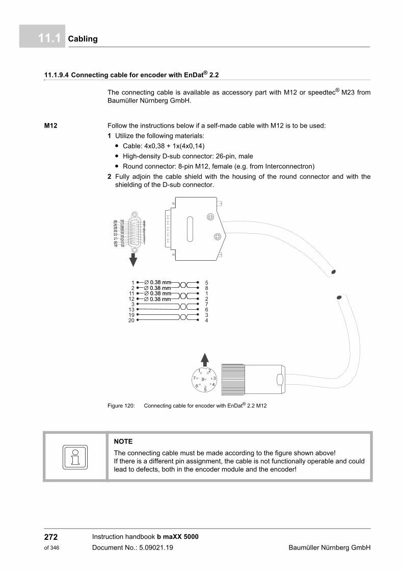
Cabling11.1
11.1.9.4 Connecting cable for encoder with EnDat® 2.2
The connecting cable is available as accessory part with M12 or speedtec® M23 fromBaumüller Nürnberg GmbH.
M12 Follow the instructions below if a self-made cable with M12 is to be used:
1 Utilize the following materials:
m Cable: 4x0,38 + 1x(4x0,14)
m High-density D-sub connector: 26-pin, male
m Round connector: 8-pin M12, female (e.g. from Interconnectron)
2 Fully adjoin the cable shield with the housing of the round connector and with theshielding of the D-sub connector.
Figure 120: Connecting cable for encoder with EnDat® 2.2 M12
NOTE
The connecting cable must be made according to the figure shown above! If there is a different pin assignment, the cable is not functionally operable and couldlead to defects, both in the encoder module and the encoder!
Instruction handbook b maXX 5000
Document No.: 5.09021.19 Baumüller Nürnberg GmbH
272of 346
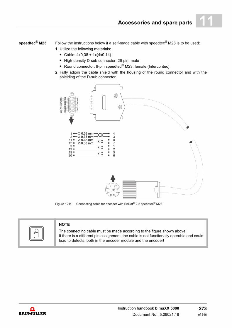
Accessories and spare parts 11
speedtec® M23 Follow the instructions below if a self-made cable with speedtec® M23 is to be used:1 Utilize the following materials:
m Cable: 4x0,38 + 1x(4x0,14)
m High-density D-sub connector: 26-pin, male
m Round connector: 9-pin speedtec® M23, female (Intercontec)
2 Fully adjoin the cable shield with the housing of the round connector and with theshielding of the D-sub connector.
Figure 121: Connecting cable for encoder with EnDat® 2.2 speedtec® M23
NOTE
The connecting cable must be made according to the figure shown above! If there is a different pin assignment, the cable is not functionally operable and couldlead to defects, both in the encoder module and the encoder!
Instruction handbook b maXX 5000
Document No.: 5.09021.19
273of 346
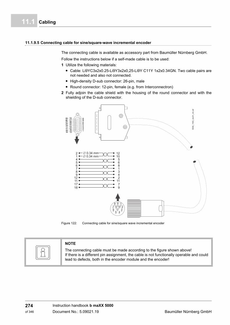
Cabling11.1
11.1.9.5 Connecting cable for sine/square-wave incremental encoder
The connecting cable is available as accessory part from Baumüller Nürnberg GmbH.
Follow the instructions below if a self-made cable is to be used:
1 Utilize the following materials:
m Cable: Li9YC3x2x0.25-Li9Y3x2x0,25-Li9Y C11Y 1x2x0.34GN. Two cable pairs arenot needed and also not connected.
m High-density D-sub connector: 26-pin, male
m Round connector: 12-pin, female (e.g. from Interconnectron)
2 Fully adjoin the cable shield with the housing of the round connector and with theshielding of the D-sub connector.
Figure 122: Connecting cable for sine/square wave incremental encoder
50
00
_11
03
_re
v0
1_
int.
cd
r
21456
89
12111718
7
1210
568
342
1179
1
Æ 0.34 mmÆ 0.34 mm
NOTE
The connecting cable must be made according to the figure shown above! If there is a different pin assignment, the cable is not functionally operable and couldlead to defects, both in the encoder module and the encoder!
Instruction handbook b maXX 5000
Document No.: 5.09021.19 Baumüller Nürnberg GmbH
274of 346
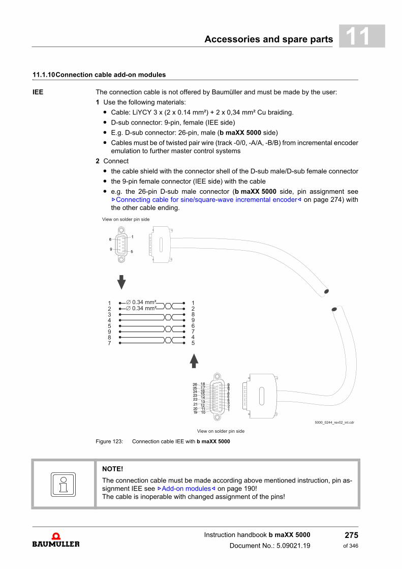
Accessories and spare parts 11
11.1.10Connection cable add-on modulesIEE The connection cable is not offered by Baumüller and must be made by the user:
1 Use the following materials:
m Cable: LiYCY 3 x (2 x 0.14 mm²) + 2 x 0,34 mm² Cu braiding.
m D-sub connector: 9-pin, female (IEE side)
m E.g. D-sub connector: 26-pin, male (b maXX 5000 side)
m Cables must be of twisted pair wire (track -0/0, -A/A, -B/B) from incremental encoderemulation to further master control systems
2 Connect
m the cable shield with the connector shell of the D-sub male/D-sub female connector
m the 9-pin female connector (IEE side) with the cable
m e.g. the 26-pin D-sub male connector (b maXX 5000 side, pin assignment seeZConnecting cable for sine/square-wave incremental encoder– on page 274) withthe other cable ending.
Figure 123: Connection cable IEE with b maXX 5000
NOTE!
The connection cable must be made according above mentioned instruction, pin as-signment IEE see ZAdd-on modules– on page 190! The cable is inoperable with changed assignment of the pins!
Instruction handbook b maXX 5000
Document No.: 5.09021.19
275of 346
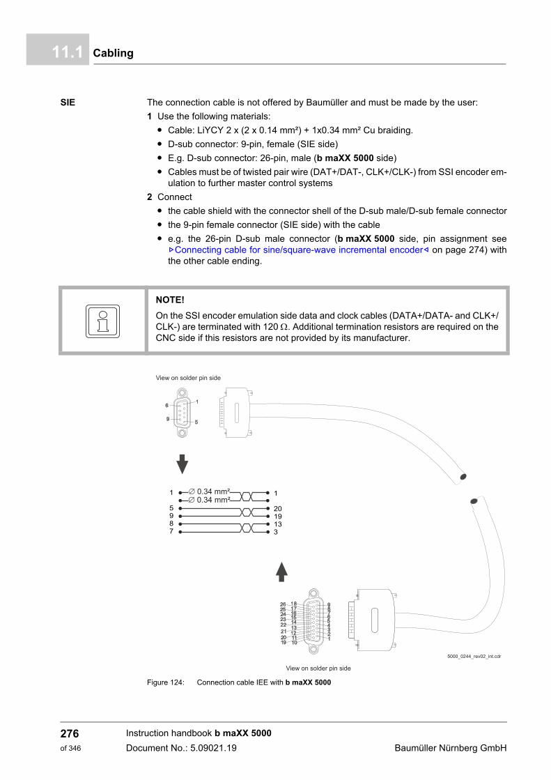
Cabling11.1
SIE The connection cable is not offered by Baumüller and must be made by the user:
1 Use the following materials:
m Cable: LiYCY 2 x (2 x 0.14 mm²) + 1x0.34 mm² Cu braiding.
m D-sub connector: 9-pin, female (SIE side)
m E.g. D-sub connector: 26-pin, male (b maXX 5000 side)
m Cables must be of twisted pair wire (DAT+/DAT-, CLK+/CLK-) from SSI encoder em-ulation to further master control systems
2 Connect
m the cable shield with the connector shell of the D-sub male/D-sub female connector
m the 9-pin female connector (SIE side) with the cable
m e.g. the 26-pin D-sub male connector (b maXX 5000 side, pin assignment seeZConnecting cable for sine/square-wave incremental encoder– on page 274) withthe other cable ending.
Figure 124: Connection cable IEE with b maXX 5000
NOTE!
On the SSI encoder emulation side data and clock cables (DATA+/DATA- and CLK+/CLK-) are terminated with 120 . Additional termination resistors are required on theCNC side if this resistors are not provided by its manufacturer.
1
5987
1
2019133
Instruction handbook b maXX 5000
Document No.: 5.09021.19 Baumüller Nürnberg GmbH
276of 346

Accessories and spare parts 11
11.2 FusesA distinction is made between protecting the power supply cables and protecting the de-vice. To fulfill CE specifications – here in particular EN 60204-1 – fuse the power supplycables.
Cable protection Use safety fuses of the operating class gL VDE 0636-201 / DIN EN 60269-2-1 / HD630.2.1 54 or circuit breaker triggering characteristic K, in accordance with VDE 0636-201/ DIN EN 60269-2-1 / HD 630.2.1 54, to protect the cable. These fuses protect againstoverloads and consequential damage from defects, for example as a result of fire. How-ever, they cannot prevent a device from being extensively destroyed in case of a short-circuit or ground fault in the DC link.
Carry out the fusing in accordance with EN 60204-1 („Electrical Equipment of Machines“).Dimension the cable fuse based on the cross-section of the power supply cable used, andin accordance with the respective applicable national standards and local regulations.
The current-carrying capacity of the cables is specified in Table 5 of EN 60204-1. For yourapplication, the corresponding value must still be determined based on the standard itself,i. e. taking into account the cable routing.
NOTE!
Approved, UL-listed safety fuses must be used in UL-authorized systems, refer toZUL notes– as from page 94.
NOTE!
Use suitable fuses with the tripping characteristic gL or gR.
NOTE!
The BM50XX is protected in case of overload because the device limits the outputcurrent. This can be considered when dimensioning the cable protection fuses.
Instruction handbook b maXX 5000
Document No.: 5.09021.19
277of 346
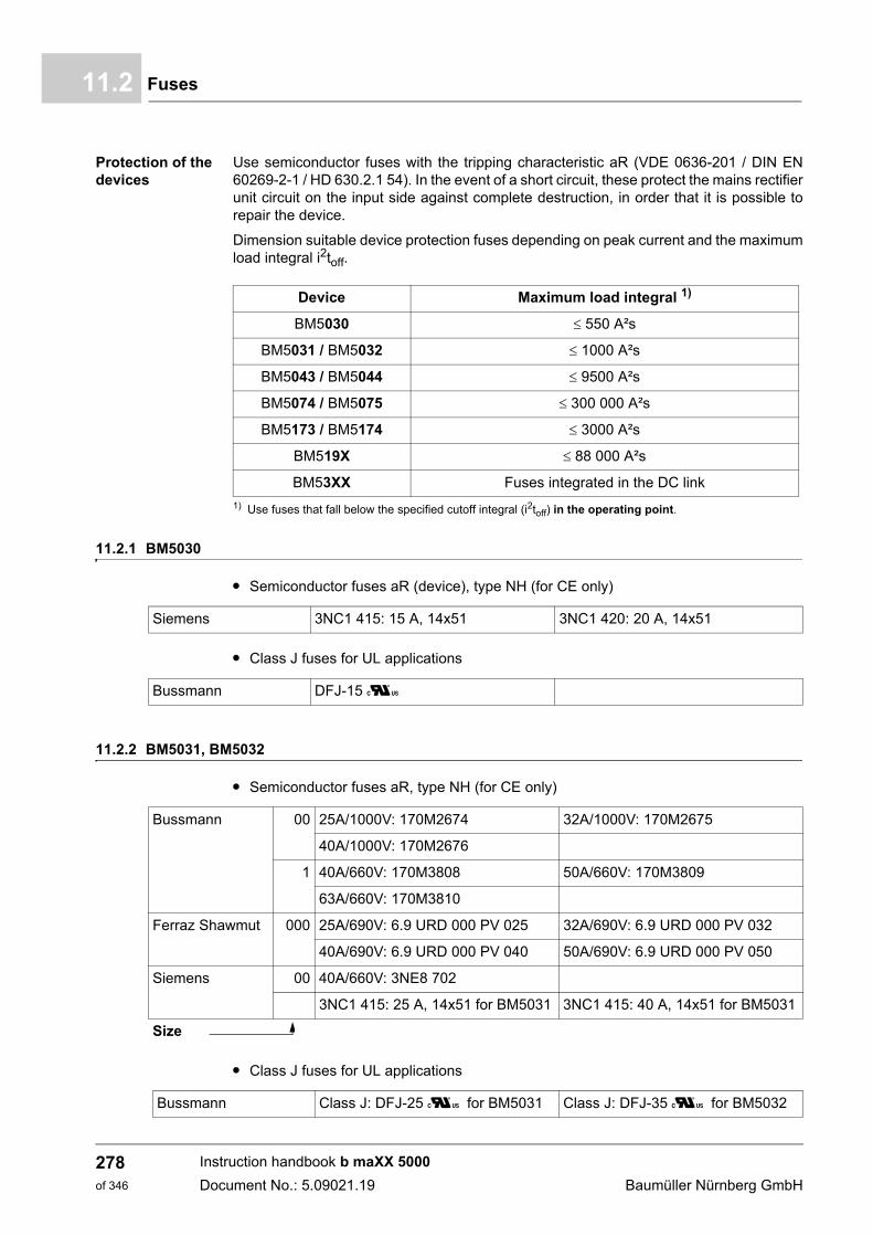
Fuses11.2
Protection of the devices
Use semiconductor fuses with the tripping characteristic aR (VDE 0636-201 / DIN EN60269-2-1 / HD 630.2.1 54). In the event of a short circuit, these protect the mains rectifierunit circuit on the input side against complete destruction, in order that it is possible torepair the device.
Dimension suitable device protection fuses depending on peak current and the maximumload integral i2toff.
1) Use fuses that fall below the specified cutoff integral (i2toff) in the operating point.
11.2.1 BM5030
m Semiconductor fuses aR (device), type NH (for CE only)
m Class J fuses for UL applications
11.2.2 BM5031, BM5032
m Semiconductor fuses aR, type NH (for CE only)
m Class J fuses for UL applications
Device Maximum load integral 1)
BM5030 550 A²s
BM5031 / BM5032 1000 A²s
BM5043 / BM5044 9500 A²s
BM5074 / BM5075 300 000 A²s
BM5173 / BM5174 3000 A²s
BM519X 88 000 A²s
BM53XX Fuses integrated in the DC link
Siemens 3NC1 415: 15 A, 14x51 3NC1 420: 20 A, 14x51
Bussmann DFJ-15 U
Bussmann 00 25A/1000V: 170M2674 32A/1000V: 170M2675
40A/1000V: 170M2676
1 40A/660V: 170M3808 50A/660V: 170M3809
63A/660V: 170M3810
Ferraz Shawmut 000 25A/690V: 6.9 URD 000 PV 025 32A/690V: 6.9 URD 000 PV 032
40A/690V: 6.9 URD 000 PV 040 50A/690V: 6.9 URD 000 PV 050
Siemens 00 40A/660V: 3NE8 702
3NC1 415: 25 A, 14x51 for BM5031 3NC1 415: 40 A, 14x51 for BM5031
Size
Bussmann Class J: DFJ-25 U for BM5031 Class J: DFJ-35 U for BM5032
Instruction handbook b maXX 5000
Document No.: 5.09021.19 Baumüller Nürnberg GmbH
278of 346
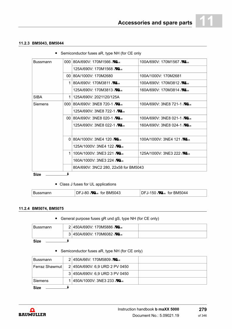
Accessories and spare parts 11
11.2.3 BM5043, BM5044m Semiconductor fuses aR, type NH (for CE only
m Class J fuses for UL applications
11.2.4 BM5074, BM5075
m General purpose fuses gR und gS, type NH (for CE only)
m Semiconductor fuses aR, type NH (for CE only)
Bussmann 000 80A/690V: 170M1566 U 100A/690V: 170M1567 U
125A/690V: 170M1568 U
00 80A/1000V: 170M2680 100A/1000V: 170M2681
1 80A/690V: 170M3811 U 100A/690V: 170M3812 U
125A/690V: 170M3813 U 160A/690V: 170M3814 U
SIBA 1 125A/690V: 2021120/125A
Siemens 000 80A/690V: 3NE8 720-1 U 100A/690V: 3NE8 721-1 U
125A/690V: 3NE8 722-1 U
00 80A/690V: 3NE8 020-1 U 100A/690V: 3NE8 021-1 U
125A/690V: 3NE8 022-1 U 160A/690V: 3NE8 024-1 U
0 80A/1000V: 3NE4 120 U 100A/1000V: 3NE4 121 U
125A/1000V: 3NE4 122 U
1 100A/1000V: 3NE3 221 U 125A/1000V: 3NE3 222 U
160A/1000V: 3NE3 224 U
80A/690V: 3NC2 280, 22x58 for BM5043
Size
Bussmann DFJ-80 U for BM5043 DFJ-150 U for BM5044
Bussmann 2 450A/690V: 170M5886 U
3 450A/690V: 170M6082 U
Size
Bussmann 2 450A/66V: 170M5809 U
Ferraz Shawmut 2 450A/690V: 6,9 URD 2 PV 0450
3 450A/690V: 6,9 URD 3 PV 0450
Siemens 1 450A/1000V: 3NE3 233 U
Size
Instruction handbook b maXX 5000
Document No.: 5.09021.19
279of 346
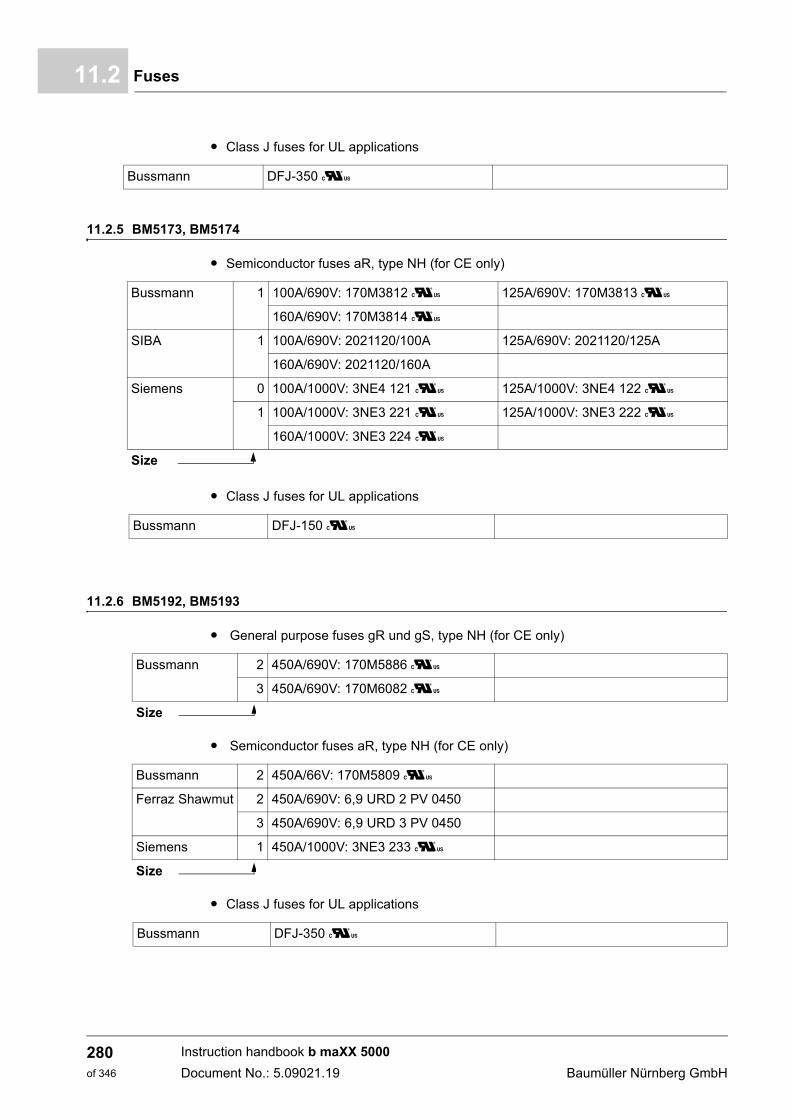
Fuses11.2
m Class J fuses for UL applications
11.2.5 BM5173, BM5174
m Semiconductor fuses aR, type NH (for CE only)
m Class J fuses for UL applications
11.2.6 BM5192, BM5193
m General purpose fuses gR und gS, type NH (for CE only)
m Semiconductor fuses aR, type NH (for CE only)
m Class J fuses for UL applications
Bussmann DFJ-350 U
Bussmann 1 100A/690V: 170M3812 U 125A/690V: 170M3813 U
160A/690V: 170M3814 U
SIBA 1 100A/690V: 2021120/100A 125A/690V: 2021120/125A
160A/690V: 2021120/160A
Siemens 0 100A/1000V: 3NE4 121 U 125A/1000V: 3NE4 122 U
1 100A/1000V: 3NE3 221 U 125A/1000V: 3NE3 222 U
160A/1000V: 3NE3 224 U
Size
Bussmann DFJ-150 U
Bussmann 2 450A/690V: 170M5886 U
3 450A/690V: 170M6082 U
Size
Bussmann 2 450A/66V: 170M5809 U
Ferraz Shawmut 2 450A/690V: 6,9 URD 2 PV 0450
3 450A/690V: 6,9 URD 3 PV 0450
Siemens 1 450A/1000V: 3NE3 233 U
Size
Bussmann DFJ-350 U
Instruction handbook b maXX 5000
Document No.: 5.09021.19 Baumüller Nürnberg GmbH
280of 346
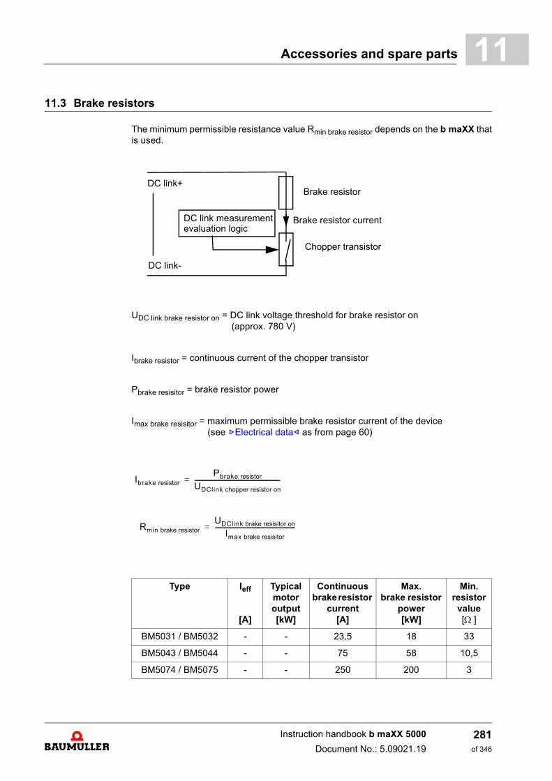
Accessories and spare parts 11
11.3 Brake resistorsThe minimum permissible resistance value Rmin brake resistor depends on the b maXX thatis used.
UDC link brake resistor on = DC link voltage threshold for brake resistor on (approx. 780 V)
Ibrake resistor = continuous current of the chopper transistor
Pbrake resisitor = brake resistor power
Imax brake resisitor = maximum permissible brake resistor current of the device (see ZElectrical data– as from page 60)
Type Ieff
[A]
Typical motor output [kW]
Continuous brake resistor
current[A]
Max. brake resistor
power[kW]
Min. resistor
value[ ]
BM5031 / BM5032 - - 23,5 18 33
BM5043 / BM5044 - - 75 58 10,5
BM5074 / BM5075 - - 250 200 3
Brake resistor
Chopper transistor
Brake resistor current
DC link+
DC link-
DC link measurement evaluation logic
Ibrake resistorPbrake resistor
UDClink chopper resistor on
-------------------------------------------------------=
Rmin brake resistorUDClink brake resisitor on
Imax brake resisitor
----------------------------------------------------=
Instruction handbook b maXX 5000
Document No.: 5.09021.19
281of 346
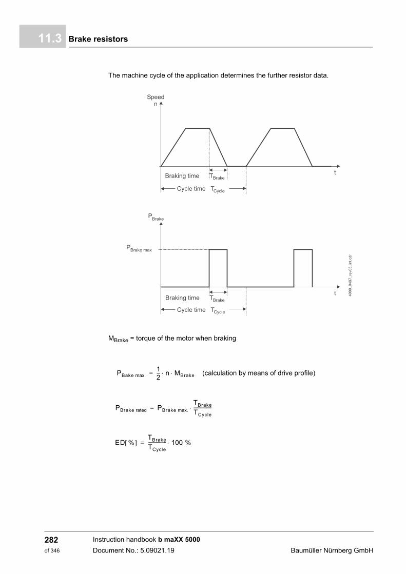
Brake resistors11.3
The machine cycle of the application determines the further resistor data.
MBrake = torque of the motor when braking
PBake max.12--- n MBrake (calculation by means of drive profile) =
PBrake rated PBrake max.
TBrake
TCycle
----------------=
ED % TBrake
TCycle
---------------- 100 %=
Instruction handbook b maXX 5000
Document No.: 5.09021.19 Baumüller Nürnberg GmbH
282of 346
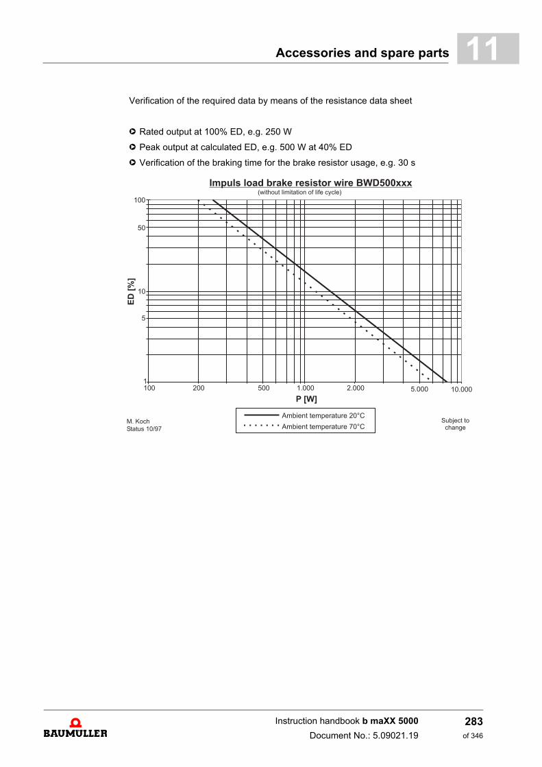
Accessories and spare parts 11
Verification of the required data by means of the resistance data sheeth Rated output at 100% ED, e.g. 250 W
h Peak output at calculated ED, e.g. 500 W at 40% ED
h Verification of the braking time for the brake resistor usage, e.g. 30 s
Instruction handbook b maXX 5000
Document No.: 5.09021.19
283of 346
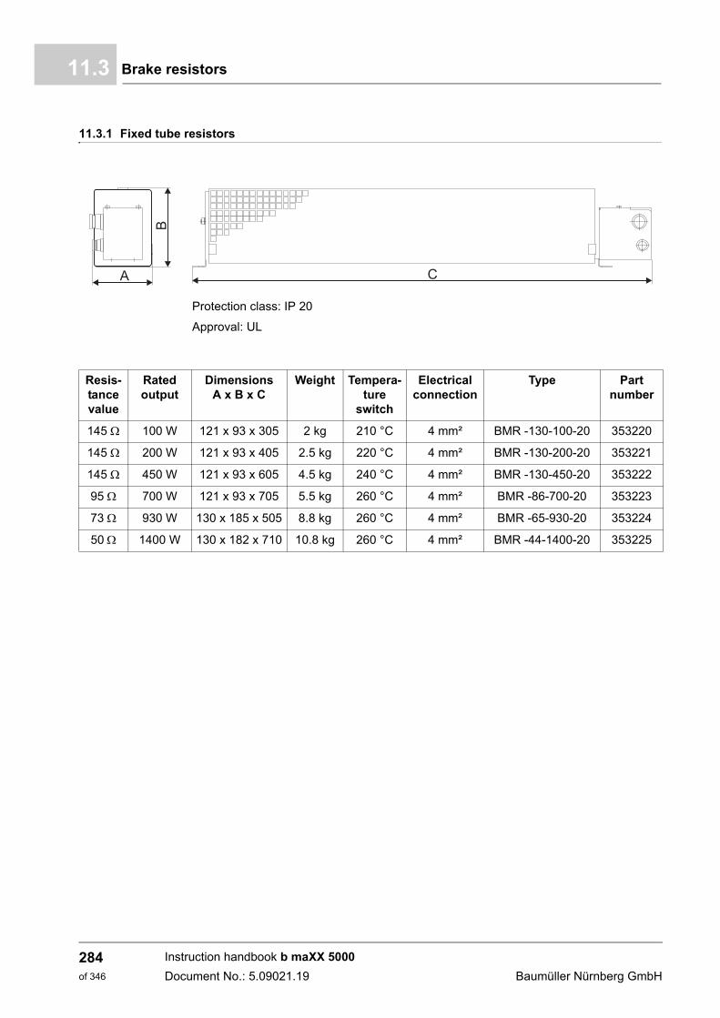
Brake resistors11.3
11.3.1 Fixed tube resistors
Protection class: IP 20
Approval: UL
Resis-tance value
Rated output
DimensionsA x B x C
Weight Tempera-ture
switch
Electrical connection
Type Part number
145 100 W 121 x 93 x 305 2 kg 210 °C 4 mm² BMR -130-100-20 353220
145 200 W 121 x 93 x 405 2.5 kg 220 °C 4 mm² BMR -130-200-20 353221
145 450 W 121 x 93 x 605 4.5 kg 240 °C 4 mm² BMR -130-450-20 353222
95 700 W 121 x 93 x 705 5.5 kg 260 °C 4 mm² BMR -86-700-20 353223
73 930 W 130 x 185 x 505 8.8 kg 260 °C 4 mm² BMR -65-930-20 353224
50 1400 W 130 x 182 x 710 10.8 kg 260 °C 4 mm² BMR -44-1400-20 353225
Instruction handbook b maXX 5000
Document No.: 5.09021.19 Baumüller Nürnberg GmbH
284of 346
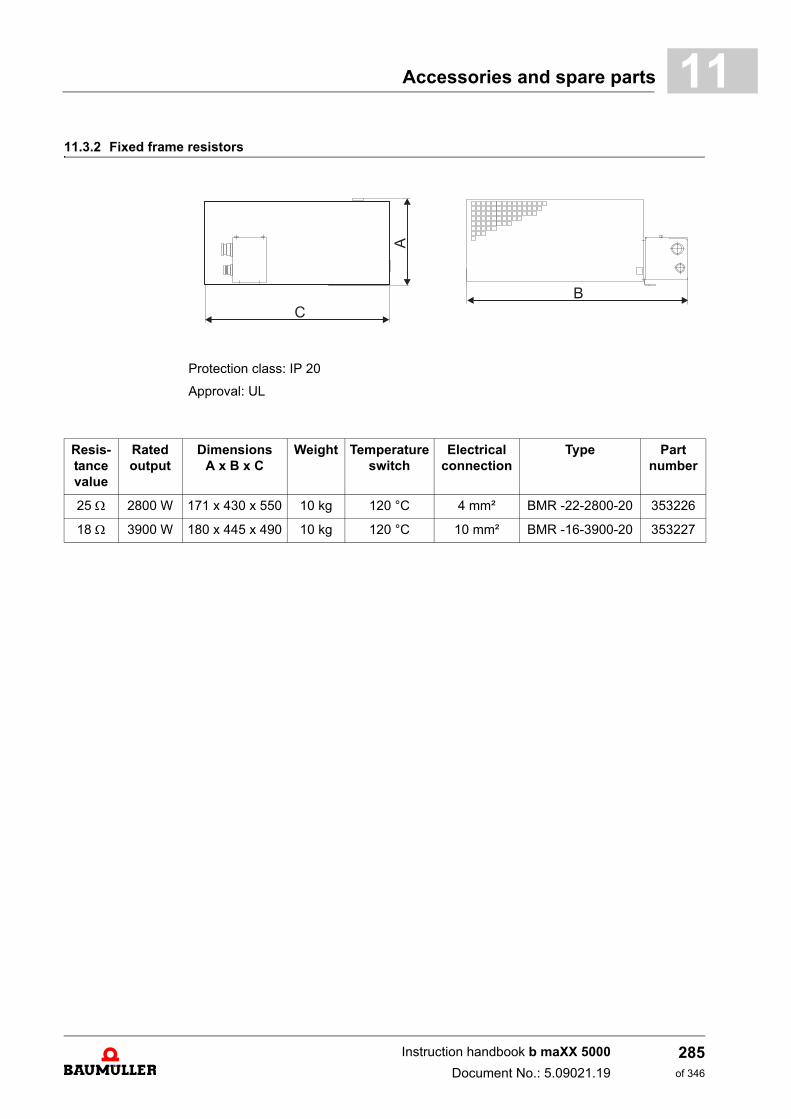
Accessories and spare parts 11
11.3.2 Fixed frame resistorsProtection class: IP 20
Approval: UL
Resis-tance value
Rated output
DimensionsA x B x C
Weight Temperature switch
Electrical connection
Type Part number
25 2800 W 171 x 430 x 550 10 kg 120 °C 4 mm² BMR -22-2800-20 353226
18 3900 W 180 x 445 x 490 10 kg 120 °C 10 mm² BMR -16-3900-20 353227
Instruction handbook b maXX 5000
Document No.: 5.09021.19
285of 346
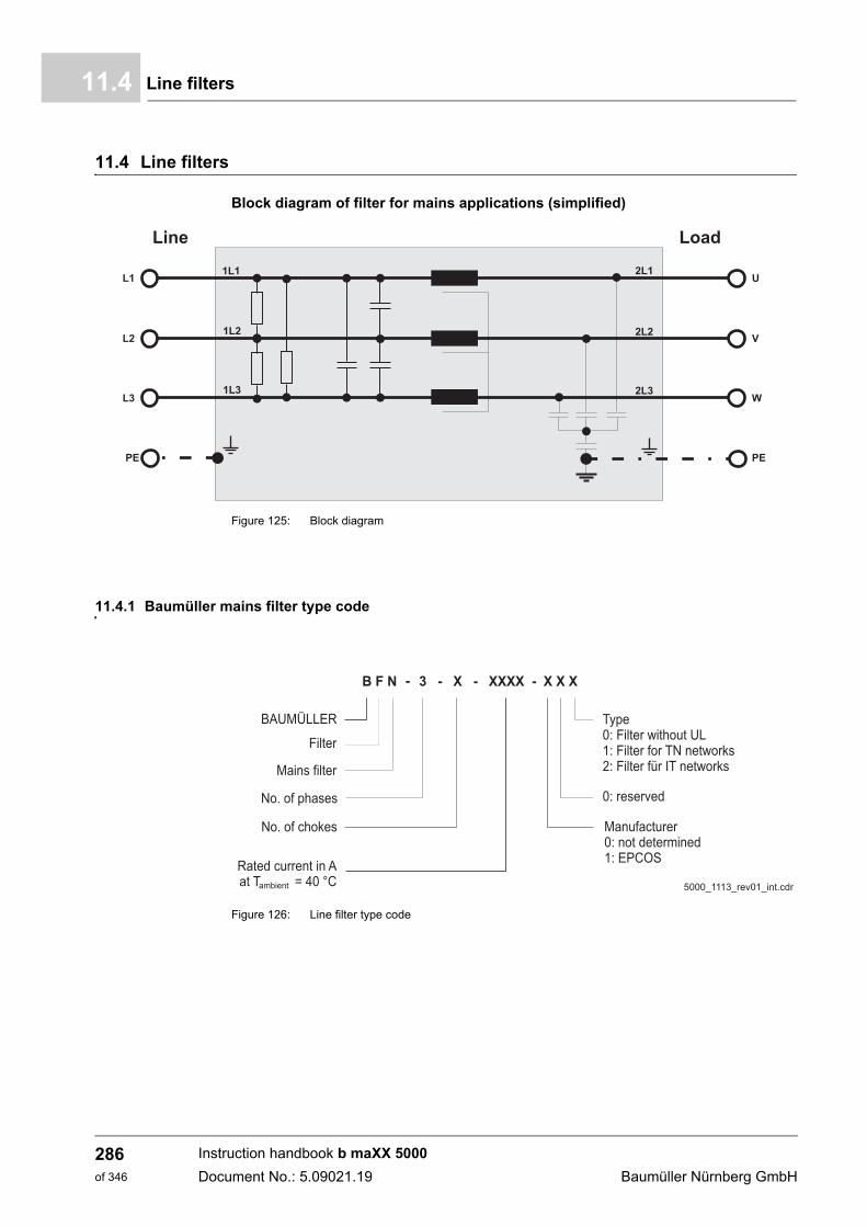
Line filters11.4
11.4 Line filters
Block diagram of filter for mains applications (simplified)
Figure 125: Block diagram
11.4.1 Baumüller mains filter type code
Figure 126: Line filter type code
Instruction handbook b maXX 5000
Document No.: 5.09021.19 Baumüller Nürnberg GmbH
286of 346
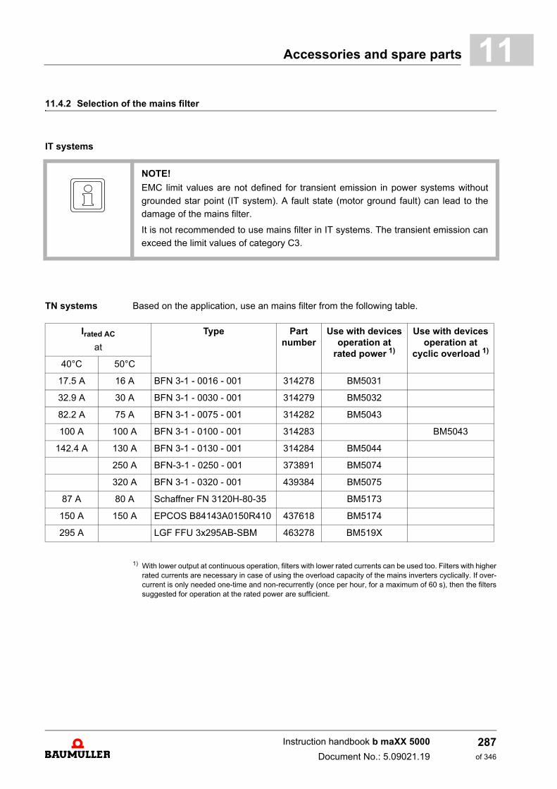
Accessories and spare parts 11
11.4.2 Selection of the mains filterIT systems
TN systems Based on the application, use an mains filter from the following table.
1) With lower output at continuous operation, filters with lower rated currents can be used too. Filters with higherrated currents are necessary in case of using the overload capacity of the mains inverters cyclically. If over-current is only needed one-time and non-recurrently (once per hour, for a maximum of 60 s), then the filterssuggested for operation at the rated power are sufficient.
NOTE!
EMC limit values are not defined for transient emission in power systems without
grounded star point (IT system). A fault state (motor ground fault) can lead to the
damage of the mains filter.
It is not recommended to use mains filter in IT systems. The transient emission can
exceed the limit values of category C3.
Irated AC
at
Type Part number
Use with devices operation at
rated power 1)
Use with devices operation at
cyclic overload 1)
40°C 50°C
17.5 A 16 A BFN 3-1 - 0016 - 001 314278 BM5031
32.9 A 30 A BFN 3-1 - 0030 - 001 314279 BM5032
82.2 A 75 A BFN 3-1 - 0075 - 001 314282 BM5043
100 A 100 A BFN 3-1 - 0100 - 001 314283 BM5043
142.4 A 130 A BFN 3-1 - 0130 - 001 314284 BM5044
250 A BFN-3-1 - 0250 - 001 373891 BM5074
320 A BFN 3-1 - 0320 - 001 439384 BM5075
87 A 80 A Schaffner FN 3120H-80-35 BM5173
150 A 150 A EPCOS B84143A0150R410 437618 BM5174
295 A LGF FFU 3x295AB-SBM 463278 BM519X
Instruction handbook b maXX 5000
Document No.: 5.09021.19
287of 346
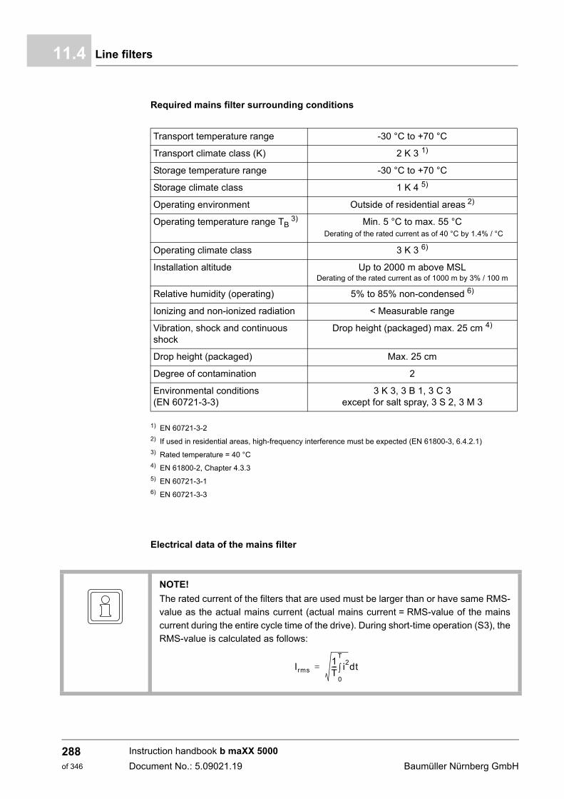
Line filters11.4
Required mains filter surrounding conditions
1) EN 60721-3-22) If used in residential areas, high-frequency interference must be expected (EN 61800-3, 6.4.2.1)3) Rated temperature = 40 °C4) EN 61800-2, Chapter 4.3.35) EN 60721-3-16) EN 60721-3-3
Electrical data of the mains filter
Transport temperature range -30 °C to +70 °C
Transport climate class (K) 2 K 3 1)
Storage temperature range -30 °C to +70 °C
Storage climate class 1 K 4 5)
Operating environment Outside of residential areas 2)
Operating temperature range TB 3) Min. 5 °C to max. 55 °C
Derating of the rated current as of 40 °C by 1.4% / °C
Operating climate class 3 K 3 6)
Installation altitude Up to 2000 m above MSLDerating of the rated current as of 1000 m by 3% / 100 m
Relative humidity (operating) 5% to 85% non-condensed 6)
Ionizing and non-ionized radiation < Measurable range
Vibration, shock and continuous shock
Drop height (packaged) max. 25 cm 4)
Drop height (packaged) Max. 25 cm
Degree of contamination 2
Environmental conditions (EN 60721-3-3)
3 K 3, 3 B 1, 3 C 3 except for salt spray, 3 S 2, 3 M 3
NOTE!
The rated current of the filters that are used must be larger than or have same RMS-
value as the actual mains current (actual mains current = RMS-value of the mains
current during the entire cycle time of the drive). During short-time operation (S3), the
RMS-value is calculated as follows:
Irms1T--- i2
0
T
dt=
Instruction handbook b maXX 5000
Document No.: 5.09021.19 Baumüller Nürnberg GmbH
288of 346
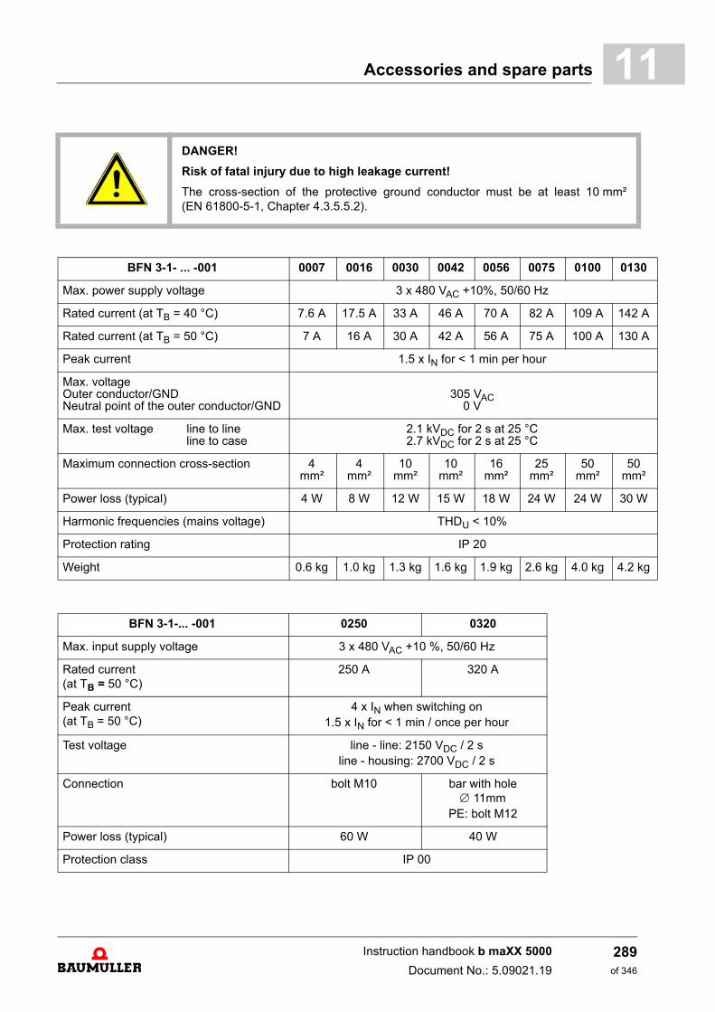
Accessories and spare parts 11
DANGER!
Risk of fatal injury due to high leakage current!
The cross-section of the protective ground conductor must be at least 10 mm²(EN 61800-5-1, Chapter 4.3.5.5.2).
BFN 3-1- ... -001 0007 0016 0030 0042 0056 0075 0100 0130
Max. power supply voltage 3 x 480 VAC +10%, 50/60 Hz
Rated current (at TB = 40 °C) 7.6 A 17.5 A 33 A 46 A 70 A 82 A 109 A 142 A
Rated current (at TB = 50 °C) 7 A 16 A 30 A 42 A 56 A 75 A 100 A 130 A
Peak current 1.5 x IN for < 1 min per hour
Max. voltageOuter conductor/GNDNeutral point of the outer conductor/GND
305 VAC0 V
Max. test voltage line to lineline to case
2.1 kVDC for 2 s at 25 °C2.7 kVDC for 2 s at 25 °C
Maximum connection cross-section 4 mm²
4 mm²
10 mm²
10 mm²
16 mm²
25 mm²
50 mm²
50 mm²
Power loss (typical) 4 W 8 W 12 W 15 W 18 W 24 W 24 W 30 W
Harmonic frequencies (mains voltage) THDU < 10%
Protection rating IP 20
Weight 0.6 kg 1.0 kg 1.3 kg 1.6 kg 1.9 kg 2.6 kg 4.0 kg 4.2 kg
BFN 3-1-... -001 0250 0320
Max. input supply voltage 3 x 480 VAC +10 %, 50/60 Hz
Rated current (at TB = 50 °C)
250 A 320 A
Peak current (at TB = 50 °C)
4 x IN when switching on1.5 x IN for < 1 min / once per hour
Test voltage line - line: 2150 VDC / 2 sline - housing: 2700 VDC / 2 s
Connection bolt M10 bar with hole 11mm
PE: bolt M12
Power loss (typical) 60 W 40 W
Protection class IP 00
Instruction handbook b maXX 5000
Document No.: 5.09021.19
289of 346
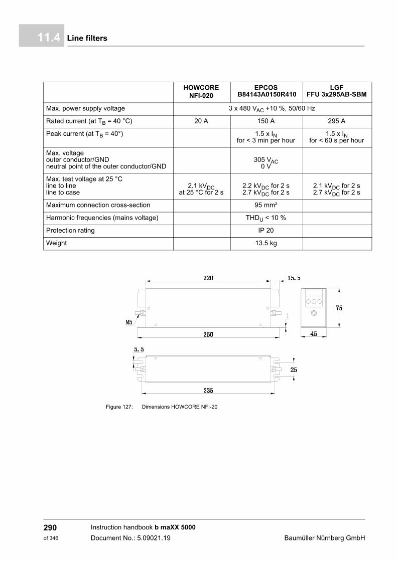
Line filters11.4
Figure 127: Dimensions HOWCORE NFI-20
HOWCORE NFI-020
EPCOS B84143A0150R410
LGF FFU 3x295AB-SBM
Max. power supply voltage 3 x 480 VAC +10 %, 50/60 Hz
Rated current (at TB = 40 °C) 20 A 150 A 295 A
Peak current (at TB = 40°) 1.5 x IN for < 3 min per hour
1.5 x IN for < 60 s per hour
Max. voltageouter conductor/GNDneutral point of the outer conductor/GND
305 VAC0 V
Max. test voltage at 25 °Cline to lineline to case
2.1 kVDC at 25 °C for 2 s
2.2 kVDC for 2 s 2.7 kVDC for 2 s
2.1 kVDC for 2 s2.7 kVDC for 2 s
Maximum connection cross-section 95 mm²
Harmonic frequencies (mains voltage) THDU < 10 %
Protection rating IP 20
Weight 13.5 kg
Instruction handbook b maXX 5000
Document No.: 5.09021.19 Baumüller Nürnberg GmbH
290of 346
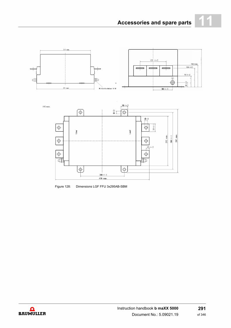
Accessories and spare parts 11
Figure 128: Dimensions LGF FFU 3x295AB-SBM
192 max.
���������
104 +/-2
70 +/- 2
192 max.
Instruction handbook b maXX 5000
Document No.: 5.09021.19
291of 346
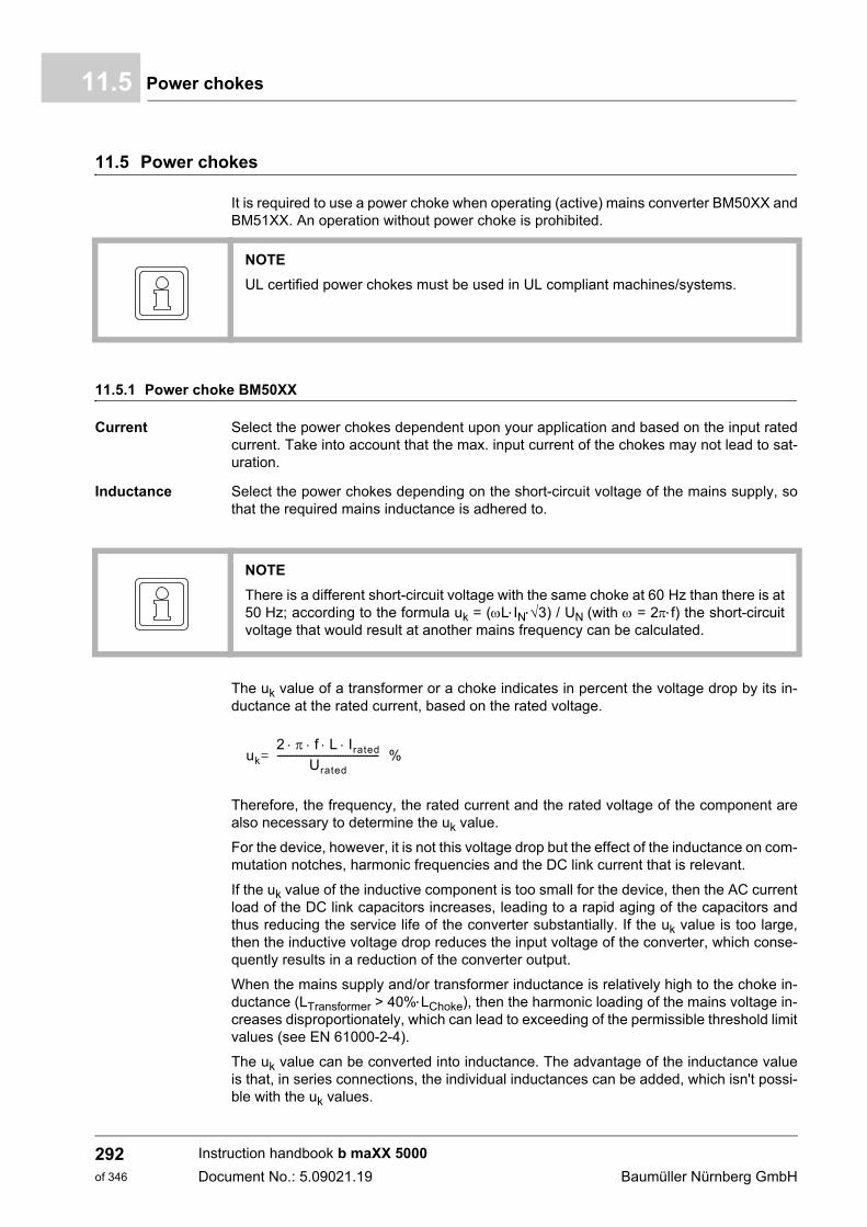
Power chokes11.5
11.5 Power chokes
It is required to use a power choke when operating (active) mains converter BM50XX andBM51XX. An operation without power choke is prohibited.
11.5.1 Power choke BM50XX
Current Select the power chokes dependent upon your application and based on the input ratedcurrent. Take into account that the max. input current of the chokes may not lead to sat-uration.
Inductance Select the power chokes depending on the short-circuit voltage of the mains supply, sothat the required mains inductance is adhered to.
The uk value of a transformer or a choke indicates in percent the voltage drop by its in-ductance at the rated current, based on the rated voltage.
Therefore, the frequency, the rated current and the rated voltage of the component arealso necessary to determine the uk value.
For the device, however, it is not this voltage drop but the effect of the inductance on com-mutation notches, harmonic frequencies and the DC link current that is relevant.
If the uk value of the inductive component is too small for the device, then the AC currentload of the DC link capacitors increases, leading to a rapid aging of the capacitors andthus reducing the service life of the converter substantially. If the uk value is too large,then the inductive voltage drop reduces the input voltage of the converter, which conse-quently results in a reduction of the converter output.
When the mains supply and/or transformer inductance is relatively high to the choke in-ductance (LTransformer > 40%LChoke), then the harmonic loading of the mains voltage in-creases disproportionately, which can lead to exceeding of the permissible threshold limitvalues (see EN 61000-2-4).
The uk value can be converted into inductance. The advantage of the inductance valueis that, in series connections, the individual inductances can be added, which isn't possi-ble with the uk values.
NOTE
UL certified power chokes must be used in UL compliant machines/systems.
NOTE
There is a different short-circuit voltage with the same choke at 60 Hz than there is at50 Hz; according to the formula uk = (LIN3) / UN (with = 2f) the short-circuitvoltage that would result at another mains frequency can be calculated.
uk
2 f L Irated Urated
------------------------------------------ %=
Instruction handbook b maXX 5000
Document No.: 5.09021.19 Baumüller Nürnberg GmbH
292of 346
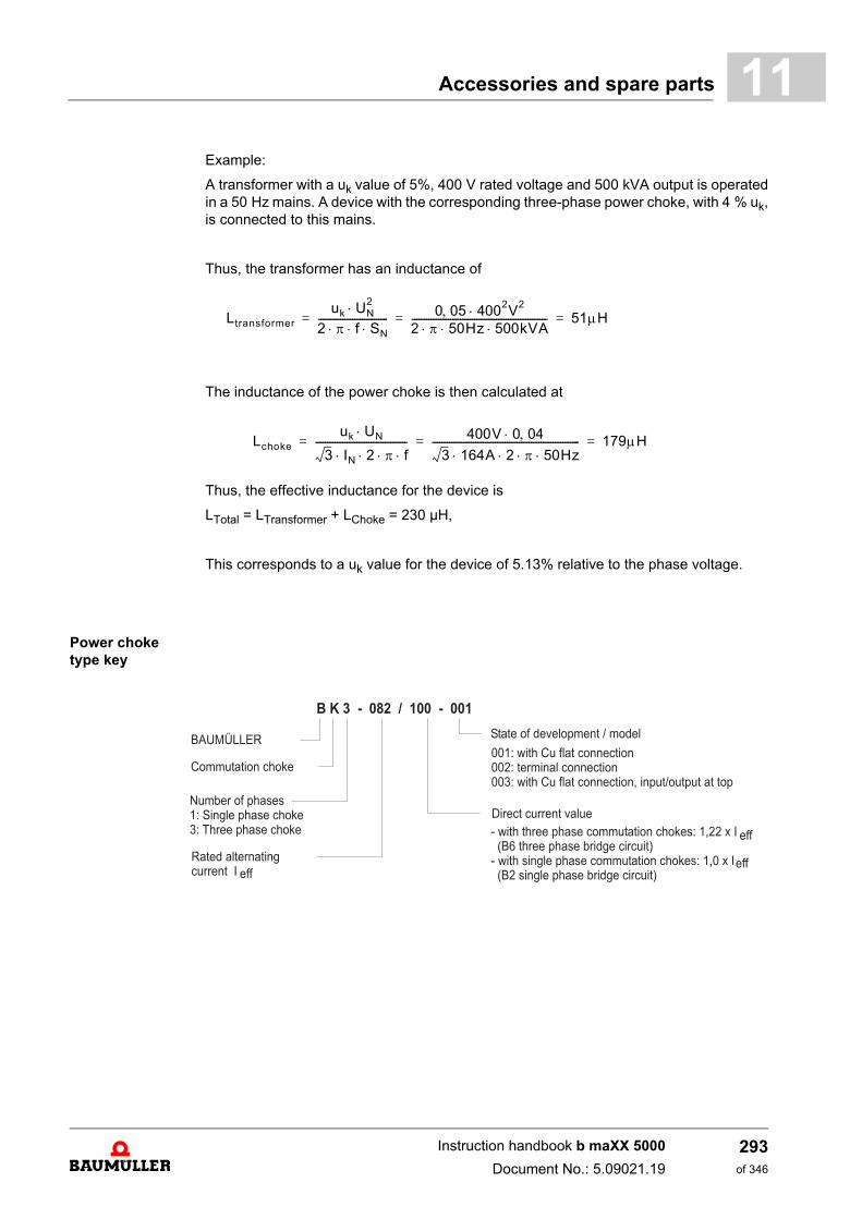
Accessories and spare parts 11
Example:A transformer with a uk value of 5%, 400 V rated voltage and 500 kVA output is operatedin a 50 Hz mains. A device with the corresponding three-phase power choke, with 4 % uk,is connected to this mains.
Thus, the transformer has an inductance of
The inductance of the power choke is then calculated at
Thus, the effective inductance for the device is
LTotal = LTransformer + LChoke = 230 µH,
This corresponds to a uk value for the device of 5.13% relative to the phase voltage.
Power choke type key
Ltransformeruk UN
22 f SN ----------------------------- 0 05 4002V2
2 50Hz 500kVA -------------------------------------------------------- 51H= = =
Lchokeuk UN
3 IN 2 f -------------------------------------- 400V 0 04
3 164A 2 50Hz ------------------------------------------------------------- 179H= = =
Instruction handbook b maXX 5000
Document No.: 5.09021.19
293of 346
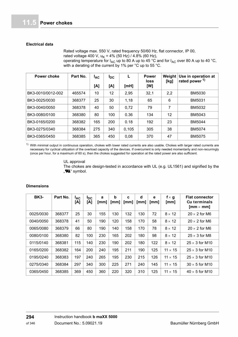
Power chokes11.5
Electrical data
Rated voltage max. 550 V, rated frequency 50/60 Hz, flat connector, IP 00, rated voltage 400 V, uK = 4% (50 Hz) / 4.8% (60 Hz), operating temperature for IAC up to 80 A up to 45 °C and for IAC over 80 A up to 40 °C, with a derating of the current by 1% per °C up to 55 °C.
1) With minimal output in continuous operation, chokes with lower rated currents are also usable. Chokes with larger rated currents arenecessary for cyclical utilization of the overload capacity of the devices. If overcurrent is only needed momentarily and non-recurringly(once per hour, for a maximum of 60 s), then the chokes suggested for operation at the rated power are also sufficient.
UL approvalThe chokes are design-tested in accordance with UL (e.g. UL1561) and signified by the„ú“ “ symbol.
Dimensions
Power choke Part No. IAC
[A]
IDC
[A]
L
[mH]
Power loss [W]
Weight [kg]
Use in operation at rated power 1)
BK3-0010/0012-002 465574 10 12 2,95 32,1 2,2 BM5030
BK3-0025/0030 368377 25 30 1,18 65 6 BM5031
BK3-0040/0050 368378 40 50 0,72 79 7 BM5032
BK3-0080/0100 368380 80 100 0.36 134 12 BM5043
BK3-0165/0200 368382 165 200 0.18 192 23 BM5044
BK3-0275/0340 368384 275 340 0,105 305 38 BM5074
BK3-0365/0450 368385 365 450 0,08 370 47 BM5075
BK3- Part No. IAC [A]
IDC [A]
a[mm]
b[mm]
c[mm]
d[mm]
e[mm]
f g[mm]
Flat connectorCu terminals[mm mm]
0025/0030 368377 25 30 155 130 132 130 72 8 12 20 2 for M6
0040/0050 368378 41 50 190 120 158 170 58 8 12 20 2 for M6
0065/0080 368379 66 80 190 140 158 170 78 8 12 20 2 for M6
0080/0100 368380 82 100 230 165 202 180 98 8 12 25 3 for M8
0115/0140 368381 115 140 230 190 202 180 122 8 12 25 3 for M10
0165/0200 368382 164 200 240 195 211 190 125 11 15 25 3 for M10
0195/0240 368383 197 240 265 195 230 215 126 11 15 25 3 for M10
0275/0340 368384 297 340 300 225 271 240 145 11 15 30 5 for M10
0365/0450 368385 369 450 360 220 320 310 125 11 15 40 5 for M10
Instruction handbook b maXX 5000
Document No.: 5.09021.19 Baumüller Nürnberg GmbH
294of 346
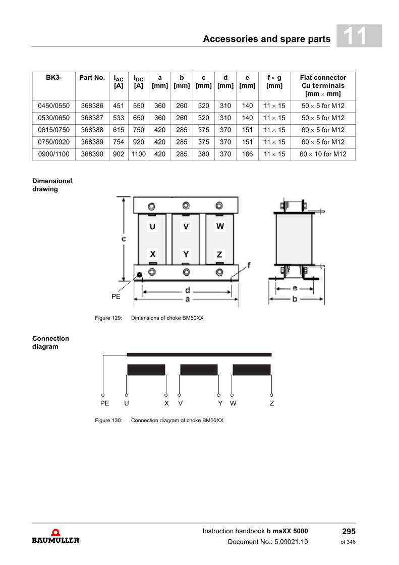
Accessories and spare parts 11
Dimensional drawing
Figure 129: Dimensions of choke BM50XX
Connection diagram
Figure 130: Connection diagram of choke BM50XX
0450/0550 368386 451 550 360 260 320 310 140 11 15 50 5 for M12
0530/0650 368387 533 650 360 260 320 310 140 11 15 50 5 for M12
0615/0750 368388 615 750 420 285 375 370 151 11 15 60 5 for M12
0750/0920 368389 754 920 420 285 375 370 151 11 15 60 5 for M12
0900/1100 368390 902 1100 420 285 380 370 166 11 15 60 10 for M12
BK3- Part No. IAC [A]
IDC [A]
a[mm]
b[mm]
c[mm]
d[mm]
e[mm]
f g[mm]
Flat connectorCu terminals[mm mm]
U V W
X Y Z
PE
PE U X V Y W Z
Instruction handbook b maXX 5000
Document No.: 5.09021.19
295of 346
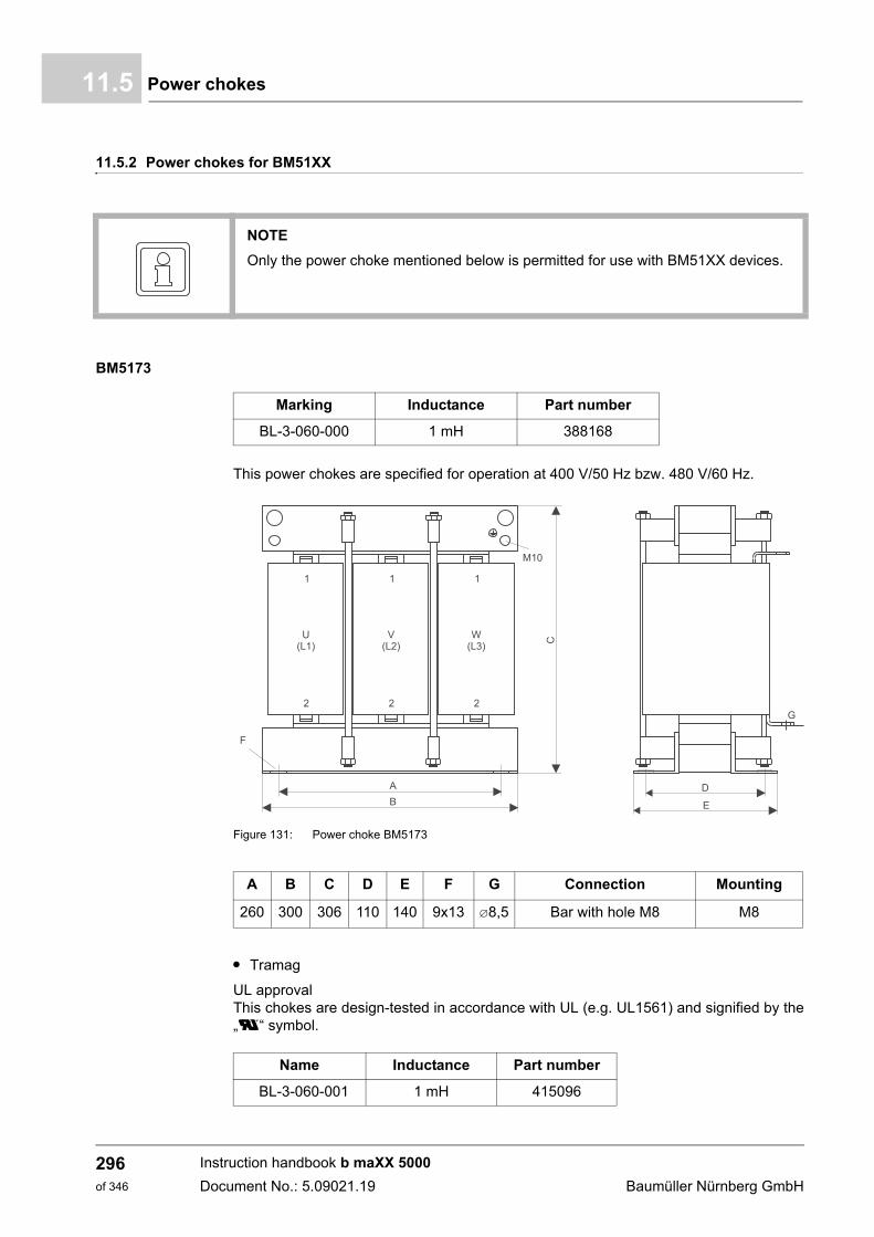
Power chokes11.5
11.5.2 Power chokes for BM51XX
BM5173
This power chokes are specified for operation at 400 V/50 Hz bzw. 480 V/60 Hz.
Figure 131: Power choke BM5173
m Tramag
UL approvalThis chokes are design-tested in accordance with UL (e.g. UL1561) and signified by the„ú“ “ symbol.
NOTE
Only the power choke mentioned below is permitted for use with BM51XX devices.
Marking Inductance Part number
BL-3-060-000 1 mH 388168
A B C D E F G Connection Mounting
260 300 306 110 140 9x13 8,5 Bar with hole M8 M8
Name Inductance Part number
BL-3-060-001 1 mH 415096
Instruction handbook b maXX 5000
Document No.: 5.09021.19 Baumüller Nürnberg GmbH
296of 346
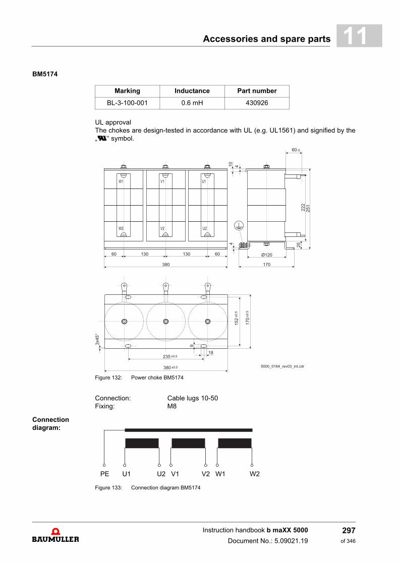
Accessories and spare parts 11
BM5174UL approvalThe chokes are design-tested in accordance with UL (e.g. UL1561) and signified by the„ú“ “ symbol.
Figure 132: Power choke BM5174
Connection: Cable lugs 10-50Fixing: M8
Connection diagram:
Figure 133: Connection diagram BM5174
Marking Inductance Part number
BL-3-100-001 0.6 mH 430926
PE U1 U2 V1 V2 W1 W2
Instruction handbook b maXX 5000
Document No.: 5.09021.19
297of 346
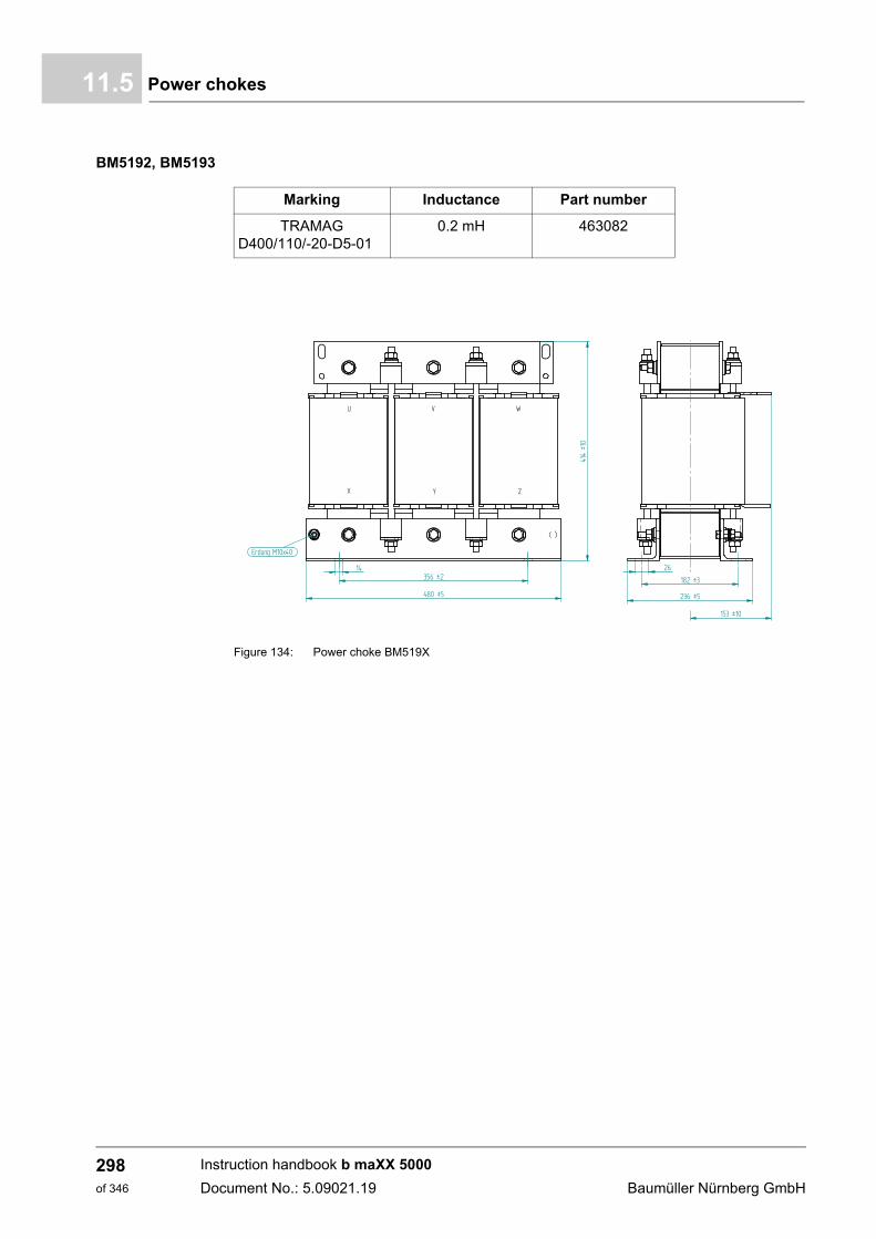
Power chokes11.5
BM5192, BM5193
Figure 134: Power choke BM519X
Marking Inductance Part number
TRAMAGD400/110/-20-D5-01
0.2 mH 463082
�
�
� �
� �
�
�� �
� ��
� ��
� � ��
��� ��
����
������������
Instruction handbook b maXX 5000
Document No.: 5.09021.19 Baumüller Nürnberg GmbH
298of 346
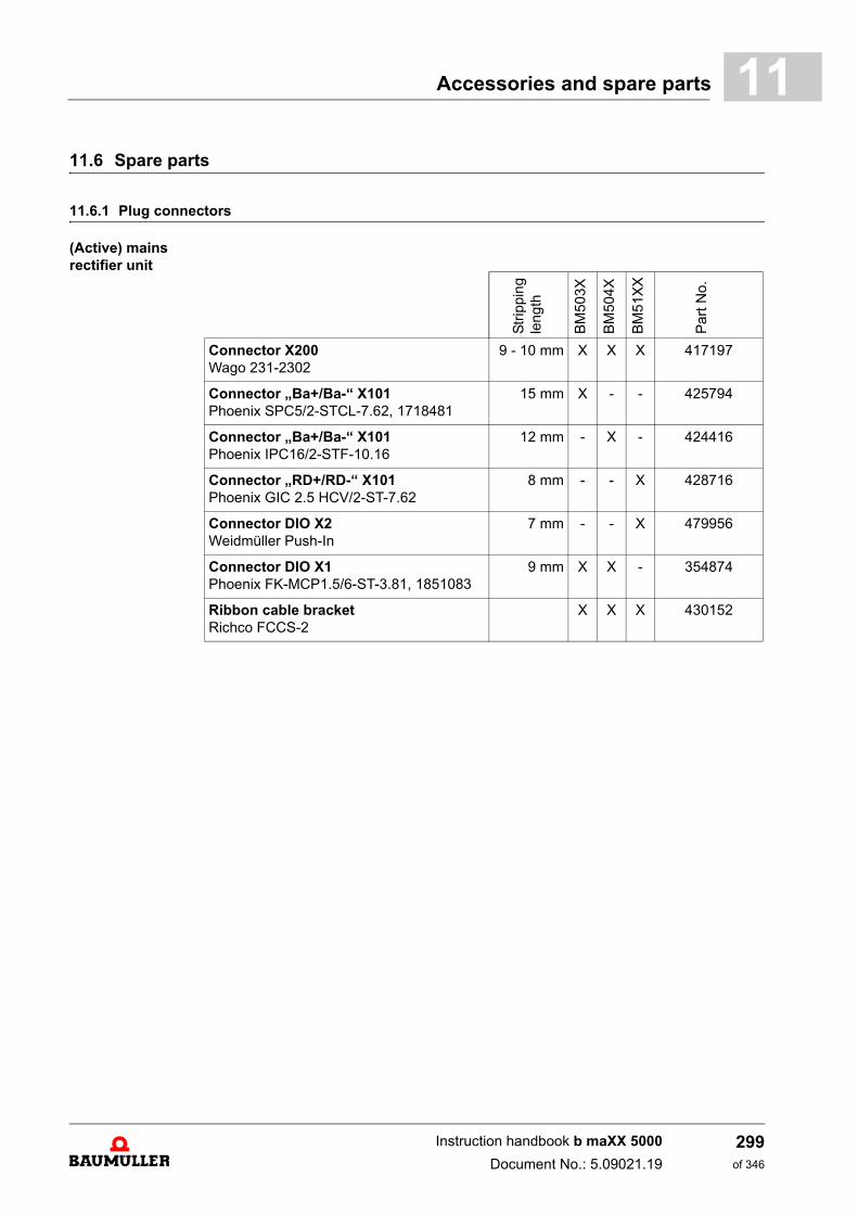
Accessories and spare parts 11
11.6 Spare parts11.6.1 Plug connectors
(Active) mains rectifier unit
Str
ipp
ing
leng
th
BM
503
X
BM
504
X
BM
51X
X
Par
t N
o.
Connector X200Wago 231-2302
9 - 10 mm X X X 417197
Connector „Ba+/Ba-“ X101Phoenix SPC5/2-STCL-7.62, 1718481
15 mm X - - 425794
Connector „Ba+/Ba-“ X101Phoenix IPC16/2-STF-10.16
12 mm - X - 424416
Connector „RD+/RD-“ X101Phoenix GIC 2.5 HCV/2-ST-7.62
8 mm - - X 428716
Connector DIO X2Weidmüller Push-In
7 mm - - X 479956
Connector DIO X1Phoenix FK-MCP1.5/6-ST-3.81, 1851083
9 mm X X - 354874
Ribbon cable bracketRichco FCCS-2
X X X 430152
Instruction handbook b maXX 5000
Document No.: 5.09021.19
299of 346
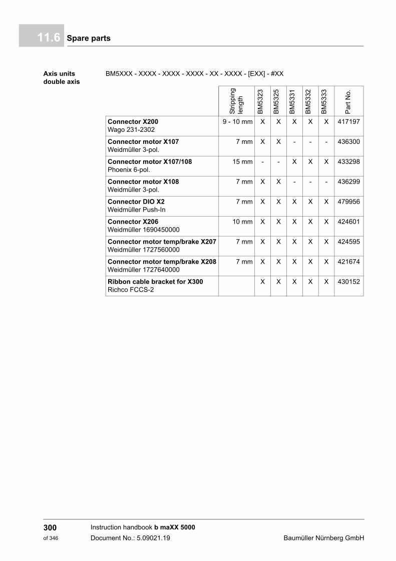
Spare parts11.6
Axis unitsdouble axis
BM5XXX - XXXX - XXXX - XXXX - XX - XXXX - [EXX] - #XX
Str
ipp
ing
len
gth
BM
53
23
BM
53
25
BM
53
31
BM
53
32
BM
53
33
Par
t No.
Connector X200Wago 231-2302
9 - 10 mm X X X X X 417197
Connector motor X107Weidmüller 3-pol.
7 mm X X - - - 436300
Connector motor X107/108Phoenix 6-pol.
15 mm - - X X X 433298
Connector motor X108Weidmüller 3-pol.
7 mm X X - - - 436299
Connector DIO X2Weidmüller Push-In
7 mm X X X X X 479956
Connector X206Weidmüller 1690450000
10 mm X X X X X 424601
Connector motor temp/brake X207Weidmüller 1727560000
7 mm X X X X X 424595
Connector motor temp/brake X208Weidmüller 1727640000
7 mm X X X X X 421674
Ribbon cable bracket for X300Richco FCCS-2
X X X X X 430152
Instruction handbook b maXX 5000
Document No.: 5.09021.19 Baumüller Nürnberg GmbH
300of 346
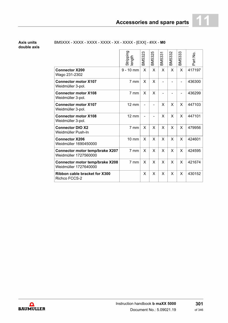
Accessories and spare parts 11
Axis unitsdouble axisBM5XXX - XXXX - XXXX - XXXX - XX - XXXX - [EXX] - #XX - M0
Str
ipp
ing
len
gth
BM
53
23
BM
53
25
BM
53
31
BM
53
32
BM
53
33
Par
t No.
Connector X200Wago 231-2302
9 - 10 mm X X X X X 417197
Connector motor X107Weidmüller 3-pol.
7 mm X X - - - 436300
Connector motor X108Weidmüller 3-pol.
7 mm X X - - - 436299
Connector motor X107Weidmüller 3-pol.
12 mm - - X X X 447103
Connector motor X108Weidmüller 3-pol.
12 mm - - X X X 447101
Connector DIO X2Weidmüller Push-In
7 mm X X X X X 479956
Connector X206Weidmüller 1690450000
10 mm X X X X X 424601
Connector motor temp/brake X207Weidmüller 1727560000
7 mm X X X X X 424595
Connector motor temp/brake X208Weidmüller 1727640000
7 mm X X X X X 421674
Ribbon cable bracket for X300Richco FCCS-2
X X X X X 430152
Instruction handbook b maXX 5000
Document No.: 5.09021.19
301of 346
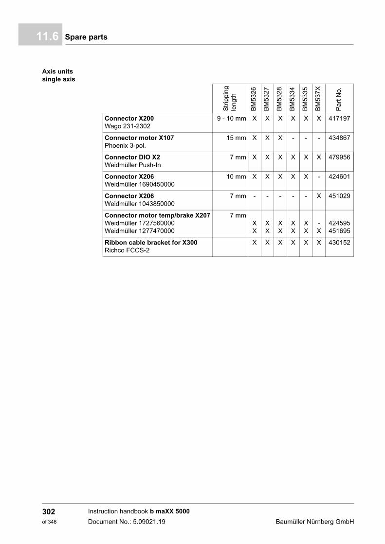
Spare parts11.6
Axis unitssingle axis
Str
ippi
ng
len
gth
BM
532
6
BM
532
7
BM
532
8
BM
533
4
BM
533
5
BM
537
X
Par
t No.
Connector X200 Wago 231-2302
9 - 10 mm X X X X X X 417197
Connector motor X107Phoenix 3-pol.
15 mm X X X - - - 434867
Connector DIO X2Weidmüller Push-In
7 mm X X X X X X 479956
Connector X206Weidmüller 1690450000
10 mm X X X X X - 424601
Connector X206Weidmüller 1043850000
7 mm - - - - - X 451029
Connector motor temp/brake X207Weidmüller 1727560000Weidmüller 1277470000
7 mmXX
XX
XX
XX
XX
-X
424595451695
Ribbon cable bracket for X300Richco FCCS-2
X X X X X X 430152
Instruction handbook b maXX 5000
Document No.: 5.09021.19 Baumüller Nürnberg GmbH
302of 346
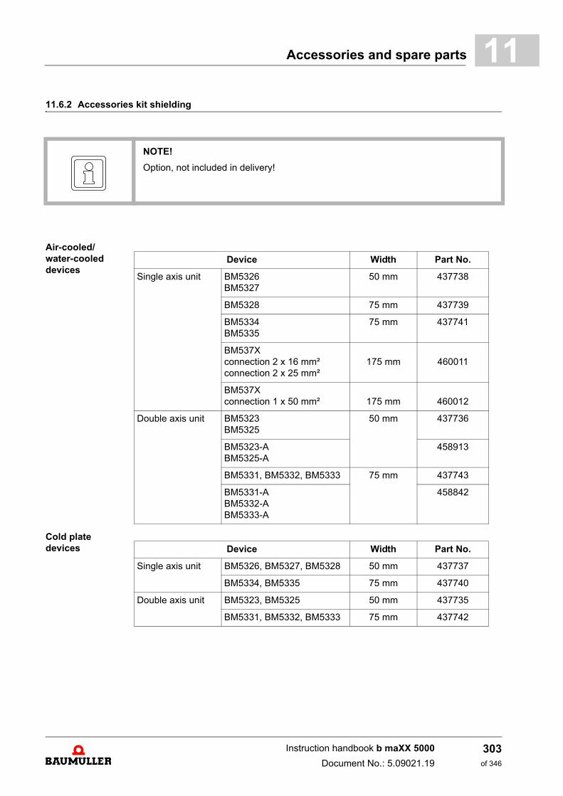
Accessories and spare parts 11
11.6.2 Accessories kit shieldingAir-cooled/water-cooleddevices
Cold platedevices
NOTE!
Option, not included in delivery!
Device Width Part No.
Single axis unit BM5326BM5327
50 mm 437738
BM5328 75 mm 437739
BM5334BM5335
75 mm 437741
BM537Xconnection 2 x 16 mm²connection 2 x 25 mm²
175 mm 460011
BM537Xconnection 1 x 50 mm² 175 mm 460012
Double axis unit BM5323BM5325
50 mm 437736
BM5323-ABM5325-A
458913
BM5331, BM5332, BM5333 75 mm 437743
BM5331-ABM5332-ABM5333-A
458842
Device Width Part No.
Single axis unit BM5326, BM5327, BM5328 50 mm 437737
BM5334, BM5335 75 mm 437740
Double axis unit BM5323, BM5325 50 mm 437735
BM5331, BM5332, BM5333 75 mm 437742
Instruction handbook b maXX 5000
Document No.: 5.09021.19
303of 346
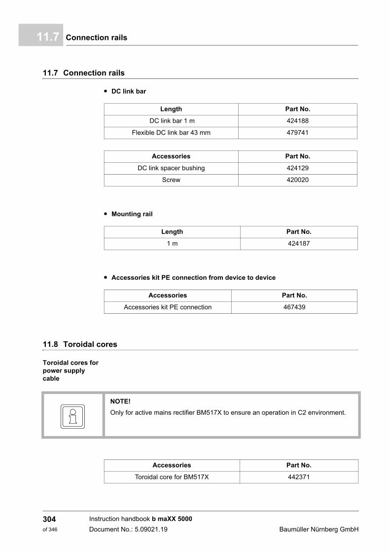
Connection rails11.7
11.7 Connection rails
m DC link bar
m Mounting rail
m Accessories kit PE connection from device to device
11.8 Toroidal cores
Toroidal cores for power supply cable
Length Part No.
DC link bar 1 m 424188
Flexible DC link bar 43 mm 479741
Accessories Part No.
DC link spacer bushing 424129
Screw 420020
Length Part No.
1 m 424187
Accessories Part No.
Accessories kit PE connection 467439
NOTE!
Only for active mains rectifier BM517X to ensure an operation in C2 environment.
Accessories Part No.
Toroidal core for BM517X 442371
Instruction handbook b maXX 5000
Document No.: 5.09021.19 Baumüller Nürnberg GmbH
304of 346
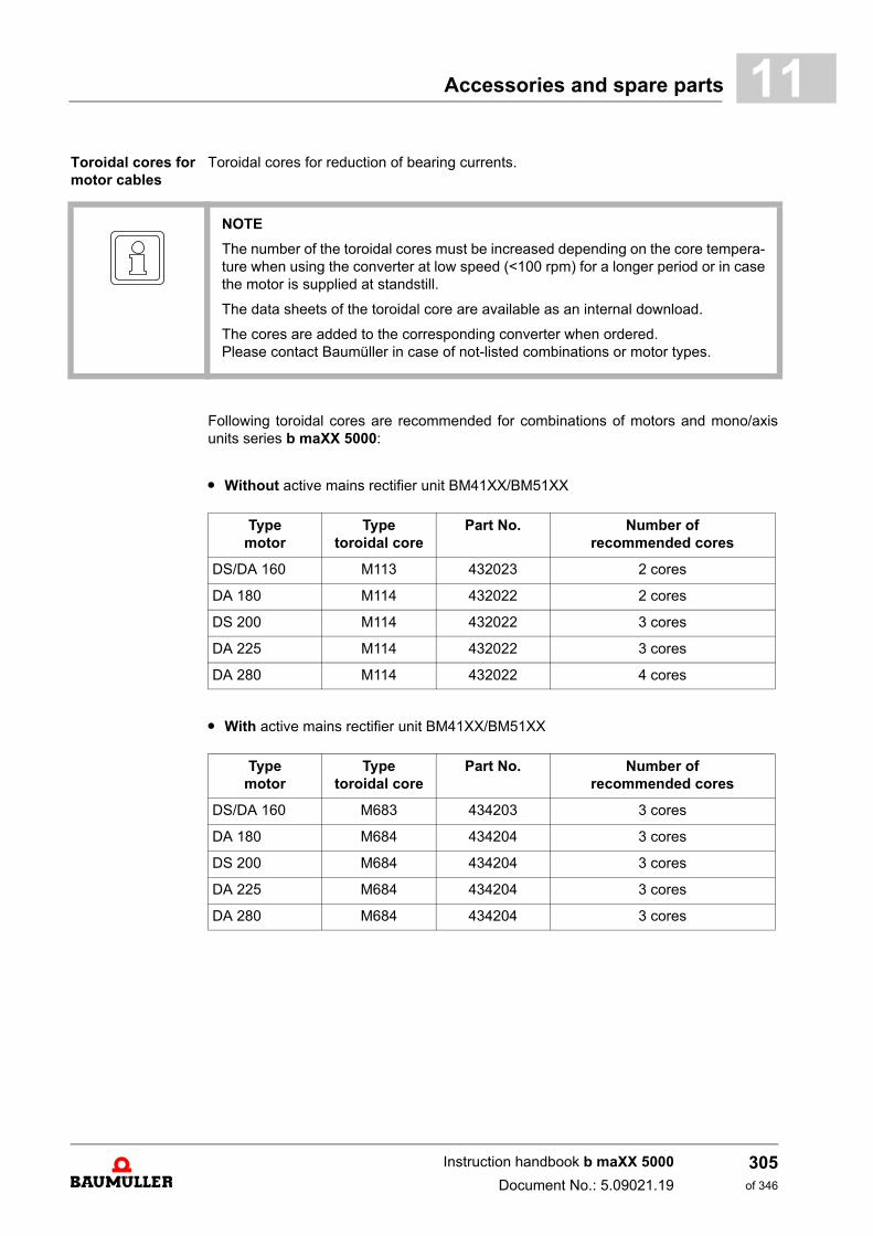
Accessories and spare parts 11
Toroidal cores for motor cablesToroidal cores for reduction of bearing currents.
Following toroidal cores are recommended for combinations of motors and mono/axisunits series b maXX 5000:
m Without active mains rectifier unit BM41XX/BM51XX
m With active mains rectifier unit BM41XX/BM51XX
NOTE
The number of the toroidal cores must be increased depending on the core tempera-ture when using the converter at low speed (<100 rpm) for a longer period or in casethe motor is supplied at standstill.
The data sheets of the toroidal core are available as an internal download.
The cores are added to the corresponding converter when ordered.Please contact Baumüller in case of not-listed combinations or motor types.
Typemotor
Typetoroidal core
Part No. Number of recommended cores
DS/DA 160 M113 432023 2 cores
DA 180 M114 432022 2 cores
DS 200 M114 432022 3 cores
DA 225 M114 432022 3 cores
DA 280 M114 432022 4 cores
Typemotor
Typetoroidal core
Part No. Number of recommended cores
DS/DA 160 M683 434203 3 cores
DA 180 M684 434204 3 cores
DS 200 M684 434204 3 cores
DA 225 M684 434204 3 cores
DA 280 M684 434204 3 cores
Instruction handbook b maXX 5000
Document No.: 5.09021.19
305of 346

Toroidal cores11.8
Instruction handbook b maXX 5000
Document No.: 5.09021.19 Baumüller Nürnberg GmbH
306of 346
12SHUTDOWN, STORAGE
In this chapter we describe, how you decommission and store the device.
12.1 Safety instructions
h Refer to ZSafety– as from page 15 and the information in ZTransport and Packaging–as from page 111.
The shutdown of the device may only be carried out by for this qualified personnel.
DANGER!
Risk of fatal injury from electrical current!
Stored electric charge.
Discharge time of the system = discharge time of the device with the longest DC linkdischarge time.
Therefore:
m Do not touch electrically live parts before taking into account the discharge time ofthe capacitors.
m Assure, that all electric connections are current-free and are safe against switch-on.
m Before working, check at the electrical connections with suitable measuring devic-es, that the connections are off-circuit.
m Remove the connections not until the safe isolation from supply has been checked.
m If additional capacitors are connected to the DC link, the DC link discharge cantake a much longer time. In this case, the necessary waiting period must itself bedetermined or a measurement made as to whether the equipment is de-energized.This discharge time must be posted, together with an IEC 60417-5036 (2002-10)warning symbol, on a clearly visible location of the control cabinet.
307of 346
Instruction handbook b maXX 5000
Document No.: 5.09021.19
Requirements to the executing personnel12.2
12.2 Requirements to the executing personnel
The personnel, who is appointed to setting out of operation, must have the requiredknowledge and instructions, which is necessary for an execution according to the rules.Select the personnel in such a way, that the safety instructions, which are mounted to thedevice and its parts as well as to the connections, are understood and applied to.
12.3 Shutdown
Execute the setting out of operation as follows:
1 Put the device off-circuit and assure the device against unintentional restart.
2 Check the isolation from supply of all connections (earliest 10 minutes after switchingoff).
3 Demount the connections and protect the connections according to the safety instructions.
4 Document the shut down setting.
12.4 Demounting
The demounting assumes a completed, documented setting out of operation.
NOTICE!
Note sharp edges.
In case, while installing, you lift a device with unprotected hands, fingers/palm can becut. If the device falls off, your feet can be cut up.
Therefore:
m Ensure that only qualified personnel, who are familiar with the safety notes and as-sembly instructions, demount this device.
Wear safety gloves.
mWear safety shoes.
Instruction handbook b maXX 5000
Document No.: 5.09021.19 Baumüller Nürnberg GmbH
308of 346
Shutdown, Storage 12
1 Secure the device against falling off/out.2 Loosen all mechanical connections.
3 Lift the device out of the control cabinet.
4 Store the device in a suitable packing.
5 At transportation pay attention to, that the device is not damaged by wrong storage orsevere shocks, also see ZWhat to observe when transporting– on page 111.
In case you want to dispose the device, additional data is available in chapter ZDisposal–as from page 311.
12.5 Storage conditions
The device is maintenance-free. If you keep to the environmental conditions during theentire period of storage, you can assume, that the device will not be damaged. In casethe environmental conditions during storage are not kept, you should assume that the de-vice is damaged after storage.
NOTICE!
Property damage because of incorrect storage conditions
Incorrect storage can damage/destroy the device.
Therefore:
Assure, that the environmental conditions are kept during the entire period of storage:
m Climatic category 1K4
m Temperature range -25 °C to +55 °C
NOTICE!
Recommissioning without forming of the capacitors.
From six months storage period on, the capacitors are destroyed during commission-ing, if they are not formed beforehand
m Reform the DC link capacitors:
n by supplying the device ready-to-operate for at least one hour with supply volt-age
n but do not enable pulses during this time.
m Consider, that it is imperative, to connect the accordingly prescribed line commu-tating chokes for this forming procedure. Devices, where no line commutatingchokes is necessary can directly be supplied with mains voltage.
Instruction handbook b maXX 5000
Document No.: 5.09021.19
309of 346
Recommissioning12.6
12.6 Recommissioning
Execute commissioning as with a new device, see ZMounting– as from page 113, ZInstallation– as from page 129.
.
NOTICE!
Recommissioning without forming of the capacitors.
From six months storage period on, the capacitors are destroyed during commission-ing, if they are not formed beforehand
m Reform the DC link capacitors:
n by supplying the device ready-to-operate for at least one hour with supply voltage
n but do not transmit a pulse enable during this time.
m Consider, that it is imperative, to connect the accordingly prescribed line commu-tating choke for this forming procedure. Devices, where no line commutating chokeis necessary can directly be supplied with mains voltage.
Instruction handbook b maXX 5000
Document No.: 5.09021.19 Baumüller Nürnberg GmbH
310of 346
13DISPOSAL
13.1 Safety regulations
NOTE!
Baumüller products are not subject to the scope of application of the EU's WasteElectrical and Electronic Equipment Directive (WEEE, 2012/19/EU). Hence,Baumüller is not obligated to bear any costs for taking back and disposing of old de-vices.
DANGER!
Risk of fatal injury from electrical current!
Stored electric charge.
Discharge time of the modular system = discharge time of the device with the longestDC link discharge time in the modular system.
Refer to ZElectrical data– as from page 60.
Therefore:
m Do not touch before taking into account the discharge time of the capacitors andelectrically live parts.
m Heed corresponding notes on the equipment.
m If additional capacitors are connected to the intermediate circuit, the intermediatecircuit discharge can take a much longer time. In this case, the necessary waitingperiod must itself be determined or a measurement made as to whether the equip-ment is de-energized. This discharge time must be posted, together with an IEC60417-5036 (2002-10) warning symbol, on a clearly visible location of the controlcabinet.
311of 346
Instruction handbook b maXX 5000
Document No.: 5.09021.19
Safety regulations13.1
CAUTION!
Danger due to sharp edges.
If the device is lifted with unprotected hands during deinstallation, palms or fingerscan be cut. If the device falls, feet could be injured.
Therefore:
m Ensure that only qualified personnel, who are familiar with the safety notes and as-sembly instructions, mount this device.
Wear safety gloves.
Wear safety shoes.
WARNING!
Danger of physical impact!
Secure device against falling down.
Therefore:
m Take suitable measures, such as supports, hoists and assisting personnel, to en-sure that device cannot fall down.
m Use appropriate means of transport.
NOTICE!
Avoid polluting the environment as a result of improper disposal.
Therefore:
m Only dispose in compliance with the health and safety regulations.
m Take heed of any special local regulations. If you are unable to directly ensure safedisposal yourself, commission a suitable disposal contractor.
m In the event of a fire, hazardous substances could possibly be generated or re-leased.
m Do not expose electronic components to high temperatures.
m Beryllium oxide is used as inner insulation, for example for various power semicon-ductors. The beryllium dust that is generated upon opening is injurious to thehealth.Do not open electronic components.
m Dispose of capacitors, semiconductor modules and electronic scrap as specialwaste.
Instruction handbook b maXX 5000
Document No.: 5.09021.19 Baumüller Nürnberg GmbH
312of 346
Disposal 13
13.2 Disposal facilities/authorities
Ensure that the disposal is handled in compliance with the disposal policies of your com-pany, as well as with all national regulations of the responsible disposal facilities and au-thorities. In case of doubt, consult the bureau of commerce or environmental protectionauthority responsible for your company.
WARNING!
Danger as a result of faulty deinstallation!
The deinstallation and disposal requires qualified personnel with adequate experi-ence.
Therefore:
m Only allow deinstallation and disposal to be performed by qualified personnel.
Instruction handbook b maXX 5000
Document No.: 5.09021.19
313of 346
Disposal facilities/authorities13.2
Instruction handbook b maXX 5000
Document No.: 5.09021.19 Baumüller Nürnberg GmbH
314of 346
APPENDIX A - ABBREVIATIONS
A Amps
AC Alternating current
BB Ready-to-operate
CE Compliant with the directives of theEuropean Union
DC Direct current
DIN Deutsches Institut für Normunge.V (German National StandardsInstitute).
EMC Electromagnetic compatibility
EMVG European EMC law
EN European standard
ESD Electrostatic discharge
ext external
GND Ground
h Hour
Î Peak current
IAC Rms-value of alternating current
IDC Rms-value of direct current
IEC International ElectrotechnicalCommission
IP Ingress protection; protection rat-ing
IS pulse inhibit
Chap. Chapter
KG Cooling air requirement of deviceinterior
KLK Cooling air requirement of heatsink
min Minute
MSKL Motor protection thermistor
n = 0 rotational speed = 0
nact Rotational speed actual value
nmax Maximum rotational speed
nmin Minimum rotational speed
MSL Height above mean sea level
No. Number
nset Rotational speed set value
NTC Negative temperature coefficientthermistor
PE Protected groundground conductor connection
PELV Protective extra-low voltage, withsafe isolation, grounded
ppm Parts per million
PTC Positive temperature coefficientthermistor
RCD Residual current protective device/ ground fault circuit breaker
SELV Safety extra-low voltage, with safeisolation
SH Quick stop
STO Safe Torque Off
Tab. Table
U Voltage
Û Peak voltage
UAC Rms-value, AC voltage
UDC Rms-value, DC voltage
UL Underwriters Laboratories
UDC link DC link voltage
VA Stainless steel
VDE Verband der Elektrotechnik, Elek-tronik und Informationstechnik(German electrical engineering,electronics and IT association)
ZK DC link
315of 346
Instruction handbook b maXX 5000
Document No.: 5.09021.19

A
Instruction handbook b maXX 5000
Document No.: 5.09021.19 Baumüller Nürnberg GmbH
316of 346
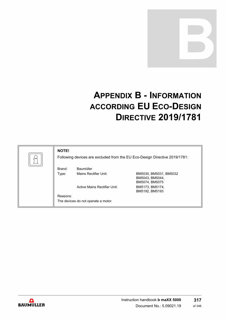
APPENDIX B - INFORMATION
ACCORDING EU ECO-DESIGN
DIRECTIVE 2019/1781
NOTE!
Following devices are excluded from the EU Eco-Design Directive 2019/1781:
Brand: Baumüller
Type: Mains Rectifier Unit: BM5030, BM5031, BM5032BM5043, BM5044, BM5074, BM5075
Active Mains Rectifier Unit: BM5173, BM5174,BM5192, BM5193
Reasons:
The devices do not operate a motor.
317of 346
Instruction handbook b maXX 5000
Document No.: 5.09021.19
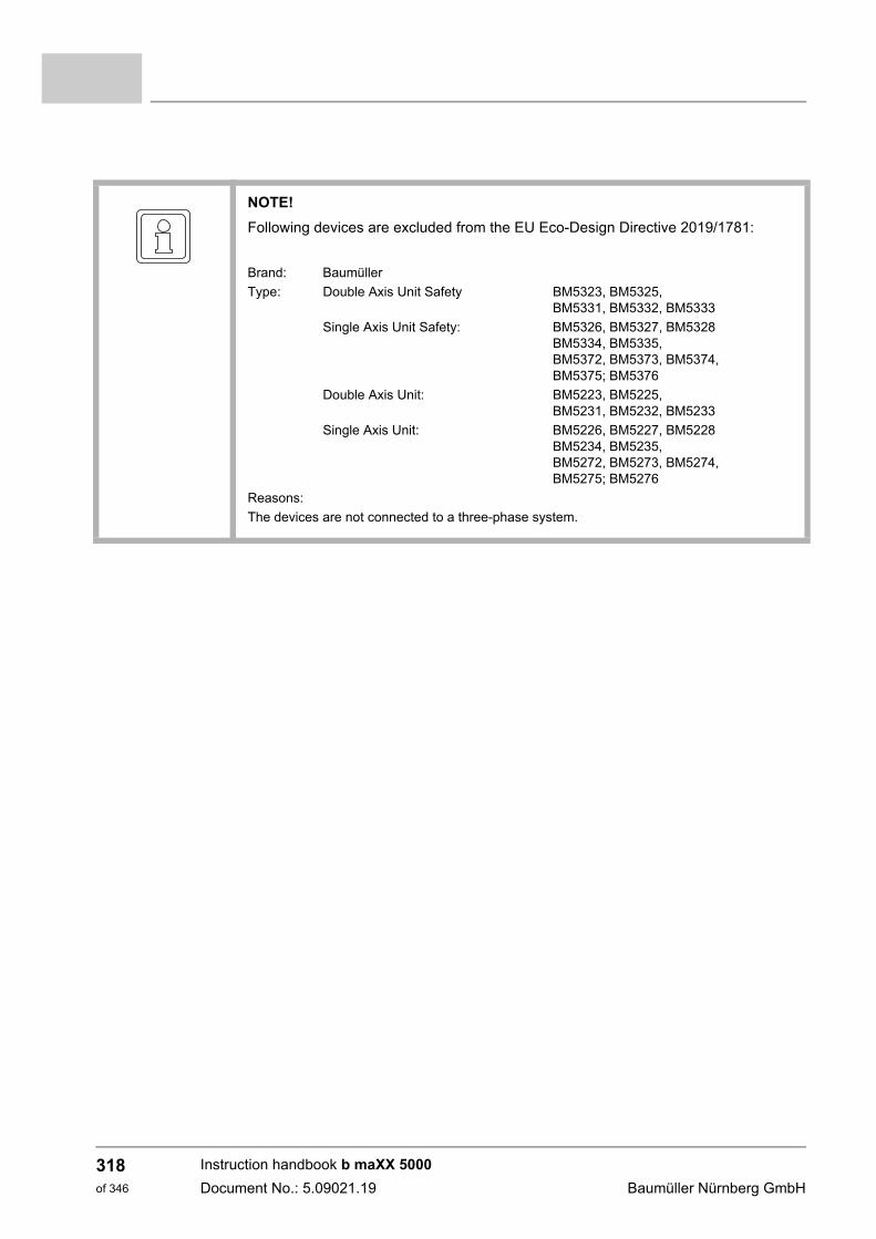
NOTE!
Following devices are excluded from the EU Eco-Design Directive 2019/1781:
Brand: Baumüller
Type: Double Axis Unit Safety BM5323, BM5325,BM5331, BM5332, BM5333
Single Axis Unit Safety: BM5326, BM5327, BM5328BM5334, BM5335,BM5372, BM5373, BM5374, BM5375; BM5376
Double Axis Unit: BM5223, BM5225,BM5231, BM5232, BM5233
Single Axis Unit: BM5226, BM5227, BM5228BM5234, BM5235,BM5272, BM5273, BM5274, BM5275; BM5276
Reasons:
The devices are not connected to a three-phase system.
Instruction handbook b maXX 5000
Document No.: 5.09021.19 Baumüller Nürnberg GmbH
318of 346

APPENDIX C - DECLARATION OF
CONFORMITY
319of 346
Operation Manual b maXX 5000
Document no.: 5.09021.19
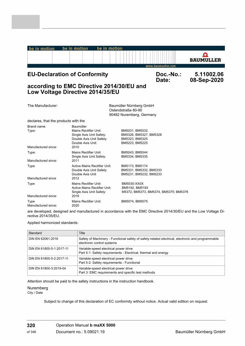
EU-Declaration of Conformity Doc.-No.: 5.11002.06Date: 08-Sep-2020
according to EMC Directive 2014/30/EU and Low Voltage Directive 2014/35/EU
The Manufacturer: Baumüller Nürnberg GmbHOstendstraße 80-9090482 Nuremberg, Germany
declares, that the products with the
Brand name BaumüllerType: Mains Rectifier Unit: BM5031, BM5032.
Single Axis Unit Safety: BM5326, BM5327, BM5328Double Axis Unit Safety: BM5323, BM5325Double Axis Unit: BM5223, BM5225
Manufactured since: 2010
Type: Mains Rectifier Unit: BM5043, BM5044Single Axis Unit Safety: BM5334, BM5335
Manufactured since: 2011
Type Active Mains Rectifier Unit: BM5173, BM5174Double Axis Unit Safety: BM5331, BM5332, BM5333Double Axis Unit BM5231, BM5232, BM5233
Manufactured since 2012
Type Mains Rectifier Unit: BM5030-XX0XActive Mains Rectifier Unit: BM5192, BM5193Single Axis Unit Safety: M5372, BM5373, BM5374, BM5375; BM5376
Manufactured since: 2016
Type Mains Rectifier Unit: BM5074, BM5075Manufactured since: 2020
are developed, designed and manufactured in accordance with the EMC Directive 2014/30/EU and the Low Voltage Di-rective 2014/35/EU.
Applied harmonized standards:
Attention should be paid to the safety instructions in the instruction handbook.
NurembergCity / Date
Subject to change of this declaration of EC conformity without notice. Actual valid edition on request.
Standard Title
DIN EN 62061:2016 Safety of Machinery - Functional safety of safety-related electrical, electronic and programmable electronic control systems
DIN EN 61800-5-1:2017-11 Variable-speed electrical power drive Part 5-1: Safety requirements - Electrical, thermal and energy
DIN EN 61800-5-2:2017-11 Variable-speed electrical power drive Part 5-2: Safety requirements - Functional
DIN EN 61800-3:2019-04 Variable-speed electrical power drivePart 3: EMC requirements and specific test methods
Operation Manual b maXX 5000
Document no.: 5.09021.19 Baumüller Nürnberg GmbH
320of 346
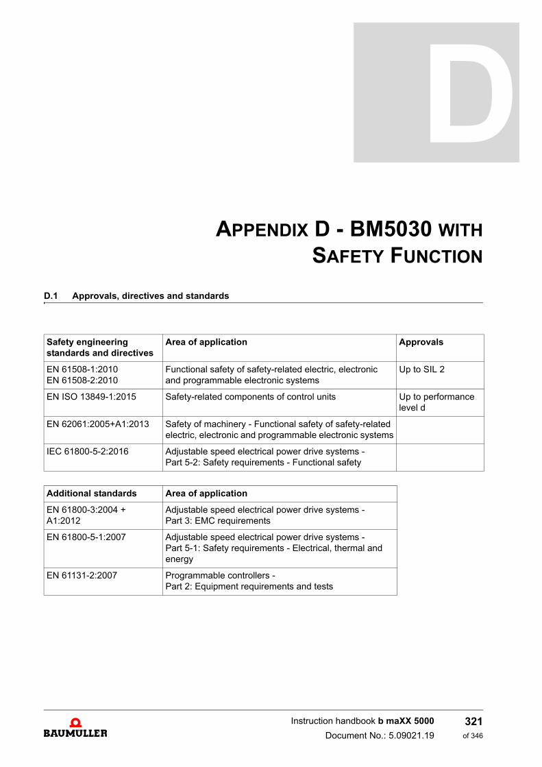
APPENDIX D - BM5030 WITH
SAFETY FUNCTION
D.1 Approvals, directives and standards
Safety engineering standards and directives
Area of application Approvals
EN 61508-1:2010EN 61508-2:2010
Functional safety of safety-related electric, electronic and programmable electronic systems
Up to SIL 2
EN ISO 13849-1:2015 Safety-related components of control units Up to performance level d
EN 62061:2005+A1:2013 Safety of machinery - Functional safety of safety-related electric, electronic and programmable electronic systems
IEC 61800-5-2:2016 Adjustable speed electrical power drive systems - Part 5-2: Safety requirements - Functional safety
Additional standards Area of application
EN 61800-3:2004 + A1:2012
Adjustable speed electrical power drive systems - Part 3: EMC requirements
EN 61800-5-1:2007 Adjustable speed electrical power drive systems - Part 5-1: Safety requirements - Electrical, thermal and energy
EN 61131-2:2007 Programmable controllers - Part 2: Equipment requirements and tests
321of 346
Instruction handbook b maXX 5000
Document No.: 5.09021.19
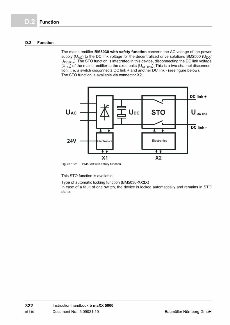
FunctionD.2
D.2 Function
The mains rectifier BM5030 with safety function converts the AC voltage of the powersupply (UAC) to the DC link voltage for the decentralized drive solutions BM2500 (UDC/UDC link). The STO function is integrated in this device, disconnecting the DC link voltage(UDC) of the mains rectifier to the axes units (UDC link). This is a two channel disconnec-tion, i. e. a switch disconnects DC link + and another DC link - (see figure below).The STO function is available via connector X2.
Figure 135: BM5030 with safety function
This STO function is available:
Type of automatic locking function (BM5030-XX2X)In case of a fault of one switch, the device is locked automatically and remains in STOstate.
Electronics Electronics
DC link
DC link +
DC link -
Instruction handbook b maXX 5000
Document No.: 5.09021.19 Baumüller Nürnberg GmbH
322of 346
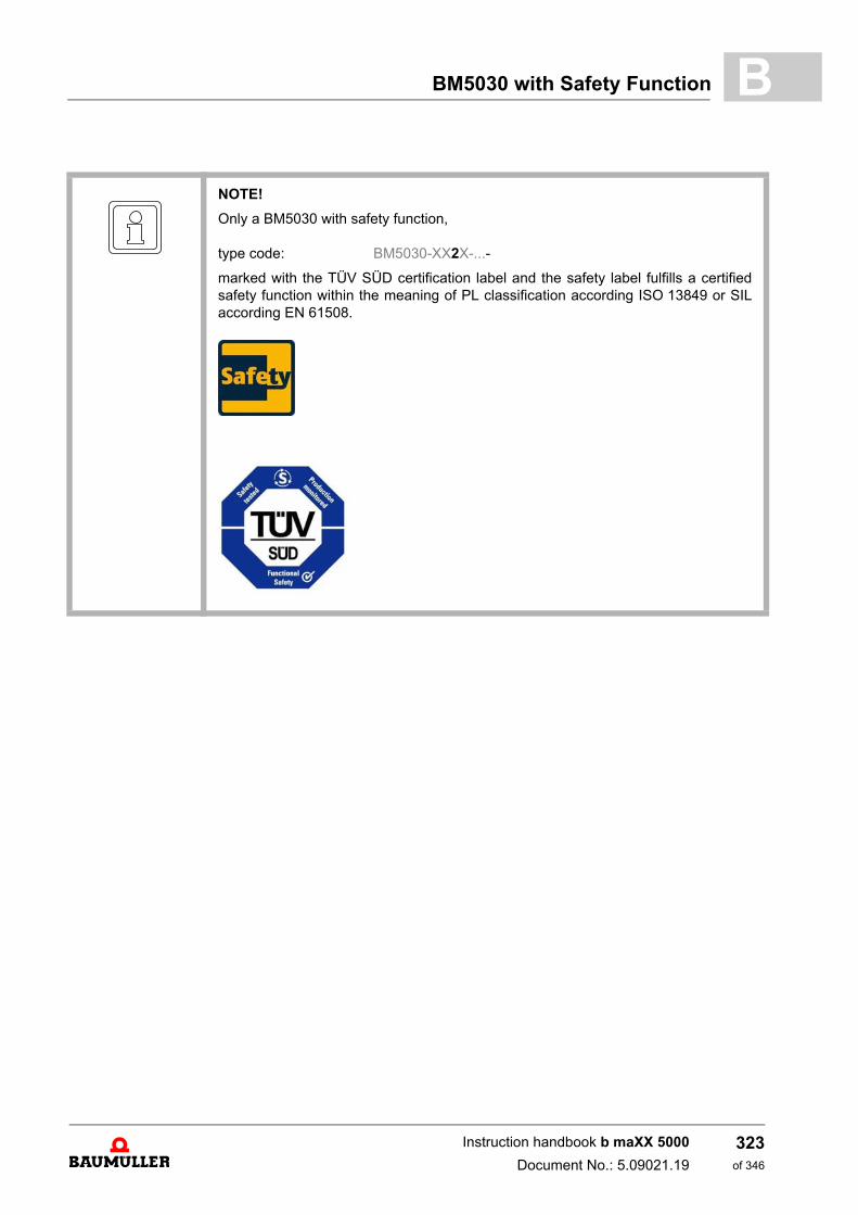
BM5030 with Safety Function B
NOTE!
Only a BM5030 with safety function,
type code: BM5030-XX2X-...-
marked with the TÜV SÜD certification label and the safety label fulfills a certifiedsafety function within the meaning of PL classification according ISO 13849 or SILaccording EN 61508.
Instruction handbook b maXX 5000
Document No.: 5.09021.19
323of 346
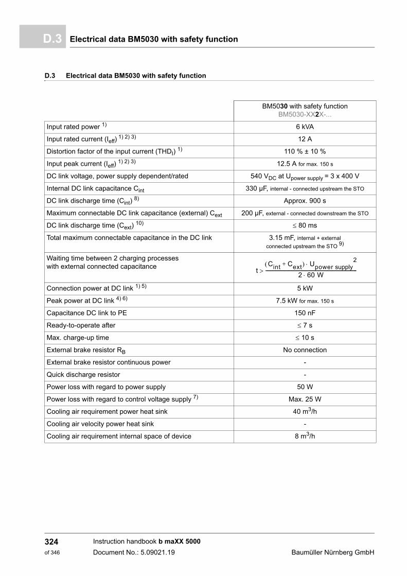
Electrical data BM5030 with safety functionD.3
D.3 Electrical data BM5030 with safety function
BM5030 with safety functionBM5030-XX2X-...
Input rated power 1) 6 kVA
Input rated current (Ieff) 1) 2) 3) 12 A
Distortion factor of the input current (THDI) 1) 110 % ± 10 %
Input peak current (Ieff) 1) 2) 3) 12.5 A for max. 150 s
DC link voltage, power supply dependent/rated 540 VDC at Upower supply = 3 x 400 V
Internal DC link capacitance Cint 330 µF, internal - connected upstream the STO
DC link discharge time (Cint) 8) Approx. 900 s
Maximum connectable DC link capacitance (external) Cext 200 µF, external - connected downstream the STO
DC link discharge time (Cext) 10) 80 ms
Total maximum connectable capacitance in the DC link 3.15 mF, internal + external
connected upstream the STO 9)
Waiting time between 2 charging processes with external connected capacitance
Connection power at DC link 1) 5) 5 kW
Peak power at DC link 4) 6) 7.5 kW for max. 150 s
Capacitance DC link to PE 150 nF
Ready-to-operate after 7 s
Max. charge-up time 10 s
External brake resistor RB No connection
External brake resistor continuous power -
Quick discharge resistor -
Power loss with regard to power supply 50 W
Power loss with regard to control voltage supply 7) Max. 25 W
Cooling air requirement power heat sink 40 m3/h
Cooling air velocity power heat sink -
Cooling air requirement internal space of device 8 m3/h
tCint Cext+ Upower supply
2
2 60 W--------------------------------------------------------------------------------
Instruction handbook b maXX 5000
Document No.: 5.09021.19 Baumüller Nürnberg GmbH
324of 346
BM5030 with Safety Function B
1) All rated values are based on an power supply voltage of 400 V/50 Hz, a DC link voltage of 540 V, a controlvoltage of 24 V and a surrounding temperature of 40 °C.2) The input current must be reduced between 40 °C and 55 °C, see correction values at changed operation
conditions, see ZCorrection values for the output current of the mains inverter BM50XX, BM51XX– on page51.
3) The mains rectifier draws the rated/peak current at rated supply voltage. The input current must be reducedif power supply voltage is higher than 400 V and the DC link output power remains constant, see ZDerating:Input current BM50XX, BM517X, BM519X– on page 54.
4) The actual possible overload time depends on the preloading of the device and the heat sink temperatureand is detected by the overload monitoring of the device.
5) With the permissible continuous DC link connected power, the power supply current is reduced. When se-lecting the connected axes ensure that the DC link connected power is not exceeded, see ZDerating: DC linkpower B503X, BM504X, BM517X, BM519X– on page 57.
6) This power consumption is only permitted for a short period of time. This must be ensured by means of ap-propriate configuration of the connected axes.
7) Without loads on the digital outputs8) Residual voltage < 60 VDC9) It is allowed to connect an additional capacitance to connector X101.
The total capacitance connected to the DC link (upstream of the STO function) is limited to 3.15 mF.10) Maximum DC link capacitance connected downstream the STO function.
Instruction handbook b maXX 5000
Document No.: 5.09021.19
325of 346
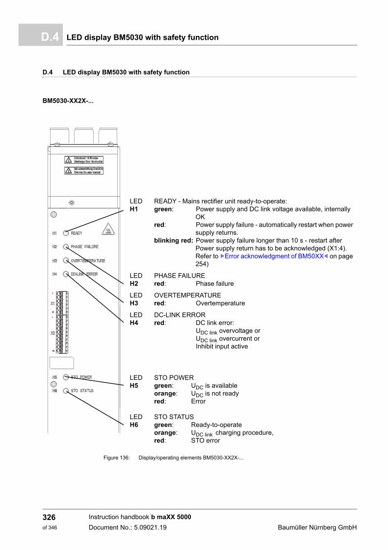
LED display BM5030 with safety functionD.4
D.4 LED display BM5030 with safety function
BM5030-XX2X-...
Figure 136: Display/operating elements BM5030-XX2X-...
LEDH1
READY - Mains rectifier unit ready-to-operate:green: Power supply and DC link voltage available, internally
OKred: Power supply failure - automatically restart when power
supply returns.blinking red: Power supply failure longer than 10 s - restart after
Power supply return has to be acknowledged (X1:4). Refer to ZError acknowledgment of BM50XX– on page 254)
LEDH2
PHASE FAILUREred: Phase failure
LEDH3
OVERTEMPERATUREred: Overtemperature
LEDH4
DC-LINK ERRORred: DC link error:
UDC link overvoltage or UDC link overcurrent orInhibit input active
LEDH5
LEDH6
STO POWERgreen: UDC is availableorange: UDC is not readyred: Error
STO STATUSgreen: Ready-to-operateorange: UDC link charging procedure, red: STO error
Instruction handbook b maXX 5000
Document No.: 5.09021.19 Baumüller Nürnberg GmbH
326of 346
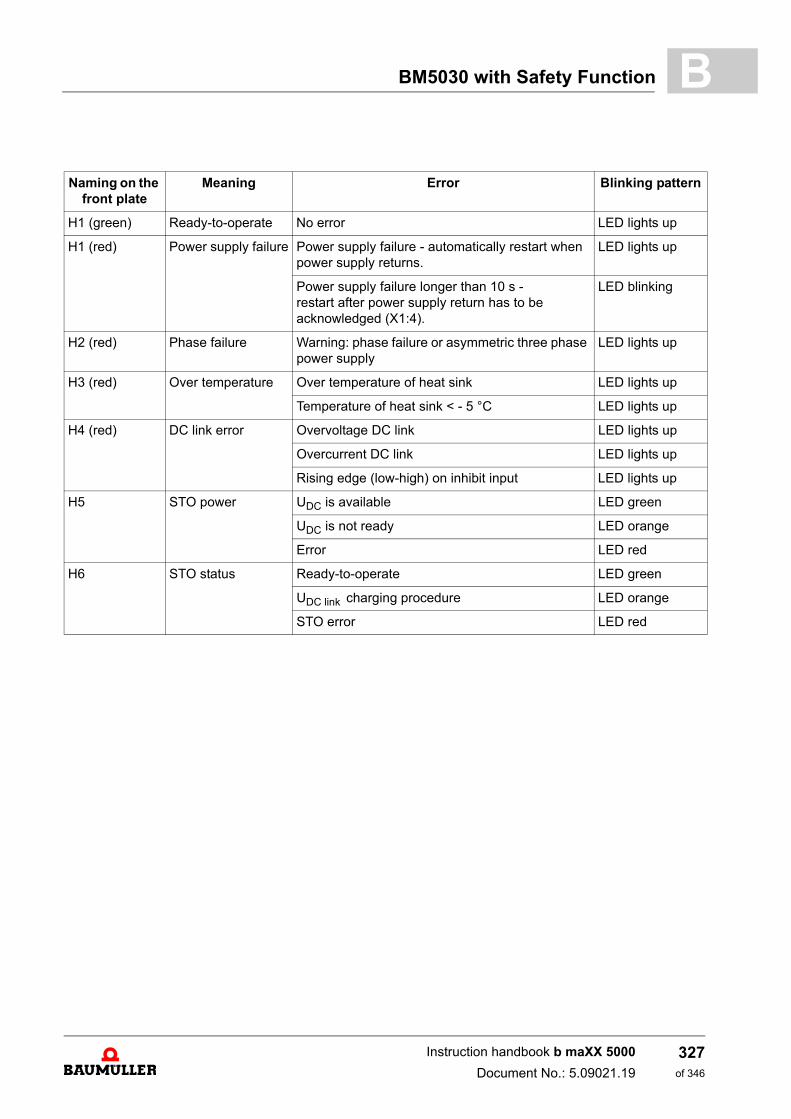
BM5030 with Safety Function B
Naming on the front plate
Meaning Error Blinking pattern
H1 (green) Ready-to-operate No error LED lights up
H1 (red) Power supply failure Power supply failure - automatically restart when power supply returns.
LED lights up
Power supply failure longer than 10 s - restart after power supply return has to be acknowledged (X1:4).
LED blinking
H2 (red) Phase failure Warning: phase failure or asymmetric three phase power supply
LED lights up
H3 (red) Over temperature Over temperature of heat sink LED lights up
Temperature of heat sink < - 5 °C LED lights up
H4 (red) DC link error Overvoltage DC link LED lights up
Overcurrent DC link LED lights up
Rising edge (low-high) on inhibit input LED lights up
H5 STO power UDC is available LED green
UDC is not ready LED orange
Error LED red
H6 STO status Ready-to-operate LED green
UDC link charging procedure LED orange
STO error LED red
Instruction handbook b maXX 5000
Document No.: 5.09021.19
327of 346
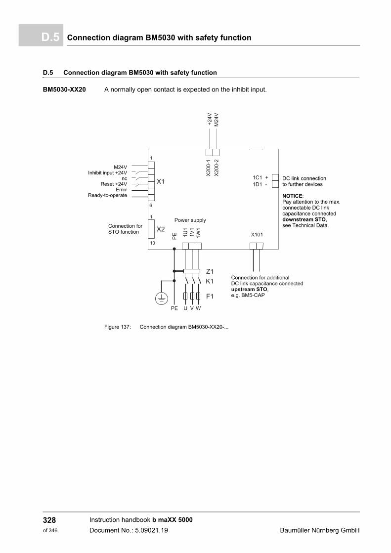
Connection diagram BM5030 with safety functionD.5
D.5 Connection diagram BM5030 with safety function
BM5030-XX20 A normally open contact is expected on the inhibit input.
Figure 137: Connection diagram BM5030-XX20-...
DC link connectionto further devices
Connection forSTO function
Power supply
M24VInhibit input +24V
ncReset +24V
ErrorReady-to-operate
Connection for additionalDC link capacitance connectedupstream STO,
NOTICE:Pay attention to the max.connectable DC link capacitance connecteddownstream STO,see Technical Data.
e.g. BM5-CAP
Instruction handbook b maXX 5000
Document No.: 5.09021.19 Baumüller Nürnberg GmbH
328of 346
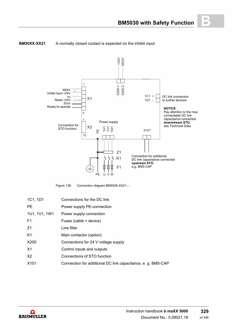
BM5030 with Safety Function B
BM50XX-XX21 A normally closed contact is expected on the inhibit input.Figure 138: Connection diagram BM5030-XX21-...
Power supply
M24VInhibit input +24V
ncReset +24V
ErrorReady-to-operate
DC link connectionto further devices
Connection forSTO function
NOTICE:Pay attention to the max.connectable DC link capacitance connecteddownstream STO,see Technical Data.
Connection for additionalDC link capacitance connectedupstream STO,e.g. BM5-CAP
1C1, 1D1 Connections for the DC link
PE Power supply PE-connection
1U1, 1V1, 1W1 Power supply connection
F1 Fuses (cable + device)
Z1 Line filter
K1 Main contactor (option)
X200 Connections for 24 V voltage supply
X1 Control inputs and outputs
X2 Connections of STO function
X101 Connection for additional DC link capacitance, e. g. BM5-CAP
Instruction handbook b maXX 5000
Document No.: 5.09021.19
329of 346
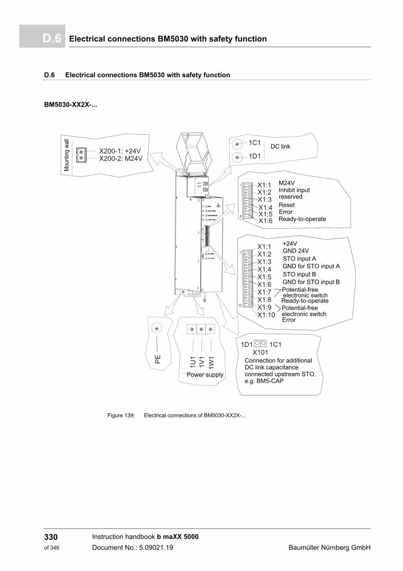
Electrical connections BM5030 with safety functionD.6
D.6 Electrical connections BM5030 with safety function
BM5030-XX2X-...
Figure 139: Electrical connections of BM5030-XX2X-...
Potential-freeelectronic switch
Potential-free electronic switch
DC link
Mou
ntin
g w
all
M24VInhibit inputreservedResetErrorReady-to-operate
+24VGND 24VSTO input AGND for STO input ASTO input BGND for STO input B
Power supply
Ready-to-operate
Error
Connection for additionalDC link capacitanceconnected upstream STO,e.g. BM5-CAP
Instruction handbook b maXX 5000
Document No.: 5.09021.19 Baumüller Nürnberg GmbH
330of 346
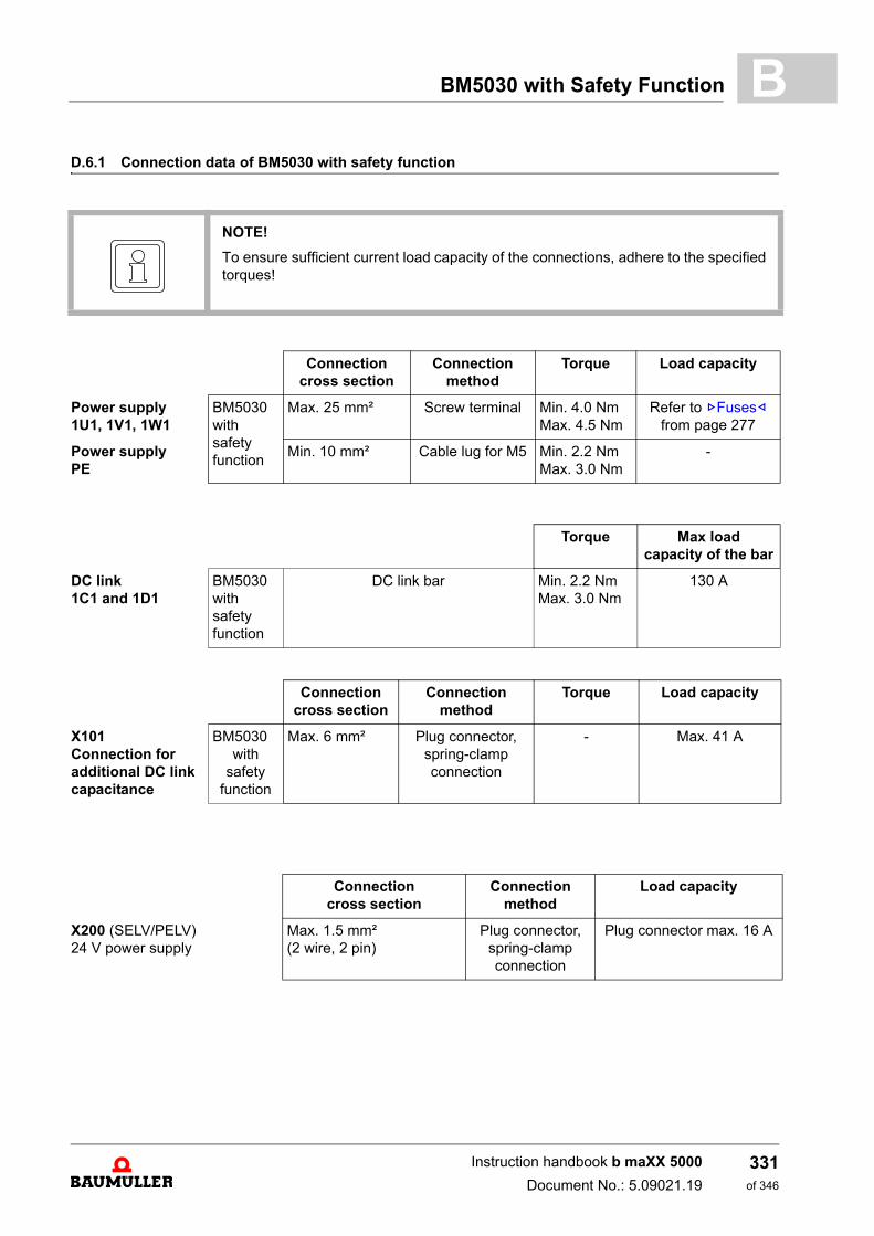
BM5030 with Safety Function B
D.6.1 Connection data of BM5030 with safety functionNOTE!
To ensure sufficient current load capacity of the connections, adhere to the specifiedtorques!
Connectioncross section
Connectionmethod
Torque Load capacity
Power supply1U1, 1V1, 1W1
BM5030with safety function
Max. 25 mm² Screw terminal Min. 4.0 NmMax. 4.5 Nm
Refer to ZFuses– from page 277
Power supplyPE
Min. 10 mm² Cable lug for M5 Min. 2.2 NmMax. 3.0 Nm
-
Torque Max load capacity of the bar
DC link1C1 and 1D1
BM5030with safety function
DC link bar Min. 2.2 NmMax. 3.0 Nm
130 A
Connectioncross section
Connectionmethod
Torque Load capacity
X101Connection for additional DC link capacitance
BM5030with
safety function
Max. 6 mm² Plug connector, spring-clamp connection
- Max. 41 A
Connectioncross section
Connectionmethod
Load capacity
X200 (SELV/PELV)24 V power supply
Max. 1.5 mm²(2 wire, 2 pin)
Plug connector, spring-clamp connection
Plug connector max. 16 A
Instruction handbook b maXX 5000
Document No.: 5.09021.19
331of 346
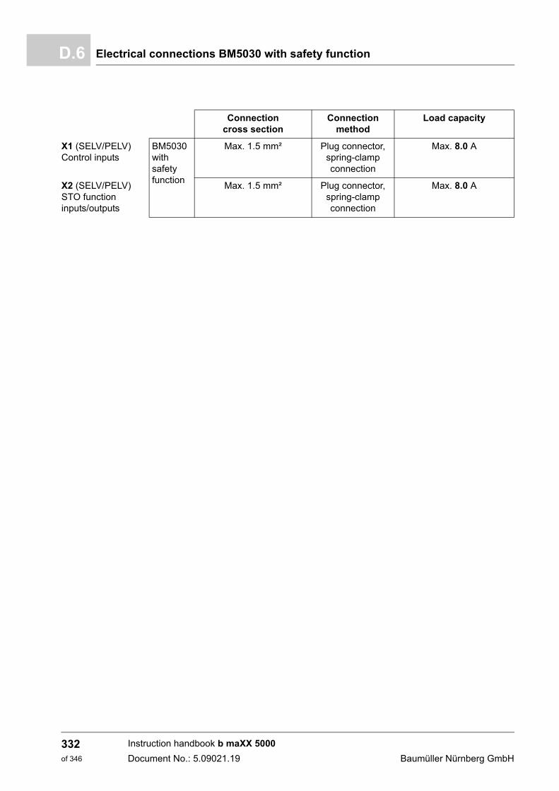
Electrical connections BM5030 with safety functionD.6
Connection cross section
Connection method
Load capacity
X1 (SELV/PELV)Control inputs
BM5030with safety function
Max. 1.5 mm² Plug connector, spring-clamp connection
Max. 8.0 A
X2 (SELV/PELV)STO functioninputs/outputs
Max. 1.5 mm² Plug connector, spring-clamp connection
Max. 8.0 A
Instruction handbook b maXX 5000
Document No.: 5.09021.19 Baumüller Nürnberg GmbH
332of 346
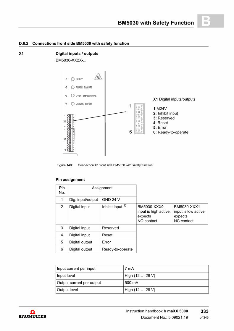
BM5030 with Safety Function B
D.6.2 Connections front side BM5030 with safety functionX1 Digital inputs / outputs
BM5030-XX2X-...
Pin assignment
X1 Digital inputs/outputs
1:M24V2: Inhibit input3: Reserved4: Reset5: Error6: Ready-to-operate
Figure 140: Connection X1 front side BM5030 with safety function
Pin No.
Assignment
1 Dig. input/output GND 24 V
2 Digital input Inhibit input 1) BM5030-XXX0input is high active, expects NO contact
BM5030-XXX1input is low active, expects NC contact
3 Digital input Reserved
4 Digital input Reset
5 Digital output Error
6 Digital output Ready-to-operate
Input current per input 7 mA
Input level High (12 … 28 V)
Output current per output 500 mA
Output level High (12 … 28 V)
Instruction handbook b maXX 5000
Document No.: 5.09021.19
333of 346
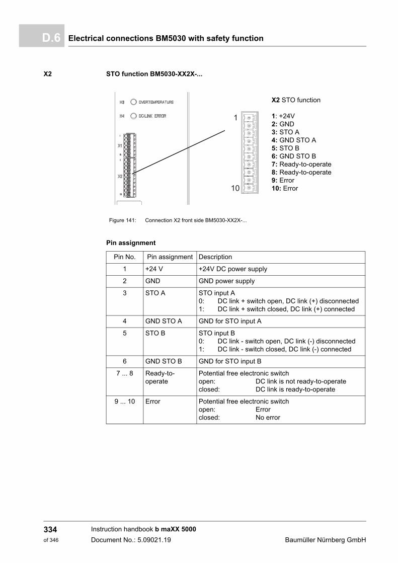
Electrical connections BM5030 with safety functionD.6
X2 STO function BM5030-XX2X-...
Pin assignment
X2 STO function
1: +24V2: GND3: STO A4: GND STO A5: STO B6: GND STO B7: Ready-to-operate8: Ready-to-operate9: Error10: Error
Figure 141: Connection X2 front side BM5030-XX2X-...
Pin No. Pin assignment Description
1 +24 V +24V DC power supply
2 GND GND power supply
3 STO A STO input A0: DC link + switch open, DC link (+) disconnected1: DC link + switch closed, DC link (+) connected
4 GND STO A GND for STO input A
5 STO B STO input B0: DC link - switch open, DC link (-) disconnected1: DC link - switch closed, DC link (-) connected
6 GND STO B GND for STO input B
7 ... 8 Ready-to-operate
Potential free electronic switchopen: DC link is not ready-to-operateclosed: DC link is ready-to-operate
9 ... 10 Error Potential free electronic switchopen: Errorclosed: No error
Instruction handbook b maXX 5000
Document No.: 5.09021.19 Baumüller Nürnberg GmbH
334of 346
BM5030 with Safety Function B
Power supply voltageX2:1, X2:2Power supply voltage for the electronics of DC link STO functionTechnical data see ZPower supply of the STO function– on page 336.
STO A inputX2:3, X2:4
First channel of safe DC link disconnection. This input operates the DC link + switch. Technical data see ZInputs STO function– on page 336.
STO B inputX2:5, X2:6
Second channel of safe DC link disconnection. This input operates the DC link - switch.Technical data see ZInputs STO function– on page 336.
Ready-to-operateoutputX2:7, X2:8
The DC link capacitors are charged via resistors after switching on the DC link switch. Af-ter that the loading resistors are bridged. Now it is possible to draw power from the DClink by the decentralized drive solutions BM2500. This state is shown by the ready-to-op-erate output ((X2:7 X2:8 closed).
Error output:X2:9, X2:10
The error output is active (X2:9 X2:10 open) as long as the DC link STO function isin error state.
The error state is triggered by following incidents:
m STO error
m Overtemperature heat sink
m Fault of heat sink temperature sensor
STO error:
m At least on DC link switch is closed if the state of the STO inputs changes to „high“.
m t1 > 5 ms (see ZSTO timing– on page 340)
NOTICE!
The decentralized drive solutions BM2500 connected to the DC link of the BM5030must not be enabled to state „operation enabled“ before the ready-to-operate outputof the BM5030 is active, otherwise a damage of the device is possible.
Instruction handbook b maXX 5000
Document No.: 5.09021.19
335of 346
Electrical connections BM5030 with safety functionD.6
Power supply of theSTO function
For the power supply of the STO function on connector X2 a 24 V power supply unit isrequired, which corresponds with the SELV/PELV standards according EN 50178.
Voltage: 24VDC -15 %/+20 %
Inputs STO function
The inputs of connector X2 have been designed according IEC 61131. The input levels are as follows in case of 24 V DC power supply:
The maximum length of the cable is 30 m.
The safe inputs are designed for an operation with sensors providing OSSD outputs. Themaximum test pulse length of 1 ms must not be exceeded.
Both inputs STO A and STO B are necessary for the safety function STO and must beactivated separately. If both inputs are activated by one cable, the fault exclusion short-circuit according IEC 61800-5-2 appendix D must be considered.
OutputsBM5030-XX2X-...
Power rating per NO contact: Max. 30 V, max. 100 mA
The maximum cable length is 30 m.
UHmax = 30 VUHmin = 11 VULmax = 5 VULmin = -3 V
IHmax = 15 mAIHmin = 2 mAILmin = not determinedILmax = 15 mA
Instruction handbook b maXX 5000
Document No.: 5.09021.19 Baumüller Nürnberg GmbH
336of 346
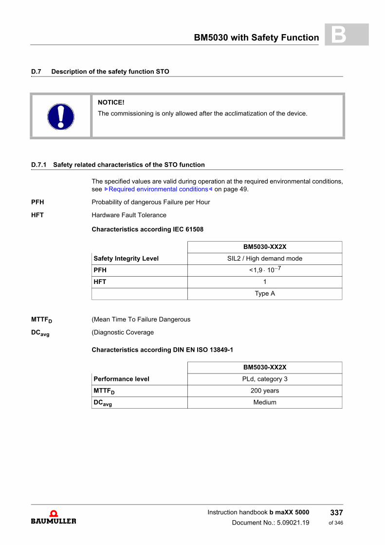
BM5030 with Safety Function B
D.7 Description of the safety function STOD.7.1 Safety related characteristics of the STO function
The specified values are valid during operation at the required environmental conditions,see ZRequired environmental conditions– on page 49.
PFH Probability of dangerous Failure per Hour
HFT Hardware Fault Tolerance
Characteristics according IEC 61508
MTTFD (Mean Time To Failure Dangerous
DCavg (Diagnostic Coverage
Characteristics according DIN EN ISO 13849-1
NOTICE!
The commissioning is only allowed after the acclimatization of the device.
BM5030-XX2X
Safety Integrity Level SIL2 / High demand mode
PFH
HFT 1
Type A
<1,9 10 7–
BM5030-XX2X
Performance level PLd, category 3
MTTFD 200 years
DCavg Medium
Instruction handbook b maXX 5000
Document No.: 5.09021.19
337of 346
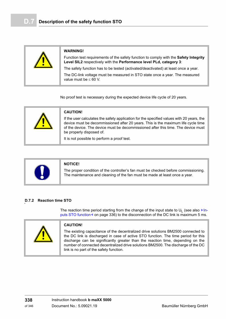
Description of the safety function STOD.7
No proof test is necessary during the expected device life cycle of 20 years.
D.7.2 Reaction time STO
The reaction time period starting from the change of the input state to UL (see also ZIn-puts STO function– on page 336) to the disconnection of the DC link is maximum 5 ms.
WARNING!
Function test requirements of the safety function to comply with the Safety IntegrityLevel SIL2 respectively with the Performance level PLd, category 3:
The safety function has to be tested (activated/deactivated) at least once a year.
The DC-link voltage must be measured in STO state once a year. The measured value must be 60 V.
CAUTION!
If the user calculates the safety application for the specified values with 20 years, thedevice must be decommissioned after 20 years. This is the maximum life cycle timeof the device. The device must be decommissioned after this time. The device mustbe properly disposed of.
It is not possible to perform a proof test.
NOTICE!
The proper condition of the controller’s fan must be checked before commissioning.The maintenance and cleaning of the fan must be made at least once a year.
CAUTION!
The existing capacitance of the decentralized drive solutions BM2500 connected tothe DC link is discharged in case of active STO function. The time period for thisdischarge can be significantly greater than the reaction time, depending on thenumber of connected decentralized drive solutions BM2500. The discharge of the DClink is no part of the safety function.
Instruction handbook b maXX 5000
Document No.: 5.09021.19 Baumüller Nürnberg GmbH
338of 346
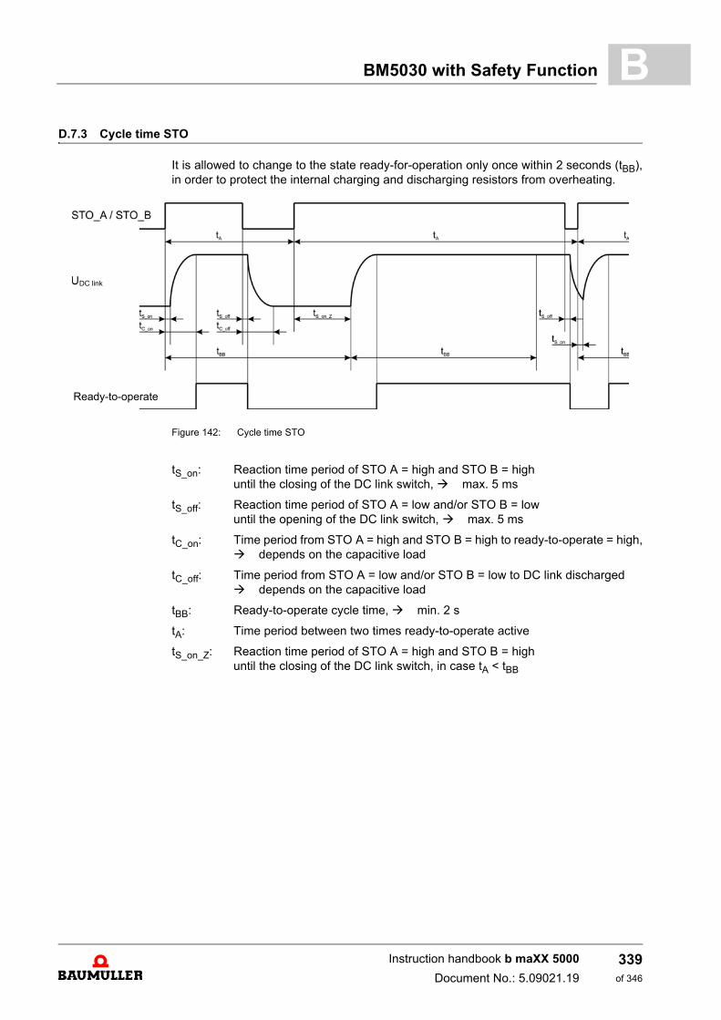
BM5030 with Safety Function B
D.7.3 Cycle time STOIt is allowed to change to the state ready-for-operation only once within 2 seconds (tBB),in order to protect the internal charging and discharging resistors from overheating.
Figure 142: Cycle time STO
tS_on: Reaction time period of STO A = high and STO B = high until the closing of the DC link switch, max. 5 ms
tS_off: Reaction time period of STO A = low and/or STO B = low until the opening of the DC link switch, max. 5 ms
tC_on: Time period from STO A = high and STO B = high to ready-to-operate = high, depends on the capacitive load
tC_off: Time period from STO A = low and/or STO B = low to DC link discharged depends on the capacitive load
tBB: Ready-to-operate cycle time, min. 2 s
tA: Time period between two times ready-to-operate active
tS_on_Z: Reaction time period of STO A = high and STO B = high until the closing of the DC link switch, in case tA < tBB
Ready-to-operate
DC link
Instruction handbook b maXX 5000
Document No.: 5.09021.19
339of 346
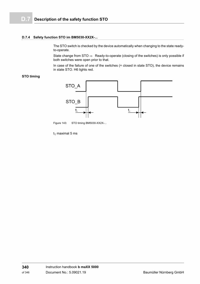
Description of the safety function STOD.7
D.7.4 Safety function STO im BM5030-XX2X-...
The STO switch is checked by the device automatically when changing to the state ready-to-operate.
State change from STO Ready-to-operate (closing of the switches) is only possible ifboth switches were open prior to that.
In case of the failure of one of the switches (= closed in state STO), the device remainsin state STO. H6 lights red.
STO timing
Figure 143: STO timing BM5030-XX2X-...
t1 maximal 5 ms
Instruction handbook b maXX 5000
Document No.: 5.09021.19 Baumüller Nürnberg GmbH
340of 346
Table of Figures
Table of Figures
Wiring of the power cables......................................................................................................... 18Signs and labels BM5XXX ......................................................................................................... 26BM503X-C/-S dimensions.......................................................................................................... 29BM503X-A dimensions............................................................................................................... 30BM504X-C/-S dimensions.......................................................................................................... 31BM504X-A dimensions............................................................................................................... 32BM504X-S dimensions............................................................................................................... 33BM504X-F dimensions............................................................................................................... 34BM517X-C/-S dimensions.......................................................................................................... 35BM519X-S dimensions............................................................................................................... 36BM519X-F dimensions............................................................................................................... 37BM532X-C/-S dimensions.......................................................................................................... 38BM532X-A dimensions............................................................................................................... 39BM533X-C/-S dimensions.......................................................................................................... 40BM533X-A dimensions............................................................................................................... 41BM533X-F dimensions............................................................................................................... 42BM537X-S dimensions............................................................................................................... 43BM537X-F dimensions............................................................................................................... 44Control voltage / 24 V power supply .......................................................................................... 47Correction value kH in dependence on the installation altitude H, BM50XX, BM51XX.............. 51Correction value kT in dependence of the temperature TU, BM53XX........................................ 52Correction value kH in dependence on the installation altitude H, BM53XX .............................. 52Derating: Output current as a function of the power supply voltage .......................................... 54Derating: Input current BM50XX, BM517X, BM519X................................................................. 54Derating: DC link voltage as a function of the power supply voltage ......................................... 55Derating: Output power as a function of the power supply voltage............................................ 55Derating: DC link voltage as a function of the power supply voltage ......................................... 56Derating: Output power as a function of the power supply voltage............................................ 56Derating: DC link power B503X, BM504X, BM517X, BM519X .................................................. 57Derating: Output current as function of the DC link voltage axis units ....................................... 57Cooling air requirement.............................................................................................................. 58Derating with a static inverter frequency < 15 Hz ...................................................................... 77Typical power-time diagram: operation with constant load ........................................................ 78Typical power-time diagram: intermittent load cycle with peak value ........................................ 78Typical power-time diagram: Intermittent load cycle .................................................................. 79Typical current-time diagram: operation with constant load....................................................... 80Typical current-time diagram: intermittent load cycle with peak value ....................................... 81Typical current-time diagram: Intermittent load cycle................................................................. 82Part number - front ..................................................................................................................... 88Affixing of the type plate............................................................................................................. 89Display/operating elements BM50XX without safety function .................................................... 96Display/operating elements BM51XX......................................................................................... 98Display/operating elements controller BM53XX....................................................................... 101Address switch setting EtherCAT®, POWERLINK®, VARAN ................................................. 108Address setting CANopen® ................................................................................................................................ 110Danger area near the mechanical mounting ............................................................................ 115Drilling pattern with mounting rail for BM50XX-S, BM53XX-S, BM51XX-S ............................. 117Drilling pattern without mounting rail for all versions................................................................ 118Cutout BM537X-F .................................................................................................................... 118Mounting instructions for the BM51XX and BM53XX, with mounting rail................................. 120Mounting instructions for the BM51XX and BM53XX, without mounting rail............................ 121Correctly mounted DC link bar ................................................................................................. 122Mounting of the neck collar screw............................................................................................ 122Mounting of the DC link bar...................................................................................................... 123
Instruction handbook b maXX 5000
Document No.: 5.09021.19341
of 346
342of 346
Table of Figures
Example DC link connection BM537X...................................................................................... 124Dimensions/drilling pattern toroidal cores................................................................................. 125Toroidal cores mounted ............................................................................................................ 126Hazard areas during electrical installation ................................................................................ 130Connection to an IT-system or Grounded Delta system........................................................... 133Connecting to IT-system or grounded phase conductor system with isolating transformer ..... 134Grounding concept, each device with PE connection............................................................... 136Grounding concept, PE connection from device to device ....................................................... 137Mounting shield sheet air-cooled devices................................................................................. 140Mounting shield sheet cold plate devices ................................................................................. 140Wrap shield motor temperature cable around motor cable....................................................... 141Tape shield motor temperature cable around........................................................................... 142Shield connection motor cable.................................................................................................. 143Mounting - single ring core ....................................................................................................... 146Mounting - several ring cores ................................................................................................... 146Connection diagram for the BM50XX-XX00 without safety function......................................... 150Connection diagram for the BM50XX-XX01 without safety function......................................... 151Connection diagram for the BM51XX ....................................................................................... 152Connection proposal BM51XX.................................................................................................. 154Connection proposal BM51XX pulse enable control ................................................................ 155Connection diagram single axis units BM5326, BM5327, BM5328.......................................... 157Connection diagram single axis units BM5334, BM5335 ......................................................... 158Connection diagram single axis units BM537X ........................................................................ 159Connection diagram for the double axis unit BM5323, BM5325............................................... 161Connection diagram for the double axis unit BM5331, BM5332, BM5333 ............................... 162Electrical connections of the BM503, BM504XX without safety function.................................. 164Electrical connections of the BM507X without safety function.................................................. 165Electrical connections of the BM517X ...................................................................................... 166Electrical connections of the BM519X ...................................................................................... 167Electrical connections of the single axis BM5326, BM5327, BM5328 ...................................... 168Electrical connections of the single axis BM5334, BM5335 ..................................................... 169Electrical connections of the single axis BM537X .................................................................... 170Connection motor/PE bolt......................................................................................................... 171Electrical connections of the double axis BM5323, BM5325.................................................... 172Electrical connections of the double axis BM5331, BM5332, BM5333..................................... 173Laying of the signal bus cable .................................................................................................. 178Connections front side BM50XX-XX0X-... without safety function........................................... 179Connections controller part BM51XX........................................................................................ 181LED display add-on module SVP ............................................................................................. 193Connection of analog inputs/outputs SVP ................................................................................ 196Connection of digital inputs/outputs SVP.................................................................................. 196Add-on module EtherNet/IP® ............................................................................................................................ 197Add-on module EtherNet/IP® ............................................................................................................................ 200Connection of analog inputs/outputs and encoder BM53XX .................................................... 203Female connector X1................................................................................................................ 219Timing diagram quick discharge ............................................................................................... 220Timing diagram brake resistor switch ....................................................................................... 220Timing diagram power supply ON after 24 V ON ..................................................................... 221Timing diagram 24 V ON before Power supply ON signal bus................................................. 221Timing diagram short power failure (< 10 s) ............................................................................. 222Timing diagram phase failure signal bus .................................................................................. 222Timing diagram long power failure (> 10 s) BM50XX-XXX0..................................................... 223Timing diagram error acknowledge at power recovery BM50XX-XXX1 ................................... 224Timing diagram Inhibit input X1:2 ............................................................................................. 225
Instruction handbook b maXX 5000
Document No.: 5.09021.19 Baumüller Nürnberg GmbH
Table of Figures
VARAN fieldbus connection ..................................................................................................... 229Hazard areas during electrical installation ............................................................................... 2377-segment display: errors and warnings .................................................................................. 253Motor cable with HIPERFACE DSL® 15 A............................................................................... 260Motor cable with HIPERFACE DSL® 20 A............................................................................... 261Motor cable with HIPERFACE DSL® 21 A............................................................................... 262Motor cable with HIPERFACE DSL® 28 A............................................................................... 263Motor cable with HIPERFACE DSL® 36 A............................................................................... 264Connecting cable for resolver .................................................................................................. 269Connecting cable for encoder with HIPERFACE® .................................................................................... 270Connecting cable for encoder with EnDat® or SSI................................................................... 271Connecting cable for encoder with EnDat® 2.2 M12................................................................ 272Connecting cable for encoder with EnDat® 2.2 speedtec® M23 .............................................. 273Connecting cable for sine/square wave incremental encoder.................................................. 274Connection cable IEE with b maXX 5000 ............................................................................... 275Connection cable IEE with b maXX 5000 ................................................................................ 276Block diagram .......................................................................................................................... 286Line filter type code .................................................................................................................. 286Dimensions HOWCORE NFI-20 .............................................................................................. 290Dimensions LGF FFU 3x295AB-SBM...................................................................................... 291Dimensions of choke BM50XX................................................................................................. 295Connection diagram of choke BM50XX ................................................................................... 295Power choke BM5173 .............................................................................................................. 296Power choke BM5174 .............................................................................................................. 297Connection diagram BM5174................................................................................................... 297Power choke BM519X.............................................................................................................. 298BM5030 with safety function .................................................................................................... 322Display/operating elements BM5030-XX2X-... ......................................................................... 326Connection diagram BM5030-XX20-... .................................................................................... 328Connection diagram BM5030-XX21-... .................................................................................... 329Electrical connections of BM5030-XX2X-... ............................................................................. 330Connection X1 front side BM5030 with safety function............................................................ 333Connection X2 front side BM5030-XX2X-................................................................................ 334Cycle time STO ........................................................................................................................ 339STO timing BM5030-XX2X-... .................................................................................................. 340
Instruction handbook b maXX 5000
Document No.: 5.09021.19343
of 346

344of 346
Table of Figures
Instruction handbook b maXX 5000
Document No.: 5.09021.19 Baumüller Nürnberg GmbH
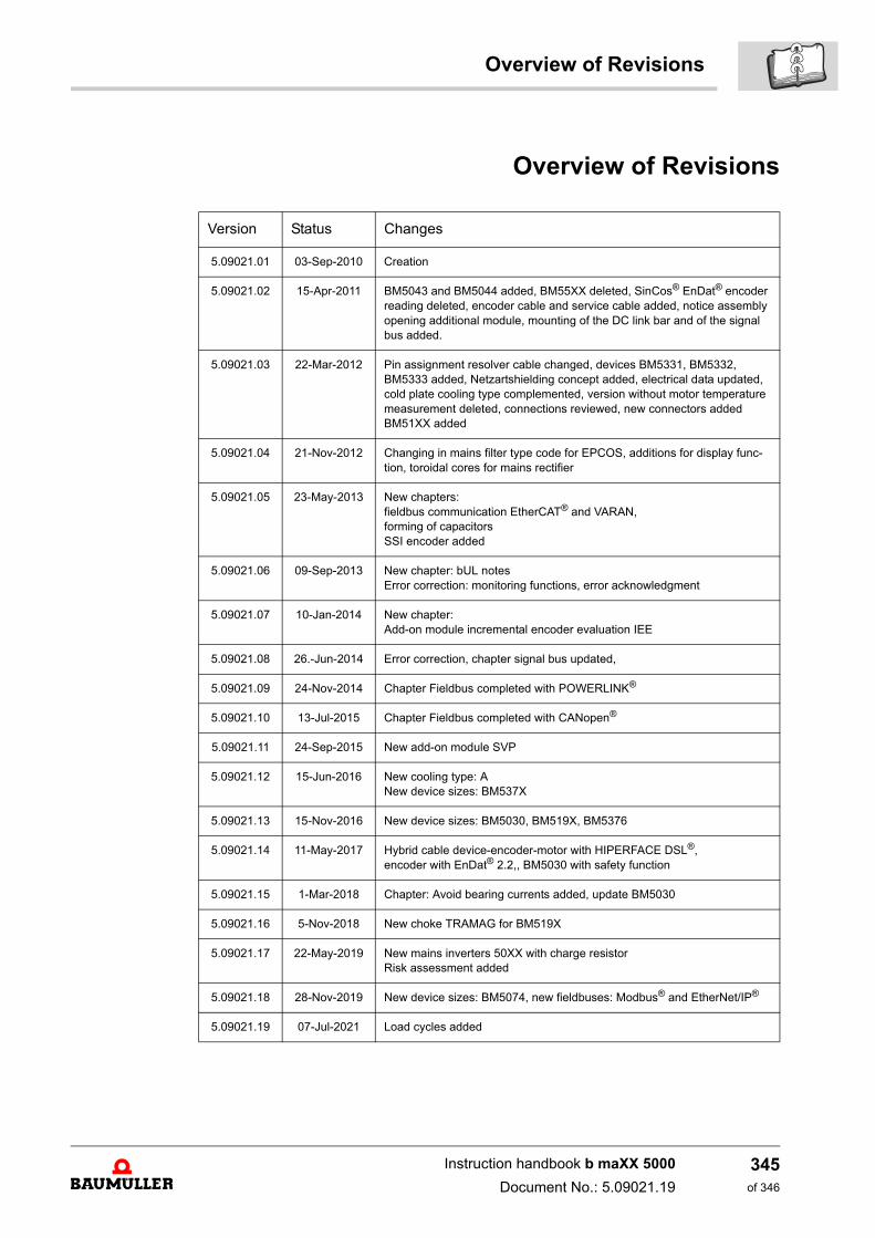
Overview of Revisions
Overview of Revisions
Version Status Changes
5.09021.01 03-Sep-2010 Creation
5.09021.02 15-Apr-2011 BM5043 and BM5044 added, BM55XX deleted, SinCos® EnDat® encoder reading deleted, encoder cable and service cable added, notice assembly opening additional module, mounting of the DC link bar and of the signal bus added.
5.09021.03 22-Mar-2012 Pin assignment resolver cable changed, devices BM5331, BM5332, BM5333 added, Netzartshielding concept added, electrical data updated, cold plate cooling type complemented, version without motor temperature measurement deleted, connections reviewed, new connectors addedBM51XX added
5.09021.04 21-Nov-2012 Changing in mains filter type code for EPCOS, additions for display func-tion, toroidal cores for mains rectifier
5.09021.05 23-May-2013 New chapters: fieldbus communication EtherCAT® and VARAN,forming of capacitorsSSI encoder added
5.09021.06 09-Sep-2013 New chapter: bUL notesError correction: monitoring functions, error acknowledgment
5.09021.07 10-Jan-2014 New chapter:Add-on module incremental encoder evaluation IEE
5.09021.08 26.-Jun-2014 Error correction, chapter signal bus updated,
5.09021.09 24-Nov-2014 Chapter Fieldbus completed with POWERLINK®
5.09021.10 13-Jul-2015 Chapter Fieldbus completed with CANopen®
5.09021.11 24-Sep-2015 New add-on module SVP
5.09021.12 15-Jun-2016 New cooling type: ANew device sizes: BM537X
5.09021.13 15-Nov-2016 New device sizes: BM5030, BM519X, BM5376
5.09021.14 11-May-2017 Hybrid cable device-encoder-motor with HIPERFACE DSL®,encoder with EnDat® 2.2,, BM5030 with safety function
5.09021.15 1-Mar-2018 Chapter: Avoid bearing currents added, update BM5030
5.09021.16 5-Nov-2018 New choke TRAMAG for BM519X
5.09021.17 22-May-2019 New mains inverters 50XX with charge resistorRisk assessment added
5.09021.18 28-Nov-2019 New device sizes: BM5074, new fieldbuses: Modbus® and EtherNet/IP®
5.09021.19 07-Jul-2021 Load cycles added
Instruction handbook b maXX 5000
Document No.: 5.09021.19
345of 346
Notes:
Instruction handbook b maXX 5000
Document No.: 5.09021.19 Baumüller Nürnberg GmbH
346of 346


Baumüller Nürnberg GmbH Ostendstraße 80-90 90482 Nürnberg T: +49(0)911-5432-0 F: +49(0)911-5432-130 www.baumueller.com
All information given in this manual is customer information, subject to change without notice. We reserve the right to further develop and actualize our products continuously using our permanent revision service. Please notice, that specifications/data/information are current values according to the printing date.These statements are not legally binding according to the measurement, computation and calculations. Before you make any information given in this manual to the basis of your own calculations and/or applications, please make sure that you have the latest edition of the information in hand.No liability can be accepted concerning the correctness of the information.


