Embed Size (px)
Citation preview

AD-A~~lS 530 DAVID M TAYLOR NAVAL SH I DDVLPETC-T / /
ANNUAL REPORT OF TH9 NAVY AEROBALLISTICS COMMITTEE TO THE NAVAL--ETCIU)
UNCLASSIFIED AER01278 DTNSRDC-81/0903 LEEEEE
-112.8 __
L3
11II1___. ,II 1.6
, MICROCOPY RESOLUTION TEST CHART
NAfI(1NAI Pk Ii AI ol IANOARO 1,l> A
0

UNCLASSIFIEDqECUITV CLASSIFICATION OF THIS PAGE (When Date Entered)
REPORT DOCUMENTATION PAGE READ INSTRUCTIONSREPORT__ DOCUMENTATIONPAGE_ BEFORE COMPLETING FORM
I. REPORT NUMBER 2. GOVT ACCESSION NO. 3. RECIPIENT'S CATALOG NUMBER
DTNSRDC-81/090 v£ _ __ _
4. TITLE (end Subtitle) S. TYPE OF REPORT & PERIOD COVEREDANNUAL REPORT OF THE NAVY AEROBALLISTICS
COMMITTEE TO THE NAVAL AIR SYSTEMS Final, 1 Jan - 31 Dec 1981COMMAND AND THE NAVAL SEA 6- PERFORMING ORO. REPORT NUMBER
SYSTEMS COMMAND FOR 1981 Aero Report 12787, AUTHOR(@) S. CONTRACT OR GRANT NUMBERS)
9. PERFORMING ORGANIZATION NAME AND ADDRESS 10. PROGRAM ELEMENT. PROJECT. TASKAREA & WORK UNIT NUMBERS
David W. Taylor Naval Ship Research
and Development Center Work Unit 1600-001Bethesda, Maryland 20084
11. CONTROLLING OFFICE NAME AND ADDRESS 12. REPORT DATE
Naval Air Systems Command, Washington, D.C. 20361 March 1982
Naval Sea Systems Command, Washington, D.C. 20362 13. NUMBER OFPAGES
21314. MONITORING AGENCY NAME & ADORESS(II different from Controlling Office) IS. SECURITY CLASS. (of this report)
UNCLASSIFIED1Sa. OECLASSIFICATION/DOWNGRADING
SCHEDULE
16. DISTRIBUTION STATEMENT (of this Report)
APPROVED FOR PUBLIC RELEASE: DISTRIBUTION UNLIMITED
17. DISTRIBUTION STATEMENT (of the abstract entered In Block 20, if different from Report)
10. SUPPLEMENTARY NOTES
19. KEY WORDS (Continue on reverse ide Ilneceosery end identify by block number)
Aeroballistics Missile Stability and Performance
Gas Dynamics Air Inlets and DiffusersHeat Transfer Aeroelasticity and Struct, -
Launch Dynamics
20. ABSTRACT (Continue an reverse eide if.neceeey end Identify by block number),
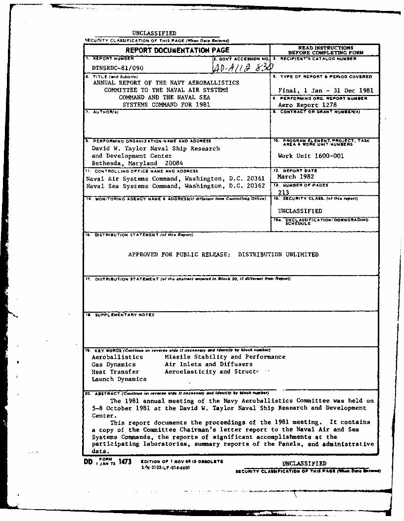
The 1981 annual meeting of the Navy Aeroballistics Committee was held on5-8 October 1981 at the David W. Taylor Naval Ship Research and DevelopmentCenter.
This report documents the proceedings of the 1981 meeting. It containsa copy of the Committee Chairman's letter report to the Naval Air and SeaSystems Commands, the reports of significant accomplishments at theparticipating laboratories, summary reports of the Panels, and administrativedata.
DO jAN73 1473 oIOt Or I OV SSIS OBSOLETE UNCLASSIFIEDS"N 0102-LF-01 4-6601 SECURITY CLASSIFICATION Or THIS PAGE (fhen 009e BeNed)
FOREWORD
-- 2 The 1981 annual meeting of the Navy Aeroballistics
Committee (NAC) was held on 5-8 October 1981 at the David W.
Taylor Naval Ship Research and Development Center._DIS)C).The 106 participants included representatives of all agencies
on the Committee, five universities, and twenty industrial con-tractors to the Navy., In addition, representatives of theNational Aeronautics and Space Administration (NASA), the Army,
and the Air Force were present as invited guests._-,This report documents the proceedings of the 1981 meeting.
It contains a copy of the Committee Chairman's letter report to
the Naval Air and Sea Systems Commands, the reports of signifi-
cant accomplishments at the participating laboratries, summaryreports of the Panels, and administrative data.
Aooss51n ForNTIS GRA&IDTIC TABUnannounced
JUstificatio
BTIC --
(_Distrjbuticn/Awv lability Codes
,Av~j2 ard/or-
Dist
iii
TABLE OF CONTENTS
Page
LETTER (LNCLUDING RECOMMENDATIONS) TO COMMANDER, NAVAL AIRSYSTEMS COMMAND, COMMANDER, NAVAL SEA SYSTEMS COMMANDFROM CHAIRMAN, NAVY AEROBALLISTICS COMMITTEE........................1
AGENCY REPORTS OF SIGNIFICANT ACCOMPLISHMENTS ................... 13
DAVID W. TAYLOR NAVAL SHIP RESEARCH AND DEVELOPMENTCENTER (DTNSRDC)...................................14
JOHNS HOPKINS UNIVERSITY/APPLIED PHYSICSLABORATORY (JHU/APL)..............................15
NAVAL AIR DEVELOPMENT CENTER (NADC)...........................16
NAVAL SURFACE WEAPONS CENTER (NSWC)...........................17
NAVAL WEAPONS CENTER (NWC)............................18
PACIFIC MISSILE TEST CENTER (PMTC)........................19
PANEL SUMMARY REPORTS...................................21
-AIR INLETS AND DIFFUSERS PANEL . .. .. .. .. .. .. .. .. .. .. . .22
GAS DYNAMICS PANEL.................................43
HEAT TRANSFER PANEL ,.. .. .. .. .. .. .. .. .. .. .. .. .. .. 63
LAUNCH DYNAMICS PANEL,,.............................101
MISSILE S TABILITY AND PERFORMANCE PANEL 123
STRUCTURES AND AEROELASTICITY PANEL........................147
APPENDIX A - NAVY AEROBALLISTICS COMMITTEE CHARTER ................ 181
APPENDIX B - CHARTERS OF THE PANELS OF THE NAVY AEROBALLISTICSCOMMITTEE..................................187
APPENDIX C - MEMBERSHIP OF THE COMMITTEE.....................195
APPENDIX D - PAST CHAIRMEN OF THE NAVY AEROBALLISTICS COMMITTEE. ......... 197
APPENDIX E - MEETINGS OF THE COMMITTEE........................199
APPENDIX F - NAVY SYMPOSIA ON AEROBALLISTICS...................205
iv
.Tq
LETTER (INCLUDING RECOMMENDATIONS) TO
COMMANDER, NAVAL AIR SYSTEMS COMMAND
COMMANDER, NAVAL SEA SYSTEMS COMMAND
FROM
CHAIRMAN, NAVY AEROBALLISTICS COMMITTEE
S
:'i 1
*1
DEPARTMENT OF THE NAVY ANNAPOLS MD 2TO
DAVID W. TAYLOR NAVAL SHIP NE AN.H AIIS. AD 2I4R
AND DEVELOPRUNT CIENTER CARDHO LASORATO YHEADOUATERSITESA A
ETHESDA. MARYLAND 204 *d REPLY REFER TO:
1606: STS5760/542012 Nov 1981
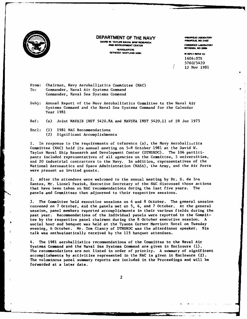
From: Chairman, Navy Aeroballistics Committee (NAC)To: Commander, Naval Air Systems Command
Commander, Naval Sea Systems Command
Subj: Annual Report of the Navy Aeroballistics Committee to the Naval AirSystems Command and the Naval Sea Systems Command for the CalendarYear 1981
Ref: (a) Joint NAVAIR INST 5420.8A and NAVSEA INST 5420.11 of 28 Jun 1975
Encl: (1) 1981 NAC Recommendations(2) Significant Accomplishments
1. In response to the requirements of reference (a), the Navy AeroballibticsCommittee (NAC) held its annual meeting on 5-8 October 1981 at the David W.Taylor Naval Ship Research and Development Center (DTNSRDC). The 106 partici-pants included representatives of all agencies on the Committee, 5 universities,and 20 industrial contractors to the Navy. In addition, representatives of theNational Aeronautics and Space Administration (NASA), the Army, and the Air Forcewere present as invited guests.
2. After the attendees were welcomed to the annual meeting by Dr. S. de losSantos, Mr. Lionel Pasiuk, Executive Secretary of the NAC discussed those actionsthat have been taken on NAC recommendations during the last five years. Thepanels and Committees then adjourned to their respective sessions.
3. The Committee held executive sessions on 6 and 8 October. The general sessionconvened on 7 October, and the panels met on 5, 6, and 7 October. At the generalsession, panel members reported accomplishments in their various fields during thepast year. Recommendations of the individual panels were reported to the Commit-tee by the respective panel chairmen during the 8 October executive session. Asocial hour and banquet was held at the Tysons Corner Marriott Hotel on Tuesdayevening, 6 October. Mr. Tom Clancy of DTNSRDC was the afterdinner speaker. Histalk was enthusiastically received by the 115 banquet attendees.
4. The 1981 aeroballistics recommendations of the Committee to the Naval AirSystems Command and the Naval Sea Systems Command are given in Enclosure (1).The recommendations are not listed in order of priority. A summary of significantaccomplishments by activities represented in the NAC is given in Enclosure (2).The voluminous panel summary reports are included in the Proceedings and will beforwarded at a later date.
2
1606:STS5760/542012 Nov 1981
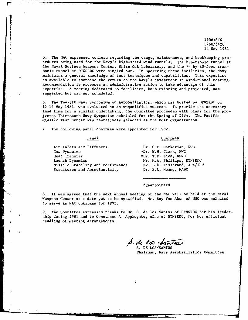
5. The NAC expressed concern regarding the usage, maintenance, and bookkeeping pro-cedures being used for the Navy's high-speed wind tunnels. The hypersonic tunnel atthe Naval Surface Weapons Center, White Oak Laboratory, and the 7- by 10-foot tran-sonic tunnel at DTNSRDC were singled out. In operating these facilities, the Navymaintains a general knowledge of test techniques and capabilities. This expertiseis available to increase the return on the Navy's investment in wind-tunnel testing.Recommendation 18 proposes an administrative action to take advantage of thisexpertise. A meeting dedicated to facilities, both existing and projected, wassuggested but was not scheduled.
6. The Twelfth Navy Symposium on Aeroballistics, which was hosted by DTNSRDC on12-14 May 1981, was evaluated as an unqualified success. To provide the necessarylead time for a similar undertaking, the Committee proceeded with plans for the pro-jected Thirteenth Navy Symposium scheduled for the Spring of 1984. The PacificMissile Test Center was tentatively selected as the host organization.
7. The following panel chairmen were appointed for 1982:
Panel Chairmen
Air Inlets and Diffusers Dr. C.F. Markarian, NWCGas Dynamics *Dr. W.H. Clark, NWCHeat Transfer *Dr. T.F. Zien, NSWCLaunch Dynamics Mr. K.A. Phillips, DTNSRDCMissile Stability and Performance Mr. L.E. Tisserand, APL/JHUStructures and Aeroelasticity Dr. S.L. Huang, NADC
*Reappointed
8. It was agreed that the next annual meeting of the NAC will be held at the NavalWeapons Center at a date yet to be specified. Mr. Ray Van Aken of NWC was selectedto serve as NAC Chairman for 1982.
9. The Committee expressed thanks to Dr. S. de los Santos of DTNSRDC for his leader-ship during 1981 and to Constance A. Applegate, also of DTNSRDC, for her efficienthandling of meeting arrangements.
S. DE LOS SChairman, Navy Aeroballistics Committee
3

RECOMMENDATIONS OF THE NAVY AEROBALLISTICSCOMMITTEE FOR 1981
ENCLOSURE (1)
L \ ...4
RECOMMENDATIONS OF THE NAVY AEROBALLISTICS COMMITTEEAT THE 1981 MEETING
1. RECOMMENDATION:
Continue to develop inviscid Euler flow codes with emphasis on the prediction offlow-fields containing regions of subsonic flow. This effort should emphasize
(a) development of efficient hybrid methods for use in three-dimensionalsupersonic flow-fields containing subsonic regions, and
(b) development of new computational methods aimed at achieving rdpidconvergence to steady state for the three-dimensional subsonic
flow-fields.
BACKGROUND:
Potential flow and linearized flow assumptions have severe limitations concern-ing their application to missile aerodynamics at high angles of attack because ofstrong shocks and rotational flow. Additional problems are encountered in dealingwith wing- or fin-body interactions even at moderate angles of attack. Inviscid orEuler codes are a promising method for handling these problems without going intothe complexity of full Navier-Stokes equations. When the axial Mach number is super-sonic, the Euler equations admit the very rapid and general marching method ofsolution. However, when the axial Mach number is subsonic (or is subsonic in a smallregion within the flow-field) this method breaks down. Existing methods for subsonicflow require some form of iterative solution and are very inefficient, requiring asmany as 600 iterations for acceptable convergence.
2. RECOMMENDATION:
Experimental programs should be undertaken to determine surface pressures on thebody and lifting surfaces of circular and noncircular finned configurations typicalof advanced tactical missiles for Mach numbers between 3 and 8. In addition, flow-field surveys should be made to determine shock layer properties with emphasis onseparated flow regions.
BACKGROUND:
In response to future tactical missile requirements, efforts are on-going topredict the aerodynamics of tactical missile configurations (e.g., circular andnoncircular bodies with wings and/or fins). Data are needed for preliminary designand to validate the predictive methods.
-5
3. RECOMMENLATION:
Improve the existing gas dynamic models for predicting rocket and ramjet plumephenomena. Specific areas that drive the ability to predict optical signatures,weapon launch interference effects and guidance interferece effects, are:
- afterbody and base separation phenomena- exit plane definition- solid particle propagation in plumes and nozzles- ad hoc turbulent mixing models- Mach disk formation and location models
State-of-the-art code development and specific validation experiments are neededin all areas above.
BACKGROUND:
The Standardized Plume Flowfield (SPF) code is currently emerging for use byvehicle design and detection system specialists. This code has specific gas dynamiclimitations that are currently the primary source of errors in IR, visible and UVsignature predictions (i.e., attack warning range and time) and in optical guidancesystem interference. The most immediate needs are for the development of baseeffects models for incorporation with SPF, the selection of the most appropriatemixing models for use in particular plume situations, an improved Mach disk model,and the formulation and execution of validation experiments to confirm or to guidethe way to improvement of the current SPF modeling. Any Navy contribution to thisTri-service program should be coordinated through the JANNAF IR and UV TacticalMis-ila Signatures Panel.
4. RECOMMENDATION:
Analyze data from test programs conducted in FY 80 and 81, that used scale modelsolid rocket motors producing representative chamber pressures and temperatures tosimulate aluminized propellant boosters (e.g., SM-2, Harpoon, Tomahawk, etc.) forevaluating shipboard, ground and ship VLS platform design heating rates, erosion andprotection requirements.
BACKGROUND:
Insufficient heating rate data are available to adequately define exhaust plumeheat flux as a function of position in the plume or to calculate heat transfer co-efficients for direct and indirect impingement of exhaust gases from solid propellantmotors. In addition, some propellants are aluminized for increased performance.Impingement of this aluminized exhaust causes surface erosion which may be of moreserious concern than the thermal environment. No adequate method of analyzingsurface erosion of different materials exists. Analysis of structure heating andenvironmental protection requirements requires a method to evaluate the thermal anderosive effects of plume impingement.
6
5. RECOMMENDATION:
An investigation should be conducted to determine the benefits of using anablator or insulation on the external surface of the missile structure, therebyallowing use of an aluminum structure. Application should be directed to the missile
mainbody. This effort should be for high supersonic and hypersonic tactical
missiles, with emphasis on solid rockets, but also including ramjets.
BACKGROUND:
An ablator or insulator on the external surface has been considered and used inpast missile designs. However, a comprehensive and organized investigation hasneither been undertaken nor documented on the feasibility and benefits of suchthermal protection. Consequently, new innovative thermal protection concepts havenot been given the attention necessary to develop them into viable candidates. With
the increased consideration being given to higher speed, there is a potential for agreater payoff for the use of an external ablator or insulation to maintain the
structure at a low temperature.
6. RECOMMENDATION:
A comprehensive program should be initiated to define realistic atmospheric
particle erosion environments with emphasis placed on probability of occurrence andincluding design criteria. Fundamental parameters that need to be addressed are:rain rate, liquid water content, particle size, spatial distribution, and geographicand seasonal variation.
BACKGROUND:
A crucial factor in the design and qualification of erosion resistant aircraftand missile radomes is the definition of realistic particle erosion environments.While rain is the most commonly addressed cause of erosion; ice, snow, and dust
(including that in a nuclear cloud) can also cause damage in high speed flight. Therain environment specified in MIL-STD-210B is not comprehensive enough and is oosevere for random design purposes. Design criteria are needed that specifyprobabilities of occurrence.
7. RECOMMENDATION:
It is recommended that experiments be conducted to measure the heating rate at
up to M = 4 on radome materials in an erosion-ablation environment.
BACKGROUND:
Advanced tactical missiles will encounter rain, snow, and possibly dust at Machnumbers up to 4 for approximately 30 sec. An accurate knowledge of the heating in
A. these environments is important because the survival or performance of componentslike composite radomes is threatened by excessive erosion-ablation, which becomes
.l7
strongly dependent on heating in the M = 2 to 4 regime. An RT/duroid 5870 radome,for example, is predicted to have almost 0.4 in. recession during an M = 4 flightthrough a rainstorm. The heating affects this recession prediction in two ways:(1) directly via ablation, and (2) indirectly through its effect on the temperaturedependent material properties that control erosion.
However, the heating in an erosive environment is not deducible from currqntdata because erosion and ablation are intrinsically coupled and the measurement ofanother variable is needed in order to infer both the erosion mass loss rate and theheating.
8. RECOMMENDATIONS:
Experimental flow-field data of service aircraft should be measured for use inthe validation of the mathematical models used in the analytical methods currentlybeing used for computing store carriage loads and store separation predictions. Alsomeasure air loads on the store.
BACKGROUND:
Analytical methods are increasingly being used in the prediction of store-carriage loads and store-separation predictions to reduce the need for expensivefull-scale flight tests and wind-tunnel tests. These analytical methods use a mathe-matical model to represent the aircraft in the calculation of flow-field interactionbetween aircraft and store. At present, many or most of the aircraft mathematicalmodels used have not been checked for accuracy due to the lack of the experimentalflow-field data required for validation. Due to the increasing use of aircraftmathematical models (math-models) in these and other aerodynamic prediction methods,the need for data to be used in the validation of the aircraft math-models is be-coming more and more important.
9. RECOMMENDATIONS:
Support studies to determine, from experimental data, the local flow influencecoefficients of one store for use in estimating the influence coefficients for
* another similar store.
BACKGROUND:
* Extensive experimental data files exist of store-aircraft Captive TrajectoryWind-Tunnel Store separation tests of many current stores and aircraft. Methodshave been investigated which show promise in the estimation of local flow-fieldinfluence coefficients from data for one store that may be useful in the estimation
r of the influence coefficients for a second store. Further development of thesemethods may provide means of using an existing databank for determing influence co-efficients for a future store shape. This would extend the usefulness of theexisting influence coefficient databank and decrease the need for extensive tests ofnew stores in the wind-tunnel captive trajectory systems.
._ .8
10. RECOMIENDATION:
Develop advanced computational procedures for the analysis and prediction offlows in complex inlet-diffuser systems, including unsteady effects caused by com-bustor oscillations. Support experimental studies to guide and validate thenumerical modeling.
BACKGROUND:
Experimental data suggest that combustor-induced pressure oscillations may feedforward into the inlet-diffuser system and drive it into unstable operation. Theseunsteady backpressures are known to couple with the normal shock movement insupercritical inlets, sometimes resulting in inlet nonstart.
Advanced computational procedures are very promising in their potential to modelsuch unsteady effects and thereby permit design of inlet-diffuser systems withgreater margins of stability and without significant performance compromises. It is,therefore, recommended that computational codes for the subject flows be developed,which are capable of treating practical geometries of gradually increasing com-plexity. Use of shock-alining adaptive grids is specially desirable to permit accu-rate positioning of shocks during transients. Experimental studies to guide thenumerical modeling and to validate the computer codes should also be supported.
11. RECOMMENDATION:
Conduct parametric experimental and analytical investigation of the inlet by-passconcept for increasing the range of stable operation.
BACKGROUND:
A two-dimensional by-pass inlet was developed for application to the Air ForceDucted Rocket Engine Development Program. The inlet utilized a high degree of ex-terAal compression combined with a relatively flat cowl lip angle which produced astrong internal reflected oblique shock. A wide "educated" slot was located on theramp surface just inside the ccwl lip to serve the dual function of an airflow by-pass system and compression surface boundary layer bleed, while acting as a shocktrap for the internal reflected shock. Inlet performance was characterized by highlevels of pressure recovery, relatively low drag, and a fairly wide range of sub-critical stable operation. Because of these encouraging results, further develop-ment of the by-pass inlet concept is recommended.
Development effort of this concept should include a parametric investigation ofthe by-pass slot geometry so that design tradeoffs of by-pass airflow, inlet pressurerecovery, and by-pass inlet overall drag coefficient can be evaluated for variousdesign applications.
9
12. RECOMMENDATION:
Support experimental and computational program directed at the understanding ofboundary-layer control in supersonic-transonic-subsonic inlet-diffusion systems.
BACKGROUND:
Boundary-layer bleed systems are used to improve inlet performance. Excessivebleed can lead to an overall performance degradation because of the need to exhaust
the bleed air. To design bleed systems having minimum bleed requirements, it isnecessary to include effects of the inlet boundary-layer characteristics and A-shockand boundary-layer interaction, which have a significant effect on shock losses.These shock-train losses can account for more than half of the total inlet loss.Currently, pipe-flow methods are used for loss prediction, and their applicabilityto realistic inlet geometries with developing boundary layers is questionable. Flowdistortion and oscillations due to separation in the subsonic diffuser should also beavoided; experimental data for short diffusers with boundary-layer control arelacking.
13. RECOMMENDATION:
Establish an experimental database for determining the components of inlet dragfor both tactical and strategic missile systems, which can be used to evaluate theaccuracy of existing theoretical methods or to guide the development of improvedpredictive methods.
BACKGROUND:
Inlet drag, which is a considerable portion of the total vehicle drag, must beaccurately known to evaluate properly the geometric requirements and the performancecapabilities of future missile systems. During tactical ramjet operation near take-over Mach number, for example, additive, cowl, diverter, and bleed pressure drag canadd up _o over 25 percent of missile-alone drag. Large uncertainty in total inletdrag can negate the design thrust margin.
The degree to which inlet drag has been measured in past wind-tunnel tests hasbeen limited by the lack of properly designed drag balances and/or the cost of suchtesting. This capability must be improved and all development programs for air-breathing missiles should include inlet drag measurements to properly assess theoverall performance of the inlets. These data should be added to the presentdatabase so that present predictive methods can be evaluated and improved whennecessary.
14. RECOMMENDATION:
Develop and experimentally verify engineering prediction methods for the exter-
nal aerodynamic characteristics of airbreathing missile configurations at arbitrarybank and control deflection angles, and to high angles of attack extending into thehypersonic regime.
10
BACKGROUND:
In order to meet future projected threats, the Navy is designing airbreathingmissiles. Engineering prediction methods, for the development of such designs and
for tradeoff studies, is nonexistent. The combination of body buildup testing, flowvisualization testing, and use of computational fluid dynamics codes has made thedevelopment of such engineering methods feasible. To support these predictiontechniques, the following experimental work is recommended: force and pressuremeasurements on hypersonic ramjet configuration models providing a wide range ofexternal geometric shapes; flow visualization of vertical regions; and additionalbody buildup measurements of component effects.
15. RECOMMENDATION:
It is recommended that experimental investigations be continued, in the lowsubsonic region, to measure forces or pressures on missile components (body, body-wing, etc.) at constant angles of attack with crossflow Reynolds number varied fromsubcritical to supercritical. Suitable test models are probably in existence.
BACKGROUND:
The interest in this type of information stems from the large mismatch betweenthe Reynolds number in subsonic tunnel testing and the full-scale Reynolds numberearly in launch. Typically, at a given angle of attack, the crossflow Reynoldsnumber in the tunnel is subcritical, whereas in flight, it is supercritical. Someprominent investigators have proposed methods to calculate the Reynolds number effect
on inclined configurations (at very low speeds), but there are no experimental datain the literature to evaluate their approach.
16. RECOMMENDATION:
Engineering design guidelines should be developed for the bounds of aerodynamic
parameters required for optimum maneuverability performance of tactical missilesfrom flight control perspective. The sensitivity of these bounds should be obtainedfor different candidate levels of flight control system complexity.
BACKGROUND:
High performance missiles are often severely limited in their maneuverability bythe inability of the flight control system to handle strongly-varying aerodynamiclateral-directional and control cross-coupling characteristics. If appropriatebounds were known and preliminary airframe designs were constrained to fit those
bounds, missile airframes will be designed which are optimized both formaneuverability and controllability.
11
17. RECOMMENDATION:
Develop and install dynamic testing equipment in the Navy's supersonic and hyper-sonic wind tunnels. The equipment should embody improved model support systems, suchas air bearings, gimbals, and free-flight techniques, as well as automated systemsfor readout of model orientation and position.
BACKGROUND:
Certain dynamic phenomena such as the "transient trim" observed in flight testsof reentry configurations, cannot be explained on the basis of static test data. Insuch cases, it becomes important to measure dynamic forces. The Navy's supersonicand hypersonic wind tunnels do not now have this capability.
18. ADMINISTRATIVE RECOMMENDATION:
Contracting officials should be directed to submit proposed purchases involvingsupersonic or hypersonic wind-tunnel tests to the Naval Surface Weapons Center (CodeK24) for comment. Those involving transonic or subsonic tests should be submittedto David W. Taylor Naval Ship Research and Development Center (Code 166).
BACKGROUND:
An inadequate test program can be extremely costly if configurational changesare required late in the development schedule. Therefore, it is desirable to obtainthe views and advice of in-house experts before accepting a contractor's plan forobtaining aerodynamic data.
Although different wind-tunnel facilities have overlapping capabilities, eachone also has unique characteristics which may be particularly appropriate to a givenset of test requirements. Contractors are not always aware of these distinctions,or they may propose to use their own facilities to enhance their profits, at theNavy's expense.
12

AGENCY REPORTS OF
SIGNIFICANT ACCOMPLISHMENTS
ENCLOSURE (2)
13
DAVID W. TAYLOR NAVAL SHIP RESEARCH AND DEVELOPMENT CENTER(DTNSRDC)
FUEL TANK JETTISON TEST FOR F-16
A test program to study the jettison characteristics of a fuel tank from theF-16 aircraft was conducted in the 7 x 10-foot transonic wind tunnel. This dynamicdrop test covered eight drop conditions at Mach numbers of 0.7 and 0.9. All launchesindicated'safe separation characteristics.
DEVELOPMENT OF A THERMAL DISTORTION COMPUTER CODE
A finite element code to account for thermal expansion in a solid has beendeveloped. The program is based on a two-dimensional model using a second, or higherorder interpolation function in the element space that will allow a linear as well asnonlinear temperature gradient to be prescribed in a solid body.
Using this code, the hot spot in the landing deck due to the concentrated heatload, such as those generated by high temperature jet exhaust (2800*F or higher) canbe readily and more realistically determined.
NONLINEAR FINITE-ELEMENT STRUCTURAL ANALYSIS USING COMPUTER GRAPHICS
A system for performing Nonlinear Finite-Element Structural Analysis in anInteractive, Graphics-Oriented computational environment has been developed. Thesystem constitutes a network of integrated software processors, referred to as GIST,which enables the user to perform a wide variety of operations accessible through acommon "command" (or "control") language. Many of these operations are actuallyperformed by independent processors which are linked through a "global database" tobehave as an integrated system.
NAVY AEROBALLISTICS COMMITTEE (NAC)
Promoting the exchange of information among naval activities, contractors to thetwo Commands (NAVAIR and NAVSEA) and other agencies engaged in aeroballistics workis one of the major NAC responsibilities. To this end, meetings and symposia areheld. In 1981, the Center had the unusual opportunity of planning and hosting boththe 12th Navy Symposium on Aeroballistics and the 1981 NAC annual meeting. Bothwent exceedingly well.
14
JOHNS HOPKINS UNIVERSITY/APPLIED PHYSICS LABORATORY(JHU/APL)
COMPARISON OF FLIGHT AND GROUND TEST DATA -STANDARD MISSILE, SM-2 ER, BLOCK II
Flight test data obtained on two control test vehicles in the Standard Missile,
SM-2 ER, Block II program validated the wind-tunnel-based aerodynamics for the con-figuration and the predicted performance of the aero/control system. The aerody-namics validated included drag, trim lift, control, and yaw-roll-couplingcharacteristics.
HYPERSONIC MISSILE CONCEPTUAL DESIGN AND PERFORMANCE
A recent investigation has shown that a tandem-rocket booster ramjet providesgreater range capability than an integral-rocket-ramjet design for the same weight,length, and volume restrictions of the Navy's vertical launch system. A furtherstudy, made to determine the effect that ramjet cruise Mach number had on materialselection and weight of structural components of the missile, indicates that theweight increased gradually from M = 5 to 6, at a greater rate from 6 to 7, and atan extremely rapid rate above 7.
THERMAL SHOCK TESTS OF STANDARD MISSILE RADOMES
A Standard Missile SM-2 radome, made of Pyroceram 9606, was tested in the solarfurnace to ascertain if it could withstand the thermal stress expected with Block IIImissiles which will be accelerated to a higher speed than Block II missiles. Theradome survived these thermal stress levels and verified the use of a design value of22,500 psi.
MODIFIED STANDARD MISSILE MR CONFIGURATION
The Standard Missile MR airframes, SM-I MR Upgrade and SM-2 Block II, have beenimproved to include a higher performance propulsion system. In order to reducestability and increase maneuverability, shorter length dorsal fins were introduced.The extensive wind-tunnel data on this configuration have been analyzed and put intoa three-dimensional nonlinear aerodynamic description of the missile's characteristicsover the full Mach number range, subsonic through supersonic, for use in asix-degree-of-freedom trajectory simulation.
15
NAVAL AIR DEVELOPMENT CENTER
(NADC)
GRAPHITE/EPOXY COMPOSITE STRUCTURES
The NADC completed the design, fabrication, and testing of a graphite/epoxycenter fuselage subcomponent. This is the first application of tension-field designin composite fuselage construction and also incorporates battle damage tolerancefeatures. Design concepts were developed for high strain damage tolerant advancedcomposite wings. These concepts will be the basis for second generation compositewing development.
TECHNICAL EVALUATION OF THE BQM-74C TARGET DRONE
The U.S. Navy recently completed a technical evaluation of the Northrop BQM-74Ctarget drone, the first Navy aerial target to incorporate a fully digital avionicprocessor (DAP). The BQM-74C, developed to --ovide supersonic threat simulation forU.S. Navy Weapons System Training and F-i' r'on, has the capability of beinglaunched from land, shipboard, or a' . ' Fhe development of launch adapters toallow air launch from the A-4 and A-. - -, as well as separation studies andstructural analysis necessary for f, .. :ification prior to air launch, wereperformed at NADC. Operational eval->td , or the BQM-74C is scheduled for thenear future.
PERFORMANCE IMPR&VEMENT OF THE AQM-37A MIgSILE TARGET
In June 1981, the Navy corpletaJ an evaluation of a modified Beech AQM-37Aguided missile target called the VARIANT. The basic AQM-37A was modified to incor-porate some minor autopilot gain changes and to include improved static pressuresensing, high temperature bonding, and a larger vertical stabilizer for improvedlateral directional stability. These modifications extended the basic performanceenvelope from a maximum air speed and altitude of Mach 2.0 at 70,000 ft to Mach 3.0at 80,000 ft.
STRUCTURAL DESIGN CRITERIA FOR AIR LAUNCHED WEAPONS
The structural design criteria imposed by MIL A 8591 were compared with actualloads experienced in captive carriage on current Navy fighter and attack aircraft.It was found that, for flight maneuvers, the inertia loads criteria of the specifica-tion were not overconservative, but the air loads criteria were oftenoverconservative.
i4
16
l i' i i :' --r -- - " i i],...... ..... .- A
NAVAL SURFACE WEAPONS CENTER
(NSWC)
AERODYNAMIC PREDICTION CODES
Completed were the fourth version of the approximate aerodynamic prediction codeand the first version of the numerical aerodynamic prediction code. Codes arecurrently being documented and transferred to legitimate users.
OBTURATOR BAND DESIGN
Completed was the first version of the Obturator Band Design handbook.
BANK TO TURN CONTROLS
It was shown that, under certain conditions, bank to turn can work as well asskid to turn control. Radome boresight error slope will be included in the simula-tion in the coming year.
POINT DEFENSE MISSILE
The preliminary design for an advanced point defense missile concept iscompleted. The design indicates that performance requirements can be met within theSea Sparrow launcher constraints.
THREE-DIMENSIONAL LASER DOPPLER VELOCIMETER
The first measurements of a three-dimensional turbulent boundary layer on asharp cone at Mach 3 with a three-dimensional Laser Doppler Velocimeter (LDV) havebeen obtained at NSWC. The angle-of-attack range was from 0 to 4 deg. Measurementswere made at one axial station for seven circumferential positions. Measurementsinclude the three components of mean velocities, turbulence intensities, andReynolds stresses. The surface shear was measured with a Preston probe.
HIGH ANGLE-OF-ATTACK FLOW FIELDS
The flow field about a model with a 3-caliber tangent-ogive nose and a 9-calibercylindrical body has been investigated in subsonic flow at an angle of attack of45 deg. These measurements were made with a two-dimensional Laser Doppler Veloci-meter. Also included were detailed pressure measurements. Of primary interest inthe investigation was the nature of the primary and secondary separation region onthe body.
17
NAVAL WEAPONS CENTER
(NWC)
AERODYNAMIC CHARACTERISTICS OF AIR BREATHING MISSILES
A survey has been completed to evaluate inlet effects on overall missileaerodynamics. Publication of a handbook is underway.
ROCKET MOTOR COOK OFF
An analysis of the thermal response of a rocket motor in a fuel fire wasaccomplished. Good agreement between analytical predictions and experiment wasobserved. Use of an intumescent paint as a retrofit to provide thermal protectionwas investigated.
BIG EYE SEPARATION
An effort was undertaken to qualify the BIG EYE weapon for release fromaircraft. Various "quick fixes" such as fin modification, afterbody flare, andcenter of gravity shift overcame previous problems.
METAL MATRIX COMPOSITE
An experimental fin consisting of a titanium honeycomb core, metal matrixtitanium skin, and solid titanium was fabricated. Tests were performed to evaluatethe fin strength. Results hold promise for lightweight strong missile components.
18
18
PACIFIC MISSILE TEST CENTER(PMTC)
AERODYNAMIC HEATING EFFECTS ON EXTERNALLY-APPLIED REFLECTIVE SHEETING
To obtain flight test intercept data, it has been proposed to apply reflectivetape to the exterior surfaces of missiles, for use with laser and IR instrumenta-tion. As part of the PMTC feasibility study, the effects of aerodynamic heatingwere estimated, using simulated trajectories for AIM-7F and AIM-54A missiles. Thesewere chosen as representative of possible candidate missiles for such applications.A PMTC digital aerodynamic heating program was used to compute the limiting thinwall and thick wall material thermal responses. Guidelines were provided on suit-ability of various locations on the body for such applications.
TOMAHAWK FLOW FIELD EFFECTS
Air frame flow field effects on cruise missile guidance are being investigatedat the PMTC to extend missile performance. Missile performance is sensitive tocomplex coupling of the flow field, air data system, and the mechanization ofautopilot control loops.
AIM-7F TRAJECTORY DISPERSIONS DUE TO COMPONENT DAMAGE
A study was conducted to investigate AIM-7F trajectory dispersions caused bycertain types of component damage. The PMTC AIM-7F digital trajectory simulationwas employed in the study. The trajectory code was modified to introduce anomaliescorresponding to four types of damages at prescribed ranges from the (stationary)ground target. All cases studied were air-to-surface missions, launched at subsonicspeeds and at two launch altitudes and elevation angles. The normal printout wassupplemented by plots of desired variables as functions of time and downrangedistance from the target.
AMRAAM/AIM-7M PERFORMANCE COMPARISONS
In support of an effort to determine the relative performance characteristicsof the AIM-7M and AMRAAM, modifications were made to the PMTC AIM-7F digital simula-tion to approximate the AIM-7M guidance system. These modifications provided for thepresence of a stand-off jammer (SOJ) of optional power, as a prescribed altitude andrange, and at various relative aspects. The study involved the determination of the
6changes in the AIM-7M maximum range launch acceptability regions (LARS) with astand-off jammer, as compared to the case with no SOJ power. Five launcher/targetspeed and altitude combinations were considered, with target aspect angles varyingfrom tail to head-on, and with jammer at various relative angles to the launchline-of-sight.
FABRICATION OF THE LAU-118/A LAUNCHER
The PMTC has made a major contribution to the development of the LAU-118/Alauncher by fabricating the first 18 launchers for use during the Navy's NTE andOPEVAL programs and the Air Force's IOTE program, and is providing the next 83
launchers.
19

PANEL SUMMARY REPORTS
21

1981 REPORT TO THE
NAVY AEROBALIISTIGS COMMflITTEE
FROM THE
AIR INLETS AND DIFFUSERS PANEL
22
INTRODUCTION
The Air Inlet and Diffusers Panel met at the David W. Taylor Naval Ship Researchand Development Center on 5-7 October 1981. Members present reported on accomplish-
ments in their respective activities during the past year and formulated technicalrecommendations foc consideration by the NAC. These are reported here. The
attendees were:
Mr. W.E. Anderson United Technologies Corp.Mr. J. Arcangeli McDonnell-Douglas Astronautics Co.
Mr. R.W. Briley Scientific Research AssociatesDr. E.F. Brown Virginia Polytechnic Institute and
State University
Dr. D.A. Caughey Princeton University
Mr. J.L. Dillon NASA Langley Research CenterDr. J.L. East Naval Surface Weapons Center
Mr. R. Estes Naval Weapons CenterDr. K. Green Naval Air Development Center
Mr. D.E. Holeski Pacific Missile Test CenterMr. A.J. Karanian United Technologies Research Center
Mr. E.J. Kremzier Marquardt Co.Dr. C.C. Lec McDonnell-Douglas Aircraft Co.Dr. G.C. -,r Boeing Military Airplane Co.
Mr. J.R. ZL--vens Johns Hopkins UniversityApplied Physics Lab
Dr. T.C. Tai (Chairman) David W. Taylor Naval Ship ResCarZh andDevelopment Center
Mr. R. Tindell Grumman Aerospace Corp.Dr. T.T. Yang Clemson UniversityMr. G.R. Zwernemann Vought 3orporation
2
23
DAVID W. TAYLOR NAVAL SHIP RESEAR,-AND DEVELOPMENT CENTER
T.C. Tai
EJECTOR TECHNOLOGY PROGRAM
To build the technology base for VSTOL aircraft, DTNSRDC is currently engagedin a contract with Clemson University to explore the use of a curved-wall shortdiffuser in thrust augmenting ejectors. The purpose of the contracted work is toidentify the shortest possible ejector that achieves reasonably high performance fora given nozzle configuration. In particular, the theoretical data of thrust augmen-tation ratio with various lift-to-drag (L/D) values are to be established, and thetradeoff of using auxiliary ejectors as a boundary-layer control device is to beevaluated. The first year's effort (1980) involves the theoretical phase only.
A paper entitled "Rotational Flow in a Curved-Wall Diffuser Designed by Usingthe Inverse Method of Solution of Potential Flow Theory" was presented at the 12thNavy Symposium on Aeroballistics by Tah-Teh Yang and Francois Ntone of ClemsonUniversity. More information on the project will be reported by Dr. Yang during the
panel meetings.
NAVAL WEAPONS CENTER
R.H. Estes
BLEED BYPASS INLET CONCEPTS
Bleed bypass inlet concepts are characterized by self-adjusting bleed devices(slots, doors, etc.) which trap the terminal shock to prevent unstable subcritical
operation. This technique can decrease the complexity of the fuel management systemand can provide a more efficient engine. Under Navy contract, United TechnologiesResearch Center (UTRC) and The Marquardt Company (TMC) have studied this concept;
- their findings can be found in the reports of each group's representative.
REDUCED OBSERVABLES PROGRAM
This technology program is directed to examine the present technology base andto examine the capability to design and evaluate the performance of tactical missileswith low observability. The major emphasis is on air-to-surface missiles using bodyshaping and inlet location to reduce the radar cross section (RCS). The total RCS ofan airbreathing missile can be dramatically reduced by reducing or eliminating thesignal returned by the inlet. The Naval Weapons Center's preliminary design andanalysis efforts to date have centered on physically shielding the inlet on the leesideof the vehicle using a combination of the missile forebody the large wings withdihedral, and the control surfaces. In addition, the inlets, themselves, have beenmounted as far aft on the vehicle as possible and, in the case of two-dimensionalinlets, have had low height-to-width ratios. Reasonable performance should beobtainable from relatively conventional two-dimensional and half axisymmetric inletsif angles of attack are kept below 7 degrees.
24
DOCK 18 RESEARCH FACILITY
The Dock 18 Research Facility of the Naval Weapons Center's Ordnance SystemsDepartment became operational during the summer of 1981. The facility is to be usedas an in-house research tool for propulsion system components such as fuel managementsystems, solid and liquid fuel combustors, ramjet inlets, gas generators, and portcovers. Activities to date have included a standing detonation wave test, a titaniumfire test, a solid fuel ramjet combustor parametric study, a high pressure heliumsystem component test, and a number of on-going facility calibrations.
3The facility consists of a high pressure air supply (195 ft , 3000 psi), a low3
pressure air supply (4000 ft , 230 psi), instrument air (120 psi), an airflow heater(2000*F nominal, 5000'F max, 1000 psi max, 15 lbm/sec), high pressure supplies ofnitrogen, hydrogen, and oxygen, a pressurized water supply (230 psi), a pressurizedfuel supply (40 gal., 1500 psi), and a recycling temperature controlled fuel supply(150 gal., -400 F to 140°F). Facility instrumentation consists of an HP9845 dataacquisition system with a total of 59 channels (19 low voltage, 40 high voltage), a14-track tape drive, a 34-channel oscillograph, a 12-channel sequence timer, a PDP-11computer with up to 4 output channels and 16 input channels, up to 30 amplifier-signal conditioners, a Schlieren system, and a color video tape system. The specialtest equipment specifically designed for testing small-scale inlets (-2.5-in.diameter), combustors, and nozzles consists of three fixed nozzles (M=2.5,3.0,3.5),a calibrated throttle, and an ejector for simulating high altitude conditions. Runtimes on the order of 30 sec to 3 min should be attainable without the use of theejector.
NASA LANGLEY RESEARCH CENTER
J.L. Dillon
AERODYNAMIC CHARACTERISTICS OF AIRBREATHING MISSILE CONFIGURATIONS
In 1977, NASA Langley Research Center developed a parametric model series thatcould be configured to cover a wide range of airbreathing missile configurations.This model series, which included single and twin axisymmetric and two-dimensionalinlets, has been tested with internal flow in the Langley Unitary Plan Wind Tunneland in the David W. Taylor Naval Ship Research and Development Center (DTNSRDC)7 ft x 10 ft Transonic Tunnel without internal flow. Most recently, configurationstudies have included integration of the airbreathing propulsion systems to thisconfiguration. For medium to long range supersonic cruise missiles, this configura-tion provides excellent stability and control, as well as good stealth characteris-tics. In order to expand the technology base on this configuration class, a blendedversion has been developed with more wing area to provide better L/D. In addition,this configuration has been designed with maximum consideration given to stealth.Wind-tunnel tests have been completed on all of the ccnfigurations shown. The test
* program includes shape variations not shown on this figure and a formal NASA reportwill be forthcoming. In addition, RCS measurements have been made on the configura-
tions with an elliptic forebody and a top-deck inlet.
25
HYPERSONIC AIRBREATHING MISSILE PROGRAM
The hypersonic airbreathing missile program at NASA Langley is centered aboutconfigurations that accommodate the integration of modular ramjet and scramjet pro-pulsion systems. For the baseline concept, the engine is nested on the underside ofthe fuselage in the bow shock layer considerably aft of the vehicle apex. The fore-body acts as a precompression surface for the inlet airflow and the lower aft end ofthe vehicle acts as a high expansion ratio nozzle. Performance calculations indicatethat this type of integrated engine-airframe configuration offers potentially largebenefits for missiles that require high maneuverability and cruise capability at highaltitudes. An effort is underway to establish the credibility of this baselinetechnology. The Marquardt Company has been funded to design a baseline dual-modehydrocarbon-fueled scramjet engine. Inlet starting and aerodynamic performance testsare proceeding at Langley.
The aerodynamic configuration spectrum has recently grown to include chin-inlet,wave-rider, and parasol-wing concepts. Also, the formulation of a cooperative inletprogram effort between NASA Langley Research Center and JHU/APL is being pursued.
IOWA STATE UNIVERSITY
D.A. Anderson
APPLICATION OF AN IMPLICIT SCM SCHEME TO INTERNAL FLOW
Under a grant from the NASA Langley Research Center, an implicit version of thesplit coefficient matrix method has been developed and applied to two-dimensionalinviscid internal flow. The goal of this research is to construct finite-differenceschemes which can be used for internal flows and achieve rapid convergence even in
channels with very high curvature. The technique has been used to solve for flow
in a one-dimensional nozzle, a two-dimensional circular 90 degree duct, and in aStanitz elbow. The duct flows, such as the Stanitz elbow flow, are fully subsonic.Convergence is very rapid even for regions where curvature is large.
SOLUTION-ADAPTIVE GRID DEVELOPMENT
For the past two years, the NASA Langley Research Center has sponsored thedevelopment of schemes for generating solution-adaptive grids at Iowa State Univer-
* sity. During this time, two schemes for producing grids, which move with the
evolving numerical solution to a problem, have emerged, and a new technique for pro-
ducing shock alining grids for use with shock capturing schemes has been produced.
All of these methods work well and are of a general application, in that no essentialproblems prevent their application to fully three-dimensional flows. Applications ofthese techniques have been made to one- and two-dimensional viscous and inviscidflows. Both internal and external flows have been solved using these adaptive gridschemes.
26
UNITED TECHNOLOGIES CORPORATION
CHEMICAL SYSTEMS DIVISION
W.E. Anderson
SPARK PROGRAM
The Solid Propellant Advanced Ramjet Kinetic Energy (SPARK) program, sponsoredby the Army Missile Command, started in September 1978. The propulsion system beingdeveloped for this demonstration effort includes a four-spoke booster grain with arod-and-tube fuel grain. A portion of the booster grain is overcast on the rod andtube. Work accomplished to date includes verification of the flameholding limitsand autoignition of the ramjet fuel with air. Regression rate and combustion effi-ciencies have been verified and the flight-weight hardware has been designed basedon these correlations. Inlet performance required to meet the design goals has beenestablished on the basis of wind-tunnel tests and integrated into the design. Fabri-cation of six unguided flight units has been completed and initial flight tests atthe Eglin Air Force Base test range have been made. Preliminary to these flights,the Chemical Systems Division (CSD) has conducted a series of freejet tests of anintegral rocket ramjet assembly at its Coyote Center Facility. The final test ofthis series demonstrated the complete combustion cycle including transition fromrocket to ramjet. All contract requirements were exceeded. The initial transitionflight test is scheduled for October 1981.
ADVANCED INDIRECT FIRE SYSTEM
The CSD started work in 1980 on an Solid Fuel Ram Jet (SFRJ) propulsion systemfor an Advanced Indirect Fire System (AIFS). This propulsion system will be launchedfrom an 8-in. diameter gun and will be used to control the flight trajectory toranges greater than 60 km. The CSD is conducting this work under a subcontract fromUnited Technologies Corp., Norden Systems, which is being funded by the U.S. ArmyArmament Research and Development Command.
During this development effort, CSD will obtain data related to the structuralcapability of the fuel grain to survive the gun launch as well as data on combustionefficiency and flameholding at Mach numbers in the range of 1.8 to 2.2. The mostsignificant achievement during the contract effort will be to demonstrate a throt-
tling concept for the SFRJ. To this end an inlet system was developed which fallswithin very stringent limits of recovery, drag, and mass flow capability. Experi-mental wind-tunnel tests were conducted to determine the aerodynamic performance ofthe complete air induction system. The system uses an axisymmetric, double-cone,nose inlet with an annular subsonic diffuser and an extended transfer duct, a tube-in-hole port cover assembly, and a dump combustor inlet. To provide maximum postgun-launch performance, high combustor total pressure recovery and low external cowldrag are specified requirements. Additionally, a design prerequisite was that thecomplete system be capable of mating to a full-scale flightweight combustor forfreejet combustion tests subsequent to the wind-tunnel test entry.
27
The inlet was designed for a Mach number of two and consists of an initialcenterbody cone of 18 degrees half angle and a second cone of 10 degrees half angle.The tube-in-hole port cover is motorized for remote positioning and flow bypass isprovided by removal of bypass duct exit covers immediately forward of the port coverassembly.
MCDONNELL-DOUGLAS ASTRONAUTICS COMPANYST. LOUIS DIVISION
G.T. Arcangeli
RAMJET INLET DESIGN AND ANALYSIS METHODS
As missile designs become more sophisticated, improved inlet performance andreduced inlet radar signature requirements result in increasingly three-dimensional
and highly distorted inlet flow fields. The analytic techniques that are used todesign these inlets must necessarily be exacting in order to accurately predict theintricate flow phenomena that are encountered. Comprehensive comparisons of theanalytic predictions to measured test data of local flow field properties and overallinlet performance are required to evaluate the abilities of these techniques and toidentify refinements necessary to extend their capabilities to meet the demands offuture inlet designs. Extensive verifications of these detailed analytic techniquesare continually performed at MDAC-St. Louis using a large database acquired in MDCpolysonic wind-tunnel and freejet tests of a variety of inlet and missile configura-tions and flight conditions. The analytic predictions of these complex flows are inexcellent agreement with the measured data.
1ACTICAL MISSILE INLET TECHNOLOGY
Ramjet engines can provide the very high performance levels required in futuretactical missile applications. However, because the ramjet must operate near itsmaximum capabilities to realize its performance potential, an accurate knowledge of
the inlet losses associated with the inlet design, inlet and missile integration, andflight conditions is mandatory. There exist only a limited amount of test data forinlets of highly maneuverable air-to-air tactical missiles. Thus, additional inves-tigations are required to provide the necessary understanding of the inlet flow fieldand performance responses to missile geometry. A comprehensive tactical missileinlet database was developed. Both axisymmetric and two-dimensional inlets have beenevaluated. The axisymmetric inlet configurations have included an external compres-sion inlet and a trailing shock inlet. A variable geometry two-dimensional inletconfiguration has provided additional data on the effects of the amount of externalcompression, throat height, throat angle, and bleed geometry.
Most recently, a chin inlet tactical missile configuration was tested in the MDCFree Jet Facility to further expand the tactical missile inlet database. The effectson the inlet flow field and performance of nose bluntness and fineness ratio, inletface wrap angle, inlet eccentricity (nose offset), rate of subsonic diffuser turning,and bleed flow rate were investigated.
28
...................... ...... • "--
INLET RADAR CROSS SECTION REDUCTION
Advances in Soviet defense systems will necessitate the development of newsignature reduction devices to ensure the survivability of strategic missile systems.Techniques of reducing the head-on radar cross section (RCS) focus on strategicmissiles. The inlet is the dominant contributor to radar reflections in the missileforward sector.
The MDAC-St. Louis has been investigating a variety of sophisticated techniquesfor reducing the inlet RCS of strategic missiles. The characteristics of thesemethods have been assessed with small-scale tests, at the MDAC-St. Louis High RangeResolution Radar Facility, and with full-scale tests at the MDC Gray Butte Facility.In addition, the effects of these RCS reducing devices on engine performance arealso being investigated and evaluated. One concept, injecting a radar absorbingfluid into the inlet, significantly reduced the missile radar cross section. Carbonloaded foam materials were used to simulate the injection of carbon slurry fuel. Thelocation, pattern, and size of the injection ports were investigated under independ-ent research and development (IRAD), and optimized for minimum RCS.
SCIENTIFIC RESEARCH ASSOCIATES, INC.
W.R. Briley
THREE-DIMENSIONAL SUPERSONIC INLET VISCOUS FLOW ANALYSIS
Under contract to NASA Lewis Research Center, a numerical method for predictingthree-dimensional viscous flow in supersonic inlets has been developed and is beingextended. The time-averaged Navier-Stokes equations for turbulent flow are reducedto a form suitable for forward-marching solution by assuming that embedded subsonicregions near walls are thin and that the flow along the sonic line is parallel tothe wall. These equations are solved using an efficient linearized block implicit(LBI) scheme. The method treats embedded shocks, boundary layer growth includingbleed effects, and various shock-boundary-layer interactions. The method has beentested in two mixed-compression inlets (Mach 3.0 and 7.4) typical of current design.The predictions of shock location and wall pressure are in good agreement withexperimental data. Other predictions also compare favorably with the two-dimensionalmethod of characteristics calculations.
THREE-DIMENSIONAL SUBSONIC DIFFUSER VISCOUS FLOW ANALYSIS
Under contract to NASA Lewis Research Center, a numerical method for predictingb three-dimensional viscous flow in advanced subsonic diffusers is being developed.
The analysis is being developed to treat diffuser geometries having curved center-lines with offset bends and with noncircular cross-sectional shapes. The analysisis based on a primary-secondary velocity decomposition in a given coordinate system,and leads to approximate governing equations which correct an a priori inviscidsolution for viscous effects, secondary flows, total pressure distortion, heattransfer, and internal flow blockage and losses. Solution of the correction
29
equations is accomplished as an initial-value problem in space using an implicitforward-marching technique. The overall solution procedure requires significantlyless computational effort than Navier-Stokes algorithms. Predictions obtained usingthis analysis have compared very favorably with experimental measurements for laminarflow in a curved circular pipe, and turbulent flow in a strongly curved rectangularduct. Present efforts address the prediction of flow in diffuser geometries havingaxial changes in cross-sectional shape and curved centerlines with offset bend.Early work on this method of analysis was sponsored by the Naval Air Systems Command.
THREE-DIMENSIONAL VISCOUS ANALYSIS OF TERMINALSHOCK REGION OF SUPERSONIC INLETS
Recently developed forward marching codes for supersonic and subsonic duct flowshave shown considerable potential to reduce the extensive test program by making veryrealistic, yet inexpensive predictions of the complex three-dimensional flow in in-lets. These forward marching codes are not suitable for analysis of transonic flowin view of the sensitivity of the flow to local area changes as well as downstreamconditions. Yet in order to be used as an inlet design system, the user must be ableto proceed from the free stream down to the engine compressor face. To link thesupersonic and subsonic forward marching analyses, an analysis capable of accuratelyand efficiently proceeding through the three-dimensional transonic terminal shockregion is being developed under contract to NASA Lewis Research Center. An existingnumerical procedure which solves the three-dimensional time-dependent Navier-Stokesequations using an efficient LBI scheme is being used. Predictions of turbulenttransonic flow in a constant-area circular tube have shown very good agreement withexperimental measurements of surface pressure measurements. Present activity ad-dresses the proper treatment of inflow-outflow boundary conditions for the inletgeomtry and the use of an adaptive grid to achieve adequate resolution in the regionof the shock.
THE MARQUARDT COMPANY
E.J. Kremzier
DUCTED ROCKET ENGINE DEVELOPMENT PROGRAMS--AIR INDUCTIONSSYSTEM DEVELOPMENT TASK
Under a U.S. Air Force contract, the development of an air induction systemapplicable to the Ducted Rocket Engine Development (DRED) program was undertaken.The development effort included a comprehensive inlet aerodynamic analysis anddesign, wind-tunnel model detail design and fabrication, wind-tunnel testing, dataanalysis, and final reporting. A two-dimensional bypass inlet (designated as ModelAM149A by Marquardt) evolved as a viable candidate for tactical missile inletapplication where ramjet minimum takeover Mach numbers are low. High levels ofpressure recovery were achieved, particularly at low Mach numbers. The subcriticalstability range was also good at low Mach numbers. Low drag was achieved duringsubcritical operation because of the high bypass momentum recovery, and duringsupercritical operation because of the low external cowl lip angle. Design of theinlet is relatively simple with no moving parts, controls, or actuators required.
30
BYPASS INLET INVESTIGATION FOR THE DUCTEDROCKET PROPULSION TEST VEHICLE
An inlet test was conducted by the Marquardt Company for the Hughes AircraftCompany (HAC) under Hughes P.O. 8K-808173 WFG. Results are applicable to the AirForce Ducted Rocket PTV program being conducted by HAC. The model for this test wasdesignated as Model AMI49A-II by Marquardt. Model hardware consisted of GovernmentFurnished Equipment fabricated by Marquardt (AMI49A) under the Air Force DRED programdescribed above and was suitably modified for the AMI49A-II test. The objective wasto confirm whether the results of the AM149A test could be applied to the AMl49A-IIconfiguration.
Inlet performance for the AMl49A-II was in general agreement with that of theAM149A for certain Mach numbers at angles of attack of 0, 5, and 10 deg. At -5 deg,however, the total pressure recovery and capture area ratio for the AMI49A-II wasconsiderably less than the AM149A inlet at all test Mach numbers. This performancedeficiency is thought to be related to the external configuration changes,particularly the wiring tunnel geometry.
A second tunnel entry was then made with additional minor modifications to theAMI49A-II and designated as the AMI49A-III. The objective of the second entry was toperform both diagnostic and documentation testing of the DR-PTV air induction system.Testing was performed during the month of September 1981, and data analysis is
presently underway.
MCDONNELL-DOUGLAS AIRCRAFT COMPANY
C.C. Lee
SUBSONIC AND TRANSONIC FOREBODY PROCEDURE
This procedure has been developed based on a relaxation solution to solve thesteady-state Navier-Stokes equations using the "velocity-splitting" method. Thismethod was selected because it is fast and economical and sufficiently rigorous toprovide a practical tool for forebody design. The computational mesh is generatedusing Thompson's method. The governing partial differential equations are solved
in successive planes of constant fuselage station. The corresponding mesh pointsare connected from plane to plane to construct a body-fitted mesh about the entiremodel. The Navier-Stokes equations are solved by successive line relaxation on aseries of passes from upstream to downstream through the computation domain. At eachstep, the variables in a given plane of constant fuselage station are solved twice.The first solution is a sweep using implicit relaxation on circumferential lines and
the second is the same technique using radial lines. Comparisons with experimentaldata have been conducted in 1981 and the predictions agree well with data in termsof pressure and viscous parameters.
31
SUBSONIC AND TRANSONIC INLET PROCEDURE
The "velocity-splitting" method has also been applied in the theoreticalanalysis of three-dimensional inlet development. A simplified form of this methodis used to construct the computational mesh. A centroid line '- iefined for theentire model and a series of radial lines is constructed for cat constant-fuselageplane. The corresponding mesh points are connected from plane to plane to form thecomputational mesh. An inviscid solution was also formulated in 1981. The solutionis based on an implicit line relaxation method. Theoretical results have beencompared with experimental data with good correlation.
SUBSONIC DIFFUSER PROCEDURE
In order to solve internal flows with severe boundary layer separation a neweffort was initiated in 1981 to develop a rigorous solution. The basic technique isa primitive-variable relaxation scheme which is used to solve the full Navier-Stokesequations. A pressure field is assumed and velocity components are calculated fromthe momentum equations. A corrected pressure field is obtained by enforcing masscontinuity. The momentum equations are solved again with this corrected pressure,and the entire process is repeated until the solution converges. This technique hasbeen formulated into two-dimensional procedure in 1981, to verify its accuracy andfeasibility. Results indicate that the predictions agree very well with experimentalvalues including the cases with severe separations.
BOEING MILITARY AIRPLANE COMPANY
G.C. Paynter
INLET DESIGN TECHNOLOGY FOR STEALTHY SUBSONIC AIRCRAFT
Stealth is now a requirement for many new tactical and strategic military* aircraft. A low inlet RCS is achieved by the use of radar absorbing materials (RAM)
and by "hiding" the inlet and compressor face from enemy radar. Inlet configurationsdesigned for low RCS may feature struts or ducts lined with RAM and may be integratedwithin the wing or fuselage structure with substantial geometry transition and offset.The existing database for the RCS and performance characteristics of various stealthyinlet concepts is inadequate. Inlets designed for low RCS may suffer substantialperformance penalties unless technology is developed to design such inlets.
The Boeing Military Airplane Company (BMAC) has an on-going IR&D program aimedat developing technology for design of submerged inlets. A baseline model is beingdesigned which features a replaceable inlet module for easy variation of inlet con-tours, use of a turbopowered simulator for good simulation of the inlet capture flow,bleed or blowing for boundary layer control, and model portability. Design of the
* model test bed and a baseline inlet will be completed in 1981. Fabrication of thetest bed and baseline inlet and a checkout test of the model in the Boeing transonicwind tunnel are planned for early 1982. A parametric test and analysis program aimedat developing a high performance submerged inlet for a strategic aircraft has beenproposed to the Air Force.
32
A coordinated effort in parallel with the test program is underway to develop aflow analysis procedure for submerged inlets. A geometry program for defining thecontours of an inlet submerged in a wing has been completed. A zonal flow analysisstrategy has been established which features a coupling between PANAIR, a three-dimensional full potential, and a three-dimensional parabolized Navier-Stokes proce-dure. Test data from the checkout test of the baseline inlet model will be used topartially validate the inlet analysis procedure. Work is presently underway togenerate a computational mesh for the baseline inlet. Analysis of the baseline inletat selected operating conditions will be completed in 1981. The BMAC has justinitiat-i a contract with the Air Force to determine the influence of a submergedinlet on the wind aerodynamics. A combined analytical and experimental program isplanned, for the 1985-1988 time period, to test a submerged inlet installed in aflight demonstrator.
DESIGN TECHNOLOGY FOR SUPERSONIC AIRCRAFT INLETS AND DIFFUSERS
A joint IR and D effort with the Air Force is underway to develop supersonicinlet installations with low RCS characteristics. The concept selection phase hasbeen completed. Two concepts, top mounted and underwing inlets, were selected.Aerodynamic and RCS models have been designed and tested to provide a final configu-ration selection. A proof-of-concept aerodynamic test for the underwing inlets wascompleted in 1980 and the test for top mounted inlets is currently underway atArnold Engineering Development Center. An RCS proof-of-concept test for both inlettypes will be completed in 1981. The objective of the program is to define RCS-performance trades for these inlet types.
Many inlet concepts with good RCS characteristics feature subsonic diffuserswith offset and RAM devices. A diffuser test apparatus was constructed to providean accurate simulation of the flow near the lip of an external compression inlet. Atest of a representative inlet geometry with a rectangular-to-round geometry transi-tion will be completed in 1981. Detailed flow survey data from this test will beused to evaluate current diffuser flow analysis procedures. A three-dimensionalviscous supersonic forebody flow analysis has been developed to predict the flowenvironment encountered by an inlet as a function of the forebody geometry, freestream conditions, and airplane attitude. This flow analysis was developed underjoint IR&D and Air Force funding. It is currently being applied to forebodygeometries now being tested at AEDC.
INLET TECHNOLOGY FOR SUPERSONIC CRUISE AIRCRAFT
A joint NASA and IR&D funded effort is underway to develop inlet technology forsupersonic cruise aircraft. One objective of this is to improve the inlet perform-ance at off-design operating conditions (angle-of-attack, starting, noise abatementmodes, etc.). A second objective is the development of an integrated digital controlsystem that is fault tolerant, reliable, and cost effective. Inlet flow analyses arebeing developed for the inlet flow at off-design operating conditions. A zonal anal-ysis approach is being developed for the flow of an axisymmetric mixed compressioninlet at an angle of attack. A Navier-Stokes analysis is being used to predict theinlet flow during unstarted and noise abatement operating modes. The analysis
33
mie=
development is being supported by a series of modeling and validation experiments.Detailed experimental investigations of the skewed shock-boundary layer interactions,normal shock interactions, and subsonic diffuser flow have been proposed to NASA.A large-scale mixed compression inlet was redesigned, refurbished, and instrumentedto provide data for validation of the inlet flow analysis procedures and data for thecontrol system simulation. A high speed test was completed in 1980 and a low speedtest is planned for early 1982.
GRUMMAN AEROSPACE CORPORATION
R.H. Tindell
F-14/GE-FlOl-X FLIGHT TESTING
A flight test program to evaluate an advanced engine design installed in theF-14 Super-Tomcat was conducted this summer. This engine, the GE-F-lOlX, which wasderived from the engine gas generator intended for the B-1 bomber program, has agreater pressure ratio and turbine inlet temperature than the TF30 which is the F-14production engine. It produces one-third more thrust and one-quarter less specificfuel consumption. The maximum corrected airflow, however, is ten percent greaterand minimum 1ile airflows are considerably less than the TF30 levels, thus raisingquestions about the high angle-of-attack maneuvering capability of the new inlet-engine system. The extreme levels of angles of attack achieved by the F-14 duringmaneuvering flight can exceed a = 70 deg. The combination of this high angle ofattack and the increased level of engine corrected weight flow, gives rise to seriousconsideration of the adequacy of inlet-engine distortion compatibility duringmaneuvering flight.
The test results, which included data from a forty probe total pressure rake,having high and low response instrumentation, show that inlet performance to anglesof attack of a = 40 deg is as expected, with no significant change to the pressurecontours due to the increased airflow. The GE-F-IOlX engines could not be stalled,even with rapid engine transients, at any combination of a/ achieved. An interest-ing phenomenon was observed during subsonic flight at idle engine operation. Thiscondition produced very low inlet mass flow ratios (MFR), on the order of MFR = 0.10to 0.20, which caused a very mild but measurable inlet instability. This subsonicinlet pressure oscillation has been denoted as purr, since it is a relatively mildacoustical phenomenon made by the F-14 Super-Tomcat. The mass flow ratio at whichthe onset of purr and buzz occur is a single, fairly well defined, function of flightMach number.
VERTICAL SHORT TAKEOFF AND LANDING (VSTOL) INLET SYSTEMS
A VSTOL inlet system is being developed to provide very high angle-of-attackperformance. Work done under contract to the NASA Lewis Research Center has estab-lished strong effects of diffuser design that must be accounted for in the inletlip-diffuser integration process. Our development program included a "passive" inletsystem having a shallow diffuser area distribution and an "active" inlet system that
34
has a 0.2 DF shorter diffuser with a much steeper area distribution. The "active"
system can employ diffuser blowing. Test results obtained with separation indica-tors at the lip and the diffuser exit showed that separation occurred almost simul-taneously at both locations with the longer inlet. For the shorter inlet, withoutblowing, the diffuser flow separated at lower inlet angles of attack. Sufficientblowing, i.e., elimination of the diffuser interaction, improved the a-capability tothat of the longer inlet.
The strong effect of diffuser design was again demonstrated during investiga-tions of the effects of variable inlet guide vanes (VIGV). It was observed that thevery presence of the VIGV assembly (8=0) at the diffuser exit substantially reducedthe a-capability of the short inlet configuration. This led to testing the longerinlet with the VIGV, but the performance of this inlet was affected to a much lesserdegree. The VIGV, when installed in the short inlet with the separation pronediffuser, interacted much more strongly. Recent testing of the short inlet withblowing, with and without VIGV showed no difference between them. This shows thatas long as diffuser separation is eliminated, either by proper area diffusion, suchas the long inlet, or by the active means of diffuser blowing, such as the shortblown inlet, the inlet system performs satisfactorily and its angle-of-attackcapability is governed by its lip design.
INLET-ENGINE MATCHING TECHNOLOGY
An experimental study to investigate problems and solutions in the area ofinlet-engine matching, in the transonic-to-supersonic range, has been proceedingwithin Grumman's Advanced Development (IR&D) program. The experiments are conductedin a 15 in. x 15 in. supersonic blowdown wind tunnel and in a 28-in. slotted tran-sonic blowdown wind tunnel, with a rectangular isolated inlet model having a
27 in. capture area. The transonic work concentrated on developing auxiliary inletsto alleviate the matching problems associated with the small throat areas of fixedramp supersonic inlets. An alternate application is to supply extra air for high-flow engines that requires very large thrust for relatively short bursts. High-flowsystems can provide very rapid accelerations, thereby reducing the normal engine
size necessary to meet a mission acceleration time requirement.
Supersonic studies were conducted to establish the tradeoffs between low drag
and large stable operating airflow range (buzz margin). By removing the compressionramps of the inlet model, a normal shock version of the inlet was derived to affectthe minimum drag configuration. The drag penalty to provide the efficient shocksystem of compression ramps was then determined. Ramp configurations that allowedthe highest mass flow ratios provided the lowest drag penalties, but had the smallest
buzz margins. Inlet control system requirements would have to be very exacting toregulate the performance and operational characteristics of these configurations. Apossible superior approach could be a bypass door, which was found to provide sig-nificant buzz margin while incurring three-fourths of the drag penalty of thevariable ramp configurations.
35
CLEMSON UNIVERSITY
T.T. Yang
ANALYSIS OF EJECTORS WITH CURVED-WALL SHORT DIFFUSERS
A procedure for analyzing an air-to-air ejector incorporating a short curved-walldiffuser was developed. In this type of ejector not only is the overall length
significantly reduced, but also the overall performance is increased because of the
highly effective pressure recovery process within the diffuser. Special featuresfor :his type of diffuser are: (1) a shear flow is admitted at the inlet, and (2) a
set of auxiliary ejectors is used to provide the necessary boundary layer control.
The analysis procedure considers a viscous boundary-layer flow within the mixing
chamber. The diffuser geometry is obtained from the potential flow theory using an
inverse procedure. It is referred to as a Griffith diffuser. The flow field within
the diffuser is calculated for a rotational flow. The effect of nonuniform velocitydistribution at the diffuser exit is accounted for in the analysis. Both the length
of the mixing chamber and a contraction at its exit end can be used to provide opti-
mum thrust augmentation. A separate analysis showed that the normalized vorticity
should be kept below 0.8 in order to prevent deceleration along the curved-wall
diffuser when shear flow is admitted at the inlet.
Parametric analysis shows that, for an ejector with (1) an inlet secondary-to-
primary area ratio of 40 to 1, (2) an overall length-to-inlet diameter ratio of 4 toI, and (3) a plenum pressure-to-inlet static pressure ratio of 2.5 to 1, a thrust
augmentation ratio, , of 1.62 can be achieved provided that the secondary ejectors
can accomplish a mass ratio of 4 to 1. An increase in either the pressure ratio or
the length-to-diameter ratio will result in a decrease in . But a decrease in the
* length-to-diameter ratio will lead to an increase of vorticity at the diffuser inlet.
For a given pressure ratio there is a minimum length-to-diameter ratio whiph satis-
fies the restriction imposed by the maximum vorticity requirement. The use of
saturated steam as the primary fluid results in a higher c value than obtainable with
air at same pressure as the steam, but having the same static temperature at theinlet as that of the ambient air.
VOUGHT CORPORATION
G.R. Zwernemann
EVALUATION OF CONVENTIONAL RAMJET (ALVRJ) MISSILE RCS AND
RCS REDUCTION TECHNIQUES
The objective of this study, performed under contract to the Naval Weapons
Center, was to determine the radar cross section (RCS) and to evaluate inlet RCS
reduction techniques for a repr( sentative ramjet missile (the Vought/NWC ALVRJ). The
three phases of this study included RCS analysis of the baseline ALVRJ missile, short
pulse radar testing of various configurations of the ALVRJ missile, analyzing RCS
data and implications on missile mission effectiveness, and determining the
36
$_
survivability of the launching aircraft. Several methods of inlet RCS reductionwere evaluated including the use of RAM, inlet screens, and V-shaped inlet edges,and the reduction of the number of inlets. The major conclusions of this study were:(1) inlet treatments were effective in providing 8 to 10 dB RCS reduction, (2) amissile with four inlets treated with RAM had lower RCS than a missile with twountreated inlets, and (3) a radome and seeker antenna RCS is up to one order of
magnitude larger than an inlet RCS.
JOHNS HOPKINS UNIVERSITY
APPLIED PHYSICS LABORATORY
J.R. Stevens
ADVANCED WIDE AREA DEFENSE MISSILE (AWADM) INLET DEVELOPMENT
Various inlet designs are being investigated for use with a dual-combustionramjet engine. In this propulsion concept, a subsonic dump combustor using a smallportion of the total capture inlet airstrea erates as a fuel-rich gas generatorwhich pilots a supersonic combustor using L,= total engine airflow. A major advan-tage of the dual-combustor approach is that acceptable combustion efficiency is ob-tained in the supersonic combustion process over a wide range of flight Mach numbersusing nontoxic and nonpyrophoric liquid hydrocarbon fuels. The baseline inlet con-cept is an axisymmetric nose inlet and preliminary estimates of its areodynamicperformance have been made. The axisymmetric annulus is split into sectors; someproviding subsonic air into the gas generator and others supplying a supersonic air-stream to the supersonic combustor. Kinetic energy efficiency, air capture, additivedrag, cowl leading edge, and cowl external wave drag for versions of the baseline
inlet concept have been estimated using Internal and external flowfields that weregenerated using inviscid finite difference techniques. An investigation of viscous
effects on inlet aerodynamic performance will be conducted using the state-of-the-artparabolized Navier-Stokes (PNS) code that has been obtained from the NASA AmesResearch Center.
37
AIR INLETS AND DIFFUSERS PANEL RECOMMENDATIONS TO NAC
The following recommendations were generated by the panel during the meeting.
1. RECOMMENDATION:
Develop advanced computational procedures for the analysis and prediction of
flows in complex inlet-diffuser systems, including unsteady effects caused by com-
buster oscillations. Support experimental studies to guide and validate the numeri-
cal modeling.
BACKGROUND:
Experimental data suggest that combustor-induced pressure oscil tions may feed
forward into the inlet-diffuser system and drive it into unstable operation. These
unsteady back pressures are known to couple with the normal shock movement in super-
critical inlets, sometimes resulting in inlet unstart.
Past ramjet engine developments have relied extensively upon experimental and
empirical approaches which are generally expensive and usually do not provide the
basic understanding of the flow processes within the combustor. New analytical tools
which provide insight into the flow mechanisms within ramjet combustors are needed to
reduce the cost of the development of future advanced ramjet propulsion systems.
Advanced computational procedures are very promising in their potential to model
such unsteady effects and thereby permit design of inlet-diffuser systems with
greater margins of stability and without significant performance compromises. It is,
therefore, recommended that computational codes for the subject flows be developed,
which are capable of treating practical geometries of gradually increasing complexity.
Use of shock-alining adaptive grids is sperically desirable to permit accurate
positioning of shocks during transients. Experimental studies to guide the numerical
modeling and to validate the computer codes should also be supported.
2. RECOMMENDATION:
Conduct parametric experimental and analytical investigation of the inlet bypass
concept for increasing the range of stable operation.
BACKGROUND:
A two-dimensional bypass inlet was developed for application to the Air Force
Ducted Rocket Engine Development program. The inlet used a high degree of external
compression combined with a relatively flat cowl lip angle which produced a strong
internal reflected oblique shock. A wide "educated" slot was located on the ramp
surface just inside the cowl lip to serve the dual function of an airflow bypass
4system and compression surface boundary layer bleed, while acting as a shock trap
* for the internal reflected shock. Inlet performance was characterized by high levels
of pressure recovery, relatively low drag, and a fairly wide range of subcritical
stable operation. Because of these encouraging results, further development of the
bypass inlet concept is recommended.
38
Any development effort of this concept should include a parametric investigationof the bypass slot geometry so that design tradeoffs of bypass airflow, inlet pres-sure recovery, and bypass inlet overall drag coefficient can be evaluated for variousdesign applications.
3. RECOMMENDATION:
Support experimental and computational program directed at the understanding ofboundary-layer control in supersonic-transonic-subsonic inlet-diffusion systems.
BACKGROUND:
Boundary-layer bleed systems are used to improve inlet performance. Excessivebleed can lead to an overall performance degradation because of the need to exhaustthe bleed air. To design bleed systems having minimum bleed requirements, it isnecessary to include effects of the inlet boundary-layer characteristics and X-shock/boundary-layer interaction, which have a significant effect on shock losses. Theseshock-train losses can account for more than half of the total inlet loss. Current-ly, pipe-flow methods are used for loss prediction, and their applicability to real-istic inlet geometries with developing boundary layers is questionable. Flowdistortion and oscillations due to separation in the subsonic diffuser should also beavoided; experimental data for short diffusers with boundary-layer control arelacking.
4. RECOMMENDATION:
Establish an experimental database for determining the components of inlet drag
for both tactical and strategic missile systems, which can be used to evaluate the*accuracy of existing theoretical methods or to guide the development of improved
predictive methods.
BACKGROUND:
Inlet drag, which is a considerable portion of the total vehicle drag, must beaccurately known to evaluate properly the geometric requirements and the performancecapabilities of future missile systems. During tactical ramjet operation near take-over Mach number, for example, additive, cowl, diverter, and bleed pressure drag canadd up to over 25 percent of missile-alone drag. Large uncertainty in total drag cannegate the design thrust margin.
The degree to which inlet drag has been measured in past wind-tunnel tests hasbeen limited by the lack of properly designed drag balances and/or the cost of such
testing. This capability must be improved and all development programs for air-breathing missiles should include inlet drag measurements to properly assess theoverall performance of the inlets. These data should be added to the present data-base so that present predictive methods can be evaluated and improved when necessary.
,4
39
5. RECOMMENDATION:
Develop and test deployable and flush inlet concepts that are applicable to tubeor gun launched missiles and as a means of inlet radar cross section (RCS) reduction.
BACKGROUND:
Tactical and strategic missiles with tube or gun launching requirements oftenplace severe packaging constraints on the inlet design. This often necessitates theuse of deployable (pop-up) on flush inlets. These inlet concepts are also attractiveas a potential means of inlet radar cross section (RCS) reduction. The currentdatabase for these inlet concepts in the supersonic regime is limited and furtherdevelopment of the concept is needed.
40

BIBLIOGRAPHY - AIR INLETS AND DIFFUSERS
Anderson, D.A. and M.M. Rai, "A New Approach to Solution Adaptive Grids," presentedat the ASME/AIAA Symposium on Computers in Flow Predictions and Fluid Dynamics(Nov 1981).
Anderson, D.A. and N. Rajendran, "Application of an Implicit SCM Technique to InternalFlows," presented at the ASME/AIAA Symposium on Computers in Flow Predictionsand Fluid Dynamics Experiments (Nov 1981).
Ball, W.H. and J. Syberg, "Experimental Investigation of a High Aspect RatioSupersonic Inlet," AIAA Paper 81-1397 (Jul 1981).
Buggeln, R.C., H. McDonald, J.P. Kreskovsky, and R. Levy, "Computation of Three-Dimensional Viscous Supersonic Flow in Inlets," AIAA Paper 80-0194 (1980);also, NASA CR-3218.
Forester, C.K., "Body Fitted 3-D Full Potential Flow Analysis of Complex Ductsand Inlets."
Hayes, C., "Aerodynamic Characteristics of a Single-Inlet Missile ConfigurationTested as Part of the AIAAM Program," NASA TM-873177 (1981).
Hayes, C., "Aerodynamic Characteristics of Twin-Inlet Missile Configurations Testedas Part of the AIAAM Program," NASA TM-83178 (1981).
Heins, A.E., Jr., "Fixed Geometry Bypass Inlet Development (U)," The MarquardtCompany, 1980 JANNAF Propulsion Meeting, Monterey, California (11-13 Mar 1980)CONFIDENTIAL.
Koncsek, J.L., "An Approach to Conformal Inlet Diffuser Design for IntegratedPropulsion Systems," AIAA Paper 81-1395 (Jul 1981).
Kreskovsky, J.P., W.R. Briley, and H. McDonald, "Prediction of Laminar and TurbulentPrimary and Secondary Flows in Strongly Curved Ducts," NASA CR-3388 (1981).
Kremzier, E.J. and A.E. Heins, Jr., "Ducted Rocket Engine Development Program--Air
Induction System Development Task (U)," Volume I - DRED Bypass Inlet Test; TheMarquardt Company, Report S-1524; AFAPL-TR- to be published (Dec 1980)CONFIDENTIAL.
Kremzier, E.J. and A.E. Heins, Jr., "Bypass Inlet Investigation for the DuctedRocket Propulsion Test Vehicle (U)," The Marquardt Company, Report S-1538(Jul 1981) CONFIDENTIAL.
Levy, R., H. McDonald, W.R. Briley, and J.P. Kreskovsky, "A Three-Dimensional
Turbulent Compressible Subsonic Duct Flow Analysis for Use with Constructed
Coordinate Systems," AIAA Paper 80-1398 (1980).
41
McDonald, H., S.J. Shamroth, and W.R. Briley, "Transonic Flow with Viscous Effects,"Proceedings, Symposium on Transonic, Shock and Multidimensional Flows, Math.Research Center, U. Wisconsin (May 1981).
Paynter, G.C., "Current Status of Inlet Flow Prediction Methods," Paper presentedat the 12th Navy Symposium on Aeroballistics (May 1981).
Rai, M.M. and D.A. Anderson, "Application of Adaptive Grids to Fluid Flow Problemswith Asymptotic Solutions," AIAA Paper 81-0114 (Jan 1981).
Rai, M.M. and D.A. Anderson, "The Use of Adaptive Grids in Conjunction with ShockCapturing Methods," AIAA Paper 81-1012 (Jun 1981).
Syberg, J., G.C. Paynter, and C.M. Carlin, "Inlet Design Technology Development -
Supersonic Cruise Research."
Yang, T. and F. Ntone, "Rotational Flow in a Curved-Wall Diffuser Designed byUsing the Inverse Method of Solution of Potential Flow Theory," Paper presentedat the 12th Navy Symposium on Aeroballistics (May 1981).
42
42
1981 REPORT TO THE
NAVY AEROBALLISTICS COMMITTEE
FROM THE
GAS DYNAMICS
PANEL
43
INTRODUCTION
The panel met at the David W. Taylor Naval Ship Research and DevelopmentCenter on 6-7 October 1981. Members present reported on accomplishments in theirrespective activities during the past year and formulated technical recommendationsfor consideration by the NAC. These are reported here.
The attendees were:
Dr. W.H. Clark (Chairman) Naval Weapons CenterDr. Leroy Devan Naval Surface Weapons CenterMr. S. Greenhalgh Naval Air Development CenterDr. M.D. Griffin Johns Hopkins University
Applied Physics LaboratoryDr. Gary Haugh Vought Corp.
Mr. Roland E. Lee Johns Hopkins UniversityApplied Physics Laboratory
Dr. Jack N. Nielsen Nielsen Engineering and Research Co.Dr. Richard Oman Grumman Aerospace Corp.Dr. Jay M. Solomon Naval Surface Weapons CenterDr. Andrew Wardlaw Naval Surface Weapons CenterDr. James Xerikos McDonnell-Douglas Astronautics Co. - WestMr. Frederic Zarlingo Naval Weapons CenterDr. Edward M. Schmidt Ballistic Research Laboratory
44
DAVID W. TAYLOR NAVAL SHIP RESEARCH AND DEVELOPMENT CENTER
R.J. Furey
VORTEX SHEDDING AND HYDRODYNAMIC NOISE
A method for computing vortex shedding in inviscid fluids from cylindricalbodies with and without fins is being developed. A discrete-vortex technique willbe applied by using analytical and numerical conformal mapping. For the actualvortex-shedding process, boundary-layer theory and techniques for Laurent-seriesexpansions will be used, the latter for the simulation of rolling bodies. A viscousmodel will be developed for modeling hydrodynamic noise due to vortex shedding.
ADAPTIVE MESHING FOR FINITE ELEMENTS
Finite Element Adaptive Refinement Solver (FEARS) is an adaptive finite elementsolver computer program with reliable a priori estimation of the errors due tofinite element modeling. The concepts and computational procedures of FEARS withregard to solving engineering problems will be extended. The possibility ofextending FEARS to three-dimensional axisymmetric problems and problems withinfinite domain is being assessed.
NAVAL WEAPONS CENTER
F. Zarlingo
Efforts at the Naval Weapons Center encompass a broad range of topics rangingfrom ramjet combustor-inlet investigations to modeling of high pressure power sources.Two studies are underway to investigate inlet-combustor interactions and oscillations.One involves an investigation of the ramjet component response to pressure distur-
bances and oscillations and ultimately modeling and validating these responses in allramjet engine testing. Test equipment has been made to study the responses ofvarious inlet designs. In a second effort, investigation of the interaction betweenacoustic waves and inlet shock is underway. High amplitude oscillations have beeninvestigated which were determined by the fuel injection to inlet air Mach number
*ratios indicating the need to insure fuel penetration into the dump recirculationzone. Acoustic modes in the laboratory combustor have been identified as has the
* relationship between the inlet and combustor acoustic lengths as an important
design consideration.
Combustion of boron propellants in ducted rocket type combustors has beeninvestigated in two-dimensional windowed combustor and water-tunnel tests. Air andfuel injection momentum have been identified as most critical parameters. Water-
.tunnel flow tests have provided insight into an understanding of observedcombustion characteristics.
An investigation of the techniques of reducing the drag of projectiles continues.
Effort is concentrated on external bur ing and contouring the base afterbody.Contouring was determined to have a significant effect on the base pressure.
45
-- - -- -
Laser Doppler Velocimeter (LDV) and flow visualization techniques have beenemployed to study the flow field in coaxial and side dump combustors. Thesemeasurements provide insight of the characteristics observed in ramjet combustortests.
Modeling, and validation of the models, of high pressure gas storage systemshave been conducted to determine the attractiveness of such systems in tacticalmissile blowdown pressurization power supplies. Using cold gas storage and mono-atomic gases such as helium were validated.
NAVAL SURFACE WEAPONS CENTER
J.M. Solomon, A. Wardlaw, and L. Devan
INVISCID FLOW CALCULATIONS
EXPLICIT BLUNT BODY CODE
A code for marching Euler's equations in time to a steady state solution of theaxially symmetric blunt body problem has been constructed using the MacCormackpredictor-corrector method applied to the (weak) conservation law form of theequations. In considering problems with highly indented shapes, application of aswitching upwind or centered spatial difference operator has been found to exhibitgreatly improved robustness. Very poor initial guesses can be used to achieve finalsolutions. This eliminates the need to deform the body shape from one with a knownsolution.
IMPLICIT BLUNT BODY CODE
An unsteady axially symmetric blunt body code based on the Beam-Warming timesplit implicit method has been developed. The code features a new formulation inwhich all flow variables and the unknown bow shock geometry are treated implicitlyin a fully coupled manner. Time asympototic solutions to steady flow over sphericaland elliptical noses have been obtained using time steps 5 to 10 times greater thanthe explicit CFL value without using added artificial viscosity. Attempts to applythe new implicit method to indented nose shapes (without artificial viscosity) havenot proven successful.
* EULERIAN MUSCL CODE
The development of an improved general purpose inviscid shock capturing methodfor problems involving strong shock waves is continuing. We have chosen to developthe MUSCL (Monatone Upstream - Centered Scheme for Conservation Laws) code which isa higher order Godunov scheme using upwind differences. This method is beingdeveloped for application to explosive blasts at height-of-burst above the ground,and axially symmetric supersonic blunt body problems. Applications of the methodto the shock-on-ramp problem have been completed for a variety of configurations.The results show excellent agreement with experimental measurements.
46
SUPERSONIC INVISCID FLOW CODE FOR TACTICAL MISSILES
The development of a steady supersonic flowfield code for applications involvingtactical missile configurations containing air inlets and/or wing or fin type controlsurfaces has been completed. The code uses the explicit MacCormack finite differencescheme applied to the weak conservation form of the equations with new procedures fortreating air inlets (unchoked and adjacent to the main body) and wings or fins withsharp leading and trailing edges. Special modeling is incorporated to simulate theeffect of body separation at moderate angles of incidence.
VISCOUS FLOW CALCULATIONS
IMPLICIT THIN LAYER BLUNT BODY CODE
A viscous unsteady blunt body code based on the thin layer approximationdeveloped by Kutler et al. of NASA Ames Research Center has been adapted for calcula-tions involving indented nose shapes. Preliminary calculations of laminar andturbulent Stanton numbers on a hemisphere cone show good agreement with measureddata. Calculated and measured surface pressures have also been compared on severalindented shapes. For cases featuring sharp corners, best results were obtained withinviscid models. A laminar model produced an excessively large separation regionand turbulence runs did not converge. On models without sharp corners the laminarand turbulent results produced improved results over inviscid calculations.
VISCOUS FLOW OVER INDENTED NOSETIPS
A new numerical method for treating the steady viscous flow field over bluntnose shapes at supersonic flight conditions is currently under development. Thebasic approach is to use directly the full steady, compressible Navier-Stokesequations discretized using certain finite difference methods. The resulting non-linear discrete equations are then solved using a Newton type iteration. To resolvethe various scales present in the problem a new grid generating scheme has beendeveloped. Preliminary analysis has indicated that standard Newton iteration is notpractical when considering realistic nose shapes. Alternative iterative strategiesare currently under investigation.
TRANSITION AND TURBULENCE MODELING
A new single transport model for transition and turbulent flow regimes is beinginvestigated. The beginning of transition of a laminar boundary layer on a flatplate was reasonably predicted based on the turbulence model. The computation wascarried out by considering a small disturbance at a frequency of f = 30 startingfrom the neutral stability curve. When the disturbance was amplified by about 200-fold according to the linear stability theory, the amplified disturbance distributionwas used as the initial condition for turbulence model equations to continuedownstream. The beginning of transition, defined as the location of minimum skin
friction coefficient, was found to be at Re x 3.0 x 10⁶ which is in good agreement106 xwith the measured value of Re = 2.8 x 10 as reported by Schubauer and Skramstad.
x
47
WIND-TUNNEL INVESTIGATIONS
SECONDARY SEPARATION REGION OF A SLENDER BODY AT INCIDENCE
Tests have been carried out on a tangent ogive model with a nose tip finenessof three under test conditions producing laminar separation. The model was rigidlymounted and tested in a wind tunnel with a nominal free-stream turbulence of 0.1percent. Surface pressures on the body surface were monitored at six cross sectionalpressure stations using internally mounted transducers and scanni-values which in-sured a pressure system response on the order of 500 Hz. The crossflow velocity com-ponents were probed in several crossflow planes using a two-dimensional LDV (laserdoppler velocimeter) in the backscatter mode. Tests were conducted at an incidence
of 45 deg with both a sharp tip and a 10 percent spherically blunted model. Pressuredata were taken at a number of different roll orientations and the model was thenrepositioned to roll angles producing maximum and minimum side forces. At thesepositions extensive flow field surveys were carried out. Velocity measurements weretaken on a very fine grid near the body surface and on a coarser one farther from it.This allowed the secondary separation regions to be resolved in great detail withoutmaking the wind-tunnel runs impractically long.
INDENTED NOSE SHAPE FLOW FIELDS
An extensive wind-tunnel investigation has been completed which provides adatabase for use in conjunction with arbitrary nose shape flow field modelingprograms. The experimental data were taken at a nominal free stream Mach number of5. The model was instrumented with 38 surface pressure transducers along a meridianextending from the model's centerline to the model's base. Flow field velocitymeasurements were made at, approximately, one hundred grid locations between themodel surface and the bow shock wave using a two-dimensional LDV system. Flow fielddensity measurements were made using a pulsed ruby laser, dual plate, opticalholography system. The test matrix includes six angle-of-attack positions and sevenroll orientations.
HIGH PERFORMANCE HYPERSONIC MISSILES
Hypersonic wind-tunnel force and moment and surface pressure data have beenobtained for a high performance conical configuration designed for moderately highlift-to-drag ratio. The force and moment data agree well with theoretical resultsobtained from an approximate solution for elliptic cones. However, pressure distri-butions are not predicted with equivalent accuracy; particularly in regions ofconcave cross section. The tests indicate that hypersonic vehicles might be designedfor lift-to-drag ratios of four or more, thus achieving favorable payload ratios
*for long range missions. The efficient performance appears to depend, in part, uponinterference effects in reentrant regions of the configurations.
48
AEROPREDICTION CODE
A rapid areoprediction program to compute static and dynamic derivatives for
tactical weapons with axisymmetric bodies, under development for a number of years,was completed in FY 81. Program improvements and changes, originating in-house andfrom contractors, have been assembled into a single segmented code. New theorieshave been documented in a report. Capabilities and uses of the program were docu-
mented in the form of a users guide and design manual reports. The code has beenchecked out and is available upon request, in source, UPDATE (CDC), or binary tapeformats.
MODIFIED HYDROCODE FOR ROCKET EXHAUST ANALYSIS
A two-dimensional, time dependent, axisymmetric, inviscid hydrocode, SHELLTC,
was modified to account for the presence of solid and liquid metallic oxide combus-
tion product particles contained in a rocket exhaust. The presence of the metallicoxide is modelled by a two-phase coupled flow model. The coupling terms, a dragforce term and a convective heat transfer term, appear in the finite differenceequations for the particulate and gas phases. Computations are shown for variousparticle size groups using uncoupled and coupled models. Computer memory require-ments place a restriction upon the maximum number of particle size groups that canbe included in a simulation. Examples are given for the impingement of a restrainedfiring exhaust from a Mark 36 Sidewinder rocket motor upon a plate 1 ft from thenozzle exit.
AERODYNAMIC CODE FOR AIRBREATHING MISSILE CONFIGURATION
An attempt to develop a capability to compute aerodynamics on nonaxisymmetricairbreathing configurations is continuing. The approach has been to develop nearand long term capabilities. Local solution methods are being adapted for near termcapabilities for Mach numbers above 2.5. Approximate methods are being investigatedfor low and high supersonic Mach number ranges and for bodies at significant anglesof attack.
JOHNS HOPKINS UNIVERSITY, APPLIED PHYSICS LABORATORY
J.C. Hagan, M.D. Griffin, and R.E. Lee
The continuing efforts in two projects related to ramjet flow field studies weredescribed. One is the application of computer codes to study hypersonic inlet con-
figurations. The other is the development and application on nonintrusive techniques
to study combustion flow fields.
Shock-capturing finite difference methods are being applied to the development
of practical codes for the inviscid analysis of hypersonic inlet designs. These
codes are being used to select promising designs for model fabrication and testing.Specific areas which have been studied recently include the effect of cowl lip
blunting on internal inviscid kinetic energy efficiency, and the effect of angle-of-
attack variations on inlet performance parameters such as additive drag, air capture,
and kinetic energy efficiency.
49
Laboratory-developed nonintrusive optical techniques for measuring flow prop-erties and species distributions are being examined to determine their applicabilityfor use in the ramjet engine testing environment. Recent efforts have been directedtoward evaluating the full capability of the LDV technique for measuring velocity,particle size and particle number density using computer analysis and simulated coldflow testing in a Mach 3.5 supersonic jet.
GAS DYNAMIC RESEARCH AT THE BALLISTIC RESEARCH LABORATORY
E.M. Schmidt
The Ballistic Research Laboratory (BRL) is responsible for the conduct of inves-
tigations into the gas dynamics of or associated with Army weapons. This includesin-bore flow, muzzle blast, free flight aerodynamics, and terminal effects. Overthe past year, the major areas of investigation were:
INTERIOR BALLISTICS
A significant effort is being expended in attempting to develop the capabilityto compute the two phase, viscous flow within a gun tube. This research is under-taken in order to resolve disagreement between predictions of one-dimensional modelsand experiment.
MUZZLE BLAST
The Army is experiencing difficulties in achieving acceptable levels of crewstation blast overp.7essure during firings of high performance weapons. Techniques
* are being developed which will permit calculation of the three-dimensional blastfield associated with a cannon.
PROJECTILE AERODYNAMICS
One of the BRL thrust in fluid dynamics involves the computation of projectilesaerodynamics over the full flight performance regime. This requires computation ofsubsonic, transonic, and supersonic gas dynamics. Particular emphasis is beinggiven to determination of stability parameters including magnus force and moment anddynamic terms.
TERMINAL EFFECTS
The Army is highly concerned with the survival of equipment on the nuclearbattlefield, The BRL is conducting both experimental and theoretical research toquantify the loadings upon equipment due to nuclear blast. A new area of researchis centered on characterizing thermal-to-blast synergism.
50
L
VIRGINIA POLYTECHNIC INSTITUTE AND STATE UNIVERSITY
C.H. Lewis
Recent work in predicting three-dimensional hypersonic viscous flows overballistic and lifting reentry vehicles has been directed toward (1) predicting theflow field over the windward side of the space shuttle during reentry at angles-of-attack t< 45 deg, (2) predicting the effects of angle-of-attack and yaw of axisym-metric and -Nnaxisymmetric bodies, and (3) predicting the effects of spin and/ormass transi,. on blunt bodies at angle-of-attack.
During the past year, a new viscous shock-layer code (VSL81) has been developed
and applied to the shuttle under perfect gas wind-tunnel conditions. Equilibriumgas and transitional and/or turbulent flows can be treated. Comparison with wind-
tunnel data shows good agreement.
Since the last NAC meeting, a parabolic Naviar Stokes (PNS) code has beendeveloped to treat angle-of-attack and yaw of nonaxisymmetric as well as axisymmetricbodies. Laminar, transitional, and/or turbulent flows of perfect gas or equilibriumair can be predicted. The accuracy of the predict!ons is currently being evaluated.
Also, since the last meeting, a PNS code was extended to treat the effects ofspin and/or mass transfer for laminar, transitional, and/or turbulent flows. Thestrong effects of grid size on the predictions of magnus forces and moments iscurrently under study.
In the future, we plan to further evaluate the accuracy of the predictions usingtwo different turbulence models, the effects of grid size on the predictions and
range of capabilities (such as angle-of-attack and body geometries) of both PNS andVSL81.
NIELSEN ENGINEERING AND RESEARCH, INC.
J.N. Nielsen
*EULER CODE STUDIES OF VORTICITY FLOWS IN MISSILE AERODYNAMICS
Under an Office of Naval Research contract, .uler equations have been used tosolve for the supersonic flow over a wing-body combination including the effects ofsymmetric body vortices and vortex shedding from subsonic leading edges of horizontal
fins. A series of runs have been made from ot = 10 deg to 25 deg and free-stream Machnumbers from 3 to 5. Various details of the flow are shown.
For Moo = 3.0 and a = 10 deg the Euler results have been used to evaluate the
accuracy of panel methods for determining the effects of body vortices on fin loads.Dr. Jack N. Nielsen is the principal investigator.
51
METHOD FOR DETERMINING THE AERODYNAMIC CHARACTERISTICS OFBALLISTIC PROJECTILES AT TRANSONIC SPEEDS
Under an Army Research Office, Durham contract, a theoretical method is beingdeveloped for determining the lift and pitching moment of ballistic projectilesthroughout the transonic range. The theoretical method makes use of the transonicequivalence rule and uses inner and outer solutions. The method has been applied toboth axisymmetric and nonaxisymmetric boattail shapes. As many as 110 separatecalculations have been carried out in 30 minutes of computer time on the CDC 7600.Dr. Stephen S. Stahara is the principal investigator.
STUDIES OF STRUCTURE AND MODELING IN HOMOGENEOUS TURBULENCE
Under contract to the Office of Naval Research and with significant computa-tional support by the NASA Ames Research Center, Nielsen Engineering and Research,Inc. (NEAR) has conducted studies involving turbulence modeling, and the basicstructure of certain simple homogeneous turbulent flows. These studies have beenused as the base "data" results from exact numerical simulations of the Navier-Stokesequations. The model studies have involved subgrid-scale models which represent thesmallest-scale motions in large-eddy simulations, in which the largest scales in aturbulent flow are calculated explicitly. Evaluation of a model proposed byresearchers at Stanford University has contributed to its development; it is now themost highly correlated with exact quantities of any model evaluated to date. Inves-tigation has also begun into the basic structure of homogeneous shear flow. Computergraphics routines have been developed to allow "flow visualization" of the results ofthe exact Navier-Stokes calculations. It is hoped that the mechanisms for the pro-duction of turbulence energy and growth of the length scales in this flow may bededuced from the study of the resulting plots. Professor Joel H. Ferziger ofStanford is the principal investigator.
DEVELOPMENT OF A MODEL OF TURBULENCE NEAR A WALL FROMSOLUTIONS OF THE NAVIER-STOKES EQUATION
Under contract to the Office of Naval Research and with significant computationalsupport by the NASA Ames Research Center, NEAR is using a new computational methodto develop a model of viscous sublayer turbulence in incompressible flow. In thisapproach, the time-dependent Navier-Stokes equations are solved in the viscous sub-layer subject to space- and time-dependent outer boundary conditions. These "edge"conditions are postulated based on experimental observations of organized eddystructure near a wall. This approach is the first one to attempt to incorporatedirectly conditions of the structure of the viscous sublayer into a turbulence model.Comparisons with experimental data of results computed in the sublayer using thistechnique are quite good for most turbulent quantities in spite of the use of verysimple edge conditions, revealing the inherent potential of the method. Developmentof this approach is continuing under the guidance of Professor Dean R. Chapman ofStanford University.
52
1~i
VOUGHT CORPORATION
ADVANCED TECHNOLOGY CENTER
C.H. Haight and G.R. Hough
HIGH PERFORMANCE COMPACT SUBSONIC DIFFUSER
The objective of this program is to provide a proof-of-concept by experimentaltesting over a range of inlet initial conditions. The goal is to improve inletperformance and inlet-airframe integration, and to enable successful and accelerateduse of viable RCS reduction concepts. Successful completion of the program describedwill provide a significant advancement of the design of high performance, short,subsonic diffusers suitable to apply to a large variety of supersonic inlet RCSreduction concepts.
EXTERNAL BURNING AND BODY CONTOURING
External burning with specially contoured afterbodies (EB/BC) was studied forbase drag reduction or propulsion of projectiles and compared with base burning andexternal burning and base burning. Igniting the fuel-rich propellant in the thrust-ing direction provides the advantages of external burning with the added gain of thejet momentum. A simplified one-dimensional model was made and two-dimensional wind-tunnel tests were carried out at a freestream Mach number of 2. The strong rela-tionship between contour length and shape, and propellant heat release rate, pre-dicted from the analysis was verified. The best performance was obtained by matchingchamber characteristics, freestream characteristics and afterbody design. Testresults indicated that the effective base pressure increase was larger for EB/BC thanfor the other configurations and injection schemes, and also was larger than for anideal nozzle at equivalent injection parameters.
AIRCRAFT SIGNATURE WITH LOW RCS WEAPON CARRIAGE
The objective of this program was to conduct preliminary tests and analyses todetermine the potential of missile signature reduction and how these results inter-act with the overall carriage and integration with the aircraft. The tests wereconducted on a full-scale STM vehicle, Vought's ALVRJ. The RCS measurements fromthis program provide a basis for developing design criteria and RCS reductiontechniques which would be applicable to a tactical ramjet missile development program.The inlet test data showed improvements through the use of RAM in the inlet interior,screens, and shape changes to the inlet leading edges. The RCS contributions due tomissiles features such as gaps were identified as being significant RCS contributors.The seeker antenna and radome was found to be the largest RCS contributor identified.The data will provide significant input to the specification of reduced RCS flowfield criteria.
53
LOW OBSERVABLE MISSILES
Vought Corporation is under contract with the Air Force Wright Aeronautical
Labori.tory (AFWAL) to evaluate the impact of low-observable considerations on air-launched strategic missiles. The object is to determine the observable levelsrequired, the degree to which those levels can be obtained through shaping, and theextent to which aerodynamic performance will be compromised by observable consid-erations. The study will start with the missile configuration resulting from therecently completed AFWAL Aerodynamic Configured Missile (ACM) study. The predictionswill be based on an integrated analytical system which uses the same geometricconfiguration for aerodynamic, radar cross section, and infrared signaturecomputations.
MULTIPLE LAUNCH ROCKET SYSTEM (MLRS)
Vought is prime contractor to the U.S. Army Missile Command for the MLRS. During
the current Maturation Phase of the contract, 62 rockets have been successfullylaunched. Flight test results indicate the overall missile drag is near thatexpected. Monitoring of drag will continue to verify analytical and wind-tunnel test
*results. The best estimate of boost phase stability data currently shows negligibleplume effects, although earlier full-scale wind-tunnel testing with a normal flow jetplume simulator had indicated strong plume effects. This area of aerodynamic defini-
tion will continue to be studied closely during the Maturation Phase.
VOUGHT HYPERVELOCITY MISSILE (HVM)
Vought is currently under contract to both the Armament Division, AFATL, and the
Ballistic Missile Defense Advanced Technology Center to develop a family of smallhypervelocity missiles that travel in excess of 4000 ft/sec and can penetrate rolledhomogenous armor of thickness used by the majority of targets on a battlefield. Insupport of these contracts, two series of wind-tunnel tests have been carried out at
Vought. The first series was conducted over a Mach number range of 0.8 to 4.8. Themodel was tested both spinning and nonspinning with angles of attack up to 20 deg.
*This test provided both basic aerodynamic characteristics and magnus effects. The
second series tested the boundary layer interaction effects of the impulsive thrustercontrol system. These tests indicated a small effect on the basic thruster impulseover the Mach number range 0.8 to 4.8. Additional aerodynamic and impulsive wind-tunnel testing will be conducted for the Eglir. HVM contract in late 1981 and early1982.
ASSAULT BREAKER
Vought is currently in the final phase of a 32 month contract to the Army
Missile Command involving development of a submissile with submunition dispenser anda T-22 missile delivery system. The current phase involves a six flight demon-stration test program using a 22-in. diameter vehicle to demonstrate technologycapable of accurate, multiple, subweapon delivery exceeding a currently deployedLance system range, payload, and delivery capabilities. Vought recently completed
54
the first two flight test demonstrations at White Sands Proving Grounds. The testsinvolved supersonic flight of the T-22 missile to a precise aimpoint above the targetarea, controlled dispense of quantities of subweapons, and delivery of the subweaponswithin prescribed laydown patterns. A significant test result has been verificationthat subweapon separation is quite similar to preflight estimates predicted usinganalytical techniques. During both flight tests, subweapon laydown was achieved inthe prescribed patterns and distribution. The actual impact patterns closelyoverlayed the predicted patterns.
EJECTOR TECHNOLOGY
Methodologies based on three-dimensional vortex-lattice and lifting-line theoriesand two-dimensional analog techniques were coupled with viscous flow predictions andimpirically-based ejector augmentor design and performance procedures to establishthe design of a high performance aero/propulsion ejector lifting surface. Superiorlift and thrust performance, particularly at high angle of attack, were predictedfor a configuration consisting of a constant-pressure mixing ejector with a lowersurface inlet and upper trailing edge exhaust flow. This configuration was sub-sequently built and tested at Mach numbers up to M = 0.3, for a four ejector-bay
0
configuration, and compared with a corresponding clean configuration tested at thesame time. The test results indicate considerable improvements in L/D for theejector wing when compared with the clean wing, and an increased angle of attackcapability of Aa > 10 deg without stall. The ejector agumentor, although designedto improve wing performance rather than provide thrust augmentation, provided athrust augmentation ratio c = 1.07 at the M = 0.3 condition, as predicted in the
0
design studies. Key elements of the work will be appropriate to aero/propulsiveintegration for cruise/maneuvering missile configurations and for ejector/mixingsuppression of nozzle IR signatures.
TURBULENCE MODELING FOR PROPULSION INDUCED EFFECTS
The model is a three-dimensional extension of an approach used previously forprediction of inlet flow maximum distortion levels and two-dimensional channel flowcharacteristics. Analytically, in conjunction with centerline and wall boundaryconditions, it forms the closure required for the governing cylindrical Reynolds andkinetic energy turbulent flow equations. Applicability of the model to shear flowsis presently focused on a fully developed turbulent pipe flow. The solutions areexpected to completely characterize the flow with a single distributive set of vortex(or eddy) properties. Comparisons with an extensive pipe flow database will be usedto verify the predicted characterization. In addition, the solutions will providethe framework for coupling the analysis with experimental boundary (or initial)conditions to define scaling relations. The results will be applicable to three-dimensional turbulent flow boundary layers and flow mixing problems in general, andultimately to missile base flows and aircraft propulsion induced effects where jetmixing and entrainment affect the flight/model scaling and simulation requirements.It also appears that the present three-dimensional turbulence model will be usefulfor estimating the effects of turbulence on plume infrared emission, and laserattenuation as affected by plume turbulence.
55
GRUMMAN AEROSPACE CORPORATIONRESEARCH DEPARTMENT
R.A. Oman
Gas dynamics projects in the Research Department at Grumman Aerospace Corpora-tion include compact diffusers; supersonic and hypersonic flows over control surfaces,cavities, and base regions; a variety of computational fluid dynamics activities inexternal aerodynamics; and an extensive program in exhaust plume fluid mechanics.The exhaust plume work includes problems of vertical takeoff and landing (VTOL)vehicles in ground effect, and the effects of plumes on engine-airframe integrationand optical signatures of aircraft and missiles.
Slot blowing has been used to prevent separation in axisymmetric subsonicdiffusers with divergence angles as high as 80 deg. Improvements in the predictionof resonance frequencies for rectangular cavities in transonic and supersonic flowhave resulted from the use of new shear layer measurements. Progress in computa-tional fluid dynamics is reflected in the widely used GRUMFOIL code for transonicairfoil analysis, and significant (e.g., 5x) reduction in computational time fortransonic three-dimensional problems through the use of alternating direction impli-cit schemes. Some recent success has also been achieved in the computation of super-sonic three-dimensional flows involving complex shock interactions. Carefully formu-lated small-scale experiments have been shown to give accurate representation ofin-ground-effect flow fields of full-scale VSTOL aircraft that employ fan jets.Substitute gases have been employed to represent the behavior of scramjet exhaustgases in wind-tunnel testing. Gas dynamics, chemistry, and radiation transportcomputer codes are being developed and applied to infrarad, ultraviolet, and visiblesignatures of aircraft and missiles i-f- variety of programs, especially those coor-dinated through the JANNAF Tactical Mi:;sile Sijnatures Panel. These are beingsupported by shock tube experiments in photochemistry, propellant kinetics, hightemperature aerosol radiation transport, and plume simulation.
MCDONNELL-DOUGLAS ASTRONAUTICS COMPANY - HUNTINGTON BEACH
J. Xerikos
DEVELOPMENT OF A ROUGH WALL OPTION FOR A THREE-DTMENSIONALTURBULENT BOUNDARY LAYER CODE
Ground test results have indicated the possibility of significant surfaceroughness effects on vehicle shock layer properties at supersonic/hypersonic speeds,e.g., representative heatshield roughness levels appear to cause a reduction in
* control effectiveness relative to smooth wall values. To further investigate thispotential problem, a three-dimensional turbulent boundary layer code has beenmodified to include a kinetic energy of turbulence equation in an attempt to modelrough wall flow field behavior. A pilot version of the code, developed under thesponsorship of the Ballistic Missile Office, Norton AFB, Contract F04701-79-C-0073,is now operational. Calculated smooth and rough wall flow field properties, whichinclude temperature and velocity profiles across the boundary layer, clearly
56
delineate roughness effects. Reasonable agreement with available wind-tunnel data,such as, wall heat transfer axial distributions on slender blunt cones, has beenobtained.
MODIFICATION AND DEVELOPMENT OF THE NSWC (PING/BING)/AERO COMPUTERCODE FOR SURFACE PRESSURE AND HEAT TRANSFER CALCULATIONS
In 1979, a computer code for aerodynamic load analysis for a missile wascompleted by MDAC under Contract N60921-78-C-0203 for NSWC-WOL. It analyzes acomplete missile or its components (wing or body) and provides pressure distributions
at given locations, as specified by the outputs of NSWC computer codes PING or BINGon the missile surface. The aero code, as originally developed, was based on thelinearized, small-disturbance equation of motion. It was later extended to include
nonlinear effects in order to treat Mach numbers up to 6. The code has been furtherextended under Contract N60921-80-C-0259 to treat (a) aerodynamic heating at highsupersonic speeds and (b) pressure distribution on a slightly blunted nose. The
input modifications have been kept to a minimum. In the aerodynamic heating case,only a few of the appropriate material properties are required with the defaultvalues set for aluminum. The output includes temperature histories and correspondingheat fluxes at selected locations. Only two new inputs are necessary for the bluntnose case.
MASSACHUSETTS INSTITUTE OF TECHNOLOGY
J.R. Baron, M. Landahl, E. Murman and C. Haldeman
NONAXISYMMETRIC CONFIGURATION DEFINITION
Known supersonic disturbance fields may be combined advantageously to definefamilies of configurations in terms of the relative strengths, axial and laterallocations, and number of the parent fields used. Such an inverse approach has beencompleted using conical shock surfaces numbering between two and four as examples.
The resulting geometries are nonaxisymmetric, range between their axisymmetric andtwo-dimensional field limits according to the scale selected, and exhibit piecewiseconical fields with attached shocks. Generally, multiple shock surfaces lead totransitions from n-gonal star-like sections to corresponding n-tuple sections fardownstream.
RESEARCH IN TURBULENCE AND RELATED AREAS
*Research has mainly been focused on turbulence structure, its relation to hydro-dynamic stability, and on possibilities of control of turbulence, especially for thereduction of turbulent skin friction. Recent efforts have primarily been directedtoward an understanding of the mechanism of coherent structures in boundary layerturbulence. Employing an inviscid model incorporating nonlinear interaction between
small-scale and large-scale bodies, it has been found that an eddy of large horizon-tal scale (a "flat" eddy) may be created from local intermittent small-scale
instability. Such an eddy is shown to evolve with time and downstream travel so as
to produce thin layers of strong shear, which in turn may give rise to new regions of
57
instability, thus generating new turbulence. The mechanism responsible for shearlayer formation is primarily stretching of mean spanwise vorticity, with inducedpressure gradients playing a minor role in this process.
SCRAMJET DUAL MODE COMPUTATIONS
A SCRAMJET operating below the design flight Mach number may not maintain super-sonic flow through the combustor. This condition can produce standing shock wavesand mixed subsonic and supersonic flows within the combustor. The rate of heatrelease as well as the area change in the combustor, together with the combustorwall viscous effects, all influence the flow. If present, any subsonic flow in the
combustor must be reaccelerated to supersonic speeds in order to maintain enginethrust. One technique to accomplish this is to tailor the heat release so as togenerate thermal choking. The general situation described above is sometimesreferred to as dual mode operation.
A computational analysis has been undertaken to investigate the fluid dynamicaspects of dual mode operation and, in particular, how the flow is influenced by theheat release distribution. At present, a one-dimensional unsteady numerical modelis under development. The equations are to be solved by means of a time dependentfinite difference technique with consideration of both steady and unsteady flows.
MAGNETIC BALANCE SYSTEM MEASUREMENTS
Dynamic Stability
The recent addition of a dedicated MINC DEC 11-23 minicomputer to the magneticbalance system permits consideration of dynamic stability derivative measurementsusing electrical white noise excitation. This procedure both eliminates aerodynamicsupport interference and makes possible the testing of unusual and complex shapes.Preliminary data have been acquired for C + C for a length-to-diameter ratiom" m
cx q 6equal to five tangent ogive cylinders. At 300 ft/sec and a 0.5 X 10 Reynolds number(based on diameter) it appears that measurements are realistic with random noiseexcitation corresponding to 0.2 deg to 0.4 deg amplitudes. The resolution and
* sensitivity are quite good, but analog data filtering is needed to reduce thescatter that comes about due to a low signal-to-noise ratio at the computer input.
*Pitch damping is derived from the change in bandwidth of the Fourier transform ofthe natural resonance in pitch.
S
58
-- ----
GAS DYNAMICS PANEL RECOMMENDATIONS TO NAC
The following recommendations were generated by the panel during the meeting.
1. RECOMMENDATION:
Continue to develop inviscid Euler flow codes with emphasis on the predictionof flow fields containing regions of subsonic flow. This effort should emphasize:
a. development of efficient hybrid methods for use in three-dimensionalsupersonic flow-fields containing subsonic regions, and
b. development of new computational methods aimed at achieving rapidconvergence to the steady state for the three-dimensional subsonic flow fields.
BACKGROUND:
Potential flow and linearized flow assumptions have severe limitations con-cerning their application to missile aerodynamics at high angles of attack becauseof strong shocks and rotational flow. Additional problems are encountered in dealingwith wing- or fin-body interactions even at moderate angles of attack. Inviscid orEuler codes are a promising method for handling these problems without going to thecomplexity of full Navier-Stokes equations. When the axial Mach number is super-sonic, the Euler equations admit the very rapid and general marching method ofsolution. However, when the axial Mach number is subsonic (or is subsonic in a smallregion within the flow field) this method breaks down. Existing methods for subsonicflow require some form of ilerative solution and are very inefficient, requiring asmany as 600 iterations for acceptable convergence.
2. RECOMMENDATION:
Experimental programs should be undertaken to determine surface pressures on thebody and lifting surfaces of circular and noncircular finned configurations typicalof advanced tactical missiles for Mach numbers between 3 and 8. In addition, flowfield surveys should be made to determine shock layer properties with emphasis onseparated flow regions.
BACKGROUND:
In response to future tactical missile requirements, efforts are ongoing topredict the aerodynamics of tactical missile configurations (e.g., circular andnoncircular bodies with wings and/or fins). Data are needed for preliminary designand to validate the predictive methods.
59
3. RECOMMENDATION:
Improve the existing gas dynamic models for predicting rocket and ramjet plumephenomena. Specific areas that drive the ability to predict optical signatures,weapon launch interference effects, and guidance interference effects are:
1. afterbody and base separation phenomena
2. exit plane definition3. solid particle propagation in plumes and nozzles4. ad hoc turbulent mixing models5. Mach disk formation and location models
State-of-the-art code development and specific validation experiments areneeded in all of the areas mentioned.
BACKGROUND:
A standardized plume flow field (SPF) code is currently emerging for use byvehicle design and detection system specialists. This code has specific gas dynamiclimitations that are currently the primary source of errors in IR, visible, and UVsignature predictions (i.e., attack warning range and time) and in optical guidance
system interference. The most immediate needs are for the development of baseeffects models for incorporation with SPF, the selection of the most appropriate
mixing models for use in particular plume situations, an improved Mach disk model,and the formulation and execution of validation experiments to confirm or to guide
the way to improvement of the current SPF modeling. Any Navy contribution to thisTriservice program should be coordinated through the JANNAF IR and UV Tactical
Missile Signatures Panel.
4. RECOMMENDATION:
Develop flow field computer codes capable of describing three-dimensional steadyand unsteady internal flows with boundary discontinuities such as those found inside dump ramjet combustors. Continue support of experimental studies to guide the
analytical modeling and validate the models developed.
BACKGROUND:
The need for tactical missiles having high speed and long range dictates the useof high performance, volumetrically (and weight) efficient propulsion systems such as
ramjet engines. Past ramjet engine developments have relied extensivelN uponexperimental and empirical approaches which are generally expensive and usually donot provide a basic understanding of the flow processes within the combustor.Experimental new analytical tools, which provide insight into the flow mechanismswithin ramjet combustors, are needed to reduce the cost of the development of futureadvanced ramjet propulsion systems. Three-dimensional internal flow models areneeded which can described the flow in more volumetrically efficient side dump ramjetcombustors or combustors having complex geometries not readily describable bytwo-dimensional internal flow field models.
60
5. RECOMMENDATION:
Continue to support analytical and experimental efforts to model and understandthe complex interaction between ramjet inlets and combustors associated with lowfrequency combustion instabilities.
BACKGROUND:
The Navy has a need for long range, high speed tactical missiles for both air
and surface launched application. Ramjet propulsion systems currently in exploratory
development are the most likely means of providing the propulsion for these future
missile systems. Previous exploratory development efforts have shown that smallliquid fuel ramjets configured for air-launched applications are subject to low
frequency (100-500 Hz) combustion instabilities which result in large amplitude
pressure oscillations. These unsteady back pressures are known to couple withnatural unstable motion of normal shocks in supercritical inlets, sometimes resulting
in inlet nonstart. A systematic investigation of the phenomenon from both an
exploratory development and basic research point of view is required.
6
61
BIBLIOGRAPHY - GAS DYNAMICS
Groves, N.C., "User's Manual for a FORTRAN IV Computer Program for ComputingEffective Wake on Axisymmetric Bodies," DTNSRDC/SPD-0993-01 (Aug 1981).
Montana, P.S., "An Interim Compressibility and Reynolds Correction for CirculationControl Airfoils," DTNSRDC/TM-16-80/17 (1980).
Tai, T.C., "Further Development of the Streamline Method for Determination ofThree-Dimensional Flow Separation," presented at the 12th Navy Symposium onAeroballistics, Bethesda, MD (12-14 May 1981).
62

1981 REPORT TO THE
NAVY AEROBALLISTIGS COMMIT
FROM THE
HEAT TRANSFER
PANEL
63
I
INTRODUCTION
The panel met at the David W. Taylor Naval Ship Research and Development Centeron 6-7 October 1981. Members present reported on accomplishments in their respec-tive activities during the past year and formulated technical recommendations forconsideration by the NAC. These are reported here.
The attendees were:
Mr. D.W. Boekemeier McDonnell-Douglas Astronautics Co.Mr. R.K. Frazer Johns Hopkins University
Applied Physics LaboratoryMr. F.R. Frederick General Dynamics, PomonaMr. R.M. Hartley David W. Taylor Naval Ship Research and
Development CenterMr. R.J. Joachim Raytheon Co.Dr. R. Kosson Grumman Aerospace, Corp.Dr. B. Laub Acruex AerothermMr. R.K. Matthews ARVIN/CALSPANMr. J. Medford Vought Corp.Mr. P.F. Melia United Technologies CorporationMr. T.V. Radovich Martin Marietta Aerospace
Orlando, FloridaMr. F.A. Strobel Naval Weapons Center
* Mr. Andy Victor Naval Weapons CenterDr. T.F. Zien (Chairman) Naval Surface Weapons Center
64
JOHNS HOPKINS UNIVERSITY, APPLIED PHYSICS LABORATORY
L.B. Weckesser, D.W. Conn, and R.K. Frazer
Heat transfer and rain erosion investigations have been conducted at the AppliedPhysics Laboratory during the past year to advance the "state of the art" in thedesign of high speed tactical missiles. Again this year substantial effort wasdirected at analyzing and testing sensor windows, with increased emphasis on radomeperformance during flight through rain. A brief summary of each project related toheat transfer and/or rain erosion is presented next. A bibliography following thepanel recommendations provides a more complete reporting of these projects.
SENSOR WINDOW PROJECTS
RADOME MATERIALS FOR HYPERSONIC FLIGHT - T.K. Fryberger
An analytical screening investigation has been conducted to determine whichradome materials might be usable on a hypersonic tactical missile. The screeningconsisted of evaluating a matrix of two radome configurations, three trajectories,and ten ceramic materials for four possible failure modes. The failure modes in-cluded thermal shock, melting, aerodynamic loading, and excessive boresight errorchange. The screening was accomplished with the Unified Radome Limitations computercode (URLIM).
Materials that were studied include: Pyroceram 9606; Pyroceram 9603; RayceramIII; slip cast fused silica (SCFS); AS-3DX, a quartz silica composite; hot pressedsilicon nitride; reaction skLtered silicon nitride; hot pressed aluminum nitride;sintered aluminum n.trjde; and Sialon 128. The radome wall thickness was set for ahalf-wave in the K - a band fcr all materials. The SCFS was also studied in afull-wave configuration. The missile's angle of attack was set to produce a lateralacceleration of thirty g's un to a maximum angle of attack of forty degrees.
,, Pyroceram 9606, Pyroceram 9603, and Rayceram III were the only materials limited7 by excessive temperatures. Due to the thin wall design, thermal stress was not a
limit for any material. Excessive attachment loads limited Pyroceram 9606, RayceramIII, and AS-3DX. The least sensitive material for boresight error (BSE) sensitivityis AS-3DX with a BSE sensitivity of 0.187 while the most sensitive material is
, sintered aluminum nitride with a BSE sensitivity of 3.19. For this study, themaximum allowable BSE sensitivity was set at 1.00. The most promising materials forall four criteria are: reaction sintered silicon nitride, both full- and half-waveSCFS, and Sialon 128.
THERMAL LtND RADIO FREQUENCY VALIDATION OF THE SM-2BLOCK II RADOME - L.B. Weckesser
The SM-2 Block II radome is predicted to experience wall temperatures up to1300OF where substantial change in its radio frequency (RF) performance, can benoted. A radome design was developed that could perform acceptably when heated to
65
the Block II temperatures. This design consists of an SM-2 Block I radome of Pyro-ceram 9606 with its wall thickness reduced by 0.003 in. and tuned with quartz tapeat 75 MHz above the missile operating frequencies. A test program was carried outat the Department of Energy's Solar Facility in Albuquerque, New Mexico to validatethe RF performance of this new radome design at flight type temperature3.
A total of 57 heated radome tests were completed during the program and theresults revealed that all objectives were successfully met. Sufficient tests wereperformed at radome nose area temperatures of 450'F, 800*F, and 1300'F to show thatthe off frequency tuning concept is satisfactory for the SM-2 Block II missile. Inaddition to tests of the new Block II radome, heated radome tests were conducted ona constant wall, unfortified radome to provide data for evaluating boresight errorpredictive methods. Data were gathered on this radome for temperatures up to 1500'Fand it should prove valuable for use in an evaluation of prediction codes.
Heated radome tests were also conducted on an SM-2 Block I radome at the BlockII temperatures. The resulting boresight error data confirmed previous analyticalpredictions that excessive boresight error slopes would be experienced at the hightemperatures. These data showed conclusively that the SM-2 Block I radome isunacceptable for use on the Block II missile.
THERMAL AND RADIO FREQUENCY RADOME TESTS FORHYPERSONIC FLIGHT - L.B. Weckesser
A follow-on to the above program was carried out at the solar facility duringMarch and April of 1981. Tests were performed on four tuned and one constant walluntuned Pyroceram 9606 radomes and one untuned slip cast fused silica radome. Radometest temperatures extended from 800OF to 2200*F with accurate boresight errormeasurements being made on all tests. The general conclusions from this testprogram, which has not as yet been documented, are that the Pyroceram 9606 radomecauses boresight error slopes in excess of 0.0 deg/deg when heated to temperaturesof 1400'F and above. Also, the data showed the slip cast fused silica radome to bequite stable at temperatures up to 1900*F and above that temperature its RF per-
* formance starts deteriorating rapidly. This work will be documented by the endof 1981.
THERMAL SHOCK TESTS OF STANDARD MISSILE RADOMES - R.K. Frazer
The Block III variant of STANDARD Missile 2 (SM-2 Block III) is being designedwith a significantly larger booster motor than presently used for SM-l or SM-2Block II. The new booster design takes advantage of additional volume available inthe vertical launcher system presently being developed. Theoretical calculations ofthermal stress in the SM-2 radome were performed for the Block III flight conditionthat showed peak stresses of about 18,400 psi. This condition for Pyroceram 9606was judged to be close enough to the design limit of 22,500 psi so that a demonstra-tion test was required. Calculations showed that solar heat flux histories could be
generated sufficient to meet and exceed the expected Block III stress values.
66
Black painted SM-2 radomes, mounted to the support stand used for BSE testing,were used for the thermal shock tests. For one test a shutter was used to createa solar flux rise time of 1 sec. Thermal stresses were measured on the insidesurface of the radomes by strain gages. For the test using the shutter the radomefailed at a stress level of 21,500 psi. A more gradual solar exposure was appliedin the second test by commanding the heliostats to the radome in a unique manner.Due to thermal limitation of the strain gages used, the experimental data areavailable only up to 10 sec for this test. An extrapolation of this data was per-formed by using measurements of the radome external surface temperature to calculatethe thermal stress which peaked at about 19,000 psi. The radome survived thistest through 37 sec of exposure at which time the solar beam was removed; about14 sec later the radome fractured. During cool down the outer surface cools fasterthan the inner surface of the radome. (During the solar heating, the tensile stressis on the inner surface.) It was estimated that this cool-down stress level wasabout 10,000 psi. A surface flaw of sufficient size could have been present on theouter surface to allow the relatively low stress failure. During the heating portionof the test this flaw would have been in compression and, therefore, would not havebeen a cause of failure.
The data show that the CRTF solar furnace produced very nearly the same thermalstress levels as are expected for SM-2 Block III flight. Further, the radomesurvived this shock. Additionally, a full-scale SM-2 radome failed at 21,500 psiduring thermal shock, largely verifying the use of a value of 22,500 for designpurposes. An overall conclusion from these two tests is that the SM-2 Block IIradome, if made of Pyroceram 9606, will not be performance limited due to thermalshock. A secondary result of this effort is that the CRTF solar furnace can providean adjustable heat flux that simulated advanced surface-to-air missile flight.
RAIN EROSION OF SLIP CAST FUSED SILICA - L.B. Weckesser
Two separate programs are being carried out at JHU/APL related to rain erosionof SCFS. A research and development (R and D) program is being sponsored by NAVSEA62R to develop a method for predicting erosion of SCFS and validate it with sledtests. Presently, an empirical equation has been developed (Stadter, Sep 1981) andit will require experimental data to determine the constants in this equation. Aprogram plan (Letter et al., Aug 1981) has been prepared for testing two radomes atthe Holloman track. These tests will be conducted in May 1982 and plans are to makeboresight error measurements on these radomes before and after the sled tests. Thiswill provide data showing the erosion effect on the radome RF performance. The
* ultimate goal of this R and D program is to develop, not only an erosion computermodel, but also a code that can be coupled to it for predicting boresight errorsresulting from the erosion.
67
Based on the data obtained from the heated radome tests at the solar facility,a SCFS radome looks attractive for use on the SM-2 Block III missile. The "Achilles'heel" of this material, however, is its low strength and its susceptibility to rainerosion. Therefore, a test program is planned (Weckesser, Aug 1981), but not yetfunded, to evaluate the erosion of SCFS radomes of the SM-2 size and shape. Again aboresight error map of the radomes will be made before and after the rain tests toshow the erosion effect. Plans are to conduct these tests in series with thosediscussed in the previous paragraph to minimize test set-up costs.
RAIN ENVIRONMENT CONSIDERATIONS - L.B. Weckesser
An investigation has been initiated at JHU/APL to define the rain environmentto be used as a specification for the SM-2 Block II and Block III missiles. Numeroustelephone contacts have been made and reports reviewed to find material that wouldassist in defining rain rate and rain extent as a function of altitude. Much morework is needed in this area and presently it is planned to have a rain specificationprepared by January 1982. Also, using an empirical procedure for defining fractureof Pyroceram 9606 radomes flying through rain, limit velocities were determined as afunction of rain rate and length of travel in rain. Details of this work weredocumented by Weckesser, Sep 1981.
INFRARED DOME FOR SM-2 BLOCK III MISSILE - W. Tropf
Infrared guidance is under consideration as a supplementary terminal mode forthe STANDARD missile. A preliminary study has been conducted concentrating on threeimportant issues: (1) the survival of an uncooled hemispherical infrared dome inthe high temperature (high speed) environment, (2) the seeker detection capabilityagainst high speed, high altitude missile targets, and (3) the capability of aninfrared seeker to adequately search the target uncertainty volume using AEGISmidcourse guidance data.
Results show that the infrared seeker dome can survive the thermal environmentof anticipated trajectories. A seeker concept of operation is reported by Tropf(May 1981) that allows good detection capability against missile targets. Candidateseekers show adequate search capability and the capacity to rapidly accumulatedetection probability.
THERMAL DESIGN PROJECTS
CARBON ABLATION IN A RAMJET COMBUSTOR ENVIRONMENT - R.W. Newman
The design of passively cooled, hypersonic tactical missiles pose many severestructural problems whose solutions are beyond the current state-of-the-art. Todesign such a combustor, the designer must accurately predict the erosion rate ofcandidate materials so that a realistic balance can be achieved between weight,performance, and cost. To make these predictions, basic experimental data must betaken to determine ablation rates as a function of surface temperature, pressure,gas flow rate, and gas composition. Tests are currently in progress to make thesemeasurements on ATJ graphite.
68
A series of preliminary tests were conducted to evaluate a method of measuringablation rates of graphite materials exposed to high-temperature oxidizing environ-ments (Hoshall, Jan 1980). The test procedure proved feasible, and the apparatusis now being modified to improve its performance. Once the modified apparatus ischecked out, a series of tests will be conducted to provide ablation data forevaluating a model for the Charring Materials Ablation (CMA) computer program. TheCMA thermochemical model will be evaluated by comparing measured ablation rates withanalytical values obtained from CMA runs. If there are significant differences,modifications of the thermochemical model will be required. See also Newman,Jun 1981.
HYTAM GAS GENERATOR THERMAL ANALYSIS - R.W. Newman
As part of the JHU/APL exploratory development program on propulsion, anintegral-rocket dual combustion (subsonic or supersonic) ramjet (IRDCR) concept isbeing investigated for use in a hypersonic tactical missile (HYTAM). In the designof the engine it is required to minimize ablation in the gas generator to keep flowarea change less than 10 percent, otherwise engine performance would be reducedsignificantly. Previous analyses (Newman, Aug 1981) indicate that a solid carbon-carbon material meets this requirement. However, due to structural attachmentlimitations, the solid carbon-carbon liner is not suitable for the HYTAM gasgenerator. The design has been modified to use a tantalum supporting structureexternal to a carbon-carbon liner. Thermal analyses (Newman, Sep 1981) indicate thatthe revised design is adequate with less than 4.0 percent area change (i.e., lessthan 0.046 inch ablation) for both the Mach 6 and 7 high altitude cruise trajectories.
A second area of concern is to keep the tantalum support temperatures low enoughto withstand combustor burst perssures. Peak temperatures were calculated to be2340'F and 3010'F for the Mach 6 and 7 cruise trajectories, respectively. Thesetemperatures appear to be low enough for the tantalum structure to withstand theburst pressures, however, a structural analysis is required to verify this design.
STANDOFF JAMMER SUPPRESSION THERMAL PROTECTION REQUIREMENTS - R.W. Newman
The Standoff Jammer Suppression (SOJS) program has been examining a ramjet-powered missile to engage jammer and missile launching aircraft at long ranges froma defended battle group. As part of this examination, critical missile components,such as the guidance electronics, warhead, fuel tank, auxiliary equipment, combustor,and actuators, have been analyzed (in a classified report by Constantine) to deter-mine thermal protection requirements for two different trajectories as a function offlight time. With the possible exception of the inboard electronics, the insulationthicknesses required to meet the design goal are within practical size and weight
* Dconstraints. Due to the large internal heat generation in the inboard electronics,active cooling will be required if active guidance is used for over half theflight time.
Combustor liner requirements were analyzed for three missile configurations andthe required DC-93-104 insulation thickness for each configuration was found asfunctions of range and maximum allowable case temperature. A conventional steel cas
69
-~~~~~~iiiiiiii .. .... . , , I i ! i liilii iii l ; ..... . ..I
is limited to a maximum temperature of 1100'F because its modulus of elasticitydecreases sharply at this temperature. Consequently, for the lower speed-longerrange case, a steel chamber wall required 0.62 in. of insulation while the samemissile at higher speed and shorter range requires 0.55-in. insulation. Becausethese thicknesses greatly reduce booster propellant capacity, an alternative is toreplace the steel case with 718 Inconel which can withstand 1750'F before its modulusis significantly reduced. Because Inconel and steel have nearly the same heatcapacity per unit volume, the predicted steel temperatures are applicable to bothmaterials. Inconel reduces the required insulation to less than 0.1 in. for bothconfigurations, although a practical minimum of 0.25 in. has been assumed for allmissiles.
ASAR COMBUSTOR INSULATION TESTS - R.W. Newman
A test program has been conducted at the Allegany Ballistics Laboratory todetermine the propulsion characteristics of an integral-rocket ramjet for use in theASAR missile.
In conjunction with these tests, the combustor liner of DC-93-104 was evaluated.Heat lamps were used to simulate external aerodynamic heating of a portion of thecombustor case. On January 21 the rocket-ramjet was successfully tested for 29 sec.The test was originally planned for 45 sec, but ramjet fuel flow rate was inadvert-ently reduced to one-tenth its normal value when a pressure reference line rupturedat 29 sec. The combustor case was instrumented with nineteen thermocouples with anadditional six thermocouples located on the headcap. The important thermal resultsare (Newman, Feb 1981):
1. During transition to ramjet propulsion a severe vibration removed all the0.005 in. diameter thermocouples from the case. In addition, over half of the 0.015in. thermocouples were torn from the case.
2. Prior to their removal, thermocouples located under the heat lamps showedcase temperatures were as expected, indicating the quartz lamps were able tosimulate the desired aerodynamic heating.
3. 'Thermocouples on the headcap inlet ports agree well with previous data andindicate .,o "flashback" of combustor gases into the duct.
4. Headcap temperatures were much greater than expected indicating higherthan anticipated ablation of headcap DC-93-104 insulating material.
NONINTRUSIVE DIAGNOSTIC INSTRUMENTATION DEVELOPMENT - R. Lee
Laboratory-developed nonintrusive optical techniques for measuring flow prop-erties and species distributions are being examined to determine their applicabilityfor use in the ramjet engine testing environment. Selected techniques are tested andevaluated in the sonic exhaust jet of a small-scale simulated ramjet combustor whichis operated at nominal combustor pressures up to 60 psia, inlet air temperatures from
70
1260 °R to 1560 *R and fuel equivalence ratios from 0.8 to 4.0 using JP-5 fuel.Successful techniques will be applied to full-scale ramjet engine testing.
Preliminary measurements in the small combustor showed that the laser dopplervelocimeter (LDV) could be used to measure the size and velocity of combustion pro-ducts; particle sizes from 3 to 30 pum and velocities from 600 to 1400 m/s. Thisyear's work has concentrated on the detailed evaluation of this technique using com-puter codes of diffraction theory and mu scattering theory together with calibrationsin a small Mach 3.5 air jet seeded with particles of known size and shape. Inaddition, an electronic signal processor was designed and incorporated to permit amore rapid data interpretation. See Lee et al., Oct 1980 and Billig et al.,May 1981.
AEROSPACE NUCLEAR SAFETY PROGRAM
RADIOISOTOPE HEAT SOURCE AND HEATER UNIT PROGRAMS - D.W. Conn
Lightweight Radioisotope Heater Unit (LWRHU) Program
The APL has completed the reentry thermal design for the LWRHU in compliancewith tighter system operational and safety requirements than those imposed upon pre-vious heater unit designs. The LWRHUs will be used aboard the Galileo and Inter-national Solar Polar spacecraft to provide thermal conditioning of temperaturesensitive hardware.
The LWRHU design consists of a 1-in. diameter, 1.25-in. long right cylinderhaving an external shell (i.e., heat shield) of three-dimensional carbon-carbon. Theright cylinder envelope was set by packaging constraints and complicated designrequirements were set by requiring accommodation for either end-on or side-on re-entries due to the aerodynamics associated with low fineness ratio cylinders. Thedesign development was supported by numerous detailed reentry analyses for variousassumed accident scenarios. These analyses included the use of a two-dimensional760 node model for the end-on mode and a three-dimensional 500 node model for theside-on mode. See Monthly Technical Progress Reports, Jan-Jun 1981 and Conn,Jan 1981.
General Purpose Heat Source (GPHS) Program
The GPHS is the latest generation radioisotope heat source that will be used inthe thermoelectric power systems for the Galileo and International Solar Polarspacecraft. This design employs a concept for standardization wherein modules canbe stacked within a thermoelectric converter to meet mission specific power require-ments. Each GPHS module contains a 250 thermal watt inventory consisting of four,discrete plutonia fuel assemblies.
The GPHS external shell is also of three-dimensional carbon-carbon material withoverall dimensions of 2 x 2 x 4 in. The parallel piped aerodynamic configuration wasdictated in large part for operational packaging efficiency, but also includes safetyrequirements by providing a low ballistic coefficient reentry to reduce aerodynamicheating and impact energy environments.
71
The JHU/APL is currently conducting an independent reentry safety assessment forthis design for accident scenarios providing design environments relative to theablation, thermostructural, and thermal response and impact failure modes. A three-dimensional 800 node thermal model will be used to examine the hypersonic or super-sonic random tumbling portion of reentry and may be expanded to a .0 node networkduring stabilized subsonic reentry to evaluate impact performance See MonthlyTechnical Progress Reports, Jan-Jun 1981 and Perini, Feb 1981.
ADVANCED SYSTEMS AND TECHNIQUES - D.W. Conn
Verification of Finite Differencing Codes
An effort is underway to evaluate the computational accuracy of various heattransfer calculation procedures contained in the JHU/APL's Standard Heat Transfercomputer code library. The core of exact solutions to provide the basis for thisevaluation will be the series "Temperature in Structures" (NAVORD REPORT 5558) pub-lished by NOTS in the late 1950's. This study has included the evaluation of inter-face heat transfer calculations with explicit finite differencing by using Thorne'ssingle space, two-layer plate exact solution. The implicit approximate factorizationtechnique is currently being evaluated through comparison with Barrett's two space,single layer exact solutions. This is a low level effort that will be supported astime permits from other project activities. See Monthly Technical Progress Reports,Jan-Jun 1981; Thorne, Mar 1958; and Barrett, May 1958.
Calculation Procedure for Interface Gaseous Conduction
A computational procedure is being developed to refine open interface heattransfer calculations involving the gaseous conduction mode. Prior calculationsassumed an interface fill gas to reside in the continuum state This procedure willdetermine the pressure histories at the various internal interfaces from a referencevacuumed state at the time of initial reentry. Pressure histories will be determinedvia (a) the net mass transfer of air diffusing across the porous carbon-carbon aero-shell as a function of local external pressure distribution, in addition to (b)accounting for helium release from the plutonia fuel (as a function of fuel tempera-ture) and resulting helium discharge from the vented containment shell. The combinedpressure and temperature computations at the interfaces then permit determination ofinterface gaseous conduction over the free-molecular to continuum density spectrum.This procedure will be incorporated into the forthcoming reentry analyses for theLWRHU and GPHS. See Monthly Technical Progress Reports, Jan-Jun 1981; Perini,Mar 1981; and Perini, Jun 1981.
72
NAVAL SURFACE WEAPONS CENTER
J.F. Yagla and T.F. Zien
INTERNAL BALLISTICS OF GUIDED MISSILE LAUNCHING SYSTEMS
The analysis of the internal ballistics of missile launching systems is achallenging engineering problem requiring the application of a variety of engineeringtechniques and the development of complicated mathematical models. The calculationsfirst require a detailed knowledge of the rocket exhaust product as the materialleaves the nozzle of the rocket motor. Very sophisticated numerical techniques andlarge computers are required to analyze the dynamics of the gas motion through theexhaust management system. Two-dimensional, nonsteady, compressible flow analyseshave been useful in developing an understanding of the flow processes, and have pro-vided velocity fields for the heat transfer analysis. Quasi one-dimensional non-steady flow techniques have been useful for calculating wave motion through thesystem and for determining mechanical design criteria. The thermal response andperformance of the protective materials used in the system have been analyzed byadapting turbulent convection heat transfer models for use with the quasi one-dimensional gas dynamics analysis. The thermal response of the ablative material,which consists of charring pyrolytic decomposition and evolution of gaseous hydro-carbons and carbon monixide has been analysed, and the results used in the gasdynamics analysis to study the chemical composition of the material passing throughthe system. The plume code LAPP, with chemical reactions and turbulent mixing, wasused to obtain boundary data and chemical composition data for use in analyzing theflow of exhaust and entrained air through the system, and in determining the finalchemical composition of the exhaust material trapped in the vehicle launch system.The final mixture for a specific launch sequence was analyzed for combustibility andfound to be safe from the standpoint of accidental combustion or detonation.
HEAT TRANSFER DATA REDUCTION TECHNIQUES
One important problem in wind-tunnel experimentation is the determination ofheat transfer measurements on the surface of the test model. Unfortunately, obtain-ing direct measurements of heat fluxes on the surface of the model is prohibitivelyexpensive. One alternative possibility is to measure temperatures inside the testmodel (which is hollow) and use this data to determine heat fluxes. The resultingmathematical problem is ill-posed and requires special methods to avoid instabilities.A prototype data reduction program was developed based on adaptation of a method ofAlifanov for a similar problem. The program ignores transverse effects and assumesconstant material properties.
The method uses the Green function for the heat equation to recast the problemas an integral equation. The integral equation is of the first kind and although itis uniquely solvable, standard solution techniques are unstable. Instead, Tikhonovregularization methods are used to compute stable approximate solutions.
Numerical experiments for several typical cases have yielded excellent resultseven in cases with relatively high measurement errors.
73
TRANSITION PREDICTION BASED ON A NEW TURBULENCE MODEL
The objective of this investigation is to develop a s.ngle transpoJ model fromthe Navier-Stokes equations for accurate predictions of skin friction, hept transfer,and fluctuating kinetic energy distributions in transitional and :urbulent flowregimes. Specific applications are to provide the needed technology base for betterNavy tactical and strategic weapon designs.
The beginning of the transition of a laminar boundary layer on a fla,. rlake wasreasonably predicted based on our turbulence model. The computation was carried outby considering a small disturbance at a frequency of f = 30 starting from the neutralstability curve. When the disturbance was amplified by about 200-fold a->:ording tothe linear stability theory, the amplified disturbance distribution was used as theinitial condition for our turbulence model equations to continue downstream. Thebeginning of the transition, defined as the location of minimum skin friction
coefficient, was found to be at Rex 3.0 x 10⁶ which is in good agreement with the
measured value of Rex = 2.8 x 10⁶ as reported by Schubauer and Skramstad. See Chien,Apr 1981 and AIAA Journal.
CALCULATION OF AERODYNAMIC HEATING RATE FOR BLUNT NOSETIP
Axisymmetric hypersonic viscous flow over a blunt nose is simulated by solvingthe unsteady Navier-Stokes equations with a thin-layer approximation using an implicitfactored scheme. The flow is assumed to be inviscid at the shock which is tracked.For simplicity, the shock and body boundary conditions are imposed explicitly. Thesteady solution is obtained asymptotically in time. The laminar heat transfer ratehas been calculated for a hemisphere-cone at Mach number 5.92 with a Courant numberof 75 and the result, in terms of Stanton number, compares well with experimentaldata and boundary layer calculation. A similar calculation has been made forturbulent flow under the same flow condition with an algebraic turbulence model.However, no comparison of the results can be made because of a lack of measured data.
An extension of a similar calculation for indented nosetip configurations andan investigation of other turbulence models are in progress. See Hsieh, future NSWCTechnical Report.
HYPERSONIC HEAT TRANSFER ON ELLIPTIC CROSS-SECTION NOSETIPS
An extensive database on a 2:1 elliptical nosetip shape (5.0 in. major axis),to be used for verification of the AVCO MTSCT three-dimensional transition code, wasgenerated in the NSWC Hypersonic Tunnel at Mach 5. Four nosetip models, in whichthe surface roughness varied from a smooth wall to a roughness value of 10 mils, weretested. The roughness values were determined from a photomicrographic technique andwere based on a 30 percent probability of exceedence of the roughness heights. Forthe 10-mil model, copper particles were brazed to the model surface in a vacuumfurnace.
74
x
Three nosetips were instrumented with 112 back-faced chromelalumel thermocouples.The 10-mil roughness model instrumentation consisted of 67 thermocouples and 31Statham pressure transducers. The test matrix consisted of sixty runs where thevariables included angle-of-attack, tunnel Reynolds number, and wall enthalpy ratio.Heat transfer data included tabulated and plotted values of the aerodynamic heatingrate (Q), heat transfer coefficient (H), and Stanton number (St) for eachthermocouple. See Jobe, Jun 1981.
HEAT TRANSFER MEASUREMENTS ON A BLUNT 7 DEGREE CONE WITH BLOWING
Reentry body (RB) flight data have shown that, after passage through light,cirrus type cloud layers on some flights, small transverse velocity components haveoccurred which have had a significant effect on impact dispersion. An investigationof this "transient trim" phenomenon is being conducted as part of the ImprovedAccuracy Program (lAP) directed by the Strategic System Project Office (SP-272). Onehypothesis for explaining the transient trim phenomenon is as follows: Duringpassage through clouds small particles impact the ablating heat shield material andcause local cracking and flaking away of portions of the outer char layer. Alter-nately, or in conjunction with particle impacts, aerodynamic shear forces may causeflaking on flights where dynamic pressures during reentry are particularly high.This flaking leads to sudden exposure of the underlying virgin material to severeaerodynamic heating and as a result, very high outgassing rates may occur in local-ized areas. Local outgassing rates may be high enough to cause boundary layer sepa-ration which could, in turn, cause induced pressures large enough to have a signifi-cant effect on aerodynamic forces and moments.
This hypothesis was developed at Lockheed Missiles and Space Company (LMSC) asa result of theoretical studies of viscous effects in typical RB flow fields by meansof numerical solutions of the Parabolized Navier-Stokes equations. An experimental
investigation of the heat shield outgassing hypothesis was included in the lAP pro-gram for FY-81. This investigation was aimed at providing an experimental databaseto be used to evaluate the effect of high local outgassing rates on RB derodynamicsand to validate the theoretical flow field calculations performed at LMSC. Theexperimental program included tests run at Mach 8 in Wind Tunnel B at ArnoldEngineering Development Center (AEDC) and tests run at Mach 14 in the Naval SurfaceWeapons Center (NSWC) Hypervelocity Tunnel. The wind-tunnel models used in bothtest programs were spherically blunted 7-deg half angle cones, and RB heat shieldoutgassing effects were simulated by blowing air (AEDC) or nitrogen (NWSC) througha porous section located just aft of the nosetip. The scope of the two wind-tunneltest programs was briefly as follows:
Both test programs included surface pressure, heat transfer and boundarylayer/flow field survey measurement. The Mach 8 test program also includedforce and moment measurements.
* The Mach 8 heat transfer and pressure tests included parametric variationon Reynolds number and blowing rate, and several tests were run with an indentednosetip shape in addition to those with the basic hemispherical nosetip. The Mach 8force and moment test included parametric variation of the geometry (length andfraction of model circumference) of the porous section as well as blowing rate and
Reynolds number.
75
One porous section geometry was investigated in the Mach 14 tests. Most of theMach 14 tests were run at a single nominal blowing rate. Two runs with no blowingand one run with a higher than nominal blowing rate were also included, however. AllMach 14 tests were run at the same Reynolds number.
In both programs tests were run at zero angle of attack and at 3 deg angle ofattack with windward and leeward blowing.
Pitot pressure surveys were made at three axial stations in both pograms, andtotal temperature surveys were also included in the Mach 8 test program. SeeRagsdale et al., Jun 1981.
NAVAL WEAPONS CENTER
F. A. Strobel
ROCKET MOTOR COOKOFF IN JP FUEL FIRES
Thermal analysis of rocket motors in fuel fires is performed at NWC in supportof efforts to (1) make current operational rocket motors safe in fuel fires with a
minimum number of modifications, (2) determine if new motor designs are potentiallyunsafe in fuel fires, and (3) evolve new design concepts to make rocket motors safein fuel fires.
ENVIRONMENT
An overview document outlining the initial effort on the program Aeroheating ofAdvanced Configurations is in the process of publication as NWC TP 6292 "Overview ofthe Aerothermal Environment of Air-Launched Missiles." The additional planned efforton this program has been cancelled.
A representative of the NWC Thermal/Structures Branch has been participating inthe revision of MIL-STD-2i0B, Climatic Extremes for Military Equipment. The mainincentive for the revision is to make its correct use more obvious to the practicingengineer. The existing standard has been misused in that the environmental datahave been applied directly to weapon systems without consideration for the use ofthe system or of the induced effects of the environment on the system. The currentcontents of MIL-STD-210B are extremes of the natural climatic environment. A pro-posed solution to this misuse has been to include induced data and cumulativeprobability measured storage data in the revision. We are opposed to the use ofinduced or response data in a military standard because these numbers are peculiarto the system under consideration and cannot be generalized. Another proposal hasbeen to include yearly cumulative probability evaluations of the natural environment.We are opposed to this approach also, as a yearly presentation tends to damp out the
seasonal cyclic temperature changes that are important to determining design require-ments. We believe MIL-STD-210 should contain the natural environment only and thatthe environment should be presented so that realistic extreme conditions may be
selected. Descriptive material should impress upon the user that he must select the
environment for proper application to his particular system.
76
The following recommended temperature ranges have been widely promulgated foruse in design:
Truck and Rail Transportation -10OF to +115 0 F
Aircraft Carrier and Ship +40°F to +90OF
Field Storage -10°F to +130 0 F
Igloo and Covered Storage -10°F to +120OF
We are opposed to these recommended temperature ranges because they are based onextensive but uncorrelated and unverified data taken in widely distributed butlimited geographical areas. We feel also that such temperature ranges are a strongfunction of the particular weapon system design and usage and cannot be generalized.We agree past design temperatures have often been too extreme but the problem is notsolved by using temperature ranges that are unrealistically moderate.
HARM MOTOR TESTS
In conducting tests on various missile components, it is often necessary to soakthe component at a particular temperature prior to testing. Sometimes the soakingdoes not start at room temperature due to failure of the heating or cooling mechanism.Thus, it is desirable to know the time to reach a particular soak temperaturestarting from any initial soak temperature. An analysis to predict these times wasperformed for the Harm motor tests and is now used in planning pre-test soak times.
STORAGE TEMPERATURES
There has been a continuing need for prediction of the temperatures experiencedby missiles in open storage. Continuing analyses and tests have been performed onthis problem for varying geographic locations and missile surface colors. Analysesin the past year have been concerned with Sidewinder, Harpoon, and Harm missiles. Apersistent question in these analyses has been the value of solar absorptivity of theweapon surface. This parameter has a strong influence on the temperature response ofthe missile exposed to direct sunlight. A particular problem has been the solarabsorptivity of various colors of gray, the color currently being used on manyweapon surfaces. The temperature achieved by a gray painted missile in hot opendesert storage (solar absorptivity assumed about 0.6 and 0.8) can be marginal forsubsequent successful operation of some components such as motor, warhead, andguidance sections. Thus, the precise value of solar absorptivity used in a partic-ular analysis takes on even greater importance. For this reason tests were performedon two samples each of gray paint as used on the F-18 and white paint. Results wereas follows for solar absorptivity: 0.25 and 0.266 for the white paint, 0.514 and0.519 for the gray paint. These values for solar absorbtivity would not generallyresult in destructively high temperature response for hot desert storage conditions.
THERMAL ANALYSIS ON THE CASE RESPONSE OF THE MK30 SUSTAINER MOTOR
Thermal responses of the case wall and surface of the MK30 sustainer motorexposed to both aerodynamic heating and heat from the burning propellant grain werepredicted using the general thermal analyzer, SINDA for aeroheating calculations and
77
a charring material thermal response and ablation computer code, CMA, to predict thethermal response due to internal motor burn. This work was done at the request ofthe Naval Ordnance Station at Indianhead, Maryland. Analysis was performed at threelocations on the missile. Location (1) with no outer insulation was exposed toaeroheating only, location (2) with an outer cork insulation was exposed to bothaeroheating and half of motor burn, and location (3) with an outer cork insulationwas exposed to both aeroheating and all of motor burn. The results show that themaximum case temperature was 593'F at location (1). An impinging shock wave willincrease the surface temperature of location (1) up to a maximum temperaturedifference of 230'F and the surface temperature of location (3) up to a maximumtemperature difference of 300*F.
ADVANCED COMtON INTERCEPT MISSILE DEMONSTRATION (ACIMD)
Preliminary thermal analyses of the radome, seeker electronics, and rocket/ramjet motor for the Advanced Common Intercept Missile Demonstration (ACIMD) vehiclewere completed. The high-flight speed and long-flight times to be encountered onACIMD pose several severe thermal problems. Several methods of maintaining accept-able temperature levels within the seeker electronics were analyzed and are currentlybeing evaluated.
A preliminary worst case aerothermal heating analysis has been performed for theACIMD radome. One-dimensional analyses were performed at three locations on theradome: one, four, and twelve inches aft of the tip. Temperature response wasdetermined for a variety of radome designs including ceramics, ablators, and ceramic
foams. Heating rates represent those experienced during a 150 sec free flight athigh altitude. Currently, Duroid 5870, a glass fiber reinforced teflon, is theleading candidate because of the thermal protection provided to the seeker sectionand because predictions show no ablation to occur.
A thermochemical ablation analysis was performed for the proposed ACIMD boosternozzle. One-dimensional analyses using the Charring Materials Ablation program (CMA)were performed at various locations in the nozzle. Because the boost time is short,less than 4.0 sec, back wall steel temperatures remain relatively cool. Problemswere foreseen in the igniter ring area and additional silica phenolic insulation was
*" recommended. Predictions for the carbon phenolic throat region show ablation depthsto be great enough to cause significant performance loss.
A thermochemical ablation analysis was also performed for the ramjet combustionchamber. The analysis was performed to see if the DC-93104 insulator would provideadequate thermal protection to the motor case during the most severe ramjet operation.Results show case temperatures to remain in the material operating range throughoutthe entire flight. Although predictions show the DC-93104 to char through theentire thickness, chamber conditions were not severe enough to cause ablation.
Preliminary designs of the ramjet nozzle allowed exposure to the solid propel-lant boost. It was felt that this exposure, although in only a very small region,might allow unacceptably high ablation of the ramjet nozzle and cause severe per-formance losses. Because calculations of heat and mass transfer coefficients in theregion of interest were not possible, analyses were performed for a range of values.Results of the analyses show that, for even very small transfer coefficients,significant ablation would occur.
78
HIGH TEMPERATURE PLASTIC RADOMES
Efforts are continuing in the evaluation and characterization of ablativeradome materials as well as in the analysis and design of full-scale ablative radomes.These radomes use noncharring, reinforced teflon materials as an external coating orin a monolithic wall construction. Advantages over ceramic radomes include resis-tance to handling damage, thermal shock failure, and catastophic rain erosion damage.
Thermal or ablative characterizations of two ablative radome materials AVCO 8029and Duroid 5870 have been completed by Aerotherm/Acurex. The ablation models derivedfor the two materials are compatible with Aerotherm's CMA program. In addition,Aerotherm has completed a rain erosion test study which has developed a methodology,using the ABRES Shape Change Code (ASCC), to extrapolate ground test data to flightconditions. A series of tests are recommended which would resolve modeling uncer-tainties to make credible extrapolations possible.
Two eight-inch diameter base secant ogive ablative radomes (AVCO 8029) have beenfabricated by AVCO Corporation. These radomes as well as two Duroid 5870 radomesare scheduled for thermostructural testing in the NWC T-Range facility. Testconditions will simulate the aerodynamic heating experienced by a medium-to-longrange air-to-air intercept missile. Pre- and Post-electrical tests will be conductedto determine the effect of surface recession on bore sight error slopes.
THERMOSTRUCTURAL EVALUATION OF SPINEL IR DOMES
Two Sidewinder-size hot pressed spinel domes manufactured by Coors Porcelain Co.were tested to failure in the NWC T-Range hot gas facility. These domes had survivedheating conditions which had caused failure in thirty previously tested magnesiumflouride domes. Failure in the spinel domes was caused by increasing the heatingconditions. Calculated failure stress for the dome was from 28,900 psi to 41,800psi, depending upon the property data used in the analysis. The magnesium fJ:.ridedomes had failure stresses ranging from 4,500 psi to 10,500 psi. Future plansinclude T-Range testing of six sapphire domes manufactured by Raytheon.
AFTERBURNER PLUME SIMULATOR
The Afterburner Plume Simulator (APS) combustion system was flight tested on theF-86 aircraft. The purpose of the APS system is to produce an infrared radiationsource similar in shape and intensity to that produced by modern fighter aircraftwith their afterburners in operation. Test results indicate successful operation atlow flight speeds; however, flameout was experienced at high subsonic Mach numbers.The system has been redesigned in an attempt to increase flame stabilization at thehigher velocities.
PHOENIX SHROUD AERODYNAMIC HEATING SIMULATION
Simulated aerodynamic heating tests on the Phoenix warhead shroud assembly wereperformed at the NWC T-Range hot gas facility. The test hardware consisted of an air
79
nozzle, nose cone, steel calibration shroud, and an apparatus to structurally loadthe test item during aeroheating to simulate flight loads. The temperature responseof the steel calibration shroud was determined for a worst case Phoenix trajectoryusing a one-dimensional thermal analysis. The facility air flow rate and totaltemperature were varied to produce a temperature time response in the calibrationshroud nearly the same as that which it would experience in actual flight. The firsttwo shroud designs tested failed in the simulated flight environment. The thirddesign, which was protected by an ablative coating of Tefzel material, was qualifiedand will be used in the production of the 54C Phoenix missile.
JET VANE THERMAL STRESS ANALYSIS
A thermal stress analysis was performed on the jet vanes used in the strap-onthrust vector control system in the Vertical Launch program. Three-dimensionaltemperature distributions within the copper-infiltrated, tungsten .,nes weredetermined as a function of vane angle of attack and rocket motor cha.,ber pressureand temperature histories. Predicted thermal stresses for two successlul motorfirings were within the capabilities of the copper-tungsten material.
EFFECT OF ANGLE OF ATTACK ON HEAT TRANSFER COEFFICIENT
As part of the thermal analysis effort on a current Naval Weapons Center weaponsprogram, it was necessary to determine exterior surface insulation requirements inorder to protect an antenna system. The required thickness was determined analyt-ically by conventional methods and some experimental verification was conducted.During the course of the tests at the NWC T-Range hot gas facility, the question was
raised as to the effect on heating -nd consequent thermal protection requirements dueto angle of attack of the missile during free flight. It was determined frompreviously conducted trajectory analyses that the angle of attack could go as highas 10 or 11 deg. The thermal analysis had assumed zero angle of attack.
MCDONNELL-DOUGLAS CORPORATION - ST. LOUIS
D.W. Boekemeier
* IN-SITU CALIBRATION OF FLIGHT HEAT TRANSFER INSTRUMENTATION
An approach for economically minimizing errors in surface heating rates obtainedfrom subsurface, transient, temperature measurements has been developed. The methodis used to determine the values of finite difference thermal model parameters which
result in a least squares error solution. A known calibration heat flux is imposedon an instrumented surface and the measured temperature history is used in an inversesolution to calculate a heating rate. Systematic variation of independent modelparameters until the calculated and calibration pulses agree within a prescribedtolerance results in a set of "calibrated" input parameters to the thermal model.
UNCERTAINTIES IN PREDICTING MISSILE STRUCTURAL TEMPERATURE
A study was completed to determine the uncertainty in predicting temperaturesfor-omissile structural components. Two-dimensional thermal models of an ablative
80
radome and a structural joint were evaluated using the Ablative Analysis Program(335-T) and the General Heat Transfer (HEATRAN) programs. The analysis was completedfor four typical trajectories to assess the effect of Mach number (Mach 3,4,5, and 6).The temperature uncertainties were determined by perturbing each uncertainty param-eter (e.g., recovery temperature, heat transfer coefficient, material properties,etc.) individually while holding all other parameters at their nominal values. Theuncertainty band of each parameter was then combined with the corresponding tempera-ture sensitivity to produce the temperature uncertainty. The series of individualtemperature uncertainties were combined by the Root-Sum-Square (RSS) method toyield the overall uncertainty factor. The results of this study have provided asystematic evaluation of all uncertainties and it has provided a ranking of the
relative merit of each uncertainty source.
HEAT PIPE THERMAL CONTROL OF AVIONIC CIRCUIT BOARDS
Small heat pipes, with cross-sectional dimensions of 0.040 in. x 0.160 in. andwith variable length, have been developed and integrated into individual electroniccircuit boards and modules. The use of these heat pipes results in small temperaturedifferences between electronic components and coolants. Analyses indicate that
resulting lower component operating temperatures, and reduced coolant demand providesignificant life-cycle-cost benefits for aircraft. Critical requirements, which aredelaying implementation of heat pipes in production electronic systems, are: (1)demonstration of their application to an entire avionic system and the resultingbenefits, and (2) manufacturing technology to establish a heat pipe production source.
PREDICTION OF PYROLYTIC GRAPHITE RECESSION IN RAMJET COMBUSTORS
A thin coating of pyrolytic graphite can protect the structure of advanced ram-jet combustors from oxidation by the hot combustion gases. However, the pryolyticgraphite also undergoes some oxidation, and recession rates must be known to predictthe required coating thickness. Excess thickness increases the cost of the coatingand degrades vehicle performance. Graphite oxidation was found to be primarily dueto oxygen, and reactions involving gas phase molecules other than oxygen can beneglected. At gas temperatures above 3800*R oxygen begins to dissociate, and graph-ite oxidation due to atomic oxygen must be considered. At high temperatures atomic
oxygen reacts with pyrolytic graphite 50 to 80 times as fast as molecular oxygen.For molecular oxygen, the Nagel and Strickland-Constable reaction rate model can beused to predict coating oxidation. In this model, the rate of reaction is a functionof molecular oxygen partial pressure and coating surface temperature. To predictoxidation by atomic oxygen, a model proposed by Rosner and Allendorf is used. The
atomic oxygen reaction rate is a function of atomic oxygen pressure, surfacetemperature, and reaction probability. For a dump stabilized combustor with gastemperatures near stoichiometric conditions (4400*R) in the recirculation zone, thepyrolytic graphite recession predicted for atomic oxygen was of the saute magnitudeas that expected from molecular oxygen.
81
POMONA DIVISION OF GENERAL DYNAMICS
F.R. Frederick
STEEL RADOME THERMAL DATA CORRELATION SM-2 BLOCK II ER CTV-2
The steel calibration radome, used for the SM-2 Block II ER radome qualificationsled tests, was flown on the CTV-2 flight test. Instrumentation mounted in theradome wall measured temperature, pressure, and total heat flux. The data werecollected for the purpose of determining the accuracy of present analytic methodsand for gaining insight into the variation of transition Reynolds number with affectssuch as pressure gradient, wall temperature, and Mach number.
To date, the radome has been thermally analyzed, using a typical thermal modelwith two separate computer programs and the resulting temperature predictions com-pared with measured flight temperatures. Predictions were found to be generally
. between 10 and 15 percent higher than measured temperatures.
CORNING GLASS WORKS THERMAL SHOCK SALT BATH FACILITY PARAMETRIC EVALUATION
A series of five Standard Missile Radome thermal shock tests was recently runto determine the capability, in terms of stress level, of the Corning Glass WorksThermal Shock Salt Bath Facility. At present the facility is used for acceptancetesting all Standard Missile radomes at 100 percent of the theoretical worst caseflight stress level experienced by the SM-2 Block I ER configuration. However,because newer configurations of the Standard Missile have more severe thermal envi-ronments, it has become necessary to do acceptance tests at higher levels and,therefore, necessary to determine the capability of the salt bath facility.
Surprisingly, it was found that bath conditions used for the present acceptancetest level (12,500 psi) are actually producing a stress level of 18,300 psi. Inaddition, while alternately varying the bath temperature and propeller speed, it wasfound that increasing the temperature increased the stress level, but increasing thepropeller speed actually caused the stress level to decrease. Increasing the pro-peller speed also caused the stress at each station to become more nonaxisymmetricand the longitudinal stress gradient to decrease. Further analysis is required todetermine the phenomenon behind the unexpected behavior with a change in the propel-ler speed.
PHASE CHANGE IN AN INFINITE SLAB SUBJECT TO TRANSIENT HEAT FLUX
An approximate analytical technique amenable to transient solidification and/or* melting problems was developed. The problem considered was a slab of some homoge-
neous material, initially at a uniform temperature well above its fusion temperature,* perfectly insulated on one face, and subjected to a uniform rate of heat removal from
its other face. The questions addressed include: How does the solidification frontproceed into the material? and How does the temperature at the surface, at which theheat is being removed, vary in time? The model considered is one-dimensional, a
unique fusion temperature is defined, and no properties are temperature dependent.
82
The heat conduction equations for the solid and liquid phases and the energybalance across the solidification front are developed. The problem iL then solvedusing Goodman's Heat Balance Integral Technique, in which the functional form ofthe temperature profiles in both phases are assumed a priori. This approximationtechnique reduces the partial differential equations to ordinary differentialequations, in time, which are then easily integrated numerically.
RAYTHEON COMPANY
MISSILE SYSTEMS DIVISION
R.J. Joachim
A PRELIMINARY EXAMINATION OF HIGH TEMPERATURE, SHORT TERM,GRAPHITE/POLYIMIDE STRENGTH
Preliminary short term (less than one minute) high temperature tensile tests ofgraphite/polyimide composite materials indicated failure stresses for six-plyunidirectional coupons in the range of 199 to 205 ksi at room temperature and between130 to 150 ksi at 850*F. Relatively smooth strength decreases were obtained forcoupons subjected to temperatures between R.T. and 850'F.
Long term (10 min) exposure data showed that the expectcd strength loss from600'F to 900*F does not occur.
ABLATION PROPERTIES OF TEFLON AND DUROID-5870
Ablation data from a Mach 5 sled test conducted at Holloman AFB is used tocharacterize Duroid-5870 and Teflon for Raytheon's AHAB computer program noncharringablation routine.
Inputting the sled velocity history into the computer program enables selectionof a constant ablation temperature with a heat of ablation versus enthalpy differencecurve which exactly duplicates the ablation thickness lost in the test. Theserelationships can then be used for other ablation applications for the two materials.
LARGE SCALE INTEGRATION (LSI) PACKAGING, THERMAL STUDY
4 Minimum spacing was analytically determined for (1) hermetic chip carriers(HCC's) on alumina substrates and polyimide boards, and for (2) chips in hybridpackages on ceramic substrates and epoxy boards. Guideline curves showing the
boundaries between direct air cooling, indirect air cooling, and further improvedcooling methods such as liquid cooling are presented for package/chip heat dissipa-tion versus center-to-center package/chip spacing. The analysis assumptions includedan inlet air temperature of 500C at 3000 ft elevation, module pressure drop of 2.0in. water maximum, and maximum chip temperature of 110'C.
83
GAS GENERATOR SHELL, PRELIMINARY THERMAL ANALYSIS
Outer and inner shell temperatures for a 2600*F hot gas generator during thelast ten seconds of projectile flight are presented as a function of wall thickness,insulation thickness, and combined internal heat transfer coefficient. The lack ofanalytical techniques to suitably bound the radiative and convective heat transfercoefficients without supplemental hardware tests is highlighted.
ENVIRONMENTAL CONTROL UNIT FOR A HIGH SPEED AIRBORNE SYSTEM
A refrigeration unit is being developed with a subcooler/superheater to maintaincomponents in an airborne system at constant room temperature conditions. A powerbudget limitation is a major requirement. Both conditioned air and an aqueous glycolliquid must be provided with a maximum excursion of 10'F. Brass board tests revealedthat as the condensing temperature was elevated from 120OF to 180 0 F, the compressorefficiency improved from 35 percent to an asymptotic value of 50 percent. Theincreasing degrees of subcooling and superheating induced by the fixed heat loadforces the evaporator capacity to be compensating, thereby providing the system withincreased efficiency. This is obtained by the addition of a relatively small heatexchanger.
GRUMMAN AEROSPACE CORPORATION
R. Kosson, V. Cirrito, and G. Gawronski
MISSILE PLUME IMPINGEMENT HEATING ON THE F-14A HORIZONTAL STABILIZER
An approximate analytic method was developed to establish missile plume impinge-ment heating on the F-14A horizontal stabilizer. The method takes into account theinitial geometry of missile and horizontal stabilizer, the missile trajectory, andthe missile plume for fully developed thrust at the initial free stream flightconditions. The forcing functions (recovery temperature and convective film coeffi-cient) for aerodynamic heating at any point on the stabilizer surface are calculatedas though the stabilizer were immersed in a uniform stream with properties equal tothose of the undisturbed plume at that location, allowing for displacement of the
* plume due to the missile trajectory. The method is shown to provide reasonableagreement with the thermocouple data obtained during a Sidewinder AIM9 missile firing.Predictions using the method have been made for the AMRAAM and Sidewinder AIM9missiles for the same flight condition, and show only modest differences in
anticipated temperature rise.
ACUREX CORPORATION
AEROTHERM DIVISION
B. Laub
HIGH STRENGTH OXIDATION RESISTANT CARBON-CARBON COMPOSITES
Aerotherm has developed new classes of two-dimensional carbon-carbon materialswith shear strengths of about 3600 psi and flexure strengths of about 44,000 psi.
84
The carbon-carbon composites are fabricated using only one to two impregnations withall processing being conducted at approximately atmospheric pressure.
New coatings are being developed as part of an in-house program to preventoxidation of the high strength carbon-carbon composites. Recent arc plasma studiesare multilayered, graded density coatings have demonstrated outstanding potential.One specimen was heated in the Aerotherm arc plasma facility at temperatures up toabout 3200*F for 30 min with very little change.
RADOME EROSION TEST STUDY
Advanced tactical missiles are required to fly high-velocity trajectoriesthrough natural weather and dust environments which can cause erosion and ablationrecession of existing radome materials, affecting radar transmission. The survivalof the entire system may be threatened since the erosion-ablation recession of acomposite material can approach the radome thickness, and ceramic radomes can failcatastrophically. Therefore, the ability (1) to predict these effects with highconfidence, (2) to conduct tests which validate the erosion performance of full-scaleradomes, and (3) to evaluate developmental materials for use in radomes becomesimportant. A study to identify an approach for achieving these three capabilitiesusing existing ground test facilities without extensive modifications has beenconducted. Key issues were the relationship between ground test and flight environ-ments, an understanding of the similitude parameters, and how to use ground testdata to predict flight performance.
ABLATIVE RADOME MATERIALS CHARACTERIZATION
A study was performed to characterize the thermal and ablative performance oftwo candidate ablative radome materials: Avcoat 8029 (a particulate-filled poly-tetrafluoroethylene) and RT/Duroid 5870M (a glass fiber-reinforced polytetra-fluoroethylene). A series of tests were conducted in the Aerotherm 1 MW arc plasmagenerator at simulated tactical missile radome flight conditions. The flat-facedcylindrical samples were instrumented with in-depth thermocouples to define thermalgradients and in-depth thermal histories. An accurate thermal and ablation modelis required because transmission characteristics can be affected by changes indielectric properties with temperature as well as radome shape and thickness.
The results demonstrated that:
1. Modeling these materials as surface sublimers is adequate.2. The thermal property models developed for both materials provide excellent
predictions of material thermal response.3. Surface temperature and recession rate can be inferred from thermocouple
data.4. Due to the sensitivity of recession rate to temperature, transient effects
are important for accurate performance predictions in typical tactical missileradome environments.
5. The thermal/ablative models developed in this program provide excellentpredictions of material performance for both Avcoat 8029 and RT/Duroid 5870M.
85
ABLATION AND SHAPE CHANGE OF DISSIMILAR MATERIALS
A computer code has been developed that predicts the shape change and thermalresponse of drastically different materials when they are placed adjacent to eachother in the thermal protection system. An example is a glass insert (e.g., anantenna window) in carbon-phenolic, under conditions where the glass is a meltingablator. The code, treats the melt layer flow, thermochemical ablation, and tran-sient conduction in the materials. It uses an integral method to predict the freestream-boundary layer interactions, such as shocks and separation that occur whensteps and cavities result from the differential recession.
PARTICLE IMPACT EROSION IN ROCKET NOZZLES
A comprehensive methodology has been developed to predict the total recessionin solid propellant rocket'nozzles. The contributions of both particulate erosionas well as thermochemical ablation are taken into account. This methodology isdivided into two parts: one for the supersonic region and the other for the subsonicand transonic regions of the nozzle.
A number of experiments were carried out to collect data and correlate theeffects of particulate erosion. Supersonic region impact was characterized by
experiments in the Dust Erosion Tunnel at AEDC and using small solid rocket motorsat the Aerojet Strategic Propulsion Company test facility. Subsonic/transonic region
impact was characterized by experiments in the arc plasma generator at Aerotherm.The latter set of experiments were conducted with molten aluminum and aluminum oxideparticles, and hence accounted for the effects of mechanical and chemical erosion
on carbonaceous surfaces.
The analytical effort on this program consisted of the development of modelsfor erosion and related phenomena, such as debris layer shielding. Flowfield codes
were selected to determine the location and conditions of impact. For the subsonicand transonic region, an existing two phase flow code was extensively modified toaccount for the effects of chamber and grain geometry on particle trajectories.Furthermore, the erosion models were incorporated into the charring material ablation(CMA) code to account for the combined (coupled) effects of ablation and erosion.
KINETIC RATE CONSTANTS FOR NOZZLE RECESSION OF PITCH-FIBERCARBON-CARBON COMPOSITES
With the advent of low-cost, mesophase (pitch) fibers, the recession thermo-chemistry in a solid-rocket motor environment of carbon-carbon composites withthese pitch fibers has been investigated. The kinetic rate constants have beendetermined for the recession of a pitch-fiber composite exposed to various nozzletest gases in the high-tomperature reactive environment of the Aerotherm I MW arcplasma generator. From the measured recession, temperature, and pressure, thecorrelation coefficients were determined for the reactions between graphite and H20,CO2, and H2*
These results indicate that the difference between the mass removal rates of apitch-fiber composite and a PAN-fiber composite is dependent upon the nozzle surface
86
temperature (type of propellant) and the mass transfer coefficient. Direct compari-son of the recession rates of these two materials requires a complete nozzle analysisaccounting for these parameters. Analytical prediction of the recession of nozzleswith a pitch-fiber composite and a PAN-fiber composite showed good agreement with themeasured recession of two of three actually fired nozzles. Sensitivity studiesshowed the importance of radiative heat loss to the insulation in a motor with largefree volume and the effect of surface roughness on recession.
CALSPAN/AEDC DIVISION*
R.K. Matthews
STORES HEATING TECHNOLOGY
This activity is concerned with defining the thermal environment of missilesand/or bombs (stores) carried on supersonic aircraft. The specific technology todetermine heating rates and temperature for various flight conditions has been docu-
mented in many reports (e.g., AEDC-TR-78-46). This past year's activity has centeredaround the captive carriage flight testing of an instrumented AIM-9 missile. Theinstrumentation consists of about 50 heat transfer gages which provide temperatureand heating rate measurements. These data are recorded on a "stand-alone" internallycarried data recording system (AEDC-TMR-81-V2). Data from three F-ill flights andone F-15 flight are currently being analyzed. One of the primary uses of this datais correlation with existing wind tunnel data. However, the prescribed flightprofiles required to produce high quality heat transfer data have been difficult toobtain. The extensive temperature measurements are providing a good "data bank" fordefining the thermal response of the missile outer skin during typical high speedflights.
AMRAAM TECHNOLOGY PROJECT
The aerothermodynamic environment of the AMRAAM is being studied both analyti-cally and experimentally. In addition to defining the AMRAAM pressure and heatingdistributions, several brief feasibility studies have been conducted which are of
interest to missile developers. These studies are discussed below:
Boresight Error Measurements on Aerodynamically Heated Radomes
Most boresight error measurements have been obtained with the radome at roomtemperature. However, Weckesser and Frazer have shown that a heated radome can pro-duce significantly different results. At AEDC, a study is underway to show howboresight error measurements can be obtained using a wind tunnel to produce a goodsimulation of the flight temperature levels and distribution on the radome. Tendifferent approaches have been considered and the more promising ones are currently
*The work reported herein was performed by the Arnold Engineering Development
Center, Air Force Systems Command. The work and analysis was done by personnel ofCalspan Field Services, Inc./AEDC Division, operating contractor for Aerospace FlighDynamics Testing at AEDC. Further reproduction is authorized to satisfy needs of
the U.S. Government.
87
... .. ' _i 1 P"" , ,, -k
being defined in detail in preparation for a test in FY-82. This test will beconducted in the new true temperature aerothermal tunnel with expertise on the radaraspects of the test being provided by General Dynamics and Georgia Tech. personnel.
Environmental Testing of Operational Missiles
The facilities at the Navy's Pacific Missile Test Center do an admirable job ofmissile environmental testing for the captive carriage model. However, operationalcheckout from launch to target is normally done by actually launching the missilewhich is very costly. A feasibility study just completed investigated the use oflarge wind tunnels to provide the simulated supersonic flight environments (tempera-ture, pressure, etc.) for actual missiles. This study showed that, in general, thesupersonic flight environment can be simulated, missile post launch operation can beverified, and that these tests are relatively inexpensive.
Rain Erosion Simulation in a Continuous Flow Wind Tunnel
Rain erosion testing is normally accomplished on a sled track or in a range(e.g., VKF Range G). One primary disadvantage of this type of testing is therelative short test time available. In an effort to provide longer test times and
less expensive tests, a brief feasibility study has been completed on the additionof "rain drops" to continuous flow wind tunnels. This study concentrated on threespecific areas:
1. injection of water droplets into the flow;2. acceleration of the droplets to the air velocity; and3. measurement of the droplet size, density, and velocity in the region of
the test article.
Of the three areas studied, the second is clearly the one presenting the biggesttechnical challenge.
Wind tunnel nozzles, as presently designed, accelerate the water drops at toohigh a rate which produces shear forces that fragment the drops into a mist. Newnozzle designs are required and the technology necessary to design this type ofnozzle is available if there is sufficient justification.
REVIEW OF FIREBOLT THERMAL ANALYSIS
The Firebolt is a high altitude, high speed (M=4) target vehicle which is
currently in development under the sponsorship of the System Division at Eglin APB.At their request, a review of the contractor's thermal analysis was performed. Nomajor aerothermal problem areas could be identified, however, this review didillustrate the need for an industry wide standard on thermal analysis. The work doneby Stultz and Kipp ("Structural Design Temperature Manual," McDonnell-Douglas, St.Louis, AFWAL-TR (to be published)) presents a good foundation tor the developmentof such a "standard."
88
• k\
HEATING TESTS AT AEDC/VKF
As in past years, a number of different tests have been conducted for severalDoD sponsors. Specifically, thin skin heating data have been obtained on the shuttle
orbiter, the MX missile, the ACMRV (Aerodynamic Configurations for Maneuvering ReentryVehicles), and others. The VKF data recording system has recently been modified from98 to 256 channels and other changes in testing techniques have helped to hold downtest costs.
MATERIALS EVALUATION TESTS
Evaluation of the thermal response and survivability of thermal protection
materials continues to increase particularly now that the new aerothermal tunnel isoperational. This facility provides duplicated Mach 4 flight conditions with atotal temperature of 11800 F.
VOUGHT CORPORATION
J. Medford
CRYOGEN SUPPLY SYSTEM FOR HIGH ALTITUDE MISSILE SENSOR
The objective of this effort was to develop a system for supplying cryogen to ahigh altitude missile sensor. The missile is launched from a carrier aircraft toorbital velocity and altitude. A cryogen supply system was developed to cool andmaintain sensor components within their required temperature limits. A supercriticalhelium configuration was selected to provide maximum thermal margin and minimumsystem weight. The system is comprised of two flight dewars and their associatedcryogen transfer hardware to store and supply coolant to the sensor. The carrieraircraft equipment dewar is located in the carrier aircraft and supplies cryogenduring captive flight. The upper stage dewar is located in the missile upper stage
equipment compartment and supplies cryogen during missile flight. The systemfeatures separate fill ports for each dewar to permit both dewars to be filledsimultaneously. The configuration also places the upper stage dewar in a standbymode during captive flight to maximize the amount of cryogen available to cool the
sensor during missile flight.
UNITED TECHNOLOGIESI
CHEMICAL SYSTEMS DIVISION
P.F. Melia
ASALM TPS DURABILITY TESTS
The ASALM TPS durability tests were concluded with four tests of identicalgeometry, center dump, and MDAC configuration combustors. Tests 14 and 15 used 3DQPlinings and tests 16 and 17 used DC93-104 linings. Similar low-high-low, 435 sec
duty cycles were tested with the exception of test 14 which had the terminal 65 sec
dive/dash replaced by an additional 215 sec of high -ititude cruise.
89
DC93-104 MODELING
The DC93-104 tests corroborated the effectiveness of the CMA/ACE/boundary layerthermal model for thick (0.5 in., 0.6 in.) DC93-104 and duty cycles with significantreactive oxygen in the combustion product species. Passive thermal models are stillfelt to be acceptable for thin DC93-104 and stoichiometric fuel-to-air ratios.
3DQP PERFORMANCE IN RAMJET COMBUSTORS
The 3DQP tests revealed a variability in apparent char conductivity from one TPSpart to the next. Small variations in virgin part porosity and combustor oxygen con-centration are tentatively believed to result in significant variations in charconductivity and survivability.
LIFRAM INSULATION PERFORMANCE
The LIFRAM IRR booster was successfully fired after modifications to combustor,nozzle, and ignitor insulation to provide extra protection in regions of local highvelccity flow. The modified insulations used included carbon phenolic, DC93-104, andcarbon-filled hydroxy-terminated polybutadiene (CFHTPB). The latter material appearsto be greatly superior to DC93-104 in the LIFRAM booster environment.
MARTIN MARIETTA CORPORATION - ORLANDO DIVISION
T.V. Radovich
CHARACTERIZATION OF GASJET NOSE TIP FOR REENTRY ENVIRONMENTS
The gasjet nose tip (GJNT) concept was developed in the mid-1970's as a compact,reliable, low-cost alternative to transpirati, cooling for severe trajectoryenvironments. In the GJNT concept, 2000'F gas, generated by the combustion of aconventional solid propellant grain, is discharged forward, typically through asingle sonic orifice at the outlet of a refractory nose tip, into the stagnationregion. Here the warm gas expands, forming a surrogate stagnation region. Thecoolant gas then mixes with the local airstream and flows aft in the boundary layer
to protect the nosetip sidewalls both thermally and chemically.
Recent testing of GJNT systems have focused on erosion resistance, as well ason thermal performance. In late 1980, erosion testing of GJNT models was performed
3at 16,000 ft/sec velocity in man-made snow (LWC=l.O gm/m ) and dust (30011, 0.88 to
32.1 gm/m ) environments at AEDC Range G. The snow environment produced negligibleerosion, while the dust provided sufficient data to verify nose tip analyticalerosion resistance methods. In-house light-gas gun tests wit' single 3/8 in.particles have also demonstrated significant large particle impact capability.Thermal characterization has recently centered on angle-of-attack testing at Mach 6.7in NASA Langley's HTST 8-ft tunnel. Data, including IR scanner measurements, are infinal reduction.
90
k
HEAT REMOVAL FROM DENSELY PACKAGED ELECTRONICS
The trend toward more compact, lighter weight weapon systems is dictatingincreased component and power dissipation densities in future electronic packages.Conversely, lower component junction temperatures are being demanded in order toincrease component reliability. In order to reconcile these requirements, researchhas been directed toward evaluating advanced techniques for removing heat fromdensely packaged electronics.
Recent cooling studies encompassed performance evaluations of PC cards withmetallic cores and sandwiched heat pipe cores, alternate card retainer devices, andcard guide to cold plate conductance schemes. Tests of cored modules with adistributed load of 40w-demonstrated center-to-edge temperature differences of from19'C for alu,.-inum cores down to 3.6C for heat pipe cores. While copper cores provedjust as effective as heat pipe cores on an overall performance basis, the weightpenalty associated with the copper was 3 times that of the aluminum heat pipe cores.
On the component level, another study established an internal cooling techniquefor high dissipation power amplifier hybrid chips. This technique incorporated theuse of a copper pad between the chip and the substrate in a standard package. Byusing a copper pad with an area greater than that of the chip and of sufficientthickness to produce a uniform temperature, reductions in chip junction temperaturesof from 145'C to 105'C could be achieved.
SPLIT CYCLE CRYOGENIC COOLER IMPROVEMENTS
Cryogenic coolers are in integral part of IR imaging systems because detectorelements must be maintained between 80*K and 100*K in order to achieve usable signal-to-noise ratios. Statistically, however, state-of-the-art coolers have a shorter"in-spec." life than the system's solid-state electronics. As a result, continuing
research is being done with the goal of increasing cooler longevity. Studies toimprove cryogenic cooler reliability address both refinements to current designs andadvanced concepts. Areas applicable to current designs include contamination control(gaseous and particulate), seal improvements, improved wear-resistant materials, andimproved processes and controls. Basic technological improvements such as crankcaseisolation, positive displacer stroke control, and a linear drive compressor are alsobeing pursued.
SHIPBOARD HATCH ANTI-ICING SYSTEM DESIGN AND TEST OPTIMIZATION
For on-deck equipment exposed to a Navy shipboard environment of -18C and 75knot relative velocity, icing rates of from 2 in./hr to 6 in./hr are not uncommon.As part of the vertical launching system (VLS) effort, a hatch anti-icing system wasdesigned and tested using a facility developed in-house. Because each VLS magazineincorporates 61 missiles cell hatches, maintaining the hatches completely free ofice was not feasible from a power consumption standpoint. Instead, the design con-cept involved preventing ice formation only along hatch edges and exposed moving
parts where bridging to the deck would restrain the hatch opening. The system selec-ted used metal clad tubular hcaters embedded along hatch edges and cartridge heaters
installed in all hatch brackets. Design power levels were obtained by dividing the
cell hatch into discrete nodes with connecting resistances using the SINDA thermal
91
electrical analog program aad considering convection as the dominant mode of heatloss. The resultant design power level along the periphery of the cell hatch was24w/linear inch.
A facility was constructed within the MO building's J environmental chamberwhich allowed for the optimization of heater power levels. The facility consistedessentially of a low speed wind tunnel with sufficient cross-sectional area to pro-,ide for full-scale hatch testing and a water delivery system capable of providingintermittent, reasonably uniform flow on the hatch. Systems were also incorporatedto vary heater power levels and to measure hatch opening torque. Testing verifiedthat while some very localized bridging occurred, the design heater power levelsallowed hatch opening well below the motor torque limit. Further testing proved thata 15 percent power reduction still offered an ample safety margin. This wasattributed, to a large degree, to the insulating effect of the ice which formed inthe center of the hatch.
KEVLAR THERMOPHYSICAL PROPERTIES
Kevlar is a highly modular organic fiber used to reinforce matrix resins,primarily epoxies, in a variety of applications. Its strong, lightweight, durablecharacteristics make it an ideal candidate for use as a motorcase material for highperformance missiles such as the Pershing II. Because Kevlar is a new material forthis type of application, thermal tests were performed to ascertain its performancein a missile aerothermodynamic environment.
Thermal tests of Kevlar 49/HBRF55A resin composite encompassed thermophysicalproperty tests and high heat flux or shear tests. Thermophysical properties obtainedwere density, thermal conductivity, specific heat, and thermal gravimetric measure-ments in nitrogen and air. The latter measurements indicated that the Kevlarcomposite starts degrading at about 460'F with rapid degradation occurring above800'F. Heat flux tests were performed at the MO Ramburner Facility under quartz
2lamps. Cold wall heat fluxes for the ramburner tests were from 25 to 35 Btu/ft sec.In this environment, the material formed a nap, much like a carpet, as the resindecomposed. Based on the ramburner test data, an ablation temperature of 800'F anda heat of ablation of 300 Btu/lbm provide the best fit of the Kevlar 49/HBRF55A resindatabase.
DUROID 5650M/FIBERGLASS RF ATTENUATION TESTS
Tests were performed to determine the RF attenuation of Duroid 5650M/fiberglasswhen subjected to the thermal environments of the MMO Ramburner Facility (cold wall
heat flux of 145 Btu/ft 2 and recovery temperature of 3100*F) and the Avco 10 MW
Plasma Arc (cold wall heat fluxes 1120 Btu/ft 2 and stagnation enthalpies = 25403tu/ibm). The tests were made at Pershing IT frequencies of interest using circularpolarize transmit and receive antennas. Measurements were also made through slip-cast fused silica as a control.
The test results revealed no carbon-flourine interaction or other surfacereactions of an amount to cause measured RF attenuation at the frequencies andtemperatures tested.
92

AD-A19 630 DAVID W TAYLOR NAVAL.SNIP RESEARCH ANO DEVELOPMENT CE-ETC F/s 5/1ANNUAL REPORT OF THE NAVY AEROBALLISTICS COMMITTEE TO THE NAVAL--ETC(U)MAR 82
UNLSIIDAR-27 TSD-100N
1.1 ' '21 ",IA
1111.25 I ± f .1.
MICROCOPY RLSOLUTION TYSI CHARI
NATINA 14Iq (F T ANDAVII, PA A
f4r
HEAT TRANSFER PANEL RECOMMENDATIONS TO NAC
1. RECOMMENDATION:
(HEAT TRANSFER AND EROSION OF SURFACES EXPOSED TO SOLID ROCKET EXHAUST):
Analyze data from test programs conducted in FY-80 and FY-81 that used scalemodel solid rocket motors producing representative chamber pressures and temperaturesto simulate aluminized propellant boosters (i.e., SM-2, Harpoon, Tomahawk, etc.) forevaluating shipboard, ground and ship VLS platform design heating rates, erosion,and protection requirements.
Establish relationships existing between heat flux and erosion rates as afunction of material type alumina deposition, axial and radial location in the plumeto the extent that heat transfer coefficients and erosion rates can be predicted.Modify or otherwise correlate existing free expansion plume profile computer codes toinclude both heat flux and erosion. Continue the experimental and analytical programto develop material response characteristics and response to the solid propellantrocket exhaust.
BACKGROUND:
.Insufficient heating rate data are available to adequately define exhaust plumeheat flux as a function of position in the plume or to calculatz heat transfer co-efficients for direct and indirect impingement of exhaust gases from solid propel-lant motors. In addition, some propellants are aluminized for increased performance.Impingement of this aluminized exhaust causes surface erosion which may be of moreserious concern than the thermal results. No adequate method of analyzing surfaceerosion against different materials exists. Analysis of structure heating andenvironmental protection requirements requires a method to evaluate the thermal anderosive effects of plume impingement.
2. RECOMMENDATION:
(MISSILE EXTERNAL ABLATOR/INSULATOR):
An investigation should be conducted to determine the benefits of using anablator or insulation on the external surface of missile structure, thereby allowinguse of an aluminum structure. Application should be directed to the missile main-
* body. This effort should be for high supersonic and hypersonic tactical missiles,with emphasis on solid rockets, but also including ramjets. The investigationshould consider existing materials as well as potential candidates in determiningthe trade-offs in weight, cost, fabrication, and other factors. The study shouldidentify for what applications (Mach number, flight time, propulsion type) use of anablator or insulation is beneficial. Factors, such as low thermal conductivity andgas dynamic shearing stress capability, are to be considered. This should be anoverall planned and coordinated effort consisting of a study, development of candi-date materials and concepts, testing and concept demonstration.
93
BACKGROUND:
An ablator of insulation on the external surface has been considered and used inpast missile designs. However, a comprehensive and organized investigation has notbeen undertaken nor documented on the feasibility and benefits of such thermal pro-tection. Consequently, new and innovative thermal protection concepts have not beengiven the attention necessary to develop them into viable candidates. With theincreased consideration being given to higher speed there is a potential for agreater payoff for using an external ablator or insulation to maintain the structure
at a low temperature.
3. RECOMMENDATION:
(EROSION ENVIRONMENT DESIGN CRITERIA):
A comprehensive program should be initiated to define realistic particle erosionenvironments with emphasis placed on probability of occurrence and including designcriteria. This effort should draw upon environmental definitions existing forstrategic systems and expand on recently completed efforts on storm modeling, specif-ically rain rate and path length statistics. Fundamental parameters that need to beaddressed are: rain rate, liquid water content, particle size, spatial distribution,and geographic and seasonal variation. Results should be presented in a statisticalformat that allows program managers to make design decisions based on probability ofoccurrence.
BACKGROUND:
A crucial factor in the design and qualification of erosion resistant aircraftand missile radomes is the definition of realistic particle erosion environments.While rain is the most commonly addressed cause of erosion, ice, snow and dust(including that in a nuclear cloud) can also cause damage in high speed flight. Therain environment specified in MIL-STD-210B is not comprehensive enough and is toosevere for random design purposes. Design criteria are needed that specify proba-
bilities of occurrence and consider the ability of seek-rs to "see" through suchenvironments.
4. RECOMMENDATION:
(PARTICLE EFFECTS ON AERODYNAMIC HEATING):
It is recommended that experiments be conducted to measure the heating rate atup to M = 4 on radome materials in an erosion-ablation environment.
BACKGROUND:
Advanced tactical missiles will encounter rain, snow, and possibly dust at Machnumbers up to 4 for approximately 30 sec. An accurate knowledge of the heating inthese environments is important because the survival or performance of components
94
like composite radomes is threatened by excessive erosion-ablation, which becomesstrongly dependent upon heating in the M = 2 to 4 regime. An RT/Duroid 5870 radome,for example, is predicted to have almost 0.4 in. recession during a M - 4 flightthrough a rainstorm. The heating affects this recession prediction in two ways: (1)directly via ablation, and (2) indirectly through its effect on the temperaturedependent material properties that control erosion.
However, the heating in an erosive environment is not deducible from currentdata because erosion and ablation are intrinsically coupled and the measurement ofanother variable is needed in order to infer both the erosion mass loss rate and theheating.
95
BIBLIOGRAPHY - HEAT TRANSFER
Billig, F.S. et al., "Instrumentation for Supersonic Combustion Research," presentedat 1981 JANNAF Propulsion Meeting, New Orleans, La. (26-28 May 1981).
Barrett, L.C. et al., "Temperatures in Structures, Part V: One Layer, Two SpaceVariables, Linear Problems," NAVORD.Report 5558, Part 5, U.S. Naval OrdnanceTest Station, China Lake, Calif. (27 May 1958).
Chiba, Z., "Particulate Impact Erosion in Entrance-Throat Region of Solid RocketNozzles," presented at the 1981 JANNAF Propulsion Meeting, New Orleans, La.(May 1981).
Chien, Y., "On the Numerical Convergence and Efficiency of Two Low-Reynolds-Number Turbulence Model Equations," 6th U.S.-FRG Data Exchange AgreementMeeting (28-30 Apr 1981).
Chien, Y., "Predictions of Channel and Boundary Layer Flows with a Low-Reynolds-Number Two-Equation Model of Turbulence," accepted for publication in AIAA
Journal.
Compton, W.R., "Derivation of Empirical Chemical Reaction Kinetics Parameters
from TGA/DTG Data," NWC TM 4357 (Jan 1981).
Compton, W.R., "Propane Fire Thermal Environment," NWC Reg Memo 3242-30-81
(17 Feb 1981).
Compton, W.R., "Singen, A Three-Dimensional Mesh Generator for the General ThermalAnalyzer, SINDA," NWC TM 4511 (Jun 1981).
Conn, D.W., "Final LWRHU End-On (2-D) Thermal Analysis for Peak Clad Response,"JHU/APL ANSP-201 (27 Jan 1981).
Constantine, R.W. et al., "Ramjet Missile Concept Investigation for the StandoffJammer Suppression (SOJS) Program (U)," presented at the 1981 JANNAF PropulsionConference, New Orleans, La. (26-28 May 1981) CONFIDENTIAL.
Dugger, G.L. to C.J. Lager, "Contract N00024-81-C-5301, Technical Program Plan andCost Estimates for the Missile Structures Exploratory Development Program,"JHU/APL AD-8700-9 (27 Aug 1981).
Frazer, R.K. and J.R. Kime, "Thermal Stress Investigations for SM-2 Block II andBlock III Radome," JHU/APL FS report to be published.
Frederick, F.R., "Steel Radome Temperature Correlation - SM-2 Block II ER CTV-2,"TM6-332-l18.6-5 General Dynamics, Pomona Division (Oct 1981).
Fryberger, T.K., "Radome Material Screening for a Hypersonic Tactical Missile (U),"
JHU/APL EM-4998 (Jun 1981) CONFIDENTIAL.
96

Fung, M.L., "Thermal Study of the Case Temperatures of the MK30 Sustainer Motor inthe Block II ER Version of the Standard Missile Type 2 (U)," NWC Reg Memo3242-31-81 (19 Feb 1981) Classified document.
Fung, M.L., "Thermal Response of the DAAMT Ramjet Nozzle During the Boost Phase (U),"NWC Reg Memo 3242-87-81 (8 Jun 1981) Classified document.
Fung, M.L., "Thermal Response of the ACIMD Ramjet Combustion Chamber (U)," NWCReg Memo 3242-99-81 (8 Jul 1981) Classified document.
Fung, M.L., "Mathematical Thermal Model of a Missile Motor with a Sublimiting/Decomposing Liner," NWC Reg Memo 3242-79-81.
Fung, M.L., "Comparison Study Between the Measured Thermal Response Data and thePredicted Analytical Thermal Response Data of a NK53 Inert Motor in a PropaneFuel Fire," NWC Reg Memo 3242-98-81.
Herr, M.D. and W.R. Compton, "Evaluation of Statistical Fracture Criteria forMagnesium Fluoride Seeker Domes," NWC TP 6226 (Dec 1980).
Hoshall, H., "Graphite Ablation Tests," JHU/APL FCP-80-003 (15 Jan 1980).
Hsieh, T., "Calculation of Hypersonic Viscous and Inviscid Flowfield About IndentedNosetip Configurations," to be published as NSWC Technical Report.
Jenke, L.M., "Debris Test of Space Shuttle Thermal Protection System Material onExternal Tank Protuberances at Mach Number 2," AEDC-TSR-80-V40.
Jobe, M.D., "Heat-Transfer and Pressure Tests on an Oblate Elliptic Nosetip in theNSWC/WO Hypersonic Tunnel at Mach Number 5 (WTR 1346)," NSWC MP 81-259(Jun 1981).
Kidd, C.T. and W.K. Crain, "General Description and Operating Instructions for anAirborne Data Recording System," AEDC-TMR-81-V2.
Know, E.C., "Thermal Response and Reusability Testing of Advanced Flexible ReusableSurface Insulation and Ceramic RSI Samples at Temperatures to 1,200*F,"AEDC-TR-79-62.
Kress, S.S. and V.A. Dalton, "PMALS Cryogen System Development Test Report," Vought* ,Report Number 380-ERHCH-11424 (15 Aug 1981).
Laub, B., "Ablative Radome Materials Characterization," Acruex Final Report
FR-81-11/AS (Sep 1981).
Laub, B. and M.R. McHenry, "Ablative Radome Materials Thermal-Ablation and ErosionModeling," presented at the 25th Annual SPIE Symposium, San Diego, Calif.
(Aug 1981).
97
Lee, R.E. et al., "Particulate Measurements in the APL Fuel-Rich Ramjet-CombustorSupersonic-Exhaust Flow," Combustion Institute Fall Meeting, Western States
Section (20-21 Oct 1980).
"LIFRAM Flash Test Report,".High Performance Integral Rocket Ramjet LIFRAM
Booster, Project 2719 (Sep 1981).
Lindsay, E.E. et al., "Static Force and Heat-Transfer Test of the AFWAL/MDAC ACMRVConfiguration at Mach Numbers 6 and 8," AEDC-TSR-82-V17.
McHenry, M. et al., "Radome Erosion Test Study," Acruex Draft Final Report FR-81-21/ATD (Sep 1981).
Monthly Technical Progress Report, Aerospace Nuclear Safety Program, ANSP-PR-068through -073 (Jan through Jun 1981).
Murray, A.L. and C.J. Wolf, "Window Ablation and Shape Change of Melting Materialswith Boundary Layer - Freestream Interactions," Acruex Final Report FR-81-19/ATD (Aug 1981).
Newman, R.W., "ASAR Combustor Thermal Test Results," JHU/APL EM-4988 (20 Feb 1981).
Newman, R.W., "Test Plan to Measure High Temperature Graphite Ablation Rate,"JHU/APL EM-4999 (26 Jun 1981).
Newman, R.W., "Thermal Analysis of HYTAM Gas Generator and Supersonic DuctLiner (U)," JHU/APL EM-4949 (2 Aug 1981) CONFIDENTIAL.
Newman, R.W., "Thermal Analysis of a Tantalum Backed Carbon-Carbon Liner for theHYTAM Gas Generator (U)," JHU/APL EM-5010 (Sep 1981) CONFIDENTIAL.
Nutt, K.W. and L.A. Ticatch, "Test Results from the NASA/Rockwell InternationalSpace Shuttle Orbiter Yaw Heating Test (OH-109)," AEDC-TSR-81-V6.
Perini, L.L. and J.C. Hagan, "Internal Pressure of the Light Weight RadioisotopeHeater Unit from Air Diffusion Through the Heat Shield," ANSP-204 (6 Mar 1981).
Perini, L.L., "Estimate of the Surface Recession for the General Purpose HeatSource," JHU/APL ANSP-203 (26 Feb 1981).
Perini, L.L. and J.C. Hagan, "Effective Thermal Conductivity in a Rarefield Gas,"
JHU/APL ANSP-208 (15 Jun 1981).
"Performance Analysis Report TPS Durability Test No. 14," ASALM, CSD 5520-TR-79-2(Oct 1979).
"Performance Analysis Report TPS Durability Tests No. 16 and 17," ASALM, CSD
5520-TR-81-1 (Jun 1980).
98
"Performance Analysis Report TPS Durability Test No. 15," ASALM, CSD 4420-TR-80-1(Dec 1980).
PMALS Thermodynamic Staff, "Aerodynamic and Thermodynamic Heating Analysis,"Vought Report Number 380-ERHCA-11603 (28 Aug 1981).
Ragsdaie, W.C. et al., "Reentry Vehicle Heatshield Outgassing Tests in the NSWCHypervelocity Tunnel (WTR 1352)," NSWC MP 81-239 (Jun 1981).
Rathman, C.E., "Phase Changes in an Infinite Slab Subject to Transient Heat Flux,"TM6-332-21.76-l General Dynamics Pomona Division (7 Apr 1981).
Rathman, C.E., "Energy Storage in a Solar-Assisted Cooking System," TM6-332-21.76-2General Dynamics Pomona Division (14 May 1981).
Roth, D.W., "Results of the Corning Glass Work's Thermal Shock Salt Bath FacilityParametric Evaluation," TM6-332-118.65-6 General Dynamics Pomona Division(Oct 1981).
Ryan, B.M., "Sidewinder Storage Temperatures," NWC Reg Memo 3242-106-80 (6 Nov 1980).
Ryan, B.M., "Harpoon Warhead Temperatures in Desert Storage," NWC Reg Memo 3242-127-80 (23 Dec 1980).
Ryan, B.M., "Effect of Color on HARM Storage Temperatures," NWC Reg Memo 3242-12-81(29 Jan 1981).
Ryan, B.M., "HARM Motor Test Prediction Times," NWC Reg Memo 3242-68-81 (1 May 1981).
Ryan, B.M., "Overview of the Aerothermal Environment of Air Launched Missiles,"NWC TP 6292 (Jul 1981).
Stadter, J., "A Preliminary Method for Predicting Erosion of Slip Cast FusedSilica Radomes," JHU/APL EM-5015 (Sep 1981).
Stallings, D.W., "Wind Tunnel Tests of Elevon Gap Heating on the Space ShuttleOrbiter (OH-107)," AEDC-TSR-81-V7.
Stallings, D.W. and A.S. Hartman, "Wind Tunnel Tests of the Space Shuttle FoamInsulation with Simulated Debonded Regions," AEDC-TSR-81-VI3.
Stallings, D.W. and A.S. Hartman, "Wind Tunnel Evaluation of MX Missile InsulationMaterial," AEDC-TSR-81-VI4.
Stallings, D.W. and A.S. Hartman, "Wind Tunnel Testing of a Windshield Material forSupersonic Aircraft," AEDC-TSR-81-VI8.
99

Stallings, D.W. and L.A. Ticatch, "Wind Tunnel Tests of Composite Missile Materials
Under Combined Aerodynamics and Aerothermal Loads," AEDC-TSR-80-V49.
Strobel, F.A., "Thermal Analysis for the LIFRAM Booster," NWC Reg Memo 3242-48-81.
Strobel, F.A., "Thermostructural Evaluation of Spinel IR Domes," presented at the25th Annual SPIE Symposium.
Thorne, C., "Temperature in Structures, Part 2: One-Dimensional, Two- and Three-Layer Plate Problems; Analytic Solutions," NAVORD Report 5558, Part 2, U.S.Naval Ordnance Test Station, China Lake, Calif. (24 Mar 1958).
Ticatch, L.A. and K.W. Nutt, "Wind Tunnel Test.s of the Space Shuttle Foam Insulationwith Simulated Debonded Regions," AEDC-TSR-81-V13 Addendum.
Ticatch, L.A. and G.D. Wannenwetsch, "Boundary Layer Profile, Surface Pressure andHeat Transfer Measurements on a Wedge in the Tunnel B Wall Boundary LayerFlow," AEDC-TSR-82-V32.
Tropf, W.J., "Preliminary Feasibility Study: Dual-Mode Guidance for StandardMissile," JHU/APL Report FiC(O) 81-C-009 (26 May 1981).
Wallace, G.A. et al., "Strategic Missile Materials Technology (SMMT) Program--Kinetic Rate Constants for Nozzle Recession of Pitch-Fiber Carbon-CarbonComposites," Acruex Final Report FR-81-18/ATD (Oct 1981).
Wannenwetsch, G., "Analysis of Discrete Heat Transfer Measurements Obtained on aWedge in Tunnel A," AEDC-TMR-81-V7.
Wannenwetsch, G., "Experiment Investigation of Discrete Heat Transfer MeasurementTechniques for Tunnel A Applications," AEDC-TSR-81-V23.
Wannenwetsch, G.D. and L.A. Ticatch, "Thin Skin Heat Transfer Tests of a Five PercentScale MX Missile at Mach Numbers 6 and 8," AEDC-TSR-81-V9.
Weckesser, L.B., "SM-2 Block III Radome Rain Erosion Investigation - ProposedProgram," JHU/APL EM-5011 (25 Aug 1981).
Weckesser, L.B., "Preliminary Rain Environment Considerations for SM-2 Block II,"JHU/APL EM-5016 (Sep 1981).
Weckesser, L.B. et al., "Thermal/RF Validation of the SM-2 Block II Radome,"JHU/APL FS-81-230 (Sep 1981).
100

1981 REPORT TO THE
NAVY AEROBALLISTICS COMMITTEE
FROM~ THE
LAUNCH DYNAMICS
PANEL
101
INTRODUCTION
The panel met at the David W. Taylor Naval Ship Research and Development Centeron 5-7 October 1981. Members present reported on accomplishments in their respectiveactivities during the past year and formulated technical recommendations for consid-eration by the NAC. These are reported here.
The attendees were:
Dr. William B. Baker, Jr. CALSPAN/AEDCMr. R. Carson Naval Air Development CenterMr. G.F. Cooper Pacific Missile Test CenterMr. L.L. Gleason Naval Weapons CenterMr. E.F. Lucero Johns Hopkins University
Applied Physics LaboratoryMr. A. McEwan Northrop Corp., Ventura DivisionMr. K.A. Phillips David W. Taylor Naval Ship Research
and Development CenterMr. P. Pondrom McDonnell-Douglas Astronautics Co.Mr. C. Matthews Air Force Armament Test Laboratory,
Eglin, FloridaMr. K. Okauchi (Chairman) Naval Weapons CenterMr. R.M. Rogers Hughes Aircraft Co.Mr. H.R. Spahr, Jr. Sandia LaboratoriesMr. R. Stallings National Aeronautics and Space
Administration Langley Research CenterMr. W.A. Walker Naval Surface Weapons Center
White Oak LaboratoryMr. J.J. Yagla Naval Surface Weapons Center
Dahlgren Laboratory
102
DAVID W. TAYLOR NAVAL SHIP RESEARCH
AND DEVELOPMENT CENTER
K.A. Phillips
FUEL TANK JETTISON TEST FOR F-16
The Center's effort in Launch Dynamics has been at a relatively low level duringthe past year. A test program to study the jettison characteristics of a fuel tankfrom the F-16 aircraft was done in the 7-ft x 10-ft transonic wind tunnel. Thisdynamic drop test covered eight drop conditions at Mach numbers of 0.7 and 0.9.
CAPTIVE TRAJECTORY SYSTEM MISHAP
Preparations for three captive trajectory system (CTS) tests were completed;however, a major fire in an electronic cabinet damaged the control unit for thesupport system. One of the test programs was postponed while the others were eithercancelled or transferred to another facility. The control console has been repairedand checked out in preparation for completing the postponed test.
SUMMARY PAPER
A paper entitled "Recent Experimental Efforts in Store Separation at DTNSRDC"by K.A. Phillips was presented at the Navy Symposium on Aeroballistics.
NAVAL SURFACE WEAPONS CENTER/DAHLGREN, VIRGINIA
J.J. Yagla
VERTICAL LAUNCHING SYSTEM
The management of the hot rocket exhaust has been of particular concern in thedevelopment of the vertical launching system (VLS). Special materials have beenrequired to protect the launcher and ship from the exhaust. The design of the VLSto fire the Standard missiles has been particularly critical due to the tremendoustemperatures and quantity of exhaust from the missile and the additional fact thatthe exhaust must be safely managed within the ship.
The analysis of the internal ballistics of missile launching systems is achallenging engineering problem requiring the application of a variety of engineeringtechniques and the development of complicated mathematical models. The calculationsfirst require a detailed knowledge of the rocket exhaust product set as the materialleaves the nozzle of the rocket motor. Very sophisticated numerical techniques andlarge computers are required to analyze the dynamics of the gas motion through theexhaust management system. Two-dimensional, nonsteady, compressible flow analyseshave been useful in developing an understanding of the flow processes, and haveprovided velocity fields for the heat transfer analysis. Quasi one-dimensional non-steady flow techniques have been useful for calculating wave motion through the
103
i;
system, and determining mechanical design criteria. The thermal response and per-formance of the protective materials used in the system have been analyzed by adapt-ing turbulent convection heat transfer models for use with the quasi one-dimensionalgas dynamics analysis. These models are described in the companion paper presented
to the Heat Transfer Panel.
The flow field in the actual launching system is fully three-dimensional, and atpresent there are no computer techniques capable of solving such a problem. However,the two-dimensional modeling has proven to be an invaluable tool for developing abasic understanding of the relative importance of the various phenomena that struc-ture the internal flow. It is shown that even a quasi one-dimensional model issufficient to obtain very good design data.
NAVAL WEAPONS CENTER
L. Gleason
This report summarizes store separation and related activities during the pastyear at the Naval Weapons Center. A summary of planned activity for next year isalso included.
STORE SEPARATION ANALYSIS
A contract has been let for a modification to the NEAR subsonic store separationcomputer program (NEAR Code). This is a one-year contract with Auburn Universityand involves incorporating most of the recommendations into the Code. This shouldlead to improved modeling of the forces and moments experienced by a store carriedon or close to a Triple Ejection Rack (TER). More accurate modeling is required ofthe flow field at the position to be occupied by the bottom store with the two
shoulder stores present. Also, full mutual interference among all three stores anda rack must be taken into account in determining the loads on the bottom store. Inaddition, provision will be made for inputting experimental data for the store alonein the free stream and accounting for movement of the separation location on aboattail afterbody based on the local angle of attack at the afterbody position.
A series of equations have been developed for the store input data requirementsfor the NEAR Code. Input requirements are reduced to store physical dimensions forpylon alone, TER, or MER. These have been developed for the A-7 and A-6.
An effort to identify user modifications to the NEAR Code was initiated.Letters were sent to known users of the code requesting a description of any modi-
fications made to the code. Upon receipt of British input these will be consolidatedand published.
An effort to convert the NEAR Code from Fort.an V to ASCII Fortran has takenconsiderable time. The source distribution program is converted and has been checkedout. The trajectory program has been converted and run, but the answers differ fromthe Fortran V runs. Investigation into these differences is now underway.
104
WIND-TUNNEL AND FLIGHT TESTS
The BIGEYE was a 6.2 program that was cancelled in the late 1960's and recentlyrevived with the idea of immediately going into production. Needless to say problemswere encountered during separation tests which necessitated "quick fixes." Wind-tunnel tests were conducted in February 1981 at the DT.SRDC Transonic Wind Tunnel.Tests were conducted on the basic BIGEYE and modified BIGEYE configurations havingvarious combinations of modified stub-fins, fins, and afterbody flare in an attemptto define a more stable configuration.
Test results show the basic BIGEYE configuration with fins stowed to be lessstable than a ROCKEYE. With the change to the wedge fins (MOD) an increment ofstability is realized. Addition of the flared afterbody resulted in stability atthe lower angle of attack equivalent to the ROCKEYE II. Movement of the center ofgravity from 47 in. to 44 in. provides a further positive increment in stabilityover a wider angle-of-attack range. This could have a significant impact on thelaunch characteristics up to the time of fin deployment. In the follow-on flighttests the above changes were incorporated. In addition, the time delay to finopening was decreased. Flight tests of the modified BIGEYE were successful in theregime where problems had been experienced. Simultaneous drops of the modifiedBIGEYE and ROCKEYE show the BIGEYE with flared afterbody to be more stable prior tofin deployment than the ROCKEYE. However, due to the "quick fix" approach taken(all modifications incorporated at one time), it is not possible to attribute the
improved separation characteristics to any one or to a combination of modifications.
PLANNED ACTIVITIES
Completion of the NEAR Code conversion to ASCII Fortran is necessitated by theinstallation of a new UNIVAC computer at the Naval Weapons Center. Some time in1982, Fortran V no longer will be supported.
Development of an F-14 model for the NEAR Code is planned for FY-82. This n.odelis required to support the ACIMD program underway at NWC.
The generalized store input equations will be developed for the F-18 and F-4.* These equations should eliminate store input errors and could easily be incorporated
into the computer program.
A report will be published describing the user modifications and/or improvementsmade to the NEAR Code.
PACIFIC MISSILE TEST CENTER
G.F. Cooper
AIRCRAFT CHANGE CONTROL BOARD
During FY-81 the PMTC Aircraft Change Control Board approved a number of exter-nal store modifications for use on PMTC aircraft. The changes approved this year
are given as follows:
105
ACCB Number Title or Subject
81-019 Approval to fly the Augmentation Light Pod on all PMTC EP-3Aand A-6 aircraft (a minor change to the nose of the existingpod was approved to a maximum airspeed of Mach 0.9).
81-025 Nose Section Modification to ALQ-167 (an addition of a bluff
radome to the underside of the nose, using the same basic podas the DLQ-3 METE series; cleared to a maximum airspeed ofMach 0.6; no jettison allowed)
81-026 Certification of DLQ-3B Tulsa Pod (for use on the S-2 air-craft, emergency jettison only; remove pod prior to wingfold)
81-028 Flight Clearance for NWC Instrumentation Pod S/N 1001 onA7-E Bu. No. 160710 (associated with AGM-88A program,cannot be jettisoned)
81-033 Rushton Tow Target Flight Clearance (evaluated by theThreat Simulation Department. Built by Flight Refueling
LTD, England; Low Level Height Keeping Target--simulatessea skimming missiles over ranges from 500 ft down to20 ft above sea level with height keeping accuracy of+7 ft. Contains radar altimeter and pitch plane heightcontrol system)
81-042 F-14A Certification to Carry AFH-IVB Photo/Video Pod onBH 224 and BH 226
THREAT SIMULATION DEPARTMENT
BQM-34 A/S to Support the RAM Program
A modified nose BQM to be flown by the PMTC Threat Simulation Department insupport of the Rolling Airframe Missile (RAM) test program. The nose contains anantenna dish which will train on a ground beacon as the BQM flies by. This is notthe first aerodynamic modification of the BQM. The RAM project configured nose was
originally flown by the Army.
Tow Target Deployment Reel for the QF-86
A tow body deployment reel originally flown on the BQM-34A is being repackaged
to go on a wing pylon of the QF-86.
106
ARNOLD ENGINEERING DEVELOPMENT CENTER, AFSC
CALSPAN/AEDC DIVISION
W.B. Baker, Jr.
AERODYNAMIC TESTING
During the period since the last panel meeting, 20 wind-tunnel tests have beenconducted producing store separation or carriage loads data. Documentation for thesetests is included in the Bibliography. Most of the testing involved separation tra-jectories or grid surveys using the Captive Trajectory Support (CTS) system. Othertests include dynamic drop, captive loads on stores in the carriage position, orfree-stream tests of stores.
Grid and CTS tests were conducted on fighter, bomber, VSTOL, and attack aircraft.Most of the testing involved the F-16 and F-15 aircraft with the rest of the testsdivided among the F-14, F-18, AV-8B, F-4E, F-ll, and the Rockwell Multirole Bomber.The primary stores for which CTS or grid data were obtained were gun pods, guidedbombs, and missiles. The bomber test was primarily directed to the measurement offlow fields around the internal and external store carriage positions. Some uniquetests were conducted to determine specialized effects such as store release from thetop of an aircraft wing, store-store interactions for munitions separating from adispenser, free-stream aerodynamics of loaded racks, and velocity flow fields asdetermined by a three-component three-color laser velocimeter.
In the test to determine store-store interactions, free-stream grid and aero-dynamic flow field data were acquired on scale models of the Anti-Material IncendiarySubmunition (AMIS). Aerodynamic flow field data were acquired on the AMIS in thepresence of the Low Altitude Dispenser (LAD). Flow field data were also taken witha model of the LAD bay closure panel at various positions relative to LAD model. Todetermine the flow field effects of one AMIS model upon another, an AMIS model wassuspended by wires and a grid survey was made using a second AXIS model mounted tothe CTS system. Flow field data were acquired at Mach numbers 0.4 and 0.8 at sub-munition and panel incidence angles, relative to the LAD, of 0 to 90 deg.
The test using a laser velocimeter (LV) to make measurements in the transonicflow field of selected aircraft-store combinations is currently in progress. Modelcomponents used in the test include a wall-mounted half fuselage with a side mountedinlet, a 45-degree swept wing with a 60-degree swept pylon and TER and three sting-supported MK-83 stores. One store is mounted on a six-component balance and can betested with or without fins. The other two stores are dummies with no fins. The LVflow field and/or store force and moment measurements will be obtained.
Two tests have been conducted in support of facility improvement projects. Onetest was to implement the continuous motion technique, via the velocity control modeof operation obtaining captive separation trajectoriet. This test was in support ofa technology project. Separation trajectories were obtained for the GBU-8/B and AGM-65A from the F-16 aircraft. Data were obtained using the facility computer in theposition control mode and the trajectory generator computer and its associated hard-ware in both the position control and velocity control modes for use in verifyingswitchover to the new testing technique. The other test was conducted to determine
107
the effects of humidity in the tunnel on CTS determined trajectories. Aerodynamicgrid and captive trajectory data were obtained for the GBU-15 (CWW) at Mach numbersfrom 0.9 to 1.3 and 2.0, airflow specific humidities from 0.0014 to 0.0070 lbm H 20/
ibm air, and tunnel total temperatures from 85 to 157*F. Trajectories and flow fieldsurveys were initiated from a pylon station of the F-15 aircraft model.
TECHNOLOGY ASSOCIATED WITH STORE SEPARATION OR CARRIAGE LOADS
Two technology projects involving three separate studies relating to storeseparation or carriage loads are currently underway at AEDC. One project involvesthe development of a semiempirical prediction technique for the prediction of totalloads and the distribution of airloads on a store in the interference flow field ofan aircraft. The other project involves several activities directed toward theimprovement of separation testing in the wind tunnel.
DISTRIBUTED LOADS TECHNOLOGY
A semiempirical code has been developed which provides quick and reasonablyaccurate predictions of aerodynamic loads and their distribution on complex storeconfigurations for a wide range of flight conditions in the free stream. The codehas been extended to provide the capability of making predictions in an interferenceflow field. Areas where further methodology refinements may be desirable have beenidentified.
An experimental technique has been developed to measure load distributions onstores in a wind tunnel by using a segmented model with separate balances for eachsegment. The validity of the technique was established by comparing the data froma large-scale four-segment model with data from a large-scale pressure model and wasextended to a smaller scale using a three-segment model of the same configuration.A small-scale segmented model will be tested in the carriage position on an aircraft,providing data for validation of the interference flow field distributed loadsprediction technique.
This work was reported in AIAA Paper 81-1896 and the wind tunnel test wasreported by Hodges, Feb 1981.
STORE SEPARATION TESTING IMPROVEMENTS
Two phases of this project are relevant to the activities of the Launch DynamicsPanel. A study is continuing for the development of small noncontact model aline-ment position sensors for use in the Captive Trajectory Support (CTS) systems in thewind tunnels at AEDC. The current study is to determine if smaller optical sensorsthan presently used in Tunnel 4T or fiber optic systems are available which can beused easily in multiple-carriage-rack models. System components have been procuredand a laboratory evaluation is underway.
Work also continues on the development of a trajectory prediction techniquebased on the regression analysis of data obtained from trajectories generated by theCTS system in the wind tunnel. Regression curve fits of the interference forces andmoments on the store attributable to the presence of the aircraft will be used along
108
with regression curve fits of freestream store aerodynamic data to provide aero-dynamic inputs to a six degree of freedom trajectory generation computer program. Aside benefit of this study has been the development of an empirical trajectory Com-pletion technique which allows the completion of prematurely terminated trajectories.
Further development of the trajectory completion technique is required and plannedfor next year.
NASA LANGLEY RESEARCH CENTER
R.L. Stallings, Jr.
STORE SEPARATION FROM CAVITIES AT SUPERSONIC SPEEDS
Conformal or submerged carriage of stores is being considered for supersonic
aircraft in order to minimize aerodynamic heating, aerodynamic drag, and radardetection; however, very little information is available in the literature to evalu-ate store aerodynamic characteristics during separation from such carriage configu-rations. Therefore, a wind-tunnel program was initiated at NASA Langley ResearchCenter to investigate the aerodynamic characteristics of typical store configurationsduring separation from cavities of various shapes and various depths. The cavitieswere located in a splitter plate that spanned the low Mach number test section of theUnitary Plan Wind Tunnel. Tests were conducted at Mach numbers from 2.36 to 2.86.
Results from these tests show that cavity shape and cavity depth can have strongeffects on store separation characteristics. For example, force and moment measure-ments obtained using a typical wing-control missile model showed that for "shallow"cavities (typical depths for conformal carriage), a silhouette cavity matching thesilhouette of the missile model resulted in far superior separation characteristicsthan a simple box cavity. However, for "deep" cavities (typical depths for internalcarriage), cavity shape had little effect on the missile separation characteristicswhich were comparable to the shallow-silhouette cavity results. Future tests areplanned to determine the separation characteristics of several generic storeconfigurations in the near field of various "shallow" cavity configurations. Testsare also planned to determine the cavity depth to length ratios corresponding tothe transition from "shallow" cavity to "deep" cavity separation characteristics.
JOHNS HOPKINS UNIVERSITY/APPLIED PHYSICS LABORATORY
E.F. Lucero
* DEVELOPMENT OF VERTICAL LAUNCHING SYSTEM (VLS)
The JHU/APL is the Weapon/Systems Missile Integration Advisor to the NAVSEA VLS
Program Manager. The Technical Direction Agent is the Naval Surface Weapons Center/Dahlgren Laboratory. The VLS has been in full-scale development at Martin Marietta
Corporation (MMC), Orlando, Florida, since June 1977. Since that time, a baselinePreproduction Model (PPM) of VLS, which consists of a five-cell module and an eight-cell module, has been designed and fabricated to interface with Aegis ships and
Standard missiles (SM). The major portion of the critical testing has been
accomplished and the technical principles have been demonstrated.
109
Testing at the White Sands Missile Range (WSMR) with the five-cell module hasincluded two SM-l Blast Test Vehicles and one SM-l with MK 56 DTRM restrained firing.These tests demonstrated that the VLS Gas Management System could safely vent theexhaust of SM for a normal launch or in an inadvertent restrained firing.
During the past year successful launches have been made at WSMR from the base-
line VLS of one single SM Launch Test Vehicle (LTV) on 7 November 1980, three LTV'sfired sequentially on 27 November 1980, and two AEGIS/SM-2(MR) Block I missiles on22 January 1981 and 6 February 1981. The guided SM-2 Block I missiles were success-
fully flown against nonmaneuvering BQM-34 targets.
The first launch of a Tomahawk missile from an experimental TOMAHAWK-capableVLS(T) was conducted on 28 November 1980 from .int Mugu, Pacific Missile Range. Thelaunch was successful.
Technical and operational evaluations will be performed on USS NORTON SOUND(AVM-1) in late 1981 and early 1982 with the installed Aegis Weapon System and SM-2Block I missiles.
During the validation phase of VLS, it was demonstrated that it was feasible tovertically launch Standard missile (SM-l) from conventional and high speed surfaceships, to fabricate lightweight canisters for storing and launching SM-I and tofabricate a Gas Management System (GMS) capable of safely containing and venting theexhaust of SM for a normal launch or in an inadvertent restrained firing. A five-cell baseline PPM was used to validate the GMS.
STANDARD MISSILE - VERTICAL LAUNCHING SYSTEM, EMERGENCE DYNAMICS
The dynamics of a missile being launched from the nontrainable VerticalLaunching System (VLS), and consequently its initial heading, is influenced by manymechanical and gas dynamic interactions from the launching system. An analytical
study to evaluate this problem (in the form of a six degree-of-freedom computer* simulation) was initiated by the Martin Marietta Corporation (MMC), the prime
contractor for full-scale development of the VLS. The JHU/APL was given the task by
NAVSEA to review this program. The MMC program was converted to run on the JHU/APLIBM 3033 computer. The JHU/APL, with assistance from the MMC, has validated the MMCprogram after some modification. Analytic results from the program show that aphysically meaningful representation of egress of the SM-2 Block I missile from theVLS canister is obtained. The program is now a useful tool for verifying the integ-rity of VLS structural components (or for identification of potential hardware modi-fications) and for determining initial missile heading and rates for a missilelaunched from a vertical canister.
DISCUSSION OF PROGRESS
Validation by JHU/APL of the MMC VLS SM-2 Block I flyout simulation has beencompleted. Analytical results show that the program provides a physically meaningful
represencation of egress of the SM-2 Block I missile from the VLS canister. It is
now a useful tool for verifying the integrity of VLS structural components (or foridentification of potential hardware modifications) and for determining initialmissile heading and rates for a missile launched from a vertical canister.
110
Preliminary predictions with the MMC simulation indicated that unacceptably highforces on the launching shoes and folded fins were generated during launch in ashipboard tactical launch environment. The impact of these results on possiblehardware redesign led to an in-depth review by JHU/APL of the MMC flyout simulation.
During the past year, JHU/APL with the assistance of MMC identified errors inthe original program which had produced erroneous values of fin forces. The programwas modified and the present results indicate that it is no longer necessary toconsider redesign of the fin restraint rail to reduce fin forces.
On shoe forces, the results of the updated program suggest that shoe forces arebeing calculated correctly. However, because of the sensitivity of these forces toanalytic modeling of the spring constants for the shoe guide rail system and theshoe-guide rail geometry, and to the moment of inertia, experimental varification ofthese input parameters should be obtained prior to hardware modification.
HUGHES AIRCRAFT COMPANY
MISSILE SYSTEMS GROUP
R.M. Rogers
LAUNCH TRANSIENT ANALYSIS AS PERFORMED AT HUGHES AIRCRAFT COMPANY
The Missile Systems Group method for conducting launch transient analyses isbased on the grid force and moment technique. Data generation is accomplished usinga CTS rig to automatically traverse the store model through a grid volume in thevicinity of the aircraft carriage position and likely trajectory paths. Aerodynamicforces and moments are measured on the store at discrete points within the inter-ference flow field, and are then reduced to yield a matrix of perturbation termsrepresenting the aircraft interference flow field. This matrix is then used inconjunction with a high order of 6-DOF trajectory simulation program to simulate thelaunch transient phenomena.
Due to the ever increasing cost of wind-tunnel testing, the Missile SystemsGroup has begun investigating means of supplementing experimental aircraft inter-ference flow field information with analytically generated data. The primary focusto date has been on the Nielsen Store Separation Trajectory Program. Current effortsinclude expanding the aircraft mathematical library. A model for the Hawker Hunterhas been created and efforts are underway to develop an F-ll1 model.
MCDONNELL AIRCRAFT COMPANY
P.L. Pondrom
1981 STORE SEPARATION ACTIVITIES
McDonnell Aircraft Company is conducting store separation analysis and flighttest demonstration for the F-18 Hornet, AV-8B Harrier, and F-15 Eagle. This reportcontains a brief summary of work related to launch dynamics for each project.
111
F/A-18 HORNET
Flight testing during FY-81 has demonstrated several store separation andjettison envelopes for the F/A-18 aircraft. Launch envelopes for the AIM-7F Sparrowmissile from the fuselage and the AIM-9L Sidewinder missile from the wingtip havebeen established. Flight demonstration testing has also established separationenvelopes for the MK-82 SE and MK-33 LD bombs deployed from the centerline andinboard wing pylons, as well as a jettison envelope for the 315-gallon fuel tank fromthe centerline pylon. A significant amount of testing has been accomplished on thefollowing stores from the centerline and inboard wing stations: MK-76, BDU-12,external fuel tank, Walleye Data Link Pod, bomb rack, and bomb rack-store combination.Flight test demonstration of store separation capability from the outboard wingstation is in progress. In addition to the flight test program, a wind-tunnel testwas conducted at Arnold Engineering Development Center (AEDC) in support of theflight test program.
Both the Sidewinder and Sparrow missiles have been launched successfullythroughout the aircraft's air-to-air missile deployment envelope. The flight testingof the F/A-18's basic air-to-air loading (Sidewinders on the wingtips and Sparrowson the fuselage) is essentially complete. This includes jettison testing of thefuselage mounted Sparrow missiles. Demonstration testing of missile launch capabilityfrom the outboard wing pylon (two Sidewinders or one Sparrow) is currently underway.The missile jettison testing from this wing station consists of missile/raillauncher combinations.
For the air-to-ground weapons, the store separation characteristics from theF/A-18's centerline and inboard pylons have proven satisfactory. The combination ofa nosedown aerodynamic pitching moment and the high end-of-stroke velocity of thevertical ejector rack (VER) has produced clean separations from the aircraft through-out the air-to-ground deployment envelope. It should be noted that even withoutejector force, the low-mass MK-76 practice bomb has exhibited successful separationfrom all six stations of a multiple ejection rack (MER), while carried on the inboardpylon up to speeds of 500 knots. Initial flight test results for separation fromthe outboard wing pylon also show favorable weapon separation characteristics.
The flight test demonstration of the F/A-18's jettison capability of externalfuel tanks, Walleye Data Link Pods, and VER-store combinations has proven to be assuccessful as the air-to-ground separations. The only flight test anomaly to dateinvolved a VER jettisoned from the inboard wing pylon, which did not exhibit thenosedown motion predicted by the wind-tunnel drop test. Because no grid survey dataexist for the VER, jettisoning of the VER has been curtailed until additional wind-tunnel data are available.
To support the flight test program, the sixth in a series of store separationwind-tunnel tests was conducted at AEDC in August of 1981. The stores tested were
VER's, LAU-61 (rocket launcher), and the VER-LAU-61 combination. In addition tocaptive trajectory system (CTS) and grid survey data, freedrop test data were ob-tained for the VER and VER-LAU-61. The previous freedrop testing used heavy-scaledwind-tunnel models. It should be noted that in drop model testing either theheavy-scaling mass properties (affecting the vertical displacement) or the light-
scaling moments of inertial properties (affecting the angular displacement) can be
112
modeled. Because the moments of inertia properties were shown to be more dominant,
based on the VER flight experience discussed above, light-scaled drop models wereused. A comparison of trajectories from light and heavy scaled models will be madewhen data are released from the AEDC.
In order to compare drop model test time histories to the grid survey database,a computer program has been developed which extracts the aerodynamic coefficientsfrom the drop test camera results. The computer code used to extract force andmoment coefficients from separation time histories can operate on wind-tunnel orflight test photometric results. The photometric results consist of a time historyof the store displacements. The store acceleration is derived from the second orderderivative of this displacement time history. Because errors will easily propagatein the derivative-calculation process, precise reading of the high speed filmrecords (at sufficient intervals) is essential for accurate determination of aero-dynamic coefficients. In addition to the extracted total coefficients, the code canobtain an increment between the flight test results and a wind-tunnel database. Thisoption will permit quick comparison of flight and wind-tunnel results for anyflight condition.
AV-8B HARRIER
Flight test demonstration of AV-8B sto - --. raion capability will begin theend of October at NATC, Patuxent River. Ti. -i plan consists of approximately 60flights. The stores to be tested inclu' air--.-ground bombs (MK-81 LDGP, MK-82 SE,MK-83 LDGP), MK-76 and :X-106 practice bombs, LAU-10 rocket launchers, tripleejector racks (various loadings), and the 330-gallon external fuel tanks.
In support of this flight test effort, a program composed of three series ofstore separation wind-tunnel tests were completed during 1980 and 1981 at AEDC. Atotal of 4291 runs were made during this test program (1437 CTS, 2812 grid surveys,and 42 free drops). The stores evaluated were air-to-ground bombs (MK-81, MK-82LDGP, MK-82 SE, MK-83 LDGP), the MK-36 LD destructor, BL-755 and MK-20 Rockeye IIcluster bombs, AGM-65 Maverick missile, LAU-1O rocket launcher, and the 300-gallon
external fuel tank. The fuel tank investigation included six fuel loadings of twodefueling sequences, three tank fin configurations, and two sets of ejection forces.
The wind-tunnel data acquired during these tests are used as the database for asix degree-of-freedom store separation program. This computer code has been developedby modifying the F/A-18 program to match AV-8B hardware. The trajectory simulation
program has been correlated with the wind-tunnel CTS results and will be used tosupport the flight test program.
* F-15 EAGLE
The safe launch of the Sparrow missile from an F-15 configured with conformal
fuel tanks has been demonstrated. In addition, computer studies of the AMRAAM
missile launched and jettisoned from the Eagle have been performed on the prototype
missiles of both the Raytheon Company and the Hughes Aircraft Company. An additionalcomputer study was performed for the carriage and deployment of an advanced design"special purpose" missile (PMALS) from the centerline of the F-15 aircraft.
113
Sparrow missile separation capability from an F-15 with conformal fuel tankswas documented in a test program conducted for the Israeli Air Force. The testprogram demonstrated the launch and jettison envelope of the AIM-7F missile separatingfrom the fuselage corner of the F-15 aircraft configured with conformal fuel tanks.The tests were conducted at Edwards Air Force Base, California during the time periodof December 1980 through January 1981. The flight test results certify a largelaunch envelope for the Sparrow missile in the presence of the conformal fuel tanks.
The six degree-of-freedom program used in the analysis of the Sparrow missilelaunch and jettison capability was modified for use in the Advanced Medium Range Air-to-Air Missile (AMRAAM) studies. These studies investigated the separation andjettison characteristics of the AMRAAM prototype from the F-15 aircraft. The AMRAAMmissile can be launched by a fuselage mounted ejector system or by a rail launchsystem from the wind pylons. Launch simulations were performed at several flightconditions including those to be used during the AMRAAM validation phase flight testprogram.
Similar analytic studies were performed on the PMALS missile launched from thecenterline pylon of the F-15 aircraft. During the missile launch, the parent air-craft is performing a roll maneuver in order to provide additional separationdistance. The study includes missile and aircraft flow field effects, missile plumeeffects, umbilical effects, ejector dynamics, and missile control during separation.
NORTHROP VENTURA DIVISION
A.J. McEwan
Northrop Ventura Division (NVD) is a developer and manufacturer of unmannedvehicle systems for target and tactical applications. A significant part of NVD's
*engineering work normally falls within the purview of the Launch Dynamics Panel.However, during the past year the engineering effort has been concentrated in vehicledefinition on three new systems and, consequently, unusually little in the way oflaunch dynamics progress and problems has been experienced. As these new systemsmove along the development path in the next few years, there will be a heavyemphasis on launch dynamics concerns.
BWM-74C
As reported last year, the BQM-74C air launch and surface launch analyses and*initial testing were completed without problems. During the past year development
testing was completed and the system became operative, including use in Mobile SeaRange operations. Launch continued to be successfully demonstrated. A papertitled "BQM-74C Air Launch Qualification" was presented by A.J. McEwan at theAssociation of Unmanned Vehicle Systems 1981 Annual Meeting in Washington, D.C.Engineering effort was started on the integration of Northrop Chukar II tow systems
into the BQM-74C design.
MQM-74C/CHUKAR II
Problems have been encountered with the separation of the new NR-4113 jatos from
the Chukar II. The jato separation trajectory occasionally results in the jato
114
impacting the carrying away the tail, which necessitates mission termination. TheNR-4113, relative to the jato it replaces, has more impulse (and, therefore, a higher
end speed), a lower ballistic coefficient W/C DS and, because of a longer burn time,
causes the vehicle angle of attack to be lower at jato separation. A definitiveseparation analysis conducted in 1973 on an earlier version of the system indicatedthat mechanical friction in the separation system and low values of vehicle angle of
attack were the two parameters which caused the greatest degradation in separationsystem performance. That analysis also showed that higher end speed and lower jato
ballistic coefficient were significant, but secondary, parameters degrading separa-tion clearances. Hardware recovered after failures of the NR-4113 to successfullyseparate, indicated that the NR-4113 showed more susceptibility to friction and
bindings than its predecessor. Thus, all four parameters cited were less favorable
for the NR-4113 than for its predecessor, which exhibited reliable separationcharacteristics. Further investigation showed that the lubricant used in the NR-4113actually worsened the friction effects due to flaking and accumulation, and a su-
perior substitute was chosen. A hardware modification was made to greatly reduce
mechanical binding and a change was made in the commanded pitch angle during launch
which results in a higher vehicle angle of attack during separation. These modifi-cations have resulted in reliable separation of the NR-4113. This outcomedemonstrates the values of the definitive separation analysis from 1973, which
identified the critical parameters affecting separation performance, which saved NVDfrom expending effort on noncritical parameters at the time of the NR-4113 failure
investigation.
NVD is currently planning the development of "nose tow" capability. Presently
all deployable tows are of the "c.g. tow" type. Progress and problems experienced
will be reported on next year.
BQM-PI
The NVD is starting a detailed design of the BQM-PI, a low-cost Mach 0.9 Navy
target for which the RFP is expected soon. Problems that will be solved as part ofthat effort include surface launch, jato separation, air carriage and launch from alarge number of Navy aircraft (including carrier-based aircraft), carriage of fixed
and deployable stores on underwing pylons, separation and tow of stores, and vehicle
recovery by parachute. These efforts will be reported on next year.
SANDIA NATIONAL LABORATORIES
H.R. Spahr
THEORETICAL STORE SEPARATION ANALYSES
The Sandia version of the AFFDL/NEAR subsonic theoretical store separation
computer program contains modifications made to the program by AFFDL, NEAR, NWC, andSandia to extend its capabilities. During the past year, no new modifications havebeen added to the program.
115
Higher priority work has prevented finishing the F-1lIA wing mathematical modelneeded to complete a mathematical model of the F-IllA aircraft for use with theAFFDL/NEAR program. Work on the F-l1A model will be continued during this nextyear.
Theoretical analyses were completed for the Advanced Tactical Bomb (ATB) proto-type store. These analyses were conducted to obtain permission to conduct full-scaleflight drop tests using NWEF A-7 aircraft.
The ATB is 18 in. in diameter, 145 in. long, and weighs 1,600 lb. This proto-type store has four fins with a 32.8 in. diagonal fin box dimension.
The aerodynamic characteristics of the ATB were computed over the Mach numberrange of interest using the NSWC computer code. These calculations showed the ATBhas an aerodynamic static margin of, approximately, 12 percent (of body length).
Sandia had previously dropped a number of prototype stores which were similarin geometry and mass properties to the ATB. Also, these prototype stores had staticmargins which bounded the ATB static margin. Therefore, detailed store separationcalculations (using the AFFDL/NEAR computer program) were not needed.
RACK EJECTION TESTS (USING NEW CCU CARTRIDGES)
The Air Force has conducted 50 MAU-12 rack ejection tests of Ballistic DropUnits which simulate the mass and inertias of the B43, B57, and B61. These testsused the new CCU-43B cartridges and the old ARD-446 and ARD-863 cartridges which arebeing replaced. The rack orifices tested are those used on F-4 and F-16 aircraft.Results from these tests will define the acceptability of the new cartridges asreplacements for the old cartridge.
Computer program EJECT, written at Sandia, uses as input data digitized verticaldisplacement and angular position data from high speed motion picture coverage ofrack ejection tests of stores. The program determines the ejection velocity andejection angular rate for the store.
Computer code EJECT is currently being used by Sandia to reduce data from motionpicture coverage of these rack ejection tests. The ejection velocity from the Sandiadata reduction will provide an independent value for comparison with the ejectionvelocity from the Air Force break wire instrumentation. The Sandia data reductionis the only source of ejection angular rate data.
FULL-SCALE FLIGHT DROP TESTS
Full-scale flight drop tests of two new Sandia stores were conducted in the pastyear. These tests are summarized briefly below.
The flight drop test development program for the B83 store is continuing. (TheB83 is a simpler, lower-cost version of the B77 store.) This store is 18 in. indiameter, 144 in. long, and weighs 2,400 lb. Each store has four fins with a 31.8-in.diagonal fin box dimension. The B83 has a static margin of approximately 20 percent.B-52, F-4, and F-ill aircraft are being used in the drop test program.
116
The flight drop test development program for the Advanced Tactical Bomb (ATB)was started this past year. The NWEF A-7 aircraft is being used in the drop test
program.
No store separation problems were encountered during these full-scale flightdrop tests of B83 and ATB stores.
ACTIVITIES PLANNED FOR NEXT YEAR
Development of the F-l1lA theoretical aircraft model for use with the AFFDL/NEARsubsonic store separation computer program will continue.
In the next year, Sandia will get a CRAY-I computer. Therefore, the AFFDL/NEARprogram will be rewritten to take maximum advantage of the vector processingcapabilities of the CRAY.
Rack ejection tests will be completed for Sandia stores ejected from the F-104rack using the new CCU cartridges. Computer program EJECT will be used to reducethe data from this series of tests.
Ejection tests of a B61 instrumented store from a MAU-12 rack will be conducted.The instrumented store has accelerometers to define the response of certain internalcomponents to the ejection forces. The results of these tests will be used to definethe ejection environment that any new components must survive.
Full-scale flight drop tests will be conducted for new versions of the B28 andB61 stores. The new versions of these stores will have external shapes virtuallyidentical to the old versions. Mass properties of the new version of these storeswill be close to those of the old versions. The B-52 aircraft will be used for theB28 drop tests and B-52, F-4, and F-ill aircraft will be used for the B61 drop tests.
VOUGHT CORPORATION
F.W. Prilliman
ASSAULT BREAKER
Vought is currently in the flight test phase of a demonstration contract with
the Army Missile Command involving development of a submissile or submunition dispen-ser and the T-22 missile delivery system. The overall program is under the sponsor-ship of the Defense Advanced Research Projects Agency (DARPA). The current phaseinvolves a six flight demonstration test program. Martin Corporation holds a similarcontract with DARP4 with the major difference being that Martin uses a 16-in. dia-meter Patriot missile as the delivery vehicle, whereas Vought is using a 22-in. dia-meter vehicle which is a SIG-D missile derivative. The baseline missile system isintended to demonstrate technology capable of accurate, multiple, subweapon deliveryexceeding currently deployed Lance system range, payload, and delivery capabilities.
A terminally guided submissile (TGSM) and a skeet delivery vehicle assembly(SDVA), submissiles and submunitions, respectively, were dispensed during the tests
from the exposed forebody dispenser bays. A significant test result has been the
117
, i d ; i . .: . "" ! - - . .. - " ' --
verification that subweapon separation is quite similar to preflight estimates pre-dicted using analytical techniques. This includes some occurrences of subweapontumbling at eject which were predicted via the combined modeling of flight condition,local flow interference, ejector mechanism, and subweapon aerodynamic effects.Substantial prior supersonic wind-tunnel airload and separation testing, specializedtrajectory routine development, and ejector mechanism testing including sled quali-fication tests were instrumental in the separation prediction efforts. During bothflight tests, subweapon laydown was achieved in the prescribed patterns anddistribution.
118
LAUNCH DYNAMICS PANEL RECOMMENDATIONS TO NAC
Three recommendations were generated by the panel during the meeting.
1. RECOMMENDATION:
Experimental flow-field data of service aircraft should be measured for use inthe validation of the mathematical models used in the analytical methods currentlybeing used for computing store carriage loads and store separation predictions.
Also measure air loads on the store.
BACKGROUND:
Analytical methods are increasingly being used in the prediction of store-carriage loads and store-separation predictions to reduce the need for expansive andextensive full-scale flight tests and wind-tunnel tests. These analytical methodsuse a mathematical model to represent the aircraft in the calculatioa of flow fieldinteraction between aircraft and store. At present many or most of the aircraftmathematical models used have not been checked for accuracy due to the lack of theexperimental flow field data required for validation. Due to the increasing use ofaircraft mathematical models in these and other aerodynamic prediction methods, theneed for data to be used in the validation of the aircraft mathematical models isbecoming more and more important.
2. RECOMMENDATION:
Support studies in the determination of local flow influence coefficients fromexperimental data of one store for use in estimating the influence coefficients foranother similar store.
BACKGROUND:
Extensive experimental data files exist of store and aircraft captive trajector-wind-tunnel store separation tests of many current stores and aircraft. Methods i-v
been investigated which show promise in the estimation of local flow field influ:,.coefficients from data for one store that may be used in the estimation of theinfluence coefficients for a second store. Further developmtnt of these methods mayprovide a means of using an existing databank for determining influence coefficientsfor a future store shape. This would extend the usefulness of the existing coeffi-cient databank and decrease the need for extensive tests of new stores in the wind-tunnel captive trajectory systems.
3. RECOMMENDATION:
Support effort to retain the captive trajectory system (CTS) capability atDTNSRDC through reprogramming and provision of the necessary interface hardware to anew computer system.
119
BACKGROUND:
The present CTS system at DTNSRDC was developed and initially operated in theearly 1970's. The system has remained basically unchanged since that time with somerecent remodelling of the electronic control system and is in excellent mechanicalcondition. The computer equipment at DTNSRDC is being replaced and a conversion ofthe interfacing hardware and software is necessary to keep the CTS system operationaland efficient. The DTNSRDC system is the only Navy CTS system available and is oneof only two such operational systems in the U.S.; the other being at AEDC, Tullahoma.The current trend for increased wind-tunnel tests and analytical store predictionseparation predictions to replace expensive and extensive full-scale flight testingof hardware has increased the need for CTS facilities. The conversion to the newcomputer equipment will provide an opportunity to incorporate many changes based onexperience gained with the present system as well as allowing the use of a faster,more reliable computer.
1120
BIBLIOGRAPHY - LAUNCH DYNAMICS
Allee, E.G., "A Wind Tunnel Test to Establish a Database for Use in the Verificationof the Dynamic Interaction Simulation of Clustered Ordnance (DISCO) ProgramPhase II; Captive Trajectory and Aerodynamic Grid Data (U)," AEDC-TSR-81-P4(Jan 1981).
Allee, E.G., G.M. Kiber and R.A. Paulk, "A Wind Tunnel Test to Support StoreCompatibility Certification on the McDonnell-Douglas AV-8B (U)," AEDC-TSR-81-P31(Jul 1981).
Anderson, C.F., "Aerodynamic Characteristics and Store Loads of a 1/24-Scale F-ll1Aircraft Model with Three External Store Loadings (U)," AEDC-TSR-81-P30(Jul 1981).
Bergmann, J.C., "Aerodynamic Characteristics of a 1/9-Scale F-16A Aircraft withPenguin and Lantern Stores in Transonic Mach Numbers (U)," AEDC-TSR-81-P27(Jun 1981).
Carman, J.B., "An Aerodynamic Loads and Separation Trajectory Wind Tunnel Test withthe Low Level Delivery Weapons and the AWECS Aircraft at Mach Numbers 0.5to 1.2 (U)," AEDC-TSR-81-P19 (Mar 1981).
Gomillion, G.R., "The Aerodynamic Characteristics and Store, Store-Pylon, andSegmented Store Loads of the 1/20-Scale F-16 Aircraft Model with SeveralExternal Store Loadings (U)," AEDC-TSR-80-P83 (Dec 1980).
Gomillion, G.R., "Freestream Aerodynamic Characteristics of Several 1/9-ScaleMultiple Store Ejector Rack (MSER) Model Configurations with Various StoreLoadings (U)," AEDC-TSR-81-P28 (Jun 1981).
Hesketh, A.A., "A Wind Tunnel Test to Investigate the Aerodynamic Forces and
Moments of the AGM-86B (ALCM) and AGMO69A (SRAM) in the Flow Field of aProposed Multi-Role Bomber (MRB) (U)," AEDC-TSR-81-PI6 (Mar 1981).
Hodges, D.A., "A Wind Tunnel Test to Determine the Distributed Loads on a 0.05-Scale GBU-15 (CWW) Model at Mach Numbers from 0.4 to 1.2 (U)," AEDC-TSR-81-P6
(Feb 1981).
JHU/APL Quarterly Report, "Vertical Launching System, October-December 1980,"JHU/APL FS-81-050 (Mar 1981).
JHU/APL, "Technical Achievements, Vertical Launching System," January-March 1981,JHU/APL FS-81-107 (Apr 1981).
Kaupp, H., "A Wind Tunnel Test to Establish a Database for Use in the Verificationof the Dynamic Interaction Simulation of Clustered Ordnance (DISCO) ProgramPhase I; Dispenser and Panel Aerodynamic Data (U)," AEDC-TSR-81-P5 (Jan 1981).
121
.. .='/l l I l i 4. . :: _ . . ..
Kiber, G.X., "A Wind Tunnel Test to Determine the Aerodynamic Characteristics ofthe GBU-12B/B Bomb in the F-ill Aircraft Flow Field (U)," AEDC-TSR-81-P15(Mar 1981).
Lawrence, F.C., "A Wind Tunnel Test to Determine Separation Characteristics of theGeneral Electric 30MM Gun Pod from the F-4E, F-16, and A-7D Aircraft (U),"AEDC-TSR-81-P25 (May 1981).
Massengill, H.P., "AEDC Humidity Study (U)," AEDC-TSR-81-P33 (Jul 1981).
Neradka, V.F., "Verification of the Flyout and Analysis Program, VerticalLaunching System," JHU/APL FS-81-086 (Apr 1981).
Neradka, V.F., "Verification of the Flyout and Analysis Program, VerticalLaunching System - Appendices," JHU/APL FS-81-086-l (Apr 1981).
Phillips, K.A., "Recent Experimental Efforts in Store Separation at DTNSRDC,"
A paper presented at the 12th Navy Symposium on Aeroballistics, Bethesda, MD(12-14 May 1981).
Stewart, Van W., "The Aerodynamic Characteristics and Store Loads of a 0.06-ScaleF-18 Aircraft Model Configured with the Raytheon AMRAAM Missile CS (U),"AEDC-TSR-80-P79 (Dec 1980).
Stewart, Van W., "The Aerodynamic Characteristics and Store Loads of the 1/20-ScaleA7D, F-4E, and F-16 Aircraft Models Configured with the CPU-5/A StoreModel (U)," AEDC-TSR-81-P32 (Jul 1981).
Tolbert, R.H., "A Wind Tunnel Test to Implement the Velocity Control Mode ofOperation of the Tunnel 4T Captive Trajectory Support (U)," AEDC-TSR-80-P73(Nov 1980).
Tolbert, R.H., "A Wind Tunnel Test to Determine the Captive Loads and SeparationCharacteristics of the Hughes Ducted Rocket in Conjunction with the F-15Aircraft (U)," AEDC-TSR-81-P24 (May 1981).
Vore, D.A., "Separation Characteristics of the Raytheon AMRAAM from the F-15and F-16 Aircraft (U)," AEDC-TSR-80-P76 (Nov 1980).
Vore, D.A., "A Wind Tunnel Test to Determine the Aerodynamic Loads on the F-14and F-15 Aircraft and on the Raytheon AMRAAM in the Carriage Position (U),"AEDC-TSR-80-P77 (Nov 1980).
Yagla, J.J., "Heat Transfer Analysis in Guided Missile Launching Systems,"A paper presented at the Navy Aeroballistics Committee Meeting held at
*David W. Taylor Naval Ship Research and Development Center, Bethesda, Md
(5-9 Oct 1981).
122

1981 REPORT TO THE
NAVY AEROBALLISTICS COMMITTEE
FROM THE
MISSILE STABILITY AND PERFORMANCE
PAN~EL
123
INTRODUCTION
The panel met at the David W. Taylor Naval Ship Research and Development Centeron 5-7 October 1981. Members present reported on accomplishments in their respectiveactivities during the past year and formulated technical recommendations forconsideration by the NAC. These are reported here.
The attendees were:
Mr. Gene Aiello Martin Marietta Aerospace
Orlando DivisionMr. Jerry Allen NASA Langley Research CenterMr. Roy Anderson Naval Air Development CenterMr. M. Michael Briggs Nielsen Engineering and Research, Inc.Mr. Steve Carter Naval Weapons CenterMr. D.P. Forsmo Raytheon Co.Dr. Michael J. Hemsch Nielsen Engineering and Research, Inc.Mr. K.A. Larsen Pacific Missile Test CenterDr. Alan R. Mitchell The Analytical Sciences Corp.Dr. T.R. Pepitone (Chairman) Naval Surface Weapons CenterMr. Mark A. Pinney Wright Patterson Air Force BaseDr. C.F. Price The Analytical Sciences, Corp.Mr. F.W. Prilliman Vought Corp.Mr. G.D. Stilley Honeywell, Inc.Mr. R.M. Taylor David W. Taylor Naval Ship Research
and Development CenterMr. L.E. Tisserand Johns Hopkins University
Applied Physics LaboratoryDr. D.J. Trulin General Dynamics, Pomona
124
DAVID W. TAYLOR NAVAL SHIP RESEARCH AND DEVELOPMENT CENTER
R.M. Taylor
TINKERTOY
Since 1978 DTNSRDC and NASA Langley Research Center have supported the NavalWeapons Center, China Lake, in a parametric investigation of airbreathing missileaerodynamics. Each year the database has been broadened, with DTNSRDC performingtransonic experiments and NASA Langley performing the supersonic experiments.
During the past year an attempt was made to fill some of the gaps in the controleffectiveness data matrix. One result of the transonic investigation is that withthe missile yawed 5 deg nose left and at angles of attack above 17.5 deg the sign ofthe side force changes from negative to positive. This appears to be due to theasymmetric shedding of vortices on the nose and forebody of the missile. A reporton this effort is in preparation at this time.
NAVAL AIR DEVELOPMENT CENTER
R. Anderson
TECHNICAL EVALUATION OF THE BQM-74C TARGET DRONE
In May 1981, the U.S. Navy completed a technical evaluation of the NorthropBQM-74C target drone. The BQM-74C is a high midwing monoplane of conventional designwith an inverted "Y" empennage, developed to provide subsonic threat simulation forU.S. Navy weapon systems training and evaluation. The target can be land, ship, orair launched and can be used for land based, shipboard, or air-to-air target missions.Launch adapters were developed at the Naval Air Development Center (NAVAIRDEVCEN) toallow air launch from the A-4 and A-6 aircraft. Also, separation studies andstructural analyses were conducted at NAVAIRDEVCEN for flight certification prior toair launched flight tests at the Naval Air Test Center, Patuxent and the PacificMissile Test Center, Point Mugu.
Of significance is the fact that the BQM-74C is the first U.S. Navy aerialtarget to incorporate a fully digital avionics processor (DAP). The digital pro-cessor provides mission flexibility through the use of a variety of differentavionics configurations. The BQM-74C has three major avionics suites, those being:(1) the basic configuration which allows remote control of the target via an ultra-high frequency (UHF) command and control link, (2) the mobile sea range (MSR) con-figuration which incorporates preprogrammed mission flight profiles with a limitedUHF remote command override capability, and (3) the on-range target (ORT) configura-tion which combines the capabilities of the basic configuration with various com-binations of MSR subkits. The ORT configuration uses the integrated target controlsystem (ITCS) for target command and control instead of an UHF command link.
Technical evaluations ot all three configurations have been completed; thelatest evaluation being of the MSR configuration which flew a 250-mile preprogrammedmission, simulating a long-range cruise missile. Operational evaluation of theBQM-74C is scheduled for the near future.
125
PERFORMANCE IMPROVEMENT OF THE AQM-37A MISSILE TARGET
In June 1981, the U.S. Navy also completed an evaluation of a modified BeechAQM- 37A guided missile target called the Variant. The AQM-37A is a liquid-rocket-propelled, air-launched, supersonic, nonrecoverable guided missile target used forair defense missions and manned aircraft training operations. Its basic performanceenvelope extends from 100 feet up to 70,000 feet and from Mach 0.6 to Mach 2.0.
The AQM-73A Variant is a basic AQM-73A which has been modified to include someminor autopilot gain changes, improved static pressure sensing, high-temperaturebonding and larger vertical stabilizers for improved lateral-directional stability.These modifications allow the Variant to expand its basic performance envelope to
include flight at Mach 3.0 at 80,000 feet. Under contract to the U.S. Navy, BeechAircraft Corporation conducted a flight test program demonstrating the improvedflight performance of the Variant. That program was successfully concluded in June1981. In the near future the Navy will evaluate an AQM-37SP which is a furthermodified Variant with a terminal dive capability, preselectable dive angles,commanded course correction capability, and an improved digital avionics processor.
NAVAL WEAPONS CENTER
AIRBREATHING MISSILE AERODYNAMIC STUDIES
The Airbreathing Missile Aerodynamics Program is a continuing effort at NWC withthe following general goals: develop theoretical and empirical aerodynamic predic-
tion methods applicable to airbreathing missile configurations, investigate inleteffect on missile aerodynamics and develop an experimental and analytical aerodynamictechnology database, and evaluate the stability and control characteristics and
requirements of airbreathing missile configurations when operated in a bank to turn
steering mode.
The Tinkertoy testing was completed. Reports by NASA Langley and DTNSRDC are inpreparation. The stability and control study final report was completed. NielsenEngineering and Research (NEAR), Inc. has completed a handbook of data on inletcontributions to external missile aerodynamic characteristics. The data will be pre-sented in a uniform format and with consistant definition of variables. NEAR, Inc.will prepare a supplement to include the remainder of the Tinkertoy data.
ADVANCED COMMON INTERCEPT MISSILE DEMONSTRATION PROGRAM (ACIMD)
The ACIMD program is a new start for FY-81. The general goals of this program
are to design, build, and flight test a ramjet powered air-to-air missile. The
principle objectives for the aerodynamics portion of the program are to: define the*preliminary drag and lift based on prior Airbreathing Missile studies, use the pro-
pulsion system determined from the preliminary studies to determine an external
configuration and aerodynamics of this configuration, and use wind-tunnel results and*predictions to document the aerodynamics of the final configuration in preparation
for a flight test program.
Using data collected from the Tinkertoy, LFRED, tail control Sparrow, and other
wind-tunnel tests, a database system was defined for this class of missile, and
126
preliminary aerodynamics for the desired configuration were determined. From thisbaseline aerodynamic data, it was determined that a DRED type inlet would be requiredto meet the range, altitude, and Mach number goals.
The Tinkertoy model was adapted for use in the wind-tunnel test program. Pre-liminary supersonic tests are scheduled to start in October and subsonic-transonictesting in November 1981.
Currently, this concept appears to be feasible, but many minor problems stillneed to be solved before flight testing of a flight vehicle can be accomplished.
NAVAL SURFACE WEAPONS CENTER
(NSWC)
HYPERSONIC WIDE AREA DEFENSE MISSILE, AERODYNAMIC TRADE STUDY
A trade study of aerodynamic configurations for an airbreathing hypersonic widearea defense missile (HWADM) is being conducted at NSWC under the sponsorship of theNaval Sea Systems Command's Aerodynamics and Structures Block. This work is beingcoordinated with APL who is performing structural design studies of these configura-tions and hypersonic wind-tunnel data correlations. The baseline external shape isthat of an existing HWADM concept, having a 21-inch diameter cylindrical body withan annular inlet, wing islands, and tail control surfaces. Modifications to thebaseline may include a lengthened and slimmed body, thin dorsal fins, nonaxisymmetric
shaping of the body, and a chin inlet. Aerodynamic coefficients are being estimatedusing the NSWC SWINT code and variations of the Air Force HABP. Computed resultswill eventually be compared with the results of the wind-tunnel data correlations.
The primary performance objective is an extended powered range. Later effortmay concentrate on the improvement of maneuverability and terminal homing respon-siveness. The hypersonic aerodynamics and structures work will eventually becoordinated with the results of other disciplinary studies concerning hypersonic widearea defense missiles to define configuration options for wind-tunnel tests.
ADVANCED COMMON INTERCEPT MISSILE
The advanced common intercept missile (ACIM) task, currently in progress,includes a performance comparison between the surface unique solid rocket design andthe integral rocket ramjet or droppable booster design. One of the major goals ofthis effort is to determine the ability of both ACIM and the surface unique variantto engage high speed sea skimming threats at minimum range. Intercepts at this range
require very short times-of-flight which may not allow sufficient time for stagingand ramjet ignition of the airbreathing design. Also, ACIM may be incapable of
providing the maneuverability levels required by such an engagement.
Current propulsion, aerodynamics, and other configuration data relevant to the
current definition of ACIM are being obtained from NWC and other contractor sourcesand incorporated into existing dynamic simulations of the ACIM. Preliminary datapertaining to the TVC separable booster are currently in hand. Aerodynamics will bebased on the modified LFRED database. Integral rocket ramjet performance is also
being obtained from NWC and Marquardt.
127
In FY-82 flight control policies will be developed for the TVC boost, IRR boost,and ram jet sustain phases of flight. Kinematic performance boundaries, based on theaforementioned aerodynamics and propulsion data, will be generated for the APODS andMSAMS missions. If an effective midcourse guidance policy encompassing co,,-iAer-
ations of efficient energy management and main lobe jamming becomes availa.. in thecourse of the study, these performance boundaries will be refined to reflect a morerealist ic tactical environment.
Six degree-of-freedom simulations of engagements of the APODS/MSAMS targetspectrum will be performed to further assess kill achievability.
Should be ACIM configuration, as presently defined, as bound to be incompatibleor inadequate in meeting APODS/MSAMS mission requirements, further design work isplanned.
ADVANCED AERODYNAMIC CONTROL CONCEPT
The NSWC is currently addressing the problem of development and demonstration ofmodern control techniques in the design of high performance, airbreathing, air-to-airmissile configurations. The work is designed to bring the modern control conceptsalready demonstrated closer to a practical autopilot design, evaluated in a morerealistic environment.
Previous work reported under this task has shown that state variable feedbackmethods are a very effective means of implementing flight control during terminalhoming. The optimal state tracking algorithm developed under this project has beenvery successful in affecting bank-to-turn control of a twin axially symmetric inletair-to-air missile configuration over a wide range of supersonic flight conditionsduring closed-loop terminal homing. In addition, the control scheme has exhibited aconsiderable degree of insensitivity to assumed modeling errors associated with thelinearized aerodynamics used in the controller development. However, these schemesmust rely on reasonably accurate measurements of the missile state (angle of attack,sideslip, etc.). Airframe angular rate information will probably be availablethrough the use of strapdown body rate sensors or inertial reference units as shouldalso be a reasonable measurement of bank angle. However, angles of attack and side-slip, necessary for maneuver and sideslip regulation, are not directly measurable andmust be inferred or estimated from available instrumentation.
Several approaches to the real-time estimation problem are being investigated,ranging in complexity from classical filter networks and deterministic observers tostochastic methods such as Kalman estimation techniques. At least two of the most
* promising techniques representing a range of sophistication and complexity will beevaluated via closed-loop homing six-degree-of-freedom simulations in conjunctionwith previously developed flight control systems. Estimation and data processingdelays will be introduced to simulate, as closely as possible, a realistic flightenvironment. Rate gyro and accelerometer response and noise characteristics willalso be included to evaluate the degradation in missile response and controllability.
The effects of elastic body coupling will be included in the flight controlsystem development and incorporated into the flight simulation. Longitudinal andlateral vibration mode shapes and frequencies will be obtained on a contemporary
128
airbreathing missile configuration (ACIM). Strapdown sensor placement will conformto realistic constraints of the airframe design. The linear optimal state trackingflight control algorithm, incorporating compensation for the assumed vehicle aero-elastic response will be evaluated via six-degree-of-freedom closed-loop homingsimulations against selected targets. Sensitivity to uncertainties in assumedvehicle aeroelastic response characteristics are also being determined.
JOHNS HOPKINS UNIVERSITY, APPLIED PHYSICS LABORATORY
STANDARD MISSILE TYPE 2, EXTENDED RANGE, BLOCK II PROGRAM
Future improvements to the SM-2 missile, capable of higher speeds to counter theadvanced-missile threats to the fleet, are being investigated in the SM-2 ER, BlockII Program. The improved version will be required to operate at higher altitudes andat considerably greater speeds than the SM-2 missile. Upgraded booster propulsionwill be used to achieve these objectives. Some intercepts at higher altitudes willrequire the large-gee maneuvers associated with large angles cf attack.
In support of this missile improvement program, extensive wind-tunnel testingwas carried out successfully by APL at the Arnold Engineering Development Center.This testing was the first experimental investigation into the three-dimensionalaerodynamic force and moment characteristics that act on this class of configurationsin the high Mach number, large angle of attack regimes. The test results obtainedhave been analyzed, on a priority basis, to provide aerodynamic information neededfor the design of the airframe. This effort included the derivation of a completethree-dimensional, nonlinear, aerodynamic description of the missile that providesthe inputs needed to support valid computerized, six-degree-of-freedom, trajectorysimulations and dynamic-flight investigations. The full missile simulation isoperational and is being used extensively in the on-going design and performanceevaluations of the SM-2 ER, Block II missile.
A major milestone was reached in November 1980 with the successful completion ofthe first phase of the flight test program. This program, consisting of four flights,took place within a twelve-month period. The highly instrumented flights providedinformation in the extended speed and altitude ranges. APL evaluations of flightdata and simulation output show that the propulsion, aerodynamics, and controlla-bility have been validated, and that the Development Program can advance to theguidance test phase with confidence that the airframe will perform kinematically aspredicted.
STANDARD MISSILE 1, MEDIUM RANGE, UPGRADE AND STANDARD MISSILE TYPE 2,MEDIUM RANGE, BLOCK II PROGRAMS
The SM-l MR, Upgrade and SM-2 MR, Block II airframes have the same external
geometry. Improvements to these weapons include an upgraded propulsion system that
will provide for higher-speed, higher-altitude intercept capabilities.
Early APL analyses associated with stability and control characteristics,referred to the airframe's new mass properties, showed that configurational candi-
dates having the long SM-I MR-type dorsal fins would exhibit excessive longitudinal
129
stability during the coast portion of flight. Follow-on analytic studies indicatedthat a shorter length dorsal would reduce the aiTframe's stability margin, improvemaneuverability, and still be compatible with proposed launchers. Wind-tunnel testsconfirmed these aerodynamic predictions and provided definitive information for thejudicious selection of a tailored dorsal-fin planform. The resulting configuration,with the shorter dorsals and an elongated body, was then subjected to extensivewind-tunnel testing to obtain the experimental data needed for the determination ofthe airframe's three-dimensional aerodynamic lift, stability, control, and tailhinge-moment characteristics appropriate to the vehicle's subsonic, transonic, andsupersonic flight regimes.
In the past year, a full three-dimensional description of the aerodynamic forcesand moments that act on the missile in three-dimensional maneuvering, from launch tointercept, was completed. The description is based on the tunnel data and providesthe nontrim, highly nonlinear aerodynamics. Its incorporation in computerizeddynamic-flight simulations that have six degrees of freedom will provide the Navywith a powerful analytical tool for evaluating the weapon system design andperformance.
AERODYNAMIC STUDY OF HYPRSONIC RAMJET MISSILE CONFIGURATIONS
Hypersonic ramjet missiles have been proposed by APL as a means of counteringadvanced threats to the fleet. One conceptual design is a nose-inlet ramjet designedfor hypersonic operation. The Navy has given support to APL for propulsion develop-ment, including inlet and combustor tests, and for missile performance evaluationstudies.
External aerodynamics for the different configurational candidates are beingestimated analytically. Because experimental data pertinent to the airframe develop-ment are very sparse, a wind-tunnel test program has been proposed to investigatethe aerodynamics for a class of nose-inlet, hypersonic ramjet configurations. Theresults would be valuable in accessing and optimizing the airframe's lifting,stabilizing, and control characteristics. Investigations addressing the integrationof tunnel characteristics and balance capabilities with model design, and theselection of test configurations have been reported.
A simple, empirical method has been developed at APL for predicting, at highspeeds, the lifting force on very-low-aspect-ratio wings mounted on bodies ofrevolution. Results obtained using this method are in good agreement with experimentfor angles of attack up to 24 deg for Mach numbers 2.5 to 7.7.
* An engineering method has been developed at AFL for calculating, at high-supersonic speeds, the effects of blunting the leading edges of lifting surfaces.For the blunting radii expected on tactical-missile surfaces in the Mach range 3 to8, it was determined that the effects on normal force and center of pressure can be
expected to be minor, whereas the effects on drag can be expected to be significant.
BANK-TO-TURN CONTROL TECHNOLOGY FOR HOMING MISSILES
The APL has conducted recent investigations into the bank-to-turn (BTT) steering
concept. The well advertised benefits associated with BTT steering are tha, maneu-verability and aerodynamic controllability can be enhanced when maneuvers are
130
executed in a preferred aerodynamic roll attitude, which for airbreathing missiles
can be the roll attitude which provides the best environment for air-inlet perform-
ance. The objective of the APL investigaticns was to go beyond the kinematic
analyses and focus attention on the BTT-guidance techniques and autopilot-design
criteria that are needed for the successful implementation of a BTT-control system.
Initial results prompted the NASA Langley Research Center to fund APL to prep re
a "Bank-to-Turn Control Technology Survey for Homing Missiles." This reportsummarizes the advantages of BTT steering, reviews the recent and current programs
that are actively investigating or considering BTT steering, and assesses the status
of the critical technology areas associated with BTT control. A follow-on investiga-
tion has produced, in the past year, a "Homing Performance Comparison of Selected
Airframe Configurations Using Skid-to-Turn and Bank-to-Turn Steering Policies" (NASACR 3420). This investigation included homing-flight and intercept-performance (miss
distance) comparisons against maneuvering targets between bank-to-turn and skid-to-
turn policies applied to interceptors having both high-lift and moderate-lift
airframes. Two representative missions were examined: a medium-range, area-defense
mission and a longer range, raid-suppression mission. Results indicate that bank-to-
turn steering can provide acceptable performance provided that moderately high bank
rates can be tolerated.
The consequences of the body-motion coupling on the autopilot design are being
evaluated in the next phase of the investigation.
VOUGHT CORPORATION
F.W. Prilliman
SUPERSONIC TACTICAL MISSILE (STM)
Vought is under contract to the Naval Weapons Center, China Lake, to develop and
fabricate additional supersonic test vehicles (STV) that are derivatives of the air-
launched low volume ramjet supersonic facility missile (ALVRJ/STM). Activity at
Vought during this reporting period has been low as the Navy continues to test and
develop the MICRAD terminal guidance system for the next vehicle, the STV-G.
TARGET DRONE
A vehicle that employs the ALVRJ/STM-developed integral rocket liquid fuel
ramjet propulsion system and the recovery system that has been preliminarily designed
for the STM is proposed to the Navy as a near term solution to the supersonic target
drone problem.. b
PERIMETER DEFENSE MISSILE (PDM)
Vought continued in-house studies of longer range alternatives to the Phoenix
and Standard missiles for perimeter defense. These alternatives employ ALVRJ/STM-developed integral rocket liquid fuel ramjet propulsion systems. The Phoenix alter-
native uses the Phoenix missile front end including the guidance and warhead. It
would be carried on the F-14 aircraft. The surface launched version is box launched.
Phoenix and Standard missile guidance and warhead are options.
131
MULTIPLE LAUNCH ROCKET SYSTEM (MLRS)
The multiple launch rocket system (MLRS) is a battlefield rocket system for theU.S. Army. The MLRS Flight Test Program during the validation phase consisted of 127engineering development and scoring-round flights at White Sands Missile Range. Thescoring-rounds demonstrated accuracy met the validation phase specification require-ments. As of this date, the MLRS Maturation Phase Flight Test Program has success-fully launched 62 rockets (52 with the XM77 warhead and 10 with the AT2 warhead).The MLRS maturation phase flight test results indicate that the overall drag is nearthat expected. Monitoring of drag will continue to verify analytical and wind-tunneltest results. Slight adjustments have been made in normal force and pitchingmoment coefficients relative to the wind-tunnel data in order to achieve the besttrajectory match.
The best estimate of boost phase stability data currently shows negligibleplume effects, althcugh earlier full-scale wind-tunnel testing with a normal flowjet plume simulator had indicated strong plume effects. This area of aerodynamicdefinition will continue to be studied closely during the Maturation Phase.
ASSAULT BREAKER
Vought is currently in the Flight Test phase of a demonstration contract withthe Army Missile Command involving development of a submissile and submunitiondispenser and the T-22 missile delivery system (assault breaker). The overall pro-gram is under the sponsorship of the Defense Advanced Research Projects Agency(DARPA). Vought is using a 22-in. diameter vehicle which is a Lance/SIG-D missilederivative. Vought recently completed the first two of the scheduled six flighttest demonstrations at White Sands Proving Grounds, New Mexico. Both tests werehighly successful. The tests involved supersonic flight of the T-22 missile to aprecise aimpoint above the target area, controlled dispense of quantities of sub-weapons and delivery of the subweapons within prescribed circular and linear laydownpatterns. Terminally guided submissile (TGSM) and skeet delivery vehicle assembly(SDVA) submissiles and submunitions, respectively, were dispensed during the testsfrom the exposed forebody dispenser bays. A significant test result has beenverification that subweapon separation is quite similar to preflight estimates pre-dicted using analytical techniques. This includes some occurrences of subweapontumbling at eject which were predicted via the combined modeling of flight condition,local flow interference, ejector mechanism, and subweapon aerodynamic effects.Substantial prior supersonic wind-tunnel airload and separation testing; specializedtrajectory routine development; and ejector mechanism testing, including sledqualification tests, were instrumental in the separation prediction efforts.
CORPS SUPPORT WEAPON SYSTEM (CSWS)
In 1980 Vought was awarded a contract by the U.S. Army for a preliminary defi-nition of the corps support weapon system (CSWS). The Vought postulated CSWS re-quirements, system structures, and system designs have been developed through mission•area analyses and system definition studies. Vought analyses have examined time andspace relationships, reconstitution, cumulative delay effects, and impacts on WarsawPack command structure and decision making. Input data, including the CSWS missionelement needs statement (MENS), target list for CSWS, system threat assessment
132
report, and the Europe I, Sequence 2A, and Europe III, Sequence 2A scenarios from
the scenario-oriented recurring evaluation system (SCORES) have been provided byMICOM and TRADOC.
The Vought-postulated solution to the CSWS requirement is Lance II which iscurrently in prototype flight-test status as the T-22 assault breaker end gamedemonstration vehicle. This early testing, along with prior simplified inertialguidance demonstration (SIG-D) flight tests and continued use of Lance inventoryassets, establish the basis for a multiphased evolution of the current Lanceoperational system into Lance II.
CONVENTIONAL STANDOFF WEAPON (CSW)
Vought is conducting studies for an air-launched variant of the Assault Breaker/CSWC missile called the conventional Standoff Weapon (CSW). It is solid rocketpowered and can be launched from F-4, F-15, F-16, and B-52 airplanes. The missilehas various alternative submunition warheads to be employed against such targets asairfields, bunkers, radar complexes, tanks, etc.
VOUGHT HYPERVELOCITY MISSILE
Vought is developing a family of small hypervelocity missiles that travel inexcess of 4000 ft/sec and can penetrate rolled homogeneous armor of thickness usedby the majority of targets on a battlefield. Vought is currently under contract toboth the Armament Division, Eglin AFB, Florida and the Ballistic Missile DefenseAdvanced Technology Center at Huntsville, Alabama.
Two series of wind-tunnel tests have been conducted to support programs atVought. The first series was conducted over a Mach number range of 0.8 to 4.8. Themodel was tested both spinning and nonspinning with angles of attack up to 20 deg.This test provided both basic aerodynamic characteristics and Magnus effects Thesecond series tested the boundary layer interaction effects of the impulsive thrustercontrol system. These tests indicated small effects on the basic thruster impulseover the Mach number range 0.8 to 4.8.
SMALL CALIBER GUIDED PROJECTILE (SCGP)
Vought has been conducting studies and wind-tunnel tests of a small caliberguided projectile (SCGP) during the past year. A proposal has been made to the Armyfor further studies and Vought is responding to an Air Force request for proposalfor studies, tests, and demonstrations. The Vought SCGP design concept employs spinstabilization and uses free stream dynamic energy for maneuvering as opposed to
pyrotechnic and/or squib maneuvering devices.
PASSIVE ACTIVE ALL WEATHER SEEKER(PAAS) GUIDANCE TECHNOLOGYINTERFACE DESIGN TRADES
Vought, conducting a design trade study of the guidance technology interface forthe passive active all weather seeker (PAAS) under contract with the Armament Division
at Eglin AFB. The program will determine the critical trades in guidance technology
133
interface design factors which will be most valuable in blending the PAAS into aducted rocket-powered missile for Range Improved Air-to-Air Technology (RIAAT)demonstrations.
LOW OBSERVABLE MISSILES
Vought Corporation is under contract with Air Force Wright AeronauticalLaboratory (AFWAL) FIMG to evaluate the impact of low observable considerations onair launched strategic missiles. The object is to determine the observable levelsrequired, the degree to which those levels can be obtained through shaping, and theextent to which aerodynamic performance will be compromised by observableconsiderations.
MARTIN MARIETTA AEROSPACE
CANNON LAUNCHED GUIDED PROJECTILES
Martin Marietta is currently developing a cannon launched projectile (GP) forthe Navy. The program is nearing the initial production stage.
The Navy GP is canard controlled and uses semiactive laser guidance during theterminal phase of flight to overcome flight dispersions and target location andmotion induced errors. The target is illuminated by an air or ship borne laser.Laser energy reflected by the target is sensed by the seeker and proportional navi-gation is used to develop steering commands for the canards. A steerable two axisgimballed gyro measures the line of sight rate which is the basis of the guidanceand control scheme. The motor is ignited at a fixed time after launch and targetacquisition is anabled at a point which is chosen at la~tnch. The acquisition systemis enabled such that the target is in the field of view. Immediately thereafter, thecanards are deployed and the guided portion of flight begins.
The Navy projectile is powered and operates without roll control. The latterfeature translates into a requirement that the roll rate diminish from as much as20 Hz at launch to less than 1 Hz within two seconds of launch. During the early
seconds of flight the canards are not deployed and so the primary source of inducedroll is the tail fins which will tend to develop twist and/or camber during thelaunch or deployment process. As a matter of reference it is noted that approxi-mately 4.7 minutes of twist or 9 minutes of camber will produce a roll rate of 1 Hz.Therefore, cintrol of tail surface "free play" and prediction of resulting induced
moments must be fairly precise.
During the current engineering development program there have been 46 fullyguided test firings including 20 shipboard shots conducted entirely by Navypersonnel. Over 80 percent of the shots were hits.IIDISPENSER LAUNCHED SUBMUNITIONS
Martin Marietta is developing a multiple warhead delivery system to deploy
several types of submunitions. A multiyear IR and D program is underway which
134
addresses technology issues related to such systems. The work includes a series ofwind-tunnel and sled tests in which submunition aerodynamic and trajectorycharacteristics are measured.
The submunition dispenser is a guided, rocket propelled missile. The warheadsection is divided into three tandem bays and each bay contains some submunitions.The terminally guided missile is typical of the submunitions to be dispensed. Thesubmunition motion in the vicinity of the dispenser must be understood because theperturbation that occurs while transversing the dispenser flowfield may conceivablycause: collisions with the dispenser, dispersion in the submunition trajectory, and/or damage to gimballed guidance sensors.
To examine the submunition behavior during the ejection process a series oftwo-sting wind-tunnel tests were conducted in the Vought High Speed Tunnel at Mach1.3 and 2.0. Ejection velocities from 7 to 36 ft/sec were examined. In general,the results indicate that appropriate provision for local flow conditions and sub-munition stability levels allow safe dispensing at least up to Mach 2.0.
To demonstrate the dispensing in a dynamic environment, a sled test wasconducted at the Naval Weapons Center, China Lake track. Successful dispensing wasdemonstrated at Mach 1.5 and the observed motion confirmed wind-tunnel and analytical
results.
HONEYWELL, INC.
G.D. Stilley
TMD DISPENSER
Honeywell has essentially completed development of the (TMD) spinning dispenserfor the Air Force. Over 100 flight tests have been completed and show generally
satisfactory, stable performance. The dispenser uses foldout fins which are cantedat a selected event time or altitude to spin up the dispenser and, therefore, providepattern size tailoring. It is currently being used for GATOR, ACM, ERAM, and AMIS
- <, submunitions. It is compatible with a wide range of delivery A/C, bomb racks, anddelivery conditions.
SLAPC DISPERSAL MECHANISM
The TMD is the first dispenser with the capability to tailor ground pattern sizeto the mission, by use of variable dispenser spin rate. Static tests have beencompleted and sled tests are being prepared.
NUMERICAL AERODYNAMICS
Applications expertise is being developed in the area of numerical aerodynamics
by a project involving installation of the HESS code developed under DTNSRDC auspices.
This panel-oriented code was selected as most suitable for the users involved at the
time. The current approach is to model dispenser weapons such as TMD.
135
ORIENTATION AND STABILIZATION FOR SENSOR FUZED SUBMUNITIONS
A significant effort, in-house and contractual, has gone into the developmentof an orientation and stabilization (O/S) device to provide descent and spin controlfor a family of sensor fuzed submunitions which use advanced standoff warheads and
millimeter wave and/or infrared sensors to attack armored targets. These weaponsuse a spiral scan (along the centerline) of the ground below to search for the
target.
WRAPAROUND FIN STABILITY
Another class of spiral scan submunition has extended at least one step beyondthe effects of wraparound fins. In this case the scanning sensor was offset fromthe centerline, while the warhead axis was parallel.
The first manifestation of wraparound fin effects was that spin rate control didnot require canting because the flare put the fin effectively at an angle of attack.Because of this, spin was in the opposite direction from that expected. Spin ratecontrol was provided by varying the amount of rotation about the longitudinal hingeline.
The theoretical analysis required adding some terms to the standard four-fin
simulation model to account for induced side moments. In addition to six-degree-of-freedom simulation, gas bearing three-degree-of-freedom wind-tunnel models were usedin studying the problem.
NIELSEN ENGINEERING AND RESEARCH, INC.
M.H. Hemsch
HIGH ANGLE-OF-ATTACK WING-ALONE DATABASE
In cooperation with NASA Ames Research Center under the sponsorship of the Army
Research Office, the Army Missile Command and NAVAIR, Nielsen Engineering andResearch, Inc. (NEAR), and NASA Langley Research Center are conducting a series oftests to obtain a comprehensive database for wings of the sort typically used on highperformance missiles. The angle of attack range if 0 to 60 deg, the Mach numberrange 0.6 to 4.5, and the aspect ratio range is 1/2 to 4. Tests of a series ofpressure wings have been completed at Langley for Mach range 1.6 to 4.6 (Stallingsand Lamb, Jul 1981). The Mach range 0.6 to 1.6 tests will be conducted at NASA Amesin the fall of 1981.
TRISERVICE DATABASE FOR PROGRAM MISSILE
* In cooperation with NASA Langley and NASA Ames under the sponsorship of allthree services, coordinated by the Office of Naval Research, NEAR is preparing aseries of tests on a generic cruciform missile model to supply a necessary databasefor the comprehensive missile aerodynamics prediction code known as PROGRAM MISSILE.The test parameters will be M = 0.6 - 4.6, ot - 0 - 45 deg, full model roll and fin
deflections from -40 deg to +40 deg. Three tunnel entries at NASA Langley and three
136
at NASA Ames will be required to complete the database. The first entry at NASALangley is scheduled for November 1981. The first entry at NASA Ames is scheduled
for January 1982.
DEBRIS AERODYNAMICS
Under the sponsorship of NAVSEA, NEAR is improving and validating a computerprogram is has developed for the six-degree-of-freedom aerodynamics characteristicsand trajectories of missile fragments. Ballistic range and water tank tests arebeing used to validate the code. Under the same contract, NEAR will determine thedebris trajectories of target fragments resulting from the operation of destructiveflight termination systems.
ANALYTICAL EXTENSION OF PROGRAM MISSILE DATABASE
Under the sponsorship of NWC and ONR, NEAR is analytically extending the findatabase of PROGRAM MISSILE to M, = 4.6 and AR = 4. Modified strip theory and flow
field data generated by the Klopfer-Nielsen Euler code are used to generate thenecessary "data." The new data will be limited to body angles of attack between 0and 20 deg.
EULER CODE STUDIES OF VORTICITY FLOWS IN MISSILE AERODYNAMICS
Under the sponsorship of ONR, NEAR has been making a study of applying the Eulerequations to vortical flows such as leading-edge separation and vortex roll-up,symmetric vortex separation from bodies of revolution, and wake flows. The lateststudies are directed toward the flow over a wing-body combination when body vorticesand fin leading-edge vortices are both present.
ANALYTICAL AND EXPERIMENTAL INVESTIGATION TO REDUCE MISSILEFIN HINGE MOMENTS
Under the sponsorship of AFFDL and ONR, NEAR is conducting an investigation toexplore, systematically, the benefits achieved in tailoring fin planform so as toachieve reduced fin hinge moments without compromising controllability. Phase I ofthe work, which involves development of a method for predicting fin hinge moments, iswell underway. Phase II involves the use of prediction methods for exploring finplanform tailoring and will include testing of the most promising fin shapes.
CONTINUED DEVELOPMENT OF MISSILE AERO-LOADING PREDICTIONPROGRAMS (DEMON)
Presently, work is nearly finished on version DEMON3 of the set of programsdesigned to compute pressure distributions and component loads acting on completemissile configurations. In this effort, sponsored by NASA Langley, the earlier
version, DEMON2, is extended to handle bodies with noncircular cross section withtriplet panels. Certain geometrical restrictions are relaxed and a new vortextracking module is developed tu determine vortex paths along body-fin and body-aloneportions of the missile for cases involving arbitrary cross sections and finlocations. Work to be performed during the next year will include addition of after-body vortex shedding effects, account for fin leading- and side-edge vortices,
137
streamline a semiproduction version designated NSWCDM limited to cruciform canardsand tails on circular cross section bodies, and extend the theoretical approach tothe high supersonic and hypersonic range.
NASA LANGLEY RESEARCH CENTER
J.M. Allen
SUPERSONIC STORE CARRIAGE AND SEPARATION
An investigation is being conducted at NASA Langley Research Center to providea near-field database of a generic nature that is applicable to store carriage andseparation problems at supersonic speeds. Early results indicated the value of asilhouette cavity as opposed to a shallow box cavity, however, many questions stillneed to be addressed (e.g., cavity geometry, model geometry, and model attitude).Current work includes the effect of depth and demonstrated that the deeper cavityimproved the separation characteristics. Future research will include cooperativeefforts with the Air Force Weapons Laboratory and the Air Force Flight DynamicsLaboratory.
THEORETICAL MISSILE AERODYNAMICS
An effort is underway to develop and verify computational methods for high-speedmissiles. Our present capabilities include operational codes, and force and momentdata, on circular bodies with cruciform fins. Our current effort is to develop theanalytical tools to handle elliptical bodies with monoplanar wings and interdigitatedtails, and to conduct a parallel experimental program for code verification. Theultimate goal is to extend these codes to handle bodies and fins of arbitrary shape.
The experimental effort at Langley is a pressure and vapor-screen test on anelliptical body with monoplane wings and interdigitated fins. A part of thetheoretical effort is the development of a vortex shedding code for missile fore-bodies of arbitrary shape. This code will provide not only the characteristics ofthe shed vortices, but also surface pressure distributions including the effects ofthe shed vortices.
A separate effort has been made to assess the ability of linear theory codes tocalculate the lateral-directional stability characteristics of simple wing-body-tailconfigurations.
A joint experimental program with the military and industry will provide sub-sonic transonic and supersonic data for complete missile configurations at highangles of attack. Elements of this program will include overall force measurements,as well as fin hinge and bending moments.
AERONAUTICAL PROPULSION INTEGRATION
Langley has completed the testing of the aero/propulsion integration model andall publications are in process. This work was presented by NASA Langley at the 12thAeroballistics Symposium held at DTNSRDC May 12-14, 1981.
138
ADVANCED AERODYNAMIC CONCEPTS
The need to provide a better aerodynamic match between longitudinal and lateral-directional stability and control has led to studies of configurations that lendthemselves to conformal carriage and offer the promise of low radar dete'tiocharacteristics. The current effort in this area is an experimental study of theeffects of replacing the straight-edged fins with low radar, curved-edge fins.Preliminary results, are that no degradation aerodynamic performance was observedwith the low-radar fins.
GENERAL DYNAMICS, POMONA DIVISION
D.J. Trulin
TERMINALLY GUIDED SUBMISSILE (TGSM)
This munition is used as part of the Assault Breaker weapon system. A dispenseris used to fly a cluster of TGSM's over the FEBA to the location of the enemy'smassed armor. The dispenser then ejects the TGSM's which search, acquire, and guide
to a target.
One of the most interesting aerodynamic aspects of the TGSM is the use of aGeneral Dynamics developed "Batwing" (patent pending). The packaging and warheadrequirements of the Assault Breaker weapon system left little volume for TGSMaerodynamic surfaces. Because high maneuverability at low speeds was desired, alarge wing surface was required. The use of the General Dynamics Batwing was aperfect match. This triangular wing is comprised of two rods for the leading andtrailing edges around which is stretched a fabric skin. The rods are so designedthat they may be folded into a small shallow depression in the body. A thin metalcover is placed over the folded wing before storing in the dispenser. The cover isejected in flight by first firing a squib that releases the cover latch. The springloaded wing then pushes the cover off into the frustrum where it is swept aft. Thewing continues to erect and then locks in its flight configuration. The erectionconcept has been tested and proven in the wind tunnel. Additional wind-tunneltesting of the erected fabric wing was also performed to measure force and momentcharacteristics; no anomalies were found from that of a solid wing.
OTHER WORK
The Standard Missile Block II programs are progressing smoothly. Their develop-
ment has been discussed in recent meetings.
The RAM missile is continuing in its engineering development with several recent
GTV flight successes.
General Dynamics also reported that the STINGER and VIPER Missile Systems areentering the production phase. The Rolling Airframe Missile is continuing in itsengineering development with several recent successful, guided flight tests.
139
THE ANALYTICAL SCIENCES CORPORATION (TASC)
C.F. Price and A.R. Mitchell
The Analytical Sciences Corporation (TASC) is involved in improving aerodynamicmodels by appropriately processing flight test data. The preflight wind-tunnel modelis used to predict the missile trajectory; any deviations between the predictedtrajectory and the actual measured trajectory are used to modify the models throughsome type of post flight processing.
In this general approach for determining the aerodynamic model from flight testdata, input forces (thrust and aerodynamic forces) are applied to the missile tocause it to fly a trajectory. The actual missile is instrumented with a variety ofsensors whose outputs are telemetered to a ground-based data collection facility.Parameterized models are derived which describe both the response of the missile tothe input forces and the characteristics of the sensor outputs. Then, in the post-flight processing stage, estimates of the parameters are obtained by some type ofmodel fitting algorithm.
AERODYNAMIC COEFFICIENT ESTIMATION SOFTWARE (ACES)
The Analytical Sciences Corporation has developed an Aerodynamic CoefficientEstimation Software (ACES) package, based on the extended Kalman filter (EKF), forestimating the model parameters. The EKF makes use of all available statisticalinformation about the sensor measurement accuracy, initial condition uncertainty,and disturbances to generate a nearly optimal (minimum variance) estimate of theparameters.
The ACES package has been and is being applied to a variety of missile andprojectile applications. In the case of projectiles, the measurements are derivedfrom an instrumented test range, such as the Aeroballistic Test Facility at EglinAir Force Base. The missile applications include Sparrow, GBU-15 glide bomb,Multiple Launch Rocket System (MLRS), AMRAAM, and HELLFIRE. Projectile data havebeen processed for 20 mm and 30 mm rounds, and for a number of scaled missilemodels which are fired as projectiles.
ROBUST AUTOPILOT ALLEVIATION OF RADOME ERROR SLOPE COUPLINGIN BANK-TO-TURN MISSILES
Alleviation of radome error slope coupling in bank-to-turn missiles is a subjectof major concern to the Navy and the Air Force. A significant, preliminary advance-ment in this area was achieved by TASC as part of its Range Improved Air-to-AirTechnology (RIAAT) effort performed for the Air Force Systems Command, ArmamentDivision.
The Navy and Air Force are interested in future enhancement of AMRAAM interceptcapabilities to achieve better seeker performance in bad weather and against jamming,and to realize better propulsive performance for greater range.
140
One challenge is presented by potentially severe radome boresight error thatcan be intrinsically present in an affordable broadband radome of efficient aero-dynamic shape. A second challenge is presented by bank-to-turn steering.which maybe required instead of skid-to-turn steering because of inlet recovery constraintsimposed by axially asymmetric rocket-ramjet designs. Bank-to-turn steering canexacerbate radome boresight error slope to autopilot coupling for classical autopilotdesigns.
One promising approach to a modern autopilot design was partially defined andevaluated in TASC's RIAAT effort. This approach employed a unique modern autopilotsynthesis technique to create a robust controller design for the alleviation ofradome error slope coupling. The term "robust" means that stability with good per-formance is achieved over a wide range of uncertain, time varying radome error slopevalues. The RIAAT evaluation of TASC's robust autopilot design used a low orderFourier model of the radome boresight error and a planar motion, three-degree-of-freedom simulation.
The Analytical Sciences Corporation has successfully proposed a follow-on effortto RIAAT in the area of robust autopilot design, "Passive-Active All-Weather Seeker(PAAS) Guidance Technology Interface Design Trades Study." The PAAS effort willextend the RIAAT robust optimal autopilot synthesis technique to create a multiloopcontroller that is robust with respect to the full, three-dimensional radome bore-
sight error statistics.
The beyond-visual-range (BVR) guidance problem is currently receiving majoremphasis as a result of the Advanced Medium Range Air-to-Air Missile (AMRAAM) programand follow-on programs. Competing AMRAAM missile configurations are presentlyundergoing validation phase tests and evaluation. The missile configurations beingimplemented by both Hughes and Raytheon will include command-update inertial guidancefor midcourse steering and an active radar terminal seeker.
The Navy is interested in range enhancement of AMRAAM through liquid rocketramjet technology, and is presently pursuing this goal in the Advanced CommonIntercept Missile (ACIM) Demonstration Program. The Air Force approach to AMRAAMrange enhancement involves ducted rocket ramjet technology, as defined in the RangeImproved Air-to-Air Technology (RIAAT) program. Both the Navy and Air Force programsinclude command-update inertial midcourse guidance and active radar seeker terminalguidance based on AMRAAM.
The Analytical Sciences Corporation's BVR guidance studies have shown thatoptimal trajectory shaping promises a payoff of extended range with more favorableend game conditions. Optimal trajectory shaping was one of the tasks performed onTASC's RIAAT study. As an initial proof of concept, pitch plane dynamics werecontrolled by angle of attack and throttle setting to maximize range at burnout.This effort emphasized numerical optimization techniques 'which would reliablyconverge. The study then considered whether the code could be implemented in realtime with on-board VLSI microprocessor technology
141
WORKED PLANNED FOR THE FUTURE
The Analytical Sciences Corporation has won the Guidance and Control for Beyond-Visual-Range Tactical Missiles competition, contracted by the Air Force SystemsCommand, Armament Division. The contract enables TASC to extend its optimal trajec-tory shaping work performed in the RIAAT study. The new effort will develop anddemonstrate six-degree-of-freedom optimal trajectory shaping with realistic finaltime constraints for hand-over to terminal guidance (i.e., the end game). Theconstraints will include allowable bounds on line-of-sight rate, terminal acquisitionrange, and flight path angle. The cost function will be a weighted sum of kineticenergy at hand-over and midcourse flight time.
142
MISSILE STABILITY AND PERFORMANCE PANEL RECOMMENDATIONS TO NAC
The following recommendations were generated by the panel during the meeting.
1. RECOMMENDATION:
Develop and experimentally verify engineering prediction methods for the exter-nal aerodynamic characterisLics of airbreathing missile configurations at arbitrarybank and control deflection angles, to high angles of attack, extending into thehypersonic regime.
BACKGROUND:
In order to meet future projected threats, the Navy is designing airbreathingmissiles. Engineering prediction methods for the development of such designs and fotradeoff studies is nonexistent. The combination of body buildup testing, flowvisualization testing, and use of computational fluid dynamics codes has recentlymade the development of such engineering methods feasible. To support these pre-dictions techniques, the following experimental work is recommended: force andpressure measurements on hypersonic ramjet configuration models providing a widerange of external geometric shapes; flow visualization of vortical regions; andadditional body buildup measurements of component effects.
2. RECOMMENDATION:
It is recommended that an experimental investigation be initiated, in the lowsubsonic region, to measure forces or pressures on missile components (body, body-wing, etc.) at constant angles of attack with crossflow Reynolds number varied fromsubcritical to supercritical. Suitable test models are probably in existence.
BACKGROUND:
The interest in this type of information stems from the large mismatch betweenthe Reynolds number in subsonic tunnel testing and the full-scale Reynolds numberearly in launch. Typically, at a given angle of attack, the crossflow Reynolds
* <number in the tunnel is subcritical, whereas in flight, it is supercritical. Someprominent investigators have proposed methods to calculate the Reynolds number effecton inclined configurations (at very low speeds) but there are no experimental data inthe literature to evaluate their approach.
3. RECOMMENDATIONS:
Assess alternative methods for reducing the sensitivity of missile interceptperformance to radome boresight error slopes. The methods to be considered shouldinclude at least the following:
(a) Increase airframe maneuver level per degree angle-of-attack
(b) Alleviate radome error slope and autopilot coupling through applicationof robust linear quadratic gaussian (RLQG) autopilot design techniques. The RLQG
143
autopilot maintains good stability characteristics with small performance penaltiesby minimizing the expected value of a "payoff" function in the presence of boresighterror slope uncertainties.
(c) Compare apparent target motion with an on-board model to provide a basisfor filtering out erroneous target line-of-sight rate information. This can bedone because target motion is limited by known factors.
(d) Reduce the effect of boresight error slope by applying an adaptivelyestimated correction term in the tracking loop. This would be achieved byintroducing high-frequency waves either through the missile control subsystem andcross-correlating the input either with tracker error signal frequency content.
(e) Store the radome boresight error characteristics on board in the missileguidance computer, and directly correct for the production errors in real time.
BACKGROUND:
The cost of current missiles designed to intercept high-altitude targets (e.g.,SM-2) is significantly increased by the need to "tune" the radome of each radome-seeker assembly in the production line, as well as the need to hold very tight pro-duction tolerances. Also, evolution of the high-altitude threat is expected to
result in the need to improve missile intercept performance in the presence ofcurrent boresight error slope levels.
Several airframe and autopilot-guidance electronics features show promise ininfluencing the stability of the guidance loop in the presence of boresight errorslopes; these ideas need to be compared and traded-off individually and in combina-tion to determine the potential payoffs in terms of radome and missile performanceand production cost.
4. RECOMMENDATION:
Engineering design guidelines should be developed for the bounds of aerodynamic
parameters required for optimum maneuverability performance of tactical missiles from* a flight control perspective. The sensitivity of these bounds should be obtained for
different candidate levels of flight control system complexity.
BACKGROUND:
High performance missiles are often severely limited in their maneuverability bythe inability of the flight control system to handle strongly-varying aerodynamiclateral-directional and control cross-coupling characteristics. If appropriatebounds were known and preliirinary airframe designs were constrained to fit thosebounds, missile airframes could be designed which could be optimized both formaneuverability and controllability.
144
BIBLIOGRAPHY - LAUNCH DYNAMICS
Anderson, R.J., "AQM-37A VARIANT Performance Investigation," Naval Air DevelopmentCenter Report NADC-81209-60 (23 Jul 1981).
Brennan, J.J.L. et al., "Performance Data Report for BQM-74C," Northrop CorporationReport NVR 79-2 (Dec 1980).
Carson, R.C., Jr., "Air Launch Characteristics of BQM-74C Aerial Target when Launchedfrom the A-6E Aircraft," Naval Air Development Center Report NADC-80055-60,Volumes I and II (24 Sep 1980).
Cronvich, L.L., "Aerodynamic Effects on Lifting Surfaces Resulting from BluntingLeading Edges," APL/JHU BFD-1-81-002 (27 Feb 1981).
DeMartino, K.A. et al., "Evaluation of Terminal Sensors for SLBM Applications -Radar Altimeter and Performance Models," The Analytic Sciences CorporationReport TR-990-3 (30 Sep 1977).
Hemsch, M.J., "Computer Code for Simulation of the Six-Degree-of-Freedom Motionof Missile Debris Fragments," Nielsen Engineering and Research, Inc. TR 220(Oct 1980).
Klopfer, G.H. and J.N. Nielsen, "Euler Solutions of the body Vortices of TangentOgive Cylinders at High Angles of Attack and Supersonic Speeds," AIAA Paper81-0361 (Jan 1981).
Kuehne, B.E., "An Assessment of Radome and Aero/Control Models for SimulatingBoresight Errors in Homing Missiles," The Johns Hopkins University, AppliedPhysics Laboratory Report FS-79-277 (Nov 1979).
Lucero, E.F., "Approximate Method for Predicting Supersonic Normal Force Coefficientof Very-Low-Aspect-Ratio Lifting Surfaces," Paper 8, 12th U.S. Navy Symposiumon Aeroballistics (12-14 May 1981).
Lucero, E.F., "Information for Planning an Aerodynamic Test Program for HypersonicRamjet Missile Configurations," APL/JHU BFD-1-81-009 (14 Aug 1981).
Marley, E.T., "Standard Missile Aerodynamics - Comparison of Recent Flight TestResults with Predictions Based on Ground Tests (U)," Paper 40, U.S. NavySymposium on Aeroballistics (12-14 May 1981) CONFIDENTIAL.
Meeker, R.E. and L.W. Strutz, "Airbreathing Missiles Stability and ControlStudy (U)," NWC TP 6224.
Nielsen, J.N. et al., "A Preliminary Method for Calculating the AerodynamicCharacteristics of Cruciform Missiles to High Angles of Attack Including Effects
of Roll Angle and Control Deflections," Nielsen Engineering and Research, Inc.ONR Report CR215-226-4F (Nov 1977).
145
Reichert, R.T., "Homing Performance Comparison of Selected Airframe ConfigurationsUsing Skid-to-Turn and Bank-to-Turn Steering Policies," NASA Contractor Report3420 (May 1981).
Serna, F.J., "Application of Robust Control Methods for the Alleviation of RadomeError Slope Coupling," The Analytical Sciences Corporation, TechnicalInformation Memorandum TIM-1831-2 (5 Nov 1980).
Stallings, R.L. and M. Lamb, "Wing-Alone Aerodynamic Characteristics for HighAngles of Attack at Supersonic Speeds," NASA TP 1889 (Jul 1981).
Tisserand, L.E. and R.J. Vendemia, Jr., "A Three-Dimensional AerodynamicDescription for the Standard Missile Type 1 MR, Upgrade and Standard MissileType 2 MR, Block II Airframe in the Transonic Speed Regime (U)," APL/JHU BFD-I-80-14B (29 May 1981) CONFIDENTIAL.
Tisserand, L.E. and R.J. Vendemia, Jr., "A Three-Dimensional AerodynamicDescription for the Standard Missile Type 1 MR, Upgrade and Standard MissileType 2 MR, Block II Airframe in the Subsonic Speed Regime (U)," APL/JHU BFD-1-80-014C (10 Jul 1981) CONFIDENTIAL.
14
146
1981 REPORT TO THE
NAVY AEROBALLIS TICS COMMITTEE
FROM THE
STRUCTURES AND AEROELASTICITY
PANEL
147
INTRODUCTION
The panel met at the David W. Taylor Naval Ship Research and Development Center
on 6-7 October 1981. Members present reported on accomplishments in their respectiveactivities during the past year and formulated technical recommendations for con-
sideration by the NAC. These are reported here.
The attendees were:
Mr. A.A. Anderson (Chairman) Pacific Missile Test CenterMr. M. Bernstein Grumman Aerospace Corp.Dr. Charles Blackmon Naval Surface Weapons CenterMr. W.C. Caywood Johns Hopkins University
Applied Physics Laboratory
Mr. Paul Hahn Martin Marietta AerospaceOrlando, Florida
Mr. E.L. Jeter Naval Weapons CenterDr. Paul M. Kenner Vought Corp.
Dr. R.F. Jones, Jr. David W. Taylor Naval Ship Researchand Development Center
Dr. Sam McIntosh Nielsen Engineering and Research, Inc.
Dr. Dan Mulville Naval Air Systems Command
Mr. Sam Owen David W. Taylor Naval Ship Researchand Development Center
Mr. R.M. Rivello Johns Hopkins UniversityApplied Physics Laboratory
Mr. D.H. Sanders Raytheon Co.Mr. S.N. Schwantes Honeywell, Inc.Mr. J. Schmich McDonnell DouglasD L S iAstronautics, Co., EastDr. L.V. Schmidt OASN
* Mr. George S. Seidel Naval Air Development Center
Mr. C.M. Standard Vought Corp.Mr. W.H. Terrill General Dynamics, Pomona
148
DAVID W. TAYLOR NAVAL SHIP RESEARCH AND DEVELOPMENT CENTER
(DTNSRDC)
J.H. Ma and R.F. Jones, Jr.
DEVELOPMENT OF A THERMAL DISTORTION COMPUTER CODE
A finite element code to account for thermal expansion in a solid has beendeveloped. The program is based on a two-dimensional model using a second, or higherorder, interpolation function in the element space that will allow a linear as wellas a nonlinear temperature gradient to be prescribed in a solid body.
Using this code, the hot spot in the landing deck due to the concentrated heatload, such as those generated by high temperature jet exhaust (2800*F or hotter) canbe readily and more realistically determined.
NONLINEAR FINITE-ELEMENT STRUCTURAL ANALYSIS USING COMPUTER GRAPHICS
A system for performing nonlinear finite-element structural analysis in aninteractive, graphics-oriented computational environment has been developed. Thesystem constitutes a network of integrated software processors, referred to as GIST,which enable the user to perform a wide variety of operations accessible through acommon "command" (or "control") language. Many of these operations are actually
performed by independent processors which are linked through a "global database" tobehave as an integrated system.
NAVAL SURFACE WEAPONS CENTER
C.M. Blackmon
STRUCTURAL TECHNOLOGY FOR ROTATING BAND EVALUATION (STROBE)
In recent years the Navy has initiated programs to replace the copper-gildingmetal rotating bands currently used on projectile bodies. The objective of theSTROBE program is to develop a structural design methodology for rotating bands usingnew nonstrategic plastic materials. The design methodology addresses materialcharacterization, material modeling, analysis methods, and innovative design concepts.
In order to solve these problems new computer programs have been developed for
the analysis of shedding and fragmentation, and engraving of plastic rotating bands.Finite element codes, which incorporate large deflections, finite strains, elastic-plastic material models, and interface elements for modeling gaps and sliding fric-tion, have been developed. These codes have been used to conduct analyses for twoprojectiles. Material property characterization data requirements have been definedand properties for two materials of current interest were obtained. This work hasbeen documented in a Rotating Band Design Methodology Handbook recently released.
Further information on the project may be obtained by contacting R.J. Edwards,Code K22, White Oak, 202-394-1901.
149
ADVANCED POINT DEFENSE
The current program is an analytical study effort which is concerned with aNavy Tactical Surface-to-Air Guided Missile System with a time frame applicable tothe years 1990-2000. Effective defense against the threat is recognized as a highpriority Navy requirement. It is highly desirable to perform several missions(surface-to-air and air-to-air) with a single missile configuration or with missilessharing a high degree of commonality. It is envisioned that this missile willcontain common G&C and ordnance sections, but may have different propulsion andairframe designs to accommodate the different launch environments from air andsurface platforms.
A contract was negotiated with the Missiles Systems Division, Raytheon, to pro-vide a preliminary airframe design capable of meeting the performance requirementsspecified.
Further information on the point defense effort may be obtained by contacting
Rick Solis, Dahlgren, 703-663-8166.
METAL MATRIX COMPOSITES
The national technology base community has been active and successful in new
material and structural developments in recent years. Integrating these successesinto viable design options to enhance future weapon systems capabilities is now apriority mandate for the Department of Defense (DoD). This undertaking will involvethe fabrication and testing of demonstration hardware, production of components fortesting, and the execution of those activities necessary to ensure that systems per-formance will be satisfactory, reproducible, and reliable.
Throughout the past decade the DoD has manifested a strong interest in devel-oping metal matrix composite (MMC) materials and has invested an estimated 70million dollars in this technology over the past ten years. In the late 1970's aMMC "thrust" was implemented to further accelerate the pace of developmental efforts.The results of the last three years' efforts, directed by the Army, Navy, Air Force,and Defense Advanced Research Projects Agency (DARPA), have advanced the MMC commu-nity rapidly toward systems applications. Present efforts focus on making this newtechnology more cost effective.
The program to develop MMC's for advanced Navy weapon systems was initiated in1974 by the Naval Sea Systems Command. Subsequent programs are now being managed bythe Office of Naval Research and by the Naval Air Systems Command. Funding which
supports the overall effort invokes basic research, exploratory development, advanceddevelopment, and manufacturing technology categories.
Technical direction for these efforts is the responsibility of Navy Laboratoriesand the technical work is performed by an in-house, academic, and industrial cartelof specialists. The Surface Weapons Center is the MMC lead-laboratory for the Navy.Efforts in MMC applications analysis have been conducted which show that significantbenefits can be realized through the use of these new materials. Examples of systemswhich have been shown to benefit are tactical missiles, hydrospace structures such as
150
mines and torpedoes, and strategic missile components. The Navy operational require-ments stress a need for improved structural materials which make more efficient useof structural mass to avoid weight, cost, and performance penalties.
Further information MMC may be obtained by contacting the Block Principal,John Foltz, White Oak, 202-394-2219 or for information relating to missileapplications, Charles Blackmon, Dahlgren, 703-663-8285.
NAVAL WEAPONS CENTER REPORT
E.L. Jeter
STRIKE WARFARE BLOCK - METAL MATRIX COMPOSITE TECHNOLOGY
The Strike Warfare Block continued to support advanced structural concepts withthe emphasis on metal matrix composites. In order to demonstrate feasibility of thesematerials, it was decided to fabricate on all-movable tail fin similar to one envi-sioned for the AIAAM mission. During the past year several parts were fabricated toevaluate producibility and joining techniques using metal matrix titanium skins andtitanium honeycomb cores. Some data were obtainea to evaluate the strengths ofdiffusion bonded joints between the metal matrix skins and solid titanium, repre-senting leading or trailing edges or wing hub support structures. Tests were per-formed on parts with crushed cores to evaluate whether or not there was significantloss of strength for this process.
Current work, in progress, will demonstrate two different joining and fabricationtechniques for a conceptual tail fin with both chordwise and spanwise tapers. Onefin will be constructed with a crushed honeycomb core, while the other will befabricated using a super-plastic formed four sheet process. An evaluation of thesetwo processes will be made to determine which one is best in terms of cost and pro-ducibility, and one will be selected for full-scale fabrication of some actual tailfins. All of the work to date has been performed by McDonnell-Douglas Astronautics,St. Louis; however, the full-scale fabrication is expected to be a competitive bidcontract.
STRUCTURAL MECHANICS RESEARCH - NONLINEAR FLUTTER ANALYSIS
This work has been funded through AIR-320B, and it consists of two parts. Thefirst part concerns monitoring on-going research at Nielsen Engineering and ResearchCompany involving experimental and analytical nonlinear flutter techniques.
The second part of this effort concerns the development of in-house capabilitiesfor performing nonlinear flutter analyses. This in-house effort involves theapplication of describing function techniques to model structural nonlinearities inthe supersonic flight regime and to develop parametric analyses of the effects ofroot bending and torsion nonlinearities of all-movable control surfaces in supersonicflight. This work is similar to that performed during past years by MDAC for theHARPOON tail fin in subsonic flight, but this study will focus on two surfaces, aHARM wing and a SPARROW-like tail fin, in supersonic flow.
151
Much of the effort this year has been spent on acquiring a general flutteranalysis capability for arbitrary planforms in supersonic flow. This seemingly easytask has been complicated by unplanned factors that arose from the use of off-the-shelf software. For example, the COSMIC version of NASTRAN was planned for use onthis effort; however, considerable use of this code has led to the conclusion thaterrors exist in the UNIVAC version of this code (level 17.6) making the flutterpackage unusable for this effort. Three other codes have been acquired that willsolve arbitrary planforms in supersonic flow, but as yet, these codes have not beensuccessfully compiled and executed on the NWC UNIVAC 1110. Current work is conti-nuing through the use of the Hughes Aircraft Corporation flutter codes that are some-what limited in planform capabilities, while these other problems are resolved.
INDEPENDENT EXPLORATORY DEVELOPMENT - EXPERIMENTAL MODAL TEST METHODS
This in-house funded effort is closely related to the above flutter study. Itcenters around the application and evaluation of modern modal test procedures onmissile wing-control section hardware that exhibits structural nonlinearitiesassociated with quick-attach joints. Several experimental modal test procedures wereacquired and implemented, including single point sine-dwell (SPSD), single pointrandom (SPR), impact testing, and the Ibrahim time domain (ITD) procedures. Attemptswere made to evaluate not only accuracy, but also ease of use of these piocedures.In some cases the optimum hardware configuration was not available to make full useof the speed of some of these techniques. We were able however, to define varioushardware configurations that would allow us to overcome these deficiencies. At thesame time we were able to project where large payoffs could be made in implementingthese techniques where adequate hardware was available. Because of these limitations,we were unable to make quantitative conclusions about whether or not 3ome of theseprocedures would perform in our environment as advercised. This deficiency affectedthe conclusions about the ITD technique more than the other-.
A brief summary of some of our conclusions follows:
1. For the nonlinear structure studied, the sine-dwell procedure was as easyto apply as any of the techniques, and it tended to produce the most consistentlybelievable results. It did require more manual interaction with a computer to pro-duce orthogonality checks and transfer functions.
2. The SPR procedure, as provided in SDRC MODAL software, can produce extremelygood results when the structure is essentially linear, as in a cantilevered wing.It also produces a variety of data formats, and this can be very useful forevaluating the accuracy of a mode. The procedure is very fast at acquiring data,especially when multiple channels of response data are available.
3. Impact testing did not prove usable on the wing studied. The high frequencyof the first mode (around 90 Hz) produced multiple hits on the hammer by confusingthe FFT analysis procedure.
4. Results with the ITD technique were inconclusive because of the unwieldyprocedures that had to be implemented due to our lack of appropriate hardware. Theaccuracy that was obtained on a simple beam structure were not on a par with theother procedures; however, it does have the benefit that it is not necessary to knowthe input force to make use of this technique.
152
NAVAL AIR DEVELOPMENT CENTER
G.S. Seidel, Jr.
APPLICABILITY OF MIL-A-8591 DESIGN CRITERIA TO STORES CARRIEDON CURRENT NAVY AIRCRAFT
There has been some concern expressed within the Navy that the inertia loadsand air loads criteria contained in the specification MIL-A-8591 (revision F) areoverconservative for Navy applications, resulting in inefficient designs and theneed to authorize exceptions. Therefore, the Naval Air Development Center has beentasked to evaluate these criteria in terms of their suitability for current Navyaircraft. Four aircraft, the A-6, A-7, F-14, and F-18, are being studied to deter-mine the loads that they can impose on external stores. Factors that affect theseloads, both inertia and aerodynamic, include the geometry, speed, and maneuverabilityof the aircraft.
Results to date of the inertia loads study show that the flight inertia loadscriteria are conservative by a margin of about 1.5 g. The most critical type ofmaneuver is a rolling pullout. This maneuver can produce high loads in all direc-tions. Rolling acceleration performance is important, but the aircraft's actualcapability is difficult to determine. Store inertia loads during catapult andarrested landing are dependent upon the elastic characteristics of the aircraft andsupporting equipment, and are difficult to quantify in terms of specificationparameters.
Aerodynamic load criteria consist of specified angle-of-attack and angle-of-sideslip values as a function of airspeed. In comparison with actual aircraftangles in critical maneuver conditions, procedure I was found to give improvedagreement over procedure II. Even so, procedure I's angles were conservative by afactor of at least 2.0.
A METHOD FOR DETERMINING CRITICAL STORE CONFIGURATIONS FORWING-STORE FLUTTER
The increasingly large inventory of wing-mounted external stores carried bycurrent attack aircraft necessitates the development of more efficient methods forpredicting critical configurations for wing-store flutter. Under Naval Air SystemsCommand sponsorship, Grumman has been exploring the approach of using optimum designsearch techniques to automatically determine critical store configurations. Thereference contains a description of the application of the resulting method to acurrent Navy aircraft, the A-6E, and its inventory of stores.
S
The determination of critical store-flutter configurations may be viewed as anoptimization problem in which the combination of permissible store parameters, thatresult in a minimum flutter speed for the aircraft uncer consideration, is to befound. The store properties are considered the "design variables" of the problem,on which the aircraft store inventory imposes certain limits or "constraints."
153
Flutter speed is chosen as the "objective or cost function" which is to be minimized.By treating the "design space" of permissible store properties, prescribed within thespecified constraints, as a continuum rather than as an assemblage of many discretepoints, numerical search techniques can be applied to determine the critical combina-
tion of stores that minimizes the objective function, i.e., results in the lowestflutter speed.
In this application the design variables were the mass, pitch moment of inertia,and center of gravity location of the store, and the pitch flexibility of the pylon.Inboard and outboard pylons were considered as a discrete variable. Results of theanalysis pointed to the expected and some unexpected configurations as being flutter-critical.
A contract for extending the work described above is in preparation at NAVAIR.In the follow-on work, Grumman will add enhancement to the program in order toimprove its efficiency, convert it to run on CDC computer equipment such as that
* available at NADC, and provide a user's manual. After this follow-on effort, theprogram will be on-line and available to users within the Navy community.
JOHNS HOPKINS UNIVERSITYAPPLIED PHYSICS LABORATORY
W.C. Caywood and R.M. Rivello
HYPERSONIC MISSILE DESIGN SUPPORT
CONCEPTUAL DESIGN AND PERFORMANCE INVESTIGATIONS
Conceptual design and performance investigations of high-speed airbreathingmissile design concepts for the wide area defense of the Navy's surface fleet in thelate 1990's have been conducted by the JHU/APL and two of its subcontractors: theMcDonnell Douglas Astronautics Company-St. Louis Division (MDAC) and Hercules,Incorporated, Allegany Ballistics Laboratory (HI/ABL). The concepts incorporate aninnovative dual-combustion (subsonic and supersonic) ramjet propulsion system with anannular inlet and are compatible with the dimensional constraints of the Navy's
vertical launch system (VLS) now under development. The MDAC and HI/ABL investiga-tions addressed preliminary detailed design and performance of a weapon with abooster partially integrated with the missile. In the JHU/APL investigations, atandem-rocket conceptual design was developed and compared with the integral-rocket
* configuration.
Weight equations for the tandem and integral-rocket concepts were derived asfunctions of missile and booster lengths. These were used with the results of boosttrajectory analyses to determine relationships between end-of-boost Mach number and
propellant mass fraction for the designs. The results were used to size the twodesign concepts for the weight and length restrictions imposed by the VLS. Thetandem-rocket was found to have greater range capability than the integral-rocketwhen both were sized to the VLS constraints. In addition, the tandem-rocket is asimpler design and should have lower development and manufacturing costs.
154
Lk
The results of these preliminary investigations have been extremely encouraging,indicating that it is feasible to design a hypersonic missile that will meet theweight and dimensional constraints as well as the range and average speed require-ments for far-term wide area naval defense. Current investigations are directed atoptimizing range and speed performance by trajectory shaping and trade-off of end-of-boost speed, cruise speed, and configuration shaping to improve the lift-to-dragaerodynamic characteristics. Also, a chin inlet configuration, that would becompatible with a bank-to-turn guidance system, is being investigated. A preliminarylayout has been completed and weight estimates of the configuration are currentlybeing developed. The results will be used to conduct performance analyses that willallow comparisons with the annular inlet configurations previously investigated thatassume skid-to-turn guidance.
EFFECT OF CRUISE MACH NUMBER ON STRUCTURAL WEIGHT
An investigation is being made to determine the effects that cruise Mach number(M ) has upon material selection and weight of structural components of a dual-cr
combustion ramjet powered hypersonic wide-area-defense missile. Temperatures andloadings of critical airframe and engine components have been determined for assumedMach-altitude design boundaries. These have been used with temperature dependentmaterial properties to determine the critical design points on the boundaries and todetermine trend lines for weight as a function of M cr. In addition, the effects
that M and range have upon thermal protection system weight and volume are alsocr
being investigated. Results show that the structural weight: increases graduallywith Mcr for 5 < Mcr < 6, increases at a greater rate for 6 < Mcr < 7, and experi-
ences an extremely rapid growth for M > 7.cr
SUPERSONIC MISSILE DESIGN INVESTIGATIONS
EX 104 ROCKET MOTOR DEVELOPMENT
The APL is providing technical assistance to the Navy in monitoring the develop-ment of the new EX 104 dual-thrust rocket motor for the Standard missile. The motoris being developed by Thiokol/Wasatch.
Thermal stress cracking of the thoriated (2 percent) tungsten nozzle throatinserts during static firing tests has persisted as a problem. Fortunately, whencracking of the nozzle exit cone insert occurs, the loose parts are trapped, result-ing in a fail safe mode. Two different vendors have supplied the tungsten inserts,and although parts from both vendors have failed, the success record from one isbetter than the other. Several redesigns in geometry have been made, but the basicproblem still exists.
Stress analyses have been conducted by both APL and Thiokol without predictingeither failure stresses or the mode of failure. Preliminary indications are that
there is little confidence in the material properties which are essential inputs tothe stress analysis. Limited material property characterization tests are currentlybeing conducted.
155
ASAR COMBUSTOR TI- *U4L TEST RESULTS
A test program has been conducted at the Hercules Incorporated/AlleganyBallistics Laboratory to determine the propulsion characteristics of an integral-rocket ramjet for use in the ASAR missile concept.
In conjunction with these tests, the combustor liner of DC 93-104 was evaluated.Heat lamps were used to simulate external aerodynamic heating of a portion of thecombustor case. The rocket-ramjet was successfully tested for 29 sec. The test wasoriginally planned for 45 sEc, but ramjet fuel flow rate was inadvertently reducedto one-tenth its normal value when a pressure reference line ruptured at 29 sec.The combustor case was instrumented with nineteen thermocouples with an additionalsix thermocouples located on the headcap. The important thermal results are:
1. During transition to ramjet propulsion a severe vibration removed all the0.005-in. diameter thermocouples and over one-half of the 0.015 in. thermocouplesfrom the case.
2. Prior to their removal, thermocouples located under the heat lamps showingcase temperatures were as expected indicating the quartz lamps were able tosimulate the desired aerodynamic heating.
3. Thermocouples on the headcap inlet ports agree well with previous data andindicate no "flashback" of combustor gases into the duct.
4. Headcap temperatures were much greater than expected indicating higherthan anticipated ablation of headcap DC 93-104 insulating material.
SUBSONIC MISSILE (TOMAHAWK) DESIGN SUPPORT
UNDERWATER VERTICAL LAUNCH FROM AN SSN-688 CLASS SUBMARINE
Investigations are being conducted at APL to support the development of theNavy's new capsule launch system (CLS) for vertically launching Tomahawk missilesfrom the SSN-688 Class submarines. The system consists of 12 vertical launch tubesin the bow external to the pressure hull. Navy contractors are: Westinghouse-Sunnyvale for the launch capsule, General Dynamics-Electric Boat Division for thesubmarine launch tube design, and General Dynamics-Convair for the missile. In thisprogram the structural design of the Tomahawk missile is assumed fixed and the launchsystem is being designed so as not to exceed the structural capability of the
* missile. Primary emphasis is given to underwater explosion shock survivability andto loadings encountered during fly-out from the launch tube under high ship speeds.Shock survivability is to be demonstrated in submerged shock test vehicle (SSTV)testing.
The APL underwater launch simulation originally developed for the Polaris andPoseidon program is being modified to accommodate the Tomahawk launch configuration.When completed, the simulation will accommodate a flexible missile (beam model)elastically supported in a flexible capsule (beam model) which, in turn, is itselfelastically supported at discrete points to a rigid mount tube. Simulation runs fora rigid missile launched from a rigid capsule indicate that uniform cross flow
156
velocities of up to 9 knots can be encountered without exceeding the structuralbending capability of the missile. Launch performance under cross flow will beexperimentally determined in underwater launch translator testing at San ClementeIsland later this year.
SURFACE LAUNCH FROM VLS
The APL is also providing technical assistance to the Navy's Joint CruiseMissile Project Office to assure that the structural limitations of the Tomahawkmissile will not be exceeded when launched from the vertical launch system (VLS) nowbeing developed for Navy surface ships. Potential problem areas that are beingaddressed are underwater shock, vibration, and in-tube launch dynamics. The under-water in-tube launch simulation is once again being modified, this time to acceptthe surface VLS configuration, for surface launch, wind and ship motion are thedisturbing forces. No simulation runs have been made to date.
MISSILE RADOME INVESTIGATIONS
MATERIAL SCREENING FOR HYPERSONIC TACTICAL MISSILES
An analytical screening investigation has been conducted to determine whichradome materials might be usable on a hypersonic tactical missile. The screeningconsisted of evaluating a matrix of two radome configurations, three trajectories,and ten ceramic materials for four possible failure modes. The failure modesincluded thermal shock, melting, aeridynamic loading, and excessive boresight errorchange. The screening was accomplished with the unified radome limitations computercode (URLIM).
Materials evaluated were: Pyroceram 9606, Pyroceram 9603, Rayceram III, slipcast fused silica (SCFS), AS-3DX - a quartz silica composite, hot pressed siliconnitirde, reaction sintered silicon nitride, hot pressed aluminum nitride, sinteredaluminum nitride, and Sialon 128. The radome wall thickness was set for a halfwave in the K-a band for all materials. The SCFS was also studied in a full waveconfiguration. The missile's angle of attack was set to produce a lateralacceleration of 30 g's up to a maximum angle of attack of forty deg.
Excessive attachment loads occurred on Pyroceram 9606, Rayceram III, and AS-3DX.
Pyroceram 9606 and Rayceram III were also limited by excessive temperature as wasPyroceram 9603. None of the materials examined were limited by thermal stress.The least sensitive material for boresight error (BSE) sensitivity is AS-3DX with aBSE sensitivity of 0.187 while the most sensitive material is sintered aluminumnitride with a BSE sensitivity of 3.19. For this study, the maximum allowable BSE
* sensitivity was set at 1.00. The most promising materials for all the criteria are:reaction sintered silicon nitride, SCFS, and Sialon 128.
STRUCTURAL AND RF PERFORMANCE OF THIN WALL RADOMES
Multimode guidance capability is a requirement for missiles that will satisfythe Navy's near and far-term area defense needs, which implies the use of thin
walled radomes. Structural analyses were conducted to determine the minimum wall
157
thicknesses that are required to carry the aerodynamic loadings during sea levelflight at speeds from M2 to M6 while undergoing a 30 g maneuver. Three radome shapes
were investigated: von Karman with length-to-diameter ratios of 2.1 and 3.0, and a
hemisphere. Of interest were base diameters of 7.5, 13.5, and 19.5 in. and flight
Mach numbers of 2, 4, and 6. The materials of interest were Pyroceram 9606, reaction-
sintered silicon nitride (RSSN), hot-pressed silicon nitride (HPSN), slip-cast fused
silics (SCFS), and quartz polyimide (QPI). The mechanical analysis indicated that
relatively thin ceramic radomes can withstand the assumed flight environments and
that, when structural failure occurs, it may be due to either buckling or excessive
bending moment stress at the base of the radome.
In the electrical performance investigation, a dual-band missile allowing 3 GHz
passive guidance combined with 35 GHz terminal homing was assumed. For this concept
an 0.078 in. halfwave Pyroceram radome was compared to full wave and half-sandwich
designs. The electrical evaluation showed that the performance of the halfwave
radome far exceeded that of the thicker alternatives. Its bandwidth was about 5
percent at 35 GHz compared to 2 percent for the others. Even within their passbands,
the boresight errors of the full wave and half-sandwich will probably be twice those
of the halfwave. However, although sturdy enough to survive a variety of missions,the halfwave radome is considered too fragile to survive the stresses of fabrication
and military handling. If high frequency systems are to be used, methods must be
found to allow the fabrication and handling of thin ceramic radomes.
RAIN DAMAGE PREDICTION
An effort is in progress to derive an expression for the amount of erosion
occurring on a slip-cast fused silica radome flying at high speeds through rain.
This information is needed to predict the changes in wall thickness and the resulting
effects on the electromagnetic properties of the radome. An empirical expression for
the maximum rate of erosion has been derived. The expression is based on results of
tests by the U.S. Army Research and Development Command involving small samples of
slip-cast fused silica radome material which are propelled through a controlled rain-
field. These test data cannot be used to predict the variation of erosion in the
axial direction because the samples tested were too short. Consequently, a purely,7 theoretical approach is being used to predict axial variation in erosion. This" involves modifications to the maximum erosion rate expression by the inclusion of
several terms which vary as a function of zhe axial location on the radome.
Tests of full-size radomes will be conducted at the Rocket Sled Track at
Holloman Air Force Base. The results of these tests will be used to verify the ana-
lytical formulas and modify them as necessary.S
URLIM CODE MODIFICATIONS FOR IR DOME ANALYSIS
The Unified Radome Limitations (URLIM) computer program has been expanded to
include a finite element thermal stress calculation technique. The new implementa-
tion of URLIM includes a slightly modified version of the SAAS III code for arbitrary
axisymmetric or plane strain problems. The new code uses the SAAS software
essentially as a subroutine under control of the URLIM main procedure. As such, the
correlation of thermal mesh parameters with the finite element geometry definitions
is accomplished putomatically, with minimum additional input required. The code has
been recently used to analyze an advanced IR dome concept for the Standard missile.
158
A further enhancement of the URLIM code for IR seeker analysis is under develop-ment, namely, prediction of the effects of an aerodynamically heated sensor window ona target acquisition ranJe. This model integrates the radiant energy emitted by eachfinite element of the senbor window that reaches the IR detector. Combined with thedetector characteristics, this model estimates when the signal-to-noise ratio for the
target decreases below acceptable limits. The new result of the calculations is thevariation of acquisition range during the missile's flight. A forthcoming user'sguide for the improved version of the URLIM program will document these changes.
THERMAL AND RF VALIDATION OF THE SM-2 BLOCK II RADOME
The SM-2 Block II radome is predicted to experience wall temperatures up to1300'F where substantial change in its RF performance can be noted. A radome designwas developed that could perform acceptably when heated to the Block II temperatures.The design consists of an SM-2 Block I radome of Pyroceram 9606 with its wall thick-ness reduced by 0.003 in. and tuned with quartz tape at 75 MHz above the missileoperating frequencies. A test program was carried out at the Department of Energy'sSolar Facility in Albuquerque, New Mexico, to validate the RF performance of this newradome design at flight temperatures.
A total of 57 heated radome tests were completed during the nrogram and theresults revealed that all objectives were successfully met. Su. cient tests wereperformed at radome nose-area temperatures of 450'F, 800'F, and 1300OF to show thatthe off frequency tuning concept is satisfactory for the SM-2 Block II missile. Inaddition to tests of the new Block II radome, heated radome tests were conducted ona constant wall, unfortified radome to provide data for evaluating boresight errorpredictive methods. Data were gathered on this radome for temperatures up to 1500'Fand it should prove valuable for use in evaluation of prediction codes.
Heated radome tests were also conducted on an SM-2 Block I radome at the BlockII temperatures. The resulting boresight error data confirmed previous analyticalpredictions that excessive boresight error slopes would be experienced at high tem-peratures. These data showed conclusively that the SM-2 Block I radome is unaccept-able for use on the Block II missile.
THERMAL AND RF RADOME TESTS FOR HYPERSONIC FLIGHT
A follow-on to the above program was carried out at the solar facility duringMarch and April 1981. Tests were performed on four tuned and one constant wall un-tuned Pyroceram 9606 radomes and one untuned slip cast fused silica radome. Radometest temperatures extended from 800°F to 2200'F with accurate boresight error meas-urements being made on all tests. The general conclusions from this test program,which has not, as yet, been documented, is that the Pyroceram 9606 radome causesboresight error slopes of about twice the value considered acceptable when heated totemperatures of 1500°F and above. Also, the data showed the slip cast fused silicaradome to be quite stable at temperatures up to 1900*F, and above that temperatureits RF performance starts deteriorating rapidly. This work will be documented by the
end of 1981.
159
!k
r.
VOUGHT CORPORATION
STRUCTURAL DYNAMICS AND LOADS
P.M. Kenner
MISSILE-LAUNCHER INTERACTION
Analyses and tests have been performed to identify design parameters most crit-
ical to missile tipoff. For the analytical work, a code was developed which includesmissile and launcher flexibility in addition to large rigid body motion of themissile. Sabot and spin rail rider flexibility, concentricity, and clearances are
also included. Tests were conducted for the Army MLRS and Quickshot Missiles and anin-house missile. Results obtained to date indicate that (1) simultaneous releaseof sabot and rider is superior to "dragging the tail" out of the tube, (2) smooth
riding surfaces with minimum launch tube stiffness discontinuity are essential, (3)launch tube stiffness should be maximized, (4) launch tube-sabot clearances should be
minimized, (5) breakout should be summetric, (6) tube length should be minimized.
Because thrust misalinment and blowby effects are extremely difficult to quan-
tify, the contribution of missile-launcher interaction to total tipoff observed inflight data is never obvious. However, a Monte Carlo analysis including bestestimates of all error sources is capable of yielding good design trades and tipoff
predictions.
PENETRATION MECHANICS
Analyses and tests have been conducted to investigate the effectiveness of
various penetrators against targets ranging from glass to four inch RHA. Tests for
this in-house activity have been conducted at Socorro, New Mexico. The work was
initiated to investigate the feasibility of using missile structure as a penetlator.
*This has the obvious advantage of reducing the weight of KE payload necessary for a
kill. It was found that tubes require a higher velocity for penetration than rodsof the same L/D and mass, and are more susceptible to obliquity. Conjecturing that
only the first part of the tube was effective as a penetrator, a tubular enhancer
was designed and tested with considerably more favorable results.
MISSILE ELEVON AEROELASTIC INSTABILITY
Catastrophic failure resulting from %levon flutter was experienced on a missile
test flight although analysis and element impedance tests had indicated a margin at
the critical condition. Subsequent investigation indicated that reduced impedance,from a buzz induced control system gas pressure drop, was a probable cause. A buzz
induced piston failure was also suspected. The problem was resolved by increasing
the flutter margin through mass balance and redesign of the piston. However, the
onset of buzz was not predicted in the original linear analysis or by re-analysis
usin a nonlinear time domain technique. Known deficiencies in the analysis were
hinge line rather than gap between main surface and control surface and a passive
control system. Work is continuing in improved methods to predict the observed
phenomena.
160
RAYTHEON COMPANY
D.H. Sanders
MOTOR IGNITION SHOCK SIMULATION
Motor ignition tests conducted on a new rocket motor at the Alleghany BallisticsLaboratory indicated high acceleration responses at the higher frequencies, 4 kHz to10 kHz. Because responses at these frequencies have been proven to be of significantconsequence to the performance of the new breed of sophisticated electronic devicesand components, such environments must be simulated in the laboratory for engineeringtesting. Traditional methods of producing laboratory shock such as simple pulse droptesting and inputting transients through an electromagnetic shaker may fail to inducethe required high frequency response necessary to simulate the ignition shockcharacteristics.
A return to the hammer impact test may be the only simple and expedient methodof inducing the desired high frequency content of the ignition transient. The firsthammer tests conducted to determine the feasibility of this type of testing tosimulate the ignition shock were conducted by applying the hammer blow by hand. Theresults of these tests showed very good agreement between the hammer tests and themotor ignition tests in both the shock time histories (transient captures) and thederived shock response spectra.
This type of testing has the obvious flaw in that the impact level of the blowcannot be accurately predetermined nor controlled for test repeatability. A specialpendulum hammer impact fixture was constructed which would deliver predictable andrepeatable shock impacts. This fixture provided for adjustable pendulum length,variable hammer displacement, and interchangeable hammer masses. By manipulatingthese variables, hammer impacts can be delivered which produce the peak accelerations,transient time durations, and frequei.cy content as portrayed by the shock responsespectra to simulate the motor ignition shock transients. These tests are not onlynecessary to determine component performance in the shock environment but are alsouseful in tracing the shock transicnt characteristics through the structure andindicating possible means for providing additional shock attenuation for component
. protection.
ROCKET SLED ISOLATION SYSTEM
An isolation system was designed to protect experimental radomes from highvibration levels induced by rocket sleds during rain erosion tests at Holloman AirForce Base. The system had to attenuate radom power spectral density levels in the
order of 20 G 2/Hz at track velocities up to 4500 ft/sec. An ideal design configura-tion would have been to mount the radome to a missile section and then isolate thesection from the sled. This was not possible because the installation had tointerface with an existing mounting ring on the sled which meant the radome had tobe cantilevered off the isolation system. Hence a major design concern was torestrict a buildup of angle of attack which would cause the radome to diverge at high
velocities.
161
_I
The design was configured around Barry Controls Cupmounts as these mounts pro-vided good snubbing action under high loads. Eight Cupmounts were arranged in a ringat the radome mounting base and provided attenuation of the high power spectraldensity levels which occurred at frequencies above 350 Hz of over 20 dB.
The maximum axial load at peak velocity was calculated to be 430 lb/mount andresulted in a radome angle of attack of less than 2 deg. Because the design loadson the mounts considerably exceeded their rated load, the mounts were tested in thelaboratory to axial loads of 500 lb without any damage or change in the elasticcharacteristics. Due to the overload and high temperatures to which the mounts weresubjected during a test run, the mounts were replaced after each run.
FACTORY SCREENING TESTS
Several years ago Raytheon conducted an industry-wide survey on limited environ-mental (factory screening) test procedures and submitted a report to the panel.Recent developments including increased sensitivity of electronic components tovibration and the necessity of isolating entire subsystems or systems has imposedincreased difficulty in conducting adequate factory screening tests. Raytheon iscurrently reevaluating the factory screening test operations and attempting toupdate the procedures to effect more successful and reliable tests. Again it isanticipated that we must draw from the military and industrial community for inputsto such an effort.
PNEUMATIC CONTROL SYSTEM
Increasing interest in a penumatic control actuating system has led to studiesto determine the stability and, hence, the feasibility of such systems. Flutteranalyses were conducted using fin-body modes and parameters of control actuatorstiffness and damping values. Studies to date indicate that it may be necessary toincrease the actuator stiffness over what is normally achieved by this type ofsystem, or by the introduction of auxiliary damping.
ISOLATION OF SMALL P.C. BOARDS
Due to the sensitivity of small electronic components, such as surface acousticwave (SAW) devices and crystal oscillators, to vibration a study is in progress todevelop new means of providing vibration protection to these types of components andthe P.C. boards which become an integral part of the assembly. These efforts arecomplicated by the small mass and physical size of the assemblies which require theuse of miniature elastomeric mounts and often by the requirements that the rhermaland electrical continuity of the system cannot be adversely altered.
I
IMPACT TECHNOLOGY
Studies are in progress to define the elastic-plastic characteristics of pro-jectiles on impact. Recent computer studies have produced time histories of theelastic-plastic deformations of projectiles and the impacted structure. Such studiesshould lead to a better understanding of both projectile and impacted structural
design.
162
III Wi
HONEYWELL INC., DEFENSE SYSTEMS DIVISION
S.N. Schwantes
DIE CAST FAE II BLU-96/B TAILCONE
In 1981, Honeywell took delivery of the first lot of 70 die cast aluminum tail-cone housings for the FAE (fuel air explosive) II BLU-96/B, a 2000 lb class freefall weapon. The die cast aluminum (A380) housing replaces a similar permanent moldA356-T6 tailcone. While retaining the same material minimum strength properties, thedie cast design is projected to result in a $47 million cost savings to the programfor a production run of 100,000 weapons. At a weight of about 93 lb before finalmachining and a maximum height and diameter of 25.2 in. and 23.5 in., this isbelieved to be the largest aluminum die casting produced in the USA.
This process was developed under Task I of the FAE II BLU-96/B MM and T(manufacturing methods and technology) program conducted by Honeywell Inc. for PBMand the Naval Weapons Center, China Lake. During the coming year several die casttailcones will be sectioned to obtain as-cast tensile test coupons. A static loadstest will be conducted to verify that the required strength criteria have been met.Vibration testing is also planned on a completely assembled store.
ONE PIECE FAE II BLU-96/B SKIN
Task II of the previously mentioned MM and T program was to develop and fabricatea larger roll forming machine to allow the 10 ft long BLU-96/B dispenser fuel con-tainer skin section to be rolled as one piece. During previous phases of the FAE IIprogram, the aluminum 6061-T6 fuel container skin was formed in three sections,requiring four extra circumferential welds and two aluminum weld rings to be usedfor assembly. For a 100,000 unit production run, the one-piece skin will save theprogram over $7.8 million and also eliminates the chance for fuel leaks in the four
deleted weld zones.
Thirty longitudinal grooves are machined in the fuel container skin sectionswhile still flat. This requires a specialized two-roll forming operation instead ofthe conventional three-roll method. A urethane coated roller plus a conventionalsteel roller with high line loads on the skin is used to roll the skin withoutexcessive bending at each skin groove. The change to ten-ft rolls required the useof end moment loads to be applied to each roller to counteract roller bendingdeflections.
EPIC CODE IMPROVEMENTS
During 1980 and 1981, additional capabilities were added to the two-dimr.sionalEPIC-2 code and the three-dimensional EPIC-3 code. These codes have been developedprimarily for problems involving intense impulsive loading due to high velocity impactand explosive detonation. These codes are based on an explicit finite elementformulation where the equations of motion are integrated directly without forming astiffness matrix.
163
For intermediate rates of plastic deformation (strain rates), both heat genera-tion and heat conduction can occur to offset work hardening effects. A heat-conduction option has been added to the EPIC codes to provide solutions for problemsinvolving thermal-mechanical interaction. Other new improvements include an optionto use a "coupled" Lagrangian-Eulerian computational technique and a three-dimensional anisotropic capability for wave propagation and plastic flow. This workhas been funded by Honeywell ID programs and contracts with BRL and Eglin AFB.
LARGE STRAIN, HIGH STRAIN RATE TESTING OF METALS
During 1981, additional tests were run using a dynamic torsion testing machinedeveloped for Honeywell Inc. by Southwest Research Institute. The hydraulic tor-sional testing machine is capable of continuous variation in strain rate from static
-lup to approximately 500 s and has sufficient torque capacity to fail high strengthalloys used in armor or penetrators. These tests allow study of both strain harden-ing and thermal softening due to localized adiabatic heating at shear bonds in themetals. Metals studied so far include two aluminums (2024-T3 and 7039), four lowalloy steels, two penetrator materials, and five high ductility materials (includingOFHC copper and AISI 1006 steel). Materials currently undergoing testing include4340 steel and nickel 201 plus repeat tests of some previous materials. The initialtesting machine was developed with Honeywell ID funding. The Ballistic ResearchLaboratory has sponsored some testing and Eglin AFB is currently funding a contracttc develop a fracture model for severe dynamic loading.
GENERAL DYNAMICS, POMONA DIVISION
W.H. Terrill
AIRFRAME MODAL TAILORING WITH COMPLIANT JOINTS
An airframe modal response problem developed in the late design phase of theRAM Anti Ship Missile Defense System due to a substantial reduction in the guidancesection weight. The resulting aft shift in the forward node in the first bending
* * mode - in combination with very low structural damping - increased the gain theautopilot accelerometer loop by 14 dB and c2ated a potentially serious autopilotstability problem. Because the RAM missile is a derivative design using many compo-nents common to the Sidewinder missile (rocket motor, warhead, and target detection
*device), few structural changes were considered possible. Several modal responsecontrol options were considered and the use of a compliant joint between the guidancesection and the control section was selected as the best choice. The compliance wasintroduced using elastomeric material bonded both to a bulkhead and a captive steelring attached to the guidance shroud with shear screws. Stiffness tailoring wasaccomplished by controlling the durometer of the elastomer. By this means a 22 dBreduction in the accelerometer gain parameter was realized in combination with asixfold increase in the first mode structural damping. Control test vehicle (CTV)flight results confirm the solution to autopilot-elastic mode stability and furthershow a dramatic reduction in the guidance section flight vibration environment.
164
COMPOSITE BOOSTER FIN DEVELOPMENT
A propulsion upgrade program for the Extended Range Standard Missile-2, hasresulted in the development of a. composite booster fin, to replace the cast magnesiumfin used on earlier versions of the Standard and Terrier missiles. The compositefin design requirements in comparison to the magnesium booster fin, include: sameplanform, same or less weight, equal to or greater flutter and strength margins, andlower cost.
The composite fin design consists of an E260H glass reinforced epoxy molding anda hybrid outer shell. The outer shell is made of three layers of Kevlar, two layersof graphite, and three layers of Kevlar laid up on a rubber mandrel. The outer skinassembly is then cured in a mold cavity without an autoclave. The curing pressure iscreated by the thermal expansion of the rubber mandrel constrained in the mold cavity.The outer shell and the spar are bonded together as the final assembly step.
Both static and dynamic analysis of the composite fin were performed using theANSYS code. A two-dimensional model was developed using 182 triangular elements and112 nodes. A minimum margin of safety in excess of 1.5 was calculated for the maxi-
mum load condition in the static load analysis. For the dynamic analysis, the samemodel was used with 45 nodal displacements selected as master degrees of freedom.The lowest five of the resulting normal modes of vibration were then used in thePomona Division supersonic flutter program to calculate the flutter speed. The pre-dicted sea level flutter speed, ignoring heating above M = 4.0, is in excess ofM = 9.0 as compared to M - 6.0 for the magnesium booster fin.
The prototype fins are being fabricated at this time and the design will beflight tested in early 1982 following preflight static and dynamic ground testing.
NEAR MISS SHIP SHOCK TESTING
As shipboard systems have grown in complexity, their ability to survive in shockenvironments has become increasingly marginal. In this regard a renewed interest inship shock testing of new vessels has developed. One such vessel is the USS KIDD(DDG-993) which will undergo ship shock testing at levels up to two-thirds of thedesign shock factor. During these tests an instrumented SM-2 Block II dynamic inertmissile (DIM) will be placed onboard the ship to measure the environment seen whileon the ready service ring of the MK 26 Mod 0 missile launching system (GMLS).
The DIM will have twelve internal accelerometers which are located in sets ofthree in four of the major sections of the missile. These accelerometers will sensein the missile's vertical, horizontal, and longitudinal axes. Based upon a finiteelement transient response analysis, the missile reponses, when low passed at 100 Hz,are expected to be 15, 25, and 35 g's in the vertical, horizontal, and longitudinaldirections, respectively. The rocket motor is instrumented with two rosetts straingages near each shoe. The forward and more heavily loaded shoe is expected toinduce strains in the range of 10,000 pin./in. in the maraging steel rocket motor.The aft shoe, which restricts the longitudinal or vertical motion in ships axes, willinduce strains in the range of 2000 pin./in.
165
The instrumentation from the DIM is landlined to an onboard signal conditioningand recording system. This system has been mounted on a shock isolated instrumentrack to withstand the ship shock environment.
MARTIN MARIETTA AEROSPACE
ORLANDO DIVISION
P.G. Hahn
HIGH PERFORMANCE, LIGHT WEIGHT MISSILE STRUCTURAL DYNAMICS
Dynamic loads present a challenge in the design of low altitude defense inter-ceptors. Flyout performance and interceptor size require the use of a compositematerial such as high-modulus graphite, for the primary structure to achieve therequired strength, stiffness, and weight. The critical structural design loads re-sult from the pressures of nuclear blast flythrough. Also, the very rapid onset ofthese pressures, which are reinforced by the shock-on-shock pressures, cause a verysevere shock environment for internal components. Another area of concern is thebuckling stability of the composite shell structure when subjected to rapidly appliedpressure pulses. In the test area, blast simulation techniques must be developed toverify the blast hardness of both the structure and internal equipment.
OPTICAL SEEKER SYSTEM STRUCTURAL DYNAMICS
Stabilized line of sight gimbal system requirements are becoming more demandingin areas of stabilization, environment, weight, and packaging. Dynamic analyses ofthese systems are crucial in aircraft and missile environments where vibration levelscan be high, weight critical, and packaging constraints combined with folded opticalpaths lead to less than efficient load carrying structure. Techniques are beingdeveloped to analyze these complex structures to predict structural contributions toline of sight stabilization errors and optimize these structures, for minimum weight,to allowed deflection and frequency constraints. Results to date have shown a 25
*- percent analytical weight reduction with 10 percent actually realizable within the*practical constraint; of hardware.
STRUCTURAL RESPONSE TO X-RAY LOADING
The response of missile structures to nuclear x-ray loading has been of recentconcern. It was feared that very detailed and complex shell models would be requiredto achieve acceptable results. However, it has been found that beam models with twoshell harmonics included are able to account for 99 percent of the energy dispersionin the structure. This allows significant model simplification without degradation
of results.
VERTICAL LAUNCHING SYSTEM STRUCTURAL DYNAMICS
Operational requirements of the shipboard missile vertical launching system haveprovided a new structural interface between missile and launcher. Both underwaterblast survival and missile flyout have added a new spectrum of dynamic loads to beconsidered in missile structure and equipment design. Missile primary structure mustcontain hardpoints such as launch shoe supports and/or holdback fitting supports
166
including safe and arm mechanisms. Constrained pressure loading of the structuremust also be considered. In addition, launcher structure must be designed to aid inmitigation of shipboard loads transmitted to the ready missiles.
VOUGHT CORPORATION
C.M. Standard
METAL MATRIX COMPOSITES (MMC)
During 1981 Vought continued its IR and D contract activities in the evaluationand development of metal matrix composites. Vought internal research into MMC isdirected at materials, component design and analysis, and fabrication and assemblyconsiderations. Contract programs on MMC include (a) NSWC Contract N60921-81-C-0114entitled "Application of Metal Matrix Composites to Tactical Missiles, Phase III;"(b) FDL Contract F33615-81-C-3211 entitled "Metal Matrix Composites StructuralDemonstration for Missiles;" (c) continuation of FDL Contract F33615-80-C-3244 enti-tled "MMC for Advanced Airframes;" and (d) continuation of NASC Contract N00019-80-C-0643 entitled "Selective Reinforcement of Titanium Aerospace Structures." The workunder these contracts is summarized briefly in the following paragraphs.
APPLICATION OF MMC TO TACTICAL MISSILES
The objective of this NSWC program is to design, fabricate, and qualify MMCmissile components to the point of being ready for flight demonstration. The compo-nents being developed are a guidance bay (body shell structure) of silicon carbideparticulate and aluminum, and a fin control surface made of a hybrid MMC constructionusing graphite and aluminum plies on a core of silicon carbide particulate andaluminum, and reinforced with plies of boron and aluminum.
MMC STRUCTURAL DEMONSTRATION
The technical objective of this FDL program is to demonstrate and validate thestructural integrity, weight, cost, and other advantages of MMC materials whenapplied to full-scale structural demonstration missile components.
The program is currently in the first quarter (3 months) of the 40-month program-The attention of the program is presently focused on the selection of baseline com-ponents and the screening of candidate material systems.
MMC FOR ADVANCED AIRFRAMES
The objective of this FDL program is to generate basic design data for siliconcarbide discontinuously reinforced aluminum MMC and to demonstrate the feasibilityof efficient structural design based on the achievable material properties. Thecomponents being developed in this program include a missile fuel tank, a stiffenedbody shell structure, and a guidance system support structure.
The specific stiffness of this low cost MMC material provides a significantsystem payoff for these missile applications.
167
SELECTIVE REINFORCEMENT OF TITANIUM AEROSPACE STRUCTURES
The technical objective of this technology program for NASC is to evaluate thestructural, material, and process characteristics and techniques for the selectivereinforcement of titanium components using small or moderate quantities of titaniuLMMC reinforcements. Test results are showing significant strengthening and stiffening obtained by selective reinforcement. The effects are especially dramatic inbending applications.
VOUGHT IN-HOUSE MMC ACTIVITY
Vought has addressed the following subjects in its 1981 activities:
1. Characterization of MMC systems including particulate, whisker, and fibercomposites
2. Failure criteria for MMC
3. NDE methodology for MMC
4. MMC rabrication techniques (machining, forming, fastening, etc.)
5. Missile system benefits (payoff studies)
SUPERPLASTIC FORMING AND DIFFUSION BONDING
Vought continued its efforts in SPF/DB during 1981 with significant achievementsin two areas. These were:
1. The fabrication of a missile body section with an integrally formed flushinlet using the 7000 series aluminum. This SPF/DB part used the Vought-developed"expanded tube" technique.
2. The combination of SPF/DB of titanium with selective reinforcements ofboron and titanium metal matrix composites.
GRUMMAN AEROSPACE CORPORATION
M. Bernstein
USE OF ADVANCED COMPOSITE MATERIAL IN THE DC-8 CFM-56 ENGINE NACELLE
The use of graphite bismaleimide composite material in place of conventionalhigh temperature metal alloys in the anti-icing section of the DC-8 CFM-56 enginenacelle is expected to prevent sonic fatigue failures in this area. Past experiencewith jet aircraft engine nacelle inlet structures indicates that the acoustic envi-ronment has caused premature fatigue failures in metal components of the inlet anti-icing systems. Anti-icing in these inlets is accomplished by heating the leadingedge portion of the inlet duct with high temperature engine bleed air forced throughpassages in the leading edge structure. This heating causes thermal stresses in thestructure which, combined with the effects of the acoustic environment, causes
168
FPO-
fatigue cracks. In the CFM-56 nacelle the internal anti-ice flow deflector structure,which experiences temperatures up to 5000 F and has previously been made of titaniumor stainless steel alloys, has been fabricated of graphite bismaleimide composite.This material not only showed superior fatigue performance to titanium in an elevatedtemperature fatigue test, but also will experience lower thermal stress than itsmetallic counterpart because it has a lower coefficient of thermal expansion. Asignificant improvement in fatigue life of the anti-icing system is expected as aresult of this application of advanced composites.
AUTOMATED SIZING OF A FORWARD SWEPT WING FOR STRENGTH ANDDIVERGENCE REQUIREMENTS
A new computer program known at Grumman as FASTOP-4 was developed and appliedto the preliminary design of the forward-swept wing of a demonstrator fighter pre-sently being developed by Grumman for the USAF and DARPA. The program was usedprimarily to size the graphite and epoxy covers so as to achieve a divergence-free,strength-adequate design having near-minimum weight. The sizing process in theFASTOP series of programs is done at the finite-element level, thereby making theresults more suitable for use in detailed design than those obtained by other methodswhich use beam or plate models to represent a lifting surface. Furthermore, thehighly automated nature of the program allows for the rapid evaluation of variouscomposite materials and fiber orientations for meeting strength and aeroelasticdesign requirements.
The FASTOP-4 program is the latest in a series of design and analysis toolswhich were developed originally under the sponsorship of the Air Force FlightDynamics Laboratory and later expanded under Grumman's IRAD program. This latestversion can treat static aeroelastic constraints on divergence speed, control-surfaceeffectiveness, or flexible-surface lift-curve slope, in combination with strengthrequirements, with the same degree of automation that was previously available onlyfor flutter-speed constraints. The procedures are highly oriented toward the least-weight design of surfaces having advanced-composite skins, although metallicconstruction can be treated just as well.
REDUCTION OF HYDRAULIC LINE OSCILLATING PRESSURES INDUCEDBY PUMP CAVITATION
During the infrequent loss of aircraft hydraulic fluid during pump operation,cavitation has been induced leading to large oscillatory pressures. Tests on anhydraulic simulator representing the two independent aircraft hydraulic systems haveshown that an Helmholtz resonator attenuator can be very effective in reducing thestresses induced in hydraulic lines and the brackets supporting them. This type ofattenuator was selected because it did not interfere with pump operation or flowvolume and it could be made quite compact. The unit is now being evaluated in anaircraft installation. The testing program was reinforced by development and appli-cation of a method for calculating standing pressure wave induced loads in finiteelement representation of hydraulic lines. This work will be described in theforthcoming 52nd Shock and Vibration Symposium.
169
ACCELERATION ENVIRONMENTAL TESTING OF FIBROUS COMPOSITES
A test program was conducted in which specimens were subjected to accelerzatedenvironmental conditions with and without accelerated fatigue. Some specimens were
preconditioned to and maintained, if fatigue tested, at a specified moisture le':el(sequential conditioning). Others were loaded and conditioned simultaneously,starting dry and proceeding to a specified weight gain (concurrent conditioning).Still other specimens were started in a dry state and conditioned in a specifiedbackground equivalent humidity while mechanically loaded.
The results of accelerated tests (residual tension and compression) wereevaluated using data obtained from real-time tests of 15-month duration, simulatingaircraft storage at tropical and temperature locations and in the supersonic flightregime of the B-1 bomber. Comparisons of strength data from accelerated and real-time environmental tests indicate that specimens with the same final moisture con-tents have the same residual strengths, irrespective of the previous moisturehistory. Thus, if the end-of-life moisture level can be reached with schemes otherthan real-time testing, they will successfully duplicate the effects of real-timeexposure. For the tropical environment and supersonic flight conditions, sincereal-time moisture levels are higher than those reachable by simple preconditioning,thermal spikes which exceed the glass transition temperature must be included inaccelerated testing.
UNSTEADY TRANSONIC AERODYNAMICS
Although the transonic speed regime has long been recognized as the most criticalfor the majority of flutter and other aeroelastic phenomena, it has been only withinthe past few years that computers have become fast enough to consider the develop-
ment of realistic unsteady-aerodynamic prediction methods in this area. For the mostpart, two types of computer codes have emerged from the work to date: (1) relativelyeconomical methods for an important but limited range of parameters (e.g., lowfrequency); and (2) comprehensive but computationally very expensive methods that areuseful primarily for benchmark calculations.
Development work at Grumman has attempted to strike a balance between these twotypes, and has focused on the finite-difference solution of the full-potential flow
equations. As an important first step, an efficient alternating-direction-implicitalgorithm in conservation form has been developed under a contract from the NASAAmes Research Center for the unsteady two-dimensional case. The method incorporatesairfoil-adapted coordinate transformations, and correctly accounts for the speed,strength, and location of moving shock waves. Due to the coordinate transformations,
* the tangential-flow boundary condition can be correctly applied at the instantaneousairfoil-surface location.
CRITICAL CONFIGURATIONS FOR WING AND EXTERNAL-STORE FLUTTER
The large inventory of wing-mounted external stores carried by current attackaircraft makes it highly important that reliable, efficient methods be available forpredicting critical configurations for wing and store flutter. The methods must bereliable in the sense of not "missing" any flutter-critical configurations from the
many thousands that must be considered, and they must be efficient in terms of both
170
Mk
calendar time and computer and/or wind-tunnel usage requirements. Unfortunately,the state of the art until recently has been such that wing and store flutterclearance has had to rely on a combination of engineering judgment and exhaustive
analyses and/or tests of individual configurations, and thus efficiency andreliability could not be achieved simultaneously.
However, under a Grumman study for the Naval Air Systems Command, completed in1980, it has been demonstrated that a new method using automated search techniquescan provide a significant improvement over the current situation. The method usesderivatives of flutter velocity with respect to store properties to direct anefficient numerical search for the minimum flutter speed within a parameter spacedefined by the range of store properties at each store station. The method has beenimplemented in a pilot computer program and applied successfully to the A-6E aircraftand its extensive store inventory. A contract to provide program enhancements andto make the program available to Navy personnel via the Naval Air Development CenterCentral Computer System is now being initiated.
STRUCTURAL EVALUATION OF GR/BMI AT HIGH TEMPERATURES
This program will investigate the suitability of (GR/BMI) for structural appli-cation through static and fatigue testing of quasi-isotropic coupons and hat-stiffened shear panels at room temperature "dry" and high temperature "wet" condi-tions. This NADC sponsored work will include static testing of notched and smoothtension and compression coupons and horizontal shear specimens, fatigue testing atthese coupons at constant amplitude and multiple levels (spectra), and static and
fatigue testing of impacted coupons and hat-stiffened shear panels.
In addition, the temperature-dependent absorption characteristics of GR/BMI willbe quantified in an early phase of the effort to permit accurate prediction of theexpected in-service moisture contents and to enable adequate definition of therequisite conditioning and testing procedures for reliable simulation of these in-service conditions. The effects of a range of impact energy levels on GR/BMI willalso be determined visually and ultrasonically in order to determine the level thatcauses barely visible impact damage for subsequent tests as a 'worst case' conditionof subvisual damage.
MCDONNELL DOUGLAS ASTRONAUTICS COMPANY - ST. LOUIS
J. Schmich
HARPOON MISSILE CAPTIVE CARRY DYNAMIC ENVIRONMENTSON THE A-6E AIRCRAFT
The U.S. Navy's Harpoon anti-ship missile is a subsonic, air-breathing, cruisemissile capable of being launched from a variety of surface ships, submarine, andaircraft. As part of the USN's effort to enhance current fleet usage, Harpoon is
scheduled to be deployed on the A-6E Intruder attack aircraft. During the Harpoon/A-6E Integration Program recently completed, a series of flight tests were conductedusing an instrumented test missile specifically designed to measure Harpoon captivecarry dynamic environments. Twelve vibration and three acoustic measurements were
171.
taken at key locations along the length of the missile. Three flight configurationswere flown during the captive carry tests. The first two configurations were withthe Harpoon in the inboard and outboard A-6E wing store locations. The third con-figuration was with the Harpoon in the inboard location and a 300 gallon tank in theoutboard location. Measurements were taken for a wide range of straight and levelaircraft flight speeds and altitudes, and for a variety of aircraft maneuvers.
Overall vibration levels (GRMS), as well as power spectral density (PSD) dis-tributions, were obtained for each vibration measurement. Comparisons of GRMSvariations with missile station indicate that the response levels in the aft missileregion, particularly in the lateral and vertical directions, are considerably greaterin magnitude than for the forward section of the missile. The RMS levels in theforward portion are fairly uniform in both direction and location. This could wellbe attributed to the guidance section protruding ahead of the leading edge of theaircraft wing, where flow conditions would be expected to be less severe. Incontrast, the high response near the missile aft end is probably the result of a moreintense interaction flow field generated by the proximity of the missile with theaircraft wing and fuselage. For comparable flight dynamic pressure conditions, thedata suggest that the trend is independent of test configurations.
A comparison of PSD plots for three measurement locations for a common flightcondition shows the same variations noted with the GRMS levels. A comparison of aftmissile region composite PSD plots for the inboard and outboard wing carry conditionswas made to gain insight into the influence of wing station location on the Harpoonenvironment. The comparison indicates that spectral density levels are higher forthe inboard captive carry configuration. Peak responses occur at similar frequenciesfor both inboard and outboard wing locations, indicating that the same system re-sponse modes are being excited, but with different intensity. A comparison ofcomposite PSD plots associated with Harpoon measurements taken at the inboard station,with and without the external fuel tank, indicates that the presence of the adjacentstore results in a reduction in spectral densities at some frequencies.
LAUNCHER GUIDE DEVELOPMENT PROGRAM STRUCTURAL DYNAMICS ANALYSIS
The U.S. Navy launcher guide development (LGDP) was initiated in September 1980.This program consists of designing and developing a new missile launcher guide toreplace the existing (ASROC) guide. A guide is composed of two missile cells that
* stow and launch torpedoes, depth charges, and Harpoon missiles. There are fourguides on an ASROC launcher, mounted in a parallel arrangement across the width ofthe launcher carriage. The new guide will be compatible with the existing launcherand will provide (1) increased flexibility to accommodate future missiles, (2)increased corrosion resistance, (3) increased survivability, (4) improved maintain-ability, (5) increased life, and (6) elimination of manual guide modifications for
i missile changeout.
Because this program is still in the design phase, the major structural dynamicseffort has been involved with performing near-miss shock and harmonic responseanalyses to assure that the new guide will meet the requirements of MIL-S-901C shockand MIL-STD-167-1 vibration. Finite element dynamic models have been developed for
* the new guide, ASROC launcher carriage and floating shock platform (FSP) simulatedship deck. The dynamic model of the guide contains 1613 degrees-of-freedom (DOF).The ASROC carriage and FSP deck models are also fairly large and contain 1222 DOF
172
and 882 DOF, respectively. The configurations of the new guide analyzed for near-miss shock were guide stowed and guide elevated 45 deg and 65 deg. As a result ofthese analyses, approximately 70 percent of the new guide structure had to beupgraded to withstand the near-miss shock environment. For the harmonic responseanalysis, the FSP deck model was removed. The MIL-STD-167-1 shipboard vibration(4 to 33 Hz) was applied at the ASROC carriage and ship deck interface. To date,only the guide stowed configuration has been analyzed. The analysis results haveshown the structural responses to be well below those resulting from near-miss shock.
COMMON WEAPON CONTROL DYNAMIC ANALYSES
The common weapon control system (CWCS) contains the fire-control system forlaunching both the Harpoon antiship missile and the ship launched Cruise missile.The CWCS electronic equipment is contained within five large racks designed foroperation on surface ships. The racks range in weight from 200 lb to 800 lb andmeasure approximately 4 ft x 3 ft x 2 ft. In order to protect the system from ship-board environments, the racks are supported by a set of six coiled, stainless steelisolators attached to the deck and bulkhead. Vendor data indicated that theisolators had a linear force displacement relationship only for small (<0.1 in.)deflections.
Finite element computer programs have long been used to determine response ofstructures to dynamic environments. The standard procedure for modeling the non-linear load deflection relationship exhibited by most shock and vibration isolatorsis to use a linear "averaged" system stiffness. Simple elastic spring elements areavailable in most finite element packages and result in accurate analyses over asmall range of deflections. However, over the range of large deflections, or wheredeflections are highly nonlinear, the linear elastic springs will yield erroneousresults.
The NASTRAN finite element program was used to determine dynamic characteristicsof the racks, including response to MIL-STD-167 vibration and MIL-S-901C shock envi-ronments. The cabinet was assumed to be rigid with all inertia properties lumped atits center of gravity (C.G.). The modal analysis was performed using spring valuestaken from the linear portion of the isolator force-deflection curve.
A linear stiffness was also used in the frequency response analysis, becauseonly low amplitude accelerations were associated with the vibration environment.The shock environment, resulting from the medium weight shock machine, was expectedto reach 120 g's, leading to large accelerations at the cabinet C.G. and largeisolator deflections in the nonlinear range.
The first shock analysis was performed using the linear stiffness. Resultsindicated larger accelerations than expected. Using a complicated set of severalNASTRAN cards, the nonlinear relationship was incorporated into the model which morerealistically represented the true system. Results indicated significantly (15percent) reduced response accelerations and isolator deflections.
173
DYNAMIC CONSIDERATIONS FOR THE CRUISE MISSILE GUIDANCE SYSTEMDIGITAL SCENE MATCHING AREA CORRELATOR
McDonnell Douglas Astronautics Company has responsibility to put into productionthe Naval Avionics Center (NAC) developed Digital Scene Matching Area Correlator(DSMAC I) unit. The DSMAC is intended to be used on a cruise missile to improvemissile accuracy just prior to target impact so that conventional weapons can beused. The production design was designated the DSMAC II. The missile attachmentbolt pattern established by the DSMAC I is a three point attachment (one top and twoside locations) in the plane of a missile station. Because the video camera in theDSMAC must look at the ground through a window in the missile shell, no fourthattachment at the bottom could be accommodated resulting in a cantilevered lower halfof the unit. The DSMAC I was a prototype design and did not have to meet the envi-ronmental specifications that the DSMAC II was required to meet, therefore, thisdesign was satisfactory. In addition, the DSMAC I design had equipment on eitherside of the attachment plate. As part of the production effort, all equipment wasrepackaged to fit on the forward side of the plate and the attachment plate wassplit into two overlying plates of combined thickness equal to the original. Oneof the plates served as an adapter plate that would accommodate varing missileattachment configurations, but with a standard bolt pattern so that the base platecould be overlaid on it. The initial design of the DSMAC II was predicted to havea first mode frequency of 90 Hz and transmissibility of 40. This was deemed un-acceptable because of excessive deflection at the lower point of the cantileveredsection and high deflections at the two side lugs and between boxes.
Design modifications to reduce these deflections were identified to be:
1. Addition of a fourth attachment point
2. Addition of a shear pin at lower attachment point
3. Increase in wall thickness
4. Addition of stiffening walls to the cantilevered lower plate
5. Addition of ribs to aft surface of base plate
6. Addition of gussets to the two side lugs
7. Replacement cf adapter plate/base plate with single plate
Evaluation of each of these modifications resulted in the implementation of only thelast two. The others were discarded due to baseline missile constraints (forth
* attachment), ineffectiveness (shear pin), and violation of DSMAC packaging con-straints (wall changes, base plate rib stiffeners). The final design first modefrequency was raised to 160 Hz with a transmissibility of 25 resulting in acceptabledeflections for the baseline missile.
FLUTTER OF CONTROL SURFACES WITH STRUCTURAL NONLINEARITIES - PHASE II
The study was undertaken to extend methods to investigate control surfaceflutter with structural nonlinearities that were developed during the Phase I
174
UNMOOR-
activity. The developed methods include the use of the describing function repre-sentation of structural nonlinearities associated with the control surface rootrotational support structure. The major activities consisted of flutter solutionsusing improved aerodynamic representation and evaluation of limitations of thedescribing function analysis technique.
Flutter of a control surface having free play and preload nonlinearities in rootroll and/or pitch degrees of freedom was investigated using unsteady incompressibleaerodynamic theory. Flutter solutions were obtained for the "effective" physicalsystem in which the nonlinear elements (root springs) were replaced with effectivelinear elements obtained using the describing function technique. Numerical timehistory solutions of the governing nonlinear equations of motion were obtained forcorrelation with flutter boundaries determined using the describing function approach.Limitations of the describing function technique were studied by including additional
terms beyond the fundamental harmonic in the Fourier series expansion of the non-linear spring's output wave shape. Magnitudes of these harmonics were compared withthe magnitude of the fundamental harmonics for a range of control surface root springrates and magnitudes of root spring nonlinearities. Combination of system parameters(support stiffness, nonlinearity magnitude, and motion amplitudes) were identified
for which the higher harmonics of the Fourier series expansion are of importance.The accuracy critical combinations of system parameters are those for which thehigher harmonics are large when compared to the fundamental component.
The conclusions of the study are: (1) unsteady aerodynamics are required toaccurately predict nonlinear behavior at high reduced frequencies, (2) nonlinearitiesin pitch and roll produce a combined influence on system flutter response, (3) at lowreduced frequencies, root pitch nonlinearities are more critical to system stability
than are root roll nonlinearities, (4) numerical simulations indicate that the
describing function approach is well-suited to flutter analysis with systemnonlinearities, and (5) error analysis indicates that the inaccuracies introduced inthe describing functional approach result from truncated higher harmonics.
I 7%
STRUCTURES AND AEROELASTICITY PANEL RECOMMENDATIONS TO NAC
The following recommendations were generated by the panel during the meeting:
1. RECOMMENDATION:
Resolve the NASIRAN supersonic unsteady aeroelastic routines.
BACKGROUND:
Several panel members have had problems with the use of these routines.
a. The Naval Weapons Center is trying to correlate HARM data on predictedflutter boundaries with the outputs of NASTRAN using these routines.
b. General Dynamics, Pomona tried to use these routines for assault breakertail fin flutter analysis giving erroneous results.
2. RECOMMENDATION:
Undertake a critical review of the current analysis and test procedures for
designing shipboard equipment to withstand underwater shock.
BACKGROUND:
The MIL-S-901C, the design specification for shipboard equipment, calls foreither a barge test or a hammer test to provide in the design, where equipment is toolarge for such tests or, where the Navy has allowed the contractor to prove in thedesign via analysis, the Dynamic Design Analysis Method (DDAM) procedure is specified.This analytical procedure is archaic and the accuracy questionable. Newer analytical
techniques are becoming available (i.e., underwater shock analysis (USA code) thatmay be 'i.oe appropriate to use.
Experience has shown that underwater shock requirements may design a major
portion of a missile structure, and an over conservative analytical procedure will* compromise the missile flight performance.
3. RECOMMENDATION:
Develop refractory structural materials required for inlets and combustors in
hypersonic wide area defense missiles.
BACKGROUND:
Little work has been performed since 1968 to advance the state-of-the-art inthis area. Studies of proposed advanced missiles indicate a need in the 2500'F to3500OF for refractory metals and to 50000 F for oxidation resistant carbon-carbonmaterials.
176
4. RECOMMENDATION:
Perform evaluation and experimental verification of available store-in-the-presence-of-an aircraft airloads methods.
BACKGROUND:
Air launched missile designers need airloads to combine with inertia loads incompliance with MIL-A-8591 for structural design computerized methods have beendeveloped fairly recently to fill this need. Although these methods are Navy spon-sored and available for general use, their accuracy and limitations are not estab-lished, and in fact are questionable. Further effort, particularly verification withexperimental data should be sponsored to define their range of applicability so thatusers in the Navy community can be confident of their results.
The original work or development of one of the codes was sponsored by NAVAIR butfurther work is needed to establish the range of applicability or limitations.
5. RECOMMENDATION:
Experimentally extract aerodynamic data and correlate with analytical methods.
BACKGROUND:
The Navy and Air Force for years have been integrating weapons on aircraft. Theintegration of these weapons has required that a flight flutter clearance be acquiredeither through in-house or contracted engineering efforts. The parts of a flutteranalysis require that both the elastic and unsteady aerodynamic definition of theaircraft and weapons be engineered. The elastic responses of the aircraft withvarious weapons "on-board" are analytically defined, then verified by ground vibrationtests (GVT). Confidence in the model is obtained through updates and modificationto the aircraft and weapons' analytical vibration model based on the experimentalresults. There exist no such systematic analytical development and experimentalverification in the area of unsteady aerodynamics. Yet these are the vital forcingfunctions of the flutter determinant which are of significant value in definitionof dynamic instability of aircraft and weapons.
177
BIBLIOGRAPHY - STRUCTURES AND AEROELASTICITY
APL/JHU, "Preliminary Feasibility Study: Dual Mode Guidance for StandardMissile (U)," APL/JHU FIC(O)81-C-009 (26 May 1981) CONFIDENTIAL.
APL/JHU, "Resolution of Differences Between Infrared Dome Stress Calculations byAPL and GD/P," APL/JHU FIC(O)81-U-O12 (27 Jul 1981) CONFIDENTIAL.
Caywood, W.C. et al., "Hypersonic Wide Area Defense Missile (HWADM) Concepts -An Update on Design and Performance (U)," JANNAF Propulsion Meeting, CPIAPublication 340, Volume VII (May 1981) CONFIDENTIAL.
Caywood, W.C. et al., "Design and Performance of Dual - Combustion Ramjet MissileConcepts for Wide Area Defense (U)," APL/JHU SR 81-5 (Jul 1981) CONFIDENTIAL.
Chipman, R., "Demonstration of a Method for Determining Critical StoreConfigurations for Wing-Store Flutter," Grumman Aerospace Corporation ReportADCR-80-1 (May 1980).
Chipman, R.R., "An Alternating-Direction-Implicit Algorithm for the UnsteadyPotential Equation in Conservation Form," NASA CR-166152 (Jul 1980).
Chipman, R.R. and A. Jameson, "An Alternating-Direction-Implicit Algorithm forUnsteady Potential Flow," AIAA Paper 81-0329 (Jan 1981).
Czyryca, E.J. and M.G. Vassilaros, "Mechanical, Fatigue, and Fracture Propertiesof Aluminum-Magnesium Alloy CS19-H3E19 and Weldments," DTNSRDC/SME-80/106 (1980).
Dailey, G. and R. Mallalieu, "Structural and Electrical Performance Considerationsin the Design of Multiband Radomes," Proceedings of the 12th Navy Symposiumon Aeroballistics held at the David W. Taylor Naval Ship Research andDevelopment Center, Paper 35, Vol. II (12-14 May 1981).
Everstine, G.C. and M.M. Hurwitz, "NASTUAN Theory and ApplicaLion CourseSupplement," DTNSRDC/CMLD-81-05 (1981).
Fryberger, T., "Radome Material Screening for a Hypersonic Tactical Missile,"APL/JHiU BBE/EM-4998 (9 Jun 1981).
Class, J.T. et al., "Acoustic Emission Determination of Deformation MechanismsLeading to Failure of Naval Alloys," DTNSRDC/SME-81-44 (1981).
Johnson, G.R., "Dynamic Analysis of a Torsion Test Specimen Including HeatConduction and Plastic Flow," Journal of Engineering Materials and Technology,Vol. 103, pp. 201-206 (Jul 1981).
Juers, R.H., "Weld Strength Criteria Investigation; Explosion Bulge TestPerformance," DTNSRDC/SME-80-05 (1980).
178
Ma, J.H., "The Development of a Finite Element Code for Thermal Elastic DistortionAnalysis of a Segmented Bearing Pad," DTNSRDC-81-173-MlO2 (1981).
Rivello, R.M., "Structural Systems for Hypersonic Tactical Missiles (U)," APL/JHURQR/80-4 and APL/JHU RQR/81-2 (1980) CONFIDENTIAL.
Rivello, R.M., "Structural Comparisons of Tandem and Integral-Rocket Boosters ofa Hypersonic Wide-Area Defense Missile (U)," Proceeding of the 12th NavySymposium on Aeroballistics, held at the David W. Taylor Naval Ship Research
and Development Center, Paper 37, Vol. III (12-14 May 1981) CONFIDENTIAL.
Rivello, R.M., "Structural Design Trends for Hypersonic Tactical Missiles (U),"APL/JHU report in preparation, CONFIDENTIAL.
Shyprykevich, P. and E. Demuts, "Accelerated Environmental Testing and its Roll
in Establishment of Design Criteria," presented at the 5th DOD/NASAConference on Fibrous Composites Instructural Design, New Orleans, LA(Jan 1982).
Weckesser, L.B. et al., "Thermal/RF Validation of the SM-2 Block II Radome," APL/JHU
FS-81-230 (Sep 1981).
179

APPENDIX A
NAVY AEROBALLISTICS COMMITTEE CHARTER
181 pn~c.iwi, a ip~La bL6I'
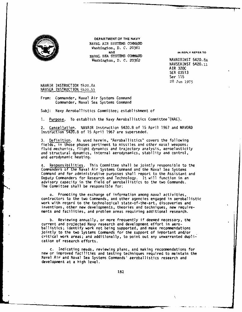
DEPARTMENT OF THE NAVY
NAVAL AIR SYSTEMS COMMAND
Washington, D. C. 20361and IN REPLY REFER TO
NAVAL SEA SYSTEMS COMMtANDWashington, D. C. 20362 NAVAIRINST 5420.8A
NAVSEAINST 5420.11AIR 320CSEA 03513Ser 11528 Jun 1975
NAVAIR INSTRUCTION 5420.8A
NAVSEA INSTRUCTION 5av2o.l
From: Commander, Naval Air Systems CommandCommander, Naval Sea Systems Command
Subj: Navy Aeroballistics Committee; establishment of
1. Purpose. To establish the Navy Aeroballistics Committee'(NAC).
2. Cancellation. NAVAIR Instruction 5420.8 of 15 April 1967 and NAVORDInstruction 5420.8 of 15 April 1967 are superseded.
3. Definition. As used herein, "Aeroballistics" covers the followingfields, in those phases pertinent to missiles and other naval weapons:fluid mechanics, flight dynamics and trajectory analysis, aeroelasticityand structural dynamics, internal aerodynamics, stability and control,and aerodynamic heating.
4. Responsibilities. This Committee shall be jointly responsible to theCommanders of the Naval Air Systems Command and the Naval Sea SystemsCommand and for administrative purposes shall report to the Assistant andDeputy Commanders for Research and Technology. It will function in anadvisory capacity in the field of aeroballistics to the two Commands.The Committee shall be responsible for:
*a. Promoting the exchange of information among naval activities,contractors to the two Commands, and other agencies engaged in aeroballisticwork with regard to the technological state-of-the-art, discoveries andinventions, other new developments, theories and techniques, new require-ments and facilities, and problem areas requiring additional research.
b. Reviewing annually, or more frequently if deemed necessary, thecurrent and projected Navy research and development effort in aero-ballistics; identify work not being supported, and make recommendationsjointly to the two Systems Commands for the support of important and/orcritical work areas; and additionally, to point out any unwarranted dupli-cation of research efforts.
c. Indicating needs, reviewing plans, and making recommendations fornew or improved facilities and testing techniques required to maintain theNaval Air and Naval Sea Systems Commands' aeroballistics research anddevelopment at a high level.
182
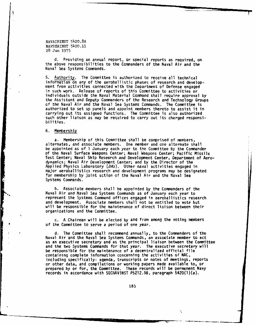
NAVAIRINST 5420.8ANAVSEAINST 5420.1128 Jun 1975
d. Providing an annual report, or special reports as required, onthe above responsibilities to the Commanders of the Naval Air and theNaval Sea Systems Commands.
5. Authority. The Committee is authorized to receive all technicalinformation on any of the aeroballistic phases of research and develop-ment from activities connected with the Department of Defense engagedin such work. Release of reports of this Committee to activities orindividuals outside the Naval Material Command shall require approval bythe Assistant and Deputy Commanders of the Research and Technology Groupsof the Naval Air and the Naval Sea Systems Commands. The Committee isauthorized to set up panels and appoint members thereto to assist it incarrying out its assigned functions. The Committee is also authorizedsuch other liaison as may be required to carry out its charged responsi-bilities.
6. Membership
a. Membership of this Committee shall be comprised of members,alternates, and associate members. One member and one alternate shallbe appointed as of I January each year to the Committee by the Commanderof the Naval Surface Weapons Center; Naval Weapons Center; Pacific MissileTest Center; Naval Ship Research and Development Center, Department of Aero-dynamics; Naval Air Development Center; and by the Director of theApplied Physics Laboratory (JHU). Other naval activities engaged inmajor aeroballistics research and development programs may be designatedfor membership by joint action of the Naval Air and the Naval SeaSystems Commands.
b. Associate members shall be appointed by the Commanders of theNaval Air and Naval Sea Systems Commands as of January each year torepresent the Systems Command offices engaged in aeroballistics researchand development. Associate members shall not be entitled to vote butwill be responsible for the maintenance of direct liaison between theirorganizations and the Committee.
c. A Chairman will be elected by ano from among the voting membersof the Committee to serve a period of one year.
d. The Committee shall recommend annually, to the Commanders of theNaval Air and the Naval Sea Systems Commands, an associate member to actas an executive secretary and as the principal liaison between the Committeeand the two Systems Commands for that year. The executive secretary willbe responsible for the maintenance of a decentralized official filecontaining complete information concerning the activities of NAC,including specifically: agenda, transcripts or notes of meetings, reportsor other data, and compilations or working papers made available to, orprepared by or for, the Committee. These records will be permanent Navyrecords in accordance with SEC14AVINST P5212.5B, paragraph 5420(l)(a).
183
NAVAIBTNST 5420 .8ANAVSEAINST 5420.1128 Jun 1975
The executive secretary will inform the Committee of Systems Commandsrequests for review of facility plans and research proposals and makearrangements for meetings that may be required betweer him, the Chair-man, the Commanders, or the Assistant and Deputy Commanders for Researchand Technology of the Naval Air and the Naval Sea Systems Commands todiscuss the annual NAC report or other matters needing mutual Naval Airand Naval Sea Systems Commands and Committee's consideration.
7. Organization and Procedures
a. Each member shall be entitled to one vote. In a member'sabsence, his alternate may vote in his stead. Three quarters of thevoting members shall constitute a quorum. No decision shall be madeinvolving specific interests of any member activity in the absence ofits voting member. In such a case, the question will be placed on theagenda for the next meeting and acted upon whether or not the activityinvolved is then represented. In the event any vote is not unanimous,the dissenting members may at their discretion submit a minority reportfor review and consideration by the Assistant and Deputy Commanders forResearch and Technology of the Naval Air and the Naval Sea SystemsCommands.
b. The Committee shall establish technical panels to aid andsupport its work in various areas of specialized interest. These panelsare established by vote of the Committee and are continued until theCommittee disestablishes the panel or changes its mission. The panelswill be composed of members from the interested Navy laboratories,Systems Command Offices, and contractors to the above. Nominations tothe panels may be made by any member or associate member of the Committeeand the appointments made by the Committee Chairman. Before making theappointments, the Chairman will obtain concurrence of the nominee andhis agency. The appointments will be made for a period of one yearstarting January 1. Appointments of non-governmental panel members willbe terminated when the contract, which was the basis for their appoint-ment, is completed. The Committee selects the Chairmen of the panels.
c. The Committee shall meet annually concurrently with its panelsto review progress, new requirements, and facility plans. Each paneland each facility will submit a report at this meeting. Following themeeting, a report will be prepared and submitted by the Committee to theNaval Air Systems Command and the Naval Sea Systems Command, summarizingdevelopments and listing items of significant progress, critical andimportant areas in aeroballistics research and development, and the needsfor new or improved facilities. Other meetings may be convened by theChairman and special reports issued to the Systems Commands as appropriate.
d. The Committee shall also sponsor technical symposia for promotingthe exchange of information in aeroballistic research. The symposiawill have a broader attendance base than the naval laboratories and theircontractors. They will be open to the other military services and govern-mert agencies, such as NASA and AEC, and contractors to these with special
184
I
NAVAIRINST 5420.8A
NAVSEAINST 5420.112 Tun 1075
competence in aeroballistics. Invitations to these symposia will betendered by the Commanders of the Naval Air and Naval Sea Systems Commands.These symposia usually will be held at three-year intervals.
K. L. LEECommander CommanderNaval Sea Systems Command Naval Air Systems Command
Distribution: (2 copies each)SNDL C4K PM-4
FKAIA NAVAIRSYSCOM (AIR 3032A, AIR 320, AIR 320C, AIR 5301)FKAIG NAVSEASYSCOM (SEA 035, SEA 0331, SEA 03513)FKA6A2 NAVWPNCENFKA6A3A NAVSHIPRANDCENFKA6A9 NAVSURFWPNCENrv.vA PACMTSTFSTCEN
Applied Physics Laboratory,Johns Hopkins University8621 Georgia AvenueSilver Soring, MD 20910
Copy to: (2 copies each unless otherwise indicated)SNDL FKA1A NAVAIRSYSCOM (AIR-320C (10 copies), AIR-9701 (10 copies),
AIR-9701A (4O copies), AIR-952 A/L I copy))FKAIG NAVSEASYSCOM (SEA 03513 (5 copies), SEA-O3AA ( 2 copies),
SEA-09G61 (25 copies))FKV27 NPPSMO (C/L)C4F9 NAVSURFWPNCENLAB (Dahlgren)
Stocked: Commaading Officer, Naval Publications and Vorms Center, 5801Tabor Avenue, Philadelphia, PA 1Q120
185

APPENDIX B
CHARTERS OF THE PANELS OF THE NAVY AEROBALLISTICS COMMITTEE
187-
PkHLCh.IG IP1 CZ bl~.I? flijS
CHARTER OF THE NACAIR INLETS AND DIFFUSERS PANEL
PURPOSE
The purpose of this panel shall be to review and evaluate technical progress inthe field of air inlets and diffusers being carried out under the cognizance of the
Naval Air and the Naval Sea Systems Commands, exchange information, and make recom-mendations to the Committee concerning the promotion and direction of research in
this field. This shall include coordination with other panels appointed by theCommittee where common interest exists and the correlation of the work of the NavalAir and the Naval Sea Systems Commands with related work conducted by facilities
not under the Commands.
SCOPE
The NAC panel on Air Inlets and Diffusers shall concern itself mainly with
studies on the magnitude and quality of pressure recovery, the mass flow capture,and the total drag of air inlets and diffusers. These studies will include effects
of boundary layer, angle of attack, Mach number, and the interactions with other
vehicle components. The panel will also be concerned with the performance of dif-fusers in wind-tunnel circuits, thrust augmenting ejectors, and in the internal flow
systems in high energy laser devices.
MEMBERSHIP AND MEETINGS
The panel members shall be appointed by the NAC chairman from nominations bythe Committee and shall meet once each year concurrently with the meeting of the
Committee as scheduled by the Committee chairman. The panel shall submit an annual
report to the Committee during this meeting. The panel chairman may schedule other
meetings of the panel.
188
CHARTER OF THE NAC
GAS DYNAMICS PANEL
PURPOSE
The purpose of this panel shall be to review and evaluate technical progress inthe field of gas dynamics being carried out under the cognizance of the Naval Airand Naval Sea Systems Commands, exchange information, and make recommendations tothe Committee concerning the promotion and direction of research in this field. Thisshall include coordination with other panels appointed by the Committee where commoninterest exists and the correlation of the work of the Naval Air and Naval SeaSystems Commands with similar work conducted by facilities not under the Commands.
SCOPE
The NAC panel on Gas Dynamics shall concern itself, in general, with the funda-mental fluid mechanics and gas dynamics of flow that occur in and around or are re-lated to guided and unguided missiles and projectiles. The panel shall considerwork which is devoted to the basic understanding of and the ability to predictdetailed flow-field structure. Examples are as follows:
1. Attached flow fields which are complex enough to require special experi-mental or analytical tools to determine their details, e.g., computational tech-niques which impact on missile and projectile design technology.
2. Separated flows such as occur near control surfaces, on vehicles at anangle of attack, in wakes, and in diffusers.
3. High temperature gas dynamic problems including the effects of molecularexcitation, chemistry, and radiation.
4. Boundary-layer and shock-wave behavior including the entire region betweencontinuum and free-molecular flow.
5. Boundary-layer stability and turbulence.
6. Special problems relating to internal fluid mechanics of solid and liquidpropellent guns and propulsion devices.
7. The panel will also be concerned with the latest test facilities andtesting techniques as they pertain to aeroballistics.
MEMBERSHIP AND MEETINGS
The panel membership shall be appointed by the NAC chairman from nominationsby the Committee and shall meet once each year concurrently with the meeting of theCommittee as scheduled by the Committee chairman. The panel shall submit an annualreport to the Committee during this meeting. The panel chairman may schedule othermeetings of the panel.
189
CHARTER OF THE NACHEAT TRANSFER PANEL
PURPOSE
The purpose of this panel shall be to review and evaluate technical progress inthe field of heat transfer viscous effects, material thermal response, and erosionbeing carried out under the cognizance of the Naval Air and Naval Sea SystemsCommands, exchange information, and make recommendations to the Committee concerningthe promotion and direction of research in this field. This shall include coordina-tion with other panels appointed by the Committee where common interest exists andthe correlation of the work of the Naval Air and the Naval Sea Systems Commandswith related work conducted by the facilities not under the Commands.
SCOPE
The NAC panel on Heat Transfer shall be concerned with all modes of heattransfer (conduction, convection, and radiation), its ffects on structures andthermal protection materials, the interaction between heat transfer and other flowfield characteristics, and the thermal properties of materials. Because both heattransfer and skin friction are extremely sensitie to the type of flow in theboundary layer, transition from laminar to turbulent flow will alsc be of primeinterest. In addition to these main topics, the panel shall be concerned with suchrelated topics as fluid injection, ablation, and other methods of controlling temper-ature. Boundary layer characteristics, in general, and their relation to base flowphenomena (particularly base drag and base heating) will be of interest. Erosion ofcomponents of flight vehicles traversing rain, ice, and dust environments shall alsobe considered by this panel.
MEMBERSHIP AND MEETINGS
The panel members shall be appointed by the NAC chairman from nominations by theCommittee and shall meet once each year concurrently with the meeting of the Commit-tee as scheduled by the Committee chairman. The panel shall submit an annual report
to the Committee during this meeting. The panel chairman may schedule other meetingsof the panel.
190
AD-AL12 630 DAVID W TAYLOR NAVALSHIP RESEARCH AND OtVELOPMENT CE--ETC F/S 5/1ANNUAL REPORT OF THE NAVY AEROBALLISTICS COM0HITTEE TO THE HAVAL--ETC(U)
UNCLASSIFIED AERO-178 DTNSRDC-1/090 NL2*ffffffffffffEE hE
iii ,.=o , 336 2_.
* . Hill'25 Qlj 1.4 .6
MICROCOPY RESOLUTION TEST CHARINAIINAL URIMUU A NDARD , A
I I
CHARTER OF THE NAC
LAUNCH DYNAMICS PANEL
PURPOSE
The purpose of this panel shall be to review and evaluate technical progress inthe field of separation of stores from aircraft as well as the launch of missiles orprojectiles from other vehicles under the cognizance of the Naval Air and the NavalSea Systems Commands, exchange information, and make recommendations to the Committeeconcerning the promotion and direction of research in this field. This shall includecoordination with other panels appointed by the Committee where common interestexists and the correlation of the work of the Naval Air and the Naval Sea SystemsCommands with related work conducted by facilities not under the Commands.
SCOPE
The NAC panel on Launch Dynamics shall concern itself with aerodynamic loadsand moments on all types of externally and internally carried airborne stores andbodies carried by other vehicles either captive or during separation; with the mutualinteraction between the body and its carrier including associated racks and pylons;and with separation and recovery dynamics and trajectories. The panel shall alsoconcern itself with the integration of the overall characteristics of a completeweapons delivery system including the carrier as a stable platform and mounting andejection systems insofar as they relate to the expeditious handling and accuratedelivery of the weapon.
MEMBERSHIP AND MEETINGS
The panel members shall be appointed by the NAC chairman from nominations bythe Committee and shall meet once each year concurrently with the meeting of theCommittee as scheduled by the Committee chairman. The panel shall submit an annualreport to the Committee during this meeting. The panel chairman may schedule othermeetings of the panel.
1
191
CHARTER OF THE NACMISSILE STABILITY AND PERFORMANCE PANEL
PURPOSE
The purpose of this panel shall be to review and evaluate technical progress inthe field of missile stability and performance being carried out under the cognizanceof the Naval Air and the Naval Sea Systems Commands, exchange information, and makerecommendations to the Committee concerning the promotion and direction of researchin this field. This shall include coordination with other panels appointed by theCommittee where common interest exists and the correlation of the work of the NavalAir and the Naval Sea Systems Commands with related work conducted by facilities notunder the Commands.
SCOPE
The NAC panel on Missile Stability and Performance shall concern itself withlongitudinal and lateral stability and control characteristics of guided missiles,static and dynamic stability of unguided missiles, and the means of improving thesecharacteristics. The areas of interest shall include research on all aerodynamiccomponent interactions, autopilot input-output characteristics, together with jet,aero-thermoelastic, and other responses of the missile insofar as they affect systemstability. The panel will also consider the interaction of aerodynamic forces (in-cluding thrust and drag) and moments on the maneuverability and trajectory character-istics of the missile.
MEMBERSHIP AND MEETINGS
The panel members shall be appointed by the NAC chairman from nominations bythe Committee and shall meet once each year concurrently with the meeting of theCommittee as scheduled by the Committee chairman. The panel shall submit an annualreport to the Committee during this meeting. The panel chairman may schedule othermeetings of the panel.
192
CHARTER OF THE NAC
STRUCTURES AND AEROELASTICITY PANEL
PURPOSE
The purpose of this panel shall be to review and evaluate technical progress inthe field of structures and aeroelasticity being carried out under the cognizance of
the Naval Air and the Naval Sea Systems Commands, exchange information, and makerecommendations to the Committee concerning the promotion and direction of researchin this field. This shall include coordination with other panels appointed by theCommittee where common interest exists and the correlation of the work of the NavalAir and the Naval Sea Systems Commands with related work conducted by the facilities
not under the Commands.
SCOPE
The NAC panel on Structures and Aeroelasticity shall concern itself mainly withproblems of the structural design environment and structural applications of mate-
rials including: strength and stiffness, self-excited or sustained vibration, dis-tribution of airloads, structural response, and aerodynamic stability and control inwhich the deformation of the structure is a factor. In general, these problems arise
from interaction between aerodynamic forces, structural restoring forces, servocontrol forces, inertial forces, aerodynamic heating, and the vehicle airframe.
These various interactions can lead to specific actions such as:
1. Flutter2. Divergence
3. Missile instability4. Control ineffectiveness5. Structural vibration6. Fatigue
7. Structural failure
MEMBERSHIP AND MEETINGS
The panel members shall be appointed by the NAC chairman from nominations by
the Committee and shall meet once each year concurrently with the meeting of the
Committee as scheduled by the Committee chairman. The panel shall submit an annual
report to the Committee during this meeting. The panel chairman may schedule other
meetings of the panel.
193

APPENDIX C
MEMBERSHIP OF THE COMMITTEE
195
PAS
NAVY AEROBALLISTICS COMMITTEE
MEMBERS AND ALTERNATE MEMBERS FOR 1981
S. de los Santos, Chairman (DTNSRDC). .. ................ A.E. JohnsonL.L. Cronvich (JHU/APL). ......... ............... E.T. MarleyC. de Crescente (NADC). .. ...................... E.J. McQuillenL.H. Schindel (NSWC). .. ......................... F.G. MooreW.J.H. Smithey (PMTC). ......... ................ W.L. MillerR.W. Van Aken (NWC) .. ........................... L. Smith
ASSOCIATES
L. Pasiuk, Executive Secretary (NAVSEASYSCOM)W.E. Volz (NAVAIRSYSCOM)G.S. Pick (NAVSEASYSCOM)F.S. Pierce (NAVAIRSYSCOM)
NAC PANELS AND PANEL CHAIRM{ANFOR 1981
Air Inlets anid Diffusers. .. ................... T.C. Tai (DTNSRDC)Gas Dynamics. .. ........................... W.H. Clark (NWC)Heat Transfer .. .......................... T.F. Zien (NSWC)Launch Dynamics .. ......................... K. Okauchi (NWC)Missile Stability and Performance .. .............. T.R. Pepitone (NSWC)Structures and Aeroelasticity .. ................ A.A. Anderson (PMTC)
196

I
APPENDIX D
PAST CIAIMEN OF THE NAVY AEROBALLISTICS COMMITTEE
1
197
bk
PAST NAC CHAIRMEN
Feb 1949 - Nov 1949...................CDR H.M. Mott-Smith (Buord)Dec 1949 - Oct 1950. .................... CDR L.G. Pooler (BuOrd)Oct 1950 - Feb 1953. ..................... CDR L.G. Pooler (NOL)Mar 1953 - Jul 1953. ................ A.I. Moskovits (Acting) (BuOrd)Sep 1953 - Jul 1955. ..................... E.A. Bonney (JHU/APL)Aug 1955 - Aug 1957. ...................... H.H. Kurtzweg (NOL)Sep 1957 - Jul 1959 ..... ................. W.R. Haseltine (NWC)Aug 1959 - Jul 1961 ...... ............... R.A. Niemann (NSWC/DL)Jul 1961 - Jan 1963. ........................... R.E. Wilson (NOL)Jan 1963 - Jan 1965 .... .............. S.T. de los Santos (DTNSRDC)Jan 1965 - Jan 1967. ...................... R.H. Peterson (NMC)Jan 1967 - Jan 1969. ..................... W.A. Kemper (NSWC/DL)
Jan 1969 - Jan 1971. ...................... L. Cronvich (JHU/APL)Jan 1971 - Jan 1973 ..... ................. W.R. Haseltine (NWG)Jan 1973 - Jan 1975 .... ................. R.E. Wilson (NSWC/WOL)Jan 1975 - Jan 1976 ... ............... S.T. de los Santos (DTNSRDC)Jan 1976 - Jan 1977. ........................ J.W. Rom (PMTC)Jan 1977 - Jan 1978 ...... ................. W.A. Langen (NADG)Jan 1978 - Jan 1979. ...................... R.W. Van Aken (NWC)Jan 1979 - Jan 1980. .................... L.L. Cronvich (JHU/APL)Jan 1980 - Jan 1981 .... .................. L.H. Schindel (NSWC)Jan 1981 -... .. .. .. .. .. .. .. .. .. S.T. de los Santos (DTNSRDC)
198

APPENDIX E
MEETINGS OF THE COMMITTEE
199

MEETINGS OF THE COMMITTEES
Meeting Date Location
(Bureau of Ordnance Committee on Aerodynamics)
1 1 Feb 1949 Navy Department, Washington, D. C.
2 26 May i"49 Naval Ordnance LaboratoryWhite Oak, Md.
(Bureau of Ordnance Committee on Aeroballistics)
3 5 Jul 1949 Naval Ordnance LaboratoryWhite Oak, Md.
4 12-13 Sep 1949 Naval Supersonic LaboratoryMassachusetts Institute of
Technology
5 7-8 Dec 1949 Naval Weapons LaboratoryDahlgren, Va.
6 3-4 Mar 1950 Naval Weapons CenterChina Lake, Calif.
7 10-11 May 1950 Ordnance Aerophysics Laboratory
Daingerfield, Texas
8 27-28 Jul 1950 Naval Weapons CenterChina Lake, Calif.
9 9-10 Oct 1950 Naval Ordnance LaboratoryWhite Oak, Md.
10 25-26 Jan 1951 Naval Supersonic LaboratoryMassachusetts Institute ofTechnology
11 9-10 Apr 1951 Naval Weapons CenterChina Lake, Calif.
12 19-20 Jul 1951 Naval Weapons Laboratory
Dahlgren, Va.
13 29-30 Nov 1951 Ordnance Aerophysics LaboratoryDaingerfield, Texas
14 27-28 Feb 1952 Johns Hopkins UniversityApplied Physics Laboratory
Silver Spring, Md.
200

MEETINGS OF THE CO1MITTEES (Continued)
Meeting Date Location
(Bureau of Ordnance Committee on Aeroballistics)
15 16 May 1952 Naval Weapons Center
China Lake, Calif.
* 6 16 15 Jul 1952 National Aeronautics and Space Adminis-tration, Ames Research Center
17 19-20 Nov 1952 Naval Weapons LaboratoryDahlgren, Va.
18 9-10 Apr 1952 Naval Supersonic LaboratoryMassachusetts Institute ofTechnology
19 13-14 Jul 1953 General Dynamics, Pomona Division
20 28-29 Oct 1953 Naval Ordnance LaboratoryWhite Oak, Md.
21 11-12 Feb 1954 Johns Hopkins UniversityApplied Physics LaboratorySilver Spring, Md.
22 13-14 May 1954 Arnold Engineering Development CenterArnold Air Force Station, Tenn.
23 21-22 Oct 1954 Johns Hopkins UniversityApplied Physics LaboratorySilver Spring, Md.
24 16-18 Jan 1955 Naval Ordnance LaboratoryWhite Oak, Md.
25 31 Jan - I Feb 1956 Naval Ordnance LaboratoryWhite Oak, Md.
26 31 Jan - 1 Feb 1957 Naval Ordnance LaboratoryWhite Oak, Md.
27 21-24 Jan 1958 Naval Ordnance LaboratoryWhite Oak, Md.
28 2-6 Feb 1959 Naval Ordnance LaboratoryWhite Oak, Md.
201
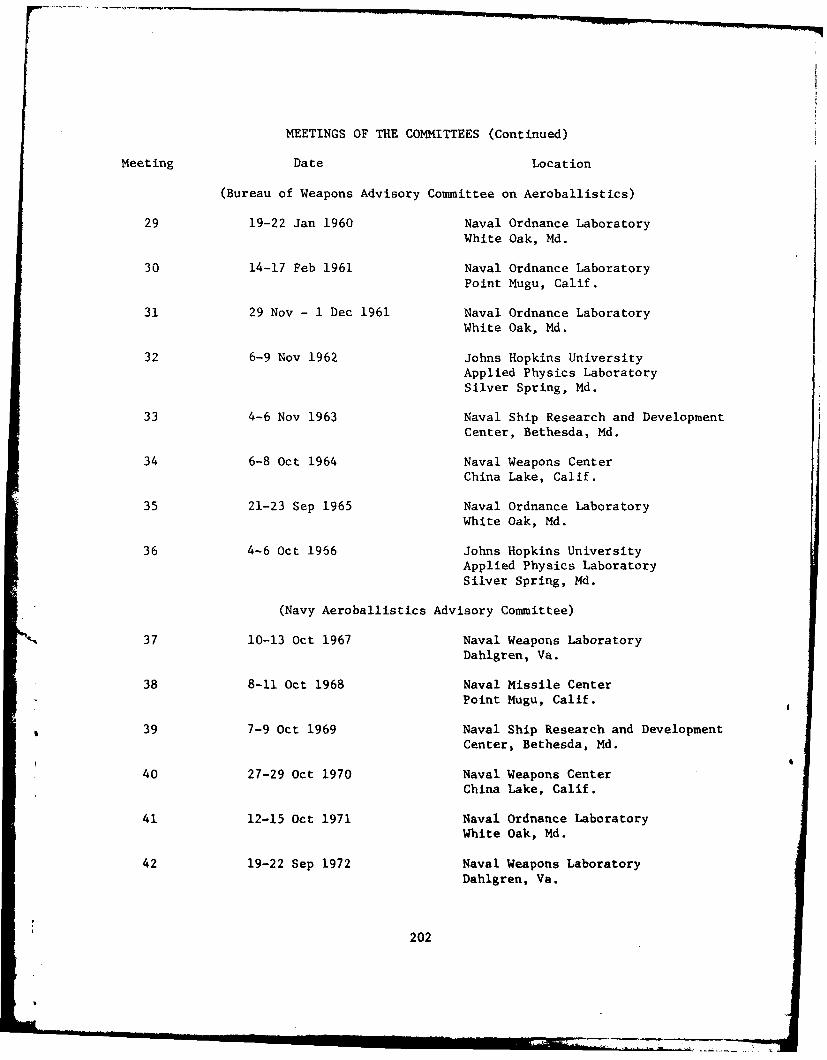
MEETINGS OF THE COMMITTEES (Continued)
Meeting Date Location
(Bureau of Weapons Advisory Committee on Aeroballistics)
29 19-22 Jan 1960 Naval Ordnance Laboratory
White Oak, Md.
30 14-17 Feb 1961 Naval Ordnance LaboratoryPoint Mugu, Calif.
31 29 Nov - 1 Dec 1961 Naval Ordnance Laboratory
White Oak, Md.
32 6-9 Nov 1962 Johns Hopkins University
Applied Physics LaboratorySilver Spring, Md.
33 4-6 Nov 1963 Naval Ship Research and Development
Center, Bethesda, Md.
34 6-8 Oct 1964 Naval Weapons CenterChina Lake, Calif.
35 21-23 Sep 1965 Naval Ordnance LaboratoryWhite Oak, Md.
36 4-6 Oct 1966 Johns Hopkins UniversityApplied Physics LaboratorySilver Spring, Md.
(Navy Aeroballistics Advisory Committee)
37 10-13 Oct 1967 Naval Weapons Laboratory
Dahlgren, Va.
38 8-11 Oct 1968 Naval Missile Center
Point Mugu, Calif.
39 7-9 Oct 1969 Naval Ship Research and Development
Center, Bethesda, Md.
40 27-29 Oct 1970 Naval Weapons Center
China Lake, Calif.
41 12-15 Oct 1971 Naval Ordnance Laboratory
White Oak, Md.
42 19-22 Sep 1972 Naval Weapons Laboratory
Dahlgren, Va.
202
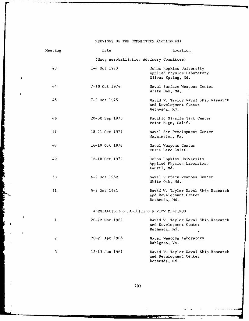
MEETINGS OF THE COMMITTEES (Continued)
Meeting Date Location
(Navy Aeroballistics Advisory Committee)
43 1-4 Oct 1973 Johns Hopkins University
Applied Physics LaboratorySilver Spring, Md.
44 7-10 Oct 1974 Naval Surface Weapons CenterWhite Oak, Md.
45 7-9 Oct 1975 David W. Taylor Naval Ship Research
and Development CenterBethesda, Md.
46 28-30 Sep 1976 Pacific Missile Test CenterPoint Mugu, Calif.
47 18-21 Oct 1977 Naval Air Development Center
Warminster, Pa.
48 16-19 Oct 1978 Naval Weapons Center
China Lake Calif.
49 16-18 Oct 1979 Johns Hopkins UniversityApplied Physics LaboratoryLaurel, Md.
50 6-9 Oct 1980 Naval Surface Weapons CenterWhite Oak, Md.
51 5-8 Oct 1981 David W. Taylor Naval Ship Researchand Development Center
Bethesda, Md.
0 AEROBALLISTICS FACILITIES REVIEW MEETINGS
1 20-22 Mar 1962 David W. Taylor Naval Ship Research
and Development CenterBethesda, Md.
2 20-21 Apr 1965 Naval Weapons LaboratoryDahlgren, Va.
3 12-13 Jun 1967 David W. Taylor Naval Ship Researchand Development CenterBethesda, Md.
203

.... ..
APPENDIX F
NAVY SYMPOSIA ON AEROBALLISTICS
205
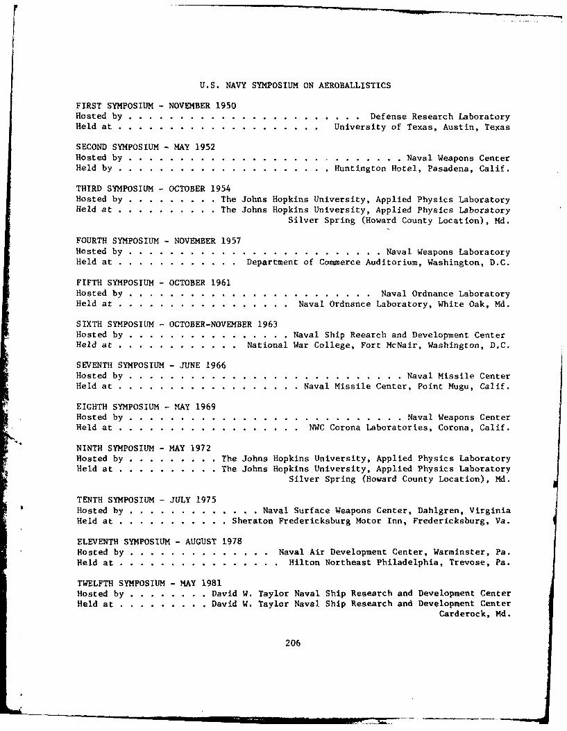
U.S. NAVY SYMPOSIUM ON AEROBALLISTICS
FIRST SYMPOSIUM - NOVEMBER 1950Hosted by ......... ....................... ... Defense Research LaboratoryHeld at ........ .................... ... University of Texas, Austin, Texas
SECOND SYMPOSIUM - MAY 1952Hosted by ........... ........................... .. Naval Weapons CenterHeld by ........ ..................... .. Huntington Hotel, Pasadena, Calif.
THIRD SYMPOSIUM - OCTOBER 1954Hosted by ........... .. The Johns Hopkins University, Applied Physics LaboratoryHeld at ... .......... .The Johns Hopkins University, Applied Physics Laboratory
Silver Spring (Howard County Location), Md.
FOURTH SYMPOSIUM - NOVEMBER 1957Hosted by .......... ......................... .. Naval Weapons LaboratoryHeld at .... ............ . Department of Commerce Auditorium, Washington, D.C.
FIFTH SYMPOSIUM - OCTOBER 1961Hosted by .......... ........................ ... Naval Ordnance LaboratoryHeld at ...... ................. ... Naval Ordnance Laboratory, White Oak, Md.
SIXTH SYMPOSIUM - OCTOBER-NOVEMBER 1963Hosted by ...... ................ .Naval Ship Reearch and Development CenterHeld at .... ............ . National War College, Fort McNair, Washington, D.C.
SEVENTH SYMPOSIUM - JUNE 1966Hosted by ........... ........................... .. Naval Missile CenterHeld at ....... .................. .Naval Missile Center, Point Mugu, Calif.
EIGHTH SYMPOSIUM - MAY 1969Hosted by ........... ........................... .. Naval Weapons CenterHeld at ....... .................. ... NWC Corona Laboratories, Corona, Calif.
NINTH SYMPOSIUM - MAY 1972Hosted by .. ......... ... The Johns Hopkins University, Applied Physics LaboratoryHeld at ... .......... .The Johns Hopkins University, Applied Physics Laboratory
Silver Spring (Howard County Location), Md.
TENTH SYMPOSIUM - JULY 1975Hosted by .... ............. .. Naval Surface Weapons Center, Dahlgren, VirginiaHeld at ... ........... .. Sheraton Fredericksburg Motor Inn, Fredericksburg, Va.
ELEVENTH SYMPOSIUM - AUGUST 1978Hosted by ..... .............. ... Naval Air Development Center, Warminster, Pa.Held at ...... ................ ... Hilton Northeast Philadelphia, Trevose, Pa.
TWELFTH SYMPOSIUM - MAY 1981Hosted by .......... .. David W. Taylor Naval Ship Research and Development CenterHeld at .. ......... .. David W. Taylor Naval Ship Research and Development Center
Carderock, Md.
206
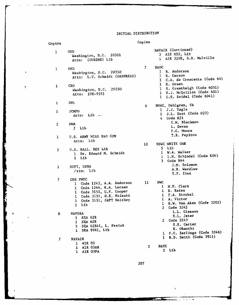
INITIAL DISTRIBUTION
Copies Copies
1 OSD NAVAIR (Continued)
Washington, D.C. 20301 3 AIR 053, Lib
Attn: (OUSDRE) Lib 1 AIR 320B, D.R. Mulville
1 OSD 7 NADC
Washington, D.C. 20350 1 R. Anderson
Attn: L.V. Schmidt (OASNRE&S) 1 R. Carson1 C.A. de Crescente (Code 60)
1 CNO I K. Green
Washington, D.C. 20350 1 S. Greenhalgh (Code 6051)
Attn: (0VO,-955). 1 E.J. McQuillen (Code 601)
i G.S. Seidel (Code 6041)
1 DNL6 NSWC, Dahlgren, VA
1 JCIPO 1 J.J. Yagla
Attn: Lib I J.L. East (Code G23)
4 Code K21
2 ONR C.M. Blackmon
2 Lib L. DevanF.G. Moore
1 U.S. ARMY MISS R&D COM T.R. Pepiton
Attn: Lib10 NSWC WHITE OAK
2 U.S. BALL. RES LAB 5 Lib
I Dr. Edward M. Schmidt 1 W.A. Walker
1 Lib I L.H. Schindel (Code K04)
3 Code R44
1 SUPT, USNA J.M. Solomon
Ittn: Lib A.B. WardlawT.F. Zien
7 CDR PMTC
1 Code 1243, A.A. Anderson 11 NWC
1 Code 1244, K.A. Larsen I W.H. Clark
I Code 3151, G.F. Cooper 1 R. Estes
I Code 3151, D.E. Holeski 1 F.A. Strobel
I Code 3151, CAPT Smithey 1 A. Victor
2 Lib 1 R.W. Van Aken (Code 3202)
2 Code 3242
8 NAVSEA L.L. Gleason
1 SEA 62B E.L. Jeter
1 SEA 62R 2 Code 3243
5 SEA 62R41, L. Pasiuk S.K. Carter
I SEA 9961, Lib K. Okauchi1 F.C. Zarlingo (Code 3246)
7 NAVAIR 1 R.D. Smith (Code 3911)
1 AIR 03
1 AIR 03AB 2 NATC
1 AIR 03PA 2 Lib
207
Copies Copies
12 DTIC 2 Analytic Sciences Corp
1 Dr. A. Mitchell2 AFAL 1 Dr. C.F. Prince
1 C. Matthew1 Lib 1 Boeing Aerospace Comp
Attn: G.C. Paynter1 ARO
Attn: Lib 2 CALSPAN/AEDC
1 Dr. W.B. Baker, Jr.1 AFLDL 1 R.K. Matthews
Attn: M.A. Pinney
3 General Dynamics/Pomona Div3 NASA LANGLEY 1 F.R. Frederick (MS 4-87)
1 J.M. Allen (MS-409) I Dr. D.J. Trulin
1 J. Dillon 1 W.H. Terrill (MS 4-39)1 R. Stallings
1 General Dynamics/Convair Div1 NASA LEWIS Attn: Lib
Attn: Lib4 Grumman Aerospace Corp
10 Johns Hopkins Univ 1 M. BernsteinI W.C. Caywood 1 R. Kosson1 L.L. Cronvich 1 R. Oman1 R.K. Frazer 1 R. TindellI M.D. Griffin1 R.E. Lee 2 Honeywell1 E.F. Lucero 1 S.N. Schwantes1 E.T. Marley I G.D. Stilley1 R.M. Rivello1 J.R. Stevens 1 Hughes Aircraft Co1 L.E. Tisserand Attn: J.R. Marshall
1 MIT I Lockheed Missiles and Space Co
Attn: J.R. Baron Huntsville, AL
Attn: Lib1 Univ of Notre Dame
1 Lockheed Missiles and Space Co1 Princeton Univ Sunnyvale, CA
Attn: Dr. D. Caughey Attn: Lib
2 VPI & State Univ 1 The Marquardt Corp
I Dr. E.F. Brown Attn: E.J. Kremizier
1 C.H. Lewis
3 Martin Marietta Aerospace Co1 Rutgers Univ I G.F. Aiello (MP-3)
Attn: Dr. D.D. Knight 1 P. Hahn (MP-336)1 T.V. Radovich
1 Acurex CorpAttn: B. Laub
208
Copies Copies
2 McDonnell-Douglas Aircraft Co 6 Vought CorpSt. Louis, MI P.O. Box 225907
1 C.C. Lee (MS-95) Dallas, TX1 P. Pondrom (MS-196) 1 G. Haugh
1 P.M. Kenner3 McDonnell Douglas Astronautics 1 J.E. Medford
Co - East I F.W. PrillimanSt. Louis, MI I C.M. Standard1 J. Arcangeli, E236, HQ, 1 G.R. Zwernemann
Rm 4781 J. Schmich, E236, HQ, 1 Vought Corp
Rm 478 Advanced Tech Center1 D.W. Boekemier, 106-4, P.O. Box 226144
Post E4 Dallas, TX
Attn: Lib1 McDonnell Douglas Astronautics
Co - WestHuntington Beach, CA CENTER DISTRIBUTIONAttn: J. Xerikos (MS 1303)
Copies Code Name4 Nielsen Engineering and Res Inc 1 160i A.E. Johnson
I M.M. BriggsI M.J. Hemsch 1 1606 S. de los SantosI Dr. S. McIntosh 1 1606 T.C. Tai1 J.N. Nielsen 1 1660 K.A. Phillips
1 Northrop Corporation 1 1660 S. Owen1 1660 R. Taylor
Attn: A.J. McEwan 1 1660 R.M. Hartley
3 Raytheon Co 1 1720 R.F. Jones, Jr.
1 D.P. Forsmo1 R.J. Joachim (MS DD 2-18) 1 1730 J.H. Ma1 D.H. Sander
10 5211.1 Reports Distribution
1 Sandia Laboratories 2 522.1 Lib (C) (1 m)
Attn: H.R. Spahr, Jr 2 522.1 Lib (C)1 522.2 Lib (A)
1 Scientific Res Associates
Attn: R.W. Bailey
3 United Technology Corp* 1 W.E. Anderson
1 A.J. KaranianI P.F. Melia
209


