Embed Size (px)
Citation preview
pWlp!ppppp|pi!ppiMi^pp^ f „.in mimimmvmmwmmmmiMm. iiiii^ijuuiiiiiii uimvmmmw
AD-A014 278
THE AMC '74 MOBILITY MODEL
M. Peter Jurkat, et al
Stevens Institute of Technology
y Prepared for:
Army Tank-Automotive Command Army Engineer Waterways Experiment Station
May 1975
DISTRIBUTED BY:
KTDi National Technical Information Service U. S. DEPARTMENT OF COMMERCE
■«liilmi«Him.iinlMminmi-v r, , ■ 1i •m)|-|ll|i||l|i||||ltlW|)j
..i»-^....,.,.

Best Available
Copy
iwilllljMP^lliiWIIJAWiWIII'l'PB'^'WriWWWIi' mam PPfW^WWH" wmmm* '" ^'nwwwm.M.WHiJmi'HP
««^^»««w««««w«^
254101
-&
•p. 1
TECHNICAL REPORT NO. 11921 (LL-149) I I I I I
x!( N|(
©! <! O I ^ I
I I I I I I I I I I I I
THE AMC 74
MOBILITY MODEL
MAY 1975
6y
M. Peter Jurkat Stevens Institute of Technology
Clifford J. Nuttall» US Army Engineer Waterways Experiment Station
Peter W. Haley US Army Tank-Autoqiotlve Command
S ARMY TANK AUTOMOTIVE COMMAND Warren. Michigan
^^RfiOTON StATENKNT A
Approved for public r«li Dli.tr buticm UnliK-ited
Roproducad by
NATIONAL TECHNICAL INFORMATION SERVICE
US Oepartmanl o( ("ommerca Sptinglield, VA. 72151
MMMlMMMMMaM MuMaMM« äahLÄ^^X^wi^ü^-'i*--^- -.-.* .■»,^. ..dl^H
■ii)iiii»<i.iH||ii.iiiiiiiiiiii«iut.iwi ii.|w'i''iiMiiiiiyii,)i.i^iii,ii j^JwrT!mmfimff9n^iW!W^ß'1 'w,,!,'"•'••'' miwmvjfwijiiuxwii• ».< ."''••iwm»'!'.".»- IIII""MII "■»wipiw.iii«!» .iii.i'u - i. wmw ■mumm
wmmmmm •'•'*,;,I^I«:«äI*V««W*WWW».^IWU%J(
UNCLASSIFIED StCUNITV CLAMtriCATION OF THIS PAOC (Whmt Data itetara«
REPORT DOCUMENTATION PAGE READ INSTRUCTIONS BEFORE COMPLETWO PORK
t. RCCIPIKNT'I CATALOG SuBSiÜ 1. HPSif NUMiU
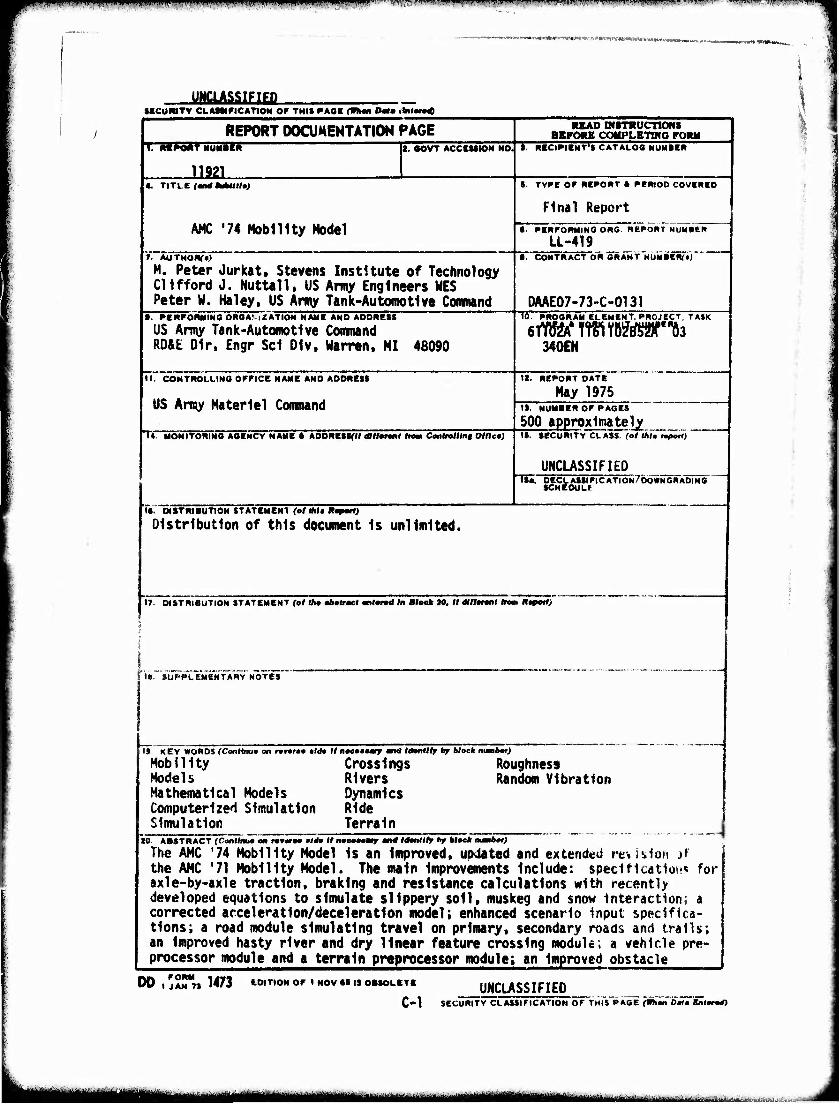
11921 _
OOVT ACCtUION NO
4. TITLE fMrfMUMaJ S. TYPE OF REPORT * RERIOD COVERED
Final Report
AMC '74 Nobility Model • . RERFORMINO ORG. REPORT NUMICR
LL-419 1. AUTHomc)
M. Peter Jurkat, Stevens Institute of Technology Clifford J. Nuttall, US Army Engineers WES Peter W. Haley. US Army Tank-Automotive Conwand
• . CONTRACT OR GRANT NUMREN^
DAAE07-73-C-0131 •■ PERFORMING OR0AM2ATION NAME AND ADDRESS
US Army Tank-Automotive Command RO&E Dir. Engr Sei Olv, Warren. MI 48090
10. RROORAM ELEMENT, PROJECT, T*$K
340CN
II. CONTROLLING OFFICE NAME AND ADDRESS
US Army Materiel Command
12. REPORT DATE
May 1975
TV MONITORING AGENCY NAME ft ADDRESSftf dftfarant ftaaTCiMlra/Hn« Otflet)
IS. NUMBER OF PAGES
500 approximately IS. SECURITY CLASS, (ol UtU «port)
UNCLASSIFIED Tw. DECLASSIFICATION/DOWNORADINO
SCHEDULE
IS. DISTRIBUTION STATEMENT (ol Ml« Rapotl)
Distribution of this document Is unlimited.
•7. DISTRIBUTION STATEMENT (ol (ha obmtrmet mtond In Block 20, 1/ dlllmnt Inm Htpotl)
18. SUPPLEMENTARY NOTES
19 KEY WORDS (Contlm» on rmnrmo »Id» IInoeooomrr and Idonlllr by block ntmabot)
HobHity Crossings Models Rivers Mathematical Models Dynamics Computerized Simulation Ride Simulation Terrain
Roughness Random Vibration
20. ABSTRACT (Canllimo on ranraa tldo M nocmtmmr mtd U—ttlly hr Mock mmbor) The AMC '74 Mobility Model Is an Improved, updated and extended revision if the AMC '71 Mobility Model. The main Improvements Include: speciflcatiov!« for axle-by-axle traction, braking and resistance calculations with recently developed equations to simulate slippery soil, muskeg and snow Interaction; a corrected acceleration/deceleration model; enhanced scenario input specifica- tions; a road module simulating travel on primary, secondary roads and trails; an Improved hasty river and dry linear feature crossing module; a vehicle pre- processor module and a terrain preprocessor module; an Improved obstacle
DO,: FORM AN 71 1473 EDITION OF I HOV SB IS OBSOLETE
C-l UNCLASSIFIED
SECURITY CLASSIFICATION OF THIS PACE (Whmn Dmtm Bnlorod)
\illtmmmmmiitmmmimmtm mm ÜüM i M
p>}W'Wiy...i.r.'l*iw^»W^ Pfffl.glW i.inm.n'iwi^ 'l>|ii"W'.vmnim.:inw.iij>-iw.i»'.»iiiii.ii.ninpU»Vilii M • ••.>,« ("WVuuWU.llMW!^
IMW—>—
lattAssiEia
l^Mi——liwi—WWMtWMWi wrw«( viUMMM IPÜWWBIA
»ICUWITV CCAMlf ICATIOM OF THI« gAgigMg Of
20. (Cont'd)
crossing Mdult; and an updatad rlda dyoaalcs mdula.
C-2 UNCLASSIFIED
MCUNITY CUAUtriCATION OF THIS F AOCpniM Data KnWntQ
J
"-•'"■-■'■■'■"■-'-'"'"—^""■"-- ■ nr "- --'■■ —'"'ii ■
itfBritfi fa 'lMi«i>»Nltoi I
»ii ipiim ii t»! i i i wnnwmmnmmKimu—* 1.1 i>w «mumum nmv " - ■■ '■'■ iflwi!"."".! i ■■ ' I.IJ... .u .«p.iMiii«. nnpii
»W*», .iii»im«i»—MWi-!«»iiim^»rtin»«'^ar—««<!* .'.«•«««■»•W'WW •)»•«•!< !«»:^y*wft»*-
^
Ü
TECHNICAL REPORT NO. 11921 (LL-149)
THE AMC '74 MOBILITY MODEL
by
M. Peter Jurkat Stevens Institute of Technology
Clifford J. Nuttall U.S. Army Engineer Waterways Experiment Station
Peter W. Haley U.S. Army Tank-Autoinotlve Command
May 1975
- Unlimited Distribution
iiiiTriinii iirm ii ■ TiMiiMMÜllMmi *iiiiirrr - ■ ■ ■
P. .■ wi,»U' f". ■■ " w^;^i^«niiiiw.JIU^.T.HWIIW...iii^PFJ»-lyiw^Hwi''■»^■»,n'!y»»jpp;■■ i.linn in in i .1 11 wjp^jp^p rr.^-w^-Tin;,,. 11^1 UI^M^H,.! 1 ^»1 LJ,I J^I ;,, F., ^wy^f^-inif w, 1 .■. .inMM»u.PPft.tiv-wi^- uii imqii., 1 ^-
p*fl^*w^«!rim»«(W*ÄW*^;B»'*Wf*»^
ABSTRACT
The AMC '74 Mobility Model Is an Improved, updated and exten- ded revision of the AMC '71 Mobility Model. The main improvements include: specifications for axle-by-axle traction, brakinq and resistance calculations with recently developed equations to simu- late slippery soil, muskeq and snow interaction; a corrected acceleration/deceleration model; enhanced scenario input specifi- cations; a road module simulatinc travel on primary, secondary roads and trails; an improved hasty river and dry linear features crossing module; a vehicle preprocessor module and a terrain pre- processor module; an Improved obstacle crossing module; and an updated ride dynamics module.
"*« )
■i
!
u
r
11
mu*mm. ^^^^m r.^ui^i.^^;:'....^!:...-...-^^:^-),,!,- , ,■-, .....„, ■:. .. ,,. .
"w™r'.,,*wfji»'"!"">»'''(nTiu!'ii» •Tw mi ii „im,,,.,,., m..mmui*ni!„ ''WBggnii.iiiii mi uif.wmm.w-,,'rrn,tmm'rwKim'*r'i.vwm,v.vnj\i ■■■■■■I " '^V'J.Wpifl'lVIVli'Hijln 'I111?«
*
ACKNOWLEDGEMENT
This report was compiled by the staffs of the Nobility and Environmental Systems Laboratory of the U.S. Army Corps of Engineers Waterways Experiment Station (MES), the Engineering Science Division of TACOM's RD&E Directorate, and the Trans- portation Research Group, Davidson Laboratory, Stevens In- stltute of Technology (SIT)% under contract DAAE07-73-C-0131.
A three-man working group was directly responsible for the generation of this report. Members of the working group were: Messrs. C. J. Nuttall, Jr. (WES)v P. W. Haley (TACOK); and Dr. M. P. Jurkat (SIT).
Mr. D. A. Sloss (SIT) assembled the Hasty River Crossing Model. Dr. Alan Lessem (WES) and Mr. R. W. Jacobson (TACOM) created the Obstacle Crossing Module.
Mr. T. Washburn (SIT) contributed significantly by assembling the Vehicle Preprocessor and participated In the development of the structure and logic flow of the whole model.
Mr. D. 0. Randolph (WES) contributed significantly to the maintenance of realism In governing algorithms.
The following supervisory personnel directed this work: Or. J. G. Parks, Chief. Engineering Science Division, and Mr. Z. J. Janosl, Supervisor« Methodology Function (TACOM), Messrs. W. G. Shockley, Chief, Mobility and Environmental Systems Lab, and A. A. Rule, Chief. Mobility Systems Division (WES), Dr. I. R. Ehrlich, Dean of Research and Mr. I. 0. Kann. Chief. Transportation Research Group (SIT).
Mrs. Maxlne Glanferml and Ms. Marian Czalczynskl, both from TACOM, performed the extremely difficult task of typing the text.
Ill
yHH^JI *j^«ftdii.iÄ'Vy\a(ffla^1w^y&*,1rt^iwJ.;A.v ..
P^'Wtl.1."11'■■""W.'HIW'W*^^'." ""^ ■'" '■" '"'' ''""l.1" i!i.iiH)H|ill^i^|l>B n.m^i MIII.-JIJ^- ^■»■■..■»,.,..I.II...H».»JIII» «<<< i -• -rw-r—~—. -,,. ..i. .ip
Minn .-^^^.«i>vj««iv»Mii«w«**«w-w-irw'rt-nwfltw<f»»*«^ 1
TABLE OF CONTENTS
1
Section
Foreword
Introduction
Page No.
1
2
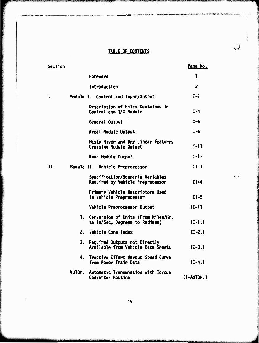
I Module I. Control and Input/Output 1-1
1 Description of Files Contained In Control and I/O Module 1-4
1 General Output 1-5
1
Areal Module Output 1-6
J;. i Hasty River and Dry Linear Features Crossing Module Output 1-11
' Road Module Output 1-13
i II Module II. Vehicle Preprocessor IM
Specification/Scenario Variables Required by Vehicle Preprocessor II-4
Primary Vehicle Descriptors Used In Vehicle Preprocessor I1-5
Vehicle Preprocessor Output 11-11
1. Conversion of Units (From M11es/Hr. to In/Sec, Degrett to Radians) 11-1.1
2. Vehicle Cone Index 11-2.1
3. Required Outputs not Directly Available from Vehicle Data Sheets I1-3.1
4. Tractive Effort Versus Speed Curve from Power Train Data I1-4.1
AUTOM. Automatic Transmission with Torque Converter Routine II-AUTOM.1
iv
mumtmm mm
r^-vr^^^^~r^myrm^7'jwnyinTm'^^^^'---™r^^^ W'" WS'•m'l^ir:VV'>n
u
u
Section Page No.
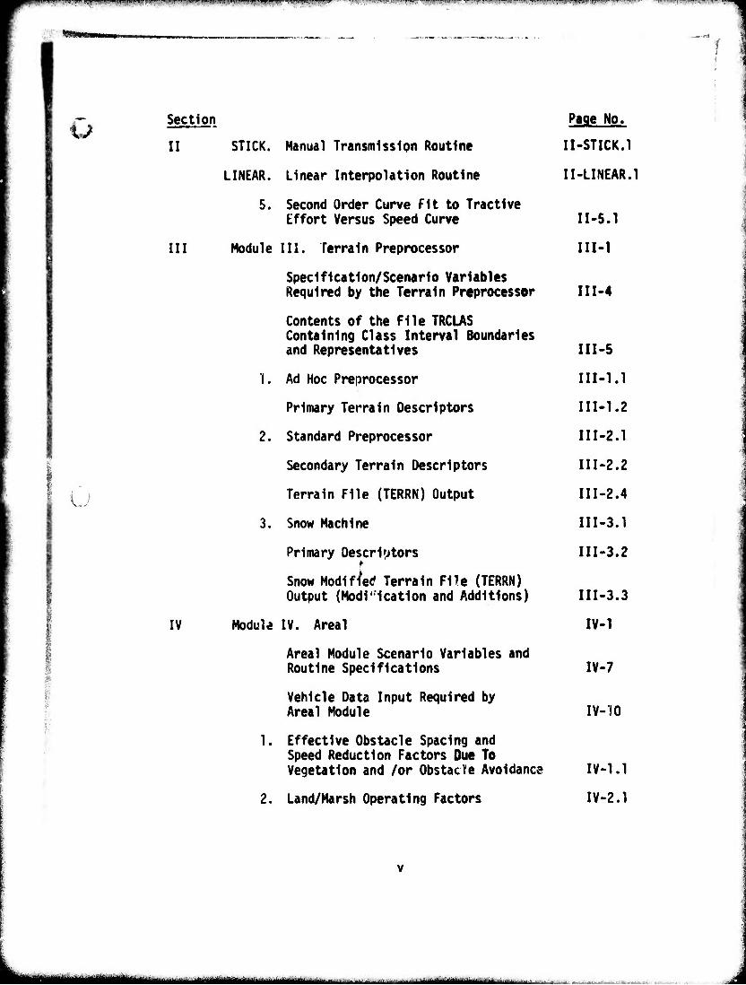
II STICK. Manual Transmission Routine II-STICK.1
LINEAR. Linear Interpolation Routine II-LINEAR.1
5. Second Order Curve Fit to Tractive Effort Versus Speed Curve I1-5.1
III Module III. Terrain Preprocessor III-l
Specification/Scenario Variables Required by the Terrain Preprocessor II1-4
Contents of the File TRCLAS Containing Class Interval Boundaries and Representatives II1-5
1. Ad Hoc Preprocessor III-l.1
Primary Terrain Descriptors III-l.2
2. Standard Preprocessor II1-2.1
Secondary Terrain Descriptors II1-2.2
Terrain File (TERRN) Output III-2.4
3. Snow Machine III-3.1
Primary Descriptors III-3.2 t
Snow Modified Terrain File (TERRN) Output (Modification and Additions) III-3.3
IV Module IV. Areal IV-1
Areal Module Scenario Variables and Routine Specifications IV-7
Vehicle Data Input Required by Areal Module IV-'iO
1. Effective Obstacle Spacing and Speed Reduction Factors Due To Vegetation and /or Obstacle Avoidance IV-1.1
2. Land/Marsh Operating Factors IV-2.1
^■M^ -" - - - Mi—i— i Mtmk WmMltJilrtiri - ■".'. _ »iT.-c
Wl^ wmwippwpm *im\\i •vv'v«imi«<f«m*mim*mmrm wmmfmmnm^'m^mm
by
Section
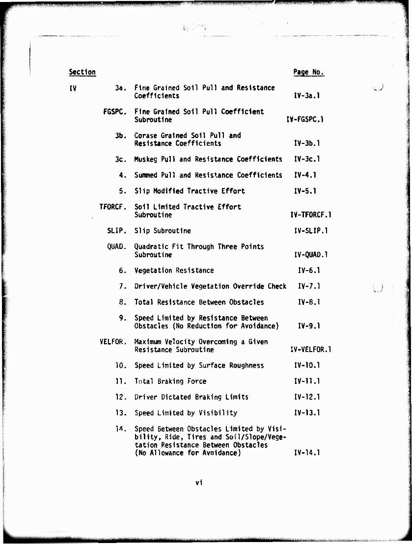
IV 3«. Fine Grained Soil Pull and Resistance Coefficients
F6SPC. Fine Grained Soil Pull Coefficient Subroutine
3b. Corase Grained Soil Pull and Resistance Coefficients
3c. Muskeg Pull and Resistance Coefficients
4. Summed Pull and Resistance Coefficients
5. Slip Modified Tractive Effort
TFORCF. Soil Limited Tractive Effort Subroutine
SLIP. Slip Subroutine
QUAD. Quadratic Fit Through Three Points Subroutine
6. Vegetation Resistance
7. Driver/Vehicle Vegetation Override Check
8. Total Resistance Between Obstacles
9. Speed Limited by Resistance Between Obstacles (No Reduction for Avoidance)
VELFOR. Maximum Velocity Overcoming a Given Resistance Subroutine
10. Speed Limited by Surface Roughness
11. Total Braking Force
12. Driver Dictated Braking Limits
13. Speed Limited by Visibility
1A. Speed Between Obstacles Limited by Visi- bility, Ride, Tires and Soil/SIope/Vege- tation Resistance Between Obstacles (No Allowance for Avoidance)
Page No.
IV-3a.l
IV-FGSPC.l
IV-3b.l
IV-3C.1
IV-4.1
IV-5.1
IV-TF0RCF.1
IV-SLIP.l
IV-QUAO.l
IV-6.1
IV-7.1
IV-8.1
IV-9.1
IV-VELF0R.1
IV-10.1
IV-11.1
IV-12.1
IV-13.1
.J
u
IV-14.1
vi
^i^ttiamimmaimwtw \ .^ ^U^-^l ^L^^^WI-.M
qpM -- ,,,11. .^..„^.^.i^. m. ,11 m,. i imnmi uiiiii -w- i j inpip ^^—W-^-P^-r,
WM ,■:
Section
IV
$ i
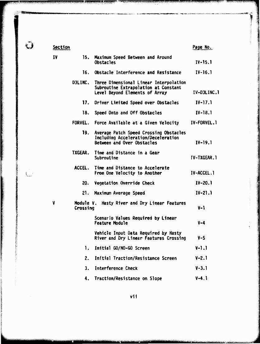
15. Maximum Speed Between and Around Obstacles
16. Obstacle Interference and Resistance
D3LINC. Three Dimensional Linear Interpolation Subroutine Extrapolation at Constant Level Beyond Elements of Array
17. Driver Limited Speed over Obstacles
18. Speed Onto and Off Obstacles
FORVEL. Force Available at a Given Velocity
19. Average Patch Speed Crossing Obstacles Including Acceleration/Deceleration Between and Over Obstacles
TXGEAR. Time and Distance in a Gear Subroutine
ACCEL. Time and Distance to Accelerate From One Velocity to Another
20. Vegetation Override Check
21. Maximum Average Speed
Module V. Hasty River and Dry Linear Features Crossing
Scenario Values Required by Linear Feature Module
Vehicle Input Data Required by Hasty River and Dry Linear Features Crossing
1. Initial GO/NO-GO Screen
2. Initial Traction/Resistance Screen
3. Interference Check
4. Traction/Resistance on Slope
Page No.
IV-15.1
IV-16.1
IV-D3LINC.1
IV-17.1
IV-18.1
IV-F0RVEL.1
IV-19.1
rV-TXGEAR.1
IV-ACCEL.1
IV-20.1
IV-21.1
V-1
V-4
V-5
V-1.1
V-2.1
V-3.1
V-4.1
vii
^MMMH ■ iaii""""- "^^ ■ dMaBatoüaaMittaMiia
|i,.!.||| ...M..|I.I., , ., |,|,ilim.»iw,i|.,.a.|),iTl..||HiiiW»..|i^Wit.n || i|.im.,,W|||i»ii lfilip,l^iH.IVJ-l>«llJ^lMiM.-"-"'^n''-T,l'l-'ll''''"l'>"'*,p]^' ■''''""'"''■^ ^'Py'''1''''"' "«'»«'T'W'ri ..„l.pjwpniipiij l..!!."":-
Section
V
VI
VII
VIII
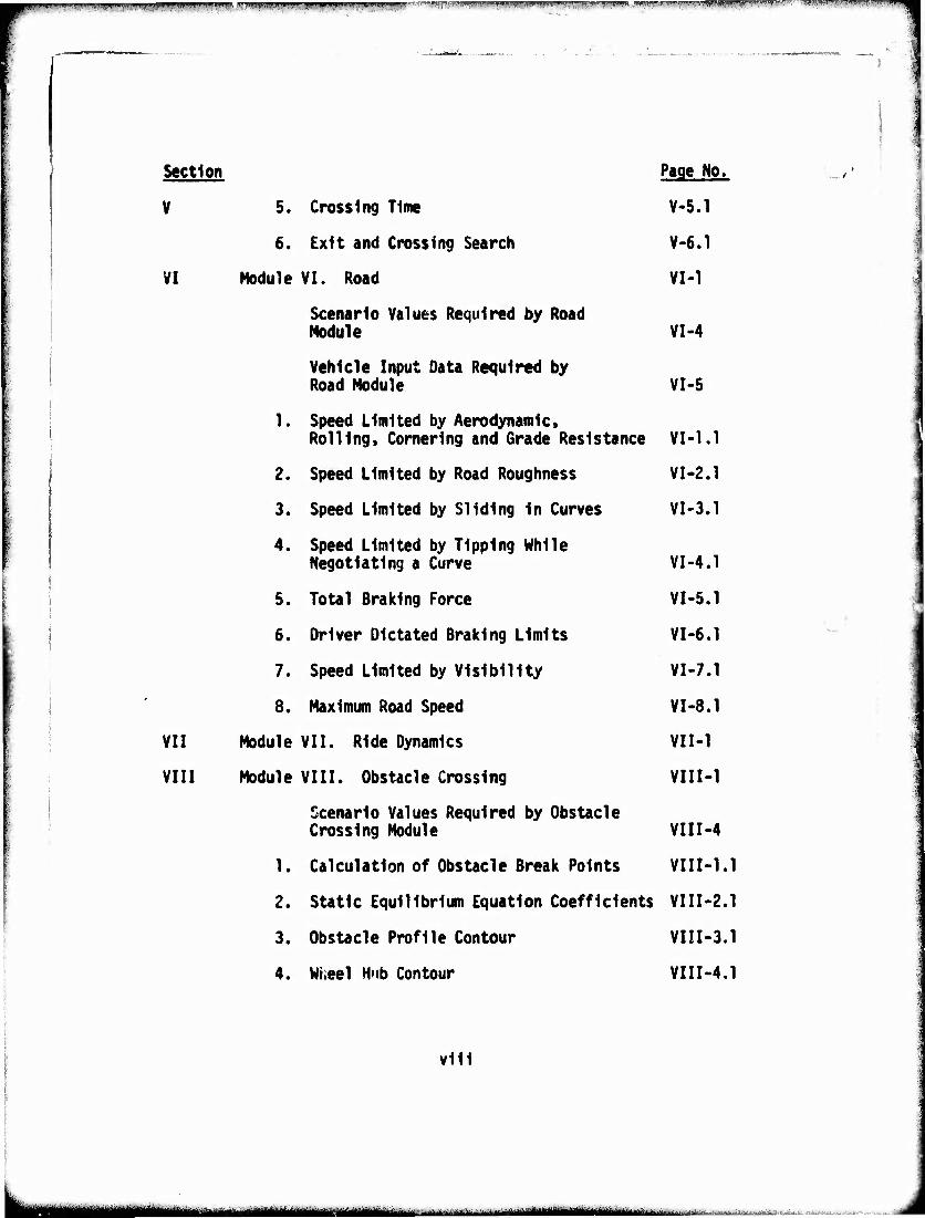
5. Crossing Time
6. Exit and Crossing Search
Module VI. Road
Scenario Values Required by Road Nodule
Vehicle Input Data Required by Road Nodule
1. Speed Limited by Aerodynamic» Rolling, Cornering and Grade Resistance
2. Speed Limited by Road Roughness
3. Speed Limited by Sliding In Curves
4. Speed Limited by Tipping While Negotiating a Curve
5. Total Braking Force
6. Driver Dictated Braking Limits
7. Speed Limited by Visibility
8. Maximum Road Speed
Nodule VII. Ride Dynamics
Module VIII. Obstacle Crossing
Scenario Values Required by Obstacle Crossing Module
1. Calculation of Obstacle Break Points
2. Static Equilibrium Equation Coefficients
3. Obstacle Profile Contour
4. Wheel Hub Contour
Page No.
V-5.1
V-6.1
VI-1
VI-4
VI-5
VI-1.1
VI-2.1
VI-3.1
VI-4.1
VI-5.1
VI-6.1
VI-7.1
VI-8.1
VII-1
VIII-1
VIII-4
VIII-1.1
VIII-2.1
VIII-3.1
VIII-4.1
vlll
■MMM^I MMHHk .^MMM—«MtllMM—in ■ -^. VaaAtUL -^"*^"-'-
p.^i!wp""" ■ .mm» mn i^.ii|,.„i»..il^.WiiwiiW|i .ni.ni]iimipwi,inji.jtiiiLpii,, immm. ■■VT^-V,,,,I^„, j^t, ,„,,,.1 .,,.,iW!lu....iil,,.y,rii|1i,..,ii)ii^ -w.-.- •wm'mvmi'v.w
KJ Section
VIII
IX
A
B
C
Page No.
5. Vehicle Clearance Contour VIII-5.1
6. Minimum Clearance and Tangential Force VIII-6.1
7. Maximum and Average Force to Override an Obstacle VII1-7.1
References IX-1
Appendix Vehicle Data Sheets A-l
Vehicle Data Sheet Instructions A-2
Vehicle Data Cross Index A-3
Vehicle Data for AMC '74 Mobility Model A-12
1. Vehicle Identification A-12
2. Running Gear A-l3
3. Power Train A-18
4. Geometry A-26
5. Water Characteristics A-29
6. Highway Characteristics A-32
7. Mobility Assist Systems A-33
8. Inputs from Dynamics Module A-34
9. Obstacle Crossing Input Data A-38
Distribution List B-l
Report Documentation Page C-l
ix
m^m MMHHMHi
mm WlJWPIJWWIWWlilli^^ »■■'■V! ■■-«'^—' ''"
^■■^L
LIST OF FIGURES
Section Page No.
III Terrain Preprocessing Flow Chart III-6
IV AMC '74 Mobility Model Areal Module Overview IV-4
AMC '74 Mobility Model Areal Module Flow Chart IV-6
VIII Vehicle Representation for AMC '74 Obstacle Module VIII-2.3
VIII Representation of Modified Obstacle Profile VIII-4.2
A Vehicle Geometry A-28
Obstacle Crossing Input Data, Figure A-1 A-40
Obstacle Crossing Input Data, Figure A-2 A-43
Obstacle Crossing Input Data, Figure A-3 A-46
mm - -- ........ aj ...... .,..,^
^m^wv^.H'.v. '.'-.■-•"(*^ - ffT«^- ■ ■ - - - . ■.-^^,-.H^«...t...jffffpyy^ffyyqp,^J■■.>^-T..*.'-».^..■■ /i."■*-^ rv..^ -, ,.,■■. ....T,, -,. ,..., : ;
I
\.J
FOREWORD
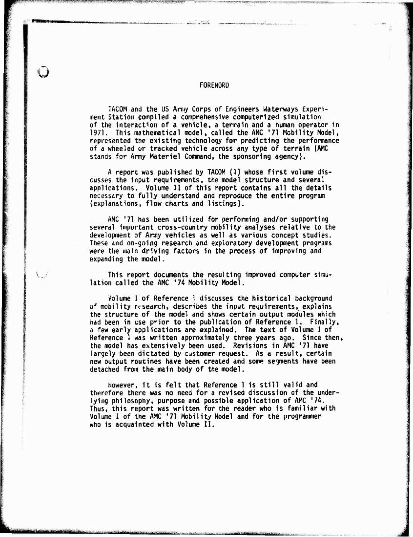
TACOM and the US Army Corps of Engineers Waterways Experi- ment Station compiled a comprehensive computerized simulation of the interaction of a vehicle, a terrain and a human operator in 1971. This mathematical model, called the AMC '71 Mobility Model, represented the existing technology for predicting the performance of a wheeled or tracked vehicle across any type of terrain (AMC stands for Army Materiel Command, the sponsoring agency).
A report was published by TACOM (1) whose first volume dis- cusses the input requirements, the model structure and several applications. Volume II of this report contains all the details necessary to fully understand and reproduce the entire program (explanations, flow charts and listings).
AMC '71 has been utilized for performing and/or supporting several important cross-country mobility analyses relative to the development of Army vehicles as well as various concept studies. These and on-going research and exploratory development programs were the main driving factors in the process of improving and expanding the model.
This report documents the resulting improved computer simu- lation called the AMC '74 Mobility Model.
Volume I of Reference 1 discusses the historical background of mobility research, describes the input requirements, explains the structure of the model and shows certain output modules which had been in use prior to the publication of Reference 1. Finally, a few early applications are explained. The text of Volume I of Reference 1 was written approximately three years ago. Since then, the model has extensively been used. Revisions in AMC '71 have largely been dictated by customer request. As a result, certain new output routines have been created and some segments have been detached from the main body of the model.
However, it is felt that Reference 1 is still valid and therefore there was no need for a revised discussion of the under- lying philosophy, purpose and possible application of AMC '74. Thus, this report was written for the reader who is familiar with Volume I of the AMC '71 Mobility Model and for the programmer who is acquainted with Volume II.
k ifft-riii— in' ■ ■ ...^.■■■^.....^^.^.l.Wii^^^^^ .„,■..
INTRODUCTION
course of three "WHEELS" Study (2), well as restrictions be expected because comprehensive mobility
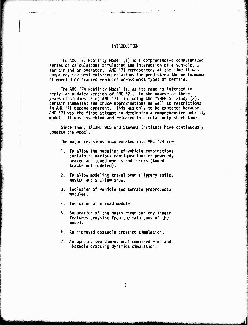
The AMC '71 Mobility Model (1) is d comprehensive computerized series of calculations simulating the Interaction ot a vehicle, a terrain and an operator. AMC '71 represented, at the time it was compiled, the best existing relations for predicting the performance of wheeled or tracked vehicles across most types of terrain.
The AMC '74 Mobility Model is, as its name is intended to imply, an updated version of AMC '71. In the years of studies using AMC '71, including the certain anomalies and crude approximations as in AMC '71 became apparent. This was only to AMC '71 was the first attempt in developing a model. It was assembled and released in a relatively short time.
Since then, TACOM, WES and Stevens Institute have continuously updated the model.
The major revisions incorporated into AMC *74 are:
1. To allow the modeling of vehicle combinations containing various configurations of powered, braked and towed wheels and tracks (towed tracks not modeled).
2. To allow modeling travel over slippery soils, muskeg and shallow snow.
3. Inclusion of vehicle and terrain preprocessor modules.
4. Inclusion of a road module.
5. Separation of the hasty river and dry linear features crossing from the irain body of the model.
6. An improved obstacle crossing simulation.
7. An updated two-dimensional combined ride and obstacle crossing dynamics simulation.
mmm — mm ■ ■■— ■ ■ ■
^^«itmWMwc
u 8. To rearrange the logic within the model to
allow more modularity and precision In cal- culation and output.
9. To correct errors In computation.
10. To allow an extended set of scenario specifications.
Revision 1 now allows the modeling of the movement of vehicles such as half-tracks, towed and/or powered and/or braked trailers, pitch articulated vehicles, vehicles with gross variations In load distribution and vehicles with variations In axle geometries In soft soil, snow or muskeg.
Revision 2 now allows modeling of many terrains and operations In rain and other Inclement weather conditions in the areal crossing module.
Revision 3 simplifies the supplying of vehicle data information by the user to the model. The terrain data Is also preprocessed and placed In a form that Is required for use In the main model.
Revision 4 is a new module which simulates travel on primary, secondary roads and trails. The outputs of this simulation are similar to the outputs of the areal module; i.e., maximum speed on a road segment.
Revision 5 is the result of experience gained In using AMC '71 for special studies and user vehicle evaluations. The areal crossing is exercised Independent of any linear feature terrain data.
Under Revision 6, the obstacle crossing problem is examined external to the areal crossing module. The force required to cross an obstacle and the geometric Interference history between the obstacle and the vehicle are calculated.
Under Revision 7, an updated dynamics module which Includes a two-dimensional ride dynamics simulation for rough terrain and a dynamics simulation for either single or multiple obstacle cros- sing has been added. Both simulations use a driver limited tolerance to vibration or shock for determining maximum speed. The updated dynamics module will be published separately (Reference 3)
Included under Revision 8 Is the clear separation of vehicle travel between obstacles and over obstacles.
«te -- - - -- i ■ ^—..^.--. ^■^.-^l^riU.:^...-^:,
Revision 9 is primarily a correction to the acceleration/ deceleration times and distances which now are calculated in closed form. This was done by approximating the power train In each gear by an analytic function and Integrating these functions. The gear- by-gear modeling also allows the addition of gear change times and velocity losses. Various other corrections were made throughout.
Under Revision 10, the user has been given control over opera- tional variables, such as weather and driver characteristics and motivation, so that the model may be used for a variety of scenarios.
AMC '74 is the precursor of the Army Mobility Model (AHM) which is due for Army-wide release in the first quarter of FY76. AMC '74 will be used in several studies before AMM is finally developed.
The term model is used here to denote the algorithms and opera- tional procedures published in this report. They are intended for computer implementation; a specific such implementation will be referred to as a programmed version of the model. AMM will be released with an accompanying programmed version which will. Insofar as possible, have the following features:
the programmed version of computational modules will be coded in machine independent FORTRAN IV.
the coding will stress transparency and direct correspondance between documentation and code.
all machine dependent functions (overlays, input/ * output, etc.) will be consolidated in a single
command and control module. However, the user will have to write his own input/output modules if his computer is different from the one at TACOM.
AMC '74 consists of 8 modules:
I. Control and I/O.
II. Vehicle Preprocessor.
Ill Terrain Preprocessor.
IV. Areal Module.
V. Hasty River and Dry Linear Feature Crossing.
VI. Road.
'''"•" j^itfttu^timtiaämmmmm ■-- i i "■"-iiiinrii J
MriMWM T^
>;
O VII. Ride Dynamics.
VIII. Obstacle Crossing.
These are briefly explained below:
I. The Input/Output module contains files of input (vehicle, terrain, scenario) and output. It is a general executive program. The structure of this module can be easily changed, if necessary, depending on the user's needs.
II. The Vehicle Preprocessor consists of algorithms which transform vehicle input data into quantities needed as Inputs to the various submodels. Some of these required data have to be hand-calculated for AMC '71.
III. The Terrain Preprocessor Is a set of algorithms whose function is to convert the class Interval number of the terrain input to quantitative values associated with terrain features or accept the quantitative values directly.
IV. The Areal Module simulates vehicle travel across the areal terrain units.
V. The Hasty River and Dry Linear Feature Crossing Module simulates a single vehicle crossing a linear feature without external aid or a bridge.
VI. The Road Module is a simulation of travel on primary, secon- dary roads and trails.
VII. The Ride Dynamics Module is a two-dimensional digital simulation of the dynamic interaction of the vehicle, rough terrain and obstacle« resulting in speed limitations due to human tolerance to rough rioe and shock.
This is an externally executed module which provides input data for the areal and road modules. The description of the dynamics module will be published separately. The data supplied by the ride dynamics module may alternatively be obtained from field tests.
VIII. The Obstacle Crossing Module is a detailed and improved simulation of the crossing of obstacles. This also is an externally executed module which provides the tractive effort required to cross the obstacles and determines interference geometry for the areal module.
—-•— m ^-"-^-^'^ .-.^dJI
"W«.'.«»»««..!
Ü
MODULE I.
Control and Input/Output
1-1
■uMttaakaHUJI ■iaaaiiMiMMiMMMMaMMi>ü.
tmmmm
Ö CONTROL AND INPUT/OUTPUT MODULE
The Control and Input/Output Module, acting in the role of a program executive, coordinates the access of the processing modules (Areal, Hasty River and Dry Linear Features Crossing, and Road) to their respective Input and output files.
It Is the Intention of the model designers that the pro- cessing modules be as machine independent as possible, and that all machine dependent coding be concentrated In the control and I/O module. This Implies that this module will open and close all files, read all Input and write all output, and, therefore, for efficiency, provide all software links between modules and routines.
Inputs consist of:
1. Basic vehicle data files
2. Terrain data files
3. Scenario data
4. Run specifications
a. Output file name
b. Output level Indicator
The basic mode of operation of the model is to mtke a series of speed or crossing time predictions for a given vehicle in each of the terrain, road or linear feature units described in the terrain data file, under a single set of scenario specifications. At the conclusion of such a run, vehicle, scenario and/or terrain inputs are changed as required to make a new set of predictions.
For each run so defined, the output file records the vehicle data used, identifies the terrain data file and scenario data used, and accumulates derived data from the working modules according to user needs as specified by the output level indicator. Four levels (1, 2, 3 and ID) are presently pro- vided, but others can be Inserted readily to meet special user requirements.
1-2
-■t---- • -■ ^ ._.^m
i Level 1 saves and records only the basic 1n-patch or In-unlt average maximum speed prediction from the Areal and/or Road Modules, or crossing time and speed from the Linear Features Nodule, for each terrain unit, road unit or linear feature In the terrain data file. These data may be used subsequently In an appropriate output processing module to generate speed maps, statistics and/or Indices, or to make best route selections or simple traverse time predictions.
Level 2 adds to the level 1 output, NO-GO or speed limit diagnostics for each unit or feature. It provides data for maps or statistics Identifying the reason* for vehicle per- formance limits throughout the area to which the terrain data are related.
Level 3 saves all level 1 and level 2 Information and, for each area or road unit, adds resistances and some Intermediate speeds needed to determine fuel consumption or to introduce acceleration and deceleration across unit boundaries for more precise traverse predictions.
Selection of other derived data for further output analysis to meet the needs of other types of studies can be rapidly developed as needed. Upon Identification of such additional needs, new output levels can be developed and added as a simple specification call. Levels 4 through 9 have been reserved for such future developments.
Level 10 saves alj, derived outputs for special program diagnostic studies.
i
■
1-3
Mum r rn - iiiiWHüi^lMiiiiiiiii miäum -
t..-i
Description of Files Contained in Control and I/O Module
Inputs VEHIC ■ generic name of file containing the basic vehicle data
OYNAM ■ generic name of file containing the tabulated outputs from the dynamics module
OBSTC ■ generic name of file containing the tabulated outputs from the obstacle crossing module
TERRN ■ generic name of terrain file con- taining the primary and secondary proper natural terrain units des- criptors.
SCENA ■ generic name of file containing the scenario Inputs
AMMOU ■ generic name of file In which all output Is written
LEVELO • output level of detail desired
1-4
K^^_ ■iiiiiiiltaMiiMBiaiiMt»iiii^^ ...v^^^^aM^aaMMii,^ ||||
General Output
The general output Is written to the output file (AMMOU) at the beginning of each run of a vehicle (at a given loading, tire Inflation specification, etc.) over all area! terrain, linear feature and/or road units described In a given (preprocessed) terrain data file (TERRN), under a given set of scenario conditions (SCENA). The output file contains:
- output file name
- vehicle identification
- payload description
- terrain data file Identification
- scenario Input data (SCENA)
- run specifications (LEVELO)
and (optional):
- complete vehicle Input data (VEHIC)
- dynamics module data (DYNAM)
- obstacle crossing module data (OBSTC)
- complete derived vehicle data
(See Module II. Vehicle Preprocessor.)
1-5
i .^^^^jljglllljg^llgillllgllliili mmini'-."^,.. ......i-j.^...,^, .,...■..,
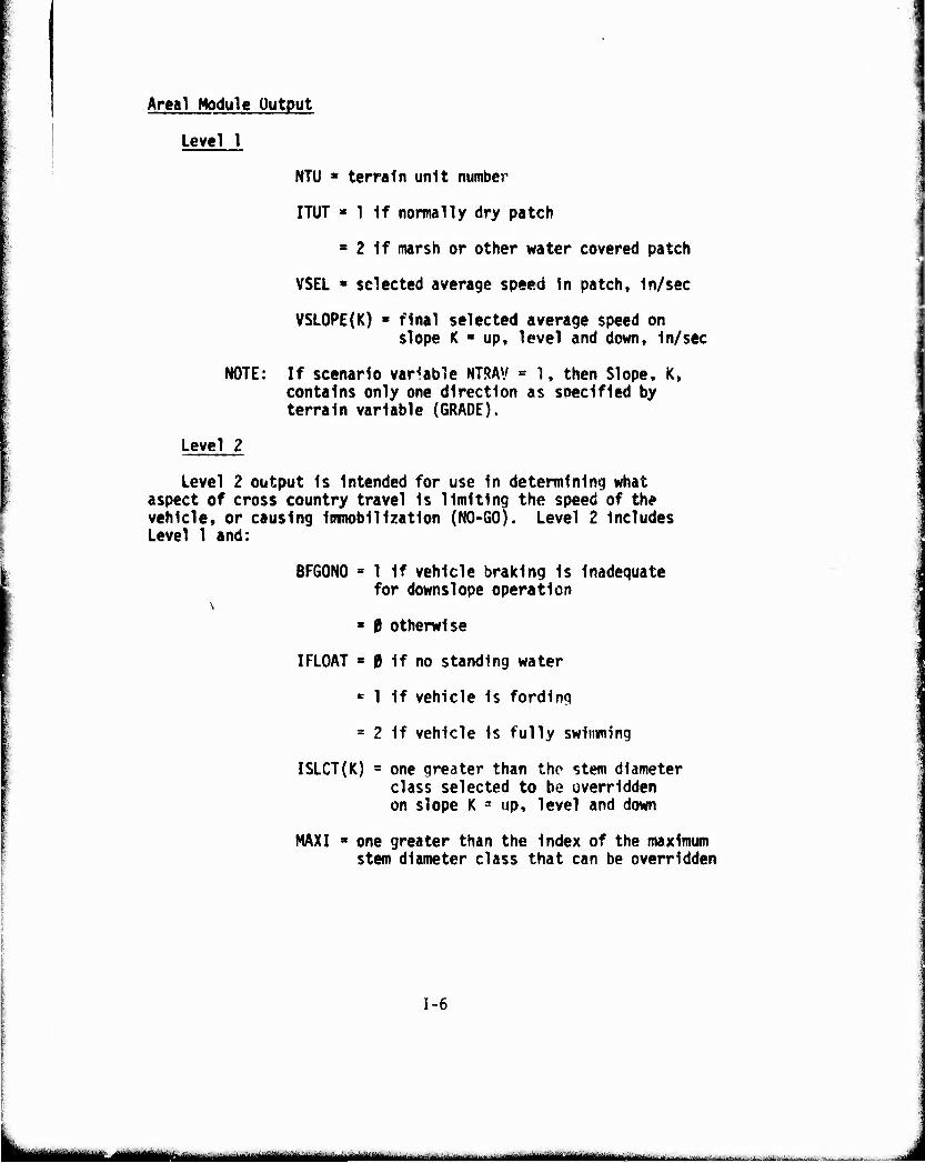
Areal Module Output
Level 1
NOTE;
NTU « terrain unit number
ITUT » 1 if normally dry patch
3 2 If marsh or other water covered patch
VSEL ■ selected average speed in patch, in/sec
VSLOPE(K) 8 final selected average speed on slope K ■ up, level and down, in/sec
If scenario variable NTRAV = 1, then Slope, K, contains only one direction as specified by terrain variable (GRADE).
Level 2
Level 2 output is Intended for use in determining what aspect of cross country travel is limiting the speed of the vehicle, or causing immobilization (NO-GO). Level 2 includes Level 1 and:
BFGONO » 1 if vehicle braking is Inadequate for downs!ope operation
« 0 otherwise
IFLOAT = 0 if no standing water
E 1 if vehicle is fording
= 2 if vehicle is fully swimming
ISLCT(K) = one greater than the stem diameter class selected to be overridden on slope K ^ up, level and down
MAXI ■ one greater than the index of the maximum stem diameter class that can be overridden
1-6
MÜÜMlTI " -- ■ "-■• ' ■ - I .aa^WlMiMilUrtMMiiMi^u J-i-.^-:..-.;..--,. -.lj„.. -^

u NEVERO • 0 If override/avoidance strategy
could have chosen obstacle override
« 1 If override/avoidance strategy never chose obstacle override due to belly/axle Interference with stumps or boulders
» 2 If override/avoidance strategy never chose obstacle override due to lack of penalty for obstacle avoidance
* 3 If detailed obstacle override determined interference
SRFO(ISLCT(K)) - speed reduction factor due to avoiding obstacles and vegetation In stem diameter class ISLCT(K)-1 and greater on slope K ■ up, level and down
SRFV(ISLCT(N)) « speed reduction factor due to avoiding vegetation In stem dia- meter class ISLCT(K)-1 and greater on slope K • up. level and down
VA(K,ISLCT(K)) s obstacle approach speed on slope K * up, level and down while overriding vegetation In stem dia- meter class ISLCT(K)-1 and smaller and avoiding vegetation in stem diameter class ISLCT(K) and greater. In/sec
VAVCHK(K,ISLCT(K)) • 1 If combination can over- ride a single tree of class ISLCT(K)-1 at speed VAV0I0(K,ISLCT(K))
* 0 otherwise
VAVOI0(K,ISLCT(K)) » speed on slope K - up. level and down avoiding obstacles but overriding vegetation in stem diameter class ISLCT(K)-1 and smaller and avoiding vegetation in stem dia- meter class ISLCT(K) and greater, in/sec
1-7
L *•"—iat<^i*"^'' '" ' ^-■.„.—M.^-...- ..v. ■ -.-,.^.^. . , |. . ^m^^^m
I lUll.iuiJ[liJiw.UMj.H|iil»pjpWJ!aiWliM^^ «llJi,||Ji!,lllll|i«llWilipWi..li,l l,|J, ~ "r^^Bvm-mrwmm
■U
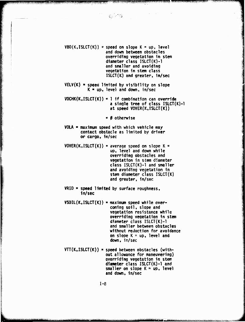
VBO(K,ISLCT(K)) = speed on slope K » up, level and down between obstacles overriding vegetation In stem diameter class ISLCT(K)-1 and smaller and avoiding vegetation In stem class ISLCT(K) and greater. In/sec
VELV(K) ' speed limited by visibility on slope K ■ up, level and down. In/sec
VOCHK(K.ISLCT(K)) ■ 1 if combination can override a single tree of class ISLCT(K)-1 at speed VOVER(K,ISLCT(K))
■ 0 otherwise
VOLA ■ maximum speed with which vehicle may contact obstacle as limited by driver or cargo. In/sec
VOVER(K,ISLCT(K)) - average speed on slope K = up, level and down while overriding obstacles and vegetation in stem diameter class ISLCT{K)-1 and smaller and avoiding vegetation In stem diameter class ISLCT(K) and greater. In/sec
VRIO * speed limited by surface roughness, in/sec
VSOIL(K,ISLCT(K)) - maximum speed while over- coming soil, slope and vegetation resistance while overriding vegetation In stem diameter class ISl.CT(K)-l and smaller between obstacles without reduction for avoidance on slope K = up, level and down, in/sec
VTT(K,ISLCT(K)) * speed between obstacles (with- out allowance for maneuvering) overriding vegetation in stem diameter class ISLCT(K)-1 and smaller on slope K * up, level and down. In/sec
1-8
8iiiiijmiigmiillmi^n^^^— ,.. .^..^.^^»luMmMii.^»^. - -^ .,...■ .-.--, w.u..: ^^^... ...,.
IfflWWI«»!..»,.!,,,,.,,.^,,,,,,,,«,,,,,,^, . WW!W!!^Pjw»w^R^niW5^
w»^^^,^,'!rJw^r™»^(»jwFsw7wwir-~ «nifigqii
■n
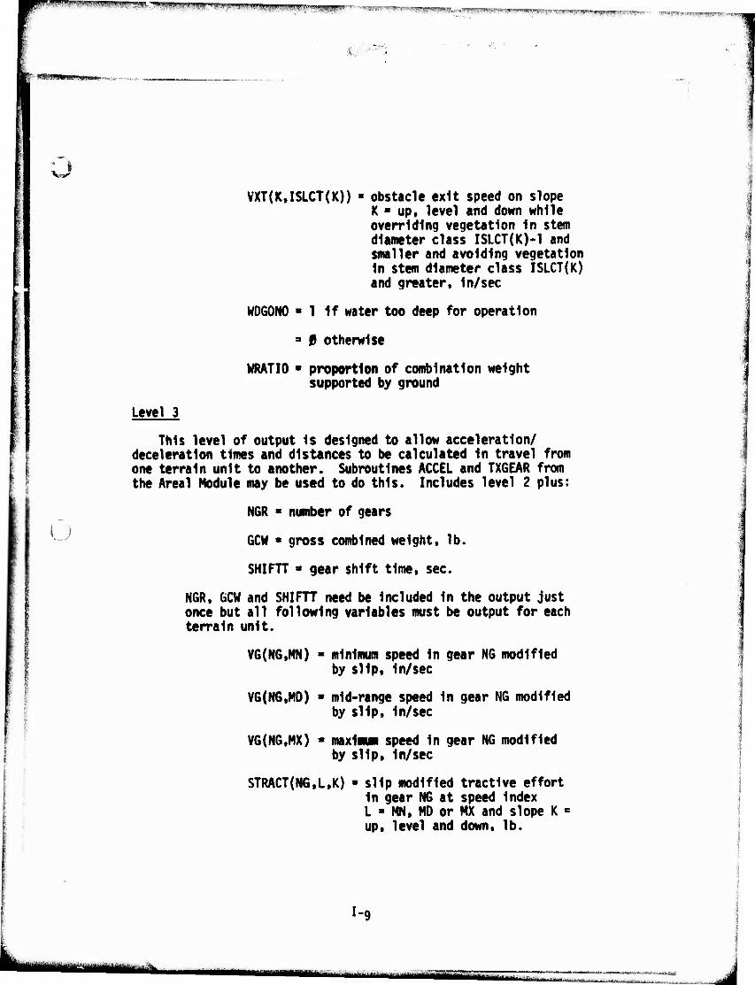
VXT(K.ISLCT(K)) obstacle exit speed on slope K ■ up, level and down while overriding vegetation In stem diameter class ISLCT(K)-1 and smaller and avoiding vegetation In stem diameter class ISLCT(K) and greater. In/sec
WDGONO » 1 If water too deep for operation
3 0 otherwise
WRATIO • proportion of combination weight supported by ground
Level 3
u
This level of output Is designed to allow acceleration/ deceleration times and distances to be calculated In travel from one terrain unit to another. Subroutines ACCEL and TXGEAR from the Areal Module may be used to do this. Includes level 2 plus:
NGR * number of gears
GCM * gross combined weight, lb.
SHIFTT ■ gear shift time, sec.
NGR, GCW and SHIFTT need be Included In the output just once but all following variables must be output for each terrain unit.
VG(NG,MN) - minimum speed In gear NG modified by slip. In/sec
VG(NG,M0) > mid-range speed In gear NG modified by slip. In/sec
VG(NG,MX) - maxlimi speed In gear NG modified by slip. In/sec
STRACT(N6.L,K) » slip modified tractive effort In gear NG at speed Index L * MN, MD or MX and slope K - up, level and down, lb.
I-c
-■ii
||l!^i^lljl»W»!f!PPPiWI3W^ ^™y"^^1^1^™?'.-'g!IWP!iwy»gi^?"^ffwwfmp^PB.•" "'".''^crwv^f^'i-^-'^W'" ■ -^<mwtrv;z™rf.vifwiii
ä ■fAm
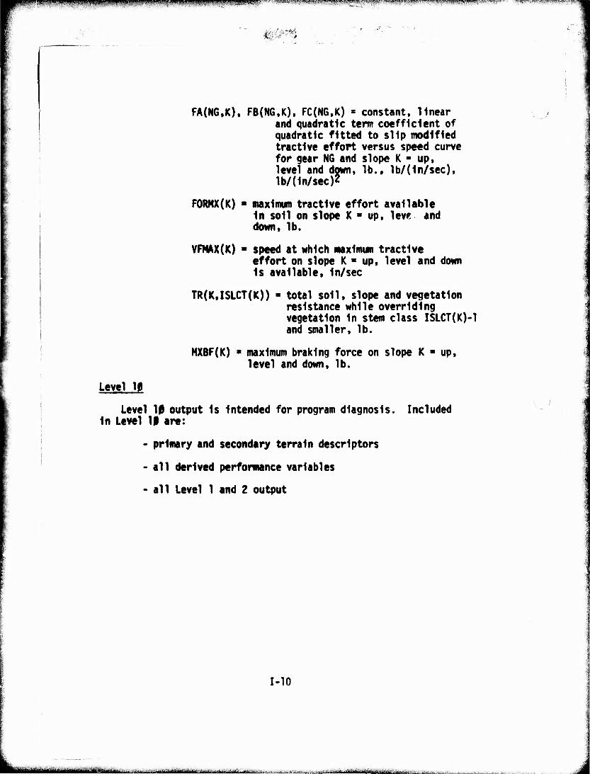
FA(N6,K), FB(NG.K), FC(NG.K) > constant, linear and quadratic term coefficient of quadratic fitted to slip modified tractive effort versus speed curve for gear NG and slope K - up. level and down, lb., 1b/(1n/sec), lb/(1n/sec)2
FORMX(K) ■ maximum tractive effort available in soil on slope K « up. leve and down, lb.
VFMAX(K) ■ speed at which maximum tractive effort on slope K * up, level and down is available. In/sec
TR(K,ISLCT(K)) - total soil, slope and vegetation resistance while overriding vegetation In stem class ISLCT(K)-1 and smaller, lb.
NXBF(K) * maximum braking force on slope K level and down, lb.
up,
Level 10
Level 10 output is Intended for program diagnosis. Included In Level 10 are:
- primary and secondary terrain descriptors
- all derived performance variables
- all Level 1 and 2 output
1-10
ifciH "iaaiiii» i i -- ■-—.. ^■■»..^. ■. ..:.^ ..■..,. ■ fiimrniia^tr.rni'- ij m
•»^WWPPWpipP: WWWWI! ^."""PW.-'Sm« '»■, »i»»".»'».1^.'«^«1! jii Ji''PJ,.'V<l,:j?w ""-•■^^;^i^w;i!T!'¥^lKiw;)TOWMW!ff»l<>^v'?tlwll'.^vg!w-wiy^^^^ -■
o
V
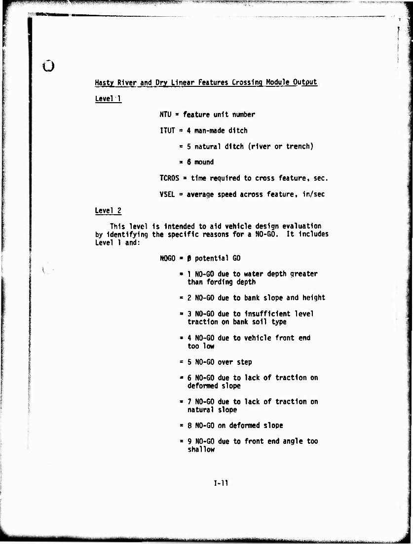
Hasty River and Dry Linear Features Crossing Module Output
Level 1
NTU * feature unit number
ITUT ■ 4 man-made ditch
» 5 natural ditch (river or trench)
* 6 mound
TCROS * time required to cross feature, sec.
VSEL » average speed across feature, in/sec
Level 2
This level is intended to aid vehicle design evaluation by identifying the specific reasons for a NO-GO. It includes Level 1 and:
NOGO - 0 potential GO
■ 1 NO-GO due to water depth greater than fording depth
* 2 NO-GO due to bank slope and height
» 3 NO-GO due to insufficient level traction on bank soil type
* 4 NO-GO due to vehicle front end too low
= 5 NO-GO over step
■ 6 NO-GO due to lack of traction on deformed slope
■ 7 NO-GO due to lack of traction on natural slope
* 8 NO-GO on deformed slope
» 9 NO-GO due to front end angle too shallow
1-11
ftüi* JJA^..-Mi.v.a.^V.^.-J^.i.^J..-.
"iiiiiwiiaiii i^iPHiW^WWppPHPiPmUJIIIIill B I' I i.ini.ii.uiniwipWii| ■injUMiiil. ... J ■ i|lllB!jl,,)l|,i.,iJl.lliiliJl , iiuinpnipn .i.iii.i - «uwnwiypyw >..II, j.^
fc.
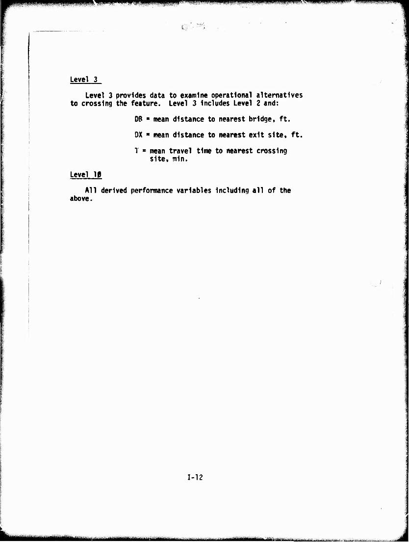
Level 3
Level 3 provides data to examine operational alternatives to crossing the feature. Level 3 Includes Level 2 and:
DB * mean distance to nearest bridge, ft.
DX « mean distance to nearest exit site, ft.
T ■ mean travel time to nearest crossing site, mln.
Level 10
All derived performance variables Including all of the above.
1-12
-- ■ ■ ^jgnnjjuimmg^ii^ WLUUU.U ^^.d^, ^-:^-..^. ....':-. „
. ■" W Ui.li IPHWWIBPWPI'Wpg i.i.iiiiijwiii mm«' ■» i" "WffPWSW
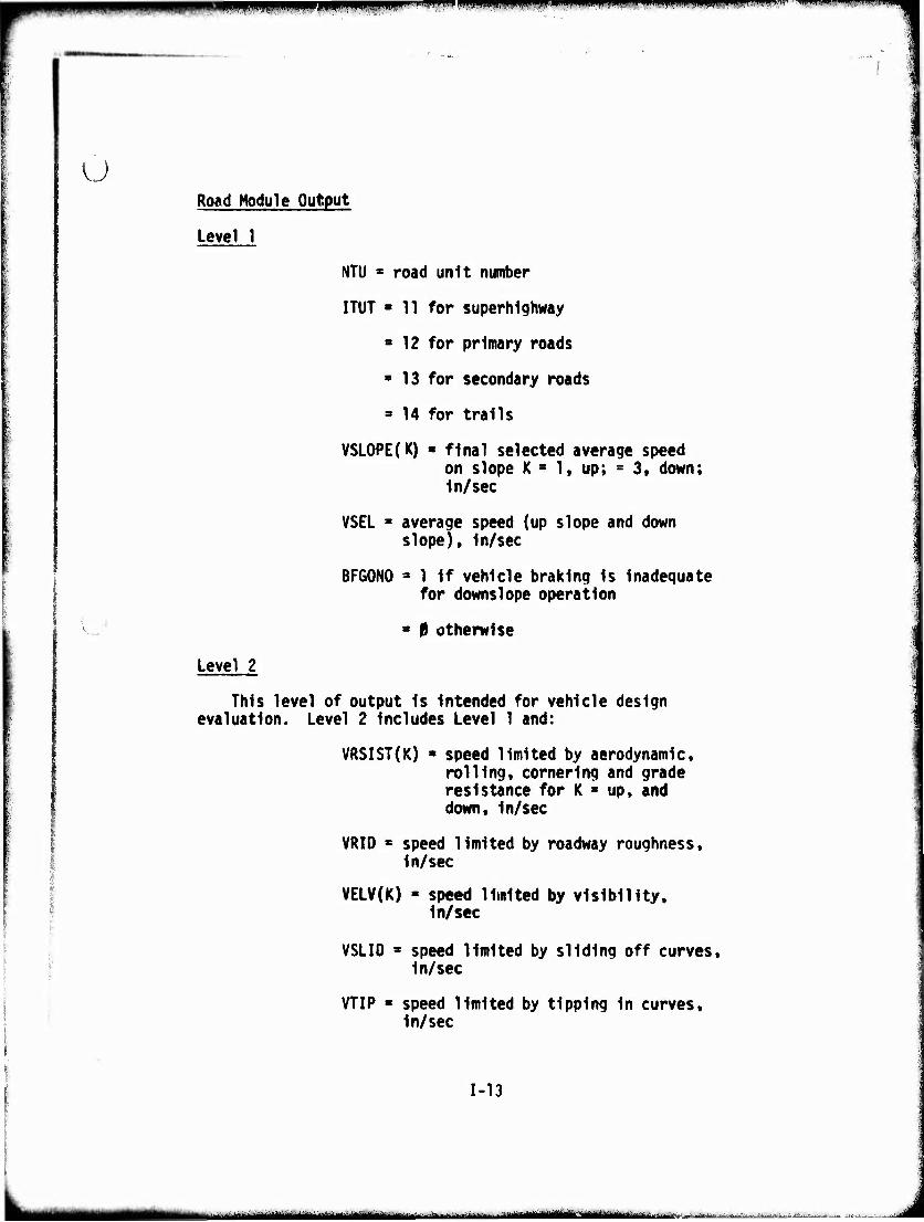
U Road Module Output
Level 1
NTU = road unit number
ITUT ■ 11 for superhighway a 12 for primary roads
» 13 for secondary roads
3 14 for trails
VSLOPE(K) > final selected average speed on slope K s 1, up; s 3« down; In/sec
VSEL * average speed (up slope and down slope). In/sec
BFGONO * 1 If vehicle braking Is Inadequate for downslope operation
* 0 otherwise
Level 2
This level of output Is Intended for vehicle design evaluation. Level 2 Includes Level 1 and:
VRSIST(K) • speed limited by aerodynamic, rolling, cornering and grade resistance for K ■ up, and down. In/sec
VRIO • speed limited by roadway roughness. In/sec
VELV(K) * speed limited by visibility. In/sec
VSLIO s speed limited by sliding off curves. In/sec
VTIP « speed limited by tipping In curves. In/sec
1-13
UUMIMilMüiHk — ■■ i irHiilllMIMÜfr r ir'riVnitttTri-i ■'■ - m-n ■ i -i i ..■.;■■. w...,:.^ aäajtaatfa HUlmn
mmmmm^iimmmimmmm^iüw '^ 'm»«mmii*\'im.vm»k,w<..i<m«\>i^.. ^m^mimmmm^^m "" ■—'-■"-
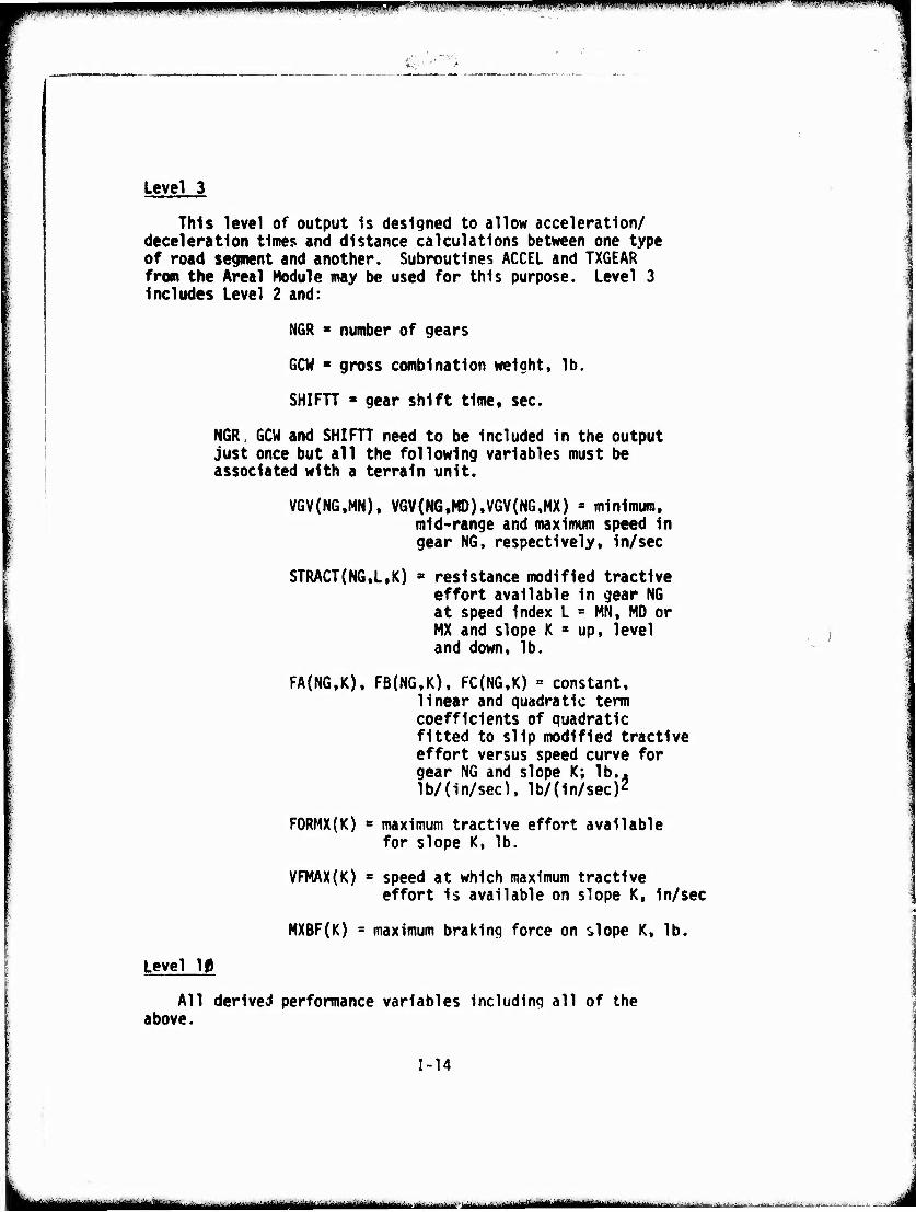
Level 3
This level of output 1s designed to allow acceleration/ deceleration times and distance calculations between one type of road segment and another. Subroutines ACCEL and TXGEAR from the Areal Module may be used for this purpose. Level 3 Includes Level 2 and:
NGR ■ number of gears
GCW « gross combination weight, lb.
SHIFTT » gear shift time. sec.
NGR, GCW and SHIFTT need to be included in the output just once but all the following variables must be associated with a terrain unit.
VGV(NG.MN). VGV(NGtMD),VGV(NG,MX) « minimum, mid-range and maximum speed In gear NG, respectively, in/sec
STRACT(NG.L.K) = resistance modified tractive effort available in gear NG at speed index L = MN, MD or MX and slope K * up, level j and down, lb.
FA(NG,K), FB(NG,K), FC(NG,K) = constant, linear and quadratic term coefficients of quadratic fitted to slip modified tractive effort versus speed curve for gear NG and slope K; lb.. lb/(in/sec). lb/(in/sec)2
FORMX(K) s maximum tractive effort available for slope K, lb.
VFMAX(K) * speed at which maximum tractive effort is available on slope K, in/sec
MXBF(K) = maximum braking force on slope K, lb.
Level 10
All derived performance variables Including all of the above.
1-14
^^mMni^M^^^^^M*aM*..t HI ii.i ninf ,...^„aau»^»aaa^^^.--„.„.,.
pppi i IIHII»II iiimjwiipni!(wp.f»*)!iiiiii^ii 'mmmmmmmn Mmwmm1""**""^" '' WBWWP ■■'IW.UXBI
■■■■>■■——
V., /
MODULE II
VEHICLE PREPROCESSOR
II-l
'IT ni [■»Mil ^m^^^m^tmt^mm^^m a^■-|^^l-.^: ■■ ' — .i...,,.■,- -.. .— .,;.^JI_J_
iB.im.miWWiWPWpp'llwwwi^i^ '.iW;4n,in!iwi.ii.! ,iii|.p!jiiffliiii).Mpw«i..,iwi.wiiPiniPWi'iii. j|i i,i.[i),.i.,wi|iiipimWwtli .inm,m vmmvmwmmm
I VEHICLE PREPROCESSOR MODULE
The vehl^e preprocessor module performs four basic operations:
1. It converts the dimensional units of the vehicle's nomenclature to the inch, pound, second, radians units used for all variables in the Areal, Hasty River and Dry Linear Features Crossing and Road Modules.
2. It computes the vehicle cone index (VCI) for fine grained, coarse grained and muskeg soils.
3. It characterizes the theoretical tractive effort versus vehicle speed relation, either from an experimental data array or from engine-transmission-final drive data. In terms of a series of quadratic expressions.
4. Finally, the preprocessor calculates a number of derived vehicle characteristics which recur in several modules or submodels such as gross combined weight, minimum path width of traction elements, etc.
^ ^ The vehicle nomenclature that appears on the vehicle data sheets has conventional dimensional units. Speeds are in MPH, lengths in inches, weights in pounds, and angles in degrees. The preprocessor converts MPH to In/sec and degrees to radians. The weight and length units are re- tained.
The tractive effort speed relation is built by using a series of quadratic curve fits to the engine-transmission- drive train data in each gear. The quadratic curve in each gear eliminates the table look-up procedure employed in AMC '71 and permits a closed form Integration for distance in the Acceleration/Deceleration (AC/DC) routine. Use of the quadratic functions reduces the number of computations re- quired whenever the AC/DC routine is used. This is important because revisions to the obstacle crossing speed algorithm in the areal module introduce AC/DC considerations more often than they occurred in AMC '71.
A significant advance over AMC '71 is In the computation of Vehicle Cone Index (VCI). The preprocessor addresses
II-2
ma^umm^^ii^mmämmm^iä^m^mittMä,,'',-,, ...„,:- .^.^^
>^m m-ji,,,,, nm.mmmmi*i \m.w .m** PWW wmmm mi •■ IBIIKII inn
the VCI computations on an axle-by-axlo or track unit-by track unit basis. Each of these indivioual running gear units is called an assembly. The individual assembly pro- cedure enables .the model to accommodate powered, unpowered, braked and unbraked assemblies. For each assembly which is powered and/or braked, the VCI and contact pressure factor (CPF) are calculated for fine grained and muskeg soils. These values are passed Into submodels 3a and 3c of the Areal Module where the pull force coefficients for fine grained and muskeg soils are calculated per assembly. It is assumed that the running gear assemblies slip uniformly. To imple- ment this assumption in the slip modified tractive effort routine of the areal module a series of effective contact pressure factors is computed for the vehicle as a whole (CPFCFü, CPFCCG).
i
The derived vehicle characteristics are peculiar to the specific algorithms within a routine. They are vehicle characteristics not ordinarily found on data sheets, txatiiples are: gross combined weight on non-braked assem- blies, minimuii! lateral distance from CG to outer wheels, percent distribution of weight on front assembly.
The nomenclature of the vehicle and its components which is used throughout the AMC '74 Mobility Model is as follows:
Element - single tire or track
Assembly - axle with wheels and tires or a pair of left and right tracks
Unit - prime mover, trailer
Combination - whole vehicle composed of the sum of all units
II-3
ttm^mmf^mm ■
■UPPPjppi iijjj|iiiipwii;t,.Aipiw^iii]iiwiH'iw'iW"<w'»w^;ui'|iii!i»w.iwW;'w^!y ■'.ftvm'*e«WMrwrr'
MkH^ —■
o Specification/Scenario Variables Required by Vehicle Preprocessor
APGDAT = 1 choose power train data (if available)
= 2 choose measured tractive effort data (if available)
U
II-4
«^li..J, ..^■■^,.^J..,.^. .,.. : . ... .. ,...J.:1J.,.^^;
pWIliWWWWiyw."jiy^^Mii^^ipi^ffiWfM .i^,iiwp.p*w"'^'^i.JJwi-WJW'.'wi«-W.'Ji•■ 'W'vWMw»," -■ -"■^^«■■.J'JI.^M«W»WH^ML'r«:■!^.wjfIU'-I..wn..vw.w.wf^wwf-wmwmv****.»mwm.vwvW''^vrK^^ ^m^^yr^ww^^r^rw^
' '■. ■"■wl^J'WttfiW•'(•«l.■','
Specification/Scenario Variables Required by Vehicle Preprocessor
AP6DAT = 1 choose power train data (if available)
= 2 choose measured tractive effort data (if available)
u
II-4
— -——i— mm—— - i.^,,-.^..^^;.._.!.. ..„, r^^. .. ,.,^,^.., , , _
lppnpnWlipp«nHipfpip!^iinv«<>pnM.«^i^!A..uim ,1 mmi ivtimv'mimwsmi: '^^^'viw*,m*mr*W'*r?.!lwwf!*n^*w*mmvm^W'fir-'
...■■,.■ ;'...'S/fy
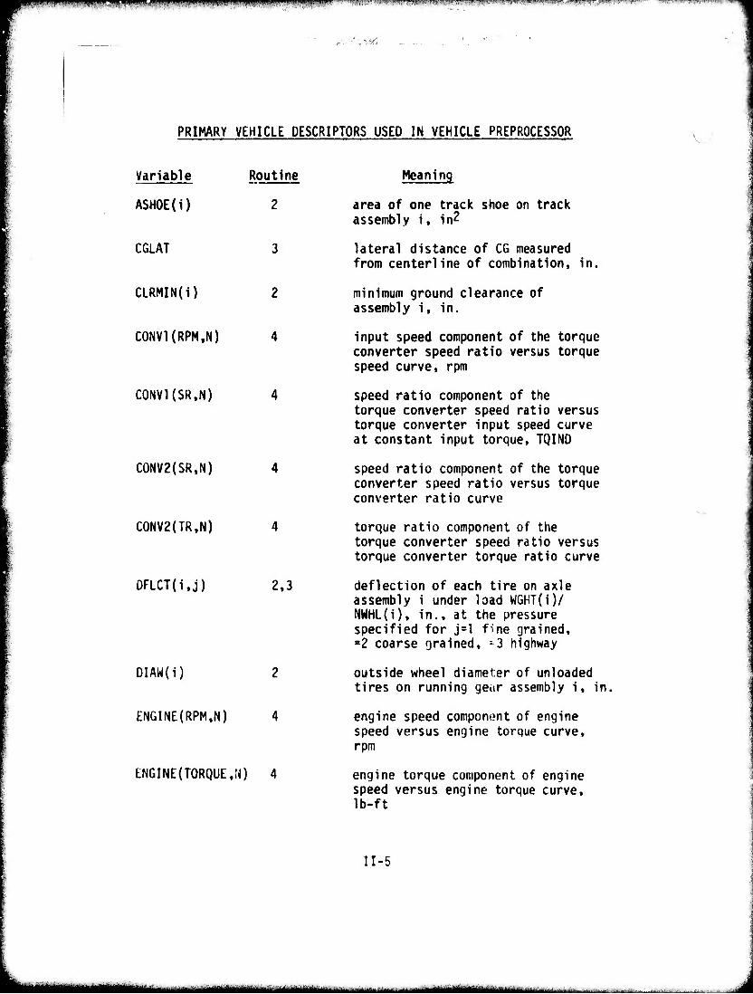
PRIMARY VEHICLE DESCRIPTORS USED IN VEHICLE PREPROCESSOR
Variable
ASHOE(i)
CGLAT
CLRMIN(i)
C0NV1(RPM,N)
CONVKSR.N)
CONV2(SR,N)
C0NV2(TR,N)
DFLCT(i,j)
Routine
2
3
2.3
DIAW(i)
ENGINE(RPM,N)
ENGINE(TORQUE.M) 4
Meaning
area of one track shoe on track assembly i, in2
lateral distance of CG measured from centerline of combination, in.
minimum ground clearance of assembly i. in.
input speed component of the torque converter speed ratio versus torque speed curve, rpm
speed ratio component of the torque converter speed ratio versus torque converter input speed curve at constant input torque, TQIND
speed ratio component of the torque converter speed ratio versus torque converter ratio curve
torque ratio component of the torque converter speed ratio versus torque converter torque ratio curve
deflection of each tire on axle assembly i under load WGHT(i)/ NWHL(i). in., at the pressure specified for j=l fine grained, =2 coarse grained, -3 highway
outside wheel diameter of unloaded tires on running gear assembly i, in,
engine speed component of engine speed versus engine torque curve, rpm
engine torque component of engine speed versus engine torque curve, Ib-ft
II-5
MMMMM^MHMMMi ■MM MMMMMHiMHlMMilHi -■-■--<"- ■■• -■■■■ -.
'■■'■T7-'r--»-i ■■■■■, "nT»3'w-n-fi-.?,-r.TrÄ^v-—■'■ .■ ■ ■ ■ Ti^-7- .IT.''.
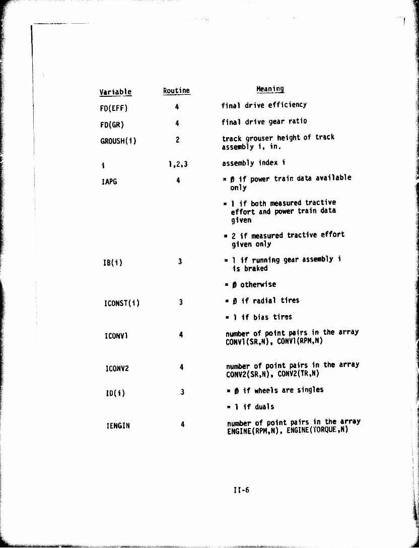
Variable Routine
FO(EFF) 4
FD(GR) 4
GROUSH(I) 2
1 1.2,3
IAPG 4
IB(1)
ICONST(I)
ICONV1
Meaning
final drive efficiency
final drive gear ratio
track grouser height of track assembly 1, In.
assembly Index 1
3 0 If power train data available only
» 1 If both measured tractive effort and power train data given
» 2 if measured tractive effort given only
» 1 If running gear assembly 1 Is braked
« 0 otherwise
- 0 If radial tires
■ 1 If bias tires
number of point pairs In the array CONVI(SR.N), CONVl(RPM.N)
IC0NV2
ID(1)
IENGIN
4
3
number of point pairs In the array C0KV2(SR,N). C0NV2(TR,N)
* 0 If wheels are singles
" 1 If duals
number of point pairs In the array ENGINE(RPM.N)( EHGINE(TORQUE,N)
II-6
■ -—■^-" ■ ■ >- -^ -■-■■--^ v^-^.- - iitifliii ■
pjUPil'i" ■* ivmw-fumii*:* Muniyi'My.wyiiiyww.i w!)fliiii.iliJ^i'f'i'^^<''.»;-^^w^B7WMv.^wv»»vwp>wr^^ww»y«P?:L'iWB»^^^ aWWW^1 ,- ^-. ,-,..,.-,
L.
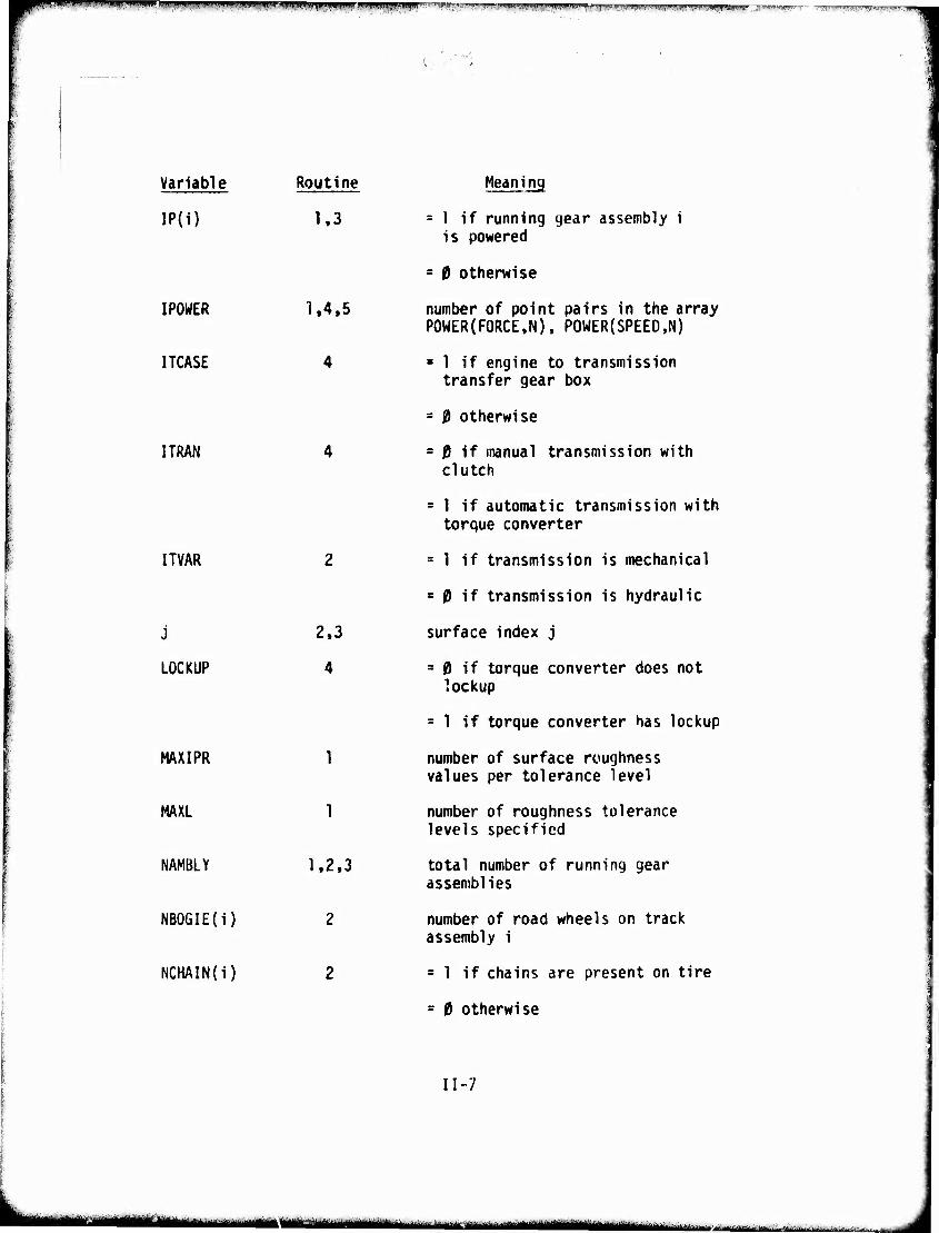
Variable
IP(1)
IPOWER
ITCASE
Routine
1,3
I TRAN
ITVAR
j
LOCKUP
MAXIPR
MAXL
NAMBLY
NBOGIE(i)
NCHAIN(i)
1.4.5
4
2.3
4
1
1
1,2,3
2
2
Meaning
= 1 if running gear assembly i is powered
= 19 otherwise
number of point pairs in the array POWER(F0RCE,N), POWER(SPEED.N)
■ 1 if engine to transmission transfer gear box
= 0 otherwise
= 0 if manual transmission with clutch
= 1 if automatic transmission with torque converter
= 1 if transmission is mechanical
= 0 if transmission is hydraulic
surface index j
= 0 if torque converter does not lockup
= 1 if torque converter has lockup
number of surface roughness values per tolerance level
number of roughness tolerance levels specified
total number of running gear assemblies
number of road wheels on track assembly i
= 1 if chains are present on tire
= 0 otherwise
11-7
jjgH ^^ "--■ —
mm ■PHP PiPWIPBWWIippiPPWIIfjpBP '" '^V;:;L'''P|^'pyww;|i<^p^')Jwro-M^^>»,w-Hw-:»w^'i,ji'tv'-.)iiii^
to MMMM «■»»- ow
Variable Routine Meaning
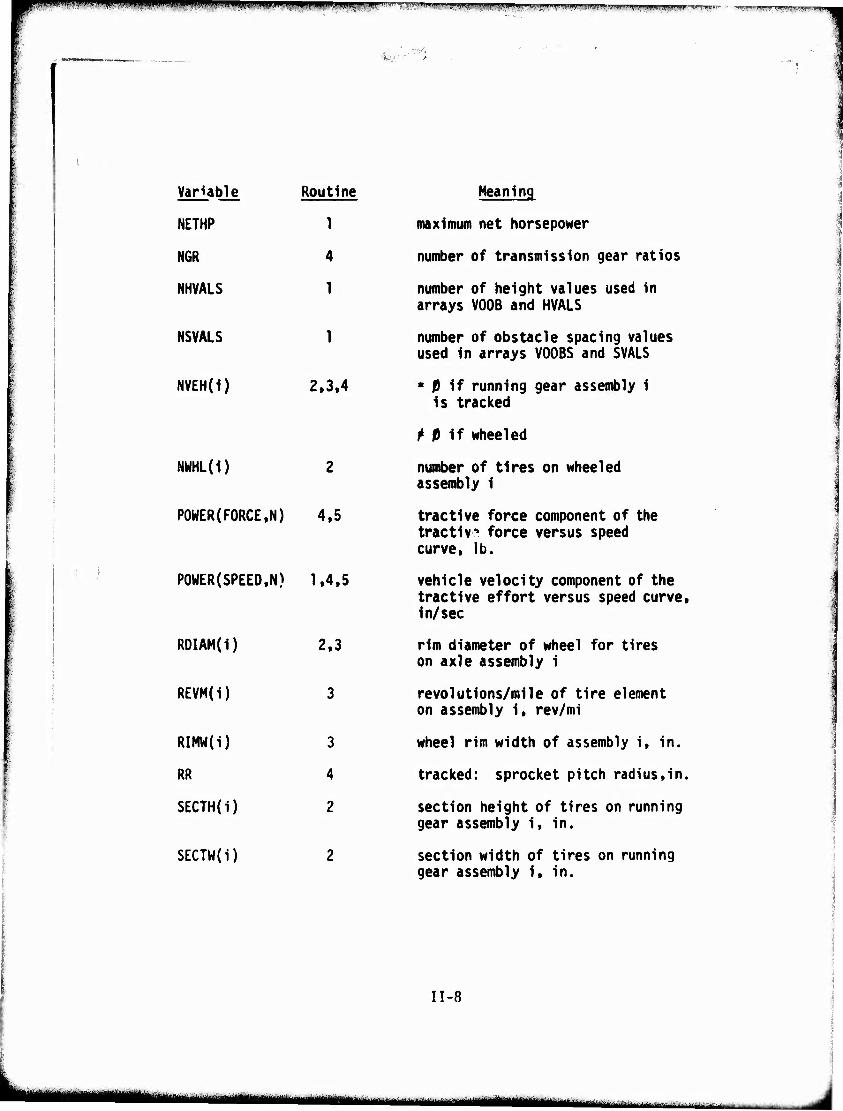
NETHP 1 maximum net horsepower
NGR 4 number of transmission gear ratios
NHVALS 1 number of height values used in arrays VOOB and HVALS
NSVALS 1 number of obstacle spacing values used in arrays V006S and SVALS
NVEH(1) 2.3.4 « 0 if running gear assembly 1 Is tracked
M if wheeled
NWHL(i)
POWER{FORCE,N) 4.5
POUER(SPEED,N) 1.4.5
ROIAM(i) 2.3
REVM(i) 3
RIMW(i) 3
RR 4
SECTH(i) 2
SECTW(i)
number of tires on wheeled assembly 1
tractive force component of the tractiv» force versus speed curve, lb.
vehicle velocity component of the tractive effort versus speed curve, in/sec
rim diameter of wheel for tires on axle assembly 1
revolutions/mile of tire element on assembly 1, rev/mi
wheel rim width of assembly i, in.
tracked: sprocket pitch radius,in.
section height of tires on running gear assembly 1, in.
section width of tires on running gear assembly 1, in.
n-8
lillJIHjIiipff.ll^.WWIUWIIJii^WPW.^^i^JIMWMpw ji)n,,|imiji|.ipi T»i"w!ffy^ii'i.Hi>w!.vi~"»i'^l>i!»j»,yi<iiwiii»l.»r''" gjBlwwpwWJPWW ! """■'I ■w»»wj'w»"-"r^Tw..cT- ■^.■,I,„I,I m^^qipnnn^
£;1^
Variable Routine
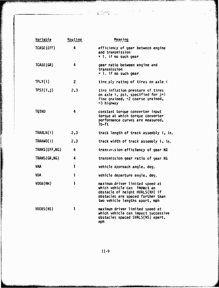
TCASE(EFF) 4
TCASE(GR) 4
TPLY(i) 2
TPSI(i,j) 2.3
TQIND 4
TRAKLN(i) 2.3
TRAKWO(I) 2,3
TRANS(EFF,NG) 4
TRANS(GR.NG) 4
VAA 1
VDA 1
VOOB(NH) 1
V00BS{NS)
Meaning
efficiency of gear between engine and transmission = 1. if no such gear
gear ratio between engine and transmission = 1. if no such gear
tire ply rating of tires on axle i
tire inflation pressure of tires on axle i, psi, specified for j=l fine grained. =2 coarse grained, =3 highway
constant torque converter input torque at which torque converter performance curves are measured. Ib-ft
track length of track assembly i. in.
track width of track assembly i. in.
transäiii'iSion efficiency of gear NG
transmission gear ratio of gear NG
vehicle approach angle, deg.
vehicle departure angle, deg.
maximum driver limited speed at which vehicle can Impact an obstacle of height HVALS(NH) if obstacles are spaced farther than two vehicle lengths apart, mph
maximum driver limited speed at which vehicle can impact successive obstacles spaced SVALS(NS) apart, mph
II-9
in — -^- - ■.'.■-- i- nil njggjinniniiiiiinmni nahiiBifiiiriVni vri i-i r ±^-i-~. BaiaiiiMMiüi
.":,«HlW'PJf'WIJ.,IIJ,ll«,WIHi,, HiJI.,u,.ll.^i|IJJ!,li.ll> .luiiii.w,ij.»i.^wl.^l<,'^ll';iilt;|>iflBi.<.i»i,»;Lm|,ili^i?.if,WFI.... ■■.■.?n»i;-r. ...i u n.i •l^fm.^.-^fyymtmf-.-.w/^ m'ft.l ■w-ft»!»'.'^"?"»-."' ■ -' T^nit",™^??™?.1:""' rw*™ r;
wmmmmmmwama
Variable Routine
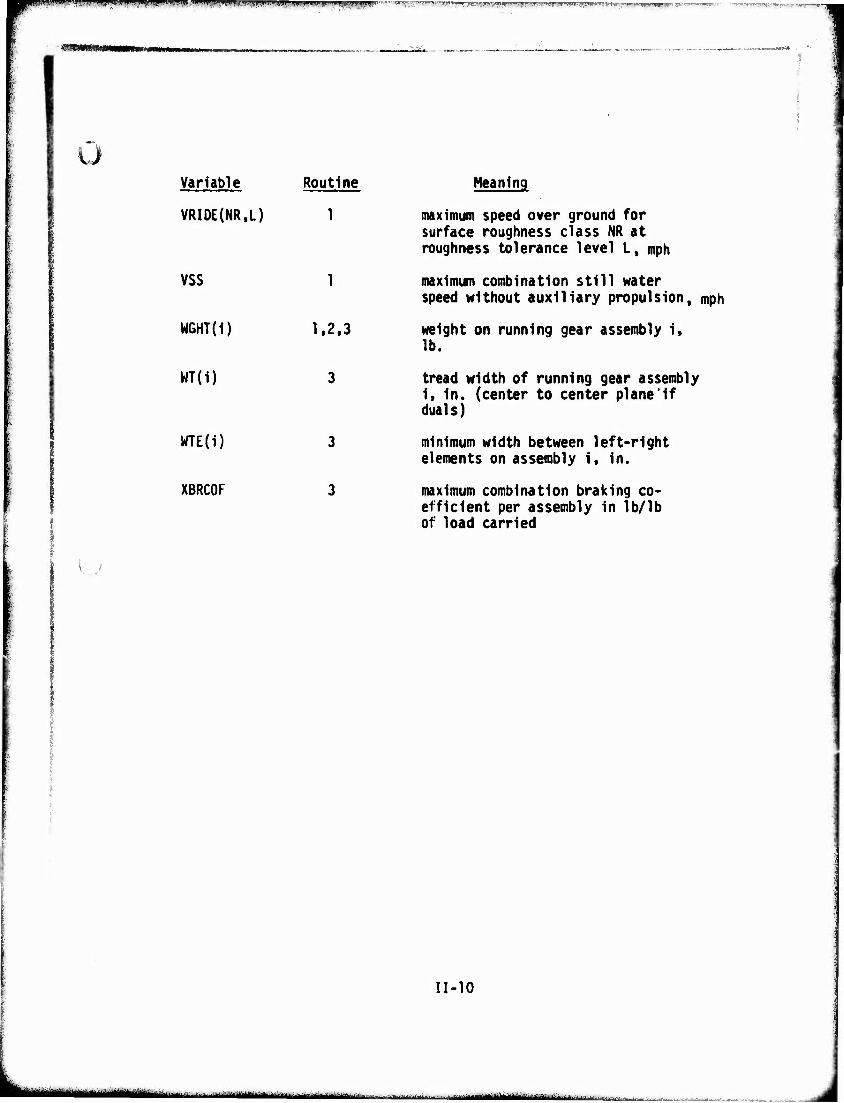
VRI0E{NR.L) 1
VSS 1
WGHT(i) 1,2,3
WT(i) 3
WTE(i) 3
XBRCOF 3
Meaning
maximum speed over ground for surface roughness class NR at roughness tolerance level L, mph
maximum combination still water speed without auxiliary propulsion, mph
weight on running gear assembly 1, lb.
tread width of running gear assembly 1, In. (center to center plane'If duals)
minimum width between left-right elements on assembly 1, in.
maximum combination braking co- efficient per assembly in lb/lb of load carried
11-10
- -- - -imi.« fc i ■ —•"*—"laMI^I *-*■ -.-■-. .. .
gpiWWMPIIPWIIW'^B^ipjIMIiHJPff'UW'lM y>!n>^PliiiinpiippMPl^pniiipin79iji>9w>!nnn! ^.wf»-1 .■ 11 »BBB guBiwii w wnw""*
h..>Ut*l^.».4. . »
Variable
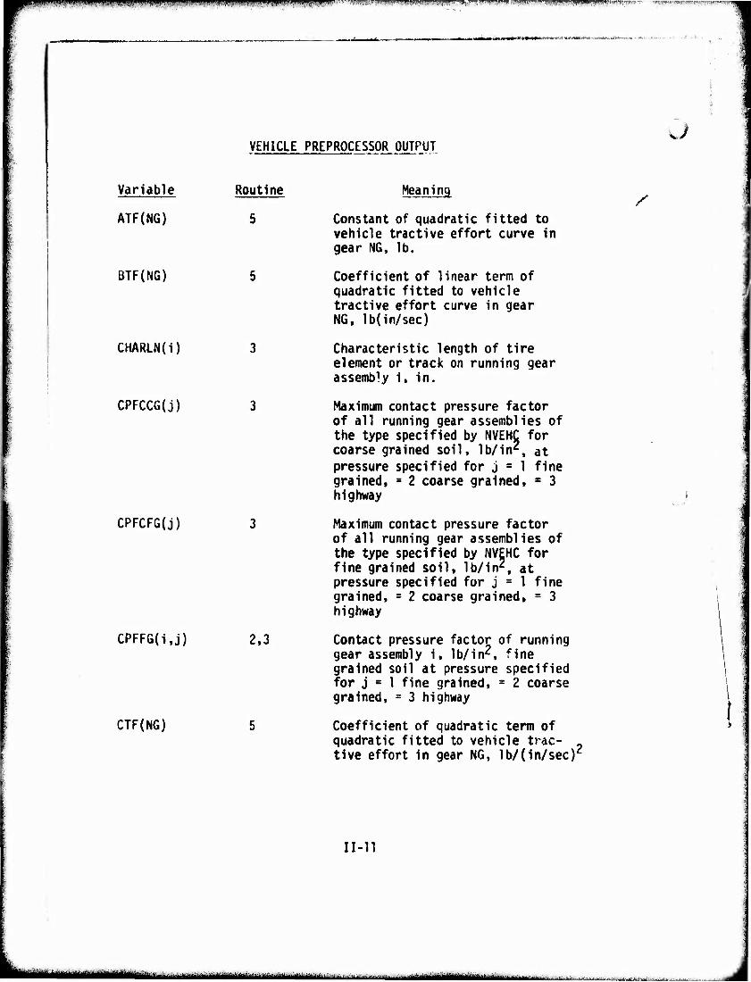
ATF{NG)
BTF(NG)
CHARLN(i)
CPFCCG(j)
CPFCFG(j)
CPFFG(i.j)
CTF(NG)
VEHICLE PREPROCESSOR OUTPUT
Routine
2,3
Meaning
Constant of quadratic fitted to vehicle tractive effort curve in gear NG, lb.
Coefficient of linear term of quadratic fitted to vehicle tractive effort curve in gear NG, lb(in/sec)
Characteristic length of tire element or track on running gear assembly i, in.
Maximum contact pressure factor of all running gear assemblies of the type specified by NVEHC for coarse grained soil, lb/in', at pressure specified for j = 1 fine grained, = 2 coarse grained, « 3 highway
Maximum contact pressure factor of all running gear assemblies of the type specified by NVEHC for fine grained soil, lb/in2, at pressure specified for j = 1 fine grained, = 2 coarse grained, = 3 highway
Contact pressure factor of running gear assembly i, lb/in2, fine grained soil at pressure specified for j » 1 fine grained, = 2 coarse grained, = 3 highway
Coefficient of quadratic term of quadratic fitted to vehicle trac- - tive effort in gear NG, lb/(in/secr
u
/
,
1
t:
ii-n
-'""'■^MMlül^^-iMiMainBlH ^^"—■' ■-■ ■--■ ■••- ■ ',■■■, - ■ ■! -
wm^mmmmm '^ I "> """" ■■'! ■■■!' » npm WWiwii"" ■M»*piii^'-- 'wii.'." «mj-n-'-iht-wm
Cv..
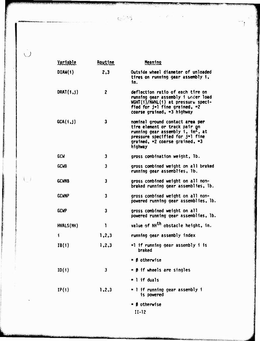
u Variable
DIAW(1)
DRAT(1,j)
6CA(i,j)
GCW
GCWB
GCWNB
GCWNP
GCUP
HVALS(NH)
i
IB(i)
ID(1)
IP(i)
Routine
2.3
3
3
3
3
3
1
1.2.3
1.2.3
1,2.3
Meaning
Outside wheel diameter of unloaded tires on running gear assembly 1. In.
deflection ratio of each tire on running gear assembly 1 ursder load M6HT(1)/NWHL(1) at pressure speci- fied for j-1 fine grained, »2 coarse grained. «3 highway
nominal ground contact area per tire element or track pair on running gear assembly 1. 1nz. at pressure specified for j"l fine grained, «2 coarse grained, "3 highway
gross combination weight, lb.
gross combined weight on all braked running gear assemblies, lb.
gross combined weight on all non- braked running gear assemblies, lb.
gross combined weight on all non- powered running gear assemblies, lb.
gross combined weight on all powered running gear assemblies, lb.
value of NHth obstacle height, in.
running gear assembly index
»1 if running gear assembly 1 is braked
■ 0 otherwise
« 0 If wheels are singles
- 1 if duals
■ 1 if running gear assembly 1 is powered
■ 0 otherwise
IM2
il—HCl MHHMI Ül—I'illliliiif l jt..^^^^,;.......„■..,...„........
mmmmmm mmm^mmmm^ ?. .1 wim i • mwmrmmm'm^^m mifiwiii mmm "'"' ' "■■'■'"' 'T'- ■■'■■i-Tir.i»">.T« 1
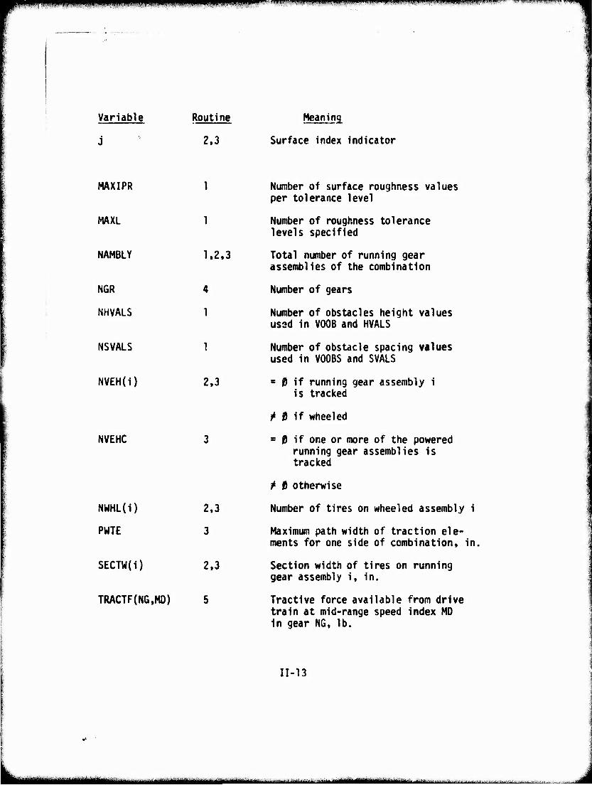
Variable Routine Meaning
2,3 Surface index indicator
MAXIPR
MAXL
NAMBLY
NGR
NHVALS
NSVALS
NVEH(i)
NVEHC
NUHL(i)
PWTE
SECTW(i)
TRACTF(NG.MD)
1.2.3
4
1
1
2.3
2.3
3
2.3
Number of surface roughness values per tolerance level
Number of roughness tolerance levels specified
Total number of running gear assemblies of the combination
Number of gears
Number of obstacles height values used in VOOB and HVALS
Number of obstacle spacing values used in VOOBS and SVALS
= 0 if running gear assembly i is tracked
^ 0 if wheeled
= 0 if one or more of the powered running gear assemblies is tracked
^ 0 otherwise
Number of tires on wheeled assembly i
Maximum path width of traction ele- ments for one side of combination, in.
Section width of tires on running gear assembly i, in.
Tractive force available from drive train at mid-range speed index MD in gear NG, lb.
11-13
MMM ^^untnutm ■■■'■- iiiillMiMiÜHllimlr
p p H pnpiipi lM|).flimB»lwl,"^"'"F'll"..,>lJl,i|j;"<>l"i"WUIirMli|!fi.ij..i!iin.|..uB,),i, pppmpiKPi
W^WBIMB'SMBBIi
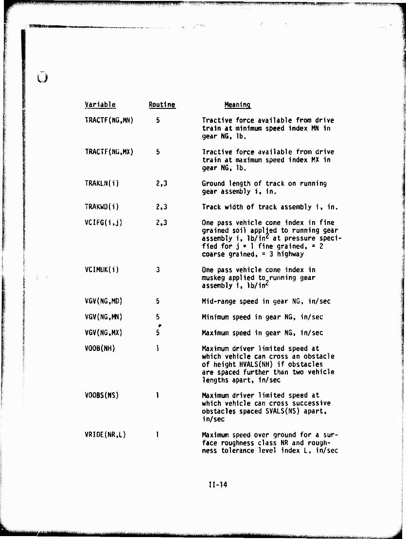
u Variable
TRACTF(NG,MN)
TRACTF{NÜ,MX)
TRAKLN(i)
TRAKWD{i)
VCIF6(i,j)
Routine
5
VCIMUK(i)
VGV(NG.MD)
VGV(NG,MN)
VGV(NG.MX)
VOOB(NH)
VOOBS(NS)
VRIDE(NR,L)
2,3
2.3
2,3
Meaning
Tractive force available from drive train at minimum speed index MN in gear NG, lb.
Tractive force available from drive train at maximum speed index MX in gear NG. lb.
Ground length of track on running gear assembly i, in.
Track width of track assembly i. in.
One pass vehicle cone index in fine grained soil applied to running gear assembly i. lb/in2 at pressure speci- fied for j » 1 fine grained. = 2 coarse grained. = 3 highway
One pass vehicle cone index in muskeg applied to running gear assembly i. lb/in2
Mid-range speed in gear NG, in/sec
Minimum speed in gear NG. in/sec
Maximum speed in gear NG. in/sec
Maximum driver limited speed at which vehicle can cross an obstacle of height HVALS(NH) if obstacles are spaced further than two vehicle lengths apart, in/sec
Maximum driver limited speed at which vehicle can cross successive obstacles spaced SVALS(NS) apart, in/sec
Maximum speed over ground for a sur- face roughness class NR and rough- ness tolerance level index L, in/sec
11-14
mam mmmm »MMIUHIMil
mmm » "■" w^^^^^wp^wa^w^^^^^w^^^^^^
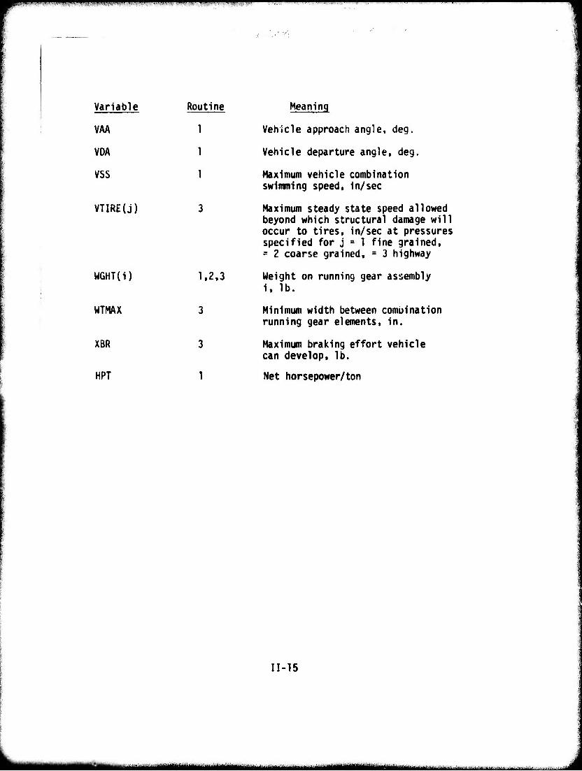
Variable Routine Meaning
VAA 1 Vehicle approach angle, deg.
VDA 1 Vehicle departure angle, deg
VSS 1 Maximum vehicle combination
VTIRE(j)
WGHT(i) 1,2.3
WTMAX 3
XBR 3
HPT 1
swimming speed, in/sec
Maximum steady state speed allowed beyond which structural damage will occur to tires, in/sec at pressures specified for j = 1 fine grained, = 2 coarse grained, = 3 highway
Weight on running gear assembly i, lb.
Minimum width between combination running gear elements, in.
Maximum braking effort vehicle can develop, lb.
Net horsepower/ton
11-15
MMMtMH -■ MHMMHMHMKM
1. Conversion of Units (From miles/hr to in/sec, degrees to radians)
Description This routine converts the units of the vehicle data as entered on the vehicle data sheets to conform to the standard lb., in., sec, radians units used throughout the working modules. When the standard input data sheets are used (and data are entered in the units in- dicated on the sheet for each entry), only units of velocity and angles must be converted; velocity from miles/hr to in/sec; and angles from degrees to radians.
II-l.l
■■■ ■ ■■--■■"|.---.. - -
■ - -
i.'-^
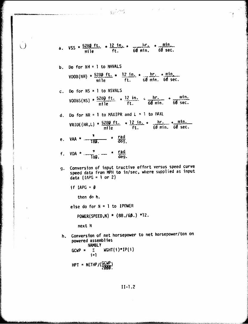
Ü a vSS * 52Bg ft- * 12 1n' * iiTi • OdJL mile ft. 6^ min. 6^ sec.
b. Do for NH = 1 to NHVALS
VOOB(NH) * 5280 ft. * 12 in. * hr. * min, mile ft. ü¥m1n. 6t) sec.
c. Do for NS = 1 to NSVALS
VOOBS(NS) * 52^ ft-i * 1|-^ - ~p~~ * -r mile ft. 60 min. 60 sec.
d. Do for NR = 1 to MAXIPR and L = 1 to I1AXL
VRIÜE(NR,L) * 52W ft. ♦ 12 in. ♦ hr. ♦ min. mile ft. 6«) min. Msec,
i
mm,
mile
_________ * 1W. 3e VAA * ~ * rad
f. VDA * ^ * rad
189. deg.
g. Conversion of input tractive effort versus speed curve speed data from MPH to in/sec, where supplied as input data (IAPG = 1 or 2)
if IAPG = 0
then do h.
else do for N = 1 to IPOWER
P0WER(SPEED.N) * (88./60.) *12.
next N
h. Conversion of net horsepower to net horsepower/ton on powered assemblies
NAMBLY GCWP = I WGHT(i)*IP(i)
i=l
HPT = NETHP/(SCWP) 20190.
II-1.2
iaamüiiittfa^iiin , 1........... ■,,:,.,.toi, ,j,^. „„„m* ■ ■■-—■ -
vmm
I n-o,*1t«««'HI'v. ■.«-»■I .
2. Vehicle Cone Index
Description This routine calculates the vehicle cone index (VCI) for fine grained, coarse grained and muskeg soils. A new feature of AMC '74 is the assembly-by-assembly calculation of VCI. This approach acconmodates vehicles whose running gear type, geometry, and/or loading varies from assembly to assembly. and on which not all of the assemblies are powered and/or braked. Drawbar force for pull or braking is developed only on powered or braked assemblies and therefore, the VCI is calculated for the powered and braked assemblies only. All of the running gear variables and factors used for the calcula- tion of VCI in AMC '71 are now applied to an assembly, i. These assembly-by-assembly VCI's are used in submodel 3 of the areal module to compute pull, braking and resis- tance forces developable at each assembly. These forces are subsequently summed in submodel 4 for the entire vehicle, along with the resistance of any unpowered or unbraked assemblies (computed in submodel 4) to arrive at the tractive and braking performance for the complete vehicle, or combination in a given soil type and strength.
Two new features are incorporated in the calculation of VCI for wheeled assemblies. In calculating the fine grained VCI (VCIFG(i.j)) the influence of tire deflection is taken into account. This feature is included recognizing that tires operating at cross- country inflation pressures may have de- flection ratios higher than the 15-20« deflection ratios which were implicit in the relevent AMC '71 algorithms. The tire deflection factor (TDF) is derived from the numeric representation of VCI described by Turnage (4). The tire deflection factor also allows examining performance of
II-2.1
MM i ■■: giigmgjmaim ,..._
rigid and near-rigid wheels in soft soil for which TDF may be as small as zero.
The second feature now included in VCI calculation for wheeled assemblies allows for a scenario input of surface-dependent operating tire Inflation pressure. The scenario input (NOPP) to either the area! or road modules permits the user either to fix the operating tire Inflation pressure of the vehicle or t,o allow the tire inflation pressure to vary depending on whether the vehicle is traveling In a fine grained or coarse grained soil or on the highway. To accommodate this user choice, VCI's for all three surfaces are calculated (VC!F6(i,j)) VCICG(i,j)) where j Is the indicator for fine grained, coarse grained or highway inflation pressure.
A further new feature is the implementation of the VCI calculation for wheeled and tracked vehicles in muskeg soils (VCIMUK(I)) which is lacking in AMC '71. Expressions used to calculate VCI for muskeg soils are developed in Reference 5.
II-2.2
-"—J--i~—■-—— —-■ ■MI— Mi I
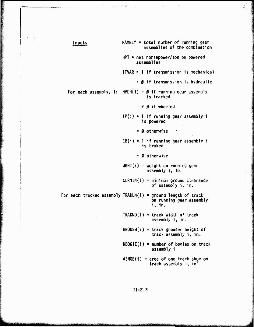
Inputs NAMBLY = total number of running gear assemj^lles 0^ ^g combination
HPT - net horsepower/ton on powered assemblies
ITVAR = 1 if transmission is mechanical
= 0 if transmission is hydraulic
For each assembly, i: NVEH(i) = 0 if running gear assembly is tracked
^ 0 if wheeled
IP(i) = 1 if running gear assembly i is powered
= 0 otherwise
IB(i) » 1 if running gear assembly i is braked
= 0 otherwise
W6HT(i) = weight on running gear assembly i, lb.
CLRMIN(i) = minimum ground clearance of assembly i, in.
For each tracked assembly TRAKLN(i) = ground length of track on running gear assembly i, in.
TRAKWD(i) = track width of track assembly i, in.
GROUSH(i) = track grouser height of track assembly i, in.
NBOGIE(i) = number of bogies on track assembly i
ASHOE(i) = area of one track shoe on track assembly i, in2
II-2.3
MBMHHM i Mjammiiiii .-^^a^-..-...-..:..,....,— ■.■.._.. ^.^... :... ■■:,-...-..-.> ^ -rt^j.^.^^.. .^ .
iiwii^iwifiiiiwwiiPTPWWIWJ^i^ "■"»yy:i J .»^■■iiu.Bii.ii.ir^w.i.>iiii■■>!■.■i.j»'iji.wi>i>.-!W'';"Hil''j'wiff'i'w>iwwi^-»»''w»iijL^' ■ ■Kwmvn'f'wwi.vvmfm
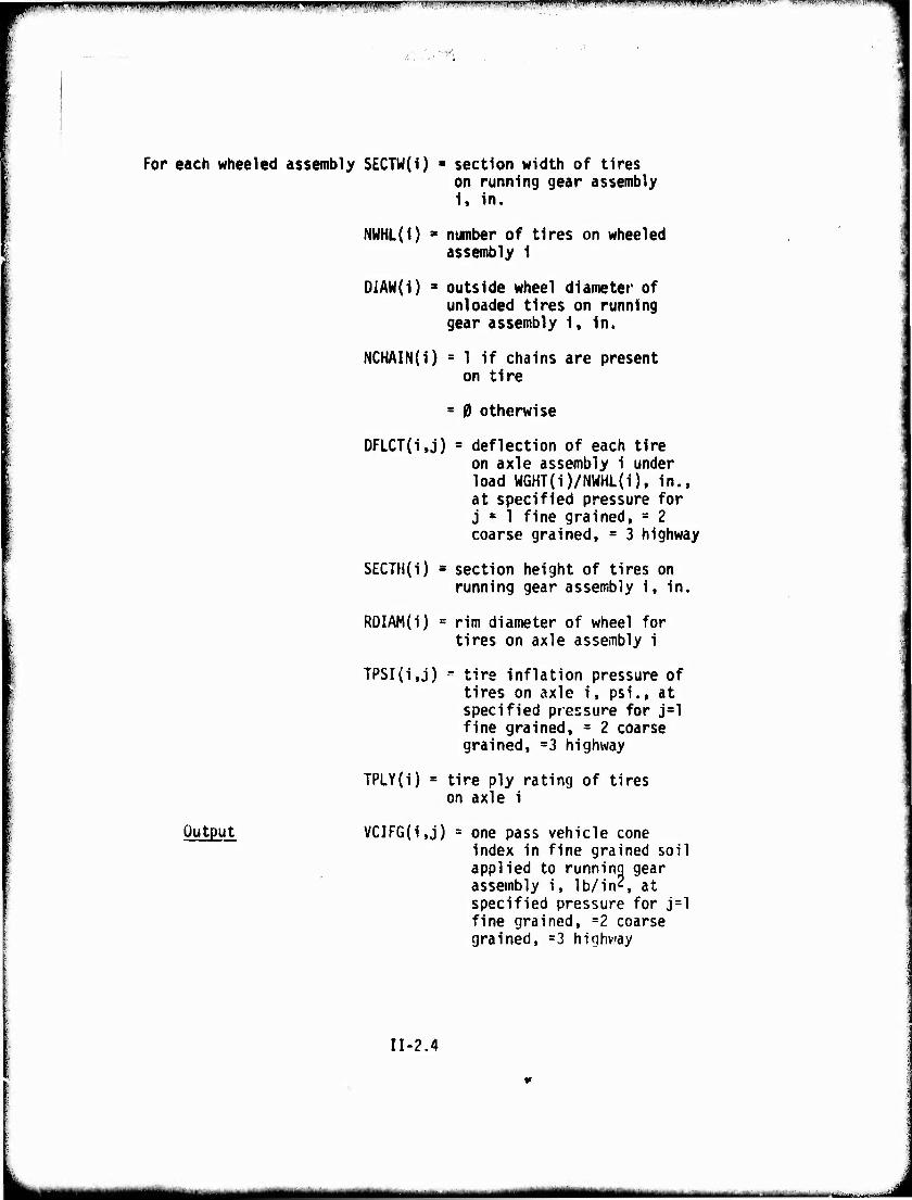
For each wheeled assembly SECTW(I) * section width of tires on running gear assembly 1. In.
NWHL(1) ■ number of tires on wheeled assembly 1
DiAW{1) a outside wheel diameter of unloaded tires on running gear assembly 1, In.
NCHAIN(I) = 1 If chains are present on tire
Output
s 0 otherwise
DFLCT(1,j) = deflection of each tire on axle assembly 1 under load W6HT(1)/NWHL(i), In., at specified pressure for j = 1 fine grained, = 2 coarse grained, = 3 highway
SECTH(i) ■ section height of tires on running gear assembly 1, in.
RDIAM(i) = rim diameter of wheel for tires on axle assembly 1
TPSI(1,j) « tire inflation pressure of tires on axle i, psi., at specified pressure for j^l fine grained, = 2 coarse grained, =3 highway
TPLY(1) = tire ply rating of tires on axle 1
VCIFG(1,j) = one pass vehicle cone index in fine grained soil applied to running gear assembly i, lb/ins at specified pressure for j=l fine grained, =2 coarse grained, =3 highway
II-2.4
MM t - ■ ■ .
ipwmwipiiii »pitjij!! ^pp^wmiwuiili ' J1 .'i'illl ».ilinnwiiiii.i I i i,i,,, n.ipfi,i ■^rw^'f^'r]■'|^^r''^'J<K'•m'''^^^y|m^^^yl™^'!rv^'"™tr^'^^'^'m^'mK^'''•''l^vl^
■Hmm
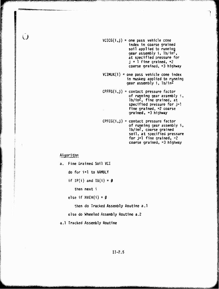
I u VCIC6(i,j) = one pass vehicle cone
index in coarse grained soil applied to running gear assembly i, lb/in2, at specified pressure for j * 1 fine grained, 32 coarse grained, s3 highway
VCIMUK(i) = one pass vehicle cone index in muskeg applied to running gear assembly i, lb/in2
CPFFG(i,j) = contact pressure factor of running gear assembly i, lb/in2, fine grained, at specified pressure for j=l fine grained, =2 coarse grained, =3 highway
CPFCG{i,j) = contact pressure factor of running gear assembly i, lb/in2f coarse grained soil, at specified pressure for j*l fine grained, =2 coarse grained, =3 highway
Algorithm
a. Fine Grained Soil VCI
do for i=l to NAMBLY
if IP(i) and IB(i) = 0
then next i
else if NVEH(i) = 0
then do Tracked Assembly Routine a.l
else do Wheeled Assembly Routine a.2
a.l Tracked Assembly Routine
II-2.5
mtmm mm ---"'-- - •■•" •'-
rw^,-I-TF-W™Il1,BWTW«i«WIWT^TW-TTWTWW^^ ,-. -v.-r.
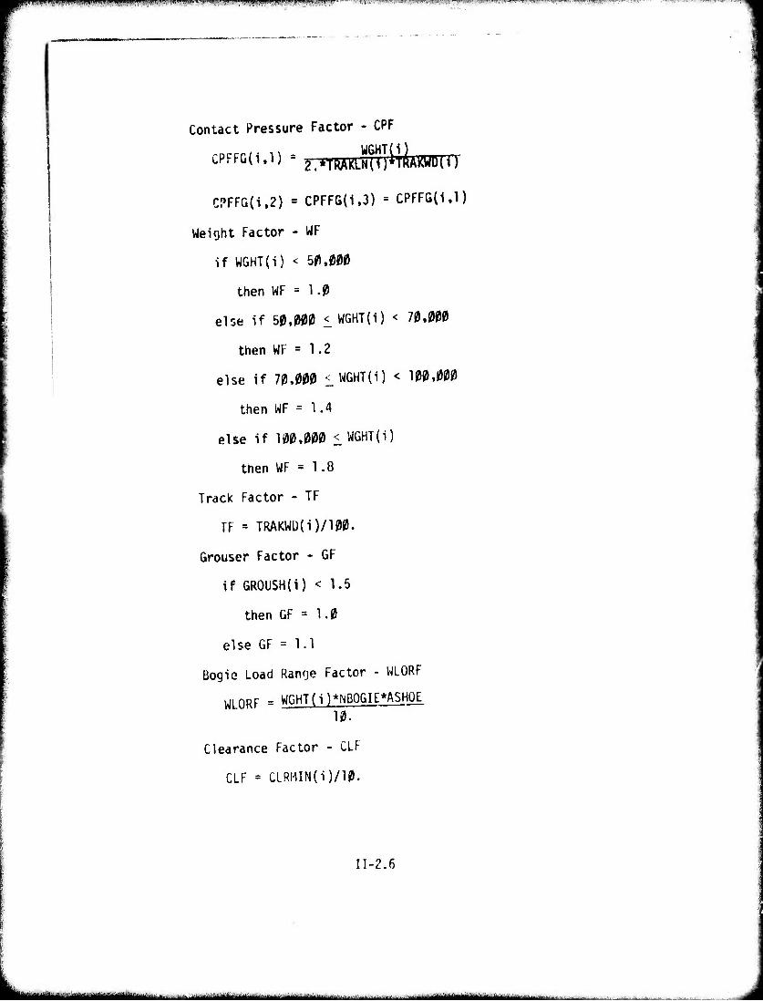
Contact Pressure Factor - CPF
CPFFG(i'1) = ^*TRAKLNm*TRAKWDH)
CPFFG(i,2) = CPFFG(1,3) = CPFFG(l.l)
Weight Factor - WF
if WGHT{i) < 50,j
then WF = 1.0
else if 50,000 < WGHT(i) < 70.(
then WF = 1.2
else if 70,000 I WGHT(i) < 100,000
then WF = 1.4
else if 100,000 < WGHT(i)
then WF = 1.8
Track Factor - TF
TF = TRAKWD(i)/100.
Grouser Factor - GF
if GROUSH(i) < 1.5
then GF = 1.0
else GF = 1.1
Bogie Load Range Factor - WLORF
WLORF = WGHT(i)*NBOGIE*A$HQE 10.
Clearance Factor - CLF
CLF = CLRHIN(i)/10.
II-2.6
—— - - -
l|l«.,!.^WB»pWWTPBIWW!l!Wtff>'W'!tWW^ " mgJT^wvf M'-Bif-yi
'WWW»»
v._y
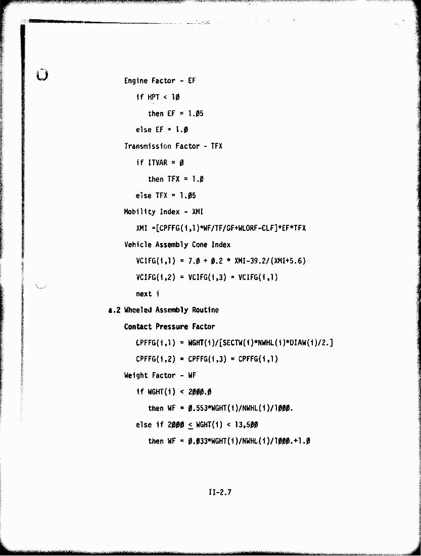
Ü ^^ Engine Factor - EF
If HPT < 10
then EF = 1.05
else EF * 1.0
Transmission Factor - TFX
If ITVAR = 0
then TFX = 1.0
else TFX = 1.05
Mobility Index - XMI
XMI =[CPFF6(i ,1 )*WF/TF/GF+WLORF-CLF]*EF*TFX
Vehicle Assembly Cone Index
VCIFG(i.l) = 7.0 + 0.2 * XMI-39.2/(XMI+5.6)
VCIFG(1,2) = VCIFG(i,3) = VCIFG(i.l)
next 1
a.2 Wheeled Assembly Routine
Contact Pressure Factor
CPFFG(1,1) = WGHT{1)/[SECTW(1)*NWHL{1)*DIAW(1)/2.]
CPFFG(1,2) « CPFFG(1,3) « CPFFG(i,l)
Weight Factor - WF
If W6HT(1) < 2000.0
then WF « 0.553*WGHT(1)/NWHL(i)/1000.
else If 2000 < WGHT(i) < 13,500
then WF « 0.033*WGHT(i)/NWHL(i)/1000.+1.0
II-2.7
■ -'^~~-~— ■ - .—^«^^»-^- ■-.■fci...Ji~jA.--a-:'..-.UL'AJ.^;ii^;
wm^^mmmumm* rnnrnmr* .I.III.J^I iillip^liwiijf^piil i iim.tin^ijiimmigi .■ in . '■ ■ '.wir,'*m,viw.*M- pgn
v+irvmrncMlt ■/9IMMHMHN
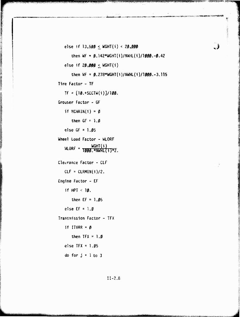
else if 13,500 < WGHT(i) < 20,(
then WF « 0.142*WGHT(i)/NWHL(i)/1000.-0.42
else if 20.000 < WGHT(i)
then WF = 0.278*WGHT(i)/NWHL(i)/1000.-3.n5
Tire Factor - TF
TF = [10.+SECTW(i)]/100.
Grouser Factor - 6F
if NCHAIN(i) = 0
then GF -■ 1.0
else 6F = 1.05
Wheel Load Factor - WLORF
ULORF T WGHT(i)
7^2.
Clearance Factor - CLF
CLF = CLRMIN(i)/2.
Engine Factor - EF
if HPT < 10.
then EF = 1.05
else EF = 1.0
Transmission Factor - TFX
if ITVAR = 0
then TFX = 1.0
else TFX = 1.05
do for j = 1 to 3
II-2.8
iimnäil—JMMMIIII ■~- -• , :--^u. - -^ ■'■• .
W'mfm^l^^^^^mWWItfVW^I&fK^WIff^^'' i|^l';i|.|).nniii,««MWM*.,l/w^^'Pii-.w»w:".™r<M-i..... i-.wv —-TT—u. .»i.i'.w.n^ww»::.^:
% HI
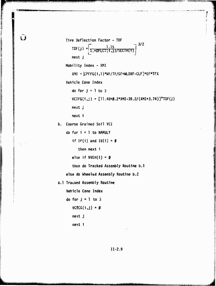
o Tire Deflection Factor - TDF r 1 15 n 3/2
iDF{J) s|j.+DFLCT(i,j)/SLi:iH(i)J next j
Mobility Index - XMI
XMI - LCPFFG(i,l)*WF/TF/GF+WLORF-CLF]*EF*TFX
Vehicle Cone Index
do for j = 1 to 3
VCIFG(i.j) = [n.48+0.2*XMI-39.2/(XMI+3.74)]*TDF(j)
next j
next i
b. Coarse Grained Soil VCI
do for i = 1 to NAMBLY
if IP(i) and IB(i) = 0
then next i
else if NVEH(i) = 0
then do Tracked Assembly Routine b.l
else do Wheeled Assembly Routine b.2
b.l Tracked Assembly Routine
Vehicle Cone Index j
do for j ^ 1 to 3
VC!CG(i,j) * 0
next j
next 1
11-2.9
■—— ^—mm—i —i—-" ^^^^—
IWW i|iJtpWi(iiii^)pwiAiJtinwhlPil|lffBWPiP||.!U>iP'IM-ll.lpipyir ' t-AWf^Wwmv^PyV^mvm^^ ■w^^mmn.imyi<!ummif^
i i
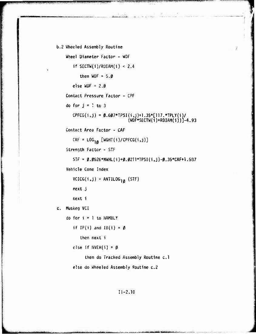
b.2 Wheeled Assembly Routine
Wheel Diameter Factor - WDF
if SECTW(i)/RDIAM{i) < 2.4
then WDF = 5.0
else WDF = 2.0
Contact Pressure Factor - CPF
do for j = : to 3
CPFCG(i,j) = 0.607*TPSI(i,j)+1.35*[117.*TPLY(i)/ {WDF*SECTW(i)+RDIAM(1))]-4.93
Contact Area Factor - CAF
CAF = LOG10 [WGHT(1)/CPFCG{i,j)]
Strength Factor - STF
STF = 0.0526*NWHL(1)+0.0211*TPSI(i.j)-0.35*CAF+1.587
Vehicle Cone Index
VCICG(i,j) = ANTILOG10 (STF)
next j
next 1
c. Muskeg VCI
do for i = 1 to NAMBLY
if IP(i) and IB(i) = 0
then next i
else if NVEH(i) = 0
then do Tracked Assembly Routine c.l
else do Wheeled Assembly Routine c.2
II-2.10
tjittäiitittmmtiMi in .^..•.. ^ -... ädi l im inMri'miiirH umntaim* 1
mum ^ppppnppn vnn" t<iw'\,wn^.nmmw!^rrmf •mysmvw.- ■""' TWt '■■■'^,v'»'T-»T"r'f,"7^'T"~t-TlTT-r" VTT^^T.:"^-^- ■-■.-T-T^W^T^ - - ■
c.l Tracked Assembly Routine
Vehicle Cone Index
VCIMUK(i) = 13.0+M25*WGHT(1)/(TRAKWD{i)+2.* TRAKLN{i))
next 1
c.2 Wheeled Assembly Routine
Vehicle Cone Index
VCIMUK(i) » 13.0+0.535*WGHT{i)/{SECTW(i)+2.* DIAW(i)*NWHL(i))
next i
exit
11-2.11
MBMUi . ...^^...- . „, , ...■J- ^. . „ ,„,,,.. H^-^-^-U*-!-»^-.^^,..-
mmmmm •••• "in»" ■■il-PF li i IP "I « 111111* MIVJ, «l|f|iii|lii|ilil IIWIIH l.«..,!...,.^. ... .J.ll... |,TI ,,.,
V.
Required Outputs Not Directly Available From Vehicle Data Sheets'
Description This routine calculates several vehicle descriptors which are not entered on the vehicle data sheets.
Included are combined contact pressure factors for fine grained soil (CPFCF6) and coarse grained soil (CPFCCG), weights on various combinations of running gear assemblies, maximum speed beyond which tire disintegration can be expected to occur (primarily needed for low inflation tires on highways VTIRE(j)), and various derived geometric values describing the running gear.
II-3.1
IMlinri ■" '^—■-- -■■-■■■ tmamm^a^i, ■ ■ ■ i ■ - - M^^MMM
!) ■mpn'.I" n^i u|i Hi ■ i-f i n■■ i, i.ii mmini^TW--.-fff,i\w,^■^■■"■'ii»■"■'>.wiiiui) rn^r.'"'.-.■■^■■M'.!l> ■,AWP".^W..'* .. "imn-wrpvm "WW ■ r1"--'.- ■■ ""^ ^-^-T^TT—^-
U
i ..
a. Combined Vehicle Designation and Contact Pressure Factor For Use in Slip Modified Tractive Effort Submodel
do for IP(i) or IB(i) t 0
do for j = 1 to 3
if NVEH(i) = 0 for any i
then NVEHC = 0
CPFCFG(j) = max {CPFF6(i,j) of the type for which NVEHC = 0}
CPFCCG(j) = max {CPFCG(i,j) of the type for which HVEHC = 0}
next j
el se NVEHC = 1
CPFCFG(j) = max {CPFFG(i J) for all 1}
CPFCCG(j) = max {CPFCG(i ,j) for all 1}
next j
Gross Combined Weight
GCW = NAMBLY
L WGHT(i) i = l
GCWB - NAMBLY
Z WGHT(i)* 1 = 1
IB(i)
GCWP •-- NAMBLY
i: WGHT(i)* i=l
IP(i)
GCWNP = GCW - ÜCWP
GCWUB = GCW - GCWB
II-3.2
mmmtk
Maximuni Tire Speed
do for j = 1 to 3
do for i - 1 to NAMBLY
if NVEH(i) = 0
then next i
else SI = SECTW(i) - 0 4*RIMW(i) 0.75
EL - M25*(Sl)1,39*[TPSI(i,j)]-7*[RDIAM(i)+Sl]
1.43 WGHT(i)/NWHL(i) TRAPSI(j) = TPSKi.j)*
if (TRAPSI(j) i TPSI(i,j))
then if ICONST(i) = 0. (radials)
then VT(i J) = 100.* TPSIfijp2^ 1 , 1 Tpsiji.sii mm
5280 * 12 in sec
else ICONST(i) = 1 (bias ply)
then VT(i,j) = 70.* TPS TPS m 2.25
5280 . 12
60 60
in sec
else (TRAPSI(j) > TPSI(i.j) underinflated)
then LM = WGHT(i)/NWHL(i) EL
/.445
if ICONST(i) = 0
then VT(i,j) = 100.* TPSI(iJ)
5280 A 12
LM * 1 * 1 6^ W
in r sec
11-3.3
mm* ■MM ■ '- ■-..--■ -.-
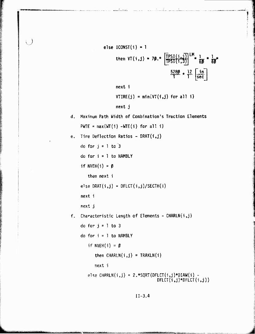
o else ICONST(i) » 1
then VT(i,j) • 70 •*[afl LM
5? W
next i
VTIRE(j) = ni1n{VT(1,j) for all i}
next j
Maximum Path Width of Combination's Traction Elements
PWTE = max{WT(i) -WTE(i) for all i}
Tire Deflection Ratios - DRAT(i,j)
do for j = 1 to 3
do for i = 1 to NAMBLY
if NVEH(i) = 0
then next i
else DRAT(i.j) = DFLCT(i,j)/SECTH(i)
next i
next j
Characteristic Length of Elements - CHARLN(i,j)
do for j = 1 to 3
do for i = 1 to NAMBLY
if NVEH(i) = 0
then CHARLN(i,j) = TRAKLN(i)
next i
else CHARLN(i.j) = 2.*SQRT(DFLCT(iJ)*DIAW{i) - DFLCT(i,j)*DFLCT(i,j))
II-3.4
* - ..-....-^-.— —-' -■ li rMHiiMi -III.» "n i
..rWHr'u«-..««»♦•r«»y"..-'»«•.■»:**--' •»""■■v-1 H IW— U»IffW'»«*•"»•-/ .l .'KWWiM*!!,*.-««»
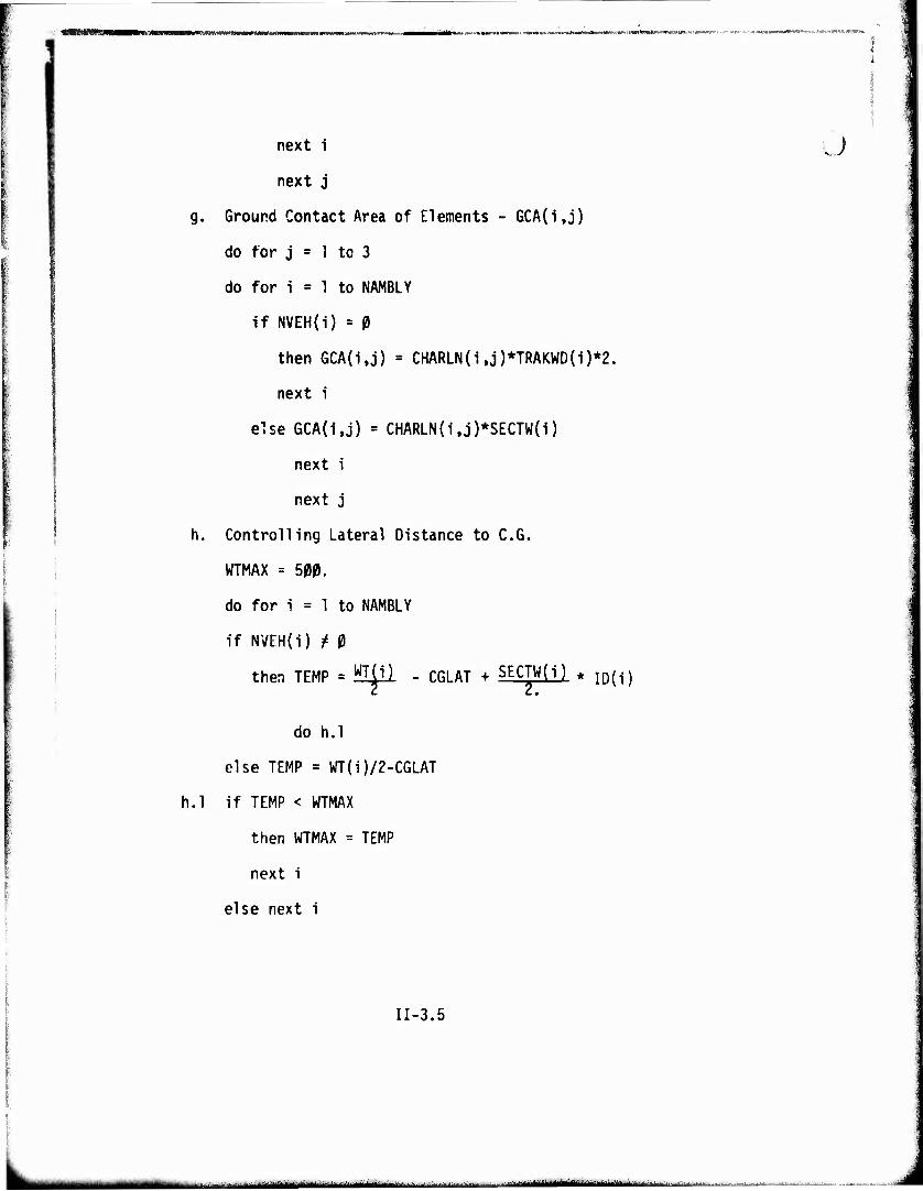
next i
next j
g. Ground Contact Area of Elements - GCA(i,j)
do for j = 1 to 3
do for i = 1 to NAMBLY
if NVEH(i) = 0
then GCA(i,j) = CHARLN(i,j)*TRAKWD(i)*2.
next i
else 6CA(i,j) = CHARLN{i,j)*SECTW(i)
next i
next j
h. Controlling Lateral Distance to C.G.
WTMAX = 500.
do for i = 1 to NAMBLY
if NVEH(i) t 0
then TEMP = Mil - C6LAT + S^W) * iD(i)
do h.l
else TEMP = WT(i)/2-CGLAT
h.l if TEMP < WTMAX
then WTMAX = TEMP
next i
else next i
Ü
II-3.5
■in nil, ,1,njrii^tMiiiaiir'^-*"-^'^--JJ-'-^"--^'^-"'-■' •■-•■: -■■ -,■,..iAm^MiiiiiUMiii^.«.,......-.«.,..'!, ■;
ummv
I Ü
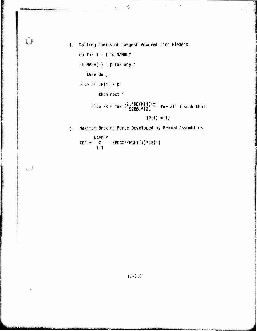
IJ
i. Rolling Radius of Largest Powered Tire Element
do for i = 1 to NAMBLY
if NVtH(i) = g for any i
then do j.
else if IP(i) = 9
then next i
else RR = max {^gj^ji)** for an i such that
IP(i) = 1}
j. Maximum Braking Force Developed by Braked Assemblies
NAMBLY XBR = Z XBRCOF*WGHT(i)*IB(i)
i=l
II-3.6
t*****'**^«'" • ■m.ni-aiMtaitftoiiiiaaimi^^^^kMMt^^ ^ ■.... ,, , ,iiiüiüiMiglMiiMliiiiüiiiriiliiill - ^^
«WiP!p«i»lB»i!pipi^^ p. .1 yiu.iwmwfW fpMliJpwBPPPWWPWiyWtW «W —-^
4. Tractive Effort Versus Speed Curve From Power Train Data
Description This routine calculates the tractive effort POKER(F0Rt;t,N) of the vehicle at a series of speeds POWLR(SPEED,N) from zero velocity to the speed in the highest gear at the governed KPM of the engine.
One of two subroutines are used; AUTOM for vehicles with automatic transmissions, or STICK for vehicles with manual transmissions.
The tractive effort calculated In this routine is equal to the "rim pull" since slip and resistances are not included at this stage.
II-4.1
msamüiKiäSü^umim^A^i ^*t .•* •■• •^t***™<■■"■***■' T^ ....^,.^^:. n ■ i-jiniiiiiiiiiiniiirr1'-' ■'" -^ ■ J
PPiP^H^WP^T^'VIJ^ff'^W'.i^Pr^.TW.-^W.un'WW «U'.;V."1i'FWF.,'l"WM'«TJJI .'.'!■:■' »T^^..:* Kl'-miTrrrw^Wr"- ' ■ ■ ■■t-.-::,-.- .^;-^^^^y.^yy^^,.j^,^..■,WTrW^'T-.y»:T^,^,p,,,j.^,^„^^^pw^j,,....q.^.,v^^„lu^^s.^pnyyT^-.^^nr^^T' .- •'?^wni '' JIW^BM^JWWWWIII
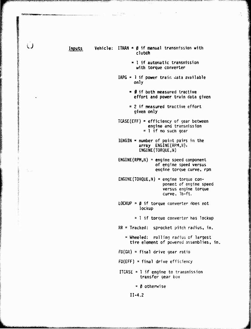
v-' Inputs Vehicle: ITRAN e 0 if manual transmission with clutch
■ 1 if automatic transmission with torque converter
IAPG a 1 If power train data available only
■ 0 if both measured tractive effort and power train data given
= 2 if measured tractive effort given only
TCASE(EFF) s efficiency of year between engine and transmission
» 1 if no such gear
IENGIN B number of point pairs in the array ENGINE(RPM.N), ENGINE(TORQUE,N)
ENGINE(RPM,N) = engine speed component of engine speed versus engine torque curve, rpm
ENGINE(TORQUE,N) » engine torque com- ponent of engine speed versus engine torque curve, Ib-ft.
■
LOCKUP = 0 if torque converter does not Si lockup
= 1 if torque converter has lockup
RR = Tracked: sprocket pitch radius, in.
= Wheeled: rolling radius of largest tire element of powered assemblies, in.
FD(GR) = final drive gear ratio
FD(EFF) = final drive efficiency
ITCASE = 1 if engine to transmission transfer gear box
- 0 otherwise
II-4.2
.***—■"d^dtin"«..-! n ':'- ■ ■ ■■■■■■■—'■.- ■^■.-■' .^ ■-■■.■ ■■.-.--:-. - M ii-mnut*--1--^**^^
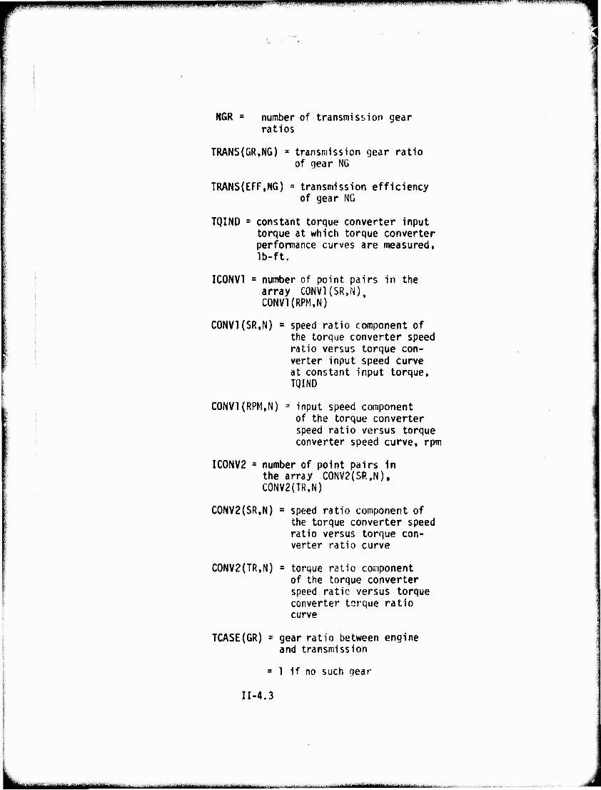
jpppippjPPPPgPPPP^P^^PPPpgl^^ iJ.i||iJ.«lgl:WVIIII»llll JI>l|.JJI|,l!»JWI.»lll,»,.ilfP»,IIWT|i.^i'B«ll»»«»)i»ilJ'. .■■ii|W»iii»n]i m w wimm™** -•r~l.
NGR = number of transmission gear ratios
TRANS(GR,NG) - transmission gear ratio of gear NG
TRANS(EFF,NG) = transmission efficiency of gear NG
TQIND = constant torque converter input torque at which torque converter performance curves are measured, Ib-ft.
IC0NV1 B number of point pairs in the array CONVl(SM), C0NV1{RPM,N)
C0NV1(SR,N) = speed ratio component of the torque converter speed ratio versus torque con- verter input speed curve at constant input torque, TQIND
C0NV1(RPM,N) = input speed component of the torque converter speed ratio versus torque converter speed curve, rpm
IC0NV2 = number of point pairs in the array C0NV2(SR.N). C0NV2(TR,N)
C0NV2(SR,N) = speed ratio component of the torque converter speed ratio versus torque con- verter ratio curve
C0NV2(TR,N) = torque ratio component of the torque converter speed ratic versus torque converter torque ratio curve
TCASE(GR) = gear ratio between engine and transmission
* 1 if no such gear
II-4.3
iiiiniiMiiitfiürüifiirir"^" '■'■■'■'- "■■' —"■-—L---^ ■ ---.-.>i>..-—-.^...w„,.;...■. .■.-.^■■*^*A
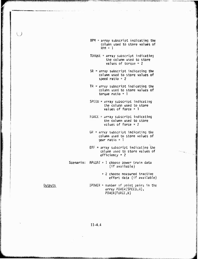
'im!"■<». "wi-i-wwrn,mmwiivH*'www npfSm^RI^■'.'.»wwp^i.'iv««11 pn^jp>P^I■»RF?, ■ ■ > nm^B<f' i.ii^ ij -■ -■ -^.«=;.- ^.i.PI' IJIM JJ.^iT^irp,! i .^i.j ;n{Mym.i»i ^y-jw^ü^.*-swuyvrw-, mwIIIMUSWj^^yilWWHS "ff ■-■ ■-T-V.-W ■^^("■.^"['T^v-T'.-"'
u RPM = array subscript indicating the
column used to store values of RPM = 1
TOKQUt - array subscript indicating the column used to store values of torque = 2
SR = array subscript indicating the column used to store values of speed ratio = 2
TR = array subscript indicating the column used to store values of torque ratio = 1
SPEED = array subscript indicating the column used to store values of force = 1
FORCE = array subscript indicating the column used to store values of force = 2
Outputs
OR 3 array subscript indicating the column used to store values of gear ratio = 1
EFF = array subscript indicating the column used to store values of efficiency - 2
Scenario: APGDAT = 1 choose power train data (if available)
= 2 choose measured tractive effort data (if available)
IPOWER = number of point pairs in the array POWER(SPEEM), POWER(FORCE,N)
II-4.4
■ ■■ -- -■' - • - —-j—^
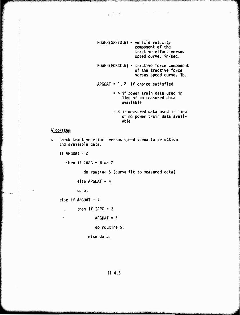
jffl^ll^l'$ym!\!lflG!*WW'^:*>W ' •'■T*J'V'''*H'*'''^ v----^^w'g.»ww|ii»\i,a(|J|f^ if-Tmnnrrr^TnnFav
POW£R(SPEED,N) * vehicle velocity component of the tractive effort versus speed curve, in/sec.
P0Wi;R(FORCE,N) " tractive force component of the tractive force versus speed curve, lb.
APGUAT »1,2 if choice satisfied
= 4 if power train data used in lieu of no measured data available
s 3 if measured data used in lieu of no power train data avail- able
Algorithm
a Check tractive effort versus speed scenario selection and available data.
If APGDAT = 2
then if IAPG - 0 or 2
do routine 5 (curve fit to measured data)
else APGDAT = 4
do b.
else if APGDAT = 1
then if IAPG = 2
APGDAT = 3
do routine 5.
else do b.
II-4.5
mmmmmm i. 'toimmitj* ■.■-.-■-.■„.■....
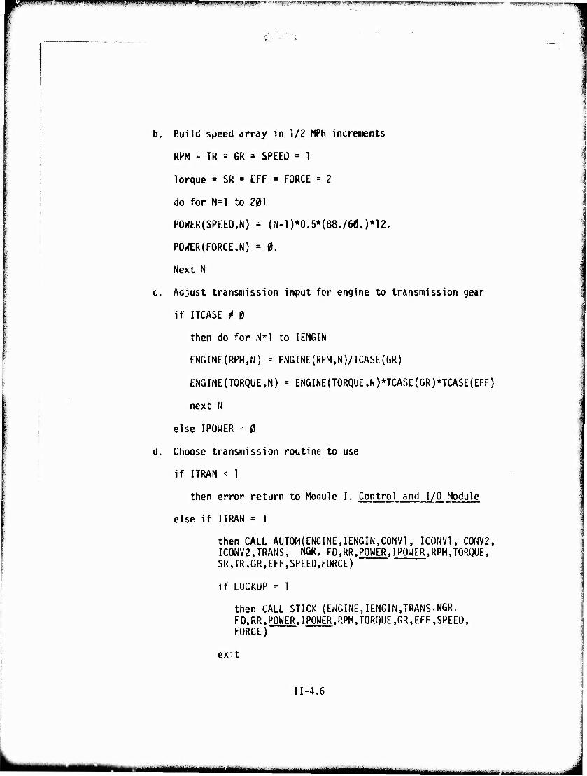
■ 1,111 WH. 1,. I, ,,m> mmm mpumr^ppppiippmppm ^^^iPwwff^wiBprawfaii^BwijWHgii'ii^^
b. Build speed array in 1/2 MPH increments
RPM = TR = GR » SPEED = 1
Torque = SR = EFF = FORCE = 2
do for N=l to 201
POWER(SPEED,N) = (N-l )*0.5*{88./66.)*12.
POWER(FORCE,N) = 0.
Next N
c. Adjust transmission input for engine to transmission gear
if ITCASE t 0
then do for N=l to IENGIN
ENGINE(RPM,N) = ENGINE(RPM.N)/TCASE(GR)
ENGINE(TORQUE,N) = ENGINE(TORQUE,N)*TCASE{GR)*TCASE(EFF)
next N
else IPOWER = 0
d. Choose transmission routine to use
if ITRAN < 1
then error return to Module I. Control and I/O Module
else if ITRAN = 1
then CALL AUTOM{ENGINE,IENGIN.C0NV1, IC0NV1, C0NV2, IC0NV2.TRANS, NGR, FD.RR,POWER,IPOWER,RPM,TORQUE, SR,TR,GR,EFF,SPEED,FORCE)
if LOCKUP = 1
then CALL STICK (ENGINE,IENGINJRANS.NGR, FD.RR.POWER.IPOWER,RPM.TORQUE.GR,EFF.SPEED, FORCE)
exit
II-4.6
mmmu*m IMiiMMMlMMiiTrml ir | ,-^.:.i, ■■.- ■-..■.... . . . ..,
Wimv^mm fmmmmm'mi'^mmmmi ^^^^^^^^^^^w
' .',r/.
else exit
else if ITRAN = 0
CALL STICK(ENGINE.IENGIN,TRANS,NGR%FD,RR, POWER. IPOWER.RPM.TORQUE.GR.EFF.SPEED.FORCE)
exit
II-4.7
ÜHaiiliMl in i urn i
«swwwwai
U Automatic Transmission with Torque Converter Routine
Description This subroutine, AUTOM, calculates the tractive effort POWER(FORCE,N) at various vehicle speeds P0WER(SPEED,N) for vehicles with automatic trans- missions. This subroutine Is identical to AUTOF of AMC '71.
11-AUTOM.1
-"■-*""-'■-"--• i m ■ ■ -
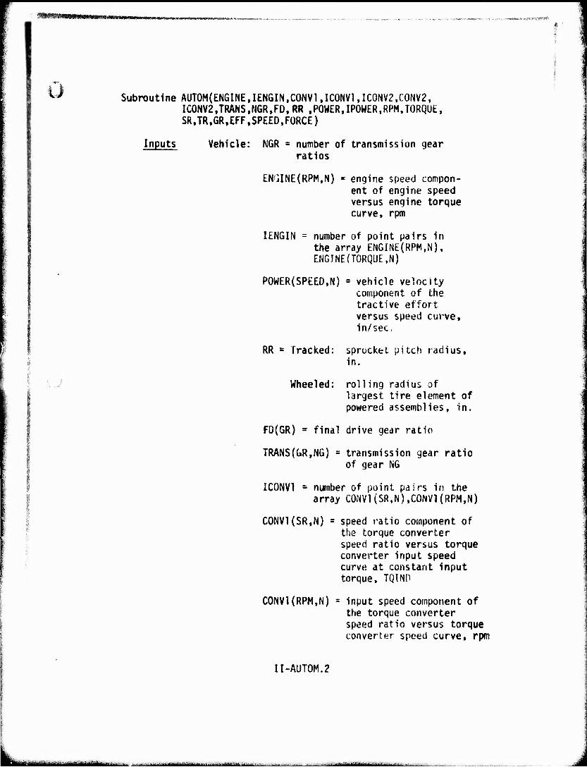
'!^*mmmmms*mt**mun
■
**' Subroutine AUTOM(ENGINE,IENGIN,CONV1,ICONV1,ICONV2,CONV2, IC0NV2,TRANS,N6R,FD, RR .POWER,IPOWER,RPM,TORQUE, SR,TR,GR,EFF,SPEED,FORCE)
Inputs Vehicle: NGR « number of transmission gear ratios
ENIJINE(RPM,N) * engine speed compon- ent of engine speed versus engine torque curve, rpm
IENGIN = number of point pairs in the array ENGINE(RPM,N). EN6INE(T0RQUE,N)
POWER(SPEED,N) = vehicle velocity component of the tractive effort versus speed curve, in/sec,
RR * Tracked: sprocket pitch radius, in.
Wheeled: rolling radius of largest tire element of powered assemblies, in.
FD(GR) = final drive gear ratio
TRANS{GR,N6) = transmission gear ratio of gear NG
IC0NV1 = number of point pairs in the array C0NV1{SR,N),C0NV1(RPM,N)
C0NV1(SR,N) " speed ratio component of the torque converter speed ratio versus torque converter input speed curve at constant input torque, TQIND
C0NV1(RPM,N) = input speed component of the torque converter speed ratio versus torque tonverter speed curve, rpm
II-AUT0M.2
litaitflltMliifuUWiMklliiliAiMikKU^^^ ■- -- ■■■ — ■'
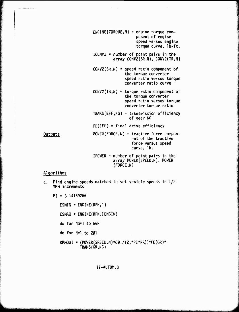
ENÜlNE(TORQUE>N) = engine torque com- ponent of engine speed versus engine torque curve, Ib-ft.
IC0NV2 = number of point pairs in the array C0NV2(SR,N), C0NV2(TR,N)
C0NV2(SR,N) = speed ratio component of the torque converter speed ratio versus torque converter ratio curve
C0NV2(TR,N) = torque ratio component of the torque converter speed ratio versus torque converter torque ratio
TRANS(EFF,NG) = transmission efficiency of gear NG
FD(EFF) = final drive efficiency
Outputs POWER(FORCE,N) * tractive force compon- ent of the tractive force versus speed curve, lb.
IPOWER = number of point pairs in the array POWER(SPEED,N), POWER (FORCE,N)
Algorithms
a. Find engine speeds matched to set vehicle speeds in 1/2 MPH increments
PI = 3.14159265
ESMIN = ENGINE{RPM,1)
ESMAX = ENGINE(RPM,IENGIN)
do for NG=1 to NGR
do for N»l to 201
RPMOUT = (POWER(SPEED,N)*60./(2.*PI*RR))*FD(GR)* TRANS(GR.NG)
II-AUT0M.3
mmtm ■ii^iTi-.'tMiiir
--- — ■ ^^jjgn^n^g,,!,,,^,,,, .
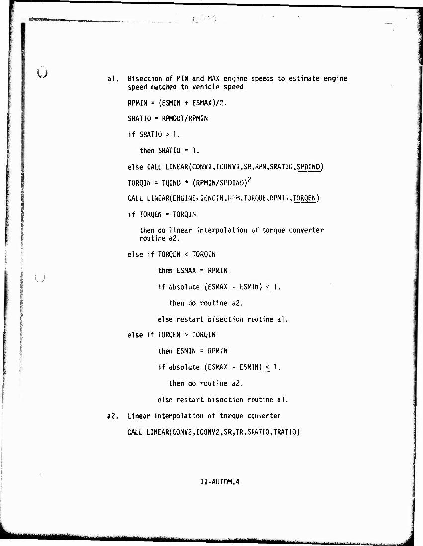
■HMWaaMMMB i.,
;
Ü
{ i
al. Bisection of MIN and MAX engine speeds to estimate engine speed matched to vehicle speed
RPMIN = (ESMIN + ESMAX)/2.
SRATIÜ = RPMOUT/RPMIN
if SRATIÜ > 1.
then SRATIO = 1.
else CALL LINEAR(C0NV1,ICUNV1,SR,RPM,SRATIÜ.SPDIND)
TÜRQIN = TQINÜ * (RPMIN/SPDIND)2
CALL LINEAR(ENÜINE, lENGIN.RPM,TORQUE,RPMIN,TORBEN)
if TORQEN = TORQIN
then do linear interpolation of torque converter routine a2.
else if TORQEN < TORQIN
then ESMAX = RPMIN
if absolute (ESMAX - ESMIN) < 1.
then do routine a2.
else restart bisection routine al.
else if TORQEN > TORQIN
then ESMIN = RPMiN
if absolute (ESMAX - ESMIN) <_ 1.
then do routine a2.
else restart bisection routine al.
a2. Linear interpolation of torque converter
CALL LINEAR(C0NV2,IC0NV2.SR,TR.SRATI0,TRATI0)
II-AUTOM.4
mmm u*m-m^^mmm — • ■- ■!■ ! ■' ! ! ,
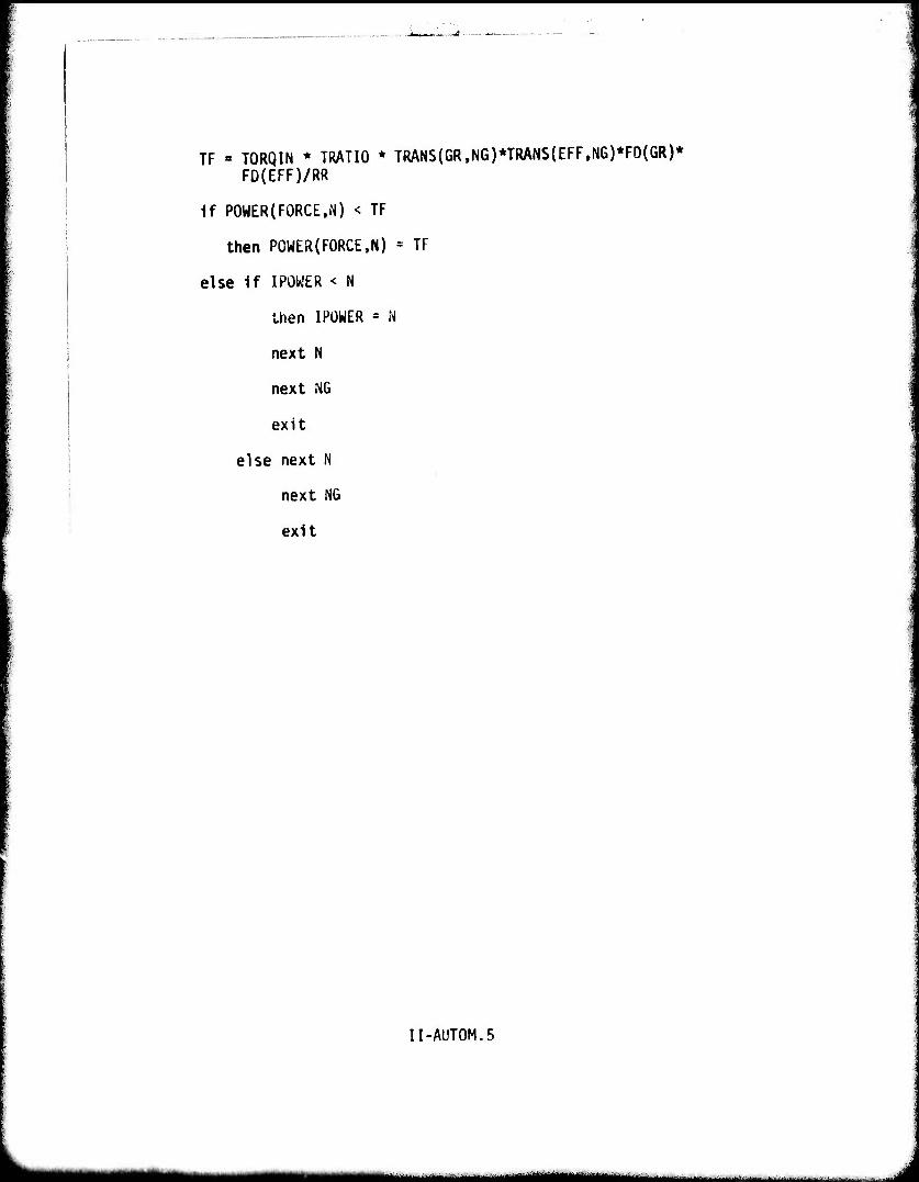
I
TF « TORQIN * TRATIO * TRANS(GR,NG)*TRANS(EFF,NG)*FD(GR)* FD(EFF)/RR
if POWER(FORCE,N) < TF
then POWER(FORCE,N) = TF
else if IPOWER < N
then I POWER = N
next N
next NG
exit
else next N
next NG
exit
I
II-AUTOM.5
MHiaHaMMH —^■■■■1 I
'vft: ■ ^v*J|||^|IBS^BlW)l!
o :-
Manual Transmission Routine
Description This subroutine, STICK, calculates the tractive effort POWER(FORCE,N) at various vehicle speeds POWER(SPEEM) for vehicles with manual trans- missions. This subroutine is identical to STICK of AMC '71.
II-STICK.l
■ lllllll I I' I I M^.! ■--
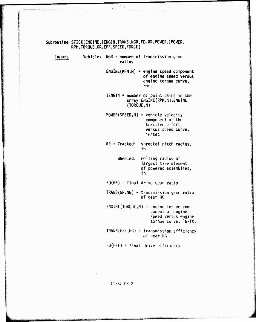
Subroutine STICK(ENGINE,IENGIN,TRANS,NGR,FD,RR,POWER,IPOWER, RPM,TORQUE,GR,EFF,SPEED,FORCE)
Inputs Vehicle: NGR s number of transmission gear ratios
ENGINE(RPM,N) = engine speed component of engine speed versus engine torque curve, rpm.
IENGIN * number of point pairs in the array ENGINE(RPM,N),ENGINE (TORQUE,N)
POWER(SPEED,N) = vehicle velocity component of the tractive effort versus speed curve, in/sec.
RR = Tracked:
Wheeled;
sprocket pitch radius. In.
rolling radius of largest tire element of powered assemblies. In.
FD(GR) = final drive gear ratio
TRANS(GR,NG) = transmission gear ratio of gear HG
ENGINE(TORQUE,N) = engine torque com- ponent of engine speed versus engine torque curve, Ib-ft.
TRANS(EFF.NG)
FD(EFF) = final drive efficiency
transmission efficiency of gear NG
II-STICK.2
- - ■ - ■
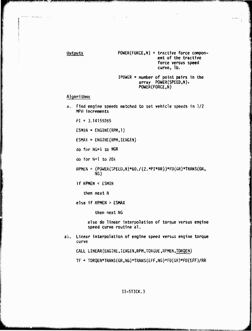
wtgmwimw^^^'imm^nwkw^Kmf^^r^^wvifß'i^mmiimmniß,* ' ||.|-".||i.11 ■■ iii»iiiHjpjj.}i)iMiwiii-.mu JWU..iiiiiPw^i^rwuiMiipuii^j'«w'uii."'."w'w.p.-T.- -.iniffi..i ,IIIW.,IU..IIHJ^
Outputs POWER(FORCE,N) = tractive force compon- ent of the tractive force versus speed curve, lb.
IPOWER ■ number of point pairs in the array POWER(SPEED,N). POWER(FORCE,N)
Algorithms
a Find engine speeds matched to set vehicle speeds in 1/2 MPH increments
PI = 3.14159265
ESMIN = ENGINE(RPM,1)
ESKAX = ENGINE(RPM,IENGIN)
do for NG«1 to NCR
do for N=l to 201
RPMEN = (P0WER(SPEED,N)*60./(2.*PI*RR))*FD(GR)*TRANS(GR. NG)
if KPMEN < ESMIN
then next N
else if RPMEN > ESMAX
then next NG
else do linear interpolation of torque versus engine speed curve routine al.
it. Linear interpolation of engine speed versus engine torque curve
CALL LINEAR{ENGINE,IENGIN,RPM,TORQUE,RPMEN.TORgEN)
TF « TORQEN*TRANS(GR,NG)*TRANS{EFF,NG)*FD(GR)*FD(EFF)/RR
II-STICK.3
ii niinm- uiti.mJtummiMmimimm^ti^mt^ä I JatorfMi'i iti--) ■■■ ---■'■■iri,-
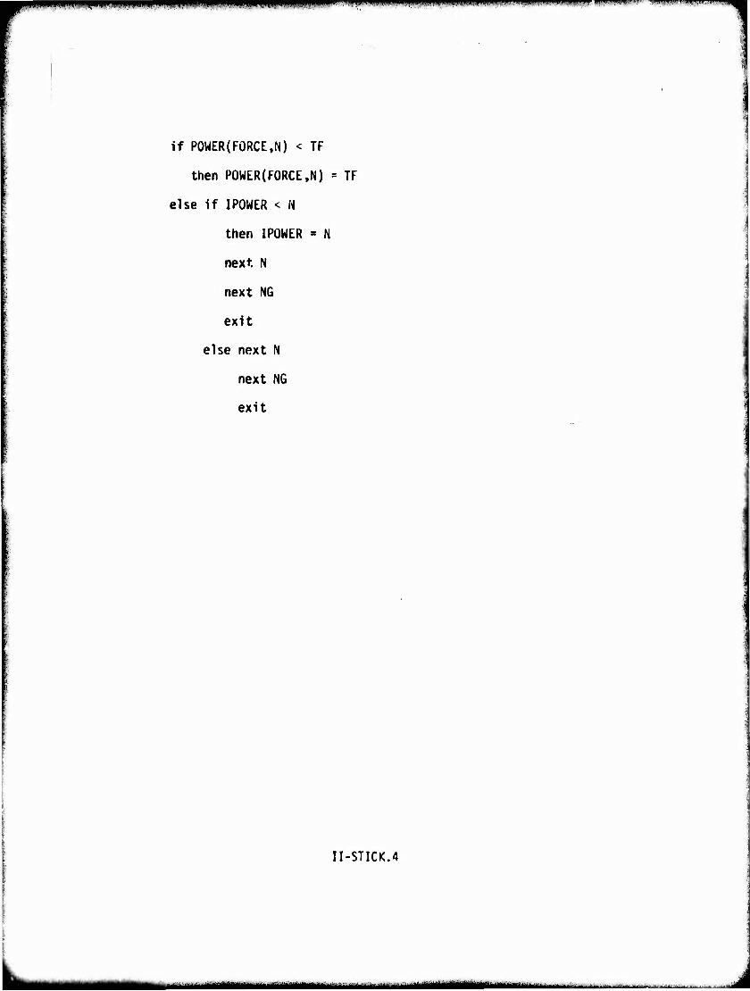
mr^^Hwpiiippjjiiiiiiii ipi f^ffllllllilflflfl^l^^ifffp^^ i »WIII, m ■■iiipini ■ »in. ... i,i,,m.:-i"iw
if POWER(FORCE,N) < TF
then P0WER(F0RCE,N) = TF
else if IPOWER < W
then IPOWER « N
next N
next NG
exit
else next N
next NG
exit
ir-STICK.4
^MM^MMHrilHWI — MMMMM, .... .... ...- ' '.......•-...
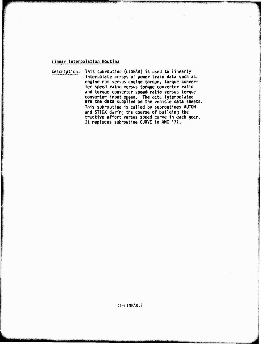
'**mi^*^^***mtii Ullim» - - ! ' . ■■ * mmni«m nnmw».m"IMv,':mm j,,,,. , ,,,,mm« j.Km.m,v"mm*-!*.-m-.:--.■■■ JI.».. ...M^,..».,.,,..-^
Linear Interpolation Routing
Description: This subroutine (LINEAR) is used to linearly Interpolate arrays of power train data such as: engine rpm versus engine torque, torque conver- ter speed ratio versus torque converter ratio and torque converter speed ratio versus torque converter input speed. The data interpolated are the data supplied on the vehicle data sheets. This subroutine is called by subroutines AUTOM and STICK during the course of building the tractive effort versus speed curve in each gear. It replaces subroutine CURVE in AMC '71.
•■;
II-LINEAR.1
-t^—■—^—*•—fc~——•—"^^•— —-"^■■■i
I
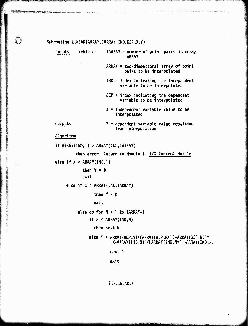
..,■«,,I.MJ ««■piHa.j.rHiiMiiu/PlM ,!".i"i«ilti''.f'^|lJ^,^J^|pJ.^*T.Hli^I'"^-i,|,lliJUil«Pii,l^B.i^.W»V»r,rir7^»^WW»^-- ■-^'-rÄ-^-'T^r?^^^WBW^,W^n^T,*^^^re^r^',TV^™r7TT7T7TTTT^^ "WWPBfTT^^^rWT^^TWTJp
,: ^«3^«»«««*«!«*»^^
« Subroutine LINEAR(ARRAY,IARRAY,IND,D£P,X,Y)
Inputs Vehicle: IARRAY = number of point pairs in array ARRAY
ARRAY ■ two-dimensional array of point pairs to be interpolated
INO 3 index indicating the independent variable to be interpolated
OEP » index indicating the dependent variable to be interpolated
X - independent variable value to be interpolated
Y - dependent variable value resulting from interpolation
Outputs
Algorithm
if ARRAY(IND.l) > ARRAY{IND,IARRAY)
then error. Return to Module I. I/Q Control Module
else If X < ARRAY(INO.l)
then Y « (9 exit
else If X > ARRAY(IND,IARRAY)
then Y » 0
exit
else do for N = 1 to IARRAY-1
if X < ARRAY(IND,N)
then next N
else Y = ARRAY(DEP,N)+CARRAY(DEP,N+l)-ARRAY(OEP.N)j* [X-ARRAY(IND,N)j/CARRAY(INO,N+l)-ARRAY(lNÜ,.NJ.
next N
exit
II-LINEAR.2
t^MMMMai .:.±..- .,.. .-■ ...■. .... -■ ■ LHU&l
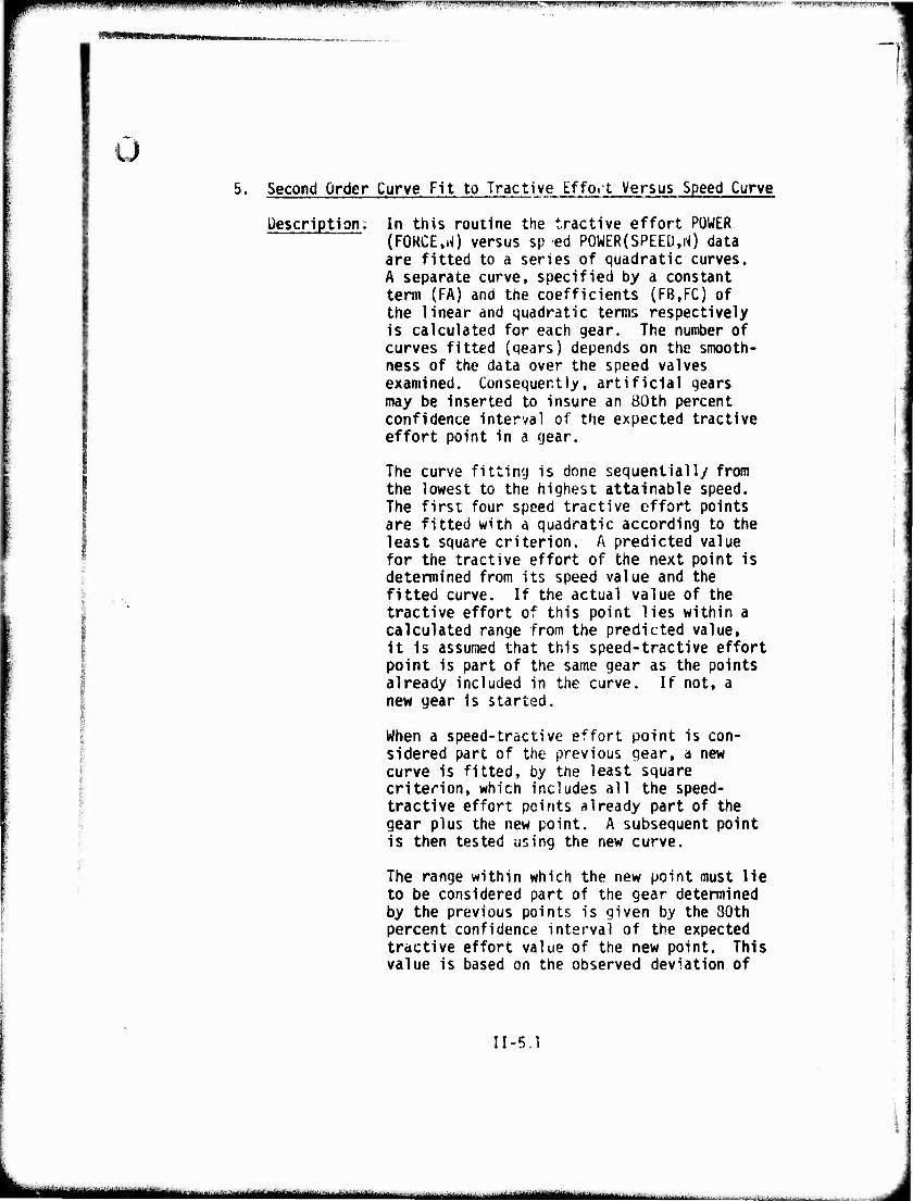
o 5. Second Order Curve Fit to Tractive if fort Versus Speed Curve
Description: In this routine the tractive effort POWER (FORCE,iO versus sp ed POWER(SPEED,N) data are fitted to a series of quadratic curves. A separate curve, specified by a constant term (FA) and the coefficients (FB.FC) of the linear and quadratic terms respectively is calculated for each gear. The number of curves fitted (gears) depends on the smooth- ness of the data over the speed valves examined. Consequently, artificial qears may be inserted to insure an BOth percent confidence interval of the expected tractive effort point in a gear.
The curve fitting is done sequentially from the lowest to the highest attainable speed. The first four speed tractive effort points are fitted with a quadratic according to the least square criterion. A predicted value for the tractive effort of the next point is determined from its speed value and the fitted curve. If the actual value of the tractive effort of this point lies within a calculated range from the predicted value, it is assumed that this speed-tractive effort point is part of the same gear as the points already included in the curve. If not, a new gear is started.
When a speed-tractive effort point is con- sidered part of the previous gear, a new curve is fitted, by the least square criterion, which includes all the speed- tractive effort points already part of the gear plus the new point. A subsequent point is then tested using the new curve.
The range within which the new point must lie to be considered part of the gear determined by the previous points is given by the 30th percent confidence interval of the expected tractive effort value of the new point. This value is based on the observed deviation of
II-5.1
aiiiijjiiijigliiijllilii^^
;rnu>*l>.ii||M|Ui HHilH.HllUlll.llM-iJII.J'» mHllWIWIW»."""-M'■I.'".1' HW " « < lliillllll , "" *rm*. ^9Bp!TCin<m
the tractive efforts to their expected values of all the points already in the gear.
When the points included within each gear are determined, the lowest, mid-range and the highest speed in each gear are placed in the array V6V. The corresponding tractive effort values are given in the array TRACTF.
In the Areal Module, these three points are adjusted for slip and tractive effort degrada- tion on slopes in submodel 5, Slip Modified Tractive Effort, and then refitted, exactly, by a new quadratic using the subroutine QUAD. These quadratics are then, later, integrated exactly in subroutine TXGEAR to allow time and distance calculation for acceleration between obstacles.
II-5.2
inttfiWirmiw
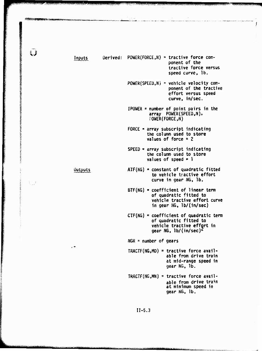
^^^^^^^^^nmm mmp» i*»'
WHHttKHHmmmmmmmmmmm
u Inputs Derived: POWER(FORCE,N) » tractive force com-
ponent of the tractive force versus speed curve, lb.
POWER(SPEED,N) = vehicle velocity com- ponent of the tractive effort versus speed curve, in/sec.
IPOWER = number of point pairs in the array POWER(SPEED,N). POWER(FORCE,N)
FORCE * array subscript indicating the column used to store values of force = 2
SPEED s array subscript indicating the column used to store values of speed • 1
Outputs ATF(NG) » constant of quadratic fitted ~ to vehicle tractive effort
curve in gear NG, lb.
BTF(NG) « coefficient of linear term of quadratic fitted to vehicle tractive effort curve In gear NG, 1b/(in/sec)
CTF(NG) " coefficient of quadratic term of quadratic fitted to vehicle tractive effort in gear NG, lb/(in/sec)2
NGR = number of gears
TRACTF(NG,MD) 3 tractive force avail- able from drive train at mid-range speed in gear NG, lb.
TRACTF(NG,MN) = tractive force avail- able from drive train at minimum speed in gear NG, lb.
II-5.3
Li
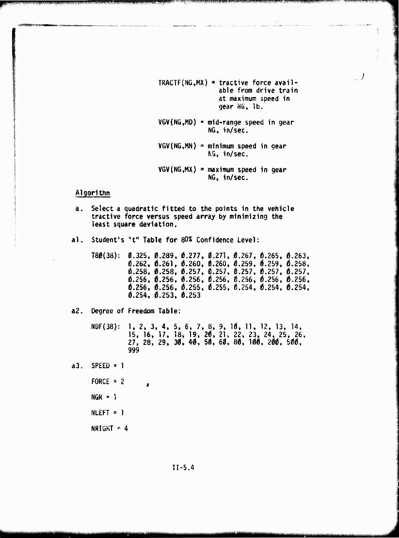
i,iiiiiii|ni.i>.i,i|(niimu*W">>><vii<i!i>i imtmi^rtmrfm j-fTT'':!'- a«i.i"i»inn-i|. i;-;.i«»f ^»"«■'■'•.tj".» !»J,l , l ' ,■ r .|. n > -rrnu" lunmwi»-1 p KIJI-"-
TRACTF(NG,MX) » tractive force avail- able from drive train at maximum speed in gear MG, lb.
VGV(NG,M0) ■ mid-range speed in gear NG, in/sec.
VGV(NG,MN) « minimum speed in gear NG, in/sec.
VGV(NG.MX) maximum speed in gear NG, in/sec.
Algorithm
a Select a quadratic fitted to the points in the vehicle tractive force versus speed array by minimizing the least square deviation.
al. Student's "t" Table for 80« Confidence Level:
T80(38): 0.325, 0.289, 0.277, 0.271, 0.267, 0.265, 0.263, 0.262, 0.261, 0.260, 0.260, 0.259, 0.259, 0.258, 0.258, 0.258, 0.257. 0.257, 0.257, 0.257, 0.257, 0.256. 0.256, 0.256, 0.256, 0.256, 0.256, 0.256, 0.256, 0.256. 0.255, 0.255, 0.254. 0.254, 0.254. 0.254. 0.253, 0.253
a2. Degree of Freedom Table:
NÜF(38): 1, 2, 3. 4. 5. 6. 7. 8, 9, 10, 11, 12, 13, 14, 15, 16, 17, 18, 19, 20, 21, 22, 23, 24, 25, 26, 27, 28, 29, 30, 40, 50, 60, 80, 100, 200, 500, 999
a3. SPEED = 1
FORCE = 2 ,
NGK - 1
NLEFT = 1
NRIGHT * 4
II-5.4
tmmm mmmum "—■"■ ■—---' ■-. .■-
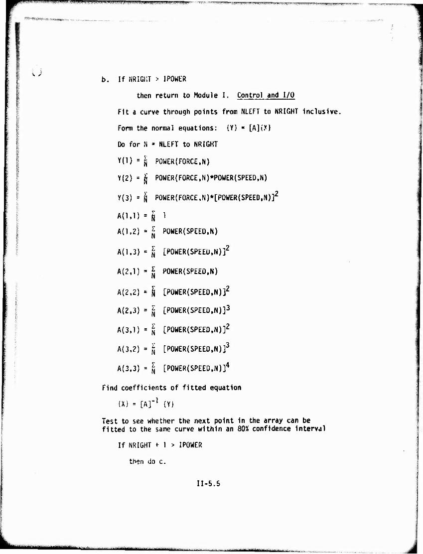
•.nf«mm.*m.t .■.wli|»i»iljiww»t!iwm4)»ftw.^ijiiiiiu.ji,.iii.jifW»»tijii)ii|i!.iLi ii.in-luiinnffwi. r v.^,, J.,l , ,,, „,„„ ;,|„^W,,„„I|J..,.^^1„^
,. .,...,,, . , ..
u
1 b. If NRIGI1T > IPOWtR
then return to Module I. Control and I/O
Fit a curve through points from NLEFT to NRIGHT Inclusive.
Form the normal equations: {Y} « [A]{y}
Do for N » NLEFT to NRIGHT
Y(l) = jj POWER (FORCE, N)
Y(2) = jjj P0WER(F0RCE,N)*POWER(SPEED,N)
Y(3) » d P0WER(F0RCE,N)*[POWER(SPEED,N)]2
A(l,l) ' I 1 A{1,2) » J P0WER(SPEE0,N)
A(1.3) «= I [POWER(SPEEU.N)]2
A{2,1) - J POWER(SPEED.N)
A(2.2) - ^ [POWER(SPEED,N)]2
A(2.3) = § [POWER(SPEED.N)]3
A(3,l) » § [POWER(SPEED.N)]2
A{3.2) = fj [POWER(SP£ED,N)]3
A{3,3) = ^ [POWER(SPEED.N)]4
Find coefficients of fitted equation
(X) = [A]"1 (Y)
Test to see whether the next point in the array can be fitted to the same curve within an 80% confidence interval
If NRIGHT + 1 > IPOWER
then do c.
II-5.5
"--"- ■' if ii.tf'ülMilMMOÜlMiiyi
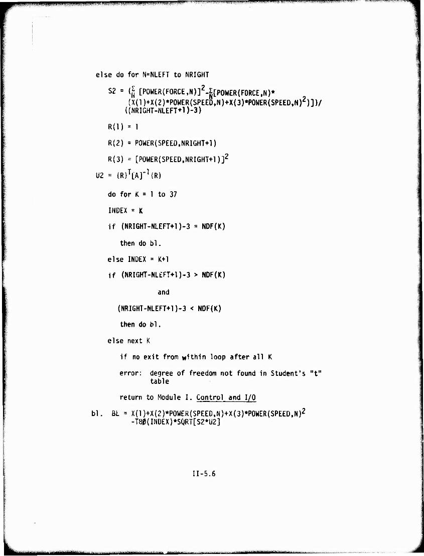
p^PPHHpi^limUB^ItHWBimywpillWUl - 'V'?«" ■■"gp»inMiiii».i!mn"l,i.i«""»in"l"ii"i"i|" ""■■ *"1"11- ,»—»-"-»"'l"u »n^i'jiu, .'"I ■ .i'-iJJ> ■ "' "•MW"«»""««!) .'il'.*«
else do for N=NLEFT to NRIGHT
f^ ronuco/cnorc M\T- S2 = {Jj [POWER(F0RCE,N)]£-E[poWER(F0RCE,N)* (X(1)+X(2)*P0WER(SPEED,N)+X(3)*P0WER(SPEED.N)2)]}/
((NRIGHT-NLEFT+l)-3)
R(l) = 1
R(2) = P0WER(SPEED,NRIGHT+1)
R(3) = [P0WER(SPEED,NRIGHT+1)]2
U2 = {RI^AJ'^R}
do for K = 1 to 37
INDEX = K
if (NRIGHT-NLEFT+1)-3 = NDF(K)
then do bl.
else INDEX = K+l
if (NRIGHT-NL£FT+l)-3 > NDF{K)
and
(NRIGHT-NLEFT+1)-3 < NDF(K)
then do bl.
else next K
if no exit from within loop after all K
error: degree of freedom not found in Student's "t" table
return to Module I. Control and I/O
bl. BL = X(1)+X(2)*P0WER(SPEE0,N)+X(3)*P0WER(SPEED,N)2
-T80(INDEX)*SQRT[S2*U2]
11-5.6
-..-^M-l—«^-»U«»^-«..,-. ,.,h -
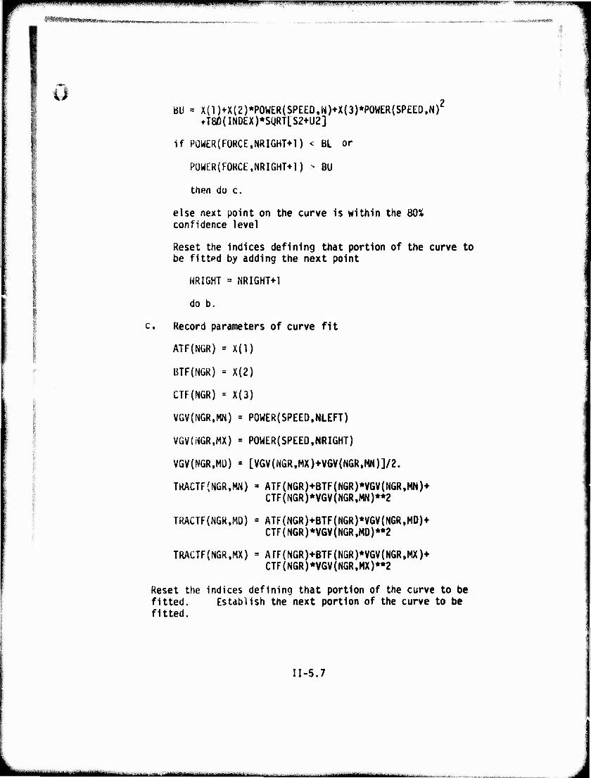
i!ft!S*ftiWS!fW*«JH|..,!fclW; .
PlllliPWIBWWWP '■■HU '" lW-l.'.".M«m> IIIIHI.IIIH.IIHIH,»||W.l.l|,.lllni.«ll|iii:Hli Iki...>i|i , I....IHI iinvjMi-ili ,»■ "^—.-
i> BU = X(1)+X(2)*P0WER(SPEED.M)+X(3)*P0WER(SPEED.N)':
tT8Ö{IN0EX)*SgRT[S2+U2]
If POWER(FORCE,NRIGH1>1) < BL or
PÜWER(F0RCE,NRIGHT+1) - BU
then do c.
else next point on the curve is within the BOX confidence level
Reset the indices defining that portion of the curve to be fitted by adding the next point
NRIGHT = NRIGHT+1
do b.
:. Record parameters of curve fit
ATF(NGR) * X(l)
BTF(NGR) = X(2)
CTF(NGR) = X(3)
VGV(NGR,MN) = POWER{SPEED,NLEFT)
VGV(N6R,MX) = POWER(SPEED.NRIGHT)
VGV(NGR,MÜ) = [VGV(NGR,MX)+VGV(NGR,MN)]/2.
TKACTF{N6R,MN) = ATF(NGR)+BTF(NGR)*VGV(NGR,MN)+ CTF(NGR)*VGV(NGR,MN)**2
TRACTF(NGR,MD) = ATF(NGR)+BTF(NGR)*VGV(NGR,MD)+ CTF{NGR)*V6V(NGR,MD)**2
TRACTF(NGR.MX) = ArF(NGR)+BTF(NGR)*V6V(NGR,MX)+ CTF(NGR)*V6V(NGRfMX)**2
Reset the indices defining that portion of the curve to be fitted. Establish the next portion of the curve to be fitted.
II-5.7
AMiai **■""■-■' "■- 1 !-- --'--— *— ■■ in ■riiiiiMr
wmm 1.111..111H1. imii i i um i ii iiiiiipiiipiiiiifiiin n iniiinrnnrmmiTr
If NRIGHT + 4 > IPOWER
then not enough points to start another gear error. Return to Module I. Control and I/O
else NGR - NGR+1
NLEFT • NRIGHT+1
NRIGHT ' NLEFT+3
do b.
II-5.8
■' -
^^w mm. appf--^-.«! ..in, .nii.p, | iiuigpjiiiwn^f^mpMPipgijiiiMiiifln^nwinvwnHan^i^^uiiuiiitiM ■ iiiopnpKimnvmnu i*..ii|M
MMMMMM
J
MODULE III
TERRAIN PREPROCESSOR
III-l
^^^^ mmfwm ^^^^^^mm
■*i&!<i:m".
u 4
TERRAIN PREPROCESSOR MODULE
The Terrain Preprocessor Module creates the terrain des- criptors of each terrain unit for use in the Areal, Hasty River and Dry Linear Features Crossing, and Road Modules. This preprocessor produces, according to several scenario in- puts, primary terrain descriptors as well as several secondary terrain descriptors derived from the primary descriptors.
All of the terrain features used in AMC '71 and reported in Reference 1 are used in AMC '74. In addition, AMC '74 includes various other terrain characteristics. These are:
1. Presence of surface water causing slippery conditions from recent rainfall.
2. Shallow snow cover.
3. Altitude.
The Terrain Preprocessor Module is a stand alone module which Is executed external to the main model of AMC '74. It consists of tlir?e preprocessing sections which may be executed in whole or in part depending on the specification/scenario inputs. Once a terrain transect has been preprocessed and the terrain descriptors (primary and secondary) are entered in a file, the terrain preprocessor need not be called again for subsequent execution of the model.
The first section of the module Is an Ad Hoc Preprocessor which accepts source terrain data and if necessary, converts the source terrain data to primary proper natural terrain units descriptors (e.g., class Interval numbers, topographic map data, climatic map data converted to terrain feature values (soil strength, grade, etc.)) (See Terrain Preprocessing Flow Chart.) At present, only the conversion of class interval numbers to primary proper natural terrain units descriptors is Included with the other source data conversions to be im- plemented later.
The Standard Preprocessor section is entered next with either the primary descriptors from the Ad Hoc Preprocessor or proper natural terrain units descriptors obtained directly from the source terrain data. This preprocessor converts
111-2
|ippiif;W»W|pWi.lW4WWii|'"M!!IWAW^^ iw.im" T-^^ry^'" ..^....(..tyM i.^!,j^u5.wi-.»),ii»'<iMjriyw'i.V'li^..''!^','Ji"'ii*',').'iJM.i;tMiii.''nr-
all dimensional units of the primary descriptors to the lb., in., rad., sec. units required by the main model and develops the secondary terrain unit descriptors, such as, patch area per obstacle, etc. The entire set of primary and secondary descriptors are placed in the proper format required by the Areal, Road and Hasty River and Dry Lintar Features Crossing Modules and stored on the Terrain File. This file becomes a permanent file of processed terrain data.
The execution of the third section of the preprocessing module depends on a snow scenario. If shallow snow covers the entire terrain transect or a portion of it, then the Terrain File and a Snow File (snow source terrain data) are brought into a Snow Machine which modifies the primary and secondary descriptors affected by snow cover. The Snow Modified Terrain File then becomes the permanent file of processed terrain data.
The terrain preprocessor can accommodate a mixture of terrain unit types on a given source terrain data file. In special cases where a single traverse is to be executed, the terrain data file may contain areal, road and linear features data. The only requirement is that the data for a particular terrain unit be complete.
III-3
llllMl—I 1 —^- ._. ,., ., „ Mt^at—B—M*tta«<IM«i««imii.»iii.iiiiii ..nil-. uniliilii.ini
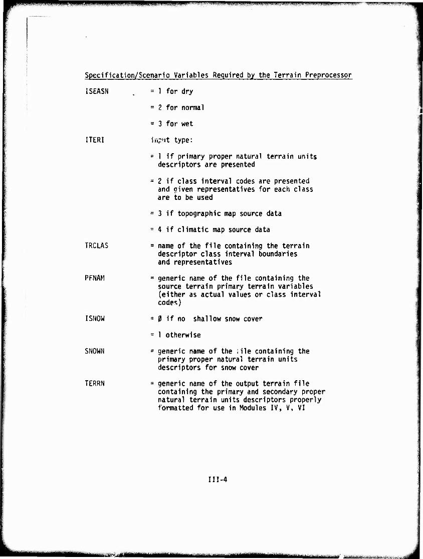
MM mm^^m i ^Vi'w»pii.''|ii^wWI!WBPp;ppil^lliyWI!pj|^iWitij »jwiiwuMif fuirti-m^mnKm-irimwi"^
Specification/Scenario Variables Required by the Terrain Preprocessor
ISEASN
ITERI
TRCLAS
PFNAM
I SNOW
SNOWN
TERRN
= 1 for dry
= 2 for normal
= 3 for wet
inp'it type:
= 1 if primary proper natural terrain units descriptors are presented
= 2 If class Interval codes are presented and oiven representatives for each class are to be used
= 3 If topographic map source data
= 4 If climatic map source data
= name of the file containing the terrain descriptor class Interval boundaries and representatives
= generic name of the file containing the source terrain primary terrain variables (either as actual values or class Interval codes)
=0 if no shallow snow cover
= 1 otherwise
= generic name of the ille containing the primary proper natural terrain units descriptors for snow cover
= generic name of the output terrain file containing the primary and secondary proper natural terrain units descriptors properly formatted for use in Modules IV, V, VI
III-4
mtmtmmm ii-.^irJ.Xv^.^a.-.i:i ■■-* .■
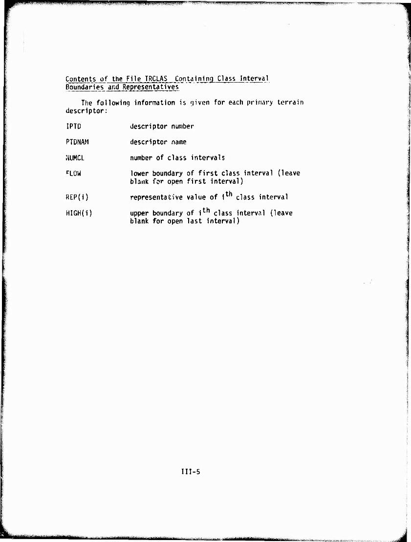
Pf» 1II|III|IIIIPJ.III.IIIP.I,IHI>«V *mmim mpippp ^—.-^.—.^—,1.ni..i,.....,,,.i.„w.iily,,|i,i,i^|j,l.,)ru,,ti,lj„,,i, ,i.Mi.,i,iiiL„i„.i,i)ii,.ll..^^,r.
Contents of the File TRCLAS Containing Class Interval Boundaries and Representatives
The followinn information is fjiven for each primary terrain descriptor:
IPTD
PTDNAM
.NUMCL
PLOW
REP(i)
HIGH(i)
descriptor number
descriptor name
number of class intervals
lower boundary of first class interval (leave blank for open first interval)
representative value of 1 class interval
upper boundary of i™ class interval (leave blank for open last interval)
III-5
■ • in **■—■■■-'-*■-- ■■■ ■-—-• ■- --»-^M—JiMtmn bfc«Äl*i-w^lBt..ir*.-j'*.ii-ta..Aai*i»,\i
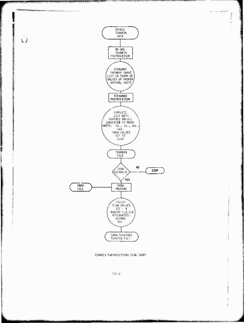
I ■MMnWMHHianMMMM.
r »^■w»'»'^ ..imnu i|jim»mg.i.ti.iiTHiwF-1"' —TT^T iuM''i«j.imin!»w«ii" ■■:i v v^-i-^-i- .-j-T»r^
u
CSNOW \ r"1LE /
SOURCE TERRAIN
DATA
AO HOC TERRAIN
f'RCPRÜCESSOR
STANDARD PREPROCESSOR
SNOW MODIFIED "^ TERRAIN Fill J
£ STOP 3
TERRAIN PREPROCESSING FLOW CHART
III-fi
mmmtttlmmM ^ ^^•-^^,. LL .,.-. -.-..^ i^.. , ^.^.j..■:.... ......:,^,-^^.t.**:±^.:iV,ii
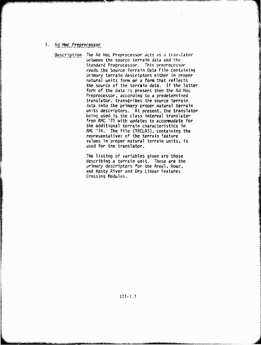
■■■fPIWIIippp^BWipWIiiWHPIWWIWBB WWW -—^r" .1 i ■■'■i-.. , i y w ••\iKm,i,m'i>f*.. — ~ vtm^.-t"—^"« ■•'< it\m'tai>i»i-«ii aunr'y '«"-"«w"!
1. Ad Hoc Preprocessor
Description The Ad Hoc Preprocessor acts as a translator between the source terrain data and the Standard Preprocessor. This preprocessor reads the Source Terrain Data File containing primary terrain descriptors either in proper natural units form or a form that reflects the source of the terrain data. If the latter form of the data is present then the Ad Hoc Preprocessor, according to a predetermined translator, transcribes the source terrain data into the primary proper natural terrain units descriptors. At present, the translator being used is the class interval translator from AMC '71 with updates to accoranodate for the additional terrain characteristics in AMC '74. The file (TRCLAS), containing the representatives of the terrain feature values in proper natural terrain units, is used for the translator.
The listing of variables given are those describing a terrain unit. These are the primary descriptors for the Areal, Road, and Hasty River and Dry Linear Features Crossing Modules.
III-l.l
Irliiiirnn-—";''""' ttä I ■■?. -<-- i ii ; -...-.■.>MJ.J.., .■.,... -t, ■ -miHr'Mi'nivin in ■ ■
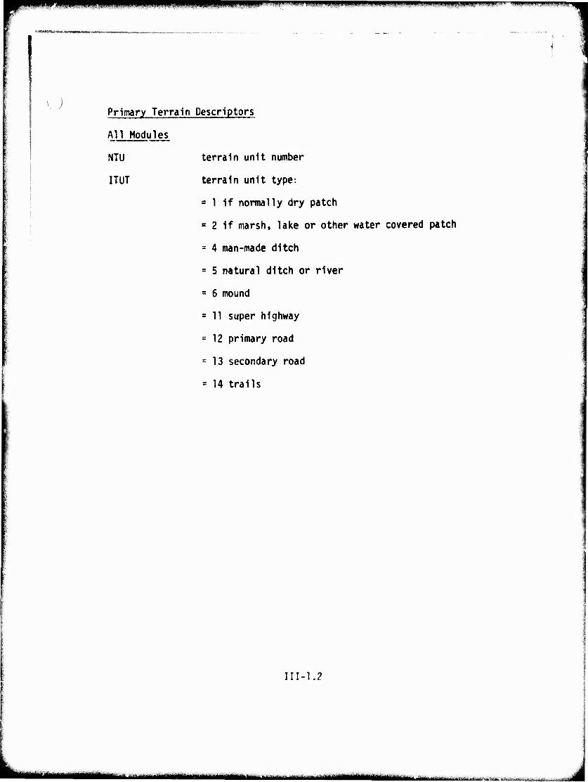
" me~i^^^mmmm*^mmi^~,^**~~~**^r*'** <• ■ < ^ '■■
Primary Terrain Descriptors
All Modules
NTU terrain unit number
ITUT terrain unit type:
= 1 if normally dry patch
= 2 if marsh, lake or other water covered patch
= 4 man-made ditch
= 5 natural ditch or river
- 6 mound
= 11 super highway
= 12 primary road
= 13 secondary road
= 14 trails
III-1.2
,ir- ril -m^mtmammimimmmtmami i m.mm.mm^ii.mmmtmmmmmk
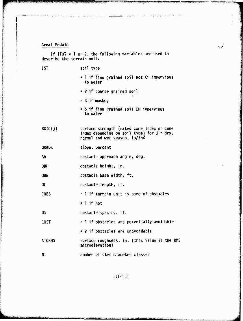
mmmmmrmmm ■■■IIIIIIP^WI^WW^F^'- ' ' " ■ »• I — ■ IJ.I.I»W.HI^I ».llliiilll^üiiHI,»'!! ■J.IIHHIi.HW!'« ii.iu»J|yT^-- .„mrm.wv mmi.i"rm'imm
Areal Module
If ITUT « 1 or 2, the following variables are used to describe the terrain unit:
1ST soil type
= 1 if fine grained soil not CH impervious to water
= 2 if coarse grained soil
= 3 if muskeg
a 6 if fine grained soil CH impervious to water
RCIC(j)
GRADE
AA
OBH
OBW
OL
I08S
OS
I0ST
ATCRMS
NI
surface strength (rated cone index or cone index depending on soil type) for j = dry, normal and wet season, Ib/inZ
slope, percent
obstacle approach angle, deg.
obstacle height, in.
obstacle base width, ft.
obstacle length, ft.
= 1 if terrain unit is bare of obstacles
f 1 if not
obstacle spacing, ft.
= 1 if obstacles are potentially avoidable
= 2 if obstacles are unavoidable
surface roughness, in. (this value is the RMS microelevation)
number of stem diameter classes
III-1.3
■■MaBMMMM " i i '• ii i ••rMiHiitiiatilittllillMMMMilli
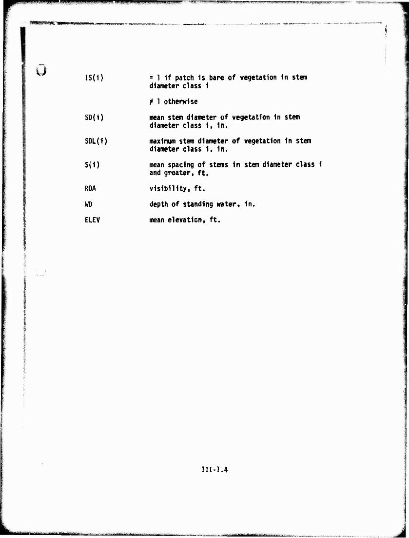
.aim' ■>I.II im iwimnj luii.nww ' IIW)"1 " ^J»» > .«-üH™, «P»|^I|!UUIII»WJI«III,I 11 nui ji 11n.11 minnniiiummp i wv »rai« n ni wiun! w.""i"- •>•■). ■^■■wwyw. '-I-T^I .Jit.'-'■i>|'i^
•swwc^«;:»-
IS(i)
SD(i)
SDL(1)
S(1)
RDA
WD
ELEV
s 1 if patch Is bare of vegetation In stem diameter class 1
t 1 otherwise
mean stem diameter of vegetation in stem diameter class 1, In.
maximum stem diameter of vegetation In stem diameter class 1, In.
mean spacing of stems In stem diameter class 1 and greater, ft.
visibility, ft.
depth of standing water, in.
mean elevation, ft.
III-1.4
MBMMÜ --- ^la^iuMt-i iiiii'llt»lriMllirtliiii-f vr ■iif..i1»iiil.' ,. .^a^.^,....^,,.,.!. ......
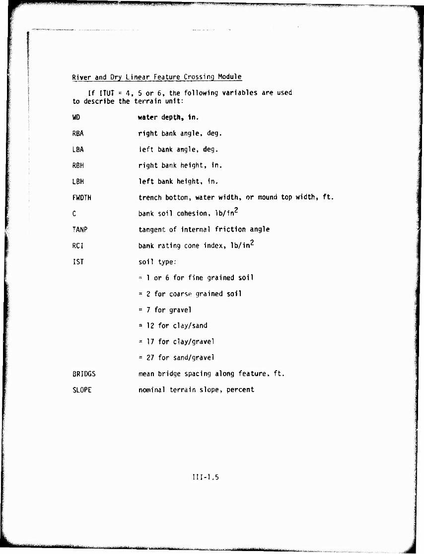
WW*I .ilftiiiiiii .n.wui.i ■"■". mrmum I^III iiupw..:^^^,,,.. .ijnmn^y,,,!^,,^^,^.^ „n^,,.
'"" <*«y">-."~««i
River and Dry Linear Feature Crossing Module
If ITUT = 4, 5 or 6, the following variables are used to describe the terrain unit:
WD
RBA
LBA
RBH
LBH
FWDTH
C
TANP
RCI
1ST
BRIDGS
SLOPE
water depth. In.
right bank angle, deg.
left bank angle, deg.
right bank height. In.
left bank height, in.
trench bottom, water width, or mound top width, ft.
bank soil cohesion, lb/in2
tangent of Internal friction angle
bank rating cone index, lb/in2
soil type:
^ 1 or 6 for fine grained soil
= 2 for coarse grained soil
= 7 for gravel
a 12 for clay/sand
= 17 for clay/gravel
= 27 for sand/gravel
mean bridge spacing along feature, ft.
nominal terrain slope, percent
III-1.5
1 MM« MMaaah^ a -„;
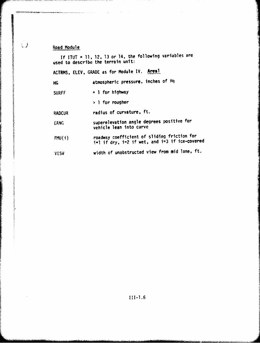
u Road Module
If ITUT • 11, 12, 13 or 14. the following variables are used to describe the terrain unit:
ACTRMS, ELEV, GRADE as for Module IV. Are«!
HG
SURFF
RADCUR
EANG
FMU(1)
VISW
atmospheric pressure. Inches of Hq
* 1 for highway
> 1 for rougher
radius of curvature, ft.
superelevation angle degrees positive for vehicle lean Into curve
roadway coefficient of sliding friction for 1«1 If dry, 1=2 if wet, and 1=3 If Ice-covered
width of unobstructed view from mid lane, ft.
III-1.6
M^^^^^M t:..^...^:-. -.N.-.:; , .■■.. .
r ■ "'■'Wlf'^'-mW&mmimmiamm
o 2. Standard Preprocessor
Description The Standard Preprocessor derives the secondary descriptors of the terrain and converts all descriptor dimensional units to the lb., in.» sec, rad. units used throughout the model. All terrain descriptors are then written onto file (TERRN) in the proper format acceptable to the three working modules mentioned earlier.
The variable list provided contains all variables required by the three working modules.
III-2.1
ii umifiBmir ,l,»i.>,.i.t.,»..,if...i-,i,„,.,-,. ^,....—,...,., . ..,. -—^-■-lll-|,n nn .,„.^,..,,.
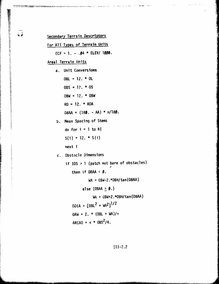
■vvWrimP'^PPwrntavKiii*»/**™,,*»™ i*i(t*.**ir«*«'.»K^^.j.
o Secondary Terrain Descriptors
For All Types of Terrain Units
ECF = 1. - .04 * ELEV/ 10M.
Area! Terrain Units
a. Unit Conversions
OBL = 12. * OL
OBS * 12. * OS
OBW = 12. * OBW
RD » 12. * RDA
OBAA = (180. - AA) * TT/180.
b. Mean Spacing of Stems
do for i = 1 to NI
S(1) = 12. * S(i)
next 1
c. Obstacle Dimensions
If I0S > 1 (patch not bare of obstacles)
then if OBAA < 0.
WA = 0BW-2.*0BH/tan (OBAA)
else (OBAA > 0.)
WA = 0BW+2.*0BH/tan(OBAA)
ODIA = [OBL2 + WA2]1/2
OAW = 2. * (OBL + WA)/IT
AREAO = n * 0BS2/4.
III-2.2
1 '---- MM^HMMHMWMa,,. ""- ---•-• im^—MIM UM
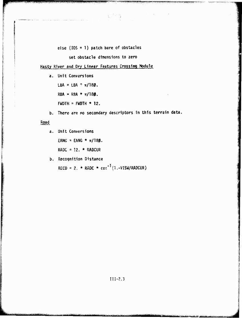
HaJ|l|)i,HjH||IIIU|H..«ul.'pm>ii r^'lv-'timmmmmimW^^^-'^Kk'^^^^y^V^'^^'m^^'^'''^^
else (IOS a 1) patch bare of obstacles
set obstacle dimensions to zero
Hasty River and Dry Linear Features Crossing Module
a. Unit Conversions
LBA = LBA ^ TT/180.
RBA » RBA * TT/180.
FWDTH = FWOTH * 12.
b. There are no secondary descriptors In this terrain data.
Road
a. Unit Conversions
EANG * EANG * TI/180.
RADC = 12. * RADCUR
b. Recognition Distance
RECD = 2. * RÄDC * cos"1 (1 .-VISW/RADCUR)
III-2.3
m ;' ■ ^.^^-^-.^ ..-...,-^ i T i mumm mm n mni .ummm I lir ^faiH!!!!!!!!!^^!, ammM i ■ i.-..^...
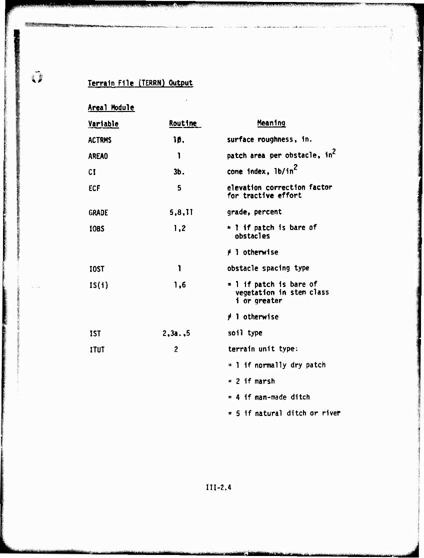
m*^^*^^—» »lip,(ipM ■.('"■.» ■«WP wflWÄ!" •'. i w ^ ■ ^.WWIII •,■*«••''«pr.».'.««!
?««SWI?W;S»«S5ils''W
Terrain File (TERRN) Output
Areal Module •
Variable Routine Meaning
ACTRMS IP. surface roughness. In.
AREAO 1 patch area per obstacle. In
CI 3b. 2
cone Index, lb/In
ECF 5 elevation correction factor for tractive effort
GRADE 5,8.11 grade, percent
I0BS 1.2 « 1 If patch is bare of
I0ST
IS(1)
1ST
ITUT
1
1.6
2.3a..5
2
obstacles
t 1 otherwise
obstacle spacing type
■ 1 If patch Is bare of vegetation In stem class 1 or greater
f 1 otherwise
soil type
terrain unit type:
= 1 if normally dry patch
= 2 if marsh
» 4 If man-made ditch
= 5 if natural ditch or river
III-2.4
ii - iiiiM^iiiiili '--■--■ ■ ■ ~
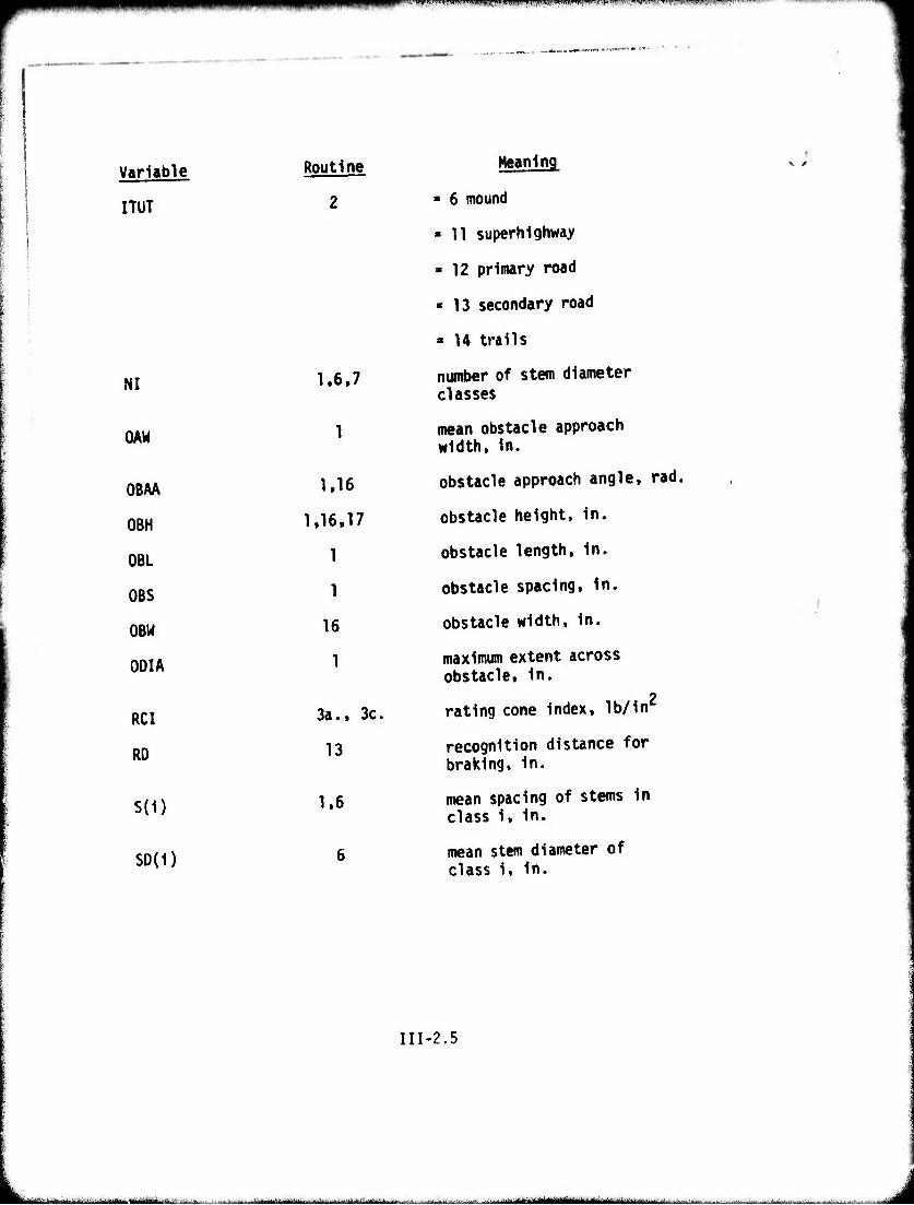
ii imßi iiiu.iwpiwi.ikll^p|]j(W|Wl|»uWi^wff,»Wi|'li''l! •V""1 'j■»■■'■"■' ■'"«"I.II»U'«II-T~
Variable Routine Meaning
ITUT 2 ■ 6 mound
- 11 superhighway
» 12 primary road
» 13 secondary road
» 14 trails
NI 1.6,7 number of stem diameter classes
OAW 1 mean obstacle approach width, in.
OBAA 1,16 obstacle approach angle, rad.
OBH 1,16,17 obstacle height, in.
OBL 1 obstacle length, in.
OBS 1 obstacle spacing, in.
OBW 16 obstacle width, in.
ODIA 1 maximum extent across obstacle, in.
RCI 3a., 3c. rating cone index, lb/in
RD 13 recognition distance for braking, in.
S(i) 1.6 mean spacing of stems in class i, in.
<;nM^ 6 mean stem diameter of class i, in.
III-2.5
■■—^-'—■^■"-■- ■-■■ ...■.■■. ,.^..-..--.. ■ ■ ■ ■ iMirii^iiiiiiiiifaMiiMiii»! iJJU,^B.il.i1lVl^»->—l^^i«..^^UEUiW^,l. J
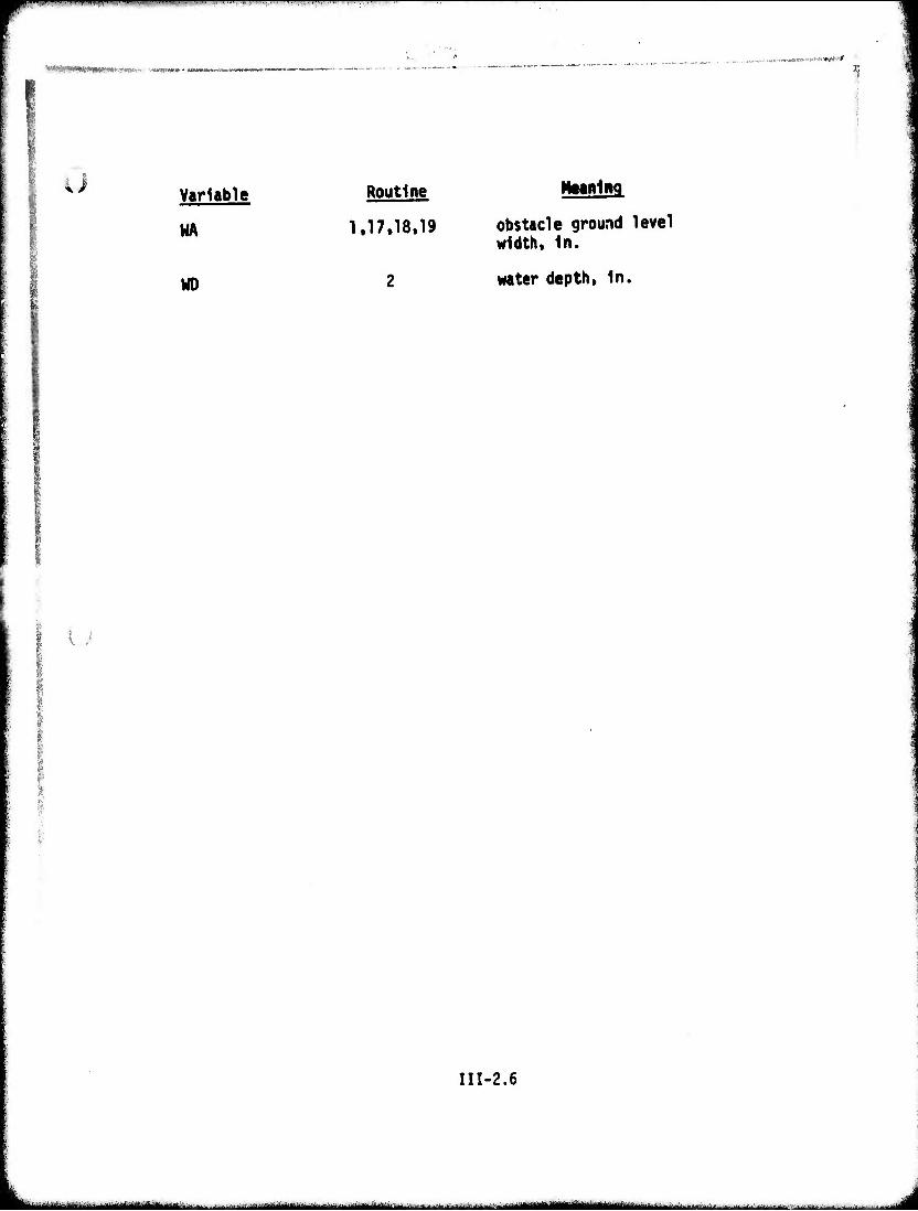
»^IPiB^^ ,III-I-IM ' ' , ■ I. ■- ■ ' l-.! IMI ,.1.1 I,,,,
-v-M ■ ymmmm- *
u Variable
WA
WD
Routine
1,17.18.19 obstacle ground level width. In.
water depth, in.
U
III-2.6
-— - —^^-^-tniii ii IMMMIIHIM - i B^MMgaBMaM, ill ' ti ■■ ,^.:--...;J.'...M....W. „ ,,„ rUfjaM
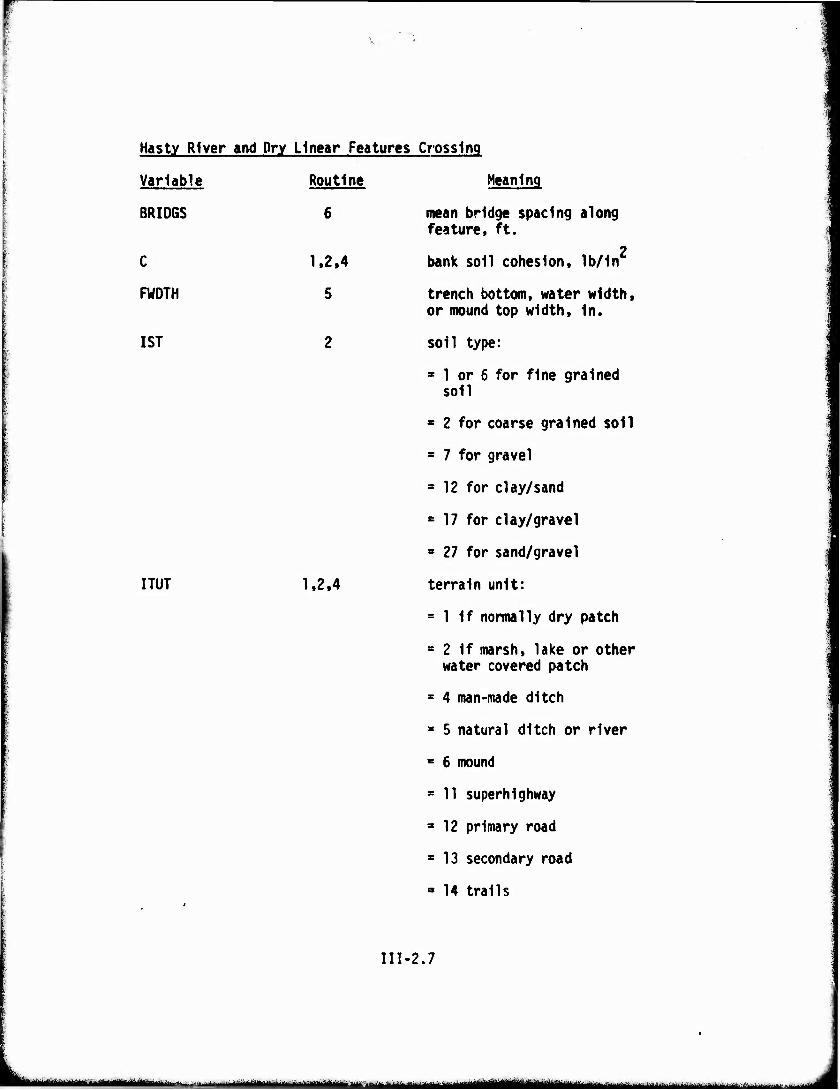
Hasty River and Dry Linear Features Crossing
Variable
BRIDGS
C
FWDTH
1ST
Routine
6
1.2.4
5
I TUT 1,2.4
Meaning
mean bridge spacing along feature, ft.
2 bank soil cohesion, lb/In
trench bottom, water width, or mound top width, in.
soil type:
3 1 or 6 for fine grained soil
» 2 for coarse grained soil
= 7 for gravel
s 12 for clay/sand
= 17 for clay/gravel
» 27 for sand/gravel
terrain unit:
= 1 if normally dry patch
= 2 if marsh, lake or other water covered patch
* 4 man-made ditch
■ 5 natural ditch or river
* 6 mound
= 11 superhighway
* 12 primary road
s 13 secondary road
= 14 trails
III-2.7
"-■'- ■ ^^^uu******.^**!*****^.^--^^ ^„.^^.„^^.^-„„.^may» - .. :. .^.^w,.„ .,-v^
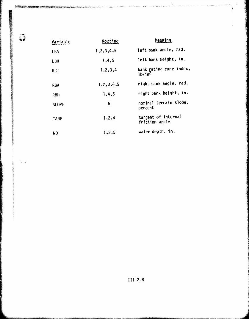
■f*^|*nj<»SWR|»» ■ -■■^WPfflC'KfWMWlwrm»»-»«.» .~w
Variable Routine
LBA 1.2,3,4,5
LBH 1.4,5
RCI 1.2,3,4
RBA 1,2,3,4,5
RBH 1,4,5
SLOPE 6
TANP 1,2,4
WD 1,2,5
Meaning
left bank angle, rad.
left bank heiqht, in.
bank rating cone index, lb/in2
right bank angle, rad.
right bank height, in.
nominal terrain slope, percent
tangent of internal friction angle
water depth, in.
III-2.8
art-itfaMi^--t ..-a-v^ ■■■ ■^■- ■■--■-^-^ ;...^..:-^^u^ ■---—-'--~^-—■'-■- - ■ ■-
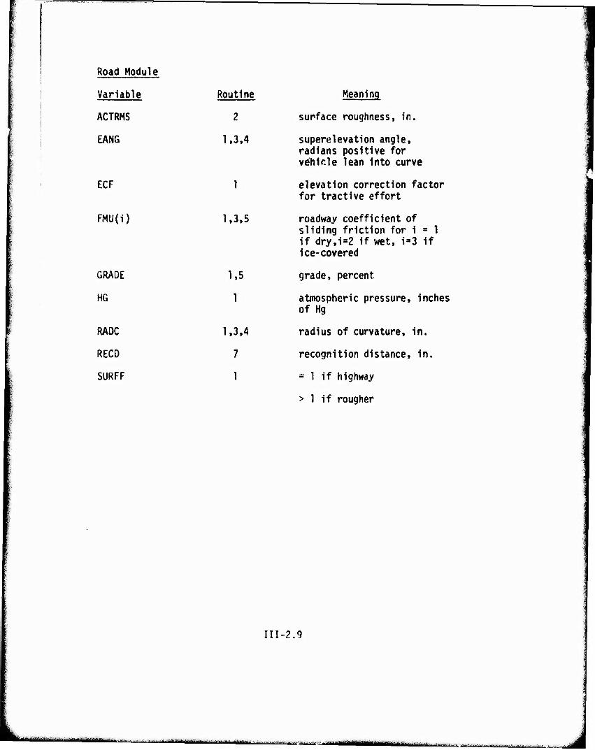
Road Module
Variable Routine Meaning
ACTRMS 2 surface roughness, in.
EANG 1.3.4 superelevation angle, radians positive for vehicle lean into curve
ECF 1 elevation correction fa for tractive effort
FMU(i) 1,3.5 roadway coefficient of
GRADE
HG
RADC
RECO
SURFF
1,5
1
1,3.4
7
1
sliding friction for 1 = 1 if dry.i=2 if wet, i»3 if ice-covered
grade, percent
atmospheric pressure, inches of Hg
radius of curvature, in.
recognition distance, in.
= 1 if highway
> 1 if rougher
III-2.9
—-'—"—'■■■
■ ' ■ ■ ■ mm mamiMHnfliaimj...;.!.,
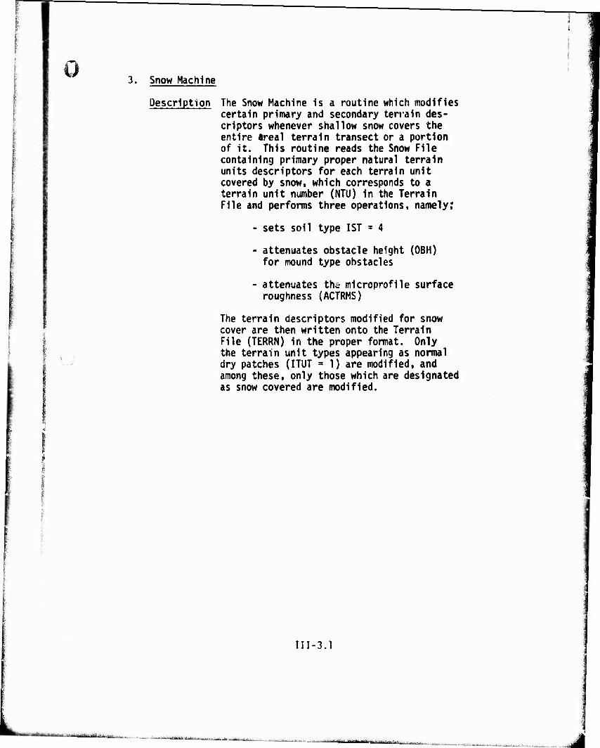
ö Snow Machine
Description The Snow Machine is a routine which modifies certain primary and secondary terrain des- criptors whenever shallow snow covers the entire area! terrain transect or a portion of it. This routine reads the Snow File containing primary proper natural terrain units descriptors for each terrain unit covered by snow, which corresponds to a terrain unit number (NTU) In the Terrain File and performs three operations, namely;
- sets soil type 1ST * 4
- attenuates obstacle height (OBH) for mound type obstacles
- attenuates the microprofile surface roughness (ACTRMS)
The terrain descriptors modified for snow cover are then written onto the Terrain File (TERRN) In the proper format. Only the terrain unit types appearing as normal dry patches (ITUT = 1) are modified, and among these, only those which are designated as snow covered are modified.
III-3.1
tajaiMj ij^jjg^gn n,^,.,-
■-.. ;,.■■,■ ^---^-...^....AL..^^J.,...|...|I.,.|
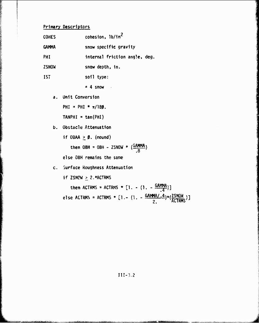
Primary Descriptors
COHES cohesion, lb/In2
GAMMA snow specific gravity
PHI Internal friction angle, deg.
ZSNOW snow depth. In.
1ST soil type:
* 4 snow
a. Unit Conversion
PHI = PHI * Tr/180.
TANPHI » tan(PHI)
b. Obstacle Attenuation
If OBAA > 0. (mound)
then OBH = OBH - ZSNOW * (GAMMA) .8
else OBH remains the same
c. Surface Roughness Attenuation
If ZSNCW > 2.*ACTRMS
then ACTRMS =» ACTRMS * [1. - (1. GAMMA )]
else ACTRMS = ACTRMS * [1.- (1. - GAMMA/.4^(ZSNOW n 2, ACTKnS
III-3.2
■^■.-.■.^,. -■ ^J- —■■- „.... II r tmvmft iÜIÜ J
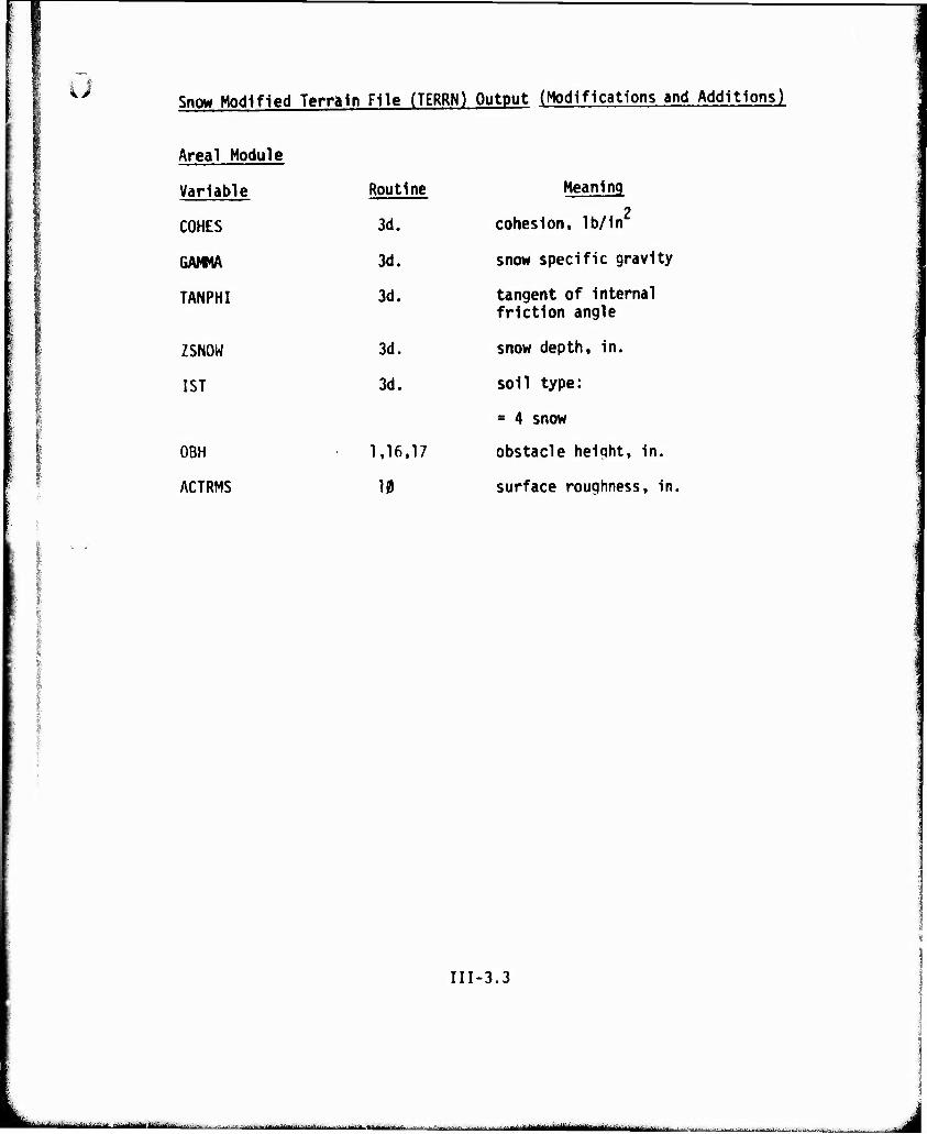
Snow Modified Terrain File (TERRN) Output (Modifications and Additions)
Areal Module
Variable Routi ne Meaning
COHES 3d. 2
cohesion, lb/in
GAMMA 3d. snow specific gravity
TANPHI 3d. tangent of internal friction angle
ZSNOW 3d. snow depth, in.
1ST 3d. soil type:
= 4 snow
OBH 1,16. 17 obstacle height, in.
ACTRMS 10 surface roughness, in.
III-3.3
uaätiämälildmav'r m,,.* .i.j.M.tjamirn.-lii.lim. It—MMMWiBMMM .In- r..,i-„-»n'rrtilirir-i'i -,rlBM^jiaiti
ü
MODULE IV
AREAL
IV-1
-- ■'-"-'■ •liii-iiiiiiillfii — ■
u AREAL MODULE
The Areal Module calculates the maximum average speed across a patch that a vehicle can be expected to maintain. (A patch or terrain unit is an area within which mobility impediments are considered uniform.) As in the AMC '71 Mobility Model, the speed is chosen to be the maximum of those calculated for various obstacle and vegetation override and/or avoidance strategies. The new Areal Module takes the place of the FOIL, COIL, PATCH and MARSH subroutines of AMC '71 and of all the subroutines they call except OBSTCL.
An overview of the Areal Module is displayed in Figure 1. The main operating position of tha module revolves around the sequentially executed stand-alone submodels. These submodels are fed vehicle, terrain and scenario data from the two pre- processors and the Input/Output Control module. Additionally, derived outputs (velocities, forces, flags and diagnostic indicators) from previously executed submodels are used as inputs to successive submodels. Each submodel provides the above mentioned derived outputs which in whole or part are used by an output processor. The output processor is external to the module and operates on the derived outputs per the user's scenario.
The major conceptual blocks of the Areal Module are dis- played in Figure 2. In each block are listed the numerical designations of the routines described in this section. A more detailed data flow chart is also given (Figure 3). This is a sequential flow chart of execution which shows input and output variable names as defined in the glossary. The routines may be calculated in the order given with some rearrangement allowed to the individual program implementation.
In addition to the vehicle and terrain input files from modules II and III, the Areal Module requires the list of scenario variables given on pages IV-5 to IV-7.
A description of each submodel follows. The following in- formation Is furnished for each:
1. Descriptive name of submodel.
2. Brief description of what the submodel does.
3. Required inputs:
a. Vehicle.
IV-2
J
b. Terrain.
c. Scenario.
d. Derived from previous submodels.
4. Derived outputs.
5. Algorithm
Although the Areal Module is so structured that each sub- model is executed in succession, eliminating the need for pro- gramming the module as subroutines, there are instances where repetitive calculations are required within a submodel. In these cases, subroutines are used. These are identified in the submodels by the CALL statement, in which outputs of the sub- routine are underlined in the CALL list. Such subroutines are specified immediately following the algorithm in the first submodel which uses each.
IV-3
L "V*'***'*""-"' '•'• ,...,>,>j.,...,mi»»>-.,..,^,.—...... lilfnlllru'lilirn .,...■.-,■,,»,-.■. | ->,— ■,
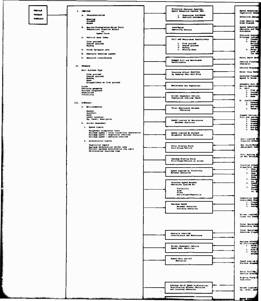
L
«■neu
j IHM»
«■uuuo
I. VMICU
*. Ckanotulltloa
| IUM»d
». tofUM-TrMMlMiea-Driv« Titln IteontlMl TTHtlva Iffort
99. •pMd CtUM
C. Mhicl« COM in4«a
Piiw fraiiMd GoarM frsiiMd MMkM
D. vrl4a DynMdoa üat«
1. Okatftd« Ov*rrl4* «psMa
P. Obataci« IntarCarwoa
II. TSMIAIM
•oli turfao« Typ«
Pin« frainad Ooara« qraiMd Huaka« ■as« SllpparLiMM on fina gminad
Gr«da obatacla laaaatrr Surfaoa roughiMaa vagatatioa Vlaibillty
III. SCBHAUO
A. ■nvitonMntal
Saaaon Rainfall Snow Laval ttavarsa Up, laval, down-patch
B. orlvar dapandant
1. Spaad Halt«
MDuqlvnaaa accaptanea laval NlRlaw apaad - total vlalblllty obacuration Mlnlaia apaad - vaqatatlon ovarrlda Nlnln« apaad - obatacla ovarrlda
2. Accalaratlon Ualta
Variation Impact Naalaua dacalaratlon drlvar uaaa farcant aailaua daealaratlon ava.labla Dacalaratlon raaetlen tlaa
■tlaotlm Qkatula tpuUfl ■pMd RMuotlon rsotor« DWi
i 1. w««utios molUm 1. ObttMla Avoiduea
•paad Mduetlas
•ffactlva I IIBJ
Tra. Daaatty fj scaa Claaaaa 1
1 LaM/Huih j QparatlBf raetora
1 spaad aadiiotiaa a obatacla a«d «M
ot.atacla OnnU Strata« iBdldil
t'. MMt < •allr/l fanäii aM im
>. MMt 1 Uck * for im
■atar Dap tu 0*4
vanicia rioattai Indicator
vanicia Boayaa^
Matar Drag Mail
SaUctad rloatil Spaad In Marak
i uaa^ly Soll ■ Motion Baalataaj «. Soll
1. rina m 1. coats? ). Huaka« «. SMM
B. Coafflelaad 1. FOMIM a, POMSS
•aa a« 1. T»»ad 1
Sam—ä vahicla t Pull and xaalatl
}'. BrakaS 4. BraUl 5. Hoa-ffl '■ "»"-•■
Soll Lialtad m Tractlva Bffatff
Nat Porca/nald Adjuataant PaM
Soll BunnlM m at Nat rorca/H
rtactlv« lf(ol«i slopa/soii auad
1. Qau 1 xot n
2. Oaa ■ «« oti DOM i
). Naalaj
.. SJ Traatl
s. ooa a Pttui »•• ■«
vagatatlon NaM Ovarriddan Siad
1 . SllMli j. luläi 1. *«a ai
Orlvar UUta«! Claaa for Ova««
Total NaalataM Ovarridlnq NalM
Total MalatMfl
[ run an« Malatanoa ooatflctaata
1. rtna «laliwd i. Ooaraa «ralnad 1. Muakat «. Ikallo« tlHM
Hmma ruU and Haalatanoa Ooafflclanta
Tiactl«a •ffort Nodinad ■y Ruanlng Gaar SoU-ILip
Maiatanca DU« vaqatatloa
Orlvar Dapandant vahlcla vagatatlon Ovarrlda Chack
Total Malatanca latvaan Obataclaa
Spaad LiBitad By Raalatanca ■atwaan obaticlaa
Spaad LlBltad By Burfaca ■Duqhnaaa Bataaan Obataclaa
Total ■rakln9 Porca SolL/Slopa/vahlcla
-texiaua »takinq Potca 5oli/siopa/vahicla or Drlvar
,
Spaad Llaltad by Vlalblllty ■atwaan Obataclaa
Jalactad Spaad Mtaaan Obataclaa Ualtad »yi
Vlalblllty Rlda Tlraa Soll/Slopa/Vaqatatian
Hailaua Spaad Satwaan Obataclaa AvoldlnR Obataclaa
Obatacla Ovarrlda Intarfaranca «nd tealatano» 1
j
Naalaua ValoeMl by Soil/Slopa/«
i. itiraal lavald
-I. Mlna ■ J. Tot lj
3pMd Ual'.a« M Surfaca Wo i jkaJ
Total Soil/Ua#j Vahlcla trakUfi
btAkmq Poroa m Indicator 1
Drlvar LlaltaAJ Up. laval, dMM|
Drlvar Dapandant Vahlcla Spaad Ovat ObaUolaa
Spaad Onto and Off Obataclaa
Avaraga Patch Spaad Accaiaratln«/ Dacalaratlng Satwaan obataclaa | and Croaalnq Obataclaa .
*~*M*tJi
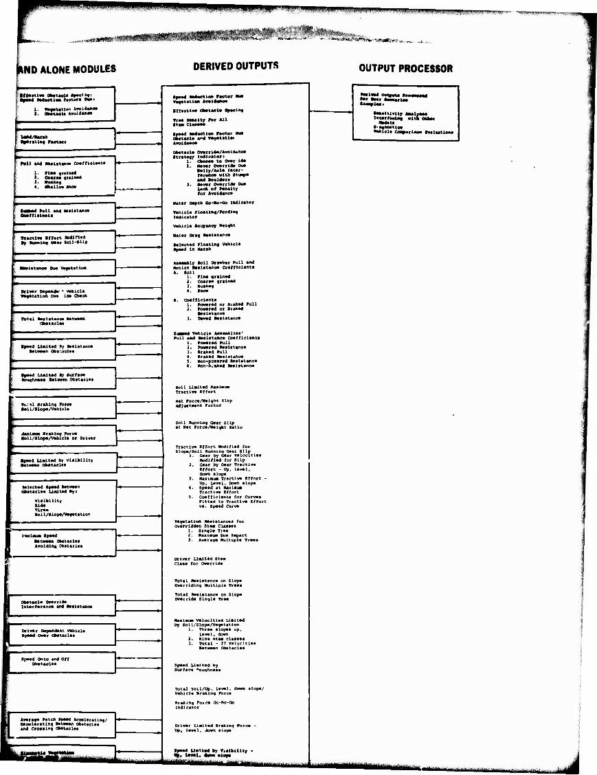
lullt ■ll.l>,li i-M^IM[;!iJi>>i|.ii.4i|^wl|.ti^iiiiW|J^w,|LJI;HW>w.
..«««WAS? "rrMfflwrwflte "iiiiwiiiiiiiii .i.
IND ALONE MODULES DERIVED OUTPUTS OUTPUT PROCESSOR
'■ : IIHctiw OMtMU •►•cl«»j S •pM4 »MMtlw raewi» Dwi
1. «MCUtlaa »voKUnoa 1. Okatasla «voHaaoa
l UM/NaNk r a**ratlat ramoia
1 Mil and üaalatKioa CDafflclasta
1. rina fialita« 1. Ooataa atalna« 1. Miuka« • . iiiallo. UM
■
. • •
f tmmm* rail and Halatanea t OMCftelanta
f TraottM Iflort fcdifiad f H luiinlitq (Uat loll-tllp
r aMlatanc« Dua Vi^atatloa
F
' OMMc oapanda • Whlcla I «tfatatlDii On Ida OMok
|
1 Itetal Malatanoa Mtoaar. Obataelai
Ipaad Ualtad ey Daalataiioa f MtoMn Oba-.aelaa
*paad Ualud ly turfaea 1 HDiiihn«» Mtano wniol«!
»
tbtal ■caktn« rocea •oU/51opa/vahl«l»
Mximm Iraklaa roroa •oll/ilopa/vahicla or DriMt
| ' ;
■FMd Umltad 6» Vlalblllty ■ataaan obatacU»
lalaotad tpaad tatwaan okataelaa Umltad »Ji
Vlalblllty Uda Tina •ol l/llopa/vagatatlon
1
■ p «roldlnt Obitulti
1 i
li^ |j obaucl« OVTviäm Pf intarfaranc« «nd Rtalatano«
K IpMd Owmt QlMtaclaa i' 1
t . . ^ ■i Obataclaa
1 I knr««< ntch SpM kcMUtatln«/ ■1 Oaealaratln^ MtiiMn obtueU* rl »IKI Croaaln« olwUeUi
K ^"-"Tflln ^
tya« Mduetia« raster Mi* v*f«t«tlon Avoldaiioa
IffactlM ObataeU fpactnf
TrM Oanaity Por fcll ■ta* ciaaaaa
Ipaad «aduetlon Factor MM Qbatael« vd vagatatlos Avoldanoa
ObatacU Owartlda/Avoid«i»c» Stratagy Xndleaten
i. AotiM to Ovvrida 2. MMr Omrrlda Ma
•aliy/Asla Intar- faranoa with ttuav« and ■ouldara
I, Mavvr Ovarrtda Dua Lack of ranalty for Avoidanca
Natar Dapth GO-HO-CO indicator
Vaniclo Ploatlnq/rordln« Indicator
vahlcla »oyyaftoy ttalfht
Matar Drag Malatanc«
talaet*d Pioatlng Vahlcla Ipaad In Marah
Aaaavtoly toll DrawbAr Pull and itotion Haalatanoa Cotrfiolanta A. loll
1. Plna gralnftd 3. Coaraa gratnad 3. Huakag 4. ■BO**
i, Ooafflclanta 1. powarad or tiakad Pull 2. Powarod or Irakad
»aalatanoa 1. Tavad Aaaiatanca
I Vahicla Aaaaabllaa' Pull and Aaaiatanca Coafflclanta
1. PoMarod Pull 2. powarad llaalitanca J. Irakad Pull I. Irakad Aaaiatanc« 5. Mon-powarad Railatanca C. Hon-b^akod aaalatanca
Soil Liaitad Nwiinua Tractlva effort
Nat Porca/Maight Slip AdJuatMant Factor
Soil Running Gaar Slip at Mat Porca/Haight Ratio
Tractiv« Effort Hodifiad for Slopa/Soil Running G*»r Slip
1. Gaar by Gaar valocltlaa Hodifiad for slip
2. Gaar by Gaar Tractlva Effort - Up, laval, Down alopa
3. NaxlMua Tractlva Effort - Up, Laval, Down alopa
4. Spaad at Haxiaua Tractlva Effort
5. Coafflclanta for Curvaa Flttad to Tractlva Effort va. Spaad Curva
Vagatatlon Raaiatancaa for Ovarrlddan Staa Claaaaa
1. Slngla Traa 2. Naxlmui Dua impact 3. Avarag« Hultipla Traoa
Drivar LlKltad Staa Claaa for Ovarrida
Total Raalatanca on Slopa Overriding Nultlpla Traaa
Total Malatanca on Slopa Ovarrida Slngla Traa
Haxiaua Valocltiaa Liaitad by Soll/Slopa/Vagatatian
1. Thraa alopa«:up, laval, down
2. Nina ataa claasaa 3. Total - 27 VaLocitlaa
■otwaan obataclaa
Spaad Liaitad by Surfaca "oughnaaa
Total soil/Up, laval, down alopa/ vahicla Braking Porca
Araking Forco Go-No-Go Indicator
Drivar Liaitad Braking Forca Up, laval, Jown alopa
Liaitad by VUihiLity ~ BlOf«
*•«■ war AaaaarUa ■svplaai
•aaaitmty AMivaM latarfaoia« with otter
Nadal« OiaaneattM «ahicla CWHKtte* tvalaatioaa
mLmmtmmmmmm m it i hmääutm
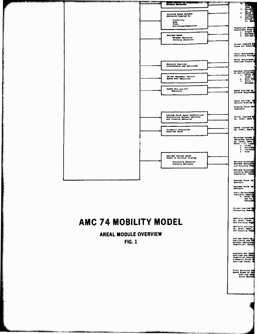
r
^■pfpwpwipRnnmKsm 1 mpfmzi^'mr'- ■wn.jw*rx
)«UoM4 SpMd ••twMn ObstAcUi Uait^l By i
Tina
. obitaeio Avoiding Obatftel«!
Obstacl« Owrrlda Zntcrfarano« and! ntalatano*
Drivvr Dapandant vatiicla Spaad Oft Obatactaa
Spaad Onto and Off Obataclaa
Avarag» Patch Spaad Acca la rating/ Daoalaratlnq Batwaan obataclaa and Croaalng Obataclaa
Kinasatlc va^atatlon OvarrIda Otack
Maxim» Avara^a Spaad ■aaad on Dacialon Stratagy
Ovarridin« obataclaa Avoiding Obataclaa
AMC 74 MOBILITY MODEL AREAL MODULE OVERVIEW
FIG. 1
Traeti« 5. ooaffti
PittW I
Vagatation Mala) Ovarrlddan Stmm 4
1. Sinai« \ 2. lUKlMt 3. Avaraf*
Drivar Ualtbd « Claaa «or OMrrU
Total KaaiataBoa Ovarriding Nultl)
Total MalataBO» | Ovarrida Singla %
Ma»lauH Valocltii by Soil/BlopaA"
1. Thrva lavvl*
2. Nina i J. Total - 1
■atw
Spaad Liaitad by . Surfac« Roughn—a
Total Soil/Up, II Vahicla Braklnf f
Braking Fore« ' indicator
Drivar UwLt*d I Up, laval, do««
Spaad Liaitad hf j Up, laval. doMi |
Salactad Spaad« I Obataclaa Ovmrwii Up, laval, do» Total - 27. liai(
1. Tir«« 2. Soil/lb 3. Vialbiii «. Rid«
NaainiUi salactft« Batwaan obataeii u>d Avoiding V«i
Maaiaw SalaetBtf Avoiding Obata«li Vagatation. Tot«
Avaraga Pore« *» ■ obatacla
Ovarr ida/Avoid«« indicator AddUM
4. Navsr • Dua t« t obatMU
Drivar Liaitad ) Contacting Obati
Obatacla Approaali Up, Laval, DOW and Avoiding V«
Obatacla Exiting | Up, Laval, DDM and Avoiding Vl
Avaraga Spaad Uy« Ovarriding and M »atwaan Obatael«« vagatation, Tot«t
Poaalbla Mav ol Ovarrida and Ol vafatatlon Owrrft Kinaaatlc Pore« V ovarrida Otack. «
Pinal Satactad MM Spaad Baaad on OM
Ovarrida Q««| Avoid abat«c|
4
^■-"■"'■- ■• ■■-' ■...■.,■■-■- .MJJ ._. ■ -- ■'- - - IIMI -^ " I
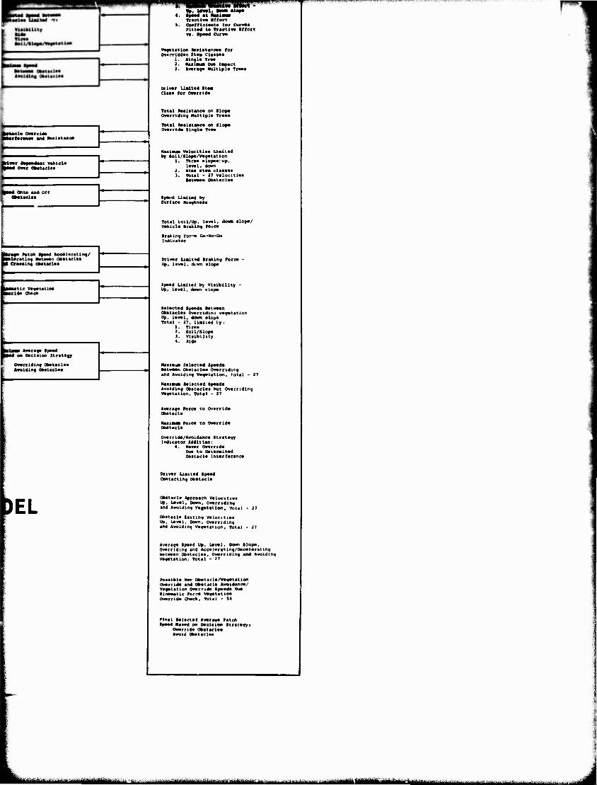
1« Ovsrrld« M*rf*r«aM «ad RBaiatano
timt Dfwiwt whiel« d Ovwr Ob*t»cU*
«4 Otto Md Off Obattei««
■U««* Patch SpMd Aco«l«ratin«/ Mltratln« »atwMn Ob«t«cl*c M Crcsainq Cbataclaa
Biaua Ava ragt Spaad on Oaclalon Stratify
Owarrldiivf Obataelaa Avoiding Obataelaa
)EL
a», uo) --— at i
■Bsmt • 1« Dam dlapa
Tracttv* Bffort Ooafflclanta for Curvoa Plttad to Tractlva ■ffort va. spoad Curva
vagatation naalatanoaa for Ovarrlddan Stas Claaaaa
1. Stnal« Traa 2. HaMlaua Dua lapact I. Avarag« Hultlpla Traaa
Driver Ualt«d Staa Claaa for Onrrida
Total Aaaiatano« on Slop« Ovorridlng Hultlpla Traaa
Total Raalitanc« on Slop« Ovarrlda Singla Traa
HaatauB valocitiaa Liaiitad by toil/Slopa/Vagatatlon
1. Thraa alopaa:up. laval, down
2. Mine ata» claaaas 3. Total - 27 valocitiaa
■atwwan obataelaa
•pa«^d Uaitad by Surdca NouqtUMaa
Total boil/Up, laval, down alopa/ Vahicla braking rorca
Braking I'orrTa Go-Ho-Go Indicator
Driver Liaitvd Braking Force ■ Up, level, dem alope
Spaed U«itad by Viaibility - Up« level, down slope
Selected Speed« Between Obataelaa Ovarridinii vegetation Up, level, down alop« Total - 27. linitad L>y i
1. Tiraa 2. Soil/Slope 1. Viaibility 4. Rid«
Naxinua Selactad Speed« Between Obttaclea Overriding and Avoiding Vegetation, total - 2
Naalauai Salaeted Speed« Avoiding Obataelaa but Overriding Vegetation. Total - 27
Average Force to Ov«rrid« Obstacle
tUmimtm Pore« to Override Obataela
Ov«rrid«/Avoidane« Strategy Indicator Addition:
«. Never Override Due to Datenained Obstacle interference
Driver Lieited Speed Contacting Obatacl«
Obitacle Approach Velocltie« Up. Level, Down, Overriding and Avoiding Vegetation, itotal
Obstacle Eaiting V«lociti«a Up, Laval. Down, Ovarndlng and Avoiding Vegetation, Total
Average Spe«d Up, Level, Down slope. Overriding and Acceleratlng/Dae«larating ««tw««n Obataelaa, Overriding and Avoiding Vagetatlon, Total - >7
Posaible Mev obataela/vegetation Override and Ob«t«cl« Avoidance/ V«f«t«tion overnd« Speed« Due Xlneaattc Pore« vegetation Override Cheek, Total • S4
Plnal Selected Average Patch Ipaad Baaed on oeciaion Strategyi
Override Obataelaa Avoid Obataelaa
MMmm^mt iiiiiifiii m aiHüims MI n ii Bi^iaMiMfcaMiMii n
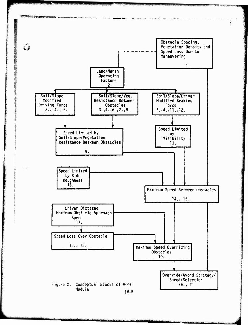
Wim TO.i Jin"" vi'"^ IHWIH
HMHMHRtlimHi WWI—imiiimmL- mnm WMM
um
Land/Marsh Operating Factors
2.
Soil/Slope Modified
Driving Force 3., 4., 5.
Soil/Slope/Veg. Resistance Between
Obstacles 3.(4.,6.t7.«8.
Speed Limited by Soil/Slope/Vegetation Resistance Between Obstacles
Speed Limited by Ride
Roughness 10.
Driver Dictated Maximum Obstacle Approach
Speed 17.
Speed Loss Over Obstacle
16., 18.
Obstacle Spacing, Vegetation Density and Speed Loss Due to Maneuvering
1
Soil/Slope/Driver Modified Braking
Force 3.,4.,11.,12.
Speed Limited by
Visibility 13.
Maximum Speed Between Obstacles
14., 15.
Maximum Speed Overriding Obstacles
19.
Figure 2. Conceptual Blocks of Areal Module IV_5
Override/Avoid Strategy/ Speed/Selection
20., 21.
-:i-: ■ --rM - '- --liiini ilüi ' r """■■•"■''l""1' •■-"-irilHÜ J
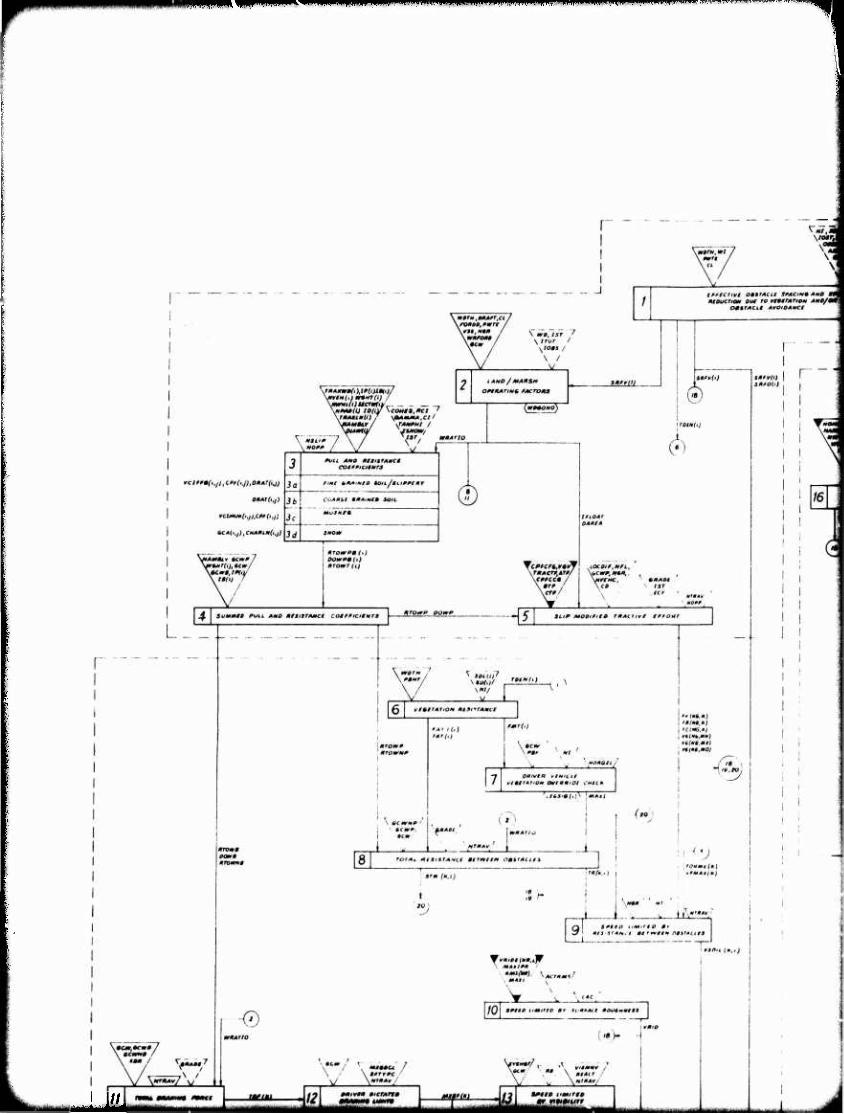
^^mmvm i< gRppvnipmpvapiimpiffnci
tmLmk
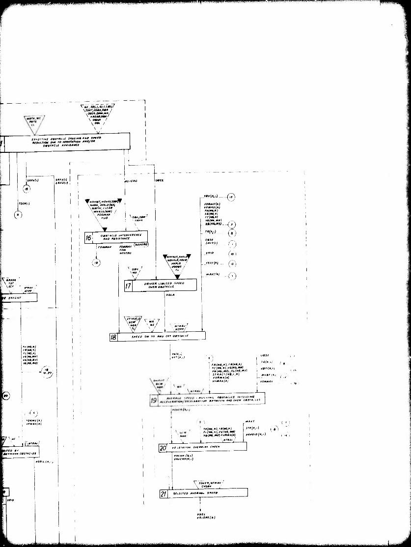
r w mtmamm^i wmifimmm'*>''wmmmmm'm^mmmw' "'»u,""i"""l"»p"»''w'*t'"l|v"«' •">•- '"-».■-"■'"•■■».-
I-
mttkfcriom our ro vtmMrATioM Atto/om OmtrACLt ArO/OAMCt
(§'
(h
\ 1ST
Iff fffOHT
fClMG.M)
te
•j •fOHMt(*}
«pmAtfM)
j I-/'"""-,
h
1
.MAMt,MALS(MA} \mwfH,cteA*
\w*Ais(mt¥i / '■ ßOOMAK
' Q»*A
16 omartcn iNTtmntfNCt
AMO AtStiTAMCt
1
0
^71
18
\WA
\ «Ml» '
/7 V
PKlVM* UMITlO SPflO 0¥ta OMSTACIC
jmAii
VfmAM(*)
~e fAi» *) ft(tM,K) rctrn.*!
(•) 0
ro
SPffP Om TO AMO Off OlSTAClf
I YM(k,,)
') TfltU.i) fA(*:*).f(*;*i I l * fC (*«.*).'WO.**) 1 ^flOffc.iJ roitfs.MDj.ruino.MM)
\ STHACTfW.t.*) | *,»*'(* fOPmK(M)
■ yfAIA*l*) tOMMA 1
I 9
I<j\>»<wr, 0««f4{j/S IMriuD-NU
yAVCtO^*,-)
20 ortmmiat c*rc*
I rot HA (*,< VAVCMItlK.i
21
V lOvim.nrmAv / \ cvtmv
smcno AvniAm» Sßaro
¥3lO*r(tl}
^M^HM^MIM ----■•— 1 jL^y
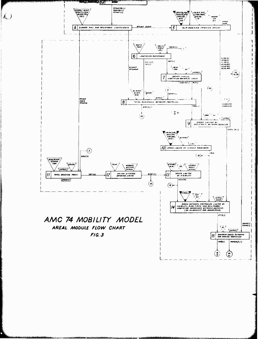
1^ ■ ..mi _ miwf'mwm' m^'^imm^sr^Tss «rowPJ ft)
ftrowr (tj
Summt» PULL Arno ßfSitrAttc* cotfßtctgmrs nrowp oowp
TcßnrwJf .THACTP.AJß/ \cwee« / \ITP /
-5
\iOCOlß,Mfi..
\MVfH€, 9* AM \ r» ist
at
»LIP moBtßitü rmAiiivi ittoHi
Pint /
vtQITAtlON AlSiSrAUCt
\ wimp/
\mcm
'I**.*)
ClMG.ß}
TTftJttMfii^ '•»/««/
prom» OOPf» HTOPm»
rcr^t HtSiSTAMCt mirpftIM 00SfJKt$5 '2 v «r» f«, '«(•«■)
(M) ;;H
. fOHMI (M )
\M0P Ml
,0* (*».lW AMIPP / \ MAU.
. M4MI . ^■AcrpM* \
Y v \"c:
10 9PtS0 IMitfO Br iV**ACt POVtHttttS
I
('.> - -j
rernL maAmm* pomsi
V \*r0*y/
12 PPtVlP OiCTATtQ ppAmtM* timtra
*-} \". \ KfMt / H1PA¥/
m*fm - ~I3 %Pito umirfo »Y v/Sitmrr
0-
AMC 74 MOBILITY MODEL AREAL MODULE FLOW CHART
FIG. 3
14
VtLV(P)
SPUD »*rwHN opsrAcift iimirto BY trtsimmrr, Piot, ftPts AMP aou/stom/ wiiSTATtom ptawAttcr mtrmrre* osirActli
(m> AiLOimAHcr pom MAMmsmmt)
15
rrrfai)
_JZ la
MKßVftJ |
MAMimtm ißt I» mirwtt* Mit AJWMO CMMCitS
t^i) mum»(;i)
L_ © ©
HUHmmmttUiiät** "■'-' ■—■---"■' I - ■-'•■'•"■^■-li'lill ii-«ii»if;--^
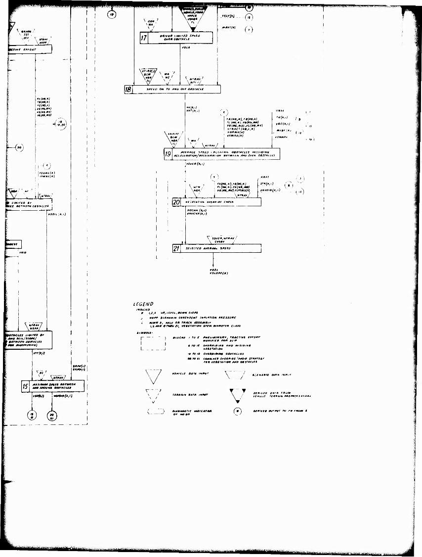
K mm At ■■ \ IST ,
ZTIVf tßßOHT
H")
• »MA*,'*)
p umirto »r wer »trtvrr* ogsTAcita
vson. ;*.ij
&
m*r»ci*s umirto t* 0 CC/L/JIOAT/
1 9§tmtr* OSlTACitS mm MMitrt/miMM)
IS
»"■(■»,«
^ \MntA¥/
MAlimum SMI» 9» rwwftt
I'-tV) CO
<b
18
V \ 0§H
\ * 7
\
V 1/7 o*iyg* umirto smo
O¥tm09STACit
s «7 \ mi 1 \ i
fOlA
w V *r«Vr7 .,i Y"^
^T H,i,v^r,?c^0^WW!IIPiPJff*^" mpt^mpviM •■ w.^.
SßttO Ott TO -•*» (J^^ 0»%TALL£
iHimr ■'
\ nmm/
V- 19
J fAS**,*),'*(**,*!
fOltMt(H) vKmAAi*)
A^ -t_
( s
" ("
AC(.fllAAttQM/e/Ctit*A"0* mtTWtlH AHO OVIH OMSTAll
rove A(M,I}
20 i \*T»Av/
MA »I
rAvoio{*fi) \»)
¥/UfATiott orimmi»! c*rc*
*A*CHH(A.i)
V tQVt*,HTmAv !
21 \ StllcriO A*I*A*. XPtfU
fan vaio*t(n)
LEGEND IMWCItS
1,1,3 vß, i.ivti.lmomm ttOAt
*OA* sctNAmio 0§MM»tmr iMßiAiiQm ßmt$svA£
aiocn s, AAif cm TAACH A»*MA»mir t, t A*O * rum* ft, wvttrAnc* irim *Amgr§m ctAS$
I ' ro jr mmtkimiMAmv, rmAc^-vt ißßonr MOAißir» ro* tvm
i ro if oftmmiPimm AMP A* Oioimt ¥i0trATnm
'• ro i» ort*mim*m omwrMcus
\
\ 7 \ ' \ /
V
( -
vtM'cit OAT» mmuf
ftAmAtm BATA immmr
»CIIABIO OAfA imAi-
\ ' 0I*'*I0 QATA fmoM \ / riMictl iwm*AtM mmtßAO'
0 MAivt» OVTAVI rv nm fmom $
mtmummmcti ttmmnäimttt ^ - ..-mmlmt
^^W! mmm\ ■ ■' -■"■ l iiw)iiii!w-jwPii«w"i,.i^1Mi,li.«,p.m«i. IIII-M-^-'.«'.''^^»---'^''-^ —'—■■ nwrnaiwiu^Miiwn
Am» MMMMMfb. MMHHMMM
u
AREAL MODULE
SCENARIO VARIABLES
AND
ROUTINE SPECIFICATIONS
IV-7
■.^.■■■■.... .^.^w...^..^ ■■■ -^■;...;.1.:..,-.I.^.^^J...
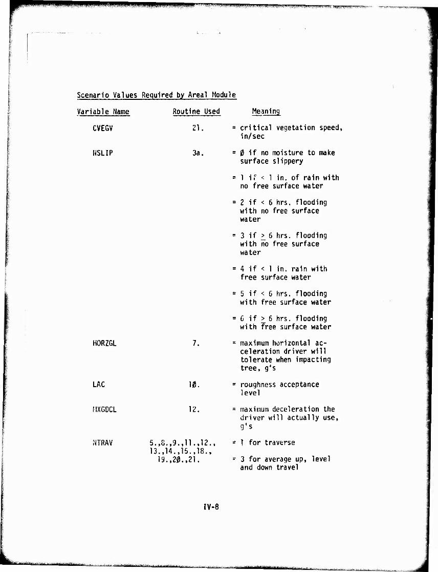
^^^WWW^^^WWWWBPWWWWWWimp! iinupiiiiii» I.II..I ..^.,^, i..- .,,,,„...,r.,,>r,,,,w..,lw,l-,,^frj1Tr.- •■mmp|n TnrirpiiUHi'.MHy^BFiu'q
1 .
Scenario Values Required by Areal Module
Variable Name
CVEGV
[(SLIP
HORZGL
LAC
MXGDCL
MTRAV
Routine Used
21.
3a.
7.
12,
5.,8.,9.,11.,12., 13.,14.,15.,18.,
19.,20.,21.
Meaning
= critical vegetation speed, in/sec
= 0 if no moisture to make surface slippery
= 1 i r < 1 in. of rain with no free surface water
= 2 if < 6 hrs. flooding with no free surface water
= 3 if ^ 6 hrs. flooding with no free surface water
= 4 if < 1 in. rain with free surface water
= 5 if < 6 hrs. flooding with free surface water
=6 if > 6 hrs. flooding with free surface water
= maximum horizontal ac- celeration driver will tolerate when impacting tree, g's
= roughness acceptance level
= maximum deceleration the driver will actually use, g's
- 1 for traverse
- 3 for average up, level and down travel
IV-8
-HiMrä-iiMrV - ■■ :- ■,.'^..-. J-^^^... . -.^.^,^.1 ■'■~- —-im ii.- ■ÜÜMl iir i i1
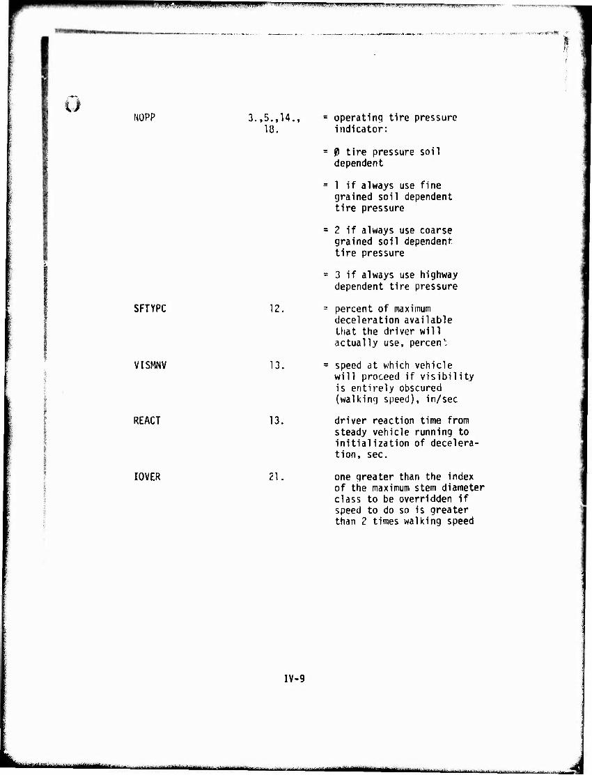
UlllMIWi«! ^|^|||p|^pp^i|^yJi||,^w.^ll^■l.l,ww^ ivrtxwrvtmK'l 'fim p •jrprr'-i\ir^
Ü NOPP 3.,5.,14.,
18.
SFTYPC 12,
VISMNV
REACT
13.
13.
I0VER 21
operating tire pressure indicator:
0 tire pressure soil dependent
1 if always use fine grained soil dependent tire pressure
2 if always use coarse grained soil dependent tire pressure
3 if always use highway dependent tire pressure
percent of maximum deceleration available that the driver will actually use, percen'
speed at which vehicle will proceed if visibility is entirely obscured (walking speed), in/sec
driver reaction time from steady vehicle running to initialization of decelera- tion, sec.
one greater than the index of the maximum stem diameter class to be overridden if speed to do so is greater than 2 times walking speed
IV-9
Mämmmtmttimiliitilk a^timim »MiMHMIMiM itMtM^MMrft., -i- ,r ■ * ■■ ^Ma ■, . . ^..1.|i„..^..... ^>^i-,.■„■,- -d
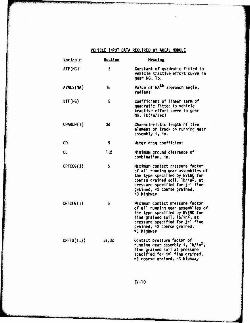
mrnrn ^^m^mma .1 mmmmm mm I fl lpT.,*i|(fli,J i n iv>J.iiiyifNif.|g|^^^ IRIPRHn '^,'«
Variable Routine
ATF(NG) 5
AVALS(NA) 16
BTF(NG) 5
CHARLN(I)
CD
CL
CPFCCG(j)
CPFCFG(j)
CPFFG(1,j)
VEHICLE INPUT DATA REQUIRED BY AREAL MODULE
Meaning
Constant of quadratic fitted to vehicle tractive effort curve in gear NG, 1b.
Value of NAth approach angle, radians
Coefficient of linear term of quadratic fitted to vehicle tractive effort curve in gear NG, lb(1n/sec)
Characteristic length of tire element or track on running gear assembly 1, In.
Water drag coefficient
Minimum ground clearance of combination. In.
Maximum contact pressure factor of all running gear assemblies of the type specified by NVEHC for coarse grained soil, Ib/ln^, at pressure specified for jal fine grained, =2 coarse grained, «3 highway
Maximum contact pressure factor of all running gear assemblies of the type specified by NVEHC for fine grained soil, lb/1n2, at pressure specified for j»l fine grained, -Z coarse grained, «3 highway
Contact pressure factor of running gear assembly 1, lb/1nz, fine grained soil at pressure specified for j»l fine grained, ■2 coarse grained, =3 highway
3d
5
1.2
3a, 3c
IV-10
..„v.- -ifraflii^g) •auMMM i—mtutoä tt^matm ta^laiMfci -'mill , j,
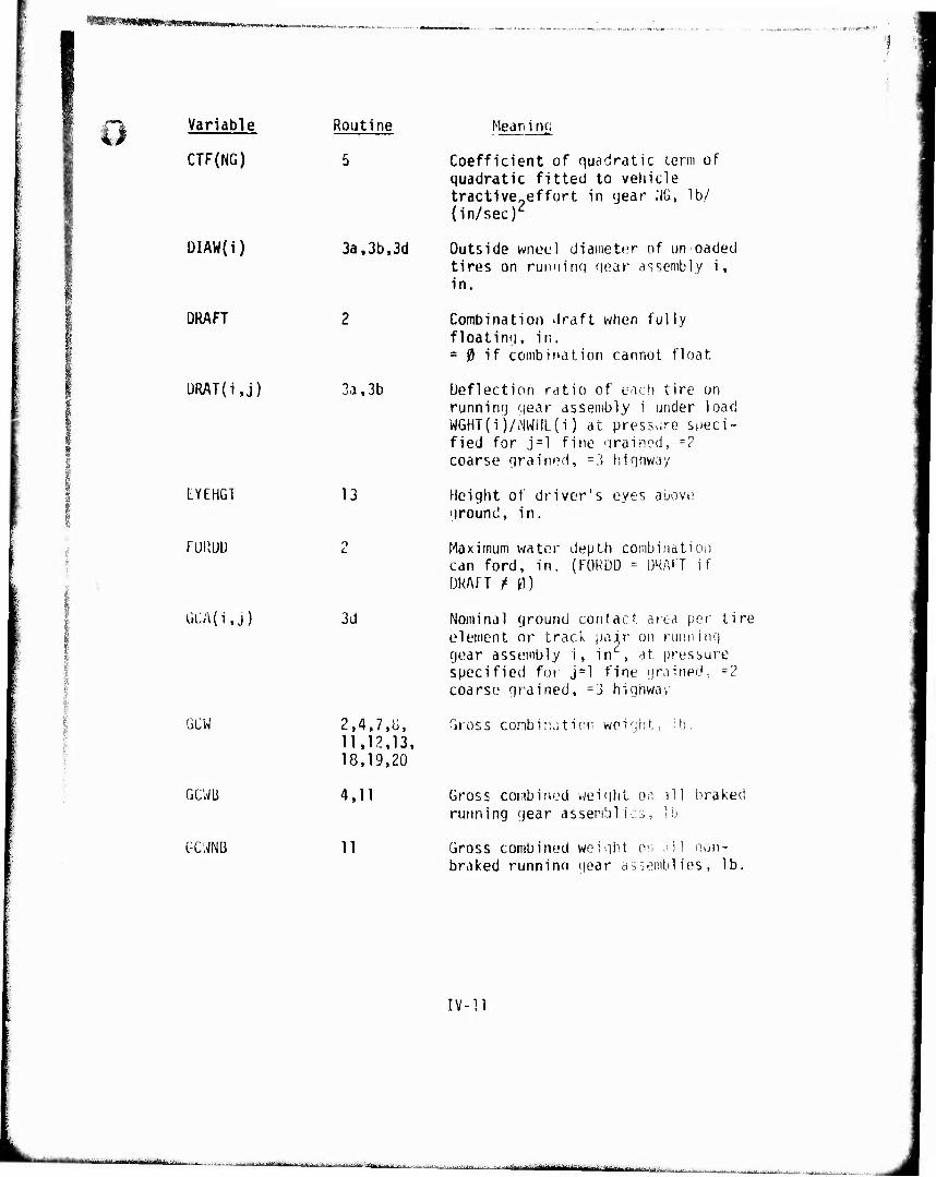
i—W—w
Variable
CTF(NG)
ÜIAW(1)
Routine Mean inn
5 Coefficient of quadratic term of quadratic fitted to vehicle tractive?effurt in year NG, lb/ (in/sec)
3a,3b,3d Outside wneel diameter of unloaded tires on rutminq near assembly i, in.
DRAFT
ÜRAT(i,j) 3a, 3b
Combination .Iraft when fully floatinq, in. = 0 if combination cannot float.
Deflection ratio of each tire on running gear assembly i under load WGHT(i)/NWHL(i) at pressure speci- fied for j=l fine qrainod, -2 coarse qrained, =3 hiqhway
EYEHGT 13 Height of driver's eyes above qround, in.
FUPvUU
GCA(i,j)
GCW
3d
2,4.7.1;. 11,12,13. 18,19,20
Maximum water depth combination can ford, in. (FORDD = DRAFT if DRAFT t 0)
Nominal ground contact area per tire element or track pair on runninq gear assembly i. in , at. pressure specified for j=l fine grained, -? coarse grained, =3 highway
Gross combination weight, lb.
GCWli
GCUNB
4,11
11
Gross combined weight ovi all braked running gear assemblies, lb.
Gross combined weight on dll non- braked runnino gear assemblies, lb.
IV-II
***■—■-^^ •.■•■■
■ nrti* in 1 iliriHiiii MM ■'—■■ --iini ,
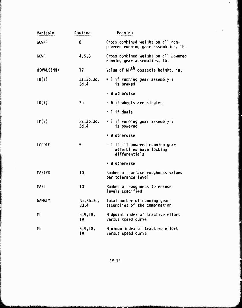
Variable Routine
GCWNP 8
GCWP 4,5.8
HOVALS(NH) 17
IB(i) 3a,3b,3c, 3d,4
ID(i)
IP(i)
LOCOIF
MAXIPR
MAXL
NAMBLY
MU
MN
3b
3a,3b,3c, 3d,4
10
10
3a,3b,3c, 3d,4
5,9,18, 19
5,9,18, 19
Meaning
Gross combined weight on all non- powered running gear assemblies, lb.
Gross combined weight on all powered running gear assemblies, lb.
Value of NHth obstacle height, in.
= 1 if running gear assembly i is braked
= 0 otherwise
= f) if wheels are singles
= 1 if duals
= 1 if running gear assembly i is powered
= 0 otherwise
= 1 if all powered running gear assemblies have locking differentials
= 0 otherwise
Number of surface roughness values per tolerance level
Number of roughness tolerance levels specified
Total number of running gear assemblies of the combination
Midpoint index of tractive effort versus speed curve
Minimum index of tractive effort versus speed curve
!V-12
■---J-- -•■■ ■..-^—■:-,. ! i ntr^M-V "■- ' ' ■■ ■' ■- ■ ■— -■ --^-'—^—«——■ ■--
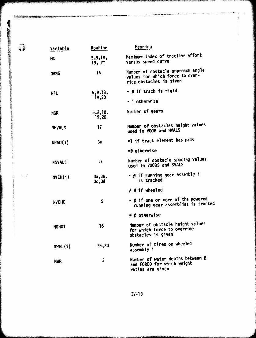
mm^mmmmminm P |ir'ii|!V4lMWJnH'HP«i|W!n«"l|ifip«^!ii:(IM. MmVf'««,.l>lHlW"^ 1 .W' Wl 'J'.nwmiWF»'!"-^"!
5 Vmmwirtommm^m^wmm*™™*' mmmaw **■ .;*■:■ !««w- «MWM ■*• -
Variable
MX
NANG
NVEHC
NOHGT
NWHL(i)
NWR
Routine
5,9,18, 19, 2?
16
NFL 5,9,18, 19,20
NGR 5,9,18, 19.20
NHVALS 17
NPAD(1) 3a
NSVALS 17
NVEH(i) 3a,3b, 3c, 3d
16
3a, 3d
2
Meaning
Maximum Index of tractive effort versus speed curve
Number of obstacle approach angle values for which force to over- ride obstacles Is given
» Mf track Is rigid
« 1 otherwise
Number of gears
Number of obstacles height values used In V00B and HVALS
»1 if track element has pads
a0 otherwise
Number of obstacle spacing values used In V00BS and SVALS
« 0 if running gear assembly 1 Is tracked
M if wheeled
■ 0 If one or more of the powered running gear assemblies is tracked
t t otherwise
Number of obstacle height values for which force to override obstacles Is given
Number of tires on wheeled assembly 1
Number of water depths between 0 and FORDO for which weight ratios are given
IV-13
..-.■ -J.,...,.-.,.,. im ■ r
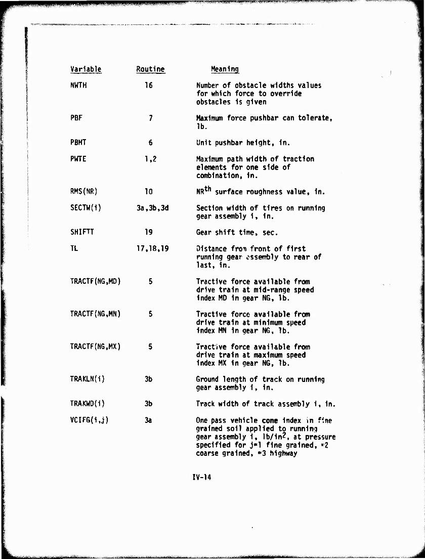
|||j|PPpp"'™"WT^«¥WUl«»,Il^.N-.,'l",l"W^
Variable
NWTH
PBF
Routine
16
PBHT 6
PWTE 1.2
RMS(NR) 10
SECTW(1) 3a,3b,3d
SHIRT 19
TL 17.18.19
TRACTF(NG,MD) 5
TRACTF(NG,MN) 5
TRACTF(NG,MX) 5
TRAKLN(i)
TRAKWD(i)
VCIFG(i.j)
3b
3b
3a
Meaning
Number of obstacle widths values for which force to override obstacles is given
Maximum force pushbar can tolerate, lb.
Unit pushbar height, in.
Maximum path width of traction elements for one side of combination. In.
NRth surface roughness value, in.
Section width of tires on running gear assembly 1, in.
Gear shift time, sec.
Distance fron front of first running gear assembly to rear of last, in.
Tractive force available from drive train at mid-range speed index MO In gear N6, lb.
Tractive force available from drive train at minimum speed index MN In gear NG, lb.
Tractive force available from drive train at maximum speed index MX in gear NG, lb.
Ground length of track on running gear assembly i, in.
Track width of track assembly i, in.
One pass vehicle cone index in fine grained soil applied to running gear assembly 1, lb/in?, at pressure specified for j«l fine grained, »2 coarse grained, «3 highway
IV-14
MMuaan .^.■.,-., J..^..-.^......-.„,-..„JJ^^..^^.^.- .........—;... ■ i ■■■ mm - - ,. i ,1 . r.ii'i- ■•^■• — '~ u!
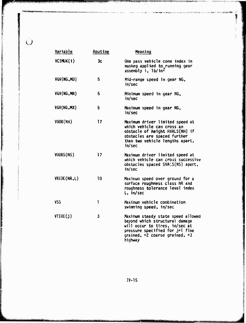
I«ll-I,'"ll rl"l".'i\T)i|ri"V"P',"i"'»,l»ti«..i u».WIIIIII.U.III w»»i'iii»iwi|»wiyTn^-'^t7^^Tn'wwwi|iWfWi)'i,t''l'»,,'w'""'' nmrmiwirpimmrT*
mmmmmtmmm S*^.-*. v^..-» iT^. v«nw«M«MM .i;W'.^NWp.. >^;':V.W!*W-'.^1W ^T
u Variable
VCIMUK(I)
VOOBS(NS)
VRIDE(NR,L)
VSS
VTIRE(j)
Routine
3c
VGV(NGtM0) 5
VGV(NG.MN) 5
VGV(NG,MX) 5
VOOB(NH) 17
17
10
1
3
Meaning
One pass vehicle cone index in muskeg applied to running gear assembly i, lb/in2
Mid-range speed in gear NG, in/sec
Minimum speed in gear NG, in/sec
Maximum speed in gear NG, in/sec
Maximum driver limited speed at which vehicle can cross an obstacle of height HVALS(NH) if obstacles are spaced further than two vehicle lengths apart, in/sec
Maximum driver limited speed at which vehicle can cross successive obstacles spaced SVALS(NS) apart, in/sec
Maximum speed over ground for a surface roughness class NR and roughness tolerance level Index L, in/sec
Maximum vehicle combination swimming speed, in/sec
Maximum steady state speed allowed beyond which structural damage will occur to tires, in/sec at pressure specified for jsl fine grained, =2 coarse grained, «3 highway
IV-15
LJJ^L^
■■IMI>lMtll
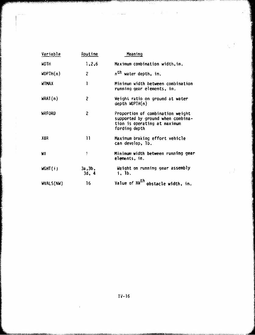
mmmmmmmm i ■■■||pn<nq|ppqgqnp^pp|pa|l||j|l^pgfpi^^i^q|H]IH9|! ««■■»<5iCT.'Hw,"f»iwi«wsi>iiiii;"»-."rT»,r'-" T'(r «n^it,,^»vTJ"v.iTTp™|
Variable Routine
WDTH 1,2,6
WDPTH(n) 2
WTMAX 1
WRAl(n) 2
WRFORD 2
XBR
WI
WGHT(i)
WVALS{NW)
11
3a,3b, 3d, 4
16
Meaning
Maximum combination width,in.
n*-*1 water depth, in.
Minimum width between combination running gear elements, in.
Weight ratio on ground at water depth WDPTH(n)
Proportion of combination weight supported by ground when combina- tion is operating at maximum fording depth
Maximum braking effort vehicle can develop, lb.
Minimum width between running gear elements, in.
Weight on running gear assembly i, lb.
Value of NWth obstacle width, in.
IV-16
^■■■■- -■■■■■■ ■ ■■'- - ■■■■ .,..^.-^..- ■..^. .--.^v,......^. ■, ,.■■. ■ -..^^-^Mjjk^^frjy,^ ...•„.-in ^.i.-!-.^^-........
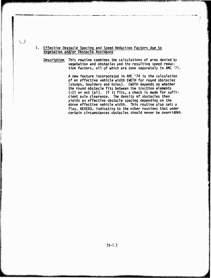
i, ri,ni,.i[m,,mmmtmmwtm*,'>i*«\*m.<Him'**'■<.!• «■"••iw-wmm-'-m w- - ■<m"i*WH mmw**,,™!
MHHBW
\ ;
1. Effective Obstacle Spacing and Speed Reduction Factors due to Vegetation and/or Obstacle Avoidance
Description This routine combines the calculations of area denied by vegetation and obstacles and the resulting speed reduc- tion factors, all of which are done separately in AMC '71.
A new feature incorporated in AMC '74 is the calculation of an effective vehicle width EWDTH for round obstacles (stumps, boulders and holes). EWDTH depends on whether the round obstacle fits between the traction elements (32) or not (al). If it fits, a check is made for suffi- cient axle clearance. The density of obstacles then yields an effective obstacle spacing depending on the above effective vehicle width. This routine also sets a flag, NEVERO, indicating to the other routines that under certain circumstances obstacles should never be overridden.
IV-1.1
ItfWM •fluuuMiiiijaaHl ■ — ■■ ■ ^^^tiittimmiimmmmtitmm ' i
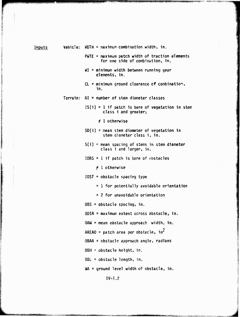
m|p> i Mif^UJ|ifflii|ipi,MBW!wfP^ppiW^^^
Inputs Vehicle: WDTH * maximum combination width, in.
PWTE = maximum patch width of traction elements for one side of combination, in.
WI = minimum width between running gear elements, in.
CL = minimum ground clearance of combination, in.
Terrain: NI = number of stem diameter classes
IS(i) c 1 if patch is bare of vegetation in stem class 1 and greater;
^ 1 otherwise
SD(i) s mean stem diameter of vegetation In stem diameter class 1, in.
S(i) = mean spacing of stems in stem diameter class 1 and larger, in.
I0BS = 1 if patch is bare of obstacles
/ 1 otherwise
I0ST ■ obstacle spacing type
= 1 for potentially avoidable orientation
= 2 for unavoidable orientation
OBS = obstacle spacing, in.
ODIA = maximum extent across obstacle, in.
OAW = mean obstacle approach width, in. 2
AREAO * patch area per obstacle, in
OBAA = obstacle approach angle, radians
OBH = obstacle height, in.
OBL « obstacle length, in.
WA = ground level width of obstacle, in.
IV-1.2
--•-■ -■ ■■■■■-^■■-■-^ ■■■>.. i ■ ■ ■ iiiiil|-iii^--,-'j-- -- l-ijtuiil-»Ki*iJJ«.«ijü.^_;
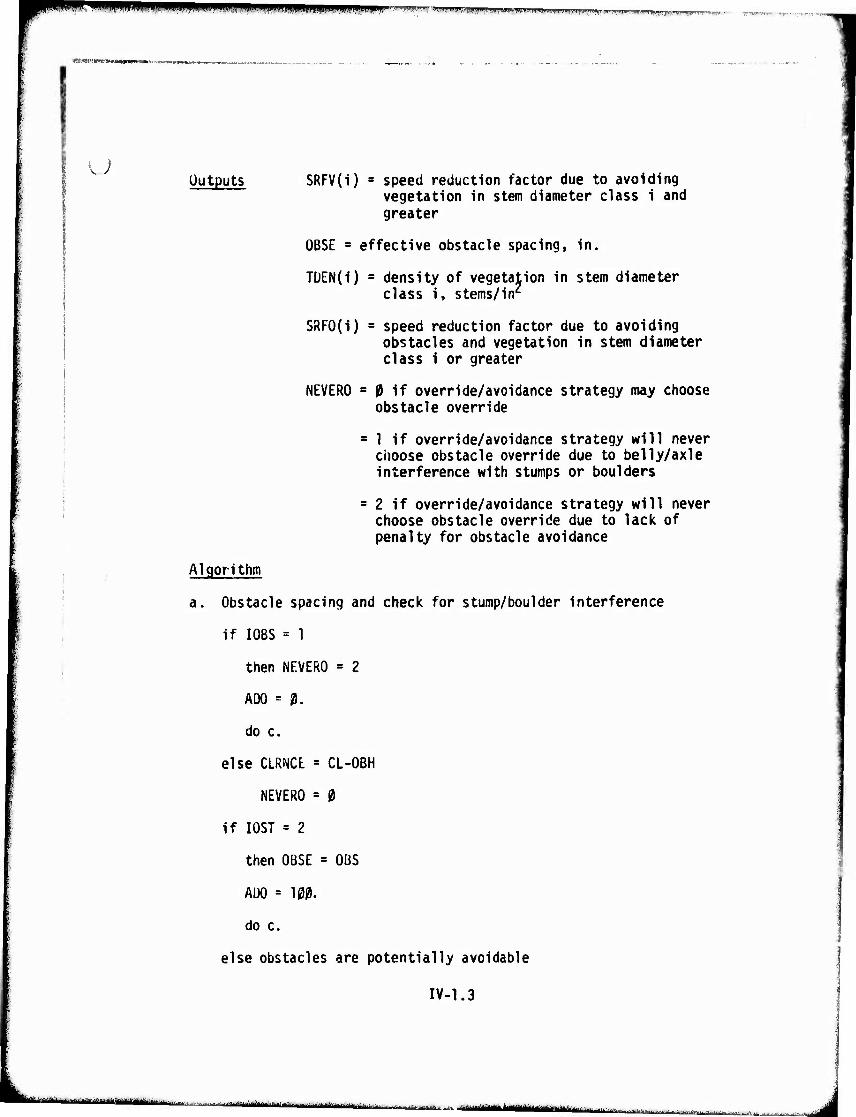
11 i mm «nil« mm*m*m vnmpagnffi Ft-iWf» i DJ III ;ii F»") -T
u Outputs SRFV(i) = speed reduction factor due to avoiding
vegetation in stem diameter class i and greater
OBSE - effective obstacle spacing, in.
TÜEN(i) s density of vegetation in stem diameter class i, stems/in2
SRFO(i) = speed reduction factor due to avoiding obstacles and vegetation in stem diameter class i or greater
NEVERO = Mf override/avoidance strategy may choose obstacle override
= 1 if override/avoidance strategy will never choose obstacle override due to belly/axle interference with stumps or boulders
= 2 if override/avoidance strategy will never choose obstacle override due to lack of penalty for obstacle avoidance
Algorithm
a. Obstacle spacing and check for stump/boulder interference
if I0BS = 1
then NEVERO = 2
ADO = ^.
do c.
else CLRNCt = CL-OBH
NEVERO = 0
if I0ST = 2
then OBSE = OBS
ADO = 100.
do c.
else obstacles are potentially avoidable
IV-1.3
tMtmtm **■■"•'■ „ra-M.i.'....«.-»...,...;..;,..,. HH ,.... ym^ | .,. .....J.,JL..,:. . |. jjgjjj^gmgg MMiaBiMfc ^- :...--..I.^..;....., |
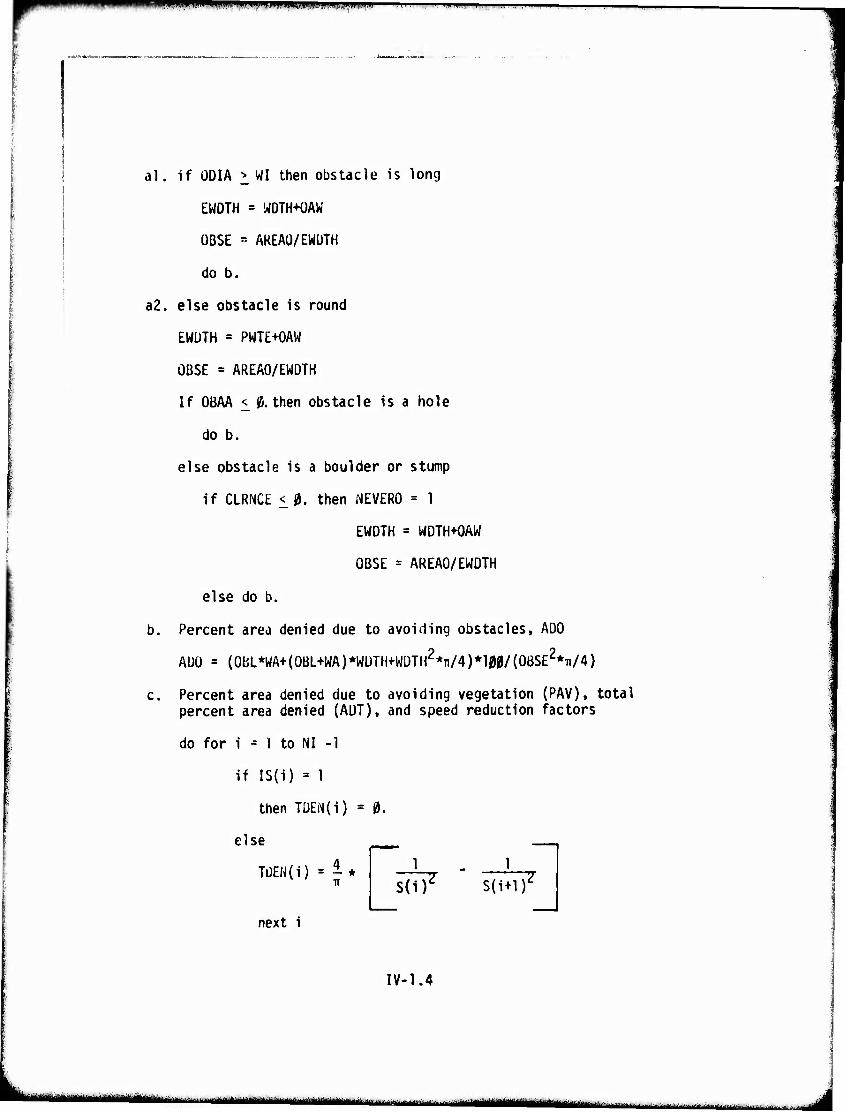
Uiipjiliiiuiu.ii. wwimmmi F- ^^^^^-^^^-^—
al, if ÜDIA > WI then obstacle is long
EWDTH = WDTH+OAW
OBSE - AREAÜ/EWÜTH
do b.
a2. else obstacle is round
EWUTH = PWTE+OAW
OBSE = AREAO/EWDTH
If OBAA < (5. then obstacle is a hole
do b.
else obstacle is a boulder or stump
if CLRNCE <,0. then NEVERO = 1
EWDTH = WDTH+OAW
OBSE = AREAO/EWDTH
else do b.
b. Percent area denied due to avoiding obstacles, ADO
ADO = (0bL*WA+(0BL+WA)*WDTH+WÜTH2*Ti/4)*lM/{0BSE2*Ti/4)
c. Percent area denied due to avoiding vegetation (PAV), total percent area denied (ADT), and speed reduction factors
do for i ^ 1 to NI -1
if IS(i) = 1
then TDEN(i) = 0.
else _
TDEN(i) = ^* 7T
next i
S(i)' s(i+ir
IV-1.4
- -— :- ■iiV 1 ^MMMMMMMM ttiamm—■ -•-^■"■iiirdim
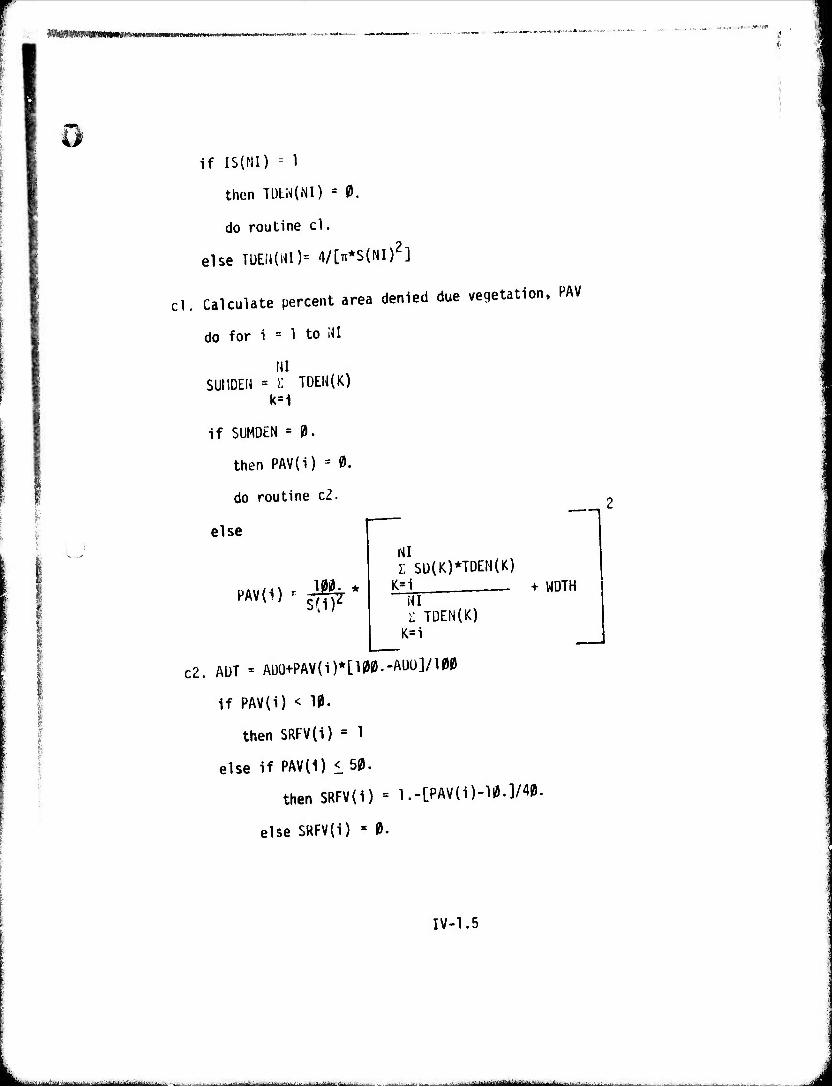
V?m'immmmm!">'m*m*m*tim*m<,*r**™
if IS(NI) - 1
then Tl)tN(NI) = 0.
do routine cl.
else TüEtUUI)= 4/[Tr*S(NI)2]
cl. Calculate percent area denied due vegetation, PAV
do for i = 1 to MI
\n SUI1DEW = ): TDEN(K)
k=1
if SUMDEN ' 0.
then PAV(i) = 0.
do routine c2.
else
m PAV(i) ^ ^
l Sü(K)*TDEN(K) K=i
m Z TDEN{K)
K=i
+ WDTH
c2. AüT = ADO+PAV(i)*[100.-AUü]/100
if PAV(i) < 10.
then SRFV(i) = 1
else if PAV(1) < 50.
thenSRFV(i) = l.-[PAV(i)-ll9.]/^
else SRFV(i) ' 0.
IV-1.5
^.„..■^.■^..y^^,:......., -.^^^^l^.^-.-l , ■ ■ . .. ^■.^.-.-^.iM^|rt.v.
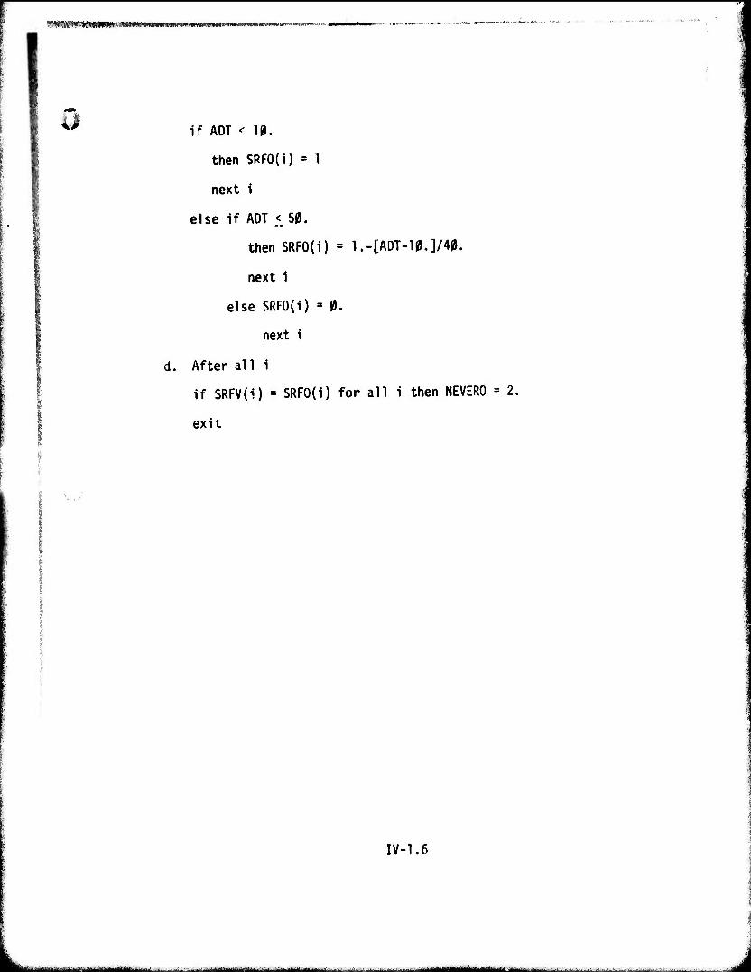
WKKtHNKBtKKMBBtBttBmmtammmmmmamtmmmmmmmanmmm Mu 11 «■
0
d.
if ADT < 10.
then SRFO(i) » 1
next i
else if ADT < 50.
then SRFO(i) = l.-[ADT-10.]/40.
next i
else SRFO(i) - 0.
next i
After al 1 i
if SRFV(i) ' SRFO(i) for all i then NEVERO
exit
IV-1.6
M—llll ---■' ^—■■' r uNi^iiMIMiyinhfrilrliii
2. Land/Marsh Operating Factors
Description This routine calculates the weight reduction factors [WRATIO] and the frontal area under water and water speed in a marsh as defined by maneuvering requirements. The weight reduction factors are calculated in (bl.) and (b2.) from the actual water depth (WD) and the known ratios given for various submerged depths (WDPTH{n)) of the vehicle. The weight reduction factor modifies the traction in subsequent submodels. The frontal area is used for calculating drag which ^Iso modifies traction. A return to the control module may take place if the vehicle is not a swimmer and the water is too deep to ford. If the vehicle is fully floating, the water speed is reduced by t\ e vegetation man- euvering factor calculated in 1. and an exit is made to the control module. If there is no water, the factors are set to values which eliminate water effects frT subsequent routines.
This routine tests the soil type and transfers control to the appropriate pull and resistance coefficient routine.
This routine replaces a section of MAIN and all of MARSH in AMC '71.
IV-?.1
•-mmiMrBi i i iil>Bhh»inTiiiwimilMMaiii-iiiiii' ■ .-^ .---.. . ...-^
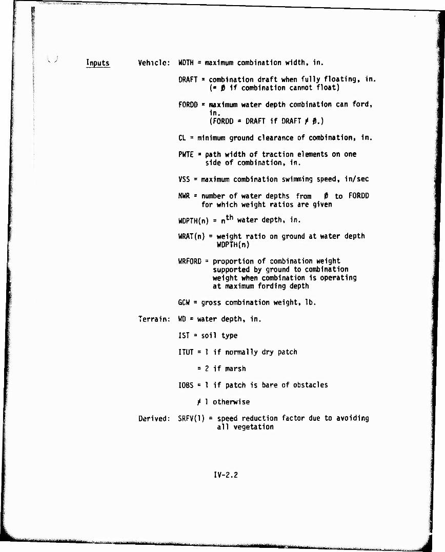
i j v x inputs Vehicle: WDTH = maximum combination width, in.
DRAFT • combination draft when fully floating, in. (■ 0 if combination cannot float)
FORDO s maximum water depth combination can ford, in. (FORDO = DRAFT if DRAFT M.)
CL - minimum ground clearance of combination, in.
PWTE ■ path width of traction elements on one side of combination, in.
VSS s maximum combination swimming speed, in/sec
NUR » number of water depths from 0 to FORDO for which weight ratios are given
WDPTH(n) = nth water depth, in.
WRAT(n) = weight ratio on ground at water depth WDPTH(n)
WRFORD s proportion of combination weight supported by ground to combination weight when combination Is operating at maximum fording depth
GCW » gross combination weight, lb.
Terrain: WD = water depth, in.
1ST = soil type
ITUT = 1 if normally dry patch
= 2 If marsh
I0BS c 1 if patch is bare of obstacles
^ 1 otherwise
Derived: SRFV(l) - speed reduction factor due to avoiding all vegetation
IV-2.2
"'"*> l lüüiiliiiiii ii ..- .-.■■■...-. -..--g..,.,^ ,. ...,.., ,..
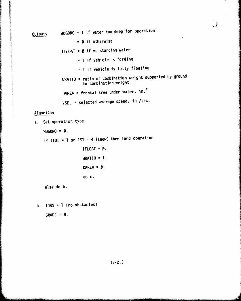
Outputs WDGONO = 1 if water too deep for operation
= 0 if otherwise
ITLOAT » 0 if no standing water
= 1 if vehicle is fording
= 2 if vehicle is fully floating
WRATIO » ratio of combination weight supported by ground to combination weight
DAREA - frontal area under water, in.2
VSEL = selected average speed, in./sec.
Algorithm
a. Set operation type
WDGONO = 0.
if ITUT = 1 or 1ST = 4 (snow) then land operation
I FLOAT - 0.
WRATIO = 1.
DAREA » 0.
do c.
else do b.
b. I0BS = 1 (no obstacles)
GRADE = 0.
IV-2.3
- ■■- m ■■ - i
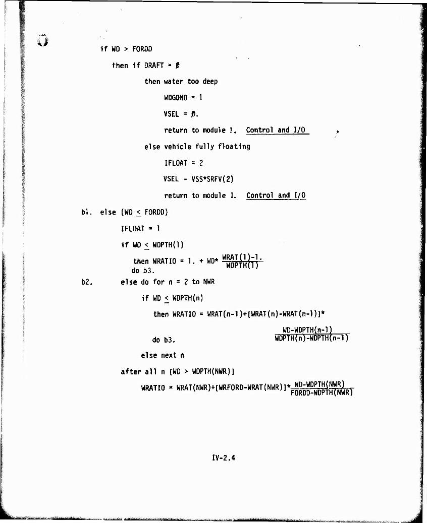
bl
b2.
if WD > FORDD
then if DRAFT = 0
then water too deep
WDGONO = 1
VSEL = D.
return to module I. Control and I/O >
else vehicle fully floating
IFLOAT = 2
VSEL = VSS*SRFV(2)
return to module I. Control and I/O
else (WD < FORDD)
IFLOAT = 1
if WD < WDPTH(l)
then WRATIO- 1.^0*^0^- do o3.
else do for n = 2 to NWR
if WD < WDPTH(n)
then WRATIO * WRAT(n-l)+[WRAT(n)-WRAT(n-l)]*
WD-WDPTH(n-l) WDPTH(n)-WDPTH(n- IT do b3.
else next n
after all n [WD > WDPTH(NWR)]
WRATIO = WMT(NWR)+[WRFORD-W(WT(NWR)]*^Qlg2^NWR)
IV-2.4
tm mt^£.ämm -■ ---^.--..,. . --~-'~^ MMi—niTt ir-
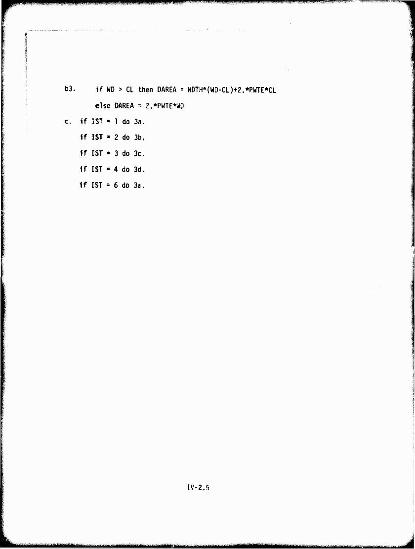
mm&iv^mmm^imi»" •• .IWIW.» mm...,.*w,„m ,mi.lv,* f„^mm mmpM»*- ..w^-f.-.■.......
b3. If WD > CL then DAREA = WDTH*(WD-CL)+2.*PWTE*CL
else DAREA = 2.*PWTE*WD
c. If 1ST = 1 do 3a.
If 1ST « 2 do 3b.
If 1ST » 3 do 3c.
If 1ST « 4 do 3d.
If 1ST « 6 do 3a.
IV-2.5
1
-■^...„^„..^-■^M^^..^, „.■■,,.-..,■ ü .^..v ..-...^^^^^^aMyiiiaai^^ .... ...^ . ... .
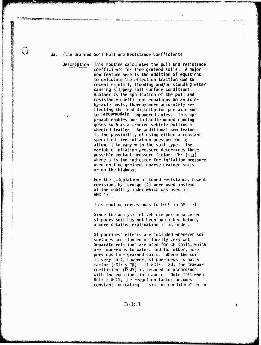
PW^ p ' ' l'»w»WIWiWIIWIWwwwi'PiwwMWl''»"wpp'i»»^i'i mm i; upwpiwiiHpp
k.**WSWl •*fa»"*AmI *•<'•■ m*>*M*Mrt«iiJlK.t»».'«•• unw«. ..,
3a. Fine Grained Soil Pull and Resistance Coefficients
Description This routine calculates the pull and resistance "" - - coefficients for fine grained soils. A major
new feature here Is the addition of equatirns to calculate the effect on traction due to recent rainfall, flooding and/or standing water causing slippery soil surface conditions. Another is the application of the pull and resistance coefficient equations on an axle- by-axle basis, thereby more accurately re- flecting the load distribution per axle and to accommodate unpowered axles. This ap- proach enables one to handle mixed running gears such as a tracked vehicle pulling a wheeled trailer. An additional new feature is the possibility of using either a constant specified tire inflation pressure or to allow it to vary with the soil type. The variable inflation pressure determines three possible contact pressure factors CPF (i,j) where j is the indicator for Inflation pressure used OP fine grained, coarse grained soils or on the highway.
For the calculation of towed resistance, recent revisions by Turnage (4) were used instead of the mobility index which was used in AMC '71.
This routine corresponds to FOIL in AMC '71.
Since the analysis of vehicle performance on slippery soil has not been published before, a more detailed explanation is in order.
Slipperiness surfaces are Separate re la are imperviou pervious fine is very soft, factor (RCIX coefficient ( with the equa RCIX > RCIS, constant indi
effects are included whenever soil flooded or locally very wet. tions are used for CH soils, which s to water, and for other, more grained soils. Where the soil however, slipperiness is not a
<_ 29). If RCIX > 20, the drawbar DOWS) is reduced in accordance tions in b and c. Note that when the reduction factor becomes eating a "skating condition" on an
IV-3a.l
mmmmm - ---■ - iäimijMtmmimiim tlMM mutm mm ^-•■■- •■ '-'■"
^mmt* mm mm i.nmt ■iiPWpii,»it.mi!iwiiiiii.iliiii,iniTPi,,iniip.mp-
fitmwwj*"!'«''* ■
extremely hard surface. The routine also takes into account the presence or absence of track pads (NPAD = 1 or NPAD = 0).
An additional factor is included in the analysis for tires (see paragraph c). This is DRAT(i,j) which accounts for the beneficial effect of high inflation pressure, which helps to main- tain the "circular" shape of the tire and thereby improves the tire's ability to break through the slippery layer.
.)
IV-3a.2
aämmmä mmmuam t .- nagggmMMaiBMiMiMiiitlMt iMIUiMilia.-nT.ni - ■liil t m ' .M, , >, mmümmamm •-■ n ""■^■^ '■!■■-■-■ -I
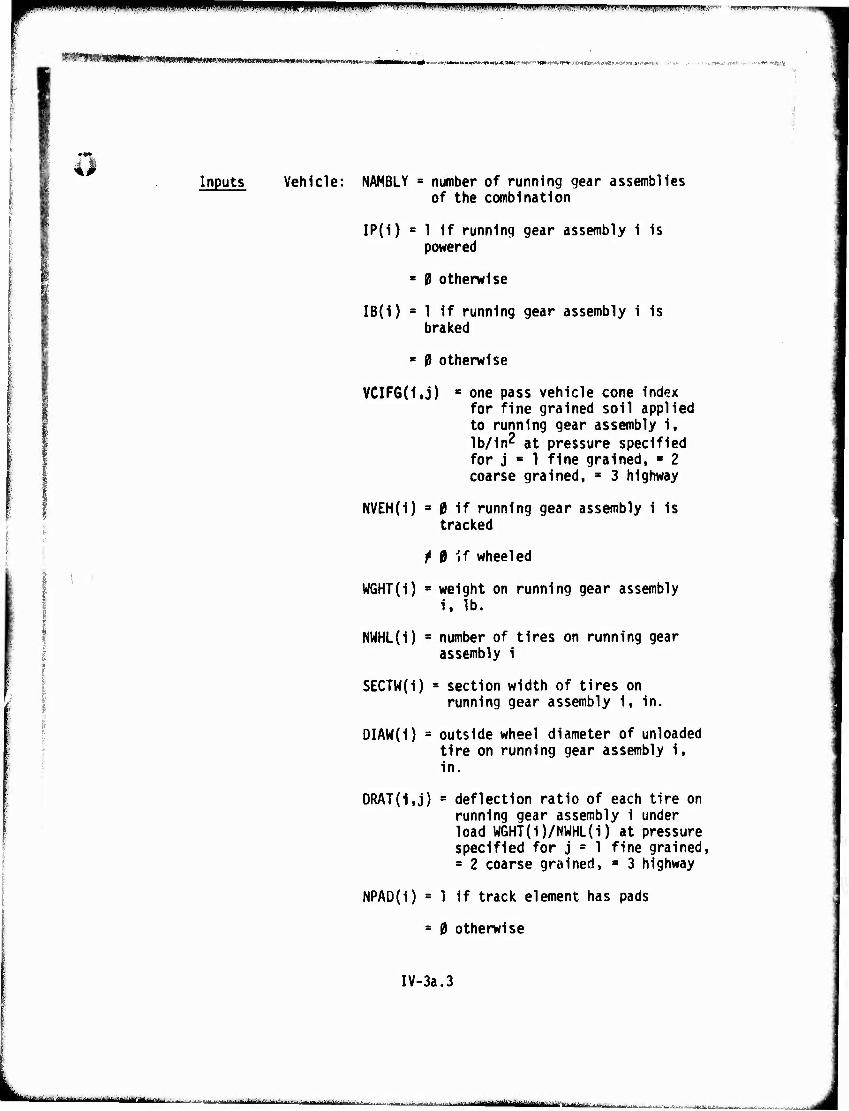
mmmmmmmmm i m9im!rmmii^r^iu\inim-'mnß>mm>rm'^m«mK'm^"i'^ßf\miißf%!'fmm''<fi!n
l%W*WV'mmm*''ymmmm>mm**tiv #'*t:'r*«ttt,w*tp-'*irtwi*. w m■•/i*»t»i'iiMM*w ■^mmiiti.Htf:- «*-"*■ »»*rtAiri»*-„t-/yjOr^^(»'»6*>w^'r?'*»J.*rt<tl:i
Inputs Vehicle: NAMBLY = number of running gear assemblies of the combination
IP(i) = 1 if running gear assembly i is powered
* 9 otherwise
IB(1) = 1 if running gear assembly i is braked
« 0 otherwise
VCIFG{1,j) ■ one pass vehicle cone index for fine grained soil applied to running gear assembly i, Ib/in^ at pressure specified for j « 1 fine grained, ■ 2 coarse grained, « 3 highway
NVEH(i) = 0 if running gear assembly i is tracked
M if wheeled
W6HT(i) ■ weight on running gear assembly i, lb.
NWHL(i) = number of tires on running gear assembly i
SECTW(I) = section width of tires on running gear assembly i, in.
DIAW(i) = outside wheel diameter of unloaded tire on running gear assembly i, in.
DRAT(1,j) = deflection ratio of each tire on running gear assembly i under load WGHT(i)/NWHL(i) at pressure specified for j c 1 fine grained, = 2 coarse grained, s 3 highway
NPAD(i) = 1 if track element has pads
= 0 otherwise
IV-3a.3
•••"^■-^^'-^ÜürMri-iTrii ■ .r^ta.ti itmi HäU BfflBfl ro '! iitoi*iüi vjja*^.-^
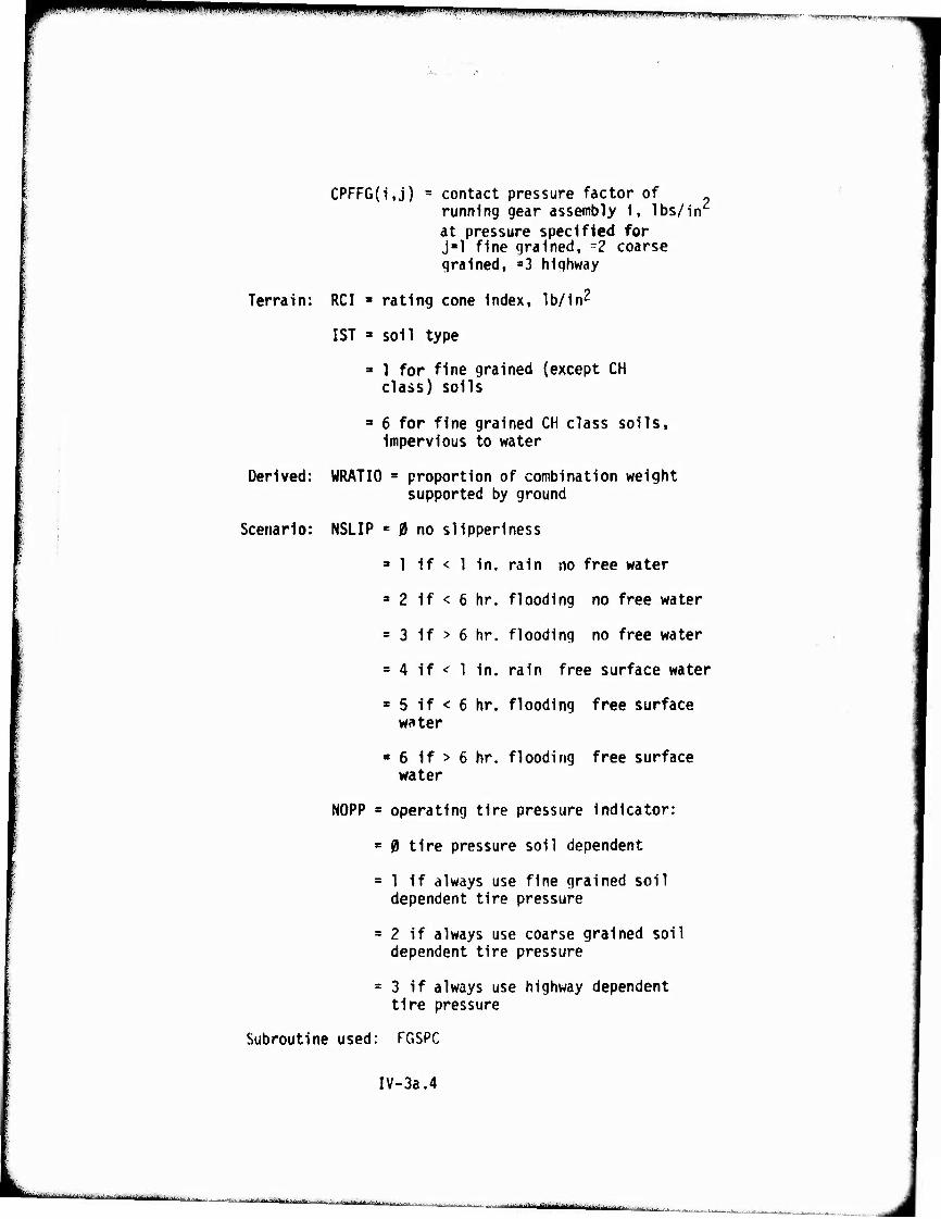
mrm l^li'-WWWilJlllinipiljjpypjiJii, i .Nu inii igpmn^i! in ,»mjm jnmmtmupm ■' ■■««jBWiflw^r'riiii'fciin^i^fjrrcn^
CPFFG(i,j) = contact pressure factor of running gear assembly 1, lbs/in at pressure specified for j-1 fine grained, =2 coarse grained, »3 highway
Terrain: RCI ■ rating cone Index, lb/In2
1ST » soil type
- 1 for fine grained (except CH class) soils
3 6 for fine grained CH class soils, impervious to water
Derived: WRATIO s proportion of combination weight supported by ground
Scenario: NSLIP = 0 no sllpperiness
3 1 if < 1 In. rain no free water
3 2 if < 6 hr. flooding no free water
= 3 if > 6 hr. flooding no free water
= 4 if < 1 in. rain free surface water
3 5 if < 6 hr. flooding free surface water
3 6 if > 6 hr. flooding free surface water
NOPP 3 operating tire pressure Indicator:
= 0 tire pressure soil dependent
= 1 if always use fine grained soil dependent tire pressure
3 2 if always use coarse grained soil dependent tire pressure
= 3 if always use highway dependent tire pressure
Subroutine used: FGSPC
IV-3a.4
■a i .^. ....-■.•■£.-..;-...J.. .-„■■^y, |J iMa&haMt m.,.«. mamtmmmm
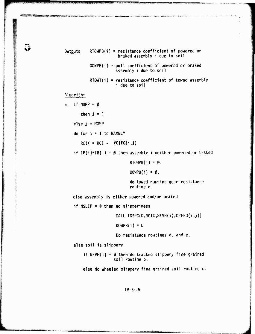
pi;pMWWWiWPPPWipww^WPllPw'^' i""1^ fii"'nmmmwm*m«»wmi»™™nw«*m"* wwgwwir -
VMMMNMMM) '.nOIViAfT.f "-Md'X/"" ^f«iii<oitv mi iniiiiMfimaTiMiiniii .■■*■■?*'■■:■-■'" ■ < •••«<.-"
[> Outputs RTOWPB(i) = resistance coefficient of powered or ^ braked assembly i due to soil
DOWPB(i) = pull coefficient of powered or braked assembly i due to soil
RTOWT(i) = resistance coefficient of towed assembly 1 due to soil
Algorithm
a. If NOPP = 0
then j = 1
else j = NOPP
do for i = 1 to NAMBLY
RCIX = RCI - VCIFG(i,j)
if IP(i)J-IB(i) = 0 then assembly i neither powered or braked
RTOWPB(i) = 0.
DOWPB(i) = 0.
do towed runninq gear resistance routine e.
else assembly Is either powered and/or braked
if NSLIP = 0 then no slipperiness
CALL FGSPC(D,RCIX,NEVH(i),CPFFG(i,j))
DOWPB(i) = D
Do resistance routines d. and e.
else soil is slippery
if NEVH(i) = 0 then do tracked slippery fine grained soil routine b.
else do wheeled slippery fine grained soil routine c.
IV-3a.5
■ ■— yttimma ■■ ■■■ ^.^. ^..^ ^. ,..■.... ^MtmäUmtäiimmmL
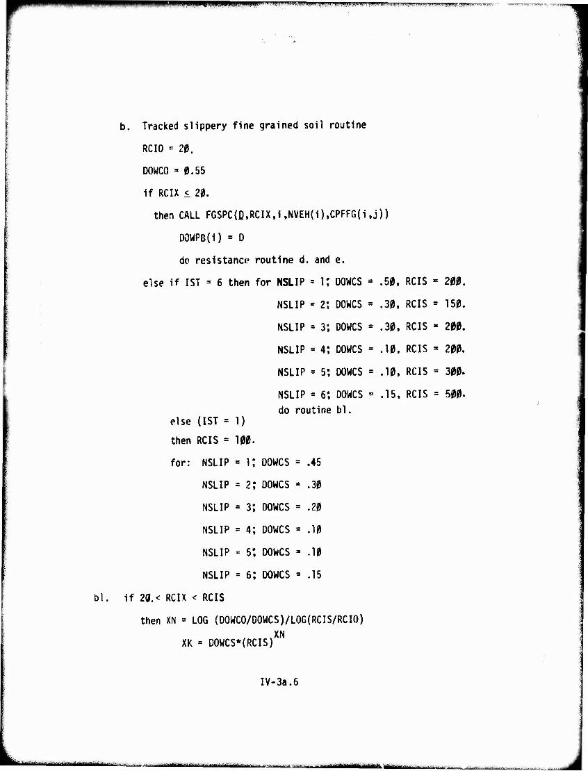
■■■ 11 nPMHmpmpRnpmm*"
bl
b. Tracked slippery fine grained soil routine
RCIO = 20.
DOWCO »0.55
if RCIX < 20.
then CALL F6SPC{D,RCIXti ,NVEH(i),CPFFG(i,j))
DOWPB(i) = D
do resistance routine d. and e.
else if 1ST = 6 then for NSLIP = K DOWCS = .50, RCIS
NSLIP = 2; DOWCS = .30, RCIS
NSLIP = 3; DOWCS = .30, RCIS
NSLIP = 4*. DOWCS = .10, RCIS
NSLIP = 5; DOWCS = .10. RCIS
NSLIP = 6», DOWCS = .15, RCIS
do routine bl. else (1ST = 1)
then RCIS = 100.
for: NSLIP = It DOWCS = .45
NSLIP = 2: DOWCS = .30
NSLIP = 3; DOWCS = .20
NSLIP = 4; DOWCS = .10
NSLIP = 5: DOWCS = .10
NSLIP = 6; DOWCS = .15
if 2g(.< RCIX < RCIS
then XN = LOG (DOWCO/DOWCS)/LOG(RCIS/RCIO)
XN XK = DOWCS*(RCIS)
IV-3a.6
200.
150.
200.
200.
300.
500.
■„--.^-^ .................,, ..■.■|i,|-||M-r||i|H [„in | ■ - mm mum ..*-*.^~.. A
üPPPWPiPWW l ' ' f^w*vF^^rmv~*im7wrrr*p*mi*^^
HHRHKIMHMWMHMWMNRnRnHMMHBMM^ «.A i'-1 niHmWHitii ^flMVHWM •i«hi#'.ii»-(ÄTWP»'■* [fcJ"M*. k ^'.^■.■■.■«•n .wyrH'i-- ■■*■'> ■'
DOWS =• XK*(^-)XN
1f NPAD = 1
then DOWPB(i) = DOWS
do resistance routines d. and e.
else CALL FGSPC(D,RCIX,NVEH(1),CPFFG(i,j))
DOWPB(i) = .5*(D+D0WS)
do resistance routines d. and e.
else (RCIX > RCIS)
if NPAD = 1 then DOWPB(l) = DOWCS
do resistance routines d. and e,
else CALL FGSPC(p,RCIX,NVEH(i),CPFFG(1 ,j))
DOWPB(i) = .5*(D+D0WS)
do resistance routines d. and e.
c. Wheeled slippery fine grained soil routine
XKDELT = DRAT(1,j)/M-0.375
RCIO =18.
DOWCO =0.4
if RC!X < 20,
then RCIX = RCIX-2.
CALL FGSPC(0,RCIX,NVEH(i),CPFFG(i,j))
DOWPB(i) ' D
do resistance routines d. and e.
IV-3a.7
MjiaMiMMMMfl ' i i ^^naujyyj - -- - inn
^WWI|P^W^WW^W^^"^WW^|p 11 ■lllll. I .»111- 7».-c-^i-, ^» .IHII.I.IUP, HI...,I i III,)I.,,,.,,|.^ ai..,iii.
else (RCIX - Z&)
if 1ST = 6 then for:
NSLIP = I,' DOWCS = .35, RCIS = 300
NSLIP = 2; DOWCS = .25 +XKDELT, RCIS = 150.
NSLIP = 3; DOWCS = .20 +XKDELT, RCIS = 200.
NSLIP = 4; DOWCS = .15 +XKDELT, RCIS = 150.
NSLIP = 5; DOWCS = .15 +XKDELT, RCIS = 150.
NSLIP = 6: DOWCS = .15, RCIS = 100.
do routine cl.
else {1ST = 1)
RCIS = 80.
for : NSLIP jM or ^ 4; DOWCS = 0.10
NSLIP = l; DOWCS = 0.30
NSLIP = 4; DOWCS = 0.10 + XKDELT
cl. if 20.< RCIX < RCIS
then XN - LÜG(DOWCO/DOWCS)/LOG(RCIS/RCIO)
XK = DOWCS*(RCIS)XN
DOWPli(i) = XK*(1./RCIX)XN
do resistance routines d. and e.
else (RCIX > RCIS)
üOWPB(i) = DOWCS
do resistance routines d. and e.
d. Powered running gear resistance
if NVEH(i) = 0 then assei.ibly is tracked
if RCIX i A.
IV-3a.8
ruu rvttumhmiimMkäm^^^Mi^MiiMt^,^^.,. . .-...., n^jajfjl
mmmrm^mm**mm mmm^mmm,mmrm^Tm^'w Tf^iTWr^"-™™w*^.-*ir*rr,r*ww-w™'W'v^ i-^r-"
qMMWMMMMlBMIWIHMMM
u
.035+.861/(RCIX+3.249)
e.
then RTOWPB(i) » .045+2.3075/(RCIX+6.5)
else if CPFFG(i,j) < 4.
then RTOWPB(i) • .4-.072*RCIX
do routine e.
else (CPFFG{i,j) >0
RTOWPB(i) » .4-.052*RCIX
do routine e.
else assembly is wheeled
if RCIX > 0.
then if CPFFG(i,j) < 4.
then RTOWPB(i)
do routine e.
else KCPFFG(1,j) > 4.)
RTOWPB(i) = .045+2.3075/(RCIX+6.5)
do routine e.
else (RCIX < 0.)
if CPFFG(i,j) < 4.
then RTOWPB(i) = .3-.043*RCIX
do routine e.
else RTOWPB(i) « .4-.029*RCIX
Towed running gear routine
if IB(i) and IP(i) f 0 then assembly is never towed
RTOWT(i) = 0.
next assembly i
1
IV-3a.9
....■-- - mail ■-■ -^-^Mto-^^^-,.-^ IM ..^:...^ ...... :.....,......
else If NVEH{1) f 0 (running gear is a wheeled axle)
then WPW «= WGHT(1)*WRATI0/NWHL(1)
BETA RCI*SECTW(1)*DIAW(i)*DRAT(i J)1/2
WpW*ri \ 2 SEdTWjIK WKW Ll- 2.*DIAW(1)J
If BETA < 2.
then RTOWT(I) = 1. - .3412*ilETA
next assembly i
else RTOWT(I) = .04 + .2/[BETA-1.35]
next assembly i
else running gear assembly is a left/right pair of track elements - set error flag since towed or unbraked tracked assemblies not included in this model. Return to Module I. Control and J/0,
IV-3a.lO
.11,,-- ■ - ..^^-tLj.' , r i ,, ,.,—^i _m^m*m*mmmm 1
1^fiS'>>mmmiimw»mnm!*w^wsinr:i'-*Miu™
Fine Grained Soil Pull Coefficient Subroutine
Description Subroutine FGSPC calculates the pull coefficient (traction/weight) in a fine grained soil. The computations are the same as in FOIL in AMC '71 with the exception that the excess RCI (RCIX) is allowed to be less than zero, the reason for this is to accommodate unpowered (but.braked) axles.
IV-FGSPC.l
■ ■ ■■ ._—^-„— •tafeatiBUaUiiiBMfe.Mtf^aHMia
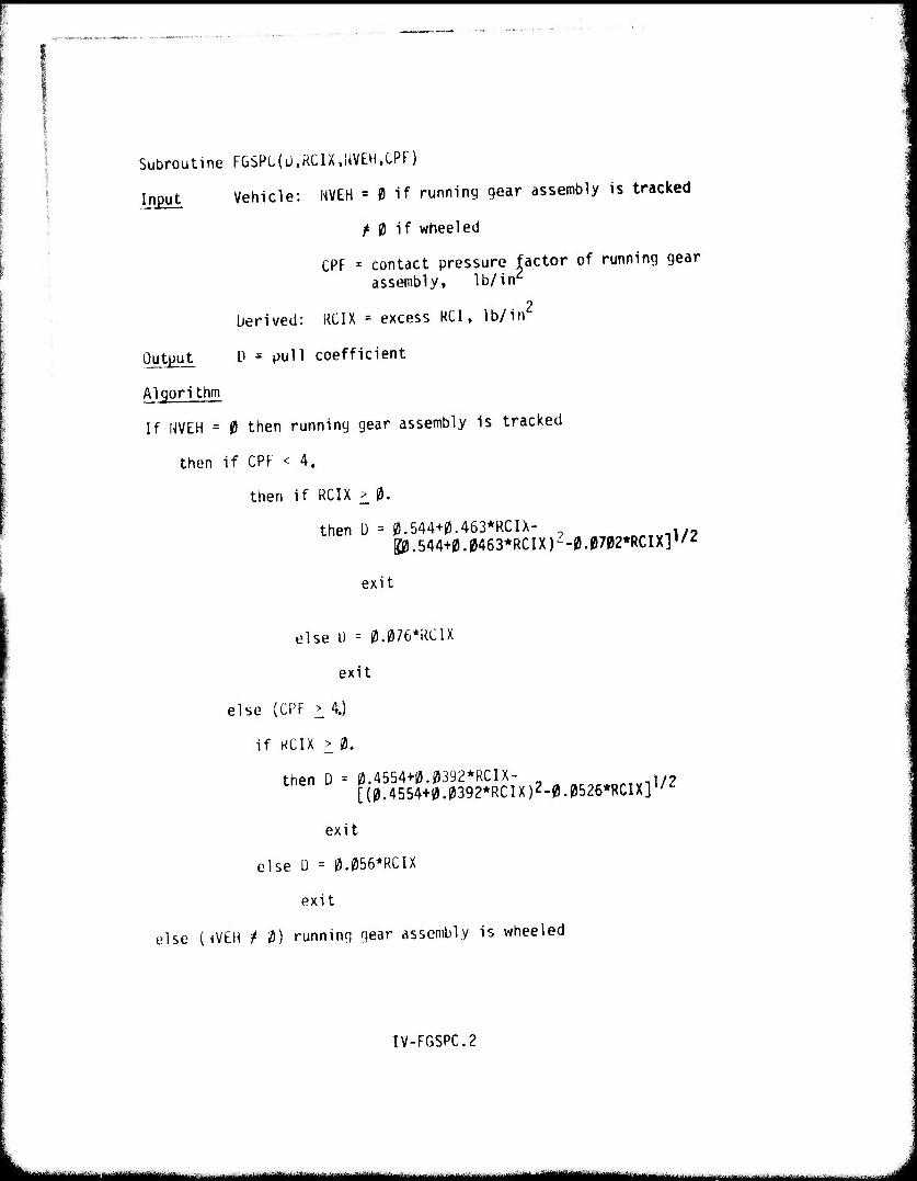
Subroutine FGSPL(ü,RCIX,NVEH,CPF)
Input Vehicle: NVEH = 0 if running gear assembly is tracked
^ 0 if wheeled
CPF = contact pressure factor of running gear assembly, lb/in2
berived: RCIX = excess RCI, lb/in2
Output D = pull coefficient
Algorithm
If H\IIH = 0 then running gear assembly is tracked
then if CPF < 4.
then if RCIX > 0.
then D = 0.544+0.463*RCIX- K0.544+0.0463*RCIX)2-0.0702*RCIXl1/2
exit
else I) = 0.076*RC1X
exit
else (CPF > 4.)
if KCIX > 0.
then D = 0.4554+0.0392*RCIX- . .- [(0.4554+0.0392*RCIX)2-0.0526*RCIX]l/Z
exit
else Ü = 0.056*RCIX
exit
else {^VEH / 0) running gear assembly is wheeled
IV-FGSPC.2
Ml—I -- ^*— III
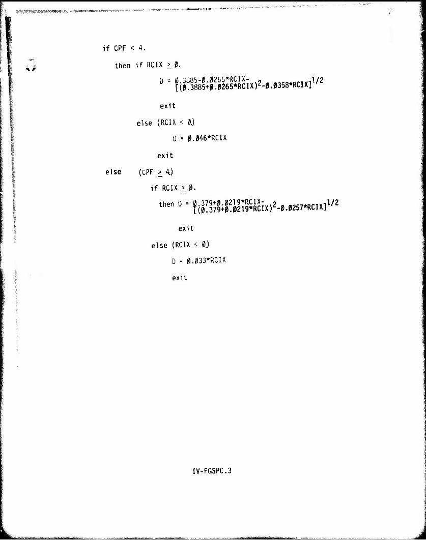
IMStRMHHMMMMMMM »^«-«iin»iwi»«Brwww"*WB«s«.»«-«m'<'>™''»
<>
if CPF < 4.
then If RCIX > 0.
[(0.3885+0.0265*RCIX)'-0.p358*RCIX],/^
exit
else (RCIX < 0.)
U = M46*RCIX
exit
else (CPF > 4.)
if RCIX > 0.
then D = 0.379+0.0219*RCIX- 9 1/? [(0.379+0.0219*RCIX)Z-0.0257*RCIX],/<;
exit
else (RCIX < 0.)
D = 0.033*RCIX
exit
IV-FGSPC.3
-w.v^....^--.^ i im ■mal i J
!,.i. J|Wl|J.i|i.lliil.tl!iUWHf .wpp^#. ii||i,M,|iipH|ifiiiifwm'.,'.J'Pin wp» ■ffynwygiwwgi
'^$3Brt*?M£t*5^^w^^ _ _ ^ ^
3b. Coarse Grained Soil Pull and Resistant Coefficient
Description In this routine, calculations for both drawbar and retistance coefficients are performed for coarse grained soils "axle-by-axle" for wheeled vehicles and track unit-by-track unit for tracked vehicles.
Dimensionless numerics developed by Turnage (4) are used instead of VCI. Numeric PIT is used in the calculation of the resistance coefficient and numeric PID is used for calculating the drawbar coefficient.
IV-3b.l
L mtit^mm i mmmm i m ÜÜM iniil UWMa
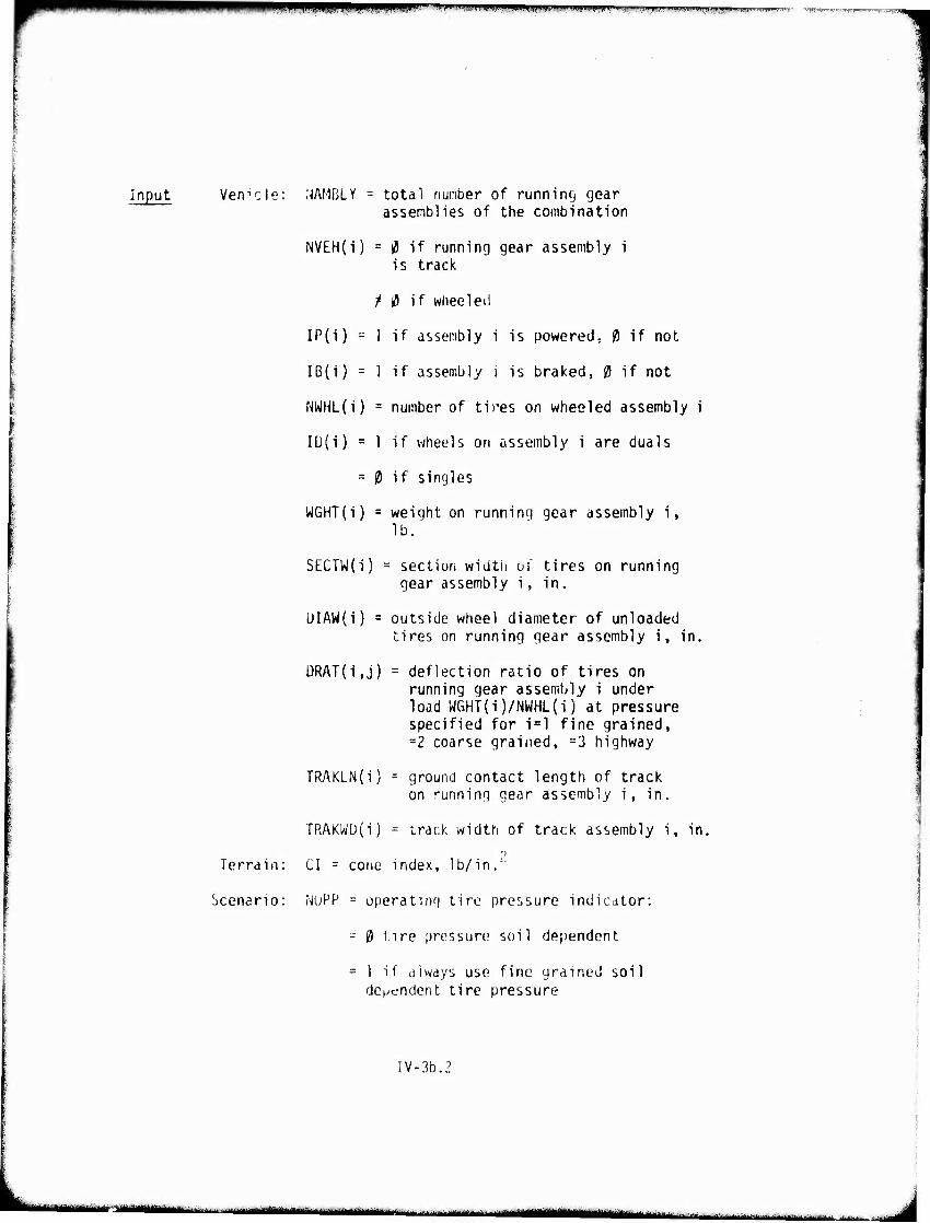
jpp i pump w^gBimww wwwwwww ww^wwwiwpffwpnwpi
input Vehicle: NAMELY = total number of running gear assemblies of the combination
NVEH(i) = iJ if running gear assembly i is track
?* 0 if wheeled
IP(i) = I if assembly i is powered, 0 if not
lB(i) = 1 if assembly i is braked, 0 if not
NWHL(i) = number of tires on wheeled assembly i
IL)(i) = 1 if wheels on assembly i are duals
= 0 if singles
WGHT(i) = weight on running gear assembly i, lb.
SECTW(i) = section width of tires on running gear assembly i, in.
UIAW(i) = outside wheel diameter of unloaded tires on running gear assembly i, in.
DRAT(i,j) = deflection ratio of tires on running gear assembly i under load WGHT(i)/NWHL(i) at pressure specified for i=l fine grained, =2 coarse grained, =3 highway
TRAKLN(i) = ground contact length of track on running gear assembly i, in.
TRAKWü(i) = track width of track assembly i, in. 9
Terrain: CI = cone index, lb/in.'
Scenario: NuPP - operating tire pressure indicator:
- 0 t.ire pressure soil dependent
= 1 if always use fine grained soil dependent tire pressure
IV-3b.2
■"'• ~—»^M^^-^.^.-....-^.-^^..-: -■ . ■■.■...■.■.... ...^^^ mm "MHWlaMtmittm, ■
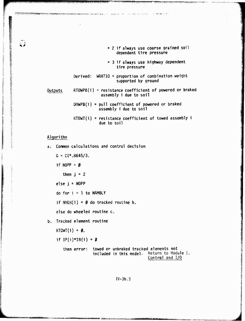
WW^WW mm.m mimm ~^^~'™r^7m*vmm'.w-mmw™*"v*ww''WM-*r^
■-^^„■....•.■.W;.,.,^,,,,,,,,,,,,, ,.„„;.„..„,,, .,„,. ,„, .,,.,., ,.
4l a 2 if always use coarse grained soil dependent tire pressure
= 3 if always use highway dependent tire pressure
Derived: WRATIO = proportion of combination weight supported by ground
Outputs RT0WPB{i) = resistance coefficient of powered or braked assembly i due to soil
DOWPB(i) = pull coefficient of powered or braked assembly i due to soil
RTOWT(i) = resistance coefficient of towed assembly i due to soil
Algorithm
a. Common calculations and control decision
G = CI*.8645/3.
if NOPP = 0
then j = 2
else j = NOPP
do for i = 1 to NAMBLY
if NVEH(i) = 0 do tracked routine b.
else do wheeled routine c.
b. Tracked element routine
RTOWT(i) = 0.
if IP(i)*IB(i) = 0
then error: towed or unbraked tracked elements not included in this model- Return to Module I,
Control and I/O
IV-3b.3
„....L-,.-^..'. --■■-. .-...-.I--.. , ■^ ~~u**«M*i«iiMHMaüulftlMta -■—■■^■■■■'■lM-- i
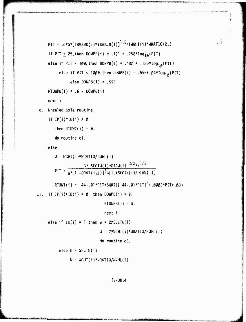
^||pPPW^Wgj;yP^,MM^?.,^.^iU.inMiil,WH.,ii,|^^ ' rT^^f!;r"tT,'T"1
IQMMIMHHMMMnMHNMianmMHNnM^^ ..,
cl
PIT = .6^*[TRAKWD(i)*TRAKLN(i)]1-5/(W6HT(i)*WRATI0/2.)
if PIT i25. then üOWPB{i) = .121 + .258*log10{PIT)
else if PIT <_ 100. then DOWPB(i) = .481' + .125*log10{PIT)
else if PIT ^ 1000.then l)OWPB{i) = .555+.04*log10(PIT)
else DOWPB(i) = .595
RTOWPB(i) = .6 - DOWPB(i)
next i
Wheeled axle routine
if IP(i)*IB(i) t 0
then RTOWT(i) = 0.
do routine cl.
else
W = WGHT(i)*WRATIO/NWHL(i)
G*[$ECTW(i)*DIAM(i)]3/2*i1/3
PIT = W*[1.-DRAT(i,j)]3*[l.+SECTW(i)/ÜIAW(i)]
RTOWT(i) = .44-.01*PIT+SgRT([.44-.01*PIT]2+.0002*PIT+.08)
if IP(i)+IB(i) = 0 then DOWPB(i) - 0.
RTOWPB(i) = 0.
next i
else if lU(i) = 1 then B = 2*SECTW(i)
W = 2fWGHT(i)*WRATI0/NWHL(i)
do routine c2.
else b - SECTW{i)
W = WGHT(i)*WRATIO/NWHL(i)
IV-3b.4
■•;--'-^ •■■■■'- ^^^^'"liTifliiiftMiriMiifta« .rn i i ^utaii wim jjJg^j^g^jjy^J^lJyj^ ..^ -...:■. nft.fa^^i \m\mma^*mm aMMamti ■■■ Mutum

^m^mmmmmmmm 111 UP."P1I I '»'">'I mW-'T--^
c2. PID - G*[B*DIAW(1)]3/2*DRAT(i,j)/[1l/2*W]
DOWPB(i) » .53 - 4.5/(PID+3.7)
RTOWPB(i) - .6 - DOWPB(i)
next 1
IV-3b.5
■■ «a— ^J
pwiUVinnpiW UIIIIMIIIiyJI IJI..IJ||IIIHWpi|inilllHil!l|llliaiwnil;P|lJI>M|ltl|ill..'llipU. >. « ,v.r.j,w,.. ~ •.v^^Tm
B
3c. Muskeg Pull and Resistance Coefficients
Description This routine is similar to the "fine grained soil pull and resistance coefficients" routine, with the exception that VCIMUK is used instead of VCIFG. The muskeg VCI is derived in the vehicle preprocessor.
IV-3C.1
m m - — - - , ■- - ■
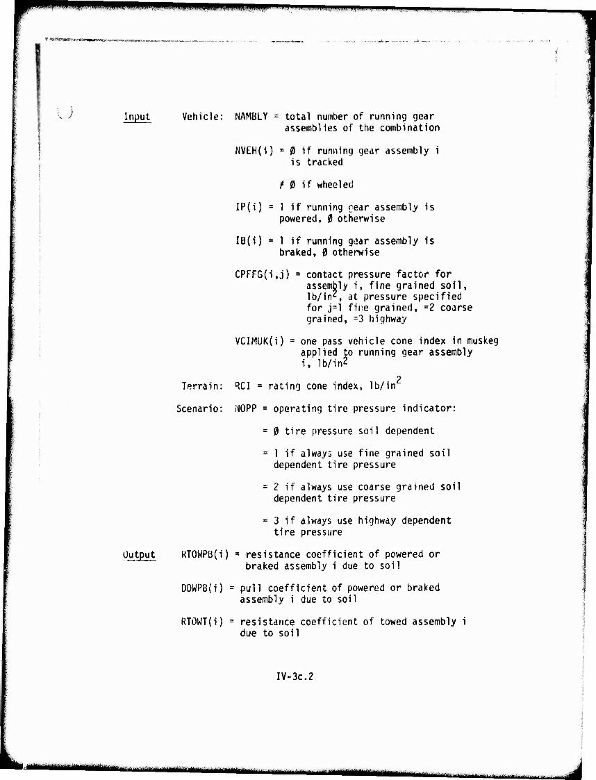
mmm ipjpmpp i. jiii...i i,u.. 111.111,11,1.1,111,11111,iiiuiiiii ii.i .11,1.,i ^^
Input Vehicle: NAMÜLY = total number of running gear assemblies of the combination
NVEH(i) s 0 if running gear assembly i is tracked
Output
/ 0 if wheeled
IP{i) = 1 if running gear assembly is powered, 0 otherwise
IB(1) = 1 if running goar assembly is braked, 0 otherwise
CPFFG(i,j) = contact pressure factor for assembly i, fine grained soil, lb/ins at pressure specified for j=l fine grained, =2 coarse grained, =3 highway
VCIMUKO) = one pass vehicle cone index in muskeg applied to running gear assembly 1, lb/in2
2 Terrain: RQl - rating cone index, lb/in
Scenario: NOPP = operating tire pressure indicator:
= 0 tire pressure soil dependent
= 1 if always use fine grained soil dependent tire pressure
= 2 if always use coarse grained soil dependent tire pressure
= 3 if always use highway dependent tire pressure
RTOWPB(i) = resistance coefficient of powered or braked assembly i due to soil
DOWPB(i) = pull coefficient of powered or braked assembly 1 due to soil
RTöWT(i) = resistance coefficient of towed assembly 1 due to soil
IV-3C.2
tMtm^^^m ^ I iM ' üürtiiii III MM!
- • Mi
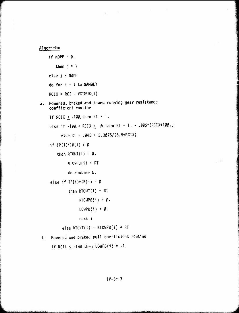
Algorithm
if NOPP = 0.
then j = I
else j = NOPP
do for i = 1 to NAMBLY
RCIX = RCI - VCIMUK(i)
a. Powered, braked and towed running gear resistance coefficient routine
if RCIX <_ -100. then RT = 1.
else if -100.< RCIX < 0.then RT = 1. - .006*(RCIX+1|
else RT = .045 + 2.3075/(6.5+RCIX)
if IP(i)*lU(i) f 0
then RTOWT(i) = 0.
RTOWFB(i) = RT
do routine b.
else if IP(i)+IB(i) = 0
then RTOWT(i) = RT
RTOWPB(i) = 0.
DOWPB(i) = 0.
next i
else RTOWT(i) = RTOWPB(i) = RT
b. Powered ana oraked pull coefficient routine
if RCIX < -100 then ÜOWPB(i) = -1,
I.)
IV-3C.3
..-■■ .... im* ■ i ■ - ii ■■ ''■' ... „.....,.:;.._........,■ --.. —
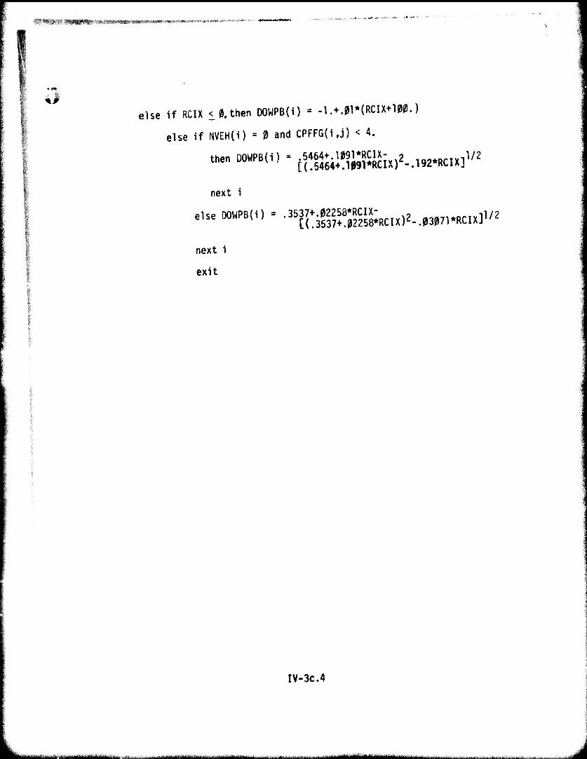
iC.m&mi «MMIIMIIMMW——I—I"»«»' ■IWI'M' i
else if RCIX < 0. then DOWPB(i) - -1. + .01*(RCIX+100.)
else if NVEH{i) = 0 and CPFFG{i,j) < 4.
then DOWPB(i) = .5464+.1^91*RCIX- 9 s/, [(.5464+.^09l*RCIX)<;-.192*RCIX],^
next i
else DOWPB(i) = ,3537+.02258*RCIX- 0 . .„ [{.3537+.(J2258*RCIX)2-.03071*RCIX]1/2
next i
exit
IV-3C.4
v.--... ■ ■,J,...^.,-;- - - Uli I
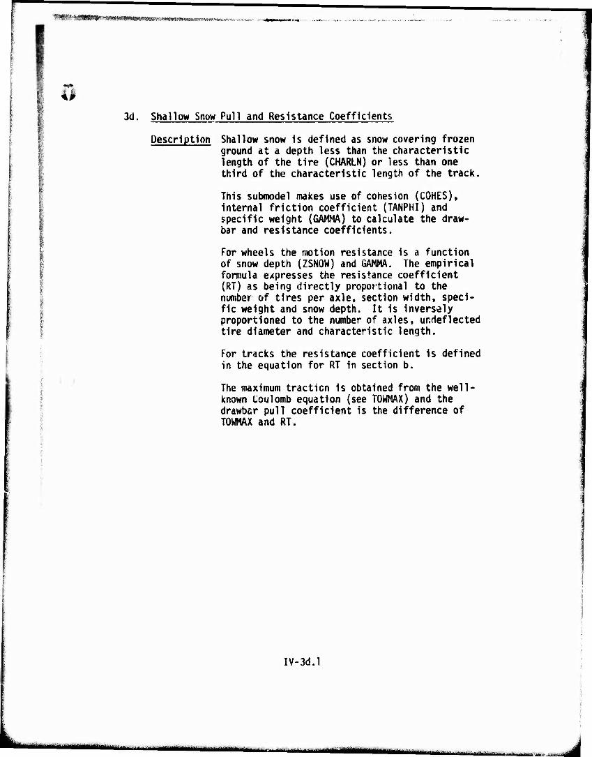
''"'TIT'WIffltlirMi^^ i tyy -./ * >-, -J. ./
3d. Shallow Snow Pull and Resistance Coefficients
Description Shallow snow Is defined as snow covering frozen ground at a depth less than the characteristic length of the tire (CHARLN) or less than one third of the characteristic length of the track.
This submodel makes use of cohesion (COHES), Internal friction coefficient (TANPHI) and specific weight (GAMMA) to calculate the draw- bar and resistance coefficients.
For wheels the motion resistance is a function of snow depth (ZSNOW) and GAMMA. The empirical formula expresses the resistance coefficient (RT) as being directly proportional to the number of tires per axle, section width, speci- fic weight and snow depth. It is inversely proportioned to the number of axles, unrleflected tire diameter and characteristic length.
For tracks the resistance coefficient is defined in the equation for RT in section b.
The maximum traction is obtained from the well- known Coulomb equation (see TOWMAX) and the drawbar pull coefficient is the difference of TOWMAX and RT.
IV-3d.l
••^—••»»^■■■MMMIaiM "■"-" 1 ^j
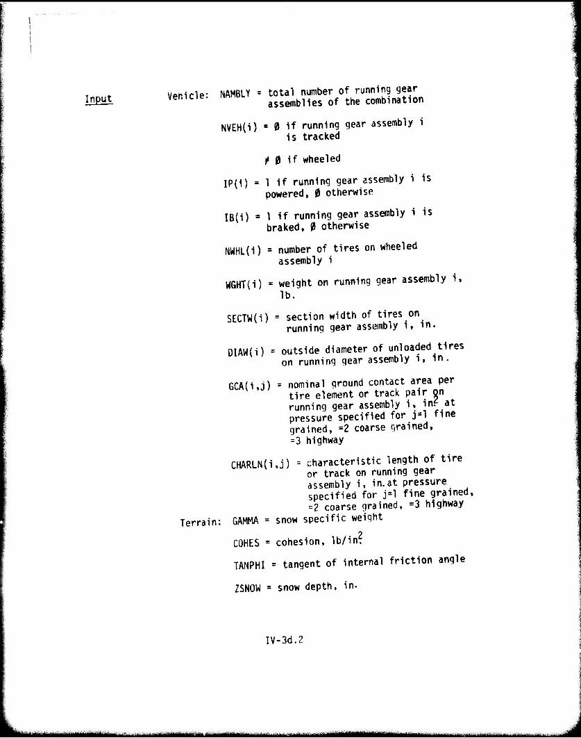
Input Vehicle: NAMBLY = total number of running gear assemblies of the combination
NVEH{i) « 0 if running gear assembly i is tracked
^ 0 if wheeled
IP(1) » 1 if running gear assembly i is powered, 0 otherwise
IB(i) ■ 1 if running gear assembly i is braked, 0 otherwise
NWHL(i) = number of tires on wheeled assembly i
WGHT(i) = weight on running gear assembly i, lb.
SECTW(i) = section width of tires on running gear assembly i, in.
DIAW{i) = outside diameter of unloaded tires on running gear assembly i, in.
GCA(i,j) = nominal ground contact area per tire element or track pair on running gear assembly i, in? at pressure specified for j=l fine grained, -2 coarse grained, =3 highway
CHARLN(i,j) = characteristic length of tire or track on running gear assembly i, in.at pressure specified for j=l fine grained, =2 coarse grained, =3 highway
Terrain: GAMMA = snow specific weight
COHES = cohesion, lb/in?
TANPHI = tangent of internal friction angle
ZSNOW = snow depth, in.
IV-3d.2
i 1 IM — i^ ...^^-^^^-^
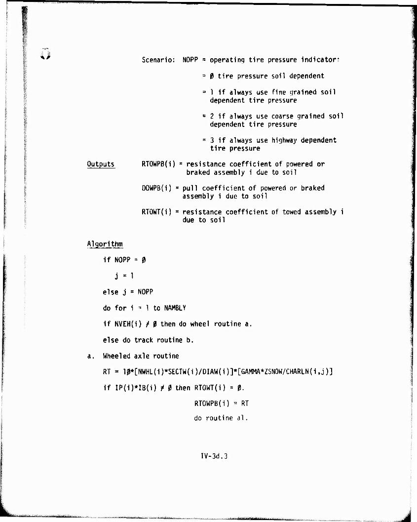
^^^^^^^^^^^^^-"
Scenario: NOPP = operating tire pressure indicator:
= 0 tire pressure soil dependent
3 1 if always use fine grained soil dependent tire pressure
= 2 if always use coarse grained soil dependent tire pressure
= 3 if always use highway dependent tire pressure
Outputs RTOWPB(i) * resistance coefficient of powered or braked assembly i due to soil
DOWPB(i) s pull coefficient of powered or braked assembly i due to soil
RTOWT(i) = resistance coefficient of towed assembly i due to soil
Algorithm
if NOPP = 0
j = 1
else j = NOPP
do for i - 1 to NAMBLY
If NVEH(i) f 0 then do wheel routine a.
else do track routine b.
a. Wheeled axle routine
RT = 10*[NWHL(i)*SECTW(i)/DIAW(i)]*[GAMMA*ZSNOW/CHARLN(i,j)]
if IP(i)*IB(i) i 0 then RTOWT(i) = 0.
RTOWPB(i) = RT
do routine al.
IV-3d.3
■ ■ ■-..-. :-- ■ ■■
"- ■-■•■'- -■:--' ■
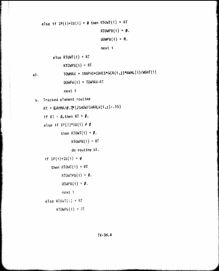
else if IP(i)+Ili(i) = 0 then RTOWT(i) = RT
RTOWPB(i) = 0.
DOWPB(I) = 3.
next 1
else RTÜWT(i) = RT
RTOWPB(i) = RT
al. TOWMAX = TANPHI+COHES*GCA(i,j)*NWHL(i)/WGHT(i)
DOWPB(i) = TOWMAX-RT
next i
b. Tracked element routine
RT = pAHMA/0.2)*(ZSNOW/CHARLN{i,j)-.15)
if RT < 0,then RT = 0.
else if IP{i)*IB(i) t 0
then RTOWT(i) = 0.
RTOWPB(i) = RT
do routine bl,
if IP(i)+IB(i) = 0
then RTOWT(i) = RT
RTOWTPB(i) = 0.
DOWPB(i) = 0.
next i
else RTOWT(i) = RT
RTOWPü(i) = RT
IV-3d.4
*- i ■- -«I i —m
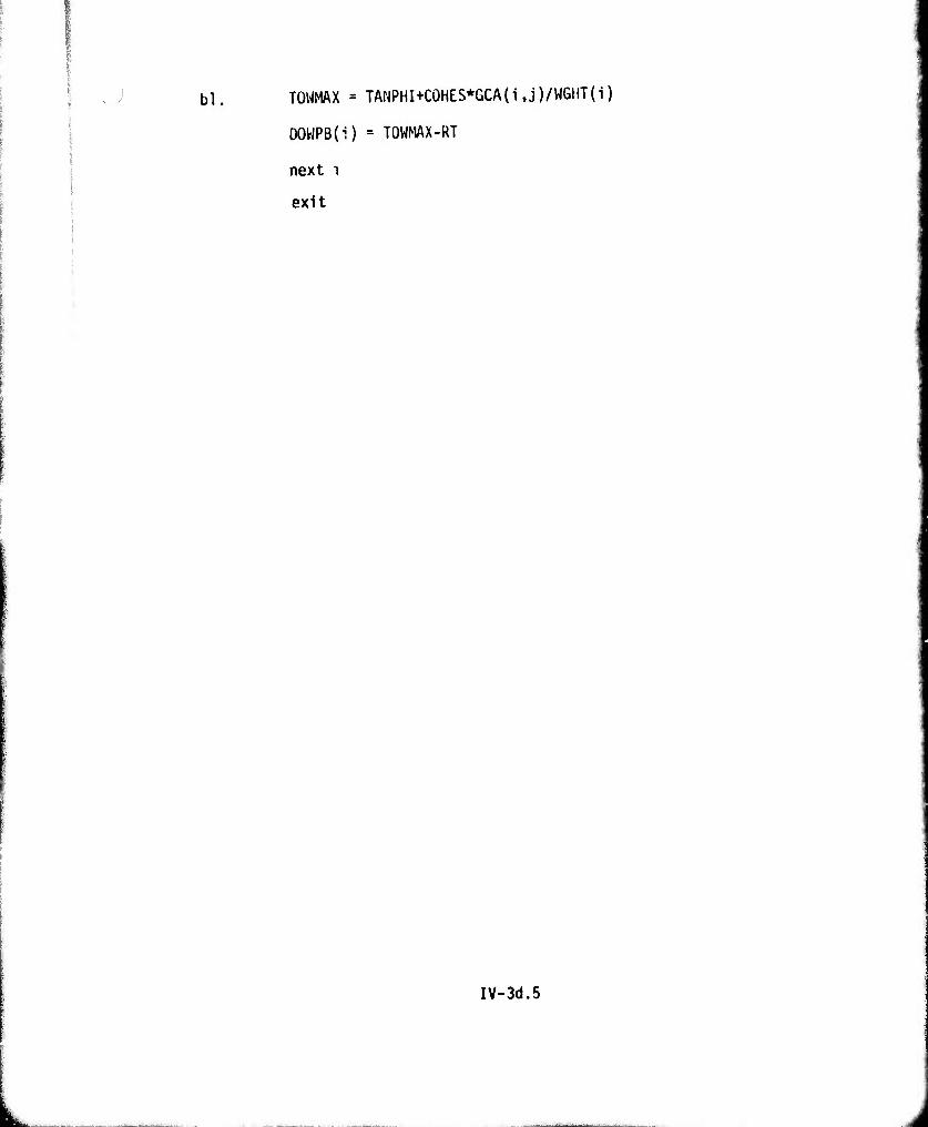
bl. TOWMAX = TANPHI+COHES*GCA(i,j)/WGMT(i)
DOWPB(i) = TOWMAX-RT
next i
exit
IV-3d.5
'»"■w »'" w JWPWP^^—
4. Summed Pull and Resistance Coefficients
Description l" this routine the pull and resistance co- efficients calculated for each running gear assembly in either one of routines 3a, 3b, 3c or 3d are sunned. Separate summations are made for all powered, braked, unpowered and unbraked assemblies.
IV-4.1
J
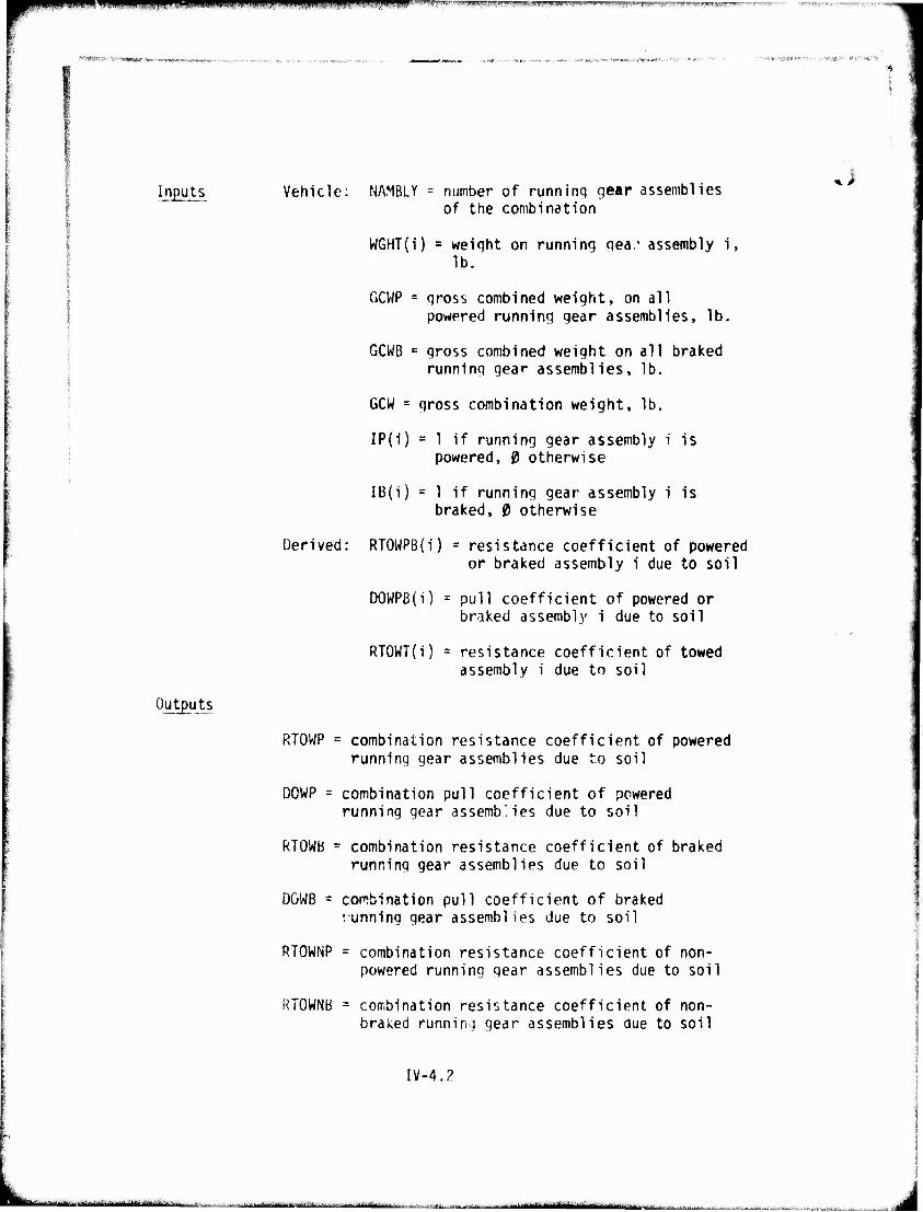
9m*m -"-I|IP I. ..IIW. VW- *r?w-?',i.vi.ii»jiii v ui •itifrn BBUBWjjjwipwp^pwF^iyfpp) fmfgmß gf^rTTW'"-yi-'*7i»r^t^'|wi'.lBr-^r"-'wy--'—-
■M*iwiesw>w^-!v VWäö* '■■ ■ ^
i i
Inputs Vehicle: NAMBLY = number of runninq gear assemblies of the combination
WGHT(i) = weiqht on running qea.- assembly i, lb.
GCWP = qross combined weight, on all powered running qear assemblies, lb.
GCWB = qross combined weight on all braked runninq qea»* assemblies, lb.
GCW = qross combination weight, lb.
IP(1) = 1 if running gear assembly i is powered, 0 otherwise
IB(i) = 1 if runninq gear assembly i is braked, 0 otherwise
Derived: RT0WPB{i) = resistance coefficient of powered or braked assembly i due to soil
DOWPB(i) = pull coefficient of powered or braked assembly i due to soil
RTOWT(i) = resistance coefficient of towed assembly i due to soil
Outputs
RTOWP = combination resistance coefficient of powered runninq gear assemblies due to soil
DOWP = combination pull coefficient of powered running gear assemblies due to soil
RTOWB = combination resistance coefficient of braked runninq gear assemblies due to soil
DGWB = combination pull coefficient of braked vunninq qear assemblies due to soil
RTOWNP = combination resistance coefficient of non- powered runninq gear assemblies due to soil
RTOWNB = combination resistance coefficient of non- braked running qear assemblies due to soil
IV-4.2
' --■■■-■- ■■ iniiiäiillihMii'llitfiili'itiiiririi'i i . . atumtmm ■ J
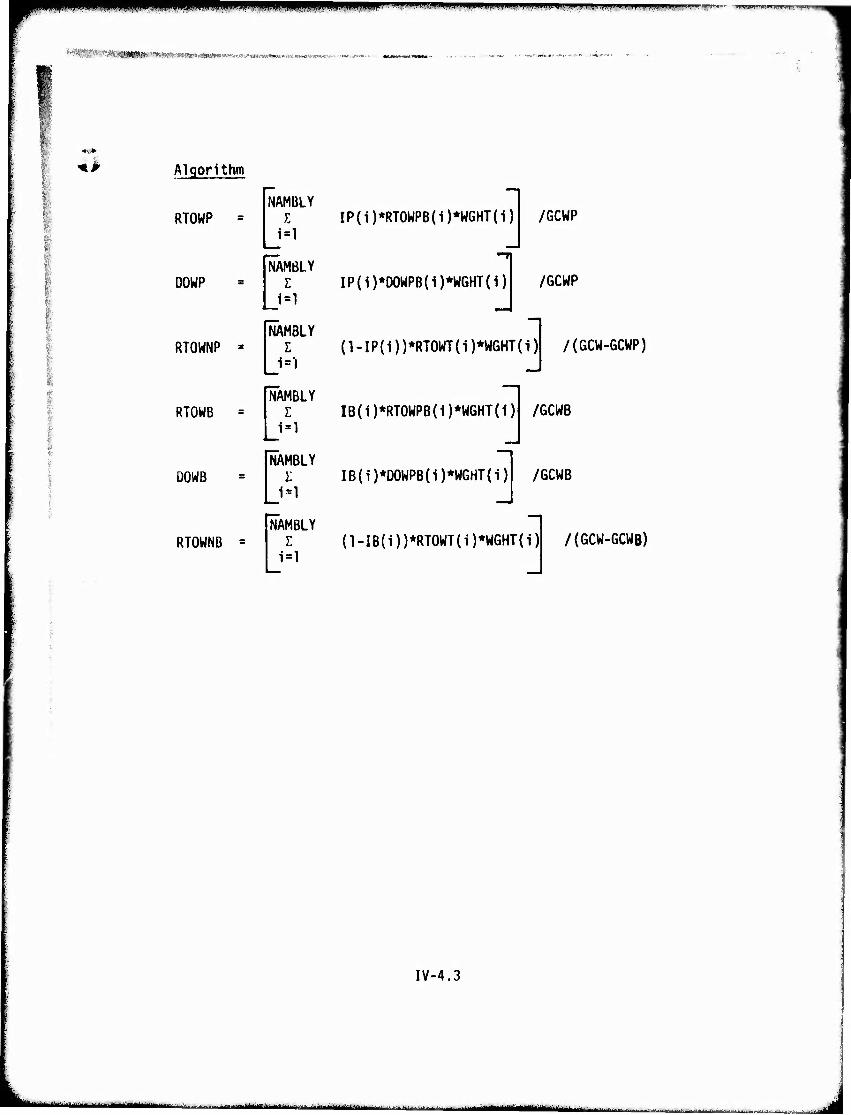
iPIPfP^P^IPIilUilMIWM^
^WBIllwniliMffiiWnwwii'i' nniiiniiiiiiiii n win HI ■■ - •■
I 4l Algorithm
RTOWP
DOWP
RTOWNP
RTOWB
DOWB
NAMBLY I
i=l
NÄMßlY E
NÄMBLY E
J=l
FAMBLY E
1=1
NÄMBLY E
J=l NAf
1 i:
IP(i)*RT0WPB(i)*WGHT(1) /GCWP
IP(i)*OOWPB{1)*WGHT(i)| /GCWP
(l-IP{i))*RTOWT(i)*WGHT(i) /(GCW-GCWP)
IB(i)*RT0WPB(i)*WGHT(1)
IB(i)*DOWPB(i)*WGHT(i)
/GCWB
/GCWB
NAMBLY RTOWNB = E
=1 (l-IB(i))*RTOWT(i)*WGHT(i) /(6CW-GCWB)
IV-4.3
ii-iHilriiiiili^Mill—IMilnlill i ^ —■- -' -■■ MMH^MM
mm jfWKH&W*' '■"■>«' "-wi' '"I'wwwff w mm l^■^■■ pH
Slip Modified Tractive Effort
Description This routine modifies the tractive effort versus speed curve obtained from the vehicle power train or measured data for slippage of the running gear in the soil.
The first new feature in this submodel is scenario input NTRAV, If NTRAV=1 the model is executed for a single traverse and only one slope (8]) will enter from the processed Terrain File. If NTRAV=3 then the usual cases of up, level and down slope are computed for each patch. A second new feature is that the effect of elevation is now accounted for by means of factor ECF.
This submodel also accounts for water drag resistance while operating in a marsh.
IV-5.1
i*--'-' ■ .^MMmau*..^. mitm i*,m*t:i*M/nin*.*i..~..-^..r.>..... J
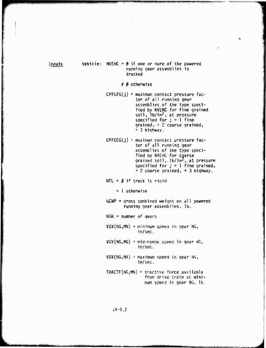
m*™m ■w ''.".«wmn'mimmimmmimm »J-.^ILI.IIJI...I.»..<IJII ijvmun^.'wvr*-' ■
Inputs Vehicle: NVEHC fi if one or more of the powered running gear assemblies is tracked
^ 0 otherwise
CPFCFG(j) = maximum contact pressure fac- tor of all running gear assemblies of the type speci- fied by NVEHC for fine grained soil, lb/in2, at pressure specified for j = 1 fine grained, = 2 coarse grained, = 3 highway.
CPFCCG(j) = maximum contacc pressure fac- tor of all running gear assemblies of the type speci- fied by NVEHC for coarse grained soil, lb/in2, at pressure specified for j = 1 fine grained, = 2 coarse grained, s 3 highway.
NFL = 0 if track is rigid
= 1 otherwise
liCWP = gross combined weight on all powered running gear assemblies, lb,
NGR = number of gears
VGV(NG,MN) = minimum speed in gear NG, in/sec.
VGV(NG,MD) = mid-range speed in gear NG, in/sec.
VGV(NG,MX) u maximum speed in gear NG, in/sec.
TRACTF(NG,MN) - tractive force available from drive train at mini- mum speed in gear NG, lb.
iV-5.2
JMüttlMmMi -YiiiliiWtilr'iimiiii-iirffiMiil '■''■^ "-"iiTn tirt'rta- MMMiM^MMbMl
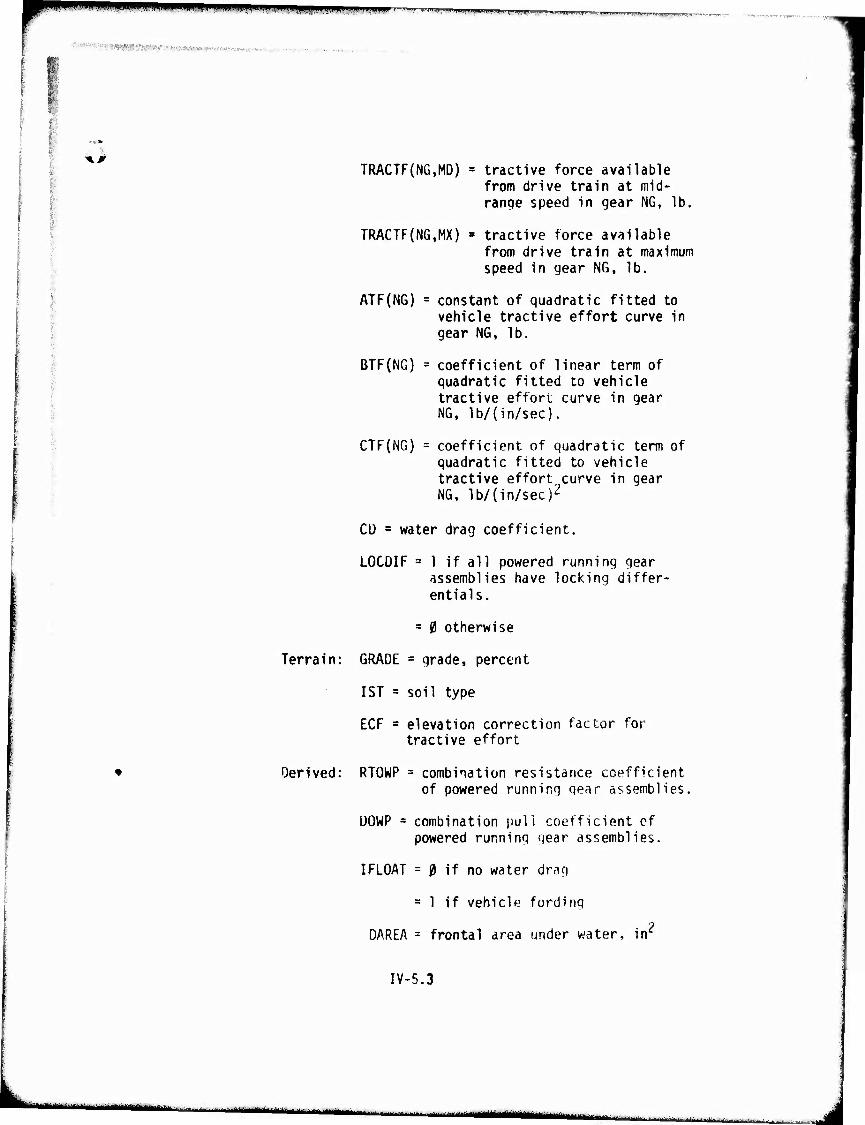
^^^MmpiPWWipM ■ r-wM»iyr.v.iiji>Wff.WWW|,T,ffT,^ly1p?,„ T WTT^nrr T"rir.-ii
I
-■i ■■ ^AJiW ' ' ..■,-™„,....-,■.;■..,■,, , „,..,.,.
xr
Terrain:
Derived:
TRACTF(NG,MD) = tractive force available from drive train at mid- range speed in gear NG, lb.
TRACTF(NG,MX) » tractive force available from drive train at maximum speed in gear NG, lb.
ATF(NG) = constant of quadratic fitted to vehicle tractive effort curve in gear NG, lb.
BTF(NG) = coefficient of linear term of quadratic fitted to vehicle tractive effort curve in gear NG, lb/(in/sec).
CTF(NG) = coefficient of quadratic term of quadratic fitted to vehicle tractive effort curve in gear NG, lb/(in/sec)2
CÜ = water drag coefficient.
LOCDIF =1 if all powered running gear assemblies have locking differ- entials.
= 0 otherwise
GRADE = grade, percent
1ST = soil type
ECF = elevation correction factor for tractive effort
RTOWP = combination resistance coefficient of powered running gear assemblies.
Ü0WP s combination puli coefficient cf powered running gear assemblies.
I FLOAT = 0 if no water drag
= 1 if vehicle fording
DAREA = frontal area under water, in2
IV-5.3
-- -- - ■ - -■- r\imu HMMMM
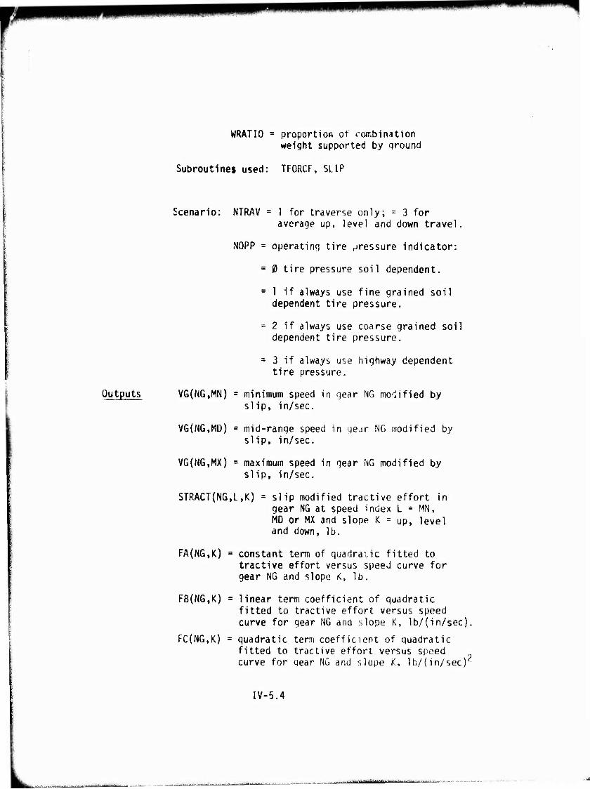
WRATIO = proportloR of rombinatlon weight supported by ground
Subroutines used: TFORCF, SLIP
Scenario: NTRAV = 1 for traverse only; = 3 for average up, level and down travel.
NOPP = operating tire pressure Indicator:
= 0 tire pressure soil dependent,
= 1 if always use fine grained soil dependent tire pressure.
- 2 if always use coarse grained soil dependent tire pressure.
= 3 if always use highway dependent tire pressure.
Outputs VG(NG,MN) = minimum speed in gear NG modified by slip, in/sec.
V6(NG,MD) = mid-range speed in gear NG modified by slip. In/sec.
VG(NG,MX) = maximum speed in gear NG modified by slip. In/sec.
STRACT(N6,L,K) = slip modified tractive effort in gear NG at speed index L = MN, MD or MX and slope K = up, level and down, lb.
FA(NG,K) = constant term of quadratic fitted to tractive effort versus speed curve for gear NG and slope K, lb.
FB(NG,K) = linear term coefficient of quadratic fitted to tractive effort versus speed curve for gear NG and slope K, lb/(in/sec).
FC(NG,K) = quadratic term coefficient of quadratic fitted to tractive effort versus speed curve for gear NG and slope K, lb/(in/sec)
IV-5.4
■ ,-'■■■-'■ ■■-■■-■ ■■
,.*. ^,^-JP.^.v i I i |||(aaiMiMMiMMMi
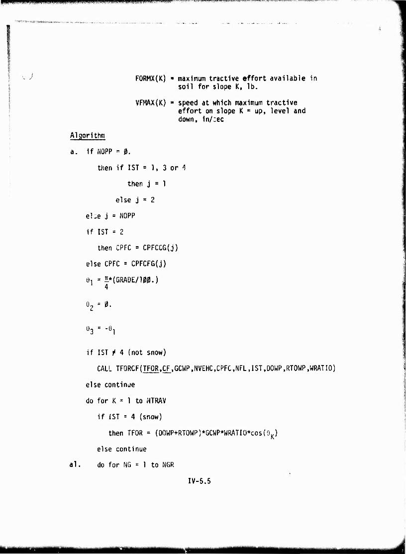
PI ■ »II »■li.iWMiimjli,lHlWtl!ni!iil>i,Wp).,.|.i i,i.|i,i„ii^.,~,.T.^T^Ti-r„,,.,.,„l.,,,„.^1r^.^.T^.^..
''"^ftrTV**;^, n*^WltMW«W»*.^.-«.-«.
v; FORMX(K) = maximum tractive effort available In soil for slope K, lb.
VFMAX(K) ■ speed at which maximum tractive effort on slope K = up, level and down, 1n/:ec
Al gorithm
a. If MOPP « 0.
then if 1ST = 1. 3 or 1
then j = 1
else j = 2
el.e j = NOPP
if 1ST = 2
then CPFC = CPFCCG{j)
else CPFC = CPFCFG(j)
0, = I* (GRADE/100.) 4
02 = 0.
ü3 = -Öl
if IST / 4 (not snow)
CALL TFORCF(TFOR,CF,GCWP,NVEHC,CPFC,NFL,1ST,DOWP.RTOWP.WRATIO)
else continue
do for K = 1 to NTRAV
if 1ST = 4 (snow)
then TFOR = (00WP+RT0WP)*GCWP*WRATI0*cos(9K)
else continue
al. do for NG = 1 to NGR
IV-5.5
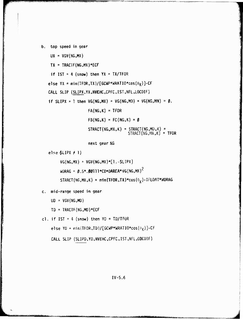
1 : l-|l'.lIJi.H|,l.limiflllH»IIU"»'"IPIi|i'»'iJ"
b. top speed in gear
UX = VGV{NG,MX)
TX = TRACTF(NG.MX)*ECF
if 1ST = 4 (snow) then YX = TX/TFOR
else YX = min{TFORJX}/[GCWP*WRATIO*cos(eK)]-CF
CALL SLIP (SLIPX.YX.NVEHC.CPFCIST.NFL.LOCDIF)
if SLIPX = 1 then VG(NG,MX) = VG(NG.MD) = VG{NG,MN) = 0.
FA(NG,K) = TFOR
FB{NG,K) = FC(N6,K) = 0
STRACT(NG,MX,K) = STRACT(NG,MD,K) = STRACT(NG.MN.K) = TFOR
next gear NG
else $LIPX t 1)
VG(NG,MX) = VGV(NG,MX)*[1.-SLIPX]
WDRAG = 0.5*.M111*CD*DAREA*VG(NG,MX)2
STRACT(NG,MX,K) = m1n{TFOR.TX}*cos(GK)-IFLOAT*WDRAG
c. mid-range speed in gear
UD = VGV(NG,M0)
TD = TRACTF(NG,MD)*ECF
cl. if 1ST = 4 (snow) then YD = TD/TFOR
else YD = min{TKOR,TD}/[GCWP*WRATIO*cos(0K)]-CF
CALL SLIP (SLIPD,YD,NVEHC,CPFC,IST,NFL,COCDIF)
IV-5.6
**,*.*.>*.,*:*^.**mlunltt^irU ,,,.,■.- -■'■■HIM | '—-MMHH —-■■ ■ i numskm^^timut „ J
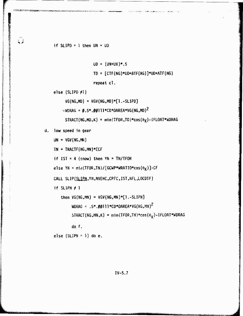
,.t*J -■.-,-- ..rr^-.-V- ■( jratMit ■■ MMNHMMIMMMftiMl! «w i-Ä'-'W-t-i*«-!. *»•! -..
if SLIPD = 1 then UN = UO
UD = (UN+UX)*.5
TD = [CTF(NG)*UD+BTF(NG)]*UD+ATF(NG)
repeat cl.
else (SLIPD f\) I
VG(NG,MD) = VGV(NG,MD)*[1.-SLIPD]
»WDRAG = 0.5*.«W111*CD*DAREA*VG(N6,MO)2
I STRACT(NG,MD,K) = min{TFOR,TD}*cos(eK)-iFLOAT*WDRAG
\ d. low speed in gear
I UN * VGV(NG.MN)
TN = TRACTF(NG,MN)*ECF
if 1ST = 4 (snow) then YN = TN/TFOR
else YN = min{TFOR,TN}/[GCWP*WRATIO*cos(eK)]-CF
CALL SLIPCSUM.YN.NVEHCCPFCIST.NFL.LOCDIF)
if SLIPN f 1
then VG(NG,MN) = VGV(NG,MN)*[1.-SLIPN]
WDRAG = .5*.00111*CD*DAREA*VG(NG,MN)2
STRACT(NG,MN,K) = min{TFOR,TN}*cos(eK)-IFLOAT*WDRAG
do f.
else (SLIPN ^ 1) do e.
IV-5.7
*****;*i^-;-1 -■...-J^^M.^—^..■.,....—.-+-^.-^. ._|,^MIM^MI J
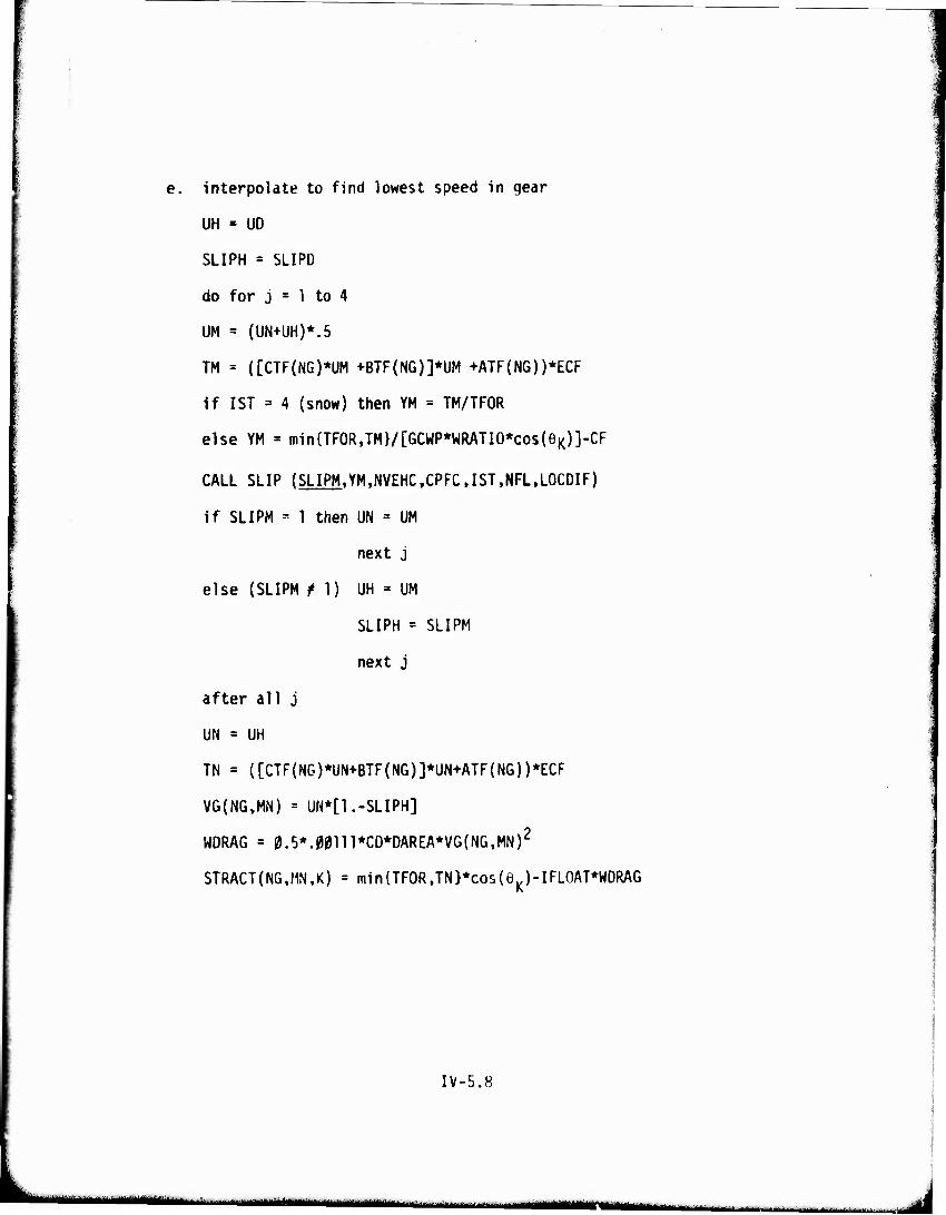
interpolate to find lowest speed in gear
UH « UD
SLIPH = SLIPO
do for j = 1 to 4
UM = (UN+UH)*.5
TM = ([CTF(NG)*UM +BTF(NG)]*UM +ATF(NG))*ECF
if 1ST = 4 (snow) then YM = TM/TFOR
else YM = min{TFOR,TM}/[GCWP*WRATIO*cos(eK)]-CF
CALL SLIP (SLIPM.YM.NVEHC.CPFC.IST.NFL.LOCDIF)
if SLIPM " 1 then UN = UM
next j
else (SLIPM M) UH = UM
SLIPH = SLIPM
next j
after all j
UN = UH
TN = ([CTF(NG)*UN+BTF(NG)]*UN+ATF(N6))*ECF
VG(NG,MN) = UN*[1.-SLIPH]
WDRAG = 0.5*.00in*CD*DAREA*VG(NG.MN)2
STRACT(NG,MN,K) = min{TFOR,TN}*cos(eK)-IFLOAT*WDRAG
IV-5.8
hmiMi v'**^*»»***********'"**-**-'*^ ^-^^^1Mri|fc<^|^ | 1 ■
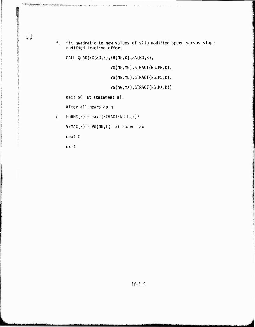
'''W^^SIWI^'W-MÄVÄ^iWWiv»-»».»...™.,.
u fit quadratic to new values of slip modified speed versus slope modified tractive effort
CALL QUAD(FC(NG,K).FB(NG.K).FAjNG.K),
VG(NG.MN),STRACT{NG,MN,K), i
VG(NG,MD).STRACT(NG,MD,K),
I VG(NG,MX),STRACT(NG,MX,K))
next NG at statcnent al.
I After all gears do g. I
g. FORMX(K) = max {STRACT(N6,L,K)) I
VFMAX(K) = VG(NG,L) at above max i
next K
exit
IV-5.9
—•^-~~—^ .... . ^
;
^ So'i Limited Tractive r.ffort Subroutine t I
Description This subroutine, TFOKCl, is used in the submodel called "slip modified tractive effort". The drawbar pull and resistance coefficients cal- culated in submodels 3 and 4 are based on 2(3:. wheel or track slip in the soil. Subroutine TFORCF calculates correction factors for the entire slip range up to 100?' slip.
Subroutine TFORCF first calculates correction . factor CF and then establishes the maximum soil limited tractive effort which occurs at 1| slip (TFOR).
IV-TF0RCF.1
■ ■ ■ ■
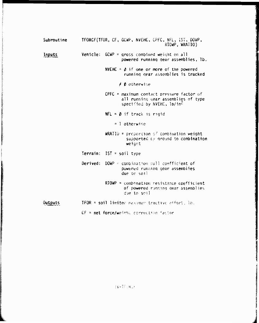
Subroutine
Inputs
Outputs
TFORCF(TF0R. CF, GCWP, NVEHC, CPFC. NFL. IST, DOWP, RTOWP, WRATIO)
Vehicle: GCWP = gross combined weight on all powered running gear assemblies, lb.
NVEHC = »J i f one or more of the powered running gear iisscmblies is tracked
/ 0 otherwise
CPFC I maximum contact pressure factor of all running ^ear assemblies of type specified by NVEHC, lb/in2
NFL * 0 if track is rigid
3 1 otherwise
WRATIO = proportion of combination weight supported by ground to combination weight
Terrain: 1ST = soil type
Derived: DOWP : combination pull coefficient of powered running gear assemblies due to soil
RTOWP ^ combinatioi! resistance coefficient of powered running gear assemblies öJO to soil
TFOR = soil limitoo mÄximuT tractive effort. ID.
CF = net force/weiin. correction 'actor
iv-i; ■■*.„>
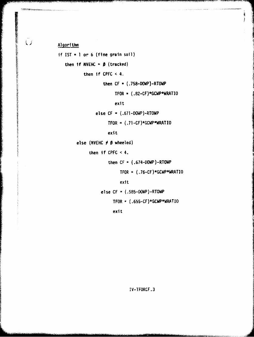
MSmäWJ!mw«l««*»n™-«„,„ __.. ,,..„—»..».„ ^^nm^mmrmmsn ^
i
^ Algorithm
If 1ST « 1 or 6 (fine grain soil)
then if NVEHC « 0 (tracked)
then if CPFC < 4.
then CF « (.758-D0WP)-RT0WP
TFOR » (.82-CF)*6CWP*WRATI0
exit
else CF » (.671-DOWP)-RTOWP
TFOR - (.71-CF)*GCWP*HRATI0
exit
else (NVEHC t 0 wheeled)
then if CPFC < 4.
then CF » (.674-D0WP)-RT0WP
TFOR = (.76-CF)*GCWP*WRATI0
exit
else CF = (.585-D0WP)-RT0WP
TFOR - (.655-CF)*GCWP*WRATI0
exit
IV-TF0RCF.3
■MM————m iniiii—i——MMmwi—inn i i [MrTwawüiii ....:■.■.■. ■■ ,a..-..-. .... ■■■
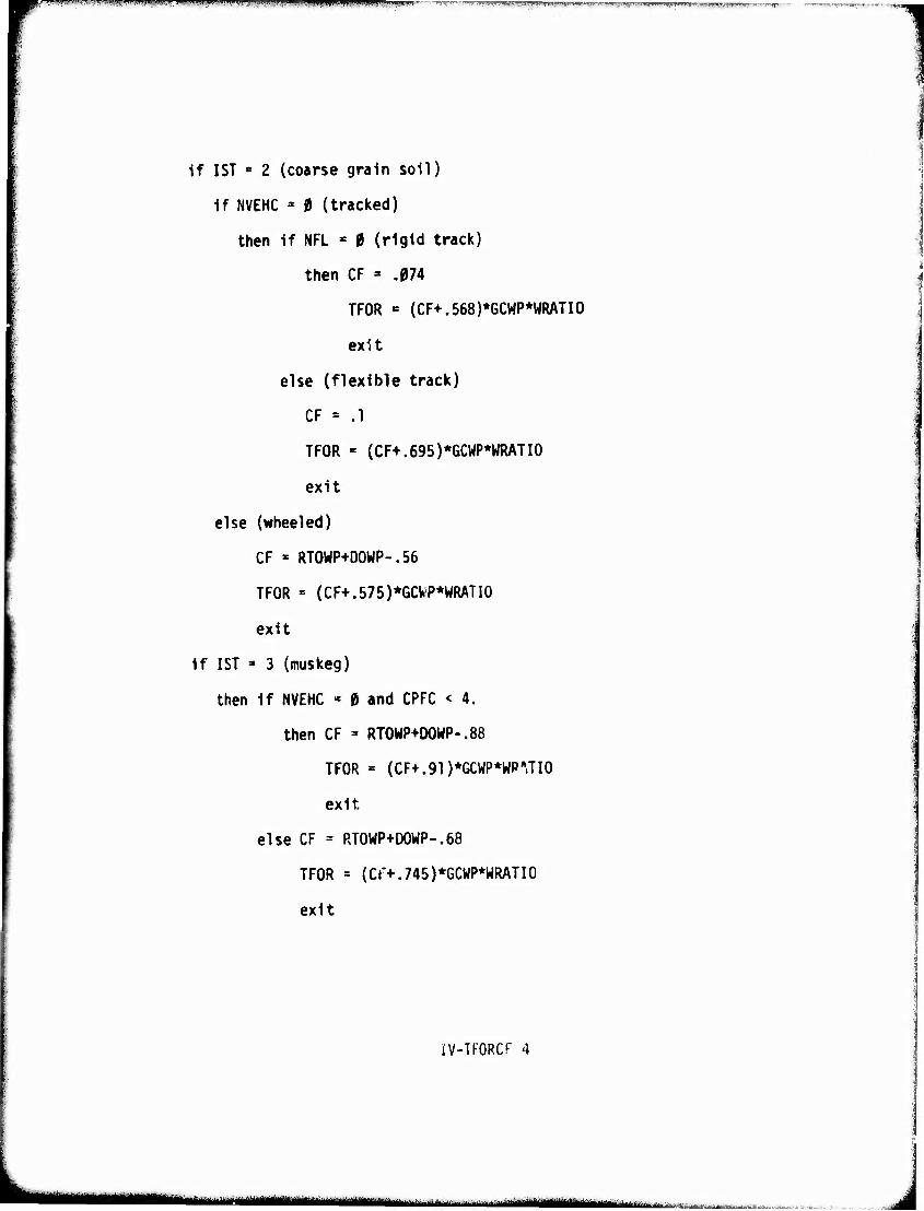
K—~~^^~"^'^'"-71'"'"■''''"'""■-" ■' "'^ -.-».■M™J|.W,*W,'"1''«IJWHI™""M- --iTipm.-ii..,, .fV,s«!l...M»*'.Llu«IMV.|imi!!ln«I.™il-v>'P, iIwiv™!p»>™TOW..«.,«f...^p»"»»w!jv
If 1ST « 2 (coarse grain soil)
if NVEHC = 0 (tracked)
then if NFL « 0 (rigid track)
then CF = .074
TFOR = {CF+.568)*GCWP*WRATI0
exit
else (flexible track)
CF = .1
TFOR •= (CF+.695)*GCWP*WRATI0
exit
else (wheeled)
CF ' RT0WP+D0WP-.56
TFOR = (CF+.575)*GCWP*WRATI0
exit
if 1ST » 3 (muskeg)
then if NVEHC * 0 and CPFC < 4.
then CF = RTOWP+DOWP-.88
TFOR = (CF+.91)*GCWP*WP',JI0
exit,
else CF = PJ0WP+D0WP-.68
TFOR = (Cr+.745)*GCWP*WRATI0
exit
IV-TFORCF 4
....,.^^^^^^,^.^^^^..^ ......„^^a^^aua^.^.^ HMigUittMattftakäaaiiai^£BaA^«i£w«ui ...-*:*. -■„. ■ .
r i
SIip Subroutine
Description Subroutine SLIP calculates the actual slip the vehicle would experience at the minimum, mid-point and maximum velocities In each gear that are used to obtain the quadratic fit coefficients of the tractive effort versus speed curve. The latter is the theoretical tractive effort versus speed curve derived in the vehicle preprocessor.
IV-SLIP.l
-lllHi—Ij—Mll I ^■ü«^ :.::»■-...:.^-^.,:/. ■_.
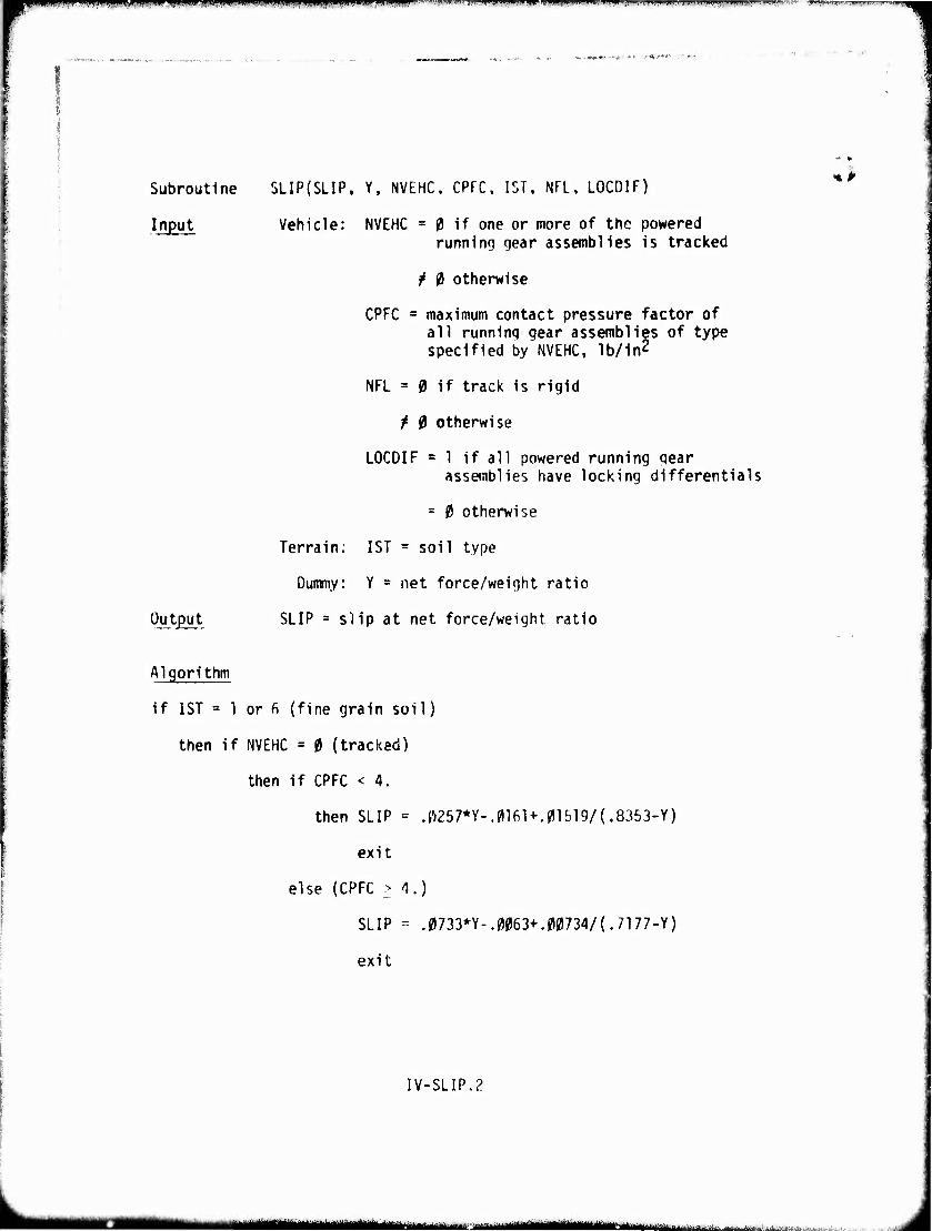
m^^™** ' ' ' l." ■'I'll - .1.1 . m mwm\Wi-l >. »mm* ".UJIH . I.JIMJII.I | |l,lipi,iJ,,ll|ii«» Ui\ n iiin,-»ii -- —:v.. ..i /.u..iHi.^.Lit.ipi»WUlfl.^|!^ifilv II^ >i!.i|l i IW.IIM.'I^.'I.II^I-I.IIJ'W-UI. »w»^^*''!...^^-^^ ■■iwiMiw)T"l.Vl,m." >■'- !■ -'»na
-•■A.'*'-11 ' '"
Subroutine
Input
Output
5LIP(SLIP, Y, NVEHC. CPFC. 1ST, NFL, LOCDIF)
Vehicle: NVEHC = 0 if one or more of the powered running gear assemblies is tracked
/ 0 otherwise
CPFC = maximum contact pressure factor of all running gear assemblies of type specified by NVEHC, lb/in2
NFL = 0 if track is rigid
t 0 otherwise
LOCDIF = 1 if all powered running gear assemblies have locking differentials
= 0 otherwise
Terrain; 1ST = soil type
Dummy: Y = net force/weight ratio
SLIP = slip at net force/weight ratio
%ß
Algorithm
if 1ST = 1 or fi (fine grain soil)
then if NVEHC = 0 (tracked)
then if CPFC < 4.
then SLIP = .0257*Y-.0161+.01519/(.8353-Y)
exit
else (CPFC > 4.)
SLIP - .0733*Y-.0063+.00734/(.7177-Y)
exit
IV-SLIP.2
^wm ■ wmmm ."...-J.-.i------"■■'..:-■;..- •'■'■' ■ ' ■ ■ ..-(■iv,je.-_^-.",!
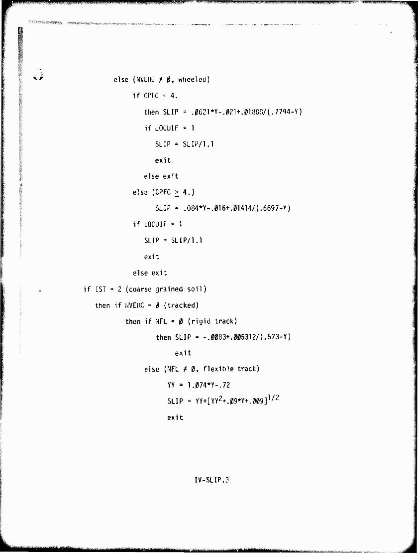
rmm mm mppflnw*1'' l"'"1' i:"'!1 i"|iKH|nH",vn<-i ■n^wg^"»1 iiiii'».w»^ippiiWII)WWP'llUIU,% '-nwim .un ix-ii'
TWT'VÄfe'arWBII^cst -^m-^HVKtaiK-mti,^,-^^: '"IWlTf J. r^.,.
^^ else (NVEHC f 0. wheeled)
if CPfC < 4.
then SLIP = .0621*Y-.02U.0l88O/{.7794-Y)
if LOCUIF = 1
SLIP = SLIP/1.1
exit
else exit
elso (CPFC > 4.)
SLIP = .O84*Y-.016+.01414/(.6697-Y)
if L0CÜIF = 1
SLIP = SLIP/1.1
exit
else exit
if 1ST = 2 (coarse grained soil)
then if NVEHC = 0 (tracked)
then if NFL = 0 (rigid track)
then SLIP = -.0083+.005312/(.573-Y)
exit
else (NFL / 0, flexible track)
YY = 1.074*Y-.72
SLIP = YY+[YY2+.09*Y+.009]1/2
exit
IV-SLIP.3
MMkMM '^•^■^—^j-^^-—-" i - ■ ■ ■ —■ i
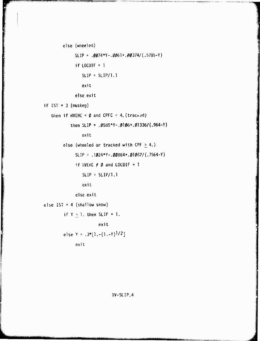
■pm l.ill.lii I IJIJ J,i|l|ai^ip,Ta^iyMBiJlllinAI'.Bii»~»liwaWg»^^^^lH'«lJ»lB!ir<''»"t>»aVl.-"?WKH>1 '
else (wheeled)
SLIP = .0074*Y-.ia061 + .^374/(.rJ785-Y)
if LOCDIF = 1
SLIP = SLIP/1.1
exit
else exit
if 1ST = 3 (muskeg)
then if NVEHC = 0 and CPFC < 4. (traced)
then SLIP = .05B5*Y-.0106+.0l336/(.964-Y)
exit
else (wheeled or tracked with CPF ^4.)
SLIP - .1024*Y-.00864+.0106?/(.7564-Y)
if NVEHC t 0 and LOCDIF = 1
SLIP = SLIP/1.1
exit
else exit
else 1ST = 4 (shallow snow)
if Y > 1. then SLIP = 1.
exit
else Y = .3*[1.-(1.-Y)V2]
exit
IV-SLIP.4
.».I..i f. .n mtmm ih., 'iiüiiu ftil i.iihulV.rj'h' 1)^!, liHiwifci»i*ttfjifc.-a.
jfpi miW ,-1"*" T"™^',l■^i,!,,"' "l'^-"'w»'Wi '■** .|.l• "■ '■ i'?".!ll"W'i''-iww »'■ mww'rymf'W**'1 ,u»»^.^»!S^7'J■w■™w■"v":■'" '-^1' ■--'■ ^jw .'HH'iiiiffi. ■wiw^wif'.'-" v y.y JB Jii>twnTiw..'iji!;.w<.i lll;^^.^-^^.^.IW.T■^T^^■^.^^^nTff^y^lTl■''■?'w■•,
^I'd'v'-.H-^i-vjiirwirtftiBiffniB»«^.!-,
(juadratic Fit Through Three Points Subroutine
Description This subroutine provides coefficients for a quad- ratic curve fitted exactly to 3 points. The subroutine is used to obtain new coefficients for tractive effort versus speed curve modified for soil slip. Dummy variables X and Y represent VG and STRACT defined in Submodel 5.
IV-QUAD.l
Amämmmmmmmmmmmmmmmmt^mm^MMm^^M^^
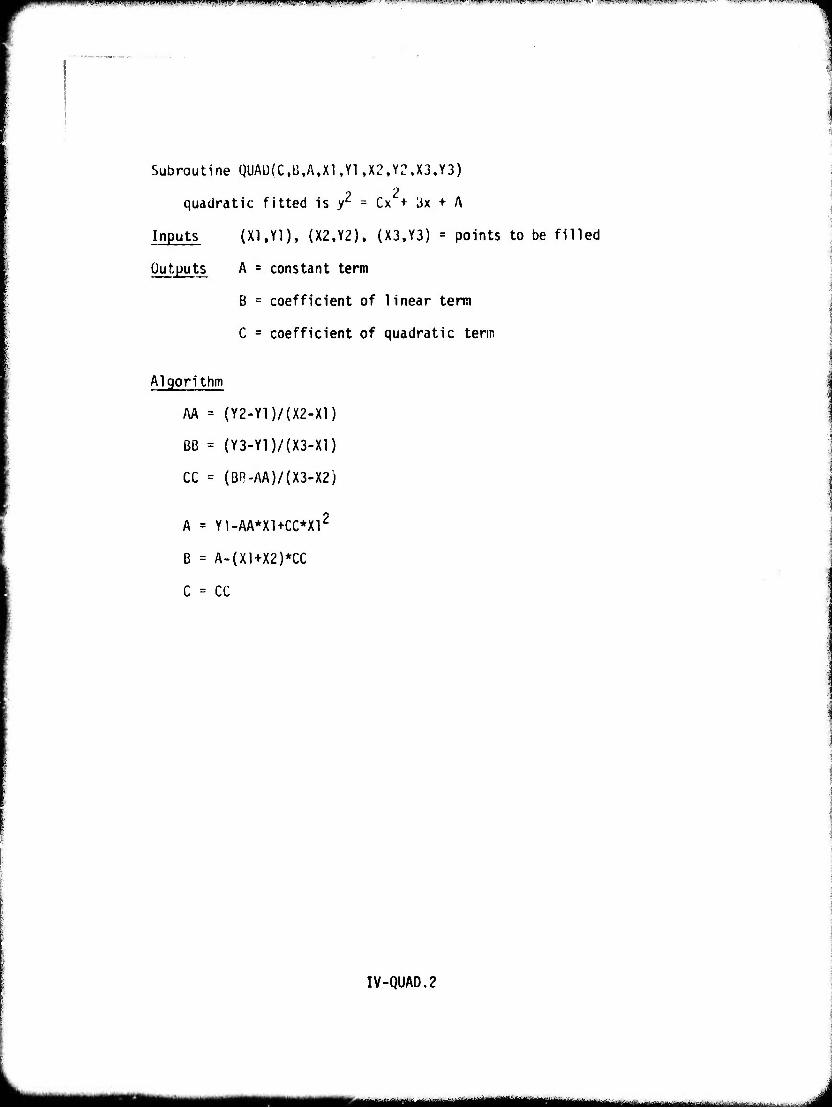
WIBP»W!IWf1WmWWW»IW«™wi«»WI»lfpi!W»BI!l^pil^^
Subroutine QUAD{C,B,A,X1,Y1 ,X2,Y2,X3,Y3)
? 2 quadratic fitted is Z1 = Cx + 3x + A
Inputs (XI,Yl), (X2,Y2), (X3,Y3) = points to be filled
Outputs A = constant term
B = coefficient of linear term
C = coefficient of quadratic tenn
Algorithm
AA = (Y2-Y1)/(X2-X1)
ßß = (Y3-Y1)/(X3-X1)
CC = (BR-AA)/(X3-X2)
A = Y1-AA*X1+CC*X12
B = A-(X1+X2)*CC
C = CC
IV-QUAD.2
■MM ■MMMM^MMMMiMH
pnpnppmiiiK wmmmummmfi^i1 "w"1 ii'ii ii>»'t^^»p«wwiii»fiw^»q|ip»ffwpMnwwi'iwi^»»»imnm'm,'nm^W'""^ i|i"J|','"r'
'•TW**'*M*,*^'ja-*inM»i i^-^» .
6. Vegetation Resistance
Description This routine calculates the forces necessary to override veqetation usinq the vegetation density calculations performed in routine 1. It is iden- tical to subroutine VEGF in the AMC '71 Mobility Model. The equations for determinii.q the output forces are explained in Reference 6.
IV-6.1
■s^MMMMH ^-..^.^.■L-^M^. ^ ..■,■.■■. ...„L- L. ■.
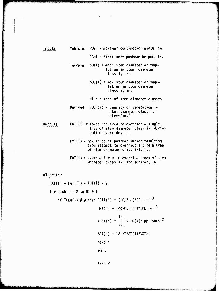
wwi^W^IWIpiPMMWippwiipp,'wiiii.i'iii »WM ^i i Mil iiiuimi ii.n mmmm iimiiii.iniinm m. ■im ji i jimp.^r- mmmmmmm
Inputs Vehicle: WÜTM - maximum combination width, in.
PBHT = first unit pushbar height, in.
Terrain: SD(i) = mean stem diameter of vege- tation in stem diameter class i, in.
SDL(i) = max stem diameter of vege- tation in stem diameter class i, in.
NI = number of stem diameter classes
Derived: TDEN(i) = density of vegetation in stem diameter class i, stems/in.'?
Outputs FATl(i) = force required to override a single tree of stem diaiaeter class i-1 during entire override, lb.
FMT(i) = max force at pushbar impact resulting from attempt to override a single tree of stem diameter class i-1, lb.
FAT(i) = average force to override trees of stem diameter class i-1 and smaller, lb.
Algorithm
FAT(l) = FATl(l) = FMT(l) = 0.
for each i = 2 to NI + 1
if TüEN(i) / 0 then FATl(i) = (%/5.8)*SDL(i-l )3
FMT{i) = (40-PBHT/?)*Sl)L(i-l)3
TFAT(i) - I TL)EN(K)*100.*SD(K)-;i
K=l
FAT(i) = 12.*TFAT{i)*WüTH
next i
exit
IV-6.2
•"---"——^-^—— a anai,
ii miui .,. n- ,...,.,,., „i ,..,, ..,.r ,..,.-.. i . i.,., . ...r ,...., .™ i ,i .Wmw' ■■■■T»".--^> ..i , i, wii ■.■>.■, .™;.i*iii-n.".i|~. ■«.-.^•r -»r"-,-. ■^.•,.. .. -inuillljii ..i.u V
else FATl(i) = 0.
FMT(i) = 0.
FAT(i) = FAT(i-l)
next i
exit
IV-6.3
"—■-■ i "-—•
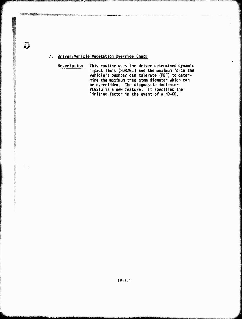
t- ■ i "»'■ji.imumii ij'niym1 '-"■" ■■-"-j''i|tJ.wi.i.Mnnnii.;nm.,iw i^t;n)|.jn)jiiM|!!W"»>ww1'1 n'^'^raiT^,i)>uwi^,wii,»itwijpiiiiiiif^BiiiMMi»^'TTar»i^«ii-|wi''»T''^.'w^Ti»|ww'if.j».^'i.^
WWygMMW 'W^JmimmmrMmmmmm*- ■Mp»'«^3fj^,.iK*.;'i»".-,-,f^v r-
:
7. Ürlver/Vehicle Vegetation Override Check
Description This routine uses the driver determined dynamic impact limit (HORZGL) and the maxinum force the vehicle's pushbar can tolerate (PBF) to deter- mine the maximum tree stem diameter which can be overridden. The diagnostic indicator VEGSIG is a new feature. It specifies the limiting factor in the event of a NO-GO.
IV-7.1
- - -—-- ■.„^ .^.>.^. .......i... J. ■aoiMaiillMiiMiM
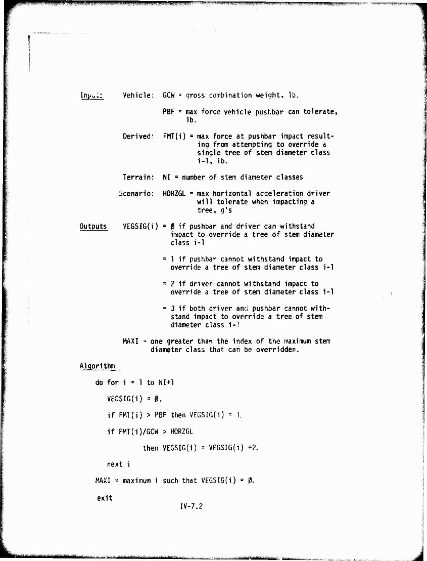
■*■"■" ^mwmiß.'imtmimuM limig^l^ttW^VWLV i''"W-rrwri'.man^iwu.^ -
Inpul: Vehicle: GCW = gross combination weight, lb,
PBF = max force vehicle pushbar can tolerate, lb.
Derived: FMT(i) = max force at pushbar impact result- ing from attempting to override a single tree of stem diameter class i-1, lb.
Terrain: NI = number of stem diameter classes
Scenario: HORZGL = max horizontal acceleration driver will tolerate when impacting a tree, g's
Outputs VEGSI6(i) = 0 if pushbar and driver can withstand impact to override a tree of stem diameter class i-1
= 1 if pushbar cannot withstand impact to override a tree of stem diameter class i-1
= 2 if driver cannot withstand impact to override a tree of stem diameter class i-1
= 3 if both driver and pushbar cannot with- stand impact to override a tree of stem diameter class t-1
MAXI - one greater than the index of the maximum stem diameter class that can be overridden.
Algorithm
do for i = 1 to NI+1
VEGSIG(i) = 0.
if FMT(i) > PBF then VEGSIG(i) = 1.
if FMT(i)/GCW > HORZGL
then VEGSIG(i) = VEGSIG(i) +2.
next i
MAXI - maximum i such that VEGSIG(i) = 0.
exit IV-7.2
rtiiMiaaahaaMii^tow.L^^_.t.--.—...,,.■. -..■ ^.-^^^
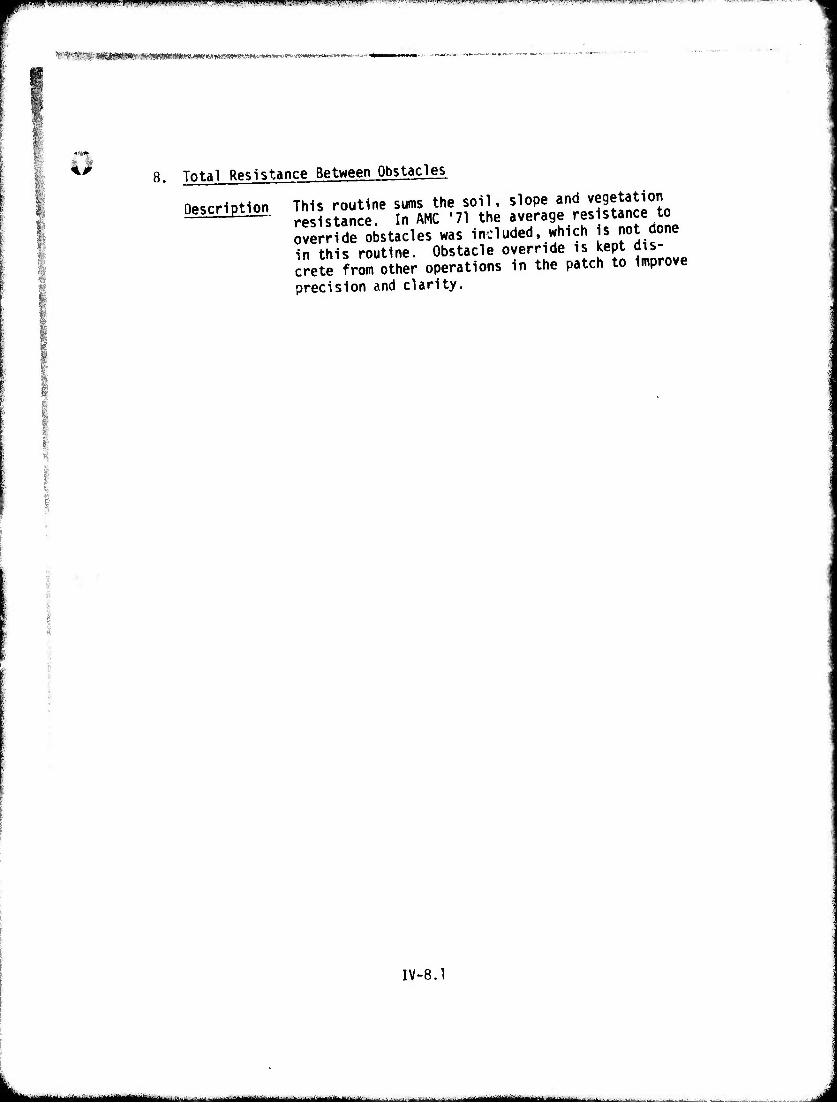
fM^PffmrniMIIBIMtl wnia ........ ui, ,,,,.„,.,,.,»..—.....,. .. ,...,
* IV^Sff IWBWIIIIIIIIIIIWIMH II MIWIllll^liaMUWlllWWWMIM MwmeMHnMt-H
8. Total Resistance Between Obstacles
Description This routine sums the soil, slope and vegetation resistance. In AMC '71 the average resistance to override obstacles was included, which is not done in this routine. Obstacle override is kept dis- crete from other operations in the patch to improve precision and clarity.
IV-8.1
L. adafllMttMBItlUte
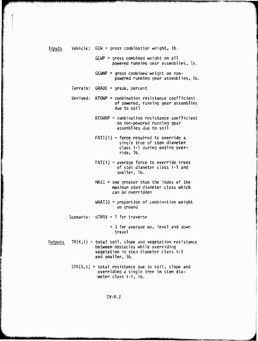
^npippRu iiii.^uiinn^ipipipipinmn«
Inputs Vehicle: GCW = gross combination weight, lb.
GCWP = gross combined weight on all powered running gear assemblies, lb.
GCWNP = gross combined weight on non- powered running gear assemblies, lb.
Terrain: GRADE = grade, percent
Derived: RTOWP = combination resistance coefficient of powered, running gear assemblies due to soil
RTOWNP = combination resistance coefficient on non-powered running gear assemblies due to soil
FATl(i) = force required to override a single tree of stem diameter class i-1 during entire over- ride, lb.
FAT(i) = average force to override trees of stem diameter class i-1 and smaller, lb.
MAXI = one greater than the index of the maximum stem diameter class which can be overridden
WRATIO = proportion of combination weight on ground
Scenario: NTRAV = 1 for traverse
= 3 for average up, level and down travel
Outputs TR(K,i) = total soil, slope and vegetation resistance between obstacles while overriding vegetation in stem diameter class i-1 and smaller, lb.
STR(K,i) = total resistance due to soil, slope and overriding a single tree in stem dia- meter class i-1, lb.
IV-8.2
bi*^. n.M-.^,^*^^^ , ,.M^^^^^..^.|jM
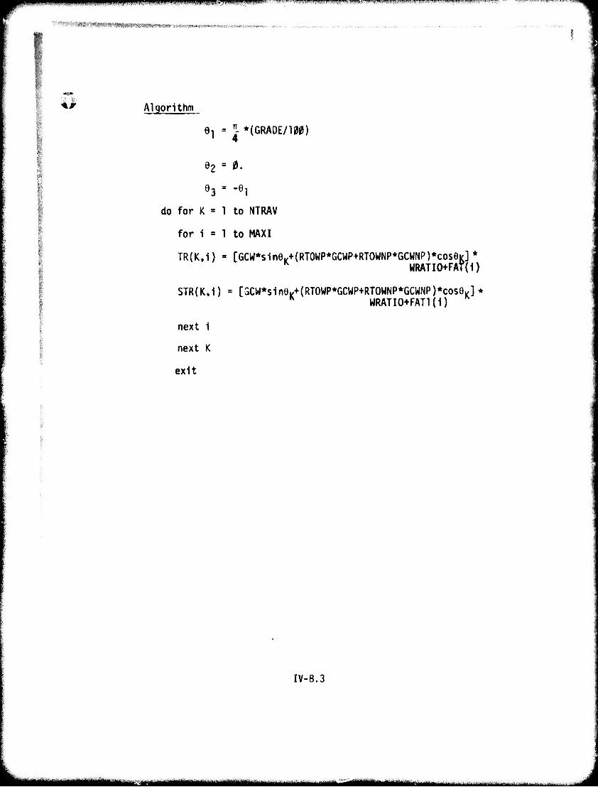
maaBW*pwaw*vi mum H.^W^BW^ ,11 Jllii i-l I ■mil I wrrm i wr • immiwu. Vimnm.,.miv i ,,,.,,,„,,,„. i, .
.•'■^f.v-,' ■
Aß Algorithm
61 = "- *(GRADE/100) 4
i
83 = -9!
do for K = 1 to NTRAV
for i = 1 to MAXI
TR(K,i) = [6CW*sinel,+(RT0WP*GCWP+RT0WNP*GCWNP)*cos9K]* K WRATIO+FAT(i)
STR{K,i) = [3CW*sin9.+ (RT0WP*GCWP+RT0WNP*GCWNP)*cose|(]* h WRATIO+FATl(i)
next i
next K
exit
IV-8.3
I Ml *to",*^fc-*,°"""j—■■• ...■.-^.., .-.-,.., ...... .
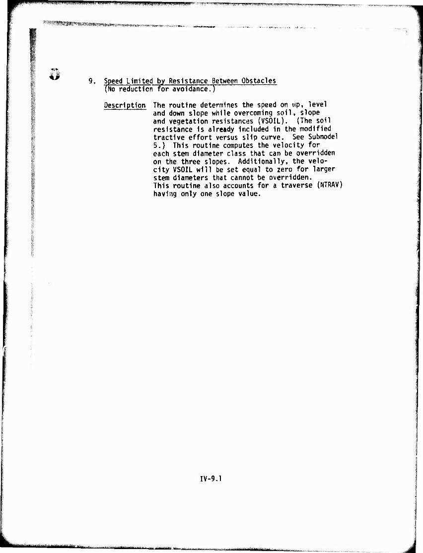
Wf^W»PWW^^^^ff«'W'!W*UWjl!IIJliM*!Ji^
'^^W^mr9mmmim^iii>^m.'mV^m;»t, lUa9tseßm<»mMow*. -»«N«««*««*- -.-
9. Speed Limited by Resistance Between Obstacles (No reduction for avoidance.)
Description The routine determines the speed on up, level and down slope while overcoming soil, slope and vegetation resistances (VSOIL). (The soil resistance is already included in the modified tractive effort versus slip curve. See Submodel 5.) This routine computes the velocity for each stem diameter class that can be overridden on the three slopes. Additionally, the velo- city VSOIL will be set equal to zero for larger stem diameters that cannot be overridden. This routine also accounts for a traverse (NTRAV) having only one slope value.
IV-9.1
L ■ - - ' ^ nlHiriiiMrtn ■'--■'- J-—--^rtMMiihttiiutf-iiiiii i muakmauu
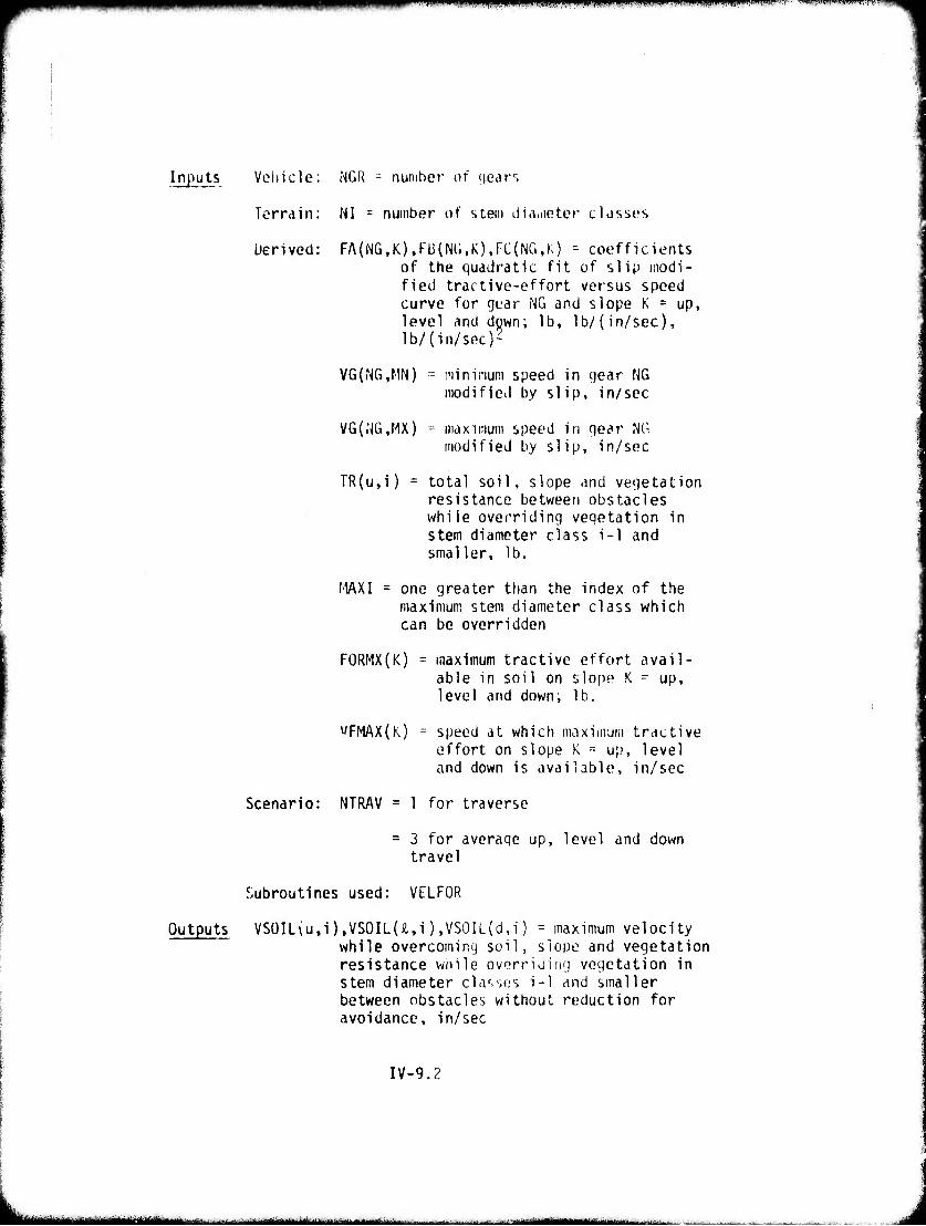
i •iimnawmiM mn «WWPWWWIWHIJ LI! ■.:- ilW.W"l!,"'-P.wriw
Inputs Vehicle: NGR = number of gears
Terrain: NI = number of stem üia.neter classes
Derived: FA(NG,K),FU(N(i,K),FC(NG,K) - coefficients of the quadratic fit of slip modi- fied tractive-effort versus speed curve for gear NG and slope K = up, level and down; lb, lb/(in/sec), lb/(in/sec)2
VG(iNG,MN) = minimum speed in gear NG modified by slip, in/sec
VG(rj6,MX) = maximum speed in gear NG modified by slip, in/sec
TR(u,i) - total soil, slope and vegetation resistance between obstacles while overriding vegetation in stem diameter class i-1 and smaller, lb.
MAXI = one greater than the index of the maximum stem diameter class which can be overridden
FORMX(K) = inaximum tractive effort avail- able in soil on slope K - up, level and down; lb.
yFMAX(K) = speed at which maximum tractive effort on slope K = up, level and down is available, in/sec
Scenario: NTRAV = 1 for traverse
= 3 for average up, level and down travel
Subroutines used: VELFOR
Outputs VSOIL(u,i),VSOlL(Ä,i),VS0IL(d,i) = maximum velocity while overcoming soil, slope and vegetation resistance woile overriding vegetation in stem diameter classes i-1 and smaller between obstacles without reduction for avoidance, in/sec
IV-9.2
■MtiWHMMlUMik r ■'- ■■ -^ ■-■u~ MtafMaMaMMaH^M^MaMM l-V.-!.-....—■'•■ ■- ~.-.J..x£.KK «« _■•■•
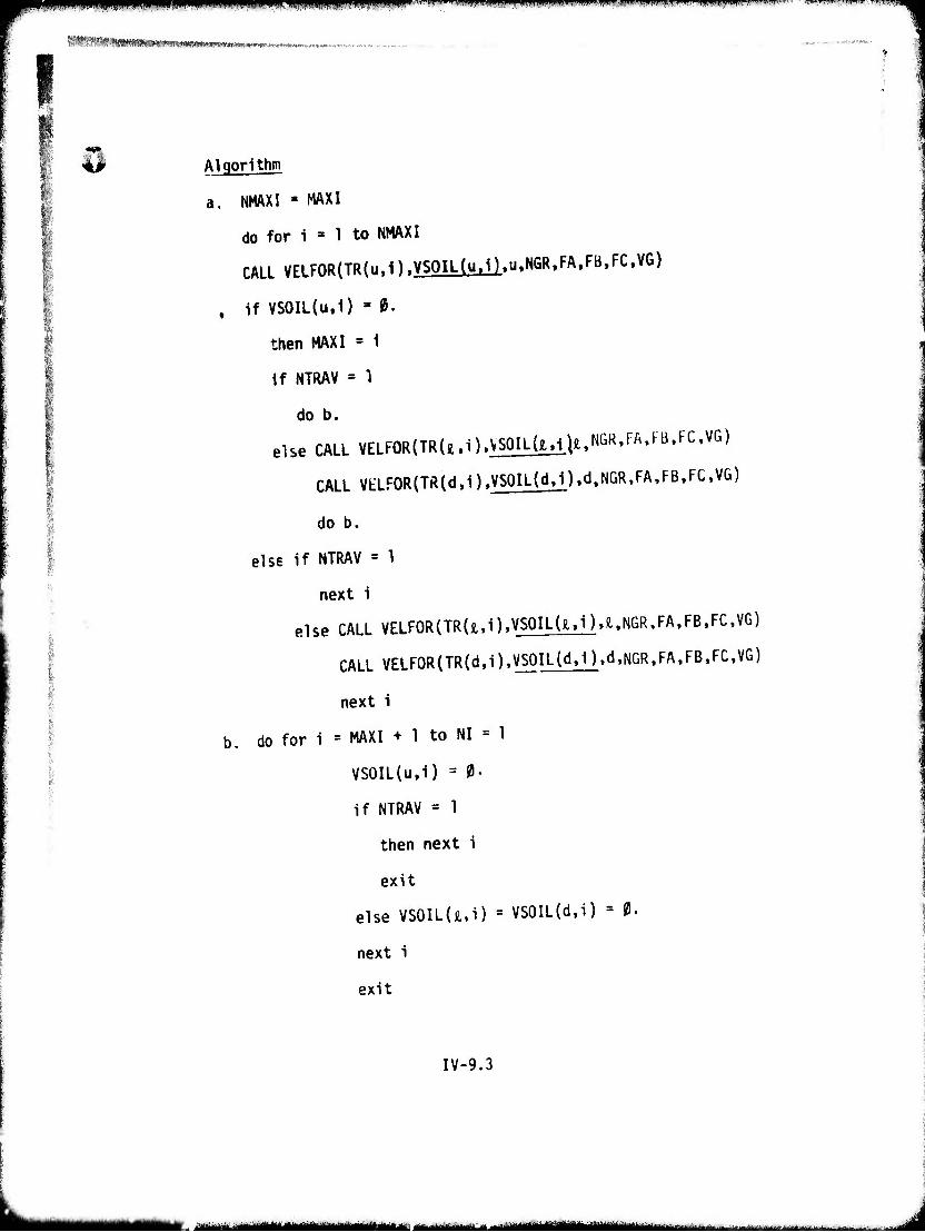
wmmmmmmimmmnmmim* W> • ■■ .«^KpiRWPiPIHtlWIII^^WWIMII.iJ««.1 W«'l.MWW,l'"(i».PV".',, I I '■ TIWB ""-v
WW—Mtlil wtn^«,^-«.^^«^.
Algorithm
a. NMAXI - MAXI
do for 1 » 1 to NMAXI
CALL VELF0R(TR(u,1).VSOILdi.D.u.NGR^A.FB.FC.VG)
. if VSOIL(u.i) » 0.
then MAXI = 1
If NTRAV = 1
do b.
else CALL VELF0R(TR(Ä.i).VMIL(xvL^,NGR,rA,Fü,FC,V6)
CALL VtLFOR(TR(d,i),VSOIL(dJ).d,NGR,FA,FB,FC,V&)
do b.
else if NTRAV = 1
next i
else CALL VELF0R(TR()t.i)tVS0IL(jl>i)>8..NGR,FAtFBtFCtVG)
CALL VELFQR(TR(d.i)>VS0IL(dt1)>dtNGR>FA>FB.FC.VG)
next i
b. do for i = MAXI + 1 to NI = 1
VS0IL(u,i) = 0.
if NTRAV = 1
then next i
exit
else VSOIL(iui) = VS0IL(d,i) = 0.
next i
exit
IV-9.3
■■ i -■■■ i -■-.-. ■■ - - - -- ■ ■ -
■■■ fumßtgi (pUpw-T^^vr^sr mmmtp^l ''"" 'i iipmm^^vnmi&mQ r*» wr1.'"^^-:*
IWBBffirililllllflMIMIilHiii Iiwiiii J iwwiiiniiwmjwwwuw i
o Maximjm Velocity Overcoming a Given Resistance Subroutine
Description This subroutine is used in submodel 9. Subroutine VELFOK examines tKe tractive effort versus speed curve segments for each gear (which are represented by quadratic equations of the form y^FCx^+FBx+FA (where y is traction, x is vehicle velocity) and establishes the intersection with the y - constant line representing the sum of the resistance due to grade and vegetation (TR), The abcissa of the intersection point is the maximum velocity that can be achieved while overcoming resistance TR. Several possibilities arc investigated including parabolic segments with either positive or negative curvature (concave up and concave down respectively) and straight lines (FC = 0).
IV-VELF0R.1
... ,.:..,.... .. x . ^ | .... V^-J-^.^.-,.....
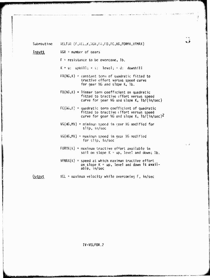
mm ■rmiimr^mmmmmm'mmnf^^i''^ WWt.,i.r^---iw)t».i»i,iiliii|lMii"1 . * ■■n
Subroutine
Inputl
Output
VELFOR (FfV£L,K,;jGR.rM,rß,FC,VG,FORMX,VFMAX)
NGR = number of qears
F = resistance to be overcome, lb.
K = u: uphill; = i: level; = d: downhill
KA(NG,K) = constant term of quadratic fitted to tractive effort versus speed curve for gear NG and slope K, lb.
FB(NG,K) = linear term coefficient on quadratic fitted to tractive effort versus speed curve for gear NG and slope K, lb/(in/sec)
FC(NG,K) = quadratic term coefficient of quadratic fitted to tractive (ffort versus speed curve for gear NG and slope K, lb/(in/sec)2
VG(NG,MN) = minimum speed in tjear NG modified for slip, in/sec
VG(NG,MX) = maximum speed in geai NG modified for slip, in/sec
FüRMX(K) = maximum tractive effort available In soil on slope K = up, level and down; lb.
VFMAX(K) = speed at which maximum tractive effort on slope K = up, level and down is avail- able, in/sec
VEL = maximum velocity while overcoming F, in/sec
IV-VELFOR.?
^^MMi^-i ■ nrnrniirrni f^gttHt^tt^'^-'^^ ^Ht-t^ MM 1- "■■'■-■i—*■- .mu
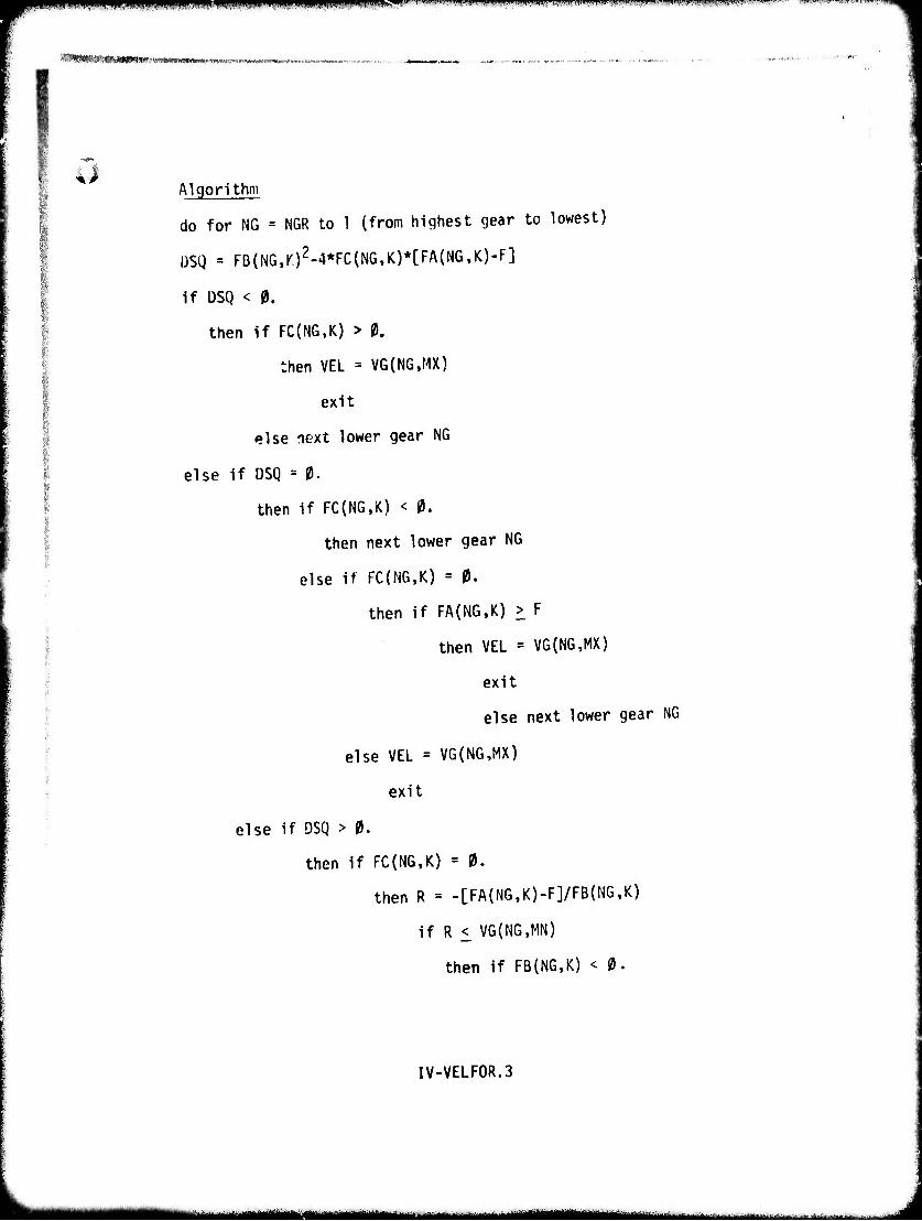
f^m^^mmi^mnimmmmi'mmwm'^v^^'^^i'''^^v"^[>-'',-^m' ^'.'i'^»'M''WW>WI«*"'UU"V*MMMW'' i,niiHii.IIw"w.',i"PJ,™;w..WwF.^. »«^«- ■'™i«l.'.'>.^-.»IM».,Hll.-
WMWMMWWMWiiwwMMiii ■ i i—«.«..»■■.■..^..■l..
^ Algorithm
do for NG = NGR to 1 (from highest gear to lowest)
I3SQ = FB(NG,K)2-4*FC(NG,K)*[FA(NG,K)-F]
if ÜSQ < 0.
then if FC(NG,K) > 0,
then VEL = VG(NG,MX)
exit
else next lower gear NG
else if DSQ = 0.
then if FC(NG,K) < 0.
then next lower gear NG
else if FC(NG,K) = 0.
then if FA(NG,K) > F
then VEL = VG(NG,MX)
exit
else next lower gear NG
else VEL = VG(NG,MX)
exit
else if DSQ > 0.
then if FC(NG,K) = 0.
then R = -[FA(NG,K)-F]/FB(NG,K)
if R < VG(NG,MN)
then if FB(NG,K) < 0.
IV-VELF0R.3
.. HaMaMaaBHMaaaM^^
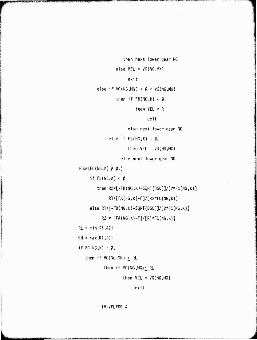
u.i.i ..■■■inm,. piWipWWtpppWWPHBBWBtWI ■I'WTW "'' -rvrrTi»,::-,,,,,,'-*^ •" pwi.i-iwF-wrw»'.'!""" HKXWfl'W^* '' »»™-^^F™
then next lower gear NG
else VEL = VG(NG,MX)
exit
else if VG(NG,MN) < R < VG(NG,MX)
then if FB(NG,K) < 0.
then VEL = R
exit
else next lower gear NG
else if FB(NG,K) v 0.
then VEL - VG(NG,MX)
else next lower gear NG
else(FC(NG,K) t 0.)
if FB(NG,K) < 0.
then R2=[-Fß(NG,K)+SQRT(DSQ)]/Lr2*FC{NG,K)]
R1=[FA(NG,K)-F]/[R2*FC(NG,K)]
else R1 = [-FB(NG,K)-SQRT(DSQ:.]/[2*FC(NG,K)]
R2 = [FA(NG,K)-F]/[R1*FC(NG,K)]
RL = min{Rl,R2}
RH = max{Rl,R21
if FC(NG,K) > 0.
then if VG(NG,MN) < RL
then if VG(NG,MX)< RL
then VEL = VG(NG,MX)
exit
IV-VELF0R.4
lifiiii i - ^.^--...^.^ - riii iMfl^^—■■^^^--^■^--■-■"^■■■-■-■-■'-■■-^■"-■-■ t^HM^r,. .■„■,^-i^Baüiaani 11 ^itiJifuuittlmmtlKHmmtttitä aajnaatt a ■,
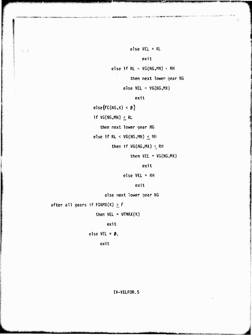
^^w^^wp P|PII,I.I.HPJ]|I,|.IIIPI^ wiijiii,iwajiiiik,^^,ipli!iiiiiwiiWPjjp>pipiiii,i.j... 11^
RMlMMHRMMHnMBlMHHMl w.^,^Mrt^J»»M'.*«*»«ft»"»«««W< ■' '■-■ «' ■■ ' 1*V,«« ■■■ "*•"»
, i else VEL = RL
exit
else if RL < VG(NG,MN) < RH
then next lower gear NG
else VEL = VG(NG.MX)
exit
else(FC(N6,K) < 0)
if V6{N6,MN) < RL
then next lower gear NG
else if RL < VG(NG,MN) < Rll
then if VG(NG,MX) < RH
then VEL = VG(NG,MX)
exit
else VEL = RH
exit
else next lower gear NG
after all gears if F0RMX{K) > F
then VEL = VFMAX(K)
exit
else VEL = 0.
exit
IV-VELF0R.5
^^^^^^^^^ i im.m m !! mnmmmm^mm
. ., . pKpm'it&evp
iß 10. Speed Limited by Surface Roughness
Description This routine determines the vehicle speed limited by the driver's tolerance to traveling over rough terrain. A table of vehicle speed versus surface roughness values obtained from either measured field data or the Ride Dynamics Module (VII) is interpolated for the actual terrain roughness (ACTRMS) of the particular patch. (This was not necessary in AMC '71 because AMC '71 could not accept actual terrain RMS values. It only oper- ated with fixed classes of RMS.)
To allow latitude of having more than one rough- ness tolerance level, different tables may be used for different motivational levels of the driver. Field experience shows that the 6 watts tolerance level is often exceeded in an emergency situation.
IV-10.1
l^^^i
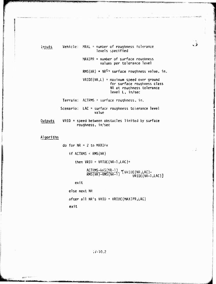
iiiiji.ii,,.iii»,npm,njijii,w.ijmin in ii ii_jiIWpjtjiWi|!^|>M,i'i»w Tim.»»».' l.l:IJiilU,P»W>ill!U^i.ii,l».Wi''W^»^ll^^^ ^^
»•i-ii&W&Ck* - " ■'■<••'*• 4)ft"'
Inputs Vehicle: MAXL = number of roughness tolerance levels specified
MAXIPR = number of surface roughness values per tolerance level
RMS(NR) a NRt" surface roughness value, in,
VRIDE(NR,L) = maximum speed over ground for surface roughness class NR at roughness tolerance level L, in/sec
Terrain: ACTRMS = surface roughness, in.
Scenario: LAC = surface- roughness tolerance level value
Outputs VRID = speed between obstacles limited by surface roughness, in/sec
>
Algorithm
do for NR = 2 to MAXIHK
if ACTRMS < RMS(NR)
then VRID = VRIUE(NR-1,LAC)+
ACTRMS RMS
RMS-kMS^'R-l) *rwDTnc/KiD .AM TNR)--TMt(FR--iT^VRIÜ ^51; VRIDE(NR-1,LAC)]
exit
else next NR
after all NR's VRID = VRIDE(MAXIPR,LAC)
exit
17-10.?
0*^ liri.iiii ii ■ r, M*m
- "iri'"ttl*iMa'"»Mlfc *'""""1'f*"'Mll""''|ir"1' ' irif.-itmr i.MM'linMJMMiH ■ MBttMü
^^K&rW't^&f ^^J^^^V P^P 1 '" mmmm^mmmw^-^ «uwww«-! ,*w^w^w, m ffl^pwp
^^■*f^.r- mwm^ Pi --VK-■WNJ^W^^'i'TIWiPTfSB-**1«-*-'' 'C'-.Vi- lü'-«''.*.«*«'^■«': ■■,-
^ 11. Total Braking Force
Description Thio routine assigns the maximum available braking force by examining the braking forces which can be generated by the soil and grade and compares tMs braking force with the maximum braking force which can be developed by the vehicle's braking system (XBR). One of the possible outputs is a NO-GO indicating inadequate braking of the vehicle on a down slope (BFGONO s 1)
IV-11.1
-■- " ■ I ä^mmmgjf^ M^MMk^MM J
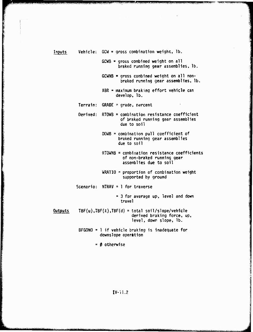
mmm wm* .I^IJU.., IIIMI^IUMHII.««IWIP>gf IP „(■»»JUPSJPIIJII1*!!. f^l
Inputs Vehicle: GCW = gross combination weight, lb.
GCWB ■ gross combined weight on all braked running gear assemblies, lb.
6CWNB ■ gross combined weight on all non- braked running gear assemblies, lb.
XBR = maximum braking effort vehicle can develop, lb.
Terrain: GRADE = grade, percent
Derived: RTOWB - combination resistance coefficient of braked running gear assemblies due to soil
DOWB = combination pull coefficient of braked running gear assemblies due to soil
RTOWNB = combination resistance coefficients of non-braked running gear assemblies due to soil
WRATIO = proportion of combination weight supported by ground
Scenario: NTRAV = 1 for traverse
= 3 for average up, level and down travel
Outputs TBF(u),TBF{0,TBF(d) = total soil/slope/vehicle derived braking force, up, level, down slope, lb.
BFGONO » 1 if vehicle braking is inadequate for downslope operation
= 0 otherwise
IV-11.2
|•^^*^l"1^""" " ' ' .....,-...— ^MMMMIiHIMkMM^Hk«. " -^ :'-'" ■'.
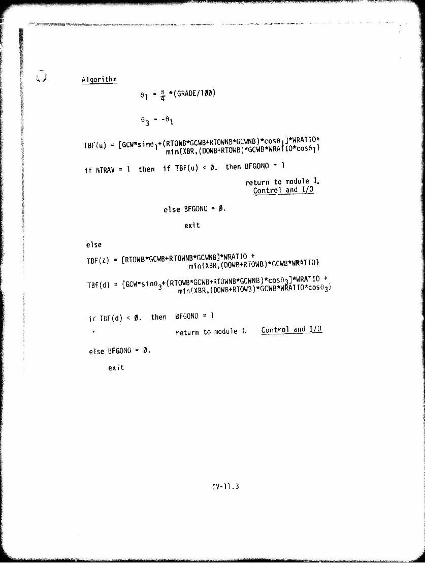
^pii« wmy-.mjji ,i.ujjii,iiin«iii.ii|iii. I.J 11, miy.ppi„.,.»«ii,Miii.i.L , iiDjjpwiii^ii}]. -v**^^--~^w^ww^-'-'m'**
^*'"j!WiiiW^*gg^>^'t^^--^tf^^ w»
i Algorithm
e1 = J *(GRADE/1M)
e3 = -91
TBF(u) = [GCW*sinö1 + (RTOWB*GCWB+RTOWNB*GCWNB)*cose1]*WRATIO+ m1n{XBR,(D0WB+RT0WB)*GCWB*WRATI0*cose1}
if NTRAV = 1 then if TBF(u) < 0. then BFGONO = 1
return to module I. Control and I/O
else BFGONO = 0.
exit
I else
TBFU) = [RTOWB*GCWB+RTOWNB*GCWNB]*WRATIO + mi n (XBR, (DOWB+RTOWB) *GCWB*WRi\T 10}
TBF(d) » [GCW*sin0.+(RTOWB*GCWB+RTOWNB*GCWNB)*cosO3]*WRATIO + J m1n(XBR,(00WB+RT0WB)*GCWB*VIRATI0*cose3
if TBF(d) < 0. then BFGONO = 1
return to module I. Control and I/O
else BFGONO = 0.
exit
l
IV-11.3
-■—''——' - —- —MM—I—11^ .
H^*^ *■ J■" »'wmiWI^IüP» IMIIIP'HI,■ iwii,■>.■',«w■■ ,'■)■' ■ ■IMUJr,'» HI-JIHW«"IT
" ... "V.^-'i'yiy^^twy-r'«)! ■
12. Driver Dictated Braking Limits
Description This is a new routine. It incorporates two driver dependent scenario inputs. The first establishes the maximum deceleration (MXGOCL) the driver is willing to use depending on comfort, cargo or perhaps emergencies. The second factor (SFTYPC) indicates that under certain circumstances the driver will not utilize the total maximum braking force available because, for example, he does not want to skid the vehicle.
IV-12.1
L. -"" """"liliül-ttilii-i fl 1 -"-liii ■•-ir<i • riiürüMiiiii r —■"'- .**,-,..^ ■^■.J..-,....^. -
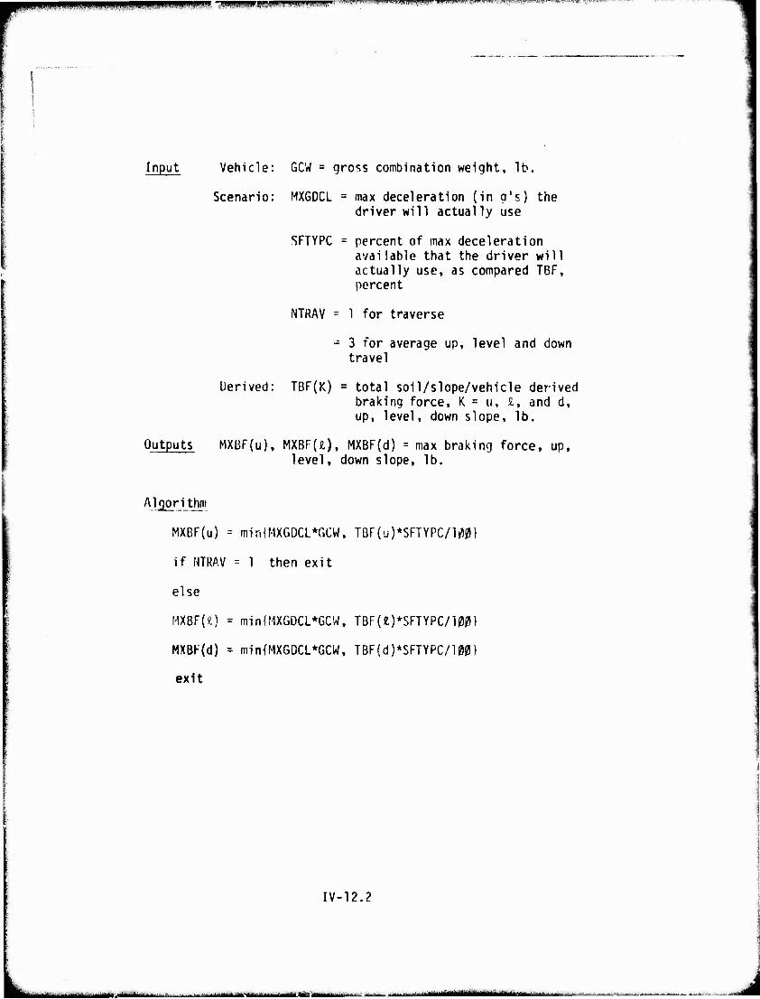
PSW», TpipiPBirJWifBPWWIPffWHSF''" •r\w rfr'svyivih* wx^^^"" »FTT^^M^' 'i11
Input Vehicle: GCW = gro^s combination weight, lb.
Scenario: MX6DCL = max deceleration (in q's) the driver will actually use
SFTYPC = percent of max deceleration available that the driver will actually use, as compared TBF, percent
NTRAV = 1 for traverse
- 3 for average up, level and down travel
Derived: TBF(K) total soil/slope/vehicle derived braking force, K = u, I, and d, up, level, down slope, lb.
Outputs MXBF(u), MXBF(ä), MXBF(d) = max braking force, up, level, down slope, lb.
Algorithm
MXBF(u) - miriiMXGDCL*GCW, TBF(u)*SFTYPC/l^}
if NTRAV = 1 then exit
else
MXBF(fc) = min{MXGDCL*GCW, TBF(t)*SFTYPC/100}
MXBF(d) = min{MXGDCL*GCW, TBF(d)*SFTYPC/100}
exit
IV-12.2
. . ■ :..,.. ^LJ .•-..-.■ . .,-..., im ,*ikim*äuk*m -MMtii MUMHyLÜttWift ■—■■—•- --■ mBi ^.M^M^HMMi gUtm^mU
i m. iiwiiiimiBMinn IWLHI'H^W,;' ■ itnmfifwKirwi>'fniri''^im
mmtmmmm» WIHIHKHtmBBmmmmmmmmimmm^
w 13. Speed Limited by Visibility
Description This routine takes the place of VISION of AMC '71. A new feature is the inclusion of the eye height of the driver as an input variable and not a constant. This height influences the recognition distance (RFCD) which in turn, affects the speed limited by visibility (VELV). A new scenario input (VISMNV) is also included which is the minimum speed at which the driver would proceed for zero visibility. This speed (VISMNV) is assumed to be equal to a man's walking speed in most cases.
IV-13.1
■"- - ' ■•-- -rifririi -^ -'-
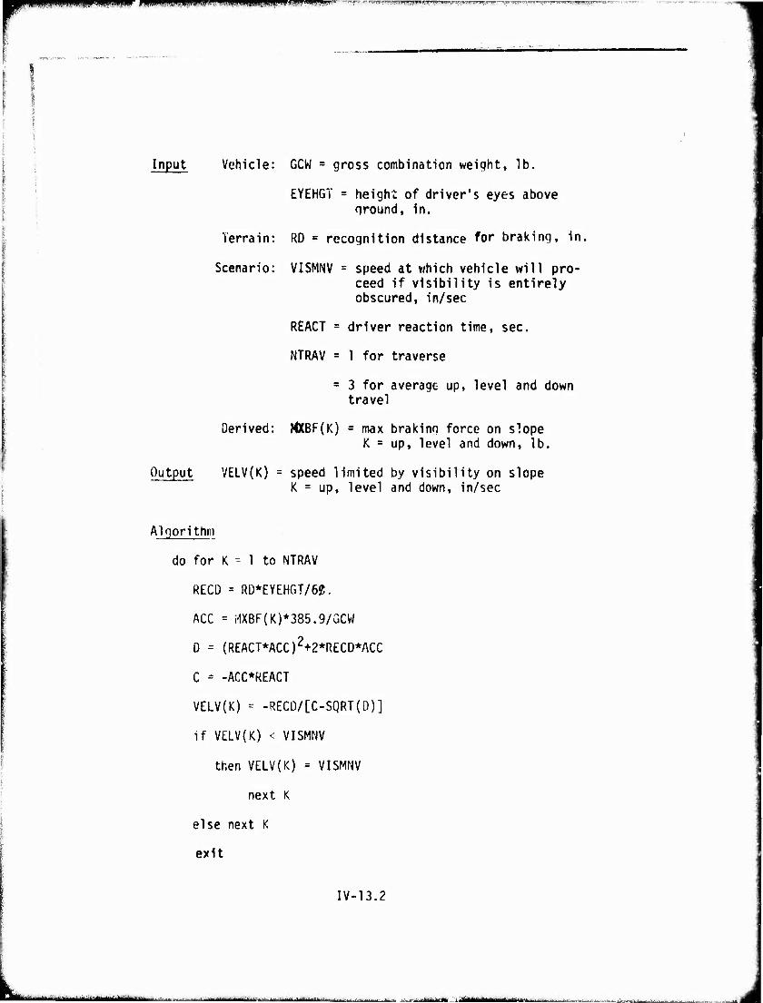
■ i.i^wijjiiiiuiii.i jiL;., ,, | ii.ii j.ijwwii.ii.i.mj. i f^^'.-'-^v-.- *■ i-rors-rwiwviw^Tn-w F.T,.TPif wr^r^^-rr.T'Tww^'wp-' '^'"•^'»■^r''™1-?^ ^
Input Vehicle: GCW = gross combination weight, lb.
EYEHGT = height of driver's eyes above ground, in.
Terrain: RD « recognition distance for braking, in.
Scenario: VISMNV = speed at which vehicle will pro- ceed if visibility is entirely obscured, in/sec
REACT = driver reaction time, sec.
NTRAV = 1 for traverse
= 3 for average up, level and down travel
Derived: MXBF(K) = max braking force on slope K = up, level and down, lb.
Output VELV{K) = speed limited by visibility on slope K = up, level and down, in/sec
Algorithm
do for K - 1 to NTRAV
RECD = RD*EYEHGT/62.
ACC = MXBF(K)*385.9/GCW
D = (REACT*ACC)2+2*RECD*ACC
C = -ACC*REACT
VELV(K) - -RECD/[C-SQRT(D)]
if VELV(K) < VISMNV
then VELV(K) = VISMNV
next K
else next K
exit
IV-13.2
"■:-- • - ■"-■ 'j-»^--»^^— [ n !■!■■■ Im M — ' ■
i mumm wmmmm um n mm mm. n \ m :-l.J|«l|li„l,Ji))pi!JJl.l.ll.|il!»n
|No al lowance tor nwiieuverlng)
Description This routine selects the minimum of the pre- viously calculated speeds. A new feature for AMC '74 is the inclusion of a speed which depends essentially on tire pressure. This forces low speed limits to guard against structural damage to tires on vehicles which cannot re-inflate their tires after operating with reduced pressures on marginal terrain.
IV-14.1
"- ■j— '—- ---■^■■■-— ' J-M—--.—■■- iiriju'i^---—'-•■"'■' i rn l J
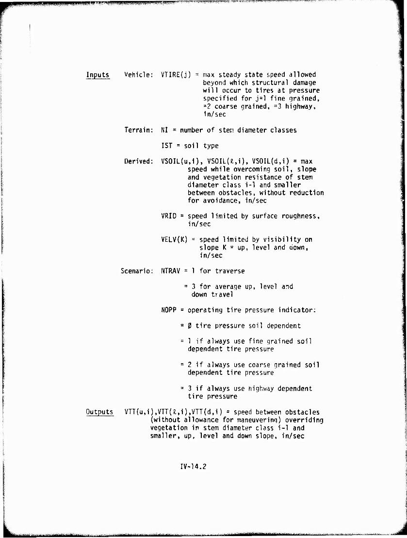
MPIBPHP^PIPSIIIPIIPPPPIP^^ win wwifP« '"VHlier*1^;' rwnw
Inputs Vehicle: VTIRE(j) = max steady state «.peed allowed beyond which structural damage will occur to tires at pressure specified for j=l fine grained, a2 coarse grained, =3 highway, in/sec
Terrain: NI = number of sten diameter classes
1ST = soil type
Derived: VS0IL(u,i), VSOILU.i), VS0IL(d,i) = max speed while overcoming soil, slope and vegetation resistance of stem diameter class i-1 and smaller between obstacles, without reduction for avoidance, in/sec
VRID = speed limited by surface roughness, in/sec
VELV(K) = speed limited by visibility on slope K = up, level and down, in/sec
Scenario: NTRAV = 1 for traverse
= 3 for average up, level and down travel
NOPP = operating tire pressure indicator:
= 0 tire pressure soil dependent
= 1 if always use fine grained soil dependent tire pressure
= 2 if always use coarse grained soil dependent tire pressure
= 3 if always use highway dependent tire pressure
Outputs VTT(u,i),VTT(x.,i),VTT(d,i) = speed between obstacles (without allowance for maneuvering) overriding vegetation in stem diameter class i-1 and smaller, up, level and down slope, in/sec
IV-14.2
Mfc-"-■- - ■ '"l^ltlirtiMiai i 1 iimMMiMr- - I 'am inn ■ ..i+vi^tviiMatMUtMamm*^^-*,™.'*,-^,,.,...*.,. ■.-....-,....,„„■,..,.■„..-■■ Mtaam
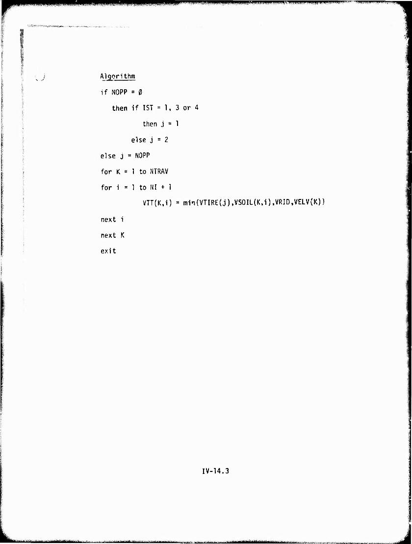
1 "i wu mimjm'vmwmmmM'mtummnimmiwmmmvwHm'-.i'^--
'-'■>*' v^txtwmtM»* ■■*— -w,«^^w..
.; Algorithm
if NOPP = 0
then if 1ST = 1, 3 or 4
then j = 1
else j = 2
else j = NOPP
for K = 1 to NTRAV
for i = 1 to NI + 1
VTT(K,i) = min(VTIRE(j).VSOIL(K,i),VRID,VELV(K))
next i
next K
exit
IV-14.3
.. —,—^-^>l „ - ■ t^tgitmaammb J
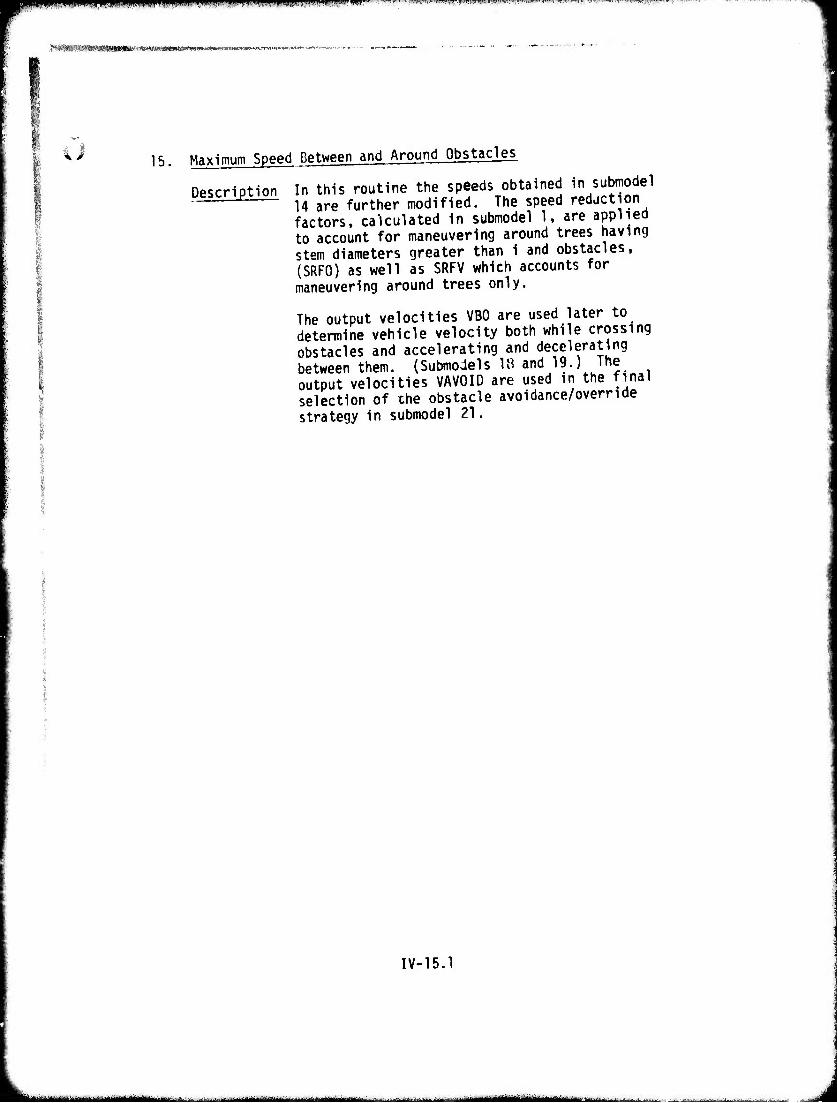
PilliniPmf^iPWIiiPinWPi lAIJ.il .ilUHIJ l!|IWJIIJIlli|l,iil|MlllJl(,i.UII i«l,l —"■ TWWTOfflWWWTOCTWnwr^ -,^r., -..-..
>äi»Wr'i«*äS!8a9»IB»'S'»(*«M.»MMt«^»-^
i it ^ 15. Maximum Speed Between and Around Obstacles
Description In this routine the speeds obtained in submodel 14 are further modified. The speed reduction factors, calculated in submodel 1, are applied to account for maneuvering around trees having stem diameters greater than 1 and obstacles, (SRFO) as well as SRFV which accounts for maneuvering around trees only.
The output velocities VBO are used later to determine vehicle velocity both while crossing obstacles and accelerating and decelerating between them. (Submodels 18 and 19.) The output velocities VAVOID are used in the final selection of the obstacle avoidance/override strategy in submodel 21.
IV-15.1
- 1 1— .i.-- - - amt^^iMm^ tmmtmt m Mti rfai^h . J
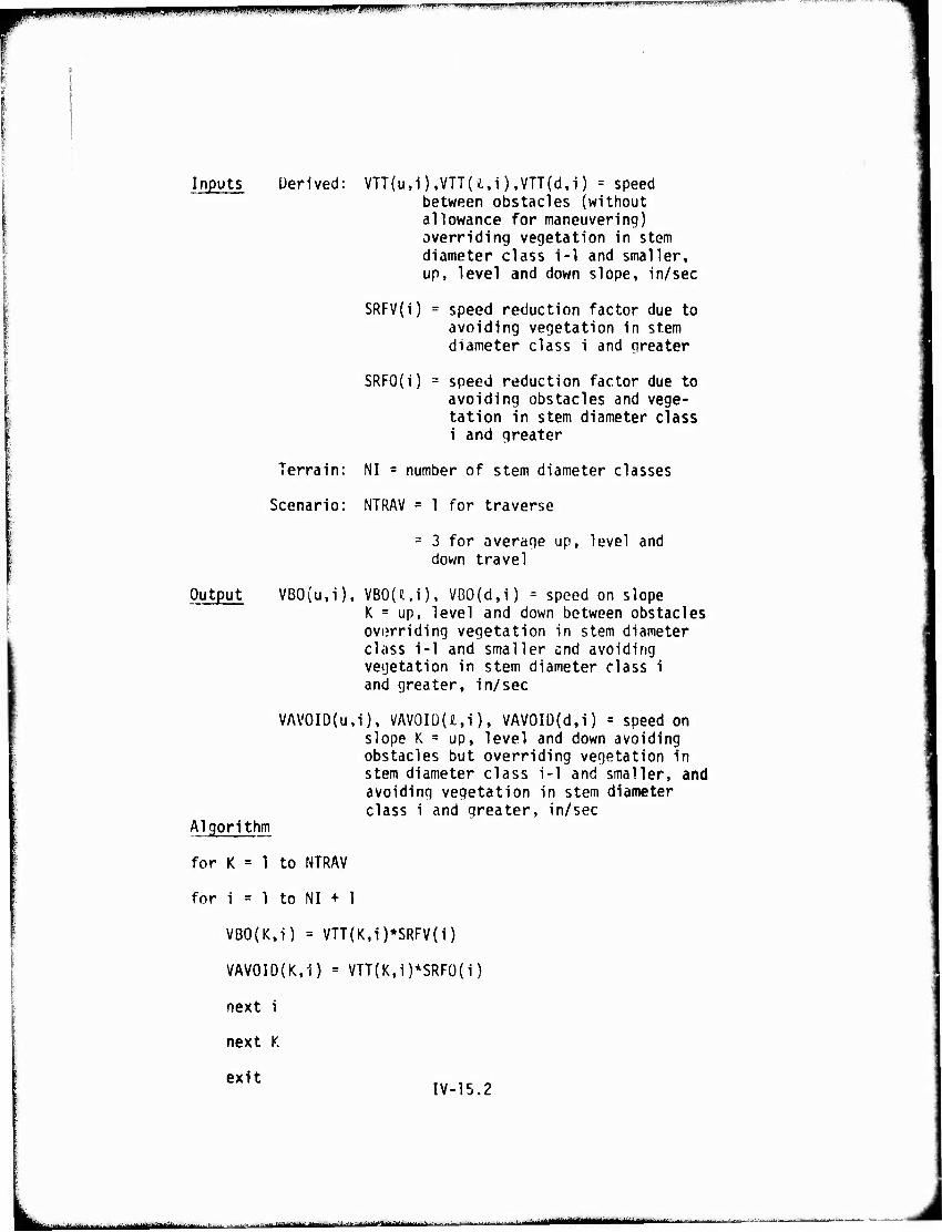
puPWWWPPWlfBWWIM ■*n*iwirr7 ■ii|]ijiii.iuip^iiiiipijiiii,iijg>»ww'»l','g'lwil'T!»»l'i|'»'"lllll!|ll-'ll'll'ii''ii'' i.i win.i.i" f^W
Inputs Üerived: VTT(u,i),VTT(£,i) ,VTT(d,i) = speed between obstacles (without allowance for maneuvering) overriding vegetation in stem diameter class i-1 and smaller, up, level and down slope, in/sec
SRFV{i) = speed reduction factor due to avoiding vegetation in stem diameter class i and greater
SRFO(i) = speed reduction factor due to avoiding obstacles and vege- tation in stem diameter class i and greater
Terrain: NI = number of stem diameter classes
Scenario: NTRAV = 1 for traverse
= 3 for average up, level and down travel
Output VB0(u,i), VBOU.i), VB0(d,i) = speed on slope K = up, level and down between obstacles overriding vegetation in stem diameter class i-1 and smaller end avoiding vegetation in stem diameter class i and greater, in/sec
VAV0ID(u,i), VAV0ID(£,i), VAV0ID(d,i) = speed on slope K = up, level and down avoiding obstacles but overriding vegetation in stem diameter class i-1 and smaller, and avoiding vegetation in stem diameter class i and greater, in/sec
Algorithm
for K = 1 to NTRAV
for i = 1 to NI + 1
VB0(K,i) = VTT(K,i)*SRFV(i)
VAV0ID(K,1) = VTT(K,i)*SRFO{i)
next i
next K
exit IV-15.2
■ MM ftt ««-"-'■' '"■"—--'- i iWli'HIIlIf^"-'-• MMMM ■ ■ ■■' ■• i
pi.iiiiiiimij.uiinw "n - m mmmmmmmmmm: T-II .. Hi»..- i»,„i,..,,,. " -> 1.1'!"" ii.i'.F irrvTVwwVM* .'< .',SMff",t;yWT<i?.Tr-
"SPKOPIWWlp« ■<e«Ä»»vw-i(8W.*^»^w.»r-«r^,»^1^ „v .„.,. ., «^., '.
16. Obstacle Interference and Resistance
i if. I i
Description This routine determines whether the vehicle can override the obstacles of the current patch, and if so, determines the average force (FOM) and the maximum force (FOMMAX) to do so. This is done by using subroutine D3LINC to interpolate in tables which give minimum clearance (CLRMIN), average force (FOO^and maximum force (FOOMAX) to overcome obstacles for the obstacle height (H0VAL5), approach angle (AVALS), and width (WVALS). These tables are generated by Module VIII., Obstacle Override.
IV-16.1
— --^■—-tlHifriii i ■■■"-— '■■-'-" ■'"—••"'—-- ~^lVlH ||', ■ :>- ft l-u....-^^ ^ IMMüIWI inai , i
■
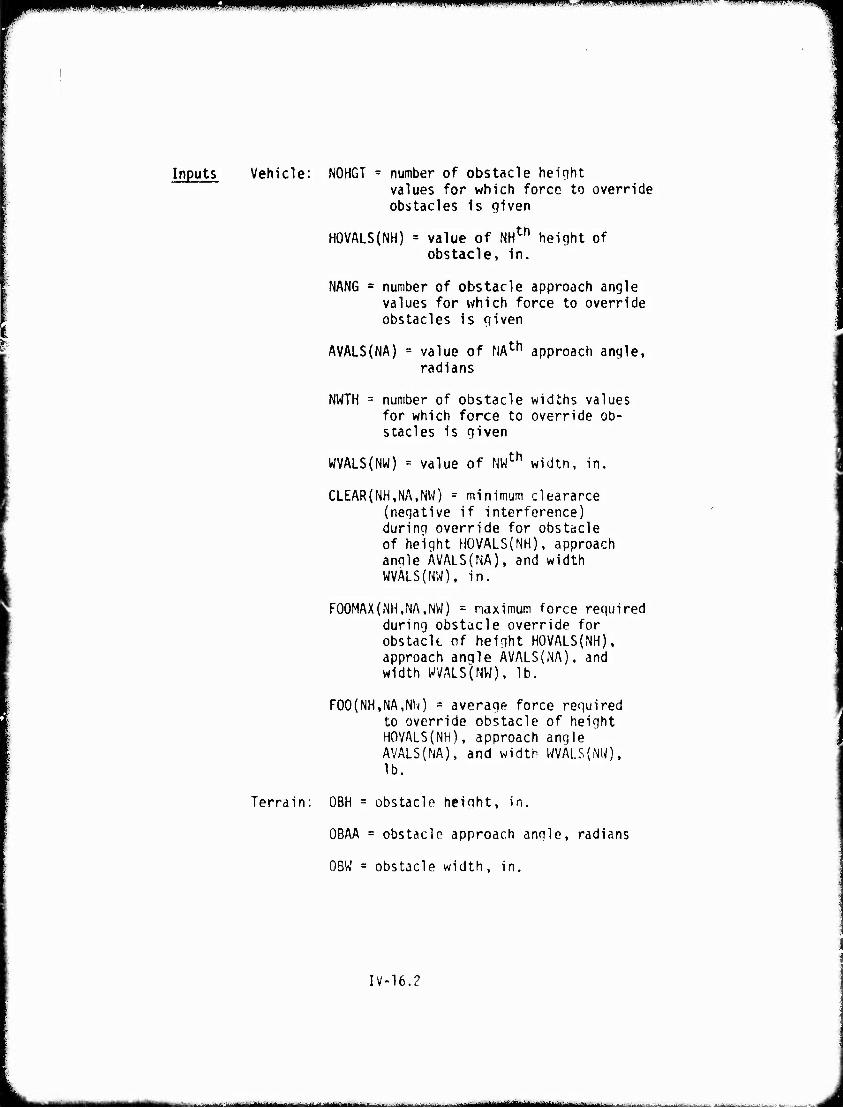
iiiiiiiini «(^WPI^WIL.IIIII,, iiiiiii.nwiiiii .u-wMi .«ijuiJiiMwii i , — •ommmFvmm'
Inputs Vehicle: NOHGT = number of obstacle height values for which force to override obstacles is given
HOVALS(NH) = value of NHth height of obstacle, in.
NANG = number of obstacle approach angle values for which force to override obstacles is given
I AVALS(NA) = value of NAth approach angle,
radians
NWTH = number of obstacle widths values for which force to override ob- stacles is given
WVALS(NW) = value of NWth width, in.
CLEAR(NH.NA.NW) - minimum clearance (negative if interference) during override for obstacle of height HOVALS(NH), approach anole ÄVALS(NA), and width WVALS(NW), in.
F00MAX(NH,NA,NW) = naximum force reguired during obstacle override for obstacle of height HOVALS(NH), approach angle ÄVALS(iNA), and width WVALS(NWK lb.
F00(NH,NA,NlO = average force required to override obstacle of height H0VALS{NH). approach angle AVALS(NA), and width WVALS(NW), lb.
Terrain: OBH = obstacle heioht, in.
OBAA = obstacle approach anole, radians
OBW = obstacle width, in.
IV-16.?
n ■ 'II- - iiinn- r i lil niianTr i i i J-LU... .. , - -■■■■ - ■-- --..— - ■ 11 -n-aaai^aiiMyiiuMM
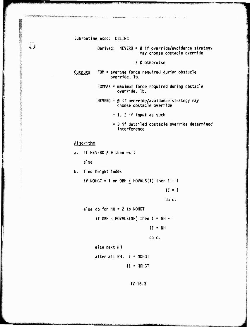
mmm m,m ■ ii^^*mm.!**»mmtm',m
[^m!m^:mWi'vmmf*'mm:*ma>tmm OMBVOMffWrHMUmti s
Subroutine used: D3LINC
Derived: NEVERO = 0 if override/avoidance strategy may choose obstacle override
Outputs FOM
^ 0 otherwise
average force required during obstacle override, lb.
FOMMAX = maximum force required during obstacle override, lb.
NEVERO s 0 if override/avoidance strategy may choose obstacle override
= 1, 2 if input as such
= 3 if detailed obstacle override determined interference
Algorithm
a. if NEVERO t 0 then exit
else
b. find height index
if NOHGT = 1 or OBH < H0VALS{1) then I = 1
II = 1
do c.
else do for NH = 2 to NOHGT
if OBH < HOVALS(NH) then I = NH - 1
II = NH
do c.
else next NH
after all NH: I = NOHGT
II = NOHGT
IV-16.3
..^MMtu-mummiatiitammtiMaMiattä "*^—«■■■■-M i n,, i i.MMM^OMain IWItiii«liiiil'li mil i ■.■■■ | ■ J
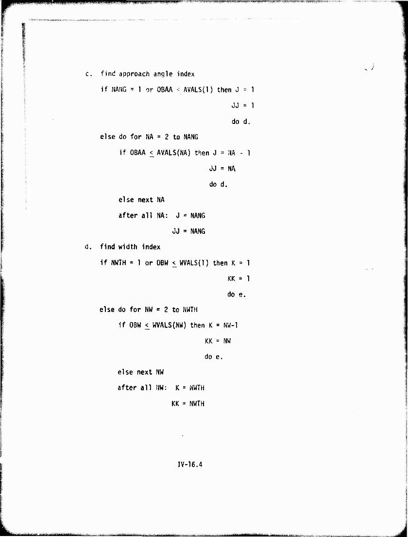
iwnw^pmpswppüp pppitppfppipppiffppp^ wrT^^r?rr»r7^-^--7r"wr-^r7f,i^w^'^^-lmir^.^
'.•ajfc^j «^-.'■»«[AajeKWT'wwi'w«*«!--
c. find approach angle index
if NANG = 1 or OBAA < AVALS(l) then J = 1
JJ = 1
do d.
else do for NA = 2 to NANG
if OBAA < AVALS(NA) then J = NA - 1
JJ = NA
do d.
else next NA
after all NA: J = NANG
JJ = NANG
d. find width index
If NWTH = 1 or OBW < WVALS{1) then K = 1
KK = 1
do e.
else do for NW = 2 to NWTH
if OBW < WVALS(NW) then K ' NW-1
KK = NW
do e.
else next NW
after all NW: K = NWTH
KK = NWTH
IV-16.4
. -... -.„■^■.,J.^. ■ ■■■"— ..' iriiiritlliiMiimi
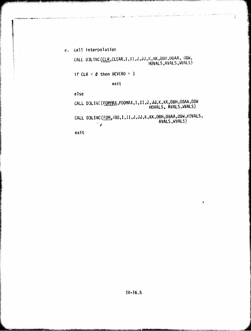
mmmmm ■ fllPiPPI^ipiinil^VlltlW .'i JPIi|l|illlJJi^ili^VMllllMWWWim'^.U'|i"^ TR" Ti^mJ/!.|,r -'•F^wwjT'f ,yreT,---rT'-r''.rri,,,TWW
■»Ml——WW.IW ■
e. call interpolation
CALL Ü3LINCCCLR,CLEAR.I,II,J,JJ.K,KK.ÜBH.ÜUAA, OBW, HOVALS,AVALS,WVALS)
if CLR < 0 then NEVERO = 3
exit
else
CALL D3LINC(F0MMAX,F00MAX,I,II,J,JJ,K.KK,0BH,0BAA,0BW HOVALS, AVALS,WVALS)
CALL DSLIMCCFOMjFOO.MI.J.JJ.K.KK.OBH.OBAA.OBW.HOVALS, AVALS,WVALS)
exit
IV-16.5
■ ■ i—i ...^ ,,^„1 ■ ....— -...,
- - ■ -
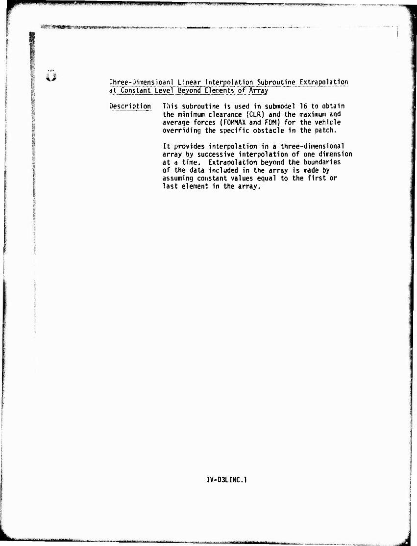
mmm wßmmm wumm "«"■"l"' v"ii»'i.[i)...miii,iiiii»iiiiii)ii.i,pii.iiij...m.l.|^^l^ii : ^f^»ir';;,'t-f «mii^iinnnmnF« ^'■W^W .R^^T^j"-^' TT '»I'TT''''
^SiW!fi*'"!«^i»S<«!(WK;<!l«»W»i>wW'
Three-Dimensioanl Linear Interpolation Subroutine Extrapolation at Constant Level Beyond Elenents of Array
Description This subroutine is used in submodel 16 to obtain the minimum clearance (CLR) and the maximum and average forces (FOMMAX and FOM) for the vehicle overriding the specific obstacle in the patch.
It provides interpolation in a three-dimensional array by successive interpolation of one dimension at a time. Extrapolation beyond the boundaries of the data included in the array is made by assuming constant values equal to the first or last element in the array.
'
IV-D3LINC.1
■-'- -' ■■1- -"-- ---.^--■^- r ■ ini. waiynUMMMiirl ■• n'liiiifiMr-^---IIM'I,- ihn
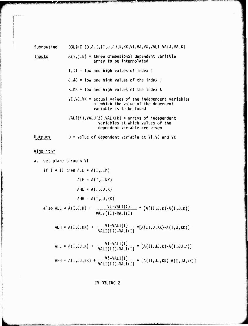
|PPp|Mptg,,^B<ip^|<P,pwap^P|PF3PPW||||^^ »I ■ . ! ,11 •m«t ..I" •l!!.llL„^lp.M«ii«,,il|ii ii ■ 1,. n.iii., .i-.,rw.-"' "- ■- ■'"-■■—'
Subroutine D3LINC (Ü,A,I,II,J,JJ,K,KK,VI,VJ,VK,VALI,VALJ,VALK)
Inputs A{i,j,k) = three dimensional dependent variable array to be interpolated
1,11 = low and high values of index i
J,JJ = low and high values of the index j
K,KK = low and high values of the index k
VI.VJ.VK = actual values of the independent variables at which the value of the dependent variable is to be found
VALI(i),VALJ(j),VALK(k) = arrays of independent variables at which values of the dependent variable are given
Outputs Ü = value of dependent variable at VI,VJ and VK
Algorithm
a. set plane through VI
if I = II then ALL = A(I,J,K)
ALM = A{I,J,KK)
AHL = A(I,JJ,K)
AHH = A(I,JJ,KK)
else ALL - A(I,J,K) + VI-VALI(n * [A(II,J.K)-A(I ,J,K)] VALi(II)-VALI(I)
ALH = A(I,J.KK) + VI-VALI(I) *[A(II.J>KK)-A(I.JtKK)] VALI{II)-VALI(I)
AHL = A(I,JJ,K) + vALl'jllHALldT* [A(II«JJ.K)-A(I .JJ'K)]
AHM - A(1.JJ,KK) + -J|^^j(I-y * [A(Ii.JJ,KK)-A(I.JJ,KK)]
IV-D3LINC.2
—L.....,.:.. ^.■,^.:..^., i-- v Ü■■ ^.■■--^ ■ -^, ■ ■■....■-..■.-yij^nHMM^MMimk - ^-..^--v■ ■ -^ ■.-• —•..,--.,..-, . ..i■ f.*■ „■miütUMätmiiuättidurtum i-1■
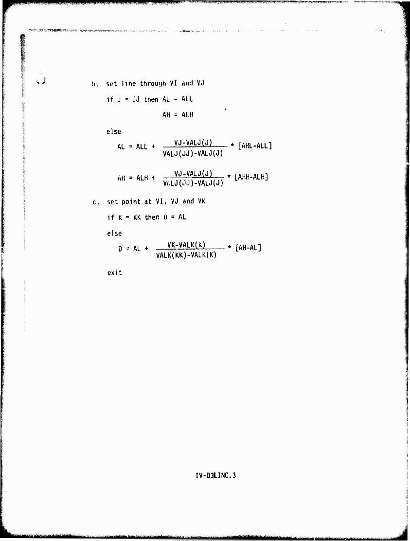
mpp^iPmpffTTJ n "■'^■■fJ.lk>J.»i IIJMIiiiiy^iii.i»,;^^!!!,^.^,,,..,,,.^^,^»,^,!.,».,,..,^,^,,^^.,,,^,,,^..;-. , ,,„_,„_ "■»■^PTT"? T.:TT,^f7
*WC,^^^','''WIH9?*^-^^.>MW'W^a^^'-^w^^^
-■
b. set line through VI and VJ
if J = JJ then AL = ALL
AH = ALH
else
AL = ALL + VJ'VALJ^) * [AHL-ALL] VALJ(JJ)-VALJ(J)
AH -. ALH + , VJ-VALJ(J) , [AHH-ALH] VALJ(JJ)-VALJ(J) L
c. set point at VI, VJ and VK
if K = KK then ü = AL
else
D = AL + - VK-VALK(K) * ^.^ VALK(KK)-VALK(K)
exit
IV-03LINC.3
,|':|ll"'''ilBII''fn|--,|l'M,MM>i>*^—: ■ -- ->■... ^■.. ■.„ ,„■■„■ M | ^^^^.... -„;■,...„-,.■■■....„...... .
tPWiiPWPiiPPI^illPfWPWW^I^WP^PWWC ,*mi..m«ß'!m.u '-■'•■ • 'rMmmm'mmf^jm.imMVMm"^^'.m'r'*ww»'mn»wwv*mi-'"'''-
« r'*PmmiwV'n<*r'i%!S*mCiT*r. *>im<m<*w--
17. Driver Limited Speed Over ObstacTe'i
Description This routine determines the maximum speed (VOLA) at which the vehicle will impact a single ob- stacle or a series of spaced obstacles in order to limit acceleration at the driver's station, or on the cargo, to pre-determined maximum values. This speed is obtained by interpolating in tables, produced by Module VII (Vehicle Ride Dynamics) which relate Impact speed limit to obstacle height (HVALS).
In AMI '74 two tables of speed versus obstacle height or spacing are provided, one for impacts with single obstacles (VOOB), and the other (VOOBS), for the situation there obstacles are so closely spaced that the dynamic effects from one obstacle are not completely damped befor? the next obstacle is encountered. The second table of speeds (VOOBS) is used for obstacles spaced closer than two vehicle lengths apart.
IV-17.1
—i——— -- -- - ^^_^^—
i
J
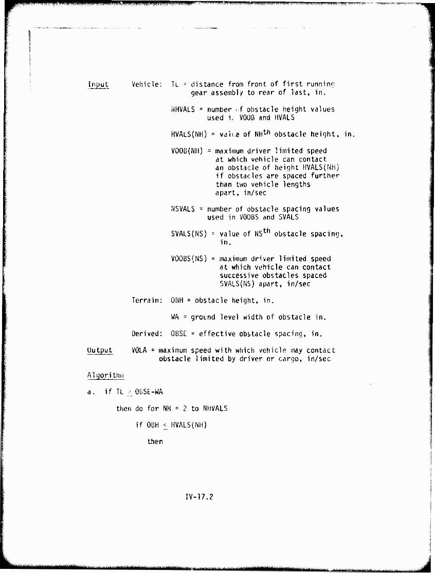
r -^**^mmm WpiJ Jin ".■■ iwmwwwwuwuw» m<r:cni?» fiwiT^r^
Input Vehicle: TL = distance from front of first runninc gear assembly to rear of last, in.
NHVALS = number if obstacle height values used K V0ÜB and HVALS
HVALS(NH) = van.e of NHth obstacle height, in.
VOOB(NH) = maximum driver limited speed at which vehicle can contact an obstacle of height HVALS(NH) if obstacles are spaced further than two vehicle lengths apart, in/sec
NSVALS = number of obstacle spacing values used in VOOBS and SVALS
SVALS(NS) - value of NSth obstacle spacing, in.
VOOBS(NS) = maximum driver limited speed at which vehicle can contact successive obstacles spaced SVALS(NS) apart, in/sec
Terrain: OBH = obstacle height, in.
WA = ground level width of obstacle in.
Derived: OBSE = effective obstacle spacing, in.
Output VOLA = maximum speed with which vehicle may contact obstacle limited by driver or cargo, in/sec
Al cjori thm
a. if TL -■ OBSL-WA
then do for NH = ? to NHVALS
if OBH < HVALS(NH)
then
IV-17.2
L ■ —
-■ limmitmtmm
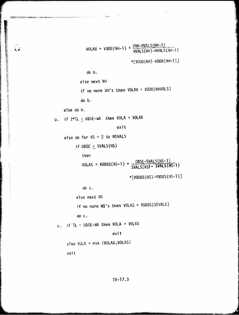
P^^^wmw^^w^^^w^^^^^^^^^^^^^^^^^^
y3^Yr:V^Wm''*mK'm***<<«mm>m»«' ■ -"• —■
;
iß
i
VOLAB = VOOB(NH-l) + 0BH-HVAL$(NH-1) HVALS(NH)-HVALS(NH-1)
*[V00B(NH)-V00B(NH-1)]
do b.
else next NH
if no more MH's then VOLAB = VOOB(NHVALS)
do b.
else do b.
if 2*TL > ÜBSE-WA then VOLA = VOLAB
exit
else do for NS = 2 to NSVALS
if OBSE <_ SVALS(HS)
then
VOLAS = VQOBS(NS-l) + OBSE-SyALS(NS-l) SVALS{NS>- SVALS(NS-l)
*[V00BS{NS)-V00BS(NS-1)]
do c.
else next iNS
if no more NS's then VOLAS = V00BS(NSVALS)
do c.
if TL < ÜBSE-WA then VOLA = VOLAS
exit
else VOLA = min {VOLAB,VOLAS)
exit
IV-17.3
m -"- -*~m*l*»mlmi*m~m**m~*~~~~~.....^
»-M***Kl?»*»'i «rrir'W«ft»»<»<W3«Mfr'r"*(-»4W»»»4Bl»l««».».Wl».«<|r..
4; 18. Speed Onto and Off Obstacles
Description This routine calculates the speed lost in cros- sing an obstacle.
The reserve force available (maximum force avail- able less resistance between obstacles) at the speed (VA) with which the vehicle encounters the obstacle Is calculated using subroutine FORVEL. If there is sufficient reserve force to overcome the obstacle resistance (FOM) then no speed loss occurs in crossing the obstacle. If not enough reserve force is available (F0RÜEF >. 0), the extra force needed is taken from the vehicle's kinetic energy (MASS*VA2), resulting in a speed loss. If there is insuffic- ient kinetic energy, then the obstacle resistance (TR+FOMMAX) is compared to the maximum tractive effort (FORMX) the vehicle can produce. If that force is sufficient then the vehicle proceeds at the speed determined by the maximum tractive effort that can be produced. If the maximum tractive effort (FORMX) is insufficient to over- come the obstacle resistance (FOM), the crossing speed Is set to zero.
This routine addresses both the sinrile obstacle crossing case and the case where the vehicle is crossing obstacles spaced closer than the vehicle's length. When the obstacles are spaced closer than the vehicle's lenqth then the velocities VSOIL, VTT, VBO definea for soil/ slope/vegetation resistance between obstacles are not applicable. However, to avoid creafina a new set of velocity variable names which depend on the same resistances (soil/slope/vegetation), the velocities VSOIL, VTT, and VBO arc recal- culated including the average force to over- ride an obstacle (FOM).
IV-18.1
■ — ---um 1 ~u*stmmmmmm
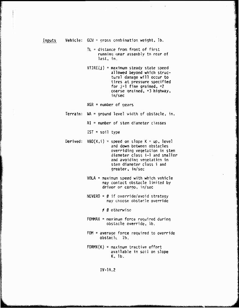
Inputs Vehicle: GCW = gross combination weight, lb.
TL = distance from front of first running gear assembly to rear of last, in.
VTIRE(j) = maximum steady state speed allowed beyond which struc- tural damage will occur to tires at pressure specified for j=l fine grained, =2 coarse grained, =3 highway, in/sec
NCR = number of gears
Terrain: WA = ground level width of obstacle, in.
NI = number of stem diameter classes
1ST = soil type
Derived: VB0{K,i) = speed on slope K = up, level and down between obstacles overriding vegetation in stem diameter class i-1 and smaller and avoiding vegetation in stem diameter class i and greater, in/sec
VOLA = maximum speed with which vehicle may contact obstacle limited by driver or cargo, in/sec
NEVERO = 0 if override/avoid strategy may choose obstacle override
f 0 otherwise
FOMMAX = maximum force required during obstacle override, lb.
FOM = average force required to override obstacK lb.
F0RMX{K) = maximum tractive effort available in soil on slope K, lb.
IV-18.2
iiiiBMiiiiiaiMMMiiiliiauMriii- ' üMMiiiiiniiiiriiiMüiiiiiMii i m inn iMMmMilMillli —' ^ ■-'■•- -'-•■'- ■---'-
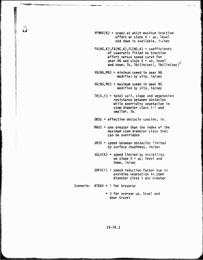
'■ ' '**MW^-' Vt-WI^SCM^MWrW-r^j^Ms^,., '■^■■-It.-.-l'i-W-l**lV*».i-."-iVr»'
VFMAX(K) = speed at which maximum tractive effort on slope K = up, level and down is available, ii./sec
FA{NG,K),FB(NG.K),FC(NG,K) = coefficients of quadratic fitted to tractive effort versus speed curve for gear NG and slope K = up, level „ and down; lb, lb/(in/sec), lb/(in/sec)
VG(NG,MN) = minimum speed in gear NG modifiel by slip, in/sec
VG(NG,MX) = maximum speed in gear NG modified by slip, in/sec
TR{K,i) = total soil, slope and vegetation resistance between obstacles while overriding vegetation in stem diameter class i-1 and smaller, lb.
OBSE = effective obstacle spacing, in.
MAXI = one greater than the index of the maximum stem diameter class that can be overridden
VRID - speed between obstacles limited by surface roughness, in/sec
VELV(K) = speed limited by visibility on slope K = up, level and down, in/sec
SRFV(i) = speed reduction factor due to avoiding vegetation in stem diameter class i and greater
Scenario: NTRAV = 1 for traverse
= 3 for average up, level and down travel
IV-18.3
^^^ M.—^—■^■^-^—~. u—^ .- ■ -- • ■ -'-■■' ■ ■-- ■■■ -■ -"- ;- 1 *
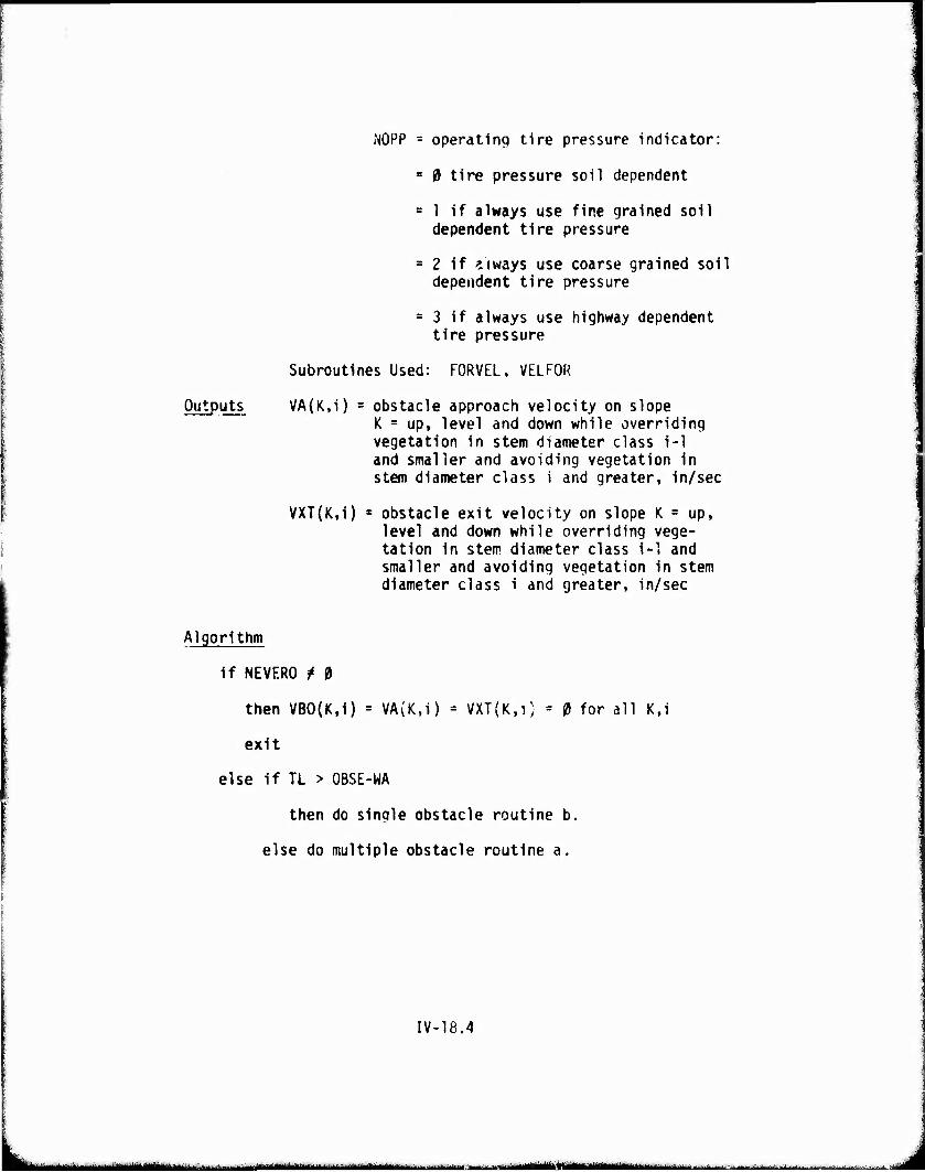
tNOPP = operating tire pressure indicator:
= 0 tire pressure soil dependent
= 1 if always use fine grained soil dependent tire pressure
= 2 If always use coarse grained soil dependent tire pressure
= 3 if always use highway dependent tire pressure
Subroutines Used: FORVEL, VELFOR
Outputs VA(K,i) = obstacle approach velocity on slope K = up, level and down while overriding vegetation in stem diameter class i-1 and smaller and avoiding vegetation In stem diameter class i and greater, in/sec
VXT(K,i) x obstacle exit velocity on slope K = up, level and down while overriding vege- tation In stem diameter class 1-1 and smaller and avoiding vegetation in stem diameter class i and greater, in/sec
Algorithm
if NEVERO f 0
then VB0(K,i) = VA(K,i) = VXT(K,i; = 0 for all K,i
exit
else if TL > OBSE-WA
then do single obstacle routine b.
else do multiple obstacle routine a.
IV-18.4
^Wiii ~ 1 .«**_<• M^MflMMBftffMl
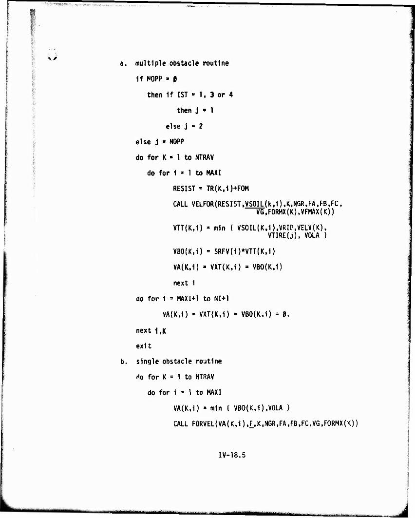
'Hy^J^Mi-T^iv, us«r«*Hf<v
•XS
'r,
■
a. multiple obstacle routine
If K)PP » 0
then If 1ST » 1, 3 or 4
then j ■ 1
else j « 2
else j « NOPP
do for K ■ 1 to NTRAV
do for 1 » 1 to MAXI
RESIST « TR(K,1)+F0M
CALL VELF0R(RESIST.yS0IL(k.1),K,N6R,FA,FB,FC, VG,FORMX(K),VFMAX(K))
VTT(K,1) = mln [ VS0IL(K,1),VRIP,VELV(K), VTIRE(j), VOLA }
VB0(K,i) = SRFV(1)*VTT{K,1)
VA(K.I) » VXT(K,1) » VB0(K,1)
next 1
do for 1 = MAXI+1 to NI+1
VA(K,1) « VXT(K,1) - VB0(K,i) = 0.
next I.K
exit
b. single obstacle routine
'io for K = 1 to NTRAV
do for 1 = 1 to MAXI
VA(K,1) » mln { VB0(K,1),V0LA }
CALL F0RVEL(VA(K,1).i.K,NGR,FA,FB,FC,VG,F0RMX(K))
IV-18.5
— —MMMMai IJMMMM1M I i I j
ÜHPPPPinPIQPmffnP11 ■ ■IIMH II —.1— «-—- ji-P-«.,.^ rr— - vnpfW! ^r ?~p'TC,^-':X-™!'"^lip(
^'V"-1; 1 'W^,I*?M*J«- .".^--ss*-
FORRQ(K) » TR(K,1)+F0M
FORDEF - F0RRQ{K)-F
If FORDEF < p.
then VXT(K,1) = VA(K,i)
next 1
else
VBSQ = VA(K,i)2-F0RDEF*{WA+TL)*3ß5.9/GCW
if VBSQ < 0.
then If F0RMX{K) < TR(K,1)+F0MMAX
then VXT{K,1) = VA(K,i) = 0.
next i
else calculate velocity to overcome max resistance over obstacle
CALL VELFOR{TR(K.l)+FOMMAX,yXT]KJLil. NGR,FA.FB.FC.VG,FORMX(K),VGMAX(K))
VA{K,1) - VXT(K,i)
next 1
else VXT(K,i) « SQRT(VBSQ)
next 1
do for i = MAXI+1 to NI+1
VXT(K,i) ' VA{K,1) = VB0(K,i) » 0.
next 1
next K
exit
IV-18.6
■ - - - ■ - •-
w ■■"-" ^w«
',,lter<a-.(«|!m.v'*4V"ir''i>* 1 •»•(« rM.*(< *«...-
"4J Force Available at a Given Velocity
üeicription This subroutine (FORVEL) calculates the force avail- able to the vehicle while it is travel inn at a qiven speed in a given gear. It is used in submodels IB and 20. The coefficients (FA.FB.FC) specifyino the quadratic curve of speed versus tractive effort in the given gear (see subroutine QUAD) are used to directly evaluate the force available at the given speed.
IV-F0RVEL.1
■ H^mmnnm ■■--—
^"W ' ll1 '■"■ mmammr'm'mm mmm • umß'i-.'rr- mmin
Subroutine FORVEL (V,F,K,NGR,FA,FB,FC,VG,FORMX)
Inputs
Output
NGR = number of dears
V = velocity, in/sec
K = u: uphill, = i: uphill; = d; downhill
FA(NG,K) = constant term of quadratic fitted to tractive effort versus speed curve for gear NG and slope K, lb.
FB(NG,K) = linear term coefficient of quadratic fitted to tractive effort versus speed curve for gear NG and slope K, lb/(in/sec)
FC(N6,K) = quadratic term coefficient of quadratic fitted to tractive effort versus speed curve for gear NG and slope K, lb/(in/secr
\/G(NG,MN) = minimum speed in qear NG, modified by slip, in/sec
VG(NG,MX) = maximum speed in qear NG modified by slip, in/sec
FORMX(K) = maximum tractive effort avail- able in soil on slope K = up, level and down; lb.
F = force available at velocity V, lb.
Algorithm
if V < VG(1,MN)
then F = FORMX(K)
exit
else if V > VG(NGR,MX)
then F = {5,
exit
IV-F0RVEL.2
-Trnit iii>-iallMJ»^fc« I lll..1.r.il - ^. ■ ,., „..^ mäl ■ • ■ ' -■■
■rWPWtlWWWBI""^1"1 ''""MM ": ~^"—WW}"'""wmfw»""m.nvtwmrtmmimtiP'
else do for NG = 1 to NGR
if V > VG(NG,MX)
then next NG
else F = (FC(NG,K)*V+FB(NG,K))*V+FA(NG.K)
exit
IV-F0RVEL.3
J.^^„^—...^^.i^.,^^.,. taM^aaymBaMafa i \\'-\imMimiutmämiiw"'-"■■■■■■- ■■■■■■ . ^jl^H
^•,^^^^^^^^^^"^^^pw^^^^"1' ■' " "" •"• '■■ ■ '- •■■■"-—■ 1 rwwiw iT.-..T.^
WUHUHSU^" «!<,JiMt»«WWl»M^C;,>.l*.S>.W»-.iT''-t»-»'"»-.S--^.-. •■<-~~.-
^^ 19. Average Patch Speed Crossing Obstacles Including Acceleration/ Deceleration Between and Over Obstacles
Description This routine calculates the average patch speed as affected by acceleration and deceleration between obstacles. It first calculates the time and distance required to accelerate from the obstacle exit speed (VXT) to the maximum feasible speed between obstacles as determined by resistances or other limits (VBO), or some lower speed governed by the distance at which deceleration must begin in order to reach the obstacle approach spaed (VA) at contact with the next obstacle. Vehicle acceleration is computed in subroutine ACCEL, which accounts for shift time (SHIFTT) between gears where appropriate. Average
r speed (VOVER) is obtained by summirg acceleration time (TA), deceleration time (VB), time (TBO) spent at maximum steady speed (VBO), and time crossing the obstacle (TOO), and dividing by effective obstacle spacing (OBSE).
IV-19.1
•^mammmm.,« ■ . ^^^. .,. .,.„nrr.| m^^M | n^t^^^m
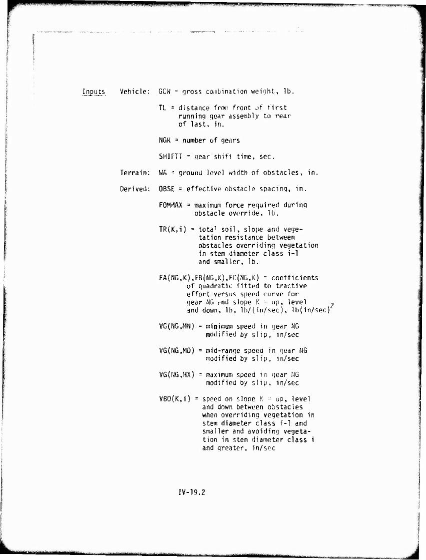
immmmmm BWmPHWP' wi wmmmsßmm&tmBmmm m m mm*mmmmmm*
Inputs Vehicle: GCW - gross coiiibination weiqht. Ib.
TL = distance fron front of first runninq gear assembly to rear of last, in.
NGR = number of qears
SHIFTT - qear shift time, sec.
Terrain: WA = ground level width of obstacles, in.
Derived: OBSE = effective obstacle spacing, in.
FOMi-lAX = maximum force required during obstacle override, lb.
TR(K,i) = tota1 soil, slope and vege- tation resistance between obstacles overriding vegetation in stem diameter class i-1 and smaller, lb.
FA(NG,K),FB(NG,K),FC(NG,K) = coefficients of quadratic fitted to tractive effort versus speed curve for gear NG ; nd slope K = up, level and down, lb, lb/(in/sec), lb{in/sec)'
VG(NG,MN) = minimum speed in gear NG modified by siip, in/sec
VG(MG,MD) = mid-range speed in gear NG modified by slip, in/sec
VG(NG,MX) = maximum speed in gear NG modified by slip, in/sec
VB0{K,i) = speed on «-lope K :--- up, level and down between obstacles when overriding vegetation in stem diameter class i-1 and smaller and avoiding vegeta- tion in stem diameter class i and greater, in/sec
IV-19.2
m**m^m*^^*mm nttmämmmmn ■— ——aiüiM^ttift^M.fcitMj WM • ■■- Hi
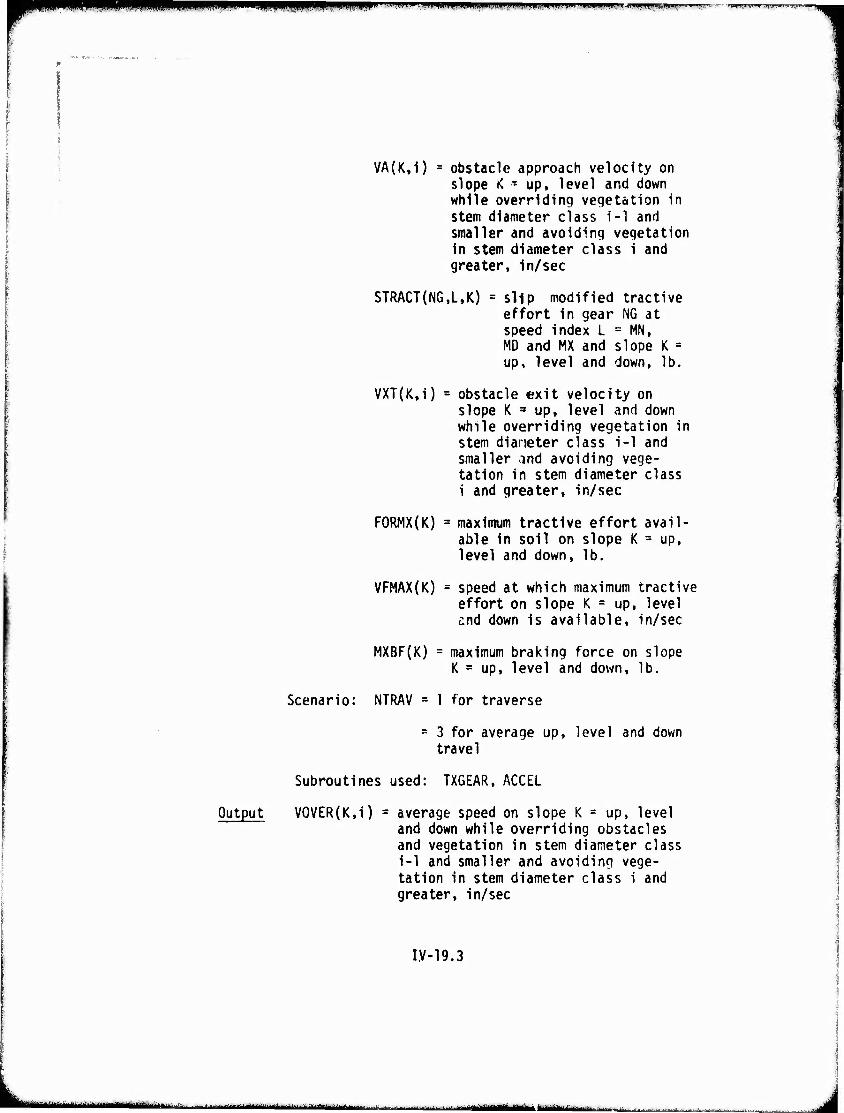
iiiiiHj . .. ii..ii uii>«miwmwMwiiiinw ■Wiwwwir'Biiup».nii....nn»|.ini^>fWw>.'
VA(K,i) = obstacle approach velocity on slope K T up, level and down while overriding veqetation in stem diameter class i-1 and smaller and avoiding vegetation in stem diameter class i and greater, in/sec
STRACT(NG,L,K) = slip modified tractive effort in gear NG at speed index L = MM, MD and MX and slope K = up, level and down, lb.
VXT(K,i) = obstacle exit velocity on slope K *• up, level and down while overriding vegetation in stem diameter class 1-1 and smaller and avoiding vege- tation in stem diameter class 1 and greater, in/sec
FORMX(K) = maximum tractive effort avail- able in soil on slope K = up, level and down, lb.
VFMAX(K) = speed at which maximum tractive effort on slope K = up, level end down is available, in/sec
MXBF(K) = maximum braking force on slope K = up, level and down, lb.
Scenario: NTRAV = 1 for traverse
- 3 for average up, level and down travel
Subroutines used: TXGEAR, ACCEL
Output V0VER(K,i) = average speed on slope K = up, level and down while overriding obstacles and vegetation in stem diameter class i-1 and smaller and avoiding vege- tation in stem diameter class i and greater, in/sec
I,V-19.3
■•• ' ■•—^■■■■■-^...~.--- ^—^.J-^-,..... in'r 'liwiam ' ■--—■■---
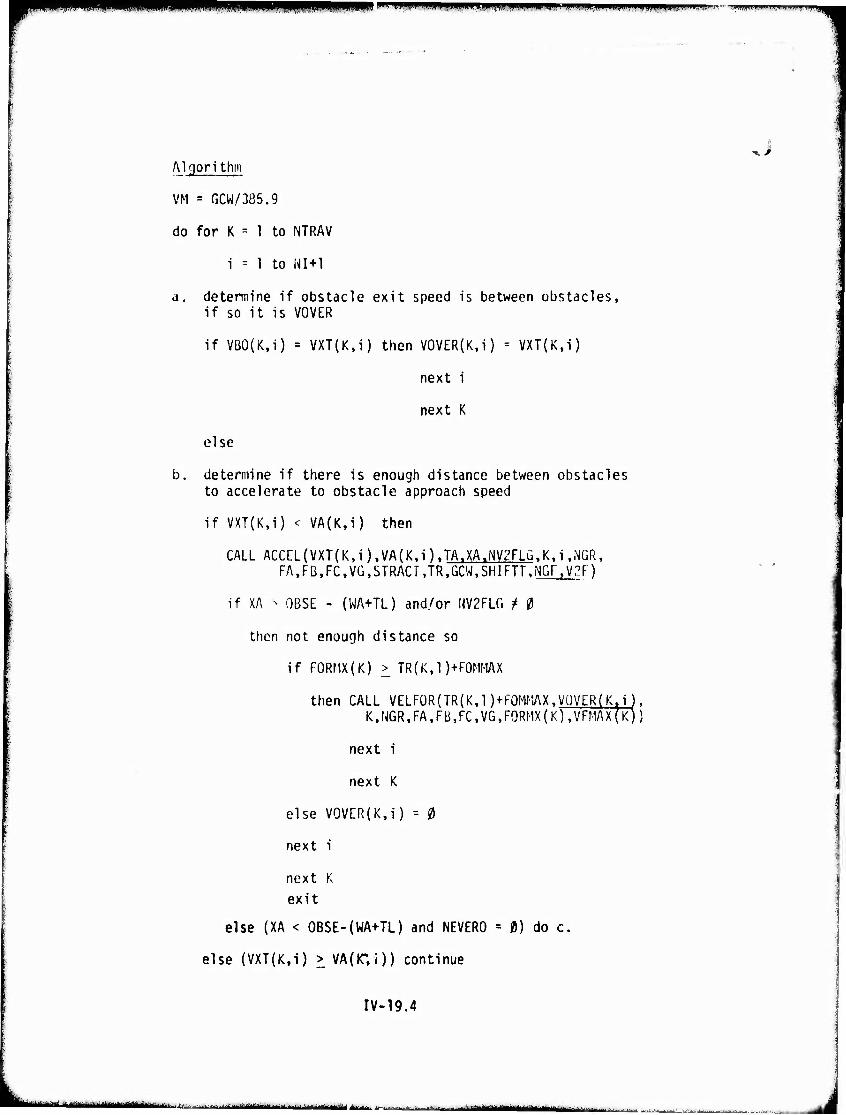
mr*m i p nL«»«i.wiii«ii|>M(aiiwi.ii. w l.iiip,iiiUjiii1|i|liMiiiiiiiiiij|iii!
, Algorithm
VM = GCW/385.9
do for K = 1 to NTRAV
1 = 1 to NI+1
a. determine if obstacle exit speed is between obstacles, if so it is VOVER
if VB0(K,i) = VXT(K,i) then V0VER(K,i) = VXT{K,i)
next i
next K
else
b. determine if there is enough distance between obstacles to accelerate to obstacle approach speed
if VXT(K,i) < VA(K,i) then
CALL ACCEL(VXT(K.i).VA(K.i).TA.XA.NV2FLG.Kti.MGR. FAtFB.FC.VG.STRACTJR.GCWtSHIFTTtNGF.V3F)
if XA - OBSE - (WA+TL) and/or HV2FLG t 0
then not enough distance so
if FORMX(K) > TR(K,1)+F0MMAX
then CALL VELFORfTR(K.l )-t-FQMMAX.VOVER(K,i). K,NGR,FA,FB,FC,VG,FORMX(K),VFMAX(K))
next i
next K
else V0VER(K,i) = 0
next i
next K
exit
else (XA < OBSE-(WA+TL) and NEVERO = 0) do c.
else (VXT(K,i) > VA(IC,i)) continue
IV-19.4
• - '«I ■"■■'■"-■— - ■ ..■-^-^-.■.. ■ ■ : ..f .- .1.1
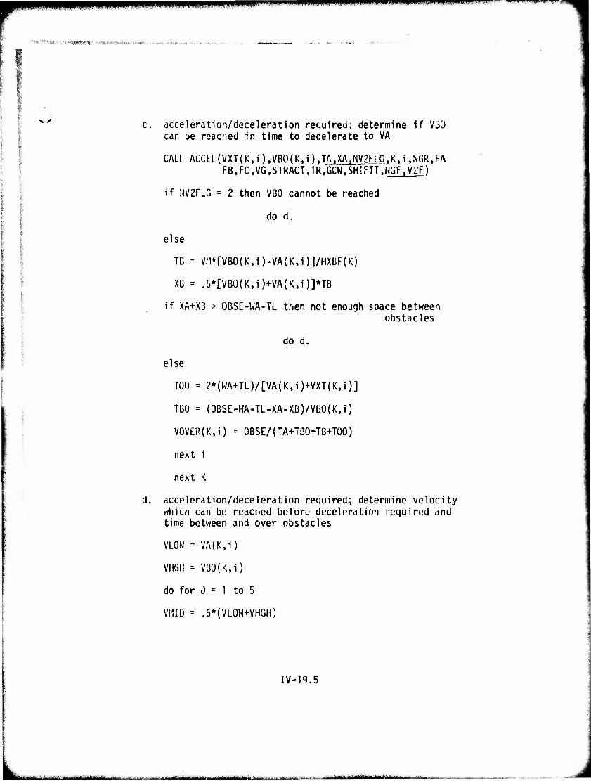
amipippwpiwipii,wiiui,iwwiwip»wii»»^i.ii"»ii'"""|.n"''""""1" ""wmm 'I"""'" - "'"" ""•' -'■■■■•■ -'
•■"'".'■'■"rt-my, ■■v^rwuRKW»',' t'mimtiimtnH/mKn'.
x r acceleration/deceleration required; determine if VBÜ can be reached in time to decelerate to VA
CALL ACCEL(VXT(K.i).VB0(K.i).TA.XA.NV2FLG1K.i,NGR.FA FB.FC.VG.STRACT.TR.GCW.SHIFTT.fJGF^ZF)
if NV2FLG = 2 then VBO cannot be reached
I d0 d' else
TG = Vn*[VBO(K,i)-VA(K,i)]/MX0F(K)
Xß = .5*[VB0(K,i)+VA(K,i)]*TB
if XA+XB > OBSE-WA-TL then not enough space between obstacles
do d.
else
TOO = 2*(WA+TL)/[VA(K,i)+VXT(K,i)]
TBO = (0BSE-HA-TL-XA-XB)/VBO(K,i)
V0V£R(K,i) = OBSE/(TA+TB0+TB+T00)
next i
next K
acceleration/deceleration required; determine velocity which can be reached before deceleration required and time between and over obstacles
VLOW = VA(K,i)
VHGH - VBO(K.I)
do for J = 1 to 5
VMID = .5*{VL0W+VHGH)
IV-19.5
li^MMJMj—^■•1 ■■ : ....... ..: ,■..-■.-...-,. . ^_^^.^^,_^. i nn'min if IT ^d
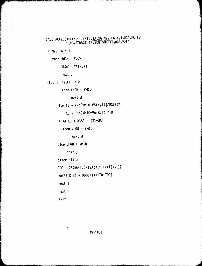
Ml miiPüpiiimw i i mmmmmmwimmv-"* *m '•■■VJ»■,..« i •• .-..«i .',
CALL ACCEL(VXT(K,i),VMlD,TA,XA,Ny2FLG,K,l,NGR,FA,F8, FC,VG,STRACT,TR,GCW,SHIFTT,NGF,V2n
if NV2FLG = 1
then VHGH = VLOW
VLOW = VA(K,i)
next J
else if NV2FLG = 2
then VHGH = VMID
next J
else TB = VM*[VMID-VA(K,i)]/MXBF{K)
XB = .5*[VMID+VA(K,i)]*TB
if XA+XB iOBSE - (TL+WA)
then VLOW = VMID
next J
else VHGH = VMID
next J
after all J
TOO = 2*(WA+TL)/(VA(K,i)+VXT(K,i))
V0VER(K,i) = OBSE/(TA+TB+TOO)
next i
next K
exit
IV-19.6
-:-..-.:^,.^
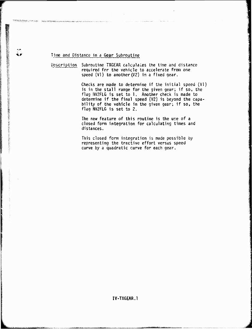
«^«»W-.-'i-VtSi;.. Üfllfft rr^JJfW-t^-fvWiVff^iiWtfWwwKtw^v J«.*,.'.
S; *p Time and Distance in a Gear Subroutine
-
Description Subroutine TXGEAR calculates the time and distance required for the vehicle to accelerate from one speed (VI) to another (V2) in a fixed gear.
Checks are made to determine if the initial speed (VI) is in the stall range for the given gear; if so, the flag NV2FLG Is set to 1. Another check is made to determine if the final speed (V2) is beyond the capa- bility of the vehicle in the given gear; if so, the flag NV2FLG is set to 2.
The new feature of this routine is the use of a closed form integration for calculating times and distances.
This closed form integration is made possible by representing the tractive effort versus speed curve by a quadratic curve for each gear.
IV-TXGEAR.l
. - aa^ajaaMi - ■■
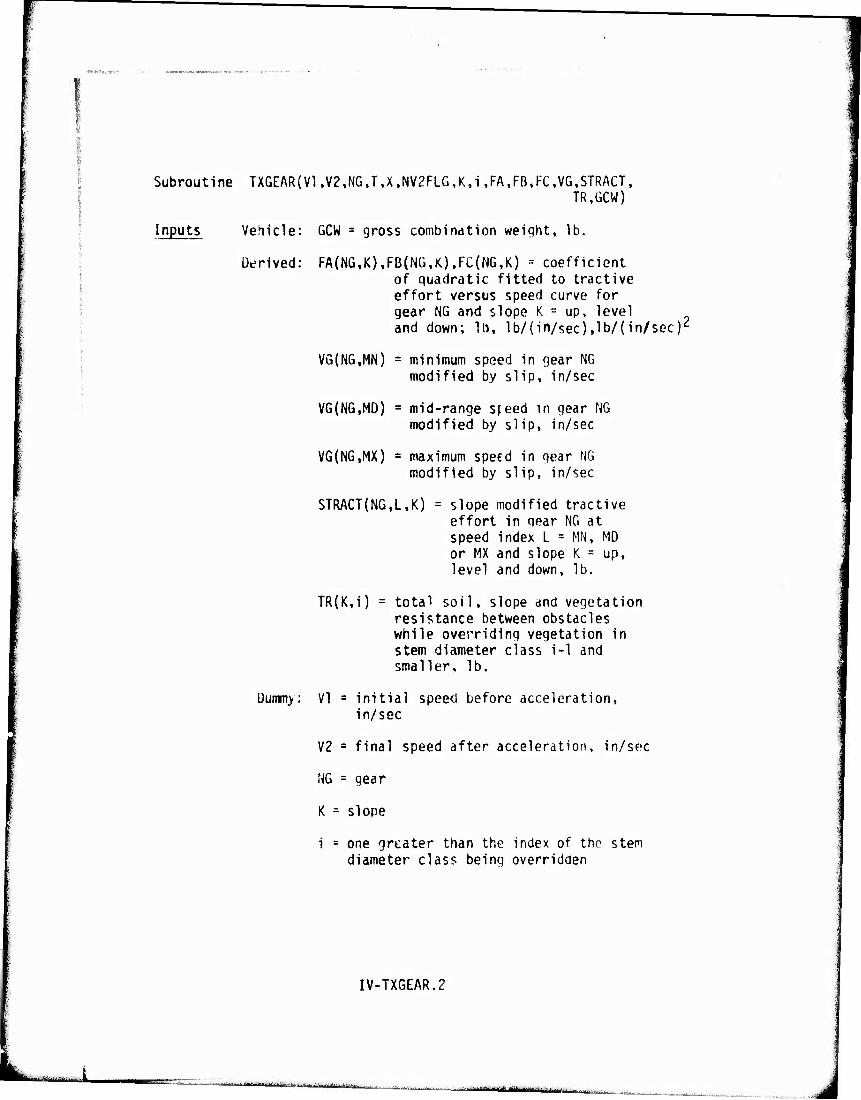
Subroutine TXGEAR{V1,V2,NG,T,X,NV2FLG,K,i ,FA,FB,KC,VG,STRACT, TR,ÜCW)
Inputs Vehicle: GCW = gross combindtion weiqht, lb.
Derived: FA(NG,K),FB(NÜ,K).FC(HG,K) = coefficient of quadratic fitted to tractive effort versus speed curve for gear NG and slope K = up, level and down; It», lb/(in/sec),lb/(in/sGc)2
VG(NG,MN) = minimum speed in gear NG modified by slip, in/sec
VG(NG,MD) = mid-range s^eed in gear NG modified by slip, in/sec
VG(NG,MX) = maximum speed in gear NG modified by slip, in/sec
STRACT{NG,L,K) = slope modified tractive effort in gear NG at speed index L = MM, MD or MX and slope K = up, level and down, lb.
TR(K,i) = total soil, slope and vegetation resistance between obstacles while overriding vegetation in stem diameter class i-1 and smaller, lb.
Dummy: VI = initial speed before acceleration, in/sec
V2 = final speed after acceleration, in/sec
NG = gear
K = slope
i = one greater than the index of the stem diameter class being overridden
IV-TXGEAR.2
■■ ■ • ■ ■ - ■
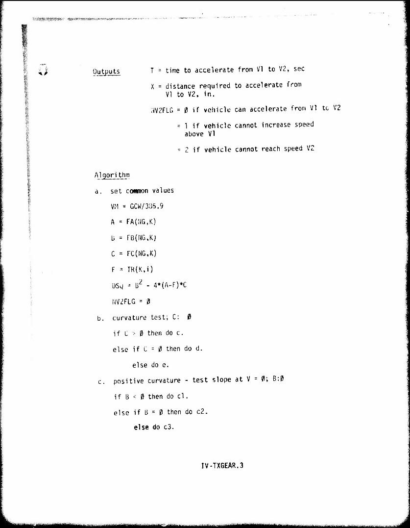
mismwsv^''-'' -«wiiwww^^w»««»»-.^-...-...^^»".
I u Outputs T = time to accelerate from VI to V2, sec
X = distance required to accelerate from VI to V2, in.
;W2FLG = 0 if vehicle can accelerate from VI tc V2
= 1 if vehicle cannot increase speed above VI
= 2 if vehicle cannot reach speed VZ
Algori thm
set cownon values
VM = GCW/335.9
A - FA(NG,K)
Ü = rB(NG,Kj
C = FC(NG,K)
F - TR(K,i)
DSg = \>Z - 4*(A-F)*C
NV2FLG -" 0
curvature test; C: 0
if C > 0 then do c.
else if C = 0 then do d.
else do e.
positive curvature - test slope at V
if B < 0 then do cl.
else if li = 0 then do c2.
else do c3.
= 0; B:0
IV-TX6EAR.3
■— ,^^m^^m ^Maaaiititniiiifr mttmmtä***** " .-..»i
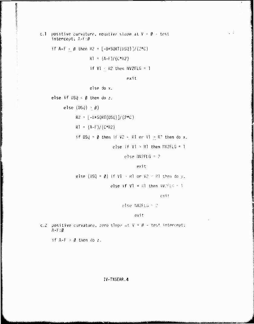
^^^—^^^^T-
c.1 positive curvature, neqativo slope at V - ?) - test intercept; A-F;0
if A-F < 0 then R2 - [-B+SQRT(ÜSQ)]/(:'*C)
Rl = {A-F)/(C*k2)
if VI ■ R2 then NV2FLG = 1
exit
else do x.
else if DSQ < 0 then do z.
else (DSQ) > 0)
R2 -- [-B+SQRT(ÜSQ)]/(2*C)
Rl = (A-I:)/(C*R2)
if DSQ > 0 then if V2 < Rl or VI > R0 then do x,
else if VI > Rl then N,V2FLG = 1
else NV2FLG -- 2
exit
else (DSQ = 0) if VI • Kl or V2 • Rl then do y.
else if VI = Rl then NVZrLf. = 1
exi t
else NV2FLG - 2
exi t
c.2 positive curvature, ^ero slope at V = 0 - test intercept; A-F:0
if A-F > 0 tiien do z.
IV-TXGEAR.4
tommm mmrnm -- ---^- tarn— mtmmUamimiiamtimm ■■- - -- -^-"■'■- ■•..■.*..■■.
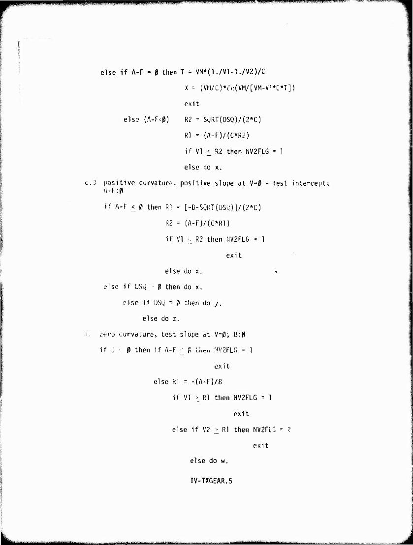
wmmmmmmmmmmmiimm. gwP^WWW ■ " " " ' ■ nil ii,»nin.ii»'ii»niiii.ii.M)j i.iu,. •m-tmrr^mi—,^■.wiiM.'niJ.m- ■ - ..■>'i ■ i mmwv <
else if A-F = 0 then T = VM*(1./Vl-1./V2)/C
X - (VM/C)*t,t!(VM/[VM-Vl*C*Tj)
exit
els? (A-F<0) R2 - SgRT(DSQ)/(2*C)
R1 = (A-F)/(C*R2)
if VI <_ R2 then NV2FLG = 1
else do x.
c.3 positive curvature, positive slope at V=0 - test intercept; A-F:0
if A-F < 0 then Rl = [-B-SQRT([JSQ)J/{2*C)
R2 = (A-F)/(C*R1)
if VI v R2 then NV2FLG - 1
exit
else do x. >
else if USg • 0 then do x.
else if DSl) = 0 then do y.
else do z.
i. zero curvature, test slope at V=0i B:0
if C • 0 then if A-F ^ 0 Ll.cn MV2FLG = 1
exit
else Rl = -(A-F)/B
if VI > Rl then NV2FLG = 1
exit
else if V2 > Rl then NV2FLG - 2
exit
else do w.
IV-TXGEAR.5
■ ■ - ■ -■~~-*-~**.-~~~*~ ■—^-
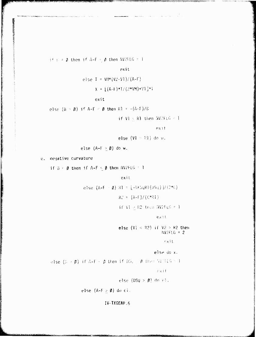
i,pipipiim«iijii,iiL.ii.ui(, WffPiPilWW^^JiPipi^Wv^A'-'iW.iupP F? !P|jPWI)W|^WpqiB^|^iPFtWW«iWIB^^ "Fw
■tSM»*^»^«*, »..-»iMMKv^.'i». MM
if :■ - «5 then if A-F ■ ^ then fJV.M l.(- -" 1
exit
else T = Vn*(V2-Vl)/(A-F)
X = [(A-l )*T/(^*VM}n'lj*l
exit
olsfi (B ■ V) if A-F ■• 0 then Rl -- -(A-F)/B
if VI ■ Rl then NV^FLG ■■ 1
fx i t
else (VI • Rl) do w.
else (A-F > 0) do w.
o. neijdtive curvature
if 3 • 0 then if A-F <- 0 then NV7FLG 1
exi l
else (A-F 0) Rl - l-V.^^Rl {üSu) j/C'*'.)
RL' = (A-F)/(C*R1)
if VI •• R2 t.nen NV^FLC. - 1
exi t.
•Isc (B 0) if A-F • ^
else (VI < R2) if V/ > R2 then NV2FLG "- 2
nxi t
else do x.
then if DSi, 0 Uu-i '.v:i LG
i • .■; i
else (DSg > 0) cln nl
else (A-F > 0) do el.
IV-TXGEAR.6
!■ mil i m , ——.-.J^^—^_
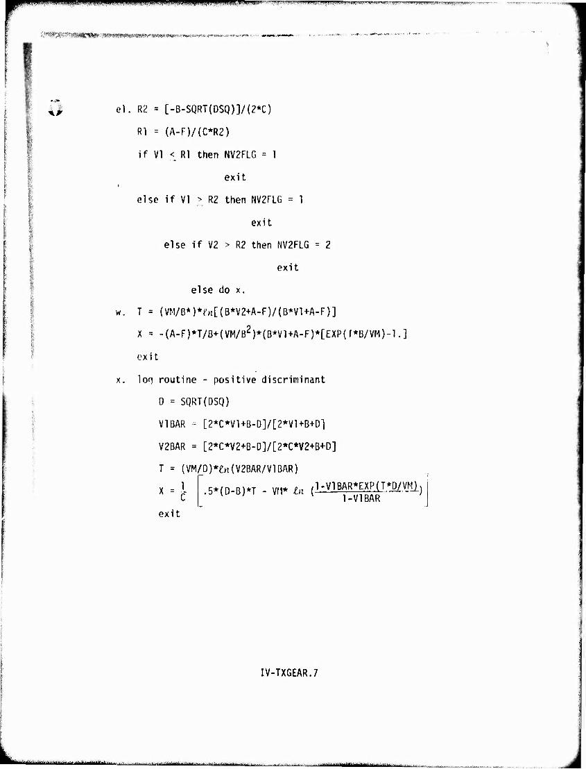
PPM wwm mmi^^m u u i IJI»I vmmf • BBPipiWPi^'^ppwpiffgMillgippwiwwilBeiTWTffifw»»^^
:^Mwmmpm*:-m«m>timsim!'- *«MI*8Ni*,«rJ;,;,-iA^WTtoi,<rtl.,11i**vwftW.'.^."P4»'^*-.
el. R2 = [-B-SQRT(DSQ)]/(2*C)
Rl = (A-F)/(C*R2)
if VI < Rl then NV2FLG = 1
exit
else if VI > R2 then NV2FLG = 1
exit
else if V2 > R2 then NV2FLG = 2
exit
else do x.
w. T = (VM/B*)*M(B*V2+A-F)/(B*V1+A-F)]
X = -(A-F)*T/B+(VM/B2)*(B*Vl+A-F)*[EXP(r*B/VM)-l.]
ox i t
x. loq routine - positive discriminant
D = SQRT{DSQ)
V1BAR -- [2*C*V1+B-D]/[2*V1+B+D1
V2BAR = [2*C*V2+B-D]/[2*C*V2+B+D]
T = (VM/D)*£H(V2BAR/V1BAR)
X = I x c exit
,5*(D-B)*T - VM* in (L^B^pD/VMl)
IV-TXGEAR.7
la^M-dMäidäitiiäättbai*^^ .. • | ■.. .-i^.^...,:.^^,....,,., ■,, ...^..J..Ji^;.J^t-y|||||B..|,|.|.||.|. | ----ii^lMi^^^^"!^----^---^.---- | J
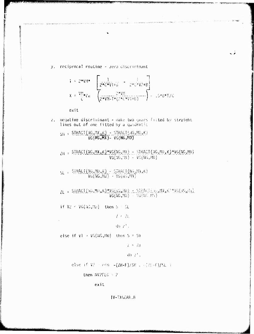
■^w"1 " m^^^^m^^^***ii um --^■-. ■■■ II.MII WWWtiW^I...T .!■ ■«!. .,. ..^,..
■>;,'-."..i *,c ■-,■ '-..-,•
y. rociprocdl routine - zero discriminant
i - 2*vrv ' 1 1 1
L V2*V
exit
;:*vri \ M-TV(2V(~*V'IH;J" /
,.'. neydtive ciiscriniinant - maky two yearr, ficted by straight lines out of one fitted by a quadratic
s„ r STRACT(NG,HX ?Kj - STRACT(HG »MD,K) VG>GTMX)V"VG('N6,MDy
SL
STRACT(NG.MX>K)*VG(NG>MX) - STRACT(WCMfi^j^VGL'i^ll^) VG(^,
;IX)'-" va(Nr^M0} ~
ST RAa lNü '2U) »A) - ':J HAC! CN; 'J MN >K) vT^.NGj'iuT'"- VG(UG,WIT
ZL . STRACT(NG.Mi).K)*VG(iJGtMÜ) -__STRAtTiUi^tt^K'^yufNG^lU] VG(NG,M;J) ■ vGfric M'I)
if V2 -• VG(,NC,nu) then S - SL
/ = /I.
do /' .
eise if Vl •• VG(NG,MU) then S = SH
/: -- l\i
do i' .
else if V;; i-iin -{ZH-F)/SH
then NV?flG • 2
exit
-n/sL
IV-TX&EAR.8
iMMMHHIII^ ■ m^mtm^^m* '*"■■ -■ -- • -■ nif^ggM ■''^'■■'■-^'■tii-hifiiiiH
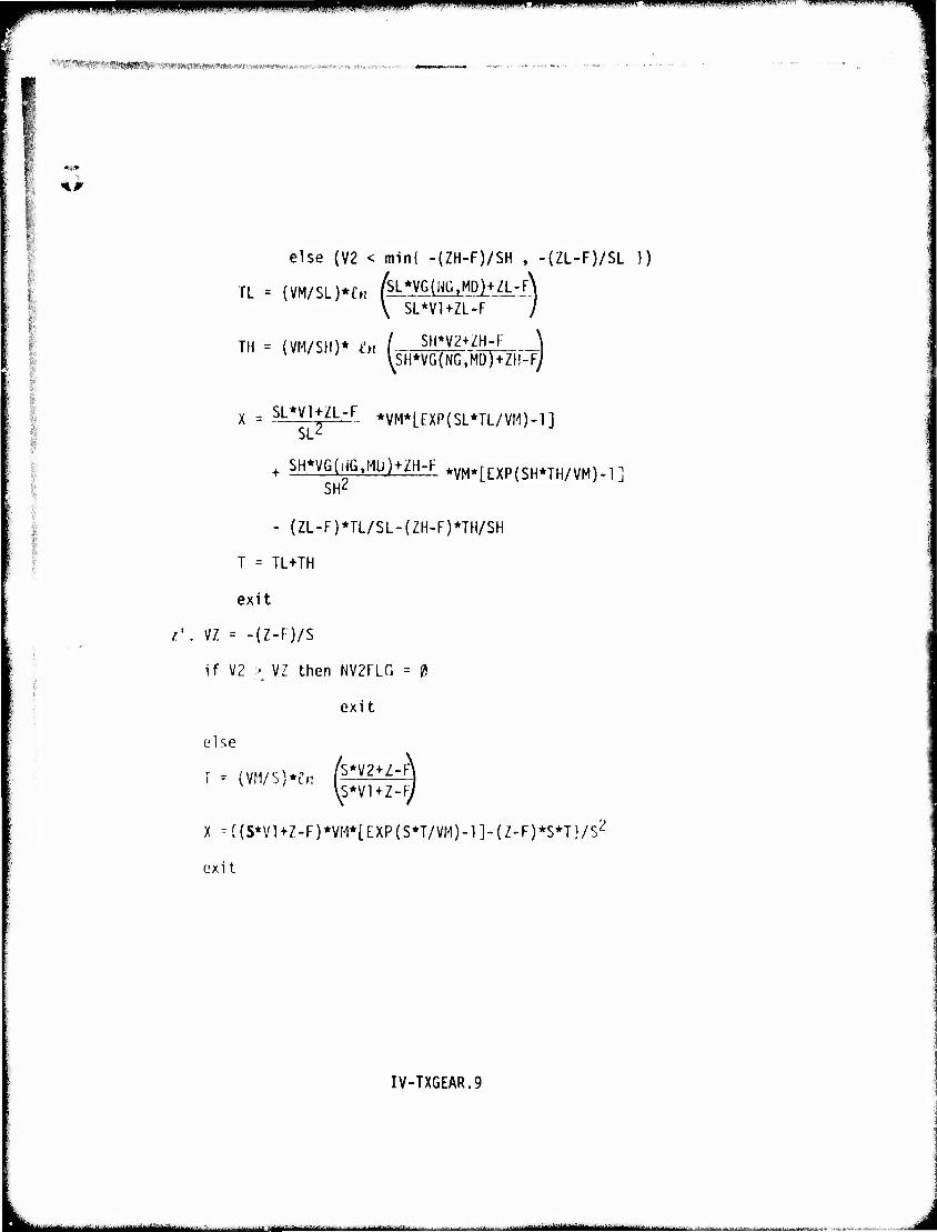
ilBPPliPPiWilipw <"" •i:'-****mmmrmwwwm~«w p ww" .v^ m...»*,m>«o «-^m-— ■■—- -—•m
'■'■' "*! ■-!>''■ ■'■ ''t^nsIS^W^^Wlmmimmmmmmmiitmmmm*». ^."T«*'-*!-^ow -.mni vj^.#
%.p
eise {V2 < min( -(ZH-F)/SH , -(ZL-F)/SL })
TL
TH
= (
= (
\ SL*V1+ZL-F /
VM/SH)* i'H ( Sp2^ \
X = SL*VUZL-F *VM*[EXP(SL*TL/VM)-1] SL'
SjmfeMüljjH^F *VM*[Exp(SH*TH/VM)-l] SH2
- (ZL-F)*TL/SL-(ZH-F)*TH/SH
T = TL+TH
exit
z'. VZ = -(Z-F)/S
if V2 > VZ then NV2FLG = 0
exit
else
\S*VI+Z-F/
X -{{S*VUZ-F)*VH*[EXP(S*T/VM)-1]-(Z-F)*S*T}/S2
exit
IV-TXGEAR.9
~ - -.^ .....:.... frfrgflgyign MMaaawi
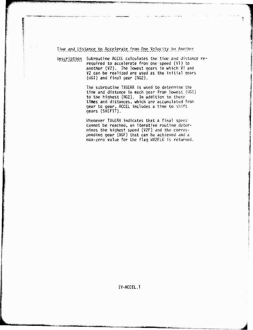
wm >jiiinP*w>i.MW'm>'ti«i.ii.. !!^w;*,*n»wi'|n,iiff',w*«iirin
'■•^wy^mam***** ■■'*■■'■***■>«'*
Time and Distance to Accelerate from One Velocity tn Annihor
Description Subroutine ACCEL calculates the time and distance re- required to accelerate from one speed (VI) to another (V2). The lowest gears in which VI and V2 can be realized are used as the initial qears (UG1) and final gear (NG2).
The subroutine TX6EAR is used to determine the time and distance in each gear from lowest (IIGl) to the highest (NG2). In addition to these times and distances, which are accumulated from gear to gear, ACCEL includes a time to shift gears (SHIFTT).
Whenever TXGEAR indicates that a final speed cannot be reached, an iterative routine deter- mines the highest, speed {V2F) and the corres- ponding gear (NGF) that can be achieved and a non-zero value for the flag NVZFLG is returned.
IV-ACCEL.1
- Illl v ■ ■-"Tinir "■^inmi-iiiniiiiliiii I i ■ ---j^i^MJMittlillMlÜlIilliLil
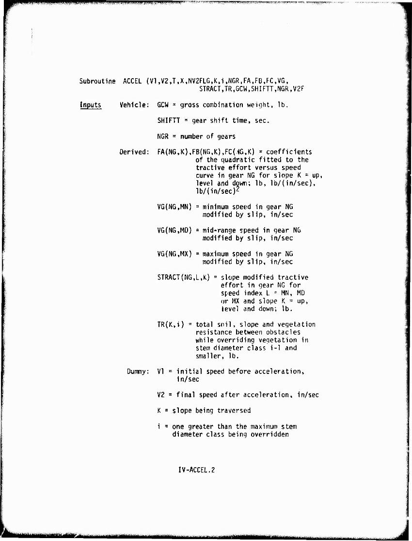
PipilHIWl^W^^WWWWWITOIiyWfB''W'!i'l,.'".ll^'WW1' ^r*\.iimf!*m,v\,imi*mfmifirwv^*'wmr/vivri™-n7rw™^™n> i
Subroutine ACCEL (VI ,V2,T,X,NV2FLG,K,i,NGR,FA,FB,FC,VG, STRACT,TR,GCW,SHIFTT,NGR,V2F
Inputs Vehicle: GCW = gross combination weight, lb.
SHIFTT = gear shift time, sec.
NGR = number of gears
Derived: FA(NG,K),FB(NG,K),FC{16,K) = coefficients of the quadratic fitted to the tractive effort versus speed curve in gear NG for slope K = up, level and down; lb, lb/{in/sec), lb/(in/sec)2
VG(NG,MN) = minimum speed in gear NG modified by slip, in/sec
VG(NG,MD) = mid-range speed in gear NG modified by slip, in/sec
VG{NG,MX) = maximum speed in gear NG modified by slip, in/sec
STRACT(NG,L,K) = slope modified tractive effort in gear NG for speed index L = MN, MD or MX and slope K = up, level and down; lb.
TR(K,i) = total soil, slope and vegetation resistance between obstacles while overriding vegetation in stem diameter class i-1 and smaller, lb.
Dummy: VI = Initial speed before acceleration. In/sec
V2 = final speed after acceleration, in/sec
K = slope being traversed
i a one greater than the maximum stem diameter class being overridden
IV-ACCEL.2
aM*ü"Et^MiM''A ■ - ■ " —^^^^^,M^,_t„^_.: .,„,^^i^MiMiMiL_u_ ■ - ii
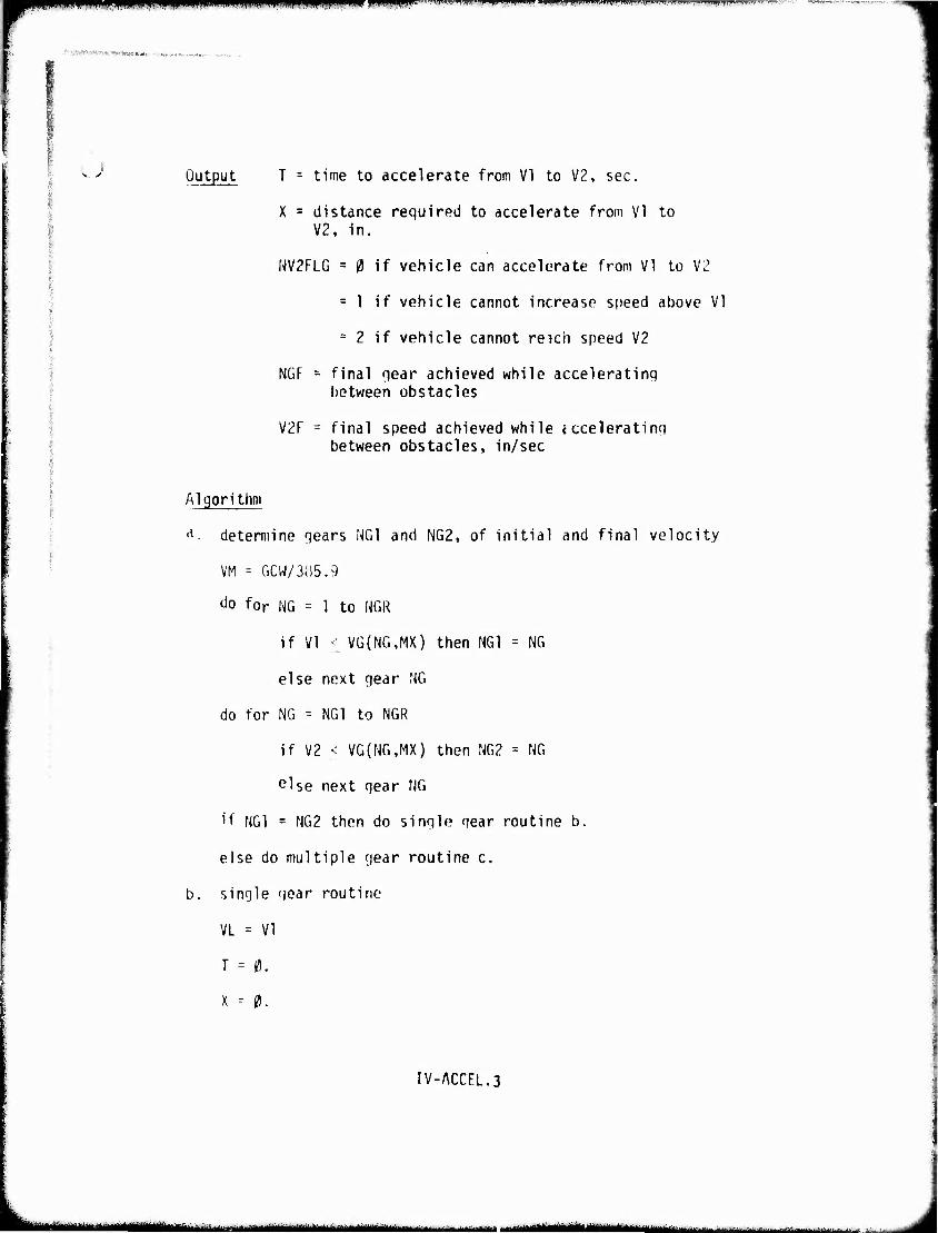
"■'■"Il1« ^r ppumipnii^r-^^wnw«mil I,IHI^JII«II»W"»I.I •»•.■.ji.ii.iiit. j»i.ii!i.,, .ii-T
, ■'■■■".■/f^-**"
.; Output T = time to accelerate from VI to V2, sec.
X = distance required to accelerate from VI to V2. in.
NV2FLG = 0 if vehicle can accelerate from VI to V2
= 1 if vehicle cannot increase speed above VI
= 2 if vehicle cannot reich speed V2
NGF = final qear achieved while acceleratinq between obstacles
V2F = final speed achieved while ccceleratinq between obstacles, in/sec
Algorithm
A- determine qears NG1 and NG2, of initial and final velocity
VM = GCW/3B5.9
^o for NG - 1 to NGR
if VI • VG(NG,MX) then NG1 = NG
else next qear NG
do for NG - NG1 to NGR
if V2 < VG(NG,MX) then NG2 = NG
else next qear NG
if NG1 = NG2 then do sinqle qear routine b.
else do multiple qear routine c.
b. single qear routine
VL = VI
T = 0.
X -- 0.
IV-ACCEL.3
MMaa^HMMMM 11 iniiinilimiiiiiirMM - ^^^^a^M^m^. ' ■■ r i
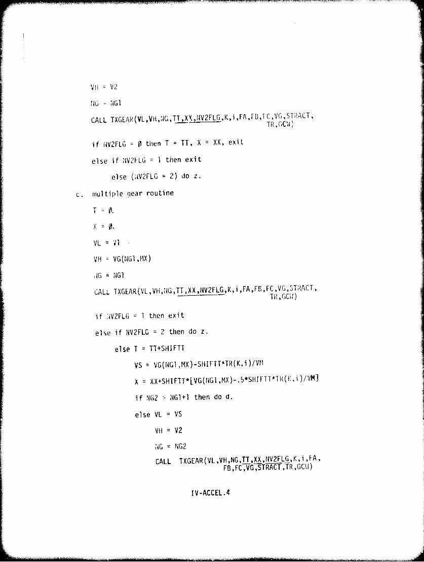
«CWapannWliJUMUii .MIH'III '-^ "•• ^■•(»■•'«•ii<-i "••■»i m'' mn rw* ••'••"> «•■' <m^l i i *w
V!l = V2
CALL TXGL:AR(VltVH,NÜtTT.XX>NV2FLGtK.itFA,rBtrCtVGT$TRACT, TR,GCW)
if NV2FLG - 0 then T = TT, X = XX, exit
else if :iV2FLÜ - 1 then exit
else (UV2FLG = 2) do z.
multiple gear routine
T - 1».
X -- 0.
VL = VI ■
VH = VG(NG1,MX)
ilG « NG1
CALL TXGLAR(VL.VH,NG>TT,XX.NV2FLG>K>i>FA.FB>FC1VGt5TRACTt TR.GCl.')
if ;.V2FLG = 1 then exit
else if NV2FLG -- 2 then do z.
else T = TT+SHIFTT
VS = VG(NGl>MX)-SHIFTT*TR{K,i)/VM
X = XX+SHIFTT*[VG(NGUMX)-.5*SHIFTT*TR(K,i)/VM]
if NG2 > NG1+1 then do d.
else VL = VS
VH = V2
NG = NG2
CALL TXGEAR(VL>VH.NG)TT.XX.NV2FLG.K.i.FA>
FB,FC,VG,STRACT JR.GCVI)
IV-ACCEL.4
■ -■■-■ ■ —-•■-' MBüMMi - ■- ■- i iimiim-
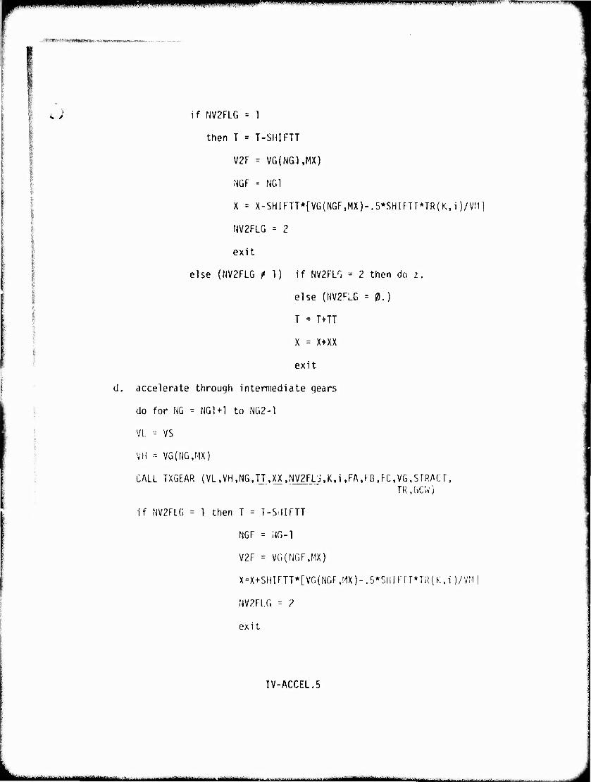
Pf- IIII»HI.I)I„IIIIII,III]| UIIRIII im.ii ^IPPPipnVXnnVÜP I^WJW l'l'UFWI1 ' -" ''.H»!«,«'.!!».!! .■IIBUT'UHID'.TH
■'■■'* ■ ■JB«.l ■■ <'t>» WM«*^«(»»i .
<l /
d.
if NV2FLG = 1
then T = T-SHIFTT
V2F = VG(NG1,MX)
NGF = NG1
X = X-SHIFTT*[Vü{NGF,MX)-.5*SHIFTT*TR(K,i)/V;i
NV2FLG - 2
exit
else (NV2FLG /I) if NV2FLG = 2 then do z.
else (m^.G = 0.)
T = T+TT
X = X+XX
exit
accelerate through intermediate gears
do for NO - NG1+1 to NG2-1
VL = VS
VH = VG(NG,MX)
CALL TXGEAR (VL ,VH,NG JJ,)^ ,r|V2Fj.J,K.i ,FA,rB ,FC,VG,STRACT , TR.GCW)
if NV2FLG = 1 then T = T-SilIFTT
NGF = iJG-1
V2F = VG(NGF.MX)
X = X+SHIFTT*[VG(NGF ,MX)-.5*StlIF 1 r*TR(K, i )/VM |
NV2F1.G = ?
exit
IV-ACCEL.5
jtimttmmifimtmmmmmmm eitm—l^^t^tmmimm ■ i mimm ■MMM^HHK.
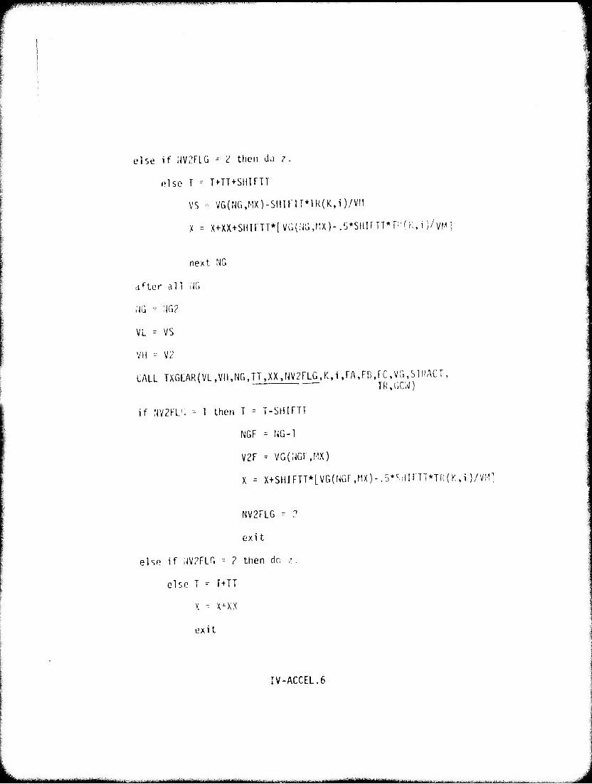
m^m^m^^ mm ^^^W
else if IJV2FLG ~- 2 then do 7.
olse T -- T+TT+SHIPTT
VS - VG(NG,MX)-SHlFTI*TR(K,i)/VM
X = X+XX+SllirTT*[VG{IJÜ,r'X)-.,j*SIIIfTT*T:'fr;,i)/vMl
next. MO
after all ;iG
;JG - :JG2
VL = VS
VH = V2
CALL TXGLARCVL.VH.NG.TT.XX^NVgFLG.K.i.FA.FlJ.rC.VG.STRACT, TR,GCW)
if flV2FL'. = 1 then T - T-SHIFTT
NGF = NG-1
V2F = VG(;jGi ,MX)
X = X+SHIFTT*[VG(NGF,MX)-.5*SHirTT*TR(K,i)/VHl
NV2FLG -- ?
exi t
else if UV2FLG -- 2 then do i.
else T - T+TT
X = x^xx
exit
IV-ACCEL.6
_^—^mmm^—t. ^^-mmam
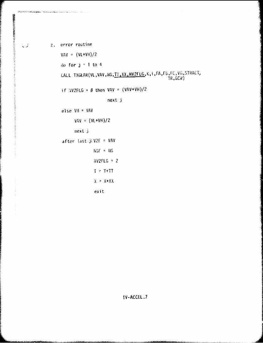
NMQftWÄW yfrWH (*(«**i 'i.wnHnMMvotaMi
^ ) z. error routine
VAV = (VL+VH)/2
do for j - 1 to 4
CALL TXGLAR(VL,VAV.NGtTT.XX.NV2FLG.K.i.FA>rB.rC,VG>STRACTJ TR.GCW)
if :W2FLG = 0 then VAV = (VAV+VH)/2
next j
else VH = VAV
VAV = {VL+VH)/2
next j
after last j: V2F - VAV
NGF = NG
NV2FLG - 2
T - T+TT
X = X+XX
exit
IV-ACCtL.7
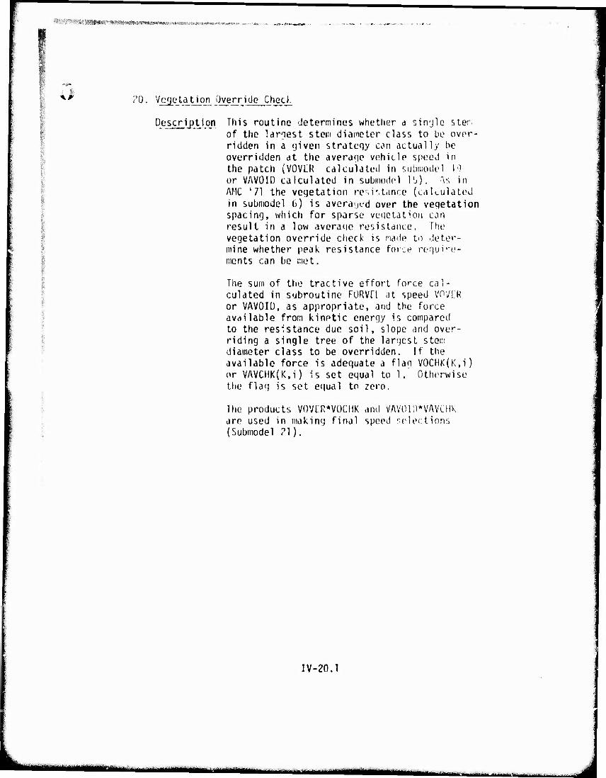
%!«f^^ 38g#«»r'*iwi«i^^ »I'^WWHPI-'A ••r^vf/i^A'' i
?0. Vegetation Override Check
Description This routine determines whether a sin'jle sler. of the larnest steii) diameter class to be over- ridden in a 'jiven strateqy con actually be overridden at the averaqe vehicle speed in the patch (VOVLR calculated in submodel 19 or VAV0IÜ calculated in submodel I1 V. in AMC '71 the vegetation resistance (calculated in submodel 6) is averaged over the veqetation spacing, which for sparse veqetation can result in a low average resistance. The vegetation override check is made to deter- mine whether peak resistance force reguire- ments can bo met.
The sum of the tractive effort force cal- culated in subroutine FüRVQ at speed VOVLR or VAV0IÜ, as appropriate, and the force available from kinetic energy is compared to the resistance due soil, slope and over- riding a single tree of the largest stem diameter class to be overridden. If the available force is adequate a flan V0CHK(K,i) or VAVCHK(K,i) is set equal to 1. Otherwise the flag is set equal to zero.
The products V0VER*V0CIIK and VAVOH)*VAVCHk are used in making final speed selections (Submodel 21).
IV-20J
- -- - ■ - - ■ ■
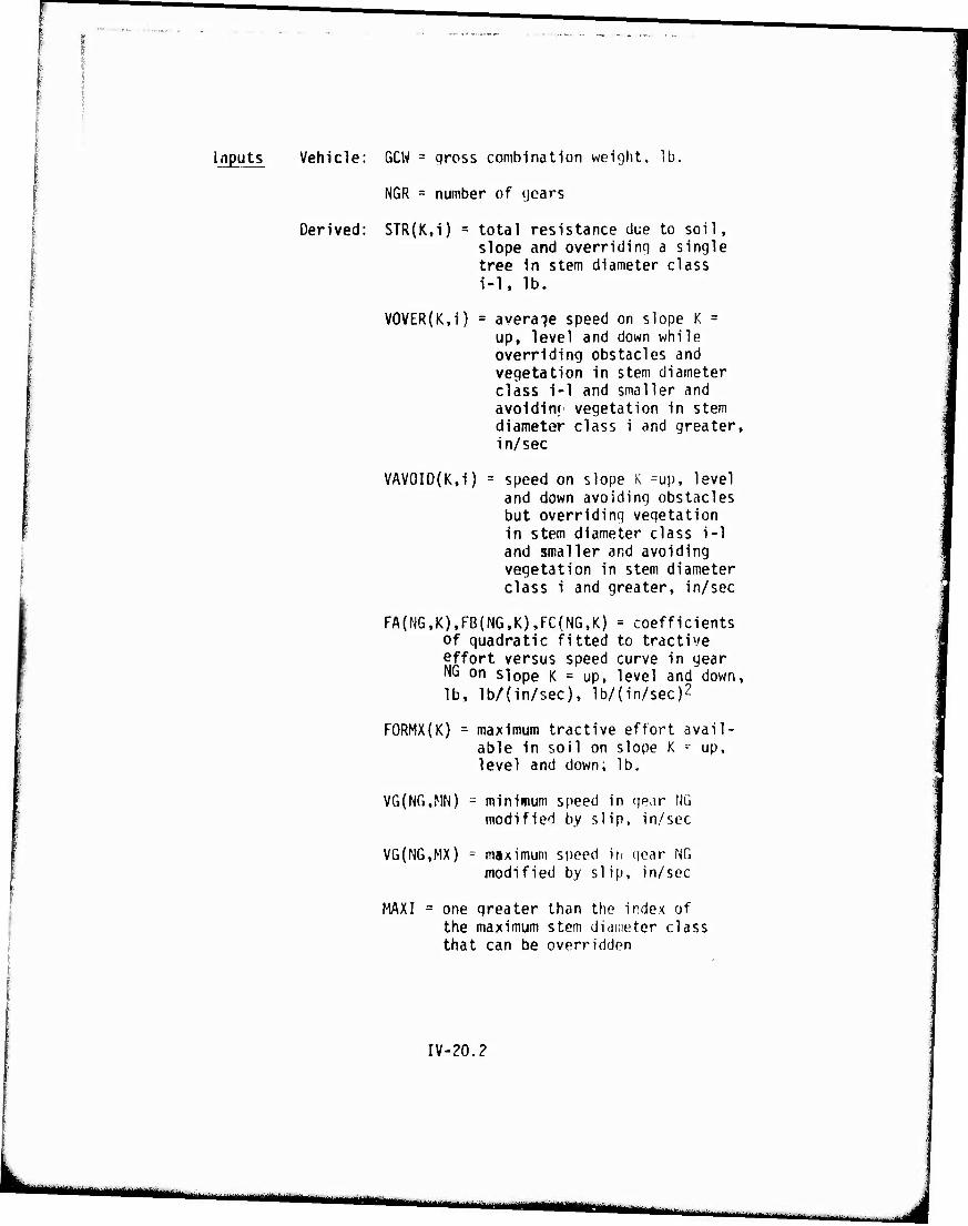
Inputs Vehicle: GCW = gross combination weight, lb.
NGR = number of (joars
Derived: STR(K,i) total resistance clue to soil, slope and overridinq a single tree in stem diameter class i-1, lb.
V0VER(K,i) = average speed on slope K = up, level and down while overriding obstacles and vegetation in stem diameter class i-1 and smaller and avoidin«1 vegetation in stem diameter class i and greater, in/sec
VAV0ID{K,i) = speed on slope K =up, level and down avoiding obstacles but overriding vegetation in stem diameter class i-1 and smaller and avoiding vegetation in stem diameter class i and greater, in/sec
FA(NG,K),FB(NG.K),FC(NG,K) = coefficients of quadratic fitted to tractive effort versus speed curve in gear NG on slope K = up, level and down, lb, lb/(in/sec), lb/(in/sec)2
FORMX(K) = maximum tractive effort avail- able in soil on slope K - up, level and down; lb.
VG{NG,MN) = minimum speed in gear NG modified by slip, in/sec
V6(NG,MX) = maximum speed in qear NG modified by slip, in/sec
MAXI = one greater than the index of the maximum stem diameter class that can be overridden
IV-20.2
■ ■
mmmm
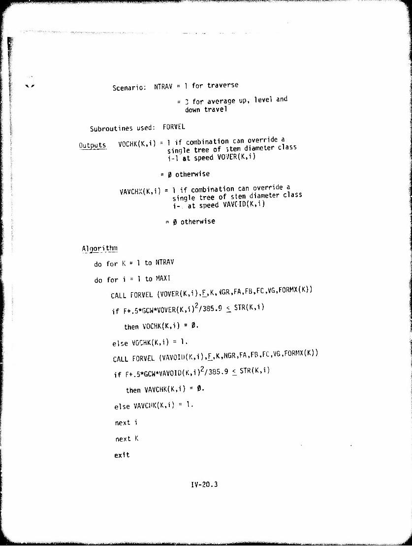
t ^
»■^■■■p^mw^^^p^ppp^ ■'■•, w '■'■' -""w" •ll-,," <.■ -"w"! ■• " 'WM-'«-
.■"-■'■"■■ «fS* .■■!•■-^'^ ■ .i^.V^V^-..;^,.,^v,,.V, .^^
Scenario: NTRAV = 1 for traverse
= 3 for average up, level and down travel
Subroutines used: FORVEL
Outputs V0CHK(K,i) = 1 if combination can override a single tree of item diameter class i-1 at speed V07ER(K,i)
= 0 otherwise
VAVCH;C{K,i) = 1 if combination can override a single tree of stem diameter class i- at speed VAVCID(K,i)
= 0 otherwise
Algorithm
do for K = 1 to NTRAV
do for i = 1 to MAX!
CALL FORVEL (V0VER{K,i),F,K,NGR,FA,FB,FC,VG,FORMX(K))
if F+.5*GCW*V0VER(K,i)2/385.9 <_STR(K,i)
then V0CHK(K,i) = 0.
else V0CHK(K,i) = 1.
CALL FORVEL (VAV0Il)(K,i) ,F,K,NGR,FA,FB.FC,VG,FORMX(K))
if F+.5*GCW*VAV0Iü(K,i)2/385.9 ^STR(K,i)
then VAVCHK(K,i) = 0.
else VAVCHK(K,i) = 1.
next i
next K
exit
IV-20.3
MM mi i ii mm '— ■.-.-—^^M»
Xf ']. ilaximum Average Speed
Description This routine assiqns the maxinjin averaqe speed in the patch (VSEL). For each direction of travel rcletive to the slope (up, level and down), the speed assiqned is the maximum achievable among the 18 possible obstacle and vegetation avoid/ override options computed, (V0CHK*V(MR,
| VAVCHK*VAVOID), subject to the following possible condition. It has been found that in iiany situations, if a vehicle will travel at a reasonable speed without overriding large trees, the driver will accept that speed rather than override more trees, e/en though by further over- riding his average speed could be increased. This reasonable speed is entered as a scenario variable CVEGV.
When a traverse prediction is being made (NTRAV = 1) the speed determined for the single slope direction specified is output as VSEL. When a non-directional area speed prediction is specified (NTRAV - 3) VStL is computed on the assumption that 1/3 of the distance traveled in the patch is uphill, 1/3 downhill and 1/3 on level ground. This assumption produces a pre- diction which is directly applicable to operations in rolling country for which the slope specified for tiie patch is the characteristic maximum slope. In patches with a prevailing slope, VSEL is considered an omni-directional average speed, and the 1/3 of distance on level ground is inter- preted as 1/3 of distance along the slope contours at a fixed elevation, is :ide slope operation. Because the average is based upon 1/3 distance in each direction (up, level and down), the maximum average, VSEL, is, in this case, the harmonic average of the maxima selected for each direction.
IV-21.1
Mi ' _ ... -.^m^.^g
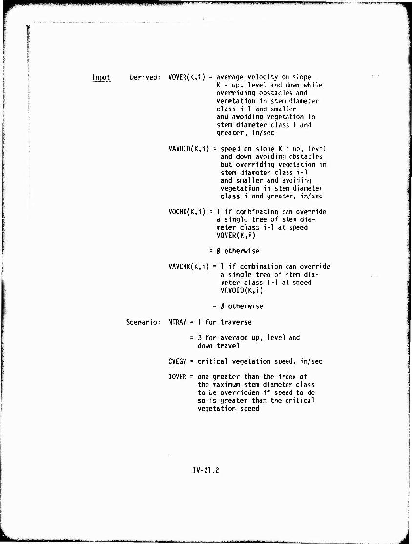
mm ""■"-' m ,,"w»**mmmm!9immmvimwvmm* M.i.pwjfiWii-ffjW»"---^-.---- ■ ^T-rwvrT^jrwT^p-r
»■'i?»*ti»BK.W>Matffl»iftm«'w
Input Uerived: VOVER(K,i) average velocity on slope K = up, level and down while overriding obstacles and vegetation in stem diameter class i-1 and smaller and avoiding vegetation in stem diameter class i and greater, in/sec
VAV0ID(K,i) = speel on slope K = up, Ipvel and down avoiding obstacles but overriding vegetation in stem diameter class i-1 and smaller and avoiding vegetation in stem diameter class i and greater, in/sec
V0CHK(K,i) = 1 if conbination can override a singl.? tree of stem dia- meter class i-1 at speed V0VER(K,i)
= 0 otherwise
VAVCHK(K,i) = 1 if combination can override a single tree of stem dia- mrter class i-1 at speed W.V0ID(K,i)
= i otherwise
Scenario: NTRAV = 1 for traverse
= 3 for average down travel
up, level and
CVEGV = critical vegetation speed, in/sec
I0VER = one greater than the index of the maximum stem diameter class to te overridden if speed to do so is greater than the critical vegetation speed
IV-21.2
■ ■ 'urn ^^m^,^^^m^m
[
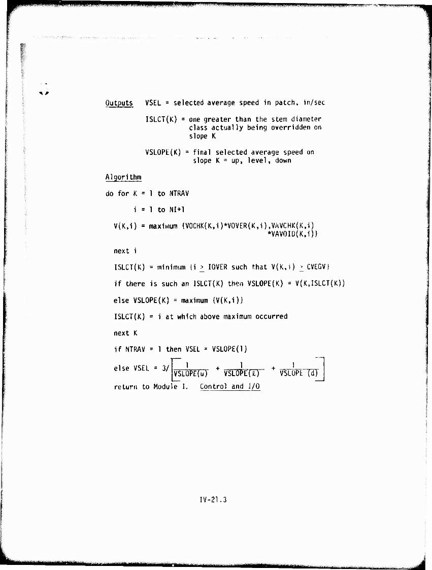
mWWPiWWHWIPW^ i. HI imw^fwwm^iniiwipmBii immmmmmmimm »., H<lll.'S,-«Bt.'W»J
■■ -.'f-1-; ;■•!,;
Ik ^
Outputs VSEL a selected average speed in patch, in/sec
ISLCT(K) = one greater than the stem diameter class actually being overridden on slope K
VSLOPE(K) = final selected average speed on slope K = up, level, down
Algorithm
do for K = 1 to NTRAV
i = 1 to NI+1
V(K.i) = maximum {V0CHK(K,i)*VOVER(K,i),V/WCHK{K,i) *VAV0ID(K,i)}
next i
ISLCT(K) = minimum {i > I0VER such that V(K,i) > CVEGV}
if there is such an ISLCT(K) then VSL0PE{K) = V(K,ISLCT(K))
else VSLOPE(K) = maximum {V(K,1)}
ISLCT(K) = i at which above maximum occurred
next K
if NTRAV = 1 then VSEL = VSLOPE(l)
else VSEL = 3/
return to Modu
1 1 VSLOPE(u) VSL0PE[ir VSLOPE'TdJ
e L Control and J/0
IV-21.3
aamm^mmimmmlimt mmm ■BMHMMi^tMi ,■■:_. ..,■.. ,.. ■; ... ^ || | ... , ,
i"1' w""- ""■■ ■ IM. .JUMII.I m .ll)JMII.IMfW^«VPW9mu^UIIjJ|JM l^ii
v^«*-^'
*^
MODULE V
HASTY RIVER AND DRY
LINEAR FEATURES CROSSING
V-l
L ■t ■■-■"■-"■->■- ■ j - '- nil miM^ll—^MMiii- i ii
^mmmw* ' TW5n^P»^Tf™r-'ir?«w'^
a^^r/a^wriKimmm^' ■■..•:.''..W<^!«^V1r;t-tf.T,.v. ■,
%# HASTY RIVER AND DRY LINEAR FEATURES CROSSING MODULE
t
This module ts intended to improve and generalize the RIVER sub- routine of AMC '71. A report in progress (Reference1!) contains the detailed rationale behind the specifications, equations, and logic of this module.
In the Mobility Model terminology a "linear feature" is any geographic feature reprecentad by a line on a topographic map; such as streams, natural drainage ditches, man-made ditches, and highway embankments. These features require specia"1 treatment since the vehicle does not negotiate a linear feature in the same manner as an areal feature (excepting obstacle override). For example, negotiating a linear feature may require that the vehicle remain "on" or "in" the feature until a route is found to exit from it. Linear features of significance are those shown on a 1:50,000 scale topographic map which cause a de- crease in vehicle speed or require the vehicle to detour the feature.
The impediments due to linear features on vehicle cross-country movement can be represented by:
- 60 or N0-G0 across the feature.
- A speed reduction while crossing the feature.
- A time required to cross the feature.
The representation used may be scenario dependent. For example, when a specific vehicle terrain and scenario are given, the Interaction between areal patches and linear features can be melded together. In this type of analysis the path of the vehicle is specified either by the scenario or the best route in the areal patches. Thfe terrain input data may inve both areal and linear features arranged in the order that the vehicle would encounter them, as specified by the scenario.
Identification of linear features on a topographic map is a straight-forward process. Normally an overlay is prepared and each significant linear feature is traced. In this manner the location and type (i.e., wet, dry, river, canal, slope, rail- road, embankment, etc.) is shown. The features are differentiated by the type of "line on the overlay and by code numbers.
V-2
'■'- I run mmt
Assignment of specific geometric properties and physical dimensions to the linear features can be done by a number of different Methods. These include:
- Use of "ground truth" data
- Measurements from airphotos and airphoto stereopairs.
- Terrain analogues.
- Estimates based on classifications of feature type.
- Intelligence data.
- f·teasurements from topographic maps.
The AMC '74 Hasty River and Dry Linear Features Crossing Nodule first determines if the feature can be crossed on the basis of upslope bank height and bank angles. If crossing is considered possible, bank interference and traction versus resistance are calculated either for the bank as presented or a deformed bank. A deformed bank is a bank formed from a natural bank by action of the vehicle's running gear. If the calculation is made for a deformed bank, allowance is made for modifying the bank by the vehicle in its attempt to negotiate the slope.
Regardless of whether crossing is possible or not, time and distance to alternate crossing sites (bridges and/or exit windows) are calculated from bridge spacings and the natural river meanders which depenJ on gross topography.
Tht! outputs, GO/NO-GO and time to cross or find other crossing sites, are returned to the user with no further analysis. liow they are used to calculate traverse times or average speeds depends on the scenario of the user. The model does not postulate a scenario.
Two specific assumptions are made:
- downslopes can always be negotiated with no time penalty if the upslope negotiation is possible
- alternate crossing sites will always allow a crossing. No time penalty is assessed other than the time to arrive at this alternate site.
The vehicle is assumed to approach the linear feature from the left uank and to exit it from the riqht bank.
Y·J
)
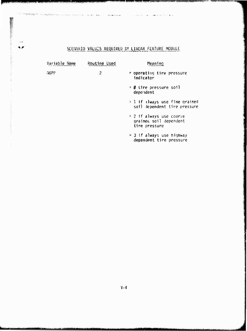
nmmHmPRii mUBP l"11111''.' «"»mimw );n.n,i|» JI» | luLmmmuimH» .^iiwuipjim.iiiipiJijiijii. "
■ ■ ■^M/^'v; ;■ ; ■; .■ . I
"»^ SCENARIO VALUZS REQUIRED BY LINEAR FEATURE MODULL
• Variable Name
NOPP
Routine Used Meaning
operating tire pressure indicator
0 tire pressure soil dependent
1 if ilways use fine grained soil Jrpendent tire pressure
2 if always use coarse grainec, soil dependent tire pressure
3 if always use highway dependent tire pressure
V-4
kMMMMHMh •MMMMi '-- '■ ■ I
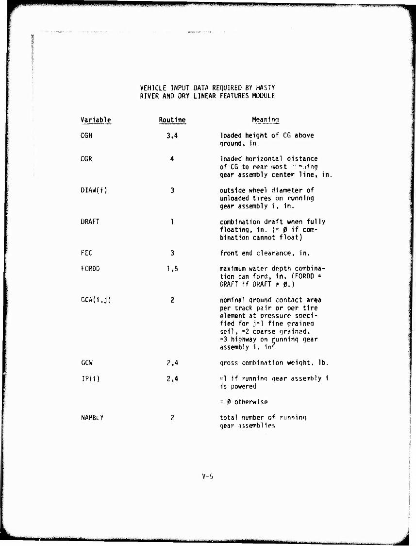
^ T' urnKfuummmm^mi
VEHICLE INPUT DATA REQUIRED BY HASTY RIVER AND DRY LINEAR FEATURES MODULE
Variable Routine
CGH 3,4
CGR 4
DIAW(I)
DRAFT
FEC
FOROD
GCA(i.j)
GCW
IP(i)
NAMBLY
3
1,5
2.4
2.4
Meaning
loaded height of CG above qround, in.
loaded horizontal distance of CG to rear most "ring gear assembly center line, in.
outside wheel diameter of unloaded tires on running gear assembly i, In.
combination draft when fully floating, in. (- 0 if com- bination cannot float)
front end clearance, in.
maximum water depth combina- tion can ford, In. (FORDD = DRAFT If DRAFT ^0.)
nominal qround contact area per track pair or per tire element at pressure speci- fied for j=l fine grained soil, =2 coarse grained, =3 highway on running gear assembly 1, in^
gross combination weight, lb.
=1 if runnino qear assembly 1 is powered
= 0 otherwise
total number of running gear -issemblles
V-6
■MMM .u^MMMMMÜ
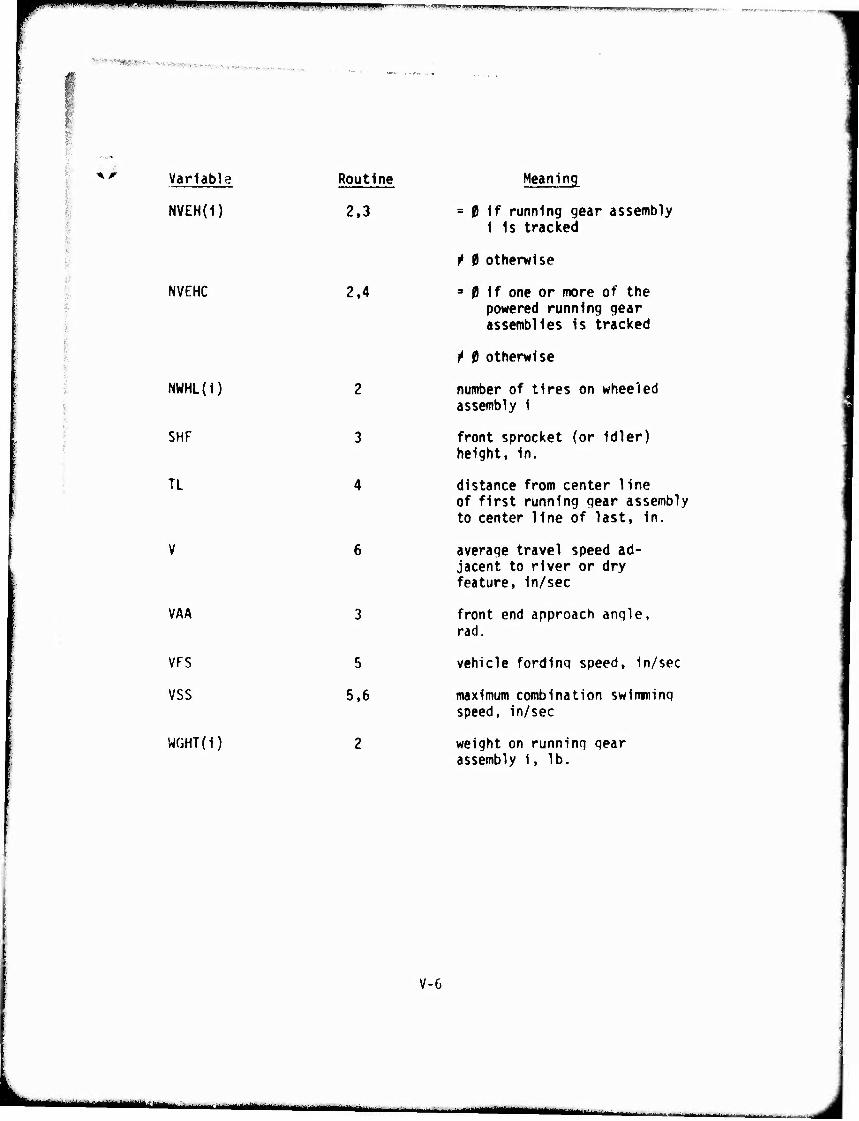
mmmmmm_ \ m *f mmm
^»;^«*»fs ...^,,:W,.;,,..,,„ .;.
—»Tr-^K-;lBWIIHlf>.'W«.W.II .Illlll. llll, IJl»»!.! »i uii.,1.1^. »i ,..., „i^wj^^,,^.-
*' Variable Routine Meaning
NVEH(i) 2,3 = 0 if running gear assembly 1 is tracked
.'.,
?
f 0 otherwise
NVEHC 2,4 =» 0 if one or more of the powered running gear assemblies is tracked
f 0 otherwise
NWHL(1) 2 number of tires on wheeled assembly 1
SHF 3 front sprocket (or idler) height, in.
TL 4 distance from center line of first running gear assembly to center line of last, in.
V 6 average travel speed ad- jacent to river or dry feature, in/sec
VAA 3 front end approach angle, rad.
VFS 5 vehicle fording speed, in/sec
VSS 5,6 maximum combination swimminq speed, in/sec
W(iHT(i) 2 weight on running gear assembly 1, lb.
V-6
-*"**''''■""-■ ■ i um " '"•" I -MMMM^iMi
1111 ■"■• ^T^.)Wiifiw^wjB^^.inBwww^wwtp|iiuyinjn.iiiii«i »uaii. LHJ.iK.j «WWPi
i
iiwgjf** : .'^ .«*>^ -r*,^-.^ :::
\r 1. Initial GO/NO-GO Screen
Description This routine makes simple checks of bank heights (RbH) and anqles (RBA) to distinquish linear features which are so severe that they pose a NO-GO to any vehicle. This routine also indicates a NO-GO when a non-swimmer (DRAFT = 0.) encounters a deep waterway.
V-l.l
"-■■—■—■*-' - -- ■
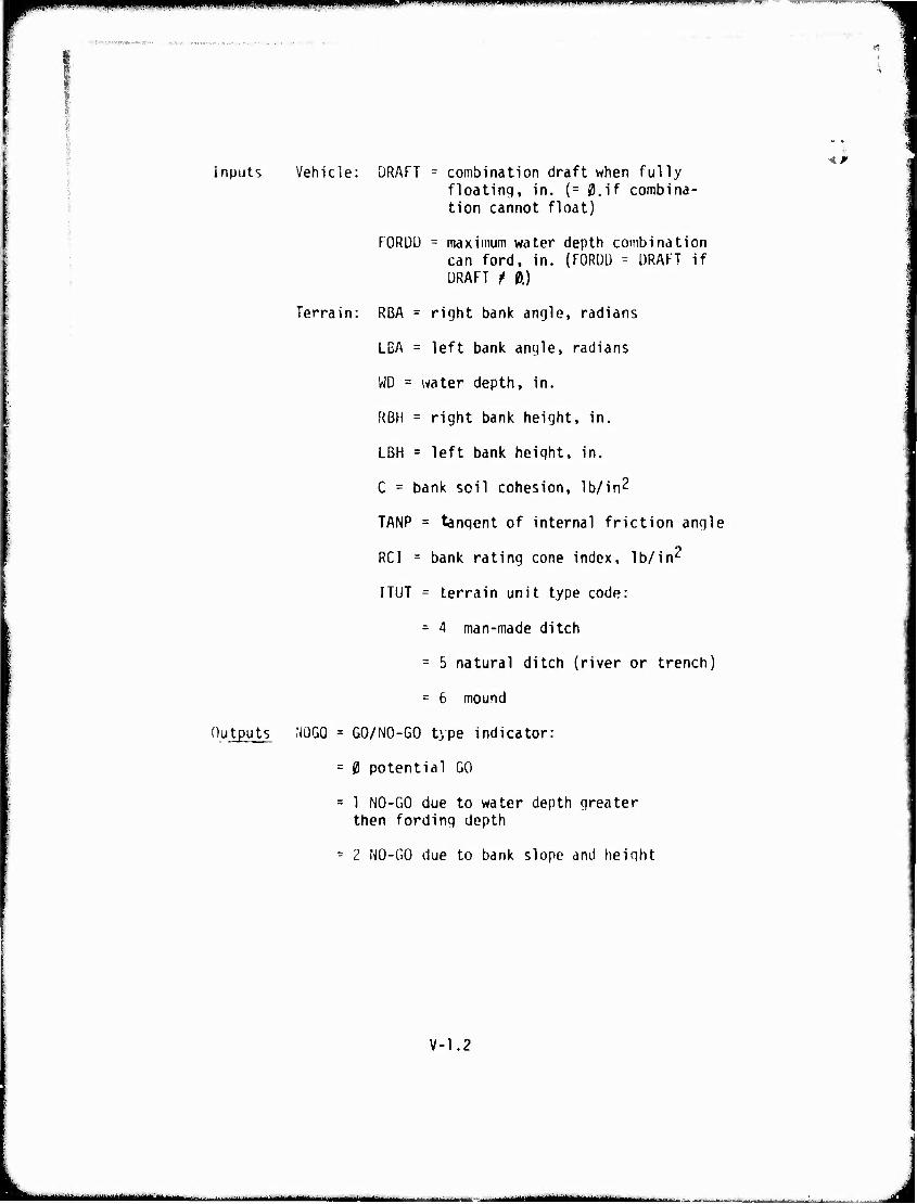
PPPÜjffi "y-'-*' "w.'it" .>fwv'i*mm wM^i'w.wF'f ■^p-iir- -»T—■ ■'■ ■"'■ »-i—^■- ■■■>-■■.■.■■.—.■^■—^.—-
■ ( ,-.<—. ^.-.■^..^ jv-..-
Inputs Vehicle: DRAFT r combination draft when fully floating, in. {= 0,if combina- tion cannot float)
FORDU = maximum water depth combination can ford, in. (FORDD = URAFT if DRAFT t 0.)
Terrain: RBA = right bank angle, radians
LBA = left bank angle, radians
WD = water depth, in.
RBM = right bank height, in.
LBH = left bank height, in.
C = bank soil cohesion, Ib/in^
TANP = tangent of internal friction angle
RCI = bank rating cone index, lb/in11
I TUT = terrain unit type code:
- 4 man-made ditch
= 5 natural ditch (river or trench)
= 6 mound
Outputs NOGO = GO/NO-GO type indicator:
= 0 potential GO
= 1 NO-GO due to water depth greater then fording depth
- 2 NO-GO due to bank slope and height
*#
V-1.2
«WMMMM I IIHI.III«!! I Hi—■IMIIIII I
piHpppHppiiiiiiMiOTnnpp*PPmMPP,iMw.iiiiiiwiHHM«u .. «—*********** ^.^.-^ ,,. ^ ^-__^_
■ft .■■■ -rKViglPw ,-; f-mait i«ra
I
<• r Algorithm
a. feature type test
if WD - 0, then feature is dry
if ITUT = 6 then do mound routine d.
else dc ditch routine c.
else do river routine D.
b. river routine
if F0RDÜ - WD and DRAFT = 0,
then NOGO = 1
do routine 6. Exit and Crossing Search
else if RBA > Tt/6.43 and RBH > 167.32
then NOGO = 2
do routine 6. Exit and Crossing Search
else NOGO = 0
exit
c. dry ditch routine
if RBA > n/5.14 and RBH > 167.32
then NOGO = 2
do routine 6, Exit and Crossing Search
else NOGO = 0
exit
V-1.3
I III ■!
■«■piMMRiiuiii.1111 mmtmmmnfmmmm i m w» ., ..-.-U..I-I,IUIPU.I'.VW-I"JIIU»IU. »'■ ■• "
d. inound routine
if LBA • n/3.79 and LBH > 167.32
then NOGO = 2
do routine 6. Exit and Crossing Search
else NOGO -- 0
exi t
V-1.4
■- —-^-- . ...^
ipii i .jjijiiM ■.»aiwiiwiwwiii.i.iiiiiinni.pniwwwiww •WPWPBPPW»"
■ mammi<>wmm*vm>m**mmm*m*l.* m&wM'vm* r
, Initial Traction/Resistance Screen
Description This routine makes an initial check to determine if the vehicle can operate at all in the soil type (IST) of the linear feature slopes. Soil type and strength (C, TANP) are used to cal- culate a traction ^TFL) and resistance (RT0WL*GCW) for the vehicle operating on level ground for the soil type and strength found on the banks. If no excess traction exists, a NOGO is assigned.
V-2.1
• ■-'- - "'■''■"-•■-"'-iiriiiinMwüniii n HiifcMMM^Mfc^«.^
^mm m^mmmmmiim mw^fmummiiMmi:-^ ■
Inputs Vehicle: GCW = qross combination weight, lb.
NAMBLY = total number of running (jear assemblies
NVEH(i) = 0 if running gear assembly i is tracked
^ 0 otherwise
NVEHC = 0 if one or more of the powered running gear assemblies is tracked
f 0 otherwise
IP(i) = 1 if running gear assembly i is powered
= 0 otherwise
GCA(iJ) = nominal ground contact area per track pair or per tire element at pressure speci- fied for j=l fine grained soil, =2 coarse grained, = 3 highway on running gear assembly i, in2
WGHT(i) = weight on running gear assembly i, lb.
NWHL(i) = number of tires on wheeled assembly i
Terrain: ITUT = terrain unit type:
= 4 for man-made ditch
= 5 natural ditch (river or trench)
- 6 mound
WD - water depth, in.
RC1 = bank rating cone index, lb/in
R3A = right bank angle, radians
LBA = left bank angle, radians
V-2.2
tämmummi ■■■■i^' -—■ täm aa^nm^imgnn -
m^m^m«'!< wfm^m ■ - ■ mum... '*j\m>M*wvfiw*r--i?vrr-*
Outputs
1ST = soil type:
= 1 fine qrained not CH impervious to water
= 2 coarse qrained
= 6 CH impervious to water
= 7 gravel
= 12 clay/sand
= 17 clay/gravel
= 27 sand/gravel
C = bank soil cohesion, lb/in
TANP = tangent of internal friction angle
Scenario: NOPP = operating tire pressure indicator:
= 0 tire pressure soil dependent
= 1 if always use fine grained soil dependent tire pressure
= 2 if always use coarse grained soil dependent tire pressure
= 3 if always use highway dependent tire pressure
RTOWL = level resistance coefficient on bank soil type
RTOW = resistance coefficient on bank
TFL - level tractive force on bank soil type, lb.
NOGO = 0 if potential GO
=3 NO-60 due to insufficient level traction on bank soil type
GAREA(i) = ground contact area of running gear assembly i, in^
V-2.3
---■-I IT II -■ :>-.^-.....^ ^.t*..: ■l^.,...J,-i.. J—^''■'■--■'■•rg|-irirtitiii,-t(iiiraMmMJtttii
—... ^^^.^j^^t^^tmrnmrnm^m MMHWMimttlMiiM .i—^. JUI^üJ ^-1~-* — " if t, „a ,,..
^mm*^ mi HPifiyi^B"1 "miiii-iiuijinini »i igiun.iiiiii m''w''*-uw'l:m-'''^«'*'>vi'-.\im\-m'wv'lwr'''
Algorithm
a. feature type test
if WD = 0.then feature is dry
if ITUT = t) then do mound routine d,
else do ditch routine c.
else do river routine b.
b. river routine
if NVEHC = 0 (wheeled vehicle)
then RTOWL = 28. -6.35*l0gig(RCI)
100.
W4, RTOW = RTOWL -
else (tracked vehicle)
RTOWL = .14
RTOW = RTOWL - R^- * 1S
1500.
IT/4. 3000.
do routine e.
dry üitch routine
if IIVEHD' 0 (wheeled Vehicle)
then RTOWL = 28. -6.35*log1g(RCI)
100.
RTOW = RTOWL - ^-A * M-_ w/4f 1200.
else (tracked vehicle)
RTOWL 12
RTOW - RTOWL - -RAA * M^ IT/4. 2500.
do routine e.
V-2.4
Ktatau BBMIIMIiMMiMraiiMiü ■ ■■•' •■ ■ •■■ ■ - - ' • ■ " •'"liüiliüiüMilÜiiiiütititfiliiiiimii i .^^-.:J.^,... .^ ,„ mau • - ■^■'-
•m*^*9mmmrmmmmwmmmmmimn< mmw laMiwimii
*«fi!;*?S(|«WWN(^H|W»B :■■';■ ;■■..,,, .,,.
mound
if NVEHC t 0 (wheeled vehicle)
then RTOWL = 28. -6J5M0^(KCI)
100.
RTOW = RTOWL/1
else (tracked vehicle)
RTOWL - .1
RTOW - RTOWL - l™ * *- 45. 2000.
do routine e.
e. traction on level
if NOPP = 0 then if 1ST = 1 or 12 or 17 or 27
then j = 1
else j = 2
else j = NOPP
do for i = 1 to NAMBLY
if NVEH(i) = 0
then GAREA(i) = GCA(i,j)
else GAREA(i) = GCA(i.j) * NWHL(i)
next i NAMBLY NAMBLY
TFL ■- C*i. IP(i)*GAREA(i)+TANP* l IP(i )*WGHT( i) i=l 1=1
TFLNET = TFL - RTOWL * GCW
if TFLNET ^ -20. then NOGO = 3
do routine 6. Exit and Crossing Search
else exit
V-2.5
— in i
mmmm^^^* mm'i' iiniwup pun
>^m.mm '■■'*i'm<m vivv*mt*>w'**i--
3. Interference Check
Descri pt ion This routine determines if there is interference between the vehicle front end and the upslope (right) bank. If there is an interference, a check is made to determine whether the bank surface is soft enougi"! (RCI < 200.) to be deformed by the vehicle to create a bank slope which the vehicle can negotiate without inter- ference. If not, a NO-GO is indicated.
V-3.1
■"-"■"-'"-■■"-T-11 HI I iiiiiir""--^' —" J
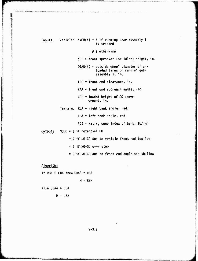
Bpi^nHiPfWW^OTl."^ll''iiaJii|iin.;Ji ill' Mwi'M.mm' ■ ^v-^-,—r .. —-.,.,,,.„^- .,,.,,,. .„„.>„„.^,...,.,
■■'-'«.Wi'Wi»»» «IMW1I1WHM1HHIHJHIII«. ■
Inputs Vehicle: NVEH(i) = |9 U running qear assembly i is tracked
/ 0 otherwise
SHF = front sprocket (or idler) height, in,
DIAW(i) = outside wheel diameter of un- loaded tires on running gear assembly i, in.
I FEC = front end clearance, in.
VAA = front end approach angle, rad.
CGH = loaded height of CG above ground. In.
Terrain: RBA = right bank angle, rad.
LBA = left bank angle, rad.
RCI = rating cone index of bank, lb/in'
Outputs NOGO = 0 if potential GO
= 4 if NO-GO due to vehicle front end too low
= 5 if NO-GO ov^r step
= 9 if NO-GO due to front end angle too shallow
Algorithm
if RBA > LBA then OBAA = RBA
H = RBH
else OBAA = LBA
H = LBH
V-3.2
täiuinmumiuuaattaiiäitmww'n- ■ -..i...-,-w.<.v. , _..-^.-^^ iitiii I.II|,;^MJ, ...■„....„^
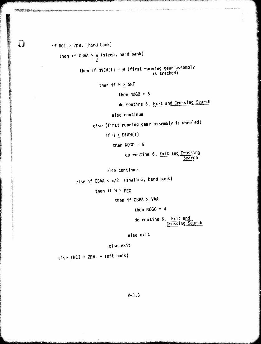
if RCI > 200. (hard bank)
then if OBAA > t (steep, hard bank) " 2
then if NVEH(l) = 0 (first running gear assembly is tracked)
then if H > SHF
then NOGO = 5
do routine 6. Ex't and Crossing Search
else continue
else (first running gear assembly is wheeled)
if H > DIAW(l)
then NOGO = 5
do routine 6. Exit and Crossing Search
else continue
else if OBAA < Tt/2 (shallov.', hard bank)
then if H > FEC
then if OBAA > VAA
then NOGO = 4
do routine 6. Exit and Crossing Search
else exit
else exit
else (RCI < 200. - soft bank)
V-3.3
— — -■ ,,|-it:. ........... ...■■ -.., .v..,, ,,, ,,.- ^ngggjgl^jgl^ .; .w.'. ^t^ tt. ,■ >^j:—-:.ii..j.^t..
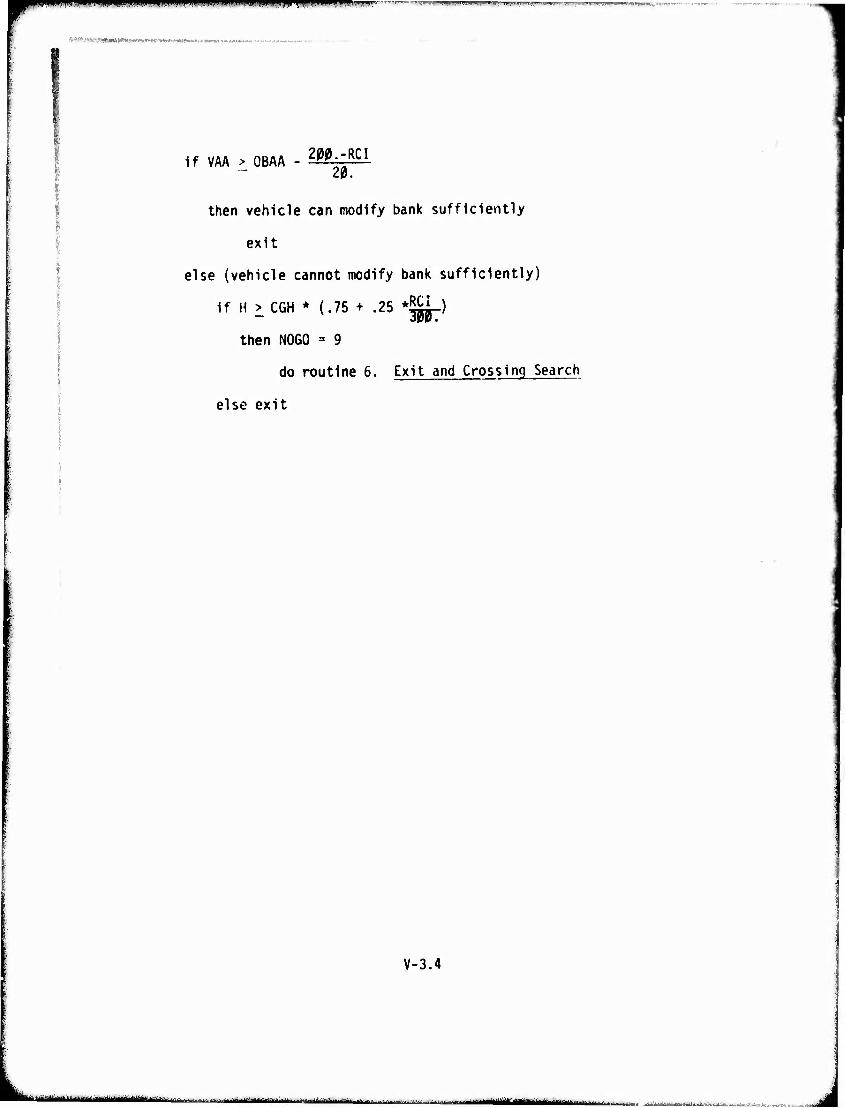
nm^mpumjiMiii wmui i« in U'.":>l. nw\ u*vf ■! ./, i.i, .1 mi. ,P !■ i|»''r'fll"w""">"JTiWf,WMmr7WWv».-■
■ --«ai«««!-»«.«-»- i«n(f«R#v,«),T*-*'*i -
If VAA > OBAA - 2gg:'RCI
20.
then vehicle can modify bank sufficiently
exit
else (vehicle cannot modify bank sufficiently)
if H > CGH * (.75 + .25 *^i-)
then NOGO = 9
do routine 6. Exit and Crossing Search
else exit
V-3.4
--'-- (MiBiMaiiBiMgiia ..... ^ tmiMätlittm^ju^mi m | i .■;-^.^hi^^U-.^.-.^.. i-.^. ,,. -'—^jjm-JnniJU
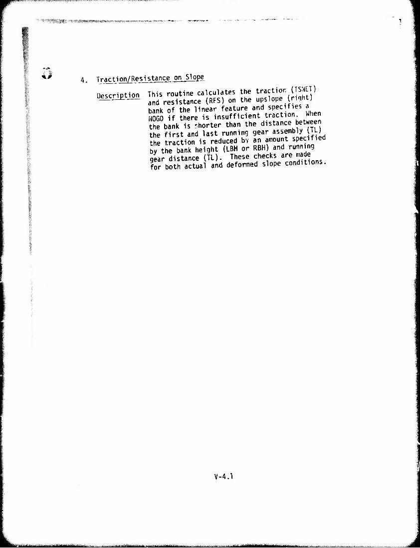
'3$9PW|KiME ■ .>*iA'y*j#^u:,»^,-'^'i«V*«rt'«»'A*wW.«;-v*-« *r»-J"'wv
o 4. Traction/Resistance on Slope
Description This routine calculates the traction (TSNET) and resistance (RFS) on the upslope (riqht) bank of the linear feature and specifies a NOGO if there is insufficient traction. When the bank is rhorter than the distance between the first and last running gear assembly (TL) the traction is reduced bv an amount specified by the bank height (LBH or RBH) and running gear distance (TL), These checks are made for both actual and deformed slope conditions.
V-4.1
— . , — " iiTiiiiiiii irtiilMliMii*iliiiiiiili I
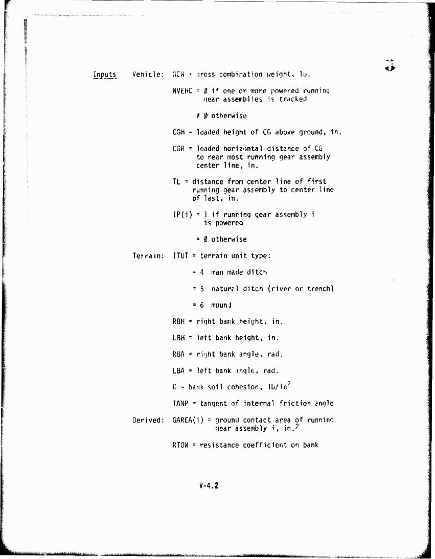
Inputs Vehicle: GCW T uross combination weight, 1ü, ^
NVEHC - 0 if one or more powered running iiear assemblies is tracked
f 0 otherwise
CGH - loaded height of CG above ground, in, i
CGR = loaded horizontal distance of CG to rear most running gear assembly center line, in.
TL = distance from center line of first running gear assembly to center line of last, in.
IP(i) = 1 if runring gear assembly i is powered
= 0 otherwise
Terrain: ITUT = terrain unit type:
= 4 man made ditch
= 5 naturell ditch (river or trench)
= 6 mounJ
RBH = right bank height, in.
LBH = left bank height, in.
RBA = right bank angle, rad.
LBA = left bank /ingle, rad.
C - bank soil cohesion, Ib/irr
TANP = tangent of internal friction angle
Derived: GAREA(i) = ground contact area of runninn gear assembly i, in.?
RTOW = resistance coefficient on bank
V-4.2
i-i-n, riflniifaJ^a—-...^..^..-.,- .^t^^üAM.-^^^,
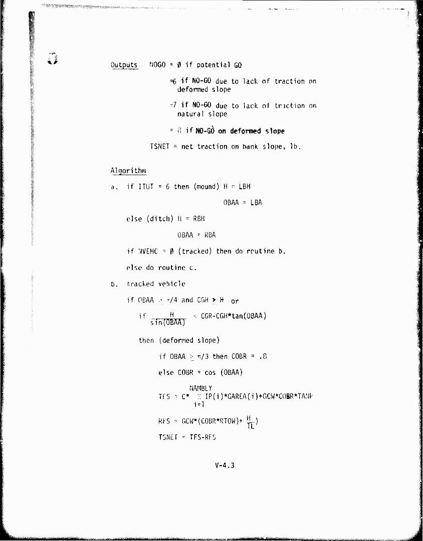
WfWmmmwmmamimmmimim '■a* Wwvipi^'n v-\%«.'.>
s,
I Outputs NOGO = 0 if potential GO
=6 if NO-GO due to lack of traction on deformed slope
=7 if NO-GO due to lack of tnction on natural slope
= <' if NO-GO on deformed slope
TSNET - net traction on bank slope, lb.
Algorithm
a. if ITUT = 6 then (mound) H - LBH
OBAA = LBA
else (ditch) H - RBH
OBAA = KBA
if NVEHC = fi (tracked) then do routine b.
olse do routine c.
b. tracked vehicle
if OBAA > .t/4 and CGH > H or
if H < CGR-CGH*tan(OBAA) sin(OBAA)"
then (deformed slope)
if OBAA > TT/3 then COBR = .8
else COBR = cos (OBAA)
NAMBLY TfS - C* ." IP(i)*GAREA(i)+GCW*COBR*TANP
i = l
RFS = GCW*(C0BR*RT0W)+ 1^)
T3NLT - TFS-RFS
V-4.3
''■■,-•" ■"'■-^•^-^^"-- • jjjddfru ■...■...;,.-,,. „.., 1 «liniMIMMÜllMtria—Mlil«
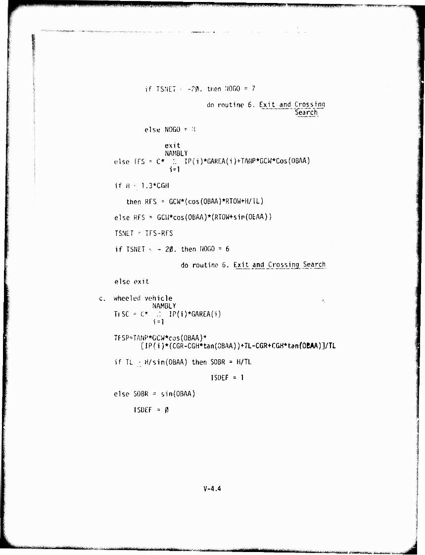
*PW wmwpiiPiiP!
•f^-iüi-nsn-Mmi,
gw^WWBWBiww" ipjiimuiiiii.niiLjuii.wmiiwu'M"»'!!' WIWIJ ',■"-
if TSNLT ■ -2$. then MOGO = 7
dn routine 6. Exit and Crossino Search
else NOGO = "'.
exit NAMBLY
else TTS = C* :. IP(i )*GAREA(i )+TAilP*GCW*Cos(OBAA) 1=1
if fi • 1.3*CGH
then RFS = GCW*(cos(OBAA)*RTOW+H/lL)
else RFS = GCW*co5{0BAA)*(RT0W+sip(0EAA))
TSNET - TFS-RFS
if TSNET - - 20. then NOGO = 6
do routine 5, Exit and Crossing Search
else exit
wheeled vehicle NAMBLY
TrSC = C* .: IP(i)*GAREA(i) i=l
TFSP=TANP*GCW*CüS(OBAA}* [IP(i)*(CGR-CGH*tan(0BAA))+TL-CGR+CGH*tan(OBAA)]/TL
if TL ■ H/sin(0BAA) then SOBR = H/TL
ISDEF = 1
else SOBR = sin(OBAA)
ISDEF = 0
V-4.4
...... ...-..-...i..^-- . ■ .-..1-kJ-.-..!^ .... ■-■1|||||||trit „MM.aMH^MM
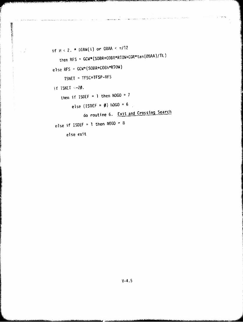
T^^ff iqpppPPPpipqppilfKnillilNW.11 ■ •mmm*>'\wiv»mmv«m»mmmv:immw-"> »w» ....«zr—-
if H < 2. * DIAW(I) or OBAA < IT/12
then RFS = GCW*(SOBR+COBR*RTOW+CGR*tan{OBAA)/TL)
else RFS = GCW*(SOBR+COBk*RTOW)
TSNF.T = TFSC+TFSP-RFS
if TSNET -20.
then if ISDEF = 1 then NOGO = 7
else (ISDEF = 0) NOGO = 6
do routine 6. Exit and Crossing Search
else if ISDEF = 1 then NOGO - 8
else exit
V-4.5
- - - -- i MM -- ^^.. ...^^MMumimmmmmmtm^ä^hM -
jmm jHiipiibi* im 11 IUIII um — ■«■••
^^,?',BWIIW(W'-'«w^wwia^>«uw;OT'»<^.Ä*K»'^
Uesari£tion^ This routine calculates an averafie crossing speed (VSEL) from the excess traction and a crossing time (TCROS) which depend on the size of the linear feature. The speed on the banks is obtained by interpolating between an assumed maximum crossing speed of 15 ft/sec at an ex- cess traction of 50 lbs. or more to a minimum speed of .5 ft/sec at a traction deficit of
20 lbs.
V-5.1
k-L..^-—^. 1
I
j
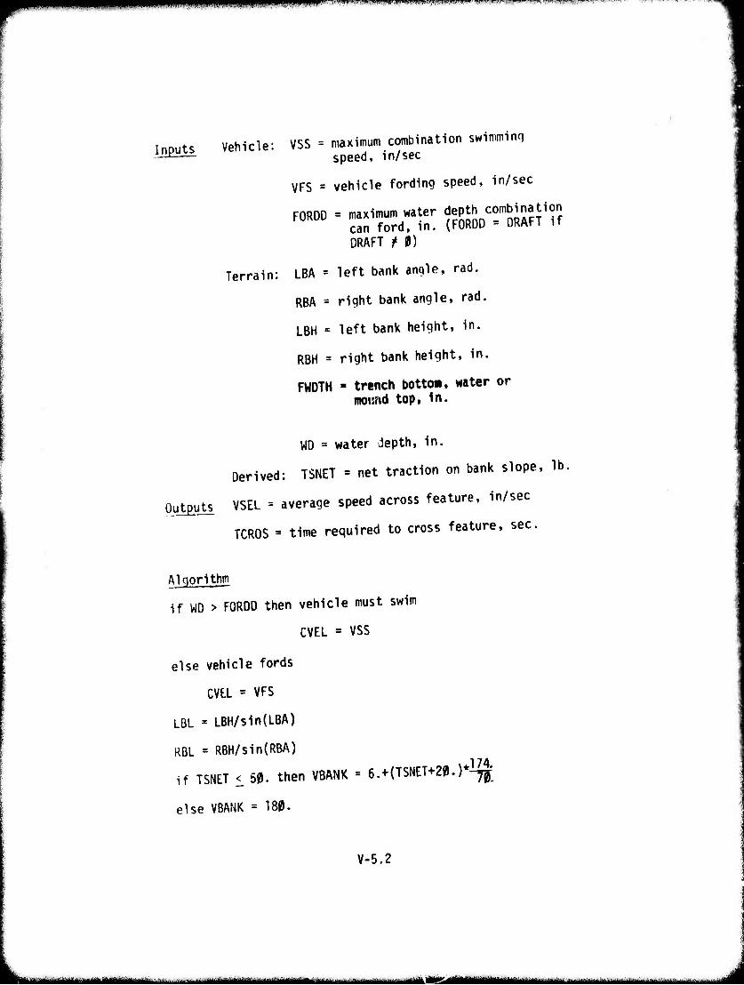
"M,!i|Pf,pi"^,,^!(f|J,ppiipil^J..IJiH^liUiii.lliiJLii l.li. i. FMP.M.IJ.,^M"1'.'«I"1H m*...m'mwwmtmi\- P^PW^. vyr...r p-n-^-w-w^^^""^ VTT^W
Inputs Vehicle;
Terrain;
VSS = maximum combination swimminq speed, in/sec
VFS = vehicle fording speed, in/sec
FORDO = maximum water depth combination can ford, in. (FORDO = DRAFT if DRAFT f 0)
LBA = left bank angle, rad.
RBA = right bank angle, rad,
LBH = left bank height, in.
RBH = right bank height, in.
FWDTH ■ trench bottom, water or moimd top. In.
WD = water depth, in.
Derived: TSNET = net traction on bank slope, lb.
Outputs VSEL = average speed across feature, in/sec
TCROS = time required to cross feature, sec.
Algorithm
if WD > FORDO then vehicle must swim
CVEL = VSS
else vehicle fords
CVE.L = VFS
LBL = LBH/sin(LBA)
RBL = RBH/sin{RBA)
if TSNET i 50. then VBANK = 6.+(TSNET+20.)*i^|
else VBANK =180.
V-5.2
—- mm --—-■ mi •■•- lim
mmmmmmwmmmmmmmmmmim^^m^^ i ■ ■•" r***—
''1,'l»lffif"';*»W«'.,w Mi}*i««r.'ww«w<i«>w!'c»«™.iii»i->«v.vi.-./'»»i...l» -.w»—«-.,,»-■
TCROS = LBL/VBANK + FWOTH/CVEL + RBL/VBANK
VSEL = (LBL + OBW + RBL)/TCR0S
exit
V-5.3
- ---■-■ i HI- liiriüVir--^ -
ippppi^ppp^liPPPPP(iiiiiii^H^jpiPiiiHi<iiNnnM'^,'-^w' i •v^wvan i —j»»« • »•■»•■iii.ii i ^--
WI(l^tww|IC»'''■■'ww^w^*Pc■nw■«vww.««^^ 1
4l 6. ExU and Crossing Search
Descriptlpn This routine estimates the distance and time (T) a vehicle would have to travel to reach a natural or man-made crossinq of the linear feature. The natural crossings are assumed to be at the apex of each meander; the meander spacing is a function of topographic slope. Bridge spacing is assumed given. The distance to each of these crossinq points (DX) or (DB) is calculated from the assumption that the vehicle encounters the linear feature any where between the crossings with equal
probability.
V-6.1
- '^—■* ■ , II ll—MMMl llll l l — .^^ ^M
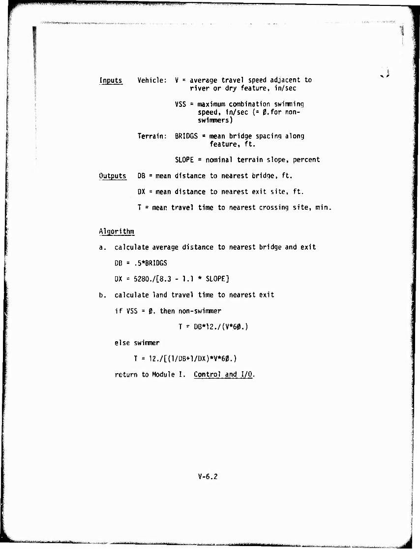
v^^^^^^r^^mm^ ii in
twmH>twt*mh»vw*wtfmsKt~'*.ti':-l- . ,;,'.. 11 ■.•.*Tt'tPff[
Inputs Vehicle: V = average travel speed adjacent to river or dry feature, in/sec
VSS = maximum combination swimming speed, in/sec (= 0.for non- swimmers)
Terrain: BRIDGS * mean bridge spacing along feature, ft.
SLOPE = nominal terrain slope, percent
Outputs DB = mean distance to nearest bridge, ft.
DX = mean distance to nearest exit site, ft.
T = mean travel time to nearest crossing site, min,
J
Algorithm
a. calculate average distance to nearest bridge and exit
DB = .5*BRIDGS
DX = 5280./[8.3 - 1.1 * SLOPE]
b. calculate land travel time to nearest exit
if VSS = 0. then non-swimmer
T - OB*12./(V*60.)
else swimmer
T = 12./[(1/DB+1/DX)*V*60.)
return to Module I. Control and I/O.
V-6.2
.^Ml.-*...*-.^..-*. ■■l.^.f.^.^^.-:
-- -"\m\ mmamam mmst '■■■■■■ jHaJtrililB —.■'•-.^ i
r q^,in*:rWÄ««sw»w<™M(w.
ü
MODULE VI
ROAD
VI-1
inir-" '"" J
S^-"t'»l!W1y,;nVV''W ' , ■ .«ü.-^-M ji*H(' «n« W» i««Tll~WWi'. "*••*<-• >j mw'vmvf^'tffittfwyC^tfff^fV
ROAD MnmiLE
*>
The iiodd flodule computes a maxiniuni speed that a wheeled vehicle is expected to maintain on a road segment. Mo pro- visions are currently included for tracked vehicles. The term road is intended to include both prepared and unprepared trails and all types of maintained and/or paved (oiled, stabilized, etc.) roads. Generally, roads are classified into primary and secondary roads and trails. These are characterized by a surface/wheel interaction involving:
1. No sinkage.
2. Soil shear properties replaced by a coefficient of friction.
3. Resistance depending on a surface micro-roughness level.
Roads may have slope and curvatu/e along the direction of travel and superelevation normal to it. A visibility distance similar to that in the Areal Module is also included.
Calculation of resistance to motion is based on a standard SAE procedure (Reference 8) modified by certain relationships found in Reference 9 by Smith.
Included are resistance and performance effects due to altitude, atmospheric pressure, temperature and wind.
The speed limited by these resistance factors (road surface, aerodynamics, grades) may be further reduced to a final maximum speed due to:
1. Ride effects caused by roughness.
2. Curvature and superelevation of the roadway.
3. Visibility restrictions due to roadside factors.
4. Tire pressure/construction factors.
VI-2
rt^^HHttmrnm** ■ ■-■ jn^ngnfr^jgyüi tivin ii^itjffiriftiimimifiniirr . ^mmg^imjn *'*t..l..:'u- -j**. ■- . ^^a, ..-■.■_. ^. _■-,.._■.._._..,„ ^
i> Scenario variables allow:
1. Adjustment of weather factors including ambient temperature, wind, and dry, wet or ice covered roads.
!
2. Human tolerance factors for ride roughness, deceleration and reaction time.
The individual routines of the Road Module are described below. Due to similarity between the Areal Module and the f<oad Module several routines and subroutines from f,he Areal Module are used without modification.
VI-3
— MMMHM — - - ■ . J
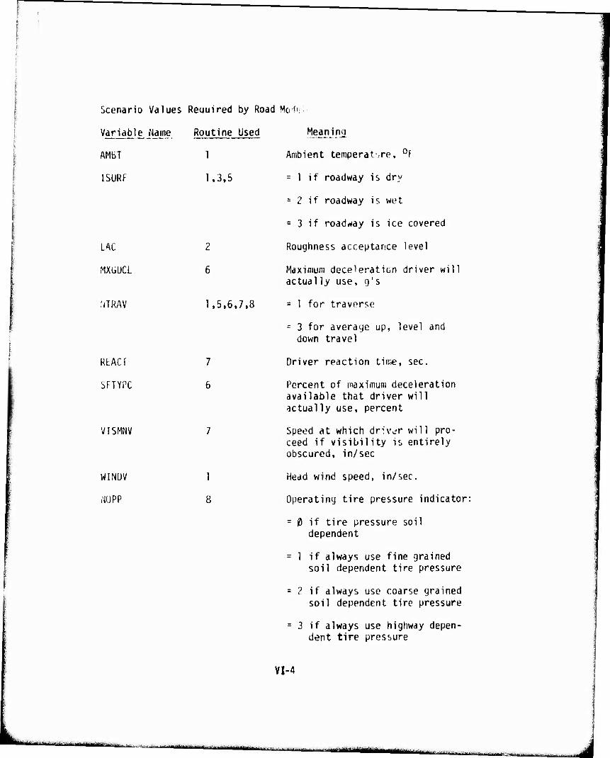
Scenario Values Reciuired by Road Mo-J
Variable Name
AMbT
1SURF
LAC
WCGUCL
NTRAV
RLACT
SFTYPC
VISMNV
WINUV
,-JÜPP
Routine Used
1,3,5
2
6
1,5,6,7,8
7
6
1
8
Meaning
Ambient temperat.re, 0f
= 1 if roadway is dry
= 2 if roadway is wet
= 3 if roadway is ice covered
Roughness acceptance level
Maximum deceleration driver will actually use, g's
= 1 for traverse
- 3 for average up, level and down travel
Driver reaction time, sec.
Percent of maximum deceleration available that driver will actually use, percent
Speed at which driver will pro- ceed if visibility is entirely obscured, in/sec
Head wind speed, in/sec.
Operating tire pressure indicator:
= 0 if tire pressure soil dependent
= 1 if always use fine grained soil dependent tire pressure
= 2 if always use coarse grained soil dependent tire pressure
= 3 if always use highway depen- dent tire pressure
VI-4
-"■■-— ■ ■■ i ..■.■.-■■. , .,., ; ■■-,! — „!! '"*■""—'"^-"Irn ■ • •" -■■JJiiillMlMi ''L-^J"J--'-'- ■■'-'I Tdf r I '-'-'■■ -■■tfinr ■'-!|ti
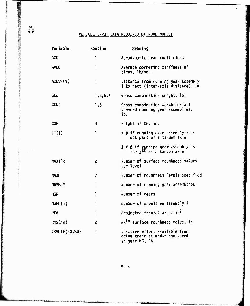
■"*'
*, VEHICLE INPUT DATA REQUIRED BY ROAD MODULE
I
Variable
ACU
Routine
AVGC 1
J AXLSP(i) 1 ■
?! | ÜCW 1,5,6.7 I ,, GCWB 1,5 3- t.
1 1 | CGH 4 r
IT(i) 1
MAXIPR
MAXL 2
NAMBLY 1
NGR 1
NWHL(i) 1
PFA 1
RMS(NR) 2
TRACTF(NG,MD) 1
Meaning
Aerodynamic drag coefficient
Average cornering stiffness of tires, lb/deg.
Distance from running gear assembly 1 to next (inter-axle distance), in.
Gross combination weight, lb.
Gross combination weight on all powered running gear assemblies, lb.
Height of CG, in.
= 0 if running gear assembly i is not part of a tandem axle
j / 0 if running gear assembly is the j"1 of a tandem axle
Number of surface roughness values per level
Number of roughness levels specified
Number of running gear assemblies
Number of gears
Number of wheels on assembly 1
Projected frontal area, in^
NR^ surface roughness value, in.
Tractive effort available from drive train at mid-range speed in gear NG, lb.
VI-5
'■-"-'^■''•'■Itarrinatyi fin- , , ,
tmtBmmmMKm i i
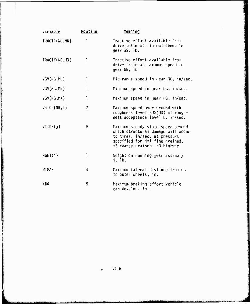
Variable Routine
TRACTF(NG,MN) 1
TRACTF(NG,MX) 1
VGV(NG,M[J) 1
VGV(NG.MN) 1
VGV(NG,MX) 1
VKlÜL(NR,L) 2
VTIRE(j)
WGHT(i) 1
WTMAX 4
XBR 5
Meaning
Tractive effort available from drive train at minimum speed in ciear NG, lb.
Tractive effort available from drive train at maximum speed in gear NG, lb
Mid-ranqe speed in gear NG, in/sec.
Minimum speed in gear NG, in/sec.
Maximum speed in qear fiG, in/sec.
Maximum speed over ground with roughness level RMS(NR) at rough- ness acceptance level L, in/sec.
Maximum steady state speed beyond which structural damage will occur to tires, in/sec, at pressure specified for j=l fine grained, =2 coarse grained, =3 highway
Weight on running gear assembly i, lb.
Maximum lateral distance from CG to outer wheels, in.
Maximum braking effort vehicle can develop, lb.
VI-6
MtWMMfMMin i ' ■ .-..-, ii. ,„'..,., . i[-"—— ■-■- MMMMMii MMHa^MM
1. Speed Limited by Aerodynamic, Rolling, Cornering and Grade Resistance " -——.---.. — ~ ~ ™. -. .~.-^..
Description: This routine calculates resistances due to aerodynamic drag, rolling, cornering and grades. The rolling resistance due to tan- dem axle alignment (FTC) and grade resistance (FG) are independent of velocity (Reference 7). The velocity dependent resistances; i.e., aerodynamic drag (FA), rolling resistance (FR) and drag resulting from tire cornering force-' (FCC) are calculated for the minimum, mid- range and maximum speed in each gear (VGV(MG, MN), VGV(NG,MD), VGV(NG,MX)). These total velocity dependent resistances (FV) are then subtracted from the net available tractive effort on the road at these respective speeds.
To obtain the net available tractive effort on the road (STRACT) the rim pull tractive effort calculated in the Vehicle Preprocessor (TRACTF) is compared to the friction available on the road (FMU). Whichever is less is chosen and the total speed resistance (FV) is subtracted to obtain the net available tractive effort (STRACT).
Subroutines QUAD and VELFOR (described in the Areal Module) are used to fit quadratics to the net available tractive effort versus speed values and to determine the maximum speed which can be maintained while overcoming these resistances.
VI-1.1
k hfeMmtMMfiMtMWMI
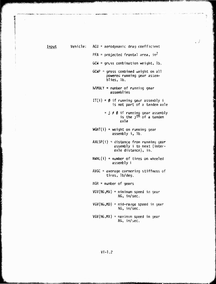
m vmmmmmmm li^»!,.!,,,» i..""J'WH'.|'J
' • 'tMHP*'* ,i«-..WWj«>. r
. / Input Vehicle: ACD = aerodynamic drag coefficient
PFA = projected frontal area, in^
&CW = grcss combination weight, lb.
GCWP = gross combined «eight on all powered running gear assem- blies, lb.
NAMBLY = number of running gear assemblies
IT(i) = 0 if running geor assembly i is not part of a tandem axle
= j / 0 if running gear assembly is the j™ of a tandem axle
WGHT(i) = weight on running gear assembly i, lb,
AXLSP(i) - distance from running gear assembly i to next (inter- axle distance), in.
NWHL{i) = number of tires on wheeled assembly i
AVGC = average cornering stiffness of tires, lb/deg.
NGR = number of gears
VGV(NG,MN) = minimum speed in gear NG, in/sec.
VGV(Nü,MD) = mid-range speed in gear NG, in/sec.
VGV(NG,MX) = maximum speed in gear NG, in/sec.
VI-1.2
,..:..,^T:.,V-_..-.-.;^J..'U.- . ..^w.^-.,...,.-...-.... -^ .l-,-^.^..^ ^ -- --——
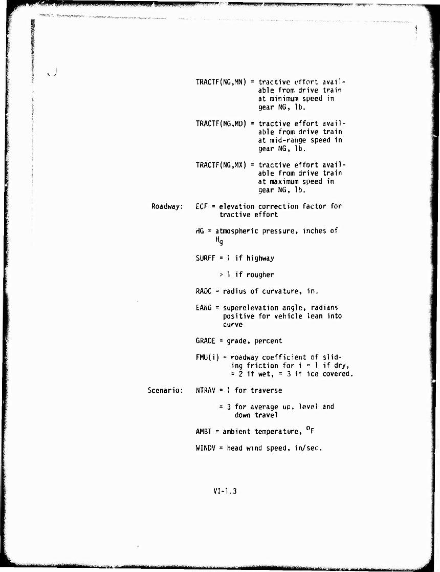
■mn ■«■■wi ^
,*»'.»..--, «WWmMN»' ■ - «x«™«-.-«,.^«.,^.^..,,,,,.^,, ,..,„,„
rr •■;ijmniiip*iiiiiiji.,ii.ii-a,4j,i!i||i!ji ■npMmppmmmppp
TRACTF(NG,MN) = tractive effort avail- able from drive train at minimum speed in gear NG, lb.
TRACTF(NG,MD) = tractive effort avail- able from drive train at mid-range speed in gear NG, lb.
TRACTF(NG,MX) = tractive effort avail- able from drive train at maximum speed in gear NG, lb.
Roadway: ECF = elevation correction factor for tractive effort
HG = atmospheric pressure, inches of Hg
SURFF = 1 if highway
> 1 if rougher
RADC = radius of curvature, in.
EANG = superelevation angle, radians positive for vehicle lean into curve
GRADE = grade, percent
FMU{i) = roadway coefficient of slid- ing friction for i = 1 if dry, = 2 if wet, = 3 if ice covered,
Scenario: NTRAV = 1 for traverse
s 3 for average up, level and down travel
AMBT = ambient temperature, 0F
WINDV = head wind speed, in/sec.
VI-1.3
nirliTr'ntiiii fiiümiiiiiidia ■ i „mm.*,-.,,.,.;,^ y imtllmimmm ■■"-■- .-■ ■■ ■■
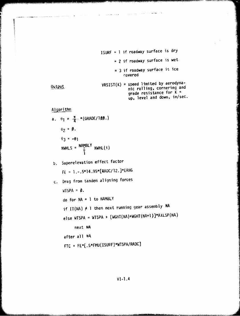
lUinwiK.iiwii
Output
I SURF = 1 if roadway surface is dry
= 2 if roadway surface is wet
= 3 if roadway surface is ice covered
VRSIST(K) - speed limited by aerodyna- mic rolling, cornering and grade resistance for K = up, level and down, in/sec,
Algorithm
a. 6! = -J- *(GRADE/10P.)
e2 = t.
63 = -ei
NWHLS.. NAMBLYNWHL(i)
1
b. Superelevation effect factor
FE = l.-.5*14.95*[RADC/12.]*EANG
c. Drag from tandem aligning forces
WTSPA = 0.
do for NA = 1 to NAMBLY
if IT{NA) f 1 then next running gear assembly NA
else WTSPA = WTSPA + [WGHT(NA)+WGHT(NA+1)]*AXLSP(NA)
next NA
after all NA
FTC « FE*[.5*FMU(ISURF)*WTSPA/RADC]
VI-1.4
— ■■—■"- - —■ - - ■ ^.^..Ll....iiJ.-Jl.-.ü.>^: I ■'--■■-
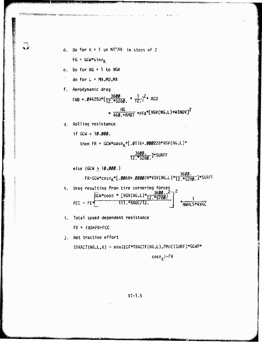
i^wwwmwwppt^^^^ww ' ' ■ "■n ■min».».!.. »■.■~^--,~-^^^-..- ̂ypHB^TnwTT^^-
^WHIIWIIIMWMWiiMIII ";',*m'«i»3«»w«!»»'»WT ..■-»«»,-.,■. 6.».„.v.
<> d. Do for K = 1 to NFAV in steps of 2
FG = GCW*s1nüK
e. Do for NG = 1 to NGk
do for L = MN,M0,MX
f. Aerodynamic drag
*46^ÄMBT*PFA*[VGV{NG.L)+WINDV]2
g. Rolling resistance
if GCW < 10.000.
then FR = GCW*coseK*[.0116+.000228*VGV(NÜ,L)*
else (GCW > 10,000.) 3600.
FR=GCW*co5eK*[.0068^.000074*VGV(NG,L)*12.*5280j*SURFF
Drag resulting from tire cornering forces i— ^fifllfl 2—12 GCW*cos6 * [VGVjNG.L)*^j;^]
FCC = FE* in.*RADC/12. 1
NWHLS*AVGC
Total speed dependent resistance
FV = FAD+FR+FCC
Net tractive effort
STRACT(NG,L.K) = min{ECF*TRACTF(NG,L),FMU(ISURF)*GCWP*
coseK}-FV
VI-1.5
■■ mm —^■■-■--^ -■ - ■- ■ ■'■■'■--■ —- HWHi ataai
^-^a-- "- -'■' ..M.^
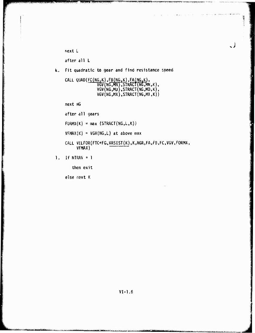
limm^lflWB PIP '•^"^T-rilimiliHI»T»|i.i»i ^.imJuiillniPTnmil-F«"»'»";—»T^'T Tw^m.mrT^wlWTf "
J
1.
next L
after all L
Fit quadratic to gear and find resistance speed
CALL gUAD(FC(NG,K).FB(NGtK).FA(NG.K). VGV(NG,MN),STRACt(N6,MN,K). VGV(NG,MU),STRACT(NG,MDfK), VGV(NG,MX),STRACT{NG,MX,K))
next NG
after all gears
FÜRMX(K) = max {STRACT{N6,L,K)}
VFMAX(K) = VGV(NG,L) at above max
CALL VELF0R(FTC+FG,VRSIST(K),K,N6R,FA,FB,FC,VGV.F0RMX, VFMAX)
If NTRAV = 1
then exit
else next K
VI-1.6
- — '" ■ i ■- -i Mi : ■ mam ■ . J
MKIlflllmlß*mm*mmmmmmmmmmmmllm'™**^^^^' ' ' mmmmmmwmmmm* ■■.■-,
Bw'^mmmufmummtrnmimmmi «*w» 1 2. Speed Limited by Road Roughness
Description: This routine determines the maximum allowable roa£l Spee<j based on driver tolerance to rough ride. It is identical to Submodel 10 of the Areal Module.
Putput: VRIÜ = speed limited by roughness, in/sec.
VI-2.1
Mi In Winiil ilttttliliiilii'l ' - - millli^lltilliitHinii-riliMlili-^iliriihir n ^äm^mmmtm^mämmmtmim^mtmtmältuir} n tr I nil _J
I I II II WIM «Jill III II I I ium..Hi.p"r»mii IFVrr ,"IWP^,fM«!W nppmH) "HIM
^««Pi'^iWWMtW'iWrirn»'«»« yf^n?w*vA^wwiiiM*f^ •■'
4> 3. Speed Limited by Sliding in Curves
Description: This routine calculates the maximum road speed in a curve limited by sliding (VSLID). The centrifugal force relationship used includes road curvature (RADC), superelevation anqle (EANG) and road coefficient of sliding friction (FMU) (Reference 10). The constant 385.9 is the acceleration of gravity in in/sec ¥
VI-3.1
— --■,-^""-" _■,_._■■, J
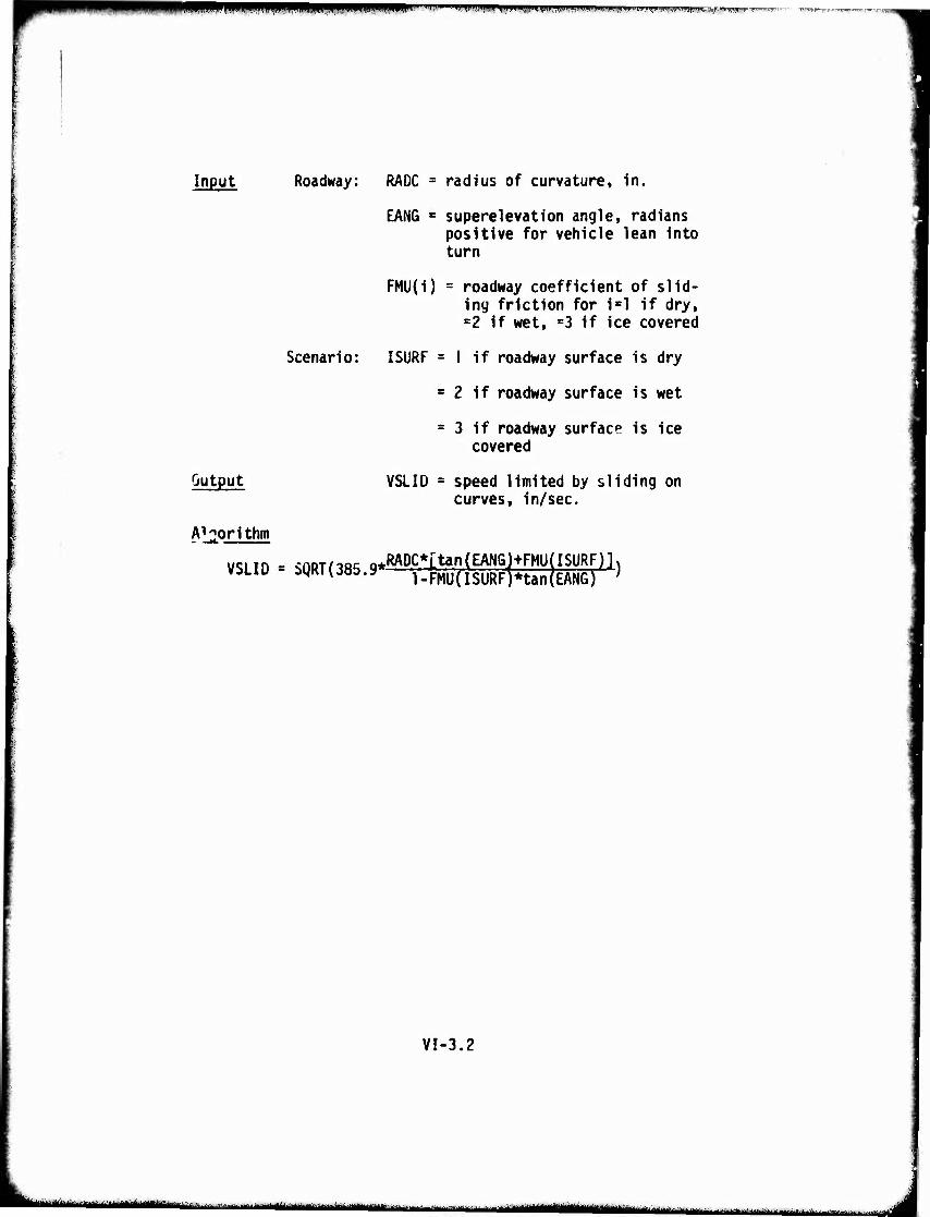
I ^WWWP^WPPyw wf.-ijmwjiwwi iiniiini ^I«»IH,»«I|IIII«F!«III. mTJ»,»,. .i»fin» IHPHI ' n '■'" T."
Input Roadway:
Scenario:
Output
RADC = radius of curvature, in.
EANG " superelevation angle, radians positive for vehicle lean into turn
FMU(i) = roadway coefficient of slid- ing friction for ixl if dry, =2 if wet, s3 if ice covered
I SURF = I if roadway surface is dry
s 2 if roadway surface is wet
= 3 if roadway surface is ice covered
VSLID * speed limited by sliding on curves, in/sec.
Algorithm
VSLID = SQRT(385 9^DC*[tan(EANGHFMU(ISURF viLiu ayKivji».» l-FMU(ISURF)nan(EANG)
ISURF)] )
VI-3.2
mmm ■—•-"—■-•--"■ ■■■■-•■■ immm ■ - ■ ■ - ■ aa
PWw *' "* " "»"I» N" !■ l,im,|iiiiMii»W»«luwi*iJ"iiiU'»u wmmm^mmn
'fl!*RP!IW^.1W»ll^t ^1^^
4. Speed Limited by Tipping While Negotiating a Curve
Description This routine calculates the maximum road speed which can be maintained in a curve limited by tipping of the vehicle (VHP) (see Reference 10), The relationship for VHP is obtained from the equation expressing the equilibrium of moments around the outer tire/pavement contact point. The forces involved are the centrifugal force and the weight of the vehicle. Constant 335.9 (in/sec2) is the gravitational acceleration g.
VI-4.1
— ■-■ ■■■ —- -,-'- ■ ■ — ■ — tttBi^n mirtftiiJi» i -J
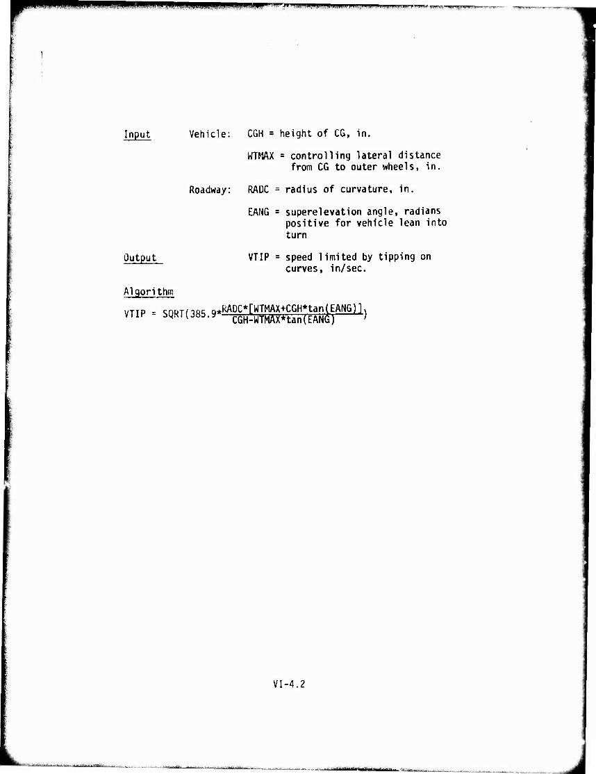
iWHumin inaiMHi i i 'mi'mmmi' HWWHWWBW .»mm ,MWmm.mi wmnrm*«**
Input
output
Algorithm
VTIP = SQRT
Vehicle: CGH = height of CG, in.
WTMAX = controlling lateral distance from CG to outer wheels, in.
Roadway: RAÜC = radius of curvature, in.
EANG = superelevation angle, radians positive for vehicle lean into turn
VTIP = speed limited by tipping on curves, in/sec.
/,Q£- ^KADC*[WTMAX+CGH*tan(EANG)]. (385-9 CGH-WTMAxHan(EANd) '
VI-4.2
■UaUJMllhtL i.-.r!.■■-.,■,..^._.t..-,.'..^'..^itt-11:iH-„<-,| ,„. .^ ^.^ ^^ ^
r ^^^■^^"'■^■"^^^^^W^'^l' ! mum ■--^-.-rv,-^., , „I, , ,, ,, ,^T,.^r„„„J.„
WMMMCniMlKS • imBmmmmmmatammnmm < ,n'-itnM»rÄti'r«.*f,'«\'«i-'iif<«»--,-.'.r
5. Total Braking Force
Description: This routine calculates the total maximum braking force (TBF) available on a grade. The braking force due to the grade is added to the minimum of the braking force from the vehicle (XBR) or the road surface to produce the total maximum braking force (TBF). If the total maximum braking force is negative, then the final average speed on this road segment is set to zero and a braking NO-GO flag is set (BFGONO). This flag is set with the apriori notion that the vehicle could not be slowed down to a safe speed to negotiate curves.
VI-5.1
lit i «^äuuOdUs^UliUMÜtti ..:.-....-,.■!..■.- . --^jfr'* wmmmtmtmm
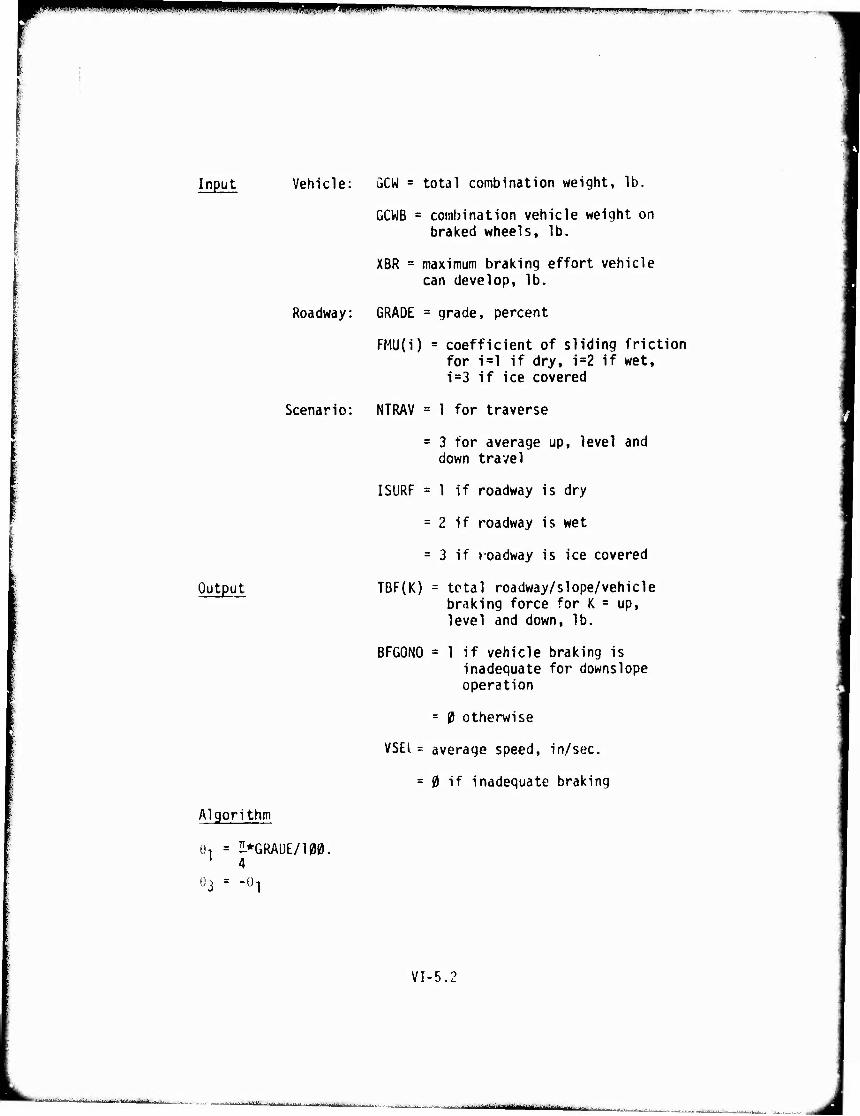
^fUfimwmmmß *** WIIWfJ«IKP"'H""i'^"W"t|M»r^'B!"»T,W)»;.'w- ■ * V *■' 7*Jt/^'r*wrrw^ vi '»rrjr^v'rrii
Input Vehicle: GCW = total combination weight, lb.
GCWB = combination vehicle weight on braked wheels, lb.
XBR = maximum braking effort vehicle can develop, lb.
Roadway: GRADE = grade, percent
FMU(i) = coefficient of sliding friction for i=l if dry, i=2 if wet, i=3 if ice covered
Scenario: NTRAV = 1 for traverse
= 3 for average up, level and down travel
I SURF = 1 if roadway is dry
= 2 if roadway is wet
= 3 if roadway is ice covered
Output TBF(K) = total roadway/slope/vehicle braking force for K - up, level and down, lb.
BFGONO = 1 if vehicle braking is inadequate for downslope operation
= 0 otherwise
VSEl = average speed, in/sec.
= 0 if inadequate braking
Algorithm
0, = UPGRADE/100. 1 4
0-: -Ü 1
VI-5,
.,..,.,..^ ...,Jt.l-..1J ..-:^...-. ..^■^.,.. ............. .... am i ^t^aiummtmimmmttBäMSti^tm > m
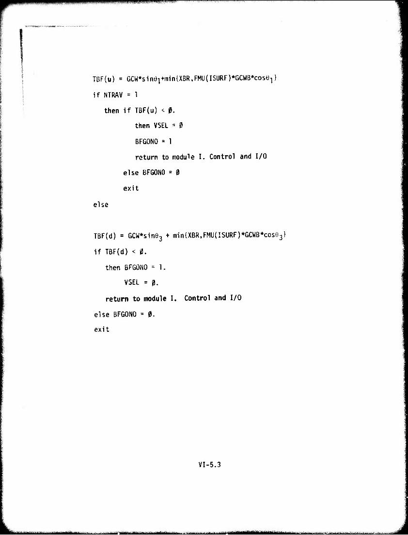
PMHnimiwM IJJIHIü.
TBF(u) = GCW*sine1+min{XBR,FMU(ISURF)*GCWB*cosü1}
if NTRAV = 1
then if TBF(u) < 0.
then VSEL * 0
BFGONO = 1
return to module I. Control and I/O
else BFGONO = 0
exit
else
TBF(d) = GCW*sine3 + min{XBR,FMU(ISURF)*GCWB*cos03}
if TBF(d) < 0.
then BFGONO = 1.
VSEL = 0.
return to module I. Control and I/O
else BFGONO = 0.
exit
VI-5.3
-■■■ ■' ■ i ■■'- -- - ■■-■
't'?if^*"ir,*^7tf^
4J Driver Dictated_BraMnc
Description: This routine calculates the maximum brakini that the driver will use based on comfort limits of the driver. It is identical to Submodel 12 of the Areal Module.
Output: MXBF(K) = maximum braking force for slope ^^— K = up, and down. lb.
*
VI-6.1
■■^...^ ;:*... .:-....-:.. ^. ■:-:*-■—■ ^^ -■■ ..■■■■ - i ■-■>-■ ---- - - ■■ ■ ■ i ■ Omeam --' MM ■ ■ ! i
fmmmmmmmmmm WPWPIWPW" " ■ipffpniiiiiwiiium iiiiw «...i^.»..!.-.»^...^
■'v - :■ mvmmm' mmm»»**™*»»*»****'- ^ ■■•
^>
I r: ■
; r
7 Speed Limited by Visibility
Description: This routine calculates the maximum road speed limited by visibility (VELV). It is Identical to Submodel 13 of the Area! Module with the exception that the height of the driver's eyes above ground is not considered.
VI-7.1
K^ i ii ■iiiriiiiiiir»ni ,mm,mm m ■ I M—M —Ml« ■ I
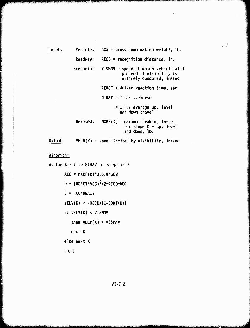
Vi|«H«lilWW^IPP«WBT^np<PMPfV19^^-ll<ul ^ lluai"^^w^«"iMiiiu|iL.uu jpiimi.'. - ■ ■ —"■'-'rr •W':--' ■". yvtT".r.-}TTr*w,'^";-
Inputs
Output
Vehicle: GCW = gross combination weight, lb.
Roadway: RECD = recognition distance, in.
Scenario: VISMNV = speed at which vehicle will proceed If visibility is entirely obscured, in/sec
REACT = driver reaction time, sec
NTRAV = U)' w.,-verse
= c iur average up, level ai'd down travel
Derived: MXBF(K) = maximum braking force for slope K = up, level and down, lb.
VELV(K) = speed limited by visibility, in/sec
Algorithm
do for K » 1 to NTRAV in steps of 2
ACC = MXBF(K)*385.9/GCW
D = (REACT*ACC)2+2*RECD*ACC
C = ACC*REACT
VELV(K) = -RECD/[C-SQRT{0)]
if VELV(K) < VISMNV
then VELV(K) = VISMNV
next K
else next K
exit
VI-7.2
tMjtat^ajMlm^ttmttlmlMltti^ idAuMMUülMÜiiWi iirttanuMMiiinmiiiiiiii mm ■■■
•wmm «i i '"mm
Maximum Road Speed
Description: This routine selects the average allowable road speed (VSEL) on the given road segment. The selection is made by choosing the minimum of all previously calculated speeds due to resis- tances, driver comfort limits and safety limits. Included in the safety speed limits is the speed limited by tire inflation pressure to prevent structural damage to the tire (VTIRE).
The final selected average speed is calculated in the same manner and using the same rationale as that used in selecting the average speed in Submodel 21 of the Areal Module; i.e., a harmonic average of the up, level and down slope speeds is taken to obtain the average selected road segment speed.
)
VI-8.1
-"— ■■- -i n ^u^i^. ,>..Ma.wjf.,v....,, ..,... .u^,.,.-.- .. -mirtiririB^liix J
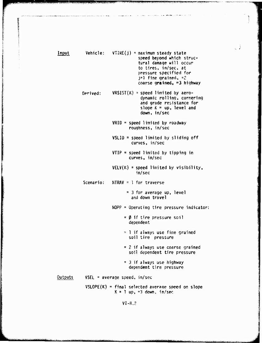
■WHIIIIIMlillllilJ m IW^WWHIfWi ■ .MI.III iiin,imp<«nmiii.j».»...'.'"T,»i'-'P'-.-^—TO—^-^T, tmiw^c-t - . ■f>ni|^T"l'
ftfrTM ■^,,r..v/.:-'.ti«»«*«R'■
Input Vehicle: VTIRE(j) = maximum steady state speed beyond which struc- tural damaqe will occur to tires, in/sec, at pressure specified for j=l fine grained, =2 coarse grained, =3 highway
Derived: VRSIST{K) = speed limited by aero- dynamic rolling, cornering and grade resistance for slope K = up, level and down, in/sec
VRID = speed limited by roadway roughness, in/sec
VSLID = speed limited by sliding off curves, in/sec
VTIP = speed limited by tipping in curves, in/sec
VELV(K) = speed limited by visibility, in/sec
. )
Scenario: NTRAV = 1 for traverse
= 3 for average up, level and down travel
NOPP = Operating tire pressure indicator:
= 0 if tire pressure soil dependent
= 1 if always use fine grained soil tire pressure
= 2 if always use coarse grained soil dependent tire pressure
= 3 if always use highway dependent tire pressure
Outputs VSEL = average speed, in/sec
VSLOPE(K) = final selected averaqe speed on slope K 3 1 up, =3 down, in/sec
VI-8.2
tatmiamtmk i limmmmmiititmmmmmmam litinim*tmmuiammim-;ir ■ ■„,.,„ ;., ...
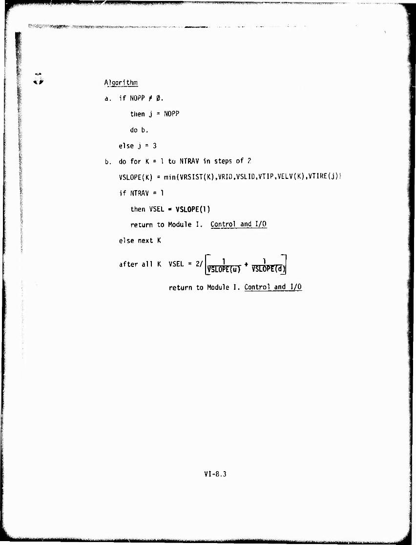
•^O^P nuipmp^iii III!III«III ...T..«.^.-...,...«...».^.».« ^Ifp *m mu^p'^'r'^^'TTi-FT^"
^-rtK^.'T^gjg^r-. ^-^wwnwf^'fww!' M^fw.^w .|HnWWW»rtnn'*-V.'^»wr' -''•■
I *> Algorithm
a. if NOPP ?« 0.
then j * NOPP
do b.
else j = 3
b. do for K = 1 to NTRAV in steps of ?
VSLOPE(K) = min{VRSIST(K),VRID,VSLID,VTIP,VELV(K),VTIRE(j)
if NTRAV = 1
then VSEL - VSLOPE(l)
return to Module I. Control and I/O
else next K
after all K VSEL = 2/[„ J[„ ,> ^ f. return to Module I. Control and I/O
VI-8.3
iiminiiMniMiii
npiiiiBiiii ^mtimmmmmmmmmm m ,|1 »mmw»™'i.«*m*i*'i!'*1 '<w
*'»BimiiiiliMiiiMwaiwiii ,'' *' ^\ '"'"* ^.^^»i ■L- ■'" ■/■■'■ •* i ■ J ■'
<A
MODULE VII
RIDE DYNAMICS
t
VIM
....,.....- — —-. ■■-*'~~- ■'■ ■'•■'" ^ i iiiiiiiiMiiiif m n .u. ■'-■"■■ J
r mi^mmmmi mmtmm ■ P»H1|g,» . '".'M. II nmmmrm ■■»» v i »VMIM >.^.-WT,-» w-"'."»»-"' "m i,i—,TM»^m-.ipii-, ■>
- /■»!l»>««*W('"««H'««W)»i|'««"-:
41 RIDE DYNAMICS MODULE
The R1de Dynamics Module of AMC '74 (Reference 3) provides the driver dictated speed limits due to vibration and shock while traveling over rough terrain or discrete obstacles. AMC '74 includes provisions for more than one tolerance level to rough ride. Potential tolerance levels for short and medium range duration of vibration Input to the driver, other occupants or cargo are foreseen as outcomes of ongoing dynamics research. The Ride Dynamics Module described in Reference 3 provides the speed versus surface roughness values tables at specified tolerance levels and also the speed versus obstacle heights for single or multiple obstacle crossings.
VII-2
L ■■ ' I IMMÜ—■-■-* '- ■ - i ' . fr-. "^•^^^^-^^■■-■■..^■.■■■■■- -—■- — ^.-,—, i .......^L
■i

mmmmmmmm mmmmmem* I.T.WIIII» mi.mii.ii.u.
,.V.'r.-r.-.;'iV<,i»'-i.«^.\'rtlW!«i .■•.;-■/.■»-•.• ■ ■■■ -■■-
^^
MODULE VIII
OBSTACLE CROSSING
VIII-1
. .,....- L^.:-..,..:^--,.,.-,-.-. ..,■ .
.^■- ■iiiirii-rii^iin ' n ■Oa
11 mumm ^WWPIIIIIPWPWWP'"™"|W > ■■ ■ w IIMHIMHIIII .IWIII inmiiin.mii»T^.iw..,w III.II>I.III,W fummgm— ^,'^*~ "m**T'r "' '" "fW\VMwrrrWf v j^ii^in^.-r
\~*'y>tifrr!&?Sfäm!Kwmmmi!m&''imnn' w »«*»«.^»
OBSTACLE CROSSING MODULE
Background
The Obstacle Crossing Module of AMC executed module which solves the static for a vehicle negotiating an arbitrarily solution of these equations produces the to cross an obstacle, the average force entire obstacle override and a geometric between the critical clearance points on obstacle profile. This module replaces and OBSF in AMC '71.
74 is an externally equations of equilibrium shaped obstacle. The maximum force required required during the interference history the vehicle and the
the subroutines OBSTCL
The features of the Obstacle Crossing Module which set it apart from the methods used in AMC '71 are:
1. Inclusion of suspension compliance within the equations of equilibrium.
2. A single degree of pitch articulation for multiple unit vehicles.
3. Arbitrarily shaped obstacles.
4. Average and maximum forces required during override.
5. Permanent file of vehicle's obstacle crossing performance.
The Obstacle Crossing Module may be executed for a single obstacle or several obstacles of varying sizes. If several obstacles are examined then a permanent file of obstacle per- formance can be generated for a given vehicle. This file is used in the Area! Module to determine the vehicle approach and exit velocities while crossing a specific obstacle in the patch.
Multiple unit vehicles which have a single degree of pitch articulation can be examined in this module. Thus, tractor/ trailer combinations are mon1 accurately addressed in AMC '74 than was possible in AMC '71.
nu-2
■ -!- ••- • -" ■
The Obstacle Crossing Module described herein is formulated for wheeled vehicles only. A tracked vehicle version 1s currently being developed and will be published at a later date as a revision to the current write-up.
Methodology
The forces and interference history are obtained by a stepwise move.ent of the vehicle over the obstacle . The vehicle's orientation (attitude and position with res~ect to the obstacle), and the tangential tire-obstacle forces are calculated by solving the static equations of equilibrium at each step. The vehicle is represented as a rigid beam on springs which are located at the vehicle's upper suspension supports. The beam springs represent either independent or bogie type suspensions. The lower ends of these springs are located at t he wheel hubs. Each suspension suppo:-t has ar. initial load which is the curb weight (no payload) of the vehicle on that support . The payload of the vehicle 1s represented as a concentrated load located at the center of gtavity of the actual payload.
The obstacle profile must be modi f ied to obtain the geometric interference history. The path that t he wheel hubs fol low over the obstacle is calculated and defined as the modified profile. The vehicle is moved across the modified obstacle profile and the clearances between the ac t ual obstacle profile an1 the reference line on the vehicle are found for the entire lengt~ of the vehicle.
The clearance data that are compileJ represent the minimum clearance between a point on the obstacle profile grid and the entire vehicle. These values can be pos iti ve or negative. At each step, the wheel travel and/or bogie swing angle are checked to determine if the suspension bump stops have been contacted . If a bump stop limit is reached , zero suspension t ravel is defined fn the equations.
The tangential force at the tire-obs tacle in terface is also calculated at each step. The inclination angl e of the tire contact patch is determined and the t angent ial t i re-obstacle Interface force 1n turn 1s calculated. The t angent ial forces are sum.ed to obtain a total tracti ve force for the vehi cle.
Vlll -3
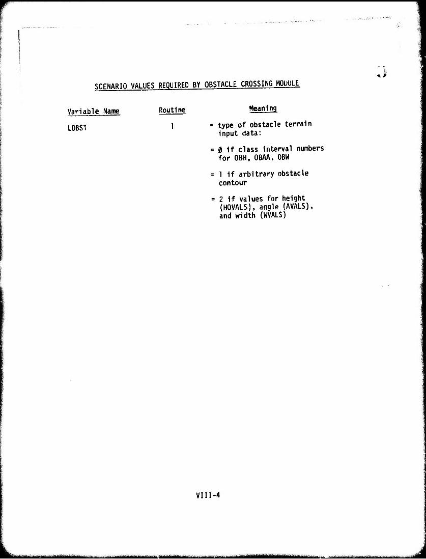
SCENARIO VALUES REQUIRED BY OBSTACLE CROSSING MODULE
Variable Name
LOBST
Routine Meaning
type of obstacle terrain input data:
0 if class interval numbers for OBH, OBAA. OBW
1 if arbitrary obstacle contour
2 if values for height (HOVALS), angle (AVALS), and width (WVALS)
VIII-4
—i—i -■ - - -— IVI IWMiiillMlfMMBIMll III mm—mimm mi J
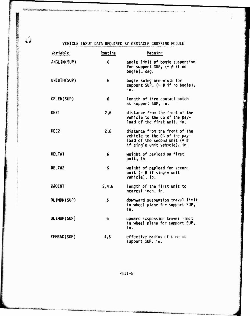
*»a**r<-!"^«öi**» ■ t'wntH&wf»''*'
VEHICLE INPUT DATA REQUIRED BY OBSTACLE CROSSING MODULE
Variable Routine
ANGLIM{SUP) 6
BMIDTH(SUP) 6
CPLEN(SUP) 6
DEE1 2.6
1 ;
DEE2 2.6
DELTW1 6
•
i DELTW2 6
i DJOINT 2.4,6
DLIMDN(SUP) 6
DLIMUP(SUP) 6
EFFRAO(SUP) 4.6
Meaning
angle limit of bogie suspension for support SUP. (« 0 if no bogie), deg.
bogie swing arm wiuth for support SUP, (* 0 if no bogie), in.
length of tire contact patch at support SUP, in.
distance from the front of the vehicle to the CG of the pay- load of the first unit, in.
distance from the front of the vehicle to the CG of the pay- load of the second unit {» 0 if single unit vehicle), in.
weight of payload on first unit. lb.
weight of payload for second unit (» 0 if single unit vehicle), lb.
length cf the first unit to nearest inch, in.
downward suspension travel limit in wheel plane for support SUP. in.
upward suspension travel limit in wheel plane for support SUP. in.
effective radius of tire at support SUP. in.
VIII-5
i^^iia^i—J.—I^
- gaüüM^
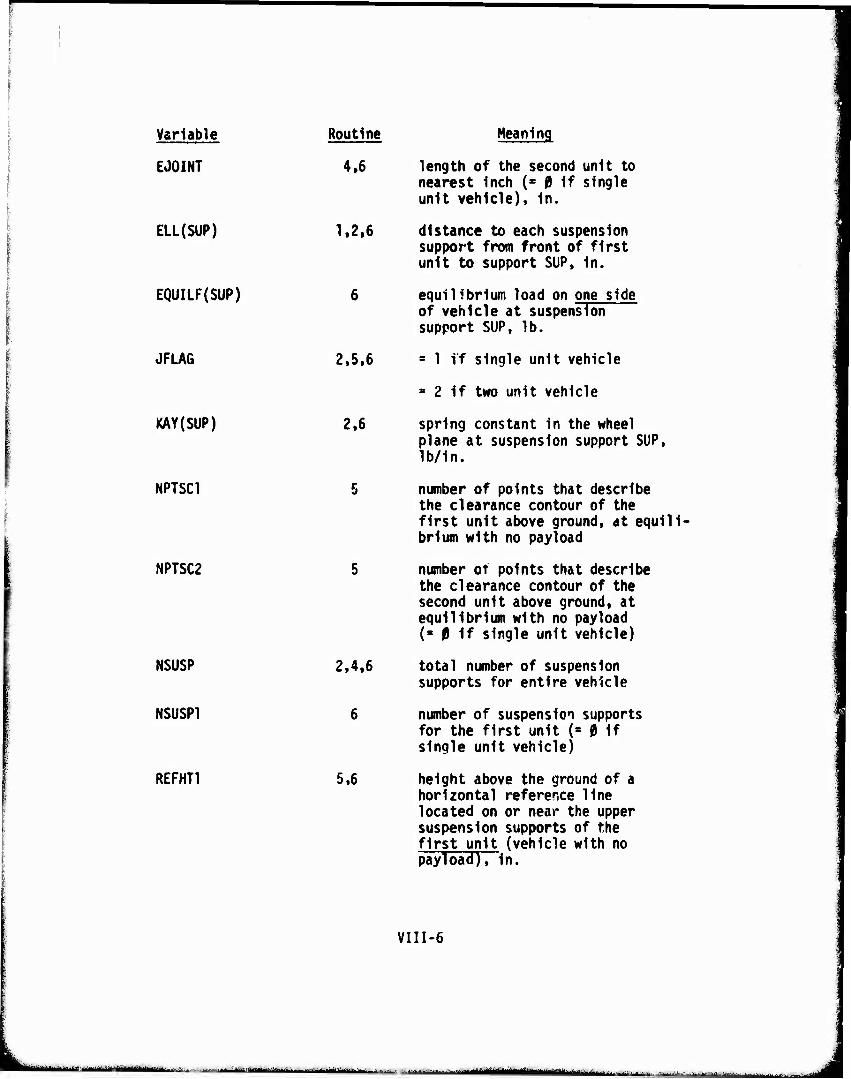
Variable Routine Meaning
EJOINT
ELL(SUP)
EQUILF(SUP)
JFLAG
KAY(SUP)
NPTSC1
NPTSC2
NSUSP
NSUSP1
REFHT1
4,6 length of the second unit to nearest Inch (* 0 1f single unit vehicle). In.
1,2.6 distance to each suspension support from front of first unit to support SUP, In.
6 equilibrium load on one side of vehicle at suspension support SUP, lb.
2,5,6 = 1 if single unit vehicle
= 2 if two unit vehicle
2,6 spring constant in the wheel plane at suspension support SUP, lb/in.
5 number of points that describe the clearance contour of the first unit above ground, at equili brium with no payload
5 number of points that describe the clearance contour of the second unit above ground, at equilibrium with no payload (■ 0 If single unit vehicle)
2,4,6 total number of suspension supports for entire vehicle
6 number of suspension supports for the first unit (= 0 if single unit vehicle)
5,6 height above the ground of a horizontal reference line located on or near the upper suspension supports of the first unit (vehicle with no payload), in.
VIII-6
- —■■■■■. ■-
'■ ■ ' ' "-"■^^*^^Jt^*tt«IM»iili«l. i '
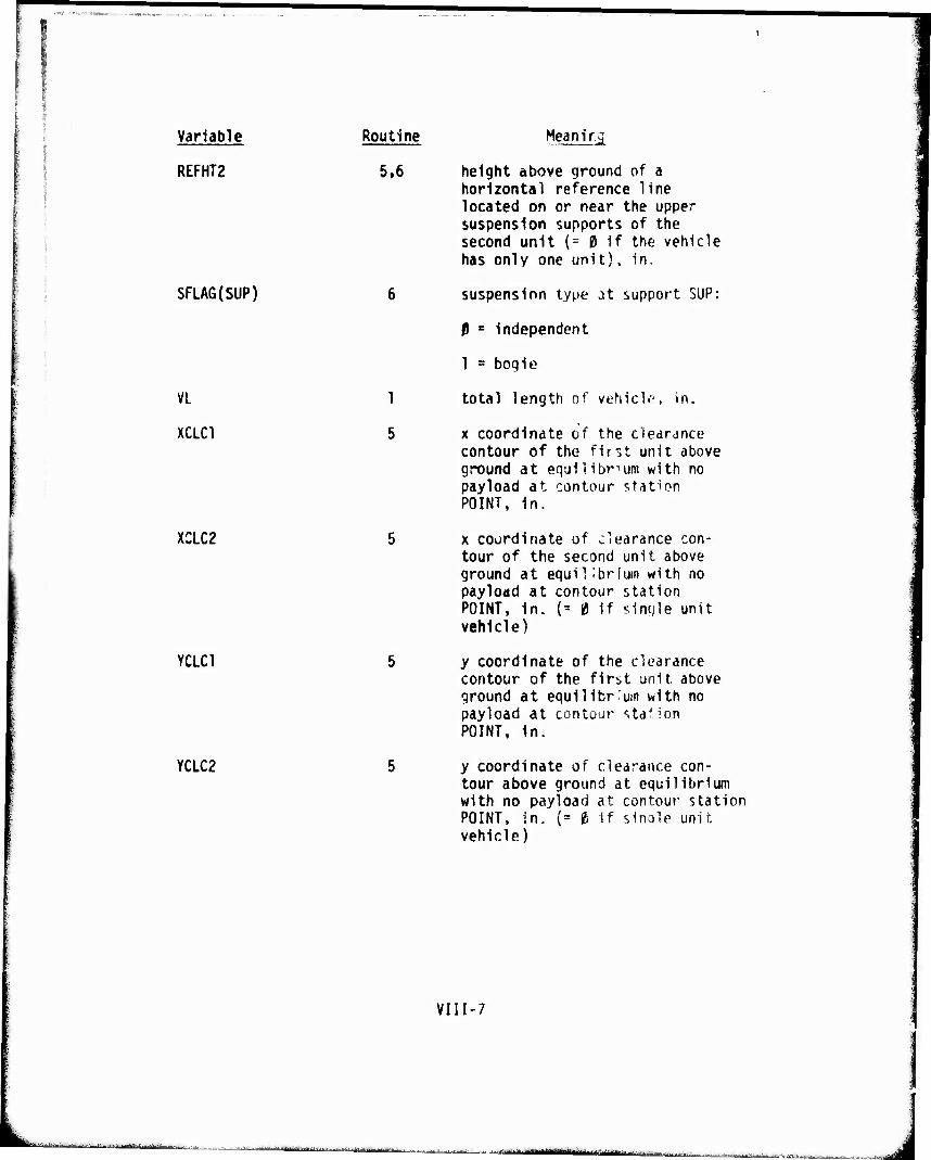
Variable
REFHT2
Routine
5.6
SFLAG(SUP)
VL
XCLC1
1
5
XCLC2
YCLC1
YCLC2
Heanir.g
height above ground of a horizontal reference line located on or near the upper suspension supports of the second unit (= £) If the vehicle has only one unit). in.
suspension type at support SUP:
0 » independent
1 = bogie
total length of vehicle, in.
x coordinate of the deardnce contour of the first unit above ground at eq'jilibr-'um with no payload at contour station POINT, in.
x coordinate of clearance con- tour of the second unit above ground at equilibrium with no payload at contour station POINT, in. (= 0 if sintjle unit vehicle)
y coordinate of the clearance contour of the first unit above ground at equilibrium with no payload at contour sta'ion POINT, in.
y coordinate of clearance con- tour above ground at equilibrium with no payload at contour station POINT, in. (= ti if single unit vehicle)
VIII-7
L. '■- 'IMII
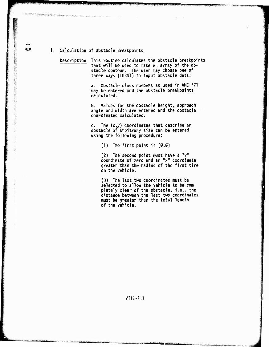
«MIM* ^WWPWI»»«»111"!!!! IIWWP'«
mmmm*.-m*m*m***, Hfpim*in&w - "
. I ■■•■
|)
1. Calculation of Obstacle Breakpoints
Description This routine calculates the obstacle breakpoints that will be used to make »r, array of the ob- stacle contour. The user may choose one of three ways (LOBST) to input obstacle data:
a. Obstacle class numbers as used in AMC '71 may be entered and the obstacle breakpoints calculated.
b. Values for the obstacle height, approach angle and width are entered and the obstacle coordinates calculated.
c. The (x,y) coordinates that describe an obstacle of arbitrary size can be entered using the following procedure:
(1) The first point is (01,0)
"y" (2) The second point must have a coordinate of zero and an "x" coordinate greater than the radius of the first tire on the vehicle.
(3) The last two coordinates must be selected to allow the vehicle to be com- pletely clear of the obstacle, i.e., the distance between the last two coordinates must be greater than the total length of the vehicle.
VIII-1.1
-—""'"'•"•'■-'•'liir i'lalArbi'iin i
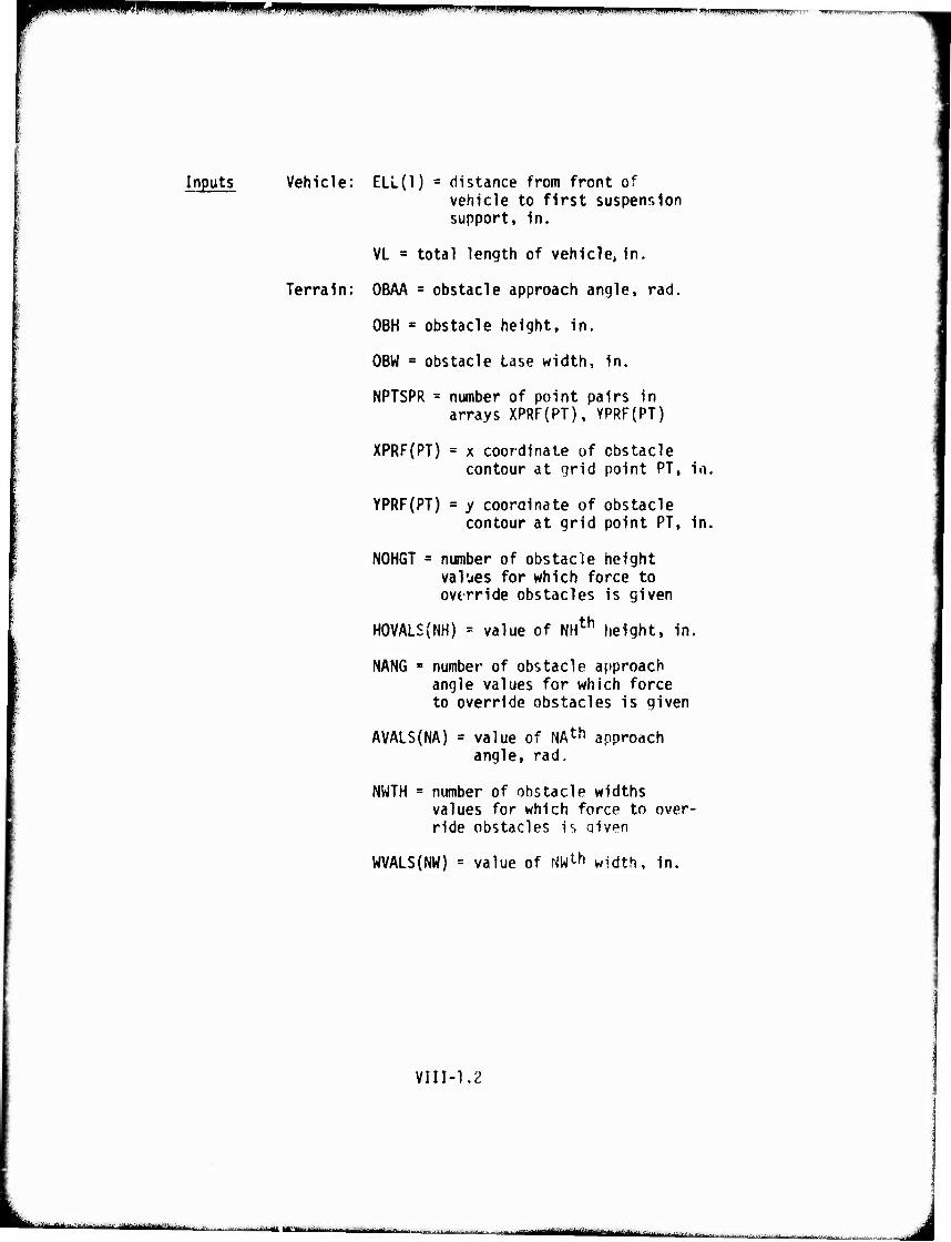
mmmmm «■WW»M ^m^mrnimfm """■•"•- ■ —üi» i BMUppii
Inputs Vehicle: ELL(l) = distance from front of vehicle to first suspension support, in.
VL = total length of vehicle, in.
Terrain: OBAA = obstacle approach angle, rad.
OBH « obstacle height, in.
OBW ■ obstacle tase width, in.
NPTSPR = number of point pairs in arrays XPRF(PT), YPRF(PT)
XPRF(PT) a x coordinate of obstacle contour at grid point PT, in.
YPRF(PT) = y coordinate of obstacle contour at grid point PT, in.
NOHGT = number of obstacle height values for which force to ovtrride obstacles is given
HOVALS(NH) = value of NHth height, in.
NANG = number of obstacle approach angle values for which force to override obstacles is given
AVALS(NA) = value of NAt^ approach angle, rad.
NWTH = number of obstacle widths values for which force to over- ride obstacles is given
WVALS(NW) = value of NW^1 width, in.
VIIM.2
-■■■'—'•-■ ■■ - - ■- ■ ■■■■■ --'■■*. M "-— -- -- I-, —'"-•-'
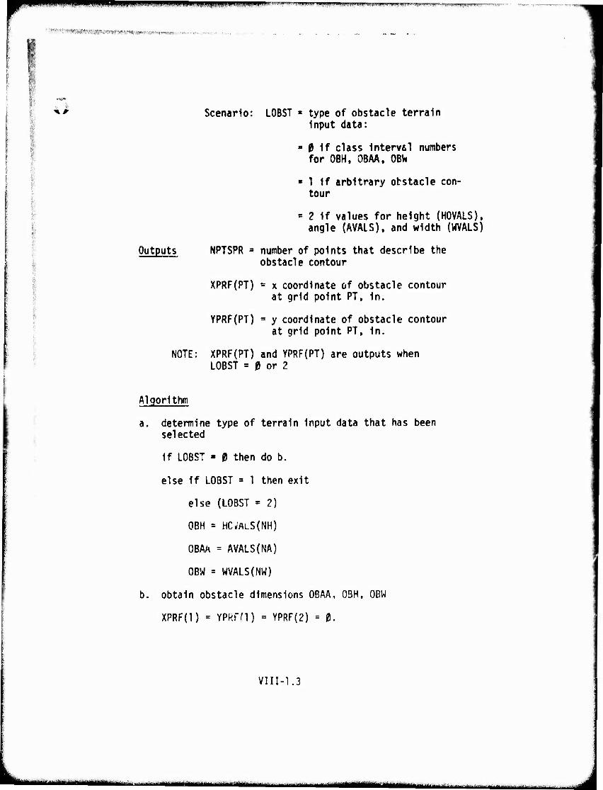
,'^^W'^mKf9Xm<S9'Wmmmmmmm«vvmi^'»'''-''''^. »■< • .......
** Scenario: LOBST = type of obstacle terrain Input data:
■ 0 1f class Interval numbers for OBH, OBAA, OBV*
» 1 If arbitrary obstacle con- tour
* 2 If values for height (HOVALS), angle (AVALS), and width (WVALS)
Outputs NPTSPR 3 number of points that describe the obstacle contour
XPRF(PT) = x coordinate of obstacle contour at grid point PT, In.
YPRF(PT) » y coordinate of obstacle contour at grid point PT, In.
NOTE: XPRF(PT) and YPRF{PT) are outputs when LOBST = 0 or 2
Algorithm
a. determine type of terrain input data that has been selected
If LOBST - 0 then do b.
else if LOBST = 1 then exit
else (LOBST = 2)
OBH = HCVALS(NH)
OBAA = AVALS(NA)
OBW = WVALS(NW)
b. obtain obstacle dimensions OBAA, OBH, OBW
XPRF(l) = YPRfd) = YPRF(2) = 0.
VII1-1.3
'" i'ri'i|i[i mummiMBi • ^u^jMamm^-i,,,,-, . -..^.^„^ Ijm ^^^g^g^mgn^ '-'-' ■' -.. ■■^■«'
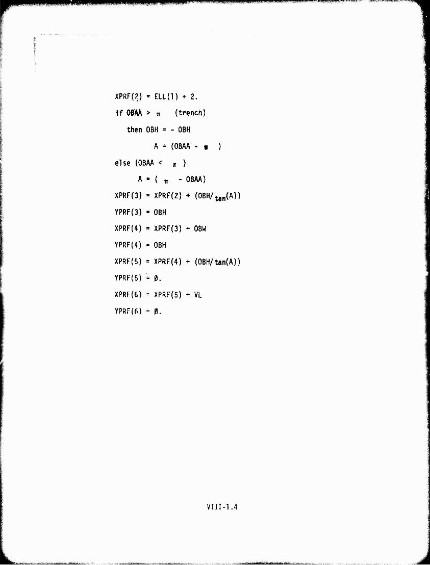
m^m^m l(|l*M.(IIMI!l l<|lll||>l(J|ll,lll*I.IIIIUIII "'" i wwmmrmm "'—""'"
XPRF(?) « ELL(l) + 2.
if OBAÄ > Ti (trench)
then OBH » - OBH
A = (OBAA - v )
else (OBAA < „ )
A » ( TT - OBAA)
XPRF(3) =» XPRF{2) + (OBH/^A))
YPRF(3) = OBH
XPRF(4) = XPRF(3) + OBW
YPRF(4) = OBH
XPRF(5) = XPRF(4) + (0BH/Un(A))
YPRF(5) = 0.
XPRF(6) = XPRF{5) + VL
YPRF(6) = 0.
VIII-1.4
.. '"-'■'fwHtiimw ii- ■ i •
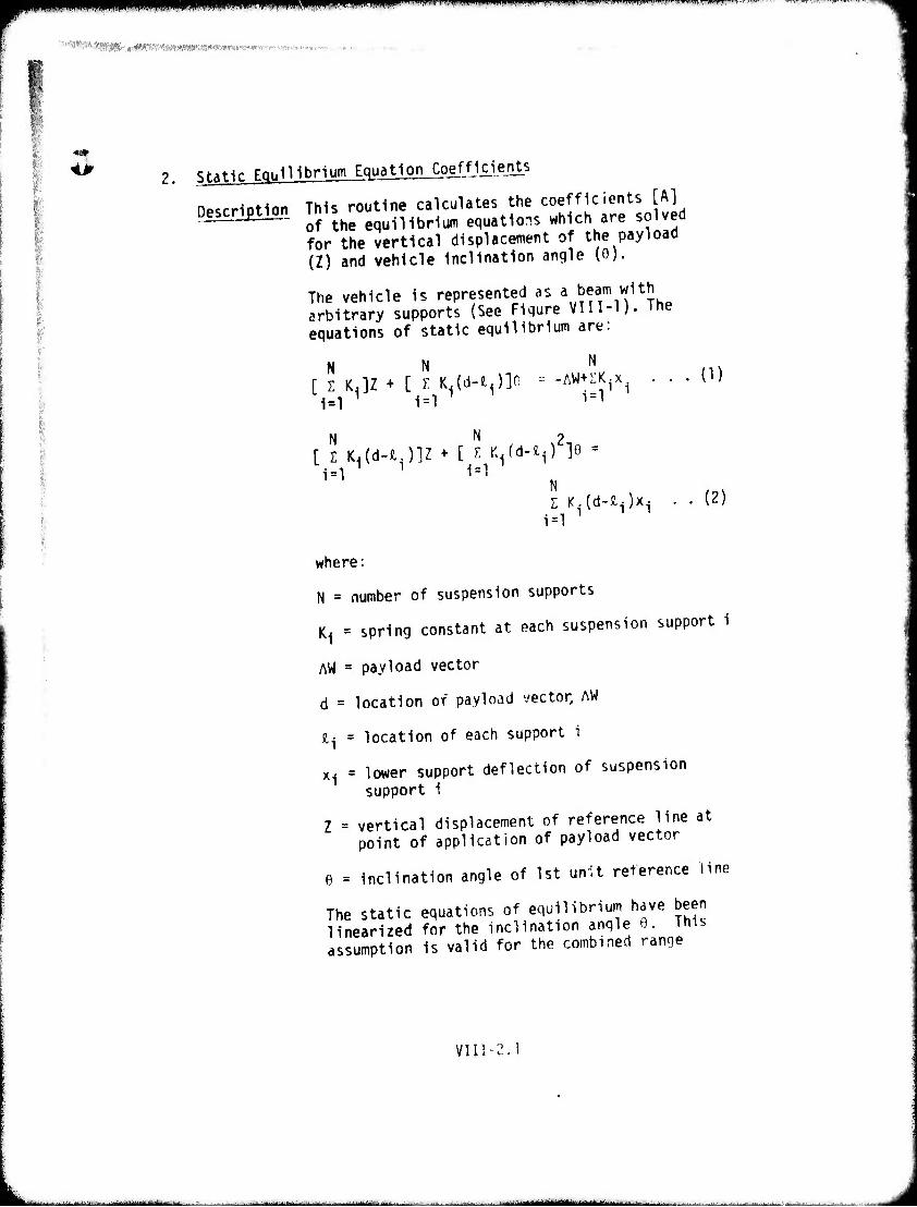
-I.,.. .... ||,|, I(I | J , mmfmmnmmimmmi RmiiiliPfPli^1"! i J"" '
■'■■"»^ffÄ^AVJB«.'W^«.•»ww>»«•^,»-s•^■n^^ •■.•r ■.-
<P Static Egiilllbriüm Equation Coefficients
Description This routine calculates the coefficients [A] of the equilibrium equations which are solved for the vertical displacement of the payload (Z) and vehicle inclination angle (0).
The vehicle is represented as a beam with arbitrary supports (See Fiqure VII1-1). The equations of static equilibrium are:
N N N [ Z KJZ + [ T. K.(d-fc.)]0 -- -AW+SK.x. . . .
1=1 ' 1=1 1 1 1=1' 1
N N [ i Md-nJlZ + [ T. K^d-^O lo
1=1 1=1
Z K.(d-S.i)xi
1=1
(1)
(2)
where:
N = number of suspension supports
K^ = spring constant at each suspension support i
AW = payload vector
d = location of payload vector, AW
i, - location of each support i
x-j = lower support deflection of suspension support 1
Z = vertical displacement of reference line at point of application of payload vector
6 = Inclination angle of 1st unit reference line
The static equations of equilibrium have been linearized for the inclination angle 0. This assumption is valid for the combined range
VII1-2.
^aiaiiatmam - 1 - -
^mmm^^mmm ,HI«WI«llH!IWlW)«llf"MI»"1l»«ll,l"Ul,lifflWI!irl»"l"",»J'1 <","lr
of military vehicle wheel bases and obstacle heights which appear in the areal features terrain data. These coefficients are used in the Routine 6, Minimum Clearance and Tangential Forces.
VIII-2.2
— ■ : ._ ,.._,
—-■■ '■
•"■ 'll1
mmmmmm mmmmm WiiKiMW»f>mimimm*immvir* «•mwMwnfttww««»«.
<p
oc 3
C4
:■ tD -■ O
: t~ :■■
tn co
■ o ■^
r^
>_> s: •«t
':■ ex j. o
.-
>>- 2r O ►—.
•X •—
LU
Li.1 9~-
a; K-
UJ *~4
_J ST U rs t—•
X Ul
cr
■ ..;-■....:-.■■-,.„,,., , - —
^W^^W^iuiiijii. ■i)!.mMi|in,uil.i»..ii..|l,^.ii,,p ^ni.iiiiippi,.,,,,,,,^,,,,,,.
Inputs Vehicle: JFLAG = 1 if single unit vehicle
= 2 if two unit vehicle
NSUSF = total number of suspension supports for entire* vehicle
KAY(SUP) = spring constant in the wheel plane at suspension support SUP, lb/in
DEE1 = distance from the front of the vehicle to the CG of the pay- load of the first unit, in.
DEE2 = distance from the front of the vehicle to the CG of the pay- load of the second unit, in. {= )fl if single unit vehicle)
ELL(SUP) * distance to each suspension support from front of first unit to support SUP, in.
DJOINT = length of the first unit to nearest inch
Outputs A(i,j) = coefficients of static equations of equilibrium, i x j = 2 x 2, single unit vehicle; i x j - 3 x 3, two unit vehicle
Algori thm
a. All = A12 = A22 = A13 = A23 = A33 = $.
if JFLAG = 2 (two unit vehicle)
then do b.
else CJFLAG = 1, single unit vehicle)
do for SUP = 1 to NSUSP
VIII-2.4
fc-^^-^.^.^_ ^ , , .^_^_— -
m?mmmmmmmmm*vmmw™***** ■'^- ■.-."-- -—r'.-r^-^-. —..■-~TT--' —"..- — ----' ■•-•-
All = All + KAY(SUP)
A12 = A12 + KAY(SUP)*(DEE1-ELL(SUP))
A22 = A22+KAY(SUP)*[(DEEl-ELL(SUP))2j
next SUP
All = 2. * All
A12 « 2. * A12
A21 - A12
A22 = 2. * A22
exit
b. calculation of coefficients for a 2-unit vehicle
bl. coefficients for first unit
do for SUP = 1 to NSUSP1
All ^ All + KAY(SUP)
A12 = A12 + KAY(SUP) * (DEEl-ELL(SUP))
A22 = A22 + KAY(SUP) * [{DEEl-ELL(SUP))2]
next SUP
b2. coefficients for 2nd unit
do for SUP = NSUSP1+1 to NSUSP
All = All + KAY(SUP)
A12 = A12 + KAY(SUP) * (DEE1-DJ0INT)
A13 = A13 + KAY(SUP) * (ELL(SUP)-DOOINT)
A22 ' A22 + KAY(SUP) * [(DEE1-DJ0INT)2]
A23 * A23 ♦ KAY(SUP) * (ELL(SUP)-DJ0INT)*(DEE1-0J0INT)
VIII-2.5
— BMirai I IlilMiM mm^ -■-■ a ■■ •■ ■ - - J
»■*^^»^ ■s^^W^^l^W m*mm jm»mi>vm""'i ''mm
A33 = A33 + KAY(SUP) * [(ELL{SUP)-DJOINT)^
next SUP
All = 2. * All
A12 - 2. * A12
A13 = 2. * A13
A21 - Al 2
A22 = 2. * A22
A23 = 2. * A23
A31 « Al 3
A32 = A23
A33 = 2. * A33
VIII-2.6

mmmmm ■ UPPPIPPiPBH fi.immwimummwnmmm™"'""^ '■
3. Obstacle Profile Contour
VIII-3.1
-— -■ ---- — - .1 M ^■nifiirrtiiiifiiiii'-1—J' ^ - J
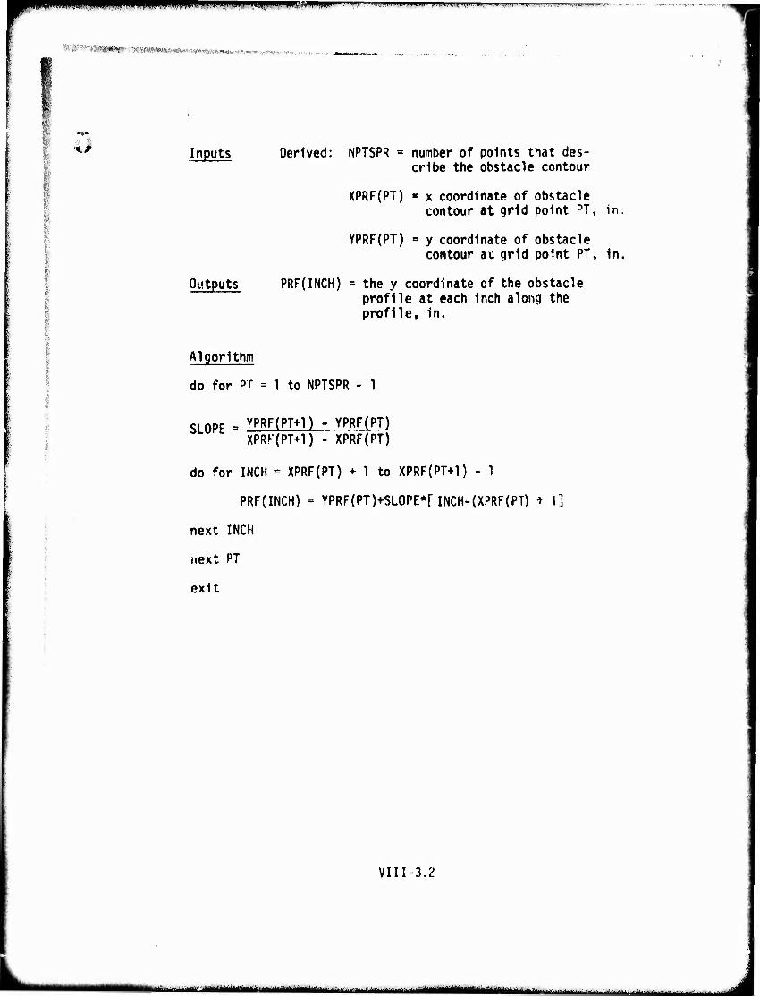
IPIPPIIIBIBWPWIIIPIIPIPF;^»^^!!! «I I . .I.......«!.«»...!«.»!!»! W.I.,
■' ■ »mmm-mmmmmsmm>mm, WRWNaÄPiW'^WftwwWHK«' «'■"■J-.
Inputs
Outputs
Derived: NPTSPR = number of points that des- cribe the obstacle contour
XPRF(PT) « x coordinate of obstacle contour at grid point PT, in.
YPRF(PT) = y coordinate of obstacle contour at grid point PT, in,
PRF(INCH) = the y coordinate of the obstacle profile at each inch along the profile, in.
Algorithm
do for PC = 1 to NPTSPR - 1
SLOPE = yPRF(PT^l) - YPRF(PT) XPRK(PT+1) - XPRF(PT)
do for INCH = XPRF(PT) + 1 to XPRF{PT+1) - 1
PRF(INCH) = YPRF(PT)+SLOPE*[ INCH-{XPRF(PT) i 1]
next INCH
next PT
exit
VIII-3.2
—- -— ^^^ ,_ _.,__-j_.- .j..
^■"^^^•■»^■^^"^^^■^■•^^H"!« iiimnwwiw»«
■I
■ •
4. Wheel Hub Contour
Description This routine builds the array (HUBPRF) of the path that Is followed by the wheel hubs as the
I vehicle moves over the obstacle. Figure VIII-? siiows the obstacle profile as mcdlfled by the
I wheel. The hub profile Is built by testinq the clearance between points on trie tire periphery (THR) and the obstacle profile (PRF) across the entire lowe»* semi-circle of the tire at sach inch x coordinate along the obstacle. The minimum clearance between the obstacle and tire periphery establishes the vertical coordinate of the wheel hub at the specific inch x coor- dinate along the obstacle.
Yin-4.1
-■- - . -~......., —^■■■■. . — ■'■■■■ i i J
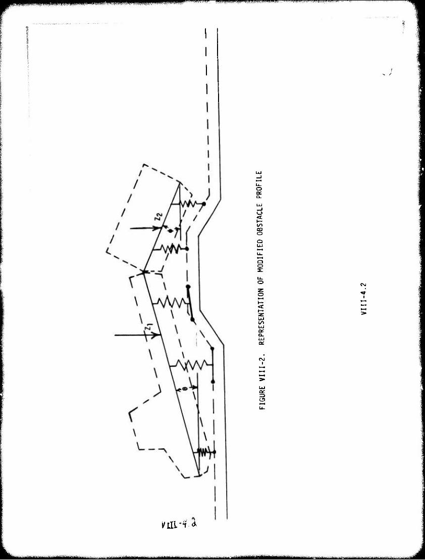
^w^^ " " ■■l ■■'■■ "'" • 1 I » I
LL. o a:
o
*^ O O
Q O 31
UJ l^ UJ
a. UJ
mi-'f *
- - --■-■ MMUBMMIW^IkM« I III I— III I - - - - ■ ^
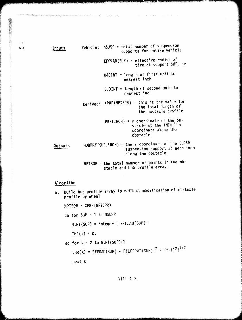
iiiijM IIIIJWIIIIIIJIUüIIJIIU, ii iiii.ii. i ii mm . IN, i, iwmmmimm»
'■■ m ■ > " ■■'''• ■'■■•■■■ ■- •■■ ■ "■-.- ■•
** Inputs
Outputs
Vehicle: NSUSP = total number of suspension supports for entire vehicle
EFFRAO(SUP) = effective radius of tire at support SUP, in.
0001NT - length of first unit to nearest inch
EJOINT * length of second unit to nearest Inch
Derived: XPRF(NPTSPR) = this is the value for the total length of the obstacle profile
PRF(INCH) = y coordinate of the ob- stacle at the INCHth x coordinate along the obstacle
HUBPRF(SUP.INCH) = the y coordinate of the SiJPth suspension support at each inch along the obstacle
NPTSOB = the total number of points in the ob- stacle and hub profile arrays
Algorithm
a build hub profile array to reflect modification of obstacle profile by wheel
NPTSOB « XPRF(NPTSPR)
do for SUP = 1 to NSUSP
NINT(SUP) » integer { EFF;.AD(SUP) }
THR(l) = 0.
do for K = 2 to NINT(SUP)+1
THR(K) = EFFRAD(SUP) - [(EFFRAD(SUP))? - fK-l)?]1/?
next K
VIII-4.3
' - —•■■ ■.—^—.-. ■ - mfru v
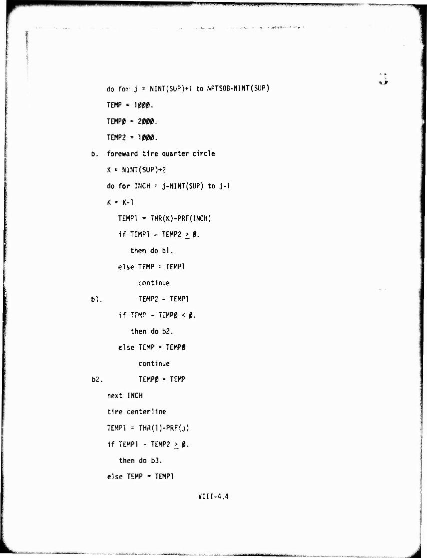
■ LiiHiii, i m ■iiiiiii^piiiiiiBiwpppBpitiiiiiiiii.i UIIIII n 11. i.i
'..«»: vjmt* < * v ,
do fof j = NINT(SUP)+1 to NPTSOB-NINT(SUP)
TEMP - 1000.
TEMP0 = 2000.
TEMP2 = 1000.
b. foreward tire quarter circle
K «= NlNT(SUP)+2
do for INCH - j-NINT(SUP) to j-1
K = K-l
TEMPI « THR(K)-PRF(INCH)
if TEMPI - TEMP2 > 0.
then do bl.
else TEMP = TEMPI
continue
bl. TEMP2 = TEMPI
if TF^r - TZMP0 < 0.
then do b2.
else TEMP = TEMP0
continue
b2. TEMP0 = TEMP
next INCH
tire centerline
TEMPI = THÄ{l)-PRF(j)
if TEMPI - TEMP2 > 0.
then do b3.
else TEMP - TEMPI
VIII-4,4
■ ■ ■•■ -^^.~- ■
I
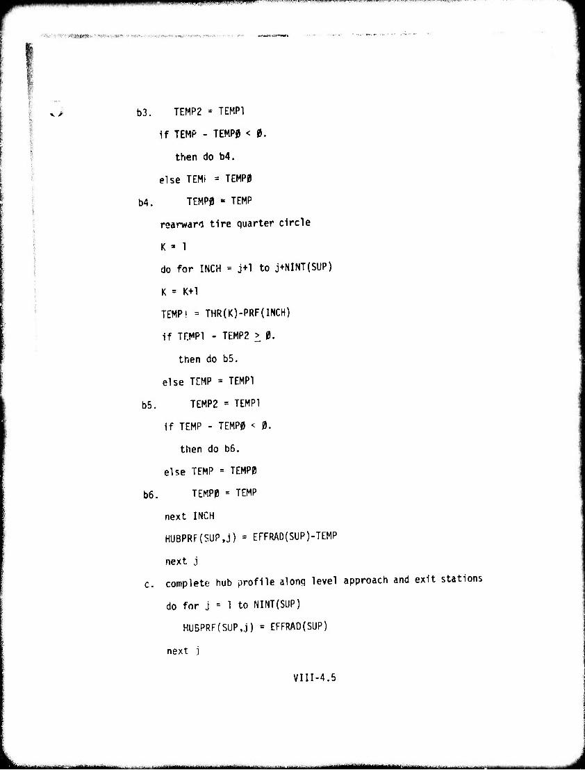
fflliiPiPipp^ipiL.lllPIIMiii -■-'...■.--M..«.-..^^.^^^,^ ..^-M^^^^^^™^-^^.-^..
fy-i '■ !:c':l-^^,fi|(^;^,vlA?i^-;rtJUttv' if'»«»v-tfnowww^wi ■.'*J^..-*^-^'. ■.■■«.'.'v'. - ■■ - ^« .^««.*fl***w»»»
^' b3. TEMP2 - TEMPI
if TEMP - TEMP0 < 0.
then do b4.
else TEMt = TEMP0
b4. TEMP0 » TEMP
rearwarl tire quarter circle
K » 1
do for INCH = j+1 to j+NINT(SUP)
K = K+l
TEMP! = THR(K)-PRF(INCH)
if TEMPI - TEMP2 > 0.
then do b5.
else TEMP = TEMPI
b5. TEMP2 = TEMPI
if TEMP - TEMP0 < 0.
then do b6.
else TEMP = TEMP0
b6. TEMP0 = TEMP
next INCH
HUBPRF(SUP,j) = EFFRAD(SUP)-TEMP
next j
c. complete hub profile along level approach and exit stations
do for j = 1 to NINT{SUP)
HUBPRF(SUP,j) = EFFRAD(SUP)
next ]
VIII-4.5
- - ■---■ - - - - iiinii—i—■ m
i« J Mjmmmm^ir'^******1 ■win i ^i«^.»««» in iwiiw m im
do for j = NPTSOB - NINT(SUP)+1 to NPTSOB
HUBPRF(SUPJ) - HUBPRF(SUP.(NPTSOB-NINT(SUP)))
next j
next SUP
exit
VIII-4.6
- ■■ J
.1. ..[ ..■■ wann l v> m PH win J.i ainm« i < < .••P <><<i< i.
u 5• v.e.hlcl_?. Clearance Contour
Description This routine creates the array (REFCLC) which Is the difference between the vehicle reference lines (REFHT1, REFHT2) and the vehicle ground clearance contours at equilibrium ((XCLC1,YCLC1), {XCLC2.YCLC2)).
VIII-5.1
■■■-■■■■'■—-fa"-^- ... .■:-..U...^.iJ^^.^;.1 ---"— — - J
||^^^^i^WP^^miill|lll.l.|l|I.HIII.|.|IHH.IHIWHIWIIWII' ........IM,...I .LT-^-^: - . , ■>.. ■■^■~,
,**. •MPH: . r»--l» ■
Inputs Vehicle: JFLAG = 1 if single unit vehicle
= 2 if two unit vehicle
REFHT1 = height above the ground of a horizontal reference line located on or near the upper suspension supports of the first unit (vehicle with no payload), in.
REFHT2 = height above ground of a horizontal reference line lo- cated on or near the upper suspension supports of the second unit (= 0 if the vehicle has only one unit), in.
NPTSC1 = number of points that des- cribe the clearance contour of the first unit above ground, at equilibrium with no payload
NPTSC2 = number of points that des- cribe the clearance contour of the second unit above ground, at equilibrium with no payload (= 0. If single unit vehicle)
XCLC1(POINT) = x coordinate of the clearance contour of the first unit above ground at equilibrium with no payload at con- tour station POINT, in.
■* A
YCLC1(POINT)
XCLC2(P0INT)
y coordinate of the clearance contour of the first unit above ground at equilibrium with no payload at contour station POINT, in.
x coordinate of clearance contour of the second unit abcvt ground at equili- brium with no payload at contour station POINT, in. (= 0. if single unit vehicle)
VIII-5.2
■
tküäkääiätäiiitim
■IP ! i mmm mmipnn
' 'l!!liVJ^'I39«PMmitMni>M ■ *■.«'".*•—^ :•..■•
^^ YCLC?(POINT) =
NOTE:
Outputs
y coordinate of clearance contour above ground at equilibrium with no pay- load at contour station POINT, in. (= 0. if sinqle unit vehicle)
The coordinate system for these points has the origin (0,0) on the ground at the front of the first unit. The x coordinates are in the horizontal direction and the y coordinates are in the vertical direction.
REFCLCO.INCH)
REFCLC(2,INCH)
the difference between the height of the vehicle clearance contour of the first unit and the reference line height REFHT1 at each inch alomj the clearance contour, in.
the difference between the height of the vehicle clearance contour of the second unit and the reference line height REFHT2 at each inch along the clearance contour, in.
Algorithm
make array of differences between reference lines and clearance contours
do for POINT = 1 to NPTSC1
NTEMP(POINT) = integer { XCLC1(POINT)} + 1
next POINT
do for POINT -- 1 to NPTSCl-l
SLOPE = (YCLC1 (POINTS)-YCLCl(POINT)) ^XCLCl (POINT+D-XCLCl (POINT)
VIII-
■rjmmppamv wspmumpw ' > MJI H I n nmmfim-^iinff>''t'my'«"'.'«r'''''l:r'1 «irn-u«i-mw.''iiwrw-
do for INCH = NTEMP(POINT) to NTEMP(P0INT+1 )-l
REFCLCd.INCH) = YCLCl (POINT)+SLOPE*(INCH-NTEMP(POINT))-REFHn
next INCH
next POINT
if JFLAG = 1 {single unit vehicle)
then exit
else (two unit vehicle)
do for POINT = 1 to NPTSC2
NTEMP(POINT) » integer { XCLC2(P0INT) } f 1
next POINT
do for POINT » 1 to NPTSC2-1
SLOPE = VCLC2(POINT-l)-YCLC2(POINT) XCLC2(P0INT+1)-XCLC2(P0INT)
do for INCH = NTEMP(POINT) to NTEMP(P0INT+1 )-l
REFCLC(2,iNCH) = YCLC2(P0INT)+SL0PE*(INCH-NTEMP(P0INT))-REFHT2
next INCH
next POINT
exit
VIII-5.4
^- m ■■■ ■■ --^-^-^-^-^--. ■ . a i ' ■ -■ -i iiitiüiiiiiMiliiiM^—ii ■
I ■■"■'"T ■' ■■>v^*^*w^^^^^ i in injiiiinpiiiiiii.
1 ■"'■■•"■. .■ttfl^ft/ciH:'- f ..WBWW*lMMWl^"TT'»*weNffi^^
%0 6, Minimum Clearance and Tangential Force
This routine calculates the minimum clearances (CLRMIN) between points on the vehicle underbody and points along the obstacle profile, and also the summed tangential forces (TFSUM) at the tire-obstacle interface for all tires along the obstacle profile. The clearances and forces are found by determining the vehicle's posi- tion and orientation (inclination angle) with respect to the obstacle at each step along the obstacle. In solving the static equations of equilibrium, the Jounce and rebound positions of the vehicle's suspension system are examined for the extent of suspension travel. If travel limits are encountered, then deflection ex- pressions are altered accordingly.
1
VIII-6.1
--■' i J
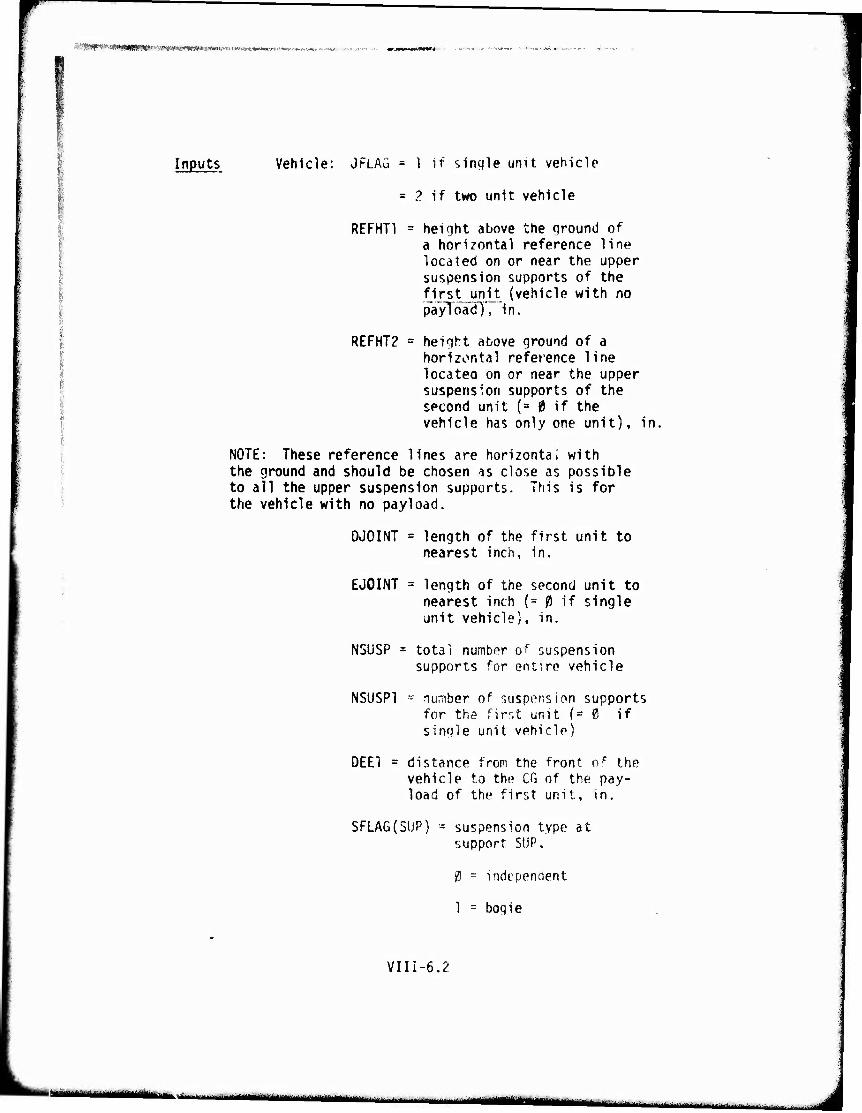
-•■«ttiQ» ^-BimmBSKp^-, ■■;mi>xmmmir.vm^ •■
Inputs Vehicle: JFLAG = 1 if simile unit vehicle
= 2 if two unit vehicle
REFHT1 = height above the ground of a horizontal reference line located on or near the upper suspension supports of the first unit (vehicle with no payToadT, In.
REFHT2 = height above ground of a horizontal reference line locateo on or near the upper suspension supports of the second unit (= 0 if the vehicle has only one unit), in.
NOTE: These reference lines are horizontal with the ground and should be chosen is close as possible to all the upper suspension supports. This is for the vehicle with no payload.
DJOINT = length of the first unit to nearest inch, in.
EJOINT = length of the second unit to nearest inch (= 0 if single unit vehicle), in.
N5USP = total numbor of suspension supports for entire vehicle
NSUSP1 - number of suspension supports for the firr,t unit (= 0 if single unit vehicle)
DEE! = distance from the front of the vehicle to tht1 CG of the pay- load of the first unit, in.
SFLAG(5UP) = suspension type at support SUP,
0 = independent
1 = bogie
VIII-6.2
mum mmm ■a.—...-..■.,..;,..: ; ..^
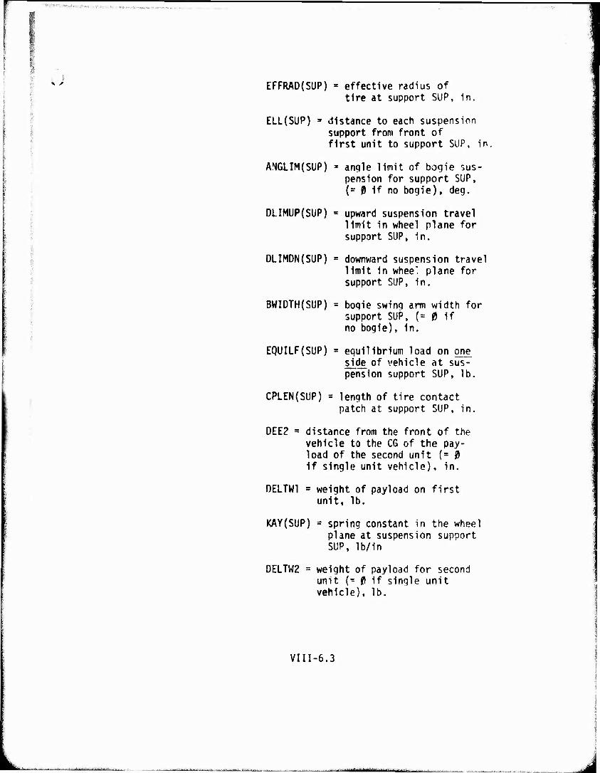
'■ V 3 ■■■., ■..■■: ;■■>;«( ,■■ >*■■■ ■ ■ ■ ■
sJ EFFRAD(SUP) = effective radius of tire at support SUP, in.
I
ELL{SUP) 3 distance to each suspension support from front of first unit to support SUP, in.
ANGLIM(SUP) = angle limit of bogie sus- pension for support SUP, (= 0 if no bogie), deg.
DLIMUP(SUP) « upward suspension travel limit in wheel plane for support SUP, in.
DLIMDN(SUP) « downward suspension travel limit in wheel plane for support SUP, in.
BWIDTH(SUP) = bogie swing arm width for support SUP, (= 0 if no bogie), in.
EQUILF(SUP) = equilibrium load on one side of vehicle at sus~-' pension support SUP, lb,
CPLEN(SUP) = length of tire contact patch at support SUP, in.
DEE2 = distance from the front of the vehicle to the C6 of the pay- load of the second unit {- 0 if single unit vehicle), in.
DELTW1 = weight of payload on first unit, lb.
KAY(SUP) = spring constant in the wheel plane at suspension support SUP, lb/in
DELTW2 = weight of payload for second unit (- P if single unit vehicle), lb.
Vin-6.3
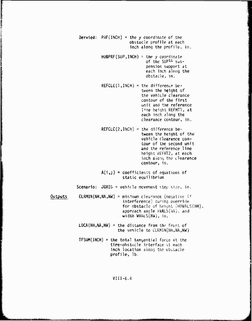
Oervied: PRF(INCH) = the y coordinate of the obstacle profile at each Inch along the profile, in,
HUBPRF(SUP,rNCH) ■- the y coordinate of the SUP^ sus- pension support at each inch along the obstacle, in.
REFCLCO.INCH) - the difference be- tween the height of the vehicle clearance contour of the first unit and the reference l^ne height REFHT1, at each inch along the clearance contour, in.
REFCLC(2,INCH) = the difference be- tween the height of the vehicle clearance con- tour of the second unit and the reference line height REFHT2, at each inch aioiij the clearance contour, in.
A(i,j) = coefficients of equations of static equilibrium
Scenario: JGRID = vehicle movenient step si/e, in.
Outputs CLRMINlNH.NA.NW) = minimum clearance (negative if interference) during override for obstacle of height (KOVALS(NH), approach angle AVALS(M). and widtn WVALS(NW), in.
LOCA(NH,NA,NW) = the distance from the front of the vehicle to CLRMlN{Nh,NA,NW)
TFSUM(INCH) = the total tangential force at the tire-obstacle irterface at each inch location along tne obstacle profile, lb.
VIII-6.4
"*'''|toaa'i'**',"'• * .^...-.^»lii^^.,-, ■ .—■■mi i liMr.1^^M_M«^.>^»aM^—i»— ,
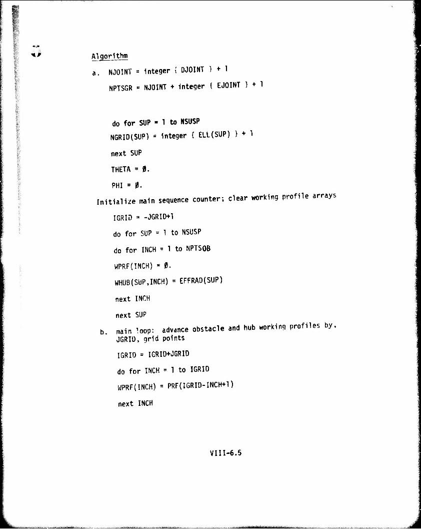
Skr
I
*> Algorithm
a. NJOINT - Integer { DJOINT > + 1
NPTSGR «= NJOINT + Integer { EJOINT } + 1
do for SUP » 1 to NSUSP
NGRID(SUP) = Integer { ELL(SUP) } + 1
next SUP
THETA = 0.
PHI = 0.
Initialize main sequence counter; clear working profile arrays
IGRID = -JGRID+1
do for SUP = 1 to NSUSP
do for INCH = 1 to NPTSQB
WPRF(INCH) = 0.
WHUB(SUP,INCH) = EFFRAD(SUP)
next INCH
next SUP
b. main loop: advance obstacle and hub working profiles by, JGRIl), grid points
IGRIO = IGRID+JGRID
do for INCH = 1 to IGRIO
WPRF(INCH) = PRF(IGRID-INCH+1)
next INCH
VIII-6.5
■.■—.... i. J
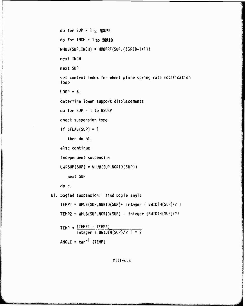
do for SUP = 1 to NSUSP
do for INCH = 1 to I6RID
WHU3(SUP,INCH) « HUBPRF(SUP,(IGRID-1+1))
next INCH
next SUP
set control index for wheel plane spring rate modification loop
LOOP = 0.
determine lower support displacements
do for SUP = 1 to NSUSP
check suspension type
if SFLAÜ(SUP) = 1
then do bl.
else continue
independent suspension
LWRSUP{SUP) = WHUß(SUP,NGRID(SUP))
next SUP
do c.
bl. bogied suspension: find bogie angle
TEMPI » WHUB(SUP,NGRID(SUP)+ integer { BWIDTH(SUP)/2 )
TEMP2 = WHUB(SUP.NGRID(SUP) - integer {BWIDTH{SUP)/?]
TEMP = (TEMPI - TEMP2)_ integer { BWIDTH(SUP)/2 } * 2
ANGLE « tan"1 (TEMP)
VIII-6.6
■|1*IIIHHII- ■■-, ,. -„T .,,,M**tmtM*imtii**ä*~****iumm**.*..., -■.■...„. JJ.,,.... „■...■**.**** ,—.., -„«_^^^i^_„„_ , „
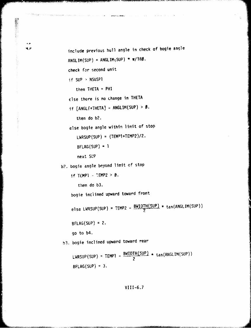
mmmmmmmmmmmmm i.iiun nunniiR •—■ -»-^——
"*•;■•;;*■ .■ ■ ■-,.•...-.. , .-.„ -.
HWHI,.IUI,I Kim .BWJ-•!.iW-'<i',>«l'^W".'« ■.-■^
*..*■ include previous hull angle in check of bogie angle
ANGLIM(SUP) = ANGLIM^SUP) * ir/180.
check for second unit
if SUP > NSUSP1
then THETA » PHI
else there is no change in THETA
if [ANGLF+THETA] - ANGLIM(SUP) > 0.
then do b2.
else bogie angle within limit of stop
LWRSUP(SUP) = (TEMPl+TEMP2)/2.
BFLAG(SUP) « 1
next SUP
b2. bogie angle beyond limit of stop
if TtMPl - TEMP2 > 0.
tSien do b3.
bogie inclined upward toward front
else LWRSüP(SUP) = TEMP2 - BWIDTH(SUP) * tan{ANGLIM(SUP))
BFLA6(SUP) = 2.
go to b4.
b3. bogie inclined upward toward rear
LWRSUP(SUP) = TEMPI - BWIDTH^SUP) * tan(ANGLIM(SUP))
BFLAG(SUP) = 3.
VIII-6.7
■
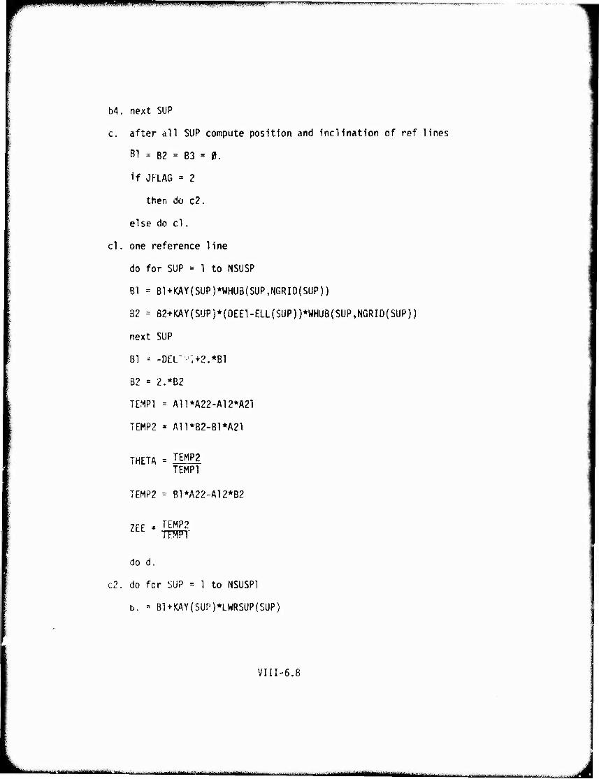
I IINIIIII III HI ^^W" ^-"flUiT*'? ^Ui'L'UJ.V-^WTWT-^TTf^^llVti, "I,»-**
54. next SUP
c. after all SUP compute position and inclination of ref lines
B1 = B2 = B3 = 0.
If JKLAG =» 2
then do c2.
else do cl.
cl. one reference line
do for SUP = 1 to NSUSP
Bl * B1+KAY(SUP)*WHUB(SUP,NGRID(SUP))
82 = 82+KAY(SUP)*(0EEl-ELL(SUP))*WHUB(SUP,NGRID{SUP))
next SUP
81 -- -DEL' :.+2.*Bl
82 = 2.*B2
TEMPI = A11*A22-A12*A21
TEMP2 » A11*B2-B1*A21
THETA = ILMP2 TEMPI
TEMP2 "- B1*A22-A12*B?
ZEE * KW2
TFMFT
do d.
c2. do fcr SUP = 1 to NSUSP1
b. - B1+KAY(SUP)*LWRSUP{SUP)
VIII-6.8
,-'iiiiiiiiiiiiiiiiiir,'-"IJ,-i"-,-fi iirmii'umti'iiiiir'iiiiiii ri^nuat^itttimi^mä ■ - J
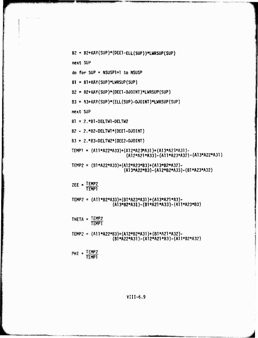
^n^P^^^^^^W^^^PW^Wi^W^^^^WW!-^— i uiPwiMwum i. in mi. n.mpin.i,,.^—„.,_^,_ .
B2 = B2+KAY(SUP)*(DEE1-ELL(SUP))*LWRSUP(SUP)
next SUP
do for SUP « NSUSP1+1 to NSUSP
Bl « B1+KAY(SUP)*LWRSUP(SUP)
B2 » B2+KAY(SUP)*(DEE1-DJ0INT)*LWRSUP(SUP)
B3 = B3+KAY(SUP)*(ELL(SUP)-DJ0INT)*LWRSUP(SUP)
next SUP
Bl = 2.*Bl-DELTVn-DELTW2
B2 - 2.*B2-DELTW1*{DEE1-DJ0INT)
B3 = 2.*B3-DELTW2*(DEE2-DJ0INT)
TEMPI « (An*A22*A33)+(A12*A23*A31)+(A13*A2l*A31)- (A12*A21*A33)-(A11*A23*A32)-(A13*A22*A31)
TEMP2 = (B1*A22*A33)+(A12*A23*B3)+(A13*B2*A32)- (A13*A22*B3)-(A12*B2*A33)-(B1*A23*A32)
ZEE ' T^P2 TEMPI
TEMP2 = (An*B2*A33)+(Bl*A23*A31)+(A13*A21*B3)- (A13*B2*A3])-(B1*A21*A33)-(An*A23*B3)
THETA = TEMP2 TEMPI
TEMP2 = {A11*A22*B3)+(A12*B2*A31)+(B1*A21*A32)- {B1*A22*A31)-(A12*A21*B3)-(A11*B2*A32)
PHI -JMl TEMPI
VIII-6.9
■-- :------■^^■■:
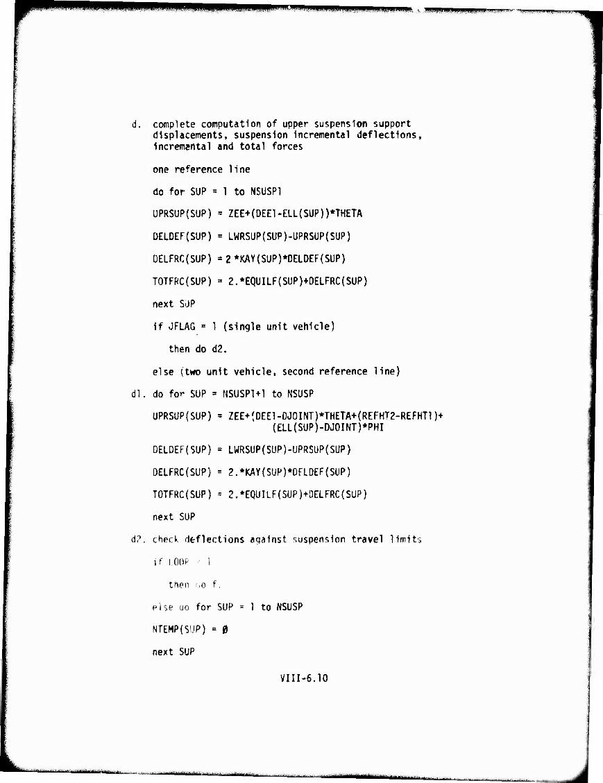
■mrnrn im.ii.iipii.npjia. •."'P'l'iiw "*** i.i|ji|iiinw.iii]i.^^nii1m.t.i!»w[.-J
d. complete computation of upper suspension support displacements, suspension Incremental deflections, Incremental and total forces
one reference line
do for SUP = 1 to NSUSP1
UPRSUP(SUP) = ZEE+(DEE1-ELL{SUP))*THETA
DELDEF(SUP) = LWRSUP(SUP)-UPRSUP{SUP)
DELFRC(SUP) ' 2 *KAY(SUP)*DELOEF{SUP)
TOTFRC(SUP) " 2.*EQUILF(SUP)+DELFRC(SUP)
next SUP
If JFLAG = 1 (single unit vehicle)
then do d2.
else (two unit vehicle, second reference line)
dl. do fo'' SUP * NSUSP1+1 to NSUSP
UPRSUP(SUP) = ZEE+(DEE1-DJ0INT)*THETA+(REFHT2-REFHT1)+ {ELL(SUP)-DJOINT)*PHI
DELDEF(SUP) = LWRSUP(SUP)-1JPRSUP(SUP)
OELFRC(SUP) = 2.*KAY(SUP)*DEL0EF{SUP)
TOTFRC(SUP) = 2.*EQUILF(SUP)+0ELFRC(SUP)
next SUP
(1?. check deflections aqalnst suspension travel limits
if LOOP - 1
then tjo f.
pise oo for SUP - 1 to NSUSP
NTEMP(SüP) = 0
next SUP
VIII-6.10
■- - ■ -a-^- ,. i
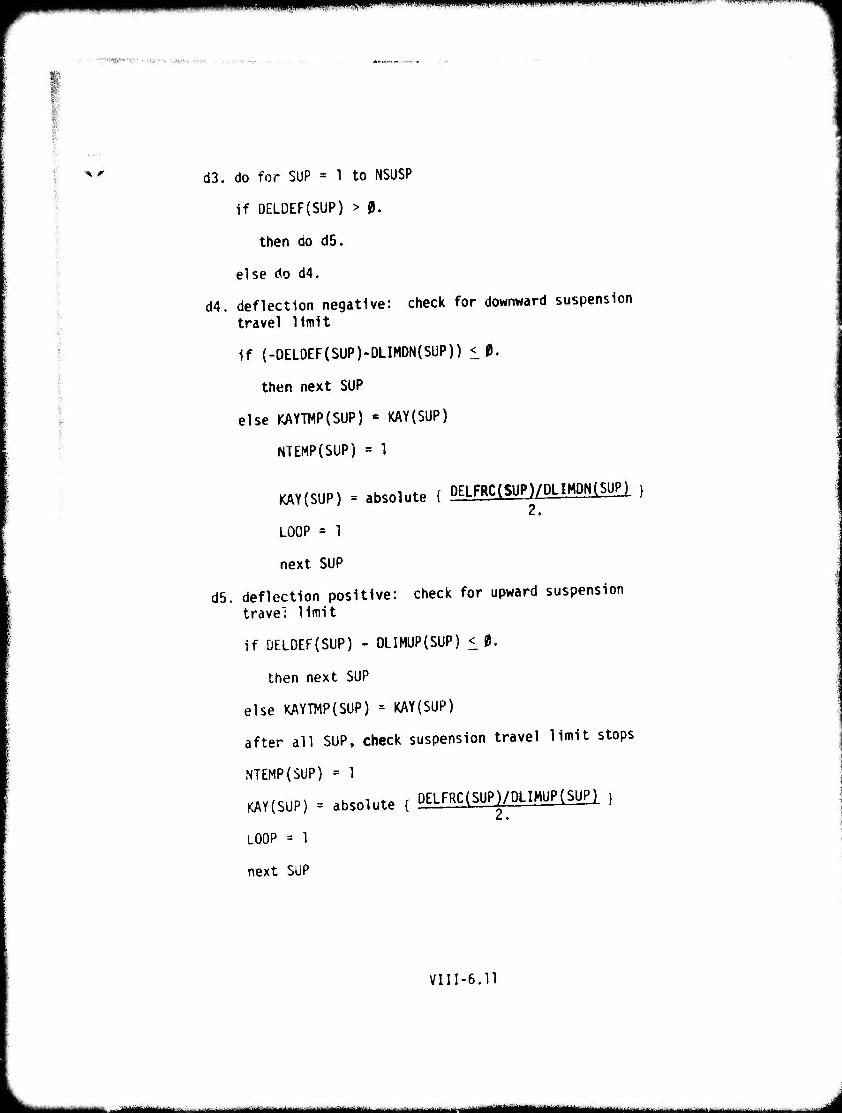
^^W" ^m^m^- >»•■ i "«! •nvrvwrn'r- Km', i-rrw-jprn
■■■■■;<■'*,:■■■*■■<.-■■ . ,.^. -,, ■ „!, .
x r d3. do for SUP = 1 to NSUSP
if DELDEF(SUP) > 0.
then do d5.
else do d4.
d4. deflection negative: check for downward suspension travel limit
if (-DELDEF(SUP)-DLIMDN(SUP)) < 0.
then next SUP
else KAYTMP(SUP) •= KAY(5UP)
NTEMP(SUP) = 1
KAY(SUP) = absolute { DELFRC(SUP)/DLIMDN(SUP) }
2.
LOOP = 1
next SUP
d5. deflection positive: check for upward suspension travel limit
if DELDEF(SUP) - OLIMUP(SUP) < 0.
then next SUP
else KAYTMP(SUP) = KAY(SUP)
after all SUP, check suspension travel limit stops
NTEMP(SUP) = 1
KAY(SUP) = absolute { DELFRC(SUP)/DLIMUP(SUP) } 2.
LOOP = 1
next SUP
VIII-6.11
mm— 11 mm i i IIIH^MIIl A
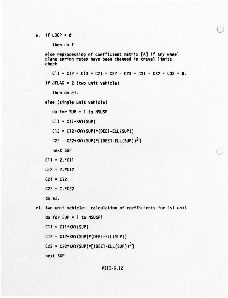
e. if LOOP = l'
tllen do f.
else reprocessing of coefficient matrix [A] 1f any wheel plane spring rates have been r.hanged 1n travel limits check
Cll = C12 ~ C13 • C21 = C22 = C23 = C31 = C32 • C33 = 8.
if JFLAG = 2 (two unit vehicle)
then do el.
else (single unit vehicle)
do for SUP • 1 to NSUSP
Cll = Cll+KAY(SUP)
ClZ = C12+KAY(SUP)*(DEE1-ELL(SUP)}
C22 = C22+KAY(SUP)*[(OEE1-ELL(SUP))2]
next SUP
Cll = 2.*C11
C12 = 2.*Cl2
C21 = Ci2
C22 = 2.*C22
do e3.
el. two unit vehicle: calculation of coefficients for 1st unit
do for 3UP = 1 to NSUSPl
Cll = Cll*KAY(SUP)
C12 :r C'I2+KAY(SUP)*(OEEl-ELL(SUP))
C22 ~ t22*KAY(SUP)*[(DEE1-ELL(SUP)) 2]
next SUP
VI 11-6.12
)
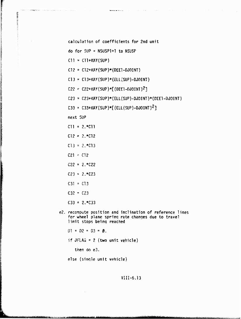
calculation of coefficients for 2nd unit
do for SUP = NSUSP1+1 to NSUSP
Cll = C11+KAY(SUP)
C12 = C12+KAY(SUP)*(DEE1-DJ0INT)
C13 = C13+KAY(SUP)*(ELL(SUP)-DJ0INT)
C22 - C22+KAY(SUP)*[(DEE1-DJ0INT)2]
C23 = C23+KAY(SUP)*(ELL(SUP)-DJ0INT)*(DEE1-DJ0INT)
C33 = C33+KAY(SUP)*[(ELL(SUP)-DJ0INT)2]
next SUP
Cll = 2.*C11
C12 = 2.*C12
C13 - 2.*C13
C21 - C12
C22 = 2.*C22
C23 = 2.*C23
C31 = C13
C32 - C23
C33 = 2.*C33
e2. recompute position and Inclination of reference lines for wheel plane spring rate changes due to travel limit stops being reached
01 = D2 = D3 = 0.
if JFLAG = 2 (two unit vehicle)
then do e3.
else (single unit vehicle)
VIII-6.13
!■— ■ - I I —ll^l ■ -- ._J^^^^»»—^^_-^_
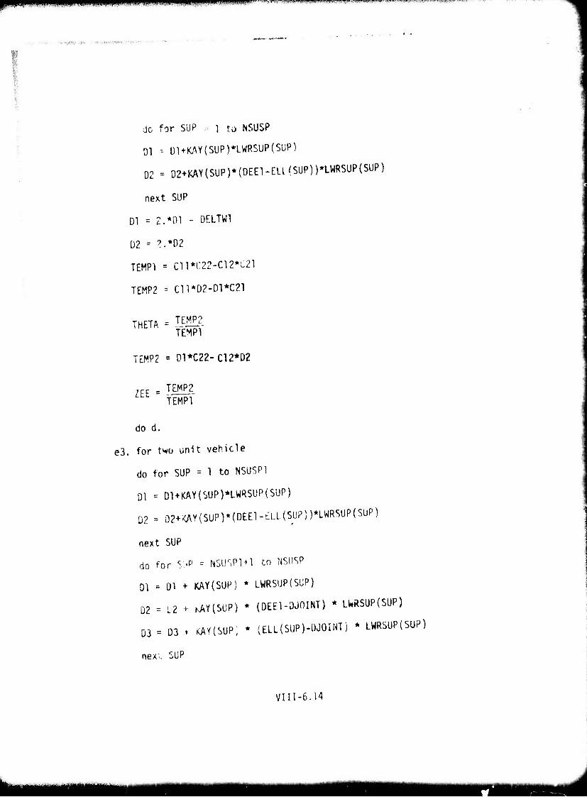
VTPM^^«^ull!.upMfl|H|)ll|ning^^^riMjniJl...MriUl«7>R>*lt'1' flW'^ f mwwwtu ti.mm.}UWW' un w ~^rr-
,. ..t/,^,- .>•, ■-. .-vI-'.*W*-'" '■ ■
do for SUP -■ i to NSUSP
Dl -- Ül + WY(SUP)*LWRSUP(S,ÜP)
D2 - D2+KAY(SUP)*(DEE1-ELI(SUP))*LWRSUP(SUP)
next SUP
Dl = 2.*D1 - 0ELTW1
02 = ?.*D2
TEMPI = C11*C22-C12*C21
TEMP2 = Cn*02-Dl*C21
TEMP2 TEMPI
THETA
TEMP2 = 01*C22-C12*D2
ZEE TEMP_2 TEMPI'
do d.
e3. for two unit vehicle
do for SUP = 1 to NSUSP1
01 - D1+KAY(SUP)*LW«SUP(SUP)
02 = Ö2+<AV(SÜP)*(DEE1-£LL(SUP))*LWRSUP(SÜP)
next SUP
do for S'JP - NSUr,Pl + l to NSUSP
Dl = Dl + KAY(SUP) * LWRSUP(SÜP)
D2 = L2 + KAY(SUP) * (DEEl-QjniNT) * LWRSUP(SUP)
03 = D3 t KAYISUP, * (ELL{SUP)-DJ0INT) * LWRSUP(SUP)
nexi SUP
VIII-6.14
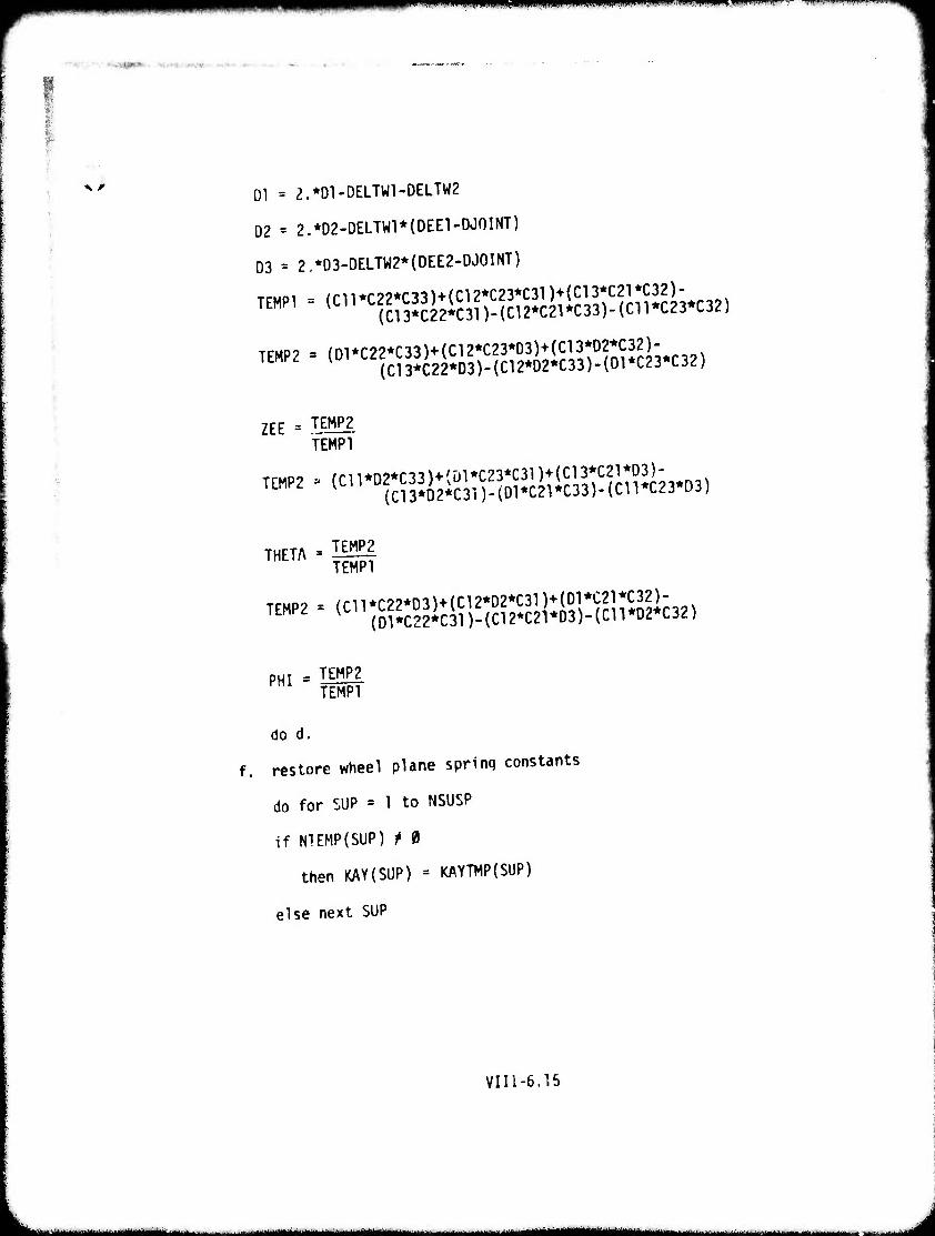
*~***i™mmmm ■ i»11 >'
%, * Dl = 2.*01-DELTW1-DELTW2
D2 = 2.*02-DELTWl*(OEEl-OJOINT)
D3 = 2.*D3-DELTW2*(DEE2-DJ0INT)
TEMPI = (C11*C22*C33)+(C12*C23*C31)+(C13*C21*C32)- (C13*C22*C31)-(C12*C21*C33)-(C11*C23*C32)
TEMP2 ' (D1*C22*C33)+(C12*C23*03)+(C13*D2*C32)- (C13*C22*03)-(C12*D2*C33)-(01*C23*C32)
ZEE = TEMP2
TEMPI
mn . (CU.O.C^^.m.HCm^;.,-^^
-™ • ?m TEMP2 = (C11*C22*D3)+(C12*02*C31)+(D1*C21*C32)-
(Dl*C22*C31)-{C12*C21*D3)-(Cn*D2*C32
PHI
do d.
TEMP2 TEMPI
restore wheel plane sprinq constants
do for SUP = 1 to NSUSP
if NIEMP(SUP) t 0
then KAY(SUP) = KAYTMP{SUP)
else next SUP
VIIl-6.15
- -- . - i ■MMMMMMBIMMt
HM^MHMMiMMMMMHMMM J
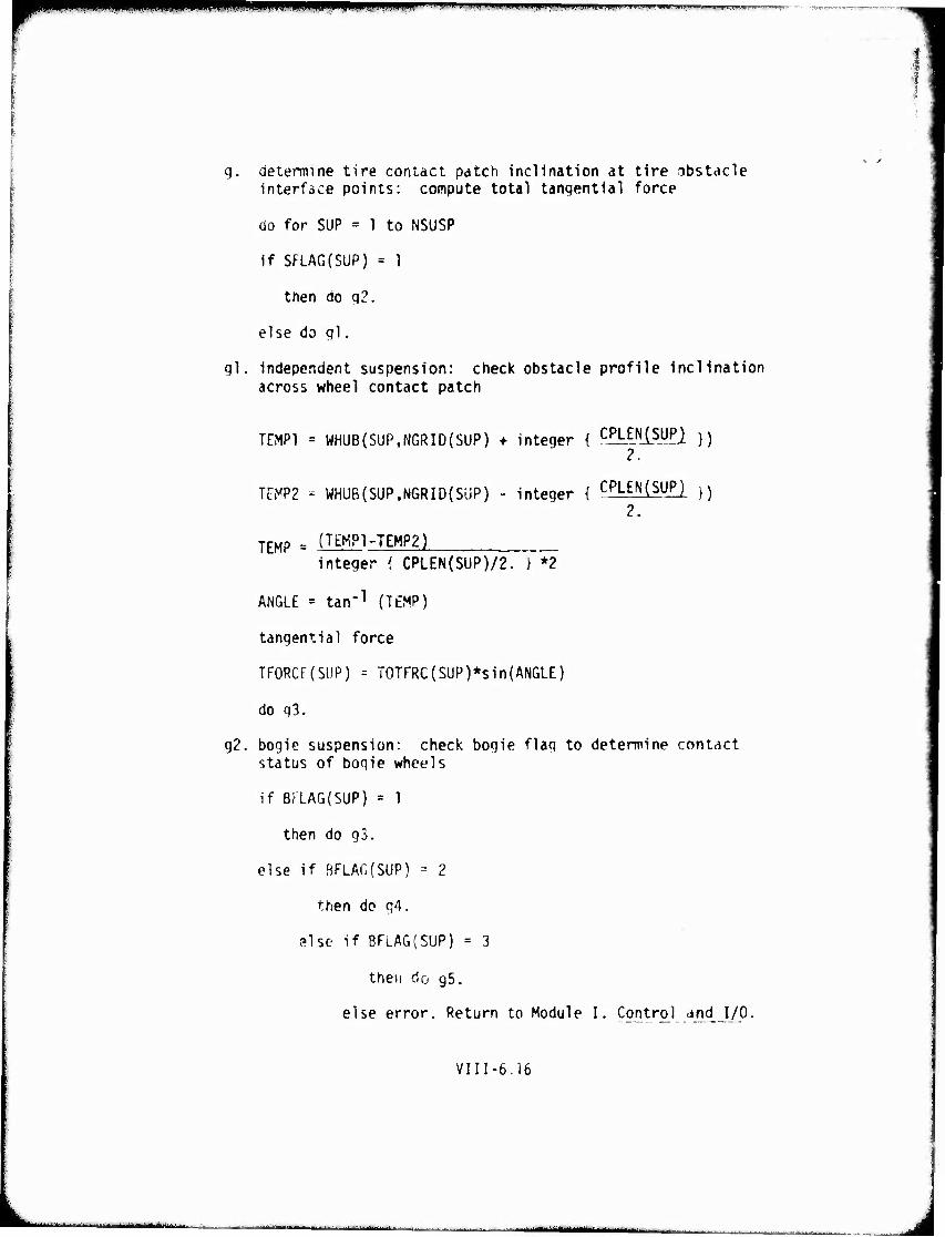
|PPpl«?f*«^i LI ILIJ.^WHIipi i ii. i.i.,, ^.■';i .*^i. imqum '.w—.1. nm ■■iiwwiMrj'.'i.-^^1^'
g. determine tire contact patch inclination at tire obstacle interface points: compute total tangential force
do for SUP = 1 to NSUSP
if SFLAG(SUP) = 1
then do q2.
else do ql.
ql. independent suspension: check obstacle profile inclination across wheel contact patch
TEMPI = WHUB(SUP.NGRID(SUP) ♦ integer { c£kE_NlsJJfl }) 2.
TEMP2 - WHüB(SUP,NGRID{SüP) - integer { CPLEN(SUH }) 2.
TEMP = (T^°1-TEMP2) integer { CPLEN(SUP)/2. } *2
ANGLE = tan"1 (TEMP)
tangential force
TFORCf(SLiP) - T0TFRC( SUP )*s in (ANGLE)
do q3.
g2. bogie suspension: check bogie flag to determine contact status of bogie wheels
if BFLA6(SUP) = 1
then do g3.
else if BFLAG(SUP) = 2
then do q4.
slse if BFLAG(SUP) = 3
then do g5.
else error. Return to Module I. Controj and I/O.
VIII-6.16
MMMAMaflMt^^MM^aMMO^.
mmm ^m "Wpw^wp^WWSWiwi
"r-'':-' ■ ■•■t^D/m-'y- . -'•■■::»•;-( r-.,,.v.
g3. both wheels in contact
TEMP1. ' WHUB(SUP, NGRID(SUP) - integer { BWIDTH(SUP)/2 } + integer [ CPLEN(SUP)/2 } )
TEMP2 » WHUB{SUP, NGRID(SUP) - Integer { BWIDTH(SUP)/2 } - Integer { CPLEN(SUP)/2 } )
TEMP = (TEMPI - TEMP2 )
Integer { CPLEN(SUP)/2 } * 2
ANGLE = tan-1(TEMP)
tangential force, forward wheel of bogie
TFORCE(SUP) = TOTFRC(SUP) * sin(ANGLE)
compute and add tangential force of rearward wheel
TEMPI = WHUB(SUP, NGRID(SUP) + integer { BWIDTH(SUP)/2 ) + integer { CPLEN(SUP)/2 ) )
TEMP2 = WHUB(SUP. NGRID(SUP) + integer { BWIDTH(SUP)/2 } - Integer { CPLEN(SUP)/2 ) )
TEMP = (TEMPI - TEMP2) integer { CPLEN(SUP)/2 }
ANGLE = tan"1(TEMP)
tangential force, both wheels of bogie
TFORCE(SUP) = TFöRCE(SUP) + TOTFRC(SUP) * sin(ANGL£)/2
next SüP: after all SUP, do h.
g4. forward bogie wheel in contact only
TEMPI = WriUB(SUP, NGRID{SUP) - integer { BWIDTH(SUP)/2 I + integer { CPLEN(SUP)/2 i )
TEMP2 = WHUB(SUP, NGRID(SUP) - integer { BWIDTH(SUP)/2 I - integer ( CPLEN(SUP)/2 } j
TEMP = (TEMPI - TEMP2)
integer { CPLEN(SUP)/2 }* 2
VI1I-6.17
^^^ — — MtfHNMMWMlMHMiaM^ ■
iinnji.iipiiiHi.,imiMiMMWij,iiu|inp ''"- > •.»«•• *■" ^n.wiwi.i'H-tfti
ANGLE -- tan"1 (TEMP)
TFORC£(SUP) - TOTFRC(SuP) * sin(ANGLE)
next SUP: after all SUP, do h.
gb. rearward boqie wheel in contact only
TEMPI = WHUQ(SUP, NGRID(SUP) + integer { BWIDTH(SUP)/2 } + integer { CPL£N(SUP)/2 ) )
TEMP2 = WHUB(SUP. NGRID(SUP) + integer { BWIDTH(SUP)/2 } - integer { CPLEN(SUP)/2 } )
TEMP - (TEMPI - TEMP2}
integer ( CPLEN(SUP)/2 } *2
ANGLE = tan"1(TEMP)
TFORCE(SUP) = TOTFRC(SUP) * sin(ANGLE)
next SUP
sum the tangential forces over all the suspension supports for the present orientation of the vehicle and obstacle
TEMP - 0.
do for SUP = 1 to NSUSP
TEMP = TEMP+TFORCE(SUP)
next SUP
TFSUM(IGRID) = TEMP
compare present clearance contour with the obstacle profile: retain algebraically the minimum clearance at each point along the vehicle contour
fl -■ F2 - 0.
do for SUP - 1 to NSUSP1
Fl » F'l t tFrRAO(SUP)
next SUP
ViiI-6.18
■■
; ■■• -PrJiKT'-y
4/ F2 = F1/NSUSP1
do for INCH « 1 to NJOINT In steps of JGRID
TEMP * ZEE+REFHT1-F2(DEE1-(INCH-1))*THETA+REFCLC(1,INCH)- WPRF(INCH)
if TEMP - MINCLR(INCH) < 0.
then MINCLR(INCH) = TEMP
LOC(INCH) = IGRID
ITEMP = INCH
next INCH
else ITEMP = INCH
next INCH
If JFLAG ' 1 (single unit vehicle)
then do j
else (JFLAG = 2, two unit vehicle)
F3 - F4 -- 0.
do for SUP => NSUSP1+1 to NSUSP
F3 = F3 + EFFRAD(SUP)
next SUP
F4 = F3/(NSUSP-NSUSP1)
do for INCH = ITEMP+JGRID to NPTSGR In steps of JGRIÜ
TEMP = ZEE+REFHT2-F4+(DEE1-DJ0INT)*THETA+(INCH-1-DJ0INT)* PHI+REFCLC(2,INCH)-WPRF(INCH)
if TEMP - MINCLR(INCH) < 0.
then HINCLR(INCH) = TEMP
LOC(INCH) «= IGRID
next INCH
else next INCH
VIII-6.19
1 . |<^MM|MMgatt||||||| ^ J

check end of obstacle override position
if IGRID < NPTSOB
then do b.
else do k.
find CLRMIN and LOCA
do for INCH = 1 to NPTSGR in steps of JGklü
if CLRMIN(NH,NA,NW) < MINCLR(INCH)
then next INCH
elce CLRMIN(NH.NA,NW) = MINCLR(INCH)
LOCA(NH,NA,NW) = LOC(INCH)
next INCH
Vlll-t.ZO
J
pipn i ■üBPP MK'.I-.UJI ■Mil ^■^ipfl,.^ffFVfpy/,^J'l^l?'W|yM»Tg'W.V '"l'KP'tff^ ^ ■■.'■ ■■■ff'-'WU '■■'■■r '■' T^w^qry^^^^^vly»r.'?ff'"ffm^:'■'T!^WffrTI^^:;■^^' '"
^M^MMMRmv ,'«KW#IMOr*«i»,*,nv»ww..-- .
i %* 7. Maximum and Average Force to Override an Obstacle
I:
Description This routine determines the average (F00) and maximum (FOOMAX) forces required during the entire override of an obstacle. In previous routines, obstacle negotiation has been addressed via the solution of the static equa- tions of equilibrium fo-mulated using an energy approach, specifically, the Lagrangian. Since this energy method presupposes a conser- vative system, energy losses due to viscous and frictional elements in the vehicle suspension and elsewhere are not treated analytically In the equations thus formed. To accorrmodate for these energy losses an estimate is made for the amount of recoverable energy in the system for complete negotiation of the obstacle. Truly, this rebound attenuation factor (RAF) is a ball park estimate based on the Model Designers' best aUempts at estimating without resorting to a time consuming dynamics solution. The positive valued tire-obstacle tangential forces are attenuated for the energy losses. A value of 1/2 is used for RAF.
vin-7.1
mm ■ .. [. J.-!-l.-...Ui^.^ mm mm'Mti . jÄÜli*-^ :..-
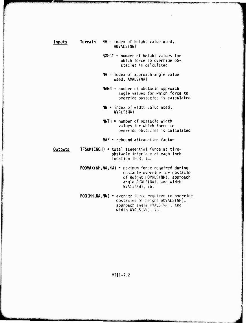
rmwm ^^^^^1 MJIiiPII.IIHi.illPHpi.. , .' ^ .'..liin.pwi minmnji.a IHH»' iifimi .:uii.iRiiaHiiiiiiaii..ai> .w.^nmnciii "ii.wfjfi.:.
Inputs Terrain: NH = index of height value u:ed, HOVALS(NH)
NOHGT - number ot" heiqht Vcilues for which force to override ob- stacles is calculated
Outputs
NA = index of approach angle value used. AVALS(NA)
NANG = number of obstacle approach angle values for which force to override obstacles is calculated
NW = index of width value used, WVALS(NW)
NWTH = number of obstacle width values for which force to override obstacles is calculated
RAF r rebound attenuation factor
TFSUM(INCH) = total tangential force at tire- obstacle interface at each inch location INCH, lb.
F00MAX(NH,NA,NW) * maximum force required during oDitacle override for obstacle of height HOVALS(NH), approach ang'ie AVALS(NA), and width WVALSfNW), lb.
FOO(MH.NA.NW) average force required to override obstacles of heigh' HGVALS{NH), approach angle AVALS(NA), and width WVALS(NWj, lb.
VIII-7.Z
■■■-■■•■"-- • nin -i >t m mmaiin «ii.miSäiit a jf mjuq.^; .; L. liit^-v. A::. ^ h,-,. ■•.>^..;,.,...--.:- v .- ■■
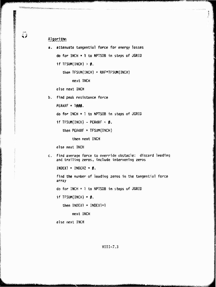
pn iniaii, n(...[.i.iiuimviimi»<ii mum wmwwpffiip^w
Algorithm
a. attenuate tangential force for energy losses
do for INCH » 1 to NPTSOB in steps of J6RID
if TFSUM(INCH) > 0.
then TFSÜM(INCH) = RAF*TFSUM(INCH)
next INCH
else next INCH
b. find peak resistance force
PEAKRF « 1000.
do for INCH = 1 to NPTSOB in steps of JGRID
if TFSUM(INCH) - PEAKRF < 0.
then PEAKRF = TFSUM(INCH)
then next INCH
else next INCH
c. find average force to override obstac'ie: discard leading and trailing zeros, include intervening zeros
INDEX! * INDEX2 = 0.
find the number of leading zeros in the tangential force array
do for INCH = 1 to NPTSOB in steps of JGRID
if TFSUM(INCH) = 0.
then INDEX1 = INDEX1+1
next INCH
else next INCH
VIII-7.3
MMMHtiM iitr •Mii-iii" ■•''■—■-"■'<'■ ■■.■■-.
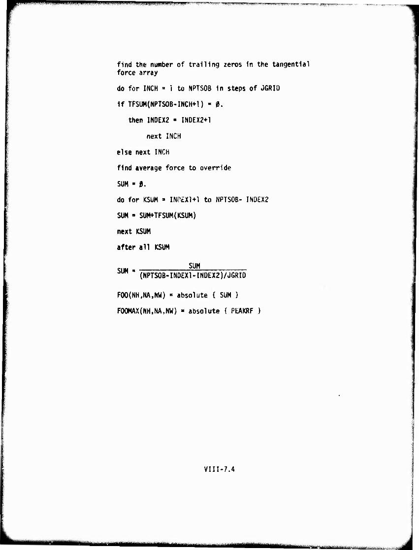
^OTW^Mm^^^mn^^^^wnwpvM.i , , , „,.,. «„.p^,,, F ,IW ,—■^■■n ■■.!■.... ..^.^ ,—.
find the number of trailing zeros in the tangential force array
do for INCH ' 1 to NPTSOB in steps of JGRID
If TFSUM(NPTSOB-INCH+1) • 0.
then INDEX2 ■ INDEX2+1
next INCH
else next INCH
find average force to override
SUM ■ a.
do for KSUM - INn£Xl+l to NPTSOB- INDEX2
SUM • SUMfTFSUM(ICSUM)
next KSUM
after all KSUM
SUM SUM "" (NPTS0B-INDEX1-INDEX2)/JGRI0
F0O(NH<NA,NW) « absolute { SUM }
F00MAX{NH,NArNW) » absolute { PtAKRF }
VIII-7.4
' MI miwim ■irHMt«iiMiiiiMriiiai'li-rx'ata«aidafe^^^ma^.,
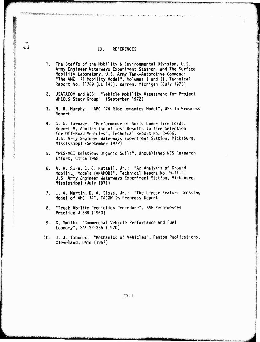
t
BpWWIIWP^r'."lWiiW^J.>iniiiw»l»i^ln ■i.|H.iiHHln.,^f>MHm..im. ii]i.iii|ini JI.HIIJIIIIII.I i.i,ui|ii m/mgi m —jtwr
i)
-AAJW. ■ •*"- ■ « .-O.-. T»4 .
IX. REFERENCES
1. The Staffs of the Hublllty & Environmental Division, U.S. Army Engineer Waterways Experiment Station, and The Surface Mobility Laboratory, U.S. Amy Tank-Automotive Command: "The AMC '71 Mobility Model". Volumes I and II, Technical Report No. 11789 (LL 143), Warren, Michigan (July 1973)
2. USATACOM and WES: "Vehicle Mobility Assessment for Project WHEELS Study Group" (September 1972)
3. N. R. Murphy: "AMC '74 Ride Dynamics Model". WES In Progress Report
4. G. W. Turnage: "Performance of Soils Under Tire Loads, Report 8, Application of Test Results to Tire Selection for Off-Road Vehicles", Technical Report No. 3-666, U.S. Army Engineer Waterways Experiment Station, Vicksburg. Mississippi (September 1972)
5. "WES-VCI Relations Organic Soils", Unpublished WES Research Effort, Circa 1968
6. A. A. rsUia, C, J. Nuttall, Jr.: "An Analysis of Ground Mobility Models (ANAMOB)", Technical Report No. M-71-4. Ü.S Army Engineer Waterways Experiment Station, Vicksburg. Mississippi (July 1971)
7. L. A. Martin, D. A. Sloss. Jr.: "The Linear Feature Crossing Model of AMC '74", TACOM In Progress Report
I 8. "Truck Ability Prediction Procedure", SAE Recommended
Practice J 588 (1963) v
9. 6. Smith: "Commercial Vehicle Performance and Fuel Economy", SAE SP-355 (1970)
10. J. J. Taborek: "Mechanics of Vehicles", Penton Publications, Cleveland, Ohio (1957)
IX-1
I - u,uiimmmm*^****mk****L**.—..-
WP^^PÜ^PW iiii»i)i(ii:iii..ij iiii|j|.nijn!iqnmm<^n"^'wi<i."i l""11 JWWI""1 mmmi'm'«lmviw,'v-'"
->■' ■ ■■ m«MN»<ira»>7«»»«««tawwKui. ■■ ■ . ,.,,r'..
^V
APPENDIX
VEHICLE DATA
SHEETS
A-l
■ iiiiifiMilMBihPiil i iifn«—■■-- I —- i—~ mm
•w 11 i mmmmmm ■VHP
VEHICLE DATA SHEET INSTRUCTIONS
The vehicle data sheets for AMC '74 have been revised to provide for greater clarity and convenience to the user In filling them out. Most vehicle component and/or overall vehicle data appearing on the data sheets can be located from standard vehicle characteristic sheets or catalogues (e.g., Tire and Rim Association, Inc. Yearbook) using the nomenclature found in these sources. With the exception rf the water characteristics. Item 5., little or no computation is necessary on the part of the user.
Tne data sheets are structured to minimize human blun- ders in both filling out the sheets and transcribing the data from these sheets to a computer file. Line items are right justified where necessary and double spaced.
Prior to filling out the data sheets, a user is requested to read the Introductory write-up in Module II, Vehicle Preprocessor, to acquaint him with the vehicle nomenclature used throughout AMC '74. Also, it is recommended that the user review the Vehicle Data Cross Index to assure that all data required are entered. At this writing, some of the vehicle data appearing on the sheets are not required but will be used at a later date. However, if these data are available, it is advised that they be provided (e.g., horsepower loss curves, auxiliary transmissions in the final drive).
Item 8, Input From Ride Dynamics Module, is included since these data could be obtained from experimental tests. The experimental data are preferred over the data obtained from the simulation performed in Module VII, Ride Dynamics.
The buoyancy characteristics in Item 5 require a knowledge of the vehicle density distribution with vehicle height. This form of data would be extremely difficult to build in the vehicle preprocessor for an arbitrary vehicle and is, therefore, loft to the user to provide.
A-2
-'■ --'—- - - ■ ■ J
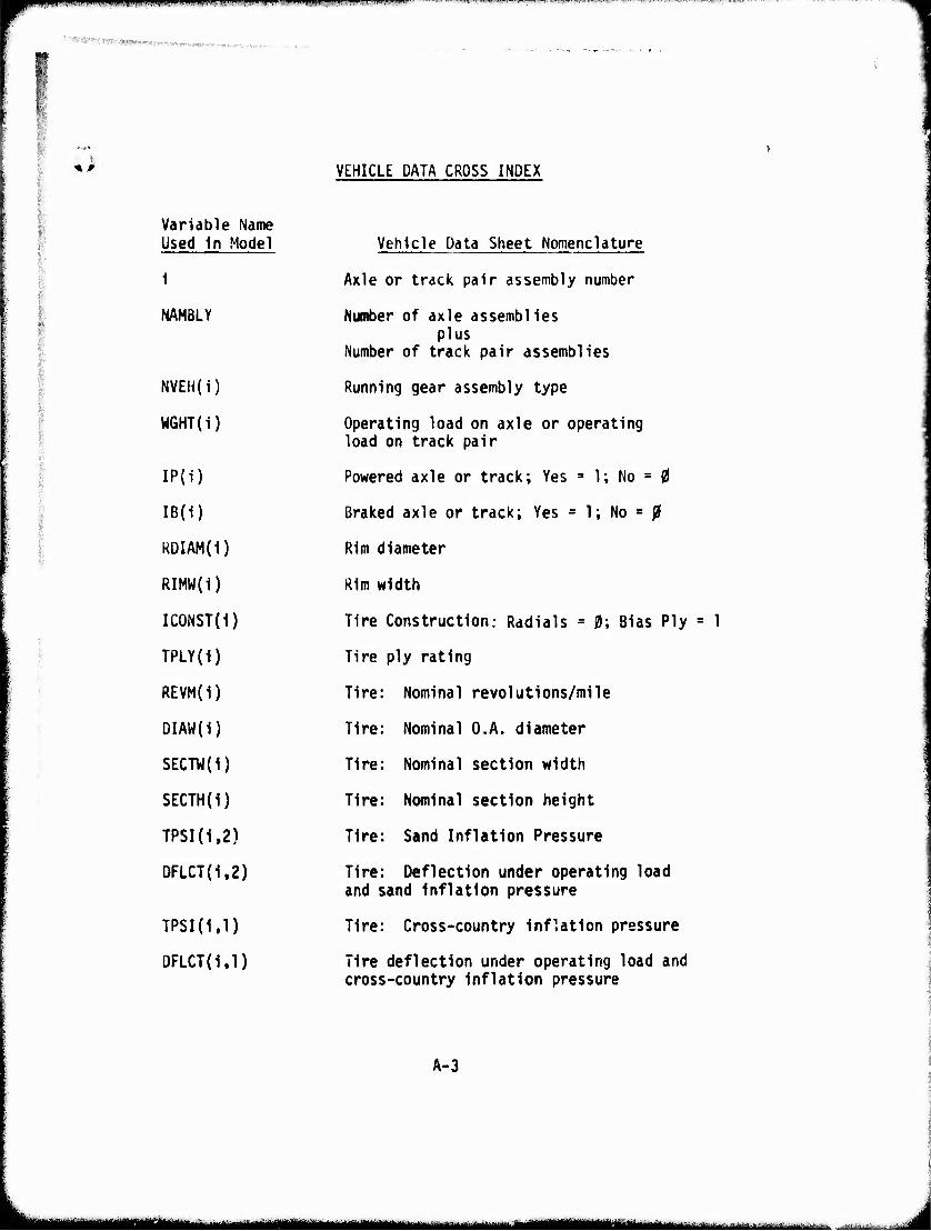
■^^T^^l.'! 1»^"M" "Wj.^WF^^W I^V«'" (I.UIli.-^ ^"^r-T^-^l M limq UIJWI.HH«« III,!! III ■IMIIJ g , ■llilll ,1.1.
''^'«^■■"^-tiw»—->■.
^ A VEHICLE DATA CROSS INDEX
;■
Variable Name Used In Model
1
NAHBLY
1
NVEH(i)
WGHT(i)
;/
IP(i) i
IB(1)
l RDIAM(1)
RIMW(1)
ICONST(i) i ■■■■
■■ TPLY(1) :
REVM(i)
i DIAW{i)
SECTW(1)
SECTH(1)
TPSI(i.2)
DFLCT(i.2)
TPSKl.l)
DFLCT(l.l)
Vehicle Data Sheet Nomenclature
Axle or track pair assembly number
Number of axle assemblies plus
Number of track pair assemblies
Running gear assembly type
Operating load on axle or operating load on track pair
Powered axle or track; Yes = 1; No = 0
Braked axle or track; Yes = 1; No = 0
Rim diameter
Rim width
Tire Construction: Radials = 0; Bias Ply
Tire ply rating
Tire: Nominal revolutions/mile
Tire: Nominal O.A. diameter
Tire: Nominal section width
Tire: Nominal section height
Tire: Sand Inflation Pressure
Tire: Deflection under operating load and sand inflation pressure
Tire: Cross-country inflation pressure
Tire deflection under operating load and cross-country inflation pressure
= 1
A-3
aMMUÜ ^^MHHHÜ ■Hi
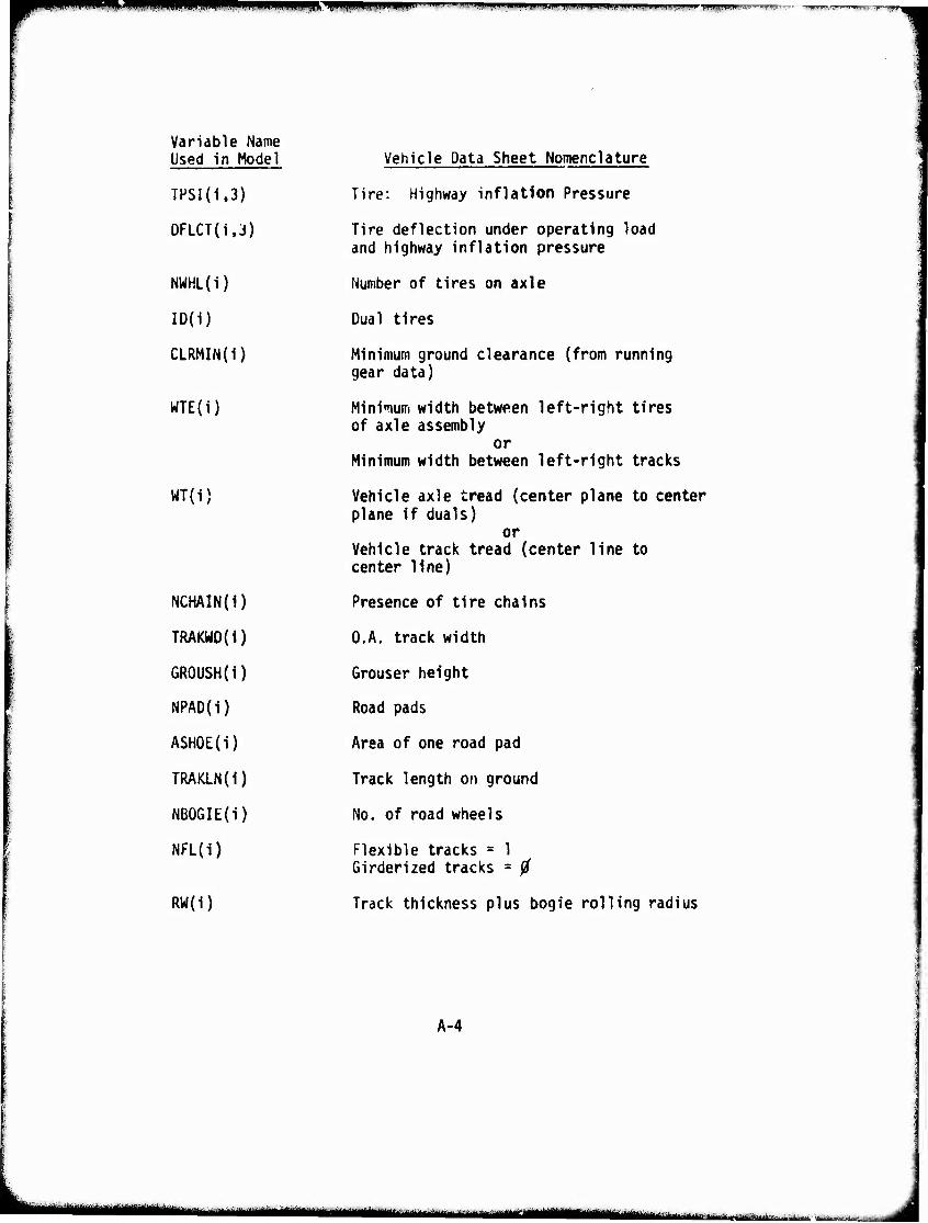
^M^ Bpii ' ' ■'i|l^iwi'i «ii^i»i'i.<i W)»..IIHJW up.i.i»ij»j»rwiui,iniinw inw,vm»".-
Variable Name Used in Model
TPSI(1,3)
DFLCT(i.j)
NWHL(i)
ID(i)
CLRMIN(I)
WTE(i)
WT{i)
NCHAIN(I)
TRAKWD(I)
GROUSH(i)
NPAD(i)
ASHOE(i)
TRAKLN(1)
NB06IE{i)
NFL(i)
RW(1)
Vehicle Data Sheet Nomenclature
Tire: Highway inflation Pressure
Tire deflection under operating load and highway inflation pressure
Number of tires on axle
Dual tires
Minimum ground clearance (from running gear data)
Minimum width between left-right tires of axle assembly
or Minimum width between left-right tracks
Vehicle axle tread (center plane to center plane if duals)
or Vehicle track tread (center line to center line)
Presence of tire chains
O.A. track width
Grouser height
Road pads
Area of one road pad
Track length on ground
No. of road wheels
Flexible tracks = 1 Girderized tracks = 0
Track thickness plus bogie rolling radius
A-4
^„tmtfHuttmttmm iMtMM^KJMMUHM üBMiiiitii iiBim i '-—*■■"■
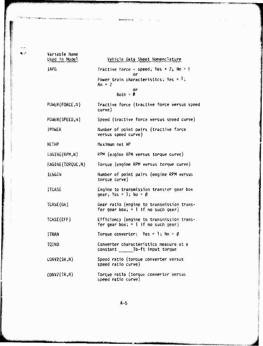
mn ' i! *mm """'■""W lyi .HJIII.... pp ■W) m.- IILJI. ■ nij.n i.f.mtn
'■«•■ •■ ■'-wr,^.. .. t«r-««MiV W%*. rv*^. -
Variable Name Used in Model
IAPG
| i i
PÜWtR(FORCE,N)
POWtR(SPEED,W)
IPOWER
NETHP
ENGINE{RPM,N)
F.NGINE(TORQUE,N)
I ENGIN
ITCASE
TCAi>E(Gk)
TCASE(EFF)
ITRAN
TQIND
C0NV2(SR,N)
C0NV2(TR,N)
Vehicle Data Sheet Nomenclature
Tractive force - speed, Yes « 2; No = 1 or
Power train characteristics; Yes = '; No = 2
or Both = 0
Tractive force (tractive force versus speed curve)
Speed (tractive force versus speed curve)
Number of point pairs (tractive force versus speed curve)
Maximum net HP
PPM (e.igine RPM versus torque curve)
Torque (engine RPM versus torque curve)
Number of point pairs (engine RPM versus torque curve)
Engine to transmission transfer gear box gear. Yes = 1; No = 0
Gear ratio (engine to transmission trans- fer gear box; =1 if no such gear)
Efficiency (engine to transmission trans- fer gear box; =1 if no such gear)
Torque converter: Yes = 1; No - 0
Converter characteristics measure at a constant Ib-ft input torque
Speed ratio (torque converter versus speed ratio curve)
Torque ratio (torque converter versus speed ratio curve)
A-5
-—'-■'nil mum gumn mmm
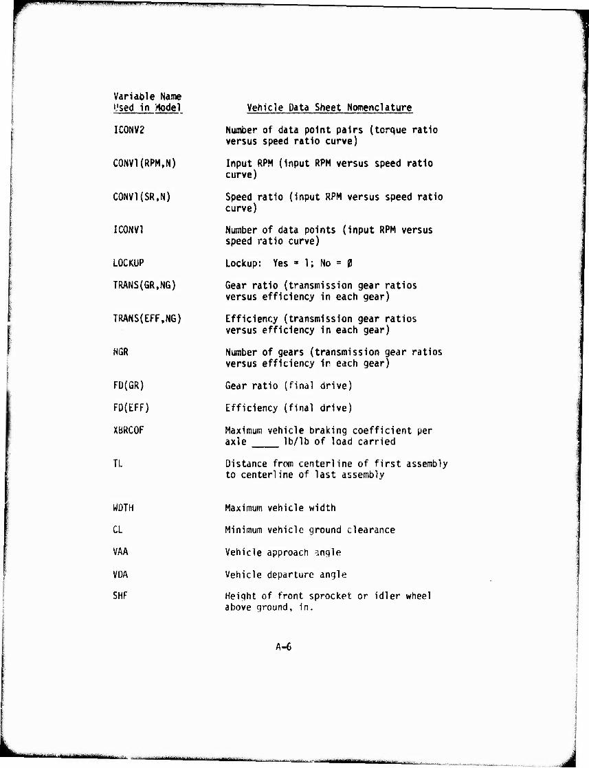
I I i. I» I ii Hi, I ii MMI^IIJII in, I.I.IIHII 1.111.,^,.
Variable Name Used in Mode}
IC0NV2
C0NV1(RPM,N)
C0NV1{SR,N)
IC0NV1
LOCKUP
TRANS(GR,NG)
TRANS(EFF,NG)
NGR
Fü(GR)
FO(EFF)
XBRCOF
TL
Vehicle Data Sheet Nomenclature
Number of data point pairs (torque ratio versus speed ratio curve)
Input RPM (input RPM versus speed ratio curve)
Speed ratio (input RPM versus speed ratio curve)
Number of data points (input RPM versus speed ratio curve)
Lockup: Yes 3 1; No = 0
Gear ratio (transmission gear ratios versus efficiency in each gear)
Efficiency (transmission gear ratios versus efficiency in each gear)
Number of gears (transmission gear ratios versus efficiency ir each gear)
Gear ratio (final drive)
Efficiency (final drive)
Maximum vehicle braking coefficient per axle lb/lb of load carried
Distance from centerline of first assembly to centerline of last assembly
WDTH
CL
VAA
VDA
SHF
Maximum vehicle width
Minimum vehicle ground clearance
Vehicle approach angle
Vehicle departure angle
Height of front sprocket or idler wheel above ground, in.
A-6
I '"" IMMBlMIMMai^i ^tn^tam '■-'-■ mi aa—aMMBiMMaftü
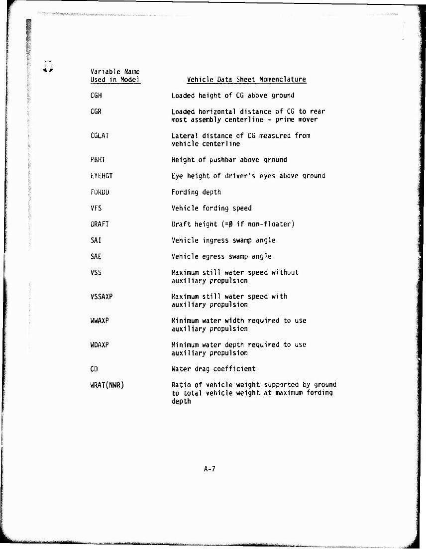
■'' ■■ Ä!*i*w^W I ■ mm» im - ■'■
;■
>
Variable Name Used in Model
CGH
CGR
CGLAT
PbHT
LYtHGT
FURUÜ
VFS
DRAFT
SAI
SAE
VSS
VSSAXP
WWAXP
WDAXP
CD
WRAT(NWR)
Vehicle Data Sheet Nomenclature
Loaded height of CG above ground
Loaded horizontal distance of CG to rear most assembly centerline - pnme mover
Lateral distance of CG measured from vehicle centerline
Height of pushbar above ground
Lye height of driver's eyes above ground
Fording depth
Vehicle fording speed
Draft height (=0 if non-floater)
Vehicle ingress swamp angle
Vehicle egress swamp angle
Maximum still water speed without auxiliary propulsion
Maximum still water speed with auxiliary propulsion
Minimum water width required to use auxiliary propulsion
Minimum water depth required to use auxiliary propulsion
Water drag coefficient
Ratio of vehicle weight supported by ground to total vehicle weight at maximum fording depth
A-7
..^.- ^^/.^-rtfy^MMiVi-l-tf.L'a-M'.,.,■,■--. juinggyym^fc^ iMBMaa ■t.,-.1riJ....^...^.:^,-........:■ --.--u
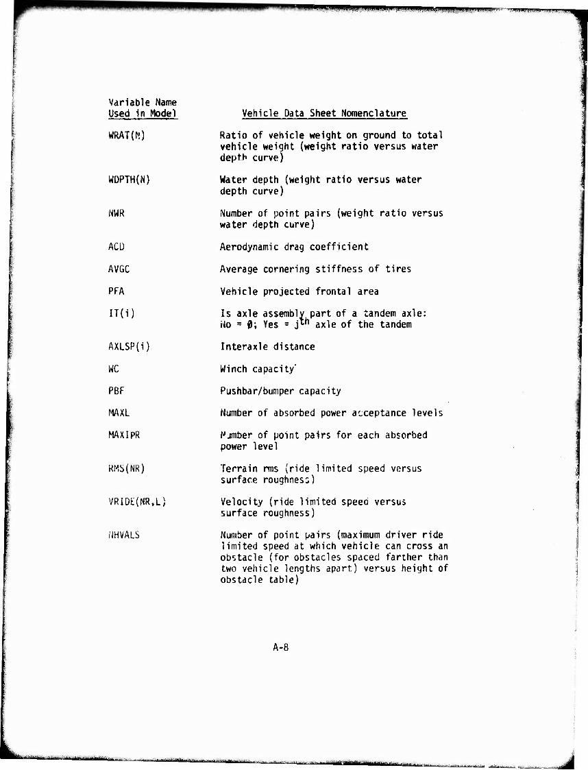
^^H*^m*>*^mm
Variable Name Used in Model
WRAT(N)
WDPTH{N)
NWR
ACÜ
AVGC
PFA
IT{i)
AXLSP(i)
WC
PBF
MAXL
MAXIpR
RMS(NR)
VRIDE(NR,L)
NHVALS
Vehicle Data Sheet Nomenclature
Ratio of vehicle weight on ground to total vehicle weight (weight ratio versus water depth curve)
Water depth (weight ratio versus water depth curve)
Number of point pairs (weight ratio versus water depth curve)
Aerodynamic drag coefficient
Average cornering stiffness of tires
Vehicle projected frontal area
Is axle assembly part of a tandem axle: No =0; Yes = j*" axle of the tandem
Interaxle distance
Winch capacity"
Pushbar/bumper capacity
Number of absorbed power acceptance levels
Njmber of point pairs for each absorbed power level
Terrain rms (ride limited speed versus surface roughness)
Velocity (ride limited speed versus surface roughness)
Number of point pairs (maximum driver ride limited speed at which vehicle can cross an obstacle (for obstacles spaced farther than two vehicle lengths apart) versus height of obstacle table)
A-8
I MMjMm iMmr,„., i iinfrj^j^^^ ■ , xU.ä-'äu.mMiikm -.^~-.;.,.-J T..^ ||| mum UMHltf mmm mmam .,^_^,.
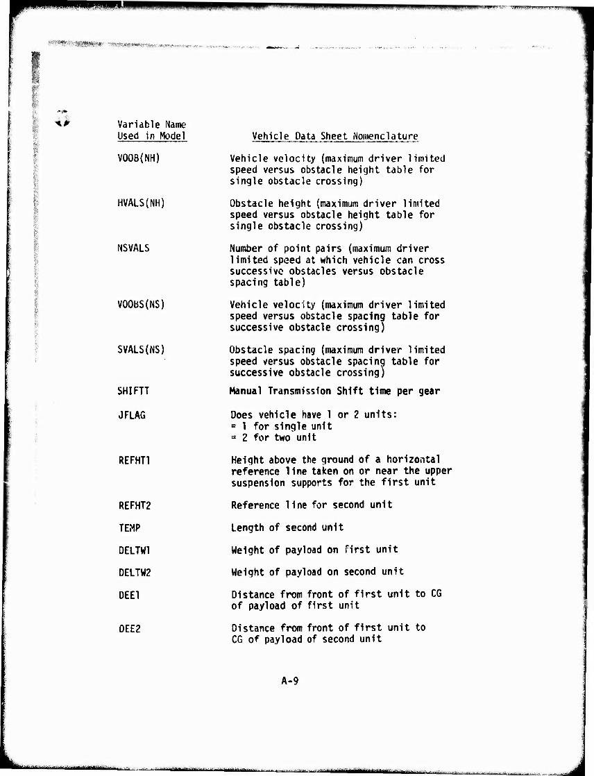
wm w^mm mmm inmm",m9>.•■'*■■:- ■
wmmmmm*. "mmmmmm WflV^T^f ^(AVip* vwif-i^r-- 9, (^ »„.* ,^,^1..
:' AM Variable Name Used in Model
VOOB(NH)
HVALS(NH)
NSVALS
VOOBS(NS)
SVALS(NS)
SHIFTT
JFLA6
REFHT1
REFHT2
TEMP
DELTW1
DELTW2
DEE1
DEE2
Vehicle Data Sheet Nomenclature
Vehicle velocity (maximum driver limited speed versus obstacle height table for single obstacle crossing)
Obstacle height (maximum driver limited speed versus obstacle height table for single obstacle crossing)
Number of point pairs (maximum driver limited speed at which vehicle can cross successive obstacles versus obstacle spacing table)
Vehicle velocity (maximum driver limited speed versus obstacle spacing table for successive obstacle crossing)
Obstacle spacing (maximum driver limited speed versus obstacle spacing table for successive obstacle crossing)
Manual Transmission Shift time per gear
Does vehicle have 1 or 2 units: = 1 for single unit = 2 for two unit
Height above the ground of a horizontal reference line taken on or near the upper suspension supports for the first unit
Reference line for second unit
Length of second unit
Weight of payload on first unit
Weight of payload on second unit
Distance from front of first unit to CG of payload of first unit
Distance from front of first unit to CG of payload of second unit
A-9
■ ■■I..MI-' ■ ■■ ' ^ •■- -■ ■ ■ ■ --- ' IIM—It- Ill
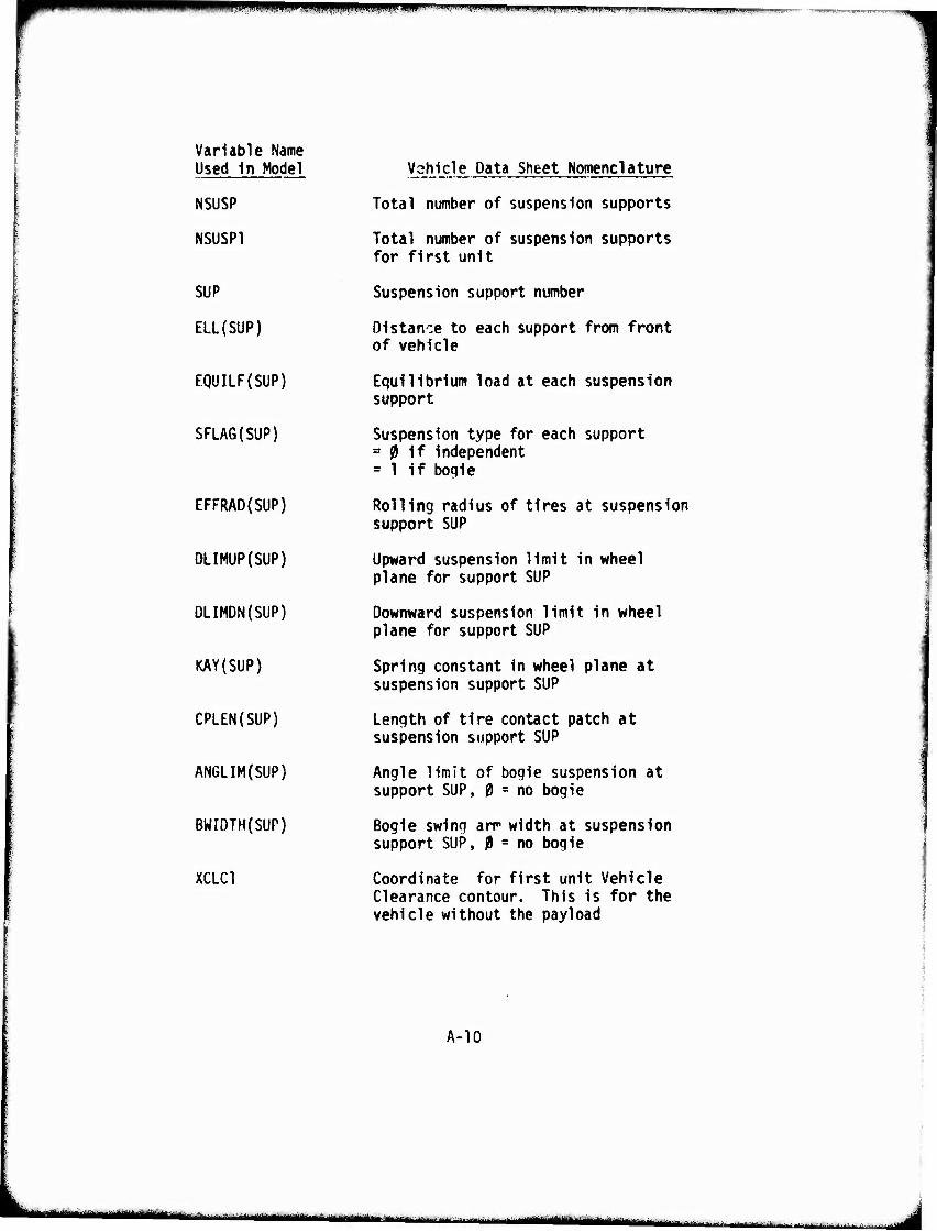
wmmm mmam !-ll.'..IHil.WWIiJ^WHI,PII|l..T..illiiil,i|!!..ifm>^TM.'>r»«».|il,i.i IIJ^IIIIJIIWH
Variable Name Used In Model
NSUSP
NSUSP1
SUP
ELL(SUP)
EQUILF(SUP)
SFLAG(SUP)
EFFRAD(SUP)
DLIMUP(SUP)
DLIMDN(SUP)
KAY(SUP)
CPLEN(SUP)
ANGLIM(SUP)
BWIDTH(SUP)
XCLC1
Vahicle Data Sheet Nomenclature
Total number of suspension supports
Total number of suspension supports for first unit
Suspension support number
Distance to each support from front of vehicle
Equilibrium load at each suspension support
Suspension type for each support = ?l if independent = 1 if bogie
Rolling radius of tires at suspension support SUP
Upward suspension limit in wheel plane for support SUP
Downward suspension limit in wheel plane for support SUP
Spring constant in wheel plane at suspension support SUP
Length of tire contact patch at suspension support SUP
Angle limit of bogie suspension at support SUP, 0 = no bogie
Bogie swing arr width at suspension support SUP, 0 = no bogie
Coordinate for first unit Vehicle Clearance contour. This is for the vehicle without the payload
A-10
wttttm ■' ---'■' - ■
1 —■■ "■■■- ■ - ■ ■— .„t,.^.^.^./^..... -.,... j;,:,.„.u.-J .: ... |i
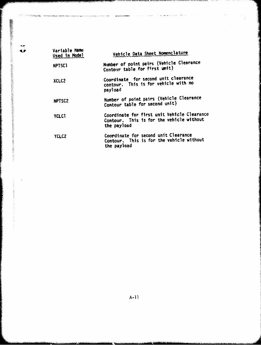
»«PPBJWW ^'^^-Tr,ii".'-w>li».>"(>».»'«r^»^r»'/.''""'1"'«w-'i -...■.., .,T^^r,,„...^™r-™>i»7r
^«»SWW» •ISMilWMWIOMl«.»«^«»
I
Variable Name Used In Model
NPTSC1
XCLC2
NPTSC2
YCLC1
YCLC2
Vehicle Data Sheet Nomenclature
Number of point pairs (Vehicle Clearance Contour table for first unit)
Coordinate for second unit clearance contour. This Is for vehicle with no payload
Number of point pairs (Vehicle Clearance Contour table for second unit)
Coordinate for first unit Vehicle Clearance Contour. This Is for the vehicle without the payload
Coordinate for second unit Clearance Contour. This Is for the vehicle without the payload
A-n
- -- i i ii mi- I ■—•—Mini ------ - - -
^mtm^mmmmiimmfm' im mmmrm^i'' «»•"w«" «*""' ••^^"'' ■«"■ N..»-*,. w.,w,WWH,,r.»^w-.fv ?rT^!"™^^^-^^™^7T-'«rsr-T7WWW.'r
IMV« ■■, -^.^B'
CO
a: o
s
(N4 r—
I <
o 1—1
3
c • o
•t— • +J Q. 'r- c u o o •1" (rt ■M 0) Q. Q •#■■
1. U (J o vO •M 0) Ü o « U ■o 1- «o s^. o a>
>> •J id
•r* Q. JZ <u
IKinHMilillllilliWMlMiM^lii« —- i ; ■'■■ - -

^^w^^^^^^^^^^ ■^^w PRPR pppn i 'wr'j"-.' .iwfiT»»^» »■I»»»,WW»I»'IIHII..II!H'L Bmmwpiiii^w^^wggwwwKWip
^,>^'1g^^Wi^^«ww$WW^
<■
LÜ
1 1
L J .
4—
CO
t. -'d flj a» ja Q. it E >i 31- -O Z «U
>>-^ >>rz <-, ^- XI (O -Q E 1-
M E «t- 01 0) «^ <*- (/»«»•• r™ lfl<C r— JO < e . «- " (/> 0) >- «J
OJ 1« •»- 0) "O W) «0 CD (U ^_ < Q. r—
p , CT <U E t. -^ C <U
•r- u -i- J:
</) (0 f0 c 3 i/1 a. i- c <■ t- 3
* : i * CU <.
! o n
S5 <
o
(- «t- C
: a»
*>< > <
CJ 3 L. i. - •-^ d g J Z ^3 i !
E E i
ii II
01 «Ü r- r-
X
c o T3 IO O
c
«o I. 0)
O
X < ID <U i. 9) * O a. c
<u
X <
I
X
-o <u <o
c
0) c o •>-
^ Si ^ (O
c •2 E
Q «r-
c 0» u - - c 0)
£ J- ■p JJ ■o <♦- •r" 0) 3 oc E
■r- 0) OC IM
•^ oo
0) (-
at a>
t a. o> ai 0) a:
at
^ E
-o at <o fc.
CQ
^ s iO o
1- *-» t- o
3 <U i-
•i- (/»
" I at
C r- •r- ••- 4-> £ (0 -»v of «A c >. o Q. -»J
3 at •— j- o
•#- >
«J c
at
CS!
Ikk_.. - ■ ■ - .,..-.^„^«»«^i^tai^m^^a»
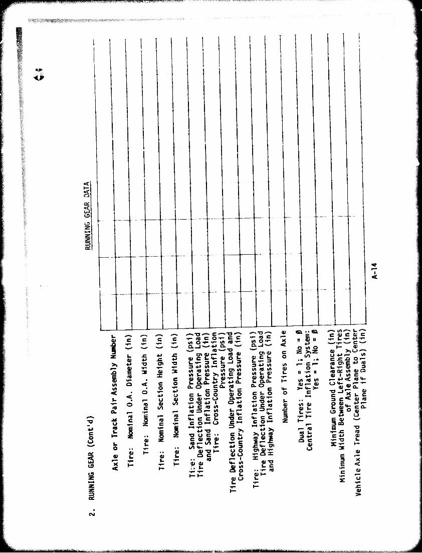
*****—>*• p>m>|giipwvfVI*wmii;'!i|«Ii."iiji II«,,.UIIIII.I ■
■MV'- .;Mv;vwr«pj^!w;'--r'',"-rv>'i.r-^w
rj
a:
3 o
I
Ä .^ v -r- .^ «A O ■^ 'I- I/) g N_» »-^ ^ . N_- Q.-J ^4J Q.
3C L. ^ ♦* J= 0>tt»i—
c
5
>, ♦* ^
§ s . V) o <
^ < : ■5=8 A. t— -r-
e 1 l
■o
c o
o •'- ■M O u to
o> a» a» c fc 1. t- 3 3 4-> </) «/> <a */> «« s- <u
c t. o o aj'i- 1- -O 4J +J c «
Of- c c ■i- «/» lO •'-
Q. «—•
. «si t-4 3 l/l
«A cn «A
t. a» f- u
0)
o o
I «A l/>
o a»
2!
3^4: 01
o o
i
< £
s
0)
C c c £ c o«— o
♦J-O ■a o c ••
si- to
o* a»
S.5 o •»■»
** 3
a* o
AS o> o
•i- «J C r~ V> O'r- K O.-J'-' <
C7>«) « C t- Uf- 3 3 4-* «A «/>«</> «A S. O'
e u o O OJt- f--o .»J ■PC«
n i u
M- C C C O»-"
■P >> >> <J «
"'S! "2 0,1-
2!
I
O (A O
to
o It -r- II
P IA )« «A 4li— 01 >-««->■
c
<o t- 3 P O C
01 O
^ «A*-« fc-'-- C 0» c « c f- t- "r" p •'- . •!- ^ c »^
I- 0)
OP«— u» c J: x» Q--
1« QC «A 0) a ai i «A c ;= P< «u-
c »< i- c 3 C< fl) <0
^B ^ is ^ •r- .C <0 C P JU
3 'x E < c «
0)
CM
...^.--.„„..^..i^^-t-^W^ , . i rilrMlffiVttitt ■"-■ ■■■■—■ I ■■-..JMiirln I. rn- i „s -■—--■■■ — - - - ■i-k^fc^-.^-. -,-,.^ ■■■.„.> ^ . ;...„ .^ ....j.-,,.^ ,.j.
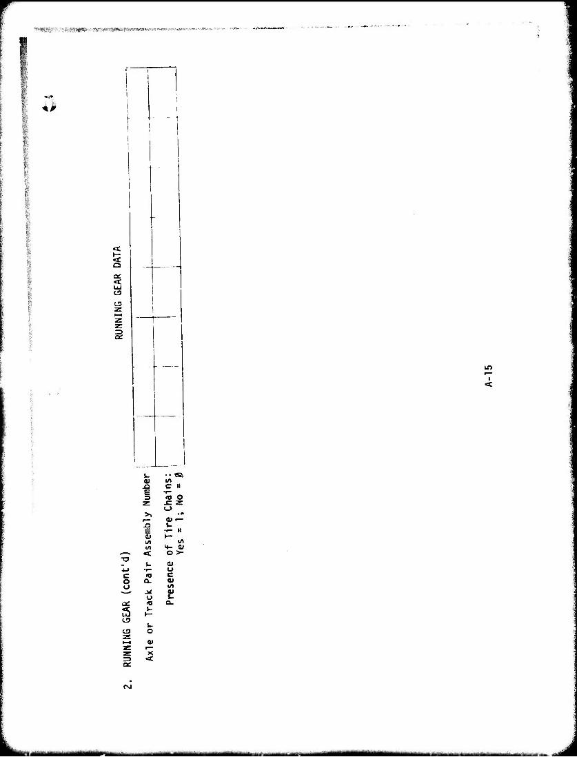
'^^^■V^AWlW^«'Wwm^
41
0£.
in r—
I <
L. .. Si 0) tft J3 C II £ •r" 3 (O o
x: z o
>> • •» 01 •—
JD k. £ •r- II <U 1— \A «/» IA <4- a»
■—• «c o >- TJ
L. 0) *J •i— u C n) c O a. 0> o t/l
o 2! a: <0 a.
3 1.
CJ L.
CD O z <—I 01 z r— z X =) <
«\J
-" - - «MMMlMMIIMMI^Ma i i —-■ - ■ i - ■■ i ■-■
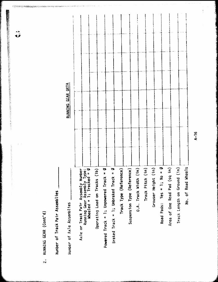
pwjWMffiWllMWHWiWWi*^^
.
i
t3
<
0)
5 a»
■M « «/»
XJ OL II
Z 0)
S ^ £
Irt < r-
^ c a» ■- £ -r-
c 5
t3
QC
a.
o
o I-
a» r—
<u
O
<u
<
C3
^ t> t» *-» —> ^ x> a» a) c f— H II U O •»-
£ 2! .= ^ ^ ^ QC ae 3
& S 1
o o « •»-
- s a. 3
CO
J^ J^ w o o J^ <o <o u i. u <0 1— 1— u
t— ■o T3 <Ü a»
c t. .* o o «t»
-o § JO
10 ("^ c o c =3
c •r- II
a>
u 1
c c ^- >_- a»
er ^: w -o 3
«-^ c ■O O IQ 10 i- o a. es o:
«A
>• c o
c
(0 u 0» Q. O
II II
a o O (O <o t- U I—
t— ■o
■o <u i- <o «I J-
a.
o
a.
5
■o
0) a> c c o w
o
CNI
J
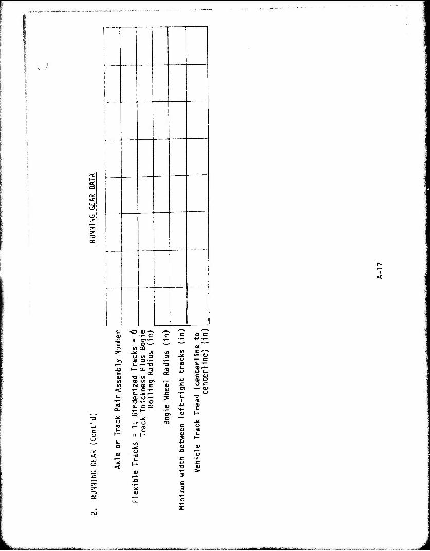
i ^j
<c UJ
CD
I
c o o
a: < CD
CD
-O (U c c c o c
J3 II 71 •r- •^ •»- 4J ••- E o ~ - - - **^ ^■^
3 to en 01 Z .* ll t« «/> C-"^
O 10 3 3 JK •^ 01 >, its 3 •f* •r- o >— c
V. i— T3 ■o ? k. ••-
E h- Q. 0) r—
4-> U a> ■o «O
<D lO O) 4J C 04 <y 4J
V) N 0) c 'äi f u c <t •^ C 4> CD «—. QJ
t. .* r_ .c *p* o t- at o r-. 3 U ■o
•r— T3 -t- O 1 <0
Q- t- c a: a» 01
k. t3 C7> 0) 1—
Ji J»f o »— <J .« (J co ^ <9 r— IO c o \- I. <u (0 y- II 1— ^ 1— u i/) 4-» o .^ <u a»
U J3 r~ a» (Q O ^~ t. f •r- X )— 4-> -C
«t -o a« (U s
>•
E 3 E
L MMlIf lllllH-IM lllll -11111 iMi^rtMä^iilli III l - i --" la - - ■
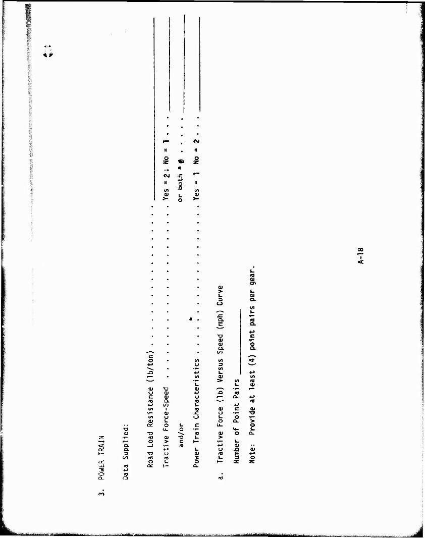
o
r— • CM
II • n
O o Z
H z
CVJ 4-1
»-■-
II o II
IA ^a 1^ 0) i. v >- o >•
00
I <
o
QJ
Q. Q. 3
CO
00
o V) •M o
JD •4->
— 1-
(U X 0) O a •M c a O H3 c u nj +J a I. w i <0
• r- a x: {A i. o (U L
QC C t. c U. O •f"
-o ■^» n> iO a -o L. O > c 1- _J •r- 10
4J L. -o t. ^ «o «; I o t. O a: h- a.
a* > 3
a. E
XI 01 0J a.
CO
to
*A u > «/> *^^ »^ i— a.
o •— l- o o a.
a» o > •r- I. ■M a»
<0 £ l~ 3
a»
v
o Q.
CO IO tt»
0) •o > O
0)
o z
ro
MiaiMIHflMäin . .^.^u^^H
"O
§
s
3 o a.
1
1
0) 1 «■> i v 0
1 ^ >
1 ■•" 1
<->
1 »— 1
"O 1 ai 1 <ü
C/J 1
I
ro
- i r iriiriiitiMMiir ir ■ J
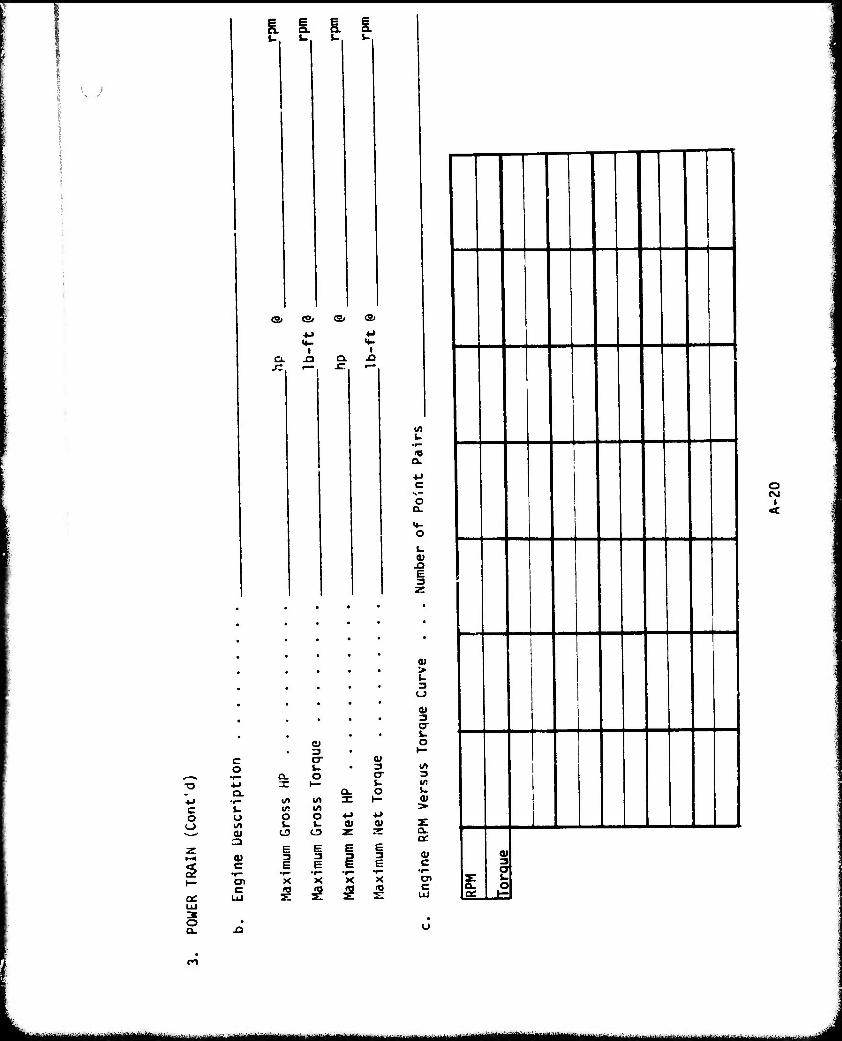
& I i i.
<a
a.
«3, (S,
t J3
I £1
C o o
I—
Qi UJ
c o
fc. o
a»
o» c •r- CD
3 tr Q)
Q. O O" XI- »- a. o «/I </» :E I— ir •/» o o *-» ^ fc. u « a»
C3 CU Z 3
E B 3 e
«J fl «
<0 Q.
O a.
z
> u 3 o a» 3 o- u o
3 to i. <u
a. a:
c en c
l
1
i
I 9
! i c .Lt
1 A rj
o CM
I
UitUMMMaMMMflM
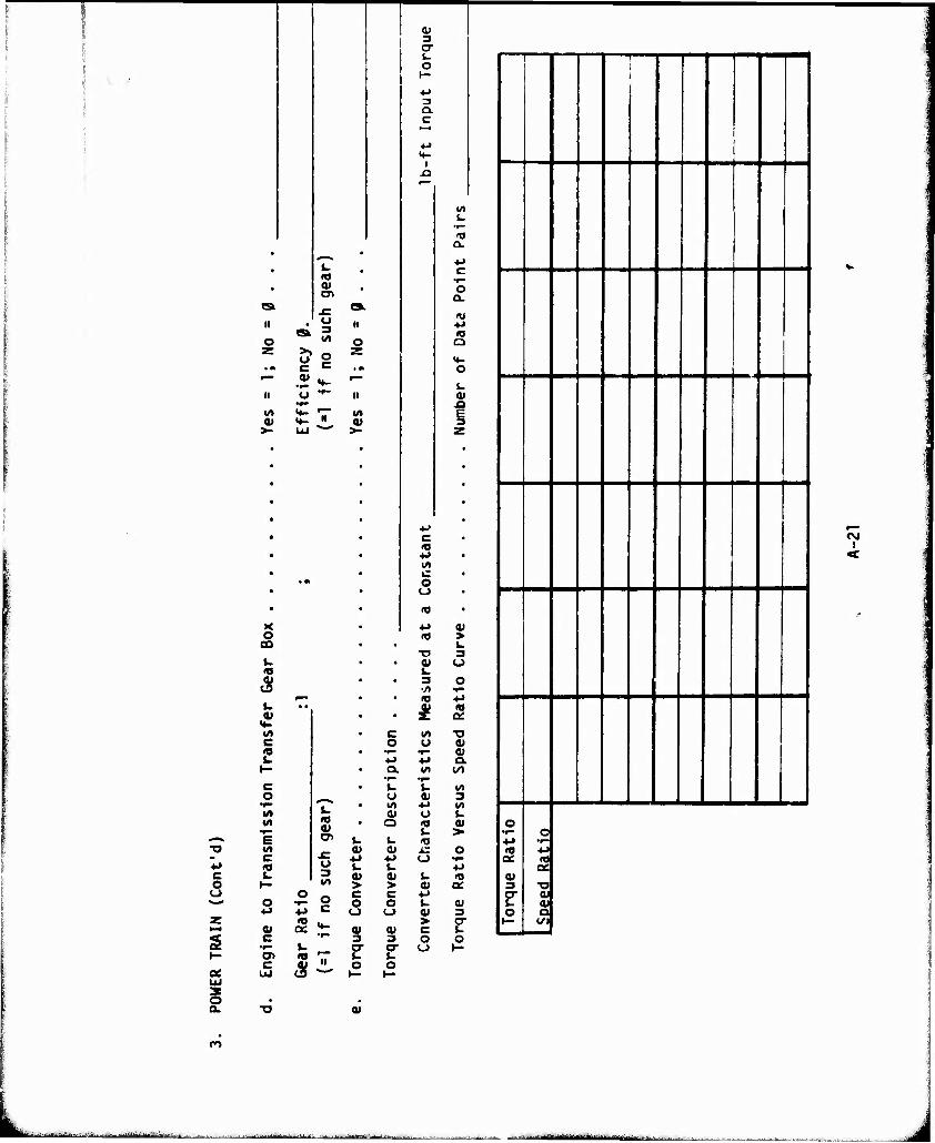
II
o
O) a> x: o 3 10
7. S8 II o ■,~
•I
o
«A
c o o
0)
«A «A
e I« c
o
4>
c
0) 3 CT 4. O
3 Q. C
CL
o a.
a
ai
E 3
O I/»
3 vo
a> a* i% *J ** M u i.
a> at > >
0 o c c •^ 2 o o
••- 3
c <0
o
u 3
10
o
■•->
o <0
> 3 O
■o 0) a.
O i-
I«
Ä-
0) 3
a- a-
u 0)
s- 01 > c o o
4J
on
0) 3 cr J- o
1
,
■■™
!
0 l»t—
r 3
O
OC
) <
o a. <u
<*>
MÜJMfrl .... ..L -i nmiiiinirtiiiYiWui HIHI n MM I'm ■ - im ^■■.-.....J-.-.
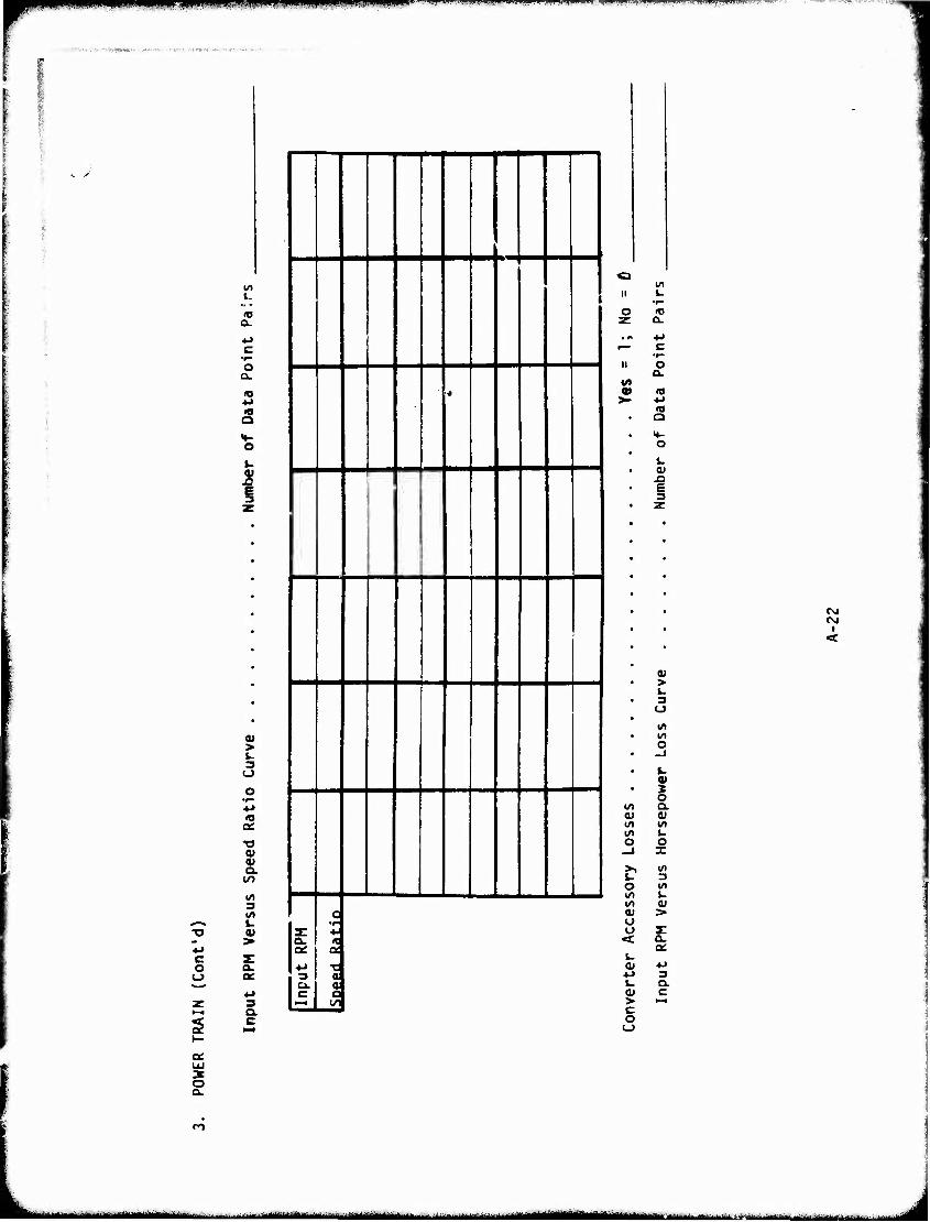
mmmm pppppm wnmm wm • m wm miwwiw r^rT^™^^"^»^-»?i7w--ipp^««w^7*?W^.-,T™^"^ ipRmffitpmi pwww
w- .-'--i ■■-r1-
a.
o a.
o
I
c o o
a* > 3
<0
at v Q. l^
I/) 3 </> W
a. ac
1
l
■<
1
Is:
, 3
c 1 >-^ ]
q
■a 01
a
II
o
1/1
r— C
«
o a.
a
L. 0) J3 e 3 Z
CVI
I
a« > 3 O VI t/l o
k 01 2 o v) a.
O) at IA 1/1
o o _i x
o I/) »/>
VI 3 {/I t- 01
S 5
01 o o z: < a.
a» -M ■M 3 i. O. ai c > >— c o
o a.
n
■' ■ - -■■^--' ■■■ -- -■■--■ --- - J
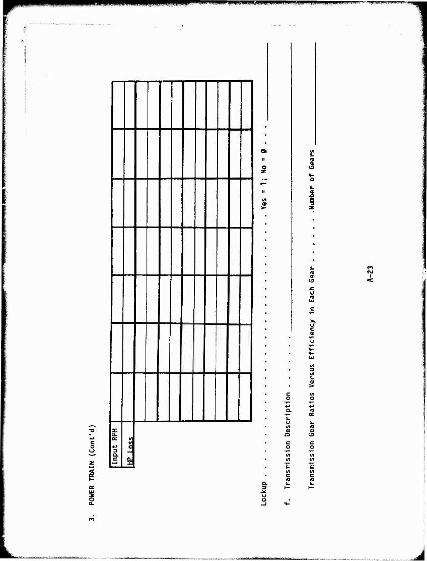
""■wmii ^^^^
C o
s
a.
1
|
j
z:
c
c - a
II
o
>-
I/)
5
5
m a» et
c
to CM
<
i
a. 3
o
c o
o
Q
•r- E it c £
(U
o
a: i-
t3
C o
•»—
to •!*• E (A c «o w
L -MllftliAH-l i i il Tl
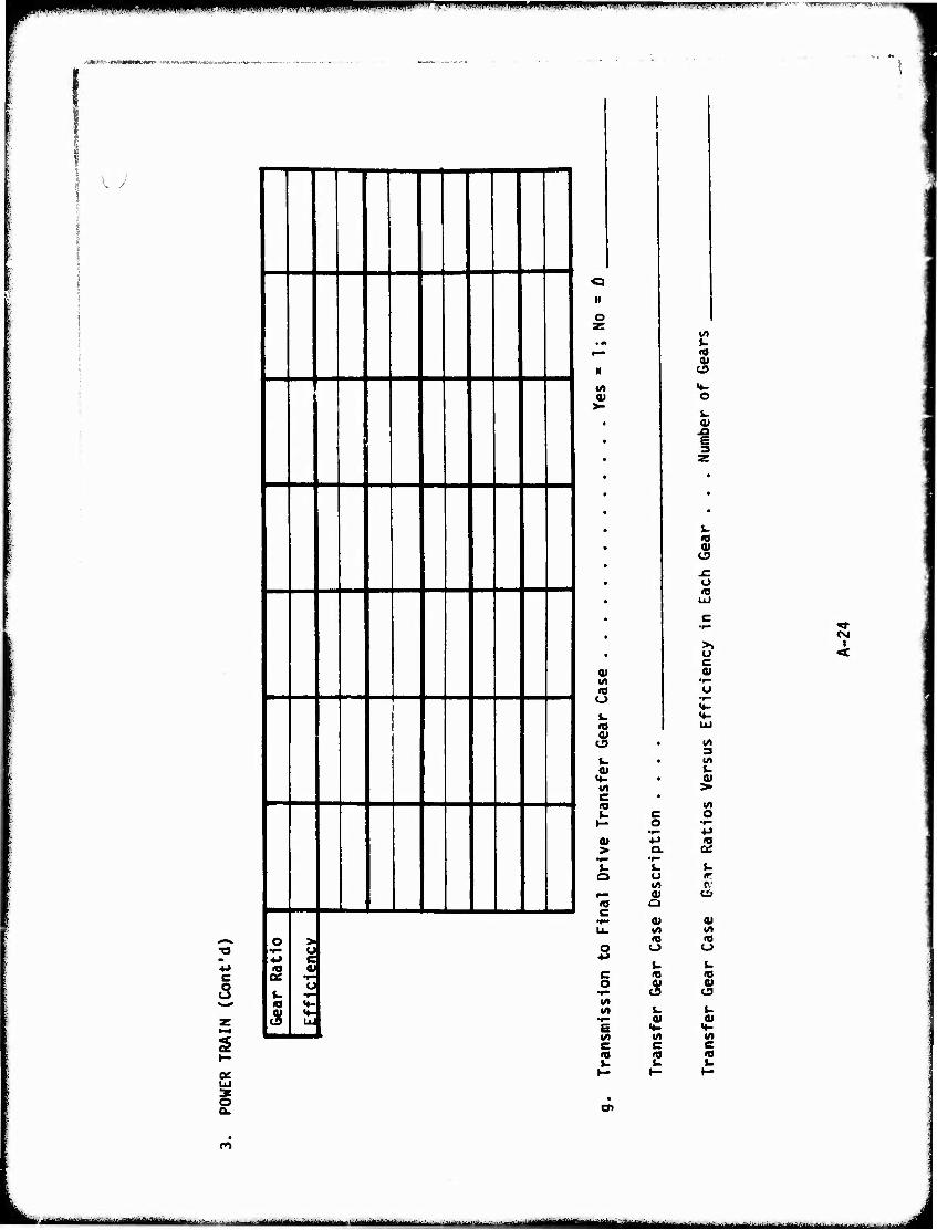
■. .»»I ip.w.iii.i, j.iii.n [■i4—.nijwminiiiii,iimi' lif ■» p.|,iv«iini.il!!. Km* «,. *
*4*fV'i-tmvmmi"-<-
e s
s UJ 3 O
lo 1 IB toe 1 U
IS
5 c 01
•»" o
**- Ul
«3 II
O
«A 01
0* l/l «O O
i. n 0)
i- 0)
«*- Ul c IS u
> J-
10
0) ^3
4->
U l/l OJ
O tO 10 O
O 4>
«A 10
«A
«T»
oi
4- 01
v> (0
« o»
Ü ID
>> O c 0J
Ul 3 Ul i. > Ul O
•t-
i. ir r
Oi ui «J o w (0 0)
C3
u OJ
CM
•i
ro
• .--.■.-..■.,■.. »Ill« ■ ■ . ■M^M iiiririiiirniiiiiTiii i ^^^^.^■■^^-.......^—^.,.v ,., ..^ J
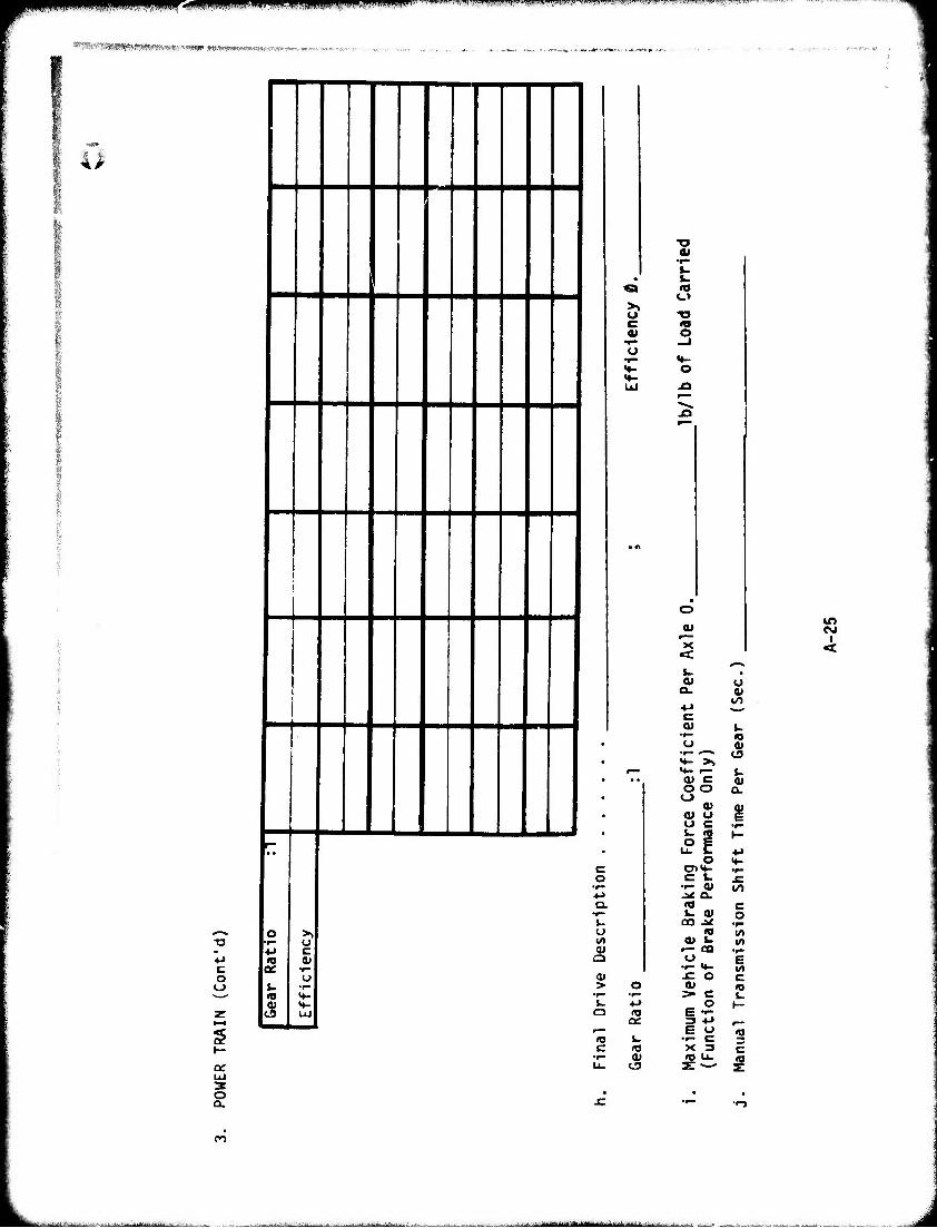
mmm zmm* 'IIII|I H^^PPUI^V i <m. || ..I, ,y.,i,mm-w i „ 111,, y »-».•■.■".v.-i'.w.i—-—T"- T™.—-^---.-^ ,^.,,r.,-..- -• witf'—WWIT«-: sT-.fy ;■
(MmmnuuMMiiuiiwt"««»' »wwi»»«™«««^,.^.,.,
4>
s
2 £
ro
"^
- —
• •
o
5. u
5
>> u c
u
c
o
■o
IT» o
o -o
c o
o I/)
> i-
a:
c to •f- 0)
o V
'x <c t-
^** a> o a. 0)
00 ••-» c 01 L.
•r- <0 U 01
•r" *"^^ C3 «♦- >> *♦- f— t- a* c OJ o o Q.
eg
o <ü a» a» o §
^ i ^ «o c U (U ©
CO ^ v- »0 (/)
O) u w »— CO .^ *-> e
X 3 C
■„^ü^... . ^■..1...„.: . . --■: .1-i-.,.^..Jm.-...n .....n^ .-.^^r.^.^I-.. .. , _ irmiiiihir-"— -- -
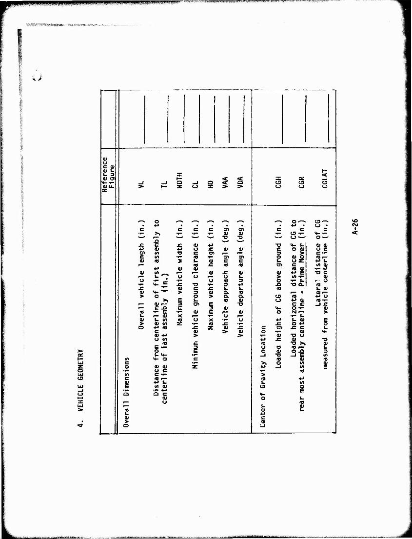
UP Vl. I !•■.«• rvvrw ■ WP—I^IBHWl " "V'wyw r'-t".'"'r^'''l''g,^fwryiffTaffF'-Tff^ ":i'-r--I'I JTrr^/nMr" '
»ft^RfW«''»».»«»«»!- «lUIIIAMW»« .»w».^.«—,-
>- Of
_i o X LÜ
(U u C 0) (U v. t- U 3 X 3 0» (7 1— ^ < X QC
»»- -^ -1 _l Q -1 o o CJ3 t3 O « U. > »— 3 CJ X > > O CJ o oe
o C—» O'-« • a • • • • « • *s • o • c C c c o» o> c c c
•1—
ÜD
•^ •F- •r- 0) 0) ■o
•w t3 «r-
f E J= a» ■M -a <+- i. 0» 0) +* 0) *J u £ 0) 01 c o at o c cr l/l •o c C7> f— 3 > C-r- c </) i" (O •^ "cri o> o |^ <Oi— V <0 X i. 01 c c L. 4J $-
•M a> a> £ <0 1« o> üi .12 5
V «^ ^» 0) x: 9 0) ■o c *■ ^ "o "o o t. > «rt •»- 0)
"o £i •r- "o <a 3 o t- u r- O NF1 JC ■a ••" o +J -O -o o. ia £ •!•■ 0> c £ £ I. <t> u a» (U «4- *— > 3 0) Q. 10 r— 1 o>»- > O o > O. o. o <o ■P u >! £ i. <0 0) o +* 01 (O^- r* 0»^- •3 O) E T3 c c -JX: r— c x> E 3 Qi «4- O t- V « "- B •^ a» E 0) o N t— > L. f— 0) X •^ "3 i— •r- t. 0) fc. v> 1 "o X •r- u •»J 1. 0> C
> 0) «/I •r— 10 ^ •1" £ o ** O o +J «o J= z OJ £ c en JZ c L c 01 > 01 o Of <♦- 0) -M > ;> i— o> ■o u u «n 4-> j= 01 ■o « e «J ■o >» 01 E i—• 3 o X3 «Or- i. 5 E o 0» O -O 3 t. <4- •^■ -J •o —1 E M
■A «»- o c «o 10 c •r- >» o trt i o 4i a» z: *i -J «/I
•r- u c •r" (O V) C f- > c 5T (O ♦J
L. (A
■r- -U UJ g
Q Q C 0) o t.
i— U ID r— u Oi (0 a t. u ■M 0) C > <u o (_>
VO CM
I
•■•-"■■ ■■■ ■-- ■-■"■-■--■•■--■^•'ittill i(li lif i -_. ■-:^.., -._-■„.: niiiiraiifrMiliiiliiiiiiiiiiiiiiiirii T r - -*'—■■•■'-■ -■ •■ -■-■■■ J
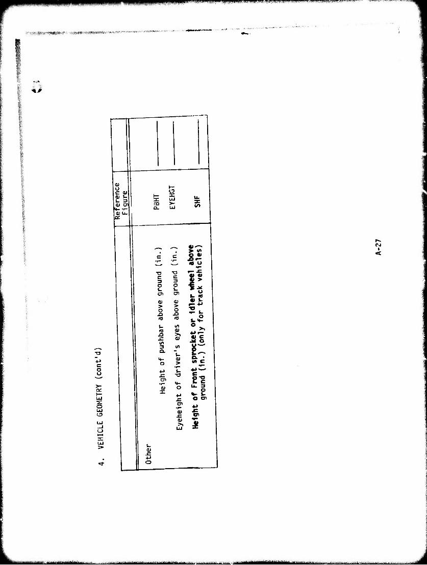
i'il|JWIJ*!*|ll)^>W»l»ipiWMIl!WPll«!( «auWJiJ|iii""^i""i " . I.I—-
■■■nmm'^'^mmr ■ «yftetwmmimiv imeat«
I 41
0) o c <u
a
no Q.
UJ >- 3:
to
3. • o
8 >- on
o UJ
i—i
-o c 3
-o c 3 1$
o i. en
o 1- C71 *15
<u > o
<U > o
2b o
JC vs 3 Q.
n I/I
|-
O > •r- t-
o. •
en
0) X
-o
o 4J
U. 3
-C o a> en
«■»
4) x: ^: C7I ai •^
UJ £
CJ
<
i. 0)
JC
o
■- - ■ ■MtfMWIIilMMM«« -•■-■ ■■
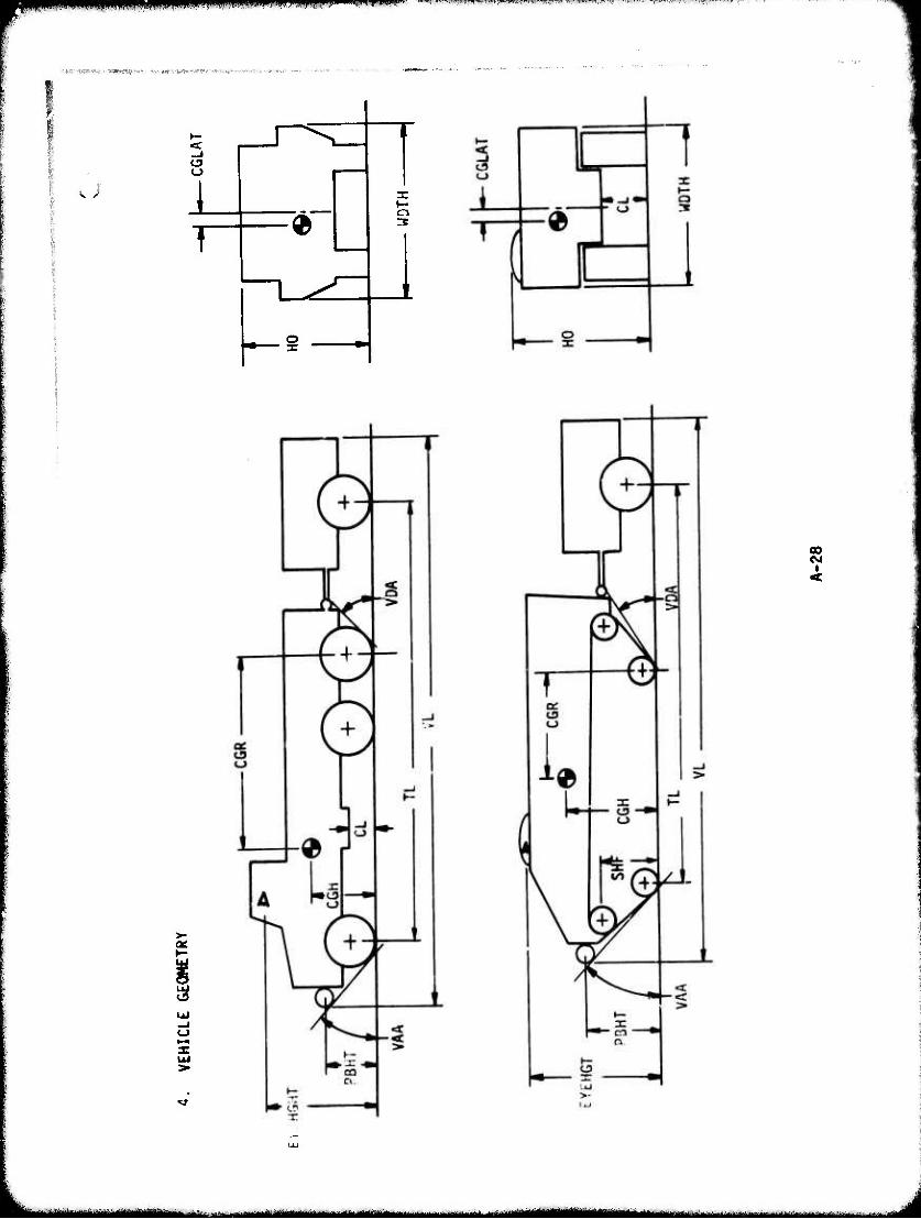
*m^^m*mm,„< ,nm m m>w«
■«a 'ffityW- v-','Wlw>t *i* < 'rw.wr'vj*|i»"wv>ip^
<v >
«
3
00 esi i
- —— - ■ ■ Mi ^^^^^ä ^.-f-.,.-. \.. .. g^^B
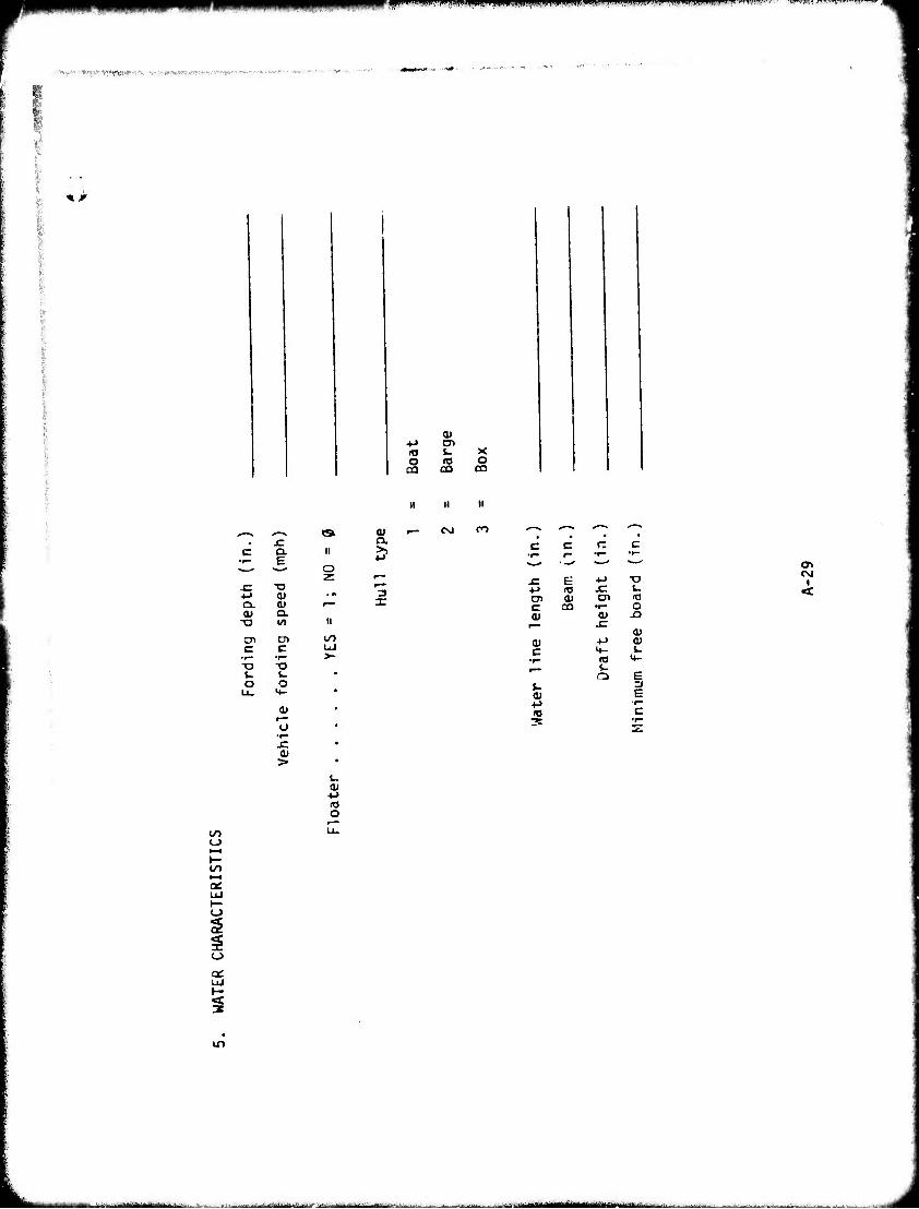
fm j.wiwiupiM^>m ,1..,H ,i,, mmm mmmm**.""
:*.^,'-. -I-».* 'pifft})**'". V '.!,'-'WtpfW'^vv. -.■"'.»
* jr
o
0)
CO
■o
c
0) 0) a.
D1 C
■a
o
r— (J
>
II
o
00 UJ >-
3
n ii
I— CsJ
o CO
ti
CO
.c E 4-» ■o +J UJ JC u en 0) C7I IT3 c co •r- O 01 0)
at 0) 4J <u c M- j- •^ (O <+- f—•■ V
Q B
fc 3 B
■!-> ■r-
10 C 3 *^—
i
■!->
O
to
LLI
I-
in
~i* — 1 ■■- J
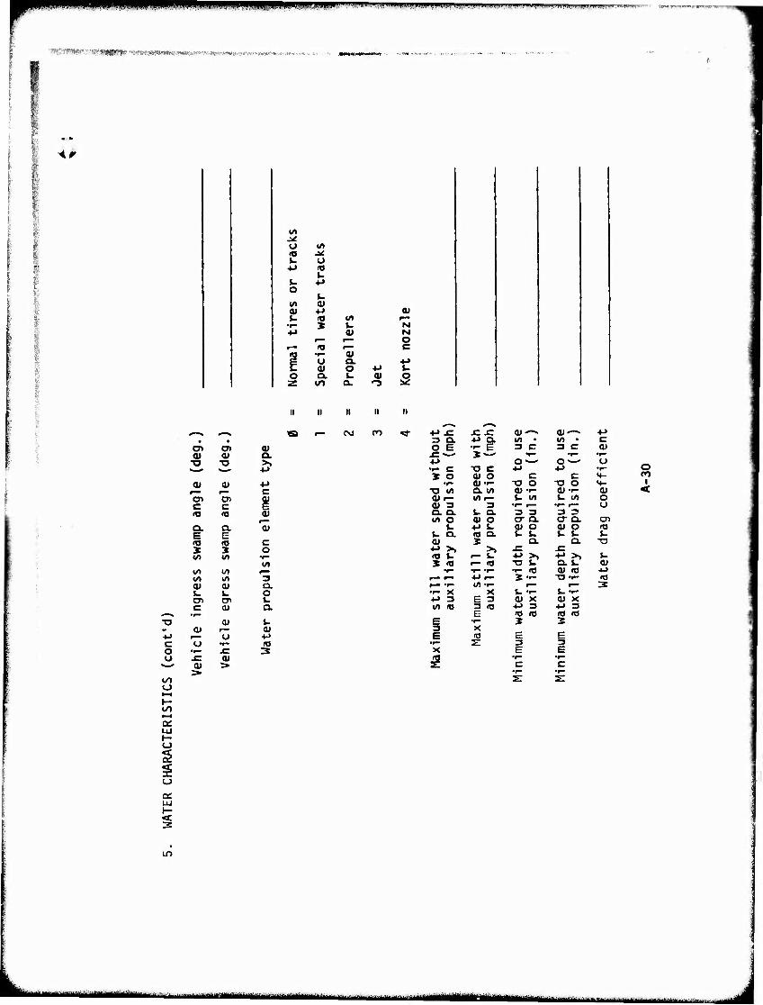
P^B^PPHPIUPPiPPBjMPyiimP^II l ■..II.I.W,!. I, IW.^I t,.,. .,.„..,.,, -r.^-
"'VST^'*!»»v"!äS19fgCT» •<^W«cBWW«W»l»^•^a■i»'•^55>>1^«ffl^!t«^'ra.■.1W«.^■.»,,,,.n. , „
><^
w» ^ u (A 10 J^ i. u
•*-» «9
i. ■M o
t- l/l 0) 01 4J 0) i- (O «/» r"
•f— X L. N +J 0) tM
r— r— O
"•5 (0 'ÖJ C
C U a. 4J j3 0) o +J u o Q. i. 0) o z 00 a. "3 m
IS r-
c o u
oo o
cr o> a> OJ 0) Q.
■o TO >» ■M
a» 0) ■M C
en en QJ c c £ <o (0 0)
Q. a. 0) E E «o <0 c X 5 o «/> i« •f-
(/» to IA ^— (/> IA 3 01 <u a. t. u o CT cr Im c 01 OL
•r- 01 i.
O) <u ^— o •4-) o •r- (O
x: 3 a»
■•-> JE J= XT 01^ <u^-. •M n a. ■*-> Q. IA • w> • C o e •c E 3 C 3 C 0) sz--* X — •r— •y-B •F-
■M o—- O'-' o •<- C -a c 4-> 4J •r" 2 3C O (U o c c <4- co
•r- a>T- -o o -o o >4- i ■a wi Q. (^ o»-.- 0)-f- (U < a>r- U>^ L. tA t- Irt O V 3 3 •t— f— •r- r— O a. a t~ a. 3 3 3 3 (A o u o O" Q. o- a. C71
u 4J i. 0) O 0) o »0 i~ OL ra a. w u i- 1- i- 0) X a. Q. -o •M >> >» J= JSl «0 tJ •— t ■M >> ■M >. L. X <0 •- (0 -o iT Q.1. 0>
•P- •r* «r» •r" *0 0) (0 ■M #—" f"" ■*-» r— X T- -o •■- IT3
Wr- r— r*- 3 •r- X X t. T- &. •!- +J 3 e 3 <U X V X in ro 3 rtj 4J 3 +J 3
E «o m •O <D E •r- X X 3 x E ITJ E g
•>- E 3 3 X E E
5 •r- C
•r— C •r-
a:
%
IT)
k" I --■■-- ■■1 HIM MkMMil ^^^BHgMMHKj ■' — ■-
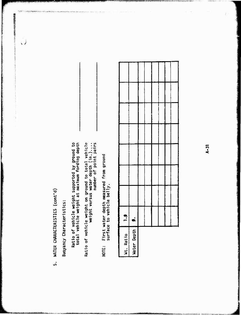
■ " iiiiiniwui *WBW P|f|||pPipppp|fpff!ljmRfv^|^rn--T.^^^ .^„„„„f. Ui, ,^.. 11. tw^.T.^rT..-7~:r~v.t mjjf^Tf, —■--- -
^A^'vTfrä^^jwnHWf»^^^
u
O -C a» • «/> a (j • ■f-
■o a» •»— • m c -o SZ"^ Q. 3 a» • -o o o» > c •M c i- c f— C 3 o>-»- f~* **-^ •r— o
T3 10 O 1. >.». +> sz O. en
JQ O O 4-» <4- +J Q.«*- e
-o 41 o o 41 E O "O i- •M =» +J J- <♦- W E i. 41 O-r- ■O 4) J3 ■o a, x C -M £ su . a. ig 3 E
3 «a 3 t >. ^—ifc. O X c 3^ TJ U) k. «rti—
*» 0> M 10 41 4J •»-» « 3 aj-o c -C C */> o • • cn-u O l-
w « o u> •»- ^ 4) £l—
u ai o> ■M > •M O •r" »•^ ^ O.-^
oo •M 0) CTl-M 4) J= o W 01 3E •i- SZ -o ai •-^ •r- 4> O) > h- %. "o a» J — L. oo a» ••" i— U ^s t-^ •M JC o <U X ae O «•1- (0 UJ « > J: T) X 4» 1— (- 0) •f- u o <a H- > sz •M to
g ^ O <u W«*- o r— > J- t-
s o in ••- 3 >» •»- +i «*- U. <A
o o e
■»-» o •a 4-*
o a: (O ac o • • LU >, •!■" LU H- 5 ■p t- < =» i« o
ao
— 1
1 1 f—
• «a.
1 0 1 '^ 1 ■*-» 1 «a 1 ^ I 1 ■*-' 1 3
■M Q.
41 ■M
s
en
m
jjaMiiiiitttttitMikAJt«. -, Mflataj|g|Mi|y|||gjgByBg|ai^,|Mja|i J
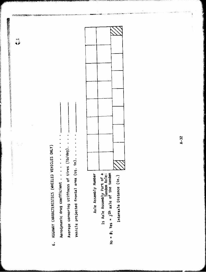
liPmpiRHpmpP II"IWIP'WWBIIWII.H.IWWW|II''JI"W'JP. ™r^wr^J^WrWw^w4r,.F«~'!»>««".^''™---"—^"^ r.H^^-"t^'-m!T7^-7;i^rnw-7'-v-.T- IJ^
;^i<mfl»WM!PW«^« :*!S«^^
4^
^
I o
en
21
O
>-
c3
vo
0) I/)
U C
4* O u
c £ r
•r- O E U c 0) >» o» -o <o
5 ^
<0
2 c
■o
o 0*
■o 2 0)
CO I <
^
w « • • e 0) 0) ü '0m**
H- <— "O • s o X c c 13 < to •r- z
u ■(J "^^
>, IT) o <u 0) a.-o JC u
^Q c •l-> c g ?£ **- 3 U) ^ o (/)
< M
at
01 «rt 'K 01 < n ^—
X X < at JZ I8
■u k X "-» ^ <
II C t/» >-4
>—•
>■
• «> ca ii
o
II ■■>■! ■-' i --■■■■-■ .—■....■...-■
tw^mmmmmm ippuu umif m .»(MiiMUBpinpiiiii./iuipi^RPiwiv.iniwi mmmmm'mHQmftflmmf" '
Ü
to
<
CO
2 o
i 5
^
^ « s >. JO Q.
3
W
3
1*... . ^-.■J,.L!;. .. Ü J
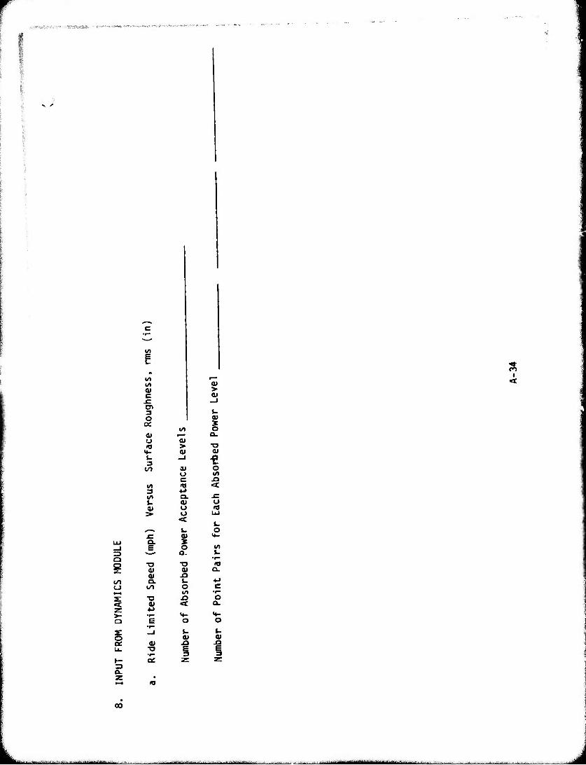
»•«.■■•.■'.•u' :-•'•■ ■ yraiws«».- -■ m- ■.*- -. »^..^ '•-v'-.hn»A,»H..u.-*
>-
01
3 O a: a> o «a
»♦- 4. 3
3
0)
t ■o
K ■o a*
«
> <u
a» o c n Q. eo u o <
Q.
•a a» U o 1/1 i3 <:
0) -a
> a»
4- ai 3 O
Q.
T3 01
O I/«
u
o
W1
10 a.
o Q.
01
I
00
- 11^— " ■■ -■■■- - ■■■- ^
l
^
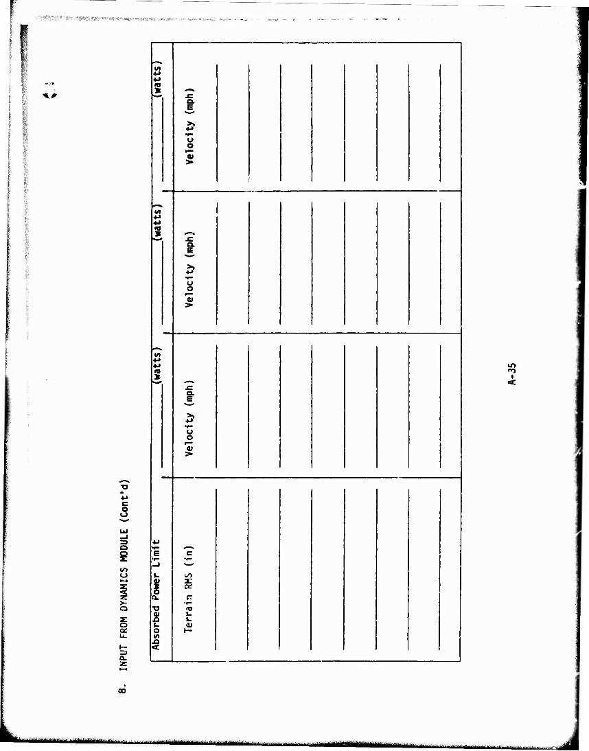
;,-,.■;-■, «wjju ■.■■W^^CTJ.VV,,,.»,,,.«.,,,^ «;;««».»,..»»-
- ►
4#
§
>- a
o oe:
3
Ut
ü o
5
t
o o
a. E
o o 0)
t
u o
in m
i
2
s: «:
■r-
U
0)
CO
M^^IK^y^j- iiiimr--- MM - ■ pini-inniimMiy .M
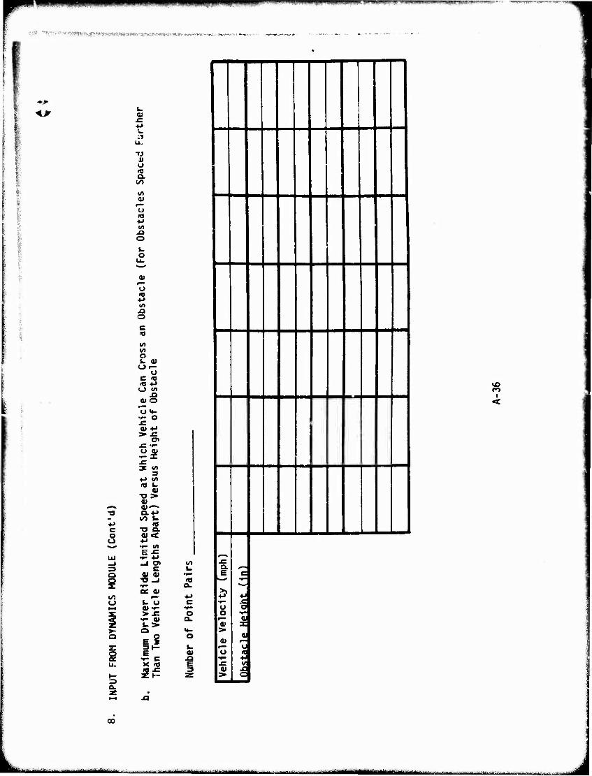
>^* mm lWll'.lMWilB^jnBf|pH||^«!||iinin.i|iii.|i.i.iii)i mpn U..,II ■ ||^pBpB)|ipw|p[aiHBpwiw
«.•■.-;„ ■...v.rv^^,,i,^,j,.,/^wfn.fl,,.^^^
*»
c o o
=3 o i ?
z: i 3 o.
w
U u Q.
1/1 01
r— O »O ■M
XI o i- o
01 r— U
(/> JQ O c "9
W»
o L. 0) Ol-
li c <a « ■♦-» O «rt
0» o
•r- O
0* 4-*
•US x: 3 «0
3 4-> </> •a w
"O > V 0)—. 0.4J
"O Q. 5< •r- «/»
|«
o> •*- > £
i- > o
E •»- c
5iS
<o a.
o a.
JQ E
J a— 1
1 i
|
1
1
Ix: 1 °>- 1 s
|
l> 1 0) Vo 1«^ If 10) l>
c
x; o «
01
! u
c
00
■■ ■ -" ■ ■■ ■ - ■ '■ I r i iiiil —L^-°^-"—" ■ - ■ ■ •'- -" -' M rdiiiiiiTiim'ini'n iiiii J
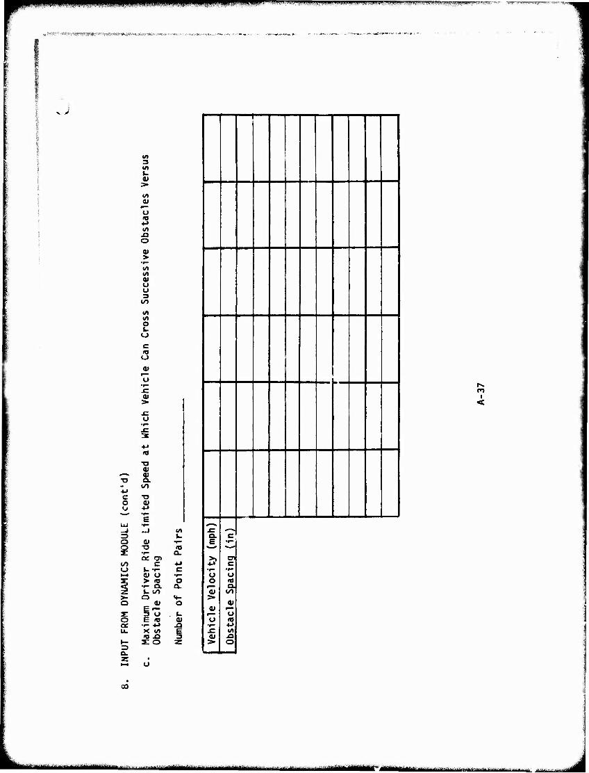
i, DM»!, I.IIIVI^IW.IIIMI iiUiiii WHIP mmm*im*mm- '^'v-^, w-' wmnmnmm*** met WMW"^."HW""I
■ ■ ■- ■,^.;..;;:,S. .■■■'...^s,,;.;.■-,.,.-.. ;.-^ ■ ■ THKWMWSW ■--. yuj-.Tmu^-m«....
x>
C o
3 l/t U
at
Tj
o
>
0) <J U 3
V) «/» I/) O t- o
o a» o
at
« ^. at ■o a.
_J —1 !/> ^ u. o ai •r—
i ■o
5 a> a.
in c +* o u •<- c N-« a» o •r-
y > «0 O rf •i- Q. GL 2 i- to >- Q «f- a a» O j- 5 "o . i. Q E «3 V oc •«- *J JJi u. X w» E
«a x> 3 H- s: o Z
1
x: le
i »p» <-» o
I'm >
i p** u
a» 3»
C •f*
CT C
•r- o <o ex to
9) U 5 XJ o
ro i
<
►-• o
CO
^^g^u^^^ -"- ^^v. —' Ml»i«ll1til»llll|-irrH>liliiir.i irmi 1li i _J
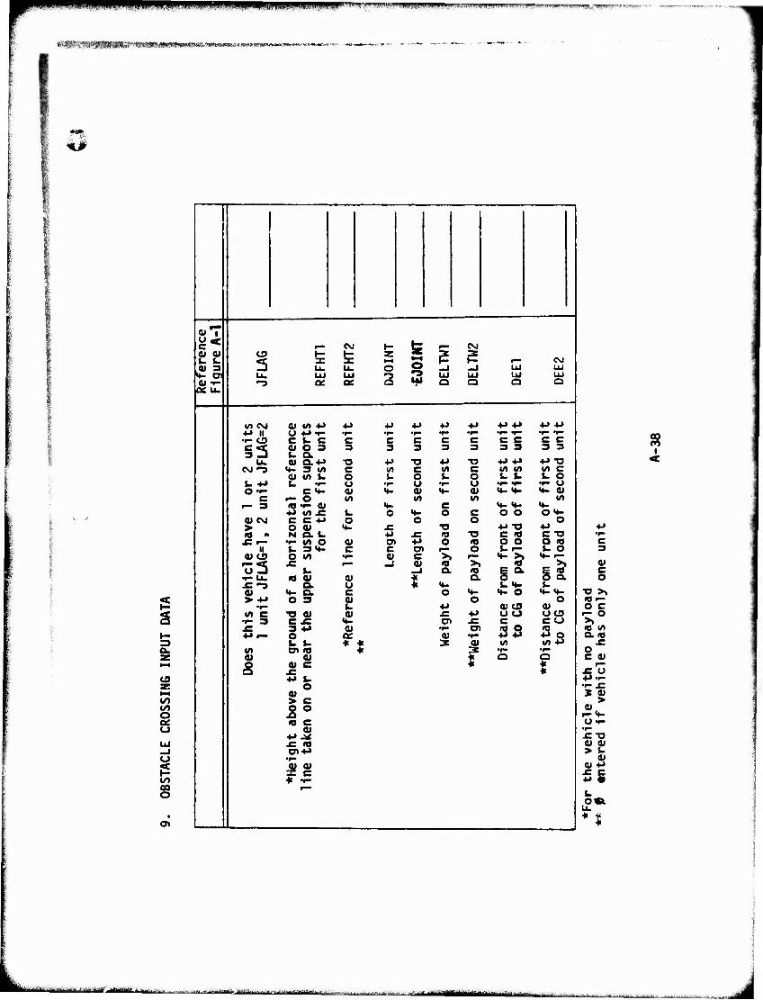
ipppp ■pnnnp l|ll^U^'.'^m'lti^*!lW^ll^J-I.H,'pi|Ji)WL'i.ll»l|)«..'WuiJiWH,l|^| »F^p^.^.T^T'^T^"
EKPMHHMMMIMWHMHiMiMMwiwi")*"*""
*#
g 3 a.
cs
CO o
Ul -J o
g o\
t—1 (U |
=* ,_ CM H
to* F— SJ
£2: CD
3 »— IE fe
Z K-l ? ? ,_ CM
L«J 3 U. U. o C3 -J -J Ul Ul k- oJ u. UJ UJ 3 T3 Ul UJ Ul Ul 4» "»-I •o CJC QC »41 o o a Q aeu.
\ «rt CO <U «/> -M 4J •p ■M ■M *i •M «J 4-> -M i -M II U -M •»- •r- •^ •r- •^ •r- •^ T- •r- W"
•i- CO C J- C C c C c C c c c c §3
(U Q.4J
3 3 3 3 3 3 3 3 3
■a ■!-> ■o 4J TJ ■M 4-* •»J "O 1 CM "3 if> 3 M c M c (/» C </) «/I Ul c
a» U> U o U o L. o L. i. s. o U ■*■» k. •»- u •r- u •»- o •r- t- 'r- O O-i- c«*- 01 <♦- 0) H- 0) 4- «4- »4- 0)
<= t— o M (A w> «A r- 3 i« 'p- 01 <*> C «^ «f- <«-
4>> <A JC u O M- o c O O 0«4- <U CM c c •»-» o o o . 0
1 > o cu «♦- x: "O •W "O ** 1 fO - N O. U ■p x: «J -o C (0 c -o 1 -C r- •r- «/> O 0» CTl +» o <o o o O (0
H l_ 3H- c C Ol o 1-. 1— u o u co O M •^ V c >! *+- >1 t- •— •33 f r^ _J 0) « ">! *»
t- _J o. ie E a §2. t- u. ie a» a> * Q. o ■C 'O 5. o * «t- i.it- ^ i w <4- Q. c o <*- «»- o •♦-<♦- > -M O 3 21 O o
1 *r" +J 0) eg a» 1 vt c t» 04 QJ Ä ■M oo ocs
•f- 3 e x: «4- en JC c CO 3 -M O
0* 0) •r- 5S Ss U t- * « a Ä W)
1 v* a> <e « 3 •f— •^ 01 0) $
a Q
s «c * * •M J-
o 0) > c 5° is c
V -M 0< f (O en-M •r-
^g « ••-
I <
01 c o
•o >, «f- o c i- o >» (0 Ul a. <o o C V
JCIJ •p'l- •f- J= 3 0) > 01 Of-
•f» -c-o 0» 0) > t.
V 01 4->
58 t.
■■' -■"•'J -- ' w- ,- ■■.;.., .mai^u^^..^..». .,.,.. , mam a^um • .. .:^M
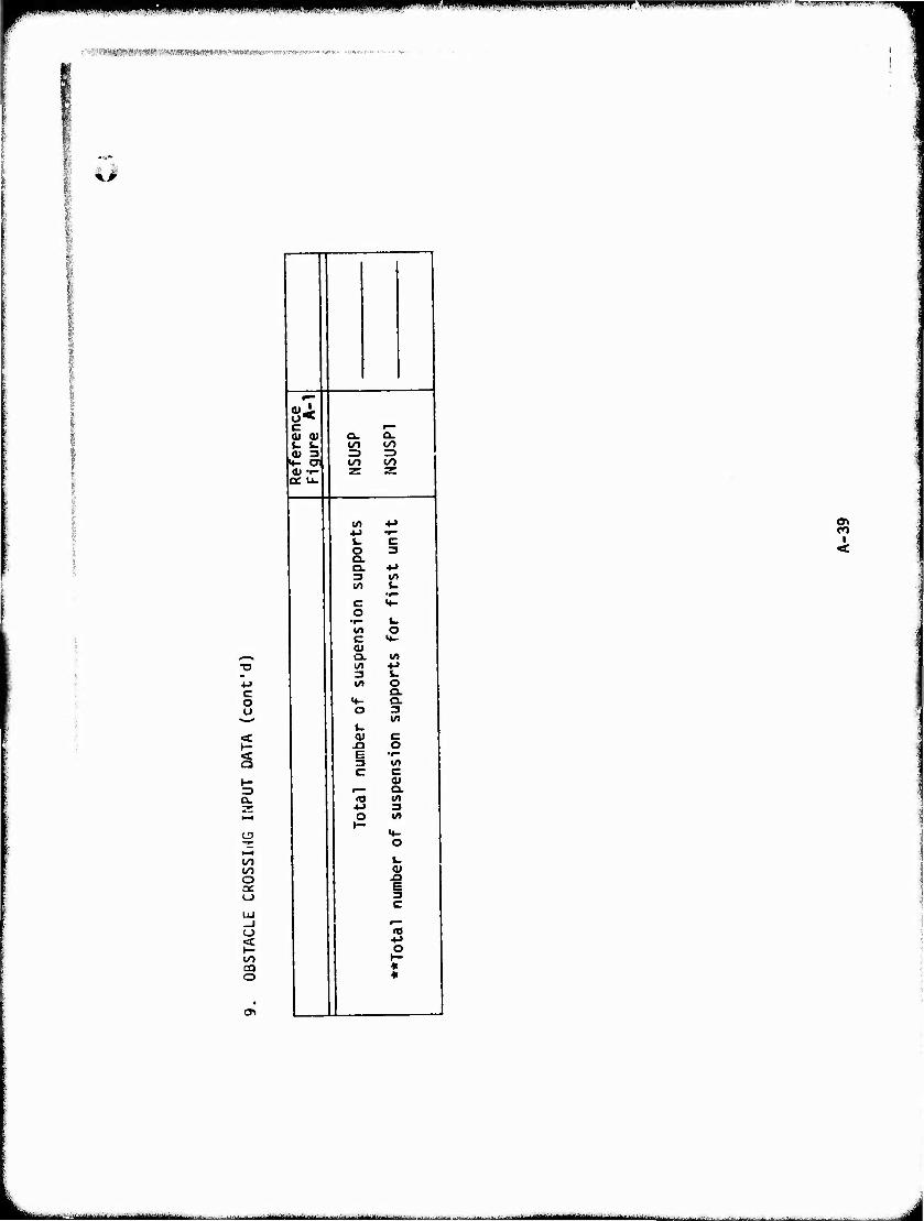
IIIIJ(.*i.HU.,IJ,iPfllllJiHHU..IIIIIIil!l 'i>HlJiiiii.iiuiuiPii«iiniiiJ
' :':ivWir*-'^:VV:''^svt*www*m**wmw*^■*'**•*:**'':■*■"'■'''■'■ ■•-«,.,.,
kß
<u. c
cc u.
c o o
^ s
CJ3
o o
< I-
CO o
w
Q. Q. «/) CO
CO 00
(/)
o 3 o. Q. ■M 3 Irt «/) U
•r- C «♦- o
•r- I. «A o C «♦- O) Q. m (/) +J 3 L. l/l O
Q. «4- a. O 3
in V. a» c x> o £ •e* 3 m c c
a> f—* Q. n in
CO
I«
<u
E 3 C
o *
--■■ II-M1-- "-' ^i
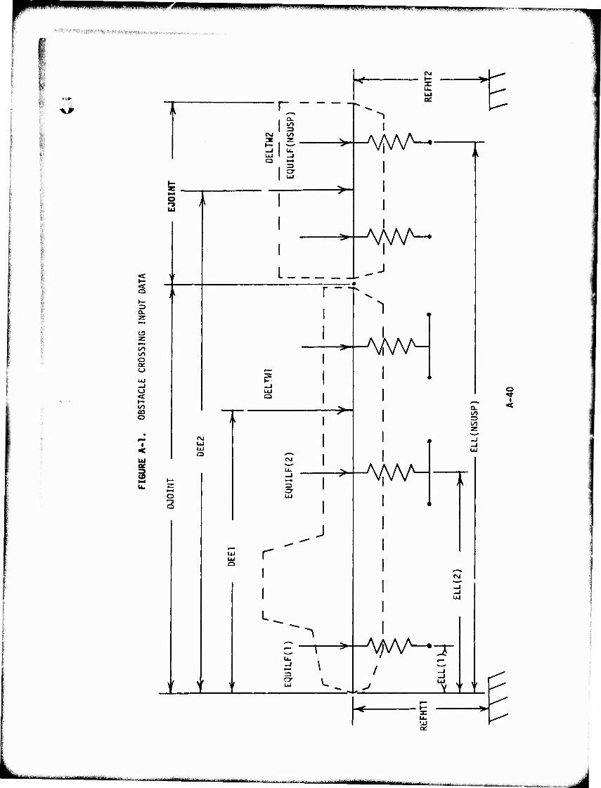
mmmm. pp^upp-ww! iii,iiiii,.i.i...i..mlwniiiiuw>fpim]ipaniiwiinji»nim.i. mmmmmpmimmmmmmm '
XJ>
o
a.
o
o on o
o
«/■) CO o
Ul
UJ
O
a
r a.
Ö
"1
AAAA
AM^ L ±-J
r
=3 Or
^-AM^
j r
^
AAW^
a.
«M
I
>' V
UJ
O
i <
■■■■--■' ■ ■ ■ — -■-■
-■ ■ ■-■-■ ■ ■ -i -
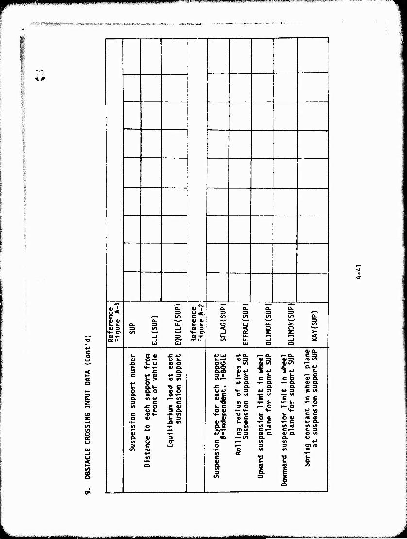
wm ,.l , IXIM-MIU I, in^llUW^WIJ l.lllll, i|Uil|i«iaiijipri||Viiil|IIU<uj|i ilHII||f>.llin!Ui|!l nwpmpv^nnipnif*^
■'''?wWS*r«^TOV.li'i«<»»J»i«»'iM«M«ff,."TOii «i»imi.w«mww«
^r
O O
£
o
to o
00 o
o> i^
^ ^-» <M ^>« *mm. ^-% *-■.
«J. a. «I a. a. Q. a. o< 3 o<. Z3 = => =3 ^■■^
c ^«-^ v> to ^ iS) t^ o. go. a. at OJ «^^ ■^-^ ^i-^ •**** 3 Q. 3 U- c u ca Q a. at to
AS 3 V) 0J 3 3 2 i a >- o»«»- _J Z) at .i- u. u- •-^ •*4 s ocu. _J cr a: u. IO u. mJ —i
UJ UJ UJ a o 4)0.
%. | a> £ 4-> 4JUJ 4-» a. r- a. i—O- C = 01 o w Ui-i •0=3 a<=> a> => IO (/>
X> 1. o 10 o oo «>0 a> to «to r-
E 3
0) o. a. a. oo ■§*> »r
0.4J
C •M 0) 4-> 3 3 N s- u f- o u > (O VI l/»r- *- o c o .^S (U o.
*J o •M Q. •r- a. 0) Q. fc. o.<*> X> C £ • a o. D. £ 3 O a. o IO o O .M H- 3 *» 3 *> 3 » VI o. 3 O-r- «a c O M f- V) •»- VI Q. «/I -M »— «« « C E E c c 3 C c « «rt C t- u ••- 1- t- o «A 5S IS u c
el 3 O -£ ^^ *i VI
C «»♦- ••- l/l ^ Irt c c c c o 0) 1- 3 0) <0 C o «> O 0) 22L •f- A V) «»■o Es. t~ c t- c «0 o •»- 5;^ vi «a VI «o VI VI c *J a« i/i c»- c ^- C 3 a> •^ 4J M C 3 ai o. « o. O VI a. 0) 3 t-V) a. s. u ifl u o- C VI VI ♦* 3 c UJ O r-"» 3 3 O) <o to 5 l/l s VI VI c
l/l c •o "O t. •f-
& t. k. o.
o s IO to tfl 3 2. 1 to 3
*
I
•»LMMM^MMW>» •■ I iirniiiiiüriimw l - ..^„.iJrtiliH
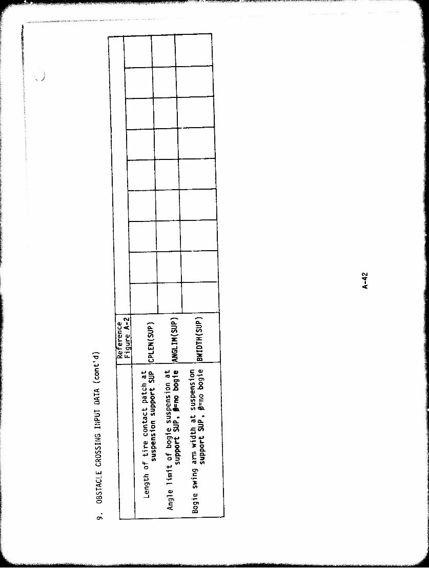
r^^ßmmf^ mmmmmmm mmmimwt :.,.-<•«»".H»w^^"l,'•■w|",,"■i,l,"''!,,"''••,.,,■■'",""■'■'ll"■•*l,|«,,"'l'"■ ■
.«K.^WrtF»**^'-*^-
u
1
CNJ <*
I <
CSJ <u i o< c V 0) 5- 5-
QiU.
^-
o o
C3
00
t/1 cn o
a%
-+-
a.
a. o
a. => </>
■M a.
(/>
St S.8. ^&
♦J c s o O IM c (- a.
«A
o ^:
c 0)
ig l/> &
O L.
«^ o. O 3
0)
"a» c
C (1) o ••- •r- C»
«/> c 3 II
(oa.
X o
El »O 1/)
cn c X <^
(U
cn o
^^^^^ MMMÜ^M^k». j^-^^i ^^^^^^u J
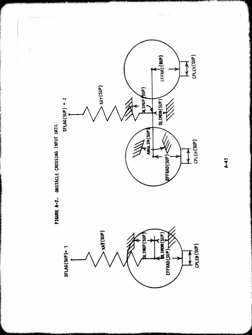
■"" «»«I mmmmimr*^^^**m HIUBIIW WJIUMMBI.W ■» ■.•mnm-if nw» m*mm
1
CO
5
i
's:
a. => CO
CO
I <
■MH^Mi ■
.—.M^MMMMM^M, J
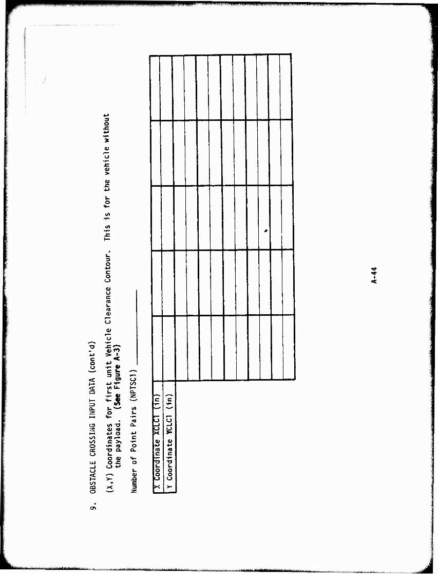
,HI||WUHIIl|||ll.l.| mmtm^Bn*
3 O -C
'5 01
u
0) > (U
o
to 'f—
•r-
C O o
<u o c 19 i~ (t» 0)
^» fli PO 1
4J r» i c < o ■^ .. u •r- 01
c *- ^*^S
3 3 r—* < at o p: +* 7~ CO < I^U. 1— Q j- . Q.
'- S! z 1— **- S ^ tn a. u*-" vo
o L. i—i «♦- •i—
• «J C3 W» T3 a.
<u n •—« ■M O +-> <^0 lO •— c l/l C >, •r" O •#- (O O ac ■O CL Q. o t-
O 0) <♦- UJ o -c O _i O -M o u < *^^* <u P >- -Q a) M £ aa X 3 o Z
'
0
X Coordinate X
CLCI (I
n)
Y Coordinate YC
LCl
(in)
<
I
(Tt
i-iiHirillwmMitah'r ,,^;itfi-..^Wii-. .iii-nr.1 -.iir- ■■■ ■■ ■IM'IIIII _j
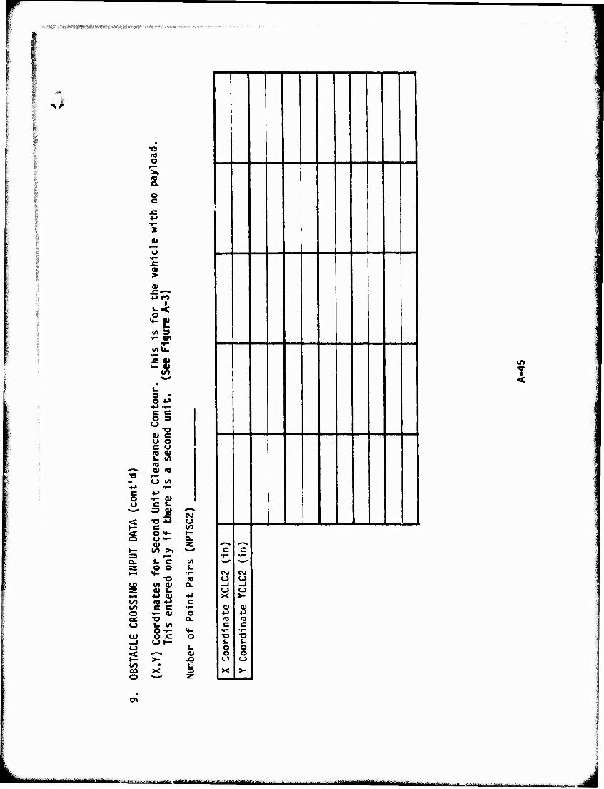
tjilf!^*fWWWI0l0*l00*äMWm^!W iwoflww »awMWWw« *»NM *****
X) IQ O
X
U
>
Mtl.
i. O -M ** •*• e c O 3 o
•a v c u o e u 10 01 u ut «
#■■■•* a> « ■o
o «/» 4J •r- C 4->
s le 3 01 ^"■^
<■ ^5 CVJ o
1— c 00 < o«^ »- a O 1- a.
4) z »— 00 >, **m*
3 Q. i. c IA Z o o (. 1-4 •♦. •f-
-o <a ÜJ «/t et a. •-^ IS •M 00 C 00 c c •r- o f- 01 O QC ■o a. o t. w
§•-£ •♦- UJ o _l CJ>- o u < ^^ a» 1- >- JQ 00 fl £ CO X 3 o Z
|
i
1 c 1 *'"
icM |_J |(-> 1 ** 1 V 1 4-> 1 ") | C
1 J-
\o
1 ^
c
CSJ
<-> _l <-> >•
<e c
1 •f" "O
o >-
<
CT>
L - -i..-..^....... *..,-.
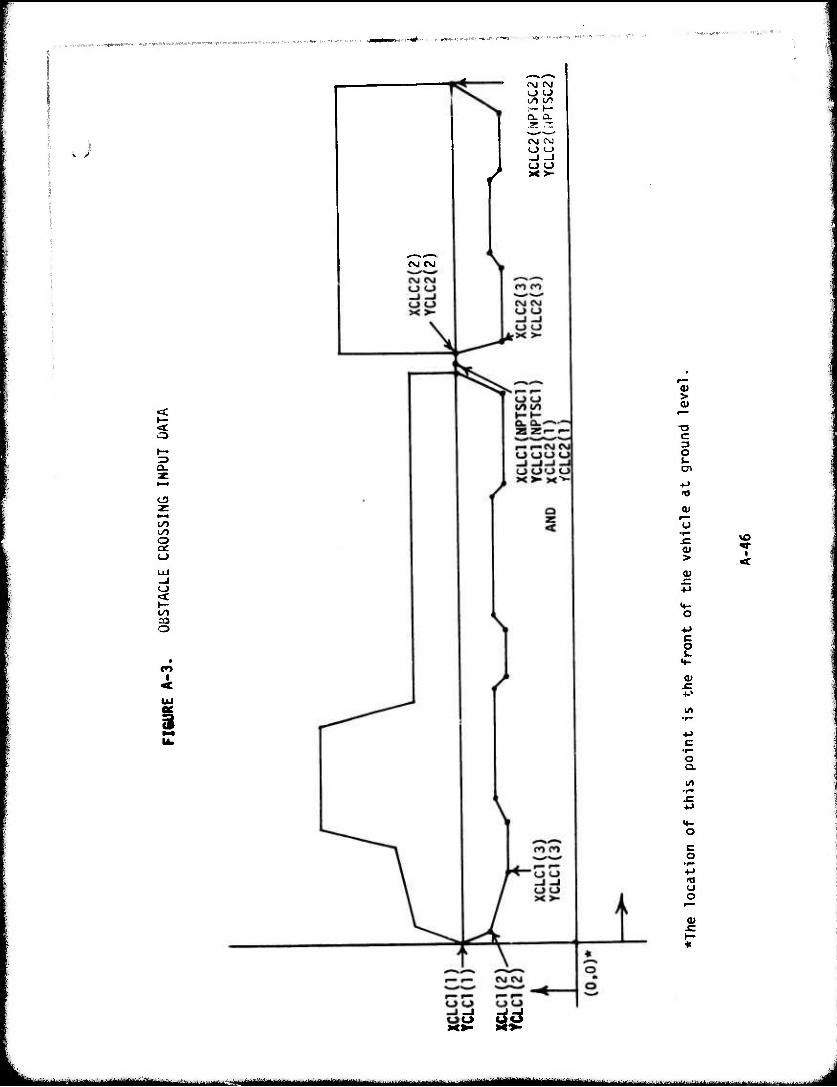
.;
<\J Cü
/
(\J CNJ
(/> (/> ■r- h- Q. a. X rr. CM CNJ
o o x>-
s
o
CO
o
ca o
CO I
<u >
c 3 O cn ■•->
»0
o
<u >
a>
4-> c o w
QJ
vo
o a. 01
c o
o o
5
t u ^Ml^MWM^^Mi -
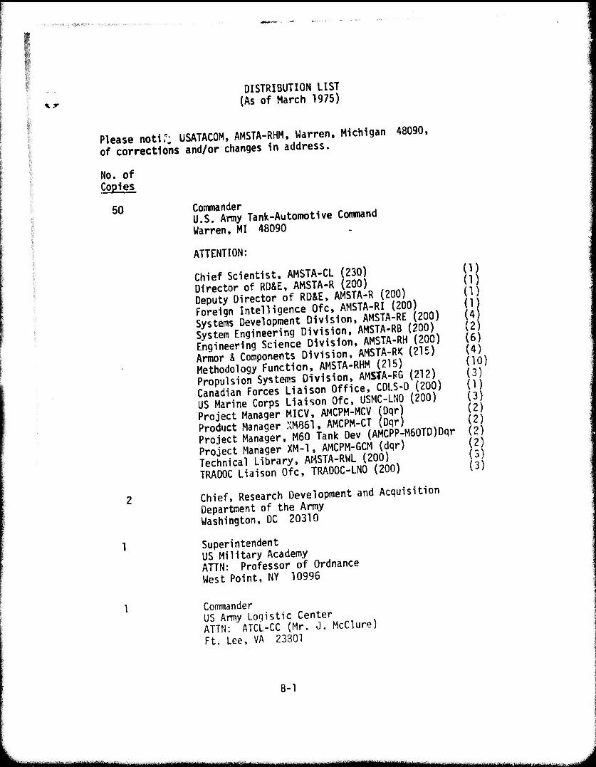
,.;>, .....vT : -ty*, -es < . -.-^..o,..-.--■■
\r
B-l
DISTRIBUTION LIST (As of March 1975)
Please notiT: USATACOM, AMSTA-RHM, Warren. Michigan 48090, of corrections and/or changes in address.
No. of Copies
50 Commander U.S. Army Tank-Automotive Conmand Warren, MI 48090
ATTENTION:
Chief Scientist. AMSTA-CL (230) (1) Director of RD&E, AMSTA-R (200) (1) Deputy Director of RD&E, AMSTA-R (200) (1) Foreign Intelligence Ofc, AMSTA-RI (200) (1) Systems Development Division, AMSTA-RE (200) (4) System Engineering Division, AMSTA-RB (200) (2) Engineering Science Division, AMSTA-RH (200) (6) Armor & Components Division, AMSTA-RK (215) (4) Methodology Function, AMSTA-RHM (215) (10) Propulsion Systems Division, AMSTA-RG (212) (3) Canadian Forces Liaison Office, CDLS-D (200) (1) US Marine Corps Liaison Ofc, USMC-LN0 (200) (3) Project Manager MICV, AMCPM-MCV (Dqr) (2) Product Manager XM861, AMCPM-CT (Dqr) (2) Project Manager, M60 Tank Dev (AMCPP-M60TD)Dqr (2) Project Manager XM-1, AMCPM-GCM (dqr) (2) Technical Library, AMSTA-RWL (200) (3) TRAD0C Liaison Ofc, TRAD0C-LN0 (200) (3)
2 Chief, Research Development and Acquisition Department of the Army Washington, DC 20310
1 Superintendent US Military Academy ATTN: Professor of Ordnance West Point, NY 10996
1 Commander US Army Loqistic Center ATTN: ATCL-CC (Mr. J. McClure) Ft. Lee, VA 23801
--'-"-- - mK-nnn -..,-■..,.. ,_,.. ^..,.^^*-**mu*m~*u**l^^.,.,^ .....,..,
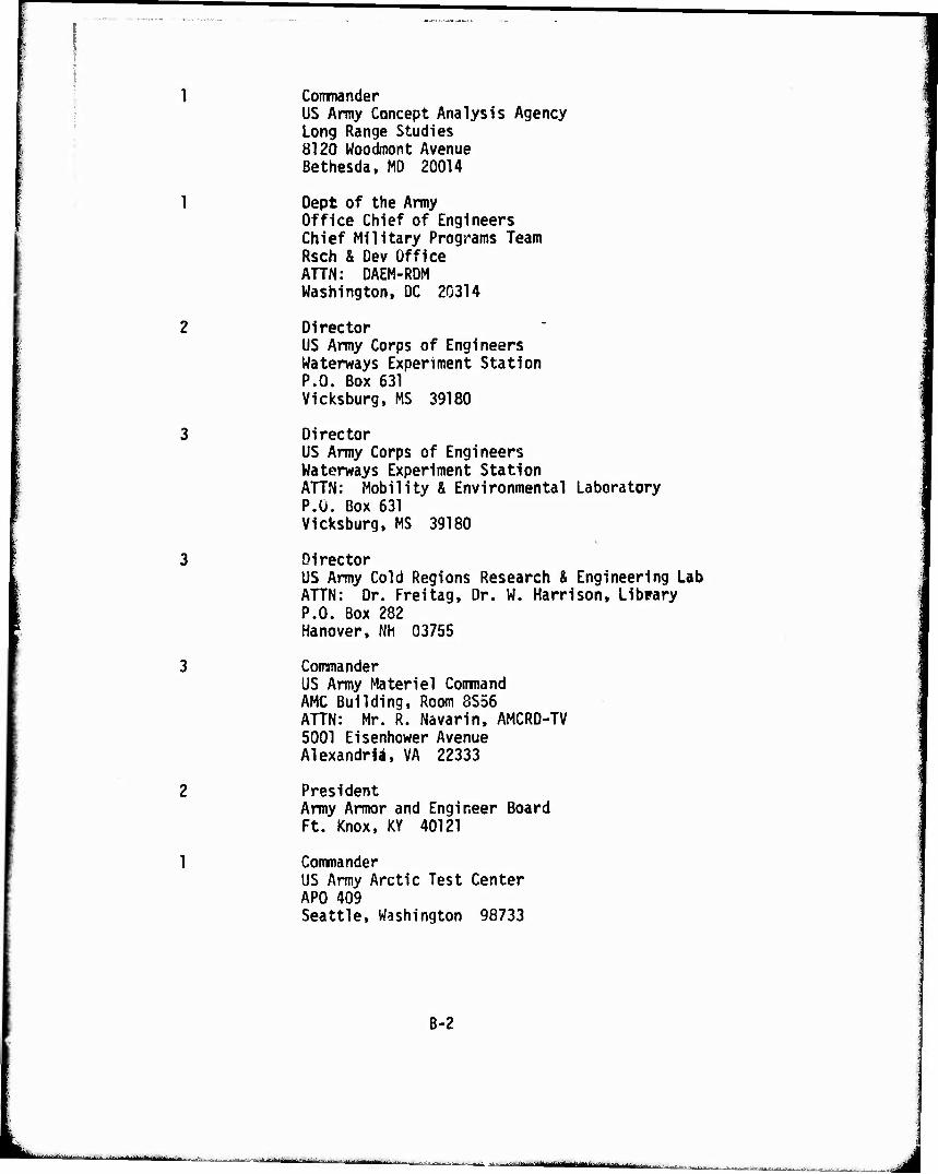
Commander US Army Concept Analysis Agency Long Range Studies 8120 Woodmont Avenue ßethesda, MD 20014
Dept of the Army Office Chief of Engineers Chief Military Programs Team Rsch & Dev Office AHN: DAEM-RDM Washington, DC 20314
Director US Army Corps of Engineers Waterways Experiment Station P.O. Box 631 Vicksburg, MS 39180
Director US Army Corps of Engineers Waterways Experiment Station ATTN: Mobility & Environmental Laboratory P.O. Box 631 Vicksburg, MS 39180
Director US Army Cold Regions Research & Engineering Lab ATTN: Dr. Freitag, Dr. W. Harrison, Library P.O. Box 282 Hanover, Nh 03755
Commander US Army Materiel Command AMC Building, Room 8S56 ATTN: Mr. R. Navarin. AMCRD-TV 5001 Eisenhower Avenue Alexandria, VA 22333
President Army Armor and Engineer Board Ft. Knox, KY 40121
Commander US Army Arctic Test Center APO 409 Seattle, Washington 98733
B-2
■ ■ ■■ ■■■'■■■■■—"
•■■■-■■- -- -■ ■
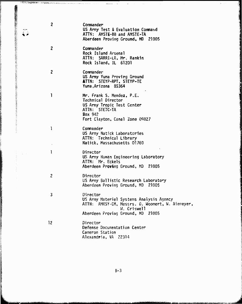
:''f*^!^^T-<t1^Xfm-nm!'h--^.^-r,.::.,
2 Commander -** US Army Test & Evaluation Coinmand 4' AHN: AMSTE-BB and AMSTE-TA
Aberdeen Proving Ground, MD 21005
Commander Rock Island Arsenal ATTN: SARRI-LR, Mr. Rankin Rock Island, IL 61201
Commander US Army Yuma Proving Ground AHN: STEYP-RPT, STEYP-TE Yuma.Arizona 85364
Mr. Frank S. Mendei, P.E. Technical Director US Army Tropic Test Center ATTN: STETC-TA Box 942 Fort Clayton, Canal Zone 09827
Commander US Army Natick Laboratories ATTN: Technical Library Natick, Massachusetts 01760
Director US Army Human Engineering Laboratory ATTN: Mr. Eckels Aberdeen Proving Ground, MD 21005
Director US Army Ballistic Research Laboratory Aberdeen Proving Ground, MD 21005
Director US Army Materiel Systems Analysis Agency ATTN: AMXSY-CM, Messrs. D. Woomert, W. Niemeyer,
W. Criswell Aberdeen Proving Ground, MD 21005
12 Director Defense Documentation Center Cameron Station Alexandria, VA 22314
B-3
^M^^-^äittgUmmmtUtiimimit ■, , ■■■MITI- i - •— .,„.,...-., ,,^^ta*äm*miimmii**L*4i*i^~.~ ^
^^^*^^*^^^^**ii*mi^m^v*~~~~~-~ —- ■MBHB ll1-" ^uPWOPBW^opnnv^
1 US Marine Corps Mobility & Logistics Division Development and Ed Command ATTN: Mr. Hickson Quantico, VA 22134
Mr. A. M. Wooley West Coast Test Branch Mobility and Support Division Marine Corps Base Camp Pendleton, CA 92055
Naval Sea Systems Command Code PMS300A1 Department of the Navy Washington, DC 20362
Naval Ship Research & Dev Center Aviation & Surface Effects Dept. Code 161 AHN: E. O'Neal & W. Zettfuss Washington, DC 20034
Director National Tillage Machinery Laboratory Box 792 Auburn, Alabama 36830
,
Director USDA Forest Service Equipment Dev Center 444 East Bonita Avenue San Dimes, CA 91773
Dr. R. A. Liston Director, Keweenaw Research Center Michigan Technological University Houghton, MI 49931
1 Engineering Societies Library 345 East 47th Street New York, NY 10017
1 Dr. M. G. Bekker 2?" East Islay Drive Santa Barbara, CA 93101
B-4
. a ■-^■Ai,-1i|||[. .hi

mm. MUMJ mmmm w»> mmm i -1- wtwwwwwwwawaiwwBwiiiwwi»pw—www.
Dr. I. R. Ehrlich, Dean for Research Stevens Institute of Technology • Castle Point Station Hoboken, NJ 07030
Grumman Aerospace Corporation ATTN: Dr. L. Karafiath. Mr. E. Markow Plant 35 Bethpage, Long Island, NY 11714
Dr. Bruce Liljedahl Agricultural Engineering Department Purdue University Lafayette, IN 46207
Dr. W. G. Baker Dean, College of Engineering University of Detroit 4001 W. McNichols Detroit, MI 48221
Mr. H. C. Hodges Nevada Automotive Test Center Box 234 Carson City, NV 89701
Mr. W. S. Hodges Lockheed Missile & Space Corporation Ground Vehicle Systems
Department 50-24, Bldg 528 Sunnyvale, CA 94088
Mr. R. D. Wismer Deere & Company Engineering Research 3300 River Drive Moline, IL 61265
Oregon State University Library Corvallis, Oregon 97331
Southwest Research Institute ATTN: Mr. R. C. Hemion 8500 Culebra Road San Antonio, TX 78228
B-5
L- ̂•■"■■' ifi .I mil " Ulli*.! ' *•' '■ M — Kill , „Mmtmmmä^
I"" ■"',"1« "W^^W^^Wi1^ ^qpmpvpmiqpisvipm
FMC Corporation Technical Library P.O. Box 1201 San Jose. CA 95108
Mr. J. Appelblatt Director of Engineering Cadillac Gaege Co. P.O. Box 1027 Warren, MI 48090
Chrysler Corporation Mobility Research Laboratory, Defense Engineering ATTN: Dr. B. VanDeusen, Mr. '• Department 6100 P.O. Box 751 Detroit, MI 48231
Library CALSPAN Corporation Box 235 4455 Genessee Street Buffalo, NY 14221
Mr. Sven E. Lind SFM, Forsvaretsforskningsanstalt Avd 2 Stockholm 80, Sweden
Mr. Rolf Schreiber c/o Bundesamt Fuer Wehrtechnik Und Beschaffung - KGII 7 - 5400 Koblenz Am Rhein 2-6 Germany
Cohron
B-6
--- - u m^AuM ..~, . . ..... ——^--- J


