Embed Size (px)
Citation preview
Operator’s ManualIMPORTANT: Read this manual carefully. It contains information about yoursafety and the safety of others. Also become familiar with the controls andtheir proper use before you operate the product.
FORM NO. 3318–825 Rev. A
Wheel Horse
42” Snowthrowerfor
Classic Garden TractorsModel No. 79360 – 7900001 & Up
Printed in USA
The Toro Company – 1996All Rights Reserved
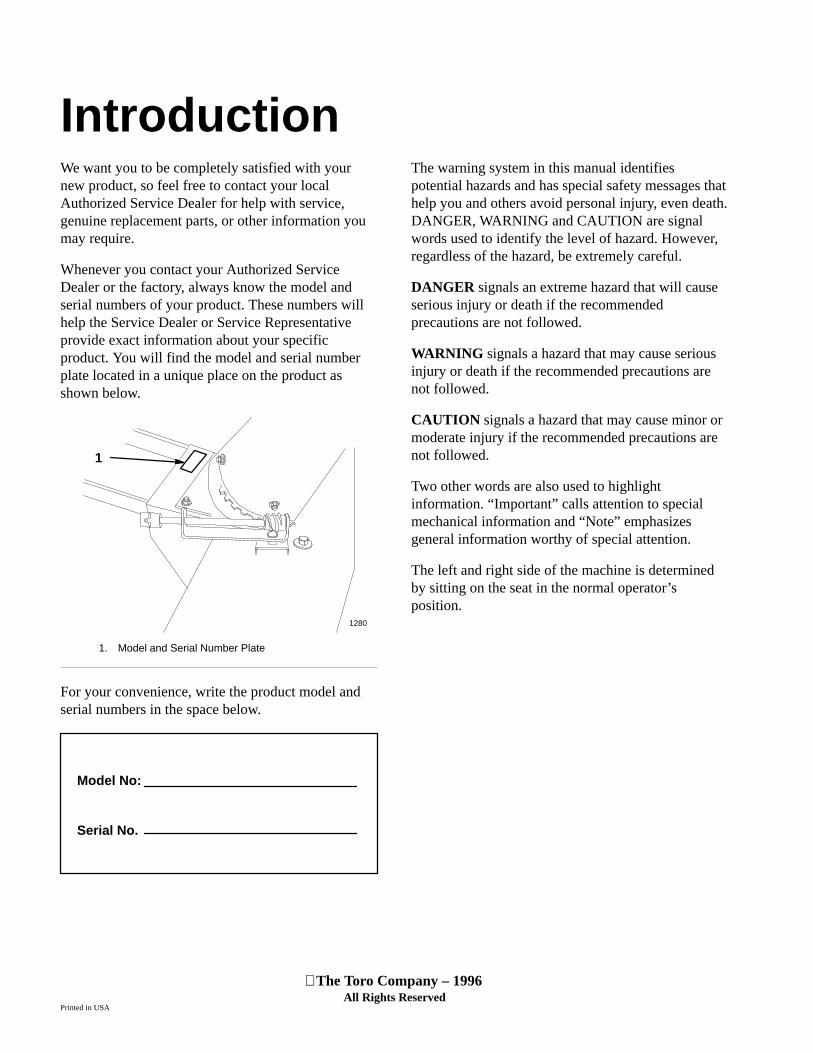
IntroductionWe want you to be completely satisfied with yournew product, so feel free to contact your localAuthorized Service Dealer for help with service,genuine replacement parts, or other information youmay require.
Whenever you contact your Authorized ServiceDealer or the factory, always know the model andserial numbers of your product. These numbers willhelp the Service Dealer or Service Representativeprovide exact information about your specificproduct. You will find the model and serial numberplate located in a unique place on the product asshown below.
1
1280
1. Model and Serial Number Plate
For your convenience, write the product model andserial numbers in the space below.
Model No:
Serial No.
The warning system in this manual identifiespotential hazards and has special safety messages thathelp you and others avoid personal injury, even death.DANGER, WARNING and CAUTION are signalwords used to identify the level of hazard. However,regardless of the hazard, be extremely careful.
DANGER signals an extreme hazard that will causeserious injury or death if the recommendedprecautions are not followed.
WARNING signals a hazard that may cause seriousinjury or death if the recommended precautions arenot followed.
CAUTION signals a hazard that may cause minor ormoderate injury if the recommended precautions arenot followed.
Two other words are also used to highlightinformation. “Important” calls attention to specialmechanical information and “Note” emphasizesgeneral information worthy of special attention.
The left and right side of the machine is determinedby sitting on the seat in the normal operator’sposition.
1
ContentsPage
Safety and Instruction Decals 2. . . . . . . . . . . . . .
Installation 5. . . . . . . . . . . . . . . . . . . . . . . . . . . . .
Loose Parts 5. . . . . . . . . . . . . . . . . . . . . . . . .
Assemble Housing 7. . . . . . . . . . . . . . . . . . .
Installing Snowthrower to Tractor 8. . . . . . .
Removing the Snowthrower 11. . . . . . . . . . .
Operation 14. . . . . . . . . . . . . . . . . . . . . . . . . . . . . .
Operating the Power Take Off (PTO) 14. . . .
Attachment Lift Lever 15. . . . . . . . . . . . . . . .
Attachment Power Lift 15. . . . . . . . . . . . . . . .
Adjusting Dial-A-Height 16. . . . . . . . . . . . . .
Adjusting Discharge Chute 16. . . . . . . . . . . .
Tips for Throwing Snow 17. . . . . . . . . . . . . .
Page
Maintenance 18. . . . . . . . . . . . . . . . . . . . . . . . . . . .
Service Interval Chart 18. . . . . . . . . . . . . . . .
Greasing and Lubrication 19. . . . . . . . . . . . . .
Adjusting Skids 20. . . . . . . . . . . . . . . . . . . . .
Reversing Scraper Blade 20. . . . . . . . . . . . . .
Adjusting Drive Chain Tension 21. . . . . . . . .
Storage 21. . . . . . . . . . . . . . . . . . . . . . . . . . . .
Troubleshooting 22. . . . . . . . . . . . . . . . . . . . . . . . .
Warranty Back Cover. . . . . . . . . . . . . . . . . . . . . . . . . .
Safety
2
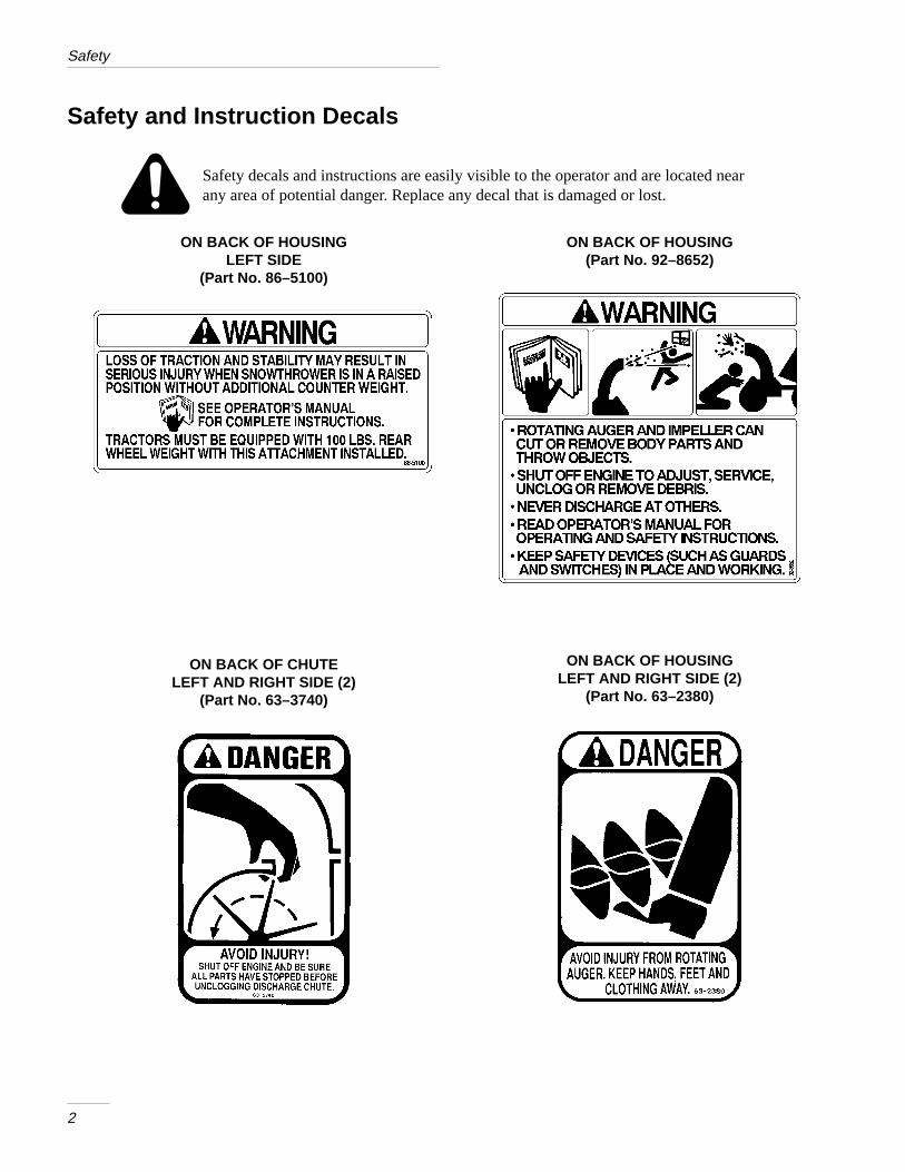
Safety and Instruction Decals
Safety decals and instructions are easily visible to the operator and are located nearany area of potential danger. Replace any decal that is damaged or lost.
ON BACK OF HOUSINGLEFT SIDE
(Part No. 86–5100)
ON BACK OF HOUSING(Part No. 92–8652)
ON BACK OF CHUTELEFT AND RIGHT SIDE (2)
(Part No. 63–3740)
ON BACK OF HOUSINGLEFT AND RIGHT SIDE (2)
(Part No. 63–2380)

3
InstallationLoose PartsNote: Use the chart below to identify parts used for assembly.
DESCRIPTION QTY. USE
Housing
Frame with idlers
Bolt 3/8–16 x 1”
Locknut 3/8”
Pulley
Set screw 5/16–18 x 1/2”
Key
Tension spring
1
1
4
4
1
2
1
1
Install frame and pulley
Top plate
Side plate
Carriage bolt 3/8–16 x 1”
Washer 3/8”
Locknut 3/8”
1
2
9
9
9
Install top and side plates
Discharge chute-Upper
Discharge chute-Lower
Deflector shield
Carriage bolt 5/16–18 x 3/4”
Carriage bolt 5/16–18 x 5/8”
Washer 5/16”
Locknut 5/16”
Rotator assembly
Carriage bolt 5/16–18 x 1”
Pyramidal washer 5/16”
1
1
1
3
3
7
7
1
1
1
Install discharge chute and rotator assembly

Installation
4
DESCRIPTION QTY. USE
Snowthrower assembly
Lift tube
Lift rod
Spacer washer 3/4”
Washer 5/8”
Hairpin cotter-large
Lift assist spring
Eyebolt
Locknut 3/8”
Belt
Crank handle
Handle support
Hairpin cotter-small
1
1
1
2
1
1
1
1
1
1
1
1
2
Mount snowthrower to tractor
Installation
5
Assemble Housing
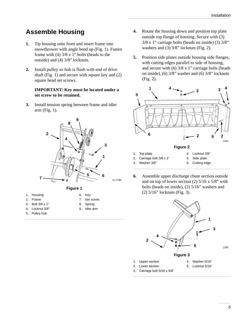
1. Tip housing onto front and insert frame intosnowthrower with angle bend up (Fig. 1). Fastenframe with (4) 3/8 x 1” bolts (heads to theoutside) and (4) 3/8” locknuts.
2. Install pulley so hub is flush with end of driveshaft (Fig. 1) and secure with square key and (2)square head set screws.
IMPORTANT: Key must be located under aset screw to be retained.
3. Install tension spring between frame and idlerarm (Fig. 1).
1
4
3
6
2
57
m–2786
98
Figure 1
1. Housing2. Frame3. Bolt 3/8 x 1”4. Locknut 3/8”5. Pulley hub
6. Key7. Set screw8. Spring9. Idler arm
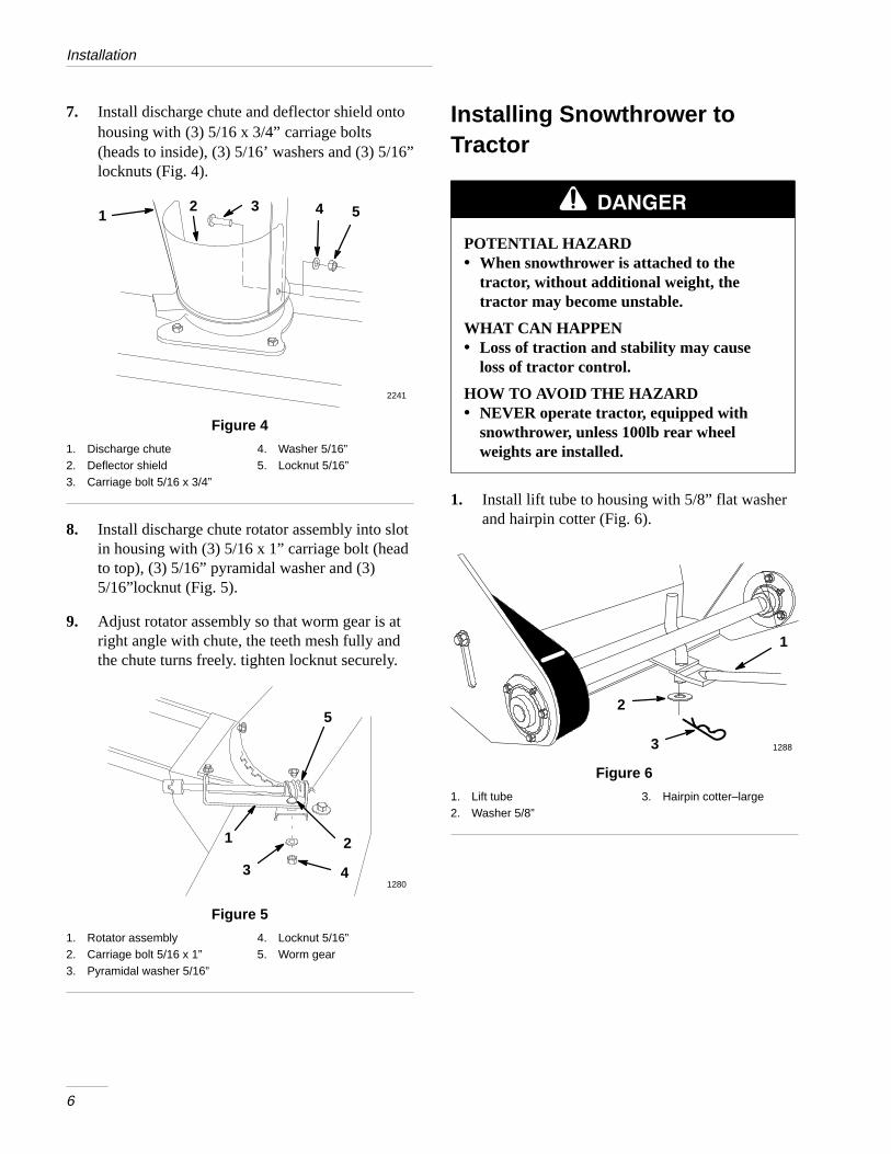
4. Rotate the housing down and position top plateoutside top flange of housing. Secure with (3)3/8 x 1” carriage bolts (heads on inside) (3) 3/8”washers and (3) 3/8” locknuts (Fig. 2).
5. Position side plates outside housing side flanges,with cutting edges parallel to side of housing,and secure with (6) 3/8 x 1” carriage bolts (headson inside), (6) 3/8” washer and (6) 3/8” locknuts(Fig. 2).
1
5
4
6
3
1281
43
2 25
Figure 2
1. Top plate2. Carriage bolt 3/8 x 1”3. Washer 3/8”
4. Locknut 3/8”5. Side plate6. Cutting edge
6. Assemble upper discharge chute section outsideand on top of lower section (2) 5/16 x 5/8” withbolts (heads on inside), (2) 5/16” washers and(2) 5/16” locknuts (Fig. 3).
1290
1
3
25
4
Figure 3
1. Upper section2. Lower section3. Carriage bolt 5/16 x 5/8”
4. Washer 5/16”5. Locknut 5/16”
Installation
6
7. Install discharge chute and deflector shield ontohousing with (3) 5/16 x 3/4” carriage bolts(heads to inside), (3) 5/16’ washers and (3) 5/16”locknuts (Fig. 4).
2 3 4
2241
51
Figure 4
1. Discharge chute2. Deflector shield3. Carriage bolt 5/16 x 3/4”
4. Washer 5/16”5. Locknut 5/16”
8. Install discharge chute rotator assembly into slotin housing with (3) 5/16 x 1” carriage bolt (headto top), (3) 5/16” pyramidal washer and (3)5/16”locknut (Fig. 5).
9. Adjust rotator assembly so that worm gear is atright angle with chute, the teeth mesh fully andthe chute turns freely. tighten locknut securely.
1 2
31280
4
5
Figure 5
1. Rotator assembly2. Carriage bolt 5/16 x 1”3. Pyramidal washer 5/16”
4. Locknut 5/16”5. Worm gear
Installing Snowthrower toTractor
POTENTIAL HAZARD• When snowthrower is attached to the
tractor, without additional weight, thetractor may become unstable.
WHAT CAN HAPPEN• Loss of traction and stability may cause
loss of tractor control.
HOW TO AVOID THE HAZARD• NEVER operate tractor, equipped with
snowthrower, unless 100lb rear wheelweights are installed.
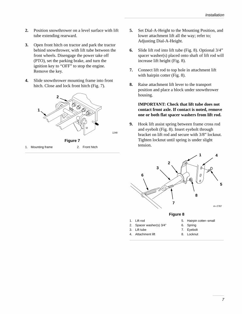
1. Install lift tube to housing with 5/8” flat washerand hairpin cotter (Fig. 6).
12883
2
1
Figure 6
1. Lift tube2. Washer 5/8”
3. Hairpin cotter–large
Installation
7
2. Position snowthrower on a level surface with lifttube extending rearward.
3. Open front hitch on tractor and park the tractorbehind snowthrower, with lift tube between thefront wheels. Disengage the power take off(PTO), set the parking brake, and turn theignition key to “OFF” to stop the engine.Remove the key.
4. Slide snowthrower mounting frame into fronthitch. Close and lock front hitch (Fig. 7).
2
1248
1
Figure 7
1. Mounting frame 2. Front hitch
5. Set Dial-A-Height to the Mounting Position, andlower attachment lift all the way; refer to;Adjusting Dial-A-Height.
6. Slide lift rod into lift tube (Fig. 8). Optional 3/4”spacer washer(s) placed onto shaft of lift rod willincrease lift height (Fig. 8).
7. Connect lift rod to top hole in attachment liftwith hairpin cotter (Fig. 8).
8. Raise attachment lift lever to the transportposition and place a block under snowthrowerhousing.
IMPORTANT: Check that lift tube does notcontact front axle. If contact is noted, removeone or both flat spacer washers from lift rod.
9. Hook lift assist spring between frame cross rodand eyebolt (Fig. 8). Insert eyebolt throughbracket on lift rod and secure with 3/8” locknut.Tighten locknut until spring is under slighttension.
m–2787
1
2
4
8
3
5
7
6
Figure 8
1. Lift rod2. Spacer washer(s) 3/4”3. Lift tube4. Attachment lift
5. Hairpin cotter–small6. Spring7. Eyebolt8. Locknut
Installation
8
10. Remove the belt cover; refer to tractorOperator’s Manual.
11. Remove hairpin cotters from trunnion andbottom of yoke (Fig. 9).
12. Unlatch and remove clevis pin that secures yokeassembly to clutch shaft. Pivot yoke out andforward to remove from clutch shaft andengagement plate (Fig. 9).
13. Place belt in outer pulley groove (Fig. 9).
14. Assemble yoke and engagement plate and attachclevis pin, trunnion and hairpin cotters to secure(Fig. 9).
m–26911
2 3
4
1
7
6
5
Figure 9
1. Hairpin cotter2. Trunnion3. Engagement plate4. Clevis pin
5. Yoke6. Clutch shaft7. Outer groove
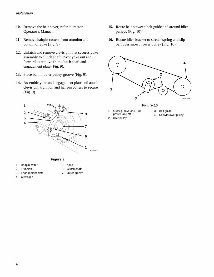
15. Route belt between belt guide and around idlerpulleys (Fig. 10).
16. Rotate idler bracket to stretch spring and slipbelt over snowthrower pulley (Fig. 10),
m–2788
1
2
3
4
Figure 10
1. Outer groove of (PTO)power take off
2. Idler pulley
3. Belt guide4. Snowthrower pulley
Installation
9
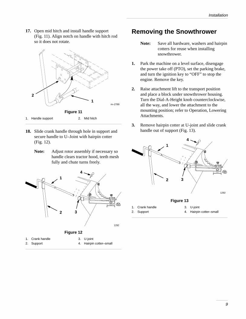
17. Open mid hitch and install handle support(Fig. 11). Align notch on handle with hitch rodso it does not rotate.
m–2789
21
Figure 11
1. Handle support 2. Mid hitch
18. Slide crank handle through hole in support andsecure handle to U–Joint with hairpin cotter(Fig. 12).
Note: Adjust rotor assembly if necessary sohandle clears tractor hood, teeth meshfully and chute turns freely.
1292
2
14
3
Figure 12
1. Crank handle2. Support
3. U-joint4. Hairpin cotter–small
Removing the Snowthrower
Note: Save all hardware, washers and hairpincotters for reuse when installingsnowthrower.
1. Park the machine on a level surface, disengagethe power take off (PTO), set the parking brake,and turn the ignition key to “OFF” to stop theengine. Remove the key.
2. Raise attachment lift to the transport positionand place a block under snowthrower housing.Turn the Dial-A-Height knob counterclockwise,all the way, and lower the attachment to themounting position; refer to Operation, LoweringAttachments.
3. Remove hairpin cotter at U-joint and slide crankhandle out of support (Fig. 13).
1292
2
14
3
Figure 13
1. Crank handle2. Support
3. U-joint4. Hairpin cotter–small
Installation
10
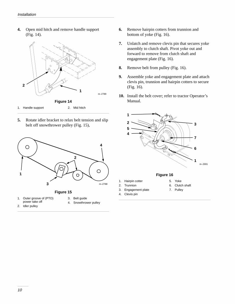
4. Open mid hitch and remove handle support(Fig. 14).
m–2789
21
Figure 14
1. Handle support 2. Mid hitch
5. Rotate idler bracket to relax belt tension and slipbelt off snowthrower pulley (Fig. 15),
m–2788
1
2
3
4
Figure 15
1. Outer groove of (PTO)power take off
2. Idler pulley
3. Belt guide4. Snowthrower pulley
6. Remove hairpin cotters from trunnion andbottom of yoke (Fig. 16).
7. Unlatch and remove clevis pin that secures yokeassembly to clutch shaft. Pivot yoke out andforward to remove from clutch shaft andengagement plate (Fig. 16).
8. Remove belt from pulley (Fig. 16).
9. Assemble yoke and engagement plate and attachclevis pin, trunnion and hairpin cotters to secure(Fig. 16).
10. Install the belt cover; refer to tractor Operator’sManual.
m–26911
2 3
4
1
7
6
5
Figure 16
1. Hairpin cotter2. Trunnion3. Engagement plate4. Clevis pin
5. Yoke6. Clutch shaft7. Pulley
Installation
11
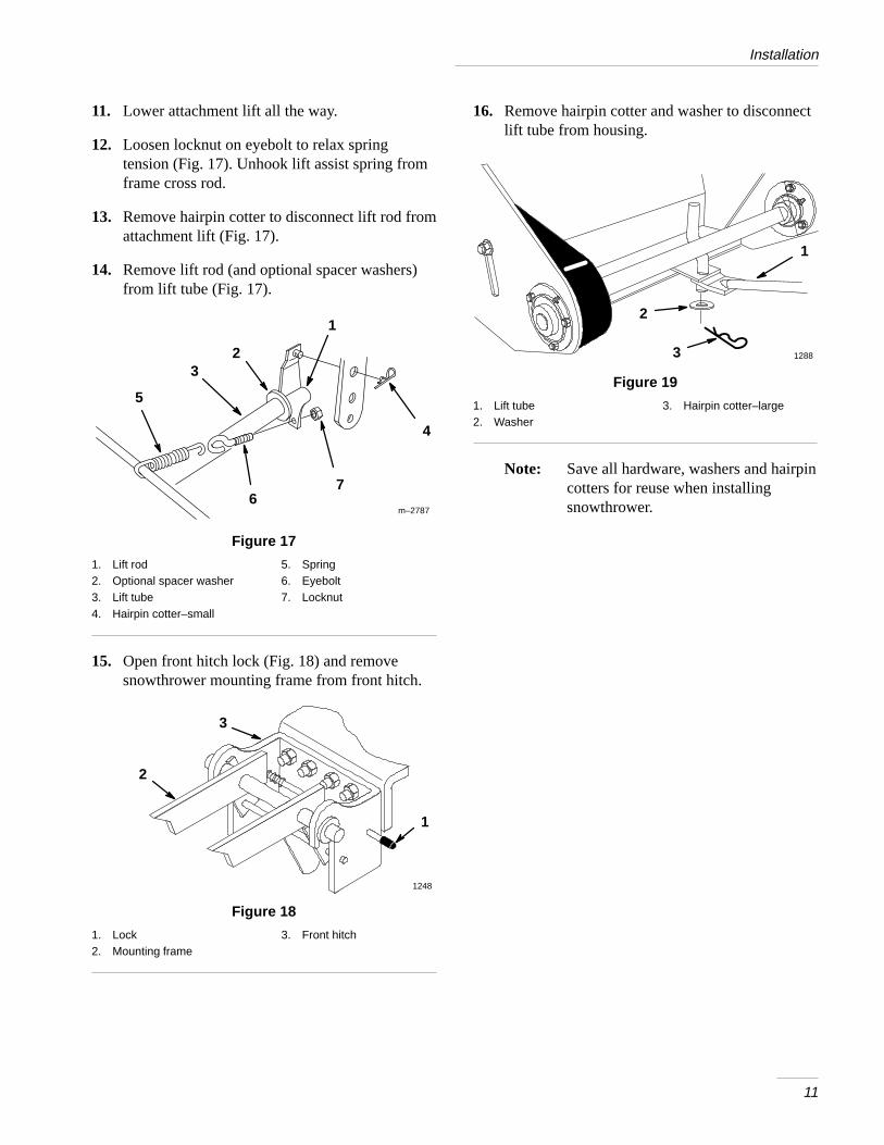
11. Lower attachment lift all the way.
12. Loosen locknut on eyebolt to relax springtension (Fig. 17). Unhook lift assist spring fromframe cross rod.
13. Remove hairpin cotter to disconnect lift rod fromattachment lift (Fig. 17).
14. Remove lift rod (and optional spacer washers)from lift tube (Fig. 17).
m–2787
1
2
7
3
4
6
5
Figure 17
1. Lift rod2. Optional spacer washer3. Lift tube4. Hairpin cotter–small
5. Spring6. Eyebolt7. Locknut
15. Open front hitch lock (Fig. 18) and removesnowthrower mounting frame from front hitch.
2
1248
1
3
Figure 18
1. Lock2. Mounting frame
3. Front hitch
16. Remove hairpin cotter and washer to disconnectlift tube from housing.
12883
2
1
Figure 19
1. Lift tube2. Washer
3. Hairpin cotter–large
Note: Save all hardware, washers and hairpincotters for reuse when installingsnowthrower.
12
Operation
POTENTIAL HAZARD• When snowthrower is attached to the
tractor, without additional weight, thetractor may become unstable.
WHAT CAN HAPPEN• Loss of traction and stability may cause
loss of tractor control.
HOW TO AVOID THE HAZARD• NEVER operate tractor, equipped with
snowthrower, unless 100 lb rear wheelweights are installed.
POTENTIAL HAZARD• Rotating auger can cut off fingers, hands or
other body parts and throw objects.
WHAT CAN HAPPEN• Contact with rotating auger and thrown
debris can cause severe injury or death.
HOW TO AVOID THE HAZARD• Stay away from the discharge and auger
openings while operating the snowthrower.• Keep your hands, feet, and any other part
of your body or clothing away fromconcealed, moving or rotating parts.
• Use a stick, not your hand, to removeobstructions from discharge chute or augerhousing.
• Before adjusting, cleaning, repairing andinspecting the snowthrower and beforeunclogging the discharge chute, shut off theengine and wait for all moving parts tostop. Move the power take off (PTO) to“OFF” and rotate the ignition key to“OFF.” Remove the key.
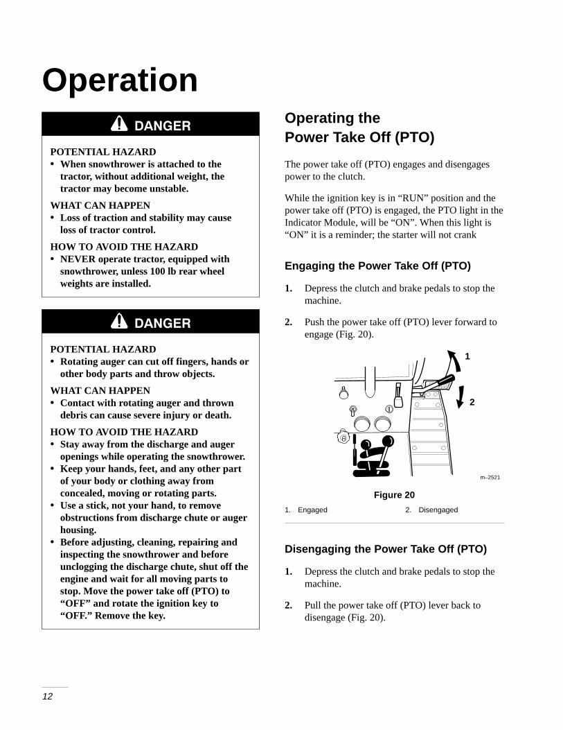
Operating thePower Take Off (PTO)
The power take off (PTO) engages and disengagespower to the clutch.
While the ignition key is in “RUN” position and thepower take off (PTO) is engaged, the PTO light in theIndicator Module, will be “ON”. When this light is“ON” it is a reminder; the starter will not crank
Engaging the Power Take Off (PTO)
1. Depress the clutch and brake pedals to stop themachine.
2. Push the power take off (PTO) lever forward toengage (Fig. 20).
2
m–2521
1
Figure 20
1. Engaged 2. Disengaged
Disengaging the Power Take Off (PTO)
1. Depress the clutch and brake pedals to stop themachine.
2. Pull the power take off (PTO) lever back todisengage (Fig. 20).
Operation
13
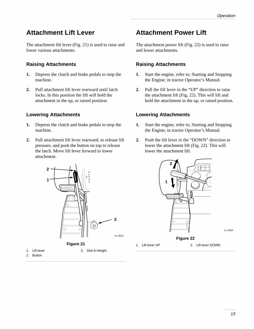
Attachment Lift Lever
The attachment lift lever (Fig. 21) is used to raise andlower various attachments.
Raising Attachments
1. Depress the clutch and brake pedals to stop themachine.
2. Pull attachment lift lever rearward until latchlocks. In this position the lift will hold theattachment in the up, or raised position.
Lowering Attachments
1. Depress the clutch and brake pedals to stop themachine.
2. Pull attachment lift lever rearward, to release liftpressure, and push the button on top to releasethe latch. Move lift lever forward to lowerattachment.
m–2514
3
2
1
Figure 21
1. Lift lever2. Button
3. Dial-A-Height
Attachment Power Lift
The attachment power lift (Fig. 22) is used to raiseand lower attachments.
Raising Attachments
1. Start the engine, refer to; Starting and Stoppingthe Engine; in tractor Operator’s Manual.
2. Pull the lift lever in the “UP” direction to raisethe attachment lift (Fig. 22). This will lift andhold the attachment in the up, or raised position.
Lowering Attachments
1. Start the engine, refer to; Starting and Stoppingthe Engine; in tractor Operator’s Manual.
2. Push the lift lever in the “DOWN” direction tolower the attachment lift (Fig. 22). This willlower the attachment lift.
m–2454
2
1
Figure 22
1. Lift lever UP 2. Lift lever DOWN
Operation
14
Adjusting Dial-A-Height
The Dial-A-Height control (Fig. 21) is used to limitthe downward travel of the attachment. TheDial-A-Height knob is rotated to change the locationof this stop, up or down.
1. Raise the attachment lift: Refer to RaisingAttachments. In the raised position theDial-A-Height knob (Fig. 21) can be rotated tochange the stop location. Turn clockwise to raiseand counterclockwise to lower the height of theattachment.
2. The Dial-A-Height indicator (Fig. 21) will showthe change, high to low, in attachment lift heightas adjustment is made.
Adjusting Discharge Chute
POTENTIAL HAZARD• Rotating auger can cut off fingers, hands or
other body parts and throw objects.
WHAT CAN HAPPEN• Contact with rotating auger and thrown
debris can cause severe injury or death.
HOW TO AVOID THE HAZARD• Stay away from the discharge and auger
openings while operating the snowthrower.• Keep your hands, feet, and any other part
of your body or clothing away fromconcealed, moving or rotating parts.
• Use a stick, not your hand, to removeobstructions from discharge chute or augerhousing.
• Before adjusting, cleaning, repairing andinspecting the snowthrower and beforeunclogging the discharge chute, shut off theengine and wait for all moving parts tostop. Move the power take off (PTO) to“OFF” and rotate the ignition key to“OFF.” Remove the key.
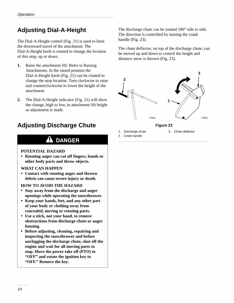
The discharge chute can be rotated 180° side to side.The direction is controlled by turning the crankhandle (Fig. 23).
The chute deflector, on top of the discharge chute, canbe moved up and down to control the height anddistance snow is thrown (Fig. 23).
1290a1292a
3
2
1
Figure 23
1. Discharge chute2. Crank handle
3. Chute deflector
Operation
15
Tips for Throwing Snow
Remove snow as soon as possible after it falls. Thisproduces best snow removal results.
Adjust skids to match the type of surface beingcleaned; refer to Adjusting Skids.
The snowthrower is designed to clean snow down tothe contact surface, but there are times when the frontof the snowthrower may tend to ride up. If thishappens, reduce forward speed.
Discharge snow downwind whenever possible, andoverlap each pass to ensure complete snow removal.If wheels slip, shift into a lower gear to reduceforward speed.
Run snowthrower for a few minutes after clearingsnow so moving parts do not freeze. Engage powertake off (PTO) to clear any remaining snow frominside housing.
Do not overload snowthrower by clearing snow at toofast a rate. If engine slows down, reduce forwardspeed.
Always use full throttle (maximum engine speed)when throwing snow.
In wet or slushy conditions, clogging of the dischargechute will be reduced by maintaining maximumengine speed and by not overloading the engine.
In some snow and cold weather conditions, somecontrols and moving parts may freeze. Therefore,when any control becomes hard to operate, stop themachine and wait for all moving parts to stop; thencheck all parts for freeze up. DO NOT USEEXCESSIVE FORCE AND TRY TO OPERATETHE CONTROLS WHEN FROZEN. Free allcontrols and moving parts before operating.
16
MaintenanceService Interval Chart
Service OperationEachUse
5Hours
25Hours
StorageService
FallService Notes
Grease–drive shaft bearings X X X
Oil–drive chain X X X
Belt–check for wear/cracks X X
Chipped Surfaces–paint X
Scraper–check for wear X X
POTENTIAL HAZARD• If you leave the key in the ignition switch, someone could start the engine.
WHAT CAN HAPPEN• Accidental starting of the engine could seriously injure you or other bystanders.
HOW TO AVOID THE HAZARD• Remove the key from the ignition switch and pull the wire off the spark plug before
you do any maintenance. Also push the wire aside so it does not accidentally contactthe spark plug.
Maintenance
17
Greasing and Lubrication
Service Interval/Specification
Grease and oil the machine after every 25 operatinghours or once a year, whichever occurs first.
Grease Type: General-purpose grease.
Oil Type: SAE 10W or 10W30.
How to Grease
1. Disengage the power take off (PTO), set theparking brake, and turn the ignition key to“OFF” to stop the engine. Remove the key.
2. Clean the grease fittings with a rag. Make sure toscrape any paint off the front of the fitting(s).
3. Connect a grease gun to the fitting. Pump greaseinto the fittings.
4. Wipe up any excess grease.
Where to Add Grease
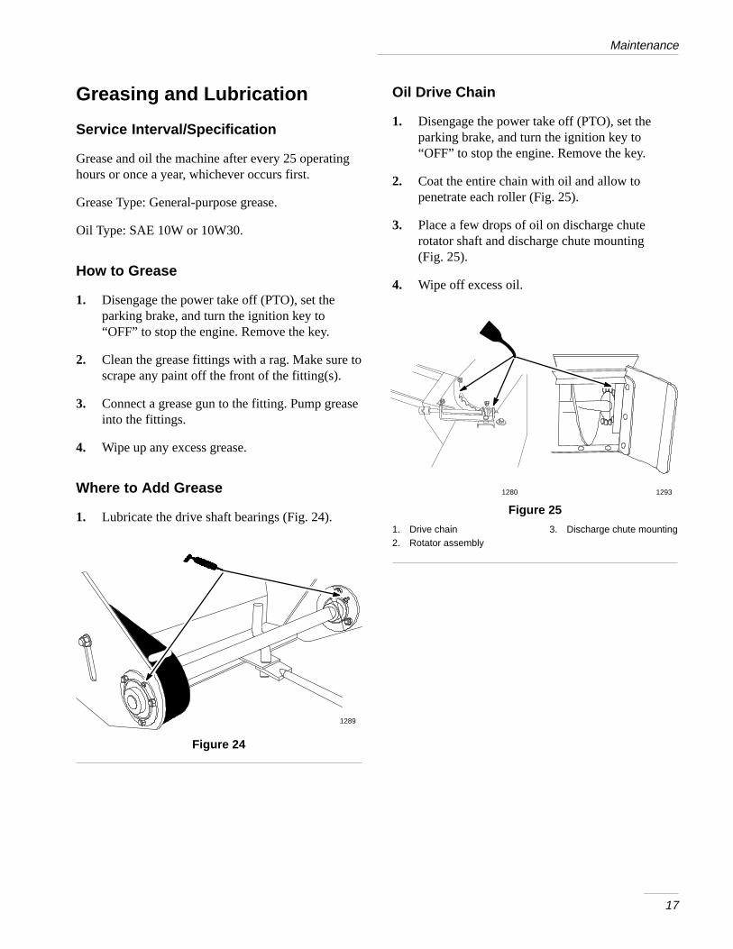
1. Lubricate the drive shaft bearings (Fig. 24).
1289
Figure 24
Oil Drive Chain
1. Disengage the power take off (PTO), set theparking brake, and turn the ignition key to“OFF” to stop the engine. Remove the key.
2. Coat the entire chain with oil and allow topenetrate each roller (Fig. 25).
3. Place a few drops of oil on discharge chuterotator shaft and discharge chute mounting (Fig. 25).
4. Wipe off excess oil.
12931280
Figure 25
1. Drive chain2. Rotator assembly
3. Discharge chute mounting
Maintenance
18
Adjusting Skids
The distance between the scraper blade and theground is controlled by skids on each side of thehousing. The height can be adjusted so the scraperblade will not catch on uneven surfaces
1. Disengage the power take off (PTO), set theparking brake, and turn the ignition key to“OFF” to stop the engine. Remove the key.
2. Move snowthrower to a level surface.
3. Loosen nuts securing skids to the housing untilthe skids slide up and down easily (Fig. 26).
4. Raise or lower skids equally on both sides, toobtain level scraping action, and tighten nuts(Fig. 26).
Note: On smooth, paved surfaces, scraperblade can be close to the surface Onuneven, gravel or crushed rocksurfaces, adjust skids to raise scraper,to prevent catching or picking uprocks.
�
����
�
�
Figure 26
1. Skid2. Housing
3. Nut
IMPORTANT: The scraper should be higherabove the pavement if the pavement surfaceson which the snowthrower will be used arecracked, rough or uneven.
Reversing Scraper Blade
The scraper blade contacts the ground preventingdamage to the snowthrower housing. Periodicallyinspect the scraper blade for wear. When scraperbecomes worn, before working surface contacts thehousing, reverse the scraper blade.
1. Disengage the power take off (PTO), set theparking brake, and turn the ignition key to“OFF” to stop the engine. Remove the key.
2. Raise the attachment lift lever: Refer to RaisingAttachments, and support the housing off theground.
3. Remove nuts,washers, carriage bolts and scraperblade (Fig. 27).
4. Reverse scraper blade and install with previouslyremoved hardware (Fig. 27).
1281a1
234
Figure 27
1. Nut2. Washer
3. Carriage bolt4. Scraper blade
Maintenance
19
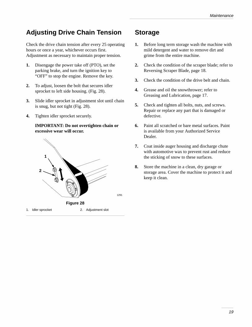
Adjusting Drive Chain Tension
Check the drive chain tension after every 25 operatinghours or once a year, whichever occurs first.Adjustment as necessary to maintain proper tension.
1. Disengage the power take off (PTO), set theparking brake, and turn the ignition key to“OFF” to stop the engine. Remove the key.
2. To adjust, loosen the bolt that secures idlersprocket to left side housing. (Fig. 28).
3. Slide idler sprocket in adjustment slot until chainis snug, but not tight (Fig. 28).
4. Tighten idler sprocket securely.
IMPORTANT: Do not overtighten chain orexcessive wear will occur.
2
1
1291
Figure 28
1. Idler sprocket 2. Adjustment slot
Storage
1. Before long term storage wash the machine withmild detergent and water to remove dirt andgrime from the entire machine.
2. Check the condition of the scraper blade; refer toReversing Scraper Blade, page 18.
3. Check the condition of the drive belt and chain.
4. Grease and oil the snowthrower; refer toGreasing and Lubrication, page 17.
5. Check and tighten all bolts, nuts, and screws.Repair or replace any part that is damaged ordefective.
6. Paint all scratched or bare metal surfaces. Paintis available from your Authorized ServiceDealer.
7. Coat inside auger housing and discharge chutewith automotive wax to prevent rust and reducethe sticking of snow to these surfaces.
8. Store the machine in a clean, dry garage orstorage area. Cover the machine to protect it andkeep it clean.

20
TroubleshootingPROBLEM POSSIBLE CAUSES CORRECTIVE ACTION
Snow does not discharge 1. Discharge chute plugged. 1. Clean chute with a stick.g
2. Auger does not rotate. 2. See auger does not rotate.
3. Auger speed to low. 3. Move throttle to “FAST”.
4. Forward speed to slow. 4. Increase ground speed.
Auger does not rotate. 1. Snow frozen to auger orhousing.
1. Scrape snow off with a stick.
2. Drive belt tension low. 2. Adjust belt tension.
3. Drive belt is worn, loose orbroken.
3. Install new drive belt.
4. Drive belt is off pulley. 4. Install blade drive belt andcheck idler pulley and beltguides for correct position.
5. Drive chain broken. 5. Replace or repair chain.
Abnormal vibration. 1. Snow frozen to auger. 1. Scrape snow off with stick.
2. Drive belt off pulley. 2. Install drive belt and checkidler pulley for correctposition.
3. Engine mounting bolts areloose.
3. Tighten engine mountingbolts.
4. Loose engine pulley, idler orsnowthrower pulley.
4. Tighten the appropriatepulley.
5. Engine pulley is damaged. 5. Contact Authorized ServiceDealer.


���������������� ����������������� ������������������ ������������������ ��������������
������������������������������������������
���������������� �� ����������������������
����������� ����������������������� ������� ������
�������������
�������������������������������������������
�������� �����������������!""!#!""�� �����$����
"%�����������������������%"�����!�""""""""�
"%�&���������������������'"�����!�""""""""�
"%�����������������������'"�����!�""""""""�
����������������������������� ��� !! �"�����!��# �"���!! ������������!�$ ! "� �"�%� � �"�&�
�'��(�'�)������������������� *���� ���� ����!�$ ! "� �"�%� � �"��� ���!��# �"���!! ��&�'������!��# �"���!! ��� �������������!+� ��� !!��,�� !�����������%� � �"� ����� ������!�������&�
-��� *��� ���������������.������/001� ���/000��� ���� �������!��# �"���!! ���!����� �"���� �� �������� .�&���.���������!��# �"���!! ��������� "������� ����������"�� ���� ��,��� ������������!��#�����%� � �"���������� ��&�
�������'�)��������������� ��� !! �"�
&�(! "��%� � �"������ ��� ���� "����������! �"���! ���&�
%&�02���"��������.����������������������!��# �"���!! �,� ��. !!���!�� ��� �� !!+��� !!��� ����������!! �&��! ��� ��. !!��� ��������� ���� ����!�� ���" *������������ ��� ���� ��� ��� �� ..��3�����!��# �"���!! ������!��%���� *��� ������� .��� ���� ����� �������� ���������4���������������� � �"5,�� "��!+�!��# �"� ��������� �����%� � �"�� ��&�
�&�� "���������!��# �"���!! �����������&�
��� �"����$����������������������,�����#����. #�����������!��# �"���!! ��� ��� ��� !!��� ���� "��������������!+&��������� ���
&�6����������!��# �"���!! �����������&�
%&��! ��� ��. !!��� ��������� ������� �� !!+��� !!�����!�� ���" *������������ ��� ���� ��� ��� �� ..��3��� * �"�������!! �� ������� .��� ���� ����� �������� ���������4���������������� � �"5&�
�&�� "���������!��# �"���!! �����������&�
)����������������� ������� �*�����+�� *��%���������#��&�����#�����.���!� ������ !�
� "��/�����
�787�221� !�77�9:�.!9���;9%!��9��9�9��"2�</&��.

��.%�������������� ������������ ��� ����������% ������� �� &�(������������� �� � ��������������������� ��%���������#��&��
-(��()�=�'����. � �����!+&�2&��������� !!�%��� ����� ���������������������� �"����$��! *��+����$��&�
�(����)��� ��! � %!�&�
� "��������
�787�221� !�77�9:�.!9���;9%!��9��9�9��"2�</&��.


