Embed Size (px)
Citation preview
STRUCTURALTIMBER ASSOCIATIONBuilding solutions in timber
Part 3 - Key principles for good practice detailing for the external envelope of CLT The purpose of advice note 14
This series of STA advice notes provides good practice design principles to reduce errors and to provide installation guidance to deliver durable, robust panelised CLT
buildings. Refer to Advice Note 14, Part 1 for the introduction and general key principles.
Part 3 provides good practice guidance for the design and concept detailing for the external envelope of panelised Cross Laminated Timber (CLT) building structures.
Introduction
CLT is manufactured using quality controlled softwood material which has no natural defence against decay caused by sustained high levels of moisture; typically above
the design threshold of 20% moisture content. Correctly designed CLT structures will not be subjected to high moisture, but incorrect installation may create conditions for
moisture to become trapped. It is essential that the design team, installation team and follow on trades understand the building materials being adopted. This series of advice
notes provides good practice design principles to reduce installation mistakes and includes guidance on installation to deliver durable, robust CLT buildings. The advice note
is set out in fi ve parts for ease of reference and application by the building team involved in a project.
STA Advice Note 14Robustness of CLT Structures
No. 14 - Part 3, March 2017
The four key design principles are:
• CLT is not positioned on the external envelope cold side,
i.e. insulation is on the outside face
• Breathable walls to allow internal moisture to defuse
• Warm roofs to be appropriately designed to avoid moisture traps
in service; consult specifi c warm roof design guidance
• Avoid water traps during installation and in service where leaks
can occur.
The three key installation principles are:
• The installers understand and have knowledge of timber as a
construction material
• Poor workmanship and interference by follow on trades can occur
if not checked (supervision of the works is part of the durability
risk mitigation process; for which the STA have provided a check
list for site works contained in Part 4)
• Temporary protection of CLT end grain that can be subjected to
exposure to wetting during construction.
ROBUSTNESS OF CLT STRUCTURES, PART 3 - MARCH 2017
AcknowledgementsWritten by STA Technical with support and review from TRADA and the sponsors’ steering group.
Endorsed by LABC Warranty and Premier Guarantee.
Advice note sponsored byAdvice note sponsored by
Kind thanks to our sponsors
STRUCTURALTIMBER ASSOCIATIONBuilding solutions in timber
ROBUSTNESS OF CLT STRUCTURES, PART 3 - MARCH 2017
STA ADVICE NOTE 14
Fig 3.0 Key to details within this advice note
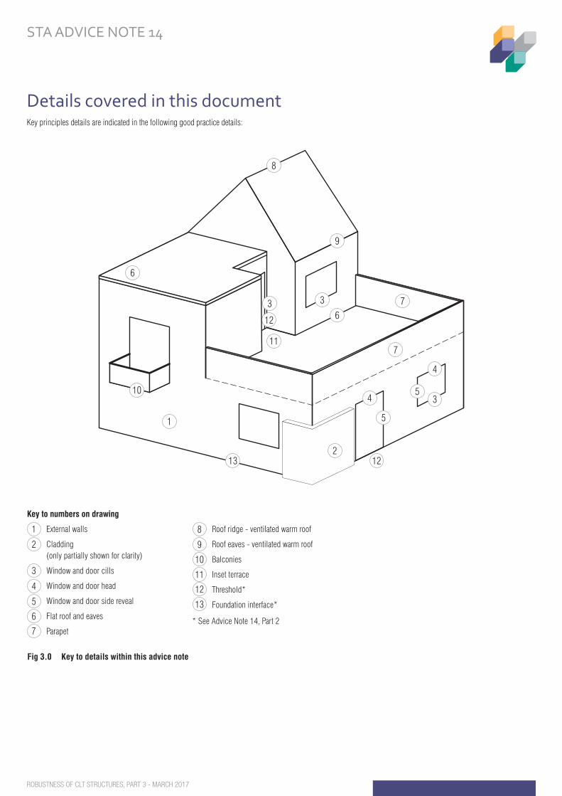
Details covered in this documentKey principles details are indicated in the following good practice details:
Fig 3.0 Key to details within this advice note
2
6
3
12
3 7
7
4
4 3
External walls
Cladding (only partially shown for clarity)
Window and door cills
Window and door head
Window and door side reveal
Flat roof and eaves
Parapet
Roof ridge - ventilated warm roof
Roof eaves - ventilated warm roof
Balconies
Inset terrace
Threshold*
Foundation interface*
* See Advice Note 14, Part 2
Key to numbers on drawing
1
2
3
4
5
6
7
8
9
10
11
12
13
1
13
5
510
8
9
6
212
11
STRUCTURALTIMBER ASSOCIATIONBuilding solutions in timber
ROBUSTNESS OF CLT STRUCTURES, PART 3 - MARCH 2017
STA ADVICE NOTE 14
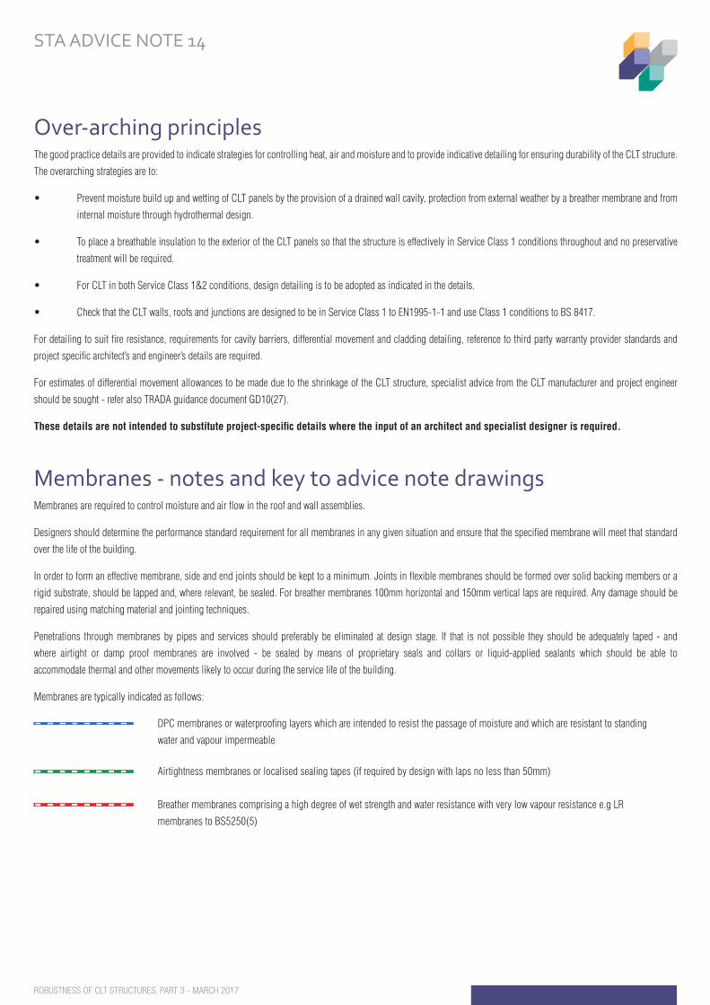
Over-arching principlesThe good practice details are provided to indicate strategies for controlling heat, air and moisture and to provide indicative detailing for ensuring durability of the CLT structure.
The overarching strategies are to:
• Prevent moisture build up and wetting of CLT panels by the provision of a drained wall cavity, protection from external weather by a breather membrane and from
internal moisture through hydrothermal design.
• To place a breathable insulation to the exterior of the CLT panels so that the structure is effectively in Service Class 1 conditions throughout and no preservative
treatment will be required.
• For CLT in both Service Class 1&2 conditions, design detailing is to be adopted as indicated in the details.
• Check that the CLT walls, roofs and junctions are designed to be in Service Class 1 to EN1995-1-1 and use Class 1 conditions to BS 8417.
For detailing to suit fire resistance, requirements for cavity barriers, differential movement and cladding detailing, reference to third party warranty provider standards and
project specific architect’s and engineer’s details are required.
For estimates of differential movement allowances to be made due to the shrinkage of the CLT structure, specialist advice from the CLT manufacturer and project engineer
should be sought - refer also TRADA guidance document GD10(27).
These details are not intended to substitute project-specific details where the input of an architect and specialist designer is required.
Membranes - notes and key to advice note drawingsMembranes are required to control moisture and air flow in the roof and wall assemblies.
Designers should determine the performance standard requirement for all membranes in any given situation and ensure that the specified membrane will meet that standard
over the life of the building.
In order to form an effective membrane, side and end joints should be kept to a minimum. Joints in flexible membranes should be formed over solid backing members or a
rigid substrate, should be lapped and, where relevant, be sealed. For breather membranes 100mm horizontal and 150mm vertical laps are required. Any damage should be
repaired using matching material and jointing techniques.
Penetrations through membranes by pipes and services should preferably be eliminated at design stage. If that is not possible they should be adequately taped - and
where airtight or damp proof membranes are involved - be sealed by means of proprietary seals and collars or liquid-applied sealants which should be able to
accommodate thermal and other movements likely to occur during the service life of the building.
Membranes are typically indicated as follows:
Membranes are typically indicated as follows:
DPC membranes or waterproofing layers which are intended to resist the passage of moisture and which are resistant to standing
water and vapour impermeable
Airtightness membranes or localised sealing tapes (if required by design with laps no less than 50mm)
Breather membranes comprising a high degree of wet strength and water resistance with very low vapour resistance e.g LR
membranes to BS5250(5)
Vapour control layer (VCL)
CLT End grain sealer - refer to Part 2
STRUCTURALTIMBER ASSOCIATIONBuilding solutions in timber
ROBUSTNESS OF CLT STRUCTURES, PART 3 - MARCH 2017
STA ADVICE NOTE 14
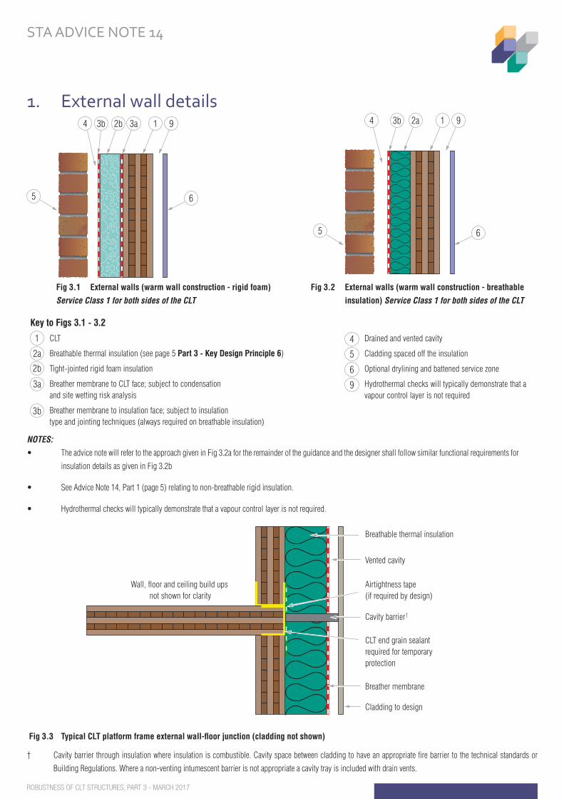
Fig 3.3 Typical CLT platform frame external wall-floor junction (cladding not shown)
† Cavity barrier through insulation where insulation is combustible. Cavity space between cladding to have an appropriate fire barrier to the technical standards or
Building Regulations. Where a non-venting intumescent barrier is not appropriate a cavity tray is included with drain vents.Fig 3.3 Typical CLT platform frame external wall-floor junction (cladding not shown)
Airtightness tape(if required by design)
Breathable thermal insulation
Wall, floor and ceiling build ups not shown for clarity
Breather membrane
Cavity barrier†
Vented cavity
Cladding to design
CLT end grain sealantrequired for temporaryprotection
NOTES:
• The advice note will refer to the approach given in Fig 3.2a for the remainder of the guidance and the designer shall follow similar functional requirements for
insulation details as given in Fig 3.2b
• See Advice Note 14, Part 1 (page 5) relating to non-breathable rigid insulation.
• Hydrothermal checks will typically demonstrate that a vapour control layer is not required.
1. External wall details
Fig 2 External walls (warm wall construction) Service Class 1 for both sides of the CLT
2a 1 9
6
3b
5
4
Fig 3.2 External walls (warm wall construction - breathable
insulation) Service Class 1 for both sides of the CLT
Fig 1.3 External walls (warm wall construction - rigid foam)
3a2b 1 9
6
3b
5
4
CLT
Breathable thermal insulation (see page 5 Part 3 - Key Design Principle 6)
Tight-jointed rigid foam insulation
Breather membrane to CLT face; subject to condensation and site wetting risk analysis
Breather membrane to insulation face; subject to insulation type and jointing techniques (always required on breathable insulation)
Drained and vented cavity
Cladding spaced off the insulation
Optional drylining and battened service zone
Hydrothermal checks will typically demonstrate that a vapour control layer is not required
Key to Figs 3.1 - 3.2
1
2a
2b
3a
3b
4
5
6
9
Fig 3.1 External walls (warm wall construction - rigid foam)
Service Class 1 for both sides of the CLT
STRUCTURALTIMBER ASSOCIATIONBuilding solutions in timber
ROBUSTNESS OF CLT STRUCTURES, PART 3 - MARCH 2017
STA ADVICE NOTE 14
Key principles
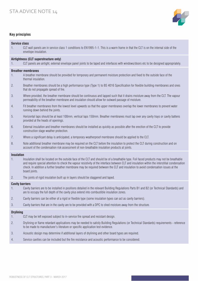
Service class1. CLT wall panels are in service class 1 conditions to EN1995-1-1. This is a warm frame in that the CLT is on the internal side of the envelope insulation.
Airtightness (CLT superstructure only)1. CLT panels are airtight, external envelope panel joints to be taped and interfaces with windows/doors etc to be designed appropriately.
Breather membranes1. A breather membrane should be provided for temporary and permanent moisture protection and fixed to the outside face of the thermal insulation.
2. Breather membranes should be a high performance type (Type 1) to BS 4016 Specification for flexible building membranes and ones that do not propagate spread of fire.
3. Where provided, the breather membrane should be continuous and lapped such that it drains moisture away from the CLT. The vapour permeability of the breather membrane and insulation should allow for outward passage of moisture.
4. Fit breather membranes from the lowest level upwards so that the upper membranes overlap the lower membranes to prevent water running down behind the joints.
5. Horizontal laps should be at least 100mm, vertical laps 150mm. Breather membranes must lap over any cavity trays or cavity battens provided at the heads of openings.
6. External insulation and breather membranes should be installed as quickly as possible after the erection of the CLT to provide construction stage weather protection.
7. Where a significant delay is anticipated, a temporary weatherproof membrane should be applied to the CLT.
8. Note additional breather membrane may be required on the CLT before the insulation to protect the CLT during construction and on account of the condensation risk assessment of non-breathable insulation products at joints.
Insulation1. Insulation shall be located on the outside face of the CLT and should be of a breathable type. Foil faced products may not be breathable and require special attention to check the vapour resistivity of the interface between CLT and insulation within the interstitial condensation check. In addition a further breather membrane may be required between the CLT and insulation to avoid condensation issues at the board joints.
2. The joints of rigid insulation built up in layers should be staggered and taped.
Cavity barriers1. Cavity barriers are to be installed in positions detailed in the relevant Building Regulations Parts B1 and B2 (or Technical Standards) and are to occupy the full depth of the cavity plus extend into combustible insulation zones.
2. Cavity barriers can be either of a rigid or flexible type (some insulation types can act as cavity barriers).
3. Cavity barriers that are in the cavity are to be provided with a DPC to shed moisture away from the structure.
Drylining1. CLT may be left exposed subject to in-service fire spread and resistant design.
2. Drylining or flame retardant applications may be needed to satisfy Building Regulations (or Technical Standards) requirements - reference to be made to manufacturer’s literature or specific application test evidence.
3. Acoustic design may determine if additional layers of drylining and other board types are required.
4. Service cavities can be included but the fire resistance and acoustic performance to be considered.
STRUCTURALTIMBER ASSOCIATIONBuilding solutions in timber
ROBUSTNESS OF CLT STRUCTURES, PART 3 - MARCH 2017
STA ADVICE NOTE 14
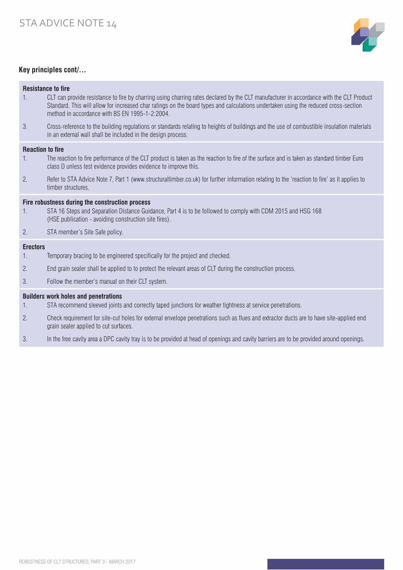
Resistance to fire1. CLT can provide resistance to fire by charring using charring rates declared by the CLT manufacturer in accordance with the CLT Product Standard. This will allow for increased char ratings on the board types and calculations undertaken using the reduced cross-section method in accordance with BS EN 1995-1-2:2004.
3. Cross-reference to the building regulations or standards relating to heights of buildings and the use of combustible insulation materials in an external wall shall be included in the design process.
Reaction to fire1. The reaction to fire performance of the CLT product is taken as the reaction to fire of the surface and is taken as standard timber Euro class D unless test evidence provides evidence to improve this.
2. Refer to STA Advice Note 7, Part 1 (www.structuraltimber.co.uk) for further information relating to the ‘reaction to fire’ as it applies to timber structures.
Fire robustness during the construction process1. STA 16 Steps and Separation Distance Guidance, Part 4 is to be followed to comply with CDM 2015 and HSG 168 (HSE publication - avoiding construction site fires).
2. STA member’s Site Safe policy.
Erectors1. Temporary bracing to be engineered specifically for the project and checked.
2. End grain sealer shall be applied to to protect the relevant areas of CLT during the construction process.
3. Follow the member’s manual on their CLT system.
Builders work holes and penetrations1. STA recommend sleeved joints and correctly taped junctions for weather tightness at service penetrations.
2. Check requirement for site-cut holes for external envelope penetrations such as flues and extractor ducts are to have site-applied end grain sealer applied to cut surfaces.
3. In the free cavity area a DPC cavity tray is to be provided at head of openings and cavity barriers are to be provided around openings.
Key principles cont/...
STRUCTURALTIMBER ASSOCIATIONBuilding solutions in timber
ROBUSTNESS OF CLT STRUCTURES, PART 3 - MARCH 2017
STA ADVICE NOTE 14
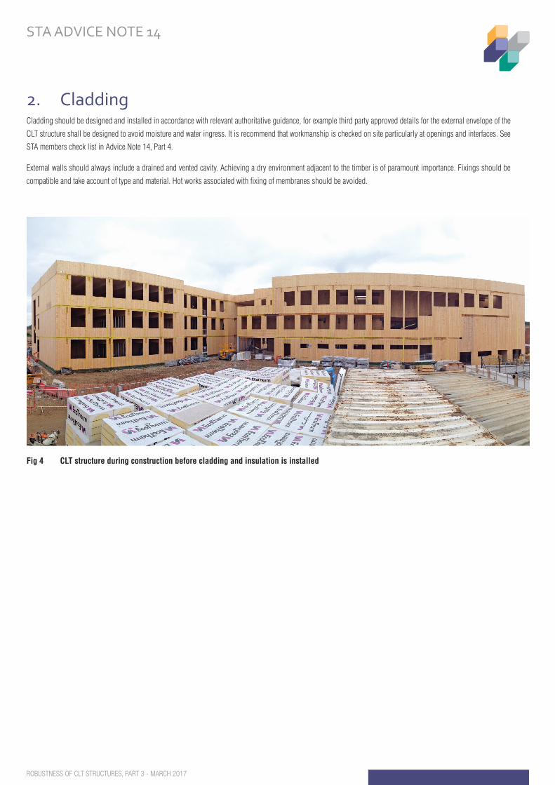
2. CladdingCladding should be designed and installed in accordance with relevant authoritative guidance, for example third party approved details for the external envelope of the
CLT structure shall be designed to avoid moisture and water ingress. It is recommend that workmanship is checked on site particularly at openings and interfaces. See
STA members check list in Advice Note 14, Part 4.
External walls should always include a drained and vented cavity. Achieving a dry environment adjacent to the timber is of paramount importance. Fixings should be
compatible and take account of type and material. Hot works associated with fixing of membranes should be avoided.
Fig 4 CLT structure during construction before cladding and insulation is installed
STRUCTURALTIMBER ASSOCIATIONBuilding solutions in timber
ROBUSTNESS OF CLT STRUCTURES, PART 3 - MARCH 2017
STA ADVICE NOTE 14
Key principles
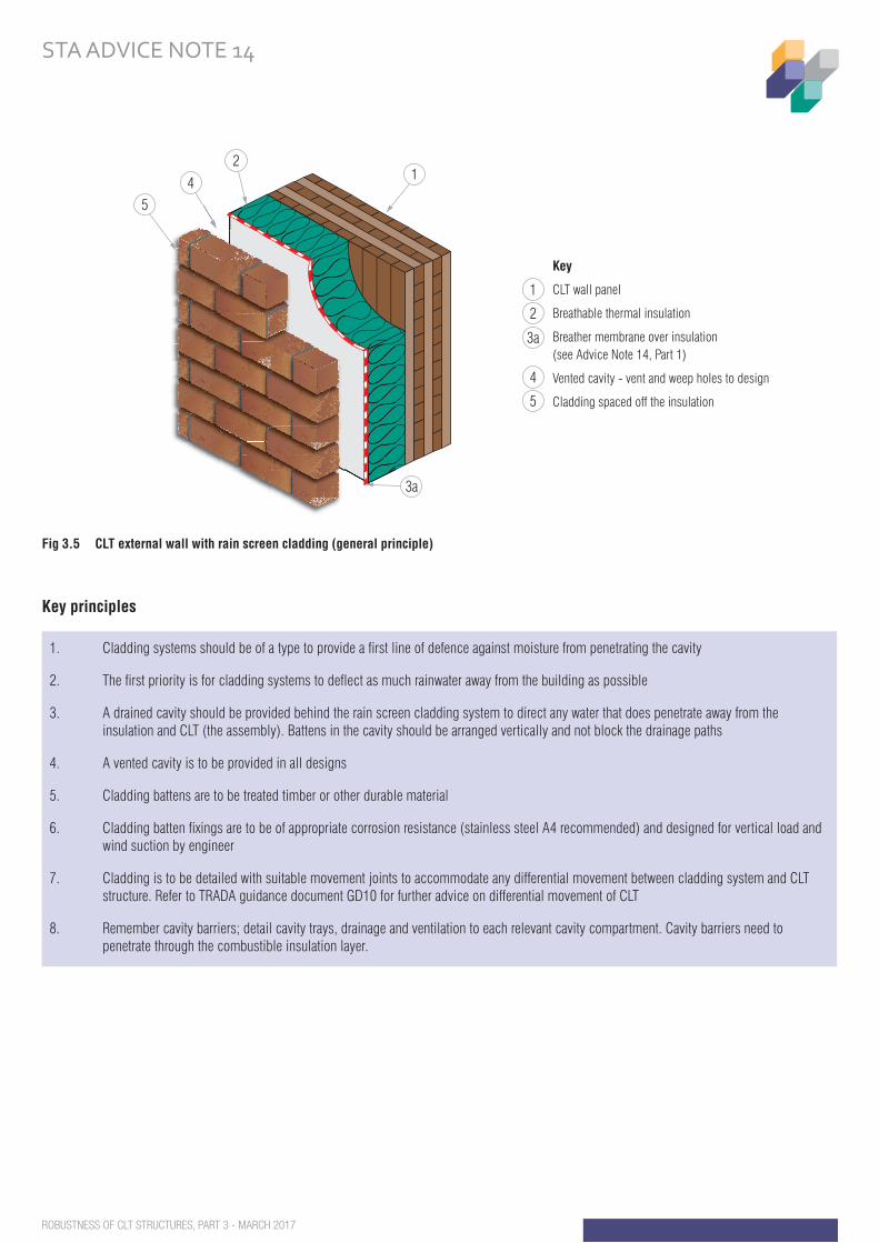
1. Cladding systems should be of a type to provide a first line of defence against moisture from penetrating the cavity
2. The first priority is for cladding systems to deflect as much rainwater away from the building as possible
3. A drained cavity should be provided behind the rain screen cladding system to direct any water that does penetrate away from the insulation and CLT (the assembly). Battens in the cavity should be arranged vertically and not block the drainage paths
4. A vented cavity is to be provided in all designs
5. Cladding battens are to be treated timber or other durable material
6. Cladding batten fixings are to be of appropriate corrosion resistance (stainless steel A4 recommended) and designed for vertical load and wind suction by engineer
7. Cladding is to be detailed with suitable movement joints to accommodate any differential movement between cladding system and CLT structure. Refer to TRADA guidance document GD10 for further advice on differential movement of CLT
8. Remember cavity barriers; detail cavity trays, drainage and ventilation to each relevant cavity compartment. Cavity barriers need to penetrate through the combustible insulation layer.
Fig 3.5 CLT external wall with rain screen cladding (general principle)Fig 3.5 CLT external wall with rain screen cladding (general principle)
Key
CLT wall panel
Breathable thermal insulation
Breather membrane over insulation(see Advice Note 14, Part 1)
Vented cavity - vent and weep holes to design
Cladding spaced off the insulation
1
2
3a
4
5
214
5
3a
STRUCTURALTIMBER ASSOCIATIONBuilding solutions in timber
ROBUSTNESS OF CLT STRUCTURES, PART 3 - MARCH 2017
STA ADVICE NOTE 14
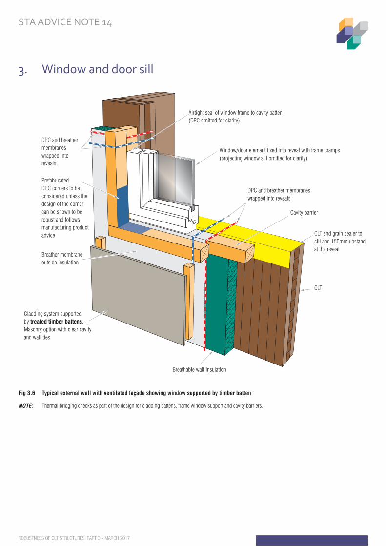
Fig 3.6 Typical external wall with ventilated façade showing window supported by timber batten
NOTE: Thermal bridging checks as part of the design for cladding battens, frame window support and cavity barriers.
3. Window and door sill
DPC and breather membraneswrapped into reveals
Prefabricated DPC corners to beconsidered unless thedesign of the cornercan be shown to berobust and followsmanufacturing productadvice
DPC and breather membraneswrapped into reveals
Breathable wall insulation
CLT
CLT end grain sealer to cill and 150mm upstand at the reveal
Cavity barrier
Window/door element fixed into reveal with frame cramps (projecting window sill omitted for clarity)
Fig 3.6 Typical external wall with ventilated façade showing window supported by timber batten
Breather membrane outside insulation
Cladding system supported by treated timber battens. Masonry option with clear cavityand wall ties
Airtight seal of window frame to cavity batten (DPC omitted for clarity)
STRUCTURALTIMBER ASSOCIATIONBuilding solutions in timber
ROBUSTNESS OF CLT STRUCTURES, PART 3 - MARCH 2017
STA ADVICE NOTE 14
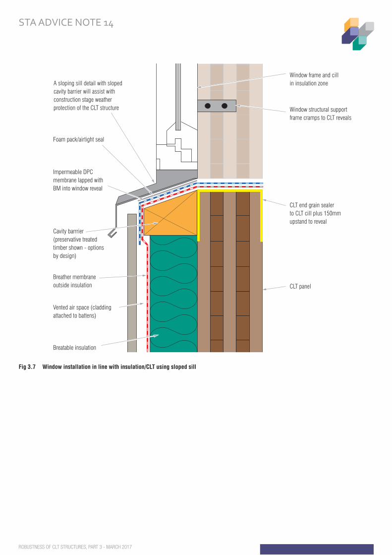
Fig 3.7 Window installation in line with insulation/CLT using sloped sillFig 3.7 Window installation in line with insulation/CLT using sloped cill
CLT panel
CLT end grain sealer to CLT cill plus 150mm upstand to reveal
Window structural support frame cramps to CLT reveals
Window frame and cillin insulation zoneA sloping sill detail with sloped
cavity barrier will assist with construction stage weather protection of the CLT structure
Impermeable DPC membrane lapped with BM into window reveal
Foam pack/airtight seal
Cavity barrrier(preservative treated timber shown - optionsby design)
Breather membraneoutside insulation
Breatable insulation
Vented air space (cladding attached to battens)
STRUCTURALTIMBER ASSOCIATIONBuilding solutions in timber
ROBUSTNESS OF CLT STRUCTURES, PART 3 - MARCH 2017
STA ADVICE NOTE 14
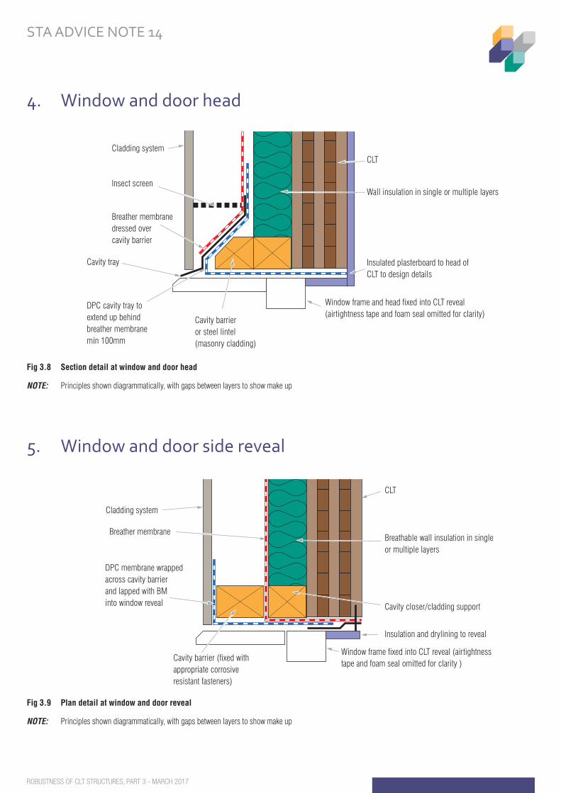
Fig 3.8 Section detail at window and door head
NOTE: Principles shown diagrammatically, with gaps between layers to show make up
Fig 3.9 Plan detail at window and door reveal
NOTE: Principles shown diagrammatically, with gaps between layers to show make up
4. Window and door head
5. Window and door side reveal
Fig 3.8 Section detail at window and door head
Cladding system
Insect screen
Breather membranedressed overcavity barrier
Cavity tray
DPC cavity tray to extend up behind breather membrane min 100mm
Cavity barrier or steel lintel (masonry cladding)
Window frame and head fixed into CLT reveal (airtightness tape and foam seal omitted for clarity)
Insulated plasterboard to head of CLT to design details
Wall insulation in single or multiple layers
CLT
Fig 3.9 Plan detail at window and door reveal
Cladding system
Breather membrane
DPC membrane wrapped across cavity barrier and lapped with BM into window reveal
Cavity barrier (fixed with appropriate corrosive resistant fasteners)
Window frame fixed into CLT reveal (airtightness tape and foam seal omitted for clarity )
Insulation and drylining to reveal
Cavity closer/cladding support
Breathable wall insulation in single or multiple layers
CLT
STRUCTURALTIMBER ASSOCIATIONBuilding solutions in timber
ROBUSTNESS OF CLT STRUCTURES, PART 3 - MARCH 2017
STA ADVICE NOTE 14
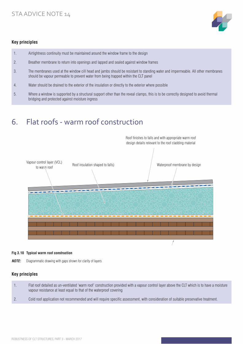
Fig 3.10 Typical warm roof construction
NOTE: Diagrammatic drawing with gaps shown for clarity of layers
Key principles
Key principles
6. Flat roofs - warm roof construction
1. Airtightness continuity must be maintained around the window frame to the design
2. Breather membrane to return into openings and lapped and sealed against window frames
3. The membranes used at the window cill head and jambs should be resistant to standing water and impermeable. All other membranes should be vapour permeable to prevent water from being trapped within the CLT panel
4. Water should be drained to the exterior of the insulation or directly to the exterior where possible
5. Where a window is supported by a structural support other than the reveal clamps, this is to be correctly designed to avoid thermal bridging and protected against moisture ingress
1. Flat roof detailed as un-ventilated ‘warm roof’ construction provided with a vapour control layer above the CLT which is to have a moisture vapour resistance at least equal to that of the waterproof covering
2. Cold roof application not recommended and will require specific assessment, with consideration of suitable preservative treatment.
Fig 3.10 Typical warm roof construction
Roof finishes to falls and with appropriate warm roofdesign details relevant to the roof cladding material
CLT roof slab
Vapour control layer (VCL)to warm roof
Roof insulation shaped to falls) Waterproof membrane by design
STRUCTURALTIMBER ASSOCIATIONBuilding solutions in timber
ROBUSTNESS OF CLT STRUCTURES, PART 3 - MARCH 2017
STA ADVICE NOTE 14
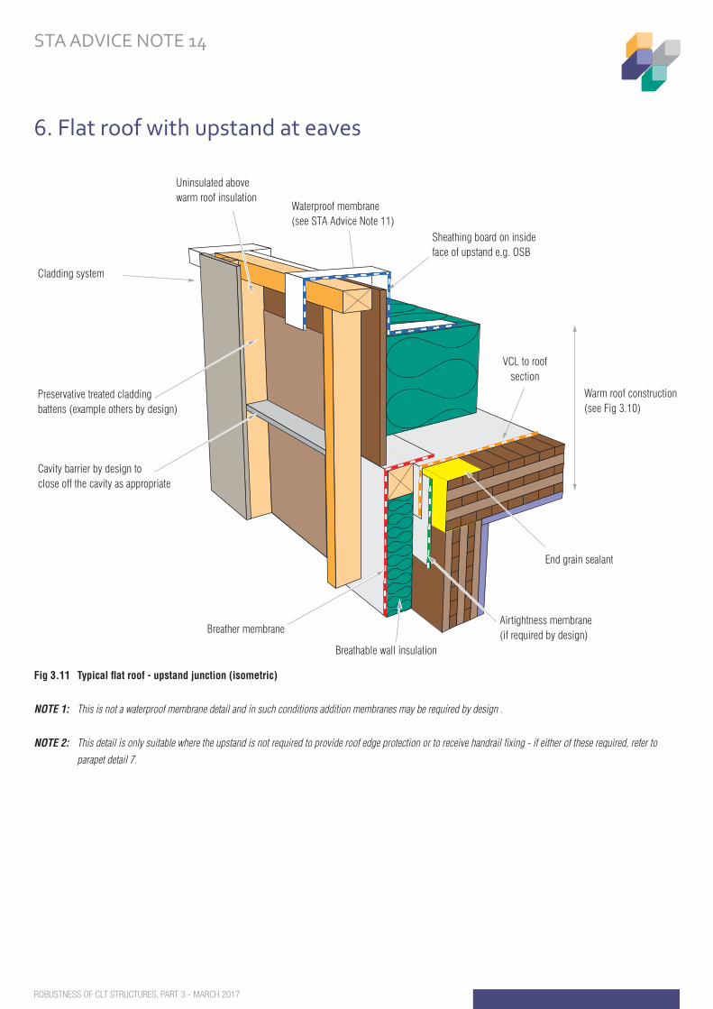
Fig 3.11 Typical flat roof - upstand junction (isometric)
NOTE 1: This is not a waterproof membrane detail and in such conditions addition membranes may be required by design .
NOTE 2: This detail is only suitable where the upstand is not required to provide roof edge protection or to receive handrail fixing - if either of these required, refer to
parapet detail 7.
6. Flat roof with upstand at eaves
VCL to roofsection
Fig 3.11 Typical flat roof - upstand junction (isometric)
Warm roof construction (see Fig 3.10)
Airtightness membrane (if required by design)
End grain sealant
Breathable wall insulation
Uninsulated above warm roof insulation
Breather membrane
Cladding system
Waterproof membrane (see STA Advice Note 11)
Preservative treated cladding battens (example others by design)
Cavity barrier by design to close off the cavity as appropriate
Sheathing board on inside face of upstand e.g. OSB
STRUCTURALTIMBER ASSOCIATIONBuilding solutions in timber
ROBUSTNESS OF CLT STRUCTURES, PART 3 - MARCH 2017
STA ADVICE NOTE 14
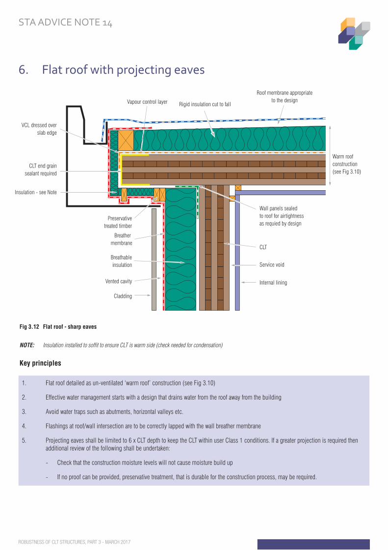
Fig 3.12 Flat roof - sharp eaves
NOTE: Insulation installed to soffi t to ensure CLT is warm side (check needed for condensation)
Key principles
6. Flat roof with projecting eaves
1. Flat roof detailed as un-ventilated ‘warm roof’ construction (see Fig 3.10)
2. Effective water management starts with a design that drains water from the roof away from the building
3. Avoid water traps such as abutments, horizontal valleys etc.
4. Flashings at roof/wall intersection are to be correctly lapped with the wall breather membrane
5. Projecting eaves shall be limited to 6 x CLT depth to keep the CLT within user Class 1 conditions. If a greater projection is required then additional review of the following shall be undertaken:
- Check that the construction moisture levels will not cause moisture build up
- If no proof can be provided, preservative treatment, that is durable for the construction process, may be required.
Fig 3.12 Flat roof - sharp eaves
Roof membrane appropriateto the design
Rigid insulation cut to fall
CLT end grainsealant required
Insulation - see Note
VCL dressed overslab edge
CLT
Service void
Internal lining
Breather membrane
Cladding
Vapour control layer
Wall panels sealedto roof for airtightness as requied by design
Preservativetreated timber
Breathableinsulation
Vented cavity
Warm roof construction (see Fig 3.10)
STRUCTURALTIMBER ASSOCIATIONBuilding solutions in timber
ROBUSTNESS OF CLT STRUCTURES, PART 3 - MARCH 2017
STA ADVICE NOTE 14
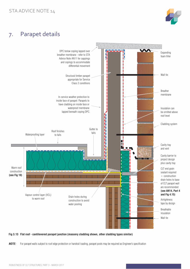
Fig 3.13 Flat roof - cantilevered parapet junction (masonry cladding shown, other cladding types similar)
NOTE: For parapet walls subject to roof edge protection or handrail loading, parapet posts may be required as Engineer’s specifi cation
7. Parapet details
Fig 3.13 Flat roof - cantilevered parapet junction (masonry cladding shown, other cladding types similar)
Vapour control layer (VCL)to warm roof
Drain holes during construction to avoid water pooling
Warm roof construction
(see Fig 10)
Breather membrane
Wall tie
Expanding foam filler
Cladding system
CLT end grain sealant required + construction drain holes to base of CLT parapet wall are recommended (see AN14, Part 4 and Fig 4.15)
Airtightness tape by design
Insulation can be omitted above roof level
Cavity trayand vent
Cavity barrier to project designplus cavity tray
Breathableinsulation
In-service weather protection to inside face of parapet: Parapets to
have cladding on inside face or waterproof membrane
lapped beneath coping DPC.
Roof finishesto falls
Structural timber parapetappropriate for Service
Class 2 conditions
DPC below coping lapped overbreather membrane - refer to STA
Advice Note AN11 for cappingsand copings to accommodate
differential movement
Gutter tofallsWaterproofing layer
Wall tie
STRUCTURALTIMBER ASSOCIATIONBuilding solutions in timber
ROBUSTNESS OF CLT STRUCTURES, PART 3 - MARCH 2017
STA ADVICE NOTE 14
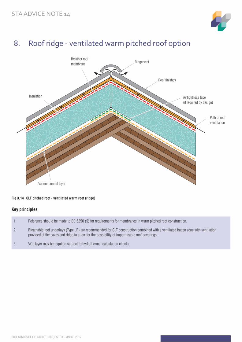
Fig 3.14 CLT pitched roof - ventilated warm roof (ridge)
Key principles
8. Roof ridge - ventilated warm pitched roof option
1. Reference should be made to BS 5250 (5) for requirements for membranes in warm pitched roof construction.
2. Breathable roof underlays (Type LR) are recommended for CLT construction combined with a ventilated batten zone with ventilation provided at the eaves and ridge to allow for the possibility of impermeable roof coverings.
3. VCL layer may be required subject to hydrothermal calculation checks.
Fig 3.14 CLT pitched roof - ventilated warm roof (ridge)
Breather roof membrane
Insulation
Vapour control layer
Airtightness tape(if required by design)
Path of roofventillation
Ridge vent
Roof finishes
STRUCTURALTIMBER ASSOCIATIONBuilding solutions in timber
ROBUSTNESS OF CLT STRUCTURES, PART 3 - MARCH 2017
STA ADVICE NOTE 14
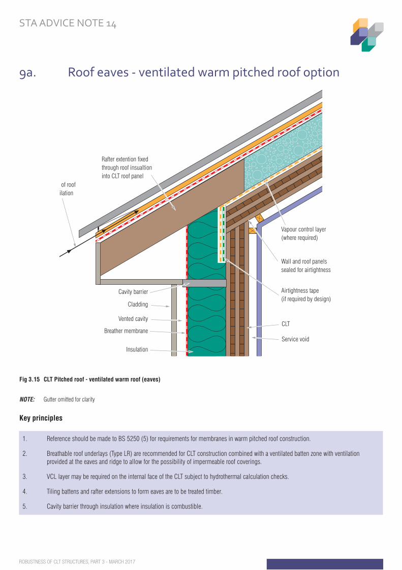
Fig 3.15 CLT Pitched roof - ventilated warm roof (eaves)
Airtightness tape(if required by design)
Wall and roof panelssealed for airtightness
CLT
Service void
Rafter extention fixedthrough roof insualtioninto CLT roof panel
Path of roofventilation
Insulation
Breather membrane
Vented cavity
Cladding
Cavity barrier
Vapour control layer(where required)
Fig 3.15 CLT Pitched roof - ventilated warm roof (eaves)
NOTE: Gutter omitted for clarity
Key principles
9a. Roof eaves - ventilated warm pitched roof option
1. Reference should be made to BS 5250 (5) for requirements for membranes in warm pitched roof construction.
2. Breathable roof underlays (Type LR) are recommended for CLT construction combined with a ventilated batten zone with ventilation provided at the eaves and ridge to allow for the possibility of impermeable roof coverings.
3. VCL layer may be required on the internal face of the CLT subject to hydrothermal calculation checks.
4. Tiling battens and rafter extensions to form eaves are to be treated timber.
5. Cavity barrier through insulation where insulation is combustible.
STRUCTURALTIMBER ASSOCIATIONBuilding solutions in timber
ROBUSTNESS OF CLT STRUCTURES, PART 3 - MARCH 2017
STA ADVICE NOTE 14
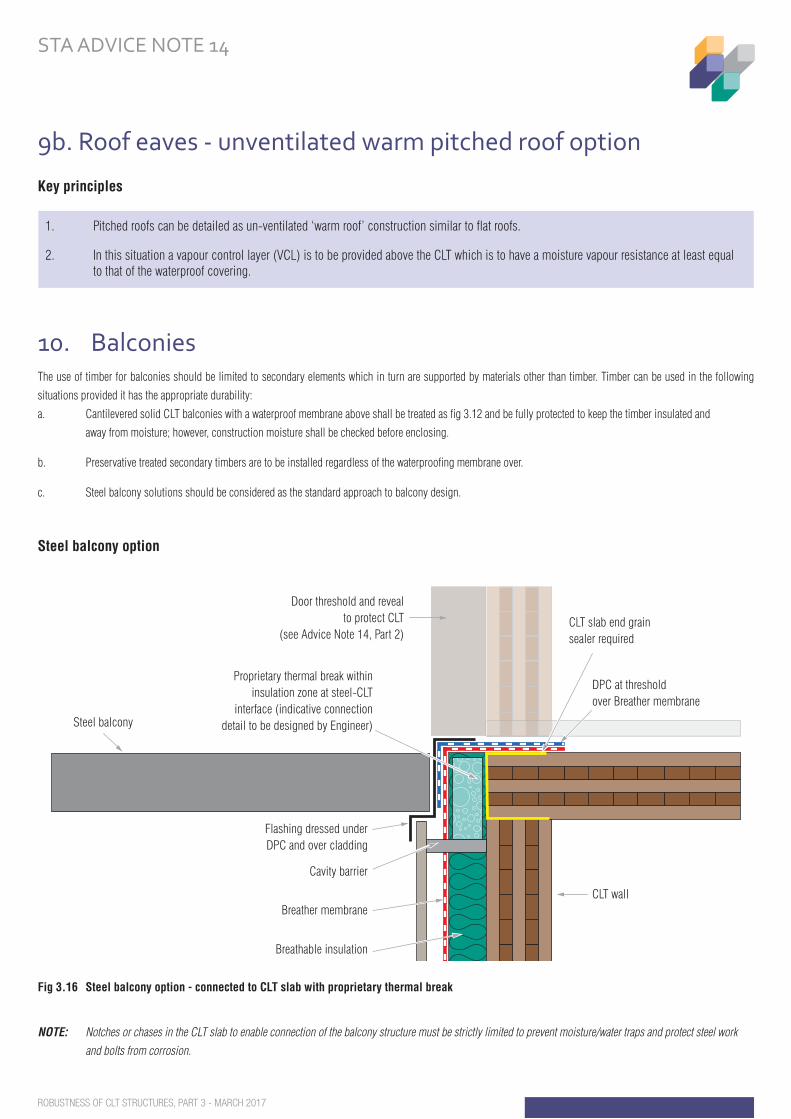
Fig 3.16 Steel balcony option - connected to CLT slab with proprietary thermal break
NOTE: Notches or chases in the CLT slab to enable connection of the balcony structure must be strictly limited to prevent moisture/water traps and protect steel work
and bolts from corrosion.
9b. Roof eaves - unventilated warm pitched roof option
Key principles
10. BalconiesThe use of timber for balconies should be limited to secondary elements which in turn are supported by materials other than timber. Timber can be used in the following
situations provided it has the appropriate durability:
a. Cantilevered solid CLT balconies with a waterproof membrane above shall be treated as fi g 3.12 and be fully protected to keep the timber insulated and
away from moisture; however, construction moisture shall be checked before enclosing.
b. Preservative treated secondary timbers are to be installed regardless of the waterproofi ng membrane over.
c. Steel balcony solutions should be considered as the standard approach to balcony design.
Steel balcony option
1. Pitched roofs can be detailed as un-ventilated ‘warm roof’ construction similar to flat roofs.
2. In this situation a vapour control layer (VCL) is to be provided above the CLT which is to have a moisture vapour resistance at least equal to that of the waterproof covering.
DPC at thresholdover Breather membrane
Fig 19 Steel balcony option - connected to CLT slab with proprietary thermal break
CLT slab end grain sealer required
Proprietary thermal break withininsulation zone at steel-CLT
interface (indicative connectiondetail to be designed by Engineer)
Door threshold and revealto protect CLT
(see Advice Note 14, Part 2)
CLT wall
Steel balcony
Breather membrane
Breathable insulation
Flashing dressed underDPC and over cladding
Cavity barrier
STRUCTURALTIMBER ASSOCIATIONBuilding solutions in timber
ROBUSTNESS OF CLT STRUCTURES, PART 3 - MARCH 2017
STA ADVICE NOTE 14
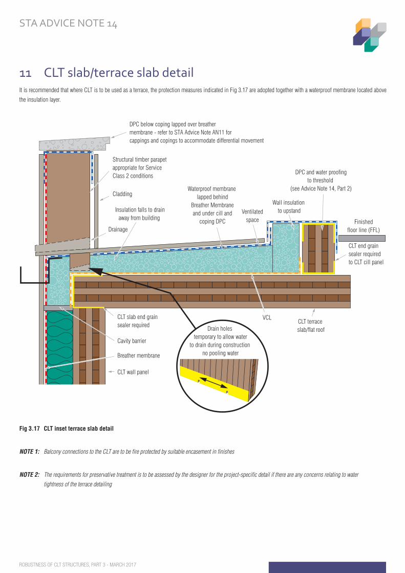
Fig 3.17 CLT cantilevered balcony slab/terrace slab detail
CLT wall panel
Breather membrane
CLT slab end grain sealer required
VCL
CLT end grain sealer requiredto CLT cill panel
Finishedfloor line (FFL)
DPC and water proofingto threshold
(see Advice Note 14, Part 2)
Wall insulation to upstandInsulation falls to drain
away from building
Cavity barrier
CLT terrace slab/flat roof
Ventilatedspace
Waterproof membrane lapped behind
Breather Membraneand under cill and
coping DPC
DPC below coping lapped over breather membrane - refer to STA Advice Note AN11 for cappings and copings to accommodate differential movement
Drainage
Structural timber parapetappropriate for Service Class 2 conditions
Cladding
Drain holes temporary to allow water
to drain during construction no pooling water
Fig 3.17 CLT inset terrace slab detail
NOTE 1: Balcony connections to the CLT are to be fire protected by suitable encasement in finishes
NOTE 2: The requirements for preservative treatment is to be assessed by the designer for the project-specific detail if there are any concerns relating to water
tightness of the terrace detailing
11 CLT slab/terrace slab detailIt is recommended that where CLT is to be used as a terrace, the protection measures indicated in Fig 3.17 are adopted together with a waterproof membrane located above
the insulation layer.
ROBUSTNESS OF CLT STRUCTURES, PART 3 - MARCH 2017
STA ADVICE NOTE 14
Key principles
1. The structural application of CLT panels is not suitable for long-term exposure to weather without an applied waterproofing membrane or cladding system. Where CLT is to be used to support an external floor such as a terrace slab, protection of the top surface and exposed edges with a waterproofing membrane will be required in addition to the slab being on the warm side of the fabric.
2. CLT structure is to be protected to Service Class 1 EN1995-1-1 and use Class 1 to BS 8417.
3. For detailing of upstands and parapet walls (see Fig 3.13 and Fig 3.17).
4. For detailing of thresholds (see Advice Note 14, Part 2).
5. For detailing of opening reveals (see Advice Note 14, Part 2).
Copyright: All images and text is the copyright of the STA. Reproduction of the information can be given to members following approval by the STA.
Limitations of the advice note: Drawings and information has been provided by the STA to provide concept details and not for construction. The project design team is
to undertake bespoke project details.
As copyright holders of this guidance, the STA have made extensive efforts to check the accuracy of the information and advice contained in this document at the date of
publication. However this guidance document is not yet fully comprehensive and further editions may be produced. The STA do not warrant the accuracy of any information
or advice contained in this document and shall not be liable for any loss, damage or expense whatsoever suffered by any person(s) who relies on or uses this information
or advice.
Steering GroupSincere thanks for the time and contribution given to this project by members of the CLT steering group.
Greg Cooper, B&K Structures Robin Lancashire - TRADA Martin Milner, Milner Associates
David Crawford, CCG OSM Guy Lewis, STA technical consultant
Kay Hartmann, KLH UK Gareth Mason, Stora Enso
www.structuraltimber.co.uk
STRUCTURALTIMBER ASSOCIATIONBuilding solutions in timber


