Embed Size (px)
Citation preview
K20321EN ed.1
TFAEY-TGAEY 4160÷4320
Y-Pack FREECOOLING rangeMacrosystem170÷361 kW
Air-cooled water chillers in Freecooling mode and Freecooling NO-GLYCOLmode with axial fans.Range with hermetic Scroll compressors and R410A refrigerant.


Contents
3
Contents
General Features .......................................................................................................................................4 Conditions of use.........................................................................................................................................4 Freecooling system logic........................................................................................................................5 Freecooling NO-GLYCOL sys tem logic ...................................................................................................5 New Y-Pack series ....................................................................................................................................6 Energy-savi ng, reliable and versatile chillers..........................................................................................6 AdaptiveFunction Plu s ............................................................................................................................6 Construction features ..............................................................................................................................8 Versions ........................................................................................................................................................8 Available Ins tallations .................................................................................................................................8 Electrical Panel ............................................................................................................................................8 Accessories ................................................................................................................................................9 Factor y fitted accessories ..........................................................................................................................9 Accessories supplied l oose........................................................................................................................9 Technical Data..........................................................................................................................................10 Electronic controls..................................................................................................................................14 Electronic contr ol .......................................................................................................................................14 KTR – Remote keyboard..........................................................................................................................14 Serial Connection ....................................................................................................................................15 Serial Connecti on ......................................................................................................................................15 Supervision.................................................................................................................................................15 Performance .............................................................................................................................................15 Choice of a chiller or heat pump and use of the perfor mance tabl es ...............................................15 Performance dat a....................................................................................................................................16 Pressure Drop s........................................................................................................................................22 TFAETY-TFAESY residual static pressures.....................................................................................24 TGAETY-TGAESY residu al static pressures....................................................................................25 Power L evels and Sound Pressure ....................................................................................................26 Operating limits .......................................................................................................................................27 Use of antifreeze solutions...................................................................................................................27 Dimensions and footprints...................................................................................................................28 Clearances and positioning .....................................................................................................................29 Handling and s torage................................................................................................................................29 Installation and Connection to the Sys tem............................................................................................29 W eight distribution.................................................................................................................................30 W ater connections..................................................................................................................................30 Maxi mum water circuit content................................................................................................................30 Water data ..................................................................................................................................................30 Expansion vessel technical data.............................................................................................................30 W ater Circuits...........................................................................................................................................31 Electrical connections ...........................................................................................................................34
Y-PACK Freecooling general characteristics
4
General Features
Conditions of use
The TFAET Y – TFAESY units ar e air cooled water chillers in Freecooling mode with centrifugal fans i n high efficiency and silenced versions. The TGAETY – TGAESY units are air cooled water chillers in Freecooling NO-GLYCOL mode with centrifugal fans in high efficiency and silenced versions .
They ar e intended for use i n conditioning plants or indus trial processes where a suppl y of chilled water is required mos t of the year. Not suitable for drinking water. The units are designed for outdoor installation.
The units comply with the following directi ves: ○ Machiner y directive 98/37/EEC (MD) ○ Low voltage directi ve 2006/95/EEC (LVD) ○ Electromagnetic compatibility Directive 89/336/EEC (EMC); ○ Pressure equipment Directive 97/23/EEC (PED).
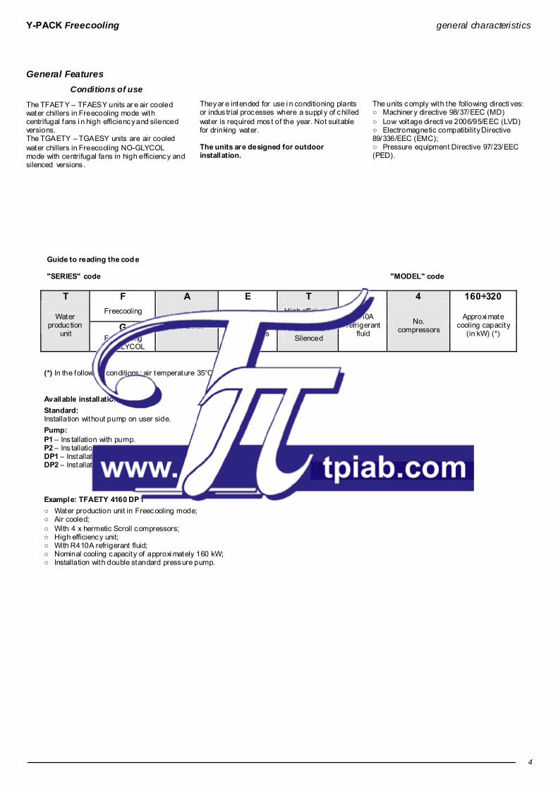
Guide to reading the cod e "SERIES" code "MODEL" code
T F A E T Y 4 160÷320
Freecooling High efficiency
G S Water
produc tion unit Freecooling
NO-GLYCOL
Air-cooled Scroll-type hermetic
compressors Silenced
R410A refrigerant
fluid No.
compressors
Approxi mate cooling capacity
(in kW) (*)
(*) In the followi ng conditions : air temperature 35°C, water temperature 7/12°C. Available installations: Standard: Installation without pump on user side. Pump: P1 – Ins tallation with pump. P2 – Ins tallation with increased static pressur e pump. DP1 – Installation with double pump, incl uding an automaticall y ac tivated pump i n stand- by. DP2 – Installation with i ncreased s tatic pressure doubl e pump, incl uding an automaticall y acti vated pump in stand-by. Example: TFAETY 4160 DP1 ○ Water production unit in Freecooling mode; ○ Air cooled; ○ With 4 x hermetic Scroll compressors; ○ High efficiency unit; ○ With R410A refrigerant fluid; ○ Nominal cooling capacity of approxi mately 160 kW; ○ Installation with double standard pressure pump.
Y-PACK Freecooling general characteristics
5
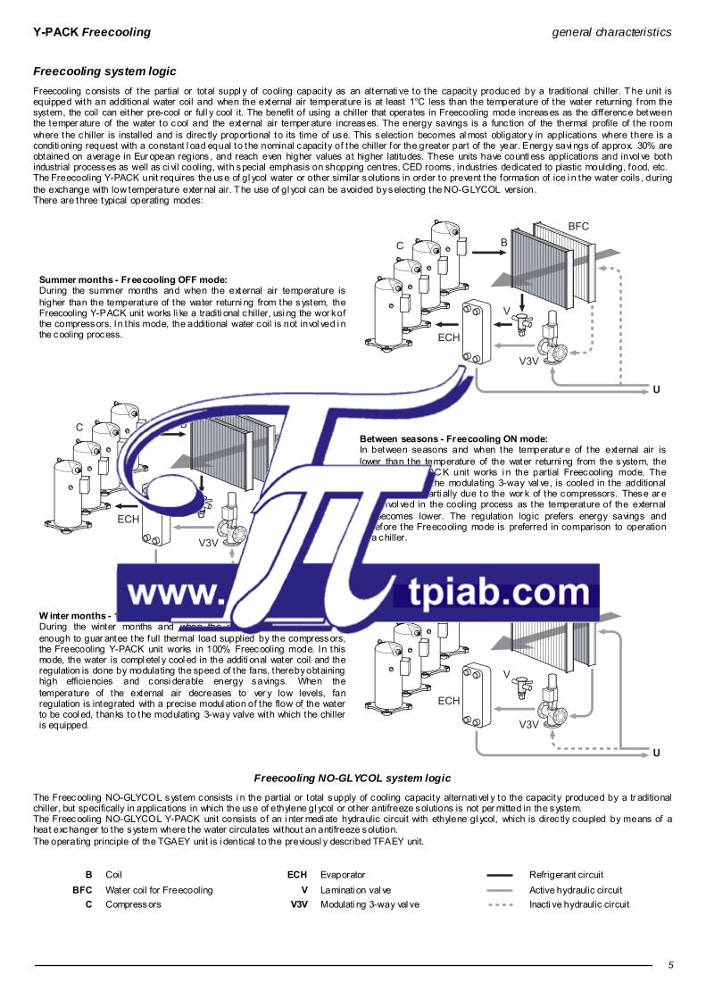
Freecooling system logic Freecooling consists of the partial or total suppl y of cooling capacity as an alternati ve to the capacity produced by a traditional chiller. T he unit is equipped with an additional water coil and when the external air temperature is at least 1°C less than the temperature of the water returning from the system, the coil can either pre-cool or full y cool it. The benefit of using a chiller that operates in Freecooling mode increases as the difference between the temper ature of the water to cool and the external air temper ature increases. The energy savings is a func tion of the thermal profile of the room where the chiller is installed and is direc tly proportional to its time of use. This selection becomes al most obligator y in applications where there is a conditi oning request with a constant l oad equal to the nominal capacity of the chiller for the greater part of the year. Energy savi ngs of approx. 30% are obtained on average in Eur opean regions , and reach even higher values at higher latitudes. These units have countl ess applications and invol ve both industrial processes as well as ci vil cooling, with special emphasis on shopping centres, CED rooms, industries dedicated to plastic moulding, food, etc. The Freecooling Y-PACK unit requires the use of gl ycol water or other similar solutions in order to prevent the formation of ice i n the water coils , during the exchange with low temperature exter nal air. T he use of gl ycol can be avoided by selecting the NO-GLYCOL version. There are three typical operating modes:
Summer months - Freecooling OFF mode: During the summer months and when the external air temperature is higher than the temperature of the water returni ng from the system, the Freecooling Y-PACK unit works li ke a traditi onal chiller, usi ng the wor k of the compressors. In this mode, the additional water coil is not invol ved i n the cooling process.
V
V3V
U
BFCBC
ECH
V
V3V
U
BFCBC
ECH
Between seasons - Freecooling ON mode: In between seasons and when the temperatur e of the external air is lower than the temperature of the water returni ng from the system, the Freecooling Y-PAC K unit works i n the partial Freecooling mode. The water, thanks to the modulating 3-way val ve, is cooled in the additional water coil and parti ally due to the wor k of the compressors. These ar e less invol ved in the cooling process as the temperature of the external air becomes lower. The regulation logic prefers energy savings and therefore the Freecooling mode is preferred in comparison to operation as a chiller.
W inter months - 100% Freecooling mod e During the winter months and when the exter nal air temperature is enough to guar antee the full thermal load supplied by the compressors, the Freecooling Y-PACK unit works in 100% Freecooling mode. In this mode, the water is compl etel y cool ed in the additi onal water coil and the regulation is done by modulating the speed of the fans, thereby obtaining high efficiencies and consi derable energy savings. When the temperature of the external air decreases to ver y low levels, fan regulation is integrated with a precise modul ation of the flow of the water to be cool ed, thanks to the modulating 3-way valve with which the chiller is equipped.
V
V3V
U
BFCBC
ECH
Freecooling NO-GLYCOL system logic
The Freecooling NO-GLYCOL system consists i n the partial or total supply of cooling capacity alternati vel y to the capacity produced by a tr aditional chiller, but specifically in applications in which the use of ethylene gl ycol or other antifreeze solutions is not per mitted in the system. The Freecooling NO-GLYCOL Y-PACK unit consists of an i nter medi ate hydraulic circuit with ethylene gl ycol, which is direc tly coupled by means of a heat exchanger to the system where the water circulates without an antifreeze solution. The operating principle of the TGAEY unit is i dentical to the previousl y described TFAEY unit.
B Coil ECH Evaporator Refrigerant circuit BFC Water coil for Freecooling V Laminati on val ve Active hydraulic circuit
C Compressors V3V Modulati ng 3-way val ve Inacti ve hydraulic circuit

Y-PACK Freecooling general characteristics
6
New Y-Pack series Energy-saving, reliable and versatile chillers
A comp lete, flexible range, with three shutter step s New water chillers from 170 to 360 kW (*) in R 410A, with four scroll compressors installed on two cooling circuits to obtain four steps of cooling and heating capacity, allowing for fl exible regulation and greater efficiency when operating at partial l oads. The efficiency of these units is also boosted by the innovati ve AdaptiveFunction Plu s control logic, with which the r ange is equipped. This logic, developed by RHOSS in partnership with the Uni versity of Padua, optimises compr essor activation and their operating cycles, as well as making it possibl e to obtain opti mum comfort levels i n all wor king conditi ons and the best perfor mances in ter ms of energy efficiency during seasonal operati on. LOW CONSUMPTION chillers The AdaptiveFunction Plu s “Economy” function combines comfort with l ow energy consumption. In fact, by adjusti ng the set-point value, it opti mises compressor operation on the basis of the actual wor king conditi ons. It is thus possible to achi eve significant seasonal energy savi ngs compared to chillers of an equi val ent power with traditional control logic. This func tion is acti vated in the Freecooling OFF mode. HIGH PRECISION chillers By using the AdaptiveFunction Plus “Precision” function, it is possi ble to achieve as littl e fluctuation as possibl e, at partial capacities , in terms of the average Set-point water temperatur e delivered to the users. Guaranteed reliabil it y, even with water in the pipes only Thanks to the “Virtual T ank” functi on, Y-Pack units with AdaptiveFunction Plu s can operate i n systems with a low water content of down to 2 litres/kW, even without the presence of a water buffer tank, whilst s till guaranteei ng the reliability of the units over ti me and the good wor king order of the system. Estimation of the syst em's thermal inertia Y-Pack units with Ad aptiveFunction Plus are able to esti mate the characteristics of the thermal i nertia that regulates the system dynamics. T his is possi ble thanks to the " ACM Autotuning” functi on, which processes the information relating to the progress of the water temperatures, identifying the opti mal value of the control parameters. Continuous system autodiagnosis The es timation function is al ways acti ve and makes it possibl e to adapt the contr ol par ameters quickl y to every change in the water circuit and thus i n the system water contents. Silent operation Thanks to the 4 shutter steps and the condensation control, installed as standard on all units, the noise level is also reduced at partial l oads . For example, during night operati on, when the load is reduced but sensiti vity to noise is at its peak, the control reduces the number of fan revolutions, the primar y noise source in this type of unit, producing obvious benefits in terms of acoustic well-being. (*) In the following conditions: condenser inlet air temperature 30°C; cooled mixture temperature (30% glycol) 10°C; differential temperature at evaporator 5°C.
AdaptiveFunction Plus The new adapti ve regul ation logic, Ad aptiveFunction Plus, is an excl usive RHOSS patent and the result of a long partnership with the University of Padua. The various algorithm pr ocessing and devel opment operations were i mplemented and tes ted on units in the Y-PACK range in the RHOSS S.p.A. Research&D evelopment Laborator y by means of numerous test campaigns. Objectives • To guarantee optimal unit operation in the sys tem in which it is installed. Evolved adaptive logic. • To obtain the best performance from a chiller in terms of energy efficiency at full and partial capacities. Low consumption chiller. Operating logic In general, the actual control logics on chillers do not consi der the characteristics of the system in which the units are installed; they usuall y regulate the retur n water temperature and are positioned so as to ensure the operation of the chillers, givi ng less priority to the system requirements. The new AdaptiveFunction Plu s adapti ve logic counters these logics with the objecti ve of optimising the chiller operation on the basis of the system char acteristics and the effecti ve thermal load. T he contr oller regulates the deli ver y water temperature and adjusts itself, as and when required, to the relative oper ating conditions usi ng: • the i nfor mation contained in the return and deli ver y water temperature to estimate the wor king conditions thanks to a particul ar mathematical for mula; • a special adapti ve algorithm that uses this esti mate to vary the val ues and the start-up and switch- off limit values of the compressors; the opti mised compressor start-up management guar antees a pr ecision water suppl y to the user, reduci ng the fluctuati on around the set- point val ue. Main functions Efficiency or Precision Thanks to the evolved control, it is possibl e to run the chiller on two different regulation setti ngs to obtain the bes t possible performance in terms of energ y efficiency and considerable seasonal savings, or high water delivery temperature precision: 1. Low consumption chiller: “Economy” option
It is well known that chillers wor k at full capacity for j ust a ver y small percentage of their operating time, while they wor k at partial capacity for most of the season. Therefore, the power they need to supply generally differs from the nominal design power, and oper ation at partial capacity has a noticeable effec t on seasonal energy perfor mance and consumpti on. This makes it necessar y to run the unit so that it is as efficient as possible at partial capacity. T he contr oller therefore ensures that the water delivery temperature is as high as possible ( when operating as a chiller) whilst compatible with the thermal l oads , meaning that it is on a sliding scale, unlike in traditional sys tems. This prevents energy wastage linked to the mai ntenance of pointlessl y onerous temperature l evels for the chiller, ensuring that the rati o between the power to be supplied and the energy to be used to produce it is always at an optimum level. Fi nall y the right level of comfort is availabl e to everyone! The option is onl y availabl e in the Freecooling OFF mode.

Y-PACK Freecooling general characteristics
7
2. High precision: “Precision” option
In this operating mode, the unit wor ks at a fi xed Set-poi nt and, thanks to the deliver y water temperature control and the evol ved regulati on logic, at a capacity of between 50% and 100%, it is possible to guarantee an average fluc tuation from the water suppl y temper ature of approximately ±1.5°C from the Set-point value compared to an average fl uctuation over time of approxi matel y ± 3°C which is normall y obtained with standard return control. The “Precision” option thus guarantees precision and reliability for all those applicati ons that require a regulator that guar antees a more accur ate constant water supply temperature, and wher e there are particular damp contr ol requirements . However, in process applications it is always advisable to use a water buffer tank or a greater system water content to guarantee higher system ther mal inertia.
FC
s
s Fluctuati on FC Load
Unit with water buffer tank, 4 litres/kW i n the sys tem and return control.
Unit with water buffer tank, 2 litres/kW i n the sys tem and deliver y control with “Precision” AdaptiveFunction Plu s functi on
The chart illustrates the fluctuations of the water temperature from the set value for the various capacities, demonstrating how a unit w ith delivery control and the AdaptiveFunc tion Plus “Precision” function guarantees greater water supply temperature precision Virtual Tank: guaranteed reliability, even with water in the pipes only A low water content in the system can cause the chiller units /heat pumps to be unreliable and can generate system instability and poor performance. Thanks to the Virtual Tank function, this is no longer a problem. T he unit can operate in systems with just 2 litres/kW in the pipes given that the control is able to compensate for the lack of i nertia specific to a water buffer tank, "muffling" the control signal, preventi ng the compressor from switching on and off in an untimely fashion and reduci ng the aver age fluctuati on of the Set-point val ue.
t
T
20000
2
4
6
8
10
12
14
3000 4000 5000 6000 7000 8000 9000
T1
T Water temperature (°C) t Time (s)
T1 Set-point temper ature Deliver y temperature with Virtual Tank
Deliver y temperature without Virtual Tank
The chart shows the various chiller outlet temperatures considering a capacity of 80%. We can observe how the temperatures of the unit with AdaptiveFunction Plus logic and the Virtual Tank function is far less varied and more stable over time, with average temperatures closer to the working Set-point compared to a unit without the Virtual Tank function. Moreover, we can see how the unit with AdaptiveFunction Plus logic and the Virtual Tank function sw itches the compressor on less often over the same period of time, w ith obvious advantages in terms of energy consumption and system reliability. ACM Autotuning compressor management AdaptiveFunction Plu s enables the Y-Pack units to adapt to the system they are ser ving, so as to al ways identify the best compressor operating parameters in the different worki ng conditions . During the initi al operating phases, the special “Autotuning” functi on enables the Y-Pack unit with Ad aptiveFunction Plus to estimate the ther mal inertia characteristics that regulate the sys tem dynamics. T he func tion, which is automaticall y acti vated when the unit is switched on for the first ti me, executes a number of set oper ating cycles, during which it processes the information r elati ve to the water temperatures. I t is thus possible to esti mate the physical charac teristics of the system and to identify the opti mal val ue of the par ameters to be used for the control. At the end of this initi al auto-es timate phase, the “Autotuning” func tion r emains acti ve, making it possible to adapt the control parameters quickl y to ever y change in the water circuit and thus in the system water contents.

Y-PACK Freecooling construction features
8
Construction features ○ Load-bearing structure and panels in galvanised and painted (RAL 9018) sheet s teel; base in gal vanised sheet s teel. ○ The struc ture consists of 2 sec tions : • sound-proofed technical compartment for housi ng the compressors, the electrical panel and the main components i n the refrigerant circuit. • aeraulic compartment for housing the heat exchange coils, the plate heat exchangers and the motor-driven fans. ○ Hermetic, Scroll-type r otar y compressors, complete with internal thermal protection and crankcase heater acti vated automaticall y when the unit s tops (as long as the power suppl y to the unit is preser ved). ○ Adequatel y insulated, braze-welded pl ate water side heat exchange i n stainless steel. The Freecooling NO-GLYCOL chillers have an additi onal water-water exchanger and a electric circulation pump to separate the internal hydraulic circuit with a water-glycol mi xtur e from the sys tem side external gl ycol free circuit. ○ Modulati ng 3-way val ve (solo TFAETY-TFAESY) to di vert the water flow originating from the system towards the Freecooling coil or directly towar ds the evaporator. ○ The air-side heat exchanger comprised of a coil of copper pipes and alumini um fins divi ded into two secti ons: one dedicated to the condensation of the refrigerant gas and the other dedicated to cooling the water when operating in Freecooling mode. ○ Motor-driven, spiral fans with external rotor, fitted with internal thermal protection and complete with protec tion grille. ○ Proportional electronic device for the pressurised and continuous regulation of the fan rotati on speed down to an external air temperature of -15°C when operating as a chiller. ○ Victaulic type water connections. ○ Differential pressur e switch that protects the unit from any i nterruptions to the water flow (only TFAETY-TFAESY). ○ Flow switch that protec ts the unit fr om any interrupti ons to the water fl ow (onl y TGAETY-TGAESY). ○ Double refrigerant circuit i n annealed copper pipe (EN 12735-1-2) complete with: cartridge drier filter, charge connecti ons, manual reset safety pressure switch on the high pressure side, automatic reset safety pressure switch on the l ow pressure side, safety val ve(s), filter shut-of f val ves, thermostatic expansion val ve, liquid receiver, solenoi d val ve on the deli ver y line, el ectronic val ve for controlling condensation when operating in Freecooling ON mode, liquid indicator, solenoid val ve on the liquid line and inl et line insul ation. ○ Unit with IP24 level of protec tion. ○ Compatible control, with AdaptiveFunction Plu s function. ○ The unit is complete with the R410A refrigerant charge. ○ The TGAETY-TGAESY Freecooling NO-GLYCOL units are supplied without the glycol mixture i n the internal circuit, which must be added ( 30% gl ycol sol ution) by the installer.
Versions
T – High efficiency version. S – Silenced version complete with soundproofed compressors, r educed speed fans. The fan speed is automaticall y increased with the external temperatur e increases considerabl y.
Available Installations
Standard: Installation without pump on user side. Pump: P1 – Ins tallation with pump. P2 – Ins tallation with increased static pressur e pump. DP1 – Installation with double pump, incl uding an automaticall y ac tivated pump in stand-by. DP2 – Installation with i ncreased s tatic pressure double pump, incl uding an automaticall y ac tivated pump i n stand- by. The pump assembl y also comes complete with: expansion tank, safety val ve, manual air bleed and water si de pressure gauge (only TFAETY-TFAESY). In the case of an i ndi vidual pump, the assembl y also comes complete with an aspiration and deliver y shut-off val ve. In the case of a double pump, the assembl y also comes complete with a deli ver y non-return val ve and an aspiration val ve for each pump.
Electrical Panel
○ Electrical board accessibl e by openi ng the front panel, conforming with current IEC norms, can be opened and closed with a suitable tool. ○ Compl ete with: • electrical wiring arranged for power suppl y 400-3ph+N-50Hz; • auxiliary power suppl y 230V-1ph-50Hz drawn from the main power supply; • control power supply 12V-1ph-50Hz drawn from the main power suppl y; • general isolator for power suppl y, complete with door interlocki ng isolator; • automatic thermal overload switch to protec t the compressors and the motor-driven fans; • protecti on fuse for auxiliar y circuit; • power contactor for the compressors; • remote machine controls: ON/OFF; • remote machine controls: compressor operating light, general lock light; • thermostat-controlled ventilation of the electrical board for high temperatur es (air in the electric board) and the acti vation of a heating element that is also ther mostat-controlled for low temper atures (air in the electric board). ○ Programmable elec tronic boar d with microprocessor, controlled by the keyboard inserted in the machine.
○ This electronic board performs the following functi ons: • regulation and management of the outlet water temperature set points ; of the safety timer delays; of the circulating pump; of the compressor and system pump hour-run meter; of the electronic anti-freeze protection which cuts in automaticall y when the machine is switched off; and of the functions that contr ol the operation of the indi vidual parts making up the machine; • complete protection of the unit, automatic emergency shutdown and display of the alarms which have been acti vated; • compressor pr otecti on phase sequence monitor; • display of the programmed set-points via the display, of the water i n/out temper atures via the display; of the condensation pressur es; of the electrical voltage values in the three phases of the electrical circuit that powers the unit; of the alarms on the displ ay; of the chiller function on the display; • user interface menu; • automatic pump oper ating time balance (DP1-DP2 installations); • automatic ac tivation of the pump i n standby in the event of an alar m (DP1-DP2 installations); • alarm code and descripti on; • alarm histor y management (menu protected by manufac turer password). ○ The followi ng is memorized for each alarm: • date and time of acti vation; • inlet/outlet water temperatur es when the alarm inter vened; • condensation pressure values at the time of the alarm. • alarm delay time from the switch-on of the connected device; • compressor status at moment of alarm; ○ Advanced functions: • Hi-Pressure Prevent with forced cooling capacity shuttering for high external temperatures; • configured for serial connec tion (KR S485, KFTT10, KRS232 and KUSB accessor y); • possibility to have a digital input for remote management of the double set point (contact RHOSS S.p.A. pre-sales); • possibility to have an analogue input for the scrolling set-point vi a a 4-20mA remote signal (contact RHOSS S.p.A. pre-sales); • management of ti me periods and operation parameters with the possi bility of dail y/weekly operating programs; • check-up and monitoring of scheduled maintenance status ; • testing of the units assisted by computer; • self-diagnosis with continuous monitoring of the func tioni ng of the unit . ○ Set-point regulation via the Ad aptive Function Plus with two opti ons: • fixed set-poi nt (Precision options); • scrolling set-point (Economy opti on). Note: in the Freecooling ON mode, set-point regulation is done only in precision mode.

Y-PACK Freecooling accessories
9
Accessories
Factory fitted accessories P1 – Ins tallation with pump. P2 – Ins tallation with increased static pressur e pump. DP1 – Installation with double pump, incl uding an automaticall y ac tivated pump in stand-by. DP2 – Installation with i ncreased s tatic pressure double pump, incl uding an automaticall y ac tivated pump i n stand- by. RA – Evaporator antifreeze electric heater to prevent the risk of ice formation inside the exchanger when the machine is switched off (as long as the unit is not disconnected from the power suppl y) (only for TFAETY-TFAESY models). RAE 1 – 27W antifreeze electric heater for motor-driven pump (availabl e for P1-DP1 installations); to prevent the water contai ned in the pump from freezing when the machine is switched off ( as long as the unit is not disconnected from the power suppl y) (only for TFAETY-TFAESY models). RAE 2 – 27W antifreeze electric heater for double motor-driven pumps (available for P2-DP2 installations); to prevent the water contained in the pumps from fr eezing when the machine is switched off (as long as the unit is not disconnec ted from the power supply) (onl y for TFAETY-TFAESY models). GM – Refrigerant circuit high and low pressure gauges. FTT10 – FTT 10 serial interface card for connection to super vision systems (LonWor ks® system compliant with Lonmar k® 8090-10 protocol with chiller profile). SS – RS485 serial interface card to create dialogue networks between cards (maximum of 200 units at a maxi mum distance of 1,000 m) and buildi ng automati on, external super vision systems or RHOSS S.p.A. supervision systems. (Supported protocols: proprietar y protocol; Modbus® RTU). CR – Power factor correction capacitors (cos Φ > 0.91). EEV – Elec tronic ther mostatic val ve. RAP – Unit with copper/pre-pai nted alumi nium coils. BRR – Unit with copper/copper coils. RRS – Unit with copper/ tin-plated copper coils. DSP – D oubl e set-point via digital consensus (incompatibl e with the CS accessor y). CS – Scrolling set point vi a analogue signal 4-20 mA (incompati ble with the DSP accessor y). On the basis of the required val ues, it could be necessary to install the EEV accessor y too. RPB – Coil protection networ ks with acci dent prevention function (to be used as an alternative to the FMB accessory). FMB – Mechanical filters to protec t the coils, with l eaf protection function (to be used as an alternative to the RPB accessor y). SFS – Soft-start device for reducing the s tart-up current during the start-up phase. Note: the NO-GLYCOL TGAET Y-TGAESY Freecooling units are equipped stand ard with larger antifreeze electric h eaters (evaporator and water circuit). If the unit has been accessorised with pumps, also these will be fit standard with larg er antifreeze electric h eaters.
Accessories supplied loose KSAM – Spring anti-vi bration mountings. KSA – Rubber anti- vibrati on mountings. KTR – Remote keypad for control at a distance with r ear illumi nated LCD display (same functi ons as the one built into the machine). KISI – C AN bus serial interface (Contr oller Area Network compatible with evol ved hydronic system for integrated comfort management (protocol supported CanOpen®). KRS232 – RS485/RS232 serial converter for interconnec tion between RS485 serial networ k and super vision systems with serial connec tion to PC via RS232 serial port (RS232 cable provided). KUSB – RS485/USB serial converter for interconnec tion between RS485 serial networ k and super vision systems with serial connec tion to PC via USB port (USB cable pr ovided). KMDM – GSM 900-1800 modem kit to be connected to the unit for the management of the parameters and any alar m signals on a remote basis. T he kit consists of a GSM modem with rel ati ve RS232 car d. It is necessary to purchase a SIM data card, not supplied by RHOSS S.p.A. KRS – RHOSS S.p.A. super vision software for unit assembl y and remote management. The kit consists of a CD-Rom and har dware key.

Y-PACK Freecooling technical data
10
Technical Data Table “A”: Technical Data
TFAETY mod el 4160 4180 4200 4230 4260 4290 4320 Freecooling OFF Nominal cooling capacity (*) kW 178 202 224 251 286 326 361 E.E.R. (*) 3,31 3,41 3,27 3,20 3,34 3,20 3,09 Sound pressure (**) dB(A) 65 67 67 69 69 70 70 Sound power l evel (***) dB(A) 89 91 91 93 93 94 94 Scroll/step compressor no. 4/4 4/4 4/4 4/4 4/4 4/4 4/4 Circuits no. 2 2 2 2 2 2 2 Fans no. x kW 4 x 2 4 x 2 4 x 2 6 x 2 6 x 2 8 x 2 8 x 2 Fan nominal air flow m³/h 78600 74400 74400 96900 102900 121600 121600 Water side heat exchanger water content l 12 12 14 15 18 21 24 Water side nominal water flow (*) m³/h 33,5 38 42,1 47,2 53,8 61,3 67,9 Nominal pressure drops, water side (*) kPa 100 127 138 152 140 155 161 Residual s tatic pressure P1 (*) kPa 116 126 138 108 95 133 98 Residual s tatic pressure P2 (*) kPa 181 182 215 187 177 176 132 R410A refrigerant charge See serial No. plate Pol yester oil charge See compressor plate Freecooling ON Freecooling cooling capacity ON ( 100%) kW 178 202 224 251 286 326 361 E.E.R. Freecooling ON (100%) 22,25 25,25 28,00 20,92 23,83 20,38 22,56 Freecooling ON temper ature (100%) °C 0,3 1 0,4 0,7 0,9 0,4 -0,8 Freecooling ON cooling capacity (Ta 5°C) kW 121,1 144,3 153,5 175,6 202,8 223,3 228,5 % cooling capacity (Ta 5°C) % 68% 71% 69% 70% 71% 68% 63% Electrical Data Freecooling OFF absorbed power (*) (●) kW 53,8 59,3 68,4 78,5 85,6 102 117 Freecooling ON absorbed power (100%) kW 8,0 8,0 8,0 12,0 12,0 16,0 16,0 Pump absor bed power (P1/D P1) / (P2/DP2) kW 3,0 / 4,0 4,0 / 5,5 5,5 / 7,5 5,5 / 7,5 5,5 / 7,5 7,5 / 9,2 7,5 / 9,2 Electrical power suppl y V-ph-Hz 400 – 3+N – 50 Auxiliary power suppl y V-ph-Hz 230 – 1+N – 50 Control power suppl y V-ph-Hz 24 – 1 – 50 Nominal current (*) (●) A 105 108 123 143 156 183 206 Maxi mum current (*) (●) A 131 143 154 178 194 229 256 Starting current (*) (●) A 300 333 344 407 424 483 510 Pump absor bed current (P1/D P1) / (P2/DP2) A 6 / 8 8 / 11 11 / 15 11 / 15 11 / 15 15 / 18 15 / 18 Dimensions Height (a) mm 2030 2030 2030 2030 2030 2030 2030 Width (b) mm 2090 2090 2090 2090 2090 2090 2090 Length (c) mm 4800 4800 4800 4800 5300 5300 5300 Exchanger inlet/outl et connections Ø 3” 3” 3” 3” 3” 3” 3”
(*) In the followi ng conditions : condenser i nlet air temperature 30°C; cooled mi xture temperature (30% glycol) 10°C; dif ferential temperature at evaporator 5°C. (**) Sound pressure l evel in dB(A), measured at a distance of 5 m from the unit, with a directionality fac tor of 2. The noise measurement refers to the units without pump. (***) Sound power level in dB(A) on the basis of measurements made i n compliance with the UNI EN-ISO 3744 standard and Eurovent 8/1. The noise measurement r efers to the units without pump.
(●) The values do not incl ude the user side motor-driven pump. Note: The val ues for available static pressure of the pumps and the pressure drops of the exchangers can be found on page 22. The calculation of the E.E.R. does not account for the absorption of the user side pump. With the external air temperature below 30°C and until the Freecooling start temperature, the machine r educes its noise level to a val ue that is below the nominal value indicated i n the table.
a
bc

Y-PACK Freecooling technical data
11
Table “A”: Technical Data
TFAESY model 4160 4180 4200 4230 4260 4290 4320 Freecooling OFF Nominal cooling capacity (*) kW 170 197 215 240 274 312 344 E.E.R. (*) 3,21 3,32 3,11 3,11 3,22 3,09 2,92 Sound pressure (**) dB(A) 60 61 61 63 64 65 65 Sound power l evel (***) dB(A) 85 86 86 88 89 90 90 Scroll/step compressor no. 4/4 4/4 4/4 4/4 4/4 4/4 4/4 Circuits no. 2 2 2 2 2 2 2 Fans no. x kW 4 x 1.25 4 x 1.25 4 x 1.25 6 x 1.25 6 x 1.25 8 x 1.25 8 x 1.25 Fan nominal air flow m³/h 62800 58400 58400 72000 79800 92000 92000 Water side heat exchanger water content l 12 12 14 15 18 21 24 Water side nominal water flow (*) m³/h 32 37 40,4 45,1 51,5 58,7 64,7 Nominal pressure drop, water side (*) kPa 91 117 123 139 128 138 145 Residual s tatic pressure P1 (*) kPa 134 143 158 128 116 161 129 Residual s tatic pressure P2 (*) kPa 199 200 234 206 197 208 167 R410A refrigerant charge See serial No. plate Pol yester oil charge See compressor plate Freecooling ON Freecooling ON cooling capacity ( 100%) kW 170 197 215 240 274 312 344 E.E.R. Freecooling ON (100%) 34,00 39,40 43,00 32,00 36,53 31,20 34,40 Freecooling ON temper ature (100%) °C -1,3 -0,8 -1,5 -1,3 -1,1 -1,6 -3,0 Freecooling ON cooling capacity (Ta 5°C) kW 104,3 124,7 130,3 147,3 170,2 188 191,1 % cooling capacity (Ta 5°C) % 61% 63% 61% 61% 62% 60% 56% Electrical Data Freecooling OFF absorbed power (*) (●) kW 53,0 59,3 69,2 77,2 85,2 100,9 117,9 Freecooling ON absorbed power (100%) kW 5,0 5,0 5,0 7,5 7,5 10,0 10,0 Pump absor bed power (P1/D P1) / (P2/DP2) kW 3,0 / 4,0 4,0 / 5,5 5,5 / 7,5 5,5 / 7,5 5,5 / 7,5 7,5 / 9,2 7,5 / 9,2 Electrical power suppl y V-ph-Hz 400 – 3+N – 50 Auxiliary power suppl y V-ph-Hz 230 – 1+N – 50 Control power suppl y V-ph-Hz 24 – 1 – 50 Nominal current (*) (●) A 102 105 121 137 151 176 202 Maxi mum current (*) (●) A 131 143 154 178 194 229 256 Starting current (*) (●) A 300 333 344 407 424 483 510 Pump absor bed current (P1/D P1) / (P2/DP2) A 6 / 8 8 / 11 11 / 15 11 / 15 11 / 15 15 / 18 15 / 18 Dimensions Height (a) mm 2030 2030 2030 2030 2030 2030 2030 Width (b) mm 2090 2090 2090 2090 2090 2090 2090 Length (c) mm 4800 4800 4800 4800 5300 5300 5300 Exchanger inlet/outl et connections Ø 3” 3” 3” 3” 3” 3” 3”
(*) In the followi ng conditions : condenser i nlet air temperature 30°C; cooled mi xture temperature (30% glycol) 10°C; dif ferential temperature at evaporator 5°C. (**) Sound pressure l evel in dB(A), measured at a distance of 5 m from the unit, with a directionality fac tor of 2. The noise measurement refers to the units without pump. (***) Sound power level in dB(A) on the basis of measurements made i n compliance with the UNI EN-ISO 3744 standard and Eurovent 8/1. The noise measurement r efers to the units without pump.
(●) The values do not incl ude the user side motor-driven pump. Note: The val ues for available static pressure of the pumps and the pressure drops of the exchangers can be found on page 22. The calculation of the E.E.R. does not include pump consumption. With the external air temperature below 30°C and until the Freecooling start temperature, the machine r educes its noise level to a val ue that is below the nominal value indicated i n the table.
a
bc

Y-PACK Freecooling technical data
12
Table “A”: T echnical D ata
TGAETY model 4160 4180 4200 4230 4260 4290 4320 Freecooling OFF Nominal cooling capacity (*) kW 180 207 229 256 291 333 368 E.E.R. (*) 3,32 3,47 3,33 3,24 3,37 3,25 3,11 Sound pressure (**) dB(A) 65 67 67 69 69 70 70 Sound power l evel (***) dB(A) 89 91 91 93 93 94 94 Scroll/step compressor no. 4/4 4/4 4/4 4/4 4/4 4/4 4/4 Circuits no. 2 2 2 2 2 2 2 Fans no. x kW 4 x 2 4 x 2 4 x 2 6 x 2 6 x 2 8 x 2 8 x 2 Fan nominal air flow m³/h 78600 74400 74400 96900 102900 121600 121600 Water side heat exchanger water content l 12 12 14 15 18 21 24 Water side nominal water flow (*) m³/h 31,0 35,6 39,4 44,0 50,1 57,3 63,3 Nominal pressure drops, water side (*) kPa 102 133 125 141 124 139 149 Residual s tatic pressure P1 (*) kPa 129 136 119 129 126 166 132 Residual s tatic pressure P2 (*) kPa 193 195 172 207 206 215 172 R410A refrigerant charge See serial No. plate Pol yester oil charge See compressor plate Freecooling ON Freecooling ON cooling capacity ( 100%) kW 180 207 229 256 291 333 368 E.E.R. Freecooling ON (100%) 18,95 20,29 22,45 18,03 20,49 17,53 18,40 Freecooling ON temper ature (100%) °C -2,9 -2,3 -2,9 -2,7 -2,4 -2,9 -4,1 Freecooling ON cooling capacity (Ta 5°C) kW 100,6 119,7 128 144,7 167,3 186,1 192,7 % cooling capacity (Ta 5°C) % 56% 58% 56% 57% 57% 56% 52% Electrical Data Freecooling OFF absorbed power (*) (●) kW 54,2 59,7 68,8 79 86,4 102,6 118,2 Freecooling ON absorbed power (100%) kW 9,5 10,2 10,2 14,2 14,2 19,0 20,0 Pump absor bed power (P1/D P1) / (P2/DP2) kW 3,0 / 4,0 4,0 / 5,5 4,0 / 5,5 5,5 / 7,5 5,5 / 7,5 7,5 / 9,2 7,5 / 9,2 Electrical power suppl y V-ph-Hz 400 – 3+N – 50 Auxiliary power suppl y V-ph-Hz 230 – 1+N – 50 Control power suppl y V-ph-Hz 24 – 1 – 50 Nominal current (*) (●) A 106 108 124 143 157 184 208 Maxi mum current (*) (●) A 131 143 154 178 194 229 256 Starting current (*) (●) A 300 333 344 407 424 483 510 Pump absor bed current (P1/D P1) / (P2/DP2) A 6 / 8 8 / 11 8 / 11 11 / 15 11 / 15 15 / 18 15 / 18 Dimensions Height (a) mm 2030 2030 2030 2030 2030 2030 2030 Width (b) mm 2090 2090 2090 2090 2090 2090 2090 Length (c) mm 4800 4800 4800 4800 5300 5300 5300 Exchanger inlet/outl et connections Ø 3” 3” 3” 3” 3” 3” 3”
(*) In the followi ng conditions : Condenser inl et air temperature 30°C; chilled water temperatur e 10°C; temperature differential at evaporator 5°C. (**) Sound pressure l evel in dB(A), measured at a distance of 5 m from the unit, with a directionality fac tor of 2. The noise measurement refers to the units without pump. (***) Sound power level in dB(A) on the basis of measurements made i n compliance with the UNI EN-ISO 3744 standard and Eurovent 8/1. The noise measurement r efers to the units without pump.
(●) The values do not incl ude the user side motor-driven pump. Note: The val ues for available static pressure of the pumps and the pressure drops of the exchangers can be found on page 22. The calculation of the E.E.R. does not take pump absorption into account, whereas the calculation of the E.E.R. Freecooling ON (100%) takes the absorpti on of the inter nal circuit pump i nto account. With the external air temperature below 30°C and until the Freecooling start temperature, the machine r educes its noise level to a val ue that is below the nominal value indicated i n the table.
a
bc

Y-PACK Freecooling technical data
13
Table “A”: Technical Data
TGAESY model 4160 4180 4200 4230 4260 4290 4320 Freecooling OFF Nominal cooling capacity (*) kW 172 199 219 245 279 318 349 E.E.R. (*) 3,22 3,34 3,14 3,15 3,24 3,11 2,92 Sound pressure (**) dB(A) 60 61 61 63 64 65 65 Sound power l evel (***) dB(A) 85 86 86 88 89 90 90 Scroll/step compressor no. 4/4 4/4 4/4 4/4 4/4 4/4 4/4 Circuits no. 2 2 2 2 2 2 2 Fans no. x kW 4 x 1.25 4 x 1.25 4 x 1.25 6 x 1.25 6 x 1.25 8 x 1.25 8 x 1.25 Fan nominal air flow m³/h 62800 58400 58400 72000 79800 92000 92000 Water side heat exchanger water content l 12 12 14 15 18 21 24 Water side nominal water flow (*) m³/h 29,6 34,2 37,7 42,2 48,0 54,7 60,0 Nominal pressure drops, water side (*) kPa 91 117 112 129 110 125 130 Residual s tatic pressure P1 (*) kPa 148 160 144 147 147 190 164 Residual s tatic pressure P2 (*) kPa 211 222 200 224 227 242 209 R410A refrigerant charge See serial No. plate Pol yester oil charge See compressor plate Freecooling ON Freecooling ON cooling capacity ( 100%) kW 172 199 219 245 279 318 349 E.E.R. Freecooling ON (100%) 26,46 27,64 30,42 25,26 28,76 24,46 24,93 Freecooling ON temper ature (100%) °C -4,6 -4,1 -4,9 -4,8 -4,5 -5,0 -6,3 Freecooling ON cooling capacity (Ta 5°C) kW 87,8 104,2 110,1 123,8 143,1 159,1 163,9 % cooling capacity (Ta 5°C) % 51% 52% 50% 51% 51% 50% 47% Electrical Data Freecooling OFF absorbed power (*) (●) kW 53,4 59,5 69,8 77,8 86,1 102,1 119,5 Freecooling ON absorbed power (100%) kW 6,5 7,2 7,2 9,7 9,7 13,0 14,0 Pump absor bed power (P1/D P1) / (P2/DP2) kW 3,0 / 4,0 4,0 / 5,5 4,0 / 5,5 5,5 / 7,5 5,5 / 7,5 7,5 / 9,2 7,5 / 9,2 Electrical power suppl y V-ph-Hz 400 – 3+N – 50 Auxiliary power suppl y V-ph-Hz 230 – 1+N – 50 Control power suppl y V-ph-Hz 24 – 1 – 50 Nominal current (*) (●) A 102 105 122 138 153 178 204 Maxi mum current (*) (●) A 131 143 154 178 194 229 256 Starting current (*) (●) A 300 333 344 407 424 483 510 Pump absor bed current (P1/D P1) / (P2/DP2) A 6 / 8 8 / 11 8 / 11 11 / 15 11 / 15 15 / 18 15 / 18 Dimensions Height (a) mm 2030 2030 2030 2030 2030 2030 2030 Width (b) mm 2090 2090 2090 2090 2090 2090 2090 Length (c) mm 4800 4800 4800 4800 5300 5300 5300 Exchanger inlet/outl et connections Ø 3” 3” 3” 3” 3” 3” 3”
(*) In the followi ng conditions : Condenser inl et air temperature 30°C; chilled water temperatur e 10°C; temperature differential at evaporator 5°C. (**) Sound pressure l evel in dB(A), measured at a distance of 5 m from the unit, with a directionality fac tor of 2. The noise measurement refers to the units without pump. (***) Sound power level in dB(A) on the basis of measurements made i n compliance with the UNI EN-ISO 3744 standard and Eurovent 8/1. The noise measurement r efers to the units without pump.
(●) The values do not incl ude the user side motor-driven pump. Note: The val ues for available static pressure of the pumps and the pressure drops of the exchangers can be found on page 22. The calculation of the E.E.R. does not take pump absorption into account, whereas the calculation of the E.E.R. Freecooling ON (100%) takes the absorpti on of the inter nal circuit pump i nto account. With the external air temperature below 30°C and until the Freecooling start temperature, the machine r educes its noise level to a val ue that is below the nominal value indicated i n the table.
a
bc

Y-PACK Freecooling electronic controls
14
Electronic controls
Electronic control
The keyboard with display makes it possible to view the operati ng temperature and all the unit process variables, as well as providi ng access to setting parameters for the operating setpoints and allowing their modification. For purposes of technical assistance, it allows password-protected access to the unit's management parameters (access for authorised personnel onl y).
ALARM!
Prg MODE
ONOFF
DISPLAY: displays the numbers and the values of all the parameters (i.e. outl et water temperature etc.), any alarm codes and all the resource s tatuses by means of strings.
ALARM!
ALARM key: makes it possible to display the code and reset any alarms.
Prg
PRG key: makes it possible to programme the machine's fundamental operating parameters.
ONOFF
ON/OFF key: makes it possible to switch the unit on and off.
UP key: used to scr oll through the list of parameters,
statuses and any alar ms; makes it possibl e to modify set points.
MODE - ENTER key: for confirming the sel ected parameters.
MODE
DOWN key:
used to scr oll through the list of parameters, statuses and any alar ms; makes it possibl e to
modify set points.
KTR – Remote keyboard
The remote keyboard with displ ay (KTR) allows the remote contr ol and display of all of the unit's digital and analogue pr ocess variables. It is therefore possibl e to control all the machine functi ons directl y in the room. Makes it possible to set and manage the ti me bands.
ALARM!
Prg MODE
ONOFF
DISPLAY: displays the numbers and the values of all the parameters (i.e. outl et water temperature etc.), any alarm codes and all the resource s tatuses by means of strings.
ALARM!
ALARM key: makes it possible to display the code and reset any alarms.
Prg
PRG key: makes it possible to programme the machine's fundamental operating parameters.
ONOFF
ON/OFF key: makes it possible to switch the unit on and off.
UP key: used to scr oll through the list of parameters,
statuses and any alar ms; makes it possibl e to modify set points.
MODE - ENTER key: for confirming the sel ected parameters.
MODE
DOWN key:
used to scr oll through the list of parameters, statuses and any alar ms; makes it possibl e to
modify set points. Note: The temporar y presence of two devices, on- boar d machi ne keyboard and remote keyboar d, will cause the on-board machine terminal to be disabled.

Y-PACK Freecooling serial connection
15
Serial Connection
Serial Connection Supervision All units are equi pped with elec tronic control that is set up interface with an external BMS via a serial communicati on line by means of the KRS485 serial interface accessor y (proprietar y pr otocol or ModBus® RTU) and the following converters. ○ KRS232 – RS485/RS232 converter for connec tion to supervision systems; ○ KUSB – RS485/USB converter for connection to super vision systems; ○ The FTT10 LonWor ks® compatible interface is also available.
In general, a super vision sys tem allows access to all unit functions, such as: ○ Making all settings which are accessi ble through the keyboard; ○ Reading all process variabl es of the inputs and outputs , whether digital or analogue; ○ Reading the various alarm codes which are present, and resetti ng them as necessar y.
KRS485 KRS485
KRS232KUSB
KRS485
Performance
Choice of a chiller or heat pump and use of the performance tables
○ For each model, Table “D” provides the cooling capacity (QF), the total absorbed el ectric power (P), on the basis of the evaporator outlet water temperature with cons tant temperature differences ΔT = 5°C; ○ Within the operati ng limits, the values in T able “D” may permit you to interpol ate performance. However, extrapolations ar e not permit ted. ○ Table “H” shows the values of the correcti ve coefficients to be applied to the nominal values if water with gl ycol is used. ○ Graph “ 1” shows the pressure dr op values of the exchangers (with respect to the indicated temperature differ entials). ○ Graph “ 2” indicates the useful static pressure of the pump (if present). Example ○ Design conditi ons for a TGAET Y air-cool ed chiller with installation P2: • Requested cooling capacity = 275 kW; • Temperature of water produced at evaporator = 13°C; • Temperature dif ferential ΔT at the evaporator = 5 °C • Inlet air temperatur e at condenser = 30°C. Using the val ues i ndicated in table “D”, and supposing a temperature differential of ΔT=5°C at the evaporator, it can be seen that model TGAETY 4230 meets the requirement with: QF = 277.4 kW; P =80.8 kW (excl uding the pump). Graph “ 1” shows the pressure dr op values Δpw of the evaporator. Δpw evaporator = 164 kPa; Graph “ 2” shows the residual static pressure values Δpr available on the machine outlet 173 kPa.
Calculation of the flow at different Δt: For machines with Pump installations , it is important to check the perfor mance of the pump if the unit has to operate with Δt other than the nominal one at the exchanger. T he calculati on of the water fl ow at Δt of other than 5°C can be achieved by appl ying the followi ng formula:
G’ = G x Δt / Δt’ With G and G’ expressed in m³/h and Δt and Δt’ in °C. For example, in order to establish the flow G’ of the TGAETY 4230 unit , operating with a temperature differential at the evaporator of Δt’ = 4°C and knowing that in nominal conditions , with Δt = 5°C, the fl ow G = 44.0 m³/h (table A T echnical Data), we appl y the formula indicated and obtain:
G’ = 44.0 x 5 / 4 = 55.0 m³/h Using Graph “2” at the i dentified flow, the useful static pressure is equal to 109 kPa.
Maxi mum 200 units . Maxi mum distance 1,000 m.

Y-PACK Freecooling performance
16
Performance data
Table “D”: TFAETY cooling capacit y in Freecooling OFF mode (ΔT = 5°C at the evaporator)
Ta (°C) 25 30 35 40 43 46
QF P QF P QF P QF P QF P QF P
Mod
el
Tue
(°C
)
kW kW kW kW kW kW kW kW kW kW kW kW 5 162,5 47,8 154,7 51,9 146,5 56,3 138,1 61,0 132,8 64,0 127,0 67,1 7 171,9 48,5 163,9 52,6 155,2 57,0 146,3 61,7 140,9 64,8 134,6 67,9 8 176,8 48,9 168,6 53,0 159,9 57,4 150,5 62,1 144,8 65,1 138,7 68,3 10 186,4 49,7 178,0 53,8 169,0 58,1 159,4 62,9 153,4 65,9 147,2 69,1 13 201,8 50,9 192,8 54,9 183,1 59,2 173,1 64,0 - - - - 41
60
15 212,3 51,7 202,7 55,6 192,8 59,9 182,3 64,7 - - - - 5 183,7 52,5 174,8 57,1 165,6 62,4 155,9 68,1 150,0 71,7 143,8 75,5 7 194,5 53,3 185,3 58,0 175,9 63,2 165,6 68,9 159,6 72,5 153,2 76,3 8 199,9 53,8 190,9 58,4 180,8 63,7 170,6 69,3 164,2 72,9 157,8 76,7 10 211,8 54,6 202,0 59,3 191,6 64,6 180,8 70,1 174,3 73,8 167,4 77,5 13 229,6 55,9 219,1 60,7 208,0 65,9 196,5 71,4 - - - - 41
80
15 241,9 56,8 230,8 61,5 219,4 66,7 207,7 72,3 - - - - 5 204,2 60,3 194,2 65,7 183,0 71,9 172,3 78,5 165,5 82,8 158,7 87,2 7 216,5 61,3 205,8 66,8 194,6 72,9 183,0 79,5 176,1 83,8 169,1 88,2 8 222,8 61,8 212,3 67,3 200,3 73,4 188,6 80,0 181,5 84,2 174,1 88,7 10 236,0 62,9 224,0 68,4 212,5 74,4 199,9 81,1 192,6 85,3 185,0 89,7 13 255,3 64,6 243,2 70,1 230,6 76,1 217,7 82,6 - - - - 42
00
15 268,9 65,8 256,2 71,3 243,3 77,3 229,8 83,8 - - - - 5 228,9 69,8 217,6 75,6 205,7 82,2 193,7 89,2 185,8 93,8 178,2 98,4 7 242,8 70,9 230,6 76,8 218,3 83,3 205,6 90,2 197,5 94,7 189,3 99,4 8 250,0 71,4 237,6 77,4 224,8 83,8 211,6 90,8 203,4 95,2 195,1 99,9 10 263,8 72,6 251,0 78,5 238,1 84,9 224,2 91,9 215,7 96,3 206,8 100,9 13 285,6 74,4 272,2 80,3 258,5 86,6 243,9 93,4 - - - - 42
30
15 300,8 75,6 286,7 81,4 272,3 87,8 256,7 94,6 - - - - 5 260,5 76,5 248,2 82,8 234,9 89,7 220,7 97,3 211,8 102,1 202,9 107,2 7 275,9 77,6 262,9 83,9 248,7 90,8 234,1 98,4 225,0 103,2 215,1 108,3 8 283,8 78,2 270,6 84,5 256,2 91,4 241,0 98,9 231,4 103,8 221,7 108,8 10 300,4 79,3 286,0 85,6 271,2 92,6 255,1 100,1 245,2 104,8 234,8 109,8 13 325,1 81,2 309,7 87,5 293,9 94,4 277,1 101,8 - - - - 42
60
15 342,2 82,4 326,0 88,7 309,8 95,6 291,8 103,1 - - - - 5 296,9 91,3 282,9 98,7 267,6 106,8 251,4 115,7 241,5 121,4 231,1 127,4 7 314,5 92,6 300,0 99,9 283,5 108,2 266,8 117,0 256,2 122,7 245,2 128,6 8 323,5 93,2 308,0 100,6 291,7 108,9 274,4 117,7 263,2 123,4 252,4 129,3 10 341,9 94,7 326,0 102,0 308,8 110,2 290,1 119,1 278,7 124,8 267,6 130,6 13 370,4 96,9 353,0 104,3 334,6 112,5 315,3 121,2 - - - - 42
90
15 389,3 98,5 371,5 105,9 351,8 114,1 332,0 122,8 - - - - 5 329,3 104,1 312,9 112,6 295,9 122,0 277,8 132,3 266,4 138,8 254,8 145,8 7 348,8 105,7 331,5 114,3 313,5 123,7 294,5 134,0 282,7 140,4 270,3 147,3 8 358,5 106,6 341,3 115,2 322,7 124,6 303,3 134,8 290,9 141,4 278,3 148,2 10 378,8 108,3 361,0 117,0 341,3 126,5 320,4 136,6 307,6 143,2 294,6 149,9 13 410,7 111,2 390,8 119,9 369,7 129,4 347,9 139,7 - - - - 43
20
15 432,0 113,3 411,1 122,0 389,0 131,5 366,1 141,7 - - - -
Ta = Dry bulb outdoor air temperature
Tue = Evaporator mi xture (30% glycol) outlet temper ature (ΔT inlet /outlet = 5 °C).
QF = Cooling capacity (evaporator fouling factor of 0.35 X 10⁻⁴ m²C/W).
P = Total absorbed el ectrical power (compressor and fan).
Note: For the various PUMP versions, add the electrical power val ues absorbed by the motor-driven pumps and shown in tables "A" to the total absorbed electrical power.

Y-PACK Freecooling performance
17
Table “D”: TFAESY cooling capacit y in Freecooling OFF mode (ΔT = 5°C at the evaporator)
Ta (°C) 25 30 35 40 43 46
QF P QF P QF P QF P QF P QF P Mod
el
Tue
(°C
)
kW kW kW kW kW kW kW kW kW kW kW kW 5 155,6 46,7 148,0 50,9 140,0 55,4 131,8 60,2 126,4 63,3 121,0 66,5 7 164,5 47,5 156,6 51,8 148,5 56,2 139,7 61,1 133,9 64,1 128,3 67,4 8 169,2 48,0 161,0 52,2 152,7 56,7 143,5 61,5 137,9 64,6 132,0 67,8 10 178,5 48,9 170,0 53,0 161,2 57,5 151,8 62,4 145,7 65,5 139,6 68,7 13 192,5 50,2 184,0 54,3 174,3 58,7 164,5 63,6 - - - - 41
60
15 202,7 51,0 193,6 55,1 183,6 59,6 173,0 64,4 - - - - 5 179,5 52,0 170,7 56,9 161,3 62,4 151,8 68,3 145,9 72,0 139,8 75,9 7 190,2 52,9 181,1 57,8 170,6 63,4 161,1 69,2 154,8 73,0 148,5 76,9 8 195,6 53,4 186,1 58,3 176,0 63,8 165,8 69,7 159,4 73,4 153,0 77,3 10 206,6 54,4 197,0 59,3 186,3 64,7 175,6 70,6 168,8 74,4 162,2 78,3 13 223,8 55,9 213,0 60,9 202,2 66,2 190,8 72,0 - - - - 41
80
15 235,1 56,9 224,1 61,9 212,9 67,2 201,2 73,0 - - - - 5 197,0 60,3 186,6 66,0 176,0 72,4 165,4 79,3 158,7 83,7 151,7 88,4 7 208,4 61,5 197,6 67,3 186,8 73,6 175,9 80,4 168,7 84,8 161,5 89,4 8 214,5 62,1 203,4 67,9 192,4 74,2 181,0 81,0 174,0 85,4 166,7 90,0 10 226,2 63,4 215,0 69,2 203,7 75,5 191,7 82,3 184,2 86,6 177,0 91,1 13 244,8 65,4 233,1 71,1 220,7 77,4 208,2 84,2 - - - - 42
00
15 257,7 66,7 245,4 72,5 232,7 78,7 219,6 85,5 - - - - 5 219,9 67,9 208,8 74,0 197,1 80,6 184,9 87,8 177,4 92,4 169,6 97,2 7 232,9 69,1 220,9 75,3 208,7 81,8 196,2 88,9 188,2 93,4 180,1 98,2 8 239,3 69,8 227,1 75,9 215,0 82,4 202,0 89,5 193,9 94,0 185,7 98,8
10 252,6 71,1 240,0 77,2 227,3 83,7 213,8 90,8 205,4 95,2 196,7 99,9 13 273,1 73,2 259,9 79,2 246,0 85,7 232,0 92,7 - - - - 42
30
15 287,2 74,6 273,6 80,6 259,0 87,1 244,3 94,1 - - - - 5 250,8 75,3 238,7 81,8 225,2 89,0 210,9 96,9 202,2 101,9 193,3 107,1 7 265,4 76,6 252,6 83,1 238,7 90,3 223,9 98,1 214,9 103,0 205,1 108,2 8 272,8 77,3 259,8 83,8 245,2 91,0 230,6 98,7 221,1 103,6 211,2 108,8 10 288,2 78,6 274,0 85,2 259,4 92,3 243,9 100,0 234,1 104,9 223,9 109,9 13 311,8 80,7 297,0 87,3 280,6 94,5 264,1 102,1 - - - - 42
60
15 328,0 82,2 312,1 88,8 295,2 95,9 277,5 103,5 - - - - 5 285,9 89,3 272,0 96,9 256,5 105,3 240,8 114,5 230,6 120,3 220,4 126,4 7 302,2 90,8 287,9 98,5 272,0 106,9 255,1 116,0 244,6 121,8 233,6 127,8 8 311,0 91,5 295,7 99,2 279,5 107,7 262,4 116,8 251,4 122,5 240,7 128,5 10 328,5 93,2 312,0 100,9 295,3 109,3 277,3 118,4 266,0 124,2 254,5 130,0 13 355,0 95,7 337,8 103,5 319,2 111,9 300,0 121,0 - - - - 42
90
15 373,4 97,5 355,0 105,3 335,5 113,8 315,4 122,8 - - - - 5 315,3 103,8 299,5 112,8 282,7 122,6 264,8 133,2 253,4 140,0 242,3 146,9 7 334,3 105,7 316,8 114,7 299,0 124,6 280,1 135,1 268,3 141,9 256,4 148,8 8 343,3 106,7 325,9 115,8 307,8 125,6 288,2 136,3 275,8 142,9 263,7 149,8 10 362,5 108,8 344,0 117,9 324,4 127,8 304,2 138,3 291,4 144,9 278,5 151,8 13 391,6 112,1 371,4 121,3 351,0 131,2 328,9 141,7 - - - - 43
20
15 411,4 114,5 390,6 123,7 368,7 133,6 346,0 144,1 - - - -
Ta = Dry bulb outdoor air temperature
Tue = Evaporator mi xture (30% glycol) outlet temper ature (ΔT inlet /outlet = 5 °C).
QF = Cooling capacity (evaporator fouling factor of 0.35 X 10⁻⁴ m²C/W).
P = Total absorbed el ectrical power (compressor and fan).
Note: For the various PUMP versions, add the electrical power val ues absorbed by the motor-driven pumps and shown in tables "A" to the total absorbed electrical power.

Y-PACK Freecooling performance
18
Table “D”: TGAETY cooling capacit y in Freecooling OFF mod e (ΔT = 5°C at the evaporator)
Ta (°C) 25 30 35 40 43
QF P QF P QF P QF P QF P QF P Mod
el
Tue
(°C
) kW kW kW kW kW kW kW kW kW kW kW kW
5 164,8 48,2 156,6 52,3 148,3 56,6 139,4 61,3 133,9 64,3 128,1 67,4 7 174,1 49,0 165,7 53,1 156,9 57,4 147,7 62,1 141,9 65,1 135,9 68,2 8 178,9 49,4 170,4 53,5 161,5 57,8 152,0 62,5 146,0 65,5 139,9 68,6 10 188,7 50,2 180,0 54,2 170,9 58,5 160,7 63,2 154,7 66,2 148,1 69,3 13 204,0 51,4 195,0 55,3 184,8 59,6 174,2 64,3 - - - - 41
60
15 215,0 52,2 205,0 56,0 194,6 60,3 183,8 65,0 - - - - 5 188,7 53,0 179,4 57,6 169,8 62,8 159,4 68,5 153,6 72,0 147,1 75,8 7 199,6 53,8 190,1 58,4 179,9 63,7 169,3 69,3 163,0 72,9 156,3 76,7 8 205,7 54,2 195,8 58,8 185,1 64,1 174,4 69,7 168,0 73,3 160,9 77,1 10 217,5 55,0 207,0 59,7 196,1 64,9 184,7 70,6 177,9 74,1 171,0 77,9 13 235,6 56,4 224,4 61,1 213,1 66,2 201,0 71,8 - - - - 41
80
15 248,1 57,3 236,6 62,0 224,6 67,1 212,2 72,6 - - - - 5 209,4 60,6 198,6 65,9 187,3 72,0 175,9 78,6 168,8 82,8 161,6 87,3 7 221,8 61,7 210,4 67,0 198,8 73,1 186,8 79,6 179,5 83,8 172,2 88,2 8 228,2 62,2 216,6 67,6 204,6 73,6 192,4 80,1 185,0 84,3 177,2 88,7 10 241,2 63,3 229,0 68,8 216,7 74,7 204,2 81,2 196,3 85,4 188,3 89,7 13 261,2 65,1 248,5 70,6 235,4 76,5 222,1 82,9 - - - - 42
00
15 275,0 66,3 261,9 71,7 248,1 77,7 234,1 84,1 - - - - 5 234,2 70,2 222,1 76,0 209,9 82,5 196,8 89,5 188,8 93,9 180,8 98,6 7 248,0 71,3 235,6 77,2 222,6 83,6 209,2 90,5 200,6 94,9 192,4 99,5 8 254,9 71,9 242,3 77,8 229,2 84,1 215,5 91,0 206,9 95,4 198,1 100,0 10 269,7 73,1 256,0 79,0 242,5 85,2 228,2 92,1 219,3 96,5 209,9 101,1 13 291,7 75,0 277,4 80,8 263,0 87,1 247,7 93,8 - - - - 42
30
15 307,0 76,3 292,3 82,0 277,1 88,3 261,0 95,1 - - - - 5 265,7 77,2 252,5 83,4 238,4 90,4 223,7 97,9 214,3 102,8 204,8 107,8 7 281,0 78,3 267,5 84,6 253,0 91,5 237,5 99,0 227,9 103,8 217,7 108,8 8 289,4 79,0 275,2 85,2 260,1 92,1 244,3 99,6 234,6 104,4 224,3 109,4 10 305,5 80,2 291,0 86,4 275,0 93,3 258,4 100,8 247,9 105,5 237,4 110,4 13 330,8 82,1 314,8 88,4 298,1 95,3 280,4 102,6 - - - - 42
60
15 348,3 83,5 331,4 89,7 313,8 96,6 295,1 104,0 - - - - 5 304,2 91,8 289,0 99,0 273,1 107,0 256,0 115,9 245,4 121,5 234,7 127,4 7 322,0 93,1 306,3 100,4 289,6 108,4 271,6 117,2 260,3 122,8 248,9 128,7 8 331,1 93,8 314,8 101,1 297,8 109,1 279,6 117,9 268,2 123,5 256,2 129,3 10 349,7 95,3 333,0 102,6 314,6 110,7 295,5 119,3 283,8 124,9 271,5 130,7 13 378,8 97,6 359,9 105,0 340,9 113,0 320,6 121,7 - - - - 42
90
15 398,4 99,2 379,0 106,6 359,0 114,7 337,2 123,4 - - - - 5 336,7 105,1 319,7 113,6 301,9 122,9 282,8 133,1 270,9 139,7 258,8 146,3 7 356,4 106,8 339,0 115,4 319,6 124,7 299,4 134,9 287,3 141,4 274,3 148,1 8 366,6 107,7 348,3 116,3 328,7 125,6 308,3 135,8 295,4 142,3 282,3 149,0 10 387,3 109,6 368,0 118,2 347,3 127,6 325,8 137,7 312,0 144,1 298,5 150,8 13 419,7 112,6 398,5 121,2 376,4 130,7 352,8 140,7 - - - - 43
20
15 441,0 114,7 419,2 123,4 396,0 132,9 371,8 143,0 - - - -
Ta = Dry bulb outdoor air temperature
Tue = Evaporator outlet water temperature(ΔT inlet/outlet = 5 °C).
QF = Cooling capacity (evaporator fouling factor of 0.35 X 10⁻⁴ m²C/W).
P = Total absorbed el ectrical power (compressor and fan).
Note: For the various PUMP versions, add the electrical power val ues absorbed by the motor-driven pumps and shown in tables "A" to the total absorbed electrical power.
Y-PACK Freecooling performance
19
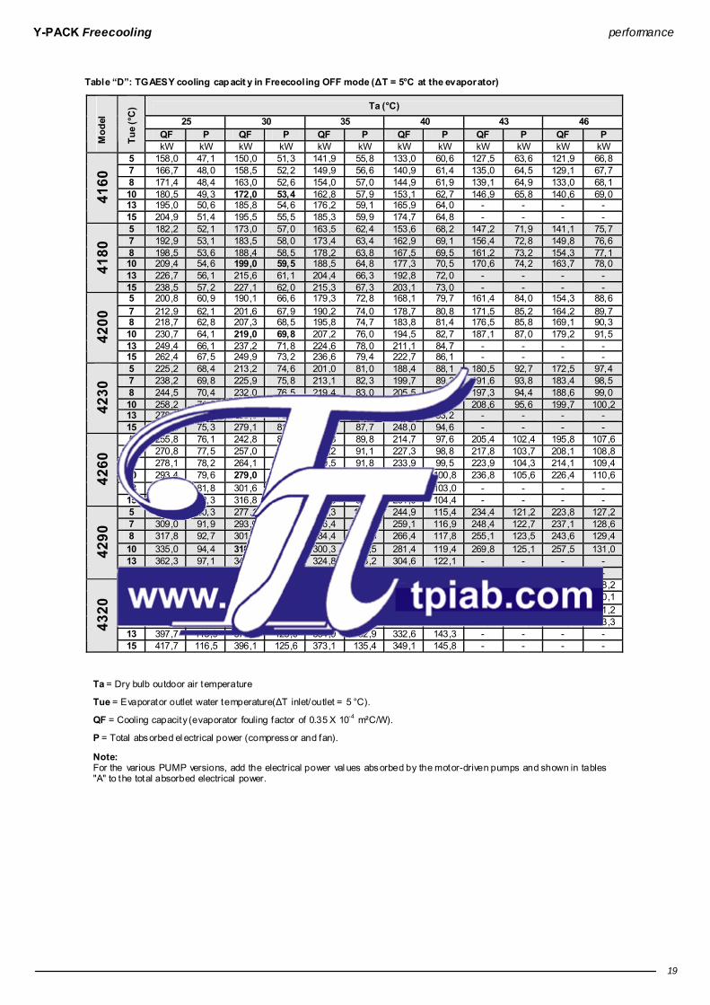
Table “D”: TGAESY cooling cap acit y in Freecooling OFF mode (ΔT = 5°C at the evaporator)
Ta (°C) 25 30 35 40 43 46
QF P QF P QF P QF P QF P QF P Mod
el
Tue
(°C
) kW kW kW kW kW kW kW kW kW kW kW kW
5 158,0 47,1 150,0 51,3 141,9 55,8 133,0 60,6 127,5 63,6 121,9 66,8 7 166,7 48,0 158,5 52,2 149,9 56,6 140,9 61,4 135,0 64,5 129,1 67,7 8 171,4 48,4 163,0 52,6 154,0 57,0 144,9 61,9 139,1 64,9 133,0 68,1 10 180,5 49,3 172,0 53,4 162,8 57,9 153,1 62,7 146,9 65,8 140,6 69,0 13 195,0 50,6 185,8 54,6 176,2 59,1 165,9 64,0 - - - - 41
60
15 204,9 51,4 195,5 55,5 185,3 59,9 174,7 64,8 - - - - 5 182,2 52,1 173,0 57,0 163,5 62,4 153,6 68,2 147,2 71,9 141,1 75,7 7 192,9 53,1 183,5 58,0 173,4 63,4 162,9 69,1 156,4 72,8 149,8 76,6 8 198,5 53,6 188,4 58,5 178,2 63,8 167,5 69,5 161,2 73,2 154,3 77,1 10 209,4 54,6 199,0 59,5 188,5 64,8 177,3 70,5 170,6 74,2 163,7 78,0 13 226,7 56,1 215,6 61,1 204,4 66,3 192,8 72,0 - - - - 41
80
15 238,5 57,2 227,1 62,0 215,3 67,3 203,1 73,0 - - - - 5 200,8 60,9 190,1 66,6 179,3 72,8 168,1 79,7 161,4 84,0 154,3 88,6 7 212,9 62,1 201,6 67,9 190,2 74,0 178,7 80,8 171,5 85,2 164,2 89,7 8 218,7 62,8 207,3 68,5 195,8 74,7 183,8 81,4 176,5 85,8 169,1 90,3 10 230,7 64,1 219,0 69,8 207,2 76,0 194,5 82,7 187,1 87,0 179,2 91,5 13 249,4 66,1 237,2 71,8 224,6 78,0 211,1 84,7 - - - - 42
00
15 262,4 67,5 249,9 73,2 236,6 79,4 222,7 86,1 - - - - 5 225,2 68,4 213,2 74,6 201,0 81,0 188,4 88,1 180,5 92,7 172,5 97,4 7 238,2 69,8 225,9 75,8 213,1 82,3 199,7 89,3 191,6 93,8 183,4 98,5 8 244,5 70,4 232,0 76,5 219,4 83,0 205,5 89,9 197,3 94,4 188,6 99,0 10 258,2 71,8 245,0 77,8 231,7 84,3 217,4 91,2 208,6 95,6 199,7 100,2 13 278,8 73,9 265,0 79,8 250,8 86,3 235,5 93,2 - - - - 42
30
15 293,6 75,3 279,1 81,3 264,0 87,7 248,0 94,6 - - - - 5 255,8 76,1 242,8 82,7 229,3 89,8 214,7 97,6 205,4 102,4 195,8 107,6 7 270,8 77,5 257,0 84,0 242,2 91,1 227,3 98,8 217,8 103,7 208,1 108,8 8 278,1 78,2 264,1 84,6 249,5 91,8 233,9 99,5 223,9 104,3 214,1 109,4 10 293,4 79,6 279,0 86,1 263,6 93,2 247,2 100,8 236,8 105,6 226,4 110,6 13 317,5 81,8 301,6 88,3 284,7 95,4 267,1 103,0 - - - - 42
60
15 333,6 83,3 316,8 89,9 299,5 96,9 281,0 104,4 - - - - 5 292,1 90,3 277,1 98,0 261,3 106,3 244,9 115,4 234,4 121,2 223,8 127,2 7 309,0 91,9 293,0 99,6 276,4 107,9 259,1 116,9 248,4 122,7 237,1 128,6 8 317,8 92,7 301,7 100,4 284,4 108,8 266,4 117,8 255,1 123,5 243,6 129,4 10 335,0 94,4 318,0 102,1 300,3 110,5 281,4 119,4 269,8 125,1 257,5 131,0 13 362,3 97,1 344,1 104,8 324,8 113,2 304,6 122,1 - - - - 42
90
15 380,8 99,0 361,2 106,7 341,3 115,1 320,2 124,0 - - - - 5 321,3 105,2 304,4 114,2 286,3 124,0 267,9 134,6 256,4 141,3 244,1 148,2 7 339,8 107,2 322,0 116,3 303,5 126,0 283,4 136,6 271,3 143,3 258,5 150,1 8 349,1 108,2 331,1 117,3 311,7 127,1 291,4 137,6 278,6 144,3 266,2 151,2 10 368,1 110,4 349,0 119,5 328,5 129,3 307,2 139,8 294,6 146,4 280,7 153,3 13 397,7 113,9 377,3 123,0 354,9 132,9 332,6 143,3 - - - - 43
20
15 417,7 116,5 396,1 125,6 373,1 135,4 349,1 145,8 - - - -
Ta = Dry bulb outdoor air temperature
Tue = Evaporator outlet water temperature(ΔT inlet/outlet = 5 °C).
QF = Cooling capacity (evaporator fouling factor of 0.35 X 10⁻⁴ m²C/W).
P = Total absorbed el ectrical power (compressor and fan).
Note: For the various PUMP versions, add the electrical power val ues absorbed by the motor-driven pumps and shown in tables "A" to the total absorbed electrical power.

Y-PACK Freecooling performance
20
Tab le “D”: TFAETY and TFAESY cooling capacit y in Freecooling ON mode (ΔT = 5°C at the evaporator)
TFAETY 4160 TFAESY 4160 Tue Ta Qf P G Δpw Tue Ta Qf P G Δpw (°C) (°C) (kW) (kW) (m³/h) (kPa) (°C) (°C) (kW) (kW) (m³/h) (kPa)
5 -4,3 154,5 8,0 29,1 23 5 -6,0 148,3 5,0 27,9 20 7 -2,4 163,7 8,0 30,8 25 7 -4,0 156,4 5,0 29,5 22 10 0,3 178,0 8,0 33,5 28 10 -1,3 170,0 5,0 32,0 25 15 4,6 202,7 8,0 38,1 35 15 3,0 193,3 5,0 36,3 30
TFAETY 4180 TFAESY 4180 Tue Ta Qf P G Δpw Tue Ta Qfa P G Δpw (°C) (°C) (kW) (kW) (m³/h) (kPa) (°C) (°C) (kW) (kW) (m³/h) (kPa)
5 -4,0 174,2 8,0 32,9 14 5 -6,0 171,4 5,0 31,2 14 7 -1,9 185,0 8,0 34,9 15 7 -3,8 181,5 5,0 34,1 15 10 1,0 202,0 8,0 38,.0 17 10 -0,8 197,0 5,0 37,0 17 15 5,6 230,2 8,0 43,3 21 15 3,8 223,8 5,0 41,2 20
TFAETY 4200 TFAESY 4200 Tue Ta Qf P G Δpw Tue Ta Qfa P G Δpw (°C) (°C) (kW) (kW) (m³/h) (kPa) (°C) (°C) (kW) (kW) (m³/h) (kPa)
5 -4,4 194,0 8,0 36,6 17 5 -6,4 186,6 5,0 35,1 15 7 -2,4 205,8 8,0 38,7 18 7 -4,4 198,4 5,0 37,2 16 10 0,4 224,0 8,0 42,1 20 10 -1,5 215,0 5,0 40,4 18 15 4,8 255,9 8,0 48,1 25 15 2,9 245,2 5,0 46,1 22
TFAETY 4230 TFAESY 4230 Tue Ta Qf P G Δpw Tue Ta Qfa P G Δpw (°C) (°C) (kW) (kW) (m³/h) (kPa) (°C) (°C) (kW) (kW) (m³/h) (kPa)
5 -3,9 217,5 12,0 41,0 21 5 -6,0 209,3 12,0 39,3 19 7 -2,0 230,6 12,0 43,4 23 7 -4,0 220,7 12,0 41,6 20 10 0,7 251,0 12,0 47,2 26 10 -1,3 240,0 12,0 45,1 23 15 5,0 286,1 12,0 53,8 32 15 2,9 274,3 12,0 51,4 28
TFAETY 4260 TFAESY 4260 Tue Ta Qf P G Δpw Tue Ta Qfa P G Δpw (°C) (°C) (kW) (kW) (m³/h) (kPa) (°C) (°C) (kW) (kW) (m³/h) (kPa)
5 -3,5 248,8 12,0 46,8 28 5 -5,5 239,2 12,0 45,0 29 7 -1,7 263,5 12,0 49,5 30 7 -3,7 253,1 12,0 47,5 31 10 0,9 286,0 12,0 53,8 34 10 -1,1 274,0 12,0 51,5 35 15 5,0 326,2 12,0 61,2 42 15 2,9 312,8 12,0 58,6 43
TFAETY 4290 TFAESY 4290 Tue Ta Qf P G Δpw Tue Ta Qfa P G Δpw (°C) (°C) (kW) (kW) (m³/h) (kPa) (°C) (°C) (kW) (kW) (m³/h) (kPa)
5 -3,8 283,2 16,0 53,2 35 5 -5,8 272,6 16,0 51,2 33 7 -2,1 300,6 16,0 56,5 38 7 -4,1 288,7 16,0 54,2 35 10 0,4 326,0 16,0 61,3 43 10 -1,6 312,0 16,0 58,7 40 15 4,3 372,8 16,0 69,7 53 15 2,2 356,4 16,0 66,6 49
TFAETY 4320 TFAESY 4320 Tue Ta Qf P G Δpw Tue Ta Qfa P G Δpw (°C) (°C) (kW) (kW) (m³/h) (kPa) (°C) (°C) (kW) (kW) (m³/h) (kPa)
5 -4,8 313,3 16,0 58,9 41 5 -7,0 300,5 16,0 56,4 39 7 -3,2 332,8 16,0 62,4 45 7 -5,3 315,5 16,0 59,6 42 10 -0,8 361,0 16,0 67,9 52 10 -3,0 344,0 16,0 64,7 48 15 3,0 410,6 16,0 77,2 63 15 0,7 390,6 16,0 73,3 58
Ta = 100% Freecooling dry bul b outdoor air temperature.
Tue = Evaporator mi xture (30% glycol) outlet temper ature (ΔT inlet /outlet = 5 °C).
QF = 100% Freecooling cooling capacity (evaporator fouling factor of 0.35 X 10⁻⁴ m²C/W).
P = Total absorbed el ectrical power (fan).
G = Water side cooling capacity.
ΔPw = Additional Freecooling coil pr essure drop.
Note: For the various PUMP versions, add the electrical power val ues absorbed by the motor-driven pumps and show in tables "A" to the total absorbed electrical power.

Y-PACK Freecooling performance
21
Table “D”: TGAETY and T GAESY cooling capacit y in Freecooling ON mode (ΔT = 5°C at the evaporator)
TGAETY 4160 TGAESY 4160 Tue Ta Qf P G Tue Ta Qf P G (°C) (°C) (kW) (kW) (m³/h) (°C) (°C) (kW) (kW) (m³/h)
5 -6,8 156,9 9,5 26,8 5 -8,4 149,6 6,5 25,6 7 -5,2 165,8 9,5 28,4 7 -6,9 158,8 6,5 27,2 10 -2,9 180,0 9,5 31,0 10 -4,6 172,0 6,5 29,6 15 0,8 205,5 9,5 35,4 15 -0,9 195,5 6,5 33,8
TGAETY 4180 TGAESY 4180 Tue Ta Qf P G Tue Ta Qfa P G (°C) (°C) (kW) (kW) (m³/h) (°C) (°C) (kW) (kW) (m³/h)
5 -6,3 179,1 10,2 30,7 5 -8,0 173 7,2 29,7 7 -4,7 190,3 10,2 32,6 7 -6,5 183,6 7,2 31,5 10 -2,3 207,0 10,2 35,6 10 -4,1 199,0 7,2 34,2 15 1,6 236,4 10,2 40,9 15 -0,3 227,6 7,2 39,2
TGAETY 4200 TGAESY 4200 Tue Ta Qf P G Tue Ta Qfa P G (°C) (°C) (kW) (kW) (m³/h) (°C) (°C) (kW) (kW) (m³/h)
5 -6,8 198,8 10,2 34 5 -8,7 189,9 7,2 32,6 7 -5,2 210,4 10,2 36,1 7 -7,2 201,8 7,2 34,6 10 -2,9 229,0 10,2 39,4 10 -4,9 219,0 7,2 37,7 15 0,9 261,1 10,2 45,3 15 -1,2 249,6 7,2 43,2
TGAETY 4230 TGAESY 4230 Tue Ta Qf P G Tue Ta Qfa P G (°C) (°C) (kW) (kW) (m³/h) (°C) (°C) (kW) (kW) (m³/h)
5 -6,5 222,2 14,2 38,1 5 -8,5 212,9 9,7 36,5 7 -5,0 236,1 14,2 40,4 7 -7,0 225,6 9,7 38,8 10 -2,7 256,0 14,2 44,0 10 -4,8 245,0 9,7 42,2 15 1,0 291,7 14,2 50,5 15 -1,2 278,8 9,7 48,2
TGAETY 4260 TGAESY 4260 Tue Ta Qf P G Tue Ta Qfa P G (°C) (°C) (kW) (kW) (m³/h) (°C) (°C) (kW) (kW) (m³/h)
5 -6,1 253 14,2 43,3 5 -8,1 243 9,7 41,6 7 -4,6 267,9 14,2 45,9 7 -6,6 256,6 9,7 44,1 10 -2,4 291,0 14,2 50,1 10 -4,5 279,0 9,7 48,0 15 1,2 331,1 14,2 57,3 15 -1,0 316,7 9,7 54,8
TGAETY 4290 TGAESY 4290 Tue Ta Qf P G Tue Ta Qfa P G (°C) (°C) (kW) (kW) (m³/h) (°C) (°C) (kW) (kW) (m³/h)
5 -6,4 288,6 19,0 49,5 5 -8,4 276,5 13,0 47,5 7 -5,0 306,4 19,0 52,6 7 -7,0 292,5 13,0 50,3 10 -2,9 333,0 19,0 57,3 10 -5 318,0 13,0 54,7 15 0,5 379,8 19,0 65,6 15 -1,6 359,9 13,0 62,4
TGAETY 4320 TGAESY 4320 Tue Ta Qf P G Tue Ta Qfa P G (°C) (°C) (kW) (kW) (m³/h) (°C) (°C) (kW) (kW) (m³/h)
5 -7,5 320,6 20,0 54,8 5 -9,6 305 14,0 52,2 7 -6,1 338,9 20,0 58,2 7 -8,2 321,4 14,0 55,3 10 -4,1 368,0 20,0 63,3 10 -6,3 349,0 14,0 60,0 15 -0,9 419,9 20,0 72,5 15 -3,2 396,8 14,0 68,5
Ta = 100% Freecooling dry bul b outdoor air temperature.
Tue = Evaporator outlet water temperature(ΔT inlet/outlet = 5 °C).
QF = 100% Freecooling cooling capacity (evaporator fouling factor of 0.35 X 10⁻⁴ m²C/W).
P = Total absorbed el ectrical power (fan and i nternal circuit pump).
G = Water side cooling capacity.
Note: For the various PUMP versions, add the electrical power val ues absorbed by the motor-driven pumps and shown in tables "A" to the total absorbed el ectrical power.

Y-PACK Freecooling performance
22
Pressure Drops Graph “1”: water side chiller pressure drop s (heat exch anger and h ydraulic circuit).
TFAETY - TF AESY
50
70
90
110
130
150
170
190
210
230
10 20 30 40 50 60 70 80 90 100
4320
4290
4160
4180
4200
4230
4260
Graph “1”: water side chiller pressure drop s (heat exch anger and h ydraulic circuit).
TGAETY - TGAESY
50
70
90
110
130
150
170
190
210
230
10 20 30 40 50 60 70 80 90 100
4320
4290
4160
4180
4200
4230
4260

Y-PACK Freecooling performance
23
Graph “3”: Additional Freecooling co il pressure drops
10 20 30 40 50 60 70 80 90 1000
10
20
30
40
50
60
70
80
90
4230
4160
4180-4200
4260-4290-4320
Calculation of Pressure Drops ○ The pr essure drops of the TFAETY-TFAESY unit in Freecooling OFF mode are calculated using graph 1 or using the RHOSS selec tion software. ○ The pr essure drops of the TFAETY-TFAESY units in Freecooling ON mode are calculated by adding to the previ ous values the val ues fr om the additi onal Freecooling coil shown in graph 3 or by usi ng the RHOSS sel ection software. ○ The pr essure drops of the TGAETY-TGAESY unit are calculated using graph 1 or using the RHOSS. selec tion software. Note: For all machines, refer in any case to admissible operating limits and thermal (ΔT).

Y-PACK Freecooling performance
24
TFAETY-TFAESY residual static pressures Graphic “2”: residual static pressures in Freecooling OFF op eration
TFAETY-TFAESY P1/DP1
0
50
100
150
200
250
300
20 30 40 50 60 70 80
4160
4180
4200
4230
4260
4290
4320
TFAETY-TFAESY P2/DP2
50
100
150
200
250
300
350
20 30 40 50 60 70 80
4160
4180
4200
4230
4260
4290
4320
Calculation of residu al st atic pressure ○ The residual static pressure of the TFAETY-TFAESY units in Freecooling OFF mode is calculating using graph 2 or using the RHOSS selecti on software. ○ The residual static pressure of the TFAETY-TFAESY units in Freecooling ON mode is calculated by subtr acting the pressure drops of the additional Freecooling coil shown in graph 3 from the pr eviousl y calculated value.

Y-PACK Freecooling performance
25
TGAETY-TGAESY residual static pressures Graph “2”: residu al st atic pressure.
TGAETY-TGAESY P1/DP1
0
50
100
150
200
250
300
20 30 40 50 60 70 80
4160
4180
4200
4230
4260
4260
4320
TGAETY-TGAESY P2/DP2
50
100
150
200
250
300
350
20 30 40 50 60 70 80
4160
4180
4200
4230
4260 4290
4320
Calculation of residu al st atic pressure ○ The residual static pressure of the TGAETY-TGAESY units is calculati ng using graph 2 or using the RHOSS selection software.

Y-PACK Freecooling performance
26
Power Levels and Sound Pressure
Sound power level in dB b y octave b ands Pressure level in dB(A) Model
125 Hz 250 Hz 500 Hz 1000 Hz 2000 Hz 4000 Hz 8000 Hz Lw dB(A) Lp 10m Lp 5m Lp 1m
4160 83 81 85 87 81 75 68 89 60 65 72 4180 86 82 85 89 84 76 69 91 63 67 73 4200 86 82 85 89 84 76 69 91 63 67 73 4230 88 84 87 90 86 78 71 93 65 69 75 4260 88 84 87 90 86 78 71 93 65 69 75 4290 89 85 89 91 88 80 72 94 66 70 76
TFA
ETY
TGA
ETY
4320 89 85 89 91 88 80 72 94 66 70 76 4160 79 77 81 83 77 69 64 85 55 60 67 4180 80 78 82 84 78 70 64 86 56 61 68 4200 80 78 82 84 78 70 64 86 56 61 68 4230 82 80 84 86 80 74 67 88 58 63 70 4260 83 81 85 87 81 75 68 89 59 64 71 4290 84 82 86 88 82 76 69 90 60 65 72
TFA
ESY
TGA
ESY
4320 84 82 86 88 82 76 69 90 60 65 72
Lw Sound power l evel in dB(A) on the basis of measur ements made in compliance with the UNI EN-ISO 3744 standard and Eurovent 8/1. The noise measurement r efers to the units without pump.
Lp Sound pressure level i n dB(A) in reference to the measurement and distance from the unit indicated in the table, with directi onality factor of 2. The noise measur ement refers to the units without pump.

Y-PACK Freecooling operating limits
27
Operating limits
105 15
40
45
50
0
-15
Standard operati on.
Operati on with stepped cooling capacity. T (°C) = Air temperatur e (D.B.). t (°C) = Water temperature produced. Maximum inlet temperature of the water or water-glycol mi xtur e 20°C.
Temperature differentials p ermitted through the exchangers ○ Temperature dif ferential at the evaporator ΔT = 3 - 8°C ( with all compressors on) for machines with "standard" ins tallation. T he maxi mum and minimum temperature dif ferential for the “Pump” machines is linked to the pump performances , which must always be checked with the help of the graphs on page 25 or using the RHOSS selection software. ○ Minimum water pressur e 0.5 Barg ○ Maxi mum water pressure 6 Barg. ○ Maxi mum water pressure on heat recover y and desuperheater 3 Barg. Note: For TGAETY and TGAESY versions , for evaporator outlet water of a temperature bel ow 5°C, please contact the RHOSS S.p.A. pr e-sales service before ordering.
Model TFAETY TGAETY TFAESY TGAESY Tmax = 46 °C (5) (2) Tmax = 46 °C (1) (2) Tmax = 40 °C (5) (3) Tmax = 40 °C (1) (3) 4160-4320 Tmax = 50 °C (5) (4) Tmax = 50 °C (1) (4)
(1) Water temperature (IN/OUT) 15/10°C. (2) Maxi mum external air temperature with unit in standard operation at full load and not silenced. (3) Maxi mum external air temperature with unit in silenced mode. (4) Maxi mum external air temperature with unit with shuttered cooling capacity. (5) Mixture temperatur e (30% glycol) (IN/OUT) 15/10°C.
Use of antifreeze solutions ○ The use of ethylene gl ycol is recommended if you do not wish to drai n the water from the water system during the winter pause, or if the unit has to suppl y chilled water at temperatures lower than 5 °C. T he addition of gl ycol changes the physical properties of the water and consequentl y the performance of the unit. T he proper percentage of gl ycol to be added to the system can be obtai ned from the mos t demanding operati ng conditions from those shown below.
○ Table "H" shows the multipli ers that allow the changes in perfor mance of the units to be determined in proportion to the required percentage of ethylene glycol. ○ The multipliers refer to the following conditi ons: condenser inl et air temperature 35°C; chilled water outlet temperature 7°C; temperature differ ential at evaporator and condenser 5°C. ○ For different operating conditi ons, the same coefficients can be used as their variations ar e negligible.
○ The el ectric heater for the water side heat exchanger (RA accessor y) and the motor-driven pump assembl y (RAE accessor y) prevents ice formation during winter br eaks (as long as the unit is not disconnected fr om the power suppl y).
T able “H”
Glycol b y weight 10 % 15 % 20 % 25 % 30 % Freezing temp erature °C -5 -7 -10 -13 -16 fc QF 0,991 0,987 0,982 0,978 0,974 fc P 0,996 0,995 0,993 0,991 0,989 fc Δpw 1,053 1,105 1,184 1,237 1,316 fc G 1,008 1,028 1,051 1,074 1,100
fc QF = Cooling capacity correction factor. fc P= Correction fac tor for the absorbed electrical power. fc Δpw = C orrection factor of the pressure drop in the evaporator fc G = Correction fac tor of the glycol water flow to the evaporator

Y-PACK Freecooling dimensions and footprints
28
Dimensions and footprints
a
b c
d i i l mh l
12
1098
55 6
777
1211
21
20
3 4
h
g
fe
1618 19 18
17
13 1415
1. Control panel; 2. Isolator; 3. Electrical board; 4. Refrigerant circuit pressure gauges (GM accessor y); 5. Compressor; 6. Evaporator; 7. Fan; 8. Finned coil; 9. Metal filter (FMB accessor y); 10. Coil protecti on mesh (RPB accessory); 11. Water inlet; 12. Water outlet; 13. User side motor-driven pump (accessor y); 14. Motor-driven pump (TGAETY – TGAESY); 15. Heat exchanger TGAET Y-TGAESY; 16. Glycol mi xture drai n (TGAET Y – T GAESY); 17. Glycol mi xture suppl y (TGAETY – TGAESY); 18. Coil air vent; 19. TGAETY – TGAESY air vent; 20. Anti-vi bration support (KSA/KSAM accessor y); 21. Pressure gauge (TGAETY-TGAESY internal circuit)
(TFAETY – TFAESY user si de);
TFAETY-TFAESY-TGAETY-TGAESY Model a b c d e f g h i l m
4160 mm 2030 2090 4800 80÷150 600 850 410 150 2220 50 1810 4180 mm 2030 2090 4800 80÷150 600 850 410 150 2220 50 1810 4200 mm 2030 2090 4800 80÷150 600 850 410 150 2220 50 1810 4230 mm 2030 2090 4800 80÷150 600 850 410 150 2220 50 1810 4260 mm 2030 2090 5300 80÷150 600 850 410 150 2470 50 1810 4290 mm 2030 2090 5300 80÷150 600 850 410 150 2470 50 1810 4320 mm 2030 2090 5300 80÷150 600 850 410 150 2470 50 1810
Model 4160 4180 4200 4230 4260 4290 4320 Inlet/outlet connections Ø 3” 3” 3” 3” 3” 3” 3”

Y-PACK Freecooling dimensions and footprints
29
Clearances and positioning
L1
L2
L3
L4
Model 4160 4180 4200 4230 4260 4290 4320 L1 mm 2000 2000 2000 2000 2000 2000 2000 L2 mm 2000 2000 2000 2000 2000 2000 2000 L3 mm 2000 2000 2000 2000 2000 2000 2000 L4 mm 1500 1500 1500 1500 1500 1500 1500
Handling and storage ○ The unit shoul d be handled with care to avoid damage to the external structure and to the internal mechanical and electrical components. ○ Do not stack the units. ○ The temperature li mits for s torage are - 9 °C ÷ 45 °C. ○ During lifting and handling, make sure that the unit is horizontal at all times.
Installation and Connection to the System ○ The unit is designed for outdoor installation. ○ The unit is fit ted with victaulic type water connections on the conditi oning system water inl et and outlet as well as with carbon steel fittings for weldi ng. ○ Isolate the unit if i nstalled in areas accessible to persons under 14 years of age. ○ The unit must be positioned to compl y with the mi nimum recommended cl earances, bearing in mind the access to water and electrical connections . ○ The unit can be equipped with anti- vibration mountings on request (KSA). ○ Shut- off valves must be installed that isolate the unit from the res t of the sys tem. El astic connection joints and sys tem/machi ne drain taps also need to be fitted. ○ A metal mesh filter (with a square mesh measuring no more than 0.8 mm), of a suitabl e size and with suitable pressure drop, must be fitted on the unit return pipes. ○ However it is installed, the coil inlet air temperatur e (ambient air) must remain withi n the set limits . ○ The water flow through the heat-exchanger should not fall below a val ue correspondi ng to a temperature differential of 8°C (with all compressors on). ○ The unit may not be installed on brackets or shel ves. ○ Correct installation and positioning includes levelling the unit on a surface capable of bearing its weight. ○ During long periods of i nacti vity, it is advisabl e to drai n the water from the system. ○ It is possible to avoid draini ng the water by addi ng ethyl ene glycol to the water circuit (see “Use of antifreeze soluti ons”). ○ The expansion tank is sized on the basis of the water content of the indivi dual machine. Additi onal expansi on tanks must be sized by the installer based on the system. In the case of models without a pump, the pump must be ins talled with the pump delivery towards the machine water inlet . Note: The space above the unit must be free from obstacles. I f the unit is completel y surrounded by walls, the distances specifi ed are still valid, provided that at l east two adjacent walls are not higher than the unit itself. There must be a mini mum gap of at least 3.5 m between the top of the unit and any obstacl es above it. If more than one unit is installed, the mi nimum distance between the finned coils should be at least 2 m.

Y-PACK Freecooling water connections
30
Weight distribution
A
F
B
E
C
D
W eight (*) Model A B C D E F
Total (*) Total (**)
TFAETY-TFAESY 4160 kg 468 428 342 344 425 463 2470 2370 TFAETY-TFAESY 4180 kg 599 501 363 367 499 591 2920 2820 TFAETY-TFAESY 4200 kg 632 517 364 369 515 623 3020 2920 TFAETY-TFAESY 4230 kg 652 534 377 382 532 643 3120 3020 TFAETY-TFAESY 4260 kg 714 580 404 406 574 702 3380 3230 TFAETY-TFAESY 4290 kg 755 604 414 416 599 742 3530 3380 TFAETY-TFAESY 4320 kg 764 613 420 423 608 752 3580 3430 TGAETY-TGAESY 4160 kg 474 454 381 370 437 454 2570 2470 TGAETY-TGAESY 4180 kg 614 536 409 401 519 591 3070 2970 TGAETY-TGAESY 4200 kg 644 553 414 405 535 619 3170 3070 TGAETY-TGAESY 4230 kg 663 570 428 419 552 638 3270 3170 TGAETY-TGAESY 4260 kg 722 594 421 415 579 699 3430 3280 TGAETY-TGAESY 4290 kg 762 619 433 426 603 737 3580 3430 TGAETY-TGAESY 4320 kg 771 628 439 433 612 747 3630 3480
(*) Weight of the units complete with all accessories and the water content. (**) Weight of the empty units with all accessories.
Water connections
Maximum water circuit content In order for the units to operate properly, mini mum water content mus t be guar anteed in the water sys tem. T he mini mum water content is established on the basis of the unit's nominal cooling capacity (table A Technical D ate), multiplied by the coefficient expressed in l/kW. If the minimum content in the system is l ower than the minimum indicated or calculated val ue, an additional tank should be ins talled. However, in process applications it is always advisable to use a water buffer tank or a greater system water content to guarantee higher system thermal i nertia.
The minimum circu it water content is 2 l /kW Example:
TFAETY 4320 Qf = 361 kW If the unit envisages control compatibl e with the AdaptativeFunction Plu s functi on, the mi nimum sys tem content must be:
Qf (kW) x 2 l/kW = 361 kW x 2 l/kW = 722 l.
Water data
Models 4160 4180 4200 4230 4260 4290 4320 Safety val ve barg 6 6 6 6 6 6 6 TFAETY-TFAESY Exchanger water content l 12 12 14 15 18 21 24 TGAETY-TGAESY Exchanger water content l 12 12 14 15 18 21 24
Expansion vessel technical data
P1-P2-DP1-DP2 Installation 4160 4180 4200 4230 4260 4290 4320
Capacity l 12 12 12 12 12 12 12 Pre-charging barg 2 2 2 2 2 2 2 Maxi mum expansion tank pressure barg 6 6 6 6 6 6 6
TGAETY-TGAESY internal circuit Model
4160 4180 4200 4230 4260 4290 4320 Capacity l 12 12 12 12 12 12 12 Pre-charging barg 2 2 2 2 2 2 2 Maxi mum expansion tank pressure barg 6 6 6 6 6 6 6

Y-PACK Freecooling water circuits
31
Water Circuits TFAETY - TF AESY Stand ard Inst allation
ST3
ST2
ST1
ST4BFC
ECH
RECF PD
AP1
VR
OUT
INFAGI
GI
RI
RI
C
C
V3V
VSM
VSM
TFAETY - TF AESY Pump P1/P2 installation
ST3
ST2
ST1
ST4BFC
ECH
RECF PD
AP1
PU RIVR
OUT
INFAGI
GI
RI
RI
C
C
V3V
VSM
VSM
VE VSM
TFAETY - TF AESY Pump D P1/DP2 in stallation
ST3
ST2
ST1
ST4BFC
ECH
RECF PD
AP1
PU RIVR
PU RIVR
VR
OUT
INFAGI
GI
RI
RI
C
C
V3V
VSM
VSM
VE VSM

Y-PACK Freecooling water circuits
32
TGAETY - TGAESY Standard Installation
ST3
ST2
ST1
ST4BFC
ECH
RE
ECG
RECF PD
AP1
PU
RIRI
RI
OUT
INFAGI
GI
RI
RI
S
C
C
VSM
VSM
F
VSM
VSM
VE
M VS
TGAETY - TGAESY Pump P1/P2 in stallation
ST3
ST2
ST1
ST4BFC
ECH
RE
ECG
RECF PD
AP1
PURI
PU
RIRI
RI
OUT
INFAGI
GI
RI
RI
S
C
C
VSM
VSM
F
VSM
VSM
VE
VE
M VS
VS

Y-PACK Freecooling water circuits
33
TGAETY - TGAESY Pump DP1/DP2 installation
ST3
ST2
ST1
ST4BFC
ECH
RE
ECG
RECF PD
AP1
PU RIVR
PU PURI
RIRI
RI
VR
OUT
INFAGI
GI
RI
RI
S
C
C
VSM
VSM
F
VSM
VSM
VE
VE
M VS
VS
CF Refrigerant circuit ECH Plate evaporator ECG Water/glycol and water soluti on exchanger
RE Evaporator antifr eeze elec tric heater (accessor y on TFAETY-TFAESY) PD Water differenti al pressure switch
F Flow switch VSM Manual bleed valve
VS Safety val ve AP1 Electronic contr ol ST1 Primar y inlet temperature gauge ST2 Primar y outlet temperature gauge
- wor king and antifreeze for Standard and Pump installations ST3 Evaporator i nlet temper ature probe ST4 Ambi ent temperature probe VE Expansion tank FA Mesh filter (installed by the i nstaller) M Pressure gauge
PU Pump VR Check val ve
S Water drain C Charge/drain val ve RI Shut- off valve GI Anti-vi bration connection
V3V 3-way val ve BFC Freecooling coil - - - - Connections to be made by the installer

Y-PACK Freecooling electrical connections
34
MIQE Terminal board in electrical panel
IG General isolator;
L1 Line 1;
L2 Line 2;
L3 Line 3;
N Neutral;
PE Earth termi nal;
KRS485 RS485 serial interface (accessor y);
KUSB RS485/USB converter (accessor y);
KISI CAN bus serial interface;
J20 Connector for KRS485, KFTT10 and KISI accessory installation;
MEU External user termi nal board;
KRS232 RS485/RS232 converter (accessor y);
PC Personal computer;
SCR Remote control selector (control with cl ean contact);
DSP Dual set-point selector (only available i n combi nati on with the EEV accessory);
CP Pump controls (consent at voltage 230 Vac, maxi mum load 2A AC1)
CS Scrolling set point vi a analogue signal 4-20 mA (incompati ble with the DSP accessor y);
LBG 1-2
General lockout light (230 Vac voltage output);
LFC 1-2-3-4
Compressor operati ng light 1-2-3-4 (230 Vac output voltage);
KMDM GSM 900-1800 modem kit ;
- - - - Connection to be made by the installer;
Electrical connections
L1
L2
L3
N
400V-3ph+N-50Hz
MEUMIQE
SCR
DSP
PEIG
KRS232KUSBKISI+
-
GN
D
KRS485
+
-
GN
D
SE
RIA
L C
AR
D
PC
PE
LBG 112.5
N
LFC 112.8
N
LFC 412.14
N
CS
KMDM
16.5
12.20
9.06
9.07
LFC 212.10
N
LFC 312.12
N
LBG 212.7
N
6
12.3
6
12.4
AC
+
~~
-
Mod
em
DC
ATTENTION ! The followi ng diagrams onl y show the connec tions to be made by the installer.
○ The el ectrical board is accessi ble from the front panel of the unit. ○ Connections must be made by skilled personnel in compliance with current standards and with the diagrams provided with the machine. ○ Always install a general isolator in a pr otected area near the unit with a del ayed characteristic curve of suitable capacity and breaking capacity. Make sure the general isolator incl udes a 3 mm mini mum opening distance between contacts. ○ Earth connecti on is compulsory by law and safeguards the user while the machine is in use. Note: Specific terminals are provided for the CS and D SP accessories .
Cable section 4160 4180 4200 4230 4260 4290 4320 Line section mm² 70 70 95 95 120 150 150 PE sec tion mm² 35 35 50 50 70 70 70 Remote control section mm² 1,5 1,5 1,5 1,5 1,5 1,5 1,5


RHOSS S.P.A. declines all responsabilities forpossible mistakes in the catalogue and reserves theright to alter the features of their products withoutnotice in the interests of continuous improvement.
K20321EN ed.109.09 - 0.000 - Stampa:
TFAEY-TGAEY 4160÷4320
Y-Pack FREECOOLING range
RHOSS S.P.A. Via Oltre Ferrovia, 32 - 33033 Codroipo (UD) - Italytel. +39 0432 911611 - fax +39 0432 [email protected] - www.rhoss.it - www.rhoss.com
IR GROUP S.A.S.7 rue du Pont à Lunettes - 69390 Vourles - Francetél. +33 (0)4 72318631 - fax +33 (0)4 [email protected]
RHOSS Deutschland GmbHHölzlestraße 23, D-72336 Balingen, OT Engstlatt - Germanytel. +49 (0)7433 260270 - fax +49 (0)7433 [email protected] - www.rhoss.de
RHOSS MERCOSURBenjamin Constant 576 - 1er Piso C.P. 1214 - Asuncion Paraguaytel/fax +595 21 493 897 - www.rhossmercosur.com
Sedi commerciali Italia: / Italy branch offices:
Area Nord-Est: 33033 Codroipo (UD) - Via Oltre Ferrovia, 32tel. +39 0432 911611 - fax +39 0432 911600
Area Nord-Ovest: 20041 Agrate Brianza (MI)Centro Colleoni - Palazzo Taurus, 1tel. +39 039 6898394 - fax +39 039 6898395
Area Centro-Sud: 00199 Roma - Viale Somalia, 109tel. +39 06 8600699-707 - fax +39 06 8600747
Area Sud: 80143 Napoli - Via G. Porzio - Centro Direzionale - Isola G8tel. +39 081 7879121 - fax +39 081 7879135


