Embed Size (px)
Citation preview
Detailed Project Report for Rail Based Mass Transit System in Varanasi
Final Report CHAPTER‐5: STATION PLANNING AND INTERMODAL INTEGRATION
February, 2016 Page 5-1
5. STATION PLANNING AND INTERMODAL INTEGRATION
5.1. COVERAGE
The proposed metro rail system has been planned to serve major passenger
catchment areas/ destinations and to enable convenient integration with other modes
of transport. Stations vary in complexity along the route and have been located by an
interactive process influenced by ridership forecasts, existing major settlements,
major roads, interchange requirements with other modes of transport, station
spacing, alignment, utilities, traffic and pedestrian requirements, station spacing, etc.
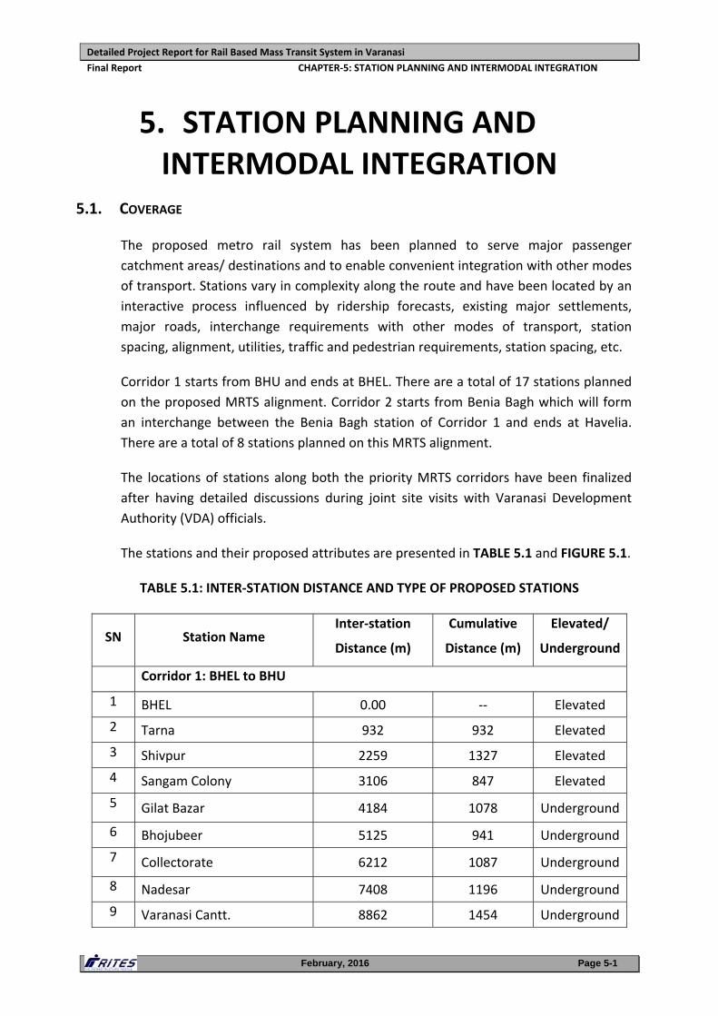
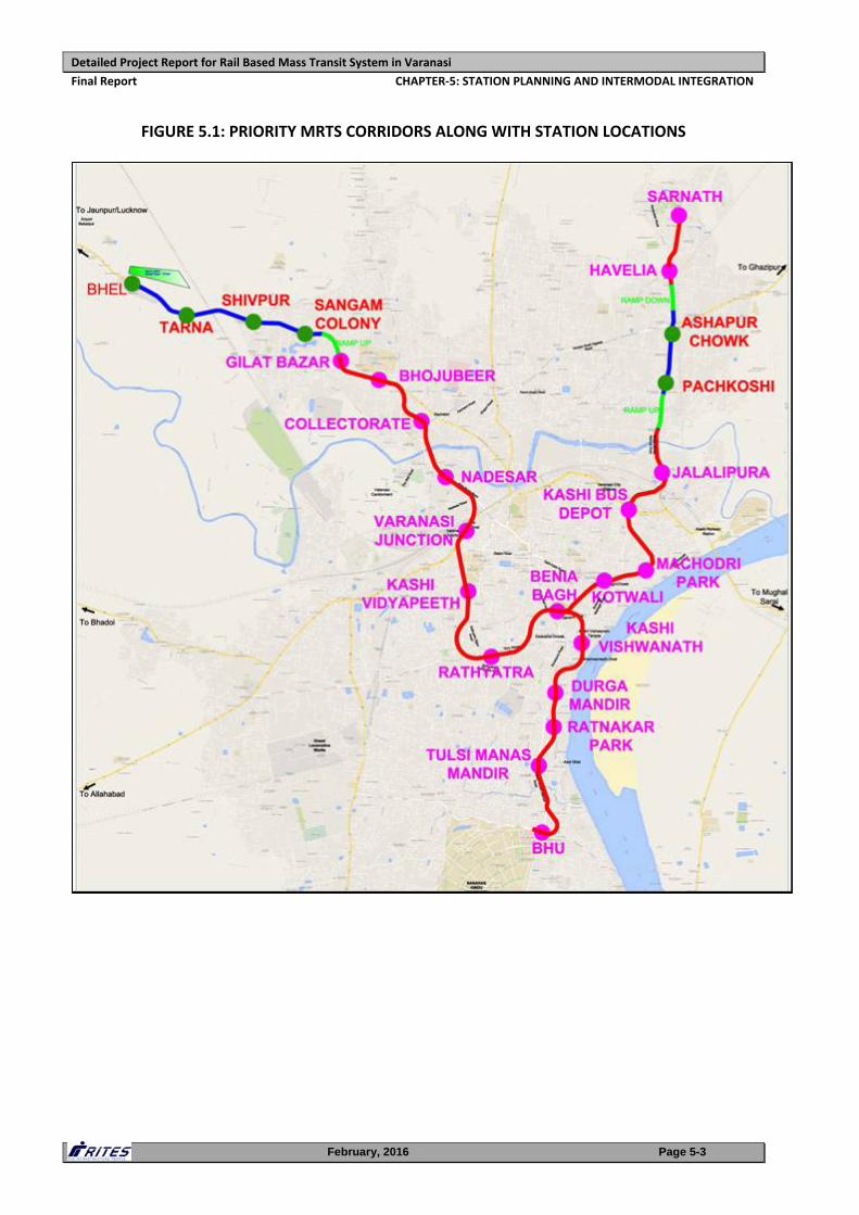
Corridor 1 starts from BHU and ends at BHEL. There are a total of 17 stations planned
on the proposed MRTS alignment. Corridor 2 starts from Benia Bagh which will form
an interchange between the Benia Bagh station of Corridor 1 and ends at Havelia.
There are a total of 8 stations planned on this MRTS alignment.
The locations of stations along both the priority MRTS corridors have been finalized
after having detailed discussions during joint site visits with Varanasi Development
Authority (VDA) officials.
The stations and their proposed attributes are presented in TABLE 5.1 and FIGURE 5.1.
TABLE 5.1: INTER‐STATION DISTANCE AND TYPE OF PROPOSED STATIONS
SN Station Name Inter‐station
Distance (m)
Cumulative
Distance (m)
Elevated/
Underground
Corridor 1: BHEL to BHU
1 BHEL 0.00 ‐‐ Elevated
2 Tarna 932 932 Elevated
3 Shivpur 2259 1327 Elevated
4 Sangam Colony 3106 847 Elevated
5 Gilat Bazar 4184 1078 Underground
6 Bhojubeer 5125 941 Underground
7 Collectorate 6212 1087 Underground
8 Nadesar 7408 1196 Underground
9 Varanasi Cantt. 8862 1454 Underground
Detailed Project Report for Rail Based Mass Transit System in Varanasi
Final Report CHAPTER‐5: STATION PLANNING AND INTERMODAL INTEGRATION
February, 2016 Page 5-2
SN Station Name Inter‐station
Distance (m)
Cumulative
Distance (m)
Elevated/
Underground
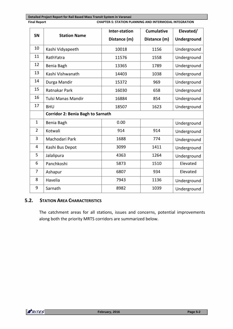
10 Kashi Vidyapeeth 10018 1156 Underground
11 RathYatra 11576 1558 Underground
12 Benia Bagh 13365 1789 Underground
13 Kashi Vishwanath 14403 1038 Underground
14 Durga Mandir 15372 969 Underground
15 Ratnakar Park 16030 658 Underground
16 Tulsi Manas Mandir 16884 854 Underground
17 BHU 18507 1623 Underground
Corridor 2: Benia Bagh to Sarnath
1 Benia Bagh 0.00 Underground
2 Kotwali 914 914 Underground
3 Machodari Park 1688 774 Underground
4 Kashi Bus Depot 3099 1411 Underground
5 Jalalipura 4363 1264 Underground
6 Panchkoshi 5873 1510 Elevated
7 Ashapur 6807 934 Elevated
8 Havelia 7943 1136 Underground
9 Sarnath 8982 1039 Underground
5.2. STATION AREA CHARACTERISTICS
The catchment areas for all stations, issues and concerns, potential improvements
along both the priority MRTS corridors are summarized below.
Detailed Project Report for Rail Based Mass Transit System in Varanasi
Final Report CHAPTER‐5: STATION PLANNING AND INTERMODAL INTEGRATION
February, 2016 Page 5-3
FIGURE 5.1: PRIORITY MRTS CORRIDORS ALONG WITH STATION LOCATIONS
Detailed Project Report for Rail Based Mass Transit System in Varanasi
Final Report CHAPTER‐5: STATION PLANNING AND INTERMODAL INTEGRATION
February, 2016 Page 5-4
5.2.1. Corridor 1: BHU to BHEL
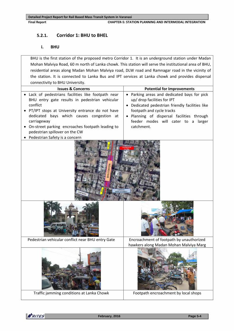
i. BHU
BHU is the first station of the proposed metro Corridor 1. It is an underground station under Madan
Mohan Malviya Road, 60 m north of Lanka chowk. This station will serve the institutional area of BHU,
residential areas along Madan Mohan Malviya road, DLW road and Ramnagar road in the vicinity of
the station. It is connected to Lanka Bus and IPT services at Lanka chowk and provides dispersal
connectivity to BHU University.
Issues & Concerns Potential for Improvements
Lack of pedestrians facilities like footpath near BHU entry gate results in pedestrian vehicular conflict
PT/IPT stops at University entrance do not have dedicated bays which causes congestion at carriageway
On‐street parking encroaches footpath leading to pedestrian spillover on the CW
Pedestrian Safety is a concern
Parking areas and dedicated bays for pick up/ drop facilities for IPT
Dedicated pedestrian friendly facilities like footpath and cycle tracks
Planning of dispersal facilities through feeder modes will cater to a larger catchment.
Pedestrian vehicular conflict near BHU entry Gate Encroachment of footpath by unauthorized
hawkers along Madan Mohan Malviya Marg
Traffic jamming conditions at Lanka Chowk Footpath encroachment by local shops
Detailed Project Report for Rail Based Mass Transit System in Varanasi
Final Report CHAPTER‐5: STATION PLANNING AND INTERMODAL INTEGRATION
February, 2016 Page 5-5
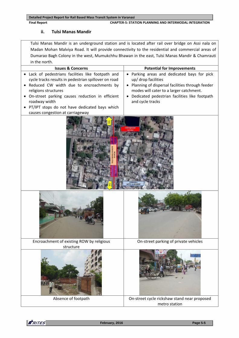
ii. Tulsi Manas Mandir
Tulsi Manas Mandir is an underground station and is located after rail over bridge on Assi nala on
Madan Mohan Malviya Road. It will provide connectivity to the residential and commercial areas of
Dumarao Bagh Colony in the west, Mumukchhu Bhawan in the east, Tulsi Manas Mandir & Chamrauti
in the north.
Issues & Concerns Potential for Improvements
Lack of pedestrians facilities like footpath and cycle tracks results in pedestrian spillover on road
Reduced CW width due to encroachments by religions structures
On‐street parking causes reduction in efficient roadway width
PT/IPT stops do not have dedicated bays which causes congestion at carriageway
Parking areas and dedicated bays for pick up/ drop facilities
Planning of dispersal facilities through feeder modes will cater to a larger catchment.
Dedicated pedestrian facilities like footpath and cycle tracks
Encroachment of existing ROW by religious structure
On‐street parking of private vehicles
Absence of footpath On‐street cycle rickshaw stand near proposed metro station
Detailed Project Report for Rail Based Mass Transit System in Varanasi
Final Report CHAPTER‐5: STATION PLANNING AND INTERMODAL INTEGRATION
February, 2016 Page 5-6
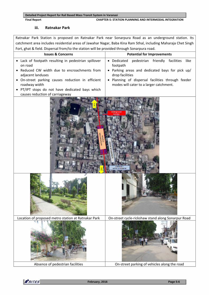
iii. Ratnakar Park
Ratnakar Park Station is proposed on Ratnakar Park near Sonarpura Road as an underground station. Its
catchment area includes residential areas of Jawahar Nagar, Baba Kina Ram Sthal, including Maharaja Chet Singh
Fort, ghat & field. Dispersal from/to the station will be provided through Sonarpura road.
Issues & Concerns Potential for Improvements
Lack of footpath resulting in pedestrian spillover on road
Reduced CW width due to encroachments from adjacent landuses
On‐street parking causes reduction in efficient roadway width
PT/IPT stops do not have dedicated bays which causes reduction of carriageway
Dedicated pedestrian friendly facilities like footpath
Parking areas and dedicated bays for pick up/ drop facilities
Planning of dispersal facilities through feeder modes will cater to a larger catchment.
Location of proposed metro station at Ratnakar Park On‐street cycle‐rickshaw stand along Sonarpur Road
Absence of pedestrian facilities On‐street parking of vehicles along the road
Detailed Project Report for Rail Based Mass Transit System in Varanasi
Final Report CHAPTER‐5: STATION PLANNING AND INTERMODAL INTEGRATION
February, 2016 Page 5-7
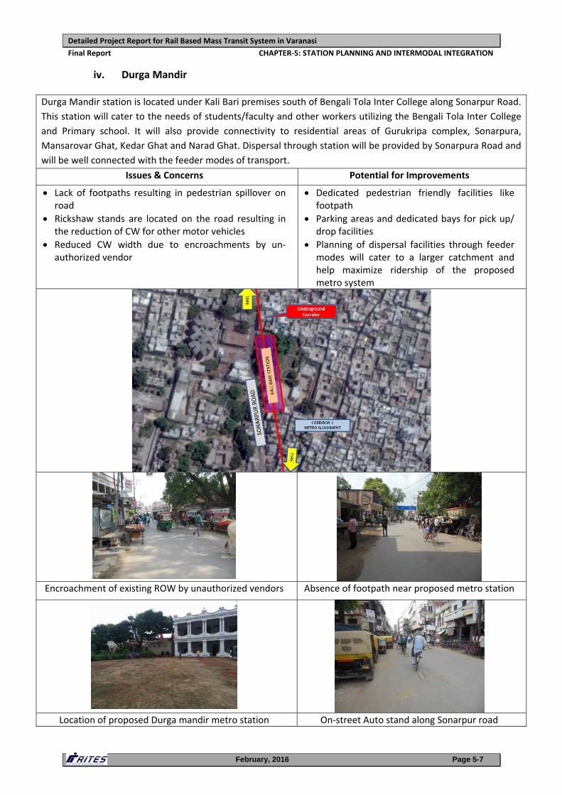
iv. Durga Mandir
Durga Mandir station is located under Kali Bari premises south of Bengali Tola Inter College along Sonarpur Road.
This station will cater to the needs of students/faculty and other workers utilizing the Bengali Tola Inter College
and Primary school. It will also provide connectivity to residential areas of Gurukripa complex, Sonarpura,
Mansarovar Ghat, Kedar Ghat and Narad Ghat. Dispersal through station will be provided by Sonarpura Road and
will be well connected with the feeder modes of transport.
Issues & Concerns Potential for Improvements
Lack of footpaths resulting in pedestrian spillover on road
Rickshaw stands are located on the road resulting in the reduction of CW for other motor vehicles
Reduced CW width due to encroachments by un‐authorized vendor
Dedicated pedestrian friendly facilities like footpath
Parking areas and dedicated bays for pick up/ drop facilities
Planning of dispersal facilities through feeder modes will cater to a larger catchment and help maximize ridership of the proposed metro system
Encroachment of existing ROW by unauthorized vendors Absence of footpath near proposed metro station
Location of proposed Durga mandir metro station On‐street Auto stand along Sonarpur road
Detailed Project Report for Rail Based Mass Transit System in Varanasi
Final Report CHAPTER‐5: STATION PLANNING AND INTERMODAL INTEGRATION
February, 2016 Page 5-8
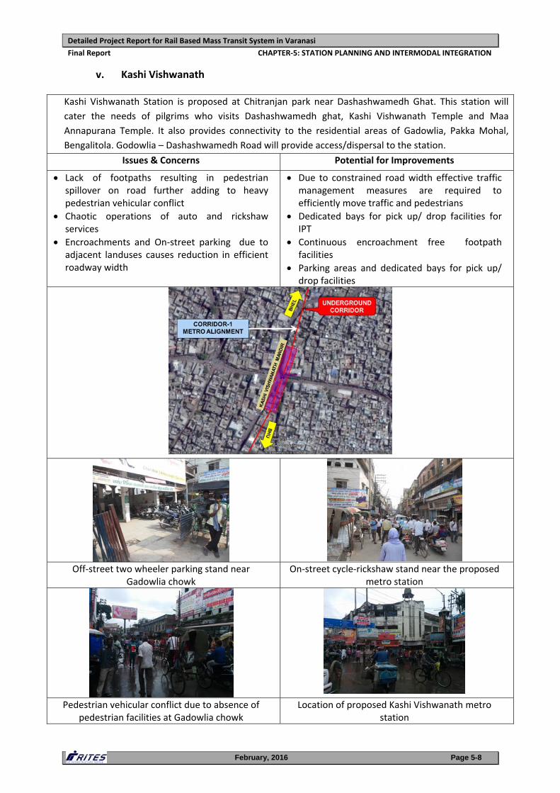
v. Kashi Vishwanath
Kashi Vishwanath Station is proposed at Chitranjan park near Dashashwamedh Ghat. This station will
cater the needs of pilgrims who visits Dashashwamedh ghat, Kashi Vishwanath Temple and Maa
Annapurana Temple. It also provides connectivity to the residential areas of Gadowlia, Pakka Mohal,
Bengalitola. Godowlia – Dashashwamedh Road will provide access/dispersal to the station.
Issues & Concerns Potential for Improvements
Lack of footpaths resulting in pedestrian spillover on road further adding to heavy pedestrian vehicular conflict
Chaotic operations of auto and rickshaw services
Encroachments and On‐street parking due to adjacent landuses causes reduction in efficient roadway width
Due to constrained road width effective traffic management measures are required to efficiently move traffic and pedestrians
Dedicated bays for pick up/ drop facilities for IPT
Continuous encroachment free footpath facilities
Parking areas and dedicated bays for pick up/ drop facilities
Off‐street two wheeler parking stand near
Gadowlia chowk On‐street cycle‐rickshaw stand near the proposed
metro station
Pedestrian vehicular conflict due to absence of pedestrian facilities at Gadowlia chowk
Location of proposed Kashi Vishwanath metro station
Detailed Project Report for Rail Based Mass Transit System in Varanasi
Final Report CHAPTER‐5: STATION PLANNING AND INTERMODAL INTEGRATION
February, 2016 Page 5-9
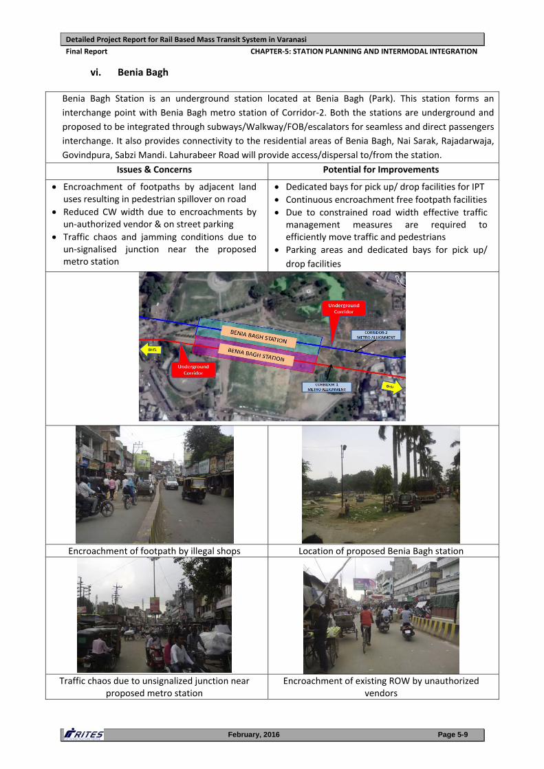
vi. Benia Bagh
Benia Bagh Station is an underground station located at Benia Bagh (Park). This station forms an
interchange point with Benia Bagh metro station of Corridor‐2. Both the stations are underground and
proposed to be integrated through subways/Walkway/FOB/escalators for seamless and direct passengers
interchange. It also provides connectivity to the residential areas of Benia Bagh, Nai Sarak, Rajadarwaja,
Govindpura, Sabzi Mandi. Lahurabeer Road will provide access/dispersal to/from the station.
Issues & Concerns Potential for Improvements
Encroachment of footpaths by adjacent land uses resulting in pedestrian spillover on road
Reduced CW width due to encroachments by un‐authorized vendor & on street parking
Traffic chaos and jamming conditions due to un‐signalised junction near the proposed metro station
Dedicated bays for pick up/ drop facilities for IPT Continuous encroachment free footpath facilities
Due to constrained road width effective traffic management measures are required to efficiently move traffic and pedestrians
Parking areas and dedicated bays for pick up/ drop facilities
Encroachment of footpath by illegal shops Location of proposed Benia Bagh station
Traffic chaos due to unsignalized junction near proposed metro station
Encroachment of existing ROW by unauthorized vendors
Detailed Project Report for Rail Based Mass Transit System in Varanasi
Final Report CHAPTER‐5: STATION PLANNING AND INTERMODAL INTEGRATION
February, 2016 Page 5-10
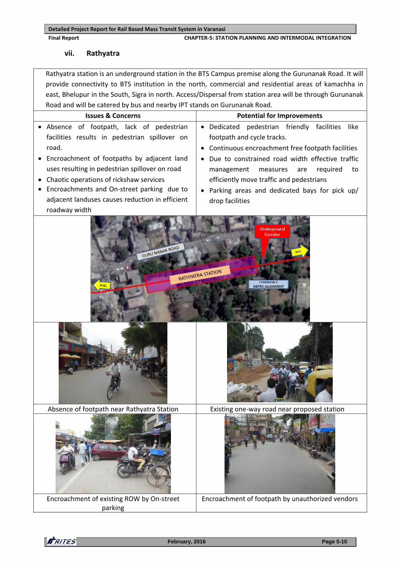
vii. Rathyatra
Rathyatra station is an underground station in the BTS Campus premise along the Gurunanak Road. It will
provide connectivity to BTS institution in the north, commercial and residential areas of kamachha in
east, Bhelupur in the South, Sigra in north. Access/Dispersal from station area will be through Gurunanak
Road and will be catered by bus and nearby IPT stands on Gurunanak Road.
Issues & Concerns Potential for Improvements
Absence of footpath, lack of pedestrian
facilities results in pedestrian spillover on
road.
Encroachment of footpaths by adjacent land
uses resulting in pedestrian spillover on road
Chaotic operations of rickshaw services Encroachments and On‐street parking due to
adjacent landuses causes reduction in efficient
roadway width
Dedicated pedestrian friendly facilities like
footpath and cycle tracks.
Continuous encroachment free footpath facilities
Due to constrained road width effective traffic management measures are required to
efficiently move traffic and pedestrians
Parking areas and dedicated bays for pick up/ drop facilities
Absence of footpath near Rathyatra Station Existing one‐way road near proposed station
Encroachment of existing ROW by On‐street parking
Encroachment of footpath by unauthorized vendors
Detailed Project Report for Rail Based Mass Transit System in Varanasi
Final Report CHAPTER‐5: STATION PLANNING AND INTERMODAL INTEGRATION
February, 2016 Page 5-11
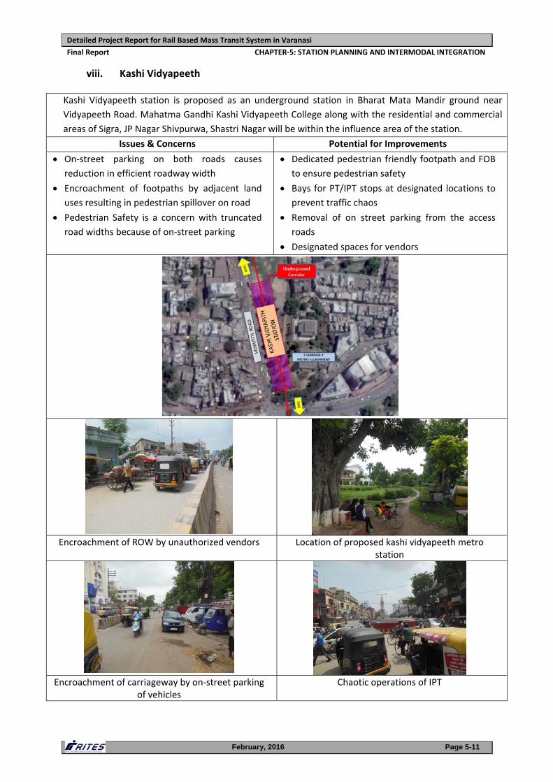
viii. Kashi Vidyapeeth
Kashi Vidyapeeth station is proposed as an underground station in Bharat Mata Mandir ground near
Vidyapeeth Road. Mahatma Gandhi Kashi Vidyapeeth College along with the residential and commercial
areas of Sigra, JP Nagar Shivpurwa, Shastri Nagar will be within the influence area of the station.
Issues & Concerns Potential for Improvements
On‐street parking on both roads causes
reduction in efficient roadway width
Encroachment of footpaths by adjacent land
uses resulting in pedestrian spillover on road
Pedestrian Safety is a concern with truncated road widths because of on‐street parking
Dedicated pedestrian friendly footpath and FOB to ensure pedestrian safety
Bays for PT/IPT stops at designated locations to prevent traffic chaos
Removal of on street parking from the access
roads
Designated spaces for vendors
Encroachment of ROW by unauthorized vendors Location of proposed kashi vidyapeeth metro station
Encroachment of carriageway by on‐street parking of vehicles
Chaotic operations of IPT
Detailed Project Report for Rail Based Mass Transit System in Varanasi
Final Report CHAPTER‐5: STATION PLANNING AND INTERMODAL INTEGRATION
February, 2016 Page 5-12
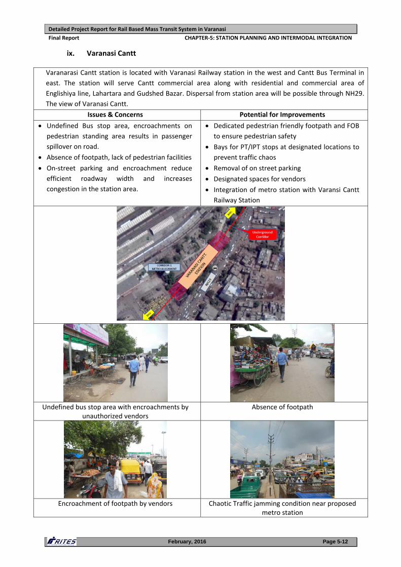
ix. Varanasi Cantt
Varanarasi Cantt station is located with Varanasi Railway station in the west and Cantt Bus Terminal in
east. The station will serve Cantt commercial area along with residential and commercial area of
Englishiya line, Lahartara and Gudshed Bazar. Dispersal from station area will be possible through NH29.
The view of Varanasi Cantt.
Issues & Concerns Potential for Improvements
Undefined Bus stop area, encroachments on
pedestrian standing area results in passenger
spillover on road.
Absence of footpath, lack of pedestrian facilities On‐street parking and encroachment reduce
efficient roadway width and increases
congestion in the station area.
Dedicated pedestrian friendly footpath and FOB to ensure pedestrian safety
Bays for PT/IPT stops at designated locations to prevent traffic chaos
Removal of on street parking
Designated spaces for vendors Integration of metro station with Varansi Cantt
Railway Station
Undefined bus stop area with encroachments by unauthorized vendors
Absence of footpath
Encroachment of footpath by vendors Chaotic Traffic jamming condition near proposed metro station
Detailed Project Report for Rail Based Mass Transit System in Varanasi
Final Report CHAPTER‐5: STATION PLANNING AND INTERMODAL INTEGRATION
February, 2016 Page 5-13
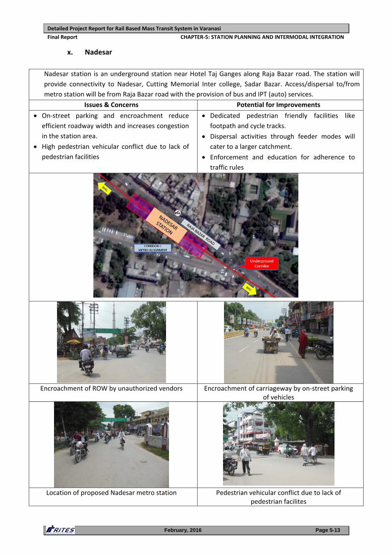
x. Nadesar
Nadesar station is an underground station near Hotel Taj Ganges along Raja Bazar road. The station will
provide connectivity to Nadesar, Cutting Memorial Inter college, Sadar Bazar. Access/dispersal to/from
metro station will be from Raja Bazar road with the provision of bus and IPT (auto) services.
Issues & Concerns Potential for Improvements
On‐street parking and encroachment reduce
efficient roadway width and increases congestion
in the station area.
High pedestrian vehicular conflict due to lack of pedestrian facilities
Dedicated pedestrian friendly facilities like
footpath and cycle tracks.
Dispersal activities through feeder modes will
cater to a larger catchment.
Enforcement and education for adherence to
traffic rules
Encroachment of ROW by unauthorized vendors Encroachment of carriageway by on‐street parking of vehicles
Location of proposed Nadesar metro station Pedestrian vehicular conflict due to lack of pedestrian facilites
Detailed Project Report for Rail Based Mass Transit System in Varanasi
Final Report CHAPTER‐5: STATION PLANNING AND INTERMODAL INTEGRATION
February, 2016 Page 5-14
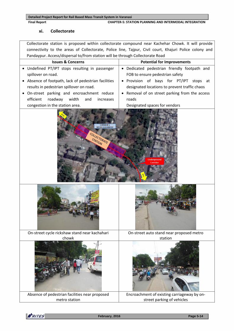
xi. Collectorate
Collectorate station is proposed within collectorate compound near Kachehar Chowk. It will provide
connectivity to the areas of Collectorate, Police line, Tajpur, Civil court, Khajuri Police colony and
Pandaypur. Access/dispersal to/from station will be through Collectorate Road
Issues & Concerns Potential for Improvements
Undefined PT/IPT stops resulting in passenger spillover on road.
Absence of footpath, lack of pedestrian facilities results in pedestrian spillover on road.
On‐street parking and encroachment reduce
efficient roadway width and increases
congestion in the station area.
Dedicated pedestrian friendly footpath and FOB to ensure pedestrian safety
Provision of bays for PT/IPT stops at
designated locations to prevent traffic chaos
Removal of on street parking from the access
roads
Designated spaces for vendors
On‐street cycle rickshaw stand near kachahari chowk
On‐street auto stand near proposed metro station
Absence of pedestrian facilities near proposed metro station
Encroachment of existing carriageway by on‐street parking of vehicles
Detailed Project Report for Rail Based Mass Transit System in Varanasi
Final Report CHAPTER‐5: STATION PLANNING AND INTERMODAL INTEGRATION
February, 2016 Page 5-15
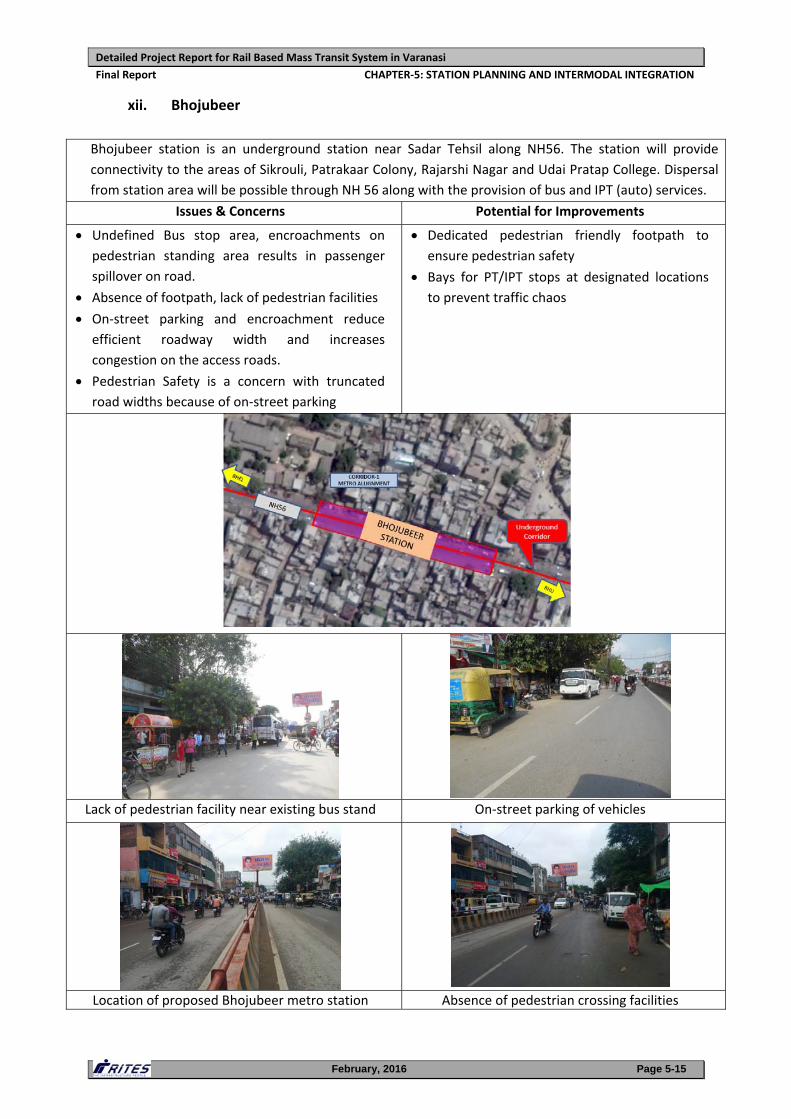
xii. Bhojubeer
Bhojubeer station is an underground station near Sadar Tehsil along NH56. The station will provide
connectivity to the areas of Sikrouli, Patrakaar Colony, Rajarshi Nagar and Udai Pratap College. Dispersal
from station area will be possible through NH 56 along with the provision of bus and IPT (auto) services.
Issues & Concerns Potential for Improvements
Undefined Bus stop area, encroachments on
pedestrian standing area results in passenger
spillover on road.
Absence of footpath, lack of pedestrian facilities On‐street parking and encroachment reduce
efficient roadway width and increases
congestion on the access roads.
Pedestrian Safety is a concern with truncated road widths because of on‐street parking
Dedicated pedestrian friendly footpath to
ensure pedestrian safety
Bays for PT/IPT stops at designated locations to prevent traffic chaos
Lack of pedestrian facility near existing bus stand On‐street parking of vehicles
Location of proposed Bhojubeer metro station Absence of pedestrian crossing facilities
Detailed Project Report for Rail Based Mass Transit System in Varanasi
Final Report CHAPTER‐5: STATION PLANNING AND INTERMODAL INTEGRATION
February, 2016 Page 5-16
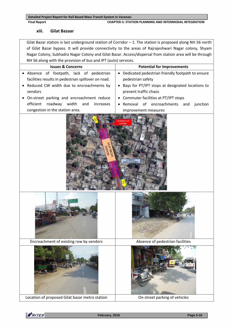
xiii. Gilat Bazaar
Gilat Bazar station is last underground station of Corridor – 1. The station is proposed along NH 56 north
of Gilat Bazar bypass. It will provide connectivity to the areas of Rajrajeshwari Nagar colony, Shyam
Nagar Colony, Subhadra Nagar Colony and Gilat Bazar. Access/dispersal from station area will be through
NH 56 along with the provision of bus and IPT (auto) services.
Issues & Concerns Potential for Improvements
Absence of footpath, lack of pedestrian
facilities results in pedestrian spillover on road.
Reduced CW width due to encroachments by
vendors
On‐street parking and encroachment reduce
efficient roadway width and increases
congestion in the station area.
Dedicated pedestrian friendly footpath to ensure pedestrian safety
Bays for PT/IPT stops at designated locations to prevent traffic chaos
Commuter facilities at PT/IPT stops
Removal of encroachments and junction
improvement measures
Encroachment of existing row by vendors Absence of pedestrian facilities
Location of proposed Gilat bazar metro station On‐street parking of vehicles
Detailed Project Report for Rail Based Mass Transit System in Varanasi
Final Report CHAPTER‐5: STATION PLANNING AND INTERMODAL INTEGRATION
February, 2016 Page 5-17
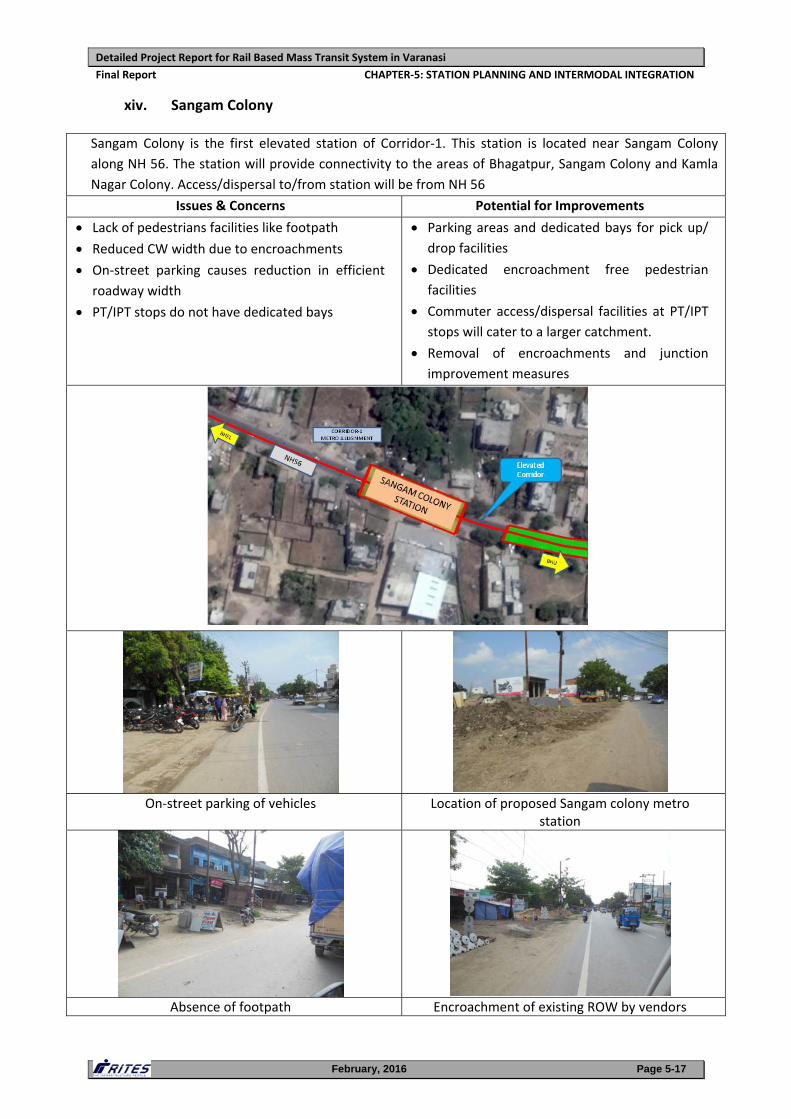
xiv. Sangam Colony
Sangam Colony is the first elevated station of Corridor‐1. This station is located near Sangam Colony
along NH 56. The station will provide connectivity to the areas of Bhagatpur, Sangam Colony and Kamla
Nagar Colony. Access/dispersal to/from station will be from NH 56
Issues & Concerns Potential for Improvements
Lack of pedestrians facilities like footpath Reduced CW width due to encroachments
On‐street parking causes reduction in efficient roadway width
PT/IPT stops do not have dedicated bays
Parking areas and dedicated bays for pick up/ drop facilities
Dedicated encroachment free pedestrian
facilities
Commuter access/dispersal facilities at PT/IPT
stops will cater to a larger catchment.
Removal of encroachments and junction
improvement measures
On‐street parking of vehicles Location of proposed Sangam colony metro station
Absence of footpath Encroachment of existing ROW by vendors
Detailed Project Report for Rail Based Mass Transit System in Varanasi
Final Report CHAPTER‐5: STATION PLANNING AND INTERMODAL INTEGRATION
February, 2016 Page 5-18
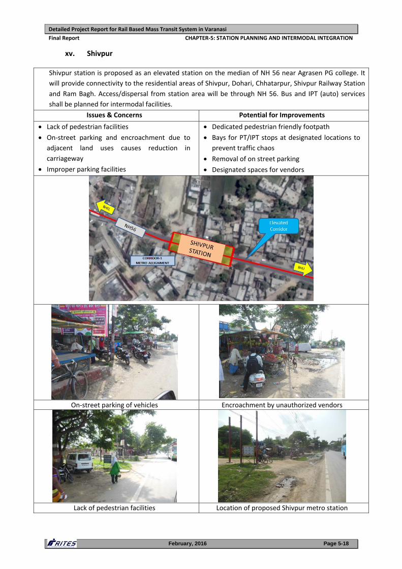
xv. Shivpur
Shivpur station is proposed as an elevated station on the median of NH 56 near Agrasen PG college. It
will provide connectivity to the residential areas of Shivpur, Dohari, Chhatarpur, Shivpur Railway Station
and Ram Bagh. Access/dispersal from station area will be through NH 56. Bus and IPT (auto) services
shall be planned for intermodal facilities.
Issues & Concerns Potential for Improvements
Lack of pedestrian facilities On‐street parking and encroachment due to
adjacent land uses causes reduction in
carriageway
Improper parking facilities
Dedicated pedestrian friendly footpath Bays for PT/IPT stops at designated locations to
prevent traffic chaos
Removal of on street parking
Designated spaces for vendors
On‐street parking of vehicles Encroachment by unauthorized vendors
Lack of pedestrian facilities Location of proposed Shivpur metro station
Detailed Project Report for Rail Based Mass Transit System in Varanasi
Final Report CHAPTER‐5: STATION PLANNING AND INTERMODAL INTEGRATION
February, 2016 Page 5-19
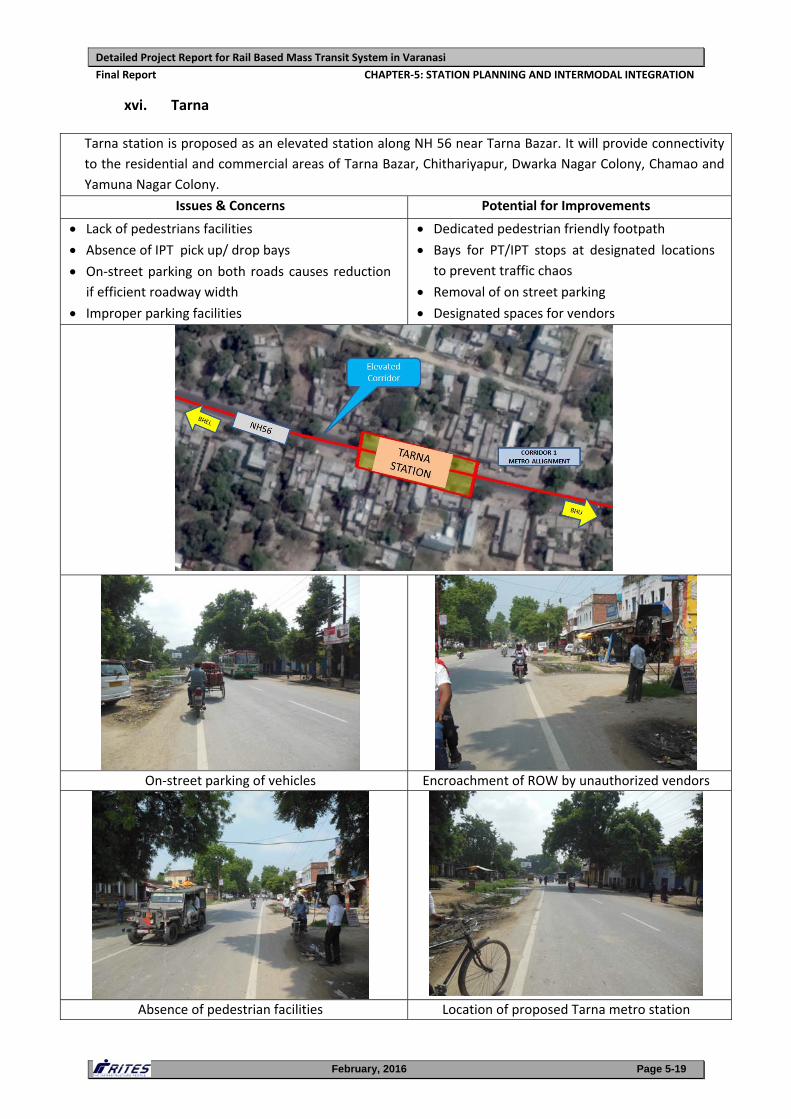
xvi. Tarna
Tarna station is proposed as an elevated station along NH 56 near Tarna Bazar. It will provide connectivity
to the residential and commercial areas of Tarna Bazar, Chithariyapur, Dwarka Nagar Colony, Chamao and
Yamuna Nagar Colony.
Issues & Concerns Potential for Improvements
Lack of pedestrians facilities Absence of IPT pick up/ drop bays On‐street parking on both roads causes reduction
if efficient roadway width
Improper parking facilities
Dedicated pedestrian friendly footpath Bays for PT/IPT stops at designated locations
to prevent traffic chaos
Removal of on street parking
Designated spaces for vendors
On‐street parking of vehicles Encroachment of ROW by unauthorized vendors
Absence of pedestrian facilities Location of proposed Tarna metro station
Detailed Project Report for Rail Based Mass Transit System in Varanasi
Final Report CHAPTER‐5: STATION PLANNING AND INTERMODAL INTEGRATION
February, 2016 Page 5-20
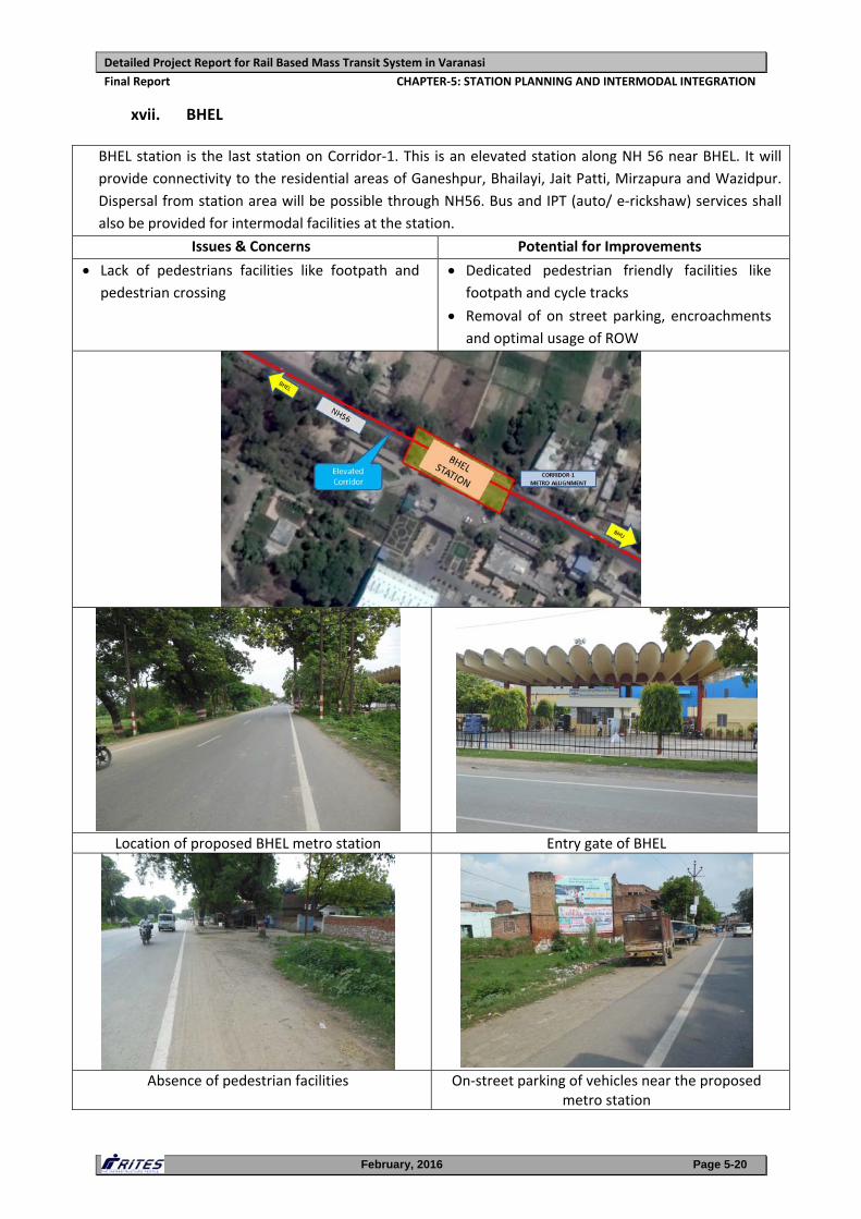
xvii. BHEL
BHEL station is the last station on Corridor‐1. This is an elevated station along NH 56 near BHEL. It will
provide connectivity to the residential areas of Ganeshpur, Bhailayi, Jait Patti, Mirzapura and Wazidpur.
Dispersal from station area will be possible through NH56. Bus and IPT (auto/ e‐rickshaw) services shall
also be provided for intermodal facilities at the station.
Issues & Concerns Potential for Improvements
Lack of pedestrians facilities like footpath and pedestrian crossing
Dedicated pedestrian friendly facilities like footpath and cycle tracks
Removal of on street parking, encroachments
and optimal usage of ROW
Location of proposed BHEL metro station Entry gate of BHEL
Absence of pedestrian facilities On‐street parking of vehicles near the proposed metro station
Detailed Project Report for Rail Based Mass Transit System in Varanasi
Final Report CHAPTER‐5: STATION PLANNING AND INTERMODAL INTEGRATION
February, 2016 Page 5-21
5.2.2. Corridor 2: Benia Bagh to Sarnath
This corridor starts from Benia Bagh and terminates near Akashwani along Sarnath
Road. The first station along this corridor is Benia Bagh. It will come up as an
underground station at Benia Bagh (Park) and will form an interchange point with
Benia Bagh metro station of Corridor‐1. Both the stations will be underground and
integrated through subways/Walkway/ FOB/ escalators for direct passengers
interchange. Benia Bagh station and their issues & concerns along with potential for
improvements are detailed in Section 5.2.1.vi (Page 5‐9) above.
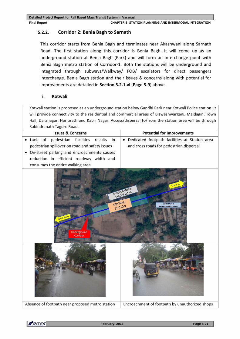
i. Kotwali
Kotwali station is proposed as an underground station below Gandhi Park near Kotwali Police station. It
will provide connectivity to the residential and commercial areas of Bisweshwarganj, Maidagin, Town
Hall, Daranagar, Haritirath and Kabir Nagar. Access/dispersal to/from the station area will be through
Rabindranath Tagore Road.
Issues & Concerns Potential for Improvements
Lack of pedestrian facilities results in
pedestrian spillover on road and safety issues
On‐street parking and encroachments causes
reduction in efficient roadway width and
consumes the entire walking area
Dedicated footpath facilities at Station area and cross roads for pedestrian dispersal
Absence of footpath near proposed metro station Encroachment of footpath by unauthorized shops
Detailed Project Report for Rail Based Mass Transit System in Varanasi
Final Report CHAPTER‐5: STATION PLANNING AND INTERMODAL INTEGRATION
February, 2016 Page 5-22
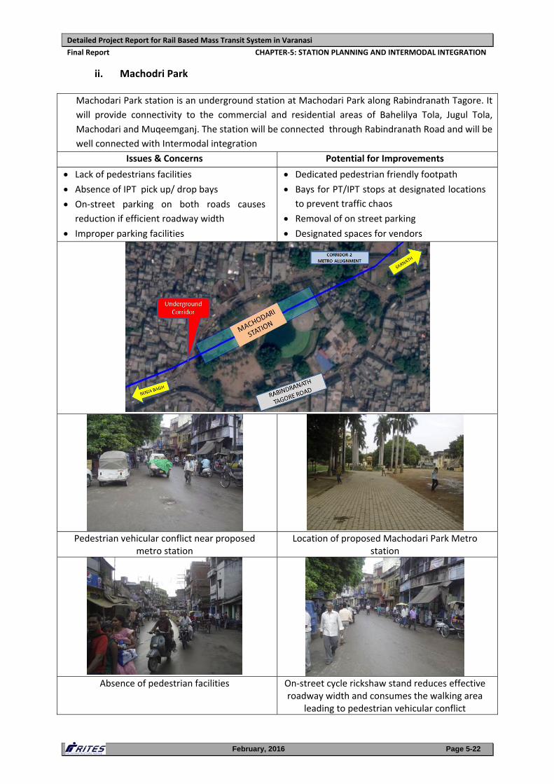
ii. Machodri Park
Machodari Park station is an underground station at Machodari Park along Rabindranath Tagore. It
will provide connectivity to the commercial and residential areas of Bahelilya Tola, Jugul Tola,
Machodari and Muqeemganj. The station will be connected through Rabindranath Road and will be
well connected with Intermodal integration
Issues & Concerns Potential for Improvements
Lack of pedestrians facilities Absence of IPT pick up/ drop bays On‐street parking on both roads causes
reduction if efficient roadway width
Improper parking facilities
Dedicated pedestrian friendly footpath Bays for PT/IPT stops at designated locations
to prevent traffic chaos
Removal of on street parking
Designated spaces for vendors
Pedestrian vehicular conflict near proposed metro station
Location of proposed Machodari Park Metro station
Absence of pedestrian facilities On‐street cycle rickshaw stand reduces effective roadway width and consumes the walking area
leading to pedestrian vehicular conflict
Detailed Project Report for Rail Based Mass Transit System in Varanasi
Final Report CHAPTER‐5: STATION PLANNING AND INTERMODAL INTEGRATION
February, 2016 Page 5-23
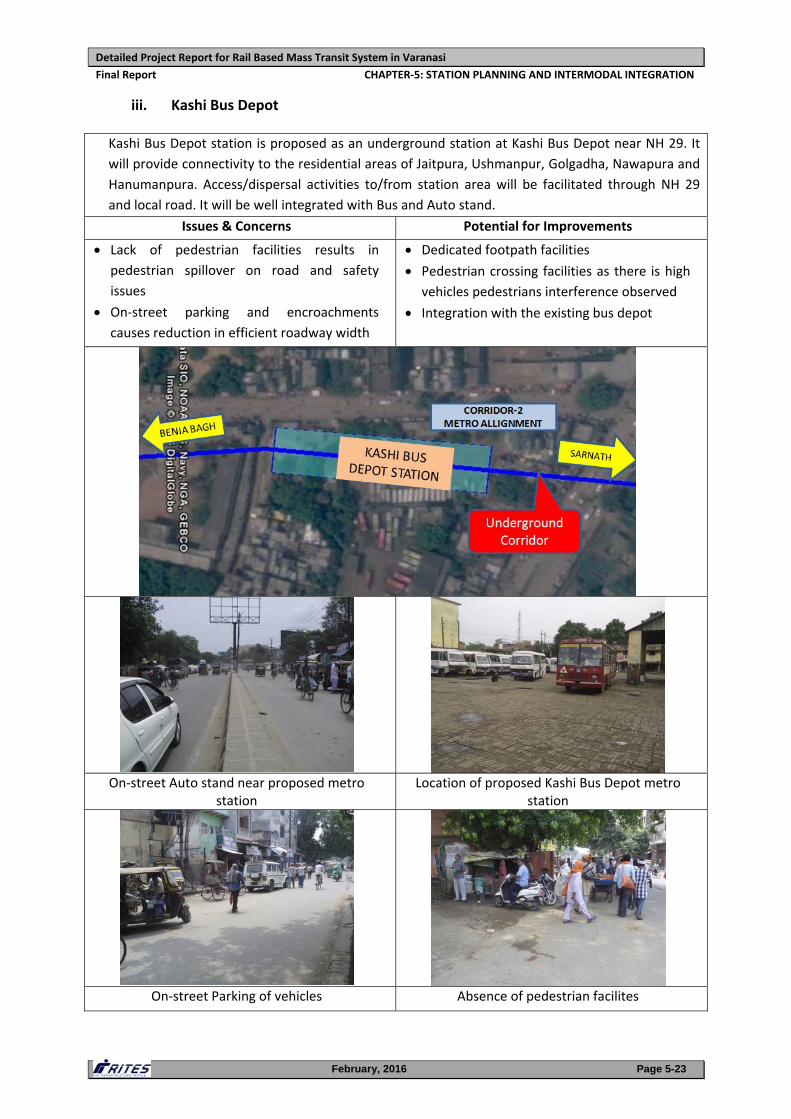
iii. Kashi Bus Depot
Kashi Bus Depot station is proposed as an underground station at Kashi Bus Depot near NH 29. It
will provide connectivity to the residential areas of Jaitpura, Ushmanpur, Golgadha, Nawapura and
Hanumanpura. Access/dispersal activities to/from station area will be facilitated through NH 29
and local road. It will be well integrated with Bus and Auto stand.
Issues & Concerns Potential for Improvements
Lack of pedestrian facilities results in
pedestrian spillover on road and safety
issues
On‐street parking and encroachments
causes reduction in efficient roadway width
Dedicated footpath facilities Pedestrian crossing facilities as there is high
vehicles pedestrians interference observed
Integration with the existing bus depot
On‐street Auto stand near proposed metro station
Location of proposed Kashi Bus Depot metro station
On‐street Parking of vehicles Absence of pedestrian facilites
Detailed Project Report for Rail Based Mass Transit System in Varanasi
Final Report CHAPTER‐5: STATION PLANNING AND INTERMODAL INTEGRATION
February, 2016 Page 5-24
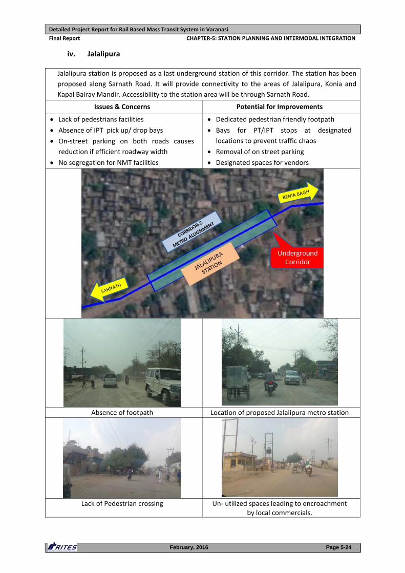
iv. Jalalipura
Jalalipura station is proposed as a last underground station of this corridor. The station has been
proposed along Sarnath Road. It will provide connectivity to the areas of Jalalipura, Konia and
Kapal Bairav Mandir. Accessibility to the station area will be through Sarnath Road.
Issues & Concerns Potential for Improvements
Lack of pedestrians facilities Absence of IPT pick up/ drop bays On‐street parking on both roads causes
reduction if efficient roadway width
No segregation for NMT facilities
Dedicated pedestrian friendly footpath Bays for PT/IPT stops at designated
locations to prevent traffic chaos
Removal of on street parking
Designated spaces for vendors
Absence of footpath Location of proposed Jalalipura metro station
Lack of Pedestrian crossing Un‐ utilized spaces leading to encroachment by local commercials.
Detailed Project Report for Rail Based Mass Transit System in Varanasi
Final Report CHAPTER‐5: STATION PLANNING AND INTERMODAL INTEGRATION
February, 2016 Page 5-25
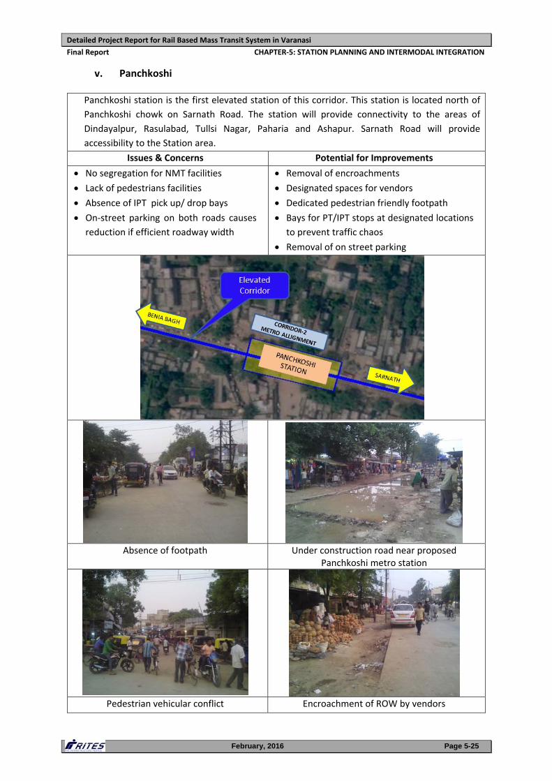
v. Panchkoshi
Panchkoshi station is the first elevated station of this corridor. This station is located north of
Panchkoshi chowk on Sarnath Road. The station will provide connectivity to the areas of
Dindayalpur, Rasulabad, Tullsi Nagar, Paharia and Ashapur. Sarnath Road will provide
accessibility to the Station area.
Issues & Concerns Potential for Improvements
No segregation for NMT facilities
Lack of pedestrians facilities Absence of IPT pick up/ drop bays On‐street parking on both roads causes
reduction if efficient roadway width
Removal of encroachments
Designated spaces for vendors Dedicated pedestrian friendly footpath Bays for PT/IPT stops at designated locations
to prevent traffic chaos
Removal of on street parking
Absence of footpath Under construction road near proposed Panchkoshi metro station
Pedestrian vehicular conflict Encroachment of ROW by vendors
Detailed Project Report for Rail Based Mass Transit System in Varanasi
Final Report CHAPTER‐5: STATION PLANNING AND INTERMODAL INTEGRATION
February, 2016 Page 5-26
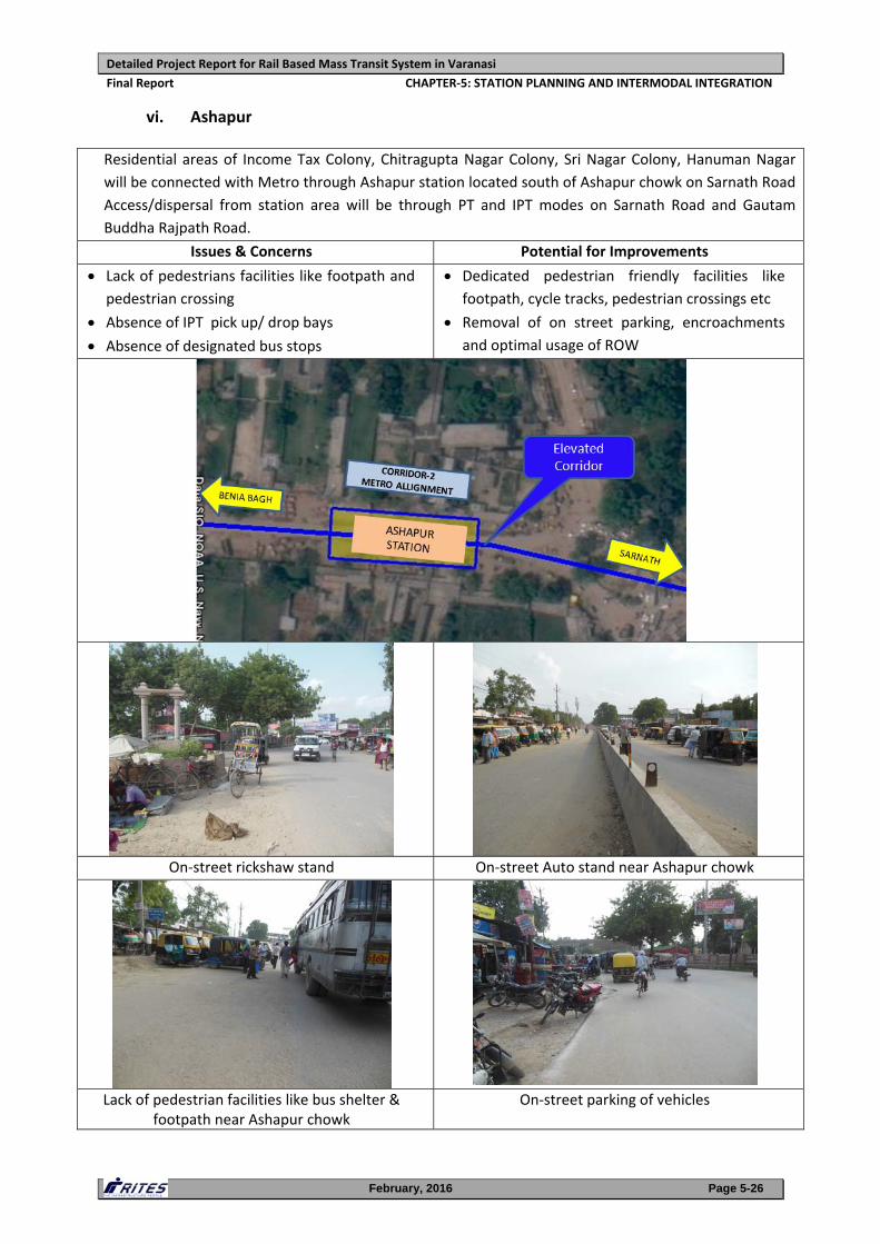
vi. Ashapur
Residential areas of Income Tax Colony, Chitragupta Nagar Colony, Sri Nagar Colony, Hanuman Nagar
will be connected with Metro through Ashapur station located south of Ashapur chowk on Sarnath Road
Access/dispersal from station area will be through PT and IPT modes on Sarnath Road and Gautam
Buddha Rajpath Road.
Issues & Concerns Potential for Improvements
Lack of pedestrians facilities like footpath and pedestrian crossing
Absence of IPT pick up/ drop bays Absence of designated bus stops
Dedicated pedestrian friendly facilities like
footpath, cycle tracks, pedestrian crossings etc
Removal of on street parking, encroachments
and optimal usage of ROW
On‐street rickshaw stand On‐street Auto stand near Ashapur chowk
Lack of pedestrian facilities like bus shelter & footpath near Ashapur chowk
On‐street parking of vehicles
Detailed Project Report for Rail Based Mass Transit System in Varanasi
Final Report CHAPTER‐5: STATION PLANNING AND INTERMODAL INTEGRATION
February, 2016 Page 5-27
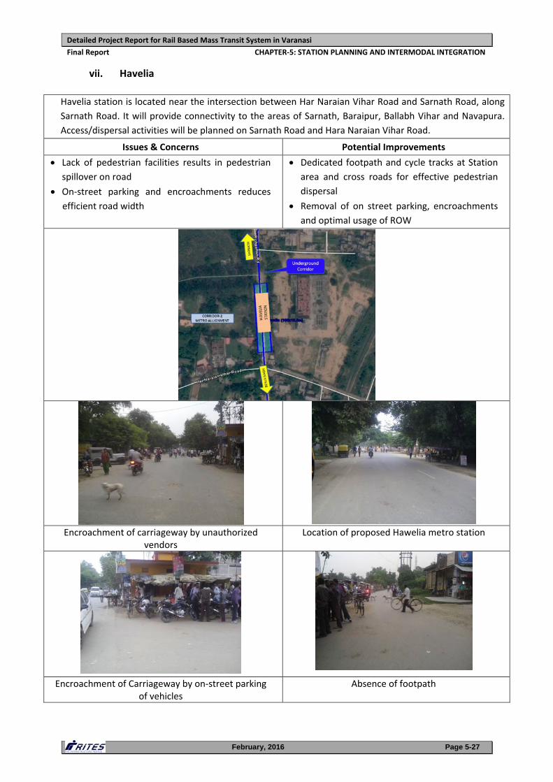
vii. Havelia
Havelia station is located near the intersection between Har Naraian Vihar Road and Sarnath Road, along
Sarnath Road. It will provide connectivity to the areas of Sarnath, Baraipur, Ballabh Vihar and Navapura.
Access/dispersal activities will be planned on Sarnath Road and Hara Naraian Vihar Road.
Issues & Concerns Potential Improvements
Lack of pedestrian facilities results in pedestrian spillover on road
On‐street parking and encroachments reduces
efficient road width
Dedicated footpath and cycle tracks at Station area and cross roads for effective pedestrian
dispersal
Removal of on street parking, encroachments
and optimal usage of ROW
Encroachment of carriageway by unauthorized vendors
Location of proposed Hawelia metro station
Encroachment of Carriageway by on‐street parking of vehicles
Absence of footpath
Detailed Project Report for Rail Based Mass Transit System in Varanasi
Final Report CHAPTER‐5: STATION PLANNING AND INTERMODAL INTEGRATION
February, 2016 Page 5-28
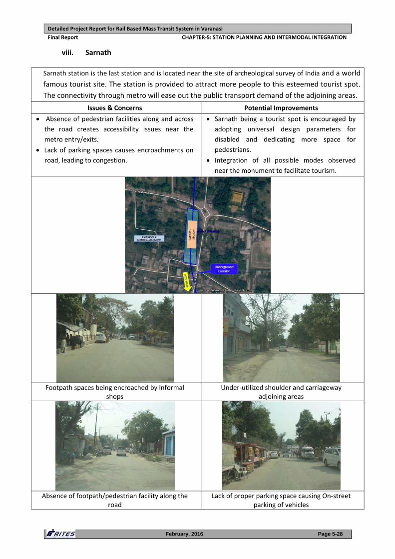
viii. Sarnath
Sarnath station is the last station and is located near the site of archeological survey of India and a world
famous tourist site. The station is provided to attract more people to this esteemed tourist spot.
The connectivity through metro will ease out the public transport demand of the adjoining areas.
Issues & Concerns Potential Improvements
Absence of pedestrian facilities along and across the road creates accessibility issues near the
metro entry/exits.
Lack of parking spaces causes encroachments on
road, leading to congestion.
Sarnath being a tourist spot is encouraged by adopting universal design parameters for
disabled and dedicating more space for
pedestrians.
Integration of all possible modes observed
near the monument to facilitate tourism.
Footpath spaces being encroached by informal shops
Under‐utilized shoulder and carriageway adjoining areas
Absence of footpath/pedestrian facility along the road
Lack of proper parking space causing On‐street parking of vehicles
Detailed Project Report for Rail Based Mass Transit System in Varanasi
Final Report CHAPTER‐5: STATION PLANNING AND INTERMODAL INTEGRATION
February, 2016 Page 5-29
5.3. STATION PLANNING
5.3.1 Station Planning – Coverage
The station planning will respond to and be determined by the following factors:
Operational requirements in the use of center and side platforms: the
underground stations are planned around island platforms, while elevated
stations are proposed to have side platforms.
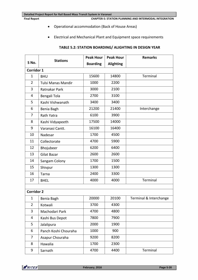
Station boarding/alighting (TABLE 5.2) and the resulting entry/exit location
requirements
Utilities such as firefighting systems, ventilation, water requirements
Structural requirements
Flexibility in design to allow stations to respond to site‐specific requirements
Future expansion if required
The essential quality in a good station layout is the provision of adequate space for
efficient movement of passengers between ground level entrances on to the trains
and vice versa in the most direct, simple and logical way.
5.3.2 Salient Features of a Typical Station
a. Station entrances provide the link between station concourse and the
surrounding streets and their location must reflect the separate constraints of
both. Station entrances are located with particular reference to passenger
catchment points and also cater for inter modal interchange which includes
buses, IPTs, pick/drop by private mode etc.
b. Important criteria that has been applied in the development of station planning
include:
Sizing of Station Passenger Facilities
Stipulated Design Standards
Emergency Evacuation
Passenger circulation, comfort, ease of use, safety and security
Detailed Project Report for Rail Based Mass Transit System in Varanasi
Final Report CHAPTER‐5: STATION PLANNING AND INTERMODAL INTEGRATION
February, 2016 Page 5-30
Operational accommodation (Back of House Areas)
Electrical and Mechanical Plant and Equipment space requirements
TABLE 5.2: STATION BOARDING/ ALIGHTING IN DESIGN YEAR
S No. Stations Peak Hour
Boarding
Peak Hour
Alighting
Remarks
Corridor 1
1 BHU 15600 14800 Terminal
2 Tulsi Manas Mandir 1000 2200
3 Ratnakar Park 3000 2100
4 Bengali Tola 2700 3100
5 Kashi Vishwanath 3400 3400
6 Benia Bagh 21200 21400 Interchange
7 Rath Yatra 6100 3900
8 Kashi Vidyapeeth 17500 14000
9 Varanasi Cantt. 16100 16400
10 Nadesar 1700 4500
11 Collectorate 4700 5900
12 Bhojubeer 6200 6400
13 Gilat Bazar 2600 2600
14 Sangam Colony 1700 1500
15 Shivpur 1300 1300
16 Tarna 2400 3300
17 BHEL 4000 4000 Terminal
Corridor 2
1 Benia Bagh 20000 20100 Terminal & Interchange
2 Kotwali 3700 4300
3 Machodari Park 4700 4800
4 Kashi Bus Depot 7800 7900
5 Jalalipura 2000 1900
6 Panch Koshi Chouraha 1000 900
7 Asapur Chouraha 9200 8200
8 Hawalia 1700 2300
9 Sarnath 4700 4400 Terminal
Detailed Project Report for Rail Based Mass Transit System in Varanasi
Final Report CHAPTER‐5: STATION PLANNING AND INTERMODAL INTEGRATION
February, 2016 Page 5-31
c. Concourse forms the interface between streets and the platform. This is where
all the passenger amenities are provided.
d. Office accommodation, operational areas and plant room space are provided in
the non‐public areas of the station.
e. The platform level has been designed for adequate assembly space for
passengers for both normal operating conditions and a recognized abnormal
scenario (emergency).
f. The location of DG set, Bore Well Pump House, Underground / overhead tank,
chiller plant and Pump Houses are preferably proposed to be located in one area
at ground level wherever possible.
5.3.3 Planning Norms & Standards
i. General
a. Station Design is dependent on the peak hour traffic load for each station.
The design year of the Study is taken as 2051, when a maximum PHPDT of
about 24,000 between BHU to BHEL and 18,000 between Benia Bagh to
Sarnath is expected to be achieved. Accordingly maximum capacity required
at any station for emergency evacuation has been adopted.
b. The platform length is planned for 3 cars/train for a train length of 68 m.
c. The total evacuation time for the movement of all passengers in an
emergency from platform level to the landing at the next level does not
exceed 4.0 minutes (as per “NFPA 130” Guidelines) in underground stations.
However this is 5.5 minutes in elevated stations considering that the stations
are open and the risk is much less.
d. The station planning is also in compliance to the “Guidelines and Space
Standards for Barrier Free Built Environment for Disabled and Elderly
persons” published by the Ministry of Urban Affairs and Employment India in
1998.
e. The egress requirement (Platform to Concourse), platform width calculations,
evacuation time calculations and passenger related facilities for the design
year 2051 are presented in Annexure 5.1, Annexure 5.2 and Annexure 5.3
respectively.
Detailed Project Report for Rail Based Mass Transit System in Varanasi
Final Report CHAPTER‐5: STATION PLANNING AND INTERMODAL INTEGRATION
February, 2016 Page 5-32
ii. Entry/Exit
a. Entrances to stations have adequate capacity to satisfy predicted passenger
flows and emergency evacuation requirement.
b. The position of entrances is determined by the juxtaposition of building
location of roadway footpath width, space availability and flow directions of
passenger traffic.
c. The numbers and width of staircases/ escalators are determined by checking
the capacity/available width against peak passenger flows rates for both
normal and emergency conditions such as delayed train service, fire etc.
d. All entrances extending to street level are proposed to be protected against
flooding. This protection is done by the provision of a minimum of 3 steps up
to a landing (+450 mm minimum)
iii. Walkways / Ramps
a. Walkways / ramps are planned based on established principles of pedestrian
flow and arranged to minimize unnecessary walking distances and cross‐
flows between incoming and outgoing passengers. Cross flow and changes in
direction are minimized or eliminated.
b. Minimum Corridor width
Unidirectional movement: 1.8 m
Bi‐directional movement: 2.0 m
Where length of the corridor is more than 30 m: 3.0 m
For staff: 1.2 m
c. Ramps
Preferred gradient: 1:20
Maximum gradient: 1:12
Minimum width:
‐ Unidirectional movement: 1.2 m
Detailed Project Report for Rail Based Mass Transit System in Varanasi
Final Report CHAPTER‐5: STATION PLANNING AND INTERMODAL INTEGRATION
February, 2016 Page 5-33
‐ Bi‐directional movement: 1.5 m
For ramp exceeding 10 m, rest platform: 1.8m
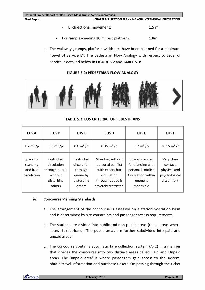
d. The walkways, ramps, platform width etc. have been planned for a minimum
“Level of Service E”. The pedestrian Flow Analogy with respect to Level of
Service is detailed below in FIGURE 5.2 and TABLE 5.3:
FIGURE 5.2: PEDESTRIAN FLOW ANALOGY
TABLE 5.3: LOS CRITERIA FOR PEDESTRIANS
LOS A LOS B LOS C LOS D LOS E LOS F
1.2 m² /p 1.0 m² /p 0.6 m² /p 0.35 m² /p 0.2 m² /p <0.15 m² /p
Space for
standing
and free
circulation
restricted
circulation
through queue
without
disturbing
others
Restricted
circulation
through
queue by
disturbing
others
Standing without
personal conflict
with others but
circulation
through queue is
severely restricted
Space provided
for standing with
personal conflict.
Circulation within
queue is
impossible.
Very close
contact,
physical and
psychological
discomfort.
iv. Concourse Planning Standards
a. The arrangement of the concourse is assessed on a station‐by‐station basis
and is determined by site constraints and passenger access requirements.
b. The stations are divided into public and non‐public areas (those areas where
access is restricted). The public areas are further subdivided into paid and
unpaid areas.
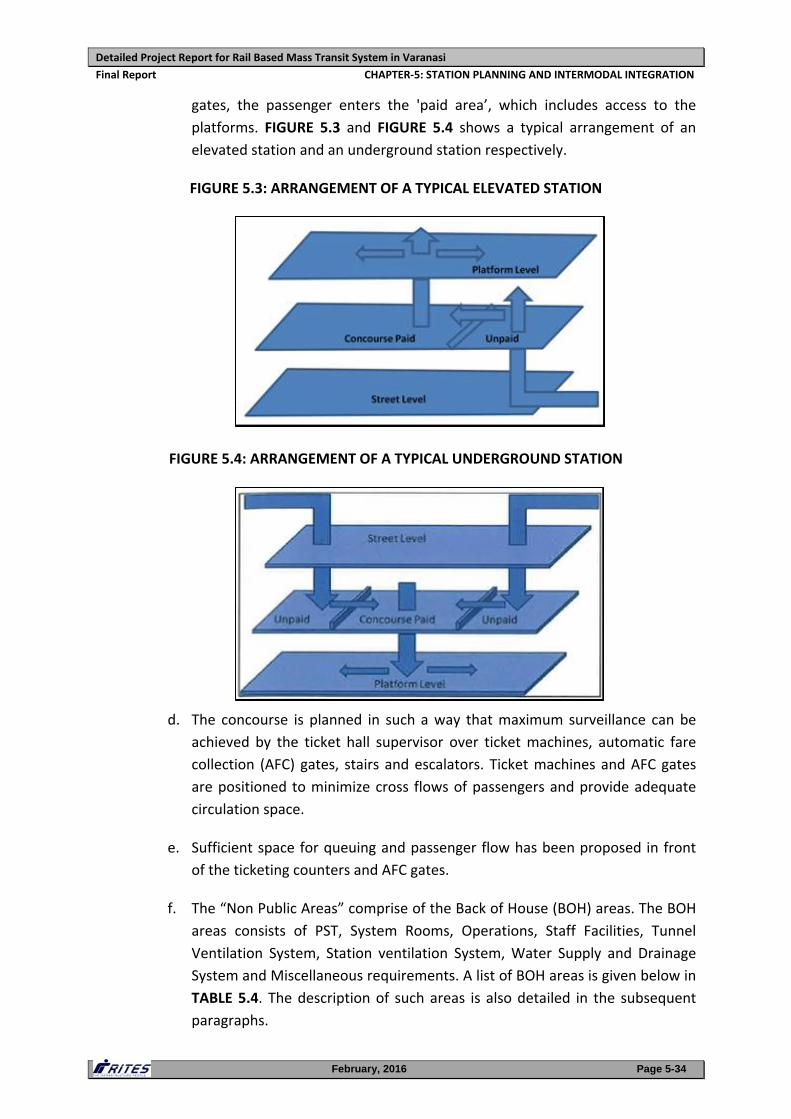
c. The concourse contains automatic fare collection system (AFC) in a manner
that divides the concourse into two distinct areas called Paid and Unpaid
areas. The 'unpaid area' is where passengers gain access to the system,
obtain travel information and purchase tickets. On passing through the ticket
Detailed Project Report for Rail Based Mass Transit System in Varanasi
Final Report CHAPTER‐5: STATION PLANNING AND INTERMODAL INTEGRATION
February, 2016 Page 5-34
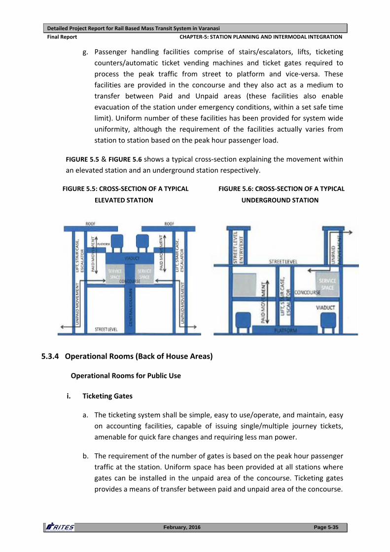
gates, the passenger enters the 'paid area’, which includes access to the
platforms. FIGURE 5.3 and FIGURE 5.4 shows a typical arrangement of an
elevated station and an underground station respectively.
FIGURE 5.3: ARRANGEMENT OF A TYPICAL ELEVATED STATION
FIGURE 5.4: ARRANGEMENT OF A TYPICAL UNDERGROUND STATION
d. The concourse is planned in such a way that maximum surveillance can be
achieved by the ticket hall supervisor over ticket machines, automatic fare
collection (AFC) gates, stairs and escalators. Ticket machines and AFC gates
are positioned to minimize cross flows of passengers and provide adequate
circulation space.
e. Sufficient space for queuing and passenger flow has been proposed in front
of the ticketing counters and AFC gates.
f. The “Non Public Areas” comprise of the Back of House (BOH) areas. The BOH
areas consists of PST, System Rooms, Operations, Staff Facilities, Tunnel
Ventilation System, Station ventilation System, Water Supply and Drainage
System and Miscellaneous requirements. A list of BOH areas is given below in
TABLE 5.4. The description of such areas is also detailed in the subsequent
paragraphs.
Detailed Project Report for Rail Based Mass Transit System in Varanasi
Final Report CHAPTER‐5: STATION PLANNING AND INTERMODAL INTEGRATION
February, 2016 Page 5-35
g. Passenger handling facilities comprise of stairs/escalators, lifts, ticketing
counters/automatic ticket vending machines and ticket gates required to
process the peak traffic from street to platform and vice‐versa. These
facilities are provided in the concourse and they also act as a medium to
transfer between Paid and Unpaid areas (these facilities also enable
evacuation of the station under emergency conditions, within a set safe time
limit). Uniform number of these facilities has been provided for system wide
uniformity, although the requirement of the facilities actually varies from
station to station based on the peak hour passenger load.
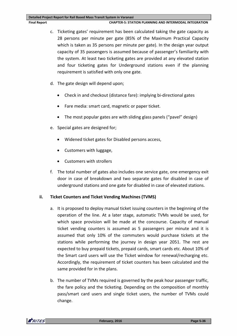
FIGURE 5.5 & FIGURE 5.6 shows a typical cross‐section explaining the movement within
an elevated station and an underground station respectively.
FIGURE 5.5: CROSS‐SECTION OF A TYPICAL
ELEVATED STATION
FIGURE 5.6: CROSS‐SECTION OF A TYPICAL
UNDERGROUND STATION
5.3.4 Operational Rooms (Back of House Areas)
Operational Rooms for Public Use
i. Ticketing Gates
a. The ticketing system shall be simple, easy to use/operate, and maintain, easy
on accounting facilities, capable of issuing single/multiple journey tickets,
amenable for quick fare changes and requiring less man power.
b. The requirement of the number of gates is based on the peak hour passenger
traffic at the station. Uniform space has been provided at all stations where
gates can be installed in the unpaid area of the concourse. Ticketing gates
provides a means of transfer between paid and unpaid area of the concourse.
Detailed Project Report for Rail Based Mass Transit System in Varanasi
Final Report CHAPTER‐5: STATION PLANNING AND INTERMODAL INTEGRATION
February, 2016 Page 5-36
c. Ticketing gates’ requirement has been calculated taking the gate capacity as
28 persons per minute per gate (85% of the Maximum Practical Capacity
which is taken as 35 persons per minute per gate). In the design year output
capacity of 35 passengers is assumed because of passenger’s familiarity with
the system. At least two ticketing gates are provided at any elevated station
and four ticketing gates for Underground stations even if the planning
requirement is satisfied with only one gate.
d. The gate design will depend upon;
Check in and checkout (distance fare): implying bi‐directional gates
Fare media: smart card, magnetic or paper ticket.
The most popular gates are with sliding glass panels (“pavel” design)
e. Special gates are designed for;
Widened ticket gates for Disabled persons access,
Customers with luggage,
Customers with strollers
f. The total number of gates also includes one service gate, one emergency exit
door in case of breakdown and two separate gates for disabled in case of
underground stations and one gate for disabled in case of elevated stations.
ii. Ticket Counters and Ticket Vending Machines (TVMS)
a. It is proposed to deploy manual ticket issuing counters in the beginning of the
operation of the line. At a later stage, automatic TVMs would be used, for
which space provision will be made at the concourse. Capacity of manual
ticket vending counters is assumed as 5 passengers per minute and it is
assumed that only 10% of the commuters would purchase tickets at the
stations while performing the journey in design year 2051. The rest are
expected to buy prepaid tickets, prepaid cards, smart cards etc. About 10% of
the Smart card users will use the Ticket window for renewal/recharging etc.
Accordingly, the requirement of ticket counters has been calculated and the
same provided for in the plans.
b. The number of TVMs required is governed by the peak hour passenger traffic,
the fare policy and the ticketing. Depending on the composition of monthly
pass/smart card users and single ticket users, the number of TVMs could
change.
Detailed Project Report for Rail Based Mass Transit System in Varanasi
Final Report CHAPTER‐5: STATION PLANNING AND INTERMODAL INTEGRATION
February, 2016 Page 5-37
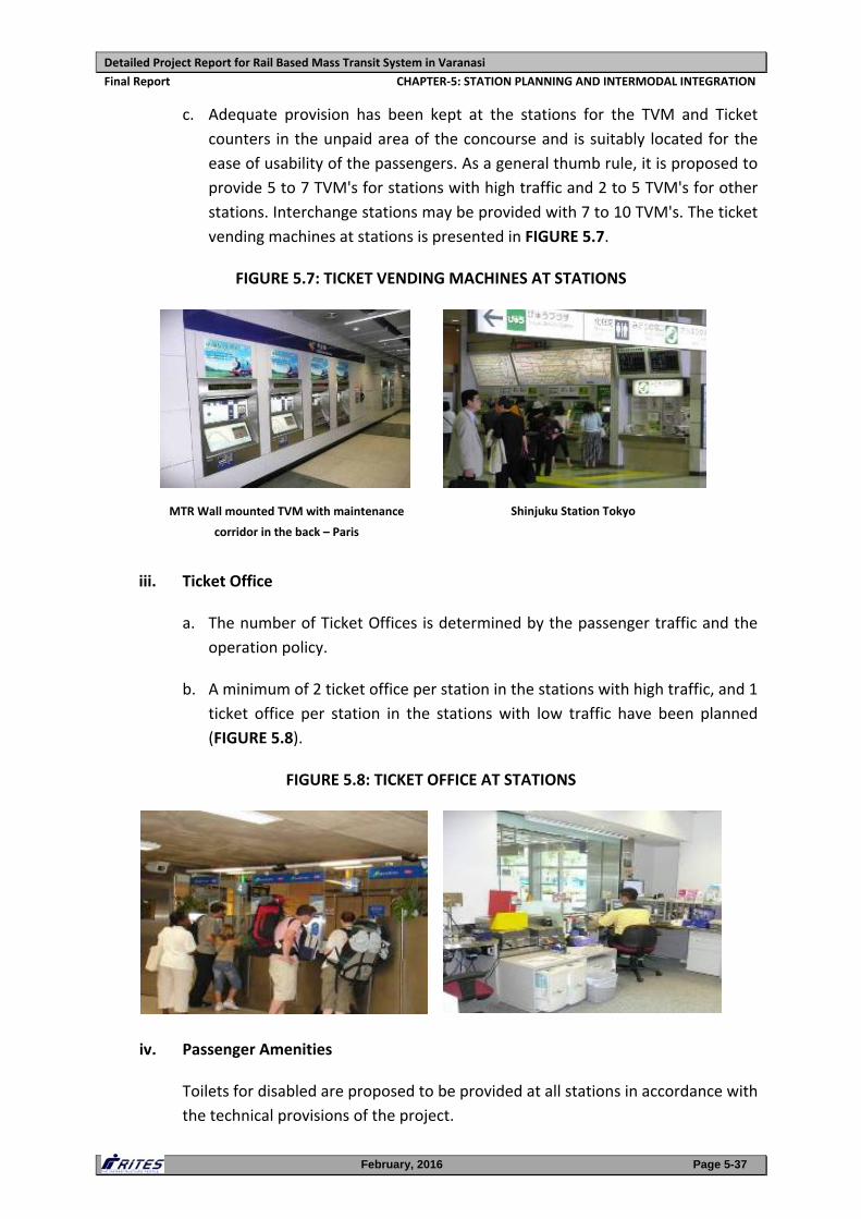
c. Adequate provision has been kept at the stations for the TVM and Ticket
counters in the unpaid area of the concourse and is suitably located for the
ease of usability of the passengers. As a general thumb rule, it is proposed to
provide 5 to 7 TVM's for stations with high traffic and 2 to 5 TVM's for other
stations. Interchange stations may be provided with 7 to 10 TVM's. The ticket
vending machines at stations is presented in FIGURE 5.7.
FIGURE 5.7: TICKET VENDING MACHINES AT STATIONS
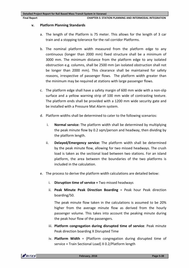
iii. Ticket Office
a. The number of Ticket Offices is determined by the passenger traffic and the
operation policy.
b. A minimum of 2 ticket office per station in the stations with high traffic, and 1
ticket office per station in the stations with low traffic have been planned
(FIGURE 5.8).
FIGURE 5.8: TICKET OFFICE AT STATIONS
iv. Passenger Amenities
Toilets for disabled are proposed to be provided at all stations in accordance with
the technical provisions of the project.
MTR Wall mounted TVM with maintenance
corridor in the back – Paris
Shinjuku Station Tokyo
Detailed Project Report for Rail Based Mass Transit System in Varanasi
Final Report CHAPTER‐5: STATION PLANNING AND INTERMODAL INTEGRATION
February, 2016 Page 5-38
v. Platform Planning Standards
a. The length of the Platform is 75 meter. This allows for the length of 3 car
train and a stopping tolerance for the rail corridor Platforms.
b. The nominal platform width measured from the platform edge to any
continuous (longer than 2000 mm) fixed structure shall be a minimum of
3000 mm. The minimum distance from the platform edge to any isolated
obstruction e.g. columns, shall be 2500 mm (an isolated obstruction shall not
be longer than 2000 mm). This clearance shall be maintained for safety
reasons, irrespective of passenger flows. The platform width greater than
the minimum may be required at stations with large passenger flows.
c. The platform edge shall have a safety margin of 600 mm wide with a non‐slip
surface and a yellow warning strip of 100 mm wide of contrasting texture.
The platform ends shall be provided with a 1200 mm wide security gate and
be installed with a Pressure Mat Alarm system.
d. Platform widths shall be determined to cater to the following scenarios:
i. Normal service: The platform width shall be determined by multiplying
the peak minute flow by 0.2 sqm/person and headway, then dividing by
the platform length.
ii. Delayed/Emergency service: The platform width shall be determined
by the peak minute flow, allowing for two missed headways. The crush
load is taken as the sectional load between two stations. For an island
platform, the area between the boundaries of the two platforms is
included in the calculation.
e. The process to derive the platform width calculations are detailed below:
i. Disruption time of service = Two missed headways
ii. Peak Minute Peak Direction Boarding = Peak hour Peak direction
boarding/50.
The peak minute flow taken in the calculations is assumed to be 20%
higher from the average minute flow as derived from the hourly
passenger volume. This takes into account the peaking minute during
the peak hour flow of the passengers.
iii. Platform congregation during disrupted time of service: Peak minute
Peak direction boarding X Disrupted Time
iv. Platform Width = {Platform congregation during disrupted time of
service + Train Sectional Load} X 0.2/Platform length
Detailed Project Report for Rail Based Mass Transit System in Varanasi
Final Report CHAPTER‐5: STATION PLANNING AND INTERMODAL INTEGRATION
February, 2016 Page 5-39
(0.2 sq m/person has been taken as the platforms are planned for a
minimum Level of Service E)
Platform shall be laid to a fall at 1:100 from the inner face of platform
screen doors for a distance of 3000 mm towards the back of the
platform. Where platform screen doors are not provided then platform
shall be laid to a fall of 1:100 from the platform edge for a distance of
350mm towards the back of the platform.
f. Markings on the platform and ramps to assist and control the flow of
passengers for boarding and alighting with a step free access from/to the
trains shall be provided. Tactile Markings shall also be provided for guiding
paths and warning strips for vision impaired persons to ease the travel for
Persons with Disabilities. The built platforms shall also provide for bright
colour contrast for low vision persons; large lettering and information
displays and digital signage; lifts with lowered control panel with Braille and
raised control buttons and auditory signals, wide doors and grip rails on the
sidewalls of the elevator car; resting areas for senior citizens and disabled
persons; well‐lit platform corridors along with public announcement system.
Inside the coaches, there will be designated spaces for wheelchair users,
audio announcement with dynamic display and sensory door closing
mechanisms.
g. Space occupied by stairs, escalators, structure, seating, platform supervisor’s
accommodation etc. is not be included as part of the platform area.
h. Platforms shall have a clear head room of at least 3000 mm to structures and
platform signs to a width of at least 2000 mm from the platform edge over
their entire length. Suspended signs, fittings, and fixtures shall have a
minimum clearance of 2100 mm above finished floor.
i. Platforms shall be provided with automatic screen walls and doors to ensure
safety of passengers due to third rail traction system. The screen doors would
open on arrival of train in sync with the train doors.
vi. Emergency Evacuation Standards
a. The Requirement is to evaluate people from a station platform to another
location, initially the next level below or above and then on to street level
without hindrance.
b. The principles to be followed are:‐
i. The maximum distance on the platform to a point at which means of
egress route leaves the platform shall not exceed 100 m. The provision
Detailed Project Report for Rail Based Mass Transit System in Varanasi
Final Report CHAPTER‐5: STATION PLANNING AND INTERMODAL INTEGRATION
February, 2016 Page 5-40
in the station layouts from the remote point on the platform to an exit
route has been kept within 50 meter.
ii. The time required walking from the farthest point on a platform to the
escalator or stair landing is considered to be half a minute. Walking
speed as per NFPA 130 has been taken as 37.8 meter/minute.
iii. A Check shall be made to ensure that sufficient capacity exists at the
level to which passengers are evacuated as being a place of ultimate
safety so that people can move freely away from stairs and escalators
as they arrive.
iv. The emergency is assumed to be occurring in one direction of travel
only at any given point of time.
c. For ensuring adequacy of platform area, stair widths and requirement of
additional emergency evacuation stairs, a maximum accumulation of
passengers in the station has been considered to be comprising waiting
passengers at the platform (including two missed headways) and section load
(or full train load if the section load exceeds a full train load) expected to be
evacuated from the peak direction at the station in case of an emergency.
Also, waiting passengers congregated during this disrupted time of service
(two missed headways) in the off‐peak direction to be added in the
evacuation from the platform to concourse in case of underground stations
and concourse to ground in both underground as well as elevated stations.
d. The train will not move from the platform until passengers have begun
clearing the platform and hence the 500 mm unoccupied zone adjacent to
the platform edge for platform without platform screen doors is included in
the calculations.
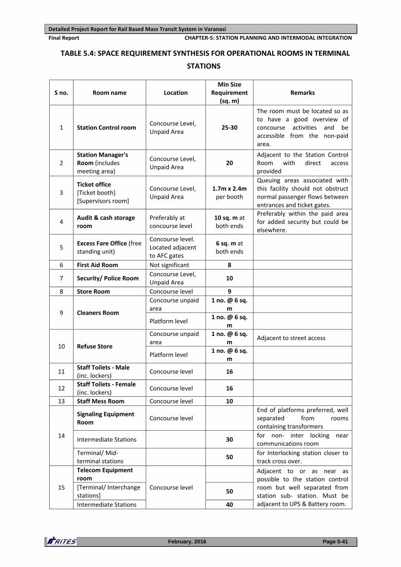
vii. Operational Rooms (BOH Areas)
Back of House (BOH) areas comprise of "Public" and “Non Public Areas”. The BOH
areas consist of PST, System Rooms, Operations, staff facilities, Water Supply and
Drainage System and Miscellaneous requirements. A list of BOH areas along with
their preferred location and the minimum size requirements is given in TABLE
5.4.
Detailed Project Report for Rail Based Mass Transit System in Varanasi
Final Report CHAPTER‐5: STATION PLANNING AND INTERMODAL INTEGRATION
February, 2016 Page 5-41
TABLE 5.4: SPACE REQUIREMENT SYNTHESIS FOR OPERATIONAL ROOMS IN TERMINAL
STATIONS
S no. Room name Location Min Size
Requirement (sq. m)
Remarks
1 Station Control room Concourse Level, Unpaid Area
25‐30
The room must be located so as to have a good overview of concourse activities and be accessible from the non‐paid area.
2 Station Manager's Room (includes meeting area)
Concourse Level, Unpaid Area
20 Adjacent to the Station Control Room with direct access provided
3 Ticket office [Ticket booth] [Supervisors room]
Concourse Level, Unpaid Area
1.7m x 2.4m per booth
Queuing areas associated with this facility should not obstruct normal passenger flows between entrances and ticket gates.
4 Audit & cash storage room
Preferably at concourse level
10 sq. m at both ends
Preferably within the paid area for added security but could be elsewhere.
5 Excess Fare Office (free standing unit)
Concourse level. Located adjacent to AFC gates
6 sq. m at both ends
6 First Aid Room Not significant 8
7 Security/ Police Room Concourse Level, Unpaid Area
10
8 Store Room Concourse level 9
9 Cleaners Room
Concourse unpaid area
1 no. @ 6 sq. m
Platform level 1 no. @ 6 sq.
m
10 Refuse Store
Concourse unpaid area
1 no. @ 6 sq. m
Adjacent to street access
Platform level 1 no. @ 6 sq.
m
11 Staff Toilets ‐ Male (inc. lockers)
Concourse level 16
12 Staff Toilets ‐ Female (inc. lockers)
Concourse level 16
13 Staff Mess Room Concourse level 10
14
Signaling Equipment Room
Concourse level End of platforms preferred, well separated from rooms containing transformers
Intermediate Stations 30 for non‐ inter locking near communications room
Terminal/ Mid‐ terminal stations
50 for Interlocking station closer to track cross over.
15
Telecom Equipment room
Concourse level
Adjacent to or as near as possible to the station control room but well separated from station sub‐ station. Must be adjacent to UPS & Battery room.
[Terminal/ Interchange stations]
50
Intermediate Stations 40
Detailed Project Report for Rail Based Mass Transit System in Varanasi
Final Report CHAPTER‐5: STATION PLANNING AND INTERMODAL INTEGRATION
February, 2016 Page 5-42
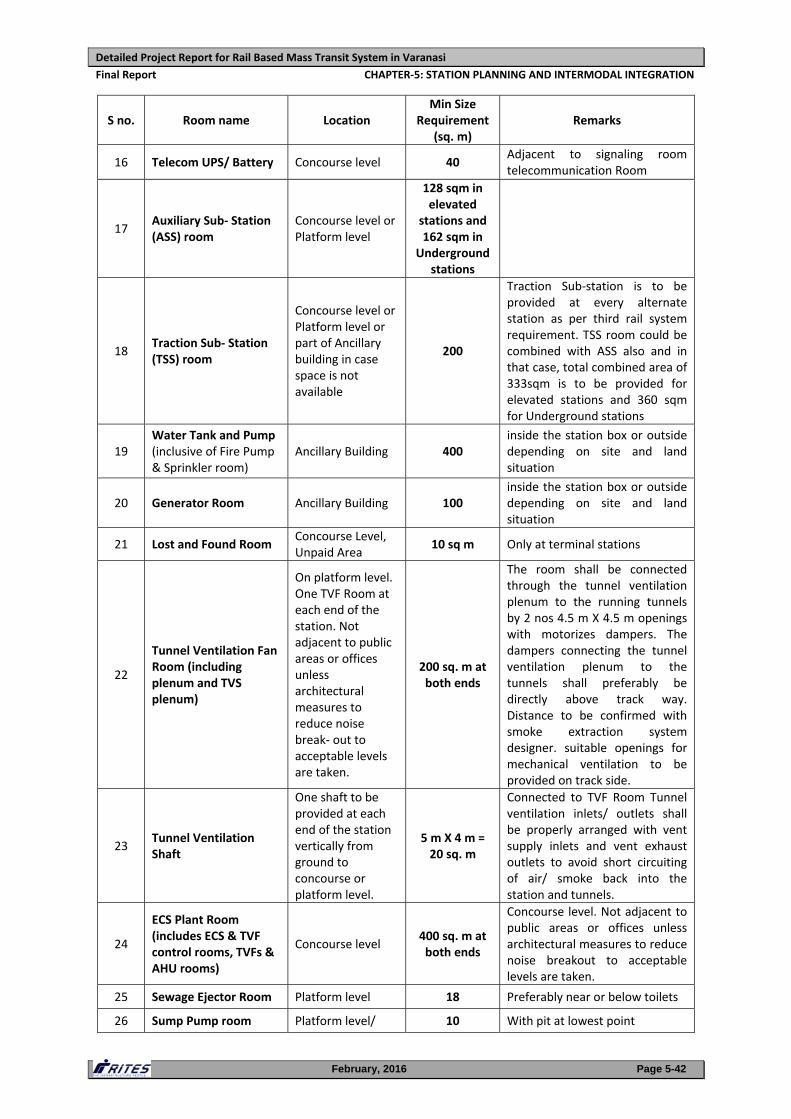
S no. Room name Location Min Size
Requirement (sq. m)
Remarks
16 Telecom UPS/ Battery Concourse level 40 Adjacent to signaling room telecommunication Room
17 Auxiliary Sub‐ Station (ASS) room
Concourse level or Platform level
128 sqm in elevated
stations and 162 sqm in
Underground stations
18 Traction Sub‐ Station (TSS) room
Concourse level or Platform level or part of Ancillary building in case space is not available
200
Traction Sub‐station is to be provided at every alternate station as per third rail system requirement. TSS room could be combined with ASS also and in that case, total combined area of 333sqm is to be provided for elevated stations and 360 sqm for Underground stations
19 Water Tank and Pump (inclusive of Fire Pump & Sprinkler room)
Ancillary Building 400 inside the station box or outside depending on site and land situation
20 Generator Room Ancillary Building 100 inside the station box or outside depending on site and land situation
21 Lost and Found Room Concourse Level, Unpaid Area
10 sq m Only at terminal stations
22
Tunnel Ventilation Fan Room (including plenum and TVS plenum)
On platform level. One TVF Room at each end of the station. Not adjacent to public areas or offices unless architectural measures to reduce noise break‐ out to acceptable levels are taken.
200 sq. m at both ends
The room shall be connected through the tunnel ventilation plenum to the running tunnels by 2 nos 4.5 m X 4.5 m openings with motorizes dampers. The dampers connecting the tunnel ventilation plenum to the tunnels shall preferably be directly above track way. Distance to be confirmed with smoke extraction system designer. suitable openings for mechanical ventilation to be provided on track side.
23 Tunnel Ventilation Shaft
One shaft to be provided at each end of the station vertically from ground to concourse or platform level.
5 m X 4 m = 20 sq. m
Connected to TVF Room Tunnel ventilation inlets/ outlets shall be properly arranged with vent supply inlets and vent exhaust outlets to avoid short circuiting of air/ smoke back into the station and tunnels.
24
ECS Plant Room (includes ECS & TVF control rooms, TVFs & AHU rooms)
Concourse level 400 sq. m at both ends
Concourse level. Not adjacent to public areas or offices unless architectural measures to reduce noise breakout to acceptable levels are taken.
25 Sewage Ejector Room Platform level 18 Preferably near or below toilets
26 Sump Pump room Platform level/ 10 With pit at lowest point
Detailed Project Report for Rail Based Mass Transit System in Varanasi
Final Report CHAPTER‐5: STATION PLANNING AND INTERMODAL INTEGRATION
February, 2016 Page 5-43
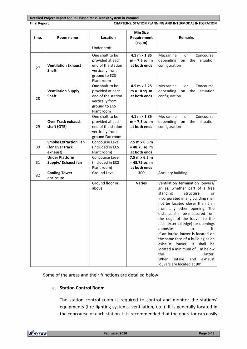
S no. Room name Location Min Size
Requirement (sq. m)
Remarks
Under croft
27
Ventilation Exhaust Shaft
One shaft to be provided at each end of the station vertically from ground to ECS Plant room
4.1 m x 1.85 m = 7.5 sq. m at both ends
Mezzanine or Concourse, depending on the situation configuration
28
Ventilation Supply Shaft
One shaft to be provided at each end of the station vertically from ground to ECS Plant room
4.5 m x 2.25 m = 10 sq. m at both ends
Mezzanine or Concourse, depending on the situation configuration
29
Over Track exhaust shaft (OTE)
One shaft to be provided at each end of the station vertically from ground Fan room
4.1 m x 1.85 m = 7.5 sq. m at both ends
Mezzanine or Concourse, depending on the situation configuration
30 Smoke Extraction Fan (for Over track exhaust)
Concourse Level (included in ECS Plant room)
7.5 m x 6.5 m = 48.75 sq. m at both ends
31 Under Platform Supply/ Exhaust fan
Concourse Level (included in ECS Plant room)
7.5 m x 6.5 m = 48.75 sq. m at both ends
32 Cooling Tower enclosure
Ground Level 300 Ancillary building
Ground floor or above
Varies Ventilation termination louvers/ grilles, whether part of a free standing structure or incorporated in any building shall not be located closer than 5 m from any other opening. The distance shall be measured from the edge of the louver to the face (external edge) for openings opposite to it.If an intake louver is located on the same face of a building as an exhaust louver, it shall be located a minimum of 1 m below the latter. When intake and exhaust louvers are located at 90°.
Some of the areas and their functions are detailed below:
a. Station Control Room
The station control room is required to control and monitor the stations’
equipments (fire‐fighting systems, ventilation, etc.). It is generally located in
the concourse of each station. It is recommended that the operator can easily
Detailed Project Report for Rail Based Mass Transit System in Varanasi
Final Report CHAPTER‐5: STATION PLANNING AND INTERMODAL INTEGRATION
February, 2016 Page 5-44
access any part of the station from this office. This room is fitted with a dialog
box for passenger information.
b. Ticket Office
The Ticket Office can also be used to inform passengers. If the main Ticket
Office is located next to the Station master control room, it will be fitted with
a self‐closing door between these two rooms. The room will require special
protection (as armoured glass, metal doors, etc.).
c. TVM back‐store room
For security reasons, the Ticket Vending Machines should be equipped with a
back store room. The TVM back‐store room is preferably located near the
Ticket Counters.
d. Security/Police Room
This room is located in each station and is used by the security staff. It is
preferable that this room is located at the concourse, in the public operation
area allowing watching over the public. This room could be fitted with
specific equipments in relation to the role of security staff.
e. First aid room
First aid room isn’t a specific operation room but will be located in every
station in accordance with the technical provisions of the project. This room
could also be used as a detention room if it is needed.
f. Passenger amenities
Toilets for public are not specific operation rooms but will be provided at all
stations in accordance with the technical provisions of the project.
g. Audit and Cash Storage Room
In each station where tickets will be sold, a Audit and Cash storage
room located next to the main ticket office is to be provided. For
security reasons, it is recommended to collect cash every day from
the ticket office and at regular intervals from the ticket vending
machines of the station. This room has to be near the Ticket Office
and TVM back‐store, with restricted and monitored access, and shall
be directly connected with it in the operation area, in order to avoid
money transfer to be visible to the public. It should also be close to
the station master’s Control Room for management reasons.
Detailed Project Report for Rail Based Mass Transit System in Varanasi
Final Report CHAPTER‐5: STATION PLANNING AND INTERMODAL INTEGRATION
February, 2016 Page 5-45
In case enough space is not available to have a separate room, Audit
and Cash storage room can be located in the ticket office. In this case,
a “protective wall” will be required in the ticket office, in order to
obstruct the visibility of cash handling from the public.
h. Male and Female Locker and Rest Rooms
These rooms shall be close to the staff operation areas. Males & females shall
have separate access, in the non‐public operation area. The area of these
rooms will depend on the number of employees in each station.
i. Male and Female Staff Toilet
It is recommended to fit the stations with specific toilets for the employees.
Separate male and female toilets shall be provided in each station.
j. Cleaner's Room
Cleaning and garbage rooms are not specific operation rooms but must be
located in every station. These rooms shall be close to each other. Hot and
cold water shall be available in the cleaning room.
k. Train Driver Rooms
In case of start and shut down operation directly in terminals with
stabled trains during the night, train driver rooms are required. These
rooms are preferably located at the platform level and include:
Train drivers dispatch office,
Training room / emergency room,
Operation storage room,
Male and female locker rooms separated,
Restrooms
The train drivers dispatch office is a specific room allowing conductors
to sign on/sign off and to be informed of new instructions and special
orders. The room should be located next to the Operation supervisor
Office.
l. Lost and Found Room
Management of Lost and Found items will be centralized in a specific station
Detailed Project Report for Rail Based Mass Transit System in Varanasi
Final Report CHAPTER‐5: STATION PLANNING AND INTERMODAL INTEGRATION
February, 2016 Page 5-46
for the entire network. The lost and found room will be located into the
public area at a Terminal Station. The lost and found location will require a
public zone and a restricted room dedicated to lost objects.
viii. Building Electrical and Mechanical Services (BEMS) Design Parameters
Water Storage
The Design of the Water tank is based upon the assumption of 35 liter/person for
raw and treated water. The capacity of the Water Tank is provided as 50cu.m
approximately for each elevated station and 200cu.m for underground station.
Electricity
Two DG sets of 400 KVA each are proposed to be provided at each elevated
station (which does not include the power supply of the train) along with one
Auxiliary Substation of 33 KV/415V. Two sets of 1000 KVA and two auxiliary
substations of 33 KV/415V for underground stations are proposed.
HVAC
To accommodate the requirement of air‐conditioning approximately 650 Ton
Refrigerant in underground station only is proposed at each station assuming the
design parameter as 100 Sq ft/ Ton. VRF system shall be adopted for elevated
stations.
Tunnel Ventilation System
The TVS is provided in a Subway system essentially to carry out the following
functions:
a) Train Pressure relief during normal operation
The movement of trains within the underground system induces unsteady air
motion in the tunnels and stations. Together with changes in cross section,
this motion of air results in changes in air pressure within trains and for
wayside locations. These changes in pressure or ‘pressure transients’ can be a
source of passenger discomfort and can also be harmful to the wayside
equipment and structures.
b) Ventilation during maintenance periods, if required
Detailed Project Report for Rail Based Mass Transit System in Varanasi
Final Report CHAPTER‐5: STATION PLANNING AND INTERMODAL INTEGRATION
February, 2016 Page 5-47
c) Removal of smoke during emergency conditions
The ventilation system shall be capable of providing a smoke‐free evacuation
route for the passengers and for the intervention of the emergency crews in
the event of fire in a running tunnel. Generally, the only practicable way to
provide such conditions is to ventilate the incident tunnel longitudinally such
that smokes moves only downstream of the fire. The strategy ensures that
smoke free conditions are maintained upstream of the fire both for the
passengers and for the emergency crews. The ventilation system is operated
in a ‘push‐pull’ supply and exhaust mode with jet fans or nozzles driving
tunnel flows such that the smoke is forced to move in one direction, enabling
evacuation to take place in the opposite direction.
This arrangement incorporates shared fans where the ventilating air flow is
directed to the incident running tunnel by means of the selective operation
of control dampers. The ventilating air is delivered to the incident tunnel
through a nozzle to control the movement of smoke within the tunnel.
Similar plant at the downstream end of the tunnel is designed to capture the
smoke and discharge it directly to atmosphere. The tunnel ventilation system
is reversible and is able to ventilate an incident running tunnel in either
direction. The selected direction of ventilation is determined by the location
of the fire along the length of the incident train; to provide smoke‐free
conditions over the longer length of the train.
d) Maintenance of smoke free evacuation route and provision of adequate
fresh air during fire related emergencies
The design and sizing of the tunnel ventilation system of an underground
metro rail project is defined principally by the:
a. Design of the rolling stock, including the design fire size
b. Operating procedures, including the frequency and speed of the
trains, and the procedures for the response to an incident
c. Required maintenance practices
d. Architecture of the stations
e. Diameter and alignment of the running tunnels
Detailed Project Report for Rail Based Mass Transit System in Varanasi
Final Report CHAPTER‐5: STATION PLANNING AND INTERMODAL INTEGRATION
February, 2016 Page 5-48
f. Accurate description of the climatic conditions, including the
probability and extent of airborne sand and dust
g. Target ridership and the corresponding levels of comfort
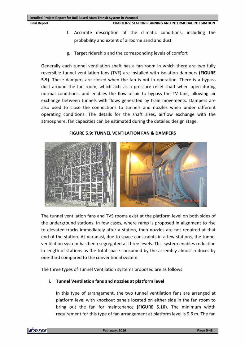
Generally each tunnel ventilation shaft has a fan room in which there are two fully
reversible tunnel ventilation fans (TVF) are installed with isolation dampers (FIGURE
5.9). These dampers are closed when the fan is not in operation. There is a bypass
duct around the fan room, which acts as a pressure relief shaft when open during
normal conditions, and enables the flow of air to bypass the TV fans, allowing air
exchange between tunnels with flows generated by train movements. Dampers are
also used to close the connections to tunnels and nozzles when under different
operating conditions. The details for the shaft sizes, airflow exchange with the
atmosphere, fan capacities can be estimated during the detailed design stage.
FIGURE 5.9: TUNNEL VENTILATION FAN & DAMPERS
The tunnel ventilation fans and TVS rooms exist at the platform level on both sides of
the underground stations. In few cases, where ramp is proposed in alignment to rise
to elevated tracks immediately after a station, then nozzles are not required at that
end of the station. At Varanasi, due to space constraints in a few stations, the tunnel
ventilation system has been segregated at three levels. This system enables reduction
in length of stations as the total space consumed by the assembly almost reduces by
one‐third compared to the conventional system.
The three types of Tunnel Ventilation systems proposed are as follows:
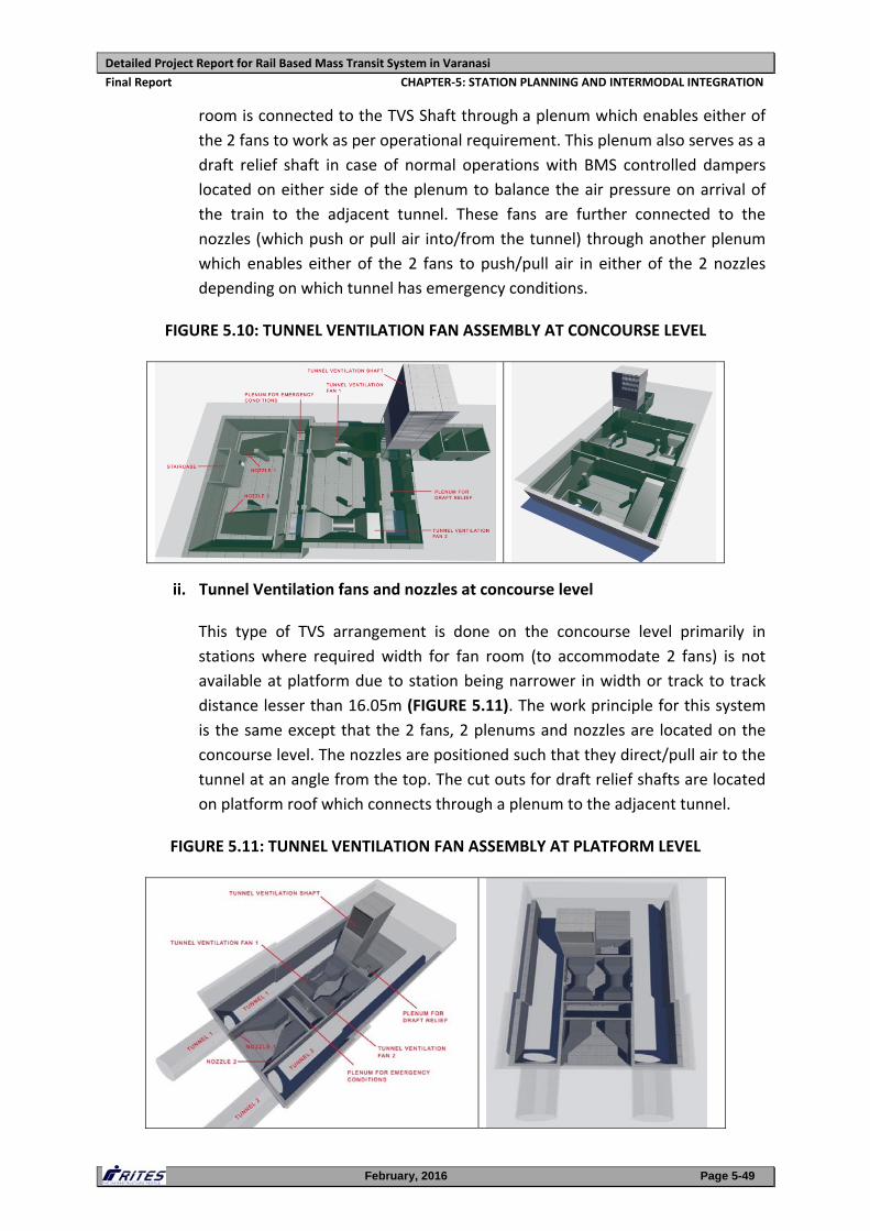
i. Tunnel Ventilation fans and nozzles at platform level
In this type of arrangement, the two tunnel ventilation fans are arranged at
platform level with knockout panels located on either side in the fan room to
bring out the fan for maintenance (FIGURE 5.10). The minimum width
requirement for this type of fan arrangement at platform level is 9.6 m. The fan
Detailed Project Report for Rail Based Mass Transit System in Varanasi
Final Report CHAPTER‐5: STATION PLANNING AND INTERMODAL INTEGRATION
February, 2016 Page 5-49
room is connected to the TVS Shaft through a plenum which enables either of
the 2 fans to work as per operational requirement. This plenum also serves as a
draft relief shaft in case of normal operations with BMS controlled dampers
located on either side of the plenum to balance the air pressure on arrival of
the train to the adjacent tunnel. These fans are further connected to the
nozzles (which push or pull air into/from the tunnel) through another plenum
which enables either of the 2 fans to push/pull air in either of the 2 nozzles
depending on which tunnel has emergency conditions.
FIGURE 5.10: TUNNEL VENTILATION FAN ASSEMBLY AT CONCOURSE LEVEL
ii. Tunnel Ventilation fans and nozzles at concourse level
This type of TVS arrangement is done on the concourse level primarily in
stations where required width for fan room (to accommodate 2 fans) is not
available at platform due to station being narrower in width or track to track
distance lesser than 16.05m (FIGURE 5.11). The work principle for this system
is the same except that the 2 fans, 2 plenums and nozzles are located on the
concourse level. The nozzles are positioned such that they direct/pull air to the
tunnel at an angle from the top. The cut outs for draft relief shafts are located
on platform roof which connects through a plenum to the adjacent tunnel.
FIGURE 5.11: TUNNEL VENTILATION FAN ASSEMBLY AT PLATFORM LEVEL
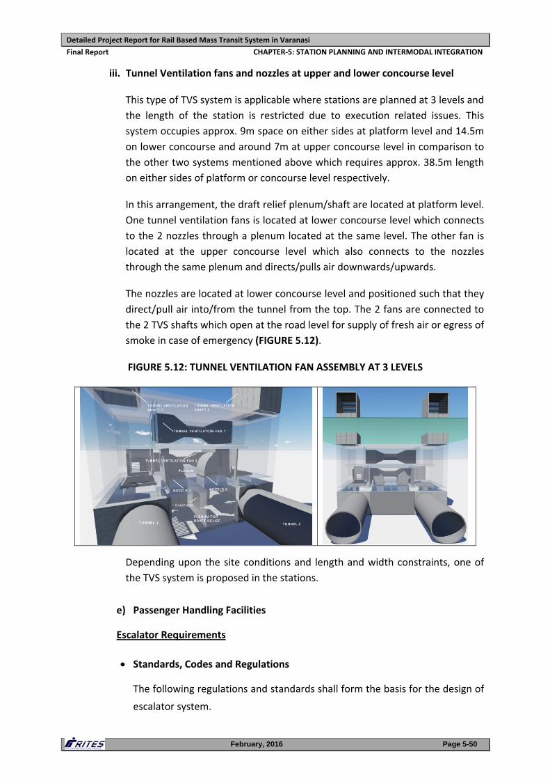
Detailed Project Report for Rail Based Mass Transit System in Varanasi
Final Report CHAPTER‐5: STATION PLANNING AND INTERMODAL INTEGRATION
February, 2016 Page 5-50
iii. Tunnel Ventilation fans and nozzles at upper and lower concourse level
This type of TVS system is applicable where stations are planned at 3 levels and
the length of the station is restricted due to execution related issues. This
system occupies approx. 9m space on either sides at platform level and 14.5m
on lower concourse and around 7m at upper concourse level in comparison to
the other two systems mentioned above which requires approx. 38.5m length
on either sides of platform or concourse level respectively.
In this arrangement, the draft relief plenum/shaft are located at platform level.
One tunnel ventilation fans is located at lower concourse level which connects
to the 2 nozzles through a plenum located at the same level. The other fan is
located at the upper concourse level which also connects to the nozzles
through the same plenum and directs/pulls air downwards/upwards.
The nozzles are located at lower concourse level and positioned such that they
direct/pull air into/from the tunnel from the top. The 2 fans are connected to
the 2 TVS shafts which open at the road level for supply of fresh air or egress of
smoke in case of emergency (FIGURE 5.12).
FIGURE 5.12: TUNNEL VENTILATION FAN ASSEMBLY AT 3 LEVELS
Depending upon the site conditions and length and width constraints, one of
the TVS system is proposed in the stations.
e) Passenger Handling Facilities
Escalator Requirements
Standards, Codes and Regulations
The following regulations and standards shall form the basis for the design of
escalator system.
Detailed Project Report for Rail Based Mass Transit System in Varanasi
Final Report CHAPTER‐5: STATION PLANNING AND INTERMODAL INTEGRATION
February, 2016 Page 5-51
American National Standard Institute (ANSI)
American Society of testing Materials (ASTM)
International Electro technical Commissions (IEC)
Indian Standard (IS)
European Norm (EN)
National Electrical manufacturers Association (NEMA)
National Fire Protection Association (NFPA)
Underwriters Laboratories, Inc. (UL)
Design Criteria
The escalators will be heavy duty “public” service escalators capable of
operating safely, smoothly and continuously in either direction, for a period
of not less than 20 hours per day, seven days per week, (except special
holiday which may be operated 24 hours a day) within the environmental
conditions prevailing within the well way and at the location where the
escalators are installed. The maximum allowable passenger load of each step
should not be less than load equivalent of three 65 kg person per step.
The escalators will be equipped with energy saving system. Speed of
escalators will be in the range of 0.6‐0.75 m/s for normal operation. The
energy saving system will reduce speed of escalators to standby speed mode
of 0.20 m/s during low traffic hour.
The number of flat steps at the upper landing should be in proportion to the
vertical rise of the escalator. For 6.1 m to 18.3 m rise, minimum four flat
steps should be provided and for a rise up to 6.1 m manufacturers’ standards
should be used (2‐3 flat steps).
The design of the escalators which act as emergency stairways should meet
all the criteria requirements in NFPA 130. The design of the escalators will be
such that they can be used as fixed staircases under a condition of power
failure, activation of stop button or activation by safety/protection devices.
When the escalators are stationed, no slipping, jerking, sliding and vibration
should occur. Escalators will be equipped with protective barriers, where
Detailed Project Report for Rail Based Mass Transit System in Varanasi
Final Report CHAPTER‐5: STATION PLANNING AND INTERMODAL INTEGRATION
February, 2016 Page 5-52
necessary.
Interfacing requirements
The following escalators interface will be monitored by the SCADA and
abnormal conditions will be alarmed:
Incoming power lines healthy.
Direction status.
Running
Fault
Emergency
Elevator Requirements
Standards, Codes and Regulations
The following regulations and standards will form the basis for the design of
elevator system.
American National Standard Institute (ANSI)
American Society of testing Materials (ASTM)
International Electro technical Commissions (IEC)
Indian Standard (IS)
European Norm (EN)
National Electrical manufacturers Association (NEMA)
National Fire Protection Association (NFPA)
Underwriters Laboratories, Inc. (UL)
Design Criteria
Lifts will be of the goods/passenger public service type and rated at minimum
180 starts per hour. Lifts will be of proven technology and designed to have
low energy consumption, low operational costs and will provide environment
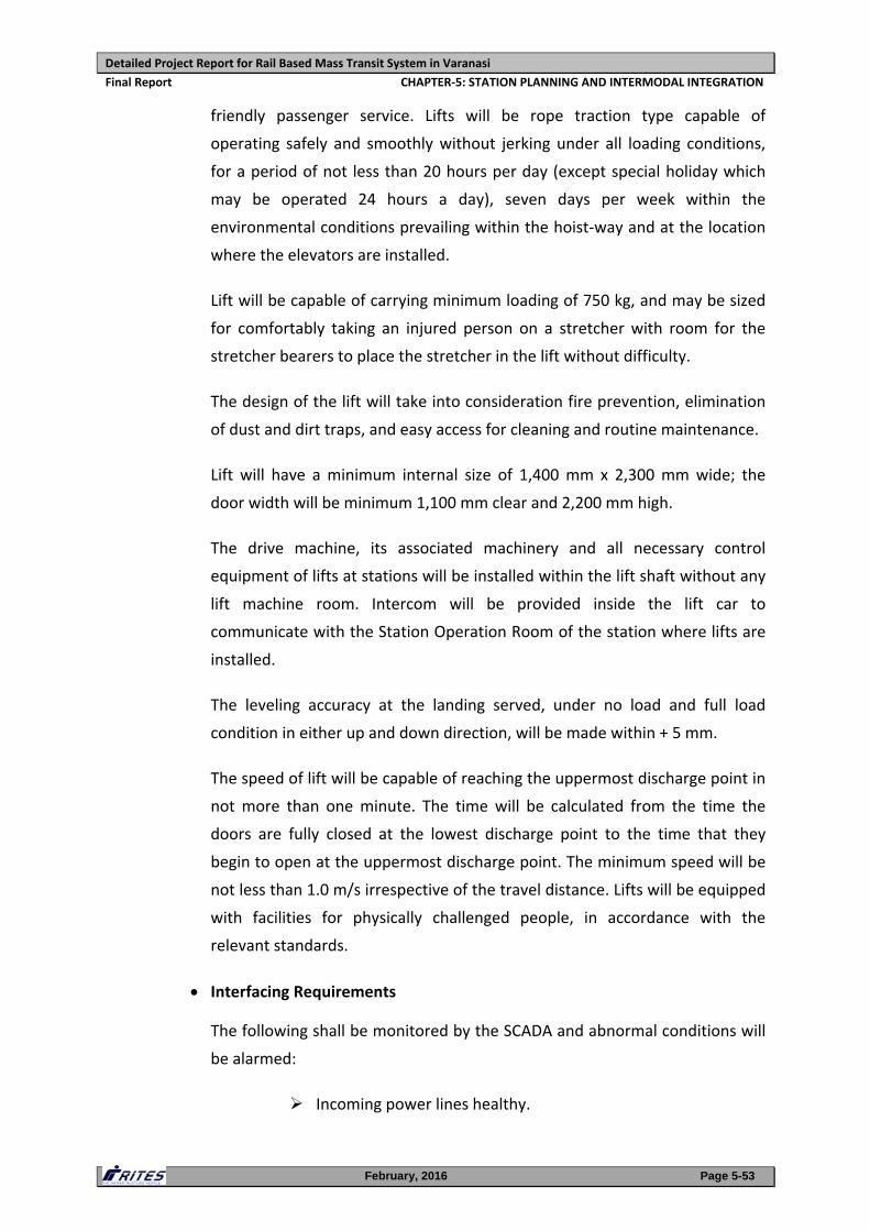
Detailed Project Report for Rail Based Mass Transit System in Varanasi
Final Report CHAPTER‐5: STATION PLANNING AND INTERMODAL INTEGRATION
February, 2016 Page 5-53
friendly passenger service. Lifts will be rope traction type capable of
operating safely and smoothly without jerking under all loading conditions,
for a period of not less than 20 hours per day (except special holiday which
may be operated 24 hours a day), seven days per week within the
environmental conditions prevailing within the hoist‐way and at the location
where the elevators are installed.
Lift will be capable of carrying minimum loading of 750 kg, and may be sized
for comfortably taking an injured person on a stretcher with room for the
stretcher bearers to place the stretcher in the lift without difficulty.
The design of the lift will take into consideration fire prevention, elimination
of dust and dirt traps, and easy access for cleaning and routine maintenance.
Lift will have a minimum internal size of 1,400 mm x 2,300 mm wide; the
door width will be minimum 1,100 mm clear and 2,200 mm high.
The drive machine, its associated machinery and all necessary control
equipment of lifts at stations will be installed within the lift shaft without any
lift machine room. Intercom will be provided inside the lift car to
communicate with the Station Operation Room of the station where lifts are
installed.
The leveling accuracy at the landing served, under no load and full load
condition in either up and down direction, will be made within + 5 mm.
The speed of lift will be capable of reaching the uppermost discharge point in
not more than one minute. The time will be calculated from the time the
doors are fully closed at the lowest discharge point to the time that they
begin to open at the uppermost discharge point. The minimum speed will be
not less than 1.0 m/s irrespective of the travel distance. Lifts will be equipped
with facilities for physically challenged people, in accordance with the
relevant standards.
Interfacing Requirements
The following shall be monitored by the SCADA and abnormal conditions will
be alarmed:
Incoming power lines healthy.
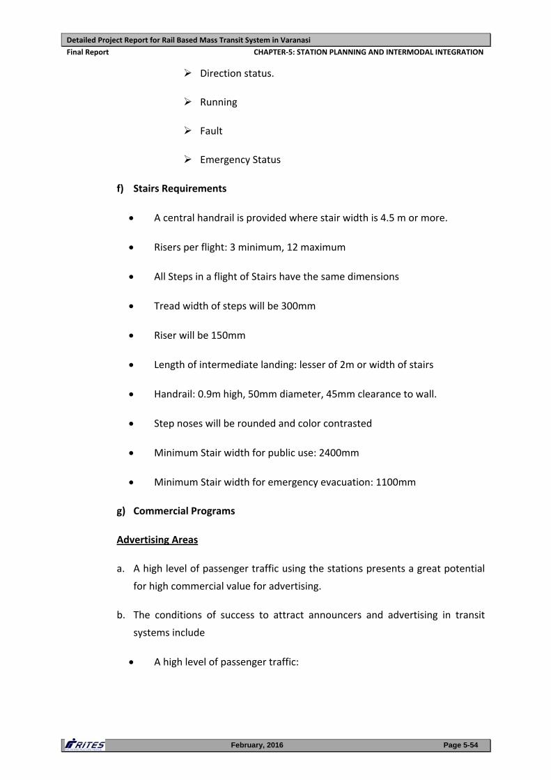
Detailed Project Report for Rail Based Mass Transit System in Varanasi
Final Report CHAPTER‐5: STATION PLANNING AND INTERMODAL INTEGRATION
February, 2016 Page 5-54
Direction status.
Running
Fault
Emergency Status
f) Stairs Requirements
A central handrail is provided where stair width is 4.5 m or more.
Risers per flight: 3 minimum, 12 maximum
All Steps in a flight of Stairs have the same dimensions
Tread width of steps will be 300mm
Riser will be 150mm
Length of intermediate landing: lesser of 2m or width of stairs
Handrail: 0.9m high, 50mm diameter, 45mm clearance to wall.
Step noses will be rounded and color contrasted
Minimum Stair width for public use: 2400mm
Minimum Stair width for emergency evacuation: 1100mm
g) Commercial Programs
Advertising Areas
a. A high level of passenger traffic using the stations presents a great potential
for high commercial value for advertising.
b. The conditions of success to attract announcers and advertising in transit
systems include
A high level of passenger traffic:
Detailed Project Report for Rail Based Mass Transit System in Varanasi
Final Report CHAPTER‐5: STATION PLANNING AND INTERMODAL INTEGRATION
February, 2016 Page 5-55
Maximum of space and maximum of repetitions: minimum space for
posters is around 96 positions to be efficient on the entire network (that
means a minimum of 6 positions per station)
Importance of light and the treatment of light to see the posters
Advertising sales agency to manage the advertising space.
c. The different possibilities of advertising spaces include
On the platforms (20% of the spaces on the platform could be used for
advertising).
On the walls beside the escalators
On the walls of the first level of the stations
Inside the Rolling Stock (specific dedicated areas)
The provision of advertisements at stations is presented in FIGURE 5.13.
FIGURE 5.13: ADVERTISEMENTS AT STATIONS
Detailed Project Report for Rail Based Mass Transit System in Varanasi
Final Report CHAPTER‐5: STATION PLANNING AND INTERMODAL INTEGRATION
February, 2016 Page 5-56
On the Rolling Stock: train wearing advertisement campaign (train is
used as an advertising medium for one campaign). Advertisement on
Rolling Stock is presented in FIGURE 5.14.
FIGURE 5.14: ADVERTISEMENTS ON ROLLING STOCK
The entire station can be used as an advertising medium for one
campaign.
New technologies can be used especially on the platforms: LCS screens
(about 8m²) with projection. It implies cables have to be set up in the
stations and on the platforms. The screens include sensors to calculate
the number of passengers who pass and see the poster. The screen can
also communicate with mobile phones.
d. General Principles about the advertising space:
Advertising spaces must be seen by the customers on the platforms and
on the platforms, a symmetry position can be set up as illustrated in
FIGURE 5.15.
Commercial Areas for Retail Shops/Kiosks/ATM's
a. Like Advertising, retail shops in the stations could provide additional financial
income. The expected level of passenger traffic in the stations provides great
potential for a high commercial value for the retail shops. An agency will
preferably be appointed for management of these retail shops at all stations
on the proposed corridor.
b. The different area possibilities for location of retail shops;
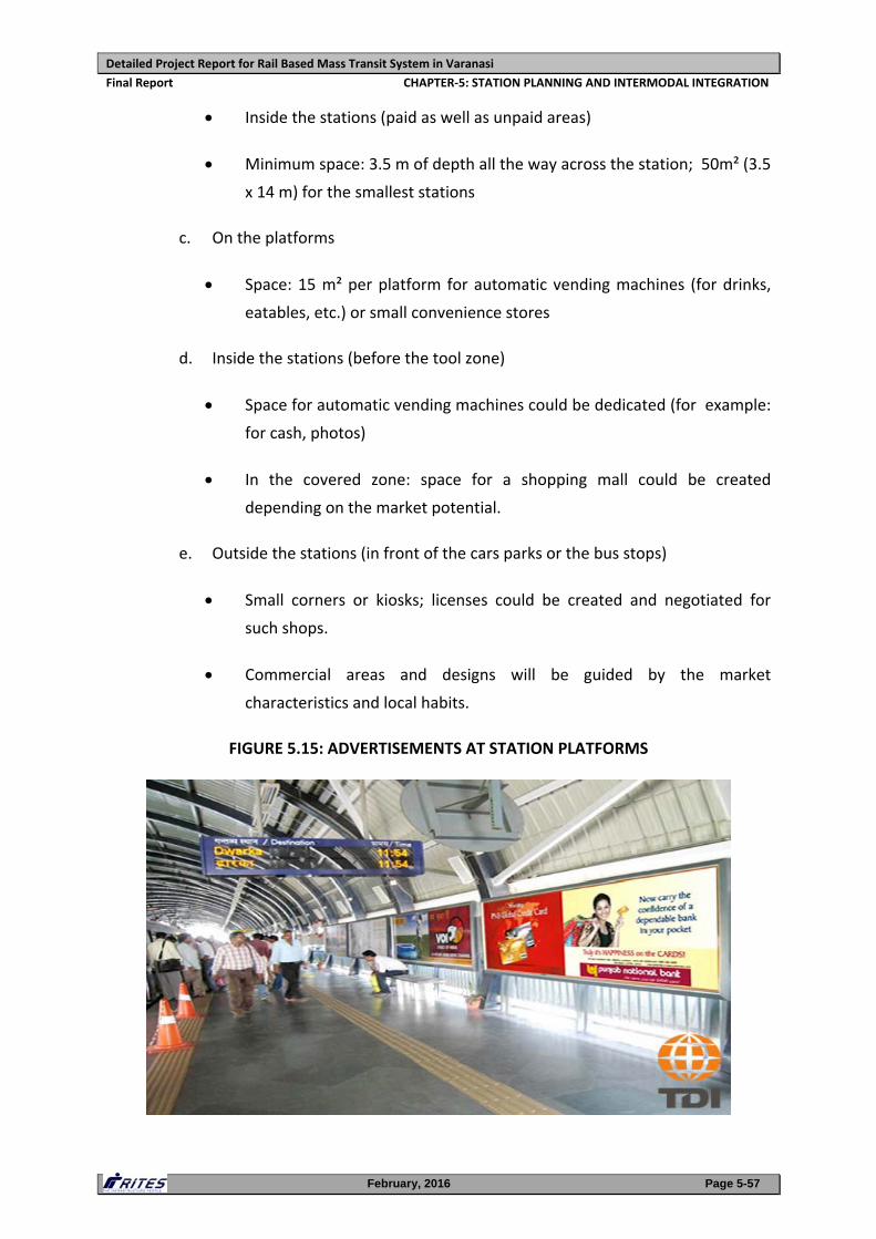
Detailed Project Report for Rail Based Mass Transit System in Varanasi
Final Report CHAPTER‐5: STATION PLANNING AND INTERMODAL INTEGRATION
February, 2016 Page 5-57
Inside the stations (paid as well as unpaid areas)
Minimum space: 3.5 m of depth all the way across the station; 50m² (3.5
x 14 m) for the smallest stations
c. On the platforms
Space: 15 m² per platform for automatic vending machines (for drinks,
eatables, etc.) or small convenience stores
d. Inside the stations (before the tool zone)
Space for automatic vending machines could be dedicated (for example:
for cash, photos)
In the covered zone: space for a shopping mall could be created
depending on the market potential.
e. Outside the stations (in front of the cars parks or the bus stops)
Small corners or kiosks; licenses could be created and negotiated for
such shops.
Commercial areas and designs will be guided by the market
characteristics and local habits.
FIGURE 5.15: ADVERTISEMENTS AT STATION PLATFORMS
Detailed Project Report for Rail Based Mass Transit System in Varanasi
Final Report CHAPTER‐5: STATION PLANNING AND INTERMODAL INTEGRATION
February, 2016 Page 5-58
5.3.5 Planning of Metro Stations
The conceptual station planning are the adaptations of the typical stations finalised
keeping in view the projected traffic, station requirements, site conditions, minimal
land acquisition, method of construction and overall cost optimisation.
Since land is at a premium throughout the corridor, the process of reconciling the land
that is actually required for the station development has had a major influence upon
the design process and important elements of the stations such as entry/exits,
concourse, platforms, ancillary buildings etc have been designed and marked for each
station to overcome land acquisition problems. But, wherever the vacant land parcels
have not been found available, land acquisition has been proposed for placing the
necessary utilities/facilities.
The most important design consideration is to provide a safe and comfortable
environment to passengers during both normal and emergency operation. The space
planning requirement for each of the stations with respect to the number of AFC
gates, ticket windows, stair width, number of escalators, platform width etc. in normal
and emergency conditions are based on peak hour passenger traffic which is detailed
in Annexure 5.1, 5.2 and 5.3. These calculations not only accommodate the normal
and delayed operation but also satisfy NFPA 130 guidelines.
The stations have been provided with an internal environment suitable for a world
class metro railway system by incorporating the experience of international best
practices. The stations have been planned in such a way that they are easily operated,
maintained and can be upgraded in future. Accommodation for staff and plant rooms
is provided at both platform and concourse levels within areas that are entirely
separate from the public access. The main plant systems accommodated within the
station are the auxiliary sub‐stations at the concourse/platform level at each end, ECS
plant rooms at concourse level at each end and adjacent to the station box and TVS
plant rooms at platform level at each end, between the two tracks. The S&T
equipment rooms are provided between the subway and ECS plant room.
The internal arrangement for the stations is evolved in such a way that Back of House
accommodation is organized, so that the rooms of a similar operational use are placed
along a common corridor and plant accommodation is clearly distinct from habitable
rooms.
A number of standardized station typologies, which can respond to the context at
specific locations have been developed. The design of stations at Varanasi is based on
the 3 car rake composition with length of train to be 67.8 m. Therefore, the length of
the platforms in both elevated stations and underground stations have been kept as
75 m with 3.6 m buffer space on either side.
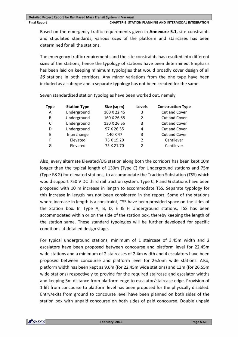
Detailed Project Report for Rail Based Mass Transit System in Varanasi
Final Report CHAPTER‐5: STATION PLANNING AND INTERMODAL INTEGRATION
February, 2016 Page 5-59
Based on the emergency traffic requirements given in Annexure 5.1, site constraints
and stipulated standards, various sizes of the platform and staircases has been
determined for all the stations.
The emergency traffic requirements and the site constraints has resulted into different
sizes of the stations, hence the typology of stations have been determined. Emphasis
has been laid on keeping minimum typologies that would broadly cover design of all
26 stations in both corridors. Any minor variations from the one type have been
included as a subtype and a separate typology has not been created for the same.
Seven standardized station typologies have been worked out, namely
Type Station Type Size (sq m) Levels Construction Type A Underground 160 X 22.45 3 Cut and Cover B Underground 160 X 26.55 2 Cut and Cover C Underground 130 X 26.55 3 Cut and Cover D Underground 97 X 26.55 4 Cut and Cover E Interchange 140 X 47 3 Cut and Cover F Elevated 75 X 19.20 2 Cantilever G Elevated 75 X 21.70 2 Cantilever
Also, every alternate Elevated/UG station along both the corridors has been kept 10m
longer than the typical length of 130m (Type C) for Underground stations and 75m
(Type F&G) for elevated stations, to accommodate the Traction Substation (TSS) which
would support 750 V DC third rail traction system. Type C, F and G stations have been
proposed with 10 m increase in length to accommodate TSS. Separate typology for
this increase in length has not been considered in the report. Some of the stations
where increase in length is a constraint, TSS have been provided space on the sides of
the Station box. In Type A, B, D, E & H Underground stations, TSS has been
accommodated within or on the side of the station box, thereby keeping the length of
the station same. These standard typologies will be further developed for specific
conditions at detailed design stage.
For typical underground stations, minimum of 1 staircase of 3.45m width and 2
escalators have been proposed between concourse and platform level for 22.45m
wide stations and a minimum of 2 staircases of 2.4m width and 4 escalators have been
proposed between concourse and platform level for 26.55m wide stations. Also,
platform width has been kept as 9.6m (for 22.45m wide stations) and 13m (for 26.55m
wide stations) respectively to provide for the required staircase and escalator widths
and keeping 3m distance from platform edge to escalator/staircase edge. Provision of
1 lift from concourse to platform level has been proposed for the physically disabled.
Entry/exits from ground to concourse level have been planned on both sides of the
station box with unpaid concourse on both sides of paid concourse. Double unpaid
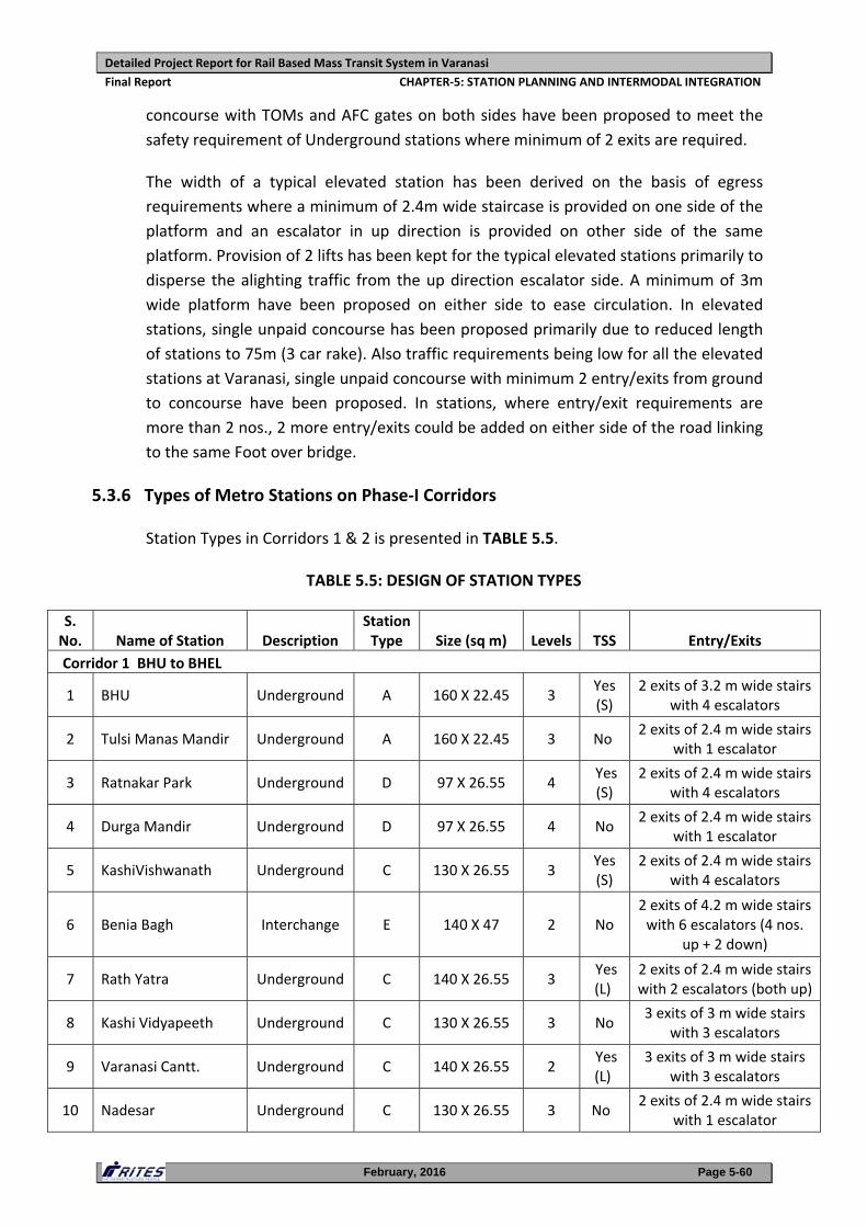
Detailed Project Report for Rail Based Mass Transit System in Varanasi
Final Report CHAPTER‐5: STATION PLANNING AND INTERMODAL INTEGRATION
February, 2016 Page 5-60
concourse with TOMs and AFC gates on both sides have been proposed to meet the
safety requirement of Underground stations where minimum of 2 exits are required.
The width of a typical elevated station has been derived on the basis of egress
requirements where a minimum of 2.4m wide staircase is provided on one side of the
platform and an escalator in up direction is provided on other side of the same
platform. Provision of 2 lifts has been kept for the typical elevated stations primarily to
disperse the alighting traffic from the up direction escalator side. A minimum of 3m
wide platform have been proposed on either side to ease circulation. In elevated
stations, single unpaid concourse has been proposed primarily due to reduced length
of stations to 75m (3 car rake). Also traffic requirements being low for all the elevated
stations at Varanasi, single unpaid concourse with minimum 2 entry/exits from ground
to concourse have been proposed. In stations, where entry/exit requirements are
more than 2 nos., 2 more entry/exits could be added on either side of the road linking
to the same Foot over bridge.
5.3.6 Types of Metro Stations on Phase‐I Corridors
Station Types in Corridors 1 & 2 is presented in TABLE 5.5.
TABLE 5.5: DESIGN OF STATION TYPES
S. No. Name of Station Description
Station Type Size (sq m) Levels TSS Entry/Exits
Corridor 1 BHU to BHEL
1 BHU Underground A 160 X 22.45 3 Yes (S)
2 exits of 3.2 m wide stairs with 4 escalators
2 Tulsi Manas Mandir Underground A 160 X 22.45 3 No 2 exits of 2.4 m wide stairs
with 1 escalator
3 Ratnakar Park Underground D 97 X 26.55 4 Yes (S)
2 exits of 2.4 m wide stairs with 4 escalators
4 Durga Mandir Underground D 97 X 26.55 4 No 2 exits of 2.4 m wide stairs
with 1 escalator
5 KashiVishwanath Underground C 130 X 26.55 3 Yes (S)
2 exits of 2.4 m wide stairs with 4 escalators
6 Benia Bagh Interchange E 140 X 47 2 No 2 exits of 4.2 m wide stairs with 6 escalators (4 nos.
up + 2 down)
7 Rath Yatra Underground C 140 X 26.55 3 Yes (L)
2 exits of 2.4 m wide stairs with 2 escalators (both up)
8 Kashi Vidyapeeth Underground C 130 X 26.55 3 No 3 exits of 3 m wide stairs
with 3 escalators
9 Varanasi Cantt. Underground C 140 X 26.55 2 Yes (L)
3 exits of 3 m wide stairs with 3 escalators
10 Nadesar Underground C 130 X 26.55 3 No 2 exits of 2.4 m wide stairs
with 1 escalator
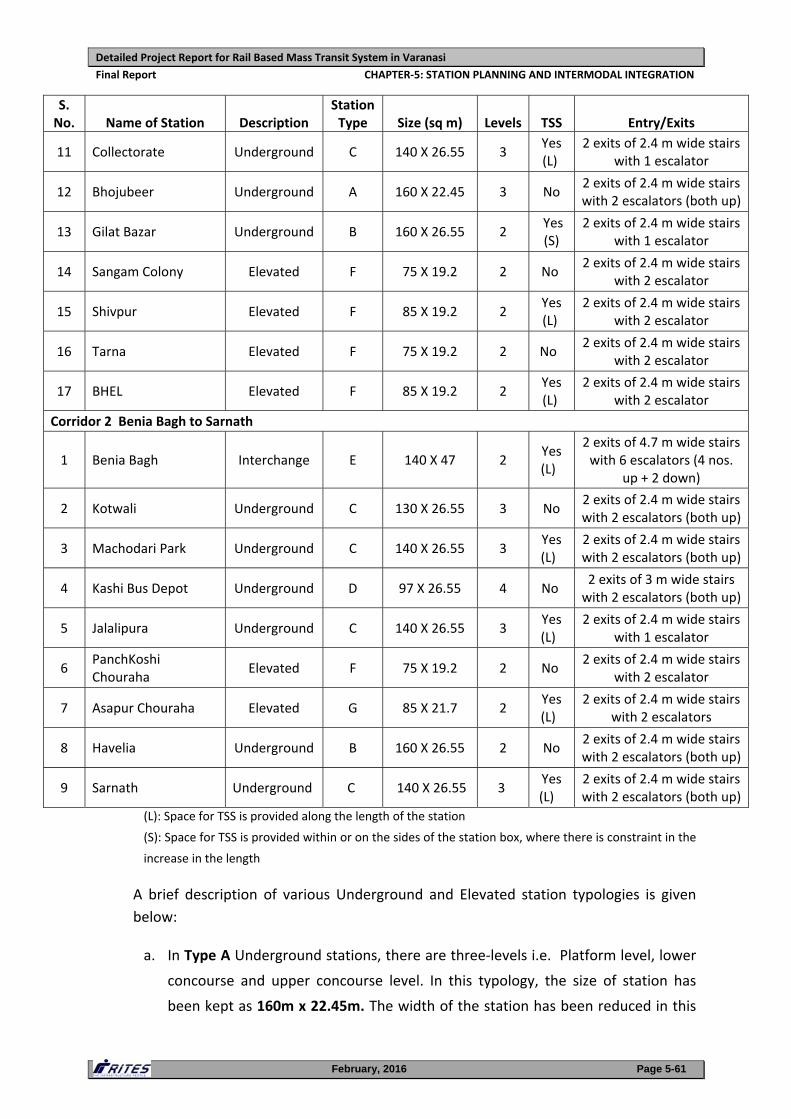
Detailed Project Report for Rail Based Mass Transit System in Varanasi
Final Report CHAPTER‐5: STATION PLANNING AND INTERMODAL INTEGRATION
February, 2016 Page 5-61
S. No. Name of Station Description
Station Type Size (sq m) Levels TSS Entry/Exits
11 Collectorate Underground C 140 X 26.55 3 Yes (L)
2 exits of 2.4 m wide stairs with 1 escalator
12 Bhojubeer Underground A 160 X 22.45 3 No 2 exits of 2.4 m wide stairs with 2 escalators (both up)
13 Gilat Bazar Underground B 160 X 26.55 2 Yes (S)
2 exits of 2.4 m wide stairs with 1 escalator
14 Sangam Colony Elevated F 75 X 19.2 2 No 2 exits of 2.4 m wide stairs
with 2 escalator
15 Shivpur Elevated F 85 X 19.2 2 Yes (L)
2 exits of 2.4 m wide stairs with 2 escalator
16 Tarna Elevated F 75 X 19.2 2 No 2 exits of 2.4 m wide stairs
with 2 escalator
17 BHEL Elevated F 85 X 19.2 2 Yes (L)
2 exits of 2.4 m wide stairs with 2 escalator
Corridor 2 Benia Bagh to Sarnath
1 Benia Bagh Interchange E 140 X 47 2 Yes (L)
2 exits of 4.7 m wide stairs with 6 escalators (4 nos.
up + 2 down)
2 Kotwali Underground C 130 X 26.55 3 No 2 exits of 2.4 m wide stairs with 2 escalators (both up)
3 Machodari Park Underground C 140 X 26.55 3 Yes (L)
2 exits of 2.4 m wide stairs with 2 escalators (both up)
4 Kashi Bus Depot Underground D 97 X 26.55 4 No 2 exits of 3 m wide stairs with 2 escalators (both up)
5 Jalalipura Underground C 140 X 26.55 3 Yes (L)
2 exits of 2.4 m wide stairs with 1 escalator
6 PanchKoshi Chouraha
Elevated F 75 X 19.2 2 No 2 exits of 2.4 m wide stairs
with 2 escalator
7 Asapur Chouraha Elevated G 85 X 21.7 2 Yes (L)
2 exits of 2.4 m wide stairs with 2 escalators
8 Havelia Underground B 160 X 26.55 2 No 2 exits of 2.4 m wide stairs with 2 escalators (both up)
9 Sarnath Underground C 140 X 26.55 3 Yes (L)
2 exits of 2.4 m wide stairs with 2 escalators (both up)
(L): Space for TSS is provided along the length of the station
(S): Space for TSS is provided within or on the sides of the station box, where there is constraint in the
increase in the length
A brief description of various Underground and Elevated station typologies is given
below:
a. In Type A Underground stations, there are three‐levels i.e. Platform level, lower
concourse and upper concourse level. In this typology, the size of station has
been kept as 160m x 22.45m. The width of the station has been reduced in this
Detailed Project Report for Rail Based Mass Transit System in Varanasi
Final Report CHAPTER‐5: STATION PLANNING AND INTERMODAL INTEGRATION
February, 2016 Page 5-62
type primarily due to space constraints to avoid any hindrance to dense
neighborhood on either side of the road under which the stations have been
proposed.
1 staircase of 3.45m width and 2 escalators have been proposed between
concourse and platform level. Platform width has been kept as 9.6m. Provision of
1 lift from concourse to platform level has been proposed.
b. In Type B Underground stations, there are two‐levels i.e. platform level and
concourse level. In this typology, the size of station has been kept as 160m x
26.55m to meet the requirement of typical 75m platform length with an option
of providing 1/2 staircases of 3.45/2.4m width and 2/4 escalators between
concourse and platform level in case of high traffic projections. Platform width
has been kept as 13m. Provision of 1 lift from concourse to platform level has
been proposed. Also, 2 large ancillary structures may be required in few stations
with high traffic in addition to the ancillary building required for Chiller plant
room and Pump Room.
c. In Type C Underground stations, there are three levels i.e. Platform level, lower
concourse and upper concourse level. In this typology, the size of station has
been kept as 130m x 26.55m primarily to ease construction and avoid hindrance
to neighboring buildings due to space constraints. 2 staircases of 2.4m width and
4 escalators have been proposed between concourse and platform level.
Platform width has been kept as 13m. Provision of 1 lift from concourse to
platform level has been proposed.
d. Type D Underground stations also comprises of four levels i.e. Platform level,
lower concourse, upper concourse and entrance level. In this typology, the size
of station has been kept as 97m x 26.55m. The length of the station has been
reduced in this type primarily due to space availability at locations (mostly parks
and open land) where these stations have been proposed. 2 staircases of 2.4m
width and 4 escalators have been proposed between upper/lower concourse and
platform level. Platform width has been kept as 13m. Provision of 1 lift from
concourse to platform level has been proposed.
e. Type E is an Interchange Underground station between Corridor 1 and Corridor 2
and a Terminal station for Corridor 2. This type of station is projected to be one
of the busiest stations due to interchange facility. There will be a large no. of
passengers interchanging between the two lines as per traffic projections. Also,
Detailed Project Report for Rail Based Mass Transit System in Varanasi
Final Report CHAPTER‐5: STATION PLANNING AND INTERMODAL INTEGRATION
February, 2016 Page 5-63
this station would accommodate the 2 entry/exits lines each from Corridor 1 and
Corridor 2. Therefore, the size of station has been kept as 140m x 47m x 3 levels.
f. The size of Type F elevated station has been kept as 75m x 19.20m where 2.4m
wide staircase is provided on one side of the platform and an escalator in up
direction is provided on other side of the same platform and provision of 2 lifts
has been proposed.
g. In Type G elevated stations, provision of 2 escalators and 1 staircase of 3.6m
width have been done on the same side of platform due to high traffic
projections. In this type, provision of only 1 lift has been proposed as dispersal at
platform level is evenly distributed. The size of Type H elevated station has been
kept as 75m x 21.70m.
Detailed description for these types has been given in Section 5.3.6.1 and 5.3.6.2.
5.3.6.1 Typical Underground Station
i. Type A ‐ 160m x 22.45m x 3 levels
The typical underground station is a three‐level station with a platform level, lower
concourse and upper concourse level. This typology where the width of station has
been kept as 22.45m with 3 levels has been developed to ease construction and
avoid hindrance and acquisition of neighbouring buildings on either sides of the
road under which these stations have been proposed.
The upper concourse level comprises of unpaid concourse, TOMs, AFC In and out
Gates, EFO and ECS plant rooms. The lower concourse level has, in addition to the
concourse, all the passenger amenities, tunnel ventilation rooms, electrical and
S&T equipment rooms, station operation areas such as Station Control Room,
Station Manager Room, Meeting Room, UPS & Battery Room, Signalling & Train
Crew Room, etc. Platform level has platforms, tracks, seepage room, sewage room,
Auxiliary Substation and similar ancillary spaces beyond the platforms on either
side. One staircase of 3.45 m width and 2 escalators have been designed from
concourse to platform to meet the traffic demands. In addition, provision of lift has
been done to bring passengers from concourse to platform level and vice versa.
Ventilation shafts, equipment hatch, entrances and chiller plants for ECS plant are
above ground structures associated with the underground station and are being
provided on the open spaces by the road side. Two entrances have been provided
to the station, one at each end. Entrances could be increased to 4 nos. as
requirements based on traffic projections and better connectivity. Structure of the
underground station is essentially a concrete box about 22.45‐m wide, 18.75m
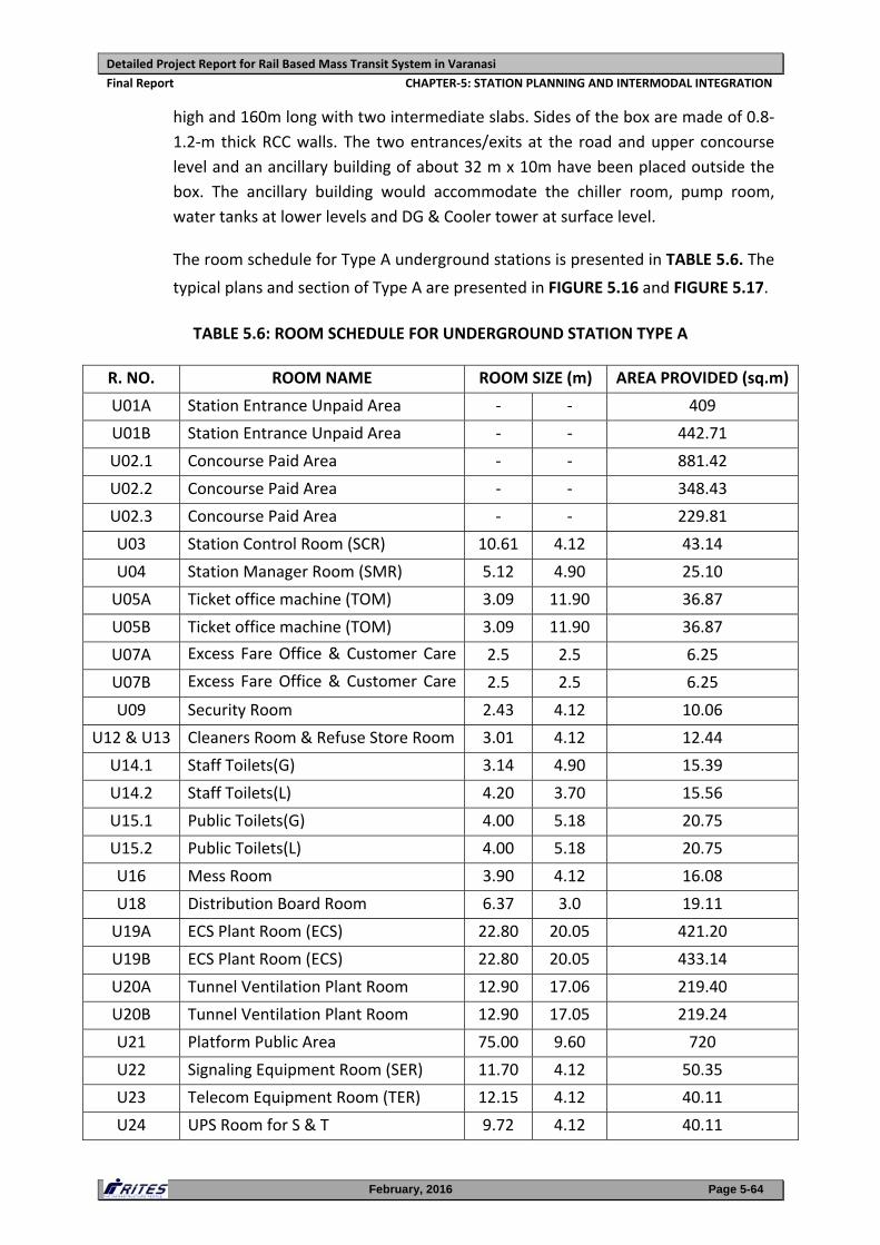
Detailed Project Report for Rail Based Mass Transit System in Varanasi
Final Report CHAPTER‐5: STATION PLANNING AND INTERMODAL INTEGRATION
February, 2016 Page 5-64
high and 160m long with two intermediate slabs. Sides of the box are made of 0.8‐
1.2‐m thick RCC walls. The two entrances/exits at the road and upper concourse
level and an ancillary building of about 32 m x 10m have been placed outside the
box. The ancillary building would accommodate the chiller room, pump room,
water tanks at lower levels and DG & Cooler tower at surface level.
The room schedule for Type A underground stations is presented in TABLE 5.6. The
typical plans and section of Type A are presented in FIGURE 5.16 and FIGURE 5.17.
TABLE 5.6: ROOM SCHEDULE FOR UNDERGROUND STATION TYPE A
R. NO. ROOM NAME ROOM SIZE (m) AREA PROVIDED (sq.m)
U01A Station Entrance Unpaid Area ‐ ‐ 409
U01B Station Entrance Unpaid Area ‐ ‐ 442.71
U02.1 Concourse Paid Area ‐ ‐ 881.42
U02.2 Concourse Paid Area ‐ ‐ 348.43
U02.3 Concourse Paid Area ‐ ‐ 229.81
U03 Station Control Room (SCR) 10.61 4.12 43.14
U04 Station Manager Room (SMR) 5.12 4.90 25.10
U05A Ticket office machine (TOM) 3.09 11.90 36.87
U05B Ticket office machine (TOM) 3.09 11.90 36.87
U07A Excess Fare Office & Customer Care 2.5 2.5 6.25
U07B Excess Fare Office & Customer Care 2.5 2.5 6.25
U09 Security Room 2.43 4.12 10.06
U12 & U13 Cleaners Room & Refuse Store Room 3.01 4.12 12.44
U14.1 Staff Toilets(G) 3.14 4.90 15.39
U14.2 Staff Toilets(L) 4.20 3.70 15.56
U15.1 Public Toilets(G) 4.00 5.18 20.75
U15.2 Public Toilets(L) 4.00 5.18 20.75
U16 Mess Room 3.90 4.12 16.08
U18 Distribution Board Room 6.37 3.0 19.11
U19A ECS Plant Room (ECS) 22.80 20.05 421.20
U19B ECS Plant Room (ECS) 22.80 20.05 433.14
U20A Tunnel Ventilation Plant Room 12.90 17.06 219.40
U20B Tunnel Ventilation Plant Room 12.90 17.05 219.24
U21 Platform Public Area 75.00 9.60 720
U22 Signaling Equipment Room (SER) 11.70 4.12 50.35
U23 Telecom Equipment Room (TER) 12.15 4.12 40.11
U24 UPS Room for S & T 9.72 4.12 40.11
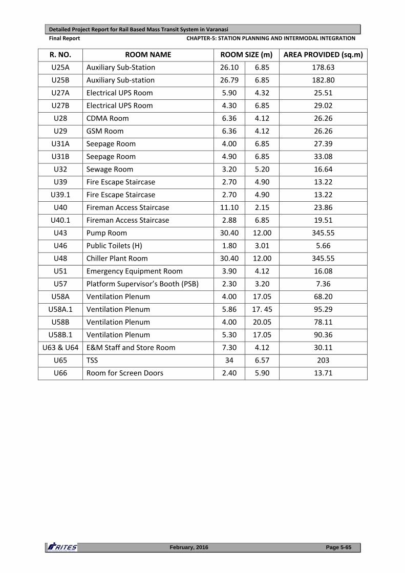
Detailed Project Report for Rail Based Mass Transit System in Varanasi
Final Report CHAPTER‐5: STATION PLANNING AND INTERMODAL INTEGRATION
February, 2016 Page 5-65
R. NO. ROOM NAME ROOM SIZE (m) AREA PROVIDED (sq.m)
U25A Auxiliary Sub‐Station 26.10 6.85 178.63
U25B Auxiliary Sub‐station 26.79 6.85 182.80
U27A Electrical UPS Room 5.90 4.32 25.51
U27B Electrical UPS Room 4.30 6.85 29.02
U28 CDMA Room 6.36 4.12 26.26
U29 GSM Room 6.36 4.12 26.26
U31A Seepage Room 4.00 6.85 27.39
U31B Seepage Room 4.90 6.85 33.08
U32 Sewage Room 3.20 5.20 16.64
U39 Fire Escape Staircase 2.70 4.90 13.22
U39.1 Fire Escape Staircase 2.70 4.90 13.22
U40 Fireman Access Staircase 11.10 2.15 23.86
U40.1 Fireman Access Staircase 2.88 6.85 19.51
U43 Pump Room 30.40 12.00 345.55
U46 Public Toilets (H) 1.80 3.01 5.66
U48 Chiller Plant Room 30.40 12.00 345.55
U51 Emergency Equipment Room 3.90 4.12 16.08
U57 Platform Supervisor’s Booth (PSB) 2.30 3.20 7.36
U58A Ventilation Plenum 4.00 17.05 68.20
U58A.1 Ventilation Plenum 5.86 17. 45 95.29
U58B Ventilation Plenum 4.00 20.05 78.11
U58B.1 Ventilation Plenum 5.30 17.05 90.36
U63 & U64 E&M Staff and Store Room 7.30 4.12 30.11
U65 TSS 34 6.57 203
U66 Room for Screen Doors 2.40 5.90 13.71
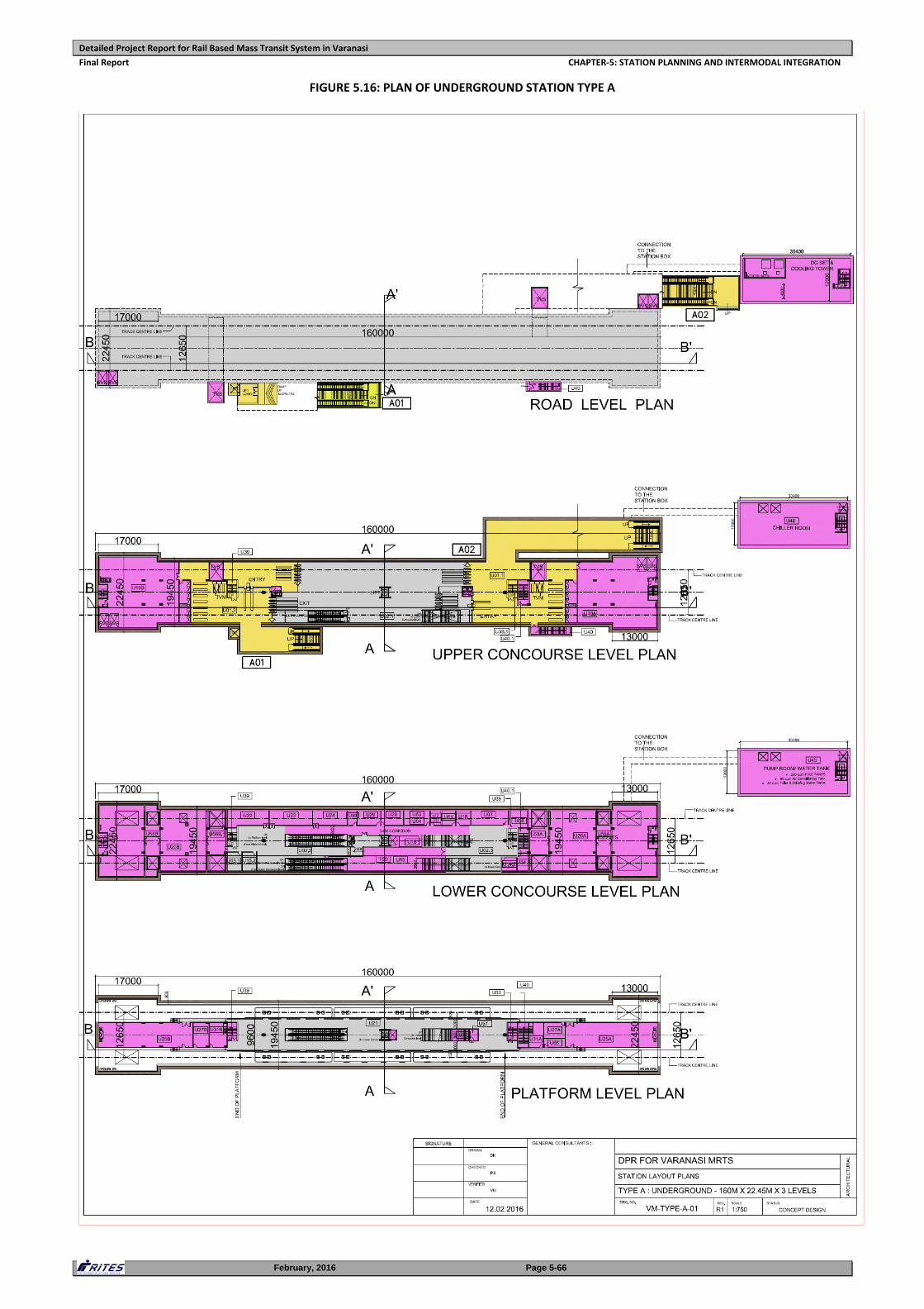
Detailed Project Report for Rail Based Mass Transit System in Varanasi
Final Report CHAPTER‐5: STATION PLANNING AND INTERMODAL INTEGRATION
February, 2016 Page 5-66
FIGURE 5.16: PLAN OF UNDERGROUND STATION TYPE A
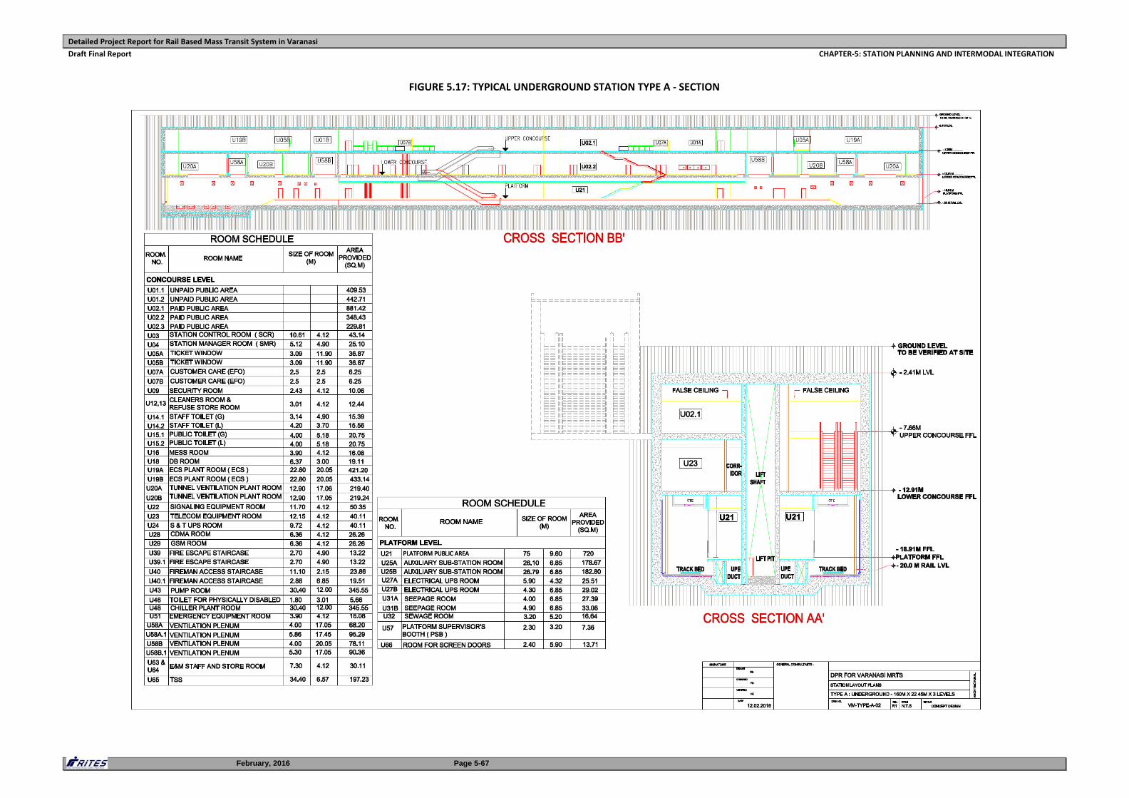
Detailed Project Report for Rail Based Mass Transit System in Varanasi
Draft Final Report CHAPTER‐5: STATION PLANNING AND INTERMODAL INTEGRATION
February, 2016 Page 5-67
FIGURE 5.17: TYPICAL UNDERGROUND STATION TYPE A ‐ SECTION
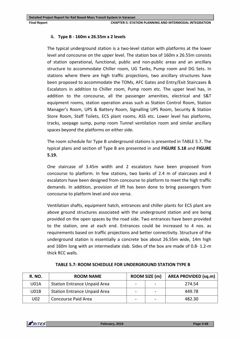
Detailed Project Report for Rail Based Mass Transit System in Varanasi
Final Report CHAPTER‐5: STATION PLANNING AND INTERMODAL INTEGRATION
February, 2016 Page 5-68
ii. Type B ‐ 160m x 26.55m x 2 levels
The typical underground station is a two‐level station with platforms at the lower
level and concourse on the upper level. The station box of 160m x 26.55m consists
of station operational, functional, public and non‐public areas and an ancillary
structure to accommodate Chiller room, UG Tanks, Pump room and DG Sets. In
stations where there are high traffic projections, two ancillary structures have
been proposed to accommodate the TOMs, AFC Gates and Entry/Exit Staircases &
Escalators in addition to Chiller room, Pump room etc. The upper level has, in
addition to the concourse, all the passenger amenities, electrical and S&T
equipment rooms, station operation areas such as Station Control Room, Station
Manager’s Room, UPS & Battery Room, Signalling UPS Room, Security & Station
Store Room, Staff Toilets, ECS plant rooms, ASS etc. Lower level has platforms,
tracks, seepage sump, pump room Tunnel ventilation room and similar ancillary
spaces beyond the platforms on either side.
The room schedule for Type B underground stations is presented in TABLE 5.7. The
typical plans and section of Type B are presented in and FIGURE 5.18 and FIGURE
5.19.
One staircase of 3.45m width and 2 escalators have been proposed from
concourse to platform. In few stations, two banks of 2.4 m of staircases and 4
escalators have been designed from concourse to platform to meet the high traffic
demands. In addition, provision of lift has been done to bring passengers from
concourse to platform level and vice versa.
Ventilation shafts, equipment hatch, entrances and chiller plants for ECS plant are
above ground structures associated with the underground station and are being
provided on the open spaces by the road side. Two entrances have been provided
to the station, one at each end. Entrances could be increased to 4 nos. as
requirements based on traffic projections and better connectivity. Structure of the
underground station is essentially a concrete box about 26.55m wide, 14m high
and 160m long with an intermediate slab. Sides of the box are made of 0.8‐ 1.2‐m
thick RCC walls.
TABLE 5.7: ROOM SCHEDULE FOR UNDERGROUND STATION TYPE B
R. NO. ROOM NAME ROOM SIZE (m) AREA PROVIDED (sq.m)
U01A Station Entrance Unpaid Area ‐ ‐ 274.54
U01B Station Entrance Unpaid Area ‐ ‐ 449.78
U02 Concourse Paid Area ‐ ‐ 482.30
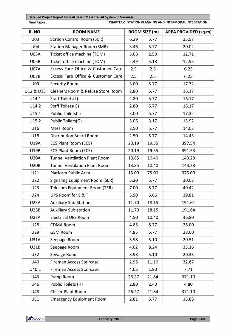
Detailed Project Report for Rail Based Mass Transit System in Varanasi
Final Report CHAPTER‐5: STATION PLANNING AND INTERMODAL INTEGRATION
February, 2016 Page 5-69
R. NO. ROOM NAME ROOM SIZE (m) AREA PROVIDED (sq.m)
U03 Station Control Room (SCR) 6.29 5.77 35.97
U04 Station Manager Room (SMR) 3.46 5.77 20.02
U05A Ticket office machine (TOM) 5.08 2.50 12.71
U05B Ticket office machine (TOM) 2.49 5.18 12.95
U07A Excess Fare Office & Customer Care 2.5 2.5 6.25
U07B Excess Fare Office & Customer Care 2.5 2.5 6.25
U09 Security Room 3.00 5.77 17.32
U12 & U13 Cleaners Room & Refuse Store Room 2.80 5.77 16.17
U14.1 Staff Toilets(L) 2.80 5.77 16.17
U14.2 Staff Toilets(G) 2.80 5.77 16.17
U15.1 Public Toilets(L) 3.00 5.77 17.32
U15.2 Public Toilets(G) 5.06 3.17 15.92
U16 Mess Room 2.50 5.77 14.03
U18 Distribution Board Room 2.50 5.77 14.43
U19A ECS Plant Room (ECS) 20.19 19.55 397.54
U19B ECS Plant Room (ECS) 20.19 19.55 391.53
U20A Tunnel Ventilation Plant Room 13.85 10.40 143.28
U20B Tunnel Ventilation Plant Room 13.85 10.40 143.28
U21 Platform Public Area 13.00 75.00 975.00
U22 Signaling Equipment Room (SER) 5.20 5.77 30.03
U23 Telecom Equipment Room (TER) 7.00 5.77 40.42
U24 UPS Room for S & T 5.90 6.66 39.81
U25A Auxiliary Sub‐Station 11.70 18.15 191.61
U25B Auxiliary Sub‐station 11.70 18.15 191.64
U27A Electrical UPS Room 4.50 10.40 46.80
U28 CDMA Room 4.85 5.77 28.00
U29 GSM Room 4.85 5.77 28.00
U31A Seepage Room 3.98 5.10 20.51
U31B Seepage Room 4.02 8.24 33.16
U32 Sewage Room 3.98 5.10 20.33
U40 Fireman Access Staircase 2.96 11.10 32.87
U40.1 Fireman Access Staircase 4.05 1.90 7.71
U43 Pump Room 26.27 21.84 371.10
U46 Public Toilets (H) 2.80 2.40 4.80
U48 Chiller Plant Room 26.27 21.84 371.10
U51 Emergency Equipment Room 2.81 5.77 15.88
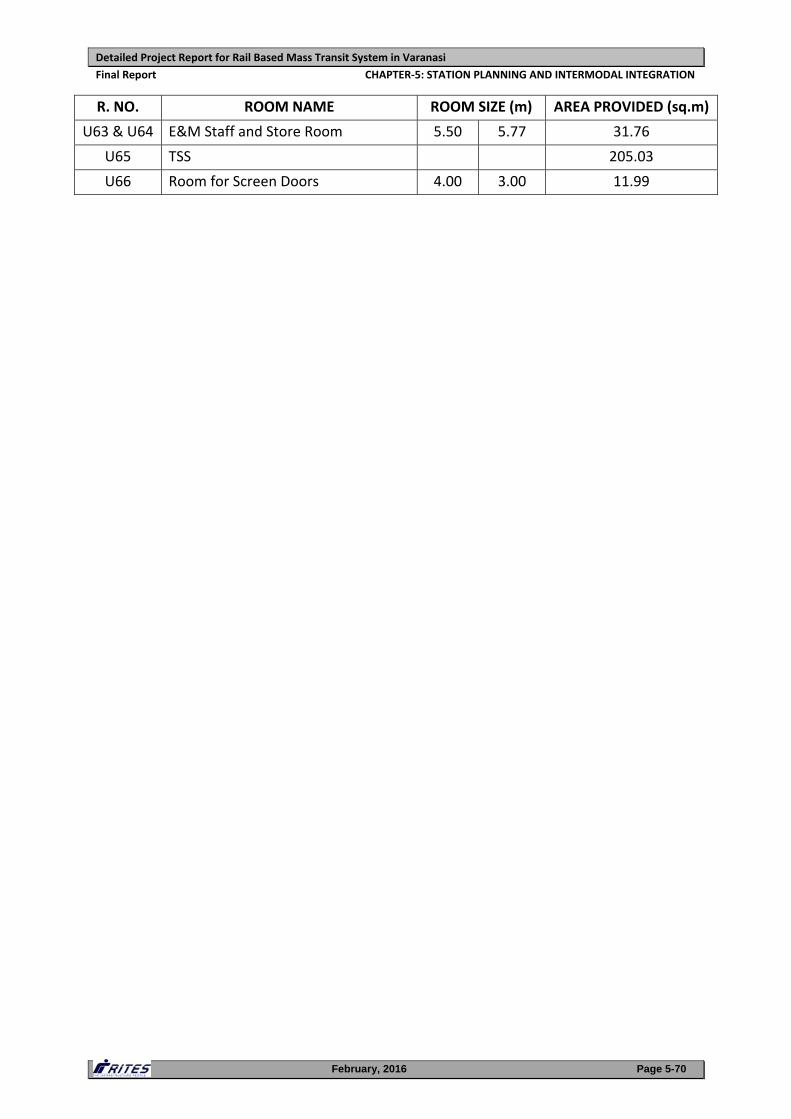
Detailed Project Report for Rail Based Mass Transit System in Varanasi
Final Report CHAPTER‐5: STATION PLANNING AND INTERMODAL INTEGRATION
February, 2016 Page 5-70
R. NO. ROOM NAME ROOM SIZE (m) AREA PROVIDED (sq.m)
U63 & U64 E&M Staff and Store Room 5.50 5.77 31.76
U65 TSS 205.03
U66 Room for Screen Doors 4.00 3.00 11.99
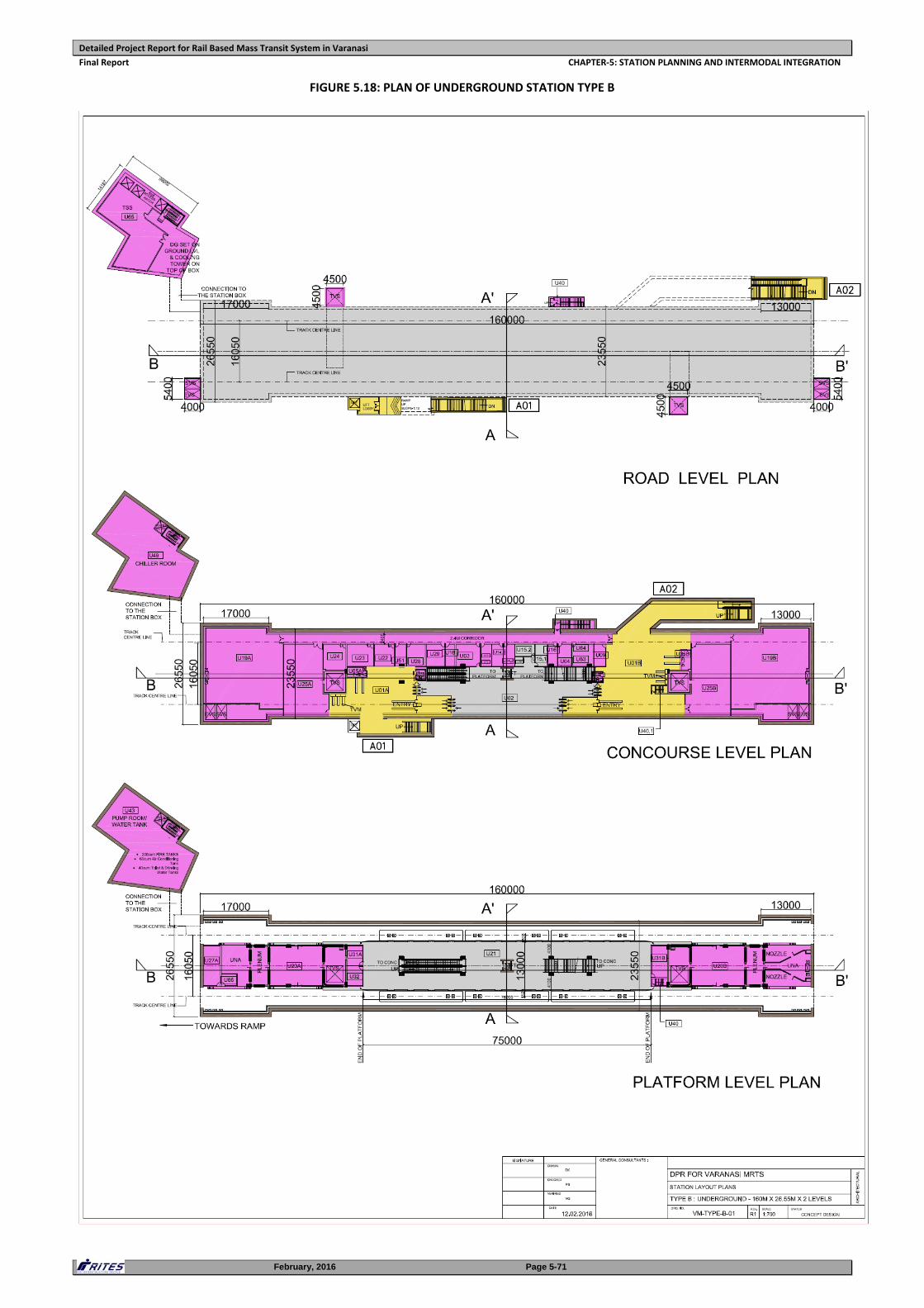
Detailed Project Report for Rail Based Mass Transit System in Varanasi
Final Report CHAPTER‐5: STATION PLANNING AND INTERMODAL INTEGRATION
February, 2016 Page 5-71
FIGURE 5.18: PLAN OF UNDERGROUND STATION TYPE B
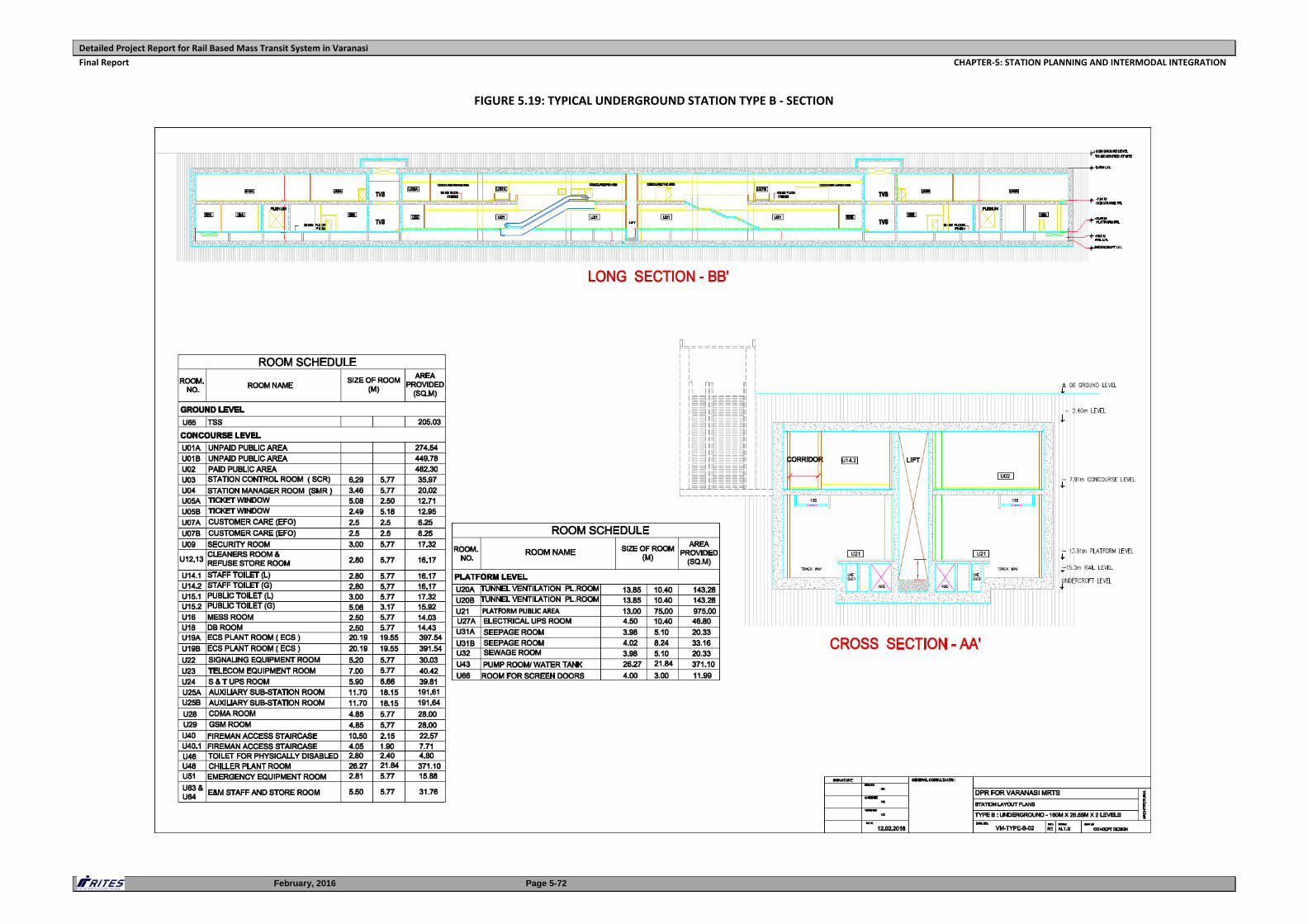
Detailed Project Report for Rail Based Mass Transit System in Varanasi
Final Report CHAPTER‐5: STATION PLANNING AND INTERMODAL INTEGRATION
February, 2016 Page 5-72
FIGURE 5.19: TYPICAL UNDERGROUND STATION TYPE B ‐ SECTION
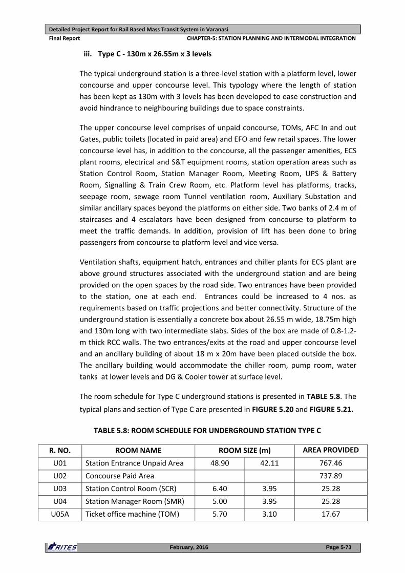
Detailed Project Report for Rail Based Mass Transit System in Varanasi
Final Report CHAPTER‐5: STATION PLANNING AND INTERMODAL INTEGRATION
February, 2016 Page 5-73
iii. Type C ‐ 130m x 26.55m x 3 levels
The typical underground station is a three‐level station with a platform level, lower
concourse and upper concourse level. This typology where the length of station
has been kept as 130m with 3 levels has been developed to ease construction and
avoid hindrance to neighbouring buildings due to space constraints.
The upper concourse level comprises of unpaid concourse, TOMs, AFC In and out
Gates, public toilets (located in paid area) and EFO and few retail spaces. The lower
concourse level has, in addition to the concourse, all the passenger amenities, ECS
plant rooms, electrical and S&T equipment rooms, station operation areas such as
Station Control Room, Station Manager Room, Meeting Room, UPS & Battery
Room, Signalling & Train Crew Room, etc. Platform level has platforms, tracks,
seepage room, sewage room Tunnel ventilation room, Auxiliary Substation and
similar ancillary spaces beyond the platforms on either side. Two banks of 2.4 m of
staircases and 4 escalators have been designed from concourse to platform to
meet the traffic demands. In addition, provision of lift has been done to bring
passengers from concourse to platform level and vice versa.
Ventilation shafts, equipment hatch, entrances and chiller plants for ECS plant are
above ground structures associated with the underground station and are being
provided on the open spaces by the road side. Two entrances have been provided
to the station, one at each end. Entrances could be increased to 4 nos. as
requirements based on traffic projections and better connectivity. Structure of the
underground station is essentially a concrete box about 26.55 m wide, 18.75m high
and 130m long with two intermediate slabs. Sides of the box are made of 0.8‐1.2‐
m thick RCC walls. The two entrances/exits at the road and upper concourse level
and an ancillary building of about 18 m x 20m have been placed outside the box.
The ancillary building would accommodate the chiller room, pump room, water
tanks at lower levels and DG & Cooler tower at surface level.
The room schedule for Type C underground stations is presented in TABLE 5.8. The
typical plans and section of Type C are presented in FIGURE 5.20 and FIGURE 5.21.
TABLE 5.8: ROOM SCHEDULE FOR UNDERGROUND STATION TYPE C
R. NO. ROOM NAME ROOM SIZE (m) AREA PROVIDED
U01 Station Entrance Unpaid Area 48.90 42.11 767.46
U02 Concourse Paid Area 737.89
U03 Station Control Room (SCR) 6.40 3.95 25.28
U04 Station Manager Room (SMR) 5.00 3.95 25.28
U05A Ticket office machine (TOM) 5.70 3.10 17.67
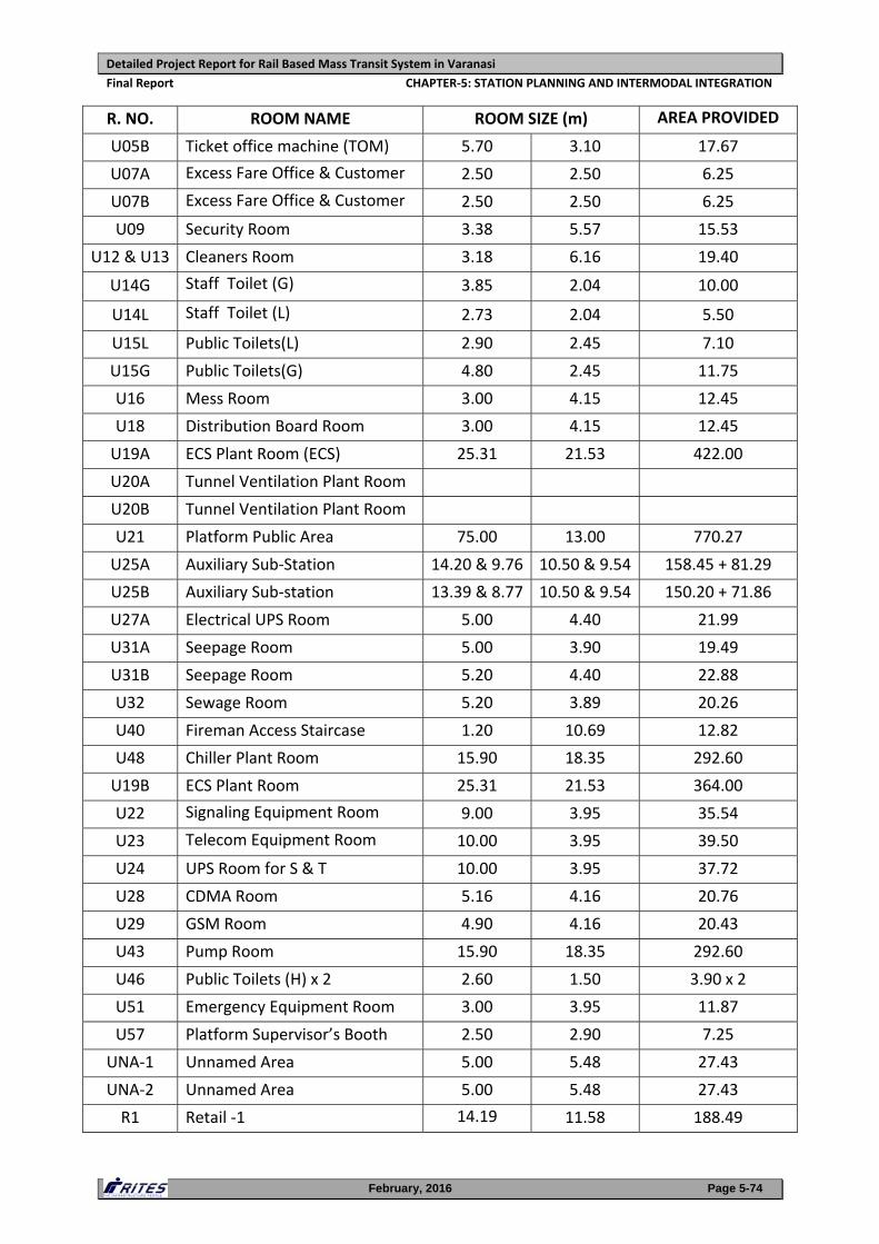
Detailed Project Report for Rail Based Mass Transit System in Varanasi
Final Report CHAPTER‐5: STATION PLANNING AND INTERMODAL INTEGRATION
February, 2016 Page 5-74
R. NO. ROOM NAME ROOM SIZE (m) AREA PROVIDED
U05B Ticket office machine (TOM) 5.70 3.10 17.67
U07A Excess Fare Office & Customer 2.50 2.50 6.25
U07B Excess Fare Office & Customer 2.50 2.50 6.25
U09 Security Room 3.38 5.57 15.53
U12 & U13 Cleaners Room 3.18 6.16 19.40
U14G Staff Toilet (G) 3.85 2.04 10.00
U14L Staff Toilet (L) 2.73 2.04 5.50
U15L Public Toilets(L) 2.90 2.45 7.10
U15G Public Toilets(G) 4.80 2.45 11.75
U16 Mess Room 3.00 4.15 12.45
U18 Distribution Board Room 3.00 4.15 12.45
U19A ECS Plant Room (ECS) 25.31 21.53 422.00
U20A Tunnel Ventilation Plant Room
U20B Tunnel Ventilation Plant Room
U21 Platform Public Area 75.00 13.00 770.27
U25A Auxiliary Sub‐Station 14.20 & 9.76 10.50 & 9.54 158.45 + 81.29
U25B Auxiliary Sub‐station 13.39 & 8.77 10.50 & 9.54 150.20 + 71.86
U27A Electrical UPS Room 5.00 4.40 21.99
U31A Seepage Room 5.00 3.90 19.49
U31B Seepage Room 5.20 4.40 22.88
U32 Sewage Room 5.20 3.89 20.26
U40 Fireman Access Staircase 1.20 10.69 12.82
U48 Chiller Plant Room 15.90 18.35 292.60
U19B ECS Plant Room 25.31 21.53 364.00
U22 Signaling Equipment Room 9.00 3.95 35.54
U23 Telecom Equipment Room 10.00 3.95 39.50
U24 UPS Room for S & T 10.00 3.95 37.72
U28 CDMA Room 5.16 4.16 20.76
U29 GSM Room 4.90 4.16 20.43
U43 Pump Room 15.90 18.35 292.60
U46 Public Toilets (H) x 2 2.60 1.50 3.90 x 2
U51 Emergency Equipment Room 3.00 3.95 11.87
U57 Platform Supervisor’s Booth 2.50 2.90 7.25
UNA‐1 Unnamed Area 5.00 5.48 27.43
UNA‐2 Unnamed Area 5.00 5.48 27.43
R1 Retail ‐1 14.19 11.58 188.49
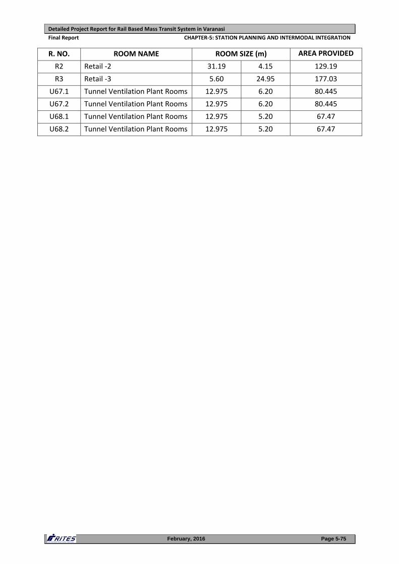
Detailed Project Report for Rail Based Mass Transit System in Varanasi
Final Report CHAPTER‐5: STATION PLANNING AND INTERMODAL INTEGRATION
February, 2016 Page 5-75
R. NO. ROOM NAME ROOM SIZE (m) AREA PROVIDED
R2 Retail ‐2 31.19 4.15 129.19
R3 Retail ‐3 5.60 24.95 177.03
U67.1 Tunnel Ventilation Plant Rooms 12.975 6.20 80.445
U67.2 Tunnel Ventilation Plant Rooms 12.975 6.20 80.445
U68.1 Tunnel Ventilation Plant Rooms 12.975 5.20 67.47
U68.2 Tunnel Ventilation Plant Rooms 12.975 5.20 67.47
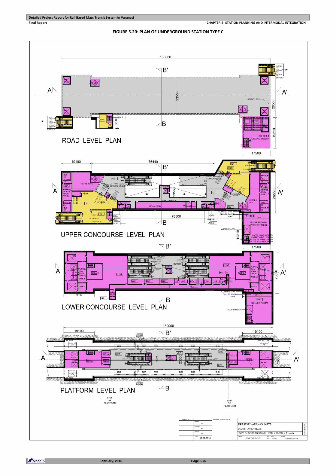
Detailed Project Report for Rail Based Mass Transit System in Varanasi
Final Report CHAPTER‐5: STATION PLANNING AND INTERMODAL INTEGRATION
February, 2016 Page 5-76
FIGURE 5.20: PLAN OF UNDERGROUND STATION TYPE C
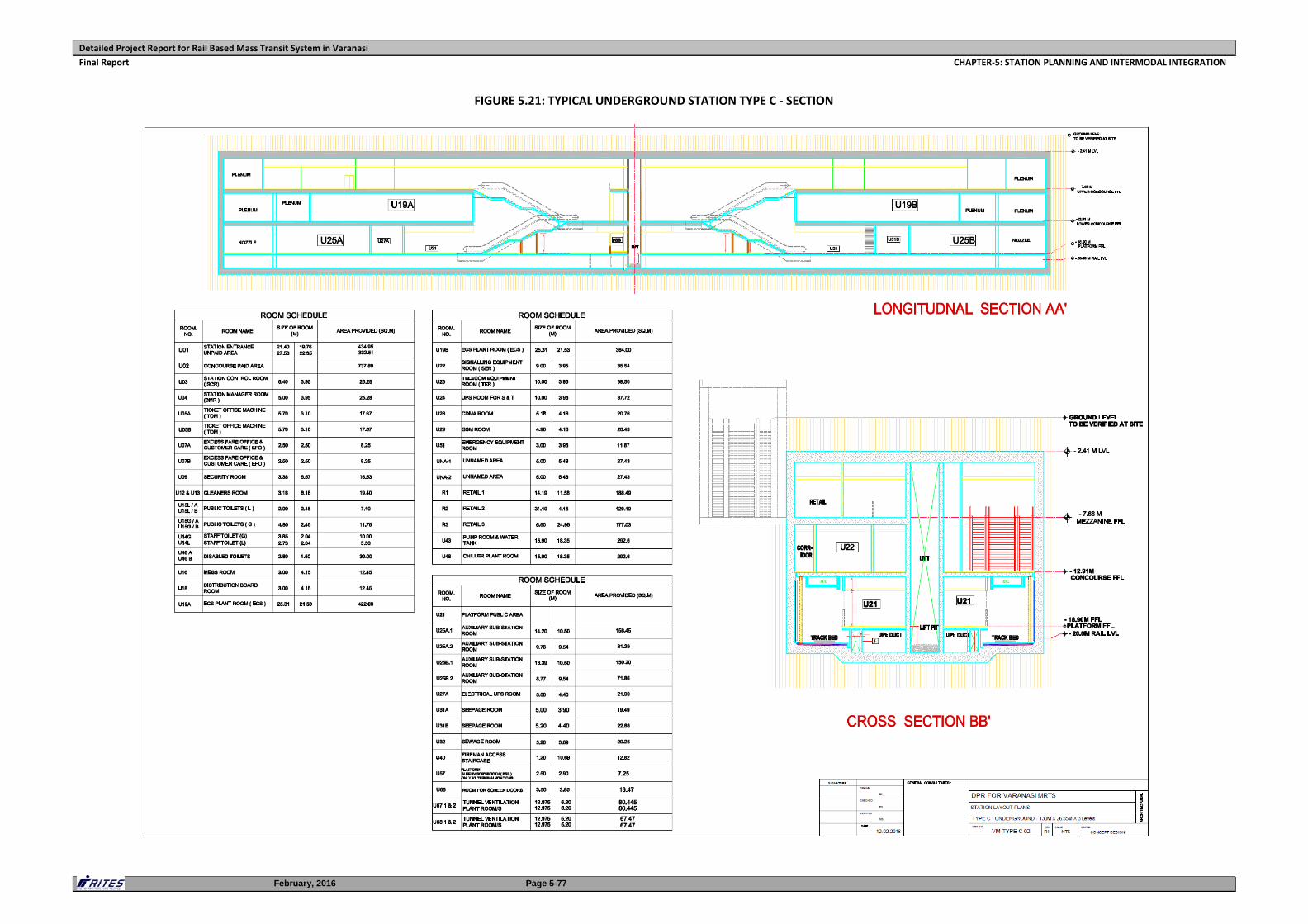
Detailed Project Report for Rail Based Mass Transit System in Varanasi
Final Report CHAPTER‐5: STATION PLANNING AND INTERMODAL INTEGRATION
February, 2016 Page 5-77
FIGURE 5.21: TYPICAL UNDERGROUND STATION TYPE C ‐ SECTION
Detailed Project Report for Rail Based Mass Transit System in Varanasi
Final Report CHAPTER‐5: STATION PLANNING AND INTERMODAL INTEGRATION
February, 2016 Page 5-78
iv. Type D ‐ 97m x 26.55m x 4 levels
This typical underground station is also a four‐level station with a platform level,
lower concourse, upper concourse level and an Entrance level. This typology where
the length of station is reduced to 97m has been developed to accommodate the
stations in the available space (mostly open land and parks) and to avoid hindrance
and acquisition of neighbouring buildings.
The Entrance level is proposed at road level and comprises of unpaid Concourse,
TOMs, AFC In and Out Gates and EFO with staircases and escalators leading to
upper concourse level. The upper concourse level comprises of paid concourse,
public toilets (located in paid area), ASS, TSS (at every third station), Transformer
Rooms, E & M Staff room and Store and ECS Plant Rooms, . The lower concourse
level has all the passenger amenities i.e. electrical and S&T equipment rooms,
station operation areas such as Station Control Room, Station Manager Room,
Meeting Room, UPS & Battery Room, Signalling & Train Crew Room, Staff Toilets
etc. Platform level has platforms, tracks, seepage room, sewage room Tunnel
ventilation room, Electrical UPS Room and similar ancillary spaces beyond the
platforms on either side. Two banks of 2.4 m of staircases and 4 escalators have
been designed from concourse to platform to meet the traffic demands. In
addition, provision of lift has been done to bring passengers from concourse to
platform level and vice versa.
Ventilation shafts, equipment hatch, entrances and chiller plants for ECS plant are
above ground structures associated with the underground station and are being
provided on the open spaces by the road side. Two entrances have been provided
to the station, one at each end. Structure of the underground station is essentially
a concrete box about 26.55‐m wide, 18.75m high and 97m long with three
intermediate slabs. Sides of the box are made of 0.8‐1.2‐m thick RCC walls. The
two entrances/exits at the Entrance level and an ancillary building of about 11 m x
35m have been placed outside the box. The ancillary building would accommodate
the chiller room, pump room, water tanks at lower levels and DG & Cooler tower at
surface level.
The room schedule for Type D underground stations is presented in TABLE 5.9 .
The typical plans and section of Type D are presented in FIGURE 5.22 and FIGURE
5.23 .
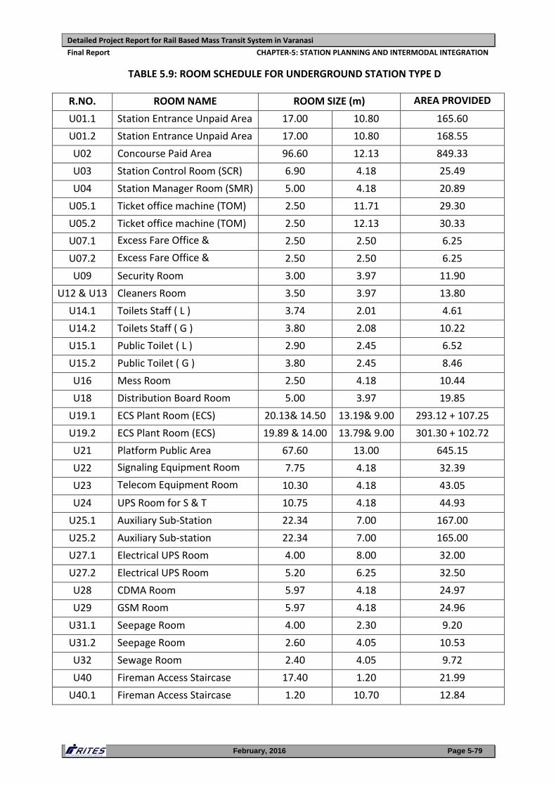
Detailed Project Report for Rail Based Mass Transit System in Varanasi
Final Report CHAPTER‐5: STATION PLANNING AND INTERMODAL INTEGRATION
February, 2016 Page 5-79
TABLE 5.9: ROOM SCHEDULE FOR UNDERGROUND STATION TYPE D
R.NO. ROOM NAME ROOM SIZE (m) AREA PROVIDED
U01.1 Station Entrance Unpaid Area 17.00 10.80 165.60
U01.2 Station Entrance Unpaid Area 17.00 10.80 168.55
U02 Concourse Paid Area 96.60 12.13 849.33
U03 Station Control Room (SCR) 6.90 4.18 25.49
U04 Station Manager Room (SMR) 5.00 4.18 20.89
U05.1 Ticket office machine (TOM) 2.50 11.71 29.30
U05.2 Ticket office machine (TOM) 2.50 12.13 30.33
U07.1 Excess Fare Office & 2.50 2.50 6.25
U07.2 Excess Fare Office & 2.50 2.50 6.25
U09 Security Room 3.00 3.97 11.90
U12 & U13 Cleaners Room 3.50 3.97 13.80
U14.1 Toilets Staff ( L ) 3.74 2.01 4.61
U14.2 Toilets Staff ( G ) 3.80 2.08 10.22
U15.1 Public Toilet ( L ) 2.90 2.45 6.52
U15.2 Public Toilet ( G ) 3.80 2.45 8.46
U16 Mess Room 2.50 4.18 10.44
U18 Distribution Board Room 5.00 3.97 19.85
U19.1 ECS Plant Room (ECS) 20.13& 14.50 13.19& 9.00 293.12 + 107.25
U19.2 ECS Plant Room (ECS) 19.89 & 14.00 13.79& 9.00 301.30 + 102.72
U21 Platform Public Area 67.60 13.00 645.15
U22 Signaling Equipment Room 7.75 4.18 32.39
U23 Telecom Equipment Room 10.30 4.18 43.05
U24 UPS Room for S & T 10.75 4.18 44.93
U25.1 Auxiliary Sub‐Station 22.34 7.00 167.00
U25.2 Auxiliary Sub‐station 22.34 7.00 165.00
U27.1 Electrical UPS Room 4.00 8.00 32.00
U27.2 Electrical UPS Room 5.20 6.25 32.50
U28 CDMA Room 5.97 4.18 24.97
U29 GSM Room 5.97 4.18 24.96
U31.1 Seepage Room 4.00 2.30 9.20
U31.2 Seepage Room 2.60 4.05 10.53
U32 Sewage Room 2.40 4.05 9.72
U40 Fireman Access Staircase 17.40 1.20 21.99
U40.1 Fireman Access Staircase 1.20 10.70 12.84
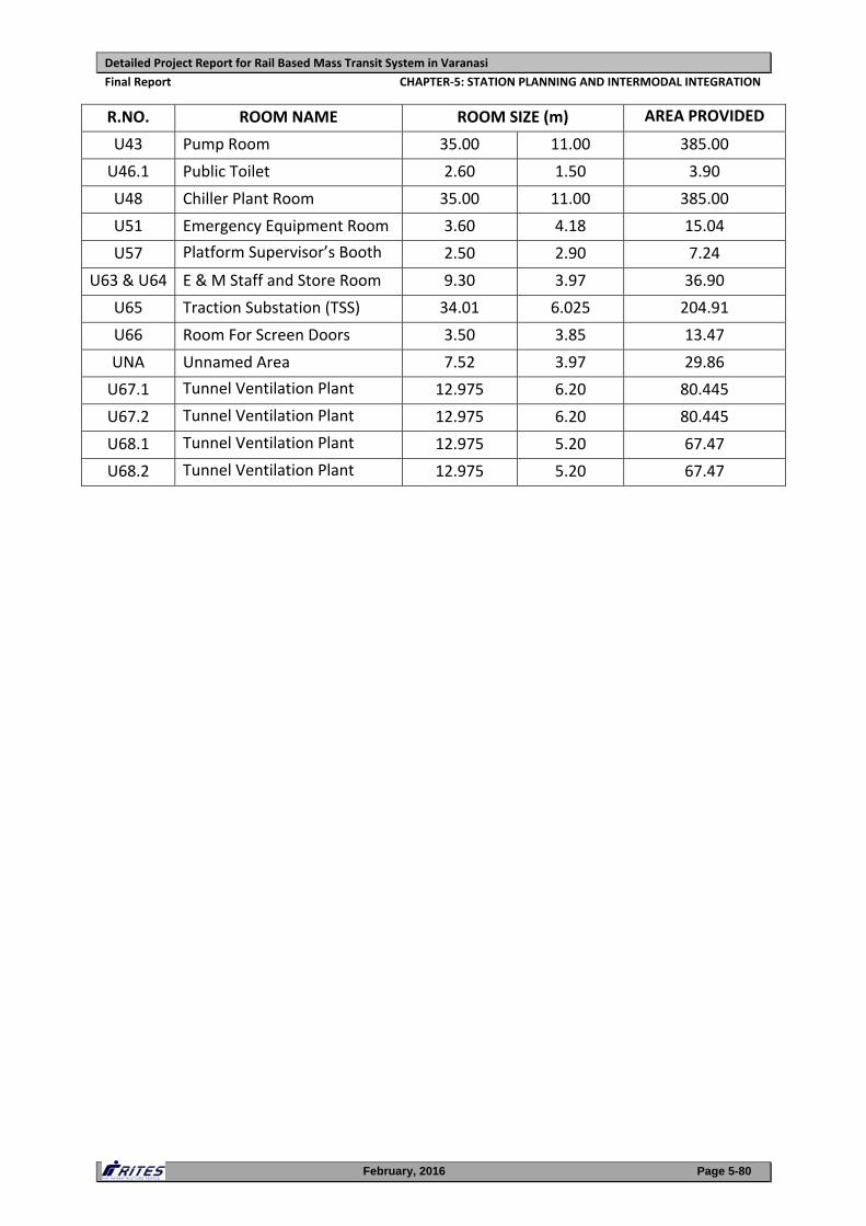
Detailed Project Report for Rail Based Mass Transit System in Varanasi
Final Report CHAPTER‐5: STATION PLANNING AND INTERMODAL INTEGRATION
February, 2016 Page 5-80
R.NO. ROOM NAME ROOM SIZE (m) AREA PROVIDED
U43 Pump Room 35.00 11.00 385.00
U46.1 Public Toilet 2.60 1.50 3.90
U48 Chiller Plant Room 35.00 11.00 385.00
U51 Emergency Equipment Room 3.60 4.18 15.04
U57 Platform Supervisor’s Booth 2.50 2.90 7.24
U63 & U64 E & M Staff and Store Room 9.30 3.97 36.90
U65 Traction Substation (TSS) 34.01 6.025 204.91
U66 Room For Screen Doors 3.50 3.85 13.47
UNA Unnamed Area 7.52 3.97 29.86
U67.1 Tunnel Ventilation Plant 12.975 6.20 80.445
U67.2 Tunnel Ventilation Plant 12.975 6.20 80.445
U68.1 Tunnel Ventilation Plant 12.975 5.20 67.47
U68.2 Tunnel Ventilation Plant 12.975 5.20 67.47
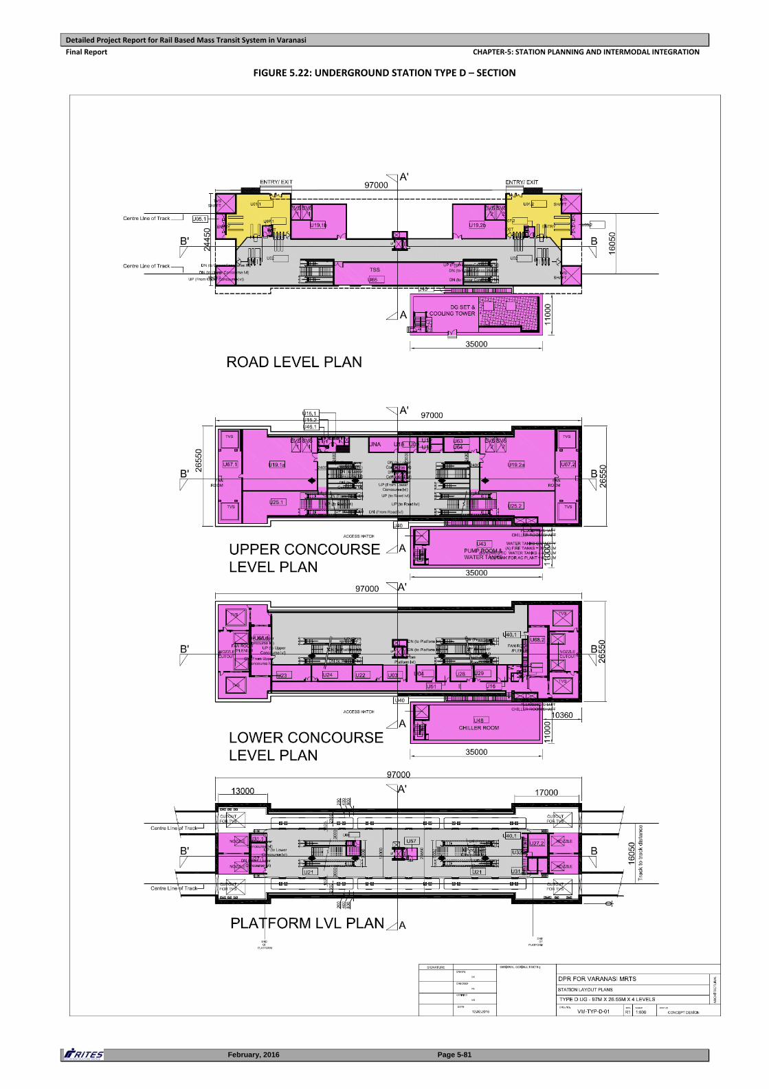
Detailed Project Report for Rail Based Mass Transit System in Varanasi
Final Report CHAPTER‐5: STATION PLANNING AND INTERMODAL INTEGRATION
February, 2016 Page 5-81
FIGURE 5.22: UNDERGROUND STATION TYPE D – SECTION
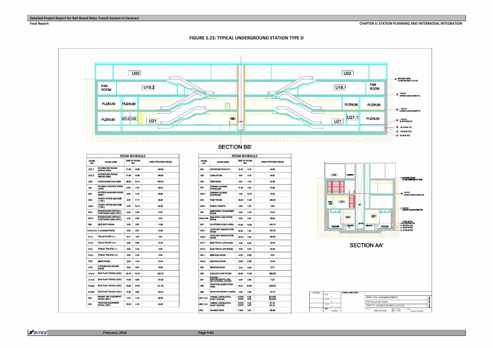
Detailed Project Report for Rail Based Mass Transit System in Varanasi
Final Report CHAPTER‐5: STATION PLANNING AND INTERMODAL INTEGRATION
February, 2016 Page 5-82
FIGURE 5.23: TYPICAL UNDERGROUND STATION TYPE D
Detailed Project Report for Rail Based Mass Transit System in Varanasi
Final Report CHAPTER‐5: STATION PLANNING AND INTERMODAL INTEGRATION
February, 2016 Page 5-83
v. Type E – 130m x 47m x 3 levels (Interchange station)
The underground station is an Interchange station between Corridor 1 and
Corridor 2 with a Terminal station for Corridor 2. This type of station is projected to
be one of the busiest stations due to interchange facility. There will be a large no.
of passengers interchanging between the two lines. Also, this station would
accommodate the 2 entry and 2 exit lines, each from Corridor 1 and Corridor 2.
Therefore, the size of station has been kept as 140m x 47m x 3 levels.
Two options were considered at the time of station planning for Benia Bagh which
are as follows:
Option 1: 2 central island platforms facilitating the interchange of passengers
between the two corridors through the concourse level only. As this option permits
construction of approach tunnels and junction where two approach tunnels meet
through TBM, it is preferred and adopted.
Option 2: 2 side platforms and 1 central island platform facilitating the interchange
of passengers coming from Sarnath and going towards BHU through the same
platform. The interchange of passengers in all other 3 directions will be through
concourse only. However, this option has not been considered due to construction
of tunnels/junction where two tunnels meet through cut and cover method
thereby leading to acquisition of lot of private land surrounding the Benia Bagh
park. Therefore, to avoid land acquisition issues Option 1 is considered to be
developed in detail.
Passengers have to enter the unpaid concourses and thereafter enter the common
paid area for going down to the two island platforms. There are island platforms
proposed to enable transfer of passengers between entry/exit lines of Corridor 1
from BHEL and entry/exit lines of Corridor 2 from Havelia/Sarnath. The entry/exit
lines to BHEL and Havelia/Sarnath are also planned with an island platform where
passengers could use the interchange facility by going up to Concourse level and
then climbing down to the platform level on other side. The station is provided
with 3 entry/exits planned to cater to passenger traffic from all directions. As the
station is proposed within the park and planned at 3 levels + ground level where
few operational services areas are located and remaining space has been
dedicated to Retail. It is also envisaged that the upper floors of the station could be
developed as a Commercial cum Retail Hub with parking facilities in front of the
station main entrance in portion of the park.
Vertical circulation, in the form of two sets of, adequately sized, stairs and
escalators have been provided in the centre of the two island platforms to cater to
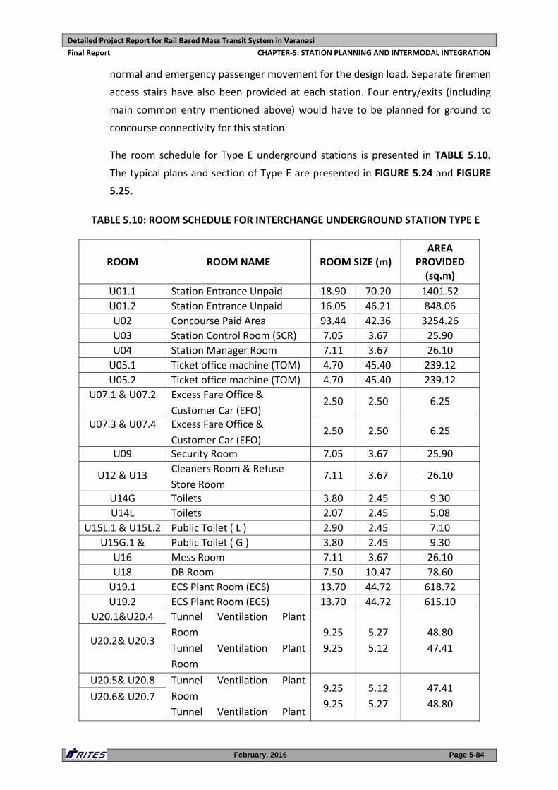
Detailed Project Report for Rail Based Mass Transit System in Varanasi
Final Report CHAPTER‐5: STATION PLANNING AND INTERMODAL INTEGRATION
February, 2016 Page 5-84
normal and emergency passenger movement for the design load. Separate firemen
access stairs have also been provided at each station. Four entry/exits (including
main common entry mentioned above) would have to be planned for ground to
concourse connectivity for this station.
The room schedule for Type E underground stations is presented in TABLE 5.10.
The typical plans and section of Type E are presented in FIGURE 5.24 and FIGURE
5.25.
TABLE 5.10: ROOM SCHEDULE FOR INTERCHANGE UNDERGROUND STATION TYPE E
ROOM ROOM NAME ROOM SIZE (m) AREA
PROVIDED (sq.m)
U01.1 Station Entrance Unpaid 18.90 70.20 1401.52
U01.2 Station Entrance Unpaid 16.05 46.21 848.06
U02 Concourse Paid Area 93.44 42.36 3254.26
U03 Station Control Room (SCR) 7.05 3.67 25.90
U04 Station Manager Room 7.11 3.67 26.10
U05.1 Ticket office machine (TOM) 4.70 45.40 239.12
U05.2 Ticket office machine (TOM) 4.70 45.40 239.12
U07.1 & U07.2
Excess Fare Office &
Customer Car (EFO)2.50 2.50 6.25
U07.3 & U07.4
Excess Fare Office &
Customer Car (EFO)2.50 2.50 6.25
U09 Security Room 7.05 3.67 25.90
U12 & U13 Cleaners Room & Refuse
Store Room 7.11 3.67 26.10
U14G Toilets 3.80 2.45 9.30
U14L Toilets 2.07 2.45 5.08
U15L.1 & U15L.2 Public Toilet ( L ) 2.90 2.45 7.10
U15G.1 & Public Toilet ( G ) 3.80 2.45 9.30
U16 Mess Room 7.11 3.67 26.10
U18 DB Room 7.50 10.47 78.60
U19.1 ECS Plant Room (ECS) 13.70 44.72 618.72
U19.2 ECS Plant Room (ECS) 13.70 44.72 615.10
U20.1&U20.4 Tunnel Ventilation Plant
Room
Tunnel Ventilation Plant
Room
9.25
9.25
5.27
5.12
48.80
47.41 U20.2& U20.3
U20.5& U20.8 Tunnel Ventilation Plant
Room
Tunnel Ventilation Plant
9.25
9.25
5.12
5.27
47.41
48.80 U20.6& U20.7
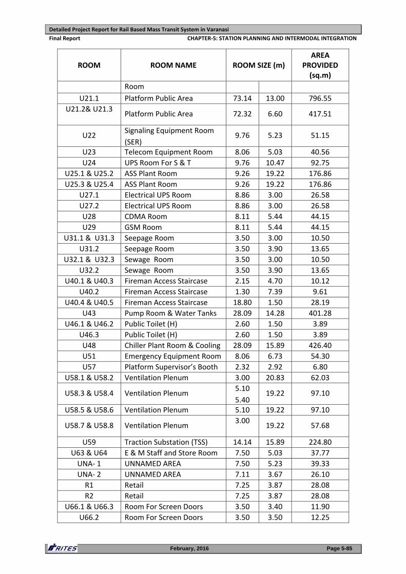
Detailed Project Report for Rail Based Mass Transit System in Varanasi
Final Report CHAPTER‐5: STATION PLANNING AND INTERMODAL INTEGRATION
February, 2016 Page 5-85
ROOM ROOM NAME ROOM SIZE (m) AREA
PROVIDED (sq.m)
Room
U21.1 Platform Public Area 73.14 13.00 796.55
U21.2& U21.3
Platform Public Area 72.32 6.60 417.51
U22 Signaling Equipment Room
(SER) 9.76 5.23 51.15
U23 Telecom Equipment Room 8.06 5.03 40.56
U24 UPS Room For S & T 9.76 10.47 92.75
U25.1 & U25.2 ASS Plant Room 9.26 19.22 176.86
U25.3 & U25.4 ASS Plant Room 9.26 19.22 176.86
U27.1 Electrical UPS Room 8.86 3.00 26.58
U27.2 Electrical UPS Room 8.86 3.00 26.58
U28 CDMA Room 8.11 5.44 44.15
U29 GSM Room 8.11 5.44 44.15
U31.1 & U31.3 Seepage Room 3.50 3.00 10.50
U31.2 Seepage Room 3.50 3.90 13.65
U32.1 & U32.3 Sewage Room 3.50 3.00 10.50
U32.2 Sewage Room 3.50 3.90 13.65
U40.1 & U40.3 Fireman Access Staircase 2.15 4.70 10.12
U40.2 Fireman Access Staircase 1.30 7.39 9.61
U40.4 & U40.5 Fireman Access Staircase 18.80 1.50 28.19
U43 Pump Room & Water Tanks 28.09 14.28 401.28
U46.1 & U46.2 Public Toilet (H) 2.60 1.50 3.89
U46.3 Public Toilet (H) 2.60 1.50 3.89
U48 Chiller Plant Room & Cooling 28.09 15.89 426.40
U51 Emergency Equipment Room 8.06 6.73 54.30
U57 Platform Supervisor’s Booth 2.32 2.92 6.80
U58.1 & U58.2 Ventilation Plenum 3.00 20.83 62.03
U58.3 & U58.4 Ventilation Plenum 5.10
5.4019.22 97.10
U58.5 & U58.6 Ventilation Plenum 5.10 19.22 97.10
U58.7 & U58.8 Ventilation Plenum 3.00
19.22 57.68
U59 Traction Substation (TSS) 14.14 15.89 224.80
U63 & U64 E & M Staff and Store Room 7.50 5.03 37.77
UNA‐ 1 UNNAMED AREA 7.50 5.23 39.33
UNA‐ 2 UNNAMED AREA 7.11 3.67 26.10
R1 Retail 7.25 3.87 28.08
R2 Retail 7.25 3.87 28.08
U66.1 & U66.3 Room For Screen Doors 3.50 3.40 11.90
U66.2 Room For Screen Doors 3.50 3.50 12.25
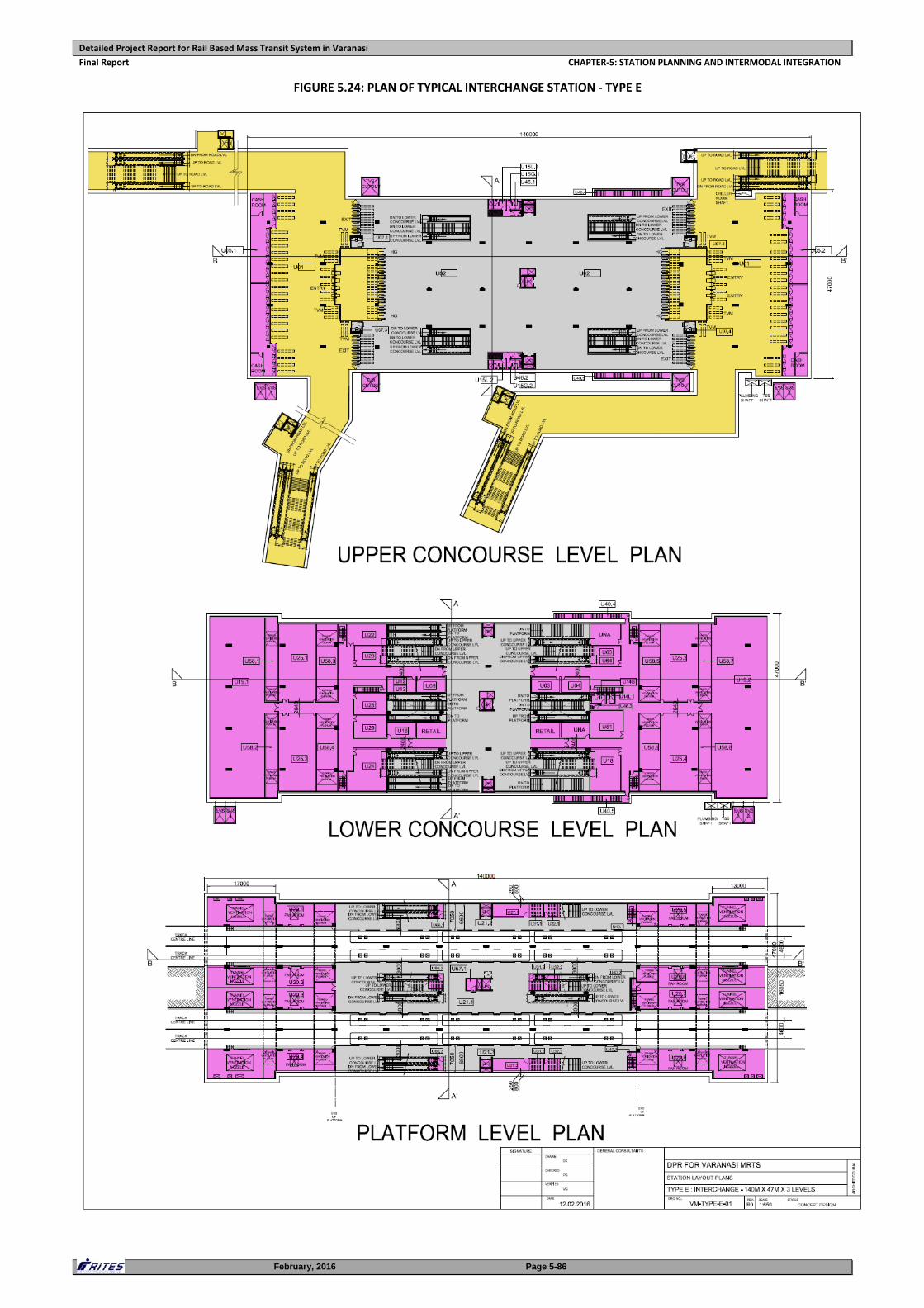
Detailed Project Report for Rail Based Mass Transit System in Varanasi
Final Report CHAPTER‐5: STATION PLANNING AND INTERMODAL INTEGRATION
February, 2016 Page 5-86
FIGURE 5.24: PLAN OF TYPICAL INTERCHANGE STATION ‐ TYPE E
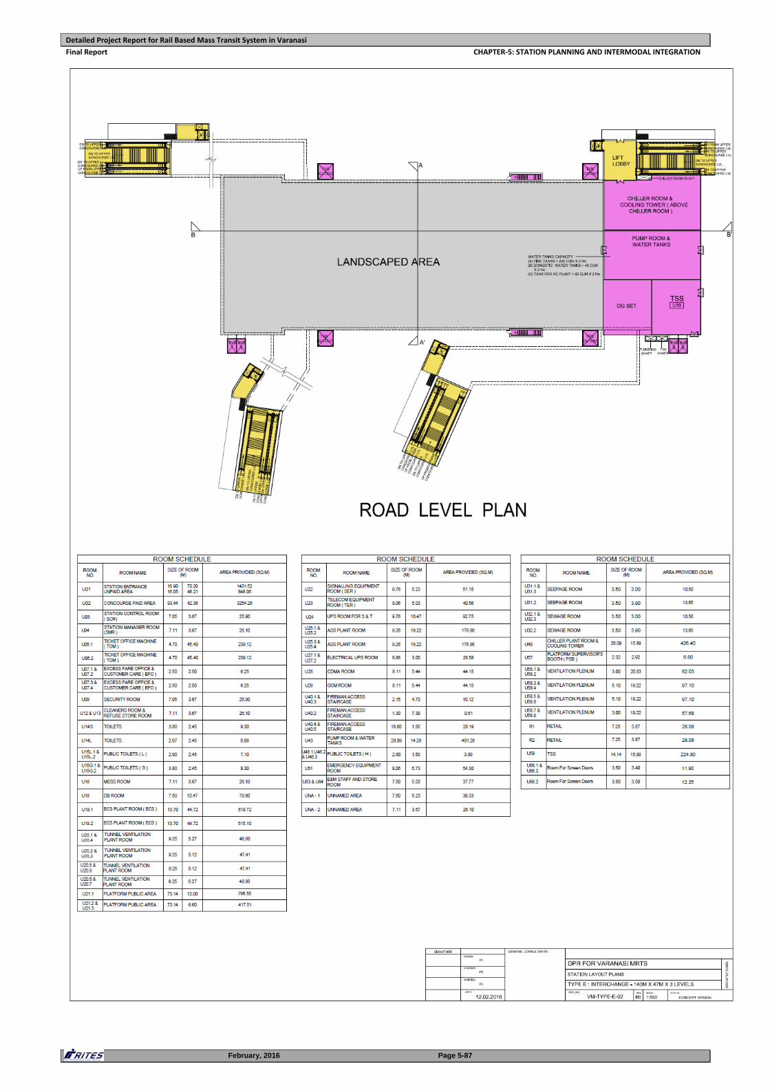
Detailed Project Report for Rail Based Mass Transit System in Varanasi
Final Report CHAPTER‐5: STATION PLANNING AND INTERMODAL INTEGRATION
February, 2016 Page 5-87
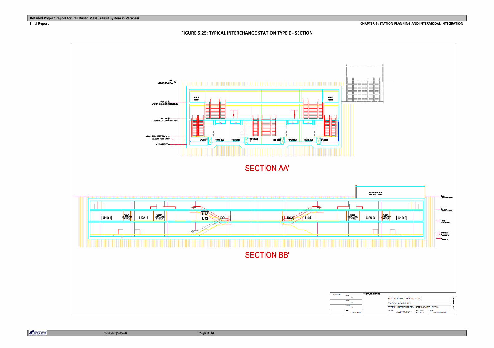
Detailed Project Report for Rail Based Mass Transit System in Varanasi
Final Report CHAPTER‐5: STATION PLANNING AND INTERMODAL INTEGRATION
February, 2016 Page 5-88
FIGURE 5.25: TYPICAL INTERCHANGE STATION TYPE E ‐ SECTION
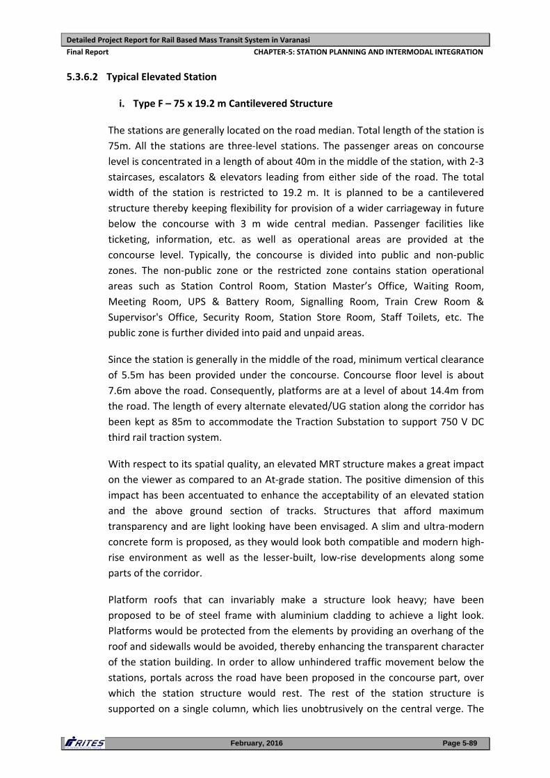
Detailed Project Report for Rail Based Mass Transit System in Varanasi
Final Report CHAPTER‐5: STATION PLANNING AND INTERMODAL INTEGRATION
February, 2016 Page 5-89
5.3.6.2 Typical Elevated Station
i. Type F – 75 x 19.2 m Cantilevered Structure
The stations are generally located on the road median. Total length of the station is
75m. All the stations are three‐level stations. The passenger areas on concourse
level is concentrated in a length of about 40m in the middle of the station, with 2‐3
staircases, escalators & elevators leading from either side of the road. The total
width of the station is restricted to 19.2 m. It is planned to be a cantilevered
structure thereby keeping flexibility for provision of a wider carriageway in future
below the concourse with 3 m wide central median. Passenger facilities like
ticketing, information, etc. as well as operational areas are provided at the
concourse level. Typically, the concourse is divided into public and non‐public
zones. The non‐public zone or the restricted zone contains station operational
areas such as Station Control Room, Station Master’s Office, Waiting Room,
Meeting Room, UPS & Battery Room, Signalling Room, Train Crew Room &
Supervisor's Office, Security Room, Station Store Room, Staff Toilets, etc. The
public zone is further divided into paid and unpaid areas.
Since the station is generally in the middle of the road, minimum vertical clearance
of 5.5m has been provided under the concourse. Concourse floor level is about
7.6m above the road. Consequently, platforms are at a level of about 14.4m from
the road. The length of every alternate elevated/UG station along the corridor has
been kept as 85m to accommodate the Traction Substation to support 750 V DC
third rail traction system.
With respect to its spatial quality, an elevated MRT structure makes a great impact
on the viewer as compared to an At‐grade station. The positive dimension of this
impact has been accentuated to enhance the acceptability of an elevated station
and the above ground section of tracks. Structures that afford maximum
transparency and are light looking have been envisaged. A slim and ultra‐modern
concrete form is proposed, as they would look both compatible and modern high‐
rise environment as well as the lesser‐built, low‐rise developments along some
parts of the corridor.
Platform roofs that can invariably make a structure look heavy; have been
proposed to be of steel frame with aluminium cladding to achieve a light look.
Platforms would be protected from the elements by providing an overhang of the
roof and sidewalls would be avoided, thereby enhancing the transparent character
of the station building. In order to allow unhindered traffic movement below the
stations, portals across the road have been proposed in the concourse part, over
which the station structure would rest. The rest of the station structure is
supported on a single column, which lies unobtrusively on the central verge. The
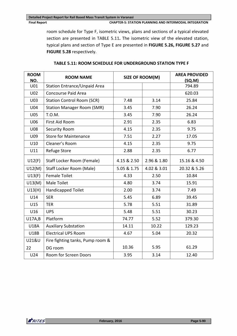
Detailed Project Report for Rail Based Mass Transit System in Varanasi
Final Report CHAPTER‐5: STATION PLANNING AND INTERMODAL INTEGRATION
February, 2016 Page 5-90
room schedule for Type F, isometric views, plans and sections of a typical elevated
section are presented in TABLE 5.11. The isometric view of the elevated station,
typical plans and section of Type E are presented in FIGURE 5.26, FIGURE 5.27 and
FIGURE 5.28 respectively.
TABLE 5.11: ROOM SCHEDULE FOR UNDERGROUND STATION TYPE F
ROOM NO.
ROOM NAME SIZE OF ROOM(M) AREA PROVIDED
(SQ.M)U01 Station Entrance/Unpaid Area 794.89
U02 Concourse Paid Area 620.03
U03 Station Control Room (SCR) 7.48 3.14 25.84
U04 Station Manager Room (SMR) 3.45 7.90 26.24
U05 T.O.M. 3.45 7.90 26.24
U06 First Aid Room 2.91 2.35 6.83
U08 Security Room 4.15 2.35 9.75
U09 Store for Maintenance 7.51 2.27 17.05
U10 Cleaner’s Room 4.15 2.35 9.75
U11 Refuge Store 2.88 2.35 6.77
U12(F) Staff Locker Room (Female) 4.15 & 2.50 2.96 & 1.80 15.16 & 4.50
U12(M) Staff Locker Room (Male) 5.05 & 1.75 4.02 & 3.01 20.32 & 5.26
U13(F) Female Toilet 4.33 2.50 10.84
U13(M) Male Toilet 4.80 3.74 15.91
U13(H) Handicapped Toilet 2.00 3.74 7.49
U14 SER 5.45 6.89 39.45
U15 TER 5.78 5.51 31.89
U16 UPS 5.48 5.51 30.23
U17A,B Platform 74.77 5.52 379.30
U18A Auxiliary Substation 14.11 10.22 129.23
U18B Electrical UPS Room 4.67 5.04 20.32
U21&U
22
Fire fighting tanks, Pump room &
DG room 10.36 5.95 61.29
U24 Room for Screen Doors 3.95 3.14 12.40
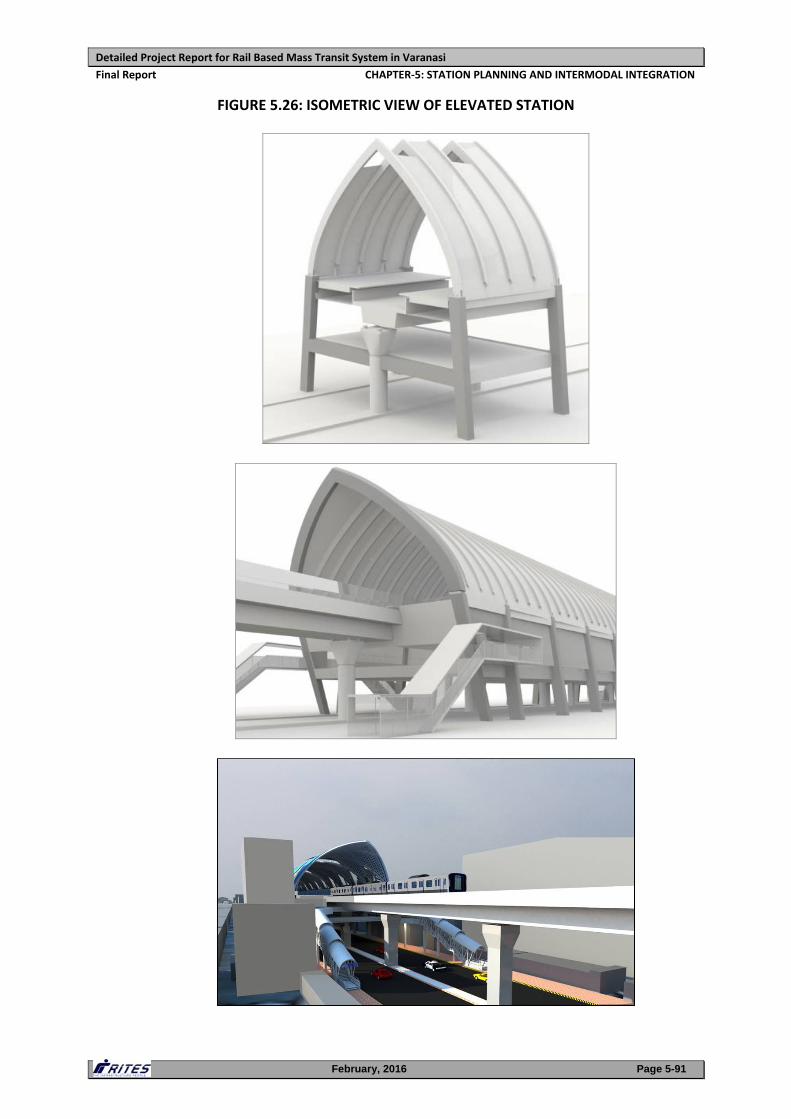
Detailed Project Report for Rail Based Mass Transit System in Varanasi
Final Report CHAPTER‐5: STATION PLANNING AND INTERMODAL INTEGRATION
February, 2016 Page 5-91
FIGURE 5.26: ISOMETRIC VIEW OF ELEVATED STATION
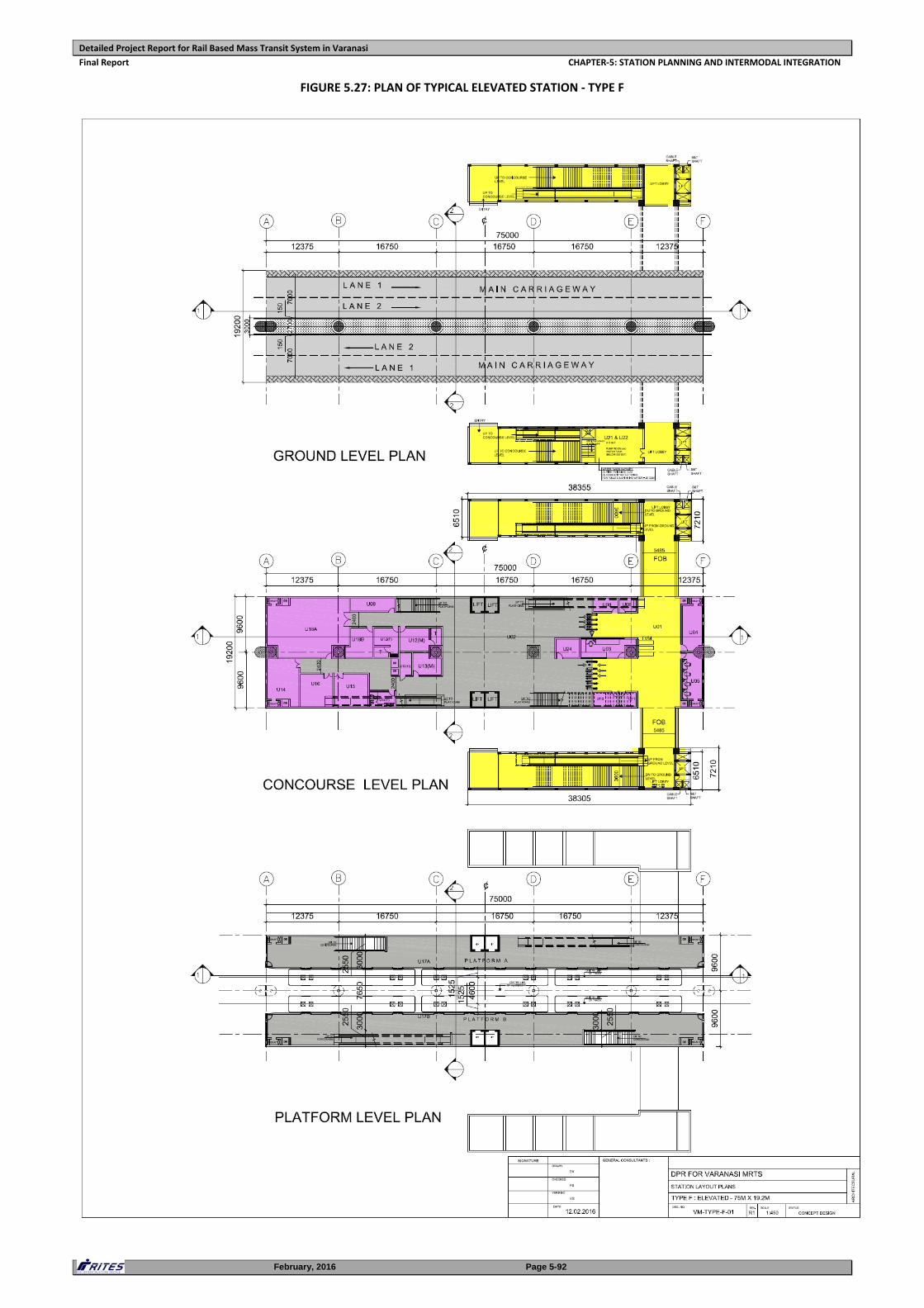
Detailed Project Report for Rail Based Mass Transit System in Varanasi
Final Report CHAPTER‐5: STATION PLANNING AND INTERMODAL INTEGRATION
February, 2016 Page 5-92
FIGURE 5.27: PLAN OF TYPICAL ELEVATED STATION ‐ TYPE F
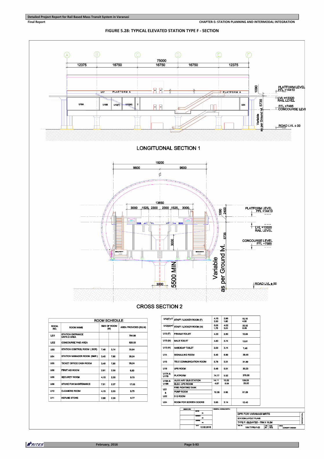
Detailed Project Report for Rail Based Mass Transit System in Varanasi
Final Report CHAPTER‐5: STATION PLANNING AND INTERMODAL INTEGRATION
February, 2016 Page 5-93
FIGURE 5.28: TYPICAL ELEVATED STATION TYPE F ‐ SECTION
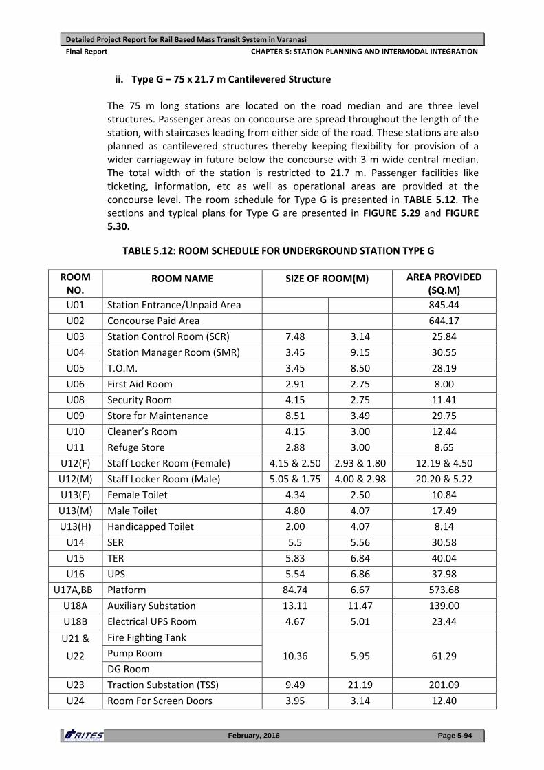
Detailed Project Report for Rail Based Mass Transit System in Varanasi
Final Report CHAPTER‐5: STATION PLANNING AND INTERMODAL INTEGRATION
February, 2016 Page 5-94
ii. Type G – 75 x 21.7 m Cantilevered Structure
The 75 m long stations are located on the road median and are three level structures. Passenger areas on concourse are spread throughout the length of the station, with staircases leading from either side of the road. These stations are also planned as cantilevered structures thereby keeping flexibility for provision of a wider carriageway in future below the concourse with 3 m wide central median. The total width of the station is restricted to 21.7 m. Passenger facilities like ticketing, information, etc as well as operational areas are provided at the concourse level. The room schedule for Type G is presented in TABLE 5.12. The sections and typical plans for Type G are presented in FIGURE 5.29 and FIGURE 5.30.
TABLE 5.12: ROOM SCHEDULE FOR UNDERGROUND STATION TYPE G
ROOM NO.
ROOM NAME SIZE OF ROOM(M) AREA PROVIDED (SQ.M)
U01 Station Entrance/Unpaid Area 845.44
U02 Concourse Paid Area 644.17
U03 Station Control Room (SCR) 7.48 3.14 25.84
U04 Station Manager Room (SMR) 3.45 9.15 30.55
U05 T.O.M. 3.45 8.50 28.19
U06 First Aid Room 2.91 2.75 8.00
U08 Security Room 4.15 2.75 11.41
U09 Store for Maintenance 8.51 3.49 29.75
U10 Cleaner’s Room 4.15 3.00 12.44
U11 Refuge Store 2.88 3.00 8.65
U12(F) Staff Locker Room (Female) 4.15 & 2.50 2.93 & 1.80 12.19 & 4.50
U12(M) Staff Locker Room (Male) 5.05 & 1.75 4.00 & 2.98 20.20 & 5.22
U13(F) Female Toilet 4.34 2.50 10.84
U13(M) Male Toilet 4.80 4.07 17.49
U13(H) Handicapped Toilet 2.00 4.07 8.14
U14 SER 5.5 5.56 30.58
U15 TER 5.83 6.84 40.04
U16 UPS 5.54 6.86 37.98
U17A,BB Platform 84.74 6.67 573.68
U18A Auxiliary Substation 13.11 11.47 139.00
U18B Electrical UPS Room 4.67 5.01 23.44
U21 &
U22
Fire Fighting Tank
10.36 5.95 61.29 Pump Room
DG Room
U23 Traction Substation (TSS) 9.49 21.19 201.09
U24 Room For Screen Doors 3.95 3.14 12.40
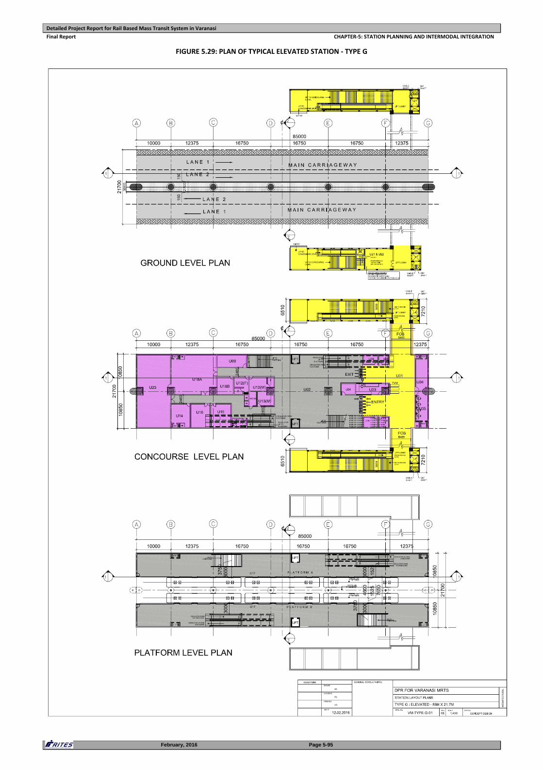
Detailed Project Report for Rail Based Mass Transit System in Varanasi
Final Report CHAPTER‐5: STATION PLANNING AND INTERMODAL INTEGRATION
February, 2016 Page 5-95
FIGURE 5.29: PLAN OF TYPICAL ELEVATED STATION ‐ TYPE G
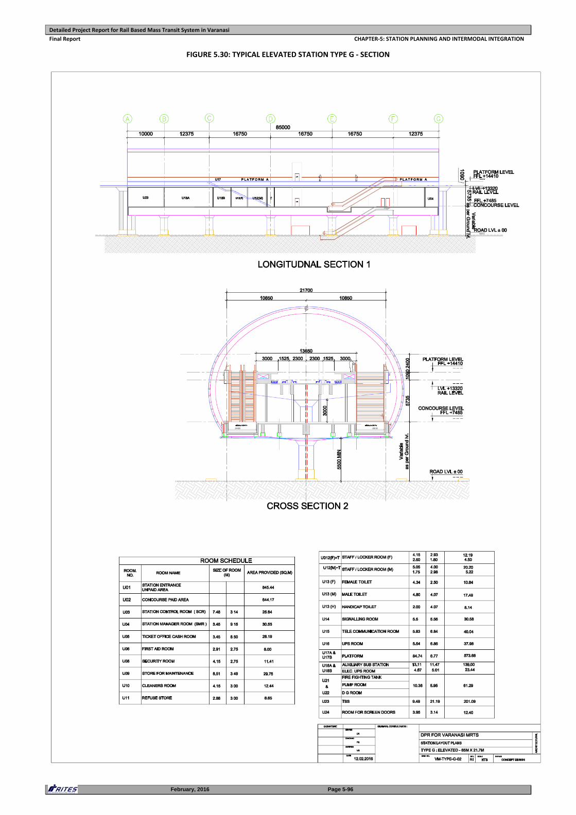
Detailed Project Report for Rail Based Mass Transit System in Varanasi
Final Report CHAPTER‐5: STATION PLANNING AND INTERMODAL INTEGRATION
February, 2016 Page 5-96
FIGURE 5.30: TYPICAL ELEVATED STATION TYPE G ‐ SECTION
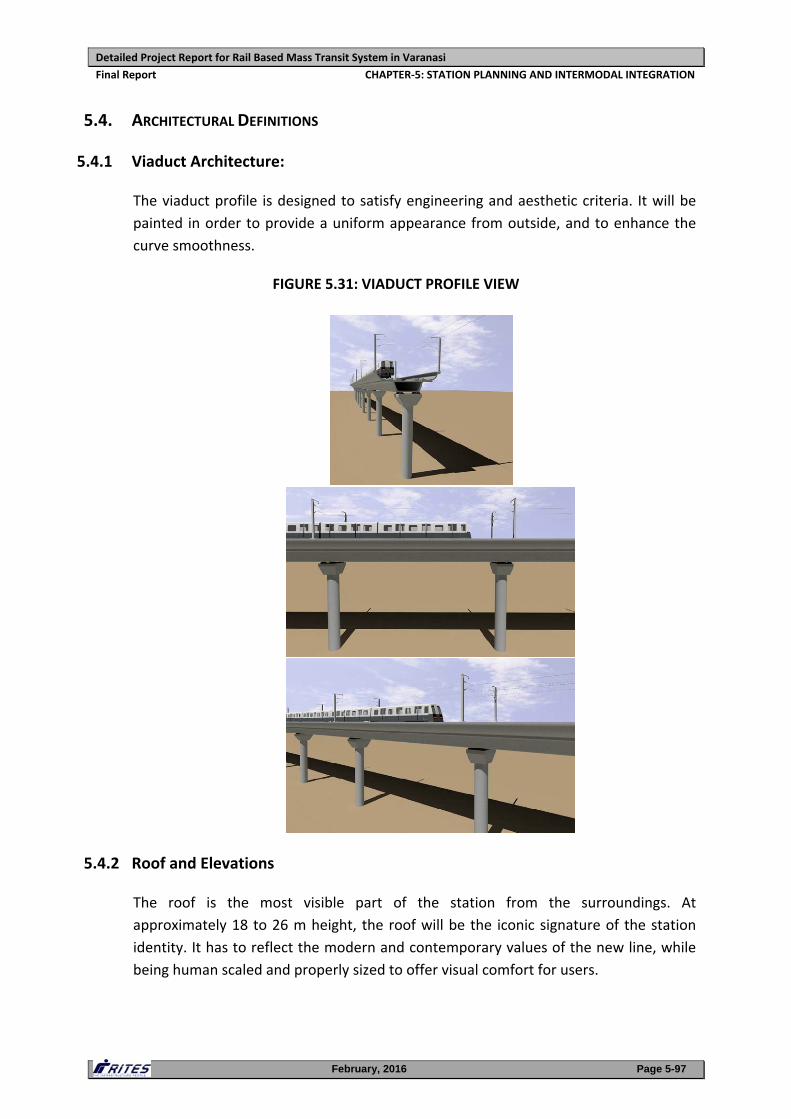
Detailed Project Report for Rail Based Mass Transit System in Varanasi
Final Report CHAPTER‐5: STATION PLANNING AND INTERMODAL INTEGRATION
February, 2016 Page 5-97
5.4. ARCHITECTURAL DEFINITIONS
5.4.1 Viaduct Architecture:
The viaduct profile is designed to satisfy engineering and aesthetic criteria. It will be
painted in order to provide a uniform appearance from outside, and to enhance the
curve smoothness.
FIGURE 5.31: VIADUCT PROFILE VIEW
5.4.2 Roof and Elevations
The roof is the most visible part of the station from the surroundings. At
approximately 18 to 26 m height, the roof will be the iconic signature of the station
identity. It has to reflect the modern and contemporary values of the new line, while
being human scaled and properly sized to offer visual comfort for users.
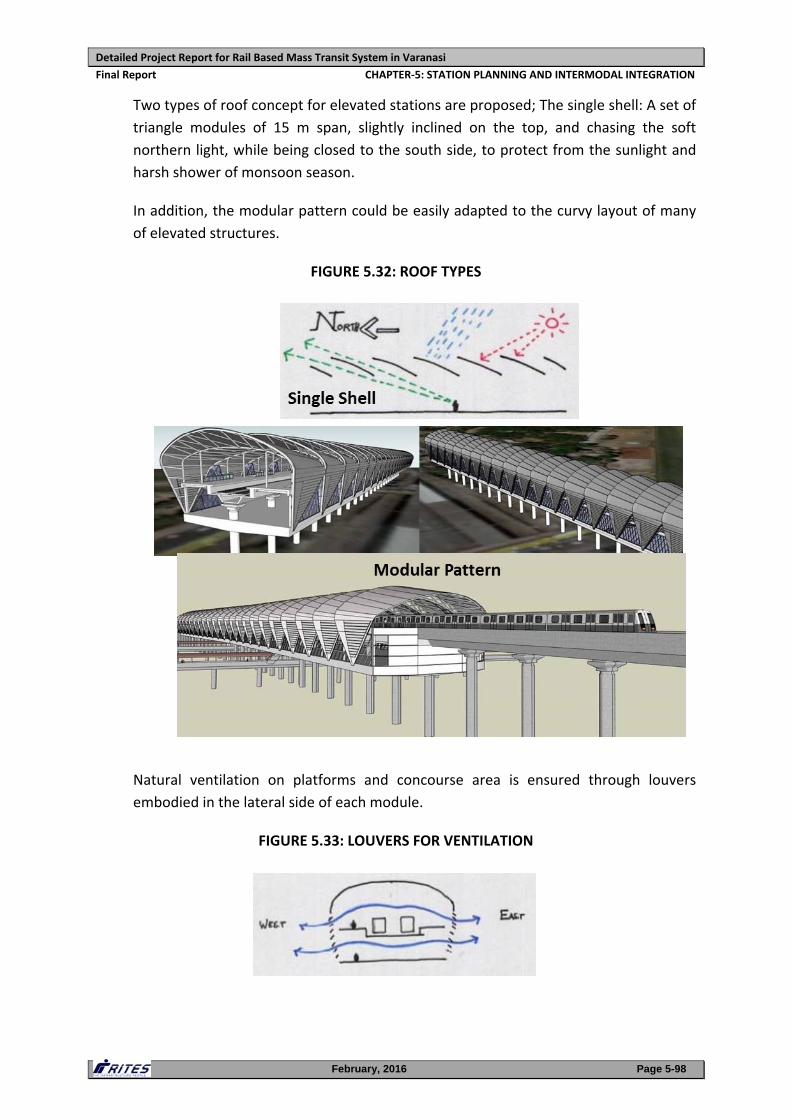
Detailed Project Report for Rail Based Mass Transit System in Varanasi
Final Report CHAPTER‐5: STATION PLANNING AND INTERMODAL INTEGRATION
February, 2016 Page 5-98
Two types of roof concept for elevated stations are proposed; The single shell: A set of
triangle modules of 15 m span, slightly inclined on the top, and chasing the soft
northern light, while being closed to the south side, to protect from the sunlight and
harsh shower of monsoon season.
In addition, the modular pattern could be easily adapted to the curvy layout of many
of elevated structures.
FIGURE 5.32: ROOF TYPES
Natural ventilation on platforms and concourse area is ensured through louvers
embodied in the lateral side of each module.
FIGURE 5.33: LOUVERS FOR VENTILATION
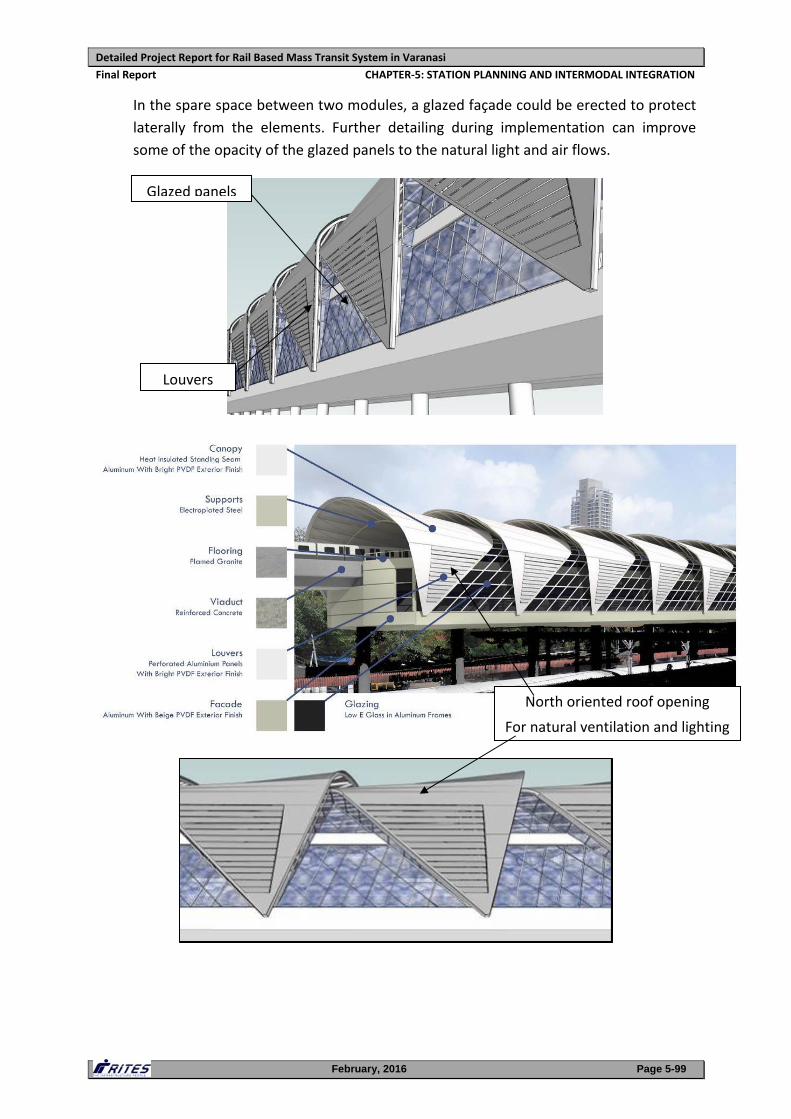
Detailed Project Report for Rail Based Mass Transit System in Varanasi
Final Report CHAPTER‐5: STATION PLANNING AND INTERMODAL INTEGRATION
February, 2016 Page 5-99
In the spare space between two modules, a glazed façade could be erected to protect
laterally from the elements. Further detailing during implementation can improve
some of the opacity of the glazed panels to the natural light and air flows.
Louvers
Glazed panels
North oriented roof opening
For natural ventilation and lighting
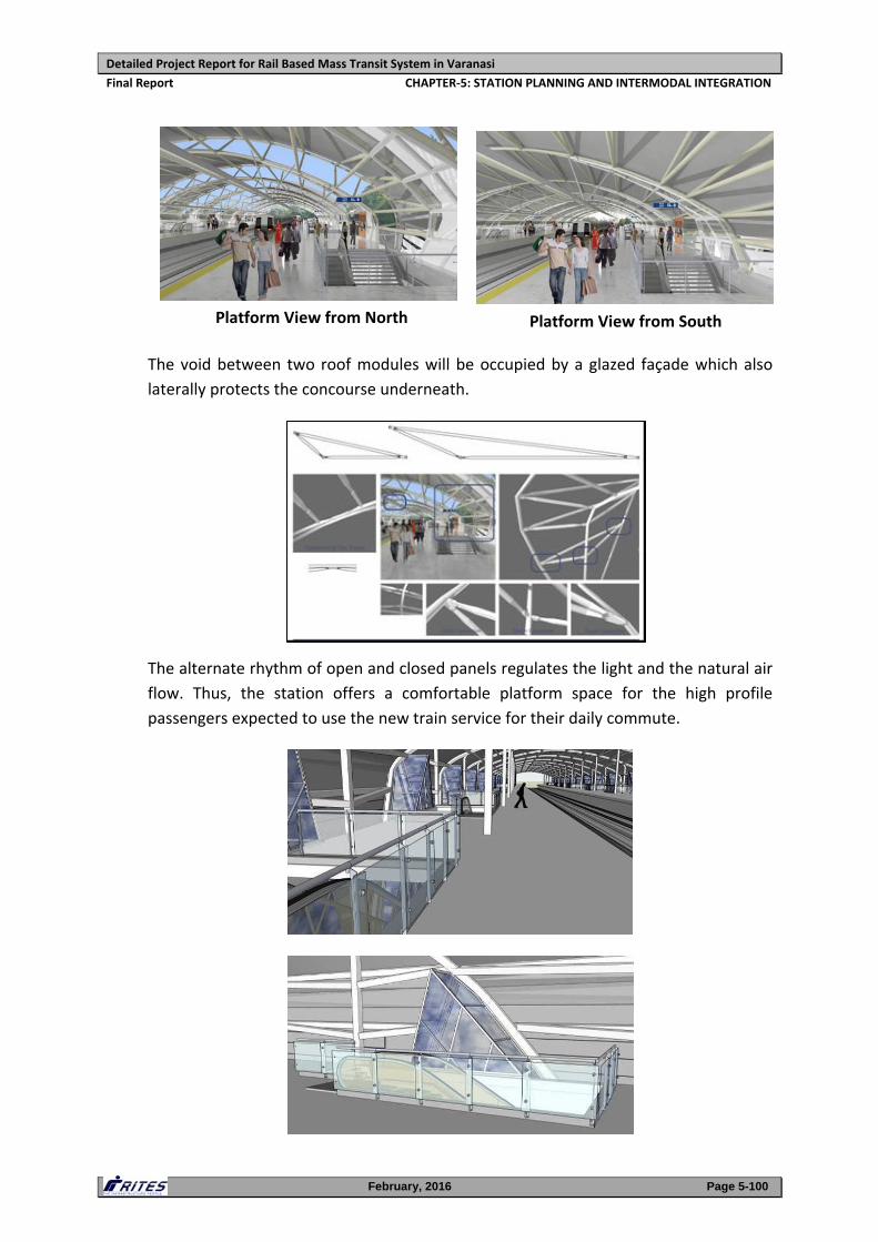
Detailed Project Report for Rail Based Mass Transit System in Varanasi
Final Report CHAPTER‐5: STATION PLANNING AND INTERMODAL INTEGRATION
February, 2016 Page 5-100
The void between two roof modules will be occupied by a glazed façade which also
laterally protects the concourse underneath.
The alternate rhythm of open and closed panels regulates the light and the natural air
flow. Thus, the station offers a comfortable platform space for the high profile
passengers expected to use the new train service for their daily commute.
Platform View from North Platform View from South
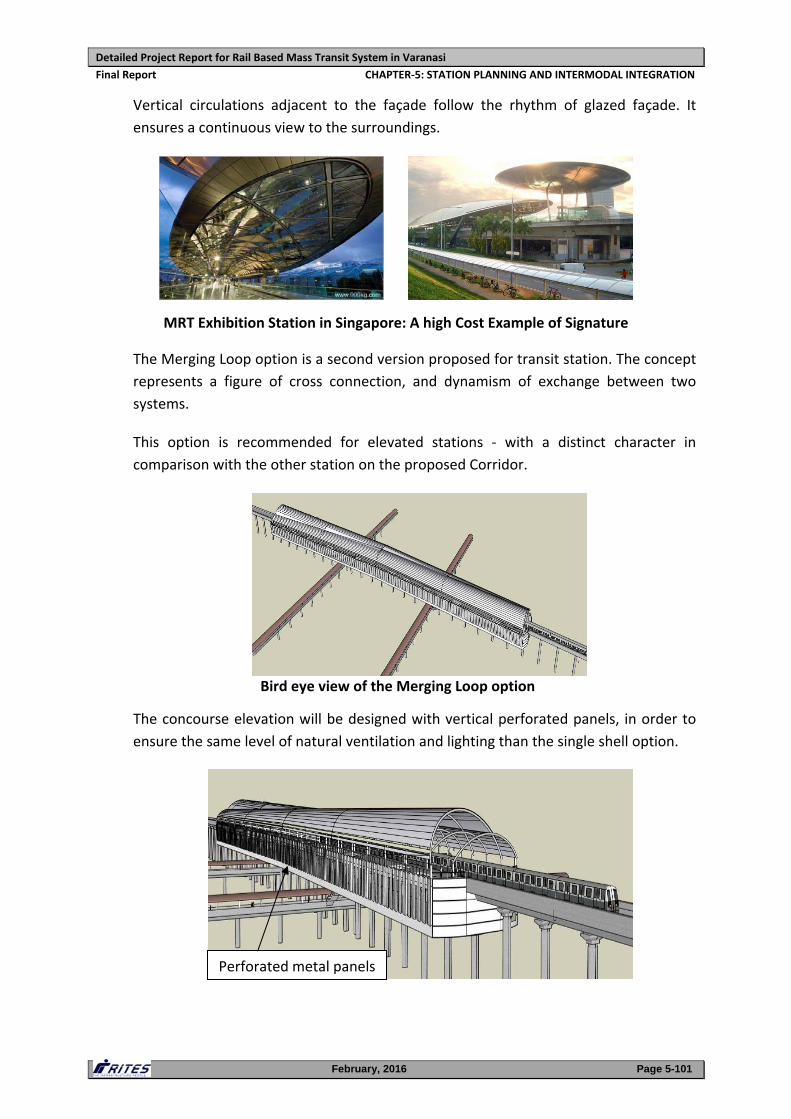
Detailed Project Report for Rail Based Mass Transit System in Varanasi
Final Report CHAPTER‐5: STATION PLANNING AND INTERMODAL INTEGRATION
February, 2016 Page 5-101
Vertical circulations adjacent to the façade follow the rhythm of glazed façade. It
ensures a continuous view to the surroundings.
The Merging Loop option is a second version proposed for transit station. The concept
represents a figure of cross connection, and dynamism of exchange between two
systems.
This option is recommended for elevated stations ‐ with a distinct character in
comparison with the other station on the proposed Corridor.
Bird eye view of the Merging Loop option
The concourse elevation will be designed with vertical perforated panels, in order to
ensure the same level of natural ventilation and lighting than the single shell option.
Perforated metal panels
MRT Exhibition Station in Singapore: A high Cost Example of Signature
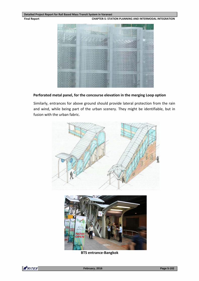
Detailed Project Report for Rail Based Mass Transit System in Varanasi
Final Report CHAPTER‐5: STATION PLANNING AND INTERMODAL INTEGRATION
February, 2016 Page 5-102
Perforated metal panel, for the concourse elevation in the merging Loop option
Similarly, entrances for above ground should provide lateral protection from the rain
and wind, while being part of the urban scenery. They might be identifiable, but in
fusion with the urban fabric.
BTS entrance‐Bangkok
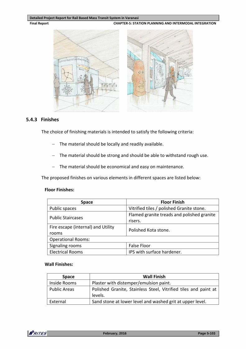
Detailed Project Report for Rail Based Mass Transit System in Varanasi
Final Report CHAPTER‐5: STATION PLANNING AND INTERMODAL INTEGRATION
February, 2016 Page 5-103
5.4.3 Finishes
The choice of finishing materials is intended to satisfy the following criteria:
The material should be locally and readily available.
The material should be strong and should be able to withstand rough use.
The material should be economical and easy on maintenance.
The proposed finishes on various elements in different spaces are listed below:
Floor Finishes:
Space Floor Finish
Public spaces Vitrified tiles / polished Granite stone.
Public Staircases Flamed granite treads and polished granite risers.
Fire escape (internal) and Utility rooms
Polished Kota stone.
Operational Rooms:
Signaling rooms False Floor
Electrical Rooms IPS with surface hardener.
Wall Finishes:
Space Wall Finish
Inside Rooms Plaster with distemper/emulsion paint.
Public Areas Polished Granite, Stainless Steel, Vitrified tiles and paint at levels.
External Sand stone at lower level and washed grit at upper level.
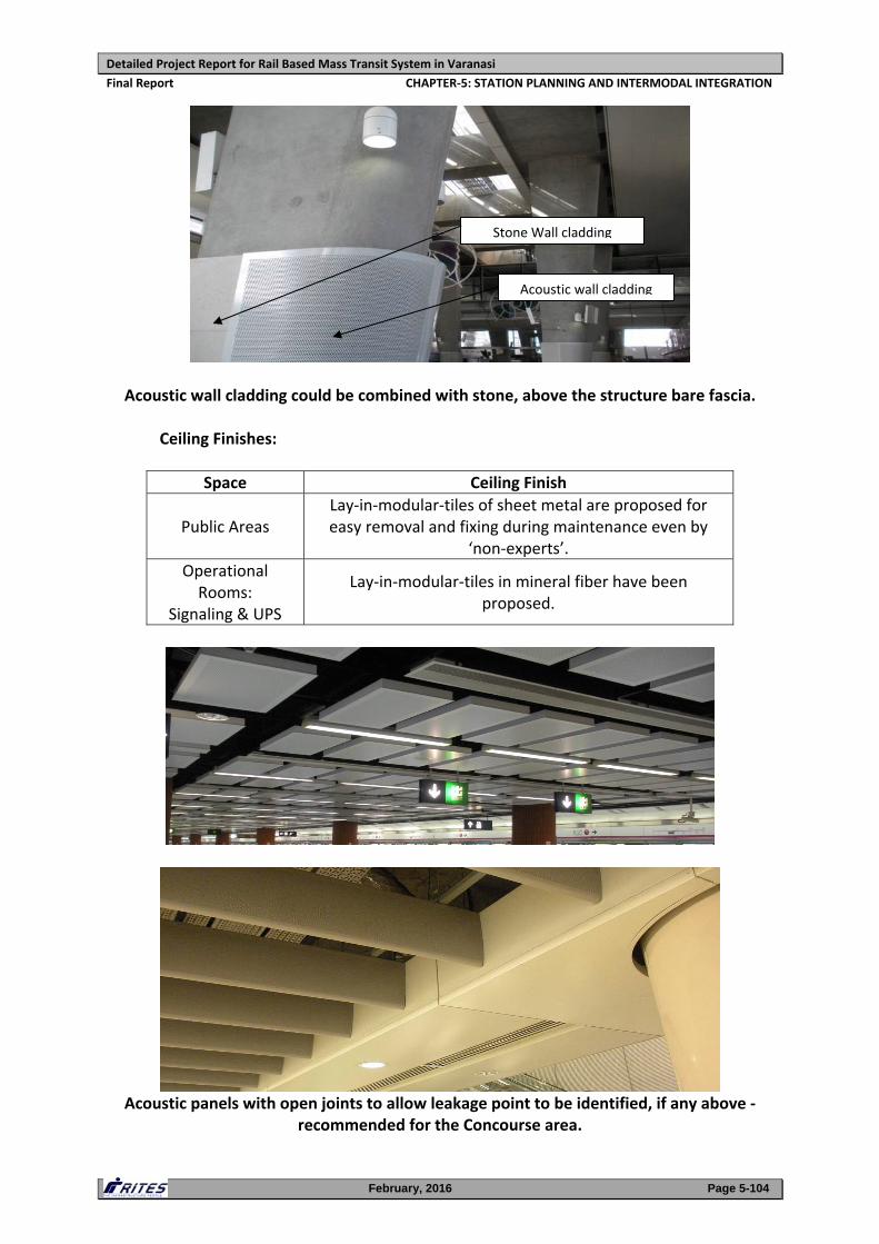
Detailed Project Report for Rail Based Mass Transit System in Varanasi
Final Report CHAPTER‐5: STATION PLANNING AND INTERMODAL INTEGRATION
February, 2016 Page 5-104
Acoustic wall cladding could be combined with stone, above the structure bare fascia. Ceiling Finishes:
Space Ceiling Finish
Public Areas Lay‐in‐modular‐tiles of sheet metal are proposed for easy removal and fixing during maintenance even by
‘non‐experts’.
Operational Rooms:
Signaling & UPS
Lay‐in‐modular‐tiles in mineral fiber have been proposed.
Acoustic panels with open joints to allow leakage point to be identified, if any above ‐
recommended for the Concourse area.
Stone Wall cladding
Acoustic wall cladding
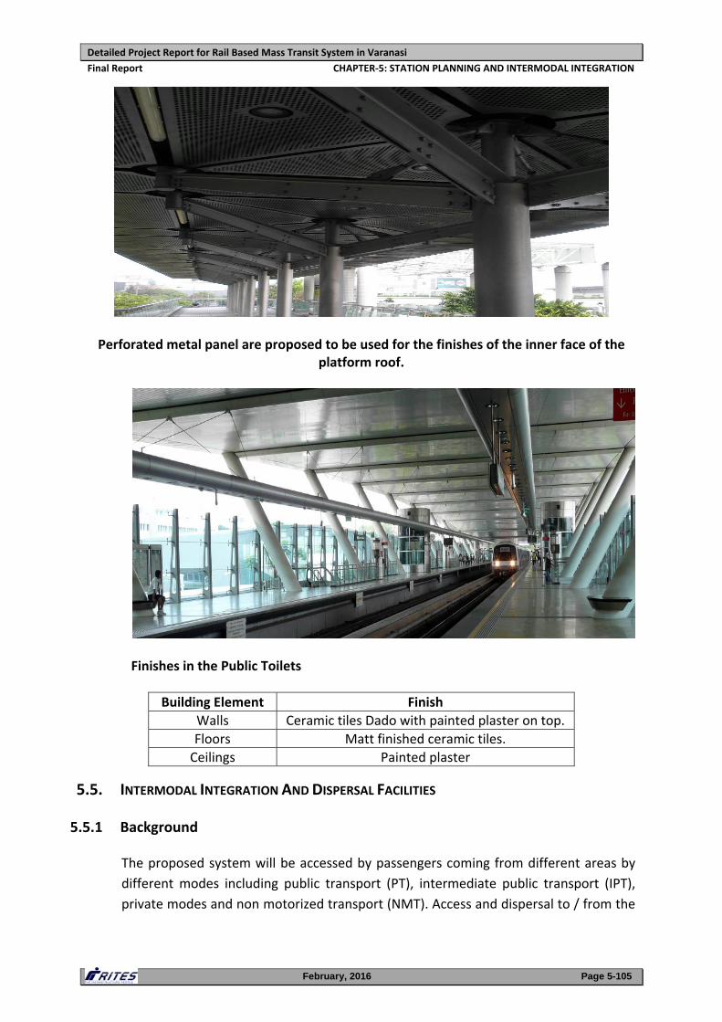
Detailed Project Report for Rail Based Mass Transit System in Varanasi
Final Report CHAPTER‐5: STATION PLANNING AND INTERMODAL INTEGRATION
February, 2016 Page 5-105
Perforated metal panel are proposed to be used for the finishes of the inner face of the
platform roof.
Finishes in the Public Toilets
Building Element Finish
Walls Ceramic tiles Dado with painted plaster on top.
Floors Matt finished ceramic tiles.
Ceilings Painted plaster
5.5. INTERMODAL INTEGRATION AND DISPERSAL FACILITIES
5.5.1 Background
The proposed system will be accessed by passengers coming from different areas by
different modes including public transport (PT), intermediate public transport (IPT),
private modes and non motorized transport (NMT). Access and dispersal to / from the
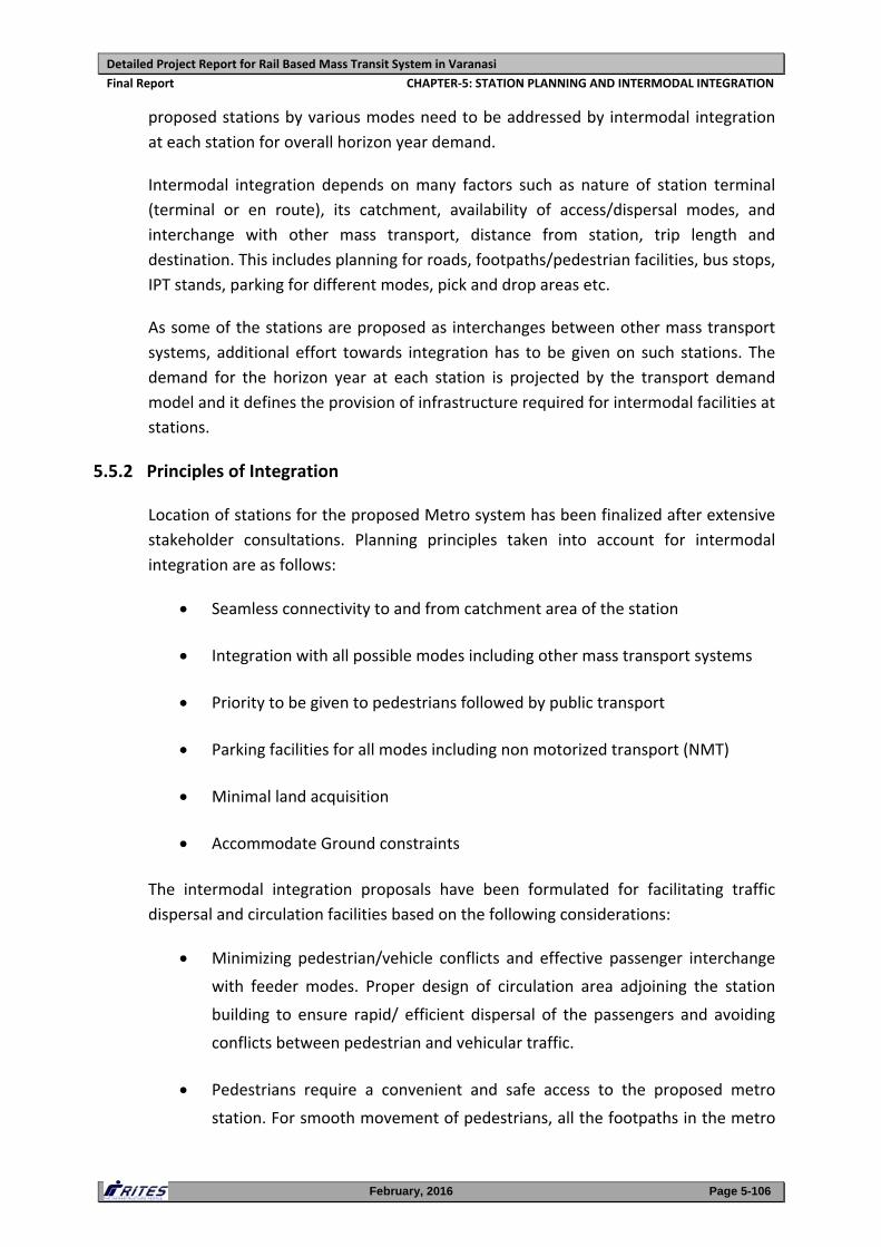
Detailed Project Report for Rail Based Mass Transit System in Varanasi
Final Report CHAPTER‐5: STATION PLANNING AND INTERMODAL INTEGRATION
February, 2016 Page 5-106
proposed stations by various modes need to be addressed by intermodal integration
at each station for overall horizon year demand.
Intermodal integration depends on many factors such as nature of station terminal
(terminal or en route), its catchment, availability of access/dispersal modes, and
interchange with other mass transport, distance from station, trip length and
destination. This includes planning for roads, footpaths/pedestrian facilities, bus stops,
IPT stands, parking for different modes, pick and drop areas etc.
As some of the stations are proposed as interchanges between other mass transport
systems, additional effort towards integration has to be given on such stations. The
demand for the horizon year at each station is projected by the transport demand
model and it defines the provision of infrastructure required for intermodal facilities at
stations.
5.5.2 Principles of Integration
Location of stations for the proposed Metro system has been finalized after extensive
stakeholder consultations. Planning principles taken into account for intermodal
integration are as follows:
Seamless connectivity to and from catchment area of the station
Integration with all possible modes including other mass transport systems
Priority to be given to pedestrians followed by public transport
Parking facilities for all modes including non motorized transport (NMT)
Minimal land acquisition
Accommodate Ground constraints
The intermodal integration proposals have been formulated for facilitating traffic
dispersal and circulation facilities based on the following considerations:
Minimizing pedestrian/vehicle conflicts and effective passenger interchange
with feeder modes. Proper design of circulation area adjoining the station
building to ensure rapid/ efficient dispersal of the passengers and avoiding
conflicts between pedestrian and vehicular traffic.
Pedestrians require a convenient and safe access to the proposed metro
station. For smooth movement of pedestrians, all the footpaths in the metro
Detailed Project Report for Rail Based Mass Transit System in Varanasi
Final Report CHAPTER‐5: STATION PLANNING AND INTERMODAL INTEGRATION
February, 2016 Page 5-107
station influence zone will be considered to be upgraded to desired level of
comfort and also proposed new within the stations vicinity areas.
High quality pedestrian access will be accomplished through design factors
such as directness and connectivity, ease of movement, safety and security.
The vendors if any on the footpaths shall be removed and desired
accessibility to metro stations will be provided. The facilities (footpaths/
walkways) will be directly integrated with the system.
Facilitating passenger interchange with other transit systems: Dedicated
linkages will be proposed like subways, skywalks, covered walkways etc.
which will reduce the passenger travel time and pedestrian load on the roads.
Circulation area with adequate parking space, designated space for
embarking and disembarking for vehicular traffic (pick‐drop zones) and feeder
modes like Buses, IPTs and NMT.
Availability of total carriageway and footpath widths required to cater to the
proposed traffic volumes to be augmented through strengthening of road
shoulder areas and relocation of vendors/hawkers, on‐street parking and all
encroachments from the service/ access roads.
The following intermodal integration and dispersal facilities have been planned at
metro stations for efficient passenger movement and to meet the shortfall in capacity
in terms of road capacity, traffic movement/ circulation, pedestrian facilities, bus
stops, IPT stands/ Pick‐Drop areas and parking.
1. Augmentation of road geometry & footpaths:
It is proposed to utilize the complete RoW to cater to the future traffic
volume. The existing road shoulder areas and service lanes have been
augmented/ strengthened in the design wherever possible.
A continuous, encroachment free and well maintained footpath of 2 m width
is proposed on major roads near station locations. A continuous footpath of a
minimum 1.2 m width is provided on the local roads connecting metro
stations.
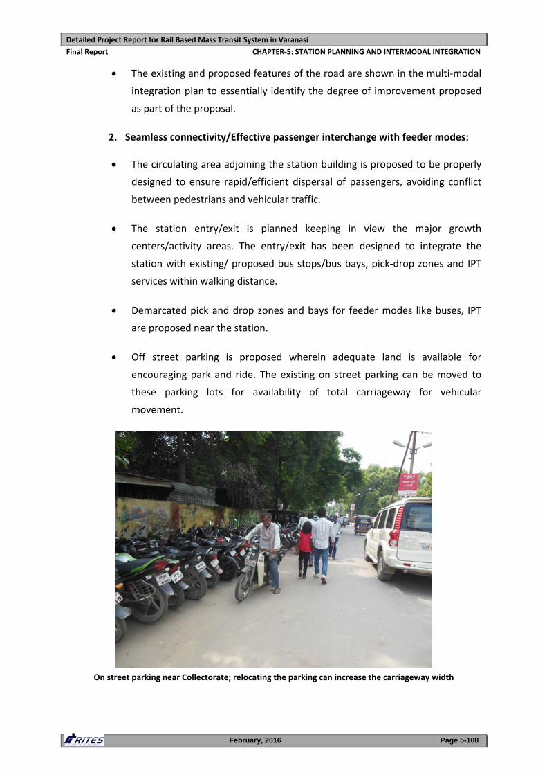
Detailed Project Report for Rail Based Mass Transit System in Varanasi
Final Report CHAPTER‐5: STATION PLANNING AND INTERMODAL INTEGRATION
February, 2016 Page 5-108
The existing and proposed features of the road are shown in the multi‐modal
integration plan to essentially identify the degree of improvement proposed
as part of the proposal.
2. Seamless connectivity/Effective passenger interchange with feeder modes:
The circulating area adjoining the station building is proposed to be properly
designed to ensure rapid/efficient dispersal of passengers, avoiding conflict
between pedestrians and vehicular traffic.
The station entry/exit is planned keeping in view the major growth
centers/activity areas. The entry/exit has been designed to integrate the
station with existing/ proposed bus stops/bus bays, pick‐drop zones and IPT
services within walking distance.
Demarcated pick and drop zones and bays for feeder modes like buses, IPT
are proposed near the station.
Off street parking is proposed wherein adequate land is available for
encouraging park and ride. The existing on street parking can be moved to
these parking lots for availability of total carriageway for vehicular
movement.
On street parking near Collectorate; relocating the parking can increase the carriageway width
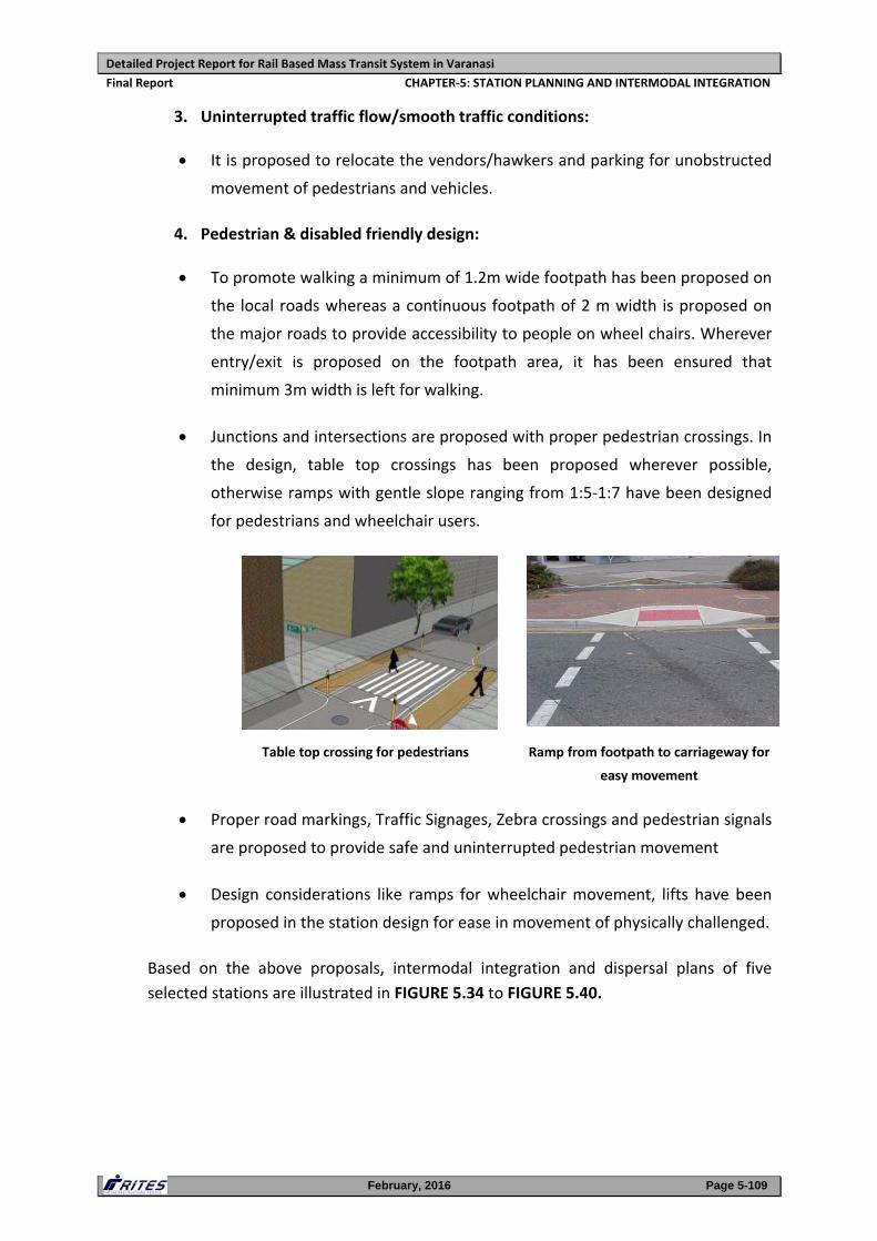
Detailed Project Report for Rail Based Mass Transit System in Varanasi
Final Report CHAPTER‐5: STATION PLANNING AND INTERMODAL INTEGRATION
February, 2016 Page 5-109
3. Uninterrupted traffic flow/smooth traffic conditions:
It is proposed to relocate the vendors/hawkers and parking for unobstructed
movement of pedestrians and vehicles.
4. Pedestrian & disabled friendly design:
To promote walking a minimum of 1.2m wide footpath has been proposed on
the local roads whereas a continuous footpath of 2 m width is proposed on
the major roads to provide accessibility to people on wheel chairs. Wherever
entry/exit is proposed on the footpath area, it has been ensured that
minimum 3m width is left for walking.
Junctions and intersections are proposed with proper pedestrian crossings. In
the design, table top crossings has been proposed wherever possible,
otherwise ramps with gentle slope ranging from 1:5‐1:7 have been designed
for pedestrians and wheelchair users.
Table top crossing for pedestrians Ramp from footpath to carriageway for
easy movement
Proper road markings, Traffic Signages, Zebra crossings and pedestrian signals
are proposed to provide safe and uninterrupted pedestrian movement
Design considerations like ramps for wheelchair movement, lifts have been
proposed in the station design for ease in movement of physically challenged.
Based on the above proposals, intermodal integration and dispersal plans of five
selected stations are illustrated in FIGURE 5.34 to FIGURE 5.40.
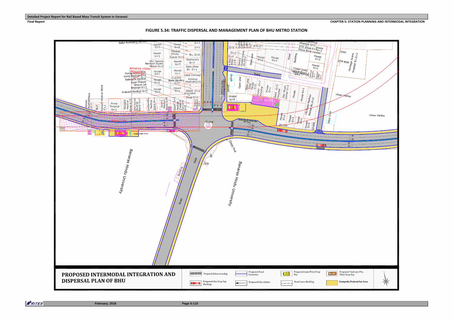
Detailed Project Report for Rail Based Mass Transit System in Varanasi
Final Report CHAPTER‐5: STATION PLANNING AND INTERMODAL INTEGRATION
February, 2016 Page 5-110
FIGURE 5.34: TRAFFIC DISPERSAL AND MANAGEMENT PLAN OF BHU METRO STATION
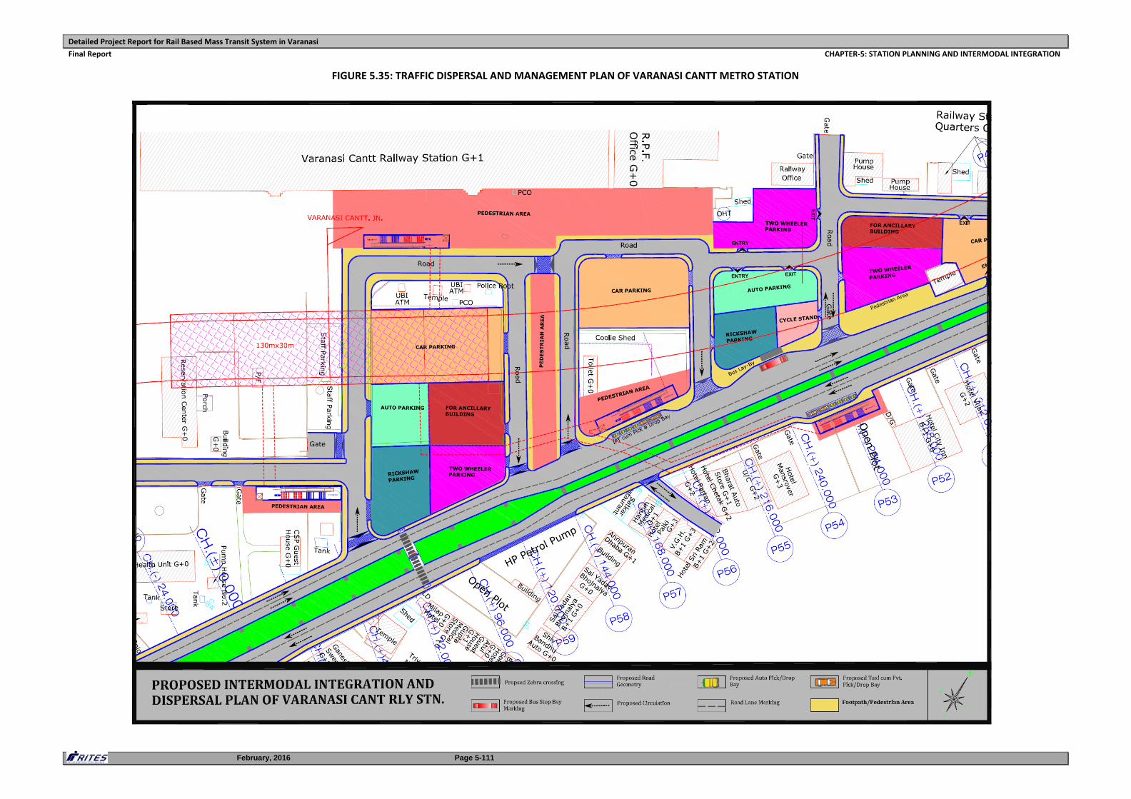
Detailed Project Report for Rail Based Mass Transit System in Varanasi
Final Report CHAPTER‐5: STATION PLANNING AND INTERMODAL INTEGRATION
February, 2016 Page 5-111
FIGURE 5.35: TRAFFIC DISPERSAL AND MANAGEMENT PLAN OF VARANASI CANTT METRO STATION
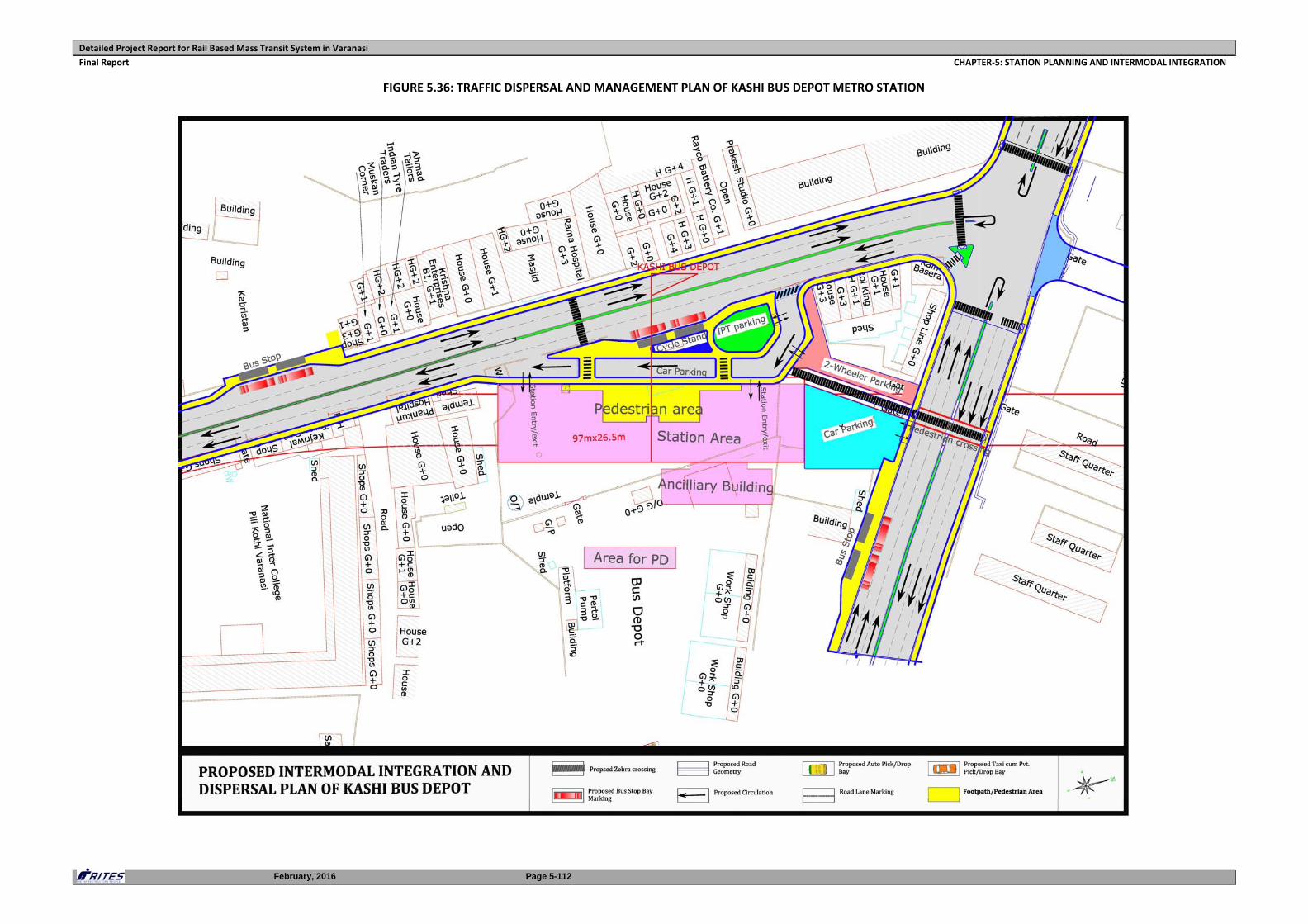
Detailed Project Report for Rail Based Mass Transit System in Varanasi
Final Report CHAPTER‐5: STATION PLANNING AND INTERMODAL INTEGRATION
February, 2016 Page 5-112
FIGURE 5.36: TRAFFIC DISPERSAL AND MANAGEMENT PLAN OF KASHI BUS DEPOT METRO STATION
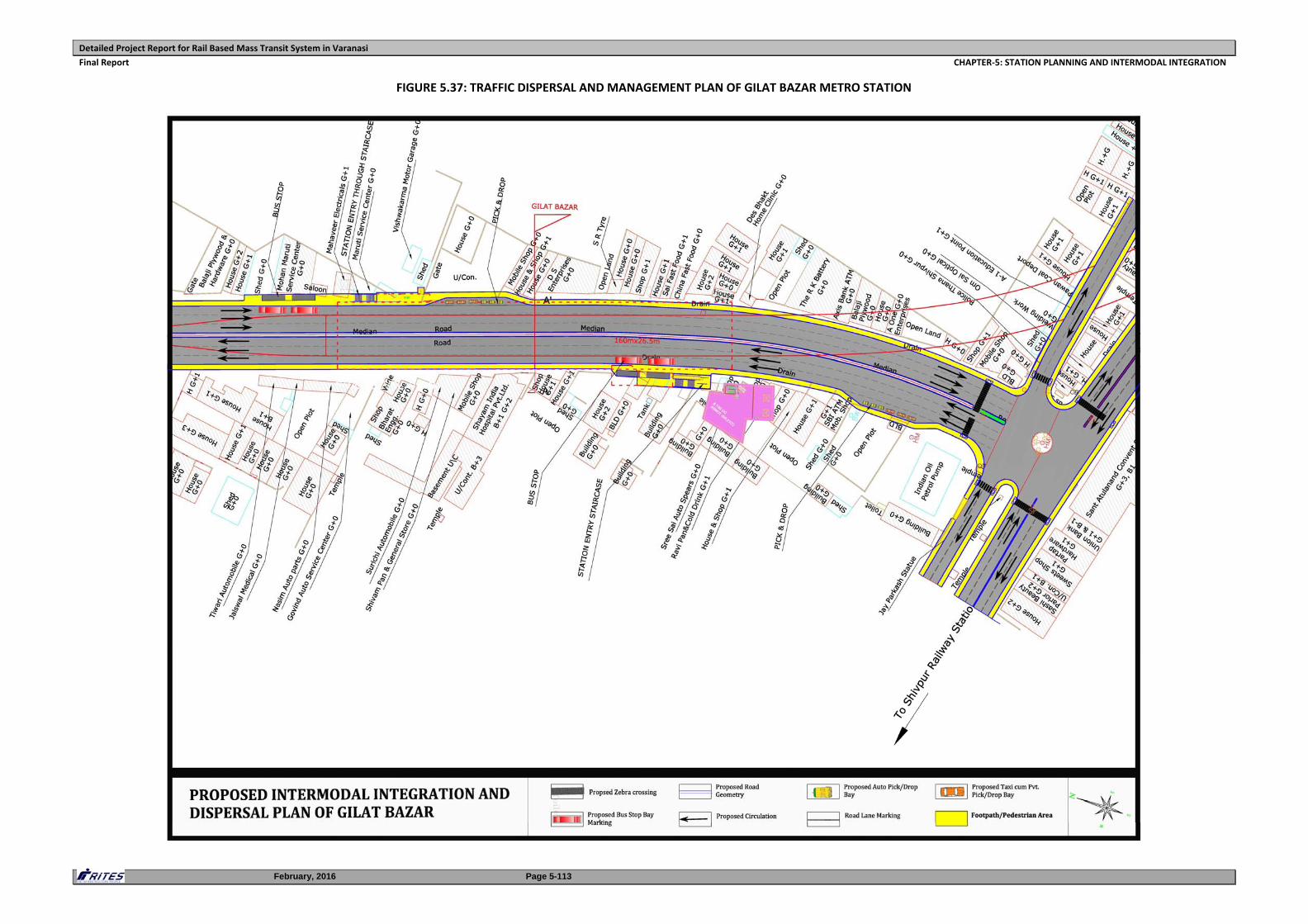
Detailed Project Report for Rail Based Mass Transit System in Varanasi
Final Report CHAPTER‐5: STATION PLANNING AND INTERMODAL INTEGRATION
February, 2016 Page 5-113
FIGURE 5.37: TRAFFIC DISPERSAL AND MANAGEMENT PLAN OF GILAT BAZAR METRO STATION
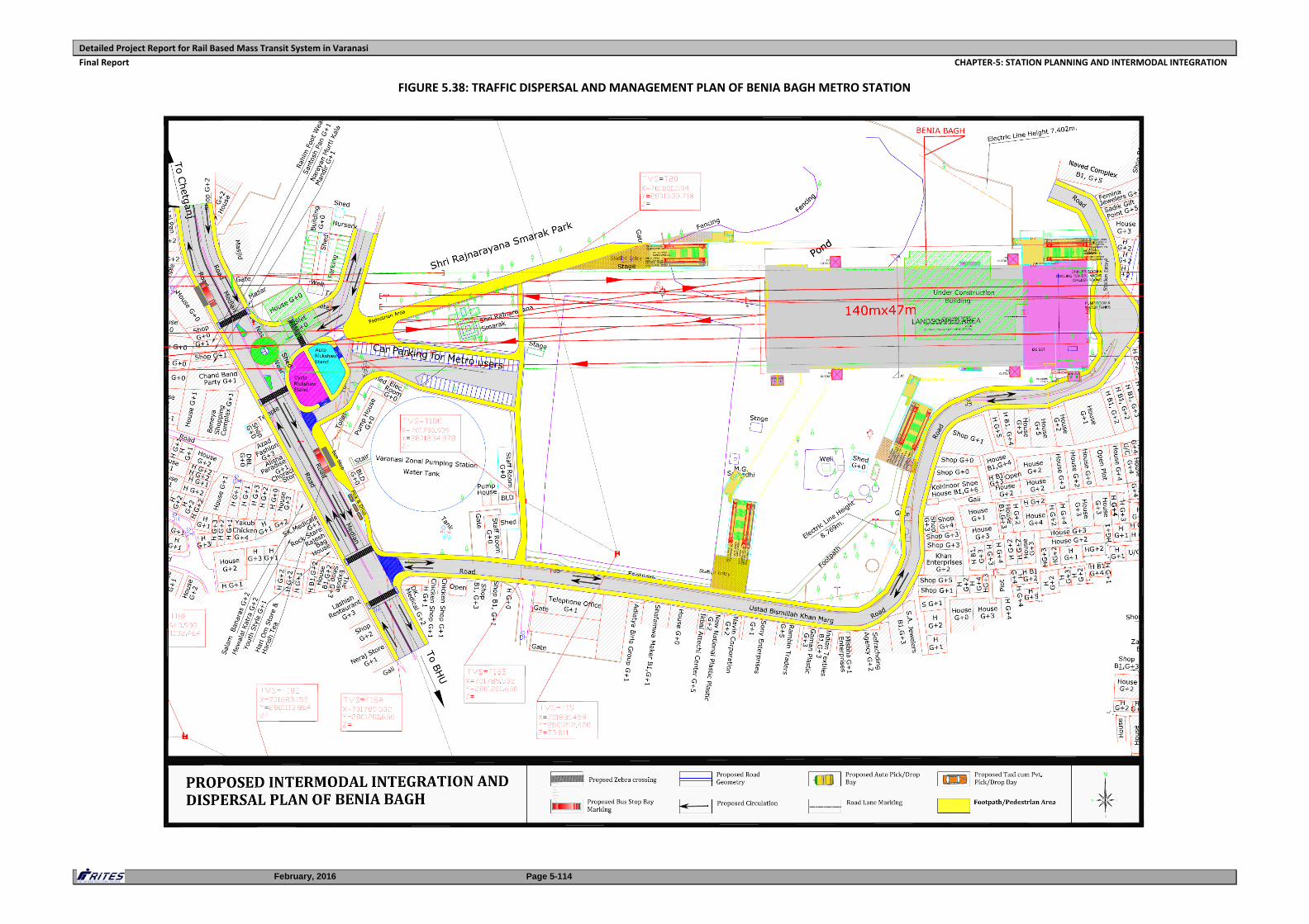
Detailed Project Report for Rail Based Mass Transit System in Varanasi
Final Report CHAPTER‐5: STATION PLANNING AND INTERMODAL INTEGRATION
February, 2016 Page 5-114
FIGURE 5.38: TRAFFIC DISPERSAL AND MANAGEMENT PLAN OF BENIA BAGH METRO STATION
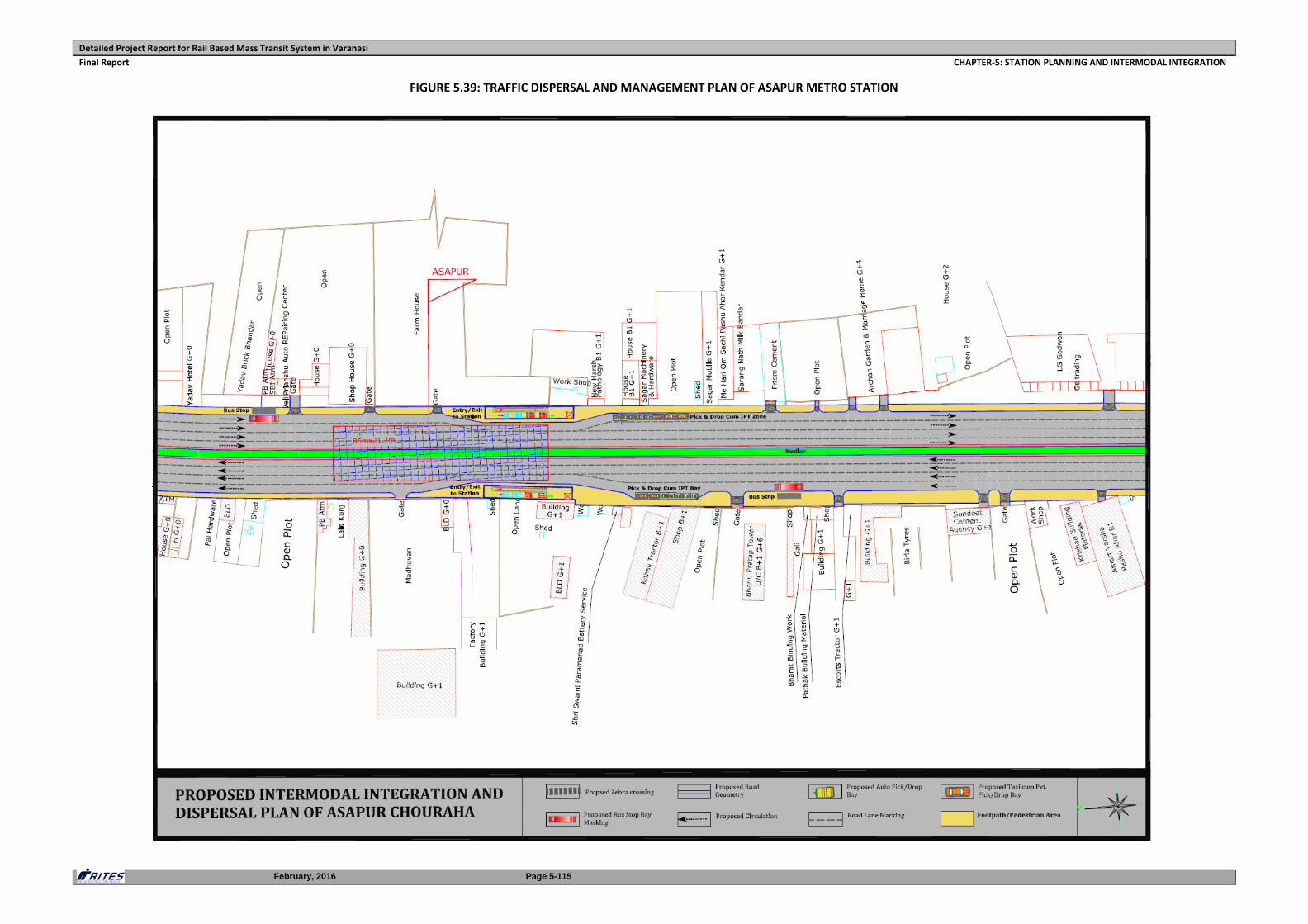
Detailed Project Report for Rail Based Mass Transit System in Varanasi
Final Report CHAPTER‐5: STATION PLANNING AND INTERMODAL INTEGRATION
February, 2016 Page 5-115
FIGURE 5.39: TRAFFIC DISPERSAL AND MANAGEMENT PLAN OF ASAPUR METRO STATION
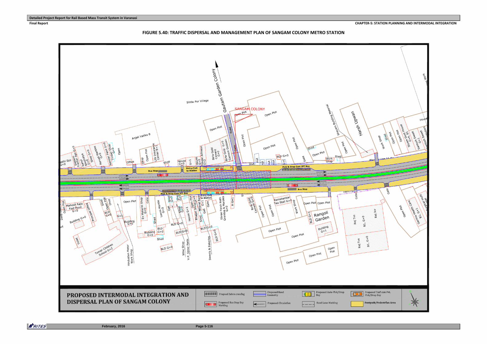
Detailed Project Report for Rail Based Mass Transit System in Varanasi
Final Report CHAPTER‐5: STATION PLANNING AND INTERMODAL INTEGRATION
February, 2016 Page 5-116
FIGURE 5.40: TRAFFIC DISPERSAL AND MANAGEMENT PLAN OF SANGAM COLONY METRO STATION
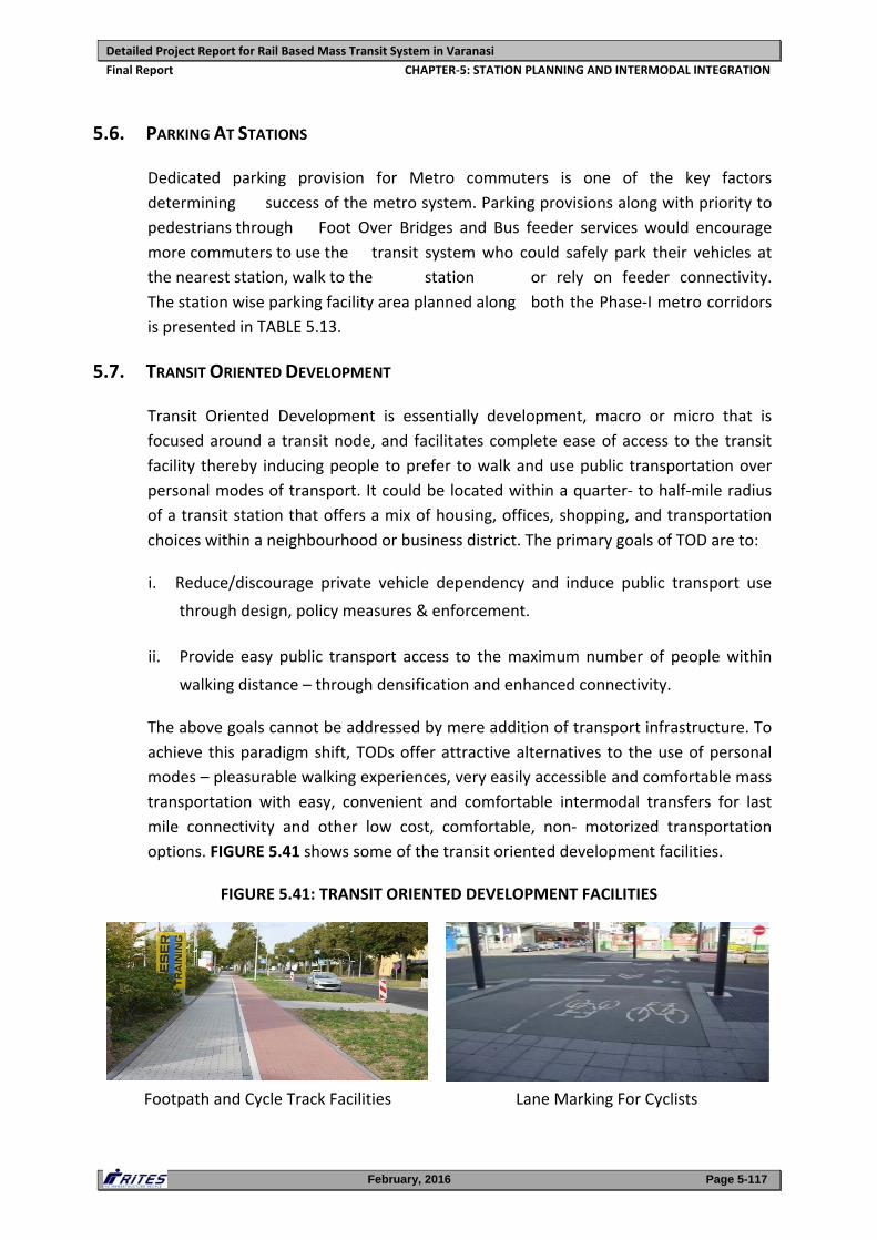
Detailed Project Report for Rail Based Mass Transit System in Varanasi
Final Report CHAPTER‐5: STATION PLANNING AND INTERMODAL INTEGRATION
February, 2016 Page 5-117
5.6. PARKING AT STATIONS
Dedicated parking provision for Metro commuters is one of the key factors
determining success of the metro system. Parking provisions along with priority to
pedestrians through Foot Over Bridges and Bus feeder services would encourage
more commuters to use the transit system who could safely park their vehicles at
the nearest station, walk to the station or rely on feeder connectivity.
The station wise parking facility area planned along both the Phase‐I metro corridors
is presented in TABLE 5.13.
5.7. TRANSIT ORIENTED DEVELOPMENT
Transit Oriented Development is essentially development, macro or micro that is
focused around a transit node, and facilitates complete ease of access to the transit
facility thereby inducing people to prefer to walk and use public transportation over
personal modes of transport. It could be located within a quarter‐ to half‐mile radius
of a transit station that offers a mix of housing, offices, shopping, and transportation
choices within a neighbourhood or business district. The primary goals of TOD are to:
i. Reduce/discourage private vehicle dependency and induce public transport use
through design, policy measures & enforcement.
ii. Provide easy public transport access to the maximum number of people within
walking distance – through densification and enhanced connectivity.
The above goals cannot be addressed by mere addition of transport infrastructure. To
achieve this paradigm shift, TODs offer attractive alternatives to the use of personal
modes – pleasurable walking experiences, very easily accessible and comfortable mass
transportation with easy, convenient and comfortable intermodal transfers for last
mile connectivity and other low cost, comfortable, non‐ motorized transportation
options. FIGURE 5.41 shows some of the transit oriented development facilities.
FIGURE 5.41: TRANSIT ORIENTED DEVELOPMENT FACILITIES
Footpath and Cycle Track Facilities Lane Marking For Cyclists
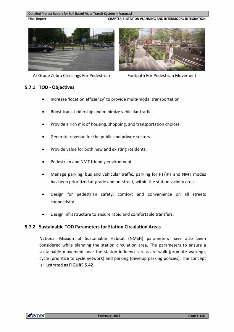
Detailed Project Report for Rail Based Mass Transit System in Varanasi
Final Report CHAPTER‐5: STATION PLANNING AND INTERMODAL INTEGRATION
February, 2016 Page 5-118
At Grade Zebra Crossings For Pedestrian Footpath For Pedestrian Movement
5.7.1 TOD ‐ Objectives
Increase ‘location efficiency’ to provide multi‐modal transportation
Boost transit ridership and minimize vehicular traffic.
Provide a rich mix of housing, shopping, and transportation choices.
Generate revenue for the public and private sectors.
Provide value for both new and existing residents.
Pedestrian and NMT friendly environment
Manage parking, bus and vehicular traffic, parking for PT/IPT and NMT modes
has been prioritized at‐grade and on‐street, within the station vicinity area.
Design for pedestrian safety, comfort and convenience on all streets
connectivity.
Design infrastructure to ensure rapid and comfortable transfers.
5.7.2 Sustainable TOD Parameters for Station Circulation Areas
National Mission of Sustainable Habitat (NMSH) parameters have also been
considered while planning the station circulation area. The parameters to ensure a
sustainable movement near the station influence areas are walk (promote walking),
cycle (prioritize to cycle network) and parking (develop parking policies). The concept
is illustrated as FIGURE 5.42.
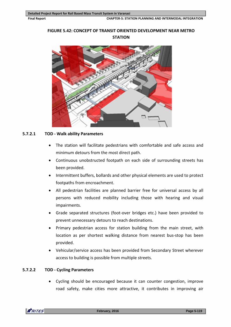
Detailed Project Report for Rail Based Mass Transit System in Varanasi
Final Report CHAPTER‐5: STATION PLANNING AND INTERMODAL INTEGRATION
February, 2016 Page 5-119
FIGURE 5.42: CONCEPT OF TRANSIT ORIENTED DEVELOPMENT NEAR METRO
STATION
5.7.2.1 TOD ‐ Walk ability Parameters
The station will facilitate pedestrians with comfortable and safe access and
minimum detours from the most direct path.
Continuous unobstructed footpath on each side of surrounding streets has
been provided.
Intermittent buffers, bollards and other physical elements are used to protect
footpaths from encroachment.
All pedestrian facilities are planned barrier free for universal access by all
persons with reduced mobility including those with hearing and visual
impairments.
Grade separated structures (foot‐over bridges etc.) have been provided to
prevent unnecessary detours to reach destinations.
Primary pedestrian access for station building from the main street, with
location as per shortest walking distance from nearest bus‐stop has been
provided.
Vehicular/service access has been provided from Secondary Street wherever
access to building is possible from multiple streets.
5.7.2.2 TOD ‐ Cycling Parameters
Cycling should be encouraged because it can counter congestion, improve
road safety, make cities more attractive, it contributes in improving air
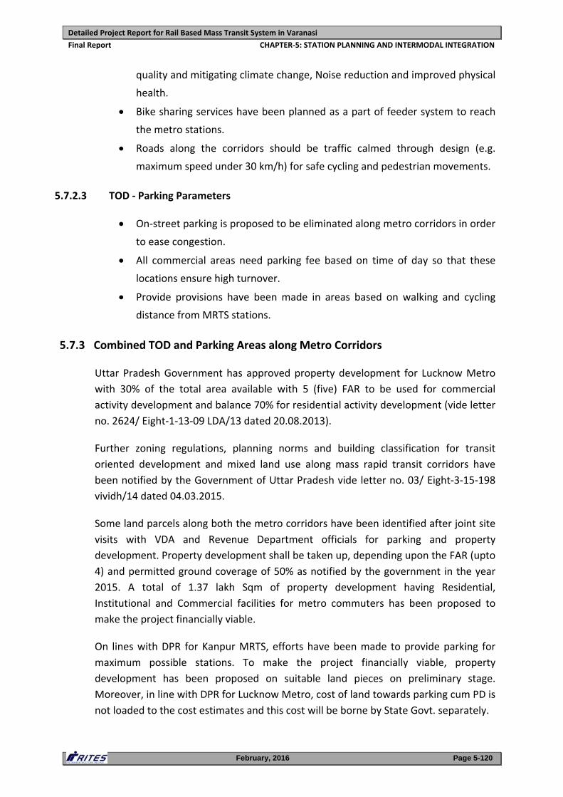
Detailed Project Report for Rail Based Mass Transit System in Varanasi
Final Report CHAPTER‐5: STATION PLANNING AND INTERMODAL INTEGRATION
February, 2016 Page 5-120
quality and mitigating climate change, Noise reduction and improved physical
health.
Bike sharing services have been planned as a part of feeder system to reach
the metro stations.
Roads along the corridors should be traffic calmed through design (e.g.
maximum speed under 30 km/h) for safe cycling and pedestrian movements.
5.7.2.3 TOD ‐ Parking Parameters
On‐street parking is proposed to be eliminated along metro corridors in order
to ease congestion.
All commercial areas need parking fee based on time of day so that these
locations ensure high turnover.
Provide provisions have been made in areas based on walking and cycling
distance from MRTS stations.
5.7.3 Combined TOD and Parking Areas along Metro Corridors
Uttar Pradesh Government has approved property development for Lucknow Metro
with 30% of the total area available with 5 (five) FAR to be used for commercial
activity development and balance 70% for residential activity development (vide letter
no. 2624/ Eight‐1‐13‐09 LDA/13 dated 20.08.2013).
Further zoning regulations, planning norms and building classification for transit
oriented development and mixed land use along mass rapid transit corridors have
been notified by the Government of Uttar Pradesh vide letter no. 03/ Eight‐3‐15‐198
vividh/14 dated 04.03.2015.
Some land parcels along both the metro corridors have been identified after joint site
visits with VDA and Revenue Department officials for parking and property
development. Property development shall be taken up, depending upon the FAR (upto
4) and permitted ground coverage of 50% as notified by the government in the year
2015. A total of 1.37 lakh Sqm of property development having Residential,
Institutional and Commercial facilities for metro commuters has been proposed to
make the project financially viable.
On lines with DPR for Kanpur MRTS, efforts have been made to provide parking for
maximum possible stations. To make the project financially viable, property
development has been proposed on suitable land pieces on preliminary stage.
Moreover, in line with DPR for Lucknow Metro, cost of land towards parking cum PD is
not loaded to the cost estimates and this cost will be borne by State Govt. separately.
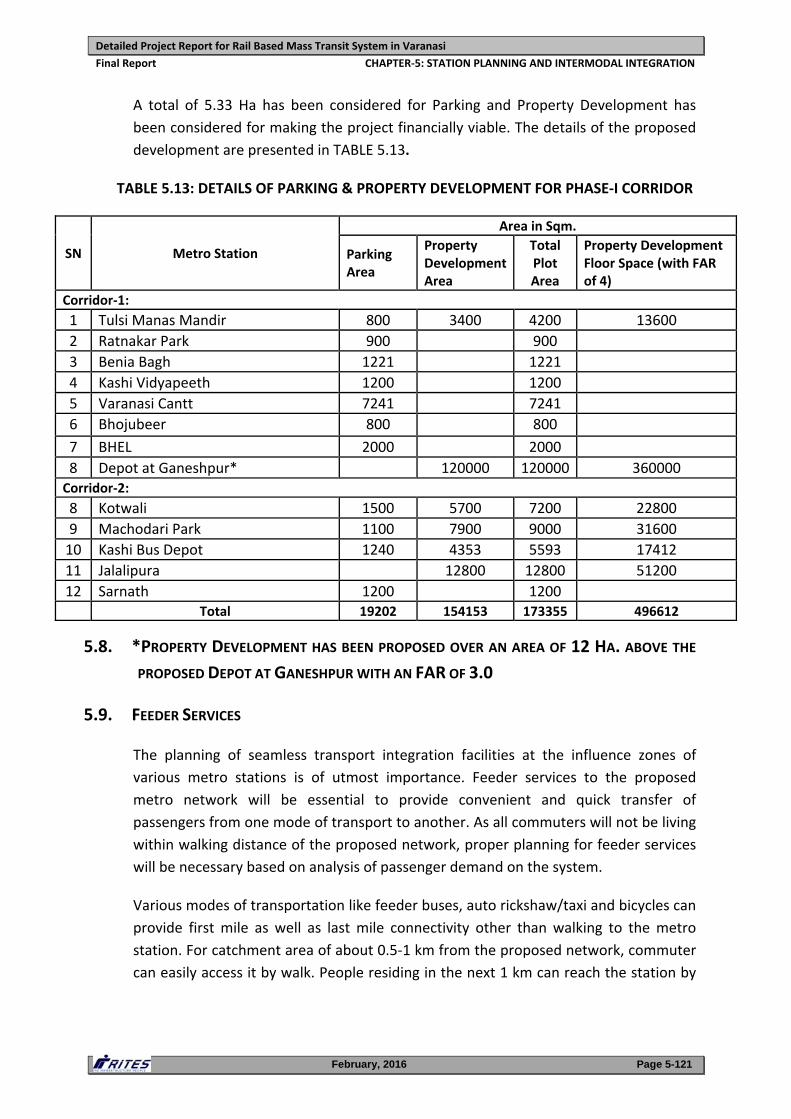
Detailed Project Report for Rail Based Mass Transit System in Varanasi
Final Report CHAPTER‐5: STATION PLANNING AND INTERMODAL INTEGRATION
February, 2016 Page 5-121
A total of 5.33 Ha has been considered for Parking and Property Development has
been considered for making the project financially viable. The details of the proposed
development are presented in TABLE 5.13.
TABLE 5.13: DETAILS OF PARKING & PROPERTY DEVELOPMENT FOR PHASE‐I CORRIDOR
SN Metro Station
Area in Sqm.
Parking Area
Property Development Area
Total Plot Area
Property Development Floor Space (with FAR of 4)
Corridor‐1:
1 Tulsi Manas Mandir 800 3400 4200 13600
2 Ratnakar Park 900 900
3 Benia Bagh 1221 1221
4 Kashi Vidyapeeth 1200 1200
5 Varanasi Cantt 7241 7241
6 Bhojubeer 800 800
7 BHEL 2000 2000
8 Depot at Ganeshpur* 120000 120000 360000 Corridor‐2:
8 Kotwali 1500 5700 7200 22800
9 Machodari Park 1100 7900 9000 31600
10 Kashi Bus Depot 1240 4353 5593 17412
11 Jalalipura 12800 12800 51200
12 Sarnath 1200 1200 Total 19202 154153 173355 496612
5.8. *PROPERTY DEVELOPMENT HAS BEEN PROPOSED OVER AN AREA OF 12 HA. ABOVE THE
PROPOSED DEPOT AT GANESHPUR WITH AN FAR OF 3.0
5.9. FEEDER SERVICES
The planning of seamless transport integration facilities at the influence zones of
various metro stations is of utmost importance. Feeder services to the proposed
metro network will be essential to provide convenient and quick transfer of
passengers from one mode of transport to another. As all commuters will not be living
within walking distance of the proposed network, proper planning for feeder services
will be necessary based on analysis of passenger demand on the system.
Various modes of transportation like feeder buses, auto rickshaw/taxi and bicycles can
provide first mile as well as last mile connectivity other than walking to the metro
station. For catchment area of about 0.5‐1 km from the proposed network, commuter
can easily access it by walk. People residing in the next 1 km can reach the station by
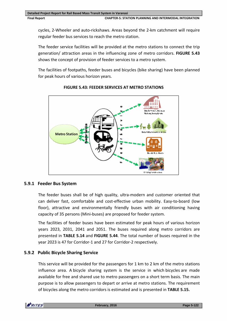
Detailed Project Report for Rail Based Mass Transit System in Varanasi
Final Report CHAPTER‐5: STATION PLANNING AND INTERMODAL INTEGRATION
February, 2016 Page 5-122
cycles, 2‐Wheeler and auto‐rickshaws. Areas beyond the 2‐km catchment will require
regular feeder bus services to reach the metro station.
The feeder service facilities will be provided at the metro stations to connect the trip
generation/ attraction areas in the influencing zone of metro corridors. FIGURE 5.43
shows the concept of provision of feeder services to a metro system.
The facilities of footpaths, feeder buses and bicycles (bike sharing) have been planned
for peak hours of various horizon years.
FIGURE 5.43: FEEDER SERVICES AT METRO STATIONS
5.9.1 Feeder Bus System
The feeder buses shall be of high quality, ultra‐modern and customer oriented that
can deliver fast, comfortable and cost‐effective urban mobility. Easy‐to‐board (low
floor), attractive and environmentally friendly buses with air conditioning having
capacity of 35 persons (Mini‐buses) are proposed for feeder system.
The facilities of feeder buses have been estimated for peak hours of various horizon
years 2023, 2031, 2041 and 2051. The buses required along metro corridors are
presented in TABLE 5.14 and FIGURE 5.44. The total number of buses required in the
year 2023 is 47 for Corridor‐1 and 27 for Corridor‐2 respectively.
5.9.2 Public Bicycle Sharing Service
This service will be provided for the passengers for 1 km to 2 km of the metro stations
influence area. A bicycle sharing system is the service in which bicycles are made
available for free and shared use to metro passengers on a short term basis. The main
purpose is to allow passengers to depart or arrive at metro stations. The requirement
of bicycles along the metro corridors is estimated and is presented in TABLE 5.15.
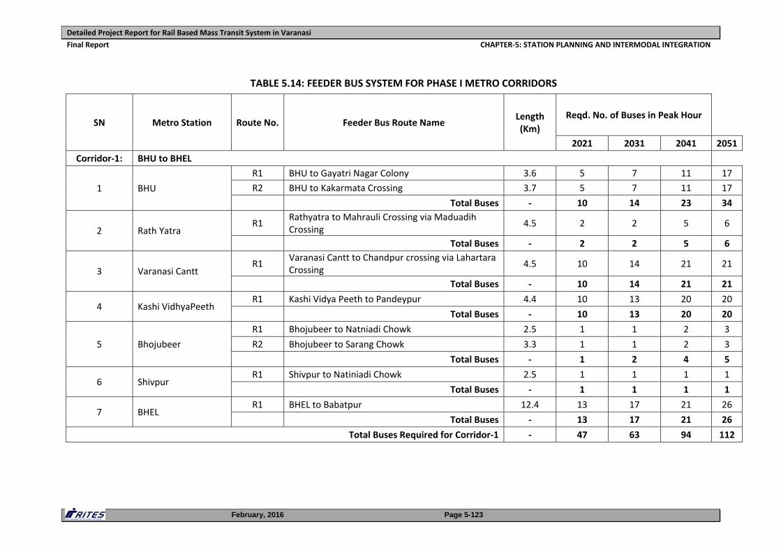
Detailed Project Report for Rail Based Mass Transit System in Varanasi
Final Report CHAPTER‐5: STATION PLANNING AND INTERMODAL INTEGRATION
February, 2016 Page 5-123
TABLE 5.14: FEEDER BUS SYSTEM FOR PHASE I METRO CORRIDORS
SN Metro Station Route No. Feeder Bus Route Name Length (Km)
Reqd. No. of Buses in Peak Hour
2021 2031 2041 2051
Corridor‐1: BHU to BHEL
1 BHU
R1 BHU to Gayatri Nagar Colony 3.6 5 7 11 17
R2 BHU to Kakarmata Crossing 3.7 5 7 11 17
Total Buses ‐ 10 14 23 34
2 Rath Yatra R1
Rathyatra to Mahrauli Crossing via Maduadih Crossing
4.5 2 2 5 6
Total Buses ‐ 2 2 5 6
3 Varanasi Cantt R1
Varanasi Cantt to Chandpur crossing via Lahartara Crossing
4.5 10 14 21 21
Total Buses ‐ 10 14 21 21
4 Kashi VidhyaPeeth R1 Kashi Vidya Peeth to Pandeypur 4.4 10 13 20 20
Total Buses ‐ 10 13 20 20
5 Bhojubeer
R1 Bhojubeer to Natniadi Chowk 2.5 1 1 2 3
R2 Bhojubeer to Sarang Chowk 3.3 1 1 2 3
Total Buses ‐ 1 2 4 5
6 Shivpur R1 Shivpur to Natiniadi Chowk 2.5 1 1 1 1
Total Buses ‐ 1 1 1 1
7 BHEL R1 BHEL to Babatpur 12.4 13 17 21 26
Total Buses ‐ 13 17 21 26
Total Buses Required for Corridor‐1 ‐ 47 63 94 112
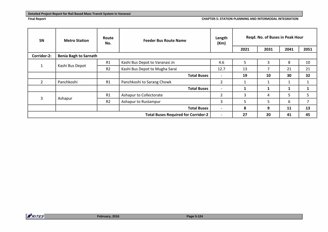
Detailed Project Report for Rail Based Mass Transit System in Varanasi
Final Report CHAPTER‐5: STATION PLANNING AND INTERMODAL INTEGRATION
February, 2016 Page 5-124
SN Metro Station Route No.
Feeder Bus Route Name Length (Km)
Reqd. No. of Buses in Peak Hour
2021 2031 2041 2051
Corridor‐2: Benia Bagh to Sarnath
1 Kashi Bus Depot R1 Kashi Bus Depot to Varanasi Jn 4.6 5 3 8 10
R2 Kashi Bus Depot to Mugha Sarai 12.7 13 7 21 21
Total Buses ‐ 19 10 30 32
2 Panchkoshi R1 Panchkoshi to Sarang Chowk 2 1 1 1 1
Total Buses ‐ 1 1 1 1
3 Ashapur R1 Ashapur to Collectorate 2 3 4 5 5
R2 Ashapur to Rustampur 3 5 5 6 7
Total Buses ‐ 8 9 11 13
Total Buses Required for Corridor‐2 ‐ 27 20 41 45
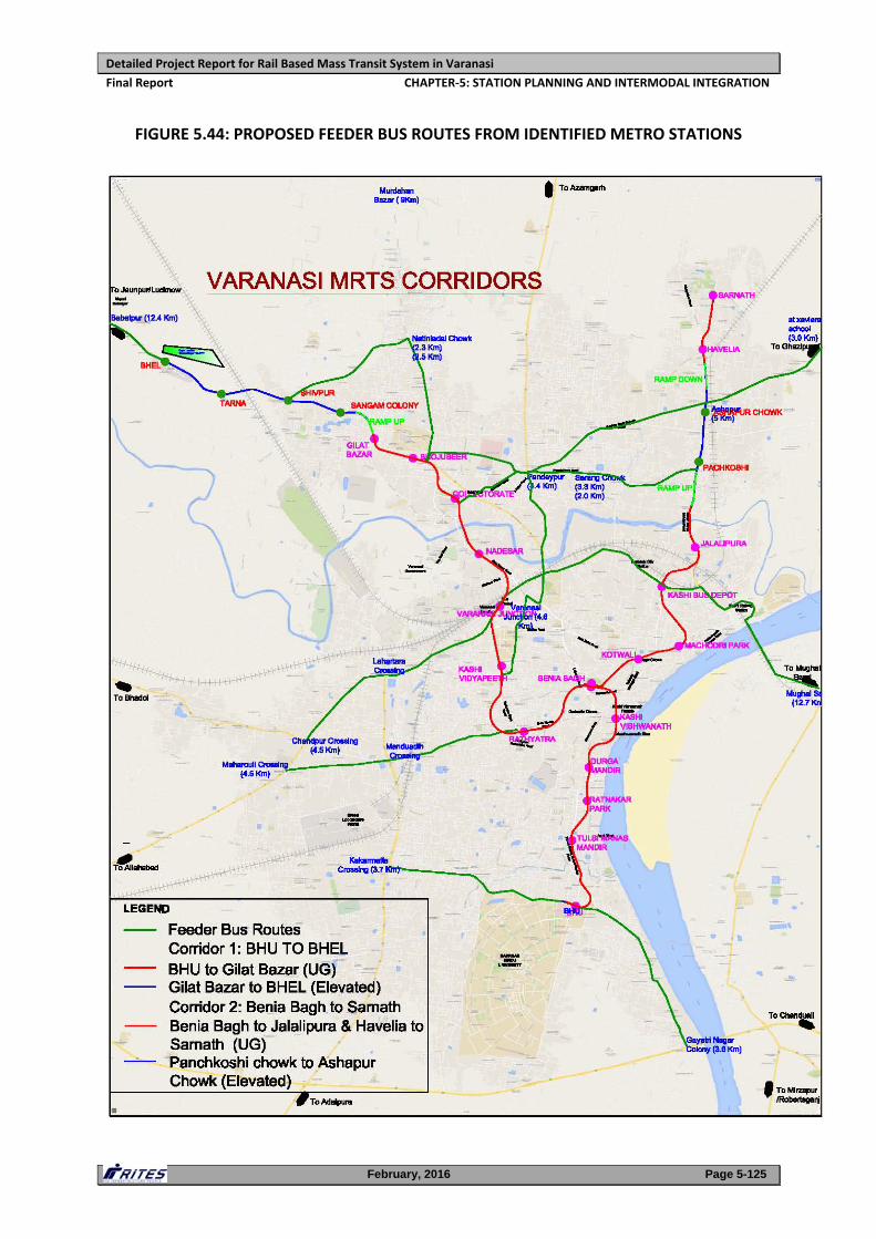
Detailed Project Report for Rail Based Mass Transit System in Varanasi
Final Report CHAPTER‐5: STATION PLANNING AND INTERMODAL INTEGRATION
February, 2016 Page 5-125
FIGURE 5.44: PROPOSED FEEDER BUS ROUTES FROM IDENTIFIED METRO STATIONS
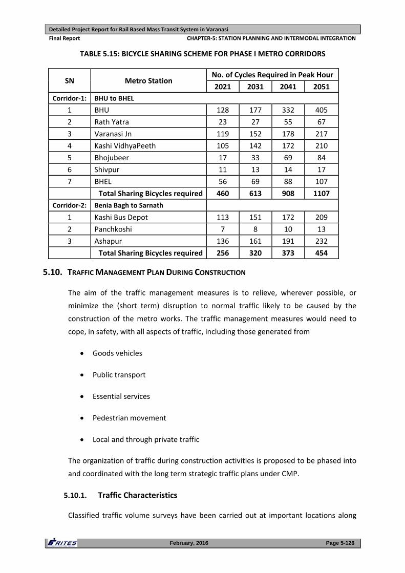
Detailed Project Report for Rail Based Mass Transit System in Varanasi
Final Report CHAPTER‐5: STATION PLANNING AND INTERMODAL INTEGRATION
February, 2016 Page 5-126
TABLE 5.15: BICYCLE SHARING SCHEME FOR PHASE I METRO CORRIDORS
SN Metro Station No. of Cycles Required in Peak Hour
2021 2031 2041 2051
Corridor‐1: BHU to BHEL
1 BHU 128 177 332 405
2 Rath Yatra 23 27 55 67
3 Varanasi Jn 119 152 178 217
4 Kashi VidhyaPeeth 105 142 172 210
5 Bhojubeer 17 33 69 84
6 Shivpur 11 13 14 17
7 BHEL 56 69 88 107
Total Sharing Bicycles required 460 613 908 1107
Corridor‐2: Benia Bagh to Sarnath
1 Kashi Bus Depot 113 151 172 209
2 Panchkoshi 7 8 10 13
3 Ashapur 136 161 191 232
Total Sharing Bicycles required 256 320 373 454
5.10. TRAFFIC MANAGEMENT PLAN DURING CONSTRUCTION
The aim of the traffic management measures is to relieve, wherever possible, or
minimize the (short term) disruption to normal traffic likely to be caused by the
construction of the metro works. The traffic management measures would need to
cope, in safety, with all aspects of traffic, including those generated from
Goods vehicles
Public transport
Essential services
Pedestrian movement
Local and through private traffic
The organization of traffic during construction activities is proposed to be phased into
and coordinated with the long term strategic traffic plans under CMP.
5.10.1. Traffic Characteristics
Classified traffic volume surveys have been carried out at important locations along
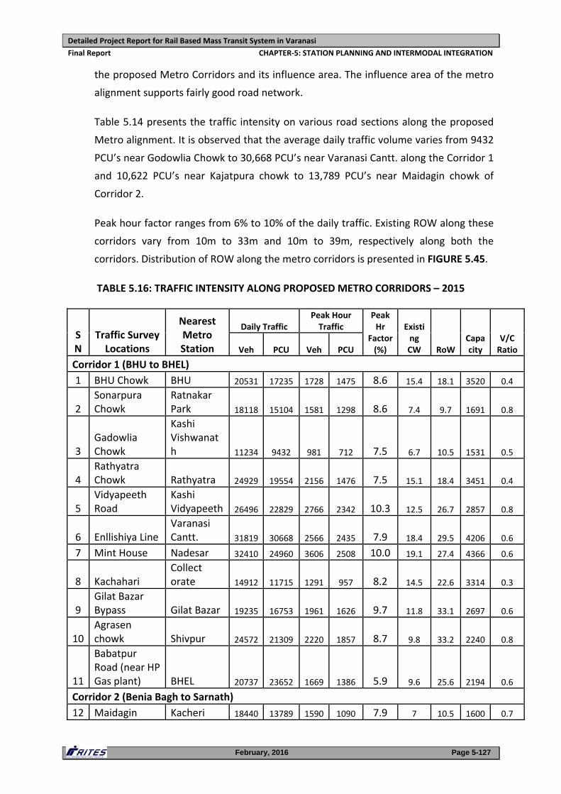
Detailed Project Report for Rail Based Mass Transit System in Varanasi
Final Report CHAPTER‐5: STATION PLANNING AND INTERMODAL INTEGRATION
February, 2016 Page 5-127
the proposed Metro Corridors and its influence area. The influence area of the metro
alignment supports fairly good road network.
Table 5.14 presents the traffic intensity on various road sections along the proposed
Metro alignment. It is observed that the average daily traffic volume varies from 9432
PCU’s near Godowlia Chowk to 30,668 PCU’s near Varanasi Cantt. along the Corridor 1
and 10,622 PCU’s near Kajatpura chowk to 13,789 PCU’s near Maidagin chowk of
Corridor 2.
Peak hour factor ranges from 6% to 10% of the daily traffic. Existing ROW along these
corridors vary from 10m to 33m and 10m to 39m, respectively along both the
corridors. Distribution of ROW along the metro corridors is presented in FIGURE 5.45.
TABLE 5.16: TRAFFIC INTENSITY ALONG PROPOSED METRO CORRIDORS – 2015
SN
Traffic Survey Locations
Nearest Metro Station
Daily Traffic Peak Hour Traffic
Peak Hr
Factor (%)
Existing CW RoW
Capacity
V/C Ratio Veh PCU Veh PCU
Corridor 1 (BHU to BHEL)
1 BHU Chowk BHU 20531 17235 1728 1475 8.6 15.4 18.1 3520 0.4
2 Sonarpura Chowk
Ratnakar Park 18118 15104 1581 1298 8.6 7.4 9.7 1691 0.8
3 Gadowlia Chowk
Kashi Vishwanath 11234 9432 981 712 7.5 6.7 10.5 1531 0.5
4 Rathyatra Chowk Rathyatra 24929 19554 2156 1476 7.5 15.1 18.4 3451 0.4
5 Vidyapeeth Road
Kashi Vidyapeeth 26496 22829 2766 2342 10.3 12.5 26.7 2857 0.8
6 Enllishiya Line Varanasi Cantt. 31819 30668 2566 2435 7.9 18.4 29.5 4206 0.6
7 Mint House Nadesar 32410 24960 3606 2508 10.0 19.1 27.4 4366 0.6
8 Kachahari Collect orate 14912 11715 1291 957 8.2 14.5 22.6 3314 0.3
9 Gilat Bazar Bypass Gilat Bazar 19235 16753 1961 1626 9.7 11.8 33.1 2697 0.6
10 Agrasen chowk Shivpur 24572 21309 2220 1857 8.7 9.8 33.2 2240 0.8
11
Babatpur Road (near HP Gas plant) BHEL 20737 23652 1669 1386 5.9 9.6 25.6 2194 0.6
Corridor 2 (Benia Bagh to Sarnath)
12 Maidagin Kacheri 18440 13789 1590 1090 7.9 7 10.5 1600 0.7
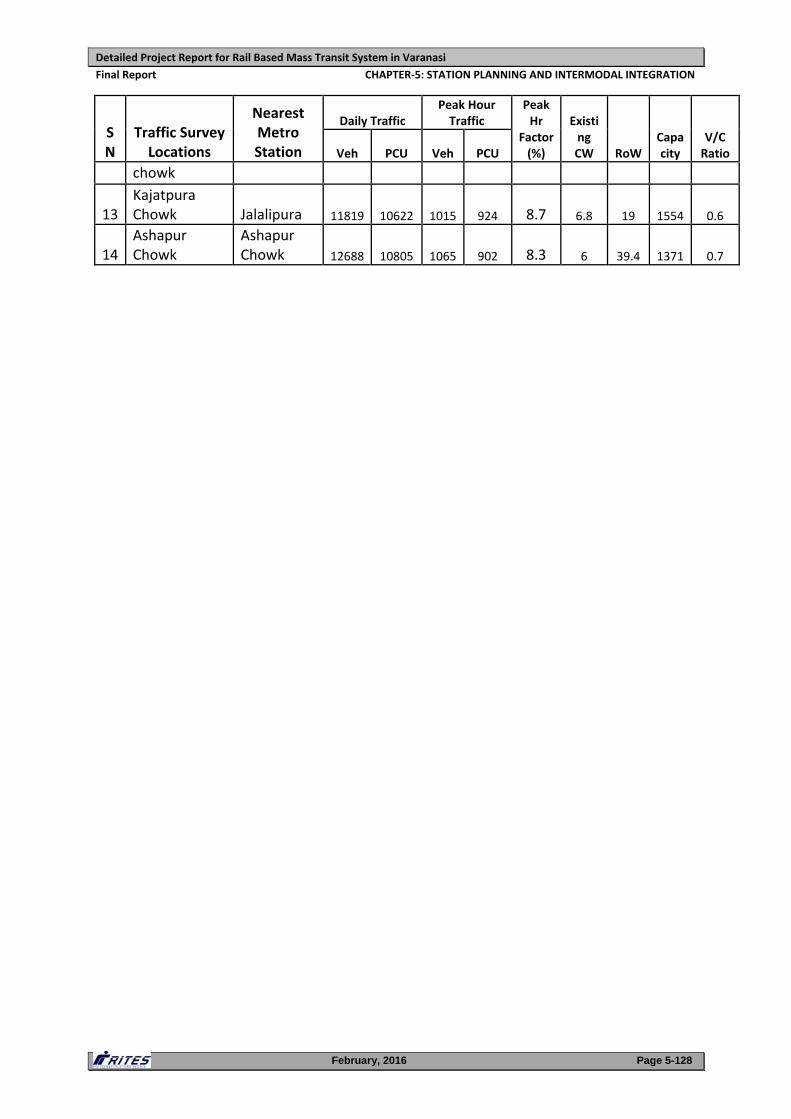
Detailed Project Report for Rail Based Mass Transit System in Varanasi
Final Report CHAPTER‐5: STATION PLANNING AND INTERMODAL INTEGRATION
February, 2016 Page 5-128
SN
Traffic Survey Locations
Nearest Metro Station
Daily Traffic Peak Hour Traffic
Peak Hr
Factor (%)
Existing CW RoW
Capacity
V/C Ratio Veh PCU Veh PCU
chowk
13 Kajatpura Chowk Jalalipura 11819 10622 1015 924 8.7 6.8 19 1554 0.6
14 Ashapur Chowk
Ashapur Chowk 12688 10805 1065 902 8.3 6 39.4 1371 0.7
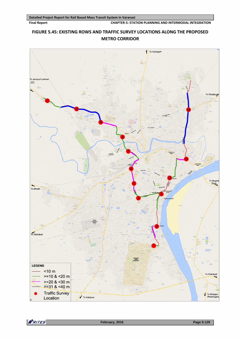
Detailed Project Report for Rail Based Mass Transit System in Varanasi
Final Report CHAPTER‐5: STATION PLANNING AND INTERMODAL INTEGRATION
February, 2016 Page 5-129
FIGURE 5.45: EXISTING ROWS AND TRAFFIC SURVEY LOCATIONS ALONG THE PROPOSED
METRO CORRIDOR
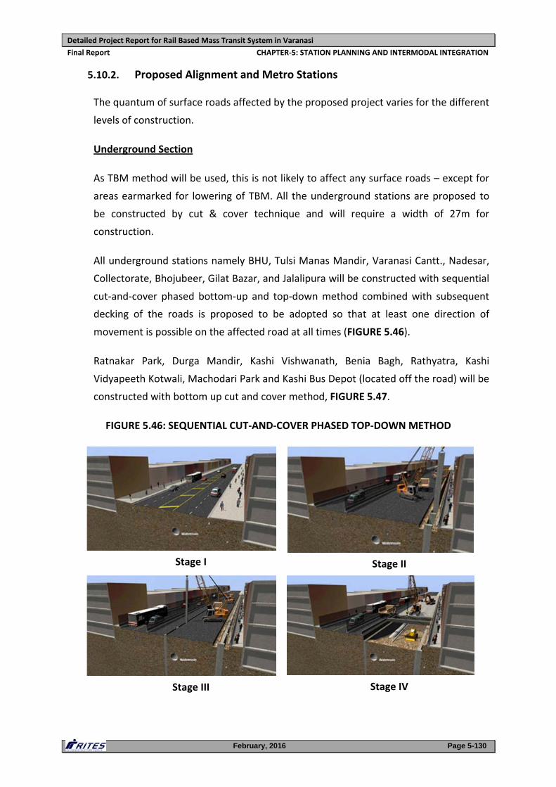
Detailed Project Report for Rail Based Mass Transit System in Varanasi
Final Report CHAPTER‐5: STATION PLANNING AND INTERMODAL INTEGRATION
February, 2016 Page 5-130
5.10.2. Proposed Alignment and Metro Stations
The quantum of surface roads affected by the proposed project varies for the different
levels of construction.
Underground Section
As TBM method will be used, this is not likely to affect any surface roads – except for
areas earmarked for lowering of TBM. All the underground stations are proposed to
be constructed by cut & cover technique and will require a width of 27m for
construction.
All underground stations namely BHU, Tulsi Manas Mandir, Varanasi Cantt., Nadesar,
Collectorate, Bhojubeer, Gilat Bazar, and Jalalipura will be constructed with sequential
cut‐and‐cover phased bottom‐up and top‐down method combined with subsequent
decking of the roads is proposed to be adopted so that at least one direction of
movement is possible on the affected road at all times (FIGURE 5.46).
Ratnakar Park, Durga Mandir, Kashi Vishwanath, Benia Bagh, Rathyatra, Kashi
Vidyapeeth Kotwali, Machodari Park and Kashi Bus Depot (located off the road) will be
constructed with bottom up cut and cover method, FIGURE 5.47.
FIGURE 5.46: SEQUENTIAL CUT‐AND‐COVER PHASED TOP‐DOWN METHOD
Stage I Stage II
Stage III Stage IV
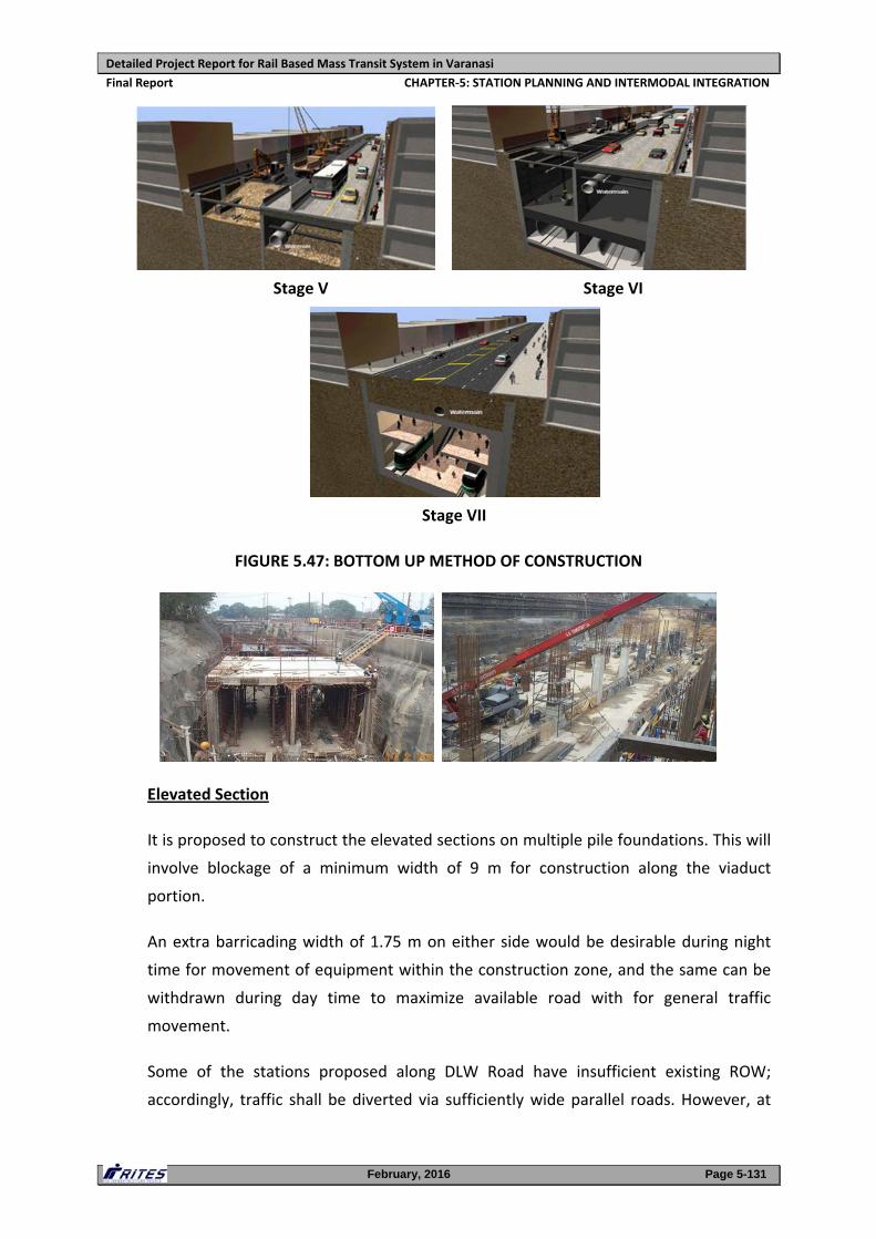
Detailed Project Report for Rail Based Mass Transit System in Varanasi
Final Report CHAPTER‐5: STATION PLANNING AND INTERMODAL INTEGRATION
February, 2016 Page 5-131
Stage V Stage VI
Stage VII
FIGURE 5.47: BOTTOM UP METHOD OF CONSTRUCTION
Elevated Section
It is proposed to construct the elevated sections on multiple pile foundations. This will
involve blockage of a minimum width of 9 m for construction along the viaduct
portion.
An extra barricading width of 1.75 m on either side would be desirable during night
time for movement of equipment within the construction zone, and the same can be
withdrawn during day time to maximize available road with for general traffic
movement.
Some of the stations proposed along DLW Road have insufficient existing ROW;
accordingly, traffic shall be diverted via sufficiently wide parallel roads. However, at
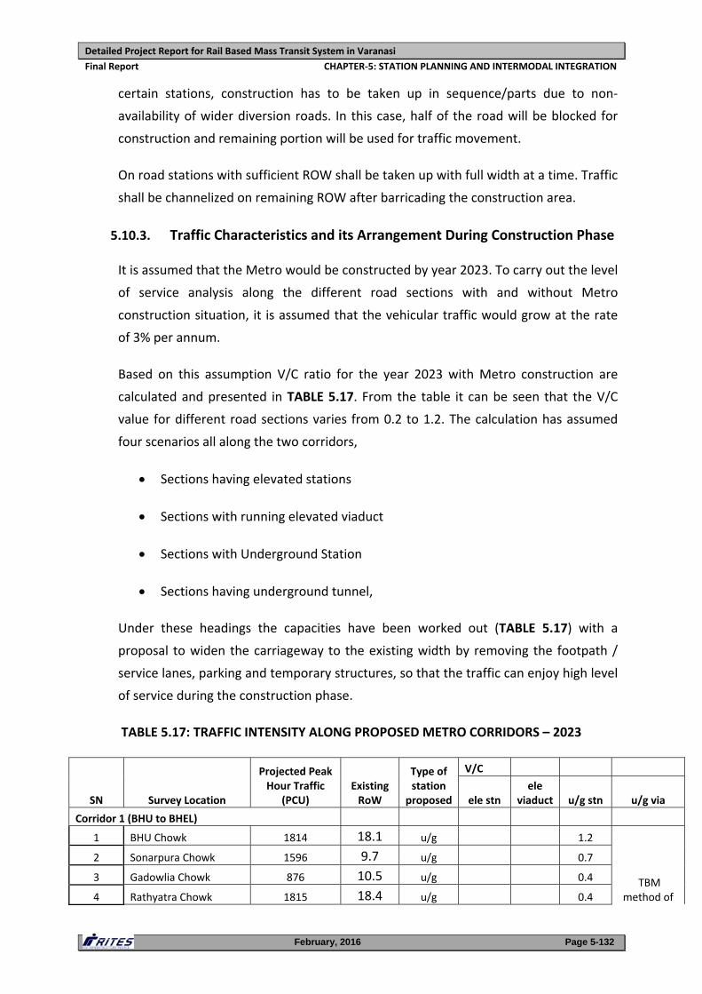
Detailed Project Report for Rail Based Mass Transit System in Varanasi
Final Report CHAPTER‐5: STATION PLANNING AND INTERMODAL INTEGRATION
February, 2016 Page 5-132
certain stations, construction has to be taken up in sequence/parts due to non‐
availability of wider diversion roads. In this case, half of the road will be blocked for
construction and remaining portion will be used for traffic movement.
On road stations with sufficient ROW shall be taken up with full width at a time. Traffic
shall be channelized on remaining ROW after barricading the construction area.
5.10.3. Traffic Characteristics and its Arrangement During Construction Phase
It is assumed that the Metro would be constructed by year 2023. To carry out the level
of service analysis along the different road sections with and without Metro
construction situation, it is assumed that the vehicular traffic would grow at the rate
of 3% per annum.
Based on this assumption V/C ratio for the year 2023 with Metro construction are
calculated and presented in TABLE 5.17. From the table it can be seen that the V/C
value for different road sections varies from 0.2 to 1.2. The calculation has assumed
four scenarios all along the two corridors,
Sections having elevated stations
Sections with running elevated viaduct
Sections with Underground Station
Sections having underground tunnel,
Under these headings the capacities have been worked out (TABLE 5.17) with a
proposal to widen the carriageway to the existing width by removing the footpath /
service lanes, parking and temporary structures, so that the traffic can enjoy high level
of service during the construction phase.
TABLE 5.17: TRAFFIC INTENSITY ALONG PROPOSED METRO CORRIDORS – 2023
SN Survey Location
Projected Peak Hour Traffic
(PCU) Existing RoW
Type of station
proposed
V/C
ele stn ele
viaduct u/g stn u/g via
Corridor 1 (BHU to BHEL)
1 BHU Chowk 1814 18.1 u/g 1.2
TBM method of
2 Sonarpura Chowk 1596 9.7 u/g 0.7
3 Gadowlia Chowk 876 10.5 u/g 0.4
4 Rathyatra Chowk 1815 18.4 u/g 0.4
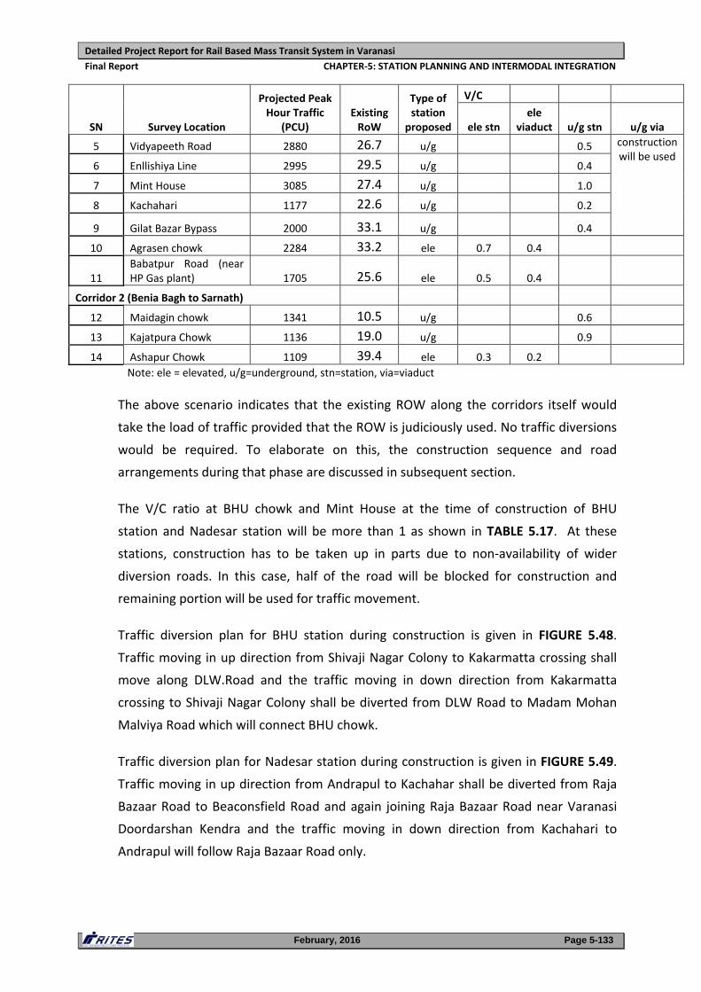
Detailed Project Report for Rail Based Mass Transit System in Varanasi
Final Report CHAPTER‐5: STATION PLANNING AND INTERMODAL INTEGRATION
February, 2016 Page 5-133
SN Survey Location
Projected Peak Hour Traffic
(PCU) Existing RoW
Type of station
proposed
V/C
ele stn ele
viaduct u/g stn u/g via
5 Vidyapeeth Road 2880 26.7 u/g 0.5 construction will be used
6 Enllishiya Line 2995 29.5 u/g 0.4
7 Mint House 3085 27.4 u/g 1.0
8 Kachahari 1177 22.6 u/g 0.2
9 Gilat Bazar Bypass 2000 33.1 u/g 0.4
10 Agrasen chowk 2284 33.2 ele 0.7 0.4
11 Babatpur Road (near HP Gas plant) 1705 25.6 ele 0.5 0.4
Corridor 2 (Benia Bagh to Sarnath)
12 Maidagin chowk 1341 10.5 u/g 0.6
13 Kajatpura Chowk 1136 19.0 u/g 0.9
14 Ashapur Chowk 1109 39.4 ele 0.3 0.2 Note: ele = elevated, u/g=underground, stn=station, via=viaduct
The above scenario indicates that the existing ROW along the corridors itself would
take the load of traffic provided that the ROW is judiciously used. No traffic diversions
would be required. To elaborate on this, the construction sequence and road
arrangements during that phase are discussed in subsequent section.
The V/C ratio at BHU chowk and Mint House at the time of construction of BHU
station and Nadesar station will be more than 1 as shown in TABLE 5.17. At these
stations, construction has to be taken up in parts due to non‐availability of wider
diversion roads. In this case, half of the road will be blocked for construction and
remaining portion will be used for traffic movement.
Traffic diversion plan for BHU station during construction is given in FIGURE 5.48.
Traffic moving in up direction from Shivaji Nagar Colony to Kakarmatta crossing shall
move along DLW.Road and the traffic moving in down direction from Kakarmatta
crossing to Shivaji Nagar Colony shall be diverted from DLW Road to Madam Mohan
Malviya Road which will connect BHU chowk.
Traffic diversion plan for Nadesar station during construction is given in FIGURE 5.49.
Traffic moving in up direction from Andrapul to Kachahar shall be diverted from Raja
Bazaar Road to Beaconsfield Road and again joining Raja Bazaar Road near Varanasi
Doordarshan Kendra and the traffic moving in down direction from Kachahari to
Andrapul will follow Raja Bazaar Road only.
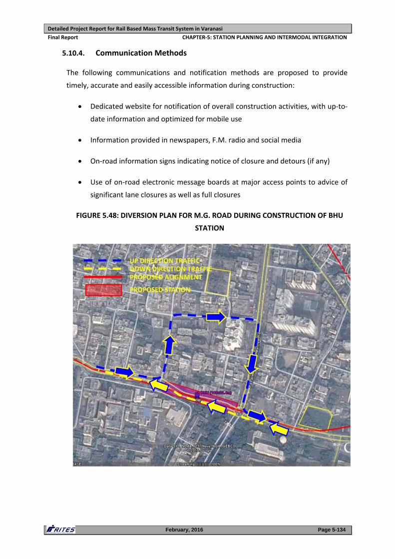
Detailed Project Report for Rail Based Mass Transit System in Varanasi
Final Report CHAPTER‐5: STATION PLANNING AND INTERMODAL INTEGRATION
February, 2016 Page 5-134
5.10.4. Communication Methods
The following communications and notification methods are proposed to provide
timely, accurate and easily accessible information during construction:
Dedicated website for notification of overall construction activities, with up‐to‐
date information and optimized for mobile use
Information provided in newspapers, F.M. radio and social media
On‐road information signs indicating notice of closure and detours (if any)
Use of on‐road electronic message boards at major access points to advice of
significant lane closures as well as full closures
FIGURE 5.48: DIVERSION PLAN FOR M.G. ROAD DURING CONSTRUCTION OF BHU
STATION
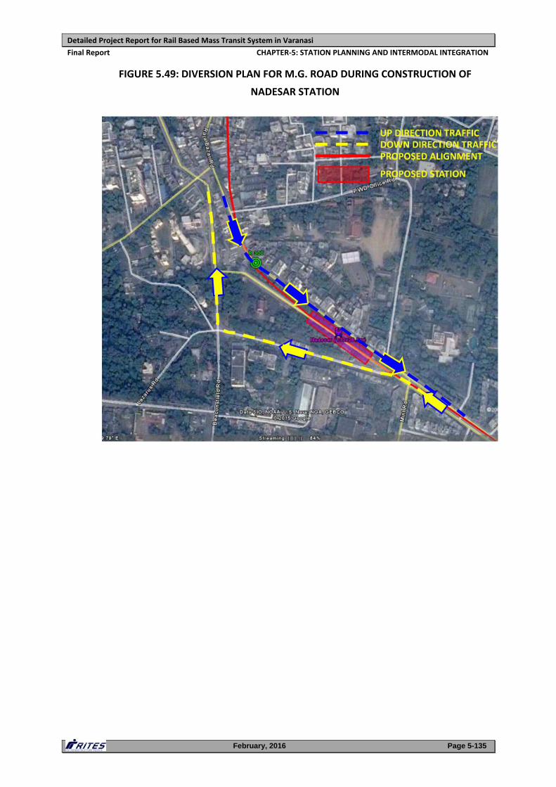
Detailed Project Report for Rail Based Mass Transit System in Varanasi
Final Report CHAPTER‐5: STATION PLANNING AND INTERMODAL INTEGRATION
February, 2016 Page 5-135
FIGURE 5.49: DIVERSION PLAN FOR M.G. ROAD DURING CONSTRUCTION OF
NADESAR STATION
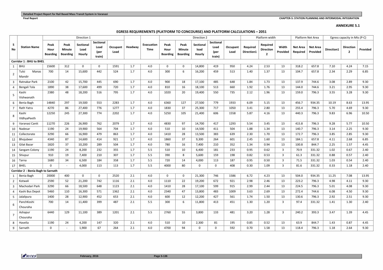
Detailed Project Report for Rail Based Mass Transit System in Varanasi
Final Report CHAPTER‐5: STATION PLANNING AND INTERMODAL INTEGRATION
February, 2016 Page 5-136
ANNEXURE 5.1
EGRESS REQUIREMENTS (PLATFORM TO CONCOURSE) AND PLATFORM CALCULATIONS – 2051
S
No Station Name
Direction 1
Headway Evacuation
Time
Direction 2 Platform width Platform Net Area Egress capacity in Mts (P‐C)
Peak
Hour
Boarding
Peak
Minute
Boarding
Sectional
Load
Hourly
Sectional
Load
(per
train)
Occupant
Load
Peak
Hour
Boarding
Peak
Minute
Boarding
Sectional
load
Hourly
Sectional
Load
(per
train)
Occupant
Load
Required
Direction1
Required
Direction
2
Width
Provided
Net Area
Required
Net Area
Provided Direction1
Direction
2 Provided
Corridor 1 : BHU to BHEL
1 BHU 15600 312 0 0 1591 1.7 4.0 0 0 14,800 419 950 4.24 2.53 13 318.2 657.8 7.10 4.24 7.15
2 Tulsi Manas
Mandir
700 14 15,600 442 524 1.7 4.0 300 6 16,200 459 513 1.40 1.37 13 104.7 657.8 2.34 2.29 6.85
3 Ratnakar Park 2100 42 15,700 445 690 1.7 4.0 900 18 17,100 485 648 1.84 1.73 13 137.9 744.6 3.08 2.89 9.30
4 Bengali Tola 1890 38 17,600 499 720 1.7 4.0 810 16 18,100 513 660 1.92 1.76 13 144.0 744.6 3.21 2.95 9.30
5 Kashi
Vishwanath
2380 48 18,200 516 795 1.7 4.0 1020 20 19,400 550 735 2.12 1.96 13 159.0 796.3 3.55 3.28 9.30
6 Benia Bagh 14840 297 19,500 553 2283 1.7 4.0 6360 127 27,500 779 1933 6.09 5.15 13 456.7 934.35 10.19 8.63 13.95
7 Rath Yatra 4270 86 27,400 776 1277 1.7 4.0 1830 37 25,300 717 1050 3.41 2.80 13 255.4 796.3 5.70 4.69 9.30
8 Kashi
VIdhyaPeeth
12250 245 27,300 774 2202 1.7 4.0 5250 105 21,400 606 1558 5.87 4.16 13 440.3 796.3 9.83 6.96 10.50
9 Varanasi Cantt 11270 226 26,900 762 2079 1.7 4.0 4830 97 14,700 417 1293 5.54 3.45 13 415.8 796.3 9.28 5.77 10.50
10 Nadesar 1190 24 19,900 564 704 1.7 4.0 510 10 14,500 411 504 1.88 1.34 13 140.7 796.3 3.14 2.25 9.30
11 Collectorate 3290 66 16,900 479 863 1.7 4.0 1410 28 13,500 383 639 2.30 1.70 13 172.7 796.3 3.85 2.85 9.30
12 Bhojubeer 4340 87 14,600 414 921 1.7 4.0 1860 37 9,300 264 601 2.45 1.60 13 184.1 657.8 4.11 2.68 6.85
13 Gilat Bazar 1820 37 10,200 289 504 1.7 4.0 780 16 7,400 210 352 1.34 0.94 13 100.8 844.7 2.25 1.57 4.45
14 Sangam Colony 1190 24 8,200 232 355 1.7 5.5 510 10 6,400 181 233 0.95 0.62 3 70.9 331.32 1.02 0.67 2.40
15 Shivpur 910 19 7,400 210 307 1.7 5.5 390 8 5,600 159 198 0.82 0.53 3 61.3 331.32 0.88 0.57 2.40
16 Tarna 1680 34 6,500 184 358 1.7 5.5 720 14 4,000 113 187 0.95 0.50 3 71.5 331.32 1.03 0.54 2.40
17 BHEL 0 ‐ 4,000 113 113 1.7 5.5 4000 80 0 0 408 0.30 1.09 3 81.6 331.32 0.33 1.18 2.40
Corridor 2 : Benia Bagh to Sarnath
1 Benia Bagh 20000 400 0 0 2520 2.1 4.0 0 0 21,300 746 1586 6.72 4.23 13 504.0 934.35 11.25 7.08 13.95
2 Kotwali 2590 52 21,200 742 1116 2.1 4.0 1110 22 19,200 672 921 2.98 2.46 13 223.2 796.3 4.98 4.11 9.30
3 Machodari Park 3290 66 18,500 648 1123 2.1 4.0 1410 28 17,100 599 915 2.99 2.44 13 224.5 796.3 5.01 4.08 9.30
4 Kashi Bus Depot 5460 110 16,300 571 1362 2.1 4.0 2340 47 13,800 483 1009 3.63 2.69 13 272.4 744.6 6.08 4.50 9.30
5 Jalalipura 1400 28 12,900 452 653 2.1 4.0 600 12 12,200 427 561 1.74 1.50 13 130.6 796.3 2.92 2.51 9.30
6 PanchKoshi
Chouraha
700 14 11,400 399 487 2.1 5.5 300 6 11,800 413 451 1.30 1.20 3 97.4 331.32 1.41 1.30 2.40
7 Ashapur
Chouraha
6440 129 11,100 389 1201 2.1 5.5 2760 55 3,800 133 481 3.20 1.28 3 240.2 393.3 3.47 1.39 4.45
8 Havelia 1190 24 4,200 147 320 2.1 4.0 510 10 2,300 81 195 0.85 0.52 13 63.9 844.7 1.43 0.87 4.45
9 Sarnath 0 ‐ 1,900 67 264 2.1 4.0 4700 94 0 0 592 0.70 1.58 13 118.4 796.3 1.18 2.64 9.30
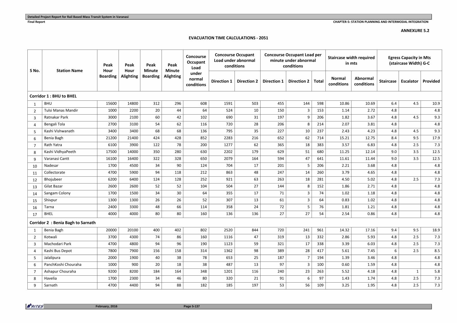
Detailed Project Report for Rail Based Mass Transit System in Varanasi
Final Report CHAPTER‐5: STATION PLANNING AND INTERMODAL INTEGRATION
February, 2016 Page 5-137
ANNEXURE 5.2
EVACUATION TIME CALCULATIONS ‐ 2051
S No. Station Name Peak Hour
Boarding
Peak Hour
Alighting
Peak Minute Boarding
Peak Minute Alighting
Concourse Occupant Load under normal
conditions
Concourse Occupant Load under abnormal
conditions
Concourse Occupant Load per minute under abnormal
conditions
Staircase width required in mts
Egress Capacity in Mts (staircase Width) G‐C
Direction 1 Direction 2 Direction 1 Direction 2 Total Normal
conditions Abnormal conditions
Staircase Escalator Provided
Corridor 1 : BHU to BHEL
1 BHU 15600 14800 312 296 608 1591 503 455 144 598 10.86 10.69 6.4 4.5 10.9
2 Tulsi Manas Mandir 1000 2200 20 44 64 524 10 150 3 153 1.14 2.72 4.8 4.8
3 Ratnakar Park 3000 2100 60 42 102 690 31 197 9 206 1.82 3.67 4.8 4.5 9.3
4 Bengali Tola 2700 3100 54 62 116 720 28 206 8 214 2.07 3.81 4.8 4.8
5 Kashi Vishwanath 3400 3400 68 68 136 795 35 227 10 237 2.43 4.23 4.8 4.5 9.3
6 Benia Bagh 21200 21400 424 428 852 2283 216 652 62 714 15.21 12.75 8.4 9.5 17.9
7 Rath Yatra 6100 3900 122 78 200 1277 62 365 18 383 3.57 6.83 4.8 2.5 7.3
8 Kashi VIdhyaPeeth 17500 14000 350 280 630 2202 179 629 51 680 11.25 12.14 9.0 3.5 12.5
9 Varanasi Cantt 16100 16400 322 328 650 2079 164 594 47 641 11.61 11.44 9.0 3.5 12.5
10 Nadesar 1700 4500 34 90 124 704 17 201 5 206 2.21 3.68 4.8 4.8
11 Collectorate 4700 5900 94 118 212 863 48 247 14 260 3.79 4.65 4.8 4.8
12 Bhojubeer 6200 6400 124 128 252 921 63 263 18 281 4.50 5.02 4.8 2.5 7.3
13 Gilat Bazar 2600 2600 52 52 104 504 27 144 8 152 1.86 2.71 4.8 4.8
14 Sangam Colony 1700 1500 34 30 64 355 17 71 3 74 1.02 1.18 4.8 4.8
15 Shivpur 1300 1300 26 26 52 307 13 61 3 64 0.83 1.02 4.8 4.8
16 Tarna 2400 3300 48 66 114 358 24 72 5 76 1.81 1.21 4.8 4.8
17 BHEL 4000 4000 80 80 160 136 136 27 27 54 2.54 0.86 4.8 4.8
Corridor 2 : Benia Bagh to Sarnath
1 Benia Bagh 20000 20100 400 402 802 2520 844 720 241 961 14.32 17.16 9.4 9.5 18.9
2 Kotwali 3700 4300 74 86 160 1116 47 319 13 332 2.86 5.93 4.8 2.5 7.3
3 Machodari Park 4700 4800 94 96 190 1123 59 321 17 338 3.39 6.03 4.8 2.5 7.3
4 Kashi Bus Depot 7800 7900 156 158 314 1362 98 389 28 417 5.61 7.45 6 2.5 8.5
5 Jalalipura 2000 1900 40 38 78 653 25 187 7 194 1.39 3.46 4.8 4.8
6 PanchKoshi Chouraha 1000 900 20 18 38 487 13 97 3 100 0.60 1.59 4.8 4.8
7 Ashapur Chouraha 9200 8200 184 164 348 1201 116 240 23 263 5.52 4.18 4.8 1 5.8
8 Havelia 1700 2300 34 46 80 320 21 91 6 97 1.43 1.74 4.8 2.5 7.3
9 Sarnath 4700 4400 94 88 182 185 197 53 56 109 3.25 1.95 4.8 2.5 7.3
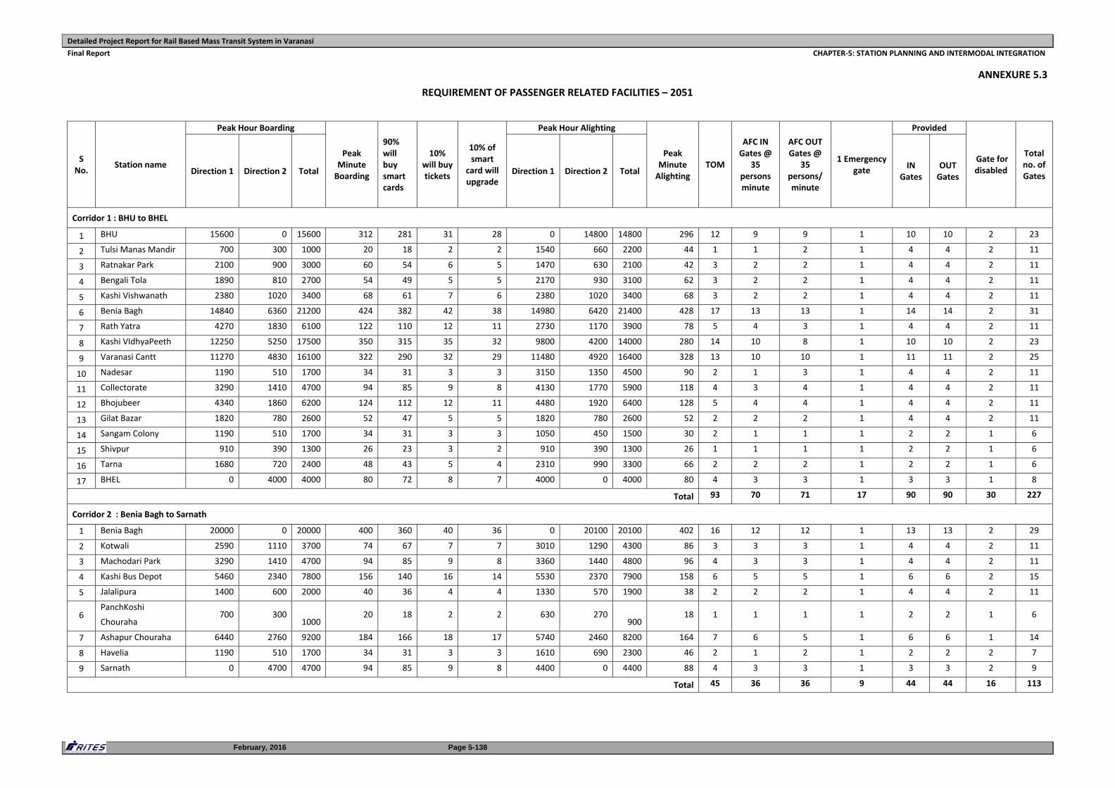
Detailed Project Report for Rail Based Mass Transit System in Varanasi
Final Report CHAPTER‐5: STATION PLANNING AND INTERMODAL INTEGRATION
February, 2016 Page 5-138
ANNEXURE 5.3
REQUIREMENT OF PASSENGER RELATED FACILITIES – 2051
S No.
Station name
Peak Hour Boarding
Peak Minute Boarding
90% will buy smart cards
10% will buy tickets
10% of smart
card will upgrade
Peak Hour Alighting
Peak Minute Alighting
TOM
AFC IN Gates @
35 persons minute
AFC OUT Gates @
35 persons/ minute
1 Emergency gate
Provided
Gate for disabled
Total no. of Gates
Direction 1 Direction 2 Total Direction 1 Direction 2 Total IN
Gates OUT Gates
Corridor 1 : BHU to BHEL
1 BHU 15600 0 15600 312 281 31 28 0 14800 14800 296 12 9 9 1 10 10 2 23
2 Tulsi Manas Mandir 700 300 1000 20 18 2 2 1540 660 2200 44 1 1 2 1 4 4 2 11
3 Ratnakar Park 2100 900 3000 60 54 6 5 1470 630 2100 42 3 2 2 1 4 4 2 11
4 Bengali Tola 1890 810 2700 54 49 5 5 2170 930 3100 62 3 2 2 1 4 4 2 11
5 Kashi Vishwanath 2380 1020 3400 68 61 7 6 2380 1020 3400 68 3 2 2 1 4 4 2 11
6 Benia Bagh 14840 6360 21200 424 382 42 38 14980 6420 21400 428 17 13 13 1 14 14 2 31
7 Rath Yatra 4270 1830 6100 122 110 12 11 2730 1170 3900 78 5 4 3 1 4 4 2 11
8 Kashi VIdhyaPeeth 12250 5250 17500 350 315 35 32 9800 4200 14000 280 14 10 8 1 10 10 2 23
9 Varanasi Cantt 11270 4830 16100 322 290 32 29 11480 4920 16400 328 13 10 10 1 11 11 2 25
10 Nadesar 1190 510 1700 34 31 3 3 3150 1350 4500 90 2 1 3 1 4 4 2 11
11 Collectorate 3290 1410 4700 94 85 9 8 4130 1770 5900 118 4 3 4 1 4 4 2 11
12 Bhojubeer 4340 1860 6200 124 112 12 11 4480 1920 6400 128 5 4 4 1 4 4 2 11
13 Gilat Bazar 1820 780 2600 52 47 5 5 1820 780 2600 52 2 2 2 1 4 4 2 11
14 Sangam Colony 1190 510 1700 34 31 3 3 1050 450 1500 30 2 1 1 1 2 2 1 6
15 Shivpur 910 390 1300 26 23 3 2 910 390 1300 26 1 1 1 1 2 2 1 6
16 Tarna 1680 720 2400 48 43 5 4 2310 990 3300 66 2 2 2 1 2 2 1 6
17 BHEL 0 4000 4000 80 72 8 7 4000 0 4000 80 4 3 3 1 3 3 1 8
Total 93 70 71 17 90 90 30 227
Corridor 2 : Benia Bagh to Sarnath
1 Benia Bagh 20000 0 20000 400 360 40 36 0 20100 20100 402 16 12 12 1 13 13 2 29
2 Kotwali 2590 1110 3700 74 67 7 7 3010 1290 4300 86 3 3 3 1 4 4 2 11
3 Machodari Park 3290 1410 4700 94 85 9 8 3360 1440 4800 96 4 3 3 1 4 4 2 11
4 Kashi Bus Depot 5460 2340 7800 156 140 16 14 5530 2370 7900 158 6 5 5 1 6 6 2 15
5 Jalalipura 1400 600 2000 40 36 4 4 1330 570 1900 38 2 2 2 1 4 4 2 11
6 PanchKoshi
Chouraha 700 300
1000 20 18 2 2 630 270
900 18 1 1 1 1 2 2 1 6
7 Ashapur Chouraha 6440 2760 9200 184 166 18 17 5740 2460 8200 164 7 6 5 1 6 6 1 14
8 Havelia 1190 510 1700 34 31 3 3 1610 690 2300 46 2 1 2 1 2 2 2 7
9 Sarnath 0 4700 4700 94 85 9 8 4400 0 4400 88 4 3 3 1 3 3 2 9
Total 45 36 36 9 44 44 16 113


