Embed Size (px)
Citation preview
Ba
se
sta
tio
n a
nt
en
na
s
Base station antennas
Rosenberger Asia Pacific Electronic Co., Ltd.
No.3, Anxiang Street, Block B, Tianzhu Airport Industrial Zone
Beijing, China 101300
Tel : (+86 10) 80481995
Fax : (+86 10) 80497052
Email: [email protected]
Rosenberger (Shanghai) Technology Co.,Ltd.
No. 303, Xinke Road, Qingpu Industrial Zone
Shanghai, China 201707
Tel : (+86 21) 69214567
Fax : (+86 21) 69212923
Rosenberger Asia Pacific Electronic Co., Ltd. Shanghai Division
B7, No. 509, Renqing Road, East Zone of Zhangjiang High-Tech Park
Shanghai, China 201201
Tel : (+86 21) 58995997
Fax : (+86 21) 58995594
Rosenberger Asia Pacific Electronic Co., Ltd. Dongguan Division
3rd Floor, Building E, Pingqian Industrial Park, Dongkeng Town
Dongguan, Guangdong Province, China
Tel : (+86 769) 82802098
Fax : (+86 769) 82802099
Rosenberger All rights reserved. 1st Edition, 2013
Please visit our website: www.RosenbergerAP.com
www.RosenbergerAP.com

www.RosenbergerAP.com
IntroductIon
Rosenberger Hochfrequenztechnik GmbH&Co. was founded in Germany in 1958 and ranks among the leading manufacturers of high-speed interconnect solutions worldwide. To serve the continuous growth and demand of the global market, Rosenberger Asia Pacific Electronic Co., Ltd. was established in China in 1997. With its long tradition of excellence and providing creative solutions, Rosenberger Asia Pacific has excelled and earned an outstanding reputation in the Asia Pacific region.
Rosenberger Asia Pacific provides products and solutions for Telecommunication, Automotive Electronics, Information Technology, Test & Measurement, Aviation, and Medical & Industries. Their product portfolio includes:• RF In-Cabinet Connection Solutions• Total Site Solutions for Base Station Applications• In-Building Wireless Solutions and Enhancement• Microwave Transmission Systems• Passive Intermodulation Analyzers• FTTX• Data Center Cabling Systems
Rosenberger HQ, Bavaria, Germany

A
B
C
D
E
www.RosenbergerAP.com
A sales network covering the entire Asia Pacific region generates an annual turnover close to 200 million USD. Reliability and competitiveness are the cornerstones of this sustainable growth, resulting in long term partnerships with most of the leading companies in their respective industries.
Rosenberger Asia Pacific maintains 6 modern manufacturing and R&D base locations in Beijing, Shanghai, and Dongguan in China; and New Delhi in India, the largest of its kind in the Asia Pacific Region. Rosenberger Asia Pacific is an ISO 9001 quality system, ISO 14001 environmental system, and ISO/TS16949 automotive industry system certified company. Equipped with advanced machining, electronic plating, assembly and testing centers and staffed by a large group of more then 200 R&D engineers, Rosenberger Asia Pacific has developed first class production assembly lines and exercises stringent product and quality control.
Presently, Rosenberger Asia Pacific maintains a far reaching network of R&D, Production, Sales and Service which extends to the whole Asia Pacific and Middle East area. For over 50 years Rosenberger has established its brand all over the world. In the future, Rosenberger Asia Pacific will continue to provide excellent product solutions and services for its customers in the entire region.
Rosenberger Asia Pacific:
A: Beijing − Headquarters, R&D, and Production
B: Shanghai Zhangjiang − R&D and Production
C: Shanghai Qingpu − R&D and Production
D: India − R&D and Production
E: Dongguan − R&D and Production

www.RosenbergerAP.com
MISSIon StAtEMEnt
corE VAluE
• Design, manufacture and deploy total solutions for telecommunication networks worldwide
• Create value for our customers through innovative products, customized services and cost effective solutions
• Maintain the highest quality standards, state-of-the-art manufacturing facilities and employ reliable supply chain management to achieve and exceed customer expectations
• Be socially responsible to our community and environment • Be committed to employee's personnel development
• Value Innovation• Customer Focus• Sustainable Growth• Social Responsibility

www.RosenbergerAP.com
ProductPortFolIoS
Base Station Antenna Feeder SystemsWireless Coverage Optimization SolutionsMicrowave Backhaul SolutionsRF In-cabinet SolutionsPassive Intermodulation Measurement SystemsFTTA/FTTH Optical Fiber SolutionsOSP Fiber Optic Outdoor Plant SolutionsIn-building Optical Network Connectivity SolutionsLow Frequency Cables and ComponentsNetwork Optimization Services
Premise Network Cabling ProductsData Center/Cloud Computing SolutionsIntelligent Infrastructure Management System
Test CablesPrecision ConnectorsCalibrationsAccessories and Tools
FAKRA Connectors and Cable AssembliesHSD® System
Non-Magnetic RF Connectors Non-Magnetic RF Cable AssembliesData/RF/Power/DC Hybrid Connectors and AssembliesCustom Data/Power Connectivity SystemFiber Optic Connectivity Products
Telecommunication System Solutions
IT/Data Communication
Testing and Measurement
Automotive
Medical & Industrial

contEnt
ROSENBERGER S-WAVE® ANTENNA TECHNOLOGy
————————————————————————————————————————————————
PART NUMBER GUIDE
————————————————————————————————————————————————
ANTENNA INDEx
————————————————————————————————————————————————
OMNI-DIRECTIONAL ANTENNAS
————————————————————————————————————————————————
LOW BAND PANEL ANTENNAS 698-960MHz Dual Polarization +45°/–45°
————————————————————————————————————————————————
LOW BAND PANEL ANTENNAS 806-960MHz Vertical Polarization
————————————————————————————————————————————————
HIGH BAND PANEL ANTENNAS 1710-2170MHz Dual Polarization +45°/–45°
————————————————————————————————————————————————
HIGH BAND PANEL ANTENNAS 1710-2170MHz Vertical Polarization
————————————————————————————————————————————————
DUAL BAND ANTENNAS 2 PORTS (with built-in Combiner) Dual Polarization +45°/–45°
————————————————————————————————————————————————
DUAL BAND ANTENNAS 4 PORTS Dual Polarization +45°/–45°
————————————————————————————————————————————————
TRIPLE BAND ANTENNAS 6 PORTS Dual Polarization +45°/–45°
————————————————————————————————————————————————
MULTI-BAND ANTENNAS Dual Polarization +45°/–45°
————————————————————————————————————————————————
TRI-SECTOR ANTENNAS Dual Polarization +45°/–45°
————————————————————————————————————————————————
LTE ExTRA-WIDE BAND ANTENNAS 1710-2690MHz Dual Polarization +45°/–45°
————————————————————————————————————————————————
REMOTE ELECTRICAL TILT
————————————————————————————————————————————————
INSTALLATION KITS
————————————————————————————————————————————————
ROSENBERGER SERVICE
————————————————————————————————————————————————
06
08
09
14
18
30
38
47
51
61
71
75
78
80
85
93
97
roSEnbErgEr S-WAVE® AntEnnA tEchnology
0605
BASE STATION ANTENNAS

OUTLINE
Rosenberger’s S-Wave® antenna products cover several frequency bands: 700LTE, AMPS, GSM, DCS, PCS, AWS, UMTS, WiMAx, and 4G-LTE. They are designed to meet the toughest applications and operating requirements covering single band, broadband and multi-band. Every antenna series is based on the experience and solid theoretical knowledge of our international R&D team. Through extensive testing, simulation and optimization, the S-Wave® antenna guarantees excellent mechanical and electrical performance. Rosenberger is committed to supplying the highest quality and most cost-effective antenna solutions.
Design Philosophy
Rosenberger adopts many state-of-the-art CAD simulation tools including ANSyS HFSS, AutoCAD, SolidWorks. These mechanical and electrical design tools allow Rosenberger’s design team to analyze and optimize the design and integration of antenna radiation/circuits for every application.
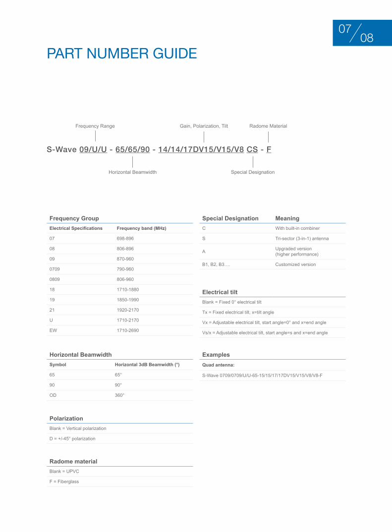
PArt nuMbEr guIdE
Frequency Range Gain, Polarization, Tilt Radome Material
Horizontal Beamwidth Special Designation
S-Wave 09/U/U - 65/65/90 - 14/14/17DV15/V15/V8 CS - F
Frequency GroupElectrical Specifications Frequency band (MHz)
07 698-896
08 806-896
09 870-960
0709 790-960
0809 806-960
18 1710-1880
19 1850-1990
21 1920-2170
U 1710-2170
EW 1710-2690
Special Designation MeaningC With built-in combiner
S Tri-sector (3-in-1) antenna
A Upgraded version (higher performance)
B1, B2, B3…. Customized version
Electrical tiltBlank = Fixed 0° electrical tilt
Tx = Fixed electrical tilt, x=tilt angle
Vx = Adjustable electrical tilt, start angle=0° and x=end angle
Vs/x = Adjustable electrical tilt, start angle=s and x=end angle
ExamplesQuad antenna:
S-Wave 0709/0709/U/U-65-15/15/17/17DV15/V15/V8/V8-F
Horizontal BeamwidthSymbol Horizontal 3dB Beamwidth (°)
65 65°
90 90°
OD 360°
PolarizationBlank = Vertical polarization
D = +/-45° polarization
Radome materialBlank = UPVC
F = Fiberglass
0807
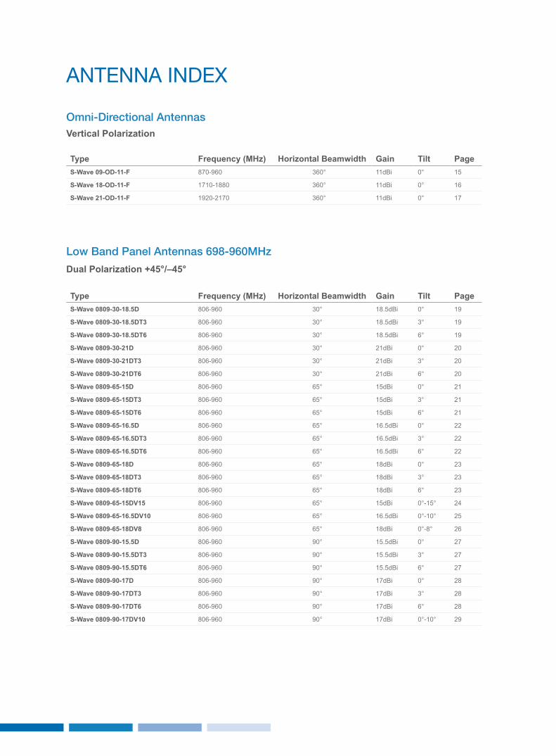
Type Frequency (MHz) Horizontal Beamwidth Gain Tilt PageS-Wave 09-OD-11-F 870-960 360° 11dBi 0° 15
S-Wave 18-OD-11-F 1710-1880 360° 11dBi 0° 16
S-Wave 21-OD-11-F 1920-2170 360° 11dBi 0° 17
Omni-Directional AntennasVertical Polarization
Low Band Panel Antennas 698-960MHz
Dual Polarization +45°/–45°
Type Frequency (MHz) Horizontal Beamwidth Gain Tilt PageS-Wave 0809-30-18.5D 806-960 30° 18.5dBi 0° 19
S-Wave 0809-30-18.5DT3 806-960 30° 18.5dBi 3° 19
S-Wave 0809-30-18.5DT6 806-960 30° 18.5dBi 6° 19
S-Wave 0809-30-21D 806-960 30° 21dBi 0° 20
S-Wave 0809-30-21DT3 806-960 30° 21dBi 3° 20
S-Wave 0809-30-21DT6 806-960 30° 21dBi 6° 20
S-Wave 0809-65-15D 806-960 65° 15dBi 0° 21
S-Wave 0809-65-15DT3 806-960 65° 15dBi 3° 21
S-Wave 0809-65-15DT6 806-960 65° 15dBi 6° 21
S-Wave 0809-65-16.5D 806-960 65° 16.5dBi 0° 22
S-Wave 0809-65-16.5DT3 806-960 65° 16.5dBi 3° 22
S-Wave 0809-65-16.5DT6 806-960 65° 16.5dBi 6° 22
S-Wave 0809-65-18D 806-960 65° 18dBi 0° 23
S-Wave 0809-65-18DT3 806-960 65° 18dBi 3° 23
S-Wave 0809-65-18DT6 806-960 65° 18dBi 6° 23
S-Wave 0809-65-15DV15 806-960 65° 15dBi 0°-15° 24
S-Wave 0809-65-16.5DV10 806-960 65° 16.5dBi 0°-10° 25
S-Wave 0809-65-18DV8 806-960 65° 18dBi 0°-8° 26
S-Wave 0809-90-15.5D 806-960 90° 15.5dBi 0° 27
S-Wave 0809-90-15.5DT3 806-960 90° 15.5dBi 3° 27
S-Wave 0809-90-15.5DT6 806-960 90° 15.5dBi 6° 27
S-Wave 0809-90-17D 806-960 90° 17dBi 0° 28
S-Wave 0809-90-17DT3 806-960 90° 17dBi 3° 28
S-Wave 0809-90-17DT6 806-960 90° 17dBi 6° 28
S-Wave 0809-90-17DV10 806-960 90° 17dBi 0°-10° 29
AntEnnA IndEx
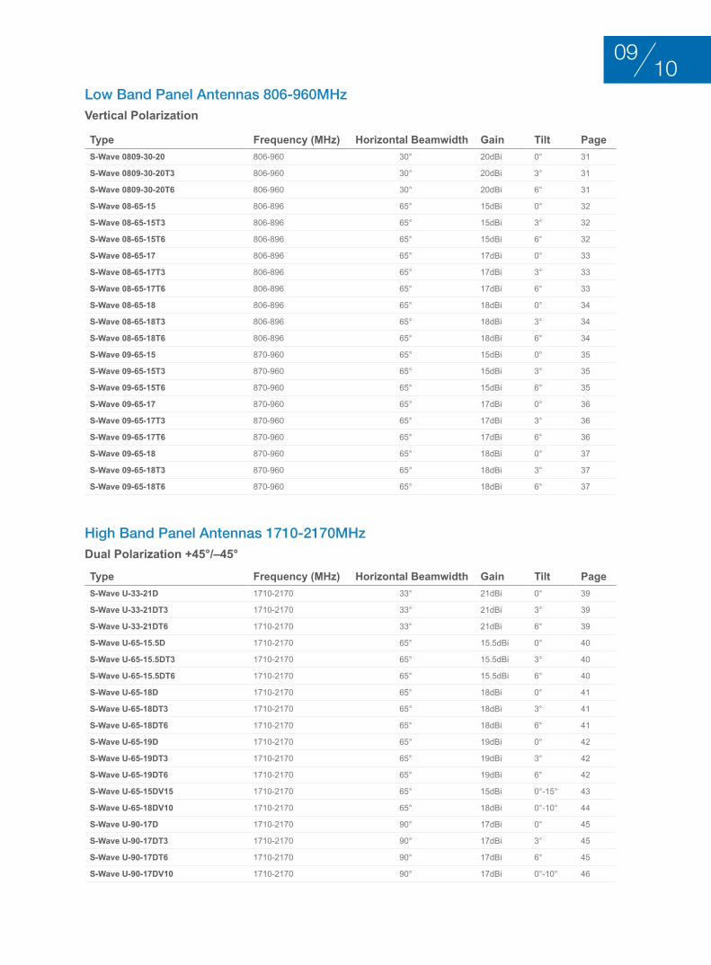
Type Frequency (MHz) Horizontal Beamwidth Gain Tilt PageS-Wave 0809-30-20 806-960 30° 20dBi 0° 31
S-Wave 0809-30-20T3 806-960 30° 20dBi 3° 31
S-Wave 0809-30-20T6 806-960 30° 20dBi 6° 31
S-Wave 08-65-15 806-896 65° 15dBi 0° 32
S-Wave 08-65-15T3 806-896 65° 15dBi 3° 32
S-Wave 08-65-15T6 806-896 65° 15dBi 6° 32
S-Wave 08-65-17 806-896 65° 17dBi 0° 33
S-Wave 08-65-17T3 806-896 65° 17dBi 3° 33
S-Wave 08-65-17T6 806-896 65° 17dBi 6° 33
S-Wave 08-65-18 806-896 65° 18dBi 0° 34
S-Wave 08-65-18T3 806-896 65° 18dBi 3° 34
S-Wave 08-65-18T6 806-896 65° 18dBi 6° 34
S-Wave 09-65-15 870-960 65° 15dBi 0° 35
S-Wave 09-65-15T3 870-960 65° 15dBi 3° 35
S-Wave 09-65-15T6 870-960 65° 15dBi 6° 35
S-Wave 09-65-17 870-960 65° 17dBi 0° 36
S-Wave 09-65-17T3 870-960 65° 17dBi 3° 36
S-Wave 09-65-17T6 870-960 65° 17dBi 6° 36
S-Wave 09-65-18 870-960 65° 18dBi 0° 37
S-Wave 09-65-18T3 870-960 65° 18dBi 3° 37
S-Wave 09-65-18T6 870-960 65° 18dBi 6° 37
Low Band Panel Antennas 806-960MHz Vertical Polarization
Type Frequency (MHz) Horizontal Beamwidth Gain Tilt PageS-Wave U-33-21D 1710-2170 33° 21dBi 0° 39
S-Wave U-33-21DT3 1710-2170 33° 21dBi 3° 39
S-Wave U-33-21DT6 1710-2170 33° 21dBi 6° 39
S-Wave U-65-15.5D 1710-2170 65° 15.5dBi 0° 40
S-Wave U-65-15.5DT3 1710-2170 65° 15.5dBi 3° 40
S-Wave U-65-15.5DT6 1710-2170 65° 15.5dBi 6° 40
S-Wave U-65-18D 1710-2170 65° 18dBi 0° 41
S-Wave U-65-18DT3 1710-2170 65° 18dBi 3° 41
S-Wave U-65-18DT6 1710-2170 65° 18dBi 6° 41
S-Wave U-65-19D 1710-2170 65° 19dBi 0° 42
S-Wave U-65-19DT3 1710-2170 65° 19dBi 3° 42
S-Wave U-65-19DT6 1710-2170 65° 19dBi 6° 42
S-Wave U-65-15DV15 1710-2170 65° 15dBi 0°-15° 43
S-Wave U-65-18DV10 1710-2170 65° 18dBi 0°-10° 44
S-Wave U-90-17D 1710-2170 90° 17dBi 0° 45
S-Wave U-90-17DT3 1710-2170 90° 17dBi 3° 45
S-Wave U-90-17DT6 1710-2170 90° 17dBi 6° 45
S-Wave U-90-17DV10 1710-2170 90° 17dBi 0°-10° 46
High Band Panel Antennas 1710-2170MHz Dual Polarization +45°/–45°
1009
Type Frequency (MHz) Horizontal Beamwidth Gain Tilt Page
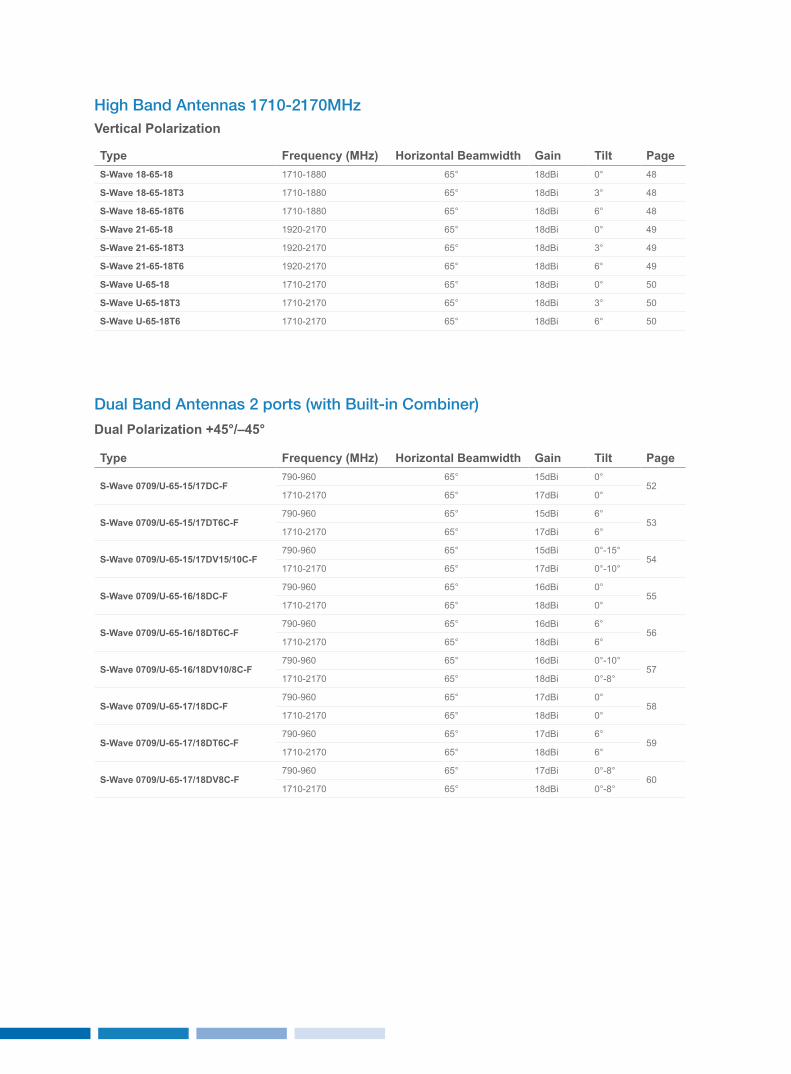
S-Wave 0709/U-65-15/17DC-F790-960 65° 15dBi 0°
521710-2170 65° 17dBi 0°
S-Wave 0709/U-65-15/17DT6C-F790-960 65° 15dBi 6°
531710-2170 65° 17dBi 6°
S-Wave 0709/U-65-15/17DV15/10C-F790-960 65° 15dBi 0°-15°
541710-2170 65° 17dBi 0°-10°
S-Wave 0709/U-65-16/18DC-F790-960 65° 16dBi 0°
551710-2170 65° 18dBi 0°
S-Wave 0709/U-65-16/18DT6C-F790-960 65° 16dBi 6°
561710-2170 65° 18dBi 6°
S-Wave 0709/U-65-16/18DV10/8C-F790-960 65° 16dBi 0°-10°
571710-2170 65° 18dBi 0°-8°
S-Wave 0709/U-65-17/18DC-F790-960 65° 17dBi 0°
581710-2170 65° 18dBi 0°
S-Wave 0709/U-65-17/18DT6C-F790-960 65° 17dBi 6°
591710-2170 65° 18dBi 6°
S-Wave 0709/U-65-17/18DV8C-F790-960 65° 17dBi 0°-8°
601710-2170 65° 18dBi 0°-8°
Dual Band Antennas 2 ports (with Built-in Combiner)
Dual Polarization +45°/–45°
High Band Antennas 1710-2170MHz Vertical Polarization
Type Frequency (MHz) Horizontal Beamwidth Gain Tilt PageS-Wave 18-65-18 1710-1880 65° 18dBi 0° 48
S-Wave 18-65-18T3 1710-1880 65° 18dBi 3° 48
S-Wave 18-65-18T6 1710-1880 65° 18dBi 6° 48
S-Wave 21-65-18 1920-2170 65° 18dBi 0° 49
S-Wave 21-65-18T3 1920-2170 65° 18dBi 3° 49
S-Wave 21-65-18T6 1920-2170 65° 18dBi 6° 49
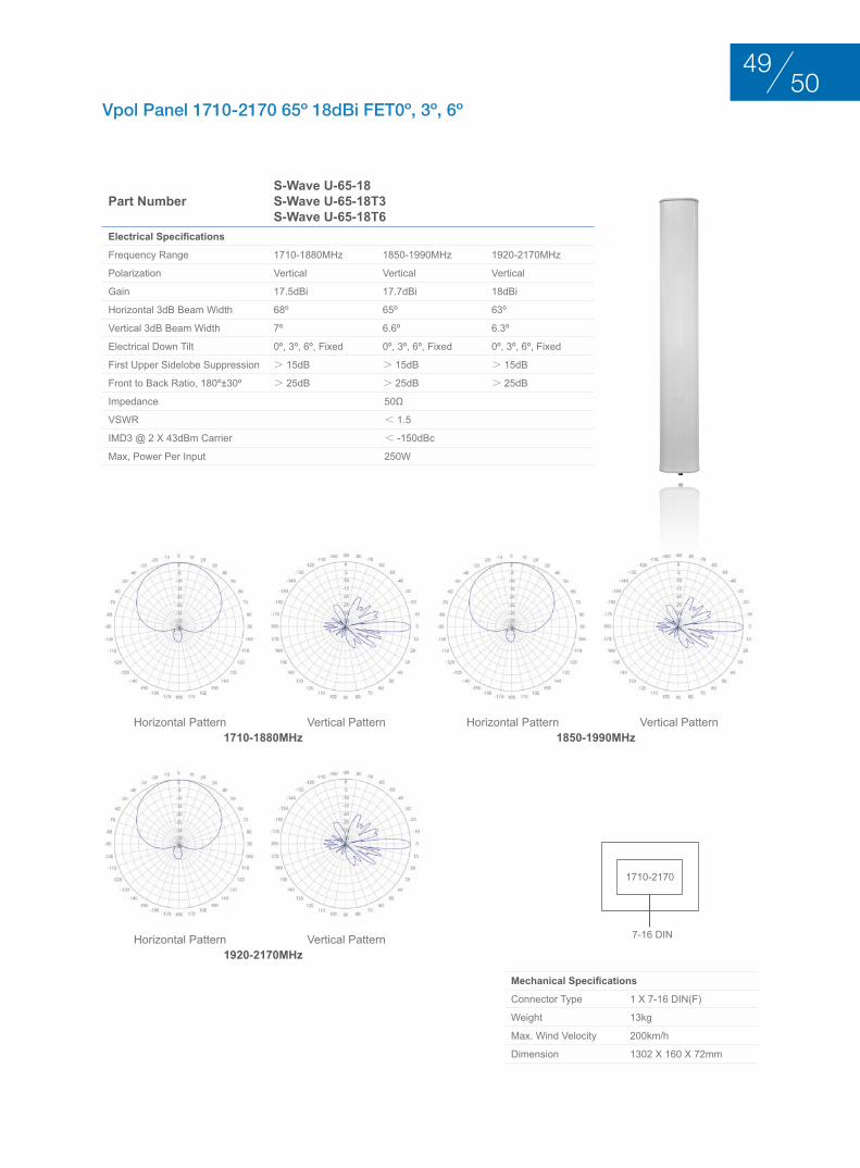
S-Wave U-65-18 1710-2170 65° 18dBi 0° 50
S-Wave U-65-18T3 1710-2170 65° 18dBi 3° 50
S-Wave U-65-18T6 1710-2170 65° 18dBi 6° 50
Type Frequency (MHz) Horizontal Beamwidth Gain Tilt Page
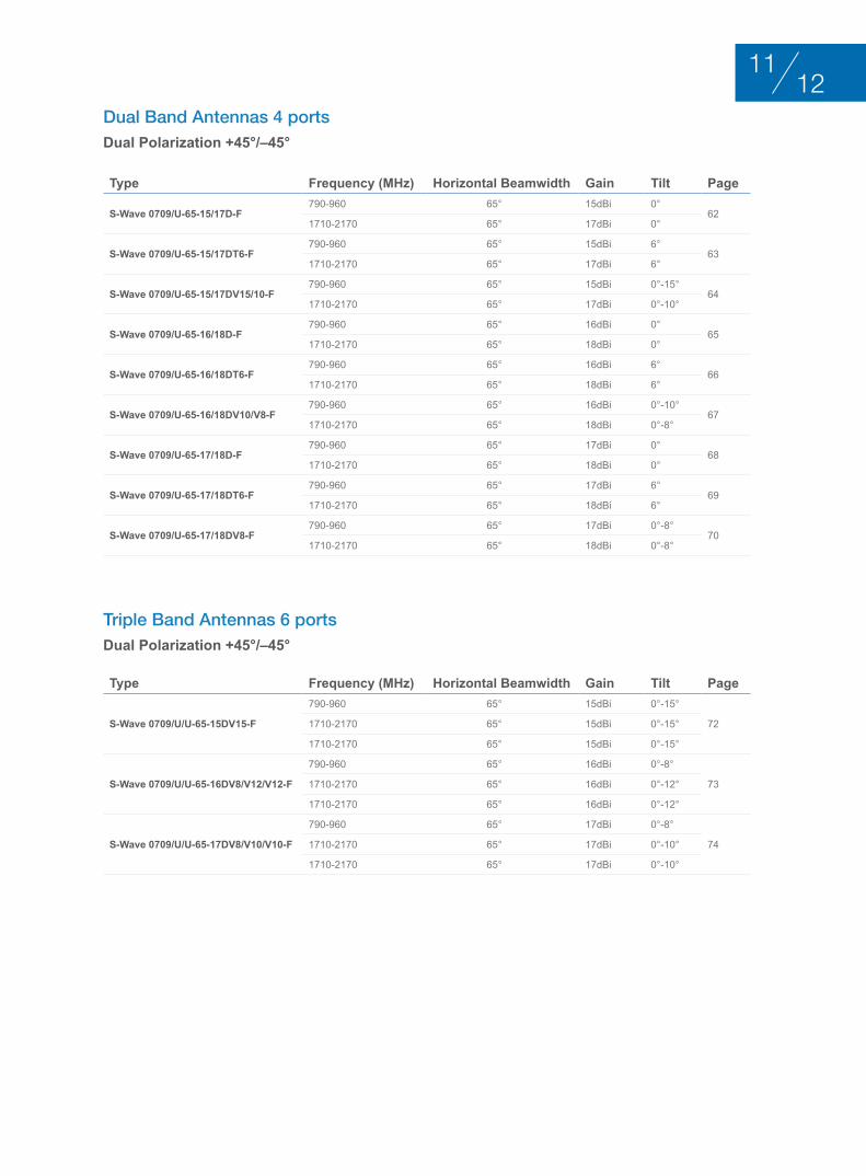
S-Wave 0709/U/U-65-15DV15-F
790-960 65° 15dBi 0°-15°
721710-2170 65° 15dBi 0°-15°
1710-2170 65° 15dBi 0°-15°
S-Wave 0709/U/U-65-16DV8/V12/V12-F
790-960 65° 16dBi 0°-8°
731710-2170 65° 16dBi 0°-12°
1710-2170 65° 16dBi 0°-12°
S-Wave 0709/U/U-65-17DV8/V10/V10-F
790-960 65° 17dBi 0°-8°
741710-2170 65° 17dBi 0°-10°
1710-2170 65° 17dBi 0°-10°
Triple Band Antennas 6 ports Dual Polarization +45°/–45°
Type Frequency (MHz) Horizontal Beamwidth Gain Tilt Page
S-Wave 0709/U-65-15/17D-F790-960 65° 15dBi 0°
621710-2170 65° 17dBi 0°
S-Wave 0709/U-65-15/17DT6-F790-960 65° 15dBi 6°
631710-2170 65° 17dBi 6°
S-Wave 0709/U-65-15/17DV15/10-F790-960 65° 15dBi 0°-15°
641710-2170 65° 17dBi 0°-10°
S-Wave 0709/U-65-16/18D-F790-960 65° 16dBi 0°
651710-2170 65° 18dBi 0°
S-Wave 0709/U-65-16/18DT6-F790-960 65° 16dBi 6°
661710-2170 65° 18dBi 6°
S-Wave 0709/U-65-16/18DV10/V8-F790-960 65° 16dBi 0°-10°
671710-2170 65° 18dBi 0°-8°
S-Wave 0709/U-65-17/18D-F790-960 65° 17dBi 0°
681710-2170 65° 18dBi 0°
S-Wave 0709/U-65-17/18DT6-F790-960 65° 17dBi 6°
691710-2170 65° 18dBi 6°
S-Wave 0709/U-65-17/18DV8-F790-960 65° 17dBi 0°-8°
701710-2170 65° 18dBi 0°-8°
Dual Band Antennas 4 ports Dual Polarization +45°/–45°
1211
Type Frequency (MHz) Horizontal Beamwidth Gain Tilt Page
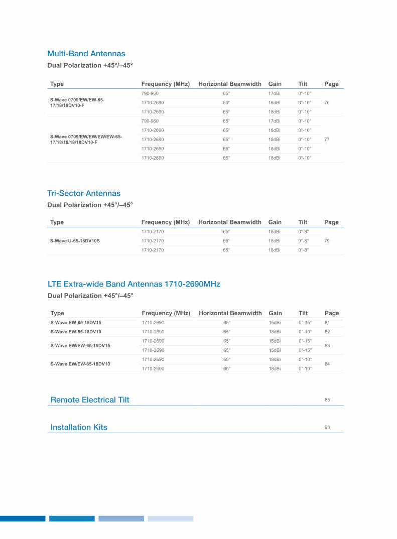
S-Wave U-65-18DV10S
1710-2170 65° 18dBi 0°-8°
791710-2170 65° 18dBi 0°-8°
1710-2170 65° 18dBi 0°-8°
Type Frequency (MHz) Horizontal Beamwidth Gain Tilt Page
S-Wave 0709/EW/EW-65-17/18/18DV10-F
790-960 65° 17dBi 0°-10°
761710-2690 65° 18dBi 0°-10°
1710-2690 65° 18dBi 0°-10°
S-Wave 0709/EW/EW/EW/EW-65-17/18/18/18/18DV10-F
790-960 65° 17dBi 0°-10°
77
1710-2690 65° 18dBi 0°-10°
1710-2690 65° 18dBi 0°-10°
1710-2690 65° 18dBi 0°-10°
1710-2690 65° 18dBi 0°-10°
Remote Electrical Tilt 85
Installation Kits 93
Tri-Sector Antennas Dual Polarization +45°/–45°
Multi-Band Antennas Dual Polarization +45°/–45°
LTE Extra-wide Band Antennas 1710-2690MHz Dual Polarization +45°/–45°
Type Frequency (MHz) Horizontal Beamwidth Gain Tilt PageS-Wave EW-65-15DV15 1710-2690 65° 15dBi 0°-15° 81
S-Wave EW-65-18DV10 1710-2690 65° 18dBi 0°-10° 82
S-Wave EW/EW-65-15DV151710-2690 65° 15dBi 0°-15°
831710-2690 65° 15dBi 0°-15°
S-Wave EW/EW-65-18DV101710-2690 65° 18dBi 0°-10°
841710-2690 65° 18dBi 0°-10°
oMnI-dIrEctIonAl AntEnnASVErtIcAl PolArIzAtIon
1413
BASE STATION ANTENNAS
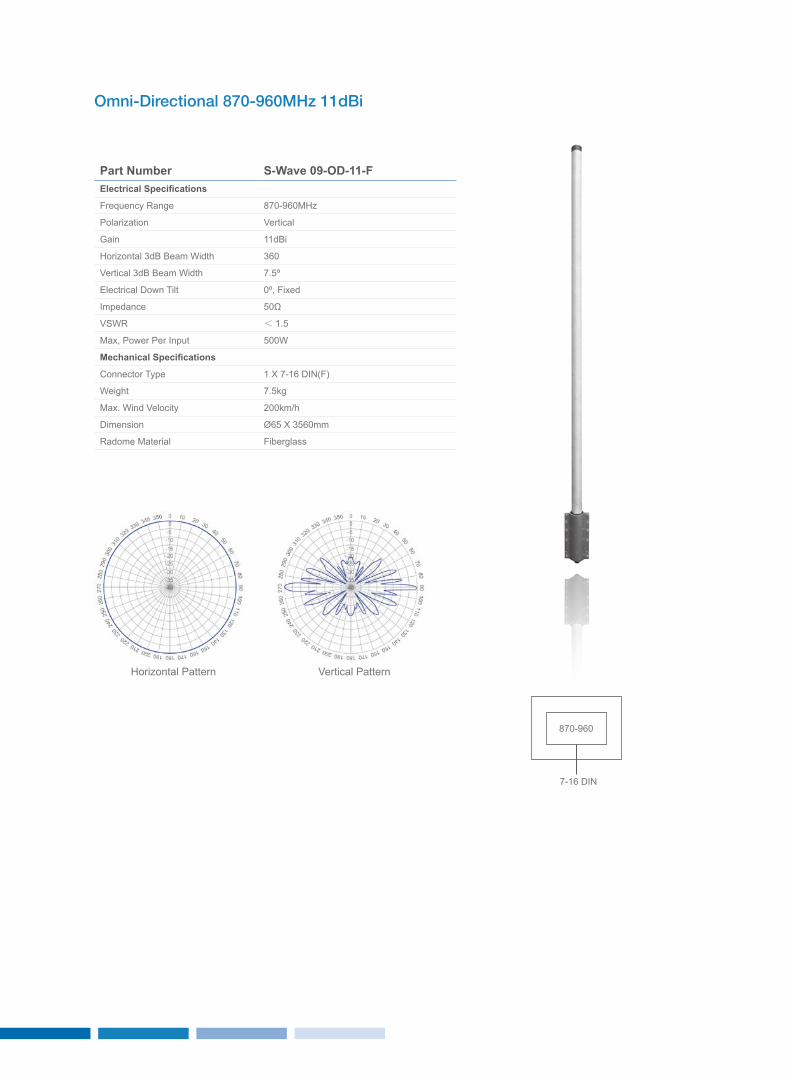
Omni-Directional 870-960MHz 11dBi
Part Number S-Wave 09-OD-11-FElectrical Specifications
Frequency Range 870-960MHz
Polarization Vertical
Gain 11dBi
Horizontal 3dB Beam Width 360
Vertical 3dB Beam Width 7.5º
Electrical Down Tilt 0º, Fixed
Impedance 50Ω
VSWR < 1.5
Max, Power Per Input 500W
Mechanical Specifications
Connector Type 1 x 7-16 DIN(F)
Weight 7.5kg
Max. Wind Velocity 200km/h
Dimension Ø65 x 3560mm
Radome Material Fiberglass
Horizontal Pattern Vertical Pattern
870-960
7-16 DIN
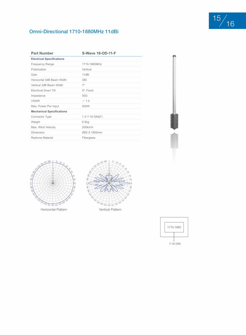
Part Number S-Wave 18-OD-11-FElectrical Specifications
Frequency Range 1710-1880MHz
Polarization Vertical
Gain 11dBi
Horizontal 3dB Beam Width 360
Vertical 3dB Beam Width 7º
Electrical Down Tilt 0º, Fixed
Impedance 50Ω
VSWR < 1.5
Max, Power Per Input 500W
Mechanical Specifications
Connector Type 1 x 7-16 DIN(F)
Weight 6.5kg
Max. Wind Velocity 200km/h
Dimension Ø65 x 1800mm
Radome Material Fiberglass
Omni-Directional 1710-1880MHz 11dBi
Horizontal Pattern Vertical Pattern
1710-1880
7-16 DIN
1615
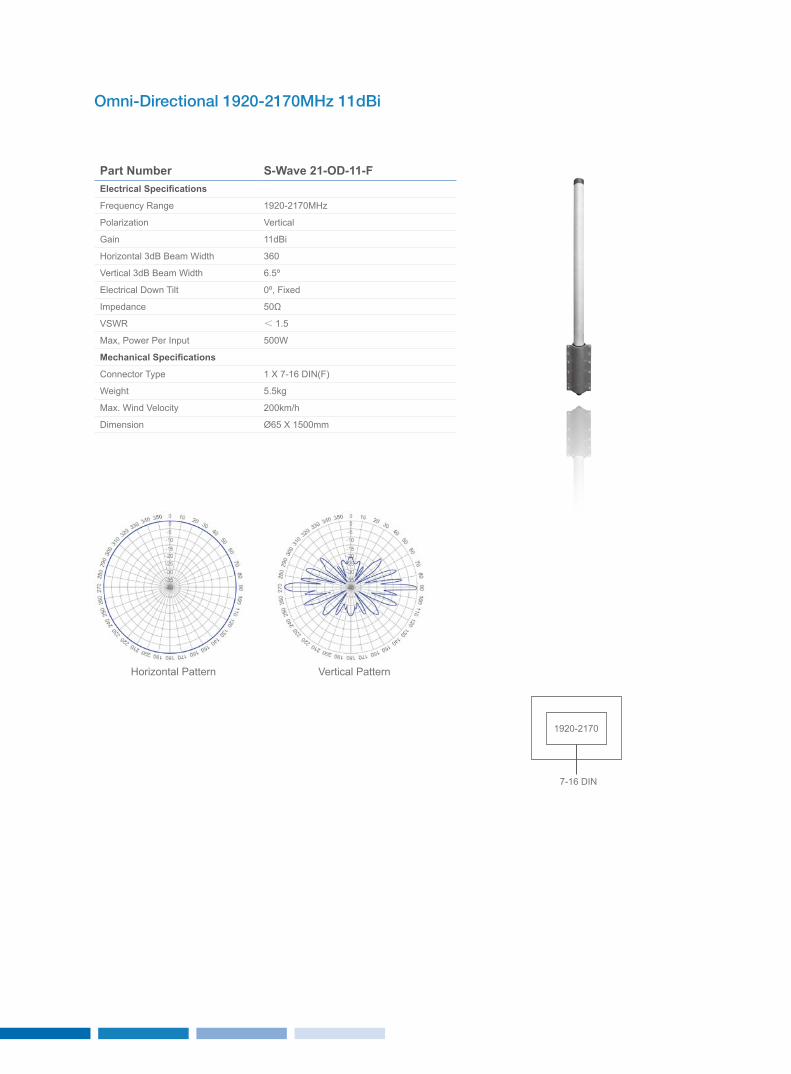
Omni-Directional 1920-2170MHz 11dBi
Part Number S-Wave 21-OD-11-FElectrical Specifications
Frequency Range 1920-2170MHz
Polarization Vertical
Gain 11dBi
Horizontal 3dB Beam Width 360
Vertical 3dB Beam Width 6.5º
Electrical Down Tilt 0º, Fixed
Impedance 50Ω
VSWR < 1.5
Max, Power Per Input 500W
Mechanical Specifications
Connector Type 1 x 7-16 DIN(F)
Weight 5.5kg
Max. Wind Velocity 200km/h
Dimension Ø65 x 1500mm
Horizontal Pattern Vertical Pattern
1920-2170
7-16 DIN
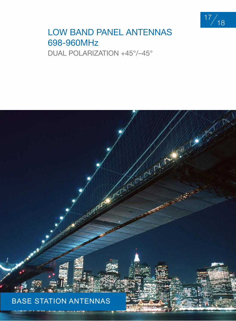
loW bAnd PAnEl AntEnnAS 698-960Mhz duAl PolArIzAtIon +45°/–45°
1817
BASE STATION ANTENNAS
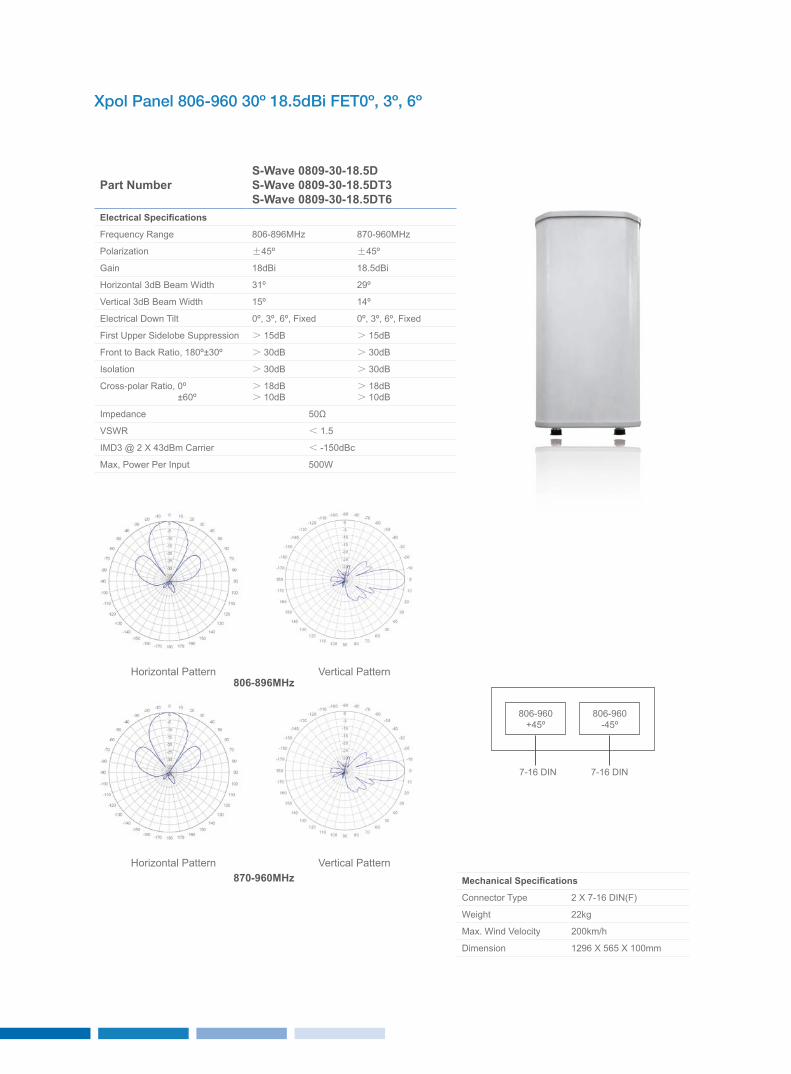
Xpol Panel 806-960 30º 18.5dBi FET0º, 3º, 6º
Part NumberS-Wave 0809-30-18.5DS-Wave 0809-30-18.5DT3S-Wave 0809-30-18.5DT6
Electrical Specifications
Frequency Range 806-896MHz 870-960MHz
Polarization ±45º ±45º
Gain 18dBi 18.5dBi
Horizontal 3dB Beam Width 31º 29º
Vertical 3dB Beam Width 15º 14º
Electrical Down Tilt 0º, 3º, 6º, Fixed 0º, 3º, 6º, Fixed
First Upper Sidelobe Suppression > 15dB > 15dB
Front to Back Ratio, 180º±30º > 30dB > 30dB
Isolation > 30dB > 30dB
Cross-polar Ratio, 0º ±60º
> 18dB> 10dB
> 18dB> 10dB
Impedance 50Ω
VSWR < 1.5
IMD3 @ 2 x 43dBm Carrier < -150dBc
Max, Power Per Input 500W
Mechanical Specifications
Connector Type 2 x 7-16 DIN(F)
Weight 22kg
Max. Wind Velocity 200km/h
Dimension 1296 x 565 x 100mm
Horizontal Pattern
Horizontal Pattern
Vertical Pattern
Vertical Pattern
806-960+45º
806-960-45º
7-16 DIN 7-16 DIN
806-896MHz
870-960MHz
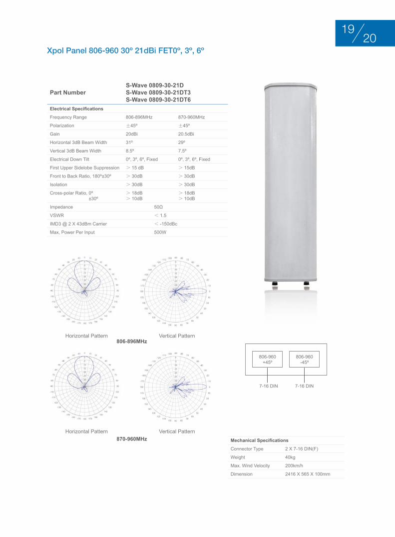
Xpol Panel 806-960 30º 21dBi FET0º, 3º, 6º
Part NumberS-Wave 0809-30-21DS-Wave 0809-30-21DT3S-Wave 0809-30-21DT6
Electrical Specifications
Frequency Range 806-896MHz 870-960MHz
Polarization ±45º ±45º
Gain 20dBi 20.5dBi
Horizontal 3dB Beam Width 31º 29º
Vertical 3dB Beam Width 8.5º 7.5º
Electrical Down Tilt 0º, 3º, 6º, Fixed 0º, 3º, 6º, Fixed
First Upper Sidelobe Suppression > 15 dB > 15dB
Front to Back Ratio, 180º±30º > 30dB > 30dB
Isolation > 30dB > 30dB
Cross-polar Ratio, 0º ±30º
> 18dB> 10dB
> 18dB> 10dB
Impedance 50Ω
VSWR < 1.5
IMD3 @ 2 x 43dBm Carrier < -150dBc
Max, Power Per Input 500W
Mechanical Specifications
Connector Type 2 x 7-16 DIN(F)
Weight 40kg
Max. Wind Velocity 200km/h
Dimension 2416 x 565 x 100mm
Horizontal Pattern
Horizontal Pattern
Vertical Pattern
Vertical Pattern
806-960+45º
806-960-45º
7-16 DIN 7-16 DIN
806-896MHz
870-960MHz
2019
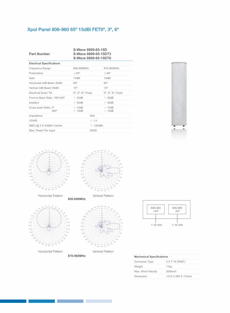
Xpol Panel 806-960 65º 15dBi FET0º, 3º, 6º
Part NumberS-Wave 0809-65-15DS-Wave 0809-65-15DT3S-Wave 0809-65-15DT6
Electrical Specifications
Frequency Range 806-896MHz 870-960MHz
Polarization ±45º ±45º
Gain 15dBi 15dBi
Horizontal 3dB Beam Width 65º 65º
Vertical 3dB Beam Width 15º 15º
Electrical Down Tilt 0º, 3º, 6º, Fixed 0º, 3º, 6º, Fixed
Front to Back Ratio, 180º±30º > 30dB > 30dB
Isolation > 30dB > 30dB
Cross-polar Ratio, 0º ±60º
> 15dB> 10dB
> 15dB> 10dB
Impedance 50Ω
VSWR < 1.4
IMD3 @ 2 x 43dBm Carrier < -150dBc
Max, Power Per Input 500W
Mechanical Specifications
Connector Type 2 x 7-16 DIN(F)
Weight 11kg
Max. Wind Velocity 200km/h
Dimension 1310 x 295 x 115mm
Horizontal Pattern
Horizontal Pattern
Vertical Pattern
Vertical Pattern
806-960+45º
806-960-45º
7-16 DIN 7-16 DIN
806-896MHz
870-960MHz
2221
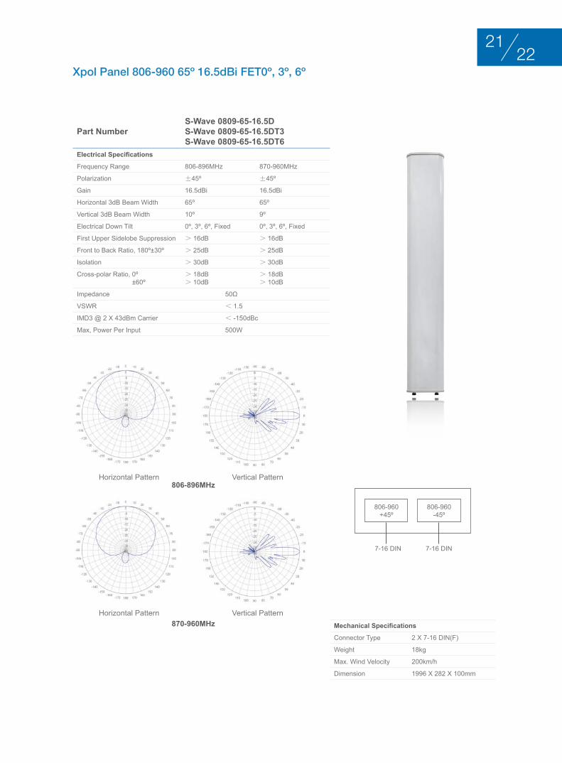
Xpol Panel 806-960 65º 16.5dBi FET0º, 3º, 6º
Part NumberS-Wave 0809-65-16.5DS-Wave 0809-65-16.5DT3S-Wave 0809-65-16.5DT6
Electrical Specifications
Frequency Range 806-896MHz 870-960MHz
Polarization ±45º ±45º
Gain 16.5dBi 16.5dBi
Horizontal 3dB Beam Width 65º 65º
Vertical 3dB Beam Width 10º 9º
Electrical Down Tilt 0º, 3º, 6º, Fixed 0º, 3º, 6º, Fixed
First Upper Sidelobe Suppression > 16dB > 16dB
Front to Back Ratio, 180º±30º > 25dB > 25dB
Isolation > 30dB > 30dB
Cross-polar Ratio, 0º ±60º
> 18dB> 10dB
> 18dB> 10dB
Impedance 50Ω
VSWR < 1.5
IMD3 @ 2 x 43dBm Carrier < -150dBc
Max, Power Per Input 500W
Mechanical Specifications
Connector Type 2 x 7-16 DIN(F)
Weight 18kg
Max. Wind Velocity 200km/h
Dimension 1996 x 282 x 100mm
Horizontal Pattern
Horizontal Pattern
Vertical Pattern
Vertical Pattern
806-960+45º
806-960-45º
7-16 DIN 7-16 DIN
806-896MHz
870-960MHz
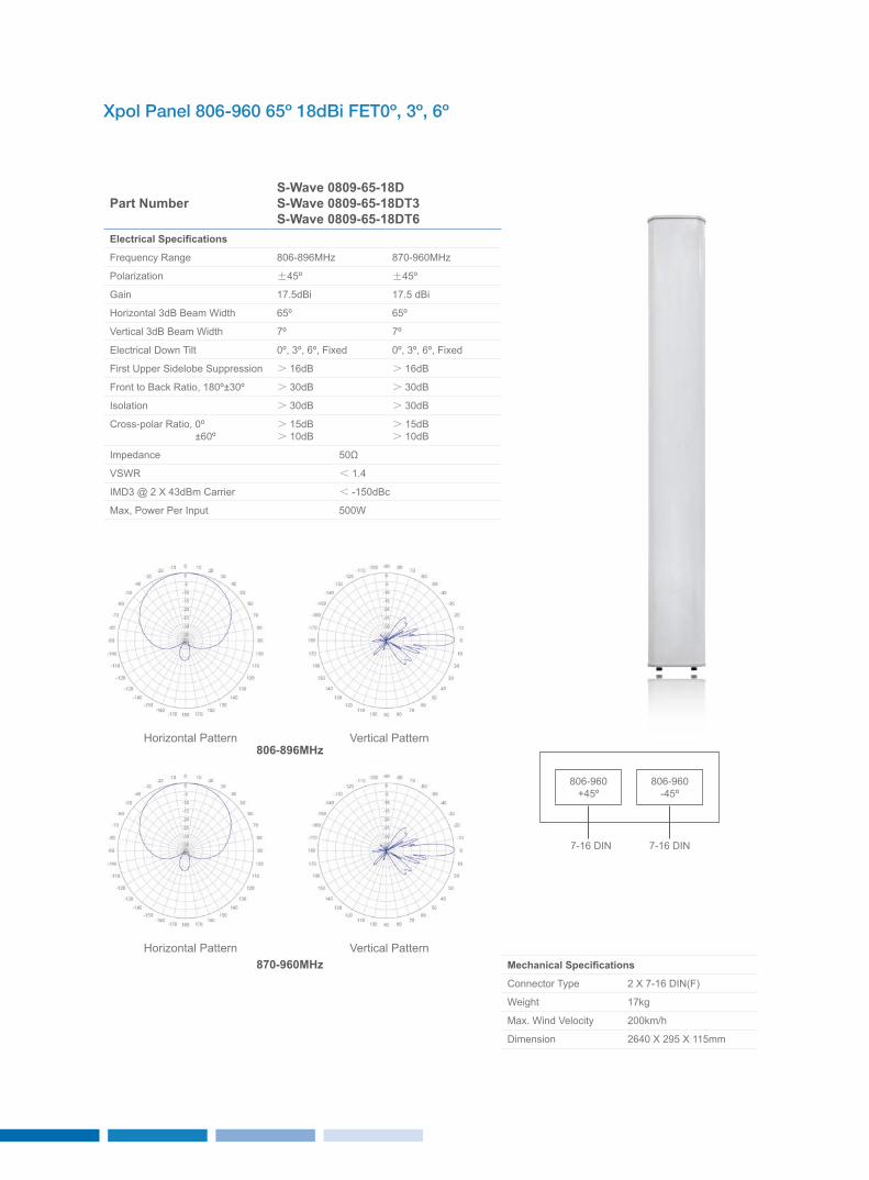
Xpol Panel 806-960 65º 18dBi FET0º, 3º, 6º
Part NumberS-Wave 0809-65-18DS-Wave 0809-65-18DT3S-Wave 0809-65-18DT6
Electrical Specifications
Frequency Range 806-896MHz 870-960MHz
Polarization ±45º ±45º
Gain 17.5dBi 17.5 dBi
Horizontal 3dB Beam Width 65º 65º
Vertical 3dB Beam Width 7º 7º
Electrical Down Tilt 0º, 3º, 6º, Fixed 0º, 3º, 6º, Fixed
First Upper Sidelobe Suppression > 16dB > 16dB
Front to Back Ratio, 180º±30º > 30dB > 30dB
Isolation > 30dB > 30dB
Cross-polar Ratio, 0º ±60º
> 15dB> 10dB
> 15dB> 10dB
Impedance 50Ω
VSWR < 1.4
IMD3 @ 2 x 43dBm Carrier < -150dBc
Max, Power Per Input 500W
Mechanical Specifications
Connector Type 2 x 7-16 DIN(F)
Weight 17kg
Max. Wind Velocity 200km/h
Dimension 2640 x 295 x 115mm
Horizontal Pattern
Horizontal Pattern
Vertical Pattern
Vertical Pattern
806-960+45º
806-960-45º
7-16 DIN 7-16 DIN
806-896MHz
870-960MHz
2423
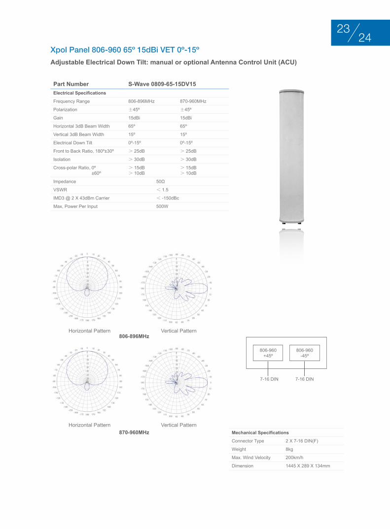
Xpol Panel 806-960 65º 15dBi VET 0º-15º
Adjustable Electrical Down Tilt: manual or optional Antenna Control Unit (ACU)
Part Number S-Wave 0809-65-15DV15Electrical Specifications
Frequency Range 806-896MHz 870-960MHz
Polarization ±45º ±45º
Gain 15dBi 15dBi
Horizontal 3dB Beam Width 65º 65º
Vertical 3dB Beam Width 15º 15º
Electrical Down Tilt 0º-15º 0º-15º
Front to Back Ratio, 180º±30º > 25dB > 25dB
Isolation > 30dB > 30dB
Cross-polar Ratio, 0º ±60º
> 15dB> 10dB
> 15dB> 10dB
Impedance 50Ω
VSWR < 1.5
IMD3 @ 2 x 43dBm Carrier < -150dBc
Max, Power Per Input 500W
Mechanical Specifications
Connector Type 2 x 7-16 DIN(F)
Weight 8kg
Max. Wind Velocity 200km/h
Dimension 1445 x 289 x 134mm
Horizontal Pattern
Horizontal Pattern
Vertical Pattern
Vertical Pattern
806-960+45º
806-960-45º
7-16 DIN 7-16 DIN
806-896MHz
870-960MHz
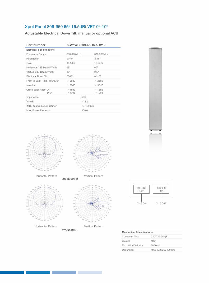
Xpol Panel 806-960 65º 16.5dBi VET 0º-10º
Adjustable Electrical Down Tilt: manual or optional ACU
Part Number S-Wave 0809-65-16.5DV10Electrical Specifications
Frequency Range 806-896MHz 870-960MHz
Polarization ±45º ±45º
Gain 16.5dBi 16.5dBi
Horizontal 3dB Beam Width 68º 65º
Vertical 3dB Beam Width 10º 9.5º
Electrical Down Tilt 0º-10º 0º-10º
Front to Back Ratio, 180º±30º > 25dB > 25dB
Isolation > 30dB > 30dB
Cross-polar Ratio, 0º ±60º
> 18dB> 10dB
> 18dB> 10dB
Impedance 50Ω
VSWR < 1.5
IMD3 @ 2 x 43dBm Carrier < -150dBc
Max, Power Per Input 400W
Mechanical Specifications
Connector Type 2 x 7-16 DIN(F)
Weight 18kg
Max. Wind Velocity 200km/h
Dimension 1996 x 282 x 100mm
Horizontal Pattern
Horizontal Pattern
Vertical Pattern
Vertical Pattern
806-960+45º
806-960-45º
7-16 DIN 7-16 DIN
806-896MHz
870-960MHz
2625
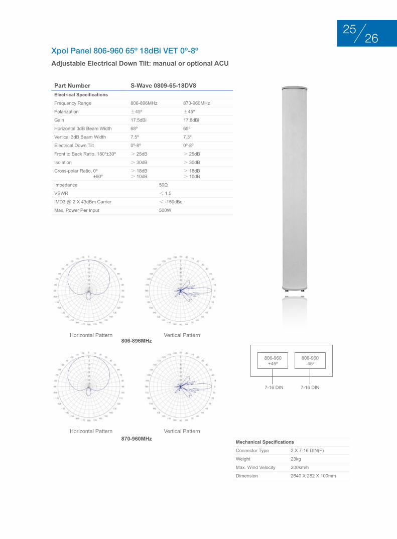
Xpol Panel 806-960 65º 18dBi VET 0º-8º
Adjustable Electrical Down Tilt: manual or optional ACU
Part Number S-Wave 0809-65-18DV8Electrical Specifications
Frequency Range 806-896MHz 870-960MHz
Polarization ±45º ±45º
Gain 17.5dBi 17.8dBi
Horizontal 3dB Beam Width 68º 65º
Vertical 3dB Beam Width 7.5º 7.3º
Electrical Down Tilt 0º-8º 0º-8º
Front to Back Ratio, 180º±30º > 25dB > 25dB
Isolation > 30dB > 30dB
Cross-polar Ratio, 0º ±60º
> 18dB> 10dB
> 18dB> 10dB
Impedance 50Ω
VSWR < 1.5
IMD3 @ 2 x 43dBm Carrier < -150dBc
Max, Power Per Input 500W
Mechanical Specifications
Connector Type 2 x 7-16 DIN(F)
Weight 23kg
Max. Wind Velocity 200km/h
Dimension 2640 x 282 x 100mm
Horizontal Pattern
Horizontal Pattern
Vertical Pattern
Vertical Pattern
806-960+45º
806-960-45º
7-16 DIN 7-16 DIN
806-896MHz
870-960MHz
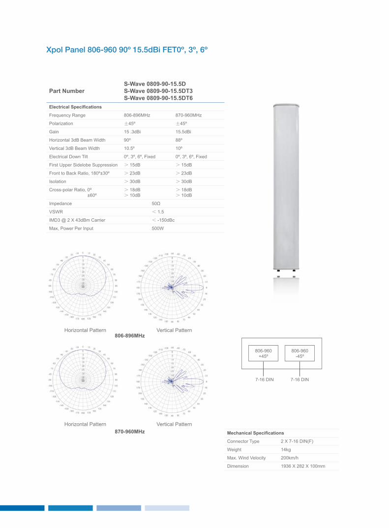
Xpol Panel 806-960 90º 15.5dBi FET0º, 3º, 6º
Part NumberS-Wave 0809-90-15.5DS-Wave 0809-90-15.5DT3S-Wave 0809-90-15.5DT6
Electrical Specifications
Frequency Range 806-896MHz 870-960MHz
Polarization ±45º ±45º
Gain 15 .3dBi 15.5dBi
Horizontal 3dB Beam Width 90º 88º
Vertical 3dB Beam Width 10.5º 10º
Electrical Down Tilt 0º, 3º, 6º, Fixed 0º, 3º, 6º, Fixed
First Upper Sidelobe Suppression > 15dB > 15dB
Front to Back Ratio, 180º±30º > 23dB > 23dB
Isolation > 30dB > 30dB
Cross-polar Ratio, 0º ±60º
> 18dB> 10dB
> 18dB> 10dB
Impedance 50Ω
VSWR < 1.5
IMD3 @ 2 x 43dBm Carrier < -150dBc
Max, Power Per Input 500W
Mechanical Specifications
Connector Type 2 x 7-16 DIN(F)
Weight 14kg
Max. Wind Velocity 200km/h
Dimension 1936 x 282 x 100mm
Horizontal Pattern
Horizontal Pattern
Vertical Pattern
Vertical Pattern
806-960+45º
806-960-45º
7-16 DIN 7-16 DIN
806-896MHz
870-960MHz
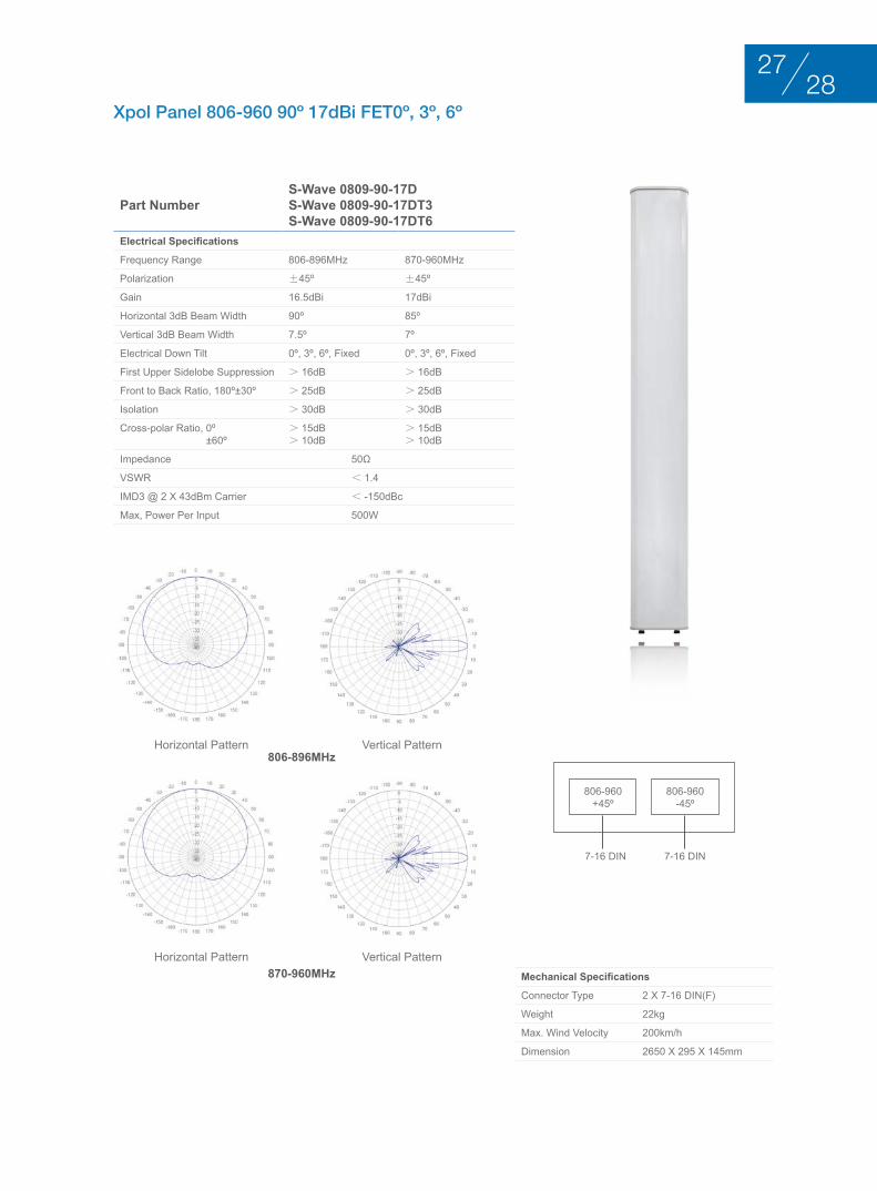
2827
Xpol Panel 806-960 90º 17dBi FET0º, 3º, 6º
Part NumberS-Wave 0809-90-17DS-Wave 0809-90-17DT3S-Wave 0809-90-17DT6
Electrical Specifications
Frequency Range 806-896MHz 870-960MHz
Polarization ±45º ±45º
Gain 16.5dBi 17dBi
Horizontal 3dB Beam Width 90º 85º
Vertical 3dB Beam Width 7.5º 7º
Electrical Down Tilt 0º, 3º, 6º, Fixed 0º, 3º, 6º, Fixed
First Upper Sidelobe Suppression > 16dB > 16dB
Front to Back Ratio, 180º±30º > 25dB > 25dB
Isolation > 30dB > 30dB
Cross-polar Ratio, 0º ±60º
> 15dB> 10dB
> 15dB> 10dB
Impedance 50Ω
VSWR < 1.4
IMD3 @ 2 x 43dBm Carrier < -150dBc
Max, Power Per Input 500W
Mechanical Specifications
Connector Type 2 x 7-16 DIN(F)
Weight 22kg
Max. Wind Velocity 200km/h
Dimension 2650 x 295 x 145mm
Horizontal Pattern
Horizontal Pattern
Vertical Pattern
Vertical Pattern
806-960+45º
806-960-45º
7-16 DIN 7-16 DIN
806-896MHz
870-960MHz
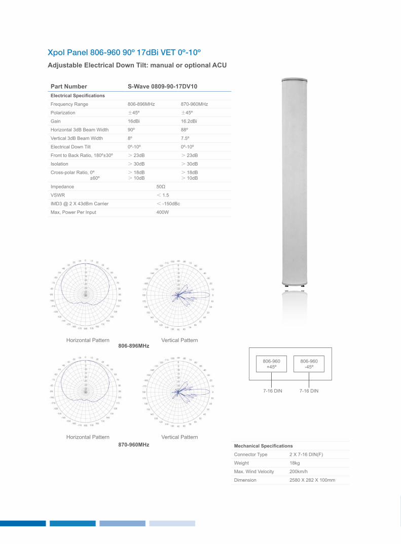
Xpol Panel 806-960 90º 17dBi VET 0º-10º
Adjustable Electrical Down Tilt: manual or optional ACU
Part Number S-Wave 0809-90-17DV10Electrical Specifications
Frequency Range 806-896MHz 870-960MHz
Polarization ±45º ±45º
Gain 16dBi 16.2dBi
Horizontal 3dB Beam Width 90º 88º
Vertical 3dB Beam Width 8º 7.5º
Electrical Down Tilt 0º-10º 0º-10º
Front to Back Ratio, 180º±30º > 23dB > 23dB
Isolation > 30dB > 30dB
Cross-polar Ratio, 0º ±60º
> 18dB> 10dB
> 18dB> 10dB
Impedance 50Ω
VSWR < 1.5
IMD3 @ 2 x 43dBm Carrier < -150dBc
Max, Power Per Input 400W
Mechanical Specifications
Connector Type 2 x 7-16 DIN(F)
Weight 18kg
Max. Wind Velocity 200km/h
Dimension 2580 x 282 x 100mm
Horizontal Pattern
Horizontal Pattern
Vertical Pattern
Vertical Pattern
806-960+45º
806-960-45º
7-16 DIN 7-16 DIN
806-896MHz
870-960MHz
3029
loW bAnd PAnEl AntEnnA 806-960Mhz VErtIcAl PolArIzAtIon
BASE STATION ANTENNAS
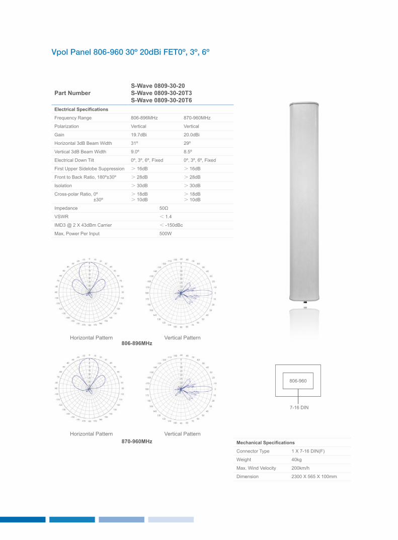
Vpol Panel 806-960 30º 20dBi FET0º, 3º, 6º
Part NumberS-Wave 0809-30-20S-Wave 0809-30-20T3S-Wave 0809-30-20T6
Electrical Specifications
Frequency Range 806-896MHz 870-960MHz
Polarization Vertical Vertical
Gain 19.7dBi 20.0dBi
Horizontal 3dB Beam Width 31º 29º
Vertical 3dB Beam Width 9.0º 8.5º
Electrical Down Tilt 0º, 3º, 6º, Fixed 0º, 3º, 6º, Fixed
First Upper Sidelobe Suppression > 16dB > 16dB
Front to Back Ratio, 180º±30º > 28dB > 28dB
Isolation > 30dB > 30dB
Cross-polar Ratio, 0º ±30º
> 18dB> 10dB
> 18dB> 10dB
Impedance 50Ω
VSWR < 1.4
IMD3 @ 2 x 43dBm Carrier < -150dBc
Max, Power Per Input 500W
Mechanical Specifications
Connector Type 1 x 7-16 DIN(F)
Weight 40kg
Max. Wind Velocity 200km/h
Dimension 2300 x 565 x 100mm
Horizontal Pattern
Horizontal Pattern
Vertical Pattern
Vertical Pattern806-896MHz
870-960MHz
806-960
7-16 DIN
3231
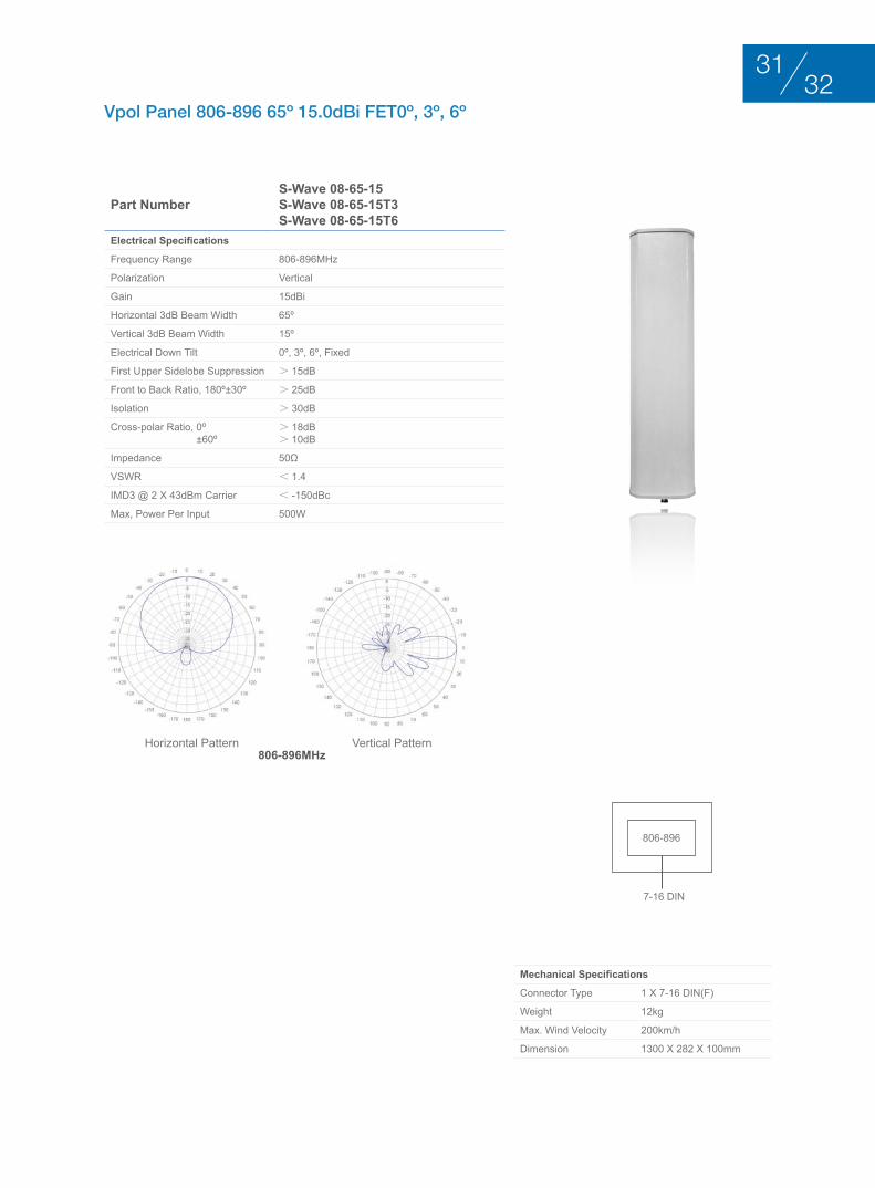
Vpol Panel 806-896 65º 15.0dBi FET0º, 3º, 6º
Part NumberS-Wave 08-65-15S-Wave 08-65-15T3S-Wave 08-65-15T6
Electrical Specifications
Frequency Range 806-896MHz
Polarization Vertical
Gain 15dBi
Horizontal 3dB Beam Width 65º
Vertical 3dB Beam Width 15º
Electrical Down Tilt 0º, 3º, 6º, Fixed
First Upper Sidelobe Suppression > 15dB
Front to Back Ratio, 180º±30º > 25dB
Isolation > 30dB
Cross-polar Ratio, 0º ±60º
> 18dB> 10dB
Impedance 50Ω
VSWR < 1.4
IMD3 @ 2 x 43dBm Carrier < -150dBc
Max, Power Per Input 500W
Mechanical Specifications
Connector Type 1 x 7-16 DIN(F)
Weight 12kg
Max. Wind Velocity 200km/h
Dimension 1300 x 282 x 100mm
Horizontal Pattern Vertical Pattern806-896MHz
806-896
7-16 DIN
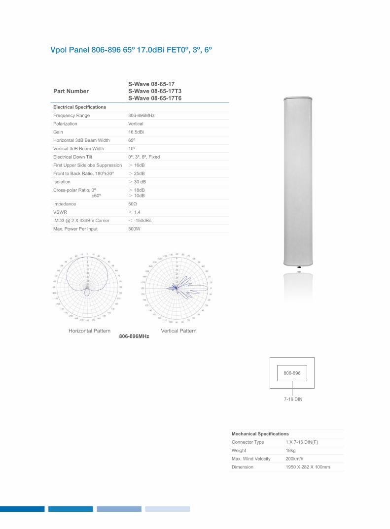
Vpol Panel 806-896 65º 17.0dBi FET0º, 3º, 6º
Part NumberS-Wave 08-65-17S-Wave 08-65-17T3S-Wave 08-65-17T6
Electrical Specifications
Frequency Range 806-896MHz
Polarization Vertical
Gain 16.5dBi
Horizontal 3dB Beam Width 65º
Vertical 3dB Beam Width 10º
Electrical Down Tilt 0º, 3º, 6º, Fixed
First Upper Sidelobe Suppression > 16dB
Front to Back Ratio, 180º±30º > 25dB
Isolation > 30 dB
Cross-polar Ratio, 0º ±60º
> 18dB> 10dB
Impedance 50Ω
VSWR < 1.4
IMD3 @ 2 x 43dBm Carrier < -150dBc
Max, Power Per Input 500W
Mechanical Specifications
Connector Type 1 x 7-16 DIN(F)
Weight 18kg
Max. Wind Velocity 200km/h
Dimension 1950 x 282 x 100mm
Horizontal Pattern Vertical Pattern806-896MHz
806-896
7-16 DIN
3433
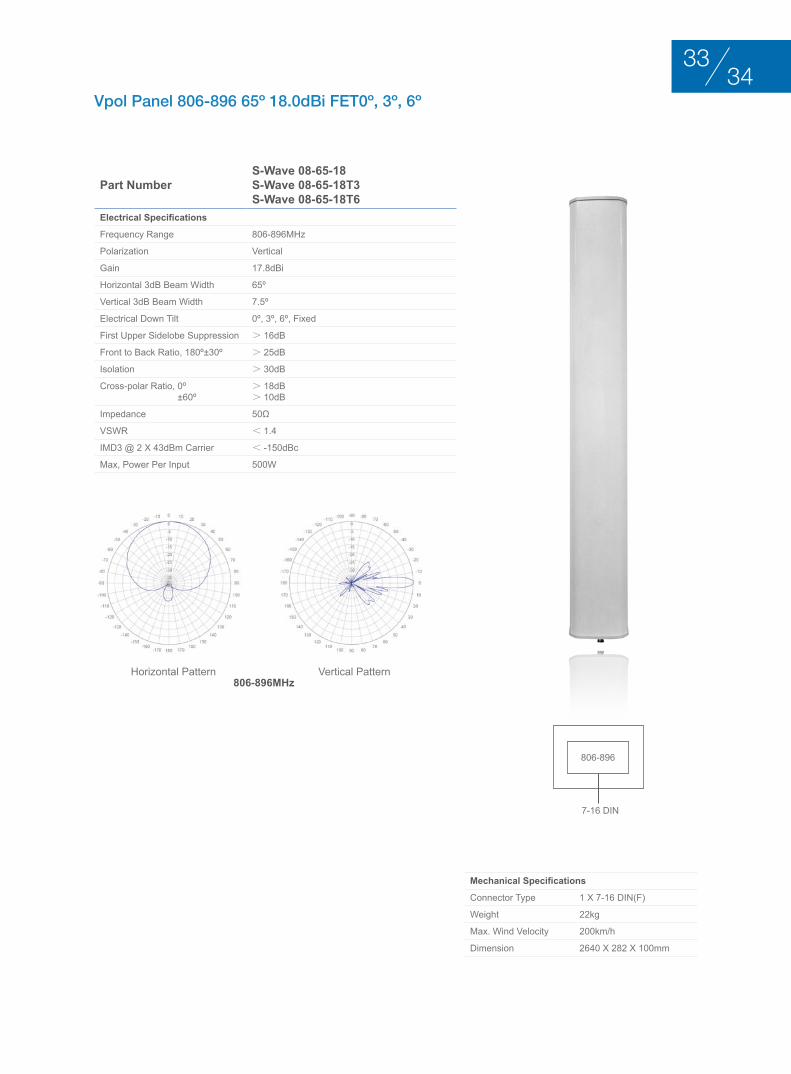
Vpol Panel 806-896 65º 18.0dBi FET0º, 3º, 6º
Part NumberS-Wave 08-65-18S-Wave 08-65-18T3S-Wave 08-65-18T6
Electrical Specifications
Frequency Range 806-896MHz
Polarization Vertical
Gain 17.8dBi
Horizontal 3dB Beam Width 65º
Vertical 3dB Beam Width 7.5º
Electrical Down Tilt 0º, 3º, 6º, Fixed
First Upper Sidelobe Suppression > 16dB
Front to Back Ratio, 180º±30º > 25dB
Isolation > 30dB
Cross-polar Ratio, 0º ±60º
> 18dB> 10dB
Impedance 50Ω
VSWR < 1.4
IMD3 @ 2 x 43dBm Carrier < -150dBc
Max, Power Per Input 500W
Mechanical Specifications
Connector Type 1 x 7-16 DIN(F)
Weight 22kg
Max. Wind Velocity 200km/h
Dimension 2640 x 282 x 100mm
Horizontal Pattern Vertical Pattern806-896MHz
806-896
7-16 DIN
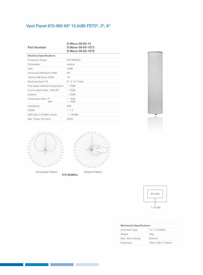
Vpol Panel 870-960 65º 15.0dBi FET0º, 3º, 6º
Part NumberS-Wave 09-65-15S-Wave 09-65-15T3S-Wave 09-65-15T6
Electrical Specifications
Frequency Range 870-960MHz
Polarization Vertical
Gain 15dBi
Horizontal 3dB Beam Width 65º
Vertical 3dB Beam Width 14º
Electrical Down Tilt 0º, 3º, 6º, Fixed
First Upper Sidelobe Suppression > 15dB
Front to Back Ratio, 180º±30º > 25dB
Isolation > 30dB
Cross-polar Ratio, 0º ±60º
> 18dB> 10dB
Impedance 50Ω
VSWR < 1.4
IMD3 @ 2 x 43dBm Carrier < -150dBc
Max, Power Per Input 500W
Mechanical Specifications
Connector Type 1 x 7-16 DIN(F)
Weight 12kg
Max. Wind Velocity 200km/h
Dimension 1300 x 282 x 100mm
Horizontal Pattern Vertical Pattern870-960MHz
870-960
7-16 DIN
3635
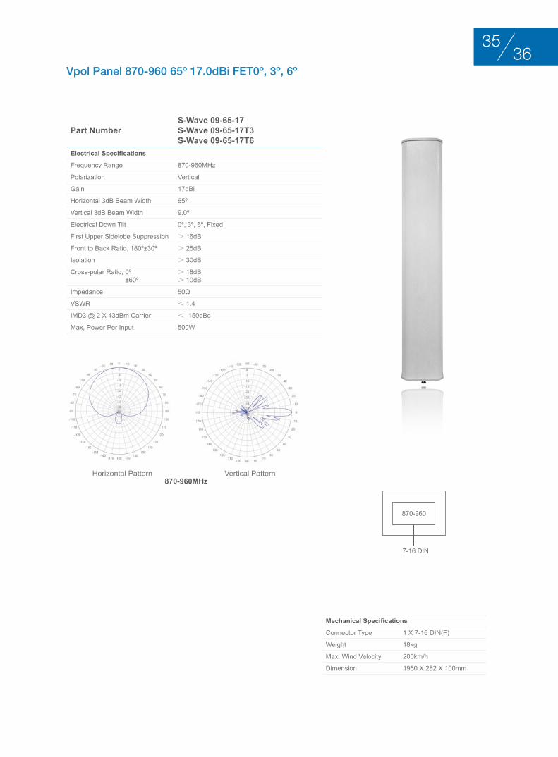
Vpol Panel 870-960 65º 17.0dBi FET0º, 3º, 6º
Part NumberS-Wave 09-65-17S-Wave 09-65-17T3S-Wave 09-65-17T6
Electrical Specifications
Frequency Range 870-960MHz
Polarization Vertical
Gain 17dBi
Horizontal 3dB Beam Width 65º
Vertical 3dB Beam Width 9.0º
Electrical Down Tilt 0º, 3º, 6º, Fixed
First Upper Sidelobe Suppression > 16dB
Front to Back Ratio, 180º±30º > 25dB
Isolation > 30dB
Cross-polar Ratio, 0º ±60º
> 18dB> 10dB
Impedance 50Ω
VSWR < 1.4
IMD3 @ 2 x 43dBm Carrier < -150dBc
Max, Power Per Input 500W
Mechanical Specifications
Connector Type 1 x 7-16 DIN(F)
Weight 18kg
Max. Wind Velocity 200km/h
Dimension 1950 x 282 x 100mm
Horizontal Pattern Vertical Pattern870-960MHz
870-960
7-16 DIN
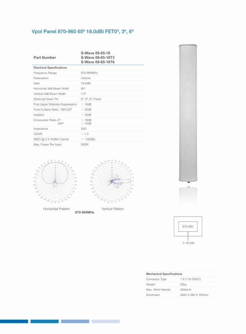
Vpol Panel 870-960 65º 18.0dBi FET0º, 3º, 6º
Part NumberS-Wave 09-65-18S-Wave 09-65-18T3S-Wave 09-65-18T6
Electrical Specifications
Frequency Range 870-960MHz
Polarization Vertical
Gain 18.0dBi
Horizontal 3dB Beam Width 65º
Vertical 3dB Beam Width 7.0º
Electrical Down Tilt 0º, 3º, 6º, Fixed
First Upper Sidelobe Suppression > 16dB
Front to Back Ratio, 180º±30º > 25dB
Isolation > 30dB
Cross-polar Ratio, 0º ±60º
> 18dB> 10dB
Impedance 50Ω
VSWR < 1.4
IMD3 @ 2 x 43dBm Carrier < -150dBc
Max, Power Per Input 500W
Mechanical Specifications
Connector Type 1 x 7-16 DIN(F)
Weight 22kg
Max. Wind Velocity 200km/h
Dimension 2640 x 282 x 100mm
Horizontal Pattern Vertical Pattern870-960MHz
870-960
7-16 DIN
3837
hIgh bAnd PAnEl AntEnnA 1710-2170MhzduAl PolArIzAtIon +45°/–45°
BASE STATION ANTENNAS
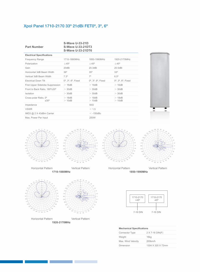
Xpol Panel 1710-2170 33º 21dBi FET0º, 3º, 6º
Part NumberS-Wave U-33-21DS-Wave U-33-21DT3S-Wave U-33-21DT6
Electrical Specifications
Frequency Range 1710-1880MHz 1850-1990MHz 1920-2170MHz
Polarization ±45º ±45º ±45º
Gain 20dBi 20.3dBi 20.5dBi
Horizontal 3dB Beam Width 36º 35º 33º
Vertical 3dB Beam Width 7.3º 7º 6.5º
Electrical Down Tilt 0º, 3º, 6º, Fixed 0º, 3º, 6º, Fixed 0º, 3º, 6º, Fixed
First Upper Sidelobe Suppression > 16dB > 16dB > 16dB
Front to Back Ratio, 180º±30º > 30dB > 30dB > 30dB
Isolation > 30dB > 30dB > 30dB
Cross-polar Ratio, 0º ±30º
> 18dB> 10dB
> 18dB> 10dB
> 18dB> 10dB
Impedance 50Ω
VSWR < 1.5
IMD3 @ 2 x 43dBm Carrier < -150dBc
Max, Power Per Input 250W
Mechanical Specifications
Connector Type 2 x 7-16 DIN(F)
Weight 16kg
Max. Wind Velocity 200km/h
Dimension 1304 x 320 x 72mm
1710-1880MHz
1920-2170MHz
1850-1990MHzHorizontal Pattern
Horizontal Pattern
Horizontal PatternVertical Pattern
Vertical Pattern
Vertical Pattern
1710-2170+45º
1710-2170-45º
7-16 DIN 7-16 DIN
4039
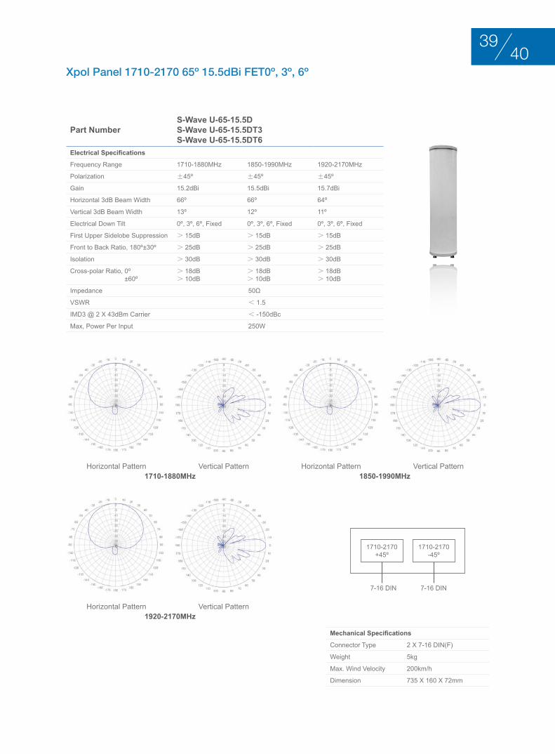
Xpol Panel 1710-2170 65º 15.5dBi FET0º, 3º, 6º
Part NumberS-Wave U-65-15.5DS-Wave U-65-15.5DT3S-Wave U-65-15.5DT6
Electrical Specifications
Frequency Range 1710-1880MHz 1850-1990MHz 1920-2170MHz
Polarization ±45º ±45º ±45º
Gain 15.2dBi 15.5dBi 15.7dBi
Horizontal 3dB Beam Width 66º 66º 64º
Vertical 3dB Beam Width 13º 12º 11º
Electrical Down Tilt 0º, 3º, 6º, Fixed 0º, 3º, 6º, Fixed 0º, 3º, 6º, Fixed
First Upper Sidelobe Suppression > 15dB > 15dB > 15dB
Front to Back Ratio, 180º±30º > 25dB > 25dB > 25dB
Isolation > 30dB > 30dB > 30dB
Cross-polar Ratio, 0º ±60º
> 18dB> 10dB
> 18dB> 10dB
> 18dB> 10dB
Impedance 50Ω
VSWR < 1.5
IMD3 @ 2 x 43dBm Carrier < -150dBc
Max, Power Per Input 250W
Mechanical Specifications
Connector Type 2 x 7-16 DIN(F)
Weight 5kg
Max. Wind Velocity 200km/h
Dimension 735 x 160 x 72mm
1710-1880MHz
1920-2170MHz
1850-1990MHzHorizontal Pattern
Horizontal Pattern
Horizontal PatternVertical Pattern
Vertical Pattern
Vertical Pattern
1710-2170+45º
1710-2170-45º
7-16 DIN 7-16 DIN
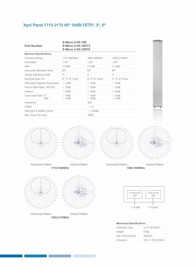
Xpol Panel 1710-2170 65º 18dBi FET0º, 3º, 6º
Part NumberS-Wave U-65-18DS-Wave U-65-18DT3S-Wave U-65-18DT6
Electrical Specifications
Frequency Range 1710-1880MHz 1850-1990MHz 1920-2170MHz
Polarization ±45º ±45º ±45º
Gain 17.5dBi 17.5dBi 17.5dBi
Horizontal 3dB Beam Width 65º 65º 65º
Vertical 3dB Beam Width 7º 7º 7º
Electrical Down Tilt 0º, 3º, 6º, Fixed 0º, 3º, 6º, Fixed 0º, 3º, 6º, Fixed
First Upper Sidelobe Suppression > 15dB > 15dB > 15dB
Front to Back Ratio, 180º±30º > 25dB > 25dB > 25dB
Isolation > 30dB > 30dB > 30dB
Cross-polar Ratio, 0º ±60º
> 15dB> 10dB
> 15dB> 10dB
> 15dB> 10dB
Impedance 50Ω
VSWR < 1.4
IMD3 @ 2 x 43dBm Carrier < -150dBc
Max, Power Per Input 300W
Mechanical Specifications
Connector Type 2 x 7-16 DIN(F)
Weight 5.5kg
Max. Wind Velocity 200km/h
Dimension 1337 x 162 x 95mm
1710-1880MHz
1920-2170MHz
1850-1990MHzHorizontal Pattern
Horizontal Pattern
Horizontal PatternVertical Pattern
Vertical Pattern
Vertical Pattern
1710-2170+45º
1710-2170-45º
7-16 DIN 7-16 DIN
4241
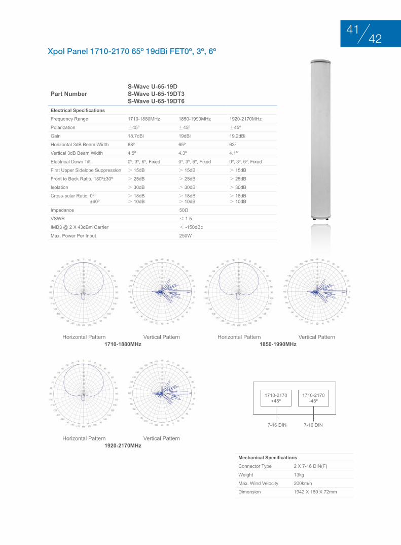
Xpol Panel 1710-2170 65º 19dBi FET0º, 3º, 6º
Part NumberS-Wave U-65-19DS-Wave U-65-19DT3S-Wave U-65-19DT6
Electrical Specifications
Frequency Range 1710-1880MHz 1850-1990MHz 1920-2170MHz
Polarization ±45º ±45º ±45º
Gain 18.7dBi 19dBi 19.2dBi
Horizontal 3dB Beam Width 68º 65º 63º
Vertical 3dB Beam Width 4.5º 4.3º 4.1º
Electrical Down Tilt 0º, 3º, 6º, Fixed 0º, 3º, 6º, Fixed 0º, 3º, 6º, Fixed
First Upper Sidelobe Suppression > 15dB > 15dB > 15dB
Front to Back Ratio, 180º±30º > 25dB > 25dB > 25dB
Isolation > 30dB > 30dB > 30dB
Cross-polar Ratio, 0º ±60º
> 18dB> 10dB
> 18dB> 10dB
> 18dB> 10dB
Impedance 50Ω
VSWR < 1.5
IMD3 @ 2 x 43dBm Carrier < -150dBc
Max, Power Per Input 250W
Mechanical Specifications
Connector Type 2 x 7-16 DIN(F)
Weight 13kg
Max. Wind Velocity 200km/h
Dimension 1942 x 160 x 72mm
1710-1880MHz
1920-2170MHz
1850-1990MHzHorizontal Pattern
Horizontal Pattern
Horizontal PatternVertical Pattern
Vertical Pattern
Vertical Pattern
1710-2170+45º
1710-2170-45º
7-16 DIN 7-16 DIN
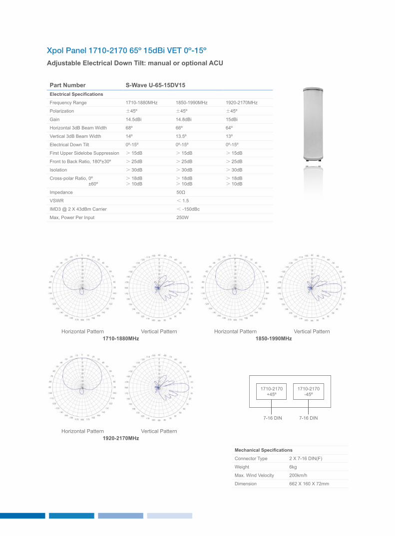
Xpol Panel 1710-2170 65º 15dBi VET 0º-15º
Adjustable Electrical Down Tilt: manual or optional ACU
Part Number S-Wave U-65-15DV15Electrical Specifications
Frequency Range 1710-1880MHz 1850-1990MHz 1920-2170MHz
Polarization ±45º ±45º ±45º
Gain 14.5dBi 14.8dBi 15dBi
Horizontal 3dB Beam Width 68º 66º 64º
Vertical 3dB Beam Width 14º 13.5º 13º
Electrical Down Tilt 0º-15º 0º-15º 0º-15º
First Upper Sidelobe Suppression > 15dB > 15dB > 15dB
Front to Back Ratio, 180º±30º > 25dB > 25dB > 25dB
Isolation > 30dB > 30dB > 30dB
Cross-polar Ratio, 0º ±60º
> 18dB> 10dB
> 18dB> 10dB
> 18dB> 10dB
Impedance 50Ω
VSWR < 1.5
IMD3 @ 2 x 43dBm Carrier < -150dBc
Max, Power Per Input 250W
Mechanical Specifications
Connector Type 2 x 7-16 DIN(F)
Weight 6kg
Max. Wind Velocity 200km/h
Dimension 662 x 160 x 72mm
1710-1880MHz
1920-2170MHz
1850-1990MHzHorizontal Pattern
Horizontal Pattern
Horizontal PatternVertical Pattern
Vertical Pattern
Vertical Pattern
1710-2170+45º
1710-2170-45º
7-16 DIN 7-16 DIN
4443
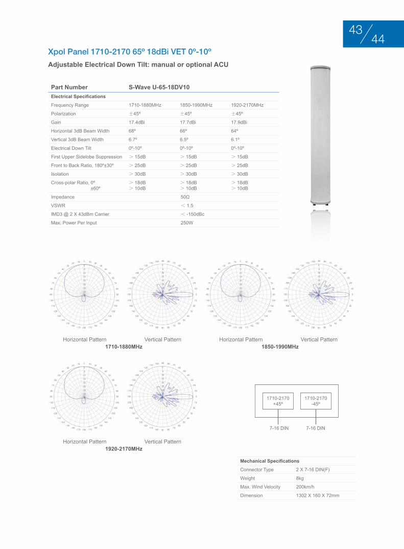
Xpol Panel 1710-2170 65º 18dBi VET 0º-10º
Adjustable Electrical Down Tilt: manual or optional ACU
Part Number S-Wave U-65-18DV10Electrical Specifications
Frequency Range 1710-1880MHz 1850-1990MHz 1920-2170MHz
Polarization ±45º ±45º ±45º
Gain 17.4dBi 17.7dBi 17.9dBi
Horizontal 3dB Beam Width 68º 66º 64º
Vertical 3dB Beam Width 6.7º 6.5º 6.1º
Electrical Down Tilt 0º-10º 0º-10º 0º-10º
First Upper Sidelobe Suppression > 15dB > 15dB > 15dB
Front to Back Ratio, 180º±30º > 25dB > 25dB > 25dB
Isolation > 30dB > 30dB > 30dB
Cross-polar Ratio, 0º ±60º
> 18dB> 10dB
> 18dB> 10dB
> 18dB> 10dB
Impedance 50Ω
VSWR < 1.5
IMD3 @ 2 x 43dBm Carrier < -150dBc
Max, Power Per Input 250W
Mechanical Specifications
Connector Type 2 x 7-16 DIN(F)
Weight 8kg
Max. Wind Velocity 200km/h
Dimension 1302 x 160 x 72mm
1710-1880MHz
1920-2170MHz
1850-1990MHzHorizontal Pattern
Horizontal Pattern
Horizontal PatternVertical Pattern
Vertical Pattern
Vertical Pattern
1710-2170+45º
1710-2170-45º
7-16 DIN 7-16 DIN
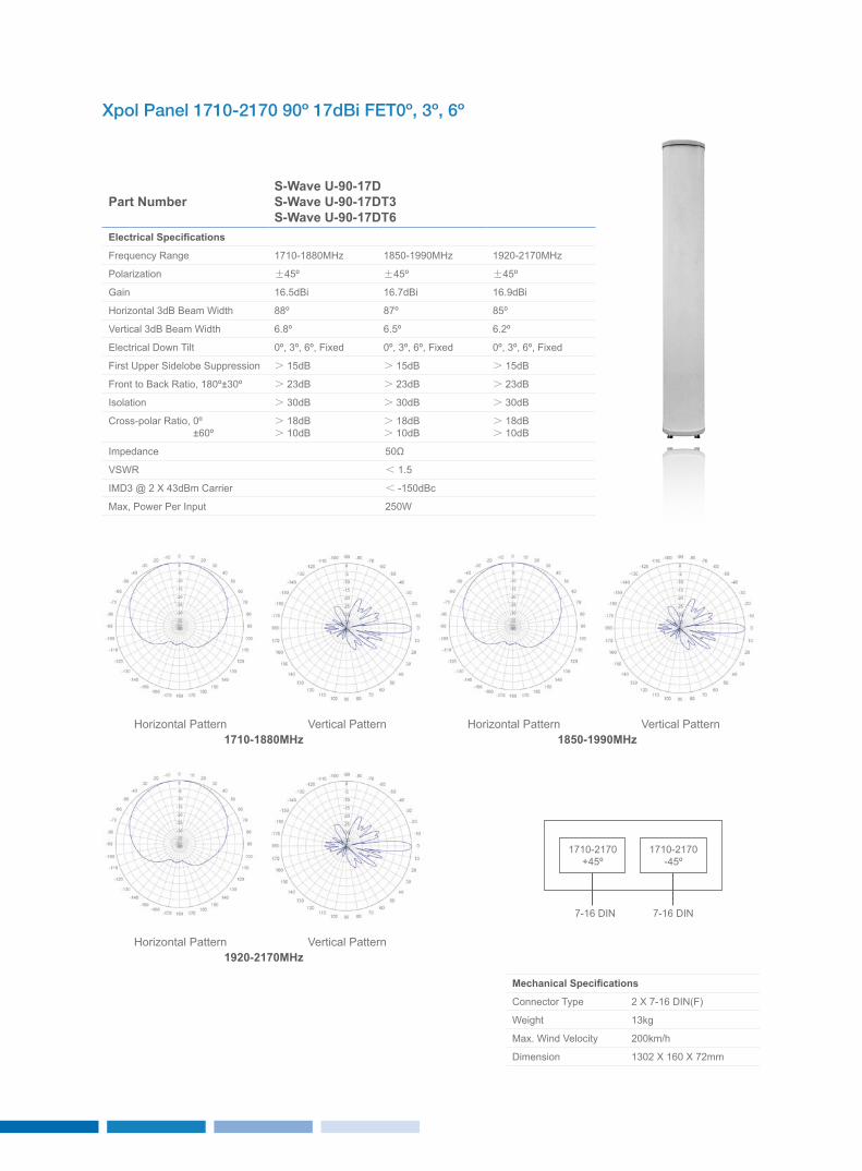
Xpol Panel 1710-2170 90º 17dBi FET0º, 3º, 6º
Part NumberS-Wave U-90-17DS-Wave U-90-17DT3S-Wave U-90-17DT6
Electrical Specifications
Frequency Range 1710-1880MHz 1850-1990MHz 1920-2170MHz
Polarization ±45º ±45º ±45º
Gain 16.5dBi 16.7dBi 16.9dBi
Horizontal 3dB Beam Width 88º 87º 85º
Vertical 3dB Beam Width 6.8º 6.5º 6.2º
Electrical Down Tilt 0º, 3º, 6º, Fixed 0º, 3º, 6º, Fixed 0º, 3º, 6º, Fixed
First Upper Sidelobe Suppression > 15dB > 15dB > 15dB
Front to Back Ratio, 180º±30º > 23dB > 23dB > 23dB
Isolation > 30dB > 30dB > 30dB
Cross-polar Ratio, 0º ±60º
> 18dB> 10dB
> 18dB> 10dB
> 18dB> 10dB
Impedance 50Ω
VSWR < 1.5
IMD3 @ 2 x 43dBm Carrier < -150dBc
Max, Power Per Input 250W
Mechanical Specifications
Connector Type 2 x 7-16 DIN(F)
Weight 13kg
Max. Wind Velocity 200km/h
Dimension 1302 x 160 x 72mm
1710-1880MHz
1920-2170MHz
1850-1990MHzHorizontal Pattern
Horizontal Pattern
Horizontal PatternVertical Pattern
Vertical Pattern
Vertical Pattern
1710-2170+45º
1710-2170-45º
7-16 DIN 7-16 DIN
4645
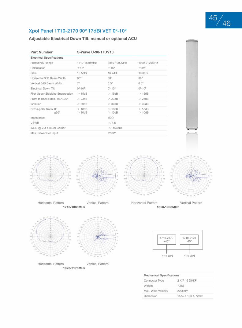
Xpol Panel 1710-2170 90º 17dBi VET 0º-10º
Adjustable Electrical Down Tilt: manual or optional ACU
Part Number S-Wave U-90-17DV10Electrical Specifications
Frequency Range 1710-1880MHz 1850-1990MHz 1920-2170MHz
Polarization ±45º ±45º ±45º
Gain 16.5dBi 16.7dBi 16.8dBi
Horizontal 3dB Beam Width 90º 88º 88º
Vertical 3dB Beam Width 7º 6.5º 6.3º
Electrical Down Tilt 0º-10º 0º-10º 0º-10º
First Upper Sidelobe Suppression > 15dB > 15dB > 15dB
Front to Back Ratio, 180º±30º > 23dB > 23dB > 23dB
Isolation > 30dB > 30dB > 30dB
Cross-polar Ratio, 0º ±60º
> 18dB> 10dB
> 18dB> 10dB
> 18dB> 10dB
Impedance 50Ω
VSWR < 1.5
IMD3 @ 2 x 43dBm Carrier < -150dBc
Max, Power Per Input 250W
Mechanical Specifications
Connector Type 2 x 7-16 DIN(F)
Weight 7.5kg
Max. Wind Velocity 200km/h
Dimension 1574 x 160 x 72mm
1710-1880MHz
1920-2170MHz
1850-1990MHzHorizontal Pattern
Horizontal Pattern
Horizontal PatternVertical Pattern
Vertical Pattern
Vertical Pattern
1710-2170+45º
1710-2170-45º
7-16 DIN 7-16 DIN
hIgh bAnd PAnEl AntEnnA 1710-2170Mhz VErtIcAl PolArIzAtIon
BASE STATION ANTENNAS
hIgh bAnd PAnEl AntEnnA 1710-2170Mhz VErtIcAl PolArIzAtIon
4847
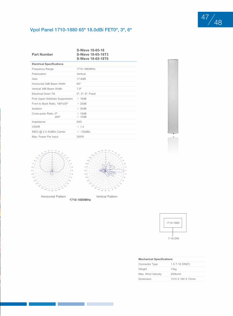
Vpol Panel 1710-1880 65º 18.0dBi FET0º, 3º, 6º
Part NumberS-Wave 18-65-18S-Wave 18-65-18T3S-Wave 18-65-18T6
Electrical Specifications
Frequency Range 1710-1880MHz
Polarization Vertical
Gain 17.8dBi
Horizontal 3dB Beam Width 65º
Vertical 3dB Beam Width 7.0º
Electrical Down Tilt 0º, 3º, 6º, Fixed
First Upper Sidelobe Suppression > 16dB
Front to Back Ratio, 180º±30º > 25dB
Isolation > 30dB
Cross-polar Ratio, 0º ±60º
> 18dB> 10dB
Impedance 50Ω
VSWR < 1.4
IMD3 @ 2 x 43dBm Carrier < -150dBc
Max, Power Per Input 300W
Mechanical Specifications
Connector Type 1 x 7-16 DIN(F)
Weight 13kg
Max. Wind Velocity 200km/h
Dimension 1310 x 160 x 72mm
Horizontal Pattern Vertical Pattern1710-1880MHz
1710-1880
7-16 DIN
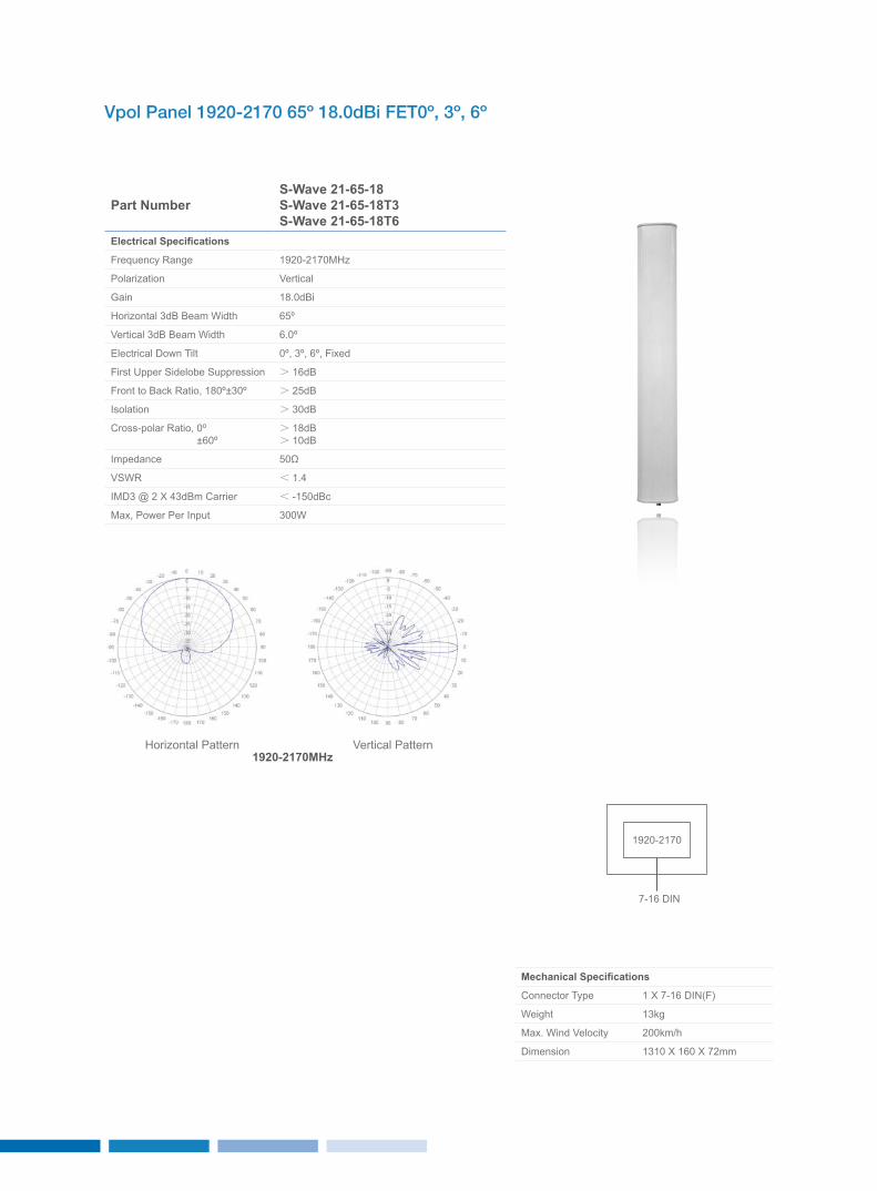
Vpol Panel 1920-2170 65º 18.0dBi FET0º, 3º, 6º
Part NumberS-Wave 21-65-18S-Wave 21-65-18T3S-Wave 21-65-18T6
Electrical Specifications
Frequency Range 1920-2170MHz
Polarization Vertical
Gain 18.0dBi
Horizontal 3dB Beam Width 65º
Vertical 3dB Beam Width 6.0º
Electrical Down Tilt 0º, 3º, 6º, Fixed
First Upper Sidelobe Suppression > 16dB
Front to Back Ratio, 180º±30º > 25dB
Isolation > 30dB
Cross-polar Ratio, 0º ±60º
> 18dB> 10dB
Impedance 50Ω
VSWR < 1.4
IMD3 @ 2 x 43dBm Carrier < -150dBc
Max, Power Per Input 300W
Mechanical Specifications
Connector Type 1 x 7-16 DIN(F)
Weight 13kg
Max. Wind Velocity 200km/h
Dimension 1310 x 160 x 72mm
Horizontal Pattern Vertical Pattern1920-2170MHz
1920-2170
7-16 DIN
5049
Vpol Panel 1710-2170 65º 18dBi FET0º, 3º, 6º
Part NumberS-Wave U-65-18S-Wave U-65-18T3S-Wave U-65-18T6
Electrical Specifications
Frequency Range 1710-1880MHz 1850-1990MHz 1920-2170MHz
Polarization Vertical Vertical Vertical
Gain 17.5dBi 17.7dBi 18dBi
Horizontal 3dB Beam Width 68º 65º 63º
Vertical 3dB Beam Width 7º 6.6º 6.3º
Electrical Down Tilt 0º, 3º, 6º, Fixed 0º, 3º, 6º, Fixed 0º, 3º, 6º, Fixed
First Upper Sidelobe Suppression > 15dB > 15dB > 15dB
Front to Back Ratio, 180º±30º > 25dB > 25dB > 25dB
Impedance 50Ω
VSWR < 1.5
IMD3 @ 2 x 43dBm Carrier < -150dBc
Max, Power Per Input 250W
Mechanical Specifications
Connector Type 1 x 7-16 DIN(F)
Weight 13kg
Max. Wind Velocity 200km/h
Dimension 1302 x 160 x 72mm
1710-1880MHz
1920-2170MHz
1850-1990MHzHorizontal Pattern
Horizontal Pattern
Horizontal PatternVertical Pattern
Vertical Pattern
Vertical Pattern
1710-2170
7-16 DIN
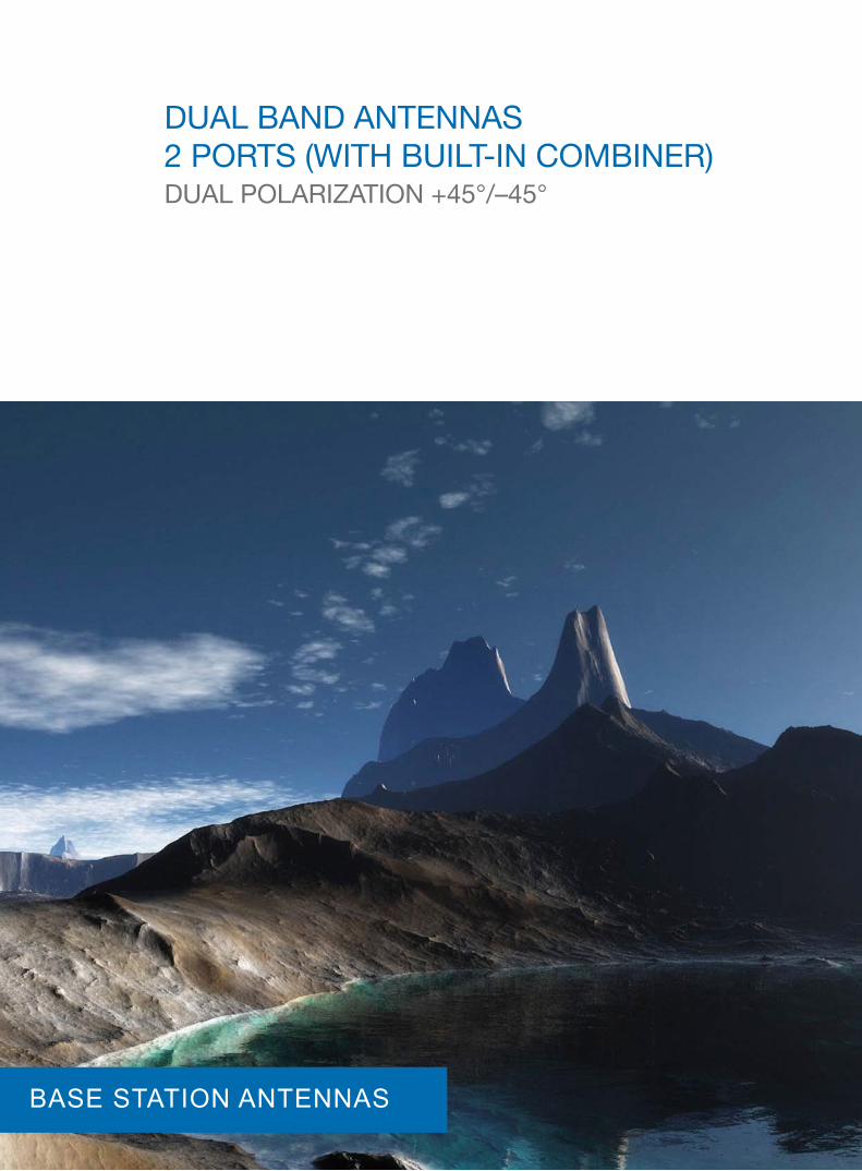
duAl bAnd AntEnnAS 2 PortS (WIth buIlt-In coMbInEr) duAl PolArIzAtIon +45°/–45°
BASE STATION ANTENNAS
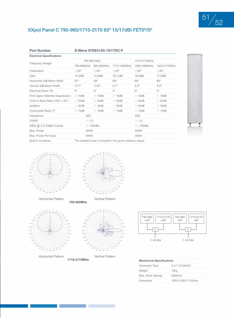
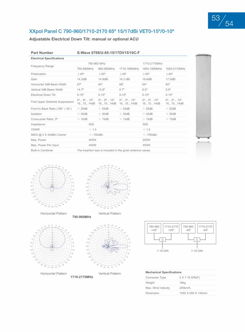
XXpol Panel C 790-960/1710-2170 65º 15/17dBi FET0º/0º
Part Number S-Wave 0709/U-65-15/17DC-FElectrical Specifications
Frequency Range790-960 MHz 1710-2170MHz
790-896MHz 880-960MHz 1710-1880MHz 1850-1990MHz 1920-2170MHz
Polarization ±45º ±45º ±45º ±45º ±45º
Gain 14.3dBi 14.9dBi 16.3 dBi 16.6dBi 17.0dBi
Horizontal 3dB Beam Width 67º 64º 66º 64º 60º
Vertical 3dB Beam Width 14.7º 13.9º 6.7º 6.5º 5.9º
Electrical Down Tilt 0º 0º 0º 0º 0º
First Upper Sidelobe Suppression > 16dB > 16dB > 16dB > 16dB > 16dB
Front to Back Ratio (180°±30°) > 25dB > 25dB > 25dB > 25dB > 25dB
Isolation > 30dB > 30dB > 30dB > 30dB > 30dB
Cross-polar Ratio, 0º > 15dB > 15dB > 15dB > 15dB > 15dB
Impedance 50Ω 50Ω
VSWR < 1.5 < 1.5
IMD3 @ 2 x 43dBm Carrier < -150dBc < -150dBc
Max, Power 400W 200W
Max, Power Per Input 450W 450W
Built-in Combiner The insertion loss is included in the given antenna values.
Mechanical Specifications
Connector Type 2 x 7-16 DIN(F)
Weight 16kg
Max. Wind Velocity 200km/h
Dimension 1550 x 295 x 145mm
Horizontal Pattern
Horizontal Pattern
Vertical Pattern
Vertical Pattern
1710-2170+45º
790-960+45º
C C
1710-2170-45º
790-960-45º
7-16 DIN 7-16 DIN
790-960MHz
1710-2170MHz
5251
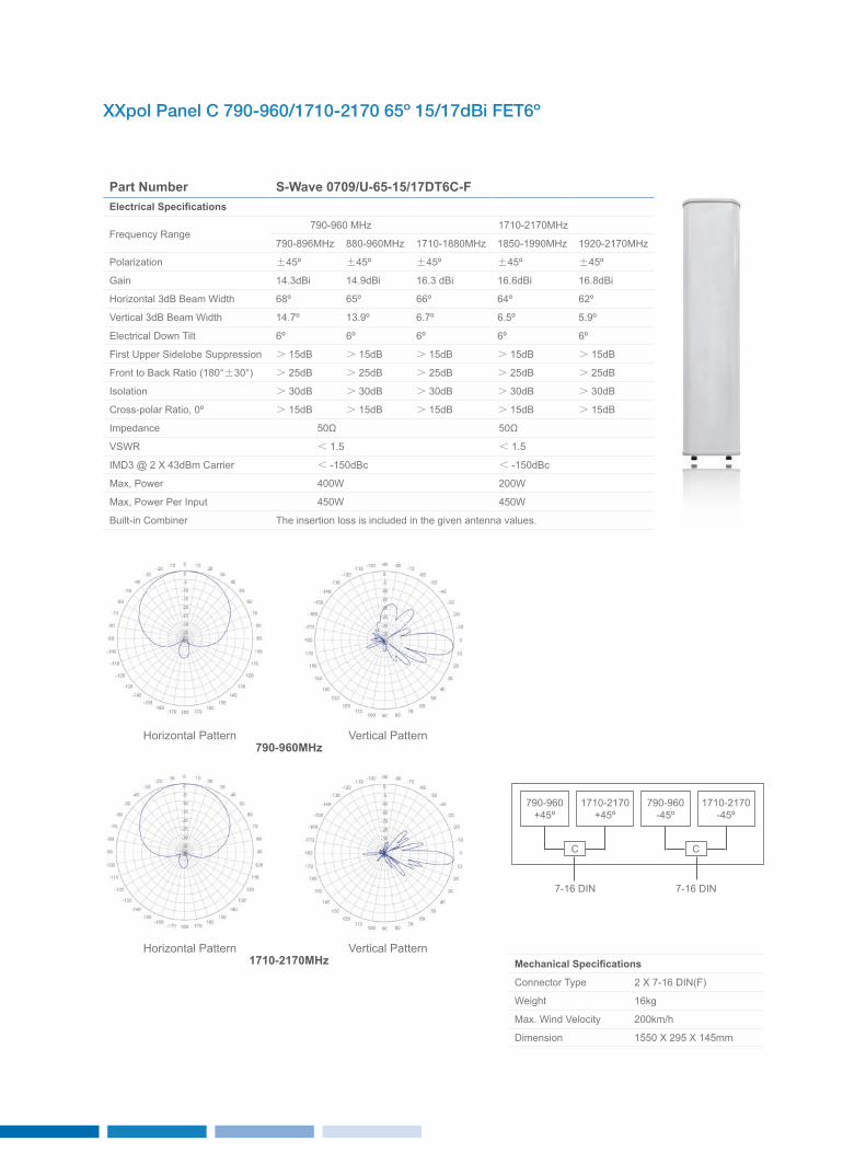
XXpol Panel C 790-960/1710-2170 65º 15/17dBi FET6º
Part Number S-Wave 0709/U-65-15/17DT6C-FElectrical Specifications
Frequency Range790-960 MHz 1710-2170MHz
790-896MHz 880-960MHz 1710-1880MHz 1850-1990MHz 1920-2170MHz
Polarization ±45º ±45º ±45º ±45º ±45º
Gain 14.3dBi 14.9dBi 16.3 dBi 16.6dBi 16.8dBi
Horizontal 3dB Beam Width 68º 65º 66º 64º 62º
Vertical 3dB Beam Width 14.7º 13.9º 6.7º 6.5º 5.9º
Electrical Down Tilt 6º 6º 6º 6º 6º
First Upper Sidelobe Suppression > 15dB > 15dB > 15dB > 15dB > 15dB
Front to Back Ratio (180°±30°) > 25dB > 25dB > 25dB > 25dB > 25dB
Isolation > 30dB > 30dB > 30dB > 30dB > 30dB
Cross-polar Ratio, 0º > 15dB > 15dB > 15dB > 15dB > 15dB
Impedance 50Ω 50Ω
VSWR < 1.5 < 1.5
IMD3 @ 2 x 43dBm Carrier < -150dBc < -150dBc
Max, Power 400W 200W
Max, Power Per Input 450W 450W
Built-in Combiner The insertion loss is included in the given antenna values.
Mechanical Specifications
Connector Type 2 x 7-16 DIN(F)
Weight 16kg
Max. Wind Velocity 200km/h
Dimension 1550 x 295 x 145mm
Horizontal Pattern
Horizontal Pattern
Vertical Pattern
Vertical Pattern
1710-2170+45º
790-960+45º
C C
1710-2170-45º
790-960-45º
7-16 DIN 7-16 DIN
790-960MHz
1710-2170MHz
XXpol Panel C 790-960/1710-2170 65º 15/17dBi VET0-15º/0-10º
Adjustable Electrical Down Tilt: manual or optional ACU
Part Number S-Wave 0709/U-65-15/17DV15/10C-FElectrical Specifications
Frequency Range790-960 MHz 1710-2170MHz
790-896MHz 880-960MHz 1710-1880MHz 1850-1990MHz 1920-2170MHz
Polarization ±45º ±45º ±45º ±45º ±45º
Gain 14.3dBi 14.9dBi 16.3 dBi 16.6dBi 17.0dBi
Horizontal 3dB Beam Width 67º 64º 66º 64º 60º
Vertical 3dB Beam Width 14.7º 13.9º 6.7º 6.5º 5.9º
Electrical Down Tilt 0-15º 0-15º 0-10º 0-10º 0-10º
First Upper Sidelobe Suppression 0º... 8º... 15º16...15...14dB
0º... 8º... 15º16...15...14dB
0º... 5º... 10º16...15...14dB
0º... 5º... 10º16...15...14dB
0º... 5º... 10º16...15...14dB
Front to Back Ratio (180°±30°) > 25dB > 25dB > 25dB > 25dB > 25dB
Isolation > 30dB > 30dB > 30dB > 30dB > 30dB
Cross-polar Ratio, 0º > 15dB > 15dB > 15dB > 15dB > 15dB
Impedance 50Ω 50Ω
VSWR < 1.5 < 1.5
IMD3 @ 2 x 43dBm Carrier < -150dBc < -150dBc
Max, Power 400W 200W
Max, Power Per Input 450W 450W
Built-in Combiner The insertion loss is included in the given antenna values.
Mechanical Specifications
Connector Type 2 x 7-16 DIN(F)
Weight 16kg
Max. Wind Velocity 200km/h
Dimension 1550 x 295 x 145mm
Horizontal Pattern
Horizontal Pattern
Vertical Pattern
Vertical Pattern
1710-2170+45º
790-960+45º
C C
1710-2170-45º
790-960-45º
7-16 DIN 7-16 DIN
790-960MHz
1710-2170MHz
5453
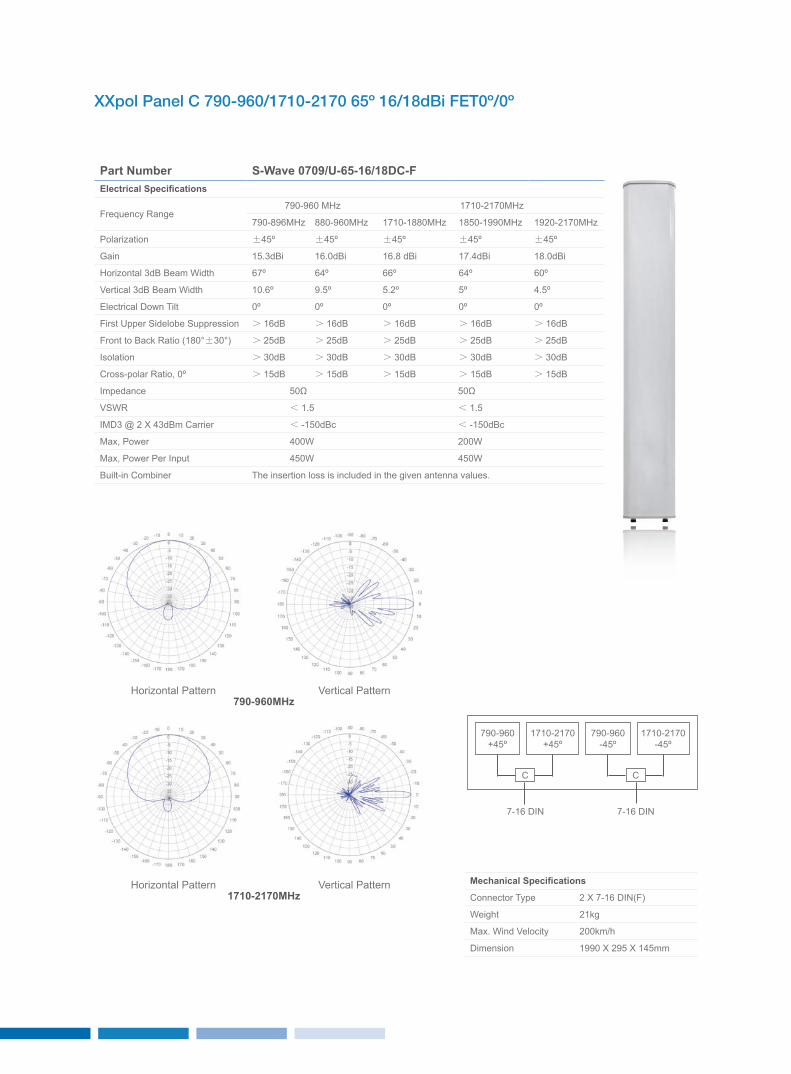
XXpol Panel C 790-960/1710-2170 65º 16/18dBi FET0º/0º
Part Number S-Wave 0709/U-65-16/18DC-FElectrical Specifications
Frequency Range790-960 MHz 1710-2170MHz
790-896MHz 880-960MHz 1710-1880MHz 1850-1990MHz 1920-2170MHz
Polarization ±45º ±45º ±45º ±45º ±45º
Gain 15.3dBi 16.0dBi 16.8 dBi 17.4dBi 18.0dBi
Horizontal 3dB Beam Width 67º 64º 66º 64º 60º
Vertical 3dB Beam Width 10.6º 9.5º 5.2º 5º 4.5º
Electrical Down Tilt 0º 0º 0º 0º 0º
First Upper Sidelobe Suppression > 16dB > 16dB > 16dB > 16dB > 16dB
Front to Back Ratio (180°±30°) > 25dB > 25dB > 25dB > 25dB > 25dB
Isolation > 30dB > 30dB > 30dB > 30dB > 30dB
Cross-polar Ratio, 0º > 15dB > 15dB > 15dB > 15dB > 15dB
Impedance 50Ω 50Ω
VSWR < 1.5 < 1.5
IMD3 @ 2 x 43dBm Carrier < -150dBc < -150dBc
Max, Power 400W 200W
Max, Power Per Input 450W 450W
Built-in Combiner The insertion loss is included in the given antenna values.
Mechanical Specifications
Connector Type 2 x 7-16 DIN(F)
Weight 21kg
Max. Wind Velocity 200km/h
Dimension 1990 x 295 x 145mm
Horizontal Pattern
Horizontal Pattern
Vertical Pattern
Vertical Pattern
1710-2170+45º
790-960+45º
C C
1710-2170-45º
790-960-45º
7-16 DIN 7-16 DIN
790-960MHz
1710-2170MHz
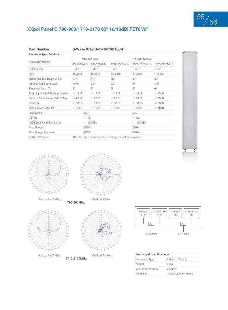
XXpol Panel C 790-960/1710-2170 65º 16/18dBi FET6º/6º
Part Number S-Wave 0709/U-65-16/18DT6C-FElectrical Specifications
Frequency Range790-960 MHz 1710-2170MHz
790-896MHz 880-960MHz 1710-1880MHz 1850-1990MHz 1920-2170MHz
Polarization ±45º ±45º ±45º ±45º ±45º
Gain 15.3dBi 16.0dBi 16.8 dBi 17.4dBi 18.0dBi
Horizontal 3dB Beam Width 67º 64º 66º 64º 60º
Vertical 3dB Beam Width 10.6º 9.5º 5.2º 5º 4.5º
Electrical Down Tilt 6º 6º 6º 6º 6º
First Upper Sidelobe Suppression > 15dB > 15dB > 15dB > 15dB > 15dB
Front to Back Ratio (180°±30°) > 25dB > 25dB > 25dB > 25dB > 25dB
Isolation > 30dB > 30dB > 30dB > 30dB > 30dB
Cross-polar Ratio, 0º > 15dB > 15dB > 15dB > 15dB > 15dB
Impedance 50Ω 50Ω
VSWR < 1.5 < 1.5
IMD3 @ 2 x 43dBm Carrier < -150dBc < -150dBc
Max, Power 400W 200W
Max, Power Per Input 450W 450W
Built-in Combiner The insertion loss is included in the given antenna values.
Mechanical Specifications
Connector Type 2 x 7-16 DIN(F)
Weight 21kg
Max. Wind Velocity 200km/h
Dimension 1990 x 295 x 145mm
Horizontal Pattern
Horizontal Pattern
Vertical Pattern
Vertical Pattern
1710-2170+45º
790-960+45º
C C
1710-2170-45º
790-960-45º
7-16 DIN 7-16 DIN
790-960MHz
1710-2170MHz
5655
Mechanical Specifications
Connector Type 2 x 7-16 DIN(F)
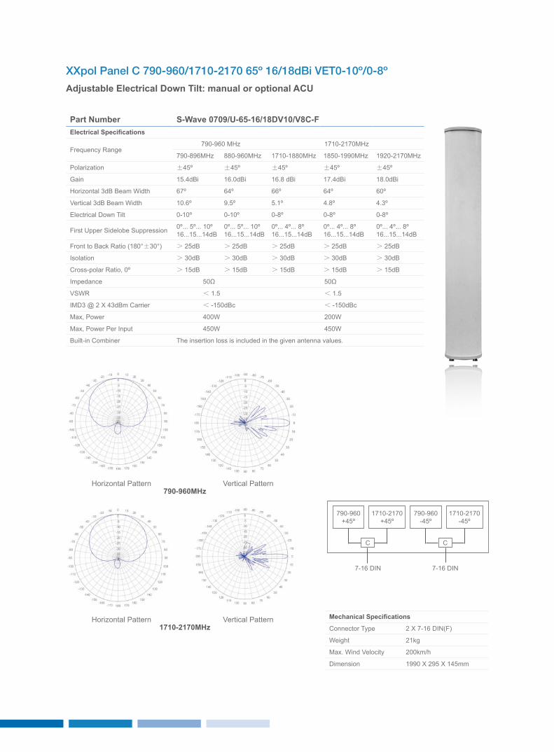
Weight 21kg
Max. Wind Velocity 200km/h
Dimension 1990 x 295 x 145mm
Horizontal Pattern
Horizontal Pattern
Vertical Pattern
Vertical Pattern
1710-2170+45º
790-960+45º
C C
1710-2170-45º
790-960-45º
7-16 DIN 7-16 DIN
790-960MHz
1710-2170MHz
XXpol Panel C 790-960/1710-2170 65º 16/18dBi VET0-10º/0-8º
Adjustable Electrical Down Tilt: manual or optional ACU
Part Number S-Wave 0709/U-65-16/18DV10/V8C-FElectrical Specifications
Frequency Range790-960 MHz 1710-2170MHz
790-896MHz 880-960MHz 1710-1880MHz 1850-1990MHz 1920-2170MHz
Polarization ±45º ±45º ±45º ±45º ±45º
Gain 15.4dBi 16.0dBi 16.8 dBi 17.4dBi 18.0dBi
Horizontal 3dB Beam Width 67º 64º 66º 64º 60º
Vertical 3dB Beam Width 10.6º 9.5º 5.1º 4.8º 4.3º
Electrical Down Tilt 0-10º 0-10º 0-8º 0-8º 0-8º
First Upper Sidelobe Suppression 0º... 5º... 10º16...15...14dB
0º... 5º... 10º16...15...14dB
0º... 4º... 8º16...15...14dB
0º... 4º... 8º16...15...14dB
0º... 4º... 8º16...15...14dB
Front to Back Ratio (180°±30°) > 25dB > 25dB > 25dB > 25dB > 25dB
Isolation > 30dB > 30dB > 30dB > 30dB > 30dB
Cross-polar Ratio, 0º > 15dB > 15dB > 15dB > 15dB > 15dB
Impedance 50Ω 50Ω
VSWR < 1.5 < 1.5
IMD3 @ 2 x 43dBm Carrier < -150dBc < -150dBc
Max, Power 400W 200W
Max, Power Per Input 450W 450W
Built-in Combiner The insertion loss is included in the given antenna values.
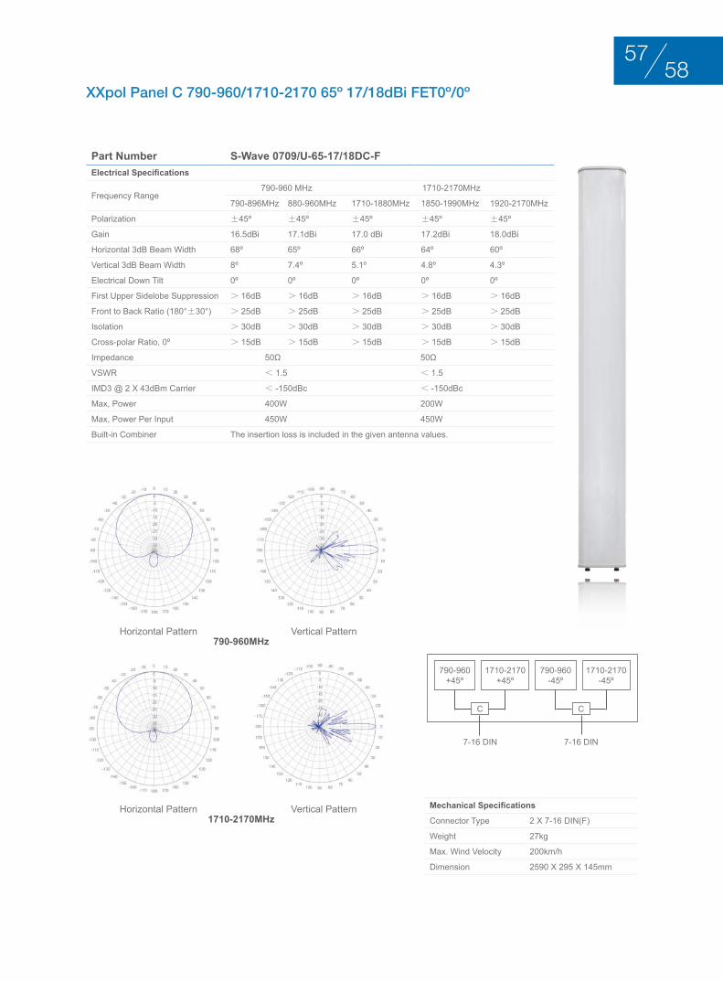
XXpol Panel C 790-960/1710-2170 65º 17/18dBi FET0º/0º
Part Number S-Wave 0709/U-65-17/18DC-FElectrical Specifications
Frequency Range790-960 MHz 1710-2170MHz
790-896MHz 880-960MHz 1710-1880MHz 1850-1990MHz 1920-2170MHz
Polarization ±45º ±45º ±45º ±45º ±45º
Gain 16.5dBi 17.1dBi 17.0 dBi 17.2dBi 18.0dBi
Horizontal 3dB Beam Width 68º 65º 66º 64º 60º
Vertical 3dB Beam Width 8º 7.4º 5.1º 4.8º 4.3º
Electrical Down Tilt 0º 0º 0º 0º 0º
First Upper Sidelobe Suppression > 16dB > 16dB > 16dB > 16dB > 16dB
Front to Back Ratio (180°±30°) > 25dB > 25dB > 25dB > 25dB > 25dB
Isolation > 30dB > 30dB > 30dB > 30dB > 30dB
Cross-polar Ratio, 0º > 15dB > 15dB > 15dB > 15dB > 15dB
Impedance 50Ω 50Ω
VSWR < 1.5 < 1.5
IMD3 @ 2 x 43dBm Carrier < -150dBc < -150dBc
Max, Power 400W 200W
Max, Power Per Input 450W 450W
Built-in Combiner The insertion loss is included in the given antenna values.
Mechanical Specifications
Connector Type 2 x 7-16 DIN(F)
Weight 27kg
Max. Wind Velocity 200km/h
Dimension 2590 x 295 x 145mm
Horizontal Pattern
Horizontal Pattern
Vertical Pattern
Vertical Pattern
1710-2170+45º
790-960+45º
C C
1710-2170-45º
790-960-45º
7-16 DIN 7-16 DIN
790-960MHz
1710-2170MHz
5857
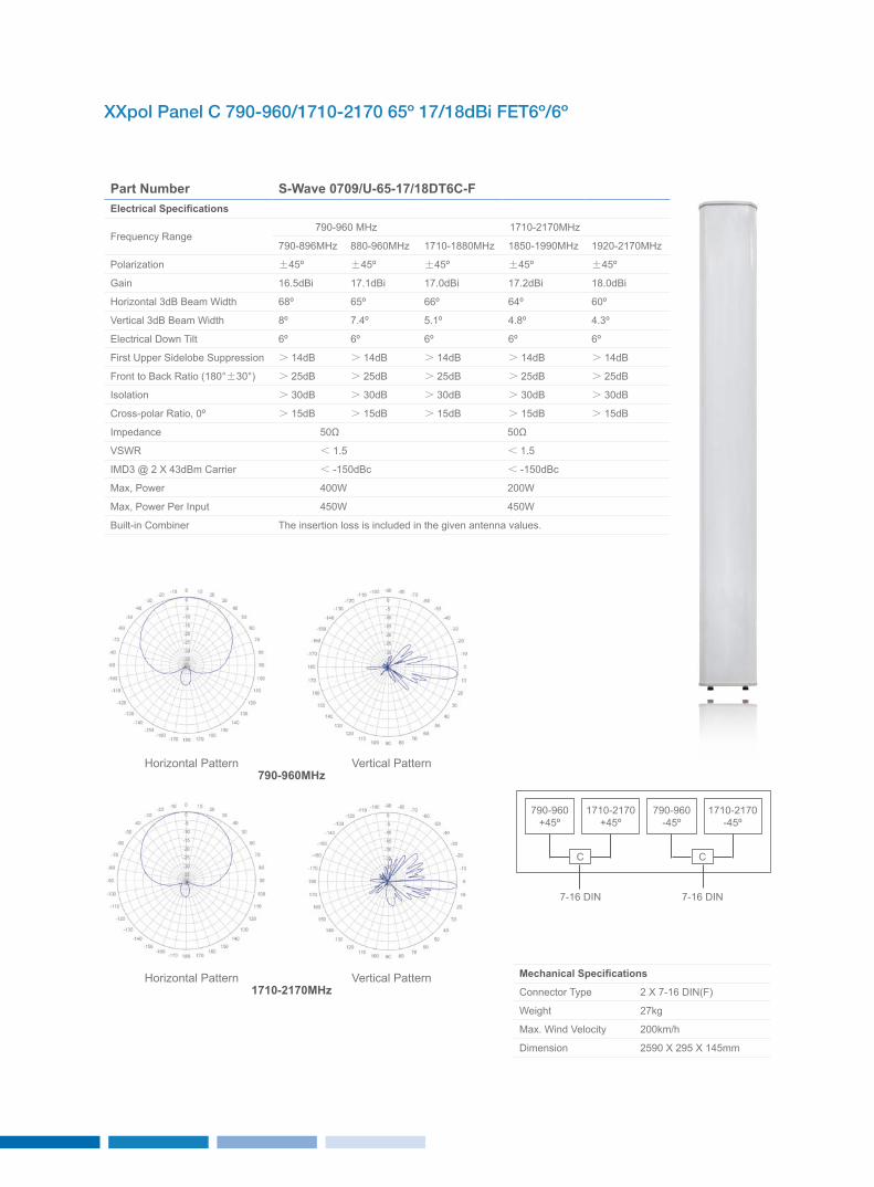
XXpol Panel C 790-960/1710-2170 65º 17/18dBi FET6º/6º
Part Number S-Wave 0709/U-65-17/18DT6C-FElectrical Specifications
Frequency Range790-960 MHz 1710-2170MHz
790-896MHz 880-960MHz 1710-1880MHz 1850-1990MHz 1920-2170MHz
Polarization ±45º ±45º ±45º ±45º ±45º
Gain 16.5dBi 17.1dBi 17.0dBi 17.2dBi 18.0dBi
Horizontal 3dB Beam Width 68º 65º 66º 64º 60º
Vertical 3dB Beam Width 8º 7.4º 5.1º 4.8º 4.3º
Electrical Down Tilt 6º 6º 6º 6º 6º
First Upper Sidelobe Suppression > 14dB > 14dB > 14dB > 14dB > 14dB
Front to Back Ratio (180°±30°) > 25dB > 25dB > 25dB > 25dB > 25dB
Isolation > 30dB > 30dB > 30dB > 30dB > 30dB
Cross-polar Ratio, 0º > 15dB > 15dB > 15dB > 15dB > 15dB
Impedance 50Ω 50Ω
VSWR < 1.5 < 1.5
IMD3 @ 2 x 43dBm Carrier < -150dBc < -150dBc
Max, Power 400W 200W
Max, Power Per Input 450W 450W
Built-in Combiner The insertion loss is included in the given antenna values.
Mechanical Specifications
Connector Type 2 x 7-16 DIN(F)
Weight 27kg
Max. Wind Velocity 200km/h
Dimension 2590 x 295 x 145mm
Horizontal Pattern
Horizontal Pattern
Vertical Pattern
Vertical Pattern
1710-2170+45º
790-960+45º
C C
1710-2170-45º
790-960-45º
7-16 DIN 7-16 DIN
790-960MHz
1710-2170MHz
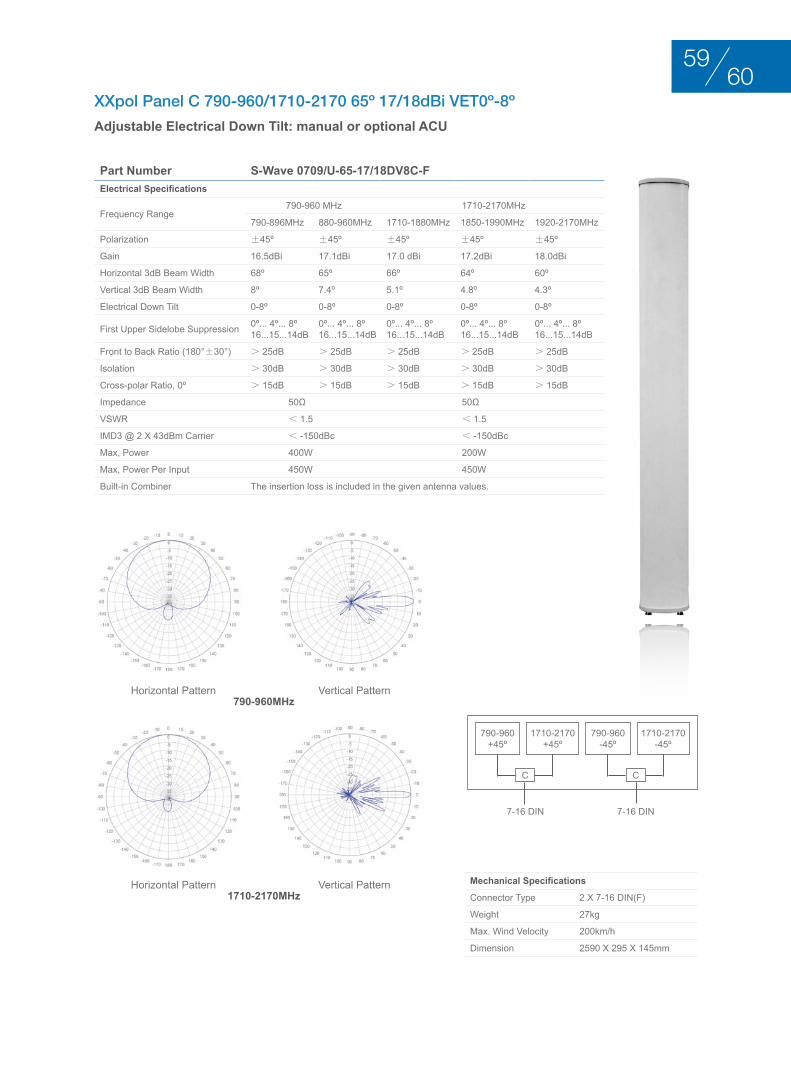
XXpol Panel C 790-960/1710-2170 65º 17/18dBi VET0º-8º
Adjustable Electrical Down Tilt: manual or optional ACU
Part Number S-Wave 0709/U-65-17/18DV8C-FElectrical Specifications
Frequency Range790-960 MHz 1710-2170MHz
790-896MHz 880-960MHz 1710-1880MHz 1850-1990MHz 1920-2170MHz
Polarization ±45º ±45º ±45º ±45º ±45º
Gain 16.5dBi 17.1dBi 17.0 dBi 17.2dBi 18.0dBi
Horizontal 3dB Beam Width 68º 65º 66º 64º 60º
Vertical 3dB Beam Width 8º 7.4º 5.1º 4.8º 4.3º
Electrical Down Tilt 0-8º 0-8º 0-8º 0-8º 0-8º
First Upper Sidelobe Suppression 0º... 4º... 8º16...15...14dB
0º... 4º... 8º16...15...14dB
0º... 4º... 8º16...15...14dB
0º... 4º... 8º16...15...14dB
0º... 4º... 8º16...15...14dB
Front to Back Ratio (180°±30°) > 25dB > 25dB > 25dB > 25dB > 25dB
Isolation > 30dB > 30dB > 30dB > 30dB > 30dB
Cross-polar Ratio, 0º > 15dB > 15dB > 15dB > 15dB > 15dB
Impedance 50Ω 50Ω
VSWR < 1.5 < 1.5
IMD3 @ 2 x 43dBm Carrier < -150dBc < -150dBc
Max, Power 400W 200W
Max, Power Per Input 450W 450W
Built-in Combiner The insertion loss is included in the given antenna values.
Mechanical Specifications
Connector Type 2 x 7-16 DIN(F)
Weight 27kg
Max. Wind Velocity 200km/h
Dimension 2590 x 295 x 145mm
Horizontal Pattern
Horizontal Pattern
Vertical Pattern
Vertical Pattern
1710-2170+45º
790-960+45º
C C
1710-2170-45º
790-960-45º
7-16 DIN 7-16 DIN
790-960MHz
1710-2170MHz
6059
duAl bAnd AntEnnAS 4 PortS duAl PolArIzAtIon +45°/–45°
BASE STATION ANTENNAS
duAl bAnd AntEnnAS 4 PortS duAl PolArIzAtIon +45°/–45°
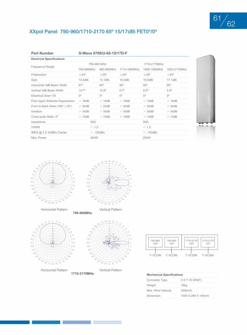
XXpol Panel 790-960/1710-2170 65º 15/17dBi FET0º/0º
Part Number S-Wave 0709/U-65-15/17D-FElectrical Specifications
Frequency Range790-960 MHz 1710-2170MHz
790-896MHz 880-960MHz 1710-1880MHz 1850-1990MHz 1920-2170MHz
Polarization ±45º ±45º ±45º ±45º ±45º
Gain 14.5dBi 15.1dBi 16.5dBi 16.8dBi 17.1dBi
Horizontal 3dB Beam Width 67º 64º 66º 64º 60º
Vertical 3dB Beam Width 14.7º 13.9º 6.7º 6.5º 5.9º
Electrical Down Tilt 0º 0º 0º 0º 0º
First Upper Sidelobe Suppression > 16dB > 16dB > 16dB > 16dB > 16dB
Front to Back Ratio (180°±30°) > 25dB > 25dB > 25dB > 25dB > 25dB
Isolation > 30dB > 30dB > 30dB > 30dB > 30dB
Cross-polar Ratio, 0º > 15dB > 15dB > 15dB > 15dB > 15dB
Impedance 50Ω 50Ω
VSWR < 1.5 < 1.5
IMD3 @ 2 x 43dBm Carrier < -150dBc < -150dBc
Max, Power 400W 200W
Mechanical Specifications
Connector Type 4 x 7-16 DIN(F)
Weight 16kg
Max. Wind Velocity 200km/h
Dimension 1550 x 295 x 145mm
Horizontal Pattern
Horizontal Pattern
Vertical Pattern
Vertical Pattern
790-960MHz
1710-2170MHz
1710-2170+45º
790-960+45º
1710-2170-45º
790-960-45º
7-16 DIN 7-16 DIN 7-16 DIN 7-16 DIN
6261
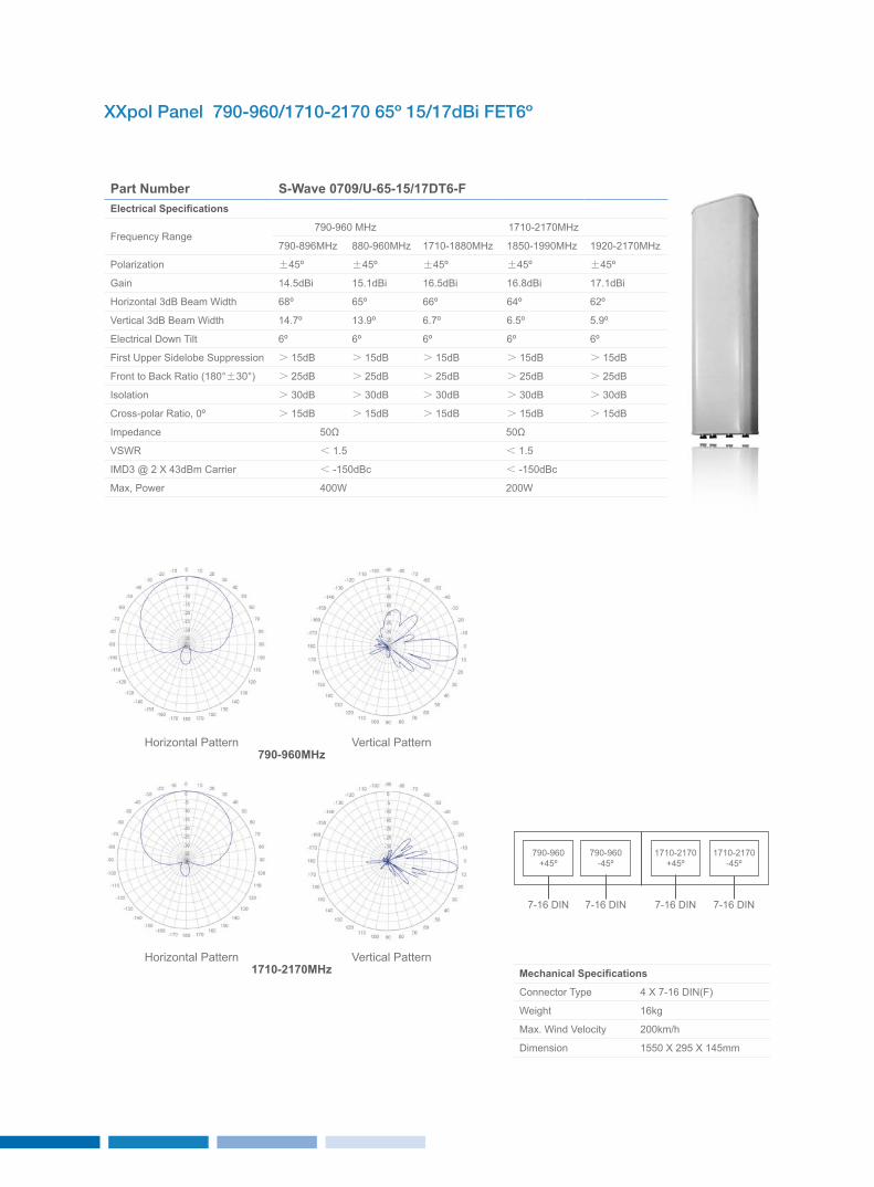
XXpol Panel 790-960/1710-2170 65º 15/17dBi FET6º
Part Number S-Wave 0709/U-65-15/17DT6-FElectrical Specifications
Frequency Range790-960 MHz 1710-2170MHz
790-896MHz 880-960MHz 1710-1880MHz 1850-1990MHz 1920-2170MHz
Polarization ±45º ±45º ±45º ±45º ±45º
Gain 14.5dBi 15.1dBi 16.5dBi 16.8dBi 17.1dBi
Horizontal 3dB Beam Width 68º 65º 66º 64º 62º
Vertical 3dB Beam Width 14.7º 13.9º 6.7º 6.5º 5.9º
Electrical Down Tilt 6º 6º 6º 6º 6º
First Upper Sidelobe Suppression > 15dB > 15dB > 15dB > 15dB > 15dB
Front to Back Ratio (180°±30°) > 25dB > 25dB > 25dB > 25dB > 25dB
Isolation > 30dB > 30dB > 30dB > 30dB > 30dB
Cross-polar Ratio, 0º > 15dB > 15dB > 15dB > 15dB > 15dB
Impedance 50Ω 50Ω
VSWR < 1.5 < 1.5
IMD3 @ 2 x 43dBm Carrier < -150dBc < -150dBc
Max, Power 400W 200W
Mechanical Specifications
Connector Type 4 x 7-16 DIN(F)
Weight 16kg
Max. Wind Velocity 200km/h
Dimension 1550 x 295 x 145mm
Horizontal Pattern
Horizontal Pattern
Vertical Pattern
Vertical Pattern
790-960MHz
1710-2170MHz
1710-2170+45º
790-960+45º
1710-2170-45º
790-960-45º
7-16 DIN 7-16 DIN 7-16 DIN 7-16 DIN

XXpol Panel 790-960/1710-2170 65º 15/17dBi VET0-15º/0-10º
Adjustable Electrical Down Tilt: manual or optional ACU
Part Number S-Wave 0709/U-65-15/17DV15/10-FElectrical Specifications
Frequency Range790-960 MHz 1710-2170MHz
790-896MHz 880-960MHz 1710-1880MHz 1850-1990MHz 1920-2170MHz
Polarization ±45º ±45º ±45º ±45º ±45º
Gain 14.5dBi 15.1dBi 16.5dBi 16.8dBi 17.1dBi
Horizontal 3dB Beam Width 67º 64º 66º 64º 60º
Vertical 3dB Beam Width 14.7º 13.9º 6.7º 6.5º 5.9º
Electrical Down Tilt 0-15º 0-15º 0-10º 0-10º 0-10º
First Upper Sidelobe Suppression 0º... 8º... 15º16...15...14dB
0º... 8º... 15º16...15...14dB
0º... 5º... 10º16...15...14dB
0º... 5º... 10º16...15...14dB
0º... 5º... 10º16...15...14dB
Front to Back Ratio (180°±30°) > 25dB > 25dB > 25dB > 25dB > 25dB
Isolation > 30dB > 30dB > 30dB > 30dB > 30dB
Cross-polar Ratio, 0º > 15dB > 15dB > 15dB > 15dB > 15dB
Impedance 50Ω 50Ω
VSWR < 1.5 < 1.5
IMD3 @ 2 x 43dBm Carrier < -150dBc < -150dBc
Max, Power 400W 200W
Mechanical Specifications
Connector Type 4 x 7-16 DIN(F)
Weight 16kg
Max. Wind Velocity 200km/h
Dimension 1550 x 295 x 145mm
Horizontal Pattern
Horizontal Pattern
Vertical Pattern
Vertical Pattern
790-960MHz
1710-2170MHz
1710-2170+45º
790-960+45º
1710-2170-45º
790-960-45º
7-16 DIN 7-16 DIN 7-16 DIN 7-16 DIN
6463
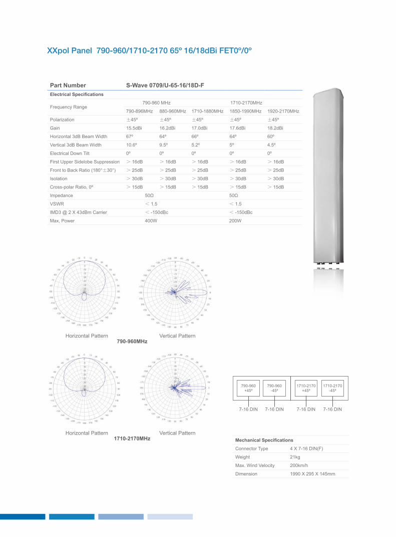
XXpol Panel 790-960/1710-2170 65º 16/18dBi FET0º/0º
Part Number S-Wave 0709/U-65-16/18D-FElectrical Specifications
Frequency Range790-960 MHz 1710-2170MHz
790-896MHz 880-960MHz 1710-1880MHz 1850-1990MHz 1920-2170MHz
Polarization ±45º ±45º ±45º ±45º ±45º
Gain 15.5dBi 16.2dBi 17.0dBi 17.6dBi 18.2dBi
Horizontal 3dB Beam Width 67º 64º 66º 64º 60º
Vertical 3dB Beam Width 10.6º 9.5º 5.2º 5º 4.5º
Electrical Down Tilt 0º 0º 0º 0º 0º
First Upper Sidelobe Suppression > 16dB > 16dB > 16dB > 16dB > 16dB
Front to Back Ratio (180°±30°) > 25dB > 25dB > 25dB > 25dB > 25dB
Isolation > 30dB > 30dB > 30dB > 30dB > 30dB
Cross-polar Ratio, 0º > 15dB > 15dB > 15dB > 15dB > 15dB
Impedance 50Ω 50Ω
VSWR < 1.5 < 1.5
IMD3 @ 2 x 43dBm Carrier < -150dBc < -150dBc
Max, Power 400W 200W
Mechanical Specifications
Connector Type 4 x 7-16 DIN(F)
Weight 21kg
Max. Wind Velocity 200km/h
Dimension 1990 x 295 x 145mm
Horizontal Pattern
Horizontal Pattern
Vertical Pattern
Vertical Pattern
790-960MHz
1710-2170MHz
1710-2170+45º
790-960+45º
1710-2170-45º
790-960-45º
7-16 DIN 7-16 DIN 7-16 DIN 7-16 DIN

XXpol Panel 790-960/1710-2170 65º 16/18dBi FET6º/6º
Part Number S-Wave 0709/U-65-16/18DT6-FElectrical Specifications
Frequency Range790-960 MHz 1710-2170MHz
790-896MHz 880-960MHz 1710-1880MHz 1850-1990MHz 1920-2170MHz
Polarization ±45º ±45º ±45º ±45º ±45º
Gain 15.4dBi 16.1dBi 16.9 dBi 17.5dBi 18.1dBi
Horizontal 3dB Beam Width 67º 64º 66º 64º 60º
Vertical 3dB Beam Width 10.6º 9.5º 5.2º 5º 4.5º
Electrical Down Tilt 6º 6º 6º 6º 6º
First Upper Sidelobe Suppression > 15dB > 15dB > 15dB > 15dB > 15dB
Front to Back Ratio (180°±30°) > 25dB > 25dB > 25dB > 25dB > 25dB
Isolation > 30dB > 30dB > 30dB > 30dB > 30dB
Cross-polar Ratio, 0º > 15dB > 15dB > 15dB > 15dB > 15dB
Impedance 50Ω 50Ω
VSWR < 1.5 < 1.5
IMD3 @ 2 x 43dBm Carrier < -150dBc < -150dBc
Max, Power 400W 200W
Mechanical Specifications
Connector Type 4 x 7-16 DIN(F)
Weight 21kg
Max. Wind Velocity 200km/h
Dimension 1990 x 295 x 145mm
Horizontal Pattern
Horizontal Pattern
Vertical Pattern
Vertical Pattern
790-960MHz
1710-2170MHz
1710-2170+45º
790-960+45º
1710-2170-45º
790-960-45º
7-16 DIN 7-16 DIN 7-16 DIN 7-16 DIN
6665
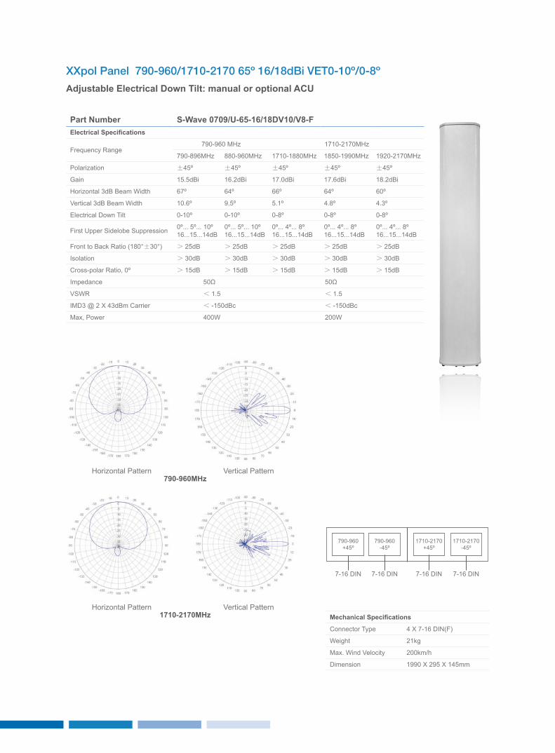
XXpol Panel 790-960/1710-2170 65º 16/18dBi VET0-10º/0-8º
Adjustable Electrical Down Tilt: manual or optional ACU
Part Number S-Wave 0709/U-65-16/18DV10/V8-FElectrical Specifications
Frequency Range790-960 MHz 1710-2170MHz
790-896MHz 880-960MHz 1710-1880MHz 1850-1990MHz 1920-2170MHz
Polarization ±45º ±45º ±45º ±45º ±45º
Gain 15.5dBi 16.2dBi 17.0dBi 17.6dBi 18.2dBi
Horizontal 3dB Beam Width 67º 64º 66º 64º 60º
Vertical 3dB Beam Width 10.6º 9.5º 5.1º 4.8º 4.3º
Electrical Down Tilt 0-10º 0-10º 0-8º 0-8º 0-8º
First Upper Sidelobe Suppression 0º... 5º... 10º16...15...14dB
0º... 5º... 10º16...15...14dB
0º... 4º... 8º16...15...14dB
0º... 4º... 8º16...15...14dB
0º... 4º... 8º16...15...14dB
Front to Back Ratio (180°±30°) > 25dB > 25dB > 25dB > 25dB > 25dB
Isolation > 30dB > 30dB > 30dB > 30dB > 30dB
Cross-polar Ratio, 0º > 15dB > 15dB > 15dB > 15dB > 15dB
Impedance 50Ω 50Ω
VSWR < 1.5 < 1.5
IMD3 @ 2 x 43dBm Carrier < -150dBc < -150dBc
Max, Power 400W 200W
Mechanical Specifications
Connector Type 4 x 7-16 DIN(F)
Weight 21kg
Max. Wind Velocity 200km/h
Dimension 1990 x 295 x 145mm
Horizontal Pattern
Horizontal Pattern
Vertical Pattern
Vertical Pattern
790-960MHz
1710-2170MHz
1710-2170+45º
790-960+45º
1710-2170-45º
790-960-45º
7-16 DIN 7-16 DIN 7-16 DIN 7-16 DIN
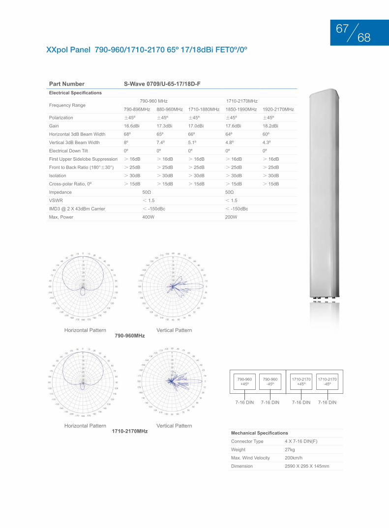
XXpol Panel 790-960/1710-2170 65º 17/18dBi FET0º/0º
Part Number S-Wave 0709/U-65-17/18D-FElectrical Specifications
Frequency Range790-960 MHz 1710-2170MHz
790-896MHz 880-960MHz 1710-1880MHz 1850-1990MHz 1920-2170MHz
Polarization ±45º ±45º ±45º ±45º ±45º
Gain 16.6dBi 17.3dBi 17.0dBi 17.6dBi 18.2dBi
Horizontal 3dB Beam Width 68º 65º 66º 64º 60º
Vertical 3dB Beam Width 8º 7.4º 5.1º 4.8º 4.3º
Electrical Down Tilt 0º 0º 0º 0º 0º
First Upper Sidelobe Suppression > 16dB > 16dB > 16dB > 16dB > 16dB
Front to Back Ratio (180°±30°) > 25dB > 25dB > 25dB > 25dB > 25dB
Isolation > 30dB > 30dB > 30dB > 30dB > 30dB
Cross-polar Ratio, 0º > 15dB > 15dB > 15dB > 15dB > 15dB
Impedance 50Ω 50Ω
VSWR < 1.5 < 1.5
IMD3 @ 2 x 43dBm Carrier < -150dBc < -150dBc
Max, Power 400W 200W
Mechanical Specifications
Connector Type 4 x 7-16 DIN(F)
Weight 27kg
Max. Wind Velocity 200km/h
Dimension 2590 x 295 x 145mm
Horizontal Pattern
Horizontal Pattern
Vertical Pattern
Vertical Pattern
790-960MHz
1710-2170MHz
1710-2170+45º
790-960+45º
1710-2170-45º
790-960-45º
7-16 DIN 7-16 DIN 7-16 DIN 7-16 DIN
6867
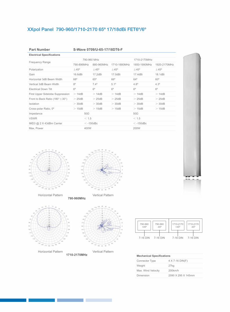
XXpol Panel 790-960/1710-2170 65º 17/18dBi FET6º/6º
Part Number S-Wave 0709/U-65-17/18DT6-FElectrical Specifications
Frequency Range790-960 MHz 1710-2170MHz
790-896MHz 880-960MHz 1710-1880MHz 1850-1990MHz 1920-2170MHz
Polarization ±45º ±45º ±45º ±45º ±45º
Gain 16.6dBi 17.2dBi 17.0dBi 17.4dBi 18.1dBi
Horizontal 3dB Beam Width 68º 65º 66º 64º 60º
Vertical 3dB Beam Width 8º 7.4º 5.1º 4.8º 4.3º
Electrical Down Tilt 6º 6º 6º 6º 6º
First Upper Sidelobe Suppression > 14dB > 14dB > 14dB > 14dB > 14dB
Front to Back Ratio (180°±30°) > 25dB > 25dB > 25dB > 25dB > 25dB
Isolation > 30dB > 30dB > 30dB > 30dB > 30dB
Cross-polar Ratio, 0º > 15dB > 15dB > 15dB > 15dB > 15dB
Impedance 50Ω 50Ω
VSWR < 1.5 < 1.5
IMD3 @ 2 x 43dBm Carrier < -150dBc < -150dBc
Max, Power 400W 200W
Mechanical Specifications
Connector Type 4 x 7-16 DIN(F)
Weight 27kg
Max. Wind Velocity 200km/h
Dimension 2590 x 295 x 145mm
Horizontal Pattern
Horizontal Pattern
Vertical Pattern
Vertical Pattern
790-960MHz
1710-2170MHz
1710-2170+45º
790-960+45º
1710-2170-45º
790-960-45º
7-16 DIN 7-16 DIN 7-16 DIN 7-16 DIN
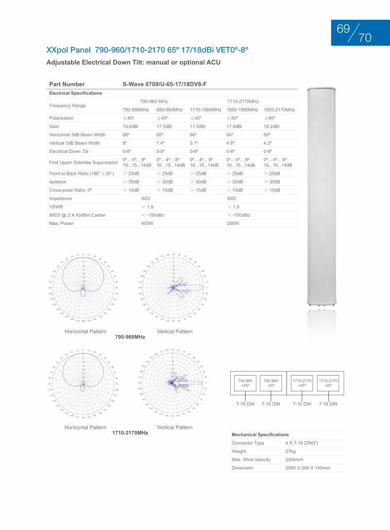
XXpol Panel 790-960/1710-2170 65º 17/18dBi VET0º-8º
Adjustable Electrical Down Tilt: manual or optional ACU
Part Number S-Wave 0709/U-65-17/18DV8-FElectrical Specifications
Frequency Range790-960 MHz 1710-2170MHz
790-896MHz 880-960MHz 1710-1880MHz 1850-1990MHz 1920-2170MHz
Polarization ±45º ±45º ±45º ±45º ±45º
Gain 16.6dBi 17.3dBi 17.0dBi 17.6dBi 18.2dBi
Horizontal 3dB Beam Width 68º 65º 66º 64º 60º
Vertical 3dB Beam Width 8º 7.4º 5.1º 4.8º 4.3º
Electrical Down Tilt 0-8º 0-8º 0-8º 0-8º 0-8º
First Upper Sidelobe Suppression 0º... 4º... 8º16...15...14dB
0º... 4º... 8º16...15...14dB
0º... 4º... 8º16...15...14dB
0º... 4º... 8º16...15...14dB
0º... 4º... 8º16...15...14dB
Front to Back Ratio (180°±30°) > 25dB > 25dB > 25dB > 25dB > 25dB
Isolation > 30dB > 30dB > 30dB > 30dB > 30dB
Cross-polar Ratio, 0º > 15dB > 15dB > 15dB > 15dB > 15dB
Impedance 50Ω 50Ω
VSWR < 1.5 < 1.5
IMD3 @ 2 x 43dBm Carrier < -150dBc < -150dBc
Max, Power 400W 200W
Mechanical Specifications
Connector Type 4 x 7-16 DIN(F)
Weight 27kg
Max. Wind Velocity 200km/h
Dimension 2590 x 295 x 145mm
Horizontal Pattern
Horizontal Pattern
Vertical Pattern
Vertical Pattern
790-960MHz
1710-2170MHz
1710-2170+45º
790-960+45º
1710-2170-45º
790-960-45º
7-16 DIN 7-16 DIN 7-16 DIN 7-16 DIN
7069
trIPlE bAnd AntEnnAS 6 PortS duAl PolArIzAtIon +45°/–45°
BASE STATION ANTENNAS
trIPlE bAnd AntEnnAS 6 PortS duAl PolArIzAtIon +45°/–45°
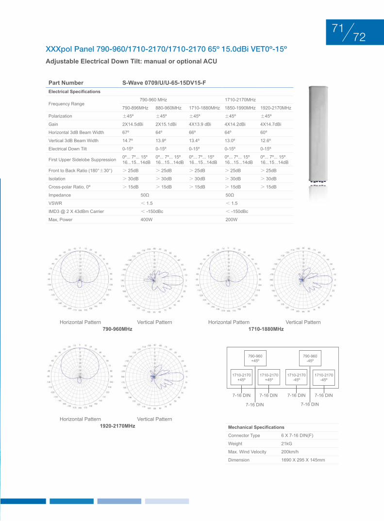
XXXpol Panel 790-960/1710-2170/1710-2170 65º 15.0dBi VET0º-15º
Adjustable Electrical Down Tilt: manual or optional ACU
Part Number S-Wave 0709/U/U-65-15DV15-FElectrical Specifications
Frequency Range790-960 MHz 1710-2170MHz
790-896MHz 880-960MHz 1710-1880MHz 1850-1990MHz 1920-2170MHz
Polarization ±45º ±45º ±45º ±45º ±45º
Gain 2x14.5dBi 2x15.1dBi 4x13.9 dBi 4x14.2dBi 4x14.7dBi
Horizontal 3dB Beam Width 67º 64º 66º 64º 60º
Vertical 3dB Beam Width 14.7º 13.9º 13.4º 13.0º 12.6º
Electrical Down Tilt 0-15º 0-15º 0-15º 0-15º 0-15º
First Upper Sidelobe Suppression 0º... 7º... 15º16...15...14dB
0º... 7º... 15º16...15...14dB
0º... 7º... 15º16...15...14dB
0º... 7º... 15º16...15...14dB
0º... 7º... 15º16...15...14dB
Front to Back Ratio (180°±30°) > 25dB > 25dB > 25dB > 25dB > 25dB
Isolation > 30dB > 30dB > 30dB > 30dB > 30dB
Cross-polar Ratio, 0º > 15dB > 15dB > 15dB > 15dB > 15dB
Impedance 50Ω 50Ω
VSWR < 1.5 < 1.5
IMD3 @ 2 x 43dBm Carrier < -150dBc < -150dBc
Max, Power 400W 200W
Mechanical Specifications
Connector Type 6 x 7-16 DIN(F)
Weight 21kG
Max. Wind Velocity 200km/h
Dimension 1690 x 295 x 145mm
1710-2170-45º
1710-2170+45º
1710-2170-45º
790-960-45º
1710-2170+45º
790-960+45º
7-16 DIN
7-16 DIN 7-16 DIN
7-16 DIN 7-16 DIN 7-16 DIN
790-960MHz
1920-2170MHz
1710-1880MHzHorizontal Pattern
Horizontal Pattern
Horizontal PatternVertical Pattern
Vertical Pattern
Vertical Pattern
7271
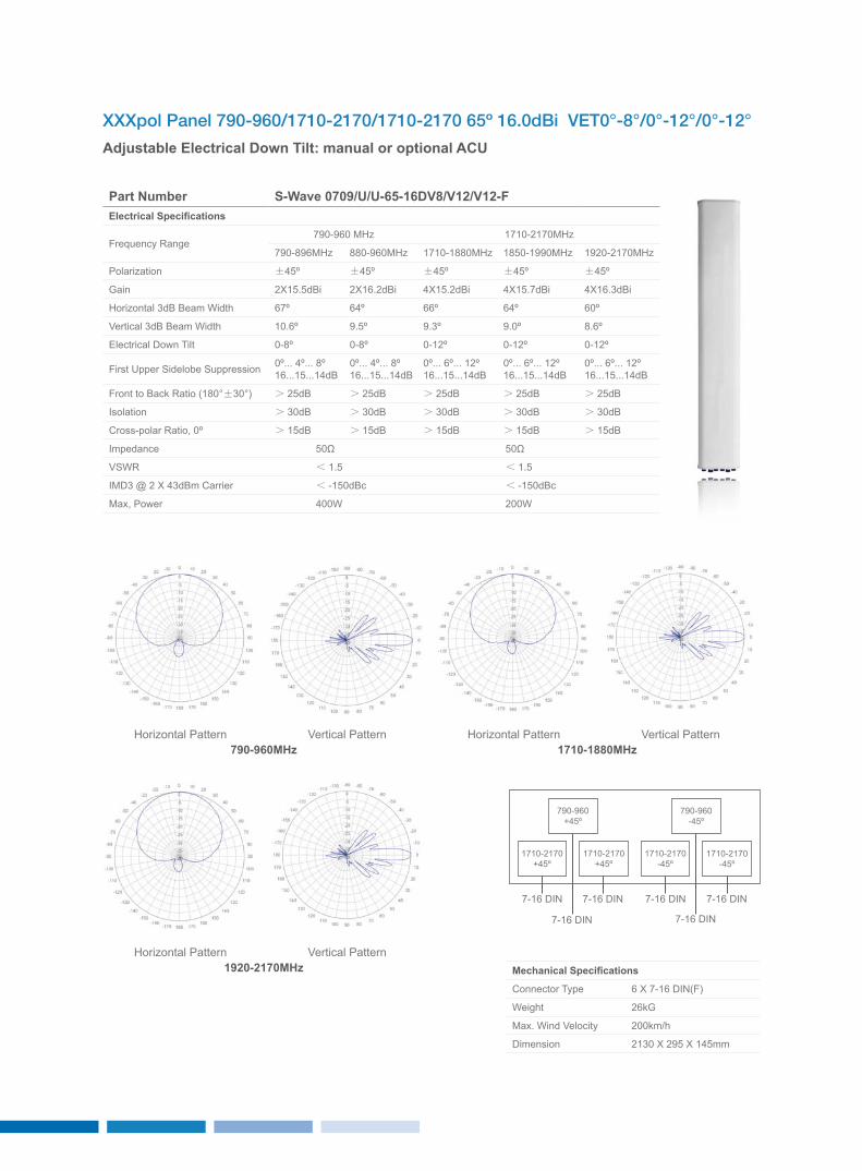
XXXpol Panel 790-960/1710-2170/1710-2170 65º 16.0dBi VET0°-8°/0°-12°/0°-12°
Adjustable Electrical Down Tilt: manual or optional ACU
Part Number S-Wave 0709/U/U-65-16DV8/V12/V12-FElectrical Specifications
Frequency Range790-960 MHz 1710-2170MHz
790-896MHz 880-960MHz 1710-1880MHz 1850-1990MHz 1920-2170MHz
Polarization ±45º ±45º ±45º ±45º ±45º
Gain 2x15.5dBi 2x16.2dBi 4x15.2dBi 4x15.7dBi 4x16.3dBi
Horizontal 3dB Beam Width 67º 64º 66º 64º 60º
Vertical 3dB Beam Width 10.6º 9.5º 9.3º 9.0º 8.6º
Electrical Down Tilt 0-8º 0-8º 0-12º 0-12º 0-12º
First Upper Sidelobe Suppression 0º... 4º... 8º16...15...14dB
0º... 4º... 8º16...15...14dB
0º... 6º... 12º16...15...14dB
0º... 6º... 12º16...15...14dB
0º... 6º... 12º16...15...14dB
Front to Back Ratio (180°±30°) > 25dB > 25dB > 25dB > 25dB > 25dB
Isolation > 30dB > 30dB > 30dB > 30dB > 30dB
Cross-polar Ratio, 0º > 15dB > 15dB > 15dB > 15dB > 15dB
Impedance 50Ω 50Ω
VSWR < 1.5 < 1.5
IMD3 @ 2 x 43dBm Carrier < -150dBc < -150dBc
Max, Power 400W 200W
Mechanical Specifications
Connector Type 6 x 7-16 DIN(F)
Weight 26kG
Max. Wind Velocity 200km/h
Dimension 2130 x 295 x 145mm
1710-2170-45º
1710-2170+45º
1710-2170-45º
790-960-45º
1710-2170+45º
790-960+45º
7-16 DIN
7-16 DIN 7-16 DIN
7-16 DIN 7-16 DIN 7-16 DIN
790-960MHz
1920-2170MHz
1710-1880MHzHorizontal Pattern
Horizontal Pattern
Horizontal PatternVertical Pattern
Vertical Pattern
Vertical Pattern
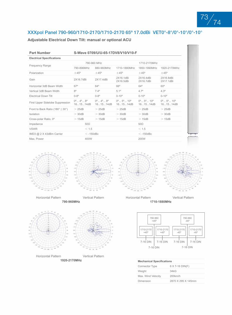
XXXpol Panel 790-960/1710-2170/1710-2170 65º 17.0dBi VET0°-8°/0°-10°/0°-10°
Adjustable Electrical Down Tilt: manual or optional ACU
Part Number S-Wave 0709/U/U-65-17DV8/V10/V10-FElectrical Specifications
Frequency Range790-960 MHz 1710-2170MHz
790-896MHz 880-960MHz 1710-1880MHz 1850-1990MHz 1920-2170MHz
Polarization ±45º ±45º ±45º ±45º ±45º
Gain 2x16.7dBi 2x17.4dBi 2x16.1dBi2x16.5dBi
2x16.4dBi2x16.7dBi
2x16.8dBi2x17.1dBi
Horizontal 3dB Beam Width 67º 64º 66º 64º 60º
Vertical 3dB Beam Width 8º 7.4º 5.1º 4.7º 4.3º
Electrical Down Tilt 0-8º 0-8º 0-10º 0-10º 0-10º
First Upper Sidelobe Suppression 0º... 4º... 8º16...15...14dB
0º... 4º... 8º16...15...14dB
0º... 5º... 10º16...15...14dB
0º... 5º... 10º16...15...14dB
0º... 5º... 10º16...15...14dB
Front to Back Ratio (180°±30°) > 25dB > 25dB > 25dB > 25dB > 25dB
Isolation > 30dB > 30dB > 30dB > 30dB > 30dB
Cross-polar Ratio, 0º > 15dB > 15dB > 15dB > 15dB > 15dB
Impedance 50Ω 50Ω
VSWR < 1.5 < 1.5
IMD3 @ 2 x 43dBm Carrier < -150dBc < -150dBc
Max, Power 400W 200W
Mechanical Specifications
Connector Type 6 x 7-16 DIN(F)
Weight 34kG
Max. Wind Velocity 200km/h
Dimension 2870 x 295 x 145mm
1710-2170-45º
1710-2170+45º
1710-2170-45º
790-960-45º
1710-2170+45º
790-960+45º
7-16 DIN
7-16 DIN 7-16 DIN
7-16 DIN 7-16 DIN 7-16 DIN
790-960MHz
1920-2170MHz
1710-1880MHzHorizontal Pattern
Horizontal Pattern
Horizontal PatternVertical Pattern
Vertical Pattern
Vertical Pattern
7473
MultI-bAnd AntEnnAS duAl PolArIzAtIon +45°/–45°
BASE STATION ANTENNAS
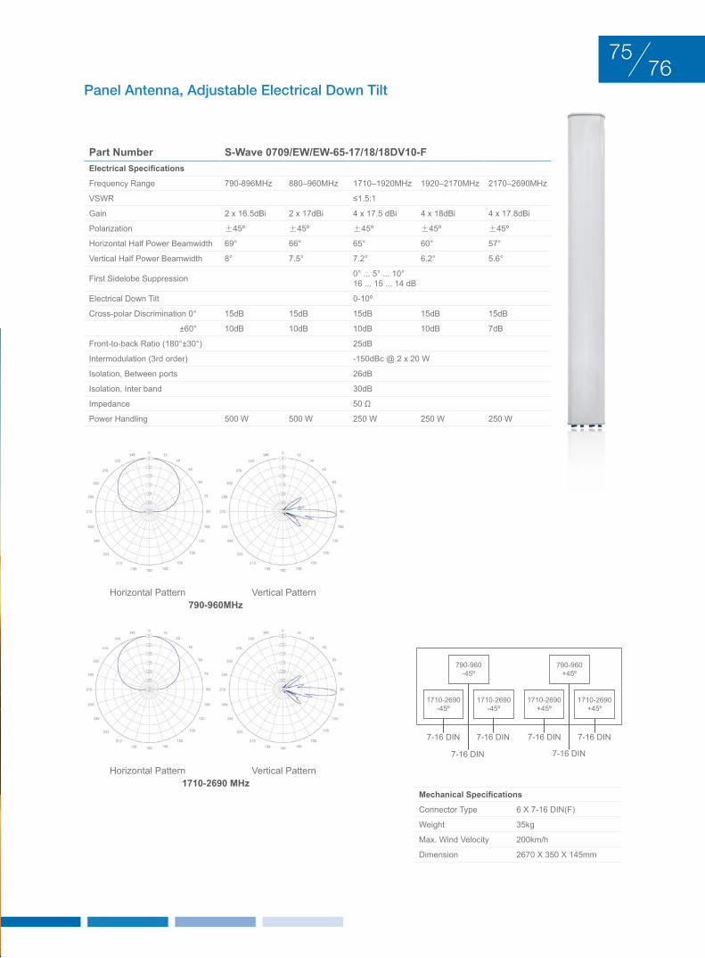
MultI-bAnd AntEnnAS duAl PolArIzAtIon +45°/–45°
Panel Antenna, Adjustable Electrical Down Tilt
Part Number S-Wave 0709/EW/EW-65-17/18/18DV10-FElectrical Specifications
Frequency Range 790-896MHz 880–960MHz 1710–1920MHz 1920–2170MHz 2170–2690MHz
VSWR ≤1.5:1
Gain 2 x 16.5dBi 2 x 17dBi 4 x 17.5 dBi 4 x 18dBi 4 x 17.8dBi
Polarization ±45º ±45º ±45º ±45º ±45º
Horizontal Half Power Beamwidth 69° 66° 65° 60° 57°
Vertical Half Power Beamwidth 8° 7.5° 7.2° 6.2° 5.6°
First Sidelobe Suppression 0° ... 5° ... 10°16 ... 15 ... 14 dB
Electrical Down Tilt 0-10º
Cross-polar Discrimination 0° 15dB 15dB 15dB 15dB 15dB
±60° 10dB 10dB 10dB 10dB 7dB
Front-to-back Ratio (180°±30°) 25dB
Intermodulation (3rd order) -150dBc @ 2 x 20 W
Isolation, Between ports 26dB
Isolation, Inter band 30dB
Impedance 50 Ω
Power Handling 500 W 500 W 250 W 250 W 250 W
1710-2690+45º
1710-2690-45º
1710-2690+45º
790-960+45º
1710-2690-45º
790-960-45º
7-16 DIN
7-16 DIN 7-16 DIN
7-16 DIN 7-16 DIN 7-16 DIN
790-960MHz
1710-2690 MHz
Horizontal Pattern
Horizontal Pattern
Vertical Pattern
Vertical Pattern
7675
Mechanical Specifications
Connector Type 6 x 7-16 DIN(F)
Weight 35kg
Max. Wind Velocity 200km/h
Dimension 2670 x 350 x 145mm
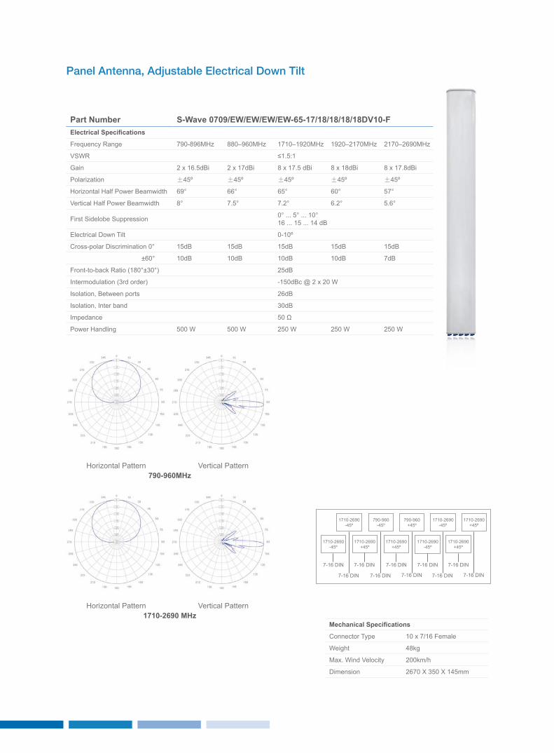
Panel Antenna, Adjustable Electrical Down Tilt
Part Number S-Wave 0709/EW/EW/EW/EW-65-17/18/18/18/18DV10-FElectrical Specifications
Frequency Range 790-896MHz 880–960MHz 1710–1920MHz 1920–2170MHz 2170–2690MHz
VSWR ≤1.5:1
Gain 2 x 16.5dBi 2 x 17dBi 8 x 17.5 dBi 8 x 18dBi 8 x 17.8dBi
Polarization ±45º ±45º ±45º ±45º ±45º
Horizontal Half Power Beamwidth 69° 66° 65° 60° 57°
Vertical Half Power Beamwidth 8° 7.5° 7.2° 6.2° 5.6°
First Sidelobe Suppression 0° ... 5° ... 10°16 ... 15 ... 14 dB
Electrical Down Tilt 0-10º
Cross-polar Discrimination 0° 15dB 15dB 15dB 15dB 15dB
±60° 10dB 10dB 10dB 10dB 7dB
Front-to-back Ratio (180°±30°) 25dB
Intermodulation (3rd order) -150dBc @ 2 x 20 W
Isolation, Between ports 26dB
Isolation, Inter band 30dB
Impedance 50 Ω
Power Handling 500 W 500 W 250 W 250 W 250 W
1710-2690+45º
1710-2690+45º
1710-2690-45º
1710-2690-45º
790-960+45º
1710-2690+45º
1710-2690+45º
1710-2690-45º
790-960-45º
1710-2690-45º
7-16 DIN
7-16 DIN 7-16 DIN 7-16 DIN7-16 DIN 7-16 DIN
7-16 DIN 7-16 DIN 7-16 DIN7-16 DIN
790-960MHz
1710-2690 MHz
Horizontal Pattern
Horizontal Pattern
Vertical Pattern
Vertical Pattern
Mechanical Specifications
Connector Type 10 x 7/16 Female
Weight 48kg
Max. Wind Velocity 200km/h
Dimension 2670 x 350 x 145mm
trI-SEctor AntEnnASduAl PolArIzAtIon +45°/–45°
BASE STATION ANTENNAS
7877
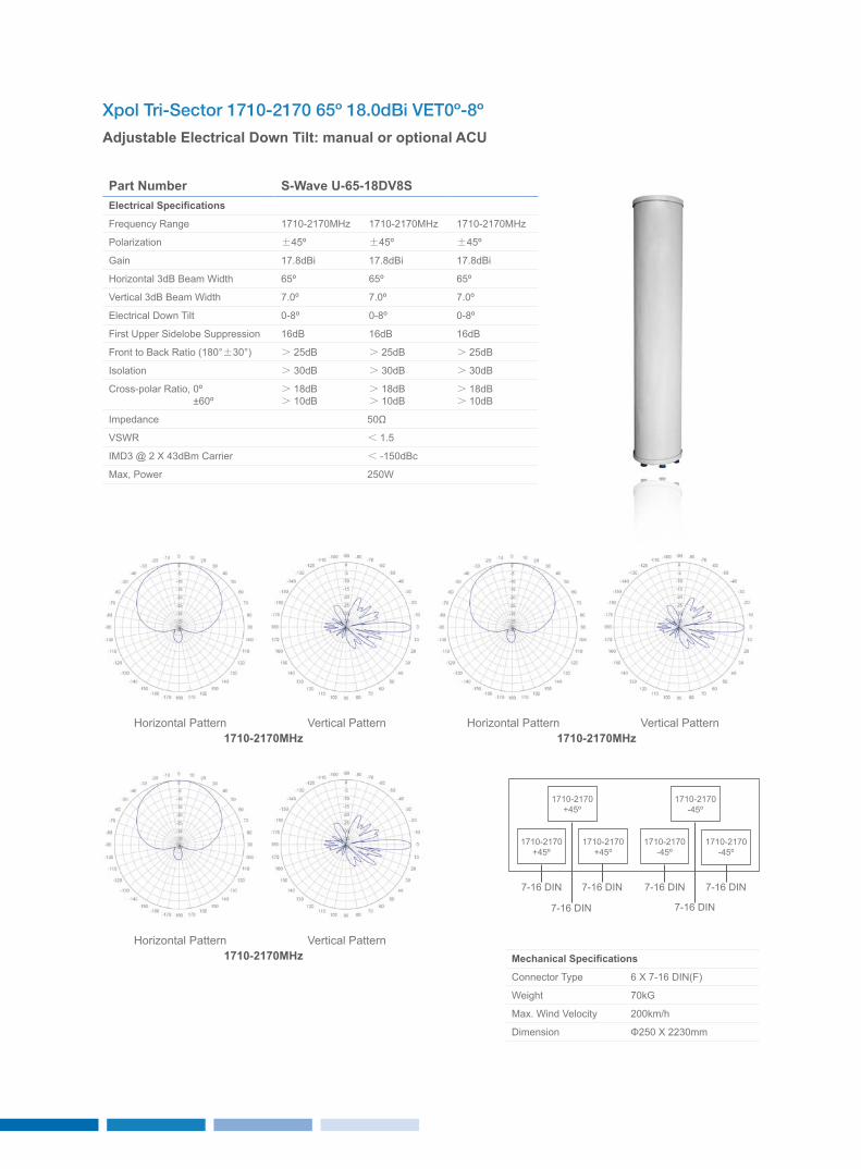
Xpol Tri-Sector 1710-2170 65º 18.0dBi VET0º-8º
Adjustable Electrical Down Tilt: manual or optional ACU
Part Number S-Wave U-65-18DV8SElectrical Specifications
Frequency Range 1710-2170MHz 1710-2170MHz 1710-2170MHz
Polarization ±45º ±45º ±45º
Gain 17.8dBi 17.8dBi 17.8dBi
Horizontal 3dB Beam Width 65º 65º 65º
Vertical 3dB Beam Width 7.0º 7.0º 7.0º
Electrical Down Tilt 0-8º 0-8º 0-8º
First Upper Sidelobe Suppression 16dB 16dB 16dB
Front to Back Ratio (180°±30°) > 25dB > 25dB > 25dB
Isolation > 30dB > 30dB > 30dB
Cross-polar Ratio, 0º ±60º
> 18dB> 10dB
> 18dB> 10dB
> 18dB> 10dB
Impedance 50Ω
VSWR < 1.5
IMD3 @ 2 x 43dBm Carrier < -150dBc
Max, Power 250W
Mechanical Specifications
Connector Type 6 x 7-16 DIN(F)
Weight 70kG
Max. Wind Velocity 200km/h
Dimension Φ250 x 2230mm
1710-2170-45º
1710-2170+45º
1710-2170-45º
1710-2170-45º
1710-2170+45º
1710-2170+45º
7-16 DIN
7-16 DIN 7-16 DIN
7-16 DIN 7-16 DIN 7-16 DIN
1710-2170MHz
1710-2170MHz
1710-2170MHzHorizontal Pattern
Horizontal Pattern
Horizontal PatternVertical Pattern
Vertical Pattern
Vertical Pattern
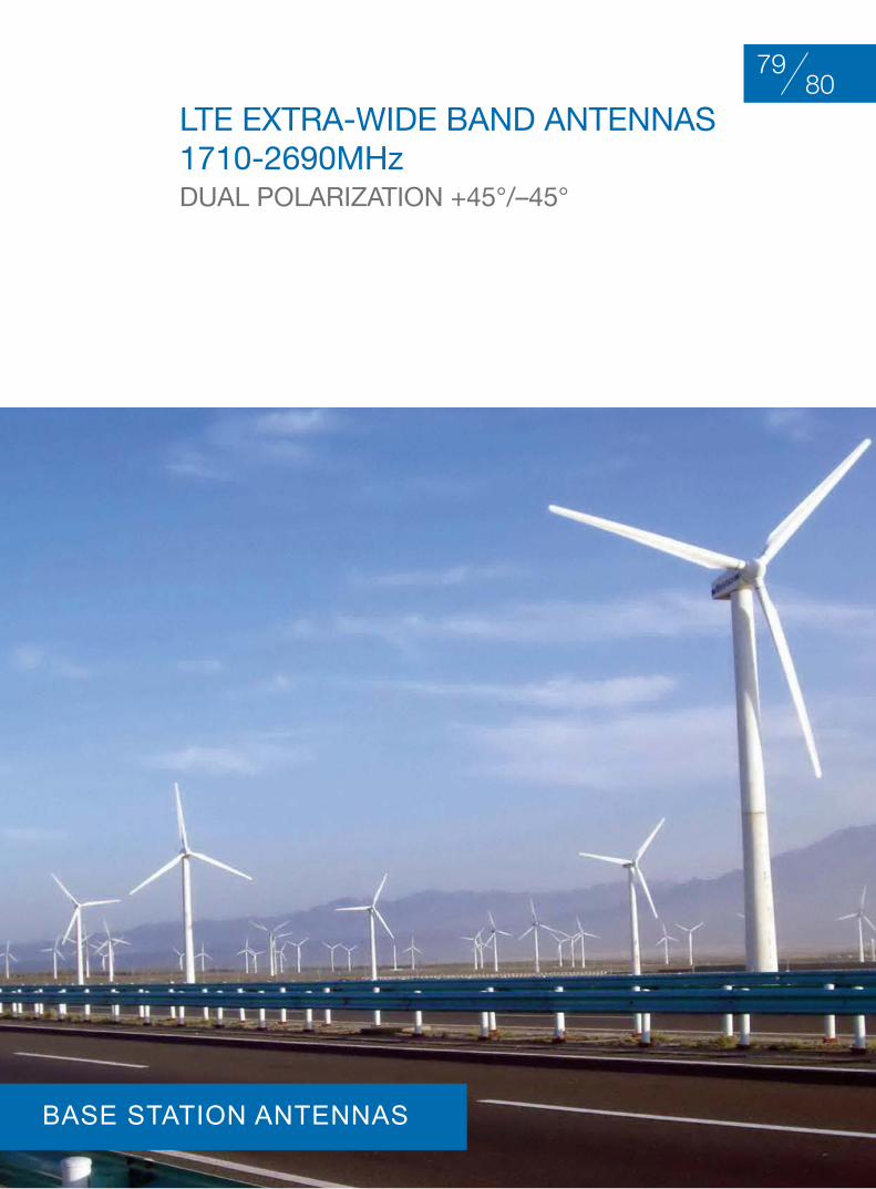
ltE ExtrA-WIdE bAnd AntEnnAS1710-2690Mhz duAl PolArIzAtIon +45°/–45°
8079
BASE STATION ANTENNAS
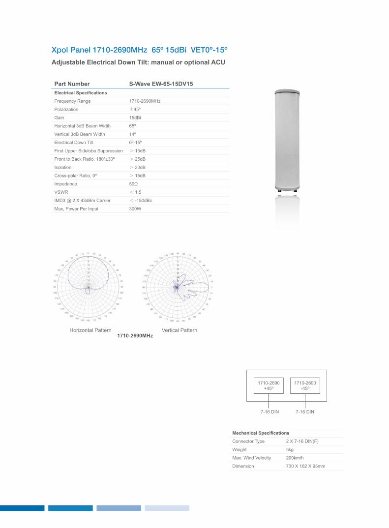
Xpol Panel 1710-2690MHz 65º 15dBi VET0º-15º
Adjustable Electrical Down Tilt: manual or optional ACU
Part Number S-Wave EW-65-15DV15Electrical Specifications
Frequency Range 1710-2690MHz
Polarization ±45º
Gain 15dBi
Horizontal 3dB Beam Width 65º
Vertical 3dB Beam Width 14º
Electrical Down Tilt 0º-15º
First Upper Sidelobe Suppression > 15dB
Front to Back Ratio, 180º±30º > 25dB
Isolation > 30dB
Cross-polar Ratio, 0º > 15dB
Impedance 50Ω
VSWR < 1.5
IMD3 @ 2 x 43dBm Carrier < -150dBc
Max, Power Per Input 300W
Mechanical Specifications
Connector Type 2 x 7-16 DIN(F)
Weight 5kg
Max. Wind Velocity 200km/h
Dimension 730 x 162 x 95mm
Horizontal Pattern Vertical Pattern
1710-2690+45º
1710-2690-45º
7-16 DIN 7-16 DIN
1710-2690MHz
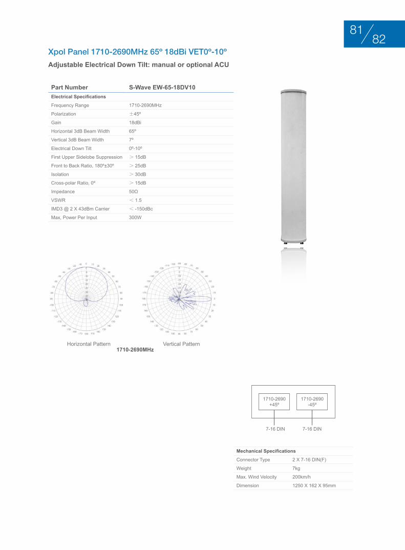
Xpol Panel 1710-2690MHz 65º 18dBi VET0º-10º
Adjustable Electrical Down Tilt: manual or optional ACU
Part Number S-Wave EW-65-18DV10Electrical Specifications
Frequency Range 1710-2690MHz
Polarization ±45º
Gain 18dBi
Horizontal 3dB Beam Width 65º
Vertical 3dB Beam Width 7º
Electrical Down Tilt 0º-10º
First Upper Sidelobe Suppression > 15dB
Front to Back Ratio, 180º±30º > 25dB
Isolation > 30dB
Cross-polar Ratio, 0º > 15dB
Impedance 50Ω
VSWR < 1.5
IMD3 @ 2 x 43dBm Carrier < -150dBc
Max, Power Per Input 300W
Mechanical Specifications
Connector Type 2 x 7-16 DIN(F)
Weight 7kg
Max. Wind Velocity 200km/h
Dimension 1250 x 162 x 95mm
Horizontal Pattern Vertical Pattern
1710-2690+45º
1710-2690-45º
7-16 DIN 7-16 DIN
1710-2690MHz
8281
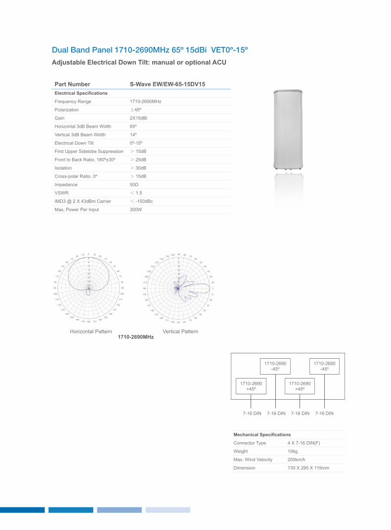
Dual Band Panel 1710-2690MHz 65º 15dBi VET0º-15º
Adjustable Electrical Down Tilt: manual or optional ACU
Part Number S-Wave EW/EW-65-15DV15Electrical Specifications
Frequency Range 1710-2690MHz
Polarization ±45º
Gain 2x15dBi
Horizontal 3dB Beam Width 65º
Vertical 3dB Beam Width 14º
Electrical Down Tilt 0º-15º
First Upper Sidelobe Suppression > 15dB
Front to Back Ratio, 180º±30º > 25dB
Isolation > 30dB
Cross-polar Ratio, 0º > 15dB
Impedance 50Ω
VSWR < 1.5
IMD3 @ 2 x 43dBm Carrier < -150dBc
Max, Power Per Input 300W
Mechanical Specifications
Connector Type 4 x 7-16 DIN(F)
Weight 10kg
Max. Wind Velocity 200km/h
Dimension 730 x 295 x 115mm
Horizontal Pattern Vertical Pattern
1710-2690-45º
1710-2690+45º
1710-2690-45º
1710-2690+45º
7-16 DIN7-16 DIN 7-16 DIN7-16 DIN
1710-2690MHz
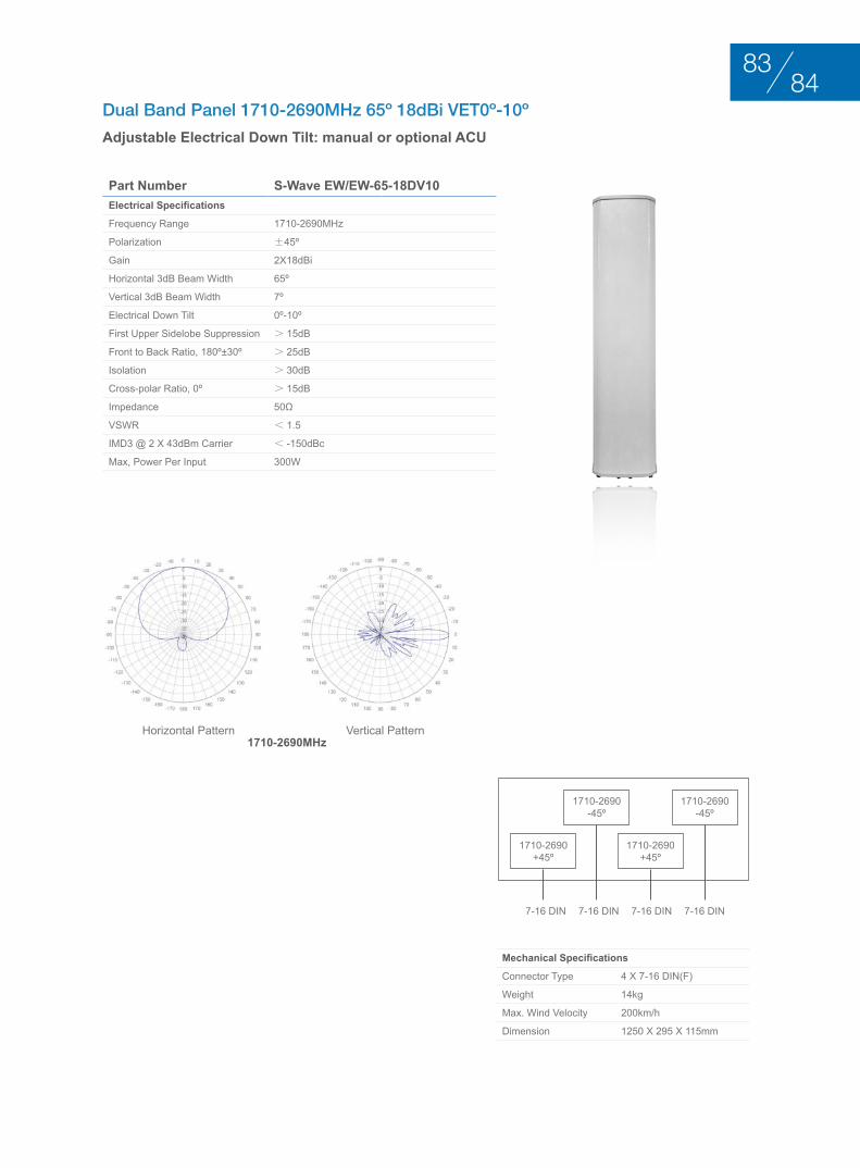
Dual Band Panel 1710-2690MHz 65º 18dBi VET0º-10º
Adjustable Electrical Down Tilt: manual or optional ACU
Part Number S-Wave EW/EW-65-18DV10Electrical Specifications
Frequency Range 1710-2690MHz
Polarization ±45º
Gain 2x18dBi
Horizontal 3dB Beam Width 65º
Vertical 3dB Beam Width 7º
Electrical Down Tilt 0º-10º
First Upper Sidelobe Suppression > 15dB
Front to Back Ratio, 180º±30º > 25dB
Isolation > 30dB
Cross-polar Ratio, 0º > 15dB
Impedance 50Ω
VSWR < 1.5
IMD3 @ 2 x 43dBm Carrier < -150dBc
Max, Power Per Input 300W
Mechanical Specifications
Connector Type 4 x 7-16 DIN(F)
Weight 14kg
Max. Wind Velocity 200km/h
Dimension 1250 x 295 x 115mm
Horizontal Pattern Vertical Pattern
1710-2690-45º
1710-2690+45º
1710-2690-45º
1710-2690+45º
7-16 DIN7-16 DIN 7-16 DIN7-16 DIN
1710-2690MHz
8483
rEMotE ElEctrIcAl tIlt (rEt)
BASE STATION ANTENNAS
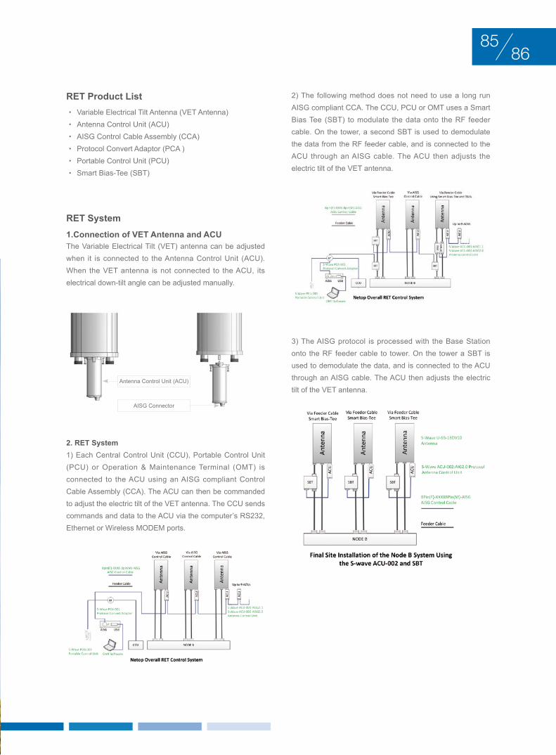
rEMotE ElEctrIcAl tIlt (rEt) RET Product List
• Variable Electrical Tilt Antenna (VET Antenna)• Antenna Control Unit (ACU)• AISG Control Cable Assembly (CCA)• Protocol Convert Adaptor (PCA )• Portable Control Unit (PCU)• Smart Bias-Tee (SBT)
RET System1.Connection of VET Antenna and ACUThe Variable Electrical Tilt (VET) antenna can be adjusted when it is connected to the Antenna Control Unit (ACU). When the VET antenna is not connected to the ACU, its electrical down-tilt angle can be adjusted manually.
2. RET System1) Each Central Control Unit (CCU), Portable Control Unit (PCU) or Operation & Maintenance Terminal (OMT) is connected to the ACU using an AISG compliant Control Cable Assembly (CCA). The ACU can then be commanded to adjust the electric tilt of the VET antenna. The CCU sends commands and data to the ACU via the computer’s RS232, Ethernet or Wireless MODEM ports.
2) The following method does not need to use a long run AISG compliant CCA. The CCU, PCU or OMT uses a Smart Bias Tee (SBT) to modulate the data onto the RF feeder cable. On the tower, a second SBT is used to demodulate the data from the RF feeder cable, and is connected to the ACU through an AISG cable. The ACU then adjusts the electric tilt of the VET antenna.
8685
Antenna Control Unit (ACU)
AISG Connector
3) The AISG protocol is processed with the Base Station onto the RF feeder cable to tower. On the tower a SBT is used to demodulate the data, and is connected to the ACU through an AISG cable. The ACU then adjusts the electric tilt of the VET antenna.
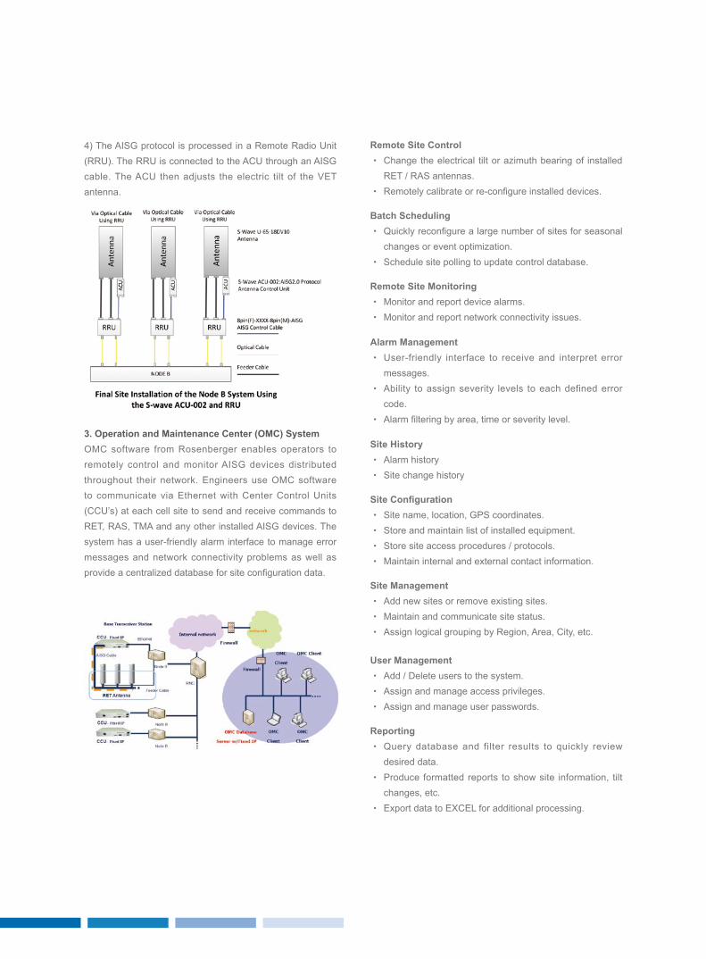
Remote Site Control• Change the electrical tilt or azimuth bearing of installed
RET / RAS antennas.• Remotely calibrate or re-configure installed devices.
Site Management• Add new sites or remove existing sites.• Maintain and communicate site status.• Assign logical grouping by Region, Area, City, etc.
Site History• Alarm history• Site change history
Batch Scheduling• Quickly reconfigure a large number of sites for seasonal
changes or event optimization.• Schedule site polling to update control database.
User Management• Add / Delete users to the system.• Assign and manage access privileges.• Assign and manage user passwords.
Site Configuration• Site name, location, GPS coordinates.• Store and maintain list of installed equipment.• Store site access procedures / protocols.• Maintain internal and external contact information.
Remote Site Monitoring• Monitor and report device alarms.• Monitor and report network connectivity issues.
Reporting• Query database and filter results to quickly review
desired data.• Produce formatted reports to show site information, tilt
changes, etc.• Export data to ExCEL for additional processing.
Alarm Management• User-friendly interface to receive and interpret error
messages.• Ability to assign severity levels to each defined error
code.• Alarm filtering by area, time or severity level.
3. Operation and Maintenance Center (OMC) SystemOMC software from Rosenberger enables operators to remotely control and monitor AISG devices distributed throughout their network. Engineers use OMC software to communicate via Ethernet with Center Control Units (CCU’s) at each cell site to send and receive commands to RET, RAS, TMA and any other installed AISG devices. The system has a user-friendly alarm interface to manage error messages and network connectivity problems as well as provide a centralized database for site configuration data.
4) The AISG protocol is processed in a Remote Radio Unit (RRU). The RRU is connected to the ACU through an AISG cable. The ACU then adjusts the electric tilt of the VET antenna.
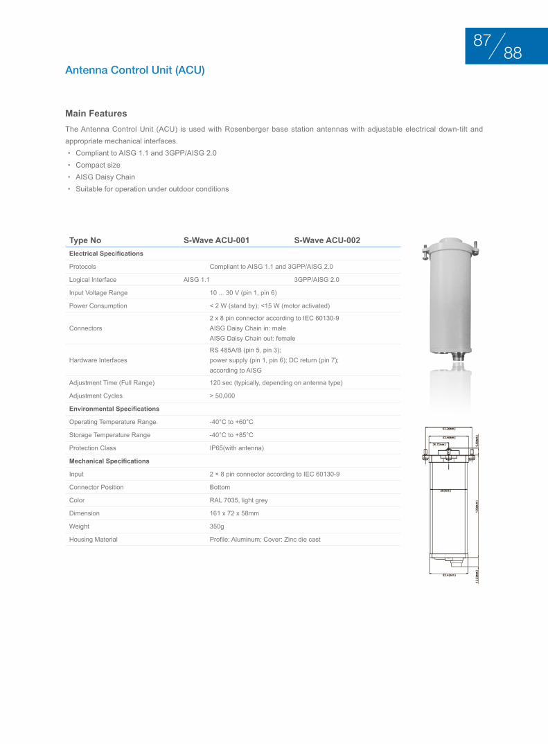
Type No S-Wave ACU-001 S-Wave ACU-002Electrical Specifications
Protocols Compliant to AISG 1.1 and 3GPP/AISG 2.0
Logical Interface AISG 1.1 3GPP/AISG 2.0
Input Voltage Range 10 ... 30 V (pin 1, pin 6)
Power Consumption < 2 W (stand by); <15 W (motor activated)
Connectors2 x 8 pin connector according to IEC 60130-9AISG Daisy Chain in: maleAISG Daisy Chain out: female
Hardware InterfacesRS 485A/B (pin 5, pin 3);power supply (pin 1, pin 6); DC return (pin 7);according to AISG
Adjustment Time (Full Range) 120 sec (typically, depending on antenna type)
Adjustment Cycles > 50,000
Environmental Specifications
Operating Temperature Range -40°C to +60°C
Storage Temperature Range -40°C to +85°C
Protection Class IP65(with antenna)
Mechanical Specifications
Input 2 × 8 pin connector according to IEC 60130-9
Connector Position Bottom
Color RAL 7035, light grey
Dimension 161 x 72 x 58mm
Weight 350g
Housing Material Profile: Aluminum; Cover: Zinc die cast
Antenna Control Unit (ACU)
Main FeaturesThe Antenna Control Unit (ACU) is used with Rosenberger base station antennas with adjustable electrical down-tilt and appropriate mechanical interfaces.• Compliant to AISG 1.1 and 3GPP/AISG 2.0 • Compact size • AISG Daisy Chain • Suitable for operation under outdoor conditions
8887
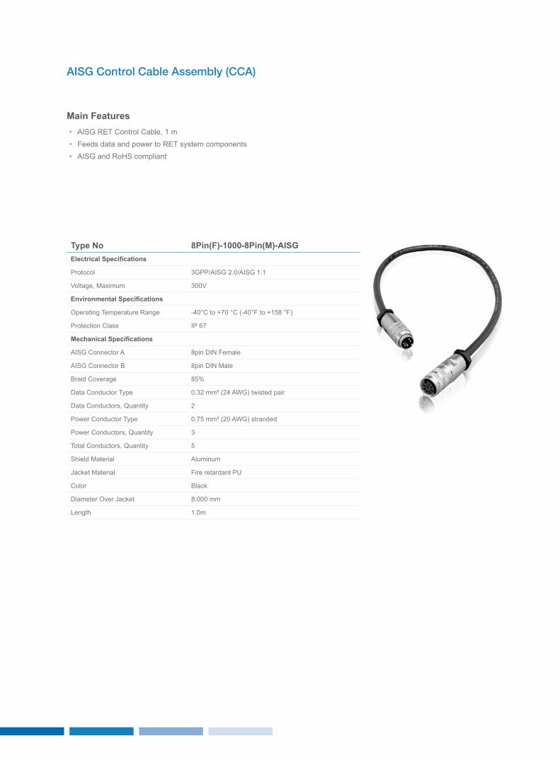
Type No 8Pin(F)-1000-8Pin(M)-AISGElectrical Specifications
Protocol 3GPP/AISG 2.0/AISG 1.1
Voltage, Maximum 300V
Environmental Specifications
Operating Temperature Range -40°C to +70 °C (-40°F to +158 °F)
Protection Class IP 67
Mechanical Specifications
AISG Connector A 8pin DIN Female
AISG Connector B 8pin DIN Male
Braid Coverage 85%
Data Conductor Type 0.32 mm² (24 AWG) twisted pair
Data Conductors, Quantity 2
Power Conductor Type 0.75 mm² (20 AWG) stranded
Power Conductors, Quantity 3
Total Conductors, Quantity 5
Shield Material Aluminum
Jacket Material Fire retardant PU
Color Black
Diameter Over Jacket 8.000 mm
Length 1.0m
AISG Control Cable Assembly (CCA)
Main Features• AISG RET Control Cable, 1 m • Feeds data and power to RET system components• AISG and RoHS compliant
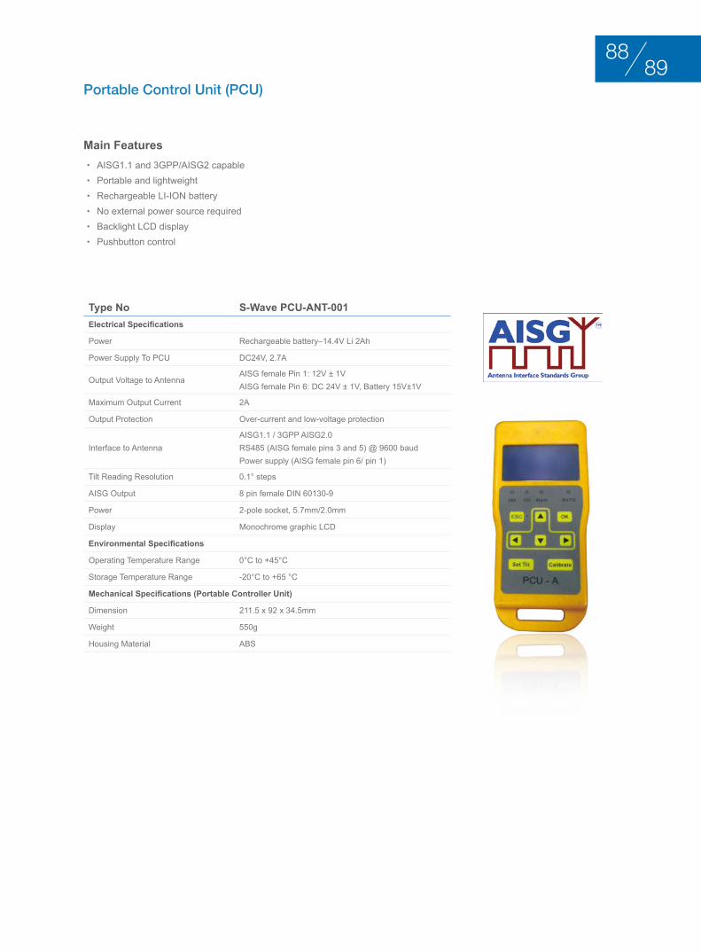
Type No S-Wave PCU-ANT-001Electrical Specifications
Power Rechargeable battery–14.4V Li 2Ah
Power Supply To PCU DC24V, 2.7A
Output Voltage to AntennaAISG female Pin 1: 12V ± 1VAISG female Pin 6: DC 24V ± 1V, Battery 15V±1V
Maximum Output Current 2A
Output Protection Over-current and low-voltage protection
Interface to Antenna AISG1.1 / 3GPP AISG2.0RS485 (AISG female pins 3 and 5) @ 9600 baudPower supply (AISG female pin 6/ pin 1)
Tilt Reading Resolution 0.1° steps
AISG Output 8 pin female DIN 60130-9
Power 2-pole socket, 5.7mm/2.0mm
Display Monochrome graphic LCD
Environmental Specifications
Operating Temperature Range 0°C to +45°C
Storage Temperature Range -20°C to +65 °C
Mechanical Specifications (Portable Controller Unit)
Dimension 211.5 x 92 x 34.5mm
Weight 550g
Housing Material ABS
Portable Control Unit (PCU)
Main Features• AISG1.1 and 3GPP/AISG2 capable • Portable and lightweight • Rechargeable LI-ION battery• No external power source required • Backlight LCD display• Pushbutton control
8988
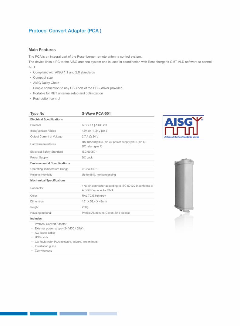
Type No S-Wave PCA-001Electrical Specifications
Protocol AISG 1.1 | AISG 2.0
Input Voltage Range 12V pin 1, 24V pin 6
Output Current at Voltage 2.7 A @ 24 V
Hardware InterfacesRS 485A/B(pin 5, pin 3); power supply(pin 1, pin 6); DC return(pin 7)
Electrical Safety Standard IEC 60950 1
Power Supply DC Jack
Environmental Specifications
Operating Temperature Range 0°C to +40°C
Relative Humidity Up to 95%, noncondensing
Mechanical Specifications
Connector1×8 pin connector according to IEC 60130-9 conforms to AISG RF-connector SMA
Color RAL 7035,lightgrey
Dimension 151 x 52.4 x 49mm
weight 290g
Housing material Profile: Aluminum; Cover: Zinc diecast
Includes
• Protocol Convert Adapter• External power supply (24 VDC / 65W)• AC power cable• USB cable• CD-ROM (with PCA software, drivers, and manual)• Installation guide• Carrying case
Protocol Convert Adaptor (PCA )
Main FeaturesThe PCA is an integral part of the Rosenberger remote antenna control system.The device links a PC to the AISG antenna system and is used in coordination with Rosenberger’s OMT-ALD software to control ALD• Compliant with AISG 1.1 and 2.0 standards• Compact size• AISG Daisy Chain• Simple connection to any USB port of the PC – driver provided• Portable for RET antenna setup and optimization• Pushbutton control
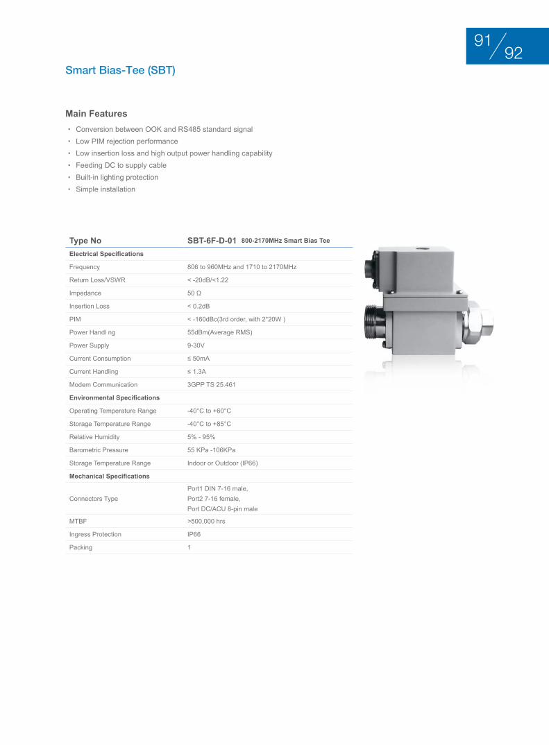
Type No SBT-6F-D-01 800-2170MHz Smart Bias Tee
Electrical Specifications
Frequency 806 to 960MHz and 1710 to 2170MHz
Return Loss/VSWR < -20dB/<1.22
Impedance 50 Ω
Insertion Loss < 0.2dB
PIM < -160dBc(3rd order, with 2*20W )
Power Handl ng 55dBm(Average RMS)
Power Supply 9-30V
Current Consumption ≤ 50mA
Current Handling ≤ 1.3A
Modem Communication 3GPP TS 25.461
Environmental Specifications
Operating Temperature Range -40°C to +60°C
Storage Temperature Range -40°C to +85°C
Relative Humidity 5% - 95%
Barometric Pressure 55 KPa -106KPa
Storage Temperature Range Indoor or Outdoor (IP66)
Mechanical Specifications
Connectors TypePort1 DIN 7-16 male, Port2 7-16 female, Port DC/ACU 8-pin male
MTBF >500,000 hrs
Ingress Protection IP66
Packing 1
Smart Bias-Tee (SBT)
Main Features• Conversion between OOK and RS485 standard signal• Low PIM rejection performance• Low insertion loss and high output power handling capability• Feeding DC to supply cable• Built-in lighting protection• Simple installation
9291
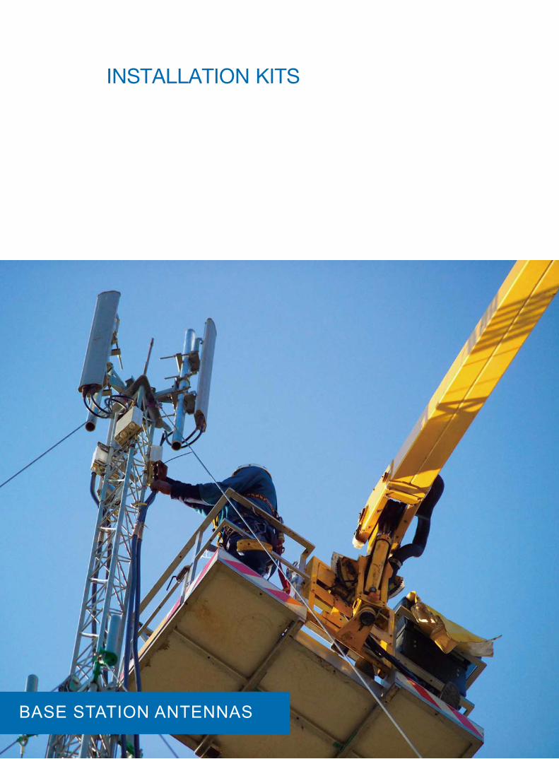
InStAllAtIon KItS
BASE STATION ANTENNAS
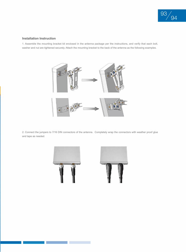
Installation Instruction1. Assemble the mounting bracket kit enclosed in the antenna package per the instructions, and verify that each bolt, washer and nut are tightened securely. Attach the mounting bracket to the back of the antenna as the following examples.
2. Connect the jumpers to 7/16 DIN connectors of the antenna. Completely wrap the connectors with weather proof glue and tape as needed.
9493
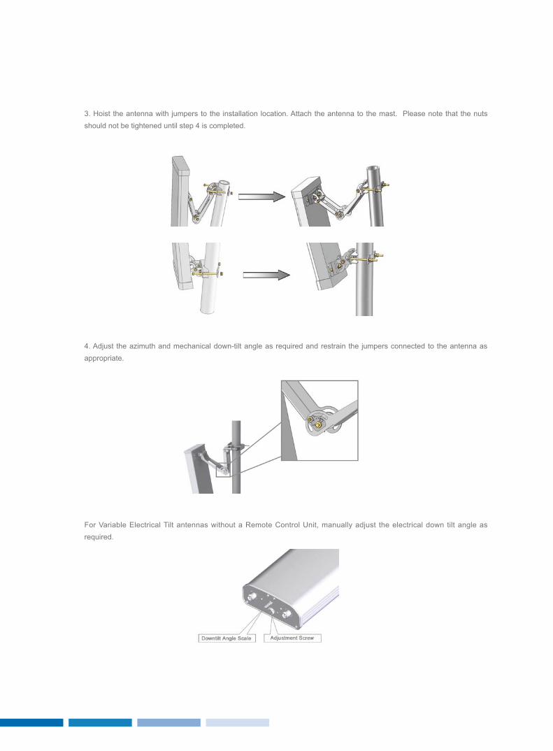
4. Adjust the azimuth and mechanical down-tilt angle as required and restrain the jumpers connected to the antenna as appropriate.
For Variable Electrical Tilt antennas without a Remote Control Unit, manually adjust the electrical down tilt angle as required.
3. Hoist the antenna with jumpers to the installation location. Attach the antenna to the mast. Please note that the nuts should not be tightened until step 4 is completed.
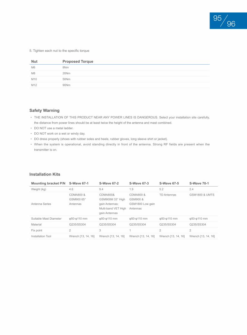
Nut Proposed TorqueM6 8Nm
M8 20Nm
M10 50Nm
M12 90Nm
Safety Warning• THE INSTALLATION OF THIS PRODUCT NEAR ANy POWER LINES IS DANGEROUS. Select your installation site carefully,
the distance from power lines should be at least twice the height of the antenna and mast combined.
• DO NOT use a metal ladder.
• DO NOT work on a wet or windy day.
• DO dress properly (shoes with rubber soles and heels, rubber gloves, long sleeve shirt or jacket).
• When the system is operational, avoid standing directly in front of the antenna. Strong RF fields are present when the
transmitter is on.
Installation Kits
5. Tighten each nut to the specific torque
Mounting bracket P/N S-Wave 67-1 S-Wave 67-2 S-Wave 67-3 S-Wave 67-5 S-Wave 70-1Weight (kg) 4.6 9.4 1.9 5.2 2.4
Antenna Series
CDMA800 & GSM900 65° Antennas
CDMA800& GSM900M 33° High gain Antennas; Multi-band VET High gain Antennas
CDMA800 & GSM900 & GSM1800 Low gain Antennas
TD Antennas GSM1800 & UMTS
Suitable Mast Diameter φ50-φ110 mm φ50-φ110 mm φ50-φ110 mm φ50-φ110 mm φ50-φ110 mm
Material Q235/SS304 Q235/SS304 Q235/SS304 Q235/SS304 Q235/SS304
Fix point 2 3 1 2 2
Installation Tool Wrench [13, 14, 16] Wrench [13, 14, 16] Wrench [13, 14, 16] Wrench [13, 14, 16] Wrench [13, 14, 16]
9695

roSEnbErgEr SErVIcE
BASE STATION ANTENNAS

9897
Rosenberger offers professional services that improve network design, reliability, scalability and efficiency.
Our service core competences include:• Network optimization• Technical consultation• Customized product design• Installation & commissioning• Onsite training & supervision• System troubleshooting• After-sales services
In addition, we also offer professional training, technical support and workshops for distributors and agents. We are committed to offering exceptional services for our customers.
Rosenberger is much more than just a supplier – Rosenberger is a valued development partner and we will strive to meet new challenges in order to scale to new heights.

Ba
se
sta
tio
n a
nt
en
na
sBase station antennas
Rosenberger Asia Pacific Electronic Co., Ltd.
No.3, Anxiang Street, Block B, Tianzhu Airport Industrial Zone
Beijing, China 101300
Tel : (+86 10) 80481995
Fax : (+86 10) 80497052
Email: [email protected]
Rosenberger (Shanghai) Technology Co.,Ltd.
No. 303, Xinke Road, Qingpu Industrial Zone
Shanghai, China 201707
Tel : (+86 21) 69214567
Fax : (+86 21) 69212923
Rosenberger Asia Pacific Electronic Co., Ltd. Shanghai Division
B7, No. 509, Renqing Road, East Zone of Zhangjiang High-Tech Park
Shanghai, China 201201
Tel : (+86 21) 58995997
Fax : (+86 21) 58995594
Rosenberger Asia Pacific Electronic Co., Ltd. Dongguan Division
3rd Floor, Building E, Pingqian Industrial Park, Dongkeng Town
Dongguan, Guangdong Province, China
Tel : (+86 769) 82802098
Fax : (+86 769) 82802099
Rosenberger All rights reserved. 1st Edition, 2013
Please visit our website: www.RosenbergerAP.com
www.RosenbergerAP.com