Embed Size (px)
Citation preview

~5.0
Report No. 7489-2(Unclassified)
SURVEY ON SEAPLANE
HYDRO-SKI DESIGN TECHNOLOGY
PHASE 2: QUANTITATIVE STUDY
by P. A. Pepper and L. Kaplan
Edo Corporation
28 March 1968
Distribution of This Document is Unlimited
Performed for the
OFFICE OF NAVAL RESEARCH and theNAVAL AIR SYSTEMS COMMANDDEPARTMENT OF THE NAVYWASHINGTON, D.C., under Contract N00014-66-C0126
Report 7489-2
KI, i
SACKNOWLEDGEMENT'"
The authors wish to acknowledge the assistance of Messrs. S. Davis andF. M•golesko, who were responsible for the computer programming and associatedcalculations. Mr. Mogolesko was also responsible for die construction of all graphsshown in h.is report.
!I
II!'
iiLI
iI ! -Report 7489-2
I TABLE OF CONTENTS
Section Title Page
ABSTRACT ................... ............. ii
SUMMARY......... . . ....................... S.I-
1. INTRODUCTION ...... ....................... .. 1-1
2. FUNDAMENTAL CONSIDERATIONS IN THE DESIGN OF HYDRO-SKIINSTALLATIONS ...... ..................... .... 2-1
2.1 Introduction .................... .......... 2-12.2 Design Procedure Sequence Guideline .......... 2-12.3 Selection of Unporting Speed and Ski Dimensions . . . . 2-4
2. 3. 1 Basic Problem Statement ... ........... ... 2-42. 3.2 Rough-Water Hull Loads vs. Speed ..... ........ 2-4
S2.3.3 Rough-Water Ski Loads vs. Speed and Beam Loading 2-52.3.4 Urkporting Speed and Ski Beam Loading .. ....... 2-6
- 2. 3. 5 Ski Area, Length, and Miscellaneous Parameters 2-62.4 Selection of Ski Location. 2-7
2.4. 1 Unporting Trim Angle ............... .... 2-72.4.2 Vertical Location...... . . ............ 2-7
2.4.2.1 Hull Clearance....... ..... . 22-72.4.2.2 Lateral Stability Effects ........ 2-S
2.4.3 Longitudinal Location ....... ........... 2-82.4.3.1 Aircraft Longitudinal Control ... ...... 2-82.4.3.2 Static Stability and Forward Location
Limit .......... .............. 2-92.4.3.3 Dynamic Stability and Aft Locatin -imit . 2-92.4.3.4 High-Angle Porpoising ..... ........ 2-102.4.3.5 Directional Stability Effects ...... 2-102.4.3.6 Correlation of Empirical Data on Longitud-
inal Ski Location ... ........ ... 2-112.5 Spray Considerations .... .............. ...... 2-112.6 Ski Installation Weights ..... .............. .... 2-12
I
I!
ii
Report 7489-2
TABLE OF CONTENTS (cont.)
Section Title Page
3. LONGITUDINAL HYDRODYNAMIC- CHARACTERISTICS OF ISOLATEDHYDRO-SK1I.......S .. 3-1
3.1 Hydro-ski Flow Regimes .......... .... .... 3-13.2 Planing Condition . ..... .......... ....... 3-33.3 Submerged Conditions ..... ................ ... 3-7
3. 3. 1 Fully Wetted Condition ...... .......... .... 3-73.3. 1.1 Lift Characteristics .......... ... 3-73.3.1.2 Drag Characteristics.... . ...... 3-8
3.3.2 Ventilated Condition. .. .......... ... 3-113; 3.2.1 Ventilation Processes and Boundaries 3-113.3.2.2 Fla. Rectangular Skis ..... ......... 3-153.3.2.3 Other Ski Geometries .......... ... 3-15
3.3.3 Cavitated Condition . . .. ............ ... 3-163:3. 3. 1 Cavitation Processes and Boundaries . 3-16
4. STRUT RESISTANCE CHARACTERISTICS .... ............ 4-14. 1 Flow Characteristics ..... ....... ...... .... 4-14.2 Drag Estimation for Fully Wetted Struts .... .... .... 4-24.3 Drag Estimation for Blunt-Base Struts ........... ... 4-24.3 Spray Drag Estimation ...... ............... .... 4-5
S5. SINGLE HYDRO-SKI IMPACTS WITH CONSTANT TRIM AND FORWARDSPEED .... .......... . ......... ............ 5-15.1 'Introduction . . . . . . . . . . . . . . . . . . . 5-1
S5.2 Smooth Water Impacts ............. .............. 5-2S5.2.1 Equation of Motion ... ................ 5-2
5.2.2 Correlation of Test Data ....... ............ 5-55.2.3 Effects of Beam Loading, Ski Length, and Deadrise on
Impact Loads ...... ............... .... 5-95. 2.4 Effects of Trim Speed on Impact Loads ... ...... 5-135.2.5 Effects of Airplane Lift on Impact Loada .... 5-20
5.3 Impacts on Waves ........ ................... 5-205.3.1 Introduction ................... 5-20
S5.3.2 Equations of Motion ......... ......... . 5-225.3.3 Correlation ofTestData.. . . . . . . .. . . .. 5-265.3.4 Effects of Impact Location on Impact Loads . . . . 5-26
5.3.5 Effects of Wave Geometry, Forward Speed, and SkiLength on Impact Loads ..... ............ 5-32
Report 7489-2
I TABLE OF CONTN',"'" ("-nnt.)
ISection Title
6. PLANING STABILITY OF THE SKELETON HYDRO-SKI SEAPLANE 6-16..1 Introduction.. .................. 6-16.2 Basic Equations................. ..................... 6-3
6. 2. 1 General Dynamic Equations. .. .................. 6-36.2.2 Planing Equilibrium ........ ..... ....... ... 6-3
S6. 2. 3 Linearized Equations of Motion . ........ ... 6-66.2.4 Stability Analysis ..... ....... ...... ... 6-9
6.3 Stability Derivatives ........ ............ .... 6-106.4 Computer Program for Planing Stability ........ ... 6-116.5 Correlation of Test Data ..... ........... . . . . .. 6-246.6 Parametric Studies of Planing Stability.. ....... ... 6-29
6. 6.1 Effects of Ski Beam Loading . ......... ....... 6-296.6..2 Effects of Ski Deadrise Angle ............ .... 6-306.6.3 Effects of Ski Incidence ... ............ ... 6-306.6.4 Effects of Ski Vertical Location ......... .... 6-346.6.5 Effects of Ski Longitudinal Location ....... ... 6-34
I 7. WAVE RESPONSE CHARACTERISTICS OF THE SKELETON HYDRO-SKI SEAPLANE ...................... ... ..... .. 7-17.1 Introduction ................ .............. ... 7-17.2 Wave Response Theory ........................ 7-2
7.2.1 Linear Approach . . . . . . . . . . . . . . 7-27.2.2 Non-Linear Approach .... ............... 7.-3
7.3 Description of Computer Program ............. .... 7-47. 3. 1 General Description .......................- 4
7.3.2 Equations of Motion......................7-67.3.3 Aerodynamic Loads ..... .................7.3.4 Hydrodynamic Loads ... ................. .- 97.3.5 Program Details ....................... 7-10
7.4 Correlation of Test Data ................ . .. 7-267.4. 1 Description of Test Data. .. .. .. ................ 7-267.4.2 Computer Calculation ..... .... . . . . ... 7-277.4.3 Principal Features of Computed Time Histories 7-287.4.4 Significant Data from Computed Time Hlistories . 7-297.4.5 Comparison with Tank Data ............... 7-297.4.6 Discussion .... ........... ......... 7-31
III
[ JReport 7489-2
TABLE OF CONTENTS (cont.)
Section Title Page
8. HYDRO-SKI LO4GITUDINAL LOCATION. ....... ......... 8-1
9. SURVEY OF HYDRO-SKI INSTALLATION WEIGHTS ......... 9-19.1 Ge e a . . . . . . . . . . . . . . . .. . . . .9 19.2 Hydro-Ski Weight ..... ................ .... 9-19.3 Hull Reinforcement Weight .................. .... 9-8
10. FINAL CONCLUSIONS AND RECOMMENDATIONS ..... ........ 10-1F 10.1 Introduction ...... ................... ...... 10-110.2 Steady-State Hydro-Ski Characteristics ............ 10-1
10. 2. 1 Planing Characteristics .... ............ .I.. 10-110. 2.2 Submerged, Fully-Wetted Characteristics . . . ... 10-210. 2.3 Submerged, Ventilated Characteristics .... ...... 10-2
10.3 Strut Resistance CTharacteristics .............. ..... 10-310.4 Single Hydro-Ski Wave Impacts ............... .... 10-310.5 Planing Stability of the Skeleton Hydro-Ski Seaplane . . . 10-5
S10. 6 Wave Response Characteristics of the Skeleton Hydro-SkiSeaplane .............. .............. .... 10-7
10.7 Hydro-Ski Longitudinal Location ............... .... 10. 810.8 Survey of Hydro-Ski Installation Weights ... ..... ... 10-910.9 Rational Design Loads for Hydro-Ski Seaplane Hulls . . . 101 910.10, Additional Recommendation . . . .. .. .. .. . .. 10. 10
[ APPENDIX A CORRELATION OF DRAG AND C.P. VALUES FOR AFULLY WETTED, FLAT PLATE. RECTANGULAR SKIOF ASPECT RATIO. 1/4 ....... ............ A-1
A-i DRAG VALUES .. .. .......................... A-1A-2 CENTER OF PRESSURE VALUES . ...... .... A-4
APPENDIX B HYDRODYNAMIC CHARACTERISTICS OF SUBMERGEDVENTILATED HYDRO-SKIS. ..... . . .. . B-I
B-i COMPUTER PROGRAM .. .. ....... . ........... B-i
B-2 CORRELATION WITH EXPERIMENTAL DATA . . . B-3FF
:[

Report 7489-2
I TABLE OF CONTENTS (cont.)
Section Title Page
APPENDIX C PLANING STABILITY DERIVATIVES FOR ASKELETON HYDRO-SKI SEAPLANE ..... ... C-1
Cl. DETERMINATION OF EQUILIBRIUM WETTED SKILENGTHS .............................. C-1
C2. UNSTEADY HYDRODYNAMIC LIFT FORCE . . . C-3C3. UNSTEADY HYDRODYNAMIC PITCHING MOMENT C-4C4. HYDRODYNAMIC STABILITY DERIVATIVES . . . C-5j C5. AERODYNAMIC STABILITY DERIVATIVES . . . C-ll
APPENDIX D HYDRO-SKI FORCES AND MOMENTS FOR WAVERESPONSE COMPUTER PROGRAM ....... .. D-i
Dl. HYDRO-SKI FORCES ................ ... D-1D2. HYDRODYNAMIC MOMENTS ............. ... D-9I D3& APPROXIMATION FOR JOHNSON'S LIFT FORMULA D-9
III
II
LIII
2'
[ SI
[ "Report 7489-2
LIST OF FIGURES
- Fipre Page
2-1 Hydrodynamic Design Sequence.. ....... . . .. . 2-2
3-1 Experimental Correction Factors for Wagner Wave-Rise Formula. . 3-6
[ 3-2 Effects of Upper Surface Camber on Lift Characteristics
of a Rectangular Flat-Bottom Ski ...... . ........... . 3-9
S 3-3 Details of Ski Models Used in Correlations 6,! Ventilation Data. . . 3-12
3-4 Correlation of Ventilation Speeds for the High-Angle Bubble........ .. 3-13
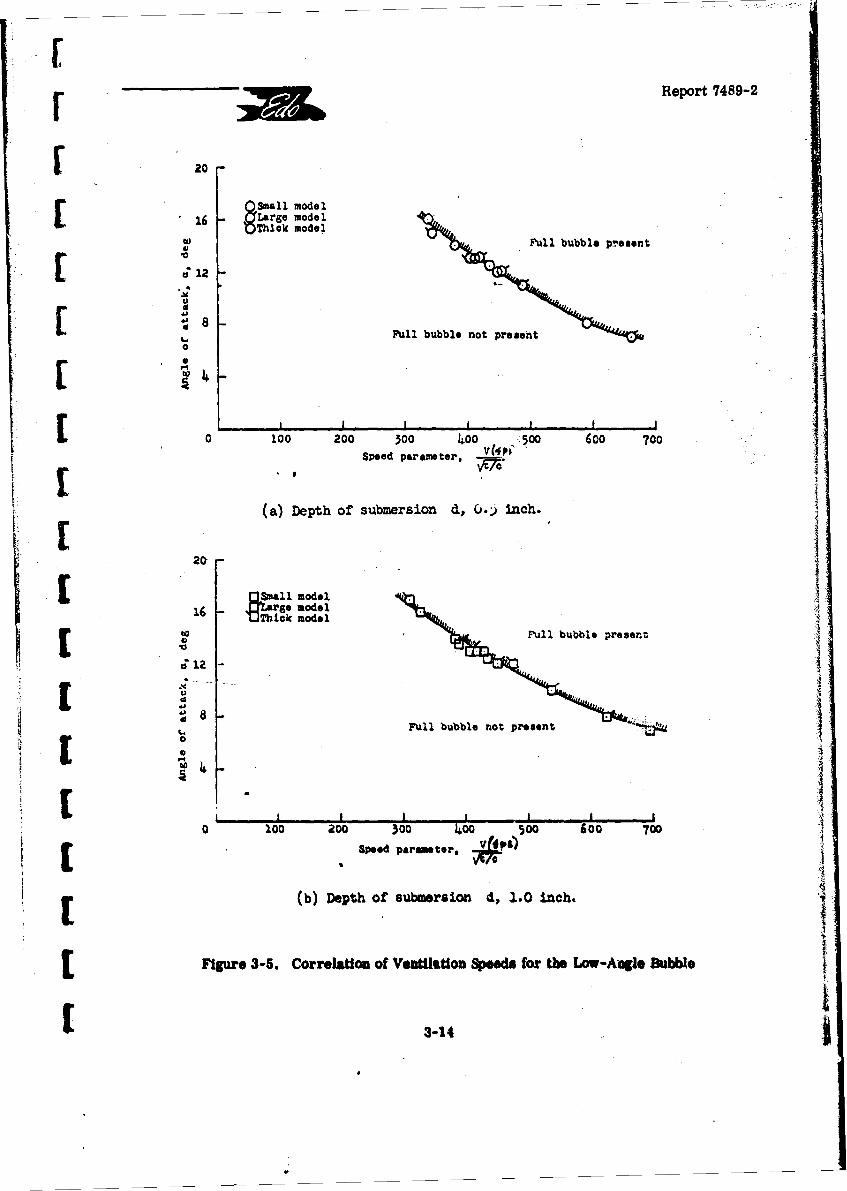
3-5 Correlation of Ventilation Speeds for the Low-Angle Bubble ..... ... 3-14
r 3-6 Comparison of Cavitation Boundaries at Various Depthsof Submersion ...................................... 3-18
[ 3-7 Effect of Flow Changes on the Lift-Drag Ratio of a Flat Hydro-Ski.. 3-19
4-1 Cavity Drag Coefficient vs. Base Cavitation Number for VariousStruts . . . . . . . . . . . .............................. . . 4-4
4-2 Cavity Length vs. Base Cavitation Number for Various Struts . . . . 4-6
5-1 Acceleration Time Histories of Smooth Water Impacts:
Comparison of Impact Theory with Test Data ............. . 5-6
5-2 Acceleration Time Histories of Smooth Water Impacts:Compar-ion of Impict Theory with Test Data . . . . . . . . . . . 5-7[
5-3 Acceleration Time Histories of Smooth Water Impacts:CompAzrison of Impact Theory with Test Data ....... ..... 5-8
5-4 Theoretical Acceleration Time Histories of Smooth Water Impacts:SBee Loading Variation . . . . . . . . . . . . . . . . . . . . . .. 5-10
[[
Lb
Report 7489-2
LIST OF FIGURES (cont'd)
Fi5eure Page
5-5 Theoretical Acceleration Time Histories of- Smooth Water Impacts:A. Deadrise Variation at Low Beam Loading: = 10 5-11
B., Deadrise Variation at Medium Beam Loading: C = 50 . ... 5-12
5-6 Theoretical Maximum Impact Acceleration in Smooth Watervs. Ski Beam Loading . . . . . . . . . . . ...... . . . . . . . 5-14
5-7 Theoretical Maximum Impact Acceleration in Smooth Water vs.Ski Deadrise Angle..... . .............. . . ... . . 5-15
5-8 Theoretical Acceleration Time Histories of Smooth Water Impacts:Ski Trim Variation ............ .................... . . . 5-16
5-9 Theoretical Acceleration Time Histories of Smooth Water Impacts:Flight Path Angle Variation ....................... 5-17
5-10 Theoretical Maximum Impact Acceleration in Smooth WaterSvs. Ski Trim Angle. . . . . . . . . . . ........................ . 5-18
5-11 Theoretical Maximum Impact Acceleration in Smooth Watervs. Flight Path Angle..... . . . . . . .................. . . . . 5-19
5-12 Theoretical Acceleration Time Histories of Smooth Water Impacts:17wing Lift" Variation .. .. .. .. .. .. .. .. .. .. .. I. .. 5-21
5-13 Sketch mustrating Location of Initial Impact Point on Wave Flank.. 5-24
G-14 Acceleration Tinw Histories of Wave Impacts: Comparison ofi Impact Theory with Test Data . . . .................. 5-27
5-15 Variation of Wave Impact Peak Acceleration with Initial Impacti Loca0tion ........... ..... 5-31
5-16A Theoretical Wave Impact Peak Acceleration vs. Initial Impact PointLocation: H - 12 Ft., Various Wave Legth-Height Ratios .... 5-36
5-16B Theoretical Wave Impact Peak Acceleration vs. Initial ImpactPoint Location: L/H = 30, Various Wave Heights . . . . . . . 5-38
1I
! [ "Report 7489-2
LIST OF FIGUMES (cont'd)
. Pe. ~ 1
6-1 Sketch Ilustrating Hydro-cid Planhn_ Rtegion In Thin-Speed Plane. 6-5-
6-2 Flow Diagram for Planing Stability Computer Program........ 6-14
6-3. Comparison of Experimental and Theoretical Lower Limit
r Porpoling Boundaries: Edo Small Ski on Mardn 329C-2"" - Seaplane . . --........... 6-27 -
6-4 Comparison of Experimental and Thebretical Lower Limit -{Porpoising Bouiidries: Martin Small Ski on Martin 329C-2Seaplane . ... ..... 6-28
6-5 Effect of Hydro-Ski Beam Loading on Lower Limit Porpoising -Boundark.. -.- -. . 6-31[ I.
6-6 Effect of Hydro-Ski Deadrise Angle-on Lower-Limit P rpoising . - -.-Boundary. ......... ..... .......... 6-32
6--7- EfEfct-of Hydro-Ski Incidence Angle on- Lower Limit PorpoisingB a- oan.az. .- .. . ... 6-3X
6-8 Effectof Hy d Longitudinal Location on Lower LimitPorpoising Boundary .......................... 6-35
6-9 Dynamic Stalillity Boundaries for Aft Hydro-Ski Location........ 6-36
7-1 Flow Diagram for Nov-Linear Wave Response Program ......... 7-17
8-1 C •ovs. S for Various Hydro-Ski Seaplanes ................. 8-2 1
9-1 Comparison oi Actual Ski Weights with Martin Formula Values.... 9-4
9-2 Comparison of Actual-Ski Weights with Edo Formula Values ..... 9-5
9-3 Comparison of Actual Strut Weights with Martin Formula Values... 9-6
9-4 Comparison of Actual Strut Weights with Edo Formula Values .... 9-7
I:.
[I. .~ I
- - Report 7489-2
I ABSTRACT
I-This report covers the second part of a two-phase survey and analysis ofhydro-ski seaplane technology. It contains quantitative correlations and parametric anal-
I yses of significant data used to define optimum hydro-ski size, ski location with respect tothe strut and aircraft, ski and strut resistance, ski loads and load factors in waves, strut i1
attachment to the aircraft, -effects of strut size and length, ind ski installation weight. The-Phase I report previously issued, contains qualitative descriptions and correlations of the - -
same information, as well as a complete bibliography of hydro-ski technology.
"J - - - These two documents contain all of the background knowledge required beforeconducting general or specific design studies of hydro-ski configurations for a given set
-of design criteria, thereby eliminating the necessity for first reviewing the entire vastj literatute on seaplane hydro-skis. Simultaneously, they serve to define the state-of-the-art in this field-and to indicate those specific areas requiring further investigation anddefinition.
I.
I
II1II
Report 7439-2
SUMMARY
[ This report furnishes a complete description of all work done under Phase 2 ofONR Air Programs Contract N00014-66-C0126, thereby completing a survey of hydro-skiseaplane technology. The Phase 1 work for this contract, covering the qualitative survey,has been described in a companion report, Roeerence (1-1).
Phase 2 of this contract consists of a quantitative survey and related analyses.[ A prevalent feature of the present effort was in the systematic use of a digital computer forthe more complex analyses covering the basic problem areas of hydro-ski seaplane dynamics.
[These were:
a) Fixed-trim, single impacts in waves;
b) Lower trim limits of stability in calm-water high-speed planing;
c) Two-degree of freedom response while traversing a train of wavesK Lat high speed.
For each of the areas investigated in this quantitative study, the existing empirical[ information was correlated with available analytical methods, including those developedduring the course of this study.
As a result of the new analyses, successful correlations, and parametric studiesdescribed in this report, the final principal conclusion drawn from the Phase 2 effort is thatpresent-day hydro-ski technology is sufficiently advanced so that the design of new hydro-skiseaplanes can be undertaken with a high degree of confidence and without danger from un-anticipated difficulties of an unusual nature. However, this high level of knowledge muststill be augmented by an equally high level of skill and ingenuity on the part of the designerand, further, the analytical approaches emphasized herein must invariably be supplementedby suitable model tests.
The main findings of each of the analytical sections of this report are
summarized below.
SSection 3: Staady-State Hydro-Ski Hydrodynamics
[Adequate theoretical methods generally exist for calculating the steady-statehydrodynamic characteristics of basic hydro-ski forms in the fully wetted, ventilated, andplaning regimes. Further experimental and theoretical studies are desirable for improvingthe calculation procedures for ventilated hydro-skis.
S-1
I - Report 7489-2
I Section 4: Strut Resistance Characteristics
Strut drag estimates can be confidently made for conditions at zero yaw angle.Further study is needed to adequately cover conditions with non-zero yaw.
Section 5: Single Hydro-Ski Wave Impacts
3 An improved procedure has been developed for calculating the time history offixed-trim single impacts in waves. The investigation revealed that, contrary to existingopinion, the maximum impact load does not occur when the initial contact is made on theI mid-flank of a wave. Parametric analyses were also made to evaluate the effect of forwardspeed, wave height, and wave length on maximum loads and associated wetted lengths.
Section 6: Dynamic Stability in Calm Water
The existing analytic method for calculation of the lower trim limit of stabilityapplies only to chines-dry planing of a conventional-hull seaplane. A corresponding methodwas developed for the ski chines-wet planing of a hydro-ski seaplane. This linear analysiswas converted to a digital computer program whose output defines the lower limit porpoisingcurve in the trim-speed plane. The correlations made with this program demonstrated itseffectiveness for analyzing porpoising behavior during the preliminary design phase. The
i parametric studies indicated certain important beneficial and detrimental effects of varioushydro-ski design parameters.
I Section 7: Wave Response of a Hydro-Ski Seaplane
To develop a rational method for selection of hydro-ski support strut length,a computer program was developed for calculation of the pitching and heaving response ofa hydro-ski seaplane while traversing a wave train at constant speed, with the assumptionthat no hull impacts occur. The calculate:) results were compatible with theoretical ex-
* pectations. The correlation with the available limited towing tank data was generallyfavorable and reasonable explanations were established for certain discrepancies.
As a result of the difficulties involved in programming this relatively complexnon-liaear analysis, it was found impractical, within the funds available for this contract,to conduct the desired parametric analyses.
I Section 8: Longitudinal Location of Hydro-Ski
The analysis of empirical data on hydro-ski longitud.nal location indicatedthat the aircraft aerodynamic characteristics play a fundamental role in determining theoptimum location of a hydro-ski. The computer programs developed in Sections 6 and 7I are considered useful for analysis of hydro-sial location in preliminary design work.
I1 8-2
I _Report 7489-2
I [ Section 9: Hydro-Ski Installation Weight
New and improved formulas ivere developed for correlating the weight datafor skis and struts of previous full-scile ski installations. Some approximations are also
provided for the weights of hull carryj-dhrough structure and ski retraction systems.
Section 10: Conclusions and Recommendations
As the principal result of this survey and analysis, it is concluded that hydro-ski seaplane design technology is suffiziently advanced so that the design of a hydro-ski"seaplane for open ocean operation car be undertaken with confidence. Recommendationsfor further research are made for those areas where gaps in the knowledge still exist.
[S-[
[
I I
I
"5If Report 7489-2
1 1. INTRODUCTION
3 This report covers the work done by Edo Corporation on Phase 2 of ONRContract No. N00014-66-CO126. The basic purpose of this contract is to produce, bymeans of a survey and analysis, a single source document defining the present state ofknowledge of seaplane hydro-ski technology.
The specific tasks assigned under this contract were as follows:
1. To conduct a literature search for all analytical and experimental dataon aircraft hydro-skis and compile a bibliography;
2. To correlate qualitatively all data relating to optimum hydro-ski shape,spray characteristics, and longitudinal, lateral, and directional stability during take-offand landing of hydro-ski seaplanes;
3. To correlate quantitatively all data relating to hydro-ski size. ;kilocation with respect to strut and aircraft, ski and strut resistauce, ski loads and loadfactors in waves, strut attachment to the aircraft, effects of strut size and length, and
I ski installation weight.
The first two of these tasks, accomplished under Phase I of this project, have3 been reported in Reference 1-1.
The fundamental viewpoint underlying the entire Phase 2 quantitative studyrevolved around the adequacy of existing analytical methods and empirical data for theestablishment of preliminary hydro-ski seaplane configurations. Based on this viewpoint.the complete range of hydro-ski technology was critically examined, beginning with the
I fundamental topic of the hydrodynamic lift of a planing surface and ending with the pitchingand heaving motions of a hydro-ski seaplane in rough water. This review revealed thatseveral important information gaps in hydro-ski technology still existed and that. corres-
I pondingly, a number of original analyses would be required.
A program plan was then established for the executi, of the technical effort.I This plan treated the dynamics of the hydro-ski seaplane in a progressively complex
manner with respect to the aircraft's degrees of freedom and possible motions.
I The program plan covered the following major problem areas:
A. Fundamental considerations in the design of hydro-ski installations,I including principles of bydro-ski sizing and location;
I
Report 7489-2
B. Steady-state hydrodynamic characteristics of hydro-skis, i. e., lift,drag and center-of-pressure values for steady planing and submerged conditions;
C. Steady-state resistance characteristics d hydro-ski support struts;
D, Single impacts of fixed-trim hydr--slds (smooth and rough watercondi`Ions);
E. Planing stability of "skeleton" hydro-ski seaplanes (two degree-of-freedom linearized dynamics, smooth water condition);
F. Wave reaponse of "t!eleton" h.dro-s M ieaplanes (two degree-of-freedom non-linear dynamics, rough water nondition);
G. Survey and analysis of hydro-sk! installation weights.
For each analysis, the following general p.rocedure was utilized:
a. Suitable analytic expressions, either prevaeusly established or newly
I developed, were defined, as required;
b. Where necessary or desirable for the particular analysts, a computer
program was developed,
data; c. Calculations were then made using, as inputs, values for avail.h)a test [data;i
d. Calculated values, such as loads, time histories, etc., were comparedI with the test results;
r e. These correlations were then used to assess the validity of the analyses;
f. The computer programs were then used to perform pertinent parametricS[rstudies and the significant results of these studies were discussed.
It will be seen in the body of this report that these analyses have led to muchfurther unification and amplification of hydro-ski knowledge and, further, have produced anumber of results directly useful in design.
This report ends with a series of significant conclusions and specific recom-mendations for further experimental and analytical work in hydro-ski technology.
1
[12
IReport 7489-2
I REFERENCES
1 Edo Report No. 7489-1: "Survey on Seaplane Hydro-Ski Design Technology.I lh~e I1: Qualitative Study," by P. A. Pepper and L. Kaplan, 23 December1966.
II
I
II
IIII
1 1-3
[ •Report- 7489-2
F 2. FUNDAMENTAL CONSIDERATIONS IN THE DESIGN OF HYDRO-SKI INSTALLATIONS
[ 2, 1 INTRODUCTION
For the guidance of the hydrodynamics engineer, this section Oescribes a numberC iof fundamental considerations that must be made during the design of hydro-ski installations,as related to actual seaplane operations (take-off, landing and taxiing) in smooth and roughwater, then presents the general sequence of design procedures, and finally discusses the'analytical and/or experimental investigations that must be covered in the design phase.Among other things, this discussion explains the pertinence and use of the analyses andcomputer programs developed during this study contract. In addition, it proposes a newmethod whereby tank tests can be combined with computer calculations to obtain important
information on hydro-ski seaplane hull loads, a subject not covered in the present state-of-the-art.
In kueping with the later sections of the report, emphasis is placed on the longitu-dinal characteristics which are obviously more basic than the others. A principal purposerof this discussion is to clarify the often conflicting hydrodynamic requirements for hydro-skiinstallation geometry in a systematic manner. It will be seen that most of the problem areasare susceptible to individual analysis but a standard procedure for the complete resolution( rand synthesis into an optimum system has not yet been achieved.
2.2 DESIGN PROCEDURE SEQUENCE GUIDELINE
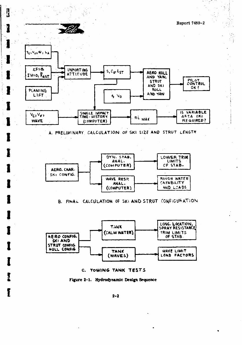
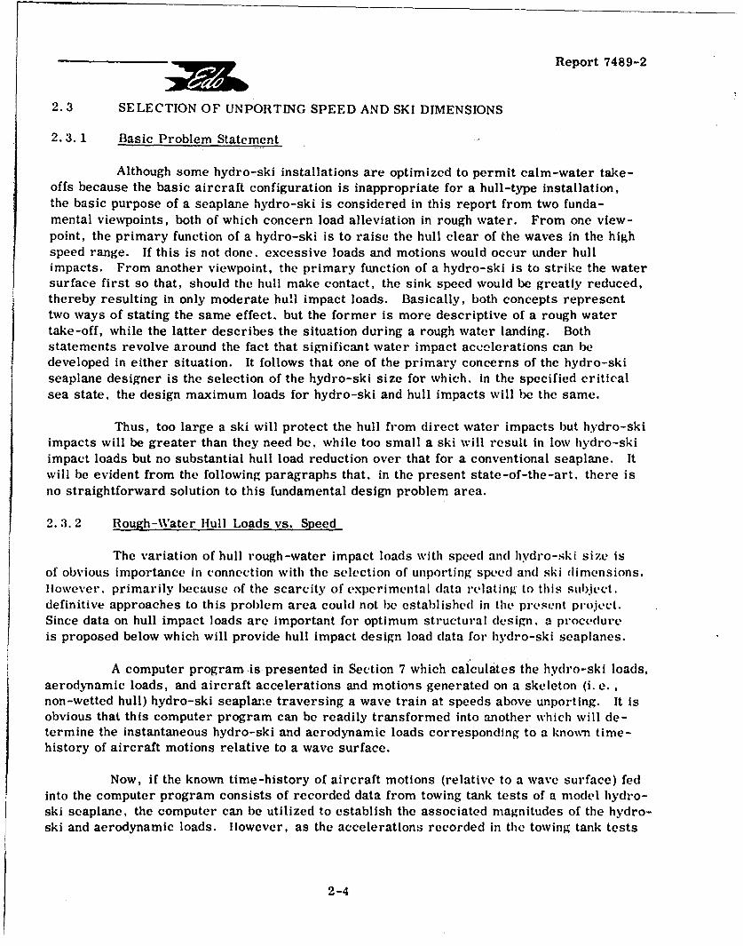
hi: Figure 2-1 presents a block diagram of the sequential procedures that will generallybe followed during the hydrodynamic configuration development phase in the design of anoperational hydro-ski configuration. Table 2-1 presents the associated nomenclature code.SThe analytical studies are seen to consist of a set of preliminary and final calculations.
r The preliminary calculations establish approximate values for the hydro-ski size,the adequacy of the aircraft roll and yaw control in calm water conditions, and the hydro-skiload factor in high speed impacts. The latter calculation also determine$ the necessity fora "variable-area" hydro-ski if it is found that, using the ski size required for the desiredunporting speed, the maximum load factors developed in high speed (landing) impacts exceedtheir desired design value. A variable-area hydro-ski utilizes a suitable mechanical ar-[ rangement to provide two different areas: a large one appropriate for speeds near unportingand a st.all one for speeds near getaway.
Utillzing the results of the preliminary calculations, more precise and definitiveanalyses of the longitudinal dynamic characteristics may be undertaken which will result thprediction of the lower trim limits of stability and the degree of rough water capability.Evaluation of the results for both the preliminary and final analytical studies will permit thefinal selection of the hydro-ski seaplane configuration on which dynamic model towing tanktests should be conducted.
- I
t
Report 7489-2
WIL
'A AN WAV (COMTRTOR
A.LIFTNR ACUAINOFSISZ AND STUALEGT
3 (COMPUTER)FkCF $TAB.
DYN.V RSTAB LOWRcU4 ATERIANAhL. CA'BLIMTS
(COMPU T ER) CFST~bLAB*
I B.~~SK COFINLCLUAIN FS6A-SRU OFG~TO
WAV ____I_____ W TE
TANK LON&. LOCATION.T~WK PRAY RESISTANCE,
(CALM WATENJ 'TRIM LIMITSA ERAO COt4PIG. F7OF STAB.
I*UW. COV4 ;rAN WAVETLIMI(WAV E S) LOA40FCTR
C. TOWING TAN4K TEST.S
Figure 2-1. Hydrodynamic Design Sequence
1 2-2
Report 7489-2
TABLE 2-
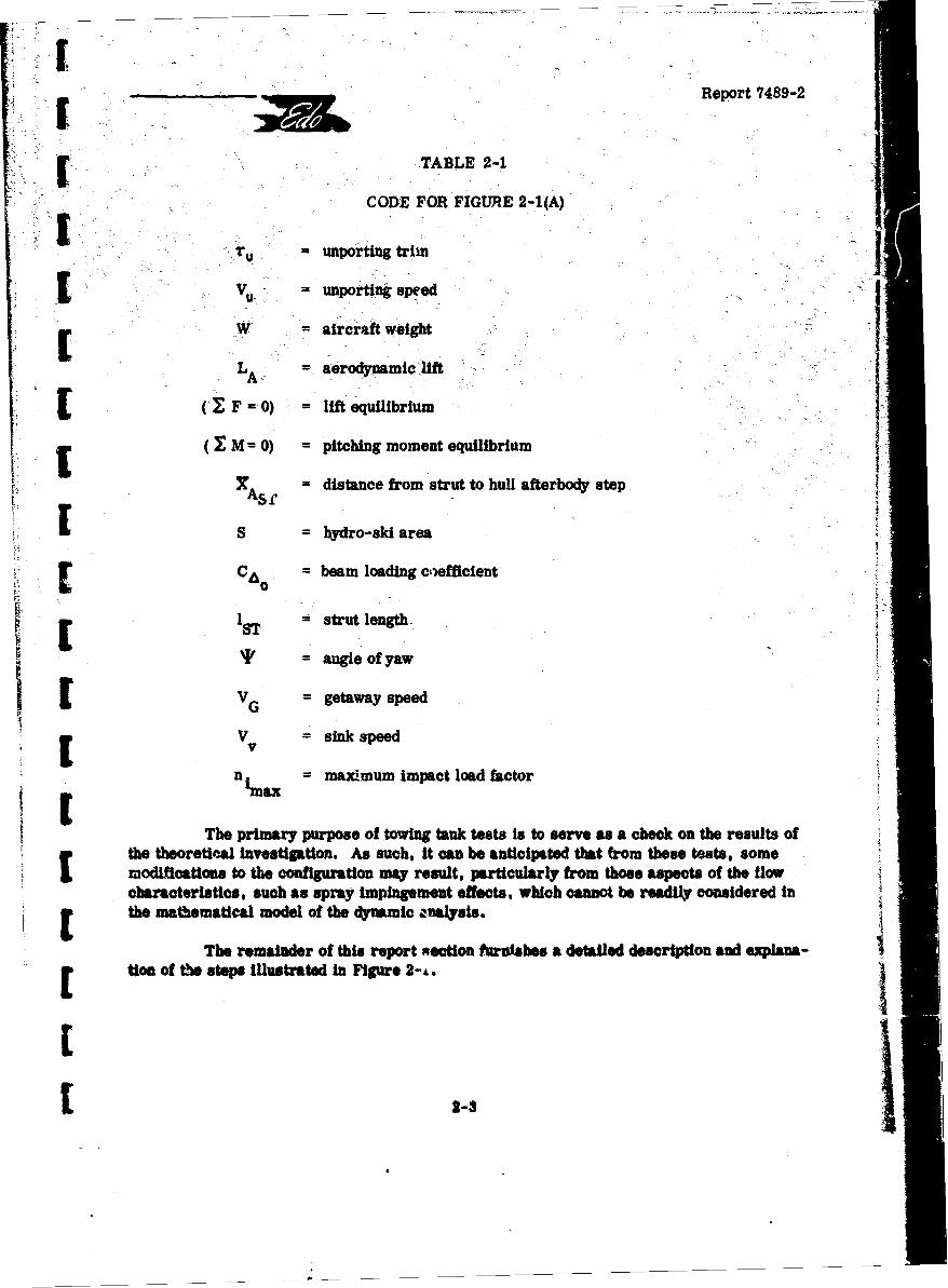
CODE FOR FIGURE 2-1(A)
=importing trim1.V unporting speed
[ W = aircraft weightj
LA = aerodynamic lift
[ (.F=O) = lift equilibrium
(I M = 0) = pitching moment equilibrium
•A1 = distance from strut to hull afterbody step
I S = hydro-ski area
' [ sC = beam loading cefficient
I strut length
'I' angle ofyaw
ILV getaway speed
V = sink speed
n = maximum impact load factorIL imax
The primary purpose of towing•tank tests is to serve as a check on the results ofthe theoretical investigation. As such, it can be anticipated that from these tests, somemodifications to the configuration may result, particularly from those aspects of the flowcharacteristics, such as spray impingement effects, which cannot be readily considered inthe mathematical model of the dynamic analysis.
The remainder of this report xection furbisles a detailed description and explana-[ tion of the steps illustrated In Figure 2-,L.
I2
Report 7489-2
2.3 SELECTION OF UNPORTING SPEED AND SKI DIMENSIONS
2.3.1 Basic Problem Statement
Although some hydro-ski installations are optimized to permit calm-water take-offs because the basic aircraft configuration is inappropriate for a hull-type installation,the basic purpose of a seaplane hydro-ski is considered in this report from two funda-mental viewpoints, both of which concern load alleviation in rough water. From one view-point, the primary function of a hydro-ski is to raise the hull clear of the waves in the highspeed range. If this is not done, excessive loads and motions would occur under hullimpacts. From another viewpoint, the primary function of a hydro-ski is to strike the watersurface first so that, should the hull make contact, the sink speed would be greatly reduced,thereby resulting in only moderate hull impact loads. Basically, both concepts representtwo ways of stating the same effect. but the former is more descriptive of a rough watertake-off, while the latter describes the situation during a rough water landing. Bothstatements revolve around the fact that significant water impact accelerations can bedeveloped in either situation. It follows that one of the primary concerns of the hydro-skiseaplane designer is the selection of the hydro-ski size for which, in the specified criticalsea state, the design maximum loads for hydro-ski and hull impacts will be the same.
Thus, too large a ski will protect the hull from direct water impacts but hydro-skiimpacts will be greater than they need be, while too small a ski will result in low hydro-skiimpact loads but no substantial hull load reduction over that for a conventional seaplane. Itwill be evident from the following paragraphs that. in the present state-of-the-art. there isno straightforward solution to this fundamental design problem area.
2. 3. 2 Rough-Water Hlull Loads vs. Speed
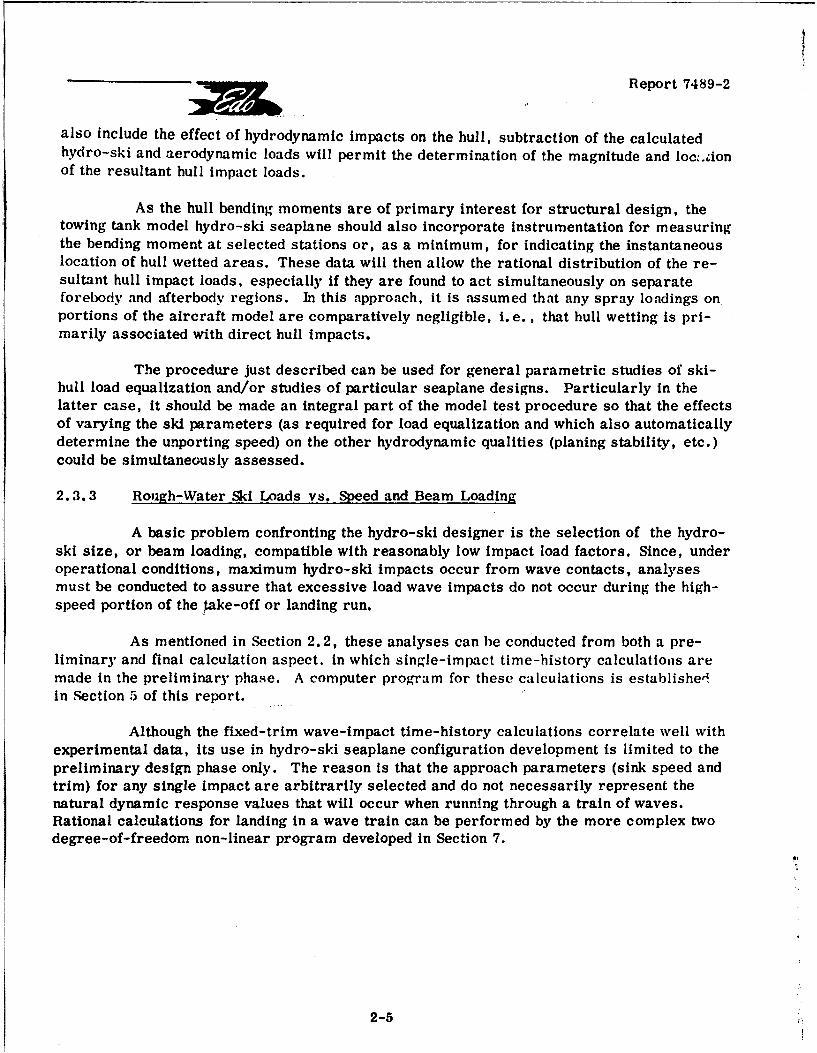
The variation of hull rough-water impact loads with speed and hydro-ski size isof obvious importance in connection with the selection of unporting speed and ski dimensions.However, primarily because of the scarcity of experimental data relating to this subject.definitive approaches to this problem area could not be established in tile present project.Since data on hull impact loads are important for optimum structural design, a procedureis proposed below which will provide hull impact design load data for hydro-ski seaplanes.
A computer program is presented in Section 7 which calculates the hydro-ski loads,aerodynamic loads, and aircraft accelerations and motions generated on a skeleton (i. e.,non-wetted hull) hydro-ski seaplare traversing a wave train at speeds above unporting. It isobvious that this computer program can be readily transformed into another which will de-termine the instantaneous hydro-ski and aerodynamic loads corresponding to a known time-history of aircraft motions relative to a wave surface.
Now, if the known time-history of aircraft motions (relative to a wave surface) fedinto the computer program consists of recorded data from towing tank tests of a model hydro-ski seaplane, the computer can be utilized to establish the associated magnitudes of the hydro-ski and aerodynamic loads. However, as the accelerations recorded in the towing tank tests
2-4
Report 7489-2
also include the effect of hydrodynamic impacts on the hull, subtraction of the calculatedhydro-ski and aerodynamic loads will permit the determination of the magnitude and loc-.ionof the resultant hull impact loads.
As the hull bending moments are of primary interest for structural design, thetowing tank model hydro-ski seaplane should also incorporate instrumentation for measuringthe bending moment at selected stations or, as a minimum, for indicating the instantaneouslocation of hull wetted areas. These data will then allow the rational distribution of the re-sultant hull impact loads, especially if they are found to act simultaneously on separateforebody and afterbody regions. In this approach, it is assumed that any spray loadings onportions of the aircraft model are comparatively negligible, i.e., that hull wetting is pri-marily associated with direct hull impacts.
The procedure just described can be used for general parametric studies of ski-hull load equalization and/or studies of particular seaplane designs. Particularly in thelatter case, it should be made an integral part of the model test procedure so that the effectsof varying the ski parameters (as required for load equalization and which also automaticallydetermine the unporting speed) on the other hydrodynamic qualities (planing stability, etc.)could be simultaneously assessed.
2.3.3 Rough-Water Ski Loads vs. Speed and Beam Loading
A basic problem confronting the hydro-ski designer is the selection of the hydro-ski size, or beam loading, compatible with reasonably low impact load factors. Since, underoperational conditions, maximum hydro-ski impacts occur from wave contacts, analysesmust be conducted to assure that excessive load wave impacts do not occur during the high-speed portion of the %ake-off or landing run.
As mentioned in Section 2.2, these analyses can be conducted from both a pre-liminary and final calculation aspect. in which single-impact time-history calculations aremade in the preliminary phase. A computer program for these calculations is establishedin Section 5 of this report.
Although the fixed-trim wave-impact time-history calculations correlate well withexperimental data, its use in hydro-ski seaplane configuration development is limited to thepreliminary design phase only. The reason is that the approach parameters (sink speed andtrim) for any single impact are arbitrarily selected and do not necessarily represent thenatural dynamic response values that will occur when running through a train of waves.Rational calculations for landing in a wave train can be performed by the more complex twodegree-of-freedom non-linear program developed in Section 7.
2-5
i]
Report 7489-2
I 2.3.4 Upwrting Speed and Ski Beam Loading
The hydro-ski unporting speed is a fundamental design parameter. When properlyselected and achieved, it represents the speed above which a properly designed hydro-ski andstrut combination will shield the hull from critical impacts in the design sea state. Althoughthis implication is basic to unporting speed selection, unporting speeds have invariably beenrelated to the calm water condition because of its relative analytical simplicity.
The standard procedure- for calculation of the hydro-ski size, or beam loading, D;J to assume a "stick-fixed" take-off. That is, the side view drawing of the hydro-ski seaplaneis laid out at that trim in which the level water line touches the ski bow and the afterbodystep. From the considerations of static force and moment equilibrium, the required hydro-f ski lift for various unporting speeds is established while accounting for the wing aerodynamiclift and the afterbody hydrodynamic lift. Having determined the required hydro-ski lift, theShuford planing lift equation (with suitable modification as required for more complex skishapes) (Section 3) can be employed to define the corresponding beam loadings associatedwith a range of hydro-ski lengths.
It may be found that the determined hydro-ski beam loading corresponding to theselected unporting speed is incompatible with the load factor limitation established as de-scribed in the preceding paragraph. - Judicious adjustments in hydro-ski dimensions and/orthe design unporting speed may then be considered to achieve tue desired compatibility. Itis sometimes necessary to employ a "variable area" hydro-ski to satisfy the conflicting beam
i loading requirements betwern unporting speed and maximum hydro-ski impact load factor.
2.3.5 Ski Area, Lengtb, and Miscellaneous Parameters
It is now evident that several configuration parameters can be varied foro. the pur-pose of developing the desired performance characteristics. For example, hydro-ski liftmay be increased by increasing the beam or incidence, or decreasing the deadrise. Eachparametric variation may introduce detrimental effects under other conditions, so thattrade-offs must be continuously evaluated.
I Consider, for example, the situation in which it is desired to reduce the unportingspeed by increasing the hydro-ski area. This may be accomplished either by increasing thehydro-ski beam or tength. Because of aspect ratio effects, changing the beam is a moreefficient way of accomplishing a change in lift. However, this approach will also invariablyresult in an increase in the maximum impact loads occurring in single impacts and in rough-water taxiing. Consequently, the final choice may involve an increase in hydro-ski length.Therefore, due to the complex relationships existing between the various hydro-ski para-meters, with respect to their relative effectiveness, compromise adjustments in the hydro-ski configurations will be made, where more than one basic dimensional parameter is si-
I multaneously varied in order to obtain the necessary or desired hydrodynamic characteristics.By referring to Sections 3, 5, and 6 of this report, considerable guidance for the quantitativeI effects of varying hydro-ski parameters may be obtained.
I 2-6
F
F,
F "Report 7489-2
2.4 SELECTION OF SI LOCATION
2.4.1 Unor-tl•ng Trim Anxle
The simple procedure described in para. 2.3.4 for preliminary estimation of the
hydro-ski dimensions to accomplish unporting at a specified velocity involves drawing a pro-r file of the hydro-ski seaplane in the unporting attitude. The geometry assumed is fairlyrepresentative of the actual attitude observed in towing tank tests, which, of course, simu-lates a fixed-stick take-off. This may not necessarily be the case under prototype opera-tional conditions, since elevator control may be applied by the pilot to keep the bow down, sothat there is no rapid pitch-up to the unporting attitude, and the hydro-ski is brought to thesurface planing regime without the afterbody contacting the water.
For hydrodynamic design purposes however, the towing tank situation at unportingis considered, since its associated greater trim implies a conservative drag condition and
- the possibility of wing stalling will then be more closely examined. Furthermore, designingfor a "two-point" unporting attitude reduces the pilot skill required for successful unporting.
L 2.4.2 Vertical Location
E 2.4.2.1 Hull Clearance
The vertical location of a hydro-ski (or, equivalently, the strut length), is obvi-onsly a primary factor affecting the rough water capability of hydro-ski seaplane configuration.[ Nevertheless, other considerations will limit the maximum strut length that may be designedfor any particular aircraft. For example, it is obvious that, for any specific hydro-ski in-stallation, a strut length can be reached which, because of the associated drag and bow-downr [ moment, will prevent the trimming up motion necessary for ski unporting. As the bow-downmoment is caused by the resultant force vector from the strut and hydro-ski passing too faraft of the c. g., it is sometimes possible to alleviate this situation by a further forward loca-
4 L tion for the ski.
The striý length is limited to that value for which corresponding unporting trimdoes not result in wing stalling. Otherwise, as the unporting attitude is approached, the
- wing lift will drop off, which increases the load on the ski and cause it to resubmerge, re-sulting in an-emergence instability. The maximum strut length selected in accordance withthis requirement (avoidance of wing stall at importing) then must be investigated relative tothe rough water capabilily when ski-borne, since its primary function is to keep the hullclear of wave impacts. The exact relationship between strut lengh and sea state negotiability
Shas not been previously established either empirically or analytically.
The approximate "rule of thumb" relationship used in the past states that the waveL [ height capability of a bydro-ski seaplane is equal to its strut length. In retrospect, as indi-
cated in the Phase I report para. 4.3.2.2, it seems that this design guideline is more ap-! [ propriate to a penetrating hydro-ski installation where, because of the high beam loading,
2-7
IReport 7489-2
I the aircraft tends to "plow through" the waves. With lower beam loadings (corresponding tolarge hydro-skis), the aircraft tends to rise over the waves so that for this type of installa-tion the strut length can presumably be less than the negotiated wave height. -
2 The foregoing empirical criteria may be used for estimating the proper strutlength during the preliminary design phase of hydro-ski configuration design. During thelater design phases, where investigations are conducted to ensure that the configuration willsatisfy the specified rough water conditions, an analytical study of the seaplane's wave re-sponse characteristics based on the method presented in Section 7, should be undertaken.
I 2.4.2.2 Lateral Stability Effects
Having established a strut length for a particular hydro-ski which satisfies therough water and longitudinal stability requirements, it may be found that when the aircraftis yawed, the rolling moment generated by the hydrodynamic side forces on the strut and
Sski is sufficiently large to introduce lateral stability problems.
To overcome the rolling tendency in yawed attitudes, adequate aerodynamic con-I trol is required. The two critical regimes for roll instability are at unporting and landing.
In the first case, unporting may be difficult, even under a moderate amount of yaw, ifailerons are ineffective at the associated, speed. In this case, it may be necessary toconsider such design changes as :ncreasing aileron size, decreasing the strut length, orincreasing the unporting speed. In the second case, if a yawed landing is made, althoughailerons are effective, it must be demonstrated that adequate restoring moment can bedeveloped. Furthermore, it is also necessary to demonstrate, either by calculations ormodel tests, that, even though aileron control is adequate, the aircraft will not roll exces-sively.in a moderately yawed landing before the pilot is able to respond and apply corrective
I control.
2.4.3 Longitudinal Location
I 2.4.3.1 Aircraft Longitudinal Control
Throughout the take-off regime., the hydro-ski and/or strut develops a continuouslyvarying pitching moment about the aircraft center of gravity. It is clearly desirable thatthe hydro-ski be installed in such a position that the magnitude and direction of the moment
I naturally tend to assist the aircraft in maintaining a trim attitude variation which results inthe shortest take-off run. As this ideal situation is unlikely to be realized in a stick-fixedtake-off, the pitching moment generated by the hydro-ski and strut for the longitudinal
I position selected should at least permit pilot controllability of the trim. This aspect of thedesign is usually investigated in towing tank tests, where the effect of different elevatordeflections on the take-off process can be evaluated.I
I1 2-8
F1 Report 7489-2
[ 2. 4. 3. 2 Static Stability and Forward Location Limit
To counteract the moment from the drag forces acting on the submerged strut[ and hydro-ski, the longitudinal position of the hydro-ski is generally located somewhat for-ward of the aircraft center of gravity. The precise location of the hydro-ski is usuallyestablished from towing tank tests, wherein the stability characteristics for different fore[ and aft ski positions are observed, and the optimum location selected.
In a basic research tank test program on the effect of hydro-ski beam loading onrough water landing characteristics (Reference 2-1), it was established that, as the beamloading increases, a more forward position of the hydro-ski is required to prevent diving.This behavior is evidently a consequence of tke increasing penetration afforded by higherbeam loadings in which, because of the greater amount of strut wetting, the strut drag plays
a greater part in the inclination of the rE sultant hydrodynamic force vector from the hydro-ski and strut. This towing tank investigation on the effect of systematically varying the[ hydro-ski beam loading demonstrated that, for any specific aircraft, the optimum longitudi-nal location of the hydro-ski is dependent on the value of the beam loading coefficient. In thestudy of Reference 2-1, landing tests in waves were conducted, and it was found that, forany longitudinal ski position, if the hydro-sk beam loading were too low, rapid pitch upmotions would occur and that too high a beam loading would result in diving. It was thereforeestablished that, as compared with large (low beam loading) hydro-skis, the optimum center
Sof pressure locations for penetrating (high beari loading) hydro-skis, are further forward.
This result could have been anticipated since, for a constant strut length, withhigher ski penetration, the greater the average wetting of the hydro-ski strut, therebycontributing a larger resistance component which increases the strut-ski resultant loadinclination. The net effect is to apply a bow-down moment, so that to compensate, the ski
3 has to be located in a somewhat more forward position. It is finally important to note that,with a ski in a relatively forward position, increasing ski incidence is also effective in pre-venting diving.
[ 2.4.3.3 Dynamic Stability and Aft Location Limit
A well-known phenomenon in seaplane behavior is that of "lower limit" dynamicr instability, commonly known as "porpoising". It is generally found that, as the staticequilibrium planing trim is reduced (at a fixed speed), a trim value is reached below whicha build-up in pitch and heave oscillations occurs. It is well-known that this instability is
f related to dynamic effects, and a relatively comrlex dynamic analysis (including aerodynamiccontributions) is required to establish the precise location of the porpoising limit in thetrim-speed plane.
A computer program for this analysis is presented in Section 6 of this report and
shown to yield good agreement with test data. The study of that report section reveals theexistence of a new factor conducive to porpoising. It is found that, for equilibrium trimangles in which the wetted area is entirely within the triangular region of a hydro-ski havinga triangular stern planform, the stable portion of the planing region becomes severely
2-9
SReport 748 9-2
I limited for a sufficiently aft location of the hydro-ski. It is thus deemed necessary to con-duct the dynamic analysis of Section 6 for ea,.h specific aircraft employing a hydro-ski, andall the more so for skis with stern planform taper, to establish the range of aft ski locations' which will cause this mode of dynamic instability.
2.4.3.4 High-Angle Porpoising
I At any speed in the ski-borne range of a hydro-ski seaplane, there exists a trimat which getaway will occur provided that trim does not correspond to wing angles of attackJ in the stalled range. It is possible however that, before the flying trim is reached, the con-figuration is such that the hull afterbody contacts the water surface and initiates a porpoising.action. This "high-angle porpoising" is less likely to occur in hydro-ski seaplanes becausethe strut places the hull at a substantially higher elevation than would be the case for con-ventional seaplanes at the same speed.
However, the possibility of high-angle porpoising should always be checked out inthe course of the towing tank mc.'lel test program because no method of analysis for thisproblem is available in the present state of the art. Reference 2-2 presents an example in
which high-angle porpoising occurred in a hydro-ski configuration. This configuration con-sisted of a hydro-ski in an extreme forward location and a hull with an extreme aft step.The towing tank tests showed that the hydro-ski wake interacted with the hull bottom tocause unsatisfactory pitching behavior.
2.4. 3. 5 Directional Stability Effects
SIt can be geiierally assumed that when the aircraft is yawed and portions of thehydro-ski and strut are wetted, the center of pressure for the resulting side load will be
i forward of the aircraft center of gravity. This destabilizing effect introduces the possibilityof direction'.1 instability.
this situation is usually evident on hydro-ski seaplanes during the landing run-outof a hydro-ski seaplane, when the forward speed is reduced sufficiently to cause submer-gence of the hydro-ski. At that time, because of the inadequacy of rudder control, a definite"hooking" motion will take place. Fortunately, because of the associated rapid deceleration,the only effect is one of personnel discomfort. However, there are two instances in hydro-ski seaplane operation where such a hooking tendency is less tolerable, one of which isI potentially catastrophic.
The first case considered is that which can occur just prior to unporting. If anaircraft yaw attitude is developing as the unporting speed is being approached, the asso-ciated destabilizing moment may reach a magnitude sufficient to cause aborting the take-offbecause of the excessive drag resulting from the asymmetrical attitude by the yawing moment,Piloting techniques, such as selection of the initial heading with respect to the wind, areusually adequate to compensate for this effect.
1 2-10
t . . . .
[ •Report 7489-2
A more serious design consideration is a yawed attitude in a rough-water landingin which the ski and strut can submerge at high speed. This has already been discussedwith respect to lateral stability effects in para. 2.4. 2. 2. In this same situation, relatively
r forward locations of the hydro-ski and strut also tend to induce hooking at high speed which,of course, would be extremely dpngerous. It is therefore necessary, in designing a pene-trating hydro-ski installation, to insure that, when ski and strut submergence occurs at
Ihigh speed, the pilot can bring the resulting unstable motion under control.
2.4.3.6 Correlation of Empirical Data on Longitudinal Ski Location
Although it is obvious from the preceding discussion that very many considerationsenter into the choice of longitudinal ski location, it was hoped that an empirical correlationfor this quantity could be established from existing geometrical data for previous ski instal-
lations. Such correlations, using single geometric parameters, were attempted, asdescribed in greater detail in Section 8 of this report. These attempted correlations wereunsuccessful and the lack of success was attributed to the multiplicity of parameters (par-ticularly, the aerodynamic parameters) which actually affect ski location.
2.5 SPRAY CONS2DERATIONS
The spray characteristics of any seaplane configuration are of vital importanceto its successful performance. Excessive spray can result in large drag increments,obscurement of pilot vision, structural damage and unstable behavior, any one of which, ifappreciable, can render the aircraft unacceptable. The spray behavior of a hydro-ski sea-
r plaine configuration is generally evaluated in the course of the towing tank investigation.
It has frequently been found that the spray characteristics observed on hydro-skiseaplane tank models are optimistic with respect to prototype behavior. This situation canusually be attributed to the lateral and directional restraints generally imposed on the modelduring its tests. A clear example of this type was furnished by the Grunberg hydrofoilsystem on the JRF-5 airplane. This configuration employs a main supercavitating hydro-
foil and two bow hydro-skis. The model tests of this configuration (Reference 2-3) showedvery mild spray created by the bow-ski unporting, whereas the corresponding prototypespray was intolerably severe. This difficulty was overcome by reduction of ski incidence,
I elimination of the ski pointed trailing edges, and addition of chine strips.
Towing tank studies have been conducted to establish parametric relationships forthe spray characteristics of planing surfaces. These studies are conducted for the utilizationof their data for the prediction of full-scale geometry and associated effects. However, theresults of these studies must be carefully interpreted, as shown by the following twospecific instances of contradictory conclusions regarding the effects of certain hydro-skidesign details on spray behavior.
SThe first case concerns the effect of horizontal chine flare on the height of themain spray. From the towing tank tests of prismatic planing surfaces in Reference 2-4 and2-5, it was concluded that horizontal chine flare is ineffective in reducing the spray height
1 2-11
Report 7489-2
of the basic deadrise sections. Nevertheless, in the full-scale tests of Reference 2-6, theobservations conclusively demonstrate that hydro-ski chine flare effectively minimizes themain spray height.
I The second example concerns the effect of vertical chine strips on suppression ofmain spray height. From the tow tank test of Reference 2-4, it was reported that 2. 2 to5. 5 percent beam width vertical chine strips are effective in reducing spray height. How-I ever, in the tow tank tests of Reference 2-5, where 4 percent beam width vertical chinestrips were attached to the prismatic deadrise planing surface; it is reported that verticalchine strips have a relatively small effect. A further examination of these two referencesreveals that the conclusions of Reference 2-4 are based upon trims of 8, 12, and 15 degrees.The conclusions of Reference 2-5 are based upon trims of 6, 18, and 30 degrees, in which
I main spray height reduction at the lowest tested trim is noted in the body of the report.
From the foregoing, it appears that, pending further detailed investigation of thesubject, both chine flare and vertical chine strips are effective in reducing main sprayheight at the trims generally associated with hydro-ski operation.
The spray burst associated with the unporting of a hydro-ski has also been asource of concern to the hydro-ski designer. For large, low-beam loading hydro-skis, a"slotted bow" has proven effective, (Reference 2-7), whereas this device resulted in noimprovement when applied to a penetrating-type hydro-ski (Reference 2-8). It must benoted, however, that the unporting spray from the basic penetrating (high beam loading)hydro-ski was much less severe than that from the basic low-beam loading ski.
j 2.6 SKI INSTALLATION WEIGHTS
Of considerable importance in preliminary design work is the ability to makereasonable weight estimates for hydro-ski installations. For this purpose, a survey andanalysis has been made of such weight information for previous ski installations. This areais covered in Section 9 of this report which describes new empirical formulas which furnishclose correlations for the individual weights of skis and ski support struts. It is empha-sized that these formulas are conservative bezause of the vast bulk of the prev'ious instal-lations used retrofitting of the skis to existing hull seaplanes.
REFERENCES
j 2-1 NACA RM L56125a: "Tank Investigation of a Series of Related Hydro-Skis asLoad-Alleviation Devices for Landing a Seaplane in Waves," by A. W. Carter.A. E. Morse, Jr, and D. R. Woodward, 19 December 1956.
2-2 Martin Comany Re2ort RM-54: "Hydrodynamic Study of Forward-Ski Aft StepSeaplane Alighting System," by D. A. King and M. G. Scheider.
21 2-12

rReport 7489-2
r RE FERENCES (Continued)
2-3 NASA TN D-220: "A Brief Investigation of a Hvdro-Ski Stabilized HydrofoilSystem on a Model of a Twin-Engine Amphibian," by Sandy M. Stubbs andEdward L. Hofman, February 1960.
2-4 Davidson Laboratory Report R-678: "On the Main Spray Generated by Planing
Surfaces," by D. Savitsky and J. P. Breslin, January 1958.
r 2-5 Davidson Laboratory Report R-768: "Final Engineering Report on Wake-ShapesI of Planing Forms Associated with High-Speed Waterbased Aircraft," by
R. L. Van Dyck, October 110.
2-6 Thurston Erlandsen Corp. - Report 6502-1: "Final Summary Report Flight Testof the Hydro-Ski Research Vehicle (HRV-1) Equipped with TEC Skis No. 4 and[ No. 4A on Strut No. 2," by 0. Erlandsen and D. B. Thurston, December 1965.
2-7 NATC PTR AD-366. 1: "Evaluation of Hydrodynamic Characteristics of ModelPBM-5S2 Airplane with a Modified Hydro-Ski, Report No. 1 Final Report,"March 1958.
r 2-8 NATC PTR AD-366.2: "Evaluation of Hydrodynamic Characteristics of Model, I PBM-5S2 Airplane with a Small Variable Area Hydro-Ski, Report No. 1 Final
Report," September 1961.
2t1i
C!t tI
[ 2-1
J Report 7489-2
3. LONGITUDINAL HYDRODYNAMIC CHARACTERISTICS3 OF ISOLATED HYDRO-SKIS
I 3.1 HYDRO-SKI FLOW REGIMES
In this report, a "hydro-ski" is defined as a hydrodynam... lifting surface of lowtotal aspect ratio, as opposed to a hydrofoil which has a large total aspect ratio. In thisdefinition, the aspect ratio A, is taken as the square of the maximum transverse dimension
I divided by planform area. The division between the two categories may be taken, somewhatarbitrarily, as A = 1.
Speaking most generally, the nature of the flow and, consequently, the pressuresand loads developed by a hydro-ski, depends in a complex manner on a number of para-meters. In addition to the parameters defining the ski geometry, of which the principal ones
i are the ski beam, total length, and deadrise, the type of flow varies with the speed (relativeto still water), the trim, and the draft (depth of lowest point on ski). In this report section,attention will be limited to steady-state flow conditions in which the ski moves at constantspeed parallel to the (still, horizontal) water surface and, also, to the condition of positiveski trim (angle between ski keel line and water surface).
The physical nature and the relations between these flow regimes have been in-vestigated for a few hydro-ski shapes of simplified geometry. These investigations haveserved to indicate the principal types of flow regimes which may be described qualitatively,as follows:
1. PLANING
I For drafts not exceeding the height of the total vertical ski projection, the ski actsas a planing surface and the flow at the forward portion of the water line is not affected by
If the proximity to the ski leading edge. This condition is maintained for all positive trimangles.
3 For slightly greater drafts (ski leading edge, L. E.) either directly above, at, orbelow the water line), the flow remains basically of planing type but can be affectAd by thedetails of the water flow around the ski L. E. and, therefore, is sensitive to the details of
S the ski L. E. geometry as well as the trim angle.
2. SUBMERGED
I For still greater drafts, i.e. submerged ski, several different types of flow arepossible, depending on ski draft, trim, and speed, as follows:
I
3-i
FReport 7489-2
[ A. Fully Wetted Flow
At all drafts and relatively low speeds and trim angles, there occurs "fullywetted" flow wherein both upper and lower surfaces of the ski are wetted. In this condition,the flow is generally similar to that over a low aspect ratio airfoil. These flows are char-acterized by the presence of trailing vortices which, in the vicinity of the ski, take the formof a vortex sheet. Further downstream, the vc-tex sheet rolis up into two separate "tip"vortices or "vortex cores". At sufficiently shallow drafts, the reduced pressure inside thetip vortices is adequate to induce a flow of air from the surface into the core regions so thatthese vortices become aerated. However, at the lower trims, the spreading of the vorticityinside the vortex sheet near the ski prevents this air from reaching the ski itself. As theski trim is increased, the aerated rolled up vortices approach the ski until, at some par-ticular trim value, they reach the ski and the entrained air then spreads over the uppersurface, finally resulting in a "ventilated flo,", condition. The conditions associated withI ventilation inception are discussed in more detail in Section 3.3. 2.
B. Ventilated Flow
In the ventilated flow condition, the upper surface of the ski becomes com-pletely exposed to the atmosphere. Excc"nt for a narrow sheet of water which is thrown overthe ski L. E., this flow Is very similar to , Oe planing type of flow.
C. Cavitated Flow
I -At deeper dripihs, it becomes more difficult for air from the surface to reachthe trailing vortices and the ski. in this case, the vortices tend to develop cavities which,instead of air, are filled with water vapor. Again, sufficient increase of trim and/or speed
I will spread the trailing cavities over the ski's surface until the latter is completely cavi-tated, i.e., covered by an underwater cavity (containing water vapor) of some finite extent.The length of this cavity is determined primarily by the "cavitation number", defined as the
'pL ambient static pressure divide I by the dynamic pressure, and increases as the cavitationnumber decreases, for example, with increase of speed. It is obvious that, for comparable[ trims and speeds, the lift on a cavitated ski is greater than that on the same ski when ven-tilated because of the reduced pressure on its upper surface.
The preceding description of the main flow regimes has been deliberately re-[ stricted to the case of uniform horizontal motion of the ski. For most eneneering purposes,It is sufficiently accurate to assume that, in the case of non-uniform motions, the latter arequasi-steady so that the flow regimes are the same as those prevailing under equivalent
• stuedy flow conditions. Some exceptions of this rule are utilized later on and will be justifiedwhen neressary.
3-2 1
Report 7489-2
3.2 PLANING CONDMiON
The steady state force and mnoment characteristics of planing surfaces in uniformhorizontal nmotior, have been investigated many times in the attempt to formulate accurateanalytical expressions for these quantities. The particular analytical expressions whichfurnish the closest approximation to the measured values appear to be those developed byShuford in Reference 3-1. These are a set of semi-empirical formulas for the lift, drag,and piching moment on planing surfaces of rectangular and triangular planforms and havingconstant deadrise.
According to Reference 3-1, the dynamic lift coefficient of such planing surfacesis given by:
CL L/qS
=C 1 + CL2
where: CL - r Cos 2 1- sin ()
L 2 -1 7l+A- Rcs (si/e)
SCL2= CD,'C sin 2 r cos T cOS Be
S and: r= trim angle, radians
$e= effective deadrise angle, radians (angle between linejoinin[: keel and chine and the horizontal)
A = wetted aspect ratio, b/I
I b = beam at waterline
SI = mean wetted length
S = wetted area = bi , for prismatic surface,
= bI m/2, for triangular surface
Aiso, Ir=
J where k= wetted keel length
c= wetted chine length
33-3
F
Report 7489-2
[The quantity, CD. C' is a cress-flow drag coefficient whose numerical value
depends on the shape of the ski bottom cross-section. Figure 3, page 33, Reference 3-1,[ shows these values for various oottom shapes. Of particular interest is the value for sur-
faces with straight vee-bottoms and sharp chives:
C 4/3
In addition to the dynamic -lift coefficient, there is an additional static lift coefficient -
due to the effective buoyancy of the planing surface. This quantity, of importance under low-speed conditions, is found to be one-half of the geometric buoyancy, Where the latter is de-
r fined as the displacement of the wedge-shaped volume between the wetted lower surface ofthe ski and the undisturbed water line. The analytic form of this quantity for a-prismaticski with flat bottom is: •
CL[C B B/2qS'm• 41- sir.2r
F = (~(b C2)si2
where CV speed coefficient = V[g-b- -
The drag coefficient of the planing ski-can be written WS:
CD = D/qS
SCf+CL tan T
where C is the familiar skin friction coefficient dependent directly on the ski Reynolds
Number:
R= Vim/1
"[ where dynamic viscosity of water.
* gvebyThe center of pressure locations, measured from the ski trailing edge, areI, given by:
I cp m Li7/8) CL + (1/2) CL2]/(CL1 CL2' ,(rectangular planform)
[3-
. Report 7489-2
and /cp/ = [m CL1 + (2/3) CL2]/(CL1 + CL 2 ) ,(triangular planform)
While the foregoing equations are relatively simple in nature, their application inspecific calculations is rendered difficult by the fact that the quantities, Ik and I , are not
defined analytically in terms of the geometric parameters (draft, trim, etc.). More speci-fically, whereas Ik can be taken as approximately equal to d/sin r , (d = draft) the value
of 1 depends on the so-called "wave rise" effect, associated with the high pressure pre-cvailing at the ski intersection with the waterline. If there were no wave rise, 1 would be
cdefined by the purely geometric relationships, as:
k c 1 tanb 2 tan T
whereas, according to the well-known Wagner theory, the wave rise increases the wettedwidth in the chines dry region by a factor of 7r /2, so that:
'k-Ic _ 1 tanb 7r tan r
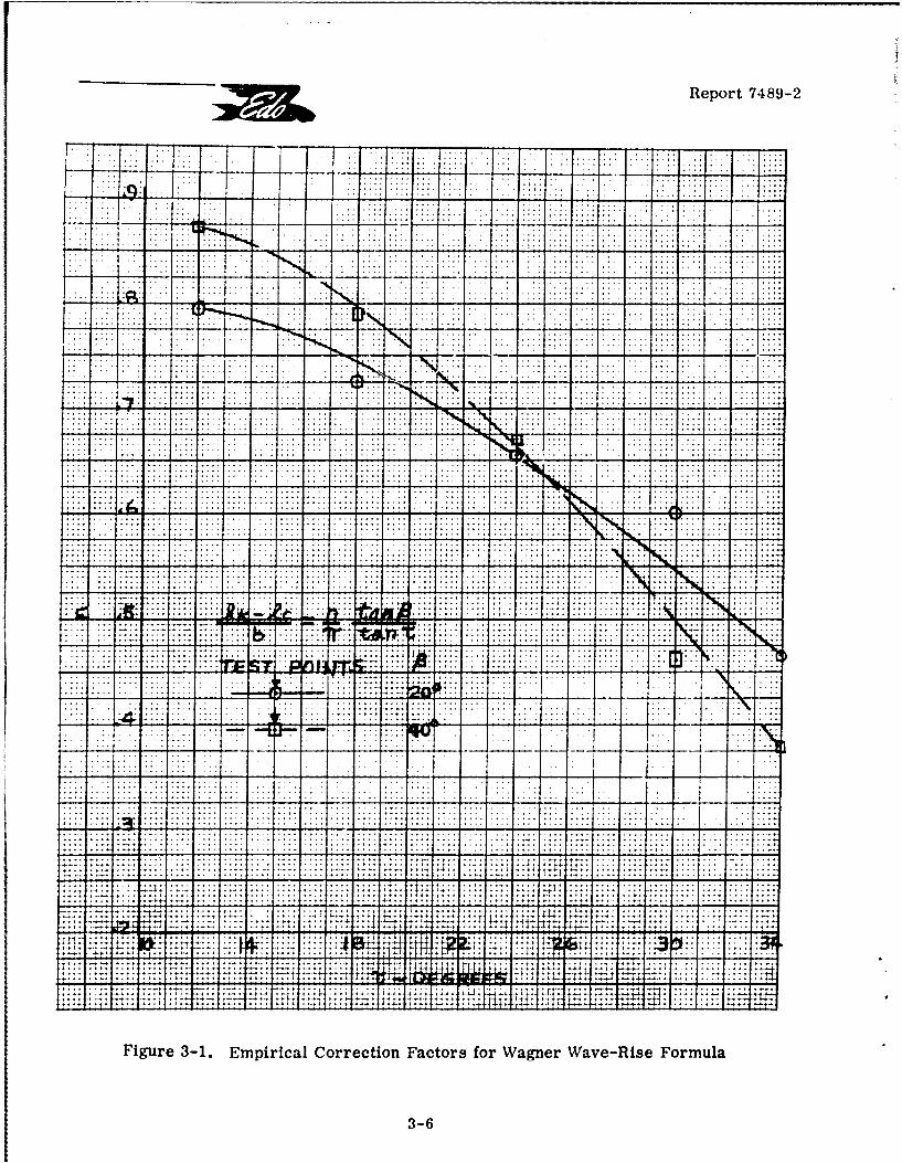
However, as shown in Figure 18, Reference 3-1, the experimental values of(1k - I c)/b exhibit a complex dependence of this quantity on P and r and, furthermore,
they are also dependent on I /b. To simplify the application of Shuford's formulas, them
experimental values of (Ik - Ic)/b shown in Figure 18, Reference 3-1, can be (somewhat
crudely) approximated, if desired, by the following expressions:
(Ik -1)/b = .085 (/30°)
Ik c c n tan/ 3
b ?r tan r
where, as shown here in Figure 3-1, the correction factor, n, depends only on )9 and r
It is obvious that, for hydro-skis, a precise knowledge of the wetted chine length,Ic, is only required for low values of 1k/b, for example, when planing very close to getaway
speed or during the very initial stages of an impact process. Further, as will be demon-strated later in this report, most current practical interest is in hydro-skis of very highbeam loadings which are not necessarily dependent on the addition of deadrise for theirimpact load alleviation capability. Finally, noting that, so far as can be established fromavailable data, the correction factor, n, is less than one, it appears that a convenient
approximation for the wave rise effect is to assume "full wave rise, " i. e.
3-5
Report 7489-2
L . .1 ......
... .. .. .... . . ...I. . . ... .
... .... ... ..
...K .. ... .... .. .....
. ... .. . .. ... .. .. . .. ... .. . .. . .. .. .. . ..
.. ....
.. -.. ..
.. . .. ..
744
q:: :: h
. ... ... .... :i .... .f .
.1I H: _ r
Figure 3-1. Empirical Correction Factors for Wagner Wave-Rise Formula
3-6
j iReport 7489-2
3 so that
Any substantial inaccuracy inherent in this approximation will then be limited to very lowtrim angles and/or very low wetted keel lengths.
This approximation has been used throughout the remainder of this report.
3.3 SUBMERGED CONDITIONS
N 3.3.1 Fully Wetted Condition
I 3.3.1.1 Lift Characteristics
A semi-empirical expression for the lift coefficient of a fully-wetted submergedski has-been derived and validated in Reference 3-2. This expression, valid only for flat(uncambered) skis with zero-deadrise and rectangular planform, is:
S=K3 27rK2-A + .8- .TCsinT SI CL= 31~KA .
221where A = b /S, and K2 and K3 are certain theoretical correction factors. K2
depends on the draft and trim, while K depends on draft, trim, and aspect ratio..3
As most practical skis have A < 1/3, little accuracy is lost by neglecting the-term, (A/10), so that:
2 I K 2A 8.2C L = K3 (1 +A) +2K2 T+-3 sin r cos
The function, K., is defined as:
K 4f2 + 8f sin r+ 1S4f 2 +8f sinr+2
where f = d [ l+ sin 05)]4 (d .0
and d is the depth of the ski (flat plate) leading edge expressed as a fraction of the skilength.
1 3-7
°F7
r Report 7489-2
As defined in Reference 3-2, K is a complex function of f, r , and A. However,
for A • 1/4, the values of K3 are nearly independent of A and, further, for r < 200,
[are nearly independent of r . Hence, in these parameter ranges, K3 depends only on f
and, for 0 < f <1, can be approximated closely by the simple expression:
K3 =1- .5e-7.28f?3
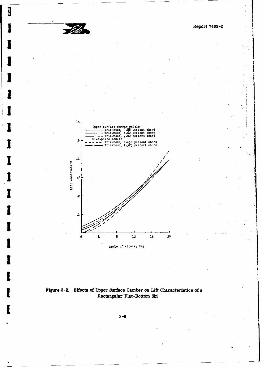
The preceding lift coefficient formula must be modified for application to morecomplex ski shapes. Of the more signmicnmt ski geometric parameters affecting ski lift,longitudinal camber has been the only parare'er systematically investigated (Reference3-3). This investigation covered the p.Iects of tdding upper surface camber to a flat plateof A = 1/4 on its hydrodynamic characteristics a% a single depth/chord ratio-of .42. Theeffects of upper surface camber on the ski lift cu .ve at this depth are shown here in Figure3-2. It is seen that, at the low angles of attack (.Tim angles), the upper surface camber
produces the well-known effect of increasing the lift coefficient through a shift of the zero-lift angle but, unlike the case for high aspect ratio surfaces, this effect becomes reduced
at higher trims.
Such geometric features as curved planforms and blunt (transom-type) trailingSedges may be expected to have a substantial effect on ski fully-wetted hydrodynamic
characteristics. Experimental data for a single ski embodying these two features are given inReference 3-4 which also compares these values with those for a flat plate.
S.... A certain amount of experimental data is available for the drag and pitchingmoment characteristics of fully-wetted submerged skis but, until now, no attempts havebeen made to correlate these values through suitable empirical formulas. As a principalpurpose of this report is the quantitative correlation of available ski data, such analyseswere made for a fiat plate ski with rectangular planform and an aspect ratio of 1/4, asfollows.
C 3.3.1.2 Drag Characteristics
If the fully-wetted lift coefficient is written as:
SL =C +CL2
27r K K Awhere C 23
Li (1+A) +2K 2
r 2and CL2 = (8/3)K3 sin r cost
L2 3
3-8
H 3 Report 7489-2
III
.6 -pper-surface-carmber modelsT hper3ufcness 88 percentchr
T 9: 60percent chordThickness, 7.02 percent chord
.• Flat-plate models
. . . . Thickness, 2.650 percent chord
SThlcmess, 1.325 percentc~r
X .4 /
-3I *2 / / /
1 .2
0 4 8 12 16 20
IAngle of ittack, dog
II
Figure 3-2. Effects of Upper Surface Camber on Lift Characteristics of aRectangular Flat-Bottom Ski
3-9
[ •Report 7489-2
C Li may be considered as a "circulation lift coefficient" and C L2 as a "cross-flow lift
coefficient".
F On the basis, it is logical to assume that the ski drag coefficient has the form:
CD = CDO + (CLl 2/7TrA ) + CL2 tan r
where: CD profile drag coefficient (section value, primarily dependentrDO on ski thickness, ratio and Reynolds Number).
ifi i /7rA l = induced drag coefficient, where '/ is the "Oswald
I> efficiency factor", which may be depth dependent.
CL2 tan r= cross-flow contribution to ski drag.
As demonstrated in Appendix A of this report, analysis of the available test data
for the 1/4. aspect ratio ski yielded a very reasonable value of C and an equally
[reasonable curve for i as a function of depth-chord ratio. The resulting exceptionally
close correlation of the experimental data is also included in Appendix A.
[ The effects of the ski drag characteristics of adding upper surface camber to aflat plate ski are described in Reference 3-3, according to which the maximum lift-dragratio decreased with increasing camber and, also, moved to higher angles of attack. Thereduction in the maximum L/D resulted both from the increased profile drag associatedwith the thicker (more cambered) skis and also from the reduced lift curve slopes.
at Also, according to the data reported in Reference 3-4, the lift-drag ratio of anactual hydro-ski incorporating a non-rectangular planform, blunt transom, bow rise, and
[upper surface camber was lower than that of a flat plate of comparable aspect ratio.
3.3.1.3 Pitching Moment Characteristics
[ The pitching moment characteristics or, rather, their equivalent, the center ofpressure values for the flat plate, rectangular ski of aspect ratio, 1/4, given in Figure12 (b), Reference 3-5, were correlated by means of the semi-empirical formula:
C C
c.p.(% chord, forward of T. E.) = (a b + 0.50 L2
CLi L CL
where "a" and 'bo vary with depth-chord ratio. Figure A-8 of Appendix A shows the" beat fit" values of "a" and "b" obtained in the correlation process. As shown in Figures
3-10
J Report 7489-2
IA-9 through A-12 of Appendix A, the correlations obtained in this manner were excellent.
i 3.3.2 Ventilated Condition
3.3.2.1 Ventilation Processes and Boundaries
J The relatively high speed associated with a hydro-ski operating below the watersurface will usually result in ventilated flow. In this flow regime, an aerated cavity ex-tends aft from the unwetted upper surface of the hydro-ski. Although the mechanism ofventilation inception and development are known from model tests and may be physicallydescribed, an analytical treatment is not yet available to predict its occurrence under full-scale conditions. The following discussion will briefly describe the phenomena observedin model tests during the ventilation process. Pertinent experimental data are also in-cluded for guidance in assuming the existence of ventilated flow when performing hydro-dynamic calculations.
For the onset of ventilation, it is necessary that an air path be developed or pro-vided to the upper surface of the hydro-ski. Such a path may be readily induced by theblunt base of a surface-piercing hydro-ski support strut.
If the depth of the ventilated pocket behind a strut extends down to the hydro-ski,it is likely that ventilated flow about the hydro-ski will be established. The depth of theventilation pocket behind a base-vented strut may be estimated from the expression,
h = V2/10.25g (p. 10-15, Reference 3-6)
I The other mechanism of development of ventilated flow about a hydro-ski is bymeans of the air travelling along the path provided by the trailing vortices, when speed,angle of attack, and free surface proximity reach certain value combinations. At highangles of attack, in the lower speed range, the separated flow from the leading edge mayreattach on the upper surface of the ski. The occ'4rrence of this "partial bubble" type ven-tilation causes little or no change in lift. However, when the speed or angle of attack isincreased so that the reattachment point reaches the trailing edge, there is an abrupt lossin lift. When ventilation occurs at the lower range of angles of attacks, the separated flowfrom the leading edge does not reattach, and there is also a sudden drop in lift.
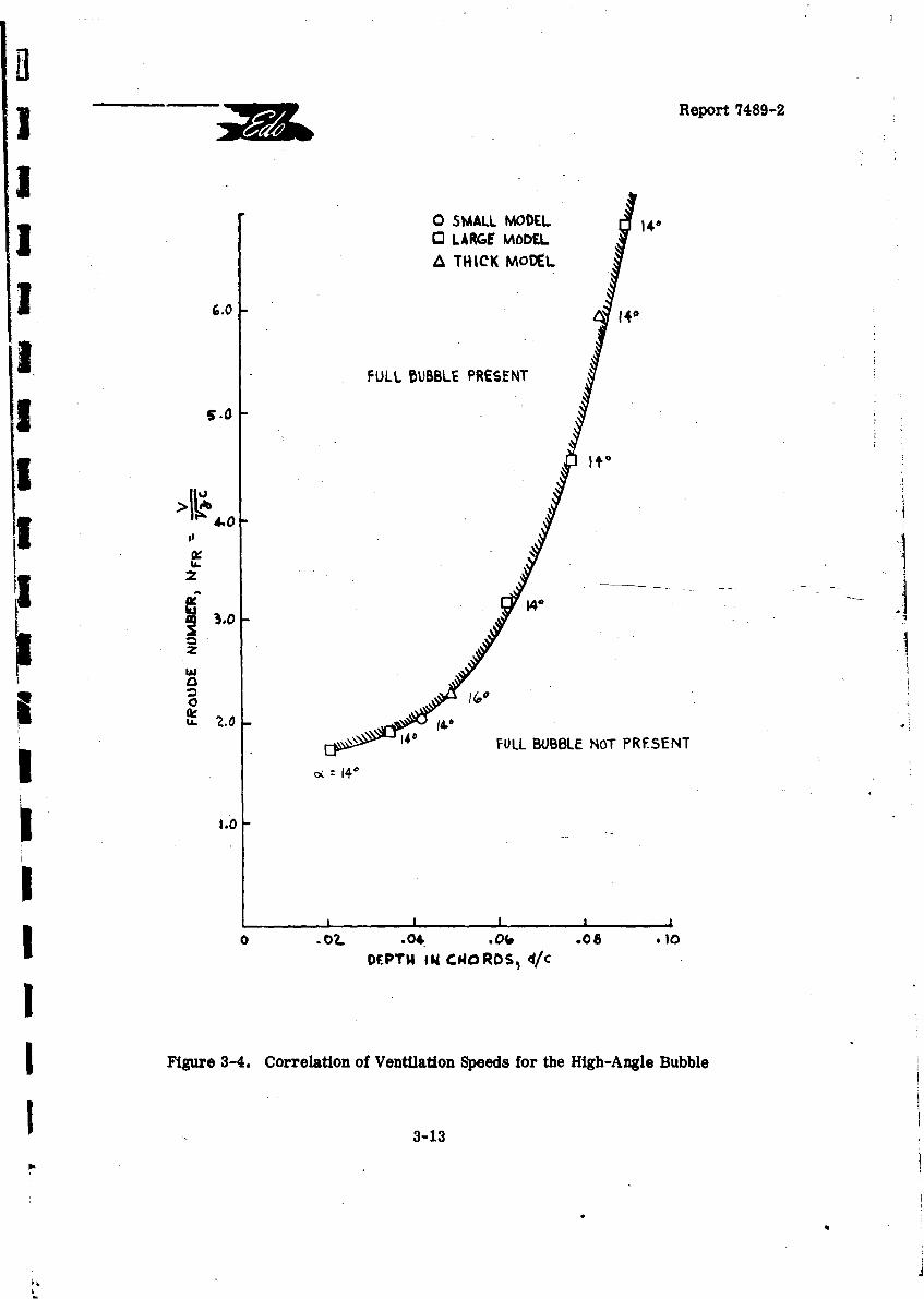
I The available correlations on the inception of vortex ventilation are presented here
in Figures 3-3 through 3-5. Although limited, the information can provide semi-quantitativeI guidance for predicting the conditions required for complete ventilation. For example, the
data presented in Figure 3-5 are for specific small-scale models at particular depths ofsubmersion and utilize dimensional speed values.
Therefore, as the required scaling laws are presently unknown, it is necessary toS rely on judgment in applying this information for predicting the nature of the flow about aprototype (full-scale) hydro-ski.
I3-11
I Report 7489-2[
.i,50 .455 03
NACA 661-012 section
[ P 2:1 ellipse-
T Side view
Top view
IFrant view
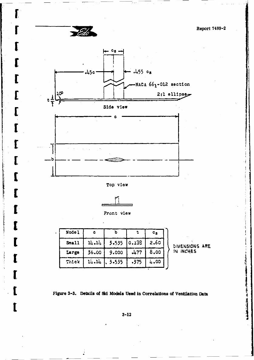
S|model I b . .. t ca
lia 14.14 3.535 o0.1.3 2.6o DIMENSIONS ARE
Large :36.00 9.000 .477 8.00 IN INdIJES
Figur 3-3. Details Of Ski Models Used in Correlations of Ventkiaton Dafta
- Report 7489-2
0 SMALL MODEL 1401 0'l LARGE MiODELA THICK MODEL
( .0 140
FULL BUBBLE PRESENT
I i'.0
j 14.&
S14° 14''• 14,0 FULL BUBBLE NOT PRESENT
I o,.,, 14°
ISI I I ,
.0 . .04 .08 ,10DEPTh 1ik CuORDS, 4/c
IFigure 3-4. Correlation of Ventilation Speeds for the High-Angle Bubble
3-13
Report 7489-2
20
U6 Large modelmThall model
[ -1SFu Pull bubble not present
0
C I I ,I I I ,lI Io100 200 300 400 500 60o 700
Speed parameter. v &
(a) Depth of submersion d, CD.) inch.
20-
C "Small modelrge model1 .JThick model
FPull bubble present
o
I Full bubble not present
S
Cf1o00 200 300 400 500 600 700
Speed parametter,
(b) Depth of submersion d, 1.0 inch.
[Figure 3-5. Correlation of Ventjition Speeds for the Low-Angle BOW
S3-14
Report 7489-2
3.3.2. 2 Flat Rectangular Skis
In Reference 3-7, Johnson has devised an essentially theoretical method forestimating the lift, drag, and center of pressure values for supercavitating hydrofoils offinite aspect. ratio operating near the free water surface. Further, he has shown that thesetheoretical values agree extremely well with the limited available test data for hydrofoilaspect ratios greater than or equal to 1.
As the only technical difference between supercavitating and ventilated flow con-ditions is in the absolute value of the cavity pressure (i. e., water vapor pressure vs.atmospheric pressure), it appears that Johnson's theory should also be directly applicableto the ventilated flow case.
Whereas the Johnson analysis covers the more general case of longitudinallycurved bottoms (bottom cambered hydrofoils), attention in the following will ',e restrictedS to the case of straight bottoms which is more representative of most practical hydro-skishapes.
As presented in Reference 3-7, Johnson's analysis is awkward for practical cal-culation as it involves two separate iteration processes, one for lift coefficients and theother for drag and moment coefficients. To-eliminate this difficulty and, simultaneously,to make this analysis more amenable for the later calculation of hydro-ski seaplane dyna-mics, Johnson' s analysis has been converted into a digital computer program. Significantdetails of this conversion ar givon in Appendix B of this revort. Incorporated in this pro-gram are certain purely empirical modifications used to provide closer agreement of cal-eulated and experimental characteristics, as explained in Appendix B. The almost perfectagreemeLt between the final calculated and the experimental characteristics for a ventilatedski of aspect ratio 1/4, is shown in Figures B-1, B-2, and B-3 of Appendix B.
3.3.2.3 Other Ski Geometries
References 3-3 and 3-4 present the results of steady-state tank tests of twohydro-ski models, both with uipper surface camber. One of these had a rectangular plan-form and a flat bottom (Model A) while the other had a non-rectangular planform and adeadrise-type of bottom (Model B). In both cases, no ventilation was observed anywhereinside the ranges of the test parameters:
ModelA: o0<r <20%, 0O<d/c< .42, 0<V <30fps
ModelB: 0* T <20', 0<d/c <.39, O<V<85fps
I It appears that the absence of ventilation for these models can be attributed di-rectly to the presence of the upper surface camber (airfoil-like profile) which tends toI prevent flow separation at the ski leading edge.
3-15
F FReport 7489-2
3.3.3 Cavitated Codition
I? 3.3.3.1 Cavitation Processes and B.u•-'ariles- , -.
As a hydro-sld seaplane accelerates from rest, the •ydro-sld shape and attitude-.will induce pressure reducti(ka ovgr a region of its surface. With increasing speed, and-depending upon the spec "ic hydro-ski installation, cavitation may occur. Thil condition ispossible if, at this same speed, the hydro-ski is submerged and no ventilation develops,. S~either by the action of tip vortices or a strut-provided air path to the- free water. surfa ce. ""
The cavitation number, based on local pressure, p, is defined as:.--,
Tr= p por s po da/2pv d a a2wt c
i where p o = free stream static pressure (varies with depth)
p = local pressure at any point on the hydro-ski surface
Cavitation begins when the local pressure value at some point reduces to PV
the vapor pressure of water. The incipient cavitation number is, therefore:- 9a.=( pco-p )/(P/2)V
1v
The minimum pressure coefficient on a-section is defined as:
2C M
• [. Cp min (min - c)f(p/2)CV
' [or, -C p Pc-Pi) /2()/2 V2pmin mi
t the inception of cavitation, -
P m j.i Pv-" +p. p
and, therefore: mri= -Cp (2 C R- P/2 V2
The minimum pressure coefficient is dependent solely on the shape of the body -and independent of its size, while the model and full-scale values of the free stream staticpressure, p., , are close to each other under towing tank test and prototype conditions.Therefore, the cavitation inception speeds observed in the towing tank tests of hydro-sidmodels are approximatoly equivalent to the full-scale cavitation inception speeds. Con-sequently, the effects of cavitation development observed in towing tank tests of hydro-ski
t13-16
SMReport 7489-2
seaplane configurations conducted in accordance with Froude scaling laws, will begin at aproportionately lower speed on the prototype aircraft.
Figure 3-6, taken from Reference 3-4, presents a comparison of towing tanktests results on cavitation boundaries for a flat plate and hydro-ski model. In both models,cavitation inception occurs at the leading edge upper surface. It is therefore evident that,unless prevented by ventilation effects, cavitation will occur on similar prototype hydro-skissomewheres inside their expected range of operational trims and speeds.
Reference 3-8 presents experimental data on the hydrodynamic characteristicsof an aspect ratio 1/4, flat plate at several depths of submersion. From Figure 3-7, re-produced from Reference 3-8, the effects of cavitation are seen to be detriments! to hydro-ski performance. Since these effects ocrnr in -a glJuai manner, no catastrophic motionsare induced. However, these same curves also illustrate the sudden change in the hydro-dynamic force with the occurrence of ventilation, which developed in these tests by airentering the trailing vortices.
It is also noted that, at the higher trims, the ventilation tendency increases withproximity to the water surface. This attitude and location is representative of the situationthat exists at the time of ski unporting during a seaplane take-off. In order to avoid un-stable aircraft behavior caused by the sudden loss in hydro-ski lift through ventilation as itapproaches the water surface, hydro-ski ventilation can be induced at deeper submergenceby utilizating a base-vented strut.
As has been made clear in Section 2 of this report, one of the most basic factorsinvolved in the selection of hydro-ski dimensions is the lift developed just as the leadingedge reaches the water surface during the take-off process (unporting condition). The flowthen is definitely ventilated and the planing lift equations are used to establish the requiredhydro-ski area.
As the planing lift of a fully wetted lower surface hydro-ski is always less thanits lift when fully wetted on both surfaces or under cavitating conditions, the hydrodynamiccharacteristics under cavitated flow conditions are of secondary concern in the basic designof a hydro-sid. However, an awareness of hydro-ski cavitation phenomena is important inappreciating possible performance discrepancies between model and prototypecharacteristics.
3-17
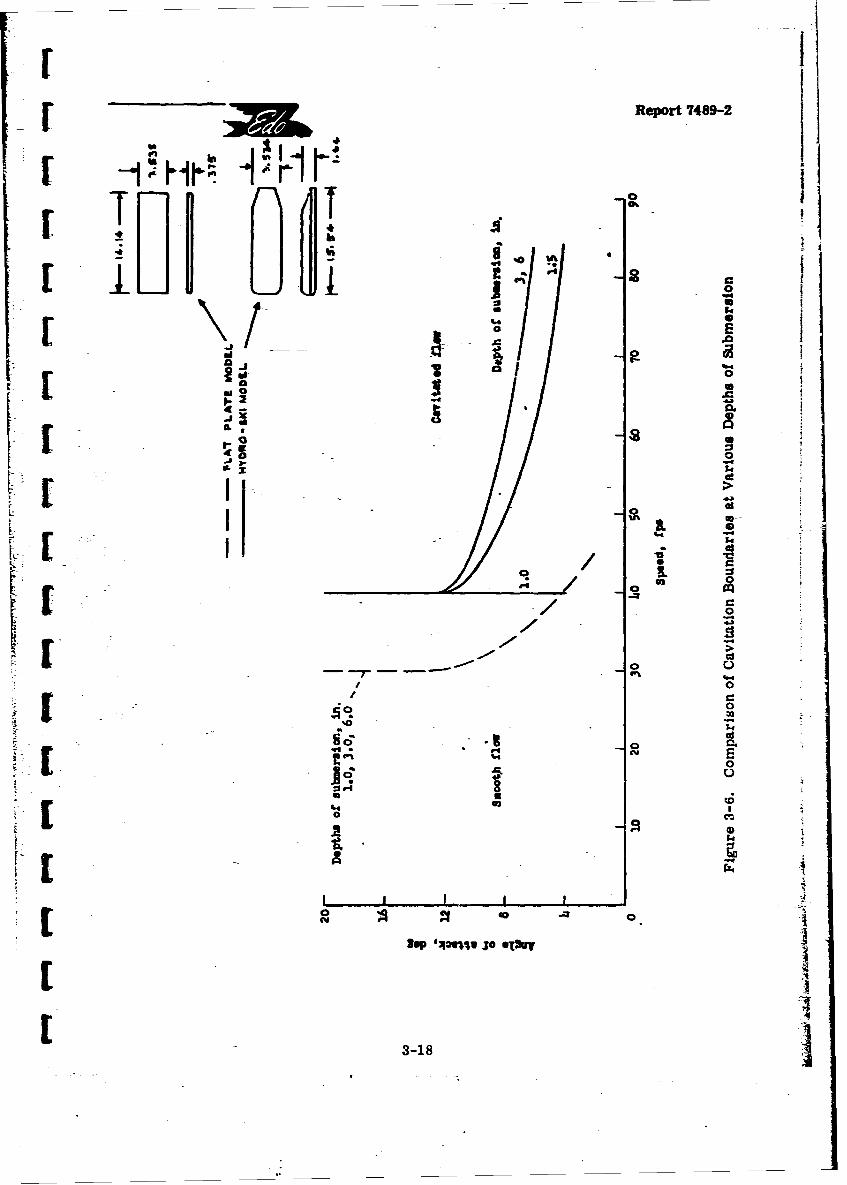
-u IReor 48-
ml'E9
_.2
dlIL
*2 I_
U0
t0 A m
E
400I 14[/
318o 6.
3-18-
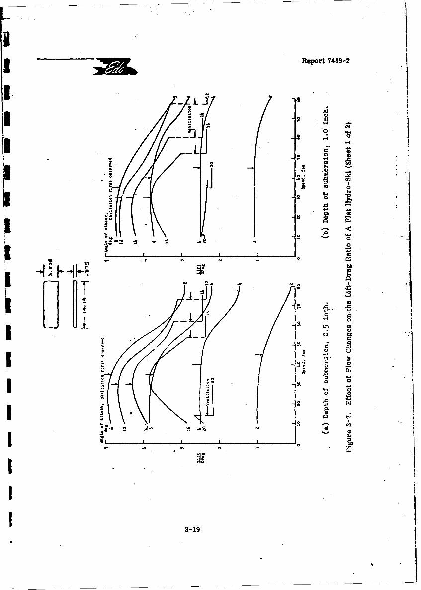
3 Report 7489-2
• 6-.. .
- o-. e
- a0 V~.... . .. •
54
* 0* I i-
• o-' o
•- - ,4.)
IA ~ be
0 !m0
4- -: .
0 P440
c;*II44.
3-19
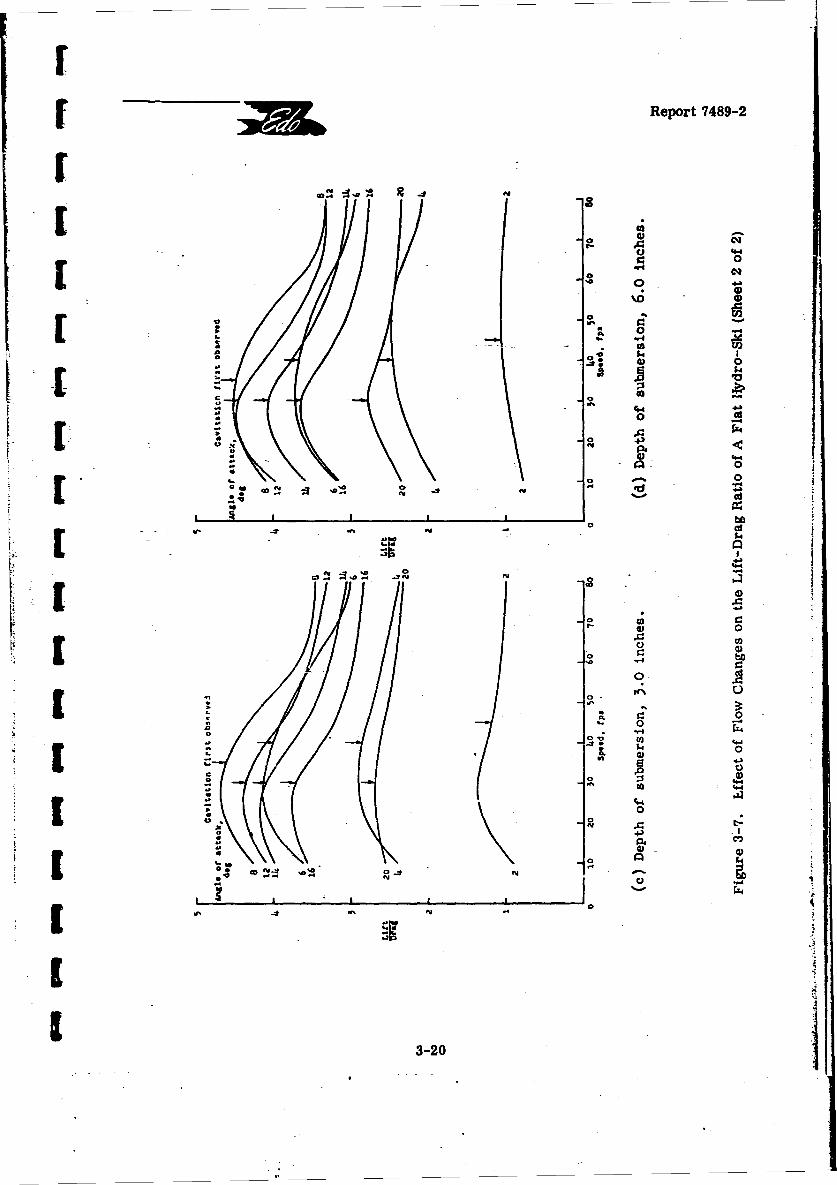
r[ Report 7489-2
f3
400
] ° o[ 0 e
0oc
"00
co o"a ..
0 *a
-U 44)
[ S,
-0.
IL 0
r44
coo
3-20
Report 7489-2
REFERENCES
3-1 NACA TN 3939: "A Theoretical and Experimental Study of Planing SurfacesIncluding Effects of Cross Section and Planform," by C. L. Shuford, Jr.,March 1957.
3-2. NACA TN 4168: "A Method for Calculation of Hydrodynamic Lift for Submergedand Planing Rectangular Lifting Surfaces," by K. L. Wadlin and K. W. Christopher,January 1958.
3-3 NACA TN D-166: "A Hydrodynamic Investigation of the Effect of Adding Upper-Surface Camber to a Submerged Flat Plate," by V. L. Vaughan, Jr.,November 1959.
3-4 NACA TN D-51: "The Hydrodynamic Characteristics of a Submerged LiftingSurface Having a Shape Suitable for Hydro-Ski Application," by V. L. Vaughan,Jr., October 1959.
3-5 NACA TN 3079: "The Hydrodynamic Char-acteristics of Modified RectangularFlat Plates Having Aspect Ratios of 1.00 and 0.25 and Operating Near a FreeWater Surface, " by K. L. Wadlin, J. A. Ramsen, and V. L. Vaughan, Jr.,March 1954.
3-6 "Fluid Dynamic Drag, " by S. F. Hoerner, Published by the Author, 1965.
3-7 NACA RM L57116: "Theoretical and Experimental Investigation of ArbitraryAspect Ratio, Supercavitating Hydrofoils Operating Near the Free WaterSurface," by V. E. Johnson, Jr., 12 December 1957.
3-8 NACA TN 3908: "Hydrodynamic Characteristics Over a Range of Speeds Up to80 Feet per Second of a Rectangular Modified Flat Plate Having an Aspect Ratioof 0.25 and Operating at Several Depths of Submersion," by V. L. Vaughan, Jr.and J. A. Ramsen, April 1957.
3-21
w iReport 7489-2
4. STRUT RESISTANCE CHARACTERISTICS
4.1 FLOW CHARACTERISTICS
Just as the hydrodynamic characteristics of a hydro-ski are dependent upon the
specific type of flow developed (e.g., fully-wetted, cavitated, or ventilated), the hydro-dynamic force characteristics of hydro-ski support struts are related to the strut flowregime. Therefore, to calculate the resistance of a strut, it is first necessary to detern-iilethe nature of the strut flow.
At very low speeds, of course, all surface-piercing struts will be fully wetted,independent of the particular cross section. As speed is increased, the pressure dropI iassociated with the flow about the strut section will cause a depression at the strut-levelwater line intersection. For most hydro-ski seaplane configurations, however, it is likely
r that, in this relatively low speed range, with the strut attached to the hull bottom and thekeel still below the level water line, fully-wetted flow will exist. Consequently, the effectof moderate water surface depressions is usually of little or no interest in the drag estima-[ rtion of hydro-ski support struts.
When the aircraft reaches the speed at which the strut-hull intersection clearsthe water surface, the flow about the strut can suddenly change from fully wetted to fullyventilated, as the hull bottom no longer blocks the development of an air passage down thestrut. It is evident that this situation is particularly applicable to base-vented strut sec-tions, although it is also possible that, prior to hull bottom emergence, such sections mayalready have a cavitation bubble extending aft of the blunt trailing edge.
It can usually be assumed that, because of the relatively high Froude numbers
(based on strut depth) prevailing at the hull bottom clearance speed, a surface-piercinghydro-ski support strut will be completely ventilated. As the ventilated cavity staticpressure is very close to atmospheric, the pressure acting on the aft portion of the strutC is greater than that for either the fully wetted or cavitated conditions, so that the drag co-efficient becomes markedly reduced. However, because of the hull bottom clearance, thesurface-piercing configuration now introduces an additional drag component due to spraygeneration. This spray drag is usually consider.bly lower in magnitude than the reductionin base drag resulting from the occurrence of ventilation. Therefore, the net effect ofventilating a strut is to lower its resistance as compared with either the fully wetted orcavitated values. Thus, in addition to enhancing ventilation of the hydro-ski upper surfacewhich precludes ski lift force breaks during unporting, this feature furnishes anotherreason for utilizing a base-vented strut sectioz.
In-general, the strut drag coefficient is dependent on various hydrodynamic[ parameters such as Reynolds number, Froude number, and cavitation number. As indicated
4-1
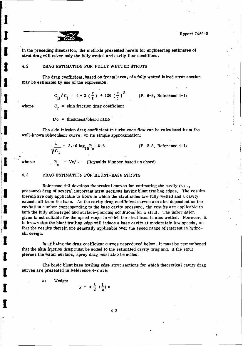
I
oReport 7489-2
in the preceding discussion, the methods presented herein for engineering estimates ofstrut drag will cover only the fully wetted and cavity flow conditions.
I 4.2 DRAG ESTIMATION FOR FULLY WETTED STRUTS
The drag coefficient, based on frontal area, of a fully wetted faired strut sectionSmay be estimated by use of the expression:
fc 11)3
S/C 4+2 t + 120(-) (P. 6-9, Reference 4-1)
where Cf = skin friction drag coefficient
t/c = thickness/chord ratio
The skin friction drag coefficient in turbulence flow can be calculated from thewell-known Schoenherr curve, or its simple approximation:
1 - 3.46 log1 0 R c-5.6 (P. 2-5, Reference 4-1)
where: R = Vc/ (Reynolds Number based on chord)
4.3 DRAG ESTIMATION FOR BLUNT-BASE STRUTS
Reference 4-2 develops theoretical curves for estimating the cavity (i. e.,pressure) drag of several important strut sections having blunt trailing edges. The results
S therein are only applicable to flows in which the strut sides are fully wetted and a cavityextends aft from the base. As the cavity drag coefficient curves are also dependent on thecavitation number corresponding to the base cavity pressure, the results are applicable toboth the fully submerged and surface-piercing conditions for a strut. The informationgiven is not suitable for the speed range in which the strut base is also wetted. However, itis known that the blunt trailing edge will induce a base cavity at moderately low speeds, so
S-- that the results therein are generally applicable over the speed range of interest in hydro-ski design.
- In utilizing the drag coefficient curves reproduced below, it must be rememberedthat the skin friction drag must be added to the estimated cavity drag and, if the strutf pierces the water surface, spray drag must also be added.
The basic blunt base trailing edge strut sections for which theoretical cavity dragcurves are presented in Reference 4-2 are:
a) Wedge: 1 ty --- 2,. ( x
4-2
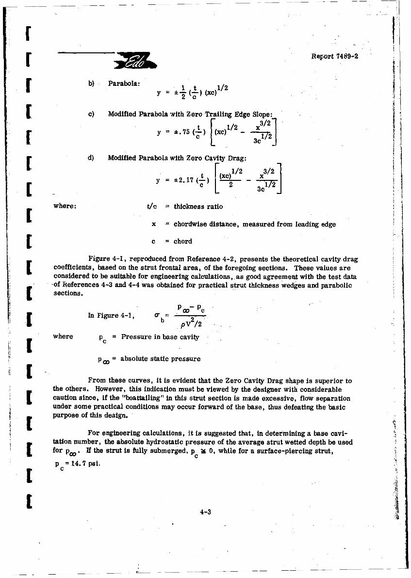
r Report 7489-2
Sb) Parabola:Y 21
Sc) Modified Parabola with Zero Trailing Edge Slope:-
1/2 x3/75( xc) _- _ I
d) Modified Parabola with Zero Cavity Drag:
t x) / 3/211-2.17(-
- ___
where: t/c = thickness ratio
x = chordwise distance, measured from leading edge
Sc chord
Figure 4-1, reproduced from Reference 4-2, presents the theoretical cavity drag[coefficients, based on the strut frontal area, of the foregoing sections. These values areconsidered to be suitable for engineering calculations, as good agreement with the test data
-of References 4-3 and 4-4 was obtained for practical strut thickness wedges and parabolicJ[sections.
- Po-Pc
In Figure 4-1, ab 2
PV /2 -
where PC = Pressure in base cavity
OP = absolute static pressure
From these curves, it is evident that the Zero Cavity Drag shape is superior to* p the others. However, this indication must be viewed by the designer with considerable
St caution since, if the "boattailing" in this strut section is made excessive, flow separation"under some practical conditions may occur forward of the base, thus defeating the basicpurpose of this design.
For engineering calculations, it is suggested that, in determining a base cavi-tation number, the absolute hydrostatic pressure of the average strut wetted depth be usedfor poo. If the strut is fully submerged, p Ct 0, while for a surface-piercing strut,
=c P 14.7 psi.
4-3
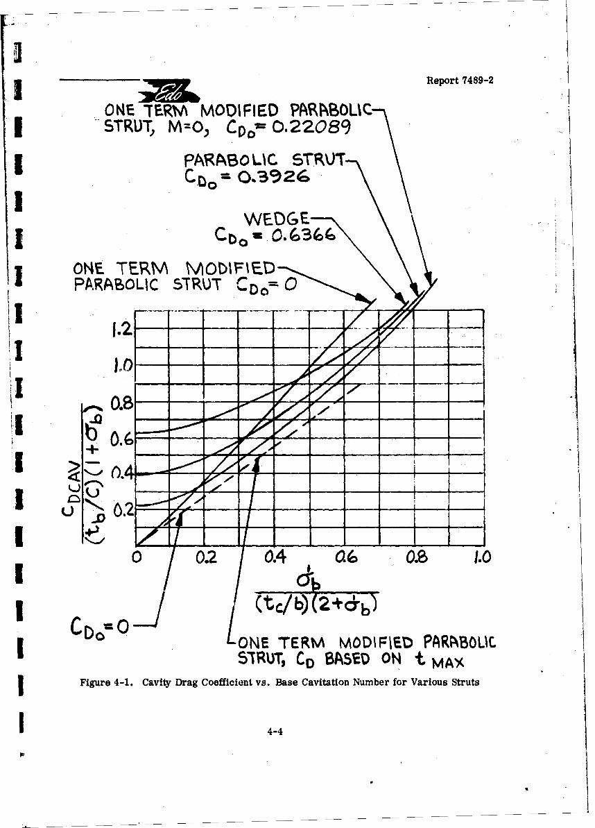
2
SReport 7489-2
ONE "TERW• MODIFIED PAIIBOLISISTRUT, M=O, C40m 0.22089
I PAgASOL C STRUCto- 0.3926
WEDGE| Lbo -O'3 (loc
ONE TERM MAODIFIEDPARABOLIC STRUT rD= 0
0 a6 Z
!3 u , 02I/),
I . e 1.
I (tC/b) (2+(b)IDO ONE TERM MODIFIEW PARABOLI.
SXRUT, C0 BASSD ON t MAXFigure 4-1. Cavity Drag Coefficient vs. Base Cavitation Number for Various Struts
1 4-4
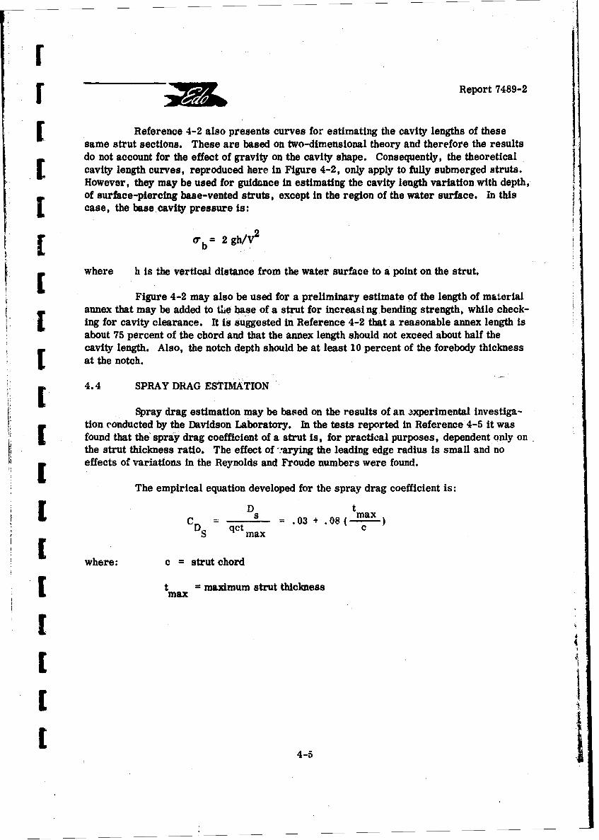
I "Report 7489-2
Reference 4-2 also presents curves for estimating the cavity lengths of thesesame strut sections. These are based on two-dimensional theory and therefore the resultsdo not account for the effect of gravity on the cavity shape. Consequently, the theoreticalcavity length curves, reproduced here in Figure 4-2, only apply to fully submerged struts.However, they may be used for guidance in estimating the cavity length variation with depth,of surface-piercing base-vented struts, except in the region of the water surface. in this
L [case, the base cavity pressure is:
2 2gh/V 2b
[ where h is the vertical distance from the water surface to a point on the strut.
Figure 4-2 may also be used for a preliminary estimate of the length of materialannex that may be added to the base of a strut for increasing bending strength, while check-ing for cavity clearance. It is suggested in Reference 4-2 that a reasonable annex length isabout 75 percent of the chord and that the annex length should not exceed about half thecavity length. Also, the notch depth should be at least 10 percent of the forebody thicknessat the notch.
4.4 SPRAY DRAG ESTIMATION
Spray drag estimation may be based on the results of an 3xperimental investiga-[i tion conducted by the Davidson Laboratory. In the tests reported in Reference 4-5 it wasfound that the spray drag coefficient of a strut is, for practical purposes, dependent only onthe strut thickness ratio. The effect of ";arying the leading edge radius is small and no
S [ effects of variations in the Reynolds and Froude numbers were found.
The empirical equation developed for the spray drag coefficient is:
D t
C tDs .03 4 .08( max)
SCD qct axc
where: c = strut chord
Stmax = maximum strut thickness
C 4-5
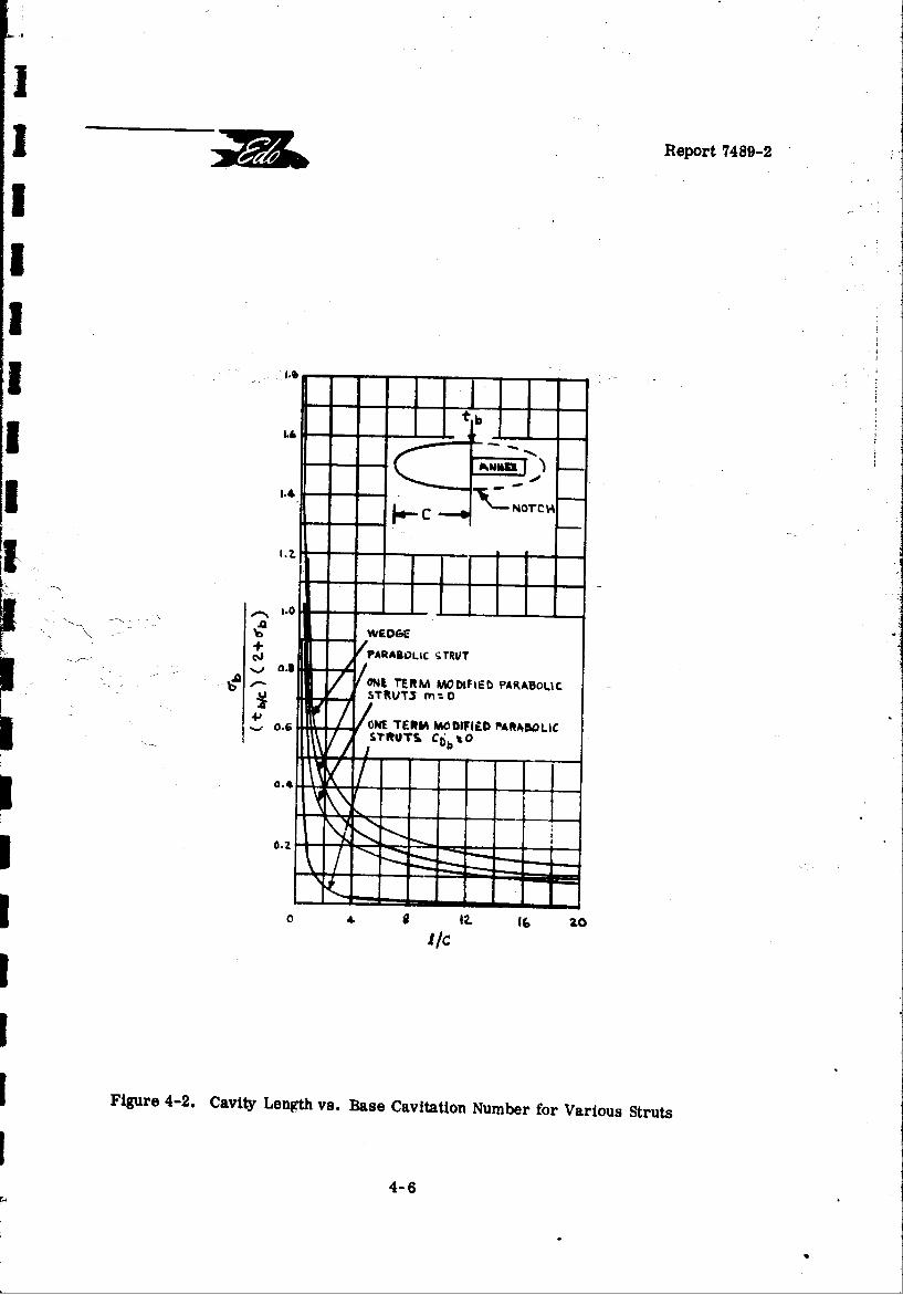
I Report 7489-2
b
3 ',4. NOTCH
". --- : :• i.0 o-
;/On R Mrn.oMFI PARABOLIC
WPE TERM A O DIC D %YRAABOLICI,STQT C6, %O
I0 4 12. 10
Figure 4-2. Cavity Length vs. Base Cavitation Number for Various Struts
4-6
IReport 7489-2
C REFERENCES
S 4-1 "Fluid-Dynamic Drag," by F. Hoerner, Published by the Author, 1965.
S 4-2 Hydronautics, Inc. Technical Report 001-16: "The Design of Base-VentedStruts for High Speed Hydrofoil Systems," by V. E. Johnson Jr. and S. E.Starley, September 1962.
-4-3 California Institute of Technology Hydrodynamics Laboratory Report No. 97-4:"A Wake Model for Free Streamline Flow Theory: Part IL Cavity Flows PastObstacles of Arbitrary Profile," by T. Y. Wu and D. P. Wang, May 1963.
4-4 Aerojet-General Corporation Report No. 2798: "Hydrodynamic Characteristicsof Base-Veuted and Supercavitating Struts for Hydrofoil Ships," by J. Levy,et al., August 1964.
S4-5 Davidson Laboratory Report 1192: "Experimental Study of Spray Drag of SomeSurface-Piercing Struts, "by D. Savitsky and J. P. Breslin, December 1966.
[
[
[[[
[ 4-7
IReport 7489-2
I
5. SINGLE HYDRO-SKI IMPACTS WITH CONSTANT TRIM1 AND FORWARD SPEED
I 5.1 INTRODUCTION
It is obvious that one of the most fundamental aspects of hydro-ski design tech-nology is the ability to predict ski impact loads. As will be emphasized later in this report,it is convenient to distinguish between the ski impact loads which occur while traversing aJ long train of waves such as in rough-water take-offs or taxiing, and those which occur duringlandings.
Unlike the conventional seaplane, where maximum hull landing loads tend to occurlater in the landing process, the maximum landing loads en a hydro-ski tend to occur at thefirst wave impact. This difference is a consequence ci the fact that, because of the smallerloads and the "centralized" ski location, the first w2.ve impact of the hydro-ski seaplanedoes not generate the large pitching moments experienced during the comparable hull im-pacts. Fortunately for the hydro-ski designer, this fact provides him v'ith relatively con-venient methods for the estimation of maximum hydro-ski loads. Thesa are of basic im-portance both in preliminary design, which often involves comparison of different ski ge-ometries (dimensions, deadrise, etc.) and installation geometries (ski incidence, etc.) andin final design where the skd structure and the ski-strut attachment become defined by themaximum ski loads and associated pressure distributions.
Because of its fundamental importance, the subject of ski impact load predictionhas received considerable attention in the past. As explained in Reference 5-1, these pastefforts have been of two different kinds, as follows:
I A) For use in preliminary design, attempts have been made to devise simpleempirical formulas, in terms of fundamental parameters (ski beam loading and deadrise)J and impact parameters (trim and initial flight path angle), for anticipated maximum impactloads in smooth water. The most sophisticated of these formulas is the one given by Mixsonin Reference 5-2.
I This formula, obtained by a regression analysis of test data covering large rangesof all the four parameters, has very substantial accuracy when properly restricted to thesmooth water condition. Unfortunately, just as with the earlier cruder formulas, its utilityis severely limited (if not destroyed) because It fails to distinguish between the maximumloads which occur while the ski Is still planing (ski L. E. above the level water line) and
I those which occur simply because the L. E. has submerged, thus limiting the load build-upprocess. In effect then, the Mixson formula is self-defeating as it requires the designer toobtain auxiliary information on the effect of ski length. As this can only be done by calcula-J tion of impact time histories which also predict the maximum impact loads, the need forMlxson's (or any other) empirical formula becomes superfluous.
55-1
SReport 7489-2
I- A further, closely related defect of the Mixson empirical formula is that it doesnot cover the case of wave impacts which is invariably the case of most practical interest.The problem of wave impacts will be treated in detail below where it will be shown that theconventional treatments of this problem are not only incorrect in principle, but also
rumorically inaccurate.
I 3B) The other approach for prediction ci maximum impact loads is through impacttime-history calculation or, alternately, through suitable mathematical analysis of time-[ histories. As just indicated, these techniques have the virtue that they automatically includedetermination of the variation of ski wetted length during the impact process and, thus, ofthe effect of ski length In limiting maximum loads. The analysis of ski load time historieshas a significant historical precedent in Milwitzky's successful analysis of the same problemSfor chines-dry hull loads (Reference 5-3) where all significant impact quantities were re-
lated directly to a single non-dimensional approach parameter.
i [An analysis of this type has been made by Markey in Reference 5-4. Unfortunately,this analysis shows very poor correlation with experiment for the values of the ski penetra-
S tion (directly related to ski wetted length) at maximum acceleration, as shown clearly inFigure 7 of Reference 5-4. This result, attributed to his inadequate approximation for thevirtual mass, means that any of his conclusions concerning ski wetted length are highlyquestionable. An even more important shortcoming of Markey's results in regard to prac-[ tical ski design problems is that they cannot be exprapolated to the rough-water case by anysimple procedure, as will be clearly demonstrated below.U,
For the foregoing reasons, the problem of single ski impacts is treated herein bypurely numerical calculations, utilizing the "equivalent planing velocity" method. This[ •method, utilized previously, is known to be equivalent, in principle, to the "virtual mass"methodfor beam loadings greater than 1.0 and is considerably simpler to apply as it doesnot involve analytic expressions for virtual mass.
5.2 SMOOTH WATER IMPACTS
5.2.1 Equation of Motion
For constant trim and forward speed, the single equation of motion can be writtenS as:
(Wg)d = W- LA - L
where: W = aircraft gross weight
[g = acceleration of gravity
d = depth of lowest point on ski below level water line
[5-23
JReport 7489-2
j LA = aerodynamic lift
SL H = hydrodynamic (ski) lift
i and where the dots signify lifferentlation with respect to time.
In the "equivaleat planing velocity" method, the ski lift force is calculatedfrom the equation:
L CLH(PVeq /2)S
where: C = ski lift coefficientLH
Sp= mass density of water
Veq = equivalent planing velocity
J S = ski wetted area
The essence of this method lies in the following two assumptions:
A. The instantaneous lift coefficient of the impacting ski is identical with that ofa planing ski having the instantaneous geometry (i. e., trim and wetted length) of the im-
i pacting ski;
B. The equivalent planing velocity, V is the fictitious horizontal velocityeq
whose component normal to the ski kael is equal to the actual instantaneous velocity normalto the keel, i.e.,
V V sinr = V sinr + d costIeq Hor V eq =V H + d cot r
= = VH 1 +(d/VH) cotr]
J where: T = trim angle (constant during impact process).
d - ski draft
55-3 I
Report 7489-2
Using the latter expression, the equation of motion becomes:
(W/g)d =W-LA - CLHPVH' /2)[1+(d/VH)cotr]2S
All of the calculations of this report section use the Shuford formula for the skiplaning lift coefficient, CLH, described in Paragraph 3.2 of this report. However, to
r simplify the calculations with negligible loss of accuracy, the wave rise effect for skis withfinite deadrise has been approximated by assuming "full wave rise", i.e.
'c =Ik'
so that A =b/1k and S = kb
For many purposes, it is convenient to rewrite the equation of motion in[ non-dimensional form. Letting
d = Sb
[ and t = a- (b/VH)
[ where: S = non-dimensional draft
a = non-dimensional time,
the equation of motion becomes:
1 (I+ 81 cot)r 2[-(irC (5-1)C2 ( W--) 2 (sin r )C&o
C2 0VHHere, C = horizontal speed coefficient = VH/VH H/
SLA/W = "Percent wing lift" expressed as a fraction
SCAo = ski beam loading = W/pgb3 3
CVH, LA/W, r , and CAo , are parameters which are considered to be constant during
the history of a particular impact process. The primes indicate differentiation with respectto 8. Also, the derivative, B" , is related to the load factor, n, by the equation:
2A0= n/CvH (5-2)
5-4
"J Report 7489-2
Finally, if the quantity, L A/W, the so-called "percentage wing lift" isdesignated as p, the equation of motion can be written as:
" (1-(p) CLH(l +•'cot )2 8
2, -(Is-np)CA (5-3)C z 2 (sin r) C&oVH
Most previous analytic studies are restricted to the special case where p = 1("100% wing lift" case). The equation then reduces to:I 2-CLH ( + 8' cot•T ) S/2 (sin T ) C& (5-4)
This case is of interest In several different respects. In the first place, it showsclearly that, during an Impact, the hydro-ski acts as a non-linear spring device. Secondly,it is seen that this equation is independent of the speed coefficient and, therefore, particu-larly suited for parametric investigations. Lastly, although no use of this fact is madeherein, this equation can actually be integrated analytically to obtain the "vertical velocity",
8', as a function of 8
5.2.2 Correlation of Test Data
The equation for the "zero wing lift" case (eq. 5-3 with p = 0), was checked bycomparison with available data. Reference 5-5 contains a series of experimental accelera-tion time-histories for smooth water impacts of rectangular skis. The tests included skisof 0* and 300 deadrise, and a ski beam loading range between 20 and 150.
Using eq. 5-3 in conjunction with Shuford's equation for CLH, the corresponding
theoretical time-histories were calculated on a high-speed digital computer. The compari-sons of these theoretical curves with the experimental data are shown in Figures 5-1, 5-2,and 5-3.
It is seen that the theoretical curves correctly duplicate all of the significanttrends of the experimental data and, with but one exception, furnish close approximationsto the measured maximum accelerations and their associated time values. The exceptionalcase, shown in Figure 5-1 (B), is for a flat ski having a beam loading of 20. It may be notedthat the discrepancy is only in the peak acceleration value and not in the times at which thepeak acceleration occurs.
As explained earlier, it is not believed that this discrepancy can be attributed tothe use of the equivalent planing velocity method. Because most current practical interestis limited to the higher loadings (C& 0 >50) for which the agreement is excellent, no furtherinvestigation of this discrepancy has been attempted.
These correlations show that the equivalent planing velocity technique is generallycapable of predicting accurate time histories of highly loaded hydro-skis in smooth water
5-5
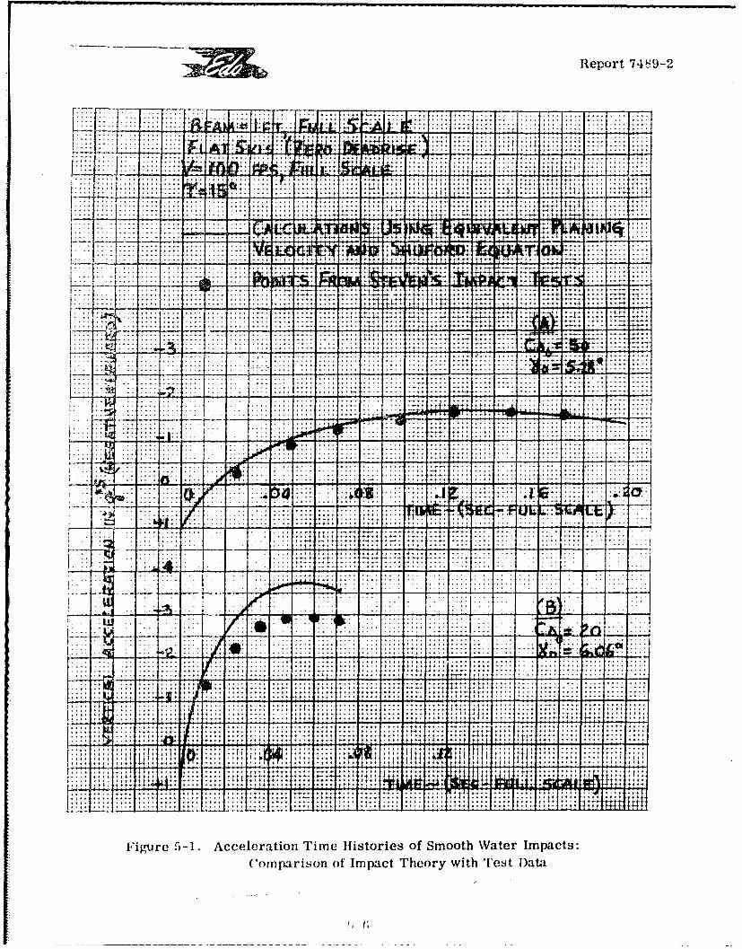
Report 74839-2
.. ......
I . ... . .. .
I.c
K.N...- .. ...
Figure~~~~.. .-.. Aceeai ..m itreso mohWtrIpc.. n~i~o of. I.p.c Thoy.ih.e. ~t
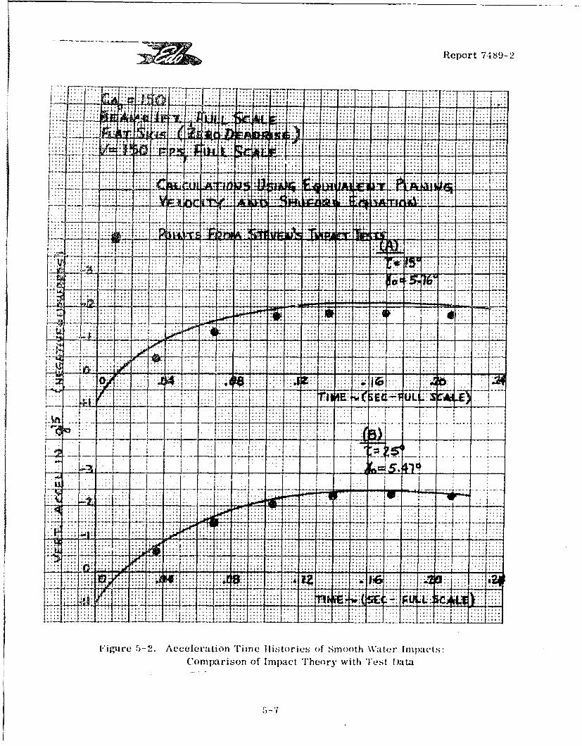
Report 74839-2
FF .. ....
t~ .. .. V2 .... ;2 i : ±. ............ . .. ...
:2:...: ... ....... ... ..-.. .. .. ..
r. m m. . .........-.. . . .. .f...
.. ....... .. .... . .
.: .. .. ... .. .
... .. ... . ..... .. ..
. .. . 4 am
tAl
ii. .. . ... .. ., .... ,.....
77,7
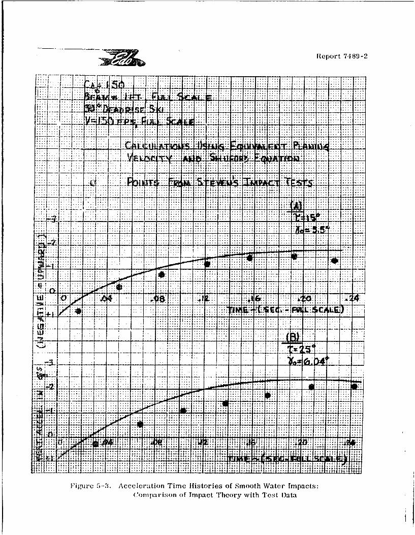
Report 7489-2
.. . .. . . .
-~~ ....- -.. ... ...--
... .... .. . . .. . . . .. .. . . .
. . . .. ... .. ..... :
.... .. .. .
... -. . . . . . .... .
... ... ... . .
... ........
... .... ~ .. .... .... .. -
... ~4. .. . . . . . . . . . ....
____ 1:..- .. . -... .. .
... ~ ... 4.. ..
.. . ... .. ... . .. . ..... ~~~~~~~ ~ . ... .. .. .... .......
I igze aJ. ccelratin Tme Hstores f Smoth ate rm:Tts.. pr'o of .. p. Theor with Te. ......
3 Report 7489-2
I impacts. It will be shown below that, when properly applied, It is equally capable of pre-dicting time histories of rough water impacts. Before proceding with this rough waterimpact correlation, a number of significant parametric studies for the smooth water caseI ~ ~Will first be presented,.!.
5.2.3 Effects of Beam Loading, Ski Length, and Deadrise on Impact Loads
The effects of these parameters on smooth water impact time hiatories were in-vestigated by computing a number of such histories, using the static "00.O% wing lift"I assumption. For this case, the equation of motion can he written as:
28" = 2n C ( (1+8' cotrC 2 LH (sin T ) C&o
The time histories of the computed accelerations and the associated wettedlength values are shown, in non-dimensional form, in Figures 5-4 and 5-5. In thesecharts, the ordinate is the non-dimensional "acceleration coefficient",
3 2n/C, 2I cvHwhere n is the acceleration in "g" units, and the abscissa is the non-dimensional time:
a- = (VH/b) t = g/b CVHt
The dashed lines represent constant values of the non-dimensional wettndlength, I/b. In this form, the charts are independent of CVH and may therefore be used
I directly to vompute actual accelerations for any given CVH value.
Figure 5-4 shows the acceleration time histories for fiat skis having different
beam loading coefficients, C&,, for a typical impact condition ( r= 10°, '.. 10,).
I It clearly illustrates the powerful effect of increasing the ski beam loading or reducing themaximum impact load, It also illustrates the effects of ski length on load limitation for agivenski beam loading. Thus, at the low beam loading (C = =10), practical ski lengths such as
1 /b' 4 will have no effect on the maximum load while at the very high beam loading(Cao= 200), a length of I/b - 4 will reduce (the already low)' maximum load by 30'7.
I Figures 5-5(A) and 5-5(B) show the effects of change in deadrise on the timehistories for two different ski beam loadings. These charts serve to illustrate a very
I significant principle of ski design, i.e., the decreasing importance of deadrise in aids ofhigh beam loading. Thus. for a beam loading of 10, the addition of 30' deadrise to a flat skireduces the acceleration coefficient by .0180 (26'. of the zero deadrise value) whereas for a
II ~5--9
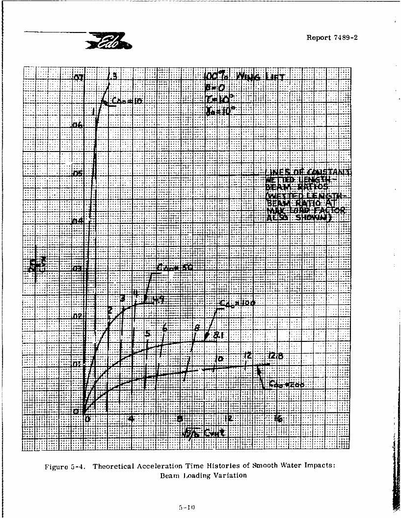
Report 7489-2
... .... -- . . . . ... +
- . 4 - .2-±2:- ~ ~ ~ ~ I - . $ j 4- -. -
.. -. .... ...- - - - - .- , , " . . . . . . .
.................
. ... ... ..- .. . . . 4 ,, , , . , * . . .
...... .. . .. -.. . . . ...... . ... .... .. 4-
. .... .... . .. . . . . . . . . . . .
4,.-'.~~~~~'-T 7'-. +.. . . . . . . . 4 . . . .
. . . . . . . . . . . .. . . . . . . . . . . . . . .
. . . . . . . . . . . . . . . . . .. . . . .'-,4 -. ,,..- - ± . . t .::
r.+... ... .... 1
w:- ...... . . .
.-..............
7: .. ... ....-
4--44-4 44 41W .. .. . ...
4-414
lif -'-4-
:2::
.. ~~.... ... ....IV4 ~
Figure 5-4. Theoretical Acceleration Time Histories of Svmooth Water Impacts:
Beam Loading Variation
5-101
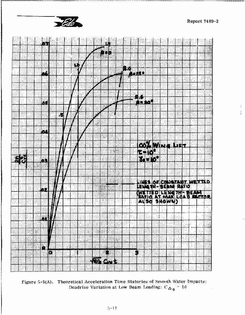
Report 7489-2
.. .... .. ..... ..
.... .... ..
.. .... ....
.6 ; L .... .... .... .... ...
.... . . .;t4
. .... ..... ...
.. .. . . . . .. .. . . .. ... .... .... ...
.. .. .... ........ .... ....... .... ....
. ..... ....
... .... . .. ... .... ...
... ... . .... .. ....
Y ... .... .... ... .... .... ..
.. .... ....
. . . ... .. .. T . ... . . . . ... . .. . .. . . .
. .... . .. .... .... . .. ...... ......... ...
... .... .... . - .1 . .... ... ... ....
.. ... .... ... .. .... .... .... ... .... ....
MJEF7
-NPOI
T--- T .. .... .... ..
.. .... .. .... ... 14 ... .... 1.1 .. ....
... .... .... ...
.... .... ....
14ý
P411.. .... .... ... MutW' LN' -ANUX A"
. . . . .. . .. . . . . .Mik
J U . .. .... .. . .... .. ....
. .. .... .... . . . ....
t t .... .. . .... .... ... .... .... .... .... .... ....
:4:4.. .. .. . .. . . .. . . .. . . .. . . . .. ..
+: -,.LL
.... ... .....
+ 1,111+
Figrure 5-5(A). Theoretical Acceleration Time Histories of Smooth Water Impacts:
Deadrise Variation at Low Beam Loading: C6 0 ý 10
5- 11
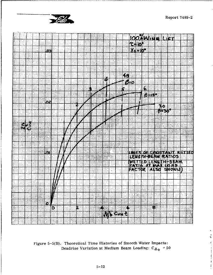
Report 7489-2
.. . . . . . .I.......... ..... .....
............i!- -!A.... ............ ... ..... .. . . . . . .. . . . . .
.................. . .... ,... ...... .. . . . .
...............4*
-I11 . .**** 11... .. 4,. 11,l.1,+I,1414 . I. . I. . . . .I. . .
lit ... ... . . . .
I .. . .. . .. . . .. .
4-.4
4 ... . . . . . . 1
......................................
.4
... ... ...
"Report 7489-2
beam loading of 50, the same increase in deadrise only reduces it by. 0046 (19% of thezero deadrise value), i.e., only 1/4 of the absolute change for the C& = 10 case.
The effects of beam loading and deadrise variations on the maximum accelerationsare summarized in Figures 5-6 and 5-7 which clearly illustrate the main points of thepreceding discussion. As a matter of interest, the corresponding curves obtained fromMixson's empirical formula (Reference 5-2) are compared with those obtained herein.While the trends are the same and the numerical values fairly close in all cases, the present
values are probably more reliable. Thus, for a flat ski with CAo = 20, the Mixson formula
shows a maximum acceleration distinctly larger than that obtained in the present calculations.Thus, the Mixson formula would show an even greater discrepancy with the test data (Figure5-1B, above) than do the present results.
5.2.4 Effects of Trim and Sink Speed on Impact Loads
Figures 5-8 and 5-9 show the calculated non-dimensional acceleration timehistories of smooth water impacts of a flat ski for various trims and for various initialflight path (sink) angles, respectively, with typical values of the other parameters. Figure5-8 illustrates several interesting effects, as follows:
1) The effects of varying trim on maxinr.um accelerations is not very great. Thismeans, for example, that in rough preliminary design calculations, the whole trim rangeneed not be investigated. Further, for a fixed iength-beam ratio, say 4.0, in the presentexample, the range of maximum accelerations would be further reduced.
2) In the typical case illu.strated, a change of trim from 30 to 200 only changesthe "peak load wetted length-beam ratio" from 7. 0 to 3.5.
3) The constant i/b curves are not monotonic; that is, it is possible to obtainthe same acceleration at the same wetted length at two different trim angles.
Figure 5-9 shows that, in the region of low sink angles (typical of conventionalseaplanes), the maximum accelerations are nearly proportional to the magnitude of the sinkangle. On the other hind, for large sink angles, which are more typical of certain types ofSTOL aircraft, the maximum load factor increases with sink angle at a much faster rate.Thus, in the particular example shown in Figure 5-9, doubling the sink angle (22.50 to 450)multiplies the maximum acceleration by a factor of 4.3.
I Figures 5-10 and 5-11 show the peak accelerations of Figures 5-8 and 5-9plotted against the pertinent parameters. These charts serve to clarify some of the pre-vious discussion. Figures 5-10 and 5-11 also show the comparable curves obtained fromMixson's empirical formula. Again, the trends are essentially the same. However,Figure 5-10 shows an appreciable discrepancy in numerical values. Again, the excellent
co;.relation of the present calculations with the test results for C Ao - 50, as shown above
5-13
I'|
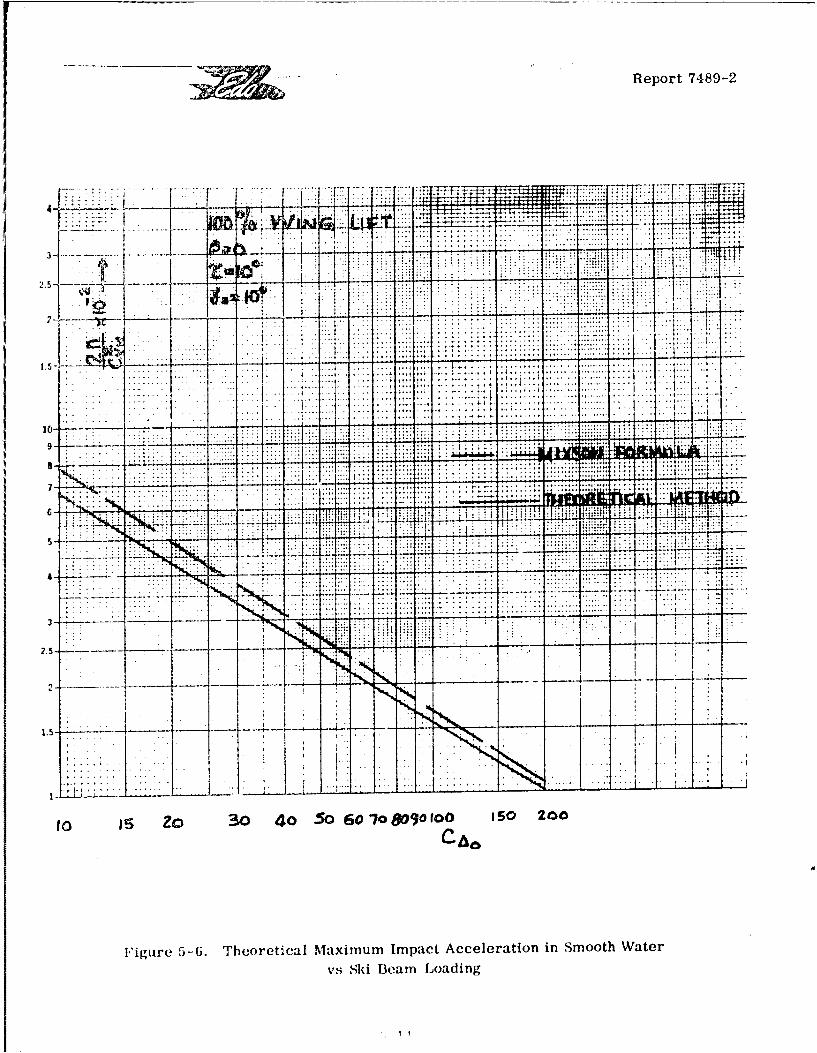
Report 7489-2
1 %4 ....... T
1 -7.
9- ....
7 -.. -4- -
5~. .........
TIP !ii.....
T7 - 'LL -- --
to e Zo 30 4o So 60 Io 8090 100 ISO 200
Figure 5-6. Theoretical Maximum Impact Acceleration in Smooth Watervs Ski Beam Loading
f1I
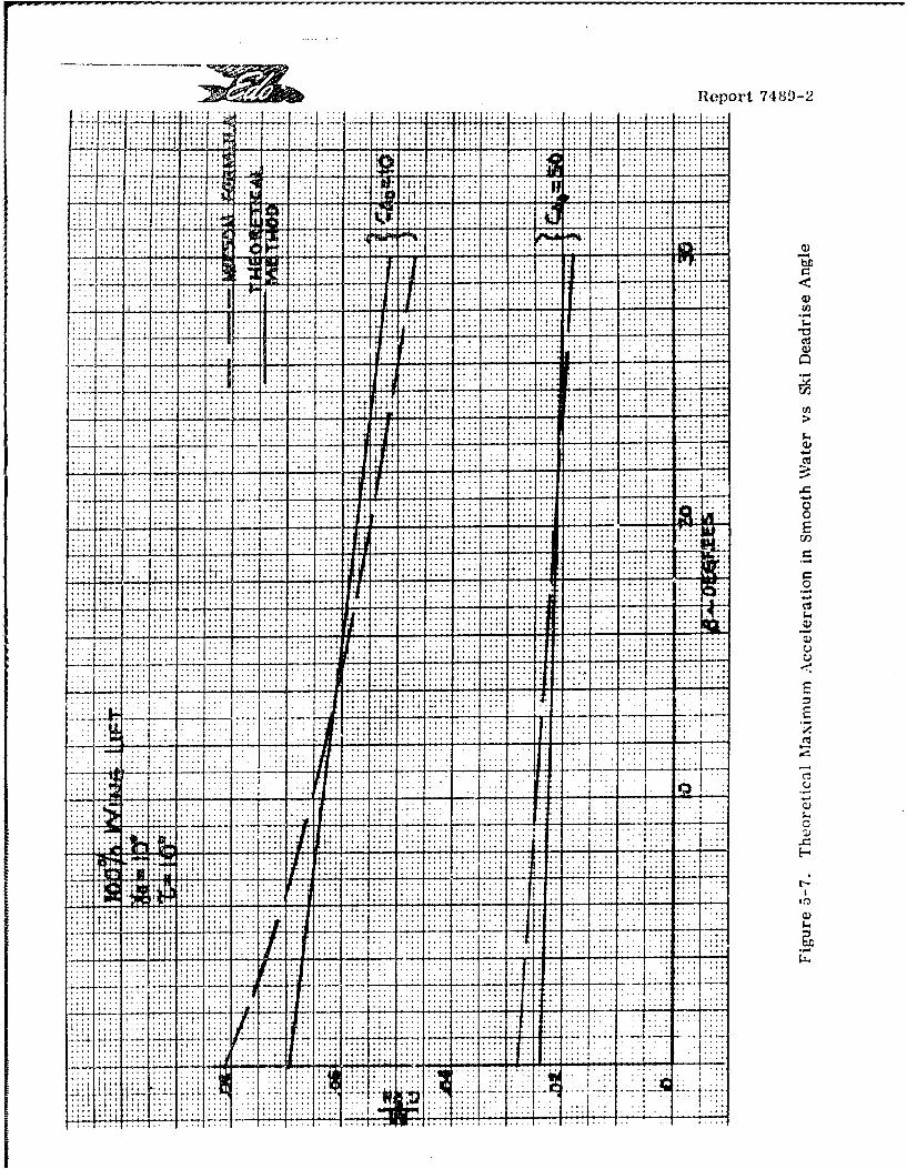
Report 7489-2
/I.:. ... ... .. . .. .. -
. . . . . ...
- -- - ~ ~ .. ... -.. - ~ ~ 2 I u..
.... ............................ ... .... .... ... .... ... .... ...
... .... ............... i ... ....
411
...................................... ...................... ....
. . . . . . . .
.. .. . ... . ...-.. ~~~~ .. . . .. .. .. ..... .. ...
:m4.. ... .. ...
7--A
1:::1
C)
w 7 =1
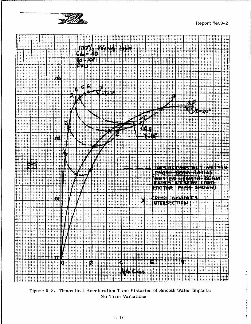
Report 7489-2
-~-.. I - .- ,. I. . -
.. 4.. .. ...
...l ....I ... +; .4
1 1+* .. ... .. . . . . . .
-t. . .:.:........................................ .. ... .... .............
.. . ... ...
.... ......
Fiue -3.TeoeiclAceertonTmeHstreso1SothWte mpcsSki rim ariaion
.4-1 .41:ý
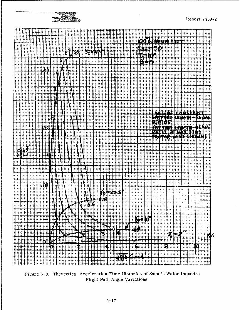
ZZ ReDort 7,189-2
IT
ih1f 'titWiwi
+ +
jpW ..... .... .-.
j
14 '.4 1 1 4 .1
+ +
t!
I I 9T4
t tttt j4 i
+ ++I .. ....
1 .4 4
:44- t
tf A A; t t t . . . . .. . .. .. .. . .. . . . . .
4+41 1-4 ... .... .... .. .. .... ....
j
t t t 4, 4 +: 41 . .. .. .. .. . .
+ +
it + +
+ I + 1-: 4I a td Arl
41 .. .. . ....
t ... .... .... .. 44
4 + +
.. . . .. .. *4 t4- ý14+ +
4 + +ý44 * t 4+ *+++ +
+ +J
V41 .. .... ....
.4 .1
.... .... ... 4
fr - 4 4 -; . ' . . - i I I _ - : ; : - - I : : 4* :1
t 14- 1,
I+ ... .....
777 + + 4 .. .... ....
r4+1 1 14 14T - :! : -:: :::: .... .... .... ...4 . .. . . .. . .. . . . . .. . . . .
;JI !M _ . 4 ++ ... .... .... .. .... ....
141
-7
4 1 4Z- Al.
.. .... ....
I
fit t.7
..... .... .... ....ti fI . t
.... .... .... .... .
*4 4
t i
ff t t + + f f
±ffl I +-t
-4 .... .... ...
+ l + I .+f +41 14 1 l +
D ::
+ . .. . .. . . . . . . . .. . .. . .
+ I :I : ; . . .... ....
4 4_+ *4: .... ....
Fi 1ýu r c 5-9. rheoretical Acceleration Time Histories of Smooth Water Impacts:
Flight Path Angle Variations
5-17
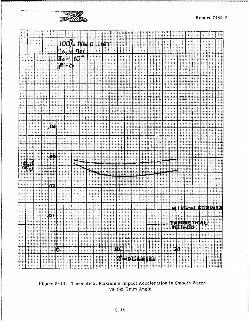
Report 7489-2
77: .7 7__ .._ ...... s
.. ..... ..... ... ...... I. .4 .. .... I.
"TT Th
. . . .. . .. . : I-
. . .... 2 : 4 .*.
~+
.. I .4 .:: . :. .
~+ +
. I
CA .... . ... ... ... .. 1...... ... ....
.<1 ....Fiur I-( .hoeia Maiu .m ac Aceerto in Sm ot .Water . .... .......
.~~ ~ ~ v Sk Tri Angle.. ...
. .. .. ... T. .I .. I I. ..
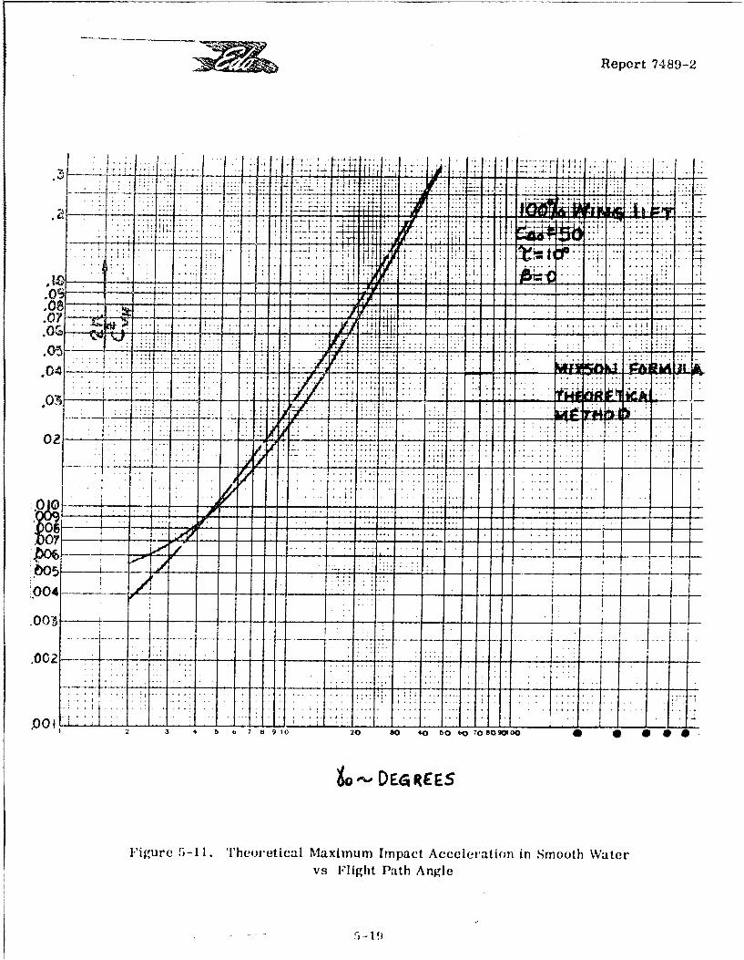
Report 7489-2
,.,
.. ......
A lI -- 7 .
.0' -
-.. ...
.0 SA d 1110 2
.
..
.. .
........
I t :
** .: ,.-
,
--- - - - - -; - -; - - -,-
.00
.4 4 V . I; ! : ,:'
*c04 - -
or.-
.0 0 3
it: : - C-4 R E E S -
- -...-. - --.... .. .. .
Figure 5-11. Theoretical Maximum Impact Acceler-ation in Smooth Water
v.9 Flight Path Angle
_..... .. - 1:
[ Report 7489-2
in Figure 5-1A, indicates that the present results are more reliable than those obtainedfrom the empirical formula. On the other hand, the agreement of the two curves in FigureE 5-11 is very good.
5.2.5 Effects of Airplane Lift on Impact Loads
Figure 5-12 shows the calculated non-dimensional acceleration time histories ofsmooth water impacts of a flat ski for various values of the "wing lift" parameter, p, withtypical values for all other parameters. These calculations are based on equation 5-3,above.
It is seen that there is a smooth dependence on "wing lift". The significant featureF of these results is that the maximum acceleration values differ by amounts which are small-er than the initial differences, the latter representing the difference in "p" values.
[5.3 IMPACTS ON WAVES
[5.3.1 Introduction
For many years, it was thought adequate to analyze hydrodynamic impacts onhead-sea wave flanks by use of an "advancing wedge" approximation. With this technique,the effect of the wave is approximated by assuming that the wave acts like an inclinedstraight wall of water moving with the true wave celerity, the slope of the 'Wall" being theactual wave slope at the initial contact point. In refined versions of this method, the effectsof the wave orbital velocities are also taken into account.
With or without the orbital velocity effects, the advancing wedge approximationleads to the conclusion that, for impacts of a given ski on the flank of a given regular (headsea) wave under given approach conditions, the maximum impact loads will always occur[ when the initial impact point is the one having the maximum wave slope (L. e., lying midwaybetween crest and trough).
This conclusion follows automatically from the manner used to account for waveslope in the impact process whereby the ski is endowed with an effective trim and an effect-ive flight path angle given respectively by:
off --
where is the wave slope. If the trim angles avd flight path angles used in Figures 5-10and 5-11 of this report are interpreted as effective quantities. It will be seen that the effectof wave slope In decreasing the effective ski trim is relatively negligible as compared withK its effect in increasing the effective initial flight path angle. As the maximum accelerations
1 ~5-20 1
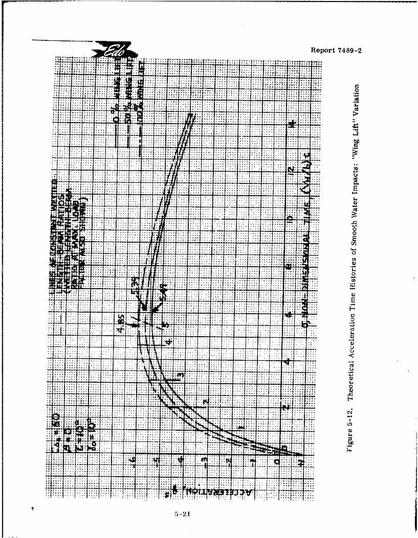
Report 7489-2
..............., ..... .. .. ..
..............
. . . . . . . . .. . . . . ... ...... .;... :'.............................................. ................ .... ....
.................................. .................................
....................
::::::........................ ...... .... ..... ............... S4
Tv...................... .... ......
................................................. .... ......... .... ......
.................................... ...............................
........................... . . .
........... .......... . . .... :.f.....- c............. ... .. . . . . . .U
.........................................................
.................. ..................... .............................. ............... ....... .... ........ ..... .. .......... . .. .. .
2.1:: -77
.:. .. .. . .
00014'15-21
I • Report 7489-2
I increase very steeply with the effective flight path angle, it follows that the maximum peakaccelerations will correspond to maximum wave slope.
It may be noted that the approach proposed in the Phase 1 report of this study,Reference 5-6, essentially agrees with this conventional concept. In that approach, theF trim and initial flight path angles in Mixson's empirical formula for smooth water impacts rwould be replaced, in the wave impact case, by the effective angles defined above, andwould be taken simply as:
m tan[7T/(LVH
max Lax- where H and L are the wave height and wave length. It is seen that this is simply one con-
venient way of utilizing the "advancing wedge" hypothesis and, as indicated earlier, stillsuffers from a lack of definition of wetted ski lengths.
The claim is now made that any method utilizing the "advancing wedge" methodF cannu. be correct (except by accident in particular cases) because this method embodies twodifferent, but closely related, fallacies. Basically, this method is wrong because it doesnot account for the exact wave profile which affects the wetting of the ski, i. e., it replacesthe actual profile by an infinite wedge. Precisely because it uses the wedge "approximation",it automatically leads to the condition that the maximum accelerations always occur forInitial impact locations at the mid-point of the wave flank.
It will now be demonstrated that more accurate calculations can be made which
account for the actual wave profile and that, when this is done, the maximum accelerationsS generally do not correspond to initial impact locations at the flank mid-point, i.e., at the
maximum wave slope locations.
S5.3.2 Equations of Motion
Although the basic equation of motion is the same for wave impacts as for smoothr water impacts, proper account must be taken of all wave effects, including geometric,kinematic, and dynamic effects. These effects may be summarized as follows:
1) The variation of both effective trim and effective flight path angle during theimpact time history;
3 2) The variation of ski wetted length as affected by the true wave profile during
the impact;
[ 3) The variation of the orbital velocity dynamic effect during the impact.
All of these wave effects can be taken into account rather simply by using a coor-Sdinate system which moves horizontally with the ski at the latter's horizontal velocity, VH
5-22
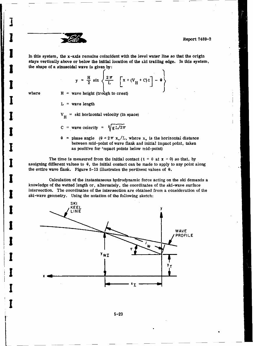
I Report 7489-2
I In this system, the x -axis remains coincident with the level water line so that the originstays vertically above or below the initial location of the bki trailing edge. In this system,j the shape of a sinusoidal wave is given by:
J H In {A.f [x +(VH+ C)] -
where H = wave height (trough to crest)
L = wavelenh
1 V = ski horizontal velocity (in space)
C wave celerity L 7r
0 = phase angle (9 = 27r xo/L, where x. is the horizontal distancebetween mid-point of wave flank and initial impact point, takenas positive for "mpact points below mid-point)
The time is measured from the initial contact (t = 0 at x = 0) so that, byassigning different values to 0, the initial contact can be made to apply to any point alongthe entire wave flank. Figure 5-13 illustrates the pertinent values of 0.
Calculation of the instantaneous hydrodynamic force acting on the ski demands aknowledge of the wetted length or, alternately, the coordinates of the ski-wave surfaceintersection. The coordinates of the intersection are obtained from a consideration of theski-wave geometry. Using the notation of the following sketch:
SKLINE
!5-2
WAVE
FPROFI L
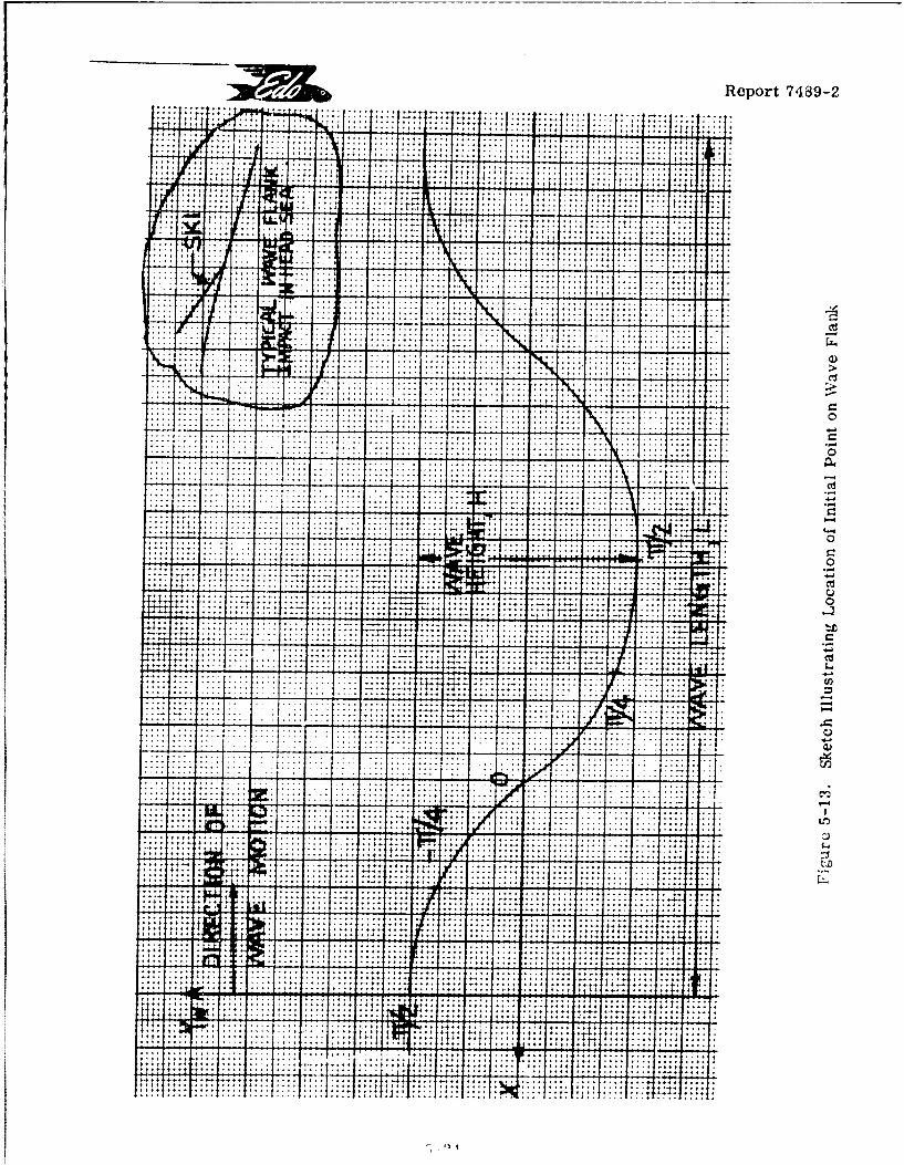
Report 7489-2
.............. .. ........
....... ....
.4+ ~ ~ ~ .. . .. . t :........ ..
cis
. . . . . .. .. . . . . ->
......... ..... . . . . :t.......
...............-.-. .:~:.:: - . .-... .... ......... -
.- .- .. . .
.. .. .. .. . .
...-........
f... . ............ .... ..
.... .. ..................... .... ............................. ..................................... .... ...
........ . .. . . . ...... .. .....
. . . . .~.... ... .. ............... .. ..
........... ........ 1U7,........................................ .............................. ........
....................
...................
.. ..........
. ... . .. . . . .
..... .... .... ,
............. ...........
. . . . ... .. . . ~ .
... ... ...
___. . ..._ . . . ,.. , . . .. . .. .
~~. .. . . . . . . . .. -. . ..
. . .. . . . . . . .. . . . . . . . . ..
Report 7489-2
it is seen that:
IW YWIT + XItan T (I -Intersection)
S But y H + (V +C)]-
These two equations, in conjunction with the relation:
I Iw = xi/cos r
and the equation of vertical motion (which basically defines YT ) serve to determine the
J instantaneous values of xI and, thus, of 1W. It is seen that the quantiy, y WI' is actually
irrelevant to the calcuiation.
I What is relevant, however, is the quantity, • the instantaneous wave slope at
the ski-wave intersection. This slope is given by:
tan I = (dy / dx)I_
I { [1 .+(VH+C)
The present calculations use effective trim and flight path angles given by:
T eff T- r- I
I eff I
Finally, orbital velocity effects, although generally small, have been taken intoaccount by inclusion of the instantaneous vertical component of the orbital velocity, wherethe pertinent orbital velocity is that at the ski-wave surface intersection.
The preceding approaches, accounting for all the known significant wave effects,were combined with the equation of motion and the "equivalent planing velocity" expressionto form a single digital computer program using non-dimensional quantities. * This program
I was used for all of the calculated (theoretical) impact time histories described below.
11 Actually, the smooth water impact calc-'lations of Section 5.2, above, were obtained fromthe same wave impact computer program as a special case: wave height = 0.
5-25
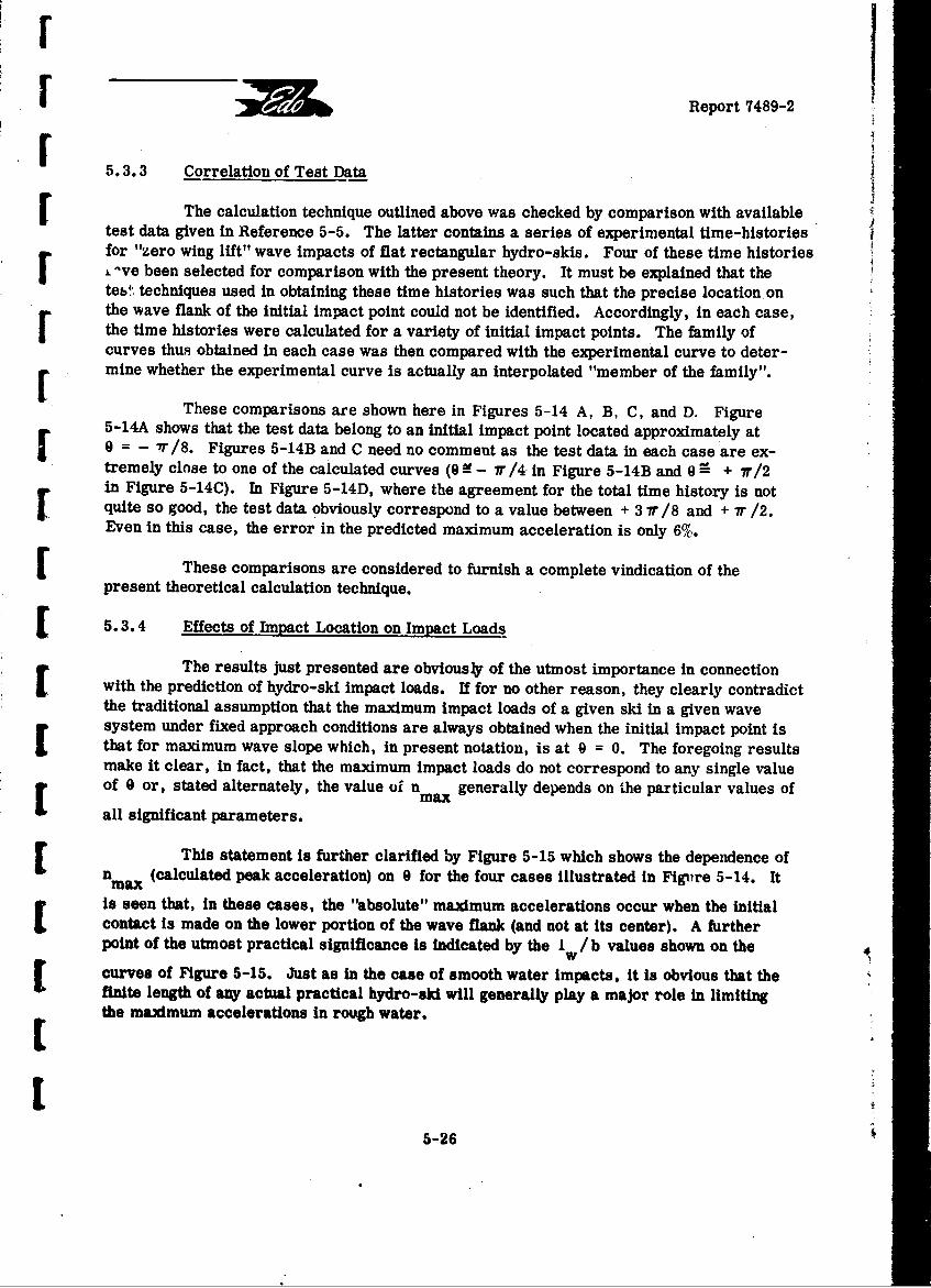
SReport 7489-2
5.3.3 Correlation of Test Data
The calculation technique outlined above was checked by comparison with availablefor "zero wing lift" wave impacts of flat rectangular hydro-skis. Four of these time histories
S"ve been selected for comparison with the present theory. It must be explained that theteb• techniques used in obtaining these time histories was such that the precise location onF the wave flank of the initial impact point could not be identified. Accordingly, in each case,the time histories were calculated for a variety of initial impact points. The family ofcurves thus obtained in each case was then compared with the experimental curve to deter-mine whether the experimental curve is actually an interpolated "member of the family".
These comparisons are shown here in Figures 5-14 A, B, C, and D. Figure5-14A shows that the test data belong to an initial impact point located approximately at9 = - 7/8. Figures 5-14B and C need no comment as the test data in each case are ex-tremely close to one of the calculated curves (9 7r /4 in Figure 5-14B and 9 0 + 7r/2r in Figure 5-14C). In Figure 5-14D, where the agreement for the total time history is notquite so good, the test data obviously correspond to a value between + 3 7r /8 and + r /2.Even in this case, the error in the predicted maximum acceleration is only 6%.F These comparisons are considered to furnish a complete vindication of the
present theoretical calculation technique.
5.3.4 Effects of Impact Location on Impact Loads
The results just presented are obviously of the utmost importance in connectionwith the prediction of hydro-ski impact loads. If for no other reason, they clearly contradictthe traditional assumption that the maximum impact loads of a given ski in a given wave[ system under fixed approach conditions are always obtained when the initial impact point isthat for maximum wave slope which, in present notation, is at 9 = 0. The foregoing resultsmake it clear, in fact, that the maximum impact loads do not correspond to any single valueof 0 or, stated alternately, the value oi nmax generally depends on the particular values of
all significant parameters.
This statement is further clarified by Figure 5-15 which shows the dependence ofnmax (calculated peak acceleration) on 0 for the four cases illustrated in Figtire 5-14. It
is seen that, in these cases, the "absolute" maximum accelerations occur when the initialcontact is made on the lower portion of the wave flank (and not at its center). A furtherpoint of the utmost practical significance is indicated by the Iw / b values shown on the
curves of Figure 5-15. Just as In the case of smooth water impacts, it is obvious that thefinite length of any actual practical hydro-ski will generally play a major role in limitingthe maximum accelerations in rough water.
5
5-26
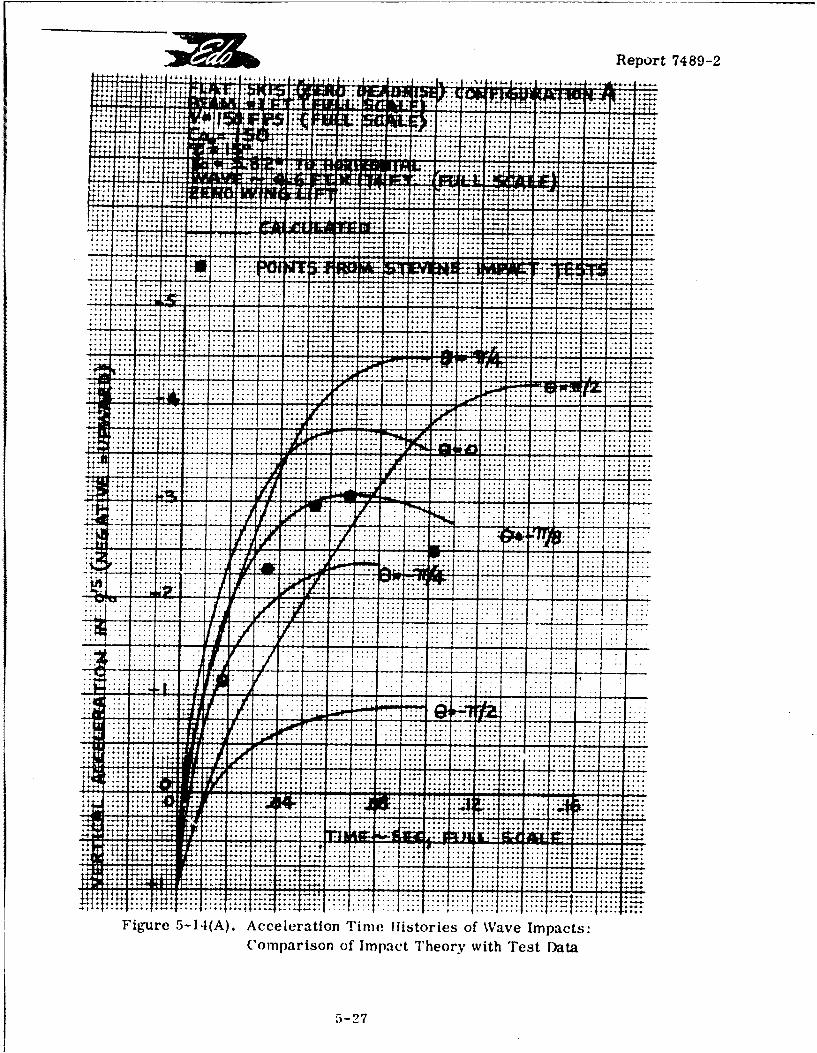
Report 7489-2
J7
owl-
__ 71-i+4
t :4:: =11.
ýT-
+
.. f
.. .... .... ..
. . . . . . . .. .. . . . .
.... .... ....
.... ..... .... .... .... ...... .... .... .... ... ....
v'row -:v. ... ....... .... ....
-ma-, ... .... ..
.. .... .... ....... .... ...
. .. .... . .. ...
. .... .... .... ...... .... .... .... .... .: .... .... ...
... .... ...
.. ... ... ...
. . . . . . .. .. . ..
.. .... .... ...
... .... .... ..
.... .... .... ....
.. .... .... .... ......... ....
4:4+ ......... ... .... ..
1.111*11 .... .... .... .... .... .... .... ....... .... ....
. .... .... .... .... ..
+ *L4 .... .. . .... ..
.... .... .... .... ........ .... .
.... .... .....
.... .... .... ...
... .... ...
Figure 5-14(A). Acceleration Tinjeb 11istories of Wave Impacts:Comparison of Impact Theory with Test Data
5-27
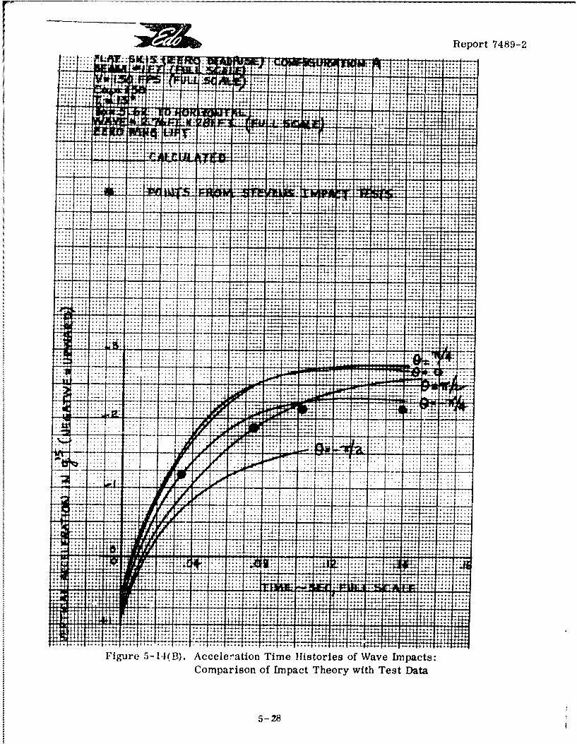
Report 7489-2
Ix P i;;
t
14+4I t -4ýj
T. T77
14-
+ý .. ... .... ...
+
'T 1:,.. . .... .... .. .... . ..... ...., +
:+A-, '-F4
.... .... .... ....... .... .....
.... ......
+t4 t4 ýt+ý -T.+,+:
;4... .... .. . .... . .... ..
.... .... .... ...
. .... .... ... .... ...
.. .... .... .... ..
... .... . .. ...
. .... . .... .... ... ... ...
.... .... ....
Ir
r.... .... .... .
+: . .... .... ....... .... .... .... I .... .... .... .....
.... ... .... .
.... .... ... ... .... .... .... .... .... ...
.... .... .... .. . .... ....
+4-:14
in.. .... ....... .... ......... .... ..
.... .... .... . ... .... ....+: +4+1+
+... .... .... ....
4t.. .... .. 11 ilff... . .... .... .... ...
ýi, tt T.. 1++t t.il+
Figure 5-1,1(Bl. Acceleration Time Histories of Wave Impacts:Comparison of Impact Theory with Test Data
5-2,9
- - ------- - ---------------- ---
Report 7489-2
I-.- a .. .... II&u
jai it.
EL. :7
.... .... ....r : .........I LL.llýij- -* '
.... .... ....... .... ...... .. . .. . ..
. . .. . . .. . .. . . . .. . .. . . .
.... .... .... .
Kul EW11........... ... ......
.. ... ..... ..
..... .... .. ... .... ...7:.:
... ... . .... .... .... .. .. ... . .... . .. . .. .. .. 1 - . .. .. ... . ...
: *::: :7:: :ý: : -: :':: :::7. .... .... ...
. I .... .... .... . .... ... .t .... ....
.... .... ... ... ........ ... .I -. ! .... .... .... ... ..... .... .... . .... .... .... ... ... ... ... .... .... ..
.... .. qr
.... ... . .. .... t%:' 4r -
.. .... ....
....... .... ...
SO
---------- + lov.
. .... .... ....
.... .. ...... .. . .... .... ....
.... .... ..
. .... .... .... ..... I .... ..... ... ... ..... .... ....
... .... ...
... tt
Figure 5-1.1(C). Acceleration Time Histories of Wave Impacts:
Comparison of Impact rheory with Test Data
5- 29
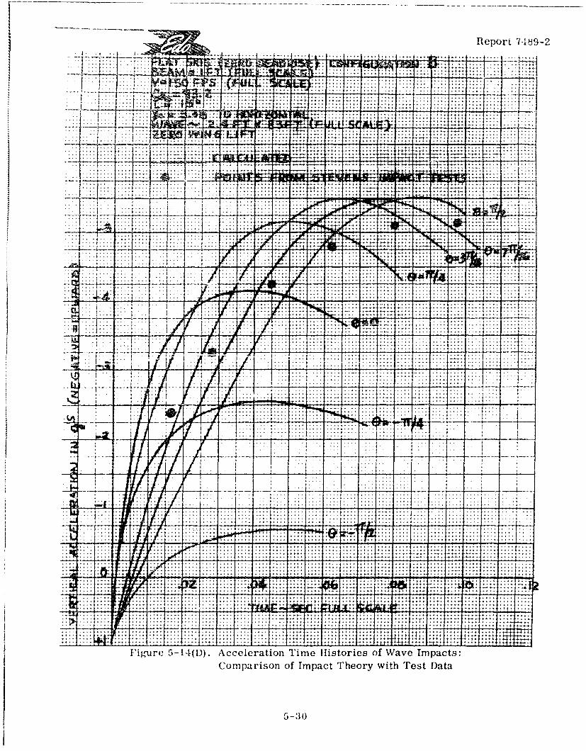
F --- -- -- - - - - - - - ------ ----------- _ _ _ _-______
Report 7.19-2
.......4;-.7
i.E. -
Tim . i. trie of. Wa.Ip
Coprio of .mpac Theory wit Test Data .. ... ..
.-. .. .).
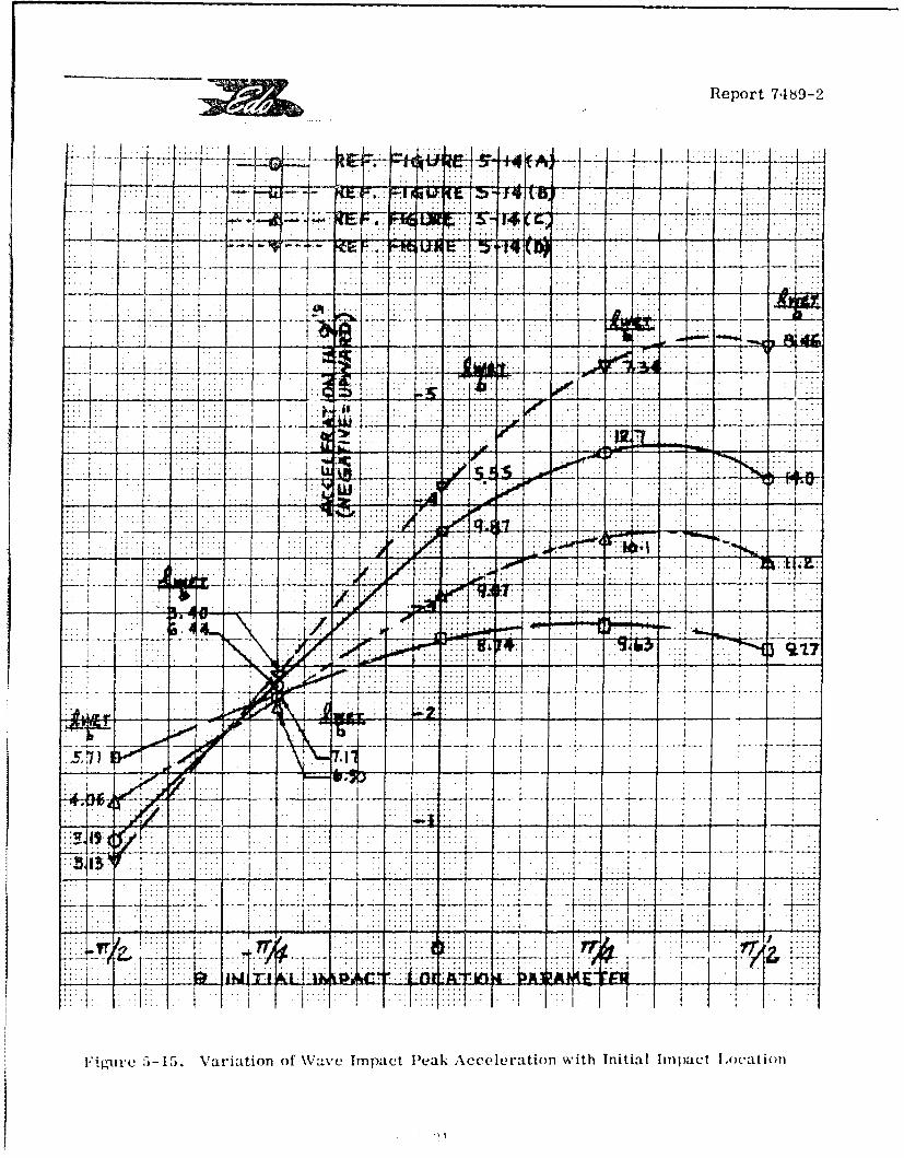
Report 7489-2
LL
-44 5I 7-7
4r::: M:1 WFigre5-5.Vki-to fWv matPa ceeainwt nta mat[oa o
Report 7489-2
In the present analysis, there are actually ten significant non-dimensionalparameters, as follows:
Aircraft Aerodynamics: "Percent Wing Lift", LA /W
rHydro-Ski: Beam Loading,C0
Deadrise Angle, R3
Length-Beam Ratio, l/b
Approach (Initial) Flightr Condition: Horizontal Speed Coefficient, CVH
Ski Trim Angle, r
Initial Flight Path (Sink) Angle, X"
SWave: Wave Height/Ski Beam, H/b
Wave Length/Ski Beam, L/b
Initial Contact Point, 0
SBecause of the large number of these parameters, it was considered infeasibleto conduct a complete parametric investigation of si gle ski wave impacts. Instead, pri-marily for illustrative purposes, a very limited parametric study has been made as will
Snow be described.
5.3.5 Effects of Wave Geometry, Forward Speed, and Ski Length, on Impact Loads
The effects of wave geometry on hydro-ski impact loads are illustrated herein bya brief parametric study in which the wave height and wave length were varied independently.Further, to illustrate the effects of a significant aircraft characteristic, all of these calcu-lations were made for two horizontal velocity values typical of ccnventional and STQL-,ry-+[ sea.planes.
To lend a note of realism, the non-dimensional parameters required for the corn-L puter program correspond to the following dimensional parameters:
Aircraft Gross Weight: 250,000 pounds
Hydro-Sli Beam: 3.40 feet
[ Hydro-Ski Deadrise Angle: 0 degrees F
5-32
J "Report 7489-2
J Ski Trim Angle: 10 degrees
Initial Vertical Velocity: 10 fps *
Horizontal Velocity (Conventional): 85 knots
3 Horizontal Velocity (STOL): 42.5 knots
Initial Flight Path (Sink) Angle(Conventional): 4 degrees
Initial Flight Path (Sink) Angle(STOL): 8 degrees
IThe calculations were made using the "100% wing lift" assumption, for the
I following full-scale wave dimensions:
CASEA. H=12ft. *
L L/H*
1 ft.
240 20
J330 30
J 480 40
CASE B. L/H =30
H L
1 ft. ft.
9 270
12 360
15 450
* Per MIL-A-8864(ASG)
I5-33
Report 7489-2
F Note that, in Case B, instead of fixing a common wave length, a common valueof L/H has been used. This choice has been made deliberately because, as explained inParagraph 5.3. 1, above, rough water accelerations computed with the traditional"advancing wedge" assumption would depend only on the (common) L/H value and not on theindividual values of L and 11.
I In the same connection, the calculations were made without assuming any limita-
tion on ski length but the effects of a typical limitation will be indicated. (With the unlimitedlength, the inherent differences between the present and "advancing wedge" computationsare more readily appreciated). The "limited" ski length is chosen as 17. 0 feet, corres-ponding to 1/b = 5.0.
F Summarizing the non-dimensional parameters:
S'Wing Lift" Parameter: p = 1
Hydro-Ski Beam Loading: C~o = 100
F Hydro-Ski Deadrise Angle: /= 0 degrees
SHydro-Ski Length-Beam Ratio: 1/b = 5 (when limited)
Hydro-Ski Trim Angle: "r = 10 degrees
Horizontal Velocity Coefficient(Conventional): CVH = 13.75
Horizontal Velocity CoefficientS(STOL): CVH =6.88
Initial Sink Angle (Conventional): X0o--4 degrees
SInitial Sink Angle (STOL): yo= 8 degrees
SCASE A. H/b =3,53
L/H
70.5 20
S105.8 30
S141 40
5-34
oI
Report 7489-2
I CASE B. L/H = 30 H/b 1,b
J 2.65 79.5
3.53 105.8
14.42 132
The principal results of these computations are illustrated in Figure 5-16. Ineach of these plots, the peak acceleration obtained from the individual time histories havebeen plotted against the initial impact location. In each figure, the first chart is forVH = 85 knots while the second chart corresponds to VH = 42. 5 knots.
Before discussing these results, it must be noted that same of them are approxi-mate. This feature arises from the fact that, in connection with tihe "equivalent planingvelocity" method, the approximation:
has been retained even in regions of low effective trim angle, where it is known to be inac-curate (see Figure 3-1, Section 3). However, the errors inherent in this approximationare sufficiently small so that the conclusions drawn from the present calculations will notI be appreciably affected.
The principal conclusions drawn from these results, most of which are of funda-mental interest in the design of hydro-ski installations for rough-water seaplanes*, are asfollows:
A. For the most part, the dependence of the peak accelerations on the wavegeometry parameters follows the anticipated trends, i.e.IIS~a. For constant wave height (Case A), the peak accelerations generally
increase very rapidly with decreasing L/H, i.e., increasing wave slopes. This is truewhether or not the ski length is limited.
1 b. For constant ;,/H (Case B), the peak accelerations increase, but veryslowly, with increasing wave height provided that the ski length is unlimited. For the caseof limited ski length, the variation with wave height can be either increasing, constant, ordecreasing, depending on other parameters, principally the initial contact point on the waveand, secondarily, on the forward speed.
*Note that, for "100% wing lift", the maximum hydrodynamic loads acting on the hydro-skiare directly proportional to the accelerations shown in Figure 5-16 and can be
I obtained by multiplying them by the aircraft gross weight.
I 535-35/
S l
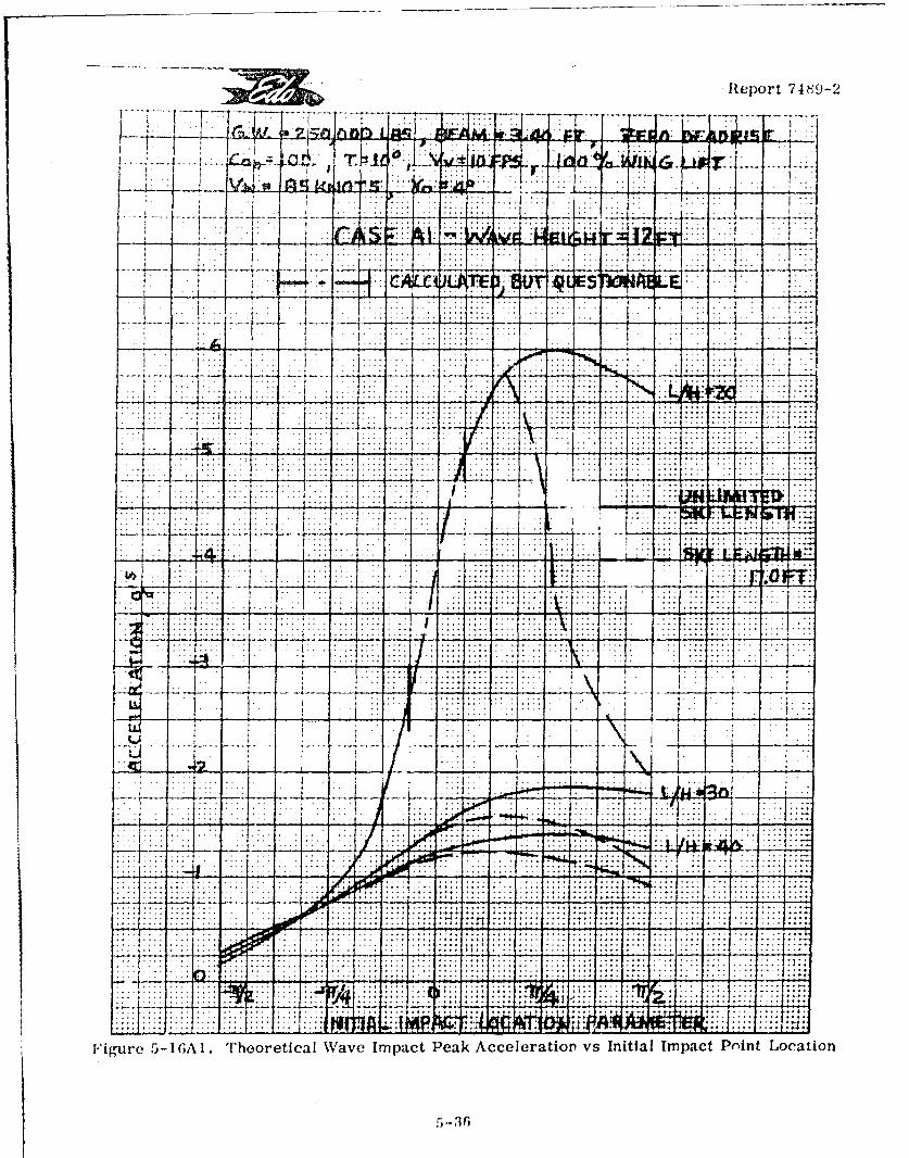
Report 74Th9-2
-rnr ILI
4--
... ... ..
-~~~.. ... .... ... -. I.: 7 T T
V..
...i .. ...
IIt
Figure ~ ~ ~ ~ ~ ~ ~ ~ ~ ~ ~ ~ 1 43GLTertclWveIpc ekAclrairv ntam ActPitLcto
.. . ...1.
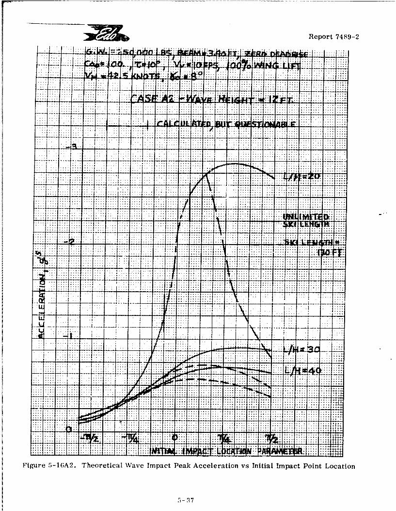
Report 7489-2
.......... . . . .. . . . .
.... .......... .. . . .. . .. .
................-4ý*
I::
Figure ~ ~ ~ ~ .. .- 2 Thorti. .a.e .m.ac Pea Acelraio vs. Inta...a.Pin octo
.. . . . . .
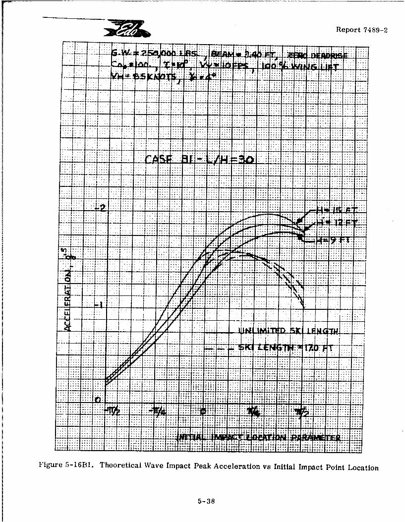
:~i~iReport 7489-2
. . . . . . . . . . . . .. .... .......
... . .....
........................ ......... .... ......... .............. :.
... .. .. ... .. .. ... ... ....... ....
....... ... ... .... .... . .... .... ... ....
. ........... ......... ....... .... .... .... .
. .I. .. . . . .
ow .. .... ....... . . .t. .................................................. ....... ..... ......... .... .... .... ...
. . . . . . . . .
.u...w...U .............................. .............4 .............----------. 30::.
or-- - --
F5-3
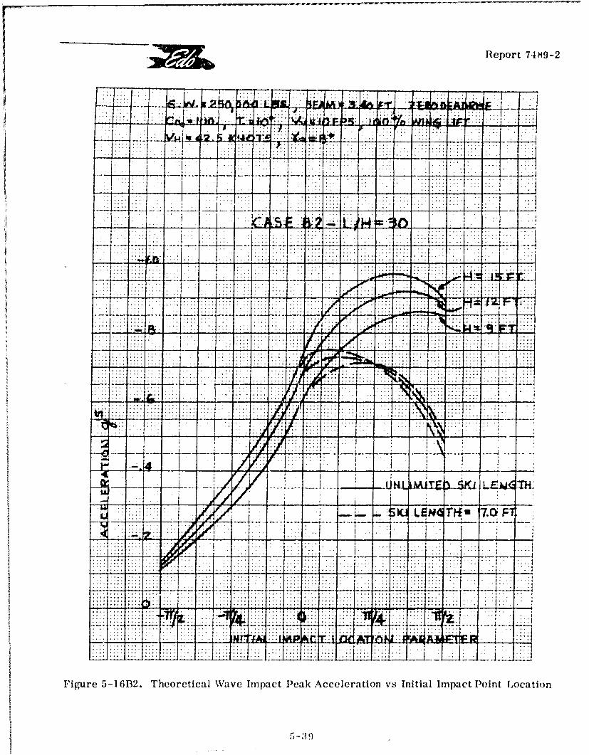
. ~ Report 74 89-2
77 -
FAJT
..... -UL I 1 ElM
... ~~. .. . . .
r:.i:
Figre -1132 Teortial av Imac Pek cceertionv .nta Imat Poin Loato
5_39.
w Report 7489-2
B. The effect of forward speed on the peak acceleration is very marked. In thepresent examples (based on constant sink speed), the peak accelerations are found to be,almost exactly, directly proportional to the forward speed.
I C. Aside from the parametric aspects of this investigation, the numerical valueshave considerable interest in connection with the present specification requirements
MIL-A-8864(ASG) . They show that a hydro-ski seaplane utilizing conventional aero-dynamic and propulsion systems (VH = 85 knots, in present example) can be expected to
experience relatively high accelerations when landing under the specified rough-waterconditions (H = 12 feet, L/H = 20), even with ski beam loadings as high as 100.
While these peak accelerations can be alleviated by one or more of several tech-niques such as increase of beam loading, decrease of ski length, incorporation of deadrise,no single one of these is nearly so effective as a substantial decrease in forward speed.I Thus, it appears that, from the important staadpoint of landing impact accelerations, thereis much to be gained by use of STOL configurations in rough-water seaplanes.
I REFERENCES
5-1 Edo Report No. 4439: "A Survey on Hydro-Ski Water Loads," by L. Kaplan,22 November 1957.
5-2 NASA MEMO 1-5-59L: The Effects of Beam Loading on Water Impact Loads andMotions," by J. S. Mixson, February 1959.
5-3 NACA TR 1103: "Generalized Theory for Seaplane Impact," by B. Milwitsky,30 October 1952.
5-4 NASA MEMO 2-10-59L: "A Generalized Hydrodynamic-Impact Theory for theLoads and Motions of Deeply Immersed Prismatic Bodies," by M. F. Markey,
[ March 19Z9.
5-5 Convair Report No. ZU-2-002: "Presentation and Analysis of Hydrodynamic Testsat Stevens Institute of Technology on Isolated Skis and Ventrals," byR. E. Leadon and J. E. Piper, 24 November 1950.
5-6 Edo Report No. 7489-1: "Survey on Seaplane Hydro-Ski Design Technology.Phase I: Qualitative Study," by P. A. Pepper and L. Kaplan, 23 December 1966.
611[4
; I Report 74 89-2
6. PLANING STABILITY OF THE SKELETON HYDRO-SKI SEAPLANE
I 6.1 INTRODUCTION
One of the most fundamental aspects of aircraft engineering is the determinationof an airplane's longitudinal and lateral dynamic stability characteristics, which includesuch items as:
A. Dynamic stability with fixed and free controls;
B. Dynamic response to control surface displacements;
I C. Dynamic response to gusts.
Further, it is well-known that these problem areas can be successfully analyzed by use ofiinearized equations of motions. These equations involve a set of aerodynamic quantities("stability derivatives') which are either estimated or obtained from suitable wind-tunneltests, or both.
Problems of dynamic stability are also of importance in connection with seaplanesunder waterborne conditions. Past experience has indicated that the principal dynamicalstability problems of waterborne seaplanes, including both conventional hull and hydro-skitypes, are those associated with "porpoising" motions.
J As explained in more detail in Reference 6-1, there are two, basically different,types of porpoising motions, both occurring in the planing regime under "stick-fixed" con-ditions. Briefly described, at planing speeds, there is usually a stable range of (equilibri-um) trim angles which is bounded by an "upper" and a "lower trim limit" of dynamicstability. Inside of the middle trim range, the seaplane is dynamically stable. At trimsabove the "upper limit", or below the "lower limit", the seaplane is dynamically unstable,the instability taking the form of so-called "porpoising" motions. Porpoising consists ofcoupled two-degree of freedom (heaving and pitching) motions involving undamped or, moreaccurately, negatively damped oscillations.
At trims above the upper limit, the porpoising is referred to as high-angle por-poising and, in the case of conventional hull seaplanes, these motions are associated withwetting of both hull forebody and afterbody. Similarly, in the case of the hydro-ski sea-plane, it is possible to encounter high-angle porpoising involving wetting of the ski and thehull afterbody. However, because of the generally low location of the ski relative to theSuill, high-angle porpoising on hydro-ski seaplanes, if it occurs at all, will generally takeplace at such high trim angles that the associated limitations on stable planing operations
1 6-1
Report 7489-2
are of little or no practical importance. In the present state of the art, there exists noanalytical method (or the required input data) for the prediction of the occurrence of high-angle porpoising. This is true for both conventional and hydro-ski seaplane types. Further-more, in the case of the hydro-ski seal.lane, tank model-testing and full-scale flight testinghave been too meager for the accumulation of test data adequate for the formulation of em-pirical relationships for such prediction.
F The situation relative to low-angle porpoising is quite different. In low-angleporpoising, the coupled heaving and pitching motions involve only wetting of the hull forebody(alternately, hydro-ski) and, thus from the hydrodynamic standpoint, only the hydromechanicsassociated with unsteady planing conditions of a single "body". In one sense, the unsteadyhydrodynamic problem is more complex than that treated in Section 5, above, because itinvolves two degrees of freedom. On the other hand, another basic feature makes for tre-mendous simplification: it is known from past experience with conventional hull seaplanesthat very accurate predictions for the occurrence of low angle porpoising can be made with[ the use of linearized dynamics.
For the most part, past practice has utilized special tank testing techniques toestablish the "lower porpoising limits" for particular seaplane configurations. Even forconvention.l seaplanes, there has never been, to our knowledge, a specific program,either experimental or analytical, investigating systematic variations in those parametersF which are known to affect low angle porpoising.
Largely because of the ignorance surrounding this subject, it has assumed anunwanted significance in the design of hydro-ski installations. In the worst cases, skiinstallations satisfying all of the known "rule-of-thumb" design principles have been testedand found to yield unacceptable and still unexplained low angle porpoising limits. Further,a major portion of past experience has been with low beam-loading skis. The presenttrend, correctly, is towards high beam-loading skis and it is more than likely that thisfundamental parametric change has a significant effect on the porpoising characteristics.This role may be either direct or, possibly, indirect as, for example, by requiring morestringent limitations on ski location, etc.
While low angle porpoising characteristics of specific hydro-ski seaplanes canalways be determined by suitable model tank tests, it is obviously most desirable to have amethod of predicting such characteristics in the earliest stages of a specific seaplane de-sign. It is perhaps even more desirable to know which aerodynamic and hydrodynamicparameters are significant and what their specific effects are on porpoising behavior. Thisproblem has been tUeated in this project by:
eA. Establishing a computer program which, for a given "skeleton hydro-skiseaplane" configuration, simultaneously defines the entire range of trim-speed combinationsfor vertical equilibrium in the planing condition and also completely defines all stabilityboundaries within this region;
[[ 6-2-
3I Repor t 7489-2
B. Comparing the theoretical stability boundaries computed in this manner withavailable towing tank measurements to demonstrate the accuracy of the theoretical method;
C. Using the computer program to perform certain basic parametric studies, InII particular, of the ski design and installation parameters.
It will be seen that, in connection with Item B, the agreement between the the-oretical and the experimental results is very satisfactory, thus clearly proving the validityof the theoretical approach.
6.2 BASIC EQUATIONS
6.2.1 General Dynamic Equations
The seaplane is considered to have freedom in heave and pitch, so that theJ general equations of its free motions are:
(W/g)h = L + L - W (6-1)H A
Ir = MH + MA (6-2)
where W = airplane weight
I = airplane pitching moment of inertia relative to c. g.
h = heave displacement, positive upward
trim angle of hull keel relative to horizon, positive nose up
L H' LJA = hydro and aero lift forces
J MH, MA = hydro and aero pitching moments
6.2.2 Planing Equilibrium
For equilibrium, i.e., steady state motion with coastant forward speed, theseequations reduce to: LH + LA = \
(6-3)eq eq
MH + MA = 0 (6-4)eq eq
I 6-3
• U
r Report 7489-2
It is assumed that eq. (6-4) can always be satisfied by application of suitableelevator deflection, i.e., unlimited elevator control is assumed to be available for thispurpose. Further, the elevator deflections are assumed to have a negligible direct effect[ on the aerodynamic lift force.
Now consider a "skeleton hydro-ski seaplane" in an equilibrium planing condition.By this is meant a configuration in which the ski is the only planing element, i. e., there isno wetting of the hull. Thus, by the same token, the only hydrodynamic forces and momentsare those arising from the wetting of the planing ski. It is now obvious that, Wi conjunctionwith the assumption concerning lift forces associated with the elevator deflection, if eq.(6-3) is considered as a relation between trim and forward speed, there is an entire rangeof trims for equilibrium at a given forward speed, within certain limits for a given "skeleton"r configuration, the specific trim values being governed by the elevator deflections.
The nature of these limits can be readily understood by considering the "trim-speed" (r vs. V) plane, as indicated by the skuch, Figure 6-1. The absolute trim limit,independent of all other restrictions, is taken as the keel trim angle corresponding to thestall angle of the aircraft. At this pcint, it should be mentioned that the principal practicalaerodynamic configuration of interest in this analysis is that with power-on and with flaps,slats, etc., set for take-off.
The other two limits in the trii-speed plane Consist of two curves, one correspond-ing to the "ski unporting" condition and the Ather to tt., "get-away" condition. The "unporting"curve represents those equilibrium trim-speed combinations corresponding to wetting of the
Sentire ski bottom area, stated here as a condition on bki wetted lengfth:
Ski Wetted Length = Total Actual Ski Length
or, simply: LW =1act
[ Similarly, the get-away curve represents the limiting trim-speed combinationsfor which the wetted ski-length ju..t becomes zero:
1w = 0
[ Finally, there exists a practical upper limit to the get-away speed which, in present appli-cations, is taken as the get-away speed corresponding to zero hull keel trim angle: T = 0.Thus, the entire planing region can be defined symbolically as:
0 r r st; 0 < I < lac 4- ~ st act
Finally, it is obvious that the unporting and get-away boundaries are actually twoparticular cu ryes belonging to the family of curves defined by constant values of wetted[ length:
6-4
40
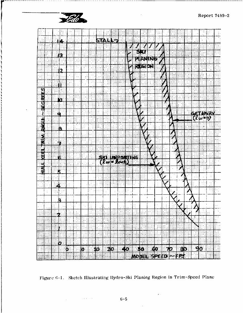
Report 7489-2
-.-. ~~~~.. ... -.... ~- - -- .
.... .. . .
.. . . .. . .. .. .
.... .... .... . . . . . . . . . ............. .... ..............
...... ...... . . . . . . . ......
...17...... ............ .... .... ..... .. ... . . . . .......... . . . ..........
... .... ...
-4 r - .. ....
T V.
. . .~- ... .-
.. ..... .
Figure 6-1. Sketch Illustrating Hydro-Ski Planing Region in Trim-Speed Plane
G-5
_ _ _Report 7489-2
The idealized construction just described must now be distinquished somewhatfrom actual aircraft behavior. It will be understood that the actual planing region for aspecific seaplane may sometimes be somewhat more limited than that considcred here.The two related principal reasons contributing to this difference are:
1) The limitations on elevator -ontrol, depending in turn on such items as c.g.location, ski location, power effects, etc,, which may prevent achievement of certain trim-r speed combinations;
2) As is typically the case with skis of large area, elevator control may be in-F adequate to permit ski unporting to occur at lower speeds without wetting of the hull after-body (two-point unporting) and/or the hull forebody through spray thrown up by the ski. Insuch cases, the basic assumption of the "skeleton hydro-ski seaplane" is only applicable toa limited portion of the "ski planing" region described above.
While purely incidental in the present context, these remarks also serve to em-phasize the most fundamental principle of hydro-ski system design, i.e., that such designmust be completeiy integrated with the aircraft's aerodynamic characteristics.
The detailed equation defining the ski unporting curve (Figure 6-1) is not pre-sented here but can be derived by utilizing Shuford's equation for the steady-state liftcoefficient for the planing ski (see Section 3.2), together with the standard aerodynamicequation:
A LA
in eq. (6-3). Similarly, the getaway curve is defined by:
C LA (r) qA Sw = W
S6.2.3 Linearized Equations of Motion
Considering now a specific planing equilibrium condition, i.e., a specific com-bination of trim and speed inside of the planing region, let (h) and (-) represent verysmall departures from their equilibrium values. Then, under stick-fixed conditions, i.e.,elevators fixed at their trim settings for the equilibrium condition, the hydro and aeroforces and moments will be those corresponding to small values of (h), (r), and by thesame token (h) and (f-). Thus, their values can be approximated by using the first terr.-sof the pertinent Taylor expansions, such as:
LH LH + (LHh)(h) +(LHT )(T) + (Li)(h) + (LH+)(Tr) (6-5)eq
6-6'
11 Report 7489-2
with similar equations for L A d MA'
In these Taylor expansions, the quantities in parentheses multip!,'ing the vant-ables are referred to as "stability derivatives. They actually represent true partial de-rivatives, i.e., for example:
LHh = (0 )r, h ,
Further, each such derivative generally depends on all four variables, thus:
iL = f 1 (h,r, h, r
The essence of the present linearized theory is that, for very small departures-from equi-librium, each stability derivative can be approximated by assigning it tho consta" Valueassociated with the equilibrium condition, thus:
I fl 1 (h =heq r r eq, o=0, r 4 =0)
I Now, if eqs. (6-5) are substituted into eqs. (6-1) and (6-2) and• fiuthe if'eqs.(6-3) and (6-4) are subtracted out, the linearized equations can be written-in the aLbreviatedi ~ ~form:-
a(Ih +) +a2(h) + a3(h) + b2 (r) +b(r) = 0 • (
c2 (h) + c3 (h) + d l1 c) + d2 ( r) + d3 (T) = 0 JSwhere: a, = W/g
a2 = LAb + LHi
aI A l L h Hh-7S3 = LAh + LHr
-(6-7)b2= LA• *+ L
Ib =L +Lb3 LAr H rI c2 = MAh + Hh
II 6-7
Report 7489-2
c C 3 Ah + MHh
(6-7)d = MA- + MH-
d = MAr + MHT
SEqs. (6-6) represent the equations of the free transient motions of the seaplanefollowing a slight disturbance from any particular equilibrium planing condition. If desired,they can be solved by selecting any arbitrary set of (small) initial values for the four qua..-titles: h, r , h, r . What is of basic importance, however, is the nature of the freemotions, which can be determined from the "natural modes".
I 'The latter are obtained by substituting the "modal relations:"
XtXh = hoe T roe (6-8)
into eqs. (6-6) to obtain:
S(alX 2+ a2 + a3)h. + (b2 X + b 3)r, =0S(6-9)
S(c 2X + c3 ) ho + (dlX 2 + d2 X + d13) To = 0 J!SEqs. (6-9 can only be true for the particular values of defined by:
aI + a2 + a3 bXk + b
[ =0 (6-10)2
c X + c dlX + d + d32 3 1 2
[ Expanding this "characteristic" equation:
(a1 X 2 a2 X +a3)(d 1X 2 +d 2 X +d)_ (b2X + b3 )(c 2X + c3 ) 0
I4 3 2or, AX + BX + CX + DX + E =0 (6-11)
1 6-8
loo
Report 7489-2
where: A a 1 d
B = a1 d2 + a2 d1
C ald 3 +ad 2 +a 3 d1 -b 2 c2 (6-12)
D 2d3+a 3d 2-b2 c 3-b 3c2
E =a3 d3 - b3 c3
Thus, the nature of the free motion is determined by the roots of a fourth-orderalgebraic equation, (6-11), whose coefficients, defined by eqs. (6-12) and (6-7), are seen tobe extremely complicated functions of the "stability derivatives" and the two inertia values,(W/g) and I.
Clearly, if desired, one could determine the nature of the free motions at any orall points of the aircraft's planing region. However, such labor is excessive as what isprincipally desired is the knowledge whether the free motions at a particular equilibriumpoint inside this region are stable or unstable. For this purpose, it is only necessary tosubdivide the total planing region into "stable" and "unstable" sub-domains. The curvesbounding these sub-domains are referred to as "stability boundaries" and are obtained from
the following stability analysis.
6.2.4 Stability Analysis
I If the leading coefficient, A, is positive, it is well-known that the necessary andsufficient conditions for the roots of an equation,
AX 4 + B X 3 + CX 2 + DX + E = 0
J to represent stable motions, are:
B > 0, C > 0, D > 0, E > 0, R> 0, (6-13)
where R, known as Routh's Discriminant, is given by:
R = BCD- B2 E - AD2 (6-14)
(This statement constitutes Routh's Stability Theorem for which a concise proofis given on pp. 331-332 of Reference 6-2.)
II 6-9
SReport 7489-2
Obviously, then, in general, there may exist a number of stability boundariesinside the planing region of a specific hydro-ski seaplane configuration which are defined,respectively, by the conditions:
B = 0, C = 0, D = 0, E = 0, R = 0 (6-15)
F The two boundaries of most practical interest can be clearly defined, as follows:
a. The boundary, E 0, separates a stable region (E > 0) in which one mode
is a "subsidence" (h = hoe-at , a> 0) from an unstable region (E < 0) in which the cor-bt
responding mode is a "divergence" (h = hoe , b> 0);
Sb. The boundary, R = 0, separates a stable region (R > 0) in which one m ode
is a positively damped oscillation (h = h. e cos w et, a >0) from an unstable region
(R < 0) in which the corresponding mode is a negatively damped, i. e., divergent oscillationbt
( =(h e cos W 2 t , b> 0). Referring back to Section 6.1, it will be seen that the
"lower porpoising limit" is equivalent to the R = 0 boundary.
L It is thus seen that determination of the stability boundaries in the trim-speed
plane depends directly on the calculation of the hydro and aero stability derivatives.
6.3 STABILITY DERIVATIVES
Analytic expressions for the hydro and aero stability derivatives are derived inAppendix C of this report.
The hydrodynamic derivatives are for a hydro-ski* undergoing unsteady planingmotions in calm water. They are derived by simple extensionis of the "equivalent planingvelocity" concept, introduced in Paragraph 5.2. 1 of this report. This concept is used inconjunction with Shuford's expression for the planing lift coefficient, which has been ex-tended to cover a type of ski planform not previously considered herein, namely, a basicrectangular planform with a pointed triangular tail area. This was found necessary for[ comparison of the theory with available test data.
Analytic expressions are also derived for the aerodynamic derivatives, usingconventional approaches. The seaplane is assumed to be insensitive to ground effect, tohave a conventional aerodynamic configuration and, further, no account is taken of power-oneffects, either direct or indirect. It will be appreciated that these limitations are not fun-damental, I. e., that the approaches utilized herein can be modified to account for suchfeatures as strong ground effects, unconventional configurations such as canard stabilizers, etc.* These derivatives are also applicable to a seaplane hull in the chines-wet condition, provi-[ ded that the wetted planform is of the type considered herein.
6-10
00i
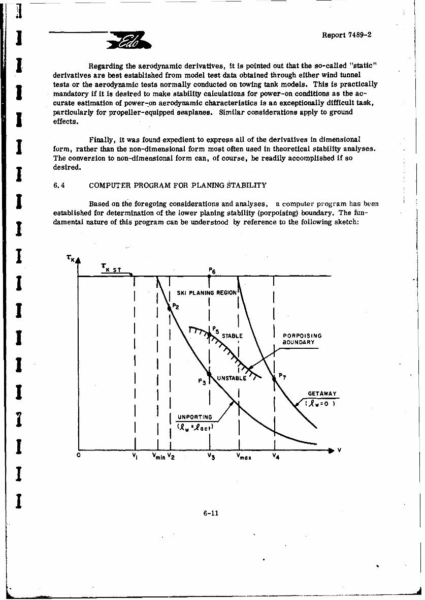
SReport 7489-2
J Regarding the aerodynamic derivatives, it is pointed out that the so-called "static"derivatives are best established from model test data obtained through either wind tunneltests or the aerodynamic tests normally conducted on towing tank models. This is practicallymandatory if it is desired to make stability calculations for power-on conditions as the ac-curate estimation of power-on aerodynamic characteristics is an exceptionally difficult task,particularly for propeller-equipped seaplanes. Similar considerations apply to ground
"I effects.
Finally, it was found expedient to express all of the derivatives in dimensionalform, rather than the non-dimensional form most often used in theoretical stability analyses.The conversion to non-dimensional form can, of course, be readily accomplished if sodesired.
6.4 COMPUTER PROGRAM FOR PLANING STABILITY
I Based on the foregoing considerations and analyses, a computer program has beenestablished for determination of the lower planing stability (porpoising) boundary. The fun-damental nature of this program can be understood by reference to the following sketch:
r T K S T P6
SKI PLANING REGION
5 I USTABLE POROSN
I IIII S. BOUNDARY
S~GETAWAY
I Vl VmIn V2 V3 Vmax V4
I6-11
Fm
Report 7489-2
A. Numerical inputs consist of all aero and hydro characteristics of the specifichydro-ski seaplane necessary for the calculation of equilibrium values and stability deriva-Lives, together with a series of preselected speeds.
B. At each speed, equilibrium conditions are calculated at various trim angles,using small trim angle increments and starting iust above T = 0° (zero hull keel trim).The first quantity calculated is the equilibrium wetted length. This value is compared with
the actual (total) ski length. cac< 1 ac this means that the ski is still submerged
and the calculation proceeds to the next higher trim value, for which the equilibrium calcu-lation is repeated. Two possibilities thus occur:
a) If the selected speed (such as V1 in sketch) is less than Vmin' the
aircraft stall angle is reached before ski planing can occur. In this case, the calculations
start all over again at the next higher (preselected) speed.
b) If the particular speed (such as V2 , V3 , or V4 ) exceeds Vin, a trim
will be reached at which the calculated wetted length is just slightly less than the actual skilength. This combination of speed and trim then represents a point (such as P2 ' P3 , P4 1
on the ski "'mporting" curve. The computer then prints out the speed and trim values,together with the equilibrium wetted length. At this point, the computer also calculates thestability parameters, i.e., the coefficients, B, C, D, E of the stability equation and thecorresponding value of R. In the usual cases, B, C, D, E, are all positive while R can beeither positive or negative. If R is positive, then the point is inside the stable region,such as P in the sketch. If R is negative, then the point is in the unstable region, such
2Sas P3 in the sketch. The computer prints out these values (B, C, D, E,R) for each pointencountered on the unporting curve.
I c) After reaching a point on the unporting boundary, the trim angle is auto-matically increased and the equilibrium values and the stability parameters are calculatedfor the new trim. The computer then compares the signs of the stability parameters withthose for the previbus trim angle. If there is no change in any of these signs, the computerproceeds to the next higher trim angle. This process is repeated until such a sign changeoccurs. Only when this happens- the computer again prints out the speed, trim, ski wettedlength, and the stability parameters. In the usual case, it is the sign of R that changesand the point at which this occurs represents a point on the "porpoising boundary", such as[ P5 in the sketch.
d) In any case, the calculations are continued until the trim reaches eitherSthe stall angle (P 6 in sketch) or else a point on the "get-away" curve (P7 in sketch). The
"get-away" curve represents the condition at which the seaplane just becomes airborne,Ii.e., mathematically speaking, at which the ski wetted length just becomes zero. On
L 6-12
J •Report 7489-2
reaching points such as P6 or P71 the computer reports the corresponding fact in its
print-out.
I e) It is obvious that, by using sufficiently small increments both for speedand trim, the computer print-out will include all the information necessary for accuratelyplotting the ski unporting curve, the getaway -urve (thus defining the boundaries of theentire ski planing region) and the stability boundaries (such as R = 0) inside of this region.
The computer program was written in Fortran lV language. Figure 6-2 is aflow diagram illustrating the program logic; Table 6-1 shows the code used; and Table6-2 is the comr-.ete program statement.
I It must finally be explained that the treatment of the aerodynamic characteristicsused in this program assumes a prior knowledge of the aircraft lift and moment curve.Some generality has been introduced by assuming both of these curves to be parabolic,rather than linear.
IIIII'IIII
I:
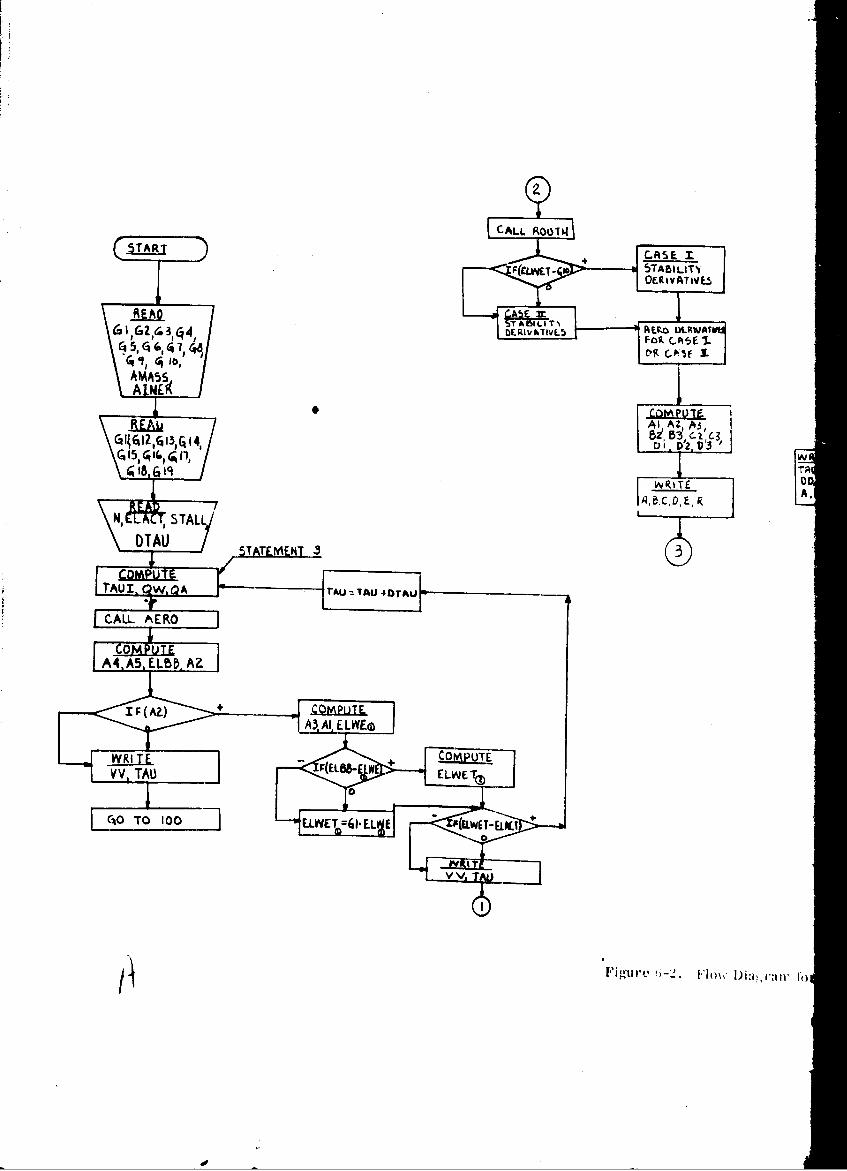
5ARIACSE
READ
" . A.
N,1 AZTA3
IQA toA r. 19 T
N REA A, a-. ICo' IDa,': E,'
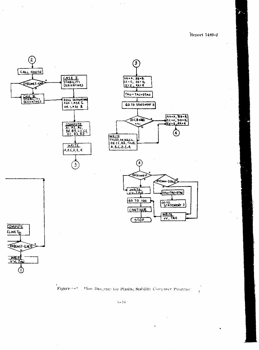
R1eport 74849-2
CALL. R0014
+_CASEM AAmA, 914.,F(L57-SABILg¶'I cc=c, DD=D,F(LE¶OEgIVATIVE5h EE* f £tt R~
TA ILIT'V RL2Q DLKWAIbLPJV&-OVL (,k5O 5 TO 5TfhIT5
OIL rh I
Ai AZ, A3bi'5Zi C3
Of D' WgtTE
DDEEL. t. TA UD,
ILEIELWTO
vvi
CO- PO*1
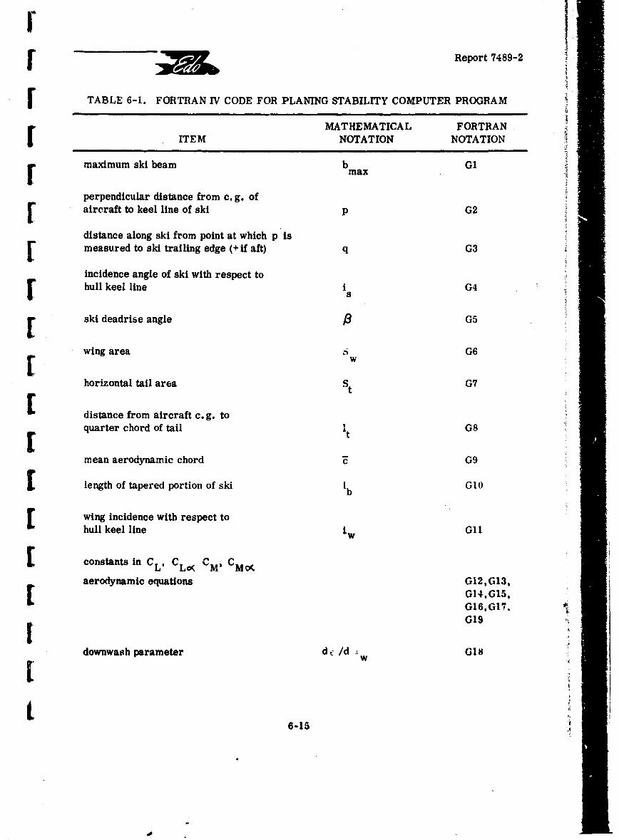
SReport 7489-2
STABLE 6-1. FORTRAN IV CODE FOR PLANING STABILITY COMPUTER PROGRAM
MATHEMATICAL FORTRANITEM NOTATION NOTATION
maximum ski beam bmax G1
perpendicular distance from c. g. ofSaircraft to keel line of ski p G2
distance along ski from point at which p Ismeasured to ski trailing edge (+ if aft) q G3
incidence angle of ski with respect tohull keel line I G4s
ski deadrise angle 3 G5
wing area G6[ whorizontal tail area St G7
distance from aircraft c. g. to
quarter chord of tail It G8[tmean aerodynamic chord G9
Slength of tapered portion of ski Ib GlO
wing incidence with respect tohull keel line iw G11
Sconstants in CL, CLc CM, CM0(
aerodynamic equations G12,G13,[ G14,GI5,G16,GI7,G19
downwash parameter dc /d G18W
6-15
dor
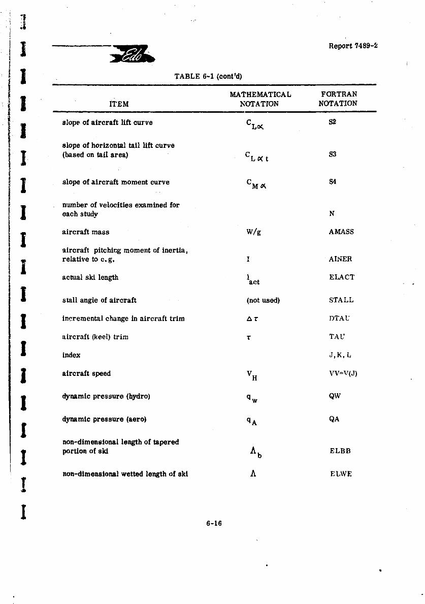
Report 7489-2
TABLE 6-1 (cont'd)
MATHEMATICAL FORTRANITEM NOTATION NOTATION
slope- of aircraft lift curve CLo S2
slope of horizontal tail lift curve
I (based on tail area) CL 0•t 83
I slope of aircraft moment curve CM A S4
t number of velocities examined foreach study N
aircraft mass W/g AMASS
-aircraft pitching moment of inertia,relative to c. g. I AINER
actual ski length 1act ELACT
I stall angle of aircraft (not used) STALL
incremental change in aircraft trim A r DTAU
aircraft (keel) trim r TAU
I index J,K, L
Saircraft speed VH VV=V(J)
Sdynamic pressure (hydro) q w QW
dynamic pressure (aero) qA QA
non-dimensional length of taperedportion of ski Ab ELBB
non-dimensional wetted length of ski A ELWE
6I
6-16
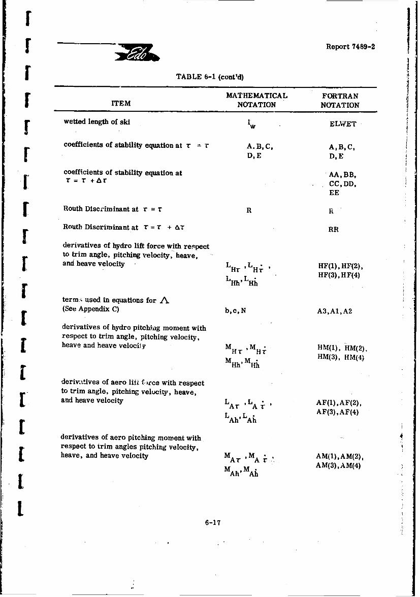
Report 7489-2j
TABLE 6-1 (cont'd)
IEMATHEMATICAL FORTRAN
ITEM NOTATION NOTATION
rwetted length of ski 1w ELWET
coefficients of stability equation at r r A. B, C, A, B, C,D, E D,E
coefficients of stability equation at AA, BB,r = r +Ar CC,DD,
EE
SRouth Discriminant at r = r R
Routh Discriminant at r = T + &1T RR
derivatives of hydro lift force with respect
to trim angle, pitching velocity, heave, "rand heave velocity LHT , LHr , HF(1), HF(2),
Lh L HF(3),HF(4)
term:. used in equations for A(See Appendix C) b, c, N A3, A1, A2
derivatives of hydro pitching moment withrespect to trim angle, pitching velocity,heave and heave velocify M H -HM(2),
T M HHM(3), HM(4)MHh' Hh
derirttives of aero liW f. Jrce with respectto trim angle, pitching velocity, heave,and heave velocity LAr ' A • AF(1),AF(2),
LAh LAh AF(3),AF(4)
derivatives of aero pitching moment with.respect to trim angles pitching velocity,heave, and heave velocity MAr 'MA AM(1),AM(2),
Ar MAr AM(3),AM(4)
MA6MA
6-17
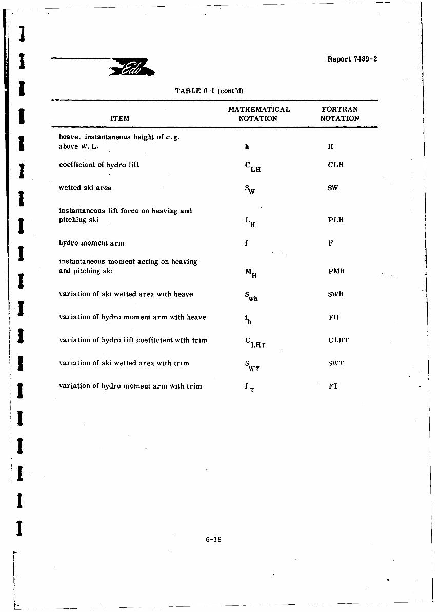
I
3 Report 7489-2
I TABLE 6-I (cont'd)
MATHEMATICAL FORTRANITEM NOTATION NOTATION
heave, instantaneous height of c. g.above W. L. h H
coefficient of hydro lift CLH CLH
wetted ski area SW SWIinstantaneous lift force on heaving andpitching ski LH PLH
hydro moment arm f F
I instantaneous moment acting on heavingand pitching ski M PMHIHvariation of ski wetted area with heave Swh SWH
variation of hydro moment arm with heave -h FH
i variation of hydro lift coefficient with trim CIH CLHT
I variation of ski wetted area with trim SWr S\VT
3 variation of hydro moment arm with trim f T FT
IIII
1 6-18
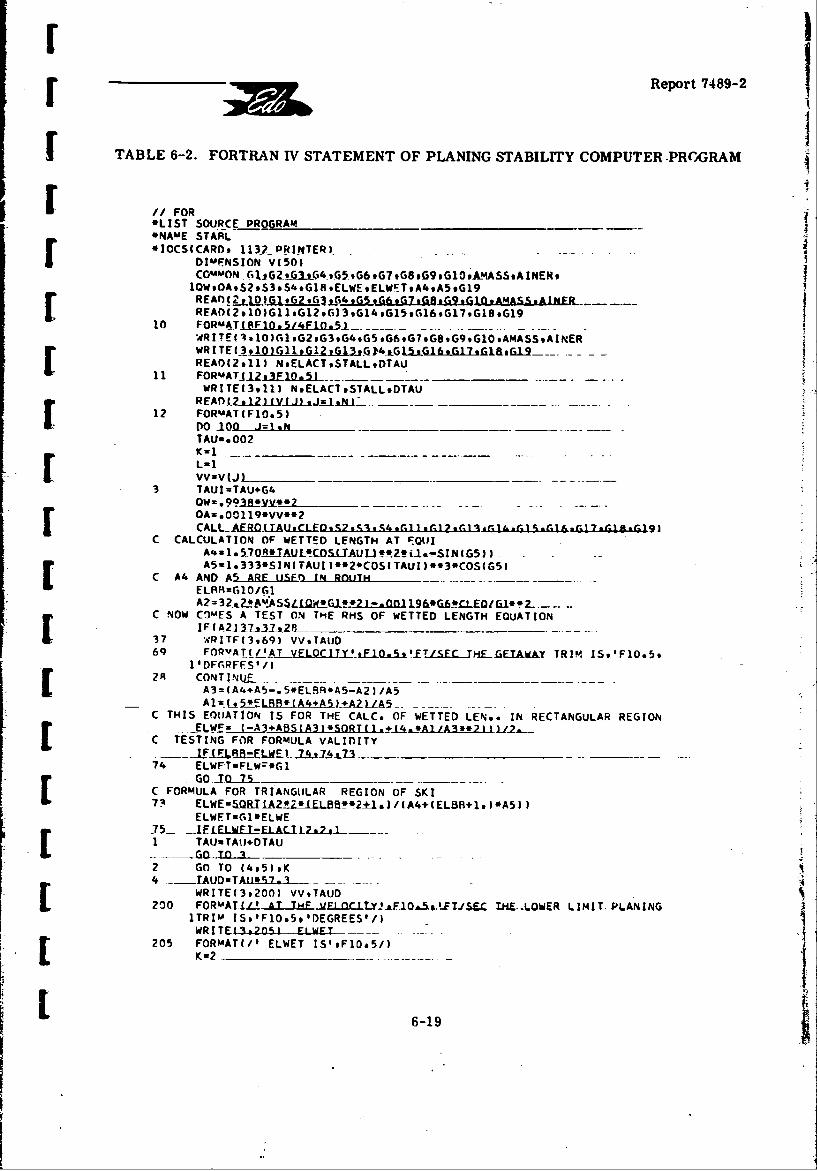
Report 7489-2
TABLE 6-2. FORTRAN TV STATEMENT OF PLANING STABILITY COMPUTER -PROGRAM
IIFOR*LIST SOURCE PROGRAM ________
*NA-E STAWL -- __________
*IOCS(CARD. 1131 -PR! NTER! - --DIMENSION V(5O1CO~mON -rljG2-eGL4-,65,966.61,B69,G9,61OA!4ASS.AINER.1OW.OA.S29S3,S4.G1BELWEELWFT.A4,A5.G19REAnl2±L)G1 .62or3GG5GGeQGo IQ *AMASS &AINEJR
READI?, 10 )G1.G129o 63 .614 .615 ,16 , 67 , 68 .61910 FORMA T(SFIO.5,*.Flo.51-- - - -
WRITE( l.10)Gll*GI2*GI3,G,5G.7G.9GOAASA[ READ(2911) NELACT*STALL9DTAU11 FORmATjIZLA3ElSJQ.i ____
WRITE(3*11) NELACT9STALL9DTAUREAn 2?&211Y(J.)1Jmj~U ___ ----- -*---[1? FORMAT(FlOe53DO 100 -J= I N ________ _
TAUs. 002
Lu IVVZv( JL _ - -- ____
3 TAUI=TAU+G4OW-.993jLyM*t*2.__OAz~.00119*VV**2
C CALCULATION OF WETTED LENGTH AT F001IA421.5708IJAL4XCQSIUAUItURoZ -&-SINlG5J IAS-1.333*SINITAUI).e2.COS(TAUI)**3.COS(G5I
C A4 AND AS ARE uISE3) 1 RAulmTELBR-z1O/G1
C NOW C-)-FS A TEST ON THE RHi5 OF WETTED LENGTH EQUATION1F(A2137237928 ________ __
37 WRITF(3969) VVsTAtUD69 FORVATW/AT VELOCITYlSl.fQ5s'-ETjcFC ME-LEAWKY TRIM IS9'F1O*5*
1 'DFGR.FFS' /1
A3= (A4+A5-.5*EL8R*A5-A2)l A5
C THIS EOIATION IS FOR THE CALC. OF WETTED LEN.- IN RECTANGULAR REGION-ELW!Ez (A3+ABSEA3 *SORTt 1.±14,AaAlj3**2I I J-2.
C TESTING FOR FORMULA VALInITY
74 ELWTFTL~r*6l[ C FORMULA FOR TRIANGULAR REGION OF SKI
ELWFTuG1*ELWE-- F5IF FIAEL CIEL297tL-.i.-[1 TA~uTAtJ.OTAU
2 GO TO (495)9K4 -- TAUDmTA'lk52-l .
WRITE(3,200) VV9TAUD200 FORmli- A TL THE vE.LO.QC.LTYJJ-FlOs.5.JTJ/SU T.HR--LOWER LIMIT PLANING
ITRIM IS,'F1O.5, 'DEGREES'/)WRITE139205, FIWET
25 FORMAT(/# ELWET IS'oF1Oa5/)
L 205 Ku26-19-

Report 7489-2
TABLE 6-2 (cont'd)
C CALCULATION OFSKI STARILTY5 CALL' R160THRV-9-Mu iI7AKqc Do E iR 9CLEOI
--GO TO 16#719L6 WRITE(3.;2O~)_ A,B*C,DE,R201 FORMAT($ AT THE LOWER LIM IT PLANING TRIM THE COEFICIENTS OF THE
ISTARILIfY EQUATION ARE(RoLJTH DISC IS LAST)'/6E15s4)AAuA _______
t~R
La?TAUs TA`6jU~l'0'530 TO 3
7 TAUDDs t~rG_~lUPI*t 7-.TAUD=TAU*57. 3 --
A IF(C*CR)23#23#
20IF(E*EE)23o23#21___
23 WRITE(3#2021_TAUDDAABBCC.ODDEE.RRTAUDA,A8C~oER22 FORNCATul AT A TRIM 0F1,F1O.5,'THE COEF ARE(R IS LAST)'/6E15*4/8
IAT A TRIM OF19F10.5s' THECOEF ARE(R IS LASTI'/6E15s4/)wWr~11t _706) LE
206- FOPMAT(/@ ELWET IS',F1O.5/i_22 AAzA_
R PRa=RCCzC
27 TAUDzTAU*57.3
WRITE i3 #2033 VV #TA _Ulr' _ HE U P R L m L N N203 'FORUMAT(I -AT THE vtLOCITY19FIo.590FT/SE THES_ PRLMI LNN1 TRIV7 !S#,F1O.59' DEGREES'/)WRITE(3#207) ELWET
207 FORMAT(/s EbLwET Is',-F1O*5/)GO TO 100
24 IF(TAU-STALL)25.2&6,26_2.5 ,.TAtUUTAUDTAU________
26 _TAUn=TAU*57.3
WRITE(3,20'., VV9TAUD204 FORMAT(' AT THEKELQM0_TY_!fl.EIs15 'FT /SEC THE PLANE STALLS AT
l'*F1O*5,' DEGREES.'/)
2THE COEF ARE (R IS LAST)'/6E15*4/)WRITE(39208) ELWET___
208 FORMAT(/' ELWET IS4 ,F1O.5/)100 CONTINUE ___________ __
CALL EXITEND____
FFATURES SUPPORTED ____
6-20

r Report 7489-2
j TABLE 6-2 (cont'd)
[ I/~~~~FOR __ _____ __
*LIST SOURCE PROGRAMSUBROUTINE ROUTM(VVsTAUIsAlRsCsD.FaRsCFlvnDIMENSION HF('.),IH(4J9AF(4)aAM(4)COMMON G~G26.~GeAGt&~~tA-MA~SSAItJPR.1OW.OAS2,S3,S4.GlRELWEELWETA4.,A5,GI9
500 HaSI(AI*(3G*O(TAUI)/SIN(TAi-)EEWETI~CI._Qu(A4/LG1Q.1. I 3AS __________________
SWu(GI*'2I(2.#G1O) 3*ELWE**2
- .PLH=CLH*SW*OW -_ _
FHu-.75/TAUICLHTu1.57OR4(1.-SINIG5 J*(l.-1.5*TAUJE*2)/(G610e1.IeZ667*COS(G5)*(lTAUI-3.5333.TAVI*.3)___SWTs-Gl*(GZ-H) /1AUI**2*ELWE/G1OFTu-s75*(G2-H) /TAUI**2HF(3 DwPLH*(SWH/SW)HL413) uP?4H*ISWHISW+FH/Fl ________
HF (1)=PLH* (CLHT/CLH+SWT/SW)M,__'4(l1)ZPMH*(CLHT/CLH+5WT/SW+FT/IFZaVV*TAUI
HM(4)2-2.*PMH/Z
5. ~HF(2 )z-2**PLH*(G2-H) IZZHm(21-2,*0I H*lG7-Hl/77 - -
GO TO 7r0
SW.mzGI*R2..LELWF-. A ____
PLH=CLH*SW*OW
* PmNzF*PLH* ~CLM~4ýAA/(Gl(rLWF+1 - ________ ___
SWHz-G1/TAUI
3'CLHTzl.57Ol!*(1.-SIN(G5))*(G2-H)*(l.-.5*TAUI**2)/((ELWE+,1)**2*Gl15)*( TAUZ-3e3333*TAUI**3j
*SWIAGI~tC7-HI/TALti**?
FT=-.75*(G2-H) /TAUI**2-.--. .
H8lUAPlk JIC[HT/rlH.s~WT/rw%HM(1 )WPMH*(C'LHT/CLH+SWT/SW+FT/F)
-- ZF~VViALLL_______.HF(4)=2*2*PLH/ZHM f 4 v7.iP~mjZf1±LZZ=VV*TAUI.*2
HM(2)=-2.*PMH*(G2-H) /ZZ
AM(l1)uS4*QA*G6*G9
L ~Am(2)*-( 1.1+Glg)*OA*S3*G7*GS**2/VV
Am( 3)x0.0[ ~AFA(4Iu-AF(1 Il/VV
I 6-21
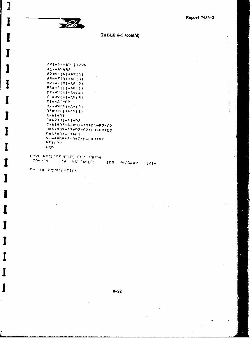
Report 7489-2
TABLE 6-2. (cont'd)
AV=4 (4 ) +AF(1)/
AI='4FI)+AF3)
r7 =&4,, (4)1 +AM ( 4)
fl?=W%4(?)+A"( 2)
J ~A=A *nl~
r=AI *rn3A?*i)?+A3*r~l..P2*C?
F=.A3*r%,-i~r
P PFT!I ~
J 4# A AI A fLFS 1214'GiA~
6-2
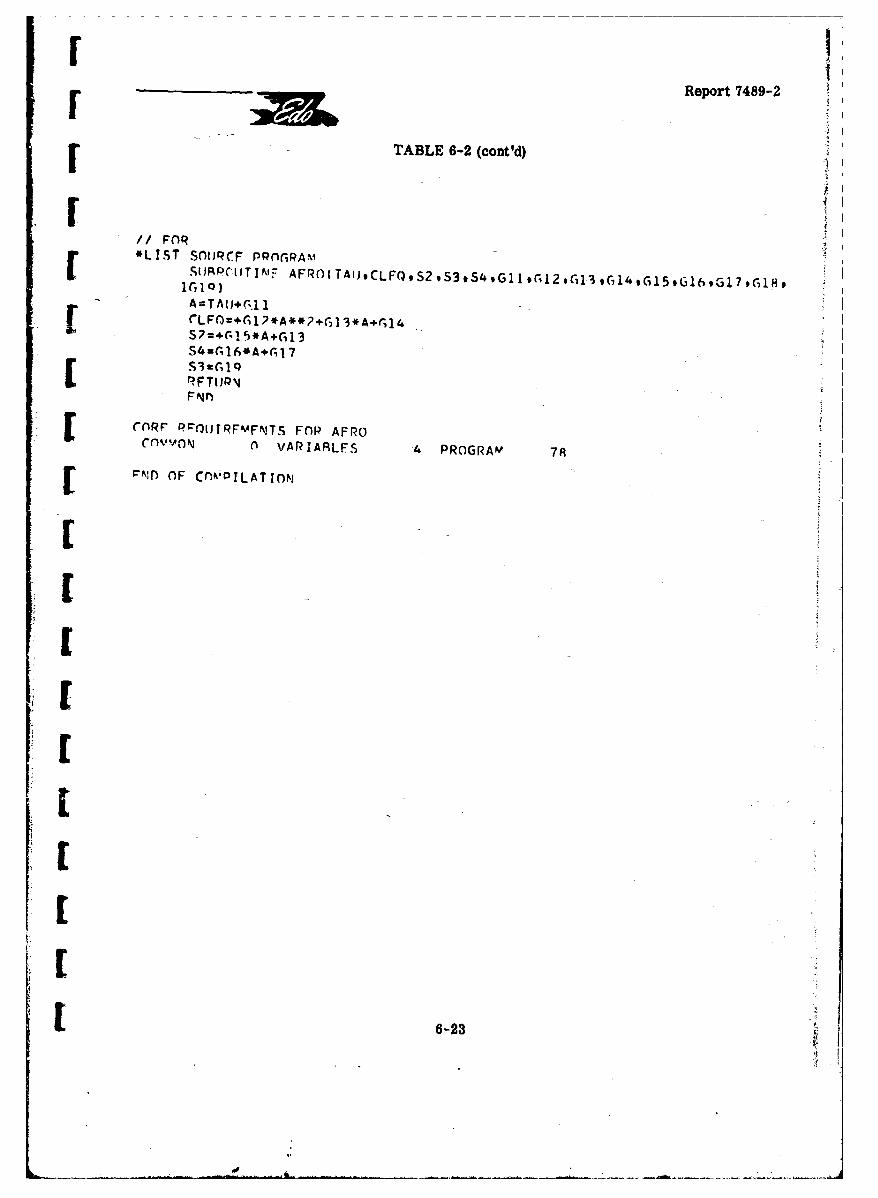
Report 7489-2
F ~TABLE 6-2 (cont'd)
/1FOR -
A=TURc1SPCOLTINIF AFRO(TAIJCLFQS2,S3,S4,G~llr 2,Gil 3 *G14,Gl5,Gl6,Gl7,G1H,
F r~(LFc0=+G1,*A**2+Gl3*A+fGl 4S2=+r(15'*A+rG13S4=C,16*Aer17
RFTrJP
[ ~CflRr PROL0tRFk4FNTS FOP AFROCOVO0f VAR IARLFS 4 PROGRAM 78
rND OF Cnk'P!LATION
6-2
Iu Report 7489-2
6.5 CORRELATION OF TEST DATA
Reference 6-3 presents the results of towing tank tests conducted on a 1/19-scaleunpowered model of the Martin Model 329-C-2 Mach-2 patrol seaplane design. These tests,which covered separate evaluations of three different hydro-ski installations designed forthis seaplane, included measurements of the lower limit porpoising boundaries. Two ofthese experimental boundaries will now be compared with the corresponding theoreticalboundaries obtained from the computer program just described.
Table 6-3 lists the aerodynamic and related inputs for the computer program. Itmay be noted that the geometric values are those for the model-while the aerodynamic valuesare those obtained from combined analyses and wind-tunnel tests of an earlier version ofthis seaplane design (Martin Model 329C-1). The resulting inaccuracies are believed to benegligible. Similarly, Table 6-4 lists the hydrodynamic inputs for the two hydro-ski instal-lations investigated. * Both of those skis had the type of planform considered in Appendix C,i.e., essentially rectangular skis with triangular trailing edges. Further, both skis hadleading edges curved in plan view. For the calculation of the ski unporting curves, the curvedleading edges were replaced by straight ones located at the area centroids of the curvedareas. This is reflected in the total ski length values listed in Table 6-4 which are slightlysmaller than the geometric lengths.
Using the values listed in Tables 6-3 and 6-4 as inputs, the computer program .just described was used to calculate tlie-ski planing region boundaries and the lower limit(porpoising) boundary for eachlof the two hydro-ski seaplane configurations. The compari-sons of the calculated and experimental porpoising boundaries are shown separately inFigures 6-3 and 6-4. In addition to the ski unporting and getaway curves which are fur-nished by the computer, these graphs show an additional intermediate trim vs. speed curvecorresponding to tihe waterline location at the intersection of the rectangular and triangularportions of eac?. ski. This particular waterline curve is of interest in interpreting thenature of the porpoising boundary and, as will be seen below, plays a fundamental role indetermining the dynamic stability characteristics of certain ski configurations.
The general nature of the relation between the experimental and theoreticalboundaries is very much the same for the two skis and is best described by the phrase:"semi-quantitative agreement." That is, the theoretical values are numerically close to
the experimental ones but do not duplicate the details of the experimental curves, particu-larly the curvature reverses. Further, ia the case of the Edo small ski (Figure 6-3), the
• The third ski installation ("Convair configuration") employs a hinged ski incorporating anoleo shock strut. Thus, the planing stability analysis for this type of configuration wouldnecessarily involve a third degree of freedom 'ski incidence) While che parameters forsuch an analysis can be readily determined from the information in this report, theanalysis itself is relatively complex and was considered to be beyond the scope of thisproject.
6-24
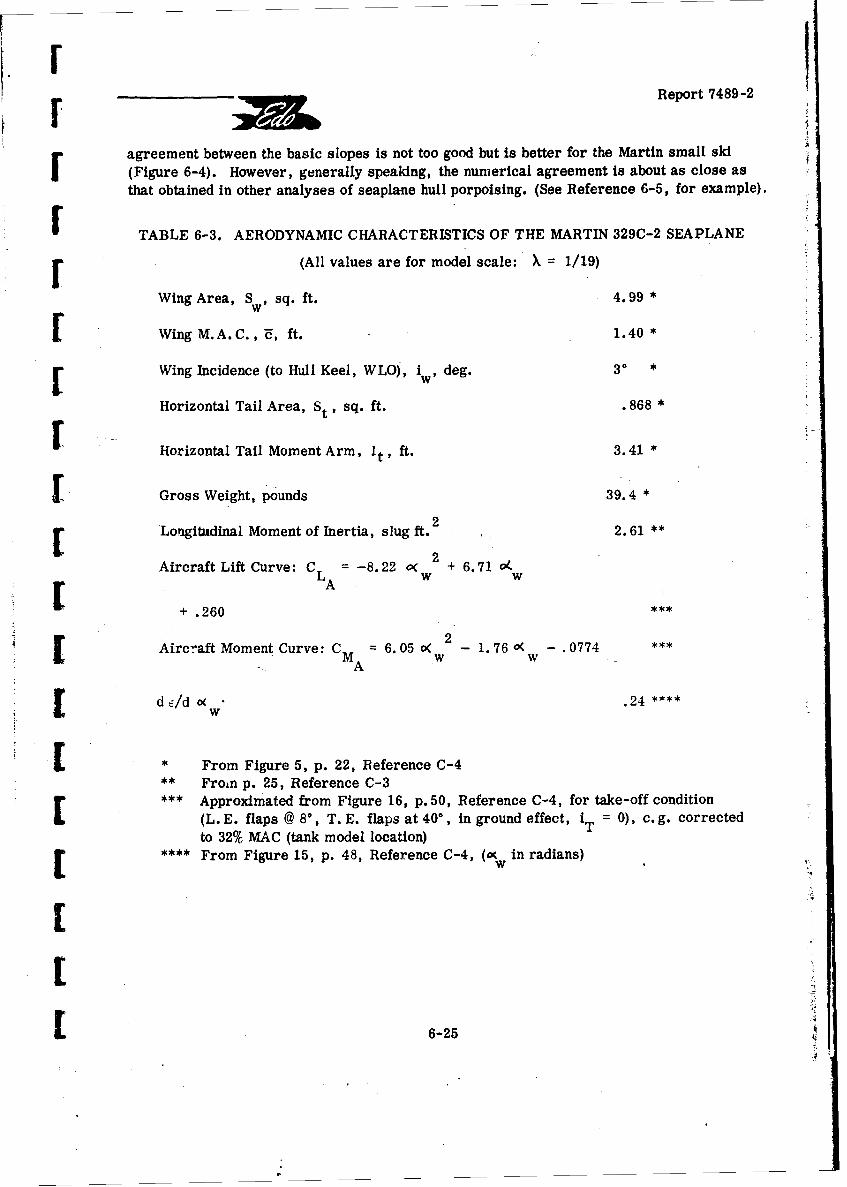
FReport '7489-2
agreement between the basic slopes is not too good but is better for the Martin small ski
(Figure 6-4). However, generally speaking, the numerical agreement is about as close asthat obtained in other analyses of seaplane hull porpoising. (See Reference 6-5, for example).
F TABLE 6-3. AERODYNAMIC CHARACTERISTICS OF THE MARTIN 329C-2 SEAPLANE
F (All values are for model scale: X 1/19)
Wing Area, SW, sq. ft. 4.*99
SWing M.A.C. , U, ft. 1. 40 *
r Wing Incidence (to Hull Keel, WLO), iw, deg. 30 *
Horizontal Tail Area, St , sq. ft. .868 *
Horizontal Tail Moment Arm, It, ft. 3.41 *
F Gross Weight, pounds 39.4 *
2Lonigitudinal Moment of Inertia, slug ft. 22.61 *
Aircraft Lift Curve: C = -8.22 o( 2 + 6.71 o([ A+ .260
Aircraft Moment Curve: C = 6. 05 o( 2 1. 76 o( .0774A w w
dc/d c< .24 ****
• From Figure 5, p. 22, Reference C-4
•** From p. 25, Reference C-3[ *** Approximated from Figure 16, p. 50, Reference C-4, for take-off condition(L. E. flaps @ 8, T.E. flaps at 40°, in ground effect, iT = 0), c.g. correctedto 32% MAC (tank model location)
" **** From Figure 15, p. 48, Reference C-4, (gw in radians)w
L 6-25
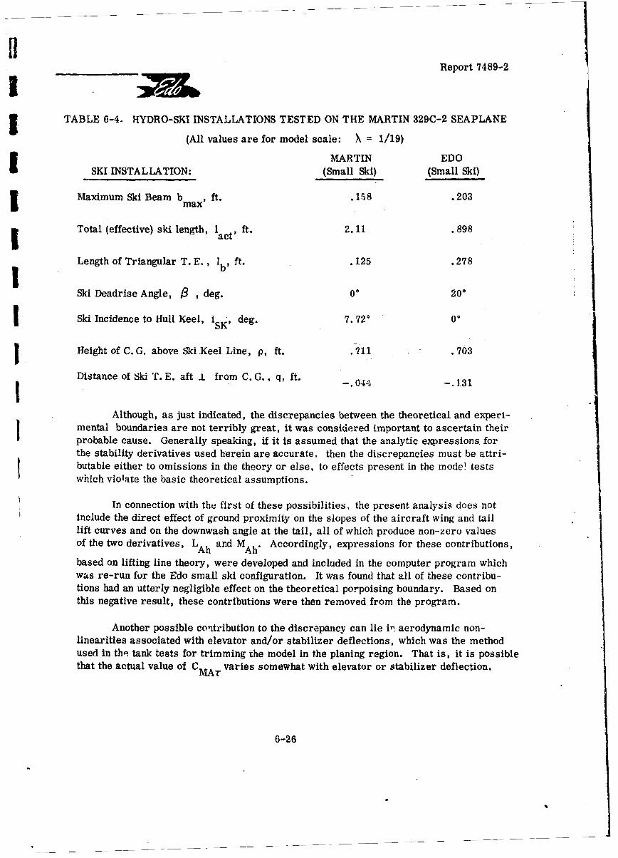
Report 7489-2
3 TABLE 6-4. HYDRO-SKI INSTALLATIONS TESTED ON THE MARTIN 329C-2 SEAPLANE
(All values are for model scale: X = 1/19)
MARTIN EDOSKI INSTALLATION: (Small Ski) (Small Ski)
3Maximum Ski Beam b max, ft. .158 .203
Total (effective) ski length, 1 ft. 2.11 .898act' * .1.9I
Length of Triangular T. E. ,I bs ft. . 125 .278
Ski Deadrise Angle, • , deg. 00 200
Ski Incidence to Hull Keel, isK, deg. 7.720 00
Height of C.G. above Ski.Keel Line, p, ft. .711 .703
Distance of Ski T. E. aft ! from C. G., q, ft. -. 044 -. 131
Although, as just indicated, the discrepancies between the theoretical and experi-mental boundaries are not terribly great, it was considered important to ascertain theirprobable cause. Generally speaking, if it is assumed that the analytic expressions forthe stability derivatives used herein are accurate, then the discrepancies must be attri-butable either to omissions in the theory or else, to effects present in the mode! testswhich violate the basic theoretical assumptions.
In connection with the first of these possibilities, the present analysis does notinclude the direct effect of ground proximity on the slopes of the aircraft wing and taillift curves and on the downwash angle at the tail, all of which produce non-zero valuesof the two derivatives, L and MAh. Accordingly, expressions for these contributions,
based on lifting line theory, were developed and included in the computer program whichwas re-run for the Edo small ski configuration. It was found that all of these contribu-tions had an utterly negligible effect on the theoretical porpoising boundary. Based onthis negative result, these contributions were then removed from the program.
Another possible contribution to the discrepancy can lie in aerodynamic non-linearities associated with elevator and/or stabilizer deflections, which was the methodused in tha tank tests for trimming the model in the planing region. That is, it is possiblethat the actual value of C MAT varies somewhat with elevator or stabilizer deflection.
6-26
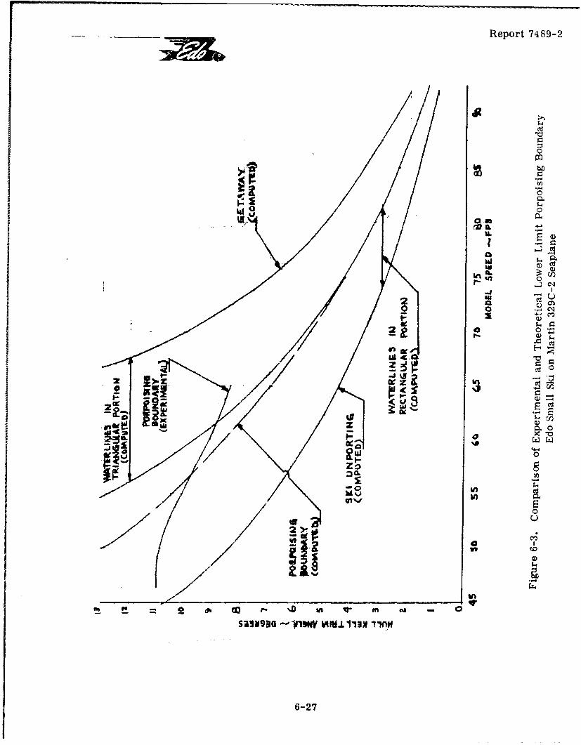
Report 7489-2
0
W 0
In
400
Cd0
2i
:300
;0I Incm in
6-27
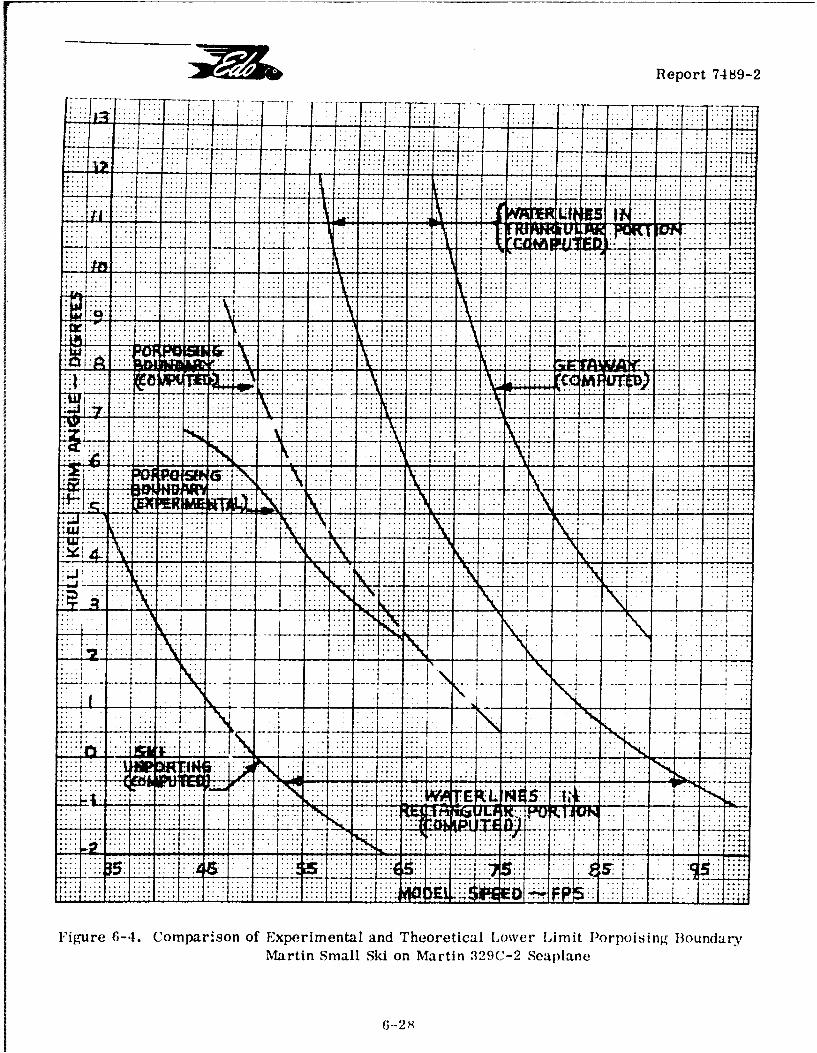
Report 7489-2
............ . .. . . . . . . . . ...... ..... ... ..
.- -... ... . .
I.. .... 4:..... ....... ~ .. ut A " w w
T ... . ..... .. . . . . . . .. .. .. .
... ... . . . . . .. .
.. ... ::I.-
.. ... .I L.E5 . .
U4 -LT
.~ ... . .. .. ... ..
PL~~~~. .. 1..:.. ... .
ME 4
6-28
V
V Report 7489-2
IUnfortunately, the basic a-odynamic data required for a direct check of this hypothesiswere unavailable. However, a check of data for another seaplane (HU-16) indicated thatthis effect was probably too small to have any appreciable effect on the computed porpoisingboundary.
It was finally concluded that the real major cause of the discrepancies betweenthe computed and experimental porpoising boundaries must be the impingement of sprayfrom the ski on various parts of the tank model. This phenomenon can be seen clearly inthe photographs shown in Reference 6-3 and is specifically mentioned in the verbal descrip-tion of the test results for both the Edo and Martin small skis. It is thus seen that thisfeature, present in the tank tests, violates the basic assumption utilized in the mathematicalmodel that there is no wetting of the hull (or aerodynamic surfaces).
If this effect is accepted as the most plausible cause for the discrepancies, theactual agreement obtained must be considered very satisfactory. This means that anyparametric studies based on the present computer program will be valid, both qualitativelyand quantitatively, but only within the confines of the assumption that there is no wetting ofthe aircraft. From the standpoint of practical engineering design, it also follows that theresults obtained with the present computer program will be useful in preliminary investiga-tions of planing stability but cannot be accepted as necessarily realistic for any given con-figuration for which accurate values can only be obtained by tank tests. This restrictionmust be borne in mind in connection with the parametric studies presented in the remainderof this report section.
Using the computer program, a limited number of such parametric studies havebeen made and will now be described. While the effects on the planing stability of the aero-dynamic parameters, particularly the static stability (M ) and pitch damping (MA .),
are of great interest, the present investigations have been limited to variations of the prin-Scipal hydrodynamic (ski) parameters, including ski beam, ski deadrise. ski incidence, and
ski vertical and horizontal locations. It is obvious that variations in ski length obtained by
changing the ski L. E. location while maintaining the same T. E. location, are of little in-herent interest as their only effects are to alter the unporting boundary of the planing regionand, accordingly, either extend or shorten the porpoising boundary curve.
For convenience in these studies, the aerodynamic characteristics of the Martin329C-2 seaplane were retained and the ski installation characteristics considered were
variations of those for the Edo small ski.
6.6 PARAMETRIC STUDIES OF PLANING STABILITY
r 6.6.1 Effects of Ski Beam Loading
The actual beam loading of the Edo small ski was 73.7. Additional computationsSwere made for beam loadings of 50, 100, and 150, i.e., for new ski beams of .231 ft.,
6-29
3 Report 7489-2
J . 183 ft., and. 160 ft. (model scale), with all other ski parameters unchanged. The resultingporpoising boundaries have been plotted in Figure 6-5.
I It is seen that increase of beam loading hP 3 the distinctly undesirable effect ofraising the porpoising boundary to higher trim values. Noting further that increased skibeam loading will, if anything, enhance upper limit porpoising as well, i.e., lower theJuppe porpoising boundary, it is apparent, in any case, that the net effect of increasedbeam loading is to reduce the stable range of trim-speed combinations for equilibrium. Itis thus obvious that, to obtain the desired load alleviation characteristics inherent In skisof high beam loading, special attention must be given to the planing stability problem, i.e.,it becomes necessary to compensate for the deleterious effects of the high beam loadi-g onplaning stability by careful selection of the other ki installation parameters.
6.6.2 Effects of Ski Deadrise Angle
The actual deadrise angle of the Edo small ski was 200. Additional computationswere made for deadrise angles of 0* and 10%, with all other ski parameters unchanged. Theresulting porpoising boundaries have been plotted in Figure 6-6.
It is seen that increase of ski deadrise angle has the same unfavorable effect asincrease of ski beam loading, i. e., it raises the porpoising boundary to higher aircrafttrim values. Thus, the other principal characteristic conducive to impact load alleviationis found to be unfavorable from the porpoising standpoint, making it all the more mandatoryto compensate by suitable choice of the remaining parameters.
6.6.3 Effects of Ski Incidence
1 The actual incidence of the Edo small ski with respect to the hull keel line was 00.Additional computations were made for ski incidences of 50 and 10', with all other skiparameters unchanged. More specifically, this means that the changes in ski incidencewere obtained by a rigid body rotation of the ski about the c. g. in which "p", the perpendicu-lar distance from the c. g. to the ski keel remains unchanged. (See the sketch of AppendixC.) The resulting porpoising boundaries have been plotted in Figure 6-7.
It is seen that increase of ski incidence has the distinctly favorable effect of lower-ing the porpoising boundary to smaller aircraft trim values. Further, while this effect cannotbe precisely predicted, it can be anticipated that positive ski incidence will also have the ef-fect of raising the aircraft trim values for the upper limit porpoising boundary (if any).
3 In practice, these significant advantages of ski incidence with respect to planingstability will, of course, be offset by its disadvantages relative to other hydrodynamic and/ordesign parameters. One obvious feature in the design category is the possible awkwardnessin retracting a ski with incidence. More important are the anticipated adverse effects ofexcessive ski incidence on ski impact loads and on ski resistance, both In smooth and roughwater. It is therefore obvious that, while a certain amount of incidence can be used very
6-30
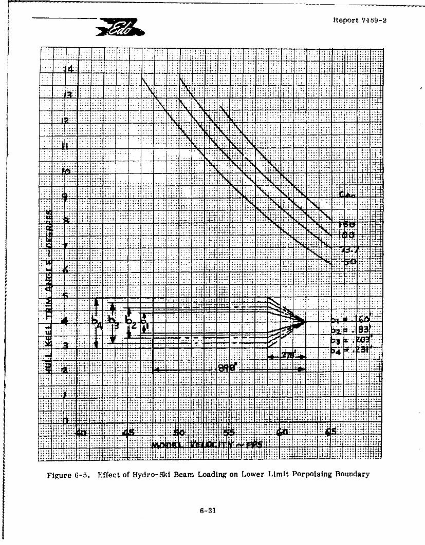
Rieport 7469-2
. . ... .. , j 4 1
... .... .. .
... ......I
4........ .......
K Y. ....................N.:: 2:.. - I. ****.a
* 4-. 4tt4*4t-1 41 ,,,
~~~. . .... ... ... t~**. ~ ~ 1 u ' .v.. . .... ....
....... ....
... ... .... :I.
Figure~~~~~~~~~~~~~~. .-5. Efeto...oSiBa.oaigo oerLmtProiigBudr
6-3t4
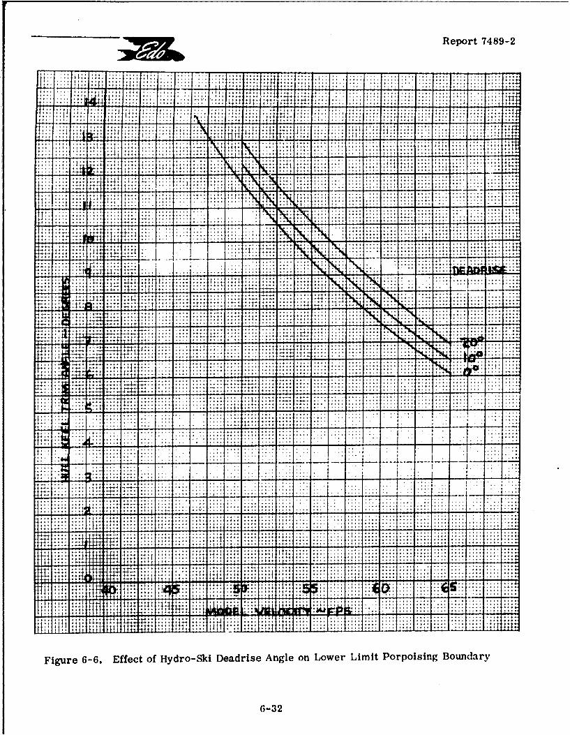
Report 7489-2
t~ .... .t 4 t. .4 .*4.4' .4 .' ... . .4
4 1 '1
- - .., . . .i.. .
144
. . . . . .. . . . . . . . . . . . . .... ... .. . . . .
.ý4 I......... . . +... . . .. . . . . . .. * *4 . . . . .. . . .. . . . . 1
++ 4* ..4,. , ... ..... ..4. . . . . . . . . . . . . . . . . ...
-t .4. . . . . . . . . . . . . . . . . . . . .
.. .. .. .. .. . .. .. .. .. . ......... .. .. .
.. .... -.. ... ..
.... ...* ... ..
+ . . . . . . .... ...
............................................................ .... .... .... .... .... ...
.. .... ........... ... .... .... ............ .... I...... .......
.. i~~.. ..... . .. . .. . .. . ... ......
.......... .... .. , : . ............... ........... .... ...
................. ..... .... ....... .
I I I .L .. ....
4.4.. .... ....
+: LL
Figure~~~~~~~~~~ 6-6. Effec of. ..dr Sk.ed...nl n oe iitPro ngBudr
1-3
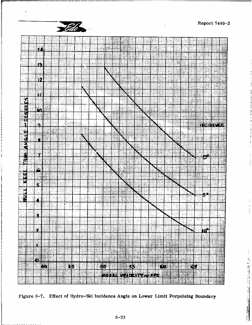
Report 7489-2
4 + 4 1 + 4
4~~~~ ~ ~ ~ ~ 4,r4 : '14t
. ...... .... .... .. . , ?
...... .... T~
... -.. ... -. -+ -4.
..... ...... .. ................. .. 4
. .. .~ - . ~ .
~t
4...*~*,f ........ ... .
...:... ... .... ...
. 4.~. .... ....., ..
.- . . . . . 1
::; ...:4 ... -.:. .. I± ... .._. ..
. . . . . .. .... .. ..' : - -+
Figure~~~~~~~~~~~~~~ .-7 Efec of .yr- .iec Anl on Loe Lii.opiigBudr
6-'34
Report 7489-2
effectively to offset the harmful effects on planing stability of high beam loading and deadrisevalues, careful analysis is required to assure that other important limitations on the skiinstallation are satisfied.
6.6.4 Effects of Ski Vertical Location
While not precisely obvious from the expressions for the hydrodynamic stabilityderivatives given in Appendix C, it is intuitively apparent that the vertical location of theski should have a negligible effect on planing stability. This assumption was checked by acalculation in which the actual strut length was doubled. The results (not plotted herein)showed that the lower limit porpoising boundary trim values were d~ecreased by only . 05',thus clearly proving the correctness of the intuitive assumption.
6.6.5 Effects of Ski Longitudinal Location
Based on the tank test results, the optimum longitudinal location of the Edo smallski corresponded to the value, q =. 131 ft. (model scale), where q is the distance to theski T. E. from the foot of the perpendicular drawn from the c. g. to the ski keel line. Addi-tional stability calculations were then made in which q was increased and decreased, re-spectively, by one whole ski length. Figulre 6-8 shows the lower limit porpoising boundariesobtained from these calculations.
It is seen that, while the effects of these rather large shifts in the longitudinallocation of the ski are not very great, shifting the ski in either direction has the favorableeffect of lowering the trim values of the porpoising boundary and, further, a forward shiftis slightly more favorable in this respect than an equal aft shift.
These particular calculations also served to reveal certain novel results con-cerning the planing stability characteristics of pointed hydro-skis which are illustrated inFigure 6-9. This graph shows that, for the aft ski location, there exist more than oneplaning stability boundary. More specifically, for this particular ski location, in additionto the usual "lower limit porpoising boundary," there are other boundaries (at higher trims)associated with changes of sign in several of the "stability coefficients. " This novel resultis explained as follows:
Examination of the mathematical expressions for the hydrodynamic stability deri-vatives in Appendix C shows that discontinuities in certain of these derivatives occur wizCnlthe waterline passes the intersection of the rectangular and triangular portions of the sk..Further, the magnitudes of these discontinuities depend on the value of the geometric para-meter, q, which defines the longitudinal location of the ski. For (relatively) forward skilocations, these discontinuities are not adequate to affect the basic nature of the planingstability characteristics, i.e. , for such locations, there exists only one stability boundaryfor which R = 0 (lower limit porpoising curve) separating the unstable (lower) trims fromthe stable (higher) trims, irrespective of waterline location on the ski.
6-34
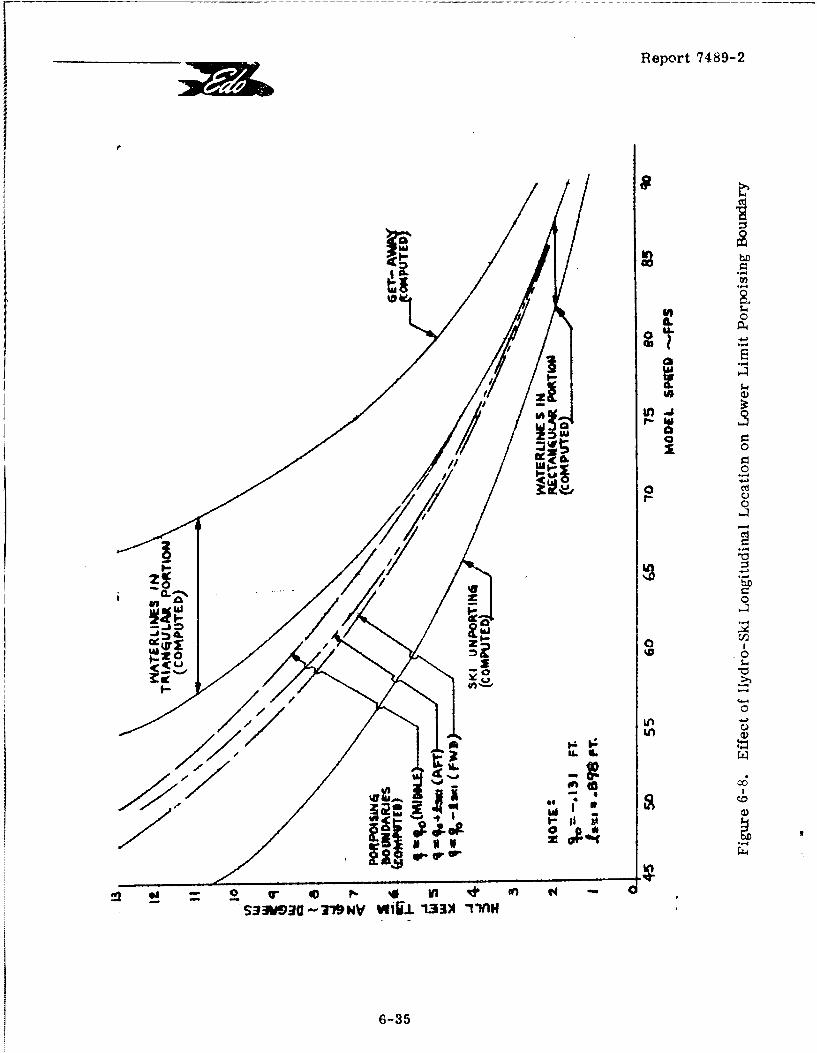
Report 7489-2
ZI'
0 Cd
o 0
z 0z
4L0UA (V£
P.20 .0
4c00/4 >fl
LC)
LL01,z
LCD
S33W3I-"NVVfiU1-33)1 TlHi
6-35
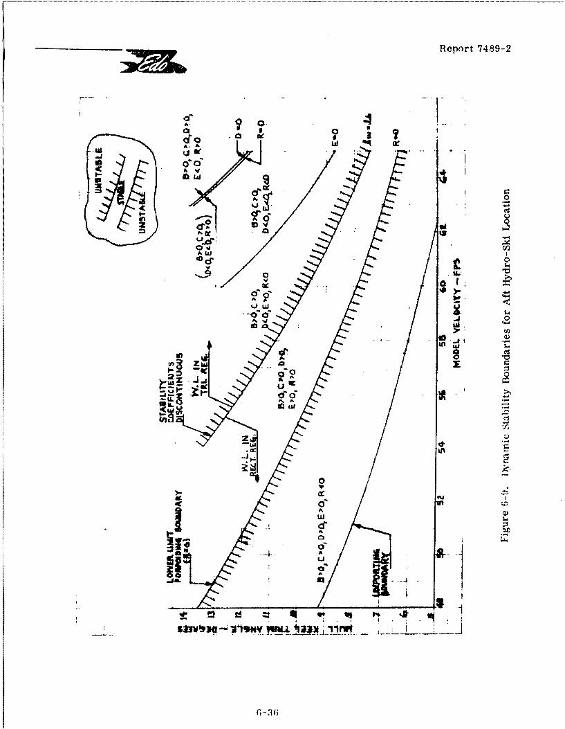
Report 7489-2
CC
A 2)00 c0
A..A .
A.x ...
LL.
1 ---
"I~
-ul 5-
A.•
-.-. UA •
53%l-. =i~N -I • ,
(; - :1 6
___________Report 7489-2 1-Me
On the other hand, if the ski is sufficiently far aft, the discontinuities -:n!:ociatedwith the waterline location become sufficient to counteract the positive stability that wouldotherwise exist ant' then result in negative stability for all waterlines in the triaugularregion. Thus, as clearly illustrated in Figure 6-9, the net undesirable result is to limitSthe region of positive dynamic stability to a relatively narrow band, all totally apart fromfurther possible limitations associated with upper limit porpoising. While it would obvi-
ously be of considerable interest to define more closely the precise aft location at whichthis novel phenomenon first occurs, this item was not investigated.
It Is supposed that a kindred phenomenon occurs in the planing stability character-istics of seaplane hulls having pointed (so-called "faired') steps. Although its beam loadingwill generally be substantially lower than that of a ski, the two configurations may otherwisebe considered comparable if the step "point" is identified with the ski T. E. If this analogyis indeed valid, then it could possibly account for the unusual "unstable 'islands' in the trimlimits of planing stability" mentioned on p. 5 of Reference 6-1.
REFERENCES
S6-1 NACA TN 1290: "Appreciation and Determination of the Hydrodynamic Qualitiesof Seaplanes," by J. B. Parkinson, May 1947.
S6-2 Milne-Thomson, -L. M. : "Theoretical Aerodynamics," 3rd Ed., Macmillan &Co., Ltd., London, 1958.
S6-3 Convair (Division of General Dynamics) Report No. ZH-139: "Towing TankEvaluation of Hydro-Ski Alighting Gear," by W. B. Barkley, October 1959.
[ 6-4 Martin Company Report ER10501: "Summary of Mach-2 Patrol Seaplane Studies,"
by H. L. Meyer, November 1958.
S6-5 ETT Unnumbered Report: "Analytical Determination of Lower Limit Stabilityof Flying Boats," by C. T. Froscher (LCdr, USN) and R. B. Greenwood
S [(LCdr, USN), May 1951.
[[
I
-I Report 7489-2
7. WAVE RESPONSE CHARACTERISTICS OF THE SKELETON HYDRO-SKI SEAPLANE
7-1 INTRODUCTION
As made clear by Figure 5-6 in Section 5 of this report, it is the high beamloading of the hydro-ski which gives rise to its load alleviation capability in single impa' ts,particularly as compared with the conventional seaplane hull. Equally dramatic and im-portant is the ability of the hydro-ski to reduce the seaplane's motions and accelerationswhen planing in rough water. As has been further clarified in Section 2, above, this capa-bility plays a fundamental role in the design of hydro-ski installations, thus making it man-datory for the designer to have available certain basic parametric studies relating to thewave response characteristics of hydro-ski seaplanes. Such data, covering as a minimumthe effects of the principal ski installation and aerodynamic parameters, could be of twotypes:
A) Experimental data as obtained from towing tank model tests and/or,preferably, full-scale flight tests;
B) Conceivably, theoretical data, as obtained from a suitable computerprogram. Such a program would, of course, have the additionaladvantage of permitting calculations to be made for specific configu-rations in lieu of or, at least prior to model tests.
At this time, the vast expense and practical difficulties involved in flight testinghave ruled out this source of information. Further, with but one exception, no genuinemodel test parametric studies have been sponsored nor is there presently in existence acomputer program relating to this subject. Considering further that the establishment andvalidation of such a program, ever with many inherent limitations, would be far more eco-nomical than model test studies. the achievement of this goal was established early duringthe current project. This report section gives:
A) A detailed description of this program;
I B) A comparison of calculated wave responses with the few availableexperimental data.,
Outputs of the computer programn for determlnation of wave response furnishescertain important practical information for hydro-sid installation design. As in Section 6,this program is based on the assumption of a "skeleton" hydro-ski seaplane. thus neglectingwetting of the hull. For a given configuration, one of the program outputs is the maximumsubmergence of the ski below the wave surface. This quan:ity is directly related to the mi-nimum strut length (alternately, the clearance between hull and ski) required to ensure thatno hull wetting occurs during high-speed taxiing.
7-1
[ Report 7489-2
Thus, the program furnishes an important criterion for strut length require-ments. It will. of course, be appreciated that this is only one of several critertA involvedin the selection of strut length. Some of the others are:
1) The strut length required to avoid hull after-body wetting in smooth waterat high trims %*to eliminate high angle porpoising tendencies and to reduce[ drag);
2) Avoidance of excessive strut length to reduce strut drag prior to unportiug;
F 3) Avoidance of excessive strut length to reduce directional instabilities,usually associated with forward ski locations;
4) The strut length required to reduce spray ingestion into engine intakesand/or propeller disks at or near unporting.
A more complete fiscussion of this entire problem area is given in Section 2of this report.
Unlike the planing stability program described in Section 6, this computer pro-gram is very -omplex because it has been deliberately based on a highly non-linear mathe-matical modei for the hydro-mechanics of the ski. Actually. a much simpler linear mathe-matical model might have been selected. Accordingly, an explanation of this choice is givenin Section 7.2 prior to the description of the non-linear analysis.
C 7.2 WAVE RESPONSE THEORY
Sr7.2.1 Linear Approach
In the preceding report section, the linearized, two degree-of-freedom equationsof motion were used to analyze the problem of dynamic stability of the skeleton hydro-ski[ seaplane in smooth water. Using well-known procedures, the same equations of motioncan also be modified to determine the motion of the planing hydro-ski seaplane in waves, pro-[ vided that the wave height is "sufficiently low".
If attention is restricted to the relatively simple case of regular, head-seawaves, the actual procedure is to consider the wave motion as a small perturbation of thesmooth water condition and to determine analytically the associated periodic hydrodynamicforces acting on the moving ski. After a suitable linearization procedure, that is, the eli-r mination of products of all small quantities (wave height, motion amplitudes and velocities),these periodic forces are then introduced on the right-hand side of eqs. (6-6). By well-known techniques, the resulting equations can be solved to yield the steady-state responsesolutions for h (t) and r (t), i. e., the persistent motions which follow the disappearance ofthe transient motiois excited by any specific disturbance.
7-2
_Report 7489-2
It is further obvious that the "2lytical determination of the steady-state re-sponse could have been established by a relatively simple extension of the analysis given InSection 6. This extension would consist of another computer program, involving the wavelength L as an additional parameter.
It is equally obvioas that there are very severe limitations on the tpplicabilityof this approach to the realistic prediction of wave response of hydro-ski seaplaier. Whilethe motions of a ski-equipped seaplane in a given (regular) wave train may be assumed to bemuch gentler than those of a comparable hull-type seaplane (of -iimilar gross weight, di-mensions, and aerodynamic and propulsion characteristics), experience shows that even the
I ski-equipped vehicle will generally exhibit a non-lin3ar response for waves of fairly sm &llamplitude. It is readily appreciated, in fact, that totally apart from wave considerations,
I a planing hydro-ski is inherently a non-linear device for at least several reasons:
A) Even at constant trim, the ski lift and pitching moment do not dependlinearly on its draft;
B) More generally, the ski lift and pitching moment are complicatednon-linear functions of draft, trim, and their rates change, as can beseen directly from eq. (5-4);
C) The Anite ski length gives rise to relatively sudden changes in liftand pi, .hing moment at (or near) ski submergence.-
Depending on wave height and wave length, some or all of these non-linear ef-fects can be important in the wave response problem. Thus, whereas the linearized theoryis capable of furnishing meaningful and practical information in the problem of the planingJ stability, it fails to do this for the wave response problem except in the uninteresting case3f extremely small wave heights.
7.2.2 Non-Linear Approach
Based on the foregoing considerations, it was decided to establish a computerprogram for the calculation of the wave response motions of a skeleton hydro-ski seaplanewhich would account for all of the known non-linearities. It was appreciated initially that,at least in principle, certain difficulties are inherent in the interpretation of such calcula-tions, for the following reason.
Whereas in the linearized approach, the steady-state response is completelyindependent of the initial conditions, this is no longer true when the equations and resultingmotions become distinctly non-linear. For example, this means that, if a time history iscalculated with one choice of initial conditions and is then repeated with all inputs the sameexcept with different initial conditions, the "steady-state" motions (those prevailing after asufficient time for the stable transient motions to damp out) may be distinctly different andshow large discrepancies in such key features as impact acceleration magnitudes, diving
V tendencies, etc.
21 7-3
rReport 7489-2
No 'a priori" answer tW this problem area can be provided at this time, in part5 because of the existing lack ol experimental data required for comparison purposes. The
approach taken in this report is a statistical one, wherein several "rums" are made for eachcase with different initial conditions. This procedure is essentially identical with that cur-rently employed In towing tank tests for determining the planing (alternately, landing) be-havior of seaplanes in rough water, wherein the moving seaplane model is dropped into thewave train in an arbitrary manner and a number ot runs are repeated to obtain statisticaldata.
r It is obvious that this approach requires some "rules-of-thumb" to insure vail---5 ;dity and proper interpretation of the statistical data. In the past, it has been stated (without
clear pro-f) that a minimum of seven runs for each case are required in tank tests to obtainvalid tesL result samples. However, because of practical limitations, many programs haveutilized as few as three or four runs.
Clearly, resolution of this problem area in this report would be entirely prema-tare. Instead, the arbitrary decision has been made to restrict the number of runs to fivefor each case. Further, also following standard tank test procedures and runs are madewith all (arbitrarily selected) initial conditions the same except for the initial location of theski relative to the wave train. This selectior has also been influenced in part by the resultsobtained in Section 5 of this report which have iudicated the importance of this parameter insingle ski impacts.
7.3 DESCRIPTION OF COMPUTER PROG,•A M
S7.3.1 General Description
The purpose of the prograija is to calculate the time history of the motions of askeleton hydro-ski seaplane when planing through waves. Several restrictuons. previouslyused in the planing stability analysis of Section 6 and the ski impact analysis of Section 5,have been retained:
A. The seaplahe's horizontal speed is maintained constant in each run and,cc rrospoiidingly, there are only two degrees of freedom (heaving andpitching);
B. The longitudinal control setting (elevators, stabilizer, etc.) Is maintainedconstant ir. each ,un and the pertinent aircraft aerodynamic characteristicsare assumed to be inlepcndent of this control setting;
C. No direct accound of power effects is taken in thu a4.rcraft's aerodynamiccharacteristics;
D. The wave train is assumed to consist of regular sinusoidal waves withthe aircraft running in the head sea condition.
7-4
*1 Report 7489-2
If It may be noted that these assumptions readily permit accounting for accompanying headwinds, if desired.
1 It will further be noted that the program is capable of being amended to removepractically all of these restrictions provided that the ensuing complications are acceptable.Even the "stick-fixed" restriction can be eliminated and replaced by an "autopilot-type" ofJ mathematical model simulating a pilot's control actions.
The computational procedure followed in the program is as follows:
1 1. The entire program, including all inputs and computer print-out, usesnon-dimensional quantities. The non-dimensionalization of all quantities,kinematic and dynamic, is effected through consistent use of two referencevalues as follows:
J DIMENSION REFERENCE
Length Ski Beam, b
I Time Ski Beam/Horiz. Velocity, b/V1 H
2. To permit calculation of the changes in the two coordinates, heave andpitch, and associated heaving and pitching velocities, inside of a smalltime interval, the two differential equations of motion are approximatedby suitable difference equations.
3. The aero and hydro loads (i.e., forces and moments) are defined analy-tically in terms of the kinematic quantities. In the case of the hydroloads, these relations also depend on the geometric relations betweenthe ski, the local wave surface, and the resultant velocity vector withspecial distinctions made between the various possible configurations(ski planing, ski submerged, and immersed bow). as explained in moredetail below.
4. Starting with specified initial conditions, including a specified location ofthe wave relative to the ski, the equations of motion are solved step-by-step, using the load values from Step 2. Through use of the "Hamming-predictor-corrector" technique, the time increment used in each step isautomatically made sufficiently small to insure continuity of the kinematicvariables.
5. The computer print-out concludes the following instantaneous quantities(all non-dimensional):
I1 7-5
F •Report 7489-2
a. Time;
b. Heave (height of c.g. above the level water line relative toequilibrium value);
c. Heave velocity;d. Heave acceleration;
e. Trim angle (angle of hull reference line (keel line) relative to horizon;
f. Pitching velocity;
g. Pitching acceleration;
h. Bow vertical acceleration (at a specified distance forward of c.g.)
L. Ski Bow Submergence (vertical distance of bow below local wave surface);
j. Ski Draft (vertical distance of ski stern below local wave surface);
[ k. Ski wetted length;
1. Wave slope (relative to the level water line, measured at ski-water line[ intersection).
* 7.3.2 Equations of Motion
The basic equations of motion are identical with those used in the analysis ofplaning stability, i. e.:
(W/g) H = L +L H-W
S.. M M(7-4)
SI T MA + MH
where it is understood that the motions involve a constant horizontal speed and fixed aero-dymanic controls. The particular control settings are those which furnish a particularequilibrium trim angle at the same horizontal speed. This equilibrium condition is de-Lscribed by the equations:
SAeq L Heq i
(7-5)M = 0
7-6
1__ •Report 7489-2
J Subtracting eqs. (7-5) respectively from eqs. (7-4),
(W/g)" = (LA - LA eq) H eq)
(7-6)
(IT" = MA eq) +(MH_ MHeq)
In these equations, H represents the instantaneous height of the c. g. above thelevel water line. It was found more convenient to use as the vertical coordinate a quantity,h, defined by the relation:
eq (7-7)
h is identical with the quantity, (h), used in Section 6 and the final basic form of theequations can be taken as:
I (W/g) h" = (LA - LA) + (LH - LHeq)
(7-8)
II = (MA- MAeq) + (MH - MHeq)
The horizontal motion of the wave train is taken relative to a vertical planethrough the aircraft c. g. so that the general expression for the wave height can be written as:IH=w sin [L 2 7r(!-T-L) - (7-9)
where: x = horizontal coordinate relative to aircraft c. g., (positive for forwardlocations)
T= L/(VH+ 4(g/27r)L
I 0 = wave phase angle.
J To obtain time histories of the aircraft motion, it is necessary to solve equations(7-8) subject to a set of four initial conditions, typically the initial values of h, r , h, andr . In addition, It is possible to select a value of 0 in eq. (7-9) so as to fix an initial wavephase relative to the aircraft in some particular manner. In the present program, only threeof these five quantities are specified explicitly: these are r o, (h). , and ( - )o . Note thatr, is not necessarily identical with r eq.) The other two quantities, i. e., ho and 0, are
Zr 7-7
rr Report 7489-2
specified implicitly through the explicit specification of the initial values:r T o'-.V [ ((@ski T. E-1 (H/2) sin[2 r/L) (psin T - q cos To)~](-0W F 91(7-10)
T F. drat--o (0= w(skiT.E. +[••-cos ro + qsinTo - Heq-hF rE~rft] F(@kT.. +q
where p and q are the quantities defined in the sketch of Appendix C.
Integration of the equations of motion, subject to the initial conditions just de-scribed, requires a knowledge of the explicit dependence of the aero and hydro loads on allof the pertinent geometric and kinematic variables. Essentially, the aero loads depend onlyon the kinematic variables and can be defined in the same manner in Section 6. The hydroloads are strongly dependent as well on the geometric variables locating the ski relative tothe wave surface. It is obvious, in fact, that provisions must be contained in the program tocover a variety of possible ski-wave geometric configurations. For certain of these confi-gurations, neither experimental nor analytic load values are presently available, even forthe corresponding steady-state condition of uniform motion in smooth water. It thereforewas necessary to devise entirely new expressions for such cases. Because of the resultingprogram complexity, it was decided to limit the analysis, for the submerged condition only,to skis of purely rectangular planform.
[7.3.3 Aerodynamic Loads
Basically, the static airload variations with trim are assumed to resemble thoser measured on the unpowered HU-16 model. For this model, the lift curve is linear below the
stall, exhibits a sharp break at the stall, and, above the stall, is again linear with a negativeslope. For large up elevator angles and neglecting some slope reduction just below the
r stall, the moment curves can be closely approximated by straight lines throughout the entirepo•itive trim range.
r Then, consistent with the treatment of Appendix C, the airload terms in theequations of motion can be written as:
L LA =q S C -SwCL eq (l+de/da)StCLt(T lt/VH}A Ae A E -L-T hVý wLT~] a* tM MAeq =q Sw CM K (h/VH) r -(1.1 + de/da)SlC *(rt V
A ~ A~w Ma K_ H eqj St~tL-t tH
SNote that, below the stall, the lift equation takes the simplified form:
1 7-8
SReport 7489-2
LA LAweq wcLa H -(/VH)- T eqj :lded)StCLat'T It/VH))
J The present program format has been based on the specific types of lift andmoment curves described above. However, the accommodation of more general types of
aerodynamic curves (with or without power effects) can be readily effected, if desired, byobvious program modifications.
I7.3.4 Hydrodynamic Loads
During the high speed portion of the rough-water landing or take-off run of ahydro-ski seaplane, the hydrodynamic loads on the hydro-ski can result from several dis-tinctly different flow conditions. Speaking most generally, the loads developed depend on therelative ski-wave location, the ski trim relative to the wave surface, and the resultant velo-
i city direction of the ski.
At the present time, theoretical and experimental data for prediction of hydro-ski impact load time-histories only cover those cases where the hydro-ski impacts thewater surface at zero or positive trim. Further, although the existing analytical methodscan account for variation of trim during the impact process, load calculation methods arenot currently available for negative trim impacts, and/or negative angles of attack in the vi-cinity of the free water surface. Consequently, for a non-linear wave response computerprogram which is required to cover all realistic impact conditions, it was found necessaryto develop analytic expressions for the hydro loads in those conditions which have not yetbeen considered in the literature.
Appendix D of this report furnishes a complete statement of the hydro-ski liftforces and moments used in the wave response program. Wherever novel expressions orvalues are used, they are believed to represent reasonable engineering approximations forwhat are, actually, relatively complex flow conditions.
While the individual expressions for the loads are considered realistic, the"transitions" between the flow regimes involve some artificiality in that they are taken as"sharp" ones. That is, the loads generally vary by finite amounts in crossing a "regimeboundary", even though the differences in geometric and/or kinematic parameters may bevery small. This results in (generally small) isolated discontinuities ('"icks") in the com-puter outputs which, of course, must be disregarded in the interpretation of the results.
Such discontinuities, of course, could be eliminated from the program by use ofmore refined (continuous) definitions of the boundaries separating the regimes. To naveeven attempted this in the present program would have increased the required effort by aninfeasibly large factor. In addition, the resulting program complexity would probably haveexceeded the capacity of this contractor's computer (IBM 1130). In short, while these dis-continuities detract from the reality of the mathematical model, this defect is considered tobe a tolerable one at the present stage of understanding of this problem area.
"7-9
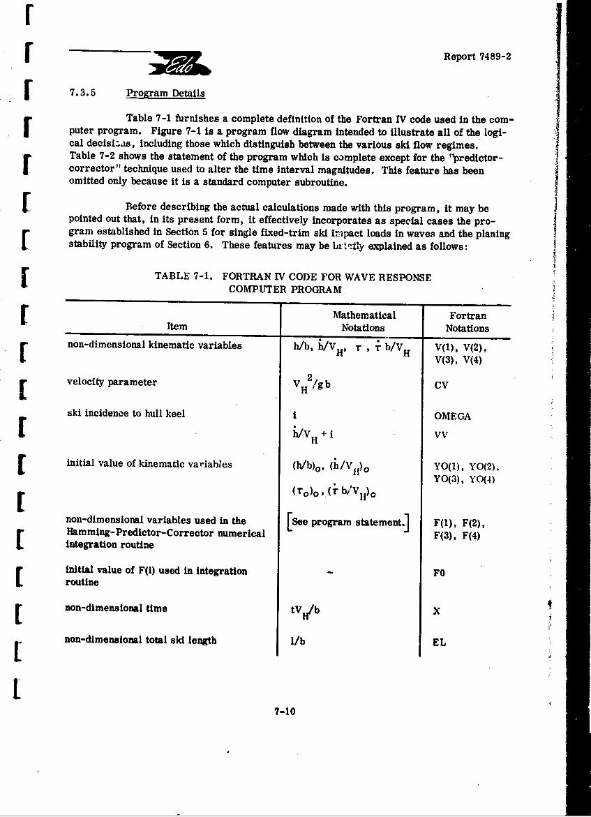
rf Report 7489-2
F 7.3.5 Program Details
Table 7-1 furnishes a complete definition of the Fortran IV code used in the com-puter program. Figure 7-1 is a program flow diagram Intended to illustrate all of the logi-cal decisiLas, including those which distinguish between the various ski flow regimes.Table 7-2 shows the statement of the program which is complete except for the "predictor-corrector" technique used to alter the time interval magnitudes. This feature has beenomitted only because It is a standard computer subroutine.
Before describing the actual calculations made with this program, it may bepointed out that, in its present form, it effectively incorporates as special cases the pro-r gram established in Section 5 for single fixed-trim ski irmpact loads in waves and the planingstability program of Section 6. These features may be bxr.fiy explained as follows:
TABLE 7-1. FORTRAN IV CODE FOR WAVE RESPONSECOMPUTER PROGRAM
Mathematical FortranItem Notations Notations
non-dimensional kinematic variables h/b, /V H , r b/VH V(1), V(2),
V(3), V(4)
velocity parameter V H 2/g b CV
ski incidence to hull keel I OMEGA
[ h/vH V W
[initial value of kinematic variables ( , (h/V i)o YO(1), YO(2)
(1o)o,( b°VH)O YO(3), YO(4)
non-dimensional variables used in the [See program statement.] F(l), F(2),Hamming-Predictor-Corrector numerical F(3), F(4)integration routine
initial value of F(i) used in integration FOroutine
non-dimensional time tVj/b XII 1non-dimensional total ski length l/b EL
77-10
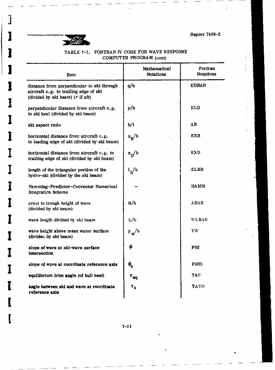
2Report 7489-2
J TABLE 7-1. FORTRAN IV CODE FOR WAVE RESPONSECOMPUTER PROGRAM (cont)
J |Mathematical FortranItem Notations Notations
I distance from perpendicular to ski through q/b EDBARaircraft c. g. to trailing edge of ski(divided by ski beam) (+ if aft)
perpendicular distance from aircraft c. g. p/b ELDI to ski keel (divided by ski beam)
ski aspect ratio b/l AR
I horizontal distance from aircraft c. g. xB/b EXBto leading edge of ski (divided by ski beam)
I horizontal distance from aircraft c. g. to x D/b EXDtrailing edge of ski (divided by ski beam)
I length of the triangular portion of the 1 b/b ELBBhydro-ski (divided by the ski beam)
I Ham ming- Predictor- Corrector Numerical - HAMMIntegration Scheme
I crest to trough height of wave H/h ABAR
(divided by ski beam)
I wave length divided by ski beam L/b WLBAII
wave height above mean water surface y w/b Y\V(divided by ski beam)
slope of wave at ski-wave surface PHIintersection
slope of wave at coordinate reference axis so PHIC
equilibrium trim angle (of hull keel) req TA U
angle between ski and wave at coordinate To TA UOreference axis
[7-11.
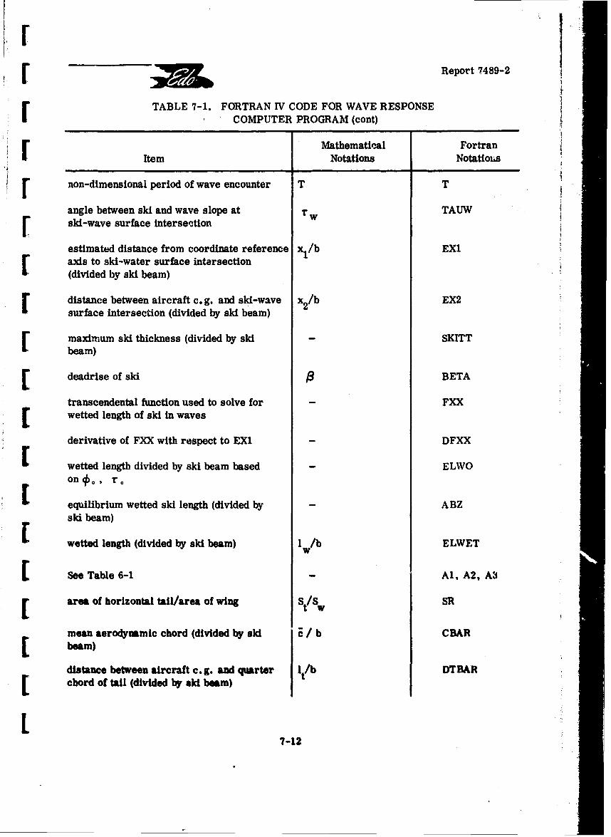
IF Report 74 89-2
TABLE 7-1. FORTRAN IV CODE FOR WAVE RESPONSECOMPUTER PROGRAM (cont)
Mathematinal FortranItem Notations Notatioizs
IF non-dimensional period of wave encounter T T
angle between ski and wave slope at T TAUWski-wave surface interse-ftion
estimated distance from coordinate reference x l/b EXIaxis to ski-water surface intersection(divided by ski beam)
distance between aircraft c.g. and ski-wave x2/b EX2
surface intersection (divided by ski beam)
S maximum ski thickness (divided by ski SKITTbeam)
E deadrise of ski 3 BETA
transcendental function used to solve for FXXC wetted length of ski in waves
derivative of FXX with respect to EX1 DFXX
[ wetted length divided by ski beam based ELWOon#o, r0
equilibrium wetted ski length (divided by ABZski beam)
wetted length (divided by ski beam) w/b ELWET
S See Table 6-1 Al, A2, A3
[ area of horizontal tail/area of wing St/Aw SR
mean aerodynamic chord (divided by ski d / b CBARbeam)
distance between aircraft c.g. and quarter lt/b DTBARS chord of tail (divided by ski beam)
L7-12
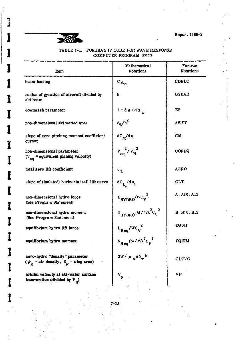
IReport 7489-2
TABLE 7-1. FORTRAN IV CODE FOR WAVE RESPONSECOMPUTER PROGRAM (cont)
Mathematical FortranItem Notations Notations
J beam loading C 0 CDELO
radius of gyration of aircraft divided by k GYBARski beam
downwash parameter 1 + d e / d a EF
non-dimensional ski wetted area SW/b 2 AWET
slope of aero pitching moment coefficient dCM/d a CMcursor
non-dimensional parameter Ve 2 / VH2 COREQ(V eq = equivalent planing velocity) q
total aero lift coefficient CL AERO1L
slope of (isolated) horizontal tail lift curve dCLt/dat CLT1non-dimensional hydro force L HYDR/WCv2 A, A10, A12
(See Program Statement)
non-dimensional hydro moment NHYDRO(b) /\Wk C v B, BIO, B12(See Program Statement) HYDRO V
equilibrium hydro lift force L eq/WC2 EQUIF
equilibrium bydro moment N H eq (b) / \Vk2 CV
Saero-bydro 'density" parameter 2W/ PA g W b CLCV'G
( p air density, S = wing area)
orbital velocity at ski-water surface V VPI ntrsection (divided by VH) P
7-13
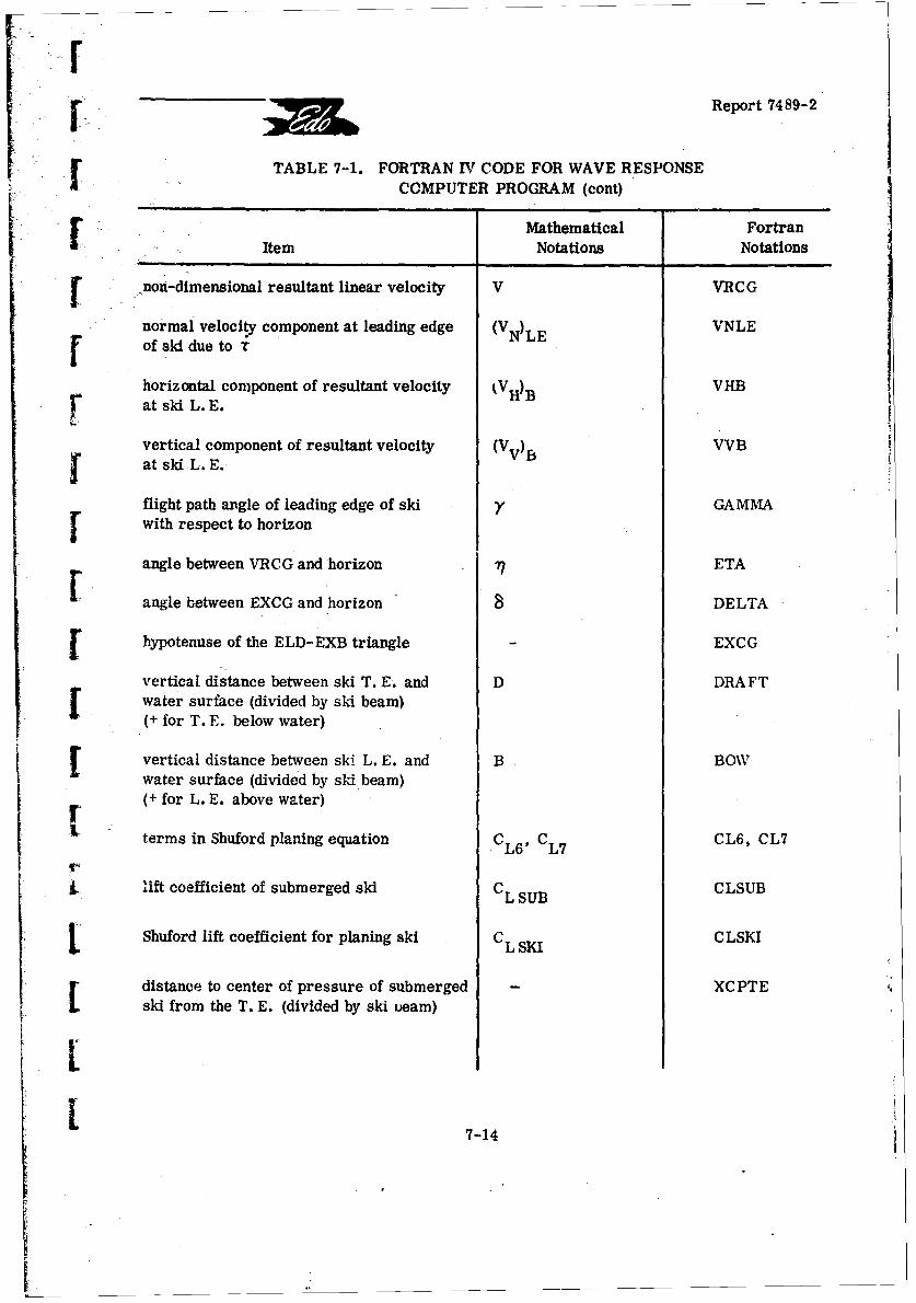
1 Report 7489-2
TABLE 7-1. FORTRAN II CODE FOR WAVE RESPONSECOMPUTER PROGRAM (cont)
SMathematical Fortran
Item Notations Notations
[ non-dimensional resultant linear velocity V VRCG
normal velocity component at leading edge (V N)LE VNLEof ski due to r
horizontal component of resultant velocity kVH)B VHBat ski L. E.
vertical component of resultant velocity (Vv)B BSat ski L.E.
flight path angle of leading edge of ski y GAMMAwith respect to horizon
angle between VRCG and horizon 1 ETA
angle between EXCG and horizon S DELTA
fhypotenuse of the ELD-EXB triangle EXCG
vertical distance between ski T. E. and D DRAFTwater surface (divided by ski beam)(+ for T.,E. below water)
Evertical distance between ski- L. E. and B BOWwater surface (divided by ski beam)(+ for L. E. above water)
terms in Shuford planing equation CL 6 , CL7 CL6, CL7
'lift coefficient of submerged ski CL SUB CLSUB
Shuford lift coefficient for planing ski CL SKI CLSKI
distance to center of pressure of submerged XCPTEski from the T. E. (divided by ski ueam)
7L7-14
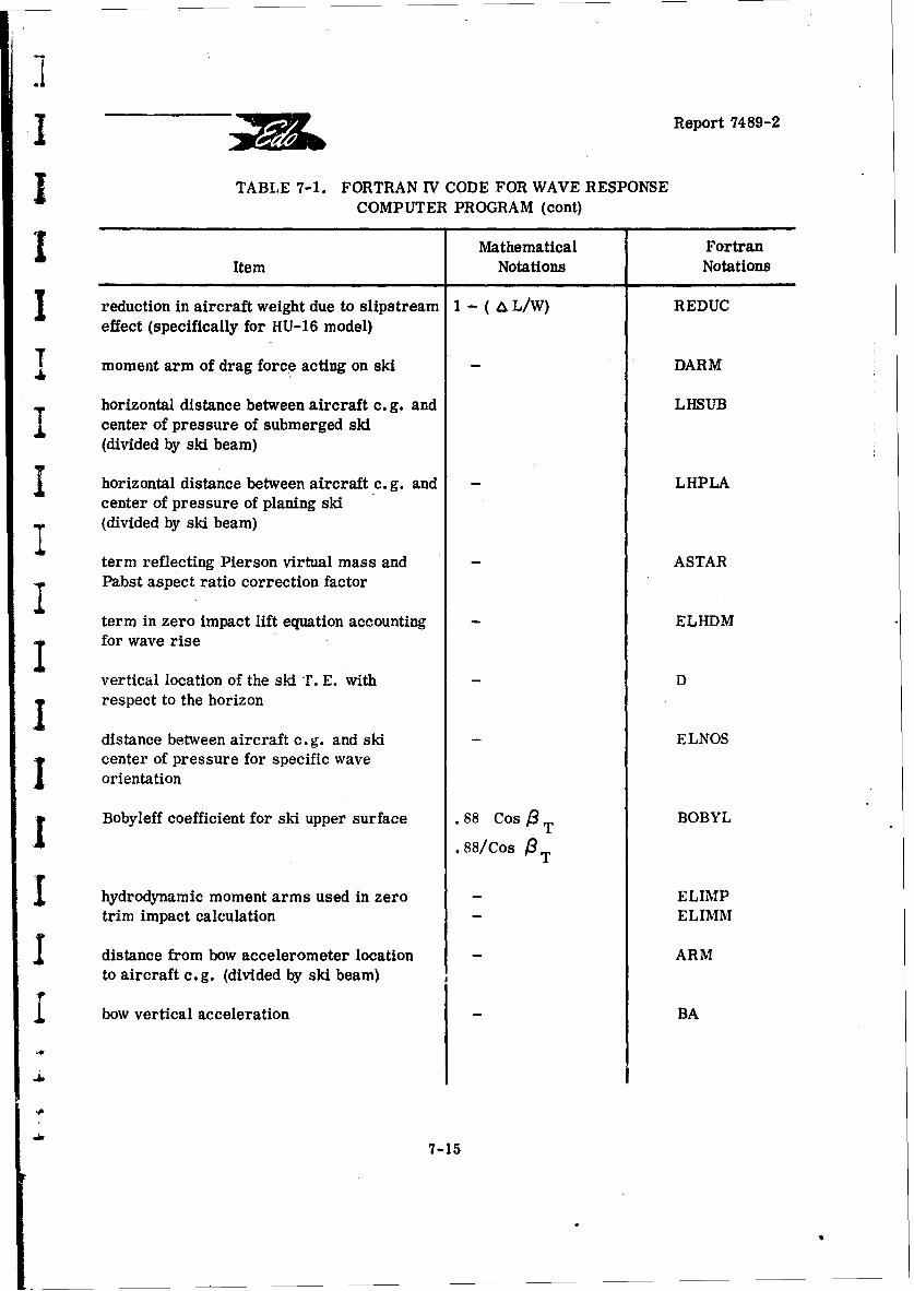
Report 7489-2
TABLE 7-1. FORTRAN IV CODE FOR WAVE RESPONSECOMPUTER PROGRAM (cont)
Mathematical FortranItem Notations Notations
reduction in aircraft weight due to slipstream 1 - ( A L/W) REDUCeffect (specifically for HU-16 model)
T moment arm of drag force acting on ski - DARM
horizontal distance between aircraft c. g. and LHSUBcenter of pressure of submerged ski(divided by ski beam)
I horizontal distance between aircraft c. g. and - LHPLAcenter of pressure of planing skiI (divided by ski beam)
term reflecting Pierson virtual mass and - ASTARz Pabst aspect ratio correction factor
term in zero impact lift equation accounting - ELHDMfor wave rise
vertical location of the ski r. E. with - Drespect to the horizon
distance between aircraft c. g. and ski - ELNOScenter of pressure for specific waveorientation
i Bobyleff coefficient for ski upper surface .88 Cos )T BOBYL
.88/Cos GT
I hydrodynamic moment arms used in zero - ELIMPtrim impact calculation ELIMM
I distance from bow accelerometer location ARMto aircraft c.g. (divided by ski beam)
{ bow vertical acceleration BA
7-15
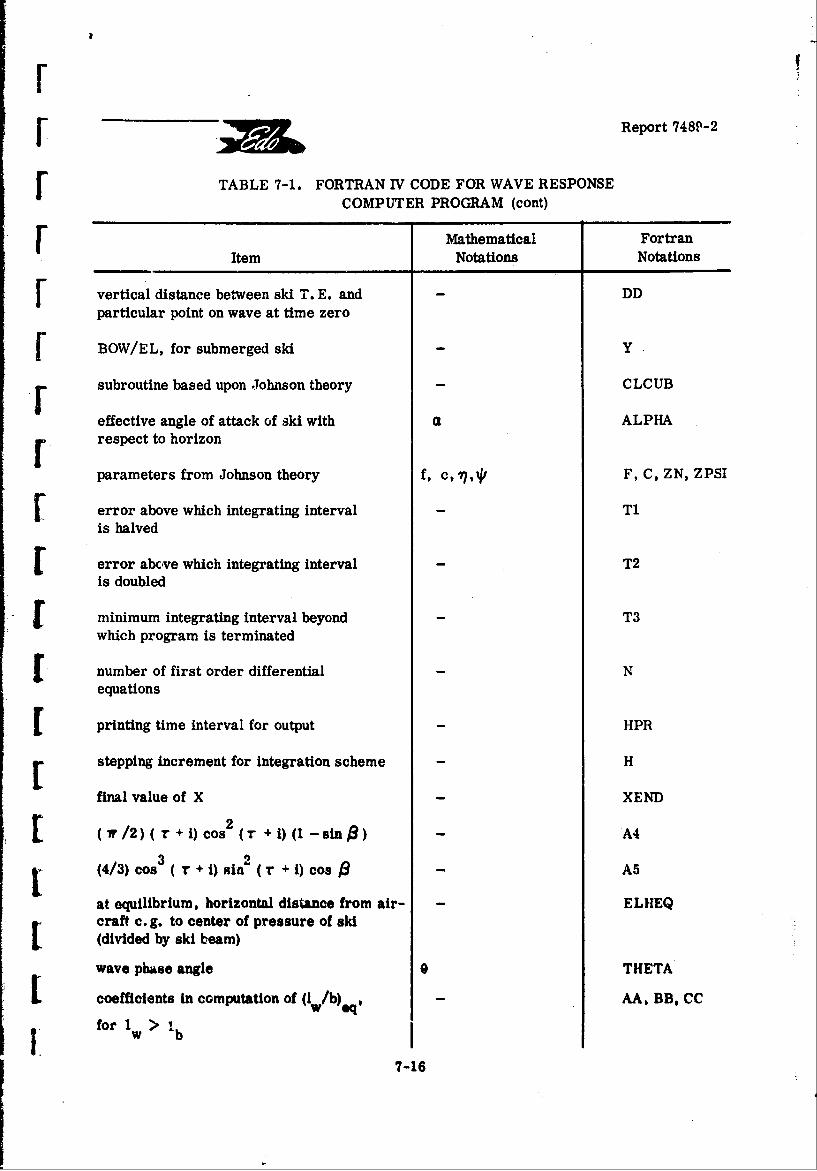
SReport 748P-2
[ TABLE 7-1. FORTRAN IV CODE FOR WAVE RESPONSECOMPUTER PROGRAM (cont)
Mathematical FortranItem Notations Notations
[ vertical distance between ski T. E. and DDparticular point on wave at time zero
[ BOW/EL, for submerged ski Y
r subroutine based upon Johnson theory CLCUB
effective angle of attack of ski with a ALPHAF respect to horizon
parameters from Johnson theory f, c, *,I F, C, ZN, ZPSI
[error above which integrating interval - Tiis halved
[error abcve which integrating interval - T2is doubled
Fminimum integrating interval beyond - T3which program is terminated
[number of first order differential Nequations
Eprinting time interval for output HPR
[stepping increment for integration scheme H
final value of X XEND
[ (r/2)(r +i) cos 2 (r + i) (I -sin$) - A4
(4/3) cos3 ( T + i) sin2 (r + i) cos - A5
at equilibrium, horizontal distance from air- - ELHEQLcraft c. g. to center of pressure of ski(divided by ski beam)
wave phase angle 0 THETA
coefficients in computation of (I /b), - AA, BB, CC
for 1 > Ib
7-16
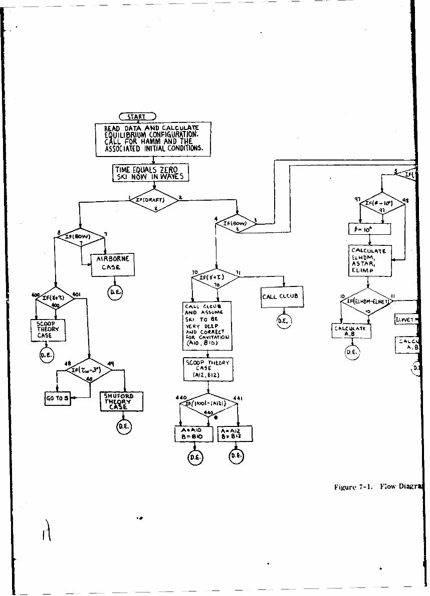
READ DATACAD CALLuLAT
TIME~A EQULS ER
XF(ORAFT)J~
CACALCULAI
A ~5 T70 E L- i M
40~~~~~~Fgr 4-0. CALL DiagCLrCCB101(EHM-L
AND AS~u0
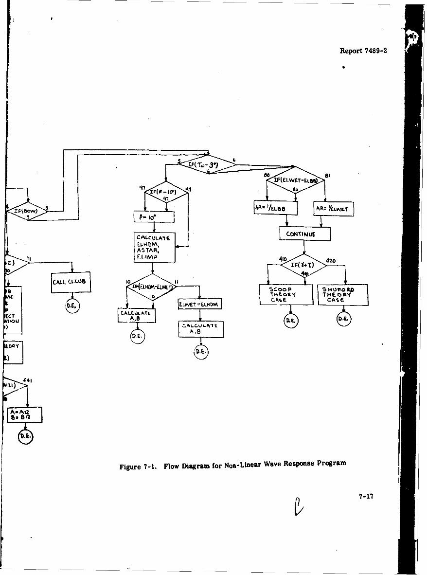
Report 7489-2
60
ELLVAD LAb'
ECT ACNII
) OQY
441
Figure 7-1. Flow Diagram for Non-Linear Wave ResponSse Program
7-17
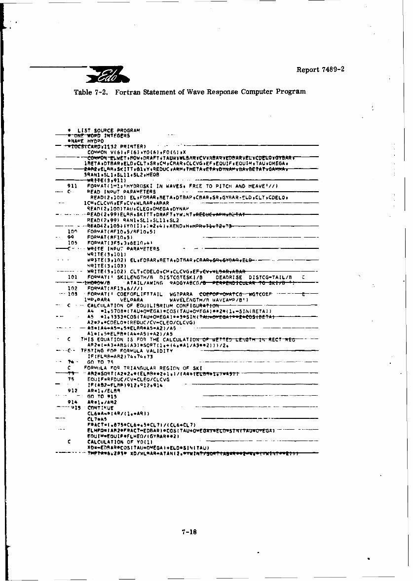
Report 7489-2
Table 7-2. Fortran Statement of Wave Response Computer Program
* LIST SOURCE. PROGRAM0 urNr. WORD ttf'TFG~rRS*NAME HYDRO
- effCROIM4 2 PRINTERICOMMON V16) ,P(6) .YO(f1) FO16) ,X
1RETADTBARELDCLTSRCMCIRARCLCVGFFEQUIFEQUIMTAUOMEGA,-4AfttwfLRAoiSITTG1,YREDIJC ARMTHfTA.CTA,D..Ag VBA,CCYAY-iGAMMAA3RANl*SL1,SL11,5L29HEQB..RfT(S,9911)
911 FORMAT(l1M1,HYDR0SKI IN WAVES* FREE TO PITCH AND HEAVE'//)C- READ INPUT PARAMETERS
READ(291001 ELoFDRAR,8ETADTARAPCBARSRGYAARý'-LDCLTCDEL0,1Ckt9CLCV~vEF9CV9WLBAReARARR EAr, ( 2,9100) TAU 9CLEOQ*OMEGA go YNAW
- --* -QEAD (2 999 LRF%9SK ITT #DRAFT oYW;NT vUC.e AP1.D...TATREAD(?,99) RAN19SL~ItSLI11SL2
ion FORMAT1AFIOe5/RE1O.5)94q FORMAT(AF1O*S) -___--- _
105 FOPMAT(3FS*3v6E10*&1"-Wi-TE INPUT PARAMETERS -
WRITE(39101)WRI-TE(391021 E~FS~BToTAtARS~aBRr----WRITEC 3,103)
- -- WRITE139102) CLT9CDEL09CM9CLCVG9EF-vCvW BAR.AflAR101 FORMAT($ SKILENGTH/B DISTCCTESKI/B DEADRISE DISTCG-TAIL/B c
--- -i1'ORDW/e ATAIL/AWINGi RADGYABCCG'B PER IMA TZe 3%IIB '?102 FORN4AT(RF13*6///)10 -O FORMAT( I COEFOFLIFTTAIL WGTPARA E
lMP*PARA VELPARA WAVELENGTM/B WAVEAMP/B')C-. -- CALCULATION OF EOuILI9RIUM CONFIGUfRAIN-
A4 ul.57OA.(TAUOMEGA).COSCTAU+OmEGA)**2*c1.-SINLBETA))
A2.?.*CDELO.C REDUC.'CV-CLEO/CLCVG)" "6-A- jAd4+AS-&S*EL9R*AS-A2)/AS -__________
AluC 05*ELPR*1A4.A5).A2)/A5C THIS EQUATION IS FOR~ THE CACLTO rW"DL%1trMEC E
AR2uC-A3.ARSCA3)*SOPT(1.,14.*A1/A3**2)))/2.----- C-- TESTING POP FORMULA VALIDITY
IF IFL9S-A92 ) 74q7473-7* -- GO TO 75 -___
C FORM1JLA FOR TRIANGULAR REGION OF SKI
75 EOUIF@RFDUC/CV-CLEG/CLCVG- I~F(A82-FLRP)9l2*R12,9l4--912 ARa1./ELOR
-GO TO 915914 ARuI./AR2
CL6vA%*1AR/(1,.AR1)CL7*IkSF3ACTuI .1750CL6..SeCL7I /(CL6*CL7)ELNPOR IAP20FRACT-EDRAR I COS ITAU.ok4EGA IwffYSM I tA090- AlF0UImwfOUIF*FLHE0/1GYR1AROO?
C CALCULATION OF VO1i)XO..ELri)AROCOSgTAUOMEGA),ELD*SIN( TAU)
7-18
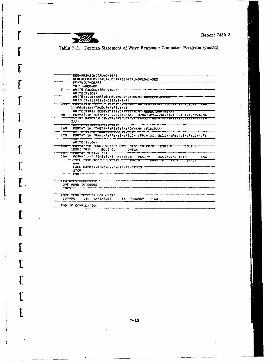
r Report 7489-2
Table 7-2. Fortran Statement of Wave Response Computer Program (cont'd)
Dr A14*S1q 1'rAUOM0EGA)______9EOV ELO*COS (TAU I EDBAR*S ZN (TAU.OMEGA I-DEO___________
VY01 )UDE0+DDN--WIECA-LCtiLATED VALUES -
WQZTE(39106)
kI!TE(3qIII)G1,(Y0( I 1.11s4)
[ 2//)
169 FORMAT11H 'THETAu',F8.5,3X,'OYNAMa'.Flc.5//)
170 FORMATC1H IRAN1019FS.4,3xISL1aeFB.4,3X,'SISB11uS.F 4,3XotSL2loF8
WRITE( 3,104)
1EGUI TRIm EQUI CL OMEGA '
104 FOmT/@TM9VBHEAVE/B VSKI/V ASKI/vV/B TRIM ANG[ VN-4 ANG -tKCEL- LVET7B3 Fum K I pAI~r IALJW UA //I
STOP
5 0ONF WORD INTEGERS
CORF[ e0.VAN 134 VARIABLES 56 PROGRPA 1168
FNO OF CnYPILA71ON _________________
7-19
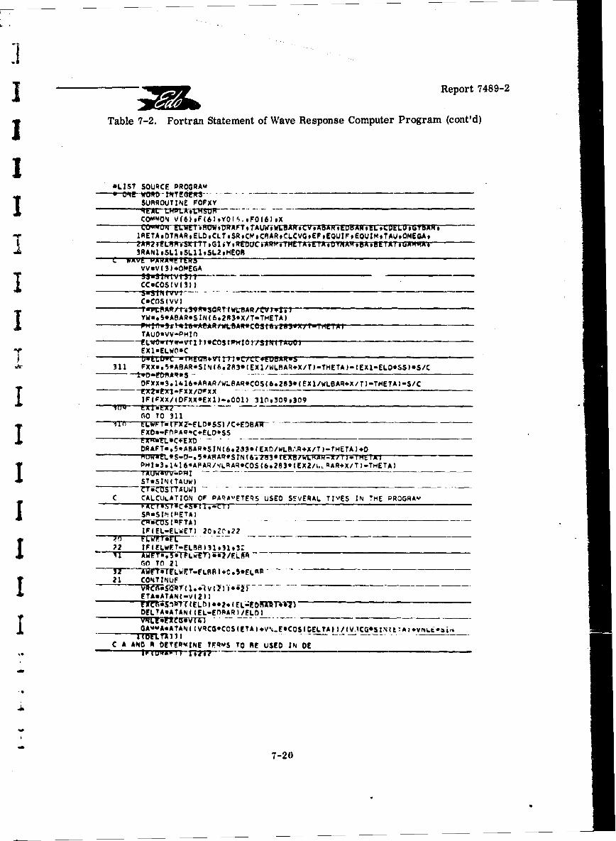
Report 7489-2
Table 7-2. Fortran Statement of Wave Response Computer Program (cont'd)
*LIST SOURCE PROGRAM _________ _______
SUAROUTINE FOFXYRE At tMPL'XetWS~w r - -_________________
YQANI#SL9SAR 1SINL293./TE HTA
311 3*OEG
CDFOSxm3.11.RRw)RCO(.8*E1wSA),)TEA-~
YWaRA8T5A8R*SZN(6*283*X/-TExDwLA)~/)rEA
_______ TAUS ZN C tAU~STTAU~J t -* 0 -~ 0__11___1_ __--__1__AM__
C CAELCUATON * PC MTR UE EEA IESZ M RGD-trI3 1 +V~STTMTFf Ct jb
GO TO 311
FXraiFnLAR*CELD*SS .L~- - _____________
21 CONTINUE ______________
_________ _______________________T)-T ETA)*
C A AC6TO OFRDTR~N TERM TO RE USED SEVRA TIf E IN!E -RG
IF(ELELWET- I 27-202

[ ~Report 748 9-2
Table 7-2. Fortran Statement of Wave Response Computer Program (cont'd)
2 IFIR OW) 49139'*-,- --1fPGAk4MA+V13))70970s71C THIS IS'Tii! SUBMERGED REGION
CALL CLCUM1CLSUAXCPTE)
VPu7.1*ABAR/SQRT(32.2OCV*WLRAR2#CCS(6.2S3*(LHSUB/WLBARX/Ti)-14f0( 1.2e 3.BOW/WLARq) -
OARmsEL"*CC-( XCPTE*EL-EDPAR) *S-A10 wCLSk)R*AWET*(1e+(V12)+VI44 *LMUs YP1Nm211i.*4_DL.QP1OuA1O*(LMSUB-DARM*(S/C )/GYRARee2ELNO~sm7*ELWFT-EORARCOREOUE (S.(VD-V(2I-V(4.I*ELNOSI*C2/ST2**2
-. IF(FIETAT)77.77978
7AfOAYL..PAR*COS C E TAT IflA@msELf*CC-(XCPTE*EL-EDFAR)*S-
79 A12080W*COREO*FACT*BORYL/CDELO- - *---B11-2.wA12*1LIISUA-OARM.IS/C) I/GYftRvv
IFIABSCA1O3-ARS(A123))44440,'4O'41*44C, AGA10-__
AGAlO60 T09 -____
441 AwA12
GO TO 0--1 CALL CLCUR(CLSUPXCPTE) __
LMSUP.FLO*S S.CXCPTF*EL-EOBAR 3*C
leEXPC ieA. 3*BOW/WLAAR I- DAUmELD*CC-(XCPTE*EL-EDMAR)*3-- ____
AaCLSUq*AWET.C1.,IVC2I*V(4I.LMSUB-VP)..2IIC2..CDELOI
GO TO 9C THIS IS THE ZERO T'qIM IMPACT'REGI`01% --- ~--- -. - --. ___
II _ _ _ _ _ _ __S? 5695 I~fPETA-e1~IQ7,5)79998 . ___________________
97 RETAee174SGO TO QA
9a CONIT I~uF
ELI--*FLWlCCET, *LMD%4ES AIF(FHD'AELWdR.OVqel jjI1GBR~
L Lf%8LPEAGASAR~tV-V.')-14)ELIM)#0*ELWT*DAFTIDEL
60 TO-11
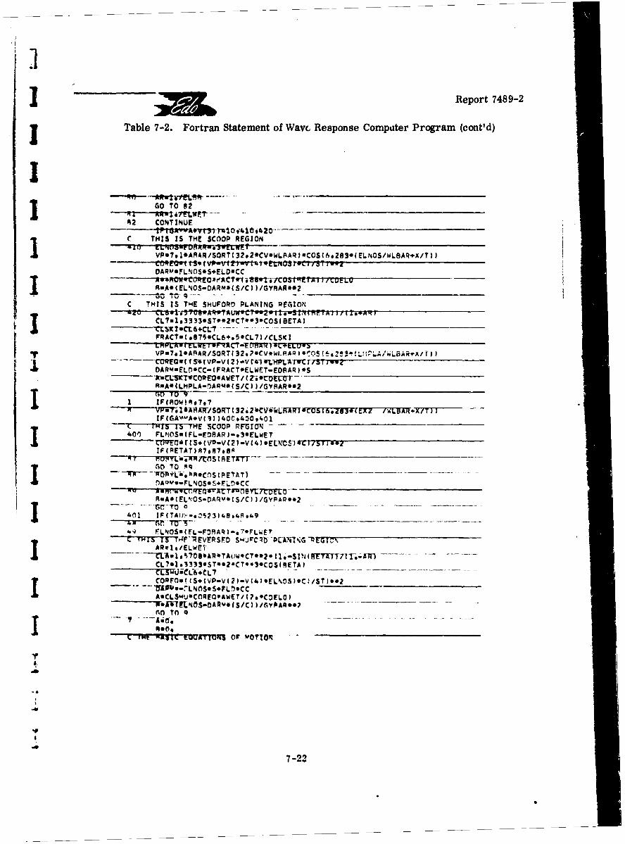
Report 748 9-2
J Table 7-2. Fortran Statement of Wavc Response Compater Program (cont'd)
00 TO 82
DARMEaFLN OS* S.ELO. CC
RaA*(ELNOS-DARmbIS/Cl 2/GYRAR**2.I~~j ot), 4 -_ __ __ __ __ __ __I_ __ __ __ _I_
CL~ml.3333#ST**2*CT**3*coS( BETA 2
FRACTw( .875*CL6+*5.CL7) /CLSKIC
R=A*ILMPLA-flAPM9( S/C))/GYFRAR**2 _________________
IF(CiAvMA+V[(2 400.400,401 __________________
C-7F iTSMSTE 'SCOOP RFG TON -. - -- - _______________
400~ F _______________________________
IF(METAT) A7,S798A
RmA.(ELNOS-DARv.(S/C, 2/GYFPAR**2
CL'a1.*333.ST*.2*CT*.3-.COS(8-ETA)____CLxwt CL-&eCL7CORFu'tS.(VP-V(?2-V(4b.ELNOS).C!/S11.?____________~"-LA %NOS* S*FLr)*CCI ~A:CLSI.4U*CO:EO0AWET/?*#CDFCOL0)no~ TO~ 9
7-22
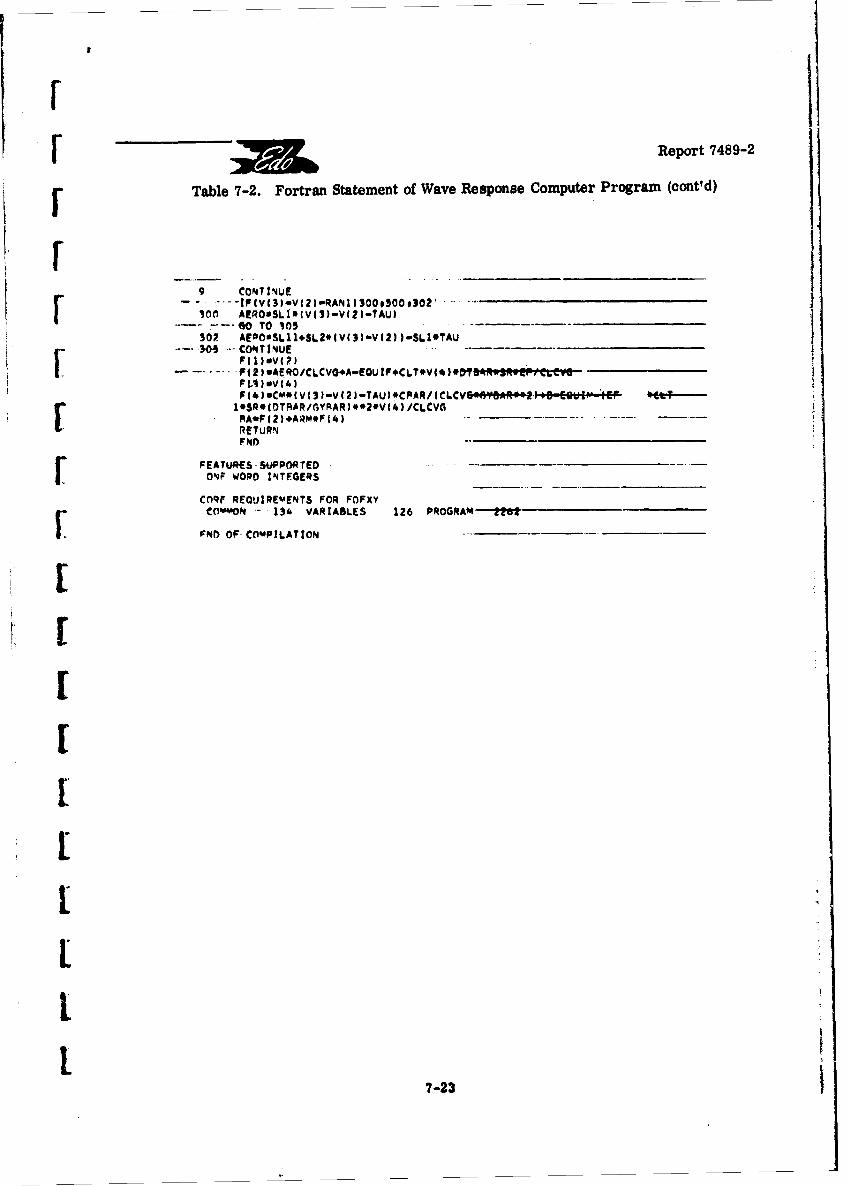
Report 7489-2
Table 7-2. Fortran Statement of Wave Response Computer Program (cont'd)
9 CONTlINUE--- IPfvgIV3-V(2)aRANll3OOo3OOo3O2*__________________
300 AfRO*SL1*(V(1)-V(2I-TAU3
302 AFPOaSL11.SL2*IV(g)-V(2fl-SLIOTAU _________________________________
P(1)sV(4)
FN
LETfSSUPRELN ODITGR
I 7-23
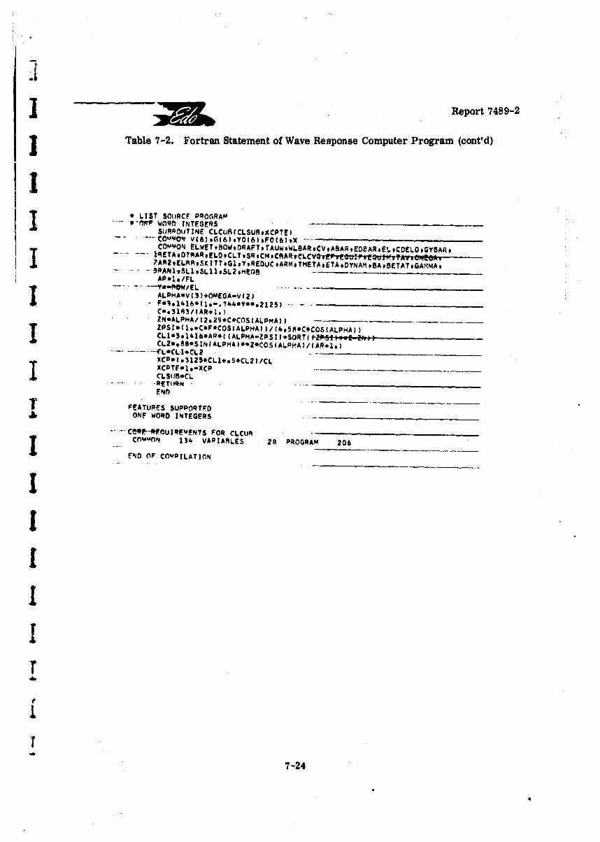
3 ~Report 748 9-2
I Table 7-2. Fortran Statement of Wave Response Computer Program (cont'd)
*LIST SOLJRCF PROGRAM0-M-" WORft INTEGERS_ _ _ _ _ _ _ _ _ _
SIIRPOuTINE CLCUB(CLSUR*XCPTE)-' Ok~vO' Vt6IG(6)9Y0(6)#FO46,,X
COMM.ON tLWET*8OWoDRAFTTAUWWLSARCVABARED8AREIoCDEL0,GYBAR,
2AR2.ELARR.K ITTeGI ,YREOUC.ARM,1METAETA.DYNAM .BABETATGAvMA,
ALPHAav(3)OEAV2
e..31R3/(AR,1..)ZN.ALPHA/42*29*C.COS(ALPMA~)) --
ZPSIUC.*+C*F*COS(ALPMAI)/(4o5R*C*COS(ALPHA))
XCo*3125*CL1,.S*CL2 )/CLXCPTFaI .- XCP-------.___
CLSIJBUCL
T ~~~FEATURES SUPPOQTFD -___
ONF WORD INTEGERS -
-- -. Ce*P-*FCtJIREVENTS FOR CLCUB _________________
COMMON 134. VARIABLES 28 PROGRAM 206 --
EN4D OF COMPILATION
7-2
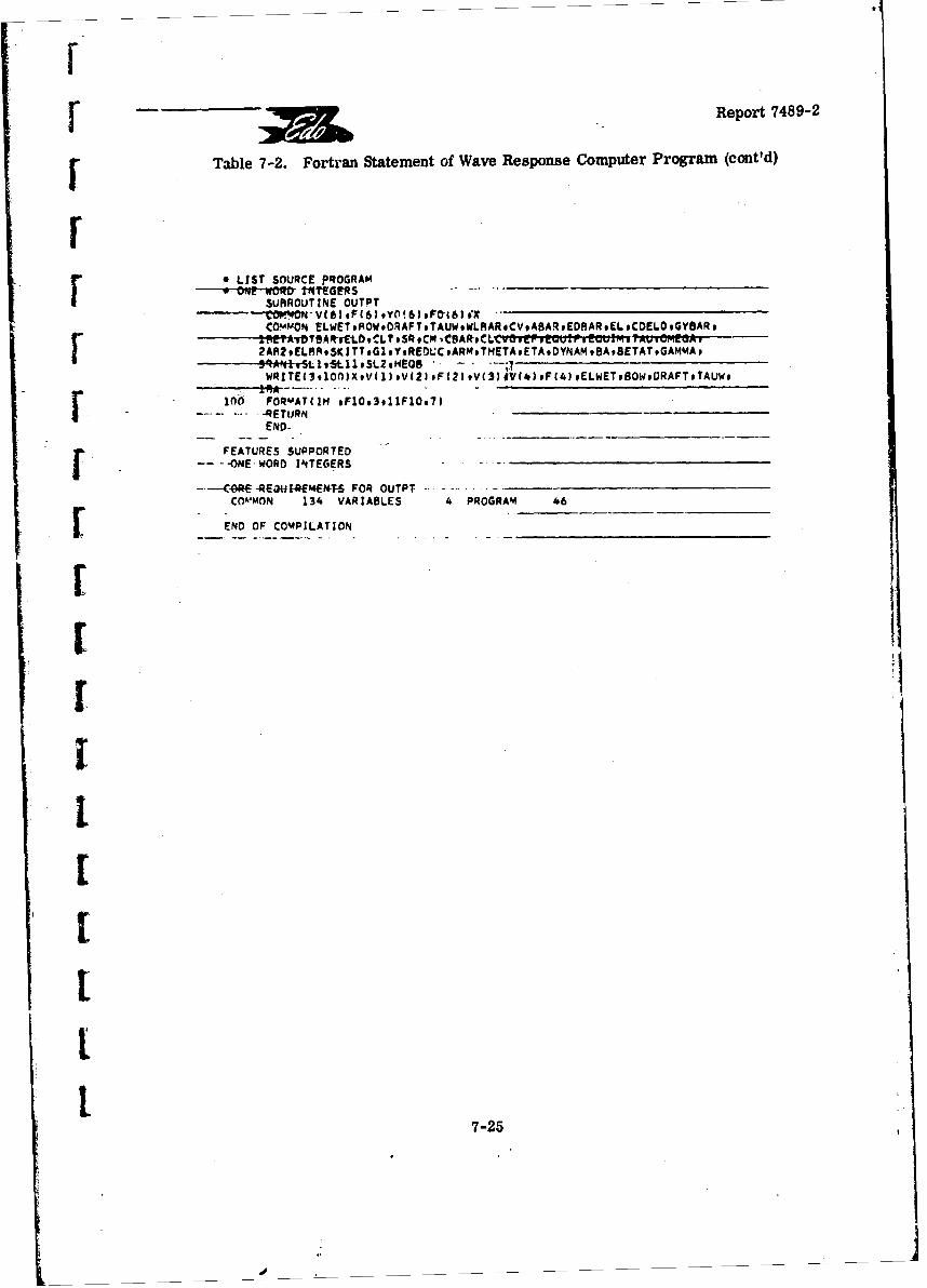
Report 7489-2
f Table 7-2. Fortran Statement of Wave Response Computer Program (cont'd)
LIST SOURCE PROGRAM______________ON WOR tTnTEERS .-.-r SURROUTINE OUTPT
COMNEL WET ,ROW .DRAFT ,TAUW, WLRAR ,CV ,ABAR .EDRAR ,EL CDELO ,GYBARs
2AR2,ELRRSKITT,61,YREOLCARNTNETA.ETADYNAMBABETATGAMMA,F ---------- 94ANr51vSpv5t11vSt.2g*4EQR -- _________________
WRITE(39100)X.V113,Vg2),F(2)oV(33aV(4UF(4)PELwETBOWtORAFT.TAUW,
100 FORMAT(1M #F1O93911F1Os7)I- -.- 4ETURNEND-
FEATURES SUPPORTED
---- ONE-WORD INTEGERS -
CO RQ4 4*- FOR OUTPT------__________ _____
COMMON 134 VARIZABLES 4 PROGRAM 46
F ~ ~~~END OF COMPILATION_______ _________
7-2
Report 7489-2
I A. FIXED-TRIM IMPACT LOADS
In the present program, the fixed-trim condition can be achieved mostreadily by assigning an arbitrary extreme high value to I, the aircraft moment of inertia,thus effectively making r = 0, so that r retains its initial value. The remaining initialconditions can then be selected to represent any desired landing impact, including the initialcontact point on the wave flank. In that case, the in!tial portion of the time history furn'shedby the present program will be coincident with that given by the program of Section 5.
t B. PLANING STABILITY
The smooth water condition is, of course, a special case where the waveheight is taken as zero and any finite arbitrary wave length is used. With these restrictions,the applicable initial conditions for the present program can be conveniently taken as:
=r = ,r = r + AT, d = deq eq
Here, deq is the draft at T (at the selected speed), and AT is some small arbitraryeq 'eqangle, say 1/4 degree.
Using these initial conditions, a run is made wherein the trim time history takesthe form of an oscillation with either divergent, constant, or subsident amplitudes. For afixed forward speed, it is a simple matter to vary T-eq to obtain that value of r eq
corresponding to oscillations of constant trim amplitude. This then represents a point onthe lower neutral dynamic stability boundary (R = 0 curve).
While this is not difficult to do, the selprate program of Section 6 for calculating
the R = 0 curve is considered preferable to the procedure just described which requiresthe intervention of the engineer.
7.4 CORRELATION OF TEST DATA
7.4.1 Description of Test Data
References 7-1 and 7-2 describe a series of towing tank tests of several hydro-ski installations on a 1/16 dynamic scale model of the HU-16 (Grumman Albatross) seaplane.Of the three skis tested, attention will be centered herein on Skis Nos. 1 and 2 which hadbeam loadings of 60 and 100, respectively, deadrise angles of 22 1/2°, and respectivelength-beam ratios of 5.20 and 5.48.
Among several other items, the tank tests included take-off runs in regularwaves (4 ft. x 120 ft., full-scale). Among the test daia are the vertical accelerations,obtained in the (full-scale) speed range of 60-80 knots, measured at the c. g. and at the bow(1 ft. forward of c. g., model scale). Aside from a few details of minor importance, such
7-26
F
F "Report 7489-2
12 as the presence of small longitudinal accelerations in the model tests, it was assumed thatthe present computer could correctly simulate the high speed portions of the model runsr which, in view of the relatively low accelerations recorded, were assumed to involve nogenuine wetting of the hull (aside from spray). Thus, in effect, complete agreement betweenthe model tests and present calculations would be indicated provided both of the followingF condittics were met:
a. Using plausible interpretations of the calculated values, the calculated[and measured c. g. and bow accelerations were reasonably close;
b. The calculations showed ski immersions not exceeding the model strut
F length.
7.4.2 Computer Calculations
SCalculations were made for a full-scale speed of 70 knots using an equilibrium(hull keel) trim angle of 11.30 (figure 15, p. 37, Reference 7-2, for VM = 30.3 fps). This
[ trim angle is the free-to-trim value for the chosen speed and an elevator angle of -25 de-grees, as measured in the tank, and includes the effects of the fixed unloading and pitchingmoment values applied to the model to simulate slipstream effects. Furthermore, it isknown from the tank tests that no porpoising occurred at this speed-trim combination, thusmaking it unnecessary to perform a planing stability check.
LIn accordance with the discussion at the end of Section 7.2, the calculations in-cluded five runs made with four of the five initial conditions the same:
Ski T. E. Draft h o 0, r= r 11.30,eq
Ebut with varying initial locations on the wave flank of the ski T. E., i. e., wave heights atthe ski T. E.:
y W (T.E.) = -H/2, - H/2 2, 0, + H/2ACT, + H/2
F where: y (T.E.) = (H/2) sin [2 7r/L) (p sin k - q cos rsk)- ]
Land p and q are defined by the sketch of Appendix C.
Each run was made for a duration of ten (10) full wave cycles, with surveillanceof the print-out process to ascertain the presence of plysically unacceptable values of trimand/or ski draft because no limitations on these two quantities had been built into the pro-gram. This number of wave cycles far exceeds the number of waves encountered by thetowing tank model in the high speed portion of a take off run.
7-27
d_____________________________________________
Report 7489-2
7.4.3 Principal Features of Computed Time Histories
The print-outs of the computed wave response time histories (not included inthis report) were carefully reviewed to:
A. Obtain an overall picture of the general nature of the motions for each skibeam loading; and
B. Extract significant data (particularly maximum accelerations and strutdrafts) together with associated information on ski-wave geometry and kinematical quantities.
The data, and their correlation with the towing tank measurements will be pre-sented below, while the following discussion covers the gross aspects of the computed timehistories.
Briefly stated, the calculated motions and accelerations for the HU-16 with theC 0 = 60 ski are appreciably more severe than those for the same aircraft with the
CA 0 = 100 ski. As typical examples, both the maximum c.g. and maximum bow vertical
accelerations are greater, the maximum ski drafts are appreciably greater, and both theairborne vertical excursions and airborne dwelling time are greater for CA 0 = 60.
The total trim range is also appreciably larger, and includes frequent occurrence of stalling.These basic results can be explained with following manner.
As a direct consequence of the lower beam loading, the impact loads in the earlyportion of the C AO = 60 ski run-outs are relatively large and so are the associated
pitching moments. These give rise to relat,,ely larger values in the later impacts. Thegreater trim motions generated by the larger p2l.zt.' moments create substantially largertrim ranges for the lower ski beam loading. Thus, on the one hand, the larger high trimvalues result In higher positive accelerations which are, of course, further aggravated byaircraft stalling (if present). On the other hand, the reduced lower trim values, in con-junction with the specific wave impact location and flight path angle, are occasionally capableof producing such low load impacts that relatively considerable ski submergence occurs.
A s will be seen below, the average trim change in the higher beam loading skirun-outs was only two degrees. This result correlates with past qualitative observationsthat very high beam loading skis produce a "plowing through the waves" effect.
However, it is important to emphasize that the comparative behavior of this sameaircraft with the two different skis is not necessarily due exclusively to the difference in theski beam loading, but may depend in part on the specific aerodynamics, specific wave condi-tions, and specific speed selected. Thus, considerably more parametric study is requiredbefore genuinely valid claims can be made.
7-28
F
I •Report 7489-2
F 7.4.4 Significant Data from Computed Time Histories
Significant data from the computed time histories is summarized in Table 7-3A.All values listed are for full-scale. In addition to the values obtained from the individualruns, this table also includes the averaged, i.e., statistical values. In addition to thefeatures discussed above, maximum sink speed values are listed. These values are alsoappreciably higher for the low beam loading ski. Lesser acceleration values were alsotabulated (not included herein) to ensure that the maximum values obtained are statistically
[ realistic.
Thus, there is no question that, at least from a qualitative standpoint, the com-L puter results agree with the general empirical experience that high beam loading skis alle-
viate motions and accelerations in rough water.
L7.4.5 Comparison with Tank Data
For convenience, the available tank data, taken from Reference 7-2, is listed inTable 7-3B. It is seen, in the first place, that any attempt at correlation is limited becausethe only quantities measured in the tank were the two vertical accelerations. Specifically, nodraft measurements were made nor is there any other way of telling whether the tank maxi-mum accelerations involved hull impacts. This feature is discussed at greater length below.
It is equally important to note that the tank data are for a finite speed range whilethe computer data are for one specific speed (midpoint of tank speed range). This differencecan possibly confuse the correlation as the effect of forward speed on the computed resultshas not been determined and cannot be readily predicted.
Finally, it is noted again that the computer runs were made using arbitrary mildinitial conditions. It is entirely plausible to suppose that, for both skis, the motions wouldbe more severe had less mild conditions been used, for example, by assuming some finite(non-zero) initial sink speeds.
With these important reservations in mind, the closest possible explanation forthe discrepancies appear to be the following. Considering first the C &o = 100 ski, the
computer showed lower vertical accelerations than did the tank tests, and also indicated nostrut wetting in any run. (The actual full-scale strut length is 4.0 feet for both ski installa-tions.) The discrepance in the vertical loads is likely due to one or both of the two reasonsjust cited (speed range and initial conditions). The severe motions from these causes wouldgive somewhat larger submergence which, for the actual hull configuration, would be ade-quate to create hull impacts and thus further exaggeration of the accelerations. This ex-
Splauation, of course, assumes that the maximum tank accelerations obtained with this skiwere, in fact, associated with hull impacts. Finally, it may be noted that, while appreciablenumerical differences exist between the comparable average accelerations, their differences
Sare identical (.56 - .57g). This result is c(asidered to lend credibility to the preceding ex-planation.
7-29
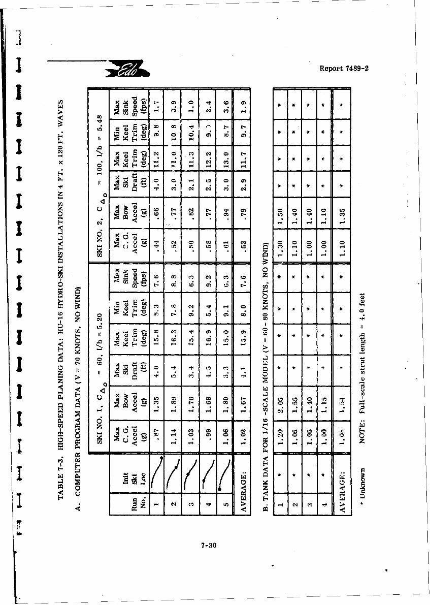
Report 7489-2
I' CQ
Z 0-
Q4 D -P C NI 0 00 0
t4 (M -8 -; 0
-P 0 m_
'1 >
a -t 0 t- CD - - -+2- II00To CO) LM
0 ~-30 -
rReport 7489-2
The exceptionally close agreement between both the ranges and average valuesof computed and measured c. g. and bow accelerations for the C& 0 = 60 ski installation
rrequires very little further comment. The one point requiring explanation is that two of thecomputed maximum ski drafts exceeded the actual strut length. It might thus be anticipatedthat the tank model could generate higher accelerations than those given by the computer.The actual fact Is that the large ski drafts occurred only a few times in the computer runsand-it is possible that they were "missed" in the tank runs because of the very limited nunt-
Sber of impacts occurring therein.
Alternately, it is also conceivable that hull impacts did occur in the tank runsbut, since a hydro-ski can effectively reduce the hull impact velocities, hull impact accele-rations did not exceed the hydro-ski impact accelerations.
S7.4.6 Discussion
It is obvious that, while these particular HU-16 tank tests remain as the onlyavailable test data, their correlation with the computer runs will remain unclear. Thisdifficulty can only be resolved by conducting a series of towing tank tests on a skeletonhydro-ski seaplane model. With such tests, procedures and measurements could be usedto permit far more direct correlation with the computer program results.
Although some of the results of the computer program are subject to further[ examination, either because of the simplified mathematical model or lack of suitable com-parative towing tank data, further parametric studies could have been made to establish therelative effects of the operational environment on hydro-ski seaplanes in the high-speedrange. Of particular interest would have been computer runs to ascertain the effects ofvariation in wave height and wave length. Unfortunately, as a result of the technical effortinvolved in developing the computer program, no time and funds were available within thepresent contract to conduct these investigations. This subject is pursued further in Section10 of this report.
REFERENCES
7-1 Davidson Laboratory Letter Report LR-976: "Development Tests of HU-16SHydroski Aircraft," by R. L. Van Dyck, October 1963.
7-2 Grumman Aircraft Engineering Corp., Report No. XA 111-108-4:S"Hu-16 Hydroski Development," by T. B. Street, February 1964.
7
7-.I1
Report 7489-2
J 8. HYDRO-SKI LONGITUDINAL LOCATION
As part of the present survey, attempts were made to correlate actual hydro-ski3 longitudinal locations, as determined from towing tank tests, with the most significanthydrodynamic ski parameters, such as ski beam loading. If successful, a correlation ofthis type would substantially reduce the preliminary design effort currently necessary forthe establishment of an optimum hydro-ski location. For this purpose, an examination wasmade of all available geometric data on towing tank models (and full-scale hydro-ski confi-I gurations) exhibiting satisfactory hydrodynamic characteristics.
The approaches used in these attempted correlations were based on the successful,but limited, correlation shown in Figure 5 of Reference 8-1. These results, which correlatethe longitudinal locations of ski centers of pressure with ski length, are for a variety of skistested on a single seaplane model (one gross weight), the tests covering only rough-waterI landings.
A variation of this approach was first attempted, in which the basic parameterswere non-dimensionalized as follows:
1) The "longitudinal location paranmeter" was taken as the angle between a line
joining the aircraft c. g. and the ski c. p. (taken, as in Reference 8-1, at 2/3 ski lengthforward of ski T. E.) and the perpendicular from the c. g. to the ski keel;
2) Instead of the ski length, the "ski size parameter" was taken as the ski beam
The "correlation" of these two quantities, shown in Figure 8-1, covers eighteendifferent model and prototype aircraft (some with several skis). These configurations areidentified in Table 8-1. It is seen that, although there is a general trend of increasing in-clination angle with increasing beam loading, the data spread is much too large to permitconstruction of a representative curve, or even a representative band of values. In brief,the correlation is considered to be much too poor for practical use in preliminary designwork.
Further attempted correlations were then made using various other combinationsof non-dimensional "longitudinal location" and "ski size" parameters. In all cases, theseattempts were equally unsuccessful. As a principal result of these studies, it was con-cluded that other configuration parameters have signiftcant effects on optimum ski locationand would thus have to be accounted for in the correlation process. It is reasonable toassume that, in addition to possible geometric parameters such as ski length-beam ratioand ski incidence, the correlation must account for the aircraft aerodynamic parameters,particularly such items as longitudinal static stability and control parameters (say,
( M/a CLIB* and (Z CM/ )c mav'mum elevator deflections, etc.
I.
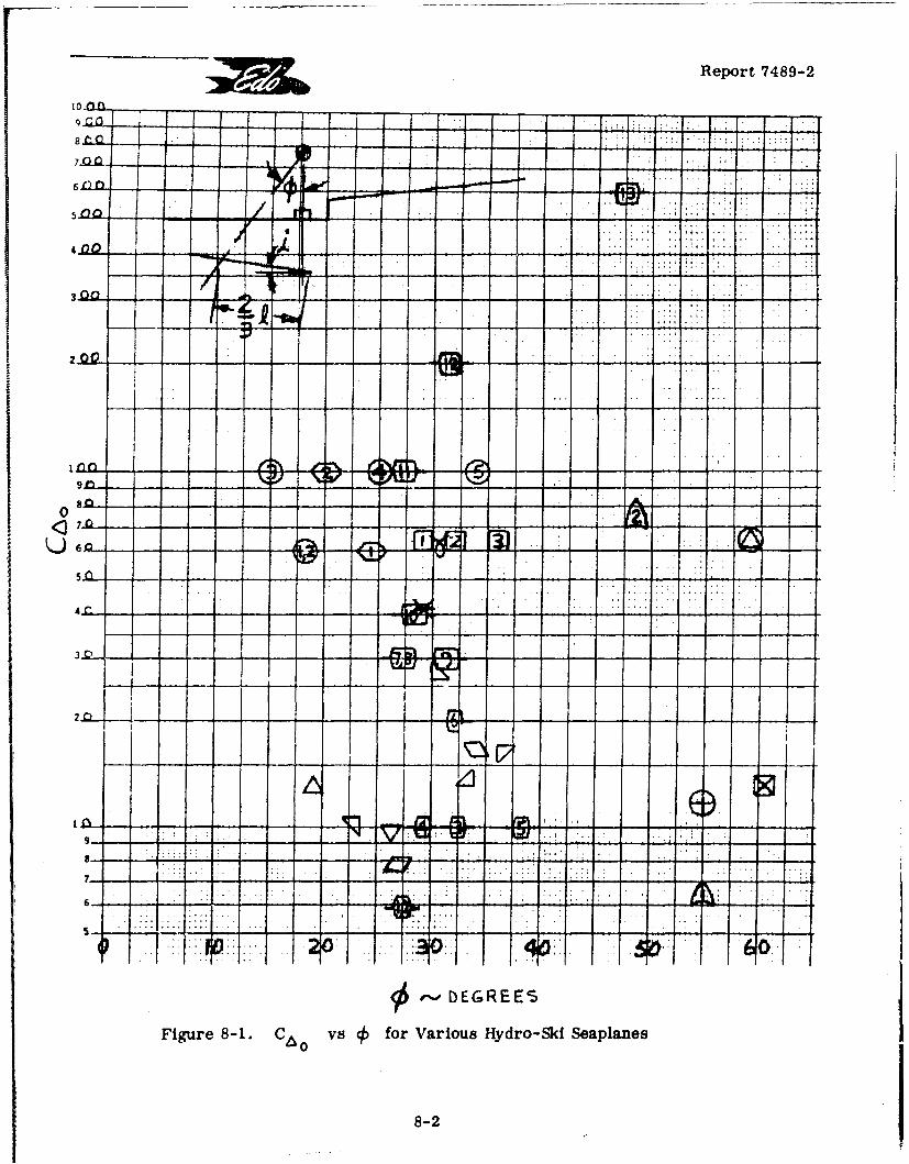
Report 7489-2
10 n
612
440
U o 6/- - - . I - - ,- - :: - i - ti - ii :- - -
2Q - - - -- - - -
i n n . . . . . .L. : . . . . .
o - -. J - - - -"1- - - - - - - ' - - - - -
v . v V; ,-,-
0
Figure.8.. ... vs frVrosHdo i "epae
4 8
j EP
< DEGREES
Figure 8-1. C Ao vs for Various Hydro-Ski Seaplanes
8-2
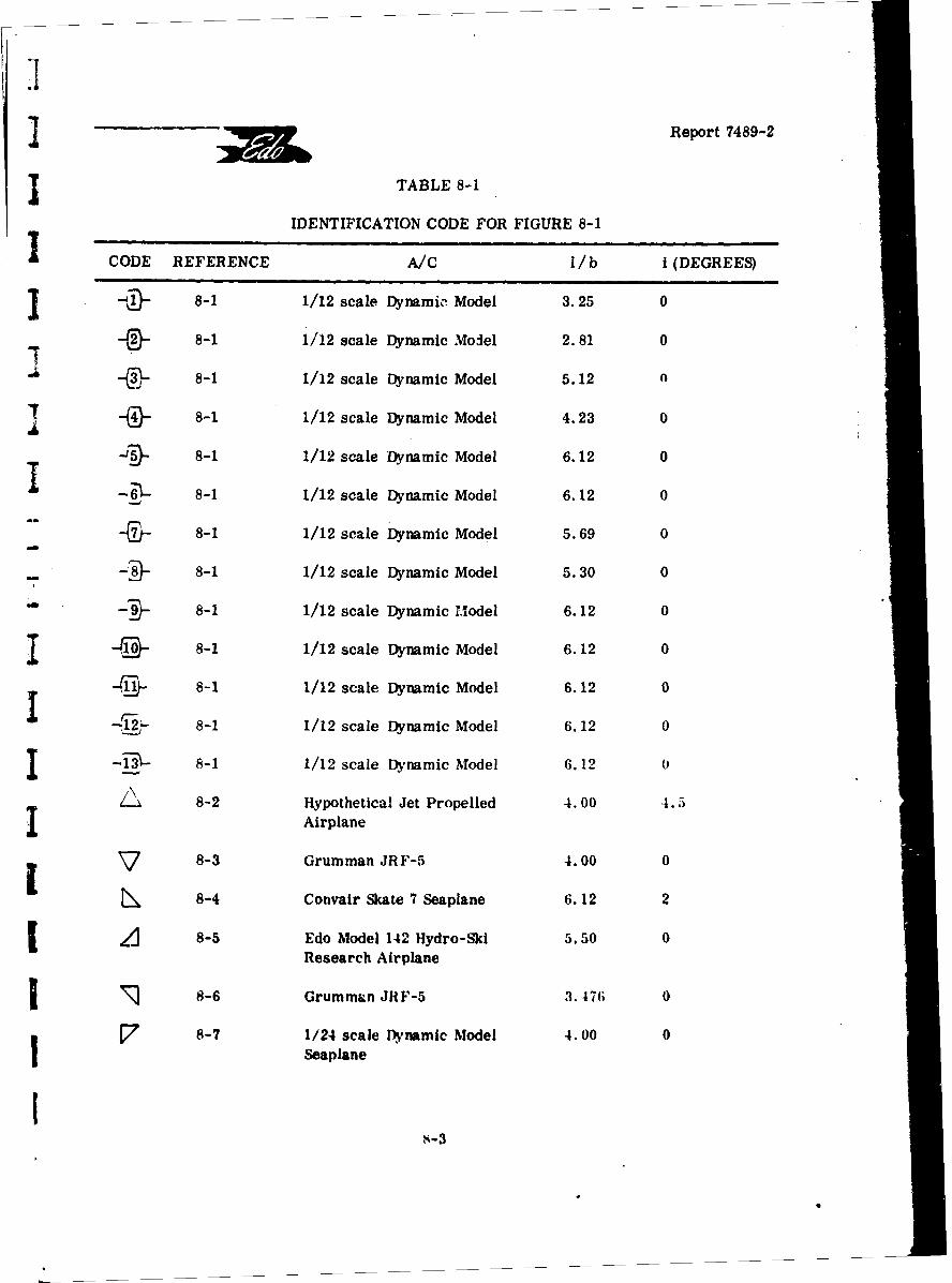
Report 7489-2
I TABLE 8-1
IDENTIFICATION CODE FOR FIGURE 8-1
CODE REFERENCE A/C 1/b i(DEGREES)
, 8-1 1/12 scale Dynamic Model 3.25 0
"8-1 1/12 scale Dynamic Model 2.581 0
- 8-1 1/12 scale Dynamic Model 5.12 n
8-1 1/12 scale Dynamic Model 4.23 0
-0- 8-1 1/12 scale Dynamic Model 6.12 0
I -5ý-- 8-1 1/12 scale Dynamic Model 6.12 0
8-1 1/12 scale Dynamic Model 5.69 0
""D- 8-1 1/12 scale Dynamic Model 5.30 0
-89- 8-1 1/12 scale Dynamic Model 6.12 0
"" -9- 8-1 1/12 scale Dynamic Model 6.12 0
D-( 8-1 1/12 scale Dynamic Model 6.12 0
,- 8-1 1/12 scale Dynamic Model 6.12 0
I 8-1 1/12 scale Dynamic Model 6.12 0
I -13ý- 8-1 1/12 scale Dynamic Model 6.12 0
A 8-2 Hypothetical Jet Propelled 4.00 4.5I Airplane
8-3 Grumman JRF-5 4.00 0
8-4 Convair Skate 7 Seaplane 6.12 2
[ A 8-5 Edo Model 142 Hydro-Ski 5.50 0Research Airplane
I • 8-6 Grumman JRF-5 3.476 0
S8-7 1/24 scale Dynamic Model 4.00 0I Seaplane
Io
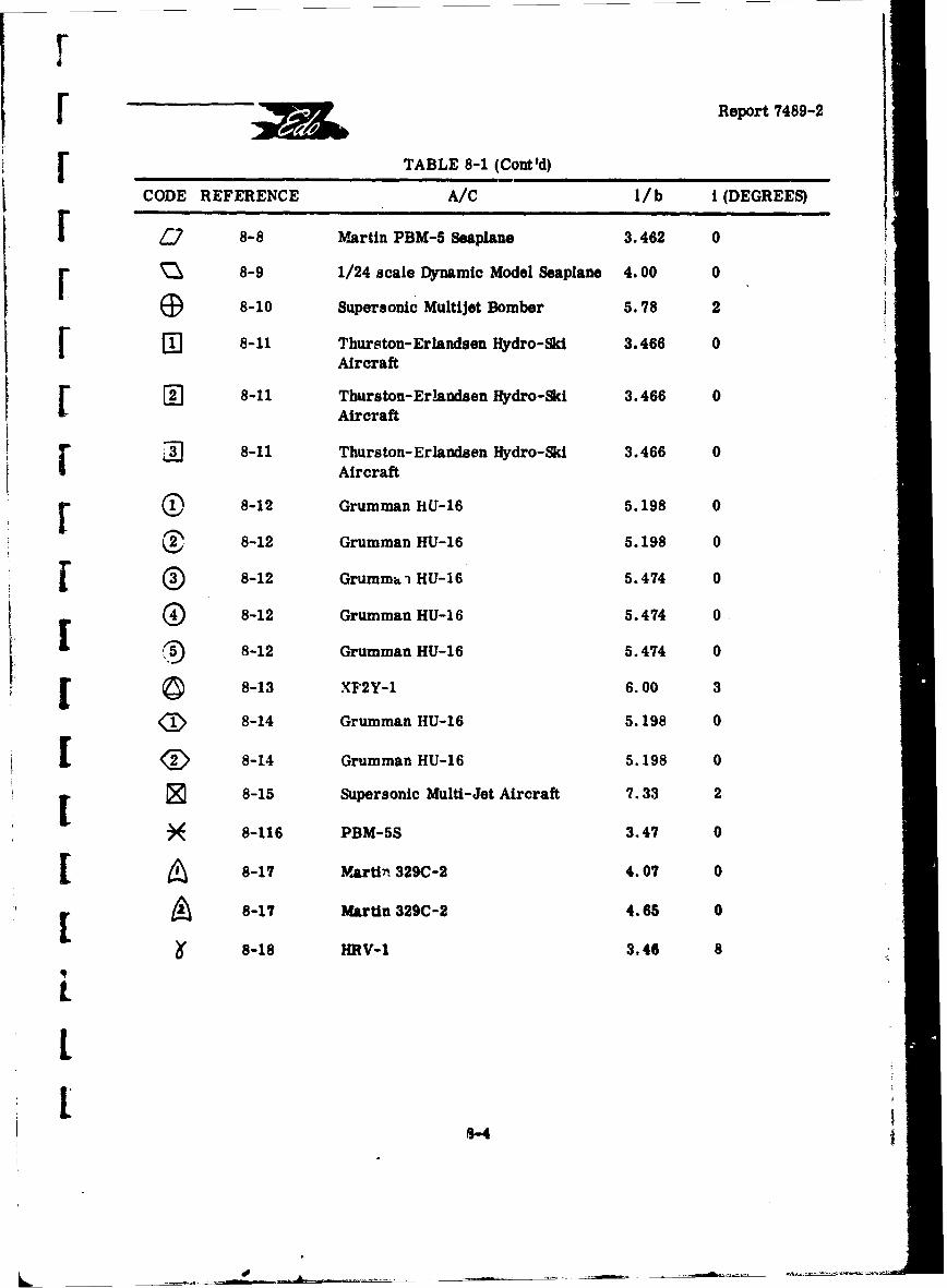
r[ Report 7489-2
[ ,TABLE 8-1 (Cont'd)
CODE REFERENCE A/C I/b i (DEGREES)
Q 8-8 Martin PBM-5 Seaplane 3.462 0
8-9 1/24 scale Dynamic Model Seaplane 4.00 0
S8-10 Supersonic Multijet Bomber 5.78 2
8-11 Thurston-Erlandsen Hydro-Ski 3.466 0Aircraft
W 8-11 Thurston-ErIandsen Hydro-Ski 3.466 0Aircraft
SD 8-11 Thurston-Erlandsen Hydro-Ski 3.466 0Aircraft
r 0 8-12 Grumman HU-16 5.198 0
C2 8-12 Grumman HU-16 5.198 0
S8-12 Grumma i HU-16 5.474 0
8-12 Grumman HU-16 5.474 0
8-12 Grumman HU-16 5.474 0
[ 8-13 XF2Y-1 6.00 3
8-14 Grumman HU-16 5.198 0
[D 8-14 Grumman HU-16 5.198 0
8-15 Supersonic Multi-Jet Aircraft 7.33 2
S8-116 PBM-5S 3.47 0
[ 8-17 MArti, 329C-2 4.07 0
[ 8-17 Martin 329C-2 4.65 0
8-18 HRV-1 3.46 8
L1.-8-4
J '. Report 7489-2
I Further investigation of this problem area was considered infeasible, partlybecause of the large additional effort involved, and partly by the lack of (readily available)required aerodynamic data for most of the aircraft. Although some of the aerodynamic para-meters could have been estimated, it was felt that such effort was not warrantea because ofthe inability to estimate accurately such features as power-on effects for prototype aircraft,
I ground effects for both prototype and model aircraft, etc.
Consequently, until much better correlations are achieved, towing tank model-- tests are st;U considered to furnish the only practical method for final determination of- optimum hy~ro-ski longitudinal locations. In addition to the usual take-off and landing runs,
such tank tests should also include rough-water constant-speed taxi tests covering theT applicable speed range.
I REFERENCES
8-1 NACA RM L56125a: "Tank Investigation of a Series of Related Hydro-Skis as"- -Load-Alleviation Devices for Landing a Seaplane in Waves, "by A. W. Carter,
A. E. Morse, Jr., and D. R. Woodward, December 1956.
"8-2 NACA RM L7104: "Preliminary Tank Tests of NACA Hydro-Skis for High-Speed Airplanes," by J. R. Dawson and K. L. Wadlin, 26 November 1947.
8-3 NACA RM L9K29: "Tank investigation of the Grumman JRF-5 Airplane Fittedwith Hydro-Skis Suitable for Operation oz, Water, Snow and Ice," Lby K. L.Wadlin and J. A. Ramsen, 12 June 1950.
1 8-4 NACA RM SL51F07a: "Hydrodynamic Investigation of a 1/13-scale modelof the Consolidated Vultee Skate 7 Seaplane Equipped with Twin Hydro-Skis,
I by R. E. McKann, C. W. Coffee, and D. D. Arabian, 12 September 1951.
8-5 NACA RM SL51124: "Tank Investigation of the Edo Model 142 '1 dro-SkiResearch Airplane," by J. A. Ramsen, K. L. Wadlin, and G. R. Gray,24 September 1951.
8-6 NACA RM SL52D17: '"rank Investigation of the Grumman JRF-5 AirplaneEquipped with Twin Hydro-Skis, " by J. A. Ramsen and G. R. Gray, 10 April1952.
1 8-7 NACA RM L53F04: "A Brief Hydrodynamic Investigation of a Navy SeaplaneDesign Equipped with Hydro-Ski," by L. J. F,&her and L. Hoffman, 1 September
[ 1953.
I!
s-
[ •Report 7489-2
[ REFERENCES (Continued)
8-8 NACA RM SL55L15: "Tank Tests of a 1/8-Size Powered Dynamic Modelof the Martin PBM-5 Seaplane Equipped with a Single Edo Hydro-Ski,"by C. W. Coffee, Jr., 6 January 1956.
[8-9 NACA RM L56D26: "Comparison with Theory of Landing Impacts of a Modelof a Seaplane Incorporating a Hydro-Ski with and without a Shock Absorber,"by E. L. Hoffman, 11 July 1956.
8-10 NACA RM L57G05: "Aerodynamic and Hydrodynamic Characteristics of aProposed Supersonic Multijet Water-Based Hydro-Ski Aircraft with a Variable-Incidence Wing, " by W. W. Petynia, F. Hasson, and H. Spooner, 23 October1957.
I 8-11 Davidson Laboratory, S. I. T. R-934: "Development Tests of Thurston-Erlandsen Hydroski Aircraft," by R. L. Van Dyck, March 1963.
[8-12 Davidson Laboratory, S.I. T. LR-976: "Development Tests of HU-16Hydroski Aircraft," by R. L. Van Dyck, October 1963.
S8-13 Convair Report ZC-2-065: "Small Ski Research Progrpm on the XF2Y-1,Airplane, "by F. H. Sharp and E. E. Whigham, OctoLer 1957.
18-14 Grumman Report XA 111-108-3: "HU-16 Hydroski Development, " by T. B.Street, August 1963.
r8-15 NACA Memo 10-13-58L: "Low Speed Aerodynamic and HydrodynamicCharacteristics of a Proposal Supersonic Multijet Water-Based Hydro-SkiAircraft with Upward Rotp'ting Engines "by W. Petynia, D. R. Croom,and E. E. Davenport, October 1958.
8-16 Davidson Laboratory, S. I.T. R-681: "To Evaluate the HydrodynamicCharacteristics of the PBM-5S on a Small Penetrating Hydro-Ski," byG. Fridsma, 14 March 1958.
18-17 Convair Report ZH-139: "Towing Tank Evaluation of Hydro-SkiAlighting Gear," by W. B. Barkley, October 1959.
8-18 Thurston-Erlandsen Corp. Report 6302-4: "Final Summary Report F.'ght Testof the Hydro-Ski Research Vehicle HRV-1 Equipped with the PBM Type Ski,"J by D. B. Thurston, 25 November 1963.
8
8-6
Ii{
Report 7489-2
1 9. SURVEY OF HYDRO-SKI INSTALLATION WEIGHTS
9.1 GENERAL
For the preliminary weight estimation of new operational hydro-ski seaplaneconfigurations, it is desirable to have a background of weight data on previous nstallations,including the separate contributions of the hydro-ski, its support strut, and the hull carry-
j through structure. Although several full-scale seaplanes have been flown with hydro-skisinstalled, all of these installations were basically experimental in nature where the primaryconsideration was the development of a "working" configuration that could safely explore andadvance hydro-ski seaplane technology.
With only one exception, all full-scale hydro-ski seaplab6• flowyx t&date havef been conversions of existing aircraft. The single exception was the Cozva-Ir XF2Y "SeaDart" and even this aircraft had two subsequent modifications in its -asic- hyc. o-skiconfiguration.
The early developmental stage in the state-of-the-art, combined ith4 %e desireto minimize engineering and manufacturing costs, admittedly resultetb in ver, !onservativestructural design approaches for these hydro-ski installations. It can 43er'forcbe antici-pated that, for new operational aircraft, the hydro-ski installation weight fr.ctiwn (percent
i of aircraft gross weight) should be distinctly improved over those indicated in'the presentweight survey. In this connection, it is obvious that the method presented in Section 5 ofthis report for the estimation of rough-water impact loads constitutes the foundation of anaccurate and rational method for the structural design of hydro-skis and, thus, for the de-velopment of rational ski weight formulas.
i 9.2 HYDRO-SKI WEIGHT
Table 9-1 lists the hydro-ski weights for previous installations, together withthe parameters which appear in the hydro-ski weight formula proposed by the MartinCompany in Reference 9-1. Thi3 formula is:
J Wski = .112 (nlalsk2 ) 1/2
where: A0 = aircraft design gross weight, lbs
y1 = design ultimate load factor
I sk =hydro-ski length (ft)
9-1
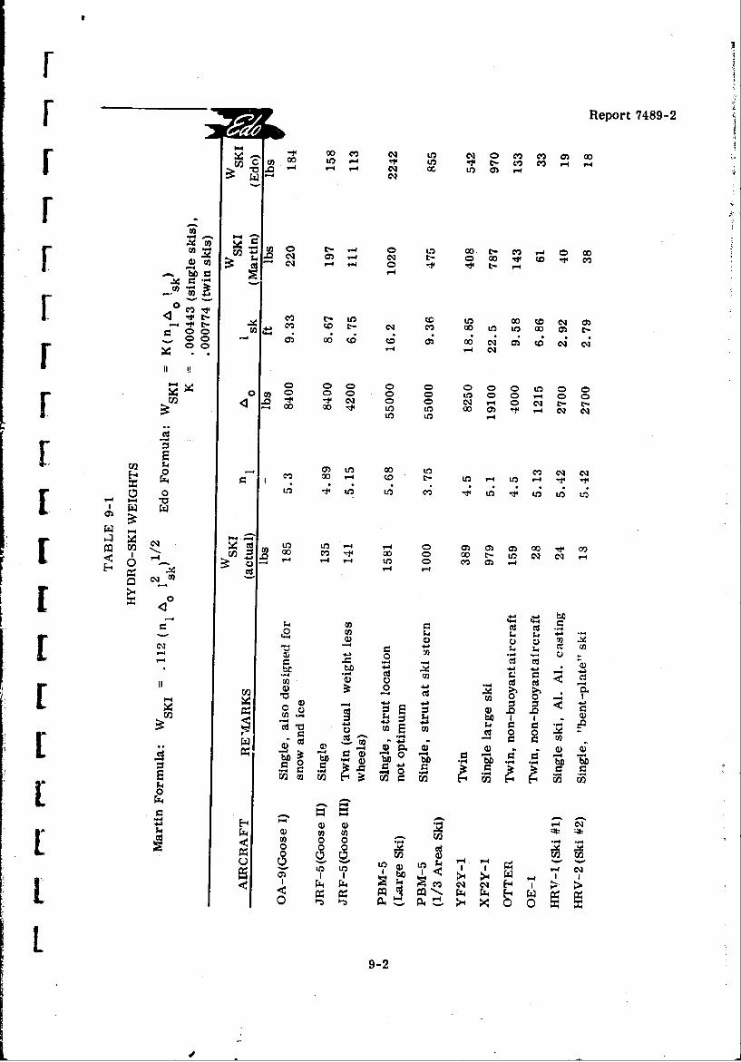
Report 7489-2
-~ ~ ~ C~LO~C 0 m~ m~ O0
F 00
cc 00 m 0000
00 C)J -i 0 CDJ N- m -
0 C CD -4 CD
U)2$ 2 '-t~ N 0 C- N L
4 O D -4 jfO C') C9 N
to LO
0. M v 0
m .-4l q ,
m~~. C.)Om "U1 U- N11-CO 0
J~bm(a Cd 9-2-
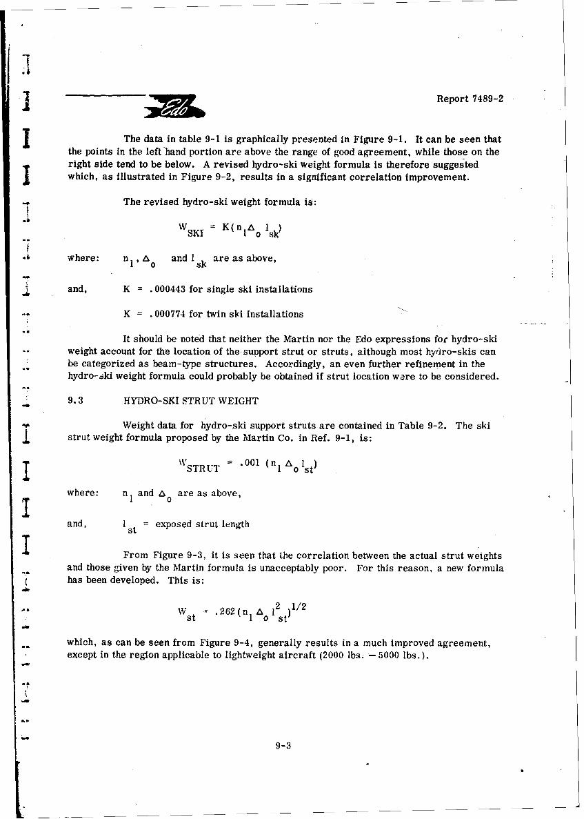
SReport 7489-2
The data in table 9-1 is graphically presented in Figure 9-1. It can be seen thatthe points in the left hand portion are above the range of good agreement, while those on theright side tend to be below. A revised hydro-ski weight formula is therefore suggestedwhich, as illustrated in Figure 9-2, results in a significant correlation improvement.
The revised hydro-ski weight formula is:
WSKI = K(nI Ao Isk)
where: n1, t 0 and I are as above,-• whr: l o sk
and, K =. 000443 for single ski installations
K = . 000774 for twin ski installations
It should be noted that neither the Martin nor the Edo expressions for hydro-skiweight account for the location of the support strut or struts, although most hydro-skis can
* be categorized as beam-type structures. Accordingly, an even further refinement in thehydro-ski weight formula could probably be obtained if strut location ware to be considered.
* 9.3 HYDRO-SKI STRUT WEIGHT
Weight data for hydro-ski support struts are contained in Table 9-2. The ski4 strut weight formula proposed by the Martin Co. in Ref. 9-1, is:
I •STRUT :.001 (nI Aolst)
where: nI and 6 are as above,I 0
and, I = exposed strut leng-th
From Figure 9-3, it is seen that the correlation between the actual strut weightsand those given by the Martin formula is unacceptably poor. For this reason, a new formulahas been developed. This is:
• Ws : 262 (nlA 1 2st)1/2
which, as can be seen from Figure 9-4, generally results in a much improved agreement,* except in the region applicable to lightweight aircraft (2000 lbs. -5000 lbs.).
9-3
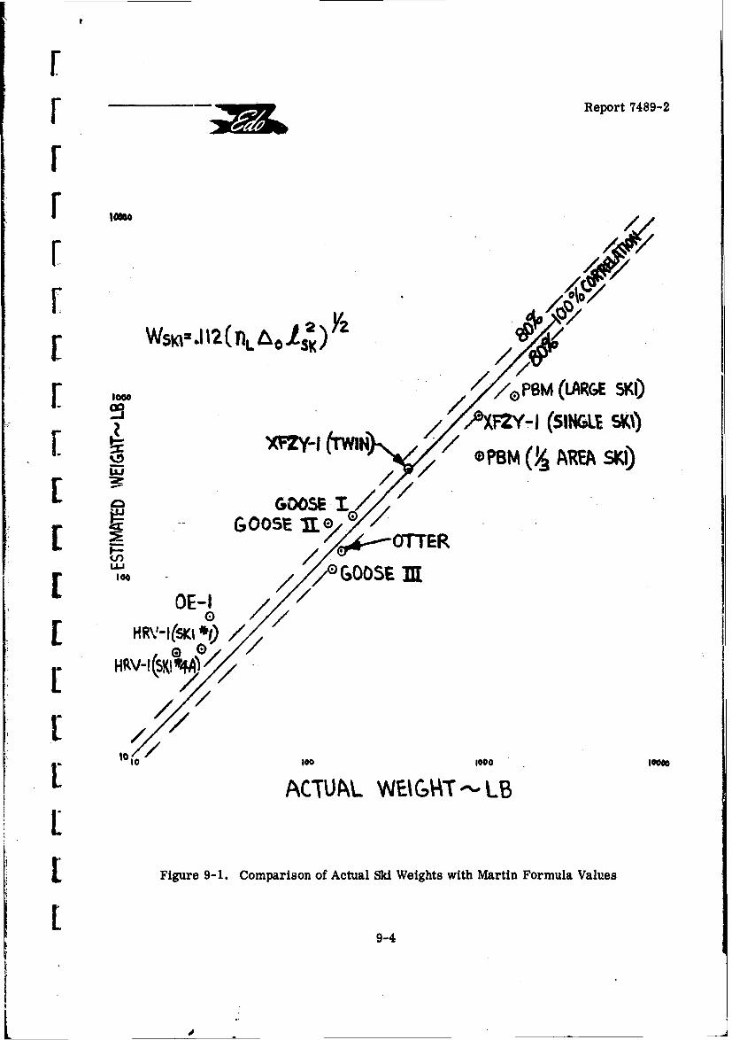
[.
r •Report 7489-2
FZ
r
[ 1o0 PBM (LARGE SKI)
/.Aizv-I (sINUE SKI)
[ ol ' /,,/GOOSE tI[ ! ~ ~~GOOSPE "U.e G .. •O.,E
L o E / //• GOOSE D[ 0OE-I
0
HRV-I(SKI 1[ ° //
.,-~¢"// ]
101 100 1000 1""0
ACTUAL_ WEIG4Tr--' LB
SFigure 9-1. Comparison of Actual Ski Weights with Martin Formula Values
9-4
do__
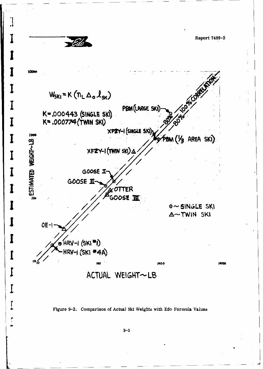
Report 7489-2
I'
I IK(L A La4)
I Kw.ooo144-ý(SI. SX0 •,
/ (VAEASKI).
I GOOSE
/OTTERI 10 GOOSEET.•.
j 7/0--SINI'wLE SKII ~// A-"TWIN SKI
/- RV-I(SKI)1[ HRV-1 SKI 04A)
1,0 100 A 100
I ACTUAL. WEIGHT---LB
Figure 9-2. Comparison of Actual Ski Weights with Edo Formula Values
9-5
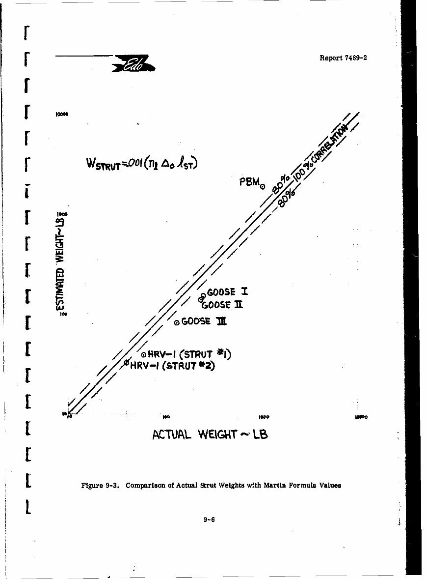
rr- Report 7489-2
I
////
[ A~//•'/ n
[ '/ "///•ooI(n , Al
[///, % 14RV-I (STRUT-*)
7//ro9e NOe 100 eo
A PCTUA~L WEIGAT L
1 Figure 9-3. Comparison of Actual Strut Weights with Martin Formula Values
L9-6 •-!
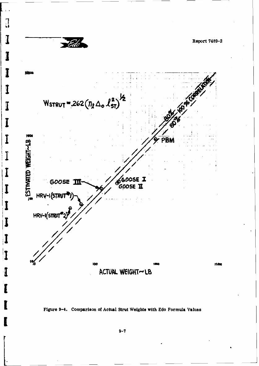
I & Report 7489-2
I
WSTRUT'iZ2 0(f,4,&0
low
i ////I E
GOO$SE -UU-4 RV:I(STReI
HRV-I(STRUT* f
0 100
ACTUAL WEIGT,-P LB
I Figure 9-4. Comparison of Actual Strut Weights with Edo Formula Values
9-7
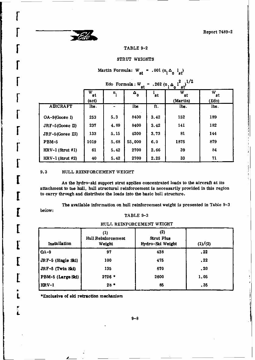
[ •Report 7489-2
r TABLE 9-2
STRUT WEIGHTS
Martin Formula: Wst = .001 (n 1st)
r Edo Formula: W st .262 (n I &o 12st)1/2
Wst n 1o 1st Wst Wst
(act) (Martin) (Edo)AIRCRAFT lbs. - lbs ft. lbs. lbs.
SOA-9(Goose I) 253 5.3 8400 3.42 152 189JRF-5(Goose U) 237 4.89 8400 3.42 141 182
JRF-5(Goose I1) 133 5.15 4200 3.73 81 144
PBM-5 1019 5.68 55,000 6.0 1875 879
HRV-1 (Strut #1) 61 5.42 2700 2.66 39 84
HRV-1 (Strut #2) 40 5.42 2700 2.25 33 71
9.3 HULL REINFORCEMENT WEIGHT
r As the hydro-sil support strut applies concentrated loads to the aircraft at itsattachment to the hull, hull structural reinforcement is necessarily provided in this region[ to carry through and distribute the loads into the basic hull structure.
The available information on hull reinforcement weight is presented in Table 9-3below:
TABLE 9-3
HULL REINFORCEMENT WEIGHT
(1) (2)Hull Reinforcement Strut Plus
SInstallation Weight Hydro-Ski Weight (1)/(2)
OA-9 97 438 .22
S JRF-5 (Single Ski) 100 475 .22
JRF-5 (Twin Ski) 135 670 .20
SPBM-5 (Large Ski) 2726 * 2600 1.05
HRV-1 28 * 85 .35
*Exclusive of ski retraction mechanism
9-8
I _ _ _ _ _ _ _ _ _ _ _ _ _
I -Repovt 7489-2
I It is observed in the foregoing table that the hull reinforcement weight ft actionrelative to the sum of ski and strut weights is fairly constant for the "Goose" modifications.For the PBM-5 and HRV-1 hydro-ski modifications, this weight fraction has a differentorder of magnitude. One reason for this discrepancy lies in the fact that, for the lattertwo cases, the hydro-ski extension could be adjusted.
I More important, the extremely high value for the hull reinforcement weight forthe PBM can be accounted for by the fact that, since ballast was required to achieve 'hedesired operating gross weight, structural components were designed and analyzed to mini-mize manufacturing costs and engineering effort at the expense of weight and bulk. A 'cord-ingly it is suggested that, for a fixed hydro-sia installation, 20% of the hydro-ski and strutweight be allocated for hull reinforcement. For a retractable hydro-ski installation, it issuggested that 40% is a reasonable value. Furthermore, based on the only available &ta(PBM-5), the ski retraction mechanism weight can be estimated to be 10% of the strut-plus-ski weight.
REFERENCES
9-1 Martin Co. Report ER9433: "Preliminary Design Data for Water-BasedAircraft with Hydrofoils or &is, "by E. G. U. Band and J. W. Cuthbert,
I June 1957.
I!II
II
II
9-9
r[Report 7489-2
10. FINAL CONCLUSIONS AND RECOMMENDATIONSr10.1 INTRODUCTION
r This report has presented a quantitative study, together with related analyses,
of principal problem areas involved in the design of seaplane hydro-ski installations. Thescope of these anialyses was necessarily subject to certain limitations of which the followingare considered to be most important:
[ 1. Only the significant longitudine.l seaplane characteristics were treated.
2. Only those problem areas were treated which were either independent of,or required no detailed knowledge of the aircraft's aerodynamic longitudinalcontrol characteristics and/or hJ! hydrodynamics.
The particular studies and analyses presented in this report follow a distinct.ogical sequence relative to problem complexity. In each individual study, the results ofthe associated analysis have been correlated with pertinent available data to affirm the vail-
[ dity of the analysis and, by implication, the particular assumptions utilized therein. Withbut one exception, these correlations have ber:• uniformly successful. These successfulcorrelations ensure the validity of the parametric studies accompanying the individualanalyses.
The present studies, analyses, and associated computer programs constitlite af unified body of knowledge which, as made clear in Section 2 of this report, can be usel togreat advantage in the preliminary design and analysis of seaplane hydro-ski installaticns.At the same time that these results unify and augment existing hydro-ski technology, theyalso serve to indicate that certain problem areas still remain unanalyzed and that furtheranalytical and/or experimental efforts are highly desirable. The. remainder of this reportsection describes the conclusions drawn from the present study and presents a list of de-tailed recommendations for such further efforts. Conclusions and recommendations ar2presented first for each of the separate topics covered in lhis report and an additional listof recommendations is furnished for those topics not covered. Wherever necessary, the[I conclusions and recommendations are accompanied by brief explanations of their signifi-cance and importance.
S10.2 STEADY-STATE HYDRO-SKI CUARACTZRISTICS (SECTION 3)
10.2.1 Planing Characteristics
It has been verified that the semi-empirical expressions for the steady-statehydrodynamic characteristics of hydro-skis established by Shuford in Reference 1O-I yield
010-1

A?
Report 7489-2
I accurate results even when the gross approximation of "full wave rise" is utilized. Thissubject is not considered to require any further investigation.
1 10.2.2 Submerged. Fully-Wetted Character:istics
The existing semi-empirical analysis for the hydro-ski lift in this flow conditionI has been extended to cover drag and pitching moment characteristics. Extremely closeagreement with the experimental data for lkis of aspect ratio, 1/4, has been obtained.
While not considered vital, it would be desirable to extend the correlation to
cover at least one other ski aspect ratio. The necessary experin' ntal data for skis ofaspect ratio, 1/8, are presently available for this purpose (Reference 10-2).
10.2. 3 Submerged, Ventilated Characteristics
The existing method for calculating these characteristics is that given byJohnson in Reference 10-3. As presented therein, this method i- awkward as it involves a"f"manual" iteration procedure for one quantity and a "manual" interpolation procedure forI another. This awkward approach has been replaced in this report by an equivalent accuratedigital computer program which can also serve as a subre)utine in dynamical problems.
I In Reference 10-3, Johnson showed that his method, essentially theoretical innature, gave accurate corre!-ttions with experimental data for a flat plate hydrofoil of aspectratio, 1. 0. In tl.s report, using the equivalent computer program, the theoretical charac-teristics of a flat plate of aspect ratio, 1/4, were calculated and compared with availabletest data. This correlation showed certain discrepancies which were attributed to the factthat the test data were for a "modified" flat plate having a bevelled trailing edge. Suitable,simple empirical correction factors were established to account for these discrepancies.When the computer program was revised accordingly, excellent agreement with the testdata was obtained.
It is firmly recommended that further investigations of this problem area beIm made, as follows:
A. Using the existing program (including the empirical corrections). thecorrelation between calculated and existing experimental values for bevelled skis of aspectratio, 1/8. should be obtained;
B. Even more important, tank test data should be obtained for both unbevelledflat plate and aeadrise skis of two aspect ratios (typically, 1/4 and 1/8). This will permit:
S•a) A more direct check of the Johnson theory for low aspect ratio surfaces;
b) Establishment of suitable empirical factors for the deadrise effect.
I10-2
[ ~Report 74 89-2
S 10.3 STRUT RESISTANCE CHARACTERLSTICS (SECTION 4)
In Section 4. the survey on strut resistance characteristics demonstrated thatadequate methnris are presently available for hydro-ski strut drag estimation under thefollowing conditions:
F a) zero yaw angle;
b) fully wetted or base-vented;
Sc) surface-piercing or completely submerged.
In some high-speed towing tank testfs utilizing base-vented struts, it has beenobserved that a "choking" phenomenon occurs, v'' Aich closes 3ff the cavity opening to theatmosphere. This effect is ascribed to the pressure reduction at the side spray walls asso-ciated with the high velocity air entering the cavity. (A report, Reference 10-6, has recentlybeen published, which includes a theoretical method for predicting the occurrence of basecavity choking. Unfortunately. this report did not arrive in time for including its results
I. herein.)
Although the contents of Section 4 deal only with the drag performance of hydro-[ski support struts at zero yaw, their side force characteristics are also of concern to thehydro-ski configuration designer. In addition to affecting the strut structural design and itsweight, hydro-ski strut side forces are an important factor in establishing the lateral and[directional stability and control characteristics during yawed attitudes with the strut im-mersod. The applicable information on this topic is sparse and it is recommended that fur-ther theoretical and empirical studies be conducted to permit prediction of the hydrodynamiccharacteristics of yawed submerged and surface-piercing st-uts in the fully-wetted andventilated flow conditions.
[.4 SINGLE HYDRO- SKI WAVE IMPACTS (SECTION 5)
LUs'g the "equivalent planing velocity" concept ii, conjunction with Shufo-rd'sexpression foi lift coefficient, an original computer program has been devised for the cal-culation of the time histories of vertical accelerations and associated wetted ski lengths ex-perienced by hydro-skis in fixed-trim impacts on head-sea wave flanks. This program per-
Smits variation of the initial location of the ski relative to the wave surface. This analysisand the associated program have been validated by the following procedures:
j A. Smooth water impact time histories calculated with the present method weresuccessfully compared with experimental values.
B. Sample parametric studies were made for smooth water impacts and theresults successfully compared with those given by Mixson's empirical, formula (Reference10-4). Thic computer program also furnishes the very important wetted length values which[ are not included in Mixson's analysis.
10-3
Report 7489-2
j1 C. Calculations were then made for certain specific (bead sea) wave impactsfor comparison with experimental data obtained in tank_ tests. In each case, for otherwisespecified conditions, the calculations covered variations in the initial location of the skirelative to the wave surface. Successful correlations were obtained but only through properdefinition of this "initial location parameter" which had not been measured in the conduct ofthe tank tests.
The calculations for Item C, above, also served to demonstrate the novel re-markabie result that, contrary to existing belief, maximum impact loads do not occur whenthe initial wave contact is made on the point of maximum wave slope but invariably occur forlower initial locations on the wave flank. Furthermore, these same examples show that thedifferences in the (relative) maximum impact loads for these two locations could be veryappreciable. It is thus concluded that the rational estimation of maximum impact loadsmust include the effects of this vital "initial location parameter." Furthermore, these samecalculations served to indicate that the ski length was a significant parameter in single waveimpacts, i. e., for certain combinations of ski-wave parameters and initial conditions, thefinite length of an actual ski could play an important role in limiting the maximum accelera-tions.
By way of sample parametric studies, the computer program was then utilizedto estimate maximum impact loads for two hypothetical large hydro-ski equipped seaplanesin open ocean operation. The two seaplanes had the same weight but different landingspeeds: 85 knots for the conventional seaplane and 42.5 knots for the STOL-type seaplane.The wave conditions covered those specified for open ocean seaplanes in the current appli-cable specification, MIL-A-8864(ASG). It was found that:
A. For a given seaplane landing in waves of fixed height. maximum impactloads vary non-linearly with wave length-height ratio, i.e., a reduction in L/H from 40 to30 results in a ielativelv small clhange of 0. 45g whereas a reduction from 30 tc 20 resultsin a relatively large change of 4.15g.
B. For a given seaplane landing in waves of fixed length-height ratio. maximumimpact loads are relatively insensitive to wave height. at least for sufficiently large waveheight values.
C. Maximum impact loads are very strongly affected by the (hoirzntal) landingspeed. In the case investigated, where the landing speed of the STOL seaplane was assumedto be half that of the conventional seaplane, the maximum impact loads (based on a commonsink speed) were found to be approximately proportional to the landing speed. This import-ant result shows that the STOL aircraft has a distinct inherent advantage over the conven-tional aircraft in regard to single wave impacts when both are equipped with the samehydro-ski.
10-4
[[ •Report 7489-2
[ It is concluded that the new approach to the calculation of impact load character-istics (trim histories, maximum loads, wetted lengths) for the single fixed-trim impacts ofa ski in waves, wherein realistic account is taken of the initial location on the wave flank, isinhereatly superior to present methods and provides extremely accurate values. It cantherefore be used with considerable confidence in parametric studies and/or ski structuraldesign. Owing to the central importance of the impact problem, it is recommended that:
[ A. Correlation be made with the remainder of the existing test data;
B. Further test data be obtained to cover wider ranges of the pertinent para-meters and the theory correlated with these;
C. Special experimental and analytical investigations be made of impacts in-[volving low relative trim angles to establish suitable methods of impact load prediction.These investigations should cover both flat and deadrise skis. The analytic methods shouldinclude the "zero trim impact" approach for the deadrise skis and, if feasible, the effect of[ trapped air, as treated in Reference 10-5, for the flat skis.
10.5 ----PLANING STABILITY OF THE SKELETON HYDRO-SKI SEAPLANE (SECTION6)
Using linearized ("small motion') theory, an original computer program hasbeen established for the calculation of planing stability boundaries of a "skeleton" hydro-skir seaplane, defined herein as one for which there is no wetting of the hull.
Using this program, calculations were made for the lower trim limits of planingstability (lower limit porpoising) for two hydro-ski installations on the Martin 329 C-2 sea-plane and the results compared with the experimental values obtained in towing tank mea-surements. These comparisons showed that numerical values were reasonably close butthat the calculated values failed to reproduce the detailed features of the experimental por-
poising boundaries. Further analyses, made with the hope of improving the agreement,proved fruitless and it was concluded that the principal source of the discrepancies was thewetting of the hull and aerodynamic surfaces in the model tests, a feature necessarilyomitted from the computer program. It was further concluded that, if allowance were made
for this effect, the theoretical results could be used with confiderce in parametric studiesbut, for detailed application, should always be checked by suitable model tests.
Parametric studies were made to establish typical effects of varying the basicparameters of the hydro-ski installation. The results of these parametric studies whichfor the most part are novel ones, are as follows:
A. Those hydro-ski features which are known to be most beneficial for impactload alleviation, namely high beam loadings and large deadrise angles, have distinctly ad-verse effects on the lower limit porpoising boundary, i.e., they raise the lower trimstability limits;
10-5
Report 7489- 2
B. A hydro-ski installation feature which is known to have an adverse effect onhydrodynamic resistance, namely ski incidence, has a distinctly favorable effect on thelower limit porpoising boundary;
C. The lower limit porpoising boundary is insensitive to large changes in strut
length;
D. The lower limit boundary can be somewhat improved (lowered) by shiftingthe ski location either forward or aft from a specific "central" location. However, in thecase of skis having pointed trailing edges, a sufficiently far aft shift can have the distinctlyunfavorable effect of limiting the stable portion of the planing region to a very narrow bandof trim angles, totally aside from other possible limitations associated with high angle
L. porpoising.
It is concluded that:
"- A. Satisfaction of the fundamental criterion of planing stability generally im-.. poses severe limitations on practically all of the significant hydro-ski configuration para-
meters;
B. These limitations are, in fact, so severe that other important system cri-teria will usually have to be compromised;
C. It follows that suitable detailed trade-off studies will have to be performedin the preliminary design of specific configurations;
D. Because the planing stability characteristics are dependent on the seaplane'sI aerodynamic characteristi'ýs, it may even be necessary and/or desirable to include these
characteristics in the trade-off studies.
I Because planing stability is such a fundamental hydrodynamic criterion andbecause of the remarkable results obtained in the brief parametric studies reported herein,it is recommended that:
A. Further wide-range experimental parametric studies be made, covering theeffects of both hydrodynamic and aerodynamic parameters, including independent variationsof ski beam loading, deadrise, incidence, vertical and horizontal locations, and T. E. shape,as well as aerodynamic static stalility and damping (equivalently, horizontal tail size andmoment arm);
B. Design studies and tank tests be used to establish feasible "variable-area"ski configurations which will specifically overcome the poor planing stability characteristicsof highly loaded skis without compromising their impact load alleviation qualities;
C. Suitable analytic studies be made to compare the planing stability character-istics of STOL and conventional hydro-ski seaplanes.
1 -
" ~10-6
r!
Report 7489-2
F 10.6 WAVE RESPONSE CHARACTERISTICS OF THE SKELETON HYDRO-SKISEAPLANE (SECTION 7)
An original computer program was established for the calculation of the heavingand pitching motions of a "skeleton" hydro-ski seaplane traversing a train of waves at con-stant forward speed. Unlike the treatment of planing stability, this program accounts forrthe (generally) highly non-linear dependence of the ski's hydrodynamic loads on the ski-wavegeometry and ski kinematics. As a matter of fact. for certain of these conditions involvingsubmerged skis. it was found necessary to establish entirely novel and, as yet. unverifiableexpressions for the loads.
The only quantitative test data relative to this problem area are the accelerationsoi a tank model of the hydro-ski HU-16 seaplane experienced in the high speed portions ofrough-water take-offs. Accordingly. for each of two hydro-skis of different beam loading,a series of five computer runs were made to simulate the high speed portions of these tankftests. The five computer runs involved variations in the location of the initial ski contactpoint on the wave flank, with all other (arbitrary) initial conditions the same.
In the case of one ski having a beam loading of 60, the agreement between themeasured and computed c. g. and bow maximum vertical accelerations, both with respectto range and average values, was remarkably close. This significant result is consideredto furnish basic validation of the computer program. For this ski, an apparent inconsistencybetween the actual strut length on the tank model and the maximum computed ski drafts wasexplained in two alternate plausible ways.
In the case of the second ski which had a beam loading of 100, there were large,but consistent discrepancies between the measured and computed vertical accelerations.Tentative but thoroughly plausible explanations were advanced to explain these differences.For this ski, the calculations showed a very narrow trim range and ski drafts less than theactual strut length. These results are consistent with the known behavior of M'igh beamloading skis.
The determination of wave response characteristics is actually a central one inthe design of hydro-ski installation. At this time, there is almost a complete lack of quan-titative data pertinent to this problem area. Accordingly, the following substantial programis recommended to eliminate this deficiency.
A towing tank test program on a model skeleton hydro-ski seaplane should beconducted to permit more specific correlation with the computer program developed in thisinvestigation. Accordingly, all the aerodynamic and hydrodynamic characteristics and de-rivatives required for the program should first be obtained by suitable model tests. Forexample, aerodynamic coefficients well above the stall should be obtained, as well as skiplaning lift coefficients at negative trims, etc.
10-7
Report 7489-2
The model skeleton hydro-ski seaplane should be systematically tested undervarious wave conditions, including calm water, with the runs being made at constant speedto conform with the existing computer program. In addition to the usual bow and c. g.accelerometers, the model instrumentation should also incorporate a means for measuringthe instantaneous hydro-ski draft.
It is to be noted that the successful correlation for the wave response of askeleton hydro-ski seaplane is a necessary prerequisite for the rational determination ofthe hull loads in accordance with the procedure presented in Section 2. (See paragraph10.9, below.)
10.7 HYDRO-SKI LONGITUDINAL LOCATION (SECTION 8)
Attempts to establish purely empirical correlations between actual hydro-skilongitudinal location and certain inherent hydro-ski parameters, such as beam loading,proved unsuccessful. These negative results tended to confirm an opinion generally shared by"hydro-ski design engineers that the behavior of a hydro-ski seaplane in the high speed plan-ing regime can be strongly influenced by the airL -ft's aerodynamic characteristics, whichwould therefore play an important role in affecting optimum ski longitudinal locations.
Although no simple empirical relationship for defining optimum ski longitudinallocations is presently available, the effects of changing this location on a seaplane's dynamicstability can be investigated with the computer program of Section 6 and, similarly, theeffects of such changes on the seaplane's wave response characteristics can be investigatedwith the computer program of Section 7. To do these things in a manner meaningful forpreliminary design, it is obviously important to relate these investigations to the aircraft'saerodynamic control characteristics covering, at least, the control available vs. the controlrequired for trimming the aircraft in particular planing equilibrium conditions.
gr Although no specific details are presented herewith, it is felt that a "pilot" pro-gram of the type just described is well warranted for an initial conclusive demonstration ofthis approach toward definition of ski location.
10.8 SURVEY OF HYDRO-SKI INSTALLATION WEIGHTS (SECTION 9)
A survey has been made of actual weight values for previous hydro-ski installa-tions. Separate comparisons were made of the actual ski and actual strut wcights with thoseobtained from the only existing empirical formula and relatively poor correlation was ob-tained. New empirical weight formulas were established which were shown to provide sub-stantially improved correlations. Rough methods were also provided for the weight estima-tion of carry-through structure and ski retraction systems.
10-8
[[ •Report 7489-2
[ Two significant conclusions were drawn with regard to future weight prediction:
A. Because all previous hydro-ski installations (with but one exception) were retro-r fitted to existing aircraft and were often based on large safety factors, it is obvious that theassociated weight data should generally prove to be somewhat pessimistic if used for pre-F diction of future system weights.
B. In Section 5 of this report, it is demonstrated that single wave impact loads andassociated wetted lengths can be predicted in a rational and accurate manner. As the asso-F ciated press-ire distribution, shears and bending moments can also be calculated, it followsthat systemrtic analyses can be made to determine:
[a) Optimum strut locations relative to the ski;
b) Ski structural requirements for various types of construction(solid plate, hollow shells with and without stringers, bulkheads);
c) Corresponding ski weight values.
By repetition of this procedure for various aircraft weights, rational and accurateformulas for ski "weight fractions" could then be derived for prescribed parameter ranges(wave geometry, sink speeds, etc.). Such ideal, minimum weight formulas would clearlyserve as invaluable design goals and it is strongly recommended that this approach be
I.followed.10.9. RATIONAL DESIGN LOADS FOR HYDRO-SKI SEAPLANE HULLS (SECTION 2)
r Section 2 of this report describes the problem areas and their relations that mustbe analyzed during the earlier phases of hydro-ski seaplane design. One of the significantproblem areas is that of the basic sizing of hydro-ski dimensions and the closely related
f area of hull structural design loads.
V_- In this connection, Section 2 describes a recommended program for the solutionof this problem for a particular aircraft configuration. Among other things, this programuses an "inverted" form of the computer program of Section 7, wherein known aircraftmotions and ski-wave geometrical relations are used to calculate instantaneous ski loads.By subtracting these loads from the total loads measured in rough water tests of a model,the experimental hall loads can be determined.
I This program is of interest for two different reasons:
A. It is of general interest because it can be used as a basis for formulationof specification requirements;
B. It is of specific interest in the design of particular hydro-ski seaplanes, es-
pecially those subject to strut height limitations of any kind.
[ ,10-9
do
Report 7489-2
I 10.10 ADDITIONAL RECOMMENDATION
At the time that the subject investigation was initiate-l, the hydro-ski representedthe most promising device which could be efficiently applied with confidence to a seaplaneconfiguration for improving its rough water capability. However, during the time frame ofthis investigation, full-scale flight tests have been conducted on a seaplane with a singlesmall hydrofoil. The results of these tests, presented in Reference 10-7, demonstratethat such a hydrofoil appendage offers even further performance improvements, at lighterweight, as compared with a small hydro-ski installation.
In view of this development, it is recommended that a survey and study be con-ducted on hydrofoil seaplane technology similar to that undertaken in the present investiga-tion. Since many of the areas covered in the hydro-ski study are equally applicable tohydrofoil design, it is anticipated that much of the work performed herein can be readilyapplied. Further, the effort required for a seaplane hydrofoil survey would be substantiallyless than that for the present ski survey because of the more limited available data for bothmodel and full-scale aircraft.
Such a parallel survey, in conjunction with the further hydro-ski programs re-commended herein, would ultimately widen the entire field of advanced seaplane technologythereby increasing the number of choices open to the designer. This would surely be re-
I flected in corresponding improvements in future design efforts.
IIIII
ml, 10-10
I-
[Report 7489-2
[ REFERENCES
S10-1 NACA TN 3939: "A Theoretical and Experimental Study of Planing SurfacesIncluding Effect of Cross-Section and Planform," by C. L. Shuford, Jr.,r March 1957.
10-2 NACA TN 3249: "The Hydrodynamic Characteristics of an Aspect-Ratio-O. 125Modified Rectangular Flat Plate Operating Near a Free Water Surface,"by J. A. Ramsen and V. L. Vaughan, Jr., October 1954.
10.3 NACA RM L57116: "Theoretical and Experimental Investigation of ArbitraryAspect Ratio, Supercavitating Hydrofoils Operating Near the Free WaterSurface," by V. E. Johnson, Jr., 12 December 1957.
S10.4 NASA MEMO 1-5-59L: "The Effect of Beam Loading on Water Impact Loads andMotions, " by J. S. Mixson, February 1959.
10.5 J. SHIP RESEARCH, VOL. 11. No. 4: "The Impact of a Flat Plate on a WaterSurface," by J. H. G. Verhagen, December 1967.
10.6 HYDRONAUTICS INC. TR 605-2: "Choking of Strut-Ventilated Foil Cavities"by C. Elata, May 1967.
J 10.7 THURSTON AIRCRAFT CORP. REPORT NO. 6702-3: "Flight Test of the HydroResearch Vehicle HRV-1 Equipped with Hydrofoil No. 1 on Strut No. 2, FinalSummary Report." by D. B. Thurston, February 1967.
I1
h-
10-11
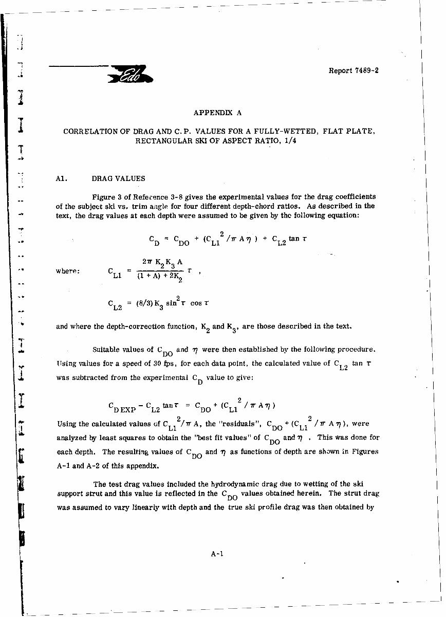
Report 7489-2
APPENDIX A
CORRELATION OF DRAG AND C. P. VALUES FOR A FULLY-WETTED, FLAT PLATE,
RECTANGULAR SKI OF ASPECT RATIO, 1/4T
Al. DRAG VALUES
Figure 3 of Reference 3-8 gives the experimental values for the drag coefficientsof the subject ski vs. trim aagle for four different depth-chord ratios. As described in the"text, the drag values at each depth were assumed to be given by the following equation:
CD =CDO + (C /7TrA 77) + CL 2 tan r
27r K2 K3 A"where: CL1 (1(+A) +2K32 r
CL2 = (8/3)K3 sin 2T cos T
and where the depth-correction function, K2 and K3 , are those described in the text.
Suitable values of CDO and •7 were then established by the following procedure.
Using values for a speed of 30 fps, for each data point, the calculated value of CL2 tan r
was subtracted from the experimental CD value to give:
C -C tn CD+(CL12/7rA'77)T' CDEXP CL2 tanr = CDO
Using the calculated values of C / A, the "residuals ", C + (C 2A ~Li DO Li 7),wr
i6 analyzed by least squares to obtain the 'best fit values" of CDO and 77 . This was done for
each depth. The resulting values of CDO and 77 as functions of depth are shown in Figures
A-1 and A-2 of this appendix.
The test drag values included the hydrodynamic drag due to wetting of the skisupport strut and this value is reflected in the CDO values obtained herein. The strut drag
was assumed to vary linearly with depth and the true ski profile drag was then obtained by
A-1
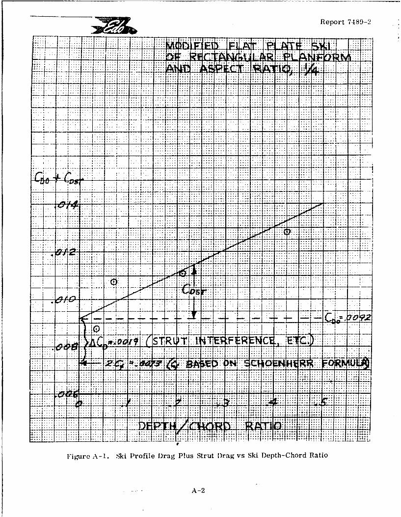
Report 71489-2
....... ... .... ,.t.
......... .......... ...
;....x...I....9.... . ... ... ...
~...... .... .... ....... ..... ... .... .... .. . ...... ... ::;::.... ....... .... . ...
1 ~~~ ..---.--.----------------
-- 4-
... .:. ..1 7-7-
....... ...... ...... .... L
.. ~~~t .7....i..;....... ....
... ...
A-22
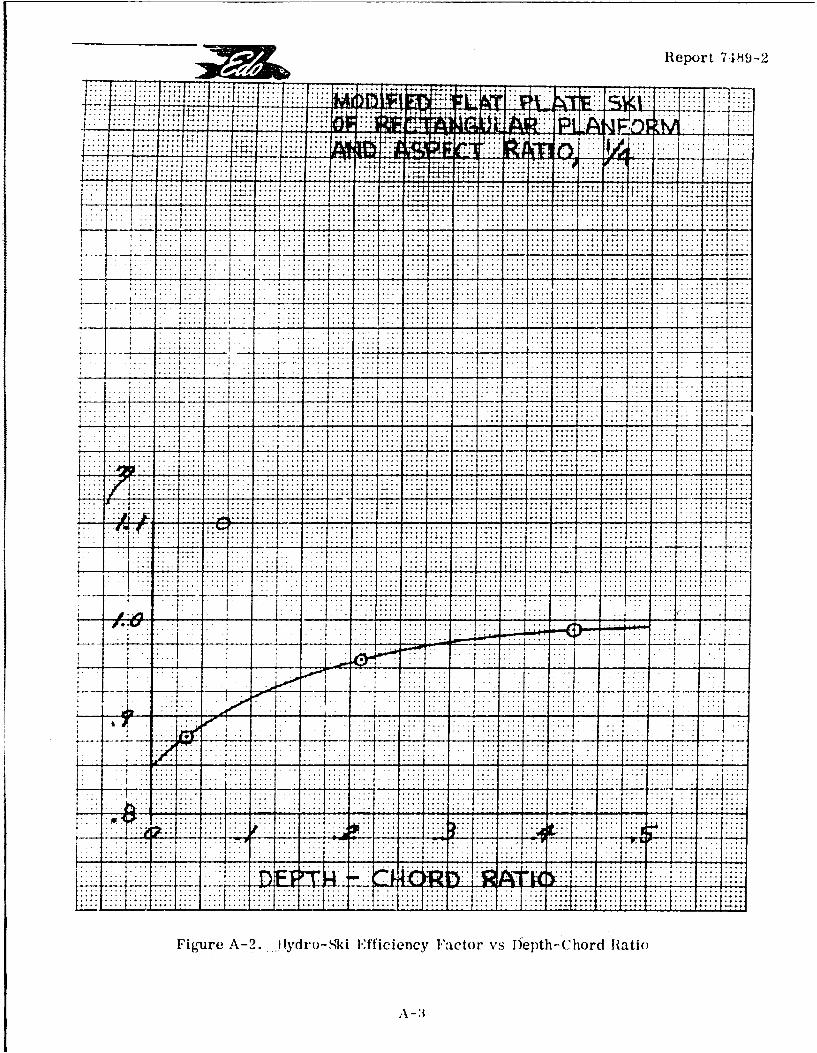
Report 7-189-2
. . . . . . ..
.. . . . ....~,
- . -4 . ... . .. -.. ... -. . . . . . . . . . .
.- 77-t .: .. .1 *. ...
.. .....
... .1
.T.. ..in
......
g6 1..1 ....
.7 7 7 .. . . .
..: ... .......
Figure A-. E fdoSiIfficiency Faictor vs Diepth ( hord Hatl()
A3
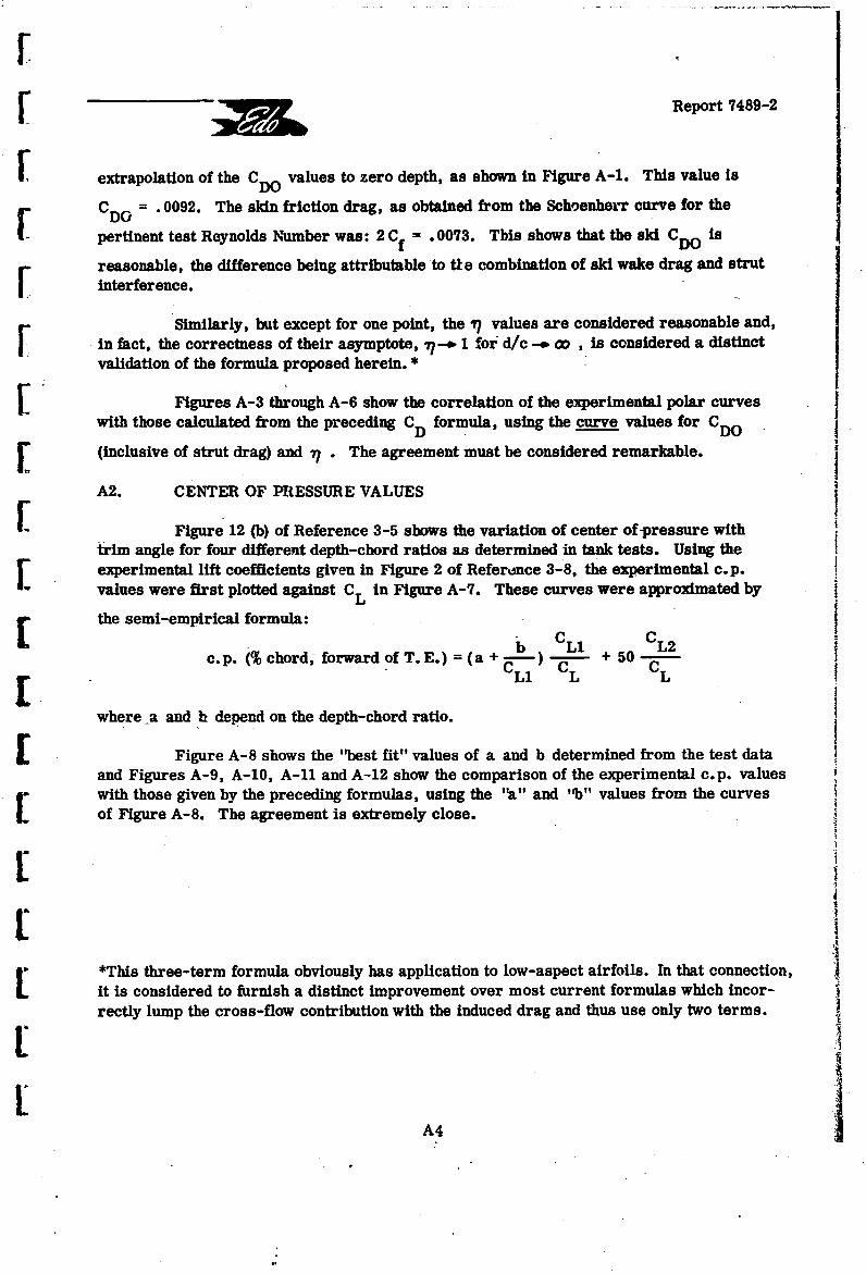
S[ Report 7489-2
Sextrapolation of the CDO values to zero depth, as shown in Figure A-i. This value is
C = . 0092. The skin friction drag, as obtained from the Schoenherr curve for the
pertinent test Reynolds Number was: 2 Cf = .0073. This shows that the ski CDO is
reasonable, the difference being attributable to tie combination of ski wake drag and strutrinterference.
Similarly, but except for one point, the 17 values are considered reasonable and,in fact, the correctness of their asymptote, 77-- 1 for d/c - co , is considered a distinctvalidation of the formula proposed herein.*
Figures A-3 through A-6 show the correlation of the experimental polar curves
with those calculated from the preceding CD formula, using the curve values for CDO
[ (inclusive of strut drag) and 71 . The agreement must be considered remarkable.
A2. CENTER OF PRESSURE VALUES
Figure 12 (b) of Reference 3-5 shows the variation of center of -pressure withtrim angle for four different depth-chord ratios as determined in tank tests. Using the
S experimental lift coefficients given in Figure 2 of Referdnce 3-8, the experimental c.p.values were first plotted against CL in Figure A-7. These curves were approximated by
E the semi-empirical formula:
Li C CL2c.p. (% chord forward of T.E.) = (a + ) + 50
L C CLi L L
where a and hi depend on the depth-chord ratio.
- Figure A-8 shows the "best fit" values of a and b determined from the test dataand Figures A-9, A-10, A-11 and A-12 show the comparison of the experimental c. p. valueswith those given by the preceding formulas, using the "a" and "b" values from the curvesof Figure A-8. The agreement is extremely close.
-" "*This three-term formula obviously has application to low-aspect airfoils. In that connection,L_ it is considered to furnish a distinct improvement over most current formulas which incor-
rectly lump the cross-flow contribution with the induced drag and thus use only two terms.A
F A4
:~i~irReport 74 89-2
.L~~~..~...... .........-- <: ;
-~~11 44 ,.,
_.. .- I .- 4 . 4-4 .. .4 .4- ... . ...
- -..- ' . .. ...... ýI. .. II. .. .. $' . . . . .- .. .. . .. .
44-.. ..... ....
+ .4*.*4Q4
................................................ .... .......
... ..... ....................
4+ *-4 -4: -1
... .... .. . ..
... .... .: .. . .. . ..: !
... .. . .. . . .. .
Figur .... .. v..oife ltPlt k fRetnua Pafr nL'~.. ....c .a..,./
.. ... ... ... .
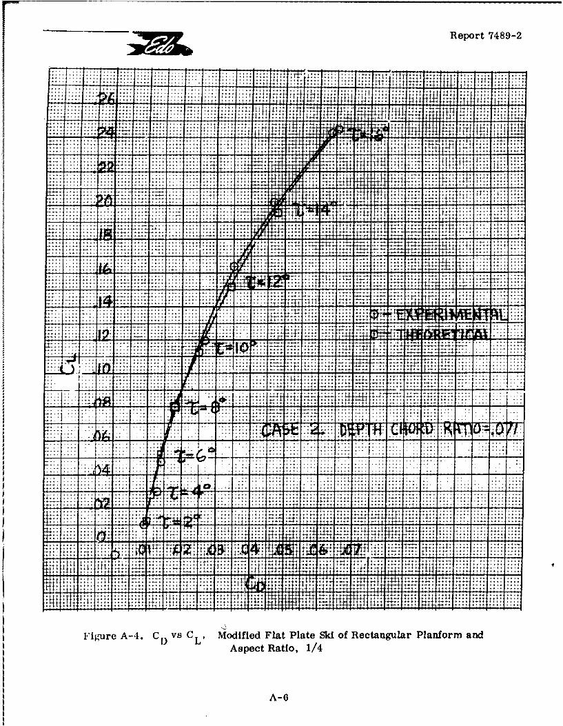
Report 74 89-2
114-
*4' . -.- 4... .. .... .. ., ,.4At 4.
-~~. .. . .~ .. . ... .... 4 *.74
.. .. . .. .. ... . ..-. .
. . .. . . *... -. .-
.... . . . .
.. ++ ~ ~ :4L.. ... ...:j2p j;8i~; 82
. . . . . . . . . . .::::.:......... ... . .t .,~
.. .... .......::: .1. .. "
. . . . . . . *. q ;:
-...... .... :..-... ... ......
......... ......... ::................
.. ... .....
:-8-.: :':; ::~ K ,.,,.... i.... 4.. -. 4- 4
.. ... .. .
Asec Raio 1/4 1"+- i +: ...
..A..-.. .
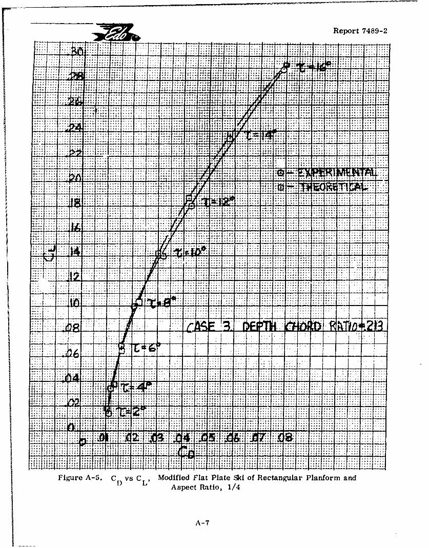
Report 7489-2
........ ...........
*~~~ ... .-* .. 4. 4 . :4 . -..
.4+
K -'
A4ec R1io 1/4
4I '~l+4-A-7
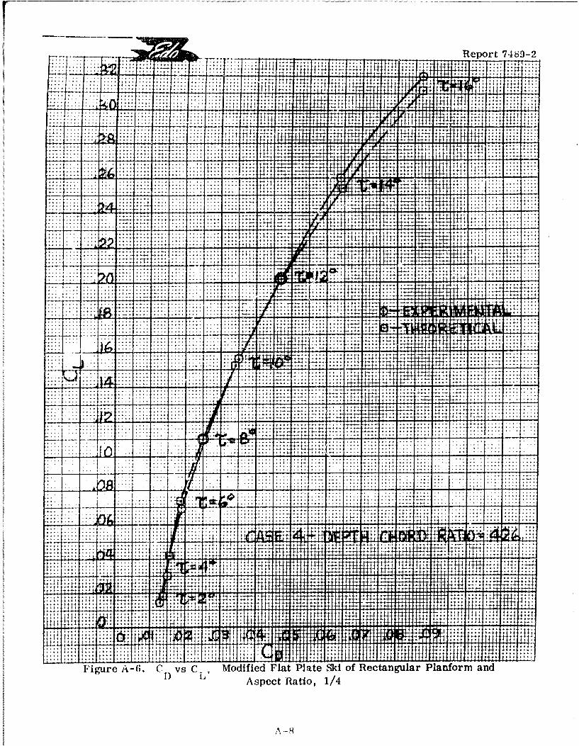
:1: .. ... ... .Report 7489-2
t2 t t: f4 f +4;4''' ý4
j~~~~~~ 1*''- 4:~w1 i::2.
.. i2,I4LILL ;-
-- ,I; I I 14,'.,.II 4
- 4 -~~~~ ~ ~~~~~ -.. ... .. ~***.* 4 .... ~ I7 ~. .... i ... .... * * - -, ..- - 4.
.. - - t . . . .. -. .
.. . ... .... ~~. .. 4 -
.1 ... .. .
V .1 +4- .. ...2z:.
-.. .... * .... 11 44 .. ... . .. ..
Ii
Asec aio 1/
A
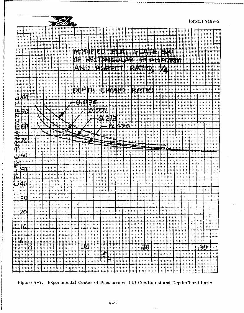
.. ..1. ... .......iU ... .
.. ... ... .. ..... 4.+t +4:
.... ... .. ...IILLp---
+: A l I I
~V77t
. .... . .. . .. ..... ....
t.~~~ ~ ......t ... ... -.. - - - .
..- ... ... .
A-7.~ ~ ~ ~ ~~~~.. ..er..ta ..nte .f Prssr v. Lift Coeficen an..pt-hrd1
.. ......-. .. .. .. .. ... .. ....
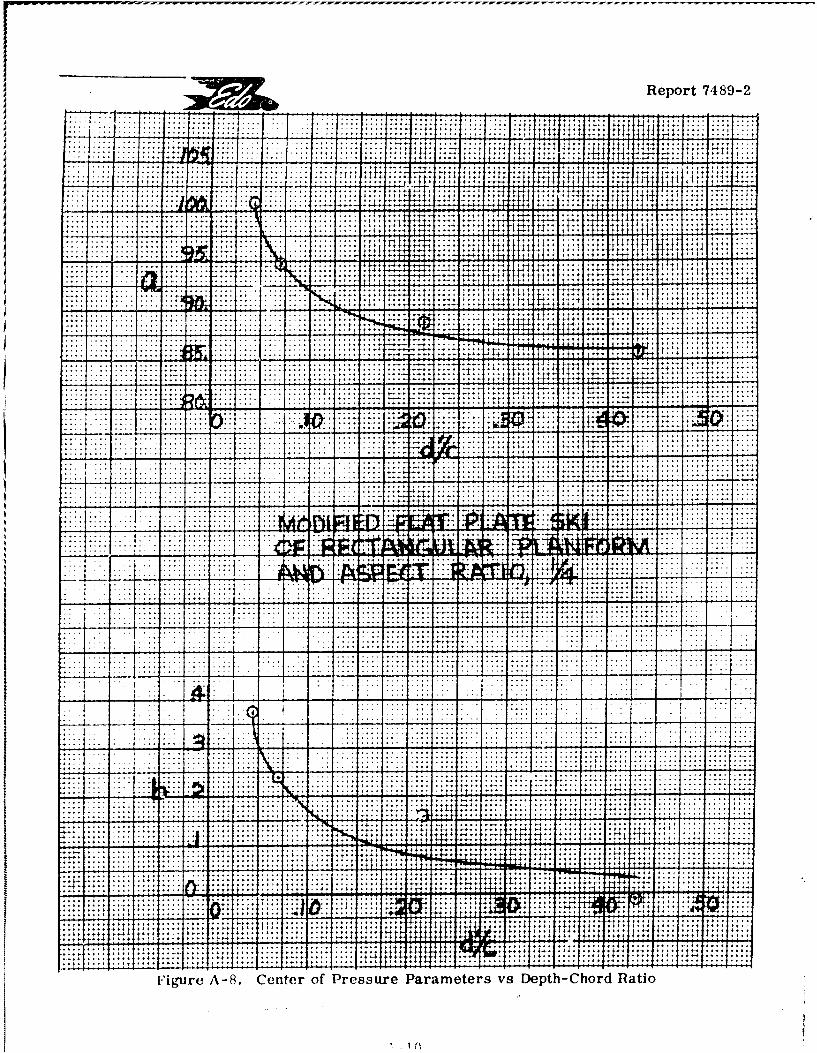
Report 7489-2
-T 7
+.... ... + f it Ti ý4 1
+ i.. . . . .. . . . + t, t
+ + * I ; . +I + +
It4 4+ +
.. .... .... .... . 4
I + +
44-4 1- -4
-4 -tl. I +TT ft "41
+ 4- 4-1
4M+: + .. ....
4ýt t tt t, ++
1 4.tl I fill +4 +
-1-11t 4 ý litt _l-1*11; :+.. .... .... .. .. . +
.... .... ..4l:
.... .... ....+4 + I1, + %'4:++:: - t,4t ttl
ý w p w i .. . 4,; +*1
.... .... .... .... T;:-44
+ ++
4 1
:'1 4 .. .... .. .
.. .. ... .... . .. .. .. ..
. ... .... ....
.... .... .... 4 ... .... .... ..
....... .... .... .... ..... ......
:41 . .... ...4
ý4 ... .... ...
.... .... . .:it
r 71
... ... .... ..
... .... .. . ....
.. .... .... ....
.... ... ..... ... .... ...... .... .. .. ....... .... .... .... .... .. ... .... .... ...
.... .... .... ..
.. . . .. . . .. . . . . .. . .. . . .. . . . . .
T`:
.... .... .... .... .. .. .. . .... ....
. .. . .... . ... I ., . . ....
.... .... .... ....
... .... .... .... .... .... .... . .... ....
+ ! : ý; +. +.... .... .... .... .. ....
+ L.4 441:I..* . .... .... .. . .... ........ .... .... ....
.... ....
++-+++ ... .... ...
Ti ;E . ý,4 +144 ... ....
+
ý"4 + -tý:. +t . .... ...
++
+ 4
+
:4 . .... .... ... 4 +1 1 .
.... .... .. .... . + + +.. f4
+ ...ý It. I4t
+
:+ + +-4 *4 1
igure A-8. Center of Pressure Parameters vs Depth-Chord Ratio
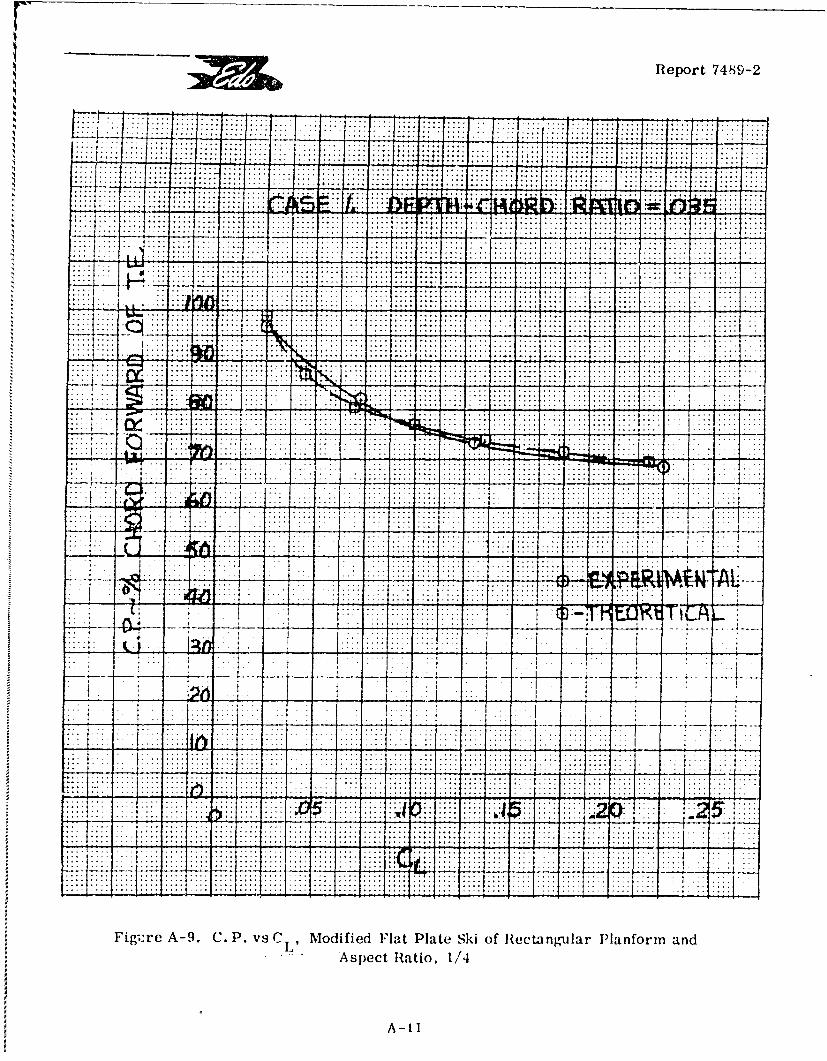
Reot78-
.............. .. . . . . . .I.. . . .. _ . _ _
.. ". .. * .... .... ....,
... .. . .... . . .... ~~~ ~~ .. .. .
....
.
... .. .f.. ... _.-
. .... ..... .
.iK. ..........K -.. ... .. ......
Fig;.~~~~~~~~~~re~~~ .... ..P. Moiid F..lteSio lc~gua lno nAsec .atio .../....
-f u :. . ., . . . % 4 : * :A.. .. . .
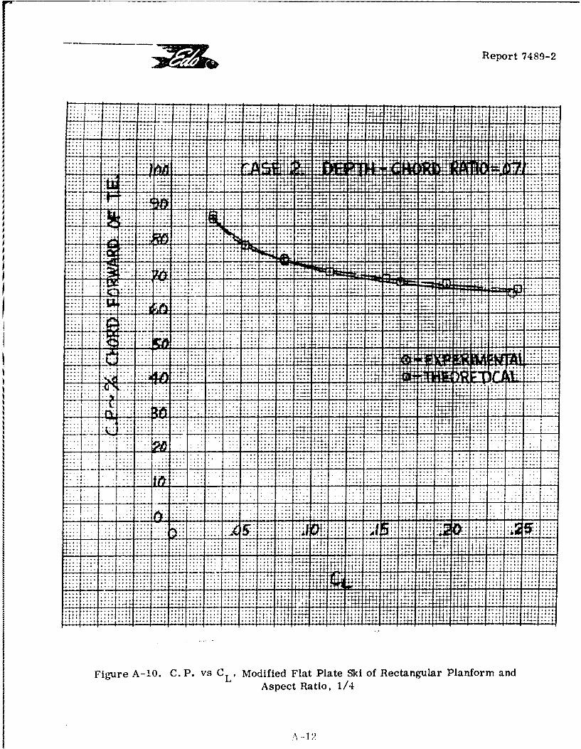
r Report 7489-2
. . ... .... ..
††††††††††††††††††††††††††††††† 4f..,..
.. . . . .... ..... ...... .. .. +r;:
-~ ~~~~~~~~~~~ - - -- - -,,,.....27:: .................
iv~~ ~ . ..... .. ..............................
Ut+
..................... .............. . :; - . .
-T -t --.. -..... ~.. .....2; ....> .. .. ..
A 121
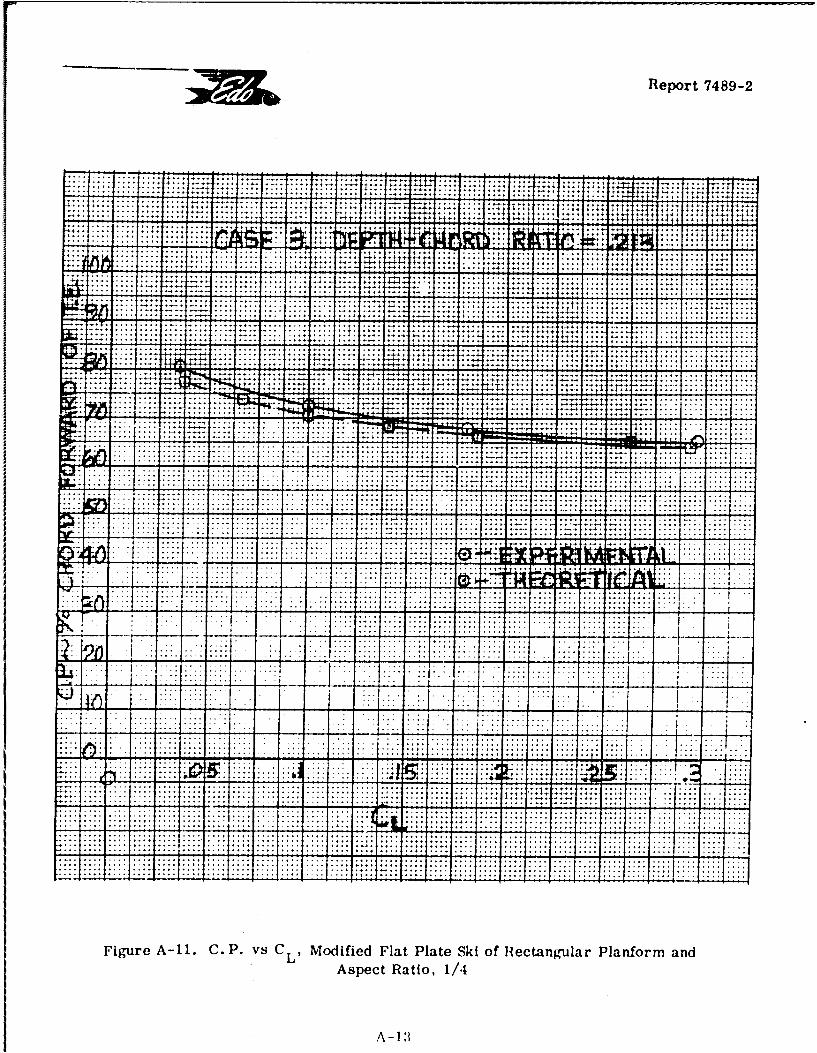
Report 7489-2
I ........... ... .... ...- :
. . . . . .~~.-.. .. ...... ... :'-4Y- - -
............ ..
T.. . .. . .,. 5 :...................... ......... ..........
..... ... .4... * 4.... ... 4**4** ... . .... 4..r ¶..4 ........ . .
................ ....4.-.....
. . .. . . . . . *~-. -4~44- 4t i4
-* -44. ..-. *. ....~ -. 4... . .. . L .o
1 . 4-. . . .
I-: .-. . . .
:1 :T : b
... .. ... .. Liz - - - - - -- - -j--
Figur 1. ... P. vs. C. oiid.ltPae.k.fRctnua afr n
L LL' Asec Ratio .. /4.
A-I T.
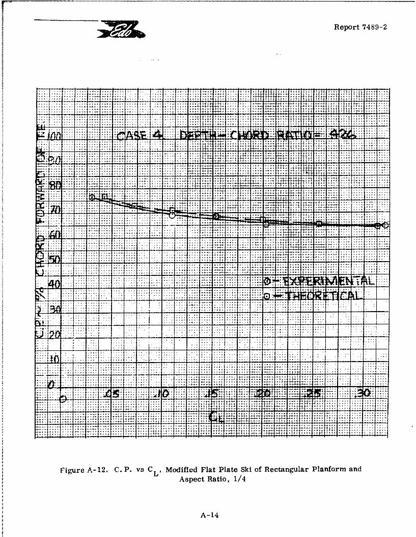
Report 7489-2
4.-41
.. .. ... 4.... ..... ,.. .. . ..... ... . *4
*.. ....... .... . .....
4* 4- t. '- . ... ... ..
* ~ ~ ~ ~ ~ . ... .... ....- +~ , * , , *
TW ..... ... t 4. .....
*I TI; .1:: "2ý '.1 ~ t2
. ..~ .. ._
... . .. ..
. ....... ..9
-~~~~.. ... ...- - --
'A1
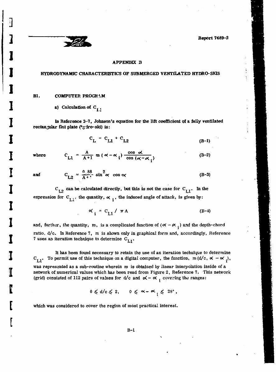
] Report 7489-2
APPENDIX 13
HYDRODYNAMIC CHARACTERISTICS OF SUBMERGED VENTILATED HYDRO-SKIS
B1. COMPUTER PROGH 'AM
I a) Calculation of C...
In Reference 3-7, Johnson's equation for the lift coefficient of a fully ventilatedrectangular flat plate (fydro-ski) is:
I L = LI C L2 (B-I)A i____
where CL A m (0(_0-- i) cos o( (B-21Ll A+1 i cos (e(-D(i) (
and C OL88 2 Cos o< (B-3)
L2 A-74oo
I CL 2 can be calculated directly, but this is not the case for CL1. In the
expression for CL, the quantity, o( i' the induced angle of attack, is given by:
I C 7r A (B-4)
and, further, the quantity, m, is a complicated function of (0( -P( i ) and the depth-chord
ratio. d/c. In Reference 7, m is shown only in graphical form and, accordingly, Reference7 uses an iteration technique to determine CLI"
It has been found necessary to retain the use of an iteration technique to determineCL1. To permit use of this technique on a digital computer, the function, m (d/c, o( - o i),
was represented as a sub-routine wherein m is obtained by linear interpolation inside of anetwork of numerical values which has been read from Figure 2, Reference 7. This network(grid) consisted of 112 pairs of values for d/c and c( - K. covering the ranges:
[ 0< d/c.< 2, 0 O<('--i 280,
which was considered to cover the region of most practical interest.
B-B-1i
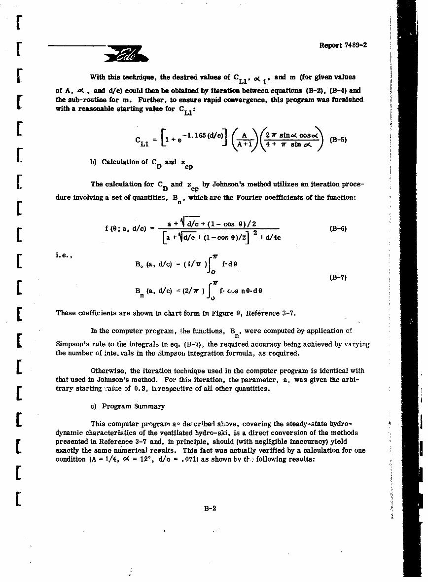
rr •Report 7489-2
SWith this technique, the desired values of CLl. o. i' and m (for given values
of A, o(, and d/c) could then be obtained by iteration between equations (B-2), (B-4) andthe sub-routine for m. Further, to ensure rapid convergence, this program was furnishedwith a reasonable starting value for CLI:
Ii L/165 We]c A,ý-, \ TSno(co (B-5= +4+ 7r (B-5)
b) Calculation of C and xD cp
The calculation for C and x by Johnson's method utilizes an iteration proce-D cpdure involving a set of quantities, B which are the Fourier coefficients of the function:
a + Id/c+ (1- cos 0/2f f(0;a, d/c) =- ]2 (B-6)[a + I, + (1 - cos 0)/2 + d/4c
L. e. ,B. (a, d/c) = (I/ r f"d9
(B-7)
B (a, d/c) - (2/r) f- cjs n0-d0n f
[ These coefficients are shown in chart form in Figure 9, Reference 3-7.
In the computer program, the fknctiuns, B , were computed by application of
nSimpson's rule to the integralb in eq. (B-7), the required accuracy being achieved by varyingthe number of inte.vals in the 3impsoit integration formula, as required.
Su Otherwise, the iteration technique used in the computer program is identical withthat used in Johnson's method. For this iteration, the parameter, a, was given the arbi-r trary starting value Af 0.3, irrespective of all other quantities.
c) Program Summary
This computer program a - de.'cr~bed above, covering the steady-state hydro-dynamic characteristics of the ventilated hydro-ski, is a direct conversion of the methods[ presented in Reference 3-7 and, in principle, should (with negligible inaccuracy) yieldexactly the same numerical results. This fact was actually verified by a calculation for onecondition (A = 1/4, o( = 120, d/c .071) as shown by t1 ý following results:
B-2tF
. _I_
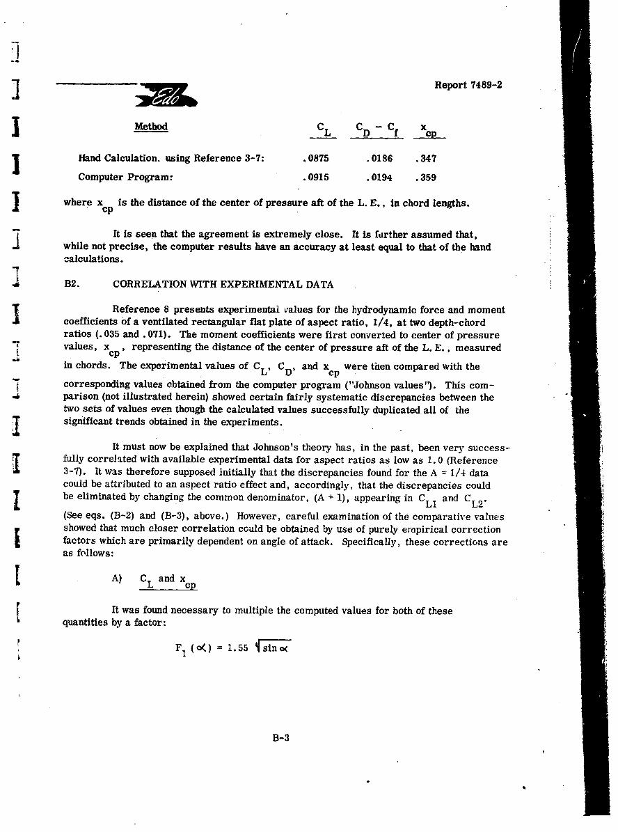
II
I ~Report 74 89-2
Method C L CD- C f x c
l Hand Calculation. using Reference 3-7: .0875 .0186 .347
Computer Program: .0915 .0194 .359
J where xcp is the distance of the center of pressure aft of the L. E., in chord lengths.
It is seen that the agreement is extremely close. It is further assumed that,while not precise, the computer results have an accuracy at least equal to that of the handc-alcula~tions.
1B2. CORRELATION WITH EXPERIMENTAL DATA
Reference 8 presents experimental values for the hydrodynamic force and momentcoefficients of a ventilated rectangular flat plate of aspect ratio, 1/4, at two depth-chordratios (. 035 and. 071). The moment coefficients were first converted to center of pressure"values, x , representing the distance of the center of pressure aft of the L. E. , measured
cp"in chords. The experimental values of CL, C and xcp were then compared with the
corresponding values obtained from the computer program ("Johnson values'). This com-parison (not illustrated herein) showed certain fairly systematic discrepancies between thetwo sets of values even though the calculated values successfully duplicated all of the
I significant trends obtained in the experiments.
It must now be explained that Johnson's theory has, in the past, been very success-fully correlated with available experimental data for aspect ratios as low as 1. 0 (Reference3-7). It was therefore supposed initially that the discrepancies found for the A = 1/4 datacould be attributed to an aspect ratio effect and, accordingly, that the discrepancies couldbe eliminated by changing the common denominator, (A + 1), appearing in C and CL2.(See eqs. (B-2) and (B-3), above.) However, careful examination of the comparative values
showed that much closer correlation could be obtained by use of purely empirical correctionfactors which are primarily dependent on angle of attack. Specifically, these corrections areas follows:
SA) CL and x
It was found necessary to multiple the computed values for both of thesequantities by a factor:
F1 (o() 1.55 sino(
B-3
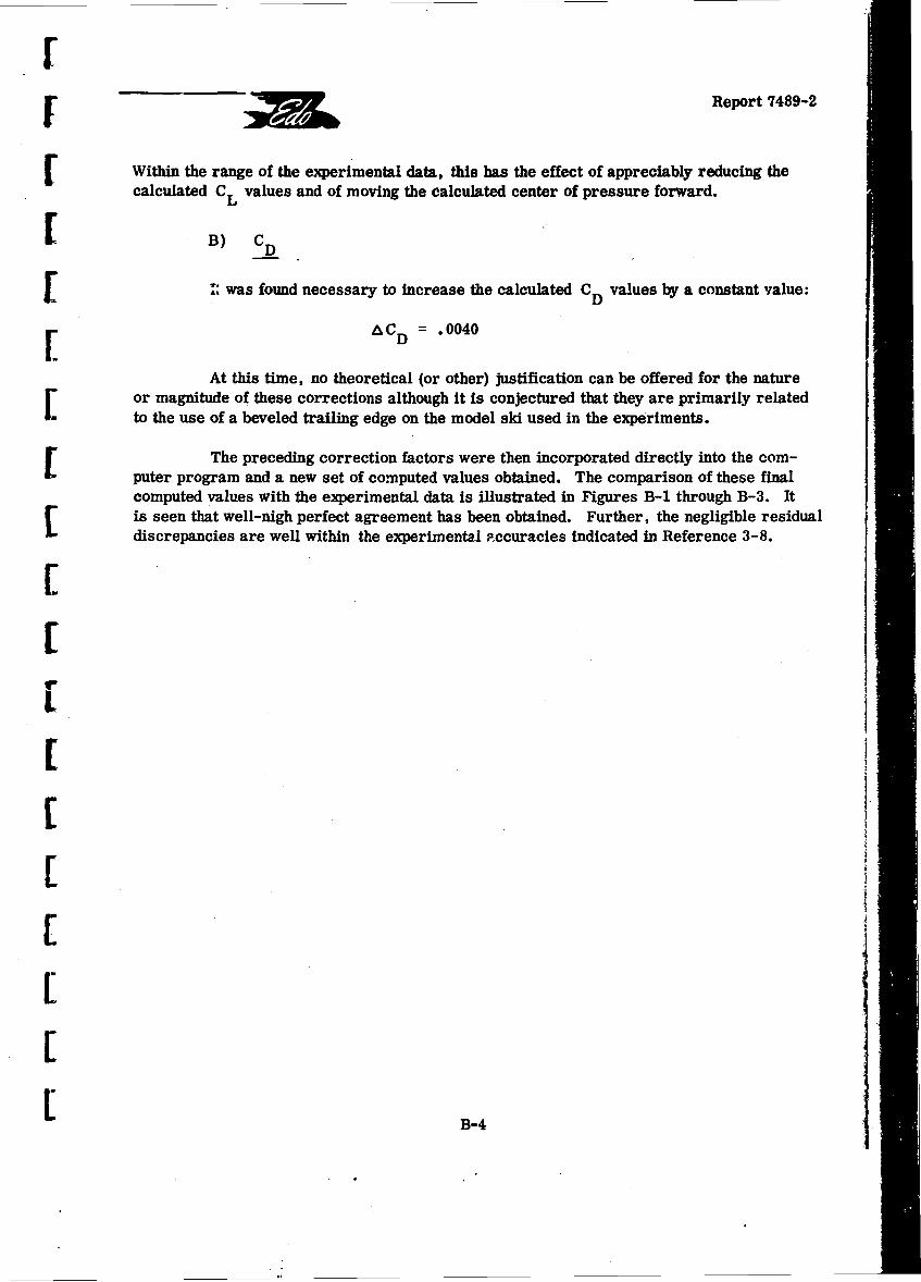
F •Report 7489-2
[Within the range of the experimental data, this has the effect of appreciably reducing thecalculated CL values and of moving the calculated center of pressure forward.
SB) CD
S: was found necessary to increase the calculated CD values by a constant value:
[a CD .0040
At this time, no theoretical (or other) justification can be offered for the natureor magnitude of these corrections although it is conjectured that they are primarily related
to the use of a beveled trailing edge on the model ski used in the experiments.
The preceding correction factors were then incorporated directly into the com-puter program and a new set of computed values obtained. The comparison of these finalcomputed values with the experimental data is illustrated in Figures B-1 through B-3. Itis seen that well-nigh perfect agreement has been obtained. Further, the negligible residualdiscrepancies are well within the experimental Foccuracies indicated in Reference 3-8.
C
[" I IL
S~B-4
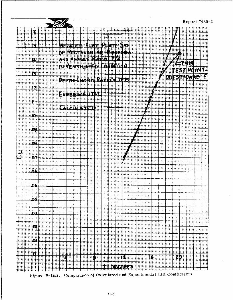
Report 7489-2
P ; T I.;: .v :s::7n-. .... .. ..
... .......
... .... .....
. . . . .- . ..
4- - -4 -"I- -* '
.. ... ... .
r. ~ ... ...... -. -
t 4 44-t*~.*IT
I igre 1(a Coparson f ClcuatedandFxprlmetalLif Coeficent
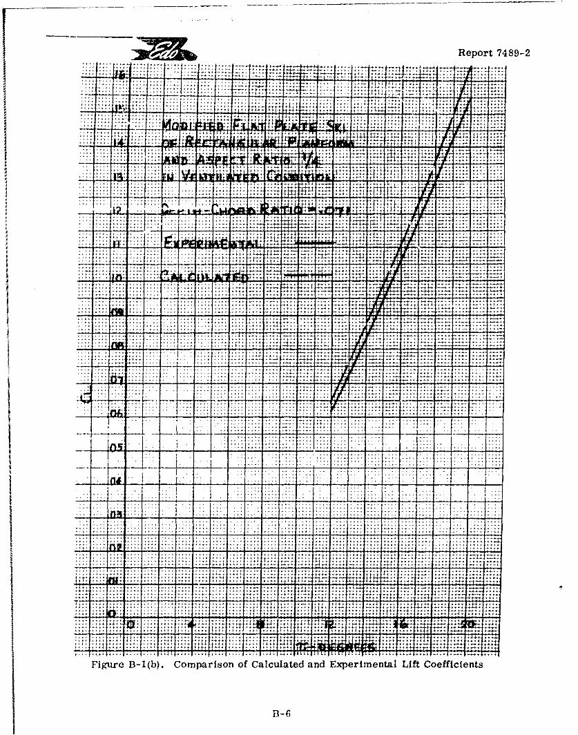
Report 7489-2
41 -77
II
............... ....... ...... t
....... 4 .,. . . . . . . . . *4 * .....-. t
::: +:- ~
77
. . . .. .. ..... .... ... ..
. . . .. . .4 . . .. .i a. . ..* *i 4
.... * 4~. * 44 4 .....-.
-~~~~~. ....-1 ....** -.4*
A",.,t 4 -44 t
Figure~~~~~~~~~~~. ....b) Comar.o of. Cacltd ...xermna.Lf ofcet
7:-
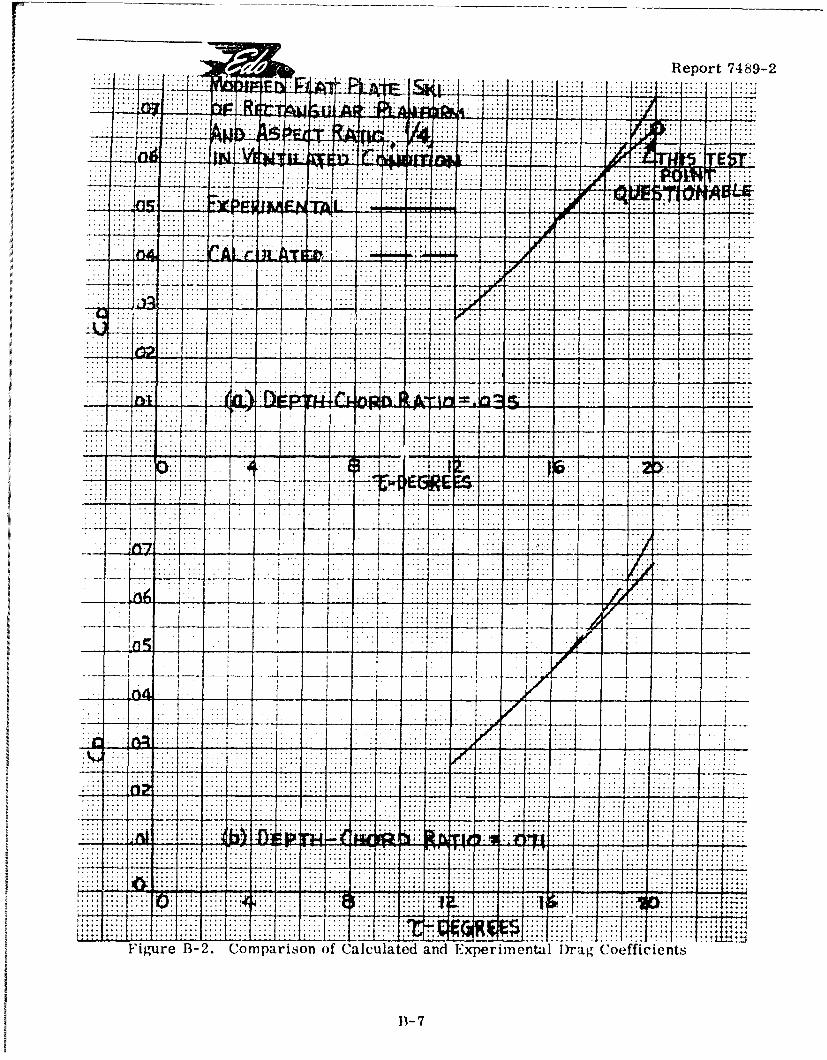
-....... ~ ~ i;:Report 7489-2
iip$ -M - - --. .... .. ...... .......
A . : .. .. .. ... .... . .. . .. . .
P . . .. .. . ..
I ~I4. 1 .. .. ... ..
-4 ;
4. 1w...... .....t.. .... .. ..
... .........
... ... -.. . .. . .
.............. .. .. .... ...... ..... ...... ...... .....- ... .. . .. .. .. . ... . .. .. ..t.. . .. . . .. .. ..Figure~ ~~~~~~.. ..2 Comarso of. Calulte and. .xeimna..r. ofiet
n-r74 .. .......
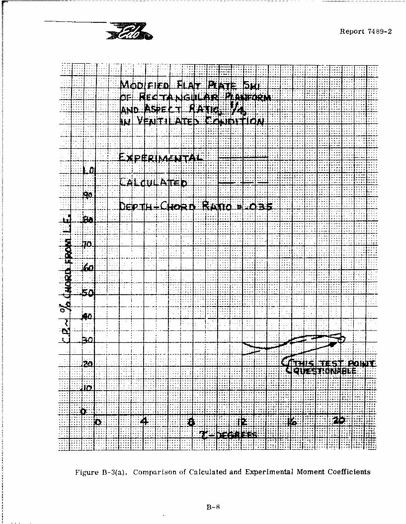
Report 7489-2
..I. .................
. ... .. . .. . .. . .. .
vv -- 4A b -Wu i-
F~~~~~~~~.. i. B.. .... Comarso ... Calulte and. Exe..tlMmetCefcet
.. . . .. .. . ....-.
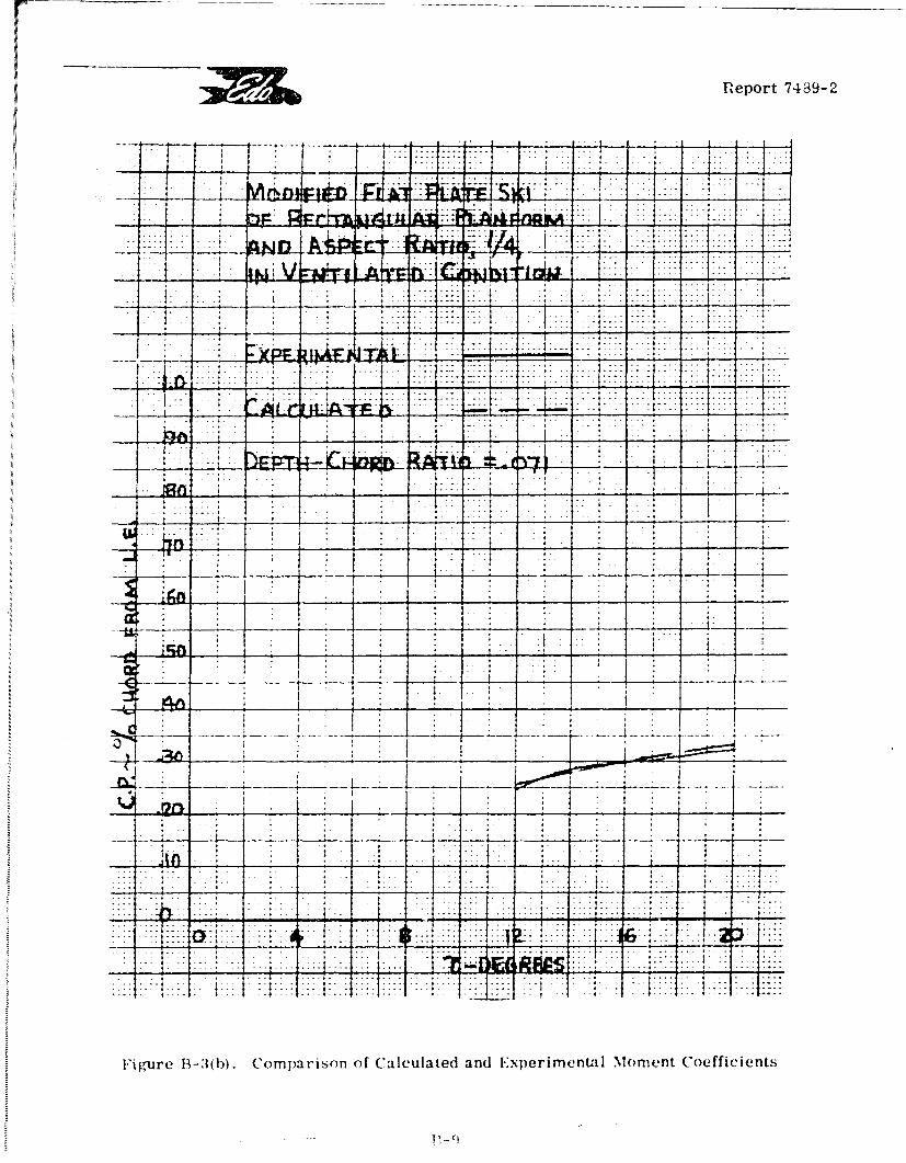
!
fReport 7489-2
.... .. . . . . . . . . . . . ....i .t . .. : ..- :::::::.... .. .. .. ..
- - : - • - - • - , : : : : - : - - : t i . : : i i : : - : : t -
I 4 ! ! : I: f - ; . : . - - -_._ . [ :: i :: - : I- . : ; -. :. 1 : : : : I : t.:- : -: :
. . . ... . . _ _ _- -i . - -1. . • . . -. . . . . ... . . .. .. .. - i "'
r..i.i.
'• .. • t • t 7• t • I . ..t- .. - - • .t .. . . ... .- - - :_•~~~ ..• . 66 R ik.-- - " ; . - . . . . •. -
ip e B Coprio of Caclae an E e im i Moment Coficient
.o.
: .. t ..-- - - - - -
. ; , .. .' , I l . ,"- I . 4 , 4 .: : .
., .. .
,- - - 9-_ _,; _ ;4 , _ 1 -1
i t " .
I -A f. .. ; I. ... ... -
,-,, -- ,: -.. -: - :' -i -!: . - . .--: . :-i: . . . :"-II .. 1.. ,-'"- '.";-.-
SI. . . . . . . . . . . I . .I - • . . . . . .
lFigre 13- 1(b). Comparison of Calculated and Experimental Moment Coefficients
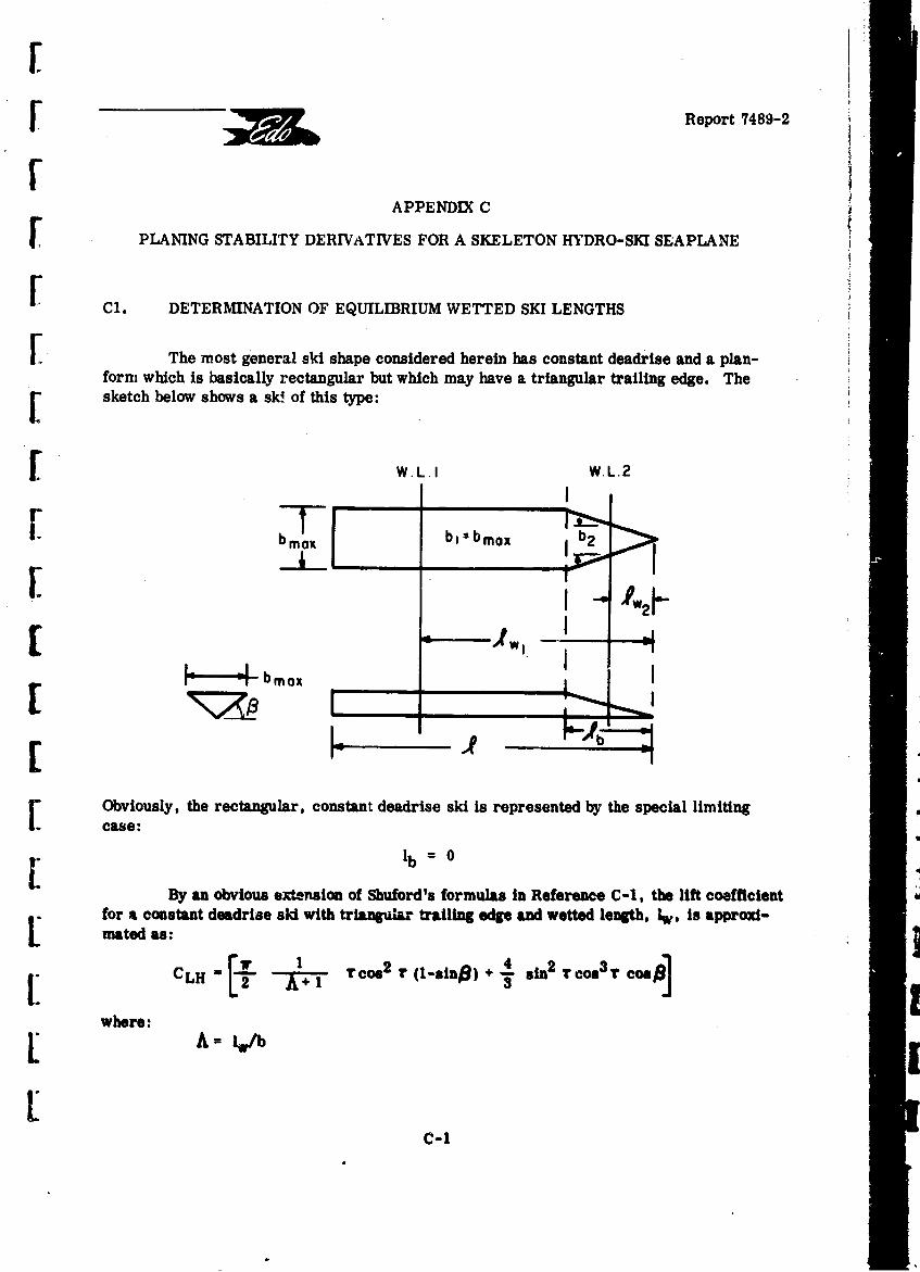
Report 7489-2
APPENDIX C
V PLANING STABILITY DERIVATIVES FOR A SKELETON HYDRO-SKI SEAPLANE
SC1. DETERMINATION OF EQUILIBRIUM WETTED SKI LENGTHS
SThe most general ski shape considered herein has constant deadrise and a plan-form which is basically rectangular but which may have a triangular trailing edge. The[ sketch below shows a sk! of this type:
SW L.I W.L.2
b b, b mox Ib2
SA.42
• ---- L - bo
Obviously, the rectangular, constant deadrise ski is represented by the special limiting 4[ case:
[ lb = 0By an obvious extension of Shuford's formulas in Reference C-1, the lift coefficient
for a constant deadriee ski with triangular trailing edge and wetted length, 1w, is approxi-mated as:
1L 3- -L cos2 r isn)+. sin2 Tool3 r cosl
where:
C-1
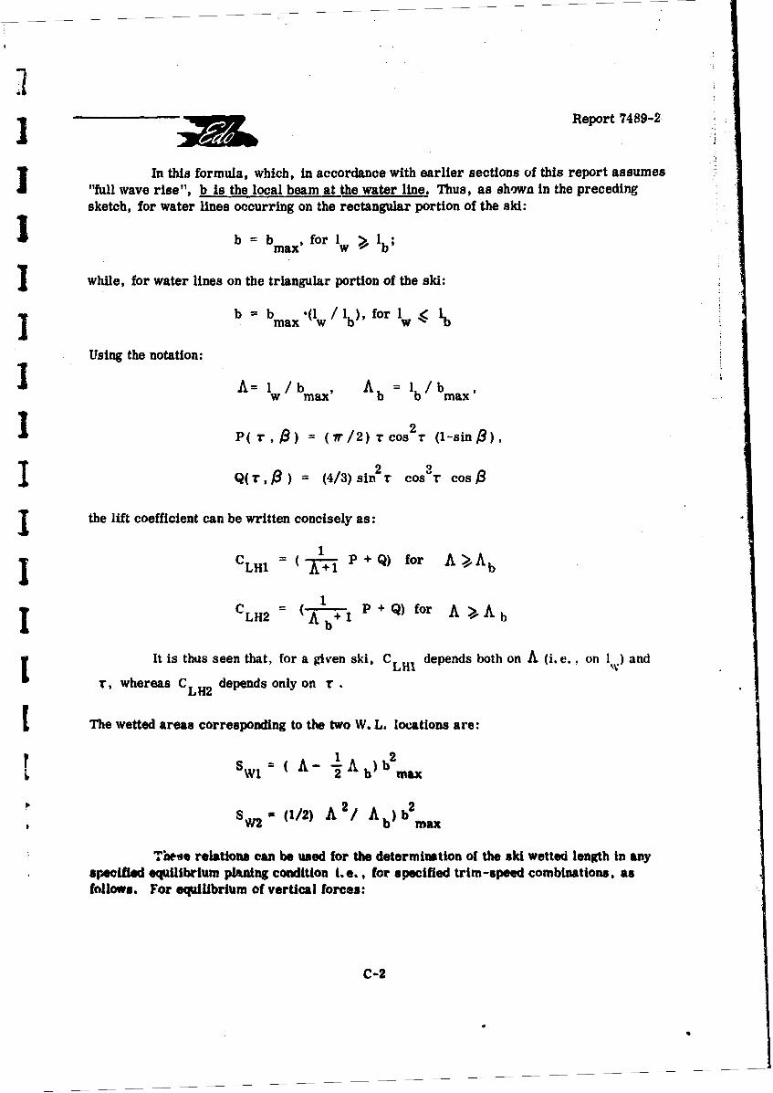
3 •Report 7489-2
In this formula, which, in accordance with earlier sections of this report assumes"full wave rise", b is the local beam at the water line. Thus, as shown in the precedingsketch, for water lines occurring on the rectangular portion of the ski:
b b b for I
max'
while, for water lines on the triangular portion of the ski:
b b b .(I/ for Imax w b' fo W
Using the notation:
A= / b , A b I lbb max'
P(r,) = (7r/2) rcos 2 r (1-sin$),
2 3SQ(r,3 )r (4/3) sin r cos"T cos
the lift coefficient can be written concisely as:1
CLHI =( P + Q) for A>AbLH1 A+1b
CLH2 = (A-1 +I P +Q) for A Ab
b
It is thus seen that, for a given ski, CLH1 depends both on A (i.e., on I*) and
r, whereas CLH2 depends only on r.
SThe wetted areas corresponding to the two W. L. locations are:
S~,= ( A- -1Ab) bm2
W1 2 2 a
SV (1/2) A 2/ Ab)b2
Tlese relations can be used for the determination of the ski wetted length in anyspecified equilibrium planing condition i.e.,, for specified trim-speed combinations, asfollows. For equilibrium of vertical forces:
C-2
Report 7489-2
SLH= W - LA =W -CL()(pA /2)V SwH W- LA LH (PAH w
S _ = WI( i • or, CLH SW(_ V CLA( ') PAi pw) Sw
where CLA( r) represents the known lift curve for the airplane. Hence, the alternate
equations defining the equilibrium wetted length are:
S(1): A Ab:- 1
+QI( A- - Ab) N
S(2): A 4 Ab Y1/2[A=2Y-A tN/[(PI A b+ Q]
"where: N - (pA/Pw) (Sw/b ) CLA (r)
.i? Note that the first of these equations requires use of the quadratic formula while the second
is explicit.
C2. UNSTEADY HYDRODYNAMIC LIFT FORCE
j The instantaneous force acting on the heaving and pitching ski is assumed to begiven by the relation:
LH - LH SW( p w/2) Veq
SLH(Pw/2)Veq
L where, in accordance with the "equivalent planing velocity" theory (previously validated forone degree of freedom), the "hydrodynamic lift area" depends only on the instantaneousgeometry of the ski relative to the (smooth) water surface i.e., on wetted length and skitrim angle, while the "equivalent planing velocity" is a fictitious steady-state horizontalvelocity which would produce the same lift force under the Instantaneous geometric conditions.
* C-3
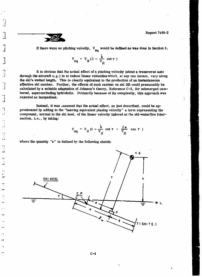
.1 Report 7489-2
I If there were no pitching velocity, V would be deflined as was done in Section 5.eq
V V (iieq H 'V cH r
It is obvious that the actual effect of a pitching velocity (about a transverse axisthrough the aircraft c. g.) is to induce linear velocities which, at any one instant, vary alongthe ski's wetted length. This is clearly equivalent to the production of an instantaneous
I effective ski camber. Further, the effects of such camber on ski lift could presumably be- ~calculated by a suitable adaptation of Johnson's theory, Reference C-2, for submerged cam-
bered, supercavitating hydrofoils. Primarily because of its complexity, this approach wasrejected as inexpedient.
Instead, it was assumed that the actual effect, as just described, could be ap-proximated by adding to the "heaving equivalent planing velocity" a term representing the
- component, normal to the ski keel, of the linear velocity induced at the ski-waterline inter-section, i.e., by taking:
eq V ( -hv colt r -La-- csc rH H
-Hwhere the quantity "all is defined by the following sketch:
-. C cg.
. P
kr
W. L.
C-4
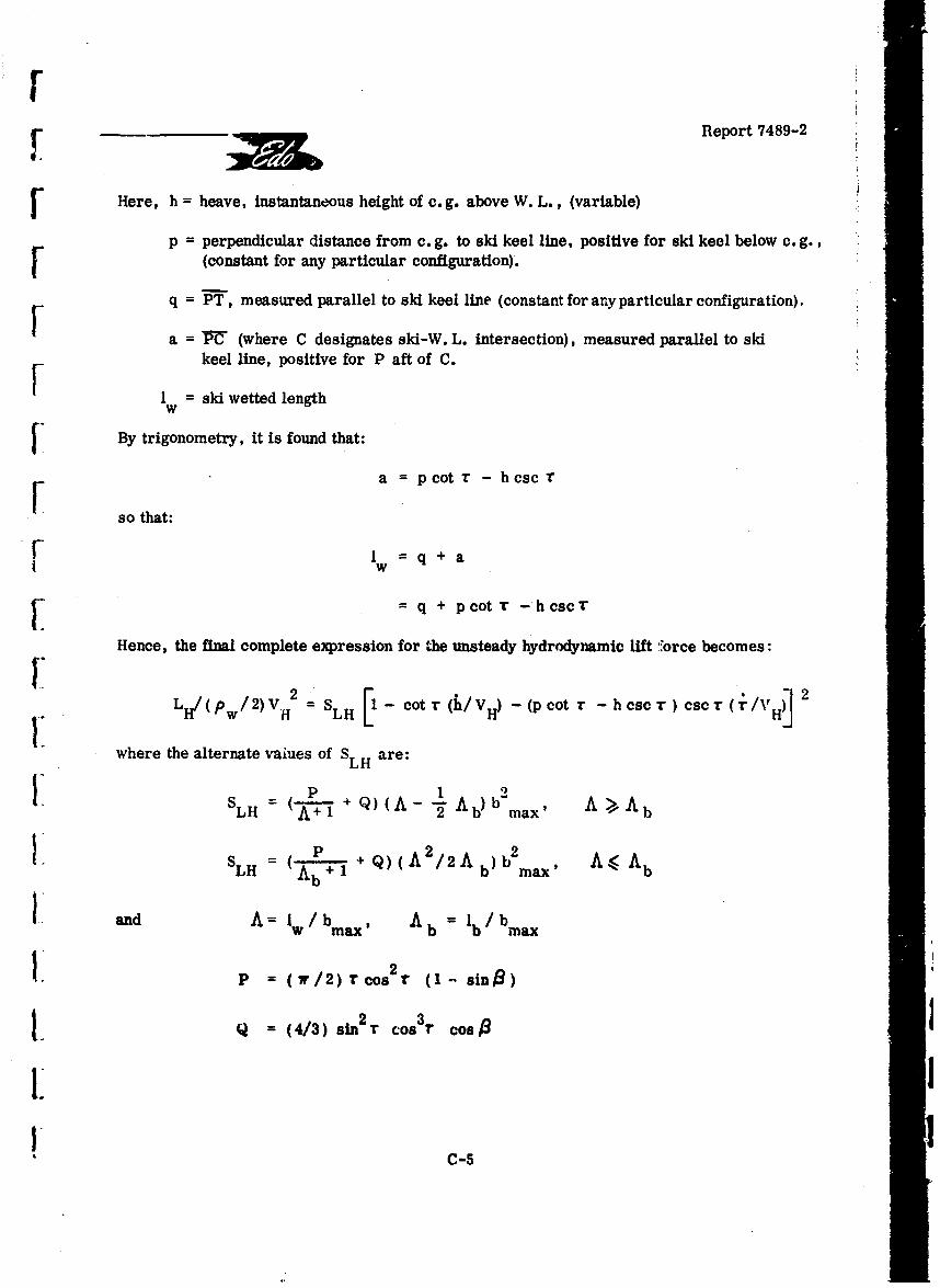
Report 7489-2
Here, h = heave, instantaneous height of c. g. above W. L., (variable)
p = perpendicular distance from c. g. to ski keel line, positive for ski keel below c. g.,[ (constant for any particular configuration).
q = PT, measured parallel to ski keel line (constant for any particular configuration).
a = • (where C designates ski-W. L. intersection), measured parallel to skikeel line, positive for P aft of C.
1 = ski wetted length
By trigonometry, it is found that:
a = pcot r - hcsc T
so that:FI =q+a =
I w + a
. q + pcot r -hcsc T
Hence, the final complete expression for the unsteady hydrodynamic lift .orce becomes:
LH/(Pw /2)V = SLH l Cot (h/VH) - (p cot r - h cscr) cscr (T C/H
where the alternate vaiues of S LH are:
SLH = ( + Q) (A - -Ab)bmax, A Ab
LH A 12 2 ax2/ )b2 A.•AbSLH = +Ab Q)'A /2Ab) b max'
I and A= Iw/bmax' Ab =1 b/bmax
P - (r/2)r Cos r (1- sine)
Q = (4/3) sin2 r cos 3 r cost 3
I !C-5
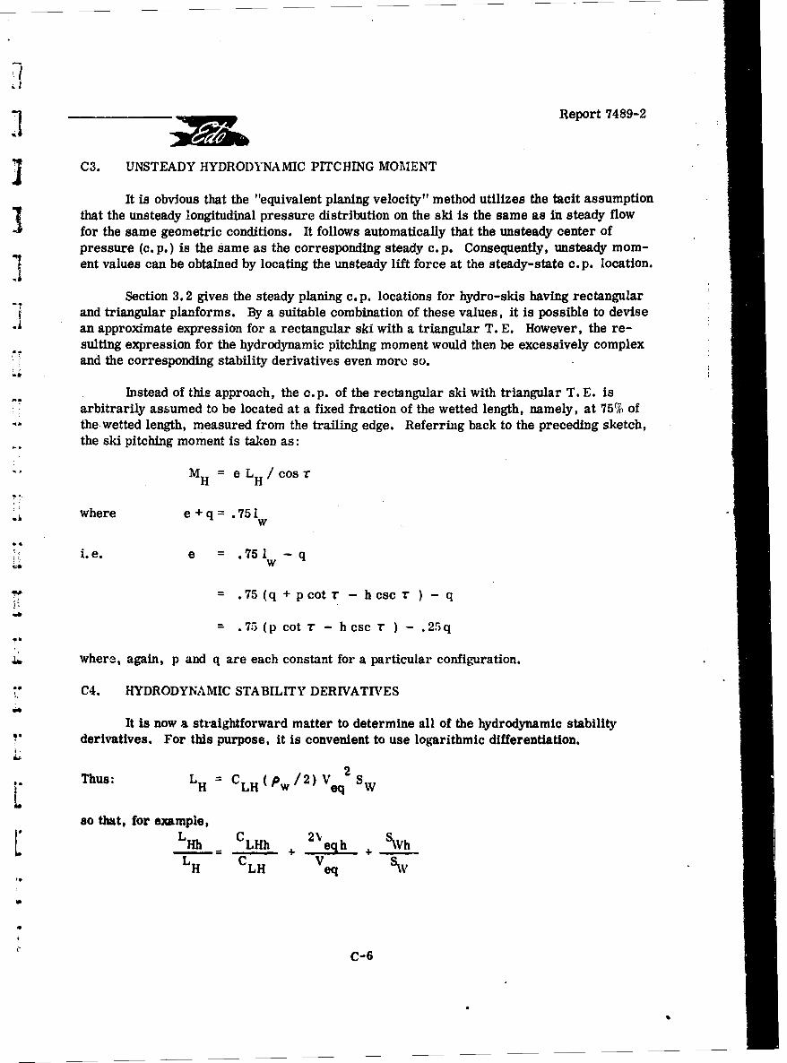
Report 7489-2
SC3. UNSTEADY HYDRODYNAMIC PITCHING MOMENT
It is obvious that the "equivalent planing velocity" method utilizes the tacit assumptionthat the unsteady longitudinal pressure distribution on the ski is the same as in steady flowfor the same geometric conditions. It follows automatically that the unsteady center ofpressure (c. p.) is the same as the corresponding steady c. p. Consequently, unsteady mom-ent values can be obtained by locating the unsteady lift force at the steady-state c. p. location.
Section 3.2 gives the steady planing c. p. locations for hydro-skis having rectangular"and triangular planforms. By a suitable combination of these values, it is possible to devisean approximate expression for a rectangular ski with a triangular T. E. However, the re-suiting expression for the hydrodynamic pitching moment would then be excessively complexand the corresponding stability derivatives even more so.
Instead of this approach, the c.p. of the rectangular ski with triangular T. E. Isarbitrarily assumed to be located at a fixed fraction of the wetted length, namely, at 75% ofthe-wetted length, measured from the trailing edge. Referring back to the preceding sketch,the ski pitching moment is taken as:
"M H = e L H/cost
where e + q= .751w
,,,i.e. e = .751 - q
= .75(q +pcotr - hcsc r ) -q
= .75 (p cot r - hcsc r ) - .25q
where, again, p and q are each constant for a particular configuration.
C4. HYDRODYNAMIC STABILITY DERIVATIVES
It Is now a straightforward matter to determine all of the hydrodynamic stabilityderivatives. For this purpose, it is convenient to use logarithmic differentiation.
2Thus: L H C H(p /2) V q2S W
so that, for example,SHh = LHh + 2 e h SVh
SH LH Veq
C-6
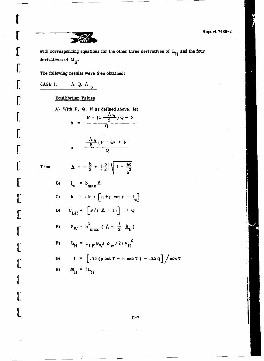
FReport 7489-2
[with corresponding equations for the other three derivatives of L H and the four
derivatives of MH.
The following results were then obtained:
O ASE I. A >, A b
Equilibrium Values
A) With P, Q, N as defined above, let:S~P + (1 Ab) Q-_N
b = 2
(P + Q) + N
SQThen A+-
2 112
[ B) Iw b AB) w max
I C) h = sin r [q+p cot r - Iv]
D) CLH= [P/( A +1)] +Q
SE) SW b2 A 1 Ab)W max( -
SF) LH = CLHSW( Pw/2)VH2
G) f = [/5(pcotr- h cscr) - .25q cosr
II H) MH M fLH
S~C-7
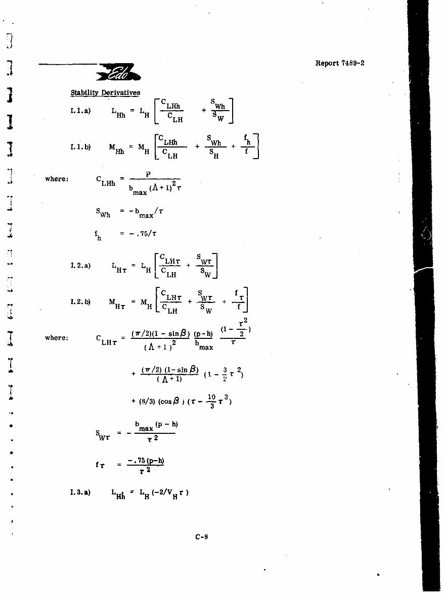
Report 7489-2
Stability Derivatives
[CL~hSW]I.1.a) =LH LHh rLHh H CLH W
L1.1.b) M h MH s H 4-i. pwhere: CLHh b
-_# b m x(A + 1)2 r"max
"S"h -b /r"SWh max
f h -75/T
1.2.a) LH T L [CI + SW
LH L L
1.2.b) MH= =LM +W. +T 2
whee: (7r/2)(1 - sing) (p-h) 21__-
wheLHr (A + 1)2 bmax
+ (r/2)(1-sino) 3( T 2)
(A+ 1)
S+ (8/3) (cos B(r- 1 0-r 3
3
* b (P -h) •
max
f -. 75 (p-h). fr = r'2
SI. 3.a) LH LH (-2/VH r)
C-8
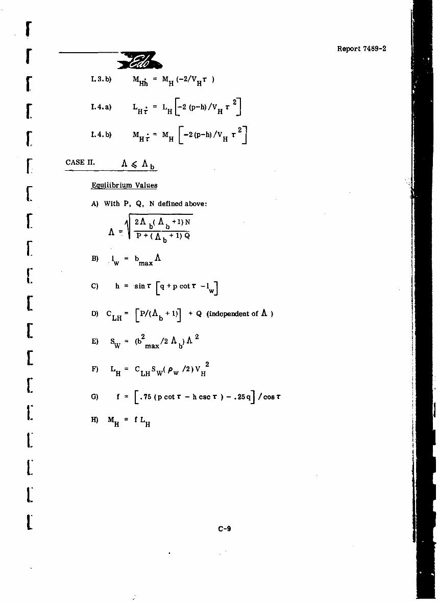
F
F 1~ bReport 7489-2
1.3.b) M Hh = MH (-2/VHr
[ 1.4.a) LHi = LH[_2(p-h)/VHr 2]
r 1.4.b) MH .= MH [-2(p-h)/VH r2]
[ CASE II. A < Ab
[E quilibrium Values
A) With P, Q, N defined above:
A= 2A b( Ab +1)N
[B -P+(Ab+ 1 )Q
B)I = b Aw max
C) h = sin rE [+ p cotr-w
[ D) C LH = [P/(Ab + 1)] + Q (independentof A
E) SW = (bm2 A b)A 2
/2AF) LH=CHSW(Pw /2) VH
G) f: [.75(pcotr-hcsc )-.25q]/COST
1. H) MS = fLH
' 9
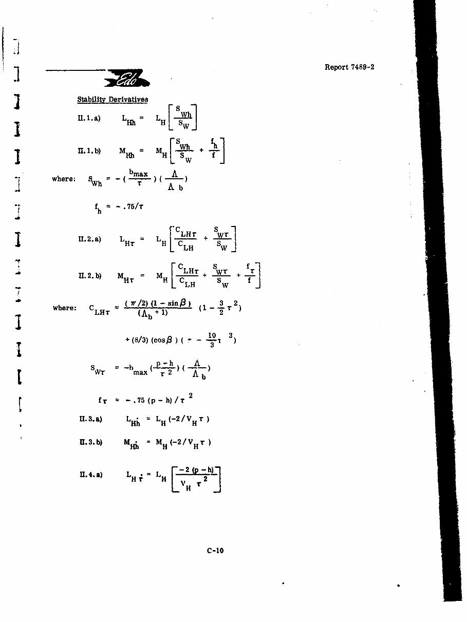
Report 7489-2
J Stability Derivatives
Il. 1.a) L LH SW]
1I II1. b) MM[-. .- + #where: _hbmax A
SWh = ( 3 Ab
"fh = -75/1
11. 2. a) L L I L~lT WT]LTH [CL LH +SW
C S 1C-HH S W fTj
where: C = 7r/2) (1 -sing) (13 2)whre LHT (Ab + 1) 2•
I S+ (8/3) (cos,8 ) - "101 3)
-b (p-h LS WT3 = -bm ax T 2 " '
t fT = -. 75(p-h)/T 2
U. 3. a) L Hý = L H(-2 /VH T)
I. 3.b) MHi = MH(-2/VH3)
U.4.a) L L L 2 (p ,-(h)H. H. LV rIT
C-10
• • I
Report 7489-2
1I. 4. b) M = -2 (p -h)r V 2
It will finally be noted that these resuiis also cover the case of the completelyrectangular ski. For the latter geometry, it is only necessary to substitute A b = 0
in all of the Case I equations.
rC5. AERODYNAMIC STABILITY DERIVATIVES
In general, the present treatment of the aerodynamic stability derivatives is similar[to that used in the classical analyses of aircraft aerodynamic stability. However, thistreatment also assumes that the four static derivatives, LAT , MAT , LAh MAh, are
known from wind-tunnel tests. It also assumes that the aircraft is of "conventional" aero-dynamic and propulsive configuration and that the hull does not contribute to any of the fourdynamic (damping) derivatives. Finally, all effects of power on the stability derivatives are[ neglected.
Before proceeding, it must be pointed out that none of these limitations really restrictthe application of the present method. Thus, the dynamic derivatives can actually be mea-sured by the more elaborate tunnel techniques presently available. Similarly, power-onderivatives can be measured by suitable wind-tunnel tests of powered models. Further, inthe case of "unconventional" configurations (canards, etc.) the dynamic derivatives can beestimated, if necessary, by approaches similar to those used herein.
The dynamic values of the aerodynamic lift and pitching moment can be written as:
SLA LA(t-o) + LAt
M =M+MA A(t-o) At
•I where "( t - o)" signifies values in the absence of the horizontal tail and "t" signifies thevalues for the horizontal tail in the presence of the wing.
SThe "tail-off" valihes can be written as:
SLA(t-o) q ACLo(l(t-o) 0weff-G O)sw
I MA(t-) = A CMo((t -o)( (weff- 0(1) Sw
where 0<woeff = cw - (/VH)
SC-Il
Report 7489-2
The horizontal tail contributions can be written as:
LAt = QCLo.t 'teff St
MAt -At CL att* t eifft
Ater C= t <
I-:Itwhr teff = <weff + 7 -C I1 t
In this expression for a< It Is necessary to account for the effect of "downwash
lag, as follows. The downwash angle is written as:-as
d dedweff
w
where e (t) is the downwash angle at the tail at time, t, and oc is the effective wingw eff
angle of attack at the earlier time:
t' =t - (It /VH)
t
Then, approximately, <weff w- VfwH weff
lh 1t( 1 • de 't •so that: • ( +I-- - - (It-
t eff weff V doew weff V w eff tH w H
di t . did (0•--)o eff + (r d e weff + t
But Cw= r + iw (I w wing incidence to ski keel)
so that 0C - (h/V +iw eff H w
w = "- (rh/VH)
d e 1h( "
Hencet , de h F c •C V It., HC ,1
II
c-I 2
r_____________Report 7489-2
From the preceding expressions, the eight aerodynamic stability derivatives are[ found to be:
r 1.a, LAh = 0*
1.b) MAh = 0*r Ah dLAr = qA CLo((t-o) w d o(1 - o tI
2. b) Ar q (I-IE)C S I2MA = qA LCM(K(t-o) w d"o( )Lo( t tltw
3.a) L A = -LAr /VH
3. b) M*Ai = -MA /VH
4.a) LdE IVl"4.) LA• = (1 +d-a--qA CL9(t St 't/VH
4.) *dE 24. b) Ar = - +d7 )qACL~t t/VH*w
in addition to these eight derivatives, it is seen that the "downwash lag" effect con-tributes two additional terms into the equations, both of which are proportional to h.While these terms represent real effects, they will be neglected herein primarily forreasons of consistency. If they were retained, consistency would demand inclusion of all
"I *The following remarks are of importance in practical application of the preceding results:1) In many cases, LAh and MAh are not necessarily zero, even approximately.
I Their actual ialues are best established by direct wind-tunnel tests for "ground effect."2) The values given above for LAr and MAr are useful for estimation purposes.
It is far better, of course, to utilize the values obtained directly from wind-tunnel tests.I 3) In accordance with conventional practice, an empirical factor, K, has been intro-duced into the expression for MA * to account for the pitch damping contributions of the
j wing and the hull. It is standard practice to assume that K • 1. .
IC1SC-1
SiReport 7489-2
other terms proportional to h and t'. While such other tarms exist and are of importancein flutter analyses, they are customarily neglected in aircraft dynamic stabilitySinvestigations. By way of further justification, it may be noted that the coefficient:
d e ) PASLAI; = (d )w CL a(t St et
represents an "added mass" whose value in a typical case is about 2% of the aircraft mass.
REFERENCES
C-1. NACA TN 3939: "A Theoretical and Experimental Study of Planing SurfacesIncluding Effects of Cross-Section and Planform," C. L. Shuford, Jr., March 1957.
C-2. NACA RM L57116: "Theoretical and Experimental Investigation of Arbitrary AspectRatio, Supercavitating Hydrofoils Operating Near the Free Water Surfaces, "byV. E. Johnson, Jr., 12 December 1957.
C-14
BS
rReport 7489-2
APPENDIX D
[ HYDRO-SKI FORCES AND MOMENTS FOR WAVE RESPONSE COMPUTER PROGRAM
D1. HYDRO-SKI FORCES
The sketches in Figure D-1 show all of the impact (wetted ski) conditions thatcan possibly arise while the seaplane is operating in waves. A level water line is showy ineach sketch only for simplicity of illustration but the load estimate for each case is intendedto be applicable to wave conditions. It will be understanding that, in the force calculations,the resultant velocity vector at the hydro-ski also includes the effect of the rigid-body angu-lar velocity about the aircraft center of gravity. That is, the linear velc'-ity of the hydro-skicenter of pressure due to aircraft rotation is vectorially added to the translational velocityso that the hydro-ski is considered to be only in translational motion at any instant.
r Case (1)SCs( The necessary conditions for Case (1) are:
a) Leading edge at or above water surface;b) Trailing edge below water surface;c) Minimum trim. + 30;r d) Lower surface only wetted.
This is the conventional impact condition extensiveJy covered in the literature.The instantaneous hydrodynamic load is determined by ca", ulating the resultant velocitycomponent normal to the keel, from which is obtained the equivalent planing velocity for usein conjunction with the Shuford planing lift formula, given in Section 3.2.
F Case (2)The necessary conditions for Case (2) are:
a) Leading edge at or below water surface;b) Trailing edge above water;
I c) Minimum trim, -3O;d) Lower surface only wetted.
This impact condition is not covered in the literature, either theoretically orempirically. It is therefore accounted for by assuming that, like Case (1), the resultantvelocity component normai So the keel defines an equivalent planing velocity, which is calcu -
Ui lated by the same method used for Case (1). However, in this case, the equivalent planing 7I velocity vector is directed toward the right in the following sketch:
DD-1
ilI
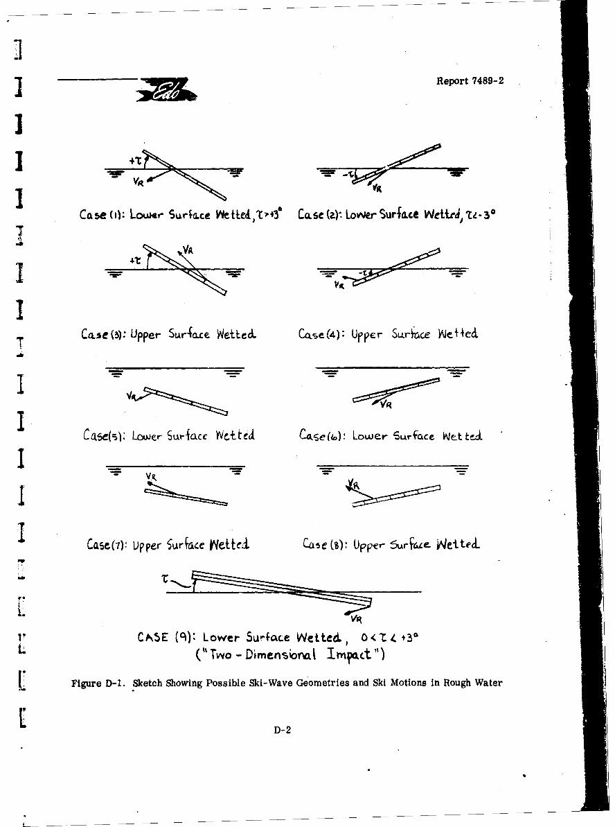
] Report 7489-2
Case s): Lower Suraxce )V~ettCt t" Case (4. LowierSurface Wct~elt3
II
CP%5E (cl): Lower SUrface Wetted. 1 0C < t +30L ("Two~ - Dimenioriat Imvpac.t")
I. Figure D-1. Sketch Showing Possible Ski-Wave Geometries and Ski Motions in Rough Water
D-
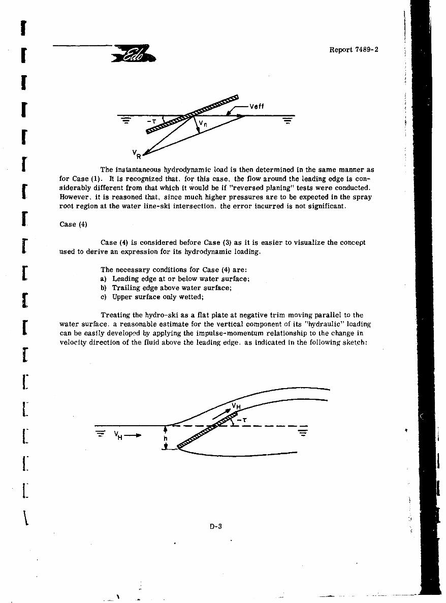
II •Report 7489-2
II
I •I
VR
I The instantaneous hydrodynamic load is then determined in the same manner asfor Case (1). It is recognized that, for this case, the flow around the leading edge is con-siderably different from that which it would be if "reversed planing" tests were conducted.However, it is reasoned that, since much higher pressures are to be expected in the sprayroot region at the water line-ski intersection, the error incurred is not significant.
I Case (4)
Case (4) is considered before Case (3) as it is easier to visualize the conceptused to derive an expression for its hydrodynamic loading.
The necessary conditions for Case (4) are:a) Leading edge at or below water surface;b) Trailing edge above water surface;[ c) Upper surface only wetted;
Treating the hydro-ski as a flat plate at negative trim moving parallel to thewater surface. a reasonable estimate for the vertical component of its "hydraulic" loadingcan be easily developed by applying the impulse-momentum relationship to the change invelocity direction of the fluid above the leading edge. as indicated in the following sketch:
FH!:
it. m
D-3 "
I --. - - - -- ~-~ ---- m~
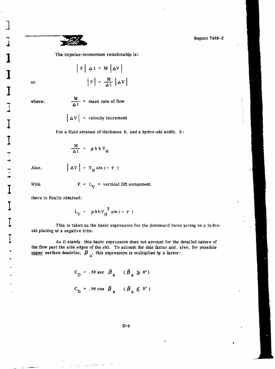
Report 7489-2
I The impulse-momentum relationship is:
II F~ Iat M &VVI
or, I FI -.-IZV Ia t
IM
where: = mass rate of flow
I AV = velocity increment
For a fluid stratum of thickness h, and a hydro-ski width, b:
M - phbVV
a t H
Also, I AV[ - vsin (- r-H
With F = LV = vertical lift component.
there is finally obtained:
Lv = phbVH2 sin(- r
I This is taken as the basic expression for the downward force acting on a hydro-ski planing at a negative trim.
I As it stands. this basic expression does not account for the detailed nature ofthe flow past the side edges of the ski. To account for this factor and, also, for possible"upper surface deadrise, 3 u, this expression is multiplied by a factor:
CD .88 see Bu u • 0°)
CD .88 cos Bu (Pu/ Q°)
D-4
Report 7489-2
The second of these terms is an approximation for the well-known Bobyleff drag coefficientfor a wedge in cavity flow and the first is an "ad hoc" estimate for the
u < 0* case for which no theory presently exists.
U
For calculating the hydrodynamic load in this case, the velocity parallel to thewater surface, V is regarded as the equivalent planing velocity, V , corresponding toH' eq'
the resultant velocity component normal to the keel.
[ Case (3)The necessary conditions for Case (3) are:
a) Leading edge at or above water surface;b) Trailing edge below water surface;c) Upper surface only wetted.
Case (3) is treated by the same approach used for Case (2). That is, the re-sultant velocity component normal to the keel defines the equivalent planing velocity. Itshould be noted that the latter is also directed toward the right side of the preceding sketch.
Case (5)The necessary conditions for Case (5) are:
a) Leading edge at or below water surface;b) Trailing edge below leading edge;c) Lower surface only wetted.
This is the conventional submerged supercavitating case which has primarilybeen studied for high-speed hydrofoil design. The Johnson supercavitating lift formula,corrected for finite depth, is used on this case. (See Section D-3 of this appendix.)
Case (6)The necessary conditions for Case (6) are:
[ a) Trailing edge at or below water surface;b) Leading edge below trailing edge;[ c) Lower surface only wetted.
This case is treated in a manner identical to Case (5), that is, depth correctionsJ• are still based on the distance from the leading edge to the water surface.
I--
Report 7489-2
3 ]Case (8)
Here again, because It is simpler conceptually, Case (8) is treated prior toCase (7). The necessary conditions for Case (8) are:
a) Leading edge below trailing edge;b) Trailing edge at or tilow water surface;c) Upper surface only wetted.
In this case, it is assumed that the cavity to the lower surface extends to the-• atmosphere so that ventilated (supercavitated) flow exists. However, when near the water
surface, the depth correction factors of Cases (5) and (6) are inapplicable because, unlike"-. Cases (5) and (6), the fluid region on the positive pressure side of the hydro-ski does not-. extend to infinity.
SAn approximate solution for this case is therefore established in the followingmanner:
1) First, the lift coefficient is determined in the same manner-. as for Cases (5) or (6) at deep draft, for ventilated flow.
2) A generally different lift force is then also calculated by the-o same method as was employed for Case (4).
"3) The lower of the two resulting values of lift force is then-v selected as being the more correct.
Case (7)
The necessary conditions for Case (7) are:
-° a) Leading edge at or below water surface;b) Trailing edge below leading edge;c) Upper surface only wetted.
The approach in this case is essentially the same as that for Case (8). That is,the deep draft calculation is made in exactly the same manner but the effect of water surface
-- proximity is treated as described for Case (5), where the normal velocity component is usedto establish the equivalent planing velocity.
"Case (9)
This conventional two-dimensional impact case is used until bow submergenceoccurs, provided that the initial contact trim angles for Cases (1) and (2) are from -3" to+30. Further, if the hydro-ski deadrise is less than 100, the effective deadrise is taken as
D-6
. i0
FI •Report 7489-2
100. The virtual mass values derived by J. D. Pierson in Reference D-1 are used to ex-press the rate of virtual mass growth with keel depth. Pierson's two-dimensional virtualmass values can be approximated by the formula:F
2 2r rw/(ir/2)pC = .2463 -. 7451 +.802
where: C = wetted semiwidth = (7r"/2) z cot R (Wagner wave rise formula);
[ z = keel draft to undisturbed water line;
[ 13 = deadrise angle, radians
The impact force acting on the hydro-ski in this condition is calculated by inte-l- gration of the hydrodynamic force per unit length over the total wetted length of the hydro-ski. That is, the fundamental expression for the hydrodynamic force per unit length is:
F dF dV dm= m-~ + VddFn w
Fds w dt n dt
where: m = virtual water mass per unit length;
[ Vn velocity component normal to the keel;n
In terms of the local draft, z:
dF dVn dz dmaw dz
-mw+ Vn dds w dz dt nd d__t
1: Since V = dz /dt,
dV 2dmw
dF m V n 2 dm.wds w n dz n dz
When this expression is integrated over the hydro-ski length, it is seen that thefirst term is related to the magnitude of the total virtual mass and the rate at which thenormal velocity varies with draft, (i. e., the acceleration) which can be neglected in hydro-ski impacts. The second term is related to the rate at which the total virtual mass varieswith draft. Accordingly, the differential force, dF, on an elemental strip of length, ds, isdependent on the chine-water surface relation at that instant. A strip of water (fixed in the
D-D-7
iReport 7489-2
still fluid) in the "chines-dry" region has a varying virtual mass, while a strip in the "chineswetted" region has a constant virtual mass. The implications of this statement on the totalhydro-ski load can be best illustrated by considering a constant trim impact of a rectangular"planform hydro-ski having deadrise, with a constant normal velocity component to the keel.In this case, prior to wetting of the chine, since the magnitude of the virtual mass -varieswith the square of the wetted width, the hydrodynamic impact force increases parabolicaliywith draft. After chine immersion has occurred, the virtual mass associated with thechines-dry region remains constant. However, it is seen that the virtual mass associatedwith the chines-wetted region varies Ainearly with the draft, so that under the assumed"constant velocity impact, the impact load remains constant until the bow submerges. Final-ly, an aspect ratio correction, I - (1).,21w), is applied to the load calculated by the basictwo-dimensional procedure to account for the finite hydro-ski length.
The hydrodynamic load in a "two-dimensional" hydro-ski impact is, therefore:
F =V 2 drw (Ib ow dn z11 21•W dsJ
S=V 2 dm b d
2 w 1 w(1- bn dz w 21 w
T where: 1 actual keel wetted length prior to chine immersion; or
wetted keel length corresponding to the draft at whichj chine immersion occurs.
The growth rate with draft of the virtual mass, dm /dz. is evaluated from
S the analytical expression:
Smw /(ir/2) p C 2 /( r 3/8) p z cot 28 = .246 8 2 .745 R+ .802
2 2
sothat dm w/dz = (.24602-745 +.802)(i7r3/4) p z cot2
where: z = actual draft, prior to chine immersion, or, after chine"immersion, draft at which chine immersion occurs.
D-8
Report 7489-2
S D2. HYDRODYNAMIC MOMENTS
Associated with the hydrodynamic loads for the nine impact conditions describedabove are their respective centers of pressure which are required for calculating hydro-dynamic moments about the aircraft center of gravity. For some of these conditions, theanalytic expressions for centers of pressure have already been established earlier in thisreport; for the remainder, a series of simple and plausible approximations have been made,as will now be described.
S~Case (1):
Shuford formvla; see Section 3.2
F Case (2):
[0. 3 of wetted lengfn forward of ski-water line intersection
Case (3):
0. 3 of wetted length forward of ski trailing edge
[ Case (4):
0. 3 of wetted length aft of ski leading edge
Cases (5), (6), (7), and (8):
Computer subroutine, as described in Appendix B.
Case (9):I-_
"2/3 of chines-dry wetted length from ski-water line intersection
J D.3. APPROXIMATION FOR JOHNSON'S LIFT FORMULA
Section 3.4 of this report describes a computer program which "automates"the calculation of ski lift and moment for the submerged ventilated condition. This programreplaces the "manual" Iteration and interpolation procedures required for application ofJohnson's theory. As mentioned in Section 3.4, it was intended to use this program as asubroutine in the wave response computer program.
When this was attempted, it was found that the total wave response program ex-ceeded the capacity of Edo's IBM 1130 Computer. To eliminate this difficulty, the venti-lated flow subroutine was replaced by another much simpler (and slightly less accurate)program, developed as follows:
D-9
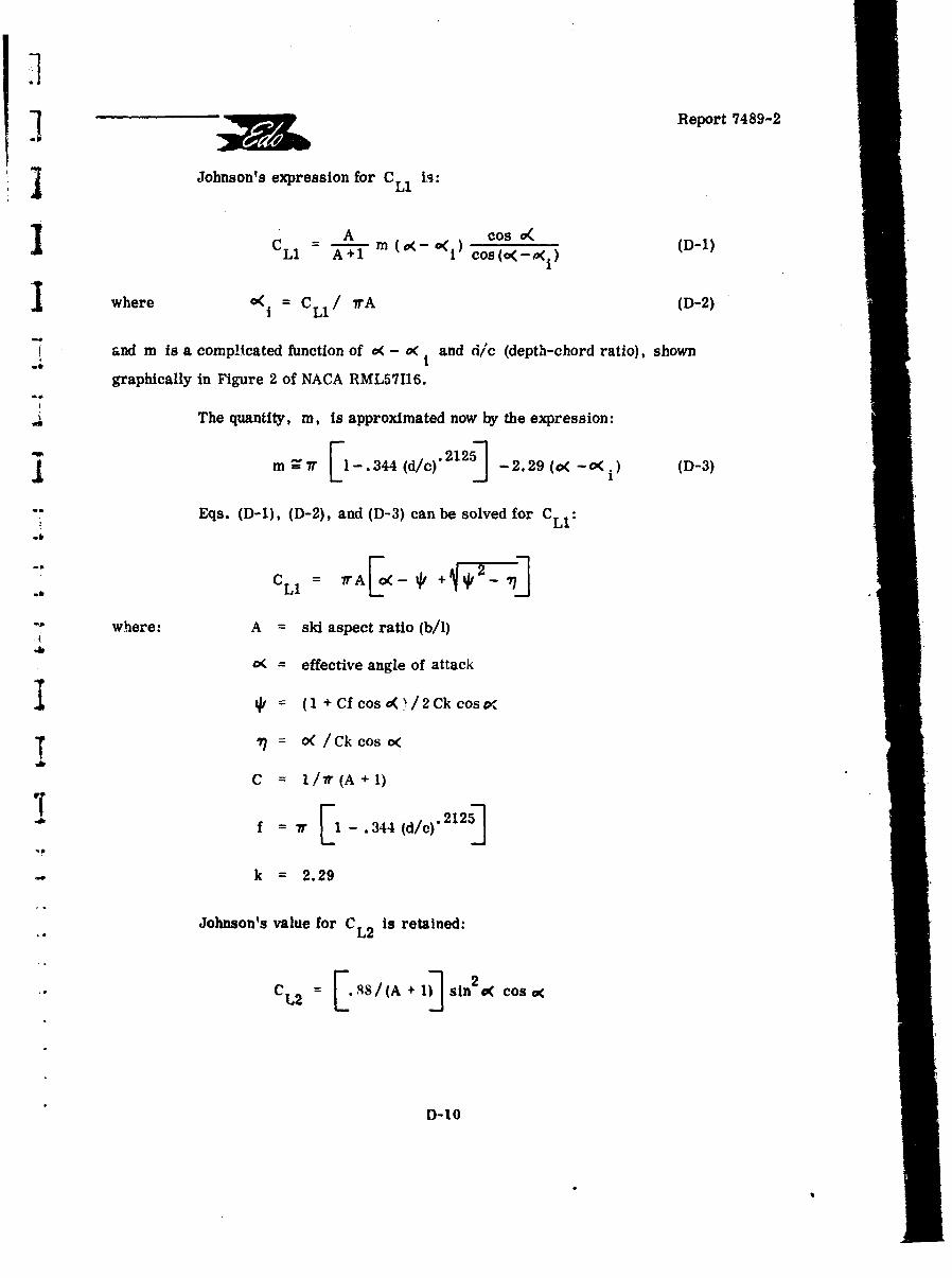
Report 7489-2
Johnson's expression for CLi is:
A Cos (D-l)
LI A+ i cos(o<-4i)where o(1 = CL1/ /rA (D-2)
i and m is a complicated function of o( - o< and dic (depth-chord ratio), shown
graphically in Figure 2 of NACA RML57116.
The quantity, m, is approximated now by the expression:
m =V I . 44(dc).2125] -2.29 (c< -c<. (D-3)
"Eqs. (D-1), (D-2), and (D-3) can be solved for CLi
CLI = irA - * +
"where: A = skd aspect ratio (b/1)
= effective angle of attack
I €= (I + Cfcosa( 2 Ck cos x
7" = o<(/Ckcos (
C = 1/7r(A+1)
f = 7.r 1 -. 344(d/c)*2125]
k = 2.29
Johnson's value for CL2 is retained:,L2
C L2 8 .8/(A +I Isin2 0( Cos 0
D-10
Sm
I.M b Report 7489-2
and his expression for the center of pressure is approximated by:
r X = (. 3 12 5 CL1 + .5CL2)/CL
where X is measured from the ski L. E.
rREFERENCES FOR APPENDIX D
SD-1 Experimental Towing Tank, Stevens Institute of Technology, Note 137:
"On the Virtual Mass of Wc ter Associated with an Immersing Wedge",r by J. D. Pierson, (undated).
N
I-
IJ
I:
Dol
| !
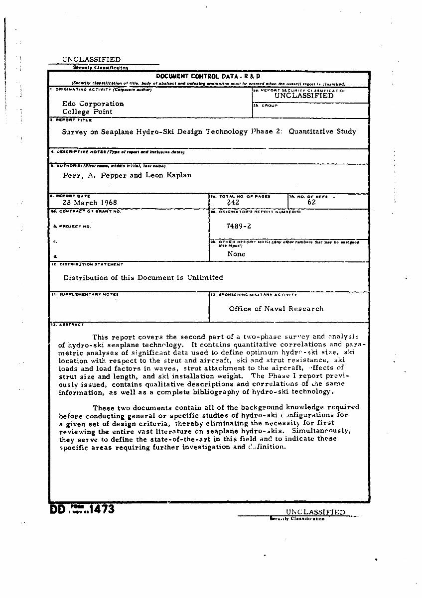
UNCLASSIFIEDSecurity Classification
DOCUMENT CONTROL DATA. R & D(Securlly ellsiflcaltlon of title, body of abetract and Indelsing an ,Inntlim must he erlnred when the overall report I. classtflied)
* i ORIGINATING ACTIVITY (Corporre author) its. REPORT SLCURITY CL.AISIFICAT1OV
i • UNCLASSIFIEDEdo Corporation 2b. GROUP
College Point3. REPORT TITLE
Survey on Seaplane Hydro-Ski Design Technology Phase 2: Quantitative Study
4. LIrSCRIPTIVW NOTES (r7.pe o pltl•p Iand inclusive dalte)
S. AUTHORISI (Piret name, windds trillall, 5isa nime)
Perr-, A. Pepper and Leon Kaplan
0. REPORT OATE 70. TOTAL NO. OF PAGES 7b. NO. oF REFS
28 March 1968 242I 62IC. CONTRAC" 01 GRANT NO. go. ORIGINATOR'S REPOIRT NUMAER(SI
b. PROJECT NO. 7489-2
C. Ob. OTHER REPORT NO(S, (Any other numbers the? may be assegnedthis report)
d. r NoneI1. OISTRIOUTION STATEMENT
Distribution of this Document is Unlimited
It. SUPPLEMENTARY NOTES I12 SPONSORING MILiTARV ACTIVITY
Office of Naval Research
1 3. ABSTRACT
This report covers the second part of a two-phase survey and analysis
of hydro-ski seaplane technology. It contains quantitative correlations and para-metric analyses of significant data used to define optimum hydrr-ski size, skilocation with respect to the strut and aircraft, ski and strut resistance, skiloads and load factors in waves, strut attachment to the aircraft, --ffects ofstrut size and length, and ski installation weight. The Phase I report previ-ously issued, contains qualitative descriptions and correlations of Lhe sameinformation, as well as a complete bibliography of hydro-ski technology.
These two documents contain all of the background knowledge requiredbefore conducting general or specific studies of hydro-ski c .nfigurations fora given set of design criteria, thereby eliminating the necessitý for firstreviewing the entire vast literature on seaplane hydro-ikis. Simultanenusly,they serve to define the state-of-the-art in this field and to indicate thosespecific areas requiring further investigation and C.4inition.
DD'.-6.1473 UNCLASSIFIEDS.cui;tv CIf•ls tiah.tlon

UNCLASSIFIEDSecurity Classification
' LINK A LINt,. LINK CKEF.Y WORDS m .
ROLE WT ROLE WT ROLE WT
Hydro..Skis
Hydrodynamics
Seaplane
Bibliography
Security Classification
1 ____ _