Embed Size (px)
Citation preview
New Zealand Geomechanics News
4 Newsletter of the New Zealand Geotechnical Society Inc.
editorial Policy
NZ Geomechanics News is a biannual newsletter issued to members of the NZ Geotechnical Society Inc. It is designed to keep members in touch with matters of interest within the geo-professions both locally and internationally. The statements made or opinions expressed do not necessarily reflect the views of the New Zealand Geotechnical Society Inc. The editorial team are happy to receive submissions of any sort for future editions of NZ Geomechanics News. The following comments are offered to assist potential contributors. Technical contributions can include any of the following:
• technical papers which may, but need not necessarily be, of a standard which would be required by international journals and conferences
• technical notes• comments on papers published in NZ Geomechanics
News• descriptions of geotechnical projects of special
interest
General articles for publication may include:• letters to the NZ Geotechnical Society• letters to the Editor• articles and news of personalities• news of current projects• industry news
Submission of text material in Microsoft Word is encouraged, particularly via email to the editor or on CD. We can receive and handle file types in most formats. Contact us if you have a query about format or content.
Diagrams and tables should be of a size and quality appropriate for direct reproduction. Photographs should be good contrast, black and white gloss prints or high resolution digital images. Diagrams and photos should be supplied with the article, but also saved seperately as 300 dpi .jpgs. Articles need to be set up so that they can be reproduced in black and white, as colour is limited.
NZ Geomechanics News is a newsletter for Society members and articles and papers are not necessarily refereed. Authors and other contributors must be responsible for the integrity of their material and for permission to publish. Letters to the Editor about articles and papers submitted by members will be forwarded to the contributing member for a right of reply.
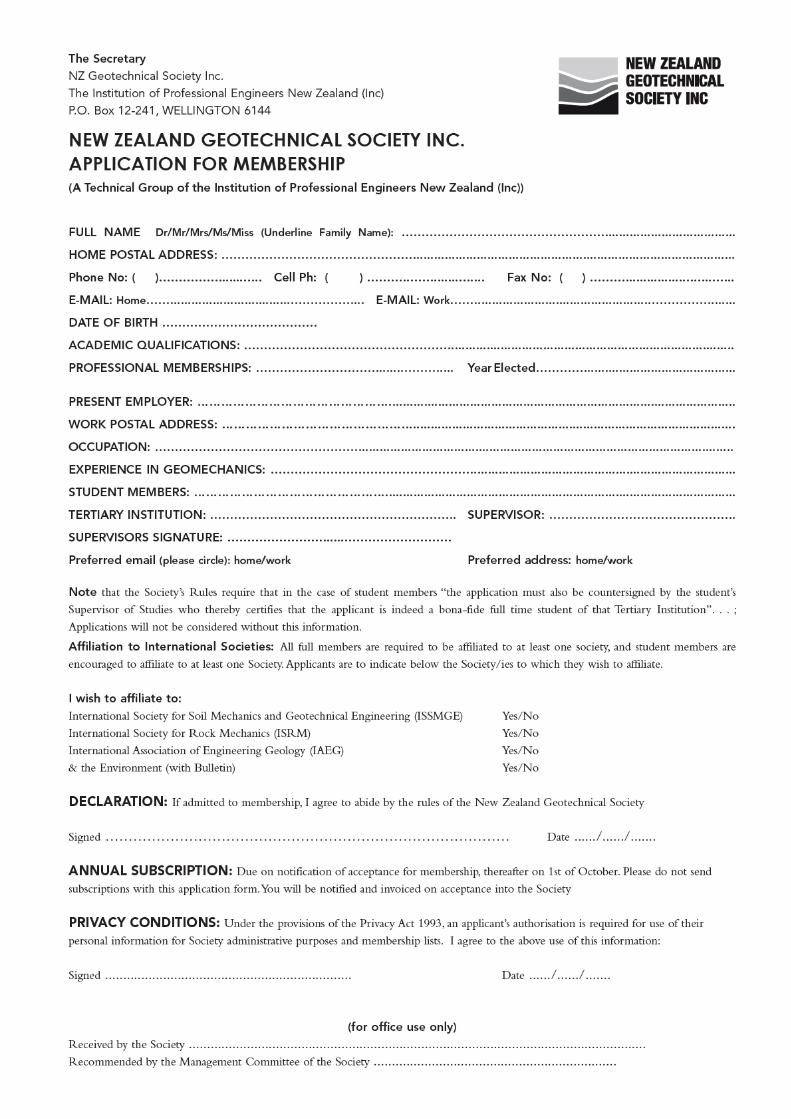
Persons interested in applying for membership of the Society are invited to complete the application form in the back of the newsletter. Members of the Society are required to affiliate to at least one International Society and the rates are included with the membership information details.
seismic considerations for the design of bridge foundations in liquefiable soils. This issue also recognises the up and coming talent in the NZ geotechnical community with the award of the inaugural NZGS Scholarship to Jawed Arefi, and details of NZGS Student Awards.
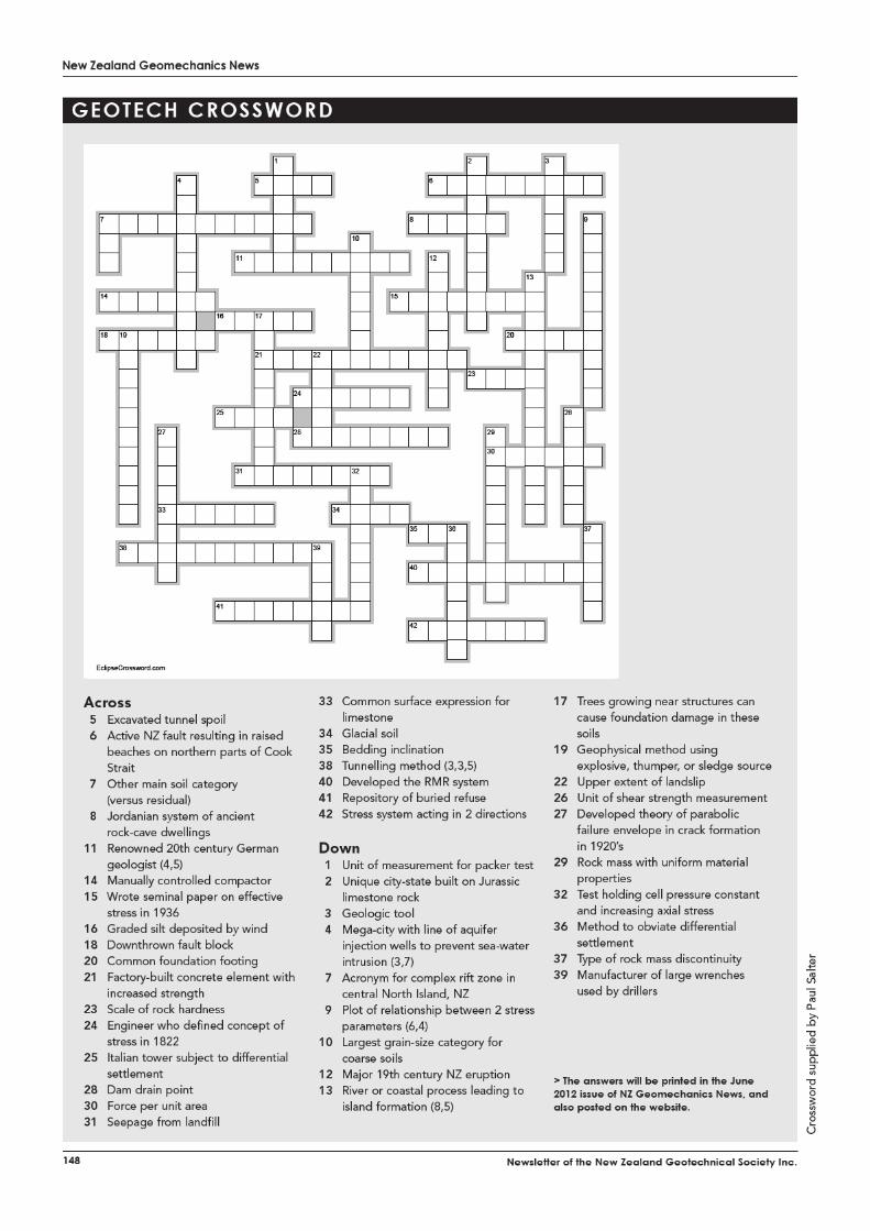
Inside, the winner of the annual photo competition is also announced and there are a couple of items to keep the brain-engaged over the holidays - a geotech teaser and crossword to complete.
As we look ahead into early 2012, I know that NZGS branch activities are already being planned and visiting lecturers pencilled in – details will follow from your branch coordinators and will be listed on the NZGS website. Have a great Christmas.
Paul Salter, NZ Geomechanics News [email protected]
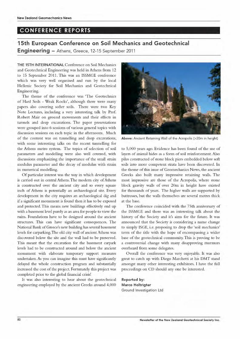
NoW that the World Cup and the Election are behind us, I hope that you can all manage to find a spare moment to read this interesting and varied issue of ‘GeoNews’ before getting too wrapped up in the Christmas season.
In his article titled ‘Geology of the Auckland Urban Area,’ Kevin Hind makes the interesting observation that our collective knowledge of the geology of the Auckland urban area is not always advanced in any meaningful way by the thousands of geotechnical investigations undertaken across the City. A recent project has provided a rare opportunity to develop a geological model across a large part of central Auckland. Kevin uses this information to develop a fuller understanding of the Manukau Fault which challenges the lack of information shown on existing geological maps.
A new initiative titled ‘Academic News’ is being launched in this issue and aims to provide a communication link between tertiary institutions and practitioners. This article includes information from tertiary institutions around the country and provides a quick and easy update on study options, current research and general news.
This issue also marks the passing of Peter Taylor with an obituary prepared by Mick Pender (and others).
Enjoy the December Issue and Merry Christmas from the NZ Geomechanics News Team!
Hamish Maclean, NZ Geomechanics News Co-editor [email protected]

New Zealand Geomechanics News
8 Newsletter of the New Zealand Geotechnical Society Inc.
services to IAEG. The inaugural award will be made at the next IAEG Congress to be held in Torino, September 2014. The Hans Cloos Medal criteria will be altered slightly to focus fully on outstanding scientific/ technical contribution and remove the requirement for significant contribution to IAEG.
The next IAEG Executive and Council meetings will be held at Banff, Canada on the occasion of the joint International Landslide Conference and 2nd North American Landslide Conference in June 2012.
Website• A group has been established to set up and maintain
the website, led by Giorgio Lollino (Italy). • There is now the ability for direct management
by National Group Presidents/Secretaries and commission Chairs to allow updating of address lists, material etc.
• The homepage will highlight a National Group and its significant outputs/ work/ characterisation/ events/ etcetera each month; data as supplied by the National Group
• All members can subscribe; outputs from the Commissions will be available only to members (currently these are available to all, so take a quick look!)
• Young Professionals can upload their CVs to the website if seeking work/ research positions
• Periodically rolling head page available for companies to advertise
• The Executive has established a sub-committee to identify how the website will continue to be developed.
CommissionsThere are currently 21 active Commissions. A Technical
Overview Committee (TOC) has been established to monitor and support the Commissions. Outputs from
those commissions that have completed their work will be available on the website along with outputs of current commissions.
IAEG AwardsHans Cloos MedalThe recipient of the Hans Cloos medal should be a person of international repute who has made a major contribution to engineering geology in his/her written papers or to the development of engineering geology and/or the IAEG in their own area. Dr Warwick Prebble has made an outstanding contribution to Engineering Geology and to the IAEG in Australasia.
The NZGS Management committee nominated Warwick for the Hans Cloos Medal. Nominees included David Cruden (Canada), Resat Ulusay (Turkey) and Victor Osipov (Russia). Dr Osipov was selected as the recipient of the award for 2012.
Richard Wolters PrizeThe Richard Wolters Prize has been awarded biannually since 1986 to commemorate the life and work of Dr Richard Wolters, his significant achievements in the advancement of engineering geology and his important role in the development of the IAEG. The Richard Wolters Prize specifically recognises meritorious scientific achievement by a younger member of the engineering geology profession. The candidates should be members of IAEG and less than 40 years of age on 1st January 2012.
Submissions are being called for this prestigious prize and the recipient will contest the award at the joint International Landslide Conference and 2nd North American Landslide Conference in Banff, June 2012.
Ann WilliamsIAEG Vice President, Australasia
New Zealand Geomechanics News
10 Newsletter of the New Zealand Geotechnical Society Inc.
inaugural webinar was presented by the ISSMGE President, Professor Jean-Louis Briand on 23 August 2011 on the topic of Bridge Scour and Levee Erosion. On this occasion no charge was made for access and it attracted some 80 registrations.
Recent natural disasters in our region and elsewhere around the world have thrown the spotlight on to geotechnical engineering. Colleagues have generally responded very well to the requirement to inform the public and interact with the media regarding the geotechnical implications of these events. However, as a general rule as a profession we do not tend to promote the excellent and important work that we do when not responding to disasters. The ISSMGE Board has discussed how we might communicate better with the public and the media on a more frequent basis and this has resulted in the formation of the ISSMGE Public Relations Committee. In his 665 Days Progress Report the President requested that members let him know if they would be interested in working on or with this committee. Details of the proposed work for the committee can be found on the ISSMGE website.
Compared to other similar organisations the view has been expressed that the ISSMGE does not recognise to as great an extent the professional and academic achievements or service of its members. With the support of the Board, at the end of 2010 the President formed a short term awards committee to investigate this view and, if necessary, to make suggestions for new awards. The outcome of this process is that the Board has approved suggestions for the following new ISSMGE awards:
• The ISSMGE Outstanding Technical Committee Award
• The ISSMGE Outstanding Geotechnical Project Award
• The ISSMGE Outstanding Innovator Award• The ISSMGE Outstanding Member Society Award• The ISSMGE Outstanding Paper Award
(International Journal of Geoengineering Case Histories)
Details of the process for nominations for these awards will be issued once these have been formulated and agreed by the Board. The first set of these new awards will be presented in Paris in 2013 at the International Conference on Soil Mechanics and Geotechnical Engineering.
Since taking office the President has encouraged members of ISSMGE Technical Committees (TC) to institute a lecture named after someone who is recognised internationally for making a major contribution to developing the field in the area of a particular TC. This is not only to recognise the contributions of the distinguished person after whom the lecture is named but also as part of
the same policy to recognise the contributions of current leaders in the field of geotechnical engineering. Eight such named lectures have now been proposed by TCs and approved by the Board. Nominations for these lectures are open to all members of ISSMGE and should be sent to the chair of the corresponding TC.
As you will have read in this and my previous reports, since his election in 2009, the President of ISSMGE has together with the Board introduced a number of new initiatives. The ISSMGE Council is the governing body of the Society and any changes to the Statutes and Bylaws of the Society proposed by the Board have to be approved by this body. Member Societies can also bring proposals directly to Council for discussion. At the forthcoming meeting of Council, which will be taking place in Toronto on 2 October 2011, there are two major proposals about which ISSMGE members in Australia and New Zealand might have a view. The first is a proposal from the USA, Mexico and Japan Member Societies to Change the name of the Society from “International Society for Soil Mechanics and Geotechnical Engineering” to “International Society for Geotechnical Engineering”. The second is a proposal from the Member Society of Greece to Change of name of the quadrennial international conference from “International Conference of Soil Mechanics and Geotechnical Engineering” (ICSMGE) to “World Conference on Soil Mechanics and Geotechnical Engineering” (WCSMGE). If you have views on these new proposals that you would like to be considered please contact the AGS or NZGS – which will both be represented at the ISSMGE Council meeting – or send them directly to me.
Professor Michael C.R. DaviesVice-President for Australasia and First Vice-President ISSMGE


New Zealand Geomechanics News
18 Newsletter of the New Zealand Geotechnical Society Inc.
10th Nonveiller Lecture titled: “Pre-Grouting for Water Control and for Rock Mass Property Improvement”. During his time in Croatia, Nick Barton was interviewed by Professor Ivan Vrkljan from Head of the Geotechnical Laboratory at the Institut IGH in Zagreb. A hard copy of the interview can be downloaded from http://www.isrm.net/fotos/editor2/nl14/interview_vrkljan_barton_isrm_2011.pdf
7 ISRM Rocha Medal 2013 Nominations for the Rocha Medal 2013 are to be received by the ISRM Secretariat by 31 December 2011. The winner will be announced during the 2012 ISRM International Symposium in Stockholm, Sweden, in May 2012, and will be invited to receive the award and deliver a lecture at the 2013 ISRM International Symposium.The Rocha Medal has been awarded annually by the ISRM, since 1982, for an outstanding doctoral thesis in rock mechanics or rock engineering, to honour the memory of Past President Manuel Rocha while stimulating young researchers. Besides the Rocha medal awarded to the winner, one or 2 runner-up certificates may also be awarded.
8 UPCOMING ISRM SPONSORED EVENTS• 27-30 May 2012, Stockholm, Sweden – EUROCK
2012 – Rock Engineering and Technology: the 2012 ISRM International Symposium
• 15-17 October 2012, Seoul, Korea – ARMS 7 – The present and Future of Rock Engineering: the 2012 ISRM Asian Regional Symposium
• 23-26 September 2013, Wroclaw, Poland – EUROCK 2013 – Rock Mechanics for Resources, Energy and Environment: the 2012 ISRM European Regional Symposium
• 29 April-5 May 2015, Montréal, Canada – Innovations in Applied and Theoretical Rock Mechanics: the ISRM 13th International Congress on Rock Mechanics
Details of these events can be found at http://www.isrm.net/conferencias/sp_conf.php?past=0&show=conf
9 ON A PERSONNAL NOTEThis RockNotes will be my final. I want to document my deep thanks to the Australian Geomechanics Society (AGS) and New Zealand Geotechnical Society (NZGS) for giving me the opportunity to hold this position for the past 4 years and to you the Members for allowing me to stay there.
The role has provided me with a wonderful opportunity to meet other rock engineers locally and overseas; I have regularly been humbled, and will continue to be, by the very high level of expertise out there. I’ve see so many exciting developments in the profession locally and
overseas. Over the period I have tried to keep the ISRM “fires” burning in the Region. It will now be up to the new Regional Vice-President to take up the flaming stick.
After a request for nominations in the December 2010 RockNotes, the AGS voted the 2012-2015 VP to be Dr David Beck. David is Principal Engineer and Owner of Beck Arndt Engineering Pty Ltd. In his career he has shown a consistent effort to advance the profession through his company’s research, by publicly advocating for high engineering standards and by encouraging students. He has worked in the minerals and civil industries, as a consultant and has maintained an ongoing professional and research interest in numerical modelling, mining rock mechanics, hydrology, tunnelling and petroleum rock mechanics. He is a regular presenter at “rock” events locally and internationally.
David’s journal won’t be without its challenges. There are many issues facing rock engineering in Australia, not least the necessity to:
• bring together practitioners in rock engineering from the mining and civil industries and from the research, education and training sectors in a spirit of collaboration and congeniality;
• improve communication between the professional societies with interests in rock engineering in the region;
• provide all practitioners with opportunities to contribute to discussions aimed at establishing uniform nationwide regulatory requirements pertaining to rock engineering;
• come up with a uniform system of chartered professional status that can apply to all rock engineers, no matter which area they principally practise in;
• give all practitioners in rock engineering the opportunity to share in the high level of expertise and be exposed to the exciting developments taking place in the profession both locally and overseas;
• address the dire shortage of trained, experienced rock engineers – the problem won’t go away if we ignore it !!;
• keep the ISRM growing even stronger than it has now become by increasing further the dialogue with the Members in the Region and overseas.
I have no doubt that David will serve you well.
Tony Meyers ISRM Vice President (Australasia)


New Zealand Geomechanics News
34 Newsletter of the New Zealand Geotechnical Society Inc.
University of AucklandSaskia de Vilder (M.Sc. started February 2011):
Engineering geology characterization of the initiation zone at two landslides dammed lakes, central North Island. This project combines terrestrial photogrammetry and traditional field survey techniques to characterize the rock mass in and around the headscarp of two landslides. Saskia is using limit equilibrium and finite difference codes to assess the influence of rock mass strength, discontinuities, pore water pressure, and seismic loading on the slope failure.
Megan Baddiley (M.Sc. started February 2011): Limit equilibrium modeling of factors influencing the stability of coastal cliffs in weak sedimentary rocks in the Auckland region. This project combines terrestrial photogrammetry and traditional field survey techniques to characterize the rock masses associated with the East Coast Bays Formation outcrops. Megan is using limit equilibrium models to assess the influence of slope angle, rock mass strength, pore pressure, and bedding orientation.
Jane Harvey (B.Sc. honours started July 2011): Landslide runout in harvested terrain in the Coromandel Peninsula, North Island. This project conducted a detailed reach by reach field description of the initiation, transport, and deposition of small debris avalanches and debris flows. Jane is using this data to model the runout behaviour of these mass movements using a dynamic analysis code.
Max McLean (M.Sc. started July 2011): Field and numerical investigation of deep-seated deformation structures in the Tararua Range, North Island. This project combines an inventory of these slope deformation structures obtained from remote sensing data, with a detailed engineering geology and geomorphology field mapping of selected features. Max will use a finite element code to model the importance of topography, rock mass strength, and structures in the formation, evolution, and stability of these landforms in the Tararua Range.
PhDsTom Algie (PhD, recently examined successfully).
Nonlinear Rotational Behaviour of Shallow Foundations on Cohesive Soil. This thesis investigates the nonlinear rotational behaviour of shallow foundations on cohesive soil. The main aim of the research was to perform large scale field experiments on rocking foundations, develop numerical models validated from those experiments, and produce a design guide for design of shallow rocking foundations on cohesive soil subject to earthquake.
Lina Sa’don (PhD, recently examined successfully) Full scale static and dynamic lateral loading of a single pile. This study presents the results of full scale field tests on single free head piles embedded in Auckland residual clay. Four hollow steel pipe piles, each with an outside diameter of 273 mm and wall thickness of 9.3 mm were installed at a site in Pinehill, Auckland. Static lateral loads were applied
by using hydraulic jack, while dynamic loads were applied using an eccentric mass shaker. The free vibration and snap-back tests were also performed by using instrumented sledgehammer and snap shackle as the quick release mechanism. The primary purpose of the pile testing is to measure the inertial response of piles in Auckland soils and to investigate how the soil stiffness decreases with increasing pile head excitation.
Andy Tai (PhD, recently examined successfully) Thermomechanical modelling of sand. The aim of this thesis is to develop a constitutive model of sand behaviour within the theoretical framework of thermodynamics. The main appeal of this modelling approach is that the theoretical basis of thermodynamics is well-established thus internal consistency within the model could be readily achieved. There is also the added advantage that we would be able to develop much deeper insight on the fundamental mechanics from the model outputs. This is in stark contrast with the traditional approach based on the theories of plasticity, which were originally developed to model the behaviour of metals. The theoretical results were interpreted against laboratory triaxial data for quartz sand and pumice sand
Anas Ibrahim (PhD, started February 2008): Dynamic properties of Auckland residual soil under very small strain range. This research focuses on the investigation of dynamic properties of undisturbed Auckland residual soil in the laboratory using improved small strain triaxial apparatus, bender element and multi-stage triaxial test with loading and unloading under the elastic range of strain. In addition, simulation of the small strain behaviour using PLAXIS is carried out.
Sam Harris (PhD, started October 2009): The development of a site-specific warning system for rainfall induced landslides. This research involves laboratory testing, numerical modelling and in-situ monitoring at site in Silverdale, adjacent to State Highway 1. Soil parameters are determined using standard laboratory tests and known mathematical relationships which are then used in saturated/unsaturated seepage finite element analysis in conjunction with limit equilibrium analysis to determine the factor of safety against slope failure due to rainfall events. These models are calibrated using field monitored data. The results will be integrated to develop site-specific warning system from which appropriate action can be implemented.
Claudia Keyser (PhD, submitted 2011) The Geotechnical and Environmental Properties of Amended Biosolids. Claudia has been studying the enhancement of the shear strength and stiffness of wastewater sludge using industrial by-products. The work concerns the sludge produced by Watercare Services waste treatment facilities at Mangere. A number of waste materials were investigated by carrying out consolidation and shear strength evaluation using a range of
New Zealand Geomechanics News
35
concentrations of the industrial additives. Fly ash was found to be the best all-round additive.
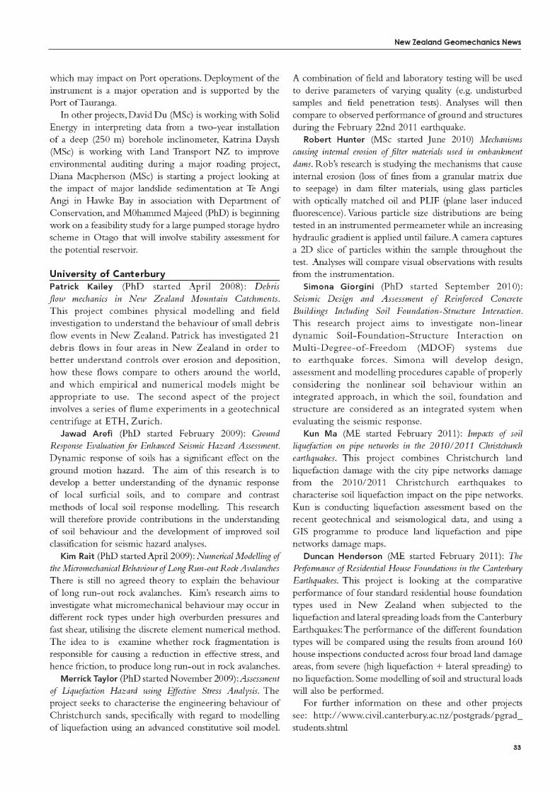
Lucas Hogan (PhD, started March 2010): Characterisation and seismic response of New Zealand Bridges. This research is split into three stages. Firstly, the categorisation of New Zealand bridge stock according to a range of construction characteristics, and definition of seismic hazard. Second, field testing of in-service bridges using forced and ambient vibration to capture the in-service dynamic characteristics of the bridge soil-foundation-structure system. Finally, using lessons learnt from field testing, the development of bridge computer models to: 1) replicate field testing results; 2) compare a range of soil-foundation-structure modelling approaches and complexities. The aim of this is to define modelling approaches accounting for non-linear soil-structure-foundation interaction in bridges that can be efficiently utilised in design.
Bilel Ragued (PhD, started March 2010): Resilience of New Zealand Port Systems. In collaboration with all port authorities in New Zealand, this research initially aims to develop a detailed overview of the current characteristics of New Zealand ports. Using this data, representative, or ‘virtual’ wharves will be defined that capture typical New Zealand characteristics. Field and analytical modeling will be carried out to determine the seismic response of wharves, accounting for soil-foundation-structure interaction. This information will be used in the development of fragility models for the prediction of damage and losses for given ground motion intensities.
Luke Storie (PhD, started September 2011) Building foundation response during earthquake loading. At this early stage Luke’s intention is to investigate the performance of building foundations in the Christchurch, particularly those which appear, from ground level manifestations, not to have been affected by liquefaction. There are a large number of foundations in this category for a wide range of building heights and configurations. Given that so much good quality ground motion data is available the outputs from this research are expected to be a most informative.
Chris Van Houtte (PhD, about to commence) The source properties of New Zealand earthquakes in the high frequency domain. Chris will shortly begin a Ph.D in Engineering Seismology. He will likely study the source properties of earthquakes, particularly the Alpine and surrounding faults. Worldwide, engineering seismologists are currently very interested in understanding the high frequency part of ground motion. His topic will likely focus on attenuation of amplitude in the frequency domain, directivity effects (currently very little is known about directivity effects > 1Hz) and structural maturity of faults (a property determined from the age, slip rate, cumulative slip and length of long-term faults) on the high frequency part of ground motion.
MEsPeter Algie (ME (part-time) started March 2011):
Analysis of the lateral load behaviour of piles in cohesionless soil. This research is investigating the lateral load behaviour of piles in cohesionless soils with the eventual aim of handling cyclic loading in saturated sand with cyclic build-up in pore water pressure, particularly in a port and harbour setting.
Michelle Willis (ME (part-time) started March 2011): Timber liquefaction piles. This research investigates the performance of timber piles as a liquefaction countermeasure. OpenSees and OpenSeesPL are used to investigate the interaction of the soil-pile system, including slippage and gapping occurring at the soil-pile interface, grid spacing and different soil/pile properties. Assumptions used in existing design methods will be assessed, and design charts will be developed.
Elby Tang (ME (part-time) started March 2011): Effectiveness of stone columns as a countermeasure for liquefaction-induced lateral spreading. This research will assess the performance of stone columns as a countermeasure against liquefaction-induced lateral spreading. In particular, how the effects of densification of surrounding soils and drainage through the stone columns can be analysed using numerical modelling and how they affect the effectiveness of stone columns. Moreover, how 3D effects can be incorporated in a 2D model.
Marco Holtrigter (ME completed 2011): A comparison between the flat dilatometer and the cone penetration test with the aid of artificial neural networks. This study compares the DMT test with the more established Cone Penetration Test (CPT) at 10 sites in the upper North Island. The purpose of the study was to compare the results and interpretations of the CPT and DMT tests in general terms and also to undertake analysis of the data to investigate possible correlations between the two tests. The study shows promising results that suggest possible CPT-DMT correlations. However, further research is needed to validate or improve these correlations.
final year BE projects:Michael Tidbury and Cecelia Lambert: (BE final year
project 2011) Snap-back testing of piles embedded in Auckland residual clay. Michael and Cecelia continued with the snap-back testing done by Lina Sa’don at the Pinehill site. The extended the range of results already completed on Lina’s piles and came up with some important improvements in our snap-test procedure.
Russell Scoones and Joseph Simpson: (BE final year project 2011) Effect of ground slope on the lateral load deformation behaviour of piles embedded in clay. Russell and Joe addressed a problem that had been raised by a university professor in the US about the lateral stiffness of piles embedded in ground with a sloping ground surface. Using
New Zealand Geomechanics News
36 Newsletter of the New Zealand Geotechnical Society Inc.
a non-linear 3D finite element software Joe and Russell showed the influence of ground slope for angles up to 30 degrees. They also demonstrated that a simple pile-head level-ground macroelement can predict the nonlinear lateral load behaviour of piles embedded in clay and also developed a way of handling the sloping ground.
Calvin and Kevin Ng: (BE final year project 2011) PLAXIS modeling of embedded retaining walls with and without tieback support. Calvin and Kevin investigated the performance of the PLAXIS two-dimensional finite element software at modeling vertical embedded retaining walls one side of which is excavated after the wall is installed. They covered both tied-back walls and also unsupported walls. Modelling with a range of embedment and excavation depths they were able to model system failure plotting the outward displacement of the top of the wall as the excavation depth was increased.
Nathan Hickman and Brian Hill: Analysis of liquefaction in Christchurch. This project attempts to quantify the liquefaction potential in Christchurch using simplified methods of evaluating liquefaction potential. Using available cpt data, maps showing calculated liquefaction potential indices indicating severity of liquefaction are produced and compared with actual liquefied zones. Explanations on why some sites that did not liquefy in the 4 September 2010 earthquake liquefied in 22 February 2011 earthquake are discussed.
David Bae and Ray Gao: (BE final year project 2011) Modelling of earthquake ground response during the Canterbury earthquakes. The purpose of this project is to study the dynamic response of Christchurch soils by simulating some of the strong motions that were recorded during the Darfield earthquake and Christchurch earthquake using effective stress ground response analysis program. Input parameters are obtained from cyclic undrained triaxial tests performed on soil samples taken from Christchurch and from boring data of sites adjacent to strong motion stations.
Jason Abraham and Ryan Wyllie: (BE final year project 2011) Site Analysis of Auckland Soil Profiles. As a result of the many volcanoes in the Auckland region, layers of volcanic rock exist at the near surface in many areas, overlying softer alluvial and sedimentary layers. This project studies the effect of these volcanics on surface ground motions using 1D site response analysis, to determine the NZS1170.5 design site class different layering characteristics correspond to.
Mohammed Al-Kubaisy and Kavinda Widanapathirana: (BE final year project 2011) Quality assurance of basecourse: The objective of this study is to investigate the variability of the components of a basecourse grading, using a sampling acceptance scheme to compare alongside TNZ standard (M/4). The data obtained (from experiments including sieve analysis and sand equivalent tests) is used for statistical analysis of assessing the quality of the aggregate. The
analysis process for the acceptance of basecourse aggregate will examine various international schemes and compare with data from local quarries.
Melvin Angelo: (BE final year project 2011) Geotechnical properties of the East Coast Bays Formation: The main objective is to investigate the geotechnical properties of the ECBF within the Auckland area. The work focuses on collating data gathered from sites in Auckland to show the local variation of soft rocks within the lithologies of the ECBF, the similarities and differences of the geotechnical properties across the Auckland region and the significance to future projects in the ECBF.
Beau Goodwin and Pak Chan: (BE final year project 2011) Triaxial testing of local rocks: The objective of this study is to evaluate the influence of pore water pressure has on strength of soft rock with particular reference to the East Coast Bays Formation. A series of tests under undrained conditions with variable pore water pressures will be tested to examine the influence it has on the strength of the soft rock. Since majority of Auckland is formed by the geological formation of the East Coast Bays Formation, means that construction projects such as a Waterview tunnel will most likely to encounter the ECBF. Therefore this study on the ECBF is vital to understand it behaviour, properties and its performance during the construction of the project.
Chenle Zhu and Sang Kim: (BE final year project 2011) Novel central drain for Rowe cell test: The objective of this research is to investigate the validity of a Geotextile Reinforced Drain (GRD) that replaces the traditional method of Sand Drain (SD) drainage for Rowe cell radial consolidation tests. This will involve evaluating the validity of the GRD for a larger diameter Rowe cell and different types of soil in the Rowe cell radial consolidation tests.
New Zealand Geomechanics News
37
tWo receNt examPles demonstrate the importance of a consulting engineer having direct communication lines with the ‘ultimate’ client.
Example 1In the first example, a specialist geotechnical consultant carried out a site investigation to support land use consent for a four Lot subdivision. The use of the site investigation report was clearly qualified as being limited to this purpose. Other standard limitations about the nature and scope of the investigations were included in the report as was the recommendation that the soils consultant be advised if conditions were found to vary from those anticipated.
Further to subdivision of the proposed four Lots, the structural engineer for a purchaser of one of the Lots relied on the limited investigation report for the detailed design of the house foundations. This use of the report was outside the original scope and purpose. During construction ground conditions were found to vary from those inferred by the structural engineer from the report. A decision was then made to design and install more expensive foundations without any consultation with the geotechnical engineer. The structural engineer informed the client that the additional costs were the result of a ‘faulty site investigation’ and on this basis the ‘ultimate’ client sought to recover costs from the geotechnical consultant.
Lessons Learnt: The Importance of Direct Communication with the ‘Ultimate’ Client
Example 2The second example involves the same geotechnical specialist. The scope of site investigations for a beach house was severely limited due to restricted access for a drilling rig. Access allowed for only one borehole which was located outside the proposed building footprint. The investigation report prepared for the structural engineer as the Client was appropriately limited and qualified. As with the first example, conditions over the site were found to vary and the structural engineer designed and supervised a substantially more expensive foundation without reference to the geotechnical consultant. The structural engineer reported to the ‘ultimate’ client that the site investigation was deficient. The ‘ultimate’ client sought recovery of additional costs from the geotechnical consultant.
ConclusionIn neither case did the structural engineers explain to the ‘ultimate’ client the explicit risks of the limited site investigations. If the geotechnical consultant had been given the opportunity to directly communicate the risks to the ‘ultimate’ client, they would have understood their exposure and, if they wished, reduced the inherent risks by carrying out more detailed investigations. In both cases a pragmatic settlement was reached without admission of fault or liability.
Article prepared by a member of NZGS
CHRISTCHURCH POLYTECHNIC INSTITUTE Of TECHNOLOGY (CPIT)The Bachelor of Engineering Technology (BEngTech) is a new 3 year engineering degree program with majors in Civil, Mechanical and Electrical engineering. The civil major of the BEngTech was offered by CPIT for the first time in 2011. Within each major, students may select a specialisation of their interest. CPIT is planning to offer a geotechnical specialisation within the civil major of BEngTech and is currently developing its capability in this area.
We value a close relationship with industry. To ensure that our specialisation is relevant and meets industry’s needs we are seeking the following support and resources:
Teaching - seeking industry practitioners to strengthen our teaching capabilities such as part time teaching of specialist subject areas involving design and construction.
Equipment - seeking resources to support and complement CPIT’s
resources, such as allowing us the use of lab test equipment and, where possible, donating any equipment surplus to requirements.
Practical training - seeking opportunities for industry attachment for 2nd and 3rd year students in the geotechnical specialisation
Research projects - CPIT and industry collaboration for 3rd year student projects
New Zealand Geomechanics News
39
different forms depending to the problem in hand and computational limitations.
Different methods of soil modelling are used to simulate seismic site response. Equivalent linear (EL) modelling is the simplest, but most commonly utilized approach in practice. This type of modelling iteratively uses an equivalent shear modulus and damping as a function of soil shear strain, and represents a simple approximation of actual nonlinear behaviour of soil. As it is linear, the computed strain returns to zero following ground shaking and hence permanent displacements and soil failure cannot be predicted. The small computational effort and the few and physically-intuitive input parameters has lead to the EL approach being widely used for small-strain and amplification studies. Alternatively, nonlinear (NL) modelling of soil has the obvious advantage that actual (nonlinear) stress-strain path during the cyclic loading is explicitly accounted for. Nonlinear models can be formulated in terms of total or effective stresses, the latter allowing modelling of the excess pore water pressure and liquefaction during earthquake shaking. The ability to evaluate the development of permanent displacement and addressing large strain levels and failure are the key advantages of NL modelling over EL models. However, the numerous parameters which must be determined for conducting nonlinear analyses is a drawback for employing such methods.
Numerical tools to conduct seismic site response analysis have developed tremendously over the last 30 years. Following the development of the EL program SHAKE (Schanbel et al, 1972), a number of nonlinear total stress models have been proposed for considering the effects of soil conditions and nonlinearity on ground motion (Matasovic, 2006; Hashash and Park, 2001; Li, 1992; Pyke, 2000; Borja et al. 2000, EPRI, 1993, Stewart et al. 2008). However, because most nonlinear total stress numerical codes use a Masing Rule-based constitutive model, they cannot adequately account for both modulus and damping characteristics as a function of shear strain simultaneously. A range of sophisticated elastic-plastic constitutive models for effective stress analyses and liquefaction problems have been also proposed and extensively verified (Cubrinovski and Ishihara, 1998; Iai, 1991; Elgamal, 2003). These methods are considered the most appropriate for analysis of cases when significant nonlinearity and deformations are expected but they are far too sophisticated and hence difficult to implement.
Selection of which seismic response method is appropriate for a particular problem requires a thorough knowledge of each methods limitations and assumptions. Many studies have tried to identify those limitations to investigate the effectiveness of each method or document the benefits of taking into account the nonlinear modelling for complex circumstances. However, many past studies have each focused on some particular aspect of nonlinear
soil response or particular input parameter, and therefore there outcomes alone do not provide a holistic picture on the appropriateness of the different methods for a particular problem.
Even more simplified than the EL approach, conventional seismic hazard analyses presently classify soils into several discrete groups, rather than explicitly modelling soil response. Based on the aforementioned site response studies and the composition of such discrete soil classes (e.g. A-E in NZS1170.5) it is clear these ‘crude’ soil class definitions are a significant source of uncertainty in the resulting seismic hazard at the ground surface.
Scope and ObjectivesThe aim of this research is to develop a better understanding of the dynamic response of local surficial soils and develop, compare and contrast methods of local soil response modelling. This project therefore forms an integral part of a wider study to assess and characterise the geologic hazards affecting New Zealand. The specific objectives of the study are:
1. Develop a simple nonlinear stress-strain model for soils which can simulate any combination of G-g and h-g curves simultaneously in the strain range of interest
2. Systematically compare and contrast the appropriateness of various methods for modelling the seismic soil response of particular soil deposits
3. Develop improved site classification measures for incorporation in seismic hazard analyses
Methodology and Research TasksThe research has different phases outlined below.
Phase 1: Developing a nonlinear soil stress-strain model to capture both shear modulus and damping curves Several computer codes and constitutive models have been developed to perform nonlinear site response analysis. Each of these focuses on a particular aspect of soil behaviour, which may not be appropriate in certain conditions. Importantly at present, in nonlinear total stress analysis methods there is no constitutive model which enables users to fit the modulus reduction and damping curves of laboratory data simultaneously. Such a model is urgently needed for conducting nonlinear site response in the absence of significant pore water pressure development.
It is conventional in practice to only fit the modulus reduction curve to experimental data or optimize the fit of both modulus reduction and damping curve (Stewart, 2008). This problem occurs because the Masing constitutive model is primarily employed in site response problems. Many researchers have pointed out (e.g. Pyke, 2008;
New Zealand Geomechanics News
40 Newsletter of the New Zealand Geotechnical Society Inc.
τσγ
γσφ
βδα
Stewart, 2008) that Masing’s unloading-reloading rule leads to over-damping at high strain and consequently to unrealistic results. Some researchers (e.g. Lo Presti, 2006; Wang, 1980) have proposed alternative models, but they do not provide a general solution to this problem. Therefore the aim is to develop a model which can simulate accurately both the modulus reduction and damping curves in one-dimensional problems and can easily be implemented in conventional site response codes.
A suitable computer code(s) will be adopted which have the potential to simulate both modulus reduction and damping curves simultaneously within total stress analyses methods.
Phase 2: Effects of different seismic response methods on predicted seismic soil response The purpose in this phase is to carry out extensive computational analyses, to compare, contrast, and provide recommendations on the appropriateness of various methods of seismic response analyses for particular soil deposits.
Typically, site response analyses are performed using deterministic methods with given nonlinear soil properties. There is however potentially significant uncertainty in the soil properties as estimated from field and/or laboratory tests, and the representations of theoretical models at capturing ‘true’ soil behaviour. Such uncertainties can be accounted for by performing extensive analyses in which the soil model parameters are varied within definite lower and upper bounds. Using currently available data in literature, a comparison between equivalent linear and nonlinear total stress analyses for several representative soil profiles will be conducted accounting for such uncertainties. In order to do this, it requires selecting different soil profiles with varying geotechnical characteristics, strong motion records and establish a database comprising diverse scenarios and categorize them in several representative groups. This will include summarizing available data which already exist for Christchurch city after Darfield (2010) and Christchurch (2011) earthquakes.
The aim of the comparison is to establish clear criteria for the applicability of the equivalent linear approach, and identify conditions under which it will introduce significant errors. It is expected that under certain conditions the EL analyses may reduce the reliability of the output especially in the case of soft soils (Pyke, 2004) or where maximum shear strain amplitudes exceed 1%.
A similar comparative study will also be used to determine the appropriateness of the nonlinear total stress analysis as compared to the more general, yet more complex, seismic effective stress analysis. It is apparent that for the cases dealing with pore water generation and liquefaction problem, total-stress analysis is not capable to capture the nonlinearity of soil response. In the comparisons various
ground response parameters will be considered including accelerations, displacements, shear strains and pore pressures where appropriate.
Phase 3: Improved soil classification for use in NZ seismic hazard analysesDespite the importance of characterizing the nonlinear seismic response of soils, the treatment of current site effects in seismic hazard analysis is very simplistic. The aim of this phase is to combine the results of the other aspects of this project to develop an improved method of site soil classification to be used in seismic hazard analysis.
Comparisons will be made between the results of the analyses conducted in phases 1-2 and soil classifications used in seismic hazard analysis, both in New Zealand and overseas. Based on these results, as well as the geotechnical information which is available throughout much of New Zealand, recommendations for an improved site classification will be developed.
OutputsThe primary outputs from this research will be:
1. A simple constitutive model which allows a simultaneous match of both modulus reduction and damping relationships over a wide range of shear strains will be developed. The model will be limited to 1-D problems and total stress analysis.
2. A detailed understanding of the appropriateness of different methods of seismic response analysis (EL, nonlinear total-stress and nonlinear effective-stress) for different soil deposits and levels of nonlinearity will be gained, with a clear guidance for selecting the most appropriate method in particular applications. This will be in the form of a rational index of effectiveness and performance of different site response methods (equivalent linear, nonlinear total-stress and nonlinear effective-stress) with regard to simulation of effects of nonlinearity and uncertainties involved for specific scenarios.
3. An improved soil classification for use in conventional seismic hazard analyses will be suggested.
The above three key outcomes will lead to a more robust and consistent implementation of seismic site response within the overall procedures for assessment of seismic performance. Such guidance is likely to lead to a wider adoption and more appropriate use of available methods for site response analysis and an improved site classification for SHA.
AcknowledgementAssociate Professor Misko Cubrinovski and Dr. Brendon Bradley kindly agreed to supervise for this research and


New Zealand Geomechanics News
44 Newsletter of the New Zealand Geotechnical Society Inc.
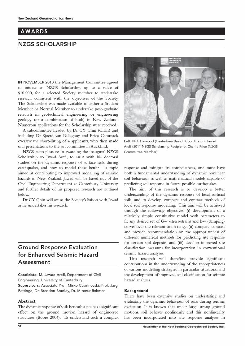
NZGS Student Awards
Saskia de Vilder An Engineering Geological Investigation of the Tutira Landslide Dam, Hawke’s Bay, New Zealand.
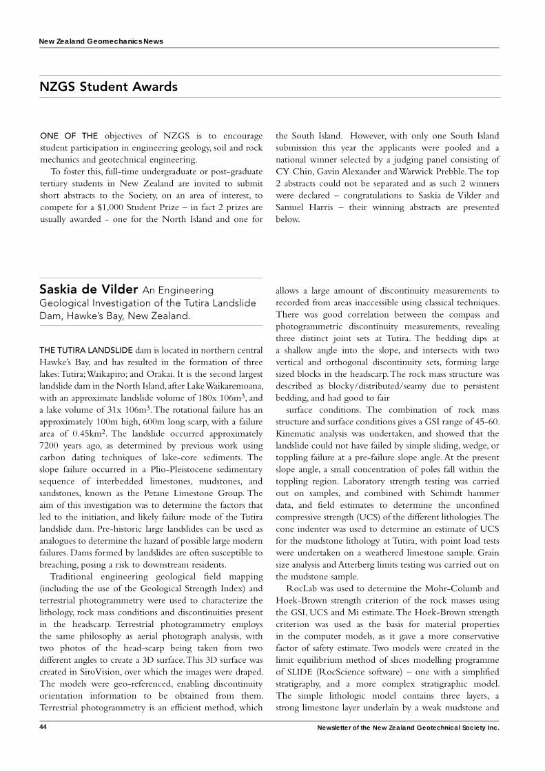
the tutira laNdslide dam is located in northern central Hawke’s Bay, and has resulted in the formation of three lakes: Tutira; Waikapiro; and Orakai. It is the second largest landslide dam in the North Island, after Lake Waikaremoana, with an approximate landslide volume of 180x 106m3, and a lake volume of 31x 106m3. The rotational failure has an approximately 100m high, 600m long scarp, with a failure area of 0.45km2. The landslide occurred approximately 7200 years ago, as determined by previous work using carbon dating techniques of lake-core sediments. The slope failure occurred in a Plio-Pleistocene sedimentary sequence of interbedded limestones, mudstones, and sandstones, known as the Petane Limestone Group. The aim of this investigation was to determine the factors that led to the initiation, and likely failure mode of the Tutira landslide dam. Pre-historic large landslides can be used as analogues to determine the hazard of possible large modern failures. Dams formed by landslides are often susceptible to breaching, posing a risk to downstream residents.
Traditional engineering geological field mapping (including the use of the Geological Strength Index) and terrestrial photogrammetry were used to characterize the lithology, rock mass conditions and discontinuities present in the headscarp. Terrestrial photogrammetry employs the same philosophy as aerial photograph analysis, with two photos of the head-scarp being taken from two different angles to create a 3D surface. This 3D surface was created in SiroVision, over which the images were draped. The models were geo-referenced, enabling discontinuity orientation information to be obtained from them. Terrestrial photogrammetry is an efficient method, which
allows a large amount of discontinuity measurements to recorded from areas inaccessible using classical techniques. There was good correlation between the compass and photogrammetric discontinuity measurements, revealing three distinct joint sets at Tutira. The bedding dips at a shallow angle into the slope, and intersects with two vertical and orthogonal discontinuity sets, forming large sized blocks in the headscarp. The rock mass structure was described as blocky/distributed/seamy due to persistent bedding, and had good to fair
surface conditions. The combination of rock mass structure and surface conditions gives a GSI range of 45-60. Kinematic analysis was undertaken, and showed that the landslide could not have failed by simple sliding, wedge, or toppling failure at a pre-failure slope angle. At the present slope angle, a small concentration of poles fall within the toppling region. Laboratory strength testing was carried out on samples, and combined with Schimdt hammer data, and field estimates to determine the unconfined compressive strength (UCS) of the different lithologies. The cone indenter was used to determine an estimate of UCS for the mudstone lithology at Tutira, with point load tests were undertaken on a weathered limestone sample. Grain size analysis and Atterberg limits testing was carried out on the mudstone sample.
RocLab was used to determine the Mohr-Columb and Hoek-Brown strength criterion of the rock masses using the GSI, UCS and Mi estimate. The Hoek-Brown strength criterion was used as the basis for material properties in the computer models, as it gave a more conservative factor of safety estimate. Two models were created in the limit equilibrium method of slices modelling programme of SLIDE (RocScience software) – one with a simplified stratigraphy, and a more complex stratigraphic model. The simple lithologic model contains three layers, a strong limestone layer underlain by a weak mudstone and
oNe of the objectives of NZGS is to encourage student participation in engineering geology, soil and rock mechanics and geotechnical engineering.
To foster this, full-time undergraduate or post-graduate tertiary students in New Zealand are invited to submit short abstracts to the Society, on an area of interest, to compete for a $1,000 Student Prize – in fact 2 prizes are usually awarded - one for the North Island and one for
the South Island. However, with only one South Island submission this year the applicants were pooled and a national winner selected by a judging panel consisting of CY Chin, Gavin Alexander and Warwick Prebble. The top 2 abstracts could not be separated and as such 2 winners were declared – congratulations to Saskia de Vilder and Samuel Harris – their winning abstracts are presented below.
New Zealand Geomechanics News
45
limestone layer respectively. The complex model contains several more layers of alternating weak mudstone and limestone, with the hard limestone layer at the top of the slope. The factor of safety for the simple model started at 2.017 (all values obtained using the Morgenstern and Price method), and 1.815 for the complex model. The Hawke’s Bay is a region which experiences both intense precipitation storms, and frequent seismic activity, therefore high pore pressure and seismic loading are important parameters included in the models. Increasing the ru value of the limestone layers - the mudstone was considered impermeable, decreased the factor of safety value, but did not lead to slope failure. The peak ground acceleration of an MM intensity 9 earthquake had the effect of reducing the factor of safety to the verge of instability, with increasing ru
value decreasing the value into the region of slope failure. . Alternative weakened rock mass strength models were also created to model the effect of material degradation on slope stability. The weak material property models have a lower factor of safety to begin with, and fail with increasing the ru value of the limestone layers. It is plausible that an earthquake combined with wet ground conditions may have triggered the Tutira landslide dam, or that progressive weakening of the rock mass was a factor which resulted in its eventual failure.
Saskia de Vilder MSc Student, School of the Environment University of Auckland.
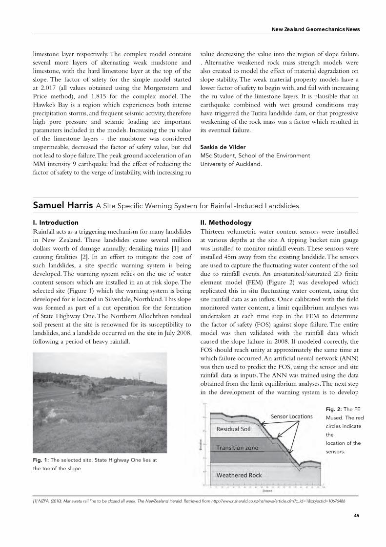
I. IntroductionRainfall acts as a triggering mechanism for many landslides in New Zealand. These landslides cause several million dollars worth of damage annually; derailing trains [1] and causing fatalities [2]. In an effort to mitigate the cost of such landslides, a site specific warning system is being developed. The warning system relies on the use of water content sensors which are installed in an at risk slope. The selected site (Figure 1) which the warning system is being developed for is located in Silverdale, Northland. This slope was formed as part of a cut operation for the formation of State Highway One. The Northern Allochthon residual soil present at the site is renowned for its susceptibility to landslides, and a landslide occurred on the site in July 2008, following a period of heavy rainfall.
Fig. 1: The selected site. State Highway One lies at
the toe of the slope
II. MethodologyThirteen volumetric water content sensors were installed at various depths at the site. A tipping bucket rain gauge was installed to monitor rainfall events. These sensors were installed 45m away from the existing landslide. The sensors are used to capture the fluctuating water content of the soil due to rainfall events. An unsaturated/saturated 2D finite element model (FEM) (Figure 2) was developed which replicated this in situ fluctuating water content, using the site rainfall data as an influx. Once calibrated with the field monitored water content, a limit equilibrium analyses was undertaken at each time step in the FEM to determine the factor of safety (FOS) against slope failure. The entire model was then validated with the rainfall data which caused the slope failure in 2008. If modeled correctly, the FOS should reach unity at approximately the same time at which failure occurred. An artificial neural network (ANN) was then used to predict the FOS, using the sensor and site rainfall data as inputs. The ANN was trained using the data obtained from the limit equilibrium analyses. The next step in the development of the warning system is to develop
Samuel Harris A Site Specific Warning System for Rainfall-Induced Landslides.
Fig. 2: The FE
Mused. The red
circles indicate
the
location of the
sensors.
[1] NZPA. (2010). Manawatu rail line to be closed all week. The NewZealand Herald. Retrieved from http://www.nzherald.co.nz/nz/news/article.cfm?c_id=1&objectid=10676486
New Zealand Geomechanics News
46 Newsletter of the New Zealand Geotechnical Society Inc.
an algorithm which can use the FOS predicted from the ANN as a basis to warn users of the warning system when failure is imminent. The users of the warning systemcan then take any necessary action, such as evacuating dwellings or closing roads.
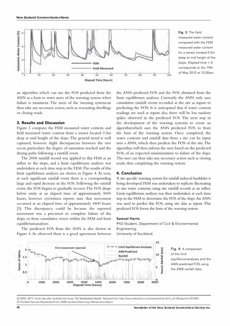
3. Results and DiscussionFigure 3 compares the FEM measured water content, and field measured water content from a sensor located 0.5m deep at mid height of the slope. The general trend is well captured, however slight discrepancies between the two occur, particulary the degree of saturation reached and the drying paths following a rainfall event.
The 2008 rainfall record was applied to this FEM as an influx to the slope, and a limit equilibrium analyses was undertaken at each time step in the FEM. The results of this limit equilirbium analyses are shown in Figure 4. As seen, at each significant rainfall event there is a corresponding large and rapid decrease in the FOS. Following the rainfall event, the FOS begins to gradually recover. The FOS drops below unity at an elapsed time of approximately 5000 hours, however eyewitness reports state that movement occurred at an elapsed time of approximately 4400 hours [3]. This discrepancy could be because the reported movement was a precursor to complete failure of the slope, or from cumulative errors within the FEM and limit equilibriumanalyses.
The predicted FOS from the ANN is also shown in Figure 4. As observed there is a good agreement between
the ANN predicted FOS and the FOS obtained from the limit equilibrium analyses. Currently the ANN only uses cumulative rainfall events recorded at the site as inputs to predicting the FOS. It is anticipated that if water content readings are used as inputs also, there will be less random spikes observed in the predicted FOS. The next step in the development of the warning systemis to create an algorithmwhich uses the ANN predicted FOS to from the basis of the warning system. Once completed, the water contents and rainfall data from a site can be input into a ANN, which then predicts the FOS of the site. The algorithm will then inform the user, based on the predicted FOS, of an expected minimumtime to failure of the slope. The user can then take any necessary action such as closing roads, thus completing the warning system.
4. ConclusionA site specific warning system for rainfall induced landslides is being developed. FEM was undertaken to replicate fluctuating in situ water contents, using site rainfall records as an influx. Limit equilibrium analyses was then undertaken at each time step in the FEM to determine the FOS of the slope. An ANN was used to predict this FOS, using site data as inputs. This predicted FOS forms the basis of the warning system.
Samuel Harris PhD Student, Department of Civil & Environmental Engineering, University of Auckland.
Fig. 3: The field
measured water content
compared with the FEM
measured water content
for a sensor located 0.5m
deep at mid height of the
slope. Elapsed time = 0
corresponds to the 19th
of May 2010 at 10.00am.
fig. 4: A comparison
of the limit
equilibriumanalyses and the
ANN predicted FOS using
the 2008 rainfall data.
[2] NZPA. (2011). Youth dies after landslide hits house. The NewZealand Herald.. Retrieved from http://www.nzherald.co.nz/nz/news/article.cfm?c_id=1&objectid=10733041[3] Transfield Services (NewZealand) Ltd. (2008). Auckland Motorways Maintenance Report.


54
special feature
56 Newsletter of the New Zealand Geotechnical Society Inc.
New Zealand Geomechanics News sPecial Feature
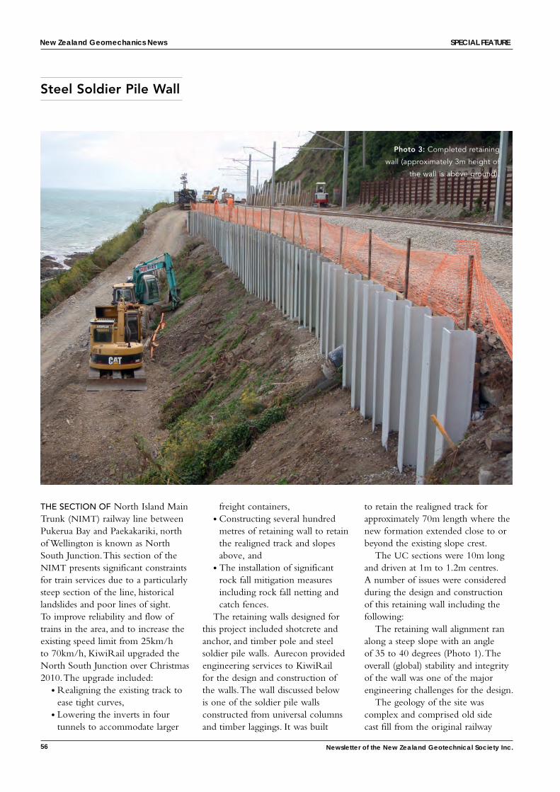
the sectioN of North Island Main Trunk (NIMT) railway line between Pukerua Bay and Paekakariki, north of Wellington is known as North South Junction. This section of the NIMT presents significant constraints for train services due to a particularly steep section of the line, historical landslides and poor lines of sight. To improve reliability and flow of trains in the area, and to increase the existing speed limit from 25km/h to 70km/h, KiwiRail upgraded the North South Junction over Christmas 2010. The upgrade included:
• Realigning the existing track to ease tight curves,
• Lowering the inverts in four tunnels to accommodate larger
freight containers,• Constructing several hundred
metres of retaining wall to retain the realigned track and slopes above, and
• The installation of significant rock fall mitigation measures including rock fall netting and catch fences.
The retaining walls designed for this project included shotcrete and anchor, and timber pole and steel soldier pile walls. Aurecon provided engineering services to KiwiRail for the design and construction of the walls. The wall discussed below is one of the soldier pile walls constructed from universal columns and timber laggings. It was built
to retain the realigned track for approximately 70m length where the new formation extended close to or beyond the existing slope crest.
The UC sections were 10m long and driven at 1m to 1.2m centres. A number of issues were considered during the design and construction of this retaining wall including the following:
The retaining wall alignment ran along a steep slope with an angle of 35 to 40 degrees (Photo 1). The overall (global) stability and integrity of the wall was one of the major engineering challenges for the design.
The geology of the site was complex and comprised old side cast fill from the original railway
Steel Soldier Pile Wall
Photo 3: Completed retaining
wall (approximately 3m height of
the wall is above ground).
New Zealand Geomechanics News
57
line construction over 100 years ago, underlain by historical landslide and colluvium materials. Gravels and boulders were present in these materials.
Limited subsurface information was available at the design stage as it was not possible to carry out detailed geotechnical investigations at the site due to access, topography, health and safety and time constraints.
The design life of the wall was 100 years and the wall was required to withstand a significant live load from the railway line carrying heavy freight.
The site is adjacent to the sea so the wall will be exposed to a highly corrosive environment.
The steep slope and live railway corridor also presented difficulties in terms of mobilising and operating construction equipment and machinery.
The construction of the retaining wall also had to be completed within a very short timeframe, of two weeks, and without major disruptions to railway traffic.
To address the above issues and
ensure an effective, efficient and practical retaining solution, driven 310 UC columns with timber laggings were selected as the most suitable retaining wall type (Photo 2 and 3). The wall construction was completed within the planned
timeframe. A number of other options were also considered as discussed below:
(a) Soldier pile wall with augered holes: Augered piles could have been a potential solution, but augering of holes would require significantly more time to complete. The soils at the site were relatively loose, hole collapse was likely and boulders in the fill would have made excavation difficult.
(b) Gravity retaining wall: This type of wall imposes additional load on the existing steep slope and requires significant excavations into the slope adjacent to the live railway line.
(c) Tied back/anchored wall: This wall was considered a suitable option to resist the relatively heavy loads from the train surcharge and earth pressure. This option was not pursued due to the time to build and test, and long term maintenance concerns relating to the anchors under the rail line.
The retaining wall was designed to resist up to 5.5m of active earth pressure. 100mm thick timber laggings were provided between the piles. The design included a provision to add additional lagging in the event of future slips below the wall. A galvanised coating and an allowance for sacrificial steel thickness were provided to cope with the aggressive corrosive environment.
Bishal Subedi Aurecon NZ Ltd
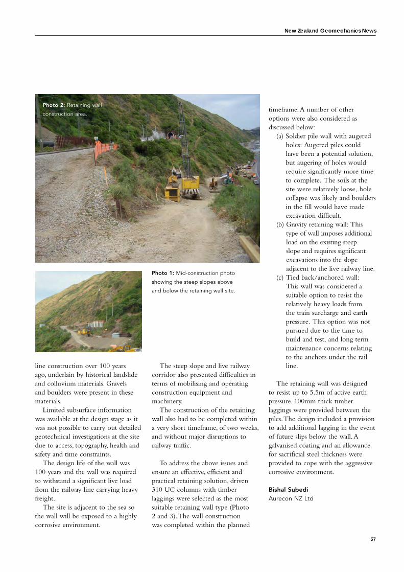
Photo 2: Retaining wall
construction area.
Photo 1: Mid-construction photo
showing the steep slopes above
and below the retaining wall site.
New Zealand Geomechanics News
59
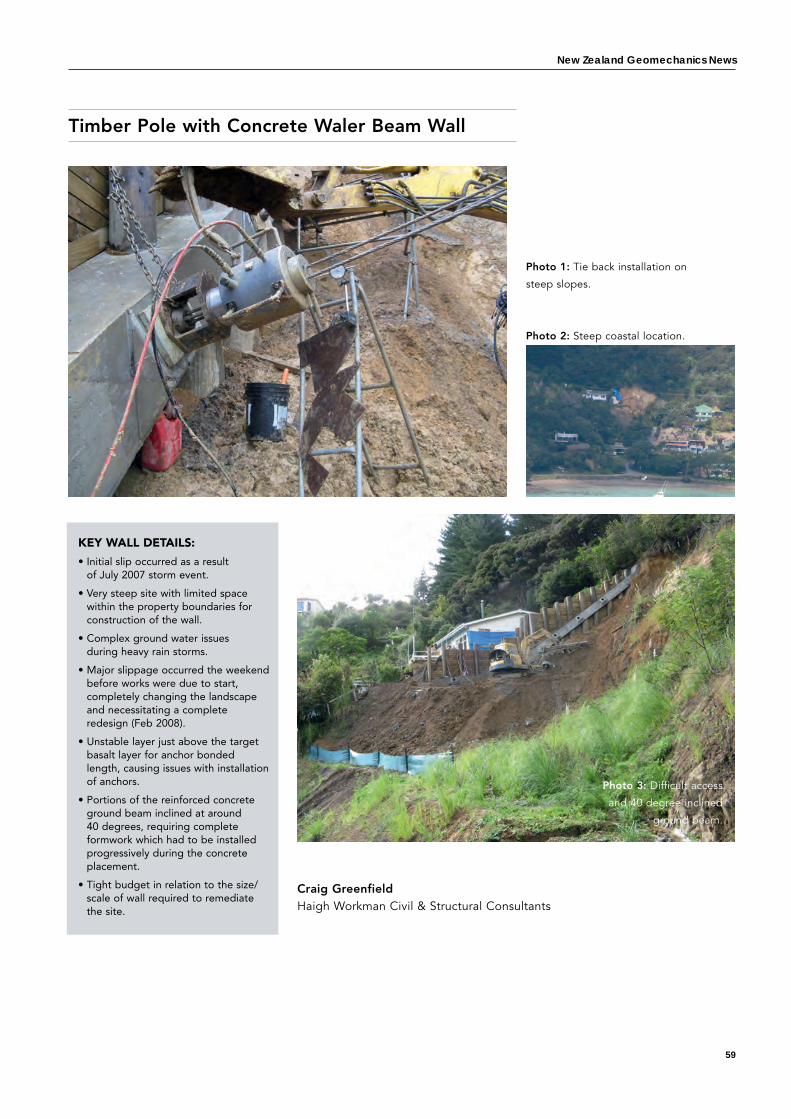
Timber Pole with Concrete Waler Beam Wall
Craig GreenfieldHaigh Workman Civil & Structural Consultants
KEY WALL DETAILS:
• Initial slip occurred as a result of July 2007 storm event.
• Very steep site with limited space within the property boundaries for construction of the wall.
• Complex ground water issues during heavy rain storms.
• Major slippage occurred the weekend before works were due to start, completely changing the landscape and necessitating a complete redesign (Feb 2008).
• Unstable layer just above the target basalt layer for anchor bonded length, causing issues with installation of anchors.
• Portions of the reinforced concrete ground beam inclined at around 40 degrees, requiring complete formwork which had to be installed progressively during the concrete placement.
• Tight budget in relation to the size/scale of wall required to remediate the site.
Photo 3: Difficult access
and 40 degree inclined
ground beam.
Photo 1: Tie back installation on
steep slopes.
Photo 2: Steep coastal location.
60 Newsletter of the New Zealand Geotechnical Society Inc.
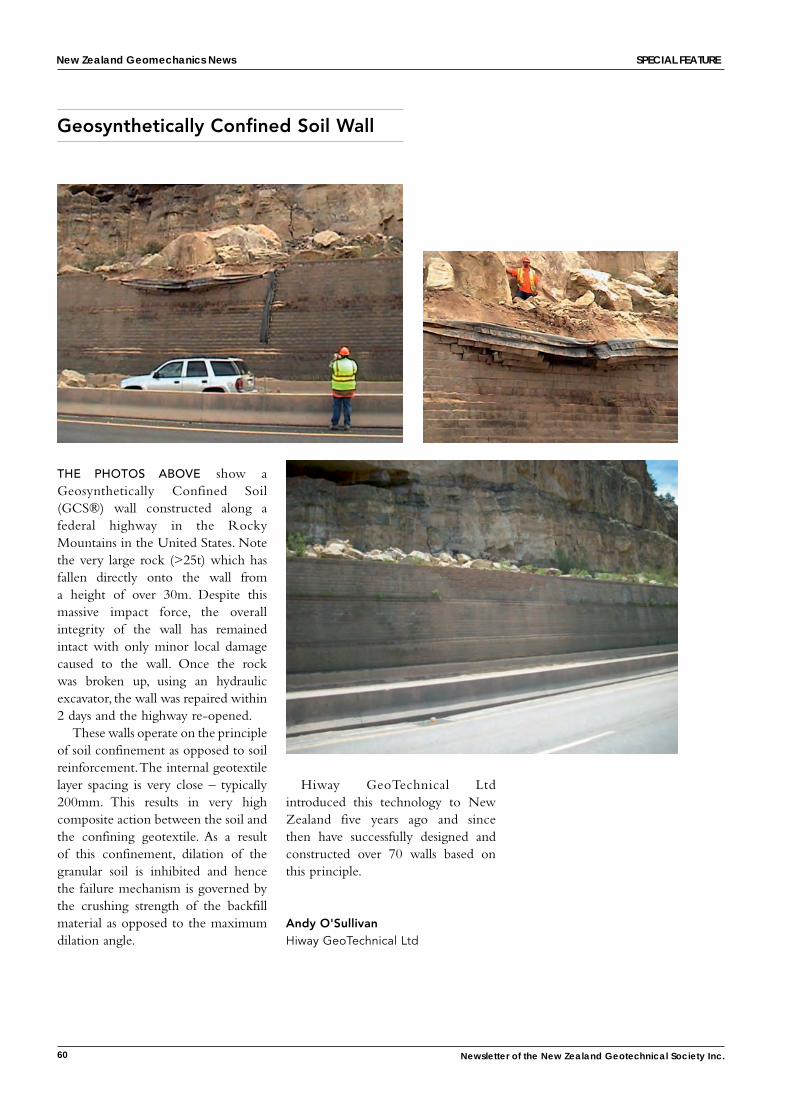
the Photos aBove show a Geosynthetically Confined Soil (GCS®) wall constructed along a federal highway in the Rocky Mountains in the United States. Note the very large rock (>25t) which has fallen directly onto the wall from a height of over 30m. Despite this massive impact force, the overall integrity of the wall has remained intact with only minor local damage caused to the wall. Once the rock was broken up, using an hydraulic excavator, the wall was repaired within 2 days and the highway re-opened.
These walls operate on the principle of soil confinement as opposed to soil reinforcement. The internal geotextile layer spacing is very close – typically 200mm. This results in very high composite action between the soil and the confining geotextile. As a result of this confinement, dilation of the granular soil is inhibited and hence the failure mechanism is governed by the crushing strength of the backfill material as opposed to the maximum dilation angle.
Geosynthetically Confined Soil Wall
Hiway GeoTechnical Ltd introduced this technology to New Zealand five years ago and since then have successfully designed and constructed over 70 walls based on this principle.
Andy O'SullivanHiway GeoTechnical Ltd
New Zealand Geomechanics News sPecial Feature
New Zealand Geomechanics News
61
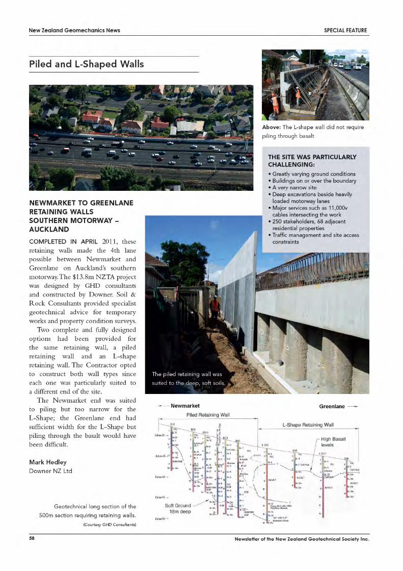
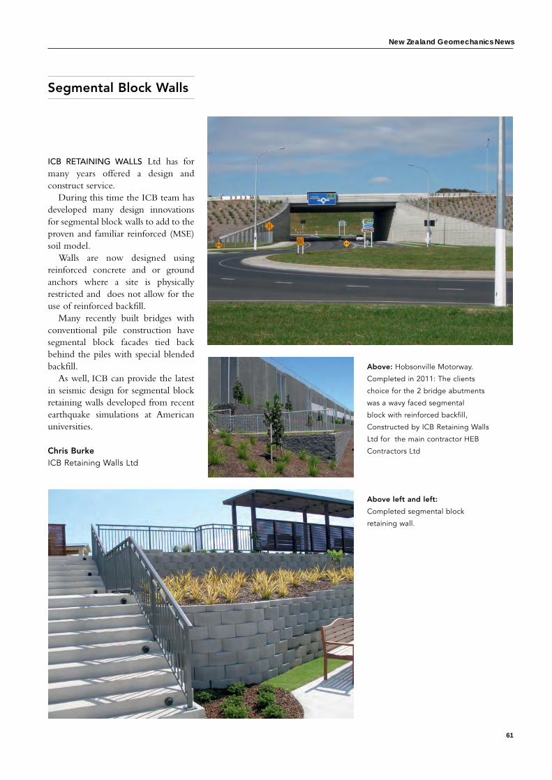
Segmental Block Walls
Above: Hobsonville Motorway.
Completed in 2011: The clients
choice for the 2 bridge abutments
was a wavy faced segmental
block with reinforced backfill,
Constructed by ICB Retaining Walls
Ltd for the main contractor HEB
Contractors Ltd
icB retaiNiNG Walls Ltd has for many years offered a design and construct service.
During this time the ICB team has developed many design innovations for segmental block walls to add to the proven and familiar reinforced (MSE) soil model.
Walls are now designed using reinforced concrete and or ground anchors where a site is physically restricted and does not allow for the use of reinforced backfill.
Many recently built bridges with conventional pile construction have segmental block facades tied back behind the piles with special blended backfill.
As well, ICB can provide the latest in seismic design for segmental block retaining walls developed from recent earthquake simulations at American universities. Chris BurkeICB Retaining Walls Ltd
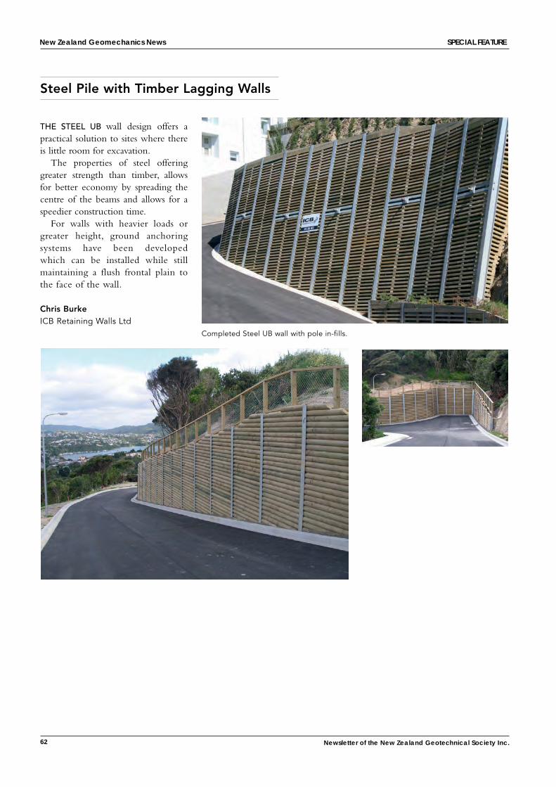
Above left and left:
Completed segmental block
retaining wall.
62 Newsletter of the New Zealand Geotechnical Society Inc.
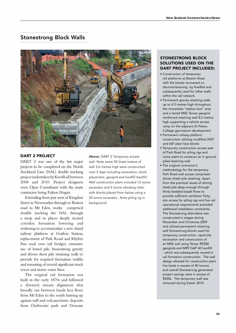
Steel Pile with Timber Lagging Walls
New Zealand Geomechanics News sPecial Feature
the steel uB wall design offers a practical solution to sites where there is little room for excavation.
The properties of steel offering greater strength than timber, allows for better economy by spreading the centre of the beams and allows for a speedier construction time.
For walls with heavier loads or greater height, ground anchoring systems have been developed which can be installed while still maintaining a flush frontal plain to the face of the wall.
Chris BurkeICB Retaining Walls Ltd
Completed Steel UB wall with pole in-fills.
New Zealand Geomechanics News
63
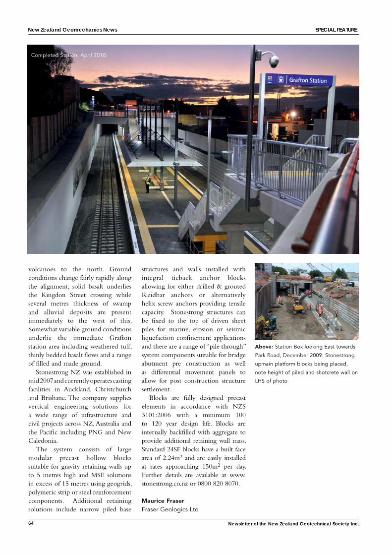
Stonestrong Block Walls
DART 2 PROJECTDART 2 was one of the last major projects to be completed on the North Auckland Line (NAL) double tracking project undertaken by KiwiRail between 2008 and 2010. Project designers were Opus Consultants with the main contractor being Fulton Hogan.
Extending from just west of Kingdon Street in Newmarket through to Boston road in Mt Eden, works comprised double tracking the NAL through a steep and in places deeply incised corridor, formation lowering and widening to accommodate a new island railway platform at Grafton Station, replacement of Park Road and Khyber Pass road over rail bridges, extensive use of bored pile, Stonestrong gravity and driven sheet pile retaining walls to provide for required formation widths and rerouting of several significant truck sewer and storm water lines.
The original rail formation was built in the early 1870s and followed a (former) stream alignment that broadly ran between basalt lava flows from Mt Eden to the south butting up against tuff and volcanoclastic deposits from Outhwaite park and Domain
Above: DART 2 Temporary access
wall. Note some 50 lineal metres of
wall 3.6 metres high were constructed
over 3 days including excavation, block
placement, geogrid and hardfill backfill.
Wall construction plant included 12 tonne
excavator and 5 tonne vibrating roller
with blocks placed from below using a
20 tonne excavator. Note piling rig in
background.
STONESTRONG BLOCK SOLUTIONS USED ON THE DART PROJECT INCLUDED:• Construction of temporary
rail platforms at Boston Road with the blocks recovered on decommissioning by KiwiRail and subsequently used for other walls within the rail network
• Permanent gravity retaining walls up to 4.5 metres high throughout the immediate “station box” area and a tiered MSE Tensar geogrid reinforced retaining wall 8.5 metres high supporting a vehicle access ramp on the adjacent St Peters College gymnasium development
• Permanent railway platform construction utilizing modified 24SF and 6SF plain face blocks
• Temporary construction access east of Park Road for piling rigs and crane plant to construct an in ground piled retaining wall.
• The original contractor’s methodology for the temporary Park Road wall access comprised driven sheet pile retaining. Apart from the practical issues of driving sheet pile deep enough through thinly bedded basalt flows to provide sufficient cantilever fixity, site access for piling rigs and live rail operational requirements provided additional installation constraints. The Stonestrong alternative was constructed in stages during November and Christmas 2009 and utilized permanent retaining wall Stonestrong blocks used for temporary construction, rapid site excavation and construction of an MSE wall using Tensar RE580 geogrids and MR9 GAP 40 hardfill - which was subsequently reused in rail formation construction. The wall design allowed for construction plant live loads in excess of 40 tonnes and overall Stonestrong generated project savings were in excess of $500k. The temporary wall was removed during Easter 2010.
64 Newsletter of the New Zealand Geotechnical Society Inc.
Completed Station, April 2010.
volcanoes to the north. Ground conditions change fairly rapidly along the alignment; solid basalt underlies the Kingdon Street crossing while several metres thickness of swamp and alluvial deposits are present immediately to the west of this. Somewhat variable ground conditions underlie the immediate Grafton station area including weathered tuff, thinly bedded basalt flows and a range of filled and made ground.
Stonestrong NZ was established in mid 2007 and currently operates casting facilities in Auckland, Christchurch and Brisbane. The company supplies vertical engineering solutions for a wide range of infrastructure and civil projects across NZ, Australia and the Pacific including PNG and New Caledonia.
The system consists of large modular precast hollow blocks suitable for gravity retaining walls up to 5 metres high and MSE solutions in excess of 15 metres using geogrids, polymeric strip or steel reinforcement components. Additional retaining solutions include narrow piled base
structures and walls installed with integral tieback anchor blocks allowing for either drilled & grouted Reidbar anchors or alternatively helix screw anchors providing tensile capacity. Stonestrong structures can be fixed to the top of driven sheet piles for marine, erosion or seismic liquefaction confinement applications and there are a range of “pile through” system components suitable for bridge abutment pre construction as well as differential movement panels to allow for post construction structure settlement.
Blocks are fully designed precast elements in accordance with NZS 3101:2006 with a minimum 100 to 120 year design life. Blocks are internally backfilled with aggregate to provide additional retaining wall mass. Standard 24SF blocks have a built face area of 2.24m2 and are easily installed at rates approaching 150m2 per day. Further details are available at www.stonestrong.co.nz or 0800 820 8070.
Maurice FraserFraser Geologics Ltd
Above: Station Box looking East towards
Park Road, December 2009. Stonestrong
upmain platform blocks being placed,
note height of piled and shotcrete wall on
LHS of photo
New Zealand Geomechanics News sPecial Feature
New Zealand Geomechanics News
65
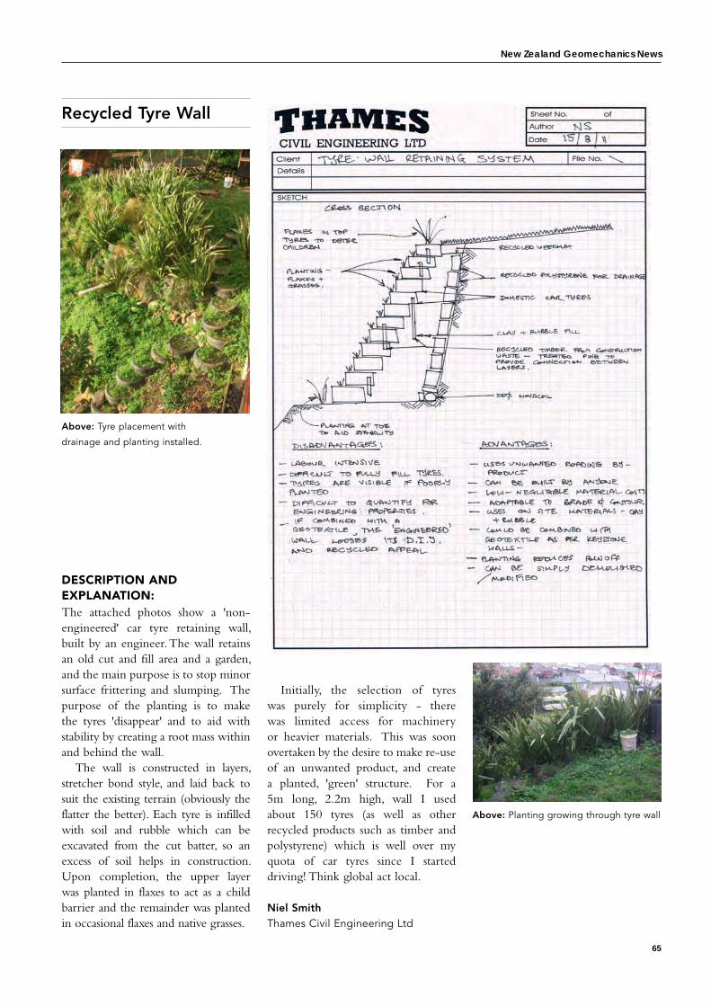
Recycled Tyre Wall
DESCRIPTION AND ExPLANATION:The attached photos show a 'non-engineered' car tyre retaining wall, built by an engineer. The wall retains an old cut and fill area and a garden, and the main purpose is to stop minor surface frittering and slumping. The purpose of the planting is to make the tyres 'disappear' and to aid with stability by creating a root mass within and behind the wall.
The wall is constructed in layers, stretcher bond style, and laid back to suit the existing terrain (obviously the flatter the better). Each tyre is infilled with soil and rubble which can be excavated from the cut batter, so an excess of soil helps in construction. Upon completion, the upper layer was planted in flaxes to act as a child barrier and the remainder was planted in occasional flaxes and native grasses.
Initially, the selection of tyres was purely for simplicity - there was limited access for machinery or heavier materials. This was soon overtaken by the desire to make re-use of an unwanted product, and create a planted, 'green' structure. For a 5m long, 2.2m high, wall I used about 150 tyres (as well as other recycled products such as timber and polystyrene) which is well over my quota of car tyres since I started driving! Think global act local.
Niel SmithThames Civil Engineering Ltd
Above: Planting growing through tyre wall
Above: Tyre placement with
drainage and planting installed.
66 Newsletter of the New Zealand Geotechnical Society Inc.
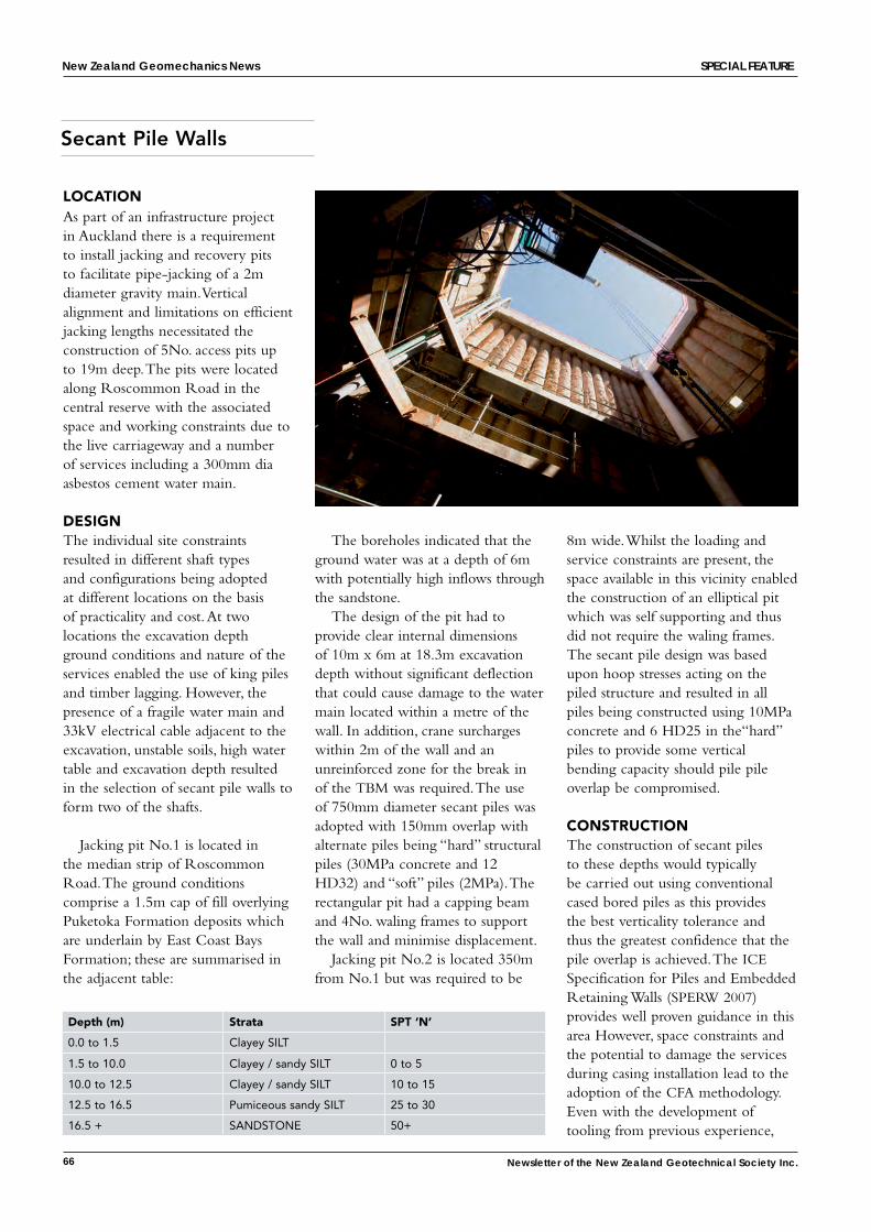
LOCATIONAs part of an infrastructure project in Auckland there is a requirement to install jacking and recovery pits to facilitate pipe-jacking of a 2m diameter gravity main. Vertical alignment and limitations on efficient jacking lengths necessitated the construction of 5No. access pits up to 19m deep. The pits were located along Roscommon Road in the central reserve with the associated space and working constraints due to the live carriageway and a number of services including a 300mm dia asbestos cement water main.
DESIGNThe individual site constraints resulted in different shaft types and configurations being adopted at different locations on the basis of practicality and cost. At two locations the excavation depth ground conditions and nature of the services enabled the use of king piles and timber lagging. However, the presence of a fragile water main and 33kV electrical cable adjacent to the excavation, unstable soils, high water table and excavation depth resulted in the selection of secant pile walls to form two of the shafts.
Jacking pit No.1 is located in the median strip of Roscommon Road. The ground conditions comprise a 1.5m cap of fill overlying Puketoka Formation deposits which are underlain by East Coast Bays Formation; these are summarised in the adjacent table:
The boreholes indicated that the ground water was at a depth of 6m with potentially high inflows through the sandstone.
The design of the pit had to provide clear internal dimensions of 10m x 6m at 18.3m excavation depth without significant deflection that could cause damage to the water main located within a metre of the wall. In addition, crane surcharges within 2m of the wall and an unreinforced zone for the break in of the TBM was required. The use of 750mm diameter secant piles was adopted with 150mm overlap with alternate piles being “hard” structural piles (30MPa concrete and 12 HD32) and “soft” piles (2MPa). The rectangular pit had a capping beam and 4No. waling frames to support the wall and minimise displacement.
Jacking pit No.2 is located 350m from No.1 but was required to be
8m wide. Whilst the loading and service constraints are present, the space available in this vicinity enabled the construction of an elliptical pit which was self supporting and thus did not require the waling frames. The secant pile design was based upon hoop stresses acting on the piled structure and resulted in all piles being constructed using 10MPa concrete and 6 HD25 in the“hard” piles to provide some vertical bending capacity should pile pile overlap be compromised.
CONSTRUCTIONThe construction of secant piles to these depths would typically be carried out using conventional cased bored piles as this provides the best verticality tolerance and thus the greatest confidence that the pile overlap is achieved. The ICE Specification for Piles and Embedded Retaining Walls (SPERW 2007) provides well proven guidance in this area However, space constraints and the potential to damage the services during casing installation lead to the adoption of the CFA methodology. Even with the development of tooling from previous experience,
Secant Pile Walls
Depth (m) Strata SPT ‘N’
0.0 to 1.5 Clayey SILT
1.5 to 10.0 Clayey / sandy SILT 0 to 5
10.0 to 12.5 Clayey / sandy SILT 10 to 15
12.5 to 16.5 Pumiceous sandy SILT 25 to 30
16.5 + SANDSTONE 50+
New Zealand Geomechanics News sPecial Feature
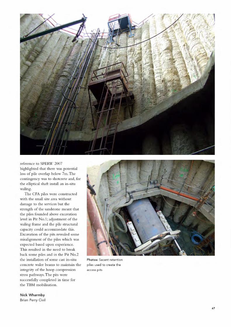
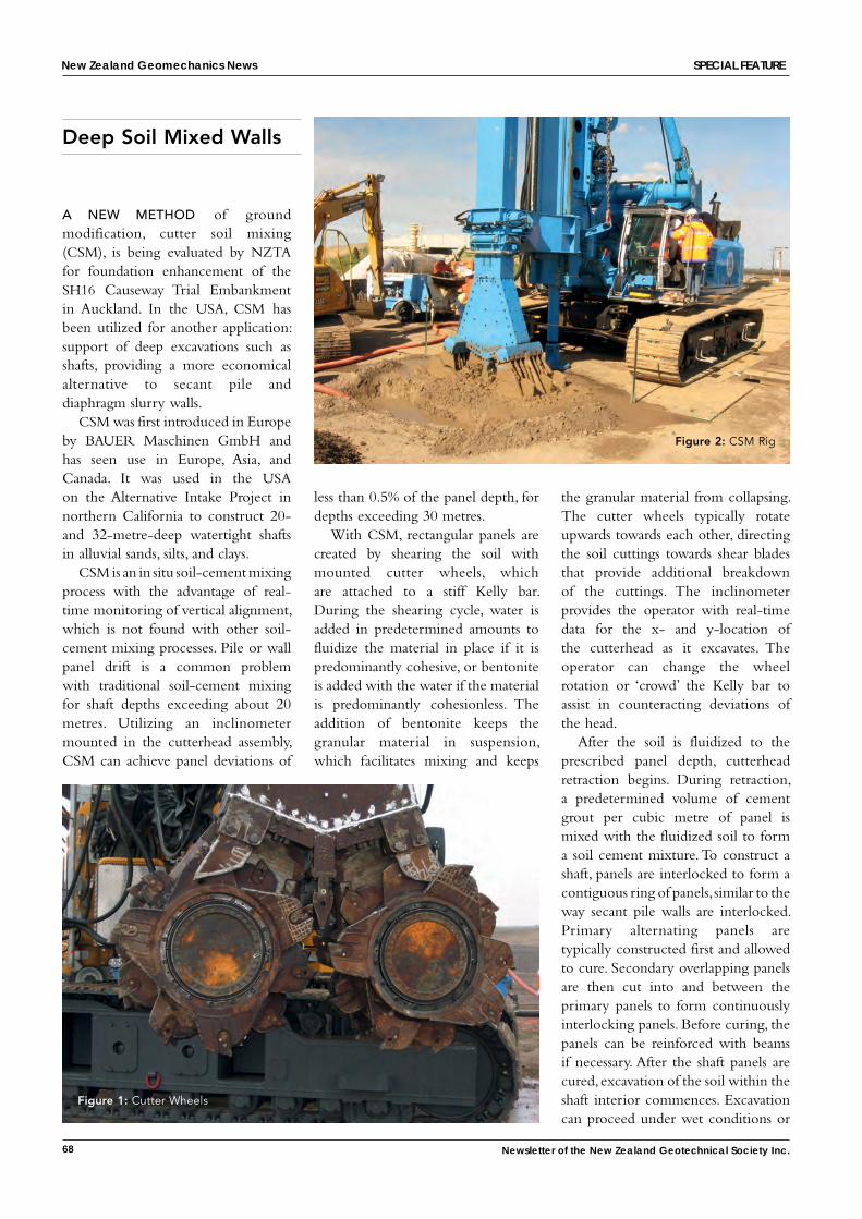
68 Newsletter of the New Zealand Geotechnical Society Inc.
Deep Soil Mixed Walls
a NeW method of ground modification, cutter soil mixing (CSM), is being evaluated by NZTA for foundation enhancement of the SH16 Causeway Trial Embankment in Auckland. In the USA, CSM has been utilized for another application: support of deep excavations such as shafts, providing a more economical alternative to secant pile and diaphragm slurry walls.
CSM was first introduced in Europe by BAUER Maschinen GmbH and has seen use in Europe, Asia, and Canada. It was used in the USA on the Alternative Intake Project in northern California to construct 20- and 32-metre-deep watertight shafts in alluvial sands, silts, and clays.
CSM is an in situ soil-cement mixing process with the advantage of real-time monitoring of vertical alignment, which is not found with other soil-cement mixing processes. Pile or wall panel drift is a common problem with traditional soil-cement mixing for shaft depths exceeding about 20 metres. Utilizing an inclinometer mounted in the cutterhead assembly, CSM can achieve panel deviations of
less than 0.5% of the panel depth, for depths exceeding 30 metres.
With CSM, rectangular panels are created by shearing the soil with mounted cutter wheels, which are attached to a stiff Kelly bar. During the shearing cycle, water is added in predetermined amounts to fluidize the material in place if it is predominantly cohesive, or bentonite is added with the water if the material is predominantly cohesionless. The addition of bentonite keeps the granular material in suspension, which facilitates mixing and keeps
Figure 2: CSM Rig
the granular material from collapsing. The cutter wheels typically rotate upwards towards each other, directing the soil cuttings towards shear blades that provide additional breakdown of the cuttings. The inclinometer provides the operator with real-time data for the x- and y-location of the cutterhead as it excavates. The operator can change the wheel rotation or ‘crowd’ the Kelly bar to assist in counteracting deviations of the head.
After the soil is fluidized to the prescribed panel depth, cutterhead retraction begins. During retraction, a predetermined volume of cement grout per cubic metre of panel is mixed with the fluidized soil to form a soil cement mixture. To construct a shaft, panels are interlocked to form a contiguous ring of panels, similar to the way secant pile walls are interlocked. Primary alternating panels are typically constructed first and allowed to cure. Secondary overlapping panels are then cut into and between the primary panels to form continuously interlocking panels. Before curing, the panels can be reinforced with beams if necessary. After the shaft panels are cured, excavation of the soil within the shaft interior commences. Excavation can proceed under wet conditions or
CSM for Deep Excavation Support – Victor Romero, CPEng, & Norm Joyal, PE (USA), Jacobs Associates, Auckland
Figure 1: Cutter Wheels
New Zealand Geomechanics News sPecial Feature
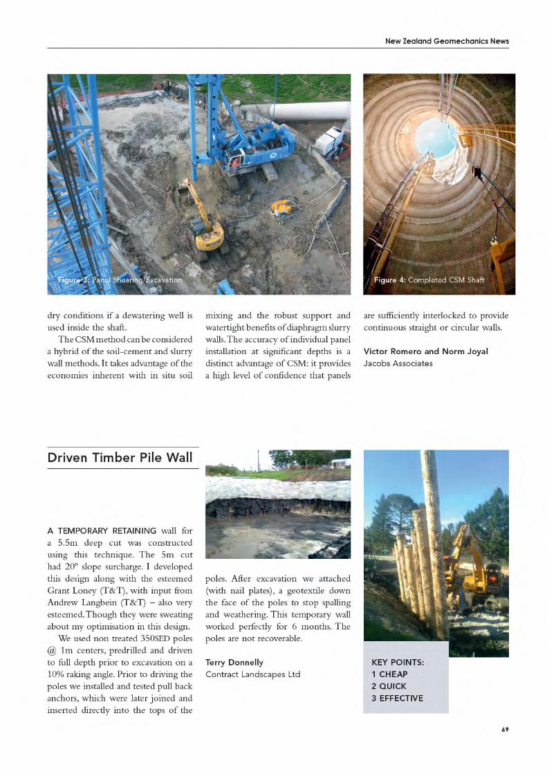
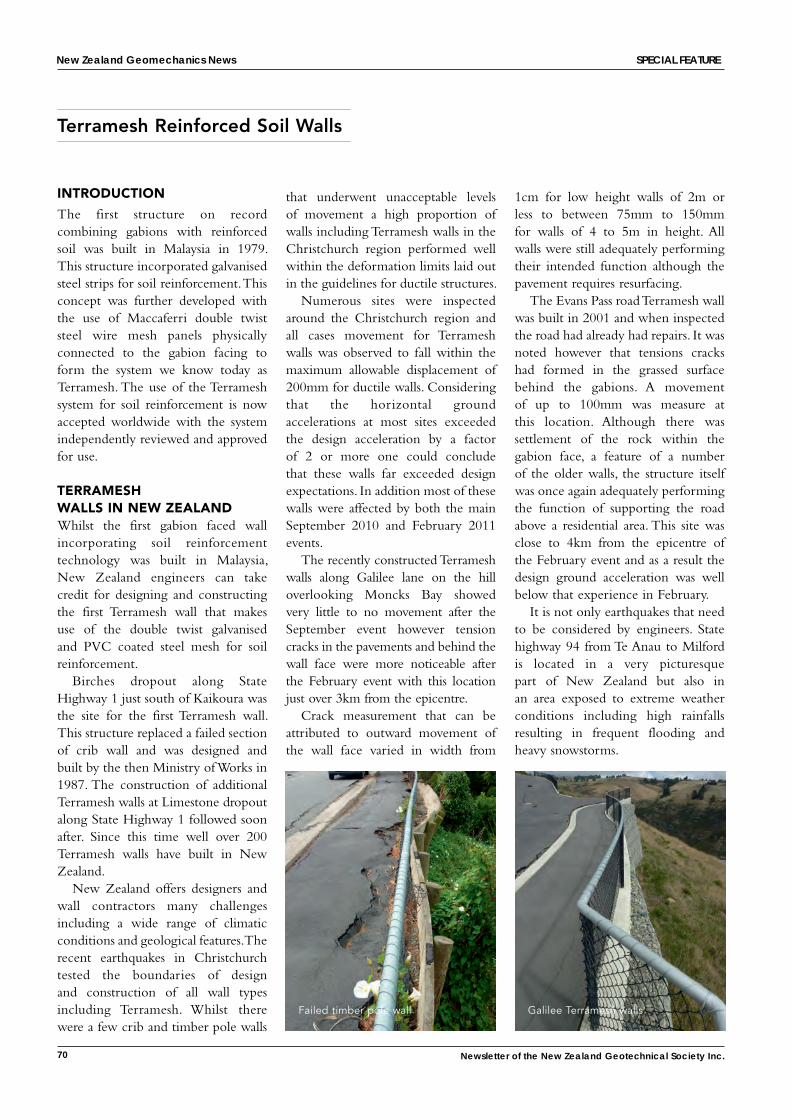
70 Newsletter of the New Zealand Geotechnical Society Inc.
INTRODUCTION
The first structure on record combining gabions with reinforced soil was built in Malaysia in 1979. This structure incorporated galvanised steel strips for soil reinforcement. This concept was further developed with the use of Maccaferri double twist steel wire mesh panels physically connected to the gabion facing to form the system we know today as Terramesh. The use of the Terramesh system for soil reinforcement is now accepted worldwide with the system independently reviewed and approved for use.
TERRAMESH WALLS IN NEW ZEALANDWhilst the first gabion faced wall incorporating soil reinforcement technology was built in Malaysia, New Zealand engineers can take credit for designing and constructing the first Terramesh wall that makes use of the double twist galvanised and PVC coated steel mesh for soil reinforcement.
Birches dropout along State Highway 1 just south of Kaikoura was the site for the first Terramesh wall. This structure replaced a failed section of crib wall and was designed and built by the then Ministry of Works in 1987. The construction of additional Terramesh walls at Limestone dropout along State Highway 1 followed soon after. Since this time well over 200 Terramesh walls have built in New Zealand.
New Zealand offers designers and wall contractors many challenges including a wide range of climatic conditions and geological features. The recent earthquakes in Christchurch tested the boundaries of design and construction of all wall types including Terramesh. Whilst there were a few crib and timber pole walls
Terramesh Reinforced Soil Walls
that underwent unacceptable levels of movement a high proportion of walls including Terramesh walls in the Christchurch region performed well within the deformation limits laid out in the guidelines for ductile structures.
Numerous sites were inspected around the Christchurch region and all cases movement for Terramesh walls was observed to fall within the maximum allowable displacement of 200mm for ductile walls. Considering that the horizontal ground accelerations at most sites exceeded the design acceleration by a factor of 2 or more one could conclude that these walls far exceeded design expectations. In addition most of these walls were affected by both the main September 2010 and February 2011 events.
The recently constructed Terramesh walls along Galilee lane on the hill overlooking Moncks Bay showed very little to no movement after the September event however tension cracks in the pavements and behind the wall face were more noticeable after the February event with this location just over 3km from the epicentre.
Crack measurement that can be attributed to outward movement of the wall face varied in width from
1cm for low height walls of 2m or less to between 75mm to 150mm for walls of 4 to 5m in height. All walls were still adequately performing their intended function although the pavement requires resurfacing.
The Evans Pass road Terramesh wall was built in 2001 and when inspected the road had already had repairs. It was noted however that tensions cracks had formed in the grassed surface behind the gabions. A movement of up to 100mm was measure at this location. Although there was settlement of the rock within the gabion face, a feature of a number of the older walls, the structure itself was once again adequately performing the function of supporting the road above a residential area. This site was close to 4km from the epicentre of the February event and as a result the design ground acceleration was well below that experience in February.
It is not only earthquakes that need to be considered by engineers. State highway 94 from Te Anau to Milford is located in a very picturesque part of New Zealand but also in an area exposed to extreme weather conditions including high rainfalls resulting in frequent flooding and heavy snowstorms.
Failed timber pole wall Galilee Terramesh walls
New Zealand Geomechanics News sPecial Feature
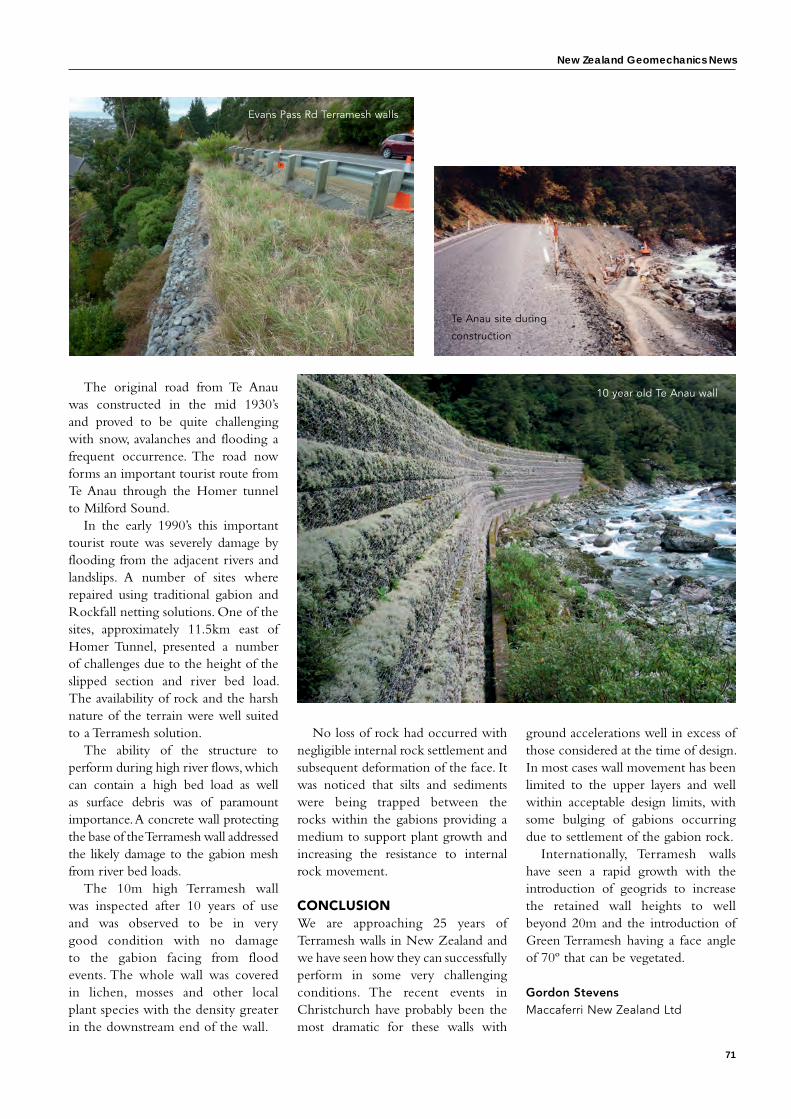
New Zealand Geomechanics News
71
The original road from Te Anau was constructed in the mid 1930’s and proved to be quite challenging with snow, avalanches and flooding a frequent occurrence. The road now forms an important tourist route from Te Anau through the Homer tunnel to Milford Sound.
In the early 1990’s this important tourist route was severely damage by flooding from the adjacent rivers and landslips. A number of sites where repaired using traditional gabion and Rockfall netting solutions. One of the sites, approximately 11.5km east of Homer Tunnel, presented a number of challenges due to the height of the slipped section and river bed load. The availability of rock and the harsh nature of the terrain were well suited to a Terramesh solution.
The ability of the structure to perform during high river flows, which can contain a high bed load as well as surface debris was of paramount importance. A concrete wall protecting the base of the Terramesh wall addressed the likely damage to the gabion mesh from river bed loads.
The 10m high Terramesh wall was inspected after 10 years of use and was observed to be in very good condition with no damage to the gabion facing from flood events. The whole wall was covered in lichen, mosses and other local plant species with the density greater in the downstream end of the wall.
No loss of rock had occurred with negligible internal rock settlement and subsequent deformation of the face. It was noticed that silts and sediments were being trapped between the rocks within the gabions providing a medium to support plant growth and increasing the resistance to internal rock movement.
CONCLUSIONWe are approaching 25 years of Terramesh walls in New Zealand and we have seen how they can successfully perform in some very challenging conditions. The recent events in Christchurch have probably been the most dramatic for these walls with
ground accelerations well in excess of those considered at the time of design. In most cases wall movement has been limited to the upper layers and well within acceptable design limits, with some bulging of gabions occurring due to settlement of the gabion rock.
Internationally, Terramesh walls have seen a rapid growth with the introduction of geogrids to increase the retained wall heights to well beyond 20m and the introduction of Green Terramesh having a face angle of 70º that can be vegetated.
Gordon StevensMaccaferri New Zealand Ltd
10 year old Te Anau wall
Te Anau site during
construction
Evans Pass Rd Terramesh walls
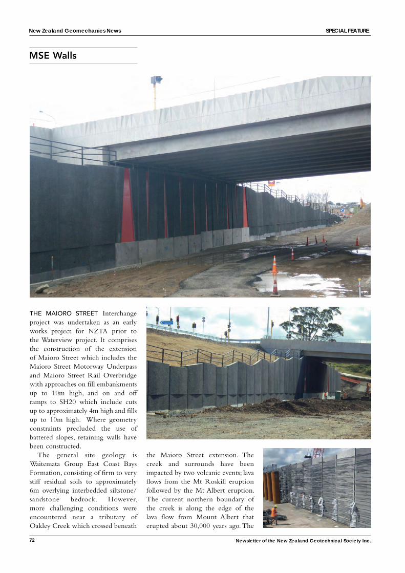
72 Newsletter of the New Zealand Geotechnical Society Inc.
MSE Walls
New Zealand Geomechanics News sPecial Feature
the maioro street Interchange project was undertaken as an early works project for NZTA prior to the Waterview project. It comprises the construction of the extension of Maioro Street which includes the Maioro Street Motorway Underpass and Maioro Street Rail Overbridge with approaches on fill embankments up to 10m high, and on and off ramps to SH20 which include cuts up to approximately 4m high and fills up to 10m high. Where geometry constraints precluded the use of battered slopes, retaining walls have been constructed.
The general site geology is Waitemata Group East Coast Bays Formation, consisting of firm to very stiff residual soils to approximately 6m overlying interbedded siltstone/sandstone bedrock. However, more challenging conditions were encountered near a tributary of Oakley Creek which crossed beneath
the Maioro Street extension. The creek and surrounds have been impacted by two volcanic events; lava flows from the Mt Roskill eruption followed by the Mt Albert eruption. The current northern boundary of the creek is along the edge of the lava flow from Mount Albert that erupted about 30,000 years ago. The
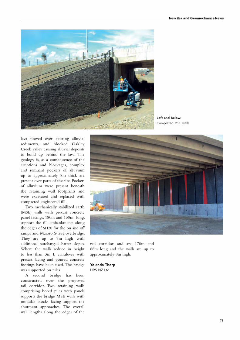
New Zealand Geomechanics News
73
lava flowed over existing alluvial sediments, and blocked Oakley Creek valley causing alluvial deposits to build up behind the lava. The geology is, as a consequence of the eruptions and blockages, complex and remnant pockets of alluvium up to approximately 8m thick are present over parts of the site. Pockets of alluvium were present beneath the retaining wall footprints and were excavated and replaced with compacted engineered fill.
Two mechanically stabilized earth (MSE) walls with precast concrete panel facings, 180m and 130m long, support the fill embankments along the edges of SH20 for the on and off ramps and Maioro Street overbridge. They are up to 7m high with additional surcharged batter slopes. Where the walls reduce in height to less than 3m L cantilever with precast facing and poured concrete footings have been used. The bridge was supported on piles.
A second bridge has been constructed over the proposed rail corridor. Two retaining walls comprising bored piles with panels supports the bridge MSE walls with modular blocks facing support the abutment approaches. The overall wall lengths along the edges of the
rail corridor, and are 170m and 88m long and the walls are up to approximately 8m high.
Yolanda Thorp URS NZ Ltd
Left and below:
Completed MSE walls


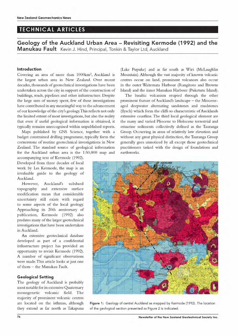
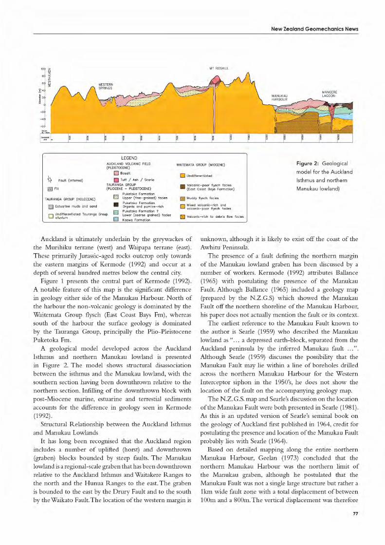
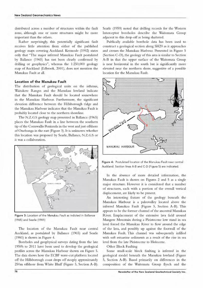
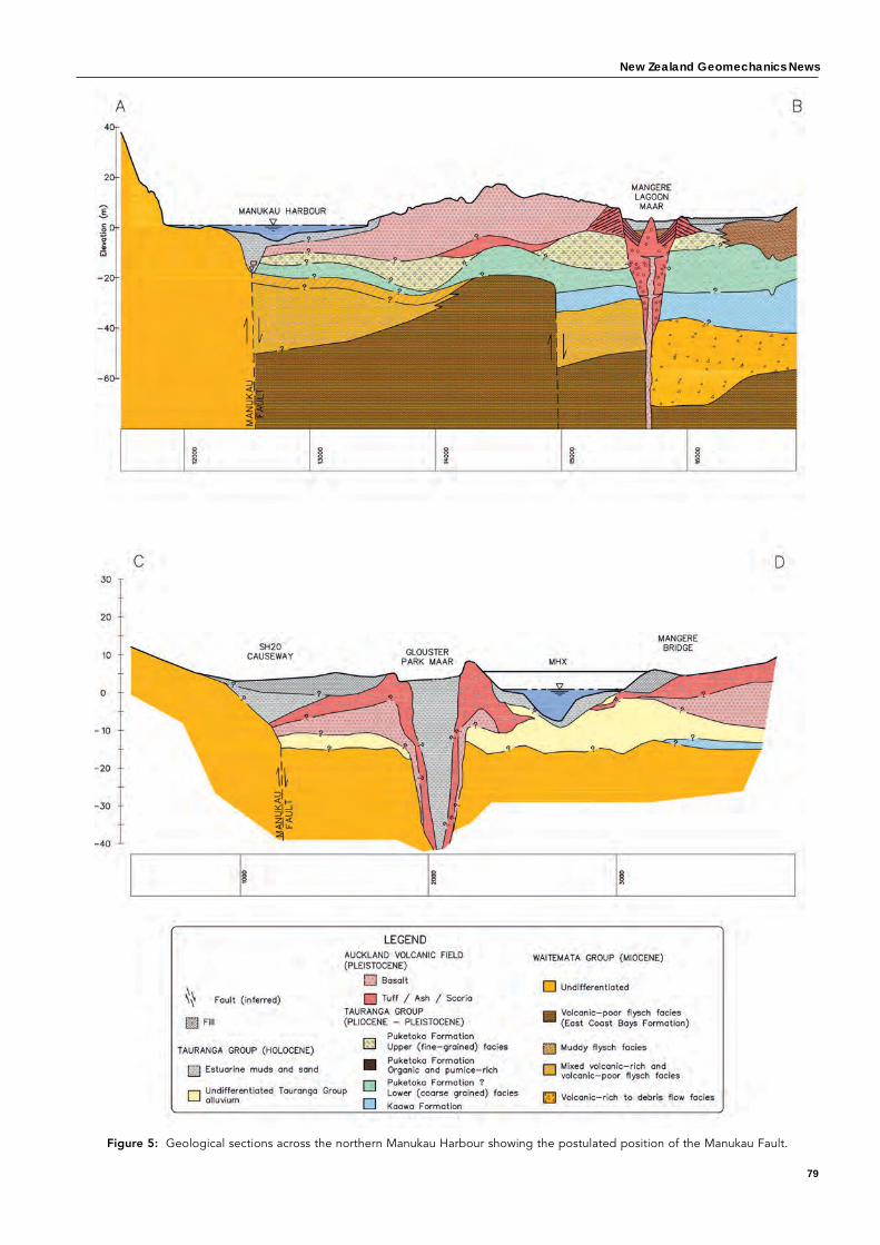
New Zealand Geomechanics News
79
Figure 5: Geological sections across the northern Manukau Harbour showing the postulated position of the Manukau Fault.
New Zealand Geomechanics News
81
Design of Bridge Foundations in Soils Prone to Liquefaction – Andy O’Sullivan, Senior Geotechnical Engineer, Hiway GeoTechnical Ltd. Andrew Holland, Senior Geotechnical Engineer AECOM, Hamilton
IntroductionThe $ 45 million Hamilton Ring Road Upgrade Extension (HRRUE) project, which is currently being constructed by Downer New Zealand Ltd, will extend the Wairere Drive 4-lane configuration from Crosby Road to Ruakura Road.
AECOM were commissioned by Hamilton City Council to undertake the design of this section of the project. The site investigation revealed the presence of sensitive, potentially liquefiable layers at two locations, namely at the Carrs Road interchange (an overbridge and large retaining walls) and the East Coast Main Truckline Rail (ECMTR) Bridge.
AECOM carried out preliminary liquefaction assessments for both of these sites which indicated that excessive deformations were likely in a large seismic event. They concluded that some form of ground improvement would be required. A number of options were considered for ground improvement including stone columns and timber piles. However, given the sensitive nature of some of the materials and the close proximity to adjacent properties, AECOM invited Hiway GeoTechnical Ltd (HGT) to provide ground improvement options based on their Deep Soil Mixing (DSM) capability. HGT were subsequently engaged as a nominated subcontractor with Downer as the head contractor.
This article will outline the analysis carried out as part of the detailed design by HGT for the ground improvement works, including the steps taken to characterise the soils. In addition, the quality assurance (QA) and additional methods used to verify the design will be discussed.
Geology and Project OutlineThe geological profile at the ECMTR Bridge consists of interbedded and intertonged layers of sandy SILTS and silty SANDS of the Hinuera Formation to a depth of over 30m. At the Carrs Road Interchange, the proposed main alignment intersects an ash hill. The geological profile here consists typically around 6m of ash or residually weathered ignimbrite, underlain by around 6-8m of moderately to highly sensitive, completely weathered (CW) ignimbrite. The sensitivity of the CW ignimbrite was observed during the site investigation when sections of the borehole core were recovered in a fully liquefied state and the CPT cone resistance was extremely low (qc < 0.1MPa; Fr < 1%). A further complication is that at the Carrs Road interchange, the proposed main alignment will be in 6m of cut and will therefore rest on the CW ignimbrite layer.
The initial design for both locations was for the bridge decks to be supported fully on piles, with isolated MSE walls at the abutments. Ground improvements would be carried out underneath the abutments as required. In the case of the overbridge at Carrs Road, the bridge was a two-span structure with the central pier supported on driven pre-cast concrete piles. During the detailed design development phase, the design was changed to delete the abutment piles entirely and to rest the superstructure directly on the MSE walls (bankseats) relying on the ground improvement for support. This option produced considerable cost savings. As a result, the ground improvement needed to take account of the additional bridge deck loadings on the MSE walls, particularly under seismic excitation.
While the DSM method is well proven, with 1,000s of international case studies available, the simplified design methods (Porbaha et al) tend to be conservative, in the author’s opinion, and do not adequately address fundamental design issues such as predicted displacements and generated shear stresses.
Therefore, for the project at Hamilton, the decision was made at an early stage of the detailed design to carry out a site specific, effective stress, time history analysis for each of the sites.
Geotechnical Assessment While the project presented a number of geotechnical challenges, the two greatest challenges were deemed to be (a) the overall seismic response of the highly layered soils at the ECMTR bridge and (b) the characterisation of the completely weathered (CW) ignimbrite material at the Carrs Road interchange. In the case of the completely weathered ignimbrite, the characterisation required an understanding of the following:
(a) Complex mineralogy (allophanes and halloysites) hence the material has a very high water content (in excess of 100%)
(b) Susceptibility to structural collapse (based on site investigation observations where sections of core appeared to “liquefy” during investigation drilling)
(c) Determination of likely performance of material in unloading conditions (at Carrs Road the proposed alignment was in up to 6m of cut). While conventional soils in such a case would become over-consolidated, due to unloading, and hence stiffer and more pseudo-elastic, this needed to be balanced against the large increase in ratio
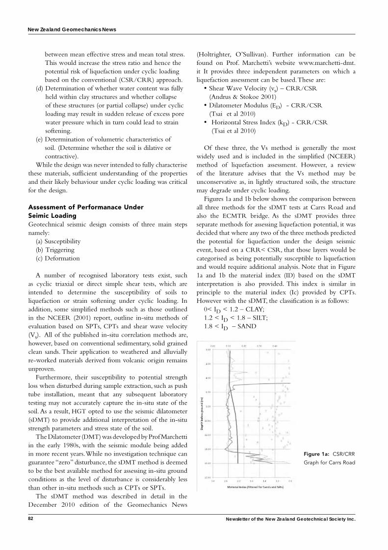
New Zealand Geomechanics News
82 Newsletter of the New Zealand Geotechnical Society Inc.
between mean effective stress and mean total stress. This would increase the stress ratio and hence the potential risk of liquefaction under cyclic loading based on the conventional (CSR/CRR) approach.
(d) Determination of whether water content was fully held within clay structures and whether collapse of these structures (or partial collapse) under cyclic loading may result in sudden release of excess pore water pressure which in turn could lead to strain softening.
(e) Determination of volumetric characteristics of soil. (Determine whether the soil is dilative or contractive).
While the design was never intended to fully characterise these materials, sufficient understanding of the properties and their likely behaviour under cyclic loading was critical for the design.
Assessment of Performanace Under Seimic LoadingGeotechnical seismic design consists of three main steps namely:
(a) Susceptibility(b) Triggering(c) Deformation
A number of recognised laboratory tests exist, such as cyclic triaxial or direct simple shear tests, which are intended to determine the susceptibility of soils to liquefaction or strain softening under cyclic loading. In addition, some simplified methods such as those outlined in the NCEER (2001) report, outline in-situ methods of evaluation based on SPTs, CPTs and shear wave velocity (Vs). All of the published in-situ correlation methods are, however, based on conventional sedimentary, solid grained clean sands. Their application to weathered and alluvially re-worked materials derived from volcanic origin remains unproven.
Furthermore, their susceptibility to potential strength loss when disturbed during sample extraction, such as push tube installation, meant that any subsequent laboratory testing may not accurately capture the in-situ state of the soil. As a result, HGT opted to use the seismic dilatometer (sDMT) to provide additional interpretation of the in-situ strength parameters and stress state of the soil.
The Dilatometer (DMT) was developed by Prof Marchetti in the early 1980s, with the seismic module being added in more recent years. While no investigation technique can guarantee “zero” disturbance, the sDMT method is deemed to be the best available method for assessing in-situ ground conditions as the level of disturbance is considerably less than other in-situ methods such as CPTs or SPTs.
The sDMT method was described in detail in the December 2010 edition of the Geomechanics News
(Holtrighter, O’Sullivan). Further information can be found on Prof. Marchetti’s website www.marchetti-dmt.it It provides three independent parameters on which a liquefaction assessment can be based. These are:
• Shear Wave Velocity (vs) – CRR/CSR (Andrus & Stokoe 2001)
• Dilatometer Modulus (ED) - CRR/CSR (Tsai et al 2010)
• Horizontal Stress Index (kD) - CRR/CSR (Tsai et al 2010)
Of these three, the Vs method is generally the most widely used and is included in the simplified (NCEER) method of liquefaction assessment. However, a review of the literature advises that the Vs method may be unconservative as, in lightly structured soils, the structure may degrade under cyclic loading.
Figures 1a and 1b below shows the comparison between all three methods for the sDMT tests at Carrs Road and also the ECMTR bridge. As the sDMT provides three separate methods for assessing liquefaction potential, it was decided that where any two of the three methods predicted the potential for liquefaction under the design seismic event, based on a CRR< CSR, that those layers would be categorised as being potentially susceptible to liquefaction and would require additional analysis. Note that in Figure 1a and 1b the material index (ID) based on the sDMT interpretation is also provided. This index is similar in principle to the material index (Ic) provided by CPTs. However with the sDMT, the classification is as follows:
0< ID < 1.2 – CLAY; 1.2 < ID < 1.8 – SILT; 1.8 < ID – SAND
Figure 1a: CSR/CRR
Graph for Carrs Road
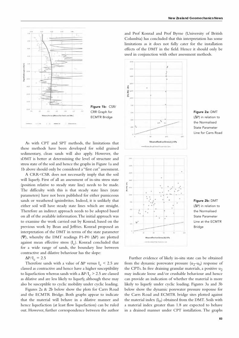
New Zealand Geomechanics News
83
As with CPT and SPT methods, the limitations that these methods have been developed for solid grained sedimentary, clean sands will also apply. However, the sDMT is better at determining the level of structure and stress state of the soil and hence the graphs in Figure 1a and 1b above should only be considered a “first cut” assessment.
A CRR<CSR does not necessarily imply that the soil will liquefy. First of all an assessment of in-situ stress state (position relative to steady state line) needs to be made. The difficulty with this is that steady state lines (state parameters) have not been published for either pumiceous sands or weathered ignimbrites. Indeed, it is unlikely that either soil will have steady state lines which are straight. Therefore an indirect approach needs to be adopted based on all of the available information. The initial approach was to examine the work carried out by Konrad, based on the previous work by Bean and Jeffries. Konrad proposed an interpretation of the DMT in terms of the state parameter (Ψ), whereby the DMT readings P1-P0 (ΔP) are plotted against mean effective stress (Ic). Konrad concluded that for a wide range of sands, the boundary line between contractive and dilative behaviour has the slope:
ΔP/Ic = 2.5Therefore sands with a value of ΔP versus Ic < 2.5 are
classed as contractive and hence have a higher susceptibility to liquefaction whereas sands with a ΔP/Ic > 2.5 are classed as dilative and are less likely to liquefy, although these may also be susceptible to cyclic mobility under cyclic loading.
Figures 2a & 2b below show the plots for Carrs Road and the ECMTR Bridge. Both graphs appear to indicate that the material will behave in a dilative manner and hence liquefaction (at least flow liquefaction) can be ruled out. However, further correspondence between the author
and Prof Konrad and Prof Byrne (University of British Columbia) has concluded that this interpretation has some limitations as it does not fully cater for the installation effects of the DMT in the field. Hence it should only be used in conjunction with other assessment methods.
Further evidence of likely in-situ state can be obtained from the dynamic porewater pressure (u2-u0) response of the CPTs. In free draining granular materials, a positive u2 may indicate loose and/or crushable behaviour and hence can provide an indication of whether the material is more likely to liquefy under cyclic loading. Figures 3a and 3b below show the dynamic porewater pressure response for the Carrs Road and ECMTR bridge sites plotted against the material index (ID) obtained from the DMT. Soils with a material index greater than 1.8 are expected to behave in a drained manner under CPT installation. The graphs
Figure 1b: CSR/
CRR Graph for
ECMTR Bridge
Figure 2a: DMT
(ΔP) in relation to
the Normalised
State Parameter
Line for Carrs Road
Figure 2b: DMT
(ΔP) in relation to
the Normalised
State Parameter
Line at the ECMTR
Bridge
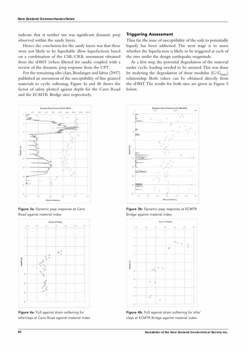
New Zealand Geomechanics News
84 Newsletter of the New Zealand Geotechnical Society Inc.
indicate that at neither site was significant dynamic pwp observed within the sandy layers.
Hence the conclusion for the sandy layers was that these were not likely to be liquefiable (flow liquefaction) based on a combination of the CSR/CRR assessment obtained from the sDMT (when filtered for sands) coupled with a review of the dynamic pwp response from the CPT.
For the remaining silts/clays, Boulanger and Idriss (2007) published an assessment of the susceptibility of fine grained materials to cyclic softening. Figure 4a and 4b shows the factor of safety plotted against depth for the Carrs Road and the ECMTR Bridge sites respectively.
Triggering AssessmentThus far, the issue of susceptibility of the soils to potentially liquefy has been addressed. The next stage is to assess whether the liquefaction is likely to be triggered at each of the sites under the design earthquake magnitude.
As a first step, the potential degradation of the material under cyclic loading needed to be assessed. This was done by analysing the degradation of shear modulus (G/Gmax) relationship. Both values can be obtained directly from the sDMT. The results for both sites are given in Figure 5 below.
Figure 3a: Dynamic pwp response at Carrs
Road against material index
Figure 3b: Dynamic pwp response at ECMTR
Bridge against material index
Figure 4a: FoS against strain softening for
silts/clays at Carrs Road against material index
Figure 4b: FoS against strain softening for silts/
clays at ECMTR Bridge against material index
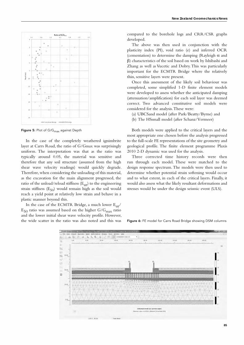
New Zealand Geomechanics News
85
Figure 5: Plot of G/Gmax against Depth
In the case of the completely weathered ignimbrite layer at Carrs Road, the ratio of G/Gmax was surprisingly uniform. The interpretation was that as the ratio was typically around 0.05, the material was sensitive and therefore that any soil structure (assumed from the high shear wave velocity readings) would quickly degrade. Therefore, when considering the unloading of this material, as the excavation for the main alignment progressed, the ratio of the unload/reload stiffness (Eur) to the engineering strain stiffness (E50) would remain high as the soil would reach a yield point at relatively low strain and behave in a plastic manner beyond this.
In the case of the ECMTR Bridge, a much lower Eur/E50 ratio was assumed based on the higher G/Gmax ratio and the lower initial shear wave velocity profile. However, the wide scatter in the ratio was also noted and this was
compared to the borehole logs and CRR/CSR graphs developed.
The above was then used in conjunction with the plasticity index (PI), void ratio (e) and inferred OCR (cementation) to determine the damping (Rayleigh α and β) characteristics of the soil based on work by Ishibashi and Zhang as well as Vucetic and Dobry. This was particularly important for the ECMTR Bridge where the relatively thin, sensitive layers were present.
Once this assessment of the likely soil behaviour was completed, some simplified 1-D finite element models were developed to assess whether the anticipated damping (attenuation/amplification) for each soil layer was deemed correct. Two advanced constitutive soil models were considered for the analysis. These were:
(a) UBCSand model (after Park/Beatty/Byrne) and(b) The HSsmall model (after Schanz/Vermeer)
Both models were applied to the critical layers and the most appropriate one chosen before the analysis progressed to the full-scale FE representations of the site geometry and geological profile. The finite element programme Plaxis 2010 2-D dynamic was used for the analysis.
Three corrected time history records were then run through each model. These were matched to the design response spectrum. The models were then used to determine whether potential strain softening would occur and to what extent, in each of the critical layers. Finally, it would also assess what the likely resultant deformations and stresses would be under the design seismic event (ULS).
Figure 6: FE model for Carrs Road Bridge showing DSM columns
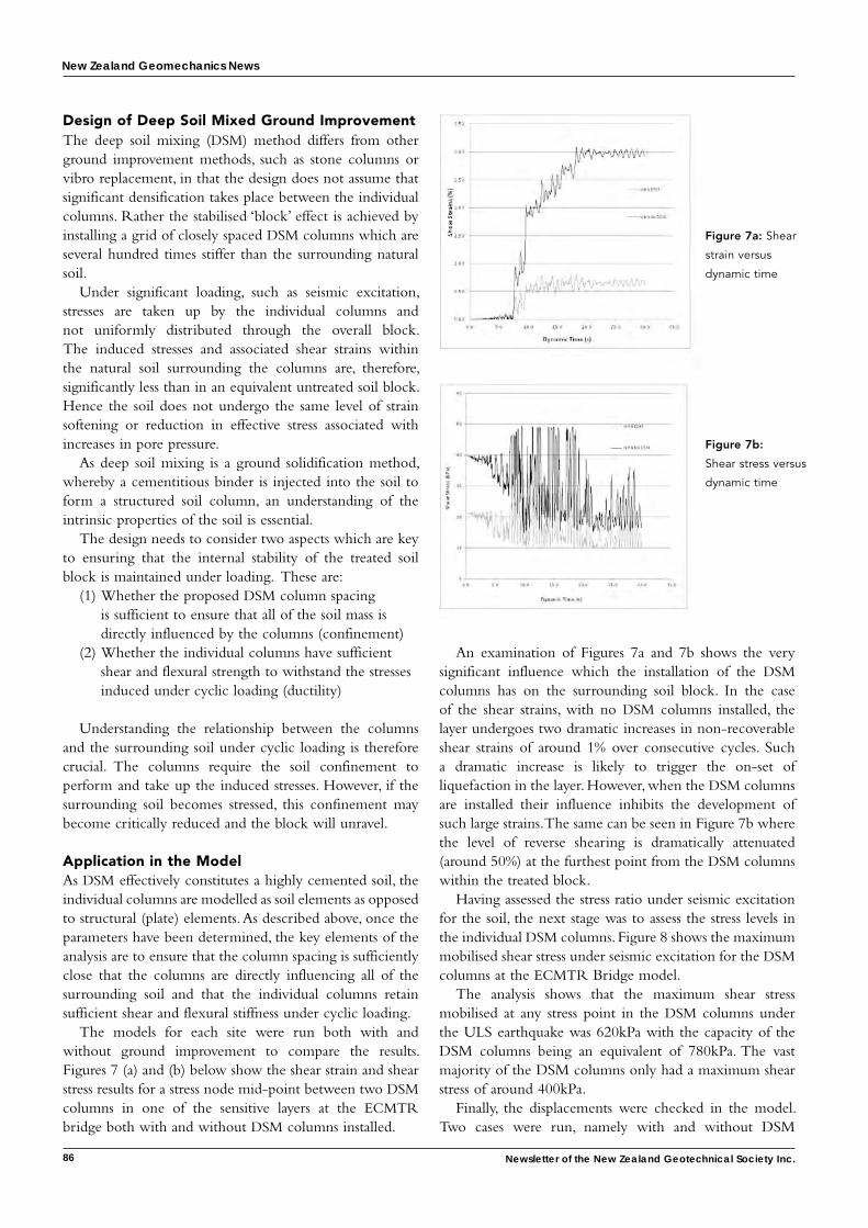
New Zealand Geomechanics News
86 Newsletter of the New Zealand Geotechnical Society Inc.
Design of Deep Soil Mixed Ground ImprovementThe deep soil mixing (DSM) method differs from other ground improvement methods, such as stone columns or vibro replacement, in that the design does not assume that significant densification takes place between the individual columns. Rather the stabilised ‘block’ effect is achieved by installing a grid of closely spaced DSM columns which are several hundred times stiffer than the surrounding natural soil.
Under significant loading, such as seismic excitation, stresses are taken up by the individual columns and not uniformly distributed through the overall block. The induced stresses and associated shear strains within the natural soil surrounding the columns are, therefore, significantly less than in an equivalent untreated soil block. Hence the soil does not undergo the same level of strain softening or reduction in effective stress associated with increases in pore pressure.
As deep soil mixing is a ground solidification method, whereby a cementitious binder is injected into the soil to form a structured soil column, an understanding of the intrinsic properties of the soil is essential.
The design needs to consider two aspects which are key to ensuring that the internal stability of the treated soil block is maintained under loading. These are:
(1) Whether the proposed DSM column spacing is sufficient to ensure that all of the soil mass is directly influenced by the columns (confinement)
(2) Whether the individual columns have sufficient shear and flexural strength to withstand the stresses induced under cyclic loading (ductility)
Understanding the relationship between the columns and the surrounding soil under cyclic loading is therefore crucial. The columns require the soil confinement to perform and take up the induced stresses. However, if the surrounding soil becomes stressed, this confinement may become critically reduced and the block will unravel.
Application in the ModelAs DSM effectively constitutes a highly cemented soil, the individual columns are modelled as soil elements as opposed to structural (plate) elements. As described above, once the parameters have been determined, the key elements of the analysis are to ensure that the column spacing is sufficiently close that the columns are directly influencing all of the surrounding soil and that the individual columns retain sufficient shear and flexural stiffness under cyclic loading.
The models for each site were run both with and without ground improvement to compare the results. Figures 7 (a) and (b) below show the shear strain and shear stress results for a stress node mid-point between two DSM columns in one of the sensitive layers at the ECMTR bridge both with and without DSM columns installed.
An examination of Figures 7a and 7b shows the very significant influence which the installation of the DSM columns has on the surrounding soil block. In the case of the shear strains, with no DSM columns installed, the layer undergoes two dramatic increases in non-recoverable shear strains of around 1% over consecutive cycles. Such a dramatic increase is likely to trigger the on-set of liquefaction in the layer. However, when the DSM columns are installed their influence inhibits the development of such large strains. The same can be seen in Figure 7b where the level of reverse shearing is dramatically attenuated (around 50%) at the furthest point from the DSM columns within the treated block.
Having assessed the stress ratio under seismic excitation for the soil, the next stage was to assess the stress levels in the individual DSM columns. Figure 8 shows the maximum mobilised shear stress under seismic excitation for the DSM columns at the ECMTR Bridge model.
The analysis shows that the maximum shear stress mobilised at any stress point in the DSM columns under the ULS earthquake was 620kPa with the capacity of the DSM columns being an equivalent of 780kPa. The vast majority of the DSM columns only had a maximum shear stress of around 400kPa.
Finally, the displacements were checked in the model. Two cases were run, namely with and without DSM
Figure 7a: Shear
strain versus
dynamic time
Figure 7b:
Shear stress versus
dynamic time
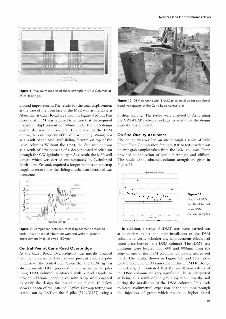
New Zealand Geomechanics News
87
ground improvement. The results for the total displacement at the base of the front face of the MSE wall at the Eastern Abutment at Carrs Road are shown in Figure 9 below. This shows that DSM was required to ensure that the required maximum displacement of 150mm under the ULS design earthquake was not exceeded. In the case of the DSM option, the vast majority of the displacement (138mm) was as a result of the MSE wall sliding forward on top of the DSM columns. Without the DSM, the displacement was as a result of development of a deeper seated mechanism through the CW ignimbrite layer. As a result, the MSE wall design, which was carried out separately by Reinforced Earth New Zealand, required a longer reinforcement strap length to ensure that the sliding mechanism identified was overcome.
Figure 9: Comparison between total displacement predicted
under ULS at base of Abutment with and without ground
improvement (max. allowed 150mm)
Central Pier at Carrs Road OverbridgeAt the Carrs Road Overbridge, it was initially planned to install a series of 450sq driven pre-cast concrete piles underneath the central pier. Given that the DSM rig was already on site, HGT proposed an alternative to the piles using DSM columns reinforced with a steel H-pile to provide additional bending capacity. Arup were engaged to verify the design for this element. Figure 10 below shows a photo of the installed H-piles. Capwap testing was carried out by T&T on the H-piles (310UC137), using a
Figure 8: Maximum mobilised shear strength in DSM Columns at
ECMTR Bridge.
6t drop hammer. The results were analysed by Arup using the GRLWEAP software package to verify that the design capacity was achieved.
On Site Quality AssuranceThe design was verified on site through a series of daily Unconfined Compression Strength (UCS) tests carried out on wet grab samples taken from the DSM columns. These provided an indication of obtained strength and stiffness. The results of the obtained column strength are given in Figure 11.
In addition, a series of sDMT tests were carried out
at both sites before and after installation of the DSM columns to verify whether any improvement effects had taken place between the DSM columns. The sDMT test positions were located 300, 600 and 900mm from the edge of one of the DSM columns within the treated soil block. The results, shown in Figure 12a and 12b below for the 300mm and 900mm offset at the ECMTR Bridge respectively, demonstrated that the installation effects of the DSM columns are very significant. This is interpreted as being as a result of the grout injection into the soil during the installation of the DSM columns. This leads to lateral (volumetric) expansion of the columns through the injection of grout which results in higher lateral
Figure 11:
Graph of UCS
results obtained
from DSM
column samples
Figure 10: DSM columns with 310UC piles installed for additional
bending capacity at the Carrs Road central pier
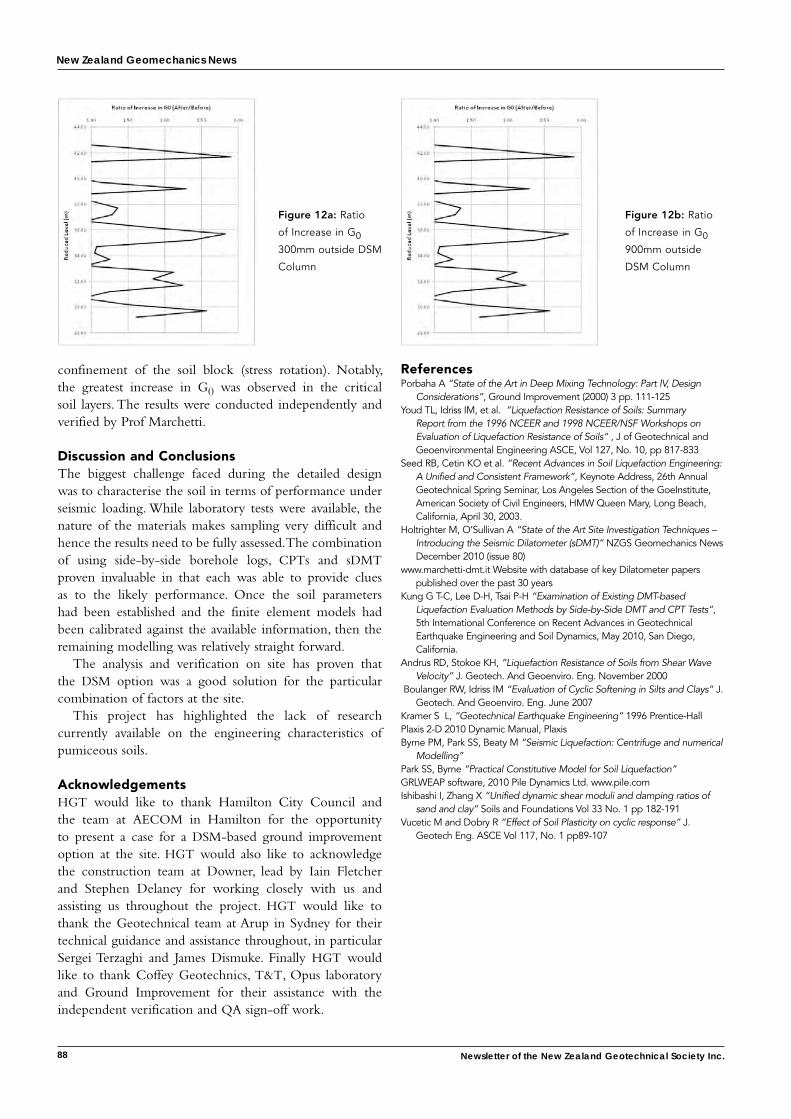
New Zealand Geomechanics News
88 Newsletter of the New Zealand Geotechnical Society Inc.
confinement of the soil block (stress rotation). Notably, the greatest increase in G0 was observed in the critical soil layers. The results were conducted independently and verified by Prof Marchetti.
Discussion and ConclusionsThe biggest challenge faced during the detailed design was to characterise the soil in terms of performance under seismic loading. While laboratory tests were available, the nature of the materials makes sampling very difficult and hence the results need to be fully assessed. The combination of using side-by-side borehole logs, CPTs and sDMT proven invaluable in that each was able to provide clues as to the likely performance. Once the soil parameters had been established and the finite element models had been calibrated against the available information, then the remaining modelling was relatively straight forward.
The analysis and verification on site has proven that the DSM option was a good solution for the particular combination of factors at the site.
This project has highlighted the lack of research currently available on the engineering characteristics of pumiceous soils.
AcknowledgementsHGT would like to thank Hamilton City Council and the team at AECOM in Hamilton for the opportunity to present a case for a DSM-based ground improvement option at the site. HGT would also like to acknowledge the construction team at Downer, lead by Iain Fletcher and Stephen Delaney for working closely with us and assisting us throughout the project. HGT would like to thank the Geotechnical team at Arup in Sydney for their technical guidance and assistance throughout, in particular Sergei Terzaghi and James Dismuke. Finally HGT would like to thank Coffey Geotechnics, T&T, Opus laboratory and Ground Improvement for their assistance with the independent verification and QA sign-off work.
ReferencesPorbaha A “State of the Art in Deep Mixing Technology: Part IV, Design
Considerations”, Ground Improvement (2000) 3 pp. 111-125Youd TL, Idriss IM, et al. ”Liquefaction Resistance of Soils: Summary
Report from the 1996 NCEER and 1998 NCEER/NSF Workshops on Evaluation of Liquefaction Resistance of Soils“ , J of Geotechnical and Geoenvironmental Engineering ASCE, Vol 127, No. 10, pp 817-833
Seed RB, Cetin KO et al. “Recent Advances in Soil Liquefaction Engineering: A Unified and Consistent Framework”, Keynote Address, 26th Annual Geotechnical Spring Seminar, Los Angeles Section of the GoeInstitute, American Society of Civil Engineers, HMW Queen Mary, Long Beach, California, April 30, 2003.
Holtrighter M, O’Sullivan A “State of the Art Site Investigation Techniques – Introducing the Seismic Dilatometer (sDMT)” NZGS Geomechanics News December 2010 (issue 80)
www.marchetti-dmt.it Website with database of key Dilatometer papers published over the past 30 years
Kung G T-C, Lee D-H, Tsai P-H “Examination of Existing DMT-based Liquefaction Evaluation Methods by Side-by-Side DMT and CPT Tests”, 5th International Conference on Recent Advances in Geotechnical Earthquake Engineering and Soil Dynamics, May 2010, San Diego, California.
Andrus RD, Stokoe KH, “Liquefaction Resistance of Soils from Shear Wave Velocity” J. Geotech. And Geoenviro. Eng. November 2000
Boulanger RW, Idriss IM “Evaluation of Cyclic Softening in Silts and Clays” J. Geotech. And Geoenviro. Eng. June 2007
Kramer S L, “Geotechnical Earthquake Engineering” 1996 Prentice-HallPlaxis 2-D 2010 Dynamic Manual, Plaxis Byrne PM, Park SS, Beaty M “Seismic Liquefaction: Centrifuge and numerical
Modelling” Park SS, Byrne “Practical Constitutive Model for Soil Liquefaction” GRLWEAP software, 2010 Pile Dynamics Ltd. www.pile.com Ishibashi I, Zhang X “Unified dynamic shear moduli and damping ratios of
sand and clay” Soils and Foundations Vol 33 No. 1 pp 182-191Vucetic M and Dobry R “Effect of Soil Plasticity on cyclic response” J.
Geotech Eng. ASCE Vol 117, No. 1 pp89-107
Figure 12a: Ratio
of Increase in G0
300mm outside DSM
Column
Figure 12b: Ratio
of Increase in G0
900mm outside
DSM Column
New Zealand Geomechanics News
89
Fifty Years of the ISRM and Associated Progress in Rock Mechanics – E.T.Brown – Senior Consultant, Golder Associates Pty Ltd, Brisbane
Abstract
The 12th Congress of the International Society for Rock Mechanics (ISRM) was held in Beijing, China, in October 2011 in the fiftieth year of the life of the Society which was established formally on 24 May 1962 in Salzburg, Austria. This paper which is a slightly revised version of one presented at the Congress (Brown, 2011), discusses the emergence of rock mechanics as a distinctive engineering and scientific discipline; the state and achievements of the discipline at the time the ISRM was founded in 1962; the events leading up to the formation of the Society; the development and achievements of the Society in the 50 years since 1962; and the progress made in the discipline of rock mechanics and rock engineering since that time.
1 IntroductionThe 12th Congress of the International Society for Rock Mechanics (ISRM) fell in the fiftieth year of the life of the ISRM which was established formally on 24 May 1962 in Salzburg, Austria (Fairhurst, 2010). The Congress therefore provided an important opportunity for the Society to recall its foundation, reflect on its achievements and on the progress made in our discipline in the 50 years since its formation, and to look forward to the next 50 years.
This paper attempts the rather large and complex task of reviewing and synthesising the emergence of rock mechanics as a distinctive engineering and scientific discipline, the state and achievements of the discipline at the time the ISRM was founded in 1962, the events leading up to the formation of the Society, the development and achievements of the Society in the 50 years since 1962, and finally, the progress made in the discipline since that time. Although too young to have been involved in the work of the Society in its earliest years before the First Congress held in Lisbon in 1966, the writer has followed the developments discussed here with keen interest for about 48 of these 50 years. He is honoured and delighted to have been invited by the Society’s President for 2007-2011, Professor John Hudson, to prepare and present his paper to the Congress (Brown, 2011). In a companion paper and lecture, Professor Hudson looked forward to the next 50 years of the Society and the discipline (Hudson, 2011).
Throughout this paper, the term rock mechanics will be used in the sense given in the ISRM Statutes: “The field of rock mechanics is taken to include all studies relative to the physical and mechanical behaviour of rocks and rock masses and the applications of this knowledge for the better understanding of geological processes and in the fields of engineering”. Thus, the
term rock mechanics generally will be taken to include rock engineering, although on occasion, the two may be expressed independently as in the now commonly used term, rock mechanics and rock engineering.
2 The World in 1962To begin, it is worth recalling what the world was like in 1962. In world politics, the Cold War was in full swing. The Premier of the then U.S.S.R, Nikita Kruschev, and the young President of the U.S.A., John F. Kennedy, were exercised over what became known as the Cuban missile crisis. Elsewhere, Harold Macmillan was the Prime Minster of the U.K., Charles de Gaulle was still the President of France, Jawaharlal Nehru was the Prime Minister of India and Chairman Mao Zedong was the leader of China. It has to be said that, at that time, the People’s Republic of China was not at all well known to those living in what is usually referred to as “the West”.
In culture – popular and otherwise – the American writer, John Steinbeck, won the Nobel Prize for Literature. There was an unhappy link to one of the life-long interests of the ISRM’s Founder and First President, Professor Leopold Müller, when the world-famous Austrian violinist, Fritz Kreisler, died on 29 January. In popular music, The Beatles released their first recording and The Rolling Stones made their public debut. In the writer’s favourite form of music – jazz – the pianist Herbie Hancock’s tune Watermelon Man topped not only the jazz charts but the popular music charts as well for several weeks in 1962.
In sport, Brazil won the World Cup in football; the New York Yankees won the World Series in baseball; the American golfer, Arnold Palmer, won his second consecutive British Open and his third U.S. Masters titles; and an Australian, Rod Laver, won the Grand Slam in tennis.
In science and technology, the first observation of laser activity was reported; the first practical light emitting diode was produced; the world’s first active telecommunications satellite, Telstar 1, was launched on 10 July; the felt-tipped pen came into being; and, although digital computing was in its infancy and the personal computer was still some years off, in a sign of things to come, the first computer game was developed for a PDP-1 computer.
3 The Emergence of Rock Mechanics as an Identifiable Discipline
The writer has argued previously that, by the early 1960s, the subject of rock mechanics, if it wasn’t yet fully
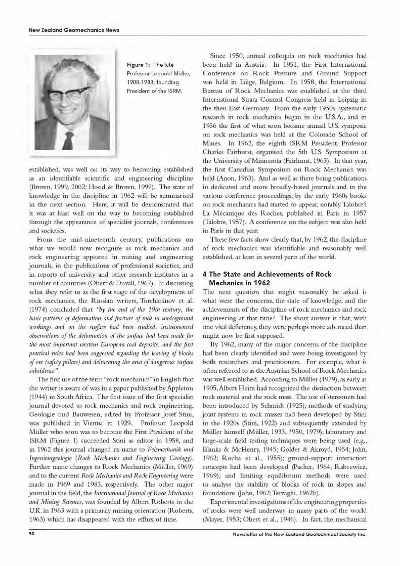
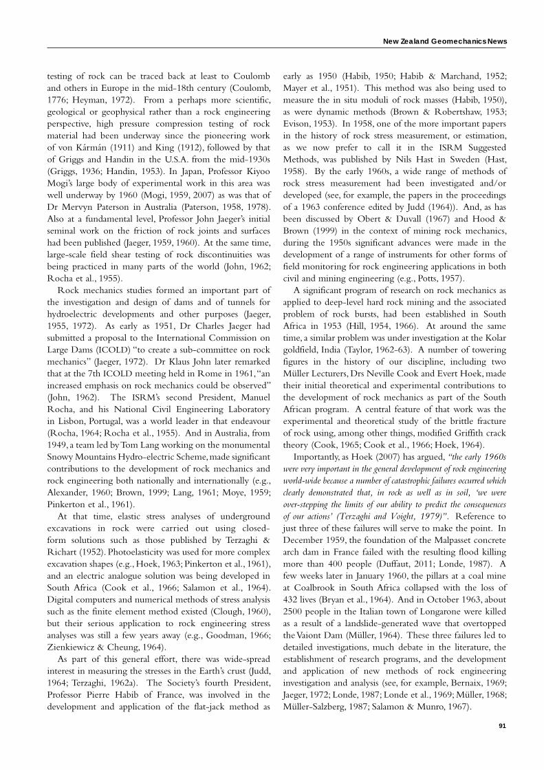
New Zealand Geomechanics News
91
testing of rock can be traced back at least to Coulomb and others in Europe in the mid-18th century (Coulomb, 1776; Heyman, 1972). From a perhaps more scientific, geological or geophysical rather than a rock engineering perspective, high pressure compression testing of rock material had been underway since the pioneering work of von Kármán (1911) and King (1912), followed by that of Griggs and Handin in the U.S.A. from the mid-1930s (Griggs, 1936; Handin, 1953). In Japan, Professor Kiyoo Mogi’s large body of experimental work in this area was well underway by 1960 (Mogi, 1959, 2007) as was that of Dr Mervyn Paterson in Australia (Paterson, 1958, 1978). Also at a fundamental level, Professor John Jaeger’s initial seminal work on the friction of rock joints and surfaces had been published (Jaeger, 1959, 1960). At the same time, large-scale field shear testing of rock discontinuities was being practiced in many parts of the world (John, 1962; Rocha et al., 1955).
Rock mechanics studies formed an important part of the investigation and design of dams and of tunnels for hydroelectric developments and other purposes (Jaeger, 1955, 1972). As early as 1951, Dr Charles Jaeger had submitted a proposal to the International Commission on Large Dams (ICOLD) “to create a sub-committee on rock mechanics” (Jaeger, 1972). Dr Klaus John later remarked that at the 7th ICOLD meeting held in Rome in 1961, “an increased emphasis on rock mechanics could be observed” (John, 1962). The ISRM’s second President, Manuel Rocha, and his National Civil Engineering Laboratory in Lisbon, Portugal, was a world leader in that endeavour (Rocha, 1964; Rocha et al., 1955). And in Australia, from 1949, a team led by Tom Lang working on the monumental Snowy Mountains Hydro-electric Scheme, made significant contributions to the development of rock mechanics and rock engineering both nationally and internationally (e.g., Alexander, 1960; Brown, 1999; Lang, 1961; Moye, 1959; Pinkerton et al., 1961).
At that time, elastic stress analyses of underground excavations in rock were carried out using closed-form solutions such as those published by Terzaghi & Richart (1952). Photoelasticity was used for more complex excavation shapes (e.g., Hoek, 1963; Pinkerton et al., 1961), and an electric analogue solution was being developed in South Africa (Cook et al., 1966; Salamon et al., 1964). Digital computers and numerical methods of stress analysis such as the finite element method existed (Clough, 1960), but their serious application to rock engineering stress analyses was still a few years away (e.g., Goodman, 1966; Zienkiewicz & Cheung, 1964).
As part of this general effort, there was wide-spread interest in measuring the stresses in the Earth’s crust (Judd, 1964; Terzaghi, 1962a). The Society’s fourth President, Professor Pierre Habib of France, was involved in the development and application of the flat-jack method as
early as 1950 (Habib, 1950; Habib & Marchand, 1952; Mayer et al., 1951). This method was also being used to measure the in situ moduli of rock masses (Habib, 1950), as were dynamic methods (Brown & Robertshaw, 1953; Evison, 1953). In 1958, one of the more important papers in the history of rock stress measurement, or estimation, as we now prefer to call it in the ISRM Suggested Methods, was published by Nils Hast in Sweden (Hast, 1958). By the early 1960s, a wide range of methods of rock stress measurement had been investigated and/or developed (see, for example, the papers in the proceedings of a 1963 conference edited by Judd (1964)). And, as has been discussed by Obert & Duvall (1967) and Hood & Brown (1999) in the context of mining rock mechanics, during the 1950s significant advances were made in the development of a range of instruments for other forms of field monitoring for rock engineering applications in both civil and mining engineering (e.g., Potts, 1957).
A significant program of research on rock mechanics as applied to deep-level hard rock mining and the associated problem of rock bursts, had been established in South Africa in 1953 (Hill, 1954, 1966). At around the same time, a similar problem was under investigation at the Kolar goldfield, India (Taylor, 1962-63). A number of towering figures in the history of our discipline, including two Müller Lecturers, Drs Neville Cook and Evert Hoek, made their initial theoretical and experimental contributions to the development of rock mechanics as part of the South African program. A central feature of that work was the experimental and theoretical study of the brittle fracture of rock using, among other things, modified Griffith crack theory (Cook, 1965; Cook et al., 1966; Hoek, 1964).
Importantly, as Hoek (2007) has argued, “the early 1960s were very important in the general development of rock engineering world-wide because a number of catastrophic failures occurred which clearly demonstrated that, in rock as well as in soil, ‘we were over-stepping the limits of our ability to predict the consequences of our actions’ (Terzaghi and Voight, 1979)”. Reference to just three of these failures will serve to make the point. In December 1959, the foundation of the Malpasset concrete arch dam in France failed with the resulting flood killing more than 400 people (Duffaut, 2011; Londe, 1987). A few weeks later in January 1960, the pillars at a coal mine at Coalbrook in South Africa collapsed with the loss of 432 lives (Bryan et al., 1964). And in October 1963, about 2500 people in the Italian town of Longarone were killed as a result of a landslide-generated wave that overtopped the Vaiont Dam (Müller, 1964). These three failures led to detailed investigations, much debate in the literature, the establishment of research programs, and the development and application of new methods of rock engineering investigation and analysis (see, for example, Bernaix, 1969; Jaeger, 1972; Londe, 1987; Londe et al., 1969; Müller, 1968; Müller-Salzberg, 1987; Salamon & Munro, 1967).
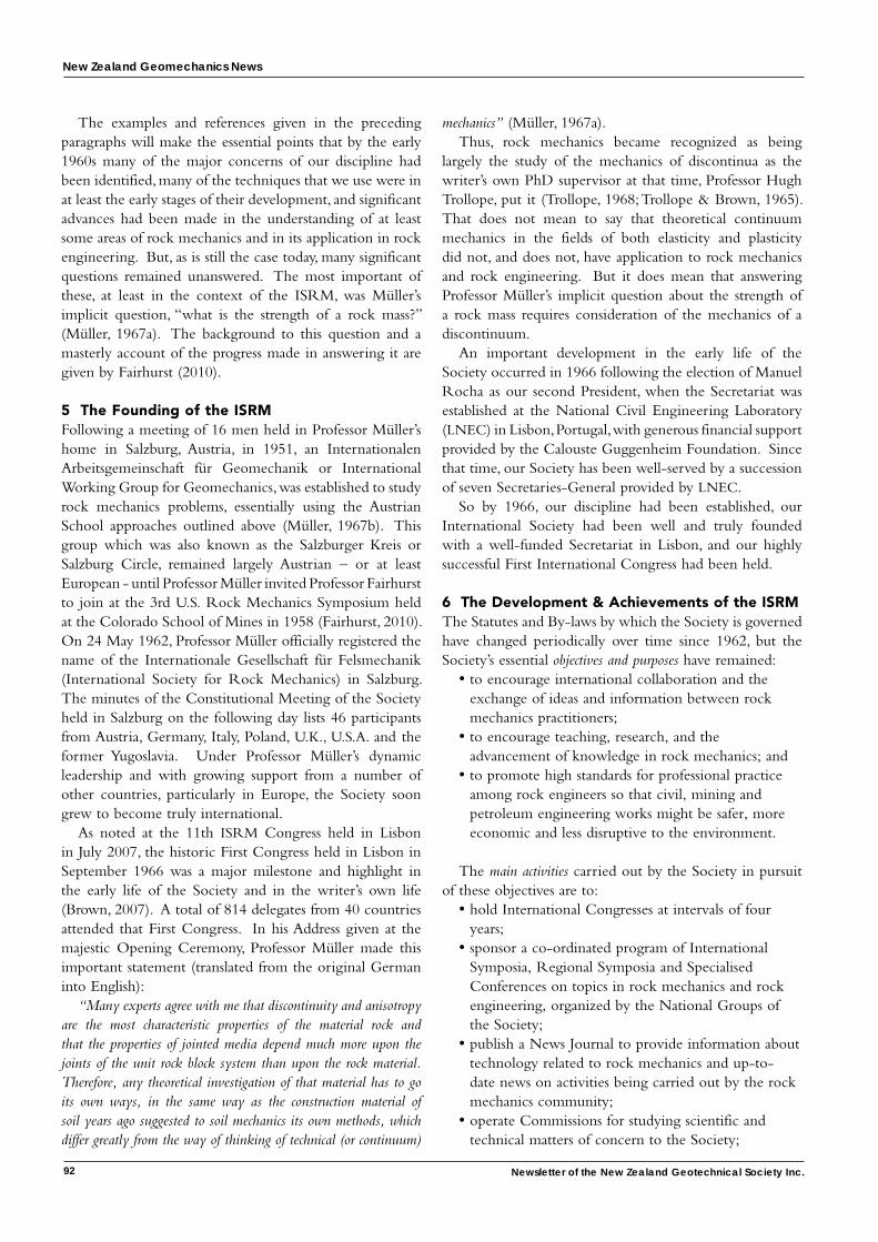
New Zealand Geomechanics News
92 Newsletter of the New Zealand Geotechnical Society Inc.
The examples and references given in the preceding paragraphs will make the essential points that by the early 1960s many of the major concerns of our discipline had been identified, many of the techniques that we use were in at least the early stages of their development, and significant advances had been made in the understanding of at least some areas of rock mechanics and in its application in rock engineering. But, as is still the case today, many significant questions remained unanswered. The most important of these, at least in the context of the ISRM, was Müller’s implicit question, “what is the strength of a rock mass?” (Müller, 1967a). The background to this question and a masterly account of the progress made in answering it are given by Fairhurst (2010).
5 The founding of the ISRMFollowing a meeting of 16 men held in Professor Müller’s home in Salzburg, Austria, in 1951, an Internationalen Arbeitsgemeinschaft für Geomechanik or International Working Group for Geomechanics, was established to study rock mechanics problems, essentially using the Austrian School approaches outlined above (Müller, 1967b). This group which was also known as the Salzburger Kreis or Salzburg Circle, remained largely Austrian – or at least European - until Professor Müller invited Professor Fairhurst to join at the 3rd U.S. Rock Mechanics Symposium held at the Colorado School of Mines in 1958 (Fairhurst, 2010). On 24 May 1962, Professor Müller officially registered the name of the Internationale Gesellschaft für Felsmechanik (International Society for Rock Mechanics) in Salzburg. The minutes of the Constitutional Meeting of the Society held in Salzburg on the following day lists 46 participants from Austria, Germany, Italy, Poland, U.K., U.S.A. and the former Yugoslavia. Under Professor Müller’s dynamic leadership and with growing support from a number of other countries, particularly in Europe, the Society soon grew to become truly international.
As noted at the 11th ISRM Congress held in Lisbon in July 2007, the historic First Congress held in Lisbon in September 1966 was a major milestone and highlight in the early life of the Society and in the writer’s own life (Brown, 2007). A total of 814 delegates from 40 countries attended that First Congress. In his Address given at the majestic Opening Ceremony, Professor Müller made this important statement (translated from the original German into English):
“Many experts agree with me that discontinuity and anisotropy are the most characteristic properties of the material rock and that the properties of jointed media depend much more upon the joints of the unit rock block system than upon the rock material. Therefore, any theoretical investigation of that material has to go its own ways, in the same way as the construction material of soil years ago suggested to soil mechanics its own methods, which differ greatly from the way of thinking of technical (or continuum)
mechanics” (Müller, 1967a).Thus, rock mechanics became recognized as being
largely the study of the mechanics of discontinua as the writer’s own PhD supervisor at that time, Professor Hugh Trollope, put it (Trollope, 1968; Trollope & Brown, 1965). That does not mean to say that theoretical continuum mechanics in the fields of both elasticity and plasticity did not, and does not, have application to rock mechanics and rock engineering. But it does mean that answering Professor Müller’s implicit question about the strength of a rock mass requires consideration of the mechanics of a discontinuum.
An important development in the early life of the Society occurred in 1966 following the election of Manuel Rocha as our second President, when the Secretariat was established at the National Civil Engineering Laboratory (LNEC) in Lisbon, Portugal, with generous financial support provided by the Calouste Guggenheim Foundation. Since that time, our Society has been well-served by a succession of seven Secretaries-General provided by LNEC.
So by 1966, our discipline had been established, our International Society had been well and truly founded with a well-funded Secretariat in Lisbon, and our highly successful First International Congress had been held.
6 The Development & Achievements of the ISRMThe Statutes and By-laws by which the Society is governed have changed periodically over time since 1962, but the Society’s essential objectives and purposes have remained:
• to encourage international collaboration and the exchange of ideas and information between rock mechanics practitioners;
• to encourage teaching, research, and the advancement of knowledge in rock mechanics; and
• to promote high standards for professional practice among rock engineers so that civil, mining and petroleum engineering works might be safer, more economic and less disruptive to the environment.
The main activities carried out by the Society in pursuit of these objectives are to:
• hold International Congresses at intervals of four years;
• sponsor a co-ordinated program of International Symposia, Regional Symposia and Specialised Conferences on topics in rock mechanics and rock engineering, organized by the National Groups of the Society;
• publish a News Journal to provide information about technology related to rock mechanics and up-to-date news on activities being carried out by the rock mechanics community;
• operate Commissions for studying scientific and technical matters of concern to the Society;
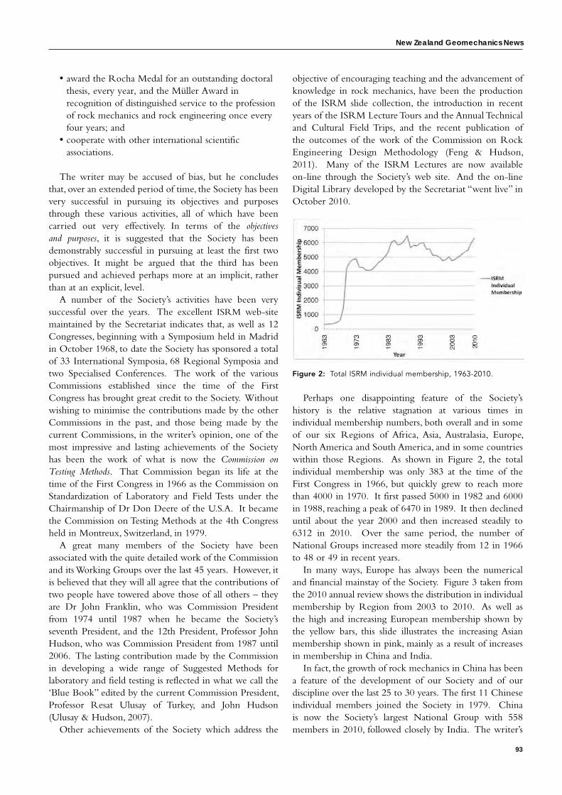
New Zealand Geomechanics News
93
• award the Rocha Medal for an outstanding doctoral thesis, every year, and the Müller Award in recognition of distinguished service to the profession of rock mechanics and rock engineering once every four years; and
• cooperate with other international scientific associations.
The writer may be accused of bias, but he concludes that, over an extended period of time, the Society has been very successful in pursuing its objectives and purposes through these various activities, all of which have been carried out very effectively. In terms of the objectives and purposes, it is suggested that the Society has been demonstrably successful in pursuing at least the first two objectives. It might be argued that the third has been pursued and achieved perhaps more at an implicit, rather than at an explicit, level.
A number of the Society’s activities have been very successful over the years. The excellent ISRM web-site maintained by the Secretariat indicates that, as well as 12 Congresses, beginning with a Symposium held in Madrid in October 1968, to date the Society has sponsored a total of 33 International Symposia, 68 Regional Symposia and two Specialised Conferences. The work of the various Commissions established since the time of the First Congress has brought great credit to the Society. Without wishing to minimise the contributions made by the other Commissions in the past, and those being made by the current Commissions, in the writer’s opinion, one of the most impressive and lasting achievements of the Society has been the work of what is now the Commission on Testing Methods. That Commission began its life at the time of the First Congress in 1966 as the Commission on Standardization of Laboratory and Field Tests under the Chairmanship of Dr Don Deere of the U.S.A. It became the Commission on Testing Methods at the 4th Congress held in Montreux, Switzerland, in 1979.
A great many members of the Society have been associated with the quite detailed work of the Commission and its Working Groups over the last 45 years. However, it is believed that they will all agree that the contributions of two people have towered above those of all others – they are Dr John Franklin, who was Commission President from 1974 until 1987 when he became the Society’s seventh President, and the 12th President, Professor John Hudson, who was Commission President from 1987 until 2006. The lasting contribution made by the Commission in developing a wide range of Suggested Methods for laboratory and field testing is reflected in what we call the ‘Blue Book” edited by the current Commission President, Professor Resat Ulusay of Turkey, and John Hudson (Ulusay & Hudson, 2007).
Other achievements of the Society which address the
objective of encouraging teaching and the advancement of knowledge in rock mechanics, have been the production of the ISRM slide collection, the introduction in recent years of the ISRM Lecture Tours and the Annual Technical and Cultural Field Trips, and the recent publication of the outcomes of the work of the Commission on Rock Engineering Design Methodology (Feng & Hudson, 2011). Many of the ISRM Lectures are now available on-line through the Society’s web site. And the on-line Digital Library developed by the Secretariat “went live” in October 2010.
Figure 2: Total ISRM individual membership, 1963-2010.
Perhaps one disappointing feature of the Society’s history is the relative stagnation at various times in individual membership numbers, both overall and in some of our six Regions of Africa, Asia, Australasia, Europe, North America and South America, and in some countries within those Regions. As shown in Figure 2, the total individual membership was only 383 at the time of the First Congress in 1966, but quickly grew to reach more than 4000 in 1970. It first passed 5000 in 1982 and 6000 in 1988, reaching a peak of 6470 in 1989. It then declined until about the year 2000 and then increased steadily to 6312 in 2010. Over the same period, the number of National Groups increased more steadily from 12 in 1966 to 48 or 49 in recent years.
In many ways, Europe has always been the numerical and financial mainstay of the Society. Figure 3 taken from the 2010 annual review shows the distribution in individual membership by Region from 2003 to 2010. As well as the high and increasing European membership shown by the yellow bars, this slide illustrates the increasing Asian membership shown in pink, mainly as a result of increases in membership in China and India.
In fact, the growth of rock mechanics in China has been a feature of the development of our Society and of our discipline over the last 25 to 30 years. The first 11 Chinese individual members joined the Society in 1979. China is now the Society’s largest National Group with 558 members in 2010, followed closely by India. The writer’s
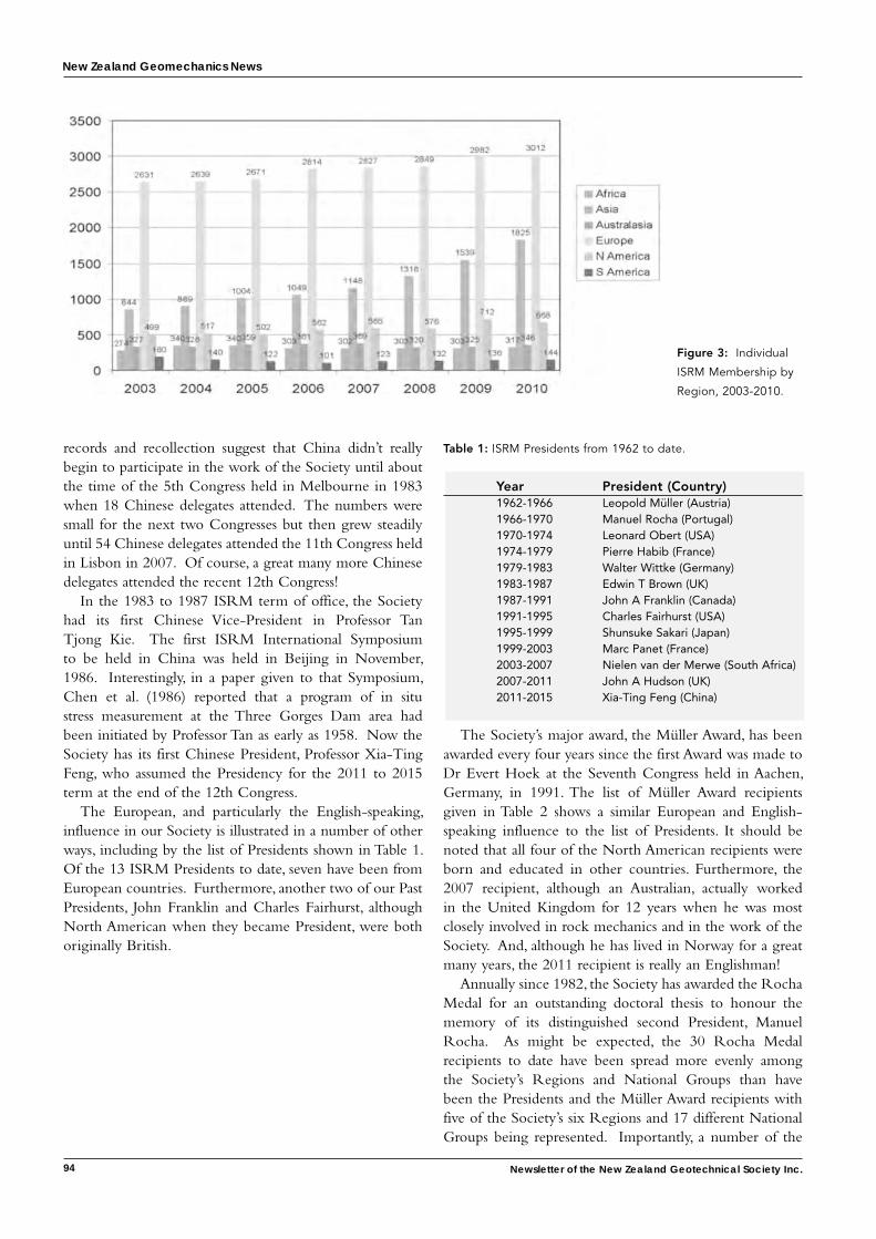
New Zealand Geomechanics News
94 Newsletter of the New Zealand Geotechnical Society Inc.
records and recollection suggest that China didn’t really begin to participate in the work of the Society until about the time of the 5th Congress held in Melbourne in 1983 when 18 Chinese delegates attended. The numbers were small for the next two Congresses but then grew steadily until 54 Chinese delegates attended the 11th Congress held in Lisbon in 2007. Of course, a great many more Chinese delegates attended the recent 12th Congress!
In the 1983 to 1987 ISRM term of office, the Society had its first Chinese Vice-President in Professor Tan Tjong Kie. The first ISRM International Symposium to be held in China was held in Beijing in November, 1986. Interestingly, in a paper given to that Symposium, Chen et al. (1986) reported that a program of in situ stress measurement at the Three Gorges Dam area had been initiated by Professor Tan as early as 1958. Now the Society has its first Chinese President, Professor Xia-Ting Feng, who assumed the Presidency for the 2011 to 2015 term at the end of the 12th Congress.
The European, and particularly the English-speaking, influence in our Society is illustrated in a number of other ways, including by the list of Presidents shown in Table 1. Of the 13 ISRM Presidents to date, seven have been from European countries. Furthermore, another two of our Past Presidents, John Franklin and Charles Fairhurst, although North American when they became President, were both originally British.
Table 1: ISRM Presidents from 1962 to date.
Year President (Country) 1962-1966 Leopold Müller (Austria) 1966-1970 Manuel Rocha (Portugal) 1970-1974 Leonard Obert (USA) 1974-1979 Pierre Habib (France) 1979-1983 Walter Wittke (Germany) 1983-1987 Edwin T Brown (UK) 1987-1991 John A Franklin (Canada) 1991-1995 Charles Fairhurst (USA) 1995-1999 Shunsuke Sakari (Japan) 1999-2003 Marc Panet (France) 2003-2007 Nielen van der Merwe (South Africa) 2007-2011 John A Hudson (UK) 2011-2015 Xia-Ting Feng (China)
The Society’s major award, the Müller Award, has been awarded every four years since the first Award was made to Dr Evert Hoek at the Seventh Congress held in Aachen, Germany, in 1991. The list of Müller Award recipients given in Table 2 shows a similar European and English-speaking influence to the list of Presidents. It should be noted that all four of the North American recipients were born and educated in other countries. Furthermore, the 2007 recipient, although an Australian, actually worked in the United Kingdom for 12 years when he was most closely involved in rock mechanics and in the work of the Society. And, although he has lived in Norway for a great many years, the 2011 recipient is really an Englishman!
Annually since 1982, the Society has awarded the Rocha Medal for an outstanding doctoral thesis to honour the memory of its distinguished second President, Manuel Rocha. As might be expected, the 30 Rocha Medal recipients to date have been spread more evenly among the Society’s Regions and National Groups than have been the Presidents and the Müller Award recipients with five of the Society’s six Regions and 17 different National Groups being represented. Importantly, a number of the
Figure 3: Individual
ISRM Membership by
Region, 2003-2010.
New Zealand Geomechanics News
95
Rocha Medal recipients have gone on to become senior and important figures in the discipline and in the Society.
Table 2: Müller Award recipients, 1991 – 2011.
Year Award Recipient 1991 Evert Hoek (Canada) 1995 Neville G W Cook (USA) 1999 Herbert H Einstein (USA) 2003 Charles Fairhurst (USA) 2007 Edwin T Brown (Australia) 2011 Nicholas R Barton (Norway)
It can be concluded, therefore, that during the first 50 years of its life, the ISRM has pursued its stated objectives and purposes conscientiously by carrying out all of its main activities at least satisfactorily, with some being carried out to considerable effect.
7 Developements and Progress in Rock Mechanics
7.1 ScopeThe task of making assessments of the main developments and the progress made in rock mechanics and rock engineering in the 50 years since the ISRM was established is a most challenging one. It is inevitable that any account such as that attempted here will reflect the writer’s personal interests, knowledge and experience, and so, to at least some extent, will be idiosyncratic. It is also inevitable that, for much the same reasons, some important contributions made by some individuals and in some countries will be overlooked. In such cases, the writer offers his apologies. The references given for each of the advances listed under sub-headings 7.2 to 7.6 below are intended to provide examples of the significant contributions made to the various topics or techniques being discussed and are not intended to be either exhaustive or definitive. The references given are, quite simply, those known and available to the writer at the time of writing.
In making an assessment such as that reported here, it is first necessary to establish a framework within which the assessment will be made and the results summarised. The framework used here is the simplified general rock engineering process used by a number of authors (e.g., Brady & Brown, 2004; Hudson & Feng, 2007; Read & Stacey, 2009) as represented by the headings of sub-sections 7.2 to 7.6. This generalised process is necessarily simplified so that it can be adapted to apply to a wide range of rock engineering activities and applications. It should be emphasised that, in practice, the process is not linear but includes parallel activities and multiple feed-back loops. Figure 4 shows a rock mechanics modelling and rock engineering design flowchart which provides more detail of the design analysis stage of the overall process.
7.2 Site Investigation and Site CharacterisationAdequate site investigation and geological, geotechnical and hydro-geological site characterisation remains at the core of any successful rock engineering project. As was suggested in Section 4, the fundamentals and basic techniques of site investigation and site characterisation were established by the time the ISRM was founded. However, since that time, significant advances have been made in a number of relevant areas such as:
• drilling and borehole logging technologies, including core orientation methods and a range of geophysical logging techniques such as the Acoustic Televiewer (ATV) (Brown, 2007a; Takahashi et al., 2006);
• geophysical methods of site investigation, including seismic reflection, refraction and cross-hole tomography (Barton, 2006; Takahashi, 2004; Takahashi et al., 2006);• methods of discontinuity data collection using
photogrammetric, remote sensing, laser scanning and 3D digital imaging technologies (Gaich et al., 2007; Grobler et al., 2003; Read & Stacey, 2009; Slob et al., 2007);
• methods of carrying out and interpreting hydro-geological characterisation tests (Elsworth & Mase, 1993; Louis, 1974);
• modern rock mass classification schemes developed from the early 1970s (Barton, 2006; Barton et al., 1974; Bieniawski, 1976, 1989; Hoek, 1994; Marinos et al., 2007);
• understanding the statistics of discontinuity systems (Billaux et al., 1989; Dershowitz & Einstein, 1988; Priest, 2004; Priest & Hudson, 1981; Zhang et al., 2002) and the application of this knowledge in tools such as Discrete Fracture Network (DFN) simulations (Dershowitz, 1995; Rogers et al., 2010);
• the 3D representation of site geology, structures and geotechnical domains using engineering design and mine planning software (Beer, 2010); and
• methods of in situ stress estimation, although this process remains fraught with difficulty (Amadei & Stephansson, 1997; Fairhurst, 2003; Hudson et al., 2003).
For a range of reasons, one area of site investigation that has not developed to any great extent in the period since the early 1960s is in situ testing. Despite the range of tools now available to assist in the overall site investigation and site characterisation process, the writer’s recent experience on some projects has been that basic core logging skills and the training provided for that important task sometimes leave much to be desired.
7.3 Rock and Rock Mass PropertiesKey developments in the general area of estimating the
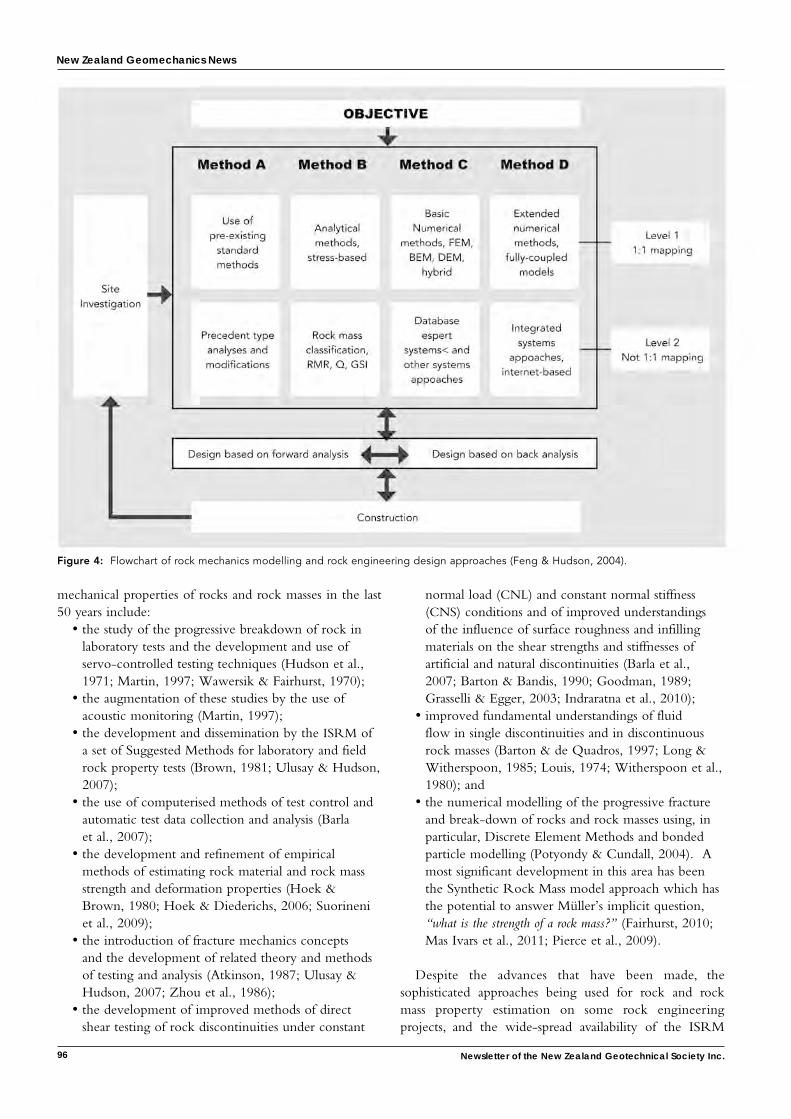
New Zealand Geomechanics News
96 Newsletter of the New Zealand Geotechnical Society Inc.
mechanical properties of rocks and rock masses in the last 50 years include:
• the study of the progressive breakdown of rock in laboratory tests and the development and use of servo-controlled testing techniques (Hudson et al., 1971; Martin, 1997; Wawersik & Fairhurst, 1970);
• the augmentation of these studies by the use of acoustic monitoring (Martin, 1997);
• the development and dissemination by the ISRM of a set of Suggested Methods for laboratory and field rock property tests (Brown, 1981; Ulusay & Hudson, 2007);
• the use of computerised methods of test control and automatic test data collection and analysis (Barla et al., 2007);
• the development and refinement of empirical methods of estimating rock material and rock mass strength and deformation properties (Hoek & Brown, 1980; Hoek & Diederichs, 2006; Suorineni et al., 2009);
• the introduction of fracture mechanics concepts and the development of related theory and methods of testing and analysis (Atkinson, 1987; Ulusay & Hudson, 2007; Zhou et al., 1986);
• the development of improved methods of direct shear testing of rock discontinuities under constant
normal load (CNL) and constant normal stiffness (CNS) conditions and of improved understandings of the influence of surface roughness and infilling materials on the shear strengths and stiffnesses of artificial and natural discontinuities (Barla et al., 2007; Barton & Bandis, 1990; Goodman, 1989; Grasselli & Egger, 2003; Indraratna et al., 2010);
• improved fundamental understandings of fluid flow in single discontinuities and in discontinuous rock masses (Barton & de Quadros, 1997; Long & Witherspoon, 1985; Louis, 1974; Witherspoon et al., 1980); and
• the numerical modelling of the progressive fracture and break-down of rocks and rock masses using, in particular, Discrete Element Methods and bonded particle modelling (Potyondy & Cundall, 2004). A most significant development in this area has been the Synthetic Rock Mass model approach which has the potential to answer Müller’s implicit question, “what is the strength of a rock mass?” (Fairhurst, 2010; Mas Ivars et al., 2011; Pierce et al., 2009).
Despite the advances that have been made, the sophisticated approaches being used for rock and rock mass property estimation on some rock engineering projects, and the wide-spread availability of the ISRM
Figure 4: Flowchart of rock mechanics modelling and rock engineering design approaches (Feng & Hudson, 2004).
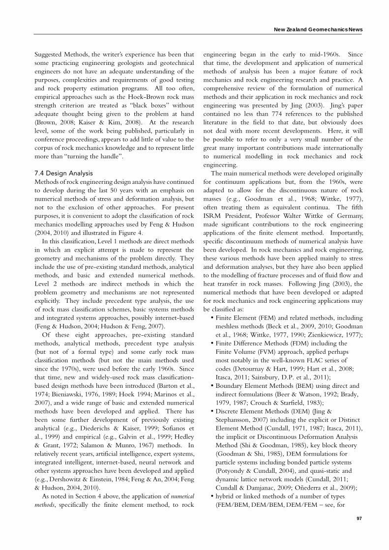
New Zealand Geomechanics News
97
Suggested Methods, the writer’s experience has been that some practicing engineering geologists and geotechnical engineers do not have an adequate understanding of the purposes, complexities and requirements of good testing and rock property estimation programs. All too often, empirical approaches such as the Hoek-Brown rock mass strength criterion are treated as “black boxes” without adequate thought being given to the problem at hand (Brown, 2008; Kaiser & Kim, 2008). At the research level, some of the work being published, particularly in conference proceedings, appears to add little of value to the corpus of rock mechanics knowledge and to represent little more than “turning the handle”.
7.4 Design AnalysisMethods of rock engineering design analysis have continued to develop during the last 50 years with an emphasis on numerical methods of stress and deformation analysis, but not to the exclusion of other approaches. For present purposes, it is convenient to adopt the classification of rock mechanics modelling approaches used by Feng & Hudson (2004, 2010) and illustrated in Figure 4.
In this classification, Level 1 methods are direct methods in which an explicit attempt is made to represent the geometry and mechanisms of the problem directly. They include the use of pre-existing standard methods, analytical methods, and basic and extended numerical methods. Level 2 methods are indirect methods in which the problem geometry and mechanisms are not represented explicitly. They include precedent type analysis, the use of rock mass classification schemes, basic systems methods and integrated systems approaches, possibly internet-based (Feng & Hudson, 2004; Hudson & Feng, 2007).
Of these eight approaches, pre-existing standard methods, analytical methods, precedent type analysis (but not of a formal type) and some early rock mass classification methods (but not the main methods used since the 1970s), were used before the early 1960s. Since that time, new and widely-used rock mass classification-based design methods have been introduced (Barton et al., 1974; Bieniawski, 1976, 1989; Hoek 1994; Marinos et al., 2007), and a wide range of basic and extended numerical methods have been developed and applied. There has been some further development of previously existing analytical (e.g., Diederichs & Kaiser, 1999; Sofianos et al., 1999) and empirical (e.g., Galvin et al., 1999; Hedley & Grant, 1972; Salamon & Munro, 1967) methods. In relatively recent years, artificial intelligence, expert systems, integrated intelligent, internet-based, neural network and other systems approaches have been developed and applied (e.g., Dershowitz & Einstein, 1984; Feng & An, 2004; Feng & Hudson, 2004, 2010).
As noted in Section 4 above, the application of numerical methods, specifically the finite element method, to rock
engineering began in the early to mid-1960s. Since that time, the development and application of numerical methods of analysis has been a major feature of rock mechanics and rock engineering research and practice. A comprehensive review of the formulation of numerical methods and their application in rock mechanics and rock engineering was presented by Jing (2003). Jing’s paper contained no less than 774 references to the published literature in the field to that date, but obviously does not deal with more recent developments. Here, it will be possible to refer to only a very small number of the great many important contributions made internationally to numerical modelling in rock mechanics and rock engineering.
The main numerical methods were developed originally for continuum applications but, from the 1960s, were adapted to allow for the discontinuous nature of rock masses (e.g., Goodman et al., 1968; Wittke, 1977), often treating them as equivalent continua. The fifth ISRM President, Professor Walter Wittke of Germany, made significant contributions to the rock engineering applications of the finite element method. Importantly, specific discontinuum methods of numerical analysis have been developed. In rock mechanics and rock engineering, these various methods have been applied mainly to stress and deformation analyses, but they have also been applied to the modelling of fracture processes and of fluid flow and heat transfer in rock masses. Following Jing (2003), the numerical methods that have been developed or adapted for rock mechanics and rock engineering applications may be classified as:
• Finite Element (FEM) and related methods, including meshless methods (Beck et al., 2009, 2010; Goodman et al., 1968; Wittke, 1977, 1990; Zienkiewicz, 1977);
• Finite Difference Methods (FDM) including the Finite Volume (FVM) approach, applied perhaps most notably in the well-known FLAC series of codes (Detournay & Hart, 1999; Hart et al., 2008; Itasca, 2011; Sainsbury, D.P. et al., 2011);
• Boundary Element Methods (BEM) using direct and indirect formulations (Beer & Watson, 1992; Brady, 1979, 1987; Crouch & Starfield, 1983);
• Discrete Element Methods (DEM) (Jing & Stephansson, 2007) including the explicit or Distinct Element Method (Cundall, 1971, 1987; Itasca, 2011), the implicit or Discontinuous Deformation Analysis Method (Shi & Goodman, 1985), key block theory (Goodman & Shi, 1985), DEM formulations for particle systems including bonded particle systems (Potyondy & Cundall, 2004), and quasi-static and dynamic lattice network models (Cundall, 2011; Cundall & Damjanac, 2009; Oñederra et al., 2009);
• hybrid or linked methods of a number of types (FEM/BEM, DEM/BEM, DEM/FEM – see, for
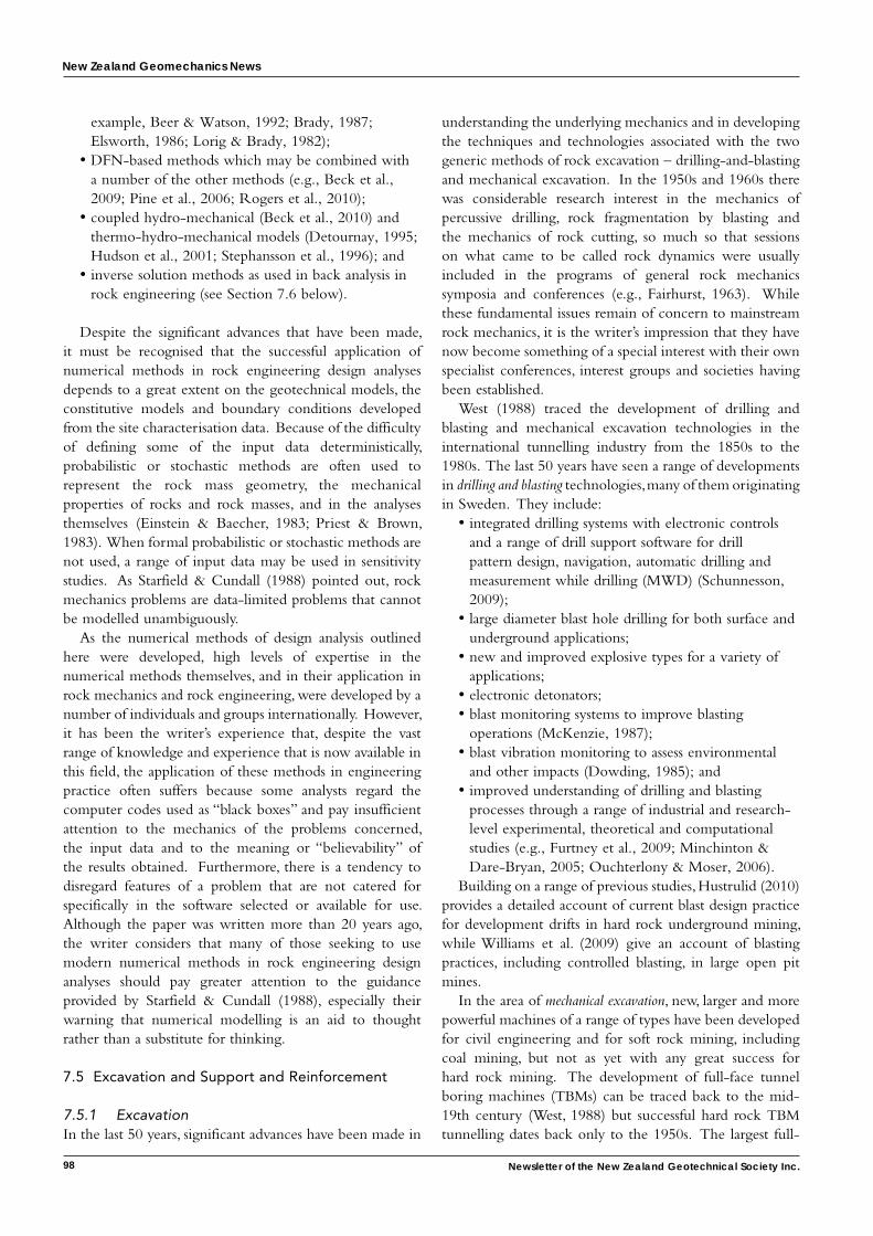
New Zealand Geomechanics News
98 Newsletter of the New Zealand Geotechnical Society Inc.
example, Beer & Watson, 1992; Brady, 1987; Elsworth, 1986; Lorig & Brady, 1982);
• DFN-based methods which may be combined with a number of the other methods (e.g., Beck et al., 2009; Pine et al., 2006; Rogers et al., 2010);
• coupled hydro-mechanical (Beck et al., 2010) and thermo-hydro-mechanical models (Detournay, 1995; Hudson et al., 2001; Stephansson et al., 1996); and
• inverse solution methods as used in back analysis in rock engineering (see Section 7.6 below).
Despite the significant advances that have been made, it must be recognised that the successful application of numerical methods in rock engineering design analyses depends to a great extent on the geotechnical models, the constitutive models and boundary conditions developed from the site characterisation data. Because of the difficulty of defining some of the input data deterministically, probabilistic or stochastic methods are often used to represent the rock mass geometry, the mechanical properties of rocks and rock masses, and in the analyses themselves (Einstein & Baecher, 1983; Priest & Brown, 1983). When formal probabilistic or stochastic methods are not used, a range of input data may be used in sensitivity studies. As Starfield & Cundall (1988) pointed out, rock mechanics problems are data-limited problems that cannot be modelled unambiguously.
As the numerical methods of design analysis outlined here were developed, high levels of expertise in the numerical methods themselves, and in their application in rock mechanics and rock engineering, were developed by a number of individuals and groups internationally. However, it has been the writer’s experience that, despite the vast range of knowledge and experience that is now available in this field, the application of these methods in engineering practice often suffers because some analysts regard the computer codes used as “black boxes” and pay insufficient attention to the mechanics of the problems concerned, the input data and to the meaning or “believability” of the results obtained. Furthermore, there is a tendency to disregard features of a problem that are not catered for specifically in the software selected or available for use. Although the paper was written more than 20 years ago, the writer considers that many of those seeking to use modern numerical methods in rock engineering design analyses should pay greater attention to the guidance provided by Starfield & Cundall (1988), especially their warning that numerical modelling is an aid to thought rather than a substitute for thinking.
7.5 Excavation and Support and Reinforcement
7.5.1 ExcavationIn the last 50 years, significant advances have been made in
understanding the underlying mechanics and in developing the techniques and technologies associated with the two generic methods of rock excavation – drilling-and-blasting and mechanical excavation. In the 1950s and 1960s there was considerable research interest in the mechanics of percussive drilling, rock fragmentation by blasting and the mechanics of rock cutting, so much so that sessions on what came to be called rock dynamics were usually included in the programs of general rock mechanics symposia and conferences (e.g., Fairhurst, 1963). While these fundamental issues remain of concern to mainstream rock mechanics, it is the writer’s impression that they have now become something of a special interest with their own specialist conferences, interest groups and societies having been established.
West (1988) traced the development of drilling and blasting and mechanical excavation technologies in the international tunnelling industry from the 1850s to the 1980s. The last 50 years have seen a range of developments in drilling and blasting technologies, many of them originating in Sweden. They include:
• integrated drilling systems with electronic controls and a range of drill support software for drill pattern design, navigation, automatic drilling and measurement while drilling (MWD) (Schunnesson, 2009);
• large diameter blast hole drilling for both surface and underground applications;
• new and improved explosive types for a variety of applications;
• electronic detonators; • blast monitoring systems to improve blasting
operations (McKenzie, 1987); • blast vibration monitoring to assess environmental
and other impacts (Dowding, 1985); and• improved understanding of drilling and blasting
processes through a range of industrial and research-level experimental, theoretical and computational studies (e.g., Furtney et al., 2009; Minchinton & Dare-Bryan, 2005; Ouchterlony & Moser, 2006).
Building on a range of previous studies, Hustrulid (2010) provides a detailed account of current blast design practice for development drifts in hard rock underground mining, while Williams et al. (2009) give an account of blasting practices, including controlled blasting, in large open pit mines.
In the area of mechanical excavation, new, larger and more powerful machines of a range of types have been developed for civil engineering and for soft rock mining, including coal mining, but not as yet with any great success for hard rock mining. The development of full-face tunnel boring machines (TBMs) can be traced back to the mid-19th century (West, 1988) but successful hard rock TBM tunnelling dates back only to the 1950s. The largest full-
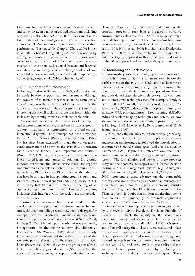
New Zealand Geomechanics News
99
face tunnelling machines are now some 15 m in diameter and can excavate in a range of ground conditions including very strong rocks (Zhao & Gong, 2006). Rock mechanics-based data and methodologies are used in the selection of modern TBMs and in computer simulations of their performance (Barton, 2000; Gong & Zhao, 2009; Rojek et al., 2010; Zhao & Gong, 2006). As with excavation by drilling and blasting, improvements in the performance, automation and control of TBMs and other types of mechanical excavators such as road headers and longwall coal shearers, are being achieved through industrial and research-level experimental, theoretical and computational studies (e.g., Rojek et al., 2010; Pichler et al., 2010).
7.5.2 Support and reinforcementFollowing Windsor & Thompson (1993), a distinction will be made between support and reinforcement, although the two are often treated together as in the term ground support. Support is the application of a reactive force to the surface of the excavation while reinforcement is a means of improving the overall rock mass properties from within the rock mass by techniques such as rock and cable bolts.
An essential concept in the mechanics of the support and reinforcement of underground excavations is ground-support interaction as represented in ground-support interaction diagrams. This concept had been developed by the Austrian School (Pacher, 1964; Rabcewicz, 1969) but has since been extended through the convergence-confinement method to which the 10th ISRM President, Marc Panet of France, made important contributions (Panet, 1993, 1995), and a wide range of linear and non-linear closed-form and numerical solutions for ground response curves and the characteristic curves for support and reinforcing elements and systems (e.g., Carranza-Torres & Fairhurst, 1999; Daemen, 1977). Despite the advances that have been made in incorporating ground support and its effects into numerical analysis codes (e.g., Itasca, 2011), as noted by Jing (2003), the numerical modelling of all aspects of support and reinforcement elements and systems, including their interfaces with the rock mass, still provides some challenges.
Considerable advances have been made in the development of support and reinforcement techniques and technology, including several new rock bolt types, for example, those with yielding or dynamic capabilities for use in rock burst prone environments (Falmagne & Simser, 2004; Ortlepp, 2007); cable bolts, particularly, but not exclusively, for application in the mining industry (Hutchinson & Diederichs, 1996; Windsor, 2004); shotcrete, particularly fibre-reinforced shotcrete and the wide-spread use of the wet mix process (Bernard, 2010); mesh and thin sprayed liners (Potvin et al., 2004); the corrosion protection of rock bolts, cable bolts and ground anchors (Windsor, 2004); the static and dynamic testing of support and reinforcement
elements (Player et al., 2008); and understanding the corrosion process in rock bolts and cables in corrosive environments (Villaescusa et al., 2008). A range of design methods for support and reinforcement systems have now been developed (e.g., Barrett & McCreath, 1995; Barton et al., 1994; Hoek et al., 2008; Hutchinson & Diederichs, 1995; Pells, 2002) to replace, or be used in conjunction with, the largely empirical methods that were used earlier in the 50-year period and still find wide-spread use today.
7.6 Monitoring and Back AnalysisMonitoring the performance of mining and civil excavations in rock had been carried out for many years before the establishment of the ISRM in 1962, and had become an integral part of rock engineering practice through the observational method. Early monitoring used mechanical and optical, and then electrical, electro-optical, electronic and microseismic techniques (see, for example, Brady & Brown, 2004; Dunnicliff, 1988; Franklin & Denton, 1973; Kovari et al., 1979; Windsor, 1993). In open pit mining, for example, GPS, photogrammetry, laser scanning (LiDAR), radar and satellite imaging techniques and systems are now also used to monitor slope movements, in particular (Girard & McHugh, 2001; Hawley et al., 2009; Herrera et al., 2010; Sakurai et al., 2009).
Subsequently, the on-line acquisition, storage, processing, management, interpretation and reporting of rock engineering monitoring data followed the introduction of computer and digital technologies (Gilby & Socol, 2010; Kimmance, 1999). Figure 5 illustrates the components of a current instrumentation data management and monitoring system. The formalisation and power of these processes today and their potential to support well-informed decision making and risk management systems (e.g., Akutagawa, 2010; Dewynter et al., 2010; Hawley et al., 2009; Schubert, 2006) represents a great advance on the comparable processes available 50 years ago, although the purposes and principles of good monitoring programs remain essentially unchanged (e.g., Franklin, 1977; Kovari & Amstad, 1993). There can be little doubt that modern monitoring systems have contributed significantly to the rock engineering achievements to be outlined in Section 7.7 below.
One of the common objectives of monitoring formalised by the seventh ISRM President, Dr John Franklin of Canada, is to check the validity of the assumptions, conceptual models and values of rock mass properties used in design calculations (Franklin, 1977). Originally, and often still today, these checks were made, and values of rock mass properties and the in situ stresses estimated, using a process of trial and error or curve fitting using forward analyses based on the theory of elasticity. However, in the late 1970s and early 1980s, it was realised that it was possible to improve this process by developing and applying more formal back analysis techniques. These
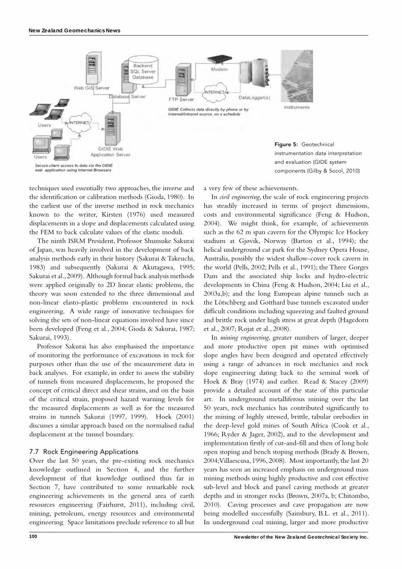
New Zealand Geomechanics News
100 Newsletter of the New Zealand Geotechnical Society Inc.
techniques used essentially two approaches, the inverse and the identification or calibration methods (Gioda, 1980). In the earliest use of the inverse method in rock mechanics known to the writer, Kirsten (1976) used measured displacements in a slope and displacements calculated using the FEM to back calculate values of the elastic moduli.
The ninth ISRM President, Professor Shunsuke Sakurai of Japan, was heavily involved in the development of back analysis methods early in their history (Sakurai & Takeuchi, 1983) and subsequently (Sakurai & Akutagawa, 1995; Sakurai et al., 2009). Although formal back analysis methods were applied originally to 2D linear elastic problems, the theory was soon extended to the three dimensional and non-linear elasto-plastic problems encountered in rock engineering. A wide range of innovative techniques for solving the sets of non-linear equations involved have since been developed (Feng et al., 2004; Gioda & Sakurai, 1987; Sakurai, 1993).
Professor Sakurai has also emphasised the importance of monitoring the performance of excavations in rock for purposes other than the use of the measurement data in back analyses. For example, in order to assess the stability of tunnels from measured displacements, he proposed the concept of critical direct and shear strains, and on the basis of the critical strain, proposed hazard warning levels for the measured displacements as well as for the measured strains in tunnels Sakurai (1997, 1999). Hoek (2001) discusses a similar approach based on the normalised radial displacement at the tunnel boundary.
7.7 Rock Engineering ApplicationsOver the last 50 years, the pre-existing rock mechanics knowledge outlined in Section 4, and the further development of that knowledge outlined thus far in Section 7, have contributed to some remarkable rock engineering achievements in the general area of earth resources engineering (Fairhurst, 2011), including civil, mining, petroleum, energy resources and environmental engineering. Space limitations preclude reference to all but
a very few of these achievements.In civil engineering, the scale of rock engineering projects
has steadily increased in terms of project dimensions, costs and environmental significance (Feng & Hudson, 2004). We might think, for example, of achievements such as the 62 m span cavern for the Olympic Ice Hockey stadium at Gjøvik, Norway (Barton et al., 1994); the helical underground car park for the Sydney Opera House, Australia, possibly the widest shallow-cover rock cavern in the world (Pells, 2002; Pells et al., 1991); the Three Gorges Dam and the associated ship locks and hydro-electric developments in China (Feng & Hudson, 2004; Liu et al., 2003a,b); and the long European alpine tunnels such as the Lötschberg and Gotthard base tunnels excavated under difficult conditions including squeezing and faulted ground and brittle rock under high stress at great depth (Hagedorn et al., 2007; Rojat et al., 2008).
In mining engineering, greater numbers of larger, deeper and more productive open pit mines with optimised slope angles have been designed and operated effectively using a range of advances in rock mechanics and rock slope engineering dating back to the seminal work of Hoek & Bray (1974) and earlier. Read & Stacey (2009) provide a detailed account of the state of this particular art. In underground metalliferous mining over the last 50 years, rock mechanics has contributed significantly to the mining of highly stressed, brittle, tabular orebodies in the deep-level gold mines of South Africa (Cook et al., 1966; Ryder & Jager, 2002), and to the development and implementation firstly of cut-and-fill and then of long hole open stoping and bench stoping methods (Brady & Brown, 2004; Villaescusa, 1996, 2008). Most importantly, the last 20 years has seen an increased emphasis on underground mass mining methods using highly productive and cost effective sub-level and block and panel caving methods at greater depths and in stronger rocks (Brown, 2007a, b; Chitombo, 2010). Caving processes and cave propagation are now being modelled successfully (Sainsbury, B.L. et al., 2011). In underground coal mining, larger and more productive
Figure 5: Geotechnical
instrumentation data interpretation
and evaluation (GIDE system
components (Gilby & Socol, 2010)
New Zealand Geomechanics News
101
longwall faces have been introduced as has longwall top coal caving to mine thicker seams, especially in China (Alehossein & Paulsen, 2010; Vakili & Hebblewhite, 2011).
Rock mechanics has become increasingly important in petroleum engineering since the 1970s as production has taken place from deeper and more difficult geological settings (Roegiers, 1999). Rock mechanics has contributed to the achievements of the petroleum and gas industry in areas such as geological and fracture modelling, including DFN modelling; seismic tomography and other geophysical techniques; borehole mechanics and wellbore stability; the measurement of in situ stresses; hydraulic fracturing and methods of enhanced oil recovery; poromechanics and coupled thermo-hydro-mechanical processes; the control of solids (generally sand) production; smart drilling including drilling deviated holes and drilling in deep water; and reservoir geomechanics (Detournay, 1995; Fjaer et al., 2008; Roegiers, 1999; Schutjens, 2009). Rock mechanics has also contributed to a number of other achievements in the exploitation of a range of energy resources, including hot, dry rock geothermal energy at depth (Thorsteinsson et al., 2008), the underground storage of oil and gas (You et al., 2006), and underground radioactive waste repository planning and design (Fairhurst, 2004; Hudson, 2010; Hudson et al., 2001), and the deep injection of solid and liquid wastes (Dusseault, 2010). Conversely, research in these areas, including through field trials, has contributed to basic and applied rock mechanics knowledge.
8 ConclusionsThis necessarily brief overview of the development and achievements of the ISRM and of the discipline of rock mechanics and rock engineering in the 50 years since the ISRM was founded in 1962 shows clearly that much of significance has been achieved. New basic understandings and engineering tools have been developed to support an increasingly wide range of rock engineering applications. Many of the advances made in rock mechanics research, in the tools and techniques now available for data collection and analysis, and in the application of rock mechanics in engineering practice, have been enabled by modern digital computing, information and communications technologies. Others have drawn on advances made in other branches of science and technology. And during this first 50 years of its life, the ISRM has pursued its stated objectives and purposes conscientiously by carrying out all of its main activities at least satisfactorily, with some being carried out to considerable effect.
For those involved, the last 50 years has been an exciting, satisfying and possibly fortuitous time in which to have been involved in rock mechanics and the ISRM. However, increases in knowledge in our and other disciplines, and change and further development of our institutions and in society at large, are inevitable. From a rock mechanics
and rock engineering perspective, the future remains full of promise, challenge and excitement.
9 AcknowledgementsThe writer wishes to record his appreciation of the support and assistance of the following members of the international rock mechanics community in providing him with information and material used in the preparation of this paper: Nick Barton, David Beck, Pierre Berest, Pierre Duffaut, Maria de Lurdes Eusébio, Charles Fairhurst, Xia-Ting Feng, John Gilby, Nuno Grossmann, Pierre Habib, Evert Hoek, John Hudson, Luís Lamas, Italo Oñederra, Matt Pierce, Eda Quadros, Bre-Anne Sainsbury, David Sainsbury, Shun Sakurai, Penny Stewart and Walter Wittke. He also wishes to thank Rob Morphet and the management of Golder Associates, Brisbane, for their support during the preparation of this paper and Jillian Roche and Brooke Anderson for their skilful assistance in readying the paper for publication.
10 ReferencesAkutagawa, S. 2010. On site visualisation as a new paradigm for field
measurement in rock engineering. In K. G. Sharma, T. Ramamurthy, V. K. Kanjlia & A. C. Gupta (eds), Advances in Rock Engineering, Proceedings ISRM International Symposium 2010 & 6th Asian Rock Mechanics Symposium, New Delhi, 23-27 October, KN 34 - KN 45. New Delhi: Central Board of Irrigation & Power.
Alehossein, H. & Paulsen, B. A. 2010. Stress analysis of longwall top caving. International Journal of Rock Mechanics & Mining Sciences, 47(1): 30-41.
Alexander, L. G. 1960. Field and laboratory tests in rock mechanics. Proceedings 3rd Australia-New Zealand Conference on Soil Mechanics & Foundation Engineering, Sydney, 161-168. Sydney: Institution of Engineers, Australia.
Amadei, B. & Stephansson, O. 1997. Rock Stress and its Measurement, 512 p. Dordrecht: Kluwer.
Anon, 1963. Proceedings Rock Mechanics Symposium, McGill University, Montreal, 7-8 September, 1962, 218 p. Ottawa: Mines Branch, Department of Mines & Technical Surveys.
Appleton, E. 1944. Scientific research: fundamentals of its application to rock mechanics. South African Mining & Engineering Journal, 55(1): 519-520.
Atkinson, B.K. (ed.) 1987. Fracture Mechanics of Rock, 534 p. London: Academic Press.
Barla, G., Barla, M., Camusso, M. & Martinotti, M. E. 2007. Setting up a new direct shear testing apparatus. In L. Ribeiro e Sousa, C. Olalla & N. F. Grossmann (eds), Proceedings 11th Congress, International Society for Rock Mechanics, Lisbon, 9-13 July, 1: 415-418. Leiden: Taylor & Francis.
Barrett, S. V. L. & McCreath, D. R. 1995. Shotcrete support design in blocky ground: towards a deterministic approach. Tunnelling & Underground Space Technology, 10(1): 79-89.
Barton, N. 2000. TBM Tunnelling in Jointed and Faulted Rock, 172 p. Rotterdam: Balkema.
Barton, N., 2006. Rock Quality, Seismic Velocity, Attenuation and Anisotropy, 729 p. London: Taylor & Francis.
Barton, N. & Bandis, S. C. 1990. Review of predictive capabilities of JRC-JCS model in engineering practice. In N. R. Barton & O. Stephansson (eds), Rock Joints, Proceedings International Symposium on Rock Joints, Loen, 4-6 June, 603-610. Rotterdam: Balkema.
Barton, N., By, T. L., Chryssanthakis, P., Tunbridge, L., Kristiansen, J., Løset, F., Bhasin, R. K., Westerdahl, H. & Vick, G. 1994. Predicted and measured performance of the 62 m span Norwegian Olympic Ice Hockey Cavern at Gjøvik. International Journal of Rock Mechanics &

New Zealand Geomechanics News
102 Newsletter of the New Zealand Geotechnical Society Inc.
Mining Sciences, 31(6): 617-641.Barton, N. & de Quadros, E. F. 1997. Joint aperture and roughness in
the prediction of flow and groutability of rock masses. In K. Kim (ed.), Linking Science to Rock Engineering, Proceedings 36th U.S. Rock Mechanics Symposium & ISRM International Symposium, New York, 29 June – 2 July, 2: 907-916. New York: Columbia University.
Barton, N., Lien, R. & Lunde, J. 1974. Engineering classification of rock masses for the design of tunnel support. Rock Mechanics, 6(4): 189-236.
Beck, D. A., Fillery, B. & Reusch, F. 2010. 3d hydro-mechanical simulation of faulted open pit slopes. Proceedings 44th U.S. Rock Mechanics Symposium & 5th U.S. - Canada Rock Mechanics Symposium, Salt Lake City, 27-30 June, Paper ARMA-425, 6p (on CD-ROM).
Beck, D. A., Pfitzner, M. J., Arndt, S. M. & Fillery, B. 2009. Estimating rock mass properties and seismic response using higher order, discontinuous, Finite Element models. In M. Diederichs & G. Grasselli (eds), Rock Engineering in Difficult Conditions, Proceedings 3rd Canada - U.S. Rock Mechanics Symposium & 20th Canadian Rock Mechanics Symposium, Toronto, 9-15 May, 12 p (on CD-ROM).
Beer, G. (ed.) 2010. Technology Innovation in Underground Construction, 504 p. Leiden: CRC Press/Balkema.
Beer, G. & Watson, J. O. 1992. Introduction to Finite and Boundary Element Methods for Engineers, 509 p. Chichester: John Wiley.
Bernaix, J. 1969. New laboratory methods of studying the mechanical properties of rock. International Journal of Rock Mechanics & Mining Sciences, 6(1): 43-90.
Bernard, S. (ed.) 2010. Shotcrete: Elements of a System, Proceedings 3rd International Conference on Engineering Developments in Shotcrete, Queenstown, 15-17 March, 310 p. Leiden: CRC Press/Balkema.
Bieniawski, Z. T. 1976. Rock mass classifications in rock engineering. In Z. T. Bieniawski (ed.), Proceedings Symposium on Exploration for Rock Engineering, Johannesburg, 1-5 November, 1: 97-106. Cape Town: Balkema.
Bieniawski, Z. T. 1989. Engineering Rock Mass Classification, 251 p. New York: John Wiley.
Billaux, D., Chiles, J. P., Hestir, K. & Long, J. 1989. Three-dimensional statistical modelling of a fractured rock mass – an example from the Fanay-Augères Mine. International Journal of Rock Mechanics & Mining Sciences, 26(3-4): 281-299.
Blanks, R. F. & McHenry, D. 1945. Large triaxial testing machine built by Bureau of Reclamation. Engineering News Record, 135(6): 171-172.
Brady, B. H. G. 1979. A direct formulation of the boundary element method of stress analysis for complete plane strain. International Journal of Rock Mechanics & Mining Sciences, 16(4): 235-244.
Brady, B. H. G. 1987. Boundary element and linked methods for underground excavation design. In E. T. Brown (ed.), Analytical & Computational Methods in Engineering Rock Mechanics, 164-204. London: Allen & Unwin.
Brady, B. H. G. & Brown, E. T. 2004. Rock Mechanics for Underground Mining, 3rd edn, 628 p. Dordrecht: Kluwer.
Brown, E. T. (ed.) 1981. Rock Characterization, Testing and Monitoring – ISRM Suggested Methods, 211 p. Oxford: Pergamon Press.
Brown, E. T. 1999. Rock mechanics and the Snowy Mountains Scheme. In The Spirit of the Snowy Fifty Years On, Proceedings 1999 Invitation Symposium, Australian Academy of Technological Sciences & Engineering, Cooma, 23-24 November, 89-101. Melbourne: Australian Academy of Technological Sciences & Engineering.
Brown, E. T. 2002. Rock mechanics in Australia. International Journal of Rock Mechanics & Mining Sciences, 39(5): 529-538.
Brown, E. T. 2007a. Block Caving Geomechanics, 2nd edn, 696 p. Brisbane: JKMRC.
Brown, E. T. 2007b. Rock mechanics – the basic mining science: challenges in underground mass mining. In L. Ribeiro e Sousa, C. Olalla & N. F. Grossmann (eds), Proceedings 11th Congress, International Society for Rock Mechanics, Lisbon, 9-13 July, 3: 1335-1347. Leiden: Taylor & Francis.
Brown, E. T. 2008. Estimating the mechanical properties of rock masses. In Y. Potvin, J. Carter, A. Dyskin & R. Jeffrey (eds), Proceedings 1st Southern Hemisphere International Rock Mechanics Symposium, Perth, 16-19 September, 1: 3-22. Perth: Australian Centre for
Geomechanics.Brown, E. T. 2011. Fifty years of the ISRM and associated progress in
rock mechanics. In Q. Qian & Y. X. Zhou (eds), Harmonising Rock Engineering and the Environment, Proceedings 12th Congress, International Society for Rock Mechanics, Beijing, 16-21 October, 1: (in press). Leiden: CRC Press/Balkema.
Brown, P. D. & Robertshaw, J. 1953. The in-situ measurement of Young’s Modulus for rock by a dynamic method. Géotechnique, 3(7): 283-286.
Bryan, A., Bryan, J. G. & Fouché, J. 1964. Some problems of strata control and support in pillar workings. The Mining Engineer, 123(41): 238-266.
Carranza-Torres, C. & Fairhurst, C. 1999. The elasto-plastic response of underground excavations in rock masses that satisfy the Hoek-Brown failure criterion. International Journal of Rock Mechanics & Mining Sciences, 36(6): 777-809.
Chen, Y., Liu, Y., Zhang, M. & Chen, R. 1986. A preliminary study of in-situ stress field in the Three-Gorge Dam area. Proceedings International Symposium on Engineering in Complex Rock Formations, Beijing, 3-7 November, 149-162. Beijing: Science Press.
Chitombo, G. P. 2010. Cave mining – 16 years after Laubscher’s 1994 paper “cave mining – state of the art”. In Y. Potvin (ed.), Caving 2010, Proceedings 2nd International Symposium on Block & Sublevel Caving, Perth, 20-22 April, 45-61. Perth: Australian Centre for Geomechanics.
Clough, R. W. 1960. The finite element method in plane stress analysis. Proceedings 2nd A.S.C.E. Conference on Electronic Computation, Pittsburgh, September, 345-378.
Cook, N. G. W. 1965. The failure of rock. International Journal of Rock Mechanics & Mining Sciences, 2(4): 389-403.
Cook, N. G. W., Hoek, E., Pretorius, J. P. G., Ortlepp, W. D. & Salamon, M. D. G. 1966. Rock mechanics applied to the study of rockbursts. Journal, South African Institute of Mining & Metallurgy, 66(10): 436-528.
Coulomb, C. A. 1776. Essai sur une application des régles de maximis et minimis à quelques problèmes de statique, relatives à l’architecture. Mémoires de Mathématique et de Physique, l’Académie Royale des Sciences, 7: 343-382.
Crouch, S. L. & Starfield, A. M. 1983. Boundary Element Methods in Solid Mechanics, 322 p. London: Allen & Unwin.
Cundall, P. A. 1971. A computer model for simulating progressive, large-scale movements in blocky rock systems. In Rock Fracture, Proceedings International Symposium on Rock Mechanics, Nancy, 4-6 October, 1: Paper II-8.
Cundall, P. A. 1987. Distinct element models of rock and soil structure. In E. T. Brown (ed.), Analytical & Computational Methods in Engineering Rock Mechanics, 129-163. London: Allen & Unwin.
Cundall, P. A. 2011. Lattice method for modelling brittle, jointed rock. In D. P. Sainsbury, R. D. Hart, C. L. Detournay & M. J. Nelson (eds), Continuum and Distinct Element Numerical Modeling in Geomechanics – 2011, Proceedings 2nd International FLAC/DEM Symposium, Melbourne, 14-16 February, 11-19. Minneapolis: Itasca International Inc.
Cundall, P. A. & Damjanac, B. 2009. A comprehensive 3D model for rock slopes based on micromechanics. In Slope Stability 2009, Proceedings 3rd International Symposium on Rock Slope Stability, Santiago, 9-11 November, 10 p (on CD-ROM).
Daemen, J. J. K. 1977. Problems in tunnel support mechanics. Underground Space, 1(3): 163-172.
Dershowitz, W. 1995. Interpretation and synthesis of discrete fracture orientation, size, shape, spatial structure and hydrologic data by forward modelling. In L. R. Myer, N. G. W. Cook, R. E. Goodman & C-F. Tsang (eds), Proceedings Conference on Fractured & Jointed Rock Masses, Lake Tahoe, 3-5 June 1992, 579-586. Rotterdam: Balkema.
Dershowitz, W. S. & Einstein, H. H. 1984. Applications of artificial intelligence to problems of rock mechanics. In C. H. Dowding & M. M. Singh (eds), Rock Mechanics in Productivity & Protection, Proceedings 25th U.S. Symposium on Rock Mechanics, Evanston, 25-27 June, 483-494. New York: A.I.M.E.

New Zealand Geomechanics News
103
Dershowitz, W. S. & Einstein, H. H. 1988. Characterizing rock joint geometry with joint system models. Rock Mechanics & Rock Engineering, 21(1): 21-51.
Desseault, M. B. 2010. Deep injection disposal: environmental and petroleum geomechanics. In K. G. Sharma, T. Ramamurthy, V. K. Kanjlia & A. C. Gupta (eds), Advances in Rock Engineering, Proceedings ISRM International Symposium 2010 & 6th Asian Rock Mechanics Symposium, New Delhi, 23-27 October, KN 21 - KN 33. New Delhi: Central Board of Irrigation & Power.
Detournay, C. & Hart, R. (eds) 1999. FLAC and Numerical Modeling in Geomechanics, Proceedings International FLAC Symposium, Minneapolis, 1-3 September, 528 p. Rotterdam: Balkema.
Detournay, E. 1995. Coupled thermo-hydro-mechanical processes in rock mechanics, with applications to the petroleum industry. In T. Fuji (ed.), Proceedings 8th Congress, International Society for Rock Mechanics, Tokyo, 25-29 September, 3: 1061-1068. Rotterdam: Balkema.
Dewynter, V., Magne, S., Rougeault, S., Ferdinand, P., Vallon, F., Avallone, L., Vacher, E., de Broissia, M., Canepa, C. & Poulain, A. 2009. Optical fiber sensing cable for underground settlement monitoring during tunnelling. In G. Beer (ed.), Technology Innovation in Underground Construction, 163-188. Leiden: CRC Press/Balkema.
Diederichs, M. S. & Kaiser, P. K. 1999. Stability of large excavations in laminated hard rock masses: the voussoir analogue revisited. International Journal of Rock Mechanics & Mining Sciences, 36(1): 97-117.
Dowding, C. H. 1985. Blast Vibration Monitoring and Control, 297 p. Englewood Cliffs: Prentice-Hall.
Duffaut, P. 2011. What modern rock mechanics owe to the Malpasset Arch Dam failure. In Q. Qian & Y. X. Zhou (eds), Harmonising Rock Engineering and the Environment, Proceedings 12th Congress, International Society for Rock Mechanics, Beijing, 16-21 October, (in press). Leiden: CRC Press/Balkema.
Dunnicliff, J. 1988. Geotechnical Instrumentation for Monitoring Field Performance, 577 p. New York: John Wiley.
Einstein, H. H. & Baecher, G. B. 1983. Probabilistic and statistical methods in engineering geology. Rock Mechanics & Engineering Geology, 16(1): 39-72.
Elsworth, D. 1986. A hybrid boundary element-finite element analysis procedure for fluid flow simulation in fractured rock masses. International Journal for Numerical & Analytical Methods in Geomechanics, 10(6): 569-584.
Elsworth, D. & Mase, C. R. 1993. Groundwater in rock engineering. In J. A. Hudson, E. T. Brown, C. Fairhurst & E. Hoek (eds), Comprehensive Rock Engineering, 1: 201-226. Oxford: Pergamon Press.
Evison, F. F. 1953. The seismic determination of Young’s modulus and Poisson’s ratio for rocks in situ. Géotechnique, 6(3): 118-123.
Fairhurst, C. (ed.) 1963. Proceedings Fifth Symposium on Rock Mechanics, University of Minnesota, Minneapolis, May 1962, 726 p. Oxford: Pergamon Press.
Fairhurst, C. 2003. Stress estimation in rock: a brief history and review. International Journal of Rock Mechanics & Mining Sciences, 40(7-8): 957-973.
Fairhurst, C. 2004. Nuclear waste disposal and rock mechanics: contributions of the Underground Research Laboratory (URL), Pinawa, Manitoba, Canada. International Journal of Rock Mechanics & Mining Sciences, 41(8): 1221-1227.
Fairhurst, C. 2010. First Vienna-Leopold-Müller Lecture: What is the strength of a rock mass? Progress in answering Müller’s (implicit) question. Proceedings 5th Colloquium, Rock Mechanics – Theory & Practice, Vienna, 26-27 November 2009, Mitteilungen für Ingenieurgeologie und Geomechanik, Band 9: 87-110.
Fairhurst, C. 2011. Grand challenges in Earth Resources Engineering – and some implications for rock mechanics and rock engineering. In D. P. Sainsbury, R. D. Hart, C. L. Detournay & M. J. Nelson (eds), Continuum and Distinct Element Numerical Modeling in Geomechanics – 2011, Proceedings 2nd International FLAC/DEM Symposium, Melbourne, 14-16 February, 3-10. Minneapolis: Itasca International Inc.
Falmagne, V. & Simser, B. P. 2004. Performance of rockburst support systems in Canadian mines. In E. Villaescusa & Y. Potvin (eds),
Ground Support in Mining & Underground Construction, Proceedings 5th International Symposium on Ground Support, Perth, 28-30 September, 313-318. Leiden: Balkema.
Feng, X-T. & An, H. 2004. Hybrid intelligent method optimization of a soft rock replacement scheme for a large cavern excavated in alternate hard and soft rock strata. International Journal of Rock Mechanics & Mining Sciences, 41(4): 655-667.
Feng, X-T. & Hudson, J. A. 2004. The ways ahead for rock engineering design methodologies. International Journal of Rock Mechanics & Mining Sciences, 41(2): 255-273.
Feng, X-T. & Hudson, J. A. 2010. Specifying the information required for rock mechanics modelling and rock engineering design. International Journal of Rock Mechanics & Mining Sciences, 47(2): 179-194.
Feng, X-T. & Hudson, J. A. 2011. Rock Engineering Design, 464 p. Leiden: CRC Press/Balkema.
Feng, X-T., Zhao, H. & Li, S. 2004. A new displacement back analysis to identify mechanical geo-material parameters using integrated intelligent methodology. International Journal for Numerical & Analytical Methods in Geomechanics, 28(11): 1141-1165.
Fjaer, E., Holt, R. M., Horsrud, P., Raaen, A. M. & Risnes, R. 2008. Petroleum Related Rock Mechanics, 2nd edn, 514 p. Amsterdam: Elsevier.
Franklin, J. A. 1977. Monitoring of structures in rock. International Journal of Rock Mechanics & Mining Sciences, 14(4): 163-192.
Franklin, J. A. & Denton, P. E. 1973. The monitoring of rock slopes. Quarterly Journal of Engineering Geology, 6(3-4): 259-286.
Furtney, J. K., Cundall, P. A. & Chitombo, G. P. 2009. Developments in numerical modeling of blast induced fragmentation: updates from the HSBM project. In J. A. Sanchidrián (ed.), Rock Fragmentation by Blasting – FragBlast 9, Proceedings 9th International Symposium on Rock Fragmentation by Blasting, Granada, 13-17 September, 335-342. Leiden: CRC Press/Balkema.
Gaich, A., Pötsch, M. & Schubert, W. 2007. Rock mass characterization for tunneling and mining using 3D images. In L. Ribeiro e Sousa, C. Olalla & N. F. Grossmann (eds), Proceedings 11th Congress, International Society for Rock Mechanics, Lisbon, 9-13 July, 2: 1019-1024. Leiden: Taylor & Francis.
Galvin, J. M., Hebblewhite, B. K. & Salamon, M. D. G. 1999. University of New South Wales pillar strength determinations for Australian and South African mining conditions. In C. Mark, K. A. Heasley, A. T. Iannocchione & R. J. Tuchman (eds), Proceedings 2nd International Workshop on Coal Pillar Mechanics & Design, Vail, 6 June, NIOSH IC 9448, 63-71. Pittsburgh: U.S. Department of Health & Human Services.
Gilby, J. & Socol, M. 2010. Geotechnical instrumentation data management. In K. G. Sharma, T. Ramamurthy, V. K. Kanjlia & A. C. Gupta (eds), Advances in Rock Engineering, Proceedings ISRM International Symposium 2010 & 6th Asian Rock Mechanics Symposium, New Delhi, 23-27 October, Paper 124, 7p (on CD-ROM). New Delhi: Central Board of Irrigation & Power.
Gioda, G. 1980. Indirect identification of the average elastic characteristics of rock masses. In P. J. N. Pells (ed.), Structural Foundations on Rock, Proceedings International Symposium, Sydney, 7-9 May, 65-73. Rotterdam: Balkema.
Gioda, G. & Sakurai, S. 1987. Back analysis procedures for the interpretation of field measurements in geomechanics. International Journal for Numerical & Analytical Methods in Geomechanics, 11(6): 555-583.
Girard, J. M. & McHugh, E. L. 2001. Emerging technologies and the future of geotechnical instrumentation. In D. Elsworth, J. P. Tinucci & K. A. Heasley (eds), Rock Mechanics in the National Interest, Proceedings 38th U.S. Symposium on Rock Mechanics, Washington D.C., 5-7 July, 1: 445-450. Lisse: Balkema.
Golder, H. Q. & Akroyd, T. N. W. 1954. An apparatus for triaxial-compression tests at high pressures. Géotechnique, 4(4): 131-136.
Gong, Q. M. & Zhao, J. 2009. Development of rock mass characteristics model for TBM penetration rate prediction. International Journal of Rock Mechanics & Mining Sciences, 46(1): 8-18.
Goodman, R. E. 1966. On the distribution of stresses around circular tunnels in non-homogeneous rocks. Proceedings 1st Congress, International Society for Rock Mechanics, Lisbon, 25 September – 1

New Zealand Geomechanics News
104 Newsletter of the New Zealand Geotechnical Society Inc.
October, 2: 249-255. Lisbon: LNEC.Goodman, R. E. 1989. Introduction to Rock Mechanics, 2nd edn, 562 p.
New York: John Wiley.Goodman, R. E. & Shi, G-H. 1985. Block Theory and its Application to
Rock Engineering, 338p. Englewood Cliffs: Prentice-Hall.Goodman, R. E., Taylor, R. L. & Brekke, T. L. 1968. A model for the
mechanics of jointed rock. Journal, Soil Mechanics & Foundations Division, A.S.C.E., 94(SM3): 637-659.
Grasselli, G. & Egger, P. 2003. Constitutive law for the shear strength of rock joints based on three-dimensional surface parameters. International Journal of Rock Mechanics & Mining Sciences, 40(1): 25-40.
Griggs, D. T. 1936. Deformation of rocks under high confining pressures. Journal of Geology, 44: 541-577.
Grobler, H. P., Poropat, G. & Guest, A. R. 2003. Photogrammetry for structural mapping in mining. Technology Roadmap for Rock Mechanics, Proceedings 10th Congress, International Society for Rock Mechanics, Johannesburg, 8-12 September, 1: 431-436. Johannesburg: Southern African Institute of Mining & Metallurgy.
Habib, P. 1950. Détermination du module d’élasticité des roches en place. Annales de l’Institut Technique du Bâtiment et des Travaux Publics, No 145, September: 27-35.
Habib, P. & Marchand, R. 1952. Mesures des pressions de terrains par l’essai de vérin plat. Suppléments aux Annales de l’Institut Technique du Bâtiment et des Travaux Publics, Série Sols et Foundations, No 58, October: 967-971.
Hagedorn, H., Rehbock-Sander, M. & Stadelmann, R. 2007. Gotthard Base tunnel: rock burst phenomenon during construction of a multifunctional section in a fault zone area. In L. Ribeiro e Sousa, C. Olalla & N. F. Grossmann (eds), Proceedings 11th Congress, International Society for Rock Mechanics, Lisbon, 9-13 July, 2: 917-920. Leiden: Taylor & Francis.
Handin, J. 1953. An application of high pressure geophysics: experimental rock mechanics. Transactions, American Society of Mechanical Engineers, 75: 315-324.
Hart, R. D., Detournay, C. L. & Cundall, P. A. (eds), 2008. Continuum and Distinct Element Modeling in Geo-Engineering, Proceedings 1st FLAC/DEM Symposium, Minneapolis, 25-27 August, 698 p. Minneapolis: Itasca Consulting Group Inc.
Hast, N. 1958. The measurement of rock pressure in mines. Sveriges Geologiska Undersokning, Series C, 52(3).
Hawley, M., Marisett, S., Beale, G. & Stacey, P. 2009. Performance assessment and monitoring. In J. Read & P. Stacey (eds), Guidelines for Open Pit Slope Design, 327-379. Melbourne: CSIRO Publishing.
Hedley, D. G. F. & Grant, F. 1972. Stope and pillar design at the Elliot Lake uranium mines. Canadian Institute of Mining & Metallurgy Bulletin, 65(723): 37-44.
Herrera, G., Tomás, R., Vicente, F., Lopez-Sanchez, J. M., Mallorquí, J. J. & Mulas, J. 2010. Mapping ground movements in open pit mining areas using differential SAR interferometry. International Journal of Rock Mechanics & Mining Sciences, 47(7): 1114-1125.
Heyman, J. 1972. Coulomb’s Memoir on Statics, 212p. Cambridge: Cambridge University Press.
Hill, F. G. 1954. An investigation of the problem of rockbursts; an operational research project. Part I. The approach to the problem and analyses of the rockbursts that have occurred on the ERPM during the years 1948-1953. Journal, Chemical, Metallurgical & Mining Society of South Africa, 55(October): 63-83.
Hill, F. G. 1966. Preface to “Rock Mechanics applied to the study of rockbursts”. Journal, South African Institute of Mining & Metallurgy, 66(10): 435.
Hoek, E. 1963. Experimental study of rock-stress problems in deep level mining. Experimental Mechanics, 3: 177-194.
Hoek, E. 1964. Fracture of anisotropic rock. Journal, South African Institute of Mining & Metallurgy, 64(10): 501-518.
Hoek, E. 1994. Strength of rock and rock masses. ISRM News Journal, 2(2): 4-16.
Hoek, E. 2001. Big tunnels in bad rock. The 36th Karl Terzaghi Lecture. Journal of Geotechnical & Geoenvironmental Engineering, A.S.C.E., 127(9): 726-740.
Hoek, E. 2007. The development of rock engineering. In Practical Rock
Engineering. Available at http://Rocscience.com/hoek/pdf/1_The_development_of_rock_engineering.pdf .
Hoek, E. & Bray, J. W. 1974. Rock Slope Engineering, 309 p. London: Institution of Mining & Metallurgy.
Hoek, E. & Brown, E. T. 1980. Underground Excavations in Rock, 527 p. London: Institution of Mining & Metallurgy.
Hoek, E., Carranza-Torres, C., Diederichs, M. S. & Corkum, B. 2008. Integration of geotechnical and structural design in tunnelling. Proceedings University of Minnesota 56th Annual Geotechnical Engineering Conference, Minneapolis, 29 February, 1-53.
Hoek, E. & Diederichs, M. S. 2006. Empirical estimation of rock mass modulus. International Journal of Rock Mechanics & Mining Sciences, 43(2): 203-215.
Hood, M. & Brown, E. T. 1999. Mining rock mechanics, yesterday, today and tomorrow. In G. Vouille & P. Berest (eds), Proceedings 9th Congress, International Society for Rock Mechanics, Paris, 25-28 August, 3: 1551-1576. Lisse: Balkema.
Hudson, J. A. 2010. Underground radioactive waste disposal: the rock mechanics contributions. In K. G. Sharma, T. Ramamurthy, V. K. Kanjlia & A. C. Gupta (eds), Advances in Rock Engineering, Proceedings ISRM International Symposium 2010 & 6th Asian Rock Mechanics Symposium, New Delhi, 23-27 October, KN 3 - KN 20. New Delhi: Central Board of Irrigation & Power.
Hudson, J. A. 2011. The next 50 years of the ISRM and anticipated future progress in rock mechanics. In Q. Qian & Y. X. Zhou (eds), Harmonising Rock Engineering and the Environment, Proceedings 12th Congress, International Society for Rock Mechanics, Beijing, 16-21 October, 1: (in press). Leiden: CRC Press/Balkema.
Hudson, J. A., Brown, E. T. & Fairhurst, C. 1971. Optimizing the control of rock failure in servo-controlled laboratory tests. Rock Mechanics, 3(4): 217-224.
Hudson, J. A., Brown, E. T., Fairhurst, C. & Hoek, E. (eds) 1993. Comprehensive Rock Engineering, 5 Vols. Oxford: Pergamon Press.
Hudson, J. A., Cornet, F. H. & Christiansson, R. 2003. ISRM Suggested methods for rock stress estimation – Part 1: Strategy for rock stress estimation. International Journal of Rock Mechanics & Mining Sciences, 40(7-8): 991-998.
Hudson, J. A. & Feng, X-T. 2007. Updated flow charts for rock mechanics modelling and rock engineering design. International Journal of Rock Mechanics & Mining Sciences, 44(2): 174-195.
Hudson, J. A., Stephansson, O., Andersson, J., Tsang, C-F. & Jing, L. 2001. Coupled T-H-M issues relating to radioactive waste repository design and performance. International Journal of Rock Mechanics & Mining Sciences, 38(1): 143-161.
Hustrulid, W. 2010. Some comments regarding development drifting practices with special emphasis on caving applications. In Y. Potvin (ed.), Caving 2010, Proceedings 2nd International Symposium on Block & Sublevel Caving, Perth, 20-22 April, 3-43. Perth: Australian Centre for Geomechanics.
Hutchinson, D. J. & Diederichs, M. S. 1996. Cablebolting in Underground Mines, 406 p. Richmond, B.C.: Bitech Publishers.
Indraratna, B., Oliveira, D. A. F. & Brown, E. T. 2010. A shear-displacement criterion for soil-infilled rock discontinuities. Géotechnique, 60(8): 623-633.
Itasca, 2011. FLAC Ver 6.0, FLAC3D Ver 4.0, FLAC/Slope Ver 6.0, UDEC Ver 5.0 & 3DEC Ver 4.1 Minneapolis: Itasca Consulting Group Inc. (See www.itascacg.com/home.php.)
Jaeger, C. 1955. Present trends in the design of pressure tunnels and shafts for underground hydro-electric power stations. Proceedings, Institution of Civil Engineers, 4(2): 116-174.
Jaeger, C. 1972. Rock Mechanics and Engineering, 417 p. Cambridge: Cambridge University Press.
Jaeger, J. C. 1959. The frictional properties of joints in rock. Geofisica Pura e Applicata, 43(Part 2): 148-158.
Jaeger, J. C. 1960. Shear fracture of anisotropic rocks. Geological Magazine, 97: 65-72.
Jaeger, J. C. 1971. Friction of rocks and stability of rock slopes. Géotechnique, 21(2): 97-134.
Jing, L. 2003. A review of techniques, advances and outstanding issues in numerical modelling for rock mechanics and rock engineering. International Journal of Rock Mechanics & Mining Sciences, 40(3):

New Zealand Geomechanics News
105
283-353.Jing, L. & Stephansson, O. 2007. Fundamentals of Discrete Element
Methods for Rock Engineering: Theory and Applications, 545 p. Amsterdam: Elsevier.
John, K. W. 1962. An approach to rock mechanics. Journal, Soil Mechanics & Foundations Division, A.S.C.E., 88(SM4): 1-30.
Judd, W. R. (ed.) 1964. State of Stress in the Earth’s Crust, Proceedings International Conference, Santa Monica, 13-14 June 1963, 732 p. New York: American Elsevier.
Kaiser, P. K. & Kim, B-H. 2008. Rock mechanics challenges in underground construction and mining. In Y. Potvin, J. Carter, A. Dyskin & R. Jeffrey (eds), Proceedings 1st Southern Hemisphere International Rock Mechanics Symposium, Perth, 16-19 September, 1: 23-38. Perth: Australian Centre for Geomechanics.
Kármán, T. von, 1911. Festigkeitsversuche unter allseitigem Druck. Zeitschrift Verein Deutscher Ingenieure, 55: 1749-1757.
Kimmance, J. P. 1999. Geographical information system application to construction and geotechnical data management on large projects. In C. F. Leung, S. A. Tan & K. K. Phoon (eds), Proceedings 5th International Symposium on Field Measurements in Geomechanics, Singapore, 1-3 December, 151-156. Rotterdam: Balkema.
King, L. V. 1912. On the limiting strength of rocks under conditions of stress existing in the earth’s interior. Journal of Geology, 20: 119-138.
Kirsten, H. A. D. 1976. Determination of rock mass elastic moduli by back analysis of deformation measurements. In Z. T. Bieniawski (ed.), Proceedings Symposium on Exploration for Rock Engineering, Johannesburg, 1-5 November, 1: 165-172. Cape Town: Balkema.
Kovari, K. & Amstad, C. 1993. Decision making in tunnelling based on field measurements. In J. A. Hudson, E. T. Brown, C. Fairhurst & E. Hoek (eds), Comprehensive Rock Engineering, 4: 571-606. Oxford: Pergamon Press.
Kovari, K., Amstad, C. & Köppel, J. 1979. New developments in the instrumentation of underground openings. In A. C. Maevis & W. A. Hustrulid (eds), Proceedings 1979 Rapid Excavation & Tunneling Conference, Atlanta, 18-21 June, 1: 817-837. New York: A.I.M.E.
Lang, T. A. 1961. Theory and practice of rockbolting. Transactions, Society of Mining Engineers of A.I.M.E., 220: 333-348.
Liu, J., Feng, X-T., Ding, X-L., Zhang, J. & Yue, D-M. 2003a. Stability assessment of the Three Gorges Dam foundation, China, using physical and numerical modeling – Part I: physical model tests. International Journal of Rock Mechanics & Mining Sciences, 40(5): 609-631.
Liu, J., Feng, X-T. & Ding, X-L. 2003b. Stability assessment of the Three Gorges Dam foundation, China, using physical and numerical modeling – Part II: numerical modeling. International Journal of Rock Mechanics & Mining Sciences, 40(5): 633-652.
Londe, P. 1987. The Malpasset Dam failure. Engineering Geology, 24(1-4): 295-329.
Londe, P., Vigier, G. & Vormeringer, R. 1969. Stability of rock slopes, a three-dimensional study. Journal, Soil Mechanics & Foundations Division, A.S.C.E., 95(SM1): 235-262.
Long, J. & Witherspoon, P. 1985. The relationship of the degree of interconnection to permeability in fracture networks. Journal of Geophysical Research, 90(B4): 3087-3098.
Lorig, L. J. & Brady, B. H. G. 1982. A hybrid discrete element-boundary element method of stress analysis. In R. E. Goodman & F. E. Heuze (eds), Issues in Rock Mechanics, Proceedings 23rd U.S. Symposium on Rock Mechanics, Berkeley, 25-27 August, 628-636. New York: A.I.M.E.
Louis, C. 1974. Rock hydraulics. In Müller, L. (ed.), Rock Mechanics, (Course held at CISM, Udine, Italy), 300-387. Vienna: Springer-Verlag.
McKenzie, C. K. 1987. Blasting in hard rock: techniques for diagnosis and modeling for damage and fragmentation. In G. Herget & S. Vongpaisal (eds), Proceedings 6th Congress, International Society for Rock Mechanics, Montreal, 30 August – 3 September, 3: 1425-1431. Rotterdam: Balkema.
Marinos, P. G., Marinos,V. & Hoek, E. 2007. The Geological Strength Index (GSI): a characterization tool for assessing engineering properties of rock masses. In C. Mark, R. Pakalnis & R. J. Tuchman (eds), Proceedings International Workshop on Rock Mass Classification for Underground Mining, Vancouver, 31 May, NIOSH IC 9498, 87-94.
Pittsburgh: U.S. Department of Health & Human Services.Martin, C. D. 1997. Seventeenth Canadian Geotechnical Colloquium:
the effect of cohesion loss and stress path on brittle rock strength. Canadian Geotechnical Journal, 34(5): 698-725.
Mas Ivars, D., Pierce, M. E., Darcel, C., Reyes-Montes, J., Potyondy, D., Young, R. P. & Cundall, P. A. 2011. The synthetic rock mass approach for jointed rock mass modelling. International Journal of Rock Mechanics & Mining Sciences, 48(2): 219-244.
Mayer, A. 1953. Les propértiés mécaniques des roches. Géotechnique, 3(8): 329-338.
Mayer, A. 1963. Recent work in rock mechanics. Géotechnique, 13(2): 99-118.
Mayer, A., Habib, P. & Marchand, R. 1951. Mesure en place des pressions de terrains. Proceedings Conference Internationale sur les Pressions de Terrains et le Soutènement dans les Chantiers d’Exploration, Liège, 24-28 April, 217-221.
Minchinton, A. & Dare-Bryan, P. 2005. The application of computer modelling for blasting and flow in sublevel caving operations. Proceedings 9th AusIMM Underground Operators’ Conference, Perth, 7-9 March, 65-73. Melbourne: Australasian Institute of Mining & Metallurgy.
Mogi, K. 1959. Experimental study of deformation and fracture of marble (1). On the fluctuation of compressive strength of marble and relation to the rate of stress application. Bulletin, Earthquake Research Institute, University of Tokyo, 37: 155-170.
Mogi, K. 2007. Experimental Rock Mechanics, 361 p. London: Taylor & Francis.
Moye, D. G. 1959. Rock mechanics in the investigation and construction of T.1 underground power station, Snowy Mountains, Australia. Geological Society of America Engineering Geology Case Histories, No 3: 13-44.
Müller, L. 1933. Untersuchungen über statistische Kluftmessungen. Geologie und Bauwesen, 5(4): 185-255.
Müller, L. 1950. Der Kluftkörper. Geologie und Bauwesen, 18(1): 52-60.Müller, L. 1964. The rock slide in the Vajont Valley. Rock Mechanics &
Engineering Geology, 2: 148-212.Müller, L. 1966. Der progressive bruch in geklufteten median.
Proceedings 1st Congress, International Society for Rock Mechanics, Lisbon, 25 September – 1 October, 1: 679-686. Lisbon: LNEC.
Müller, L. 1967a. Address to the Opening Session. Proceedings 1st Congress, International Society for Rock Mechanics, Lisbon, 25 September – 1 October, 1966, 3: 80-83. Lisbon: LNEC.
Müller, L. 1967b. Address to the Closing Session. Proceedings 1st Congress, International Society for Rock Mechanics, Lisbon, 25 September – 1 October, 1966, 3: 90-92. Lisbon: LNEC.
Müller, L. 1968. New considerations of the Vajont slide. Rock Mechanics & Rock Engineering, 6(1): 1-91.
Müller, L. 1969. New editorial system. Rock Mechanics, 1(1): 1-4.Müller, L. 1979. Josef Stini: contributions to engineering geology and
slope movement investigations. In B. Voight (ed.), Rockslides and Avalanches, 2: 95-109. Amsterdam: Elsevier.
Müller-Salzburg, L. 1987. The Vajont catastrophe - a personal view. Engineering Geology, 24(1-4): 423-444.
Obert, L. & Duvall, W. I. 1967. Rock Mechanics and the Design of Structures in Rock, 650 p. New York: John Wiley.
Obert, L., Windes, S. L. & Duvall, W. I. 1946. Standardized tests for determining the physical properties of mine rock. U.S. Bureau of Mines Report of Investigation 3891.
Oñederra, I., Chitombo, G. P., Cundall, P. A. & Furtney, J. K. 2009. Towards a complete validation of the lattice scheme in the Hybrid Stress Blasting Model (HSBM). In J. A. Sanchidrián (ed.), Rock Fragmentation by Blasting – FragBlast 9, Proceedings 9th International Symposium on Rock Fragmentation by Blasting, Granada, 13-17 September, 343-351. Leiden: CRC Press/Balkema.
Ortlepp, W. D. 2007. Dynamic capacity in cable anchors and rockbolts. In Cave Mining, 1st International Symposium on Block & Sub-level Caving, Cape Town, 8-10 October, 405-419. Johannesburg: Southern African Institute of Mining & Metallurgy.
Ouchterlony, F. & Moser, P. 2006. Likenesses and differences in the fragmentation of full-scale and model-scale blasts. Fragblast-8, Proceedings 8th International Symposium on Rock Fragmentation by

New Zealand Geomechanics News
106 Newsletter of the New Zealand Geotechnical Society Inc.
Blasting, Santiago, 7-11 May, 207-220. Santiago: Editec.Pacher, F. 1964. Deformationsmessungen im Versuchstollen als Mittel
zur Erforschung des Gebirgsverhaltens und zur Bemessung des Ausbaues. Rock Mechanics & Engineering Geology, Suppl IV, 149-161.
Panet, M. 1993. Understanding deformations in tunnels. In J. A. Hudson, E. T. Brown, C. Fairhurst & E. Hoek (eds), Comprehensive Rock Engineering, 1: 663-690. Oxford: Pergamon Press.
Panet, M. 1995. Calcul des Tunnels par la Methode de Convergence-Confinement. Paris: Press de l’Ecole Nationale des Ponts et Chausses.
Paterson, M. S. 1958. Experimental deformation and faulting in Wombeyan marble. Bulletin, Geological Society of America, 69: 465-476.
Paterson, M. S. 1978. Experimental Rock Deformation – The Brittle Field, 254 p. Berlin: Springer-Verlag.
Pells, P. J. N. 2002. Developments in the design of tunnels and caverns in the Triassic rocks of the Sydney region. International Journal of Rock Mechanics & Mining Sciences, 39(5): 569-587.
Pells, P. J. N., Poulos, H. G. & Best, R. J. 1991. Rock reinforcement and design for a shallow large span cavern. In W. Wittke (ed.), Proceedings 7th Congress, International Society for Rock Mechanics, Aachen, 16-20 September, 2: 1193-1198. Rotterdam: Balkema.
Pichler, J., Lammer, E. & Bertignoll, H. 2010. Innovative roadheader technology for safe and economic tunnelling. In G. Beer (ed.), Technology Innovation in Underground Construction, 315-333. Leiden: CRC Press/Balkema.
Pierce, M., Gaida, M. & DeGagne, D. 2009. Estimation of rock block strength. In M. Diederichs & G. Grasselli (eds), Rock Engineering in Difficult Conditions, Proceedings 3rd Canada - U.S. Rock Mechanics Symposium, Toronto, 9-15 May, Paper 4360 (on CD-ROM).
Pine, R. J., Coggan, J. S., Flynn, Z. N. & Elmo, D. 2006. The development of a new numerical modelling approach for naturally fractured rock masses. Rock Mechanics & Rock Engineering, 39(5): 395-419.
Pinkerton, I. L., Andrews, K. E., Bray, A. N. G. & Frost, A. C. H. 1961. The design, construction and commissioning of Tumut 1 Power Station. Journal, Institution of Engineers, Australia, 33(7-8): 235-252.
Player, J., Thompson, A. & Villaescusa, E. 2008. Dynamic testing of reinforcement systems. In T. R. Stacey & D. F. Malan (eds), Proceedings 6th International Symposium on Ground Support in Mining & Civil Engineering Construction, Cape Town, 30 March – 3 April, 597-622. Johannesburg: Southern African Institute of Mining & Metallurgy.
Potts, E. L. J. 1957. Underground instrumentation. Quarterly, Colorado School of Mines, 52(3): 135-182.
Potvin, Y., Stacey, D. & Hadjigeorgiou, J. (eds) 2004. Surface Support in Mining, 416 p. Perth: Australian Centre for Geomechanics.
Potyondy, D. O. & Cundall, P. A. 2004. A bonded-particle model for rock. International Journal of Rock Mechanics & Mining Sciences, 41(8): 1329-1364.
Priest, S. D. 2004. Determination of discontinuity size distributions from scanline data. Rock Mechanics & Rock Engineering, 37(5): 347-368.
Priest, S. D. & Brown, E. T. 1983. Probabilistic stability analysis of variable rock slopes. Transactions, Institution of Mining & Metallurgy, Section A: Mining Industry, 92: A1-12.
Priest, S. D. & Hudson, J. A. 1981. Estimation of discontinuity spacing and trace length using scanline surveys. International Journal of Rock Mechanics & Mining Sciences, 18(3): 183-197.
Rabcewicz, L. 1969. Stability of tunnels under rock load. Water Power, 21(6-8): 225-229, 266-273, 297-304.
Read, J. & Stacey, P. (eds) 2009. Guidelines for Open Pit Slope Design, 496 p. Melbourne: CSIRO Publishing.
Roberts, A. 1963. Editorial. International Journal of Rock Mechanics & Mining Sciences, 1(1): 3-4.
Rocha, M. 1964. Mechanical behaviour of rock foundations in concrete dams. Transactions, 8th International Congress on Large Dams, Edinburgh, 1: 785-832.
Rocha, M., Serafim, J. L., Silveira, A. & Neto, J. R. 1955. Deformability of foundation rocks. Proceedings 5th International Congress on Large Dams, Paris, R75, 3: 531-559. Paris: Editions Science et Industrie.
Roegiers, J-C. 1999. The importance of rock mechanics to the petroleum industry. In G. Vouille & P. Berest (eds), Proceedings 9th Congress, International Society for Rock Mechanics, Paris, 25-28 August, 3: 1525-1549. Lisse: Balkema.
Rogers, S., Elmo, D., Webb, G. & Catalan, A. 2010. A discrete fracture network based approach to defining in situ, primary and secondary fragmentation distributions for the Cadia East panel cave project. In Y. Potvin (ed.), Caving 2010, Proceedings 2nd International Symposium Block & Sublevel Caving, Perth, 20-22 April, 425-439. Perth: Australian Centre for Geomechanics.
Rojat, F., Labiouse, V., Kaiser, P. K. & Descoeudres, F. 2008. Brittle rock failure in the Steg lateral adit of the Lötschberg base tunnel. Rock Mechanics & Rock Engineering, 42(2): 341-359.
Rojek, J., Oñate, E., Labra, C., Kargl, H. & Akerman, J. 2010. Optimizing rock cutting through computer simulation. In G. Beer (ed.), Technology Innovation in Underground Construction, 299-314. Leiden: CRC Press/Balkema.
Ryder, J. A. & Jager, A. J. (eds) 2002. Rock Mechanics for Tabular Hard Rock Mines, 489 p. Johannesburg: SIMRAC.
Sainsbury, B. L., Sainsbury, D. P. & Pierce, M. E. 2011. A historical review of the development of numerical cave propagation simulations. In D. P. Sainsbury, R. D. Hart, C. L. Detournay & M. J. Nelson (eds), Continuum and Distinct Element Numerical Modeling in Geomechanics – 2011, Proceedings 2nd International FLAC/DEM Symposium, Melbourne, 14-16 February, 23-36. Minneapolis: Itasca International Inc.
Sainsbury, D. P., Hart, R. D., Detournay, C. L. & Nelson, M. J. (eds) 2011. Continuum and Distinct Element Numerical Modeling in Geomechanics – 2011, Proceedings 2nd International FLAC/DEM Symposium, Melbourne, 14-16 February, 852 p. Minneapolis: Itasca International Inc.
Sakurai, S. 1993. Back analysis in rock engineering. In J. A. Hudson, E. T. Brown, C. Fairhurst & E. Hoek (eds), Comprehensive Rock Engineering, 4: 543-569. Oxford: Pergamon Press.
Sakurai, S. 1997. Lessons learned from field measurements in tunnelling. Tunnelling & Underground Space Technology, 12(4): 453-460.
Sakurai, S. 1999. Interpretation of field measurements in tunnelling practice. In G. Vouille & P. Berest (eds), Proceedings 9th Congress, International Society for Rock Mechanics, Paris, 25-28 August, 3: 1517-1523. Lisse: Balkema.
Sakurai, S. & Akutagawa, S. 1995. Some aspects of back analysis in geotechnical engineering. In L. Ribeiro e Sousa & N. F. Grossmann (eds), Eurock ’93 - Safety & Environmental Issues in Rock Mechanics, Proceedings International Symposium, Lisbon, 21-24 June 1993, 1133-1140. Rotterdam: Balkema.
Sakurai, S., Farazmand, A. & Adachi, K. 2009. Assessment of the stability of slopes from surface displacements measured by GPS in an open pit mine. In G. Deák & Z. G. Agioutantis (eds), Sustainable Exploitation of Natural Resources, Proceedings 3rd International Seminar ECOMINING – Europe in 21st Century, Milos Island, Greece, 4-5 September, 239-248.
Sakurai, S. & Takeuchi, K. 1983. Back analysis of measured displacement of tunnels. Rock Mechanics & Rock Engineering, 16(3): 173-180.
Salamon, M. D. G. & Munro, A. H. 1967. A study of the strength of coal pillars. Journal, South African Institute of Mining & Metallurgy, 68(2): 55-67.
Salamon, M. D. G., Ryder, J. A. & Ortlepp, W. D. 1964. An analogue solution for determining the elastic response of strata surrounding tabular mine excavations. Journal, South African Institute of Mining & Metallurgy, 65(2): 115-137.
Schmidt, W. 1925. Gefügestatistik. Tschermaks Mineralogische und Petrographische Mitteilungen, 38: 392-423.
Schubert, W. 2006. The role of on-site engineering in underground projects. In C. F. Leung & Y. X. Zhou (eds), Rock Mechanics in Underground Construction, Proceedings ISRM International Symposium 2006 & 4th Asian Rock Mechanics Symposium, Singapore, 8-10 November, 71-82. Singapore: World Scientific Publishing Co.
Schunnesson, H. 2009. Modern tools and equipment for tunnelling and drifting. In P. Dight (ed.), Proceedings 1st International Seminar on Safe & Rapid Development Mining, Perth, 6-7 May, 139-148. Perth: Australian Centre for Geomechanics.

New Zealand Geomechanics News
107
Schutjens, P. 2009. Book review: Petroleum Related Rock Mechanics, 2nd edn, 2008. International Journal of Rock Mechanics & Mining Sciences, 46(8): 1398-1399.
Shi, G-H. & Goodman, R. E. 1985. Two dimensional discontinuous deformation analysis. International Journal for Numerical & Analytical Methods in Geomechanics, 9(6): 541-556.
Slob, S., Hack, H. R. G. K., Feng, Q., Röshoff, K. & Turner, A. K. 2007. Fracture mapping using 3D laser scanning techniques. In L. Ribeiro e Sousa, C. Olalla & N. F. Grossmann (eds), Proceedings 11th Congress, International Society for Rock Mechanics, Lisbon, 9-13 July, 1: 299-302. Leiden: Balkema.
Starfield, A. M. & Cundall, P. A. 1988. Towards a methodology for rock mechanics modelling. International Journal of Rock Mechanics & Mining Sciences, 25(3): 99-106.
Stephansson, O., Jing, L. & Tsang, C-F. (eds) 1996. Coupled Thermo-Hydro-Mechanical Processes of Fractured Media, 596 p. Amsterdam: Elsevier.
Stini, J. 1922. Technische Geologie, 789 p. Stuttgart: Ferdinand Enke.Suorineni, F. T., Chinnasane, D. R. & Kaiser, P. K. 2009. A procedure for
determining rock-type specific Hoek-Brown brittle parameter s. Rock Mechanics & Rock Engineering, 42(6): 849-881.
Takahashi, T. 2004. ISRM Suggested Methods for land geophysics in rock engineering. International Journal of Rock Mechanics & Mining Sciences, 41(6): 885-914.
Takahashi, T., Takeuchi, T. & Sassa, K. 2006. Suggested Methods for borehole geophysics in rock engineering. International Journal of Rock Mechanics & Mining Sciences, 43(3): 337-368.
Talobre, J. 1957. La Mécanique des Roches, 444 p. Paris: Dunod.Taylor, J. T. M. 1962-63. Research on ground control and rockbursts
on the Kolar Goldfield, India. Transactions, Institution of Mining & Metallurgy, Section A: Mining Industry, 72: 317-338.
Terzaghi, K. 1962a. Measurement of stresses in rock. Géotechnique, 12(2): 105-124.
Terzaghi, K. 1962b. Stability of steep slopes on hard unweathered rock. Géotechnique, 12(4): 251-270.
Terzaghi, K. & Richart, F. E. 1952. Stresses in rock about cavities. Géotechnique, 3(2): 57-90.
Terzaghi, R. D. & Voight, B. 1979. Karl Terzaghi on rock slides: the perspective of a half-century. In B. Voight (ed.), Rockslides and Avalanches, 2: 111-133. Amsterdam: Elsevier.
Thorsteinsson, H., Augustine, C., Anderson, B. J., Moore, M. C. & Tester, J. W. 2008. The impacts of drilling and reservoir technology advances on EGS exploitation. Proceedings 33rd Workshop on Geothermal Reservoir Engineering, Stanford University, 28-30 January, Stanford Geothermal Program Publication SGP-TR-2008, 14 p.
Tincelin, E. 1952. Mesures des pressions de terrains dans les mines de fer de l’est. Annales de l’Institut Technique du Bâtiment et des Travaux Publics, Série Sols et Foundations, No 58, October: 972-990.
Trollope, D. H. 1968. The mechanics of discontinua or clastic mechanics in rock problems. In K. G. Stagg & O. C. Zienkiewicz (eds), Rock Mechanics in Engineering Practice, 275-320. London: John Wiley.
Trollope, D. H. & Brown, E. T. 1965. Pressure distributions in some discontinua. Water Power, 17(8): 310-313.
Turchaninov, I. A., Iofis, M. A. & Kasparyan, E. V. 1979. Principles of Rock Mechanics, 493 p. Translated from Russian by A. L. Peabody; translation edited by W. A. Hustrulid. Rockville, MD: Terraspace.
Ulusay, R. & Hudson, J. A. (eds) 2007. The Complete ISRM Suggested Methods for Rock Characterization, Testing and Monitoring: 1974-2006, 628 p. Ankara: ISRM Turkish National Group.
Vakili, A. & Hebblewhite, B. K. 2010. A new cavability assessment criterion for Longwall Top Coal Caving. International Journal of Rock Mechanics & Mining Sciences, 47(8): 1317-1329.
Villaescusa, E. 1996. Excavation design for bench stoping at Mount Isa mine, Queensland, Australia. Transactions, Institution of Mining & Metallurgy, Section A: Mining Industry, 105: A1-10.
Villaescusa, E. 2008. Geotechnical considerations for planning and design of open stopes. In H. Schunnesson & E. Nordlund (eds), MassMin 2008, Proceedings 5th International Conference & Exhibition on Mass Mining, Luleå, 9-11 June, 341-352. Luleå: Luleå University of Technology.
Villaescusa, E., Hassell, R. & Thompson, A. G. 2008. Development of
a corrosivity classification for cement grouted cable. In T. R. Stacey & D. F. Malan (eds), Proceedings 6th International Symposium on Ground Support in Mining & Civil Engineering Construction, Cape Town, 30 March – 3 April, 461-476. Johannesburg: Southern African Institute of Mining & Metallurgy.
Wawersik, W. R. & Fairhurst, C. 1970. A study of brittle rock fracture in laboratory compression tests. International Journal of Rock Mechanics & Mining Sciences, 7(5): 561-575.
West, G. 1988. Innovation and the Rise of the Tunnelling Industry, 355 p. Cambridge: Cambridge University Press.
Williams, P., Floyd, J., Chitombo, G. & Maton, T. 2010. Design implementation. In J. Read & P. Stacey (eds), Guidelines for Open Pit Mine Design, 265-326. Melbourne: CSIRO Publishing.
Windsor, C. R. 1993. Measuring stress and deformation in rock masses. In T. Szwedzicki (ed.), Proceedings Australian Conference on Geotechnical Instrumentation and Monitoring in Open Pit and Underground Mining, Kalgoorlie, 21-23 June, 33-52. Rotterdam: Balkema.
Windsor, C. R. 2004. A review of long, high capacity reinforcing systems used in rock engineering. In E. Villaescusa & Y. Potvin (eds), Ground Support in Mining & Underground Construction, Proceedings 5th International Symposium on Ground Support, Perth, 28-30 September, 17-41. Leiden: Balkema.
Windsor, C. R. & Thompson, A. G. 1993. Rock reinforcement – technology, testing, design and evaluation. In J. A. Hudson, E. T. Brown, C. Fairhurst & E. Hoek (eds), Comprehensive Rock Engineering, 4: 451-484. Oxford: Pergamon Press.
Witherspoon, P. A., Wang, J. S. Y., Iwai, K. & Gale, J. E. 1980. Validity of cubic law for fluid flow in a deformable rock fracture. Water Resources Research, 16(6): 1016-1024.
Wittke, W. 1977. Static analysis for underground openings in jointed rock. In C. S. Desai & J. T. Christian (eds), Numerical Methods in Geotechnical Engineering, 589-638. New York: McGraw-Hill.
Wittke, W. 1990. Rock Mechanics: Theory and Applications with Case Histories, 1075 p. Translated from German by R. Sykes in co-operation with S. Semprich & B. Plischke. Berlin: Springer.
You, T., Gatelier, N. & Laurent, S. 2006. Design methodology for hydrocarbon caverns, influence of in-situ stresses on large sections. In C. F. Leung & Y. X. Zhou (eds), Rock Mechanics in Underground Construction, Proceedings ISRM International Symposium 2006 & 4th Asian Rock Mechanics Symposium, Singapore, 8-10 November, Paper 63, 9 p (on CD-ROM). Singapore: World Scientific Publ. Co.
Zhang, L., Einstein, H. H. & Dershowitz, W. S. 2002. Stereological relationship between trace length and size distribution of elliptical discontinuities. Géotechnique, 52(6): 419-433.
Zhao, J. & Gong, Q. M. 2006. Rock mechanics and excavation by tunnel boring machine. In C. F. Leung & Y. X. Zhou (eds), Rock Mechanics in Underground Construction, Proceedings ISRM International Symposium 2006 & 4th Asian Rock Mechanics Symposium, Singapore, 8-10 November, 83-96. Singapore: World Scientific Publ. Co.
Zhou, W., Yang, R. & Zhou, L. 1986. An analysis of jointed rock using fracture mechanics for stability of arch dam abutment. Proceedings International Symposium on Engineering in Complex Rock Formations, Beijing, 3-7 November, 470-478. Beijing: Science Press.
Zienkiewicz, O. C. 1977. The Finite Element Method, 3rd edn, 787 p. London: McGraw-Hill.
Zienkiewicz, O. C. & Cheung, Y. K. 1964. Buttress dams on complex rock foundations. Water Power, 16(5): 193-217.
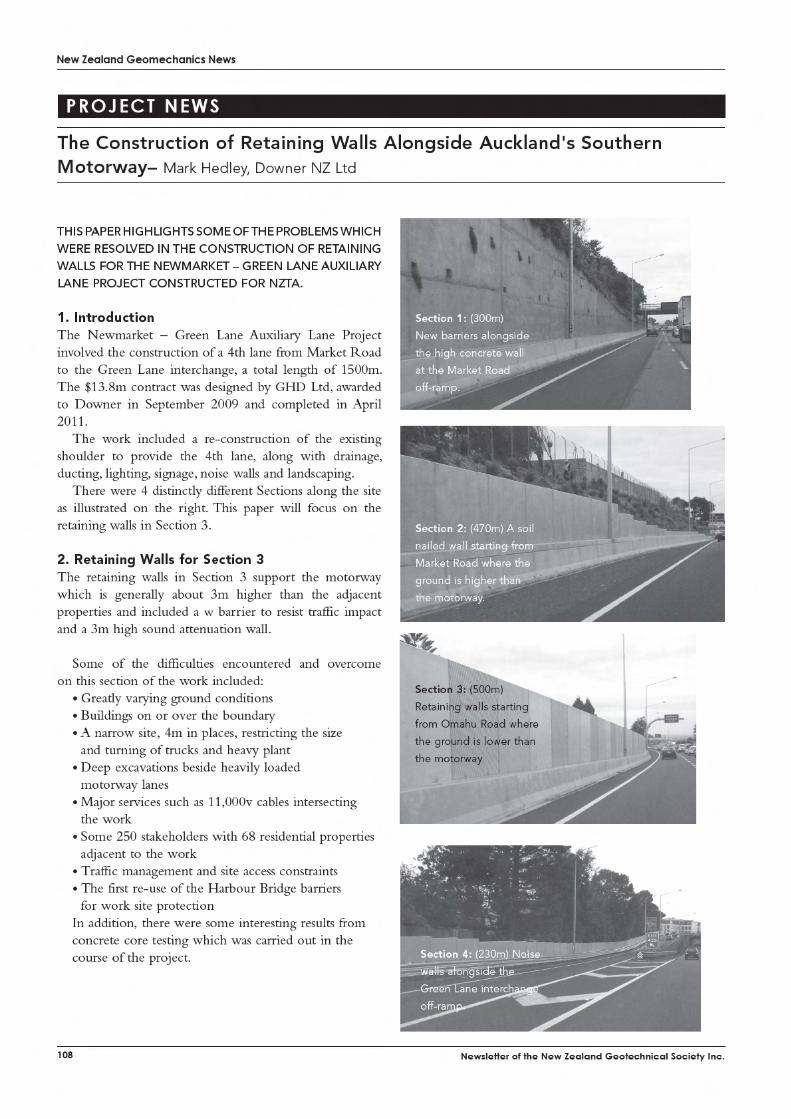
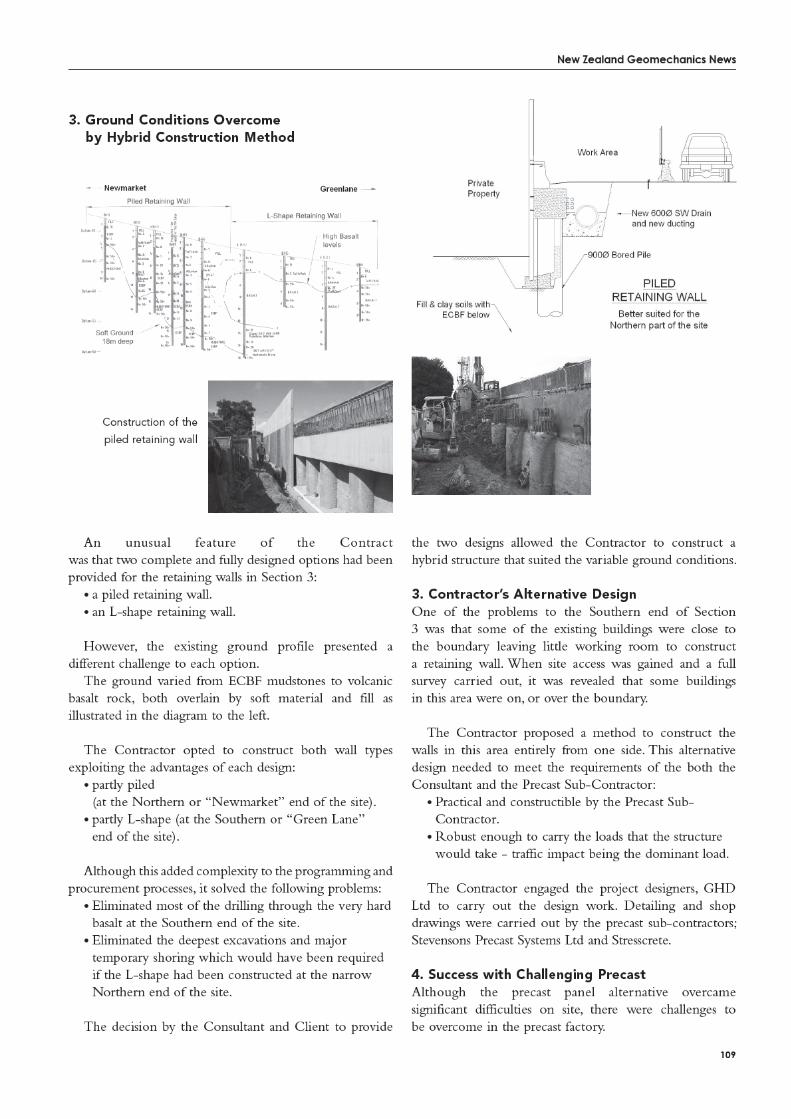
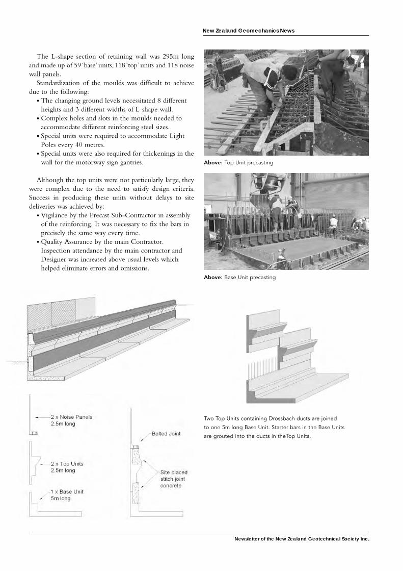
Newsletter of the New Zealand Geotechnical society inc.
New Zealand Geomechanics News
The L-shape section of retaining wall was 295m long and made up of 59 ‘base’ units, 118 ‘top’ units and 118 noise wall panels.
Standardization of the moulds was difficult to achieve due to the following:
• The changing ground levels necessitated 8 different heights and 3 different widths of L-shape wall.
• Complex holes and slots in the moulds needed to accommodate different reinforcing steel sizes.
• Special units were required to accommodate Light Poles every 40 metres.
• Special units were also required for thickenings in the wall for the motorway sign gantries.
Although the top units were not particularly large, they were complex due to the need to satisfy design criteria. Success in producing these units without delays to site deliveries was achieved by:
• Vigilance by the Precast Sub-Contractor in assembly of the reinforcing. It was necessary to fix the bars in precisely the same way every time.
• Quality Assurance by the main Contractor. Inspection attendance by the main contractor and Designer was increased above usual levels which helped eliminate errors and omissions.
Above: Base Unit precasting
Two Top Units containing Drossbach ducts are joined
to one 5m long Base Unit. Starter bars in the Base Units
are grouted into the ducts in theTop Units.
Above: Top Unit precasting
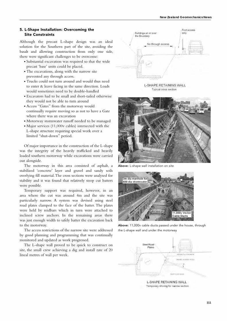
New Zealand Geomechanics News
111
5. L-Shape Installation: Overcoming the Site Constraints
Although the precast L-shape design was an ideal solution for the Southern part of the site, avoiding the basalt and allowing construction from only one side, there were significant challenges to be overcome:
• Substantial excavation was required so that the wide precast ‘base’ units could be placed.
• The excavations, along with the narrow site prevented any through access.
• Trucks could not turn around and would thus need to enter & leave facing in the same direction. Loads would sometimes need to be double-handled
• Excavators had to be small and short-tailed otherwise they would not be able to turn around
• Access “Gates” from the motorway would continually require moving so as not to have a Gate where there was an excavation
• Motorway stormwater runoff needed to be managed• Major services (11,000v cables) intersected with the
L-shape structure requiring special work over a limited “shut-down” period.
Of major importance in the construction of the L-shape was the integrity of the heavily trafficked and heavily loaded southern motorway while excavations were carried out alongside.
The motorway in this area consisted of asphalt, a stabilized ‘concrete’ layer and gravel and sandy soils overlying fill material. The cross sections were analysed for stability and it was found that relatively steep cut batters were possible.
Temporary support was required, however, in an area where the cut was around 4m and the site was particularly narrow. A system was devised using steel road plates clamped to the face of the batter. The plates were held by reidbars which in turn were attached to inclined screw anchors. In the remaining areas there was just enough width to safely batter the excavation back to the motorway.
The access restrictions of the narrow site were addressed by good planning and programming that was continually monitored and updated as work progressed.
The L-shape wall proved to be quick to construct on site, the small crew achieving a dig and install rate of 20 lineal metres of wall per week.
Above: L-shape wall installation on site
Above: 11,000v cable ducts passed under the house, through
the L-shape wall and under the motorway
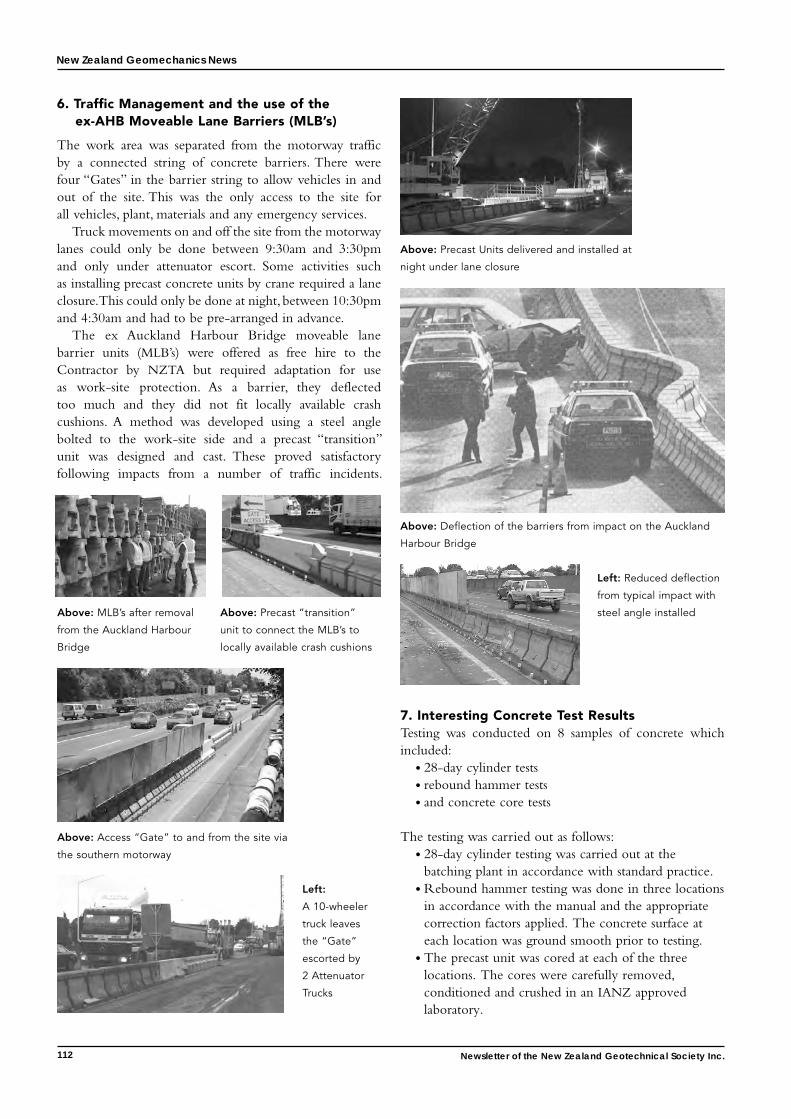
New Zealand Geomechanics News
112 Newsletter of the New Zealand Geotechnical Society Inc.
6. Traffic Management and the use of the ex-AHB Moveable Lane Barriers (MLB’s)
The work area was separated from the motorway traffic by a connected string of concrete barriers. There were four “Gates” in the barrier string to allow vehicles in and out of the site. This was the only access to the site for all vehicles, plant, materials and any emergency services.
Truck movements on and off the site from the motorway lanes could only be done between 9:30am and 3:30pm and only under attenuator escort. Some activities such as installing precast concrete units by crane required a lane closure. This could only be done at night, between 10:30pm and 4:30am and had to be pre-arranged in advance.
The ex Auckland Harbour Bridge moveable lane barrier units (MLB’s) were offered as free hire to the Contractor by NZTA but required adaptation for use as work-site protection. As a barrier, they deflected too much and they did not fit locally available crash cushions. A method was developed using a steel angle bolted to the work-site side and a precast “transition” unit was designed and cast. These proved satisfactory following impacts from a number of traffic incidents.
7. Interesting Concrete Test Results Testing was conducted on 8 samples of concrete which included:
• 28-day cylinder tests• rebound hammer tests• and concrete core tests
The testing was carried out as follows:• 28-day cylinder testing was carried out at the
batching plant in accordance with standard practice.• Rebound hammer testing was done in three locations
in accordance with the manual and the appropriate correction factors applied. The concrete surface at each location was ground smooth prior to testing.
• The precast unit was cored at each of the three locations. The cores were carefully removed, conditioned and crushed in an IANZ approved laboratory.
Above: MLB’s after removal
from the Auckland Harbour
Bridge
Above: Precast “transition”
unit to connect the MLB’s to
locally available crash cushions
Above: Access “Gate” to and from the site via
the southern motorway
Left:
A 10-wheeler
truck leaves
the “Gate”
escorted by
2 Attenuator
Trucks
Above: Precast Units delivered and installed at
night under lane closure
Above: Deflection of the barriers from impact on the Auckland
Harbour Bridge
Left: Reduced deflection
from typical impact with
steel angle installed
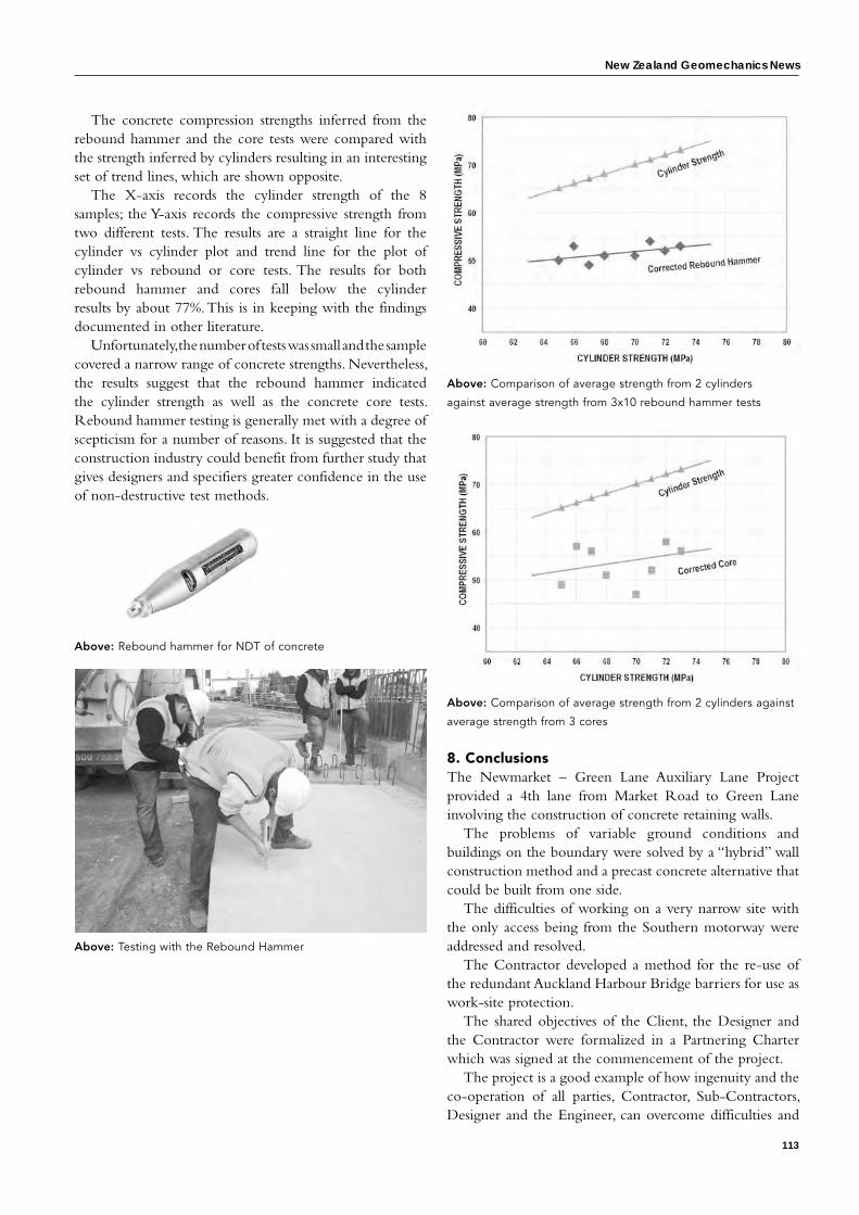
New Zealand Geomechanics News
113
The concrete compression strengths inferred from the rebound hammer and the core tests were compared with the strength inferred by cylinders resulting in an interesting set of trend lines, which are shown opposite.
The X-axis records the cylinder strength of the 8 samples; the Y-axis records the compressive strength from two different tests. The results are a straight line for the cylinder vs cylinder plot and trend line for the plot of cylinder vs rebound or core tests. The results for both rebound hammer and cores fall below the cylinder results by about 77%. This is in keeping with the findings documented in other literature.
Unfortunately, the number of tests was small and the sample covered a narrow range of concrete strengths. Nevertheless, the results suggest that the rebound hammer indicated the cylinder strength as well as the concrete core tests. Rebound hammer testing is generally met with a degree of scepticism for a number of reasons. It is suggested that the construction industry could benefit from further study that gives designers and specifiers greater confidence in the use of non-destructive test methods.
Above: Rebound hammer for NDT of concrete
Above: Testing with the Rebound Hammer
Above: Comparison of average strength from 2 cylinders against
average strength from 3 cores
8. Conclusions The Newmarket – Green Lane Auxiliary Lane Project provided a 4th lane from Market Road to Green Lane involving the construction of concrete retaining walls.
The problems of variable ground conditions and buildings on the boundary were solved by a “hybrid” wall construction method and a precast concrete alternative that could be built from one side.
The difficulties of working on a very narrow site with the only access being from the Southern motorway were addressed and resolved.
The Contractor developed a method for the re-use of the redundant Auckland Harbour Bridge barriers for use as work-site protection.
The shared objectives of the Client, the Designer and the Contractor were formalized in a Partnering Charter which was signed at the commencement of the project.
The project is a good example of how ingenuity and the co-operation of all parties, Contractor, Sub-Contractors, Designer and the Engineer, can overcome difficulties and
Above: Comparison of average strength from 2 cylinders
against average strength from 3x10 rebound hammer tests

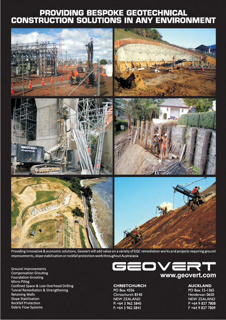
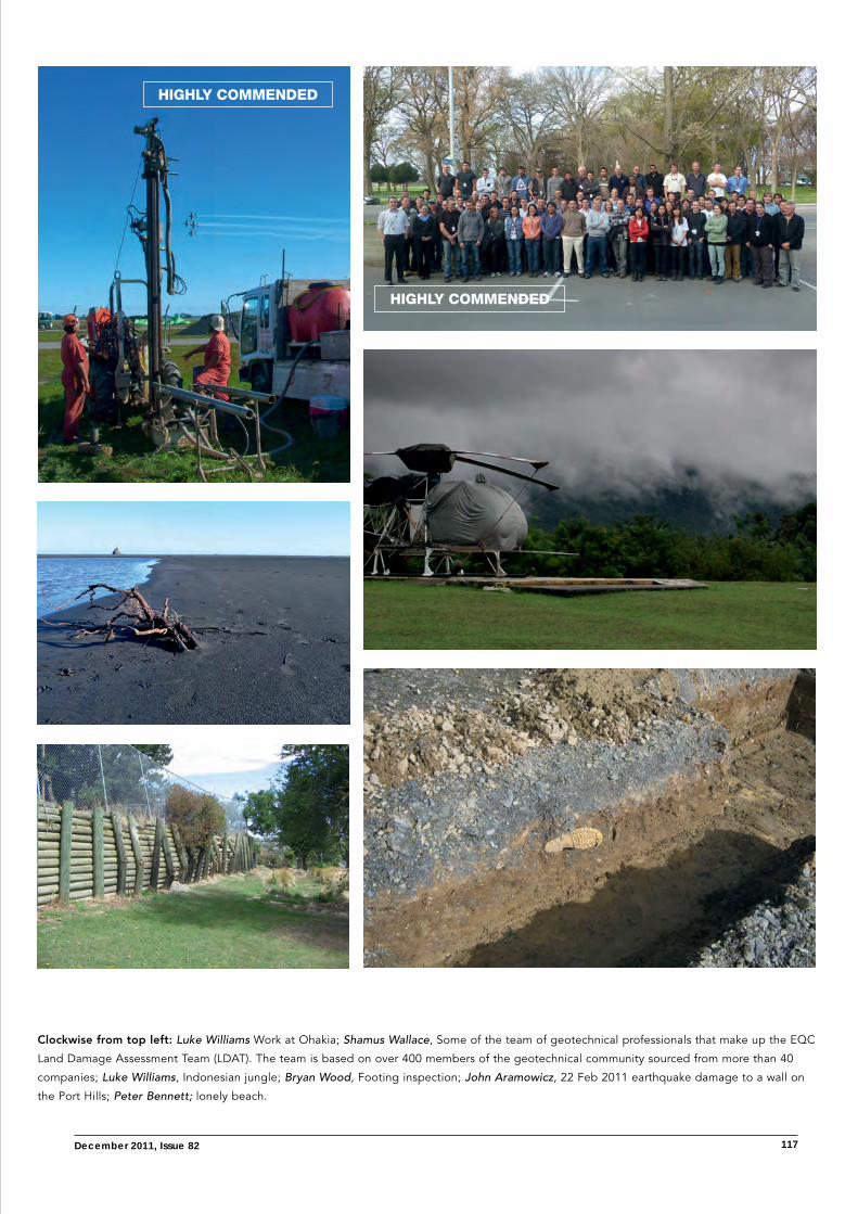
december 2011, issue 82 117
highly cOMMeNded
highly cOMMeNded
Clockwise from top left: Luke Williams Work at Ohakia; Shamus Wallace, Some of the team of geotechnical professionals that make up the EQC
Land Damage Assessment Team (LDAT). The team is based on over 400 members of the geotechnical community sourced from more than 40
companies; Luke Williams, Indonesian jungle; Bryan Wood, Footing inspection; John Aramowicz, 22 Feb 2011 earthquake damage to a wall on
the Port Hills; Peter Bennett; lonely beach.
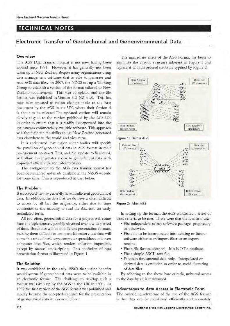

Leading edge infrastructure solutions
Ground Engineering opportunities - New Zealand
Aurecon provides world class professional consulting engineering services to clients across New Zealand, Australia and internationally. An independent, employee owned company, Aurecon has more than 7000 staff in over 80 offices worldwide. We empower people to make a difference through innovation and team work and our projects are widely recognised for client and service excellence.
Our Ground Engineering team is well established as one of the largest within New Zealand, with broad capability across the country. We seek additional skilled Geotechnical Engineers and Engineering Geologists to help us deliver on an expanding and diverse workload that includes road, rail, water, tunnelling and telecommunications infrastructure, residential townships, asset management, mining, industrial, energy and commercial projects. We are heavily involved in providing geotechnical assessments and solutions for infrastructure impacted by the Canterbury Earthquakes. Opportunities range from experienced graduates through to lead positions in offices based in Auckland, Christchurch, Hamilton, Nelson, Tauranga and Wellington.
We are interested in both skilled specialists and well-rounded generalist ground engineering practitioners who can clearly demonstrate their technical abilities through experience and understanding in site investigation and ground characterisation, parameter evaluation, state of the art analysis and applied engineering design. A working knowledge of modern interpretative, database and analytical software is an advantage but a thorough grounding in first principles is essential. Practitioners who demonstrate a good understanding of geological hazards and geotechnical risk management and mitigation measures are especially welcomed.
If you are looking for a challenging and rewarding position in a forward thinking organisation that provides a strong foundation to further develop your career and experience, then look no further. We offer the chance for you to work alongside passionate and world class peers, who strive to be thought leaders.
To register your interest please visit careers.aurecongroup.com, and apply under job number NGS777879.
For general enquiries please phone James Marsh on (04) 4390299.
Leading. Vibrant. Global. www.aurecongroup.com
Construction
Data & Telecommunications
Defence
Energy
Government
International Development Assistance
Manufacturing
Property
Resources
Transport
Water
Image courtesy of Jarvis Marketing


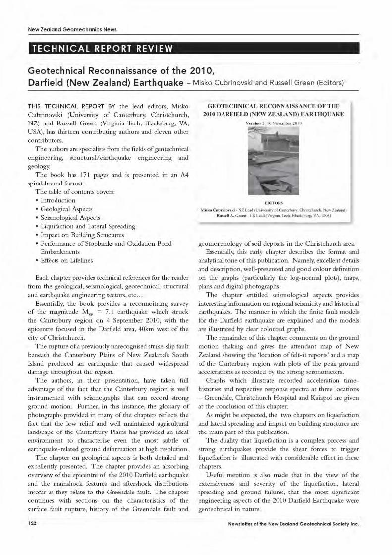


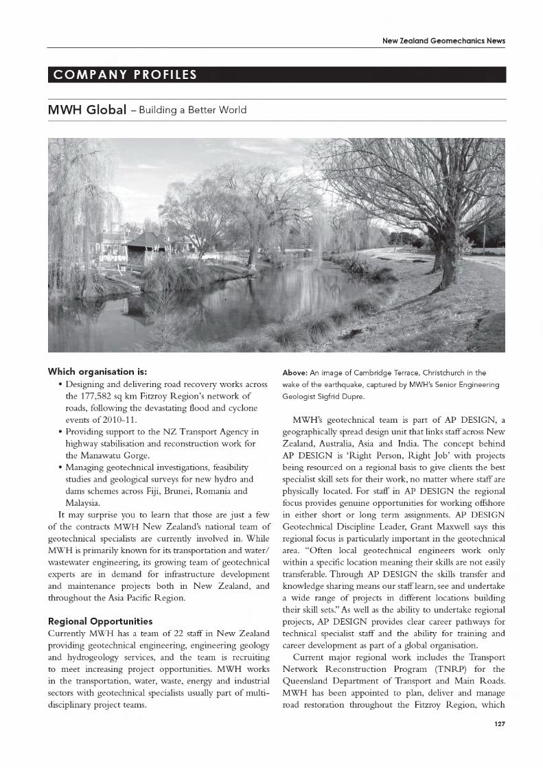
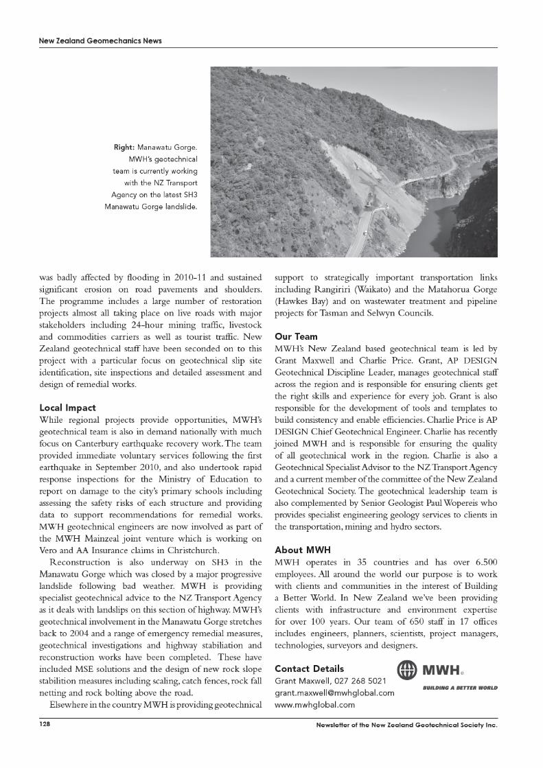


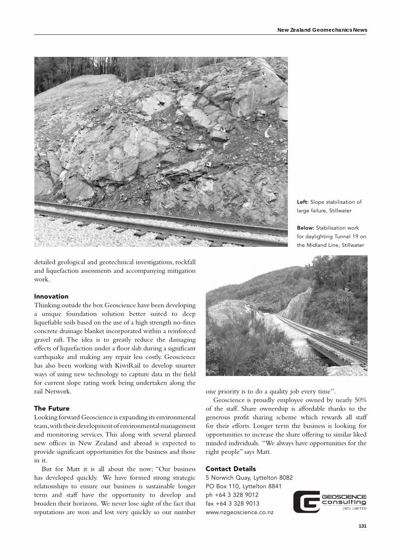
New Zealand Geomechanics News
131
one priority is to do a quality job every time”. Geoscience is proudly employee owned by nearly 50%
of the staff. Share ownership is affordable thanks to the generous profit sharing scheme which rewards all staff for their efforts. Longer term the business is looking for opportunities to increase the share offering to similar liked minded individuals. “We always have opportunities for the right people” says Matt.
Contact Details 5 Norwich Quay, Lyttelton 8082PO Box 110, Lyttelton 8841ph +64 3 328 9012fax +64 3 328 9013www.nzgeoscience.co.nz
detailed geological and geotechnical investigations, rockfall and liquefaction assessments and accompanying mitigation work.
InnovationThinking outside the box Geoscience have been developing a unique foundation solution better suited to deep liquefiable soils based on the use of a high strength no-fines concrete drainage blanket incorporated within a reinforced gravel raft. The idea is to greatly reduce the damaging effects of liquefaction under a floor slab during a significant earthquake and making any repair less costly. Geoscience has also been working with KiwiRail to develop smarter ways of using new technology to capture data in the field for current slope rating work being undertaken along the rail Network.
The futureLooking forward Geoscience is expanding its environmental team, with their development of environmental management and monitoring services. This along with several planned new offices in New Zealand and abroad is expected to provide significant opportunities for the business and those in it.
But for Matt it is all about the now; “Our business has developed quickly. We have formed strong strategic relationships to ensure our business is sustainable longer term and staff have the opportunity to develop and broaden their horizons. We never lose sight of the fact that reputations are won and lost very quickly so our number
Left: Slope stabilisation of
large failure, Stillwater
Below: Stabilisation work
for daylighting Tunnel 19 on
the Midland Line, Stillwater


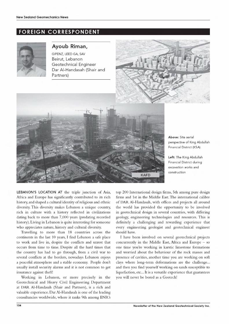
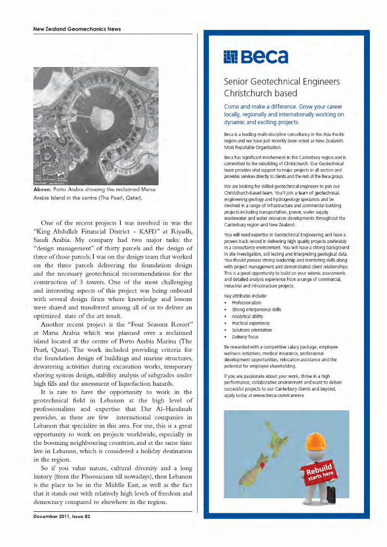

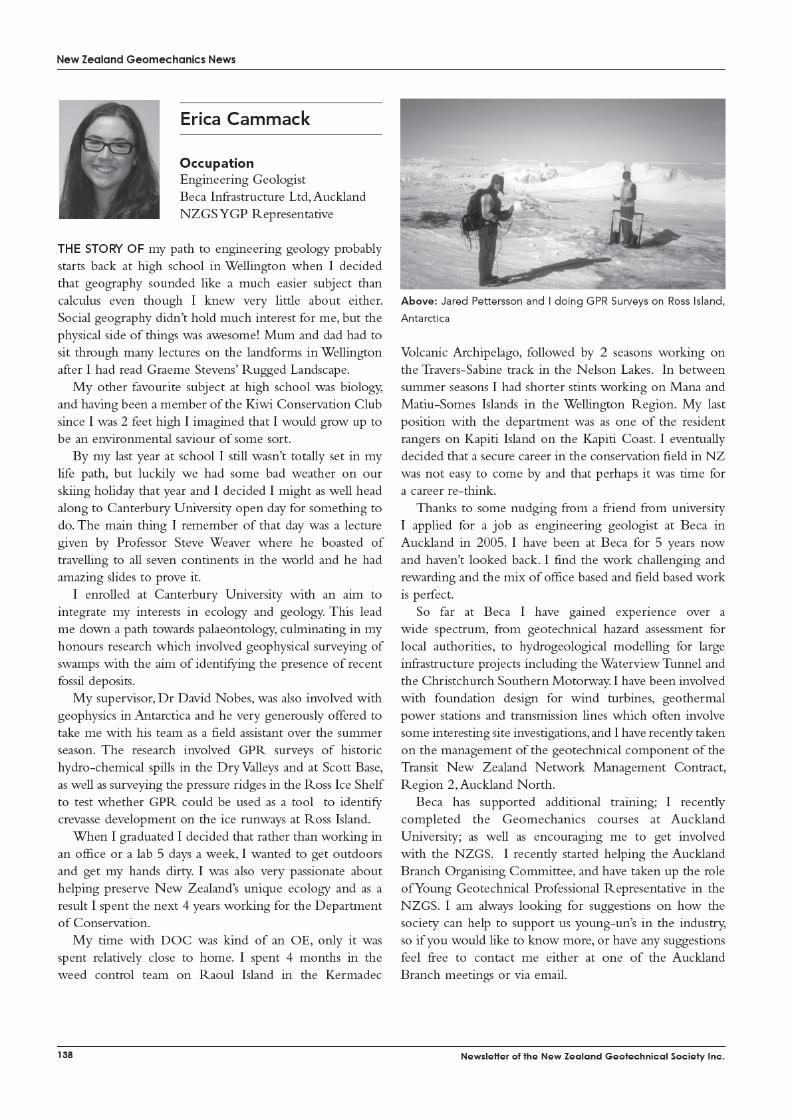
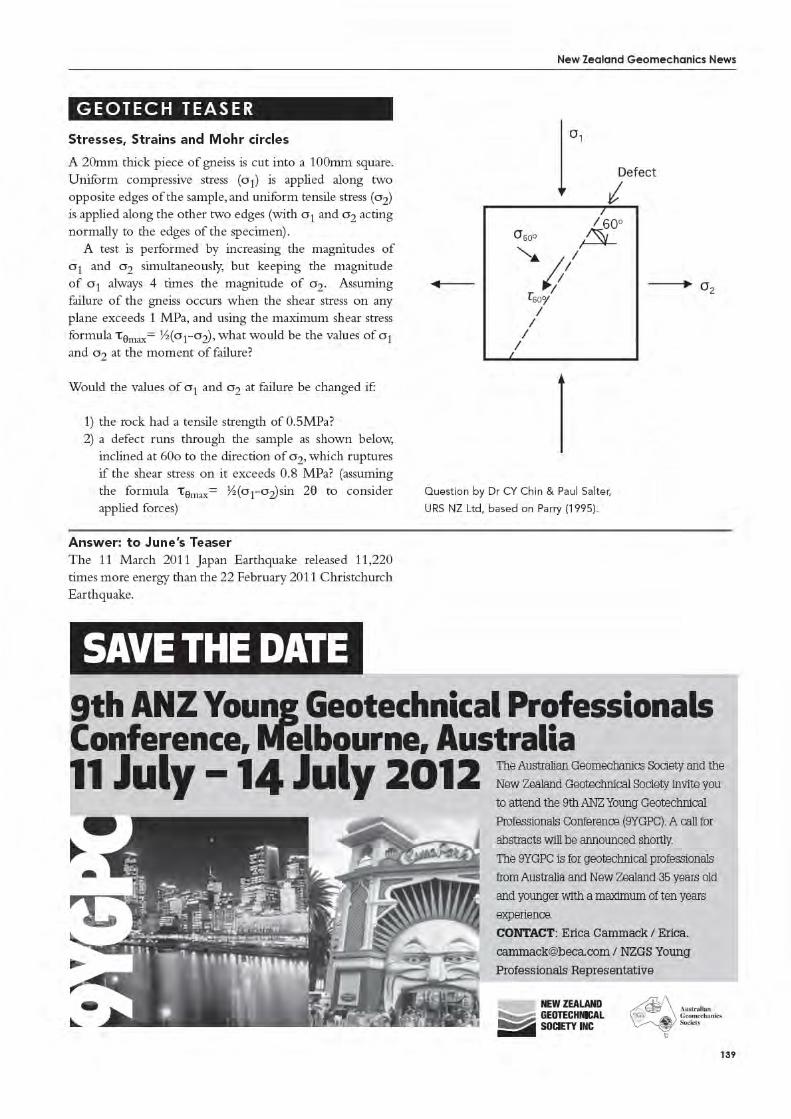


New Zealand Geomechanics News
141
aNswer
Answer to June 2011 Issue 81 Crossword
Across 3 STEREONET—Graph for plotting
structural data 4 COBALT—trace element lacking in
pumice soils that historically limited farming
6 SLAKING—rock cyclical wetting & drying
7 PLAXIS—commonly used finite element modelling software
9 IRONSAND—mineral source, used only by NZ, for industrial steel making
10 MULDOON—PM who sponsored “Think Big” infrastructure projects
12 LLOYDHOMER—Photographer of NZ geology & landscapes (5,5)
14 TOMO—Sinkhole in limestone landscape
15 SOFTROCK—Material in continuum between soil and rock (4,4)
16 PACKER—test to interpret dam foundation permeability
17 HOOVER—Famous concrete gravity-arch dam
19 PIEZOMETRIC—aquifer pressure head 23 LOG—Graphic summary of lithologic
units 24 ALLOCHTHON—Miocene,
geotechnically problematic, soils emplaced over Northland & East Coast
27 GRANITE—Predominant rock type exposed on Stewart Island
30 CERA—Established 2011 to work on rebuilding Christchurch
33 SCHIST—medium-grade metamorphic rock
34 STAPLEDON—Author of Engineering Site Investigation (1977)
35 SHEARBOX—lab test on undisturbed sample to determine residual strength (5,3)
36 HERETAUNGA—Coastal plain in southern Hawke’s Bay used as groundwater resource
37 RUATANIWHA—Dam constructed from glacial outwash & colluvium from Benmore Range
38 YOUNGSMODULUS—soil stiffness derived from stress-strain curve (6,7)
Down 1 POINTLOAD—method of strength
testing rock field specimens (5,4) 2 SEISMIC—Geophysical method using
sledge hammer source 4 CHLORITE—often green phyllosilicate
mineral with 4 endmembers 5 DSIR—Govt body disolved into Crown
Research Institutes in 1992 8 ALLOPHANE—weathering product
of volcanic glass 11 MOHRSCIRCLE—2-D graphical
representation of state of stress 13 OVERCONSOLIDATION—Application
of additional load on soil profile 18 PLINIAN—Eruption with columns
of gas & ash 20 COARSE—soils with <35% fines 21 MASS—Term for non-homogeneous
rock or soil 22 BISHOPS—hand calculation method
for slope stability 25 THIRTYTHREE—Diameter (in mm) of
large shear vane in Pilcon field kit (6,5) 26 GABRIELSGULLY—Location of gold
find prompting Otago Rush (8, 5) 27 GEOMECHANICS—NZGS award for
distinguished paper contributing to development of geotechnics in NZ
28 DUNSTAN—Major active fault near the Clyde Dam
29 BONDLENGTH—Portion of rock bolt fastened to borehole (4,6)
31 DILATANCY—soil tendancy to undergo volume change when deformed
32 DESKSTUDY—Typical 1st phase of investigation (4,5)


New Zealand Geomechanics News
143
Van Ballegooy, S (Sjoerd) * Committee Member(Elected Member)
Tonkin & Taylor LtdPO Box 5271Wellesley StreetAuckland [email protected]
09 355 0715 Ph021 378 964 Mob09 307 0265 Fax
Woodward, S (Simon) * Committee Member(Elected Member)
Geotek Services LtdP O 39015HowickManuaku [email protected]
09 535 9814 Ph09 535 7243 Fax0274 735 712 Mob
Davies, M (Prof. Michael) ISSMGE Australasian Vice President
Dean of EngineeringFaculty of EngineeringUniversity of AucklandPrivate Bag [email protected]
09 373 7599 Ext 87924
Beck, D (Dr. David) ISRM Australasian Vice President
Beck Engineering Pty Ltd 9 Reid DriveChatswood West 2067NSW [email protected]
+61 412 135 782 Cell
Brideau, M-A(Marc-André. Ph.D.)
NZ ISRM Representative Lecturer in Engineering GeologySchool of EnvironmentUniversity of AucklandPrivate Bag 92019Auckland, 1142New [email protected]
09-373-7599 ext. 85195 Work09-373-7435 Fax027-244-7867 Mob
Williams, A (Ann) IAEG Australasian Vice President
Beca Infrastructure132 Vincent StreetP O Box 6345Auckland [email protected]
09 300 9172 Ph09 300-9300 Fax021-809-162 Mob
Gitte Abildgaard NZGS Web Manager Contact Gitte:[email protected]
Website: www.nzgs.org
• Co-opted position + Appointed position * Elected members of committee
Aurecon .........................................................................................................119
Avalon .......................................................................................................13,120
BECA Geotest ....................................................................................43,135
Boart Longyear (NZ) Ltd ..................................................................124
Brian Perry Civil ........................................................................................53
Broons ...............................................................................................................42
Civil Services (HB) Ltd ....................................................................123
Coffey NZ Ltd ....................................................outside back cover
DCN Drilling Ltd .....................................................................................15
Drill Force NZ Ltd ...............................................................................133
Geoconsult ..................................................................................................125
Geogrubb ........................................................................................................16
Geoscience Consulting Ltd ..............................................................132
Geotech Drilling .....................................................................................130
Geotechnics Ltd ................................. 31,74-75, inside back cover
Geovert Ltd ...............................................................................................115
Griffiths...............................................................................................................9
Grouting Services NZ Ltd ...................................................................30
Hiway Geotechnical .................................................................................80
HRS Hoare Research Software ....................................................121
Keynetix Limited .......................................................................................11
Maccaferri NZ ..........................................................inside front cover
McMillan Specialist Drilling Services ..........................................25
MWH NZ ...................................................................................................126
Opus International Hamilton ............................................................27
Perry Drilling ...............................................................................................26
Pro Drill ...........................................................................................................32
Reinforced Earth Limited ....................................................................49
Stonestrong Infrastructure ....................................................................41
Techsoft Australasia Pty Ltd ............................................................129
Tonkin and Taylor ......................................................................................12
URS.................................................................................................................114
Uretek ................................................................................................flier insert
advertisers directory