Embed Size (px)
Citation preview
NLR-TP-2000-443
A basic flight simulation tool for rigid airshipsA basic flight simulation tool for rigid airshipsA basic flight simulation tool for rigid airshipsA basic flight simulation tool for rigid airships
A.J.J. Lemmers and A.P.L.A. Marsman
NationaalNationaalNationaalNationaal Lucht- en Ruimtevaartlaboratorium Lucht- en Ruimtevaartlaboratorium Lucht- en Ruimtevaartlaboratorium Lucht- en RuimtevaartlaboratoriumNational Aerospace Laboratory NLR
NLR-TP-2000-443
A basic flight simulation tool for rigid airshipsA basic flight simulation tool for rigid airshipsA basic flight simulation tool for rigid airshipsA basic flight simulation tool for rigid airships
A.J.J. Lemmers and A.P.L.A. Marsman
This report is based on a presentation held on the 3rd International Airship Convention andExhibition 2000, Friedrichshafen on 4 July 2000.
The contents of this report may be cited on condition that full credit is given to NLR andthe authors.
Division: Flight
Issued: August 2000
Classification of title: Unclassified
-2-NLR-TP-2000-443
Summary
The National Aerospace Laboratory NLR is developing a basic flight simulation tool of a rigid
airship. This tool will allow simulation of a generic large rigid airship and it will support the
fundamentals of Flight Mechanics and Stability and Control. The tool will run in a PC-based
environment using MATLAB/Simulink. The basic simulation will support six degrees of
freedom and will cover the complete flight envelope. A modular approach is used for the
design, which gives the possibility for an easy upgrade when new or modified data is available.
-3-NLR-TP-2000-443
Contents
1 Introduction 4
2 Development philosophy 5
3 Architecture of the simulation tool 7
4 Components of the simulation tool 9
4.1 Buoyancy and static lift 9
4.2 Aerodynamics 12
4.3 Virtual mass 12
4.4 Propulsion 12
4.5 Mass properties 13
4.6 Equations of motion 14
5 Applications 14
6 Conclusions 15
7 References 16
(16 pages in total)
-4-NLR-TP-2000-443
1 Introduction
The National Aerospace Laboratory NLR operates at its Amsterdam establishment a versatile
flight simulation facility for research in various areas. This is a high-quality modular research
and development facility, capable of simulating both fixed-wing and rotary-wing aircraft. It is
used in military and civil research programmes for national and international customers. NLR's
research flight simulation facility consists of a set of advanced hardware and software
components, structured in a modular fashion to allow virtually any vehicle to be simulated. The
simulator equipment consists of many modules, such as cockpits, visual, motion and computer
systems, and a large set of simulation software modules and tools. The simulator’s modular and
versatile set-up enables efficient interchange of aircraft models, equipment, etc.
NLR currently operates the following simulation facilities:
§ the National Simulation Facility (NSF), primarily assigned to military simulation projects
(F-16MLU, helicopter etc.) mounted on a six degrees-of-freedom (6-dof) motion platform.
§ the Research Flight Simulator (RFS) with a generic transport aircraft cockpit for civil
simulation projects mounted on a six degrees-of-freedom (6-dof) motion system.
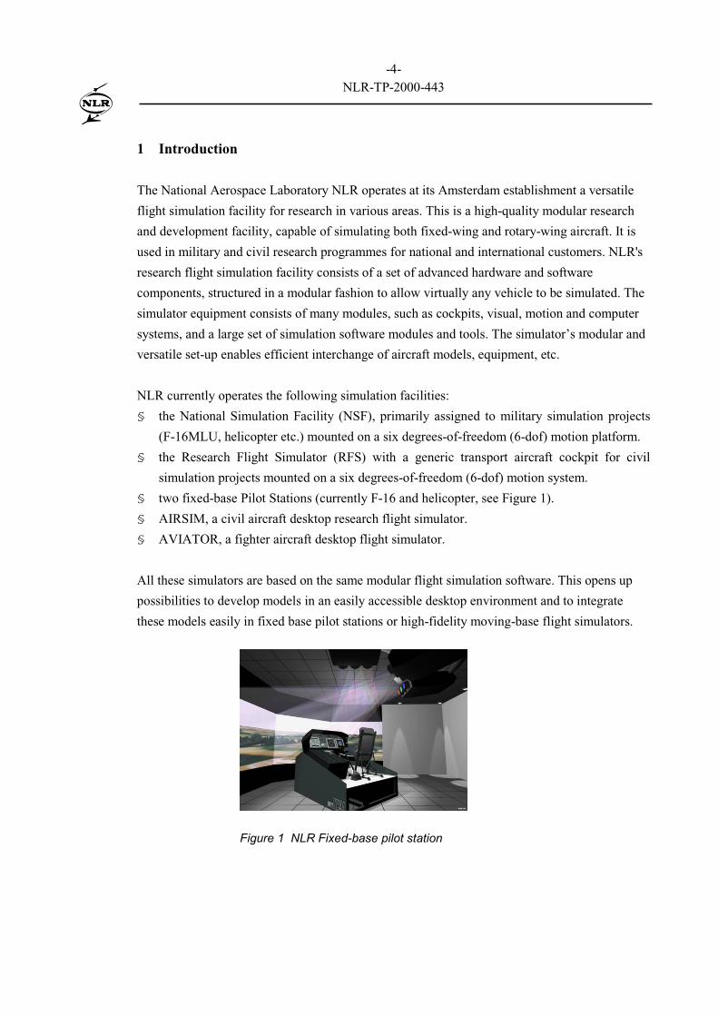
§ two fixed-base Pilot Stations (currently F-16 and helicopter, see Figure 1).
§ AIRSIM, a civil aircraft desktop research flight simulator.
§ AVIATOR, a fighter aircraft desktop flight simulator.
All these simulators are based on the same modular flight simulation software. This opens up
possibilities to develop models in an easily accessible desktop environment and to integrate
these models easily in fixed base pilot stations or high-fidelity moving-base flight simulators.
Figure 1 NLR Fixed-base pilot station
-5-NLR-TP-2000-443
In September 1999 the NLR Flight Simulation department started a project with Rigid Airship
Design (RAD) to develop a Basic Flight Simulation Tool. This tool will allow simulation of a
generic large rigid airship. The tool will be developed using MATLAB/Simulink and will run in
a PC-based desktop environment. This basic tool will support the fundamentals of Flight
Mechanics and Stability and Control and will provide the user with response analysis of control-
surface, engine and trim commands. Also the reaction on changing winds may be investigated.
The basic simulation will support full six degrees of freedom equations of motion. Models for
the aerodynamics, buoyancy, mass and inertia including virtual mass, and engines are
implemented in the airship simulation tool. A modular approach is used for the design and
development of the simulation tool, which gives the possibility for an easy upgrade and
incorporation of new or modified models and data. This is an extremely useful property in the
design process of an airship, because it allows synchronous maturation of airship design and the
simulation tool. This opens up simulation possibilities in every stage of the design process.
Although the basic simulation tool will be built with MATLAB/Simulink on PCs, the potential
to exchange models with more sophisticated simulators is available. NLR has tools to integrate
these MATLAB/Simulink models in a real-time simulation environment, which is required for
studies with a pilot-in-the-loop. Studies in the fields of flight handling and human factors are
obvious. Growth potential towards an engineering simulator is foreseen to test all (avionics)
equipment on board. Eventually a training simulator may be derived from this tool.
2 Development philosophy
A simulation tool can support various phases in the development of a rigid airship. Initially the
basic simulation tool will support RAD in understanding the dynamic behaviour of the rigid
airship while adapting the configuration. In future stages of the rigid airship development an
engineering simulator will be required to test avionics equipment on board and pilot handling
before the maiden flight and to analyse the flight tests. When the airship is used in an
operational evironment also a training simulator will be needed. To ease the development of all
these simulation tools and to assure consistency between these tools, use of the same airship
model would be a large advantage. Therefore it is necessary that the basic simulation tool will
be able to grow with the progress of the airship development.
During the development process more and more data will become available. For example the
aerodynamic model, first the aerodynamic data is gathered with handbook methods, later data
from windtunnel measurements will become available and in the final development stage data
-6-NLR-TP-2000-443
from real flight tests can be used. This will lead to more sophisticated aerodynamic models
during the progress of the airship development. To take advantage of these high-fidelity models
the simulation tool must have the capability to exchange models. To achieve this capability a
modular approach will be used for the simulation tool.
The basic simulation tool will be built with MATLAB/Simulink in order to provide a PC-based
desktop environment. MATLAB is a technical computing environment that combines numeric
computation, advanced graphics and visualisation, and a high-level programming language.
MATLAB includes numerous preprogrammed functions for data analysis and visualisation,
modelling, simulation, prototyping, application development and GUI design. Simulink has
been built on top of MATLAB and enables developers to build graphical block diagrams,
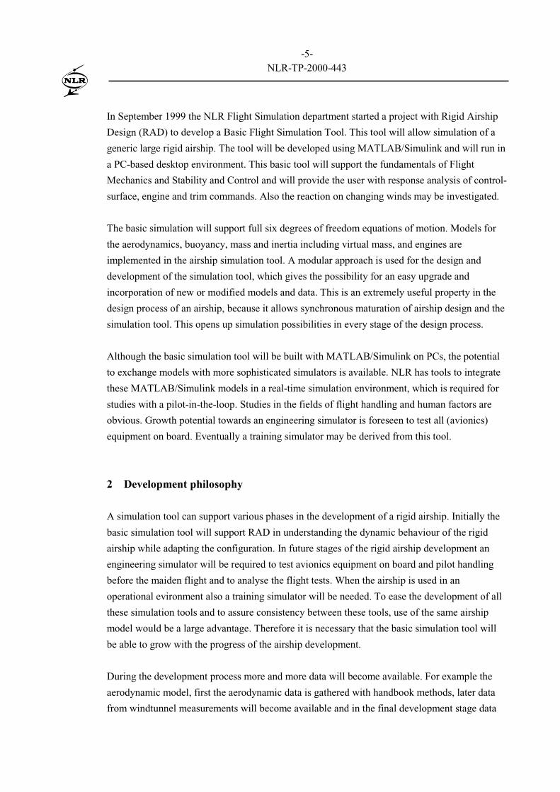
simulate dynamic systems and evaluate system performance. NLR has developed MOSAIC
[tenDam99], a tool to import externally developed models into MATLAB/Simulink and to
export the models for use in the real-time simulation (RTS) environment at NLR [Brouwer96].
This allows an upgrade of the basic simulation tool to a real-time simulator.
In Figure 2 the basic simulation tool is integrated in the NLR Real-Time simulation
environment.
RTS
MOSAIC
Basic Simulation
Tool
SCRAMNET
Ethernet
Controls
Visual
Motion
FMS
PFD
EICAS
Figure 2 NLR Real-Time Simulation Environment with Basic Simulation Tool
-7-NLR-TP-2000-443
3 Architecture of the simulation tool
In the previous paragraph the reasons for using a modular approach were discussed. In this
paragraph the general structure of the simulation model will be outlined and an overview of the
implementation of this model in Simulink will be given.
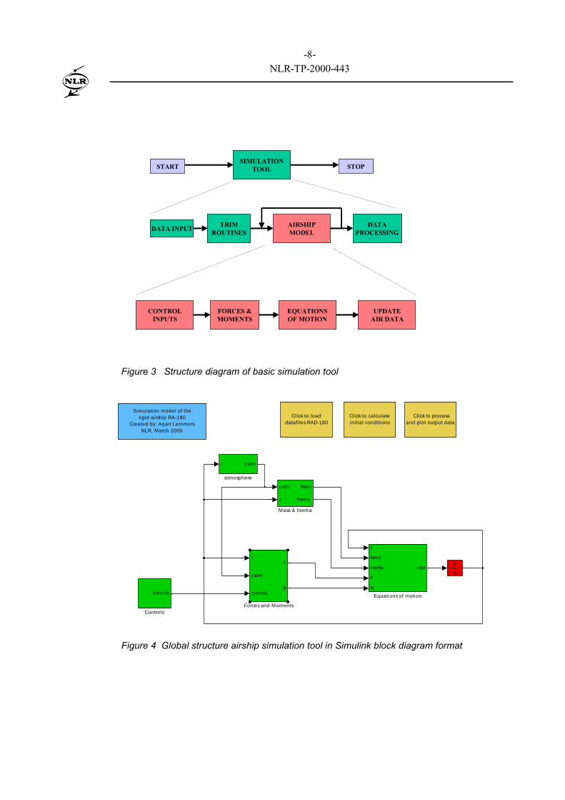
In Figure 3 the modular structure of the basic flight simulation tool is given. This diagram
shows the sequence of operations which will be used for off-line simulation of aircraft. This is a
generic sequence and it is valid for all kind of aircraft or airships. For online piloted flight
simulation it is necessary to include additional modules to determine indications of cockpit
instruments, visual system projection, deflections of the actuators of the motion system, etc.
However the model structure of the simulator will be the same.
Before starting the simulations, the data of the airship will be loaded and a trim routine will be
used to calculate steady-state values for the state and input variables for a flight condition
specified by the user. Now the actual simulation can start. A number of subroutines, such as the
aerodynamic, buoyancy and propulsion modules, have to be called to calculate the time
derivatives. These time derivatives of the state equations will be integrated numerically with
integration routines included within the simulation program. After the simulation the data will
be processed and will be presented in a number of figures.
The global structure of the airship simulation tool is shown in Figure 4 in Simulink block
diagram format. The structure of the airship model is based on the simulation model of the
amphibious aircraft Canadair CL-415 [Lemmers96]. Several blocks can be determined in the
airship model: controls, atmosphere, mass and inertia, forces and moments, and the equations of
motion. The overall structure is clearly visible in this figure. The state derivatives are functions
of external forces and moments and the mass and inertia properties of the airship. Other blocks
are atmosphere, which contains calculation of atmospheric variables like pressure, air
temperature, etc., and engine controls in which the control settings of the engines can be
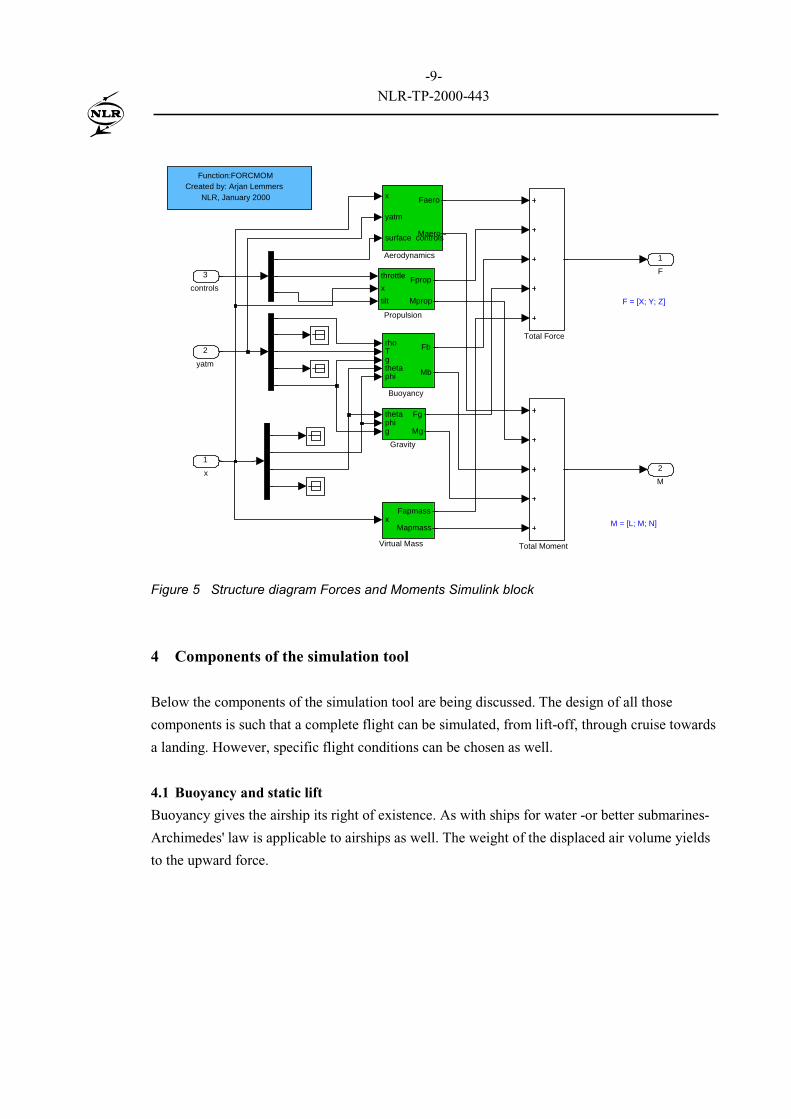
adapted. The external forces and moments can be divided into different categories (see Figure
5): aerodynamics, propulsion, buoyancy, gravity and virtual mass. These models will be
discussed in the next chapter.
-8-NLR-TP-2000-443
START STOP
AIRSHIPMODEL
DATA INPUTDATA
PROCESSINGTRIM
ROUTINES
SIMULATIONTOOL
FORCES &MOMENTS
EQUATIONSOF MOTION
UPDATEAIR DATA
CONTROLINPUTS
START STOP
AIRSHIPMODEL
DATA INPUTDATA
PROCESSINGTRIM
ROUTINES
SIMULATIONTOOL
FORCES &MOMENTS
EQUATIONSOF MOTION
UPDATEAIR DATA
CONTROLINPUTS
Figure 3 Structure diagram of basic simulation tool
Simulation model of therigid airship RA-180
Created by: Arjan LemmersNLR, March 2000
x y atm
atmosphere
Cl ick to processand plot output data
Cl ick to calculate initial conditions
Cl ick to load datafiles RAD-180
y atm
x
Mass
Inertia
Mass & Inertia
s
1x
y atm
controls
F
M
Forces and Moments
x
Mass
Inertia
F
M
xdot
Equations of motioncontrols
Controls
Figure 4 Global structure airship simulation tool in Simulink block diagram format
-9-NLR-TP-2000-443
F = [X; Y; Z]
M = [L; M; N]
2
M
1
F
Function:FORCMOMCreated by: Arjan Lemmers
NLR, January 2000
Total Moment
Total Force
throttle
x
tilt
Fprop
Mprop
Propulsion
thetaphig
Fg
Mg
Gravity
rhoTgthetaphi
Fb
Mb
Buoyancy
xFapmass
Mapmass
Virtual Mass
x
yatm
surface controls
Faero
Maero
Aerodynamics
3
controls
2
yatm
1
x
Figure 5 Structure diagram Forces and Moments Simulink block
4 Components of the simulation tool
Below the components of the simulation tool are being discussed. The design of all those
components is such that a complete flight can be simulated, from lift-off, through cruise towards
a landing. However, specific flight conditions can be chosen as well.
4.1 Buoyancy and static lift
Buoyancy gives the airship its right of existence. As with ships for water -or better submarines-
Archimedes' law is applicable to airships as well. The weight of the displaced air volume yields
to the upward force.
-10-NLR-TP-2000-443
gVB air ⋅⋅= ρ [1]
where,
B is the buoyancy force [N],
V the volume of the airship [m3],
ρair the density of the air [kg/m3] and
g the Earth gravity constant [m/s2].
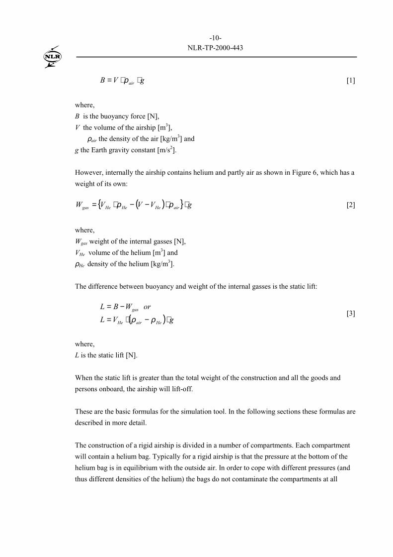
However, internally the airship contains helium and partly air as shown in Figure 6, which has a
weight of its own:
( ){ } gVVVW airHeHeHegas ⋅⋅−−⋅= ρρ [2]
where,
Wgas weight of the internal gasses [N],
VHe volume of the helium [m3] and
ρHe density of the helium [kg/m3].
The difference between buoyancy and weight of the internal gasses is the static lift:
( ) gVL
orWBL
HeairHe
gas
⋅−⋅=
−=
ρρ[3]
where,
L is the static lift [N].
When the static lift is greater than the total weight of the construction and all the goods and
persons onboard, the airship will lift-off.
These are the basic formulas for the simulation tool. In the following sections these formulas are
described in more detail.
The construction of a rigid airship is divided in a number of compartments. Each compartment
will contain a helium bag. Typically for a rigid airship is that the pressure at the bottom of the
helium bag is in equilibrium with the outside air. In order to cope with different pressures (and
thus different densities of the helium) the bags do not contaminate the compartments at all
-11-NLR-TP-2000-443
times. At low altitudes the lower part of each compartment will be filled with air, which will be
ventilated with the surrounding as the volume of the helium bag is varying, see Figure 6.
Within the simulation tool the density within the bags does not just vary due to different
(pressure) altitudes, but also other effects may be investigated:
§ Different purity of the helium
§ Different fullness factors per bag
§ Different superheat per bag.
When the helium is polluted with other gasses, the purity becomes less than 100% and therefore
the density within the bag increases, yielding to less static lift than according to equation [3]
Due to leakage, the fullness factor of each bag will reduce with time, and thus the volume of the
bag. By decreasing the fullness factor relatively rapid the loss of a bag in a compartment can be
simulated.
Superheat, certainly when the sun heats just a part of the airship, may destabilise the flight. Due
to the higher temperature the volume of the bags increase according to the first gas-law:
P
TRV
⋅= [4]
where,
R is the gas constant [K/(N.m)],
T the temperature [K] and
P the pressure [Pa].
The static lift equation [3] may become different for a set of compartments, which may induce a
pitching moment.
Air
Figure 6 Helium bag in compartments
Air
Helium
-12-NLR-TP-2000-443
4.2 Aerodynamics
Due to its large size and relative low speed, the aerodynamics of an airship are characterised by
high Reynolds-numbers and a profound boundary layer. However, for the simulation tool any
aerodynamic function may be implemented. Compared with fixed wing aircraft, the structure of
the aerodynamic calculations is adapted for the axial-symmetric body of an airship. Table-
lookup function blocks enable easy modification of the aerodynamics when more data becomes
available. Initially data from literature and theoretical aerodynamics must be used, replaced by
windtunnel data in a later stage and eventually updated by flight test results.
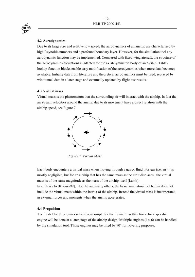
4.3 Virtual mass
Virtual mass is the phenomenon that the surrounding air will interact with the airship. In fact the
air stream velocities around the airship due to its movement have a direct relation with the
airship speed, see Figure 7.
Each body encounters a virtual mass when moving through a gas or fluid. For gas (i.e. air) it is
mostly negligible, but for an airship that has the same mass as the air it displaces, the virtual
mass is of the same magnitude as the mass of the airship itself [Lamb].
In contrary to [Khoury99], [Lamb] and many others, the basic simulation tool herein does not
include the virtual mass within the inertia of the airship. Instead the virtual mass is incorporated
in external forces and moments when the airship accelerates.
4.4 Propulsion
The model for the engines is kept very simple for the moment, as the choice for a specific
engine will be done at a later stage of the airship design. Multiple engines (i.e. 6) can be handled
by the simulation tool. Those engines may be tilted by 90° for hovering purposes.
Figure 7 Virtual Mass
-13-NLR-TP-2000-443
4.5 Mass properties
Weight is the counterpart of buoyancy. The total weight of an airship is the sum of:
§ the frame and all systems (i.e. the engines),
§ the fuel in the fuel tanks,
§ the water in the ballast tanks,
§ the payload,
§ the internal gas
The weight of frame and systems can be seen as constant for this simulation program, while the
fuel-weight will reduce due to fuel consumption. Furthermore the centre of gravity may be
controlled by rearranging the water over the ballast tanks. Within this simulation program the
payload is regarded as an invariable entity. Finally the weight of the internal gas, already
mentioned by equation [2] is a variable as the part filled with air is ventilated according the
volume of the helium bags.
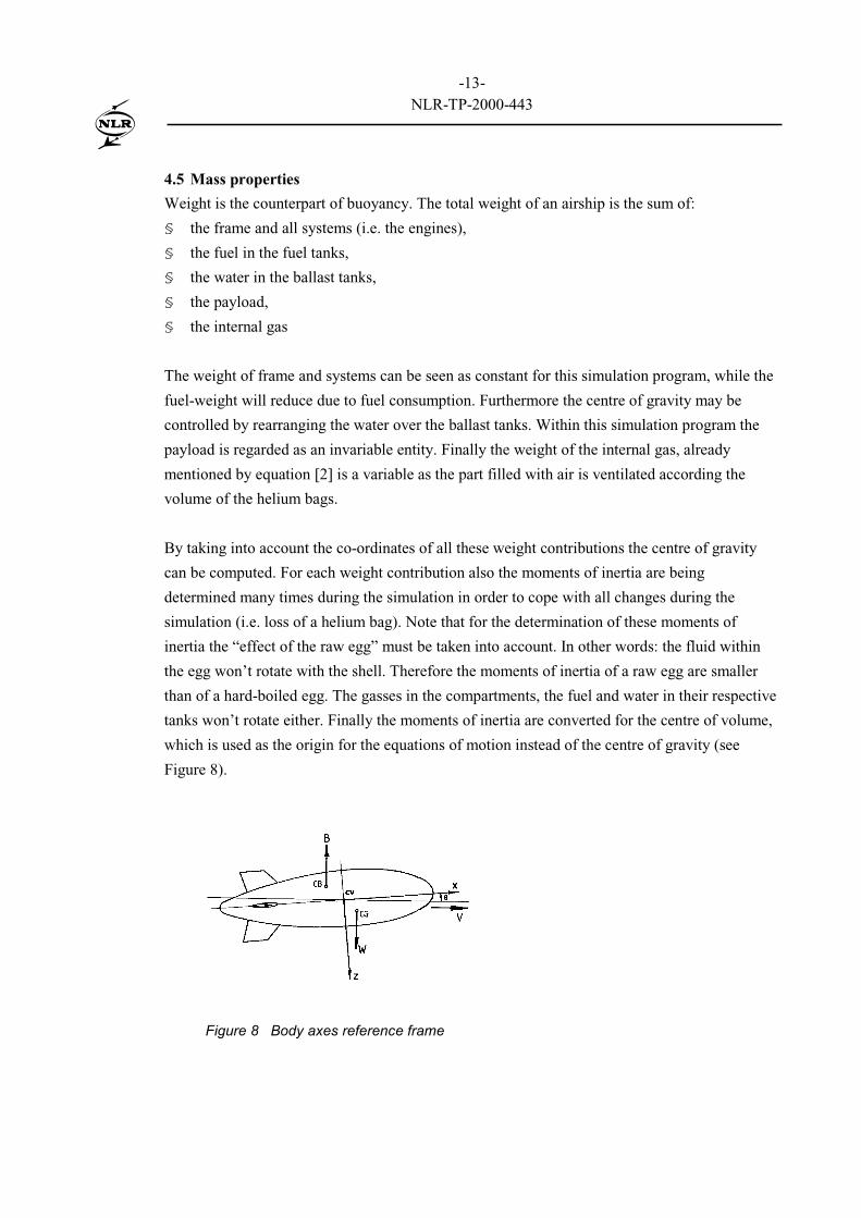
By taking into account the co-ordinates of all these weight contributions the centre of gravity
can be computed. For each weight contribution also the moments of inertia are being
determined many times during the simulation in order to cope with all changes during the
simulation (i.e. loss of a helium bag). Note that for the determination of these moments of
inertia the “effect of the raw egg” must be taken into account. In other words: the fluid within
the egg won’t rotate with the shell. Therefore the moments of inertia of a raw egg are smaller
than of a hard-boiled egg. The gasses in the compartments, the fuel and water in their respective
tanks won’t rotate either. Finally the moments of inertia are converted for the centre of volume,
which is used as the origin for the equations of motion instead of the centre of gravity (see
Figure 8).
Figure 8 Body axes reference frame
-14-NLR-TP-2000-443
4.6 Equations of motion
The airship dynamics can be expressed as a set of differential equations. These equations
express the motions of the airship in terms of external forces and moments. The development of
the equations of motion can follow the standard aircraft practice. The major differences with an
aircraft model are due to the effect that the airship is buoyant and displaces a large volume.
Therefore the familiar aircraft equations of motion are extended with buoyancy and virtual mass
forces. However the virtual mass contribution can also be included in the mass properties of the
airship as is described in [Khoury99]. An other difference is that the airship equations of motion
are developed with respect to a body axes reference frame with the origin at the centre of
volume (see Figure 8) instead of the centre of gravity. The centre of volume has been chosen
because this centre is assumed to be constant during the flight unlike the centre of gravity. This
leads to additional mass and inertia terms in the equations of motion.
5 Applications
As already indicated in the introduction, this basic simulation tool has a growth potential:
§ The MATLAB/Simulink version as is, has applications in the support of the airship design.
§ When downloading the models into a research flight simulator pilot-in-the-loop handling
and other Human Factors can be investigated.
§ Another focus on simulated testing is with an engineering simulator allowing hardware-in-
the-loop such as avionics and actuators.
§ Eventually a training simulator may be derived from this tool.
The basic simulation tool finds its applications in the design stage of a rigid airship. The effects
of different configurations (i.e. three or four fins, engine positions, stretching the body, etc.) can
be visualised for normal operations as well as for degraded modes (i.e. loss of a helium bag,
engine failure) or adverse weather conditions. Requirements such as the size of the control
surfaces can be investigated.
Furthermore the basic tool can be used to design the -digital- flight control laws and to perform
analytical tests well in advance of either pilot or hardware-in-the-loop tests.
-15-NLR-TP-2000-443
6 Conclusions
A basic flight simulation tool is developed that allows the simulation of a generic large rigid
airship. It supports the fundamentals of Flight Mechanics and Stability and Control and provides
the user with response analysis of control-surface, engine and trim commands or changing
winds. The basic simulation supports the whole flight envelope and full six degrees of freedom
of motion. It finds its applications in the design stage of a rigid airship. The effects of different
configurations can be visualised and requirements such as the size of control surfaces can be
investigated.
The modular approach makes it easy to upgrade the tool by incorporation of new or modified
data and models. This opens up simulation possibilities in every stage of the design process. The
basic tool has the potential to exchange models with more sophisticated simulators and can be
integrated in a real-time simulation environment. This real-time environment gives possibilities
for pilot-in-the-loop handling and other Human Factor studies. Eventually an engineering
simulator for testing avionics systems or a training simulator may be derived from this tool.
-16-NLR-TP-2000-443
7 References
• [Brouwer96]
The National Simulation Facility NSF: The application of the Real-time simulation support
tool PROSIM, W. Brouwer, A.A. ten Dam, P. Schrap, NLR-TP-96033, NLR, Amsterdam,
Januari 1996
• [tenDam99]
MOSAIC: Automated simulation model transfer from MATLAB/SIMULINK to Eurosim,
Technical note: version 1.0, A.A. ten Dam, W.W.M. Heesbeen and W.F. Lammen, NLR-
CR-99561, NLR, Amsterdam, December 1999
• [Khoury99]
Airship Technology, G. A. Khoury and J.D. Gillet, Cambridge University Press, Cambridge,
1999
• [Lamb]
The inertia coefficients of an ellipsoid moving in a fluid, H. Lamb, Aeronautical Research
Commitee, Report and Memoranda No. 623
• [Lemmers96]
Modelling and simulation of non-linear flight and landing on water of the Canadair CL-415
in a Matlab/Simulink environment, A.J.J. Lemmers, Graduate’s Thesis, Delft University of
Technology, Faculty of Aerospace Engineering, Delft, June 1996


